Nokia DTX 3 Service Manual. Www.s Manuals.com. Manual
User Manual: PBX Connectivity Terminal Nokia DTX-3 - Service manuals and Schematics, Disassembly / Assembly. Free.
Open the PDF directly: View PDF ![]() .
.
Page Count: 76
- SERVICE MANUAL
- nokia_dtx-3_service_manual_02_gen_secured [Unlocked by www.freemypdf.com].pdf
- nokia_dtx-3_service_manual_03_systm5_secured [Unlocked by www.freemypdf.com].pdf
- nokia_dtx-3_service_manual_04_parts_secured [Unlocked by www.freemypdf.com].pdf
- nokia_dtx-3_service_manual_06_servsw_secured [Unlocked by www.freemypdf.com].pdf
- Service Software
- Table of Contents
- General
- Software Environment of the Support Modules
- Installation
- BACK TO MAIN PAGE
- Service Software
- nokia_dtx-3_service_manual_07_servtool_secured [Unlocked by www.freemypdf.com].pdf
- Service Tools
- Table of Contents
- Flash Loading Adapter FLA-7
- Flash Prommer FPS-4 (Sales Pack)
- Security Box TDF-4
- DC Power Cable SCF-7
- D9-D9 Cable AXS-4
- D15-D15 Cable AXS-5
- Service Cable DKT-6A
- Line Adapter Test cable SCS-24
- SW Security Device PKD-1
- Power Cable PCC-1B
- Modular T-Adapter
- MBUS Cable DKT-7A
- Line Adapter Test Cable CA-15DS
- BACK TO MAIN PAGE
- Service Tools
- nokia_dtx-3_service_manual_08_trouble_secured [Unlocked by www.freemypdf.com].pdf
- nokia_dtx-3_service_manual_09_accs_secured [Unlocked by www.freemypdf.com].pdf

Customer Care Services
Technical Documentation
Issue 1 4/03
Copyright 2003 Nokia Mobile Phones. All Rights Reserved
SERVICE
MANUAL
[NMP Part No. 0275712]
DTX-3 PBX Connectivity Ter-
minal

Customer Care Services
Technical Documentation
Issue 1 4/03
Copyright 2003 Nokia Mobile Phones. All Rights Reserved
Amendment Record Sheet
Amendment
No Date Inserted
By Comments
05/2003 ViK Issue 1
Customer Care Services
Technical Documentation
Issue 1 4/03
Copyright 2003 Nokia Mobile Phones. All Rights Reserved
Service Manual Structure
General Information
Modules
Parts List with Schematic and Layout Diagrams
Variants
Service Software Instructions
Service Tools
Disassembly / Troubleshooting
Accessories
Customer Care Services
Technical Documentation
Issue 1 4/03
Copyright 2003 Nokia Mobile Phones. All Rights Reserved
IMPORTANT
This document is intended for use by qualified service personnel only.
Company Policy
Our policy is of continuous development; details of all technical modifications will be
included with service bulletins.
While every endeavour has been made to ensure the accuracy of this document, some
errors may exist. If any errors are found by the reader, NOKIA MOBILE PHONES Ltd
should be notified in writing.
Please state:
Title of the Document + Issue Number/Date of publication
Latest Amendment Number (if applicable)
Page(s) and/or Figure(s) in error
Please send to: Nokia Mobile Phones Ltd
CCS Technical Documentation
PO Box 86
FIN-24101 SALO
Finland
Customer Care Services
Technical Documentation
Issue 1 4/03
Copyright 2003 Nokia Mobile Phones. All Rights Reserved
Warnings and Cautions
Please refer to the phone's user guide for instructions relating to operation, care and
maintenance including important safety information. Note also the following:
Warnings:
1. CARE MUST BE TAKEN ON INSTALLATION IN VEHICLES FITTED WITH ELEC-
TRONIC ENGINE MANAGEMENT SYSTEMS AND ANTI-SKID BRAKING SYS-
TEMS. UNDER CERTAIN FAULT CONDITIONS, EMITTED RF ENERGY CAN
AFFECT THEIR OPERATION. IF NECESSARY, CONSULT THE VEHICLE DEALER/
MANUFACTURER TO DETERMINE THE IMMUNITY OF VEHICLE ELECTRONIC
SYSTEMS TO RF ENERGY.
2. THE HANDPORTABLE TELEPHONE MUST NOT BE OPERATED IN AREAS LIKELY
TO CONTAIN POTENTIALLY EXPLOSIVE ATMOSPHERES EG PETROL STATIONS
(SERVICE STATIONS), BLASTING AREAS ETC.
3. OPERATION OF ANY RADIO TRANSMITTING EQUIPMENT, INCLUDING CELLU-
LAR TELEPHONES, MAY INTERFERE WITH THE FUNCTIONALITY OF INADE-
QUATELY PROTECTED MEDICAL DEVICES. CONSULT A PHYSICIAN OR THE
MANUFACTURER OF THE MEDICAL DEVICE IF YOU HAVE ANY QUESTIONS.
OTHER ELECTRONIC EQUIPMENT MAY ALSO BE SUBJECT TO INTERFERENCE.
Cautions:
1. Servicing and alignment must be undertaken by qualified personnel only.
2. Ensure all work is carried out at an anti-static workstation and that an anti-
static wrist strap is worn.
3. Ensure solder, wire, or foreign matter does not enter the telephone as dam-
age may result.
4. Use only approved components as specified in the parts list.
5. Ensure all components, modules screws and insulators are correctly re-fit-
ted after servicing and alignment. Ensure all cables and wires are reposi-
tioned correctly.

Customer Care Solutions
DTX-3 Series Transceivers
Issue 1 4/03 Nokia Mobile Phones Ltd.
General Information

DTX-3
General Information CCS Technical Documentation
Page 2 Nokia Mobile Phones Ltd. Issue 1 4/03
Table of Contents
Page No
Introduction to DTX-3 (Nokia 32) .......................................................................................................3
Product Concept Generally ................................................................................................................3
Concept ...................................................................................................................................................3
Nokia 32 Sales package contents ....................................................................................................5
Technical Specifications ........................................................................................................................6
Mechanical Characteristics ...............................................................................................................6
Environmental Conditions ...............................................................................................................6

CCS Technical Documentation General Information
DTX-3
Issue 1 4/03 Nokia Mobile Phones Ltd. Page 3
Introduction to DTX-3 (Nokia 32)
Nokia 32 PBX Connectivity Terminal includes two modules:
1. Nokia TME-3 or Nokia TME-4 GSM transceiver
2. Nokia DTX-3 application module.
The Nokia TME-3 is a Class 4/5 (EGSM900) and Class 1/2 (EGSM1800) dual band GSM
terminal. The Nokia TME-4 is a GSM850/1900 dual band terminal.
The DTX-3 provides an analogue two-wire connection for a landline telephone set or PBX
(Private Branch eXchange) trunk or extension connection.
The main purpose of the Nokia 32 is to provide direct GSM connection for companies
using fixed line PBX.
Calls targeted to the GSM network can be diverted via Nokia 32. Thus the company gets
a direct connection to a GSM network from the internal fixed line telephones without
the costly interconnection fee between fixed and GSM networks.
Product Concept Generally
Nokia 32 PBX connectivity terminal is a GSM device for PBX (Private Branch Exchange)
connections. Nokia 32 has interfaces for PBX trunk and extension connections and the
trunk connection can be also used for normal landline telephone connection substituting
fixed telephone line. The terminal also supports data connections with CSD, HSCSD and
GPRS.
The telephone line connections for Nokia 32 are provided with standard two-wire con-
nection through RJ-11 connectors. Each connection method, trunk and extension, have
their own dedicated RJ-11 ports. The data connection is provided via RS-232 connection
over a D9 female connector. In addition, Nokia 32 has interfaces for power supply and
external antenna adapter. Nokia 32 internal antenna is used when there is no need for an
external antenna.
The main purpose of Nokia 32 is to use it as a GSM router beside a company PBX. Com-
pany calls to GSM numbers are routed via Nokia 32 in order to gain cost savings in GSM-
to-GSM calls and the fixed telephone line is bypassed. Nokia 32 also gives the opportu-
nity to use GSM network features in landline environment.
Concept
(For list of abbreviations kindly refer to the manual section Modules.)
1. The Nokia 32 is connected to an analogue trunk interface of a PBX.
2. The Nokia 32 is connected to an analogue extension interface of a PBX.
The Nokia 32 is attached either to an analogue trunk (fig. 1) or an analogue extension
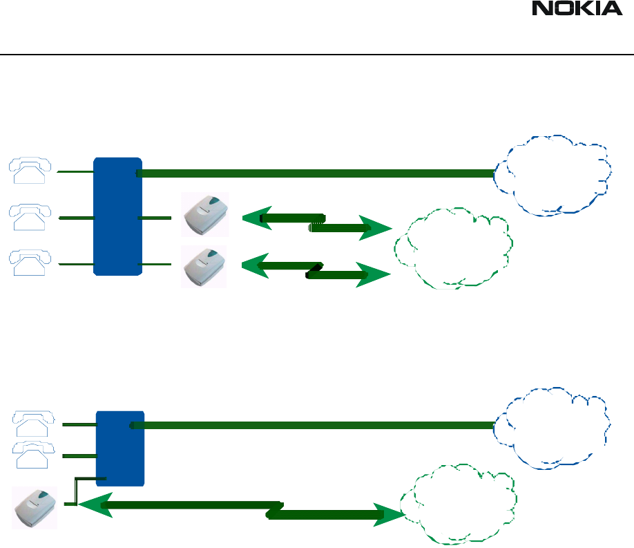
DTX-3
General Information CCS Technical Documentation
Page 4 Nokia Mobile Phones Ltd. Issue 1 4/03
(fig. 2) line of the PBX.
Figure 1: Nokia 32 connected to a Trunk Interface of a PBX
Figure 2: Nokia 32 connected to an analog extension interface of a PBX
After the Nokia 32 has been connected to a PBX, the PBX may require reconfiguration to
route mobile targeted calls via the Nokia 32. This reconfiguration requires special know-
how about the PBX. In order to perform successful installation, further information must
be asked from the PBX supplier. In no conditions it is recommended to do the installation
without adequate know-how and tools.
When Nokia 32 is connected to the extension side of the PBX, the originator of call
affects to the routing by calling to the extension where Nokia 32 is connected and then
keys in the targeted mobile number.
PSTN
Network
GSM
Network
PSTN
Network
GSM
Network
PSTN
Network
GSM
Network
PSTN
Network
GSM
Network
CCS Technical Documentation General Information
DTX-3
Issue 1 4/03 Nokia Mobile Phones Ltd. Page 5
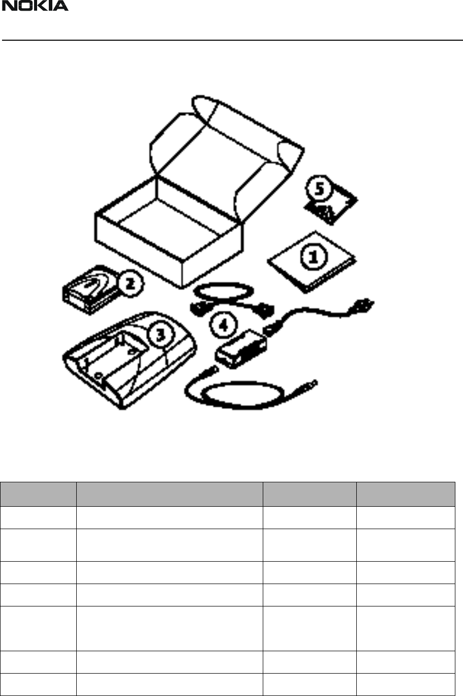
Nokia 32 Sales package contents
:
Table 1: Nokia 32 sales package contents
Item Name Type code Material code
1User’s Guide
2Connectivity Terminal TME-3
TME-4
0600344
0600342
3Application Module DTX-3 0630596
4Power Supply ACW-5B 0630526
4Power Cord alternatives Euro: PCW-5
UK: PCW-5X
US: PCW-5U
0730248
0730247
0730246
4DC Cable AKD-2A 0730248
5Installation Kit 0262959
DTX-3
General Information CCS Technical Documentation
Page 6 Nokia Mobile Phones Ltd. Issue 1 4/03
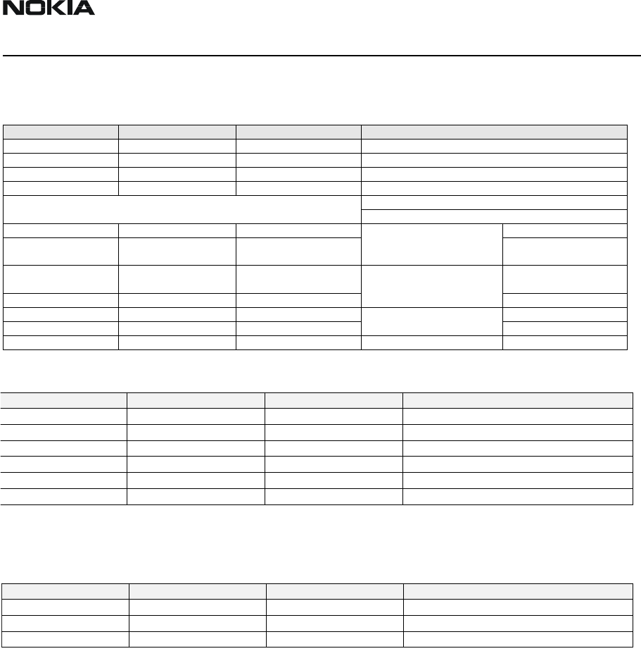
Technical Specifications
Mechanical Characteristics
Technical specifications
Data Standard RS-232.
All applicable ITU-T V.25ter, ETSI GSM 07.07 and ETSI GSM 07.05 commands are sup-
ported.
HSCSD max 43.2kbits/s (Depending on operator services).
GPRS multi-slot class 6 (3+1, 2+2, 2+1).
User Interface Features
User Interface consist of three two-colour light indicators that show the state/mode of
the TME-3 or TME-4 and DTX-3. Some user interface functionality is contained in the
software application running in the host computer.
Environmental Conditions
TME-3/TME-4 is not protected against ingress of water. DTX-3 may be instantaneously
subjected to dripped or condensed water. Longer term contact with water will cause per-
manent damage.
TME-3/TME-4 and DTX-3 do not break mechanically after a free fall from 100cm (about
40 inches) height to a concrete floor.
Unit Dimensions (mm) Weight (g) Notes
TME-3 terminal 84 x 53 x 26 65 Without power supply
DTX-3 Application Module 121 x 158 x 45 174 Without power supply
Parameter Ambient temperature
(degrees Celsius)
Ambient humidity
(relative)
Max operation -10 to +55 20 to 75%
Storage -40 to +85 5 to 95%, non condensing
Customer Care Solutions
DTX-3 Series Transceivers
Issue 1 4/03 Nokia Mobile Phones Ltd.
Modules

DTX-3
Modules CCS Technical Documentation
Page 2 Nokia Mobile Phones Ltd. Issue 1 4/03
Table of Contents
Page No
Glossary of Terms ..........................................................................................................3
Functional Description of DTX-3 ..................................................................................5
Circuit Description .......................................................................................................5
Interfaces and Connectors ............................................................................................5
Nokia 32 LED Indicators ...............................................................................................6
LED Indicator status: ...................................................................................................7
Signal tones ..................................................................................................................8
Key Sequences ..........................................................................................................8

CCS Technical Documentation Modules
DTX-3
Issue 1 4/03 Nokia Mobile Phones Ltd. Page 3
Glossary of Terms
ACCIf Accessory Interface block of MAD2WD1
AIF Application Interface
ASIC Application Specific Integrated Circuit
BB Baseband
CCONT Power management IC for digital phones
CIS PCMCIA Card Information Structure
COBBA_GJP DCT3 RF-interface and audio codec ASIC
with serial MAD interface
CSP Chip Scale Package
DB Dual band
DCS1800 Digital Cellular system at 1800 MHz
DCT3 Digital Core Technology, 3rd generation
DSP Digital Signal Processor
EMC Electromagnetic compatibility
EMI Electromagnetic Interference
FBUS Asynchronous Full Duplex Serial Bus
GSM Global System for Mobile communications
HSCSD High Speed Circuit Switched Data
MBUS 1-wire half duplex serial bus
MCU Micro Controller Unit
MDI MCU-DSP Interface
MAD MCU+ASIC+DSP asic, common name for whole family
MAD2PR1 Modified MAD2 asic, pin count 144 instead of 176
MAD2WD1 MCU+ASIC+DSP with HSCSD specific changes

DTX-3
Modules CCS Technical Documentation
Page 4 Nokia Mobile Phones Ltd. Issue 1 4/03
PA Transmit Power Amplifier
PBX Private Branch Exchange
PC Personal Computer
PWB Printed Wiring Board
PCM Pulse Code Modulation
PCM SIO Synchronous serial bus for PCM audio transferring
PCMCIA PC Memory Card International Association
PSTN Public Switched Telephone Network
RF Radio Frequency
SIM Subscriber Identity Module
SMART PCMCIA interface ASIC
Sulo PCMCIA interface ASIC for RPM-3
UI User Interface
VCXO Voltage Controlled Crystal Oscillator
VCTCXO Voltage Controlled Temperature Compensated
Crystal Oscillator.
CCS Technical Documentation Modules
DTX-3
Issue 1 4/03 Nokia Mobile Phones Ltd. Page 5
Functional Description of DTX-3
Circuit Description
The DTX-3 application module connects the TME-3/TME-4 with the fixed telephone net-
work and/or with any unmanned connection, e.g. telemetry, remote control, security sys-
tems, remote data retrieval.
The Data module baseband blocks provide the MCU, DSP, external memory interface and
digital control functions in the UPP ASIC . Power supply circuitry, charging, audio pro-
cessing and RF control hardware are in the UEM ASIC.
The purpose of the RF block is to receive and demodulate the radio frequency signal from
the base station and to transmit a modulated RF signal to the base station.
Product and Module List
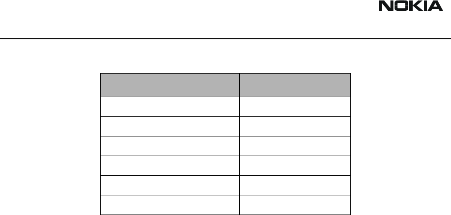
Interfaces and Connectors
Telephone interface /PBX Trunk interface:
Telephone interface /PBX Extension interface:
Name of module Type code Material
code Notes
Application module DTX-3 0630596
Transceiver TME-3 0600344
Assembly parts A-cover
B-cover
9458825
9458911
Assembly parts must be ordered as separate spare
parts
Transceiver TME-4 0600342
Signals Value
High Impedance Mode 50V
Ringing Voltage 70VAC
Line Impedance 600 Ω
Signals Value
Off-Hook AC impedance 600 Ω
On-Hook AC impedance 150k Ω
On-Hook DC resistance 10M Ω
Loop DC current Min. 15 mA, max. 120mA
DTX-3
Modules CCS Technical Documentation
Page 6 Nokia Mobile Phones Ltd. Issue 1 4/03
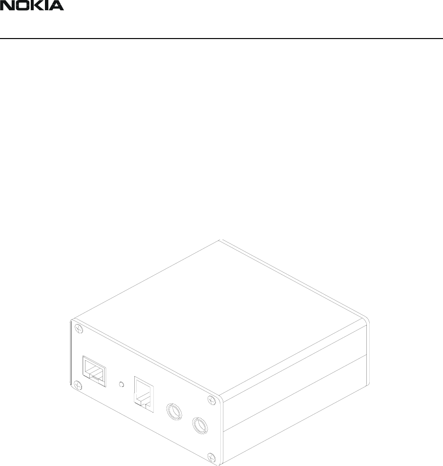
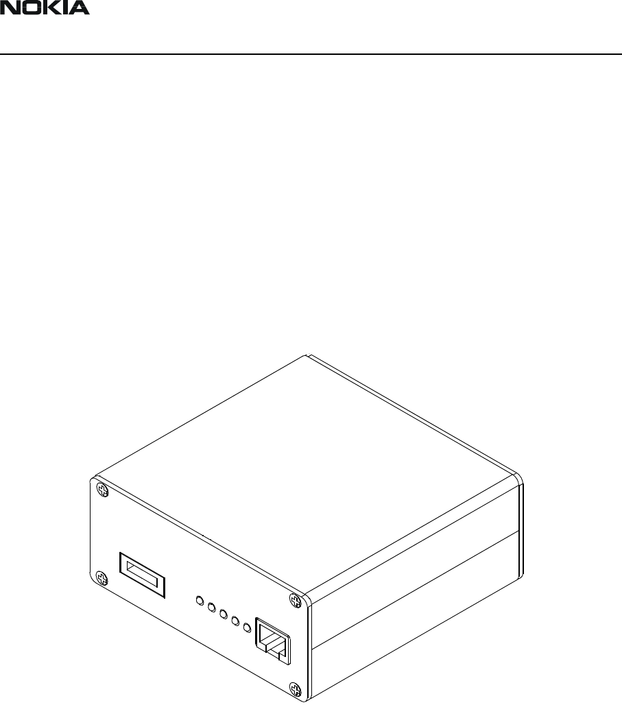
RJ-11 Trunk/Extension Connectors
This interface is a standard analog 2-wire interface for analog PBX trunk or analog land-
line telephone, or for analog PBX extension.
M2M System Connector
Custom pin header 2x25 for connection between GSM and PBX Application module.
RS 232 Data Connector
D9 female connector for standard level RS 232 data.
Power Supply Connector
Connector for ACW-5B power supply.
Antenna connector
TME-3 external antenna connector.
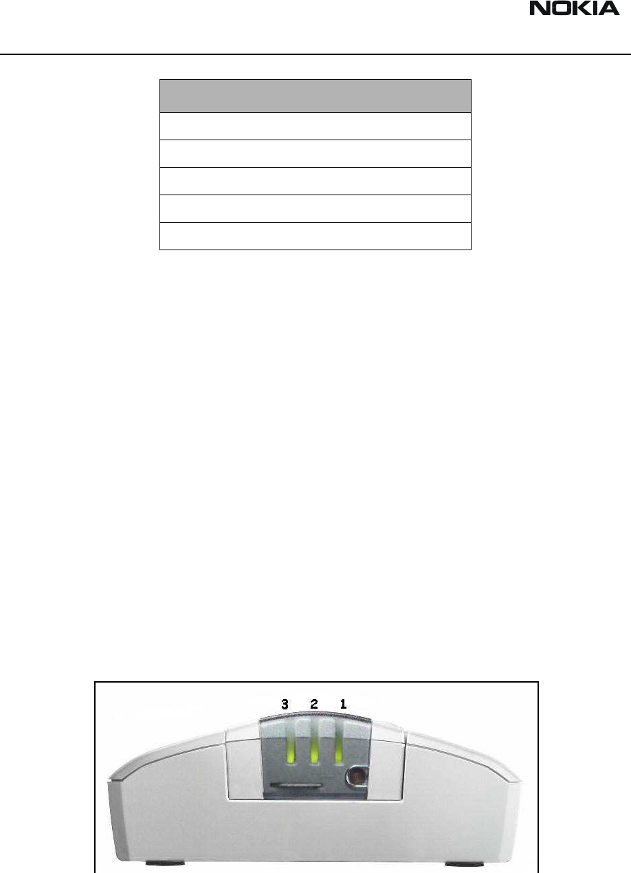
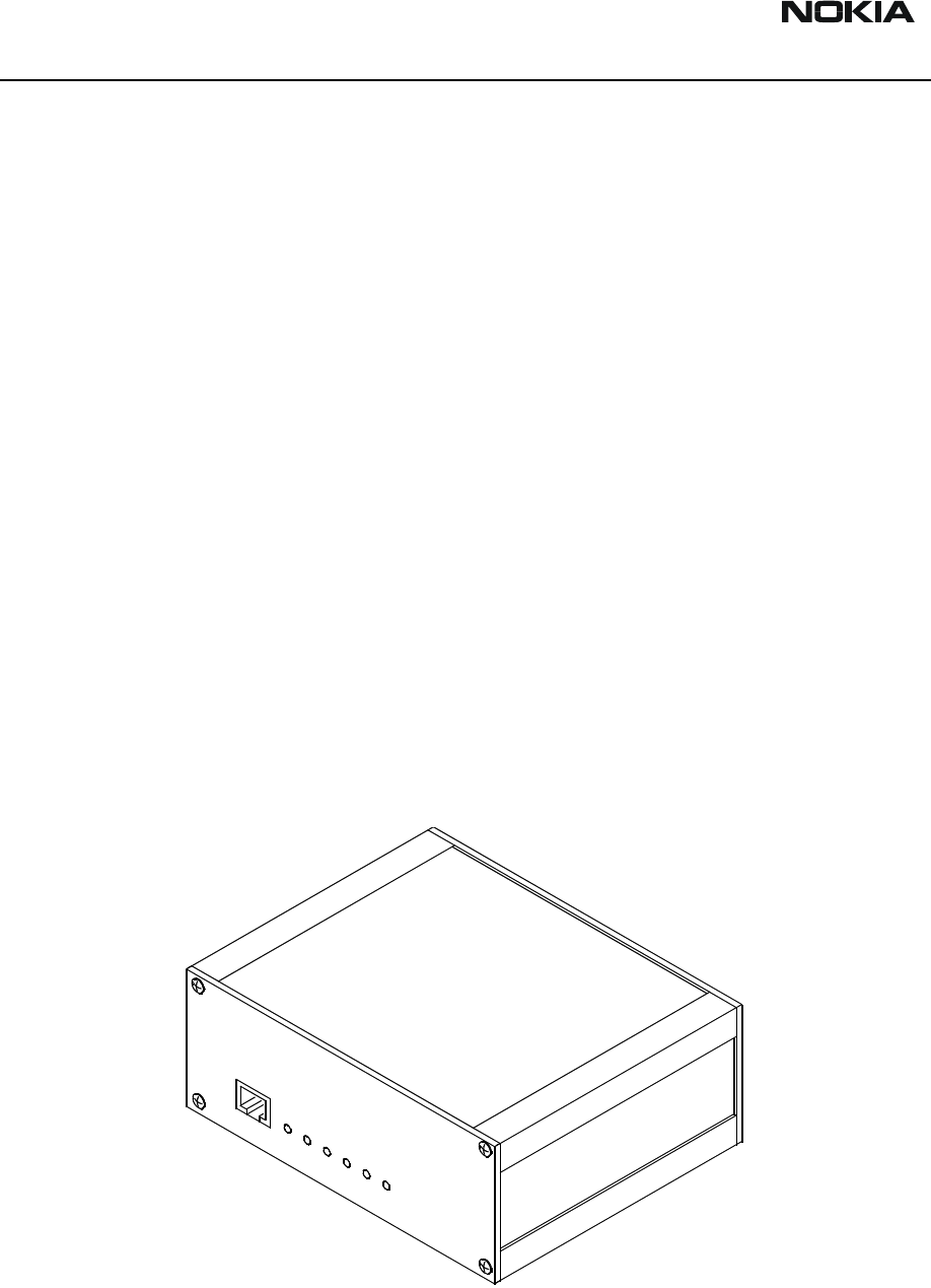
Nokia 32 LED Indicators
TME-3 comprises three indicator LEDs:
Figure 1: Indicator LEDs
Connector Name
RJ-11 Trunk/Extension Connector
M2M System Connector
RS232 connector
Power connector
Antenna connector
CCS Technical Documentation Modules
DTX-3
Issue 1 4/03 Nokia Mobile Phones Ltd. Page 7
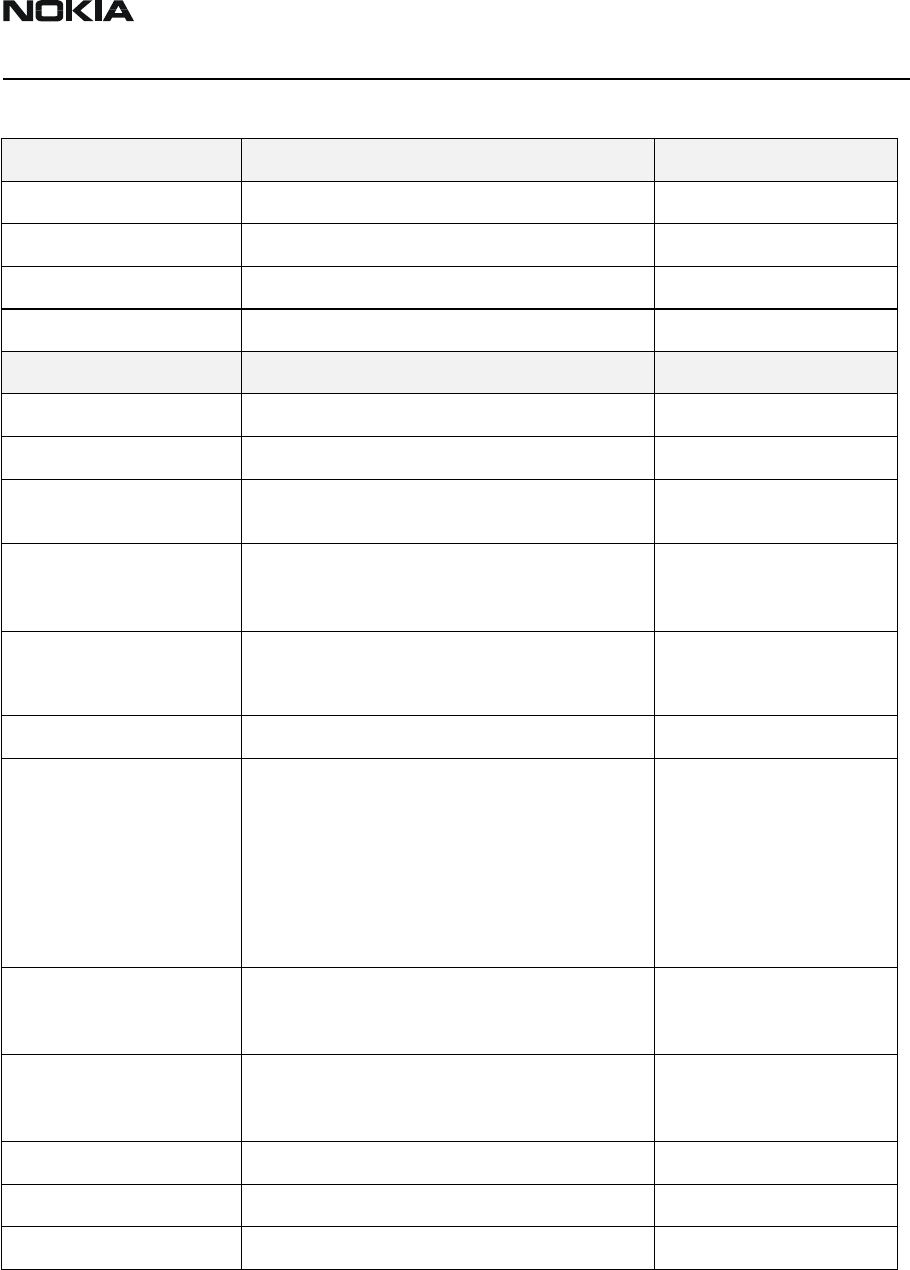
LED Indicator status:
Table 1: Nokia 32 LED indicator status during start-up
Table 2: Nokia 32 LED indicator status during normal operation
*) Led state due to current mode (trunk/extension) of the Nokia 32 terminal
Table 3: Nokia 32 LED indicator status in special situations
“SMS message received” signal will be resetted by off-hook, which also clears the mes-
sage from the message box.
LED 1 LED 2 LED 3 Description
- - - Power off
Green scan Green scan Green scan Power on, connecting to network
- Red blink - PIN query/ new PIN query
- Red blink Red blink PUK query
Intensity of Field S trength
Red blink - - <- 105 dBm
G reen blink - - Unacceptable -105 … -100
dBm
Green -100 … -95
dBm
Green Green blink
W eak
-95 … -90 dBm
Green Green -90 … -85 dBm
Green Green Green blink
Moderate -85 … -80 dBm
Green Green Green Good >-80 dBm
LED 1 LED 2 LED 3 Description
Green Green In service, trunk mode
Green Green In service, extension mode
* * Green blink Call on
* * Green blink Incoming call
* * Green/Red blink Message received/ Voice mail in box
* * Red blink Message storage full
LED 1 LED 2 LED 3 Description
Green/Red blink Green/Red blink Green/Red blink Insert SIM card
Red blink Red blink Red blink Failure, contact service
Yellow Yellow Yellow Initialising
DTX-3
Modules CCS Technical Documentation
Page 8 Nokia Mobile Phones Ltd. Issue 1 4/03
Signal tones
Key Sequences
These sequences have to be entered using a normal landline telephone set connected to
the trunk connector of Nokia 32
Tone sequence Description
- - - - - - - - - - - - - - - - - - Insert SIM card
- _ _ - _ _ - _ _ Enter PIN code
_ _ _________ ___________ Enter PUK code
- - - - Error tone ()
_________ _________ Ok
- - - - - - - - - - - - SMS received
CCS Technical Documentation Modules
DTX-3
Issue 1 4/03 Nokia Mobile Phones Ltd. Page 9
Table 4: Nokia 32 button sequences used in trunk mode.
Sequence Functionality Response
PIN# PIN code input Tone
PUK# PUK code input Tone
0**value Volume control, louder. ‘Value’ from 1 to 10. Tone
555**# System reset Tone
CONFIGURATION STATE
**####** Configuration state Tone / Light indication
Acces code query state PIN Query tone and light
1234# Acces code enter. Default acces code. Acces code can
be changed or query can be disabled
Tone / Light indication
2**XXXX# XXXX = interruption time in milliseconds. XXXX= 0 =
LI disabled. Default 400ms. Back to configuration
state
Tone / Light indication
3**XXXX# XXXX = Reversal time in milliseconds
(999 => polarity reversed whole call time)
Tone / Light indication
4# Entry code to CLI mode changing Query state flashing
4**XXX# XXX=
000 = ETSI FSK (default)
001 = DTMF
010 = DTMF_DK
111 = None
Tone / Light indication
5# Entry code to operator selection. If roaming user can
select the operator entering operator code. If 000
operator will be selected automatically.
Query state flashing
5**XXX# XXX = operator number
000 = default (automatic selection)
Network searching. Tone and
light indication about the
succes.
5# Entry code to …
444*OLD PIN*NEW PIN# Change PIN code Tone / Light indication
888*OPERATOR CODE# Change Operator if roaming Tone / Light indication

DTX-3
Modules CCS Technical Documentation
Page 10 Nokia Mobile Phones Ltd. Issue 1 4/03
[ This page intentionally left blank. ]
Customer Care Solutions
DTX-3 Series Transceivers
Issue 1 4/03 Nokia Corporation
DTX-3 Parts List

DTX-3 Company confidential
DTX-3 Parts List CCS Technical Documentation
Page 2 Nokia Corporation. Issue 1 4/03
Table of Contents
Variants of DTX-3 Nokia 32 .........................................................................................3
Transceiver Variants ....................................................................................................3
Country-specific settings .............................................................................................3
DTX-3 Exploded Diagram .............................................................................................4
DTX-3 Assembly Parts List .........................................................................................5
CCS Technical Documentation DTX-3 Parts List
Company confidential DTX-3
Issue 1 4/03 Nokia Corporation. Page 3
Variants of DTX-3 Nokia 32
Transceiver Variants
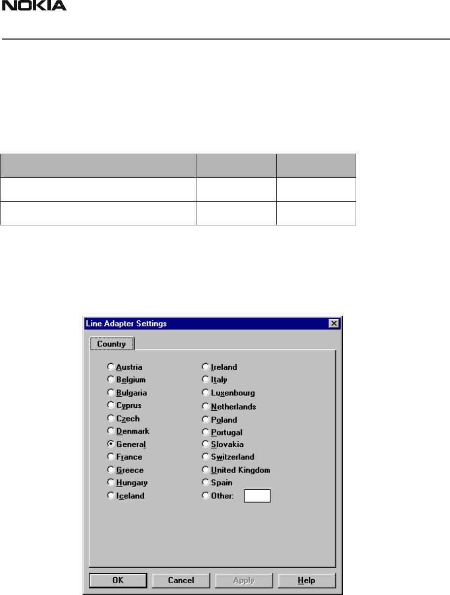
Country-specific settings
The country code allows different country-specific settings to be activated in SWAP-
module. Choose Software -> Line Adapter -> Settings.
Table 1:
Name Type des. Code
Transceiver TME-3 TME-3 0600344
Transceiver TME-4 TME-4 0600342
DTX-3 Company confidential
DTX-3 Parts List CCS Technical Documentation
Page 4 Nokia Corporation. Issue 1 4/03
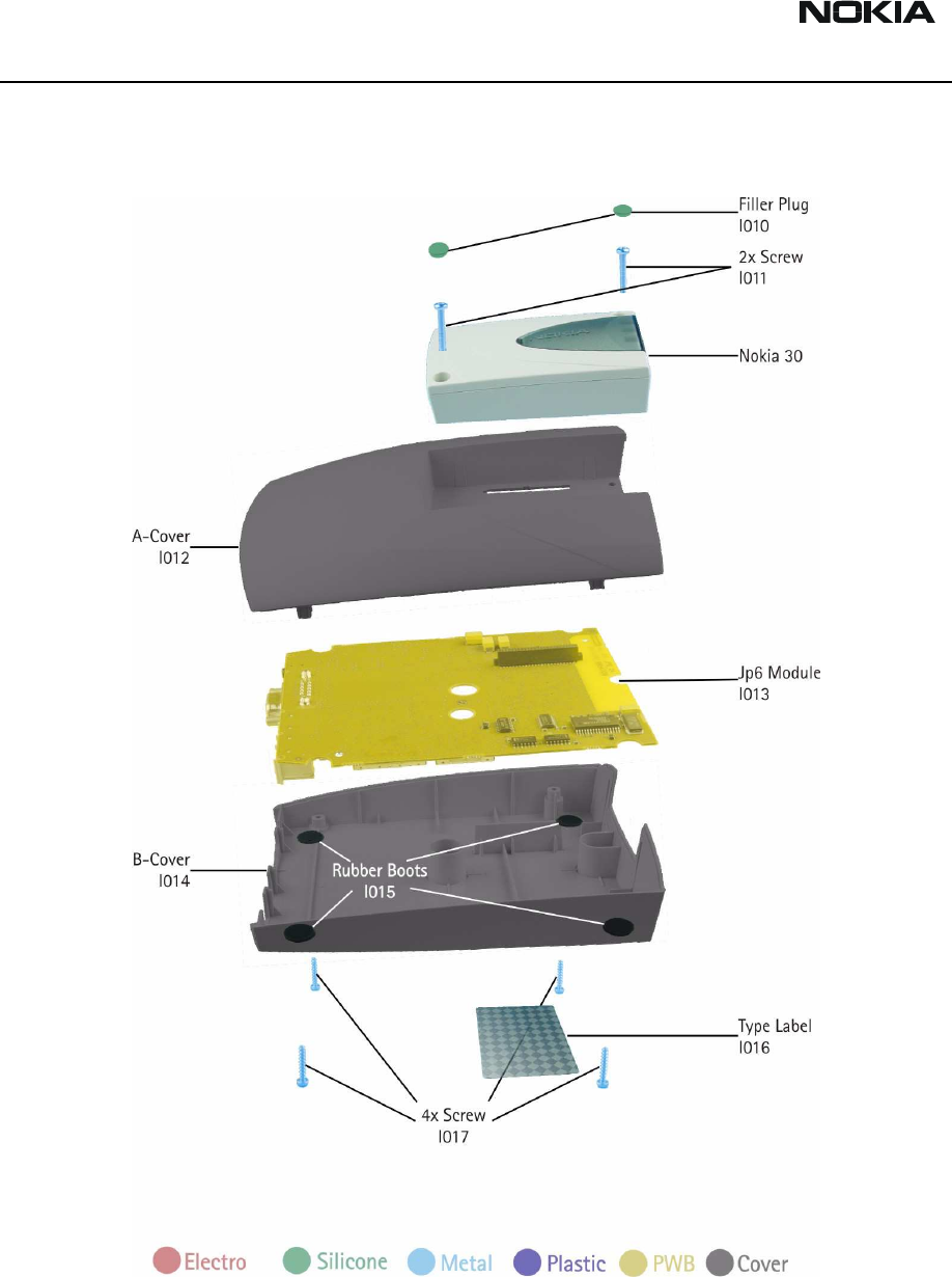
DTX-3 Exploded Diagram
The following picture shows the exploded view of DTX-3 module.
The application module consists of two injection moulded plastic parts, frame and
bracket for the Application Interface connector (pin header) and a PWB inside the mod-
ule.
CCS Technical Documentation DTX-3 Parts List
Company confidential DTX-3
Issue 1 4/03 Nokia Corporation. Page 5
DTX-3 Assembly Parts List
Table 2:
Part Number in
Exploded View Qty Part Name Material Code
l010 2 Filler plugs
I011 2 Screws 3x18 T10 6150081
Nokia 30/Nokia31 1 TME-3 0600344
l012 1 A-cover 9458825
l013 1 JP-6 0201946
l014 1 B-cover 9458911
l015 4 Rubber Boots xxx
l016 1 Type Label 9370625
l017 4 Screws 2.5x12 T8 6290141

DTX-3 Company confidential
DTX-3 Parts List CCS Technical Documentation
Page 6 Nokia Corporation. Issue 1 4/03
[This page intentionally left blank.]
Customer Care Solutions
DTX-3 Series Transceivers
Draft 2 3/03 Nokia Corporation.
Service Software

DTX-3
Service Software CCS Technical Documentation
Page 2 Nokia Corporation. Draft 2 3/03
Table of Contents
Page No
General ........................................................................................................................... 3
Hardware requirements for Windows 98/NT ..............................................................3
Software Environment of the Support Modules ............................................................ 3
Installation...................................................................................................................... 3
Mechanical Connections ..............................................................................................3
Installing the Service Software on PC Hard Disk .......................................................4
Flash Prommer (FPS-4)............................................................................................. 4
First time installation of WinTesla: .............................................................................4
For Windows 3.1 and 3.11: ....................................................................................... 5
For Windows 98 and NT:.......................................................................................... 5
Installation of DTX-3 support modules (WinTesla already installed): .......................6
CCS homepage.......................................................................................................... 6
For Windows 98 and NT:.......................................................................................... 6
Flash Instructions for DTX-3 .......................................................................................7
Flash Concept for DTX-3 ............................................................................................8
Label printing ...............................................................................................................9
Identification ................................................................................................................9
Product code.............................................................................................................. 9
SW version .............................................................................................................. 10
PSN.......................................................................................................................... 10
Manufacture date..................................................................................................... 10
HW version ............................................................................................................. 10
Default factory values ................................................................................................10
Fault logger ................................................................................................................11

CCS Technical Documentation Service Software
DTX-3
Draft 2 3/03 Nokia Corporation. Page 3
General
To run the Service Software, a software protection device (PKD–1) has to be connected
to the parallel port. TDF–4 box must connected to PC for flashing purposes.
Note: if this software is to be run on laptops, the power saving feature MUST be
switched off.
Hardware requirements for Windows 98/NT
The recommended minimum hardware standard to run Service Software is any computer
which has a Pentium processor, memory 8 MB and meets HW requirements recom-
mended by Microsoft.
Software Environment of the Support Modules
The Service Software user interface is intended for the following environments:
Microsoft Windows 3.11 (enhanced mode), Windows 95/98 and Windows NT. For those
who are familiar with Windows environment this application will be easy to use. Detailed
information about Windows and application usage can be found from the Microsoft
Windows Users Guide.
As an ordinary Windows application, the main idea in the user interface is that selections
are made with menus, push buttons and shortcut keys.
Selections can be done by using keyboard and/or mouse. There is always a status bar dis-
played at the bottom of the main window which contains information about current
actions.
Installation
Mechanical Connections
Caution: Make sure that you have switched off the PC and the printer before
making connections.
Caution: Do not connect the PKD–1 key to the serial port. You may damage
your PKD–1 !
Please refer to service setup in this chapter for information regarding different flash set-
ups.
Attach the dongle PKD–1 to the parallel port 1 (25–pin female D–connector) of the PC.

DTX-3
Service Software CCS Technical Documentation
Page 4 Nokia Corporation. Draft 2 3/03
When connecting PKD–1 to the parallel port, be sure that you insert the computer side of
the PKD–1 to the PC (male side). If you use a printer on parallel port 1, install the PKD–1
between the PC and your printer cable.
The PKD–1 should not affect devices working with it. If some errors occur (errors in
printing are possible) please try printing without the PKD–1. If printing is OK without the
PKD–1 please contact your dealer. We will offer you a new PKD–1 in exchange for your
old one.
Installing the Service Software on PC Hard Disk
The program is delivered on a diskette and is copy protected with a PKD–1 dongle. It
must be present in parallel port when using Service Software.
The program must be installed on the hard disk before use.
Keep the original diskette safe to enable upgrading of the program !
Flash Prommer (FPS-4)
Installation instructions can be found at the following intranet address:-
http://www.nmp.nokia.com/sasw/projects/prommer/manual/manual.htm
First time installation of WinTesla:
Do the following to make a complete WinTesla installation with support for DTX-3:
Insert the WinTesla software diskette into the floppy drive on your computer (i.e. Drive
A:)

CCS Technical Documentation Service Software
DTX-3
Draft 2 3/03 Nokia Corporation. Page 5
For Windows 3.1 and 3.11:
Start Windows, type win <Enter>
Open the File manager, open Main window and start File manager.
Select the floppy drive and:
Start installation, double–click the wt_inst.exe file.
Follow the instructions on the screen. Write down the directory where WinTesla is
installed on your hard disk.
When installation has finished remove the WinTesla software disk from your floppy drive.
Insert the Dongle driver diskette into your floppy drive.
Select the floppy drive and:
Start installation, double–click the dk2wn16.exe file.
Follow the instructions on the screen.
When installation has finished remove the dongle driver software disk
from your floppy drive.
Continue with the support modules installation.
For Windows 98 and NT:
Open Microsoft Explorer, Select Start –Programs – Explorer
Select the floppy drive and:
Start installation, double–click the wt_inst.exe file.
Follow the instructions on the screen. Write down the directory where WinTesla is
installed on your hard disk.
When installation has finished remove the WinTesla software disk from your floppy drive.
Insert the Dongle driver diskette into your floppy drive.
Select the floppy drive and:
Start installation, double–click the dk2wn32.exe file.
Follow the instructions on the screen.

DTX-3
Service Software CCS Technical Documentation
Page 6 Nokia Corporation. Draft 2 3/03
When installation has finished remove the dongle driver software disk from your floppy
drive.
Continue with the support modules installation.
Installation of DTX-3 support modules (WinTesla already installed):
To install the new Service Software Program, follow the steps below:
Insert the new Service software diskette into the floppy drive on of your computer (i.e.
Drive A:)
CCS homepage
Service Software can also be downloaded from the following address:
http://calns01net.europe.nokia.com/nmp/rd/pams/softrel.nsf/sr2
For Windows 98 and NT:
Open Microsoft Explorer, select Start –Programs– Explorer
Select the floppy drive.
Start installation, double–click the asinstall.exe file.
Follow the instructions on the screen.
CCS Technical Documentation Service Software
DTX-3
Draft 2 3/03 Nokia Corporation. Page 7
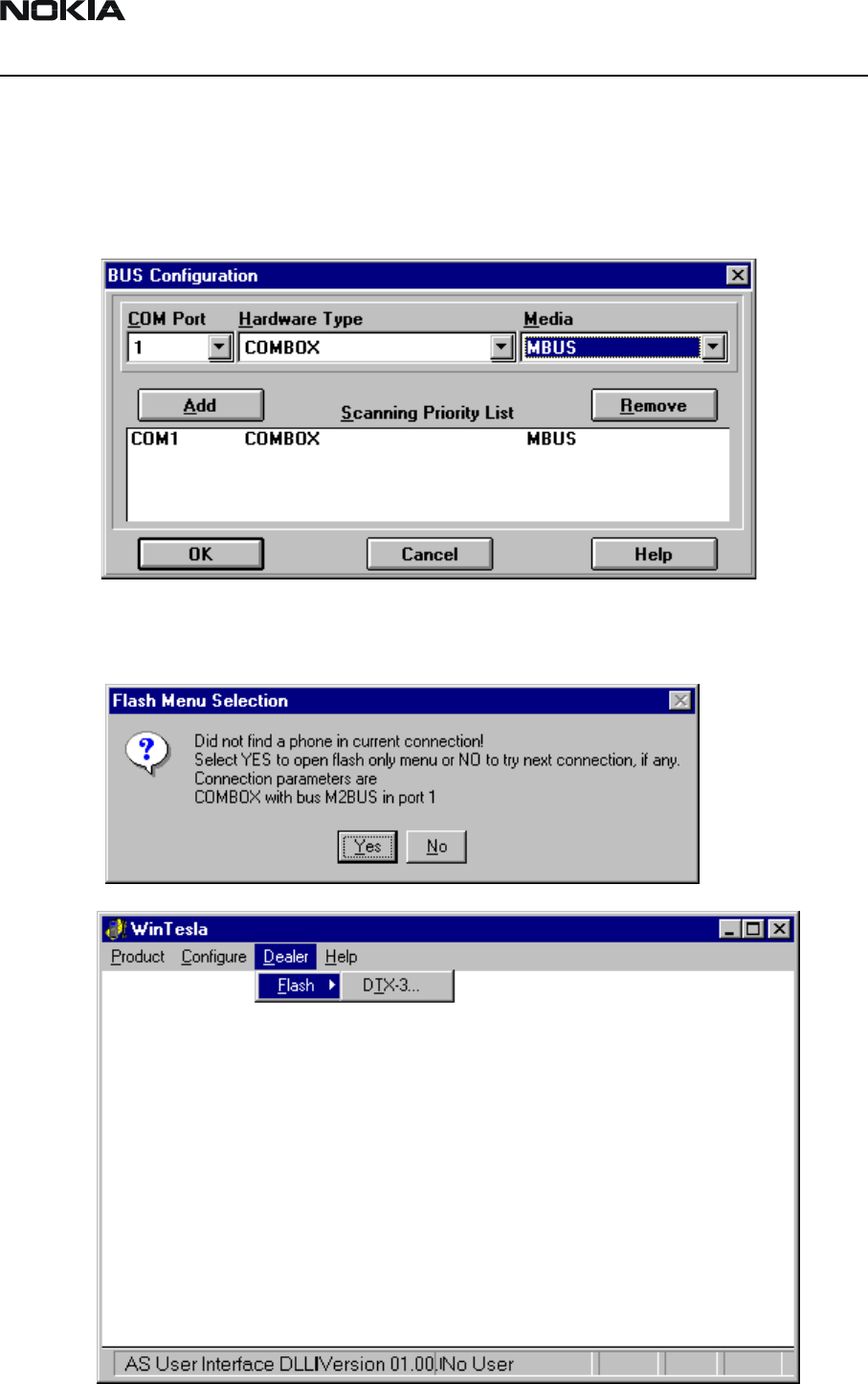
Flash Instructions for DTX-3
The Nokia 32 PBX Connectivity application module is flashed in the following way:
1 For flashing the DTX-3 application module, the Bus configuration must be
changed to COMBOX. Select Configure -> Buses.
2 Select Product -> Product Open -> DTX-3. Select Yes to open the Flash Menu and
select Dealer -> Flash -> DTX-3.
DTX-3
Service Software CCS Technical Documentation
Page 8 Nokia Corporation. Draft 2 3/03
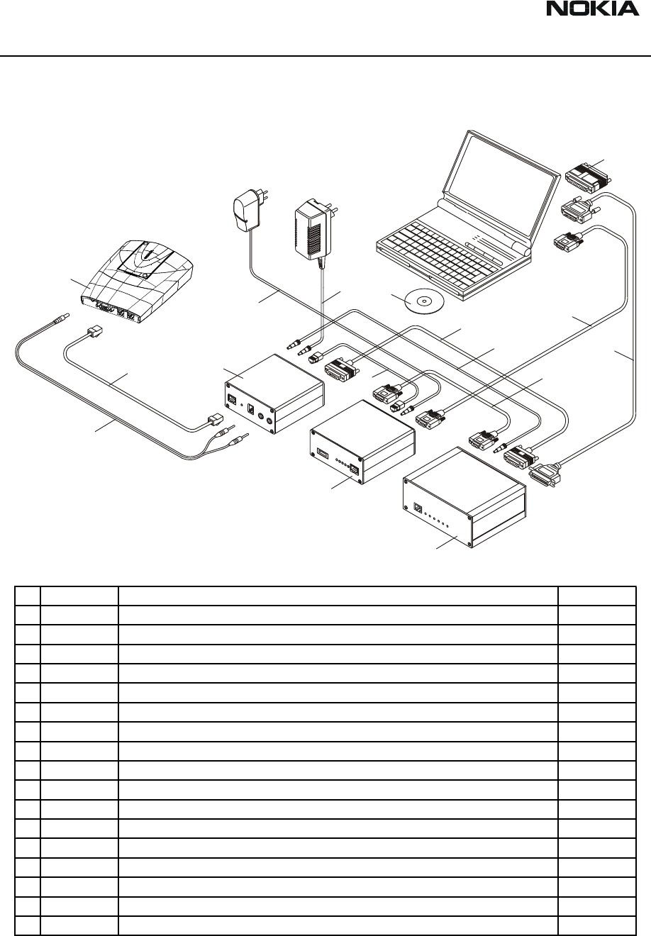
Flash Concept for DTX-3
Note! DKT-6A Flash Cable is connected to trunk connector.
15
16
2
13
11
9
10
7
8
14
5
6
4
3
12
1
1 DTX-3 Application Module 0630596
2 DKT-6A Flashing Cable 0730213
3 PCC-1B DC Power Cable 0770050
4 FLA-7 Flash Loading Adapter 0770119
5 TDF-4 Flash Security Box 0770106
6 FPS-4 Flash Prommer 0750090
7 XMS-3 Service Cable 0730174
8 AXS-5 D15 - D15 Cable 0730091
9 SCF-7 DC Power Cable 0730141
10 AXS-4 D9 -D9 Cable 0730090
11 AXS-4 D9- D9 Cable 0730090
12 Printer Cable 0730029
13 PKD-1 Software Protection Key O750018
14 ACH-6E Charger 0675084
15 ACS-6E Charger 0680016
16 Service SW for DTX-3 can be downloaded from:
http://www.nmp.nokia.com/nmp/ccsweb.nsf
(software selection)
CCS Technical Documentation Service Software
DTX-3
Draft 2 3/03 Nokia Corporation. Page 9
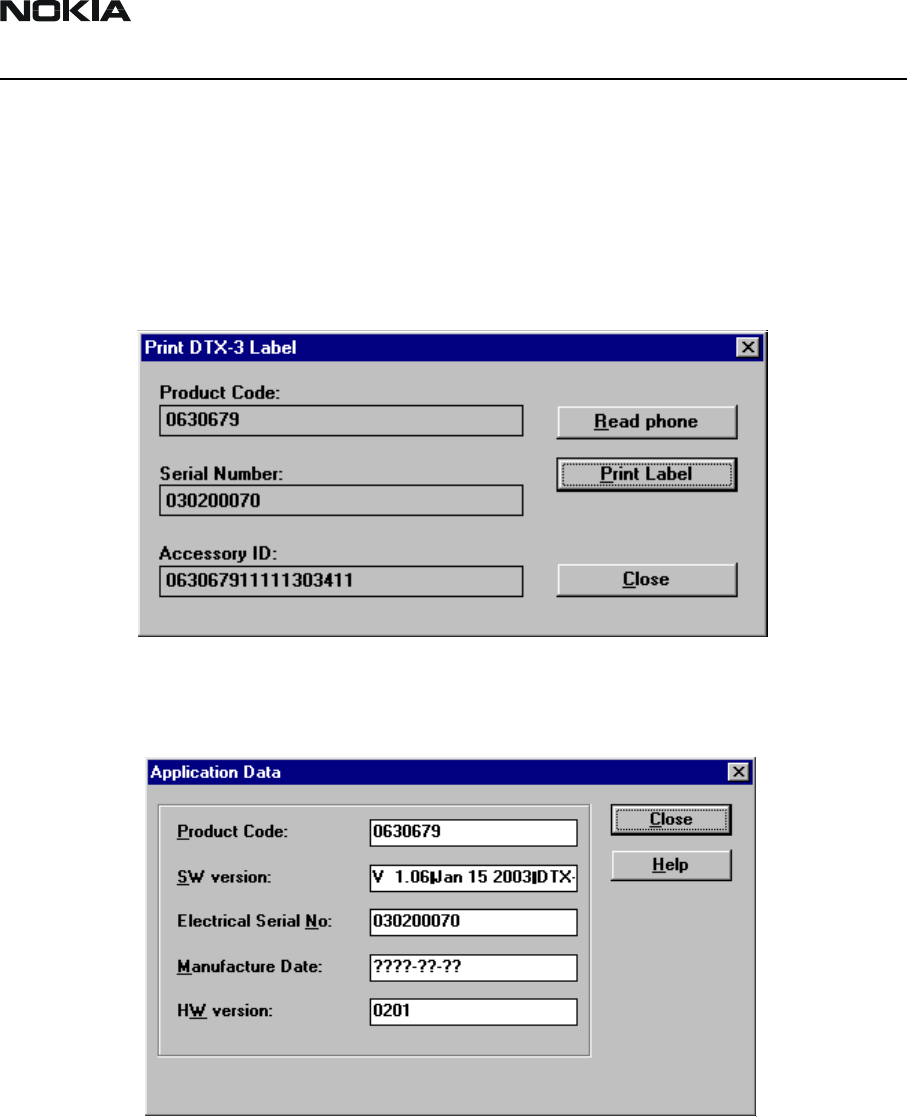
Label printing
The label printing function is like N22 label printing function, but it contains only the
application module label. GSM terminal labels are removed. With N32 it is possible to
read the product codes directly from the application module. With N22 the product code
is entered manually.
Choose Software -> Print Label
Identification
Choose Software -> Production Data
The information should be readable, not editable.
Product code
The product code is shown same way as in N22 service application.
DTX-3
Service Software CCS Technical Documentation
Page 10 Nokia Corporation. Draft 2 3/03
SW version
The SW version is shown same way as in N22 service application.
PSN
The electrical serial number can be read same way as in N22 service application.
Manufacture date
This information is set by manufacturing site. Date should be stated in format YYYY-MM-
DD. It is essential for warranty period information.
HW version
The HW version is shown same way as in N22 service application.
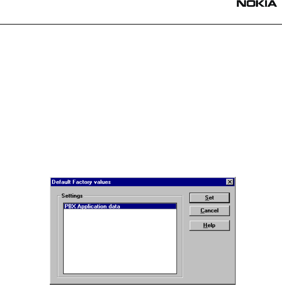
Default factory values
Figure 1: Choose Software -> Set Factory Values
This command is used for re-setting factory values to the EEPROM of the Application
Module.
CCS Technical Documentation Service Software
DTX-3
Draft 2 3/03 Nokia Corporation. Page 11
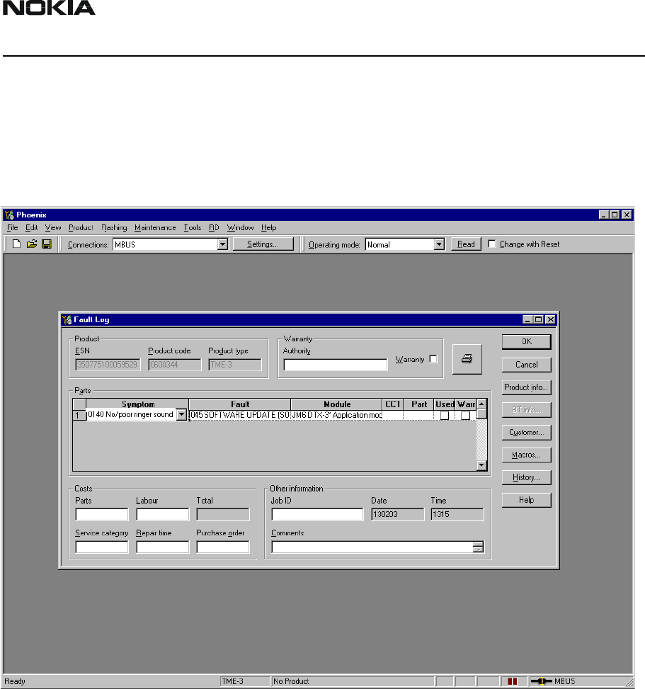
Fault logger
The N32 PBX Connectivity application module fault logger works in TME-3/4 Phoenix.
New module “reason” is PBX Application Module DTX-3, needs to be added to TME-3/4
Phoenix.

DTX-3
Service Software CCS Technical Documentation
Page 12 Nokia Corporation. Draft 2 3/03
[This page intentionally left blank.]
Customer Care Solutions
DTX-3 Series Transceivers
Issue 1 4/03 Nokia Corporation
Service Tools

DTX-3
Service Tools CCS Technical Documentation
Page 2 Nokia Corporation Issue 1 4/03
Table of Contents
Page No
Flash Loading Adapter FLA-7 .....................................................................................3
Flash Prommer FPS-4 (Sales Pack) .............................................................................4
Security Box TDF-4 ....................................................................................................5
DC Power Cable SCF-7 ...............................................................................................6
D9-D9 Cable AXS-4 ....................................................................................................7
D15-D15 Cable AXS-5 ................................................................................................8
Service Cable DKT-6A ................................................................................................9
Line Adapter Test cable SCS-24 ...............................................................................10
SW Security Device PKD-1 .....................................................................................11
Power Cable PCC-1B ................................................................................................12
Modular T-Adapter ....................................................................................................13
MBUS Cable DKT-7A ..............................................................................................14
CCS Technical Documentation Service Tools
DTX-3
Issue 1 4/03 Nokia Corporation Page 3
Flash Loading Adapter FLA-7
The flash loading adapter FLA-7 is used in MCU SW upgrade. Service cable DKT-6A is also
needed.
Power is supplied to FLA-7 from ACH-6E charger. Power for the FPS-4 can be connected
via FLA-7 by SCF-7 DC power cable.
The adapter is connected to the flash prommer FPS-4 by the AXS-5 cable and to the
security box TDF-4 by the XCM-1 cable.
Product Code
Flash Loading Adapter FLA-7: 0770119
Figure 1: View of FLA-7
DTX-3
Service Tools CCS Technical Documentation
Page 4 Nokia Corporation Issue 1 4/03
Flash Prommer FPS-4 (Sales Pack)
The flash prommer FPS-4 is used to update the main software of the phone. Updating is
done by first loading the new MCU software from the PC to the flash prommer, and then
loading the new SW from the prommer to the phone. When updating more than one
phone in succession, the MCU soft ware only needs to be loaded to the prommer once.
The sales pack includes:
- Charger ACS-2 4624582
- Printer Cable 0730029
- D9 - D9 Cable AXS-4 0730090
- AXD-1 DC-Cable 0730144
- SW disc 0774228 and 0774043
Note! Due to hardware changes in RPM-3 product installation software has been
updated to contain RPM-3 specific files. Make sure that you have newest FPS-4 software
before you start setting up SW upgrade equipment.
Product Code
Flash Prommer FPS-4: 00750090
Figure 2: View of FPS-4
CCS Technical Documentation Service Tools
DTX-3
Issue 1 4/03 Nokia Corporation Page 5
Security Box TDF-4
The security box TDF-4 is required for updating MCU software, and infra red testing.
Note: TDF-4 is delivered in de-activated mode.
Fill in the enclosed Activation Request Form, and fax to NMP Salo to get the activation
code.
Product Code
Security Box TDF-4: 0770106
Figure 3: View of TDF-4
DTX-3
Service Tools CCS Technical Documentation
Page 6 Nokia Corporation Issue 1 4/03
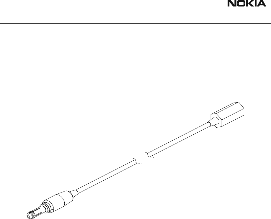
DC Power Cable SCF-7
The DC power cable SCF-7 is used for connecting power from ACL-3 charger via FLA-7 to
FPS-4.
Product Code
DC Power Cable SCF-7: 0730141
Figure 4: View of SCF-7
CCS Technical Documentation Service Tools
DTX-3
Issue 1 4/03 Nokia Corporation Page 7
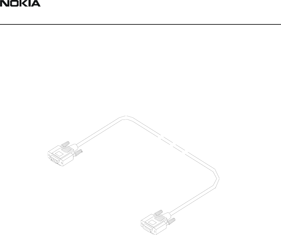
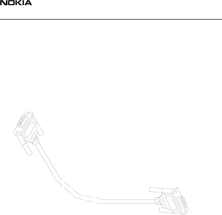
D9-D9 Cable AXS-4
The D9-D9 cable AXS-4 is used to connect two 9-pin D-connectors, for example,
between PC and TDF-4 security box. The D9-D9 cable AXS-4 is used to connect TDF-4
security box to FPS-4 Flash Prommer.
Product Code
D9 - D9 Cable AXS-4: 0730090
Figure 5: View of AXS-4
DTX-3
Service Tools CCS Technical Documentation
Page 8 Nokia Corporation Issue 1 4/03
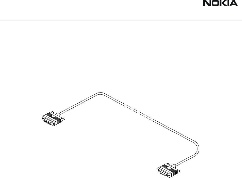
D15-D15 Cable AXS-5
The D15-D15 cable AXS-5 is used to connect two 15-pin D-connectors, for example,
between FLA-7 and FPS-4.
Product Code
D15-D15 Cable AXS-5: 0730091
Figure 6: View of AXS-5
CCS Technical Documentation Service Tools
DTX-3
Issue 1 4/03 Nokia Corporation Page 9
Service Cable DKT-6A
Service Cable DKT-6A is used to connect FLA-7 to DTX-3.
One connector a 6-pin modular connector, the other is a 10-pin modular connector.
Product Code
Modular Cable DKT-6A: 0730213
Figure 7: View of DKT-6A
DTX-3
Service Tools CCS Technical Documentation
Page 10 Nokia Corporation Issue 1 4/03
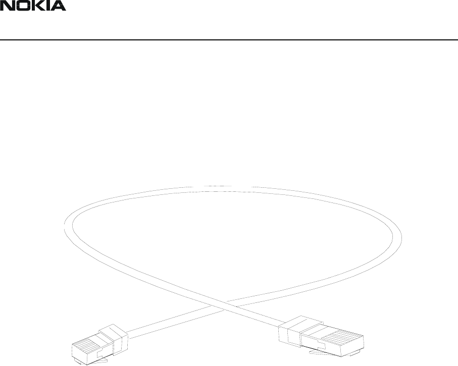
Line Adapter Test cable SCS-24
Line Adapter Test Cable SCS-24 is connected between trunk connector and T-adapter
when testing the Nokia 32 Application Module. It consists of 50 cm flat 6-core cable
with a 6-pin modular connector at each end
Product Code
Line Adapter Test Cable SCS-24 0730223
Figure 8: View of SCS-24
CCS Technical Documentation Service Tools
DTX-3
Issue 1 4/03 Nokia Corporation Page 11
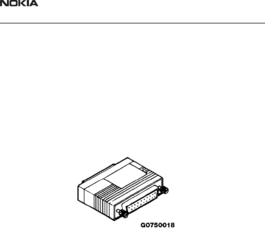
SW Security Device PKD-1
SW security device is a piece of hardware enabling the use of the service software when
connected to the parallel (LPT) port of the PC. Without the dongle present it is not possi-
ble to use the service software. Printer or any such device can be connected to the PC
through the dongle if needed.
Caution: Make sure that you have switched off the PC and the printer before mak-
ing connections!
Caution: Do not connect the PKD-1 to the serial port. You may damage your PKD-
1!
Product Code
SW Security Device PKD-1: 0750018
Figure 9: View of PKD-1
DTX-3
Service Tools CCS Technical Documentation
Page 12 Nokia Corporation Issue 1 4/03
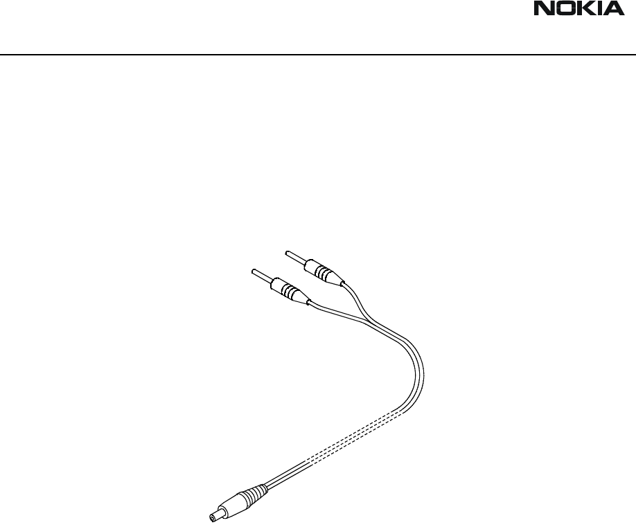
Power Cable PCC-1B
Power Cable PCC-1B is used to connect the DTX-3 application module with the Flash
Loading Adapter.
Product Code
Power Cable PCC-1B: 0770050
Figure 10: View of PCC-1B
CCS Technical Documentation Service Tools
DTX-3
Issue 1 4/03 Nokia Corporation Page 13
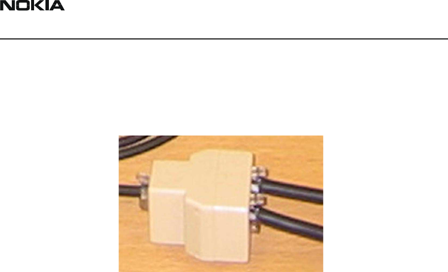
Modular T-Adapter
Modular T-Adapter is used in testing the Nokia 32 Application module. SCS-24 Line
Adapter Test Cable from trunk Connector and CA-15DS Line Adapter test cable from
extension connector are connected to the T-Adapter during loop test. DKT-7A MBUS
Cable is also connected to the T-connector to make the connection to PC.
DTX-3
Service Tools CCS Technical Documentation
Page 14 Nokia Corporation Issue 1 4/03
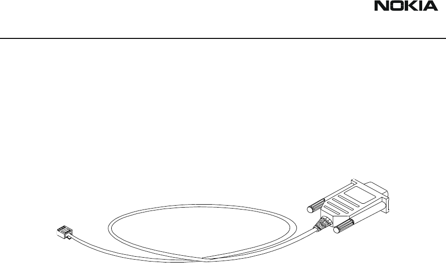
MBUS Cable DKT-7A
Service MBUS cable connects the PC to the T-Adapter when testing the Nokia 32 Appli-
cation Module.
Product Code
MBUS Cable DKT-7A: 0730211
Figure 11: MBUS Cable DKT-7A
CCS Technical Documentation Service Tools
DTX-3
Issue 1 4/03 Nokia Corporation Page 15
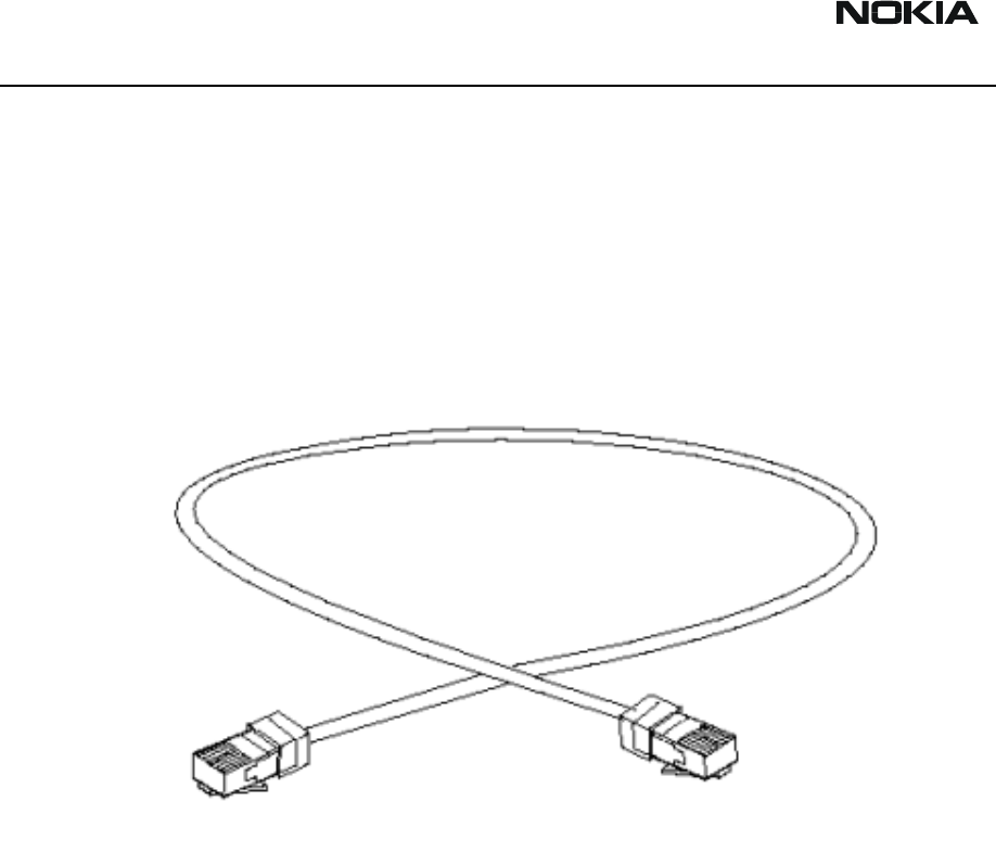
Line Adapter Test Cable CA-15DS
Line adapter test cable CA-15DS is connected between extension and T-connector
(4626134) when testing the Nokia 32. It consists of 50cm of flat 6-core cable with 6-pin
modular connector at each end.
Product Code
Line Adapter Test Cable CA-15DS: 0730302
Figure 12: Line Adapter test cable CA-15DS

DTX-3
Service Tools CCS Technical Documentation
Page 16 Nokia Corporation Issue 1 4/03
[This page intentionally left blank.]
Customer Care Solutions
DTX-3 Series Transceivers
Issue 1 4/03 Nokia Corporation
Disassembly and Troubleshooting

DTX-3
Disassembly and Troubleshooting CCS Technical Documentation
Page 2 Nokia Corporation Issue 1 4/03
Table of Contents
Page No
Introduction ....................................................................................................................3
Disassembly, DTX-3 ...................................................................................................3
Troubleshooting .............................................................................................................3
General .........................................................................................................................3
Equipment needed .......................................................................................................4
Software needed ...........................................................................................................4
Visual overlook ............................................................................................................4
Initial connections ........................................................................................................5
Troubleshooting flowchart for Nokia 32 and DTM-3 .................................................6
Troubleshooting flowchart for DTX-3 ........................................................................7
Testing with WinTesla service software ...................................................................8
CCS Technical Documentation Disassembly and Troubleshooting
DTX-3
Issue 1 4/03 Nokia Corporation Page 3
Introduction
The purpose of this document is to help in hardware troubleshooting of the Nokia 32 PBX
Connectivity Terminal.
TME-3/TME-4 troubleshooting is described in the TME-3/TME-4 manual.
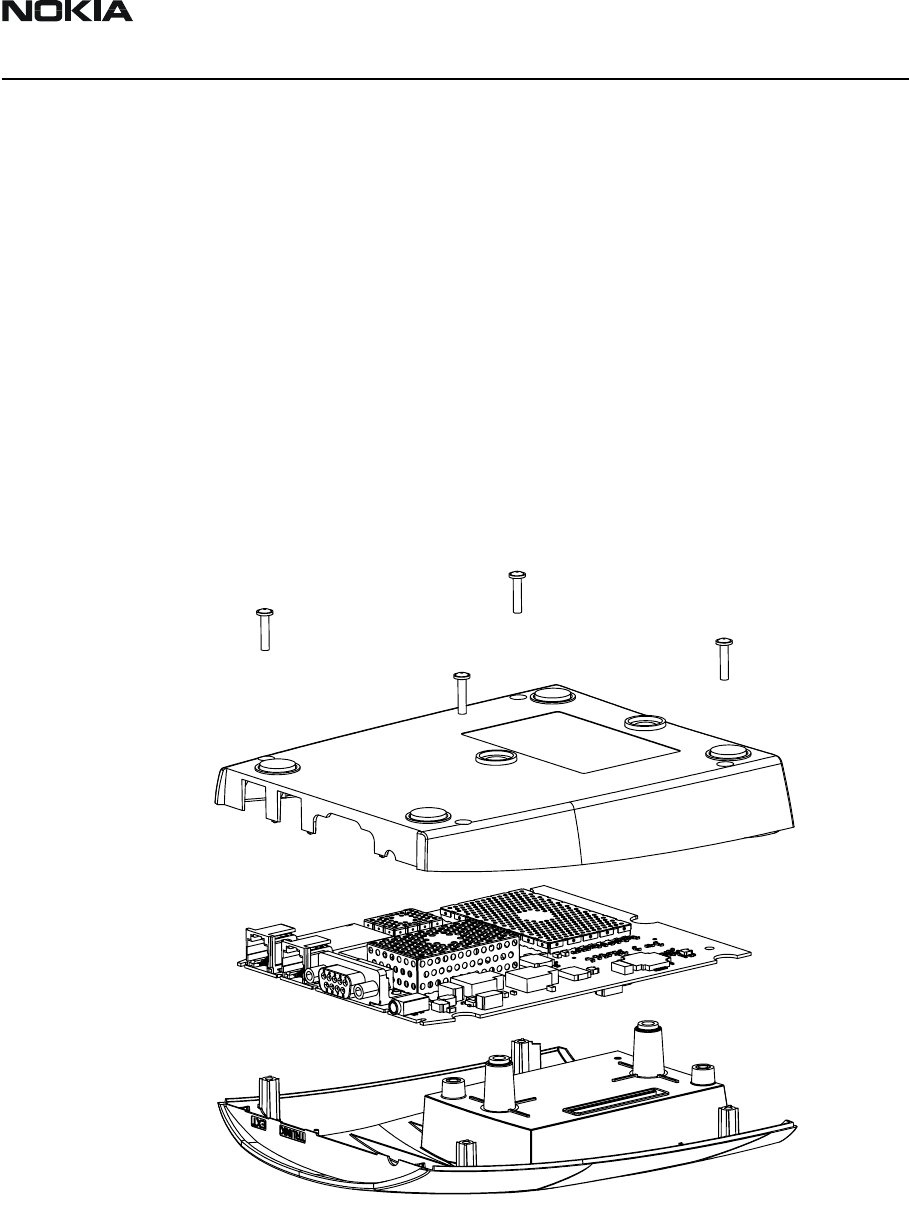
DTX-3 module is not designed to be repaired, except for the Application Interface Con-
nector.
Disassembly, DTX-3
Figure 1: DTX-3 disassembly

DTX-3
Disassembly and Troubleshooting CCS Technical Documentation
Page 4 Nokia Corporation Issue 1 4/03
Troubleshooting
General
The purpose of this document is to help the service point to solve which part of the radio
is faulty. The service policy with the Nokia 32 connectivity terminal is, that only the TME-
3/TME-4 will be repaired.
Both TME-3 and DTX-3 covers can be replaced if necessary.
Equipment needed:
• SIM card without PIN query
•ACW-5 Adapter
• ACW-5 mains cable
• ACW-5 power cable
• A landline telephone
• A Nokia 32 (including TME-3/TME-4 and DTX-3 modules)
•T-piece
• DKT-7A service cable
• CA-15DS audio test cable
• SCS-24 audio test cable
• Personal computer (PC)
Software needed:
• Wintesla sw for DTX-3
CCS Technical Documentation Disassembly and Troubleshooting
DTX-3
Issue 1 4/03 Nokia Corporation Page 5
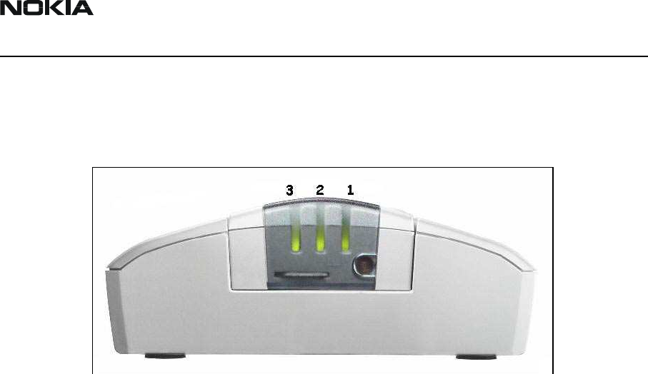
Visual overlook
The LED indicators are split into two parts:
Figure 2: LED indicators
LED indicators 2&3 are used to tell in which mode the line adapter is at the moment. LED
indicator 1 is used to tell the state of the embedded GSM terminal. At least one LED indi-
cator from both parts should be on or blinking. If e.g. both LED indicator 2 and LED indi-
cator 3 are off, the fault most probably is in the application module.
Initial connections:
1. Insert SIM card to TME-3/TME-4.
2. Attach DTX-3 to TME-3/TME-4.
3. Connect CA-15DS cable between one input port of T-piece and EXT connector.
4. Connect SCS-24 cable between the other input port of T-piece and TRUNK connector.
5. Connect cable DKT-7A between output port of T-piece and PC.
6. Connect power cable between DTX-3 and ACW-5.
7. Connect mains cable between ACW-5 and mains plug. See the instructions on the bot-
tom side of the adapter.
8. Choose Testing -> Self Tests... from Wintesla.
DTX-3
Disassembly and Troubleshooting CCS Technical Documentation
Page 6 Nokia Corporation Issue 1 4/03
Nokia 32
ACW-5
DKT-7A
SCS-24
DA-15DS
CCS Technical Documentation Disassembly and Troubleshooting
DTX-3
Issue 1 4/03 Nokia Corporation Page 7
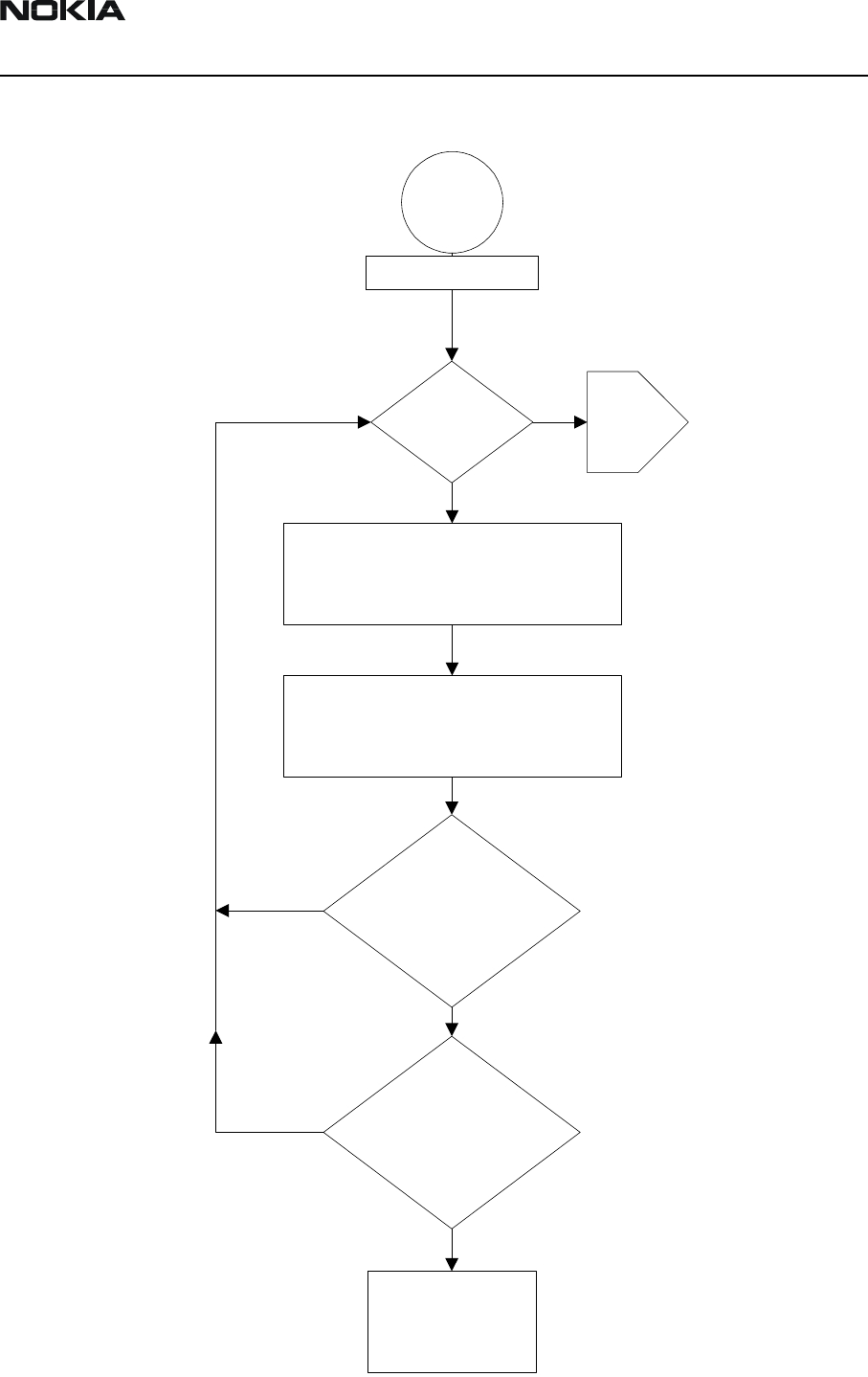
Troubleshooting flowchart for Nokia 32 and TME-3/TME-4
Start
DTX-3 self
test pass ?
Swap TME-3
Refer to TME-3 service instruction
Disconnect T-piece from DTX-3
TRUNK connector and audio cable
from EXT connector
DTX-3
failure
TME-3 LED's blink
according to guide ?
Voice call tests to both
directions works ?
End
N
Y
Y
Y
N
N
Factory reset
DTX-3
Disassembly and Troubleshooting CCS Technical Documentation
Page 8 Nokia Corporation Issue 1 4/03
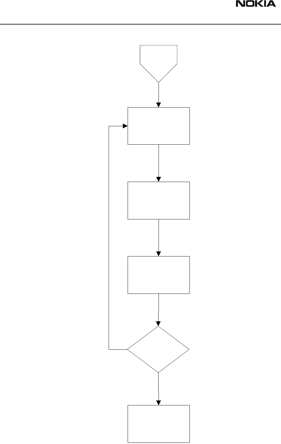
Troubleshooting flowchart for DTX-3
DTX-3
failure
Swap DTX-3
Set initial
connections
Set country
parameter
DTX-3 self
test pass ?
End
Y
N
CCS Technical Documentation Disassembly and Troubleshooting
DTX-3
Issue 1 4/03 Nokia Corporation Page 9
Testing with WinTesla service software
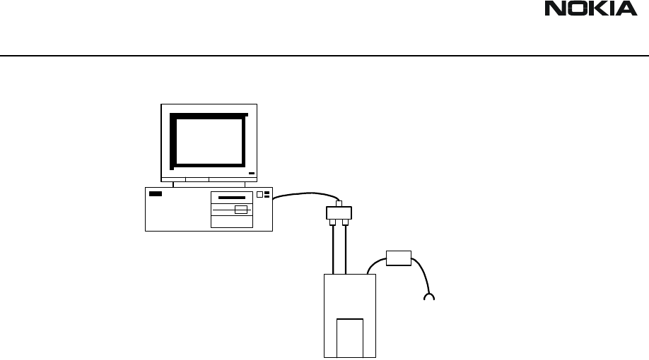
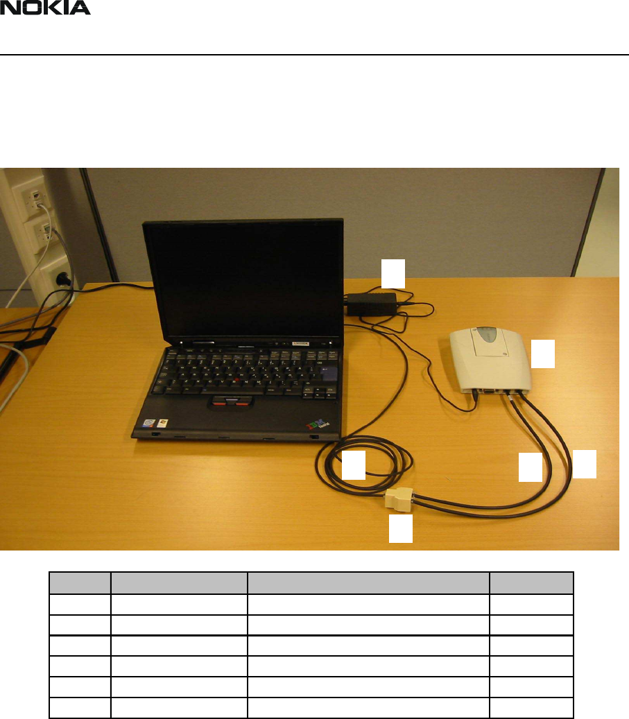
Set the Initial connection setup.
Figure 3: Test equipment set-up
1
15
2
36
4
No. Type Description Code
1 DTX-3 APPLICATION MODULE 0630596
2 ACW-5 POWER SUPPLY 0630526
3 DKT-7A MBUS CABLE 0730211
4 T-CONNECTOR 4626134
5 CA-15DS LINE ADAPTER TEST CABLE 0730302
6 SCS-24 LINE ADAPTER TEST CABLE 0730223
DTX-3
Disassembly and Troubleshooting CCS Technical Documentation
Page 10 Nokia Corporation Issue 1 4/03
WinTesla tests
Testing of Line adapter circuits
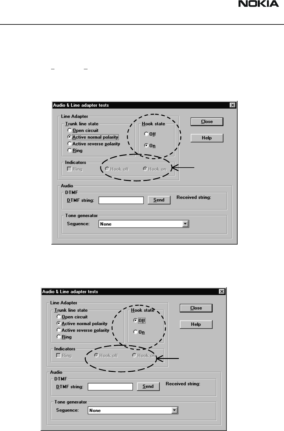
Choose Testing -> Audio -> Line Adapter...
Hook state indicator
Figure 4: Hook on/off test window 1
Check that the Hook off/on indicator state will change when you change the hook state.
If not, the DTX-3 is faulty.
Figure 5: Hook on/off test window 2
indicators
indicators
CCS Technical Documentation Disassembly and Troubleshooting
DTX-3
Issue 1 4/03 Nokia Corporation Page 11
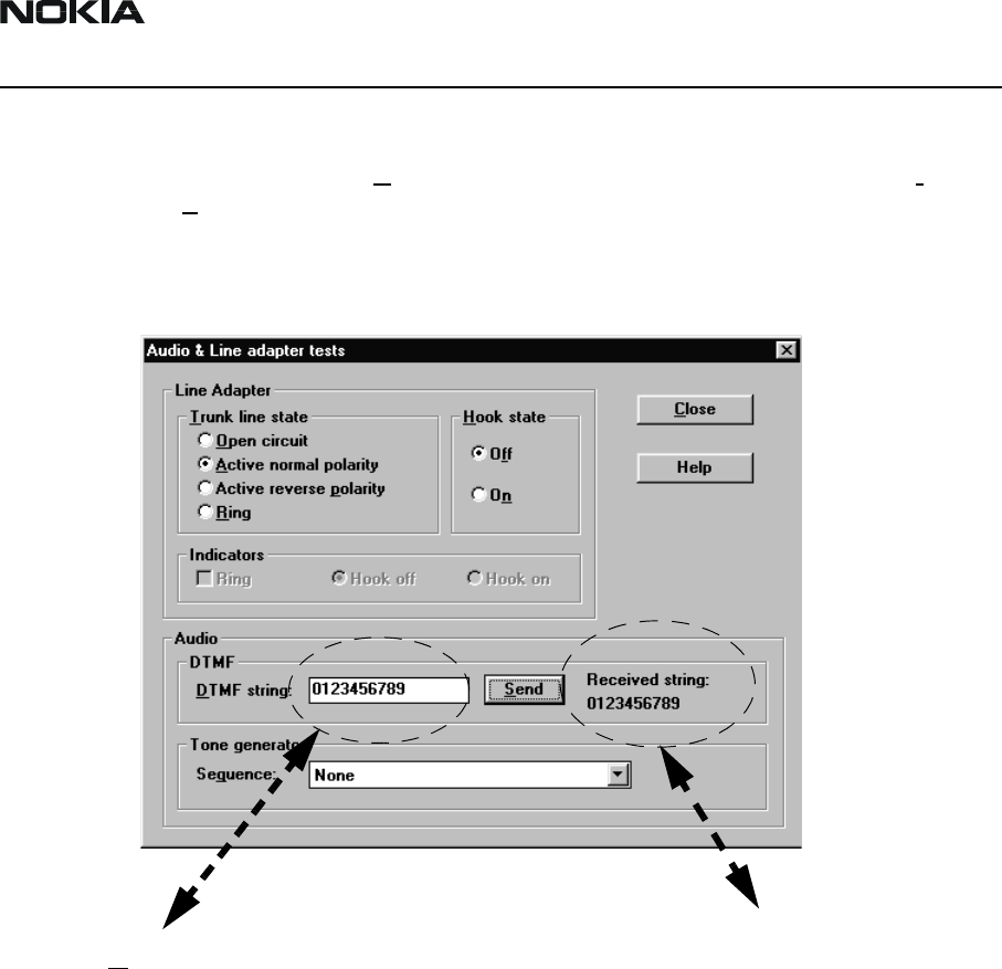
DTMF receiving and transmitting
Write some numbers to the DTMF string field. Change the hook off state to 'Off',
press the Send button and listen from the earpiece the DTMF tones. Check also from
the 'Received string:' row, that all numbers that you just selected were transmitted.
Figure 6: DTMF test window
DTMF String field Received String field
DTX-3
Disassembly and Troubleshooting CCS Technical Documentation
Page 12 Nokia Corporation Issue 1 4/03
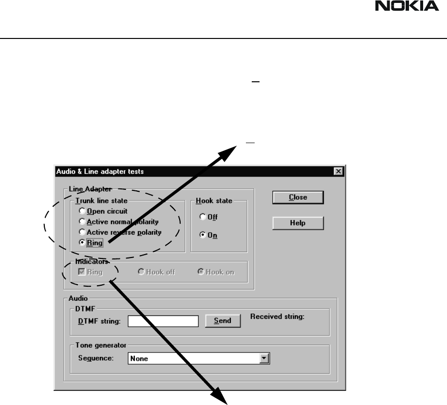
Ringing Voltage Indicator
Change the 'Trunk line state' selection to the Ring position.
Figure 7: Audio&Line Test window
Check that also the state of the Ring indicator changes (it might take few seconds). If
the indicator will not change it's position, change the 'Trunk line state' choice to it's
original setting, and try again couple of times. If the indicator will not change it's posi-
tion, the DTX-3 is probably broken.
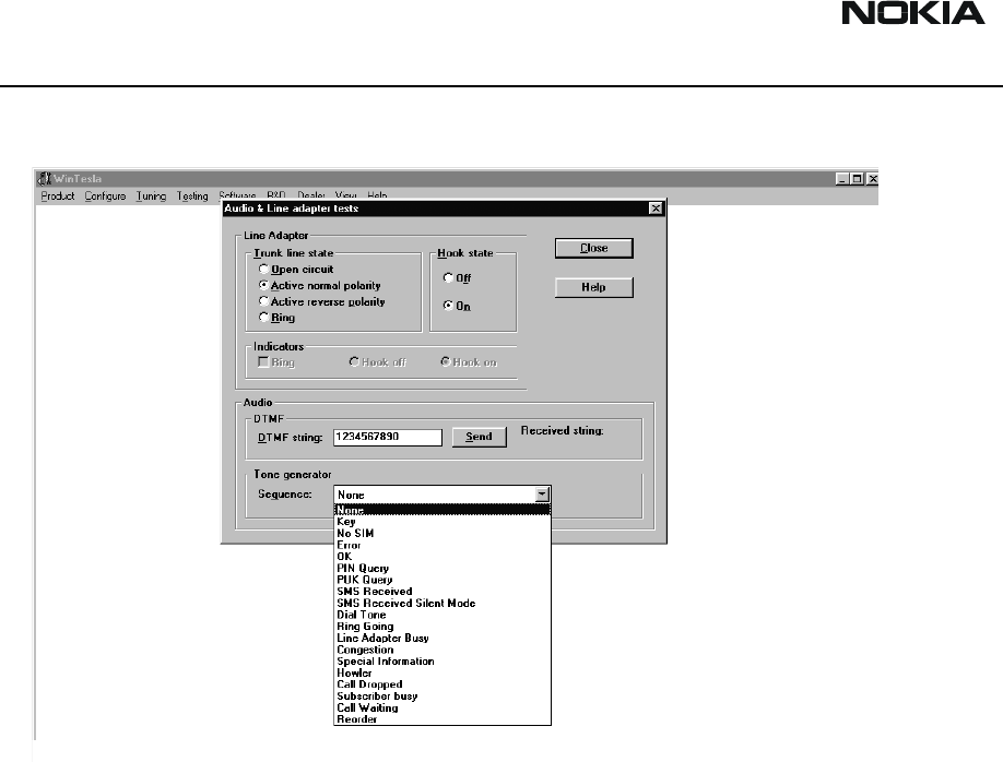
Activate the HF-state from the land-line telephone, or take the earpiece to listen the sig-
nal tones. From the Tone generator field you can select different tones to be listened.
Ring position
Ring indicator state
CCS Technical Documentation Disassembly and Troubleshooting
DTX-3
Issue 1 4/03 Nokia Corporation Page 13
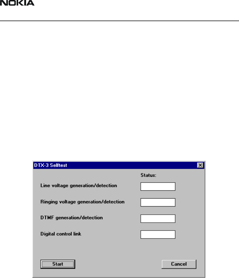
Self tests
The following build in selftests will be supported by Nokia 32 in addition to Nokia 22
selftests:
• Line voltage
• Ringing generation/detection
• DTMF generation/detection
• GSM link test
For more detailed information see Ratti SW Selftest Functional Specification .
A dialog box should be developed to start selftests.
The result of individual selftest should be stated clearly with passed/failed/not executed
and the overall result as well.
DTX-3
Disassembly and Troubleshooting CCS Technical Documentation
Page 14 Nokia Corporation Issue 1 4/03
Figure 8: Audio codec Test window
If you can not hear these tones, the audio codec is probably faulty.
Try to make also a test call with the land line telephone.
Customer Care Solutions
DTX-3 Series Transceivers
Issue 1 4/03 Nokia Mobile Phones Ltd.
Accessories

DTX-3
Accessories CCS Technical Documentation
Page 2 Nokia Mobile Phones Ltd. Issue 1 4/03
Table of Contents
Page No
RS-232 Data Cable .........................................................................................................3
Product Code ...............................................................................................................3
Antenna Cable XRP-3 ....................................................................................................4
Product Code ...............................................................................................................4
MBUS Cable DKT-7A ...................................................................................................5
Product Code ...............................................................................................................5
CCS Technical Documentation Accessories
DTX-3
Issue 1 4/03 Nokia Mobile Phones Ltd. Page 3
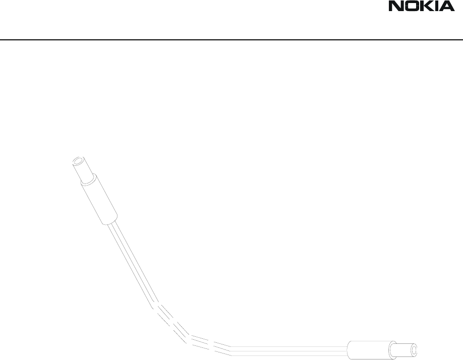
RS-232 Data Cable
For sending and receiving of SMS, PC-Fax, file transfer, e-mail and internet access a
standard RS-232 Data Cable is needed
Product Code
RS-232 Data Cable 0730029
Figure 1: RS-232 Data Cable
DTX-3
Accessories CCS Technical Documentation
Page 4 Nokia Mobile Phones Ltd. Issue 1 4/03
Antenna Cable XRP-3
This adapter cable can be used to connect a standard FME antenna connector to TME-3.
Product Code
Antenna Cable XRP-3: 0730206
Figure 2: Antenna Cable XRP-3
CCS Technical Documentation Accessories
DTX-3
Issue 1 4/03 Nokia Mobile Phones Ltd. Page 5
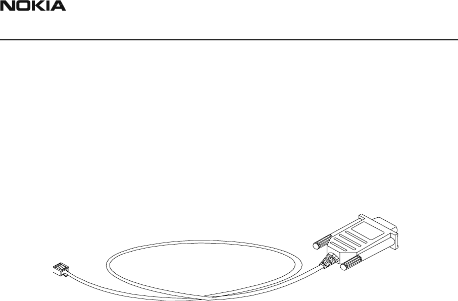
MBUS Cable DKT-7A
Service MBUS cable to connect PC to DTX-3 (trunk connector). It comprises a D9 con-
nector and a modular 6-pin connector.
Product Code
MBUS Cable DKT-7A: 0730211
Figure 3: MBus cable DKT-7A

DTX-3
Accessories CCS Technical Documentation
Page 6 Nokia Mobile Phones Ltd. Issue 1 4/03
[This page intentionally left blank.]