O_gc24xr O Gc24xr
User Manual: o_gc24xr
Open the PDF directly: View PDF ![]() .
.
Page Count: 34
OPERATORS MANUAL
J. & M. Mfg. Co., Inc.
284 Railroad Street - P.O. Box 547
Fort Recovery, OH 45846
Ph: (419) 375-2376 Fax: (419) 375-2708
www.jm-inc.com
Rev. 8.23.2016
GRAIN CART
19XR
2
Stance
Front
Rear
Auger Side
Opposite
Auger Side

3
Table Of Contents
4. . . . . . . . . . . . . . . . . . . . . . . . . . . . . . . . . . . . . . . . . . . . . .To The Dealer
5. . . . . . . . . . . . . . . . . . . . . . . . . . . . . . . . . . . . . . . . . . . . . .General Information
5. . . . . . . . . . . . . . . . . . . . . . . . . . . . . . . . . . . . . . . . . . . . . .Specications
6. . . . . . . . . . . . . . . . . . . . . . . . . . . . . . . . . . . . . . . . . . . . . .Bolt Torque Chart
7. . . . . . . . . . . . . . . . . . . . . . . . . . . . . . . . . . . . . . . . . . . . . .Safety Rules
8. . . . . . . . . . . . . . . . . . . . . . . . . . . . . . . . . . . . . . . . . . . . . .Decals
9. . . . . . . . . . . . . . . . . . . . . . . . . . . . . . . . . . . . . . . . . . . . . .Initial Operation & Maintenance
10-11 ..........................................Operating Instructions
11 .............................................Brake Set-Up
12. . . . . . . . . . . . . . . . . . . . . . . . . . . . . . . . . . . . . . . . . . . . .Lubrication Schedule
13. . . . . . . . . . . . . . . . . . . . . . . . . . . . . . . . . . . . . . . . . . . . .Troubleshooting
14. . . . . . . . . . . . . . . . . . . . . . . . . . . . . . . . . . . . . . . . . . . . .Adjusting Upper & Lower Flighting
15. . . . . . . . . . . . . . . . . . . . . . . . . . . . . . . . . . . . . . . . . . . . .Storage Preparation
16-34 ..........................................Repair Parts

4
To The Dealer
Read manual instructions and safety rules. Make sure all items on the Dealer’s Pre-Delivery and Delivery Check Lists are
completed before releasing equipment to the owner.
The dealer must complete the Warranty Registration found on the Dealer Portal website located at dealer.jm-inc.com.
and return it to J. & M. Mfg. Co., Inc. at the address indicated on the form. Warranty claims will be denied if the Warranty
Registration has not been submitted.
EXPRESS WARRANTY:
J. & M. Mfg. Co. Inc. warrants against defects in construction or materials for a period of ONE year. We reserve the right
to inspect and decide whether material or construction was faulty or whether abuse or accident voids our guarantee.
Warranty service must be performed by a dealer or service center authorized by J. & M. Mfg. Co., Inc. to sell and/
or service the type of product involved, which will use only new or remanufactured parts or components furnished by
J. & M. Mfg. Co., Inc. Warranty service will be performed without charge to the purchaser for parts or labor based on
the Warranty Labor Times schedule. Under no circumstance will allowable labor times extend beyond the maximum
hours indicated in the Warranty Labor Times schedule for each warranty procedure. The purchaser will be responsible,
however, for any service call and/or transportation of the product to and from the dealer or service center’s place
of business, for any premium charged for overtime labor requested by the purchaser, and for any service and/or
maintenance not directly related to any defect covered under the warranty. Costs associated with equipment rental,
product down time, or product disposal are not warrantable and will not be accepted under any circumstance.
Each warranty term begins on the date of product delivery to the purchaser. Under no circumstance will warranty be
approved unless (i) the product warranty registration card has been properly completed and submitted to the equipment
manufacturer, and (ii) a warranty authorization number has been issued by the equipment manufacturer. This Warranty is
effective only if the warranty registration card is returned within 30 days of purchase.
This warranty does not cover a component which fails, malfunctions or is damaged as a result of (i) improper modication
or repair, (ii) accident, abuse or improper use, (iii) improper or insufcient maintenance, or (iv) normal wear or tear. This
warranty does not cover products that are previously owned and extends solely to the original purchaser of the product.
Should the original purchaser sell or otherwise transfer this product to a third party, this implied, with respect to tires or
other parts or accessories not manufactured by J. & M. Mfg. Co., Inc. Warranties for these items, if any, are provided
separately by their respective manufacturers.
THIS WARRANTY IS EXPRESSLY IN LIEU OF ALL OTHER WARRANTIES OR CONDITIONS, EXPRESS, IMPLIED
OR STATUTORY, INCLUDING ANY IMPLIED WARRANTY OF MERCHANTABILITY OR FITNESS FOR PARTICULAR
PURPOSE.
In no event shall J. & M. Mfg. Co., Inc. be liable for special, direct, incidental or consequential damages of any kind. The
exclusive remedy under this Warranty shall be repair or replacement of the defective component at J. & M. Mfg. Co., Inc’s.
option. This is the entire agreement between J. & M. Mfg. Co., Inc. and the Owner about warranty and no J. & M. Mfg.
Co., Inc. employee or dealer is authorized to make any additional warranty on behalf of J. & M. Mfg. Co., Inc.
The manufacturer reserves the right to make product design and material changes at any time without notice. They
shall not incur any obligation or liability to incorporate such changes and improvements in products previously sold to
any customer, nor shall they be obligated or liable for the replacement of previously sold products with products or parts
incorporating such changes.
SERVICE:
The equipment you have purchased has been carefully manufactured to provide dependable and satisfactory use. Like
all mechanical products, it will require cleaning and maintenance. Lubricate the unit as specied. Observe all safety
information in this manual and safety signs on the equipment.
For service, your authorized J. & M. dealer has trained mechanics, genuine J. & M. service parts, and the necessary tools
and equipment to handle all your needs.
Use only genuine J. & M. service parts. Substitute parts may void warranty and may not meet standards required for
safety and satisfactory operation. Record the model number and serial number of your equipment in the spaces provided:
Model No: 19XR Grain Cart Serial No: ________________________ Date of Purchase: ___________________
Purchased From: ________________________________________________________________________________
Provide this information to your dealer to obtain correct repair parts.
5
19XR
340,2 cm
294,3 cm
218 cm
262 cm
338 cm
305 cm
132 cm
711 cm
45,7 cm
573 cm
863,6 cm
454,2 cm
258 cm
594 cm
376,4 cm
46 cm
A
B
C
D
E
F
G
H
I
J
K
L
M
N
0
P
O
P
L
NM
I
A
B
C
JK
H
G
F
D
Eective Side Reach
(throw)
E
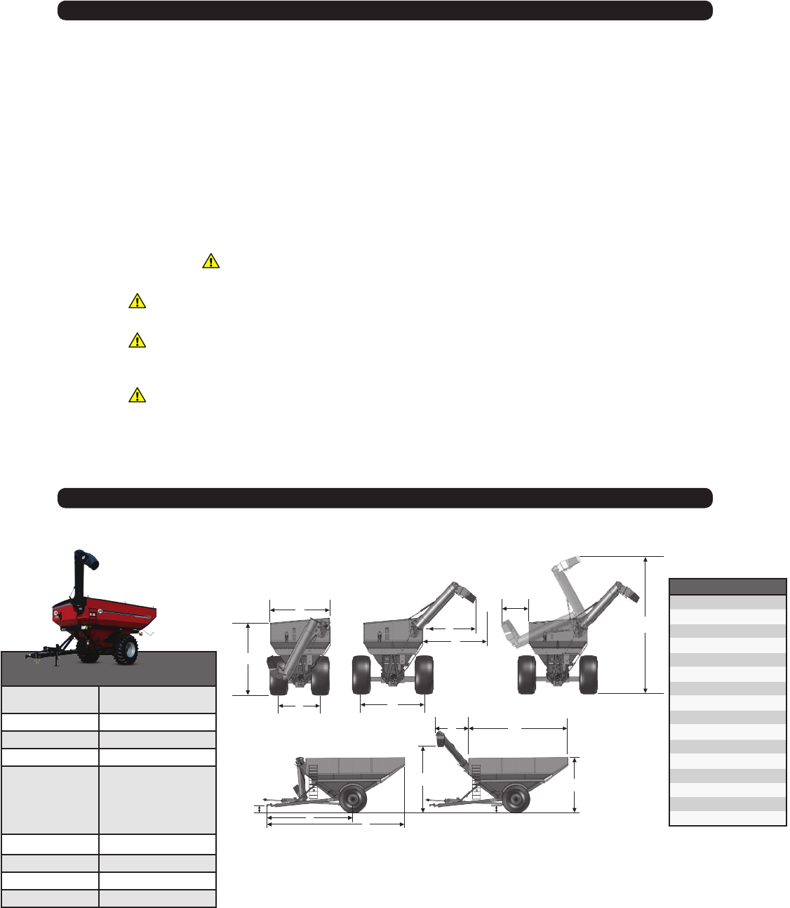
Specications
Specications are subject to change without notice or obligation.
Specications 19XR
Capacity
19 Metric Tons Corn
20,22 Metric Tons Wheat
Auger
41 cm (16”)
Wheels 21x32, 27x32, 30x32, 25x36
Spindle Size 12,5 cm (5”)
Tire Size 900/60R32-R1-2-193,
24.5x32-R3-2-16,
30.5 x 32-R1-2-18,
800/60R32-R3-2,
35.5 x 32-R3-2,
66 x 43.00-R1-2
Tongue Weight Empty 885 kg
Tongue Weight Loaded 1250 kg
Unload Time 2 minutes 10 seconds
Total Weight 5940kg
General Information
TO THE OWNER:
The purpose of this manual is to assist you in operating and maintaining your grain cart in a safe manner. Read it
carefully. It furnishes information and instructions that will help you achieve years of dependable performance and help
maintain safe operating conditions. If this machine is used by an employee or is loaned or rented, make certain that the
operator(s), prior to operating:
1. Is instructed in safe and proper use.
2. Reviews and understands the manual(s) pertaining to this machine.
Throughout this manual, the term IMPORTANT is used to indicate that failure to observe can cause damage to equipment.
The terms CAUTION, WARNING and DANGER are used in conjunction with the Safety-Alert Symbol (a triangle with an
exclamation mark) to indicate the degree of hazard for items of personal safety. When you see this symbol, carefully read
the message that follows and be alert to the possibility of personal injury or death.
This Safety-Alert symbol indicates a hazard and means
ATTENTION! BECOME ALERT! YOUR SAFETY IS INVOLVED!
Indicates an imminently hazardous situation that, if not avoided, will
result in death or serious injury.
Indicates a potentially hazardous situation that, if not avoided,
will result in death or serious injury, and includes hazards that are
exposed when guards are removed.
Indicates a potentially hazardous situation that, if not avoided, may
result in minor or moderate injury.
Indicates that failure to observe can cause damage to equipment.
Indicates helpful information.
DANGER
WARNING
CAUTION
IMPORTANT
NOTE
6
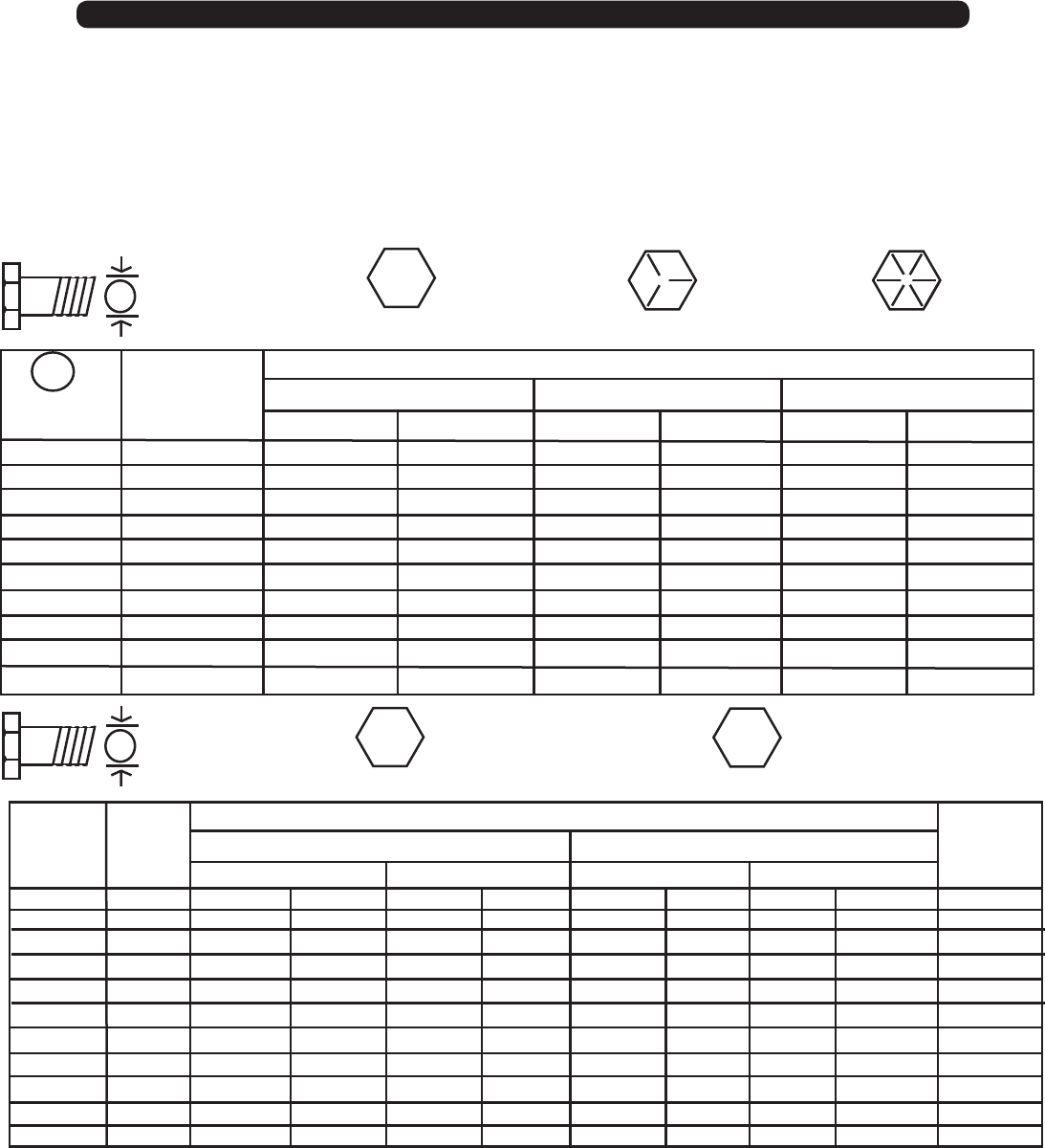
Bolt Torque Chart
Always tighten hardware to these values unless a different torque or tightening procedure is listed for specic application.
Fasteners must always be replaced with the same grade as specied in the manual parts list.
Always use the proper tool for tightening hardware: SAE for SAE hardware and Metric for Metric hardware.
Make sure fastener threads are clean and you start thread engagement properly.
All torque values are given to specications used on hardware dened by SAE J1701 & J1701M (JUL 96)
A
A
SAE SERIES
TORQUE
CHART
METRIC SERIES
TORQUE
CHART
10.9
8.8
Diameter
(Inches)
AWrench
Size
1/4
5/16
3/8
7/16
1/2
9/16
5/8
3/4
7/8
1
7/16”
1/2”
9/16”
5/8”
3/4”
13/16”
15/16”
1-1/8”
1-5/16”
1-1/2”
6
12
23
36
55
78
110
192
306
467
8
17
31
48
75
106
149
261
416
634
10
19
35
55
85
121
170
297
474
722
13
26
47
75
115
164
230
403
642
979
14
27
49
78
120
171
240
420
669
1020
18
37
67
106
163
232
325
569
907
1383
MARKING ON HEAD
SAE 2 SAE 5 SAE 8
LBS.-FT. LBS.-FT. LBS.-FT.N-m N-m N-m
Diameter
&
(Millimeters)
Thread Pitch
6 x 1.0
8 x 1.25
10 x 1.5
12.1.75
14 x 2.0
16 x 2.0
18 x 2.5
20 x 2.5
22 x 2.5
24 x 3.0
30 x 3.0
10 mm
13 mm
16 mm
18 mm
21 mm
24 mm
27 mm
30 mm
34 mm
36 mm
46 mm
8
20
39
68
109
169
234
330
451
571
1175
6
15
29
50
80
125
172
244
332
421
867
11
27
54
94
151
234
323
457
623
790
1626
8
20
40
70
111
173
239
337
460
583
1199
8
21
41
75
118
181
263
367
495
623
1258
6
16
30
55
87
133
194
270
365
459
928
11
29
57
103
163
250
363
507
684
861
1740
8
22
42
76
120
184
268
374
505
635
1283
6 x 1.0
8 x 1.0
10 x 1.25
12.1.25
14 x 1.5
16 x 1.5
18 x 1.5
20 x 1.5
22 x 1.5
24 x 2.0
30 x 2.0
Metric 10.9Metric 8.8Metric 8.8 Metric 10.9
MARKING ON THREADMARKING ON THREAD
COARSE THREAD FINE THREAD
Wrench
Size
Diameter
&
(Millimeters)
Thread Pitch
Metric Bolt Head
Identication
SAE Bolt Head
Identication
Metric
Grade 8.8
Metric
Grade 10.9
SAE Grade 2
(No Dashes)
SAE Grade 5
3 Radial Dashes
SAE Grade 8
6 Radial Dashes
TIGHTENING WHEEL NUTS
Standard 3/4” wheel studs and nuts should be tightened to torque 678 Nm (500 Ft.-Lbs.) during initial operation of the grain cart
and then checked for proper torque after every 10 hours of use. Failure to do so may damage wheel nut seats. Once seats are
damaged, it will become impossible to keep nuts tight.

7
Safety Rules
ATTENTION! BECOME ALERT! YOUR SAFETY IS INVOLVED!
Safety is a primary concern in the design and manufacture of our products. Unfortunately, our efforts to provide safe
equipment can be erased by an operator’s single careless act. In addition, hazard control and accident prevention are
dependent upon the awareness, concern, judgment, and proper training of personnel involved in the operation, transport,
maintenance and storage of equipment.
Make certain that the operator(s), prior to operating is instructed in safe and proper use and reviews and understands
the manual(s) pertaining to this machine. Also make certain that the operator(s) reviews and understands the operator’s
manual of the tractor prior to hooking up or operating the grain cart.
Read this manual before you operate this machine. If you do not understand any part of this manual, or need more
information, contact the manufacturer or your authorized dealer.
SAFETY
Understand that your safety and the safety of other persons is measured by how you service and operate this machine.
Know the positions and functions of all controls before you try to operate them. Make sure to check all controls in a safe
area before starting your work.
The safety information given in this manual does not replace safety codes, federal, state or local laws. Make certain your
machine has the proper equipment as designated by local laws and regulations.
A frequent cause of personal injury or death is from persons falling off equipment and being run over. Do not permit
persons to ride on this machine.
Travel speeds should be such that complete control and machine stability is maintained at all times. Where possible,
avoid operating near ditches, embankments and holes. Reduce speed when turning, crossing slopes and rough, slick or
muddy surfaces.
Collision of high speed road trafc and slow moving machines can cause personal injury or death. On roads, use asher
lights according to local laws. Keep slow-moving-vehicle emblem visible. Pull over to let faster trafc pass.
Hydraulic oil leaking under pressure can penetrate skin and cause infection or other injury. To prevent personal injury,
• Relieve all pressure, before disconnecting uid lines,
• Before applying pressure, make sure all connections are tight and components are in good condition,
• Never use your hand to check for suspected leaks under pressure. Use a piece of cardboard or wood for this
purpose.
• If injured by leaking uid, see your doctor immediately.
When transporting the grain cart, always keep the auger in the stow position.
Use care when moving of operating the grain cart near electric lines as serious injury or death can result from contact.
Never adjust, service, clean, or lubricate the grain cart until all power is shut off. Keep all safety shields in place. Keep
hands, feet, hair and clothing away from moving parts while the grain cart is in operation.
The service ladder is for service work only. If you must climb into the grain tank, be certain that all power is shut off and
then use extreme caution when climbing into the grain cart.
Make sure that everyone is clear of equipment before applying power or moving the machine.
Make sure that the grain cart is fastened securely to the tractor by using a high strength hitch pin, clip and safety chains.
Make sure that the grain cart hitch properly matches the hitch type of the tractor. Use a single prong (spade) grain cart
hitch with a double prong (clevis) tractor hitch. Use a double prong (clevis) grain cart hitch with a single prong (spade)
tractor hitch.
Before lling the grain cart, make certain that no one is inside the grain tank. Never allow children or anyone in, near, or
on the grain cart during transport or during loading and unloading of grain. Be aware that moving grain is dangerous and
can cause entrapment, resulting in severe injury or death by suffocation.
Never operate the auger system with anyone inside the grain tank. Hands, feet, hair and clothing can t through the
openings in and around the grate. Contact with the auger can cause severe injury or death. Make certain that all power
is shut off before service work is performed.
Before unhooking the grain cart from the tractor, be sure the jack stand is properly mounted and in place and the wheels
are properly blocked to prevent the cart from moving.
8
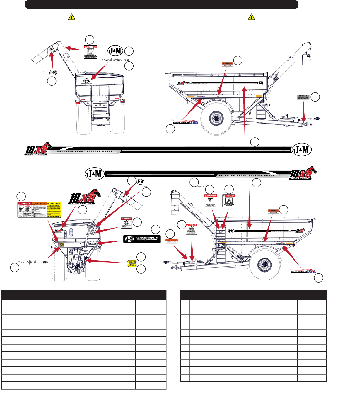
Decals
• Place decals accordingly. Clean surface before attaching decals.
ATTENTION! BECOME ALERT! YOUR SAFETY IS INVOLVED!
Replace Immediately If Damaged or Missing
1
2
3
4
5
6
7
8
9
10
11
12
13
14
15
16
17
18 19
1
4
6
13
5
# Description Part. No.
1 J&M Logo Sm 3-5/8” x 5-1/4” JM0015150
2 Danger Electric Lines JM0015099
3 J&M Oval Decal, Large JM0015151
4 www.jm-inc.com JM0019239
5 Quality Made In The USA JM0019241
6 Warning - Keep Lug Nuts Tightened Decal 1-5/8” x 4.0” JM0010150
7 Do Not Wrap Chain JM0027021
8 19XR Ton Side Stripe OS JM0039480
9 19XR Ton Side Stripe AS JM0039481
10 Danger Warning Importan JM0037665
11 Model Number GC 19XR JM0036929
12 Open JM0025433
# Description Part. No.
13 Danger - Rotating Driveline JM0018036
14 JM Manufacturing 284 Railroad St JM0039482
15 Storage Position JM0027473
16 Field Position JM0027472
17 Warning Check PTO Overlap JM0025435
18 Danger Keep O Ladder While JM0018034
19 Danger Do Not Enter Grain Tank JM0018033
20 2.0 x 9.0 Reective Amber Strip JM0009946
21 2.0 x 9.0 Fluorescent Orange Strip JM0009944
22 2.0 x 9.0 Red Reective Strip JM0009945
23 Close JM0025434
23
9
Initial Operation and Maintenance
WARNING
BE CERTAIN THAT ALL POWER IS SHUT OFF BEFORE SERVICING THE GRAIN CART.
Before the grain cart is put into service:
Have the safety instructions been read and clearly understood by the operator(s) of this machine?
Has the gearbox been properly lled with EP-80-90 gearbox lubricant?
Have all nuts, bolts, bearings and braces been properly fastened?
Has the PTO been checked for proper overlap?
IMPORTANT: Has the slip clutch on the PTO been serviced? If the slip clutch is left unchecked, damages to the power-
take-off and drive shaft may result. Before using the grain cart, loosen the bolts around the slip clutch. Make sure the
friction plates turn free of each other and are not corroded together. Re-tighten the tension bolts. Run the auger system
EMPTY and check for proper engagement of the slip clutch.
CHECK PTO OVERLAP LENGTH. Overlap length may vary depending on the tractor model and hitch setting. Try to
obtain the greatest possible overlap without bottoming out in the extreme operating conditions. Too much overlap may
cause the PTO to bottom out and damage the driveline. Not enough overlap may cause the PTO front and back halves
to separate. From the fully compressed (shortest) length the PTO should be telescoped (extended) between 25,4 cm and
55,88 cm. Different PTO lengths may need to be purchased to accommodate your terrain. A 10,16 cm shorter or a 25,4
longer PTO can be ordered through your dealer from J&M Manufacturing.
GREASE BEARINGS: Are all bearings on the drive line properly greased? Are all set screws in the bearings and U-joints
tight? Has the power-take-off shaft been properly greased at all points including the cross bearings? Has the universal
joint at the gearbox been greased? Have all grease points at the auger hinge area, including the hanger bushing
assembly been greased?
TIRE PRESSURE: Are the tires properly inated? The following is to be used as a general guide for tire ination for
cyclic use. Figures can vary depending on specic brand of tire used. It is important that tires are inspected before
and after the unit is loaded. The tire should stand up with no side wall buckling or distress as the tire rolls. Do
Not Exceed The Tire Pressure Indicated Below:
Tire Size kPa PSI
24.5 x 32-R3-2-16 165 40
30.5 x 32-R1-2-18 234 40
800/60R32-R3-2 317 46
900/60R32-R1-2A 455 39
35.5 x 32-R3-2 179 36

10
Operating Instructions
WARNING: BE CERTAIN THAT ALL POWER IS SHUT OFF WHEN HOOKING UP TO TRACTOR OR CONNECTING
HYDRAULIC LINES TO TRACTOR.
Preparing the Grain Cart for Use: The 19XR Grain Cart requires a 200 hp tractor or larger.
IMPORTANT: Do NOT pull a loaded grain cart on highway. For incidental highway travel, observe the section
below.
Tow Loads Safely
Stopping distance increases with speed and weight of towed loads, and on slopes. Towed loads with or without brakes
that are too heavy for the tractor or are towed too fast can cause loss of control. Consider the total weight of the
equipment and its load.
Observe these recommended maximum road speeds, or local speed limits which may be lower.
Road Travel (grain cart empty): Do not travel more than 32 km/hr (20 mph) and do not tow loads more
than 1.5 times the pulling unit’s weight.
Ensure the load does not exceed the recommended weight ratio. Use additional caution when towing loads under
adverse surface conditions, when turning, and on inclines.
WARNING: For greater stability on uneven or steep terrain, position non-scale wheel spindles at the furthest out setting.
IMPORTANT:
1) Connect grain cart hitch to tractor drawbar using a good quality hitch pin. Attach the safety chain to the tractor and
around the A-frame of the cart as shown. Make sure the grain cart hitch properly matches the hitch of the tractor. Use a
single prong (spade) grain cart hitch with a tractor double prong (clevis) hitch. Use a double prong (clevis) grain cart hitch
with a single prong (spade) tractor hitch.
Safety Chain User Instruction
a) Secure the safety chain by looping it around the each side of the grain cart as shown and
connecting to the towing machine’s attaching bar.
b) Do Not allow any more slack than necessary for articulation (maximum 28 cm, 11”)
c) Do Not use any intermediate support as the attaching point.
d) Store the safety chain by securing it around the main axle A-frame of the grain cart.
e) Replace the safety chain if one or more links or end ttings are broken, stretched or otherwise
damaged or deformed.
2) Attach the power-take-off shaft to the tractor. The PTO must have at least 25,4 cm (10”) of engagement. Check tractor
drawbar for clearance and length and adjust if necessary. Make sure the PTO does not bottom out when making
sharp turns as it may bend the drive shaft.
3) Make sure the jack stand is removed from the lower support position before the cart is moved. Never use the jack to
support a loaded grain cart.
4) Be sure that no debris or foreign objects are in the grain cart.
VERY IMPORTANT: Under no circumstance is it recommended to tow a loaded grain cart in excess of 13 kph.
WHEEL NUTS: Are the wheel nuts properly fastened? Torque to 678 Nm for 3/4” wheel studs and nuts. Wheel studs
and nuts should be checked after each load during initial operation of the cart and then after every 10 hours of
use. Failure to do so may damage wheel studs and nuts. Once the seats are damaged, it will become impossible to
keep the lug nuts tight.
The drawing shows the proper way to mount the wheels using Budd-type nuts. The wheels supplied with
your grain cart have straight holes and the Budd nuts will be mounted according to Figure 1. Wheels that
are improperly installed on the grain cart, resulting in product failure, will nullify warranty and shift the
burden of liability to the owner/operator. We recommend you inspect your wheel nuts to make sure
they are properly installed. Also, check the wheel nuts on a regular basis to ensure they are tight.
LIGHTING AND SAFETY DECALS: Are the rear, amber extremity lights properly positioned? Extend the lights within
40,6cm (16”) of the left and right extremities of the grain cart. Is an SMV Emblem attached to the rear of the grain cart?
Are the lights working properly? Are all lights and reective decals clean, visible and properly placed?
Figure 1

11
Operating Instructions (Continued)
CAUTION
• Do NOT operate the grain cart before reading and understanding the Operator’s Manual and ALL danger, warning and
caution signs.
• Be sure that a Slow-Moving-Vehicle emblem is attached to the rear of the grain cart.
• Never exceed 1,000 rpm on the PTO and driveline system.
• Never fold or extend the auger until the PTO has come to a complete stop.
• Never ll the grain cart unless the gate indicator is in the closed position.
• Never allow foreign object (shovels, etc.) to be placed inside the grain cart.
• Never engage the lugs and drive dogs on the augers when the system is moving at a high rate of speed.
• Never perform maintenance work or service the grain cart with the tractor running.
5) Attach the hydraulic lines to the tractor. Two hydraulic lines (green band) operate the inside gate mechanism. Connect
these lines to one service outlet on the tractor. Two hydraulic lines (yellow band) operate the folding mechanism of
the auger. Connect these lines to a second service outlet on the tractor. The remaining two hydraulic lines (red band)
operate the hydraulic ow control spout located at the end of the upper auger. Connect these lines to a third service outlet
on the tractor. Make sure the air is bled from the hydraulic cylinders and hoses.
6) Run the auger system EMPTY before loading grain into the tank for actual use. Make certain that the slip clutch is
operating and that the upper and lower augers are properly engaged.
7) Connect the lighting 7-prong connector end on the main wiring harness to the tractor electrical outlet. Make sure that
all asher and turn indicator lights are working properly before incidental highway travel.
Embedding of the brakes before use.
1. Before starting the embedding be sure that the brake levers are properly adjusted.
Push a full braking and check that the brake cylinder has a stroke of 35 - 45 mm.
2. Drive at 40 km/h.
3. Procedure a) - Perform 10 braking applications at 3 bar pressure approx (half stroke
of the pedal) from 40 km/h to stop. After each stop, release the brake, wait 1 minute
then start speeding up to 40 km/h and then brake with the tractor in neutral.
OR
Procedure b) - Alternatively you can operate with a continuous braking at 1.5 - 2 bar
for about 2 minutes, during this procedure the brakes repeatedly develop smoke. A
rst smoke emission is due to the combustion of the painting of the drums (about
200 °C). The second emission is due to the stabilization of the friction material (over
300 ° C). At the occurrence of the second emission is appropriate to suspend the
heating procedure.
4. If you have a thermometer, measure the temperature of the brake drums and
resume the running when the temperature is below 100 °C. If you don’t have the
thermometer please wait about 30 minutes before running again.
5. Perform 5 brake applications to 3 bars with a 5-minute interval (cleaning of the
friction material).
6. Cool the brake down to 100 ° C.
7. Check the stroke of the cylinder and restore the values according to point 1.
8. Begin the test for approval. If the minimum performance for approval is not achieved,
repeat the procedure from the beginning.
Brake Set-Up
12
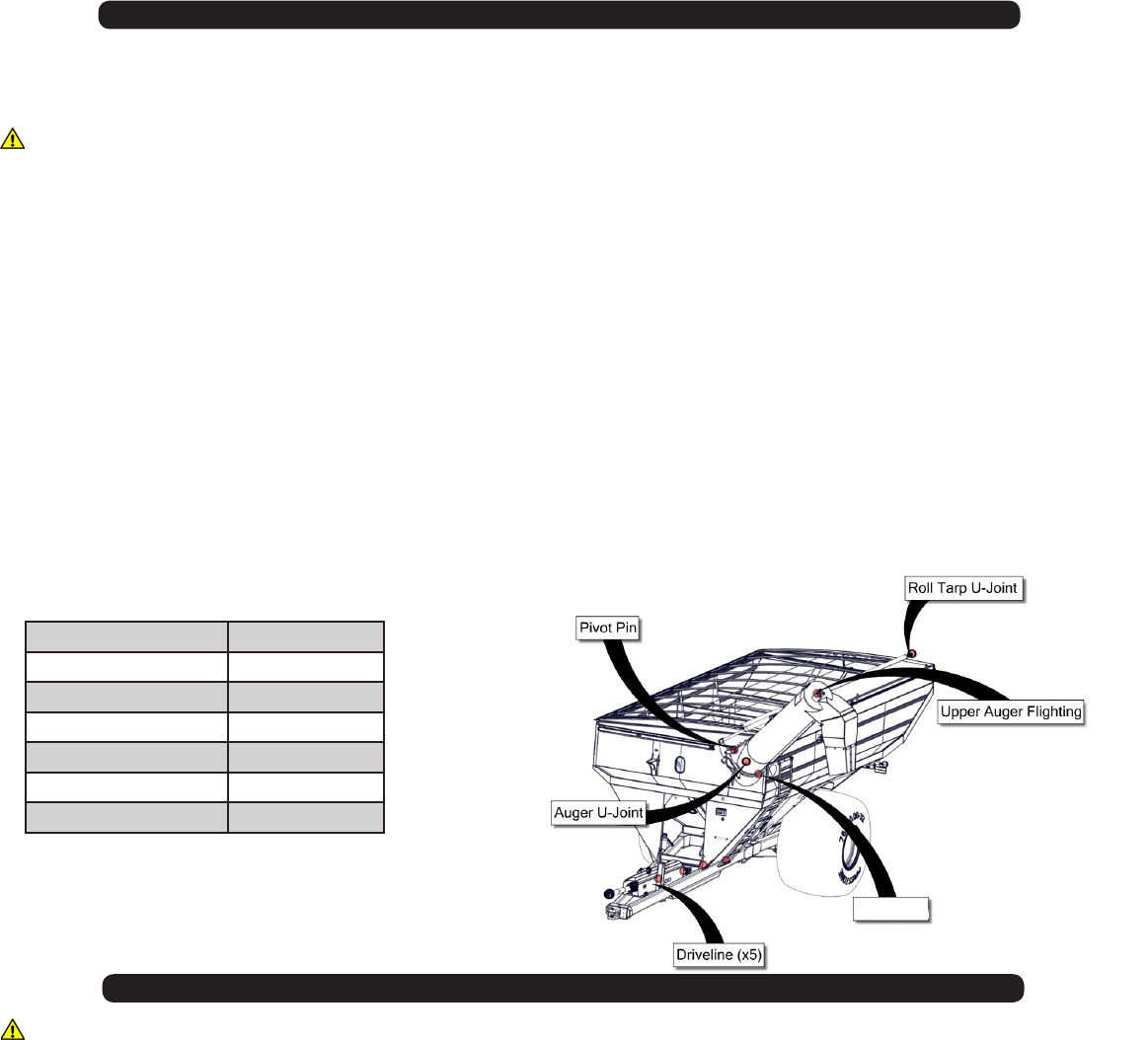
Lubrication Service Schedule
IMPORTANT: Your grain cart has grease ttings at all critical points. These should be serviced before the grain cart is
put into operation.
WARNING
BE CERTAIN THAT ALL POWER IS SHUT OFF BEFORE SERVICING THE GRAIN CART
PTO & DRIVE LINE: The grease ttings on the PTO should be serviced after every 8 hours of use. Service the grease
ttings on each of the drive bearings and also the universal joint after every 8 hours of use.
AUGER FOLDING MECHANISM: One grease tting is located on the pivot pin of the folding auger. This tting should
be serviced after every 8 hours of use. Service the grease tting on the hanger bushing assembly (top end of the lower
auger assembly) after every 8 hours of use or as needed.
SPRING LOADED UPPER AUGER BEARING: Service the grease tting on the upper auger bearing (located at the top
end of the upper auger assembly) after every 8 hours of use. Lubricate the springs and retaining bolts on the bearing
before prolonged storage of the grain cart.
GEARBOX: Gearbox lubricant has been added to the gearbox during nal assembly. Recheck the lubricant level before
initial operation of the grain cart, then periodically according to use. An inspection plug is located in the center of the top
of the gearbox mount plate. To check the uid level, remove the vented inspection plug and drain plug at the bottom of
the gearbox. Drain the lubricant. Return the drain plug and rell the gearbox with 0,71 liters (24 ounces) of gear box
lubricant for 51 cm (20”) auger. The gearbox is properly lled when half full of lubricant. DO NOT OVERFILL. Use EP
80-90 gearbox lubricant or equivalent.
Pivot Pin Once Annually
Roll Tarp U-Joint Once Annually
Upper Auger Flighting Every 8hrs of use.
Tripod Leg Every 8hrs of use.
Auger U-Joint Every 8hrs of use.
Drive line Every 8hrs of use.
Brake Bearing Every 8hrs of use.
WARNING
BE CERTAIN ALL POWER IS SHUT OFF WHEN SERVICING THE GRAIN CART
• Repack the bearings in the hub assembly once a year or as needed. Use a good quality LS EP2 Severe Duty, High
Shock Load, Lithium based Grease. Also check the seal for wear and replace if necessary.
• Check the grain cart periodically for cracks in welds and for other structural damage. Have cracked welds xed
immediately. Failure to do so could result in extensive damage to the grain cart and greatly reduce the life of the cart.
• Lubricate the slides on the clean-out door.
• Check all hydraulic hoses for wear and replace as necessary.
• Make sure all tires are properly inated. See INITIAL OPERATION AND MAINTENANCE in the Owner’s Manual for
recommended instructions for tire pressure. It is important that tires are inspected before and after unit loaded.
• Check PTO for wear of plates in the slip clutch. Replace if needed.
• Make sure that all guards and shields are in place before operating the grain cart.
Routine Maintenance
Hanger

13
Troubleshooting
WARNING
MAKE SURE THAT ALL POWER IS SHUT OFF BEFORE SERVICING THE GRAIN CART. MAINTENANCE AND
REPAIR SERVICE WORK TO BE PERFORMED BY QUALIFIED SERVICEMEN ONLY.
Trouble... Possible Cause... Possible Remedy...
Auger will not return to down position
or move from stow position.
Dirt In Restrictor (see pg. 15)
Faulty Check Valve
Upper ighting and lower ighting are
locked together (see pg. 14)
Remove restrictor ttings from outside
hydraulic cylinder and clean out dirt
Replace Check Valve
Bearing on top of upper auger ighting
need adjusting. When the auger is in
the engaged position, there must be
1/8” (0,32cm) gap between bottom
of top bearing and top of upper tube
housing (SEE ADJUSTING THE
UPPER AUGER FLIGHTING)
Hanger Bushing Assembly at the top
of the lower auger ighting is hot
Top of the hanger bushing assembly is
rubbing against the drive dog
(See pg.14)
Loosen the two bolts and re-adjust
the position of the hanger bushing
assembly. Re-tighten bolts.
Remove the lower ighting assembly
and place a shim between the spline
coupler and the gearbox.
Excessive Vibration Auger ighting or shaft is bent
Drive shaft is bent
Straighten or replace auger ighting
Replace or straighten drive shaft
Grain ow stoppage Bolt sheared in drive dog
Folding auger before complete stop
Replace bolt in drive dog. Engage
upper and lower ighting at a slow rate
of speed. (Drive dogs and lugs are
being engaged too fast.)
Upper and lower ightings are
disengaging before auger comes
to a complete stop. Replace bolt
in the drive dog. Never engage
or disengage the upper and lower
ightings until the augers come to a
complete stop.
Replace key and tighten set screw.
Auger tube is breaking away from the
grain cart at the hinge area or the ram
in the hydraulic folding cylinder is bent
Upper auger is extended in the upright
position while traveling in the eld
Repair or place folding cylinder if
necessary. Remember to lower auger
to the eld position after unloading.
PTO key sheared
Flip-up Auger Rest not ipping over
center.
Cable has loosened. With Auger in Filed position tighten
cable to the handle.

14
Adjusting the Lower Flighting
WARNING
MAKE SURE THAT ALL POWER IS SHUT OFF BEFORE ADJUSTING THE FLIGHTING ASSEMBLY.
If the drive-dog and hanger assembly are becoming excessively hot during unloading, the lower ighting and/or hanger
may need adjusting. The hanger bushing assembly has elongated holes where it attaches to the outer tube assembly.
Loosen the two 3/8” bolts on the hanger bushing assembly. Adjust the hanger either up or down and vertically center it
between the ighting and drive dog. Re-tighten the bolts. Make certain that the ighting center and drive-dogs do not rub
the hanger bushing assembly, causing them to become hot.
If the hanger can no longer be adjusted by moving it up or down on the elongated holes, both the hanger bushing
assembly and the lower ighting will have to be removed. See instructions on pg. 36 for ighting removal. After removing
them from the tube assembly, place a shim [between 0,32cm (1/8”) to 0,48cm (3/16”) thick] where the gearbox and the
spline coupler (welded to the lower ighting). Replace the lower ighting and reattach the hanger to the tube assembly.
Readjust the hanger assembly. NOTE: The bottom of the lower ighting is not attached to the gearbox with any bolts or
set screws but may be ‘frozen’ fast. Be careful when removing the lower ighting from the gearbox. For easier removal of
the lower ighting, keep the gearbox at the bottom intact, remove the (2) 3/8” bolts from the hanger bushing assembly and
pull the lower ighting off of the gearbox.
After adjusting the lower ighting, move the upper auger to the unload position and check the upper ighting for
readjustment.
WARNING
MAKE SURE ALL POWER IS SHUT OFF BEFORE ADJUSTING THE FLIGHTING ASSEMBLY
If the upper and lower augers to do not properly separate during the unfolding sequence, the upper ighting may
need adjusting. Before making adjustment to the upper ighting, check to see if the lugs and drive dogs on the auger
assemblies are locking together. If they are not locked together, check to see if dirt is in the restrictor or if a faulty check
valve on the hydraulic cylinder used to raise and lower the upper auger assembly may be causing the problem. If dirt is in
the restrictor, see “Removing Dirt From Restrictors On Hydraulic Cylinders” below.
Fold the upper tube assembly into the upright position. Position the upper ighting in the engaged position with the lower
ighting. Locate the four-hole ange bearing on the top of the upper auger tube housing. With the upper ighting in the
engaged position, check the spacing between the upper bearing and the upper tube housing. There must be a 0,32cm
(1/8”) space between the base of the four-hole ange bearing and the upper tube housing. If there is NOT a space
between the bearing and the upper tube housing, or if there is more than a 0,32cm (1/8”) space, the upper ighting will
need to be adjusted. To adjust the upper ighting, loosen the 1 1/4” hex nuts both above and below the four-hole ange
bearing. Move the 1 1/4” hex nuts up or down the threaded shaft on the top of the auger ighting shaft until the bearing
moves to approximately 0,32cm (1/8”) above the base of the upper tube housing. When the four-hole ange bearing is
properly located, tighten both 1 1/4” hex nuts together to secure the bearing position.
If the upper and lower ighting still does not separate properly during the folding sequence, a small bevel may need to
be removed from the inside of the lugs where they engage the drive dogs on the auger assemblies. Grind approximately
0,32cm (1/8”) from the corner of the lugs where they touch against the drive dogs.
Adjusting the Upper Flighting

15
Removing Dirt From The Restrictors On The Hydraulic Cylinder
WARNING
MAKE SURE THAT ALL POWER IS SHUT OFF AND THE UPPER AUGER TUBE IS IN THE DOWN POSITION
BEFORE REMOVING THE RESTRICTORS.
Remove restrictors from the 90 degree street elbow on the hydraulic cylinder. Remove dirt from the tting to allow
hydraulic oil to ow through the restrictor. Reattach the restrictor to the street elbow. Use Teon sealant tape or
equivalent on the threads of the restrictor before re-attaching.
If the restrictor continues to plug with dirt, replace the restrictor or lter the hydraulic oil in your system.
IMPORTANT: When the grain cart is not going to be used for a period of time, store the cart in a dry, protected place.
Leaving your grain cart outside, open to the weather will shorten it’s life.
Follow the procedure below when your grain cart is placed in storage for periods up to six months.
1. Cover electronic monitor (if equipped) with plastic before washing the grain cart. Wash or clean and completely
lubricate the grain cart. See the lubrication service section in this manual.
2. Remove all grain from inside the grain tank, auger tube assemblies, and at the clean-out door.
3. Check the gearbox oil and replace with new EP 80-90 gearbox lubricant or equivalent if necessary.
4. Touch up areas where paint may have worn away. Use a good quality primer paint, especially before re-applying
graphite paint to the interior slopes of the grain tank.
5. Retract all hydraulic cylinders to prevent the piston rods from rusting.
6. If the grain cart is equipped with an electronic weigh system, fully charge the battery to prevent freezing. Disconnect
the negative (-) ground cable at the battery to prevent possible discharge.
7. Clean the tires before storage. Inate the tires at regular intervals.
8. Open the clean-out door at the base of the grain tank.
9. Loosen the Slip Clutch Tension Bolts. (Yellow Comer PTO only)
Removing From Storage
• Check the gearbox to make sure it has the appropriate amount of oil.
• If equipped with an electronic scale system, check the battery and make sure that it is fully charged. Reconnect the
negative (-) cable.
• Inate the tires to the correct operating pressure.
• Close the clean out door at the base of the grain tank.
• Make sure all safety shields are in the proper position.
• Tighten the Slip Clutch Bolts on the PTO until the spring length is 3,23cm (1.27”). (Yellow Comer PTO only)
Storage Preparation
TITLE
16
Repair Parts List and Diagrams
When performing maintenance work, wear sturdy, rough-soled work shoes and protective equipment for eyes, hair, hands,
hearing and head. Follow the Operator’s Manual instructions to ensure safe and proper maintenance and repair.
Your local, authorized dealer can supply genuine replacement parts. Substitute parts may not meet original equipment
specications and may be dangerous.
WARNING
MAKE SURE ALL POWER IS SHUT OFF BEFORE PERFORMING ANY MAINTENANCE OR REPAIR WORK.
TIRES FOR GRAIN CARTS
Description Part. No.
Wheel Rim, 10 hole, 21x32 (8.785 pilot) (11.25 bolt circle) JM0026977
Wheel Rim, 10 hole, 21x32 (11.13 pilot) (13.19 bolt circle) JM0020025
Wheel Rim, 10 hole, 25x36 (11.13 pilot) (13.19 bolt circle) JM0020048
Wheel Rim, 10 hole, 27x32 (11.13 pilot) (13.19 bolt circle) JM0017899
Wheel Rim, 10 hole, 31x32 (3 piece) (11.13 pilot) (13.19 bolt circle) (for 35.5x32 R-3 Tires) JM0020037
Wheel Rim, 10 hole, 30 X 32 JM0020005
Rubber O-Ring Seal for 31x32-10 Wheel Rim (52-49469-00) JM0020030
Description Part. No.
24.5x32 Diamond Tire, 16 ply (for 21x32-10HD heavy duty wheel) JM0021549
30.5x32 Lug Tire, 14 ply (for 27x32-10 wheel) JM0017665
305x32-R1-2-18 27x32 Wheels and 30.5x32 Lug Tires-18 ply (Alliance) JM0039470
30.5x32 Diamond Tire, 14 ply (for 27x32-10 wheel) JM0030266
35.5x32 Diamond Tire, 20 ply (for 31x32-10 3-piece wheel) JM0021557
66x43.00 Lug Tire, 16 ply (for 25x36-10 wheel) JM0021535
900/60R32-R1 JM0017662
WHEEL RIMS FOR GRAIN CARTS
17
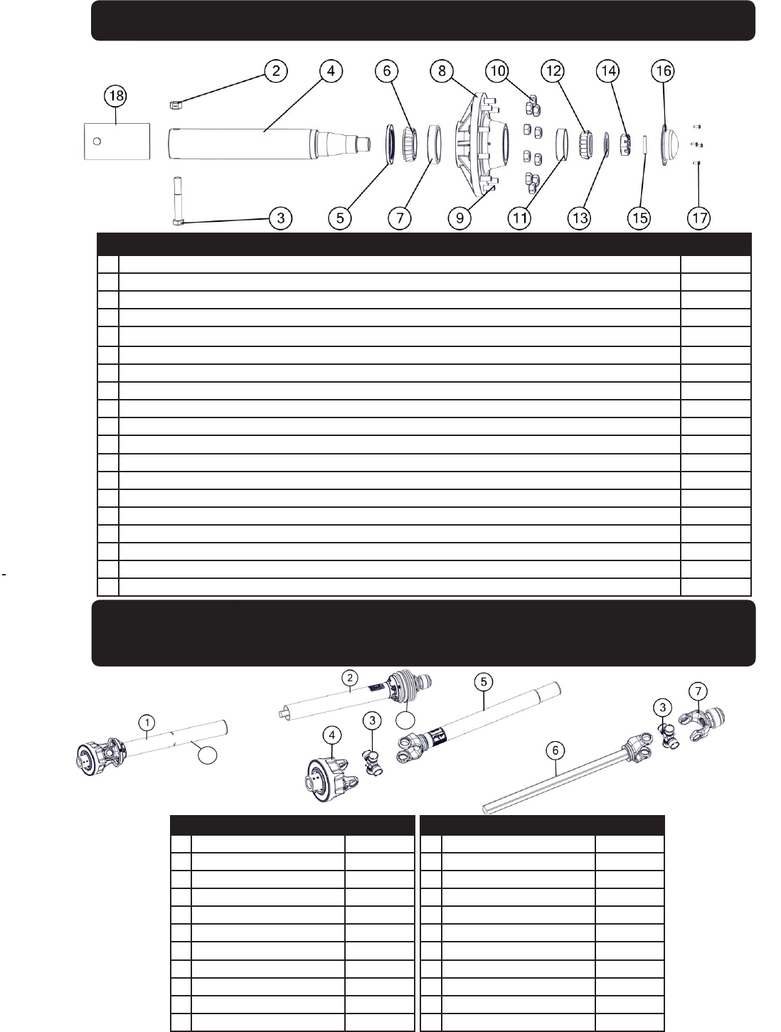
#Description Part. No.
1 Hub and Spindle Assembly Complete (Overseas) JM0031622
2 1”-8 Gr5 Z Centerlock Hex Nut JM0002149
3 1" x 7" Gr5 Z Hex Bolt (165400) JM0016689
4 4-1/2" Spindle x 23-15/16" (281900) JM0018794
5 Seal (6" OD - 3-3/4" ID) for hub w/ scales (since March 2000)(750-35) JM0021456
5 Seal (6" OD) 1-906979 (CR-43771) JM0018955
6 Large Bearing (910346) JM0018849
7 Large Race (HM212049) JM0018848
8 Hub with large bearing and small races, 3/4" studs & nuts (13.19 bolt circle) (11.13 pilot)(W-881) JM0020510
9 3/4"-16 Wheel Stud (913564) JM0018957
10 3/4"-16 Wheel Nut (913571) JM0018958
11 Small Race (HM212011) JM0018854
12 Small Bearing (910347) JM0018852
13 Spindle Washer (913635) JM0015900
14 Large Castle Nut (912973) JM0015899
15 Cotter Pin (905945) JM0018956
16 Dust Cap (909921) JM0018954
17 1/4”-20 x 1” Gr5 Z Hex Bolt (141G5B) JM0002095
18 Spindle Sleeve JM0031626
HUB & SPINDLE ASSEMBLY W-881
For Model 810 and all Walker Equipped Grain Carts with 4-1/2” Diameter Spindles
Power Take-O (PTO) Sha Assembly
1-3/4” Weasler - Black in Color
Used on all Extended Reach Grain Carts
# Description Part. No.
1 Back Half PTO JM0018513
1 Back Half PTO (XL) JM0030331
2 1-3/4” Front Half PTO JM0018514
2 1-3/4” Front Half PTO (XL) JM0030330
2 1-3/8” Front Half PTO JM0024367
2 1-3/8” Front Half PTO (XL) JM0030640
3 55ECross Kit JM0018449
4Auto Clutch JM0018500
5 Yoke, Tube & Sleeve JM0018519
5 Yoke, Tube & Sleeve (XL) JM0031647
6 Yoke & Sha Assembly JM0018520
# Description Part. No.
6 Yoke & Sha Assembly (XL) JM0031648
7 1-3/4” Spring Lock Yoke JM0018506
7 1-3/8” Spring Lock Yoke JM0024353
8Front Guard JM0018518
8 Front Guard (XL) JM0030642
9 Back Guard JM0018517
9 Back Guard (XL) JM0030645
10 1-3/4” PTO Complete JM0018443
10 1-3/4” PTO Complete (XL) JM0030332
10 1-3/8” PTO Complete JM0024333
9 1-3/8” PTO Complete (XL) JM0030641
8
9
18
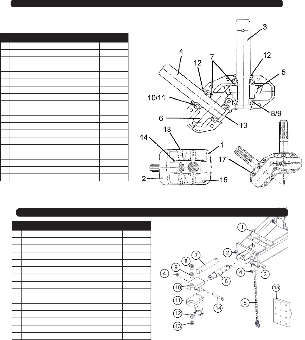
130 Degree Gearbox Assembly
# Description Part. No.
1 Casting, Upper Half (A0150) JM0025088
2 Casting, Lower Half (A0149) JM0025089
3 1-3/4” Input Sha (A0142) JM0025090
4 1-3/4” Output Sha (A0143) JM0025091
5 18 Tooth Gear (H61S18) JM0025092
6 29 Tooth Gear (H61S29) JM0025093
7 Shim, Arbor (H00101-01) JM0025094
8 Bearing, Cup (414276) JM0025077
9 Bearing, Cone (514137) JM0025078
10 Bearing, Cup (413620) JM0025095
11 Bearing, Cone (413687) JM0025096
12 Seal (617285) JM0025097
13 End Cap (400301) JM0025076
14 Bolt (438225) JM0025085
15 Plug (400300) JM0025080
16 Bushing (4003VB) JM0025073
17 Plug,Vent (2003PR) JM0025081
18 Plug (200300) JM0025075
19 130 Degree Gearbox Complete (H130-9) JM0017840
# Description Part. No.
1 1"-8 x 5-1/2" Gr5 Z Hex Bolt JM0002110
2 1-1/4"-7 Gr5 Z Nylon Locking Hex Jam Nut JM0027201
3 1-1/4"-7 x 4" Gr8 Z Hex Bolt JM0026073
4 1"-8 Gr5 Z Centerlock Hex Nut JM0002149
5 30k Lb Safety Chain JM0027440
6 Digi-Star - 2-7/8" Weigh Bar JM0000355
7 2-7/8" Long Non Scale Hitch Bar JM0025227
8 1-1/4"" Pin adapter for GC Spade Hitch JM0019032
9 1-1/2" Pin adapter for GC Clevis Hitch Tang JM0014203
10 Hitch Weldment JM0017978
11 Draw Bar JM0017976
12 1-1/4" Pin adapter for GC Clevis Hitch Tang JM0019031
13 1-1/2" Pin adapter for GC Clevis Hitch Tang JM0014206
14 1"-8 x 7-1/2" Gr8 YZ Hex Bolt JM0017944
15 Universal Hitch Mount Plate JM0029111
Hitch Assembly
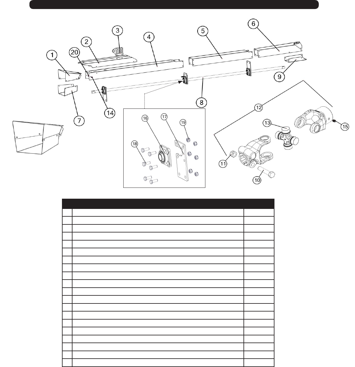
19
# Description Part. No.
1 3 M Wide - PTO Knuckle Guard JM0029525
2 Shield Hydraulic Hose Conduit JM0029764
3 3 Keyed LF Hydraulic Hose Holder JM0021437
4 3 M Wide - Front Driveline Shield JM0029524
5 3 M Wide 700Bu - Middle Driveline Shield JM0034055
6 700Bu 3 M Wide - Rear Driveline Shield JM0034079
7 PTO Clutch Under Cover JM0029761
8 150” Driveline JM0021345
9 U-Joint Bottom Shield JM0036716
10 5/8”-11 x 3” Gr5 Z Hex Bolt JM0002105
11 5/8"-11 Gr5 Z Centerlock Hex Nut JM0002146
12 U-Joint JM0017957
13 Cross Kit JM0017958
14 M10-1.5 x 25 Gr8.8 YZ SF Hex Bolt(for all of the driveline sheilding) JM0002093
15 3/8”-16 x 1/2” Set Screw JM0019044
16 1 3/4” Flange Bearing 4- hole JM0018774
17 10 7/8” Bolt On Drive Shaft Support Plate JM0019550
18 M16-2 x 45 Gr8.8 YZ Hex Bolt JM0002116
19 M16-2 Gr8.8 YZ Nylon Locking Hex Nut JM0002164
20 M10-1.5 Gr8.8 YZ SF Hex Nut(for all of the driveline sheilding) JM0002154
Driveline Assembly
20
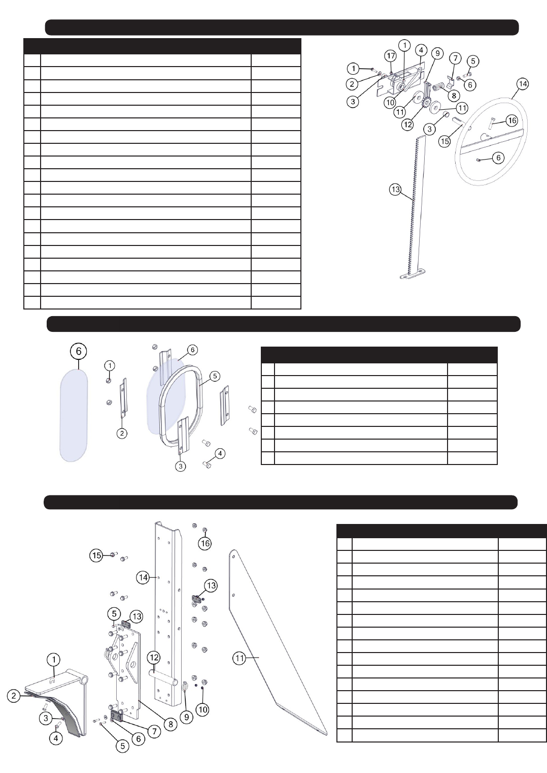
Door Wheel Assembly (2015 & Newer)
Auger Rest Assembly
# Description Part. No.
1 1/4"-20 x 1" Gr5 Z Hex Bolt JM0002095
2 3/8 USS Flat Washer JM0003061
3 .754 ID x .874 OD x .625 LG Bronze Bushing (BB-34) JM0009455
4 Nylon Guided Rack Housing Weldment JM0030635
5 3/8"-16 x 1-1/4" Gr5 Z Hex Bolt JM0016675
6 3/8"-16 Gr5 Z Hex Nut JM0001707
7 Rack Track Guide (Scrubber Plate) JM0002851
8 Small Compression Spring JM0001688
9 Nylon Track Guide JM0029354
10 Flip Lock JM0029459
11 Keyway Washer JM0029454
12 15 Tooth Sprocket - 3/4" Bore w/ Key JM0029455
13 Nylon Guided Rack Track 20-1/4” Weldment JM0030651
13 Nylon Guided Rack Track 27-1/2” Weldment JM0030634
14 Rack Wheel Weldment JM0028897
15 Stub Sha - 3/4" x 4-1/8" with readed End JM0029440
16 3/8”-16 x 1-3/4” Gr5 Z Hex Bolt JM0002097
17 1/4”-20 Gr5 Z Centerlock Hex Nut JM0001505
16 Complete Nylon Door Wheel Assembly (20-1/4”) JM0030652
16 Complete Nylon Door Wheel Assembly (27-1/2”) JM0029460
# Description Part. No
1 Flip-Up Auger Rest Weldment JM0020538
2 Guide Plate JM0024456
3 3/8" USS Flat Washer JM0003061
4 3/8"-16 x 1" Gr5 Z Hex Bolt JM0001592
5 M6 x 360 Gr8.8 YZ Hex Bolt JM0031474
6 M6 Flat Washers JM0019447
7 Bounce Pad JM0020802
8 Auger Rest Mount Bolt Plate JM0030549
9 1/4" Dia. Snap Ring Zinc Plated JM0001870
10 M6 Gr8.8 YZ Nylon Locking Hex Nut JM0002167
11 Flip Auger Rest Brace JM0033747
12 Flip Up Auger Rest Pin JM0028218
13 Cable Guide JM0021917
14 Slide Plate JM0029715
15 M10 x 25 Gr8.8 YZ SF Hex Bolt JM0002093
16 M10 Gr8.8 YZ SF Hex Nut JM0002154
# Description Part. No.
1 M10 Gr8.8 YZ Nylon Locking Hex Nut JM0002162
2 Inside Window Brace (WB-4) JM0000253
3 Outside Window Brace (WB-4B) JM0000256
4 M10 x 25 Gr8.8 YZ Hex Bolt JM0031355
5 Oval Window Grommet (112500) JM0000254
6 Oval Window (IW-71212) JM0000255
6 Long Oval Window JM0033502
7 Inspection Window Kit (IWK-1) JM0025752
Inspection Windows
21
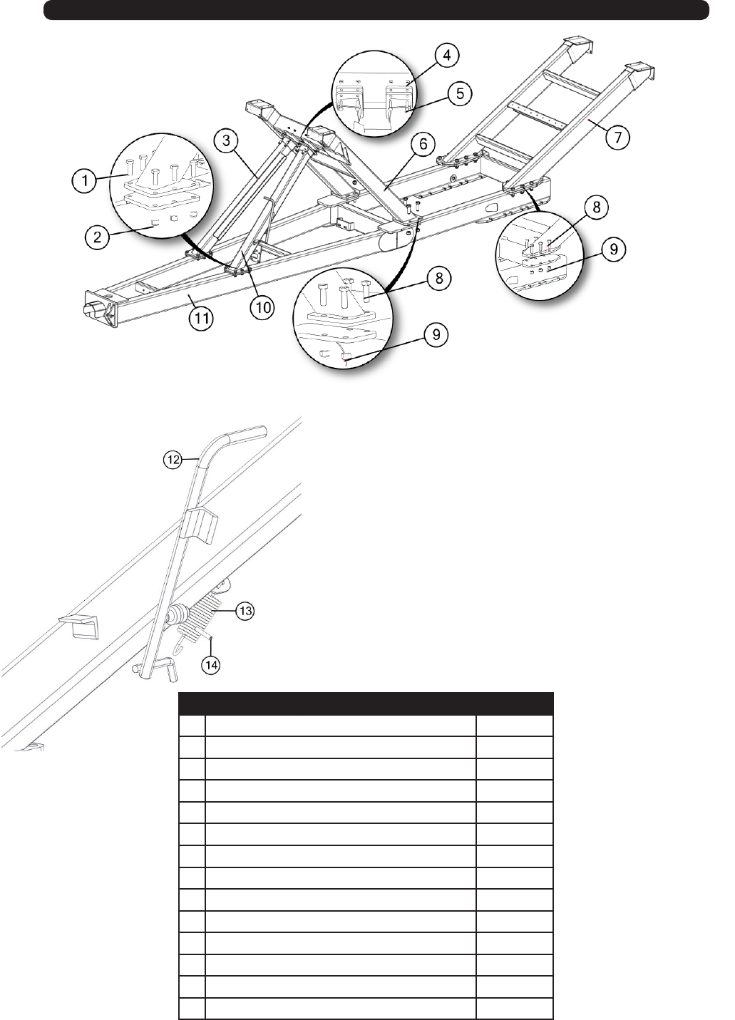
Frame
# Description Part. No.
1 M16-2 x 45 Gr8.8 YZ Hex Bolt JM0002116
2 M16-2 Gr8.8 YZ Nylon Locking Hex Nut JM0002164
3 700 Bu 3M Wide OAS Front Leg Brace JM0032833
4 M12-1.75 Gr8.8 YZ Nylon Locking Hex Nut JM0002163
5 M12-1.75 x 50 Gr8.8 YZ Hex Bolt JM0001490
6 700Bu 3M - Front Leg Weldment JM0032752
7 Rear Leg Weldment JM0032734
8 M24-3 x 75 Gr8.8 Hex Bolt JM0002118
9 M24-3 Gr8.8 YZ Nylon Locking Hex Nut JM0002165
10 700Bu 3M Wide - AS Front Leg Brace JM0033211
11 700 Bu 3M Wide Main Frame Weldment JM0032660
12 Auger Rest Handle JM0021843
13 Extension Spring JM0024976
14 Roll Pin JM0009896
22
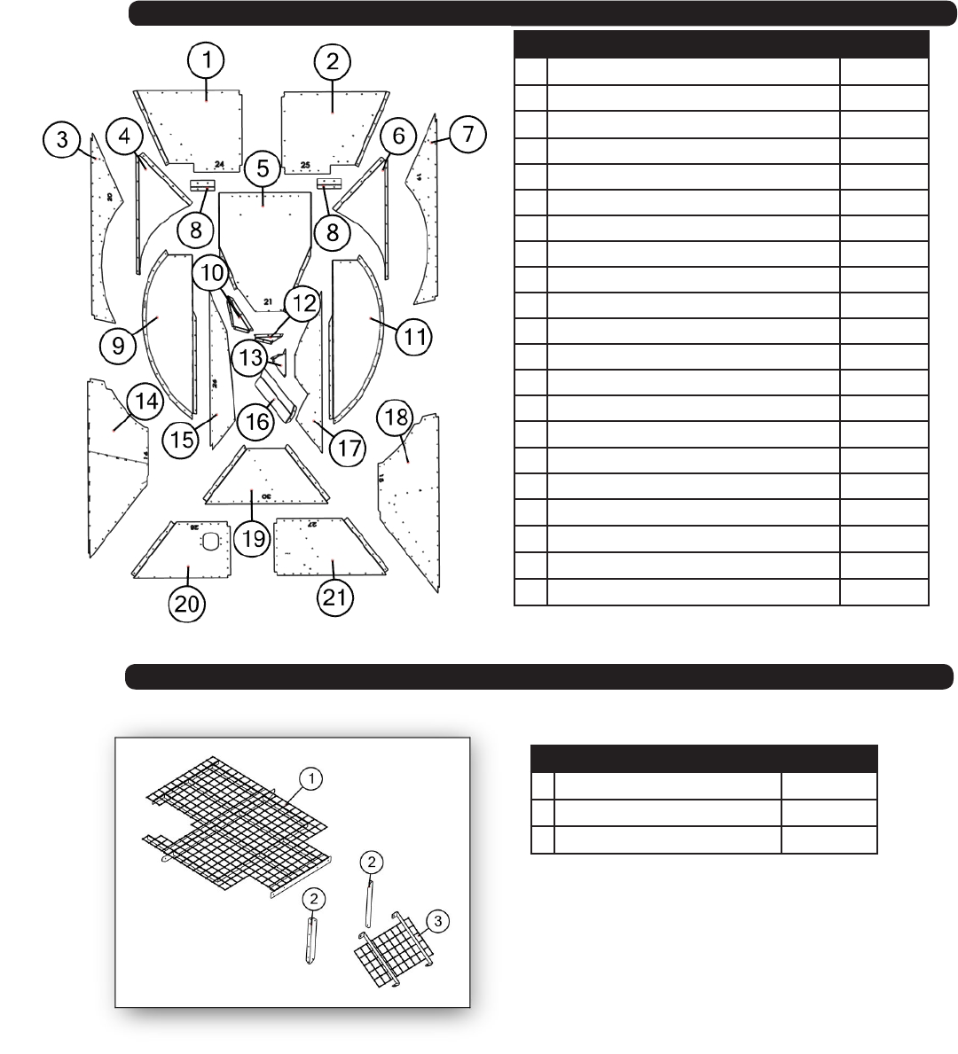
Lower Level Panels
# Description Part. No.
1 OAS Rear Lower Middle Panel JM0033248
2 AS Rear Lower Middle Panel JM0033246
3 OAS Lower Middle Rear Panel JM0035512
4 OAS Wheel Well Shedder Panel JM0033646
5 Straight Auger Rear Bottom Panel JM0035439
6 Wheel Well Shedder Panel JM0033667
7 Straight AS Lower Middle Rear Panel JM0035520
8 Wheel Well Corners JM0002891
9 OAS Wheel Well JM0035508
10 Straight Auger Inside Shedder Panel JM0035471
11 AS Wheel Well JM0035507
12 Straight 16" Bottom Rear Wall Splice Plate JM0035418
13 AS Wall GB Splice Plate JM0032854
14 Straight OAS Lower Mid Front Panel JM0035516
15 Wide Straight Auger - OAS Bottom Panel JM0035353
16 Clean Out Door BT JM0035740
17 Straight Auger AS Bottom Panel JM0035503
18 Straight AS Lower Mid Front Panel JM0035518
19 Wide Straight Auger - Front Lower Panel JM0035351
20 OAS Front Lower Middle Panel JM0036314
21 AS Front Lower Middle Panel JM0036318
Tank Screen
# Description Part. No.
1 Main Screen Weldment JM0029703
2 Fender Well Brace JM0029696
3 Rear Tank Screen JM0029699
23
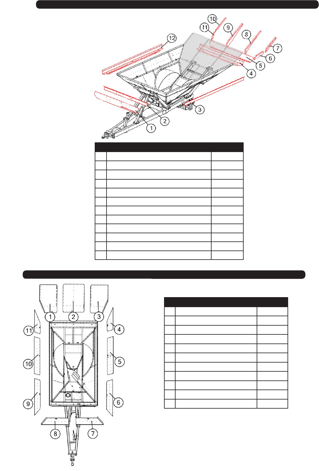
Rails
# Description Part. No.
1 Front Rail Cross Brace JM0033490
2 Wide Front Rail JM0032665
3 Wide AS Rail JM0032678
4 Wide Rear Rail JM0032667
5 Rear Rail Cross Brace JM0033255
6 Rear Slope Corner Braces - AS Bottom Half JM0033711
7 Rear Slope Corner Braces - AS JM0033715
8 Rear Batman Wings - Mid AS JM0033266
9 Rear Batman Wings - Mid OAS JM0033274
10 Rear Slope Corner Braces -OAS JM0033568
11 Rear Slope Corner Brace - OAS Bottom Half JM0033542
12 Wide OAS Rail JM0032661
Mid-Level Panels
# Description Part. No.
1Rear Top OAS Panel JM0033448
2Rear Top Center Panel JM0033455
3Rear Top AS Panel JM0033456
4AS Upper Middle Rear Panel JM0033441
5AS Upper Middle Middle Panel JM0033433
6AS Upper Middle Front Panel JM0033430
7Front AS Upper Middle Panel JM0033434
8OAS Front Upper Middle Panel JM0033440
9OAS Upper Middle Front Panel JM0033442
10 OAS Upper Middle Mid Panel JM0033443
11 OAS Upper Middle Rear JM0033445
24
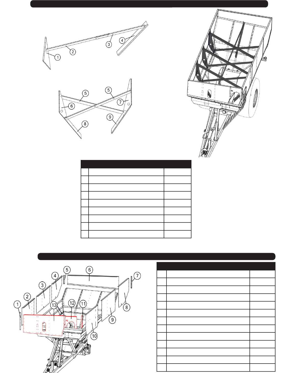
Sideboard Braces
# Description Part. No.
1 Front Tri Gusset JM0032894
2 Front To Rear Brace - Front JM0002682
3 Front To Rear Brace - Rear JM0033997
4 Rear Slope Brace JM0034205
5 X-Bracing JM0034001
6 OAS Tri Gusset JM0032887
7 AS Tri Gusset JM0032885
8 OAS Wall Slope Brace JM0033975
9 AS Wall Slope Brace JM0033830
# Description Part. No.
1OAS Front Corner JM0033505
2Wide OAS Top Front Panel JM0033458
3OAS Top Middle Sheet JM0033460
4OAS Top Rear Panel JM0033462
5OAS Rear Corner JM0033499
6Rear Top Panel JM0033492
7AS Rear Corner JM0033497
8AS Top Rear Panel JM0033468
9AS Top Middle Panel JM0033466
10 Wide Straight Auger - AS Top Front Panel JM0035342
11 AS Front Corner JM0035528
12 Wide -Straight Auger Front Corner Panel JM0033474
13 Front Top Panel JM0033472
Top Panels
25
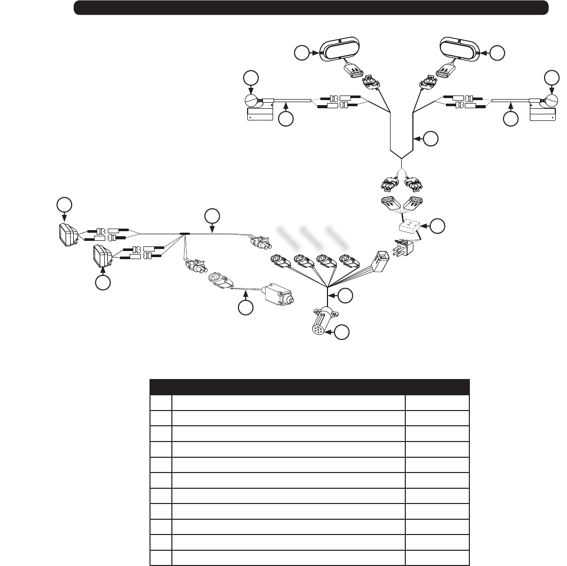
Light Kit Assembly
# Description Part. No.
1Red Light (LED) JM0034389
2 Amber Light Only JM0018819
3Extendable Amber Light Assembly (Left Side) JM0018817
4Extendable Amber Light Assembly (Right Side) JM0018826
5Wiring Harness for Rear Lights (Each) JM0020437
6Light Enhancer JM0010566
7Main Wiring Harness with 7-Prong Connector End JM0020439
8Limit Switch (for eld light) JM0036040
9Field Light Wire JM0020438
10 Field Light (LED, Grain Cart)(Bullet Lead Ends) JM0000881
11 7-Prong Connecter End Only JM0010528
Accessory
Accessory
Accessory
1
1
5
43
6
7
2
8
2
10
10
9
11
TITLE
26
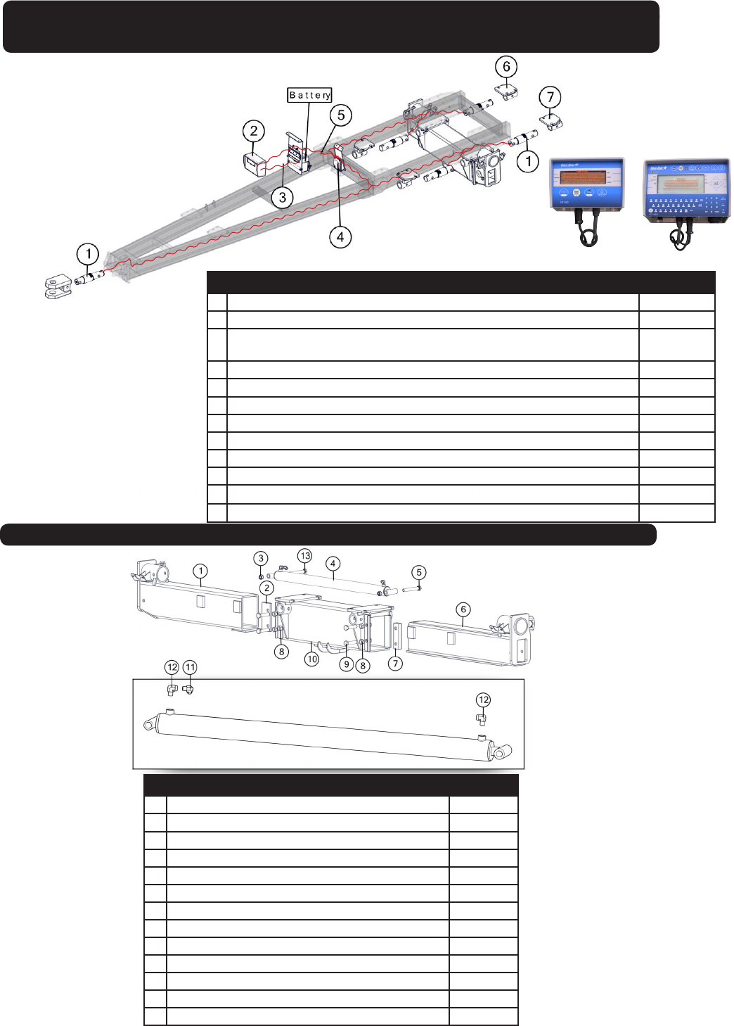
WEIGH SCALE SYSTEMS
Digi-Star 5-Point Scale System
For Single Wheel Applications with Bolt-on Axles
# Description Part. No.
1 2-7/8” Weigh Bar, 1” Pin Hole (278WB-T1) JM0000355
2 GT400 Indicator with Serial Port EZ-150, EZ-2000, EZ-400 (GT400) JM0019040
2 GT 460 Indicator “Upgrade” includes serial port, Downloader USB port and
alpha-numeric key pad (GT-460)
JM0015453
3 Power Cord to Battery, Digi Star (PC-1) JM0025812
4 5 Point Junction Box (JB-5) JM0019038
5 30’ Standard Cable for J-Box to Indicator (141837) JM0025820
5 10’ Long Extension Cord to Mount Indicator in Cab (ECI-1) JM0025815
5 20’ Long Extension Cord to Mount Indicator in Cab (ECI-2) JM0025816
6 External Scale Mount Rear OAS JM0030032
7 External Scale Mount Rear AS JM0029540
8 Optional “Y” Cable to Connect both Printer and Downloader (403037) JM0025817
9 Flashdrive memory stick-programmed (114991) JM0025819
GT-400 GT-460
# Description Part. No.
1 AS Axle Insert JM0030596
2AS Clamp Plate JM0030313
3 M24-3 Gr8.8 YZ Nylon Locking Hex Nut JM0002165
4 Welded 3" x 40" Stroke Hydraulic Cylinder JM0031363
5 M24-3 x 180 Gr8.8 YZ Hex Bolt JM0031353
6 OAS Axle Insert JM0030300
7OAS Clamp Plate JM0030288
8 1"-14 Gr8 YZ Hex Nut JM0019926
9 1"-8 x 4-1/2" Gr5 Z Hex Bolt JM0016687
10 Main Axle Weldment JM0030623
11 3/8" male NPT x 3/8" female NPT Street 90 JM0030059
12 3/8" female NPT x 1/2" male NPT; 90 degree elbow JM0010292
13 M24-3 x 220 Gr8.8 YZ Hex Bolt JM0031357
Adjustable Axle
TITLE
27
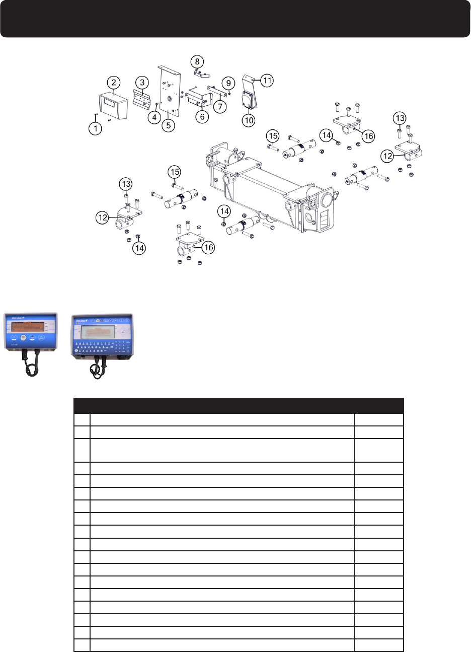
WEIGH SCALE SYSTEMS
Digi-Star 5-Point Scale System Hardware
Hardware for Single Wheel and Track System Bolt-on Axles
# Description Part. No.
1 M6-1 x 20 Gr8.8 YZ Hex Bolt JM0002120
2 GT400 Indicator with Serial Port EZ-150, EZ-2000, EZ-400 (GT400) JM0019040
2 GT 460 Indicator “Upgrade” includes serial port, downloader USB port
and alpha-numeric key pad (GT-460)
JM0015453
3 Indicator Mounting Bracket, GT460 (MBI-1) JM0019648
3 Indicator Mounting Bracket, GT400 (MBI-1S) JM0000361
4 M10-1.5 x 25 Gr8.8 YZ SF Hex Bolt JM0002093
5 Scale Mount Plate JM0000362
6 Battery Box with Strap (BB-2) JM0000365
7 Battery Box Strap JM0000364
8 Chord Wrap JM0000363
9 M10-1.5 Gr8.8 YZ SF Hex Nut JM0002154
10 6 Point Junction Box (JB-5) JM0019038
11 Junction Box Mount JM0000366
12 External Scale Mount Rear AS JM0029540
13 M24-3 x 75 Gr8.8 Hex Bolt JM0002118
14 M24-3 Gr8.8 YZ Nylon Locking Hex Nut JM0002165
15 M24-3 x 130 Gr8.8 YZ Hex Bolt JM0031228
16 External Scale Mount Rear OAS JM0030032
GT-400 GT-460
28
Top Auger Assembly
23 25
24

29
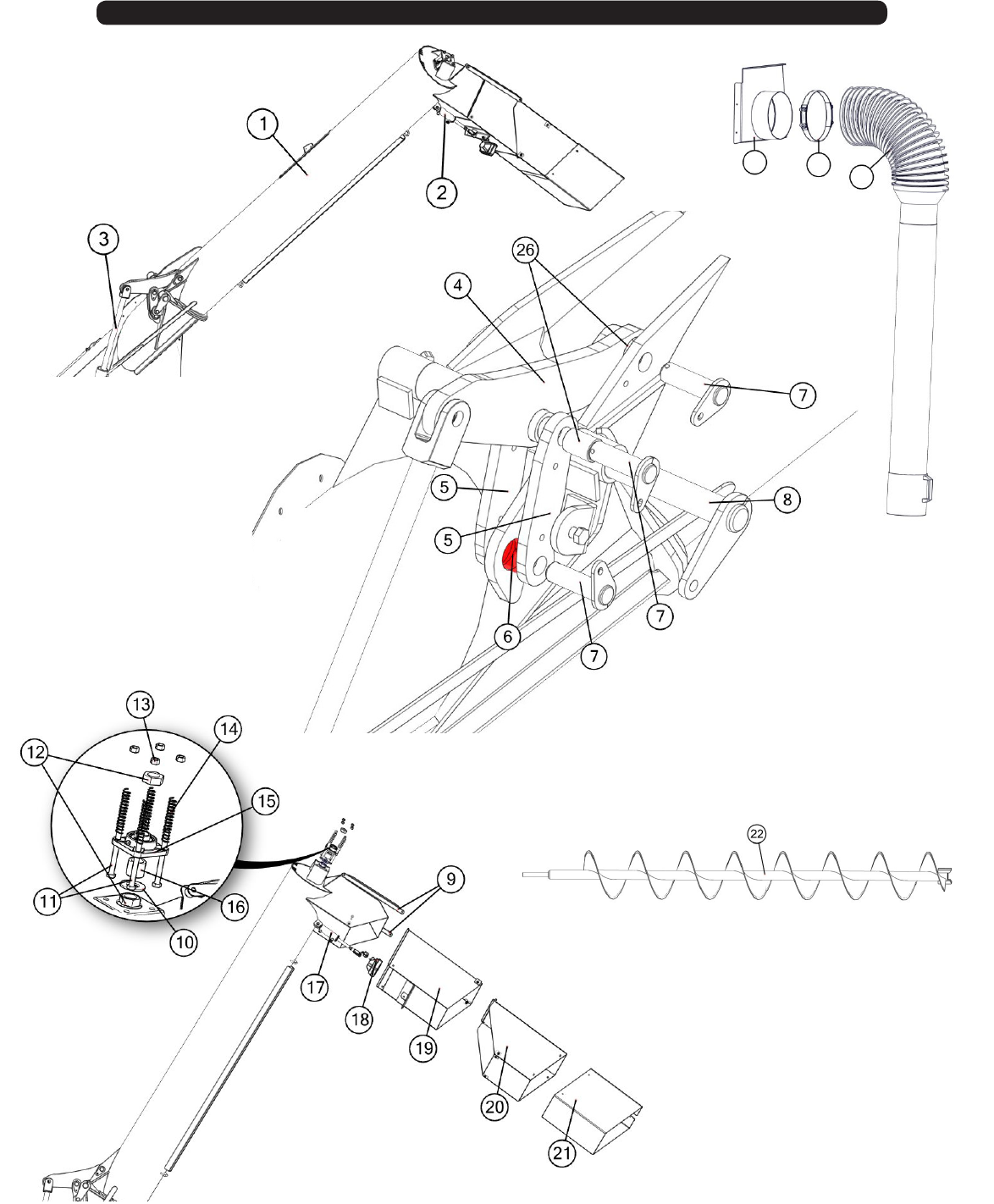
Top Auger Assembly
# Description Part. No.
1 16” Straight Auger Top Tube Weldment JM0035069
2 1-3/4" x 4" Hydraulic Cylinder JM0018564
3 3" x 24" Welded Cushion Cylinder JM0025661
4 Long Fold Main Link JM0035725
5 Master Link w/ Keeper JM0035075
6 Main Link Pivot Spool JM0020453
7 1 1/4 Pin Keeper JM0035930
8 Auger Hinge Pin Weldment JM0022086
9 Tele Spout Main Linkage Rod JM0035034
10 1 1/4 ID x 2 1/2 O.D. x 1/8 ZN USS FLat Washer JM0020322
11 1/2"-13 x 5-1/2" HHMB Grade 5 Zinc JM0001498
12 1-1/4"-12 PN Gr5 Hex Jam Nut JM0001606
13 1/2"-13 Gr5 Z Centerlock Hex Nut JM0001511
14 Springs JM0018559
15 1 1/4” 4-Bolt Flange Bearing, 33/64 Bolt Hole JM0018560
16 Spacer 1-1/4” Long JM0021646
17 1 3/4” x 4” Hydraulic Cylinder JM0018564
18 Field Light (LED) JM0037154
19 16" Side Shooter Weldment - Straight JM0034901
20 16" Telescoping Spout Weldment JM0035731
21 16" Tele Spout Rubber Spout JM0036682
22 16” GC19T Bottom Flighting Weldment JM0035919
23 Straight 16in Spout to Seed JM0039307
24 10” Flex Hose Clamp - Lundell Plastics JM0010502
25 10” dia x 12’ Long 2 Stage Tele Spout with Handle JM0030265
26 Sleeve Composite Bearing JM0021957
*-R = Red
*-B = Blue
*-G = Green
*-Y = Yellow
When requesting an item with color, end the part
number with -R, -B, -G, or -Y. (e.g. JM0000000-R)
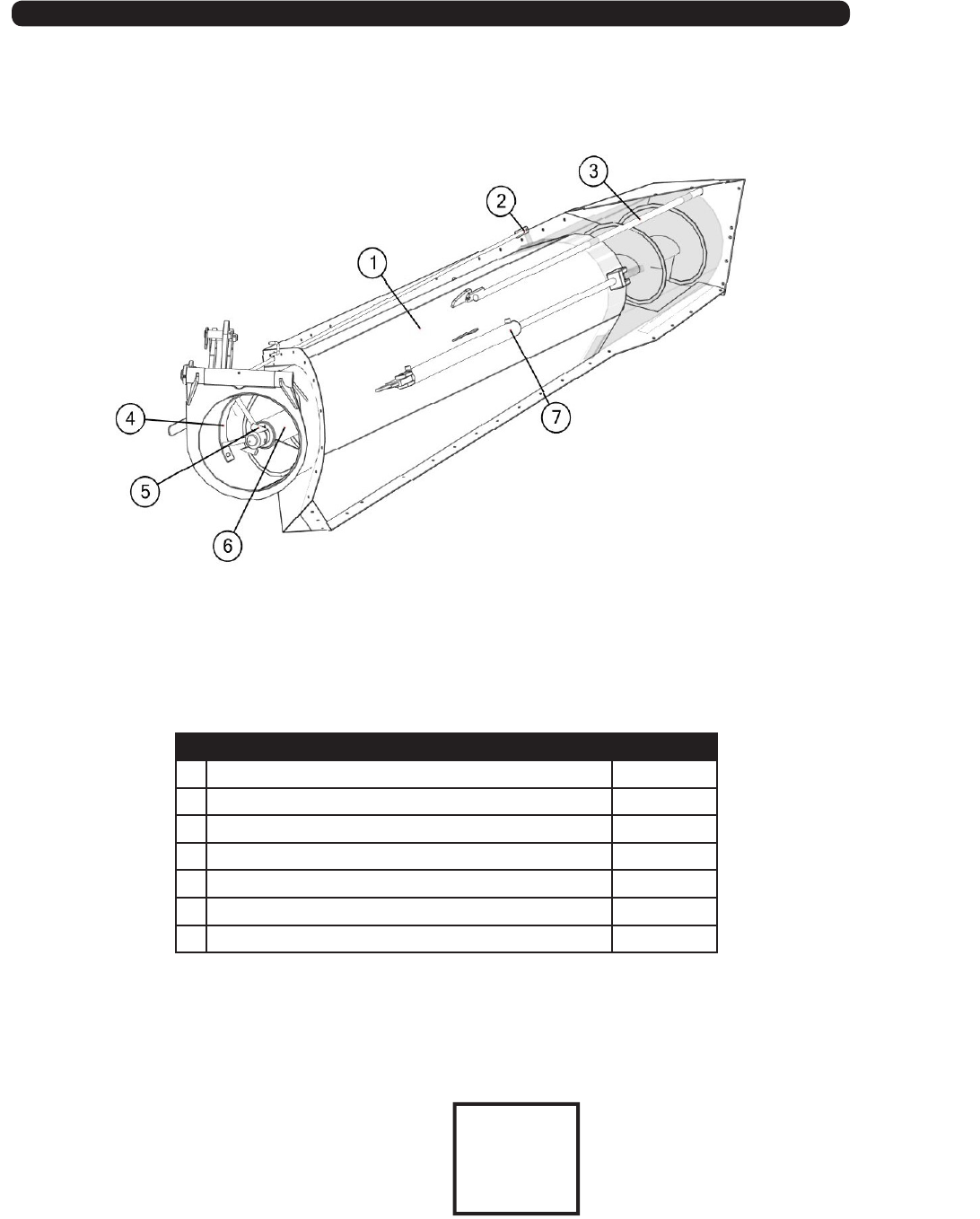
30
# Description Part. No.
1 Straight Auger - Bottom Tube Weldment JM0035375
2 Indicator Rod JM0000079
3 Guide Rod JM0016646
4 Auger Hanger JM0024419
5 Drive Dog Weldment JM0024412
6 GC19T Bottom Flighting - 16" w/ 4.5" Pipe (154 3/8”) JM0036634
7 2” x 36” Welded Cylinder JM0018523
Lower Auger Assembly
*-R = Red
*-B = Blue
*-G = Green
*-Y = Yellow
When requesting an item with color, end the part
number with -R, -B, -G, or -Y. (e.g. JM0000000-R)
Couplers
(Welded to Shell)
TITLE
31
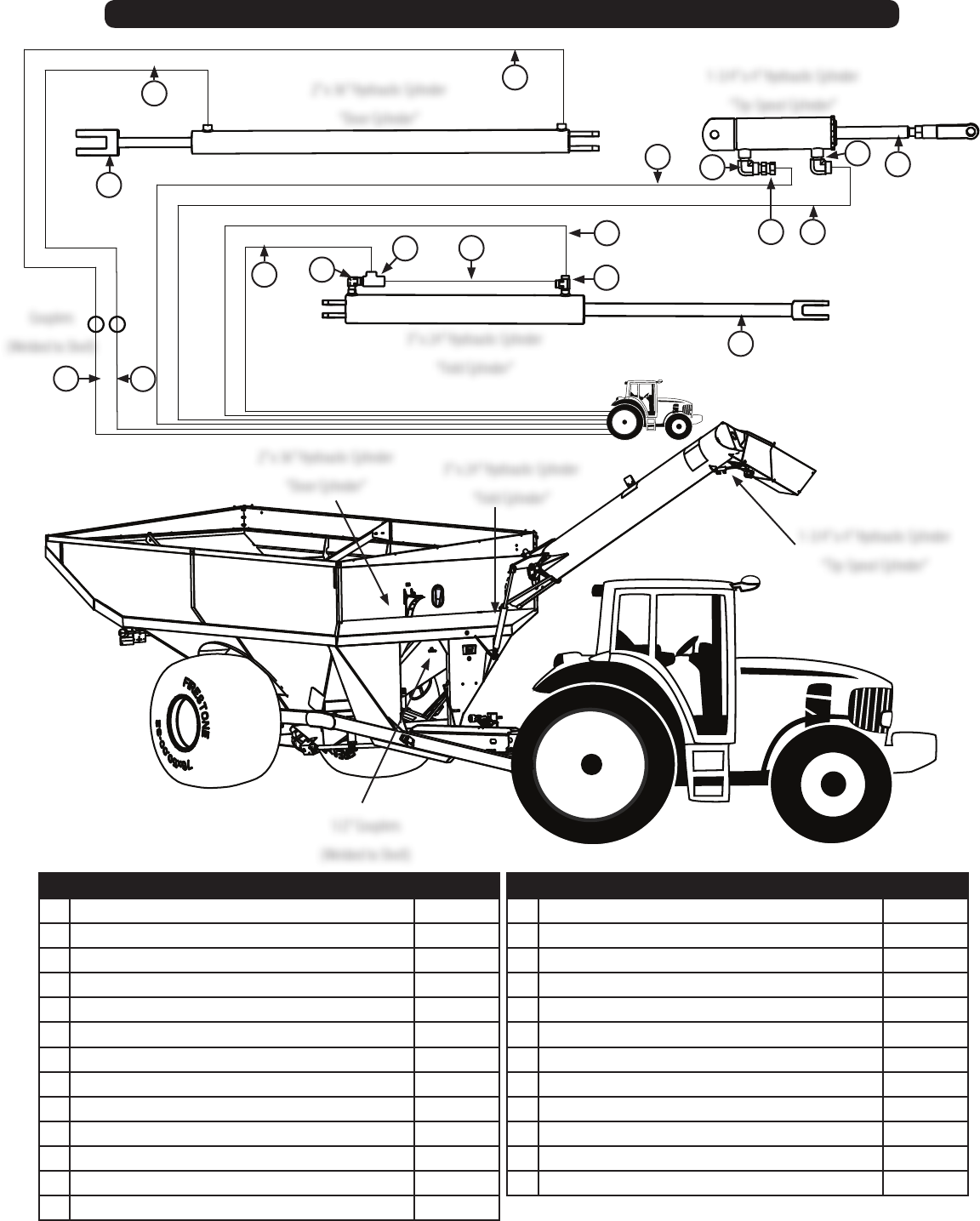
12 Series Hydraulic Hoses & Cylinders
# Description Part. No.
1 Hydraulic Hose 1/4” x 212” (812) JM0030611
1 Hydraulic Hose 1/4” x 240” (1012, 1112, 1312, 1412) JM0024985
2 Hydraulic Hose 1/4” x 212” (812) JM0030611
2 Hydraulic Hose 1/2” x 240” (1012, 1112, 1312, 1412) JM0024985
3 Hydraulic Hose 1/4” x 61” (812) JM0024905
3 Hydraulic Hose 1/4” x 43” (1012, 1112, 1312, 1412) JM0024904
4 Hydraulic Hose 1/4” x 29” (812) JM0030609
4 Hydraulic Hose 1/2” x 43” (1012, 1112, 1312, 1412) JM0024906
5 2” x 36” Welded Cylinder JM0018523
6 Hydraulic Hose 1/4” x 324” (812) JM0030600
6 Hydraulic Hose 1/4” x 290” (1012, 1112, 1312, 1412) JM0024983
7 3/8” female NPT x 1/2” male NPT; 90 degree elbow JM0010292
8 PC-37 Check Valve JM0018233
# Description Part. No.
9 Li Cylinder Hydraulic Hose 1/4” x 21” JM0024896
10 Hydraulic Hose 1/4” x 346” (812) JM0027896
10 Hydraulic Hose 1/4” x 308” (1012,1112, 1312, 1412) JM0024984
11 3/8” male NPT x 3/8” female NPT x 3/8” female NPT; Street T JM0018266
12 3” x 24” Welded Cushion Cylinder JM0019644
13 Hydraulic Hose 1/4” x 456” (812) JM0030610
13 Hydraulic Hose 1/4” x 474” (1012, 1112, 1312, 1412) JM0024982
14 1/4” male NPT swivel with .032 orice JM0020113
15 1/4” male NPT X 1/4” female NPT rigid; 90 degree elbow JM0020115
16 Hydraulic Hose 1/4” x 456” (812) JM0030610
16 Hydraulic Hose 1/4” x 482” (1012, 1112, 1312, 1412) JM0024982
17 1-3/4” x 4” Hydraulic Cylinder JM0018564
13
1-3/4” x 4” Hydraulic Cylinder
“Tip-Spout Cylinder”
2” x 36” Hydraulic Cylinder
“Door Cylinder”
3” x 24” Hydraulic Cylinder
“Fold Cylinder”
1-3/4” x 4” Hydraulic Cylinder
“Tip-Spout Cylinder”
2” x 36” Hydraulic Cylinder
“Door Cylinder”
3” x 24” Hydraulic Cylinder
“Fold Cylinder”
Couplers
(Welded to Shell)
1/2” Couplers
(Welded to Shell)
17
12
5
10
9
6
4
3
16
2
1
8
711
15
15
14
32
Roll Tarp Assembly
Prop-Up Bars
Tarp Stand-O Crank Handle Holder
Crank Handle U-Joint
Tarp Assembly
Front Endcap Rear Endcap

33
Tarp Assembly
Rear Endcap
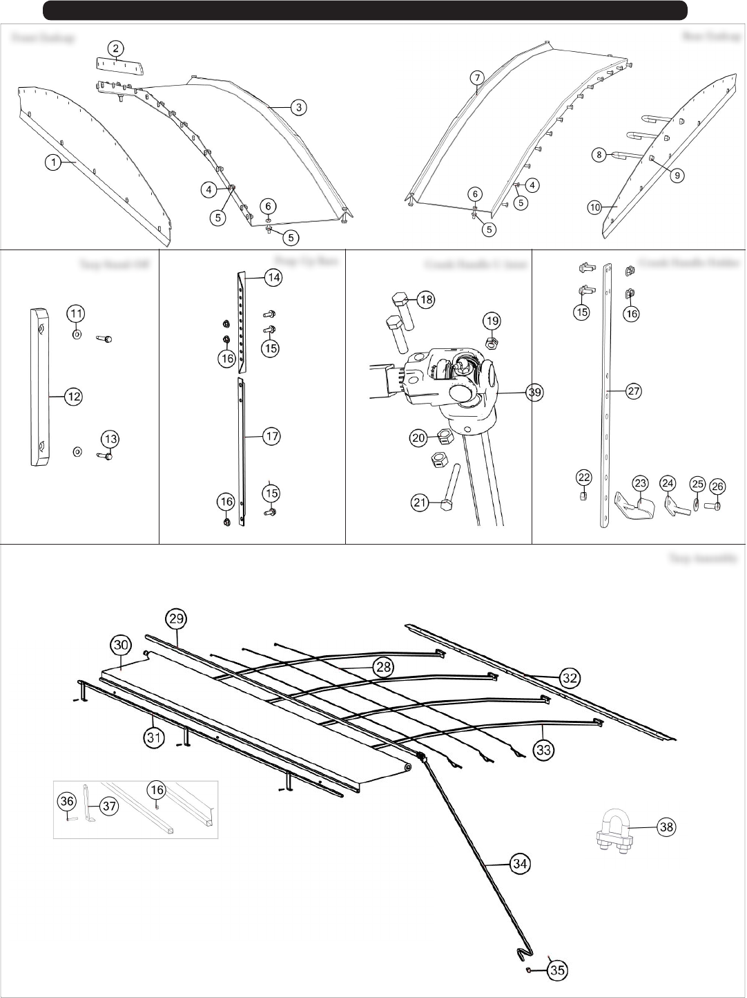
Roll Tarp Assembly
# Description Part. No.
1 Front End Cap Plate JM0001573
2 Tarp Nylon Riser JM0000196
3 Front Arched End Cap JM0001572
4 M6 x 14 Gr8.8 YZ Hex Bolt JM0031837
5 M6 Gr8.8YZ SF Nylon Locking Hex Nut JM0002167
6 M6 x 16 Gr8.8 YZ Hex Bolt JM0031839
7 Rear Arched End Cap JM0001574
8 3/8”-16 Gr5 Z J-Bolt JM0001519
9 3/8”-16 Gr5 Z Centerlock Hex Nut JM0001512
10 Rear End Cap Plate JM0001575
11 M6 Flat Washer JM0019447
12 Tarp Stando JM0001889
13 1/4” x 1-1/2” Self Tapping Screw JM0001571
14 Upper Adjustable Bow Support 13” JM0021404
15 M10 x 25 Gr8.8 YZ Hex Bolt JM0031355
16 M10 Gr8.8 YZ Nylon Locking Hex Nut JM0002162
17 Lower Adjustable Bow Support 19” JM0000179
17 Lower Adjustable Bow Support 27” JM0021403
18 3/8”-16 x 1-1/2” Gr5 Z Hex Bolt JM0001659
19 1/4”-20 Gr5 Z Centerlock Hex Nut JM0001505
20 3/8”-16 Gr5 Z Centerlock Hex Nut JM0001512
21 M6 x 65 Gr8.8 YZ Hex Bolt JM0002121
22 M12 Gr8.8 YZ Nylon Locking Hex Nut JM0002163
23 Roll Tarp - Handle Hanger PP JM0002967
24 Roll Tarp - Handle Hanger Rubber Flap JM0002551
25 1/2” USS Flat Washer JM0003082
26 M12 x 35 Gr8.8 YZ Hex Bolt JM0020955
27 Crank Holder JM0000164
28 3/16” Cable (1010, 1120) JM0021408
29 Tarp Roll Tube Weldment JM0036753
30 Tarp with Rivets JM0036747
31 1” Square Tie-Down Tube JM0036749
32 Tightening Lip Front JM0036352
32 Tightening Lip Rear JM0036356
33 Arched Tarp Bows JM0001585
34 Crank with Splined U-Joint JM0019888
35 Yellow Cap JM0018963
36 M10 x 50 Gr8.8 YZ Hex Bolt JM0001486
37 Tarp Stop Bracket JM0000187
38 Cable Clamp-Small JM0001514
39 U-Joint JM0001517
34
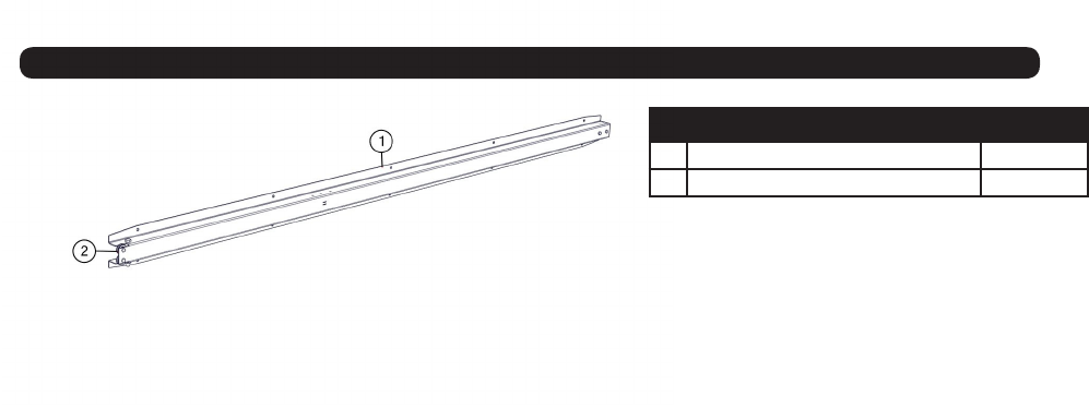
Spring Return Assembly
# Description Part. No.
1 Spring Return Assembly JM0012965
2 Spring Return Cable JM0012981
