O_nitrogro_4.12.17 O Nitrogro 4.12.17
User Manual: o_nitrogro_4.12.17
Open the PDF directly: View PDF ![]() .
.
Page Count: 57
OPERATORS MANUAL
J. & M. Mfg. Co., Inc.
284 Railroad Street - P.O. Box 547
Fort Recovery, OH 45846
Ph: (419) 375-2376 Fax: (419) 375-2708
www.jm-inc.com
Rev. 10.10. 2016
NITRO-GRO
PRECISION APPLICATOR
5010
5016

2
Table of Contents
4-5 ....................................................To the Dealer
6 ......................................................General Information
7 ......................................................Bolt Torque Chart
8 ......................................................Specications
9 ......................................................Safety Rules
10-14 ..................................................Components
15 .....................................................Pre-Operation Checklist
16-20 ..................................................Initial Operation
18 .....................................................Wheel Spacing
19-20 ..................................................Quick Start
21 .....................................................Break in Period
22 .....................................................Trouble Shooting
23 .....................................................Service/Maintenance
23 .....................................................Storage
24-25 ..................................................Safety Signs
26-40 ..................................................Repair Parts
42-45 ..................................................Fertilizer Hose Routing
46-49 ..................................................Hydraulic Schematic
50-51 ..................................................Orice Kits
52 .....................................................Liquid Control System(Raven Controller)
3

4
To The Dealer
Read manual instructions and safety rules. Make sure all items on the Dealer’s Pre-Delivery and Delivery Check Lists are completed
before releasing equipment to the owner.
The dealer must complete the Warranty Registration found on the Dealer Portal website located at dealer.jm-inc.com and return
it to J. & M. Mfg. Co., Inc. at the address indicated on the form. Warranty claims will be denied if the Warranty Registration has not been
submitted.
EXPRESS WARRANTY:
J. & M. Mfg. Co. Inc. warrants against defects in construction or materials for a period of ONE year. We reserve the right to inspect
and decide whether material or construction was faulty or whether abuse or accident voids our guarantee.
Warranty service must be performed by a dealer or service center authorized by J. & M. Mfg. Co., Inc. to sell and/or service the type
of product involved, which will use only new or remanufactured parts or components furnished by J. & M. Mfg. Co., Inc. Warranty
service will be performed without charge to the purchaser for parts or labor based on the Warranty Labor Times schedule. Under no
circumstance will allowable labor times extend beyond the maximum hours indicated in the Warranty Labor Times schedule for each
warranty procedure. The purchaser will be responsible, however, for any service call and/or transportation of the product to and
from the dealer or service center’s place of business, for any premium charged for overtime labor requested by the purchaser, and
for any service and/or maintenance not directly related to any defect covered under the warranty. Costs associated with equipment
rental, product down time, or product disposal are not warrantable and will not be accepted under any circumstance.
Each warranty term begins on the date of product delivery to the purchaser. Under no circumstance will warranty be approved
unless (i) the product warranty registration card has been properly completed and submitted to the equipment manufacturer, and
(ii) a warranty authorization number has been issued by the equipment manufacturer. This Warranty is eective only if the warranty
registration card is returned within 30 days of purchase.
This warranty does not cover a component which fails, malfunctions or is damaged as a result of (i) improper modication or
repair, (ii) accident, abuse or improper use, (iii) improper or insucient maintenance, or (iv) normal wear or tear. This warranty
does not cover products that are previously owned and extends solely to the original purchaser of the product. Should the original
purchaser sell or otherwise transfer this product to a third party, this implied, with respect to tires or other parts or accessories not
manufactured by J. & M. Mfg. Co., Inc. Warranties for these items, if any, are provided separately by their respective manufacturers.
THIS WARRANTY IS EXPRESSLY IN LIEU OF ALL OTHER WARRANTIES OR CONDITIONS, EXPRESS, IMPLIED OR STATUTORY, INCLUDING
ANY IMPLIED WARRANTY OF MERCHANTABILITY OR FITNESS FOR PARTICULAR PURPOSE.
In no event shall J. & M. Mfg. Co., Inc. be liable for special, direct, incidental or consequential damages of any kind. The exclusive
remedy under this Warranty shall be repair or replacement of the defective component at J. & M. Mfg. Co., Inc’s. option. This is the
entire agreement between J. & M. Mfg. Co., Inc. and the Owner about warranty and no J. & M. Mfg. Co., Inc. employee or dealer is
authorized to make any additional warranty on behalf of J. & M. Mfg. Co., Inc.
The manufacturer reserves the right to make product design and material changes at any time without notice. They shall not incur
any obligation or liability to incorporate such changes and improvements in products previously sold to any customer, nor shall
they be obligated or liable for the replacement of previously sold products with products or parts incorporating such changes.
SERVICE:
The equipment you have purchased has been carefully manufactured to provide dependable and satisfactory use. Like all
mechanical products, it will require cleaning and maintenance. Lubricate the unit as specied. Observe all safety information in
this manual and safety signs on the equipment.
For service, your authorized J. & M. dealer has trained mechanics, genuine J. & M. service parts, and the necessary tools and
equipment to handle all your needs.
Use only genuine J. & M. service parts. Substitute parts may void warranty and may not meet standards required for safety and
satisfactory operation. Record the model number and serial number of your equipment in the spaces provided:
Model No: 5010-5016 NitroGro Applicator Serial No: ________________________ Date of Purchase: ____________
Purchased From: ________________________________________________________________________________
Provide this information to your dealer to obtain correct repair parts.
5
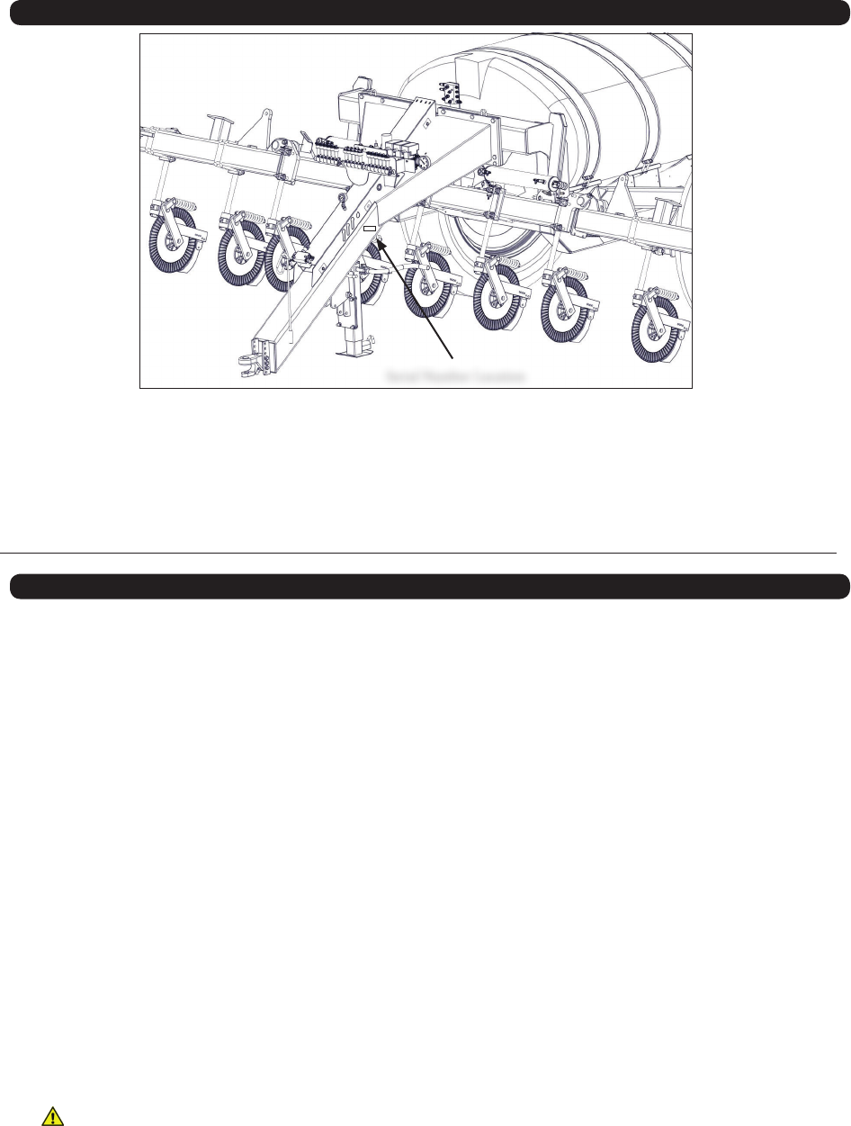
Serial Number
Serial Number Location
Serial Number________________
Model Number________________
Standard practice when ordering parts or obtaining information from your dealer requires the serial number and model number.
Have numbers available before making contact.
Dealer Set-Up
• Adjust wheels to desired width. (page 18)
• Move light brackets so that the amber light sticks out past the wheels.(page 18)
• Slide coulters down and reattach hoses
• Run water into the tank, turn pump on and check for leaks
• See set-up instructions in the ACE Pump Manual
• See set-up instructions in the ACE Pump Manual
• Turn on 3-section valves and check for ow to each row
• Inspect the unit for loose nuts, bolts, etc.
• Check all bearings and grease ttings for proper lubrication.
• Make sure that working parts move freely and function as intended.
• Check the hydraulic cylinders, hydraulic hoses, fertilizer ttings, and seals for leaks.
WARNING - Use cardboard or wood to check for leaks.
• Make sure that the lug nuts are tightened and all tires are inated properly.
• Check that all of the safety decals, reective decals, and the slow moving vehicle sign are properly
located.
• Make sure that all the lights function properly.

6
General Information
TO THE OWNER:
The purpose of this manual is to assist you in operating and maintaining your nitrogen applicator in a safe manner. Read it carefully.
It furnishes information and instructions that will help you achieve years of dependable performance and help maintain safe
operating conditions. If this machine is used by an employee or is loaned or rented, make certain that the operator(s), prior to
operating:
1. Is instructed in safe and proper use.
2. Reviews and understands the manual(s) pertaining to this machine.
Throughout this manual, the term IMPORTANT is used to indicate that failure to observe can cause damage to equipment. The
terms CAUTION, WARNING and DANGER are used in conjunction with the Safety-Alert Symbol (a triangle with an exclamation mark)
to indicate the degree of hazard for items of personal safety. When you see this symbol, carefully read the message that follows and
be alert to the possibility of personal injury or death.
This Safety-Alert symbol indicates a hazard and means ATTENTION!
BECOME ALERT! YOUR SAFETY IS INVOLVED!
Indicates an imminently hazardous situation that, if not avoided, will
result in death or serious injury.
Indicates a potentially hazardous situation that, if not avoided, will
result in death or serious injury, and includes hazards that are exposed
when guards are removed.
Indicates a potentially hazardous situation that, if not avoided, may
result in minor or moderate injury.
Indicates that failure to observe can cause damage to equipment.
Indicates helpful information.
DANGER
WARNING
CAUTION
IMPORTANT
NOTE
Note: The right and the left hand sides of the implement are determined by facing the same direction that the applicator
will travel when moving forward.
7
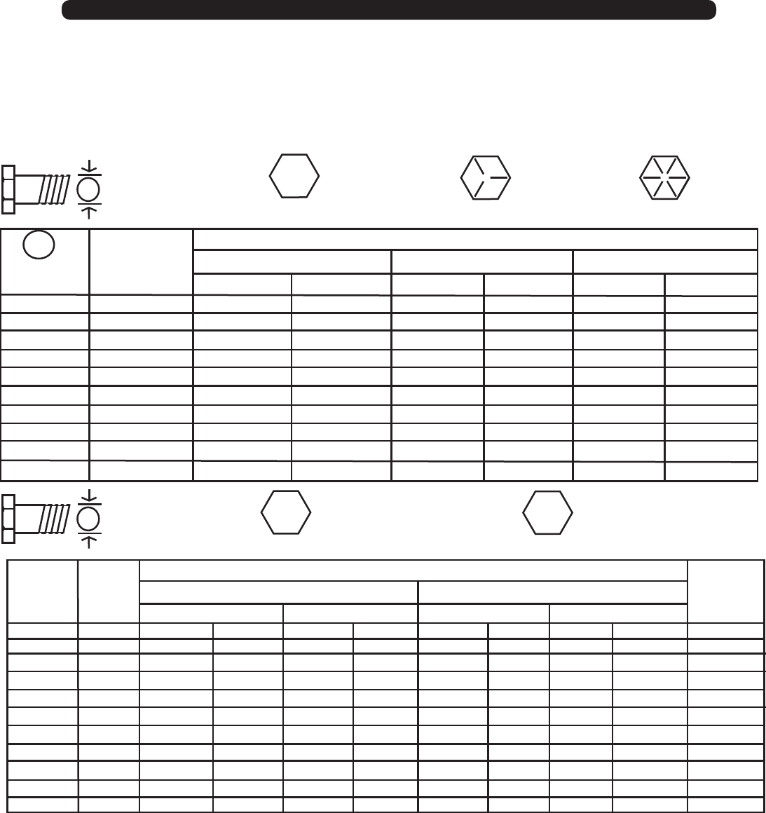
Bolt Torque Chart
Always tighten hardware to these values unless a dierent torque or tightening procedure is listed for specic application.
Fasteners must always be replaced with the same grade as specied in the manual parts list.
Always use the proper tool for tightening hardware: SAE for SAE hardware and Metric for Metric hardware.
Make sure fastener threads are clean and you start thread engagement properly.
All torque values are given to specications used on hardware dened by SAE J1701 & J1701M (JUL 96)
A
A
SAE SERIES
TORQUE
CHART
METRIC SERIES
TORQUE
CHART
10.9
8.8
Diameter
(Inches)
AWrench
Size
1/4
5/16
3/8
7/16
1/2
9/16
5/8
3/4
7/8
1
7/16”
1/2”
9/16”
5/8”
3/4”
13/16”
15/16”
1-1/8”
1-5/16”
1-1/2”
6
12
23
36
55
78
110
192
306
467
8
17
31
48
75
106
149
261
416
634
10
19
35
55
85
121
170
297
474
722
13
26
47
75
115
164
230
403
642
979
14
27
49
78
120
171
240
420
669
1020
18
37
67
106
163
232
325
569
907
1383
MARKING ON HEAD
SAE 2 SAE 5 SAE 8
LBS.-FT. LBS.-FT. LBS.-FT.N-m N-m N-m
Diameter
&
(Millimeters)
Thread Pitch
6 x 1.0
8 x 1.25
10 x 1.5
12.1.75
14 x 2.0
16 x 2.0
18 x 2.5
20 x 2.5
22 x 2.5
24 x 3.0
30 x 3.0
10 mm
13 mm
16 mm
18 mm
21 mm
24 mm
27 mm
30 mm
34 mm
36 mm
46 mm
8
20
39
68
109
169
234
330
451
571
1175
6
15
29
50
80
125
172
244
332
421
867
11
27
54
94
151
234
323
457
623
790
1626
8
20
40
70
111
173
239
337
460
583
1199
8
21
41
75
118
181
263
367
495
623
1258
6
16
30
55
87
133
194
270
365
459
928
11
29
57
103
163
250
363
507
684
861
1740
8
22
42
76
120
184
268
374
505
635
1283
6 x 1.0
8 x 1.0
10 x 1.25
12.1.25
14 x 1.5
16 x 1.5
18 x 1.5
20 x 1.5
22 x 1.5
24 x 2.0
30 x 2.0
Metric 10.9Metric 8.8Metric 8.8 Metric 10.9
MARKING ON THREADMARKING ON THREAD
COARSE THREAD FINE THREAD
Wrench
Size
Diameter
&
(Millimeters)
Thread Pitch
Metric Bolt Head
Identication
SAE Bolt Head
Identication
Metric
Grade 8.8
Metric
Grade 10.9
SAE Grade 2
(No Dashes)
SAE Grade 5
3 Radial Dashes
SAE Grade 8
6 Radial Dashes
TIGHTENING WHEEL NUTS
Standard 3/4” wheel bolts should be tightened to torque 500 Ft.-Lbs. During initial operation of the applicator and then checked
for proper torque after every 1 hour of use. Failure to do so may damage wheel nut seats. Once seats are damaged, it will become
impossible to keep nuts tight. The correct tire pressure for the 380-90R46 tire is 64 PSI.

8
Specications
SPECIFICATIONS
5000 Series Applicators
Tank Size 1,000 Gallon 1,600 Gallon
Base Width 30’-0” 40’-0”
Ground Clearance 34” 34”
Row Spacing* 20”, 30” 20”, 30”
Number of Coulters 11, 13, 15, 17, 23, 25 11, 13, 15, 17, 23, 25
Coulter Style Grove Engineered Products (GEP) Grove Engineered Products (GEP)
Fertilizer Delivery Knife or Injection Knife or Injection
Wing Flex Standard 8º Flex Up - 6º Flex Down
Can be operated rigidly
Standard 8º Flex Up - 6º Flex Down
Can be operated rigidly
Wing Kick Standard Standard
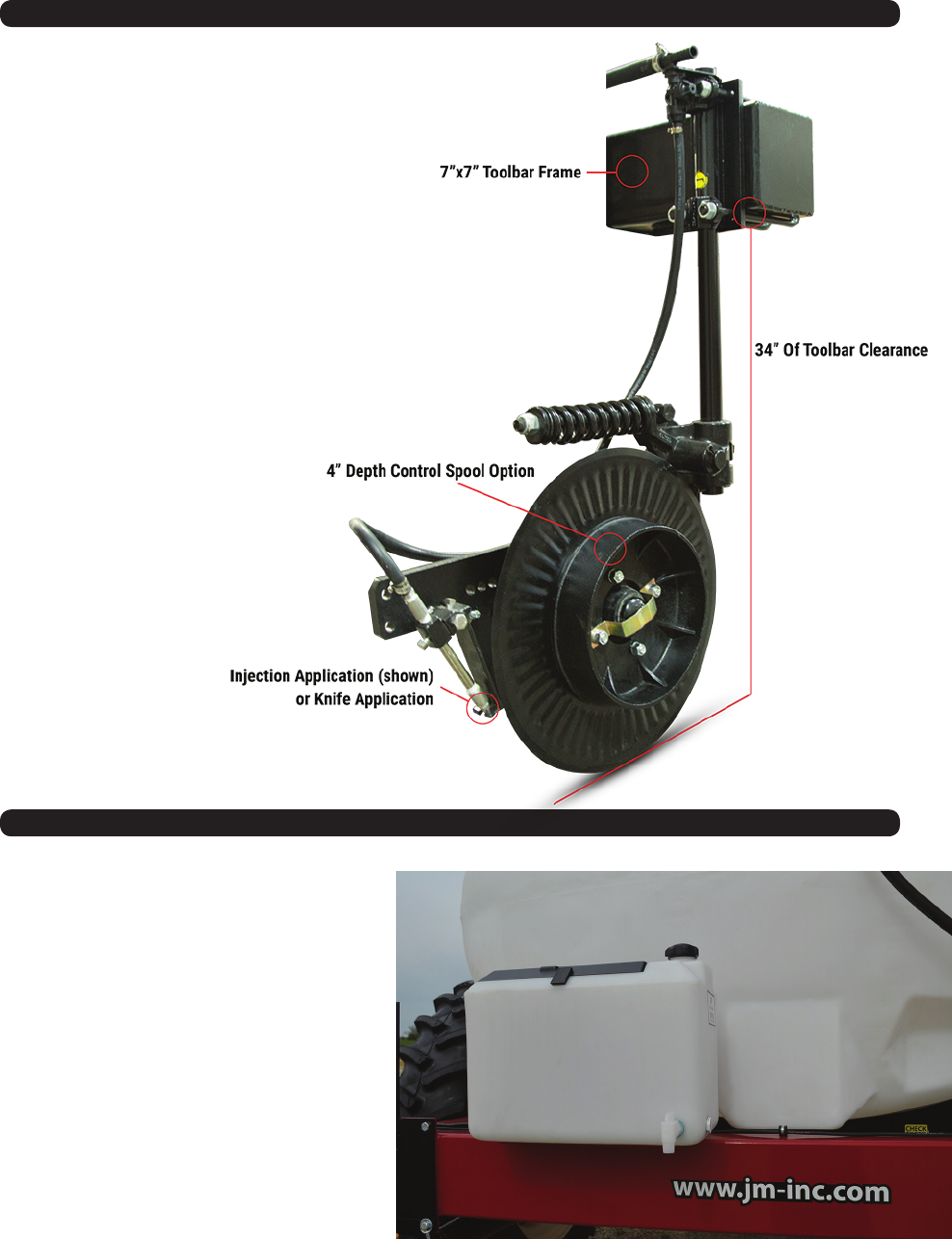
Coulter Frame Tubing 7” x 7” Toolbar 7” x 7” Toolbar
Hydraulic Down Pressure Standard Standard
Standard Hydraulic Driven Pump Ace Pump Ace Pump
Optional Ground Driven Pump John Blue John Blue
Wheels 46” w/IF380/90R46 Firestone Tires 46” w/IF380/90R46 Firestone Tires
Transport Width 15’-0” 15’-0”
Transport Height 12’-6” 12’-6”
Transport Length 16’-8” 20’-8”
Pin To Axle 12’-0” 14’-0”
Flow Monitors Optional Optional
Depth Control Spools Optional Optional
Quick Fill 2” Fill Standard - 3” Fill Optional 2” Fill Standard - 3” Fill Optional
Wash Tank Standard 9 Gallon Wash Tank Standard 9 Gallon Wash Tank
Empty Weight 10,500 lbs. 10,900 lbs.
Tongue Weight Empty 2,700 lbs. 2,800 lbs.
Tongue Weight Loaded 2,900 lbs. 3,000 lbs.
* Other Row Spacing Available Upon Request

9
Safety Rules
ATTENTION! BECOME ALERT! YOUR SAFETY IS INVOLVED!
Safety is a primary concern in the design and manufacture of our products. Unfortunately, our eorts to provide safe
equipment can be erased by an operator’s single careless act. In addition, hazard control and accident prevention are
dependent upon the awareness, concern, judgment, and proper training of personnel involved in the operation, trans-
port, maintenance and storage of equipment.
Make certain that the operator(s), prior to operating is instructed in safe and proper use and reviews and understands
the manual(s) pertaining to this machine.
Read this manual before you operate this machine. If you do not understand any part of this manual, or need more
information, contact the manufacturer or your authorized dealer.
SAFETY
Understand that your safety and the safety of other persons is measured by how you service, and operate this machine.
Know the positions and functions of all controls before you try to operate them. Make sure to check all controls in a safe
area before starting your work.
The safety information given in this manual does not replace safety codes, federal, state or local laws. Make certain your
machine has the proper equipment as designated by local laws and regulations.
A frequent cause of personal injury or death is from persons falling o equipment and being run over. Do not permit
persons to ride on this machine.
Travel speeds should be such that complete control and machine stability is maintained at all times. Where possible,
avoid operating near ditches, embankments and holes. Reduce speed when turning, crossing slopes and rough, slick
or muddy surfaces.
Collision of high speed road trac and slow moving machines can cause personal injury or death. On roads, use asher
lights according to local laws. Keep slow-moving-vehicle emblem visible. Pull over to let faster trac pass.
Keep all safety shields in place.
Keep hands, feet, hair and clothing away from moving parts while unit is in operation.
Make sure that everyone is clear of equipment before applying power or moving the machine.
Make sure that the implement is fastened securely to the tractor by using the proper hitch pin, clip and safety chains.
Do NOT exceed speeds in excess of 20 MPH. Also be sure slow moving vehicle emblem is attached to rear of transport.
Before unhooking the implement from the towing unit, be sure to properly block the wheels to prevent the imple-
ment from moving. Be sure the jack assembly is positioned in the park position and the weight has been transferred
to the jack assembly before unhooking the implement.
Avoid high pressure uids. Escaping uid under pressure can perpetrate the skin causing serious injury. Always
relieve pressure before disconnecting hydraulic lines. Wear proper hand and eye protection when searching for leaks.
Use wood or cardboard instead of hands. Keep all components in good repair.
10
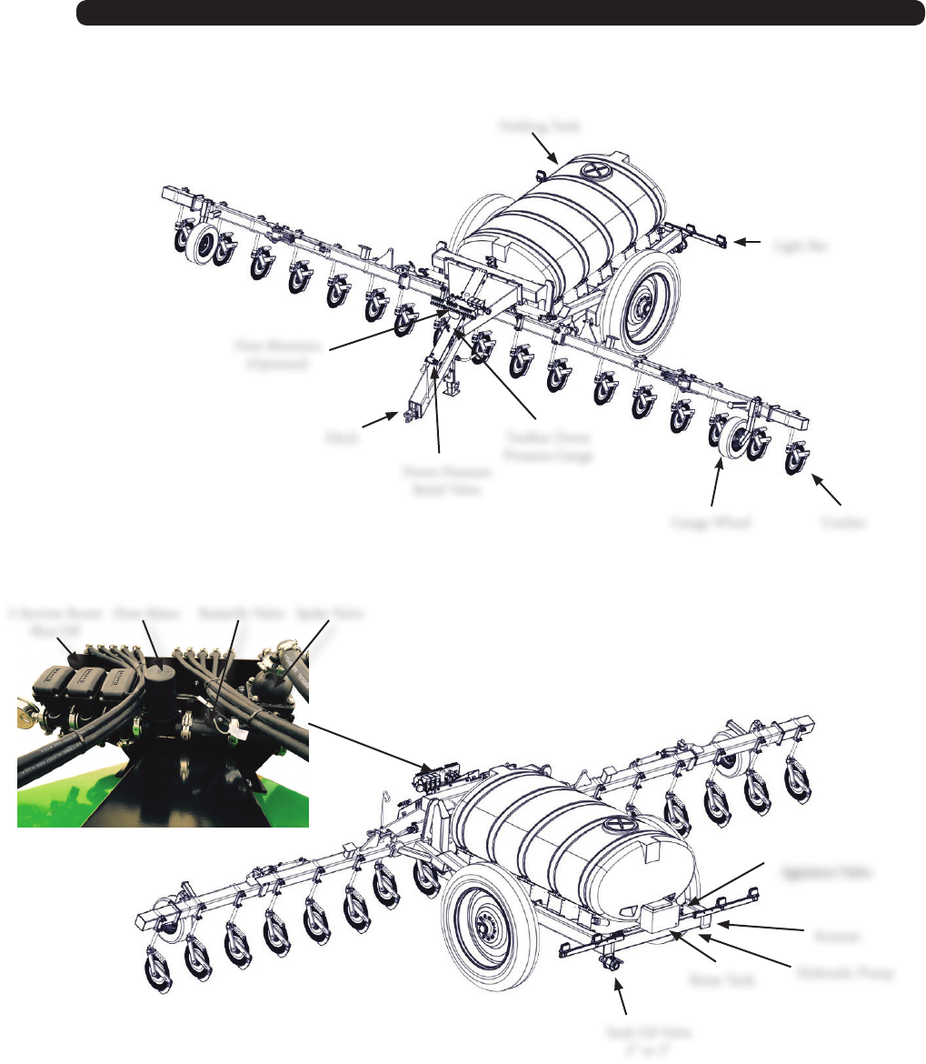
NitroGro Components
Hitch
Coulter
Holding Tank
Gauge Wheel
Rinse Tank
Light Bar
Tank Fill Valve
2” or 3”
Hydraulic Pump
Flow Monitors
(Optional)
Strainer
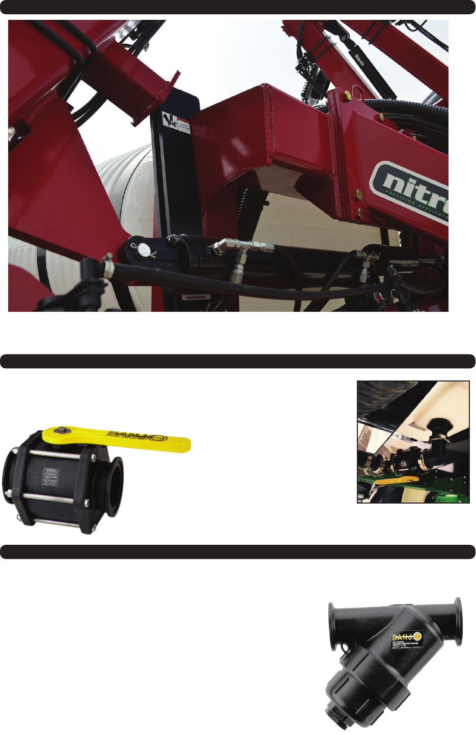
3-Section Boom
Shut O
Buttery ValveFlow Meter Spike Valve
Toolbar Down
Pressure Gauge
Down Pressure
Relief Valve
Agitation Valve
11
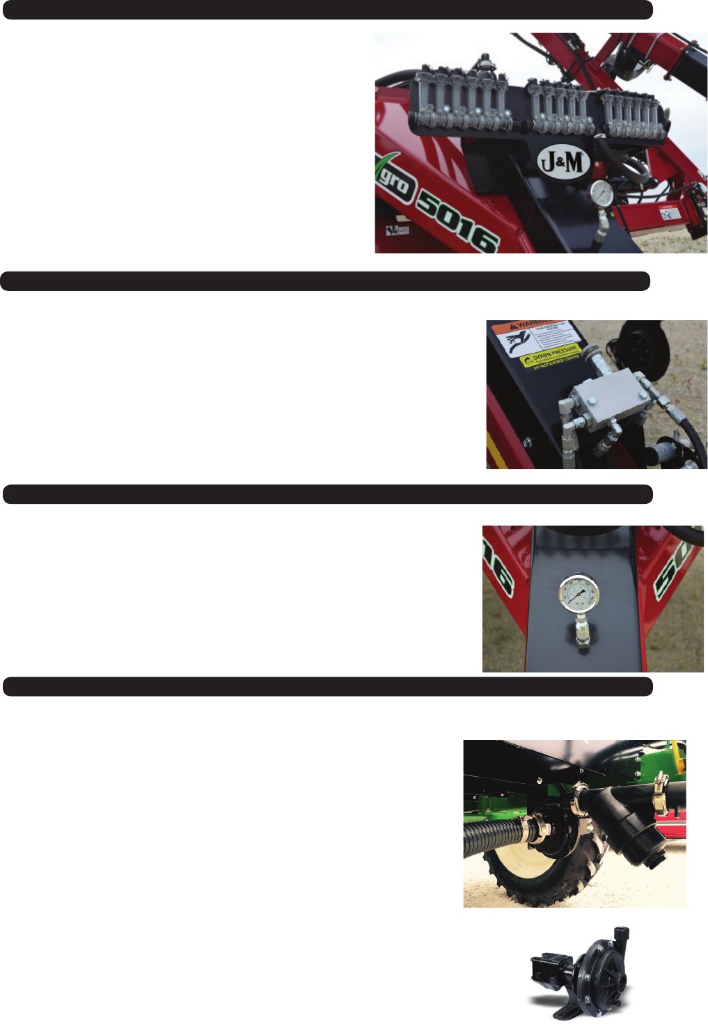
Flow Monitors
Optional Flow Monitors are available to allow the
operator to see the rate of ow to each coulter
through a oating ball located inside the transparent
inspection tube. Each coulter is connected with a
separate supply hose.
Down Pressure Relief Valve
Tool Bar Down Pressure Gauge
Hydraulic Pump
It is VERY IMPORTANT NOT TO EXCEED 1,350 PSI of pressure
on the Down Pressure Gauge. Doing so may cause damage to
the inner wing fold cylinders. (See the Toolbar Down Pressure
Gauge)
Counter Clockwise = Decreased Pressure
The Nitro-Gro Applicator is equipped with the Ace FMC-150-HYD-206
pump. This pump requires 7 GPM maximum hydraulic uid input.
The Hydraulic Pump is located at the rear of the unit below the
tank and near the tank outlet to provide faster pump priming and
prevent cavitation.
Turn the hydraulic ow of the tractor all the way down before you
put the hydraulic fertilizer pump into use. The applicator pump
only requires 7 GPM of hydraulic ow to make 120 GPM of
fertilizer ow. If you don’t turn down the tractor hydraulic ow
to the pump, damage will occur. (See Set-Up Instructions in the
pump manual.)
IMPORTANT - Do Not Exceed 7 Gallons Per Minute Max Hydraulic Fluid Input.
IMPORTANT - Do Not Exceed 1,350 PSI on the Down Pressure Gauge.
The Down Pressure Relief Valve provides adjustable
hydraulic pressure to force the coulters on the wings
into the ground while allowing the wing to ex up
and down as needed to follow the contour of the
ground.
Clockwise = Increased Pressure
12
Coulter
Hand Wash Tank
The number of coulters is determined by the
number of rows (usually one less or one more).
So the number of rows will be even, and the
number of coulters will be odd, since you are
placing the nitrogen between the rows. Example,
a 16 row unit will have either 15 or 17 coulters. A
16 row applicator with 15 coulters is considered
a “one-down” unit. Similarly, a 16 row applicator
with 17 coulters is considered a “one-up” unit.
Hand Wash Tank allows user to clean chemicals
spills from their hands quickly and easily.
13
Transport Latches
Shut-O & Fill Valve
Strainer
e Nitro-Gro Applicator is standard equipped with a 2” Shut-O and
Fill Valve. ere is an upgrade option for a 3” Shut-O and Fill Valve.
e 3” Valve will allow a quicker ll.
e Transport Latches are designed for safe transport. When the Transport Latches are resting on the
Main Frame and the pins are installed, the Nitro Gro Applicator can not lower.
e Nitro-Gro Applicator is standard equipped with a strainer designed
to remove dirt and debris from the fertilizer to prevent downstream
clogs.
14
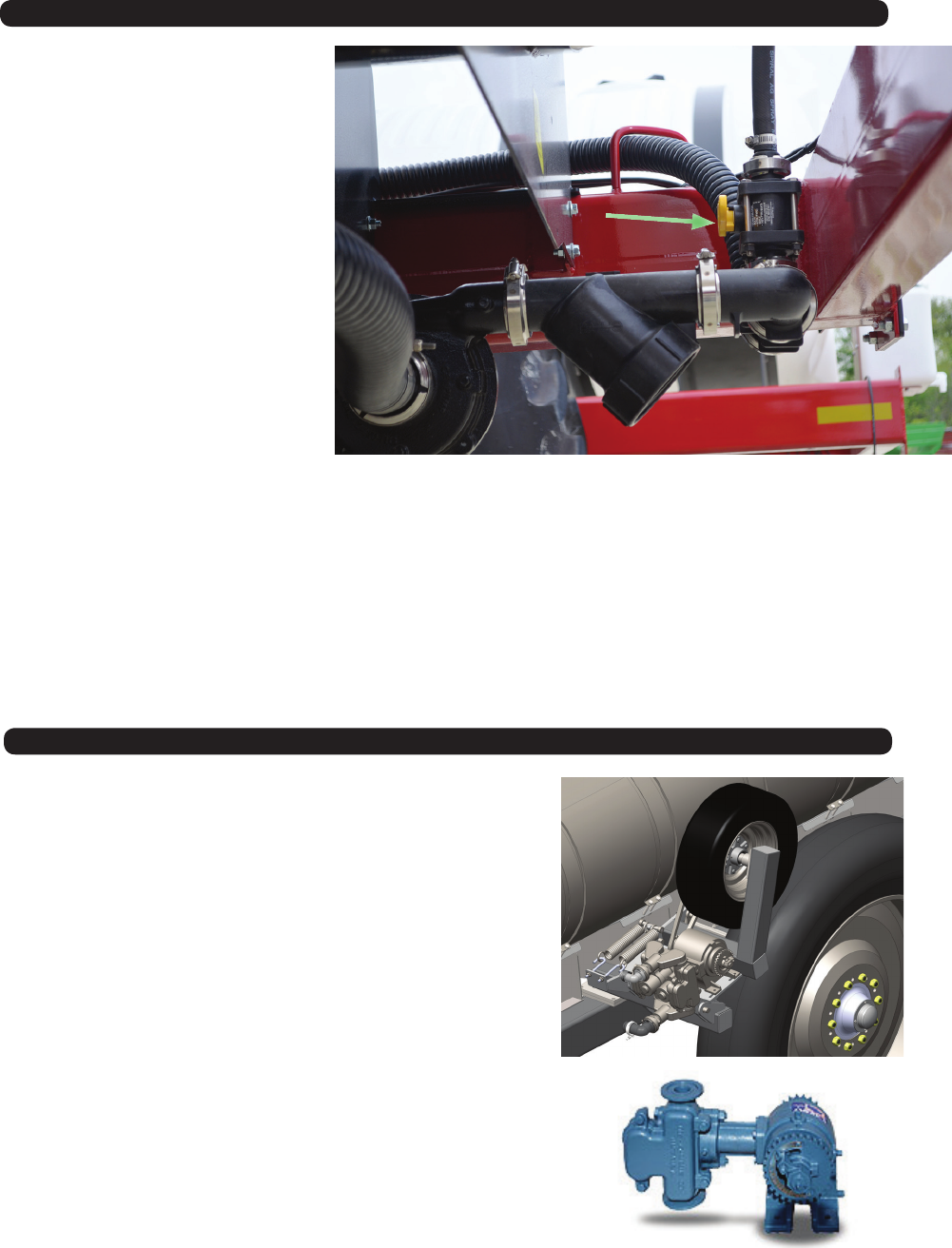
Optional Ground Drive Pump
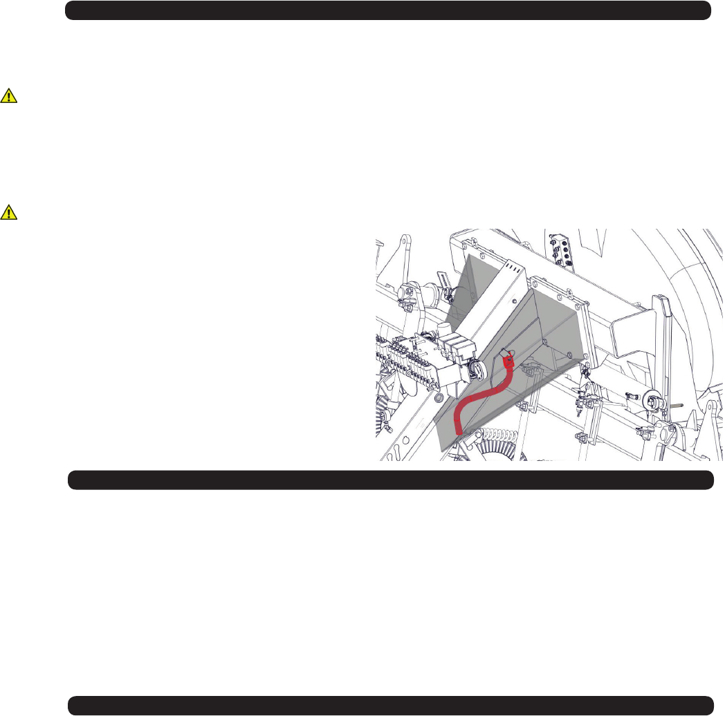
Agitation Valve (Hydraulic Pump Units Only)
e John-Blue Ground Drive pump comes in either single or
double piston conguration. It does not require any control
valves. e rate is controlled by an adjustment on the pump
and it naturally compensates for dierent speeds since it is
driven o of the main frame wheel.
e Agitation Valve is designed to allow
air to escape from the pump so it can
easily prime. When you’re running in the
eld, a little liquid runs through the
Agitation valve back to the tank. (You
will need to adjust the amount of
agitation.)
e Agitation Valve can also be used
to evenly mix additives by running the
pump with the electronic control valves
closed.

15
Pre-Operation Checklist
PREPARING THE NITRO-GRO APPLICATOR:
IMPORTANT - Before putting the applicator into operation, check the machine for damaged or worn parts and
replace as necessary.
Only use a tractor with sucient power and weight to operate the applicator.( For 16 Row 170 HP, 12 Row 130HP) Be
sure the applicator is properly attached to the tractor, the pin is properly secured, and (if equipped) the safety chain(s)
are properly installed. Inspect all safety decals for visibility and remove any debris.
Lights and SMV:
The SMV Emblem has to be positioned with a point of the triangle upward and as near to the rear and centered or as
near to the left of center of the unit as practicable. Also the SMV emblem needs to be located two to ten feet above the
ground measured from the lower edge of the emblem. Before transporting make sure that all of the lights, reectors and
the SMV emblem are clean and visible.
Hardware:
Make sure all hardware is properly fastened according to the Bolt Torque chart found in this manual. Recheck all
hardware for tightness after the unit has been operated for several hours. Check that all pins and retaining rings are in
good condition. Replace any pins or retaining rings that are worn, damaged or missing.
Hydraulic Hoses:
Check the hydraulic hoses to make sure they are not rubbing against sharp edges, are not kinked and not twisted.
Hoses should be secured to the applicator with nylon tie straps. Check hoses and ttings for hydraulic leaks. Tighten
or replace as necessary.
Lubrication:
Lubricate the Nitro-Gro applicator according to the Lubrication Schedule outlined in the SERVICE section of this
manual. (page 18)
Tires and Wheels:
Check the tire pressure in the transport tires and make sure the tire pressure is equal. The recommended tire pressure
is 64 PSI. Make sure the wheel lug nuts are tightened to 500 Ft. Lbs. Check the wheel lug nuts before initial operation
and after the unit has been operated for several hours to ensure the lug nuts remain tight. Make sure the pressure of
the Gauge Wheels is 45 PSI and the (optional) Ground Drive Pump Tire is 15PSI. Tighten the Gauge Wheel and Drive
Pump Tire lug nuts to 121 Ft.Lbs.
Filling the tank:
Make sure the area is clear of bystanders when lling the tank. Always wear protective clothing, gloves, and masks
when handling fertilizer/chemicals. Follow the fertilizer/chemical manufacturers instructions exactly when lling the
tank. Keep the lid on at all time to keep debris out of the tank.
Fertilizer Pump:
Raise the toolbar with wings unfolded and turn on the fertilizer pump. Check that there is liquid coming out of each
injector. Clean injectors if necessary. Replace injectors accordingly. (If equipped with Ground Driven Pump, raise
coulters out of the ground and spin the drive wheel by hand.)
Unfolding the Wings:
It is recommended unfolding the side wings in the eld. Keep all bystanders away while unfolding the wings.
16
Connect the applicator to the tow vehicle using a hitch pin and make sure a retaining pin is secured in the hitch pin.
Always attach the safety chains to the applicator and the tow vehicle.
WARNING – Before unhooking the applicator, unpin the jack from storage poision, and lock it in the usage
postion lower the jack stand to the ground until weight of the applicator is transferred to the jack. Keep hands
and feet away from the jack stand when lowering.
Remove the Hitch Pin and unhook the safety chains.
WARNING – Always relieve hydraulic system pressure before disconnecting hoses from tractor or servicing
hydraulic system. See the tractor’s operators manual for proper procedures. Disconnect the hydraulic hoses.
Install dust covers over the hose plugs and outlets.
When not in use the jack handle
is stored under the tongue.
Connect the hoses so that the toolbar raises when the tractor control lever is pulled back and lowered when
the control is pushed forward.
Hook up hydraulic lines.
Set #1 - Green Hoses - Raise & Lower/ Wing Kick/ Down-pressure
Set#2 Red Hoses -Wing Fold
Set#3 - Black Hoses - Hydraulic Pump (Hook the return hose to low pressure return port at the tractor)
Transporting
Comply with ALL state and local laws governing highway safety and regulations when moving machinery on public
roads. Be sure an SMV (Slow Moving Vehicle) emblem is in place and clearly visible on the rear of the applicator. The
SMV Emblem has to be positioned with a point of the triangle upward and as near to the rear and centered or as near to
the left of center of the unit as practicable. Also the SMV emblem needs to be located two to ten feet above the ground
measured from the lower edge of the emblem. Make sure all lights are clearly visible and working properly BEFORE
highway travel. Be sure the amber, red and orange retro-reective tape on the implement is in place and clearly visible.
The transport speed should not exceed 10 MPH in the eld or over rough terrain. Highway transportation speed should
not exceed 20 MPH Reduce transport speed when necessary to maintain full control of the implement at all times.
The ground drive pump transport lock should be in place before transporting the Nitro-Gro.
The toolbar transport locks should have the locking pins in place before transport.
Connecting the Hydraulic Hoses
Hitching and Unhitching the Applicator

17
Fertilizer Pump
Your Nitro-Gro Applicator is equipped with the Ace FMC-150-HYD-206 pump.
Note: Refer to the pump’s owners manual to regulate the hydraulic ow to the pump.
Attach the pump hydraulic hoses to the tractor so the pump operates in the lower/retract position. The pump can
then be turned o in the forward ”oat” position. Turning the pump o in “oat” instead of “neutral” allows the hy-
draulic system pressure to equalize and prevents the occurrence of damaging pressure spikes.
The return line should be connected to a low pressure return port if available. The low pressure return port routes
oil directly to the reservoir minimizing return line pressure. Low return line pressure extends the motor seal life and
increases operating eciency.
WARNING- Failure to regulate oil ow will cause motor failure.
Note: Refer to the pump’s owners manual to locate your tractor model and follow the appropriate setup instruc-
tions.
WARNING- Not a suitable pump for ammable liquids.
Adjusting the Field Depth
Folding & Unfolding
• Raise the toolbar to take the weight o of the transport latches and unpin the transport latch/wing
• Unfold the wing assemblies. On 40ft units, one cylinder will unfold the inner wing section and another cylinder
will unfold the outer wing section. The inner wing will automatically fold to the wing “kick-up” position, then
unfold the outer wing section until it is in alignment with the inner wing section
• (Pre 2017 Models) After the outside wing is unfolded, to lower the center toolbar to the ground. The center
section will lower rst until the toolbar raise/lower cylinders reach the cylinders stops which sets your depth. As
soon as the cylinder stops against the cylinder spacers, pressure will build and allow the wing kick cylinder to fold
the winds down parallel with the center section.
• (2017 & Newer) After the outside wing is unfolded, lower the toolbar to the ground, adjust the ow control on the
down pressure cylinder so the wing coulters come into contact with the ground at the same time as the center
coulters.
• When you raise the unit up, the entire toolbar raises up until the toolbar raise/lower cylinders are fully extended,
then the wings will start to fold to the kick-up wing position.
• Once the wings are in the kick-up position the outside wing section can be folded against the inside wing section.
After the inside and outside wing sections are folded together, the wings can continue to be folded until the
transport Latch/Wing Rest is engaged against the center base weldment.
• Slightly lower the toolbar to allow weight to the Transport Latches/ Wing Rest. (Note: If you lower the toolbar too
far the wing -kick cylinder will begin to extend and the wings will begin to unfold.)
18
Down Pressure
• Set the down pressure just high enough to keep the gauge wheels in contact with the ground. Excessive pressure
can cause premature wear on wing pivots and gauge wheels.
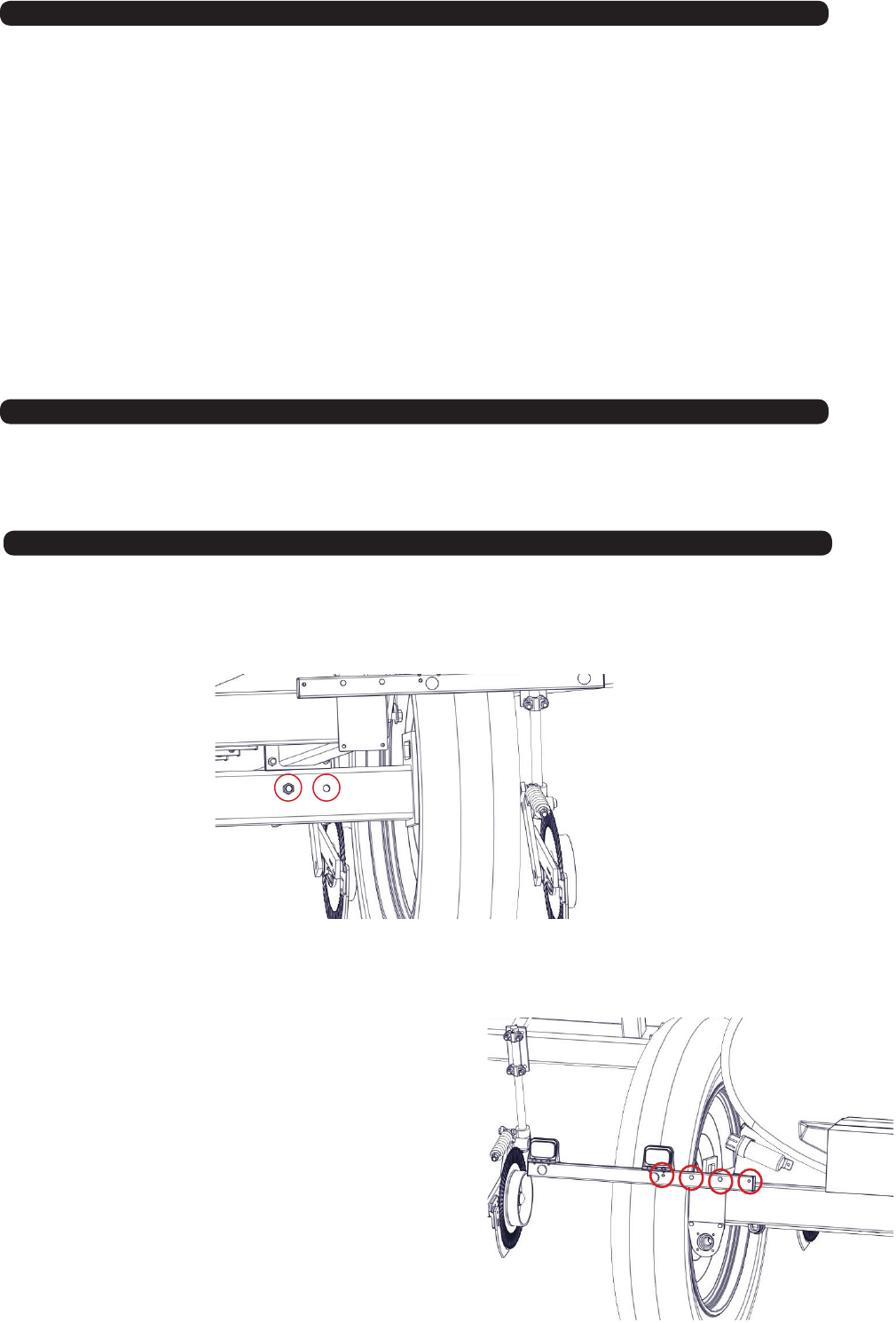
Wheel Spacing
• To set up the Applicator for 20” or 30” rows use the inside hole. This will set the wheel spacing at 120”.
• To set up the Applicator for 22” rows use the outside hole. This will set the wheel spacing at 132”.
• The center section of coulters should be set rst. The Toolbar Cylinders have spacers included. Add or remove
spacers until the center section is positioned at the appropriate depth. Lower the unit until the lift cylinders bottom
out on the stroke control spacers. Add or remove stroke control spacers until the center toolbar section reaches desired
application depth. It is a good idea to be moving forward when lowering the toolbar. When the center section of
the toolbar is set to proper depth.
• After the toolbar is set with the cylinder spacers, adjust the wing gauge wheel setting until the wings are level
with the base section and the entire toolbar is at and even. Once the toolbar is set and leveled, further adjust-
ment is typically not necessary.
Adjusting the Feild
When shipped the light bar will be attached using holes A and B. The light bracket needs to be positioned so that the
Amber light is out past the wheel.
NOTE - When changing the wheel spacing it may be necessary to move the Light Brackets so the Amber
Light is out past the wheel.
• For 20” and 30” row spacing use holes B and C.
• For 22” rows use holes C and D.
AB C D

19
1) Hook tractor to Nitro-Gro and adjust hitch so that frame
on applicator is level or tilting back slightly.
2) Hook up hydraulic lines.
Set #1 - Green Hoses - Raise & Lower/ Wing Kick/ Down-pressure
Set#2 - Red Hoses - Wing Fold
Set#3 - Black Hoses - Hydraulic Pump
IMPORTANT - For the black hoses hook the return hose to a
low pressure return port at the tractor.
3) Raise the unit to relieve pressure on
transport latches and wing rests. Remove transport
latch pins and place in storage holes next to the
lock holes.
4) Unfold the unit.
Spacers
Li Cylinder
3) Lower the unit until the lift cylinders bottom out on the stroke control spacers. Add or remove
stroke control spacers until the center toolbar section reaches desired application depth. It is
a good idea to be moving forward when lowering the toolbar.
6) Adjust the wing Gauge wheels so that the coulters on the wings are at the same depth and
the toolbar is level when lowered.
5) Using the desired rate of application (GPA) and speed of application (MPH), use the supplied
orice sizing chart on pages 50-51of this manual to determine which orices will provide
optimal application pressure. Install the orices in the check valve unit above each row unit
that is mounted on the coulter shaft.
NOTE – The unit will be either be set up to skip a row, “One Down”, or re-apply the
outside row,”One Up”.
-If the unit is set up as “One Down” (11 or 15 coulters) then the outside coulters on
each end of the unit will need to be 1.5x rate of the other coulters.
-If the unit is set up as “One Up” (13 or 17 coutlers) then the outside coulters on
each end of the unit will need to be 0.5x rate of the other coulters.
7) Put some water in the tank and check for leaks.
IMPORTANT - Before proceeding to the next step make sure that the valve is open to the pump. NEVER
run the pump dry.
6) With the valve to the pump open perform the initial setup of the pump as outlined in the pump owners manual.
After the pump is set up recheck the applicator for leaks.
7) In-eld adjustment of hydraulic down-pressure: Adjust so that the coulters are staying at desired depth with the
least amount of hydraulic pressure necessary.
IMPORTANT - DO NOT exceed 1,350 PSI.
8) Adjust tractor hydraulic ow on the Raise and Lower/Wing Kick/Down-pressure circuit as low as possible while
maintaining a reasonable toolbar raise and lower speed. This will help prevent creating excess heat in the hydraulic
system as this circuit provides continuous toolbar down-pressure.
9) Fold the wings up for transport.
IMPORTANT - Be sure to have the toolbar fully raised before folding the wings up! Failure to do so will
result in damage to the unit.
Operation
Orice
20
Initial Console Programming
HINT: If you enter the wrong value when entering your data press “ENTER” then press “ENTER” again and re-enter your value again.
• Select the unit of measure by pressing the CE button until the desired until of measure appears in the display and press “ENTER”
NOTE - The unit of measure for the United States is Volume per Acre.
• Select the type of sensor being used (SP2) by pressing the CE button until the desired sensor type appears in the display and
press “ENTER”
• The message “CAL C-SD STANDARD VALVE” will appear in the console’s display. Press “ENTER”
• The message “CAL SELF TEST 00” will appear in the console’s display. Press the BOOM CAL 1 button and enter the value shown
in the table. To store the values press “ENTER” (the enter button will light up) input the value and then press “ENTER”. Your
value is now stored. Repeat for Boom 2 and 3. Use the arrow keys to advance to the remaining booms.
• Press the “SPEED CAL” button and input the appropriate speed cal. value for the type of sensor being used and press “ENTER”
NOTE - For the PHOENIX 10 the speed cal. is 785.
• Press the “METER CAL” button and enter the meter cal. value stamped on the ow meter’s identication tag.
NOTE - The meter cal. value is 720 gallons.
• Press the “VALVE CAL” button and input the calibration number that corresponds with the control valve being used and press “ENTER”.
NOTE - For this unit the valve cal. is 2123.
• Press the “RATE 1 CAL” button and “ENTER” the Rate 1 value. Refer to the “Calculate the Rate 1 and Rate 2 Cal Values” section of
the Raven SCS 440 manual and press “ENTER”.
• Press the “RATE 2 CAL” button and “ENTER” the Rate 2 value. Refer to the “Calculate the Rate 1 and Rate 2 Cal Values” section of
the Raven SCS 440 manual and press “ENTER”.
• The initial console programming is now complete, and the ashing “CAL” in the console’s display should turn o. If it does not,
repeat the procedure starting from the rst step above.
• These settings will be stored and the previous steps do not need to be repeated after powering OFF/ON.
RESET: If an entry or selection error is made during any steps of this procedure, turn the POWER switch to the OFF position, press
CE and hold while turning the POWER switch to the ON position to reset the console.
HINT: If you enter the wrong value when entering your data press “ENTER” then press “ENTER” again and re-enter your value again.
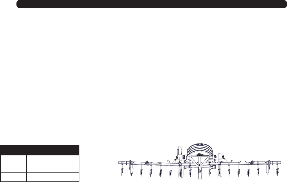
Boom 3
Boom 2
Boom 1
Boom # 12 Row 16 Row
Boom 1 105 165
Boom 2 150 150
Boom 3 105 165
Quick Start For The Raven 440 Coutroller With Phoenix 10 GPS

21
Break In Period
First 30 minutes of operation:
1. Check that all coulters and nozzles are clean and working properly. Clean and adjust accordingly.
2. Check all hydraulic and chemical lines. Be sure none of them are kinked, pinched or leaking. Adjust lines accordingly.
3. Re-torque all of the wheel bolts.
4. Check all other fasteners and hardware. Adjust accordingly.
5. Lubricate all grease ttings.
After 4 hours of operation:
1. Check that all coulters and nozzles are clean and working properly. Clean and adjust accordingly.
2. Check all hydraulic and chemical lines. Be sure none of them are kinked, pinched or leaking. Adjust lines accordingly.
3. Re-torque all of the wheel bolts.
4. Check all other fasteners and hardware. Adjust accordingly.
After 10 hours of operation:
1. Check that all coulters and nozzles are clean and working properly. Clean and adjust accordingly.
2. Check all hydraulic and chemical lines. Be sure none of them are kinked, pinched or leaking. Adjust lines accordingly.
3. Re-torque all of the wheel bolts.
4. Check all other fasteners and hardware. Adjust accordingly.
After the 10 hours of operation break in period check, begin the standard maintenance schedule as described in the
service section of this manual.

22
Troubleshooting
WARNING - MAKE SURE THAT ALL POWER IS SHUT OFF BEFORE SERVICING THE APPLICATOR. MAINTENANCE AND REPAIR
SERVICE WORK TO BE PERFORMED BY QUALIFIED SERVICEMEN ONLY.
Trouble... Possible Cause... Possible Remedy...
Wings only partially unfold • Actuating raise/lower remote
instead of fold/unfold remote
• Use fold/unfold remote
Toolbar will not lower • Transport latch pins still in
transport position
• Pressure still on transport
latches
• Remove and place eld use position
• Raise toolbar to relieve pressure on
transport latches before lowering
Toolbar will not raise or lower
Wings will not fold out or unfold
• Faulty hydraulic coupler • Replace with new coupler
• Lift cylinders have improper
combination of cylinder spacers
• Add or remove spacers as
necessary
Wings are tilted up from center
toolbar section
• Gauge wheels set too low
• Hydraulic down pressure not set
high enough
• Center toolbar section set too
deep
• Move gauge wheels up
• Increase pressure be fore turning
adjustment knob clockwise
• Add cylinder spacers to lift
cylinders
Wings are tilted down from center
toolbar section
• Gauge wheels set too high
• Center toolbar section set too
shallow
• Move gauge wheels down
• Remove cylinder spacers from lift
cylinders
Center toolbar section too deep or
too shallow
Fertilizer pressure gauge showing
high pressure when applying fertilizer
• Install larger orices
• Clear debris
• Adjust hoses as necessary
• Slow down
• Orices too small
• Plugged knives
• Kinked hoses
• Speed too fast
Unable to maintain set application
rate
• Clogged Strainer
• Orices too small
• Agitation valve too far open
• Clean strainer
• Install larger orices
• Adjust valve as necessary
Hydraulic pump will not prime • Tank valve clogged
• Agitation valve closed • Unclog valve
• Open valve
*Refer to the ACE hydraulic pump manual, raven controller manual, and CDS-John Blue pump manual for additional
trouble shooting information.

23
To prolong the life of your Nitro-Gro applicator, perform the following on a regular basis:
1. Grease coulter hubs, 2 pumps every 50 hours.
2. Check lighting before over the road transport. Make sure lights and SMV emblem are clean from dirt and eld debris.
3. Check implement for damage, cracked welds, loosened hardware, etc. After the unit is repaired promptly repaint
to prevent further damage.
4. Check hydraulic system for leaks and hose damage, twists or kinks and repair as needed.
5. Check fertilizer handling system for leaks and hose damage, twists or kinks and repair as needed.
6. Check tire pressures and lug nuts periodically and adjust as required.
7. Grease Wheel Hubs.
8. Grease jack.
To prolong the life of your Nitro-Gro applicator, perform the following before placing the implement in storage:
1. Remove dirt and debris that may cause rusting.
2. Repaint any areas where the paint has been chipped, scratched or worn away.
3. Coat all earth moving surfaces with a suitable rust preventative.
4. Inspect for damaged or worn parts and replace before next use.
5. Lubricate coulter hubs.
6. Replace all worn, torn and faded decals and reectors.
7. Store the implement inside away from inclement weather.
8. Flush all fertilizer from the system.
9. Cover Flow Monitors from the sunlight. If the Flow Monitors are exposed to the sun for a long period of time
they will turn cloudy and hard to see through.
10. To winterize your Nitro-Gro you need to drain the tank and all fertilizer hoses. Once the system is drained
add Marine RV Anti Freeze. Run the Anti Freeze thru the strainer, valves, check valves, and the orices.
Service
Storage

24
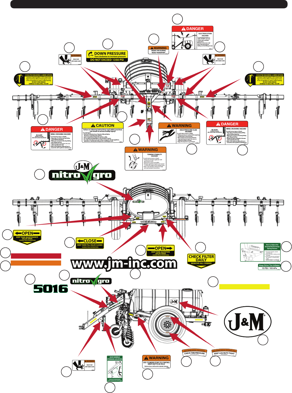
Safety SIgns
ATTENTION! BECOME ALERT! YOUR SAFETY IS INVOLVED!
Replace Immediately If Damaged or Missing
# Description: Decals Part. No.
1 Grease Decal JM0015104
2 Warning - Pinch Point JM0014994
3 Down Pressure Decal JM0035892
4 Warning - Insert Pin Be For Road Transport JM0038103
5 Danger - Electrocution Hazard JM0035887
6 Caution - Observe Instructions JM0035881
7 Danger - Crushing Hazard JM0035883
8 J&M Oval JM0038110
9 Warning - Towing Stability JM0035882
10 Warning - High Pressure Fluid JM0035880
11 NitrGro with J&M Decal JM0039474
12 Open Tank Maintenance Valve JM0039478
13 Close Tank Fill Valve JM0035891
14 Open Agitation Valve JM0039479
15 Check Filter Daily JM0035884
16 Ground Drive Adjustment JM0038102
17 Ground Drive Tire Pressure JM0038101
18 2.0 x 9.0 Red Reective Strip JM0009945
19 2.0 x 9.0 Fluorescent Orange Strip JM0009944
20 Nitrgro Logo5010L JM0038114
20 Nitrogro Logo5010R JM0038116
20 Nitrogro Logo5016L JM0038117
20 Nitrogro Logo5016R JM0038118
21 NitroGro Decal JM0039473
22 J&M Website JM0038108
23 2.0 x 9.0 Reective Amber Strip JM0009946
24 Jack Handle Storage JM0038105
25 Warning - Cylinder Stops JM0035890
26 Check Tire Pressure JM0038097
27 Tighten Lug Nuts JM0035885
25
Safety Signs
1
234
5
7
9
10
11
12
13
14 15 16
17
18
19
20
2
1
8
7
21 22
23
24
25
26 27
2
6
26
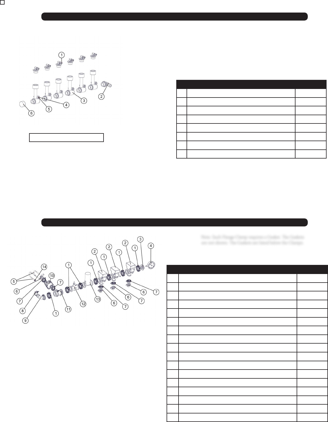
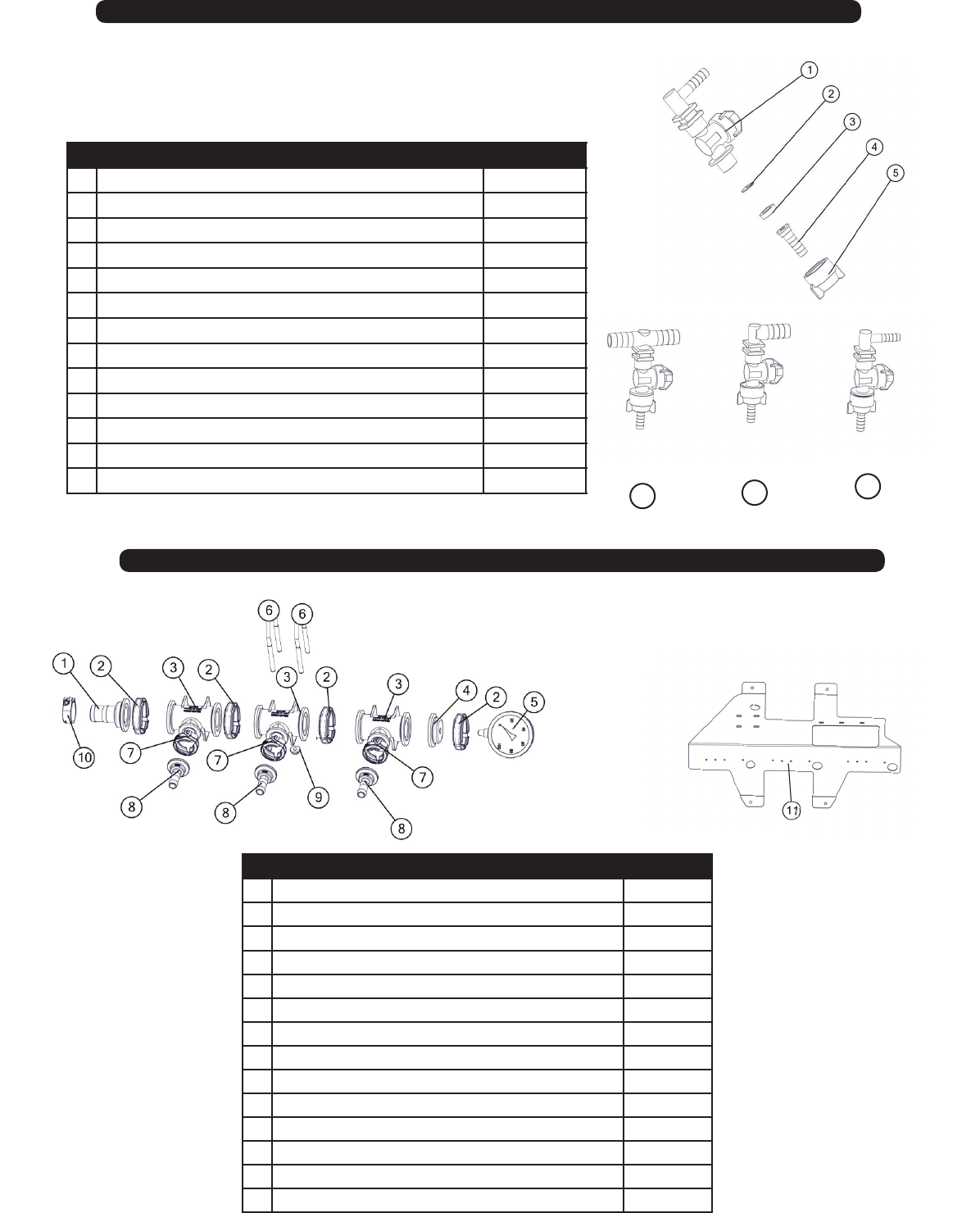
# Description Part. No.
1 20511-00 O-Ring x .38in Hose Barb 90 Deg JM0024469
1 3/8 Hose Clamp (Not Shown) JM0039206
2 20513-00 O-Ring x .75in Hose Barb 90 Deg JM0024468
2 3/4 Hose Clamp (Not Shown) JM0039205
3 20460-00 Flow Indicator JM0021569
4 1/4”-20 Gr5 Z Centerlock Hex Nut JM0001505
5 1/4”-20 x 2” Gr5 Z Hex Bolt JM0001591
6 20521-00 O-Ring Cap - Flow Indicator JM0021579
# Description Part. No.
1 2" Manifold Flange Clamp JM0035251
1 2” Manifold Gasket (Not Shown) JM0021145
2 Raven Boom Valve JM0032478
3 Banjo 2" Manifold Plug With 1/4" NPT for Gauge JM0021147
4 Pressure Gauge Stainless Steel 0-100psi, 4" JM0036636
5 3/8” Round U-Bolt 2” Pipe Size Extended JM0018627
6 1" Flange x 90 deg. 3/4" Hose Barb JM0032501
6 3/4 Hose Clamp (Not Shown) JM0039205
7 1" Manifold Flange Clamp JM0032496
7 1” Manifold Gasket (Not Shown) JM0035239
8 Hose Clamp - 1 1/2” Hose JM0021189
9 2" Manifold Flange x 90 deg. 1-1/2" Hose Barb JM0034352
10 100psi Spike Valve With 1" Manifold Flanges JM0032499
11 2" Manifold Tee X 1" Manifold JM0035116
12 Raven Flow Meter RFM60P JM0032488
13 Raven Control Valve JM0032490
14 3/8 -16 Gr5 Z SF Hex Nut JM0002152
5000 Flow Monitor
5000 Manifold (Hydraulic Pump Only)
Note: Each Flange Clamp requires a Gasket. e Gaskets
are not shown. e Gaskets are listed below the Clamps.
6 Row Flow Indicator Manifold
*Same parts for the 3,4, 5 Row
Flow Indicator Manifold
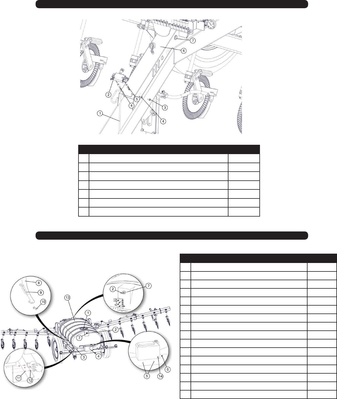
27
# Description Part. No.
1 1/2" Hose Holder JM0027120
2 3/8"-16 x 4" Gr5 Z Hex Bolt JM0002098
3 3/8”-16 x 1” Gr5 Z SF Hex Bolt JM0002092
4 3/8"-16 Gr5 Z Centerlock Hex Nut JM0001512
5 3/4 DIA x .385 x 2.0 JM0002444
6 Hose Shroud - Tongue JM0034836
7 1 1/2 ID x 0.188 GW x 1 3/4 GD Grommet JM0016924
# Description Part. No.
1 16in Fertilizer Tank Lid With Vent JM0037949
2 3/4" Hose Barb X 3/4 Male NPT 90 Deg(Hyd Pump) JM0035226
2 3/4” Hose Clamp (Not Shown) JM0039205
3 Manual Canister JM0010115
4 9 Gallon Safety/Fresh Water Tank JM0030587
5 1/4”-20 x 1/2” Gr5 Z Hex Bolt JM0001481
6 3/4” NPT PVC readed Plug Schedule 40 JM0037251
7 3/4” NPT Bulkhead Tank Flange ASM(Hyd Pump) JM0035222
8 Band For Elliptical Norwesco Tank JM0030208
9 1/2”-13 X 4.5 Gr5 Z Hex Bolt JM0008548
10 1/2”-13 Gr5 Z Centerlock Hex Nut JM0001511
11 1/4”-20 Gr5 Z SF Hex Nut JM0001630
12 1/4”-20 x 3/4” Gr5 Z Hex Bolt JM0001507
13 Norwesco Elliptical Tank 1,000 Gallon JM0027371
13 Norwesco Elliptical Tank 1,600 Gallon With Sump JM0027372
14 Drum Faucet - 3/4” NPT JM0039066
5000 Pressure Gauge & Shoud
5000 Tank
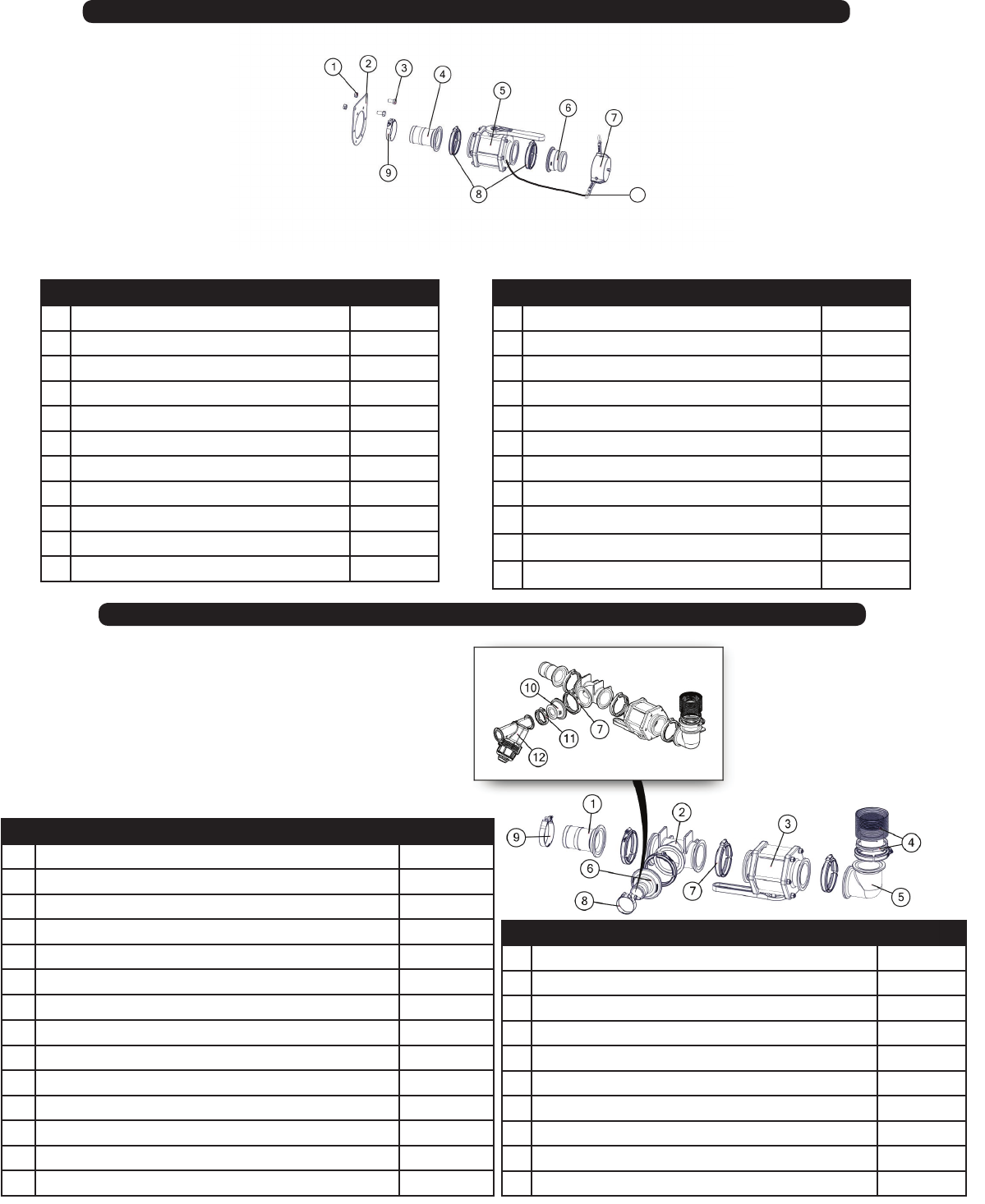
28
# Description (3” Quick Fill) Part. No.
1 1/2"-13 Gr5 Z Centerlock Hex Nut JM0001511
2 Ball Valve Mount Plate 3" Banjo JM0034894
3 1/2-20 x 1 Gr5 Z Hex Bolt JM0028442
4 3" Manifold Flange to 3" Hose Barb JM0021244
5 Ball Valve - 3" Full Port Flange Manifold JM0021230
6 3" Manifold Flange x 3" QDC Male JM0035205
7 3" Poly Cam Lever Cap JM0035206
8 3” Manifold Flange Clamp JM0035237
8 3” Manifold Gasket(Not Shown) JM0021239
9 T-Bolt Hose Clamp 3” Hose JM0035248
10 Lanyard JM0039282
# Description (3” Quick Fill) Part. No.
1 3" Manifold Flange to 3" Hose Barb JM0021244
2 Manifold Tee - 3" JM0021232
3 Ball Valve - 3" Full Port Flange Manifold JM0021230
4 3" x 3" Manifold EPDM Flange Bulkhead Fitting JM0035114
5 90 Deg Coupling, 3" Manifold Flange JM0033979
6 3" Manifold Flange x 2" Hose Barb JM0034333
7 3” Manifold Flange Clamp JM0035237
7 3” Manifold Gasket(Not Shown) JM0021239
8 T-Bolt Hose Clamp 2” Hose JM0035247
9 T-Bolt Hose Clamp 3” Hose JM0035248
10 3” Manifold X 2” Manifold Flange Reducer Coupling JM0035130
11 2”FP Manifold Flange Clamp JM0035251
11 2”FP Manifold Gasket(Not Shown) JM0021145
12 Manifold Y Strainer - 2” Flange, 30 Mesh JM0033803
5000 Fill Valve 2” & 3”
5000 Tank Fittings for 2” & 3”
# Description (2” Quick Fill) Part. No.
1 1/2"-13 Gr5 Z Centerlock Hex Nut JM0001511
2 Ball Valve Mount Plate 2"FP Banjo JM0034889
3 1/2-20 x 1 Gr5 Z Hex Bolt JM0028442
4 2"FP Manifold Flange to 2" Hose Barb JM0033796
5 Ball Valve - 2"FP Flange Manifold JM0031370
6 2"FP Manifold Flange x 2" QDC Male JM0035249
7 2" Poly Cam Lever Cap JM0035250
8 2”FP Manifold Flange Clamp JM0035251
8 2”FP Manifold Gasket(Not Shown) JM0021145
9 T-Bolt Hose Clamp 2” Hose JM0035247
10 Lanyard JM0039282
# Description (2” Quick Fill) Part. No.
1 2"FP Manifold Flange to 2" Hose Barb JM0033796
2 Manifold Tee - 2"FP JM0033797
3 Ball Valve - 2"FP Flange Manifold JM0031370
42" x 2"FP Manifold EPDM Flange Bulkhead Fitting JM0033793
5 90 Deg Coupling, 2"FP Manifold Flange JM0033795
6 2"FP Manifold Flange x 2" Hose Barb JM0033796
7 2”FP Manifold Flange Clamp JM0035251
7 2”FP Manifold Gasket(Not Shown) JM0021145
8 T-Bolt Hose Clamp 2” Hose JM0035247
9 T-Bolt Hose Clamp 2” Hose JM0035247
10
Shown as 3” tank ttings
29
# Description Part. No.
1 2" Manifold Flange x 90 deg 1-1/2" Hose Barb JM0034352
2 2" Manifold Tee x 1" Manifold JM0035116
3 Ball Valve - 1" Manifold Flange JM0033824
4 1" Flange x 3/4" Hose Barb JM0021401
4 3/4” Hose Clamp(Not Shown) JM0039205
5 90 Deg Coupling - 2" Manifold Flange JM0033991
6 Manifold Y Strainer - 2" Flange, 30 Mesh JM0033803
7 Pump - Centrifugal JM0033798
8 2" Hose Barb x 2" Full Port Manifold Flange JM0033796
9 Plate - Hyd Fertilizer Pump Mounting JM0034960
10 3/8-16 Gr5 Z SF Hex Nut JM0002152
11 T-Bolt Hose Clamp 1 1/2” Hose JM0021189
12 3/8"-16 x 1-1/2" Gr5 Z SF Hex Bolt JM0001633
13 2” Manifold Flange Clamp JM0035251
13 2” Manifold Gasket (Not Shown) JM0021145
14 1” Flange Clamp JM0032496
14 1” Manifold Gasket (Not Shown) JM0035239
15 T-Bolt Hose Clamp 2" Hose JM0035247
15 T-Bolt Hose Clamp 3” Hose JM0035248
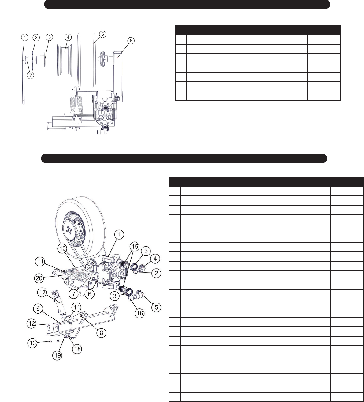
5000 Strainer & Hydraulic Pump
# Description Part. No.
1 3/8” Round U-Bolt 2” Pipe Size Extended JM0018627
2 Raven FC CV SV ASM W-Fittings (Assembly) JM0038228
3 Mount for Flow Control Valves JM0040083
4 3/8”-16 Gr5 Z SF Hex Nut JM0002152
5 3/8"-16 x 1" Gr5 Z SF Hex Bolt JM0002092
6 Flow Indicator Manifold - 6 row with 3/4” inlet and 3/8” outlets JM0024470
7 Flow Indicator Manifold - 5 row with 3/4” inlet and 3/8” outlets JM0021591
7 Flow Indicator Manifold - 4 row with .75 inlet and .38 outlets(Not Shown) JM0039279
7 Flow Indicator Manifold - 3 row with .75 inlet and .38 outlets(Not Shown) JM0039280
5000 Flow Control Mount (Hydraulic Pump Only)
30
# Description Part. No.
1 Diaphragm Check Valve 3/8" Hose Single JM0036383
1 Diaphragm Check Valve 3/4” Hose Tee JM0036379
1 Diaphragm Check Valve 3/4” Hose Single JM0036381
1a 3/8” Hose Clamp (Not Shown) JM0039206
1b 3/4” Hose Clamp (For the 3/4” Diaphragm Check Valve) JM0039205
2 Orice Specify pg 51
3 Seat Gasket JM0036372
4 Outlet Hose Barb, 3/8" Poly JM0036368
4 3/8” Hose Clamp (Not Shown) JM0039206
5 Quickjet Cap, Black JM0036371
6 Diaphragm Check Valve 3/4” Hose Tee Assembly JM0041782
7 Diaphragm Check Valve 3/4” Hose Single Assembly JM0041783
8 Diaphragm Check Valve 3/8” Hose Single Assembly JM0037890
5000 Check Valve
# Description Part. No.
1 2" Manifold X 1-1/2" Barb JM0021161
2 2" Manifold Flange Clamp JM0035251
2 2" Manifold Gasket(Not Shown) JM0021145
3 2" Manifold Tee x 1" Manifold JM0035116
4 2" Manifold Plug With 1/4" NPT for Gauge JM0021147
5 Pressure Gauge Stainless Steel 0-100psi, 4", 1/4" NPT JM0036636
6 3/8 x 16 Round U-Bolt 2in Pipe Size Extended JM0018627
7 1" Manifold Flange Clamp JM0032496
7 1" Manifold Gasket With Rib EPDM(Not Shown) JM0035239
8 1" Flange x 3/4" Hose Barb JM0021401
8 3/4” Hose Clamp(Not Shown) JM0039205
9 3/8-16 Gr5 Z SF Hex Nut JM0002152
10 1” T-Bolt Clamp JM0021189
11 Flow Monitor Mount JM0034846
5000 Ground Driven Pump Manifold
3/8” Single
Assembly
8
3/4” Tee
Assembly
6
3/4” Single
Assembly
7
31
# Description Part. No.
1 Roller Chain #50 JM0034463
2 50A45 Sprocket #50 Roller Chain JM0034459
3 Sprocket Mount "Ground Drive Pump" JM0034442
4 14 x 6 Wheel 1 1/8 Inset JM0019535
5 ST215-75D14 Tire Carlisle Sport Trail JM0019529
6 Ground Drive Pump Pivot JM0036063
7 3/8"-16 x 1" Gr5 Z SF Hex Bolt JM0002092
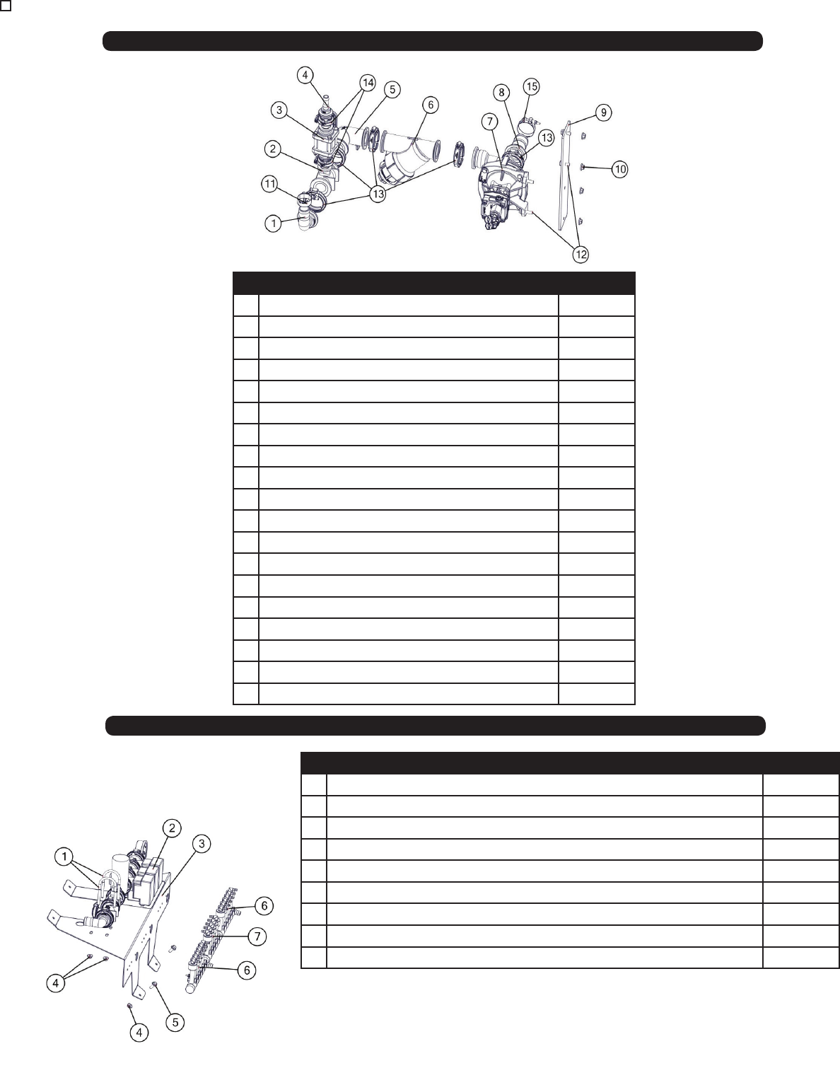
5000 Ground Drive Pump
# Description Part. No.
1 John Blue NGP-9055 Dual Piston Pump JM0035142
1 John Blue NGP 7055-F Single Piston Pump JM0034503
2 T-Bolt Hose Clamp 1-1/2” JM0021189
3 2" Manifold Gasket(Not Shown) JM0021145
3 2" Manifold Flange Clamp JM0035251
4 2" Manifold Flange x 90 deg 1-1/2" Hose Barb JM0034352
5 2" Manifold x 2" Hose Barb 90 Deg JM0035141
6 1/2"-13 Gr5 Z Hex Nut JM0001624
7 1/2’’-13 Gr5 Z J-Bolt JM0002168
8 1 x 3-1/2” Clevis Pin with Cotter Pins JM0001817
9 Ground Drive Pump Mount JM0036062
10 Tongue Spring (24T,HT) 3/8 x 1 3/4 x 12 1/2 JM0014200
11 Sha Collar - Set Screw 3/4” JM0025216
12 5/8”-11 x 2” Gr5 Z Hex Bolt JM0002104
13 5/8”-11 Gr5 Z Centerlock Hex Nut JM0002146
14 Cylinder Lock Latch JM0036330
15 1 1/2” Male MPT X 2” Manifold Flange(Dual Piston Pump) JM0035124
16 T-Bolt Hose Clamp 2” Hose JM0035247
17 Lion 2 bore x 4 stroke WH series JM0034861
18 1-8 Gr5 Z Nylon Locking Hex Nut JM0002161
19 1”-8 X 5” Gr5 Z Pn Hex Bolt JM0001558
20 Linkage Weldment JM0037580
John Blue Dual Piston repair kit (Not Shown) JM0038496
5000 Ground Driven Pump
See wing wheel section of manual for hub components pg. 37
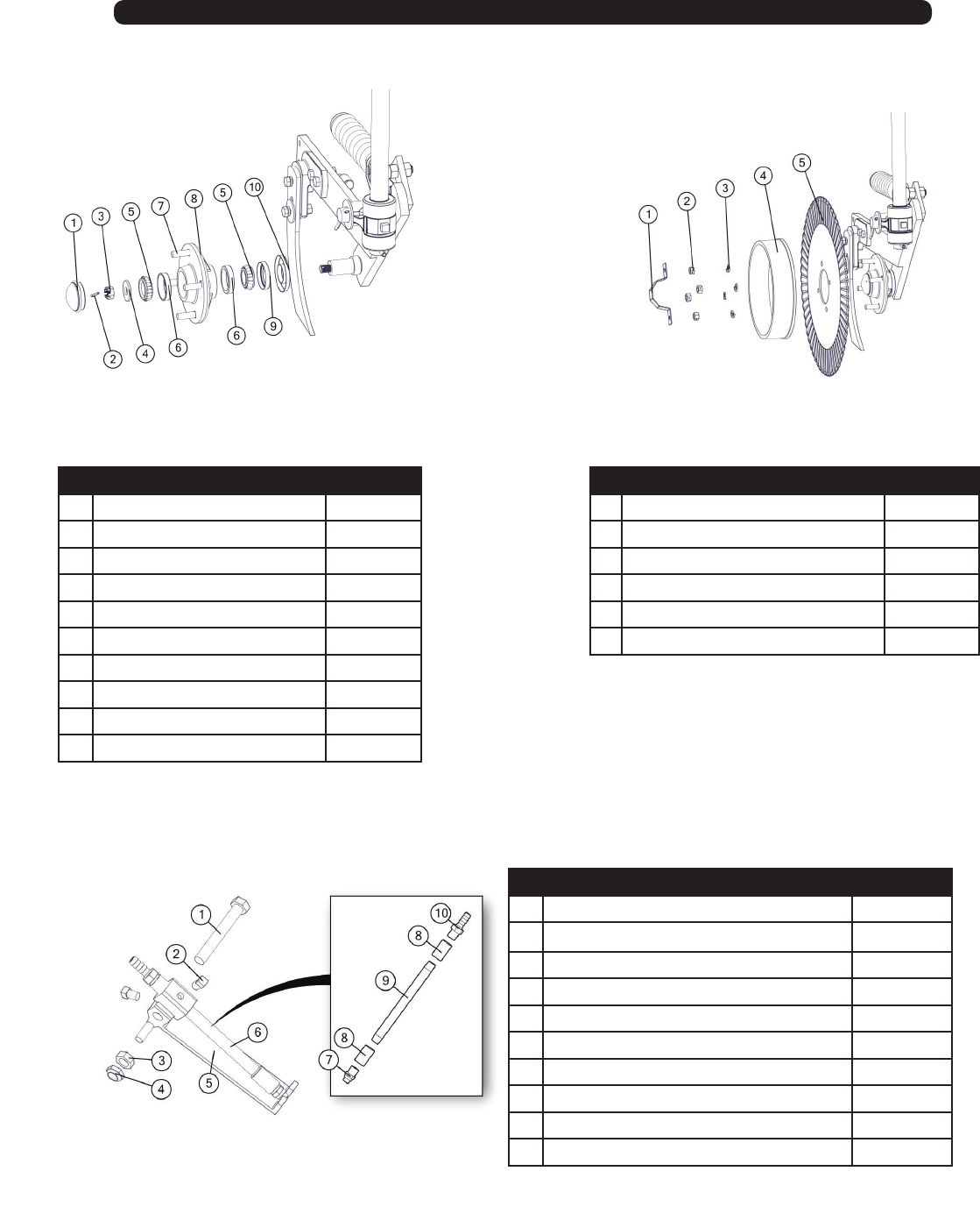
32
# Description Part. No.
1 Dust Cap Keeper JM0038391
2 1/2”-13 Gr5 Z Hex Nut JM0002124
3 1/2” Zinc Finish Lock Washer JM0019021
4 Depth Control Spool JM0031281
5 20” Ripple Blades JM0031269
5 20” Wavy Blade JM0038506
# Description Part. No.
1Dust Cap JM0038288
2 1/8” Cotter Pin JM0004177
3 1/2” castle nut JM0038277
4Hub Washer JM0038278
5 Tapered Single - LM67048 JM0019564
6 Cup LM67010 JM0026564
7 1/2”-13 x 2” Gr2 Z Stud JM0038410
8Hub JM0038285
9 Grease Seal JM0038287
10 Seal Protector JM0038267
5000 GEP Coulter
Hub
Assembly Blade &
Depth Control
Spool
# Description Part. No.
1 1/2”-13 x 3-1/2” SS Hex Bolt JM0041790
2 3/8”-16 x 1/2” Square Head SS Bolt JM0041793
3 1/2”-13 SS Hex Jam Nut JM0041791
4 1/2”-13 SS Nylon Locking Hex Jam Nut JM0041792
5 GC3205 Injection Mount JM0035055
6 Fertilizer Injector With Fittings JM0041788
7 Stream Jet see pg 55
8 1/4” NPT Merchant Coupling SS JM0036441
9 1/4” NPT x 6 Pipe Nipple SS JM0036445
10 Hose Barb 3/8” x 1/4” MPT Stainless Steel JM0036419
33
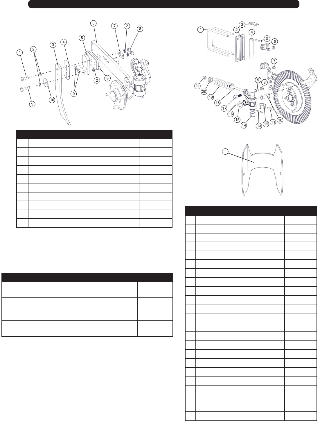
# Description Part. No.
1 1/2” -13 x 1-1/4” Gr5 Z Hex Bolt JM0001513
2 1/2” Zinc Finish Lock Washer JM0019021
3 Wiese Knife JM0031273
4 Shims- 1/8” JM0038415
5 Knife Bracket JM0038279
6 Coulter Arm JM0038397
7 1/2” USS Flat Washer JM0003082
8 1/2”-13 Gr5 Z Hex Nut JM0002124
9 1/2”-13 x 1-3/4” Gr5 Z Hex Bolt JM0002101
10 1/2” ID x 2” OD Flat Washer - 1/8” ick JM0026973
# Description Part. No.
1 5/8" x 7" x 10-1/4" U-Bolt JM0030958
2 Channel Bracket Plate JM0030954
3 QJ Mounting Tab JM0036048
4 28" Sha - Coulter Mount JM0030959
5 3/8” x 3” SS Roll Pin JM0037162
6 Channel Bracket Casting JM0030956
7 5/8”-11 Gr5 Z Hex Nut JM0001522
8 3/4-10 Hex Nut JM0002125
9 Nylon Spring Bushing JM0038264
10 Nylon Bushing JM0038259
11 5/8”-11 x 1” Square Head Bolt JM0037259
12 Lock Collar, 30° Rotation JM0031280
12 Lock Collar, 45° Rotation JM0038604
13 3/8” x 3” SS Roll Pin JM0037162
14 Sha Nylon Bushing JM0038258
15 Washer JM0038272
16 Cotter Pin JM0038414
17 3/4-10 G5 Z Bolt 3”Lg JM0038263
18 Spring Rod JM0038265
19 Spring JM0038269
20 Spring Alignment Cast JM0038270
21 Nylon Lock Nut JM0026756
22 Nitrogen Sealer Cable Closer JM0038176
5000 GEP Coulter
22
Description Part. No.
Coulter Knife Bracket Package (Knife Assembly)
Item: 1,2,4,5,7,8,9,& 11
JM0041705
Coulter Assembly (Hub Assembly Item: 1-10) (Blade &
Depth Control Spool Item: 1) (Knife Assembly Item: 6)
(Coulter Assembly Item: 8-21)
JM0031265
Coulter Bracket Package, (Coulter Assembly)
Item: 1,2,6,& 7
JM0035053
Coulter
Assembly
Knife
Assembly
34
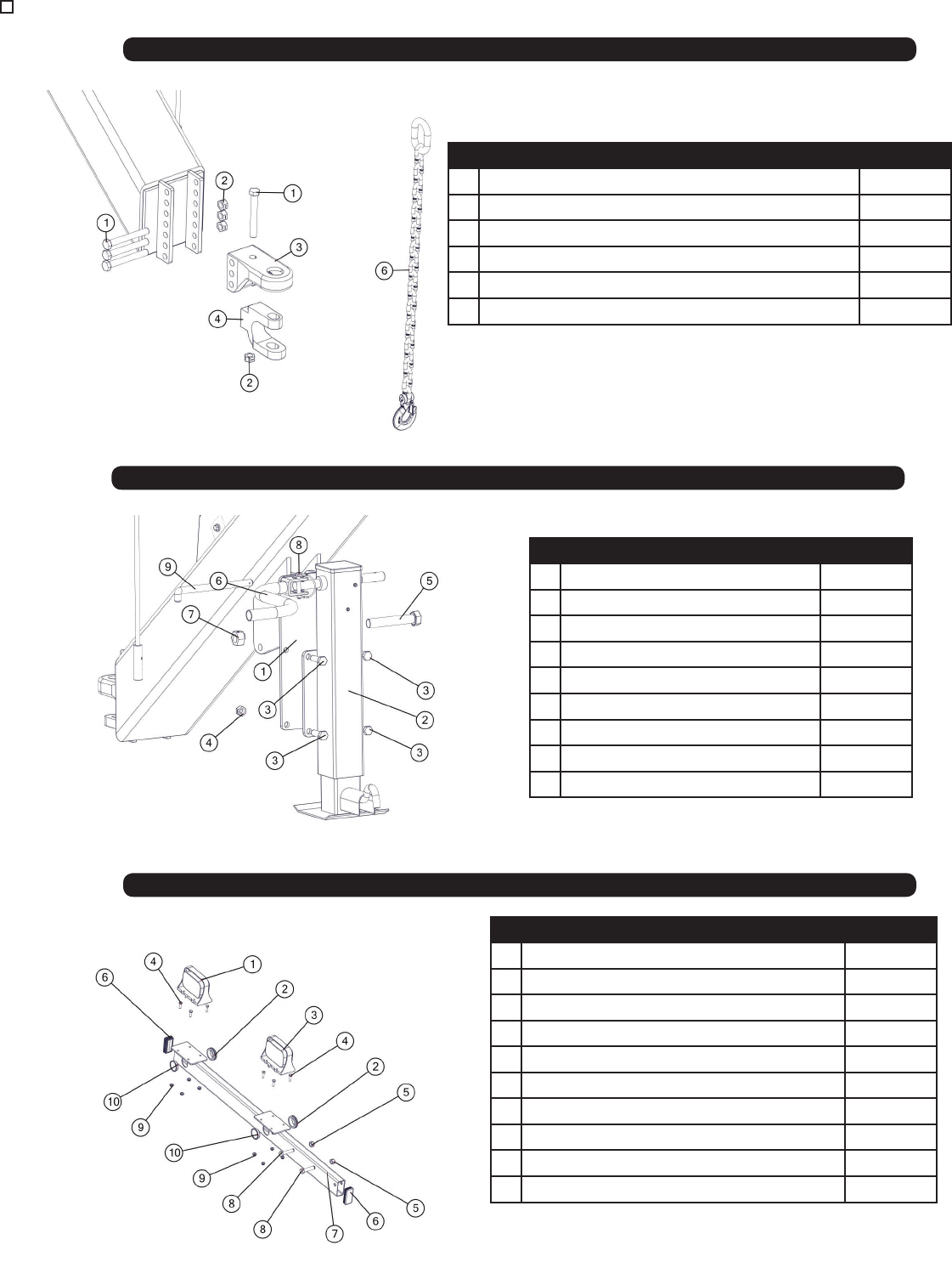
5000 Hitch
# Description Part. No.
1 3/4”-10 x 6” Gr8 Z Hex Bolt JM0037185
2 3/4”-10 Gr5 Z Centerlock Hex Nut JM0002147
3 CTD Perfect Hitch Base PP23XLR JM0037174
4 CTD Perfect Hitch Clevis 1-1/4” x 1-3/4” Slot JM0037173
5 Hitch Assembly (Items 1 through 4) JM0037177
6 Safety Chain JM0027440
# Description Part. No.
1 Jack Mounting Bracket JM0031545
2 Jack Assembly (NitroGro & 510ST) JM0030054
3 5/8"-11 x 2" Gr8 Z Hex Bolt JM0001771
4 5/8"-11 Gr5 Z Centerlock Hex Nut JM0002146
5 1”-8 x 6” Gr5 Z Hex Bolt JM0002111
6 Jack Handle JM0037953
7 1”-8 Gr5 Z Centerlock Hex Nut JM0002149
8 Lynch Pin 3/8” x 2-1/2” JM0014929
9 3/4" L Pin JM0003076
5000 Jack Weldment
# Description Part. No.
1 Amber Light JM0009975
2 1-1/2” ID x 0.188 GW x 1-3/4” GD Grommet JM0016924
3 Red Light JM0009976
4 1/4"-20 x 1" Gr5 Z Hex Bolt JM0002095
5 1/2"-13 Gr5 Z Centerlock Hex Nut JM0001511
6 1-1/2” x 3” Rectangular Tubing Plug JM0037249
7 Light Bar Weldment JM0036071
8 1/2”-13 x 2-1/4” Gr5 Z Hex Bolt JM0016677
9 1/4"-20 Gr5 Z SF Hex Nut JM0001630
10 Plastic Plug for 1-3/4” Hole JM0037250
5000 Light Bar
35
Wings
# Description Part. No.
1 1” x 3.4 Clevis Pin JM0001816
2 Cotter Pin JM0003064
3 3/4”-10 x 3.0 Gr5 Z Hex Bolt JM0027464
4 Pivot Pin - 2-1/2 Dia With Bolt Retainer JM0031502
5 3/4”-10 Gr5 Z Centerlock Hex Nut JM0002147
6 3/8”-16 x 0.5 Socket Set Screw Nylon Tip JM0037255
7 Sha - Down pressure Cylinder JM0032428
8 Lion 4 Bore x 24 Stroke Welded WH Series JM0030730
9 Linkage - Down pressure Cylinder JM0034014
10 Sleeve Composite Bearing JM0020546
11 JD 4 Bore x 8 Stroke Welded Cyl JM0030757
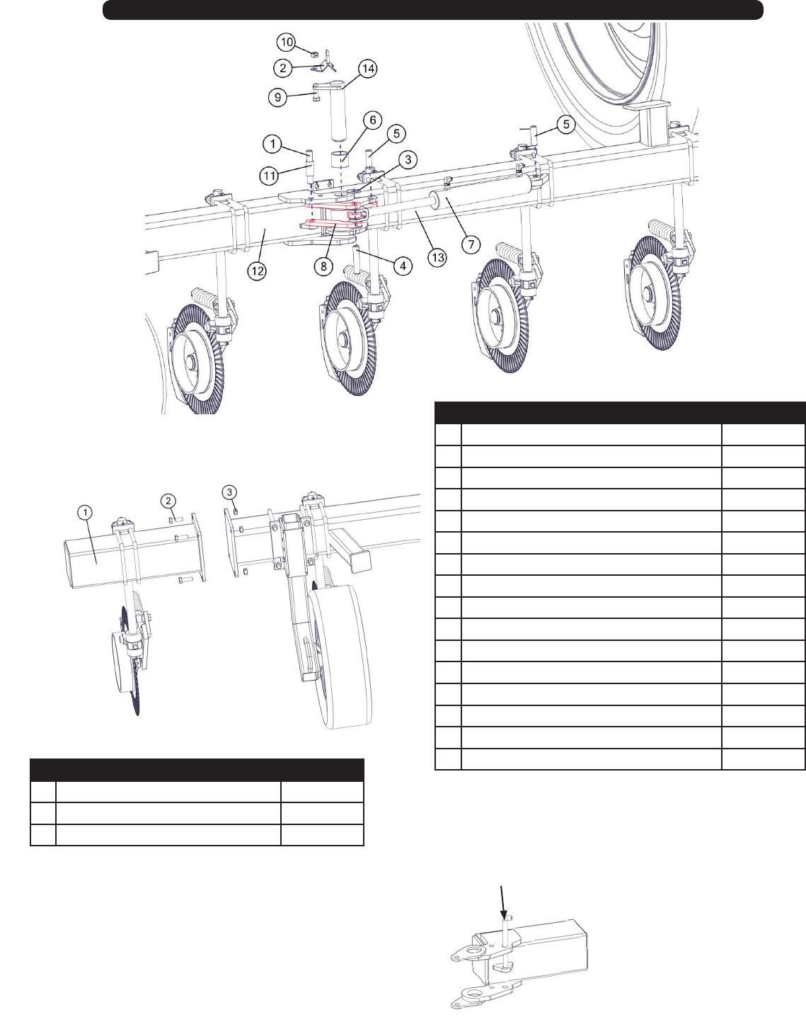
36
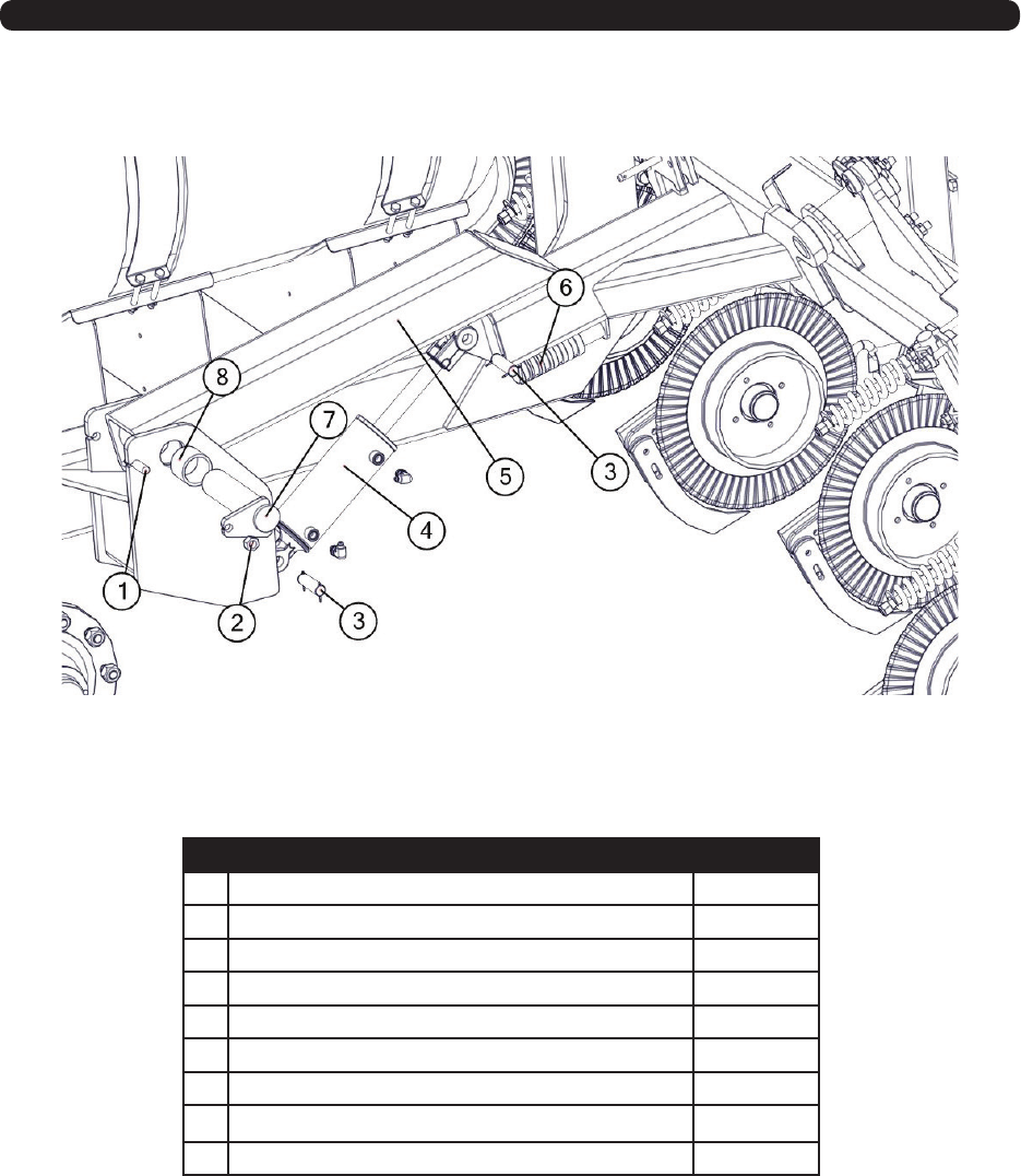
Wings
# Description Part. No.
1 Mounting Bracket JM0020472
2 5/8”-11 x 2” Gr8 Z Hex Bolt JM0001771
3 5/8”-11 Gr5 Z Centerlock Hex Nut JM0002146
# Description Part. No.
1 Pin - 1” x 6 LG JM0031495
2 Hose Mount JM0036703
3 1.0 USS Flat Washer JM0003063
4 Pin - 1” x 5 LG JM0031496
5 1 x 3-1/2” Clevis Pin with Cotter Pins JM0001817
6 Sleeve Composite Bearing JM0020546
7 3 x 14 Welded JD Cylinder JM0035057
8 Linkage - Outside Wing JM0030333
9 3/4” -10 x 3.0 Gr5 Z Hex Bolt JM0027464
10 3/4” -10 Gr5 Z Centerlock Hex Nut JM0002147
11 Spacer - Linkage JM0031494
12 Outside Wing (Right Side) JM0034129
12 Outside Wing (Le Side) JM0034107
13 Mid Wing (Right Side, 2016) JM0034131
13 Mid Wing (Le Side, 2016) JM0034130
14 Pivot Pin - 2-1/2 Dia With Bolt Retainer JM0031502
30’ Wing
Extension
JM0035008
Lock Pin
JM0003076
37
# Description Part. No.
1 Square U-Bolt 7-1/8” Inside Width x 9” Length, 5/8”-11 JM0020901
2 Gauge Wheel Mount JM0031518
3 Gauge Wheel Assembly (Right Hand) JM0031511
3 Gauge Wheel Assembly (Le Hand) JM0031520
4 5/8”-11 Gr5 Z Centerlock Hex Nut JM0002146
5 5/8” x 7” Hitch Pin JM0003079
6 3/16” x 2-1/2” Hair Clip Pin JM0001657
7 Grease Seal, 6-8 Ton JM0026572
8 Large Inner Bearing for 6-8 Ton JM0019563
9 Large Cup for 6-8 Ton JM0026565
10 Wheel Stud for Hub, 6-8 Ton (1/2”-20 x 1-7/8”) JM0019559
11 Hub with Races, Studs and Nuts, 7-8 Ton JM0026566
12 Small Cup for 6-10 Ton JM0026564
13 Small Outer Cone for 6-10 Ton JM0019564
14 3/4” Z Flat Washer (2” OD) JM0010006
15 3/4”-10 Gr5 Z Castle Hex Nut JM0002130
16 3/16” x 1 1/2” Cotter Pin, 6-10 Ton JM0014348
17 Tire ST215-75D14 JM0019529
18 Wheel Rim, 6 hole 14” x 6” JM0019535
19 1/2”-20 Lug Nut, 6-8 Ton JM0003062
20 Dust Cap, 6-10 Ton JM0026567
5000 Wing Wheel
38
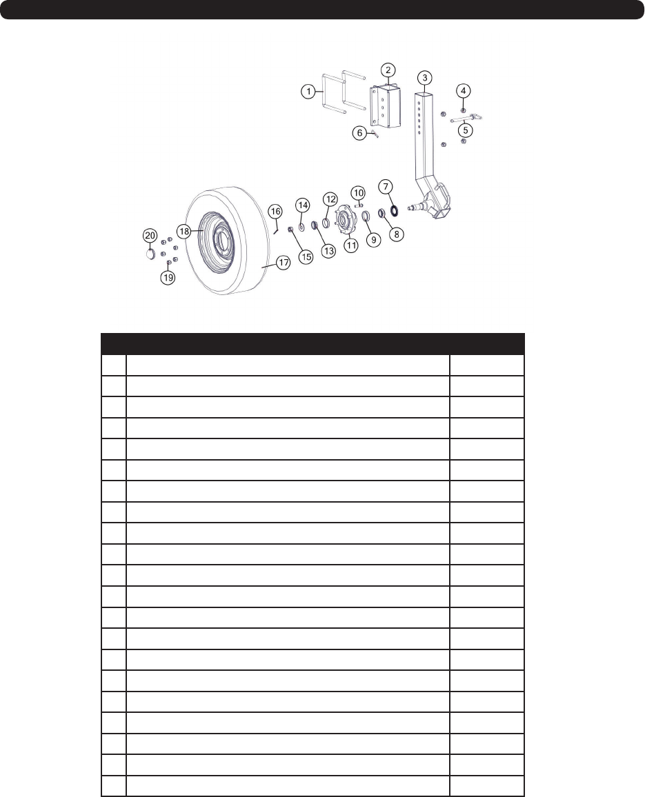
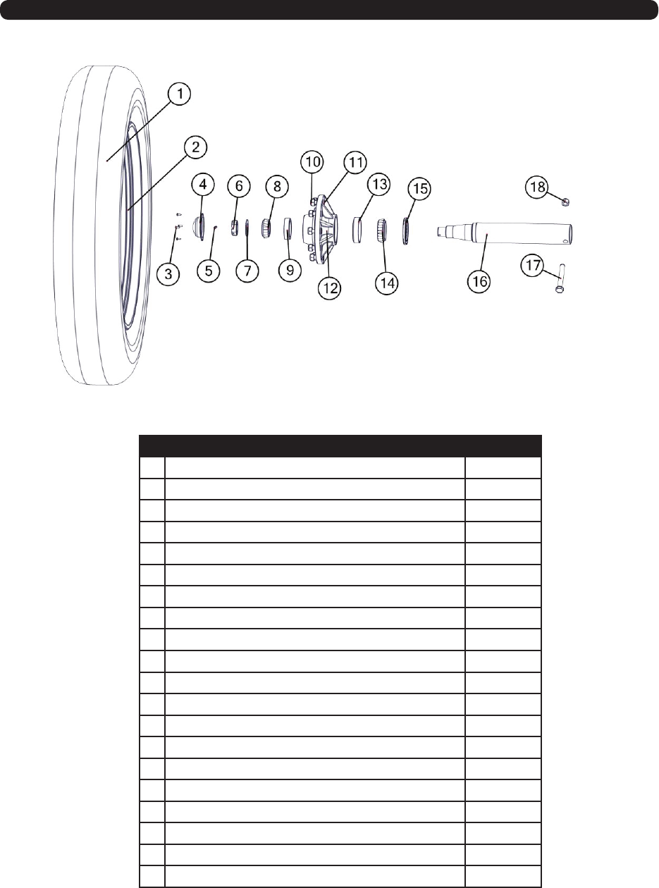
Spindle
# Description Part. No.
1 480/80R42 Tire Firestone JM0020038
1 380/90R46 Tire Firestone JM0016170
2 Wheel, 46 x 12 10 Holes JM0029935
2 Wheel, 42 x 16 10 Holes JM0020015
3 1/4”-20 x 3/4” Gr5 Z Hex Bolt JM0001507
4 Dust Cap JM0018954
5 3/8 x 2 3/4 Z Roll Pin JM0018956
6 2.0-12 Gr5 Z Castle Hex Nut JM0015899
7 2 1/8 ID x 3 3/4 OD Flat Washer - 3/16” ick JM0015900
8 Tapered Single JM0018852
9 Sm Race JM0018854
10 3/4 -16 Lugnut JM0018958
11 3/4 -16 x 1 3/4” Stud JM0018957
12 Hub with Races, Lugs, Studs, and Nuts JM0020510
13 Lg. Race JM0018848
14 Tapered Single JM0018849
15 Grease Seal JM0018955
16 4.5 Spindle JM0018794
17 1.0-8 x 7.0 Gr5 Z Hex Bolt JM0016689
18 1-8 Gr5 Z Nylon Locking Hex Nut JM0002161
39
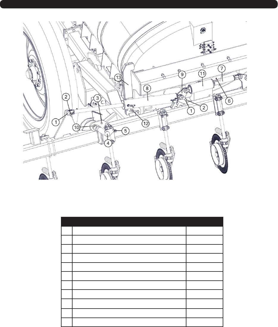
Tool Bar
# Description Part. No.
1 3/4”-10 x 3.0 Gr5 Z Hex Bolt JM0027464
2 3/4”-10 Gr5 Z Centerlock Hex Nut JM0002147
3 1 x 3-1/2” Clevis Pin with Cotter Pins JM0001817
4 JD 4 Bore x 8 Stroke Welded Cyl JM0030757
5 Toolbar Base Section (2016) JM0034136
5 Toolbar Base Section ( Aer 2017) JM0039525
6 1 1/2” in Dia Cyl Spacer, Kit JM0037182
7 Pivot Pin - 2-1/2 Dia With Bolt Retainer JM0031502
8 Sleeve Composite Bearing JM0020546
40
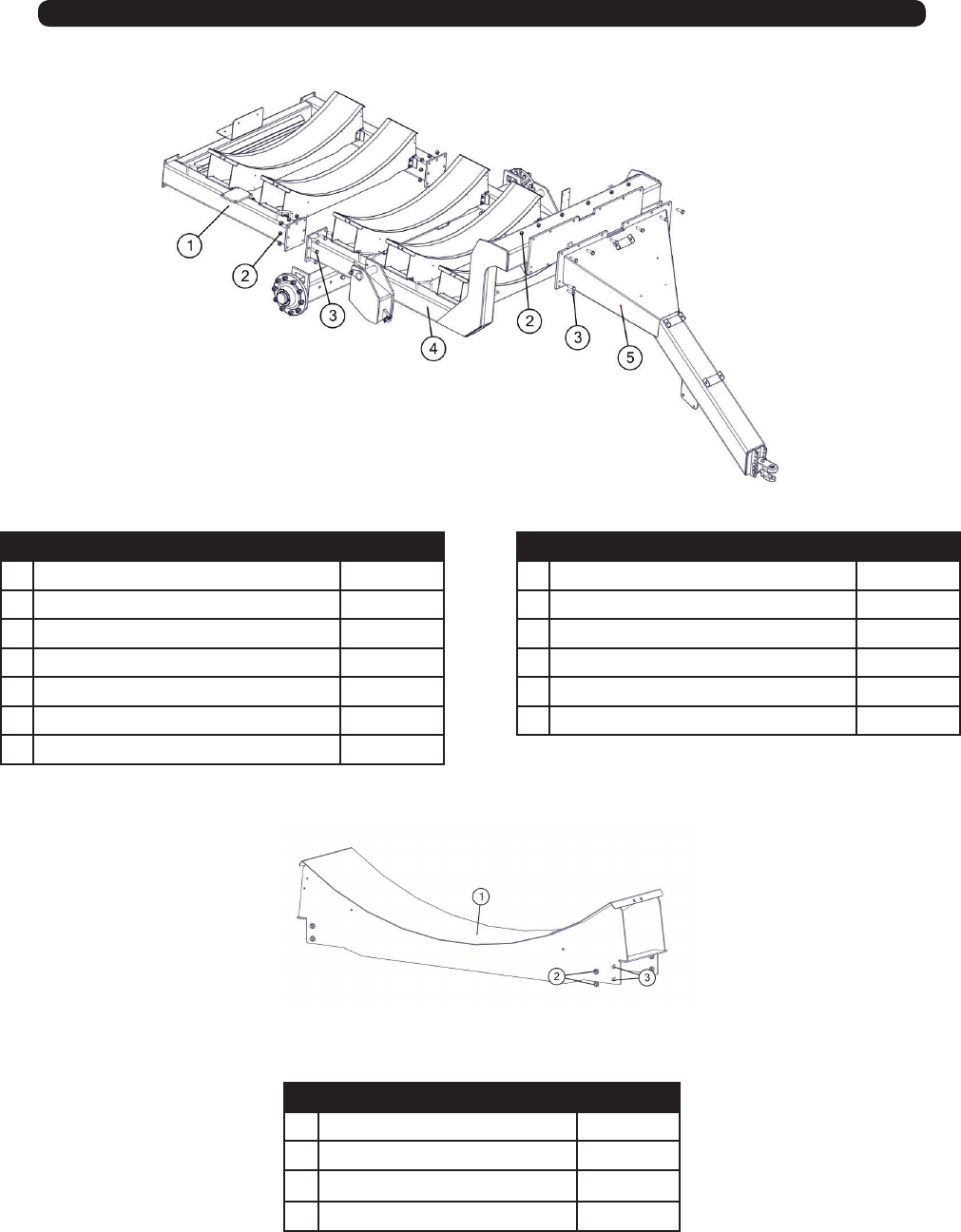
Frame
# Frame 2016 Part. No.
1 Rear Frame 5016 JM0033742
1 Rear Frane 5010 JM0033744
2 3/4”-10 Gr5 Z Centerlock Hex Nut JM0002147
3 3/4”-10 x 3.0 Gr5 Z Hex Bolt JM0027464
4 Base Frame 5016 JM0033657
4 Base Frame 5010 JM0033744
5 Tongue JM0033656
# Description (Tank Saddle) Part. No.
1 Saddle - Tank (2016) JM0034199
1 Saddle - Tank ( Aer 2016) JM0036718
2 3/8 -16 Gr5 Z SF Hex Nut JM0002152
3 3/8”-16 x 1” Gr5 Z SF Hex Bolt JM0002092
# Frame Aer 2017 Part. No.
1 Rear Frame 5016 JM0039435
1 Rear Frane 5010 JM0033744
2 3/4”-10 Gr5 Z Centerlock Hex Nut JM0002147
3 3/4”-10 x 3.0 Gr5 Z Hex Bolt JM0027464
4 Base Frame (All) JM0036468
5 Tongue JM0033656
41
42
Tank
Fill Valve
2” or 3”
Ground Drive Pump
Strainer
1
2
3
45
6
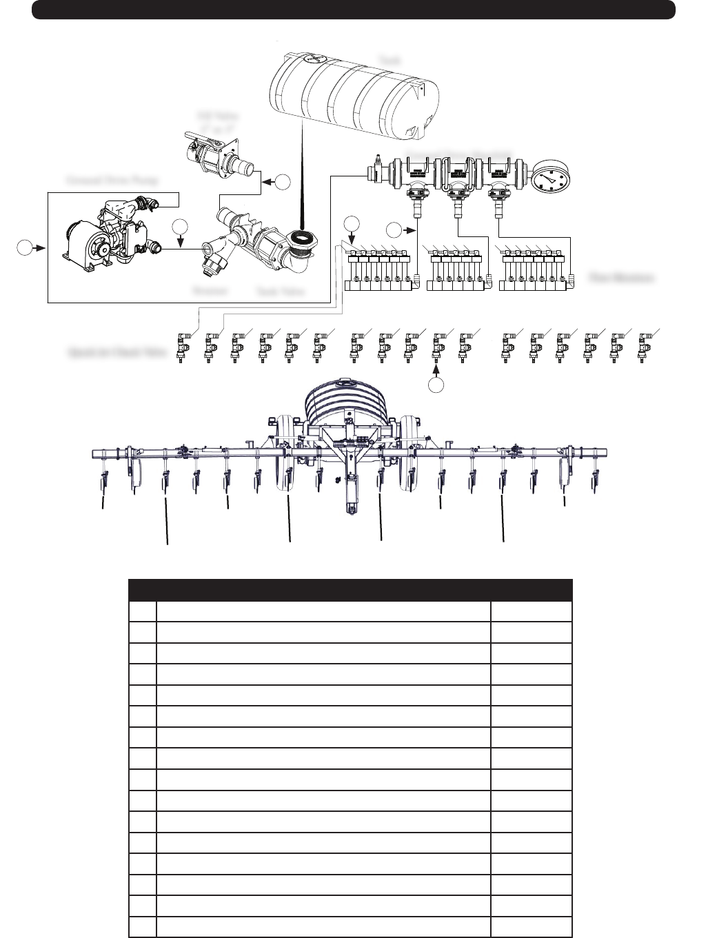
Fertilizer Hose Routing - Ground Drive Pump without Flow Monitors
Tank Valve
Ground Drive Manifold
Quick Jet Check Valve
# Description Part. No.
1 19’ x 1-1/2” Hose from Pump to Manifold (1600 Gal.) JM0040211
1 15’ x 1-1/2” Hose from Pump to Manifold (1000 Gal.) JM0040330
2 48” x 2” Hose from Ground Drive Pump to Strainer JM0040214
3 36” x 2” Hose from Fill Valve to Tee JM0040215
3 38” x 3” Hose from Fill Valve to Tee JM0040216
4 210” x 3/4” Hose from Manifold to Quick Jet Check Valve JM0040217
5 30” x 3/4” Hose Quick Jet Check Valve to next Quick Jet Check Valve JM0040218
6 52” x 3/8” Hose from Quick Jet Check Valve to Coulter JM0040219
43
Fertilizer Hose Routing - Ground Drive Pump with Flow Monitors
1
2
3
4
5
6
Tank
Fill Valve
2” or 3”
Ground Drive Pump
Strainer Tank Valve
Ground Drive Manifold
# Description Part. No.
1 19’ x 1-1/2” Hose from Pump to Manifold (1600 Gal.) JM0040211
1 15’ x 1-1/2” Hose from Pump to Manifold (1000 Gal.) JM0040330
2 48” x 2” Hose from Ground Drive Pump to Strainer JM0040214
3 36” x 2” Hose from Fill Valve to Tee JM0040215
3 38” x 3” Hose from Fill Valve to Tee JM0040216
4 30” x 3/4” Hose from Manifold to Flow Monitors JM0040217
5 Center Coulter 3/8” Hose 112” Lg JM0041658
5 1 From Center Coulter 3/8” Fertilizer Hose 142” Lg JM0041659
5 2 From Center Coulter 3/8” Fertilizer Hose 172” Lg JM0041660
5 3 From Center Coulter 3/8” Fertilizer Hose 145” Lg JM0041661
5 4 From Center Coulter 3/8” Fertilizer Hose 175” Lg JM0041662
5 5 From Center Coulter 3/8” Fertilizer Hose 205” Lg JM0041663
5 6 From Center Coulter 3/8” Fertilizer Hose 245” Lg JM0041664
5 7 From Center Coulter 3/8” Fertilizer Hose 275” Lg JM0041665
5 8 From Center Coulter 3/8” Fertilizer Hose 305” Lg JM0041666
6 52” x 3/8” Hose from Quick Jet Check Valve to Coulter JM0040219
Quick Jet Check Valve
Flow Monitors
Center
1 From
Center
2 From
Center
3 From
Center
4 From
Center
5 From
Center
6 From
Center
7 From
Center
8 From
Center
44
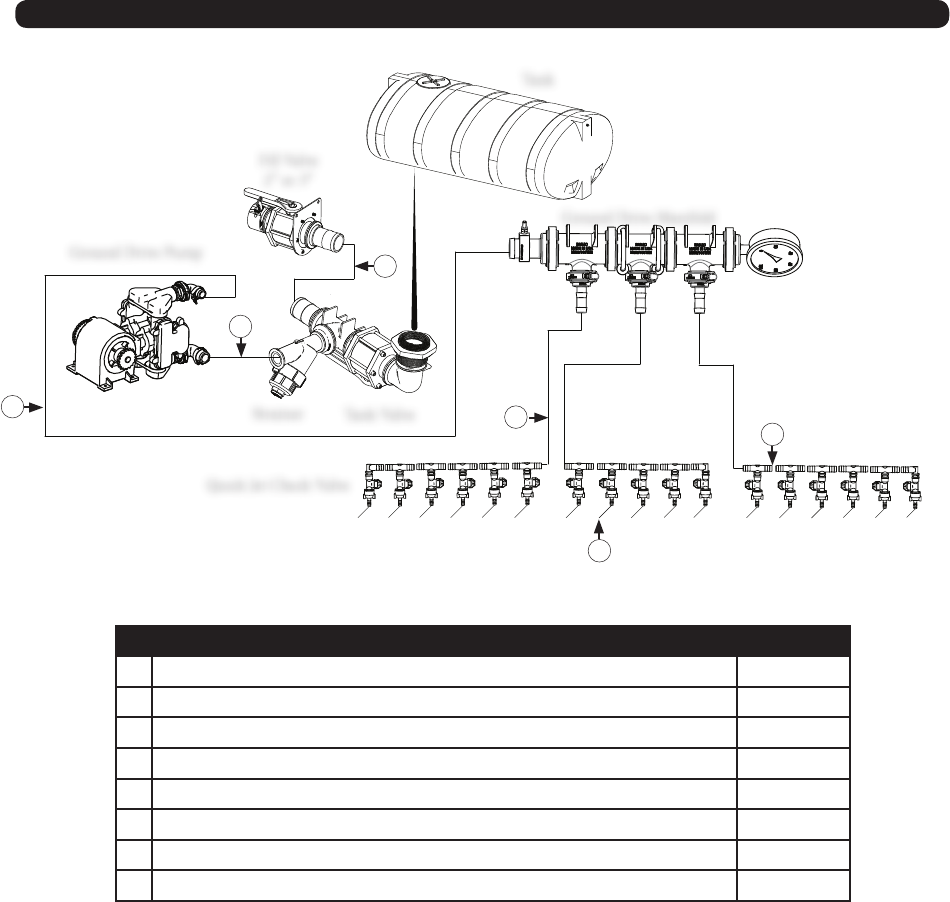
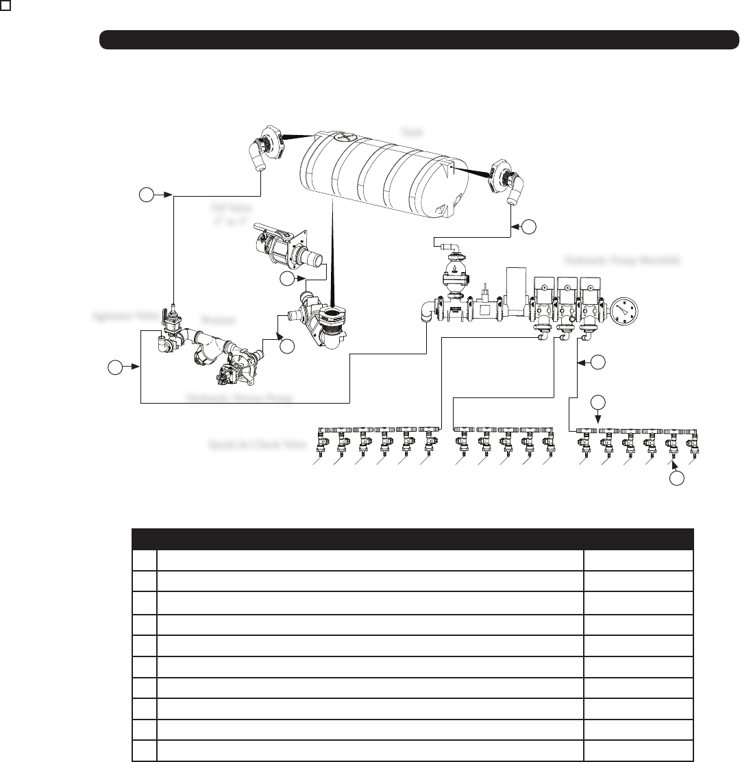
Fertilizer Hose Routing - Hydraulic Pump without Flow Monitors
Tank
Fill Valve
2” or 3”
Hydraulic Driven Pump
Strainer
Agitation Valve
Hydraulic Pump Manifold
Quick Jet Check Valve
# Description Part. No.
1 1-1/2” x 228”; Hose from Hydraulic Pump to Manifold (1600 Gal.) JM0040211
1 1-1/2” x 180”; Hose from Hydraulic Pump to Manifold (1000 Gal.) JM0040330
2 2” x 32”; Hose from Tank to Pump JM0040224
3 2” x 36” Hose from Fill Valve to Tee JM0040215
3 3” x 38” Hose From Fill Valve to Tee JM0040216
4 3/4” x 210” Fertilizer Hose from Manifold to Quick Jet Check Valve JM0040217
5 3/4” x 30” From Quick Jet Check Valve to next Quick Jet Check Valve Hose JM0040218
6 3/8” x 52” Hose From Quick Jet Check Valve to Coulter JM0040219
7 3/4” x 55” Agitation Valve to Tank Fertilzer Hose JM0040332
8 3/4” x 55” Spike Valve to Tank Fertilzer Hose JM0040332
7
1
3
2
8
4
6
5
45
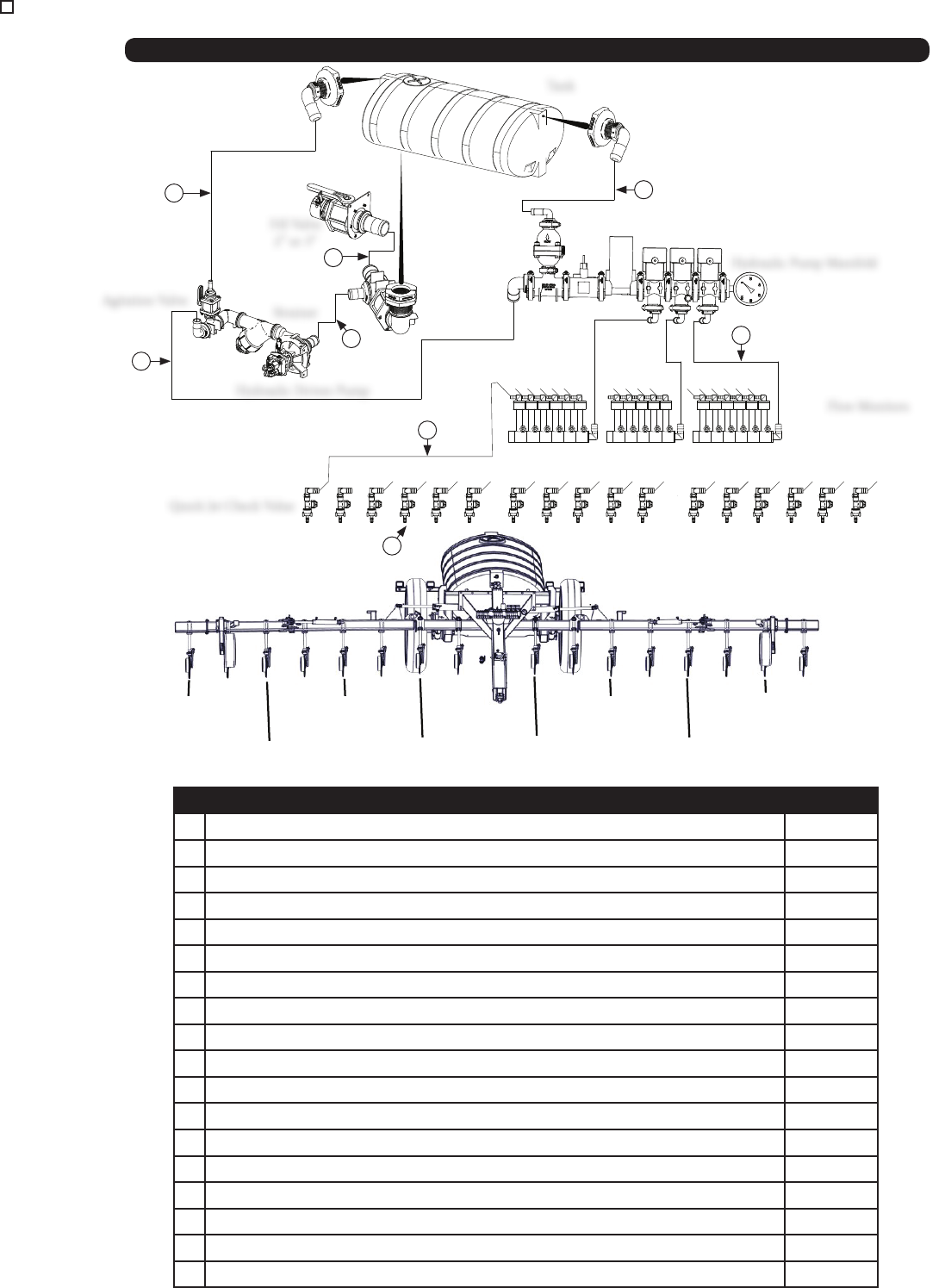
Fertilizer Hose Routing - Hydraulic Pump with Flow Monitors
# Description Part. No.
1 1-1/2” x 228”; Hose from Pump to Manifold (1600 Gal.) JM0040211
1 1-1/2” x 180”; Hose from Pump to Manifold (1000 Gal.) JM0040330
2 2” x 32’’; Hose from Tank to Pump JM0040224
3 36” x 2” Hose from Fill Valve to Tee JM0040215
3 38” x 3” Hose from Fill Valve to Tee JM0040216
4 3/4” x 30”; Hose from Manifold to Flow Monitors JM0040218
5 Center Coulter 3/8” hose 112” Lg JM0041658
5 1 From Center Coulter 3/8” Fertilizer Hose 142” Lg JM0041659
5 2 From Center Coulter 3/8” Fertilizer Hose 172” Lg JM0041660
5 3 From Center Coulter 3/8” Fertilizer Hose 145” Lg JM0041661
5 4 From Center Coulter 3/8” Fertilizer Hose 175” Lg JM0041662
5 5 From Center Coulter 3/8” Fertilizer Hose 205” Lg JM0041663
5 6 From Center Coulter 3/8” Fertilizer Hose 245” Lg JM0041664
5 7 From Center Coulter 3/8” Fertilizer Hose 275” Lg JM0041665
5 8 From Center Coulter 3/8” Fertilizer Hose 305” Lg JM0041666
6 3/8” x 52”; Hose from Quick Jet Check Valve to Coulter JM0040219
7 3/4” x 55”; Agitation valve to Tank JM0040332
8 3/4” x 55”; Spike Valve to Tank JM0040332
Hydraulic Pump Manifold
Flow Monitors
Tank
Fill Valve
2” or 3”
Agitation Valve Strainer
Hydraulic Driven Pump
7
1
3
2
5
8
4
6
Center
1 From
Center
2 From
Center
3 From
Center
4 From
Center
5 From
Center
6 From
Center
7 From
Center
8 From
Center
Quick Jet Check Value
46
4
12
4
4
4
13
3
3
3
3
1
2
3
6
7
11
9
8
8
9
11
10
5
Hydraulic Schematic (Hoses & Cylinders) After Serial #
3” x 14” Fold/Unfold
3” x 14” Fold/Unfold
4” x 24” Fold/Unfold
4” x 24” Fold/Unfold
4” x 8” Down Pressure
Cylinder
4” x 8” Raise/Lower
Hydraulic Pump
0-1500 PSI
Pressure Gauge
Manifold
4” x 8” Raise/Lower
2” x 4” Ground Driven
Pump

47
Hydraulic Schematic (Hoses & Cylinders) After Serial #
# Description Part. No.
1 3/8” Hose 80”; 1/2” MPT Rigid #6 Female Swivel JIC JM0041604
2 3/8” Hose 160”; 1/2” MPT Rigid x 10 x #6 Female Swivel JIC JM0041612
3 3/8 Hose 80”; #6 Female Swivel JIC; Both Ends JM0041613
4 3/8” Hose 104”; #6 Female Swivel JIC Both Ends JM0041615
5 1/2” Hose 336”; 1/2” MPT Rigid, 3/8” MPT Rigid (Model 5016 28’) JM0041617
5 1/2” Hose 300”; 1/2” MPT Rigid, 3/8” MPT Rigid (Model 5010 25’) JM0041618
6 3/8” Hose 336”; 1/2” MPT Rigid, 3/8” MPT Rigid (Model 5016 28’) JM0041677
6 3/8” Hose 300”; 1/2” MPT Rigid, 3/8” MPT Rigid (Model 5010 25’) JM0041678
7 3/8” Hose 32”; 3/8 Female JIC Swivel, both ends JM0041687
8 3 x 14 Welded JD Cylinder JM0035057
8 Seal Kit for 3 x 14 Hydraulic Cylinder JM0039240
9 JD 4 Bore x 24 Stroke Welded WH Series JM0030730
9 Seal Kit for 4 x 24 Hydraulic Cylinder JM0039242
10 JD 4 Bore x 8 Stroke Welded Cyl JM0030757
10 Seal Kit for 4 x 8 Hydraulic Cylinder JM0039241
11 JD 4 Bore x 8 Stroke Welded Cyl JM0030757
11 Seal Kit for 4 x 8 Hydraulic Cylinder JM0039241
12 3/8” Hose 94”; 3/8” Female NPT Swivel, 3/8” Female JIC Swivel 5010 JM0041680
12 3/8” Hose 118”; 3/8” Female NPT Swivel, 3/8” Female JIC Swivel 5016 JM0041681
13 lion 2 bore x 4 stroke WH series JM0034861
13 Seal Kit for 2 x 4 Hydraulic Cylinder JM0039239
48
4
13
4
4
4
14
3
3
3
3
1
2
3
6
7
8
12
10
9
9
10
12
11
5
Hydraulic Schematic (Hoses & Cylinders) 2016
3” x 14” Fold/Unfold
3” x 14” Fold/Unfold
4” x 24” Fold/Unfold
4” x 24” Fold/Unfold
4” x 8” Down Pressure
Cylinder
4” x 8” Raise/Lower
Hydraulic Pump
0-1500 PSI
Pressure Gauge
Manifold
Counterbalance Valve
4” x 8” Raise/Lower
2” x 4” Ground Driven
Pump

49
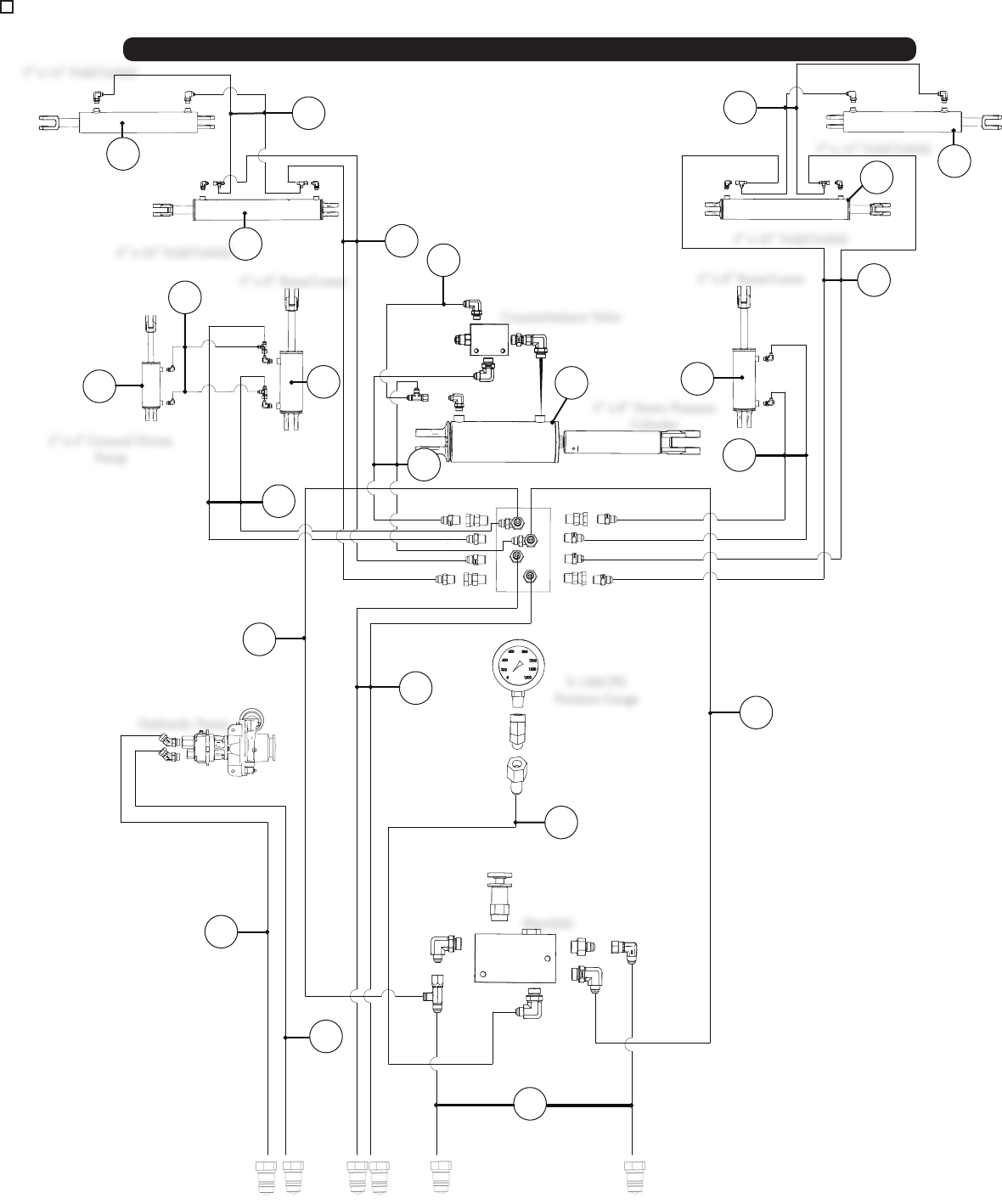
Hydraulic Schematic (Hoses & Cylinders) Before Serial #
# Description Part. No.
1 3/8” Hose 80”; 1/2” MPT Rigid x #6 Female Swivel JIC JM0041604
2 3/8” Hose 160”; 1/2” MPT Rigid x 10 x #6 Female Swivel JIC JM0041612
3 3/8 Hose 80”; #6 Female Swivel JIC; Both Ends JM0041613
4 3/8” Hose 104”; #6 Female Swivel JIC Both Ends JM0041615
5 1/2” Hose 336”; 1/2” MPT Rigid, 3/8” MPT Rigid (Model 5016) JM0041617
5 1/2” Hose 300”; 1/2” MPT Rigid, 3/8” MPT Rigid (Model 5010) JM0041618
6 3/8” Hose 336”; 1/2” MPT Rigid, 3/8” MPT Rigid (Model 5016) JM0041677
6 3/8” Hose 300”; 1/2” MPT Rigid, 3/8” MPT Rigid (Model 5010) JM0041678
7 3/8” Hose 32”; 3/8 Female JIC Swivel, 3/8” Female JIC Swivel JM0041687
8 3/8” Hose 16”; 3/8 Female NPT Swivel Both Ends JM0041679
9 3 x 14 Welded JD Cylinder JM0035057
9 Seal Kit for 3 x 14 Hydraulic Cylinder JM0039240
10 JD 4 Bore x 24 Stroke Welded WH Series JM0030730
10 Seal Kit for 4 x 24 Hydraulic Cylinder JM0039242
11 JD 4 Bore x 8 Stroke Welded Cyl JM0030757
11 Seal Kit for 4 x 8 Hydraulic Cylinder JM0039241
12 JD 4 Bore x 8 Stroke Welded Cyl JM0030757
12 Seal Kit for 4 x 8 Hydraulic Cylinder JM0039241
13 3/8” Hose 94” ; 3/8” Female NPT Swivel, 3/8” Female JIC Swivel 5010 JM0041680
13 3/8” Hose 118”; 3/8” Female NPT Swivel, 3/8” Female JIC Swivel 5016 JM0041681
14 lion 2 bore x 4 stroke WH series JM0034861
14 Seal Kit for 2 x 4 Hydraulic Cylinder JM0039239
50
13
10
9
8
15
16
1
1
2
1
1
3
1
6
7
5
17
1
1
1
1
2
1
1
12
11
1
2
14
1
1
18
2
2
1
1
4
6
6
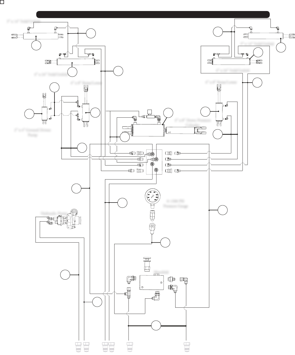
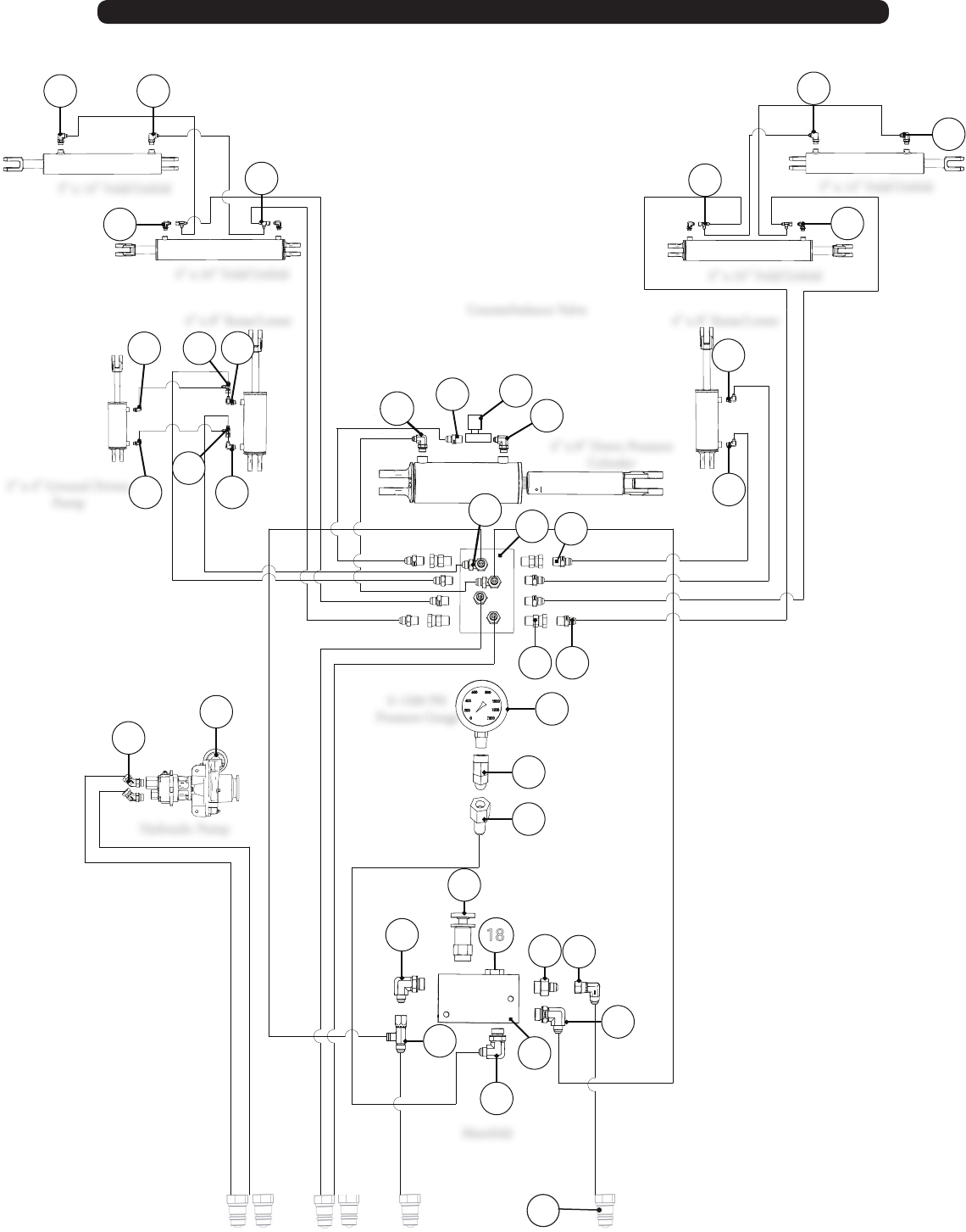
Hydraulic Schematic (Fittings) 2017
3” x 14” Fold/Unfold 3” x 14” Fold/Unfold
4” x 24” Fold/Unfold
4” x 24” Fold/Unfold
4” x 8” Down Pressure
Cylinder
4” x 8” Raise/Lower
Hydraulic Pump
0-1500 PSI
Pressure Gauge
Manifold
Counterbalance Valve
4” x 8” Raise/Lower
19
2” x 4” Ground Driven
Pump

51
# Description Part. No.
1 #6 Male JIC x #8 Male O-Ring; 90 Degree Elbow JM0037159
2 #6 Male JIC x #6 Female JIC Swivel x #6 Male JIC Tee JM0037163
3 #8 Male O-Ring x 3/8 Male NPT; 90 Degree Elbow JM0041630
4 Parker Flow Control Valve JM0041626
5 #6 Male JIC X 0.5” Male NPT X #6 Male JIC; Tee JM0010291
6 #6 male JIC x 3/8 Male NPT; Straight JM0037167
7 3/8 male NPT X 3/8 female NPT swivel; straight JM0018231
8 Pressure Gauge 0-1500psi, 2”, 1/4” NPT Bottom Mount Donaldson JM0037152
9 1/4 male NPT x 1/4 female NPT rigid; 45 degree elbow JM0037156
10 1/4 Female NPT x 3/8 Compression Bulk Head Fitting JM0037155
11 #6 Male JIC x #6 Female JIC Swivel; 90 Degree Elbow JM0010295
12 #6 male JIC x #8 male o-ring; straight JM0010302
13 Hydraforce Pressure Reducing/Relieving Valve JM0034800
14 SFP26157 Manifold w/#8 O-Ring Ports for PRV and CV JM0034773
15 #10 Male O-Ring x #8 Female Pipe Swivel; 45 Degree Elbow JM0037253
16 Pump - Centrifugal JM0033798
17 Manifold Block - 1/2 NPT X (2) 3/8 NPT JM0028902
18 Check Valve JM0034805
19 Male Pioneer End W/ Ball JM0039220
Hydraulic Schematic (Fittings) 2017
52
13
10
9
8
15
16
1
1
2
1
1
1
3
17
4
1
1
2
6
7
5
18
1
1
1
1
2
1
1
12
11
1
2
14
1
1
19
2
2
1
1
6
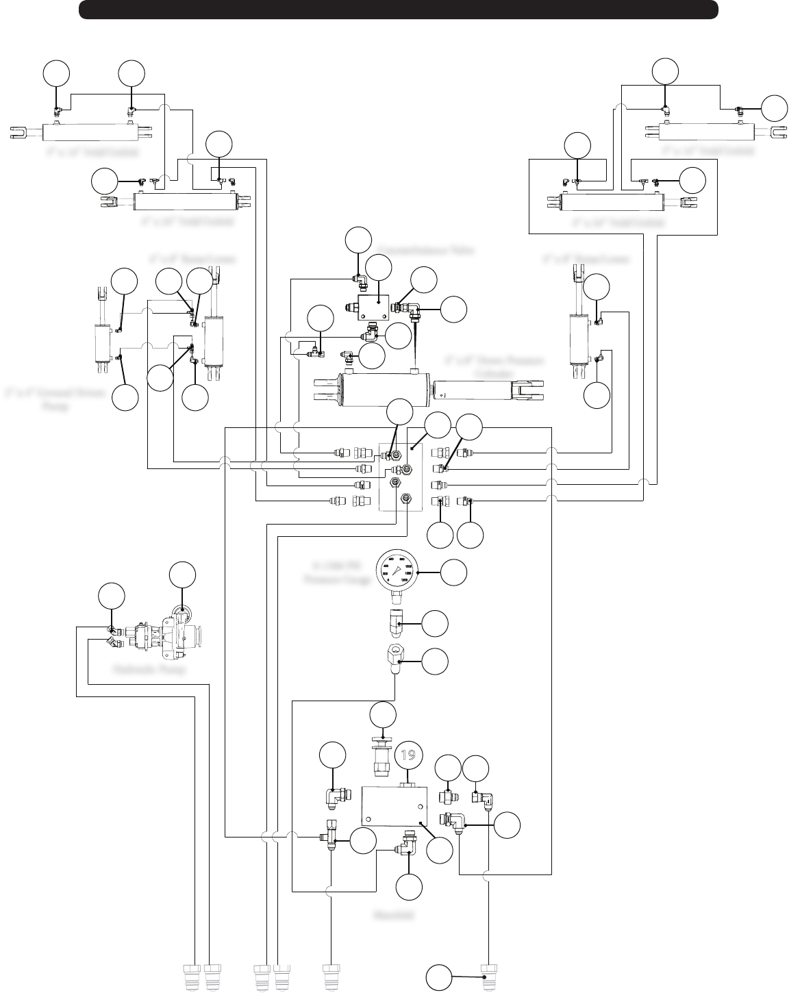
Hydraulic Schematic (Fittings) 2016
3” x 14” Fold/Unfold 3” x 14” Fold/Unfold
4” x 24” Fold/Unfold
4” x 24” Fold/Unfold
4” x 8” Down Pressure
Cylinder
4” x 8” Raise/Lower
Hydraulic Pump
0-1500 PSI
Pressure Gauge
Manifold
Counterbalance Valve
4” x 8” Raise/Lower
20
2” x 4” Ground Driven
Pump

53
# Description Part. No.
1 #6 Male JIC x #8 Male O-Ring; 90 Degree Elbow JM0037159
2 #6 Male JIC x #6 Female JIC Swivel x #6 Male JIC Tee JM0037163
3 #6 male JIC x #6 male o-ring – 90 degree elbow JM0026121
4 #8 Male O-Ring x #6 Female JIC Swivel; Straight JM0037165
5 #6 Male JIC X 0.5” Male NPT X #6 Male JIC; Tee JM0010291
6 #6 male JIC x 3/8 Male NPT; Straight JM0037167
7 3/8 male NPT X 3/8 female NPT swivel; straight JM0018231
8 Pressure Gauge 0-1500psi, 2”, 1/4” NPT Bottom Mount Donaldson JM0037152
9 1/4 male NPT x 1/4 female NPT rigid; 45 degree elbow JM0037156
10 1/4 Female NPT x 3/8 Compression Bulk Head Fitting JM0037155
11 #6 Male JIC x #6 Female JIC Swivel; 90 Degree Elbow JM0010295
12 #6 male JIC x #8 male o-ring; straight JM0010302
13 Hydraforce Pressure Reducing/Relieving Valve JM0034800
14 SFP26157 Manifold w/#8 O-Ring Ports for PRV and CV JM0034773
15 #10 Male O-Ring x #8 Female Pipe Swivel; 45 Degree Elbow JM0037253
16 Pump - Centrifugal JM0033798
17 ECJ Manifold with CBBC-LBN CBalance Cartridge JM0035030
18 Manifold Block - 1/2 NPT X (2) 3/8 NPT JM0028902
19 Check Valve JM0034805
20 Male Pioneer End W/ Ball JM0039220
Hydraulic Schematic (Fittings) 2016

54
Rate (GPA) 20 25 30 35
Speed (MPH) 4 6 8 10 12 4 6 8 10 12 4 6 8 10 12 4 6 8 10 12
#10 Injector 6 15 26 40 58 10 23 40 63 91 15 33 58 91 131 20 45 79 124 178
#15 Injector 3 7 12 18 26 5 10 18 28 41 7 15 26 41 59 9 20 35 55 80
#20 Injector 2 4 7 10 15 3 6 10 16 23 4 8 15 23 33 5 11 20 31 45
#30 Injector 1 2 3 5 7 1 3 5 7 10 2 4 7 10 15 2 5 9 14 20
#40 Injector 012341134612468135811
Rate (GPA) 40 45 50 55
Speed (MPH) 4 6 8 10 12 4 6 8 10 12 4 6 8 10 12 4 6 8 10 12
#10 Injector 26 58 104 162 233 33 74 131 205 295 40 91 162 253 364 49 110 196 306 440
#15 Injector 12 26 46 72 104 15 33 59 92 132 18 41 72 113 163 22 49 88 137 197
#20 Injector 7 15 26 41 59 8 19 33 52 75 10 23 41 64 92 12 28 49 77 111
#30 Injector 3 7 12 18 26 4 8 15 23 33 5 10 18 28 41 5 12 22 34 49
#40 Injector 2 4 7 10 15 2 5 8 13 19 3 6 10 16 23 3 7 12 19 28
Injector Tip Size
NOTE - The highlighted values indicate pressures that are in the optimal pressure range of 20 - 50 psi.
The row spacing is 30 inches.
- With #10 on the center, use #15 for one and a half rate outside, (11 or 15 knife).
- With #15 on the center, use #8 for half rate outside, (13 or 17 knife), and #20 for one and a half rate outside, (11 or 15 knife).
- With #20 on the center, use #10 for half rate outside, (13 or 17 knife), and #30 for one and a half rate outside, (11 or 15 knife).
- With #30 on the center, use #15 for half rate outside, (13 or 17 knife).
- With #40 on the center, use #20 for half rate outside, (13 or 17 knife), and #60 for one and a half rate outside, (11 or 15 knife).
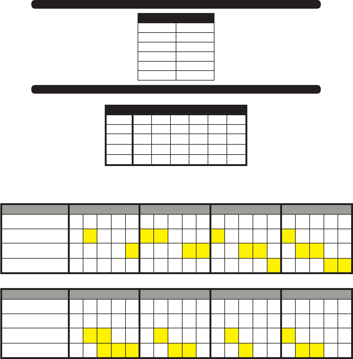
55
Rate (GPA) 20 25 30 35
Speed (MPH) 4 6 8 10 12 4 6 8 10 12 4 6 8 10 12 4 6 8 10 12
.075 Orice Pressure (psi) 14 31 54 85 122 21 48 85 132 191 31 69 122 191 275 42 93 166 260 374
.107 Orice Pressure (psi) 3 7 12 19 27 5 11 19 30 42 7 15 27 42 61 9 21 37 58 83
.132 Orice Pressure (psi) 1 3 5 9 12 2 5 9 13 19 3 7 12 19 28 4 9 17 26 38
Rate (GPA) 40 45 50 55
Speed (MPH) 4 6 8 10 12 4 6 8 10 12 4 6 8 10 12 4 6 8 10 12
.075 Orice Pressure (psi) 54 122 217 339 488 69 154 275 429 618 85 191 339 530 763 103 231 410 641 923
.107 Orice Pressure (psi) 12 27 48 76 109 15 34 61 96 138 19 42 76 118 170 23 51 91 143 206
.132 Orice Pressure (psi) 5 12 22 34 49 7 16 28 43 62 9 19 34 53 77 10 23 41 64 93
Orice Size
Orice Kits
NOTE - The highlighted values indicate pressures that are in the optimal pressure range of 20 - 50 psi.
The row spacing is 30 inches.
- With .075 on the center, use .054 for half rate outside (13 or 17 knife), and .093 for one and a half rate outside, (11 or 15 knife).
- With .107 on the center, use .075 for half rate outside (13 or 17 knife), and .132 for one and a half rate outside, (11 or 15 knife).
- With .132 on the center, use .093 for half rate outside (13 or 17 knife), and .161 for one and a half rate outside, (11 or 15 knife).
Description Part. No.
.054 Orice JM0036373
.075 Orice JM0036374
.093 Orice JM0036375
.107 Orice JM0036376
.132 Orice JM0036377
.162 Orice JM0036378
Kit Orice Size
0.054 0.075 0.093 0.107 0.132 0.162
11 Knife 0 9 2 9 9 2
13 Knife 2 11 2 11 11 0
15 Knife 0 13 2 13 13 2
17 Knife 2 15 2 15 15 0
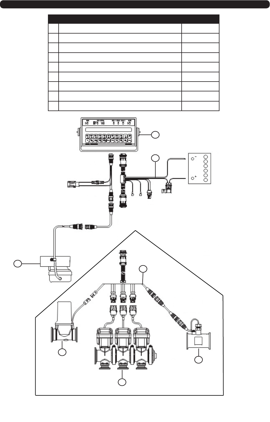
56
SCS 440 Liquid Control System
# Light Harness Part. No.
1Control Console JM0039335
2Console Cable JM0039337
3Phoenix GPS Speed Sensor JM0039338
4Flow Cable* JM0039336
5Controls Valve* JM0032490
6Boom Valves* JM0032484
7Flow Meter* JM0032488
8ISO Kit (Not Shown) JM0039339
9 ISO Cable (Not Shown) JM0039341
SCS 440 LIQUID CONTROL SYSTEM
Control Console
JM0039335
SCS 440: 063-0171-183
Console Cable
JM0039337
10’: 115-0171-085
To Switched Power
Radar Power
Cable
Phoenix GPS
Speed Senser
1-117-0171-165
JM0039338
Flow Cable
JM0039336
12: 115-0171-055
Flow Meter
1-063-171-793
JM0032488
Boom Valves
JM0032484
3 Section: 063-0171-928
Control Valve
1-063-0172-125
JM0032490
*Components Included In
Standard Hydraulic Pump
Packages.
Not Shown:
Optional ISO Kit & Cable
1-117-6100-001 - JM0039339
1-115-0171-974 - JM0039341
1
2
4
3
5
6
7
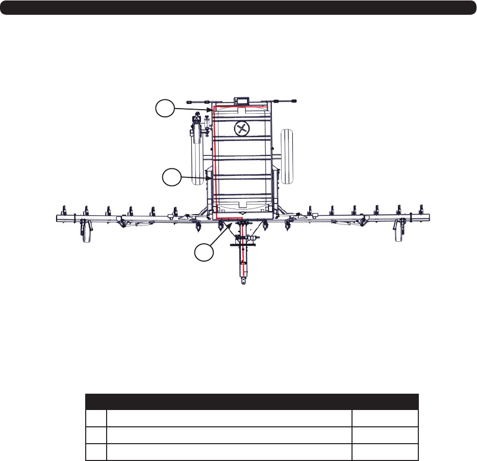
57
Wire Harness
# Light Harness Part. No.
1Main Wiring Harness with 7 Prong Connector JM0027077
2Soil Conditioner Light Wiring Harness JM0027080
3Light Enhancer and Adaptr Kit (3 wires) JM0010566
1
2
3
