ORBIT Rising Stem Ball Valves Brochure
User Manual: ORBIT Rising Stem Ball Valves Brochure Resource Library
Open the PDF directly: View PDF ![]() .
.
Page Count: 28
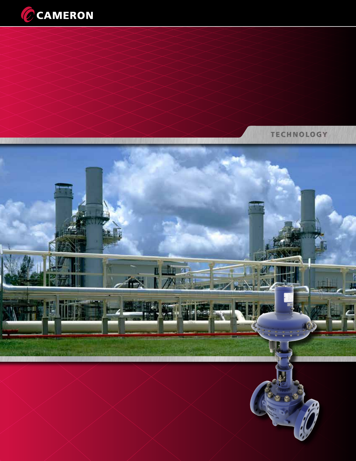
ORBIT Valves
Unique tilt-and-turn design for fast, low-torque operation and long-term, reliable
performance in applications when zero leakage and frequent operation are demanded.


1
ORBIT VALVES
Standard Features ................................................................................. 2
Quality Assurance ................................................................................. 3
Operating Principle ............................................................................... 4
Market Operations ................................................................................ 5
Product Range and Options .................................................................. 6
How to Order ....................................................................................... 7
One-Piece Stem, Enclosed Bonnet Valves Details and Materials .............. 8
Two-Piece Stem, Enclosed Bonnet Valves Details and Materials .............. 10
One-Piece Stem, OS&Y Bonnet Valves Details and Materials .................. 12
Two-Piece Stem, OS&Y Bonnet Valves Details and Materials .................. 14
End Flange Bolting Dimensions ............................................................. 16
Seat and Stem Packing Selection ........................................................... 18
Markings .............................................................................................. 19
Actuator Figure Numbers ...................................................................... 20
Services for Valves and Actuation .......................................................... 23
Trademark Information ......................................................................... 24
Table of Contents
2
ORBIT Valves
STANDARD FEATURES
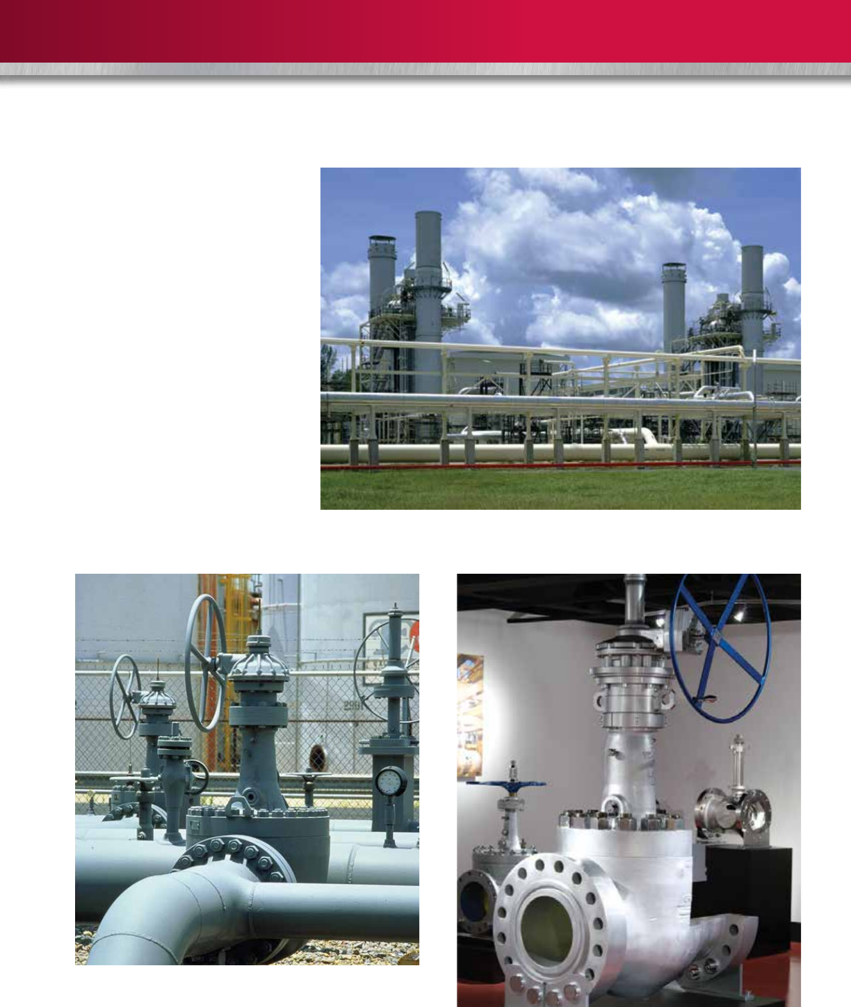
Cameron’s ORBIT® valves are ideal for applications when zero leakage and frequent operation are demanded. They are
used globally in gas processing plants using molecular sieve systems in switching service.
• No Rubbing Between Sealing Surfaces
The tilt-and-turn action eliminates seal abrasion,
which is the major cause of seat
wear in conventional ball,
gate and plug valves.
• Injectable Packing
For in-service
maintenance, stem
packing material is
injected through the
packing fitting, giving
complete control of fugitive
emissions. (Available on all enclosed
bonnet models.)
• Single-seat Design
The single, stationary seat in
the ORBIT valve seals in
both directions and avoids
the problems of
trapped pressure
between seals.
• Long Life
ORBIT valves
replace
troublesome ball
valves, gate
valves, globe
valves and plug
valves. The ORBIT design has
performance advantages that
reduce plant outage and reduce the
cost of ownership.
• Optimum Flow
Full port or reduced port openings give high CV figures.
System pumping efficiency is enhanced and erosion problems
are reduced.
• Top-entry Design
In-line inspection and repair, after system
depressurizing, simplifies maintenance.
• Dual Stem Guides
Hardened stem slots and tough
guide pins control the lift-and-turn
action of the stem.
• Self-cleaning
Tilting the core away from the seat
before rotation causes immediate
flow around 360 degrees of the core
face. Product flow flushes any foreign
material away from the seat without
localized, high-velocity erosive flow.
• Low-torque Operation
ORBIT valves turn easily because
seal rubbing is eliminated.
• Wear-resistant Hard
Facing on Core
The core face is a hard, polished
material that will endure difficult
service, without loss of sealing
integrity.
• Mechanical
Cam Closure
The cam angle at the
lower end of the stem
provides a mechanically
energized seal.
NOTE: Never remove any part from an
ORBIT valve unless specifically instructed
to do so in the literature, or without first
consulting a Cameron representative.
Incorrect procedure could result in personal injury
and/or property damage.
3
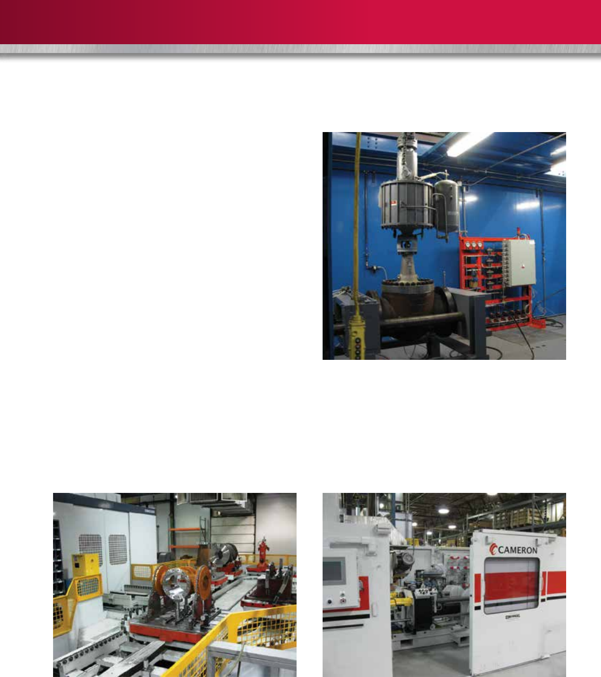
Cameron’s Little Rock, Ark., US, manufacturing facility has
quality programs that are ISO 9001 registered.
Specifications and Compliances
• API 6D
• ISO 9001:2008
• PED 97/23/EC
• ATEX Directive 94/9/EC
• GOST
• GOST-R Certificate and RTN Permit
• ISO 15848-1 (Fugitive Emission Type Testing)
• Shell GSI SPE 77/300 TAT Qualified and
TAMAP Two-Star Rating
• ASME B16.34
Cameron’s manufacturing philosophy and the standard
36-month warranty ensures that the design, materials
and workmanship of all ORBIT products result in years of
dependable operation.
Certifications for hydrostatic test results and material
properties are available on request.
The Little Rock facility has undergone a new layout
reorganization and CAPEX investment in state-of-the-art
equipment.
Every ORBIT valve built is individually pressure tested to meet or
exceed industry standards.
Gas testing and certification to the latest industry standards is
performed by independent inspectors.
QUALITY ASSURANCE
4
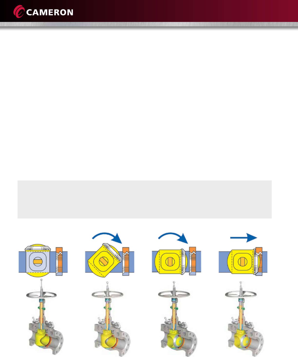
To close an ORBIT valve,
as the handwheel is
turned, the stem begins
to lower.
Precision spiral grooves in
the stem act against fixed
guide pins, causing the
stem and core to rotate.
Continued turning of the
handwheel rotates the
core and stem a full 90
degrees without the core
touching the seat.
Final turns of the
handwheel mechanically
wedge the stem down,
pressing the core firmly
against the seat.
To Close an ORBIT Valve
Every ORBIT valve incorporates a proven tilt-and-turn
operation that eliminates seal rubbing, which is the
primary cause of valve failure.
When an ORBIT valve is closed, the core is mechanically
wedged tightly against the seat, ensuring positive shutoff.
When an ORBIT valve begins to open, the core tilts away
from the seat and line flow passes uniformly around the
core face. This eliminates the localized high-velocity flow
that typically creates uneven seat wear in ordinary ball,
gate and plug valves. The core then rotates to the fully
open position.
The absence of seal rubbing during both opening and
closing means easy, low-torque valve operation and
long-term reliable performance.
When valve leakage cannot be tolerated, Cameron’s
ORBIT operating principle can be relied upon to deliver a
positive shutoff.
OPERATING PRINCIPLE
5
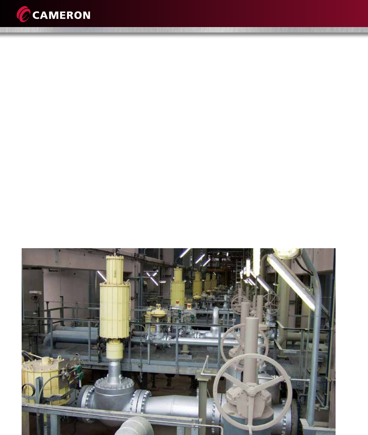
MARKET OPERATIONS
The ORBIT valve’s top-entry design provides convenient access
for in-line inspection and repairs, when required. For
environmental protection, injectable packing can be replenished
while valves are under full line pressure on enclosed bonnet
models.
An ORBIT model is displayed at the customer show room in Little
Rock, Ark., US.
ORBIT valves are ideal where frequent cycling and a positive shutoff are required, conditions
that are prevalent in molecular sieve applications in gas processing plants.
ORBIT valves are ideally suited for:
• Mol sieve dehydration
switches valves
• Flowlines
• Meter isolation
• Dryer switching
• Block and bypass
• Product segregation
• Emergency shutdown
• Suction and discharge isolation
• Heat transfer fluids/hot oil
• Hydrogen service
• Many additional applications
6
Cameron’s ORBIT brand offers complete packages that can include valves, actuators and instrumentation.
Materials
Carbon steel, stainless steel, duplex SS, high-nickel alloys
and other special materials are used as service conditions
require. External protective coatings are available for
added durability in corrosive environments.
Seats
Soft or metal-seated options are selected for the intended
service. Because the seals in the valves do not rub, and
because they are mechanically compressed shut, they
survive in high-temperature and abrasive situations.
Operation
Hand or power operation can be selected. Cameron’s
ORBIT brand offers double-acting, spring-close and
spring-open pneumatic actuators. User-selected electric
and hydraulic actuators are available. Instrumentation
choices also are offered.
Customizing
Handwheel extensions, safety interlocks, position
indicator limit switches, thermal jackets, custom painting
and special inspection can be provided.
Maintenance and Repairs
Cameron’s services include inspection, maintenance and
repairs for all ORBIT valve products.
ORBIT valves are manufactured in a variety of materials, sizes and trims to meet specific requirements.
PRODUCT RANGE AND OPTIONS

7
Sizes Available
ASME Class
(PN)
150
(20)
300
(50)
600
(100)
900
(150)
1500
(250)
2500
(420)
Reduced Port, Flanged in. 2 through 30 2 through 30 2 through 30 3 through 24 3 through 20 3 through 16
(mm) (50 through 750) (50 through 750) (50 through 750) (80 through 600) (80 through 500) (80 through 400)
Full Port, Flanged 1 through 24 1 through 24 1 through 24 1 through 20 1 through 16 2 through 12
(25 through 600) (25 through 600) (25 through 600) (25 through 500) (25 through 400) (50 through 300)
Reduced Port, Butt Weld 3 through 20 3 through 20 3 through 20 3 through 20 3 through 20 3 through 12
(80 through 500) (80 through 500) (80 through 500) (80 through 500) (80 through 500) (80 through 300)
Full Port, Butt Weld 2 through 16 2 through 16 2 through 16 2 through 16 2 through 16 2 through 10
(50 through 400) (50 through 400) (50 through 400) (50 through 400) (50 through 400) (50 through 250
Full Port, Butt Weld x Flanged – 2 through 16 – – – –
(50 through 400)
Full Port, Socket Weld – – 1 through 2 1 through 2 1 through 2 1
(25 through 50) (25 through 50) (25 through 50) (25)
Full Port, Threaded – – 1 through 3 1 through 3 1 through 2 1
(25 through 80) (25 through 80) (25 through 50) (25)
HOW TO ORDER
Class
1 – ASME/ANSI 150 3 – API 1000
2 – ASME/ANSI 300 5 – API 2000
4 – ASME/ANSI 600 6 – API 3000
5 – ASME/ANSI 900 7 – API 5000
6 – ASME/ANSI 1500
7 – ASME/ANSI 2500
Trim*
0 – T3 Modified
2 – T7 Modified
3 – Standard (T3)
5 – Special Preparation
7 – Sour Corrosive (T7)
8 – Corrosive (316 SS) (T8)
Model
1 – Standard
2 – Low-temp. -50° F (-46° C)
3 – Alloy Steel
4 – API
5 – National Grid (UK)
6 – Corrosive: 316 SS -155° F (-104° C)
7 – Duplex SS
8 – Drilling Valves
9 – High-nickel Alloy
Port Size and Connection
2 – Full Port, Flanged
3 – Reduced Port, Flanged
4 – Full Port, Threaded
5 – Reduced Port, Butt Weld
6 – Full Port, Butt Weld
6 – Full Port, Socket Weld
6 – Full Port, Butt Weld x RF
Ordering Information
How to develop figure numbers:
Example
1433H = Standard, ASME/ANSI Class 600, Reduced Port, Flanged, Standard (T3)
* For a more complete explanation of trims and figure numbers, consult your Cameron representative.
** Valve figure number may use more than one suffix. Example: 1433H8L.
Cameron reserves the right to substitute materials listed on the following pages with alternate materials for the designated service.
1433H
Suffix**
A – Type of Seat 250° F (121° C) Max.
H – Type of Seat 500° F (260° C) Max.
H8 – Type of Seat 800° F (427° C) Max.
PK – Type of Seat 570° F (299° C) Max.
L – Adapted for Actuator
BB – Block-and-Bleed Model
GS – Grease Seal Model
S – Non-standard End-to-End Dimension
SC – Chevron Special Trim
Note: See page 18 for seat selection.
8
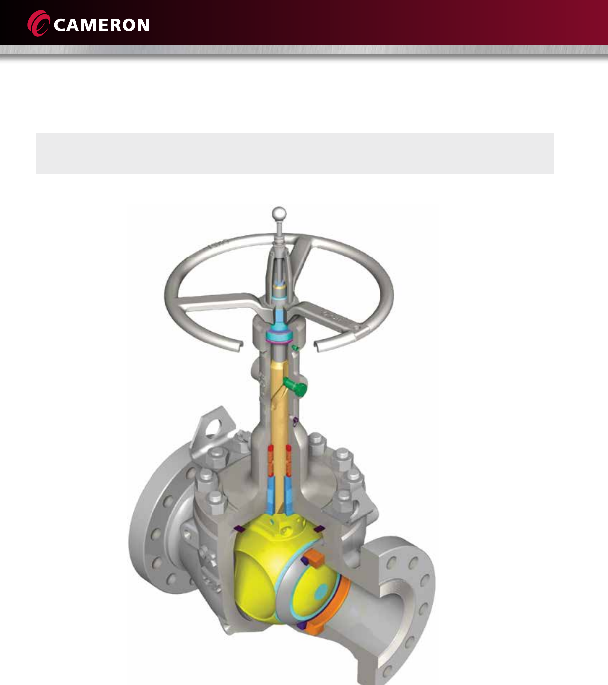
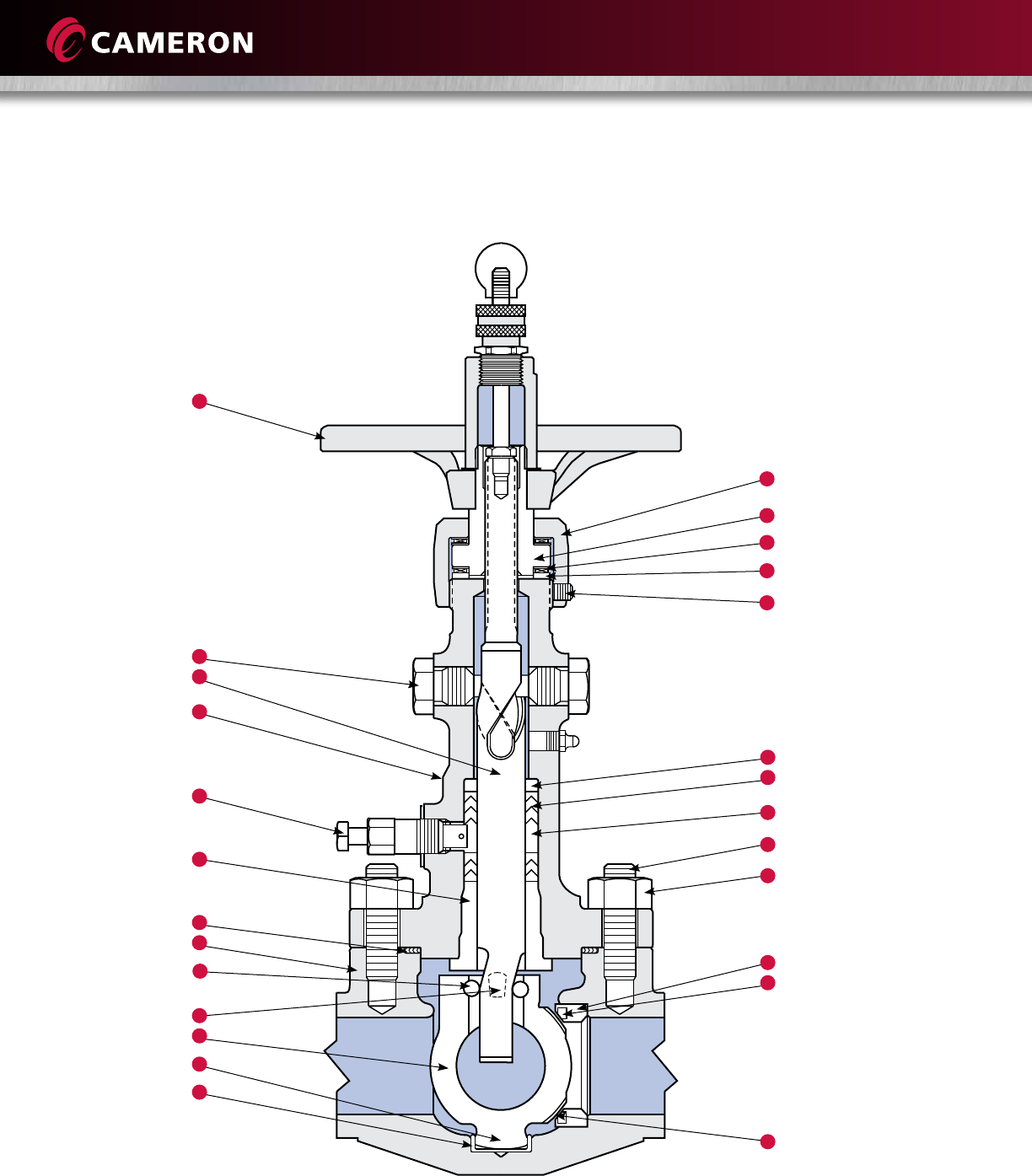
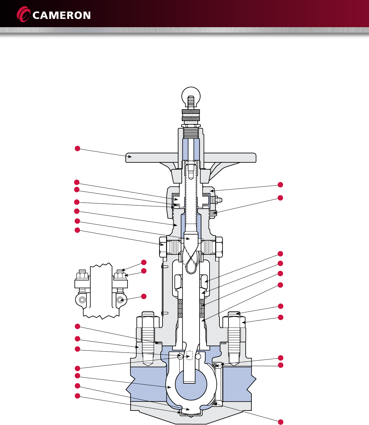
ONE-PIECE STEM, ENCLOSED BONNET VALVES
19
22
23
24
26
21
16
17
4
5
6
7
9
15
14
2
20
18
3
1
12
8
10
13
25
Details and Materials
11

9
Materials List
Standard T3 Standard T7 Low-Temp. T3 Low-Temp. T7
Parts Description -20° F to 500° F -20° F to 500° F -50° F to 500° F -50° F to 500° F
(-29° C to 260° C) (-29° C to 260° C) (-46° C to 260° C) (-46° C to 260° C)
1 Body ASTM A216 Gr. WCC ASTM A216 Gr. WCC ASTM A352 Gr. LCC ASTM A352 Gr. LCC
2 Bonnet ASTM A216 Gr. WCC ASTM A216 Gr. WCC ASTM A352 Gr. LCC ASTM A352 Gr. LCC
3 Gasket Stainless Steel and Graphite Stainless Steel and Graphite Stainless Steel and Graphite Stainless Steel and Graphite
4 Stud ASTM A193 Gr. B7 ASTM A193 Gr. B7M ASTM A320 Gr. L7 ASTM A320 Gr. L7M
5 Nut ASTM A194 Gr. 2H ASTM A194 Gr. 2HM ASTM A194 Gr. 4 or 7 ASTM A194 Gr. 7M
6 Seat Body Stainless Steel Stainless Steel Stainless Steel Stainless Steel
7 Seat Insert Teflon®Teflon Teflon Teflon
8 Core ASTM A216 Gr. WCC ASTM A216 Gr. WCC ASTM A216 Gr. WCC ASTM A216 Gr. WCC
9 Core Face Nickel Nickel-based CRA Nickel Nickel-based CRA
10 Trunnion Overlay – Nickel-based CRA – Nickel-based CRA
11 Core Pin Stainless Steel Nickel-based CRA Stainless Steel Nickel-based CRA
12 Support Pin Stainless Steel Stainless Steel Stainless Steel Stainless Steel
13 Trunnion Bushing Stainless Steel Stainless Steel Stainless Steel Stainless Steel
14 Stem Alloy Steel Stainless Steel Alloy Steel Stainless Steel
15 Stem Guide Alloy Steel Stainless Steel Alloy Steel Stainless Steel
16 Packing Rings Teflon Teflon Teflon Teflon
17 Injectable Packing ORBIT GP6 ORBIT GP6 ORBIT GP6 ORBIT GP6
18 Bonnet Bushing Stainless Steel Stainless Steel Stainless Steel Stainless Steel
19 Bonnet Nut Carbon Steel Carbon Steel Carbon Steel Carbon Steel
20 Packing Fitting Stainless Steel Stainless Steel Stainless Steel Stainless Steel
21 Packing Chamber Bushing Carbon Steel Carbon Steel Carbon Steel Carbon Steel
22 Drive Nut Ductile Ni-resist Alloy Steel Alloy Steel Alloy Steel
23 Bearing Alloy Steel Alloy Steel Alloy Steel Alloy Steel
24 Bearing Race Alloy Steel Alloy Steel Alloy Steel Alloy Steel
25 Handwheel Ductile Iron Ductile Iron Ductile Iron Ductile Iron
26 Set Screw Alloy Steel Alloy Steel Alloy Steel Alloy Steel
Actual materials of construction will depend on the valve size, pressure class, end configuration and service conditions.
Consult Cameron for a detailed materials list.
This is a partial list of material options. Many alternatives can be provided to match the actual service requirements.
10
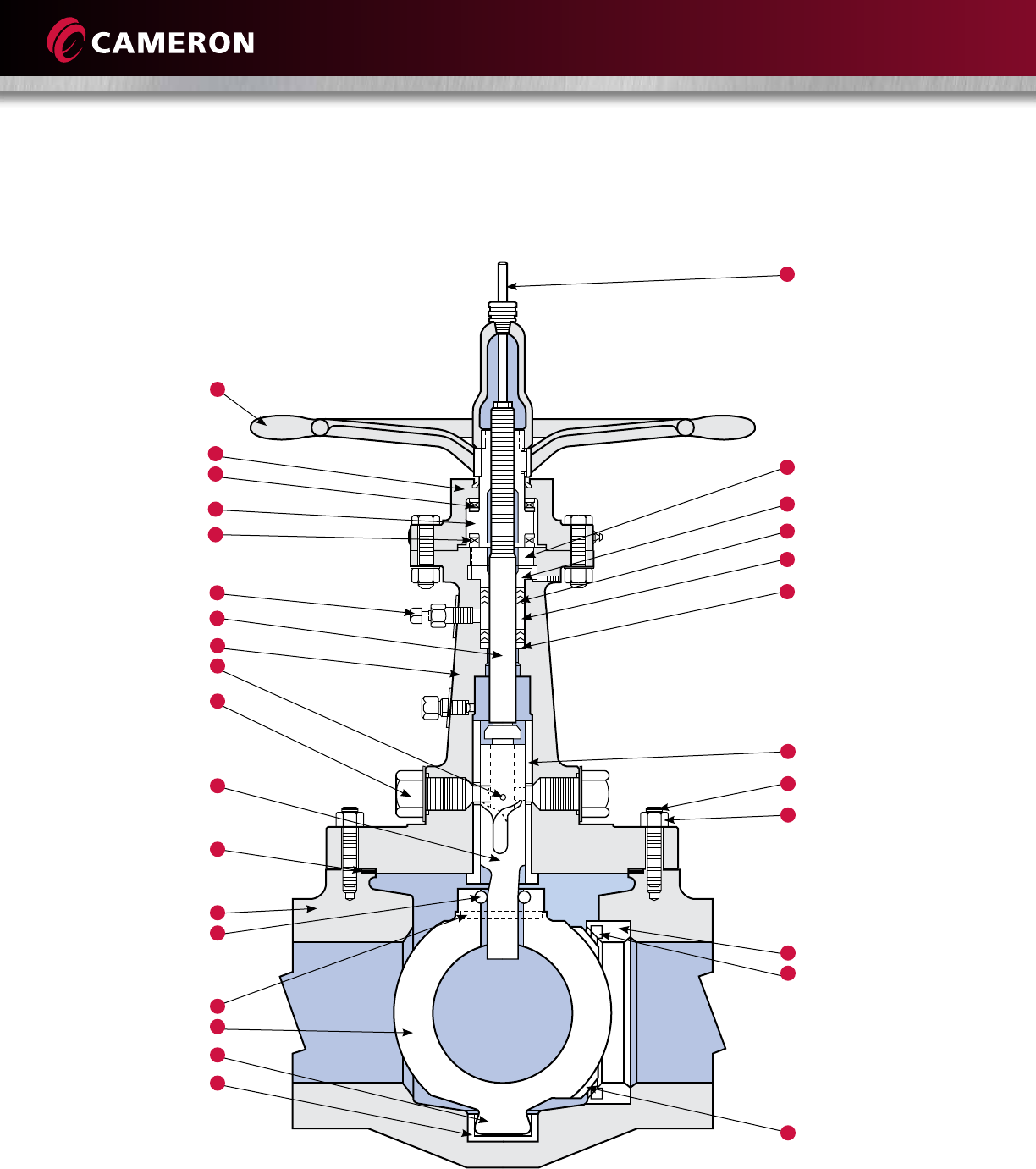
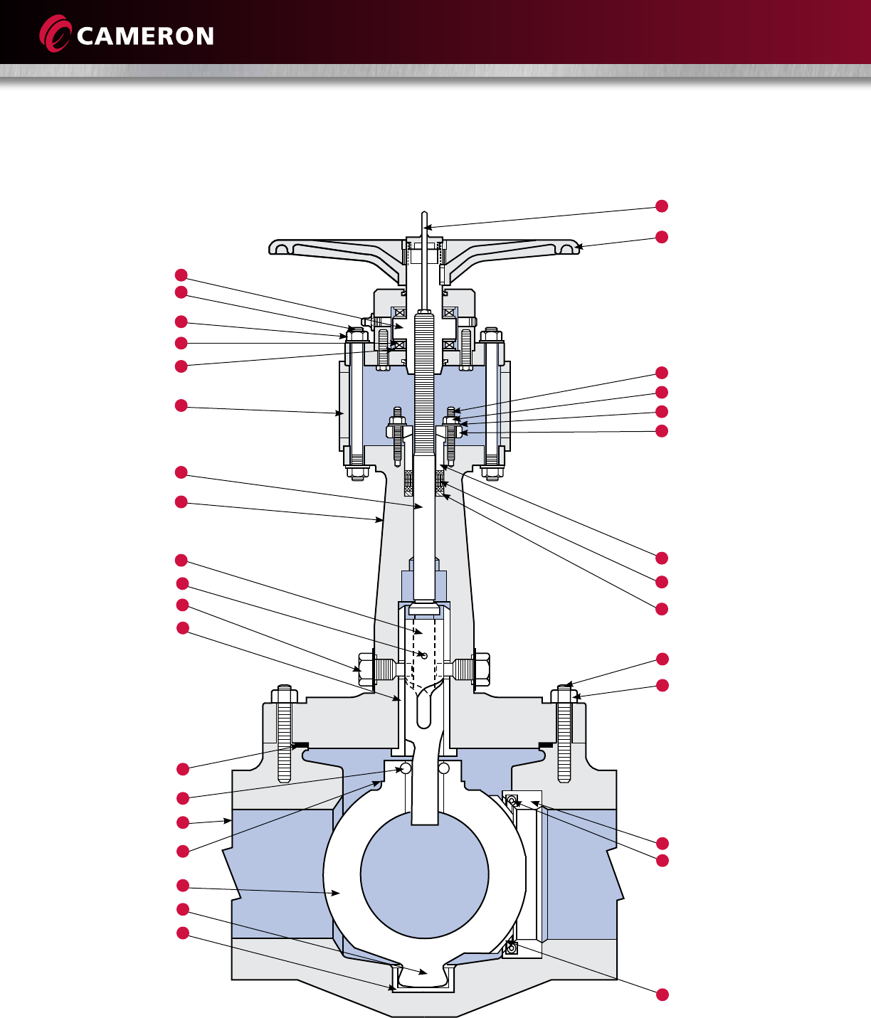
TWO-PIECE STEM, ENCLOSED BONNET VALVES
30
29
18
19
22
20
4
5
6
7
9
2
16
17
15
3
1
11
12
8
10
13
27
28
24
26
23
25
21
14
Details and Materials

11
Materials List
Standard T3 Standard T7 Low-temp. T3 Low-temp. T7
Parts Description -20° F to 500° F -20° F to 500° F -50° F to 500° F -50° F to 500° F
(-29° C to 260° C) (-29° C to 260° C) (-46° C to 260° C) (-46° C to 260° C)
1 Body ASTM A216 Gr. WCC ASTM A216 Gr. WCC ASTM A352 Gr. LCC ASTM A352 Gr. LCC
2 Bonnet ASTM A216 Gr. WCC ASTM A216 Gr. WCC ASTM A352 Gr. LCC ASTM A352 Gr. LCC
3 Gasket Stainless Steel and Graphite Stainless Steel and Graphite Stainless Steel and Graphite Stainless Steel and Graphite
4 Stud ASTM A193 Gr. B7 ASTM A193 Gr. B7M ASTM A320 Gr. L7 ASTM A320 Gr. L7M
5 Nut ASTM A194 Gr. 2H ASTM A194 Gr. 2HM ASTM A194 Gr. 7 ASTM A194 Gr. 7M
6 Seat Body Stainless Steel Stainless Steel Stainless Steel Stainless Steel
7 Seat Insert Teflon Teflon Teflon Teflon
8 Core ASTM A216 Gr. WCC ASTM A216 Gr. WCC ASTM A216 Gr. WCC ASTM A216 Gr. WCC
9 Core Face Nickel Nickel-based CRA Nickel Nickel-based CRA
10 Trunnion Overlay – Nickel-based CRA – Nickel-based CRA
11 Core Pin Stainless Steel Stainless Steel Stainless Steel Stainless Steel
12 Support Pin Stainless Steel Stainless Steel Stainless Steel Stainless Steel
13 Trunnion Bushing Stainless Steel Stainless Steel Stainless Steel Stainless Steel
14 Stem Stainless Steel Stainless Steel Stainless Steel Stainless Steel
15 Stem Cam Alloy Steel Stainless Steel Alloy Steel Stainless Steel
16 Stem Pin Alloy Steel Stainless Steel Alloy Steel Stainless Steel
17 Stem Guide Alloy Steel Stainless Steel Alloy Steel Stainless Steel
18 Packing Rings Teflon Teflon Teflon Teflon
19 Injectable Packing ORBIT GP6 ORBIT GP6 ORBIT GP6 ORBIT GP6
20 Bonnet Sleeve Stainless Steel Stainless Steel Stainless Steel Stainless Steel
21 Packing Fitting Stainless Steel Stainless Steel Stainless Steel Stainless Steel
22 Packing Chamber Bushing Carbon Steel Carbon Steel Carbon Steel Carbon Steel
23 Drive Nut Ductile Ni-resist Alloy Steel Alloy Steel Alloy Steel
24 Drive Nut Retainer ASTM A216 Gr. WCC ASTM A216 Gr. WCC ASTM A216 Gr. WCC ASTM A216 Gr. WCC
25 Bearing Alloy Steel Alloy Steel Alloy Steel Alloy Steel
26 Bearing Race Alloy Steel Alloy Steel Alloy Steel Alloy Steel
27 Handwheel Ductile Iron Ductile Iron Ductile Iron Ductile Iron
28 Position Indicator Rod Stainless Steel Stainless Steel Stainless Steel Stainless Steel
29 Packing Gland Aluminum Bronze Carbon Steel Carbon Steel Carbon Steel
30 Packing Gland Retainer Carbon Steel Carbon Steel Carbon Steel Carbon Steel
Actual materials of construction will depend on the valve size, pressure class, end configuration and service conditions.
Consult Cameron for a detailed materials list.
This is a partial list of material options. Many alternatives can be provided to match the actual service requirements.
12
ONE-PIECE STEM, OS&Y BONNET VALVES
18
28
4
5
6
7
9
21
19
20
3
1
11
12
8
10
13
27
24
25
26
2
14
15
23
22
16
17
Details and Materials

13
Actual materials of construction will depend on the valve size, pressure class, end configuration and service conditions.
Consult Cameron for a detailed materials list.
This is a partial list of material options. Many alternatives can be provided to match the actual service requirements.
Materials List
Standard T3 Standard T7
Parts Description -20° F to 800° F -20° F to 650° F
(-29° C to 427° C) (-29° C to 343° C)
1 Body ASTM A216 Gr. WCC ASTM A216 Gr. WCC
2 Bonnet ASTM A216 Gr. WCC ASTM A216 Gr. WCC
3 Gasket Stainless Steel and Graphite Stainless Steel and Graphite
4 Stud ASTM A193 Gr. B7 ASTM A193 Gr. B7M
5 Nut ASTM A194 Gr. 2H ASTM A194 Gr. 2HM
6 Seat Body Stainless Steel Stainless Steel
7 Seat Insert Stainless Steel Stainless Steel
8 Core ASTM A216 Gr. WCC ASTM A216 Gr. WCC
9 Core Face Nickel Cobalt Alloy
10 Trunnion Overlay – Nickel-based CRA
11 Core Pin Stainless Steel Nickel-Based CRA
12 Support Pin Stainless Steel Stainless Steel
13 Trunnion Bushing Stainless Steel Stainless Steel
14 Stem Alloy Steel Stainless Steel
15 Stem Guide Alloy Steel Stainless Steel
16 Packing Rings Graphite and Carbon Graphite and Carbon
17 Bonnet Bushing Stainless Steel Stainless Steel
18 Bonnet Nut Carbon Steel Carbon Steel
19 Packing Eyebolt Nut ASTM A194 Gr. 2H ASTM A193 Gr. 2HM
20 Packing Eyebolt Pin Stainless Steel Stainless Steel
21 Packing Eyebolt Stainless Steel Stainless Steel
22 Packing Gland Ductile Iron Ductile Iron
23 Packing Gland Retainer ASTM A216 Gr. WCC ASTM A216 Gr. WCC
24 Drive Nut Ductile Ni-resist Alloy Steel
25 Bearing Alloy Steel Alloy Steel
26 Bearing Race Alloy Steel Alloy Steel
27 Handwheel Ductile Iron Ductile Iron
28 Set Screw Alloy Steel Alloy Steel
14
TWO-PIECE STEM, OS&Y BONNET VALVES
21
22
4
5
6
7
9
25
3
11
1
12
8
10
13
29
14
2
15
16
17
23
19
24
18
33
32
26
30
31
27
28
20
Details and Materials

15
Materials List
Standard T3 Standard T7
Parts Description -20° F to 800° F -20° F to 650° F
(-29° C to 427° C) (-29° C to 343° C)
1 Body ASTM A216 Gr. WCC ASTM A216 Gr. WCC
2 Bonnet ASTM A216 Gr. WCC ASTM A216 Gr. WCC
3 Gasket Stainless Steel and Graphite Stainless Steel and Graphite
4 Stud ASTM A193 Gr. B7 ASTM A193 Gr. B7M
5 Nut ASTM A194 Gr. 2H ASTM A194 Gr. 2HM
6 Seat Body Stainless Steel Stainless Steel
7 Seat Insert Stainless Steel Stainless Steel
8 Core ASTM A216 Gr. WCC ASTM A216 Gr. WCC
9 Core Face Nickel Cobalt Alloy
10 Trunnion Overlay – Nickel-based CRA
11 Core Pin Stainless Steel Stainless Steel
12 Support Pin Stainless Steel Stainless Steel
13 Trunnion Bushing Stainless Steel Stainless Steel
14 Stem Stainless Steel Stainless Steel
15 Stem Cam Alloy Steel Stainless Steel
16 Stem Pin Alloy Steel Stainless Steel
17 Stem Guide Alloy Steel Stainless Steel
18 Packing Chamber Bushing Carbon Steel Carbon Steel
19 Packing Gland Ductile Iron Ductile Iron
20 Packing Gland Retainer ASTM A216 Gr. WCC ASTM A216 Gr. WCC
21 Stud ASTM A193 Gr. B7 ASTM A193 Gr. B7M
22 Nut ASTM A194 Gr. 2H ASTM A194 Gr. 2HM
23 Washer Carbon Steel Carbon Steel
24 Packing Rings Graphite and Carbon Graphite and Carbon
25 Bonnet Sleeve Stainless Steel Stainless Steel
26 Drive Nut Ductile Ni-resist Alloy Steel
27 Bearing Alloy Steel Alloy Steel
28 Bearing Race Alloy Steel Alloy Steel
29 Packing Access Sleeve Carbon Steel Carbon Steel
30 Stud ASTM A193 Gr. B7 ASTM A193 Gr. B7
31 Nut ASTM A194 Gr. 2H ASTM A194 Gr. 2H
32 Handwheel Ductile Iron Ductile Iron
33 Position Indicator Rod Stainless Steel Stainless Steel
Actual materials of construction will depend on the valve size, pressure class, end configuration and service conditions.
Consult Cameron for a detailed materials list.
This is a partial list of material options. Many alternatives can be provided to match the actual service requirements.

16
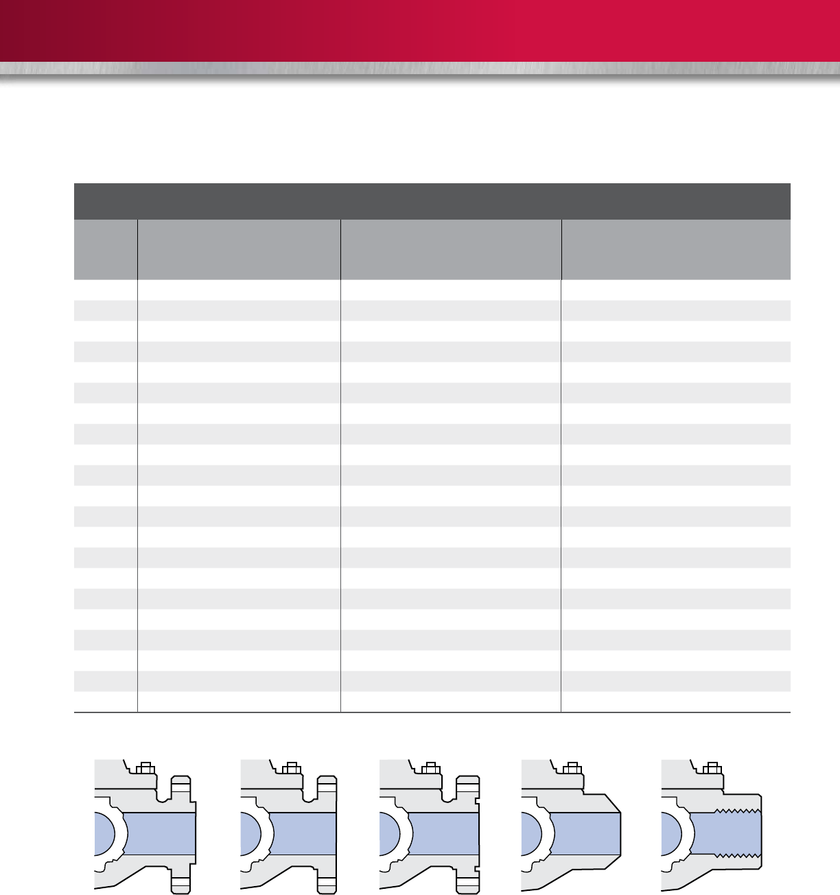
END FLANGE BOLTING DIMENSIONS
ASME/
ANSI Class 150 Class 300 Class 600
Valve
Size
in.
Number
of
Fasteners
per Valve
Fastener
Diameter
in.
Length
of
Studs
in.
*Length
of
Capscrews
in.
Number
of
Fasteners
per Valve
Fastener
Diameter
in.
Length
of
Studs
in.
*Length
of
Capscrews
in.
Number
of
Fasteners
per Valve
Fastener
Diameter
in.
Length
of Stud *Length
of
Capscrew
in.
RF
in.
RTJ
in.
1 8 1/2 3 – 8 5/8 3-1/4 – 8 5/8 3-1/2 3-1/2 –
1-1/2 8 1/2 3-1/4 – 8 3/4 3-1/2 – 8 3/4 4-1/4 4-1/4 –
2 x 1-1/2 x 2 8 5/8 3-1/4 – 16 5/8 3-1/2 – 16 5/8 4-1/4 4-1/4 –
2 8 5/8 3-1/4 – 16 5/8 3-1/2 – 16 5/8 4-1/4 4-1/4 –
2 BB/GS 8 5/8 3-1/4 – – – – – – – – – –
3 x 2 x 3 8 5/8 3-1/2 – 16 3/4 4-1/4 – 16 3/4 5 5 –
3* 8 5/8 2-1/2 1-1/2 16 3/4 4-1/4 – 16 3/4 5 5 –
4 x 3 x 4* 16 5/8 2-3/4 1-3/4 16 3/4 4-1/2 – 16 7/8 5-3/4 5-3/4 –
4* 16 5/8 2-3/4 1-3/4 12 3/4 4-1/2 – 16 7/8 5-3/4 5-3/4 –
– – – – 4 3/4 – 2-1/4 – – – – –
6 x 4 x 6 16 3/4 4 – 24 3/4 4-3/4 – 24 1 6-3/4 6-3/4 –
6* 16 3/4 3 2 16 3/4 4-3/4 – 24 1 6-3/4 6-3/4 –
– – – – 8 3/4 – 2-1/2 – – – – –
8 x 6 x 8 16 3/4 4-1/4 – 24 7/8 5-1/2 – 24 1-1/8 7-1/2 7-3/4 –
8* 12 3/4 4-1/4 1-1/2 16 7/8 5-1/2 – 24 1-1/8 7-1/2 7-3/4 –
4 3/4 – 2 8 7/8 – 3 – – – – –
10 x 8 x 10* 20 7/8 4-1/2 – 28 1 6-1/4 – 32 1-1/4 8-1/2 8-1/2 –
4 7/8 4-1/2 2-1/4 4 1 – 3-3/4 – – – – –
10 24 7/8 4-1/2 – 32 1 6-1/4 – 32 1-1/4 8-1/2 8-1/2 –
12 x 10 x 12 24 7/8 4-3/4 – 32 1-1/8 6-3/4 – 40 1-1/4 8-3/4 8-3/4 –
12 24 7/8 4-3/4 – 32 1-1/8 6-3/4 – 40 1-1/4 8-3/4 8-3/4 –
14 x 12 x 14 24 1 5-1/4 – 40 1-1/8 7 – 40 1-3/8 9-1/4 9-1/4 –
14 – – – – 40 1-1/8 7 – 40 1-3/8 9-1/4 9-1/4 –
16 x 12 x 16 – – – – – – – – 40 1-1/2 10 10 –
16 x 14 x 16 32 1 5-1/4 – 40 1-1/4 7-1/2 – – – – – –
16 32 1 5-1/4 – 40 1-1/4 7-1/2 – 40 1-1/2 10 10 –
18 x 16 x 18 32 1-1/8 5-3/4 – 48 1-1/4 7-3/4 – 40 1-5/8 10-3/4 11 –
20 x 16 x 20 40 1-1/8 6-1/4 – 48 1-1/4 8 – 48 1-5/8 11-1/4 11-1/2 –
18 32 1-1/8 6-1/4 – – – – – – – – – –
20* – – – – 48 1-1/4 7-3/4 – 36 1-5/8 11-1/4 11-1/2 –
– – – – – – – – 12 1-5/8 – – 5-3/4
24 x 20 x 24 – – – – 48 1-1/2 9 – 48 1-7/8 13 13-1/4 –
24 – – – – 48 1-1/2 9 – 48 1-7/8 13 13-1/4 –
* Space limitations prevent the use of through-bolts in some of the holes in the end flanges on these valves.
These holes are drilled and tapped so that a shorter stud bolt or capscrew can be used.
17
ASME/
ANSI Class 900 Class 1500 Class 2500
Valve
Size
in.
Number
of
Fasteners
per Valve
Fastener
Diameter
in.
Length of Studs Number
of
Fasteners
per Valve
Fastener
Diameter
in.
Length of Studs Number
of
Fasteners
per Valve
Fastener
Diameter
in.
Length of Studs
RF
in.
RTJ
in.
RF
in.
RTJ
in.
RF
in.
RTJ
in.
1 8 3/4 5 5 8 7/8 5 5 – – – –
1-1/2 8 1 5-1/2 5-1/2 8 1 5-1/2 5-1/2 – – – –
2 16 7/8 5-3/4 5-3/4 16 7/8 5-3/4 5-3/4 16 1 7 7
3 x 2 x 3 16 7/8 5-3/4 5-3/4 16 1-1/8 7 7 16 1-1/4 9 9-1/4
3 16 7/8 5-3/4 5-3/4 16 1-1/8 7 7 16 1-1/4 9 9-1/4
4 x 3 x 4 16 1-1/8 6-3/4 6-3/4 16 1-1/4 7-3/4 7-3/4 16 1-1/2 10-1/4 10-3/4
4 16 1-1/8 6-3/4 6-3/4 16 1-1/4 7-3/4 7-3/4 16 1-1/2 10-1/4 10-3/4
6 x 4 x 6 24 1-1/8 7-1/2 7-1/2 24 1-3/8 10-1/4 10-1/2 16 2 13-3/4 14-1/2
6 24 1-1/8 7-1/2 7-3/4 24 1-3/8 10-1/4 10-1/2 16 2 13-3/4 14-1/2
8 x 6 x 8 24 1-3/8 8-3/4 8-3/4 24 1-5/8 11-1/2 12-3/4 24 2 15-1/4 16
8 24 1-3/8 8-3/4 8-3/4 24 1-5/8 11-1/2 12-3/4 24 2 15-1/4 16
10 x 8 x 10 32 1-3/8 9-1/4 9-1/4 24 1-7/8 13-1/4 13-1/2 24 2-1/2 19-1/2 20-1/2
10 32 1-3/8 9-1/4 9-1/4 24 1-7/8 13-1/4 13-1/2 – – – –
12 x 10 x 12 40 1-3/8 10 10 32 2 14-3/4 15-1/4 – – – –
12 40 1-3/8 10 10 32 2 14-3/4 15-1/4 – – – –
14 x 12 x 14 40 1-1/2 10-3/4 11 32 2 1/4 16 16-3/4 – – – –
16 x 12 x 16 40 1-5/8 11-1/4 11-1/2 32 2-1/2 17-1/2 18-1/2 – – – –
16 40 1-5/8 11-1/4 11-1/2 32 2-1/2 17-1/2 18-1/2 – – – –
18 x 16 x 18 40 1-7/8 12-3/4 13-1/4 – – – – – – – –
20 x 16 x 20 40 2 13-3/4 14-1/4 32 3 21-1/4 22-1/4 – – – –
20 40 2 13-3/4 14-1/4 – – – – – – – –
ASME/ANSI
Raised-face
Flanged
ASME/ANSI
Flat-face
Flanged
RTJ
(RG)
Flanged
Butt
Weld
Socket Weld
or
Threaded
18
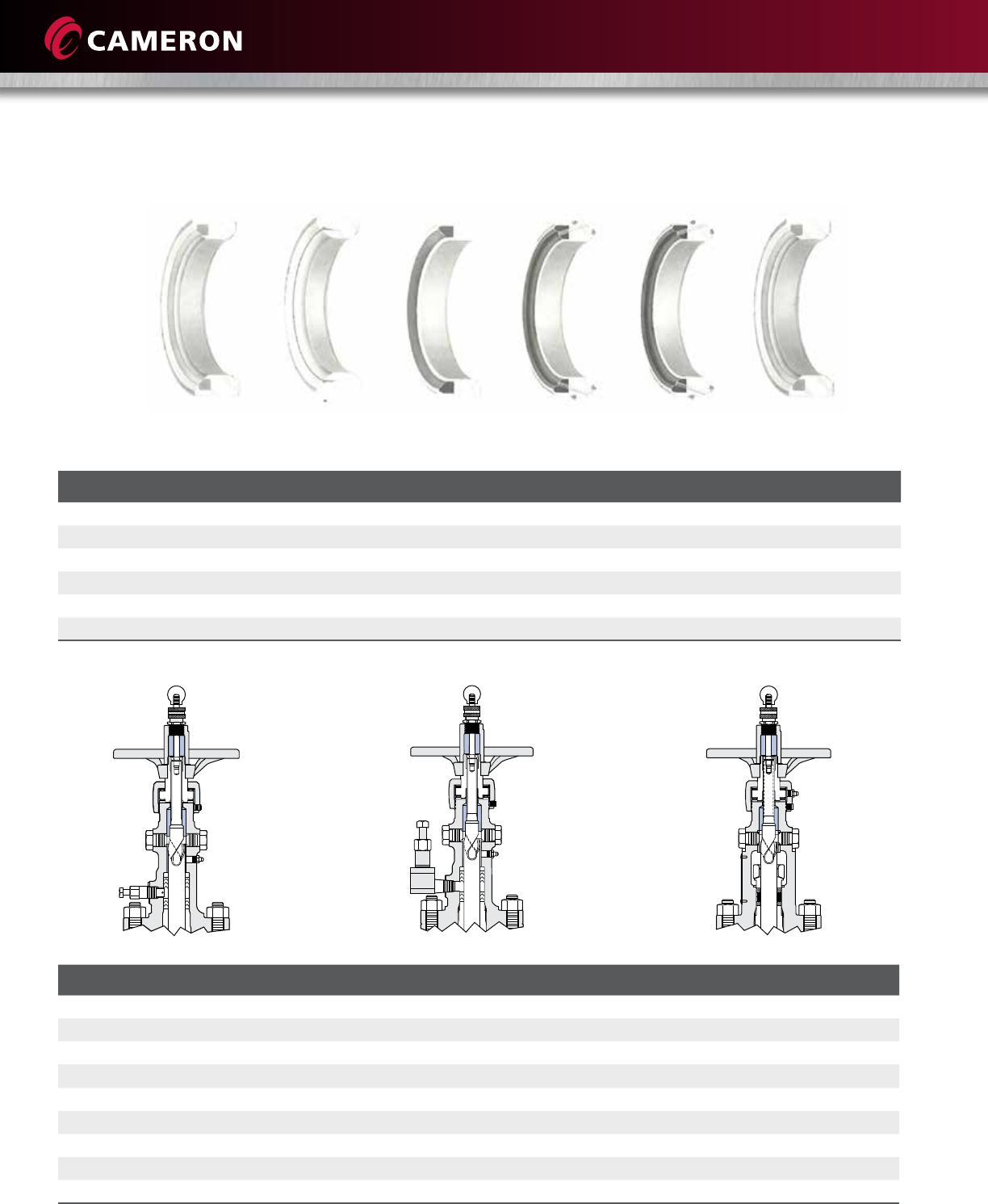
SEAT AND STEM PACKING SELECTION
Seat Selection
Temperature Insert Material Support Ring Bore Sizes (in.) Seat Options
-50° F to 250° F (-46° C to 121° C) Nylon Carbon Steel 2 to 16 Type A, BB and GS
-50° F to 250° F (-46° C to 121° C) Nylon Stainless Steel 2 to 16 Type A, BB and GS
-155° F to 500° F (-104° C to 260° C) Teflon TFE Stainless Steel 1 to 24 Type H
-155° F to 800° F (-104° C to 427° C) – Stainless Steel 1 Type H8
-155° F to 800° F (-104° C to 427° C) Stainless Steel Tube Stainless Steel 1-1/2 to 24 Type H8
-50° F to 570° F (-46° C to 300° C) PEEK®Stainless Steel 2 to 12 Type PK
Stem Packing Selection
Temperature/Service Packing Material ORBIT Designation
-50° F to 500° F (-46° C to 260° C) Injectable Teflon Packing with Fire-safe Graphite Top Ring GP6
*-50° F to 800° F (*-46° C to 427° C) Graphite Rings with OS&Y Packing GP20
*-155° F (104° C) for 316 SS Valve
-30° F to 550° F (-34° C to 288° C) Injectable Teflon Packing with Fire-safe Graphite Top Ring GP19
Ammonia Service
-20° F to 400° F (-29° C to 204° C) Injectable Teflon Packing with Teflon Rings GP27
MTBE Service
-30° F to 275° F (-34° C to 135° C) Injectable Teflon Packing with Teflon Rings GP7
Oxygen Service
Other packing materials available.
Teflon
TFE
Type H
All
Metal
Type H8
Nylon
Type A
Nylon
Block-and-Bleed
Type BB
Nylon
Grease Seal
Type GS
PEEK
Seat
Type PK
Standard Injectable Packing Low-temperature Injectable Packing OS&Y Packing
19
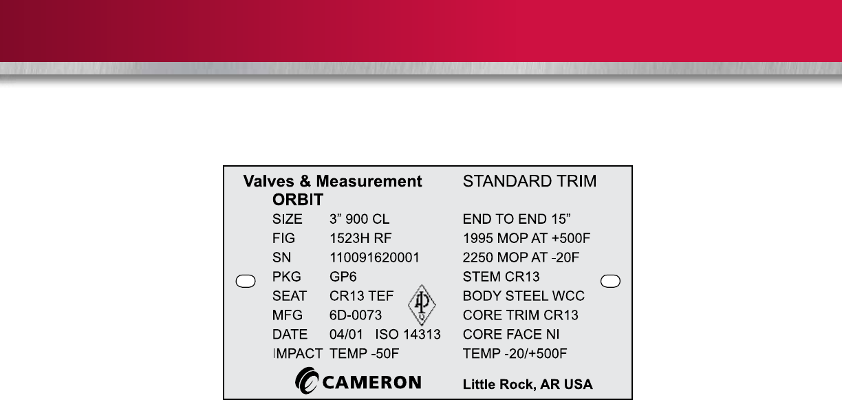
MARKINGS
Body Markings – ASME/ANSI Valve
The serial number is stamped into the side of the valve body or the OD of the flange. If the valve has ring joint facings, the
ring gasket number is stamped into the OD of the flange. Preferred pressure end and seat size code are stamped on the OD
of flanged valves and on the hub end of butt weld and threaded valves. The end connection size and class are stamped or
cast on the body.
Nameplate Markings for Valve Trim
AS Alloy Steel
15-6 Carpenter 450® Stainless Steel
660 A-638 (Grade 660)
HF-C Hardfacing Hastelloy C® and C-276
C-276 Hastelloy C-276®
MP35N Latrobe®
CO-U Cobalt-Based Ultimet®
NICU Monel®
NI Nickel
COCR Stellite®
17-4 17-4PH Stainless Steel
CR13 410 and 420 Stainless Steel (13% Chrome)
718 Inconel 718®
316 316 Stainless Steel
NYL Nylon
PEEK Polyetheretherketone
TEF Teflon
Nameplate Markings for Stem Packing
GP-6 General Service
GP-7 Oxygen Service
GP-19 Ammonia Service
GP-27 MTBE Service
Graphite OS&Y (Graphite Rings)
GP-22 Injectable Graphite
20
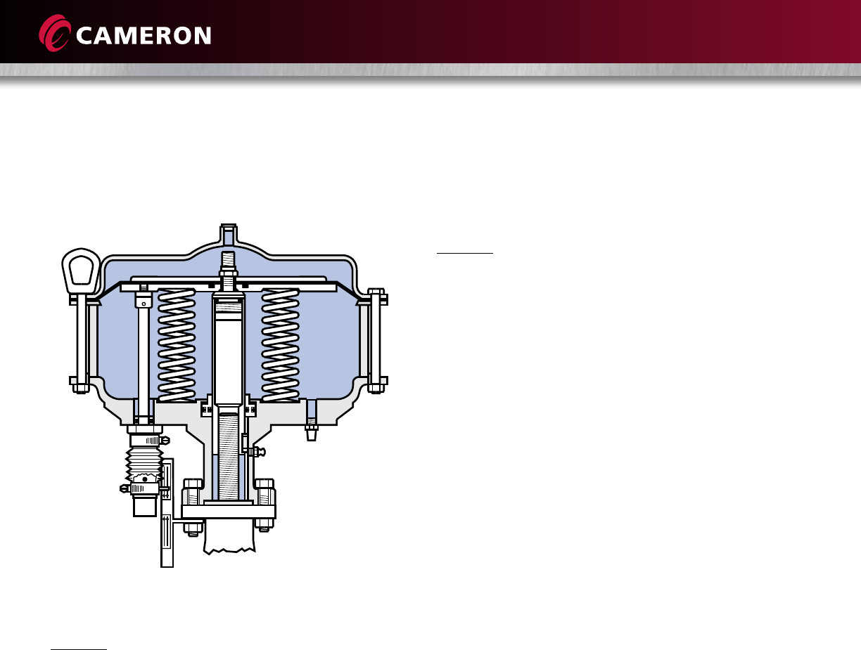
ACTUATOR FIGURE NUMBERS
Diaphragm Actuator
Double-acting Style
Example: 164100-280
First Figures (8, 16 or 42)
(Nominal Size of Diaphragm) x 10
8 = Approximately 80 sq in
16 = Approximately 160 sq in
42 = Approximately 420 sq in
Second Figure
(0)(4) etc. = Actuator/Valve Mounting Configuration
Third Figures
(100)(625)(1125) etc. = Valve Stem Thread Size
Fourth Figure
Available Accessories
275 = Manual Close Mechanism
280 = Two-way Manual Mechanism
301 = Snubber
376 = Snubber and Manual Close Mechanism
381 = Snubber Two-way Manual Mechanism
Spring-return Style
Example: 62585-275
First Figures
(100)(625)(1125) etc. = Valve Stem Thread Size
Second Figures (8, 16 or 42)
(Nominal Size of Diaphragm) x 10
8 = Approximately 80 sq in
16 = Approximately 160 sq in
42 = Approximately 420 sq in
Third Figure
Type of Spring-action and Mounting Configuration
0 = Spring Close, Threaded Adapter
3 = Spring Open, Threaded Adapter
4 = Spring Close, Flange Adapter
5 = Spring Open, Flange Adapter, etc.
Fourth Figure
Available Accessories
275 = Manual Close Mechanism for Spring Open
280 = Two-way Manual Mechanism for Spring Open
301 = Snubber
291 = Two-way Manual Mechanism for Spring Close
376 = Snubber and Manual Close Mechanism for Spring
Open
381 = Snubber and Two-way Manual Mechanism for
Spring Open
21
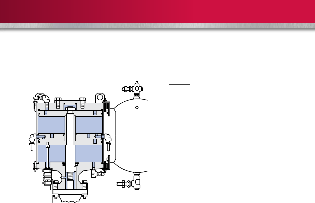
Piston Actuator
Example: LS-185-D-5-X-S
First Figure
L = Low-pressure Cylinder Actuator, 80 psi Maximum
Pressure
Second Figure
G = Double-cylinder Damping or No Damping
S = Single-cylinder Damping
Third Figures
(12)(18)(20) etc. = Nominal Diameter of Actuator Piston
(inches)
Fourth Figures
(3)(4)(5) etc. = Nominal Piston Stroke (inches)
Fifth Figure
(D)(T) etc. = Number of Cylinders (Double/Triple, etc.)
Sixth Figures
(1)(2)(3) etc. = Actuator/Valve Mounting Configuration
(Consult Cameron for specific details)
Seventh Figure
Accessory Features
C = Mechanical Override – Closed
H = Hydraulic Override – Open,
Mechanical Override – Closed
L = Positive Close Locking Device
M(N) = Mechanical Override – Open and Closed
O = Hydraulic Override – Open and Closed
X = No Accessory Features
Eighth Figure
S = Spring Return
22
These are typical selections of actuators for soft-seated valves with standard T3 trim and pipeline pressure from the preferred
end. The correct choice of actuator will depend on pressure direction, temperature, flow conditions, valve trim and valve end
connections. Consult Cameron for the specific actuator/valve combination that is most suitable for the intended service.
ASME/ANSI Class 150 Class 300 Class 600
Valve Size
in.
Double-acting
Actuator
Spring-close
Actuator
Spring-open
Actuator
Double-acting
Actuator
Spring-close
Actuator
Spring-open
Actuator
Double-acting
Actuator
Spring-close
Actuator
Spring-open
Actuator
1 84625 62584 62588 84625 62584 62588 84625 62584 62588
1-1/2 84625 62584 62588 84625 62584 62588 84625 62584 62588
2 84625 62584 62588 84625 62584 62588 84625 62584 62588
3 84100 100164 100165 84100 100164 100165 164100 100164 100165
4 84100 100164 100165 84100 100164 100165 164100 100167 100165
6 164100 100167 – 164100 100167 * 164100 123424 *
8 164100 123424 * 164100 123424 * 424125-301 LS-185-D-25-X-S *
10 424125-301 125424 * 424125-301 LS-185-D-25-X-S * LS-185-D-5 LS-205-D-5-X-S *
12 LS-185-D-5 LS-185-D-5-X-S * LS-185-D-5 LS-205-D-5-X-S * LS-205-D-6 LS-205-D-6-X-S *
14 – – - LS-185-D-5 LS-205-D-X-S * LS-267-D-19 LS-267-D-19-X-S *
16 LS-207-D-19 LS-267-D-X-S * LS-207-D-19 LS-267-D-19-X-S * LS-267-D-19 LS-267-D-19-X-S *
18 LS-267-D-19 – – – – – – – –
20 – – – LG-2611-T-29 – – LG-2611-T-29 – –
24 – – – LG-4214-D-33 – – LG-4214-D-33 – –
ASME/ANSI Class 150 Class 300 Class 600
Valve Size
in.
Double-acting
Actuator
Spring-close
Actuator
Spring-open
Actuator
Double-acting
Actuator
Spring-close
Actuator
Spring-open
Actuator
Double-acting
Actuator
Spring-close
Actuator
Spring-open
Actuator
1 84625 62584 62588 84625 62584 62588 84625 62584 62588
1-1/2 164100 100164 * 164100 100164 * – – –
1-3/4 – – – – – – 164100 100164 *
2 164100 100164 100165 164100 100164 100165 – – –
3 164100 100164 100165 164100 100167 * 164101 120424 *
4 164100 100167 * 164100 121424 * 424125-301 125424 *
6 424125-301 LS-185-D-25-X-S * LS-185-D-5 LS-205-D-5-X-S * LS-185-D-5 LS-205-D-5-X-S *
8 LS-185-D-15 LS-205-D-15-X-S * LS-208-D-31 * * LS-269-D-32 * *
10 LS-205-D-16 LS-267-D-16-X-S * LS-269-D-32 * * – – –
12 LS-267-D-19 LS-267-D-19-X-S * LG-2611-T-29 * * – – –
16 LG-2611-T-29 – – LG-4214-D-33 – – – – –
*Consult Cameron
*Consult Cameron
Electric Actuators
Cameron supplies electric actuated valve packages using many of the commercially available power actuators built by other
companies. The electric actuator is selected, mounted, adjusted and tested by Cameron so that field performance of the entire
valve assembly can be ensured.
Hydraulic Actuators
Commercially available hydraulic actuators built by other vendors are available upon request.
ACTUATOR FIGURE NUMBERS (CONT.)
23
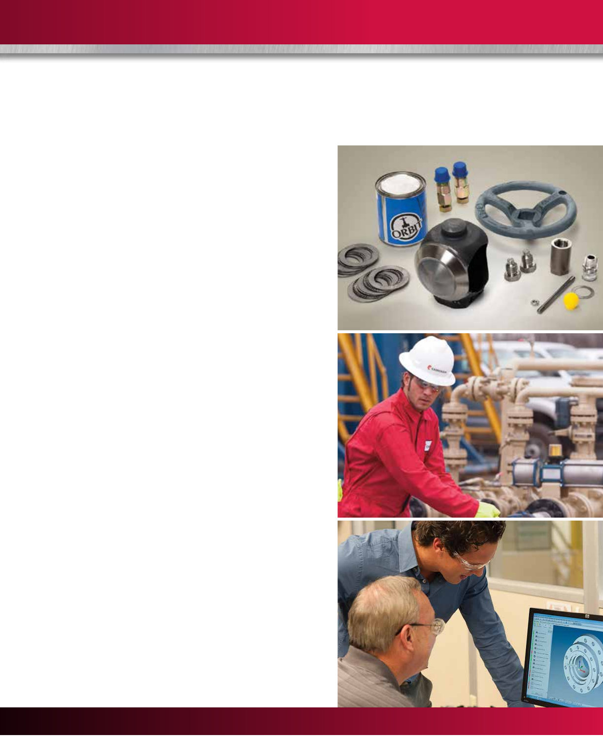
Services for Valves and Actuation
Global Network and Local Support
Cameron is well-positioned to deliver total valve support,
quickly and efficiently, with unmatched OEM expertise.
Our highly skilled engineers and technicians are available
around the clock, seven days a week to respond to
customer queries, troubleshoot problems and offer
reliable solutions.
Easily Accessible Parts and Spare Valves
• OEM spare valves, actuators and parts (including
non-Cameron brands)
• Handling, storage, packaging, and delivery
• Dedicated stocking program
Comprehensive Services Portfolio
• Parts and spare valves
• Repair
• Field services
• Preventative maintenance
• Equipment testing and diagnostics
• Remanufacturing
• Asset preservation
• Customer property management
• Training and recertification services
• Warranty
Customized Total Valve CareSM (TVC) Programs
Customized asset management plans that optimize
uptime, availability and dedicated services.
• Engineering consultancy
• Site management
• Flange management
• Startup and commissioning
• Spare parts and asset management
• Operational support
WE BUILD IT. WE BACK IT.
USA • CANADA • LATIN AMERICA • EUROPE • RUSSIA • AFRICA • MIDDLE EAST • ASIA PACIFIC

24
Trademark Information
ORBIT® is a registered trademark of Cameron.
This document contains references to registered trademarks or product designations
that are not owned by Cameron.
Registered Trademark Owner
Carpenter 450 Carpenter Technology Corp.
Hastelloy Haynes International, Inc.
Inconel INCO Nickel Sales, Inc.
Latrobe Timkin Latrobe Steel
Monel INCO Alloys International, Inc.
PEEK Victrex PLC.
Stellite Stoody Deloro Stellite, Inc.
Teflon E.I. DuPont De Nemours & Company
Ultimet Haynes International, Inc.

25

HSE Policy Statement
At Cameron, we are committed ethically, financially and personally to a
working environment where no one gets hurt and nothing gets harmed.
H
E
A
L
T
H
S
A
F
E
T
Y
A
N
D
E
N
V
I
R
O
N
M
E
N
T
A
L
E
X
C
E
L
L
E
N
C
E
C
A
M
E
R
O
N
©2015 Cameron | ORBIT is a registered trademark of Cameron. | SWP 1M 07/15 AD01201V
3250 Briarpark Drive, Suite 300
Houston, TX 77042
USA
Tel 1 281 499 8511
Learn more about ORBIT valves:
www.c-a-m.com/ORBIT
ORBIT@c-a-m.com
HSE Policy Statement
At Cameron, we are committed ethically, financially and personally to a
working environment where no one gets hurt and nothing gets harmed.
H
E
A
L
T
H
S
A
F
E
T
Y
A
N
D
E
N
V
I
R
O
N
M
E
N
T
A
L
E
X
C
E
L
L
E
N
C
E
C
A
M
E
R
O
N
