Pco3_operating_manual_rev03 Pco3 Operating Manual Rev03
User Manual: pco3_operating_manual_rev03
Open the PDF directly: View PDF ![]() .
.
Page Count: 74
- 1.0 INTRODUCTION
- 2.0 SEQUENCE OF OPERATIONS
- 3.0 CONFIGURATION
- 4.0 TECHNICAL SPECIFICATIONS
- 4.1 Controller and Display
- 4.2 General Characteristics
- 4.3 Mechanical Characteristics
- 4.4 Electrical Characteristics
- 4.5 Digital Inputs
- 4.6 Analog inputs
- 4.7 Analog Outputs
- 4.8 Digital Outputs
- 4.9 P-LAN Network Terminal
- 4.10 Cable Length
- 4.11 Standard Input / Outputs
- 4.12 Optional Features
- 4.13 Functional characteristics
- 4.14 Building Management System
- 5.0 CONTROLLER INTERFACE
- 6.0 Navigation Menu
- 7.0 SETUP MENU
- 8.0 RUN TIME HOUR METERS
- 9.0 BUILDING MANAGEMENT SYSTEM (BMS)
- 10.0 TECHNICIAN MENU
- 11.0 TROUBLESHOOTING GUIDE
Rev.03a 12-21-10
Page 1 of 74
Compu-Aire
SYSTEM 2200+3L
PROGRAMMABLE CONTROLLER
-USER MANUAL-
8167 Byron Road Whittier, CA 90606
Phone: (562) 945-8971 Fax: (562) 696-0724
SUBJECT TO CHANGE WITHOUT INCURRING OBLIGATION

Rev.03a 12-21-10
Page 2 of 74
Compu-Aire
Table of Contents
1.0 INTRODUCTION ............................................................................................................................... 8
2.0 SEQUENCE OF OPERATIONS ............................................................................................................. 8
2.1 Standard Units in General ........................................................................................................ 8
2.2 Lead/Lag Redundancy – p-LAN Network ................................................................................... 9
2.3 Air Cooled/Chilled Water Plus .................................................................................................. 9
2.4 Economizer ............................................................................................................................ 10
2.5 Energymiser (EM) Unit Using 2-Way Valves ............................................................................ 11
2.6 Water Cooled Energymizer ..................................................................................................... 12
2.7 Dry Fluid Cooler With Energymizer ......................................................................................... 13
2.8 Special Pump and Dry Fluid Cooler control logic ..................................................................... 15
2.9 Optional features ................................................................................................................... 16
3.0 CONFIGURATION ........................................................................................................................... 16
3.1 Main menu ............................................................................................................................ 17
3.2 Screen Settings....................................................................................................................... 17
3.3 Network Configuration ........................................................................................................... 18
3.4 Network Monitor ................................................................................................................... 18
3.5 Assigning Private and Shared terminals .................................................................................. 19
3.6 P-LAN Setup ........................................................................................................................... 20
3.6.1 Master Unit (ID=1) .......................................................................................................... 20
3.6.2 Slave Unit (ID=2) ............................................................................................................. 20
3.6.3 P-LAN WIRING ................................................................................................................ 21
3.7 General Options ..................................................................................................................... 22
4.0 TECHNICAL SPECIFICATIONS .......................................................................................................... 23
4.1 Controller and Display ............................................................................................................ 23
4.2 General Characteristics .......................................................................................................... 23
4.3 Mechanical Characteristics ..................................................................................................... 23
4.4 Electrical Characteristics......................................................................................................... 24
4.5 Digital Inputs .......................................................................................................................... 24
4.6 Analog inputs ......................................................................................................................... 24

Rev.03a 12-21-10
Page 3 of 74
Compu-Aire
4.7 Analog Outputs ...................................................................................................................... 25
4.8 Digital Outputs ....................................................................................................................... 25
4.9 P-LAN Network Terminal ........................................................................................................ 25
4.10 Cable Length .......................................................................................................................... 25
4.11 Standard Input / Outputs ....................................................................................................... 26
4.12 Optional Features................................................................................................................... 27
4.13 Functional characteristics ....................................................................................................... 27
4.14 Building Management System ................................................................................................ 27
5.0 CONTROLLER INTERFACE ............................................................................................................... 28
5.1 LED Indicators ........................................................................................................................ 28
5.2 Navigation Buttons................................................................................................................. 28
6.0 Navigation Menu ........................................................................................................................... 29
6.1 Menu Tree ............................................................................................................................. 29
6.2 Accessing Submenus .............................................................................................................. 30
6.3 Main Menu Selection ............................................................................................................. 30
6.4 Unit Status ............................................................................................................................. 30
6.5 Trending................................................................................................................................. 31
6.5.1 Graph Overviews ............................................................................................................ 31
6.5.2 Icon Description and function ......................................................................................... 32
6.6 Alarms.................................................................................................................................... 34
6.6.1 Alarm Viewing and Function ........................................................................................... 34
6.6.2 Alarm Reset .................................................................................................................... 34
7.0 SETUP MENU ................................................................................................................................. 35
7.1 Entering a password ............................................................................................................... 35
7.2 Setup Menu Tree ................................................................................................................... 36
7.3 Setpoints ................................................................................................................................ 36
7.3.1 Changing Setpoints ......................................................................................................... 36
7.3.2 Changing Alarm Setpoints ............................................................................................... 37
7.4 Clock Setup ............................................................................................................................ 37
7.4.1 Time and Date Setup ...................................................................................................... 37
7.4.2 Night Setback ................................................................................................................. 37

Rev.03a 12-21-10
Page 4 of 74
Compu-Aire
8.0 RUN TIME HOUR METERS .............................................................................................................. 38
9.0 BUILDING MANAGEMENT SYSTEM (BMS) ...................................................................................... 39
9.1 Modbus.................................................................................................................................. 39
9.1.1 Mounting ....................................................................................................................... 39
9.2 POINTLIST .............................................................................................................................. 41
9.3 LONWORKS ............................................................................................................................ 44
9.3.1 General characteristics ................................................................................................... 44
9.3.2 Physical channels ............................................................................................................ 44
9.3.3 Physical Circuit Board Layout .......................................................................................... 44
9.3.4 LED Color Description ..................................................................................................... 45
9.3.5 Installation ..................................................................................................................... 45
9.3.6 Connection to the PCO3 Controller ................................................................................. 46
9.3.7 Connection to the LonWorks® network .......................................................................... 46
9.3.8 Service pin ...................................................................................................................... 46
9.3.9 WINK event .................................................................................................................... 47
9.4 BACNET OVER TCP/IP ............................................................................................................. 48
9.4.1 Installation ..................................................................................................................... 48
9.4.2 Functions........................................................................................................................ 48
9.4.3 Default parameters ........................................................................................................ 48
9.4.4 Restarting the software .................................................................................................. 49
9.4.5 Configuration ................................................................................................................. 49
9.4.6 Web server ..................................................................................................................... 51
9.4.7 Accessing the operating system by authentication .......................................................... 51
9.4.8 CGI script ........................................................................................................................ 52
9.4.9 SNMP ............................................................................................................................. 52
9.4.10 BACnet ........................................................................................................................... 52
9.4.11 WARNINGS ..................................................................................................................... 52
9.5 BANET over MS/TP ................................................................................................................. 53
9.5.1 Installation ..................................................................................................................... 53
9.5.2 Meaning of the jumpers ................................................................................................. 54
9.5.3 Operation ....................................................................................................................... 54

Rev.03a 12-21-10
Page 5 of 74
Compu-Aire
9.5.4 Recalling the factory configuration (“factory bootswitch” mode) .................................... 56
9.5.5 Configuration ................................................................................................................. 56
9.5.6 BACNET Parameter Description ...................................................................................... 57
10.0 TECHNICIAN MENU ........................................................................................................................ 58
10.1 Alarm Setup ........................................................................................................................... 58
10.1.1 Available Alarms ............................................................................................................. 60
10.1.2 Sensor Offset .................................................................................................................. 62
10.1.3 Digital Input .................................................................................................................... 62
10.2 Network Setup ....................................................................................................................... 63
10.2.1 Define a Network ........................................................................................................... 63
10.2.2 Network Assist ............................................................................................................... 63
10.3 Manual Control ...................................................................................................................... 64
10.4 Factory Setting Menu Tree ..................................................................................................... 65
10.4.1 Digital Inputs and Digital Outputs ................................................................................... 66
10.4.2 HVAC .............................................................................................................................. 67
10.4.3 Analog Inputs and Analog Outputs.................................................................................. 69
10.4.4 Changing Passwords ....................................................................................................... 70
10.5 Factory Reset ......................................................................................................................... 70
11.0 TROUBLESHOOTING GUIDE ............................................................................................................ 71

Rev.03a 12-21-10
Page 6 of 74
Compu-Aire
Table of Figures
Figure 1– Configurations screen ............................................................................................................ 17
Figure 2 - Screen calibration .................................................................................................................. 17
Figure 3–Changing unit ID ...................................................................................................................... 19
Figure 4 - Touch sensitive graphical display ........................................................................................... 23
Figure 5 - Controller............................................................................................................................... 23
Figure 6 – Graphical user interface user interface .................................................................................. 28
Figure 7 - Main Menu ............................................................................................................................ 29
Figure 8 - Unit general status ................................................................................................................. 30
Figure 9 - Room demand icons .............................................................................................................. 30
Figure 10- Graphical sensors representation .......................................................................................... 31
Figure 11 - Graph description ................................................................................................................ 31
Figure 12 - Pressure graph ..................................................................................................................... 31
Figure 13– Alarm History ....................................................................................................................... 34
Figure 14–Password prompt .................................................................................................................. 35
Figure 15 - Entering a password ............................................................................................................. 35
Figure 16 - Setup menu ......................................................................................................................... 35
Figure 17 - Setup Menu Tree ................................................................................................................. 36
Figure 18 - Room temperature setpoints ............................................................................................... 36
Figure 19 - Room humidity setpoints ..................................................................................................... 36
Figure 20 - Clock setup .......................................................................................................................... 37
Figure 21 - Component run time meters ................................................................................................ 38
Figure 22 - Building management system .............................................................................................. 39
Figure 23 - Communication protocol...................................................................................................... 39
Figure 24 - LONTalk Card ....................................................................................................................... 44
Figure 25 - Remove plastic cover ........................................................................................................... 46
Figure 26- Cut out window .................................................................................................................... 46
Figure 27 - Installing plugin card ............................................................................................................ 46
Figure 28 - Replacing windows cover ..................................................................................................... 46
Figure 29 - PCOWeb .............................................................................................................................. 50
Figure 30 - Window cover ...................................................................................................................... 50
Figure 31 - Installing PCOWeb................................................................................................................ 50
Figure 32 - Installing plastic cover .......................................................................................................... 50
Figure 33 - Alarm configuration ............................................................................................................. 58
Figure 34 - Alarm delays ........................................................................................................................ 60
Figure 35 -Alarm switch over ................................................................................................................. 60
Figure 36 - Network Setup ..................................................................................................................... 63
Figure 37 - Network Assist ..................................................................................................................... 63
Figure 38 - Factory Setting ..................................................................................................................... 65
Figure 39 - Digital input configuration .................................................................................................... 66

Rev.03a 12-21-10
Page 7 of 74
Compu-Aire
Figure 40 - Digital output configuration ................................................................................................. 66
Figure 41 - Analog input configuration ................................................................................................... 69
Figure 42 - Analog output configuration ................................................................................................ 69
Figure 43 - Changing default password .................................................................................................. 70
Figure 44 - Factory reset ........................................................................................................................ 70

Rev.03a 12-21-10
Page 8 of 74
Compu-Aire
1.0 INTRODUCTION
System 2200+3L is a programmable controller based on a double microprocessor, designed for
precise "Smart" control of an air conditioning system. The System 2200+3L is made up of a
microprocessor based MAIN BOARD equipped with a set of terminals used to interface the
microcontroller board to the controlled devices; such compressors, fans, and heaters,
humidifiers and valves. The program is retained in a flash based memory and configuration
parameters are permanently stored (even in the case of power failure) in a non-volatile
memory.
System 2200+3L also includes a microprocessor based TERMINAL unit complete with graphical
touch screen display with built in navigation keypad and led indicators allowing the users to
easily set the controlled parameters for set points, dead bands, alarm thresholds and carry out
the main working operations (on/off, displaying controlled variables, printouts). The controller
and graphical display terminal are powered by 24VAC power supply using low voltage control
transformers from the unit. Connection between the terminal unit and main board is necessary
only when programming System 2200+3L basic parameters. The controller is linked to a graphic
display terminal via standard three wire cable.
2.0 SEQUENCE OF OPERATIONS
2.1 Standard Units in General
In general, the controller is operated as follows.
• Fan starts up on demand for cooling, heating, humidifying or dehumidifying or operates
continuously
• Sequences the compressors on in stages with programmable delays to meet demand for
cooling and dehumidification
• Sequences the heaters on in stages with programmable delays to meet demand for heating
or reheat during dehumidification mode
• Activates the humidifier as needed to meet the humidity demand
• Dehumidification is achieved by means of cooling to reduce the humidity level. During the
dehumidification process, if the temperature falls below the room set point, heating is
brought on to reheat the air and maintain room temperature.
• The controller monitors the complete system for any sensors, fans, compressors, heaters
and humidifier failure. Upon critical failures, the complete system will shut down with
alarm. For certain component failures, the applicable feature is disabled to insure safe
operation. For example, when compressor failure occurs, the failed compressor shall be
locked out but the system shall provide cooling by other compressor if available. On a
heater failure, the heaters are locked out. The system will not use that function until

Rev.03a 12-21-10
Page 9 of 74
Compu-Aire
manually reset on the display. The controller also keeps the history of last 100 alarms after
you reset them.
2.2 Lead/Lag Redundancy – p-LAN Network
System 2200+ series controllers can be set for n+ redundancy setup. Maximum 16 units can be
linked together on p-LAN network. The p-LAN networked units are identified with unit ID
numbers. The p-LAN software resides in the unit ID# U01 which is also called as a MASTER unit. All
the other units on that network are considered as SLAVE units. Each controller is self independent
controller with necessary sensors and it can be used as a standalone unit. When used on p-LAN
Network, each unit must have same software revision and set to maintain same set points and
same safety alarms. The unit U01 must be set for the total units on the network.
When more than one unit are connected through p-LAN network for lead/lag operation, the first
controller, unit ID# U01 is defined as the “Master” and the rest (U02, U03 ….U16) are define as
“Slave”. The Master always starts first to maintain the temperature and humidity set points. The
Slave is kept on standby as long as the Master is able to achieve the set points within the dead
band. When the Master fails to do so, it calls in the Slave to assist. Then both units will be
running towards the targets set on the Master (set points on the Slave is irrelevant in this
situation). The Slave drops out when set points are achieved. When the Master fails by any of
the selectable failures (such as compressor high/low pressure failure and fire alarm), the Master
drops off and the Slave comes in to work independently according to its own set points until the
Master is recovered. When the system is reset and restarted, the Master comes in first and
follows the above rules.
The units can be set to cycle to achieve equal run time on each unit. At the end of each cycle, the
role of each unit switches to its counterpart, meaning the Master becomes the Slave and the
Slave becomes the Master during the next cycle. During each cycle, the units operate according
to the above lead/lag logic.
2.3 Air Cooled/Chilled Water Plus
Summary of Equipment
The primary system shall be Chilled Water Cooling. Direct Expansion Cooling shall be setup as a
back up to the Chilled Water system. Both systems are designed to work independent of each
other.
The Chilled Water System comes standard with a three (3) way water modulating valve, coil, and
an optional “no water flow switch”. The DX system is equipped with a DX coil, compressor(s), and
outdoor air cooled condenser. Optional heaters and humidifiers are also available if needed
A unique feature of Air Cooled/Chilled Water Plus units is that the chilled water coil is located at
the side of the direct expansion coil. The auxiliary chilled water coil is custom sized so that it
provides identical cooling capacity obtained during the refrigeration cycle with the compressor
operating.

Rev.03a 12-21-10
Page 10 of 74
Compu-Aire
Cooling-Chilled Water
Chilled Water cooling is the primary cooling system for C+ units. For optimum performance, the
controller is programmed to call chilled water cooling for the first 300 seconds regardless of the
chilled water temperature.
The C+ unit can switch over from one cooling mode to another based on sensing Chilled Water
flow or Chilled Water temperature. The standard practice is to sense the Chilled Water flow for
switching.
If “No Water flow” switch is selected, the unit senses the flow of chilled water by using pressure
differential switch and switches over to DX cooling based on loss of water flow. When No water
flow switch is selected for switch over, the unit only work on either DX or C.W. cooling mode.
If chilled water supply temperature is selected for switch over, than the unit shall continue with
chilled water cooling if the chilled water supply temperature is bellow the required temperature
set point and switch over to the DX cooling.
Cooling-Direct Expansion
Direct Expansion Cooling is designed to operate when the water flow switch senses that there is
no water flow. A digital signal is sent to the system from the controller to modulate the three (3)
way valve to cut water flow to the chilled water coil and the backup system direct expansion
cooling should start. The controller signals the compressor to start cooling. The outdoor
condenser get energized as needed.
2.4 Economizer
Summary of Equipment
The Economizer Mixing Box is factory provided, however, it might be installed in the field by
others. Typically, the Air Side Economizer Mixing Box is provided for our Maxi-Kool unit with
System 2200 series controller.
Sequence of Operation
The evaporator fan and a set of dampers for the economizers is energized depends on heating or
cooling demands. The PCO3 controller commands the economizer box to bring either the
minimum amount of outside air or only outside air based on outside air temperature and
humidity. The controller determines whether the outdoor air temperature and humidity is
suitable for “economizer-cooling”. If the outdoor air is suitable, mechanical cooling shall be
locked out by the outdoor enthalpy control. The set of economizer damper actuators shall be
energized, operating the outdoor air and the return air dampers. The economizer damper
actuators shall be regulated to maintain proper discharge air temperature. When outdoor air is
not suitable for “economizer-cooling”, the Economizer shall be locked out and the outdoor air
damper shall maintain minimum position while the indoor fan is operating. Upon unit shutting
down or power loss, the spring return motor actuator shall close the outdoor air damper. The
Economizer shall be automatically locked out during the heat mode (if applicable).

Rev.03a 12-21-10
Page 11 of 74
Compu-Aire
The Air Side Economizer box shall include: prewired modulating spring return damper actuators,
economizer control logic with compressor assist option, minimum outside air damper position
control, economizer control sensors including outdoor air temperature and humidity (enthalpy)
sensor, supply air and or mixed air sensors. The supply air temperature sensor is used to maintain
the desire supply air temperature using DX and Economizer cooling together. The exhaust of
room air during economizer cooling mode shall be done by others in the field.
2.5 Energymiser (EM) Unit Using 2-Way Valves
Summary of Equipment
Energy miser units are provided with Dual Cooling options. DX cooling using Compressor based
system and Economizer cooling using Water Side Economizer Coil.
The primary system shall be Direct Expansion Cooling. The free cooling Energy miser coil is
provided together with the DX cooling coil. If the Water temperature drops below the Energy
miser set point, the condenser water is diverted to the free cooling coil and DX cooling will be
programmed to either turned off or made available to assist based on demand.
The Energy miser System shall be provided with a Two (2) way water regulating valve for
condenser coil, a Two (2) way modulating chilled water valve for energy miser coil, DX coil(s),
compressor(s) and co-axial water condenser(s). The water valves on water cooled condensers and
free cooling energy miser CW Valves will allow the water flow in either condenser coil or free
cooling EM coil. The two way control valve shall control the amount of flow to auxiliary energy
miser cooling coils to meet the demand when in EM cooling mode. The Two way water regulating
valve will control the amount of water flow in condenser based on the refrigerant pressure in DX
cooling mode. System shall be programmed to do either DX cooling or EM cooling based on
entering water temperature.
Energy miser systems are connected to Cooling Tower or Dry Fluid Coolers to obtain re-circulating
water or water glycol solution. In addition, the system is equipped with steam generating
humidifier, electric reheat and microprocessor based controller.
A unique feature of Energy miser system is that the free cooling water coil is located just before
the direct expansion coil and is properly sized to provide the same cooling capacity as the DX
system at 45 Deg. F entering water temperature. The indoor unit will send a signal to enable and
disable the outdoor auxiliary equipment. The outdoor equipment has its own control logic to
provide water temperature suitable for either EM mode or DX cooling mode.
Cooling-Direct Expansion
Direct Expansion Cooling shall operate when the water temperature increases above the specified
EM set point. A digital signal is sent to the system by microprocessor to signal the compressors
and the two (2) way valves will regulate the water flow into the water cooled condensers based
on the refrigerant pressure. Each compressor system shall have separate 2-Way water regulating
valves. The Energy miser mode depends on the entering water temperature and it is adjustable.

Rev.03a 12-21-10
Page 12 of 74
Compu-Aire
Cooling-Energy miser Mode
The unit can switch over from DX cooling mode to Free cooling Energy miser mode based on the
Entering Water temperature.
Unit shall start in DX cooling mode. If the temperature of water supply drops below the set point
for the Energy miser mode, the unit will switch over to the Energy miser free cooling mode. The
outdoor fluid cooler shall be provided with energy miser control panel to maintain lower fluid
temperature during energy miser mode.
In the free cooling energy miser mode the compressors will remain shut off while the fans of the
unit shall be on. Humidification and Dehumidification modes shall be operating as needed.
2.6 Water Cooled Energymizer
Summary of Equipment
Energy miser units are provided with Dual Cooling options. DX cooling using Compressor based
system and Economizer cooling using Water Side Economizer Coil.
The primary system shall be Direct Expansion Cooling. The free cooling Energy miser coil is
provided together with the DX cooling coil. If the Water temperature drops below the Energy
miser set point, the condenser water is diverted to the free cooling coil and DX cooling will be
programmed to either turned off or made available to assist based on demand.
The Energy miser System shall come standard with a three (3) way water regulating valve for
condenser coil, a three (3) way modulating chilled water valve for energy miser coil, DX coil(s),
compressor(s) and co-axial water condenser(s). The water valves on water cooled condensers and
free cooling energy miser CW Valves are Three Way mixing type designed to divert the flow in
either condenser coil or free cooling EM coil. Three (3) way is used to maintain pressure drop, as
constant GPM is required for free cooling systems. The (3) three way control valve shall control
the amount of flow to auxiliary energy miser cooling coils and maintain constant temperature
and relative humidity
Energy miser systems are connected to Cooling Tower or Dry Fluid Coolers to obtain re-circulating
water or water glycol solution. In addition, the system is equipped with steam generating
humidifier, electric reheat and microprocessor based controller.
A unique feature of Energy miser system is that the free cooling water coil is located just before
the direct expansion coil and is properly sized to provide the same cooling capacity as the DX
system at 45 Deg. F entering water temperature.
Cooling-Direct Expansion
Direct Expansion Cooling shall operate when the water temperature increases above the specified
set point. A digital signal is sent to the system by microprocessor to signal the three (3) way valve
to divert the water flow from the free cooling coil to the water cooled condensers and the direct

Rev.03a 12-21-10
Page 13 of 74
Compu-Aire
expansion cooling mode shall start. The microprocessor shall signal the compressor to start
cooling and at the same time energize the water regulating valve to supply water flow to the co-
axial condenser. The Energy miser mode depends on the entering water temperature and it is
adjustable.
Note: Continuous water shall be flowing through the chilled water valve and will only supply
water to coil when called upon.
Cooling-Energy miser Mode
The unit can switch over from DX cooling mode to Free cooling Energy miser mode based on the
Entering Water temperature.
Unit shall start in DX cooling mode. If the temperature of water supply drops below the set point
for the Energy miser mode, the unit will switch over to the Energy miser free cooling mode. The
controller will send signal to the auxiliary equipment to run Energy miser mode for fluid
temperature control. The outdoor fluid cooler shall be provided with energy miser control panel
to maintain lower fluid temperature during energy miser mode.
In the free cooling energy miser mode the compressors may shut off while the fans of the unit
shall be on. Humidification and Dehumidification modes shall be operating as needed. The
Compressors can be locked to remain off during energy miser mode if necessary.
2.7 Dry Fluid Cooler With Energymizer
Summary of Equipment
DRY FLUID COOLER (DFC): The Dry Fluid Cooler Shall Consist of Casing, Coil, Direct-drive Propeller
Fan(s) driven by individual Fan Motor(s), Fan Guard and Mounting Legs. All fan motors shall be
factory wired to a common electrical control box. The Dry Fluid Cooler shall be arranged for
Vertical Air Flow.
The Glycol Coil shall have aluminum fins bonded to copper tubes and shall have full collars that
completely cover the copper tubes. The coil shall be pressure tested to 350 psig and shall be
designed for counter flow for high heat transfer efficiency.
The Dry Fluid Cooler casing shall be made from a non-corrosive metal to minimize maintenance.
Adjustable mounting legs and supports shall be furnished with the DFC. Vibration isolators of the
rubber and shear or spring type are to be field provided by others.
The motors shall be permanently lubricated, sealed ball bearings, with inherent overload
protection. Motors shall be mounted inside the Dry Fluid Cooler Casing for weather protection.
The direct drive fan blades shall be aluminum, and shall be protected by a heavy gauge, steel
wire, zinc plated, and epoxy coated fan guard. Full width baffles to prevent bypass air shall
separate each fan section.

Rev.03a 12-21-10
Page 14 of 74
Compu-Aire
Dry Fluid Cooler (DFC) requires separate power supply and one set of dry contact from indoor unit
to Enable/Disable.
DFC is equipped with its own control panel that includes power block, fan contactors, aqua stats,
freeze stats, relays and single or dual pump package control as necessary.
Aqua stats are installed in the control panel and bulbs to be attached with leaving water header of
the coil.
For understanding purpose use 4 fan dry fluid cooler with drawing # 700-232-041
The fluid cooler shall be provided with ambient T-stats to control the water temperature during
DX cooling mode. The fluid cooler shall bypass the T-Stat control logic and run all fans
continuously during Energy Miser mode.
Condenser cooling mode
If the water temperature is above 50Deg. F. (Default setting) the DFC will be in normal condenser
cooling mode. Aqua stat # 1 will be open above 50 Deg. F.
In normal cooling mode, DFC will be enabled by either of the compressor from indoor unit. The
Freeze stat is installed in series of the enabling signal. If the freeze stat opens, the DFC unit will be
fully disabled.
1. The first fan of DFC runs continuously as long as enabling signal is present.
2. The default setting for second fan to cycle OFF is 60 Deg. F and below with aqua
stat
3. The default setting for third fan to cycle OFF is 70 Deg. F. and below with aqua
stat #
4. The default setting for forth fan to cycle OFF is 75 Deg. F. and below with aqua
stat #
5. All these default settings are field adjustable to fine tune the unit operation.
Energy miser cooling mode
During winter months, when water temperature drops bellow the 50Deg. F. the aqua stat # 1 will
close and DFC unit will switch over to free cooling energy miser mode. In Energy miser mode, all
other aqua stat (aqua stat 2, 3 and 4) will be bypassed and all fans will run continuously. The free
cooling temperature set point on Aqua stat # 1 must synchronize with Energy miser water
temperature set point for indoor unit.
Pumps
Summary of Equipment
PUMP PACKAGE: The pump package shall include a close coupled, industrial duty pump with
heavy-duty ball bearings motors, stainless steel shafts and bronze fitted construction. The pump
package shall include pump starter, aqua-stats, and fan cycling contactor(s) to control the
condenser glycol temperature. The control panel shall be factory provided for filed installation in

Rev.03a 12-21-10
Page 15 of 74
Compu-Aire
a weatherproof box provided on the Dry Fluid Cooler. The pump shall be protected with a base
and weather shield from the ambient conditions.
DUAL PUMP PACKAGE (Optional): The dual pump package shall include close-coupled, industrial
duty pumps with heavy-duty ball bearings motors, stainless steel shafts and bronze fitted
construction. The pump package shall include pump starters, aqua-stats, and fan cycling
contactor(s) to control the condenser glycol temperature. The control panel shall be factory
provided for filed installation in a weatherproof box provided on the Dry Fluid Cooler. The pumps
shall be protected with a base and complete vented weather enclosure from the ambient
conditions. The optional Pressure Differential (No Water Flow)Switch shall be provided for field
installation.
GLYCOL PUMP: A matching centrifugal circulating pump is provided for field mounting and piping.
Pump Operation
When compressor is on the pump and fluid cooler will be enabled. Note that this is in DX cooling.
In free cooling the logic is the same, as pumps is enabled with economizer cooling.
2.8 Special Pump and Dry Fluid Cooler control logic
Pump speed adjusted based on differential pressure across pumps as 2-way control valves modulate.
Dry cooler and Pump controller Sequence of operation
Free cooling mode
Either outdoor air temperature is monitored or a signal from each crac unit (free cooling and DX
condenser) is sent to the pump controller to determine which function is provided.
Fan speed may be increased sufficiently to allow pump minimum operating speed to be maintained
should zone loads decrease, thus decreasing flow below safe pump operation.
Outside air temperature reaches 48F
Pump controls switch to free cooling mode – Fans run 100% until condenser outlet temperature reaches
38F, at which time fans speed will reduce to maintain 38F or minimum pumps speed is reached, then
fans will reduce speed to maintain minimum pump speed, which is accomplished by 2-way valves
modulating open is response to increased condenser water supply temperature.
Controls shall monitor both fan KW and Pump KW energy consumption and determine best speed
combination to maintain lowest condenser supply water temperature during free cooling more.
DX Cooling mode
Outside air temperature 50F

Rev.03a 12-21-10
Page 16 of 74
Compu-Aire
Pump control increases fan speed as condenser water temperature increases. Maintain 65F condenser
outlet water by modulating fan speed. At 75F exiting condenser water temperature fan speed is 100%.
Controls shall monitor both fan KW and Pump KW energy consumption and determine best speed
combination to maintain lowest condenser supply water temperature during DX cooling more.
2.9 Optional features
• Discharge air temperature sensor to prevent overheating or cooling of the air stream
• Outside air temperature sensor for automatic temperature adjustment or economizer
action
• Free-cooling temperature sensor for water cooled systems
• Hot gas bypass either by solenoid or by modulating electronic valve
• Redundant system operation of two or more units with automatic crossover and
compensation
• Networking to a central command computer, or to an existing building automation system
The System 2200+3L is truly one of the most powerful and flexible controllers available for HVAC
units today.
3.0 CONFIGURATION
The display unit is pre-configured at the factory for the most common user requirements.
Nonetheless, some settings can be changed to adapt the device specific needs. The menus can
be accessed by pressing any point on the touch screen together with the (up) and (Prg) buttons
for at least one second. Alternatively, press the (up) + (down) + (enter) buttons together for at
least one second.
The following operations exit the menu.
1. Pressing the Esc button
2. Automatically 1 minute after a button was pressed or the touch screen touched
3. Pressing the “X” symbol when displayed at the top right
As shown in the Figure 1 in the “Configuration screen”, a combination navigating buttons and
touch screen can be used to input new configuration parameters.
• To access an item, simply press the touch screen on the corresponding indication, or
press the (up) / (down) buttons until selecting it and then confirm by pressing (enter).
• To modify the value of a field, after having activated it (a field is active when the cursor
is flashing inside), press the (up) / (down) buttons to change the value and press (enter)
to save it.
• Pressing Esc before the Enter key will cancel the modifications made to the field.
Rev.03a 12-21-10
Page 17 of 74
Compu-Aire
Figure 1– Configurations screen
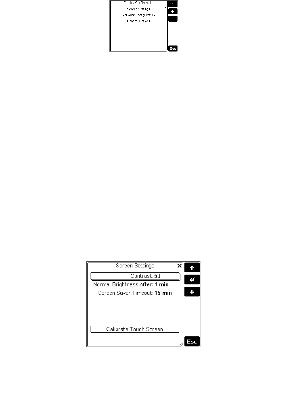
3.1 Main menu
The main menu is used to select the three main configuration categories
• Screen Settings: Settings relating to the screen
• Network Configuration: Settings relating to the RS485 network
• General Options: Various settings
3.2 Screen Settings
The following options are available
• Contrast - Used to set the contrast of the display (from 0 to 100, default: 50)
• Normal Brightness After - Used to set the time after the touch screen or the buttons are
last pressed that the display switches from “high brightness” to “normal brightness”.
Possible values are ranged from 30 s to 15 min, default: 1 min
• Screen Saver Timeout - Used to set the time after the touch screen or the buttons are last
pressed that the display switches off
• After having switched to “normal brightness”. Possible values are range from 30 s to 4
hours (4 hrs.), default: 15 min;
• Calibrate Touch Screen - The touch screen can be calibrated if it is evidently misaligned. To
align the touch screen, press the center of the crosses displayed in sequence. When the
message “Done: touch the screen to ESC” indicates that the operation has been completed
successfully. If the screen displays “Bad: touch to ESC and repeat”, repeat the calibration
process.
Figure 2 - Screen calibration

Rev.03a 12-21-10
Page 18 of 74
Compu-Aire
3.3 Network Configuration
The following options are available under network configuration screen.
• Terminal Address - Used to set the address of the terminal (from 1 to 32, default: 32). If
the value “--” is set (two dashes are displayed), the terminal will communicate with the
pCO board using the “Point-Point” protocol (not pLAN) : the “Baud Rate”,
• Network Monitor and Setup I/O Board fields will then disappear, as they have no
meaning.
• Baud Rate - Used to set the pLAN communication baud rate. The possible values are 62500
(default) or 115200 (used only if all the devices in the network are configured for this
speed). Note that not all the pLAN devices support the 115200 setting.
• Network Monitor - This is used to display the status of the network (see next paragraph)
• Setup I/O Board / Setup- These fields are used to modify the list of terminals associated
with each individual pCO board, as described in paragraph “pCO: Assigning the list of
private unit ID number.
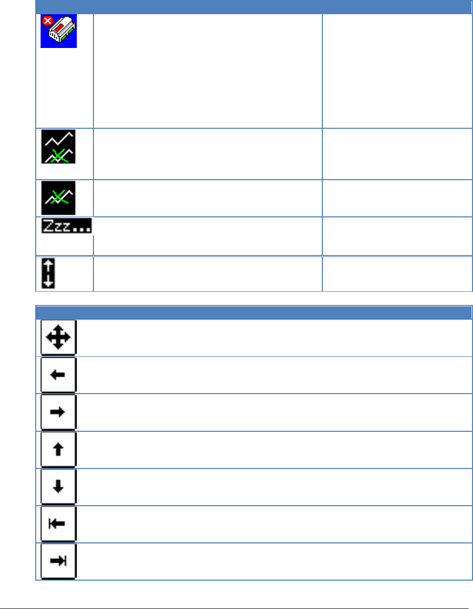
3.4 Network Monitor
This screen is used to display the status of the network, indicating graphically which devices are
connected for each address. The meanings of the symbols are the following.
Icon
Description
pCO controller active in the network
Any type of terminal active in the network
Current terminal
Device not connected
If activity is detected on the network, the message “Online” is displayed.
Press the Esc button to exit the screen.
Rev.03a 12-21-10
Page 19 of 74
Compu-Aire
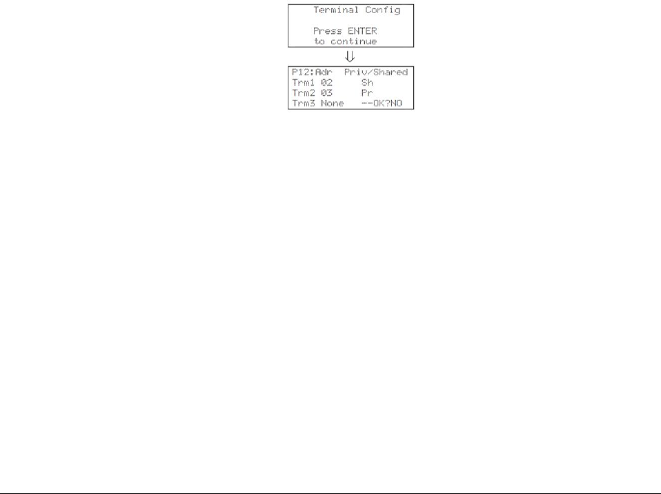
3.5 Assigning Private and Shared terminals
The list of terminals associated with each individual controller board can be modified from the
“Network Configuration” menu as follows.
1. Select the address of the required board using the (up) / (down) buttons in the “Setup I/O
Board” field (only the boards that are effectively on-line can be selected) and confirm by
pressing (enter). If the pLAN network is not working correctly, or no controller board is
present, the field is not modifiable, and “--“(two dashes) will be displayed.
2. Press the “Setup” button: the screens will be displayed in sequence, see Figure 3 for detail.
3. Use the enter button to move the cursor from one field to the next, and (up) / (down)
change the value of the current field. The P:xx field shows the address of the selected board
(in the example, board number 12 has been selected).
4. To exit the configuration procedure and save the data, select the “OK?” field, set “Yes” and
confirm by pressing (enter). Alternatively, if the terminal remains inactive (no button is
pressed) for more than 30 s, the configuration procedure is automatically ended without
saving the changes.
Important: the pGD terminals cannot be configured as “Sp” (shared printer) as the printer
output is not featured. Selecting this mode has no effect on the management of printed
messages sent via pLAN.
Figure 3–Changing unit ID

Rev.03a 12-21-10
Page 20 of 74
Compu-Aire
3.6 P-LAN Setup
3.6.1 Master Unit (ID=1)
1. Turn the power off
2. Verify the connection between the PCO3 Controller and the PGD3 (graphical display).
3. Turn the power on
4. Hold down the Up + Enter + Down buttons
5. Select Network configuration
6. Set Terminal Address = 0
7. Turn the power OFF
8. Turn the power ON and immediately hold down the Up + Alarm buttons(about 10 seconds)
9. Release the buttons when you see “Self-test” screen
10. Use the Up/Down button to set the ID=1 then press enter. The screen may look like a fault
occurred but, this is normal.
11. Turn the power OFF
12. Turn the power ON and immediately press Up + Enter + Down buttons
13. Select Network Configuration
14. Set the Terminal Address=17 and press ENTER
15. Select Setup for I/O board
16. Follow on screen direction to complete the setting.
3.6.2 Slave Unit (ID=2)
1. Turn the power OFF
2. Verify the connection between the PCO3 Controller and the PGD3 (graphical display).
3. Turn the power ON
4. Hold down the Up + Enter + Down buttons
5. Select Network configuration
6. Set Terminal Address = 0
7. Turn the power off
8. Turn the power ON and immediately hold down the Up + Alarm buttons(about 10 seconds)
9. Release the buttons when you see “Self-test” screen
10. Use the Up/Down button to set the ID=2 then press enter. The screen may look like a fault
occurred but, this is normal.
11. Turn the power OFF
12. Turn on the power and immediately press Up+Enter+Down buttons
13. Select Network Configuration
14. Set the Terminal Address=18
15. Select Setup for I/O board
16. Follow on screen direction to complete the setting.
Note: For unit 3 and up, use SLAVE UNIT setup instructions and increase the Address ID
by 1 and terminal ID by 1.
Rev.03a 12-21-10
Page 21 of 74
Compu-Aire
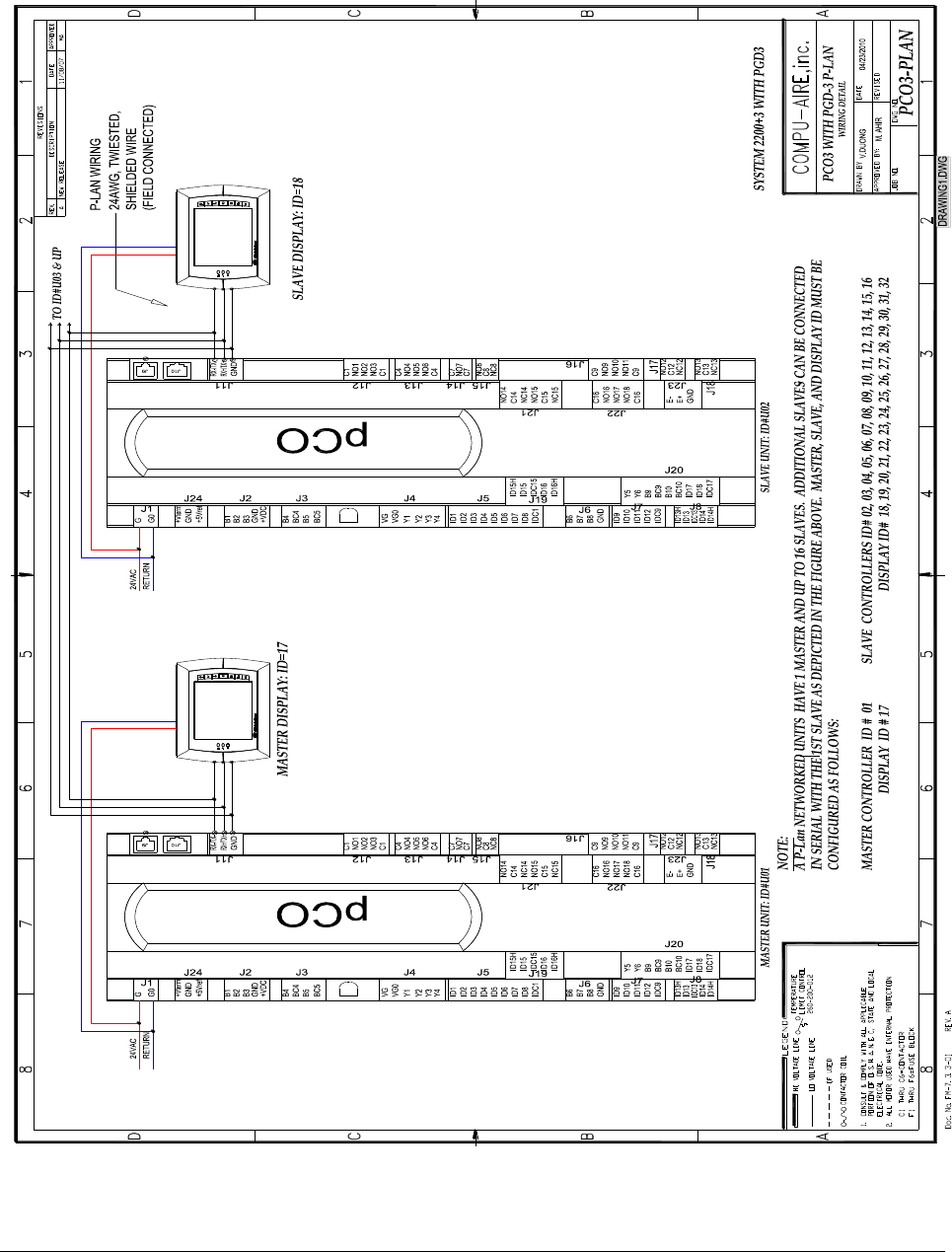
3.6.3 P-LAN WIRING

Rev.03a 12-21-10
Page 22 of 74
Compu-Aire
3.7 General Options
The following options are available
• Beep Volume: Used to set the volume associated to the buttons and the touch screen
pressing. The possible values are “off”, “low”, “high”. Default: high. This parameter has no
effect on the alarm signal, which is activated or deactivated by the pCO;
• Beep On: Used to set when the “Beep” sounds. The possible values are: “active items”
(associates a sound with the active area of the display), “screen” (associates a sound with
any point on the touch screen) and “screen & keys” (associates a sound with both the touch
screen and the keypad). Default: “screen & keys”;
• Download Bar: activates (“yes”) or deactivates (“no”) the display of the status bar that
indicates the progress of the page. Default: “yes”;
• Clear Cache Memory: deletes the cache memory used to accelerate the display of the
screens. This function may be useful if there are errors in the graphics. Pressing the button
displays a window that prompts for confirmation. Press “yes” to confirm the operation or
“no” to abort it;
• Display Firmware Update: starts the pGD firmware update procedure, as described in the
next paragraph.
Rev.03a 12-21-10
Page 23 of 74
Compu-Aire
4.0 TECHNICAL SPECIFICATIONS
4.1 Controller and Display
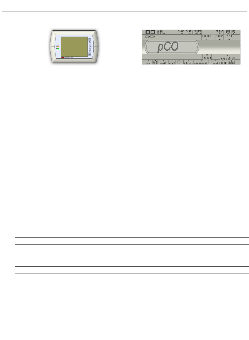
Figure 4 - Touch sensitive graphical display
Figure 5 - Controller
4.2 General Characteristics
PCO3 is a microprocessor-based electronic controller developed in compliance with the European
RoHS standards. It provides a solution for many applications in the air-conditioning and
refrigeration sectors ensuring absolute versatility, allowing specific products to be created to
customer request. PCO3 runs the control program, and is fitted with the set of terminals required
for connection to the devices (compressors, fans…). The program and the parameters are saved to
FLASH-MEMORY and E2promfor safe keeping even in the event of power failures (without
requiring a backup battery). PCO3 also allows connection to the pLAN (pCO Local Area Network)
and can be connected, as well as to other pCO3 controllers. All the controllers in the pLAN can
exchange information (variables, digital or analogue, depending on the application software used)
at high transmission speed. Up to 32 units can be connected, including pCO controllers and
terminals, so as to share the information effectively. The connection to the supervisor serial line,
via the CAREL or Modbus™ communication protocol over the RS485 standard, is performed by
inserting an optional serial board in the pCO3. Other optional cards can be used to connect to a
supervisor via standards other than RS485. Finally, the serial field bus interface, using the optional
board, ensures connection to the field devices controlled.
4.3 Mechanical Characteristics
Dimension:
110x315x60mm
Installation:
DIN rail according to DIN 43880 and CEI EN 50022 standards
Materials:
Techno polymers
Flame Retardant:
V0 (UL94) and 960°C (IEC 695)
Ball Pressure Test:
125°C
Resistance to creeping
current:
≥250 V
Color:
Grey RAL7035
Rev.03a 12-21-10
Page 24 of 74
Compu-Aire
4.4 Electrical Characteristics
Power Supply
24VAC 50/60Hz P=40 VA
Terminal Block
Plug-in male/female connectors, max voltage 250 Vac;
cable cross-section: min. 0.5 mm2 - max 2.5 mm2
CPU
H8S2320, 16 bit, 24 MHz
Memory
2+2 MB
Clock
Built in with battery backup
4.5 Digital Inputs
I/O
18
Classification Circuits
Category I (J5, J7, J20) 24 Vac/Vdc, Category III (J8, J19) 230 Vac
WARNING:
230 Vac 50/60 Hz (10/-15%)
Two 230/24Vac inputs present on J8 and J12 have the same common pole and
consequently will be both 24 Vac/Vdc or both 230 Vac. Basic insulation between the two
inputs for DC inputs, connect the negative pole to the common terminal.
Note: Separate as much as possible the probe and digital input signal cables from the
cables carrying the inductive loads and the power cables, to avoid possible
Electromagnetic disturbance.
4.6 Analog inputs
A/D conversion
10 bit
Type
Universal: (inputs B1, B2, B3, B6, B7, B8) CAREL NTC temperature sensor (-
50T90°C; R/T 10 kΩ at 25°C), HT NTC 0T150°C, voltage: 0 to 1 Vdc, 0 to 5 V
ratiometric or 0 to 10 Vdc, current: 0 to 20 mA or 4 to 20 mA,
selectable via software. Input resistance in 0 to 20 mA= 100Ω
passive: (inputs B4, B5, B9, B10) CAREL NTC temp. sensor (see universal type),
PT1000 (-100T200°C; R/T 1000 Ω at 0°C) or voltage-free digital input (5 mA),
selectable via software
Delay
0.5s
Precision
± 0.3 % of full scale
WARNING: The 21VDC available at the +Vdc terminal (J2) can be used to power any active
probes, the maximum current is 150 mA, thermally protected against short-circuits. To supply
the ratiometric 0 to 5 V probes, use the +5VREF (Imax: 60 mA) present at terminal J24.
Rev.03a 12-21-10
Page 25 of 74
Compu-Aire
4.7 Analog Outputs
Number I/O
6
Type
0-10V
Resolution
8bit
Max load
8 ohm
Precision
± 2 % of end scale on outputs: Y1, Y2, Y3 and Y4
-2%/+5% of end scale on: Y5 and Y6
4.8 Digital Outputs
Type
Relay
Max I/O
18
4.9 P-LAN Network Terminal
Type
RS485 half duplex asynchronous
Speed
62.5kbps or 115.2kbps
Terminal
6-pin telephone (J10)
P-LAN
3-pin plugin (J11)
4.10 Cable Length
Cable Type
Power Supply Distance
Power Supply
Telephone
50m
150mA from PCO3
AWG24 shielded cable
200m
150mA from PCO3
AWG20/22 shielded cable
500m
Separate power via TCONN6J000
The maximum cable length between the two PCO3 controllers using AWG20/22 shielded cable is
500 meters.
Note:
A maximum of one terminal (pCOT, pCOI, pGD0, pGD1) can be connected, or two
terminals but without using use the backlighting on display. One version of the
pCO3 features optically-isolated connection to the pLAN network.
The graphic terminal and aria terminal should be always powered with a separate
power supply.
The 21VDC present at +Vterm (J24) can be used to power an external terminal
with a maximum input of 2 W. Only one terminal can be connected (for example
PLD terminal or ARIA terminal) in addition to the one connected to terminal J10.
Rev.03a 12-21-10
Page 26 of 74
Compu-Aire
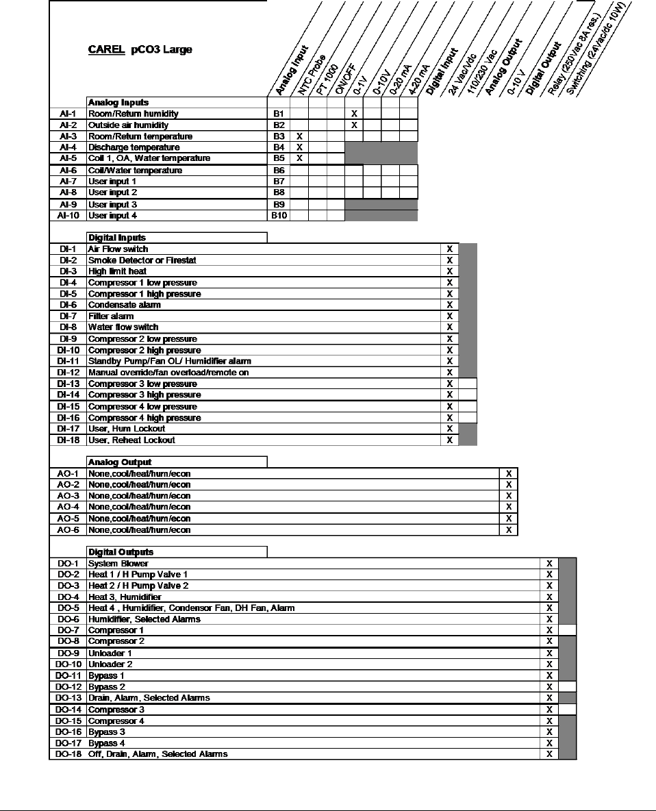
4.11 Standard Input / Outputs
The following table defines standard I/O ports for the PCO3 controller. Refer to the electrical
wiring diagram for actual wiring.

Rev.03a 12-21-10
Page 27 of 74
Compu-Aire
4.12 Optional Features
Option
Function
RS-485 CARD
Protocol: MODBUS
PCO-WEB CARD
Protocol: BACNET, SNMP,HTTP,FTP,TCP/IP
PCO-NET
Protocol: BACNET MS/TP
LONCARD
Protocol: LONWORKS
4.13 Functional characteristics
Multiple controllers may be used to combine cooling units into a p-LAN network that operates as
a single entity, enhancing the already-high performance and efficiency of units.
PCO3 controller is available as a factory-installed assembly. Remote console box with graphic
touch sensitive display wall-mount version is available for remote operation and monitoring of
cooling units.
Supported Protocol: pLAN protocol, “Point-Point” protocol with up to 32 nodes
Backlighting Level: Two levels of brightness, “high” and “normal”
4.14 Building Management System
BMS Protocol: LONWorks
BACnet over TCP/IP
BACnet over MS/TP
Modbus over RS-485
Rev.03a 12-21-10
Page 28 of 74
Compu-Aire
5.0 CONTROLLER INTERFACE
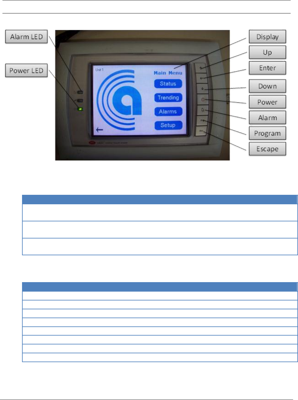
Figure 6 – Graphical user interface
5.1 LED Indicators
LED Light
Function
Alarm LED
ON – Indicates active alarms
OFF – No alarm
Power LED
ON – Unit is power on
OFF – Unit is power off
Power Failure
ON – System is recovered from a power lost
OFF – No power lost
Table 1- LED indicators
5.2 Navigation Buttons
Key Name
Function
Display
Touch sensitive graphical interface
Up
Navigate up to previous entry
Down
Navigate down to next entry
Enter
Execute current selection
Power
Turn the unit ON/OFF
Alarm
View and Reset active alarms
Program
Not used
Escape
Exit and return to previous screen
Table 2 - Navigating buttons
Rev.03a 12-21-10
Page 29 of 74
Compu-Aire
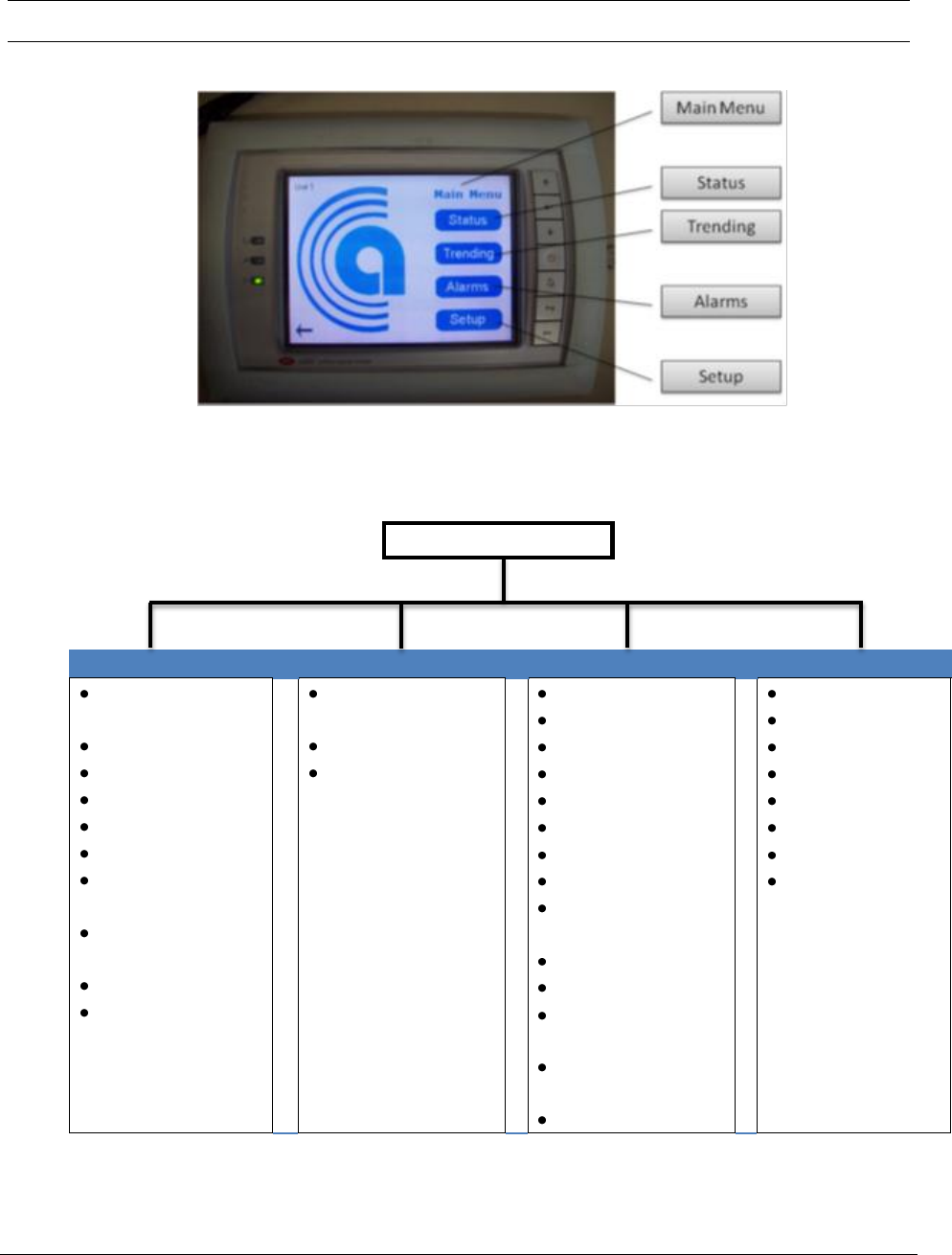
6.0 Navigation Menu
Figure 7 - Main Menu
6.1 Menu Tree
Main Menu
Status
Trending
Alarms
Setup
Room
Temperature
Room Humidity
Compressors
Heaters
ON/OFF Status
Fan Status
Water in
Temperature
Discharge Air
Temperature
High Pressures
Low Pressures
Room
Temperature
Room Humidity
Compressor
pressures
No Air Flow
Dirty Filter
Fire Alarm
Global Alarm
No Water Flow
Condensate
Low Pressure
High Pressure
Compressor
Short Cycling
Heater over heat
Sensor Failures
Over/Under
Temperatures
Over/Under
Humidity
Alarm Reset
Setpoints
Clock
Run Time
BMS
Technician
Factory
Alarm Log
Exit
Rev.03a 12-21-10
Page 30 of 74
Compu-Aire
6.2 Accessing Submenus
While viewing the menu, use the up and down arrow keys to scroll through the icons page-by-
page. To scroll through the icons one-by-one, press the enter key then use the up and down
arrow keys.
Note: Viewing settings require a password
Level 1 Password = 1 Leve2 Password = 2 Factory Setting = Consult Factory
6.3 Main Menu Selection
Icon
Function
Status
Displays current temperature, humidity, and system demand
Trending
Graphical display of current/past status reading
Alarms
Display or Reset current/previous alarms
Setup
Unit setup
Table 3 - Main menu description for Figure 7
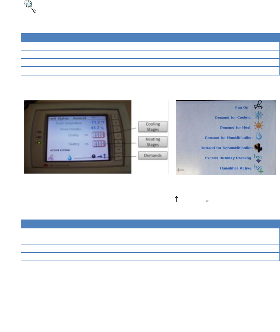
6.4 Unit Status
Figure 8 - Unit general status
Figure 9 - Room demand icons
General unit status shows the current room temperature, humidity, heating, and cooling
demands. Additional sensors are listed by pressing the (up ) or (down ) buttons as shown in
Figure 8. Pressing the (help?) button brings up the help screen as shown in Figure 9.
Icon
Function
Demands
Displays Fan, cooling, heating, humidification, dehumidification, excess humidity
draining, and humidifier
Cooling
Displays current active cooling stages
Heating
Displays current active heating stages
Table 4 – Unit general status
Rev.03a 12-21-10
Page 31 of 74
Compu-Aire
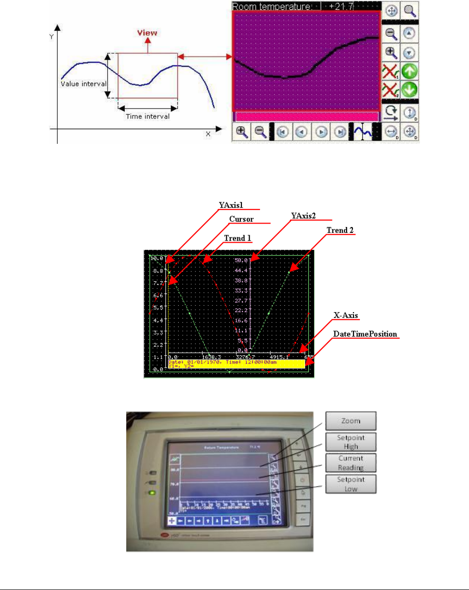
6.5 Trending
6.5.1 Graph Overviews
Figure 10- Graphical sensors representation
Figure 11 - Graph description
Figure 12 - Pressure graph
Rev.03a 12-21-10
Page 32 of 74
Compu-Aire
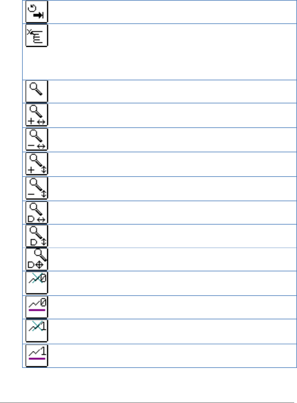
6.5.2 Icon Description and function
Icon
Description
Action
Indicates that the downloading of the data
relating to the Trend from the pCO* has failed.
Next to the letter X (see the image to the right)
a number is displayed identifying the type of
error in more detail:
4: the pCO does not have enough memory to
manage the graphs.
5: the variable displayed is not a Public
Variable.
Press the key.
4: use a pCO with more
memory (pCO XM-Expanded
Memory).
5: declare the variable as a
Public Variable.
Indicates that no data is available for one of the
two trends. This condition only occurs when
attempting to display the two trends at the
same time.
Nothing, or move the view to
display the data for the other
trend.
Indicates that there are no available data in the
current view.
Move the time interval.
Indicates that the data relating to the trend is
being downloaded from the pCO, but the
remaining time is unknown.
Wait
Indicates that for at least one of the trends the
data are outside of the current value interval.
Move the view in high or in
the lower.
Key
Description
Pan mode is activated.
When pressed, all the keys relating to zooming mode go to the Normal position.
Move the view to the left
Move the view to the right
Move the view up
Move the view down
View is moved so as to display the first data saved (the oldest data).
View is moved so as to display the last data saved (the most recent data).
Rev.03a 12-21-10
Page 33 of 74
Compu-Aire
View is moved so as to display the last data saved (the most recent data).
When pressed, all the keys relating to zooming mode go to the Normal position.
When pressed, changes the status from Normal to Pressed.
When in Normal status, selecting a point on the graph the graph cursor is
positioned at the closest value saved. The corresponding Y1, Y2 and X values
can be displayed in a text box under the X Axis.
When in Pressed status, selecting a point on the graph, the view is moved so the
point selected is in the center.
Activate Zoom mode.
When pressed, all the keys relating to Pan mode go to the Normal position.
Activate Zoom mode, all the other keys relating to Zoom mode switch to Normal
status and Zoom In on the horizontal axis. When in Pressed status, selecting a
point on the graph the view Zoom In on the horizontal axis
Activate Zoom mode, all the other keys relating to Zoom mode switch to Normal
status and Zoom Out on the horizontal axis. When in Pressed status, selecting a
point on the graph the view Zoom Out on the horizontal axis.
Activate Zoom mode, all the other keys relating to Zoom mode switch to Normal
status and Zoom In on the vertical axes. When in Pressed status, selecting a
point on the graph the view Zoom In on the vertical axes.
Activate Zoom mode, all the other keys relating to Zoom mode switch to Normal
status and Zoom Out on the vertical axes. When in Pressed status, selecting a
point on the graph the view Zoom Out on the vertical axes.
Reset the scales of the X axis as defined
Reset the scales of the Y1/Y2 axes as defined
Reset the scales of the X, Y1 and Y2 axes. This is the combination of the previous
two commands.
Enable the display of trend no. 1
Normal=hidden Pressed=visible
When pressed changes the status from Normal to Pressed.
Indicate that trend no.1 is available.
Enable the display of trend no. 2
Normal=hidden Pressed=visible
When pressed, changes the status from Normal to Pressed.
Indicate that trend no.2 is available.
Rev.03a 12-21-10
Page 34 of 74
Compu-Aire
6.6 Alarms
PCO3 controller provides both audible and visual alarm event log. Up to 100 event entries are
automatically saved in a non-volatile memory area in descending order. The last event always
displays when the alarm button is depressed from the any screen.
Figure 13– Alarm History
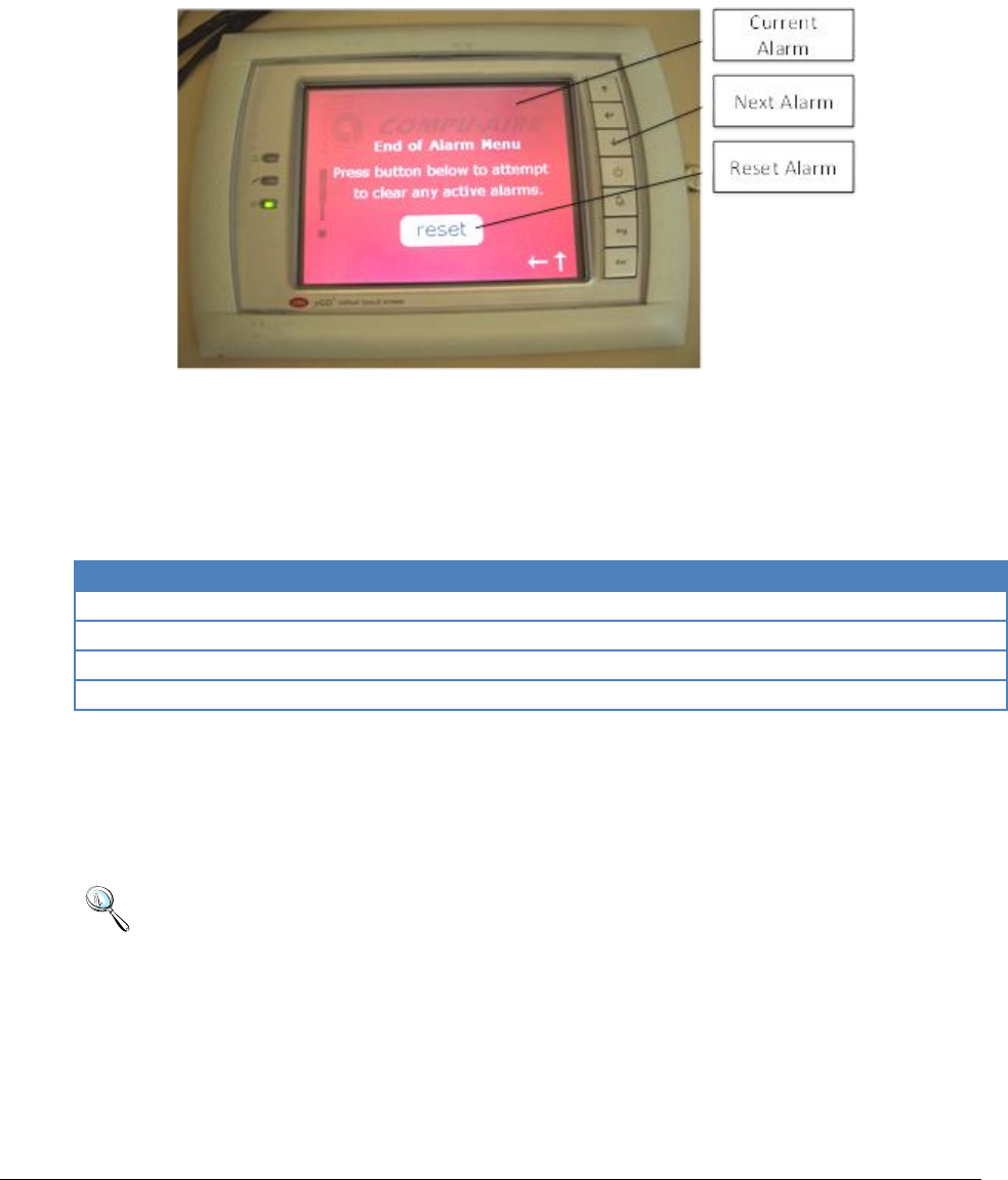
6.6.1 Alarm Viewing and Function
Only active alarms are accessible under the “Alarm button”. Consult the alarm history, under
setup, to view the remaining alarms.
Action
Function
Alarm
Pressing the alarm button at any time
Next
Shows the next alarm
Previous
Shows previous alarm
Reset
Clears out active alarms and turns off the alarm LED
6.6.2 Alarm Reset
The controller generates both visual and audible alarm continuously until cleared. To reset
alarm, press the alarm button and scroll down to the reset menu by pressing the down button.
Press the Reset button on the screen.
Note: All active alarms remain active until the root cause of the event is rectified.
Rev.03a 12-21-10
Page 35 of 74
Compu-Aire
7.0 SETUP MENU
“SETUP MENU” has three (3) levels of accessing right end user, technician, and setting reserved
for factory setup. A password must be supplied to gain access to any setting.
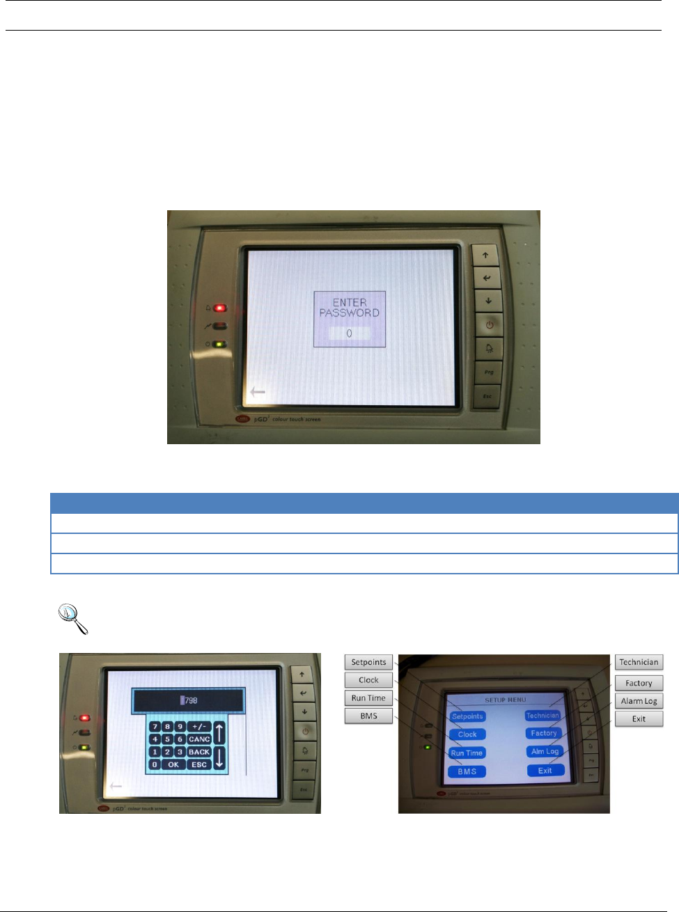
7.1 Entering a password
No password is required to view system status, active alarm, or turning the unit ON/OFF. System
is automatically locked out after 5 minutes of inactivity and returned to the main screen. A new
password must be entered to regain access to the setting.
Figure 14–Password prompt
Password
Level
Accessibility
1
1
Setpoint
2
2
Technician
1798
3
Factory setup (Consult factory for more information)
Table 5 - Default Passwords
Note: Entering a service menu requires a password. Default password is listed in Table 5.
Figure 15 - Entering a password
Figure 16 - Setup menu
Rev.03a 12-21-10
Page 36 of 74
Compu-Aire
7.2 Setup Menu Tree
Setpoints and other settings are organized as shown below in Figure 17. Not all settings are
available to all units. Press Exit button at any time to return to the previous screen.
SETUP MENU
Setpoints
Clock
Run Time
BMS
Technician
Factory
Alarm Log
-Room Temperature
-Temp High Alarm
-Temp Low Alarm
-Humidity
-Hum High Alarm
-Hum Low Alarm
-Temp Water In
-Temp Discharge Air
-Time
-Date
-Night Setback
-Fan
-Economizer
-Compressors
-Heaters
-Unit ID
-Baud Rate
-Protocol
*Modbus
*BACnet
*LONWorks
*Carel
-Alarm Setup
-Sensor Offsets
-Digital Setup
-Network
-Manual Control
-Digital Inputs
-Digital Outputs
-Analog Inputs
-Analog Outputs
-HVAC
-Password
-Factory Reset
-Alarm
-Time/Date
-Event
Figure 17 - Setup Menu Tree
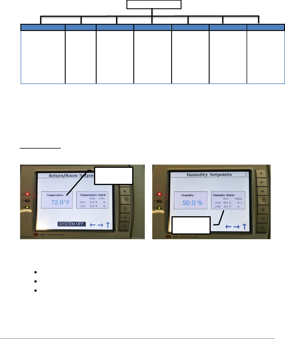
7.3 Setpoints
The controller is shipped with default selections for all necessary settings. In some cases,
adjustments can be made to meet the application requirements. Use Up and Down arrow
buttons to navigate between settings for different sensor.
Default Setting:
Temperature: 72°F Humidity: 50%
Figure 18 - Room temperature setpoints
Figure 19 - Room humidity setpoints
7.3.1 Changing Setpoints
Tap the Temperature/Humidity display
Enter a new value from the virtual keyboard
Tap on the enter button once done
Temperature
Setpoints
High & Low
Setpoints
Rev.03a 12-21-10
Page 37 of 74
Compu-Aire
7.3.2 Changing Alarm Setpoints
The alarm High and Low setpoints trigger an alarm event when the room returns temperature
falls below or exceed the set limits.
Tap on the High/Low value
Enter a new value from the virtual keyboard
Tap the enter button when done
Note: The controller is programmed to shut down the entire system once the return
air temperature reaches 125°F. This alarm event supersedes all other events.
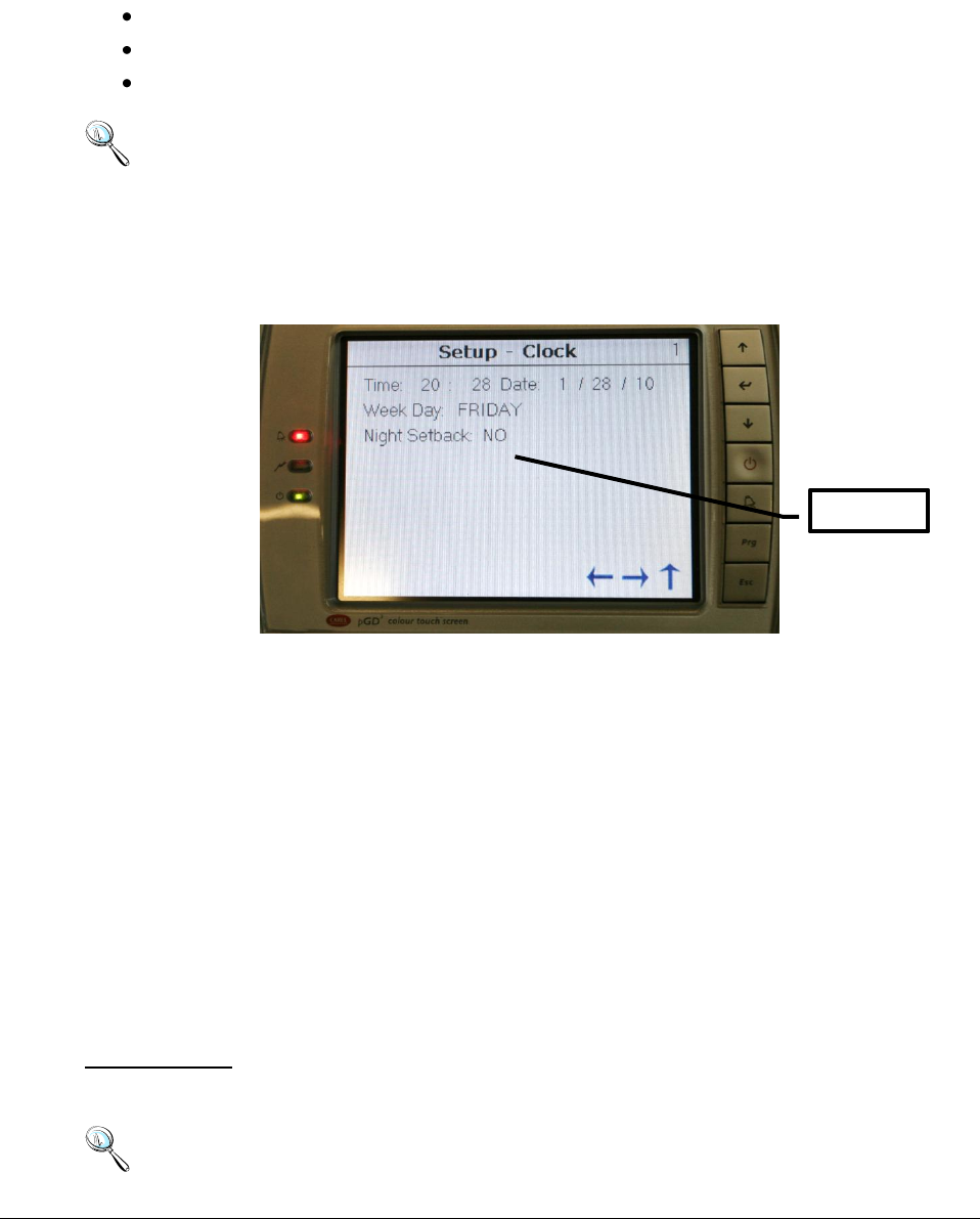
7.4 Clock Setup
The controller features an internal clock. Current time and date are backed up by an internal
Lithium-On battery. Consult the factory for battery replacement.
Figure 20 - Clock setup
7.4.1 Time and Date Setup
Tap on the corresponding number on the touch screen. Enter a new number from the virtual
keypad. Press Enter when finished. Changes take effect immediately and require no system
reset.
7.4.2 Night Setback
The controller supports 7 days unoccupied and occupied modes. Separate temperature and
humidity setpoints are available and take priority when the night setback mode is active.
To active the Night Setback, change its setting to “YES” and follow the on screen directions. Use
the arrow keys to navigate through the different screens to program each individual day.
Default Setting:
Night Setback: NO
Note: It is not recommended to set the Night Setback for computer room cooling.
Night Setback
Rev.03a 12-21-10
Page 38 of 74
Compu-Aire
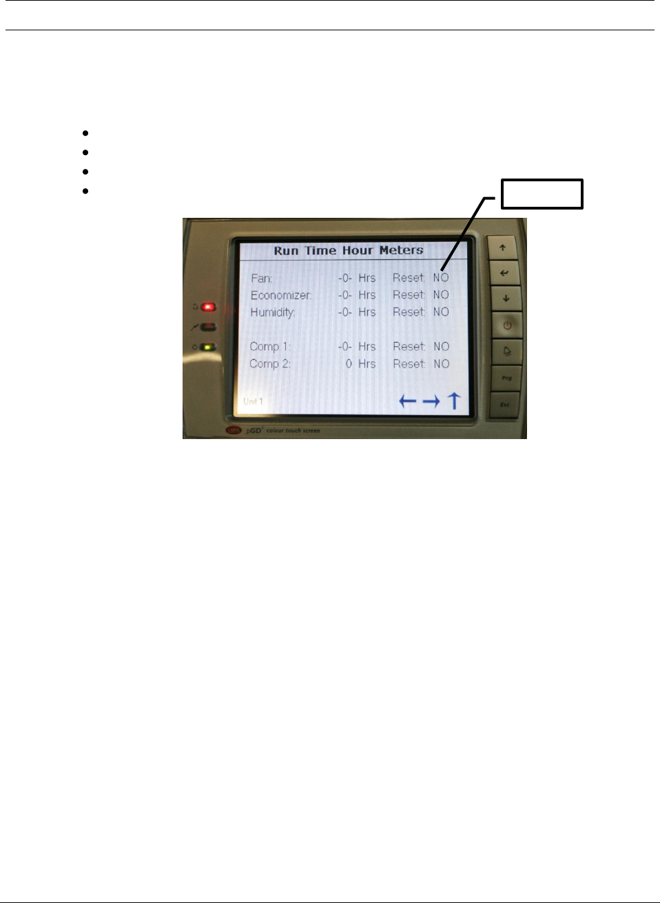
8.0 RUN TIME HOUR METERS
The controller keeps track of run time for each individual component for servicing purposes.
Each counter can be reset individually.
Setting Timer
Change the Reset setting from “NO” to “YES”
Press Enter from the virtual screen
The run time hour is reset immediately
Repeat the same process for other components
Figure 21 - Component run time meters
Reset timer
Rev.03a 12-21-10
Page 39 of 74
Compu-Aire
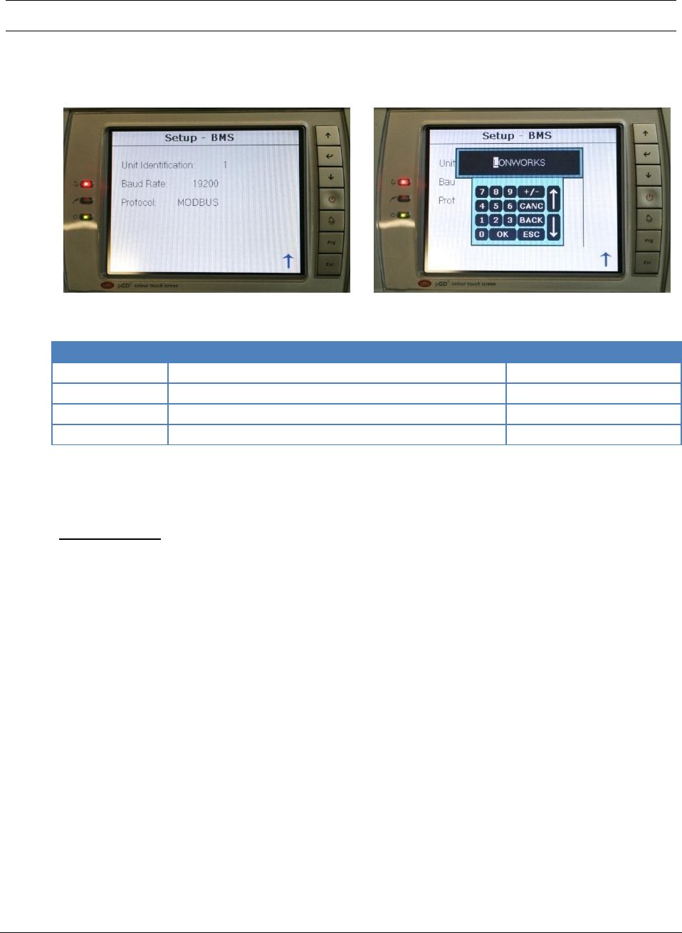
9.0 BUILDING MANAGEMENT SYSTEM (BMS)
PCO3 controller is capable of communicating with external remote Building Management
System (BMS). Supporting protocol is enabled by a plug-in communication card.
Figure 22 - Building management system
Figure 23 - Communication protocol
Protocol
Description
Default Baud Rate
Modbus
Serial communication through RS-485
19,200
LONWorks
LONTalk communication
4,800
BACnet MS/TP
BACnet over MS/TP
4,800
BACnet TCP/IP
BACnet over TCP/IP, SMNP, HTML, FTP
19,200
PCO3 controller also features an alternative method of networking multiple cooling unit in a
built in standalone p-LAN network through terminal J11.
Default Setting:
Unit Identification: 1 Baud Rate: 19200 Protocol: Modbus
9.1 Modbus
The PCO3 controller supports an optional RS-485 card, which allows you to interface directly the
pCO3 to a supervisory network RS485. The max baudrate available is 19200 baud (it can be set by
software).
9.1.1 Mounting
To install the card in the pCO unit follow these instructions:
1. Remove the "serial card" placement cover with a screwdriver.
2. Remove the pre-punctured plastic piece corresponding to the card being installed.
3. Insert the optional card into the corresponding connector; confirm the card is firmly
placed on both plastic supports on the pCO3 case.
4. Close the cover using the screwdriver making sure the outside card terminal fits within
the punched hole made on the cover.
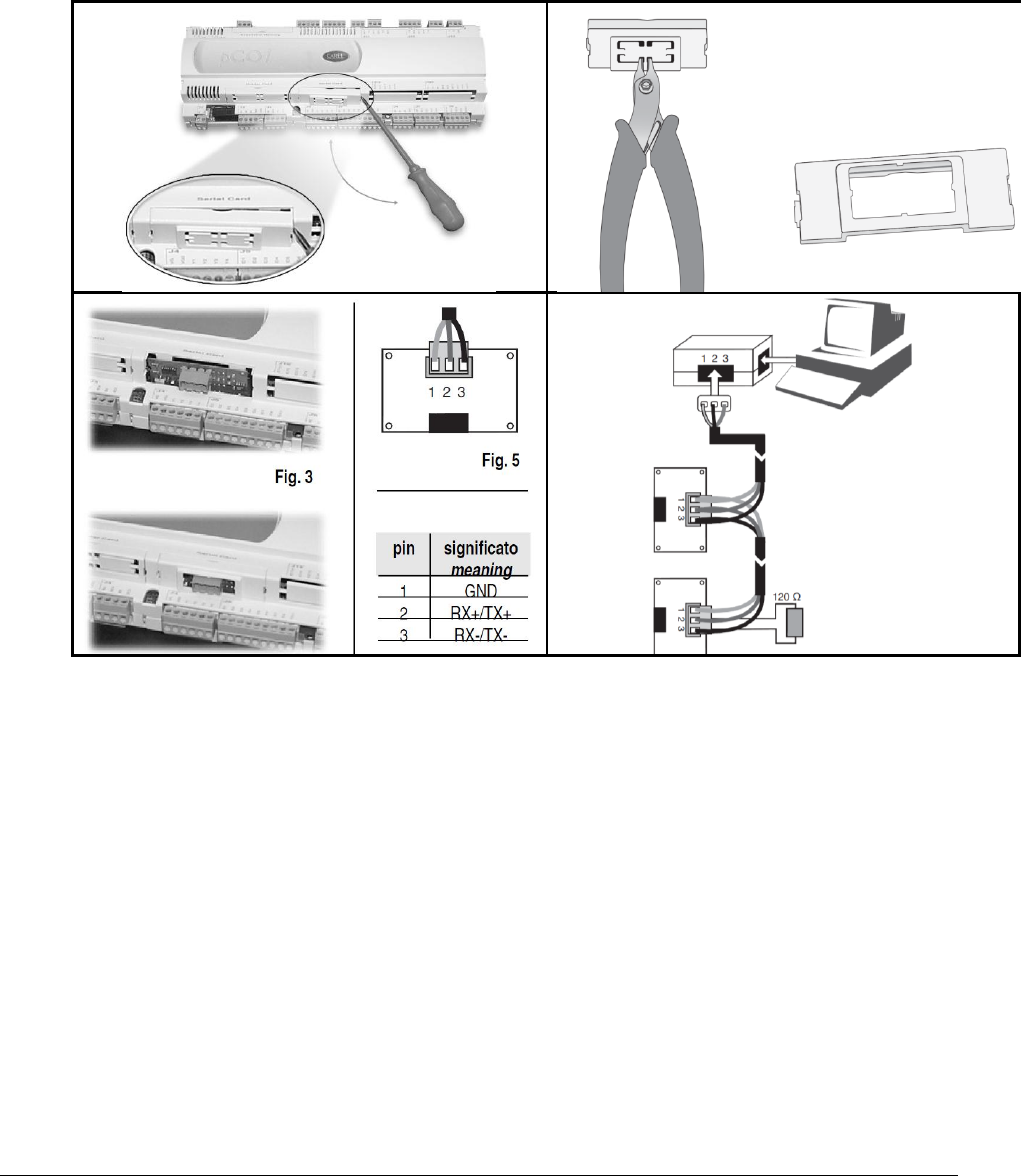
Rev.03a 12-21-10
Page 40 of 74
Compu-Aire
The connection with the RS485 network is carried out by means of the plug-in terminal
connector on the card Pin-wiring of the connector is stamped on the card. If the card is placed
in the last position of the supervision serial line, pins 2 and 3, you must connect a 120 Ω - 1/4 W
end line resistors.
Table 6 - Modbus card installation
Warning
When handling the card, please follow the advice below. Electrical damage may occur to the
electronic components as a result of electrostatic discharges from the operator. Suitable
precautions must be taken when handling these components.
• Before using any electronic component or card, ground yourself (not touching the card
does not prevent a spike, as static electricity can produce a 10000V spike discharge
which can form an arc of about 1cm)
• All components must be kept inside their original package as long as possible. If
necessary, take the board from its package and place it into an antistatic package
without touching the back of the board with your hands
• Absolutely avoid non-antistatic plastic bags, polystyrene or sponge.
• Do not pass the card directly to other operators (to prevent from electrostatic induction
and discharges).

Rev.03a 12-21-10
Page 41 of 74
Compu-Aire
9.2 POINTLIST
The following point list is available for LONWORKS, Modbus, and BACnet communication card.
Use the corresponding register or index value to monitor it from the remote BMS system.
Carel
LONworks
Modbus
BACnet
Type
Index
pCO
Name NV
Type
NV
Register
Analog
Value
Direction
Description
ANL
1
nvoTmpSet/nviTmpSet
105
40002
1
R/W
Temperature set point
ANL
2
nvoTmpBand/nviTmpBand
105
40003
2
R/W
Temperature band
ANL
3
nvoHighTmpSet/nviHighTmpSet
105
40004
3
R/W
Temperature High alarm set point
ANL
4
nvoLowTmpSet/nviLowTmpSet
105
40005
4
R/W
Temperature Low alarm set point
ANL
5
nvoHumSet/nviHumSet
81
40006
5
R/W
Humidity set point
ANL
6
nvoHighHumSet/nviHighHumSet
81
40007
6
R/W
Humidity High alarm set point
ANL
7
nvoLowHumSet/nviLowHumSet
81
40008
7
R/W
Humidity Low alarm set point
ANL
8
nvoHumBand/nviHumBand
81
40009
8
R/W
Humidity band
ANL
9
nvoTemperature
105
40010
9
R
Temperature reading
ANL
10
nvoHumidity
81
40011
10
R
Humidity reading
ANL
11
40012
11
R
Outside Air Humidity
ANL
12
40013
12
R
Discharge Temperature
ANL
13
40014
13
R
Outside Air Temperature
ANL
14
40015
14
R
Coil or Water Temperature
ANL
15
40016
15
R
User Sensor 1
ANL
16
40017
16
R
User Sensor 2
ANL
17
40018
17
R
User Sensor 3
ANL
18
40019
18
R
User Sensor 4
ANL
19
nvoHighPr_1
40020
19
R
High Pressure 1 (Pressure
Transducer)
ANL
20
nvoLowPr_1
40021
20
R
Low Pressure 1 (Pressure
Transducer)
ANL
21
nvoHighPr_2
40022
21
R
High Pressure 2 (Pressure
Transducer)
ANL
22
nvoLowPr_2
40023
22
R
Low Pressure 2 (Pressure
Transducer)
ANL
23
nvoCondPr_1
40024
23
R
Condenser Pressure 1
ANL
24
nvoCondPr_2
40025
24
R
Condenser Pressure 2
ANL
25
nvoOAEcono_Set
40026
25
R/W
Outside Air Economizer Setpoint
ANL
26
40027
26
R/W
Discharge Air Economizer Setpoint
ANL
27
40028
27
R/W
Water Economizer Setpoint
Carel
LONworks
Modbus
BACnet
Type
Index
pCO
Name NV
Type
NV
Register
Analog
Value
Direction
Description
INT
1
nvoTmpInt/nviTmpInt
8
40130
1001
R/W
Temperature control Integration time
INT
2
nvoHumInt/nviHumInt
8
40131
1002
R/W
Humidity control Integration time
INT
3
nvoStatus
8
40132
1003
output
0=System off, 1=system on,
2=active,3=standby,4=override,5=off by

Rev.03a 12-21-10
Page 42 of 74
Compu-Aire
digital input, 6=manual
INT
4
Analog Out Y1
81
40133
1004
R
Analog Out Y1
INT
5
Analog Out Y2
81
40134
1005
R
Analog Out Y2
INT
6
Analog Out Y3
81
40135
1006
R
Analog Out Y3
INT
7
nvoHumStatus
81
40136
1007
R
Humidity demand (0-100%)
INT
8
40137
1008
R
Analog Out Y4
INT
9
40138
1009
R
Analog Out Y5
INT
10
40139
1010
R
Analog Out Y6
INT
11
40140
1011
R
Current Day
INT
12
40141
1012
R
Current Hour
INT
13
40142
1013
R
Current Minute
INT
14
40143
1014
R
Current Month
INT
15
40144
1015
R
Current Second
INT
16
40145
1016
R
Current Weekday
INT
17
40146
1017
R
Current Year
Carel
LONworks
Modbus
BACnet
Type
Index
pCO
Name NV
Type
NV
Register
Analog
Value
Direction
Description
DGT
1
nvoOnOffStat/nviOnOffStat
95
2
1
R/W
Unit ON/OFF status
DGT
2
nvoTmpCntr/nviTmpCntr
95
3
2
R/W
Temperature control type 0=P 1=PI
DGT
3
nvoHuCntr/nviHuCntr
95
4
3
R/W
Humidity control type 0=P 1=PI
DGT
4
nvoAirflowAlm
95
5
4
R
no airflow alarm
DGT
5
nvoHighHtAlm
95
6
5
R
High heat Alarm
DGT
6
nvoSmokeAlm
95
7
6
R
Smoke alarm
DGT
7
nvoC1LPAlm
95
8
7
R
Compressor 1 low pressure alarm
DGT
8
nvoC1HPAlm
95
9
8
R
Compressor 1 high pressure alarm
DGT
9
nvoC2LPAlm
95
10
9
R
Compressor 2 low pressure alarm
DGT
10
nvoC2HpAlm
95
11
10
R
Compressor 2 high pressure alarm
DGT
11
nvoC1CycAlm
95
12
11
R
Compressor 1 short cycle alarm
DGT
12
nvoC2CycAlm
95
13
12
R
Compressor 2 short cycle alarm
DGT
13
nvoDrainAlm
95
14
13
R
Drain alarm
DGT
14
nvoHighTmpAlm
95
15
14
R
High Temperature alarm
DGT
15
nvoLowTmpAlm
95
16
15
R
Low Temperature alarm
DGT
16
nvoHighHuAlm
95
17
16
R
High Humidity alarm
DGT
17
nvoLowHuAlm
95
18
17
R
Low Humidity alarm
DGT
18
nvoWtrFlAlm
95
19
18
R
Water Flow alarm
DGT
19
nvoFireAlm
95
20
19
R
Fire alarm
DGT
20
nvoHeat1Out
95
21
20
R
Heat1 output status
DGT
21
nvoHeat2Out
95
22
21
R
Heat 2 output status
DGT
22
nvoHeat3Out
95
23
22
R
Heat 3 output status
DGT
23
nvoHeat4Out
95
24
23
R
Heat 4 output status
DGT
24
nvoC1Out
95
25
24
R
Compressor 1 output status
DGT
25
nvoC2Out
95
26
25
R
Compressor 2 output status
DGT
26
nvoC3Out
95
27
26
R
Compressor 3 output status
DGT
27
nvoC4Out
95
28
27
R
Compressor 4 output status

Rev.03a 12-21-10
Page 43 of 74
Compu-Aire
DGT
28
29
28
R
humidifier alarm
DGT
29
30
29
R
DGT
30
31
30
R
DGT
31
32
31
R
standby unit on
DGT
32
33
32
R
filter alarm
DGT
33
34
33
R
discharge heat did not raise alarm
DGT
34
35
34
R
discharge cool did not fall alarm
DGT
35
36
35
R
fan overload
DGT
36
37
36
R
DGT
37
38
37
R
DGT
38
39
38
R
Compressor 4 low pressure / User
DGT
39
40
39
R
Compressor 4 hi pressure / User
DGT
40
41
40
R
User with Humidify Lockout
DGT
41
42
41
R
User with Reheat Lockout
DGT
42
43
42
R
DGT
43
44
43
R
DGT
44
45
44
R
a unit is off pLAN network
DGT
45
46
45
R
user1 low alarm
DGT
46
47
46
R
user1 high alarm
DGT
47
48
47
R
user2 low alarm
DGT
48
49
48
R
user2 high alarm
DGT
49
50
49
R
user3 low alarm
DGT
50
51
50
R
user3 high alarm
DGT
51
52
51
R
user4 low alarm
DGT
52
53
52
R
user4 high alarm
DGT
53
54
53
R
Fan Output
DGT
54
55
54
R
Heater 1 Output
DGT
55
56
55
R
Heater 2 Output
DGT
56
51
56
R
Bypass 4 Output
DGT
57
58
57
R
Humidifier Output
DGT
58
59
58
R
Dehumidifier Output
DGT
59
60
59
R
DGT
60
61
60
R/W
Reset Alarm Command
DGT
61
62
61
R
Unloader 1 Output
DGT
62
63
62
R
Unloader 2 Output
DGT
63
64
63
R
Bypass 1 Output
DGT
64
65
64
R
Bypass 2 Output
DGT
65
66
65
R
System Alarm
DGT
66
67
66
R
Remote On command via digital input
DGT
67
68
67
R
DGT
68
69
68
R
Bypass 3 Output
DGT
69
70
69
R
Alarm 2
DGT
70
71
70
R
Condenser Fan Output
DGT
71
72
71
R
Manual Override
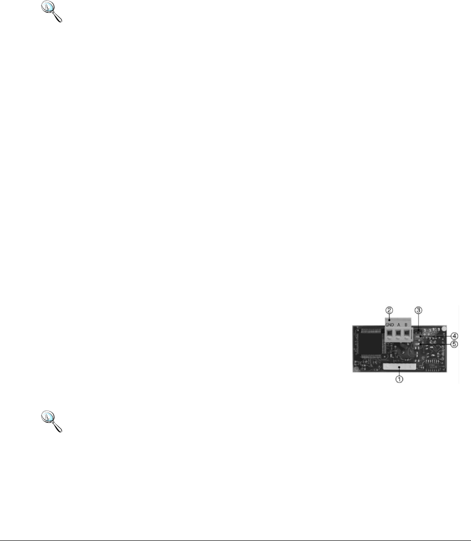
Rev.03a 12-21-10
Page 44 of 74
Compu-Aire
9.3 LONWORKS
The serial interface boards for LonWorks® networks are optional accessories for the PCO3
controller which allows the controllers to be connected directly to a LonWorks® network.
The use of these boards requires knowledge of and experience with the LonWorks® network
installation and maintenance tools.
9.3.1 General characteristics
Note: The LONTalk card is preprogrammed at the factory. Commissioning the device is
required to have proper readings when probing.
The program installed on the board may correspond to a standard LonMark® profile. The board
is programmed by the manufacturer when LonMark® profiles are used or in the field for custom
profiles.
9.3.2 Physical channels
Depending on the model, the interface boards communicate via two physical channels, TP/FT-10
and TP-RS485-39, as described in the LonWorks® literature. The LONTalk card uses an Echelon®
FTT-10 transceiver, approved for use on the TP/FT-10 channel. This channel has the following
main characteristics:
• Allows the connection of a maximum of 64 nodes for each network segment;
• The nodes can be connected without any restrictions in the topology: that is, star, ring, on
one bus only, or with any combination of these;
• Communication speed: 78,125 kbps;
• Maximum distance (Belden 85102 cable): 500m for connections between the nodes with
free topology; 2700m for bus connections with double line terminator.
9.3.3 Physical Circuit Board Layout
1. Connector to the PCO3 Controller
2. Terminal block for LonWorks® network (GND, A, B)
3. Service pin
4. Green service LED
5. Red fault LED
Figure 24 - LONTalk Card
Note: The ground wire (GND) is not requires in some application.

Rev.03a 12-21-10
Page 45 of 74
Compu-Aire
9.3.4 LED Color Description
The green service LED:
• Signals the status of the node, as per the LonWorks® protocol
• Hardware fault: always ON or always OFF
• Node configured (normal operation): ½ second ON, then always OFF
• Node NOT configured: flashing at ½ Hz
• Node without software application: 1 second ON, 2 seconds OFF, then always OFF
• Node in continuous reset: flashing
• Remains on during the activation of the service pin
• Remains on for one second when receiving a wink command via the network
The red fault LED:
• Signals problems in the connection between the board and the pCO.
WARNING: If the red LED comes on make sure the instructions described under Installation have
been carefully followed. THE COMMUNICATION BAUD RATE ON THE PCO HAS BEEN SET TO 4800
BAUD.
9.3.5 Installation
WARNINGS: precautions in handling the board. Electrical damage may occur to the electronic
components as a result of electrostatic discharges from the operator. Suitable precautions must
be taken when handling these components, specifically:
• Before handling any electronic component or board, touch an earthed object
(simply not touching the component is not enough to prevent a spike, as static
electricity can produce a 10000V discharge, which can form an arc of about 1cm)
• All materials must be kept inside their original package as long as possible. If
necessary, take the controller from its package and place it into antistatic packaging,
without touching the back of the board
• Absolutely avoid non-antistatic plastic bags, polystyrene or sponges;
• Do not pass the electronic components or boards directly to other operators (to
prevent electrostatic induction and discharges)
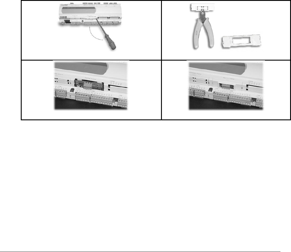
Rev.03a 12-21-10
Page 46 of 74
Compu-Aire
9.3.6 Connection to the PCO3 Controller
With reference to Figures 25-28 below, insert the board in the pCO3 as follows:
1. Disconnect the power supply to the pCO3 and use a screwdriver, remove the serial card
cover
2. Remove the pre-cut plastic part from the cover to make a rectangular window cutout
3. Insert the optional board in the corresponding plug-in connector, initially holding it
diagonally and then making sure it is properly inserted and pushed up against the two
plastic supports on the case of the PCO3
4. Close the cover and aligning the connector on the serial board with the hole made in the
cover
5. Reconnect the power supply to the pCO. If the pCO supervisor serial communication
has been set to use the Carel protocol at 4800 baud, the red LED on the board will come
on for a few seconds and then will go off immediately, indicating normal operation.
Figure 25 - Remove plastic cover
Figure 26- Cut out window
Figure 27 - Installing plugin card
Figure 28 - Replacing windows cover
9.3.7 Connection to the LonWorks® network
The physical connection to the LonWorks® network is performed using the connector with
removable terminals fitted on the board, according to the Echelon® instructions and
specifications. For further information on installation, maintenance, the cross-section and type
of cable, refer to the LonWorks® literature.
9.3.8 Service pin
To activate the service pin, simply momentarily short-circuit the two pins on the board (see
Figure 24) with the tip of a screwdriver or a similar tool. The service pin must only be activated
during the installation of the node. When the pin is activated, the node sends a broadcast
message over the LonWorks® network, containing the information required for identification.

Rev.03a 12-21-10
Page 47 of 74
Compu-Aire
9.3.9 WINK event
A generic supervisor can send the WINK command to a specific node on the LonWorks®
network. This generates an event that the application on the specific node can respond to with
any action decided by the programmer. In this specific case, the service LED on the interface
comes on for one second, thus making it possible to check the correct operation of the
connection between the interface and LonWorks® network.

Rev.03a 12-21-10
Page 48 of 74
Compu-Aire
9.4 BACNET OVER TCP/IP
9.4.1 Installation
The board is installed in the PCO3 controller, when off, as follows
1. Remove the “Serial Card” cover from the PCO3 using a screwdriver.
2. Insert the board in the corresponding plug-in connector, making sure it is fully inserted
and in contact with the two supports located on the case of the PCO3. This operation
may be difficult due to the limited space, consequently, it is recommended to insert the
board at an angle and then turn it until aligning the connectors.
3. Close the cover again, using the cover supplied with the board, lining up the connector
on the serial board with the opening in the cover.
4. (optional): stick one or both labels supplied outside and/or inside the electrical panel
near the PCO3, so that the MAC ADDRESS can be read without needing to open the
electrical panel for the connection to the Ethernet network, use an S/FTP cable,
category 5e or higher.
9.4.2 Functions
The pCOWeb board is used to connect the pCO3 controller to an Ethernet network and
consequently perform the following functions.
• Access the information on the pCO3 (network variables and parameters) using an
Internet browser, such as Internet Explorer™ installed on a PC and connected to the
pCOWeb via TCP/IP (see Web server)
• Connection to a supervisory network that uses one of the following standard protocols
o SNMP v1 & v2c
o BACnet Ethernet ISO8802-2/8802-3
o BACnet/IP
9.4.3 Default parameters
In order to access the configuration (see the Configuration section), the pCOWeb can be started
using the “factory bootswitch parameters”:
IP address= 172.16.0.1 Net mask= 255.255.0.0;
“root” user password: froot
“httpadmin” user password: fhttpadmin
“guest” user password: fguest

Rev.03a 12-21-10
Page 49 of 74
Compu-Aire
To start the pCOWeb with default parameters, proceed as follows:
When the pCOWeb is off:
• switch on the pCO3 controller with the pCOWeb already inserted and hold the button
for at least 20 s, until the status LED starts flashing SLOWLY 3 times, red-dark;
• release the button while the LED is flashing, after having flashed 3 times, the LED turns
green, then, to confirm the recognition of the button, the LED will flash QUICKLY 3
times, red-dark.
• To complete the pCOWeb boot phase, wait approximately 50 s until the status LED
flashes regularly. From this moment on, the pCOWeb can be accessed via the network
When the pCOWeb is already on:
• Restart the pCOWeb software (see “Restarting the software”)
• After restarting, proceed as above for when the pCOWeb is off.
Note: In “factory bootswitch parameters” mode, the pCOWeb does not save the
parameters recalled, but simply uses them, and therefore, when next restarted without
pressing the button, it will use the parameters set by the user (if just acquired, with DHCP)
9.4.4 Restarting the software
To restart the software when the board is in stable operation (that is, with the status LED
flashing regularly), press and hold the button for between 5 and 10 seconds; after around 10 s
from releasing the button, the status LED will stop flashing, and after a further 15 seconds the
software on the board will restart.
9.4.5 Configuration
Note: For the correct operation of the pCOWeb, a number of basic parameters need to
be set, such as the IP address and Netmask; each device connected to an Ethernet
network, to communicate with a host, must have a unique IP address.
PCOWeb is supplied with the DHCP function already active. Therefore, in a network served by a
DHCP server, pCOWeb will automatically acquire the necessary parameters without requiring
configuration. In the case of a network without DHCP, the parameters need to be configured
manually (see the “Accessing the user configuration...” section).
Accessing the user configuration (via Ethernet network and configuration web pages)
Automatic network configuration (DHCP): ask the network administrator for the address that
has automatically been assigned to the pCOWeb already connected; the administrator will need
to know the MAC ADDRESS of the pCOWeb.
Network without DHCP: when first using the board, it is recommended to connect pCOWeb
directly to a computer using a crossed Ethernet cable; then start the board with the “factory
bootswitch” parameters (see “Pushbutton”).
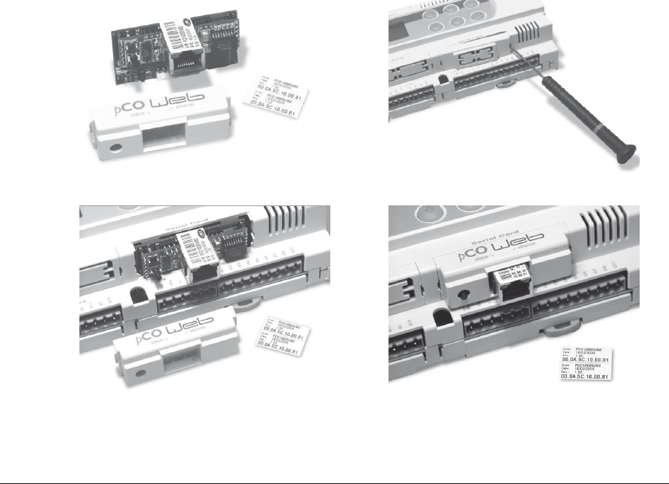
Rev.03a 12-21-10
Page 50 of 74
Compu-Aire
To allow the PC to access the pCOWeb:
• The PC used for the configuration must be in the same sub-network as the pCOWeb; set
the network parameters on the PC as follows:
o IP address= if DHCP: ask the network administrator; with “factory bootswitch
parameters”: 172.16.xxx.xxx (with xxx.xxx as desired, as long as different from
the 0.1 already used by pCOWeb);
o Netmask= 255.255.0.0.
• The browser on the PC must have the option corresponding to the use of a proxy server
disabled. If the network settings on the PC and the browser are correct, typing the IP
address of the pCOWeb in the address bar will access the default home page of the
pCOWeb. Then enter the area reserved for the administrator, using the special link (Go
to Administrator Area) and the following pre-set account:
o username= admin
o password= fadmin
The basic parameters for communication and access are located in the “Configuration” area.
Choose “Network”: the primary IP address of the board and three aliases can be set.
To configure the DHCP function type “DHCP” in the place of the IP address. If the network does
not use DHCP, ask the network administrator for a valid IP address and Netmask for the local
network that the pCO3 will be connected to.
Figure 29 - PCOWeb
Figure 30 - Window cover
Figure 31 - Installing PCOWeb
Figure 32 - Installing plastic cover

Rev.03a 12-21-10
Page 51 of 74
Compu-Aire
Note: the parameters recalled with the “Pushbutton” cannot be modified and must not
be confused with the values that are modifiable by the user. For a complete description of
all the parameters that can be set, consult the factory for user manual.
9.4.6 Web server
The web server included in the pCOWeb is “thttpd”, compliant with the HTTP 1.1 specifications,
and is used to display HTML pages directly on the Internet browser. A client application can
thus control and monitor the pCO3 controller that the pCOWeb board is installed on from a
remote location.
The HTML pages can be easily created and downloaded to the pCOWeb by the end user with
any FTP client. Common programs can be used to create the custom HTML pages (e.g.
Macromedia® Dreamweaver™ or Microsoft® FrontPage™) and download them to the pCOWeb
via FTP client such as SmartFTP™ (www.smartftp.com).
9.4.7 Accessing the operating system by authentication
The system can be accessed via a telnet terminal or via FTP. Authentication with user name and
password is required for each access. The following users are registered.
User Name
Description
Default Password
Allowed
root
administrator of the operating
system
froot
no limitation
httpadmin
web administrator
Fhttpadmin
R/W access to the http
directory; read-only to
the other directories.
guest
guest
fguest
Table 7 - PCOWeb passwords
The password can be modified by accessing the administrator page. The password recalled with
the “Pushbutton” function will not be modified and must not be confused with the passwords
that are modifiable by the user. This page can also be used to set the access restrictions for each
of the various directories in the http tree. Consequently, connecting via FTP and logging in as
the web administrator, as follows will access the pCOWeb user file system
• username= httpadmin;
• password= fhttpadmin (note “f” as in “factory” as the first letter).
The customized pages should be saved in the following directory: /usr/local/root/flash/http.
Note: The pages downloaded to the pCOWeb must have the correct properties and be
able to be displayed with a browser; setting these attributes correctly via FTP is quite
difficult, and consequently the “auto-set attributes” function is available in the
administrator pages. To activate this function, simply click the “Adjust HTML pages
attributes” link; it is recommended to do this whenever modifying one or more HTML
pages.

Rev.03a 12-21-10
Page 52 of 74
Compu-Aire
9.4.8 CGI script
CGI scripts can be written in bash language or compiled languages. These must have the .cgi
extension and must reside in the http/usr-cgi directory. As for the HTML pages, these files must
also have the properties correctly set and enabled. IMPORTANT: It is recommended to click on
the “Adjust HTML pages attributes” link whenever modifying one or more .cgi scripts.
9.4.9 SNMP
PCOWeb is able to communicate using the SNMP protocol (v1 & v2c). It therefore acts as a
gateway between the CAREL proprietary protocol and SNMP. The information available via
SNMP relates to all the data sent to the supervisors by the application loaded on the pCO3.
PCOWeb manages some standard traps and allows a trap to be defined for each digital variable
on the pCO3. The parameters relating to the management of the SNMP protocol can be set
using the administrator configuration pages.
9.4.10 BACnet
PCOWeb is able to communicate using the BACnet protocol over Ethernet:
• ISO8802-2 over 8802-3;
• BACnet/IP.
It acts as a gateway between the controller proprietary protocol and BACnet. The information
transferred involves all the data sent to the supervisor by the application loaded on the pCO3.
The parameters relating to the management of the BACnet protocol are set using the
administrator configuration pages.
9.4.11 WARNINGS
Precautions when handling the board!
The electrical damage that occurs to electronic components is almost always due to electrostatic
discharges caused by the operator. Consequently, suitable precautions must be taken when
handling these components, in particular:
• Before handling any electronic component or board, touch an earthed object (avoiding
contact with a component is not sufficient, as a 10,000 V discharge, a voltage that can
easily be reached by static electricity, creates an arc of around 1 cm);
• The materials must remain as long as possible inside their original packages. If
necessary, remove the board from the packing and then place the product in antistatic
packaging without touching the sides of the board containing the electronic
components;
• Always avoid using plastic, polystyrene or non-antistatic materials;
• Always avoid passing the board between operators (to avoid the phenomena of
electrostatic induction and consequent discharges).
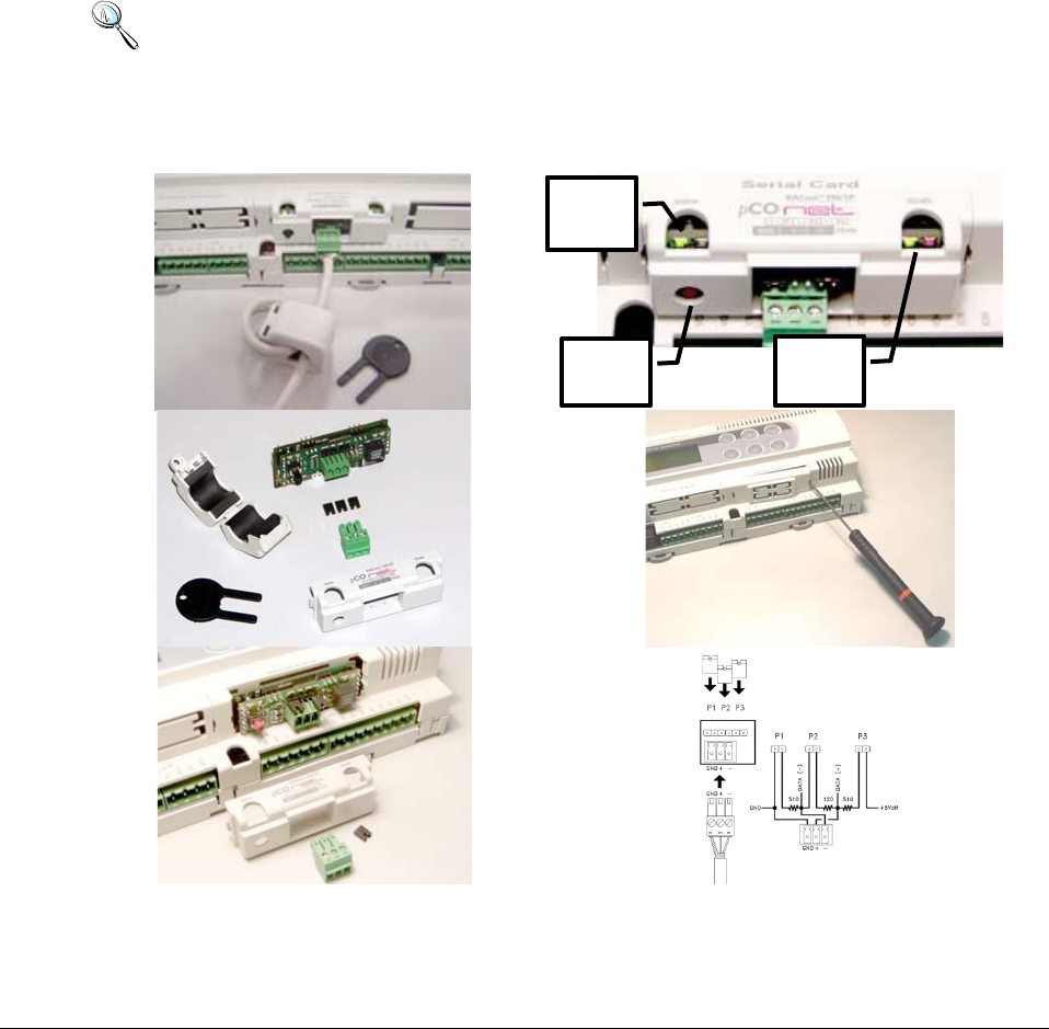
Rev.03a 12-21-10
Page 53 of 74
Compu-Aire
9.5 BANET over MS/TP
Optional add on board is available for BACnet over Master/Slave application.
9.5.1 Installation
1. Disconnect the power supply from the pCO3 and remove the “Serial Card” cover.
2. Insert PCOnet card in the plug-in connector, making sure that it is fully inserted and in
contact with the two supports on the pCO3. As there is little space available, this
operation may be complex: as a result, insert the PCOnet card at an angle then tilt it
back until the connectors line up.
3. Insert the required jumpers (see below for the meanings of these).
4. Fit the cover supplied with the PCOnet.
Note: If the device used to read the data from the 485 network is grounded and the
RS232-RS485 converter or the RS485 serial port on the device have functional insulation of
less than 2kV, connector G0 on the PCO3 board must be grounded. The board cannot be
installed in direct contact with the metal panel on the electrical panel.
Table 8- Installation guide
Push
Button
Status
LED
RS-485
LED

Rev.03a 12-21-10
Page 54 of 74
Compu-Aire
9.5.2 Meaning of the jumpers
Jumpers P1, P2 and P3 are located inside the front opening of the cover. See table 7 for
installation guide.
• Jumper P1 adds a 510 ohm polarization resistance between the negative data line (-)
and GND
• Jumper P2 adds a 120 ohm terminal resistance between the two data lines (+) and (-);
• Jumper P3 adds a 510 ohm polarization resistance between the positive data line (+) and
the +5 VDC internal voltage.
Insert all three jumpers on the unit at the start of network and the unit at the end of the
network. Do not insert the jumpers on the intermediate units. For compliance of the product
with the European EMC standards, add the ferrite supplied to the network cable, as illustrated
in Table 7.
9.5.3 Operation
The Status LED (left) indicates the status of communication with the controller and the status of
the PCOnet.
Starting sequence: on power-up, or after restarting PCOnet, the Status LED switches in the
following sequence:
• OFF for 2 seconds;
• 2 seconds after restarting: quick flash red-green-red-green
• 5 seconds after restarting: green on steady
• Approximately 50 seconds after restarting: flashing (color: see below - Status of
communication with the pCO3) PCOnet-pCO* communication starts.
Status of communication with the pCO3: Once the starting sequence has been completed, the
Status LED flashes to indicate the quality of communication with the PCO3:
• Quick green-OFF-green if communication with the pCO3 is OK (pCO* ON-LINE);
• Slow red-OFF-red if communication has not been established with the pCO* (pCO3 OFF-
LINE)
• Green-red-green if PCOnet detects errors or a temporary lack of response from the
pCO3.

Rev.03a 12-21-10
Page 55 of 74
Compu-Aire
The RS485 LED (right) indicates the status of communication with the BACnet MS/TP network
(RS485). The LED shows the following information:
Starting sequence: on power-up or after rebooting PCOnet, the RS485 LED switches in the
following sequence:
• Off for approximately 50 seconds;
• Approximately 50 seconds after restarting PCOnet: slow green–red–green–red: at
the end, BACnet will be active.
Status of communication with the BACnet MS/TP network: once the starting sequence has been
completed, the RS485 LED flashes to indicate the quality of communication with the BACnet
MS/TP network:
• Green with occasional red flashes if communication is OK (BACnet MS/TP meaning:
green ON = PCOnet keeps the Token (control of the MS/TP network); green OFF =
PCOnet DOES NOT keep the Token; red on = Poll-For-Master, search for a Master to pass
the Token to)
• Green and red ON together (BACnet MS/TP meaning: continuous Poll-For-Master):
communication not established (connection problems, or no network device found); this
may depend on electrical connection difficulties or communication settings that are not
compatible with the other network devices connected. See the section on configuration.
The Pushbutton Function
• restart PCOnet
• recall the factory configuration
Restarting PCOnet
With the board on and in stable operation (Status LED flashing continuously), hold the
button for more than 5 seconds and no more than 10 seconds. Approximately 10
seconds after releasing the button, the Status LED will stop flashing, and 15 seconds
later PCOnet will be restarted: Status LED quickly flashing red-green-red-green.

Rev.03a 12-21-10
Page 56 of 74
Compu-Aire
9.5.4 Recalling the factory configuration (“factory bootswitch” mode)
With the following procedure, PCOnet uses the default parameters instead of the ones specified
by the user. See the table of parameters and factory values in the section on Configuration. In
“factory bootswitch” mode, PCOnet does not save the recalled values, and consequently when
next restarted without pressing the button, PCOnet will again load the user settings. When
purchasing PCOnet, the user parameters are set to the factory configuration values.
With PCOnet OFF:
• Switch PCOnet on (i.e. switch on the pCO* controller with the PCOnet board inserted)
by pressing and holding the button for at least 20 seconds: the Status LED will flash
SLOWLY 3 times, red-off
• Release the button while the LED is flashing: after 3 red flashes, the LED comes on
green; the LED then confirms recognition of the button by flashing QUICKLY 3 times red-
off, and then comes on green again
Complete start-up of the PCOnet will take another 40 seconds, then the RS485 LED starts
flashing; only from this moment on can PCOnet be accessed via a remote connection.
With PCOnet already ON:
• Restart PCOnet (see above: Restarting PCOnet)
• After the restart procedure, follow the steps described above for PCOnet OFF
9.5.5 Configuration
Configuring the PCOnet parameters for correct communication over an MS/TP network:
• Connect PCOnet via RS485 to a computer: during configuration, the CAREL product code
CVSTDUMOR0 for USB ports can be used.
• Converters should not be used in the installation due to the large volume of data
transmitted across a complex BACnet™ network.
• Install the CAREL “BACset” configuration tool, available free-of-charge at ksa.carel.com.
Note: If the values of the pCOnet parameters are not suitable, communication with
BACset may not be possible. To connect to pCOnet, restart pCOnet using “factory
bootswitch” mode (see the section on Operation - Pushbutton).

Rev.03a 12-21-10
Page 57 of 74
Compu-Aire
9.5.6 BACNET Parameter Description
Device Instance
This is a number that uniquely identifies a device inside the BACnet® network (the
BACnet® network can also include non-MS/TP BACnet® devices). If two units have the
same Device Instance, identification errors will be generated.
Station Address
This is a number that differentiates the units in the BACnet® MS/TP network. If two
units have the same Station Address, identification errors will be generated. To speed
up the data exchange between the Master units, the Station Address of the Master units
should start from 0 and continue without skipping any numbers.
Max Info Frames
This establishes the maximum number of information packages exchanged, above which
the Master unit will give up control (Token) of the network to another Master unit. It
thus indirectly establishes a sort of priority between the Master units in the network:
high numbers guarantee the Master a higher data exchange volume.
MaxMaster
To speed up data exchange between the Master units, Max Master should be set to the
Station Address of the Master with the highest Station Address. In fact, each Master,
after having used the network, passes over control to the next Master. The Max Master
parameter specifies to pCOnet the address of the network Master with the highest
Station Address: using this parameter, pCOnet will know that there is no other Master
with a higher Station Address than Max Master; pCOnet will then give control of the
network to the next Master, however not beyond Max Master; if no next Master is
found, the cycle will begin again, with control being given to the Master with the lowest
Station Address.
Baud Rate
Data transfer speed. The Baud Rate must be the same for all the devices connected.
Otherwise the exchange of data will generate communication errors. For extended
networks, low baud rates should be specified, as these guarantee less communication
errors. If Baud Rate=76800, make sure the device supports this communication speed.
This baud rate is not supported by the RS232 serial port on a normal PC.
Parameter
Min
Max
Factory
Device Instance
0
4194303
77000
Station Address
0
127
0
Max Master
0
127
127
Max Info Frames
0
255
20
Baud Rate
9600, 19200,
38400,76800
Table 9 - BACnet MS/TP parameters
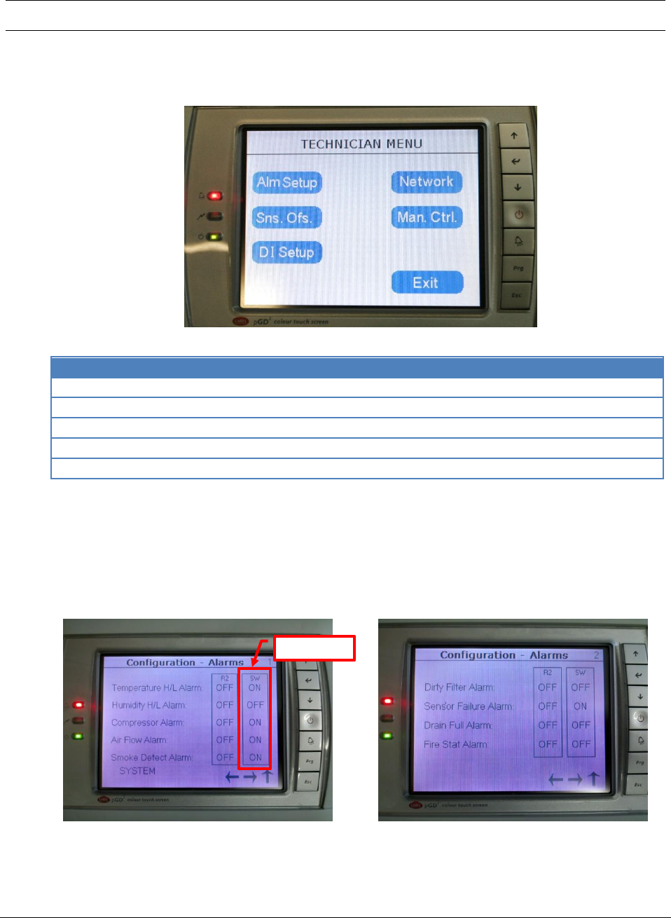
Rev.03a 12-21-10
Page 58 of 74
Compu-Aire
10.0 TECHNICIAN MENU
The service menu has settings that assist the installation and maintaining process. Each setting
is defined as shown below.
Table 10 - Technician menu
Icon
Description
Alm Setup
Alarm sensor setup for temperature, humidity, smoke, no air flow, etc.
Sns. Ofs.
Sensor calibration offset
DI Setup
Controller digital input setup
Network
P-LAN network setup
Man. Ctrl
Manual control for each components
Table 11 - Technician menu description
10.1 Alarm Setup
The controller supports a general alarm or global alarm for the following events. Each individual
alarm can be configured to be part of a global arm. R2 is the second relay which is connected to a
normally opened dry contactor. Consult the electrical wiring diagram for more information.
Figure 33 - Alarm configuration
Switch over

Rev.03a 12-21-10
Page 59 of 74
Compu-Aire
Default Setting:
Configuration R2 SW
Temp. H/L Alarm: OFF OFF
Hum. H/L Alarm: OFF OFF
Compressor Alarm: OFF ON
Air Flow Alarm: OFF ON
Smoke Detect alarm: OFF OFF
Configuration R2 SW
Dirty Filter Alarm: OFF OFF
Sensor Failure Alarm: OFF ON
Drain Full Alarm: OFF OFF
Fire Stat Alarm: OFF OFF
Note: Not all systems are equipped with a general alarm or global alarm. Setting the
SW=ON will shut the current active unit down and switch the operation over to standby
unit. The “Switch Over” column setting only available when more than one unit are
networked together.
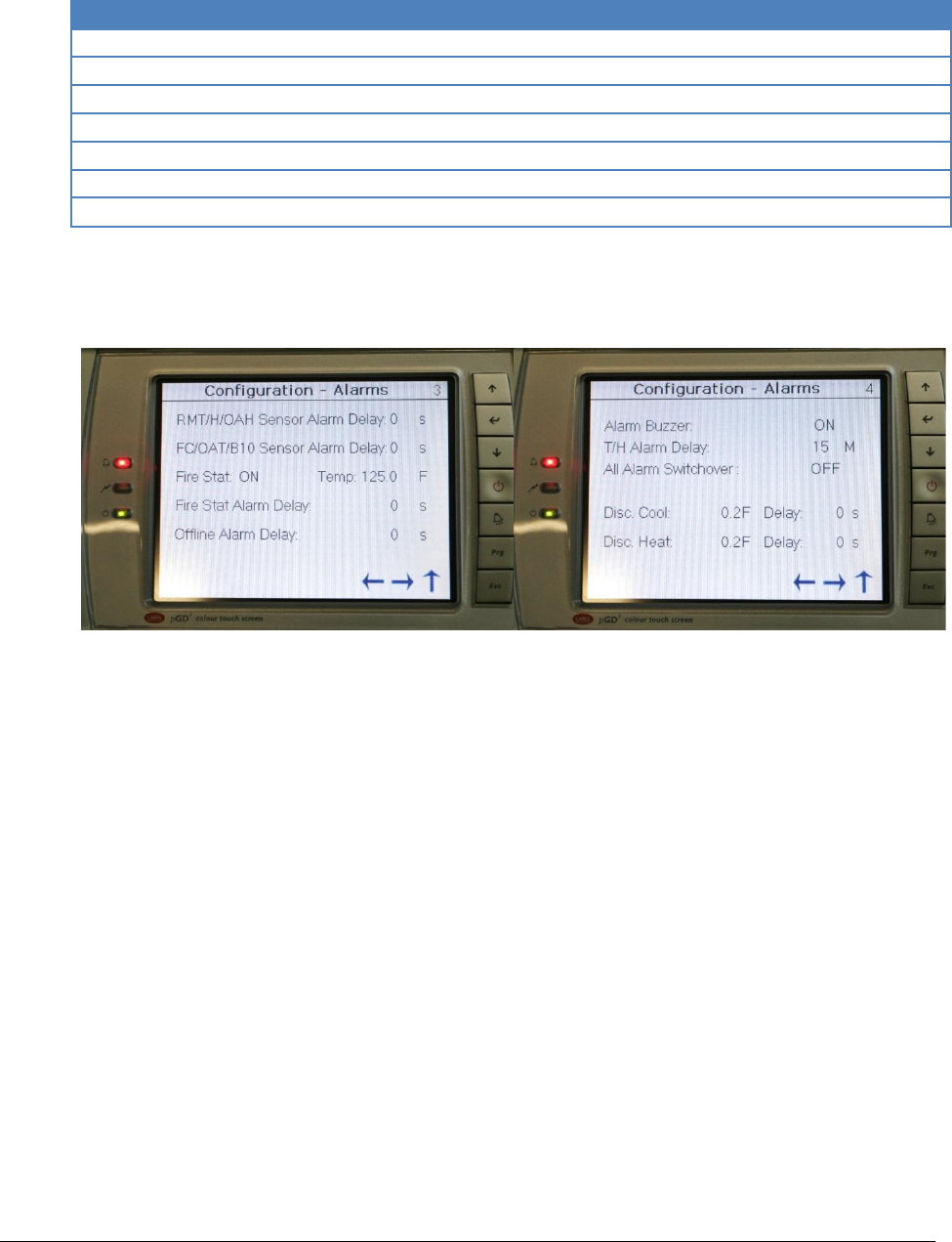
Rev.03a 12-21-10
Page 60 of 74
Compu-Aire
10.1.1 Available Alarms
Alarm
Function
Temperature H/L Alarm
High low alarm set under Setpoint
Humidity H/L Alarm
Humidity high/low set under setpoints
Compressor Alarm
Compressor fail
Air Flow Alarm
Air flow loss
Smoke Detect Alarm
Smoke is detected in the system
Dirty Filter Alarm
Filter is dirty, need replacement
Fire Stat Alarm
Temperature reaches 125°F
Table 12 - Global alarms
The alarm status is notated by its current setting. To set the alarm, change the setting to either
“ON/OFF” by tapping the screen and toggling via the virtual keyboard.
Figure 34 - Alarm delays
Figure 35 -Alarm switch over
The PCO3 controller implements time out sensor delays to insure smooth operation. Each delay
is dictated in second unless otherwise noted.

Rev.03a 12-21-10
Page 61 of 74
Compu-Aire
Default Setting
• RMT/OAH Sensor: 0s
• FC/OAT/B10: 0s
• Fire Stat: ON Temp: 125.0°F
• Fire Stat Alarm Delay: 0s
• Offline Alarm Delay: 60s
• Alarm Buzzer: OFF
• T/H Alarm Delay: 15M
• All Alarm Switchover: OFF
• Disc Cool/Heat: 0.2°F 0s
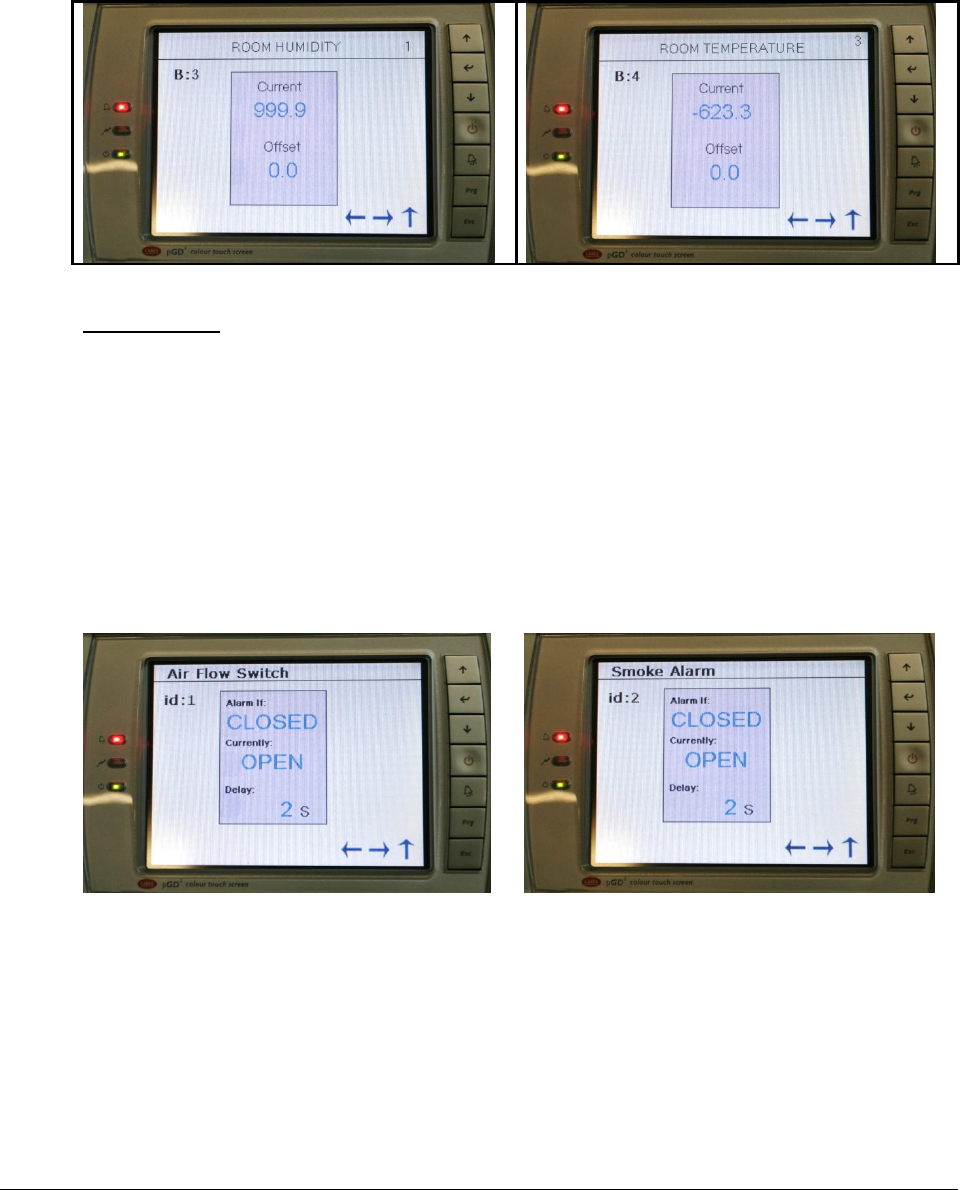
Rev.03a 12-21-10
Page 62 of 74
Compu-Aire
10.1.2 Sensor Offset
PCO3 controller provides sensor calibration to match the reading to a reference device. Setting
can be positive or negative offset. All adjustments take effect immediately.
Table 13 - Sensor calibration
Default Setting
Offset: 0
10.1.3 Digital Input
Digital setup is reserved for factory used only. If required, adjustment can be made to fine tune
the equipment to work with other applications. The controller is designed to recognize a 24VAC
signal from the sensor and trigger a corresponding alarm which is commonly used in normally
opened relay. In some cases, where a normally opened relay is use, a reverse logic must be set
in the controller to get the alarm function to register properly. Available options are closed and
open.
Table 14 - Digital Input Setting
Setting Description
Alarm If: CLOSED: Used for normally open sensor
OPEN: Used for normally closed sensor
Currently: Read only OPEN/CLOSED
Shows the current status of the input relay
Available Options
Smoke Alarm No Air Flow Hi Heat Limit
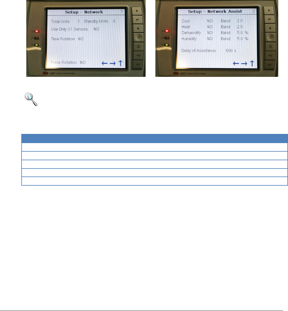
Rev.03a 12-21-10
Page 63 of 74
Compu-Aire
Compressors Low Compressors High Dirty Filter
Water Flow
10.2 Network Setup
The controller supports up to 16 units working together as single unity in a p-LAN network. A P-
LAN network composes of one (1) master unit with up to fifteen (15) slave devices. Proper unit
identification is required prior to proceeding. See P-LAN setup section for more information.
Figure 36 - Network Setup
Figure 37 - Network Assist
Note: A P-LAN network has a minimum of two units and a maximum of sixteen units.
Only one master is allowed. The Network Setup screen is accessible by the master unit
ID=1. This option is not available on the slave unit.
10.2.1 Define a Network
Icon
Function
Total Units
Total unit including the master
Standby Units
Number of standby units
Use U1 Sensors
Use master unit sensors for every units
Time Rotation
Number of day and time to rotate
Force Rotation
Force the standby unit to become active
Table 15 - Setting a P-LAN network
10.2.2 Network Assist
In a P-LAN network, all standby units are capable of assisting the active unit in cooling, heating,
dehumidifying, and humidifying mode. The dead band of each individual mode can be set
according to Figure 37. The delay of assistance is set to 600 seconds by default. After 600s,
standby units become active and assist only if the active unit is unable to maintain the setpoints
in the elapsed time. Once the setpoints are satisfied, standby units return to standby and the
cycle starts over.

Rev.03a 12-21-10
Page 64 of 74
Compu-Aire
10.3 Manual Control
Manual control is designed to turn on necessary components for a fixed amount of time. This
function can be used to vacuum and charge the unit, service the unit, or perform a functional test.
After an adjustable time out (defaults to 5 minutes, max 99 minutes), the designated component
returns back to AUTO and resumes its normal operation. Applicable analog/digital outputs are
selectable as ON, OFF, or AUTO mode. The following components are available in the manual
setting.
Note: Do not use this option to permanently turn off components such as reheat or
humidifier. Refer to Factory->HVAC setting for detail.
Default Setting: AUTO for all components
Blower
Low pressure bypass
Heaters
Compressors
Liquid Solenoids
Humidifier
Analog outputs
Global alarm
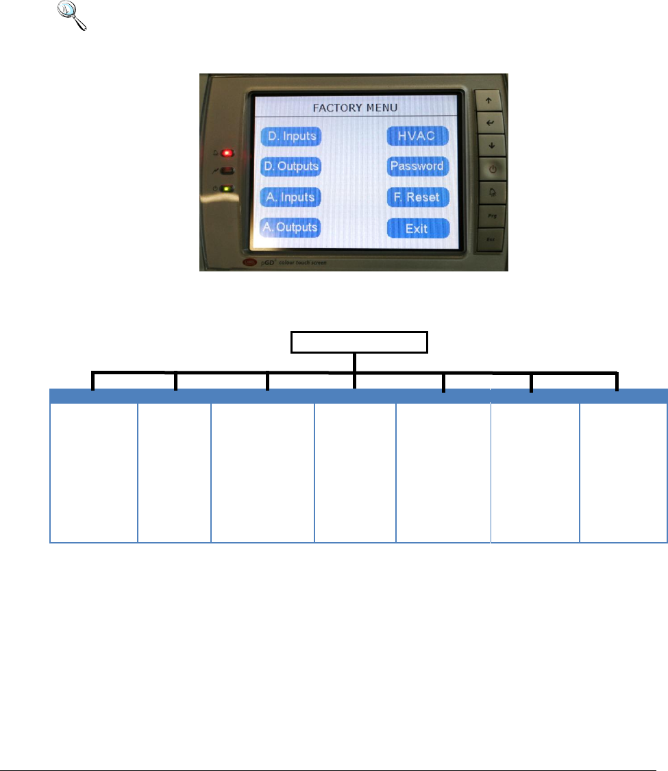
Rev.03a 12-21-10
Page 65 of 74
Compu-Aire
FACTORY SETTING
The controller is fully programmed at the factory to meet its specifications. Adjustments to the
default settings sometime are required in the field to fine tune the controller to adapt it to the
environment.
Note: A level 3 password is required to gain access to the Factory Menu. Changes to the
factory settings are crucial and only recommend for a well trained technician or under
factory guidance.
Figure 38 - Factory Setting
10.4 Factory Setting Menu Tree
FACTORY MENU
D. INPUTS
D. OUTPUTS
A. INPUTS
A. OUTPUTS
HVAC
PASSWORD
F. RESET
Air Flow
Smoke Alarm
High Heat Limit
Compressor
Condensate
Water Flow
Filter Alarm
Fan Overload
Remote ON/OFF
Condensate
Blower
Heater
Heat Pump
Compressors
Unloaders
Bypass
Humidifier
Global Alarm
Room Humidity
Room Temperature
Dsc. Temperature
Coils Temperature
Water In Temperature
Pressure Transducer
Economizer
Voltage Min/Max
Fan Mode
Fan Delay
Shut down Fan
Fan Min/Max ON
Unit °C/°F
Compressor Setup
Economizer
DX Assist
Low Pressure Retry
Dead Bands
Level 1
Level 2
Level 3
Factory Reset
Op. Mode
Reset Alarm Hist.
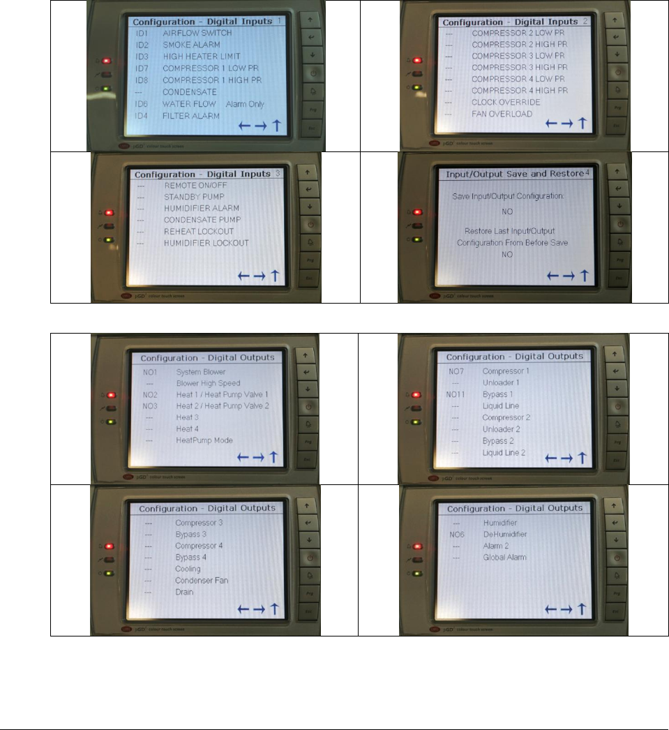
Rev.03a 12-21-10
Page 66 of 74
Compu-Aire
10.4.1 Digital Inputs and Digital Outputs
All digital inputs and outputs are predefined and governed by the electrical wiring diagram. All
settings are pre-configured at the factory prior to shipping. Changes are not recommended
unless suggested by the factory. Consult the factory for more detail.
In general, the controller works with a 24VAC input from the normally opened relay. The
internal relay from the controller sends out a 24VAC on the digital output terminals to
designated coils in order to energize the high voltage components.
Figure 39 - Digital input configuration
Figure 40 - Digital output configuration
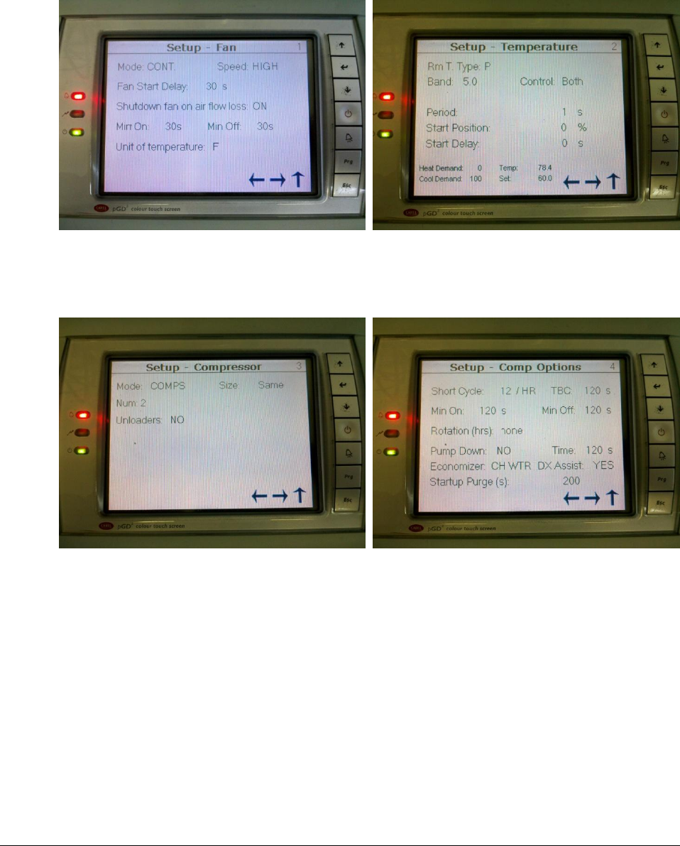
Rev.03a 12-21-10
Page 67 of 74
Compu-Aire
10.4.2 HVAC
The HVAC section contains crucial settings that can have great impact how the system perform.
All changes made in this section should be dealt with extra. Consult the factory if assistance is
needed. Not all options are available on all units.
Figure 41 Fan Setup
Mode: Continuous, Demand
Speed: High, Low
Figure 42 Sensor Setup
Room T. Type: Proportional, Integral, PID
Band: Deadband default 5.0 (±2.5°F)
Figure 43 Compressor Setup
Mode: Comps, Chilled water/water cooled
Num: Number of stages
Figure 44 Compressor Option
TBC: Time between compressors
Min ON/OFF: Minimum time comp stays ON
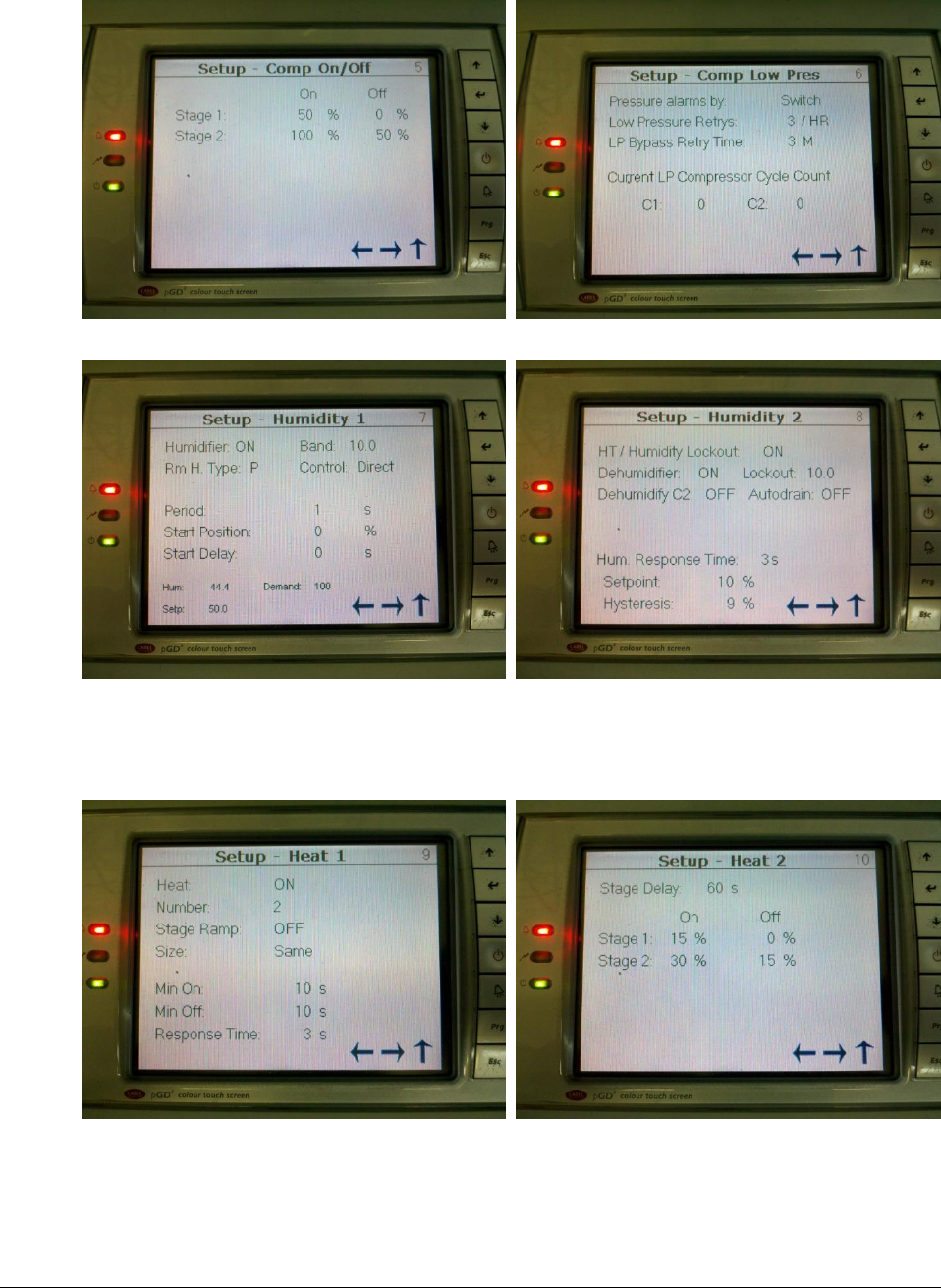
Rev.03a 12-21-10
Page 68 of 74
Compu-Aire
Figure 45 Compressor Stage ON/OFF
Figure 46 Low Pressure Retry
Figure 47 Humidifier
Humidifier: ON/OFF
Band: Deadband 10 (±5%)
Figure 48 Humidity Lockout
HT/Hum Lockout: ON/OFF, lockout 2nd comp.
Figure 49 Heater Setup
Heat: Heater ON/OFF
Figure 50 Heating Demand
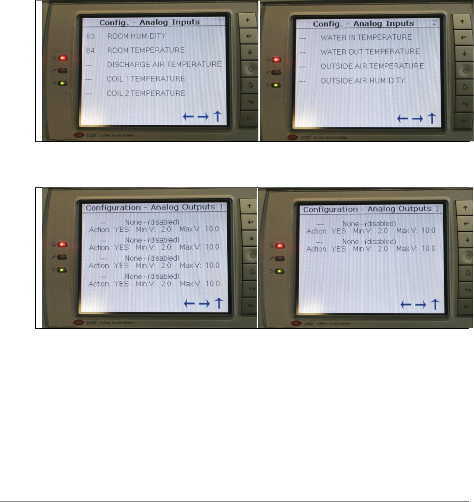
Rev.03a 12-21-10
Page 69 of 74
Compu-Aire
10.4.3 Analog Inputs and Analog Outputs
Analog input terminals on the controllers are used for a wide variety of analog sensors. The
majority of input sensors are used for monitoring room temperature and humidity. NTC and
transducers are also supported.
Analog output terminals are primarily used for economizer systems where modulating output
signals are required. Consult the factory for any special equipment use request.
Figure 51 - Analog input configuration
Figure 52 - Analog output configuration
Warning: Consult the manufacturer prior making any changes.
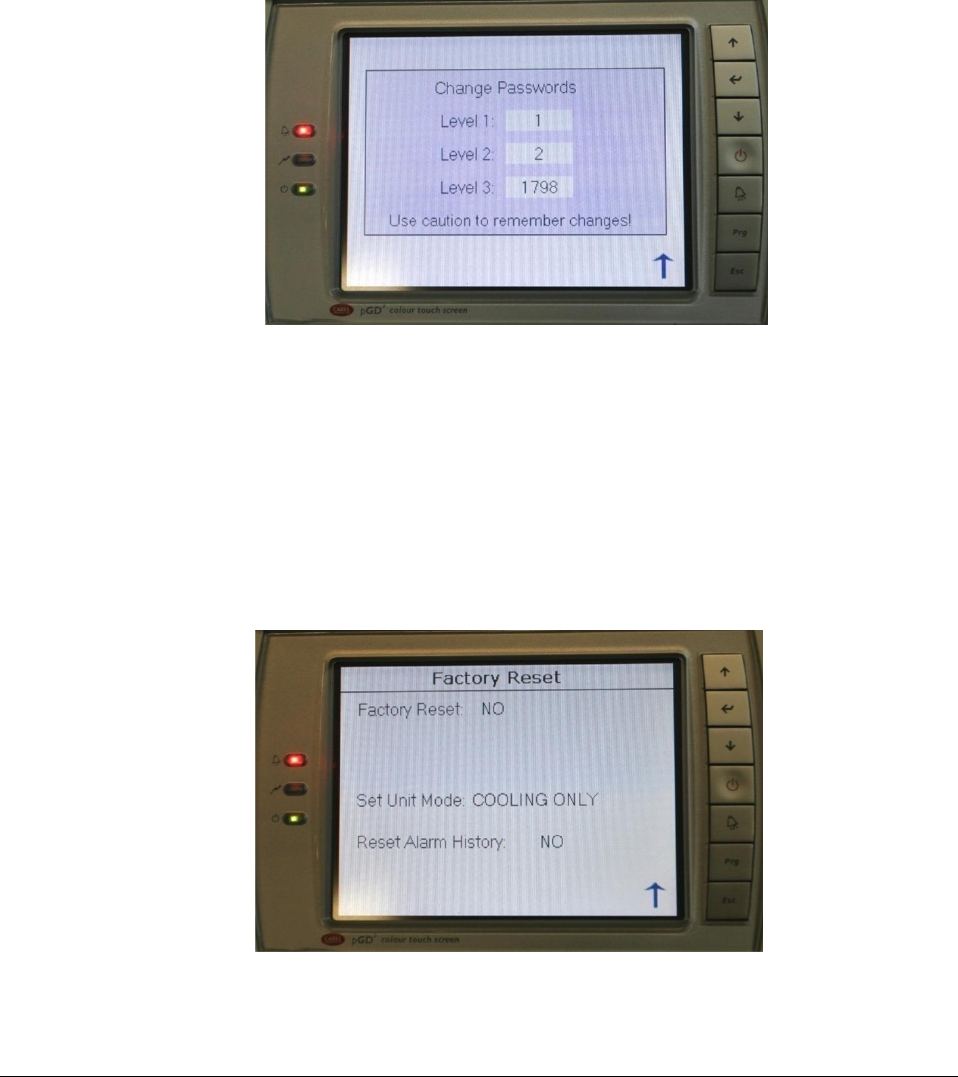
Rev.03a 12-21-10
Page 70 of 74
Compu-Aire
10.4.4 Changing Passwords
Default passwords are defined by the factory. See Entering a password for more detail.
Adjustment to the default password is sometime required by the end user. Password is
protected and not retrievable. Changes to the default password must be stored in a safe place.
The factory cannot retrieve the lost or forgotten password.
Figure 53 - Changing default password
10.5 Factory Reset
Factory reset is used to reset the controller to its default setting. Not all default settings are
applicable to all units.
Warning: Do not perform this function. It will wipe out all the default settings and return the
controller settings back to its default values. A reconfiguration is required to set it back to its
specifications.
Figure 54 - Factory reset

Rev.03a 12-21-10
Page 71 of 74
Compu-Aire
11.0 TROUBLESHOOTING GUIDE
SYMTOM
POSSIBLE CAUSE
REMEDY
Black screen
Loss of power
Check 24Vac at controller and display
No link
Wrong unit ID
Check Unit ID. See “P-LAN setup” for
instruction.
Incorrect wires
Check wiring on J11 from the controller to the
display.
Loss of
communication link
between controller &
display
Make sure the controller and display get
proper 24Vac voltage.
Cable length
Check to make sure cables meets specification
and not exceeding 200 meters for 24AWG.
Buzzer ON
Alarm events
Press the Alarm button to view the alarm.
Press up/down arrow key to view next alarm.
Alarm reset
Press the alarm button following by pressing
the down arrow key until “Reset” shows on
the screen. Tap the Reset button on the
screen to clear the alarm.
Screen
nonresponsive
Missed calibration
See “Screen Calibration” for detail on
recalibration.
Modbus not
communicating
Cabling
Check to make sure cable is comply with
standard and not exceeding 1000 meters.
Speed
Make sure computer and controller are set to
the same speed. Default speed on the PCO3
controller is 19.2k.
Add-on card not
installed properly
Verify that the card is installed properly.
Check the matting connectors with a flash
light. Check for status light.
LONTalk not
responding
Cabling
Verify the physical wires between the
controller and the BMS system. A parallel
cable should be in used.
Not commission
Decommission and commission the card. Use
a Wink command to check response.
Wrong speed
configured
Verify that the speed is set to 4800 from the
controller under “Supervisor Setup”. Check
for LED status error code.
BMS not accessible
Verify that the card is setup properly
PCOWeb fails
communication
Wrong cable
A crossed over cable is required for direct
connection from PC to controller
Add-on card not
installed properly
Check for proper matting connectors between
the controller and the add-on card

Rev.03a 12-21-10
Page 72 of 74
Compu-Aire
Incorrect IP
Check DHCP server for correct IP. Boot up in
factory setting for default IP: 172.16.0.1 to
assign static IP. See PCOWeb setup for detail
Wrong Temperature
or Humidity reading
or sensor fail
Wrong jumper setting
Pop open the sensor module and verify that
the setting on the temp/hum sensor board is
set to 0-1V
Power supply
Check for proper 24VDC coming on +G and
GND at the sensor board
Water damage
Check for water condensation on the probe.
Dry it out for any moisture. Relocate the
sensors if necessary.
Wrong offset /
Calibration
Check for sensor offset and recalibrate against
a reference point if necessary.
Alarm not reset
Alarm source not
rectified
Check for the cause of the alarm. The alarm
cannot be cleared if the cause of the alarm still
persists.
Stuck in Manual
Mode
Force components ON
Set all components under “Manual Ctrl”
screen to Auto mode
Compressor not ON
Incorrect setpoint
Check system setpoint for cooling
temperature. Compressor only runs when
temperature drops below room setpoint.
Reheat Lockout
Over amp protection
System incorporate a reheat lockout if cooling
and humidifier are ON
High Temperature
Temperature rises
above max setpoint
Room is too hot. Check sensor and reset
alarm after fixing the problem.
Low Temperature
Temperature drops
below min setpoint
Room is too cold. Check sensor and reset
alarm after fixing the problem.
High Humidity
Humidity rises above
max setpoint
Too much moisture in the air. Check and reset
the alarm after fixing the problem.
Low Humidity
Humidity drops below
min setpoint
Room is too dry. Check and reset the alarm
after rectify the problem.
No Air Flow
Static pressure drop
Check motor, duct work, and filter. Reset the
alarm after rectifying the problem.
Sensitive switch
Check and recalibrate the switch if necessary.
Consult the electrical wiring for more detail.
Dirty Filter
Clogged filter
Check and replace filter if necessary
Sensitive switch
Check the dirty air filter switch and recalibrate
the sensitivity level if necessary. Consult the
electrical wiring for more detail.
High Pressure
Refrigerant pressure
rises above limit
Check the high head pressure and reset the
alarm after a manual reset on the pressure
switch.
Low Pressure
Refrigerant pressure
drops below limit
Check for low pressure switch. Change low
pressure bypass time out and reset the alarm
after rectifying the problem.

Rev.03a 12-21-10
Page 73 of 74
Compu-Aire
Compressors short
cycling
Compress ON/OFF too
frequent
Check discharge and return air temperature.
Adjust compressor Max ON if needed.
Heater Overheat
Heater overload
Check if heater is overloading. Check and
reset alarm after rectifying the problem
Incorrect trigger level
Verify setting under “Technician->DI Setup-
>Heater Overheat” Alarm IF=Closed
Smoke Alarm
Smoke detected
Check for fire hazard and reset alarm after
rectifying the problem.
Condensate Alarm
Water detected
Check for water level on the bottom tray.
Check drain valve and reset alarm after
rectifying the problem.
Pump failed
Condensate pump
failed
Check pump for proper voltage and wiring.
Check pump’s floaters for consistency. Check
if water still resides in pump’s reservoir. Reset
alarm after rectifying the problems.