SM8E 1R51U0(PG) Pg
User Manual: pg
Open the PDF directly: View PDF ![]() .
.
Page Count: 74
- QUICK REFERENCE INDEX
- Table of Contents
- PRECAUTION
- PREPARATION
- BASIC INSPECTION
- COMPONENT DIAGNOSIS
- POWER SUPPLY ROUTING CIRCUIT
- GROUND CIRCUIT
- HARNESS
- Harness Layout
- Wiring Diagram Codes (Cell Codes)
- ELECTRICAL UNITS LOCATION
- HARNESS CONNECTOR
- ELECTRICAL UNITS
- STANDARDIZED RELAY
- SUPER MULTIPLE JUNCTION (SMJ)
- FUSE BLOCK-JUNCTION BOX (J/B)
- FUSE AND FUSIBLE LINK BOX
- FUSE AND RELAY BOX
- ON-VEHICLE REPAIR
- SERVICE DATA AND SPECIFICATIONS (SDS)

PG
PG-1
ELECTRICAL & POWER CONTROL
C
D
E
F
G
H
I
J
K
L
B
SECTION PG A
O
P
N
CONTENTS
POWER SUPPLY, GROUND & CIRCUIT ELEMENTS
PRECAUTION ............................................... 2
PRECAUTIONS ................................................... 2
Precaution for Supplemental Restraint System
(SRS) "AIR BAG" and "SEAT BELT PRE-TEN-
SIONER" ...................................................................2
Precaution for Power Generation Variable Voltage
Control System ..........................................................2
PREPARATION ............................................ 3
PREPARATION ................................................... 3
Special Service Tool .................................................3
Commercial Service Tool ..........................................3
BASIC INSPECTION .................................... 4
BATTERY ............................................................ 4
How to Handle Battery ..............................................4
Work Flow .................................................................6
COMPONENT DIAGNOSIS .......................... 7
POWER SUPPLY ROUTING CIRCUIT ............... 7
Schematic .................................................................7
Wiring Diagram - POWER - ......................................9
Fuse ........................................................................20
Fusible Link .............................................................20
Circuit Breaker (Built Into BCM) ..............................20
GROUND CIRCUIT ............................................21
Ground Distribution .................................................21
HARNESS ..........................................................31
Harness Layout .......................................................31
Wiring Diagram Codes (Cell Codes) .......................56
ELECTRICAL UNITS LOCATION ....................59
Electrical Units Location ..........................................59
HARNESS CONNECTOR .................................62
Description ...............................................................62
ELECTRICAL UNITS ........................................65
Terminal Arrangement .............................................65
STANDARDIZED RELAY .................................66
Description ...............................................................66
SUPER MULTIPLE JUNCTION (SMJ) .............68
Terminal Arrangement .............................................68
FUSE BLOCK-JUNCTION BOX (J/B) ..............70
Terminal Arrangement .............................................70
FUSE AND FUSIBLE LINK BOX ......................71
Terminal Arrangement .............................................71
FUSE AND RELAY BOX ..................................72
Terminal Arrangement .............................................72
ON-VEHICLE REPAIR .................................73
BATTERY ..........................................................73
Removal and Installation .........................................73
SERVICE DATA AND SPECIFICATIONS
(SDS) ............................................................74
BATTERY ..........................................................74
Battery .....................................................................74

PG-2
< PRECAUTION >
PRECAUTIONS
PRECAUTION
PRECAUTIONS
Precaution for Supplemental Restraint System (SRS) "AIR BAG" and "SEAT BELT
PRE-TENSIONER" INFOID:0000000001547048
The Supplemental Restraint System such as “AIR BAG” and “SEAT BELT PRE-TENSIONER”, used along
with a front seat belt, helps to reduce the risk or severity of injury to the driver and front passenger for certain
types of collision. This system includes seat belt switch inputs and dual stage front air bag modules. The SRS
system uses the seat belt switches to determine the front air bag deployment, and may only deploy one front
air bag, depending on the severity of a collision and whether the front occupants are belted or unbelted.
Information necessary to service the system safely is included in the SR and SB section of this Service Man-
ual.
WARNING:
• To avoid rendering the SRS inoperative, which could increase the risk of personal injury or death in
the event of a collision which would result in air bag inflation, all maintenance must be performed by
an authorized NISSAN/INFINITI dealer.
• Improper maintenance, including incorrect removal and installation of the SRS, can lead to personal
injury caused by unintentional activation of the system. For removal of Spiral Cable and Air Bag
Module, see the SR section.
• Do not use electrical test equipment on any circuit related to the SRS unless instructed to in this
Service Manual. SRS wiring harnesses can be identified by yellow and/or orange harnesses or har-
ness connectors.
Precaution for Power Generation Variable Voltage Control System INFOID:0000000001547049
CAUTION:
For this model, the battery current sensor that is installed to the negative battery cable measures the
charging/discharging current of the battery and performs various engine controls. If an electrical com-
ponent is connected directly to the negative battery terminal, the current flowing through that compo-
nent will not be measured by the battery current sensor. This condition may cause a malfunction of
the engine control system and battery discharge may occur. Do not connect an electrical component
or ground wire directly to the battery terminal.
PG
PREPARATION
PG-3
< PREPARATION >
C
D
E
F
G
H
I
J
K
L
B
A
O
P
N
PREPARATION
PREPARATION
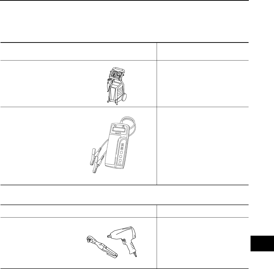
Special Service Tool INFOID:0000000001547050
The actual shapes of Kent-Moore tools may differ from those of special service tools illustrated here.
Commercial Service Tool INFOID:0000000001547051
Tool number
(Kent-Moore No.)
Tool name
Description
—
(J-48087)
Battery Service Center
Tests battery.
For operating instructions, refer to Technical
Service Bulletin and Battery Service Center
User Guide.
—
(J-44373) Model 620
Battery/Starting/Charging system
tester
Tests starting and charging systems.
For operating instructions, refer to Technical
Service Bulletin.
WKIA5280E
SEL403X
Tool number
Tool name
Description
Power tool Loosening bolts and nuts
PBIC0190E
PG-4
< BASIC INSPECTION >
BATTERY
BASIC INSPECTION
BATTERY
How to Handle Battery INFOID:0000000001712683
CAUTION:
• If it becomes necessary to start the engine with a booster battery and jumper cables, use a 12-volt
booster battery.
• After connecting battery cables, ensure that they are tightly clamped to battery terminals for good
contact.
• Never add distilled water through the hole used to check specific gravity.
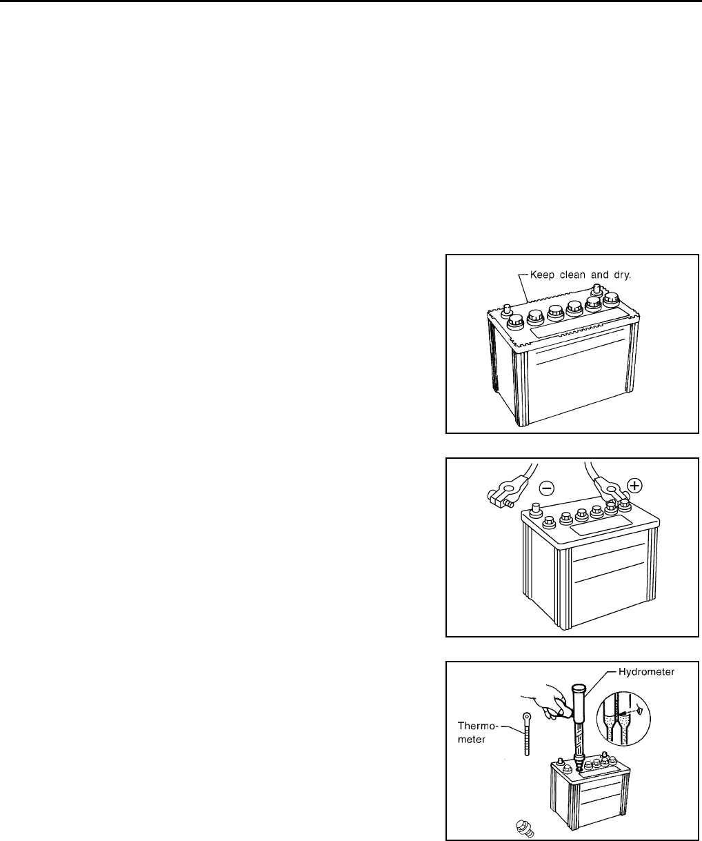
METHODS OF PREVENTING OVER-DISCHARGE
The following precautions must be taken to prevent over-discharging a battery.
• The battery surface (particularly its top) should always be kept
clean and dry.
• The terminal connections should be clean and tight.
• At every routine maintenance, check the electrolyte level.
This also applies to batteries designated as “low maintenance” and
“maintenance-free”.
• When the vehicle is not going to be used over a long period of
time, disconnect the battery cable from the negative terminal. (If
the vehicle has an extended storage switch, turn it off.)
• Check the charge condition of the battery.
Periodically check the specific gravity of the electrolyte. Keep a
close check on charge condition to prevent over-discharge.
CHECKING ELECTROLYTE LEVEL
WARNING:
Never allow battery fluid to come in contact with skin, eyes, fabrics, or painted surfaces. After touch-
ing a battery, never touch or rub your eyes until you have thoroughly washed your hands. If acid con-
tacts eyes, skin or clothing, immediately flush with water for 15 minutes and seek medical attention.
MEL040F
ELA0349D
MEL042F
PG
BATTERY
PG-5
< BASIC INSPECTION >
C
D
E
F
G
H
I
J
K
L
B
A
O
P
N
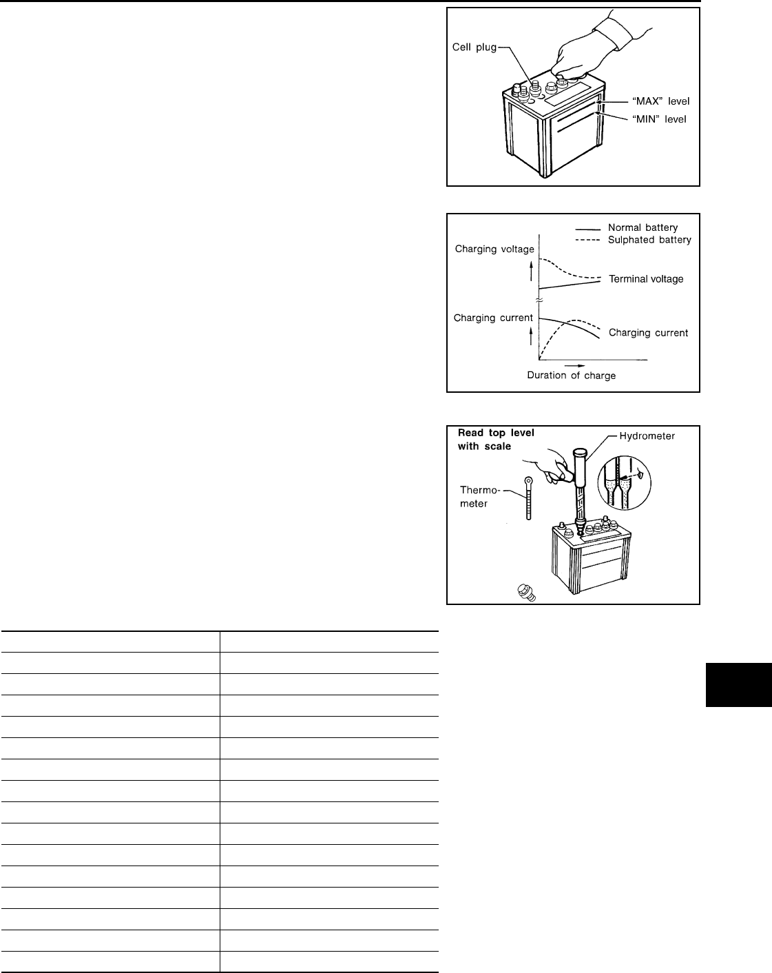
• Remove the cell plug using a suitable tool.
• Add distilled water up to the MAX level.
Sulphation
A battery will be completely discharged if it is left unattended
for a long time and the specific gravity will become less than
1.100. This may result in sulphation on the cell plates.
To determine if a battery has been “sulphated”, note its voltage
and current when charging it. As shown in the figure, less cur-
rent and higher voltage are observed in the initial stage of
charging sulphated batteries.
A sulphated battery may sometimes be brought back into ser-
vice by means of a long, slow charge, 12 hours or more, fol-
lowed by a battery capacity test.
SPECIFIC GRAVITY CHECK
1. Read hydrometer and thermometer indications at eye level.
2. Use the chart below to correct your hydrometer reading accord-
ing to electrolyte temperature.
Hydrometer Temperature Correction
MEL043F
PKIA2353E
MEL042FA
Battery electrolyte temperature [°C (°F)] Add to specific gravity reading
71 (160) 0.032
66 (150) 0.028
60 (140) 0.024
54 (130) 0.020
49 (120) 0.016
43 (110) 0.012
38 (100) 0.008
32 (90) 0.004
27 (80) 0
21 (70) −0.004
16 (60) −0.008
10 (50) −0.012
4 (40) −0.016
−1 (30) −0.020
−7 (20) −0.024

PG-6
< BASIC INSPECTION >
BATTERY
CHARGING THE BATTERY
CAUTION:
• Never “quick charge” a fully discharged battery.
• Keep the battery away from open flame while it is being charged.
• When connecting the charger, connect the leads first, then turn on the charger. Never turn on the
charger first, as this may cause a spark.
• If battery electrolyte temperature rises above 55 °C (131 °F), stop charging. Always charge battery at
a temperature below 55 °C (131 °F).
Charging Rates
Do not charge at more than 50 ampere rate.
NOTE:
The ammeter reading on your battery charger will automatically decrease as the battery charges. This indi-
cates that the voltage of the battery is increasing normally as the state of charge improves. The charging amps
indicated above refer to initial charge rate.
• If, after charging, the specific gravity of any two cells varies more than 0.050, the battery should be replaced.
Work Flow INFOID:0000000001712684
TROUBLE DIAGNOSIS WITH BATTERY SERVICE CENTER
For battery testing, use Battery Service Center (J-48087). For details and operating instructions, refer to Tech-
nical Service Bulletin and/or Battery Service Center User Guide.
−12 (10) −0.028
−18 (0) −0.032
Battery electrolyte temperature [°C (°F)] Add to specific gravity reading
Corrected specific gravity Approximate charge condition
1.260 - 1.280 Fully charged
1.230 - 1.250 3/4 charged
1.200 - 1.220 1/2 charged
1.170 - 1.190 1/4 charged
1.140 - 1.160 Almost discharged
1.110 - 1.130 Completely discharged
Amps Time
50 1 hour
25 2 hours
10 5 hours
5 10 hours

PG-8
< COMPONENT DIAGNOSIS >
POWER SUPPLY ROUTING CIRCUIT
WKWA5489E
PG
POWER SUPPLY ROUTING CIRCUIT
PG-9
< COMPONENT DIAGNOSIS >
C
D
E
F
G
H
I
J
K
L
B
A
O
P
N
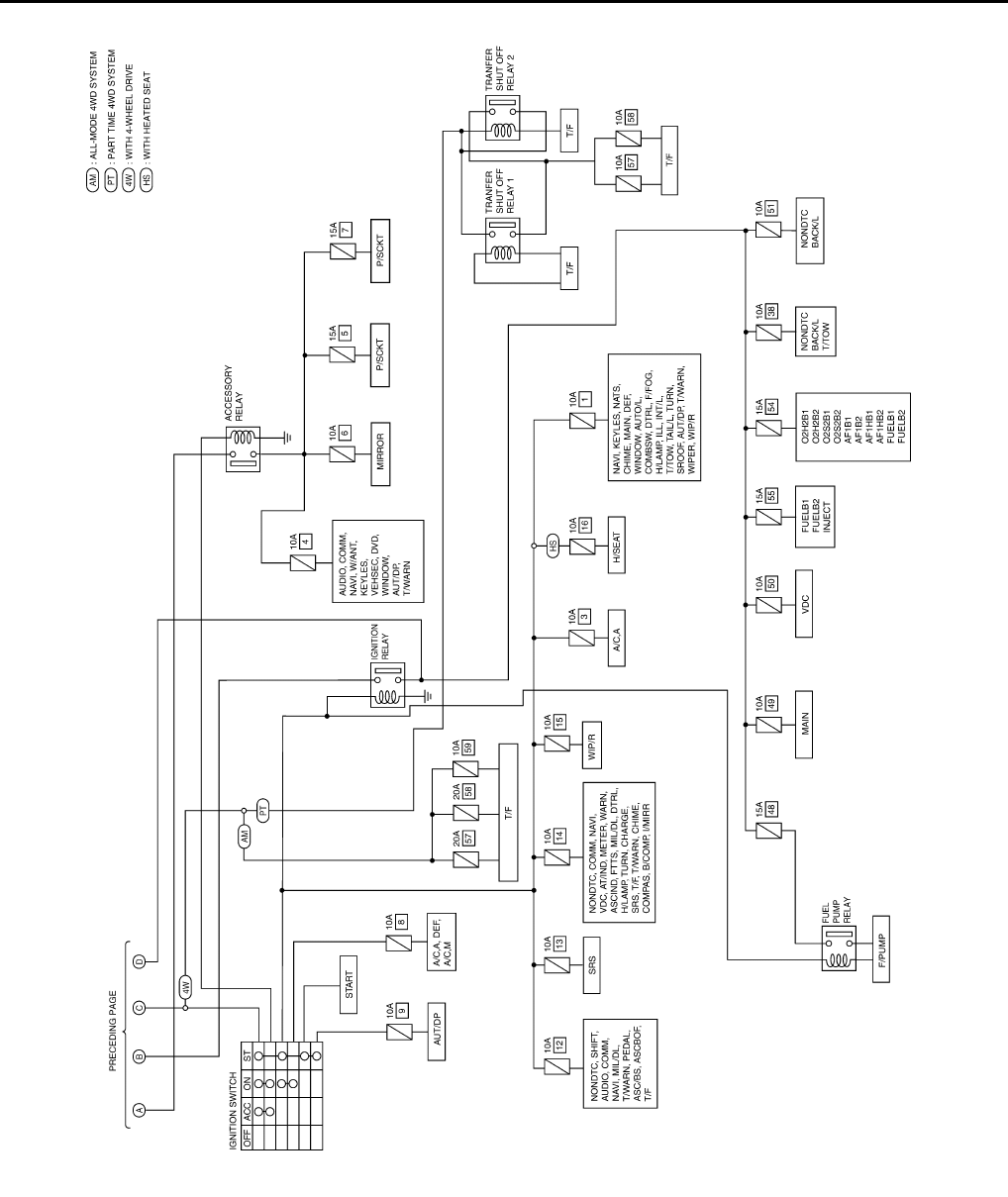
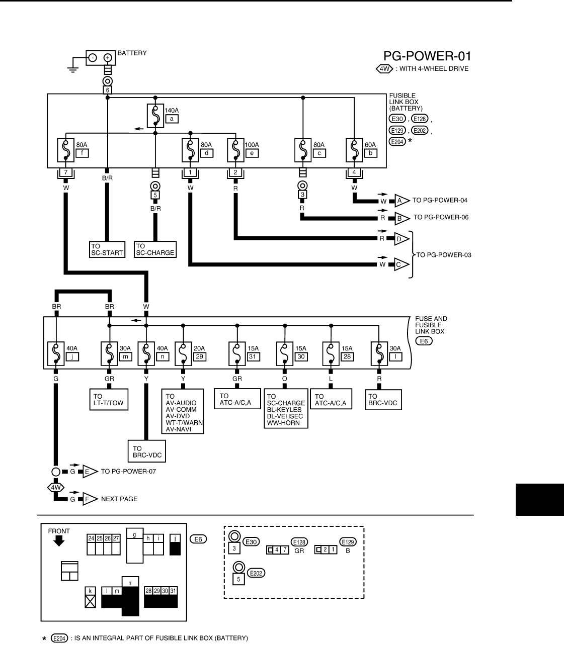
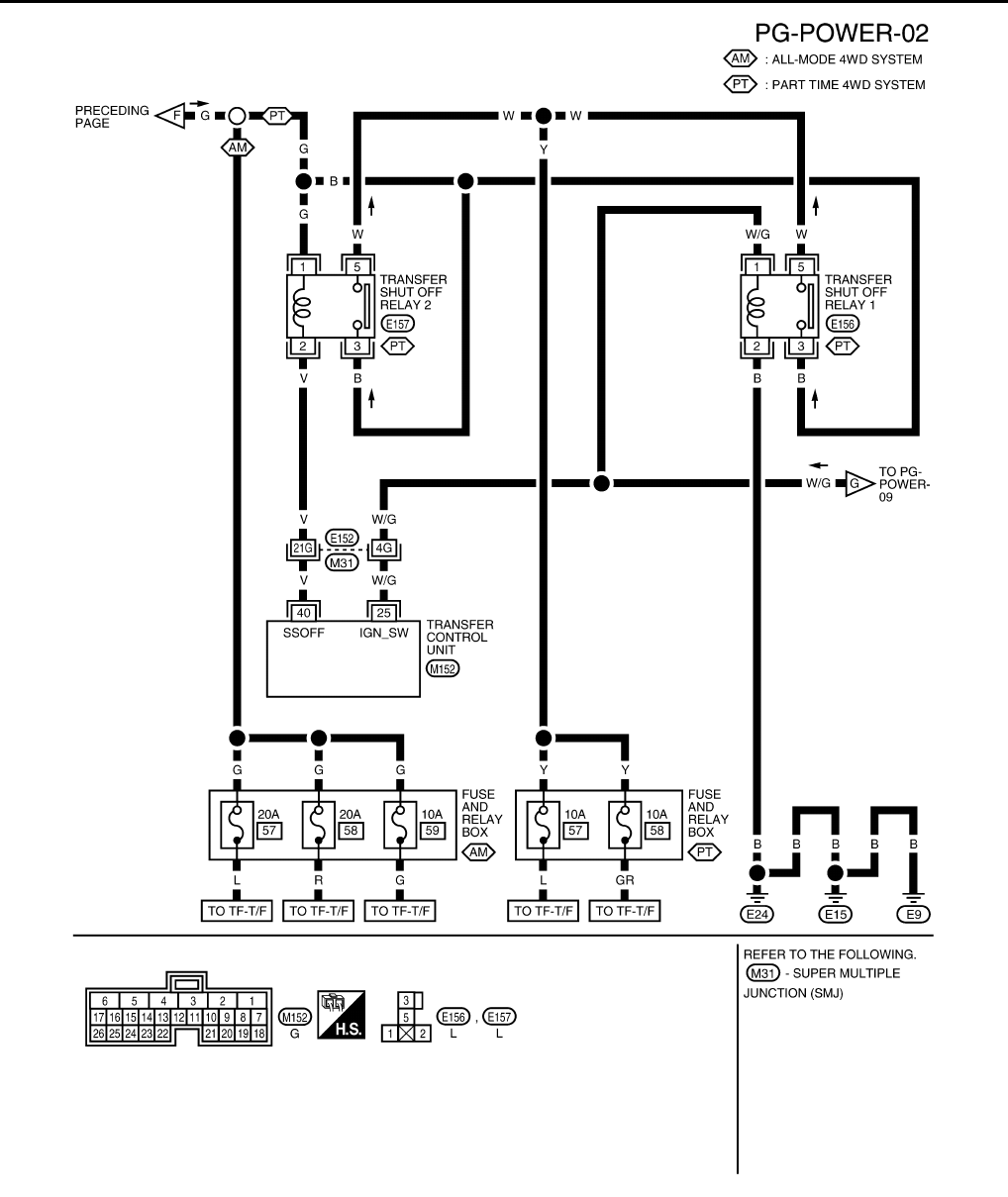
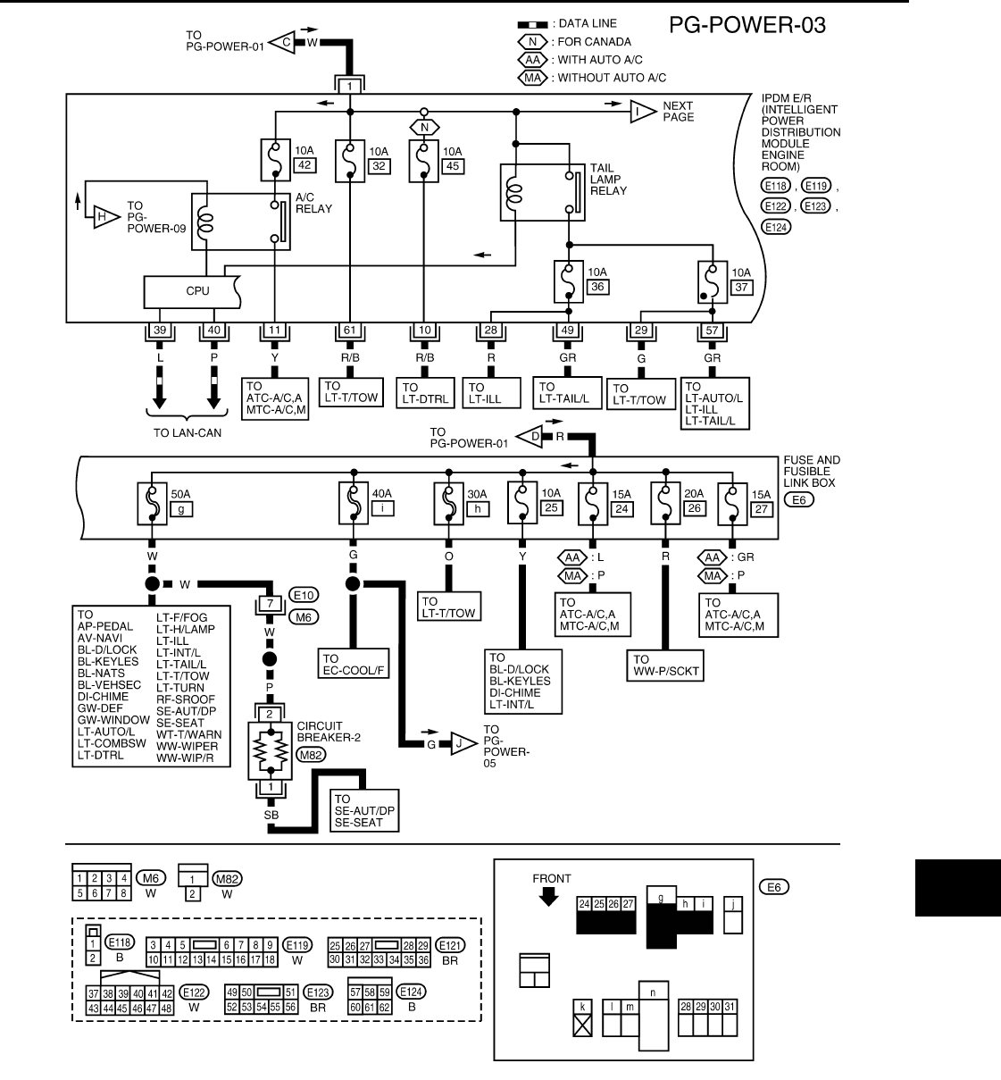
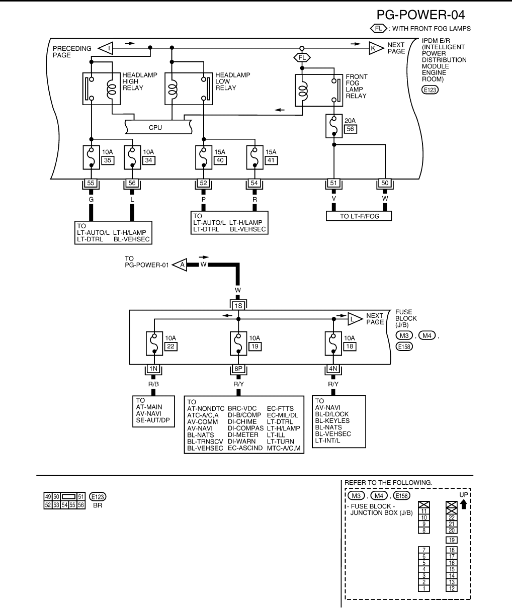
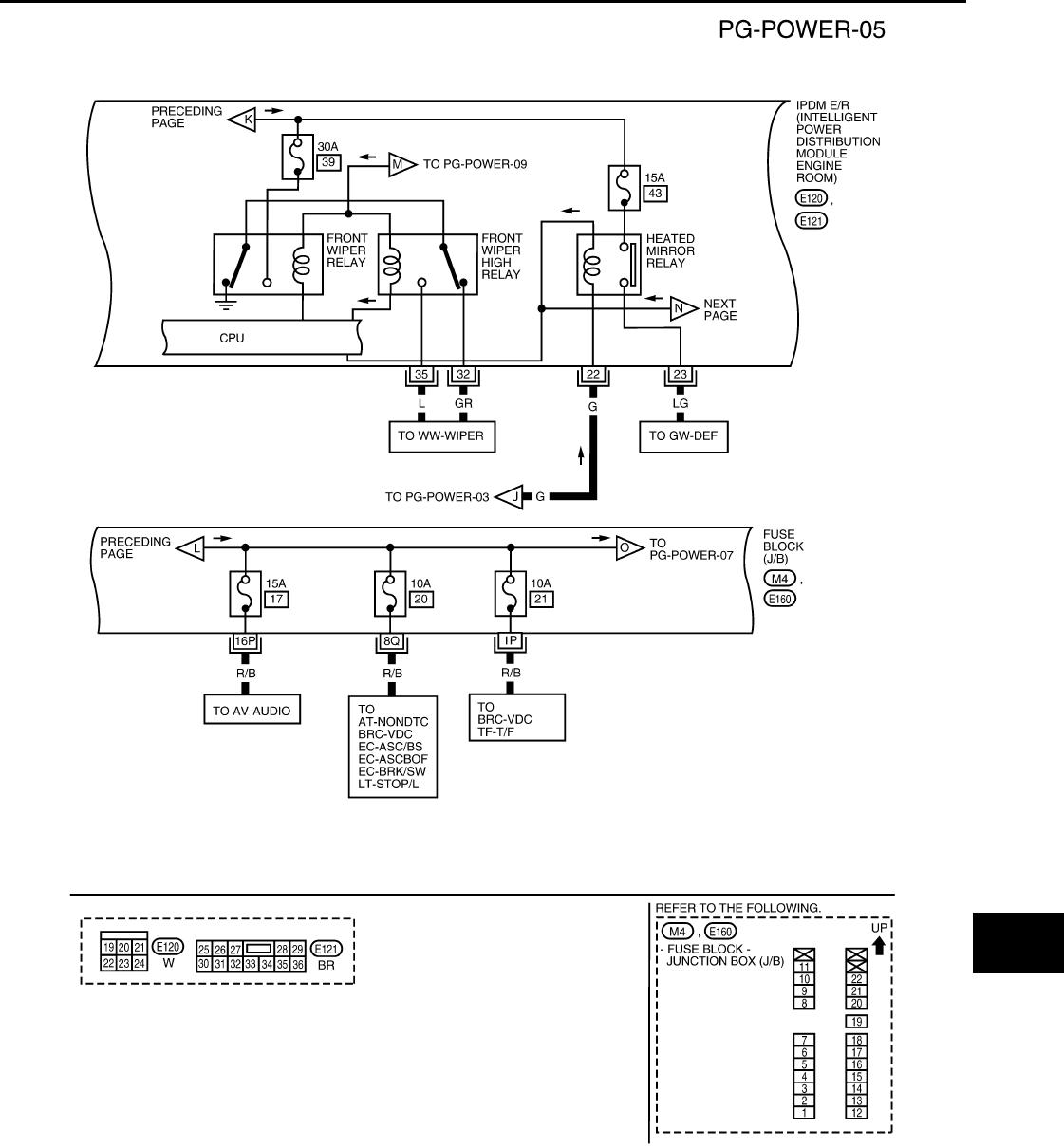
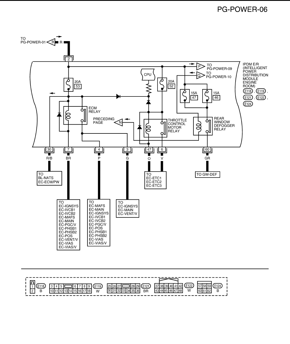
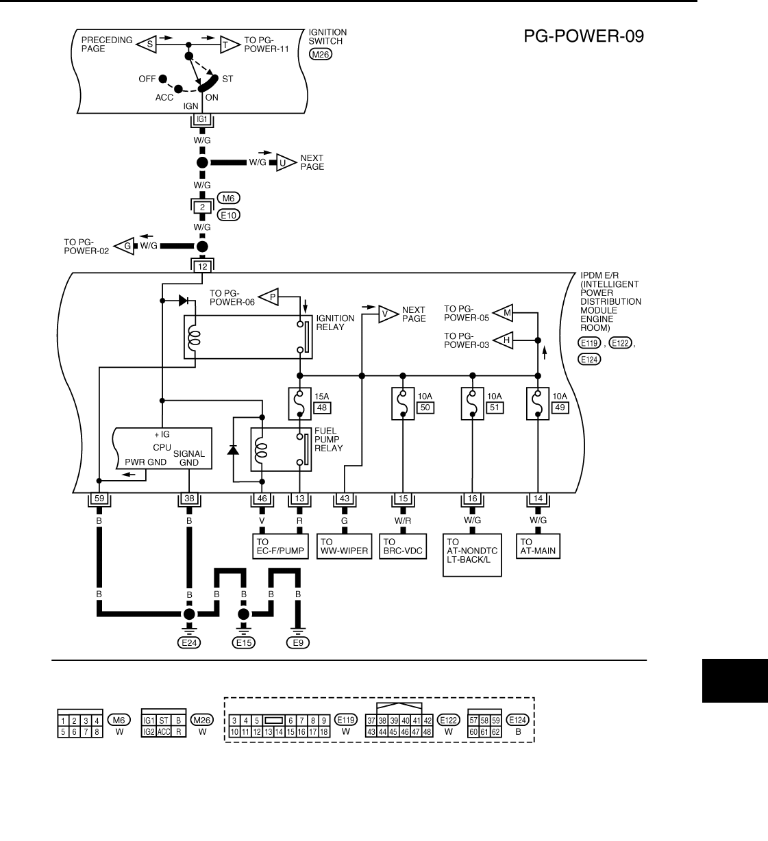
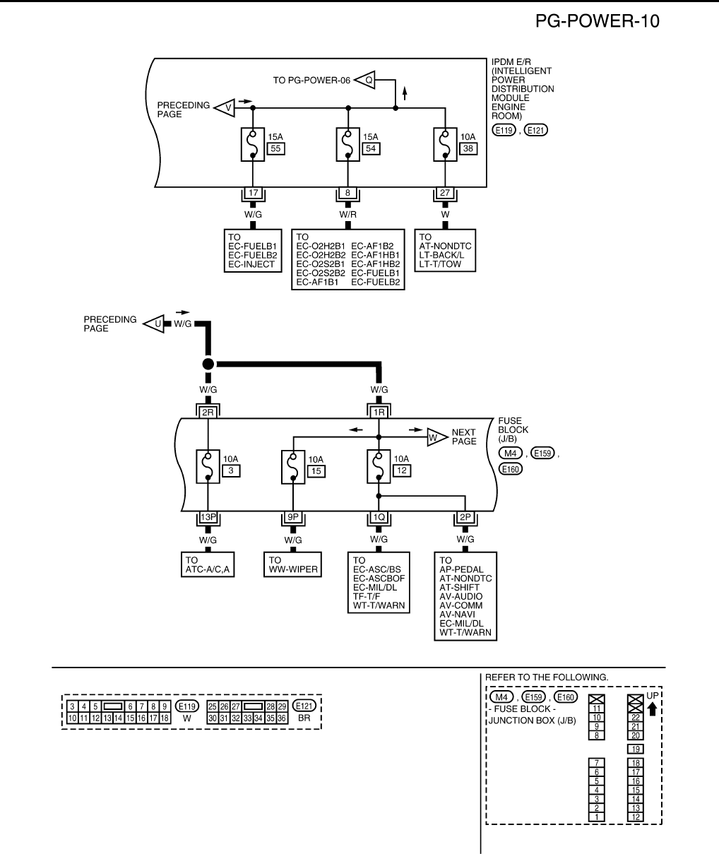
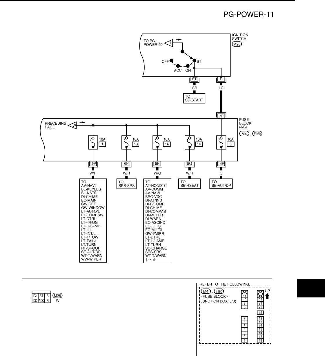
Wiring Diagram - POWER - INFOID:0000000001731007
BATTERY POWER SUPPLY — IGNITION SW. IN ANY POSITION
WKWA5490E
PG-10
< COMPONENT DIAGNOSIS >
POWER SUPPLY ROUTING CIRCUIT
WKWA5491E
PG
POWER SUPPLY ROUTING CIRCUIT
PG-11
< COMPONENT DIAGNOSIS >
C
D
E
F
G
H
I
J
K
L
B
A
O
P
N
WKWA5492E
PG-12
< COMPONENT DIAGNOSIS >
POWER SUPPLY ROUTING CIRCUIT
WKWA5493E
PG
POWER SUPPLY ROUTING CIRCUIT
PG-13
< COMPONENT DIAGNOSIS >
C
D
E
F
G
H
I
J
K
L
B
A
O
P
N
WKWA5494E
PG-14
< COMPONENT DIAGNOSIS >
POWER SUPPLY ROUTING CIRCUIT
WKWA5495E
PG
POWER SUPPLY ROUTING CIRCUIT
PG-15
< COMPONENT DIAGNOSIS >
C
D
E
F
G
H
I
J
K
L
B
A
O
P
N
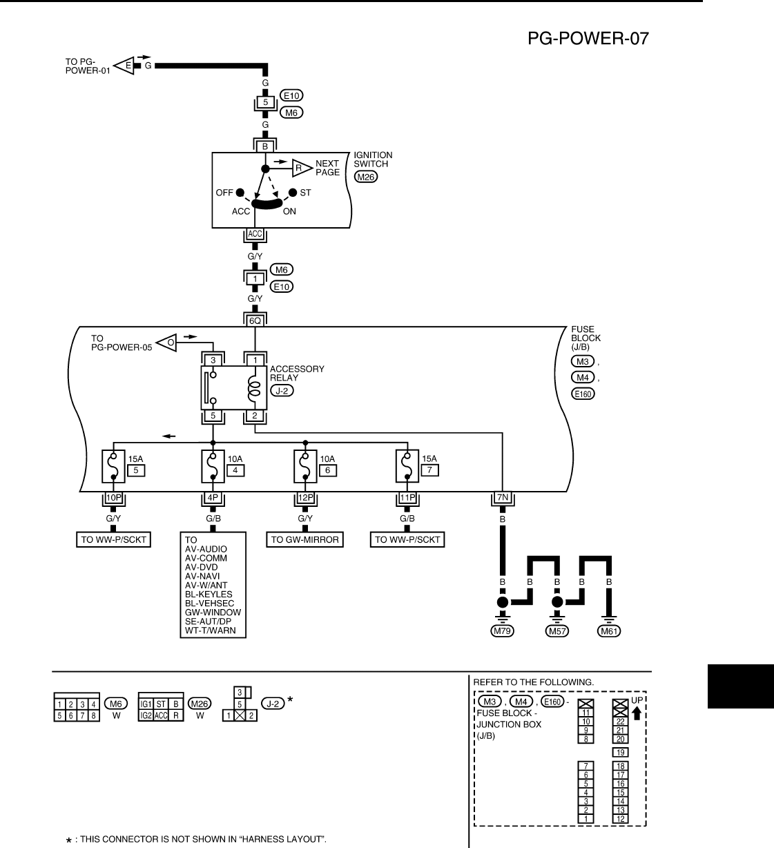
ACCESSORY POWER SUPPLY — IGNITION SW. IN ACC OR ON
WKWA5497E
PG-16
< COMPONENT DIAGNOSIS >
POWER SUPPLY ROUTING CIRCUIT
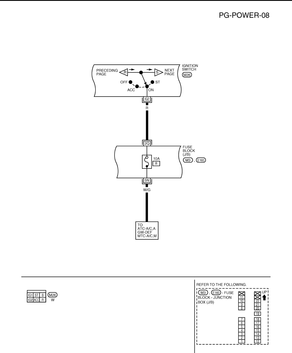
IGNITION POWER SUPPLY — IGNITION SW. IN ON
WKWA4410E
PG
POWER SUPPLY ROUTING CIRCUIT
PG-17
< COMPONENT DIAGNOSIS >
C
D
E
F
G
H
I
J
K
L
B
A
O
P
N
IGNITION POWER SUPPLY — IGNITION SW. IN ON AND/OR START
WKWA4411E
PG-18
< COMPONENT DIAGNOSIS >
POWER SUPPLY ROUTING CIRCUIT
WKWA5496E
PG
POWER SUPPLY ROUTING CIRCUIT
PG-19
< COMPONENT DIAGNOSIS >
C
D
E
F
G
H
I
J
K
L
B
A
O
P
N
IGNITION POWER SUPPLY — IGNITION SWITCH IN START
WKWA4413E
PG-20
< COMPONENT DIAGNOSIS >
POWER SUPPLY ROUTING CIRCUIT
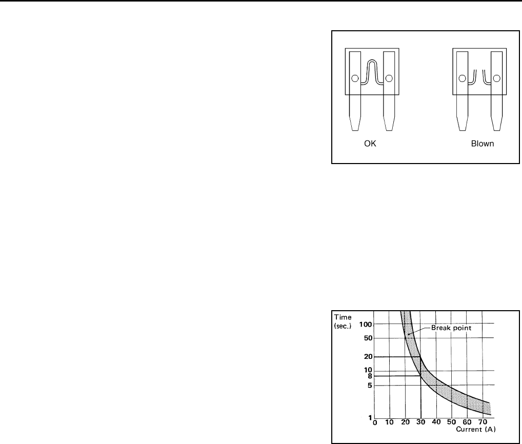
Fuse INFOID:0000000001731008
• If fuse is blown, be sure to eliminate cause of incident before
installing new fuse.
• Use fuse of specified rating. Never use fuse of more than specified
rating.
• Do not partially install fuse; always insert it into fuse holder prop-
erly.
• Remove fuse for “ELECTRICAL PARTS (BAT)” if vehicle is not
used for a long period of time.
Fusible Link INFOID:0000000001731009
A melted fusible link can be detected either by visual inspection or by feeling with finger tip. If its condition is
questionable, use circuit tester or test lamp.
CAUTION:
• If fusible link should melt, it is possible that critical circuit (power supply or large current carrying
circuit) is shorted. In such a case, carefully check and eliminate cause of incident.
• Never wrap outside of fusible link with vinyl tape.
• Never let fusible link touch any other wiring harness, vinyl or rubber parts.
Circuit Breaker (Built Into BCM) INFOID:0000000001731010
For example, when current is 30A, the circuit is broken within 8 to 20
seconds.
A circuit breaker is used for the following systems:
• Power windows
• Power sunroof
CEL083
SBF284E
PG
GROUND CIRCUIT
PG-21
< COMPONENT DIAGNOSIS >
C
D
E
F
G
H
I
J
K
L
B
A
O
P
N
GROUND CIRCUIT
Ground Distribution INFOID:0000000001731011
Main Harness
WKIA5857E
PG-22
< COMPONENT DIAGNOSIS >
GROUND CIRCUIT
WKIA5858E
PG
GROUND CIRCUIT
PG-23
< COMPONENT DIAGNOSIS >
C
D
E
F
G
H
I
J
K
L
B
A
O
P
N
WKIA3568E

PG-24
< COMPONENT DIAGNOSIS >
GROUND CIRCUIT
Engine Room Harness
WKIA5859E
PG
GROUND CIRCUIT
PG-25
< COMPONENT DIAGNOSIS >
C
D
E
F
G
H
I
J
K
L
B
A
O
P
N
WKIA5860E
PG-26
< COMPONENT DIAGNOSIS >
GROUND CIRCUIT
WKIA5861E
PG
GROUND CIRCUIT
PG-27
< COMPONENT DIAGNOSIS >
C
D
E
F
G
H
I
J
K
L
B
A
O
P
N
Engine Control Harness
WKIA5862E
PG-28
< COMPONENT DIAGNOSIS >
GROUND CIRCUIT
Body Harness
WKIA5863E
PG
GROUND CIRCUIT
PG-29
< COMPONENT DIAGNOSIS >
C
D
E
F
G
H
I
J
K
L
B
A
O
P
N
Body No. 2 Harness
WKIA5864E
PG-30
< COMPONENT DIAGNOSIS >
GROUND CIRCUIT
Back Door No. 2 and Back Door Harness
WKIA3575E

PG
HARNESS
PG-31
< COMPONENT DIAGNOSIS >
C
D
E
F
G
H
I
J
K
L
B
A
O
P
N
HARNESS
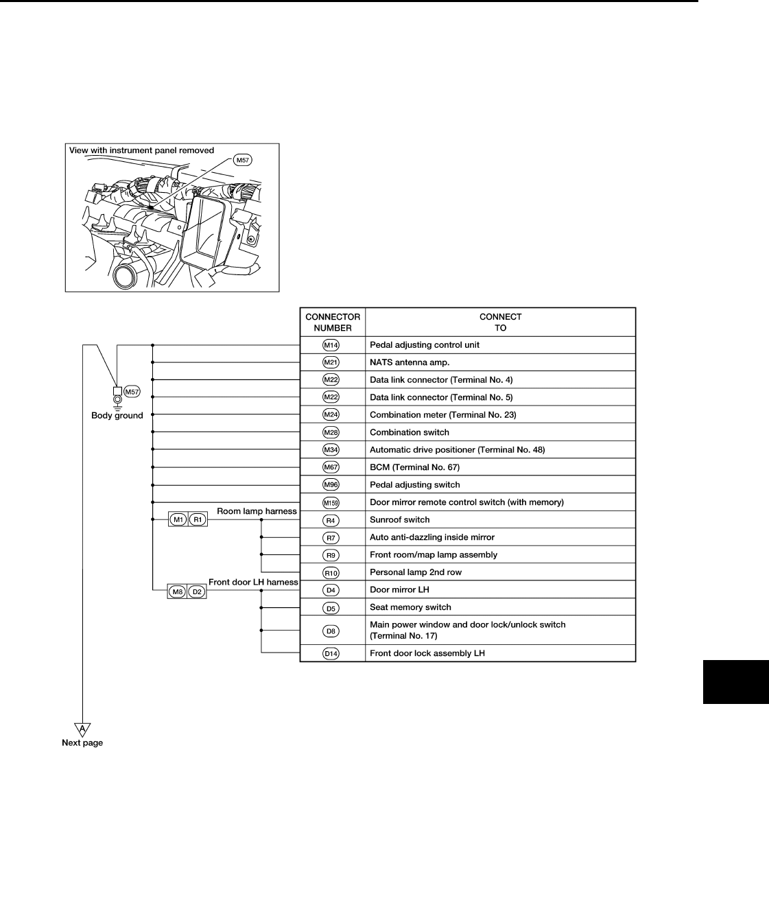
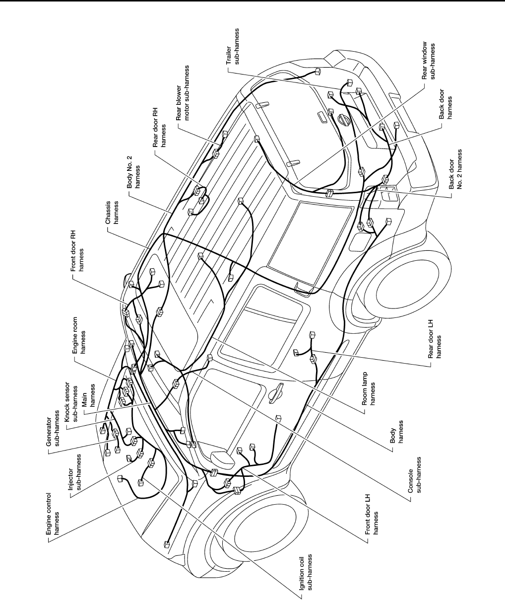
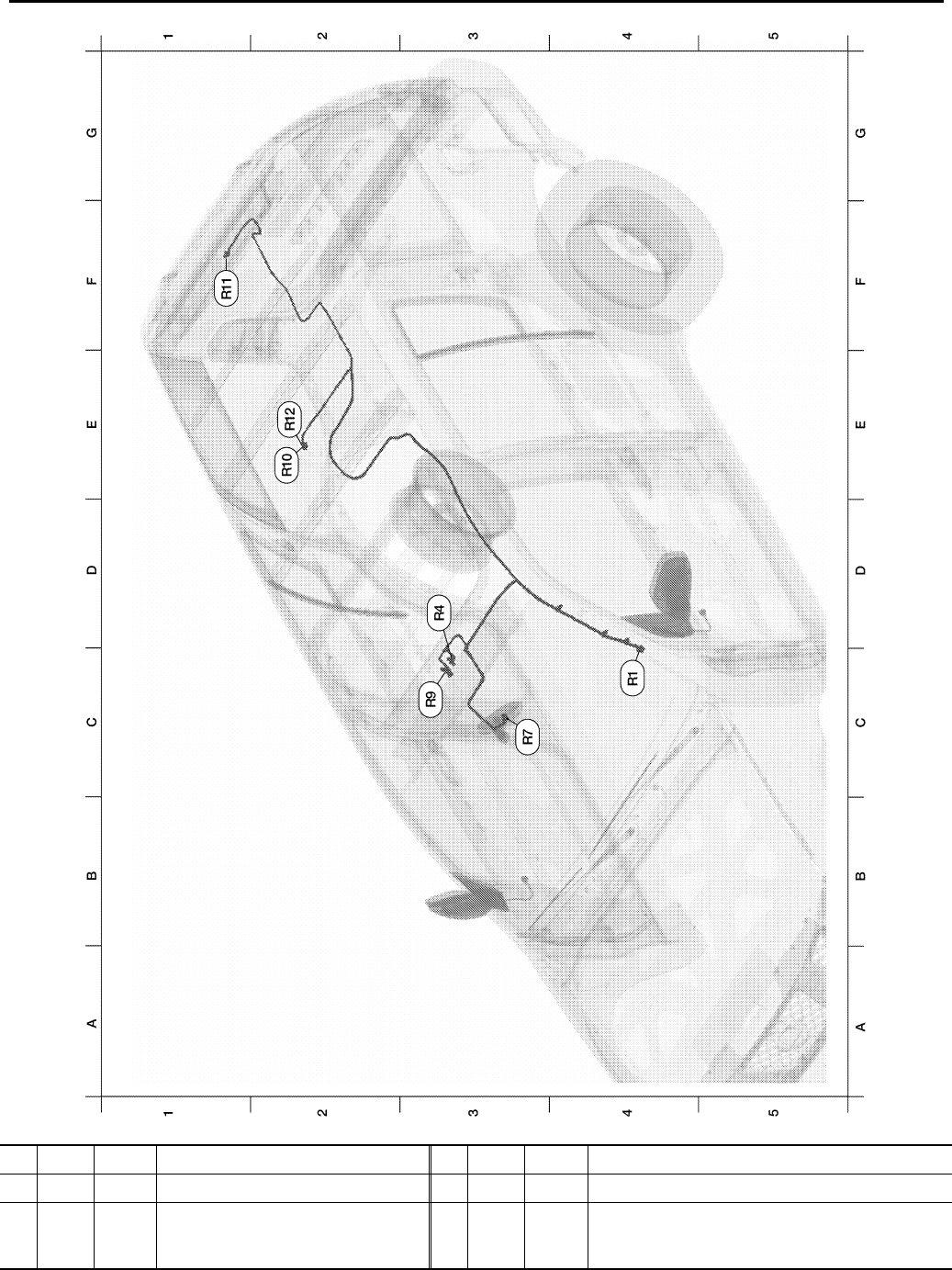
Harness Layout INFOID:0000000001731012
HOW TO READ HARNESS LAYOUT
The following Harness Layouts use a map style grid to help locate
connectors on the drawings:
• Main Harness and Console Sub-harness
• Engine Room Harness (RH View) Engine Compartment and Gen-
erator Sub-harness
• Engine Room Harness (Passenger Compartment)
• Engine Room Harness (LH View) Engine Compartment
• Engine Control Harness, Injector Sub-harness, Ignition Coil Sub-
harness, and Knock Sensor Sub-harness
• Chassis Harness and Trailer Sub-harness
• Body Harness
• Body No. 2 Harness and Rear Blower Motor Sub-harness
• Room Lamp Harness
• Back Door Harness, Back Door No. 2 Harness, Rear Window Sub-harness, and Rear Window Defogger
Sub-harness
To use the grid reference
1. Find the desired connector number on the connector list.
2. Find the grid reference.
3. On the drawing, find the crossing of the grid reference letter column and number row.
4. Find the connector number in the crossing zone.
5. Follow the line (if used) to the connector.
SEL252V
PG-32
< COMPONENT DIAGNOSIS >
HARNESS
OUTLINE
WKIA5865E

PG
HARNESS
PG-33
< COMPONENT DIAGNOSIS >
C
D
E
F
G
H
I
J
K
L
B
A
O
P
N
MAIN HARNESS
WKIA5866E
A3 M1 W/12 : To R1 C3 M51 W/8 : Front blower switch
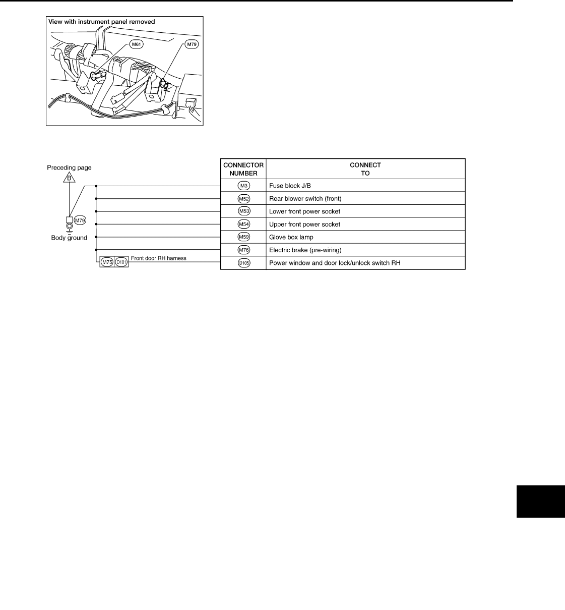
F1 M3 W/8 : Fuse block (J/B) E3 M52 W/8 : Rear blower switch (front)
F2 M4 W/16 : Fuse block (J/B) E3 M53 B/2 : Power socket
A5 M6 W/8 : To E10 E3 M54 GR/2 : Power socket
A4 M8 W/16 : To D2 C3 M55 W/4 : Hazard switch

PG-34
< COMPONENT DIAGNOSIS >
HARNESS
A4 M9 W/24 : To D1 E4 M56 W/16 : To M201
A3 M10 Y/4 : To E29 B3 M57 – : Body ground
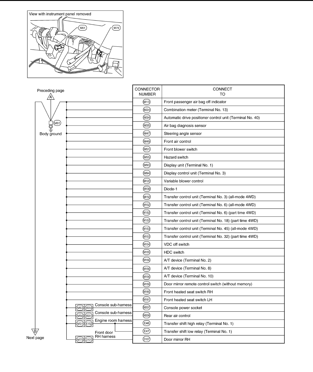
C3 M13 W/3 : Front passenger air bag OFF indicator E2 M58 B/6 : Intake door motor
B3 M14 W/16 : Pedal adjusting control unit E1 M59 BR/2 : Glove box lamp
B2 M18 W/40 : BCM (body control module) D2 M61 — : Body ground
B3 M19 W/15 : BCM (body control module) E2 M62 B/2 : Front blower motor
B3 M20 B/15 : BCM (body control module) D4 M63 W/6 : To M204
C4 M21 W/4 : NATS antenna amp. E4 M64 W/6 : To M202
C3 M22 W/16 : Data link connector A3 M70 BR/1 : To M350 (with Sirius satellite tuner)
B2 M24 W/40 : Combination meter A3 M70 V/1 : To M350 (with XM satellite tuner)
B3 M26 W/6 : Ignition switch F2 M74 W/16 : To D102
B3 M27 W/2 : Key switch F2 M75 W/12 : To D101
C3 M28 W/16 : Combination switch B3 M76 W/6 : Electric brake (pre-wiring)
C4 M29 Y/6 : Combination switch (spiral cable) D1 M77 Y/4 : Front passenger air bag module (service
replacement)
C4 M30 GR/8 : Combination switch (spiral cable) E1 M79 — : Body ground
F2 M31 SMJ : To E152 A3 M82 W/2 : Circuit breaker-2
C3 M32 W/4 : In-vehicle sensor E2 M83 W/4 : To B142
B3 M33 W/32 : Automatic drive positioner control unit E3 M85 W/4 : Aux in jack
B4 M34 W/16 : Automatic drive positioner control unit B4 M91 W/16 : To E26
E5 M35 Y/28 : Air bag diagnosis sensor unit D2 M93 W/24 : Display unit
F3 M36 SMJ : To B149 D2 M94 W/24 : Display control unit (with NAVI)
A4 M40 SMJ : To B69 D2 M95 W/32 : Display control unit (with NAVI)
A4 M41 W/12 : Pre-wiring for satellite radio tuner B4 M96 BR/6 : Pedal adjusting switch
A4 M41 W/12 : Satellite radio tuner B3 M97 BR/5 : Heated seat relay
C2 M42 W/12† : Audio unit (without NAVI) D2 M98 W/16 : AV switch
E3 M42 W/
12†† : Audio unit (with NAVI) E2 M105 Y/2 : Front passenger air bag module
C2 M43 W/10† : Audio unit (without NAVI) E2 M106 O/2 : Front passenger air bag module
E3 M43 W/
10†† : Audio unit (with NAVI) A2 M109 BR/2 : Front tweeter LH
C2 M44 W/6† : Audio unit (without NAVI) E1 M111 BR/2 : Front tweeter RH
E3 M44 W/6†† : Audio unit (with NAVI) E2 M120 W/4 : Remote keyless entry receiver
D2 M45 W/16† : Audio unit (without NAVI) E2 M122 W/4 : Variable blower control (with ATC)
D3 M45 W/
16†† : Audio unit (with NAVI) E2 M122 B/4 : Front blower motor resistor (with MTC)
B4 M47 W/8 : Steering angle sensor C4 M123 W/2 : Tire pressure warning check connector
E1 M48 BR/2 : To M501 B4 M129 BR/1 : Satellite radio tuner (with Sirius satellite
tuner)
D3 M49 B/26 : Front air control B4 M129 V/1 : Satellite radio tuner (with XM satellite
tuner)
E3 M50 W/18 : Front air control B2 M139 B/2 : Diode-1
B3 M140 B/2 : Diode-2
D4 M141 GR/8 : 4WD shift switch
C2 M142 B/6 : Mode door motor
E2 M143 B/6 : Air mix door motor (passenger)
C1 M145 B/4 : Optical sensor

PG
HARNESS
PG-35
< COMPONENT DIAGNOSIS >
C
D
E
F
G
H
I
J
K
L
B
A
O
P
N
ENGINE ROOM HARNESS (RH VIEW)
E2 M146 W/2 : Intake sensor
D2 M147 B/6 : Air mix door motor (driver) (with ATC)
D2 M147 B/6 : Air mix door motor (front) (with MTC)
C3 M150 W/2 : Ignition keyhole illumination
B4 M152 W/26 : Transfer case control unit (part time
4WD)
B4 M152 W/24 : Transfer case control unit (all-mode
4WD)
B4 M153 GR/24 : Transfer case control unit (all-mode
4WD)
B4 M153 W/24 : Transfer case control unit (part time
4WD)
D4 M154 GR/6 : VDC off switch
D4 M155 W/8 : HDC switch
D4 M156 W/10 : A/T device
B4 M159 W/16 : Door mirror remote control switch
D3 M160 BR/6 : Front heated seat switch RH
D4 M161 BR/6 : Front heated seat switch LH
F2 M162 W/2 : To B131
A3 M163 BR/6 : Rear blower motor relay
Console sub-harness
E4 M201 W/16 : To M56
E4 M202 W/6 : To M64
E4 M204 W/6 : To M63
E4 M205 GR/16 : DVD player
F5 M206 L/16 : DVD player
F5 M207 B/2 : Console power socket
F5 M208 GR/5 : Rear air control
F5 M209 GR/6 : Rear air control
D4 M210 W/18 : To B77
PG-36
< COMPONENT DIAGNOSIS >
HARNESS
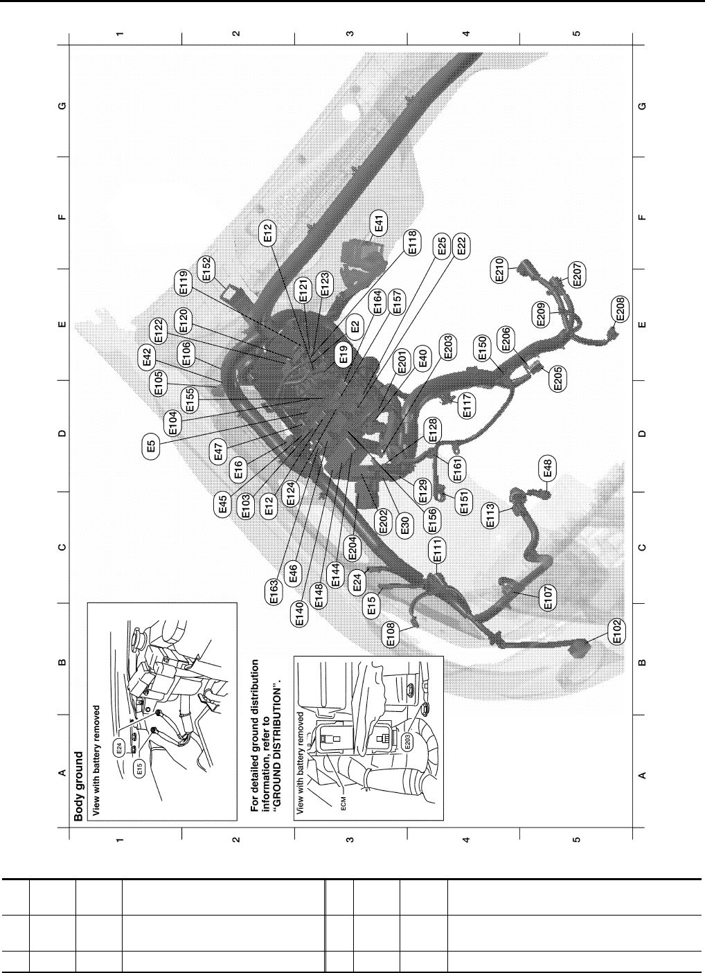
Engine Compartment
Refer to "ENGINE ROOM HARNESS (LH VIEW)" for continuation of engine room harness. WKIA5729E
E3 E2 W/16 : To F32 E3 E123 BR/8 : IPDM E/R (intelligent power distribution mod-
ule engine room)
D1 E5 W/24 : To F14 D2 E124 B/6 : IPDM E/R (intelligent power distribution mod-
ule engine room)
F2 E12 L/5 : Stop lamp relay D4 E128 GR/2 : Fusible link box (battery)

PG
HARNESS
PG-37
< COMPONENT DIAGNOSIS >
C
D
E
F
G
H
I
J
K
L
B
A
O
P
N
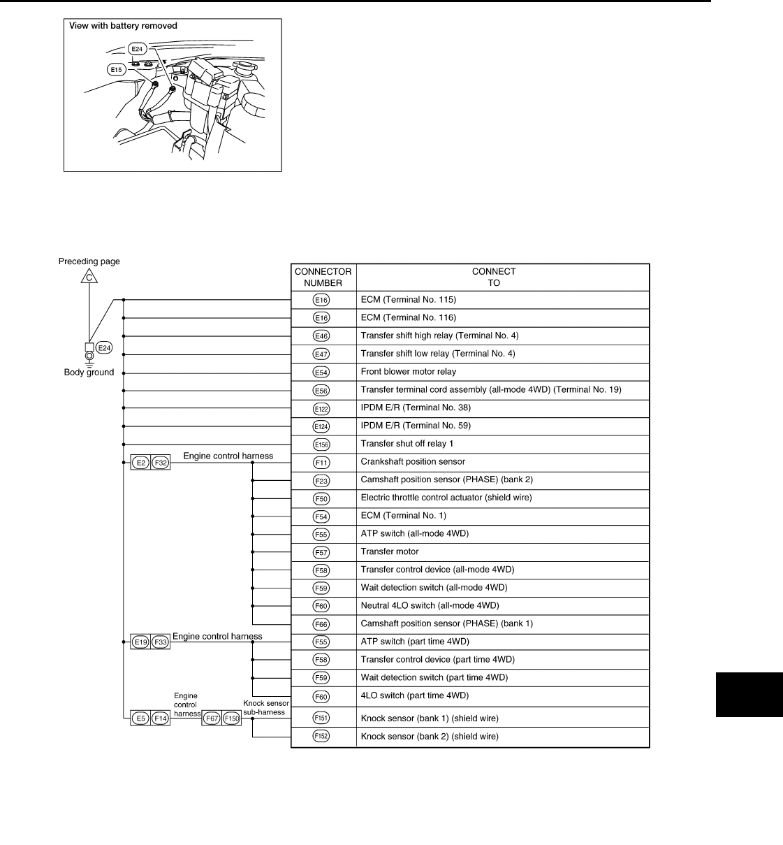
C3 E15 — : Body ground D4 E129 BR/2 : Fusible link box (battery)
D2 E16 B/40 : ECM B3 E140 BR/6 : Trailer tow relay 2
E3 E19 W/16 : To F33 C3 E144 L/4 : Heater pump relay
F4 E22 BR/6 : Front blower motor relay C3 E148 L/4 : Trailer tow relay 1
C3 E24 — : Body ground E4 E150 — : Battery ground
F4 E25 BR/6 : Rear blower motor relay C4 E151 — : Negative battery cable
C3 E30 — : Fusible link box (battery) D2 E155 L/4 : Transfer shut off relay (all-mode 4WD)
E4 E40 GR/9 : To E201 C4 E156 L/4 : Transfer shut off relay 1 (part time 4WD)
F3 E41 SMJ : To C1 (located RH rear of engine
compartment) E3 E157 L/4 : Transfer shut off relay 2 (part time 4WD)
E1 E42 — : Relay box D4 E161 B/3 : Battery current sensor
C2 E45 BR/6 : Back-up lamp relay C2 E163 L/4 : Trailer turn relay RH
C2 E46 B/5 : Transfer shift high relay E3 E164 L/4 : Trailer turn relay LH
D2 E47 B/5 : Transfer shift low relay Generator sub-harness
D5 E48 B/3 : Refrigerant pressure sensor E3 E201 GR/9 : To E40
F1 E51 W/2 : To B104 C3 E202 B/1 : Fusible link box (battery)
B5 E102 B/2 : Front fog lamp RH E4 E203 — : Body ground
C2 E103 B/5 : Daytime light relay 1 C3 E204 — : Battery (positive) starter
D1 E104 L/4 : Daytime light relay 2 D5 E205 GR/3 : Generator
D1 E105 B/2 : Front and rear washer motor E4 E206 — : Generator
E2 E106 BR/2 : Washer fluid level switch E4 E207 GR/1 : Starter motor
C5 E107 B/3 : Front headlamp RH D5 E208 GR/3 : Oil pressure switch
B3 E108 GR/2 : Front side marker lamp RH E5 E209 — : Generator
C4 E111 GR/3 : Front turn signal/parking lamp RH F5 E210 — : Starter motor
C4 E113 GR/4 : Cooling fan motor
D4 E117 GR/2 : Front wheel sensor RH
F4 E118 B/2 : IPDM E/R (intelligent power distri
bution module engine room)
F2 E119 W/18 : IPDM E/R (intelligent power distri
bution module engine room)
E2 E120 W/6 : IPDM E/R (intelligent power distri
bution module engine room)
E3 E121 BR/12 : IPDM E/R (intelligent power distri
bution module engine room
E1 E122 W/12 : IPDM E/R (intelligent power distri
bution module engine room)
PG-38
< COMPONENT DIAGNOSIS >
HARNESS
Passenger Compartment
WKIA5730E
B4 E10 W/6 : To M6
C3 E20 B/6 : Accelerator pedal position (APP)
sensor
B4 E26 W/16 : To M91
B4 E29 Y/4 : To M10
B4 E34 W/8 : To B40

PG
HARNESS
PG-39
< COMPONENT DIAGNOSIS >
C
D
E
F
G
H
I
J
K
L
B
A
O
P
N
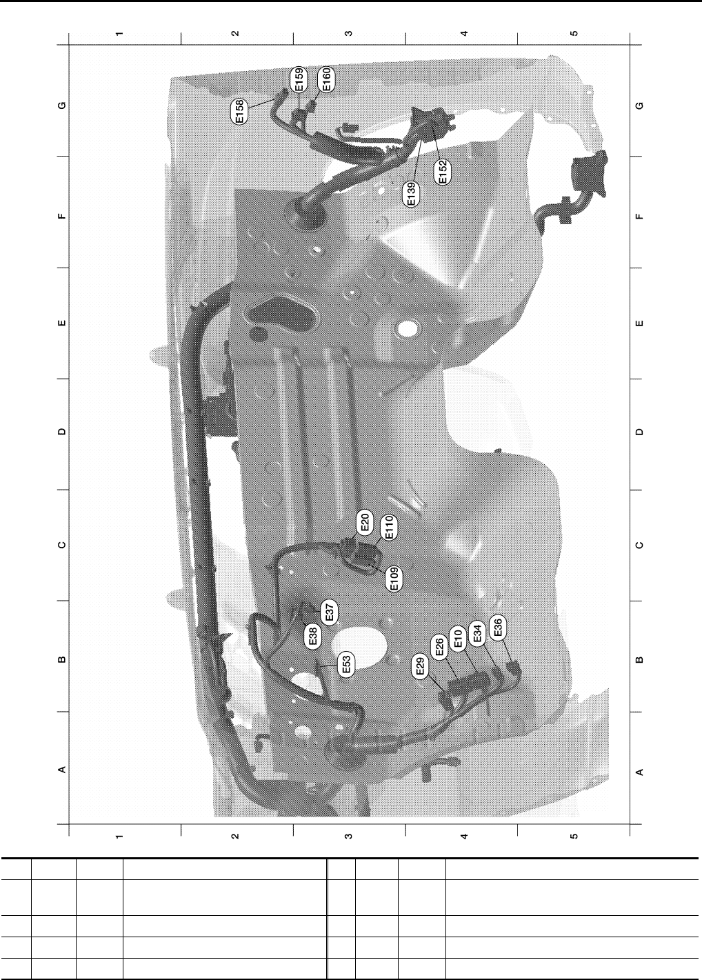
ENGINE ROOM HARNESS (LH VIEW)
B4 E36 W/2 : To B42
B3 E37 BR/2 : ASCD brake switch
B3 E38 W/4 : Stop lamp switch
B3 E53 B/1 : Park brake switch
C3 E109 GR/2 : Pedal adjusting motor
C3 E110 W/4 : Pedal adjusting motor
F3 E139 W/8 : To B107
F4 E152 SMJ : To M31
G2 E158 B/1 : Fuse block (J/B)
G3 E159 B/2 : Fuse block (J/B)
G3 E160 W/8 : Fuse block (J/B)
PG-40
< COMPONENT DIAGNOSIS >
HARNESS
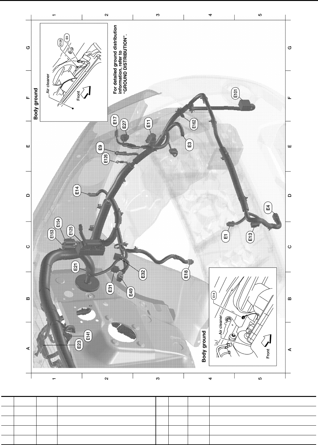
Engine Compartment
Refer to "ENGINE ROOM HARNESS (RH VIEW)" for continuation of engine room harness. WKIA5731E
C4 E1 B/2 : Ambient sensor 1
E4 E3 B/1 : Horn (without dual note horn)
E4 E3 B/2 : Horn (with dual note horn)
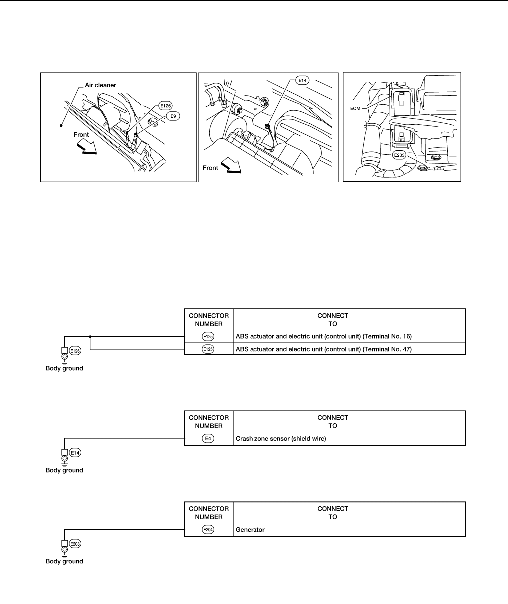
D5 E4 Y/2 : Crash zone sensor
E2 E9 — : Body ground

PG
HARNESS
PG-41
< COMPONENT DIAGNOSIS >
C
D
E
F
G
H
I
J
K
L
B
A
O
P
N
E3 E11 B/3 : Front headlamp LH
C5 E13 GR/2 : Ambient sensor 2
D1 E14 — : Body ground
F2 E17 GR/2 : Front side marker lamp LH
B4 E18 GR/2 : Front wheel sensor LH
C1 E21 GR/2 : Brake fluid level switch
A1 E23 GR/5 : Front wiper motor
E2 E27 GR/3 : Front turn signal/park lamp LH
B2 E31 B/3 : Front pressure sensor
C3 E32 B/3 : Rear pressure sensor
B3 E49 B/6 : Active booster
F5 E101 B/2 : Front fog lamp LH
C1 E125 B/47 : ABS actuator and electric unit (control
unit)
E2 E126 — : Body ground
A2 E141 B/2 : Heater pump
C1 E153 W/2 : Transfer motor relay (all-mode 4WD)
C1 E154 W/2 : Transfer motor relay (all-mode 4WD)
E4 E162 B/1 : Horn
PG-42
< COMPONENT DIAGNOSIS >
HARNESS
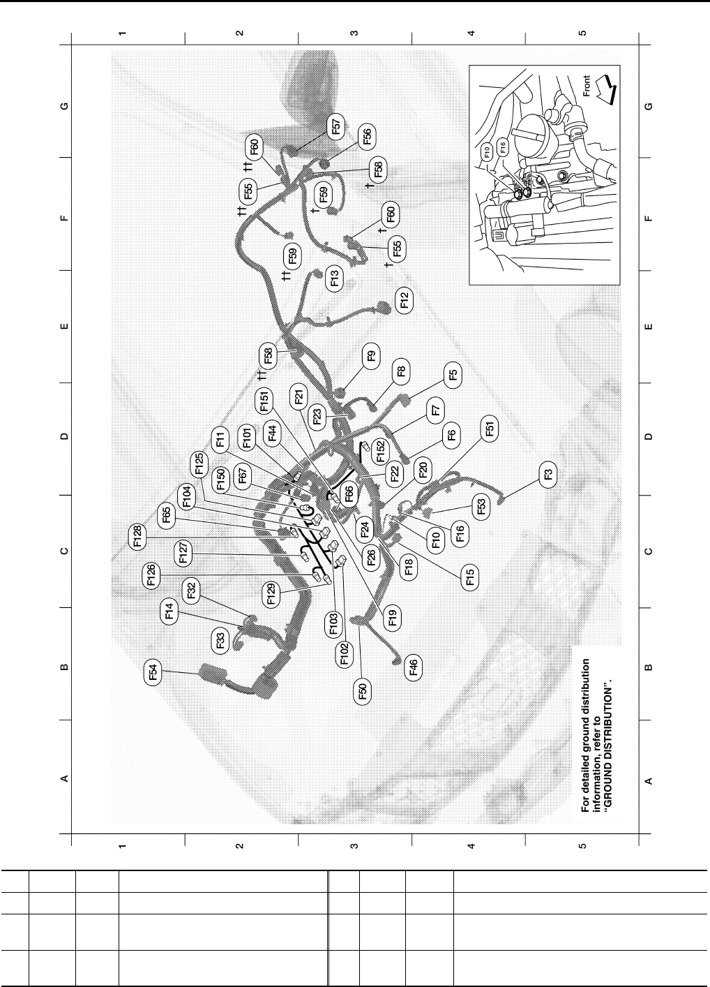
ENGINE CONTROL HARNESS
LKIA0848E
D5 F3 B/1 : A/C Compressor E2 F58†† GR/6 : Transfer control device (all-mode 4WD)
E4 F5 GR/4 : Air fuel ratio (A/F) sensor 1 (bank 2) F3 F59† GR/2 : Wait detection switch (part time 4WD)
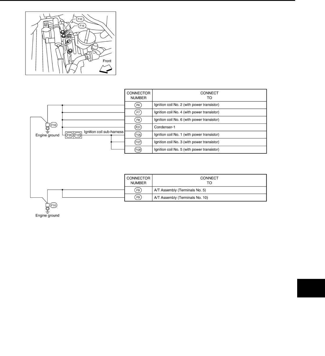
D4 F6 GR/3 : Ignition coil No. 2 (with power tran-
sistor) F2 F59†† B/2 : Wait detection switch (all mode 4WD)
D4 F7 GR/3 : Ignition coil No. 4 (with power tran-
sistor) F3 F60† GR/2 : 4LO switch (part time 4WD)

PG
HARNESS
PG-43
< COMPONENT DIAGNOSIS >
C
D
E
F
G
H
I
J
K
L
B
A
O
P
N
E3 F8 GR/3 : Ignition coil No. 6 (with power tran-
sistor) G2 F60†† GR/2 : 4LO switch (all-mode 4WD)
E3 F9 G/10 : A/T assembly C1 F65 GR/4 : Air fuel ratio (A/F) sensor 1 (bank 1)
C4 F10 — : Engine ground D3 F66 GR/3 : Camshaft position sensor (PHASE) (bank 1)
D2 F11 B/3 : Crankshaft position sensor (POS) D2 F67 L/4 : To F150
E3 F12 G/4 : Heated oxygen sensor 2 (bank 2) Injector sub-harness
E3 F13 L/4 : Heated oxygen sensor 2 (bank 1) D2 F101 GR/4 : To F44
B1 F14 W/24 : To E5 B3 F102 GR/2 : Fuel injector No. 1
C4 F15 L/2 : EVAP canister purge volume control
solenoid valve B3 F103 GR/2 : Fuel injector No. 3
C4 F16 — : Engine ground D2 F104 GR/2 : Fuel injector No. 5
C3 F18 GR/2 : Fuel injector No. 2 Ignition coil sub-harness
B3 F19 B/2 : VIAS control solenoid valve D2 F125 G/8 : To F26
D4 F20 GR/2 : Fuel injector No. 4 C1 F126 GR/3 : Ignition coil No. 1 (with power transistor)
D2 F21 GR/2 : Condenser-1 C1 F127 GR/3 : Ignition coil No. 3 (with power transistor)
D3 F22 GR/2 : Fuel injector No. 6 C1 F128 GR/3 : Ignition coil No. 5 (with power transistor)
D3 F23 B/3 : Camshaft position sensor (PHASE)
(bank 1) C2 F129 G/2 : Intake valve timing control solenoid valve
(bank 1)
C3 F24 GR/2 : Engine coolant temperature sensor Knock sensor sub-harness
C3 F26 G/8 : To F125 D2 F150 L/4 : To F67
C2 F32 W/16 : To E2 D2 F151 B/2 : Knock sensor (bank 1)
B2 F33 W/16 : To E19 D3 F152 B/2 : Knock sensor (bank 2)
D2 F44 GR/4 : To F101
B4 F46 B/3 : Power steering pressure sensor
B3 F50 B/6 : Electric throttle control actuator
D4 F51 G/2 : Intake valve timing control solenoid
valve (bank 2)
C4 F53 B/6 : Mass air flow sensor
B1 F54 B/81 : ECM
F3 F55† B/2 : ATP switch (all-mode 4WD)
F2 F55†† B/2 : ATP switch (part time 4WD)
G3 F56 B/8 : Terminal cord assembly (all-mode
4WD)
G3 F57 B/2 : Transfer motor (all-mode 4WD)
F3 F58† B/8 : Transfer control device (part time
4WD)

PG-44
< COMPONENT DIAGNOSIS >
HARNESS
CHASSIS HARNESS
LKIA0847E
F2 C1 SMJ : To E41
D2 C5 GR/5 : Fuel level sensor unit and fuel pump
A3 C6 B/2 : EVAP canister vent control valve
A3 C7 GR/3 : EVAP control system pressure sensor
C3 C13 GR/4 : Rear wheel sensor assembly

PG
HARNESS
PG-45
< COMPONENT DIAGNOSIS >
C
D
E
F
G
H
I
J
K
L
B
A
O
P
N
B4 C51 GR/6 : To C125
A4 C52 B/2 : To C150
Trailer sub-harness
B4 C125 GR/6 : To C51
A5 C126 B/7 : Trailer (7-pin)
A5 C126 B/4 : Trailer (4-pin)
A4 C150 B/2 : To C52
PG-46
< COMPONENT DIAGNOSIS >
HARNESS
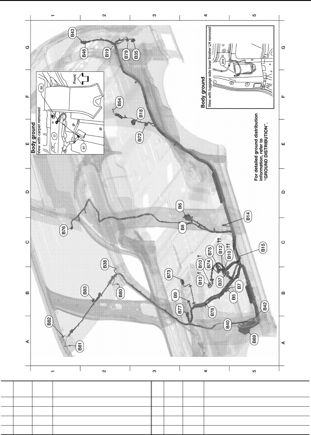
BODY HARNESS
LKIA0849E
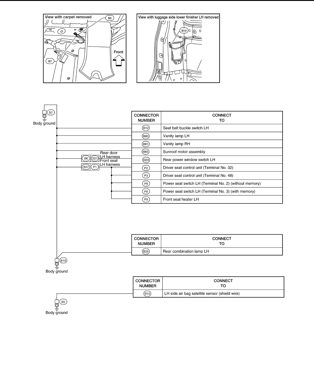
B5 B5 — : LH side air bag satellite sensor (shield
wire)
D4 B6 W/12 : To D201
B5 B7 — : Body ground
C4 B8 W/3 : Front door switch LH
B3 B9 Y/12 : Air bag diagnosis sensor unit

PG
HARNESS
PG-47
< COMPONENT DIAGNOSIS >
C
D
E
F
G
H
I
J
K
L
B
A
O
P
N
C4 B10 Y/2 : Front LH side air bag module
B4 B12 W/3 : Seat belt buckle switch LH
D5 B14 Y/2 : Front LH seat belt pre-tensioner
C5 B15 Y/2 : LH side air bag (satellite) sensor
F3 B18 W/3 : Rear door switch LH
G2 B19 — : Body ground
G3 B35 W/6 : Rear combination lamp LH
B4 B37 W/16 : To P1
B2 B38 Y/2 : LH side front curtain air bag module
A4 B40 W/8 : To E34
B5 B42 W/2 : To E36
G1 B43 W/8 : To D401
G2 B48 W/6 : To D402
F2 B54 Y/2 : LH side rear curtain air bag module
A5 B69 SMJ : To M40
E3 B72 W/8 : Subwoofer (with BOSE audio system)
B3 B73 B/6 : Yaw rate/side/decel G sensor
C4 B74 GR/8 : BOSE speaker amp.
C4 B75 B/24 : BOSE speaker amp.
C1 B76 W/16 : Video monitor
B4 B77 W/16 : Video monitor
B4 B78 Y/2 : To B157
G2 B79 W/4 : Fuel lid door lock actuator
B2 B80 W/2 : Vanity lamp LH
A1 B81 W/2 : Vanity lamp RH
A1 B82 Y/2 : RH side front curtain air bag module
B2 B83 B/10 : Sunroof motor assembly
PG-48
< COMPONENT DIAGNOSIS >
HARNESS
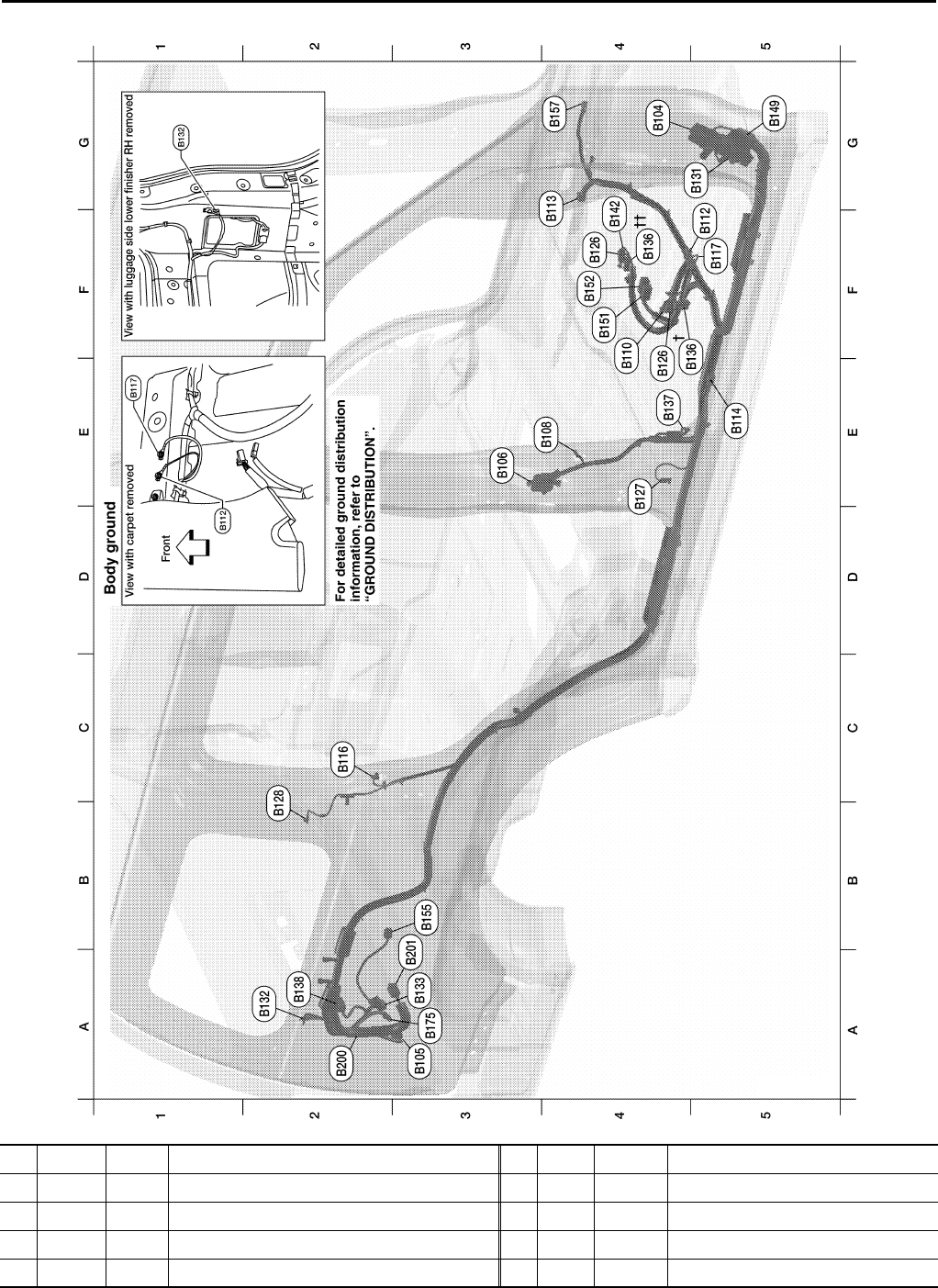
BODY NO. 2 HARNESS
WKIA5732E
G4 B104 W/2 : To E51
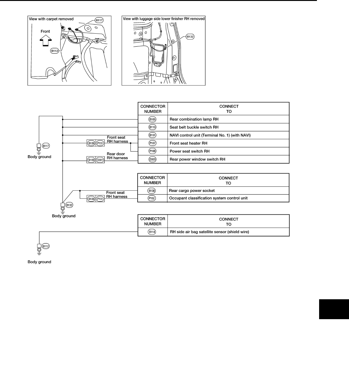
A3 B105 W/6 : Rear combination lamp RH
E3 B106 W/12 : To D301
E4 B108 W/3 : Front door switch RH
F4 B110 W/3 : Seat belt buckle switch RH

PG
HARNESS
PG-49
< COMPONENT DIAGNOSIS >
C
D
E
F
G
H
I
J
K
L
B
A
O
P
N
F5 B112 — : RH side air bad satellite sensor (shield wire)
G3 B113 Y/12 : Air bag diagnosis sensor unit
E5 B114 Y/2 : RH side air bag (satellite) sensor
C2 B116 W/3 : Rear door switch RH
F5 B117 — : Body ground
F4 B126 Y/2 : Front RH side air bag module
E4 B127 Y/2 : Front RH seat belt pre-tensioner
B2 B128 Y/2 : RH side rear curtain air bag module
G5 B131 W/2 : To M162
A2 B132 — : Body ground
A3 B133 W/4 : Rear blower motor resistor
F4 †B136 W/16 : To P151 (with power seat)
F4 ††B136 W/8 : To P151 (without power seat)
E4 B137 B/3 : Belt tension sensor
A2 B138 B/2 : Rear cargo power socket
F4 B142 W/4 : To M83
G5 B149 SMJ : To M36
F4 B151 W/40 : NAVI control unit (with NAVI)
F4 B152 W/32 : NAVI control unit (with NAVI)
B3 B155 B/6 : Air mix door motor (rear)
G4 B157 Y/2 : To B78
A3 B175 W/2 : To B200
Rear blower motor sub-harness
A2 B200 W/2 : To B175
B3 B201 B/2 : Rear blower motor
PG-50
< COMPONENT DIAGNOSIS >
HARNESS
ROOM LAMP HARNESS
LKIA0623E
C4 R1 W/12 : To M1
D3 R4 W/3 : Sunroof switch
C3 R7 W/7
: Auto anti-dazzling inside mirror
(without HOMELINK® universal
transceiver)
PG
HARNESS
PG-51
< COMPONENT DIAGNOSIS >
C
D
E
F
G
H
I
J
K
L
B
A
O
P
N
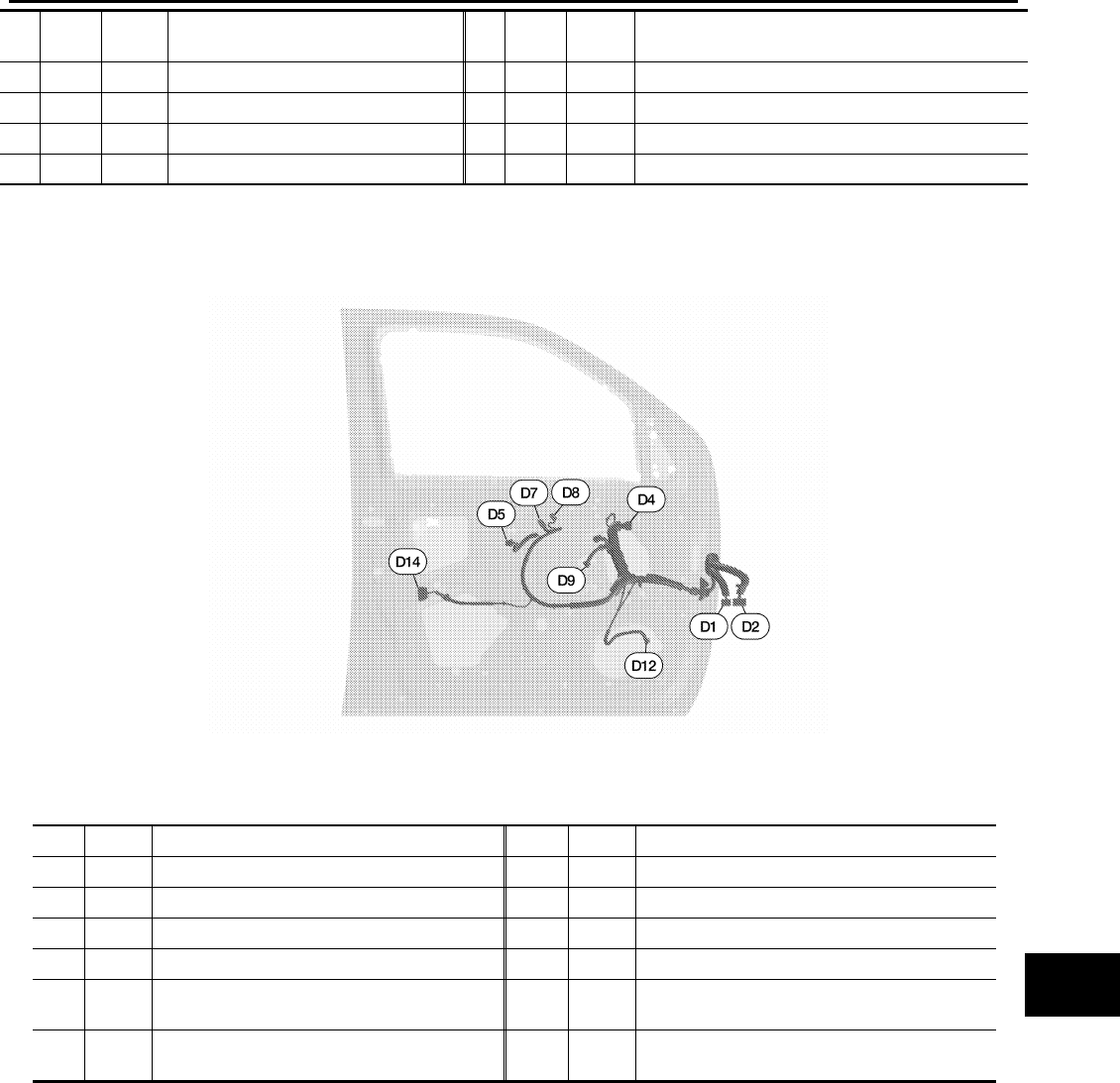
FRONT DOOR LH HARNESS
C3 R7 B/10 : Auto day/night inside mirror (with
HOMELINK® universal transceiver)
C3 R9 W/3 : Front room/map lamp assembly
E2 R10 W/3 : Personal lamp 2nd row
F1 R11 W/2 : Cargo lamp
E2 R12 W/3 : Room lamp 2nd row
WKIA5184E
D1 W/24 : To M9 D9 B/6 : Front power window motor LH
D2 W/16 : To M8 D12 W/2 : Tweeter LH
D4 B/10 : Door mirror LH (with heated mirrors) D14 GR/6 : Front door lock assembly LH
D4 B/3 : Door mirror LH (without heated mirrors)
D5 W/8 : Seat memory switch
D7 W/16 : Main power window and door lock/unlock
switch
D8 W/3 : Main power window and door lock/unlock
switch
PG-52
< COMPONENT DIAGNOSIS >
HARNESS
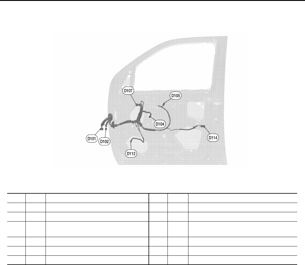
FRONT DOOR RH HARNESS
WKIA5185E
D101 W/12 : To M75 D107 B/10 : Door mirror RH (with heated mirrors)
D102 W/16 : To M74 D112 W/2 : Front door speaker RH
D104 B/6 : Front power window motor RH D114 W/2 : Front door lock actuator RH
D105 W/12 : Power window and door lock/unlock
switch RH
D107 B/3 : Door mirror RH (without heated mirrors)
PG
HARNESS
PG-53
< COMPONENT DIAGNOSIS >
C
D
E
F
G
H
I
J
K
L
B
A
O
P
N
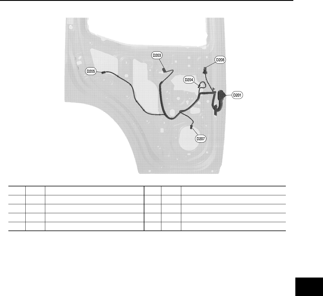
REAR DOOR LH HARNESS
LKIA0850E
D201 W/12 : To B6 D207 W/2 : Rear door speaker LH (without BOSE)
D203 W/8 : Rear power window switch LH D207 BR/2 : Rear door speaker LH (with BOSE)
D204 B/2 : Rear power window motor LH D208 BR/2 : Rear door tweeter LH
D205 W/2 : Rear door lock actuator LH
PG-54
< COMPONENT DIAGNOSIS >
HARNESS
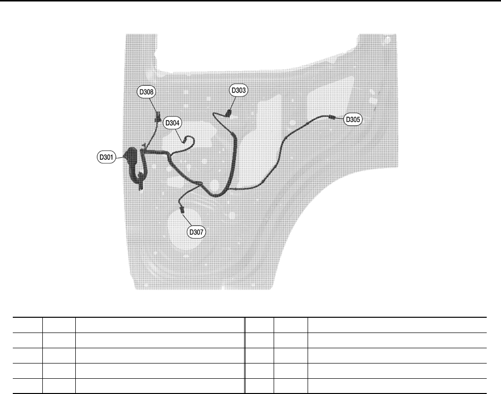
REAR DOOR RH HARNESS
LKIA0851E
D301 W/12 : To B106 D307 W/2 : Rear door speaker RH (without BOSE)
D303 W/8 : Rear power window switch RH D307 BR/2 : Rear door speaker RH (with BOSE)
D304 B/2 : Rear power window motor RH D308 BR/2 : Rear door tweeter RH
D305 W/2 : Rear door lock actuator RH
PG
HARNESS
PG-55
< COMPONENT DIAGNOSIS >
C
D
E
F
G
H
I
J
K
L
B
A
O
P
N
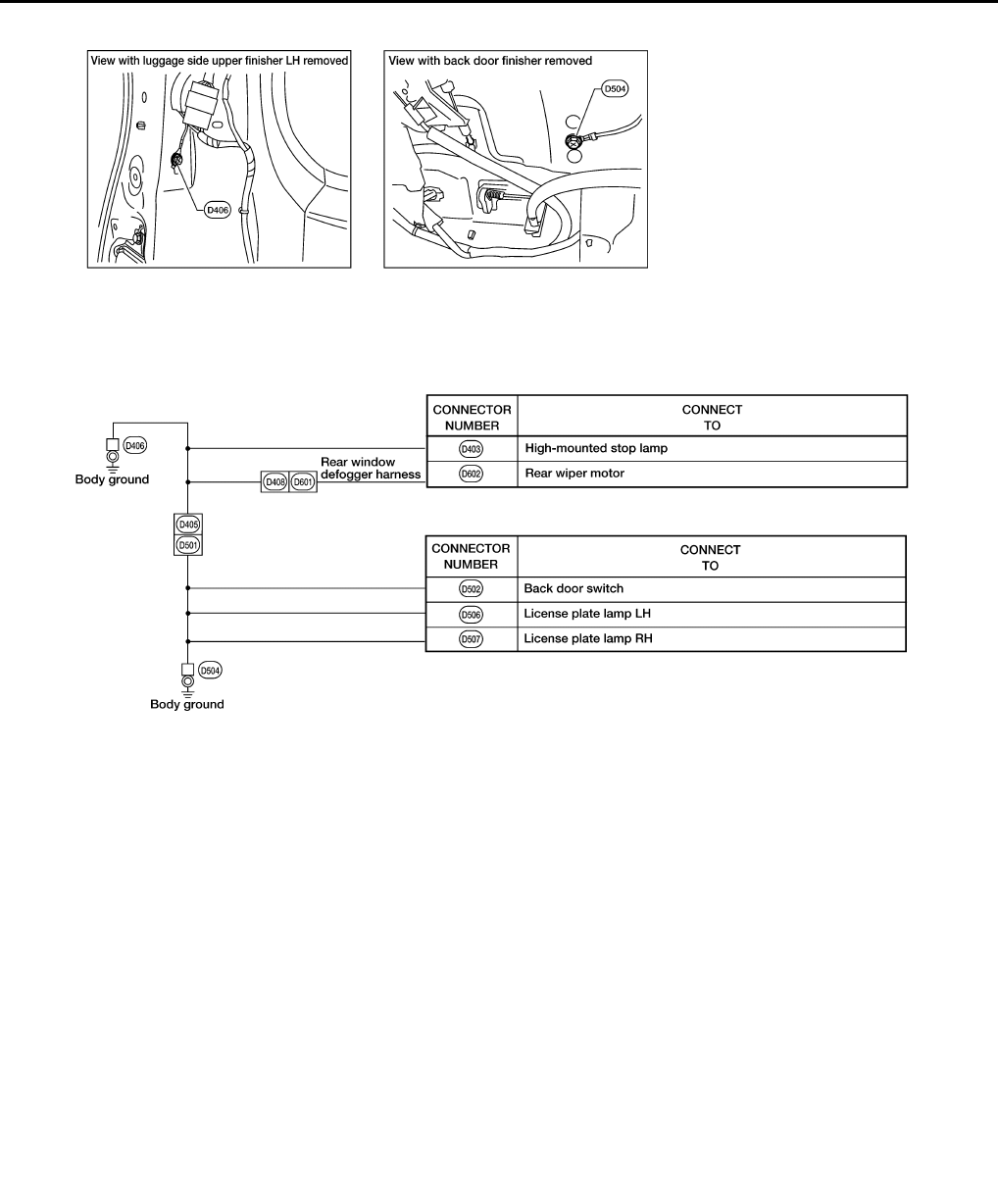
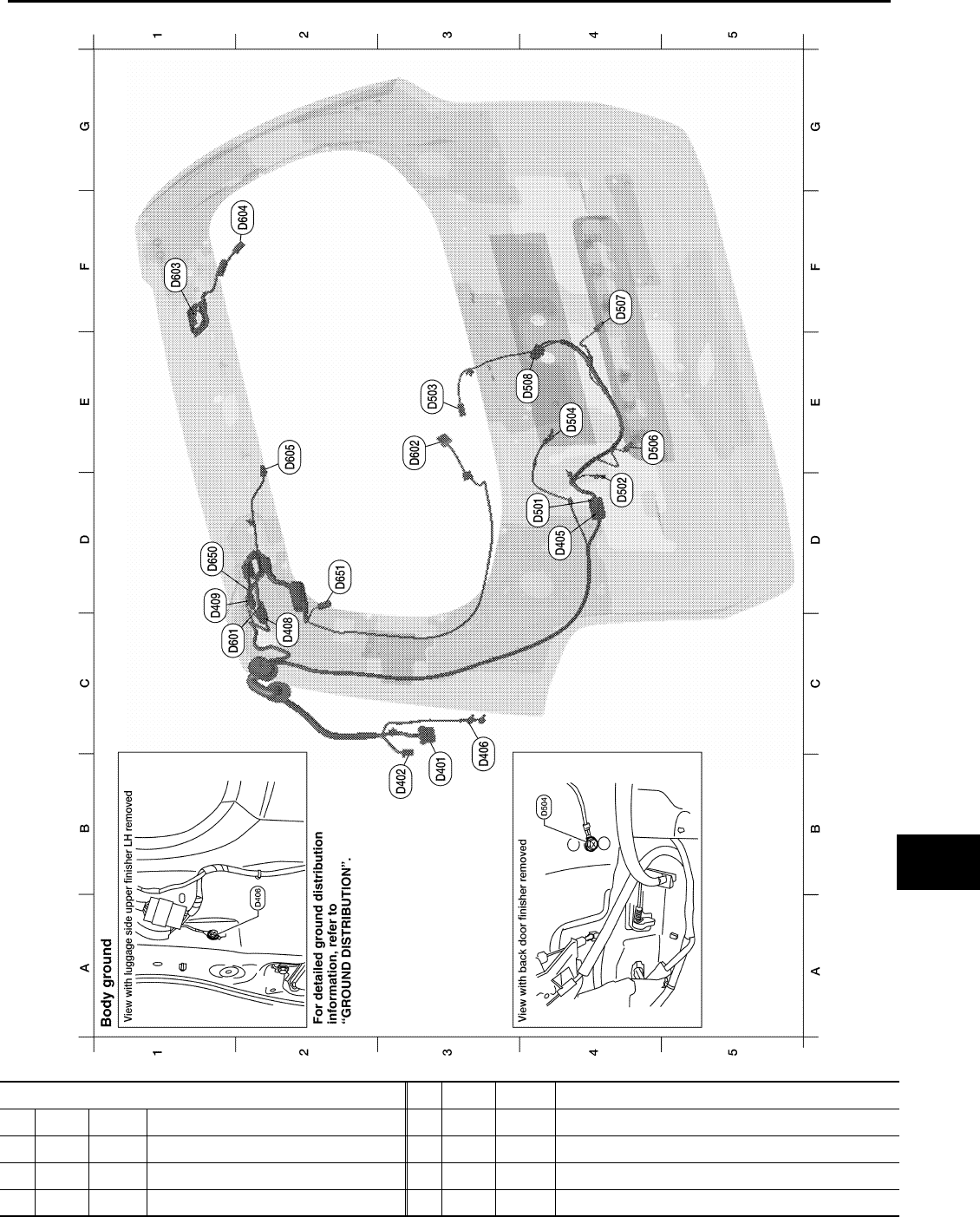
BACK DOOR HARNESS
LKIA0628E
Back door No. 2 harness
B3 D401 W/8 : To B43
B3 D402 W/6 : To B48
D4 D405 W/8 : To D501
B3 D406 — : Body ground

PG-56
< COMPONENT DIAGNOSIS >
HARNESS
Wiring Diagram Codes (Cell Codes) INFOID:0000000001731013
Use the chart below to find out what each wiring diagram code stands for.
Refer to the wiring diagram code in the alphabetical index to find the location (page number) of each wiring
diagram.
C2 D408 W/4 : To D601
D1 D409 W/1 : To D650
Back door harness
D4 D501 W/8 : To D405
D4 D502 W/3 : Back door switch
E3 D503 B/1 : Glass hatch ajar switch
E4 D504 — : Body ground
E4 D506 W/2 : License plate lamp LH
F4 D507 W/2 : License plate lamp RH
E4 D508 W/4 : Back door lock actuator
Rear window sub-harness
C1 D601 W/4 : To D405
E3 D602 W/4 : Rear wiper motor
F1 D603 — : Body ground (defogger)
F2 D604 B/1 : Rear window defogger
E2 D605 W/2 : High mounted stop lamp
Rear window defogger sub-harness
D1 D650 W/1 : To D409
D2 D651 B/1 : Rear window defogger
Code Section Wiring Diagram Name
A/C,A ATC Auto Air Conditioner
A/C,M MTC Manual Air Conditioner
AF1B1 EC Air Fuel Ratio (A/F) Sensor 1 Bank 1
AF1B2 EC Air Fuel Ratio (A/F) Sensor 1 Bank 2
AF1HB1 EC Air Fuel Ratio (A/F) Sensor 1 Heater Bank 1
AF1HB2 EC Air Fuel Ratio (A/F) Sensor 1 Heater Bank 2
APPS1 EC Accelerator Pedal Position Sensor
APPS2 EC Accelerator Pedal Position Sensor
APPS3 EC Accelerator Pedal Position Sensor
ASC/BS EC ASCD Brake Switch
ASC/SW EC ASCD Steering Switch
ASCBOF EC ASCD Brake Switch
ASCIND EC ASCD Indicator
AT/IND DI A/T Indicator Lamp
AUDIO AV Audio
AUT/DP SE Automatic Drive Positioner
AUTO/L LT Auto Light Control
B/COMP DI Combination Meter Board Computer
BACK/L LT Back-up Lamp
BRK/SW EC Brake Switch
CAN AT CAN Communication Line
CAN EC CAN Communication Line
CAN LAN CAN System
CHARGE SC Charging System

PG
HARNESS
PG-57
< COMPONENT DIAGNOSIS >
C
D
E
F
G
H
I
J
K
L
B
A
O
P
N
CHIME DI Warning Chime
COOL/F EC Cooling Fan Control
COMBSW LT Combination Switch
COMM AV Audio Visual Communication System
COMPAS DI Compass
CUR/SE EC Battery Current Sensor
D/LOCK BL Power Door Lock
DEF GW Rear Window Defogger
DTRL LT Headlamp - With Daytime Light System
DVD AV DVD Entertainment System
ECM/PW EC ECM Power Supply for Back-Up
ECTS EC Engine Coolant Temperature Sensor
ETC1 EC Electric Throttle Control Function
ETC2 EC Throttle Control Motor Relay
ETC3 EC Throttle Control Motor
F/FOG LT Front Fog Lamp
F/PUMP EC Fuel Pump
FTS AT A/T Fluid Temperature Sensor
FTTS EC Fuel Tank Temperature Sensor
FUELB1 EC Fuel Injection System Bank 1
FUELB2 EC Fuel Injection System Bank 2
H/LAMP LT Headlamp
HORN WW Horn
HSEAT SE Heated Seat
I/MIRR GW Inside Mirror (Auto Anti-Dazzling Mirror)
IATS EC Intake Air Temperature Sensor
IGNSYS EC Ignition System
ILL LT Illumination
INJECT EC Injectors
INT/L LT Room/Map, Vanity, Cargo, and Personal Lamps
IVCB1 EC Intake Valve Timing Control Solenoid Valve Bank 1
IVCB2 EC Intake Valve Timing Control Solenoid Valve Bank 2
KEYLES BL Remote Keyless Entry System
KS EC Knock Sensor
MAFS EC Mass Air Flow Sensor
MAIN AT Main Power Supply and Ground Circuit
MAIN EC Main Power Supply and Ground Circuit
METER DI Speedometer, Tachometer, Temp. and Fuel Gauges
MIL/DL EC Malfunction Indicator Lamp
MIRROR GW Door Mirror
NATS BL Nissan Anti-Theft System
NAVI AV Navigation System
NONDTC AT Non-Detective Items
O2H2B1 EC Rear Heated Oxygen Sensor 2 Heater Bank 1
O2H2B2 EC Rear Heated Oxygen Sensor 2 Heater Bank 2
O2S2B1 EC Heated Oxygen Sensor 2 Bank 1
O2S2B2 EC Heated Oxygen Sensor 2 Bank 2
P/SCKT WW Power Socket
PEDAL AP Adjustable Pedal System
PGC/V EC EVAP Canister Purge Volume Control Solenoid Valve
PHSB1 EC Camshaft Position Sensor (PHASE) (Bank 1)
PHSB2 EC Camshaft Position Sensor (PHASE) (Bank 1)

PG-58
< COMPONENT DIAGNOSIS >
HARNESS
PNP/SW AT Park/Neutral Position Switch
PNP/SW EC Park/Neutral Position Switch
POS EC Crankshaft Position Sensor (POS)
POWER PG Power Supply Routing
PRE/SE EC EVAP Control System Pressure Sensor
PS/SEN EC Power Steering Pressure Sensor
RP/SEN EC Refrigerant Pressure Sensor
SEAT SE Power Seat
SEN/PW EC Sensor Power Supply
SHIFT AT A/T Shift Lock System
SROOF RF Sunroof
SRS SRS Supplemental Restraint System
STSIG AT Start Signal Circuit
START SC Starting System
STOP/L LT Stop Lamp
T/TOW LT Trailer Tow
T/WARN WT Low Tire Pressure Warning System
TAIL/L LT Parking, License and Tail Lamps
T/F TF Transfer Case
TPS1 EC Throttle Position Sensor
TPS2 EC Throttle Position Sensor
TPS3 EC Throttle Position Sensor
TRNSCV BL HOMELINK® Universal Transceiver
TURN LT Turn Signal and Hazard Warning Lamps
VDC BRC Vehicle Dynamic Control System
VEHSEC BL Vehicle security (theft warning) system
VENT/V EC EVAP Canister Vent Control Valve
VIAS EC Variable Air Induction Control System
VIAS/V EC Variable Air Induction Control System Valve
VSSA/T AT Vehicle Speed Sensor A/T (Revolution Sensor)
W/ANT AV Audio Antenna
WARN DI Warning Lamps
WINDOW GW Power Window
WIP/R WW Rear Wiper and Washer
WIPER WW Front Wiper and Washer
PG
ELECTRICAL UNITS LOCATION
PG-59
< COMPONENT DIAGNOSIS >
C
D
E
F
G
H
I
J
K
L
B
A
O
P
N
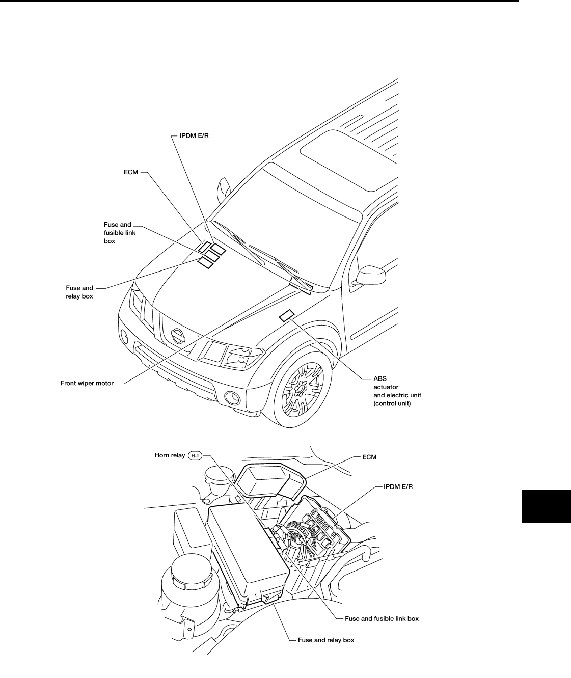
ELECTRICAL UNITS LOCATION
Electrical Units Location INFOID:0000000001731014
ENGINE COMPARTMENT
LKIA0629E
PG-60
< COMPONENT DIAGNOSIS >
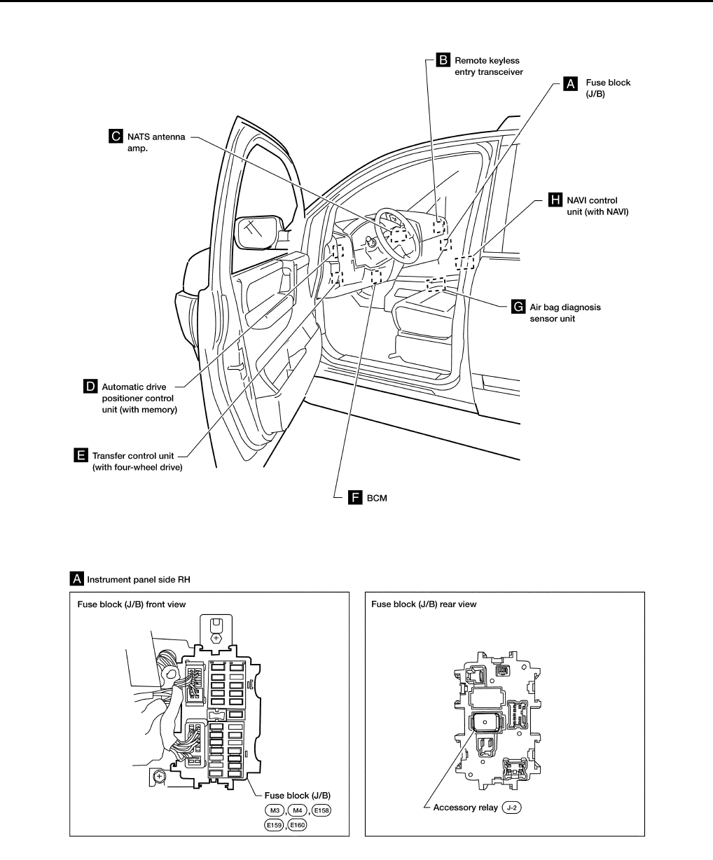
ELECTRICAL UNITS LOCATION
PASSENGER COMPARTMENT
WKIA5024E

PG
ELECTRICAL UNITS LOCATION
PG-61
< COMPONENT DIAGNOSIS >
C
D
E
F
G
H
I
J
K
L
B
A
O
P
N
WKIA5025E
PG-62
< COMPONENT DIAGNOSIS >
HARNESS CONNECTOR
HARNESS CONNECTOR
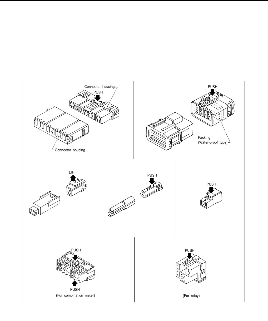
Description INFOID:0000000001731015
HARNESS CONNECTOR (TAB-LOCKING TYPE)
• The tab-locking type connectors help prevent accidental looseness or disconnection.
• The tab-locking type connectors are disconnected by pushing or lifting the locking tab(s). Refer to the illus-
tration below.
Refer to the next page for description of the slide-locking type connector.
CAUTION:
Do not pull the harness or wires when disconnecting the connector.
[Example]
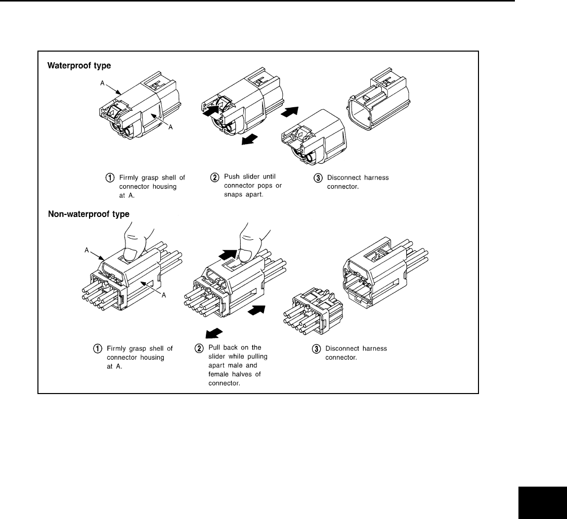
HARNESS CONNECTOR (SLIDE-LOCKING TYPE)
• A new style slide-locking type connector is used on certain systems and components, especially those
related to OBD.
• The slide-locking type connectors help prevent incomplete locking and accidental looseness or disconnec-
tion.
• The slide-locking type connectors are disconnected by pushing or pulling the slider. Refer to the illustration
below.
SEL769DA
PG
HARNESS CONNECTOR
PG-63
< COMPONENT DIAGNOSIS >
C
D
E
F
G
H
I
J
K
L
B
A
O
P
N
CAUTION:
• Do not pull the harness or wires when disconnecting the connector.
• Be careful not to damage the connector support bracket when disconnecting the connector.
[Example]
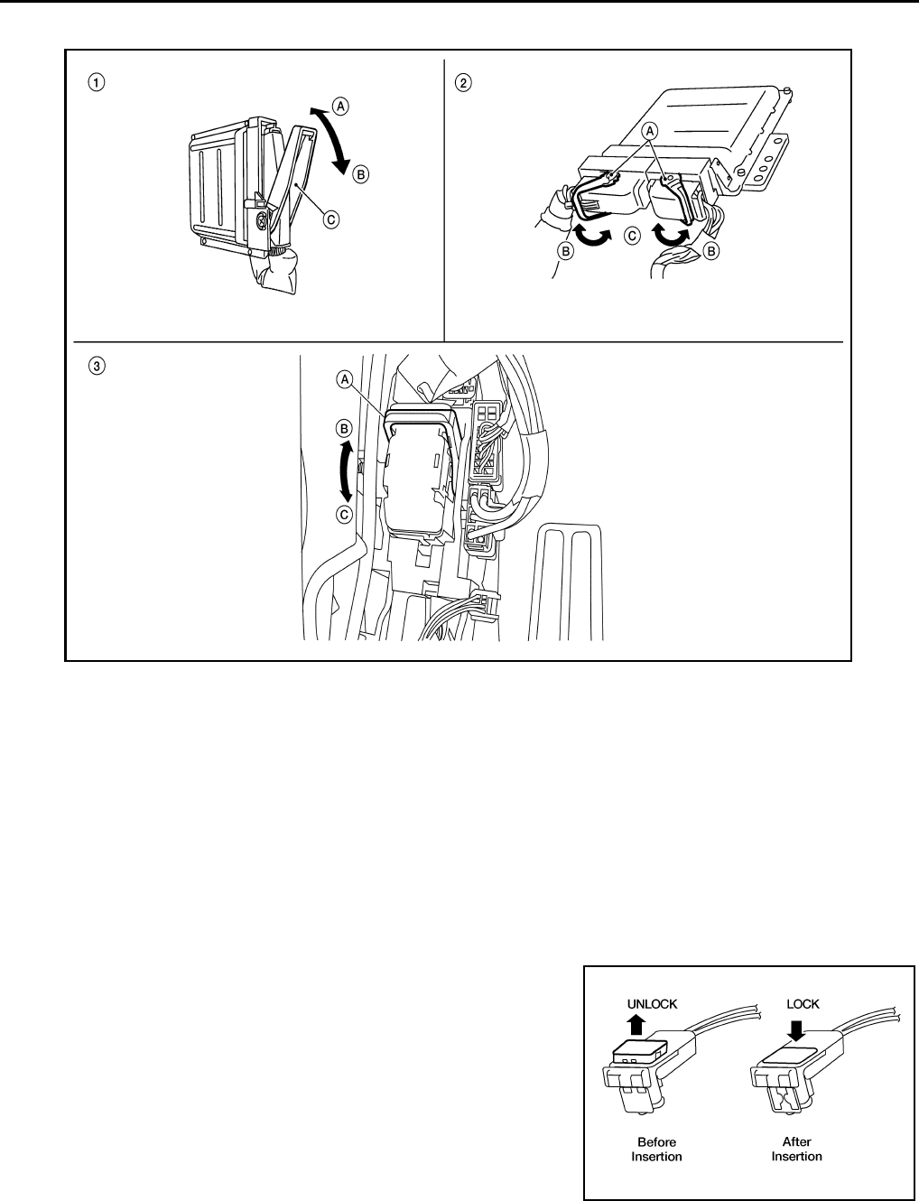
HARNESS CONNECTOR (LEVER LOCKING TYPE)
• Lever locking type harness connectors are used on certain control units and control modules such as ECM,
ABS actuator and electric unit (control unit), etc.
• Lever locking type harness connectors are also used on super multiple junction (SMJ) connectors.
• Always confirm the lever is fully locked in place by moving the lever as far as it will go to ensure full connec-
tion.
CAUTION:
AEL299C
PG-64
< COMPONENT DIAGNOSIS >
HARNESS CONNECTOR
Always confirm the lever is fully released (loosened) before attempting to disconnect or connect these
connectors to avoid damage to the connector housing or terminals.
HARNESS CONNECTOR (DIRECT-CONNECT SRS COMPONENT TYPE)
• SRS direct-connect type harness connectors are used on certain SRS components such as air bag modules
and seat belt pre-tensioners.
• Always pull up to release black locking tab prior to removing connector from SRS component.
• Always push down to lock black locking tab after installing connector to SRS component. When locked, the
black locking tab is level with the connector housing.
CAUTION:
• Do not pull the harness or wires when removing connectors
from SRS components.
LKIA0670E
1. Control unit with single lever
A. Fasten
B. Loosen
C. Lever
2. Control unit with dual levers
A. Levers
B. Fasten
C. Loosen
3. SMJ connector
A. Lever
B. Fasten
C. Loosen
WHIA0103E
PG
ELECTRICAL UNITS
PG-65
< COMPONENT DIAGNOSIS >
C
D
E
F
G
H
I
J
K
L
B
A
O
P
N
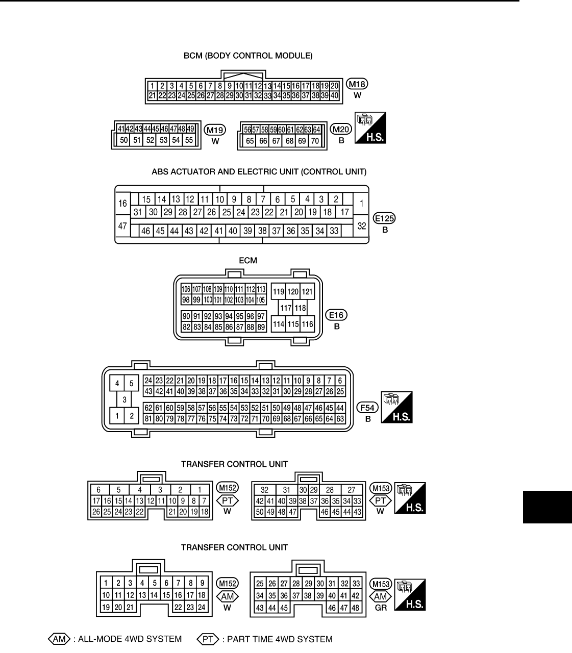
ELECTRICAL UNITS
Terminal Arrangement INFOID:0000000001731016
WKIA5869E
PG-66
< COMPONENT DIAGNOSIS >
STANDARDIZED RELAY
STANDARDIZED RELAY
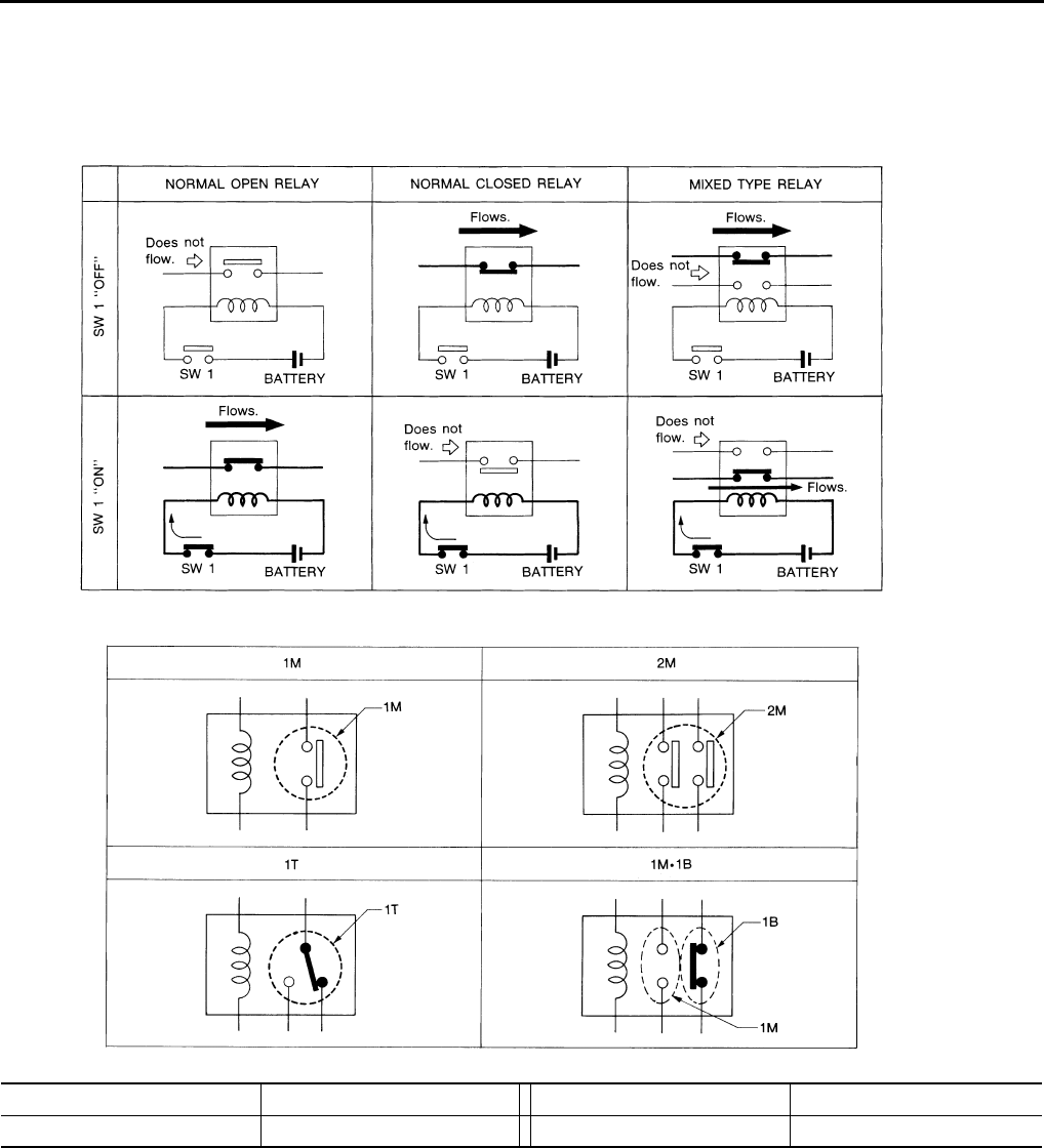
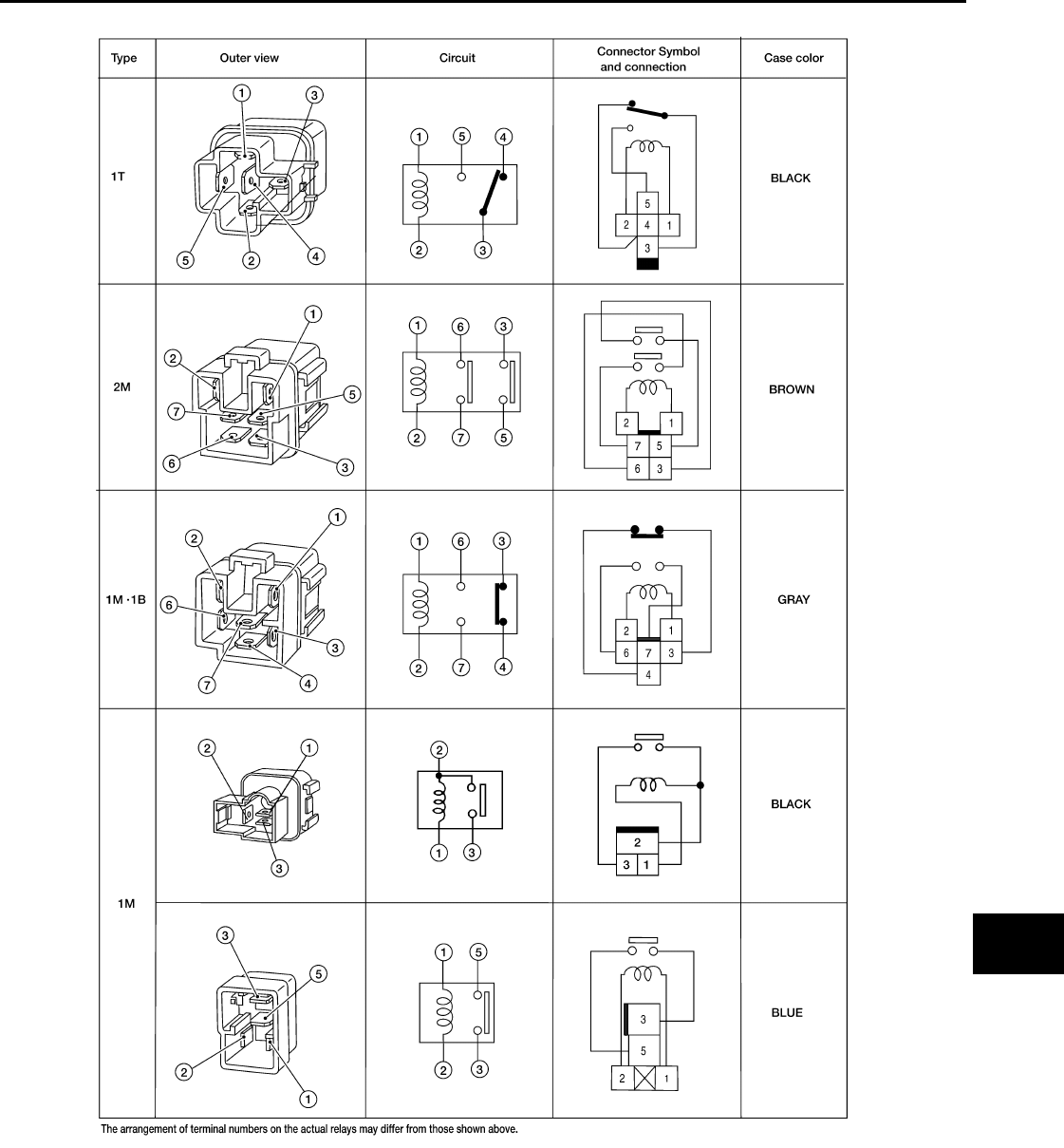
Description INFOID:0000000001731017
NORMAL OPEN, NORMAL CLOSED AND MIXED TYPE RELAYS
Relays can mainly be divided into three types: normal open, normal closed and mixed type relays.
TYPE OF STANDARDIZED RELAYS
SEL881H
SEL882H
1M 1 Make 2M 2 Make
1T 1 Transfer 1M·1B 1 Make 1 Break
PG
STANDARDIZED RELAY
PG-67
< COMPONENT DIAGNOSIS >
C
D
E
F
G
H
I
J
K
L
B
A
O
P
N
WKIA0253E
PG-68
< COMPONENT DIAGNOSIS >
SUPER MULTIPLE JUNCTION (SMJ)
SUPER MULTIPLE JUNCTION (SMJ)
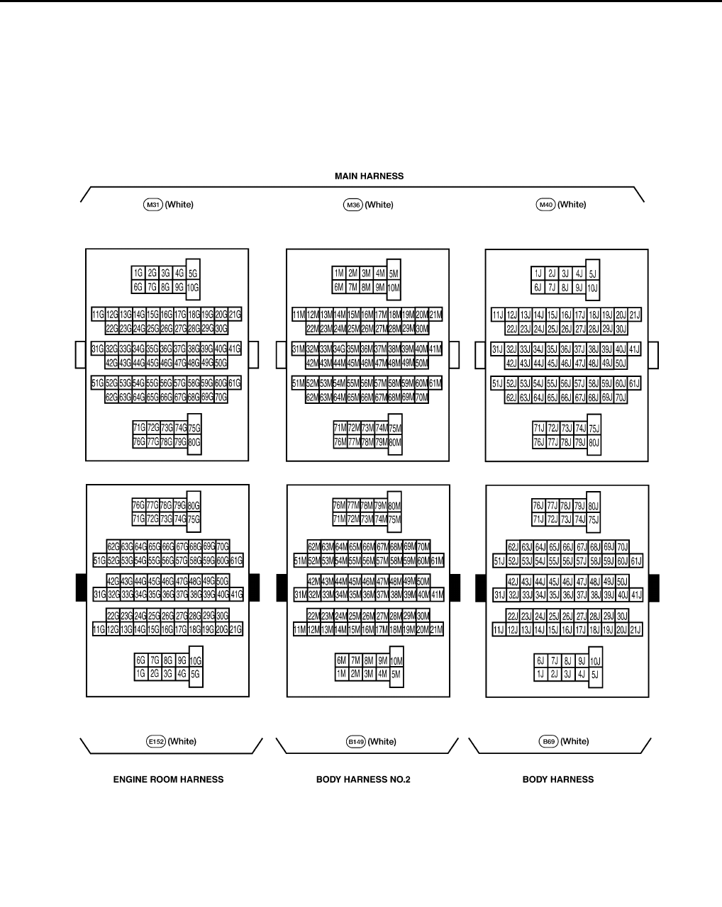
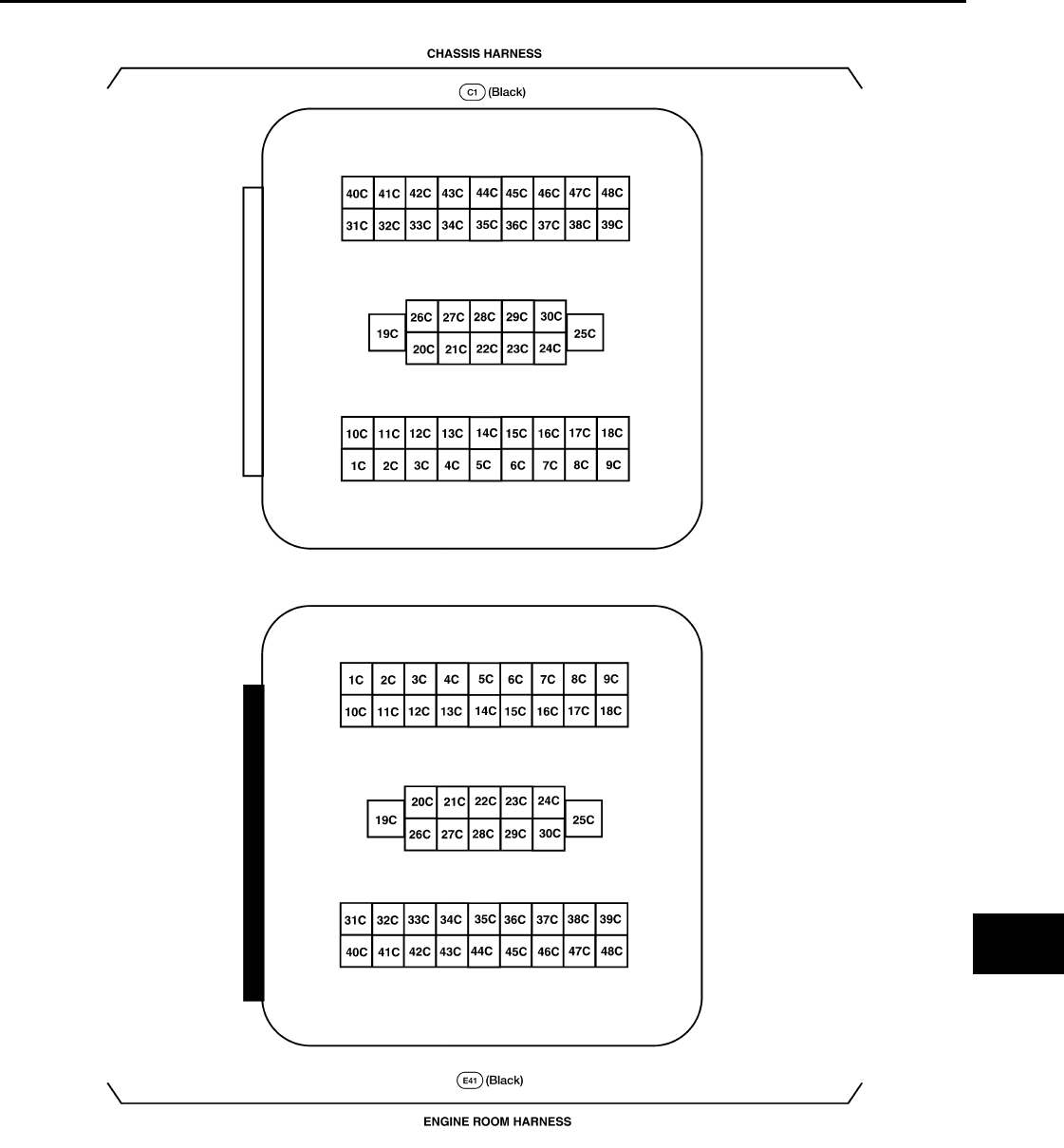
Terminal Arrangement INFOID:0000000001731018
WKIA3590E
PG
SUPER MULTIPLE JUNCTION (SMJ)
PG-69
< COMPONENT DIAGNOSIS >
C
D
E
F
G
H
I
J
K
L
B
A
O
P
N
WKIA4179E
PG-70
< COMPONENT DIAGNOSIS >
FUSE BLOCK-JUNCTION BOX (J/B)
FUSE BLOCK-JUNCTION BOX (J/B)
Terminal Arrangement INFOID:0000000001731019
WKIA5012E
PG
FUSE AND FUSIBLE LINK BOX
PG-71
< COMPONENT DIAGNOSIS >
C
D
E
F
G
H
I
J
K
L
B
A
O
P
N
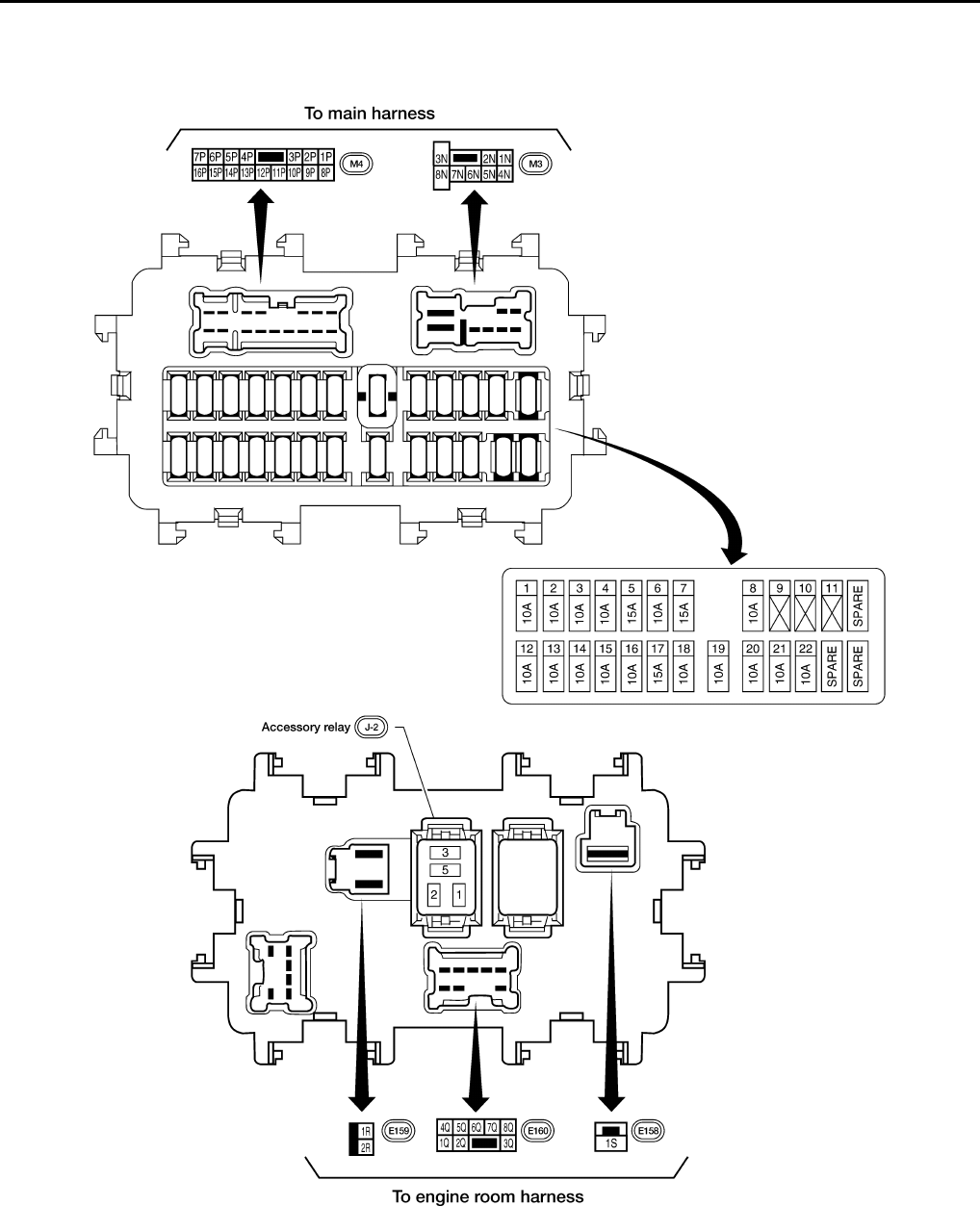
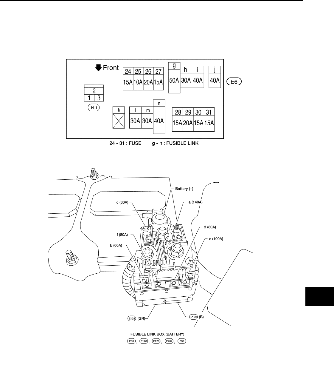
FUSE AND FUSIBLE LINK BOX
Terminal Arrangement INFOID:0000000001731020
WKIA5013E
PG-72
< COMPONENT DIAGNOSIS >
FUSE AND RELAY BOX
FUSE AND RELAY BOX
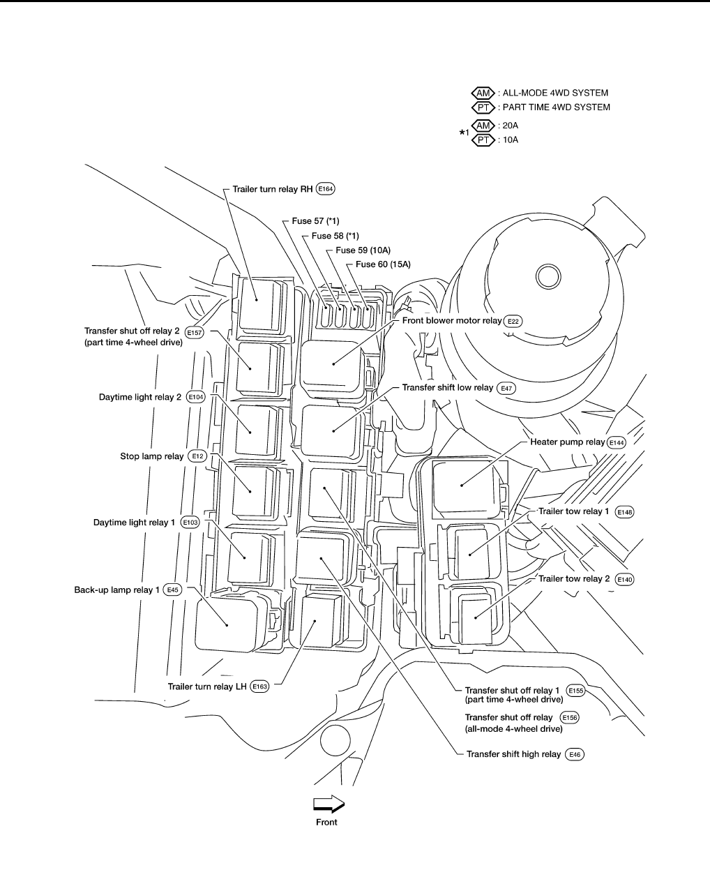
Terminal Arrangement INFOID:0000000001731021
WKIA5870E
PG
BATTERY
PG-73
< ON-VEHICLE REPAIR >
C
D
E
F
G
H
I
J
K
L
B
A
O
P
N
ON-VEHICLE REPAIR
BATTERY
Removal and Installation INFOID:0000000001547054
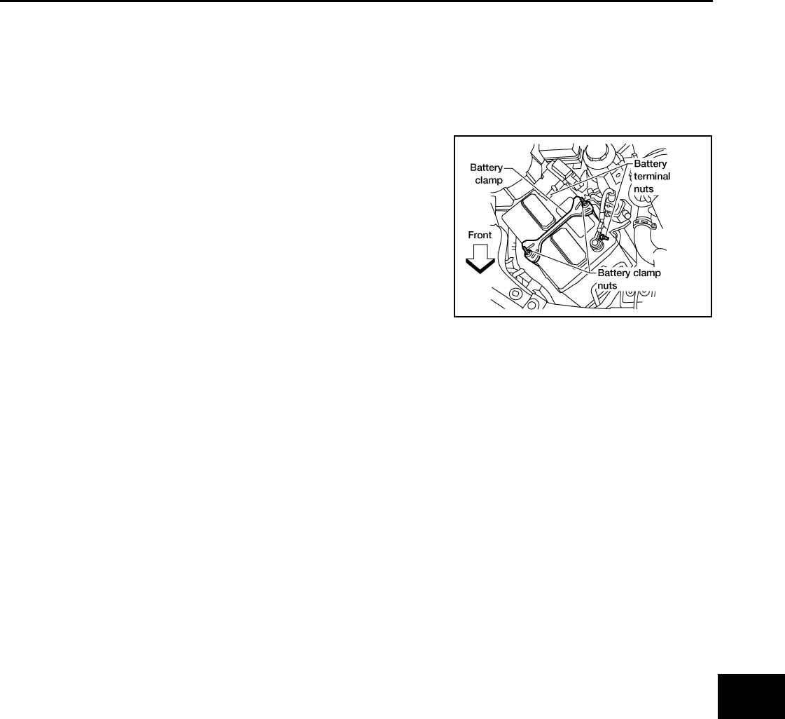
REMOVAL
1. Disconnect both negative and positive battery terminal.
CAUTION:
Remove negative battery terminal first.
2. Remove battery clamp nuts and battery clamp.
3. Remove battery.
INSTALLATION
Installation is in the reverse order of removal.
CAUTION:
Install positive battery terminal first.
WKIA3188E
Battery clamp nuts : 3.4 N·m (0.35 kg-m, 30 in-lb)
Battery terminal nut : 3.4 N·m (0.35 kg-m, 30 in-lb)

PG-74
< SERVICE DATA AND SPECIFICATIONS (SDS)
BATTERY
SERVICE DATA AND SPECIFICATIONS (SDS)
BATTERY
Battery INFOID:0000000001547053
Standard battery
Type Gr. 24
Capacity (20 HR) minimum V-AH 63
Cold cranking current A
(For reference value) 550
