Ftp://ftp.tapr.org/picsig/docs/pic E_assy_manual Pic E Assy Manual
User Manual: ftp://ftp.tapr.org/picsig/docs/pic-e_assy_manual
Open the PDF directly: View PDF ![]() .
.
Page Count: 16

TAPR PIC-E Manual May 1999 Page 1 of 16
TAPR PIC-E
T
A
P
R
™
Tucson Amateur Packet Radio
8987-309 E. Tanque Verde Rd #337
Tucson, Arizona • 85749-9399
Office: (940) 383-0000 • Fax: (940) 566-2544
Internet: TAPR@TAPR.ORG • www.tapr.org
Non-Profit Research and Development Corporation
TAPR PIC-Encoder
This document was written February 1999. Rev 1, May 1999. ©1999 Tucson Amateur Packet Radio Corp.
Reproduction or translation of any part of this work beyond that
permitted by sections 107 or 108 of the 1976 United States
Copyright Act (or its legal successor) without the express written
permission of Tucson Amateur Packet Radio Corporation is
unlawful except as noted below. Requests for permission to copy
or for further information should be addressed to Tucson Amateur
Packet Radio Corporation. Except as noted above, permission
is hereby granted to any nonprofit group or individual to
reproduce any portion of this document provided that: the
reproduction is not sold for profit; the intent of the reproduction
is to further disseminate information on Amateur Packet Radio;
the reproduction is not used for advertising or otherwise
promoting any specific commercial product; full credit is given
to Tucson Amateur Packet Radio Corporation (including address)
as the original source of information; and Tucson Amateur Packet
Radio Corporation is notified in writing of the reproduction.
The information contained in this document has been carefully checked and is believed to be entirely reliable.
However, no responsibility is assumed for inaccuracies. Tucson Amateur Packet Radio Corporation (TAPR) reserves
the right to make changes in any products to improve reliability, function or design without obligation to purchasers
of previous equipment. TAPR does not assume any liability arising out of the application or use of any product or
circuit described herein; neither does it convey license under its patent rights or the rights of others.
Introduction
The TAPR PIC-Encoder (PIC-E) is a general-purpose
packet radio encoder based on the Microchip, Inc.
PIC16F84 PIC microcontroller. The PIC-E was
designed to provide a generic interface between the
digital world (in the form of serial data streams) and
the amateur packet radio world (in the form of AX.25
packets) and is fully programmable by the user. For
example, the user can program the PIC
microcontroller to take serial data from a GPS receiver
or weather station and transmit it as formatted packet
frames. Virtually any data that can be provided to
the device as a serial input stream can be reformatted
and transmitted as 1200 bps packet radio.
The PIC-E is based on two chips: a Microchip, Inc.
PIC16F84 microcontroller and a MX-COM, Inc.
MX614 Bell 202 modem chip. The PIC16F84 is a
general purpose “computer on a chip” that can be
programmed and reprogrammed by the end user. The
PIC-E has an on-board PIC programmer. It is only
necessary to connect a short serial cable between the
PIC-E and a PC serial port and run the appropriate
programming software.
The PIC can be programmed to receive an incoming
data stream and reformat it for transmission as AX.25
frames. The PIC sends the formatted data to the
MX614 that generates tones necessary to transmit 1200
bps packet over the radio’s audio channel. The MX614
contains an energy detect circuit. Receive audio can
be routed to the MX614 and it can determine whether
the channel is in use and send this information back
to the microcontroller. As a result, no additional VOX
or carrier detect circuitry is required to prevent the
PIC-E from colliding with other users on the channel.
The MX614 can detect both digital signals and voice,
so it is suitable for applications where digital and
audio signals are mixed on the same frequency.
The PIC-E is an open system and it is hoped that many
hams will use it as a platform for developing new
and innovative applications. Almost any application
that involves point to point or point to multi-point
Introduction 1
Acknowledgments 2
Parts List 2
Construction Notes 3
Construction 4
Operation 8
Programming the PIC-E 8
Radio and Mic Interfacing 10
Serial Device Interfacing 13
Applications 13
Jumpers 14
Troubleshooting 15
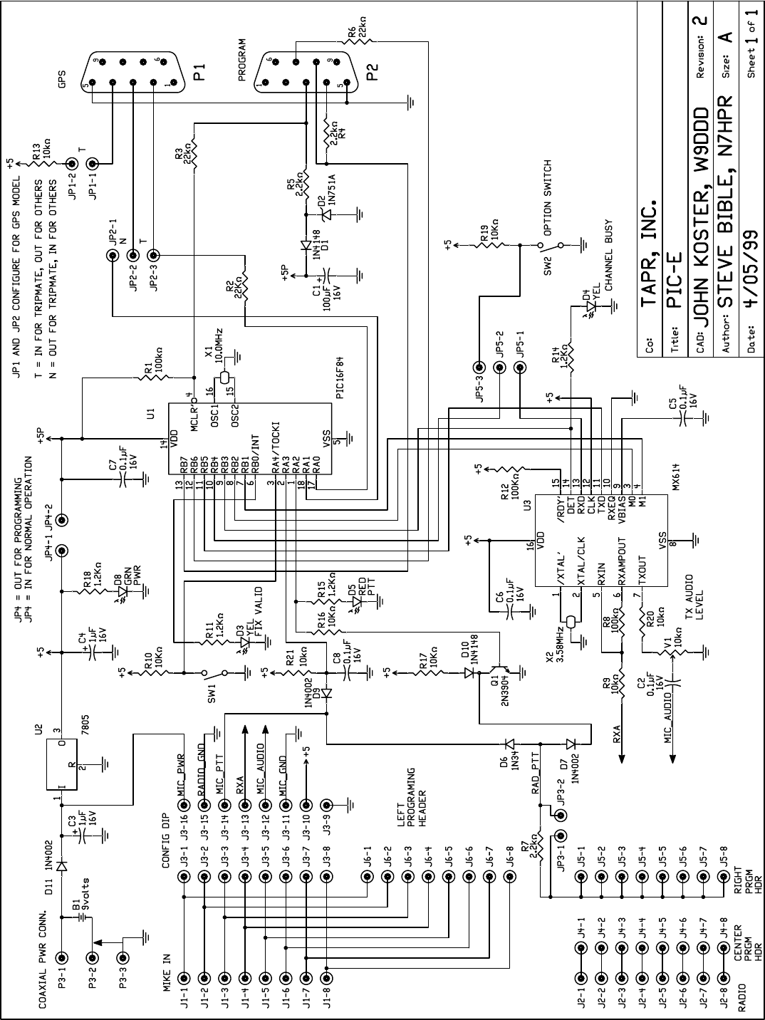
Schematic 16

Page 2 of 16 May 1999 TAPR PIC-E Manual
Acknowledgements
The Tucson Amateur Packet Radio PIC-Encoder Kit
was made possible by the pioneering efforts of (in
alphabetical order):
Steve Bible, N7HPR Project Manager
Joe Borovetz, WA5VMS Parts Liaison
Steve Dimse, K4HG Conceptual Design
Byon Garrabrant, N6BG Programmer,
Conceptual Design
John Hansen, W2FS Programmer,
Conceptual Design
Greg Jones, WD5IVD TAPR Project Liasion
John Koster, W9DDD PCB Design
Dan Welch, W6DFW Conceptual Design,
Documentation
transmission of low-density data is a candidate for
PIC-E development. To write applications for the
PIC-E you will need to learn how to develop PIC
firmware. Don’t worry, it is not all that difficult. Most
of what you will need to get started is readily available
at little or no cost. The software to get started in PIC
development is available for free at
http://www.microchip.com. A discussion of the
basics of getting started in PIC programming can be
found in an article by W2FS in the October 1998 issue
of QST. The Proceedings of the 1998 TAPR/ARRL
Digital Communications Conference contains
information on how to implement AX.25 UI frames
in PIC microcontroller. While the 16F84 contains only
1K of program space, it turns out that this provides
enough room not only to decode incoming serial data
and construct outgoing packets, but to do a significant
amount of processing and reformatting of the data as
well.
As PIC-E programs are developed they will be
displayed or linked from the TAPR PIC-E web site
located at http://www.tapr.org/taprf/html/
Fpice.html. If you’ve created a project and would like
to display or link to it, contact TAPR at tapr@tapr.org.
Updated documentation can be found at
http://www.tapr.org/taprf/html/Fpice.html or
ftp://ftp.tapr.org/picsig/docs/.
Contributed files can be found at
ftp://ftp.tapr.org/picsig/software/. Files can be
anonymously uploaded to
ftp://ftp.tapr.org/picsig/upload/.
PIC-E is discussed on the PIC special interest group.
You can join PIC SIG via the web at
http://www.tapr.org/cgi-bin/lyris.pl?join=picsig.
PARTS LIST
The parts list is organized by quantity and part type.
Verify that all parts are present by checking in the
space [ ] provided as you locate the part in the list.
You may wish to take this opportunity to sort the parts
into a compartmented container such as an egg carton
or muffin tin as you inventory them. This will aid
you in kit building.
Resistors (1/4 w, 5% Carbon Film):
[ ] (4) 1.2K ohm (brown-red-red-gold)
R11,R14,R15,R18
[ ] (3) 2.2K ohm (red-red-red-gold) R4,R5,R7
[ ] (9) 10K ohm (brown-black-orange-gold)
R3,R9,R10,R13,R16,R17,R19,R20,R21
[ ] (2) 22K ohm (red-red-orange-gold) R2,R6
[ ] (3) 100K ohm (brown-black-yellow-gold)
R1,R8,R12
Resistor, (Trimpot, 25-Turn)
[ ] (1) 10K ohm Trimpot (103) V1
Capacitors
Capacitors may be marked in various ways. The
typical markings are listed but may vary. Find all that
match and the remaining ones, if any, should become
apparent by elimination.
Mylar or Monolithic
[ ] (5) 0.1 uf (104) C2,C5,C6,C7,C8
Electrolytic or Tantalum
[ ] (2) 1uF (105) C3,C4
[ ] (1) 100 uf C1
Diode
[ ] (1) 1N34 Germanium Diode D6
[ ] (3) 1N4002 Silicon Diode D7,D9,D11
[ ] (2) 1N4148 Silicon Diode D1,D10
[ ] (1) 1N5231BDICT-ND 5.1V Zener Diode D2
Light Emitting Diodes
[ ] (1) Green T1 D8
[ ] (2) Yellow T1 D3,D4
[ ] (1) Red T1 D5
Integrated Circuits
NOTE: Do not handle the ICs at this time! Carefully
remove the black foam carrier with ICs from the bag
and verify the ICs against this list. Do not touch the
ICs!
[ ] (1) PIC16F84 U1
[ ] (1) MX614 U3
TAPR PIC-E Manual May 1999 Page 3 of 16
Transistors
[ ] (1) 2N3904 NPN Transistor Q1
Voltage Regulators
[ ] (1) 7805 U2
Ceramic Resonators
Ceramic Resonators look very much like a dipped
capacitor, but have three leads.
[ ] (1) 3.58 MHz X2
[ ] (1) 10 MHz X1
IC Sockets
[ ] (2) 16-pin DIP Socket U3, J3
[ ] (1) 18-pin DIP Socket U1
[ ] (1) 16-pin Machine Tooled DIP Socket J3
Connectors
[ ] (3) 1x2-pin male header
[ ] (2) 1x3-pin male header
[ ] (3) 1x8-pin male header (or (1) 1x8 and (1) 2x8)
[ ] (12) 2-pin Jumper, Push-On
[ ] (1) DB9 Female PCB right angle mount
[ ] (1) DB9 Male PCB right angle mount
[ ] (2) 8-pin RJ-45 jack PCB right angle mount
[ ] (1) 2.1 mm Coaxial Jack
[ ] (1) 2.1 mm Coaxial Plug
Miscellaneous
[ ] (1) Printed Circuit Board
[ ] (1) Assembly Manual (this document)
[ ] (1) Cable Assembly with RJ-45 connectors
[ ] (2) Miniture Toggle Switches
[ ] (4) 4-40 x 3/8” screws
[ ] (4) 4x40 nuts
[ ] (1) Solid wire
CONSTRUCTION NOTES
You are now ready to begin construction of the PIC-
Encoder. Follow standard construction practices
when building the unit.
Use a temperature-controlled, fine-tipped soldering
iron of relatively low wattage (25 watts maximum,
15 watts is ideal) and a good quality 60/40 or 63/37
rosin-core solder for construction. Keep the tip of your
soldering iron bright and clean, wiping it frequently
on a wet rag or sponge. Make solder joints carefully,
but swiftly. Prolonged heat on a PC board pad can be
as disastrous as it can ruin the PC board. Two to three
seconds should be enough time to apply heat to any
joint. Due to the proximity of some of the traces on
the PC board, solder bridges are a very distinct
possibility. Following these points could eliminate
several hours of troubleshooting (or worse). This is
good practice when working on any kit.
You will need small flush or semi-flush cutting pliers
and small-tipped long nosed pliers. A magnifying
glass may prove helpful to identify the values of the
small components.
Pay careful attention to the directions that follow. Pay
close attention to the following:
1) Read this entire document prior to starting
construction of your kit.
2) Identifying the pins on headers - Pin 1 is identified
by the square pad on silk-screen.
Electrostatic Protection
The Integrated Circuits are susceptible to static
discharge. Observe anti-static precautions when
assembling the PIC-Encoder.

Page 4 of 16 May 1999 TAPR PIC-E Manual
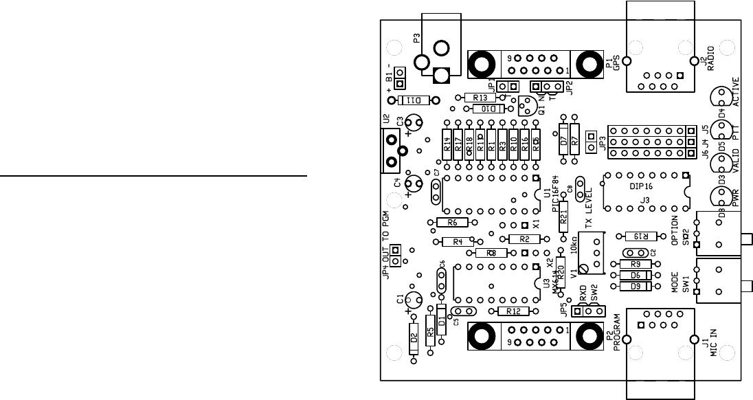
CONSTRUCTION
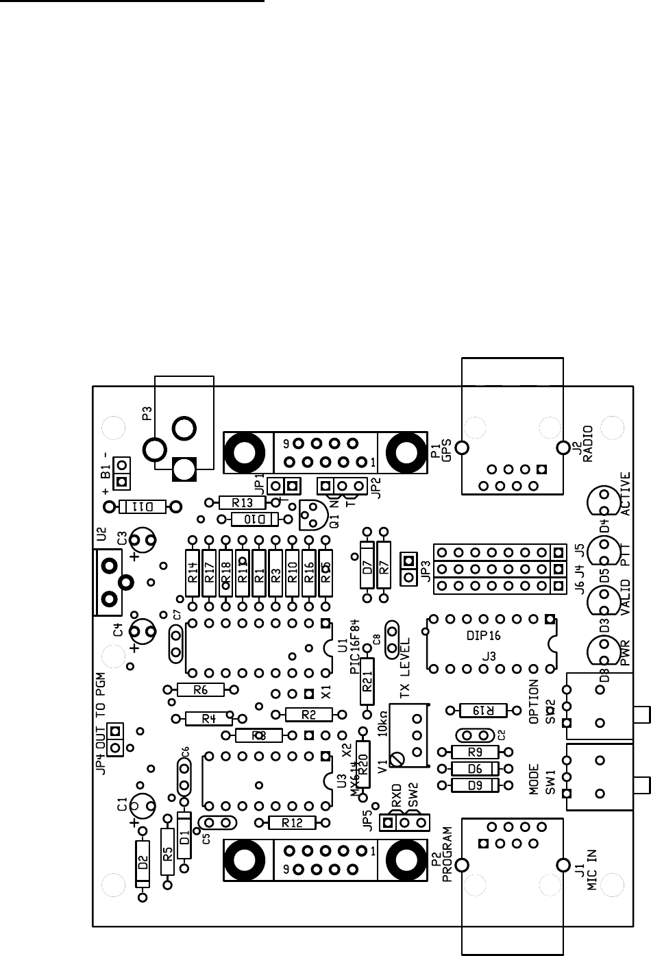
Refer to the layout diagram for clarification of parts
placement.
Resistors
Resistors have a lead spacing of 0.4" and should lie
flat on the PC board. You may wish to use a lead
former to pre-form the resistor leads for neatest
appearance.
Install the following resistors:
[ ] R14 1.2K ohm (brown-red-red-gold)
[ ] R17 10K ohm (brown-black-orange-gold)
[ ] R18 1.2K ohm (brown-red-red-gold)
[ ] R11 1.2K ohm (brown-red-red-gold)
WARNING! Be careful when clipping leads, as they
have a tendency to fly towards your eyes! Take
appropriate precautions (grasp leads and wear eye
protection).
[ ] Solder and clip the leads (8 total)
[ ] R1 100K ohm (brown-black-yellow-gold)
[ ] R3 10K ohm (brown-black-orange-gold)
[ ] R10 10K ohm (brown-black-orange-gold)
[ ] R16 10K ohm (brown-black-orange-gold)
[ ] R15 1.2K ohm (brown-red-red-gold)
[ ] Solder and clip the leads (10 total)
[ ] R13 10K ohm (brown-black-orange-gold)
[ ] R7 2.2K ohm (red-red-red-gold)
[ ] R5 2.2K ohm (red-red-red-gold)
[ ] Solder and clip the leads (6 total)
[ ] R6 22K ohm (red-red-orange-gold)
[ ] R4 2.2K ohm (red-red-red-gold)
[ ] R8 100K ohm (brown-black-yellow-gold)
[ ] R2 22K ohm (red-red-orange-gold)
[ ] Solder and clip the leads (8 total)
[ ] R12 100K ohm (brown-black-yellow-gold)
[ ] R9 10K ohm (brown-black-orange-gold)
CAUTION! Diode D6 and D9 are next to resistor R9.
Make certain that you install resistor R9 in its proper
place.
[ ] R19 10K ohm (brown-black-orange-gold)
[ ] R20 10K ohm (brown-black-orange-gold)
[ ] R21 10K ohm (brown-black-orange-gold)
[ ] Solder and clip the leads (10 total)
Now check your work. All leads should be soldered.
There should be no solder bridges or cold solder
connections.
[ ] OK so far.
This completes the resistor installation. You should
have no remaining resistors.
[ ] No resistors remaining.
Diode
Diodes are polarity sensitive devices. Diodes are
mounted flat near the surface of the board like the
resistors previously installed. The cathode end of the
diode is banded and corresponds to the banded silk-
screen legend on the PCB.
Install the following diodes:
[ ] D1 1N4148
[ ] D2 1N5231 Zener
[ ] Solder and clip the leads (4 total)
[ ] D7 1N4002
[ ] D6 1N34
[ ] D9 1N4002
[ ] Solder and clip the leads (6 total)
[ ] D10 1N4148
[ ] D11 1N4002
[ ] Solder and clip the leads (4 total)
Now check your work. All leads should be soldered.
There should be no solder bridges or cold solder
connections.
[ ] OK so far.
This completes the diode installation. You should have
no remaining diodes.
[ ] No diodes remaining.

TAPR PIC-E Manual May 1999 Page 5 of 16
IC Sockets
NOTE: If any socket pins are bent, carefully straighten
them with a pair of long-nose pliers before assembly.
Some types of IC sockets have crimps in the pins to
hold them in place when automatic wave soldering
is performed. These sockets may be tricky to install if
you are not familiar with them. If your kit contains
these sockets, you may want to straighten the pins
before attempting to insert them into the PC board.
When installing IC sockets double check to ensure
that the socket is seated properly against the board
with the notch matching the silk-screen. Pin 1 (nearest
the socket notch) has a square solder pad. Be sure
that all IC socket pins are showing on the solder side
of the board. Next, tack-solder two diagonally
opposite corners first (such as pins 1 and 8 on a 14-
pin socket).
Then solder the remaining pins of that socket before
proceeding to the next one. If you find a socket is
difficult to install, remove it and double-check for a
bent pin.
CAUTION! Take care to avoid solder bridges!
NOTE: Do not solder the 16-pin Machine IC Socket
to the PCB. It will be plugged into the socket J3 as a
programming header later.
Install the following IC sockets:
[ ] U1 18-pin
[ ] U3 16-pin
[ ] J3 16-pin
Now check your work. All leads should be soldered.
There should be no solder bridges (a blob of solder
that shorts two adjacent soldered connections) or cold
(gray and/or grainy looking) solder connections.
[ ] OK so far.
This completes the IC socket installation. You should
have one 16-pin Machined IC sockets remaining.
[ ] One 16-pin Machined IC socket remaining.
Trimpots
Align the trimpot according to the silkscreen.
Install the trimpot:
[ ] V1 10K ohm
[ ] Solder and clip the leads (3 total)
Capacitors
All capacitors should be mounted as nearly flush to
the board surface as practical without stressing the
leads.
Install the following capacitors:
[ ] C2 0.1 uF (104)
[ ] C5 0.1 uF (104)
[ ] C6 0.1 uF (104)
[ ] C7 0.1 uF (104)
[ ] C8 0.1 uF (104)
[ ] Solder and clip the leads (10 total)
Electrolytic and Tantalum capacitors are polarized.
The positive lead goes in the hole on the board marked
with a “+”. Be careful! Typically the negative lead is
marked and sometimes the positive lead is marked.
[ ] C3 1 uF
[ ] C4 1 uF
[ ] Solder and clip the leads (4 total)
[ ] C1 100 uF
[ ] Solder and clip the leads (2 total)
Now check your work. All leads should be soldered.
There should be no solder bridges or cold solder
connections.
[ ] OK so far.
This completes the capacitor installation. You should
have no remaining capacitors.
[ ] No capacitors remaining.

Page 6 of 16 May 1999 TAPR PIC-E Manual
Ceramic Resonators
Ceramic resonators are not polarity sensitive.
Install the following ceramic resonators:
[ ] X1 10 MHz
[ ] X2 3.58 MHz
[ ] Solder and clip the leads (6 total)
Transistor
NOTE: Transistors are polarized components. Match
the body of the transistor with the silk-screened
outline and carefully bend the transistor leads to
match the hole pattern on the PC board. The bottom
of the body of the transistor should not be more than
1/4" above the PC board.
[ ] Q1 2N3904 NPN Transistor
[ ] Solder and clip the leads (3 total)
Voltage Regulator
NOTE: Voltage regulators are polarized components.
Match the body of the voltage regulator with the silk-
screened outline and carefully bend the leads to match
the hole pattern on the PC board. The bottom of the
body of the voltage regulator should not be more that
1/4” above the PC board.
NOTE: position the 7805 with the heatsink positioned toward the
edge of the PCB
[ ] U2 7805
[ ] Solder and clip the leads (3 total)
Male Headers
The 2-, 3-, and 8-pin male headers will be installed
next. The plastic body of the part should rest flush
with the top surface of the PC board. The short end of
the pins goes into the PC board, the long end sticks
up.
WARNING! Do not hold these parts with your
fingers as they quickly get very hot while soldering
in place.
Place a 2-pin jumper on the header to insulate your
finger from the pins, hold the header in place and
tack solder one pin. Check for proper alignment. If
alignment is off, you can reheat the one pin to adjust.
Once the alignment is correct, solder the rest of the
pins and then reflow (reheat) the first pin you
soldered.
[ ] JP1 1x2 pin
[ ] JP3 1x2 pin
[ ] JP4 1x2 pin
[ ] JP2 1x3 pin
[ ] JP5 1x3 pin
Place two or more 2-pin jumpers on the three 1x8 male
headers (between J5 and J6 and from J6 to J4) to
interlock them together and then tack solder. Check
for proper alignment. Once alignment is correct,
solder the rest of the pins.
NOTE: Your kit may contain (1) 1x8 header and (1)
2x8 header. Follow the same general procedure.
Solder them side-by-side using two 2-pin jumpers to
interlock and align them for soldering.
[ ] J4 1x8 pin
[ ] J5 1x8 pin
[ ] J6 1x8 pin
Connectors
CAUTION! Soldering the coaxial power connector
is a bit tricky because of the large mounting holes.
[ ] P3 Coaxial power connector
Install the DB-9 connectors in their respective
locations. First, secure the connector using two screws
and nuts. Next, solder the leads.
[ ] P1 DB-9 male (GPS)
[ ] P2 DB-9 female (Program)
Gently rock the RJ-45 connectors until they snap into
place and solder the leads.
[ ] J1 RJ-45 connector
[ ] J2 RJ-45 connector
Switches
Install two miniature toggle switches. Position them
according to the silkscreen and solder the leads and
body mounting pins.
[ ] SW1
[ ] SW2

TAPR PIC-E Manual May 1999 Page 7 of 16
Light Emitting Diodes (LEDs)
LEDs are polarized components. The flat side on the
body and the shorter lead of the two identifies the
cathode lead. Insert the LED according to the silk-
screen outline.
[ ] D8 Green LED (Power)
[ ] D3 Yellow LED (Valid)
[ ] D5 Red LED (PTT)
[ ] D4 Yellow LED (Active)
[ ] Solder and clip the leads (8 total)
Jumpers
Install push-on jumpers in the following locations:
[ ] JP2 – N
[ ] JP3
[ ] JP4
[ ] JP5 – SW2
[ ] Eight between J4/J6
Voltage Checks
It is best to do a preliminary voltage check before
installing the Integrated Circuits. This is a relatively
easy check to make and can save you headaches later
but first you need to supply power to the PIC-E.
The PIC-E can be powered via two methods, either
from an external power supply or batteries. The
onboard 7805 voltage regulator can accept an input
voltage from 7 to 20 volts. The output of the 7805 is
+5 volts at 1Amp. A power adapter (wall wart) that
supplies 9 or 12 volts DC rated at least 100 mA with a
2.1 mm coaxial connector will work fine. Make certain
that the center conductor is positive. Batteries can
also power the PIC-E. A 9 volt transistor battery works
great.
Power can be applied to the PIC-E via two methods,
either through the 2.1 mm coaxial power connector
P3 or B1 (two solder holes near P3). As mentioned
before, the center pin of P3 is positive. Observe the
polarity markings when connecting power to B1.
[ ] Apply 7 to 20 Volts DC power to P3 or B1.
[ ] The green power LED should light.
NOTE: JP4 must be installed.
Measure +5VDC at the following locations:
[ ] JP4
[ ] U1 pin 14
[ ] U3 pin 16
If the above measurements are incorrect, carefully
inspect the PIC-E for solder bridges, parts placement,
polarity of parts, anything that looks unusual. Use
the PIC-E schematic to trace the flow of power
through the PIC-E to locate and correct the problem.
If the above measurements are correct, proceed to the
next section.
Integrated Circuits
Observing static precautions and polarity, install the
following ICs in their sockets. Pay particular attention
to aligning the notch of the IC with the socket:
WARNING! Remove all power before installing ICs.
[ ] Remove power from the PIC-E.
Install the following ICs:
[ ] U1 PIC16F84
[ ] U3 MX614
Page 8 of 16 May 1999 TAPR PIC-E Manual
OPERATION
The PIC-E is a flexible and versatile device. There are
several ways to interface and configure it. The PIC-E
can be interfaced to a serial device, such as a GPS
receiver or weather station, a microphone and radio.
A typical PIC-E installation will use a serial device
and a radio. Interfacing a microphone to the PIC-E is
not mandatory.
Now that your PIC-E is fully assembled, it’s time to
learn how to program and interface it to radios and
serial devices. First, you’ll learn how to program the
PIC-E with a small diagnostic program that will test
various functions. Once these are completed, you’ll
learn how to interface the PIC-E to radios and serial
devices.
Programming the PIC-E
The onboard serial programmer on the PIC-E receives
power from the serial port.
WARNING! WARNING! WARNING!
DO NOT power the PIC-E during programming.
Serial ports differ from computer to computer and
there may not be sufficient voltage to power the
PIC-E during programming. If you have difficulty
programming the PIC, remove the jumper on JP4
during programming. This will remove
programming power from the rest of the PIC-E
circuitry during programming.
NOTE: JP4 must be installed during normal PIC-E
operation. If you forget to install JP4 prior to operating
the PIC-E, the power LED will not light when power
is applied.
The programming circuitry on the PIC-E is based on
the Ludipipo programmer designed my Ludwig
Catta. John Hansen, W2FS, wrote about this
programmer in an article in the October 1998 QST,
"Using PIC microcontrollers in Amateur Radio
projects." There are several software programs that
interface to the Ludipipo circuitry. Two have been
tested on the PIC-E: PiX and PicProg. PiX is a DOS
based programmer and PicProg is Windows based.
For this example we’ll use PicProg. John illustrates
how to use PiX in his QST article.
Loading PicProg onto your computer
PicProg is a Windows PIC16C84 programmer that can
program the PIC-E. Unzip the picprg06.zip file
into a suitable directory on your computer. Run
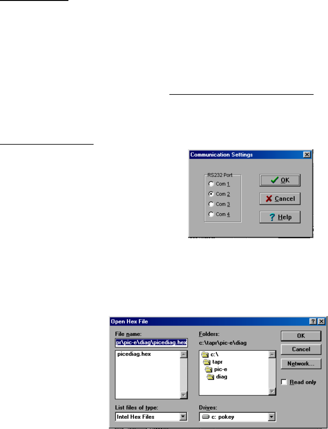
PicProg and set the communications port by selecting
Setup|Com Port from the menu bar. The following
window will pop up:
Click on the radio button corresponding to the
computer comm port connected to the PIC-E.
Connect a serial cable to the PIC-E Program P2 jack
and your computer’s serial port.
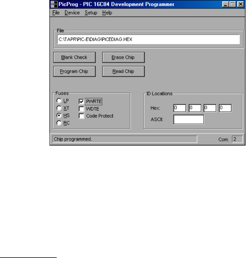
Next, open the diagnostic hex file picediag.hex
by selecting File|Open File from the menu bar. The
following window will pop up:
TAPR PIC-E Manual May 1999 Page 9 of 16
Browse to the directory containing picediag.hex and click OK. PicProg is now ready to program the
PIC-E.
Check the box next to PWRTE to select Power-up Timer option of the PIC. To program the PIC-E click on the
Program Chip button. The status line in the lower left will indicate the programming status. The power
LED on the PIC-E will glow slightly while programming is in progress. In about a minute, if all goes well, the
status line will report "Chip programmed" when completed.
In case of problems, check the serial cable and connections. Try a shorter (or shorten) the cable. Try removing
jumper JP4. This removes power to the surrounding circuitry and applies it only to the PIC. The PIC-E
programmer uses the serial port for power and not all serial ports are the same from computer to computer.
If the power output is low, the programming of the PIC can fail. Remember to reinstall JP4 when programming
is complete.
Run diagnostic
The diagnostic program tests the MX614 modem chip and lights the VALID LED. Place both toggle switches
to the right. Apply power to the PIC-E. The switch functions are:
Mode Switch right – Off
Mode Switch left – Toggle tones at 1200 bps and assert PTT
Option Switch right – Off
Option Switch left – light VALID LED
[ ] Apply power to the PIC-E.
[ ] Move the Option Switch to the left. The VALID LED should light.
[ ] Without a radio connected to the PIC-E, move the Mode Switch to the left, the PTT LED should light.
[ ] Move both toggle switches to the right.
[ ] Remove power to the PIC-E.
Page 10 of 16 May 1999 TAPR PIC-E Manual
Radio and Microphone Interfacing
This section discusses interfacing the PIC-E to a radio
and microphone.
[ ] Install the 16-pin machine tooled DIP socket in J3.
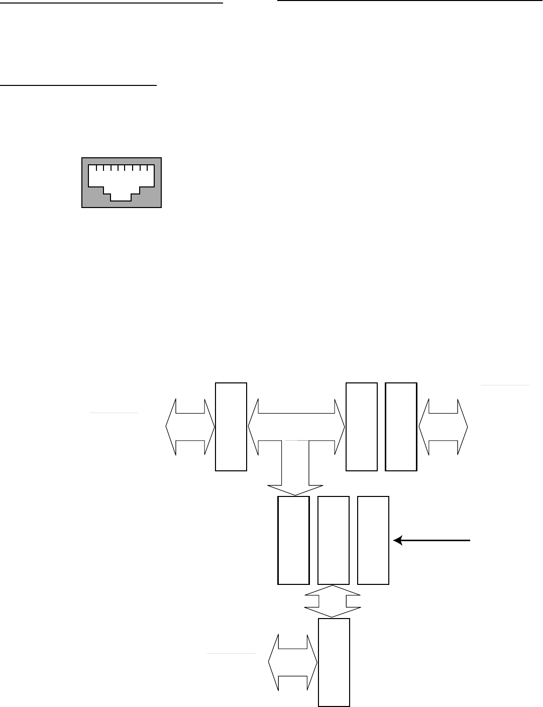
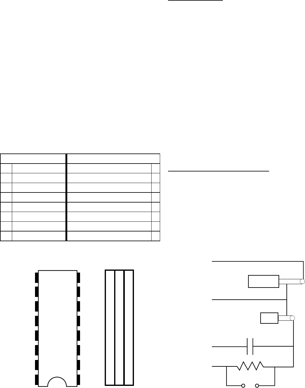
J1 Microphone/J2 Radio Jacks
Microphone jack J1 and Radio jack J2 are 8-pin RJ-45
jacks. Pins 1 though 8 of J1 and J2 correspond to pins
1 through 8 of J3 (see Figure 1). The pin-out of J1 and
J2 is:
J3/J4/J5/J6 – Microphone/PTT Programming Header
Jumpers J3/J4/J5/J6 configure your microphone and
radio to the PIC-E. A microphone connects to Jack J1
(RJ-45) and a radio to J2 (RJ-45). Figure 1 illustrates
the signal flow through the PIC-E.
Programming Header J3 is a machined-tooled 16-pin
DIP socket that plugs into DIP socket J3. The user
inserts wire jumpers between one side of the socket
(pins 1-8) to the other side (pins 9-16) connecting
signals between the microphone, radio, and the PIC-
E.
[ ] Using Table 1 on the next page, write in the
signal name corresponding to the pin number
of your radio’s microphone jack in right-hand
column.
[ ] Draw a line between the microphone jack
signal name in the right-hand column to the
corresponding PIC-E signal name in the left-
hand column. These lines will become wire
jumpers on the DIP programming header J3.
Mandatory signals (indicated by * on Table 1)
to be connected to the PIC-E are:
A cable assembly with a RJ-45 plug on each end is
included in the kit. If you are interfacing the PIC-E to
a radio that already has a RJ-45 connector, connect
the cable between the PIC-E and radio. If the radio
you are interfacing to does not have a RJ-45 jack, you
can cut the cable to length and solder on a microphone
connector that mates to your radio.
Figure 1 – Signals Interface
12345678
Looking into RJ-45 jack
J1
RJ-45
J3
Pins
1-8
J3
Pins
9-10
J2
RJ-45
J6
Left
J4
Center
J5
Right
RAD_PTT
Radio
RAD_PTT
RXA
MIC_AUDIO
RADIO_GND
Microphone
MIC_AUDIO
MIC_PTT
MIC_GND
PIC-E
9 - MIC_PWR
10 - RADIO_GND
11 - MIC_PTT
12 - RXA
13 - MIC_AUDIO
14 - MIC_GND
15 - +5
16 - GND
TAPR PIC-E Manual May 1999 Page 11 of 16
- Ground (either Radio_Ground,
MIC_Ground, or Ground)
- Mic_Audio (PIC-E TX Audio to Radio)
- MIC_PTT (Microphone Push-to-Talk)
Optional signals are:
- +5V (PIC-E voltage to user equipment,
no greater than 50 mA)
- RXA (Radio speaker audio to PIC-E for
data/carrier sense)
- MIC_Power (Radio voltage to power
PIC-E)
[ ] Cut and strip the solid wire supplied in the kit
for jumpers between the pin holes of the
machined-tooled DIP socket corresponding to
the lines drawn on Table 1.
PTT Selection
Jumpers on the eight rows of pins on J4 and J6 pass
through microphone signals from J1 (MIC IN) to J2
(RADIO). The user installs seven 2-pin jumpers to
pass all microphone signals with the exception of Push
to Talk (PTT). The pin corresponding to PTT is
jumpered between J4 and J5 using a 2-pin connector.
This action disconnects the PTT signal between the
microphone and radio and allows the PIC-E to control
PTT.
[ ] Find the pin number of the microphone PTT.
Pin number __________.
[ ] Remove the 2-pin jumper across J4/J6
corresponding to the PTT pin.
[ ] Install the 2-pin jumper across J4/J5
corresponding to the PTT pin.
Handie-Talkie Interfacing
If you plan to interface a handie-talkie to the PIC-E
and require a resistance inline with the PTT line (such
as Yaesu and Icom radios), remove jumper JP3. This
will insert a 2.2K ohm resistance inline with the
PIC-E RAD_PTT signal. Figure 3 shows a typical
handie-talkie interface for Alinco, ICOM, Standard,
Tandy, and Yaesu radios.
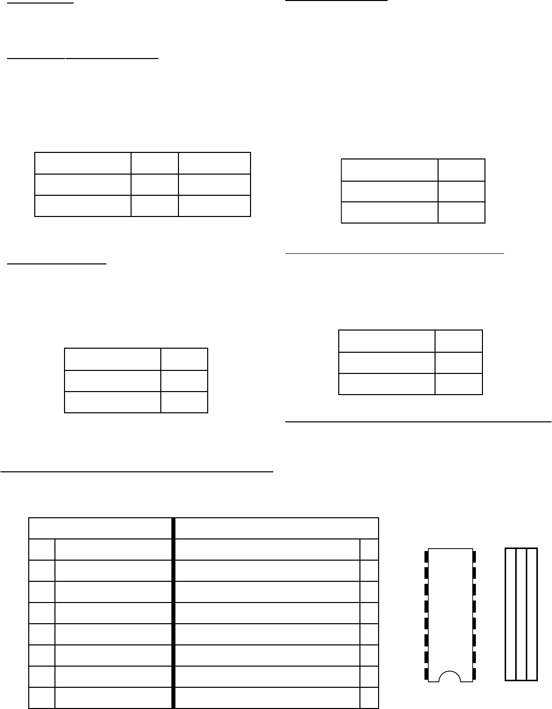
Figure 2 – Programming Jumpers
slangiSE-CIPslangiSkcaJenohporciM
9)*(dnuorG8
01V5+7
11dnuorGCIM6
21)*(oiduACIM5
31AXR4
41)*(TTPCIM3
51dnuorGoidaR2
61rewoPCIM1
Table 1 - Jumper J3
Figure 3. Typical HT Interface
J3
9
10
11
12
13
14
15
16
8
7
6
5
4
3
2
1
8
7
6
5
4
3
2
1
J5 J6 J4
RXA
GND
MIC_AUDIO
PTT
EAR
MIC
JP3

Page 12 of 16 May 1999 TAPR PIC-E Manual
Setting Deviation
Setting the PIC-E audio output sets the deviation of
the packet signal. This is an important setting. If the
audio output is too low the receiving station will not
decode packets. If the audio output is too high the
radio will be over-deviated and cause splatter.
You can set the deviation via one of three methods:
manual, voltage measurement, or deviation meter.
Manual
If you do not have access to an oscilloscope, service
monitor, or deviation meter, you can set the deviation
using manual method with good results. Set the
deviation as follows:
[ ] Connect the PIC-E to your radio.
[ ] Attach a dummy load to the radio’s antenna
connection.
[ ] Set the PIC-E audio output to minimum by
turning V1 fully counter-clockwise.
[ ] Power up the PIC-E with the diagnostic pro-
gram loaded.
[ ] Use a second radio to monitor the output of
the transmitter connected to the PIC-E.
[ ] Set the MODE SW to the right. PTT LED
should light and the radio starts transmitting.
[ ] Slowly turn V1 clockwise. Tones should be
heard on the monitoring radio.
[ ] Continue to turn V1 clockwise until the vol-
ume of the tone stops changing. Turn V1
slightly counter-clockwise.
[ ] Set the MODE SW to the left.
[ ] Remove power to the PIC-E.
This completes deviation setting. Skip to Serial Device
Interfacing.
Voltage Measurement
If you have access to an oscilloscope or peak-to-peak
measuring voltmeter, set the deviation as follows:
[ ] Connect the oscilloscope to the MIC_AUDIO
line of the PIC-E.
[ ] Set the PIC-E audio output to minimum by
turning V1 fully counter-clockwise.
[ ] Power up the PIC-E with the diagnostic pro-
gram loaded.
[ ] Set the MODE SW to the right. PTT LED
should light and the radio starts transmitting.
[ ] Slowly turn V1 clockwise.
[ ] Set the MIC_AUDIO output to 850 millivolts,
peak to peak.
[ ] Set the MODE SW to the left.
[ ] Remove power to the PIC-E.
This completes deviation setting. Skip to Serial Device
Interfacing.
Deviation Meter
If you have or have access to a service monitor or
deviation meter such as the AEA (now Timewave)
DM-1, set the deviation as follows:
[ ] Connect the output of the radio to a service
monitor or deviation meter.
[ ] Set the PIC-E audio output to minimum by
turning V1 fully counter-clockwise.
[ ] Power up the PIC-E with the diagnostic pro-
gram loaded.
[ ] Set the MODE SW to the right. PTT LED
should light and the radio starts transmitting.
[ ] Slowly turn V1 clockwise.
[ ] Set deviation to 3.5 – 4.0 kHz.
[ ] Set the MODE SW to the left.
[ ] Remove power to the PIC-E.
This completes deviation setting.

TAPR PIC-E Manual May 1999 Page 13 of 16
Serial Device Interfacing
The PIC-E can be interfaced to any serial device such
as GPS receivers or weather stations. Since the PIC-E
is fully programmable, you can parse the serial stream
into any format you desire and output it via the radio
port at Bell 202 tones.
P1 is configured as a Data Terminal Equipment (DTE)
serial port (i.e. computer port). Any Data
Communications Equipment (DCE) device can
connect pin-for-pin to the port. The pin outs are (labels
are with respect to the PIC-E):
Applications
That completes the interfacing of the PIC-E. All that
remains is to program the PIC-E for the application
of interest. You can choose to load an already written
program or write one of your own. As PIC-E
programs are developed they will be displayed or
linked from the TAPR PIC-E web site located at
http://www.tapr.org/taprf/html/Fpice.html. If
you’ve created a project and would like to display or
link to it, contact TAPR at tapr@tapr.org.
Updated documentation can be found at
http://www.tapr.org/taprf/html/Fpice.html or
ftp://ftp.tapr.org/picsig/docs/.
Contributed files can be found at
ftp://ftp.tapr.org/picsig/software/. Files can be
anonymously uploaded to
ftp://ftp.tapr.org/picsig/upload/.
PIC-E is discussed on the PIC special interest group.
You can join PIC SIG via the web at
http://www.tapr.org/cgi-bin/lyris.pl?join=picsig.
rebmuNniP1PnoitpircseD
2)DXR(nIlaireS
3)DXT(tuOlaireS
4)RTD(ydaeRlanimreTataD
5dnuorG
For normal serial connections, configure the following
jumpers:
JP1 – open
JP2 – jumper across N
A Delorme Tripmate GPS receiver can be interfaced
to the PIC-E by placing jumpers in the following
locations:
JP1 – closed
JP2 – jumper across T
Page 14 of 16 May 1999 TAPR PIC-E Manual
JUMPERS
The following tables summarize the jumper selections
on the PIC-E.
JP1, JP2 – Tripmate Selection
Delorme’s Tripmate GPS receiver can be used with
the PIC-E. Install jumpers JP1 and JP2 according to
the table below. JP1 will apply +5VDC to pin 4 of P1
and JP2 will jumper pins 2 and 3 together. To
configure P1 for normal serial operations, install
jumpers JP1 and JP2 according to the table below.
JP5 – MX614 Receive/Option Switch SW2
The PIC16F84 microcontroller has a finite number of
I/O pins. Jumper JP5 allows you to select whether
you want PIC port RB4 (pin 10) to be configured to
receive digital data from the MX614 modem chip or
switch SW2.
1PJ2PJ
laireSlamroNNnepO
etampirTTdesolC
JP3 – Handi-Talkie
JP3 provides a 2.2 Kohm resistor in series with the
PTT line. If a handie-talkie is interfaced to the PIC-E
and resistance is needed inline with PTT, JP3 should
be open. If resistance is not need, JP3 should be
jumpered (closed).
3PJ
lamroNdesolC
rotsiseRnepO
JP4 – Programming
The onboard serial programmer of the PIC-E receives
its power from the serial port. It is not necessary to
power the PIC-E during programming. However,
serial ports differ from computer to computer and
there may not be sufficient voltage to power the PIC-
E during programming. If you have difficulty
programming the PIC, remove the jumper on JP4
during programming. This will allow you to remove
programming power from the rest of the PIC-E
circuitry during programming. JP4 must be installed
(closed) during normal PIC-E operation.
4PJ
lamroNdesolC
gnimmargorPnepO
5PJ
evieceR416XMDXR
hctiwSnoitpO2WS
J3/J4/J5/J6 – Microphone/PTT Programming Header
Jumpers J3/J4/J5/J6 configure your microphone and
radio to the PIC-E. A microphone connects to Jack J1
(RJ-45) and a radio to J2 (RJ-45). Refer to the Radio
and Microphone Interfacing section to configure these
headers.
slangiSE-CIPslangiSkcaJenohporciM
9)*(dnuorG8
01V5+7
11dnuorGCIM6
21)*(oiduACIM5
31AXR4
41)*(TTPCIM3
51dnuorGoidaR2
61rewoPCIM1
J3
9
10
11
12
13
14
15
16
8
7
6
5
4
3
2
1
8
7
6
5
4
3
2
1
J5 J6 J4
TAPR PIC-E Manual May 1999 Page 15 of 16
TROUBLESHOOTING
Most problems stem from bad solder connections.
Inspect all solder connections. Make certain that there
are no solder bridges or cold solder joints with a dull
gray appearance. All solder joints should be smooth
and shiny.
Check parts placement paying particular attention to
components that are polarity sensitive such as the
voltage regulator U2, transistor Q1, LEDs, and diodes.
Check that ICs U1 and U3 are inserted with the notch
on the chip matching the notch on the socket.
Power Problems - If the PIC-E is not operating
correctly, check that the output of the 78L05 voltage
regulator U2 is outputting +5 volts. You can measure
this on pin 1 of JP4. Check that +5 volts are available
on U1 pin 14 of the PIC and U3 pin 16 the MX614
chip. Trace the voltage signal using the schematic.
Page 16 of 16 May 1999 TAPR PIC-E Manual
Copyright 1999,
