Product Detail Manual PR
User Manual: pr
Open the PDF directly: View PDF ![]() .
.
Page Count: 10

PR-1
PROPELLER SHAFT
D DRIVELINE/AXLE
CONTENTS
C
E
F
G
H
I
J
K
L
M
SECTION
A
B
PR
PROPELLER SHAFT
PREPARATION ........................................................... 2
Special Service Tools ............................................... 2
Commercial Service Tools ........................................ 2
NOISE, VIBRATION AND HARSHNESS (NVH)
TROUBLESHOOTING ................................................ 3
NVH Troubleshooting Chart ..................................... 3
REAR PROPELLER SHAFT ...................................... 4
On-Vehicle Service ................................................... 4
PROPELLER SHAFT VIBRATION ........................ 4
APPEARANCE CHECKING .................................. 4
Removal and Installation .......................................... 4
REMOVAL ............................................................. 5
INSTALLATION ..................................................... 5
INSPECTION ........................................................ 6
Disassembly and Assembly ...................................... 7
DISASSEMBLY ..................................................... 7
ASSEMBLY ........................................................... 8
SERVICE DATA .......................................................... 9
General Specifications .............................................. 9
Journal Axial Play ..................................................... 9
Propeller Shaft Runout Limit ..................................... 9
PR-2
PREPARATION
PREPARATION PFP:00002
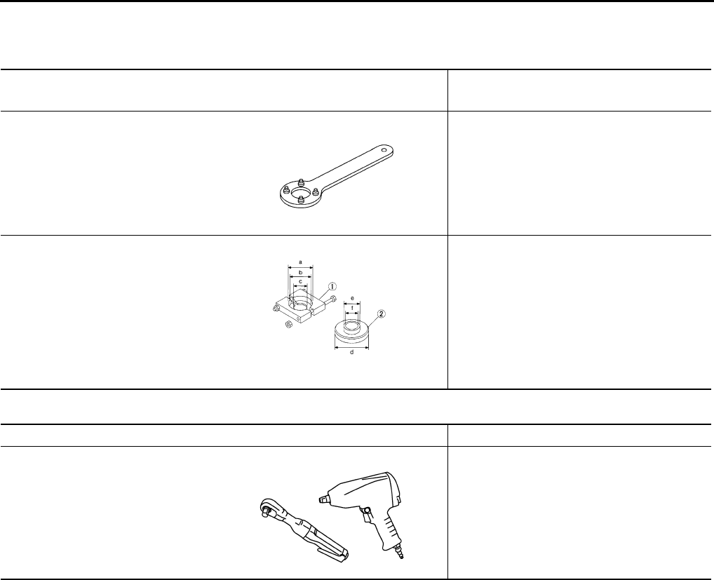
Special Service Tools ADS000R9
The actual shapes of Kent-Moore tools may differ from those of special service tools illustrated here.
Commercial Service Tools ADS000RA
Tool name
Tool number (Kent-Moore No.) Description
ST38060002 (J34311)
Companion flange wrench
Removing and installing propeller shaft lock
nut
Drift pinion rear inner race puller set
1.ST30031000 (J22912–01) puller
2.ST30901000 ( – )
Equivalent tool (J26010–01) Base
a : 90mm (3.54in) dia.
b : 80mm (3.15in) dia.
c : 50mm (1.97in) dia.
d : 79mm (3.11in) dia.
e : 45mm (1.77in) dia.
f : 35mm (1.33in) dia.
Remove center bearing
NT113
S-NT640
Tool name Description
Power tool Loosening bolts and nuts
PBIC0190E
NOISE, VIBRATION AND HARSHNESS (NVH) TROUBLESHOOTING
PR-3
C
E
F
G
H
I
J
K
L
M
A
B
PR
NOISE, VIBRATION AND HARSHNESS (NVH) TROUBLESHOOTING PFP:00003
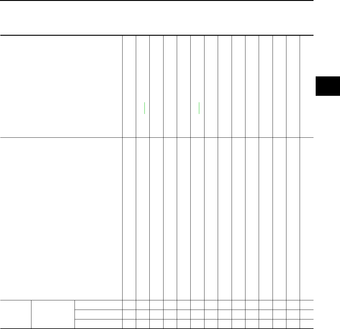
NVH Troubleshooting Chart ADS000RB
Use the chart below to help you find the cause of the symptom. If necessary, repair or replace these parts.
×: Applicable
Reference page
—
Refer to PR-4
—
—
—
Refer to PR-4
—
NVH in RFD section
NVH in FAX, RAX, FSU, and RSU section
NVH in to WT section
NVH in WT section
NVH in RAX section
NVH in BR section
NVH in PS section
Possible cause and SUSPECTED PARTS
Uneven rotation torque
Center bearing improper installation
Excessive center bearing axial end play
Center bearing mounting (insulator) cracks, damage or deterioration
Excessive joint angle
Rotation imbalance
Excessive runout
DIFFERENTIAL
AXLE AND SUSPENSION
TIRES
ROAD WHEEL
DRIVE SHAFT
BRAKES
STEERING
Symptom PROPELLER
SHAFT
Noise ××××××××××××××
Shake × × ××××××
Vibration ××××××× ×× × ×
PR-4
REAR PROPELLER SHAFT
REAR PROPELLER SHAFT PFP:37000
On-Vehicle Service ADS000R6
PROPELLER SHAFT VIBRATION
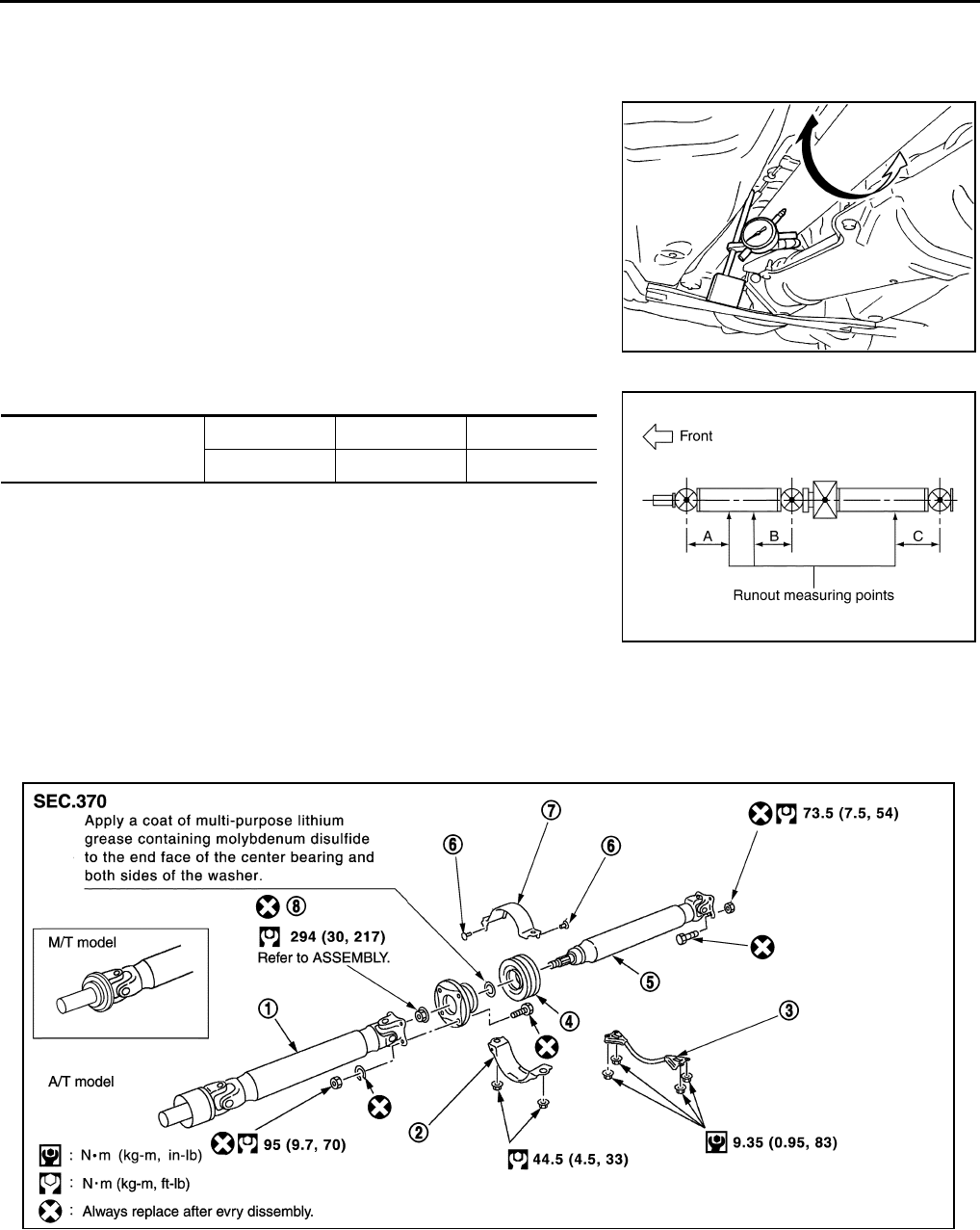
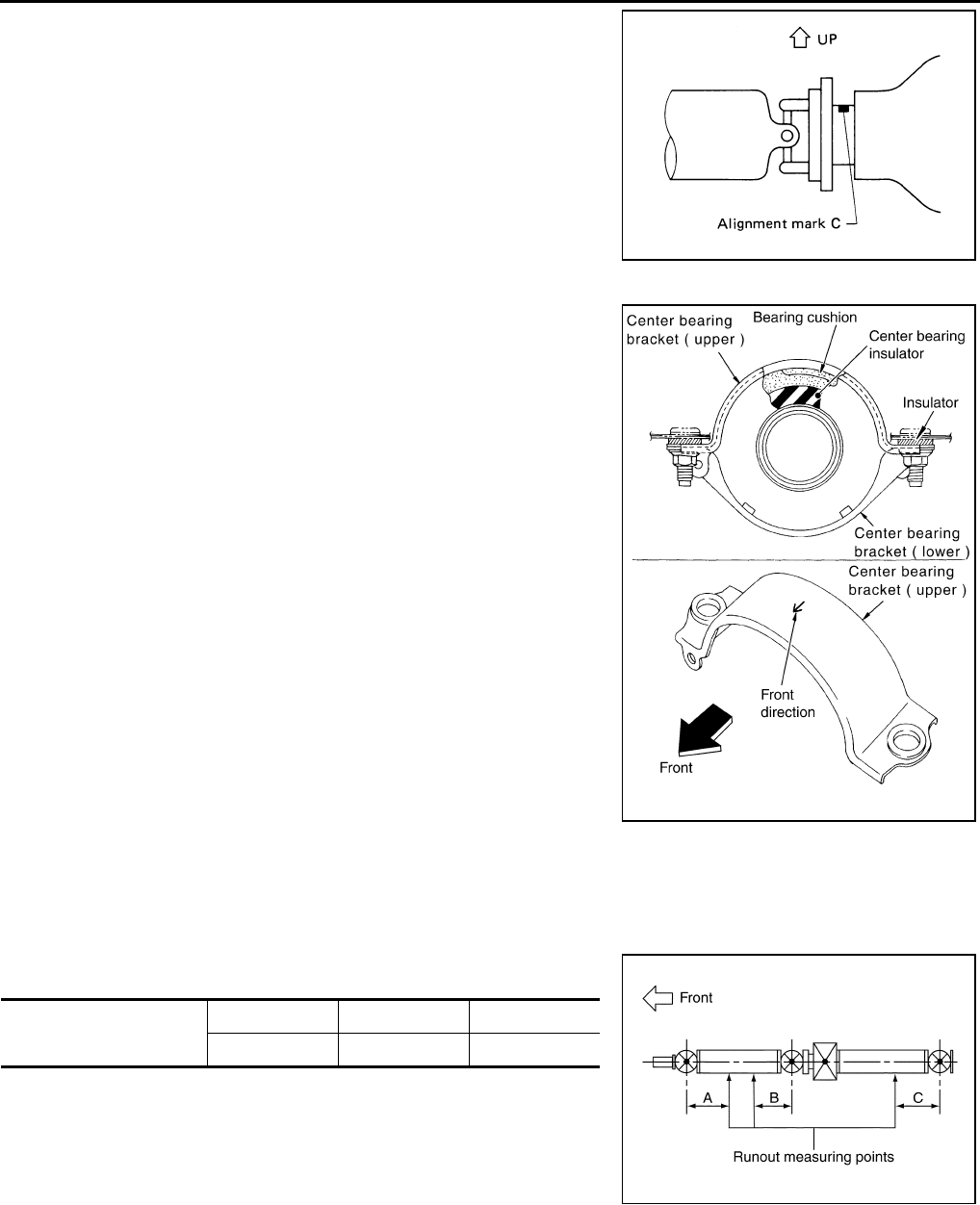
If vibration is present at high speed, inspect propeller shaft runout
first.
1. Measure propeller shaft runout at several points by rotating final
drive companion flange with hands.
Propeller shaft runout measuring points:
Unit: mm (in)
2. If runout still exceeds specifications, disconnect propeller shaft
at final drive companion flange; then rotate companion flange
90, 180, 270 degrees and reconnect propeller shaft.
3. Check runout again. If runout still exceeds specifications,
replace propeller shaft assembly.
APPEARANCE CHECKING
●Inspect propeller shaft tube surface for dents or cracks. If damaged, replace propeller shaft assembly.
●If center bearing is noisy or damaged, replace it.
Removal and Installation ADS000R7
Runout limit : 0.6 mm (0.024 in) or less
SDIA1087E
Distance ABC
192 (7.56) 172 (6.77) 170 (6.69)
PDIA0027E
1. 1st shaft 2. Center bearing mounting bracket
(lower)
3. Floor rain force
4. Center bearing 5. 2nd shaft 6. Clip
7. Center bearing mounting bracket
(upper)
8. Lock nut
SDIA2070E
REAR PROPELLER SHAFT
PR-5
C
E
F
G
H
I
J
K
L
M
A
B
PR
REMOVAL
1. Move A/T select lever to N range position, set M/T shift lever to neutral position.
2. Release parking brake.
3. Put matchmarks on flanges and separate propeller shaft from
final drive.
4. Remove exhaust tube with power tool.
5. Remove floor reinforcement.
6. Remove propeller shaft.
INSTALLATION
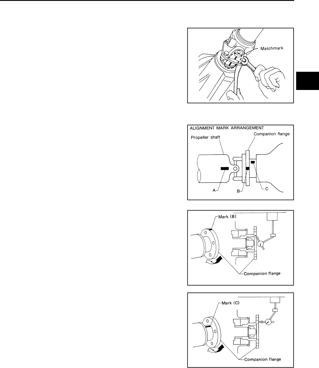
Companion Flange Installation
If companion flange has been removed, put new alignment marks B
and C on it. Then, reassemble using the following procedure. (Per-
form step 4 when final drive and propeller shaft are separated from
each other. Also perform step 4 when either of these parts is
replaced with a new one.)
1. Erase original marks B and C from companion flange with suit-
able solvent.
2. Put mark B on flange perimeter.
a. Measure companion flange vertical runout.
b. Determine the position where maximum runout is read on dial
gauge. Put mark (shown by B in figure) on flange perimeter cor-
responding to maximum runout position.
3. Put mark C on flange perimeter.
a. Measure companion flange surface runout.
b. Determine the position where maximum runout is read on dial
gauge. Put mark (shown by C in figure) on flange perimeter cor-
responding to maximum runout position.
SPD103
SPD053A
SPD062A
SPD063A
PR-6
REAR PROPELLER SHAFT
4. Position companion flange and propeller shaft using alignment
marks A and B. Set the marks A and B as close to each other as
possible. Temporarily attach bolts and nuts.
5. Press down propeller shaft with alignment mark C facing
upward. Then tighten the lower nut to specified torque.
6. Tighten remaining nuts to specified torque.
Center Bearing Bracket Installation
●Position the bearing cushion overlap as illustrated.
INSPECTION
●Inspect propeller shaft runout. If runout exceeds specifications, replace propeller shaft assembly.
●Propeller shaft runout measuring points Unit: mm (in)
●If runout still exceeds specifications, replace propeller shaft assembly.
SPD061A
SDIA0981E
Runout limit: 0.6 mm (0.024 in) or less
Distance ABC
192 (7.56) 172 (6.77) 170 (6.69)
PDIA0027E
REAR PROPELLER SHAFT
PR-7
C
E
F
G
H
I
J
K
L
M
A
B
PR
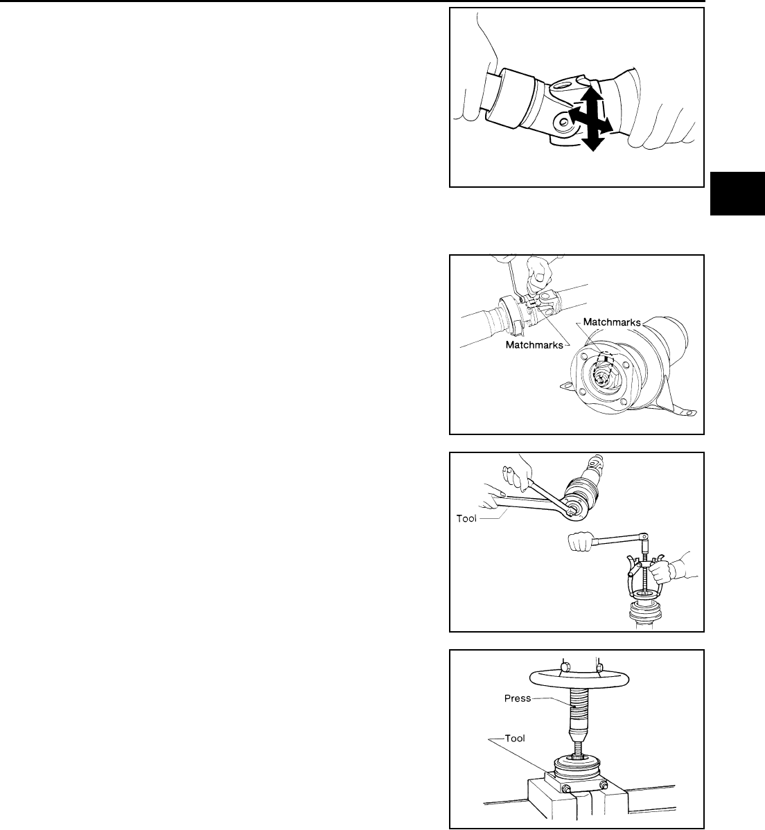
●Inspect journal axial play. If the play exceeds specifications,
replace propeller shaft assembly.
Disassembly and Assembly ADS000R8
DISASSEMBLY
Center Bearing
1. Put matchmarks on flanges, and separate 2nd tube from 1st
tube.
2. Put matchmarks on the flange and shaft.
3. Remove locking nut with Tool.
4. Remove companion flange with puller.
5. Remove center bearing with Tool and press.
Journal axial play: 0 mm (0 in)
SPD874
SPD226A
Tool number :ST38060002 (J34311)
SPD170A
Tool number :ST30031000 (J22912–01)
SPD113
PR-8
REAR PROPELLER SHAFT
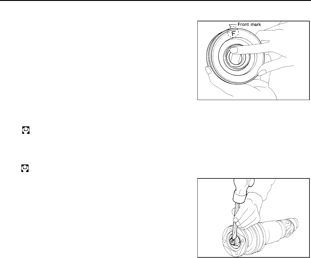
ASSEMBLY
Center Bearing
1. When installing center bearing, position the “F” mark on center
bearing toward rear of vehicle.
2. Apply a coat of multi−purpose lithium grease containing molyb-
denum disulfide to the end face of the center bearing and both
sides of the washer.
3. The lock nut is tightened according to the following.
a. Using a suitable torque wrench and tighten lock nut.
b. Loosen lock nut and tighten specified torque again.
4. Stake the nut. Always use new one.
5. Align matchmarks when assembling tubes.
SPD114
:294N·m (30.0kg–m,217ft–lb)
:82.9N·m (8.5kg–m,61ft –lb)
SPD117
SERVICE DATA
PR-9
C
E
F
G
H
I
J
K
L
M
A
B
PR
SERVICE DATA PFP:00030
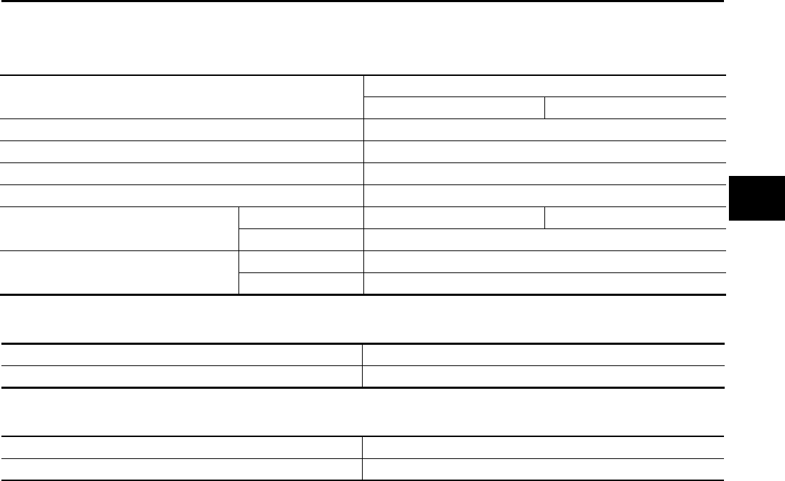
General Specifications ADS000W1
Unit: mm (in)
Journal Axial Play ADS000W2
Unit: mm (in)
Propeller Shaft Runout Limit ADS000W3
Unit: mm (in)
Applied model VQ35DE
M/T A/T
Propeller shaft model 3S80A
Number of joints 3
Coupling method with transmission Sleeve type
Type of journal bearings Shell type (Non-disassembly type)
Shaft length (Spider to spider) 1st 619 (24.37) 581 (22.87)
2nd 902 (35.51)
Shaft outer diameter 1st 82.6 (3.25)
2nd 82.6 (3.25)
Model 3S80A
Journal axial play 0 (0)
Model 3S80A
Propeller shaft runout limit 0.6 (0.024) or less

PR-10
SERVICE DATA
