Prusa3d Manual Mk3 En
User Manual:
Open the PDF directly: View PDF ![]() .
.
Page Count: 69
Please always refer to the http://www.prusa3d.com/drivers/
for an updated version of this 3D printing handbook (PDF download).
QUICK GUIDE TO THE FIRST PRINT
1. Read the safety instructions carefully (page 7)
2. Place the printer on a flat and stable surface (page 10)
3. Download and install the drivers (page 39)
4. Calibrate the printer by following our calibration flow / wizard (page 11)
5. Insert the SD into the printer and print your first model (page 25)
Important notice, tip, hint or information that helps you print with ease.
Read carefully! This part of the text has the uppermost importance - either for user
safety of for a proper printer service.
This symbol indicates text related to a printer kit only.
Handbook
version
3.0
from
December
2,
2017
©
Prusa
Research
s.r.o.
2
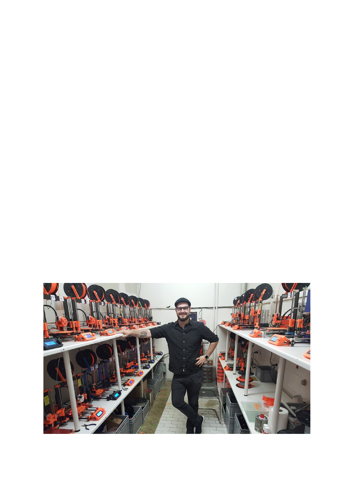
About the author
Josef Prusa (born Feb 23rd, 1990) became interested in the 3D printing phenomenon before
joining the Prague’s University of Economics in 2009 - at first it was a hobby, a new
technology open to changes and improvements. The hobby soon became a passion and
Josef grew into one of the leading developers of Adrien Bowyer’s international, open source,
RepRap project. Today, you can see the Prusa design in different versions all around the
world, it is one of the most popular printers and thanks to it, knowledge about the 3D printing
technology significantly increased among the public.
Jo’s work on self-replicating printers (you can print the other printer parts with your printer)
are still ongoing and currently, there is Prusa i3 - the third iteration of the original 3D printer.
It is constantly updated with the latest innovations and you've just purchased its latest
version. In addition to printer hardware upgrades, the main goal is to make the technology
more accessible and understandable to all users.
Josef Prusa also organizes workshops for the public, participates in professional
conferences dedicated to the popularization of 3D printing. For example, he lectured at the
TEDx conference in Prague and Vienna, at World Maker Faire in New York, Maker Faire in
Rome or at the Open Hardware Summit hosted by MIT. Josef also teaches Arduino at
Charles University and was also a lecturer at the Academy of Arts in Prague.
In his own words, he imagines 3D printers will be available in every home in a not too distant
future. “If anything is needed, you can simply print it. In this field, you just push the
boundaries every day... We're glad you're part of it with us!”
3

Table of contents
2 Product details 6
3 Introduction - Glossary, Disclaimer, Safety instructions, Licenses 6
4 Original Prusa i3 MK3 printer 8
5 Original Prusa i3 MK3 printer kit 9
6 First steps 10
6.1 Printer unpacking and proper handling 10
6.2 Printer assembly 11
6.3 Setup before printing 11
6.3.1 Calibration flow and wizard 11
6.3.2 Flexible steel sheet surface preparation 13
6.3.2.1 Flexible steel sheet with powder coated PEI 15
6.3.2.2 Flexible steel sheet with PEI foil 15
6.3.3 Increasing the adhesion 15
6.3.4 Selftest (kit only) 16
6.3.4.1 Selftest error messages and resolution (kit only) 16
6.3.5 Calibrate XYZ (kit only) 17
6.3.5.1 Calibrate XYZ error messages and resolution (kit only) 18
6.3.6 Calibrate Z 20
6.3.7 Loading the filament into the extruder 21
6.3.7.1 Unloading the filament 22
6.3.8 First layer calibration (kit only) 22
6.3.8.4 Bed level correction (kit only) 23
6.3.9 Fine-tuning the first layer 23
6.3.9.1 Print prusa logo 23
6.3.9.2 Check probe height (kit only) 24
7 Printing 25
7.1 Removing objects from the printer. 25
7.2 Printer Control 26
7.2.1 LCD screen 26
7.2.2 Print statistics 27
7.2.3 Fail stats 27
7.2.4 Normal vs. Stealth mode 27
7.2.5 Factory reset 27
7.2.6 SD card sorting 28
7.2.7 Testing if file (.gcode) is complete 28
7.2.8 LCD layout 29
7.2.9 Print speed versus print quality 32
7.2.10 USB cable and Pronterface 32
7.3 Printer addons 34
7.3.1 Different nozzles 34
7.3.1.1 Hardened steel nozzle 35
7.3.1.2 0.25mm nozzle 35
8 Advanced Calibration 35
8.1 PID tuning for Hotend (Optional) 35
4

8.2 PINDA probe calibration/ Temp. calibration (Experimental/Optional) 36
8.3 View XYZ calibration details (Optional) 36
8.4 Linear Advance (Experimental) 37
8.5 Extruder info 38
9 Printer drivers 39
10 Printing your own models 39
10.1 Where you can get the 3D models? 39
10.2 In what program you can create your own models? 39
10.3 PrusaControl 40
10.4 Slic3r Prusa Edition 42
10.5 Bundled 3D models 43
10.6 Print in color with ColorPrint 44
10.7 Printing of non-standard models 46
10.7.1 Printing with support material 46
10.7.2 Large object printing 47
11 Materials 49
11.1-11 ABS, PLA, PETG, HIPS, PP, Nylon, Flex, Composite materials, ASA, nGen, PC-ABS 49
11.12 Dialing in new materials 56
12 FAQ - Printer maintenance and print issues 57
12.1 Regular maintenance 57
12.1.1 Bearings 57
12.1.2 Fans 57
12.1.3 Extruder drive gear 58
12.1.4 Electronics 58
12.1.5 PEI rejuvenation 58
12.2 Print surface preparation 58
12.3 Filament sensor 59
12.3.1 Running out of filament 59
12.3.2 Filament jam 59
12.3.3 False sensor readings and debugging 59
12.3.3.1 Dust on the sensor - how to clean 60
12.3.3.2 Extreme light conditions 60
12.3.3.3 Exotic filaments 60
12.4 Clogged / jammed extruder 60
12.5 Nozzle cleaning 61
12.6 Replacing / changing the nozzle 62
12.7 Printing problems 63
12.7.1 Layers break and split when printing from ABS material 63
12.7.2 Models contain either too much or not enough of the filament 64
12.8 Problems with finished models 64
12.8.1 Model breaks and/or is easily damaged 64
12.9 Updating printer firmware 64
13 FAQ - common issues when assembling the printer kit 65
13.1 Printer is rocking - YZ frame - geometry check 65
13.2 Printer stops printing soon after start 66
13.3 Printer can’t read the SD card 66
13.4 Loose X- and/or Y-axis belts 67
13.5 Detached cables to the heatbed 68
5
2 Product details
Title: Original Prusa i3 MK3 / Original Prusa i3 MK3 (kit), Filament: 1.75 mm
Manufacturer: Prusa Research s.r.o., Partyzánská 188/7A, Prague, 170 00, Czech Republic
Contacts: phone +420 222 263 718, e-mail: info@prusa3d.com
EEE group: 3 (IT and/or telecommunication equipment), Device use: indoor only
Power supply: 90-135 VAC, 2 A / 180-264 VAC, 1 A (50-60 Hz)
Working temperature range: 18 °C (PLA)-38 °C, indoor use only
Working humidity: 85 % or less
Kit weight (brutto / netto): 9.8 kg / 6.3 kg, assembled printer weight (brutto / netto): 12 kg /
6.3 kg. Serial number is located on the printer frame and also on the packaging.
3 Introduction
Thank you for purchasing our original 3D printer Original Prusa i3 MK3 from Josef Prusa
either as an assembled printer or a printer kit - as your purchase supports us with its further
development. Read the handbook carefully, please, all chapters contain valuable info for the
correct service of the printer. Original Prusa i3 MK3 is a successor to Original Prusa i3
MK2S with numerous hardware and software upgrades, which lead to improved reliability,
increased print speed, and ease of use and assembly.
Please check the http://prusa3d.com/drivers page for the updated version of this 3D
printing handbook (PDF download).
In case of any printer related problem do not hesitate to contact us at info@prusa3d.com
.We
are glad to receive all your valuable comments and tips. We strongly suggest you visit our
official forum at forum.prusa3d.com, where you can find solutions to common issues, tips,
advice and hints in addition to actual information about the Original Prusa i3 printer’s
development.
3.1 Glossary
Bed, Heatbed, Printbed - Commonly used term for printing pad - a heated area of the 3D
printer where 3D objects are printed.
Extruder - Printing head or extruder is a part of a printer consisting of a nozzle, hobbed
pulley, idler and a nozzle fan.
Filament - Term for plastic provided on a spool is called “filament”, it’s used throughout this
handbook as well as in the LCD menu on the printer.
Heater, Hotend - another name for a printing nozzle.
1.75 - 3D printers use two different diameters (thickness) of a filament (thickness): 2.85 mm
(commonly called as 3 mm) and 1.75 mm. 1.75mm version is more used worldwide though
there is no difference in printing quality.
6
3.2 Disclaimer
Failure to read the Manual may lead to personal injury, inferior results or damage to the 3D
printer. Always ensure that anyone who operates the 3D printer knows and understands the
contents of the Manual. We can not control the conditions in which you assemble the
Original Prusa i3. For this and other reasons we do not assume responsibility and expressly
disclaim liability for loss, injuries, damage, or expense arising out of or in any way connected
with the assembly, handling, storage, use or disposal of the product. The information in this
Manual is provided without any warranty, expressed or implied, regarding its correctness.
3.3 Safety instructions
Please be very cautious during any interaction with the printer. This printer is an
electrical device with moving parts and hot-temperature areas.
1. The device is for indoor use only. Do not expose the printer to rain or snow. Always keep
the printer in a dry environment at a minimum distance of 30 cm from other objects.
2. Always place the printer on a stable place, where it can not fall or tip over.
3. The printer supply is household power outlet 230 VAC, 50 Hz or 110 VAC / 60 Hz; Never
connect the printer to a different power supply, it may cause malfunction or damage to the
printer.
4. Place the power cord so you can’t stumble on it, or step on it or otherwise expose to any
damage. Make sure that the power cord is not mechanically or otherwise damaged. Stop
using damaged cable immediately and replace it.
5. When you disconnect the power cord from the socket, pull the plug rather than the cord to
reduce the risk of damage to plug or AC outlet.
6. Never disassemble the printer power supply, it does not contain any parts that could be
repaired by an unskilled worker. All repairs must be provided by a qualified technician.
7. Do not touch the nozzle or heat bed when the printer is printing or is warming up. Note
that the temperature of the nozzle is 210-300 °C (410-572 °F); heatbed temperature can
reach over 100 °C (212 °F). Temperatures above 40 °C (104 °F) can cause harm to human
body.
8. Do not reach inside the printer while it is still in operation. An injury may be caused by its
moving parts.
9. Prevent children from unsupervised access to the printer even when the printer is not
printing.
10. Do not leave the printer unattended while it's still on!
11. Plastic is being melted during printing which produces odors. Set up the printer some
place well ventilated.
3.4 Licenses
Original Prusa i3 MK3 printer is a part of the RepRap project, the first open source 3D printer
project free to use under a GNU GPL v3 license (www.gnu.org/licenses/gpl-3.0.en.html). If
you improve or alter any part of a printer and you are willing to sell, then you have to publish
the source codes under the same license. All 3D-printed elements of the printer that can be
improved upon can be found at http://www.prusa3d.com/prusa-i3-printable-parts/.
7
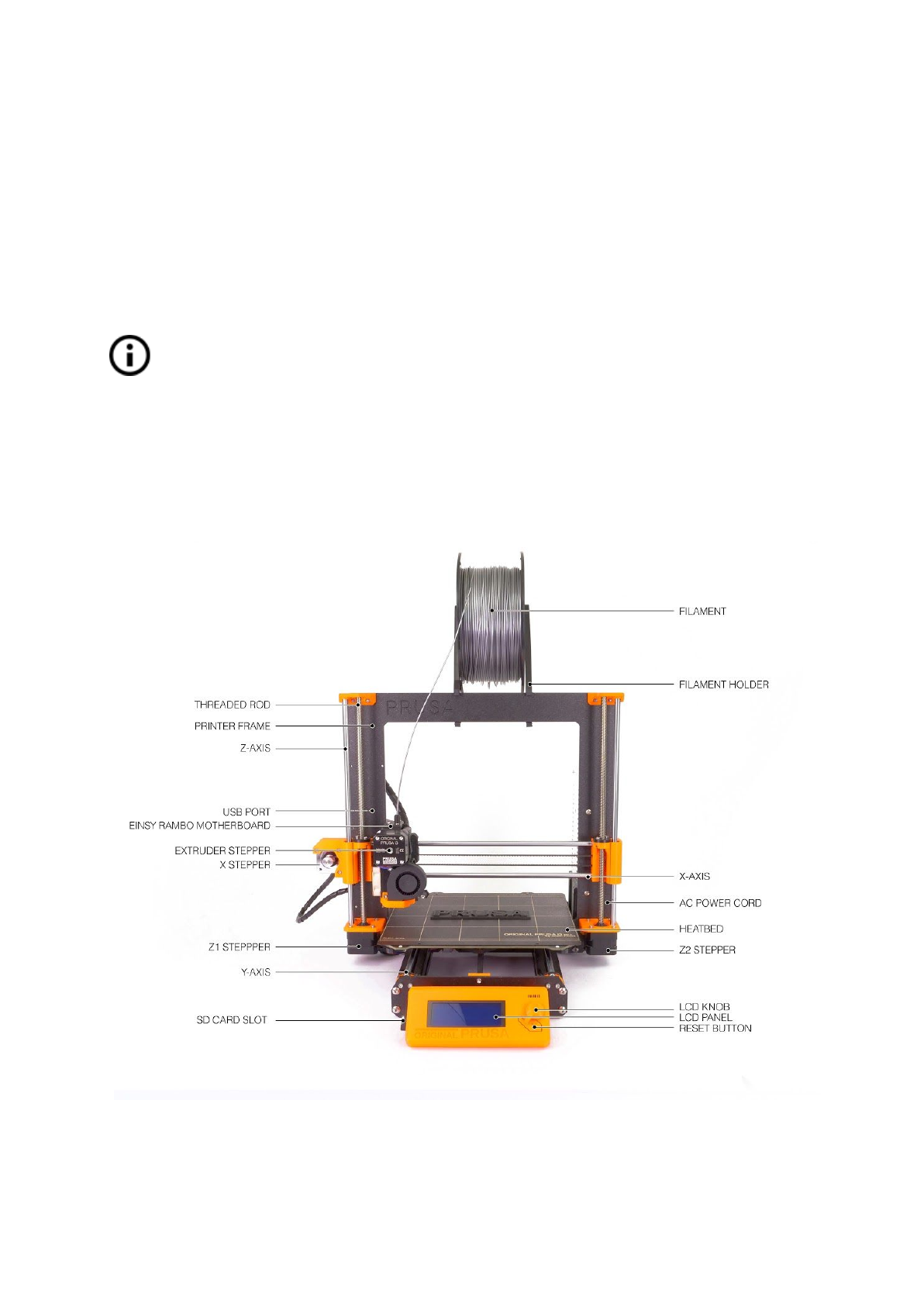
4 Original Prusa i3 MK3 printer
Unlike the printer kit, it’s completely assembled and almost ready to print. After plugging in
and running the necessary calibration you, can print a 3D object in a matter of minutes after
unpacking the printer. Keep in mind you can use our support email when you purchased the
assembled printer. Do not hesitate to write us if you need any advice or help. We will gladly
help with any specific prints.
3D printers use two different diameters of a filament (you can find more in chapter
Materials
): 2.85 mm and 1.75 mm. 1.75mm version is used more worldwide, though
there is no difference in printing quality. The filament is provided on a spool where
you can find the basic information - filament maker, material (ABS, PLA, etc.) and
filament diameter. 2.85 mm filament is commonly called as 3 mm.
This printer supports only a 1.75 mm filament. Please check the filament diameter to be
1.75 mm before inserting into the extruder. Do not try to insert wider filament it could
damage the extruder.
Pict.
1
-
Original
Prusa
i3
MK3
printer
description
8
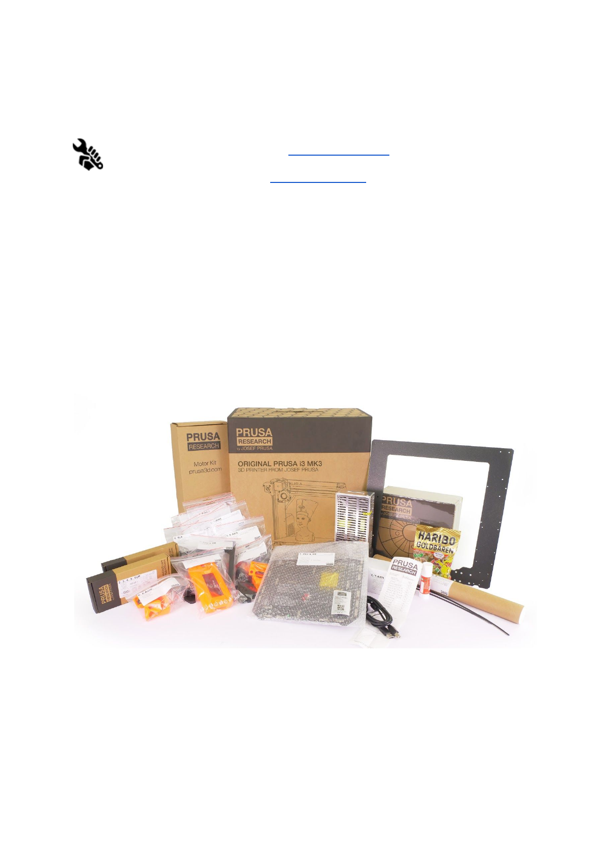
5 Original Prusa i3 MK3 printer kit
Original Prusa i3 MK3 kit is pictured in pict. 2. Detailed information and assembly
description can be found in chapter 6.2 Printer assembly. We offer the support for
users who purchased the printer kit through our official forum. If you need help do
not hesitate to visit our forum at forum.prusa3d.com. You can find the answers to
your problem there. If not, please just post your question directly there.
Pict.
2
-
Original
Prusa
i3
MK3
printer
kit
unboxed
9
6 First steps
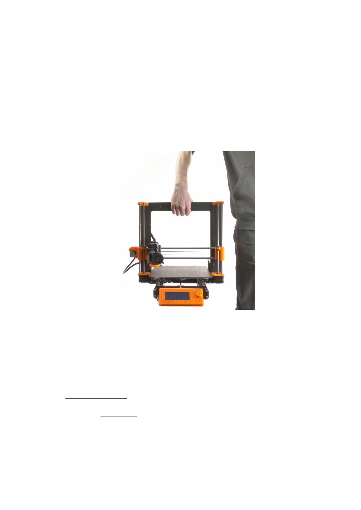
6.1 Printer unpacking and proper handling
Holding the upper frame, take the printer and pull it out from the box. Be careful when
handling the printer not to damage the electronics and thus the proper printer functionality.
Anytime you move the printer, always hold the upper frame with hotbed upright pointing
away from you as pictured in pict. 3.
When unpacking the fully assembled version, remove
the top foam from the box and gently lift the printer up. Parts of the printer are secured by
more foam which needs to be removed. Some parts are additionally secured with the white
zip-ties, cut those off too.
Pict.
3
-
Proper
handling
of
a
printer
Both the assembled version and the kit version come with a few things you might need
during the printer use.
-USB Cable - used for uploading a new firmware or alternatively printing from the
computer.
-Acupuncture needle - used for cleaning the nozzle when stuck. See the chapter
11.5 Nozzle cleaning for more information.
-Glue stick - Used for better Nylon adhesion or as a separator for Flex materials. See
the chapter 11 Materials for more information.
- Test protocol - All the components of every printer are tested. The electronic parts
are even connected as in a final assembly and battery of tests is ran. Only when all
tests pass the electronics get a serial number and protocol + S/N stickers are printed.
Test protocol shows all the test results of your printer components.
10
6.2 Printer assembly
With Original Prusa i3 MK3 printer kit we suggest to follow the guidelines and
assemble the kit according to the the online manual at manual.prusa3d.com. (Online
manual is available in several languages on the website). The construction of the
printer should not take more than one working day. After a successful completion
continue to the chapter 6.3 Setup before printing.
6.3 Setup before printing
● Place the printer to a horizontally stable position, the best place is a workbench
where there is no risk of draft.
● Attach the filament holders to the upper frame.
● Attach Filament to the holders. Make sure the filament spool doesn’t jam and can
move freely.
● Plug in the AC power cord and turn on the switch.
● Check out the firmware version (in the Support menu via LCD panel) and please
upgrade to the latest one from our website www.prusa3d.com/drivers.
Filament is a common term for the plastic rod - material provided on a spool from
which 3D objects are printed.
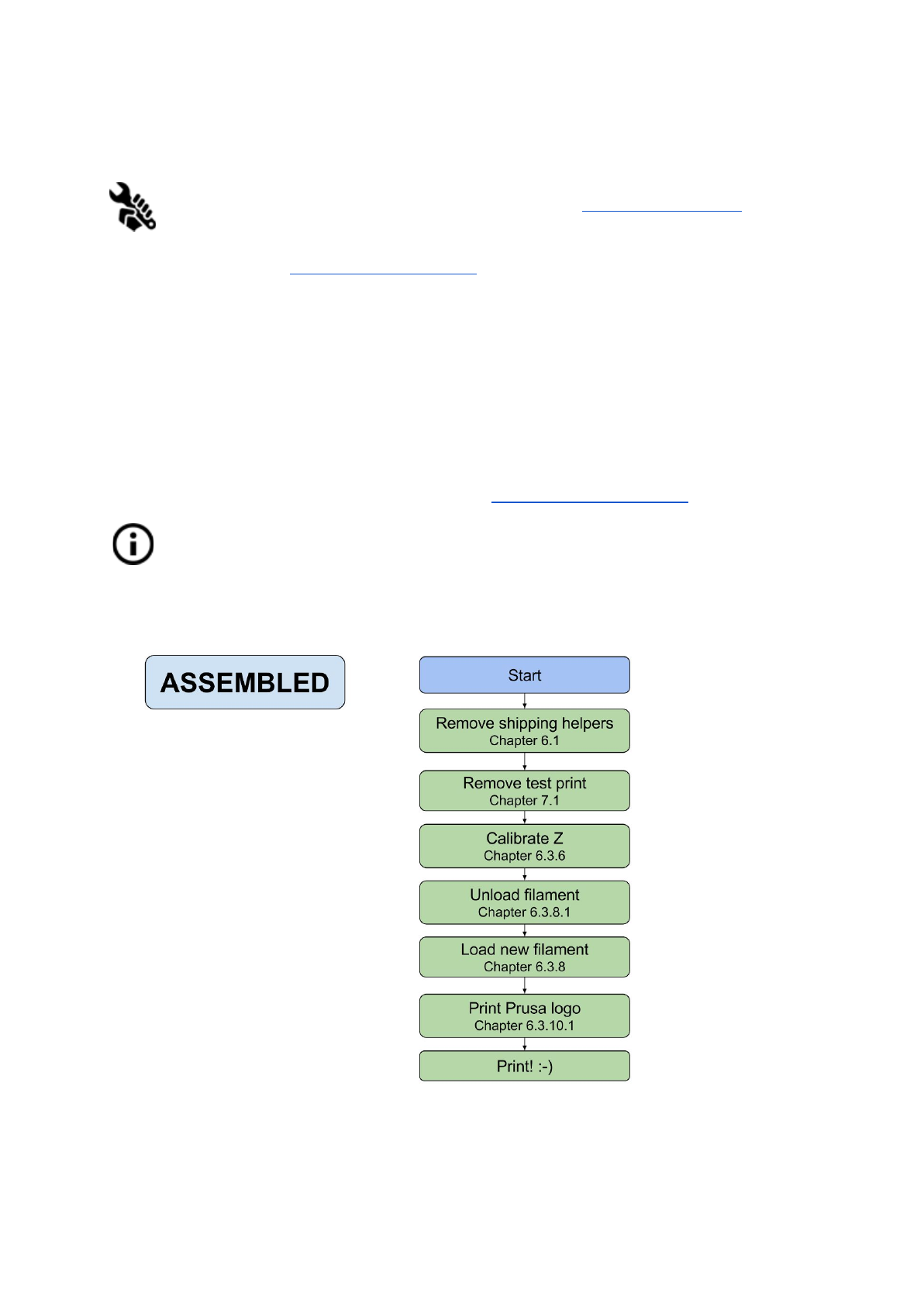
6.3.1 Calibration flow and wizard
11
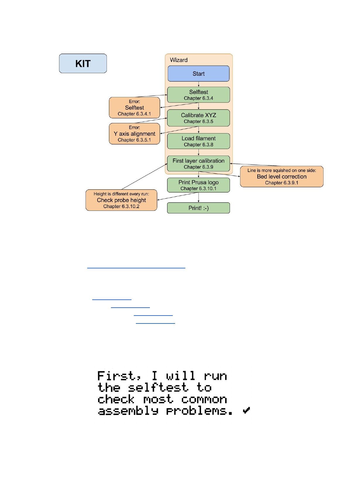
With your first start-up of your freshly assembled printer, it will guide you through all the tests
and calibrations you need to do to get started printing.
Wizard can be also started manually from LCD menu Calibration -> Wizard. Do not forget
to read chapter 6.3.2 PEI print surface preparation before running the Wizard.
It follows the calibration flow and helps you with following steps:
● Selftest - Chapter 6.3.4
● Calibrate XYZ - Chapter 6.3.5
● Loading the filament - Chapter 6.3.7
● First layer calibration - Chapter 6.3.8
It is not mandatory to use it, and you can cancel the wizard at the beginning. Then you
should just manually follow the calibration flow as on older firmware revisions.
Pict.
4
-
Wizard
setup
12
There are few special occasions where you will need to redo the calibration or part of it.
●Firmware update - Complete guide is in the chapter 12.9 Updating printer firmware.
6.3.8. First layer calibration needs to be rerun otherwise the printer will show an error
message.
● Readjusting the P.I.N.D.A. probe - Run 6.3.6 Calibrate Z to store new reference Z
height values.
It is important to disconnect the printer USB from any computer or OctoPrint running
on Raspberry Pi for the whole calibration. Printer will not respond to any request
from the host and communication will timeout, when host resets the connection, the
printer restarts and might end up in weird state requiring 7.2.5 Factory Reset.
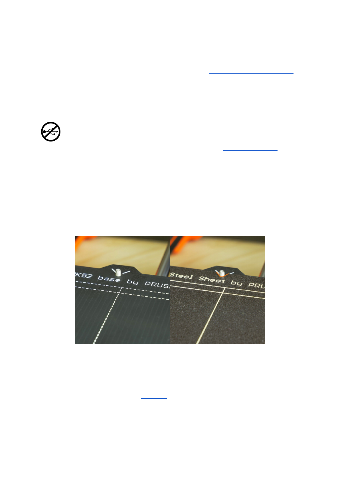
6.3.2 Flexible steel sheet surface preparation
The MK52 heatbed has embedded high curie temperature magnets. These magnets are
able to firmly hold removable spring steel sheets. There are two pins at the end of the
heatbed that will align perfectly with cut out slots in the spring steel sheets. Make sure the
bed is clean and there aren’t any debris on it before you put on the steel sheet. Never
print directly on the heatbed.
Pict.
5
-
HeatBed
MK52
base
and
powder
coated
steel
sheet
surface
To achieve the best adhesion on the new surface, it is important to keep the surface clean.
Cleaning of the surface is very easy. The best option is Isopropyl alcohol available in
drugstores which is the best for ABS, PLA and others (except for PETG where the adhesion
may be too strong. See the chapter 11.3 PET for instructions). Pour a little amount on
unscented paper towel and wipe the print surface. The bed should be cleaned while cold for
the best results but it can also be cleaned when already preheated for PLA, just be careful
not to touch the bed surface or the nozzle. When cleaning at higher temperatures the alcohol
will evaporate before it can clean anything. Alternatively, you can clean the bed with warm
13
water and a few drops of a dish soap on a paper towel. Denatured alcohol is yet another
option.
The surface does not have to be cleaned before every print! It is just important to not
touch the steel sheet with your hands or dirty tools. Clean your tools with the
same solution as you would the sheet and you will be able to start your next print
right away.
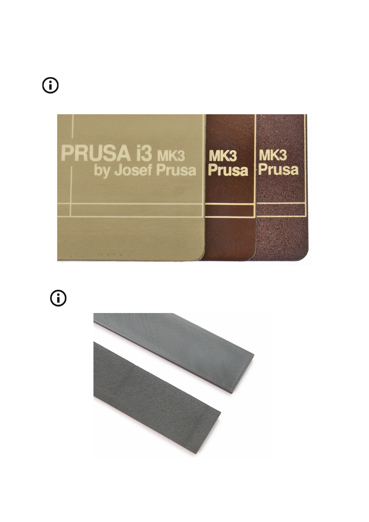
Pict.
6
-
Steel
print
sheets
-
smooth
PEI
sheet,
glossy
powder
coated
PEI
and
textured
powder
coated
PEI
All original print surfaces from Prusa Research are coated from both sides.
.
Pict.
7
-
Smooth
vs
powder
coated
effect
on
print
surface
14
6.3.2.1 Flexible steel sheet with powder coated PEI
Powder coating directly on metal makes it very hard to damage this build plate. If a heated
nozzle crashed into it, the metal can dissipate the heat. Powder coating also gives the
surface distinct textured look that will be visible on your prints.
6.3.2.2 Flexible steel sheet with PEI foil
Uses the same PEI sheets as on the MK2/S.
You can leave small marks on the print surface with your nozzle or tools, they will typically
be shinier than the rest. It does not affect the functionality or adhesion. However, if you want
to have same surface look on the whole printbed you can resurface it. The easiest way is to
take a hard side of dry kitchen sponge and wipe the affected area with circular motion gently
few times.
The industrial glue which holds the PEI sheet on the heatbed itself softens when
temperatures greater than 110 °C are used. If higher temperatures are used, the
glue can migrate under the PEI and create slight bumps on the surface.
6.3.3 Increasing the adhesion
In some special occasions, like a tall object with a very small contact area with the print
surface, you might need to increase the adhesion. Fortunately PEI is a very chemically
resistant polymer and you can temporary apply other adhesion solutions without damaging
it. This also applies to materials which would not stick to PEI otherwise, like Nylon etc.
Before applying anything to the bed, consider using Brim option in Slic3r which increases
the surface area of the first layer.
For Nylon blends a simple glue stick does the trick. Glue can be later easily removed by
window cleaner or dish soap water.
For ABS prints, ABS juice can be used and later cleaned with pure acetone. Be very gentle
when applying the juice and do so while the bed is cold. Prints will attach very strongly.
Prepared juice can be also purchased in our e-shop. Unfortunately, UPS service
does not allow to deliver any acetone-based products due to shipping constraints. In
that case you get only the bottle and ABS from our e-shop and you have to source
the acetone locally.
15

6.3.4 Selftest (kit only)
The purpose of the selftest routine is to check most common errors when assembling and
connecting electronics and to help indicate any possible errors after assembly. You can run
the Selftest from Calibration menu on LCD panel. This should not be necessary on the
assembled printers as those are pretested.
Initiating this routine performs a series of tests. The progress and results of each step are
displayed on the LCD. In case of errors found, the selftest is interrupted and the reason for
error is shown to guide users in troubleshooting.
The selftest is just a diagnostic tool, the printer will still attempt to print even after
the test fails. If you are absolutely certain that the affected part is correct, you may
continue with the print process.
Test consists of
●Extruder and print fan test
●Heatbed and hotend proper wiring
●XYZ motors proper wiring and functionality
●XY axis length
●XY belts tension
●Loose belt pulley test
6.3.4.1 Selftest error messages and resolution (kit only)
Front
print
fan/
Left
hotend
fan
-
Not
spinning:
Check proper wiring of print and hotend fan cables. Ensure that both are properly
connected to the EINSY electronics, and that they are not swapped.
Please
check/
Not
connected
-
Heater/
Thermistor:
Check proper wiring of hotend power cables and thermistor cables. Ensure that both
are properly connected to the EINSY electronics, and that they are not swapped.
Bed/Heater
-
Wiring
error:
Check that heatbed and hotend power cables are not swapped or thermistor cables
from both hotend and heatbed are not swapped in the EINSY electronics.
Loose
pulley
-
Pulley
{XY}:
The belt pulley is loose and slips on the motor shaft. It is important to tighten the first
grub screw on the flat piece of shaft, then continue with the second grub screw.
Axis length
-
{XY}:
Printer measures the length of the axis by going from end to end twice. If the
measured value is different from the physical length, your axis might be blocked from
16
moving all the way. Check by hand if axis is running smoothly when printer is
powered off.
Endstops
-
Wiring
error
-
Z:
Check the proper cabling of PINDA probe. Routine indicates PINDA has malfunction
or is not properly responding. Check the proper connection in the EINSY electronics.
Endstop
not
hit
-
Motor
Z:
Check if Z axis can go all the way down to trigger the PINDA prove over the bed.
6.3.5 Calibrate XYZ (kit only)
The Original Prusa i3 MK3 comes with a full mesh bed leveling feature, however
for this to work we need to first calibrate the distance between tip of the nozzle
and P.I.N.D.A (Prusa INDuction Autoleveling) probe.
The process is fairly straightforward, so let’s get to it.
The purpose of the X/Y/Z calibration routine is to measure the skew of the X/Y/Z axes and to
find the position of the 4 calibration points on the print bed for the proper bed leveling. You
can run the XYZ calibration from Calibration menu on LCD panel. This should not be
necessary on the assembled printers as those are factory calibrated.
Place a sheet of a regular office paper (for example the checklist shipped with
every order) and hold it under the nozzle during the first round (first 4 points
being checked) of calibration. If the nozzle catches on the paper during the
process, power off the printer and lower the P.I.N.D.A. probe slightly. See the
P.I.N.D.A. probe response diagram in 6.3.9.2 Check probe height. The paper
will not affect the calibration process. The nozzle must not touch the print
surface or deflect the bed by any means. If everything went correctly, continue
with the calibration process.
Initiating this routine performs a series of measurements in three rounds: In the first round
without the steel sheet installed 4 sensor points on the print bed are searched for carefully
as to not touch the print bed by the nozzle. In the second round, the point locations are
improved. In the last round with the steel sheet on the height above the 9 sensor points is
measured and stored into a non-volatile memory for reference, this finished the Z axis
calibration.
At the start of the XYZ calibration procedure the printer homes X and Y axis. After that, Z
axis will begin to move up until both sides touch the printed parts at the top.
Please make sure the Z axis went all the way up and you heard a rattling sound as the Z
stepper motors skip steps.This procedure ensures, that 1) the X axis is perfectly horizontal,
17

2) the print nozzle is in a known distance from the print bed. In case the Z carriage did not
touch the end stoppers, the printer could not possibly know the height of the print nozzle
above the print bed and it could, therefore, crash into the print bed during the first round of
the X/Y calibration procedure.
The XYZ calibration procedure also prompts you to "Please
clean
the
nozzle
for
calibration.
Click
when
done."
If this advice is not followed and there is a plastic debris on the print nozzle, then the debris
may touch the print bed or even push the print bed away from the PINDA probe, so the
PINDA probe will not trigger properly and the calibration will fail.
After the calibration is passed, the values can be reviewed for tweaking later. When you get
your axes perpendicular or slightly skewed, nothing needs to be tweaked as printer will
perform with the best accuracy. Learn more in chapter 8.3 View XYZ calibration details
(Optional) under 8 Advanced calibration.
6.3.5.1 Calibrate XYZ error messages and resolution (kit only)
1) XYZ
calibration
failed.
Bed
calibration
point
was
not
found.
Calibration routine did not find a bed sensor point. The printer stops close to the bed
point, which it failed to detect. Please verify, that the printer is assembled correctly,
that all axes move freely, the pulleys do not slip and the print nozzle is clean. If
everything looks good, re-run the X/Y calibration and verify with a sheet of paper
between the nozzle and the print bed that the print nozzle does not touch the print
bed during the calibration routine. If you feel a friction of the nozzle against the sheet
of paper and the nozzle is clean, you need to screw the PINDA probe slightly lower
and re-run the X/Y calibration.
2) XYZ
calibration
failed.
Please
consult
the
manual.
The calibration points were found in positions far from what should be expected for a
properly assembled printer. Please follow the instructions of case 1).
3) XYZ
calibration
ok.
X/Y
axes
are
perpendicular.
Congratulations!
Congratulations, you built your printer precisely, your X/Y axes are perpendicular.
4) XYZ
calibration
all
right.
X/Y
axes
are
slightly
skewed.
Good
job!
Good job, the X/Y axes are not precisely perpendicular, but still quite all right. The
firmware will correct for the X/Y skew during normal printing, so boxes will be printed
with right angles.
18

5) XYZ
calibration
all
right.
A
skew
will
be
corrected
automatically.
You may consider to re-align the X/Y axes (as described in the chapter 6.3.5.1 Y
axis alignment). Still the firmware will correct the skew during normal printing and as
long as the X and Y axes move freely, the printer will print correctly.
During the mesh bed leveling procedure following errors may be reported on the display.
1) Bed
leveling
failed.
Sensor
disconnected
or
cable
broken.
Waiting
for
reset.
Verify, whether the PINDA probe cable is plugged into the RAMBo board correctly. If
it is the case, the PINDA probe is broken and it needs to be replaced.
2) Bed
leveling
failed.
Sensor
didn’t
trigger.
Debris
on
nozzle?
Waiting
for
reset.
This is a safety check to avoid the nozzle to crash into the print bed if the PINDA
sensor stops working or something goes wrong with the printer mechanics (for
example, a pulley slips). This safety check may be triggered as well, if the printer has
been moved to an uneven surface. Before doing anything else, make the Z axis level
by going all the way up and try again.
At the end of the X/Y calibration, the printer measures the reference height above
each of the 9 bed sensor points and stores the reference heights into a non-volatile
memory. During the normal bed leveling, it is expected that the PINDA probe triggers
not further than 1 mm from the reference value, therefore the nozzle is not allowed to
move more than 1 mm below the reference value during the bed calibration.
If you moved the printer, you may need to re-run the Z calibration to sample new
reference Z height values reflecting the twist and bend of the table surface the printer
is sitting on. If that does not help, please verify, that the PINDA probe is aligned with
the sensor points on the print bed during the bed Z calibration. The alignment shall
be ensured by the automatic X/Y calibration routine. If the PINDA probe is no more
aligned during the Z calibration over time, it is possible, that a pulley is slipping or
something on the machine frame got loose.
3) Bed
leveling
failed.
Sensor
triggered
too
high.
Waiting
for
reset.
Similar to case 2). This time the PINDA sensor triggered more than 1 mm above the
reference height. Before doing anything else, make the Z axis level by going all the
way up and try again.
19

6.3.6 Calibrate Z
Calibrate Z is located in Calibration menu. It is always done with steel sheet on. It should
be performed whenever you move the printer to different location. It saves the heights of all
9 calibration points in non-volatile memory. Stored information is used every time mesh bed
leveling is called during a print. When the measured values are vastly different to the stored
value, print is canceled as it is a good indicator something is wrong. Calibrate Z is a part of
Calibrate XYZ routine so there’s no need to run it after successful Calibrate XYZ.
It is a good practice to run this procedure every time you travel or printer is shipped as the
geometry might change slightly and cause an error.
At the start of the Z calibration procedure the printer homes X and Y axis. After that, Z axis
will begin to move up until both sides touch the printed parts at the top.
Please make sure the Z axis went all the way up and you heard a rattling sound as the Z
stepper motors skip steps. This procedure ensures, that 1) the X axis is perfectly horizontal,
2) the print nozzle is in a known distance from the print bed. In case the Z carriage did not
touch the end stoppers, the printer could not possibly know the height of the print nozzle
above the print bed and it could therefore crash into the print bed during the Z calibration
procedure.
The Z calibration procedure also prompts you to "Please
clean
the
nozzle
for
calibration.
Click
when
done."
If this advice is not followed and there is a plastic debris on the print nozzle, then the debris
may touch the print bed or even push the print bed away from the PINDA probe, so the
PINDA probe will not trigger properly and the calibration will fail.
20
6.3.7 Loading the filament into the extruder
● You need to preheat the nozzle before inserting the filament (and the bed too if you
like to print right away). The temperature depends on the material used. Detailed
information about nozzle and bed temperatures are described at chapter 11
Materials.
● Press the LCD-knob to enter the main menu on the LCD. Rotate the button to choose
Preheat option and confirm by pressing the LCD-knob. Next you choose the material
you will print from. Choose a material then confirm with LCD-knob. The nozzle and
heatbed will heat to the requested temperature.
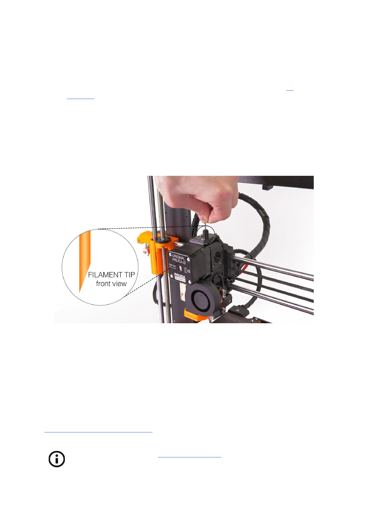
●Press the LCD-knob on the LCD panel to enter the main menu. Insert the filament to
the extruder, choose the Load filament option in the menu and press the button to
confirm. Filament is then loaded to the extruder by the extruder stepper
automatically. You should cut the top of the filament as shown in the picture below.
Pict.
8
-
Loading
the
filament
to
the
extruder
● Check if the filament is flowing from the nozzle.
● If you change the filament for a new one do not forget to completely remove the old
filament before the printing by extruding the filament from Settings - Move axis -
Extruder until the color is completely changed.
If your filament is running out during a print, you can easily change it for a new spool. Just go
to the LCD menu, select Tweak submenu and press Change filament. Printer will pause, go
out of the print area, unload the old filament and guide you on the LCD what to do. You can
even insert filament of different color and make your prints more colorful. Check out chapter
10.6 Printing in color with ColorPrint to find out how to make more intricate color models.
Read chapter about our new 12.3 Filament sensor and it’s functions. Autoloading of
the filament, when inserted into the extruder body is a planned feature.
21
6.3.7.1 Unloading the filament
Similar procedure to the loading operation. Preheat the nozzle for material you used last
time (pre assembled printers are shipped with PLA). Wait for temperatures to stabilize and
use Unload filament option from the menu.
6.3.8 First layer calibration (kit only)
Now we will finally calibrate the distance between the tip of the nozzle and the probe.
Check if your print surface is clean! You can find instructions how to clean it in
the chapter 6.3.2 PEI print surface preparation. Don't forget to complete 6.3.5
Calibrate XYZ chapter or you can permanently damage the print surface!
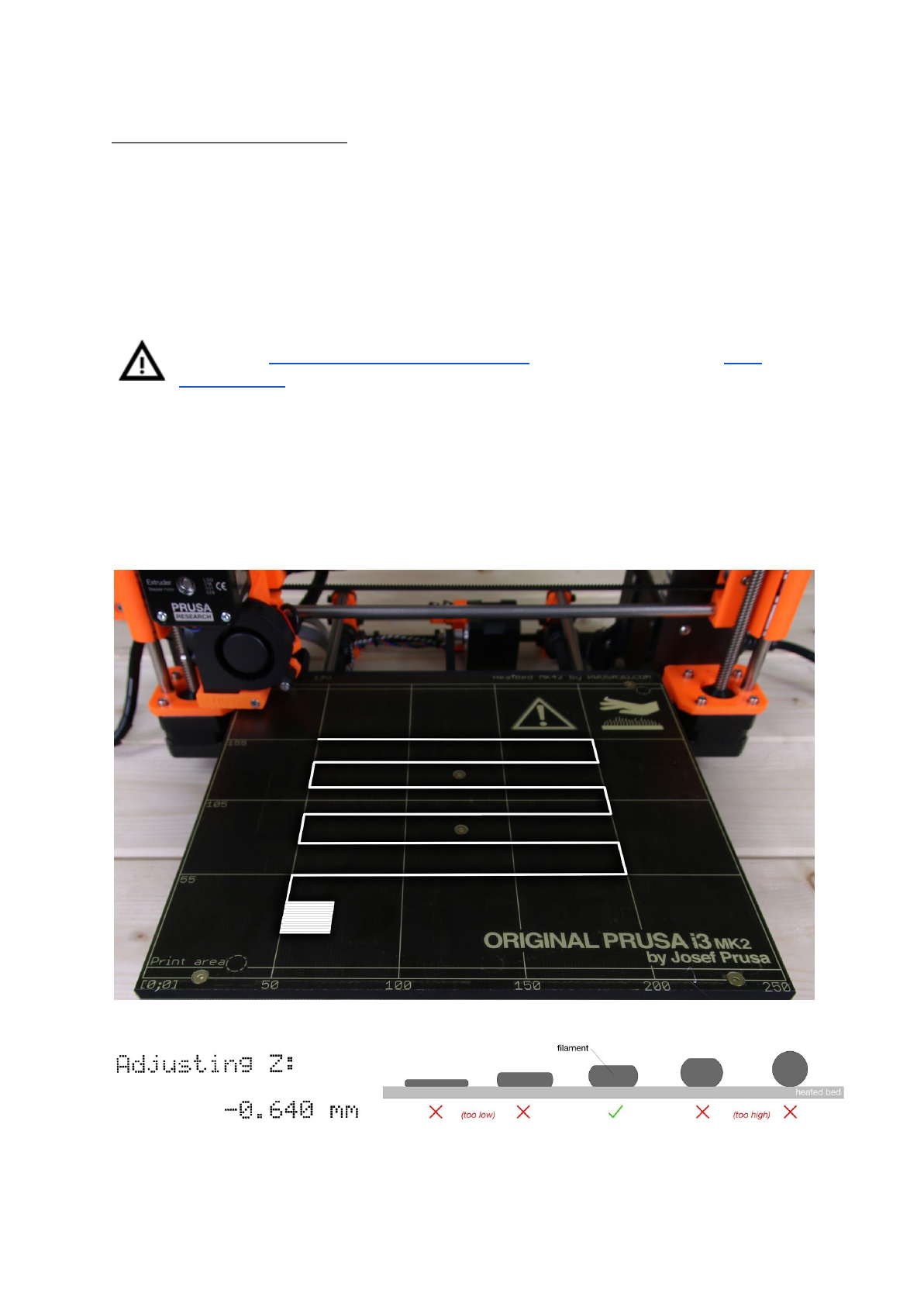
You can launch the calibration from menu Calibration -> First layer cal.
The printer will probe the bed and start printing zig zag pattern on the print surface. The
nozzle will be at the height based on the P.I.N.D.A probe setting, it must not by any means
touch the print surface.
Pict.
9
-
How
to
tune
the
nozzle
height
live
during
the
test
print.
Note:
-0.640
mm
is
only
for
illustration.
Your
setting
will
be
different!
22
Observe the line which is being extruded on the print surface. New menu will automatically
show up where you can tune the nozzle height live during the test print. The point is to lower
the nozzle until the extruded plastic sticks nicely to the bed and you can see it is being
slightly squished. Set value should not exceed -1 mm, if you have to adjust it more, move
the probe slightly higher.
Loosen the two screws on the probe holder to make adjustments. By rotating the probe
counter clockwise, it will raise at 1mm per turn. It is very handy for precise adjustments,
but it can also be pushed in and out when set screws are loosened completely. Then rerun
Calibrate Z followed by the First layer calibration again.
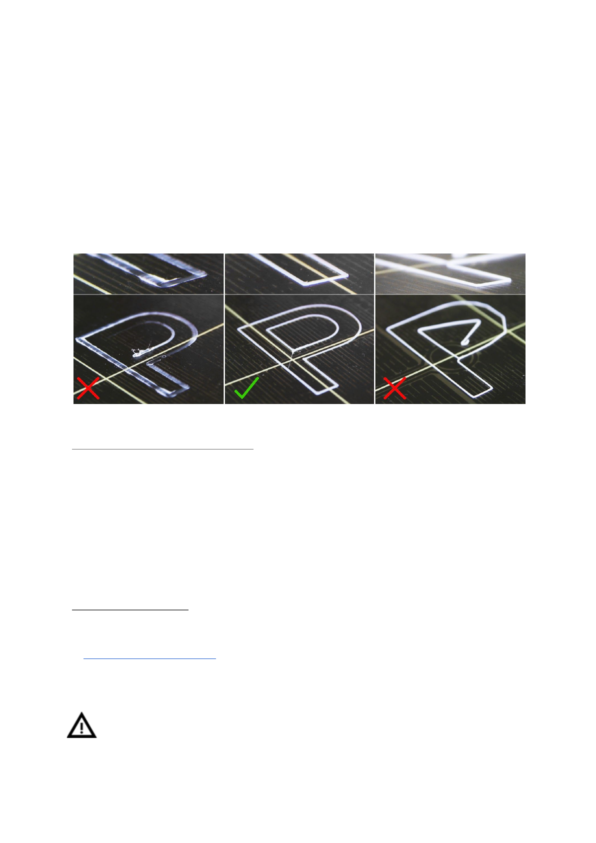
Pict.
10
-
The
properly
tuned
first
layer
6.3.8.4 Bed level correction (kit only)
A bed level correction is an advanced feature is designed to allow advanced users to correct
for the slightest imperfections in the first layer. This feature can be found in Calibration -
Bed level correction. For example if the first layer seems to be ever so slightly more
squished on the right side, you can virtually raise the nozzle by +20 microns on the right
side. Settings are available for Left, Right, Front and Back. The limit is +-50 microns and
even +-20 microns can make a huge difference. When you are using this function, do small
incremental changes. Negative value will act as lowering the bed in the selected direction.
6.3.9 Fine-tuning the first layer
6.3.9.1 Print prusa logo
After finishing the calibration gcode, it is a good idea to print a simple object. The Prusa
gcode from the supplied SD card is a great example. The Live adjust Z function (described
in 6.3.8. First layer calibration) works during every print, so you can finetune at any point.
You can see the properly tuned first layer on the Pict. 11.
Calibration might be slightly different for different steel print sheets as the coating
thickness varies. It is a good practice to check the first layer and adjust accordingly
with Live adjust Z when switching between different types of steel sheets.
23
Pict.
11
-
Perfect
Prusa
logo
first
layer
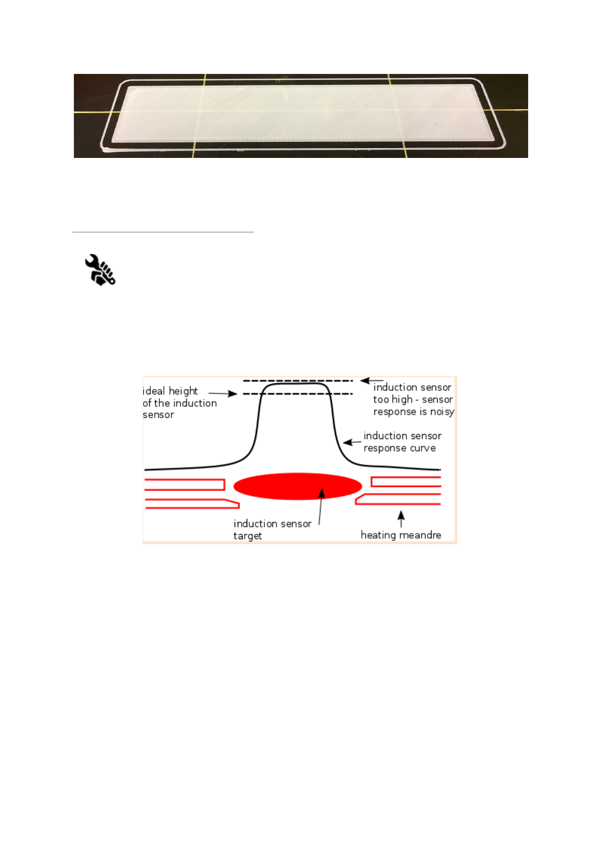
6.3.9.2 Check probe height (kit only)
If the first layer seems inconsistent between multiple prints, the probe might be
too high. Lower it slightly. Loosen the two screws on the probe holder to make
adjustments. By rotating the probe clockwise, it will lower at 1mm per turn. It
is very handy for precise adjustments, but it can also be pushed in and out when set screws
are loosened completely. Then try again Calibrate XYZ. Keep in mind, the probe must be
always higher than the nozzle tip, otherwise it will catch on prints.
Pict.
12
-
Probe
response
diagram.
Now you are done!
24
7 Printing
● Make sure that the nozzle and the bed are heated to the desired temperature. If you
forget to preheat the printing nozzle and the bed before printing, the printer will
automatically check the temperatures of the nozzle and the bed; printing will start
when desired temperature is reached - it can take several minutes. However, we
recommend preheating the printer beforehand as described in the chapter 6.3.7
Loading the filament into the extruder.
Do not let the preheated printer idle. When a printer is preheated and non-printing
material in an extruder degrades over time - it may cause the nozzle to jam up.
● Watch the first few printed layers to be sure filament has attached to the bed
properly (5 to 10 minutes).
● Press the LCD-knob and choose the Print from SD option from menu, press to
confirm and pick the desired model model_name.gcode. Printer will start printing the
object.
The filename (.gcode) must not contain any special characters otherwise the
printer is not able to display the file on the LCD.
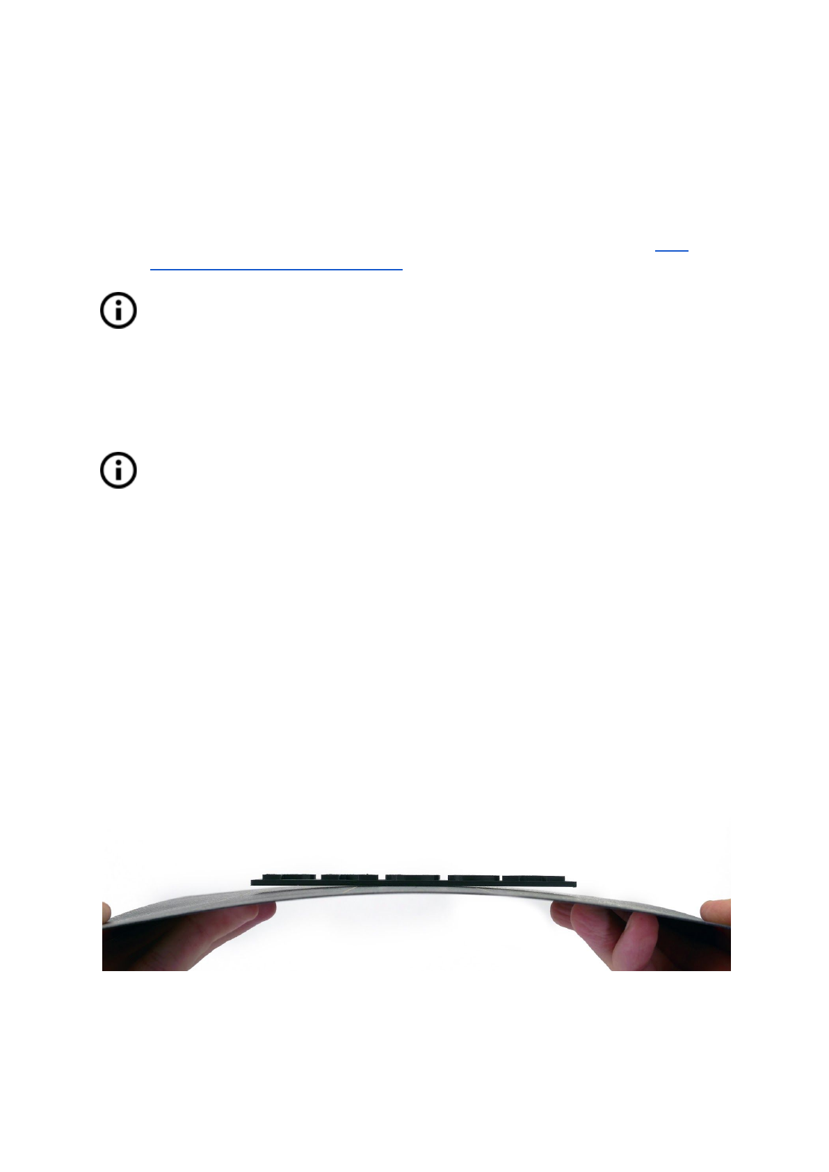
7.1 Removing objects from the printer.
Removing prints from the build plate is much easier with the ability to remove and bend the
build plate. Different thermal expansion of the steel sheet and plastics used in 3D printing
also helps with detaching prints after the plate has cooled down.
● When printing is finished let the nozzle and heatbed cool down before removing the
printed object. Always handle the printed objects when temperature of the bed and
nozzle drop to the room temperature, when the bed is hot objects are very hard to
remove. Remove the steel sheet from the printer and bend it slightly, prints should
pop off.
● If you experience any troubles removing the object (especially the small ones) you
can use a flat tool like a spatula with rounded corners to prevent damage of PEI.
Slide the spatula under the corner of the object and gently push, until the print pops
off.
Pict.
13
-
Removing
the
model
from
PEI
print
surface
by
bending
the
steel
sheet
25
7.2 Printer Control
There are two ways controlling the printer. You can use the LCD panel integrated with the
printer or you can connect your computer with USB cable. We suggest the LCD panel
because of its speed and reliability, and moreover you do not rely on a computer.
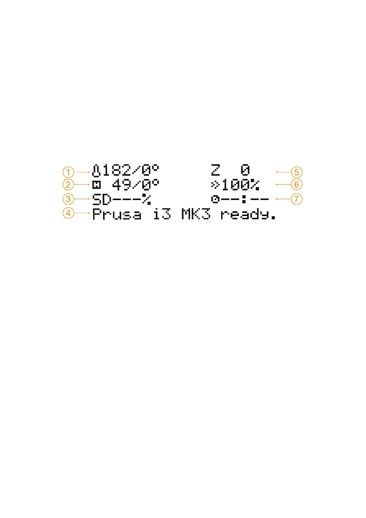
7.2.1 LCD screen
● Main screen is an information screen displaying the most important details. These
are the temperature of the nozzle and the heatbed (1, 2), printing time (3) and the
actual Z-axis position (5).
Pict.
14
-
LCD
layout
1. Nozzle temperature (actual / desired temperature)
2. Heatbed temperature (actual / desired temperature)
3. Progress of printing in % - shown only during the printing
4. Status bar (Prusa i3 MK3 ready / Heating / model_name.gcode, etc.)
5. Z-axis position
6. Printing speed
7. Elapsed printing time - shown only when printing
26

7.2.2 Print statistics
The printer tracks printing statistics. When you access this option during a print, you will see
statistics for the running print. If you do so while the printer is idle, you will see the lifetime
statistics. Both filament usage and print time are being tracked.
Pict.
15
-
Print
statistics
7.2.3 Fail stats
Printer keeps statistics about the failures it went thru and recovered during the last print. It is
useful to asses the long print, for example over a night or a weekend if everything ran
smoothly. Fail stats are placed at the bottom of the LCD menu.
Failures which are detected:
● Filament runout
● Power panic
● Lost steps / shifted layers
7.2.4 Normal vs. Stealth mode
The printer offers two print modes. Normal mode is required for the detection of lost steps
(shifted layers) while still being quieter that silent mode on MK2/S. The second is called
Stealth mode and utilizes Trinamic StealthChop technology making the printer almost
inaudible with print cooling fan being the noisiest part of the printer. Stealth mode however
doesn’t provide lost step detection.
7.2.5 Factory reset
The factory reset is used when troubleshooting the printer and resetting it to the factory
state.
Entering the factory reset menu:
1. Press and release the reset button (marked X and positioned under the control
knob on the LCD panel)
2. Press and hold the control knob until you hear a beep
3. Release the control knob
Options:
●Language option resets the language preference.
27
●Statistics will erase all the recorded print time and material from the memory.
●Shipping prep which resets only the printer language selection. All the calibration
data including the Live adjust Z remain intact. Even though the calibration data are
still present and functional, the printer will prompt user once to run the Calibrate Z
function. This light factory reset is mainly used for resetting of assembled printers
before shipping out of the factory, and users are expected to select their language
and run Calibrate Z after unpacking.
●All data which resets everything including all calibration data and whole EEPROM is
cleaned. After this reset, user is expected to go through the calibration flow again,
except setting the probe height.
If you experience random glitches after firmware update or after printer upgrade, use the All
data option.
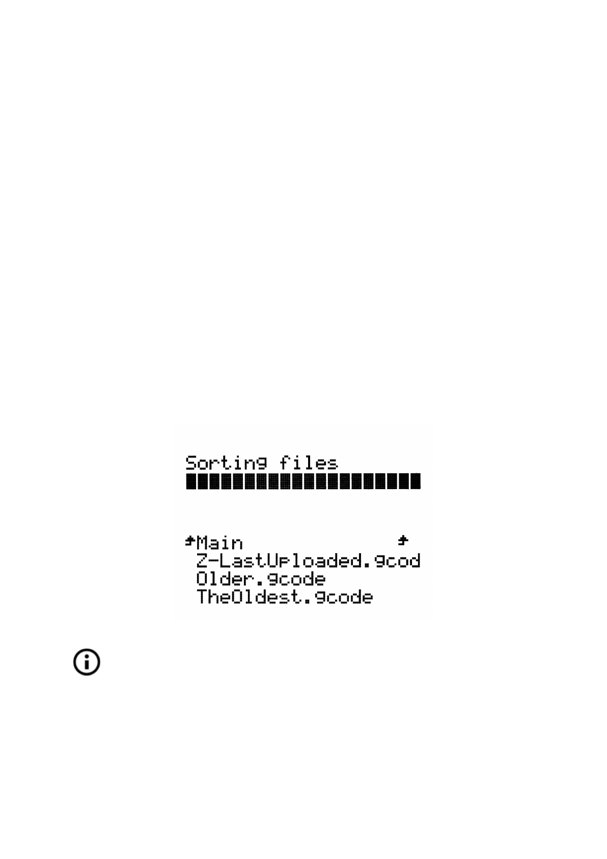
7.2.6 SD card sorting
Files on the SD card can be sorted, you can change the sorting type in Settings -> Sort:
[Type] you can select to sort by name, by date or no sorting. The best is by time where
newest files are on the top.
Folders are shown on the top of the SD card menu and then other files follow.
Maximum number of files which can be sorted is 100. If there are more, some of them will
remain unsorted.
Pict.
16
-
SD
card
sorting
SD card file sorting will be available from FW 3.1.1 final.
7.2.7 Testing if file (.gcode) is complete
The printer automatically looks for common g-codes which indicate the end of the generated
file. If they are not detected, you will get a warning. You can still continue printing if you wish,
but at least checking the file should be done.
28

Pict.
17
-
Incomplete
file
warning
.gcode file testing will be available from FW 3.1.1 final.
7.2.8 LCD layout
Items not mentioned below are not used for the common print setup - you should not change
any of the unmentioned items unless you are absolutely sure what you are doing.
❏Info screen
❏Live adjust Z (during the printing process only)
❏Tune (during the printing process only)
❏Speed
❏Nozzle
❏Bed
❏Fan speed
❏Flow
❏Change filament
❏Mode
❏Pause print (during the printing process only)
❏Stop print (during the printing process only)
❏Preheat
❏PLA - 215/60
❏PET - 240/90
❏ABS - 255/100
❏HIPS - 220/100
❏PP - 254/100
❏FLEX - 230/50
❏Cooldown
❏Print from SD
❏Load filament
29

❏Unload filament
❏Settings
❏Temperature
❏Nozzle
❏Bed
❏Fan speed
❏Move axis
❏Move X
❏Move Y
❏Move Z
❏Extruder
❏Disable steppers
❏Filament sensor - On / Off
❏Fans check - On / Off
❏Crash detection - On / Off
❏Temperature calibration - On / Off
❏Mode - Normal / Stealth
❏Live adjust Z
❏Select language
❏SD card - Normal / FlashAir
❏Sort - Time / Alphabet / None
❏Calibration
❏Wizard
❏First layer calibration
❏Auto home
❏Selftest
❏Calibrate XYZ
❏Calibrate Z
❏Mesh Bed Leveling
❏Bed level correction
❏PID Calibration
❏Show end stops
❏Reset XYZ calibration
❏Temperature Calibration
30

❏Statistics
❏Support
❏Firmware version
❏XYZ calibration detail
❏Extruder info
❏Belt status
❏Temperatures
❏Fail stats
31
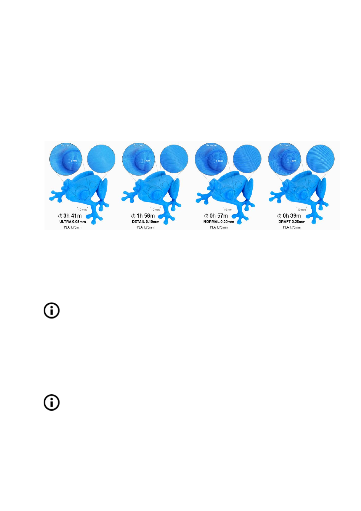
7.2.9 Print speed versus print quality
Printing a small object takes a few minutes, but printing larger models are time consuming -
there are prints taking tens of hours. The overall printing time can be changed in different
ways. First way to alter the printing speed is changing layer height in Slic3r - upper right
windows shows Print settings option. Default setting is 0.20 mm (NORMAL), you can speed
up the printer by choosing the 0.35 mm (FAST) option. Raising speed will result in the model
being less detailed with visible layer borders. If you prefer quality over speed, choose 0.10
mm (DETAIL) option. Printing time will double but the model gets the extra detail. Again,
higher printing speed results in less detailed model
.
Pict.
18
-
Print
quality
vs
print
time
Speed can al so be changed while printing. LCD shows the FR 100 % item - it’s actual print
speed (feed rate). By turning the LCD-knob clockwise you can increase the print speed up to
999 %. However, we do not advise to increase the speed over 200 %. Watch the results of
increased speed on the printed model and adjust the speed eventually.
When increasing the speed always check the model is cooled properly - especially
when printing small object from ABS increased speed causes the distortion
(sometimes called “warping”) of the model. You can prevent this issue by printing
more similar objects together - layer printing interval is long enough to prevent this
issue.
If the model shows lower quality than desired you can decrease the printing speed - turn the
LCD-knob counterclockwise. Minimum usable printing speed is around 20 % of nominal
speed.
7.2.10 USB cable and Pronterface
We strongly recommend to use LCD panel while printing on Prusa i3 MK3 -
Pronterface doesn’t support all functions of a new firmware (e.g. filament change
while printing).
Keep in mind that when printing from the Pronterface the computer must be connected to
the printer during the whole printing process - computer must be prevented from sleep,
hibernation or shutting down. Disconnecting the computer during the print ends the printing
without the option to finish the object.
32
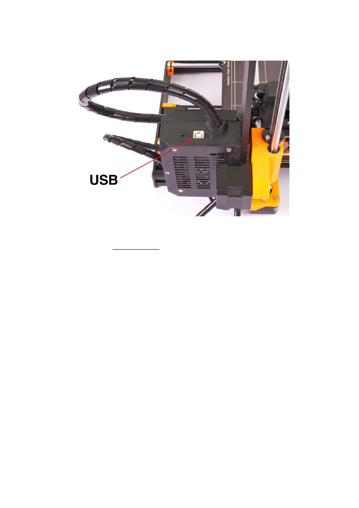
● Connect the printer to the computer with the USB cable.
Pict.
19
-
You
can
find
USB
port
here
● Choose connection port in Pronterface (download available with the printer drivers,
see the chapter 9 Printer drivers): Mac users use /usbmodem
port, PC Windows
ports are COM1, COM2, etc.; the correct port is displayed in device manager, Linux
users connect the printer using the virtual serial port. When the printer is connected
click the Connect button. Right column shows the connection information.
● Next step is loading the model with Load model button and choosing the
model_name.gcode (no special symbols in file name).
● You can control the movement of all printer axes at the control area.
● Next you can preheat the printer and prepare it for the printing. Set the temperatures
for the nozzle (heater) and heatbed (bed) and click Set button. Printer starts heating
immediately. Always check that the temperatures set in Pronterface are correct
according to our material guide!
● You can check the actual temperatures of nozzle and bed in Pronterface.
● When model is loaded right column shows the estimated print duration: Estimated
duration (pessimistic)
33
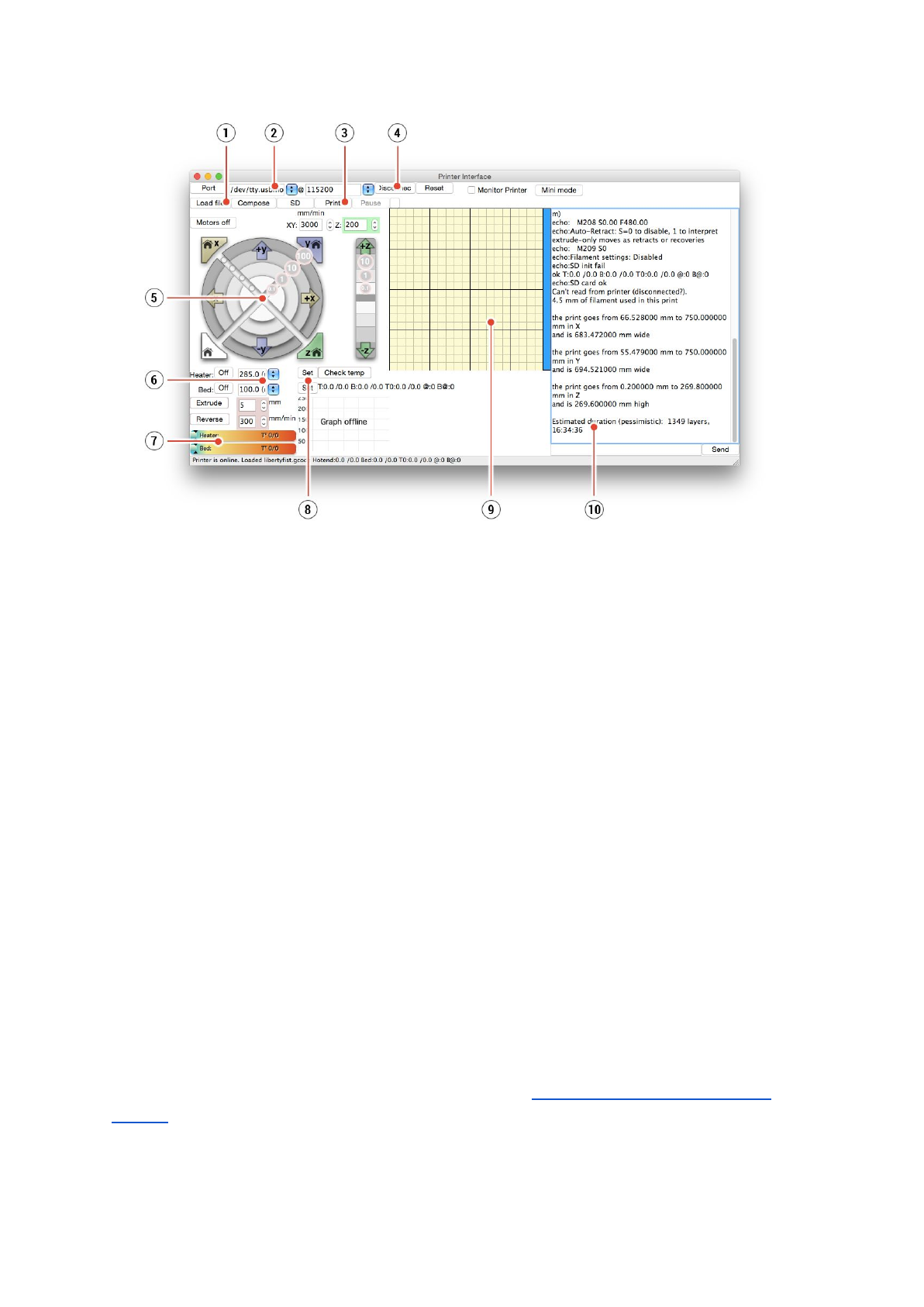
Pict.
20
-
Pronterface
1. Load file button is used to load the desired model.. Model must be in *.gcode file
format.
2. Choose the port printer is connected to computer. (mostly /usbmodem
for Mac,
COM1, COM2, etc for Windows PC).
3. Print button starts the printing process.
4. Disconnect button disconnects the printer from the computer.
5. Printer controls. Here you can manipulate the printer axes.
6. Setting the nozzle and bed temperatures.
7. Thermometer.
8. Confirming the set temperatures, heating starts.
9. 2D print process preview.
10. Info panel. Estimated print time, axis position and other info is displayed after loading
the model.
7.3 Printer addons
7.3.1 Different nozzles
E3D, a UK based company, supplies hotends for the Original Prusa i3 MK3 has whole
ecosystem of upgrades and addons. We support some of them. You have to use proper
preset settings for different nozzles in Slic3r or PrusaControl.
You can check out how to change the nozzle in section 12.6 Replacing / changing the
nozzle.
34

7.3.1.1 Hardened steel nozzle
Hardened steel nozzles are a must for highly abrasive materials. Regular brass nozzles will
degrade very quickly and lose their properties.
Most of the abrasive materials are composites, plastics with something mixed in. Some
examples are ColorFabb XT CF20, ColorFabb Bronzefill, ColorFabb Brassfill and some glow
in the dark filaments. Always ask your filament vendor if you are not sure. Slight
disadvantage is that some standard materials like ABS aren’t possible to print as fast as with
regular nozzle.
7.3.1.2 0.25mm nozzle
To get finer detail on 0.1mm or 0.05mm print settings, you can use 0.25mm nozzle. But use
it for only very small objects, only couple centimeters big. The print time can be considerably
longer compared to 0.4mm. Ideal use is jewelery.
8 Advanced Calibration
Additional calibration tools and settings for advanced users are available, but they are
entirely optional and some of them even experimental.
8.1 PID tuning for Hotend (Optional)
In case you are experiencing wide swings in temperatures of your nozzle (e.g +/- 5 C°), you
shall do PID tuning on your printer. If
you
are
experiencing
major
temperature
fluctuations
higher
than
that,
check
that
your
hotend
thermistor
is
properly
seated
in
the
heater
block
and
plugged
to
your
EINSY
board
first.
You can find this feature in Calibration - PID calibration. In this menu you have the option
to choose the temperature for which PID will be run. Set the temperature with which you
print the most as it will tune it for that the best, however, general stability will improve for all
temperatures (PLA/ABS/PETG). After that, nozzle will heat up to the set temperature in 5
cycles. During cycles it is mastering the amount of power needed to reach the temperature
and maintain it.
Do not touch the nozzle during this process until it is fully finished as it will reach
high temperatures!
Be aware that PID tuning is not a solution for all of the temperature fluctuation issues.
Always make sure that your printer is located in a room with stable ambient temperatures,
more about that in Thermal Runaway and Temperature Drops at help.prusa3d.com
.
35

8.2 PINDA probe calibration/ Temp. calibration (Experimental/Optional)
All induction proximity probes drift the sensing distance with increased temperature. This
might affect the quality of the first printed layer. PINDA v2 probe, included in the MK3, has
embedded thermistor inside it’s body to measure the temperature and fully compensate for
the drift.
Precalibrated data table is stored in the printer and the temperature calibration is active by
default.
You can re-calibrate the data table from the menu, it can be found in Calibration - Temp.
calibration - Calibrate. Before you do so, please make sure that your nozzle and heatbed
are perfectly clean as the extruder will be moving around heatbed during this process.
This procedure must be done in a place with normal room temperature around 21°C/69°F.
Do not touch the nozzle or heatbed during this process until it is fully finished as it will reach
high temperatures!
Once calibrating your PINDA probe, it will be comparing its data readings under different
temperatures and also on top of that it will include your Live Z data. This should help you to
have stable Live Z.
Still make sure that your 1st layer is done properly. More about that in 6.3.9. Fine-tuning the
first layer
8.3 View XYZ calibration details (Optional)
This feature can be found in Support -> XYZ cal. Details and provides access to more
detailed info about XYZ calibrating results. The 1st screen tells you the distance of the
“perfect” position of your two front calibration points. Ideally, all of these are positive and at
least 10 mm or more. When you get your axes perpendicular or slightly skewed,
nothing needs to be tweaked as printer will perform with the best accuracy.
Pict.
21
-
Distance
of
the
front
calibration
point
from
the
axis
start.
36
Pressing the button will get you to the 2nd screen. This screen will identify how far you are
from the perfect perpendicularity. It is measuring the skew of your X/Y axis.
Up
to
0.25
°
=
Severe
skew
compensating
for
offset
of
1.1
mm
on
250
mm
length
Up
to
0.12°
=
Slight
skew
compensating
for
offset
of
0.5
mm
on
250
mm
length
Under
0.12°
=
No
need
to
compensate
,
X/Y
axes
are
perpendicular.
Congratulations!
8.4 Linear Advance (Experimental)
Linear advance is a new technology which predicts the pressure build-up in the extruder
when printing at higher speeds. Firmware of the printer uses that prediction to decrease the
amount of filament extruded just before stopping a decelerating, which prevents blobs or
artifacts at the sharp corners.
If you are using different slicers than Slic3r PE or PrusaControl or you just want to
tweak and play around with different values, you can manually change the settings
in gcode script. However, if you do not understand the concept of gcodes yet or
never played with editing it, stop reading here and skip for another chapter.
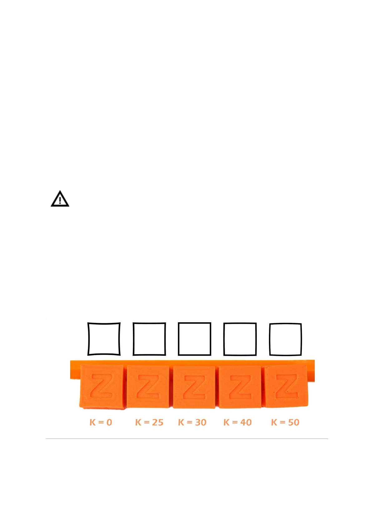
The K values (the parameter affecting how much Linear Advance affects the print) we
measured and tested are as follows:
● PLA: M900 K30
● ABS: M900 K30
● PET: M900 K45
● Multi material printer: M900 K200 for all materials
Pict.
22
-
How
K
value
affects
the
print
37

These values are preset in our Slic3r PE. The K value is set in custom gcode section in the
Filament Settings tab, NOT under the printer specific custom gcode. PrusaControl uses
the same K values but will not allow users editing.
Simplify3D, Cura, … users just need to add “M900 K??” into the starting gcode script. Keep
in mind you need to manually change that for different filament materials. Only Slic3r PE has
custom gcode for each filament preset and therefore K value is changed automatically.
Set the speed you want, print something (large enough for speed to show up). If sharp
corners have blobs, increase K value. If you see missing filament, decrease the K value.
Please note that different brands and colors of the same material may require
slightly different K value when printing at extreme speeds, however our presets
should be fine with all of them.
8.5 Extruder info
Extruder info provides debug information about the extruder sensors.
It provides info of:
● Extruder cooling fan RPM
● Print cooling fan RPM
● Information of filament moving in the extruder
●Illumination level of the filament sensor - optimally below 100
This information can be used to check the function of the fans and asses how well particular
filament works with the sensor.
38

9 Printer drivers
Latest drivers and information can be found at http://www.prusa3d.com/drivers/.
Driver package contains following settings and programs:
PrusaControl - preparing the 3D models to .gcode format for printing.
Slic3r Prusa Edition - preparing the 3D models to .gcode format for printing.
Pronterface - legacy printing from a computer (in case you don’t want to print from SD)
NetFabb - repairing the corrupted or unprintable models
Settings - optimized print settings for Slic3r, Cura, Simplify3D and KISSlicer
Drivers for Prusa i3 printer - Windows a Mac drivers
Test objects
10 Printing your own models
10.1 Where you can get the 3D models?
The best way to get started with your own 3D printing is to find already created models on
internet - they should be in the .stl or .obj format . Fortunately there are a lot of fans and
there are sites from which you can download a wealth of ready-made 3D models - from a
simple shaver holder to a detailed aircraft engine model.
3D models are generally free to download under the Creative Commons - Attribution -
Non Commercial (Models not to be used commercially, you must always include the name
of the author) or for a small fee. We have selected the most interesting sites with high-quality
models:
1. http://www.thingiverse.com/
2. https://pinshape.com/
3. https://www.youmagine.com/
4. http://www.shapeways.com/
5. http://www.123dapp.com/
10.2 In what program you can create your own models?
To create a 3D model yourself, you need a dedicated program. The easiest way to quickly
create a model is TinkerCad (www.tinkercad.com) - an online editor (no installation needed)
- you create your 3D model directly in the browser window. It is free, is easy to operate and
you will find even basic video tutorials, so after a few minutes nothing prevents you to create
your first 3D object.
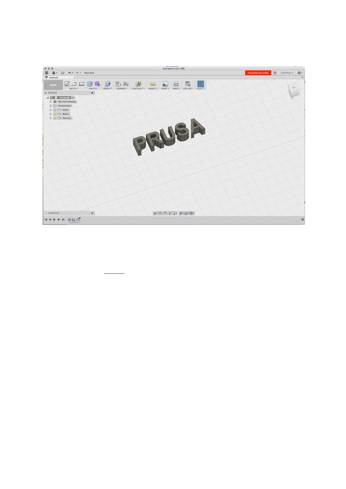
Other popular tool for creating models is Fusion 360
(https://www.autodesk.com/products/fusion-360/) for PC, Mac and iPad. Website provides a
quick guide along with detailed video tutorials so it’s a very good choice for novice
enthusiasts.
There is a great deal of 3D programs - free or paid - your choice depends more on your
personal taste and preferences. The following is a list of other programs used for making 3D
39
models: OpenScad, DesignSpark Mechanical, Fusion 360°, Blender, Maya, 3DS Max,
Autocad and many more…
Pict.
23
-
Fusion
360
10.3 PrusaControl
A 3D printer can print almost anything. Whether you’ve downloaded 3D models from the
Internet or created your own models, you will need to convert the .obj or .stl format into a
.gcode file. Gcode is a file format readable by a 3D printer. The file contains information for
nozzle movement and the amount of filament to extrude. The right tool for this task - and for
many more - is the PrusaControl program.
You set the printing material, print quality and the print speed in PrusaControl. You can
manipulate the object here, varying the placement on the printbed, resize it, etc.
PrusaControl is the easiest way to get perfect prints on the MK3 and should be used when
first experiencing the 3D printing world. When you get more advanced and want to tweak the
print settings or add new materials, Slic3r Prusa Edition is waiting for you.
40
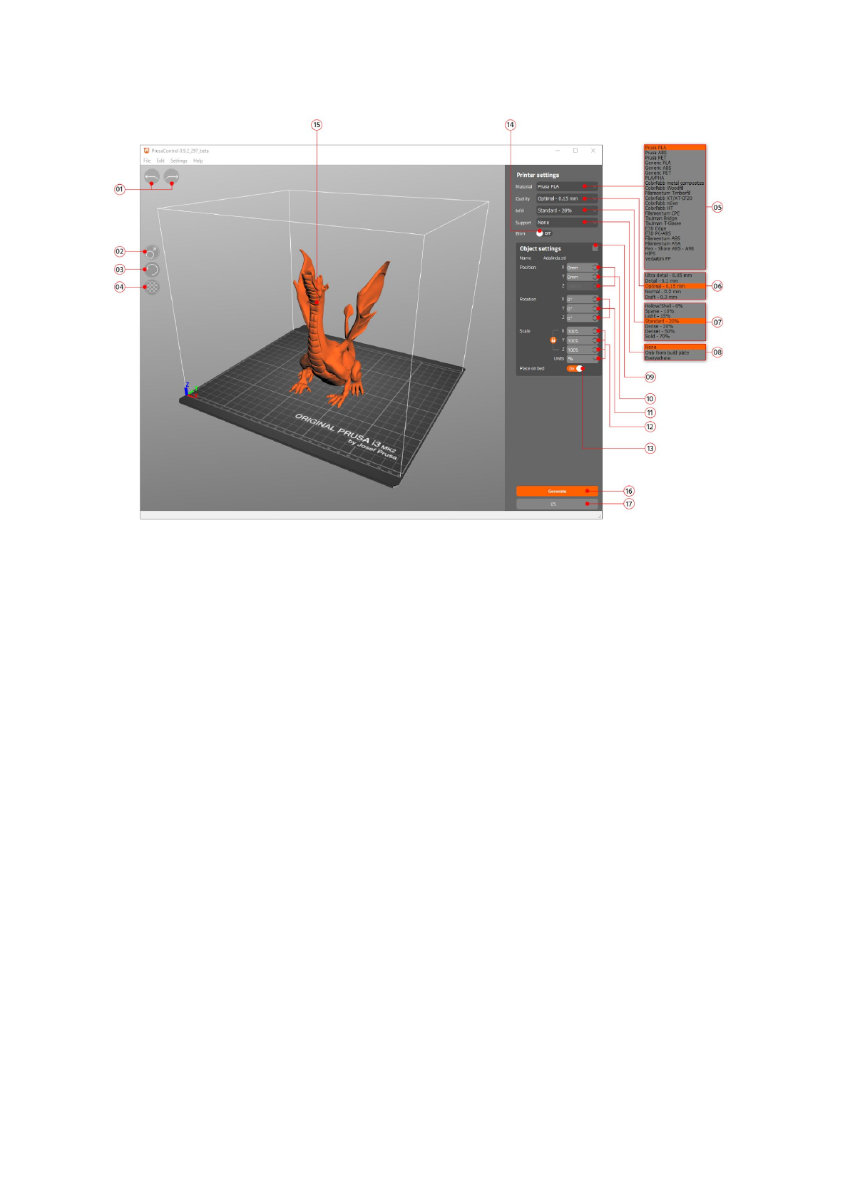
Pict.
24
-
Prusa
Control
interface
1. Undo/Redo buttons return changes.
2. Scale button allows you to scale with the mouse while the model is selected.
3. Rotate button allows you to rotate with the mouse while the model is selected (outer
circle step are 0,1°, inner circle step is 45°.)
4. Auto arrange button positions objects on the print bed.
5. Material selection menu
6. Quality / Speed setting of a print menu
7. Infill menu
8. Supports menu
9. Reset transformation settings button
10. Position values
11. Rotation values
12. Scale values
13. Place on bed button turns on automatic placing of objects to Z=[0]
14. Brim On/Off button
15. Model preview
16. Generate button slices the model
17. Progress bar
41
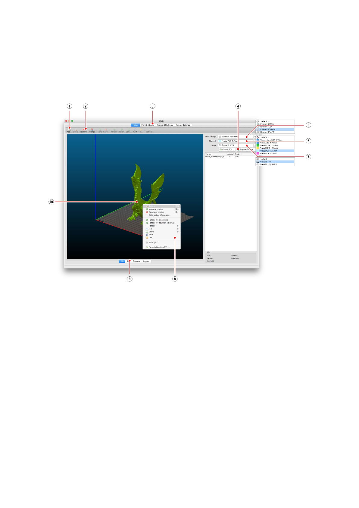
10.4 Slic3r Prusa Edition
PrusaControl is built on top of the Slic3r Prusa Edition and hides all the unnecessary clutter
from having all settings exposed. If you choose to create your own specific print settings or
tweak material settings heavily, you can use Slic3r PE directly.
Pict.
25
-
Slic3r
interface
1. Add button loads models into Slic3r.
2. Delete and Delete All buttons remove the model(s) from Slic3r.
3. Opens the detailed settings of print, filament and printer.
4. When the model is ready for print this button generates the .gcode file.
5. Quality / Speed setting of a print
6. Material selection
7. Printer selection
8. Right-click on model opens the menu with rotate, resize and other options
9. Type of model preview
10. Model preview
42
10.5 Bundled 3D models
We asked couple known 3D designers and prepared some printable object for you to print.
They are ideal for the first prints on your new printer. STL and GCODE files are available
after installing the driver’s package in “3D Objects” folder or bundled on your SD card. You
can check them out at http://www.prusa3d.com/printable-3d-models/.
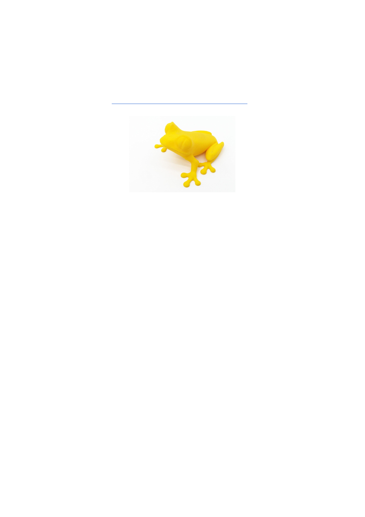
Pict.
26
-
50
microns
treefrog
is
commonly
used
as
a
3D
printing
benchmark.
43
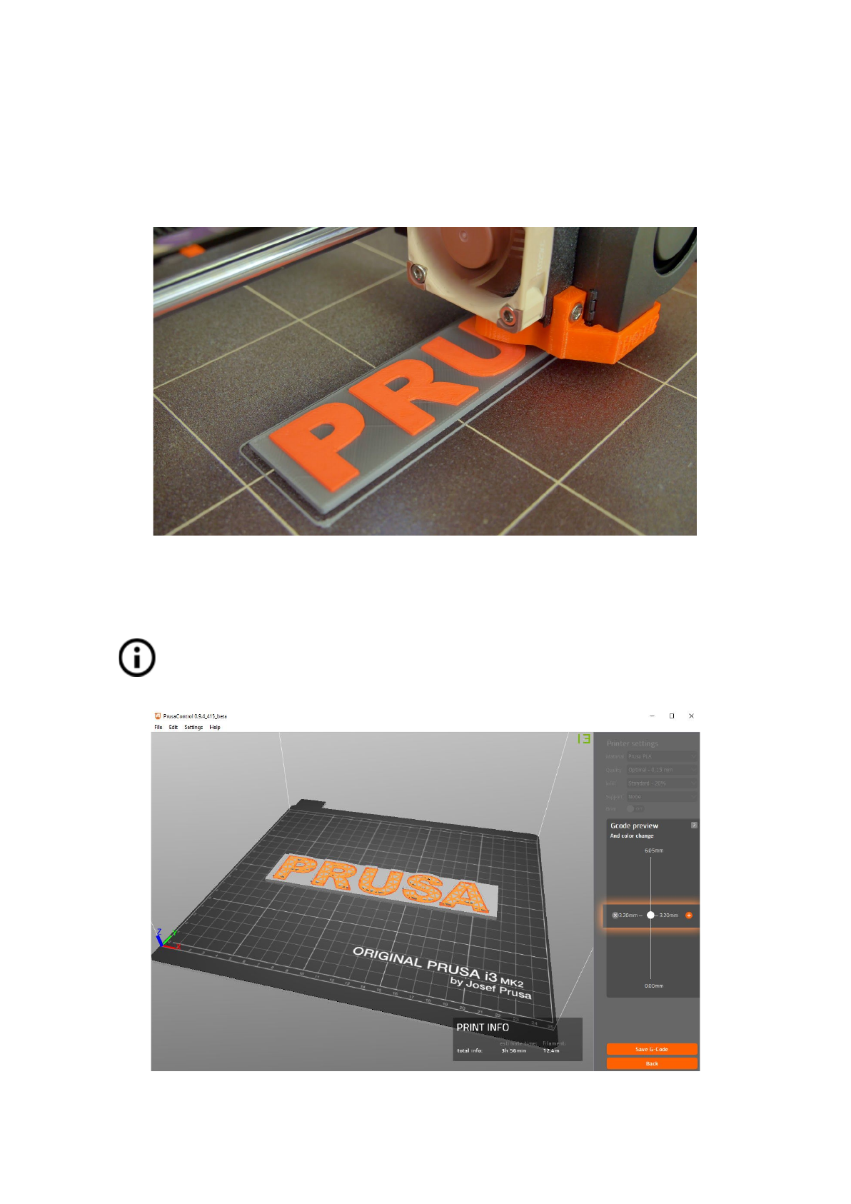
10.6 Print in color with ColorPrint
There is a simple way on how to create layer based multicolored 3D prints with PrusaControl
or with our simple online ColorPrint app by manually changing the filament.
Pict.
27
-
Multicolored
object
printed
with
ColorPrint
ColorPrint is now directly integrated into the PrusaControl and filament
changes can be added when the gcode is already generated before saving it
to the file. PrusaControl can also add color changes to existing gcodes
(generated in Slic3r for example). You can also use Web ColorPrint for gcode
from other slicers including Slic3r Prusa Edition.
Pict.
28
-
Adding
color
change
in
PrusaControl
44
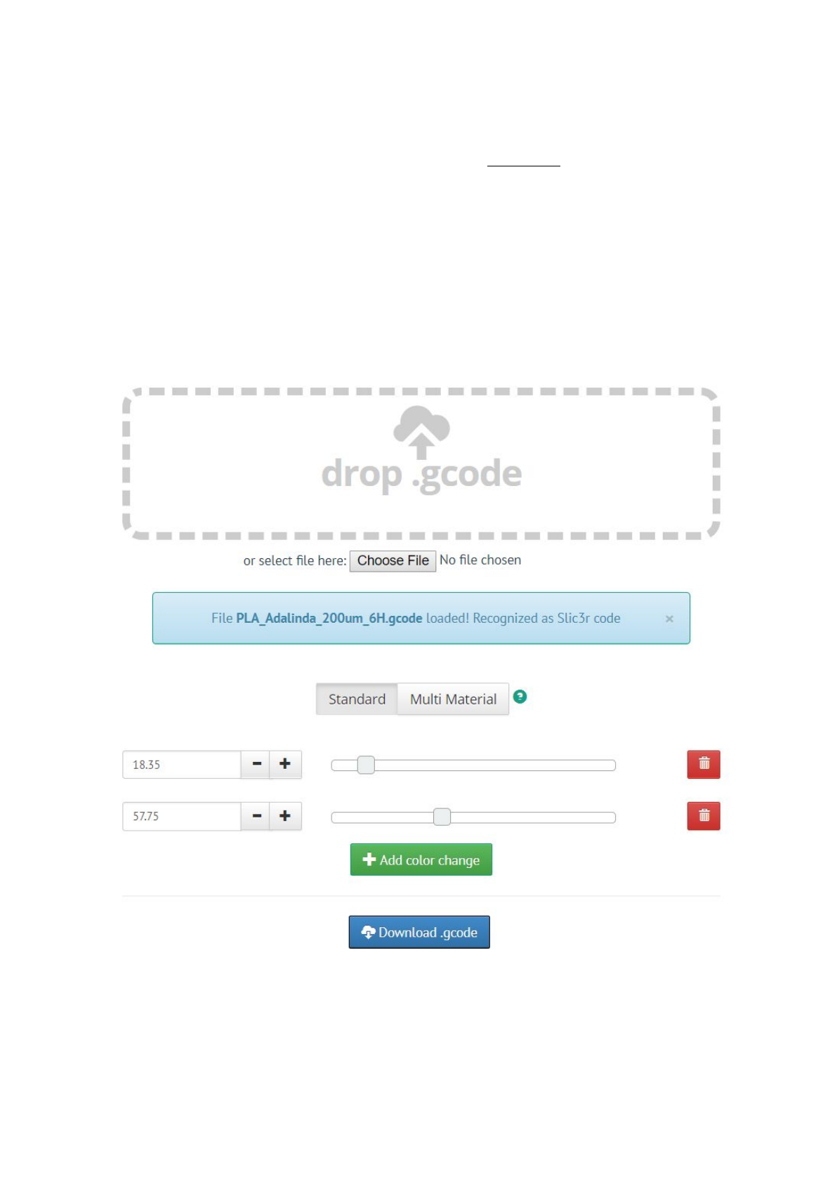
● First of all you need to prepare regular gcode with common print and filament
settings. Save the file.
● Then go to www.prusaprinters.org and choose Color Print in the header menu.
● Drag the gcode to frame and click on Add change button.
● Find the height of the layer where you want to make the color change. This can be
easily found in Slic3r under tab “Layers.” The scale along right side displays the
height of individual layers. Set this number to the box. Number of these changes is
unlimited.
● When you are done with your modification, download the file. This file is ready to be
printed!
Pict.
29
-
Web
version
of
Colorprint
interface
at
prusaprinters.org/colorprint
45
Insert the filament which you want to start with into your printer and start printing the file.
When the color change is triggered from the gcode the printer will follow simple procedure:
● Stop moving and retract
● Raise the Z by 2 mm and move quickly outside the printbed
● Unload the current filament
● You will get asked to insert the new filament. When you do so and continue, filament
will be pulled into the hotend and LCD will display “Changed correctly?” with three
options:
1. “Yes” Everything went ok and printing can continue. Check if the new color is clear
without any remains of the previous filament - if yes, choose this option to continue
printing with a new color.
2. “Filament not loaded” If the new filament was not loaded properly, choose this
option and the printer will start the automatic filament load again. When the filament
is loaded properly, you can choose the “Yes” option and the printing will continue with
a new color.
3. “Color not clear” Filament was loaded but the color is still mixed with the previous
filament. Press the button with this option and the printer will extrude more filament
from the nozzle. When the color is pure without any remains of the previous filament
you can choose the “Yes” option and the printing will continue with a new color.
After confirming, the printer returns to the original position and continues to print.
Other options for multicolored print is to use the filament change option. Choose
the Tune and then Change filament option during the print. Printer will pause the
printing process, unload the filament and signals you to insert the new filament. The
procedure is the same as above.
You should always use the same material or combine materials with similar print
temperatures and settings.
10.7 Printing of non-standard models
Slic3r helps you while printing the non-standard models as models with overhangs and/or
models larger than a printing bed.
10.7.1 Printing with support material
When you print models you can find special cases different from standard printing. The first
case is printing with support material.
If you print an object with a gradient lower than 45° the material overhang would be
preventing the object to be printed correctly. Slic3r allows you to print such objects thanks to
the ‘Printing with support’ function. Support material is an extra structure printed as
scaffolding for the object - you can remove the support material after the printing is finished.
Choose the Print
Settings
tab (1) and click the Support
Material
option (2) in left column.
First you have to check the Generate
support
material
box (3). Next item - Overhang
threshold
(4) lets you set the minimal angle for printing the support material. Setting this item
46
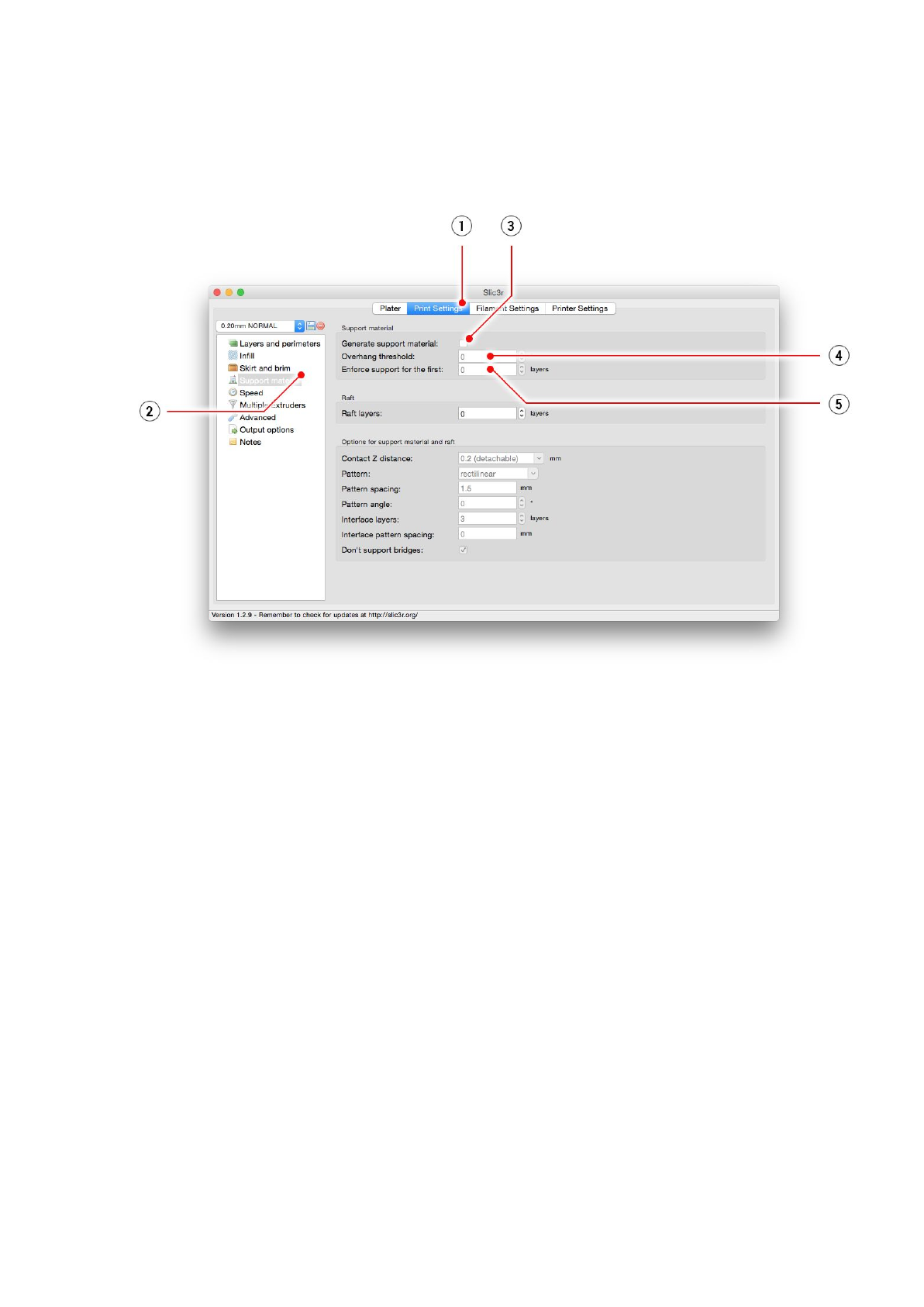
to zero lets the printer detect problematic parts automatically and print support where it’s
needed.
Enforce
support
option (5) is used mostly with small models or models with a small base to
prevent the object from breaking or tearing out from the bed.
Pict.
30
-
Print
with
support
menu
10.7.2 Large object printing
Another special printing case is when printing objects larger than the heatbed. The first
option is to resize the object to a printable size. Right-click on an object in Slic3r opens a
menu with the Scale
…
option, then you choose Uniformly
, if you want to scale down the
model evenly; or you can alter the size of a model along the one of the axes: Along
X,
Y,
Z
axis
…
47
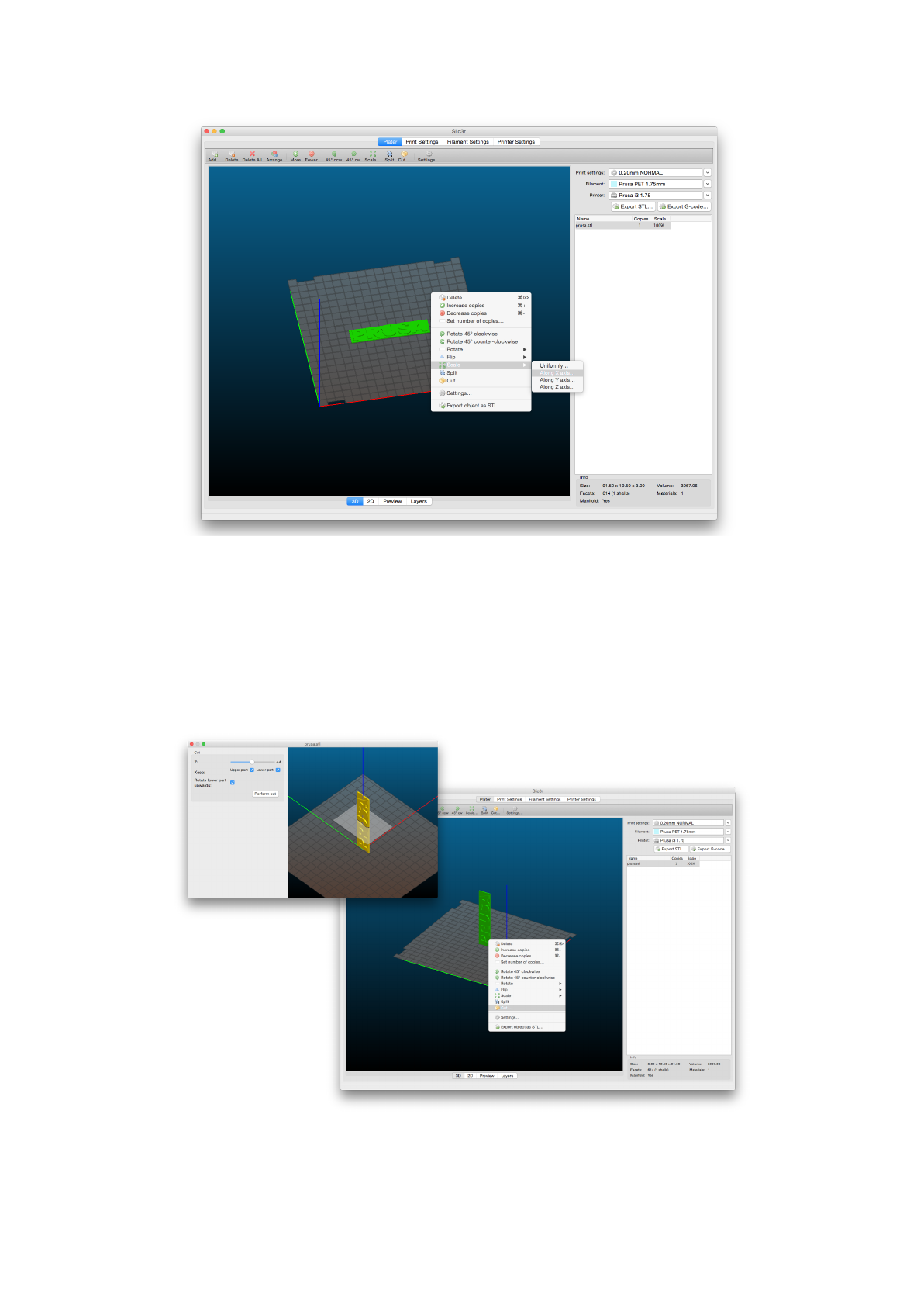
Pict.
31
-
Size
change
of
a
printed
object
If you need to print an object that doesn’t fit the printer, you have to cut the object using
Slic3r. Right-click and choose the Cut
…
option in the menu. You can cut the object
horizontally - if you need to perform a cut in a different axis, use the Flip...
option in the same
menu.
Pict.
32
-
Cutting
the
object
with
the
Cut
option
48
11 Materials
Temperatures and the heatbed treatment before a print according to a specific material.
11.1 ABS
ABS is a very strong and versatile material with great thermal resistance. It’s suitable for
both indoor and outdoor use.
ABS is a thermoplastic polymer, that means that just like PLA, it can be melted and
crystallized multiple times without degrading too much. ABS, however, melts at a higher
temperature than PLA. Higher melting temperature gives ABS great thermal resistance, your
prints won’t show signs of deformation up to 98 °C.
ABS includes high wear resistance synthetic rubber, which makes it very strong and
impact resistant. And last but not least, it’s soluble in acetone! This makes it really easy to
not only connect multiple parts together but also allows you to smooth prints with acetone
vapors. You still have to be careful when handling acetone, but it’s not anywhere near as
dangerous as for example PLA solvents.
The best use of ABS is for architectural models, concept models, spare parts (car
interior, gears, phone cases), etc.
On the other hand, thermal contraction is where ABS makes it really hard to successfully
print something. And that’s especially true when printing anything big. Even with the heatbed
at 100 °C, your part may start lifting from the build plate and warp. This and the unpleasant
smell of ABS is why you should consider getting an enclosure for your printer when printing
with ABS. Or at least place the printer in a warm room.
If you need to use your print outside or just need your print stronger, give ABS a shot. It’s
what LEGO is made of after all.
ADVANTAGES
DISADVANTAGES
High impact and heat resistance
Bad smell
Strong and versatile
Worse resolution
Soluble in acetone (easy post-processing)
Needs warm room or enclosure
Can be vapor smoothed
● Nozzle temperature: 255 °C
● Bed temperature: 100 °C. You can set the bed temperature between 80 to 110 °C
depending the size of an object (larger object means higher temperature)
● Heatbed: Make sure the surface is clean as described in 6.3.2 PEI print surface
preparation chapter
49
11.2 PLA
PLA is the most commonly used filament. It’s biodegradable,easy to print, and a very
strong material. The perfect choice for printing large objects thanks to its low thermal
expansion (little to no warping) and for printing tiny parts because of its low melting
temperature. This material only is proven for 50 microns layer height.
PLA has a relatively low melting temperature of about 175 degrees Celsius. Unlike so-called
thermoset materials, PLA can be heated past its melting point multiple times with very little
degradation. It’s also very hard material, but that also means it’s somewhat brittle and once it
breaks, it likes to shatter.
The best use of PLA is for printing concept models, prototypes, low-wear toys, etc.
However, PLA is not a perfect material and just like every other plastic has some
disadvantages. The low melting temperature also means low-temperature resistance.
Parts start to lose mechanical strength at temperatures over 60 °C.
The combination of being both biodegradable and having low-temperature resistance means
that it’s not ideal for outdoor use, not to mention low UV-resistance. Also, PLA is only
soluble in chemicals like chloroform or hot benzene. So when connecting multiple pieces,
you’re better off just using glue.
Even though PLA is biodegradable and the material on its own is food safe, we do not
suggest to repeatedly drink or eat from your 3D prints. Because of the small fractures on
the print surface, bacteria can build up in there over time. You can prevent this by applying
food safe coating. When post-processing PLA, it’s better to use wet sanding. Without water
you'll quickly start heating the plastic by friction, it will melt locally and make it hard to keep
sanding.
ADVANTAGES
DISADVANTAGES
Easy to print
Brittle
Can print tiny parts
Low-temperature resistance
Can print huge objects
Difficult post-processing
Hard and stiff
Low warping
Environmentally friendly
● Nozzle temperature: 215 °C
● Bed temperature: 50 - 60 °C
● Heatbed: Make sure the surface is clean, as described in 6.3.2 PEI print surface
preparation chapter
50
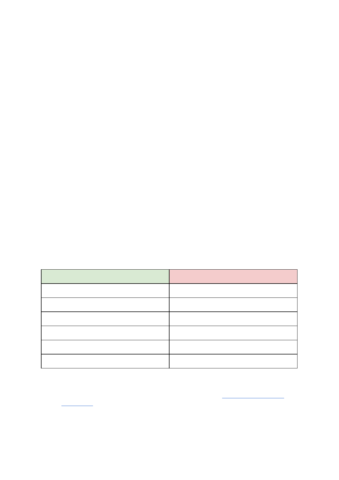
11.3 PET/PETG
PETG is a very tough material with good thermal resistance. It’s universal but suitable
especially for mechanical parts and both indoor and outdoor use. PETG has almost no
warping, so printing large objects isn’t a problem. We use PETG to print parts for our
printers!
PETG is one of our favorite materials for 3D printing. It’s almost as easy to print as PLA, but
it can offer many mechanical properties that PLA prints just cannot achieve.
The G in the acronym PETG stands for Glycol which is added during the manufacturing
process. Glycol modifies the properties of PET, so that it’s easier to print, less brittle and
clearer when printing with semi-transparent variants. PETG has low thermal expansion, so
even when printing big and without an enclosure, it rarely lifts from the bed and warps. In
addition to that, PETG is ductile. It has a healthy amount of flex which can prevent parts
from breaking under stress.
Unlike PLA or ABS, PETG tends to ooze a bit and may leave strings of plastic on your
print. You can fight this with increasing retraction and playing with hotend temperature, but if
you use our filament presets in Slic3r or Prusa Control, we already did that for you and the
amount of stringing is minimal. If you witness a tiny bit of stringing anyway, you can get rid of
it by quickly blasting your finished prints with a heat gun.
PETG sticks very well to PEI, which is generally a good thing. But sometimes it could stick a
little bit too well and you could rip a piece of PEI from the bed, so you should use a
separating agent (e.g. gluestick).
If you can handle the oozing and strong adhesion, you’ll be left with a very durable print, that
is considerably temperature resistant and usable for both indoor and outdoor use.
ADVANTAGES
DISADVANTAGES
Easy to print
Possibility of stringing
Good layer adhesion
Not soluble in acetone
Very tough, low warping
Prone to scratches
Temperature resistance
Little shrinking
Durable
● Nozzle temperature: 240 °C
● Bed temperature: 80 - 100 °C
● Heatbed: Make sure the surface is clean, as described in 6.3.2 PEI print surface
preparation chapter. Do not use isopropyl alcohol to clean the bed, or the adhesion
may be too strong, if you do not have anything else on hand use the bundled glue as
a separator after cleaning it. Windex or similar windows cleaner is a great option for
PET and you don’t need to use the glue after the cleaning. Pour a little amount on an
unscented paper towel and wipe the print surface.
51
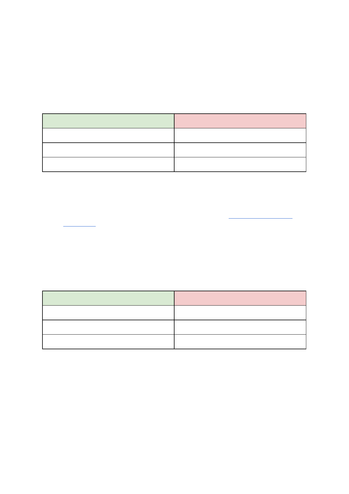
11.4 HIPS
HIPS is high impact polystyrene, and as for behavior, it's similar to ABS, so it's easy to print.
It's a universal and stable material with excellent heat resistance, and it produces very
smooth layers. HIPS is also very malleable, and it can be dissolved using limonene. HIPS is
mostly suited for printable mechanical components.
ADVANTAGES
DISADVANTAGES
Smooth
High level of warping
Durable
Bad smell
Soluble
● Nozzle temperature: 220 °C
● Bed temperature: 100 °C. You can set the bed temperature between 80 to 110 °C
depending the size of an object (larger object means higher temperature)
● Heatbed: Make sure the surface is clean, as described in 6.3.2 PEI print surface
preparation chapter
11.5 PP
Polypropylene is a flexible and resistant material suitable for printing of the precise objects
requiring the flexibility, firmness and persistence.
ADVANTAGES
DISADVANTAGES
Tough
High level of warping
Semi-flexible
Temperature resistance
● Nozzle temperature: 254 °C
● Bed temperature: 95 - 100 °C.
● Heatbed: The best results are obtained with common scotch tape - just attach the
tape directly to the print surface and clean it after the print is finished.
11.6 Nylon (Taulman Bridge)
Nylon is very tough material suitable for mechanical parts.
52
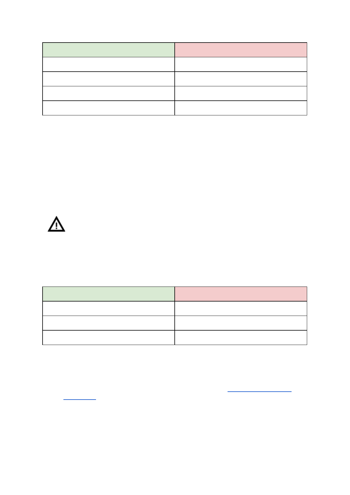
ADVANTAGES
DISADVANTAGES
Durable
Demanding storage (it’s hygroscopic)
Chemically resistant
Flexible, but strong
Chemical resistance
● Nozzle temperature: 240 °C
● Bed temperature: 80 - 90 °C.
● Heatbed: Use one coat of glue stick. Clean as described after the print.
11.7 Flex
Flex is a very strong and flexible material. There are many use cases where hard plastic is
not the ideal or even unusable at all. But whether you need a phone cover, an action camera
case or wheels for your RC car, flexible is the way to go.
Before you start printing from Flex, clean the nozzle from the previous material -
preheat the nozzle and load PLA to remove any other previous material. When
loading Flex loosen the extruder (idler) screws. Keep in mind that when printing
from Flex the automatic filament exchange function may not work properly.
Flex has very good abrasion resistance, remains flexible in cold environments, and is
resistant to many solvents. It doesn’t shrink much when cooling down, so you can be fairly
accurate with your measurements and perfect fit models.
ADVANTAGES
DISADVANTAGES
Flexible and elastic
Needs extra steps when loading filament
Little shrinking
Can be tricky to print
Good layer adhesion
Needs to be printed slowly
● Nozzle temperature: 230 °C
● Bed temperature: 50 °C. You can set the bed temperature up to 65 °C depending
on the size of an object. (larger object means higher temperature)
● Heatbed: Make sure the surface is clean as described in 6.3.2 PEI print surface
preparation chapter. Some very soft flex materials can bond to the bed too much and
require to use glue on the bed as a separator to prevent PEI damage.
53
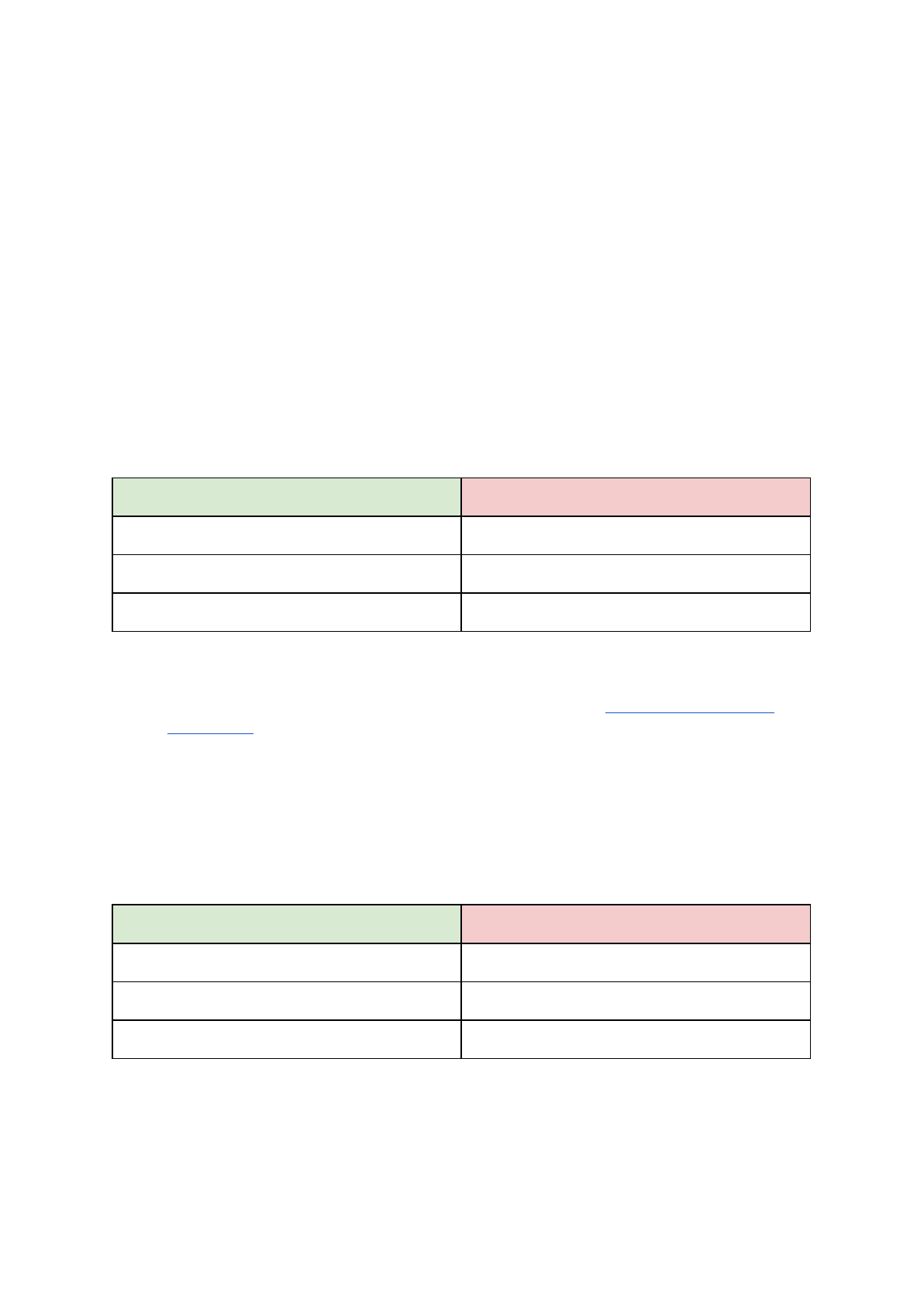
11.8 Composite materials
Composite materials (woodfill, copperfill, bronzefill, glow-in-the-dark, carbon or aramid
composites and many others) consist of a main plastic base and second material in the form
of dust. These materials tend (except for wood composites) to be very abrasive, therefore
hardened nozzle is strongly suggested for long-term printing. The larger nozzle is
recommended while printing with wood composites (0.5 mm and up). Please use
corresponding print settings in Slic3r or PrusaControl as print parameters can be very
different depending on plastic base.
The first step in polishing is sanding. It’s a good idea to start with a coarse grit size (80) and
slowly move up the grit table. After sanding a big improvement in polish can be achieved
with steel wool or brass brush. If you’re still not happy with the finish, you can try wet
sanding with a very fine grit (1500).
ADVANTAGES
DISADVANTAGES
Easy to print
Needs hardened nozzle
No warping
Great look after post-processing
● Nozzle temperature: 190 - 210 °C
● Bed temperature: 50 - 70 °C (bigger object -> higher temp.)
● Heatbed: Make sure the surface is clean as described in 6.3.2 PEI print surface
preparation chapter.
11.9 ASA
Acrylonitrile-styrene-acryl (ASA) is a material with properties similar to ABS, its main benefit
is increased weather and UV resistance. Another advantage is overall dimensional stability.
To achieve cast-like surface, acetone smoothing can be used…
ADVANTAGES
DISADVANTAGES
Heat and UV resistant
Bad smell
Soluble in acetone (easy post-processing)
High level of warping
Can be vapor smoothed
● Nozzle temperature: 270 - 280 °C
● Bed temperature: 100 - 110 °C (bigger object -> higher temp.)
● Heatbed: Make sure the surface of the heatbed is clean. Usage of brim is suggested
(see Prusa Knowledgebase).
54
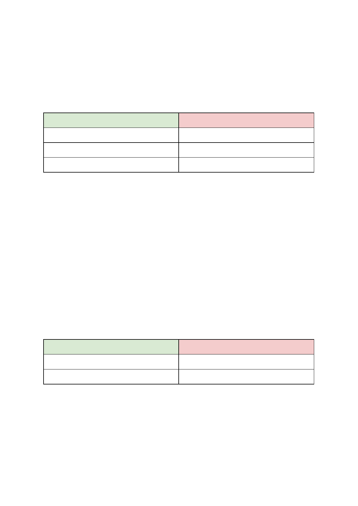
11.10 nGen
Developed by Eastman Chemical Company and colorFabb, nGen offers increased
resistance to heat as well as dimensional stability. The material is low-odor and styrene-free.
ADVANTAGES
DISADVANTAGES
High gloss
Brittle
Good surface finish
A bit of warping
Good layer adhesion
● Nozzle temperature: 240 °C
● Bed temperature: 80 - 100 °C (bigger object -> higher temp.)
● Heatbed: Make sure the surface is clean. Do not use isopropyl alcohol to clean the
bed, or the adhesion may be too strong, use window cleaner instead. If you do not
have anything else on hand use the bundled glue as a separator after cleaning it.
Windex or similar windows cleaner is a great option for nGen and you don’t need to
use the glue after the cleaning. Spray small amount on unscented paper towel and
wipe the print surface.
11.11 PC-ABS (E3D)
Polycarbonate ABS (PC-ABS) is an enhanced version of traditional ABS. Offers easier
processing, higher strength, stiffness and temperature resistance. PC-ABS is also suitable
for structures with openings, its bridging capability is improved compared to ABS. Typical
usage of PC-ABS is for durable plastic parts like television or computer casings.
ADVANTAGES
DISADVANTAGES
Lightweight
Warps
Good for mechanical parts
Low elasticity
● Nozzle temperature: 270 - 280 °C
● Bed temperature: 100 - 110 °C (bigger object -> higher temp.)
● Heatbed: Make sure the surface of the heatbed is clean.
55

11.12 Dialing in new materials
Each manufacturer produces slightly different material even though, they are under the
same group. For example Prusa PLA and ColorFabb PLA will have a slightly different output
when printed.
To achieve the best possible output you should experiment with the nozzle temperature,
fan speed, print speed and flow. All of these can be changed even during a print from the
Tweak menu on the LCD panel.
Same also applies even for materials which are not listed here. Take the manufacturer
suggested settings, find the closest match in Slic3r material profiles, modify and save as
new. Continue by printing few simple test pieces and continuously use the Tweak
menu. After each improvement, don’t forget to modify the settings in Slic3r. Reset the tweak
values before every print.
Don’t forget to share your settings on our forums or directly with us.
56
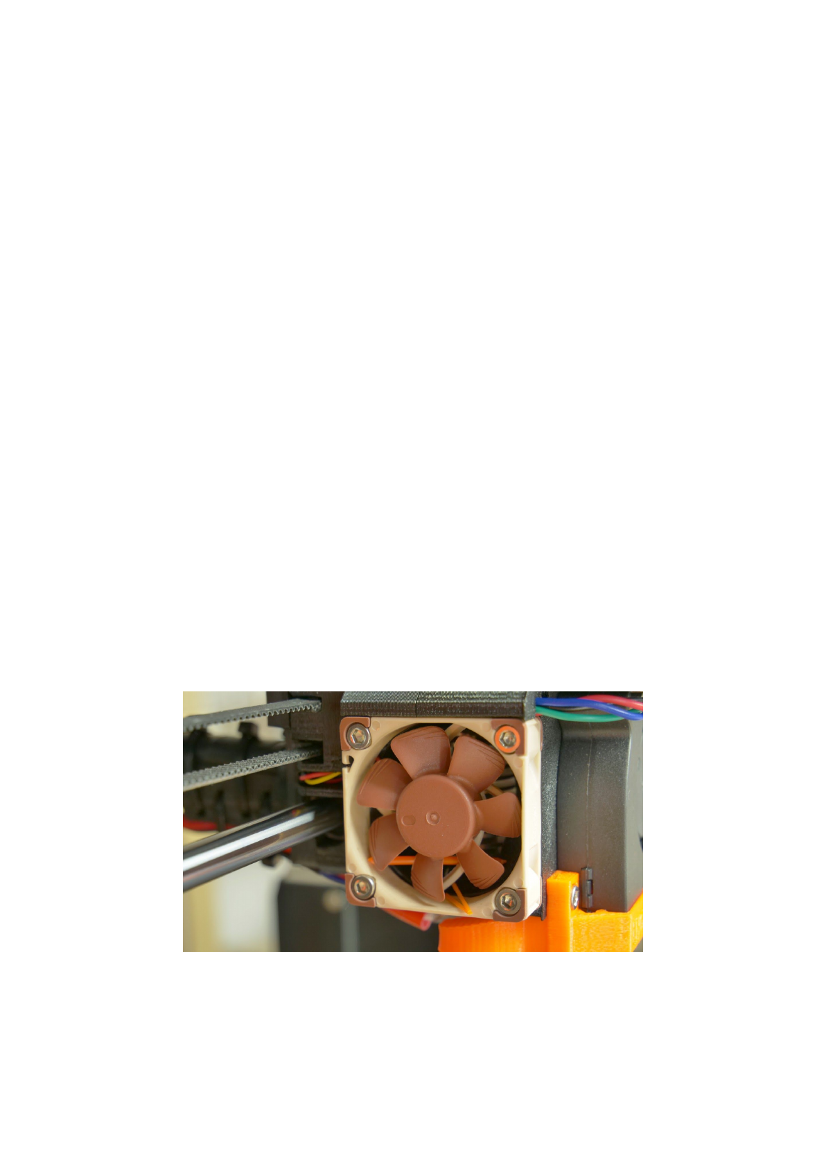
12 FAQ - Printer maintenance and print issues
12.1 Regular maintenance
12.1.1 Bearings
Every couple hundred hours, the smooth rods should be cleaned with paper towel. Then
apply a little bit of general purpose machine oil on the smooth rods and move the axis back
and forth couple of times. This cleans the dirt and increases longevity.
If you feel the axis is not running smoothly anymore, bearings can be taken out and greased
on the inside (they need to be removed from axis as plastic lip will prevent the grease from
getting inside). Super-lube or any other multi purpose grease will do.
12.1.2 Fans
Both fans should be checked and cleaned every couple hundred hours, dust or plastic build
up can decrease their efficiency or even damage them. Computer cleaner spray will get the
dust away and tweezers can be used for little plastic strands.
Both extruder and part cooling fans measure current RPM (Rounds Per Minute). Because of
that, they can detect any problem that will cause the fan to slow down, like a piece of
filament getting stuck in it. If you get a fan error, check that it can rotate freely, clear any
debris that may be stuck in it.
Pict.
33
-
Nozzle
cooling
fan
from
Noctua
57
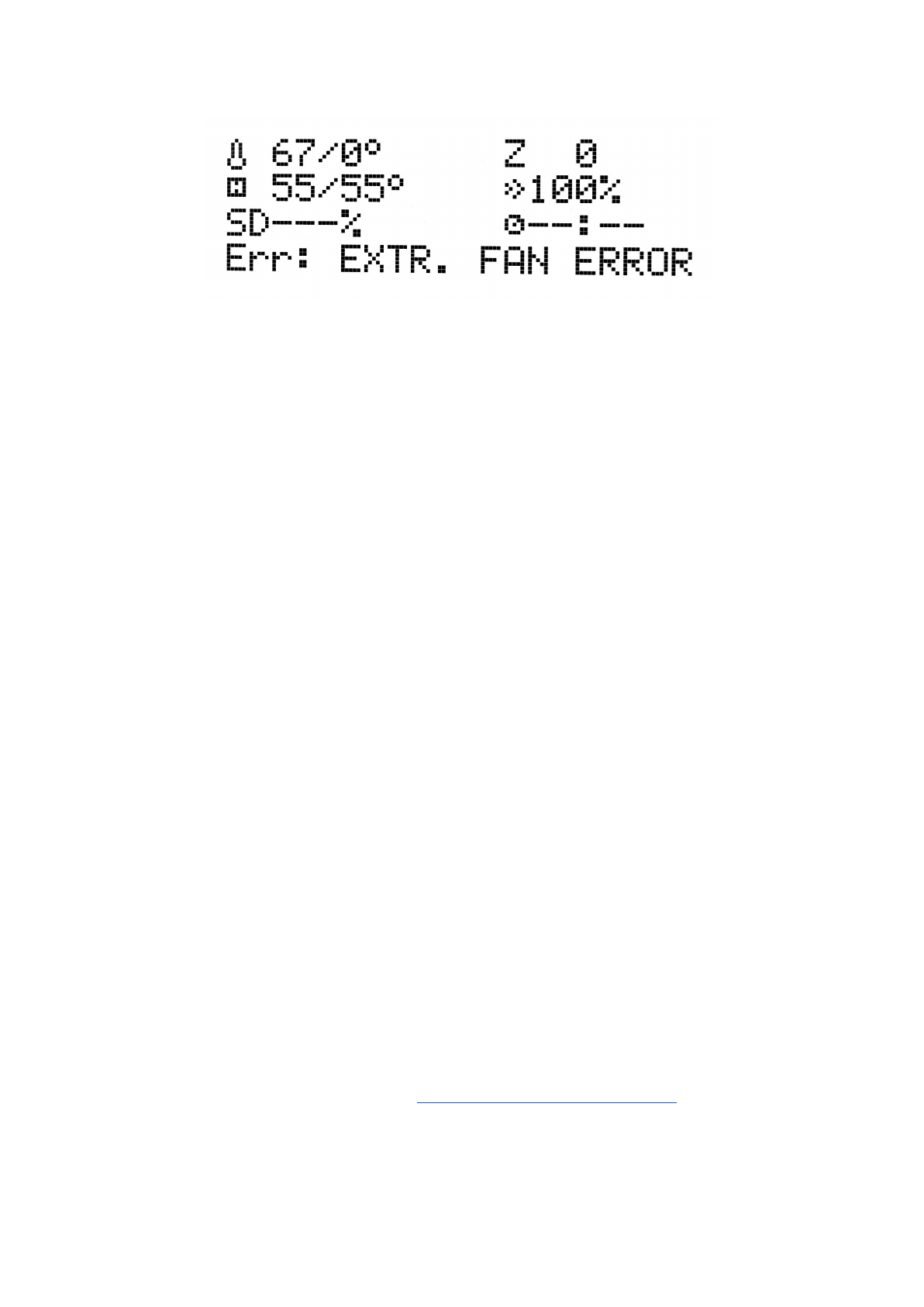
Pict.
34
-
Fan
error
The nozzle cooling fan is made by Noctua. These premium fans are known for their superb
quietness and exceptional performance.
You can turn off the monitoring in LCD menu under Settings -> Check fans for example if
you replaced one of the fans with replacement not supporting RPM sensing.
12.1.3 Extruder drive gear
The hobbed drive gear on the extruder motor shaft can have build up of filament shavings in
the grooves and cause under extrusion. A small brass brush is ideal tool to clean the
grooves but regular toothpick will do the job as well. Check and clean from the access
window on both sides of the extruder assembly. Clean what you can, then rotate the gear
and repeat. Nothing needs to be disassembled. Clean when you see signs of missing plastic
in the objects, e.g. missing lines of extrusion.
12.1.4 Electronics
It is good practice to check and eventually reset the electrical connectors on the mini RAMBo
board. Do so after first 50 hours of printing and then every 150-200 hours.
12.1.5 PEI rejuvenation
PEI can lose its adhesive powers after couple hundred hours. Wipe thoroughly with acetone
when you see models getting loose to restore the adhesion.
12.2 Print surface preparation
Print surface preparation is described in 6.3.2 PEI print surface preparation chapter.
58
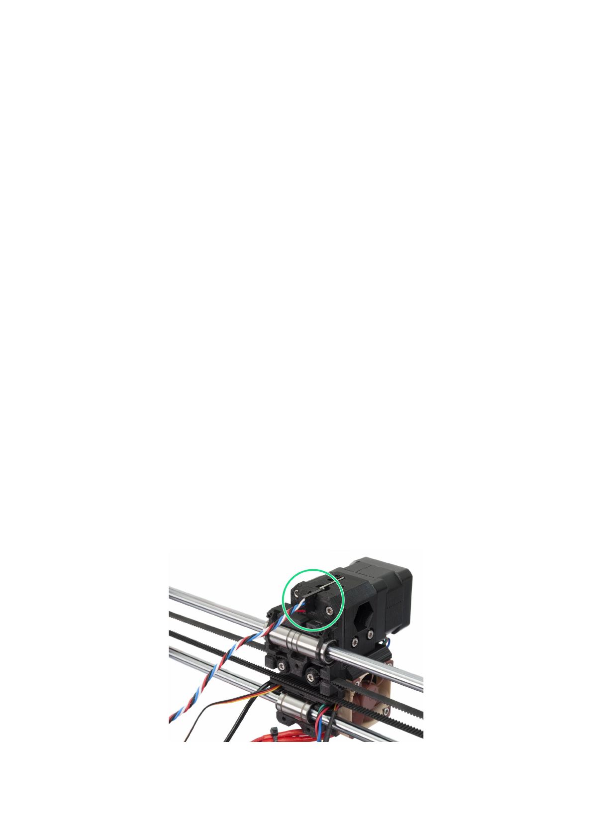
12.3 Filament sensor
The optical filament sensor detects the presence of filament and also it’s movement.
Filament sensor can detect:
● Running out of filament
● Filament getting stuck - jammed nozzle
12.3.1 Running out of filament
Running out of filament will no longer cause a print failure. If you run out of filament, the
printer will automatically pause the print, unload the remaining few centimeters in the
heatbreak and move the X-carriage away from the print. You will be prompted to replace the
spool and insert new filament. Use pliers to remove extruded filament from the loading
process. After that, you can continue in the current print.
12.3.2 Filament jam
The sensor can also detect filament getting stuck. Unfortunately, in most cases, it’s not
possible to recover the current print, because it’s hard to detect the exact moment of the
jam happening. However, in future version of the firmware, we plan to offer few more options
how to eventually save the print. When the jam is detected, the printer will try to unload the
filament. However, this may not be always possible if too much filament was already ground
off. Either way, the printer will stop, display a warning about jam happening and cool down to
prevent any further damage.
12.3.3 False sensor readings and debugging
You can encounter false runout readings from the sensor. First check if the sensor is
positioned correctly and connectors are properly seated.
Pict.
35
-
Properly
connected
filament
sensor
59
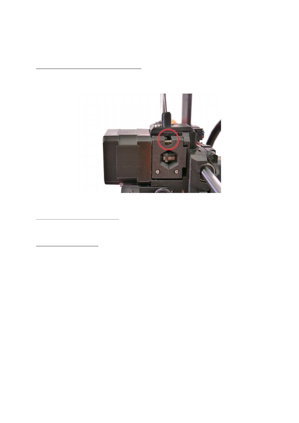
If everything is in order, other causes might be:
12.3.3.1 Dust on the sensor - how to clean
If you start getting a lot of false alarms on filament jams or filament running out, your sensor
might need cleaning. The easiest way is to use compressed air. There is a dedicated hole in
the x-carriage exactly for this purpose.
Pict.
36
-
Access
hole
for
cleaning
the
filament
sensor
12.3.3.2 Extreme light conditions
If you’re printing in extreme light conditions (direct sunlight, very strong LED lighting) you
might also encounter some false alarms. Settings -> Fil. sensor [on/off].
12.3.3.3 Exotic filaments
Some translucent filaments focus more light on the sensor and this can result in weird
behavior. Certain colors like ivory, matte white or lime green can also cause false alarms. If
you’re printing with any of these filaments and you’re getting a lot of false alarms, consider
turning the sensor off in Settings -> Fil. sensor [on/off].
12.4 Clogged / jammed extruder
Material clogged in the extruder can cause problems with the printing or with the loading of a
new filament.
● Heat the nozzle, remove the filament from the extruder and cut the rod about 10 cm
above the damaged part.
● The next step is to clean the extruder. There is a service hole on the left side of the
extruder where you can access the hobbed pulley (pict. 37).
● Clean the hobbed pulley, then heat the nozzle before reloading the filament.
● If a problem persists you will have to clean the nozzle.
60
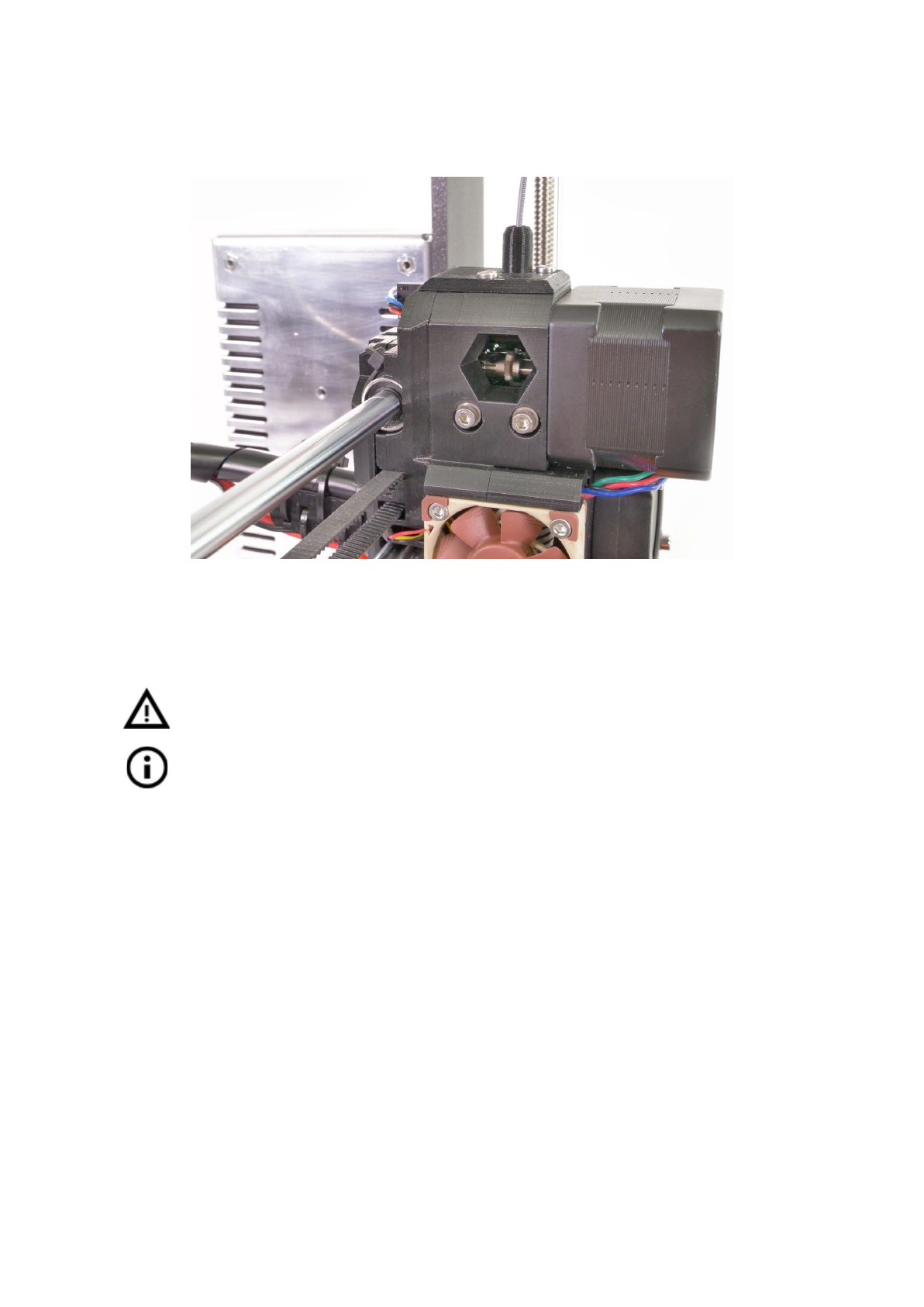
Pict.
37
-
Cleaning
the
extruder
-
you
can
see
the
hobbed
pulley
through
the
service
hole
12.5 Nozzle cleaning
Do not touch the nozzle during these procedures as it is preheated and you may
burn yourself!
Before you do any of these procedures. Go to the LCD - settings - move axis -
move Z axis. As you will be operating with the hotend.
Use
a
wire
brush
to
clean
the
nozzle
from
outside.
Heat
the
nozzle
before
you
do
so.
Filament is pouring out a little
If filament doesn’t go through the extruder smoothly and only small volume is coming out,
first check the extruder fan is working properly and that the temperature is set correctly (PLA
210 °C; ABS 255 °C, HIPS 220 °C, PET 240 °C). Also check that the filament was correctly
loaded into the extruder.
If that is not the case. Follow the instructions below:
1. Heat the nozzle according to filament you want to print from, load the filament and
put a bundled acupuncture needle (0,3-0,35 mm) into the nozzle from below -
between 1 and 2 cm deep.
2. Choose Load filament option from the LCD menu and check if filament is extruded
properly.
3. Put the acupuncture needle into the nozzle again and repeat these steps a few
times more. When the filament is extruded properly, the nozzle is clear.
None of the filament is going through the nozzle
61
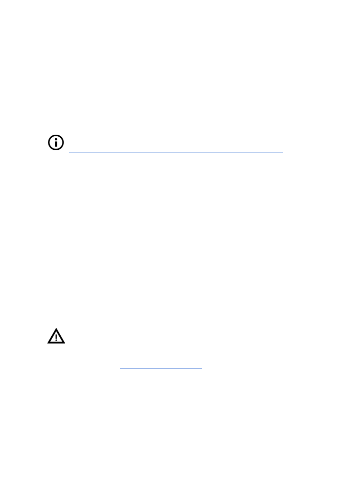
If none of the filament is going thru. Then most likely your hotend got clogged. In order to
fully clear it, please follow these instructions:
1. Heat up the nozzle to 250 °C for PLA or 270°C for ABS jams.
2. Wait 3-5 minutes and then go LCD - Load filament. If you cleared the clog and
filament went thru. Simply lower the temps to normal and re-do load filament again.
3. If successful, you can resume printing.
12.6 Replacing / changing the nozzle
In case of replacing the Olsson Ruby nozzle. Please visit this website for
instructions, otherwise you might damage it!
http://support.3dverkstan.se/article/66-the-olsson-ruby-instructions-for-use .
Preheat the nozzle (LCD menu -> Settings -> Temperature -> Nozzle) and set the
temperature to at least 200°C. Heating the nozzle is crucial for removing the old nozzle and
putting in the new one.
1) Move the extruder body upwards to get to the nozzle end (LCD menu -> Settings ->
Move axis -> Move Z -> Set the height by rotating the LCD knob and then confirm).
2) Unscrew the screw on fan mouthpiece and the two screws on the print fan and
remove both parts (Pict. 38, part 1).
3) Remove the two front screws on the nozzle fan (Pict. 38, part 2).
4) Unscrew the two screw holding the extruder cover (Pict. 38, part 3). Even though
the nozzle itself is accessible directly, we recommend to remove the extruder cover
to get access to the heating element.
5) Now the whole nozzle body is accessible (Pict. 38, part 4).
6) Hold the heating element with a spanner (size 17) and unscrew the nozzle (Pict. 38,
part 5). Be careful, the nozzle is still hot!
When the new nozzle is inserted, tighten it while the nozzle is preheated. While tightening do
not forget to hold the heating element with the spanner. Re-assemble the extruder, insert the
filament and you are ready to print.
Be careful, the nozzle is hot during this whole process and can cause burns!
Be careful around the hotend thermistor leads, you can break them easily.
Be careful and don’t apply force to the nozzle or heater block, you can bend
the heatbreak easily.
It is a good practice to run 6.3.8 First layer calibration after changing the nozzle!
62
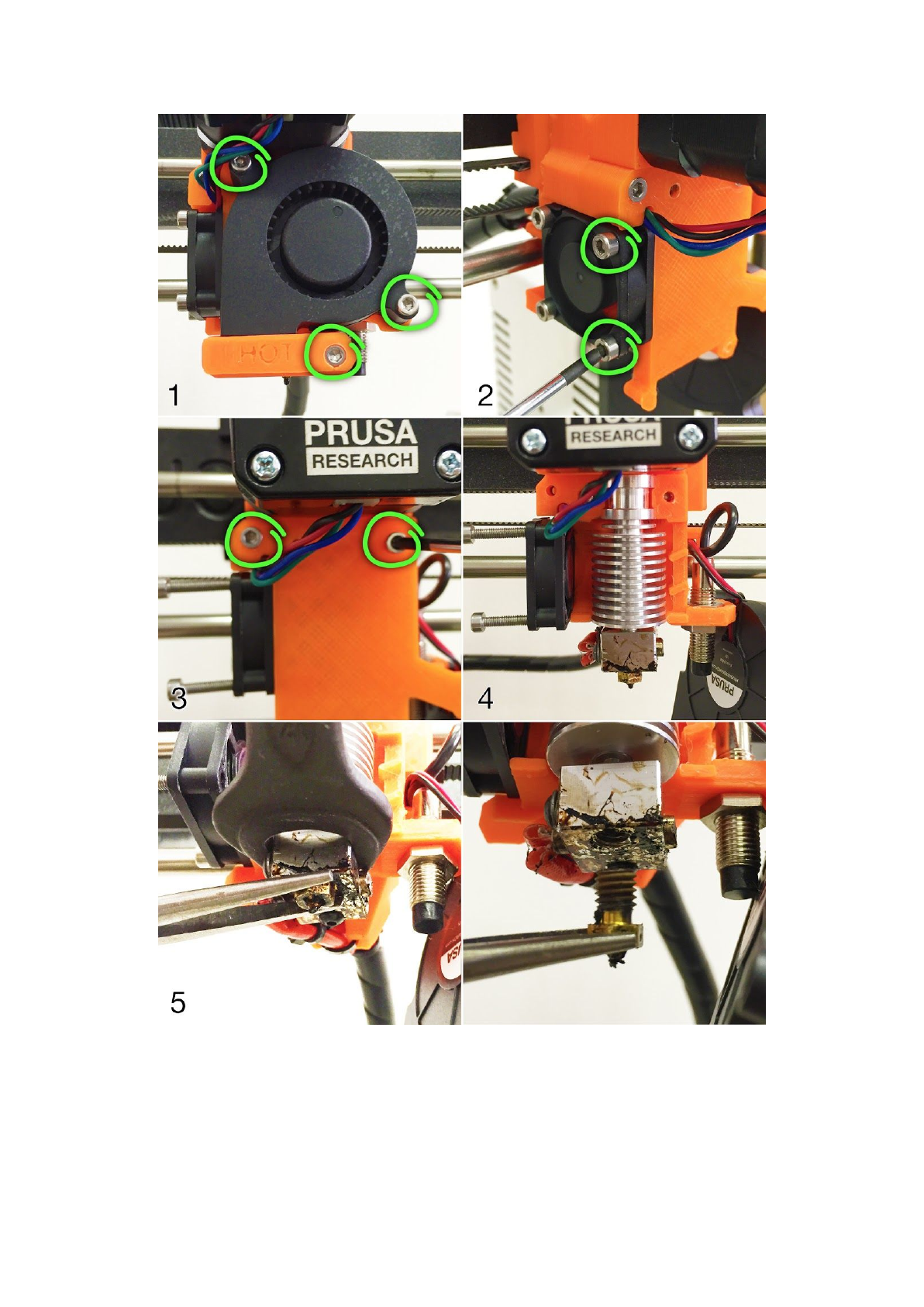
Pict.
38
-
Nozzle
change
12.7 Printing problems
12.7.1 Layers break and split when printing from ABS material
63
ABS material has a higher thermal expansion than other materials. We suggest other
materials like PET, HIPS or PLA when you print larger models.
12.7.2 Models contain either too much or not enough of the filament
You can manage the filament flow during the print. Use the LCD-knob and choose Tune -
Flow - xx% where you can adjust the filament flow. Pronterface users can enter the value
M221 Sxx into the command line.
When you change the filament flow next print will use the same settings unless you
change it again in menu or you reset the printer or unplug it from the power source.
12.8 Problems with finished models
12.8.1 Model breaks and/or is easily damaged
A typical feature of larger models printed from ABS. If you have set the temperature
properly, the printer is away from drafts and object design is right, the printed object should
not break. The easiest way to avoid breaking or overall model fragility is to choose a different
material. The strongest are PET, HIPS and PLA; while PLA has low heat resistance,PET is
the firmest and has the lowest thermal expansion.
When parts break and there is no spare time to reprint the model you can use
super glue or any other glue for plastics for temporal fix :).
12.9 Updating printer firmware
Firmware update is a simple process which is done via the USB cable and a computer. With
the driver installation a program called FirmwareUpdater V2 is installed on the computer.
The latest firmware can be found on http://www.prusa3d.com/drivers/ where you can find the
latest guide on which firmware to choose and detailed instructions for the process. Printer
will reset automatically right before the update and after the update is finished. First Layer
Calibration is required to finish after the firmware update, see chapter 6.3.9 First layer
calibration.
64
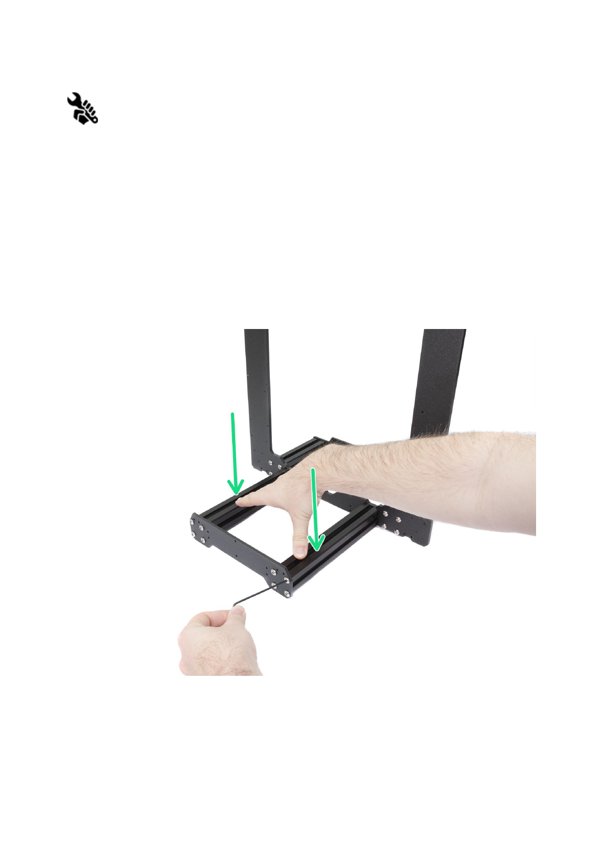
13 FAQ - common issues when assembling the printer kit
13.1 Printer is rocking - YZ frame - geometry check
If your printer is rocking on the table, please check step 11 of Y axis assembly - YZ frame -
geometry check.
All the components are cut or drilled by a machine for highest precision, but with uneven
tightening it is possible to warp the frame.
● Using your hand, try to wiggle with the frame sides and check, whether some corners
are lifting up or not.
● In case you find some imperfections, release the screws, press the extrusions
against the FLAT SURFACE and tighten them again.
Pict.
39
-
Proper
way
to
tighten
the
frame,
plates
and
aluminium
extrusion
together.
65
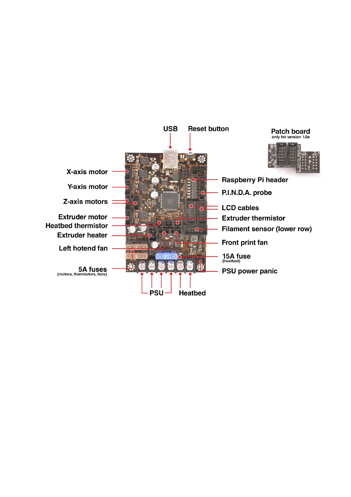
13.2 Printer stops printing soon after start
Extruder is likely overheated. Make sure the nozzle fan is working properly. If not, please
inspect its connection according to the assembly manual.
Pict.
40
-
Proper
wiring
of
the
connectors
13.3 Printer can’t read the SD card
First, make sure that the file name on the SD does not contain special characters -
otherwise the file could not be displayed on the LCD. If there is no error in the file name,
check the EXT2 wiring (from electronics to LCD). If the cable is connected properly, try to
swap the cables.
66
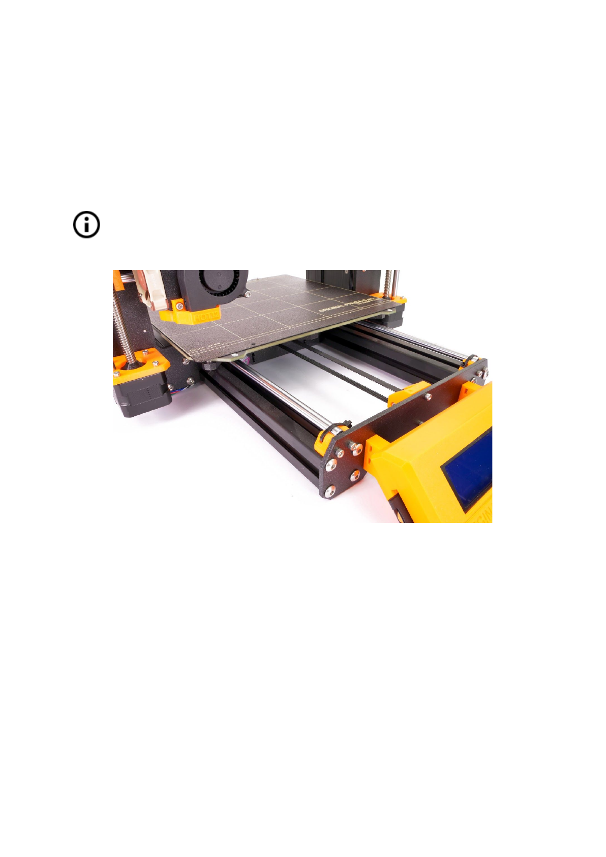
13.4 Loose X- and/or Y-axis belts
Check if both belts are properly tightened, loose belts would cause a printer malfunction and
prevent proper printing. The easiest way to check is printing a round object - if any of the
belts are not tightened properly the result is an irregular shape instead of a perfect circle.
Y-axis belt is located under the heatbed, X-axis belt moves the extruder. See the pictures
with properly tightened belts.
You can check the belt status on the LCD menu under Support -> Belt status after
successfully running a selftest. Values 240 +- 40 are good.
Pict.
41
-
A
properly
tightened
Y-axis
belt
under
the
heatbed
67
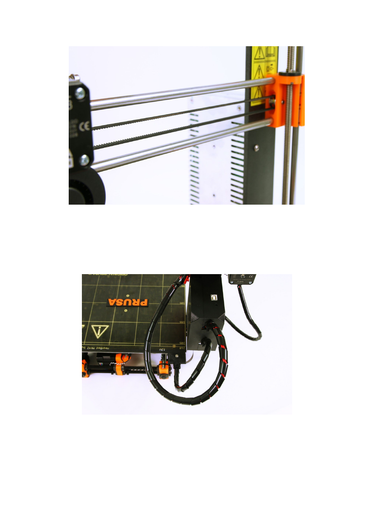
Pict.
42
-
A
properly
tightened
X-axis
belt
13.5 Detached cables to the heatbed
Do not forget to use a spiral wrap on heatbed cables and attach the cables properly so they
won’t restrict movement during printing.
Pict.
43
-
Cables
to
be
wrapped
in
a
spiral
wrap
68