Rhino PSM Series Power Supplies Installation Psm_install Install
User Manual: psm_install PSx Series Power Supplies Instruction Sheets
Open the PDF directly: View PDF ![]() .
.
Page Count: 2
1
RHINO Industrial Power Supplies Installation Instructions Rev: 04/16
www.automationdirect.com
Rhino PoweR SuPPlieS – PSM SeRieS
INSTALLATION INSTRUCTIONS
PSM Series Industrial Power Supply
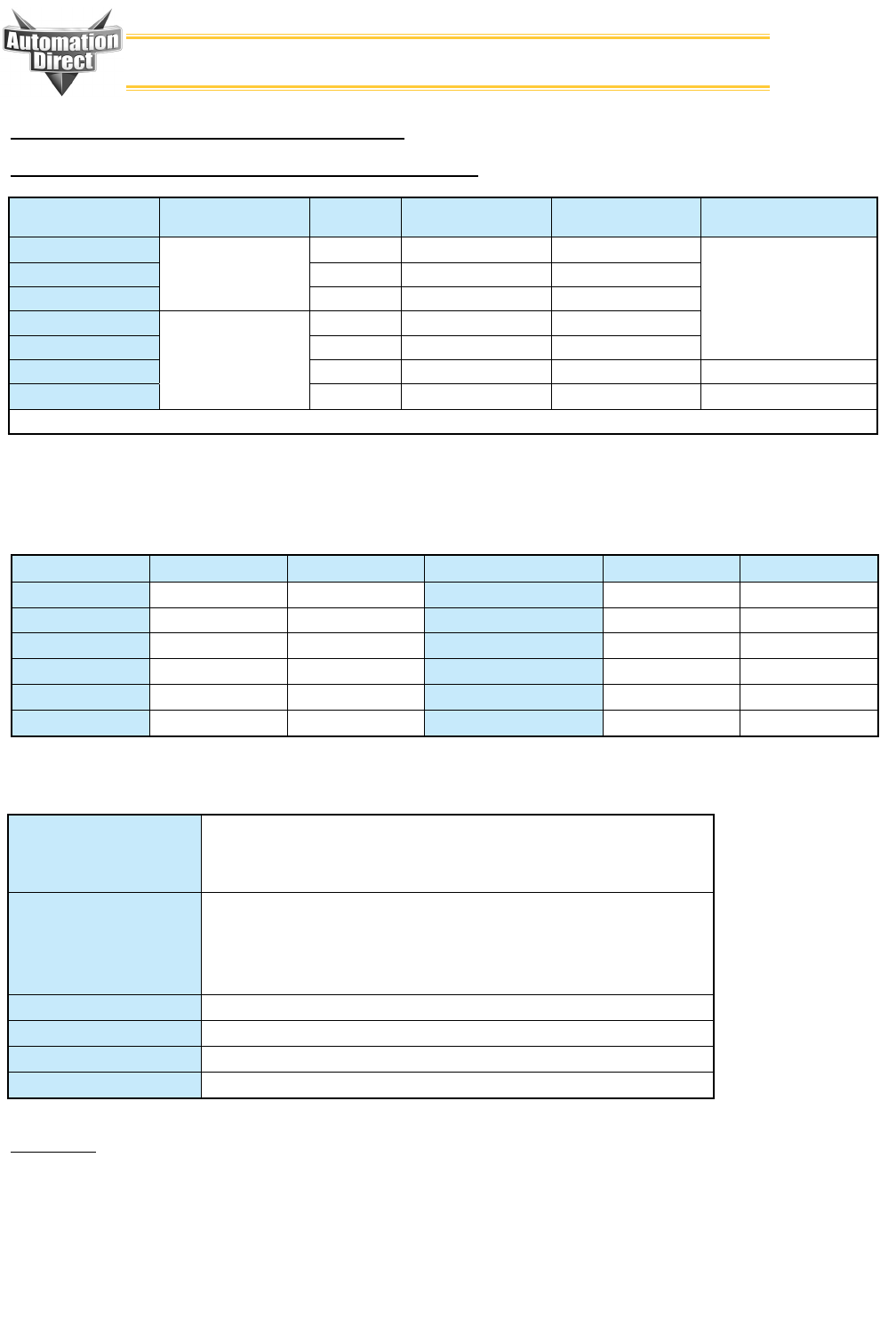
Operating temperature
range: Natural Air Convection
Cooling
-25°C - +70°C max , -13°F - +158°F max
Output Power Derating:
above +40°C [104°F]
PSM12-078S 0.5%/K
PSM24-090S(N) 1.5%/K
PSM12-156S 3.0%/K
PSM24-180S 3.0%/K
PSM24-360S 3.0%/K
PSM24-600S 6.0%/K
Storage temperature range: -25°C - +85°C max (-13°F - +185°F max)
Parallel Operation: Up to 5 power supplies possible.User selectable standard mode and parallel mode by jumper on PCB.
Connections: Screw type terminal COMBICON. Recommended tightening torque 0.5 to 0.6Nm
Case material: Aluminium (chassis) and Zinc-plated steel (cover)
Input current: @ Vin=115VAC @ Vin=230VAC Power Consumption @ Vin=115VAC @ V20in=230VAC
PSM12-078S 2.0A typ. 1.0A typ. PSM12-078S 95 Watt typ. 93 Watt typ.
PSM24-090S (N) 2.1A typ. 1.0A typ. PSM24-090S (N) 106 Watt typ. 105 Watt typ.
PSM12-156S 2.5A typ. 1.4A typ. PSM12-156S 175 Watt typ. 173 Watt typ.
PSM24-180S 2.8A typ. 1.5A typ. PSM24-180S 209 Watt typ. 207 Watt typ.
PSM24-360S 5.0A typ. 2.5A typ. PSM24-360S 425 Watt typ. 412 Watt typ.
PSM24-600S 10.0A typ. 5.0A typ. PSM24-600S 690 Watt typ. 670 Watt typ.
Part Number * AC-Input Voltage
Range
Output Power
Max. **Output *** Output Voltage
Adjustment Range
Recommended Circuit
Breaker (Characteristic B)
PSM12-078S 85VAC - 264VAC
Universal Input
50 / 60Hz
78 Watt 12.0VDC / 6.0A 12.0 - 14.0VDC
6 - 16A
PSM24-090S 90 Watt 24.0VDC / 3.75A 24.0 - 28.0VDC
PSM24-090S-N 90 Watt 24.0VDC / 3.75A 24.0 - 28.0VDC
PSM12-156S 115VAC / 230VAC
Autorange
85VAC - 132VAC
187VAC - 264VAC
50 / 60Hz
156Watt 12.0VDC / 12.0A 12.0 - 14.0VDC
PSM24-180S 180 Watt 24.0VDC / 7.5A 24.0 - 28.0VDC
PSM24-360S 360 Watt 24.0VDC / 15.0A 24.0 - 28.0VDC 10 - 16A
PSM24-600S 600 Watt 24.0VDC / 25.0A 24.0 - 28.0VDC 16 - 25A
Note: All output terminals shall be wired to the load.
* Observe output current derating at operation below an input voltage of 110VAC
** Maximum output current at Vout nom
** Adjustable by potentiometer with a screwdriver.
To Install
1. Read and follow Safety and Installation instructions on the back of this page.
2. Hook top of power supply’s DIN rail clip on DIN rail
3. Push down tab on top of power supply to open DIN rail clip.
4. Rotate power supply into DIN rail and release tab.
5. Verify the DIN rail clip is securely fastened on DIN rail.
6. Connect wires as indicated on power supply. All output terminals shall be wired to the load.

2
RHINO Industrial Power Supplies Installation Instructions Rev: 04/16
www.automationdirect.com
Rhino PoweR SuPPlieS – PSM SeRieS
Safety Instructions:
• Before installation read these instructions carefully and
completely. These installation instructions cannot cover every
possible installation, operation or maintenance situation.
Further information can be obtained from the product data-
sheets, which can be downloaded, from the Internet at http://
www.automationdirect.com.
• These power supplies are constructed in accordance with the
safety requirements of IEC/EN/60950, EN 60204, EN50178,
IEC/EN 60079-15 and EN61558-2-8. They are approved
(BG-mark) in accordance with EN60950, EN50178 and fulfil
the requirements of the Low Voltage Directive (LVD). They
are Approved by CSA.
• Before any installation, maintenance or modification work
ensure that the main switch is switched off and prevented from
being switched on again. Non-observance, touching of any live
components or improper handling of this power supply can
result in death, severe personal injury or substantial property
damage. Proper and safe operation is dependent on proper
storage, handling, installation and operation.
• Compliance with the relevant national regulations (in the USA,
Europe and other countries) must be ensured. Before operation
is started the following conditions must be ensured:
• Connection to mains supply in compliance with
national regulations (NEC, NEMA, VDE0100 and
EN50178).
• Use of stranded wires, all strands must be fastened in
the terminal blocks. (Potential danger of contact with
the case)
• Power supply and mains cables must be sufficiently
fused.
• Degree of protection I to IEC536.The non-fused
protective earth connection must be connected to the
FG terminal (Protection Class I).
• All output wires must be rated for the power supply
output current and must be connected with the
correct polarity.
• Sufficient cooling must be ensured.
• Never work on the power supply if power is supplied! Risk of
electric arcs and electrical shock, which can cause death, severe
personal injury or substantial property damage.
• Warning: Hazardous voltages and components storing a very
substantial amount of energy are present in this power supply
during normal operating conditions. However, these are inac-
cessible. Improper handling may result in an electric shock or
serious burns! Do not open the power supply until at least 5
minutes after it has been disconnected from the mains on all
poles.
• Only trained personnel may open the power supply.
• Do not introduce any objects into the power supply. The
output voltage adjustment potentiometer may only be actuated
using an insulated screwdriver.
• Keep away from fire and water
Installation Instructions:
• This power supply is designed for professional indoor systems.
In operation the power supply must not be accessible. It may
be installed and put into service by qualified personnel only.
• Do not operate without PE connection! To comply with EMC
and safety standards (CE mark, approvals) the power supply
must be operated only if PE terminal is connected to the
non-fused earth conductor.
• The correct mounting position for optimal cooling perfor-
mance must be observed. Do not cover any ventilation holes.
Please allow minimum free space of 80mm (3.15in.) above and
below, and 50mm (1.97”) on each side of the power supply for
air convection. Observe power derating.
• All output terminals shall be wired to the load.
• The internal fuse is not accessible, as it may not be replaced
by the user. If this internal fuse has blown, the power supply
likely has an internal defect and, for safety reasons, must be
discarded, or, if under warranty, returned. In case this internal
fuse has to be replaced in the field, replace only with same type
and rating of fuse for continued protection against risk of fire.
• Recycling: The unit contains elements that are suitable for
recycling, and components that need special disposal. You are
therefore requested to make sure that the power supply will be
recycled environment friendly at the end of its service life.
• Warning: To minimize the risk of potential safety problems,
follow all applicable local and national codes that regulate the
installation and operation of your equipment. These codes
vary from area to area and it is your responsibility to determine
which codes should be followed and to verify that the equip-
ment, installation, and operation are in compliance with the
latest revision of these codes.
• Equipment damage or serious injury to personnel can
result from the failure to follow all applicable codes and
standards. We do not guarantee the products described
in this publication are suitable for your particular appli-
cation, nor do we assume any responsibility for your
product design, installation or operations.
• If you have any questions concerning the installation or
operation of this equipment, or if you need additional
information, please call us at 770-844-4200.
• This publication is based on information that was avail-
able at the time it was printed. At Automationdirect.
com™ we constantly strive to improve our products and
services, so we reserve the right to make changes to the
products and/or publications at any time without notice
and without any obligation. This publication may also
discuss features that may not be available in certain revi-
sions of the product.
