Px 412
User Manual: px-412 Protos X Installation and I/O Manual -AutomationDirect
Open the PDF directly: View PDF ![]() .
.
Page Count: 2
PX-412 – Two-channel
0 to 10 VDC Analog
Output Terminal
The PX-412 Analog Output Terminal
provides two electrically isolated, 0 to
10 VDC outputs with 12-bit resolution,
common ground potential, and Run
LED status. Use with
the Protos XTM I/O
System.
PX-412
1
2
3
4
5
6
7
8
Tech Support 770-844-4200Sales 800-633-0405
1
2
3
4
5
6
7
8
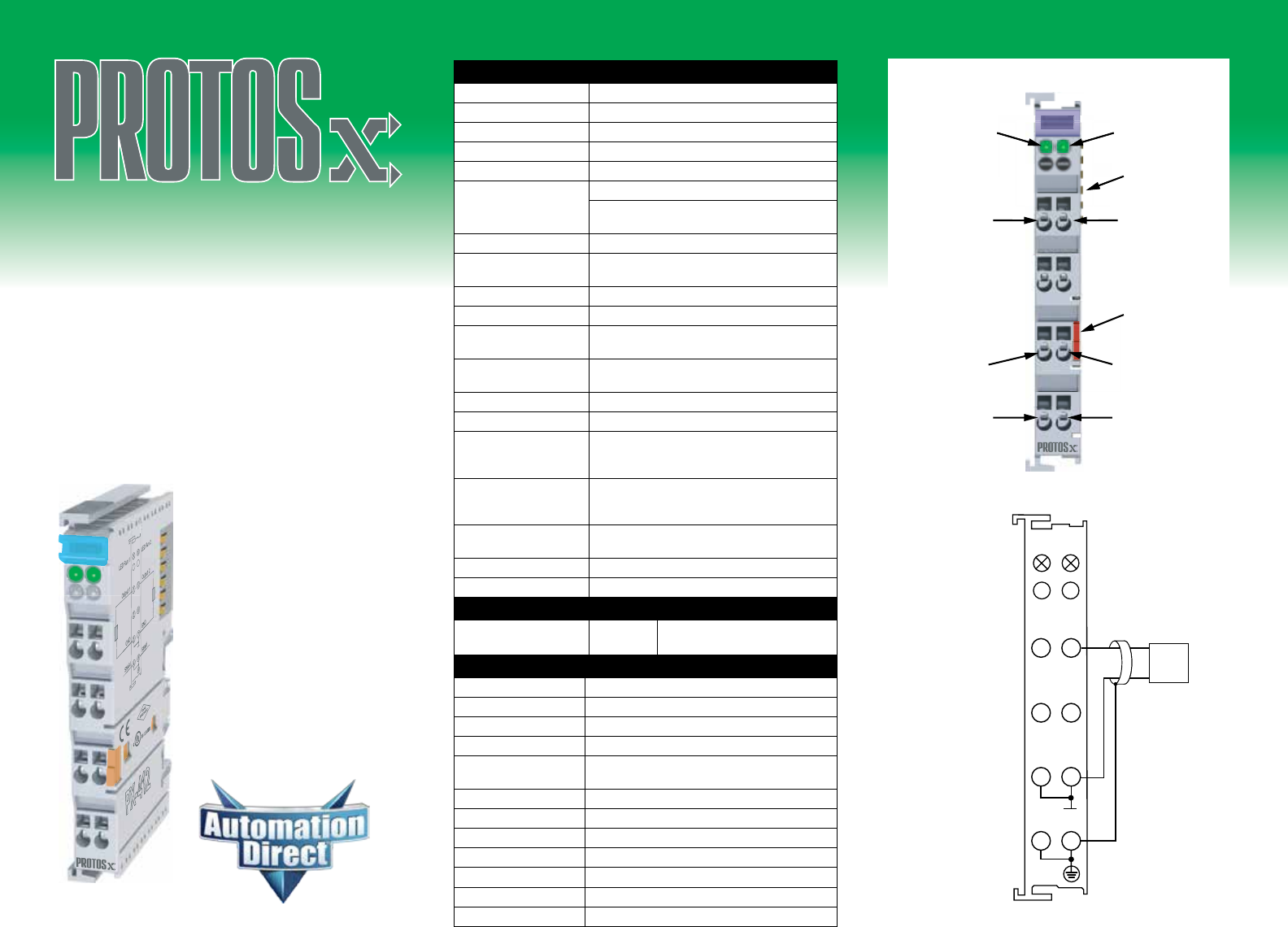
Run LED1
Shield
Ground
+Output 1
Shield
Run LED2
+Output 2
I/O Bus
contacts
DIN rail
release
tab
Ground
PX-412
R
LED Run 1LED Run 2
1
2
3
4
5
6
7
8
PX-412
–
+
Load
+O1+O2
GNDGND
Shld Shld
PX-412 Analog Voltage Output Terminal
Number of Channels 2
Output Ranges 0 to 10 VDC
Resolution 12 bit
Output Type Single-ended
Data Format Decimal: 0-32767
Data Bytes Consumed
PX-MOD: 4-bytes output
PX-TCP1/TCP2: 8-bytes out/8-bytes in (not
used)
Output Power Source 24VDC via terminal power bus
Load Consumption
(from Power Terminals) None
Source Load > 5kΩ (short-circuit protected)
Conversion Time Approx. 1.5ms
Accuracy ± 0.5 LSB linearity error, ± 0.5 LSB offset error
± 0.1% of the full scale value
Current Consumption
from I/O Bus (5V) 75mA
Electrical Isolation 500Vms (I/O Bus/signal voltage)
Heat Dissipation 1W max.
Adjacent Mounting on
Bus Terminals with
Power Contact
Yes
Adjacent Mounting on
Bus Terminals without
Power Contact
Yes
Passes Terminal Bus
Power No
Passes PE Bus No
Status Indicators 2, see LED Status chart
LED Status On Off
Green LED: RUN Normal
Operation
Watchdog error if no data
transmitted within WD set time.
General Specifi cations
Operating Temperature 32° to 131°F (0° to 55°C)
Storage Temperature 13° to 185°F (-25° to 85°C)
Relative Humidity 5% to 95%, non-condensing
Environment Air No corrosive gases permitted
Mounting/Orientation
Restrictions 35mm DIN rail/None
Vibration conforms to EN 60068-2-6
Shock conforms to EN 60068-2-27, EN 60068-2-29
Noise Immunity conforms to EN 61000-6-2/ EN61000-6-4
Protection Class IP20
Weight 85g
Dimensions (WxHxD) 12 x 100 x 68.8 mm (0.47 x 3.94 x 2.71 in)
Agency Approvals UL File No. E157382, CE
www.automationdirect.com
Protos XTM is a trademark of Automationdirect.com Incorporated

www.automationdirect.comSales 800-633-0405
HOT SWAP NOT PERMITTED
Always remove power from the system before inserting or
removing bus terminals or couplers as failure to do so could
cause malfunction or damage to the terminals, couplers or
other connected devices.
WIRING CONNECTION
Wire connection is made through a spring clamp style
terminal. This terminal is designed for a single-conductor
solid or stranded wire. Wire connection is made by rmly
pushing the screwdriver into the screwdriver slot, inserting
the wire into the wire slot and removing the screwdriver,
locking the wire into position.
WARNING
To minimize the risk of potential safety problems, you
should follow all applicable local and national codes
that regulate the installation and operation of your
equipment. These codes vary from area to area and it is
your responsibility to determine which codes should be
followed, and to verify that the equipment, installation,
and operation are in compliance with the latest revision
of these codes.
Equipment damage or serious injury to
personnel can result from the failure to follow all
applicable codes and standards. We do not guaran-
tee the products described in this publication are
suitable for your particular application, nor do we
assume any responsibility for your product design,
installation, or operation.
If you have any questions concerning the instal-
lation or operation of this equipment, or if you need
additional information, please call Technical Support at
770-844-4200.
This publication is based on information that was
available at the time it was printed. At AutomationDirect.
com® we constantly strive to improve our products and
services, so we reserve the right to make changes to
the products and/or publications at any time without
notice and without any obligation. This publication may
also discuss features that may not be available in
certain revisions of the product.
Document Name Edition/Revision Date
PX-412-DS 1st ED. 9/15/2014
Copyright 2014, AutomationDirect.com Incorporated/All Rights Reserved Worldwide.
MOUNTING
For system assembly, rst attach a bus coupler by
snapping onto 35mm DIN rail and securing into posi-
tion using the DIN rail locking wheel (where applicable)
located on the left side of the coupler. To add a bus
terminal, insert unit onto right side of bus coupler using
the tongue and groove at the top and bottom of the
unit, pressing gently until it snaps onto the DIN rail.
A proper connection cannot be made by sliding the
units together on the DIN rail. When correctly installed,
no signicant gap can be seen between the attached
units. Bus connection is made through the six slide
contacts located on the upper right side of the units.
Add up to 64 bus terminals per bus coupler, including a
bus end terminal.
REMOVAL
A locking mechanism prevents individual units from
being pulled off. For bus terminal removal, pull the
orange DIN rail release tab rmly to unlatch the unit
from the rail. If attached to other terminal units, slide
unit forward until released. For bus couplers with
locking wheels, release the DIN rail locking wheel, then
pull rmly on DIN rail release tab.
Wiring Specications
Connection Type Spring Clamp Terminals
Wire Gauge / Wire Cross Section 28-14 AWG / 0.08 - 2.5mm2
Screwdriver Width 2.5mm (0.10) such as our
TW-SD-MSL-2
Wire Stripping Length 8mm
Firmly pull DIN Rail Release Tab
to unlatch unit from rail.
Where applicable, rotate Locking
Wheel to unlock Bus Coupler
Tech Support 770-844-4200
IMPORTANT
For complete assembly instructions and compatibility
between terminals see the PX-USER-M manual available
for free download at www.automationdirect.com.
Insert unit using tongue and groove
molded guide and press gently until
it becomes firmly seated on DIN rail.
Align tab with
molded guide
ntil
r
a
a
i
i
l
l
.
Where applicable, rotate Locking
Wheel to lock Bus Coupler
Wire Slot
Screwdrive
r
Slot
S
S
