SINAMICS S120 Commissioning Manual With STARTER Ih1
User Manual:
Open the PDF directly: View PDF ![]() .
.
Page Count: 408 [warning: Documents this large are best viewed by clicking the View PDF Link!]
- SINAMICS S120 Commissioning manual with STARTER
- Legal information - Warning notice system
- Preface
- Contents
- 1 Fundamental safety instructions
- 2 Preparation for commissioning
- 2.1 Requirements for commissioning
- 2.2 Check lists to commission SINAMICS S
- 2.3 PROFIBUS components
- 2.4 PROFINET components
- 2.5 System rules, sampling times and DRIVE-CLiQ wiring
- 2.6 Supported sample topologies
- 2.7 DRIVE-CLiQ diagnostics
- 2.8 Powering-up/powering-down the drive system
- 3 Commissioning
- 3.1 Safety instructions for commissioning
- 3.2 Procedure when commissioning
- 3.3 STARTER commissioning tool
- 3.3.1 General information on STARTER
- 3.3.2 Important functions in the STARTER commissioning tool
- 3.3.2.1 Restoring the factory settings
- 3.3.2.2 Load project to target device.
- 3.3.2.3 Create data records (offline) and copy
- 3.3.2.4 Retentively saving data
- 3.3.2.5 Load the project to the PG/PC
- 3.3.2.6 Create and correct safety functions
- 3.3.2.7 Activate write protection
- 3.3.2.8 Activate know-how protection
- 3.3.3 Activating online operation: STARTER via PROFIBUS
- 3.3.4 Activating online operation: STARTER via Ethernet
- 3.3.5 Activating online operation: STARTER via PROFINET IO
- 3.4 Creating a project in the STARTER commissioning tool
- 3.5 Commissioning the servo control booksize format for the first time
- 3.6 Commissioning U/f vector control booksize format for the first time
- 3.7 Commissioning the vector control chassis format for the first time
- 3.8 First commissioning vector control AC drive blocksize format
- 3.9 First commissioning servo control AC drive blocksize format
- 3.10 Commissioning of power units connected in parallel
- 3.11 Learn devices
- 3.12 Selection and configuration of encoders
- 3.13 Commissioning of SIMOTICS L-1FN3 linear motors
- 3.13.1 Safety instructions for commissioning linear motors
- 3.13.2 Checklists for commissioning
- 3.13.3 General information for setting the commutation
- 3.13.4 Parameterizing a motor and encoder
- 3.13.5 Parameterizing and testing the temperature sensors
- 3.13.6 Determining the angular commutation offset / maintaining the tolerance
- 3.13.7 Special case of a parallel connection
- 3.13.8 Optimization of the closed-loop control
- 3.14 Commissioning induction motors (ASM)
- 3.15 Commissioning of synchronous reluctance motors 1FP1 without a damper cage
- 3.16 Commissioning permanent-magnet synchronous motors
- 3.17 Commissioning separately-excited synchronous motors
- 3.18 Commissioning SIMOTICS T-1FW6 built-in torque motors
- 3.18.1 Safety instructions for commissioning of built-in torque motors
- 3.18.2 Checklists for commissioning
- 3.18.3 General information for setting the commutation
- 3.18.4 Parameterizing a motor and encoder
- 3.18.5 Parameterizing and testing the temperature sensors
- 3.18.6 Determining the angular commutation offset / maintaining the tolerance
- 3.18.7 Special case of a parallel connection
- 3.18.8 Optimization of the closed-loop control
- 3.19 Commissioning of SSI encoders
- 3.20 Commissioning of a 2-pole resolver as absolute encoder
- 3.21 Temperature sensors for SINAMICS components
- 3.22 Basic Operator Panel 20 (BOP20)
- 4 Diagnostics
- 4.1 Diagnostics via LEDs
- 4.1.1 Control Units
- 4.1.2 Power units
- 4.1.2.1 Safety instructions for diagnostic LEDs of the power units
- 4.1.2.2 Active Line Module booksize
- 4.1.2.3 Basic Line Module booksize
- 4.1.2.4 Smart Line Modules booksize 5 kW and 10 kW
- 4.1.2.5 Smart Line Modules booksize 16 kW to 55 kW
- 4.1.2.6 Single Motor Module / Double Motor Module / Power Module
- 4.1.2.7 Braking Module in booksize format
- 4.1.2.8 Smart Line Module booksize compact format
- 4.1.2.9 Motor Module booksize compact format
- 4.1.2.10 Control Interface Module in the Active Line Module chassis format
- 4.1.2.11 Control Interface Module in the Basic Line Module chassis format
- 4.1.2.12 Control Interface Module in the Smart Line Module chassis format
- 4.1.2.13 Control Interface Module in the Motor Module chassis format
- 4.1.2.14 Control Interface Module in the Power Module chassis format
- 4.1.3 Additional modules
- 4.1.3.1 Control Supply Module
- 4.1.3.2 Sensor Module Cabinet SMC10 / SMC20
- 4.1.3.3 Sensor Module Cabinet SMC30
- 4.1.3.4 Sensor Module Cabinet SMC40
- 4.1.3.5 Communication Board CBC10 for CANopen
- 4.1.3.6 Communication Board Ethernet CBE20
- 4.1.3.7 Communication Board Ethernet CBE25
- 4.1.3.8 Voltage Sensing Module VSM10
- 4.1.3.9 DRIVE-CLiQ Hub Module DMC20
- 4.1.4 Terminal Module
- 4.2 Diagnostics via STARTER
- 4.3 Diagnostic buffer
- 4.4 Diagnostics of uncommissioned axes
- 4.5 Fault and alarm messages
- 4.6 Troubleshooting for encoders
- 4.1 Diagnostics via LEDs
- A Appendix
- Index

STARTER Commissioning Manual
___________________
___________________
___________________
___________________
___________________
___________________
SINAMICS
S120
STARTER Commissioning Manual
Commissioning Manual
Applies to:
Firmware Version 4.8
(IH1), 07/2016
6SL3097
-4AF00-0BP5
Preface
Fundamental safety
instructions
1
Preparation for
commissioning
2
Commissioning
3
Diagnostics
4
Appendix
A

Siemens AG
Division Digital Factory
Postfach 48 48
90026 NÜRNBERG
GERMANY
Document order number: 6SL3097-4AF00-0BP5
Ⓟ
06/2016 Subject to change
Copyright © Siemens AG 2004 - 2016.
All rights reserved
Legal information
Warning notice system
This manual contains notices you have to observe in order to ensure your personal safety, as well as to prevent
damage to property. The notices referring to your personal safety are highlighted in the manual by a safety alert
symbol, notices referring only to property damage have no safety alert symbol. These notices shown below are
graded according to the degree of danger.
DANGER
indicates that death or severe personal injury will result if proper precautions are not taken.
WARNING
indicates that death or severe personal injury may result if proper precautions are not taken.
CAUTION
indicates that minor personal injury can result if proper precautions are not taken.
NOTICE
indicates that property damage can result if proper precautions are not taken.
If more than one degree of danger is present, the warning notice representing the highest degree of danger will
be used. A notice warning of injury to persons with a safety alert symbol may also include a warning relating to
property damage.
Qualified Personnel
The product/system described in this documentation may be operated only by
personnel qualified
for the specific
task in accordance with the relevant documentation, in particular its warning notices and safety instructions.
Qualified personnel are those who, based on their training and experience, are capable of identifying risks and
avoiding potential hazards when working with these products/systems.
Proper use of Siemens products
Note the following:
WARNING
Siemens products may only be used for the applications described in the catalog and in the relevant technical
documentation. If products and components from other manufacturers are used, these must be recommended
or approved by Siemens. Proper transport, storage, installation, assembly, commissioning, operation and
maintenance are required to ensure that the products operate safely and without any problems. The permissible
ambient conditions must be complied with. The information in the relevant documentation must be observed.
Trademarks
All names identified by ® are registered trademarks of Siemens AG. The remaining trademarks in this publication
may be trademarks whose use by third parties for their own purposes could violate the rights of the owner.
Disclaimer of Liability
We have reviewed the contents of this publication to ensure consistency with the hardware and software
described. Since variance cannot be precluded entirely, we cannot guarantee full consistency. However, the
information in this publication is reviewed regularly and any necessary corrections are included in subsequent
editions.

STARTER Commissioning Manual
Commissioning Manual, (IH1), 07/2016, 6SL3097-4AF00-0BP5 5
Preface
SINAMICS documentation
The SINAMICS documentation is organized in the following categories:
● General documentation/catalogs
● User documentation
● Manufacturer/service documentation
Additional information
You can find information on the following topics at the following address
(https://support.industry.siemens.com/cs/de/en/view/108993276):
● Ordering documentation/overview of documentation
● Additional links to download documents
● Using documentation online (find and search in manuals/information)
Please send any questions about the technical documentation (e.g. suggestions for
improvement, corrections) to the following e-mail address
(mailto:docu.motioncontrol@siemens.com).
Siemens MySupport/Documentation
At the following address (https://support.industry.siemens.com/My/ww/en/documentation),
you can find information on how to create your own individual documentation based on
Siemens' content, and adapt it for your own machine documentation.
Training
At the following address (http://www.siemens.com/sitrain), you can find information about
SITRAIN (Siemens training on products, systems and solutions for automation and drives).
FAQs
You can find Frequently Asked Questions in the Service&Support pages under Product
Support (https://support.industry.siemens.com/cs/de/en/ps/faq).
SINAMICS
You can find information about SINAMICS at the following address
(http://www.siemens.com/sinamics).

Preface
STARTER Commissioning Manual
6 Commissioning Manual, (IH1), 07/2016, 6SL3097-4AF00-0BP5
Usage phases and their documents/tools (as an example)
Table 1 Usage phases and the available documents/tools
Usage phase
Document/tool
Orientation
SINAMICS S Sales Documentation
Planning/configuration • SIZER Engineering Tool
• Configuration Manuals, Motors
Deciding/ordering SINAMICS S120 catalogs
• SIMOTION, SINAMICS S120 and Motors for Production Machines
(Catalog PM 21)
• SINAMICS and Motors for Single-axis Drives (Catalog D 31)
• SINUMERIK & SINAMICS
Equipment for Machine Tools (Catalog NC 61)
• SINUMERIK 840D sl Type 1B
Equipment for Machine Tools (Catalog NC 62)
Installation/assembly • SINAMICS S120 Manual for Control Units and Additional System Components
• SINAMICS S120 Manual for Booksize Power Units
• SINAMICS S120 Manual for Booksize Power Units C/D Type
• SINAMICS S120 Manual for Chassis Power Units, Air-cooled
• SINAMICS S120 Manual for Chassis Power Units, Liquid-cooled
• SINAMICS S120 Manual for AC Drives
• SINAMICS S120 Manual Combi
• SINAMICS S120M Manual Distributed Drive Technology
• SINAMICS HLA System Manual Hydraulic Drive
Commissioning • STARTER Commissioning Tool
• SINAMICS S120 Getting Started with STARTER
• SINAMICS S120 Commissioning Manual with STARTER
• SINAMICS S120 CANopen Commissioning Manual
• SINAMICS S120 Function Manual Drive Functions
• SINAMICS S120 Safety Integrated Function Manual
• SINAMICS S120/S150 List Manual
• SINAMICS HLA System Manual Hydraulic Drive
• Startdrive commissioning tool1)
• SINAMICS S120 Getting Started with Startdrive1)
• SINAMICS S120 Commissioning Manual with Startdrive1)
Usage/operation • SINAMICS S120 Commissioning Manual with STARTER
• SINAMICS S120/S150 List Manual
• SINAMICS HLA System Manual Hydraulic Drive
• SINAMICS S120 Commissioning Manual with Startdrive1)

Preface
STARTER Commissioning Manual
Commissioning Manual, (IH1), 07/2016, 6SL3097-4AF00-0BP5 7
Usage phase
Document/tool
Maintenance/servicing • SINAMICS S120 Commissioning Manual with STARTER
• SINAMICS S120/S150 List Manual
• SINAMICS S120 Commissioning Manual with Startdrive1)
References • SINAMICS S120/S150 List Manual
1) available as of Startdrive V14 release
Target group
This documentation is intended for machine manufacturers, commissioning engineers, and
service personnel who use the SINAMICS drive system.
Benefits
This manual provides all of the information, procedures and operator actions required for the
particular usage phase.
Standard scope
The scope of the functionality described in this document can differ from that of the drive
system that is actually supplied.
● Other functions not described in this documentation might be able to be executed in the
drive system. However, no claim can be made regarding the availability of these functions
when the equipment is first supplied or in the event of service.
● The documentation can also contain descriptions of functions that are not available in a
particular product version of the drive system. The functionality of the supplied drive
system should only be taken from the ordering documentation.
● Extensions or changes made by the machine manufacturer must be documented by the
machine manufacturer.
For reasons of clarity, this documentation does not contain all of the detailed information on
all of the product types, and cannot take into consideration every conceivable type of
installation, operation and service/maintenance.
Technical Support
Country-specific telephone numbers for technical support are provided in the Internet at the
following address (https://support.industry.siemens.com/sc/ww/en/sc/2090) in the "Contact"
area.

Preface
STARTER Commissioning Manual
8 Commissioning Manual, (IH1), 07/2016, 6SL3097-4AF00-0BP5
Relevant directives and standards
You can obtain an up-to-date list of currently certified components on request from your local
Siemens office. If you have any questions relating to certifications that have not yet been
completed, please ask your Siemens contact person.
Certificates for download
The certificates can be downloaded from the Internet:
Certificates (https://support.industry.siemens.com/cs/ww/de/ps/13206/cert)
EC Declaration of Conformity
You can find the EC Declaration of Conformity for the relevant directives as well as the
relevant certificates, prototype test certificates, manufacturers declarations and test
certificates for functions relating to functional safety ("Safety Integrated") on the Internet at
the following address (https://support.industry.siemens.com/cs/ww/en/ps/13231/cert).
The following directives and standards are relevant for SINAMICS S devices:
European low-voltage directive
SINAMICS S devices fulfil the requirements stipulated in the Low-Voltage Directive
2014/35/EU, insofar as they are covered by the application area of this directive.
European machinery directive
SINAMICS S devices fulfil the requirements stipulated in the Low-Voltage Directive
2006/42/EU, insofar as they are covered by the application area of this directive.
However, the use of the SINAMICS S devices in a typical machine application has been fully
assessed for compliance with the main regulations in this directive concerning health and
safety.
European EMC Directive
SINAMICS S devices comply with the EMC Directive 2014/30/EU.
EMC requirements for South Korea
SINAMICS S devices with the KC marking on the rating plate satisfy the EMC requirements
for South Korea.
Specification for semiconductor process equipment voltage drop immunity
SINAMICS S devices meet the requirements of standard SEMI F47-0706.
Eurasian conformity
SINAMICS S comply with the requirements of the Russia/Belarus/Kazakhstan customs union
(EAC).
Preface
STARTER Commissioning Manual
Commissioning Manual, (IH1), 07/2016, 6SL3097-4AF00-0BP5 9
North American market
SINAMICS S devices provided with one of the test symbols displayed fulfil the requirements
stipulated for the North American market as a component of drive applications.
You can find the relevant certificates on the Internet pages of the certifiers:
● For products with UL certificate (http://database.ul.com/cgi-
bin/XYV/template/LISEXT/1FRAME/index.html)
● For products with TÜV SÜD certificate (https://www.tuev-
sued.de/industry_and_consumer_products/certificates)
Possible test symbols
Australia and New Zealand (RCM formerly C-Tick)
SINAMICS S devices showing the test symbols fulfil the EMC requirements for Australia and
New Zealand.
Quality systems
Siemens AG employs a quality management system that meets the requirements of ISO
9001 and ISO 14001.
Not relevant standards
China Compulsory Certification
SINAMICS S devices do not fall in the area of validity of the China Compulsory Certification
(CCC).
EMC limit values in South Korea
The EMC limit values to be observed for Korea correspond to the limit values of the EMC
product standard for variable-speed electric drives EN 61800-3 of category C2 or the limit
value class A, Group 1 to KN11. By implementing appropriate additional measures, the limit
values according to category C2 or limit value class A, Group 1, are observed. Further,
additional measures may be required, such as using an additional radio interference
suppression filter (EMC filter).
The measures for EMC-compliant design of the system are described in detail in this manual
respectively in the EMC Installation Guideline Configuration Manual.
The final statement regarding compliance with the standard is given by the respective label
attached to the individual unit.

Preface
STARTER Commissioning Manual
10 Commissioning Manual, (IH1), 07/2016, 6SL3097-4AF00-0BP5
Ensuring reliable operation
The manual describes a desired state which, if maintained, ensures the required level of
operational reliability and compliance with EMC limit values.
Should there be any deviation from the requirements in the manual, appropriate actions (e.g.
measurements) must be taken to check/prove that the required level of operational reliability
and compliance with EMC limit values are ensured.
Spare parts
Spare parts are available on the Internet at the following address
(https://www.automation.siemens.com/sow?sap-language=EN).
Product maintenance
The components are subject to continuous further development within the scope of product
maintenance (improvements to robustness, discontinuations of components, etc).
These further developments are "spare parts-compatible" and do not change the article
number.
In the scope of such spare parts-compatible further developments, connector positions are
sometimes changed slightly. This does not cause any problems with proper use of the
components. Please take this fact into consideration in special installation situations (e.g.
allow sufficient clearance for the cable length).
Use of third-party products
This document contains recommendations relating to third-party products. Siemens accepts
the fundamental suitability of these third-party products.
You can use equivalent products from other manufacturers.
Siemens does not accept any warranty for the properties of third-party products.

Preface
STARTER Commissioning Manual
Commissioning Manual, (IH1), 07/2016, 6SL3097-4AF00-0BP5 11
Ground symbols
Table 2 Symbols
Symbol
Meaning
Connection for protective conductor (PE)
Ground (e.g. M 24 V)
Connection for function potential bonding
Notation
The following notation and abbreviations are used in this documentation:
Notation for faults and alarms (examples):
•
F12345
Fault 12345
•
A67890
Alarm 67890
•
C23456
Safety message
Notation for parameters (examples):
•
p0918
Adjustable parameter 918
•
r1024
Display parameter 1024
•
p1070[1]
Adjustable parameter 1070, index 1
•
p2098[1].3
Adjustable parameter 2098, index 1 bit 3
•
p0099[0...3]
Adju
stable parameter 99, indices 0 to 3
•
r0945[2](3)
Display parameter 945, index 2 of drive object 3
•
p0795.4
Adjustable parameter 795, bit 4

Preface
STARTER Commissioning Manual
12 Commissioning Manual, (IH1), 07/2016, 6SL3097-4AF00-0BP5
STARTER Commissioning Manual
Commissioning Manual, (IH1), 07/2016, 6SL3097-4AF00-0BP5 13
Contents
Preface ................................................................................................................................................... 5
1 Fundamental safety instructions ............................................................................................................ 19
1.1 General safety instructions ..................................................................................................... 19
1.2 Safety instructions for electromagnetic fields (EMF) .............................................................. 24
1.3 Handling electrostatic sensitive devices (ESD) ...................................................................... 25
1.4 Industrial security .................................................................................................................... 26
1.5 Residual risks of power drive systems .................................................................................... 27
2 Preparation for commissioning .............................................................................................................. 29
2.1 Requirements for commissioning ........................................................................................... 30
2.2 Check lists to commission SINAMICS S................................................................................. 32
2.3 PROFIBUS components ......................................................................................................... 35
2.4 PROFINET components ......................................................................................................... 36
2.5 System rules, sampling times and DRIVE-CLiQ wiring .......................................................... 37
2.5.1 Overview of system limits and system utilization .................................................................... 37
2.5.2 System rules ........................................................................................................................... 38
2.5.3 Rules on the sampling times ................................................................................................... 40
2.5.3.1 Rules when setting the sampling times .................................................................................. 40
2.5.3.2 Rules for isochronous mode ................................................................................................... 42
2.5.3.3 Default settings for the sampling times ................................................................................... 44
2.5.3.4 Setting the pulse frequency .................................................................................................... 45
2.5.3.5 Setting sampling times ............................................................................................................ 46
2.5.3.6 Overview of important parameters .......................................................................................... 47
2.5.4 Rules for wiring with DRIVE-CLiQ .......................................................................................... 48
2.5.4.1 Binding DRIVE-CLiQ interconnection rules ............................................................................ 48
2.5.4.2 Recommended interconnection rules ..................................................................................... 50
2.5.4.3 Rules for automatic configuration ........................................................................................... 53
2.5.4.4 Changing the offline topology in the STARTER commissioning tool ...................................... 54
2.5.4.5 Modular machine concept: Offline correction of the reference topology ................................ 55
2.5.5 Notes on the number of controllable drives ............................................................................ 58
2.5.5.1 Number of drives depending on the control mode and cycle times ........................................ 58
2.5.5.2 Cycle mix for servo control and vector control ........................................................................ 64
2.6 Supported sample topologies ................................................................................................. 67
2.6.1 Topology example: Drives in vector control ............................................................................ 67
2.6.2 Topology example: Parallel Motor Modules in vector control ................................................. 69
2.6.3 Topology example: Power Modules ........................................................................................ 70
2.6.4 Example topologies: Drives in servo control. .......................................................................... 72
2.6.4.1 Example: Sampling time 125 µs ............................................................................................. 72
2.6.4.2 Examples: Sampling time 62.5 µs and 31.25 µs .................................................................... 73
2.6.5 Topology example: Drives in U/f control (vector control) ........................................................ 74

Contents
STARTER Commissioning Manual
14 Commissioning Manual, (IH1), 07/2016, 6SL3097-4AF00-0BP5
2.7 DRIVE-CLiQ diagnostics ........................................................................................................ 75
2.8 Powering-up/powering-down the drive system ...................................................................... 76
3 Commissioning ..................................................................................................................................... 81
3.1 Safety instructions for commissioning ................................................................................... 81
3.2 Procedure when commissioning ............................................................................................ 82
3.3 STARTER commissioning tool ............................................................................................... 84
3.3.1 General information on STARTER ......................................................................................... 84
3.3.1.1 Calling STARTER .................................................................................................................. 84
3.3.1.2 Description of the user interface ............................................................................................ 85
3.3.1.3 BICO interconnection procedure in STARTER ...................................................................... 86
3.3.2 Important functions in the STARTER commissioning tool ..................................................... 95
3.3.2.1 Restoring the factory settings ................................................................................................ 95
3.3.2.2 Load project to target device. ................................................................................................. 96
3.3.2.3 Create data records (offline) and copy .................................................................................. 96
3.3.2.4 Retentively saving data .......................................................................................................... 96
3.3.2.5 Load the project to the PG/PC ............................................................................................... 97
3.3.2.6 Create and correct safety functions ....................................................................................... 97
3.3.2.7 Activate write protection ......................................................................................................... 97
3.3.2.8 Activate know-how protection ................................................................................................ 98
3.3.3 Activating online operation: STARTER via PROFIBUS ....................................................... 100
3.3.4 Activating online operation: STARTER via Ethernet............................................................ 102
3.3.5 Activating online operation: STARTER via PROFINET IO .................................................. 108
3.4 Creating a project in the STARTER commissioning tool ..................................................... 115
3.4.1 Creating a project offline ...................................................................................................... 115
3.4.2 Creating a project online ...................................................................................................... 119
3.5 Commissioning the servo control booksize format for the first time .................................... 123
3.5.1 Task ..................................................................................................................................... 123
3.5.2 Component wiring (example) ............................................................................................... 125
3.5.3 Signal flow of the commissioning example .......................................................................... 126
3.5.4 Commissioning with STARTER (example) .......................................................................... 127
3.6 Commissioning U/f vector control booksize format for the first time .................................... 133
3.6.1 Task ..................................................................................................................................... 133
3.6.2 Component wiring (example) ............................................................................................... 134
3.6.3 Signal flow of the commissioning example .......................................................................... 135
3.6.4 Commissioning with STARTER (example) .......................................................................... 136
3.7 Commissioning the vector control chassis format for the first time ..................................... 143
3.7.1 Task ..................................................................................................................................... 144
3.7.2 Component wiring (example) ............................................................................................... 145
3.7.3 Signal flow of the commissioning example .......................................................................... 146
3.7.4 Commissioning with STARTER (example) .......................................................................... 147
3.8 First commissioning vector control AC drive blocksize format ............................................ 155
3.8.1 Task ..................................................................................................................................... 155
3.8.2 Component wiring (example) ............................................................................................... 156
3.8.3 Quick commissioning using the BOP (example) .................................................................. 156

Contents
STARTER Commissioning Manual
Commissioning Manual, (IH1), 07/2016, 6SL3097-4AF00-0BP5 15
3.9 First commissioning servo control AC drive blocksize format .............................................. 160
3.9.1 Task ...................................................................................................................................... 160
3.9.2 Component wiring (example) ................................................................................................ 161
3.9.3 Quick commissioning using the BOP (example) .................................................................. 162
3.10 Commissioning of power units connected in parallel ............................................................ 165
3.11 Learn devices ........................................................................................................................ 171
3.12 Selection and configuration of encoders............................................................................... 173
3.12.1 Encoder selection ................................................................................................................. 173
3.12.2 Configuring an encoder......................................................................................................... 174
3.12.3 Example: Commissioning and replacement of a DRIVE-CLiQ encoder ............................... 180
3.13 Commissioning of SIMOTICS L-1FN3 linear motors ............................................................ 182
3.13.1 Safety instructions for commissioning linear motors ............................................................ 182
3.13.2 Checklists for commissioning ............................................................................................... 183
3.13.3 General information for setting the commutation .................................................................. 185
3.13.4 Parameterizing a motor and encoder ................................................................................... 186
3.13.5 Parameterizing and testing the temperature sensors ........................................................... 200
3.13.6 Determining the angular commutation offset / maintaining the tolerance ............................ 204
3.13.6.1 Checking the commutation angle offset with STARTER ...................................................... 205
3.13.6.2 Checking the commutation angle offset with an oscilloscope .............................................. 206
3.13.7 Special case of a parallel connection ................................................................................... 218
3.13.8 Optimization of the closed-loop control ................................................................................. 219
3.14 Commissioning induction motors (ASM)............................................................................... 220
3.15 Commissioning of synchronous reluctance motors 1FP1 without a damper cage ............... 223
3.16 Commissioning permanent-magnet synchronous motors .................................................... 225
3.16.1 Encoder adjustment in operation .......................................................................................... 230
3.16.2 Automatic encoder adjustment ............................................................................................. 232
3.16.3 Pole position identification .................................................................................................... 232
3.16.4 Overview of the important parameters .................................................................................. 234
3.17 Commissioning separately-excited synchronous motors ..................................................... 235
3.18 Commissioning SIMOTICS T-1FW6 built-in torque motors .................................................. 236
3.18.1 Safety instructions for commissioning of built-in torque motors ........................................... 236
3.18.2 Checklists for commissioning ............................................................................................... 237
3.18.3 General information for setting the commutation .................................................................. 239
3.18.4 Parameterizing a motor and encoder ................................................................................... 240
3.18.5 Parameterizing and testing the temperature sensors ........................................................... 254
3.18.6 Determining the angular commutation offset / maintaining the tolerance ............................ 258
3.18.6.1 Checking the commutation angle offset with STARTER ...................................................... 260
3.18.6.2 Checking the commutation angle offset with an oscilloscope .............................................. 260
3.18.7 Special case of a parallel connection ................................................................................... 272
3.18.8 Optimization of the closed-loop control ................................................................................. 273
3.19 Commissioning of SSI encoders ........................................................................................... 274
3.19.1 Notes on commissioning SSI encoders ................................................................................ 274
3.19.2 Encoder identification for SSI encoders without incremental tracks ..................................... 278
3.19.3 Overview of important parameters ........................................................................................ 280
3.20 Commissioning of a 2-pole resolver as absolute encoder .................................................... 281

Contents
STARTER Commissioning Manual
16 Commissioning Manual, (IH1), 07/2016, 6SL3097-4AF00-0BP5
3.21 Temperature sensors for SINAMICS components .............................................................. 282
3.22 Basic Operator Panel 20 (BOP20) ....................................................................................... 292
3.22.1 Operation with BOP20 (Basic Operator Panel 20) .............................................................. 292
3.22.1.1 General information about the BOP20 ................................................................................. 292
3.22.1.2 Displays and using the BOP20 ............................................................................................ 296
3.22.1.3 Fault and alarm displays ...................................................................................................... 301
3.22.1.4 Controlling the drive using the BOP20 ................................................................................. 302
3.22.2 Important functions via BOP20 ............................................................................................ 302
4 Diagnostics .......................................................................................................................................... 305
4.1 Diagnostics via LEDs ........................................................................................................... 306
4.1.1 Control Units ........................................................................................................................ 306
4.1.1.1 Description of the LED states of a CU320-2 ........................................................................ 306
4.1.1.2 Description of the LED states of a CU310-2 ........................................................................ 311
4.1.2 Power units .......................................................................................................................... 316
4.1.2.1 Safety instructions for diagnostic LEDs of the power units .................................................. 316
4.1.2.2 Active Line Module booksize ............................................................................................... 316
4.1.2.3 Basic Line Module booksize ................................................................................................ 317
4.1.2.4 Smart Line Modules booksize 5 kW and 10 kW .................................................................. 318
4.1.2.5 Smart Line Modules booksize 16 kW to 55 kW ................................................................... 318
4.1.2.6 Single Motor Module / Double Motor Module / Power Module ............................................ 319
4.1.2.7 Braking Module in booksize format ...................................................................................... 320
4.1.2.8 Smart Line Module booksize compact format ...................................................................... 320
4.1.2.9 Motor Module booksize compact format .............................................................................. 321
4.1.2.10 Control Interface Module in the Active Line Module chassis format .................................... 322
4.1.2.11 Control Interface Module in the Basic Line Module chassis format ..................................... 323
4.1.2.12 Control Interface Module in the Smart Line Module chassis format .................................... 324
4.1.2.13 Control Interface Module in the Motor Module chassis format ............................................ 325
4.1.2.14 Control Interface Module in the Power Module chassis format ........................................... 326
4.1.3 Additional modules ............................................................................................................... 327
4.1.3.1 Control Supply Module ......................................................................................................... 327
4.1.3.2 Sensor Module Cabinet SMC10 / SMC20 ........................................................................... 327
4.1.3.3 Sensor Module Cabinet SMC30 .......................................................................................... 328
4.1.3.4 Sensor Module Cabinet SMC40 .......................................................................................... 328
4.1.3.5 Communication Board CBC10 for CANopen ....................................................................... 329
4.1.3.6 Communication Board Ethernet CBE20 .............................................................................. 330
4.1.3.7 Communication Board Ethernet CBE25 .............................................................................. 332
4.1.3.8 Voltage Sensing Module VSM10 ......................................................................................... 334
4.1.3.9 DRIVE-CLiQ Hub Module DMC20 ....................................................................................... 334
4.1.4 Terminal Module .................................................................................................................. 335
4.1.4.1 Terminal Module TM15 ........................................................................................................ 335
4.1.4.2 Terminal Module TM31 ........................................................................................................ 336
4.1.4.3 Terminal Module TM120 ...................................................................................................... 336
4.1.4.4 Terminal Module TM150 ...................................................................................................... 337
4.1.4.5 Terminal Module TM41 ........................................................................................................ 338
4.1.4.6 Terminal Module TM54F ...................................................................................................... 339

Contents
STARTER Commissioning Manual
Commissioning Manual, (IH1), 07/2016, 6SL3097-4AF00-0BP5 17
4.2 Diagnostics via STARTER .................................................................................................... 341
4.2.1 Function generator ................................................................................................................ 341
4.2.2 Trace function ....................................................................................................................... 345
4.2.2.1 Single trace ........................................................................................................................... 345
4.2.2.2 Multiple trace ......................................................................................................................... 348
4.2.2.3 Startup trace ......................................................................................................................... 350
4.2.2.4 Overview of important alarms and faults .............................................................................. 352
4.2.3 Measuring function ................................................................................................................ 353
4.2.4 Measuring sockets ................................................................................................................ 355
4.3 Diagnostic buffer ................................................................................................................... 360
4.4 Diagnostics of uncommissioned axes................................................................................... 363
4.5 Fault and alarm messages ................................................................................................... 366
4.5.1 General information about faults and alarms ........................................................................ 366
4.5.2 Buffer for faults and alarms ................................................................................................... 367
4.5.3 Configuring messages .......................................................................................................... 371
4.5.4 Overview of important function diagrams and parameters ................................................... 374
4.5.5 Propagation of faults ............................................................................................................. 375
4.5.6 Alarm classes ........................................................................................................................ 376
4.6 Troubleshooting for encoders ............................................................................................... 378
A Appendix............................................................................................................................................. 381
A.1 List of abbreviations .............................................................................................................. 381
A.2 Documentation overview ...................................................................................................... 391
A.3 Availability of hardware components .................................................................................... 392
A.4 Availability of SW functions ................................................................................................... 397
Index................................................................................................................................................... 403

Contents
STARTER Commissioning Manual
18 Commissioning Manual, (IH1), 07/2016, 6SL3097-4AF00-0BP5
STARTER Commissioning Manual
Commissioning Manual, (IH1), 07/2016, 6SL3097-4AF00-0BP5 19
Fundamental safety instructions
1
1.1
General safety instructions
DANGER
Danger to life due to live parts and other energy sources
Death or serious injury can result when live parts are touched.
• Only work on electrical devices when you are qualified for this job.
• Always observe the country-specific safety rules.
Generally, six steps apply when establishing safety:
1. Prepare for shutdown and notify all those who will be affected by the procedure.
2. Disconnect the machine from the supply.
– Switch off the machine.
– Wait until the discharge time specified on the warning labels has elapsed.
– Check that it really is in a no-voltage condition, from phase conductor to phase
conductor and phase conductor to protective conductor.
– Check whether the existing auxiliary supply circuits are de-energized.
– Ensure that the motors cannot move.
3. Identify all other dangerous energy sources, e.g. compressed air, hydraulic systems, or
water.
4. Isolate or neutralize all hazardous energy sources by closing switches, grounding or
short-circuiting or closing valves, for example.
5. Secure the energy sources against switching on again.
6. Ensure that the correct machine is completely interlocked.
After you have completed the work, restore the operational readiness in the inverse
sequence.
WARNING
Danger to life through a hazardous voltage when connecting an unsuitable power supply
Touching live components can result in death or severe injury.
• Only use power supplies that provide SELV (Safety Extra Low Voltage) or PELV-
(Protective Extra Low Voltage) output voltages for all connections and terminals of the
electronics modules.
Fundamental safety instructions
1.1 General safety instructions
STARTER Commissioning Manual
20 Commissioning Manual, (IH1), 07/2016, 6SL3097-4AF00-0BP5
WARNING
Danger to life when live parts are touched on damaged devices
Improper handling of devices can cause damage.
For damaged devices, hazardous voltages can be present at the enclosure or at exposed
components; if touched, this can result in death or severe injury.
• Ensure compliance with the limit values specified in the technical data during transport,
storage and operation.
• Do not use any damaged devices.
WARNING
Danger to life through electric shock due to unconnected cable shields
Hazardous touch voltages can occur through capacitive cross-coupling due to unconnected
cable shields.
• As a minimum, connect cable shields and the conductors of power cables that are not
used (e.g. brake cores) at one end at the grounded housing potential.
WARNING
Danger to life due to electric shock when not grounded
For missing or incorrectly implemented protective conductor connection for devices with
protection class I, high voltages can be present at open, exposed parts, which when
touched, can result in death or severe injury.
• Ground the device in compliance with the applicable regulations.
WARNING
Danger to life due to electric shock when opening plug connections in operation
When opening plug connections in operation, arcs can result in severe injury or death.
• Only open plug connections when the equipment is in a no-voltage state, unless it has
been explicitly stated that they can be opened in operation.
Fundamental safety instructions
1.1 General safety instructions
STARTER Commissioning Manual
Commissioning Manual, (IH1), 07/2016, 6SL3097-4AF00-0BP5 21
NOTICE
Material damage due to loose power connections
Insufficient tightening torques or vibrations can result in loose electrical connections. This
can result in damage due to fire, device defects or malfunctions.
• Tighten all power connections with the specified tightening torques, e.g. line supply
connection, motor connection, DC link connections.
• Check all power connections at regular intervals. This applies in particular after
transport.
WARNING
Danger to life due to fire spreading if housing is inadequate
Fire and smoke development can cause severe personal injury or material damage.
• Install devices without a protective housing in a metal control cabinet (or protect the
device by another equivalent measure) in such a way that contact with fire is prevented.
• Ensure that smoke can only escape via controlled and monitored paths.
WARNING
Danger to life through unexpected movement of machines when using mobile wireless
devices or mobile phones
Using mobile wireless devices or mobile phones with a transmit power > 1 W closer than
approx. 2 m to the components may cause the devices to malfunction, influence the
functional safety of machines therefore putting people at risk or causing material damage.
• Switch the wireless devices or mobile phones off in the immediate vicinity of the
components.
WARNING
Danger to life due to the motor catching fire in the event of insulation overload
There is higher stress on the motor insulation through a ground fault in an IT system. If the
insulation fails, it is possible that death or severe injury can occur as a result of smoke and
fire.
• Use a monitoring device that signals an insulation fault.
• Correct the fault as quickly as possible so the motor insulation is not overloaded.
Fundamental safety instructions
1.1 General safety instructions
STARTER Commissioning Manual
22 Commissioning Manual, (IH1), 07/2016, 6SL3097-4AF00-0BP5
WARNING
Danger to life due to fire if overheating occurs because of insufficient ventilation clearances
Inadequate ventilation clearances can cause overheating of components with subsequent
fire and smoke. This can cause severe injury or even death. This can also result in
increased downtime and reduced service lives for devices/systems.
• Ensure compliance with the specified minimum clearance as ventilation clearance for
the respective component.
WARNING
Danger of an accident occurring due to missing or illegible warning labels
Missing or illegible warning labels can result in accidents involving death or serious injury.
• Check that the warning labels are complete based on the documentation.
• Attach any missing warning labels to the components, in the national language if
necessary.
• Replace illegible warning labels.
NOTICE
Device damage caused by incorrect voltage/insulation tests
Incorrect voltage/insulation tests can damage the device.
• Before carrying out a voltage/insulation check of the system/machine, disconnect the
devices as all converters and motors have been subject to a high voltage test by the
manufacturer, and therefore it is not necessary to perform an additional test within the
system/machine.
WARNING
Danger to life when safety functions are inactive
Safety functions that are inactive or that have not been adjusted accordingly can cause
operational faults on machines that could lead to serious injury or death.
• Observe the information in the appropriate product documentation before
commissioning.
• Carry out a safety inspection for functions relevant to safety on the entire system,
including all safety-related components.
• Ensure that the safety functions used in your drives and automation tasks are adjusted
and activated through appropriate parameterizing.
• Perform a function test.
• Only put your plant into live operation once you have guaranteed that the functions
relevant to safety are running correctly.

Fundamental safety instructions
1.1 General safety instructions
STARTER Commissioning Manual
Commissioning Manual, (IH1), 07/2016, 6SL3097-4AF00-0BP5 23
Note
Important safety notices for Safety Integrated functions
If you want to use Safety Integrated functions, you must observe the safety notices in the
Safety I
ntegrated manuals.
WARNING
Danger to life or malfunctions of the machine as a result of incorrect or changed
parameterization
As a result of incorrect or changed parameterization, machines can malfunction, which in
turn can lead to injuries or death.
• Protect the parameterization (parameter assignments) against unauthorized access.
• Respond to possible malfunctions by applying suitable measures (e.g. EMERGENCY
STOP or EMERGENCY OFF).
Fundamental safety instructions
1.2 Safety instructions for electromagnetic fields (EMF)
STARTER Commissioning Manual
24 Commissioning Manual, (IH1), 07/2016, 6SL3097-4AF00-0BP5
1.2
Safety instructions for electromagnetic fields (EMF)
WARNING
Danger to life from electromagnetic fields
Electromagnetic fields (EMF) are generated by the operation of electrical power equipment
such as transformers, converters or motors.
People with pacemakers or implants are at a special risk in the immediate vicinity of these
devices/systems.
• Ensure that the persons involved are the necessary distance away (minimum 2 m).

Fundamental safety instructions
1.3 Handling electrostatic sensitive devices (ESD)
STARTER Commissioning Manual
Commissioning Manual, (IH1), 07/2016, 6SL3097-4AF00-0BP5 25
1.3
Handling electrostatic sensitive devices (ESD)
Electrostatic sensitive devices (ESD) are individual components, integrated circuits, modules
or devices that may be damaged by either electric fields or electrostatic discharge.
NOTICE
Damage through electric fields or electrostatic discharge
Electric fields or electrostatic discharge can cause malfunctions through damaged
individual components, integrated circuits, modules or devices.
• Only pack, store, transport and send electronic components, modules or devices in their
original packaging or in other suitable materials, e.g conductive foam rubber of
aluminum foil.
• Only touch components, modules and devices when you are grounded by one of the
following methods:
– Wearing an ESD wrist strap
– Wearing ESD shoes or ESD grounding straps in ESD areas with conductive flooring
• Only place electronic components, modules or devices on conductive surfaces (table
with ESD surface, conductive ESD foam, ESD packaging, ESD transport container).
Fundamental safety instructions
1.4 Industrial security
STARTER Commissioning Manual
26 Commissioning Manual, (IH1), 07/2016, 6SL3097-4AF00-0BP5
1.4
Industrial security
Note
Industrial security
Siemens provides products and solutions with industrial security functions that support the
secure operation of plants, solutions, machines, equipmen
t and/or networks. They are
important components in a holistic industrial security concept. With this in mind, Siemens’
products and solutions undergo continuous development. Siemens recommends strongly
that you regularly check for product updates.
For the
secure operation of Siemens products and solutions, it is necessary to take suitable
preventive action (e.g. cell protection concept) and integrate each component into a holistic,
state
-of-the-art industrial security concept. Third-party products that may be in use should
also be considered. For more information about industrial security, visit this address
(
http://www.siemens.com/industrialsecurity).
To stay informed about product updates as they
occur, sign up for a product-specific
newsletter. For more information, visit this address (
http://support.automation.siemens.com
).
WARNING
Danger as a result of unsafe operating states resulting from software manipulation
Software manipulation (e.g. by viruses, Trojan horses, malware, worms) can cause unsafe
operating states to develop in your installation which can result in death, severe injuries
and/or material damage.
• Keep the software up to date.
You will find relevant information and newsletters at this address
(http://support.automation.siemens.com).
• Incorporate the automation and drive components into a holistic, state-of-the-art
industrial security concept for the installation or machine.
You will find further information at this address
(http://www.siemens.com/industrialsecurity).
• Make sure that you include all installed products into the holistic industrial security
concept.
WARNING
Danger to life due to software manipulation when using exchangeable storage media
Storing files onto exchangeable storage media amounts to an increased risk of infection,
e.g. with viruses and malware. As a result of incorrect parameterization, machines can
malfunction, which in turn can lead to injuries or death.
• Protect files stored on exchangeable storage media from malicious software by taking
suitable protection measures, e.g. virus scanners.

Fundamental safety instructions
1.5 Residual risks of power drive systems
STARTER Commissioning Manual
Commissioning Manual, (IH1), 07/2016, 6SL3097-4AF00-0BP5 27
1.5
Residual risks of power drive systems
When assessing the machine- or system-related risk in accordance with the respective local
regulations (e.g., EC Machinery Directive), the machine manufacturer or system installer
must take into account the following residual risks emanating from the control and drive
components of a drive system:
1. Unintentional movements of driven machine or system components during
commissioning, operation, maintenance, and repairs caused by, for example,
– Hardware and/or software errors in the sensors, control system, actuators, and cables
and connections
– Response times of the control system and of the drive
– Operation and/or environmental conditions outside the specification
– Condensation/conductive contamination
– Parameterization, programming, cabling, and installation errors
– Use of wireless devices/mobile phones in the immediate vicinity of electronic
components
– External influences/damage
– X-ray, ionizing radiation and cosmic radiation
2. Unusually high temperatures, including open flames, as well as emissions of light, noise,
particles, gases, etc., can occur inside and outside the components under fault conditions
caused by, for example:
– Component failure
– Software errors
– Operation and/or environmental conditions outside the specification
– External influences/damage
3. Hazardous shock voltages caused by, for example:
– Component failure
– Influence during electrostatic charging
– Induction of voltages in moving motors
– Operation and/or environmental conditions outside the specification
– Condensation/conductive contamination
– External influences/damage
4. Electrical, magnetic and electromagnetic fields generated in operation that can pose a
risk to people with a pacemaker, implants or metal replacement joints, etc., if they are too
close
5. Release of environmental pollutants or emissions as a result of improper operation of the
system and/or failure to dispose of components safely and correctly
For more information about the residual risks of the drive system components, see the
relevant sections in the technical user documentation.

Fundamental safety instructions
1.5 Residual risks of power drive systems
STARTER Commissioning Manual
28 Commissioning Manual, (IH1), 07/2016, 6SL3097-4AF00-0BP5
STARTER Commissioning Manual
Commissioning Manual, (IH1), 07/2016, 6SL3097-4AF00-0BP5 29
Preparation for commissioning
2
Before commissioning observe the conditions described in this chapter.
● The preconditions for commissioning must be fulfilled (in the next chapter).
● The relevant checklist must have been worked through.
● The bus components required for communication must be wired up.
● DRIVE-CLiQ wiring rules must be complied with.
● The ON-OFF responses of the drive.

Preparation for commissioning
2.1 Requirements for commissioning
STARTER Commissioning Manual
30 Commissioning Manual, (IH1), 07/2016, 6SL3097-4AF00-0BP5
2.1
Requirements for commissioning
The following are necessary for commissioning a SINAMICS S drive system:
● A programming device (PG/PC)
● STARTER commissioning tool
● A communication interface, e.g. PROFIBUS, PROFINET, Ethernet
● Completely wired-up drive line-up (see the SINAMICS S120 Manual)
Preparation for commissioning
2.1 Requirements for commissioning
STARTER Commissioning Manual
Commissioning Manual, (IH1), 07/2016, 6SL3097-4AF00-0BP5 31
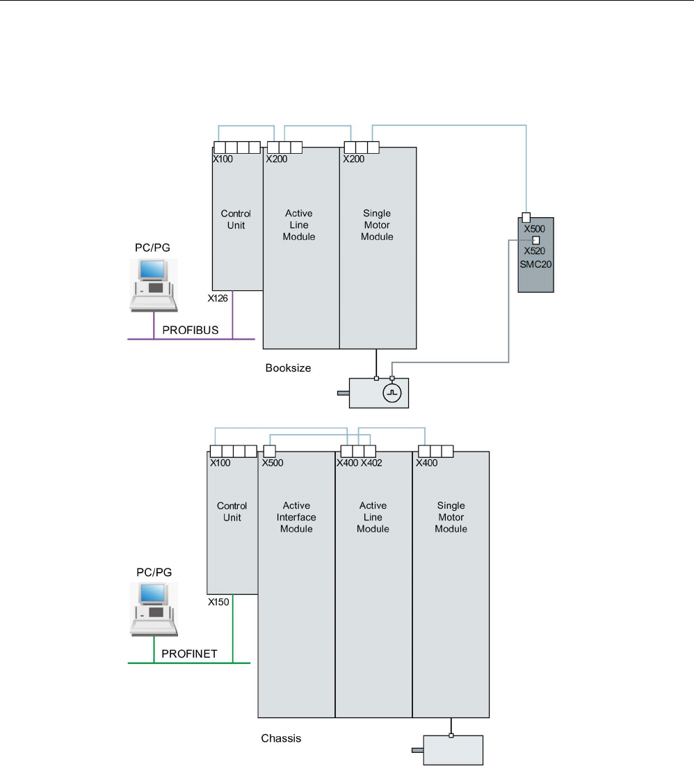
The following diagram shows a configuration example with booksize and chassis
components, as well as with PROFIBUS and PROFINET communication:
Image 2-1 Component configuration (example)

Preparation for commissioning
2.2 Check lists to commission SINAMICS S
STARTER Commissioning Manual
32 Commissioning Manual, (IH1), 07/2016, 6SL3097-4AF00-0BP5
2.2
Check lists to commission SINAMICS S
Checklist (1) for commissioning booksize power units
The following checklist must be carefully observed. Read the safety instructions in the
manuals before starting any work.
Table 2- 1 Checklist for commissioning (booksize)
Check
OK
Are the environmental conditions in the permissible range?
Is the component firmly attached to the fixing points provided?
Is the specified air flow for cooling the devices ensured?
Have the ventilation clearances for the components been observed?
Is the memory card correctly inserted in the Control Unit?
Are all necessary components of the configured drive line-up available, installed and
connected?
Do the temperature monitoring circuits fulfill the specifications of protective separa-
tion?
Have the DRIVE-CLiQ topology rules been observed?
Have the line-side and motor-side power cables been dimensioned and routed in
accordance with the environmental and routing conditions?
Have the maximum permitted cable lengths between the frequency converter and the
motor (depending on the type of cables used) been observed?
Have the power cables been properly connected to the component terminals with the
specified torque?
Have all of the remaining screws been tightened to the specified torque?
Has all wiring work been successfully completed?
Are all connectors correctly plugged in and screwed in place?
Have all the covers for the DC link been closed and latched into place?
Have the shield supports been correctly connected through a large surface area?
Checklist (2) for commissioning chassis power units
The following checklist must be carefully observed. Read the safety instructions in the
manuals before starting any work.
Table 2- 2 Checklist for commissioning (chassis)
Activity
OK
Are the environmental conditions in the permissible range?
Are the components correctly installed in the cabinets?
Is the specified air flow for cooling the devices ensured?
Is an air short-circuit between the air inlet and outlet for the chassis components pre-
vented by the installation arrangements?
Have the ventilation clearances for the components been observed?

Preparation for commissioning
2.2 Check lists to commission SINAMICS S
STARTER Commissioning Manual
Commissioning Manual, (IH1), 07/2016, 6SL3097-4AF00-0BP5 33
Activity
OK
Is the memory card correctly inserted in the Control Unit?
Are all necessary components of the configured drive line-up available, installed and
connected?
Do the temperature monitoring circuits fulfill the specifications of protective separa-
tion?
Have the DRIVE-CLiQ topology rules been observed?
Have the line-side and motor-side power cables been dimensioned and routed in
accordance with the environmental and routing conditions?
Have the maximum permitted cable lengths between the frequency converter and the
motor (depending on the type of cables used) been observed?
Is the ground for the motors directly connected to the ground for the Motor Modules
(shortest distance)?
Are the motors connected with shielded power cables?
Are the power cable shields connected as closely as possible to the terminal box
across a wide area?
Have the power cables been properly connected to the component terminals with the
specified torque?
Have all of the remaining screws been tightened to the specified torque?
Has the total power of the DC busbar been dimensioned sufficiently?
Has the busbar/wiring for the DC connection between the infeed and the Motor Mod-
ules been dimensioned sufficiently with regard to the load and installation conditions?
Are the cables between the low-voltage switchgear and the power unit protected with
line fuses? Line protection
(1)
must be taken into account.
Have measures been taken to relieve strain on the cables?
For external auxiliary infeed: Have the cables for the auxiliary infeed been connected
according to the Equipment Manual?
Have the control cables been connected in accordance with the required interface
configuration and the shield applied?
Have the digital and analog signals been routed with separate cables?
Has the distance from power cables been observed?
Has the cabinet been properly grounded at the points provided?
Has the connection voltage for the fans in the chassis components been adapted
accordingly to the supply voltages?
For operation on non-grounded supply systems: Has the connection bracket for the
interference suppression at the Infeed Module or the Power Module been removed?
Is the period from the date of manufacture to the initial commissioning or the downtime
of the power components less than two years
(2)
?
Is the drive operated from a higher-level controller/control room?
(1)
Combined fuses are recommended for conductor and semi-conductor protection (VDE 636,
Part 10 and Part 40 / EN 60269-4). For information about the relevant fuses, see the catalog.
(2)
If the downtime period is longer than two years, the DC-link capacitors must be formed (see the
"Maintenance and Servicing" chapter in the Equipment Manual). The cabinet type plate can be
used to ascertain the date of manufacture.

Preparation for commissioning
2.2 Check lists to commission SINAMICS S
STARTER Commissioning Manual
34 Commissioning Manual, (IH1), 07/2016, 6SL3097-4AF00-0BP5
Checklist (3) for commissioning blocksize Power Modules
The following checklist must be carefully observed. Read the safety instructions in the
manuals before starting any work.
Table 2- 3 Check list for commissioning blocksize
Check
OK
Are the environmental conditions in the permissible range?
Is the component firmly attached to the fixing points provided?
Is the specified air flow for cooling the devices ensured?
Have the ventilation clearances for the components been observed?
Is the memory card correctly inserted in the Control Unit?
Are all necessary components of the configured drive line-up available, installed and
connected?
Do the temperature monitoring circuits fulfill the specifications of protective separa-
tion?
Have the line-side and motor-side power cables been dimensioned and routed in
accordance with the environmental and routing conditions?
Have the maximum permitted cable lengths between the frequency converter and the
motor (depending on the type of cables used) been observed?
Have the power cables been properly connected to the component terminals with the
specified torque?
Have all of the remaining screws been tightened to the specified torque?
Has all wiring work been successfully completed?
Are all connectors correctly plugged in and screwed in place?
Have the shield supports been correctly connected through a large surface area?

Preparation for commissioning
2.3 PROFIBUS components
STARTER Commissioning Manual
Commissioning Manual, (IH1), 07/2016, 6SL3097-4AF00-0BP5 35
2.3
PROFIBUS components
For communication via PROFIBUS, the following components are necessary.
● A communication module for PG/PC connection via the PROFIBUS interface.
– PROFIBUS connection to a PG/PC via USB port (USB V2.0).
Structure: USB port (USB V2.0) + adapter with 9-pin SUB-D socket connector to
connect to PROFIBUS.
Used with driver SIMATIC NET PC Software Edition 2008 + SP2
Article number: 6GK1571-1AA00
● Connecting cable
Connecting cable between PROFIBUS adapter and PG/PC, such as
– CP 5xxx cable, article number: 6ES7901-4BD00-0XA0
– MPI cable (SIMATIC S7), article number: 6ES7901-0BF00-0AA0
Cable lengths
Table 2- 4 Permissible PROFIBUS cable lengths
Baud rate [bit/s]
Max. cable length [m]
9.6 k to 187.5 k
1000
500 k 400
1500 k
200
3000 to 12000 k
100

Preparation for commissioning
2.4 PROFINET components
STARTER Commissioning Manual
36 Commissioning Manual, (IH1), 07/2016, 6SL3097-4AF00-0BP5
2.4
PROFINET components
For communication via PROFINET, the following components are necessary:
● A communication module for PG/PC connection via the PROFINET interface.
Note
Cables that can be used for commissioning
For commissioning using the STARTER commissioning tool, the onboard Ethernet
interface of the Control Unit can be used with a crosso
ver cable from CAT5 and higher.
The PROFINET module CBE20 supports all standard Ethernet cables and crossover
cables from CAT5/5e and higher. The crossover cable is essential for an Ethernet X127
interface.
● Connecting cable
Connecting cable between PROFINET interface and PG/PC, such as
– Industrial Ethernet FC TP Standard Cable GP 2 x 2 (up to max. 100 m)
Standard bus cable with rigid conductors and a special design for fast installation
– Industrial Ethernet FC TP Flexible Cable GP 2 x 2 (up to max. 85 m)
– Industrial Ethernet FC Trailing Cable GP 2 x 2 (up to max. 85 m)
– Industrial Ethernet FC Trailing Cable 2 x 2 (up to max. 85 m)
– Industrial Ethernet FC Marine Cable 2 x 2 (up to max. 85 m)
● Connector
Connector between the PROFINET interface and the PG/PC, for example
– Industrial Ethernet FC RJ45 Plug 145 for Control Unit

Preparation for commissioning
2.5 System rules, sampling times and DRIVE-CLiQ wiring
STARTER Commissioning Manual
Commissioning Manual, (IH1), 07/2016, 6SL3097-4AF00-0BP5 37
2.5
System rules, sampling times and DRIVE-CLiQ wiring
2.5.1
Overview of system limits and system utilization
The number and type of controlled axes, infeeds and Terminal Modules as well as the
additionally activated functions can be scaled by configuring the firmware.
Note
The subsequently described rules are applicable for both the STARTER and Startdrive
commissioning tools. This is the reason that only the "Commissioning tool" term is used.
The software and control functions available in the system are executed cyclically with
different sampling times (p0115, p0799, p4099). These sampling times are automatically
pre-assigned when configuring the drive (see Section Default setting (Page 44)). They can
be subsequently adapted by the user.
The number of controllable drives, infeeds and Terminal Modules that can be operated with
the selected Control Unit depends on some system rules, the set sampling times, the control
mode and the activated additional functions.
There are also still dependencies and rules for the components used and the selected
DRIVE-CLiQ wiring.
The existing rules are described in greater detail in the following sub-sections. After this
there are notes on the number of controllable drives and some example topologies.
The following standard quantity structures are operable with standard clock cycles:
● 12 V/f control axes with 500 µs
● 6 vector axes with 500 µs
● 6 servo axes with 125 μs
● 3 vector axes with 250 μs
● 3 servo axes with 62.5 μs
● 1 servo axis with 31.25 μs (single-axis module)
Consequently, the conversion of an axis from 125 µs to 62.5 µs normally leads to the loss of
an axis. This rule can also be used for the clock-cycle mixing to achieve a general estimate
of the quantity structure.
Especially for demanding configurations, drives with high dynamic response or a large
number of axes with additional utilization of special functions for example, a check using the
SIZER engineering tool is recommended. The SIZER engineering tool calculates the
feasibility of the project.
Finally, the utilization flag in r9976 indicates whether a topology is operable. If the utilization
exceeds 100%, this is indicated with fault F01054. In this case, one or more axes must be
dispensed with or the function scope reduced.

Preparation for commissioning
2.5 System rules, sampling times and DRIVE-CLiQ wiring
STARTER Commissioning Manual
38 Commissioning Manual, (IH1), 07/2016, 6SL3097-4AF00-0BP5
2.5.2
System rules
A maximum of 24 drive objects (DOs) can be connected to one Control Unit.
Control Units
● The CU310-2 Control Unit is a single-axis control module for operating the AC/AC Power
Modules in the Blocksize (PM240-2 or PM340) and Chassis formats. Terminal Modules,
Sensor Modules and HUB Modules can also be connected in addition to these.
● The CU320-2 Control Unit is a multi-axis control module for operating Infeed Modules and
Motor Modules in Booksize, Chassis and Blocksize formats. Terminal Modules, Sensor
Modules and HUB Modules can also be connected in addition to these.
Motor Modules/control modes
For the CU310-2 Control Unit the following applies:
● The CU310-2 Control Unit is a single-axis control module (servo control, vector control or
vector control V/f control) plugged into a PM240-2 or PM340 Power Module, or for
operation with a maximum of one AC/AC Power Module in the Chassis format (via the
X100 DRIVE-CLiQ connection).
For the CU320-2 Control Unit the following applies:
● The CU320-2 Control Unit is a multi-axis control module for operating Motor Modules in
the Booksize, Chassis and Blocksize formats (PM240-2 and PM340 via CUA).
● For multi-axis modules, each axis counts individually (one Double Motor Module = two
Motor Modules).
● A maximum of 6 drive objects may be operated concurrently in servo control and HLA
control.
● There can be a maximum of 12 drive objects of the VECTOR type present concurrently.
– A maximum of 6 drive objects can be operated concurrently in vector control.
– A maximum of 12 drive objects can be operated concurrently with U/f control.
● Mixed operation of control types:
The following are permitted:
– Mixed operation of servo control and V/f control.
– Mixed operation of vector control and V/f control.
– Mixed operation of HLA and servo control.
– Mixed operation of HLA and vector control and V/f control.
The following are not permitted:
– Mixed operation of servo control and vector control.
– Mixed operation of HLA and servo control and V/f control.

Preparation for commissioning
2.5 System rules, sampling times and DRIVE-CLiQ wiring
STARTER Commissioning Manual
Commissioning Manual, (IH1), 07/2016, 6SL3097-4AF00-0BP5 39
The following applies when connecting Motor Modules in parallel:
● A parallel connection is only permitted in the chassis format and only in the vector control
or V/f control mode.
● A maximum of four Motor Modules are permitted in a parallel connection. All Motor
Modules connected in parallel must have the same output.
● A drive object is created for a parallel connection.
● Only one parallel connection exactly is permitted per Control Unit.
Line Modules
For the CU310-2 Control Unit the following applies:
● Operating Line Modules is not permitted
For the CU320-2 Control Unit the following applies:
● Only one drive object of the Smart Line Module (SLM), Basic Line Module (BLM) and
Active Line Module (ALM) types is permitted in each case.
● Mixed operation of an Active Line Module with a Smart Line Module (SLM) or with a Basic
Line Module (BLM) is not permitted.
● Mixed operation of a drive object of the Smart Line Module (SLM) type with a drive object
of the Basic Line Module (BLM) type is permitted.
● An active Voltage Sensing Module (VSM) must be assigned to each active Active Line
Module (ALM) or Smart Line Module (SLM) of the chassis format. A violation of this rule
causes fault F05061 to be issued.
● Two further Voltage Sensing Modules can be operated with the "network transformer"
function module for Active Line Modules (ALM).
The following applies to parallel connection of Line Modules:
● Parallel connection is permitted for Infeed Modules in the chassis format and for Active
Line Modules (ALM) from the 120 kW performance class for the booksize format.
● A maximum of four Infeed Modules are permitted within a parallel connection.
● In booksize format, a maximum of two Active Line Modules (ALM) from the 120 kW
performance class are permitted within a parallel connection.
● The operation of Infeed Modules with different performance values is not permitted within
a parallel connection.
● An active Voltage Sensing Module (VSM) must be assigned to each Active Line Module
(ALM) in the parallel connection. A violation of this rule causes alarm F05061 to be
issued.
● When using Smart Line Modules (SLM) an active Voltage Sensing Module (VSM) must
be assigned to at least one Smart Line Module (SLM) in the parallel connection. A
violation of this rule causes fault F05061 to be issued.

Preparation for commissioning
2.5 System rules, sampling times and DRIVE-CLiQ wiring
STARTER Commissioning Manual
40 Commissioning Manual, (IH1), 07/2016, 6SL3097-4AF00-0BP5
Terminal Modules
Control Unit CU320-2:
● In total a maximum of 16 drive objects of the types TM15 Base, TM31, TM15, TM17,
TM41, TM120 or TM150 can be operated concurrently.
● A maximum of one F Terminal Module (TM54F) can be connected (in addition).
Control Unit CU310-2:
● In total a maximum of eight drive objects of the types TM15 Base, TM31, TM15, TM17,
TM41, TM120 or TM150 can be operated concurrently.
● A maximum of three drive objects of the types TM15, TM17 and TM41 may be operated
concurrently in each case.
● A maximum of one F Terminal Module (TM54F) can be connected (in addition).
DRIVE-CLiQ Module (HUB)
● A maximum of eight drive objects can be operated concurrently for a DRIVE-CLiQ
Module (DMC20 or DME20). DMC20/DME20 do not count twice here.
2.5.3
Rules on the sampling times
2.5.3.1
Rules when setting the sampling times
The following rules apply when setting the sampling times:
General rules
● There are a maximum 2 possible cycle levels on the Control Unit, where the lowest
sampling times are not integer multiples with respect to one another. All sampling times
set must be an integer multiple of the smallest sampling time from one of these two cycle
levels.
Example 1:
– Smallest sampling time cycle level 1: Active Line Module with 250 µs
– Smallest sampling time cycle level 2: One VECTOR drive object with 455 µs
(p0113 = 1.098 kHz)
This setting is permitted.
Additional sampling times must be integer multiples of 250 µs or 455 µs.
Terminal Modules, Terminal Board, Control Unit:
● For the digital and analog inputs/outputs of these components the minimum sampling
time (p0799, p4099, p0115) set must be 125 µs.

Preparation for commissioning
2.5 System rules, sampling times and DRIVE-CLiQ wiring
STARTER Commissioning Manual
Commissioning Manual, (IH1), 07/2016, 6SL3097-4AF00-0BP5 41
Pulse frequencies and current controller sampling times:
● The current controller sampling times of the drives and infeeds must be synchronous to
the set pulse frequency of the power unit (see also p1800 in the SINAMICS S120/S150
Lists Manual). Any increase in the pulse frequency requires a reduction in the sampling
times and increases the derating in the power unit.
Line Modules
● For Active Line Modules (ALM) and Smart Line Modules (SLM) in booksize format the
only current controller sampling time which can be set is 125 µs or 250 µs.
● For Active Line Modules (ALM) and Smart Line Modules (SLM) in chassis format the
permitted current controller sampling time depends on the relevant module. The current
controller sampling time can either only be set to 250 µs or the current controller sampling
time selected can be 400 µs or 375 µs (375 µs for p0092 = 1).
● For Basic Line Modules (BLM) the only current controller sampling time which can be set
is 2000 µs (chassis format) or 250 µs (booksize format).
Motor Modules
● For Single Motor Modules in booksize format, a current controller sampling time of
minimum 31.25 µs can be set (31.25 µs ≤ p0115[0] ≤ 500 µs).
● For Double Motor Modules in booksize format, a current controller sampling time of
minimum 62.5 µs can be set (62.5 µs ≤ p0115[0] ≤ 500 µs).
● For Motor Modules in chassis format, a current controller sampling time of minimum 125
µs can be set (125 µs ≤ p0115[0] ≤ 500 µs).
● For Motor Modules in blocksize format, a current controller sampling time of 62.5 µs,
125 µs, 250 µs or 500 µs can be set (only pulse frequencies in multiples of 2 kHz are
permissible).
For PM240-2 FS D-F the minimum current controller sampling time is 125 µs.
● For the HLA module, a current controller sampling time of minimum 62.5 µs can be set
(62.5 µs ≤ p0115[0] ≤ 250 µs).
Servo control / HLA control
● A current controller sampling time between 31.25 µs and 250 µs can be set for servo
drives (31.25 µs ≤ p0115[0] ≤ 250 µs).
● For HLA drives, a current controller sampling time between 62.5 µs and 250 µs can be
set (62.5 µs ≤ p0115[0] ≤ 250 µs).
● The fastest sampling time for a drive object in servo control or HLA is as follows:
– Ti = 31.25 µs: Exactly one drive object in servo control
– Ti = 62.5 µs: Max. three drive objects in servo control or HLA
– Ti = 125 µs: Max. six drive objects in servo control or HLA

Preparation for commissioning
2.5 System rules, sampling times and DRIVE-CLiQ wiring
STARTER Commissioning Manual
42 Commissioning Manual, (IH1), 07/2016, 6SL3097-4AF00-0BP5
Vector control / V/f control
● A current controller sampling time between 125 µs and 500 µs can be set for vector
drives (125 µs ≤ p0115[0] ≤ 500 µs). This also applies to operation with V/f control.
● For vector control and vector control, V/f control modes, and when using a sine-wave filter
(p0230 > 0), it is only permissible to change the current controller sampling time of the
DO involved in multiple integer steps of the default value on account of the design of the
sine-wave filter.
● The fastest sampling time of a drive object in vector control mode is obtained as follows:
– Ti = 250 µs: Max. three drive objects in vector control
– Ti = 375 µs: Max. four drive objects in vector control
– Ti = 400 µs: Max. five drive objects in vector control
– Ti = 500 µs: Max. six drive objects in vector control
Note
Restriction of the number of axes for chassis in vector control
For active edge modulation / optimized pulse patterns and active wobbling, only half the
number of axes
is permitted.
● The fastest sampling time of a drive object in V/f control mode is obtained as follows:
– Ti = 500 µs: Max. 12 drive objects in V/f control mode
● When vector control is operated together with vector control, V/f control, a maximum of 11
axes is possible (ALM, TB and TM additionally possible).
Safety functions
● Only Single Motor Modules are permitted for servo axes with a current controller cycle
TIReg ≤ 62.5 μs with the "Safety sensorless" functionality.
2.5.3.2
Rules for isochronous mode
Note
PROFIBUS legend
T
dp = PROFIBUS cycle (also DP cycle)
T
mapc = master application cycle time
T
i = Input Time (German time of incorporation of actual value)
T
o = Output Time (German time for setpoint value specification)

Preparation for commissioning
2.5 System rules, sampling times and DRIVE-CLiQ wiring
STARTER Commissioning Manual
Commissioning Manual, (IH1), 07/2016, 6SL3097-4AF00-0BP5 43
The following supplementary conditions must be observed for isochronous operation:
● The PROFIBUS cycle Tdp must be an integer multiple of 250 μs.
● The PROFIBUS cycle Tdp must be an integer multiple of the current controller cycle.
● The times Ti (time of incorporation of actual value) and To (time for setpoint value
specification) must be integer multiples of 125 μs.
● The times Ti and To must be an integer multiple of the current controller cycle.
● Tmapc is an integer multiple of the speed controller cycle.
● Because Ti and To are always predefined for a PROFIBUS line, all drives of a Control Unit
are affected and run with the same setting.
● p0092 = 1 (isochronous operation preassignment/validation) sets default values for the
controller cycles for isochronous PROFIdrive operation during the initial commissioning.
– The current controller cycles from "Table 2-9 Pulse frequencies and current controller
cycles for servo control (Page 59)" can be set for servo control.
– The current controller cycles from "Table 2-11 Pulse frequencies and current controller
cycles for vector control (Page 60)" can be set for vector control.
● The setting rules for the safety actual value acquisition cycle and the safety monitoring
cycle must be observed (for details, see SINAMICS S120 Safety Integrated Function
Manual):
– The monitoring cycle (p9500) must be an integer multiple of the actual value
acquisition cycle (p9511). For p9511 = 0, the isochronous PROFIBUS cycle Tdp is
used as the actual value acquisition cycle.
– Actual value acquisition cycle ≥ 4 x current controller cycle.
– The DP cycle should be at least one current controller cycle longer than the sum of Ti
and To.
The above conditions mean that the smallest common multiple of the current controller
cycles of all axes operated on the isochronous PROFIBUS and 125 µs is used to set Ti, To
and Tdp.
If isochronous operation is not possible due to incorrect sampling time settings, an
appropriate message will be output (A01223, A01224).
Cycle settings for SINAMICS Link
SINAMICS Link permits only three cycle settings:
Table 2- 5 Settings for activated isochronous operation
Ti [µs]
To [µs]
Tdp [µs]
500
500
500
500 1000 1000
1500
1500
1500

Preparation for commissioning
2.5 System rules, sampling times and DRIVE-CLiQ wiring
STARTER Commissioning Manual
44 Commissioning Manual, (IH1), 07/2016, 6SL3097-4AF00-0BP5
2.5.3.3
Default settings for the sampling times
The sampling times of the functions are pre-assigned automatically when the drive is
configured.
These default settings are based on the selected mode (vector/servo control) and the
activated functions.
If isochronous mode is to be possible with a controller, before the automatic configuration,
parameter p0092 must be set to "1" in order that the sampling times are appropriately preset.
If isochronous operation is not possible due to incorrect sampling time settings, an
appropriate message will be output (A01223, A01224).
If the application requires a change of the preset sampling times, they can be set using
parameters p0112 and p0113 or directly using p0115, p0799 and p4099.
Note
Recommendation
Only appropriately qualified experts should change the sampling times set as default values.
When commissioning for the first time, the current controller sampling times (p0115[0]) are
automatically preset with factory setting values:
Table 2- 6 Factory settings
Construction type
Number
p0112
p0115[0]
p1800
Active Infeed
Booksize
1
2 (Low)
250 µs
-
Chassis
400 V / ≤ 300 kW
690 V / ≤ 330 kW
1
1
2 (Low)
2 (Low)
250 µs
250 µs
-
-
Chassis
400 V / > 300 kW
690 V / > 330 kW
1
1
0 (Expert)
1 (xLow)
375 µs (p0092 =
1)
400 µs (p0092 =
0)
-
-
Smart Infeed
Booksize
1
2 (Low)
250 µs
-
Chassis
400 V / ≤ 355 kW
690 V / ≤ 450 kW
1
1
2 (Low)
2 (Low)
250 µs
250 µs
-
-
Chassis
400 V / > 355 kW
690 V / > 450 kW
1
1
0 (Expert)
1 (xLow)
375 µs (p0092 =
1)
400 µs (p0092 =
0)
-
-
Basic Infeed
Booksize
1
4 (High)
250 µs
-
Chassis
1
2 (Low)
2000 µs
-

Preparation for commissioning
2.5 System rules, sampling times and DRIVE-CLiQ wiring
STARTER Commissioning Manual
Commissioning Manual, (IH1), 07/2016, 6SL3097-4AF00-0BP5 45
Construction type
Number
p0112
p0115[0]
p1800
SERVO
Booksize 1 ... 6 3 (Standard) 125 µs 4 kHz
Chassis
1 ... 6
1 (xLow)
250 µs
2 kHz
Blocksize 1 ... 5 3 (Standard) 125 µs 4 kHz
VECTOR
Booksize
1 ... 3 only n_ctrl
1 ... 6 only U/f
3 (Standard) 250 µs
4 kHz
Chassis
400 V / ≤ 250 kW
2 kHz
Booksize
4 ... 6 only n_ctrl
7 ... 12 only f_ctrl
0 (Expert) 500 µs
4 kHz
Chassis
400 V / ≤ 250 kW
2 kHz
Chassis
400 V / > 250 kW
690 V
1 ... 4 only n_ctrl
1 ... 5 only U/f
5 ... 6 only n_ctrl
0 (Expert)
1 (xLow)
0 (Expert)
375 µs (p0092 =
1)
400 µs (p0092 =
0)
500 µs (p0092 =
1)
1.333 kHz
1.25 kHz
1.0 kHz
Note
If a Power Module Blocksize is connected to a Control Unit, the sampling times of all vector
drives are set according to the rules for Power Modules Blo
cksize (only 250 µs or 500 µs
possible).
2.5.3.4
Setting the pulse frequency
The sampling times for the following functions are set by selecting the appropriate values in
p0112 for the closed-loop control configuration in µs and are copied to p0115[0...6]
depending on the performance levels required:
● Current controller (p0115[0])
● Speed controller (p0115[1])
● Flux controller (p0115[2])
● Setpoint channel (p0115[3])
● Position controller (p0115[4])
● Positioner (p0115[5])
● Technology controller (p0115[6])
The performance levels range from xLow to xHigh. Details of how to set the sampling times
are given in the SINAMICS S120/S150 List Manual.

Preparation for commissioning
2.5 System rules, sampling times and DRIVE-CLiQ wiring
STARTER Commissioning Manual
46 Commissioning Manual, (IH1), 07/2016, 6SL3097-4AF00-0BP5
Setting the pulse frequency using the commissioning tool in online operation
Enter the minimum pulse frequency in p0113. For isochronous operation (p0092 = 1), you
can only set the parameter so that a resulting current controller cycle with an integer multiple
of 125 μs is obtained. The required pulse frequency can be set after commissioning (p0009 =
p0010 = 0) in p1800.
Table 2- 7 Pulse frequency for isochronous operation
Control type
p0115[0]
Current controller cycle / µs
p0113
Pulse frequency / kHz
Servo control
250
2
125 4
Vector control
500
1
250 2
When commissioning is exited (p0009 = p0010 = 0), the effective pulse frequency (p1800) is
appropriately pre-assigned, depending on p0113, and can be subsequently modified.
2.5.3.5
Setting sampling times
If sampling times are required which cannot be set using p0112 > 1, you can directly set the
sampling times in expert mode using p0115.
If p0115 is changed online, then the values of higher indices are automatically adapted.
Note
Do not change the sampling times when the commissioning tool is
in the offline mode,
because in this case if there is an incorrect parameterization, the project download is
canceled.
Making and checking settings
1. Activate in the expert list of the Control Unit the drive base configuration with p0009 = 3.
2. In the expert list of the drive object, activate the expert mode with p0112 = 0.
3. Specify the current controller cycle for the drive object as follows: p0115[0] = current
controller cycle.
For the current controller clock cycle, only use the values from "Table 2-9 Pulse
frequencies and current controller cycles for servo control (Page 59)" and "Table 2-11
Pulse frequencies and current controller cycles for vector control (Page 60)".
4. Close in the expert list of the Control Unit the cycle setting with p0009 = 0.
A startup is then performed. The speed controller cycle and flux controller cycle are
adapted automatically so that they remain an integer multiple of the current controller
cycle.
5. Then check the maximum speed p1082, the set pulse frequency p1800 and start an
automatic calculation of the controller data (p0340 = 4).

Preparation for commissioning
2.5 System rules, sampling times and DRIVE-CLiQ wiring
STARTER Commissioning Manual
Commissioning Manual, (IH1), 07/2016, 6SL3097-4AF00-0BP5 47
2.5.3.6
Overview of important parameters
Overview of important parameters (see SINAMICS S120/S150 List Manual)
•
p0009
Device commissioning parameter filter
•
p0092
Isochronous mode, pre
-assignment/check
•
p0097
Select drive object type
•
r0110[0...2]
Basic sampling times
•
p0112
Sampling times pre
-setting p0115
•
p0113
Pulse frequency minimum selection
•
r0114[0...9]
Pulse frequency minimum recommended
•
p0115[0...6]
Sampling times for internal control loops
•
r0116[0...1]
Drive object cycle recommended
•
p0118
Current controller computing dead time
•
p0340[0...n]
Automatic calculation of motor/control parameters
•
p0799[0...2]
CU inputs/outputs, sampling time
•
p1082[0...n]
Maximum velocity
•
p1800[0...n]
Pulse frequency setpoint
•
p4099
Inputs/outputs sampling
time
•
r9780
SI monitoring cycle (Control Unit)
•
r9880
SI monitoring cycle (Motor Module)
•
r9976[0...7]
System utilization

Preparation for commissioning
2.5 System rules, sampling times and DRIVE-CLiQ wiring
STARTER Commissioning Manual
48 Commissioning Manual, (IH1), 07/2016, 6SL3097-4AF00-0BP5
2.5.4
Rules for wiring with DRIVE-CLiQ
Rules apply for wiring components with DRIVE-CLiQ. A distinction is made between binding
DRIVE-CLiQ rules, which must be unconditionally observed and recommended rules, which
should then be maintained so that the topology, generated offline in the commissioning tool,
no longer has to be changed.
The maximum number of DRIVE-CLiQ components and the possible wiring type depend on
the following factors:
● The binding DRIVE-CLiQ wiring rules
● The number and type of activated drives and functions on the Control Unit in question
● The computing power of the Control Unit in question
● The set processing and communication cycles
Below you will find the binding wiring rules and some other recommendations as well as a
few sample topologies for DRIVE-CLiQ wiring.
The components used in these examples can be removed, replaced with others or
supplemented. If components are replaced by another type or additional components are
added, then the SIZER configuring tool should be used to check this topology.
If the actual topology does not match the topology created offline using the commissioning
tool, the offline topology must be changed accordingly before it is downloaded.
2.5.4.1
Binding DRIVE-CLiQ interconnection rules
The following generally binding DRIVE-CLiQ rules must be observed to ensure safe
operation of the drive.
● Only one Control Unit is permitted in the role of DRIVE-CLiQ master in a DRIVE-CLiQ
topology.
● A maximum of 14 DRIVE-CLiQ nodes can be connected to a Control Unit port on a
DRIVE-CLiQ line.
Note
One Double Motor Module, one DMC20, one DME20, one TM54F and o
ne CUA32 each
correspond to two DRIVE
-CLiQ nodes. This also applies to Double Motor Modules, at
which just one drive is configured.
● Ring wiring or double wiring of components is not permitted.
● Drive topologies with DRIVE-CLiQ components that are not supported (by the type and
the firmware version of the Control Unit) are not permitted.

Preparation for commissioning
2.5 System rules, sampling times and DRIVE-CLiQ wiring
STARTER Commissioning Manual
Commissioning Manual, (IH1), 07/2016, 6SL3097-4AF00-0BP5 49
● The sampling times (p0115[0] and p4099) of all components that are connected to a
DRIVE-CLiQ line must be divisible by one another with an integer result, or all the
sampling times set for the components must be an integer multiple of a common "base
cycle".
– Example 1: A Line Module with 250 µs and Motor Modules with 125 µs can be
operated together on a DRIVE-CLiQ line ("base cycle": 125 µs)
– Example 2: A Line Module with 250 µs and a Motor Module with 375 µs can be
operated together on a DRIVE-CLiQ line ("base cycle": 125 µs)
If the current controller sampling time Ti at one drive object has to be changed in a
sampling time that does not match the other drive objects in the DRIVE-CLiQ line, the
following solutions are available:
– Insert the modified drive object into a separate DRIVE-CLiQ line. Note here that a total
of 2 cycle levels are permissible on a Control Unit.
– Modify the current controller sampling times and/or the sampling times of the
inputs/outputs of the other drive objects similarly so they match the modified sampling
time again.
● With the CU310-2 Control Unit the connection to the AC/AC Power Modules in
chassis format is made via the DRIVE-CLiQ connection X100.
Rules and instructions for avoiding overloads
In general any overload must be avoided of a DRIVE-CLiQ line and the components
connected to it through too many components with small sampling times. The following rules
and instruction apply for this:
● A DRIVE-CLiQ line with components with a sampling time of Ti = 31.25 μs
may only be
connected with components that are permitted for this sampling time. The following
components are permitted:
– Single Motor Modules in booksize format
– Sensor Modules SMC20, SMI20, SMI24, SME20, SME25, SME120 and SME125
– High-frequency damping modules (HF damping modules)
– Additional DRIVE-CLiQ lines must be used for additional components.
● With current controller sampling times 31.25 µs and 62.5 µs the axes to the DRIVE-CLiQ
connections must be distributed as follows:
– DRIVE-CLiQ socket X100: Infeed, axes 2, 4, 6, ...
– DRIVE-CLiQ socket X101: Axes 1, 3, 5, ...
● For a current controller cycle of 31.25 μs, a filter module should be directly connected to a
DRIVE-CLiQ socket of the Control Unit.
● A maximum of 4 Motor Modules with Safety Extended Functions may be operated on one
DRIVE-CLiQ line (for current controller cycle TIReg = 125 μs on all axes). No further
DRIVE-CLiQ components other than a Line Module and Sensor Modules may be
connected to this DRIVE-CLiQ line.
Exception: For SINAMICS S120M, a maximum of 6 S120M with Safety Extended
Functions can be operated on one DRIVE-CLiQ line.

Preparation for commissioning
2.5 System rules, sampling times and DRIVE-CLiQ wiring
STARTER Commissioning Manual
50 Commissioning Manual, (IH1), 07/2016, 6SL3097-4AF00-0BP5
The following applies for the CU Link and the CX32 and NX10/NX15 Control Units:
● In a topology with CU Link, the SINUMERIK NCU is DRIVE-CLiQ master for the NX and
the SIMOTION D4xx is master for the CX32.
● The CX32 or NX10/NX15 Control Units are master for the subordinate components.
● The connection to the Control Unit is obtained from the PROFIBUS address of the CX/NX
(10 → X100, 11 → X101, 12 → X102, 13 → X103, 14 → X104, 15 → X105).
● It is not permitted to combine SIMOTION Master Control Units and SINUMERIK Slave
Control Units.
● It is not permitted to combine SINUMERIK Master Control Units and SIMOTION Slave
Control Units.
2.5.4.2
Recommended interconnection rules
The following recommended rules should be observed for the DRIVE-CLiQ wiring:
General
● The following applies to all DRIVE-CLiQ components with the exception of the Control
Unit: The DRIVE-CLiQ sockets Xx00 are DRIVE-CLiQ inputs (Uplink), the other DRIVE-
CLiQ sockets are outputs (Downlink).
– The DRIVE-CLiQ cable from the Control Unit should be connected to DRIVE-CLiQ
socket X200 on the first booksize power unit or X400 on the first chassis power unit.
– The DRIVE-CLiQ connections between the power units should each be connected
from the DRIVE-CLiQ sockets X201 to X200 and/or X401 to X400 on the follow-on
component.
Line Modules
● An individual Line Module should be connected directly to the Control Unit (recommended
DRIVE-CLiQ socket: X100).
– Several Line Modules should be connected in series.
Motor Modules
● No more than 6 Motor Modules should be connected to a DRIVE-CLiQ line on the Control
Unit (including with vector, V/f control).
● Motor Modules should be connected directly to the Control Unit in vector control.
– If the DRIVE-CLiQ socket X100 is already assigned to a Line Module, the DRIVE-
CLiQ socket X101 should be used.
– Several Motor Modules should be connected in a line.
– If there is already a Line Module present at X100, the Motor Module should be
connected in line to socket X201 of the Line Module.
– Several Motor Modules should be connected in a line.
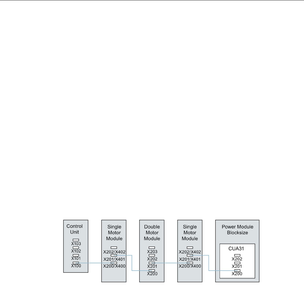
Preparation for commissioning
2.5 System rules, sampling times and DRIVE-CLiQ wiring
STARTER Commissioning Manual
Commissioning Manual, (IH1), 07/2016, 6SL3097-4AF00-0BP5 51
● In servo control Motor Modules should be connected to a DRIVE-CLiQ line together with
the Line Module.
– Several Motor Modules should be connected in a line.
– If there is already a Line Module present, the first Motor Module should be connected
in line to socket X201 of the Line Module.
– If there is no Line Module present, the first Motor Module should be connected directly
to the Control Unit (recommended DRIVE-CLiQ socket: X100).
● If the Motor Modules need to be distributed across two DRIVE-CLiQ lines (e.g. on
account of the predetermined current controller sampling times), the next higher DRIVE-
CLiQ socket on the Control Unit should be used.
Example, vector control in the chassis format:
– Active Line Module current controller cycle 400 µs: X100
– Motor Module current controller cycle 250 µs: X101
– Motor Module current controller cycle 400 µs: X102
● Only one end node should be connected to free DRIVE-CLiQ sockets within a DRIVE-
CLiQ line (e.g. Motor Modules wired in a line), for example, one Sensor Module or one
Terminal Module, without routing to additional components.
● For mixed operation of the servo control and vector V/f control operating modes, separate
DRIVE-CLiQ lines should be used for the Motor Modules.
● A Power Module with the CUA31/CUA32 should be connected to the middle or end of the
DRIVE-CLiQ line.
Image 2-2 DRIVE-CLiQ line example
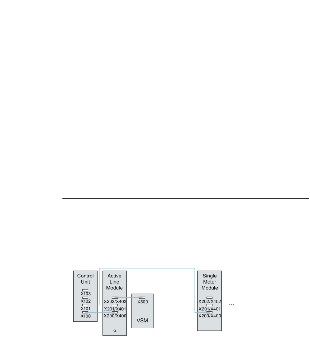
Preparation for commissioning
2.5 System rules, sampling times and DRIVE-CLiQ wiring
STARTER Commissioning Manual
52 Commissioning Manual, (IH1), 07/2016, 6SL3097-4AF00-0BP5
Encoder, Sensor Modules
● The motor encoder or Sensor Module should be connected to the associated Motor
Module.
Connecting the motor encoder via DRIVE-CLiQ:
– Single Motor Module Booksize to terminal X202
– Double Motor Module Booksize motor X1 to terminal X202 and motor X2 to terminal
X203
– Single Motor Module chassis to terminal X402
– Power Module blocksize with CUA31: Encoder to terminal X202
– Power Module blocksize with CU310-2: Encoder to terminal X100 or to terminal X501
of a Terminal Module
– Power Module chassis to terminal X402
● If possible, Sensor Modules of direct measuring systems should not be connected to the
DRIVE-CLiQ line of Motor Modules, but rather to free DRIVE-CLiQ sockets of the Control
Unit.
Note
This restriction does not apply to star
-type connections for the Motor Modules.
Voltage Sensing Modules
● The Voltage Sensing Module (VSM) should be connected to the DRIVE-CLiQ socket
X202 (booksize format) or X402 (chassis format) of the associated Line Module/Motor
Module.
– If the DRIVE-CLiQ socket X202/X402 is not available, a free DRIVE-CLiQ socket on
the Line Module/Motor Module should be selected.
Image 2-3 Example of a topology with VSM for booksize and chassis components

Preparation for commissioning
2.5 System rules, sampling times and DRIVE-CLiQ wiring
STARTER Commissioning Manual
Commissioning Manual, (IH1), 07/2016, 6SL3097-4AF00-0BP5 53
Terminal Modules
● Terminal Modules should be connected to DRIVE-CLiQ socket X103 of the Control Unit in
series.
● The TM54F should not be operated together on the same DRIVE-CLiQ line as Line
Modules or Motor Modules.
● If possible, Terminal Modules should not be connected to the DRIVE-CLiQ line of Motor
Modules, but rather to free DRIVE-CLiQ sockets of the Control Unit.
Note
This restriction does not apply to star
-type connections for the Motor Modules.
2.5.4.3
Rules for automatic configuration
With "Automatic Configuration" (Auto commissioning) the Control Unit software creates drive
objects for the connected Line Modules, Motor Modules and Terminal Modules. For the
Motor Modules the control mode is set via parameter p0097.
In addition to this the following DRIVE-CLiQ wiring topologies support automatic assignment
of components to the drive objects.
● An encoder that is connected directly to a Motor Module or via a Sensor Module, is
assigned to this drive object as motor encoder (encoder 1).
● If a second encoder is connected to a Motor Module in addition to the motor encoder, it is
assigned to the drive as encoder 2. The encoder connected to terminal X202 or X402 is
then the motor encoder (encoder 1).
● If a TM120 or TM150 is connected to the Motor Module, the temperature channels of the
TM are connected with the motor temperature monitoring of the drive. In this case, the
motor encoder may be connected to the TM120 or TM150.
● If a Voltage Sensing Module (VSM) is connected to a Line Module then it is assigned to
the infeed drive object.
Recommended connection:
– Booksize to terminal X202
– Chassis to terminal X402
● If a Voltage Sensing Module (VSM) is connected to a Motor Module then it is assigned to
the drive object.
Note
If two VSMs are connected to the Motor Module, the first (p0151[0]) is assigned to th
e line
voltage measurement (see p3801) and the second is assigned to the motor voltage
measurement (see p1200).
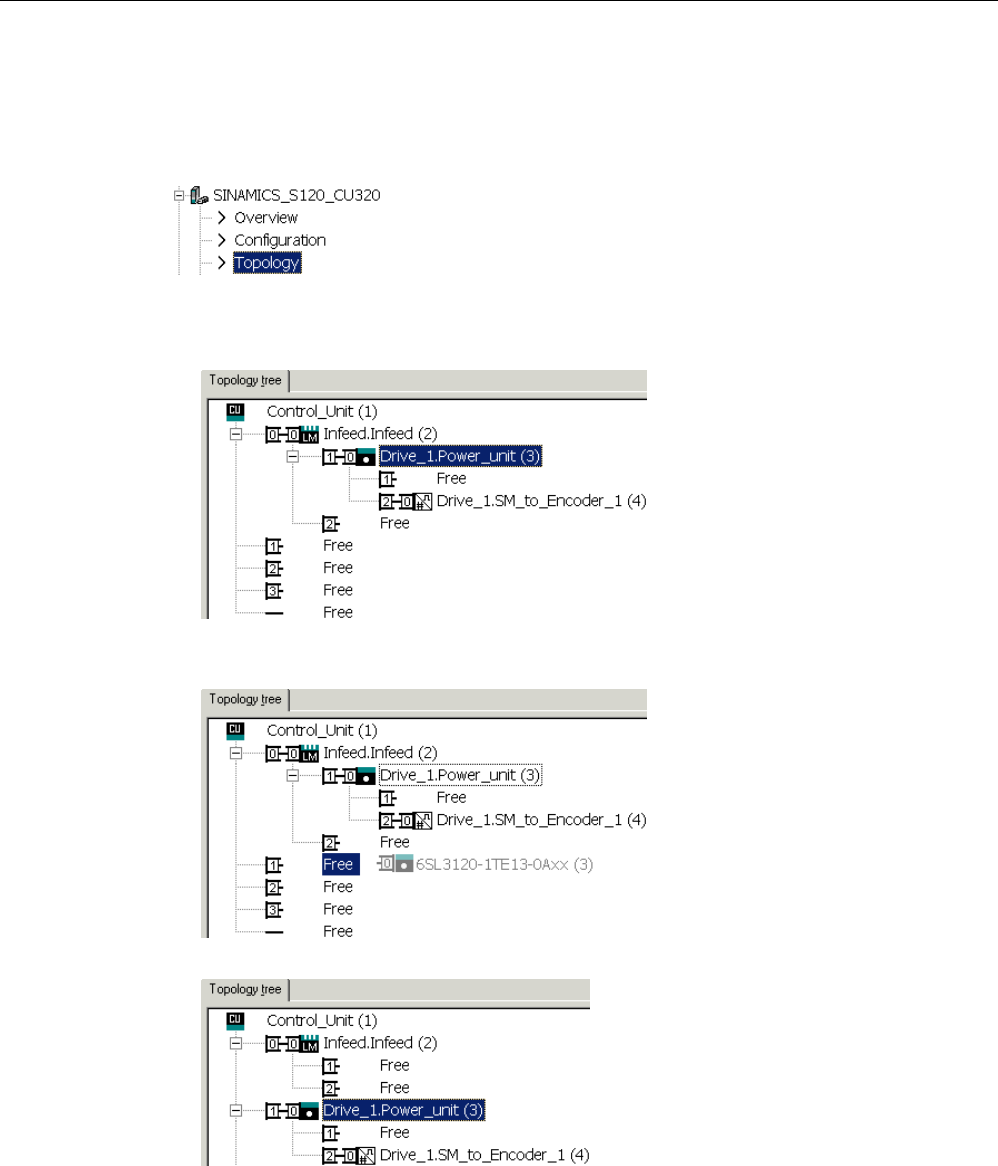
Preparation for commissioning
2.5 System rules, sampling times and DRIVE-CLiQ wiring
STARTER Commissioning Manual
54 Commissioning Manual, (IH1), 07/2016, 6SL3097-4AF00-0BP5
2.5.4.4
Changing the offline topology in the STARTER commissioning tool
The device topology can be changed in the STARTER commissioning tool by shifting the
components in the topology tree.
Example: Changing the DRIVE-CLiQ topology
1. Select the DRIVE-CLiQ component.
2. While holding down the mouse button, drag the component to the required DRIVE-CLiQ
interface and release the mouse button.
You have changed the topology in the STARTER commissioning tool.

Preparation for commissioning
2.5 System rules, sampling times and DRIVE-CLiQ wiring
STARTER Commissioning Manual
Commissioning Manual, (IH1), 07/2016, 6SL3097-4AF00-0BP5 55
2.5.4.5
Modular machine concept: Offline correction of the reference topology
The topology is based on a modular machine concept. The machine concept is created
offline in the STARTER commissioning tool in the maximum version as reference topology.
The maximum version is the maximum expansion of a particular machine type. In the
maximum version, all the machine components that can be used are pre-configured in the
reference topology.
Deactivating components / handling non-existent components
In a lower expansion stage of the machine, you must mark drive objects and encoders that
are not used in the STARTER topology. To do this, for the corresponding drive objects and
encoder, set parameter p0105 or p0145 = 2 (deactivate component and does not exist).
Components set to the value "2" in a project generated offline must never be inserted in the
actual topology at all.
If a component fails, the sub-topology can also be used to allow a machine to continue to
operate until the spare part is available. In this case, however, no BICO source must be
interconnected from this drive object to other drive objects.
Example of a sub-topology
The starting point is a machine created offline in the STARTER commissioning tool. "Drive 1"
was not implemented for this machine.
1. You can remove drive object "Drive 1" "offline" from the reference topology using
p0105 = 2.
2. Change over the DRIVE-CLiQ cable from the Control Unit directly to "Drive 2".
3. Transfer the project with "Download to drive unit".
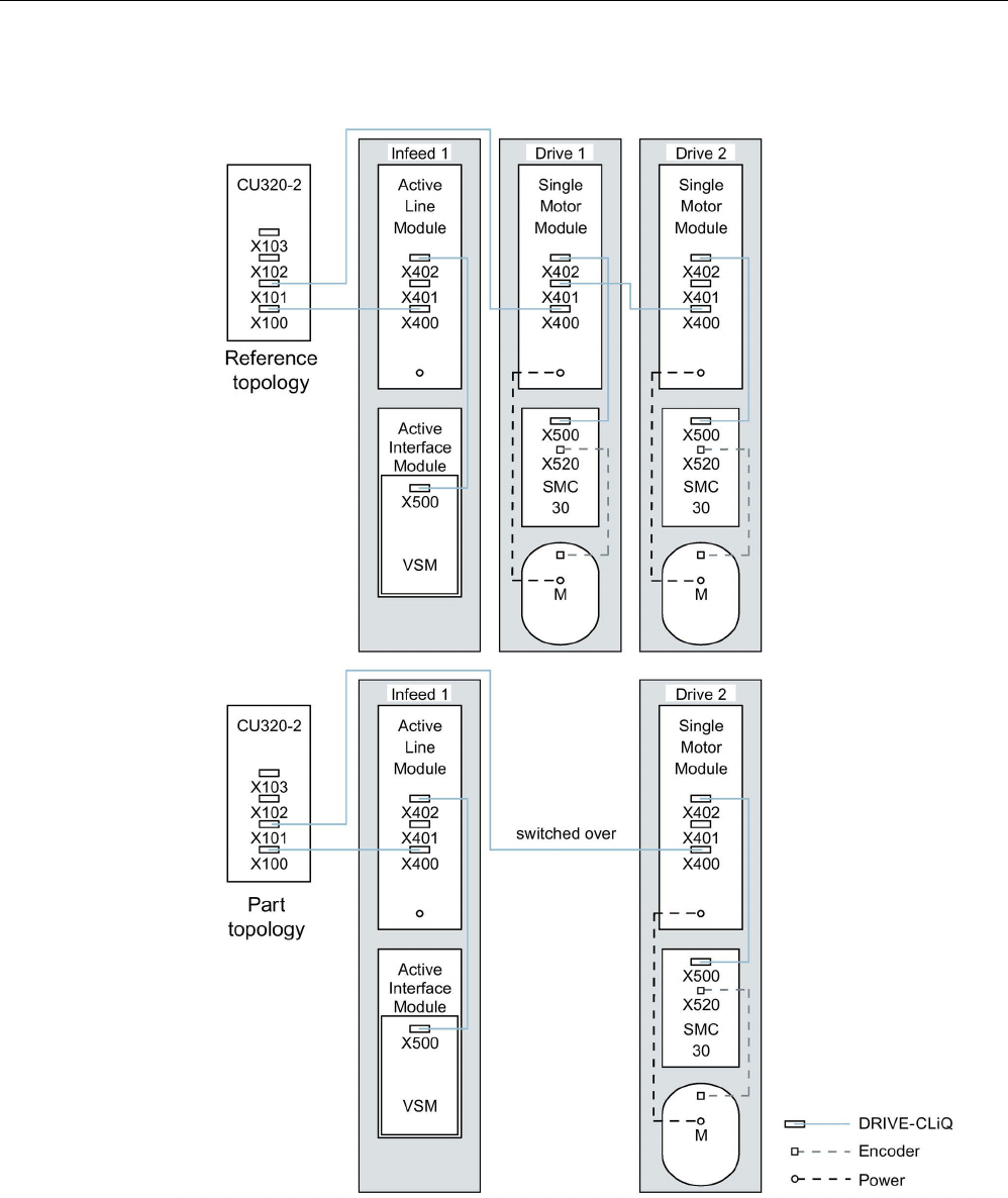
Preparation for commissioning
2.5 System rules, sampling times and DRIVE-CLiQ wiring
STARTER Commissioning Manual
56 Commissioning Manual, (IH1), 07/2016, 6SL3097-4AF00-0BP5
4. Then execute a "Copy RAM to ROM".
Image 2-4 Example of a sub-topology

Preparation for commissioning
2.5 System rules, sampling times and DRIVE-CLiQ wiring
STARTER Commissioning Manual
Commissioning Manual, (IH1), 07/2016, 6SL3097-4AF00-0BP5 57
Note
Incorrect SI status display
If a drive in a Safety Integrated drive line
-up is deactivated using p0105, then r9774 is not
correctly output. The signa
ls of a deactivated drive are no longer updated.
Activating/deactivating components
Drive objects can be activated/deactivated using parameter p0105 and encoders with
p0145[0...n] in the Expert list in the same way. If a component is not required at certain
times, then for the component, change parameter p0105 or p0145 from "1" to "0". The
deactivated components remain inserted, however, they are deactivated. Errors are not
displayed from deactivated components.
Overview of important parameters (see SINAMICS S120/S150 List Manual)
•
p0105
Activating/deactivating drive object
•
r0106
Drive object active/inactive
•
p0125[0...n]
Activate/deactivate power unit component
•
r0126[0...n]
Power unit components active/inactive
•
p0145[0...n]
Enable/disable sensor inter
face
•
r0146[0...n]
Sensor interface active/inactive
•
p9495
BICO behavior for deactivated drive objects
•
p9496
BICO behavior when activating drive objects
•
p9498[0...29]
BICO BI/CI parameters to de
-activated drive objects
•
p9499[0...29]
BICO BO/CO parameter
s to de-activated drive objects
•
r9774.0...31
CO/BO: SI Status (group STO)

Preparation for commissioning
2.5 System rules, sampling times and DRIVE-CLiQ wiring
STARTER Commissioning Manual
58 Commissioning Manual, (IH1), 07/2016, 6SL3097-4AF00-0BP5
2.5.5
Notes on the number of controllable drives
2.5.5.1
Number of drives depending on the control mode and cycle times
The number of axes that can be operated with a Control Unit depends on the cycle times
and the control mode. The number of usable axes and the associated clock cycle times for
each control type are listed below. The other available remaining computation times are
available for options (e.g. DCC).
Cycle times for servo control and HLA
The following table lists the number of axes that can be operated with a Control Unit in servo
control and HLA. The number of axes is also dependent on the cycle times of the controller:
Table 2- 8 Sampling time setting for servo control
Cycle times [µs]
Number
Motor/dir. measur-
ing systems
TM1)/TB
Current con-
troller
Speed controller
Axes
Infeed
125 125 6 1 [250 μs] 6 / 6 3 [2000 μs]
62.5
62.5
3
1 [250 μs]
3 / 3
3 [2000 μs]
31.25
2)
31.25
2)
1
1 [250 μs]
1 / 1
3 [2000 μs]
1)
Valid for TM31 or TM15IO; restrictions are possible for TM54F, TM41, TM15, TM17, TM120, TM150 depending on the
set sampling time.
2)
In the cycle level 31.25 µs, you can also create the following objects:
Sensor Module External (SME) and SMC20 that support the current firmware and hardware. These can be recognized
from the Article end number ... 3.
No additional axis can be operated in this cycle level.
Adjustable pulse frequencies and current controller cycles for servo control
The pulse frequencies that can be set depending on the selected current controller cycle are
shown in r0114. Because of the integrating current measurement, pulse frequencies that are
a multiple of half the current controller sampling frequency should be preferred. Otherwise,
the current is not measured synchronous to the pulse frequency and a fluctuating actual
current value results. This causes disturbance in the control circuits and higher losses in the
motor (such as pulse frequency 5.333 kHz and current controller cycle 62.5 μs).

Preparation for commissioning
2.5 System rules, sampling times and DRIVE-CLiQ wiring
STARTER Commissioning Manual
Commissioning Manual, (IH1), 07/2016, 6SL3097-4AF00-0BP5 59
The recommended settings are marked with
XX
in the Table; all other possible settings are
marked with X.
Table 2- 9 Pulse frequencies and current controller cycles for servo control
Pulse fre-
quency [kHz]
Current controller cycle [µs]
250.0
187.5
150.0
125.0
100.0
93.75
75.0
62.5
50.0
37.5
31.25
16.0
X
-
-
X
-
-
-
X
-
-
XX
13.333
-
-
X
-
-
-
X
-
-
XX
-
12.0 X - - - - - - - - - -
10.666
-
X
-
-
-
X
-
-
-
-
X
10.0 - - - - X - - -
XX
- -
8.888
-
-
-
-
-
-
-
-
-
X
-
8.0
X
-
-
X
-
-
-
XX
-
-
X
6.666
-
-
X
-
-
-
XX
-
X
X
-
6.4
-
-
-
-
-
-
-
-
-
-
X
5.333
-
X
-
-
-
XX
-
X
-
X
-
5.0
-
-
-
-
XX
-
-
-
X
-
-
4.444
-
-
-
-
-
-
X
-
-
-
-
4.0
X
-
-
XX
-
-
-
X
-
-
-
3.555
-
-
-
-
-
X
-
-
-
-
-
3.333
-
-
XX
-
X
-
X
-
-
-
-
3.2
-
-
-
-
-
-
-
X
-
-
-
2.666
-
XX
-
X
-
-
-
-
-
-
-
2.5
-
-
-
-
X
-
-
-
-
-
-
2.222
-
-
X
-
-
-
-
-
-
-
-
2.133
-
-
-
-
-
X
-
-
-
-
-
2.0
XX
-
-
X
X
-
-
-
-
-
-
1.777 - X - - - - - - - - -
1.666
-
-
X
-
-
-
-
-
-
-
-
1.6
-
-
-
X
-
-
-
-
-
-
-
1.333
-
X
X
-
-
-
-
-
-
-
-
Note
Clock cycle mix
Detailed information about the clock cycle mix for servo control is provided in Section
Cycle
mix for servo control and vector control
(Page 64).

Preparation for commissioning
2.5 System rules, sampling times and DRIVE-CLiQ wiring
STARTER Commissioning Manual
60 Commissioning Manual, (IH1), 07/2016, 6SL3097-4AF00-0BP5
Cycle times for vector control
This following table lists the number of axes that can be operated with a Control Unit in the
vector control mode. The number of axes is also dependent on the cycle times of the
controller:
Table 2- 10 Sampling time setting for vector control
Cycle times [µs]
Number
Motor/dir. measur-
ing systems
TM1)/TB
Current con-
troller
Speed controller
Axes
Infeed2)
500 µs
2000 µs
6
1 [250 μs]
6 / 6
3 [2000 μs]
400
3)
µs
1600 µs
5
1 [250 μs]
5/5
3 [2000 μs]
250 µs 1000 µs 3 1 [250 μs] 3 / 3 3 [2000 μs]
1)
Valid for TM31 or TM15IO; restrictions are possible for TM54F, TM41, TM15, TM17, TM120, TM150 depending on the
set sampling time.
2)
For power units in chassis format, the infeed cycle depends on the power rating of the module and can be 400 μs, 375
μs or 250 μs.
3) This setting results in lower remaining computation times.
Adjustable pulse frequencies and current controller cycles for vector control
The pulse frequencies that can be set depending on the selected current controller cycle are
shown in r0114.
This means that maximum 2 cycle levels can be mixed.
Note
Clock cycle mix
Detailed information about the clock cycle mix for servo control is provided in Section
Cycle
mix for servo control and vector
control (Page 64).
Table 2- 11 Pulse frequencies and current controller cycles for vector control
Pulse fre-
quency [kHz]
Current controller cycle [µs]
500.0
375.0
312.5
250.0
218.75
200.0
187.5
175.0
156.25
150.0
137.5
125.0
16.0
X
X
X
X
-
-
X
-
-
-
-
X
15.0
-
-
-
-
-
X
-
-
-
-
-
-
14.545
-
-
-
-
-
-
-
-
-
-
X
-
14.0
X
-
-
-
-
-
-
-
-
-
-
-
13.714
-
-
-
-
X
-
-
-
-
-
-
-
13.333
-
X
-
-
-
-
-
-
-
X
-
-
12.8
-
-
X
-
-
-
-
-
X
-
-
-
12.0 X - - X - - - - - - - -
11.428
-
-
-
-
-
-
-
X
-
-
-
-

Preparation for commissioning
2.5 System rules, sampling times and DRIVE-CLiQ wiring
STARTER Commissioning Manual
Commissioning Manual, (IH1), 07/2016, 6SL3097-4AF00-0BP5 61
Pulse fre-
quency [kHz]
Current controller cycle [µs]
500.0
375.0
312.5
250.0
218.75
200.0
187.5
175.0
156.25
150.0
137.5
125.0
10.666
-
X
-
-
-
-
X
-
-
-
-
-
10.0
X
-
-
-
-
X
-
-
-
-
-
-
9.6 - - X - - - - - - - - -
9.142
-
-
-
-
X
-
-
-
-
-
-
-
8.0
X
X
-
X
-
-
-
-
-
-
-
X
7.272
-
-
-
-
-
-
-
-
-
-
X
-
6.666
-
-
-
-
-
-
-
-
-
X
-
-
6.4
-
-
X
-
-
-
-
-
X
-
-
-
6.0
X
-
-
-
-
-
-
-
-
-
-
-
5.714
-
-
-
-
-
-
-
X
-
-
-
-
5.333
-
X
-
-
-
-
X
-
-
-
-
-
5.0
-
-
-
-
-
X
-
-
-
-
-
-
4.571
-
-
-
-
X
-
-
-
-
-
-
-
4.0
X
-
-
X
-
-
-
-
-
-
-
X
3.636
-
-
-
-
-
-
-
-
-
-
X
-
3.333
-
-
-
-
-
-
-
-
-
X
-
-
3.2
-
-
X
-
-
-
-
-
X
-
-
-
2.857
-
-
-
-
-
-
-
X
-
-
-
-
2.666
-
X
-
-
-
-
X
-
-
-
-
-
2.5
-
-
-
-
-
X
-
-
-
-
-
-
2.285
-
-
-
-
X
-
-
-
-
-
-
-
2.0 X - - X - - - - - - - -
1.6
-
-
X
-
-
-
-
-
-
-
-
-
1.333
-
X
-
-
-
-
-
-
-
-
-
-
1.0
X
-
-
-
-
-
-
-
-
-
-
-
Note
Restriction for the chassis format
If edge modulation and wobbling are activated simultaneously with p1802 ≥ 7 and p1810.2 =
1 respectively, the quantity structure for vector
control is halved. Then a maximum of 3 axes
at a current control cycle of 500 µs, 2 axes at 400 µs or 1 axis at 250 µs are permitted.

Preparation for commissioning
2.5 System rules, sampling times and DRIVE-CLiQ wiring
STARTER Commissioning Manual
62 Commissioning Manual, (IH1), 07/2016, 6SL3097-4AF00-0BP5
Cycle times for V/f control
The following table lists the number of axes that can be operated with a Control Unit in the
V/f control mode. The number of axes is dependent on the current controller clock cycle:
Table 2- 12 Sampling time setting for V/f control
Cycle times [µs]
Number
Motor/dir. measur-
ing systems
TM/TB
Current
controller
Speed controller
Drives
Infeed
500
2000
12
1 [250 μs]
- / -
3 [2000 μs]
Mixed operation of servo control and V/f open-loop control
In mixed operation with servo control and U/f control, one axis in servo control at 125 µs
uses exactly as much computing power as 2 axes in U/f control at 500 µs. In conjunction with
servo control, a maximum of 11 axes are permitted (1 servo control plus 10 vector control
V/f).
Table 2- 13 Number of axes for mixed servo control operation
Number of axes in servo control
Number of axes in V/f control
6
125 µs
3
62.5 µs
0
-
5
125 µs
-
-
2
500 µs
4
125 µs
2
62.5 µs
4
500 µs
3
125 µs
-
-
6
500 µs
2
125 µs
1
62.5 µs
8
500 µs
1
125 µs
-
-
10
500 µs
0
-
0
-
12
500 µs
Mixed operation of vector control and V/f open-loop control
In mixed operation with vector control and V/f control, one axis in vector control at 250 µs
uses exactly as much computing power as two axes in V/f control at 500 µs. In conjunction
with vector control, a maximum of 11 axes are permitted (1 vector control plus 10 V/f
control).
Table 2- 14 Number of axes for mixed vector control operation
Number of axes in vector control
Number of axes in V/f control
6
500 µs
3
250 µs
0
-
5
500 µs
-
-
2
500 µs
4
500 µs
2
250 µs
4
500 µs
3
500 µs
-
-
6
500 µs
2
500 µs
1
250 µs
8
500 µs
1
500 µs
-
-
10
500 µs
0
-
0
-
12
500 µs

Preparation for commissioning
2.5 System rules, sampling times and DRIVE-CLiQ wiring
STARTER Commissioning Manual
Commissioning Manual, (IH1), 07/2016, 6SL3097-4AF00-0BP5 63
Cycle times of the CU310-2 in the servo control mode
Table 2- 15 Sampling time setting for servo control
Cycle times [µs]
Number
Via DQ2)
Snapped-on
TM1)/TB
Current
controller
Speed controller
Axes
Infeed
Motor Module
Power Module
125
125
1
-
-
1
3 [2000 μs]
62.5
62.5
1
-
-
1
3 [2000 μs]
1)
Valid for TM15, TM17 or TM41; for TM54F, TM31, TM120, TM150 - restrictions are possible dependent on the set
sampling time.
2) DQ = DRIVE-CLiQ
If the 310-2 Control Unit is snapped on to a PM340 or a PM240-2 FS A-C, a minimum
current controller clock cycle of 62.5 µs is possible. For PM240-2 FS D-F the minimum
current controller clock cycle is 125 µs.
Using DCC
The available remaining computation time can be used for DCC. In this case, the following
supplementary conditions apply:
● For a 2 ms time slice, a max. of 75 DCC blocks can be configured for each servo control
axis with 125 μs that can be omitted/eliminated (≙ 2 V/f axes with 500 μs).
● 50 DCC blocks for 2 ms time slice correspond to 1.5 V/f axes with 500 μs.
Detailed information about handling and using DCC standard blocks is provided in the
"SINAMICS/SIMOTION Editor Description DCC" manual.
Using EPOS
The following table lists the number of axes that can be operated with a SINAMICS S120
when using a "basic positioner" (EPOS) function module. The number of axes is dependent
on the current controller clock cycle.
Table 2- 16 Sampling times when using EPOS
Cycle times [µs]
Cycle times [ms]
Number
Current controller
Speed controller
Position controller
Positioner
Axes
Infeed
250 250 2 8 6 1 [250 μs]
250
250
1
4
5
1 [250 μs]
125
125
1
4
4
1 [250 μs]
The CPU processing time required for the function module EPOS (with 1 ms position
controller/4 ms positioner) corresponds to the same CPU processing time of 0.5 V/f axes
with 500 μs.

Preparation for commissioning
2.5 System rules, sampling times and DRIVE-CLiQ wiring
STARTER Commissioning Manual
64 Commissioning Manual, (IH1), 07/2016, 6SL3097-4AF00-0BP5
Use of SINAMICS web server
The available computation time can be used for SINAMICS web server. The following
boundary condition applies here:
● The utilization of the system (r9976) must be less than 90%!
● A maximum of 5 users can access data on the same drive via the SINAMICS web server.
Using CUA31/CUA32
Information on using the Control Unit Adapter CUA31 or CUA32:
● CUA31/32 is the first component in the CUA31/32 topology: 5 axes
● CUA31/32 is
not
the first component in the CUA31/32 topology: 6 axes
● For a current controller cycle of 62.5 µs, only one axis is possible with one CUA31/32.
2.5.5.2
Cycle mix for servo control and vector control
Supplementary conditions
The rules for setting the sampling time (see Chapter Rules when setting the sampling times
(Page 40)) and the rules on isochronous mode (see Chapter Rules for isochronous mode
(Page 42)) apply.
These rules mean that the smallest common multiple of the current controller cycles of all
axes operated on the isochronous PROFIBUS and 125 µs is used to set Ti, To and Tdp.
Current controller cycles for cycle mix
Consequently the smallest common multiple of the current and speed controller cycles of all
axes operated on the isochronous PROFIBUS is used to set the base cycle for Ti, To and
Tdp. For a cycle mix, a compromise must be sought between the base cycle to set Ti, To and
Tdp, and the required pulse frequency.

Preparation for commissioning
2.5 System rules, sampling times and DRIVE-CLiQ wiring
STARTER Commissioning Manual
Commissioning Manual, (IH1), 07/2016, 6SL3097-4AF00-0BP5 65
Table 2- 17 Examples of cycle mixes for servo control
Cycle mix: Current controller cycles [µs]
Base cycle for Ti, To [µs]
Base cycle for Tdp,
Tmapc[µs]
250.00
+125.00
250
250
187.50 +125.00 375 750
150.00
+125.00
750
750
125.00
+125.00
125
250
100.00
+125.00
500
500
93.75
+125.00
375
750
75.00
+125.00
375
750
62.50
+125.00
125
250
50.00
+125.00
250
250
37.50
+125.00
750
750
31.25
+125.00
125
250
Base cycles for the isochronous PROFIBUS for a cycle mix with 125 μs
Table 2- 18 Examples for cycle mixes for vector control
Cycle mix: Current controller cy-
cles [µs]
Base cycle for Ti, To
[µs]
Base cycle for Tdp
[µs]
Base cycle for Tmapc
[µs]
500.00
+250.00
500
500
2000
375.00
+250.00
750
750
3000
312.50
+250.00
1250
1250
5000
250.00
+250.00
250
250
1000
218.75
+250.00
1750
1750
7000
200.00
+250.00
1000
1000
4000
187.50
+250.00
750
750
3000
175.00
+250.00
1750
1750
7000
156.25
+250.00
1250
1250
5000
150.00
+250.00
750
750
3000
137.50
+250.00
2750
2750
11000
125.00
+250.00
250
250
1000
Base cycles for the isochronous PROFIBUS for a cycle mix with 250 μs

Preparation for commissioning
2.5 System rules, sampling times and DRIVE-CLiQ wiring
STARTER Commissioning Manual
66 Commissioning Manual, (IH1), 07/2016, 6SL3097-4AF00-0BP5
Note
The speed controller cycle is assigned automatically when the current controller cycle is set:
•
Servo control: Speed controller cycle = current controller cycle
•
Vector control: Speed controller cycle = current controller cycle x 4
The preassignment of the speed controller cycle can be changed to influence T
mapc. For
example, the current controller cycle can be increased from 800
µs to 1000 µs so that Tmapc
can be set to be a mult
iple of 1000 µs.
Asynchronous node on the isochronous PROFIBUS
For cycle mix, lengthened base cycles with the following effects often result on the
isochronous PROFIBUS:
● Because the isochronous PROFIBUS can no longer be operated with the default setting,
adaptations must be made to the hardware configuration.
● The increased setting values for Ti, To and Tdp have disadvantageous effects on the
dynamics of the position control loop.
Despite a cycle mix, the parameter p2049 can be used to operate the axis with the different
current controller cycle asynchronously on the isochronous PROFIBUS. This allows the
default setting of the hardware configuration to be retained.
This, however, causes the advantages of the isochronous operation for the asynchronous
axis to be lost:
● The setpoints act at times that differ from To, i.e. an interpolating position-controlled
operation with other axes is not possible.
● The actual values are read at times that differ from Ti, i.e. the actual values must not be
used to control other axes.
A critical application would be, for example, a spindle that cuts a thread with the
programmed thread pitch together with a position-controlled Z-axis by the controller
adjusting the plunging depth of the Z-axis depending on the spindle position.
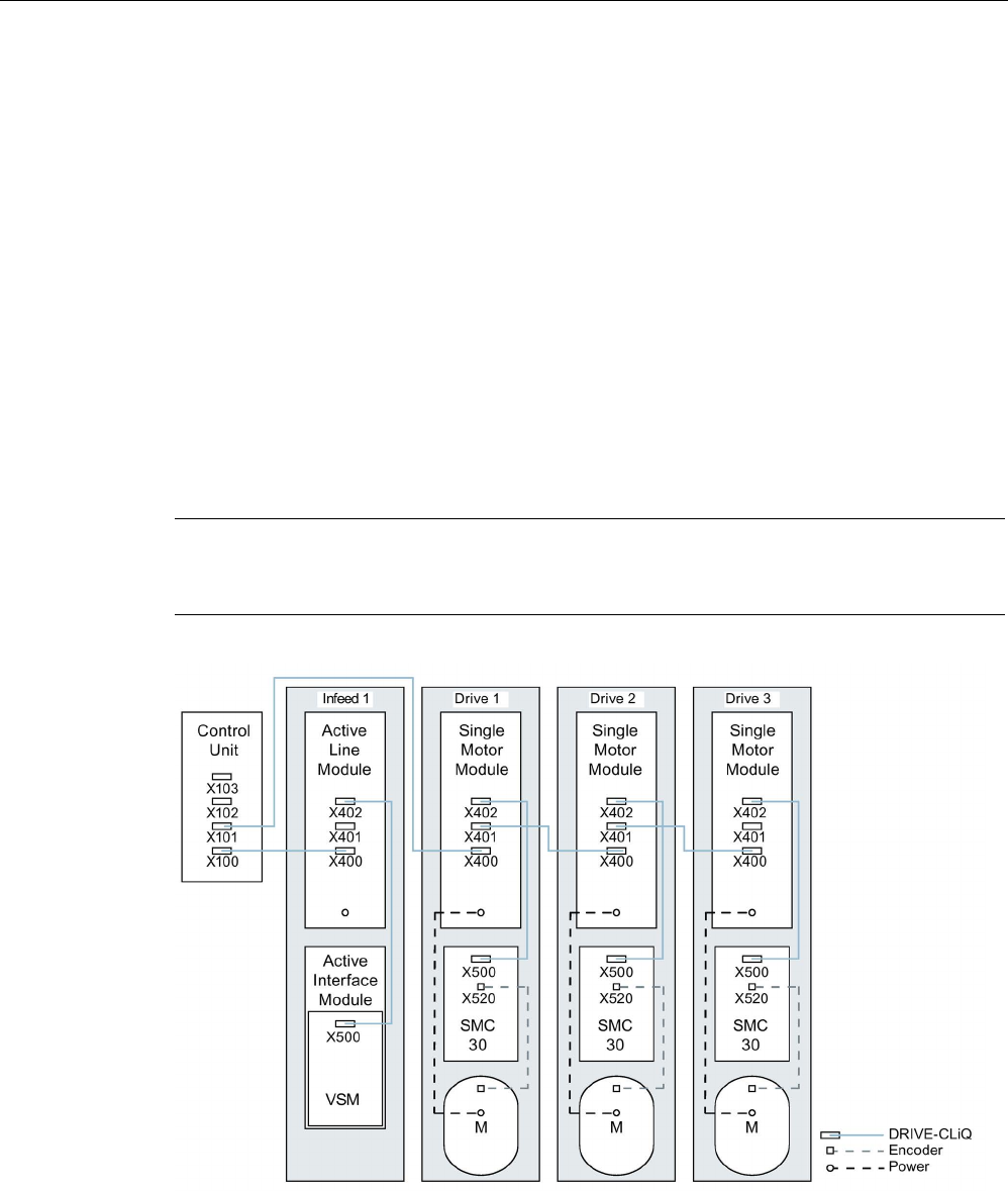
Preparation for commissioning
2.6 Supported sample topologies
STARTER Commissioning Manual
Commissioning Manual, (IH1), 07/2016, 6SL3097-4AF00-0BP5 67
2.6
Supported sample topologies
2.6.1
Topology example: Drives in vector control
Example 1
A drive line-up with three Motor Modules in chassis format with identical pulse frequencies or
three Motor Modules in booksize format in vector control mode.
The Motor Modules chassis format with identical pulse frequencies or the Motor Modules
booksize format in vector control mode can be connected to 1 DRIVE-CLiQ interface on the
Control Unit.
In the following diagram, three Motor Modules are connected to the DRIVE-CLiQ socket
X101.
Note
The offline topology automatically generated in the STARTER commissioning tool must be
manually modified, if this topology was wired.
Image 2-5 Drive line-up (chassis) with identical pulse frequencies
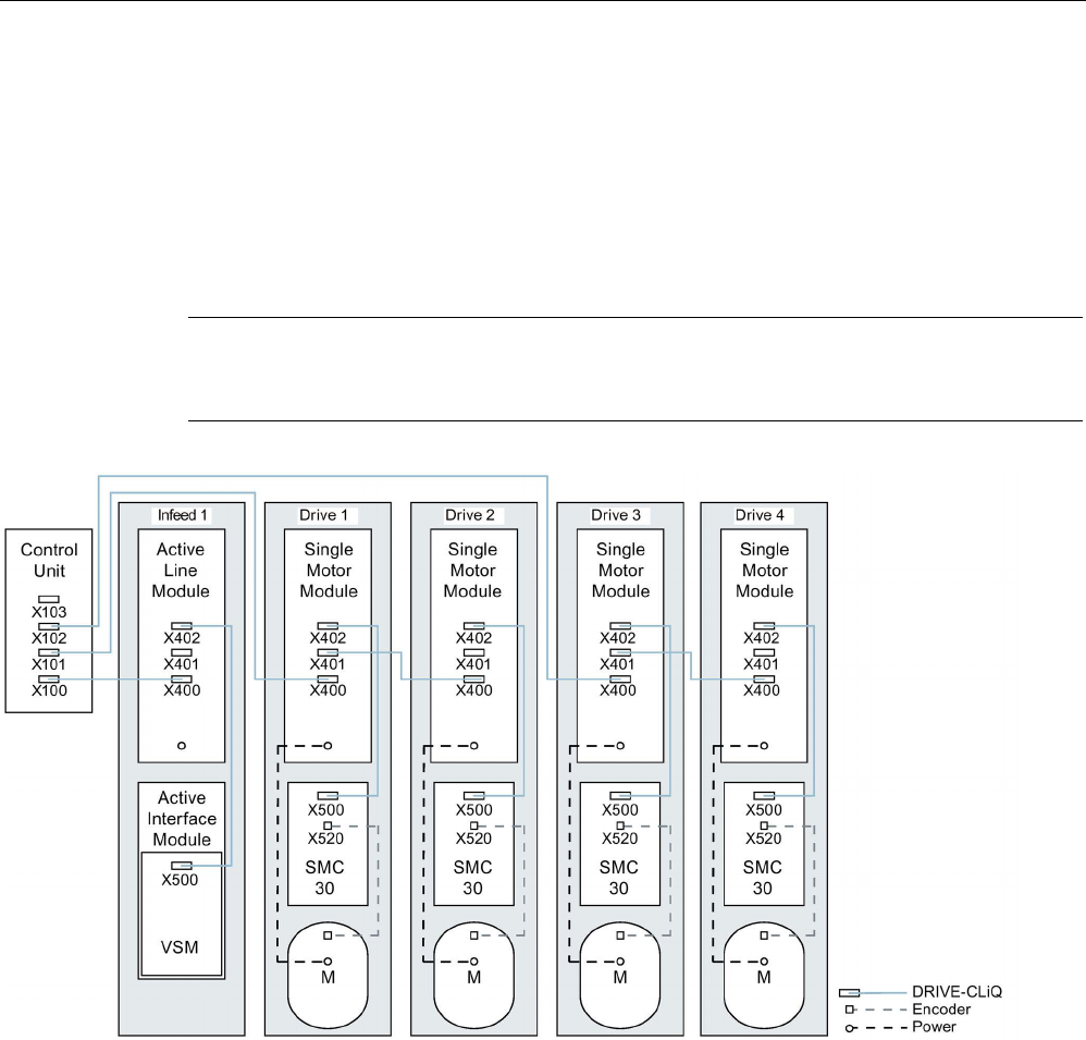
Preparation for commissioning
2.6 Supported sample topologies
STARTER Commissioning Manual
68 Commissioning Manual, (IH1), 07/2016, 6SL3097-4AF00-0BP5
Drive line-up comprising four Motor Modules in the chassis format with different pulse frequencies
It is advantageous to connect Motor Modules with different pulse frequencies to different
DRIVE-CLiQ sockets of the Control Unit. They may also be connected at the same DRIVE-
CLiQ line.
In the following diagram, two Motor Modules (400 V, output ≤ 250 kW, pulse frequency
2 kHz) are connected to interface X101 and two Motor Modules (400 V, output > 250 kW,
pulse frequency 1.25 kHz) are connected to interface X102.
Note
The offline topology automatically generated in the STARTER commissioning tool must be
manually modified, if this topology was wired.
Image 2-6 Drive line-up in chassis format with different pulse frequencies
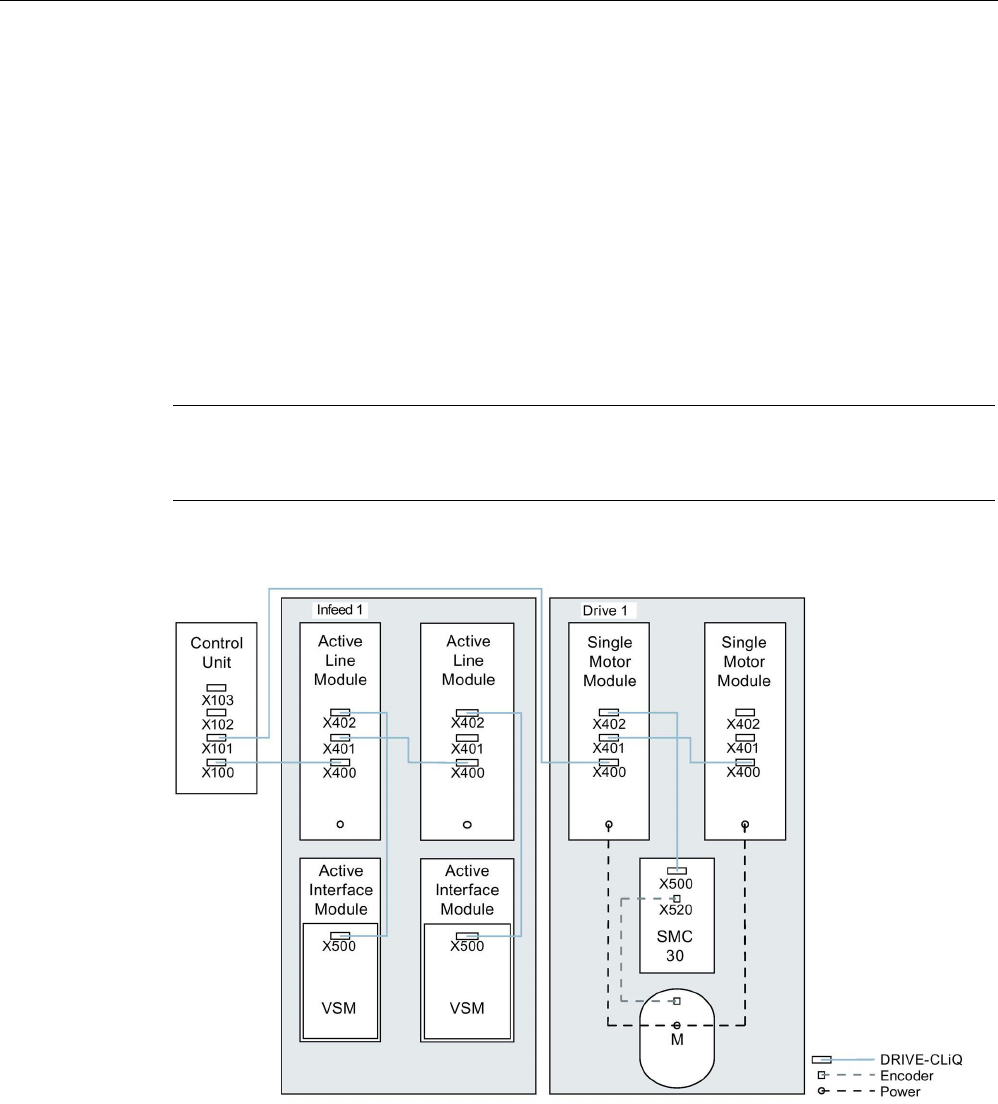
Preparation for commissioning
2.6 Supported sample topologies
STARTER Commissioning Manual
Commissioning Manual, (IH1), 07/2016, 6SL3097-4AF00-0BP5 69
2.6.2
Topology example: Parallel Motor Modules in vector control
Drive line-up with two parallel-connected Line Modules and Motor Modules in the chassis format of
the same type
Parallel-connected Line Modules in the chassis format and Motor Modules in the chassis
format of the same type can be connected to a DRIVE-CLiQ socket of the Control Unit.
In the following diagram, two Active Line Modules and two Motor Modules are connected to
the X100 or X101 socket.
You can find additional notes in Chapter "Parallel connection of power units" in the
SINAMICS S120 Function Manual.
Note
The offline topology automatically generated in the STARTER commissioning tool must be
manually modified, if this topology was wired.
Image 2-7 Drive line-up with parallel-connected power units in the chassis format
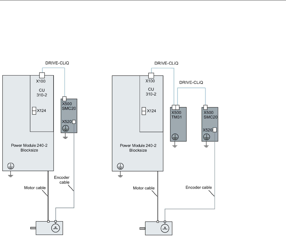
Preparation for commissioning
2.6 Supported sample topologies
STARTER Commissioning Manual
70 Commissioning Manual, (IH1), 07/2016, 6SL3097-4AF00-0BP5
2.6.3
Topology example: Power Modules
Blocksize
Image 2-8 Drive line-ups with Power Modules blocksize
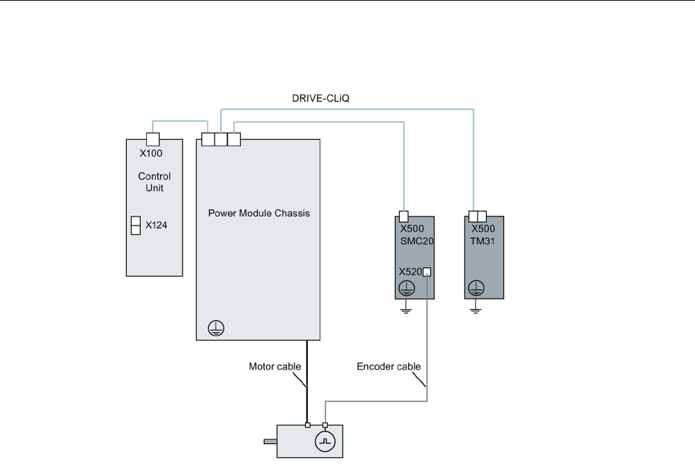
Preparation for commissioning
2.6 Supported sample topologies
STARTER Commissioning Manual
Commissioning Manual, (IH1), 07/2016, 6SL3097-4AF00-0BP5 71
Chassis
Image 2-9 Drive line-up of a Power Module chassis
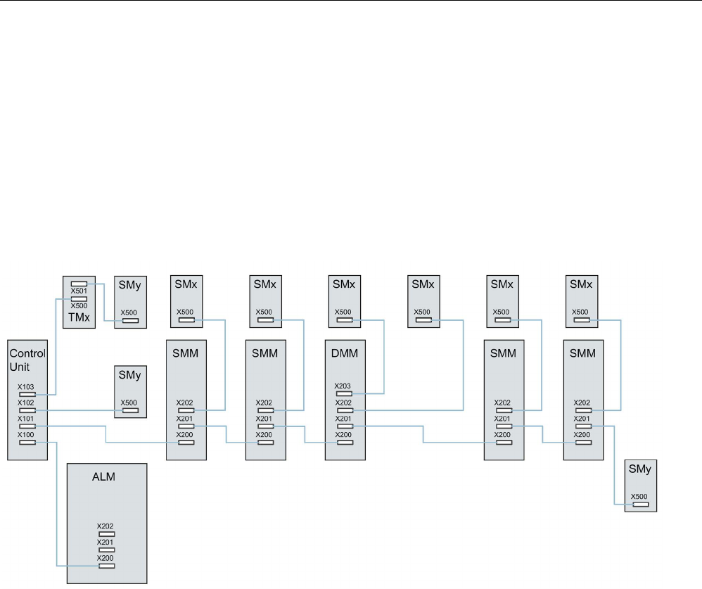
Preparation for commissioning
2.6 Supported sample topologies
STARTER Commissioning Manual
72 Commissioning Manual, (IH1), 07/2016, 6SL3097-4AF00-0BP5
2.6.4
Example topologies: Drives in servo control.
2.6.4.1
Example: Sampling time 125 µs
The following diagram shows the maximum number of controllable servo drives and extra
components. The sampling times of individual system components are:
● Active Line Module: p0115[0] = 250 µs
● Motor Modules: p0115[0] = 125 µs
● Terminal Module/Terminal Board p4099 = 1 ms
Image 2-10 Topology example of a SERVO drive line-up
Legend for the topology example:
ALM = Active Line Module
SMM = Single Motor Module
DMM = Double Motor Module
SMx = Motor encoder
SMy = Direct measuring system
TMx = TM31, TM15DI/DO, TB30

Preparation for commissioning
2.6 Supported sample topologies
STARTER Commissioning Manual
Commissioning Manual, (IH1), 07/2016, 6SL3097-4AF00-0BP5 73
2.6.4.2
Examples: Sampling time 62.5 µs and 31.25 µs
Examples, CU320-2 with 62.5 µs sampling time:
● Topology 1:1 x ALM (250 µs) + 2 x servo (62.5 µs) + 2 x servo (125 µs) + 3 x TM15 Base
(p4099[0] = 2000 µs) + TM54F + 4 x Safety Integrated Extended Functions with encoder
SI Motion monitoring clock cycle (p9500) = 12 ms + SI Motion actual value sensing clock
cycle (p9511) = 4 ms + 4 x direct measuring systems.
● Topology 2:1 x ALM (250 µs) + 2 x servo (62.5 µs) + 2 x V/f (500 µs) + 3 x TM15 Base
(p4099[0] = 2000 µs) + 2 x Safety Integrated Extended Functions with encoder SI Motion
monitoring clock cycle (p9500) = 12 ms + SI Motion actual value sensing clock cycle
(p9511) = 4 ms + 2 x Safety Integrated Extended Functions sensorless + 2 x direct
measuring systems.
● Topology 3:1 x servo (62.5 μs) + 4 x V/f is not possible in connection with Safety
Integrated.
Example, CU320-2 with 31.25 µs sampling time:
● Topology 1:1 ALM (250 µs) on a line, 1 x servo (31.25 µs) on a line, 3 x TM15 Base
(p4099[0] = 2000 µs) on a line and in series.
● Topology 2:1 ALM (250 µs) on a line, 1 x servo (31.25 µs) on a line, 1 direct measuring
system on a line.
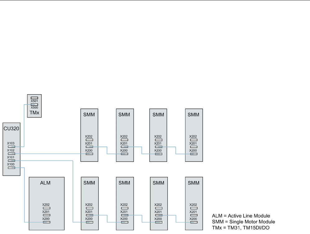
Preparation for commissioning
2.6 Supported sample topologies
STARTER Commissioning Manual
74 Commissioning Manual, (IH1), 07/2016, 6SL3097-4AF00-0BP5
2.6.5
Topology example: Drives in U/f control (vector control)
The following diagram shows the maximum number of controllable vector V/f drives with
additional components. The sampling times of individual system components are:
● Active Line Module: p0115[0] = 250 µs
● Motor Modules: p0115[0] = 500 µs
● Terminal Module/Terminal Board p4099 = 2 ms
Image 2-11 Topology example of a vector drive line-up in U/f control

Preparation for commissioning
2.7 DRIVE-CLiQ diagnostics
STARTER Commissioning Manual
Commissioning Manual, (IH1), 07/2016, 6SL3097-4AF00-0BP5 75
2.7
DRIVE-CLiQ diagnostics
Using the DRIVE-CLiQ diagnostics, you can check the connections and cables of DRIVE-
CLiQ connections. For data transfer errors, to localize the faulted connection, the error
counter in the involved blocks can be evaluated.
In addition to the error counter showing all errors, detailed diagnostics can be carried out for
the individual connections. For selected connections, the number of errors is determined for
a time interval that can be specified and made traceable using a parameter. As a result of
the interconnectability, you can record when data transfer errors occur and correlate them
with other events in the drive.
Overview of important parameters (see SINAMICS S120/S150 List Manual)
•
r9936[0...199]
DRIVE
-CLiQ diagnostics, error counter connection
•
p9937
DRIVE
-CLiQ diagnostics configuration
•
p9938
DRIVE
-CLiQ detailed diagnostics configuration
•
p9939
DRIVE
-CLiQ detailed diagnostics time interval
•
p9942
DRIVE
-CLiQ detailed diagnostics individual connection selection
•
r9943
DRIVE
-CLiQ detailed diagnostics individual connection error counter
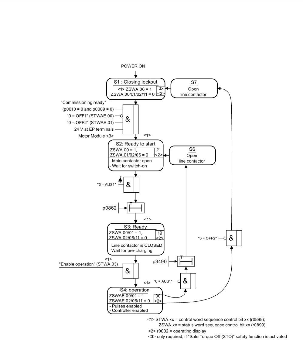
Preparation for commissioning
2.8 Powering-up/powering-down the drive system
STARTER Commissioning Manual
76 Commissioning Manual, (IH1), 07/2016, 6SL3097-4AF00-0BP5
2.8
Powering-up/powering-down the drive system
Powering up the infeed
Image 2-12 Powering up the infeed
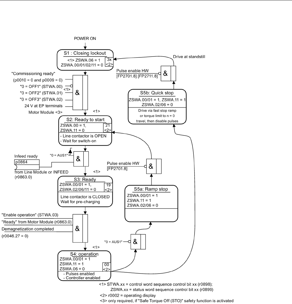
Preparation for commissioning
2.8 Powering-up/powering-down the drive system
STARTER Commissioning Manual
Commissioning Manual, (IH1), 07/2016, 6SL3097-4AF00-0BP5 77
Powering up the drive
Image 2-13 Powering up the drive

Preparation for commissioning
2.8 Powering-up/powering-down the drive system
STARTER Commissioning Manual
78 Commissioning Manual, (IH1), 07/2016, 6SL3097-4AF00-0BP5
Off responses
● OFF1
– n_set = 0 is input immediately to brake the drive along the deceleration ramp (p1121).
– When zero speed is detected, the motor holding brake (if parameterized) is closed
(p1215). The pulses are suppressed when the brake application time (p1217) expires.
Zero speed is detected if the actual speed drops below the threshold (p1226) or if the
monitoring time (p1227) started when the speed setpoint ≤ speed threshold (p1226)
has expired.
● OFF2
– Instantaneous pulse suppression, the drive "coasts" to a standstill.
– The motor holding brake (if parameterized) is closed immediately.
– Switching on inhibited is activated.
● OFF3
– n_set=0 is input immediately to brake the drive along the OFF3 deceleration ramp
(p1135).
– When zero speed is detected, the motor holding brake (if parameterized) is closed.
The pulses are suppressed when the brake application time (p1217) expires. Zero
speed is detected if the actual speed drops below the threshold (p1226) or if the
monitoring time (p1227) started when the speed setpoint ≤ speed threshold (p1226)
has expired.
– Switching on inhibited is activated.
Control and status messages
Table 2- 19 Power-on/power-off control
Signal name
Internal control word
Binector input
PROFIdrive/Siemens
telegram 1 ... 352
0 = OFF1 STWA.00
STWAE.00
p0840 ON/OFF1 STW1.0
0 = OFF2 STWA.01
STWAE.01
p0844 1. OFF2
p0845 2. OFF2
STW1.1
0 = OFF3 STWA.02 p0848 1. OFF3
p0849 2. OFF3
STW1.2
Enable operation STWA.03
STWAE.03
p0852 Enable operation STW1.3

Preparation for commissioning
2.8 Powering-up/powering-down the drive system
STARTER Commissioning Manual
Commissioning Manual, (IH1), 07/2016, 6SL3097-4AF00-0BP5 79
Table 2- 20 Switch-in/switch-out status signal
Signal name
Internal status word
Parameter
PROFIdrive/Siemens
telegram 1 ... 352
Ready for switching on ZSWA.00
ZSWAE.00
r0899.0 ZSW1.0
Ready for operation ZSWA.01
ZSWAE.01
r0899.1 ZSW1.1
Operation enabled ZSWA.02
ZSWAE.02
r0899.2 ZSW1.2
Closing lockout active ZSWA.06
ZSWAE.06
r0899.6 ZSW1.6
Pulses enabled
ZSWA.11
r0899.11
ZSW2.10
1)
1) only available in Interface Mode p2038 = 0
Function diagrams (see SINAMICS S120/S150 List Manual)
•
2610
Sequence control
- control unit
•
2634
Sequence control
- missing enable signals, line contactor control, logic
operation
•
8732
Basic Infeed
- control unit
•
8832
Smart Infeed
- control unit
•
8932
Active Infeed
- control unit

Preparation for commissioning
2.8 Powering-up/powering-down the drive system
STARTER Commissioning Manual
80 Commissioning Manual, (IH1), 07/2016, 6SL3097-4AF00-0BP5

STARTER Commissioning Manual
Commissioning Manual, (IH1), 07/2016, 6SL3097-4AF00-0BP5 81
Commissioning
3
3.1
Safety instructions for commissioning
WARNING
Danger to life if the fundamental safety instructions and residual risks are not carefully
observed
The non-observance of the fundamental safety instructions and residual risks stated in
Chapter 1 can result in accidents with severe injuries or death.
• Adhere to the fundamental safety instructions.
• When assessing the risk, take into account residual risks.
WARNING
Danger to life as a result of motor movement during motor data identification
Motor data identification causes movements of the drive, which can result in death, serious
injury, or damage to property.
• Ensure that nobody is in the danger zone and that the mechanical parts can move
freely.
• Respond to possible malfunctions by applying suitable measures (e.g. EMERGENCY
STOP or EMERGENCY OFF).

Commissioning
3.2 Procedure when commissioning
STARTER Commissioning Manual
82 Commissioning Manual, (IH1), 07/2016, 6SL3097-4AF00-0BP5
3.2
Procedure when commissioning
The following steps are required when commissioning a drive:
1. Create project with STARTER.
2. Configure the drive unit in STARTER.
3. Save the project in STARTER.
4. Establish online operation with the target device in STARTER.
5. Load project to target device.
6. The result: the motor turns.
WARNING
Risk of death if safety instructions and residual risks are not carefully observed
If the safety instructions and residual risks are not observed in the associated hardware
documentation, accidents involving severe injuries or death can occur.
• Observe the safety instructions provided in the hardware documentation.
• When assessing the risk, take into account residual risks.
Note
Acceptance test required
A project with Sa
fety Integrated can be created offline. However, for commissioning, an
acceptance test must be performed which is only possible online.
Note
Updating units only after the project upload
In the commissioning tool (STARTER or Startdrive), after the changeover of the axis type via
p9302/p9502 and subsequent POWER ON, the units that depend on the axis type are only
updated after a project upload.
Note
Please observe the installation guidelines and safety instructions in the SINAMICS S120
Equipment Manua
ls.
If several Motor Modules are supplied from a non-regenerative infeed unit (e.g. a Basic Line
Module), or for power failure or overload (for SLM/ALM), the Vdc_max control may only be
activated for a Motor Module whose drive should have a high moment of inertia.
For the other Motor Modules this function must be disabled or monitoring must be set.
If the Vdc_max control is active for several Motor Modules, then for an unfavorable
parameterization, the controllers can mutually influence one another negatively. The drives
can become unstable, individual drives can unintentionally accelerate.

Commissioning
3.2 Procedure when commissioning
STARTER Commissioning Manual
Commissioning Manual, (IH1), 07/2016, 6SL3097-4AF00-0BP5 83
Remedial measures:
● Activating the Vdc_max control:
– Vector control: p1240 = 1 (factory setting)
– Servo control: p1240 = 1
– U/f control: p1280 = 1 (factory setting)
● Inhibiting the Vdc_max control:
– Vector control: p1240 = 0
– Servo control: p1240 = 0 (factory setting)
– U/f control: p1280 = 0
● Activating the Vdc_max monitoring function
– Vector control: p1240 = 4 or 6
– Servo control: p1240 = 4 or 6
– U/f control: p1280 = 4 or 6
WARNING
Danger to life as a result of unplanned motion of individual drives
If several Motor Modules are supplied from one infeed unit, then if the Vdc_max control is
incorrectly parameterized, individual drives can accelerate in an uncontrolled fashion -
which can lead to death or severe injury.
• Only activate the Vdc_max control for the Motor Module whose drive has the highest
moment of inertia.
• Inhibit this function for all other Motor Modules, or set this function to monitoring only.

Commissioning
3.3 STARTER commissioning tool
STARTER Commissioning Manual
84 Commissioning Manual, (IH1), 07/2016, 6SL3097-4AF00-0BP5
3.3
STARTER commissioning tool
The STARTER commissioning tool is used to parameterize and commission drive units from
the SINAMICS product family.
The STARTER commissioning tool can be used for the following:
● Commissioning
● Testing (via the control panel)
● Drive optimization
● Diagnostics
● Setting up and activating the safety functions
System prerequisites
You can find the system requirements for the STARTER commissioning tool in the "readme"
file in the STARTER installation directory.
3.3.1
General information on STARTER
3.3.1.1
Calling STARTER
Note
The following procedure refers to the Windows 7 operating system. Operation can differ
slightly for other operating systems (e.g. Windows XP).
Calling the STARTER application
1. Click the STARTER symbol of your user interface.
Or
2. In the Windows starting menu, call the menu command "Start > STARTER > STARTER".
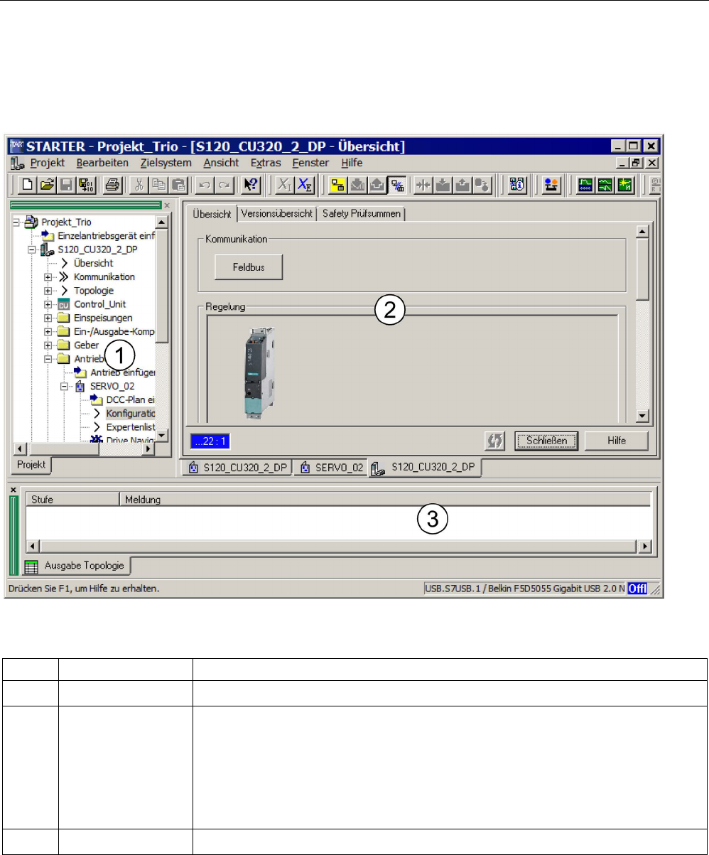
Commissioning
3.3 STARTER commissioning tool
STARTER Commissioning Manual
Commissioning Manual, (IH1), 07/2016, 6SL3097-4AF00-0BP5 85
3.3.1.2
Description of the user interface
You can use the STARTER commissioning tool to create the project. The different areas of
the user interface are used for different configuration tasks (refer to diagram below):
Image 3-1 The different areas of the STARTER user interface
No.
Operating area
Description
①
Project navigator This area displays the elements and objects that can be added to your project.
② Work area In this area you perform the tasks to create the project:
• When you are configuring the drive, this area contains the Wizards that help you
configure the drive objects.
• When you configure the parameters for the speed setpoint filter, for example.
• When you call up the expert list, the system displays a list of all the parameters that
you can view or change.
③
Detail view This area provides detailed information on faults and alarms, for example.
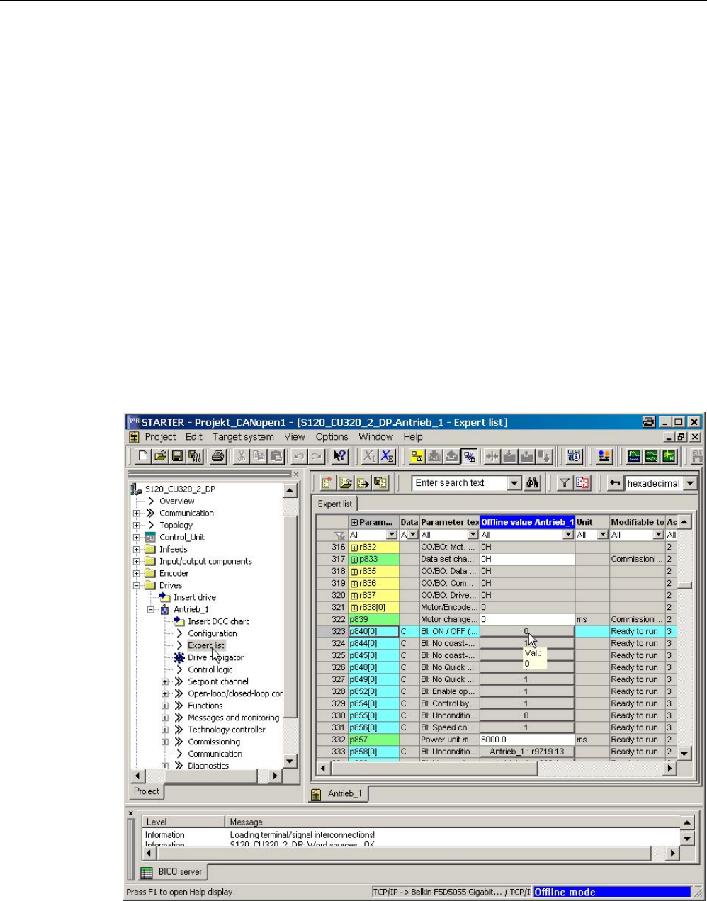
Commissioning
3.3 STARTER commissioning tool
STARTER Commissioning Manual
86 Commissioning Manual, (IH1), 07/2016, 6SL3097-4AF00-0BP5
3.3.1.3
BICO interconnection procedure in STARTER
You can parameterize the drive settings in the OFFLINE mode via STARTER by means of
BICO interconnection. Parameterization can be carried out via the following means:
● Expert list
● Graphical screen interface
The steps described below explain the general BICO interconnection procedure in the
STARTER commissioning tool.
BICO interconnection in the expert list
When carrying out BICO interconnection via the expert list, proceed as follows:
You want to interconnect parameter p0840 of the control word with parameter r8890[0], for
example.
1. In the project navigator, select for example "Drive_1", and call the expert list via the
shortcut menu "Expert list".
2. Search for parameter p0840.
Image 3-2 Parameters in the expert list
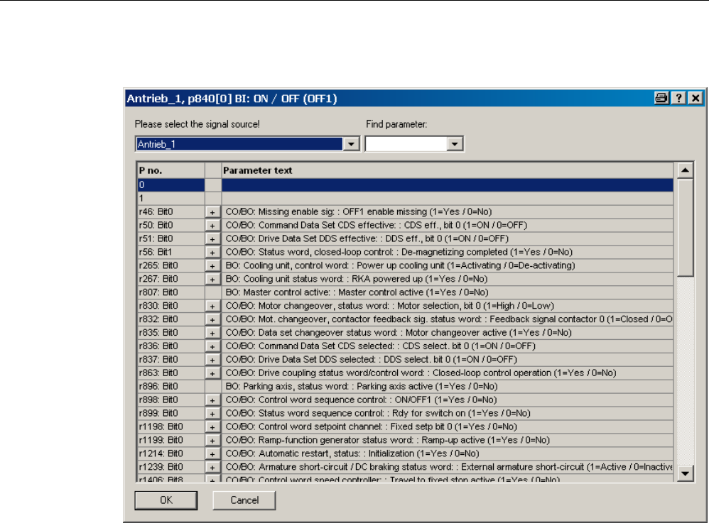
Commissioning
3.3 STARTER commissioning tool
STARTER Commissioning Manual
Commissioning Manual, (IH1), 07/2016, 6SL3097-4AF00-0BP5 87
3. Click the button to interconnect with a parameter.
Image 3-3 Interconnectable parameters
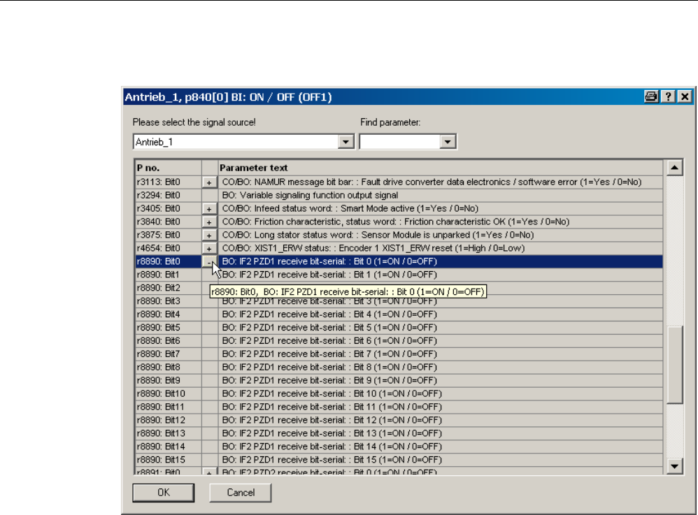
Commissioning
3.3 STARTER commissioning tool
STARTER Commissioning Manual
88 Commissioning Manual, (IH1), 07/2016, 6SL3097-4AF00-0BP5
A list from which you can select the available r parameters is now displayed.
Image 3-4 Selection list
4. Click the plus symbol of parameter r8890:bit0.
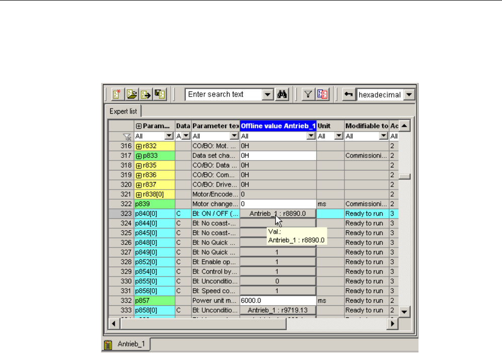
Commissioning
3.3 STARTER commissioning tool
STARTER Commissioning Manual
Commissioning Manual, (IH1), 07/2016, 6SL3097-4AF00-0BP5 89
5. Double-click r8890: Bit0.
In the expert list, you can now see that p0840 has been interconnected with parameter
r8890[0].
Image 3-5 Interconnection closed
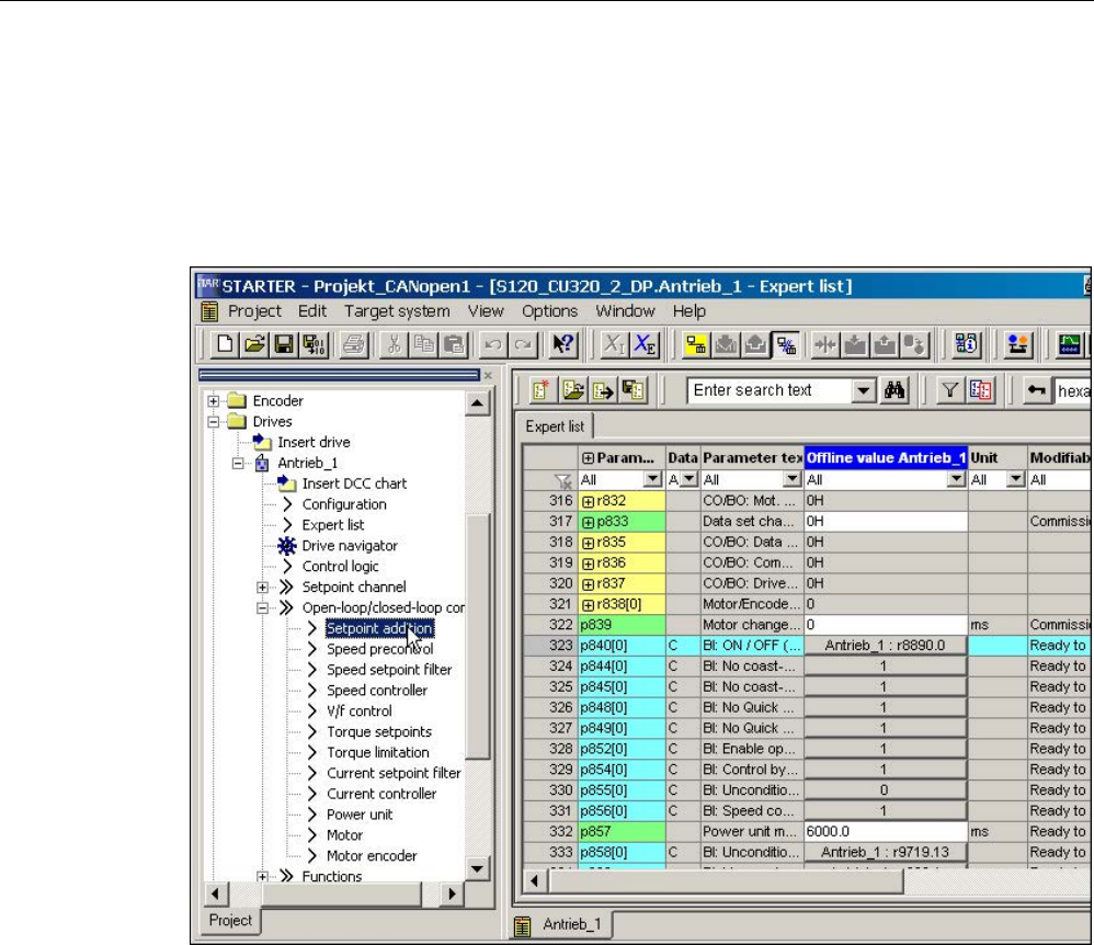
Commissioning
3.3 STARTER commissioning tool
STARTER Commissioning Manual
90 Commissioning Manual, (IH1), 07/2016, 6SL3097-4AF00-0BP5
Graphical screen interface
When carrying out BICO interconnection via the graphical screen interface, proceed as
follows:
For the setpoint velocity, which is a 32-bit data type, you want to interconnect parameter
p1155[0] for "Speed setpoint 1" with parameter r8860[1], for example.
Image 3-6 Parameters in the expert list
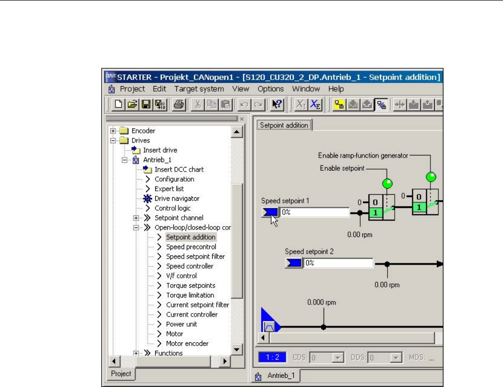
Commissioning
3.3 STARTER commissioning tool
STARTER Commissioning Manual
Commissioning Manual, (IH1), 07/2016, 6SL3097-4AF00-0BP5 91
1. In the project navigator, double-click the "Setpoint addition" selection under "Drive_1 >
Open-loop/closed-loop control".
Image 3-7 Setpoint addition
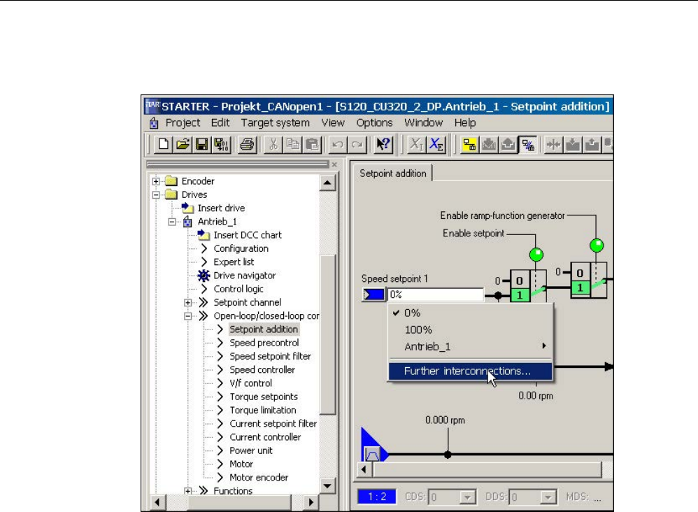
Commissioning
3.3 STARTER commissioning tool
STARTER Commissioning Manual
92 Commissioning Manual, (IH1), 07/2016, 6SL3097-4AF00-0BP5
2. Click the blue field to the left of the field for "Speed setpoint 1" and then click the selection
"Further interconnections", which is now displayed.
Image 3-8 Display additional interconnections
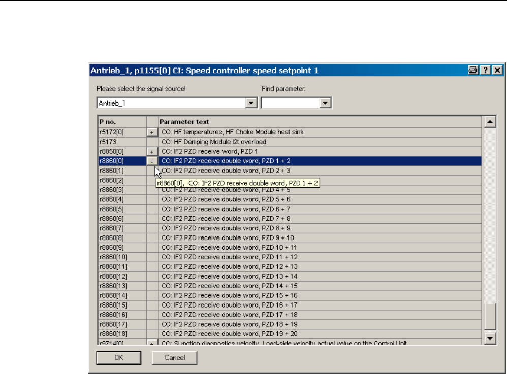
Commissioning
3.3 STARTER commissioning tool
STARTER Commissioning Manual
Commissioning Manual, (IH1), 07/2016, 6SL3097-4AF00-0BP5 93
A list from which you can select the available r parameters is now displayed.
Image 3-9 Selection list
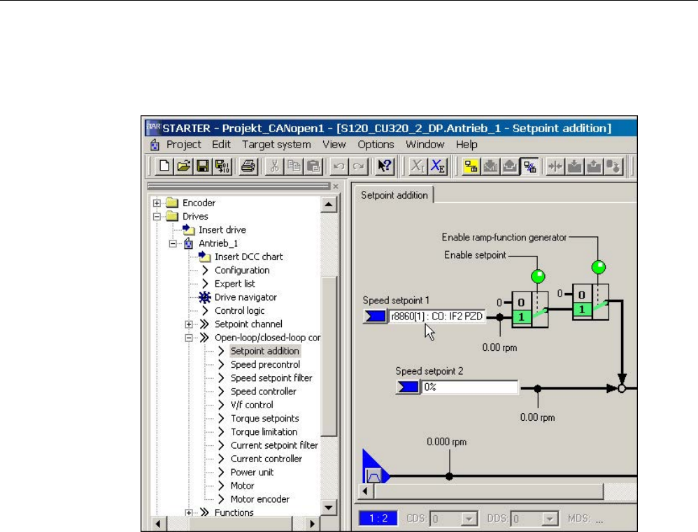
Commissioning
3.3 STARTER commissioning tool
STARTER Commissioning Manual
94 Commissioning Manual, (IH1), 07/2016, 6SL3097-4AF00-0BP5
3. Double-click r8860[1].
In the graphic screen interface, you can now see that p1155 has been interconnected
with parameter
r8860[1]
.
Image 3-10 Interconnection closed

Commissioning
3.3 STARTER commissioning tool
STARTER Commissioning Manual
Commissioning Manual, (IH1), 07/2016, 6SL3097-4AF00-0BP5 95
3.3.2
Important functions in the STARTER commissioning tool
The STARTER commissioning tool offers the following functions to support the project
handling:
● Restoring the factory settings
● Various operating wizards
● Configuring and parameterizing drives
● A virtual control panel to rotate the motors
● Run trace functions for controller optimization of the drives
● Create and copy data records
● Load the project from the programming device to the target device
● Copy volatile data from RAM to ROM
● Load the project from the target device to the programming device
● Create and activate safety functions
● Activate write protection
● Activate know-how protection
The programming device is called "PG/PC" in the subsequent text. The Control Unit of the
SINAMICS drive system is called the "Target device".
Operating support using wizards
Wizards are integrated in STARTER for various functions to support operation.
3.3.2.1
Restoring the factory settings
You can use this function to set all the parameters in the working memory of the Control Unit
to the factory settings. To ensure that the data on the memory card is also reset to the
factory settings, choose the "Copy from RAM to ROM" function. This function can only be
activated in the online mode. To activate the function:
1. Call the shortcut menu "Drive unit > Target device > Restore factory settings".
In the following prompt window you can select as to whether you also wish to save the
factory setting in the ROM.
2. Click "OK" to acknowledge.

Commissioning
3.3 STARTER commissioning tool
STARTER Commissioning Manual
96 Commissioning Manual, (IH1), 07/2016, 6SL3097-4AF00-0BP5
3.3.2.2
Load project to target device.
You can use this function to load the actual project from the PG/PC into the Control Unit. A
consistency check is first made for the project. If inconsistencies are detected, corresponding
messages are output. You must resolve the inconsistencies before loading. If the data is
consistent, then it will be transferred into the work memory of the Control Unit. In order to
execute this function in the online mode, the following operator actions are alternatively
available:
1. Select the drive unit and call the menu "Project > Load to target system".
or
2. Select the drive unit and call the shortcut menu "Target device > Load to target device".
Or
3. Select the drive unit and call the menu "Target system > Load > Load CPU/drive unit to
target device...".
Or
4. If the drive unit has a gray background, click the symbol "Load CPU/drive unit to
target device...".
3.3.2.3
Create data records (offline) and copy
Drive and command data sets (DDS and CDS) can be added in the drive's configuration
screen. Click the appropriate buttons to do this. Before data sets are copied, all the wiring
needed for both data sets should be completed.
For more information about data sets, refer to Chapter "Basics of the drive system" in the
SINAMICS S120 Function Manual Drive Functions.
3.3.2.4
Retentively saving data
You can use this function to save volatile Control Unit data to the non-volatile memory
(memory card). After backing up, the data is also retained if the 24 V Control Unit supply has
been switched off. In order to execute this function in the online mode, the following operator
actions are alternatively available:
1. Select the drive unit and call the menu "Target system > Copy RAM to ROM".
Or
2. Select the drive unit and call the shortcut menu "Target device > Copy RAM to ROM".
Or
3. If the drive unit has a gray background, click the symbol "Copy RAM to ROM".
Or
4. If, after every download into the target device, data is also to be automatically transferred
into the non-volatile memory, call the menu "Tools > Settings...".
5. Click the "Download" tab and activate the option "After loading, copy RAM to ROM". Click
"OK" to confirm this setting.

Commissioning
3.3 STARTER commissioning tool
STARTER Commissioning Manual
Commissioning Manual, (IH1), 07/2016, 6SL3097-4AF00-0BP5 97
3.3.2.5
Load the project to the PG/PC
You can use this function to load the current Control Unit project to STARTER. This function
can only be activated in the online mode. In order to execute this function in the online mode,
the following operator actions are alternatively available:
1. Select the drive unit and call the shortcut menu "Target device > Load CPU/drive unit into
PG/PC...".
Or
2. Select the drive unit and call the menu "Target system > Load > Load CPU/drive unit to
PG...".
Or
3. If the drive unit has a gray background, click the symbol "Load CPU/drive unit to
PG/PC...".
3.3.2.6
Create and correct safety functions
To set up, activate and operate the Safety Integrated functions, various screen forms are
available in the STARTER commissioning tool wizards. You can access the Safety
Integrated functions online and offline in the project tree.
1. In the project tree, open the following structure: "Drive unit xy > Drives > Drive xy >
Functions > Safety Integrated".
2. Double-click the function entry "Safety Integrated".
Note
Additional information about how to use Safety Integrated functions is provided in the
SINAMICS S120 Function Manual Safety Integrated.
3.3.2.7
Activate write protection
Write protection prevents settings from being inadvertently changed. No password is
required for write protection. This function can only be activated in the online mode.
1. Select the required drive unit in the project navigator of your STARTER project.
2. Call the shortcut menu "Write protection drive unit > Activate".
Write protection is now activated. In the expert list you can recognize that write protection
is active by the fact that the entry fields of all adjustable parameters are shown with gray
shading.
In order to permanently transfer your setting, after changing write protection, you must
carry out the "RAM to ROM" data save operation.

Commissioning
3.3 STARTER commissioning tool
STARTER Commissioning Manual
98 Commissioning Manual, (IH1), 07/2016, 6SL3097-4AF00-0BP5
3.3.2.8
Activate know-how protection
Activate know-how protection
The "Know-how protection function" prevents, for example, strictly confidential company
know-how for configuration and parameter assignment from being read. The know-how
protection requires a password. The password must comprise at least 1 and a maximum of
30 characters.
1. Select the required drive unit in the project navigator of your STARTER project.
2. Call the shortcut menu "Know-how protection drive unit > Activate".
The "Activate Know-how Protection for Drive Unit" dialog box opens.
Image 3-11 Activate know-how protection
3. The "Without copy protection" option is active by default. When an appropriate memory
card is inserted in the Control Unit, you can choose from two copy-protection options:
– With basic copy protection (permanently linked to the memory card)
– With extended copy protection (permanently linked to the memory card and control
unit)
WARNING
Danger to life through software manipulation when using removable storage media
The storage of files on removable storage media involves a high risk of infection, e.g. via
viruses or malware. As a result of incorrect parameterization, machines can malfunction,
which in turn can lead to injuries or death.
• Protect the files on removable storage media against harmful software through
appropriate protective measures, e.g. virus scanners.
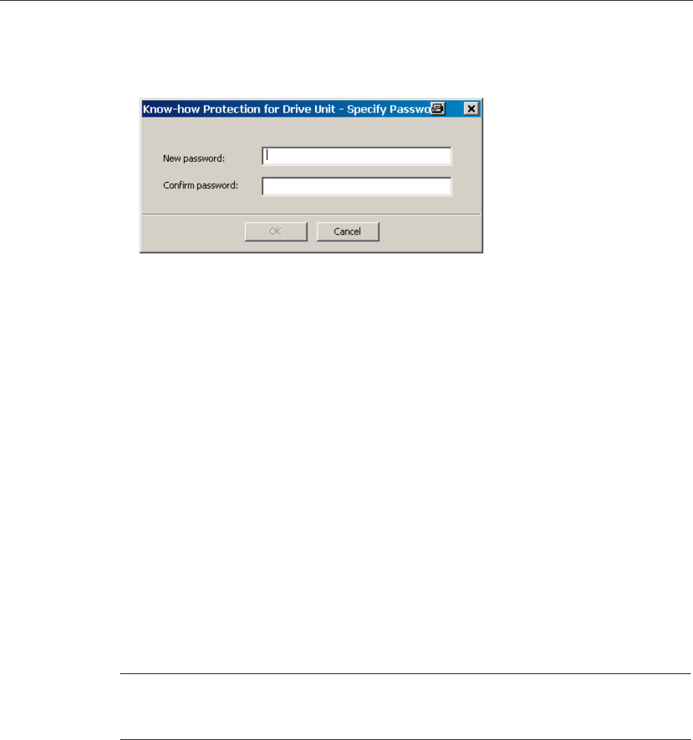
Commissioning
3.3 STARTER commissioning tool
STARTER Commissioning Manual
Commissioning Manual, (IH1), 07/2016, 6SL3097-4AF00-0BP5 99
4. Click "Specify".
The "Know-how Protection for Drive Unit - Specify Password" dialog box opens.
Image 3-12 Set a password for the know-how protection.
5. In the "New password" field, enter the password (1 to 30 characters). Pay attention to
upper- and lower-case.
6. Enter it again in the "Confirm password" field and click "OK" to confirm the entry.
The dialog box is closed and the password is shown in encrypted form in the "Activate
Know-how Protection for Drive Unit" dialog box.
7. If, despite active know-how protection, you permit diagnostic functions, activate the "Allow
diagnostic functions (trace and measuring functions)" option with a mouse click.
This allows the trace function, the measuring function and the function generator to be
used despite know-how protection.
8. The "Copy RAM to ROM" option is active by default and ensures that the know-how
protection is permanently stored in the Control Unit. If you want to use the know-how
protection temporarily, deactivate this option.
9. Click "OK" to confirm the settings you made.
Know-how protection is now activated. If larger data volumes are being encrypted, a
progress display informs that the encryption or the activation of the know-how protection
is still running.
The text "Know-how protected" then appears instead of the content in all protected
parameters of the expert list.
Note
A detailed description of the know
-how protection functions is provided in Chapter "Basics of
the drive system" in the SINAMICS S120 Function Manual Drive Functions.
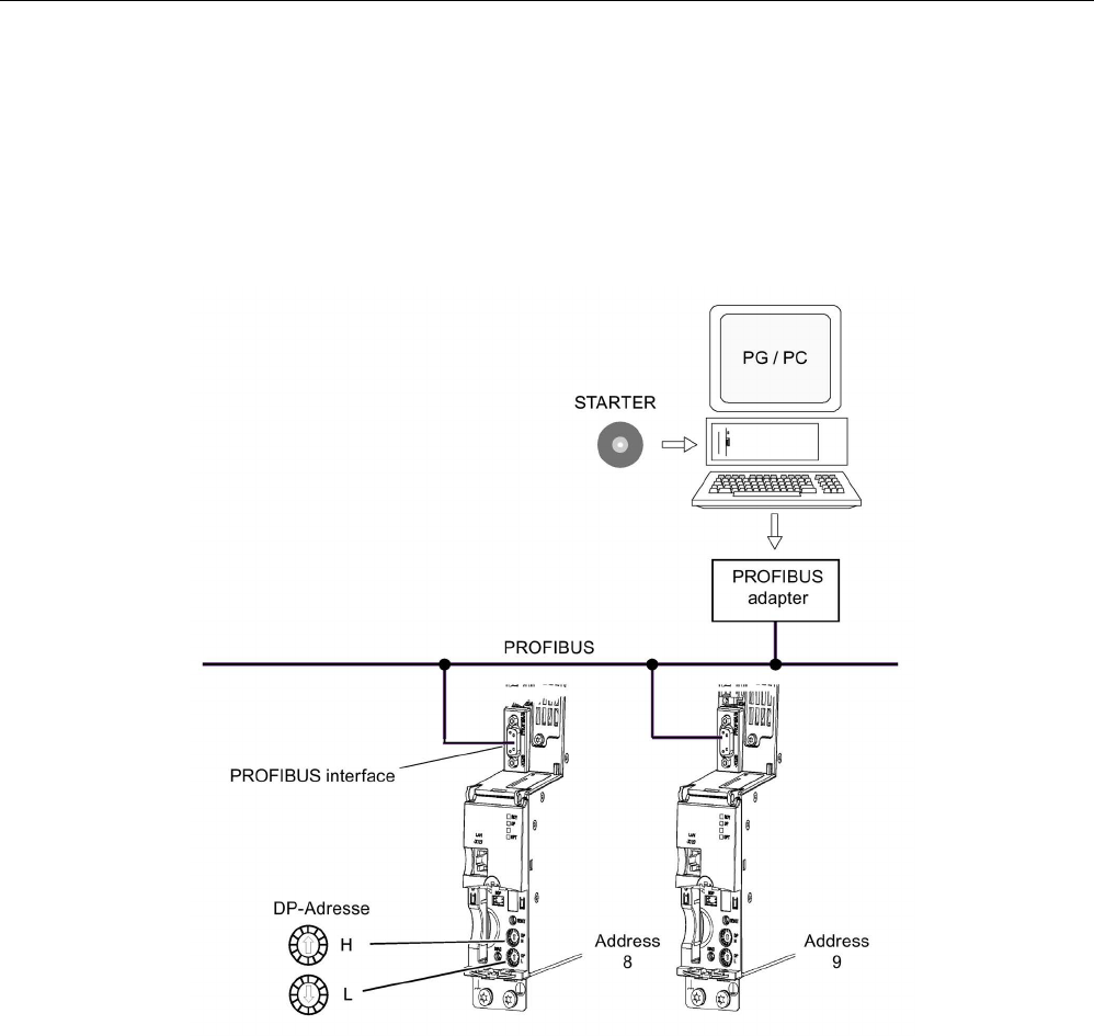
Commissioning
3.3 STARTER commissioning tool
STARTER Commissioning Manual
100 Commissioning Manual, (IH1), 07/2016, 6SL3097-4AF00-0BP5
3.3.3
Activating online operation: STARTER via PROFIBUS
The programming device (PG/PC), on which the STARTER commissioning tool is activated,
is connected to PROFIBUS using a PROFIBUS adapter.
STARTER via PROFIBUS (example with 2 CU320-2 DP)
Image 3-13 Connecting the programming device to the target device via PROFIBUS

Commissioning
3.3 STARTER commissioning tool
STARTER Commissioning Manual
Commissioning Manual, (IH1), 07/2016, 6SL3097-4AF00-0BP5 101
Making the STARTER settings for PROFIBUS
The following settings are required in the STARTER commissioning tool for communication
via PROFIBUS:
1. Call the menu "Tools > Set PG/PC interface ...".
2. If the interface has still not been installed, click on the "Select" button.
3. In the selection list on the left-hand side, select the module that you want to use as the
interface.
4. Click the "Install" button.
The selected module is then listed in the "Installed" list.
5. Click on "Close".
6. Call the menu "Tools > Set PG/PC interface ..." and click on the "Properties" button.
7. Activate or deactivate the option "PG/PC is the only master on the bus".
Note
PROFIBUS setting
•
Baud rate
– Connect STARTER to an operational PROFIBUS:
The STARTER commissioning tool automatically detects the baud rate used by
SINAMICS for PROFIBUS, and this is then used.
– Connect STARTER for commissioning:
The Control Unit automatically detects the baud rate set in the STARTER
commissioning tool, and this is then used.
•
PROFIBUS addresses:
The PROFIBUS addresses for the individual drive units must be specified in the project
and must match the address settings on the devices.
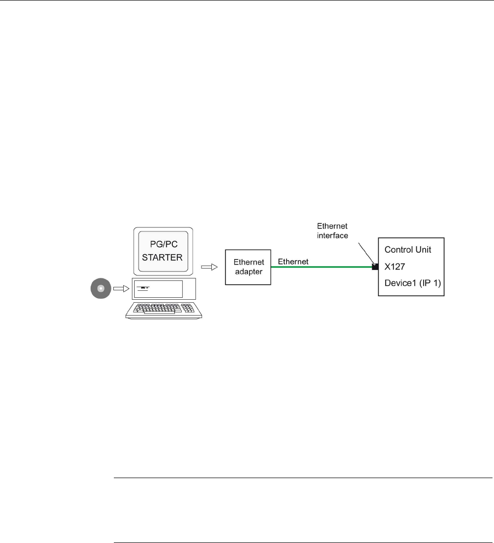
Commissioning
3.3 STARTER commissioning tool
STARTER Commissioning Manual
102 Commissioning Manual, (IH1), 07/2016, 6SL3097-4AF00-0BP5
3.3.4
Activating online operation: STARTER via Ethernet
The Control Unit can be commissioned with the PG/PC via the integrated Ethernet interface.
This interface is provided for commissioning purposes only and cannot be used to control the
drive in operation. Routing with a possibly inserted CBE20 expansion card is not possible.
Precondition
● STARTER as of version 4.1.5
● Control Unit CU320-2 DP as of version "C" or CU320-2 PN
STARTER via Ethernet (example)
Image 3-14 Connecting the PG/PC to the target device via Ethernet (example)
Install online operation via Ethernet
1. Install the Ethernet interface in the PG/PC according to the manufacturer's instructions.
2. Set the IP address of the Ethernet interface in Windows:
– Assign the PG/PC a free IP address (e.g. 169.254.11.1 ).
– In the delivery condition, the IP address of the internal Ethernet interface X127 of the
Control Unit is 169.254.11.22.
Note
Ethernet interface
X127 is intended for commissioning and diagnostics.
Do not use this interface for other purposes and ensure that X127 is always
accessible (e.g. for service).
3. Set the access point of the STARTER commissioning tool.
4. Use the STARTER commissioning tool to specify a name for the Control Unit interface.

Commissioning
3.3 STARTER commissioning tool
STARTER Commissioning Manual
Commissioning Manual, (IH1), 07/2016, 6SL3097-4AF00-0BP5 103
Setting the IP address in Windows 7
Note
The following procedure is based on the Windows 7 operating system. Under other operating
systems (such as Windows XP), operation may
differ slightly.
1. In the PG/PC call the control panel using the "Start > Control Panel" menu item.
2. In the control panel of your PG/PC, under "Network and Internet", select the "Network and
Sharing Center" function.
3. For your network card that is displayed, click the connection link.
4. Click in the status dialog of the connection on "Properties" and acknowledge the
subsequent confirmation prompt with "Yes".
5. In the properties dialog of the connection, select the "Internet protocol 4 (TCP/IPv4)"
element and then click "Properties".
6. In the properties dialog, activate the "Use the following IP address" option.
7. Set the IP address of the PG/PC access interface to the Control Unit to 169.254.11.1 and
the subnet mask to 255.255.0.0.
Image 3-15 Example: IPv4 address of the PG/PC
8. Click "OK" and close the Windows-specific window of the network connections.
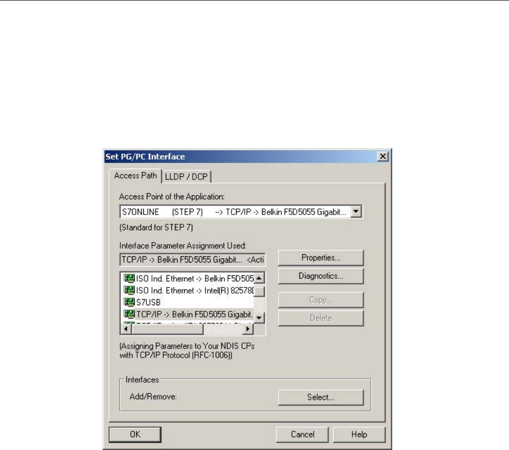
Commissioning
3.3 STARTER commissioning tool
STARTER Commissioning Manual
104 Commissioning Manual, (IH1), 07/2016, 6SL3097-4AF00-0BP5
Making settings in the STARTER commissioning tool
In the STARTER commissioning tool, set the communication via Ethernet as follows (in our
example, we are using the Ethernet interface "Belkin F5D 5055"):
1. Call the menu "Tools > Set PG/PC interface ...".
2. Select the "Access point of the application", and therefore the interface parameter
assignment (in the example we use the access point "S7ONLINE (STEP 7)" and the
interface parameterization "TCP/IP(Auto)->Belkin F5D 5055").
Image 3-16 Selecting the Ethernet interface at the PG/PC
If the desired interface does not yet exist in the selection list, you can create it.

Commissioning
3.3 STARTER commissioning tool
STARTER Commissioning Manual
Commissioning Manual, (IH1), 07/2016, 6SL3097-4AF00-0BP5 105
3. Click the "Select" button.
Image 3-17 Setting the interface
4. In the selection list on the left-hand side, select the module that you want to use as the
interface.
5. Click the "Install" button.
The selected module is then listed in the "Installed" list.
6. Click the "Close" button.
You can then check the IP address of the integrated Ethernet interface as follows:
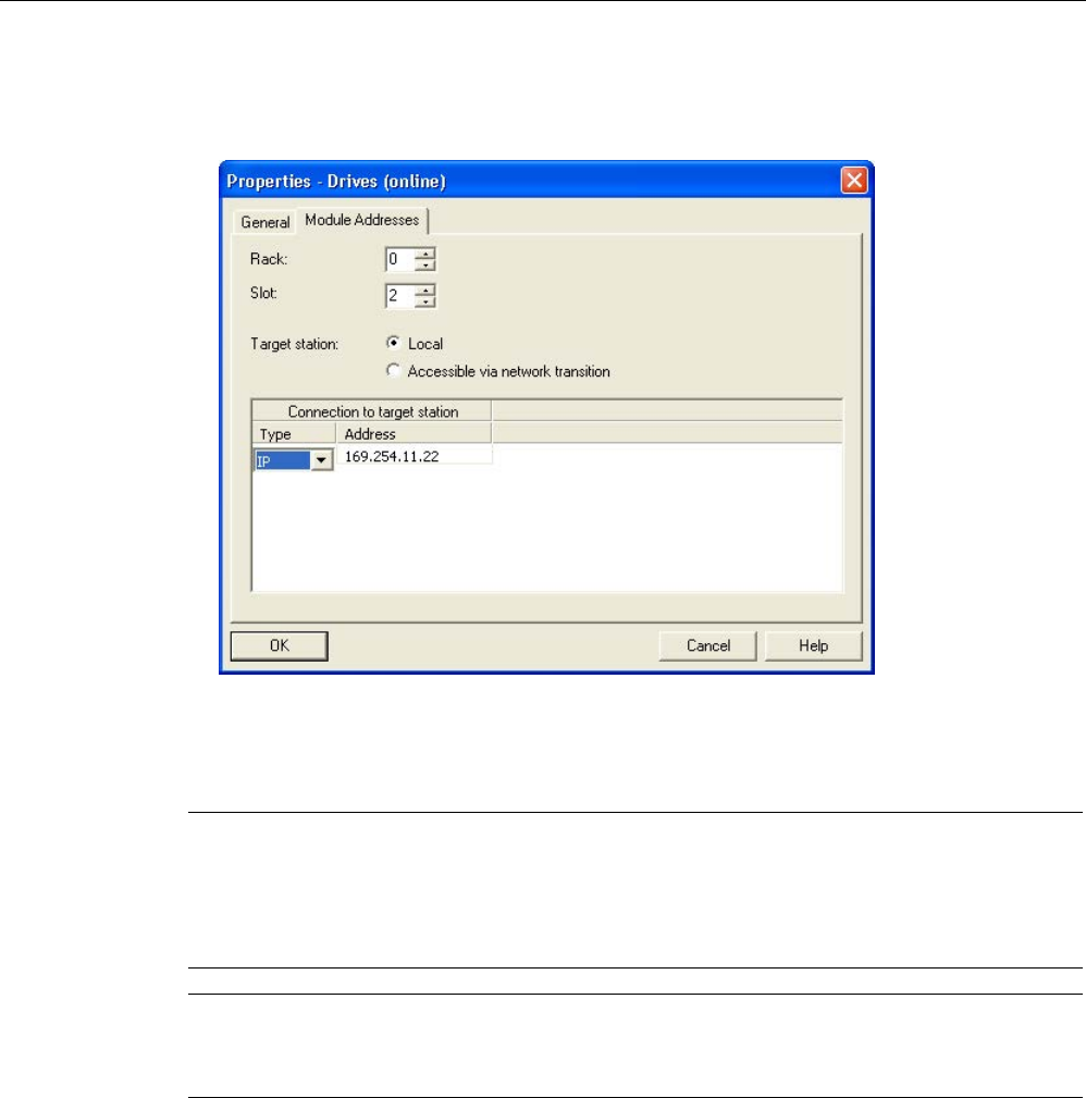
Commissioning
3.3 STARTER commissioning tool
STARTER Commissioning Manual
106 Commissioning Manual, (IH1), 07/2016, 6SL3097-4AF00-0BP5
7. Select the drive unit and call the shortcut menu "Target device > Online access ...".
8. Click the "Module addresses" tab.
Image 3-18 Setting the online access
Assigning the IP address and name
Note
When assigning names to IO devices (e.g. a Control Unit) in Ethernet (SINAMICS
components), then ST conventions (Structured Text) must be complied with. The names
must be unique within Ethernet. Other than "
-" and ".", no special characters are permitted in
the name of an IO device.
Note
The IP address and device name are stored non
-volatile on the memory card of the Control
Unit.
Assigning the IP address using the "Accessible nodes" function
Use the STARTER commissioning tool to assign an IP address and a name for the Ethernet
interface.
1. Connect the Control Unit to the PG/PC.
2. Switch on the Control Unit.
3. Open STARTER.
4. Load your project or create a new project.

Commissioning
3.3 STARTER commissioning tool
STARTER Commissioning Manual
Commissioning Manual, (IH1), 07/2016, 6SL3097-4AF00-0BP5 107
5. Call the menu "Project > Accessible nodes" or click the symbol "Accessible nodes" to
search for available nodes in the Ethernet.
The SINAMICS drive unit is identified and displayed as bus participant Drive unit_1 with
IP address 169.254.11.22.
6. Select the bus node entry and select the shortcut menu "Edit Ethernet node...".
7. In the dialog "Edit Ethernet nodes", enter the device name for the Ethernet interface.
– Click "Assign name".
– If no entry is in the subnet mask, enter 255.255.0.0 in the subnet mask for the IP
configuration.
– Click the "Assign IP configuration" button.
– Close the Information window "The parameters were transferred successfully".
– Click the "Close" button.
8. Click the "View/Refresh (F5)" button to display the IP address and the value
"NameOfStation" = "The assigned name" in the entry for the bus node.
Note
If these two pieces of information are not be displayed in the entry for the bus node, close
the "Accessible nodes" dialog and search for nodes
that can be accessed again.
9. If the Ethernet interface is displayed as bus node, select the entry and click the "Accept"
button.
The SINAMICS drive is displayed as new drive object in the project tree. You can now
configure the new drive unit.
10.Click the "Connect to selected target devices" button and call the menu "Target system >
Load to target device", to load the project to the Control Unit memory card.
The IP address and device name are stored non-volatile on the memory card of the Control
Unit.
Parameterizing the interface in the expert list
1. Assign the "Name of Station" in parameter p8900
2. Assign the "IP Address of Station" in parameter p8901
(factory setting 169.254.11.22).
3. Assign the "Default Gateway of Station" in parameter p8902
(factory setting 0.0.0.0).
4. Assign the "Subnet Mask of Station" in parameter p8903
(factory setting 255.255.0.0).
5. Activate the configuration with p8905 = 1.
6. Activate and save the configuration with p8905 = 2.
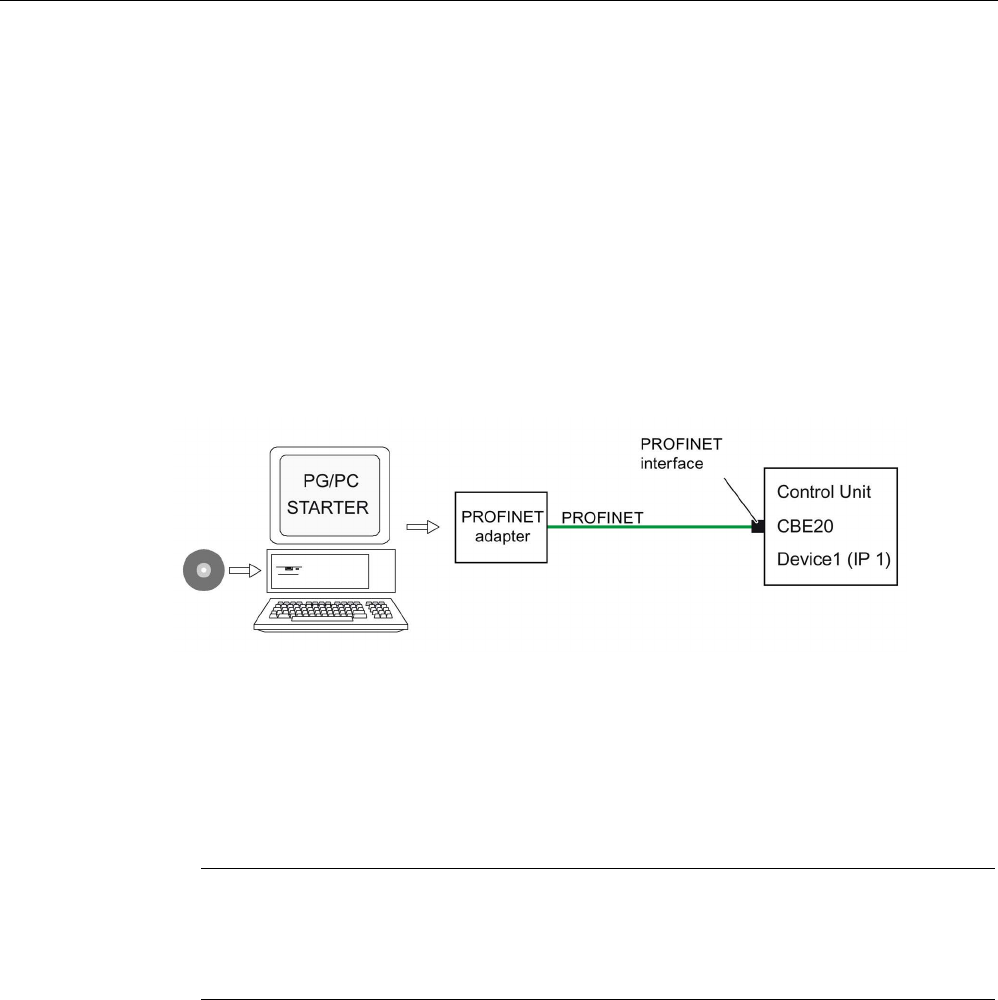
Commissioning
3.3 STARTER commissioning tool
STARTER Commissioning Manual
108 Commissioning Manual, (IH1), 07/2016, 6SL3097-4AF00-0BP5
3.3.5
Activating online operation: STARTER via PROFINET IO
Online operation with PROFINET IO is implemented using TCP/IP.
Preconditions
● STARTER as of version 4.1.5
● PROFINET-confom CU3xx PN
● CU32x with CBE20
STARTER via PROFINET IO (example)
Image 3-19 Connecting the PG/PC to the target device via PROFINET (example)
Establishing online operation with PROFINET
1. Assign the PG/PC a fixed, free IP address. In our example, we selected 169.254.11.1,
based on the factory setting of the integrated Ethernet interface X127 (169.254.11.22).
Set the subnet mask to 255.255.0.0.
Note
Ethernet interface X127 is intended for commissioning and diagnostics.
Do not use this interface for other purposes and ensure that X127 is always accessible
(e.g. for service).
2. Make the settings in the STARTER commissioning tool.
3. Select online operation in the STARTER commissioning tool.
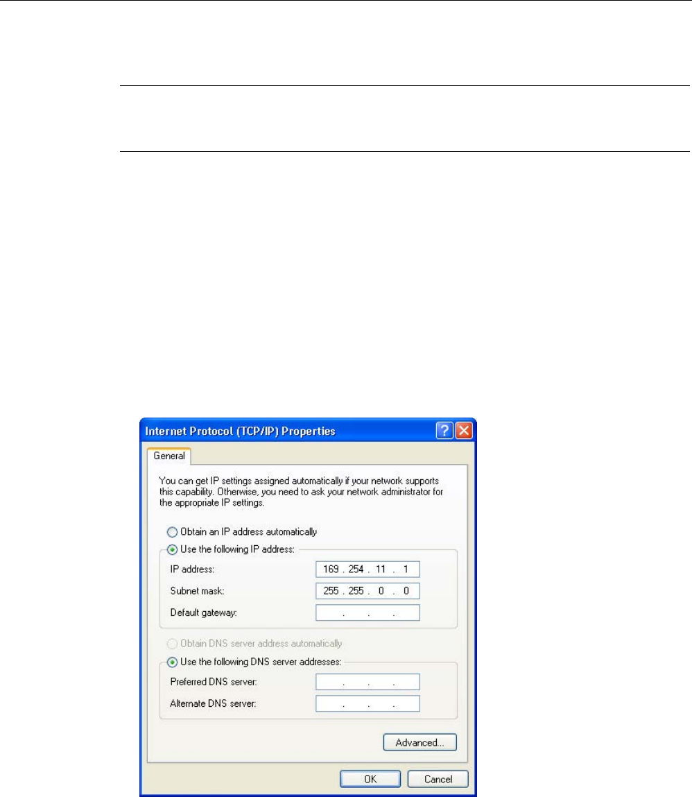
Commissioning
3.3 STARTER commissioning tool
STARTER Commissioning Manual
Commissioning Manual, (IH1), 07/2016, 6SL3097-4AF00-0BP5 109
Setting the IP address in Windows 7
Note
The following procedure is based on the Windows 7 operating system. Under other operating
systems (such as
Windows XP), operation may differ slightly.
1. In the PG/PC call the control panel using the "Start > Control Panel" menu item.
2. In the control panel of your PG/PC, under "Network and Internet", select the "Network and
Sharing Center" function.
3. For your network card that is displayed, click the connection link.
4. Click in the status dialog of the connection on "Properties" and acknowledge the
subsequent confirmation prompt with "Yes".
5. In the properties dialog of the connection, select the "Internet protocol 4 (TCP/IPv4)"
element and then click "Properties".
6. In the properties dialog, activate the "Use the following IP address" option.
7. Set the IP address of the PG/PC access interface to the Control Unit to 169.254.11.1 and
the subnet mask to 255.255.0.0.
Image 3-20 Example: IPv4 address of the PG/PC
8. Click "OK" and close the Windows-specific window of the network connections.
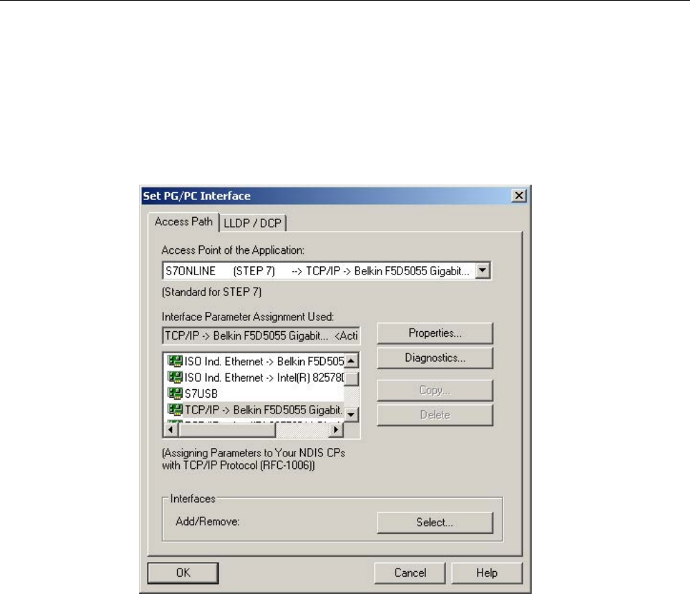
Commissioning
3.3 STARTER commissioning tool
STARTER Commissioning Manual
110 Commissioning Manual, (IH1), 07/2016, 6SL3097-4AF00-0BP5
Setting the interface in the STARTER commissioning tool
In the STARTER commissioning tool, you set communication via PROFINET as follows:
1. Call the menu "Tools > Set PG/PC interface ...".
2. Select the "Access point of the application", and therefore the interface parameter
assignment (in the example we use the access point "S7ONLINE (STEP 7)" and the
interface parameterization "TCP/IP(Auto)->Belkin F5D 5055").
Image 3-21 Setting the PG/PC interface
If the desired interface does not yet exist in the selection list, you can create it.
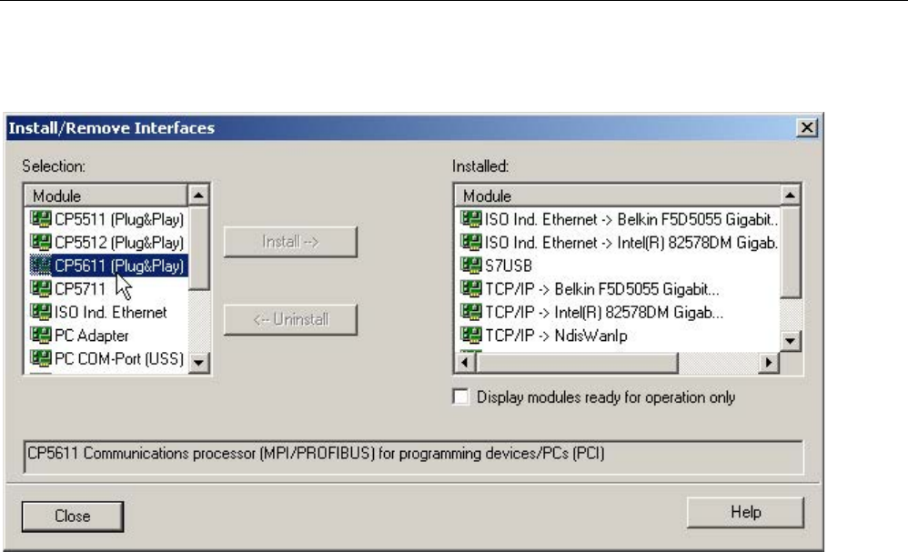
Commissioning
3.3 STARTER commissioning tool
STARTER Commissioning Manual
Commissioning Manual, (IH1), 07/2016, 6SL3097-4AF00-0BP5 111
3. Click the "Select" button.
Image 3-22 Setting the interface
4. In the selection list on the left-hand side, select the module that you want to use as the
interface.
5. Click the "Install" button.
The selected module is then listed in the "Installed" list.
6. Click the "Close" button.
You can then check the IP address of the integrated Ethernet interface as follows:
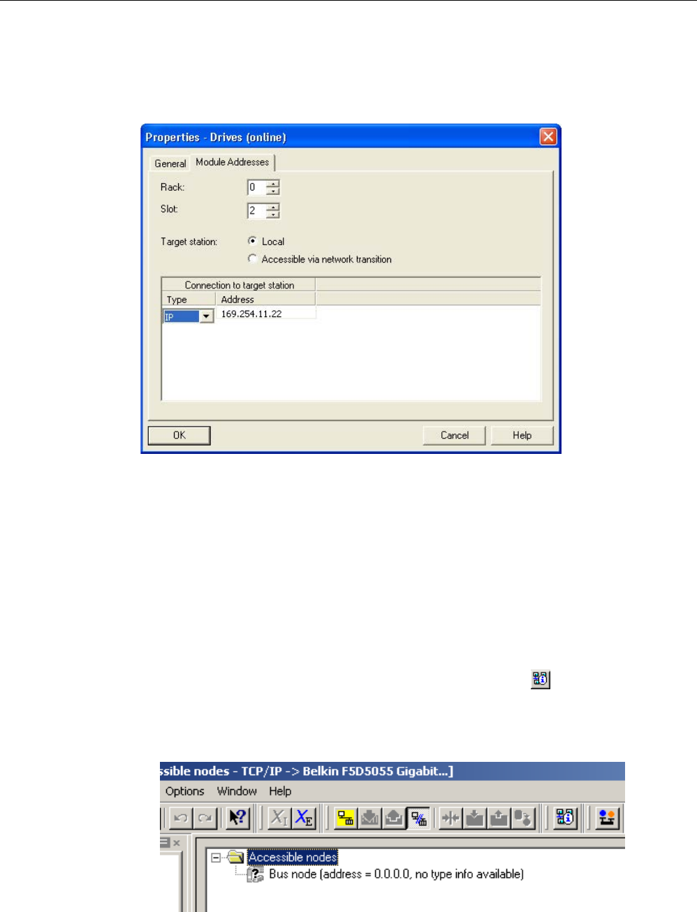
Commissioning
3.3 STARTER commissioning tool
STARTER Commissioning Manual
112 Commissioning Manual, (IH1), 07/2016, 6SL3097-4AF00-0BP5
7. Select the drive unit and call the shortcut menu "Target device > Online access ...".
8. Click the "Module addresses" tab.
The IP address that you set must be located under "Connect to target station".
Image 3-23 Setting online access
Assigning an IP address and a name to the drive unit
With the STARTER commissioning tool, you can assign an IP address and a name to the
PROFINET interface (e.g. CBE20) of the drive unit. The following steps are required:
1. Connect the PG/PC via a Crosslink-Ethernet cable with the CBE20, inserted in the
CU320-2.
2. Switch on the Control Unit.
3. Open the STARTER commissioning tool.
4. Call the menu "Project > Accessible nodes" or click the symbol "Accessible nodes".
– The search is performed for available nodes connected to PROFINET.
– The Control Unit is identified and displayed under "Accessible nodes" as the bus node
with the IP address 0.0.0.0, without any type information.
Image 3-24 Bus nodes found

Commissioning
3.3 STARTER commissioning tool
STARTER Commissioning Manual
Commissioning Manual, (IH1), 07/2016, 6SL3097-4AF00-0BP5 113
5. Right-click the bus node entry to open the shortcut menu "Edit Ethernet node ...".
– In the selection window that opens "Edit Ethernet node" you will also see the MAC
address.
6. Under "Set IP configuration", enter the IP address that you selected (e.g. 169.254.11.33)
and the subnet mask (e.g. 255.255.0.0).
7. Click the "Set IP configuration" button.
– The data transfer is confirmed.
8. Click the "Update" button.
– The bus node is identified as drive unit.
– The address and the type are specified.
In the "Edit Ethernet node" selection window you can also assign a device name to the
drive unit that has been detected.
9. In the "Device name" field, enter the name that you have selected.
Note
ST (Structured Text) conventions must be satisfied for the name assignment of IO
devices in PROFINET (SINAMICS components). The names must be unique within
PROFINET. Rules for assigning names:
•
Other than "-" and ".", no special characters (such as accented characters, spaces,
brackets) are permitted in the name of an IO device.
•
The device name must not begin or end with the "-" character.
•
The device name must not begin with a number.
•
Maximum total length of 240 characters (lowercase characters, numbers, hyphen, or
period)
•
A name component within the device name, e.g. a string between two periods, must
not exceed 63 characters.
•
The device name must not take the form n.n.n.n (n = 0..999).
•
The device name must not begin with the character sequence "port-xyz" or "port-xyz-
abcde" (a, b, c, d, e, x, y, z = 0..9).
10.Click the "Assign name" button.
– The data transfer is confirmed.
11.Click the "Update" button.
– The bus node is detected as drive unit and is consecutively numbered.
– The address, device name and the type are specified.

Commissioning
3.3 STARTER commissioning tool
STARTER Commissioning Manual
114 Commissioning Manual, (IH1), 07/2016, 6SL3097-4AF00-0BP5
12.Close the "Edit Ethernet node" window.
13.Activate the option button in front of the detected drive unit and click the "Accept" button.
The SINAMICS drive with CBE20 is transferred as a drive object into the project tree. You
can now continue to configure the drive object.
14.Click the "Connect to target system" button and then call the menu "Target system >
Load > To target device", to load the project to the Control Unit memory card.
The IP address and device name are stored non-volatile on the memory card of the
Control Unit.
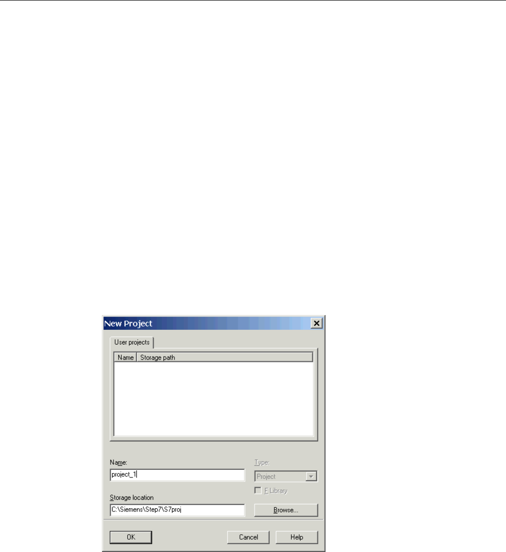
Commissioning
3.4 Creating a project in the STARTER commissioning tool
STARTER Commissioning Manual
Commissioning Manual, (IH1), 07/2016, 6SL3097-4AF00-0BP5 115
3.4
Creating a project in the STARTER commissioning tool
3.4.1
Creating a project offline
PROFIBUS
To create a project offline, you need the PROFIBUS address, the device type and the device
version, e.g. firmware version 4.5 or higher. Example of a sequence of the grouping:
Create a new project
1. Call the "Project > New ..." menu.
The following default settings are displayed:
– User projects: Projects already in the target directory
– Name: Project_1 (can be freely selected)
– Type: Project
– Storage location (path): Default (can be set as required)
2. If necessary, correct "Name" and "Storage location", and confirm with "OK".
The project is created offline and loaded to the target system when the configuring is
complete.
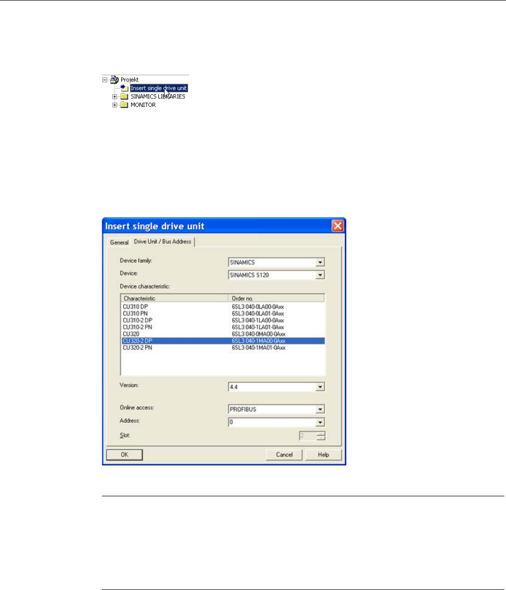
Commissioning
3.4 Creating a project in the STARTER commissioning tool
STARTER Commissioning Manual
116 Commissioning Manual, (IH1), 07/2016, 6SL3097-4AF00-0BP5
Add a single drive
1. Double-click in the project tree on "Insert single drive unit".
The following settings are pre-assigned:
– Device type: CU320-2 DP
– Device version: 4.5 or higher
– Address type: PROFIBUS/USS/PPI
– Bus address: 7
2. If necessary, correct the settings, and confirm with "OK".
Note
Bus address
The PROFIBUS address of the Control Unit must be set for initial commissioning.
Using the rotary coding switches on the
Control Unit, the address can be set to a value
between 1 and 126 and read via p0918. If the coding switches are at "0" (factory setting),
the value can be alternatively set between 1 and 126 using p0918.
Configure the drive unit
Once you have created the project, you have to configure the drive unit. Some examples are
provided in the following Chapters.
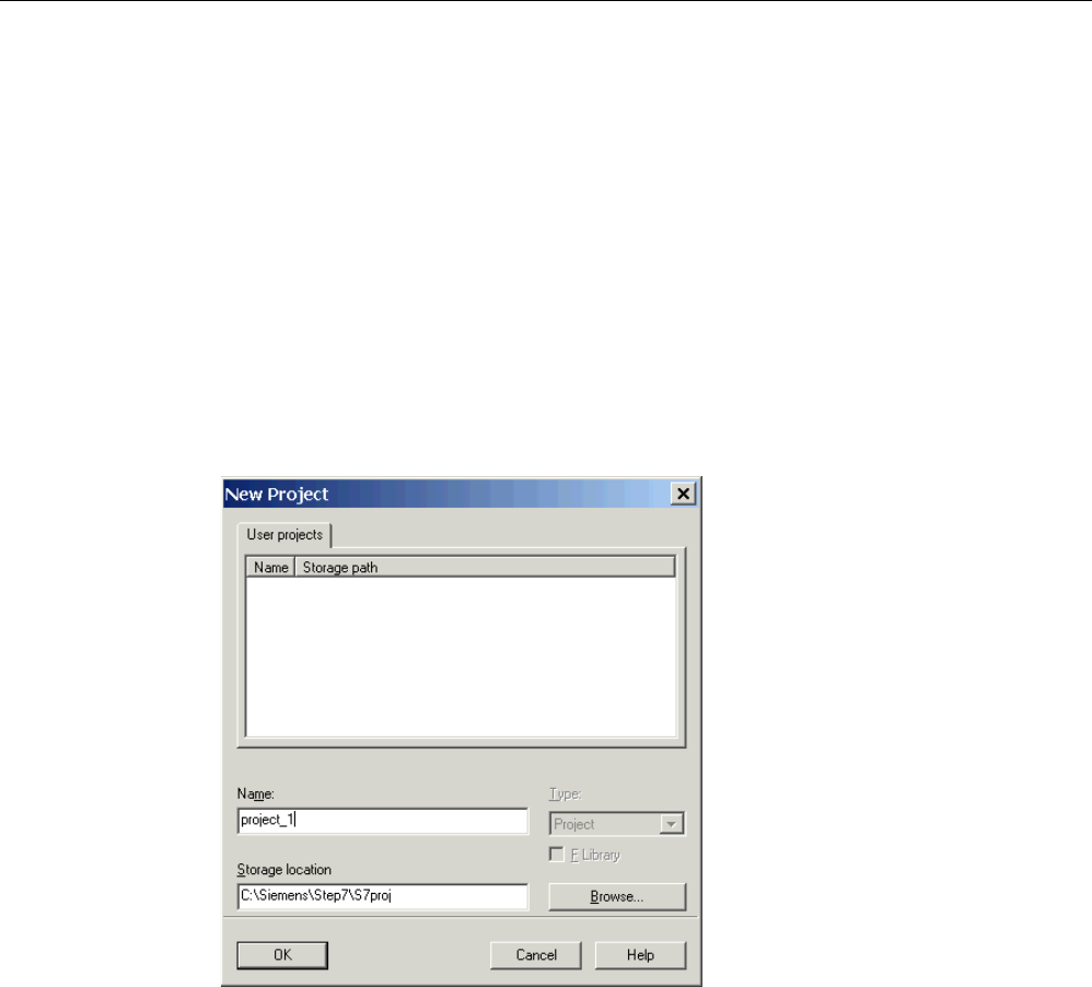
Commissioning
3.4 Creating a project in the STARTER commissioning tool
STARTER Commissioning Manual
Commissioning Manual, (IH1), 07/2016, 6SL3097-4AF00-0BP5 117
PROFINET
To create a project offline, you need the PROFINET address, the device type and the device
version, e.g. firmware version 4.5 or higher.
Create a new project
1. Call the "Project > New ..." menu.
The following default settings are displayed:
– User projects: Projects already in the target directory
– Name: Project_1 (can be freely selected)
– Type: Project
– Storage location (path): Default (can be set as required)
2. If necessary, correct "Name" and "Storage location", and confirm with "OK".
The project is created offline and loaded to the target system when the configuring is
complete.
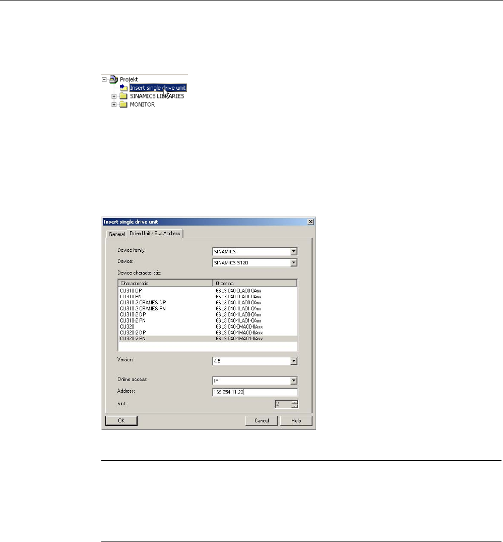
Commissioning
3.4 Creating a project in the STARTER commissioning tool
STARTER Commissioning Manual
118 Commissioning Manual, (IH1), 07/2016, 6SL3097-4AF00-0BP5
Add a single drive
1. Double-click in the project tree on "Insert single drive unit".
The following settings are pre-assigned:
– Device type: CU320-2 PN
– Version: 4.5 or higher
– Online access: IP
– Address: 169.254.11.22
2. If necessary, correct the settings, and confirm with "OK".
Note
Bus address
The PROFINET address of the Control Unit must not be set for initial commissioning.
When delivered, the TCP/IP address of the Control Unit is set to 169.254.11.22. The
address can be correspondingly changed to meet indiv
idual requirements.
Configure the drive unit
Once you have created the project, you have to configure the drive unit. Some examples are
provided in the following Chapters.
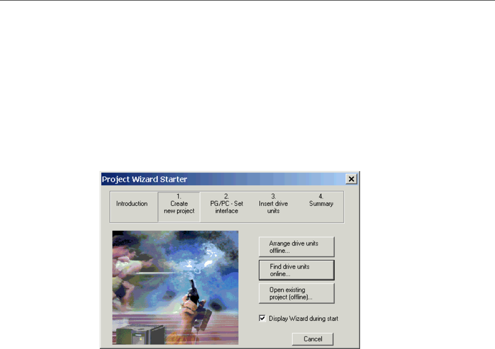
Commissioning
3.4 Creating a project in the STARTER commissioning tool
STARTER Commissioning Manual
Commissioning Manual, (IH1), 07/2016, 6SL3097-4AF00-0BP5 119
3.4.2
Creating a project online
In order to search online for bus nodes via PROFIBUS or PROFINET, the drive unit must be
connected with the PG/PC via PROFIBUS or PROFINET. Example of a commissioning
sequence with STARTER
Create a new project
1. Call the menu "Project > New with wizard".
2. Click "Find drive units online".
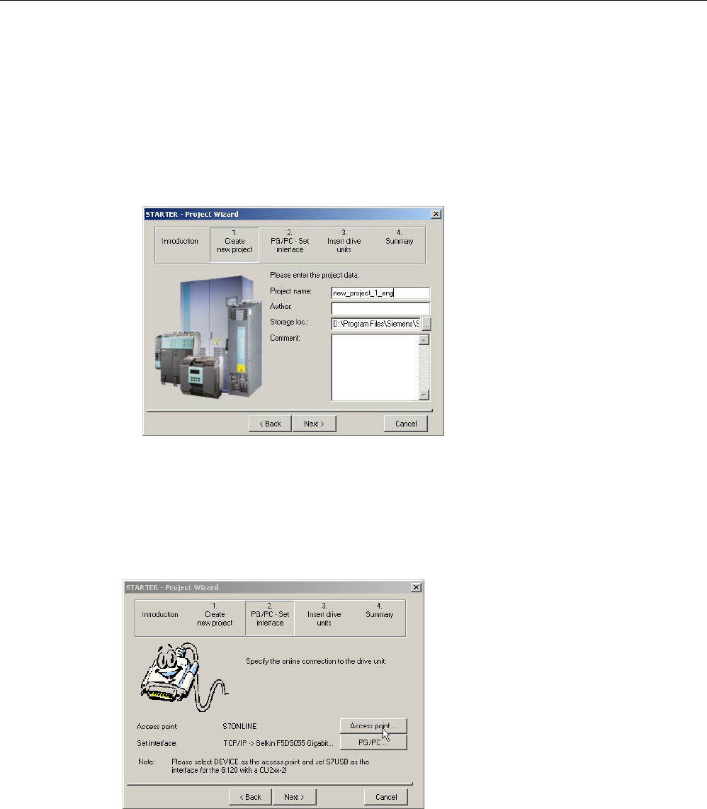
Commissioning
3.4 Creating a project in the STARTER commissioning tool
STARTER Commissioning Manual
120 Commissioning Manual, (IH1), 07/2016, 6SL3097-4AF00-0BP5
Enter the project data.
1. Enter the following project data:
– Project name: Project_1, can be freely selected
– Author: Any
– Storage location: Any
– Comment: Any
2. If necessary, correct the corresponding project data.
3. Click "Continue >".
Set up the PG/PC interface
The PG/PC interface can be setup in this window.
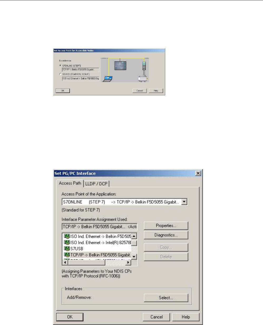
Commissioning
3.4 Creating a project in the STARTER commissioning tool
STARTER Commissioning Manual
Commissioning Manual, (IH1), 07/2016, 6SL3097-4AF00-0BP5 121
Selecting the access point
The target device can be accessed using STARTER or via STEP 7.
1. For step 2, click "Access point".
2. Select the access point for the accessible nodes, and confirm with "OK".
Selecting the PG/PC interface
In this window, the interface can be selected, set and tested.
1. For step 2, click "PG/PC".
2. Select the "Access point of the application" and therefore also the interface parameter
assignment.
If the desired interface does not yet exist in the selection list, you can create additional
interfaces clicking the "Select" button.
3. Click "OK" to confirm your settings.
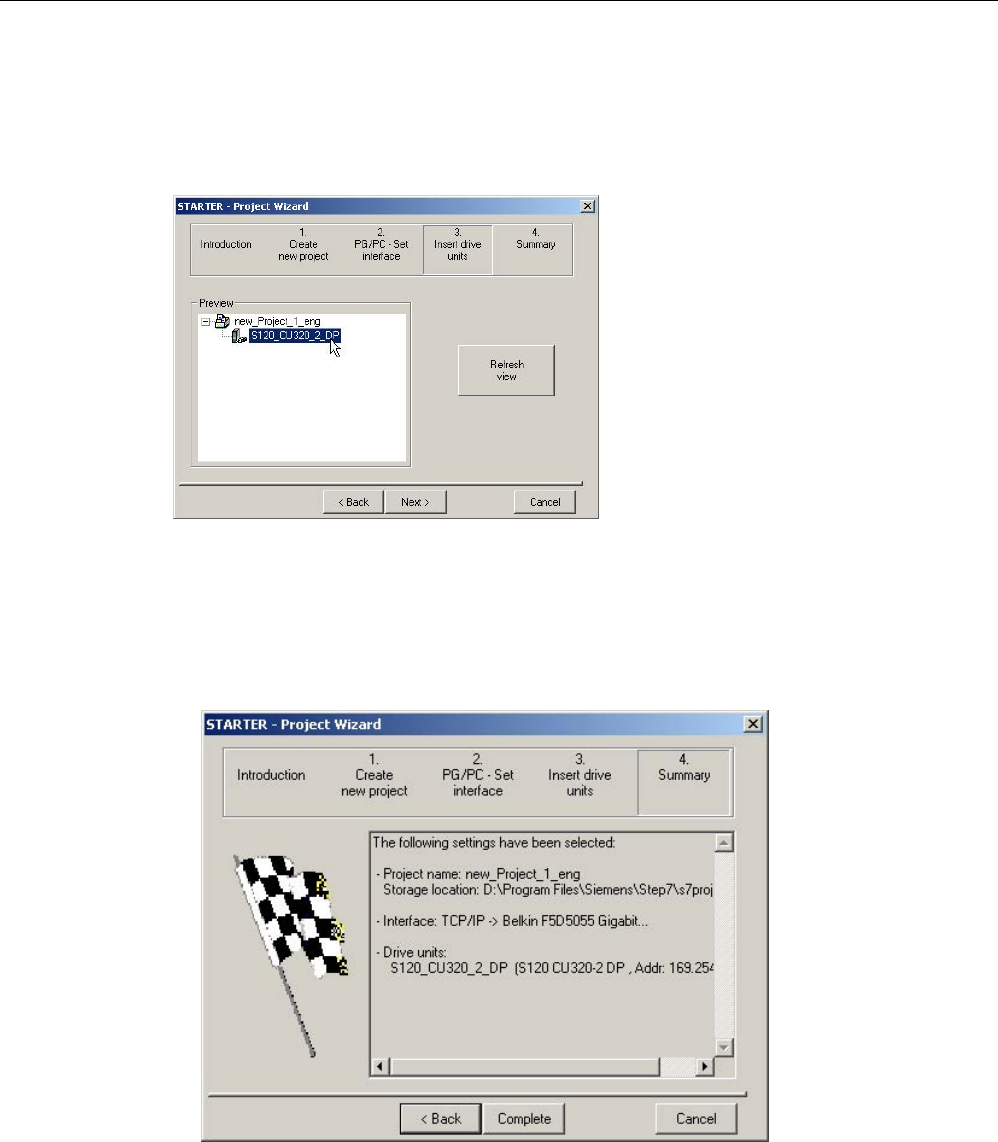
Commissioning
3.4 Creating a project in the STARTER commissioning tool
STARTER Commissioning Manual
122 Commissioning Manual, (IH1), 07/2016, 6SL3097-4AF00-0BP5
Insert drives
The nodes are shown here in the preview.
Use the button "Refresh view" to update the preview.
1. Click "Continue >".
Summary
You have now created the project. The project wizard shows the current settings.
1. Click "Finish".
Configure the drive unit
Once you have created the project, you have to configure the drive unit. Some examples are
provided in the following Chapters.

Commissioning
3.5 Commissioning the servo control booksize format for the first time
STARTER Commissioning Manual
Commissioning Manual, (IH1), 07/2016, 6SL3097-4AF00-0BP5 123
3.5
Commissioning the servo control booksize format for the first time
An example provided in this chapter explains all the configuration and parameter settings, as
well as tests that are required for initial commissioning. Commissioning is carried out using
the STARTER commissioning tool.
Preconditions for commissioning
● The commissioning preconditions (Page 30) have been met.
● The commissioning checklists (Page 32) (Tables 2-1 and 2-2) have been completed and
the points fulfilled.
● The STARTER commissioning tool is installed and activated.
– System prerequisites, refer to the Readme file in the STARTER installation directory.
● The drive system has been wired according to the specifications.
● The communication between the PG/PC and drive system has been prepared.
● The power supply of the Control Unit (24 V DC) has been switched on.
3.5.1
Task
Commissioning a drive unit with the following components:
Table 3- 1 Component overview
Designation
Component
Article number
Closed-loop control and infeed
Control Unit 1 Control Unit 320-2 DP 6SL3040-1MA00-0AA0
Active Line Module
Active Line Module 16 kW
6SL3130-7TE21-6AA.
Line filter
Active Interface Module
6SL3100-0BE21-6AB0
Drive 1
Single Motor Module 1
Single Motor Module 9 A
6SL3120-1TE21-0AA.
Sensor Module 1.0
SMC20
6SL3055-0AA00-5BA.
Motor 1
Synchronous motor
1FK7061–7AF7.–....
Motor encoder 1 Incremental encoder sin/cos C/D
1 Vpp 2048 p/r
1FK7...–.....–.A..
Sensor Module 1.1
SMC20
6SL3055-0AA00-5BA.
External encoder Incremental encoder
sin/cos 1 Vpp 4096 p/r
-
Drive 2
Single Motor Module 2
Single Motor Module 18 A
6SL3120-1TE21-8AA.
Motor 2
Induction motor
1PH7103–.NG..–.L..
Sensor Module 2
SMC20
6SL3055-0AA00-5BA.
Motor encoder 2 Incremental encoder sin/cos
1 Vpp 2048 p/r
1PH7...–.M...–....

Commissioning
3.5 Commissioning the servo control booksize format for the first time
STARTER Commissioning Manual
124 Commissioning Manual, (IH1), 07/2016, 6SL3097-4AF00-0BP5
The enable signals for the infeed and the two drives must be transmitted via PROFIBUS.
● Telegram for the Active Line Module
Telegram 370: Infeed, 1 word
● Telegram for drive 1
Standard telegram 4: Speed control, 2 position encoders
● Enable signals for drive 2
Standard telegram 3: Speed control, 1 position encoder
Note
For more information about tele
gram types, see SINAMICS S120 Function Manual Drive
Functions or SINAMICS S120/S150 List Manual.
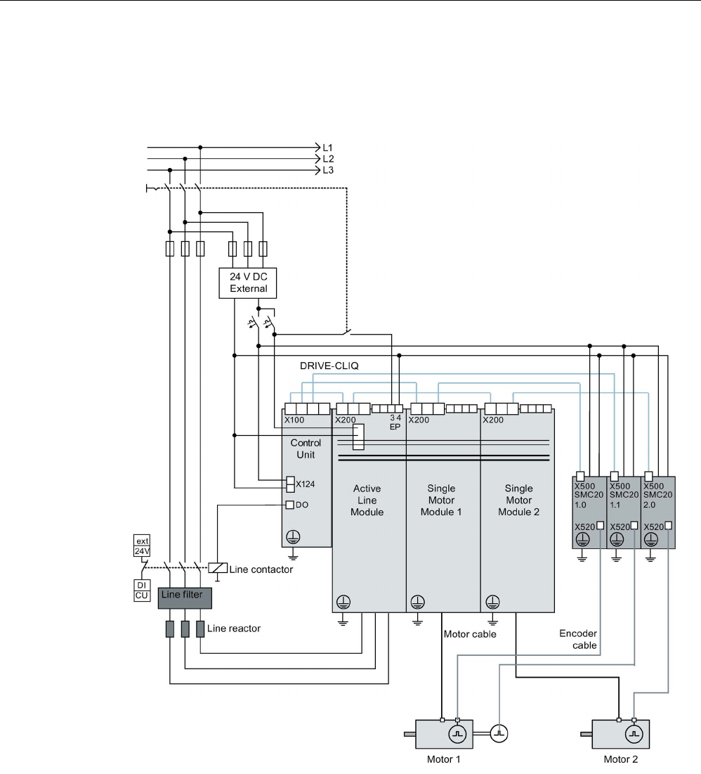
Commissioning
3.5 Commissioning the servo control booksize format for the first time
STARTER Commissioning Manual
Commissioning Manual, (IH1), 07/2016, 6SL3097-4AF00-0BP5 125
3.5.2
Component wiring (example)
The following diagram shows the structure of the components and the appropriate wiring.
The DRIVE-CLiQ wiring is highlighted in bold.
Image 3-25 Component wiring (example)
Additional information on wiring and connecting the encoder system is provided in the
Manual.
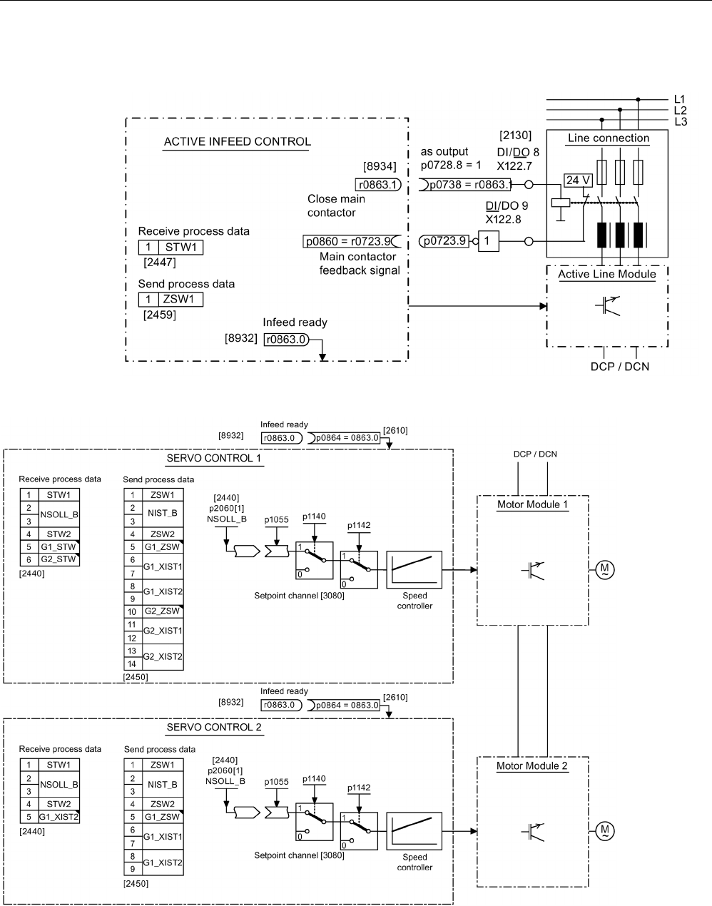
Commissioning
3.5 Commissioning the servo control booksize format for the first time
STARTER Commissioning Manual
126 Commissioning Manual, (IH1), 07/2016, 6SL3097-4AF00-0BP5
3.5.3
Signal flow of the commissioning example
Image 3-26 Signal flow of the commissioning example - servo control, Part 1
Image 3-27 Signal flow of the commissioning example - servo control, Part 2

Commissioning
3.5 Commissioning the servo control booksize format for the first time
STARTER Commissioning Manual
Commissioning Manual, (IH1), 07/2016, 6SL3097-4AF00-0BP5 127
3.5.4
Commissioning with STARTER (example)
The table below describes the steps for commissioning a drive using the STARTER
commissioning tool.
Table 3- 2 Sequence for commissioning with the STARTER commissioning tool (example)
What?
How?
Comment
1. Creating a new
project
1. Call the "Project > New..." menu.
2. Enter a project name in the "New project" dialog.
3. Click "OK".
-
2. Automatic configu-
ration
1. Call the "Project > Connect to selected target devices" menu.
As there is still no device available in the project, the
STARTER commissioning tool offers the option of searching
for accessible nodes.
2. Click "Yes".
3. Activate the drive unit accessed by clicking the checkbox.
4. Click "Apply".
The drive project is transferred into the project view.
5. Call the "Project" > "Connect to selected target devices" menu
again.
You are now connected online to the drive unit.
6. Double-click "Automatic configuration". Click "Configure".
7. During automatic commissioning, the wizard will offer you the
option of selecting the drive object type. As default assign-
ment, select all of the "SERVO" components.
8. Click "Create".
9. After the automatic configuration has been completed, you
have the option of going OFFLINE or remaining ONLINE. Se-
lect "Go OFFLINE".
-
3. Configuring
the infeed
1. Double-click in the project tree on "Infeeds".
2. Double-click the infeed that has been created.
3. Click the yellow "Wizard..." button.
4. To check the automatic settings and to enter additional data,
such as equipment codes, etc. continue with step 3.2.
-
Note:
When the factory setting is p7826 = 1, the firmware is automatically updated to the status on the memory card when a
configured DRIVE-CLiQ component is first booted. This may take several minutes and is indicated by the READY-LED on
the corresponding components flashing green/red and the Control Unit flashing orange (0.5 Hz). Once all updates have
been completed, the READY-LED on the Control Unit flashes orange at 2 Hz and the corresponding READY-LED on the
components flashes green/red at 2 Hz. For the firmware to be activated, a POWER ON must be carried out for the compo-
nents.
For infeed units connected to the drive unit, which during the automatic configuration do not communicate with the Control
Unit via DRIVE-CLiQ, you must manually configure and transfer them into the drive topology. These devices can only be
inserted in the offline mode.

Commissioning
3.5 Commissioning the servo control booksize format for the first time
STARTER Commissioning Manual
128 Commissioning Manual, (IH1), 07/2016, 6SL3097-4AF00-0BP5
What?
How?
Comment
3.1 Inserting
an infeed unit
If there is no DRIVE-CLiQ connection to the Control Unit, then
you must manually enter the data of the infeed unit using the
wizard.
1. Double-click in the project tree on "Infeeds".
2. Double-click "Insert infeeds".
3. Enter a name for the infeed.
4. Select the type.
5. Click "OK".
If the line environment or
DC-link components are
changed, line/DC-link iden-
tification should be repeat-
ed.
3.2 Infeed 1. Enter a component name.
2. Select the line voltage range.
3. Select the cooling type.
4. Select the baud rate.
5. The available components are now in the selection list.
6. Select the required infeed from the list.
7. Click "Continue >".
-
3.3 Infeed - additional
data
1. Activate the line/DC-link identification when switching-on for
the first time.
2. Accept the device supply voltage from the previous window.
The rated line frequency is determined automatically.
3. Make sure that the option "Line filter available" is activated.
4. For an infeed in the "booksize" format, select a line filter.
You can select one from several versions.
5. If applicable, enter the number of parallel infeeds.
6. Where relevant, select a Voltage Sensing Module.
7. Where relevant, select an external Braking Module.
8. Where relevant, select master/slave operation for several
infeeds.
9. Click "Continue >".
-
3.4 Process data
exchange
(infeed)
One of three telegrams can be selected for communication: 370,
371 and 999.
1. Select the required telegram (e.g. 370).
2. Click "Continue >".
-
3.6 Configuration,
summary
Configuration of the infeed unit has been completed. A summary
is displayed.
1. Click "Complete".
The infeed unit data can be
copied to the clipboard for
plant documentation pur-
poses and then added to a
text program, for example.
NOTICE
Damage to the infeed for control using another Control Unit
If the infeed is controlled by a Control Unit other than that used for the Motor Module, the
"Ready" signal for the infeed r0863.0 must be interconnected with drive parameter p0864
"Infeed ready" via a digital input/output. If this is not taken into account, the infeed may be
damaged.

Commissioning
3.5 Commissioning the servo control booksize format for the first time
STARTER Commissioning Manual
Commissioning Manual, (IH1), 07/2016, 6SL3097-4AF00-0BP5 129
What?
How?
Comment
4. Configuring the
drives
You must individually configure the drives in the offline mode. The
wizard displays the data determined automatically from the elec-
tronic type plate.
-
For drives connected to the drive unit, which during the automatic configuration do not communicate with the Control Unit
via DRIVE-CLiQ, you must manually configure and transfer them into the drive topology. These devices can only be in-
serted in the offline mode. In this case, perform the commissioning with step 4.1.
If the drives have already been created by the automatic configuration, click "Configuration" > "Configure DDS... " under
the drive. Then continue from step 4.2. Settings of the power unit data and for motors with DRIVE-CLiQ interface, the mo-
tor data is also already pre-assigned based on the electronic type plate.
4.1 Inserting drives 1. Double-click in the project tree on "Drives".
2. Double-click the "Insert drives" entry.
3. Enter a name for the drive.
4. For the drive object, select "SERVO".
5. Click "OK".
-
4.2 Control structure 1. Select function modules.
2. Select the required control mode.
3. Click "Continue >".
-
4.3 Power unit 1. Enter a name for the component.
2. Select the DC supply voltage.
3. Select the cooling type.
4. Select the type.
The available components are now in the selection list.
5. Select the required power unit from the list.
6. Click "Continue >".
-
4.4 Configuration,
power unit BICO
interconnection
If an infeed without DRIVE-CLiQ connection is used, a message
is displayed stating that the operating signal must be connected.
1. In the following dialog "Infeed in operation", set parameter
p0864 to the binector output of the digital input to which the
operating feedback signal of the infeed is interconnected.
2. Click "Continue >".
-
5 Configuring the
motor
1. Enter a name for the motor (e.g. an equipment code).
2. If your motor has its own DRIVE-CLiQ interface, select the
"Motor with DRIVE-CLiQ interface" item.
3. Click "Continue >" and proceed with step 5.2.
When commissioning, the motor data is automatically transferred
to the Control Unit.
You can select a standard
motor from the list of mo-
tors or manually enter the
motor data. You can then
select the motor type.
1. If you use a standard motor select the item, "Select standard
motor from list".
2. Select the standard motor type from the "Motor type" list.
3. Select your motor.
4. Click "Continue >".
Depending on the particular motor type, motor properties are
additionally queried; then continue with step 5.2.

Commissioning
3.5 Commissioning the servo control booksize format for the first time
STARTER Commissioning Manual
130 Commissioning Manual, (IH1), 07/2016, 6SL3097-4AF00-0BP5
What?
How?
Comment
1. If your motor is not in the default list, select "Enter motor da-
ta".
2. Click your motor type in the "Motor type" list.
3. Click "Continue >".
5.1 Configuring the
motor data
Enter your motor data according to the data sheet.
If you have no mechanical
data, then the data is esti-
mated based on the type
plate data. The equivalent
circuit diagram data is also
estimated on the basis of
the data on the type plate
or determined by means of
automatic motor data iden-
tification.
Alternatively, after entering the motor data, perform a motor data
identification when commissioning for the first time.
Alternatively, for some motor types you can use motor data from
the motor list.
1. To do so, click the template.
2. Follow the instructions of the wizard and click "Continue >".
3.
If known, enter the mechanical/electrical data of the motor and
the drive train or the data of a PE spindle.
4. For this drive, select whether you require a calculation of the
motor/controller data.
5.2 Configuring a
motor holding
brake
1. If you are not using a motor holding brake, click "Continue >"
Or
2. If you are using a motor holding brake, select it in the dialog
box and then subsequently configure it.
3. Click "Continue >".
Additional information: see
SINAMICS S120 Function
Manual Drive Functions.
5.3 Configuring an
encoder
You can connect up to three encoders.
1. If you are using DRIVE-CLiQ encoders, select the appropriate
item.
2. Click "Continue >".
The encoder is automatically identified and configured.
If you are using an encoder
that is not in the list, you
can also manually enter
the data.
By clicking Details, you can
view the data of the en-
coder selected from the the
encoder list.
Alternatively, you can use a standard encoder.
1. Select this encoder from the list.
2. Click "Continue >".
Alternatively, you can use your own encoder.
1. Select "Enter data".
2. Click "Encoder data".
3. Select the measuring system.
4. Enter the required data and click "OK".
5. Click "Continue >".
5.4 Entering
encoder data
1. Enter the encoder data into the input screen form and click
"OK".
2. If a standard motor was selected in step 5, continue with step
5.6.
Enter additional encoders
in the same way as de-
scribed above.
5.5 Drive functions 1. If a standard motor was not selected, select the technological
application here.
2. When required, activate the motor identification function.
Your choice of application
influences the calculation
for the open-loop/closed-
loop control parameters.
5.6 Configuring pro-
cess data ex-
change
1. For communication, select the PROFIdrive telegram from
several telegrams.
-
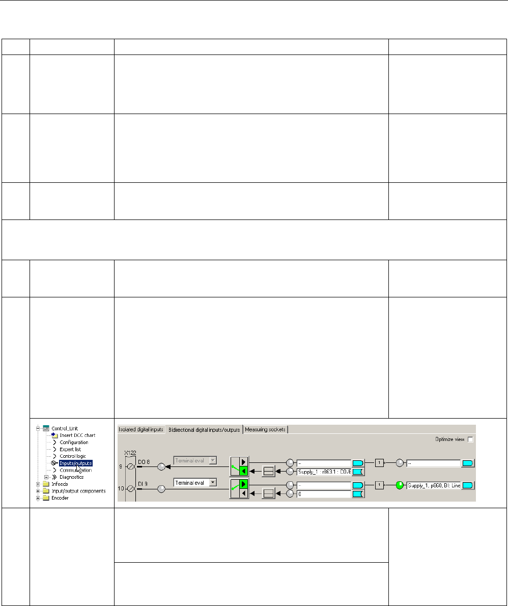
Commissioning
3.5 Commissioning the servo control booksize format for the first time
STARTER Commissioning Manual
Commissioning Manual, (IH1), 07/2016, 6SL3097-4AF00-0BP5 131
What?
How?
Comment
5.7 Configuration,
summary
The configuration of the drive train has been completed. A sum-
mary is displayed.
1. Click "Complete".
The drive data can be
copied to the clipboard for
plant documentation pur-
poses and then added to a
text program, for example.
5.8 Configuring drive
functions
1. In the project tree click Drives\Drive xy\Configuration.
2. Click the "Function modules/technology packages" button.
Under the "Function modules" tab, you can activate single or
multiple function modules.
3. Click "OK".
-
5.9 Summary The drive data can be copied to the clipboard for system docu-
mentation purposes and then pasted into a text processing pro-
gram, for example.
-
Note
The reference parameters and limit values can be protected from being automatically overwritten in the STARTER com-
missioning tool by p0340 = 1: Drive -> Configuration-> "Reference parameters / blocked list" tab.
6 Enable signals
and BICO inter-
connections
The enable signals for the infeed and the two drives must be
implemented via the digital inputs on the Control Unit.
-
6.1 Line contactor 1. Make the following settings for the line contactor:
– p0728.8 = 1, sets DI/DO as output
– p0738 = 0863.1 line contactor on
– p0860 = 0723.9 line contactor, feedback signal
The line contactor should
be controlled from the drive
object (DO) Infeed_1.
See function diagram
[8838]
In the "Function > Line
contactor control" screen
form, you can check that
the interconnection is cor-
rect.
7. Save the parame-
ters on the device
1.
Call the "Project" > "Connect to selected target devices" menu
(online mode).
2. Call the "Target system > Load > Load CPU/drive unit to tar-
get device..." menu.
Left-click the drive unit
(SINAMICS S120).
1. Select the drive unit in the project tree.
2. Call the "Target system > Copy RAM to ROM" menu
(save the data on the memory card).

Commissioning
3.5 Commissioning the servo control booksize format for the first time
STARTER Commissioning Manual
132 Commissioning Manual, (IH1), 07/2016, 6SL3097-4AF00-0BP5
What?
How?
Comment
8. The motor
starts to run
The drives can be started via the control panel in the STARTER
commissioning tool.
The control panel can be found in the project navigator under
"Drive unit > Drives > Commissioning > Control panel".
For more information about
the control panel, see
Getting Started.
The control panel supplies
the control word 1 (STW1)
and speed setpoint 1
(NSOLL).
For more information about
line/DC-link identification,
see the SINAMICS S120
Function Manual Drive
Functions.
Diagnostic functions in the STARTER commissioning tool
Under Component > Diagnostics > Control/status words
● Control/status words
● Status parameters
● Missing enable signals

Commissioning
3.6 Commissioning U/f vector control booksize format for the first time
STARTER Commissioning Manual
Commissioning Manual, (IH1), 07/2016, 6SL3097-4AF00-0BP5 133
3.6
Commissioning U/f vector control booksize format for the first time
An example provided in this chapter explains all the configuration and parameter settings, as
well as tests that are required for initial commissioning. Commissioning is carried out using
the STARTER commissioning tool.
Preconditions for commissioning
● The commissioning preconditions (Page 30) have been met.
● The commissioning checklists (Page 32) (Tables 2-1 and 2-2) have been completed and
the points fulfilled.
● The STARTER commissioning tool is installed and activated.
– System prerequisites, refer to the Readme file in the STARTER installation directory.
● The drive system has been wired according to the specifications.
● The communication between the PG/PC and drive system has been prepared.
● The power supply of the Control Unit (24 V DC) has been switched on.
3.6.1
Task
A drive in the "booksize" format with "V/f vector control" control mode with the following
components is to be commissioned for the first time:
Table 3- 3 Component overview
Designation
Component
Article number
Closed-loop control and infeed
Control Unit Control Unit 320-2 DP 6SL3040-1MA00-0AA0
Smart Line Module
Smart Line Module 16 kW
6SL3130-6TE21-6A..
Line filter package 16 kW Line filter and line reactor 6SL3100-0BE21-6AB0
Drive 1
Single Motor Module 1
Single Motor Module 9 A
6SL3120-1TE21-0A..
Motor 1
Induction motor
1PH8083-1.F2.-....
Drive 2
Single Motor Module 2
Single Motor Module 9 A
6SL3120-1TE21-0A..
Motor 2
Induction motor
1PH8083-1.F2.-....
The enable signals for the infeed and the drive should be implemented via terminals.
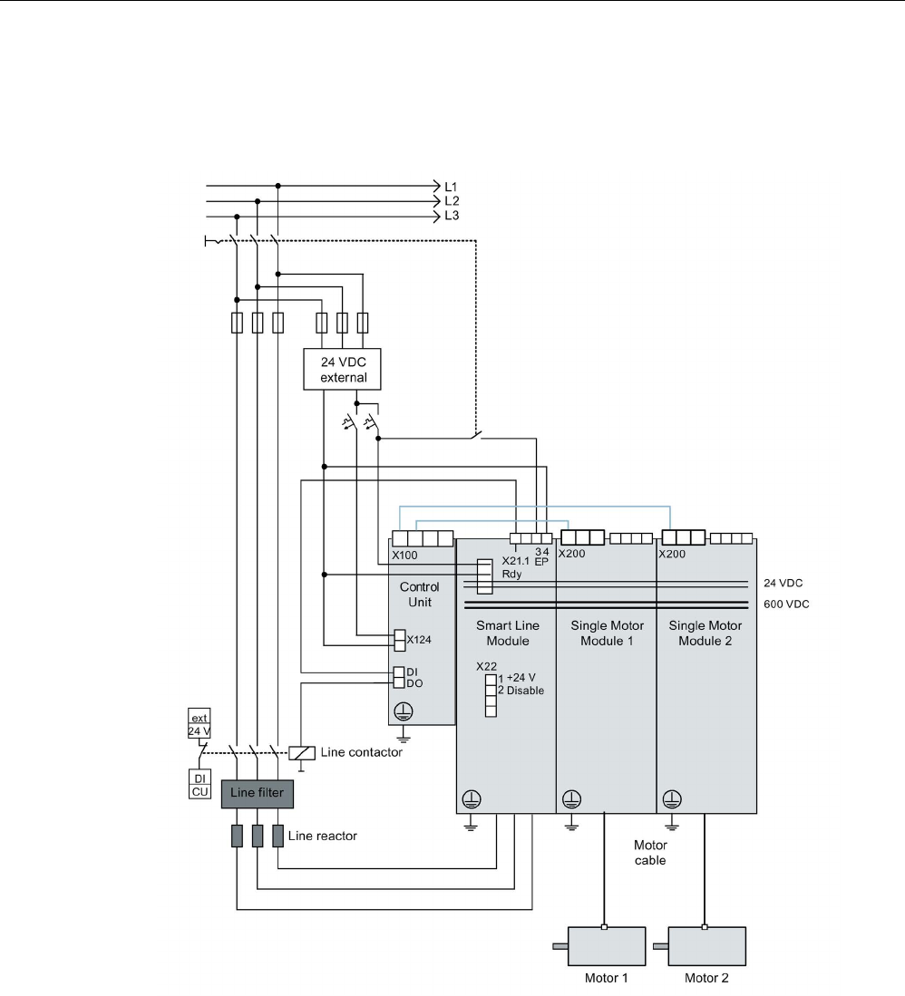
Commissioning
3.6 Commissioning U/f vector control booksize format for the first time
STARTER Commissioning Manual
134 Commissioning Manual, (IH1), 07/2016, 6SL3097-4AF00-0BP5
3.6.2
Component wiring (example)
The following diagram shows the structure of the components and the appropriate wiring.
The DRIVE-CLiQ wiring is highlighted in bold.
Image 3-28 Component wiring (example)
For more information on wiring and connecting the encoder system, see the Equipment
Manual.
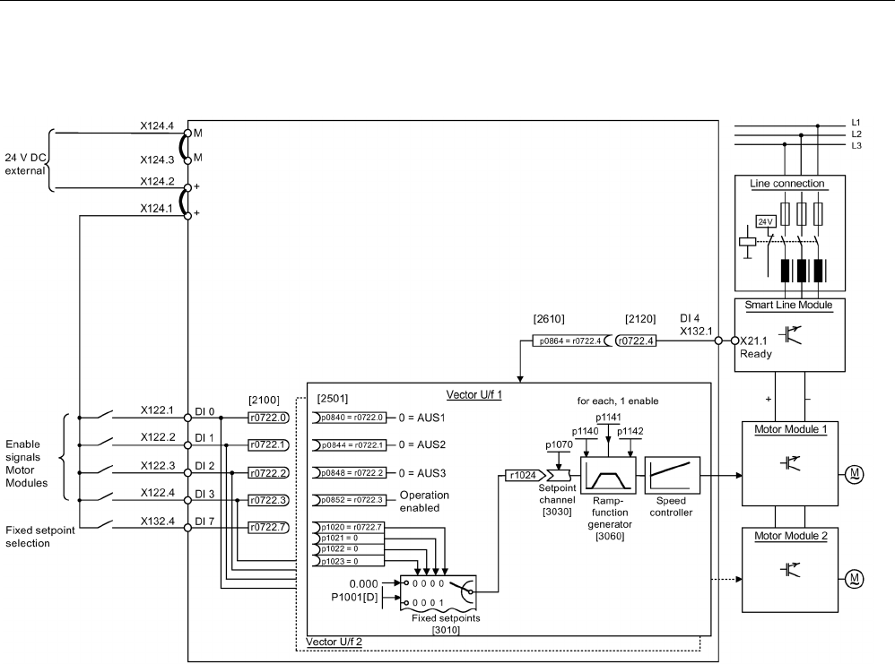
Commissioning
3.6 Commissioning U/f vector control booksize format for the first time
STARTER Commissioning Manual
Commissioning Manual, (IH1), 07/2016, 6SL3097-4AF00-0BP5 135
3.6.3
Signal flow of the commissioning example
Image 3-29 Signal flow diagram of the example vector U/f control mode in the booksize format

Commissioning
3.6 Commissioning U/f vector control booksize format for the first time
STARTER Commissioning Manual
136 Commissioning Manual, (IH1), 07/2016, 6SL3097-4AF00-0BP5
3.6.4
Commissioning with STARTER (example)
The table below describes the steps for commissioning the example using the STARTER
commissioning tool.
Table 3- 4 Commissioning sequence (example)
What?
How?
Comment
1. Creating a new
project
1. Call the "Project > New..." menu.
2. Enter a project name in the "New project" dialog.
3. Click "OK".
-
2. Automatic configu-
ration
1. Call the "Project > Connect to selected target devices" menu.
As there is still no device available in the project, STARTER
offers the option of searching for accessible nodes.
2. Click "Yes".
3. Activate the drive unit accessed by clicking the checkbox.
4. Click "Apply".
The drive unit is transferred into the project window.
5. Call the "Project" > "Connect to selected target devices"
menu again.
You are now connected online with the drive unit.
6. Double-click "Automatic configuration". Click "Configure".
7. During automatic commissioning, the wizard will offer you the
option of selecting the drive object type. As default assign-
ment, select all of the "Vector" components.
8. Click "Create".
9. After the automatic configuration has been completed, you
have the option of going OFFLINE or remaining ONLINE. Se-
lect "Go OFFLINE".
-
3. Configuring
the infeed
1. Double-click in the project tree on "Infeeds".
2. Double-click the infeed that has been created.
3. Click the yellow "Wizard..." button.
4. To check the automatic settings and to enter additional data,
such as equipment codes, etc. continue with step 3.2.
-
Note:
When the factory setting is p7826 = 1, the firmware is automatically updated to the status on the memory card when a
configured DRIVE-CLiQ component is first booted. This may take several minutes and is indicated by the READY-LED on
the corresponding components flashing green/red and the Control Unit flashing orange (0.5 Hz). Once all updates have
been completed, the READY-LED on the Control Unit flashes orange at 2 Hz and the corresponding READY-LED on the
components flashes green/red at 2 Hz. For the firmware to be activated, a POWER ON must be carried out for the compo-
nents.
For infeed units connected to the drive unit, which during the automatic configuration do not communicate with the Control
Unit via DRIVE-CLiQ, you must manually configure and transfer them into the drive topology. These devices can only be
inserted in the offline mode.

Commissioning
3.6 Commissioning U/f vector control booksize format for the first time
STARTER Commissioning Manual
Commissioning Manual, (IH1), 07/2016, 6SL3097-4AF00-0BP5 137
What?
How?
Comment
3.1 Inserting
an infeed unit
If there is no DRIVE-CLiQ connection to the Control Unit, then
you must manually enter the data of the infeed unit using the
wizard.
1. Double-click in the project tree on "Infeeds".
2. Double-click "Insert infeed".
3. Enter a name for the infeed.
4. Select the type.
5. Click "OK".
If the line environment or
DC-link components are
changed, line/DC-link iden-
tification should be repeat-
ed.
3.2 Infeed 1. Enter a component name.
2. Select the line voltage range.
3. Select the cooling type.
4. Select the type.
The available components are now in the selection list.
5. Select the required infeed from the list.
6. Click "Continue >".
-
3.3 Infeed - additional
data
1. Activate the line/DC-link identification when switching-on for
the first time.
2. Accept the device supply voltage from the previous window.
The rated line frequency is determined automatically.
3. If applicable, enter the number of parallel infeeds.
4. Where relevant, select a Voltage Sensing Module.
5. Where relevant, select an external Braking Module.
6. Click "Continue >".
-
3.4 Process data ex-
change
(infeed)
One of three telegrams can be selected for communication: 370,
371 and 999.
1. Select the required telegram.
2. Click "Continue >".
-
3.5 Configuration,
summary
Configuration of the infeed unit completed. A summary is dis-
played.
1. Click "Complete".
The infeed unit data can be
copied to the clipboard for
plant documentation pur-
poses and then added to a
text program, for example.
NOTICE
Damage to the infeed for control using another Control Unit
If the infeed is controlled from another Control Unit, then the ready signal of the infeed must
be connected to parameter p0864 "infeed ready" of the drive through a digital input/output.
If this is not taken into account, the infeed may be damaged.

Commissioning
3.6 Commissioning U/f vector control booksize format for the first time
STARTER Commissioning Manual
138 Commissioning Manual, (IH1), 07/2016, 6SL3097-4AF00-0BP5
What?
How?
Comment
4. Configuring the
drives
You must individually configure the drives in the offline mode.
The wizard displays the data determined automatically from the
electronic type plate.
-
For drives connected to the drive unit, which during the automatic configuration do not communicate with the Control Unit
via DRIVE-CLiQ, you must manually configure and transfer them into the drive topology. These devices can only be in-
serted in the offline mode. In this case, perform the commissioning with step 4.1.
If the drives have already been created by the automatic configuration, click "Configuration" > "Configure DDS... " under
the drive. Then continue from step 4.2. Settings of the power unit data and for motors with DRIVE-CLiQ interface, the mo-
tor data is also already pre-assigned based on the electronic type plate.
4.1 Inserting drives 1. Double-click in the project tree on "Drives".
2. Double-click the "Insert drives" entry.
3. Enter a name for the drive.
4. For the drive object, select "VECTOR".
5. Click "OK".
-
4.2 Control structure 1. Select function modules.
2. Switch the closed-loop control to "V/f control".
3. Select the required control mode.
4. Click "Continue >".
-
4.3 Power unit 1. Enter a name for the component.
2. Select the DC supply voltage.
3. Select the cooling type.
4. Select the type.
The available components are now in the selection list.
5. Select the required power unit.
6. Click "Continue >".
-
4.4 Configuration,
power unit BICO
interconnection
If an infeed without DRIVE-CLiQ connection is used, a message
is displayed stating that the operating signal must be connected.
1. In the following dialog "Infeed in operation", set parameter
p0864 to the binector output of the digital input to which the
operating feedback signal of the infeed is interconnected.
2. Click "Continue >".
-
4.5 Configuring addi-
tional data
In this window, you can additionally select the following
• Various output filters
• A Voltage Sensing Module
• A parallel connection
With this dialog window,
the configuration of the
Motor Module has been
completed.
NOTICE
Damage to a sine-wave filter if it is not activated during commissioning
The sine-wave filter may be damaged if it is not activated during commissioning.
• Activate use of a sine-wave filter during commissioning via parameter p0230 = 3.

Commissioning
3.6 Commissioning U/f vector control booksize format for the first time
STARTER Commissioning Manual
Commissioning Manual, (IH1), 07/2016, 6SL3097-4AF00-0BP5 139
What?
How?
Comment
5 Drive setting You can select the motor standard (IEC/NEMA) and power unit
application (duty cycles).
-
5.1 Configuring the
motor
1. Enter a name for the motor (e.g. an equipment code).
2. If your motor has its own DRIVE-CLiQ interface, select the
item.
3. Click "Continue >".
When commissioning, the motor data is automatically transferred
to the Control Unit.
You can select a standard
motor from the list of mo-
tors or manually enter the
motor data. You can then
select the motor type.
1. If you use a standard motor select the item, "Select standard
motor from list".
2. Select the standard motor type from the "Motor type" list.
3. Select your motor.
4. Click "Continue >".
1. If your motor is not in the default list, select "Enter motor
data".
2. Click your motor type in the "Motor type" list.
3. Click "Continue >".
5.2 Configuring the
motor data
Enter your motor data according to the data sheet.
If you have no mechanical
data, then the data is esti-
mated based on the type
plate data. The equivalent
circuit diagram data is also
estimated on the basis of
the data on the type plate
or determined by means of
automatic motor data iden-
tification.
Alternatively, after entering the motor data, perform a motor data
identification when commissioning for the first time.
Alternatively, for some motor types you can use motor data from
the motor list.
1. To do so, click the template.
2. Follow the wizard by clicking "Next >".
3. If known, you can enter the mechanical/electrical data of the
motor and the drive train or the data of a PE spindle.
4. If necessary, select a complete calculation of the mo-
tor/controller data without equivalent circuit diagram data.
5. For this example, select the simple drive.
5.3 Configuring a
motor holding
brake
1. If you are not using a motor holding brake, click "Continue >".
Or
2. If you are using a motor holding brake, you can select and
configure the brake in this window.
3. Click "Continue >".
For additional information,
see SINAMICS S120 Func-
tion Manual Drive Func-
tions.
5.4 Configuring an
encoder
You can connect up to three encoders.
1. If you are using a DRIVE-CLiQ encoder, then select the ap-
propriate item.
2. Click "Next >".
The encoder is automatically identified and configured.
When using an encoder
that is not in the list, after
step 4.8, you can also
enter the data manually.
By clicking Details, you can
view the data of the encod-
er selected from the the
encoder list.
Alternatively, you can use a standard encoder.
1. Select the encoder from the list.
2. Click "Continue >".

Commissioning
3.6 Commissioning U/f vector control booksize format for the first time
STARTER Commissioning Manual
140 Commissioning Manual, (IH1), 07/2016, 6SL3097-4AF00-0BP5
What?
How?
Comment
Alternatively, you can use your own encoder.
1. Select Enter data.
2. Click the encoder data.
3. Select the measuring system.
4. Enter the required data and click "OK".
5. Click "Continue >".
5.5 Entering
encoder data
Enter the encoder data into the input screen form and click "OK". Enter additional encoders
in the same way as de-
scribed above.
5.6 Configuring drive
functions
You can select certain technological applications and the type of
motor data identification.
Your choice of application
influences the calculation
for the open-loop/closed-
loop control parameters.
5.7 Configuring pro-
cess data ex-
change
For communication, select the PROFIdrive telegram from several
telegrams.
-
5.8 Important
parameters
You can specify important parameters as limit values in this win-
dow.
These include, the mechanical supplementary conditions of the
drive train.
-
5.9 Configuration,
summary
The configuration of the drive train has been completed. A sum-
mary is displayed.
1. Click "Complete".
The drive data can be
copied to the clipboard for
plant documentation pur-
poses and then added to a
text program, for example.
Note
The reference parameters and limit values can be protected from being automatically overwritten in the STARTER com-
missioning tool by setting p0340 = 1. In the STARTER commissioning tool, you will find this under Drive > Configuration >
Blocked list tab.
6.
Enable signals and
BICO interconnec-
tions
The enable signals for the infeed and the two drives must be
implemented via the digital inputs on the Control Unit.
1. In the project tree, click "Drive unit \ Control Unit \ In-
puts/outputs".
2. Select "Bidirectional digital inputs/outputs".
-
6.1 Line contactor 1. Make the following settings for the line contactor:
– p0728.8 = 1, sets DI/DO as output
– p0738 = 0863.1 control (energize) line contactor
– p0860 = 0723.9 line contactor, feedback signal
The line contactor must be
controlled by the infeed_1
drive object (DO).
See function diagram
[8834]
In the "Function > Line
contactor control" screen
form, you can check that
the interconnection is cor-
rect.
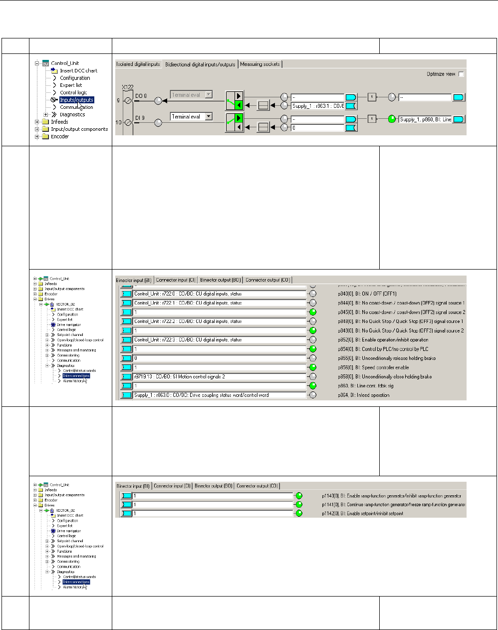
Commissioning
3.6 Commissioning U/f vector control booksize format for the first time
STARTER Commissioning Manual
Commissioning Manual, (IH1), 07/2016, 6SL3097-4AF00-0BP5 141
What?
How?
Comment
6.2 Enable Motor
Module
• Enable signals for the Motor Module (drive_1)
p0840 = 722.0 ON/OFF1
p0844 = 722.1 1. OFF2
p0845 = 1 2. OFF2
p0848 = 722.2 1. OFF3
p0849 = 1 2. OFF3
p0852 = 722.3 Enable operation
See function diagram
[2501]
6.3 Ramp-function
generator
• Ramp-function generator
p1140 = 1 Ramp-function generator enable
p1141 = 1 Ramp-function generator start
p1142 = 1 Enable setpoint
See function diagram
[3060]
6.4 Setpoint • Specify setpoint
p1001 = 40 Fixed setpoint 1
See function diagram
[3010]
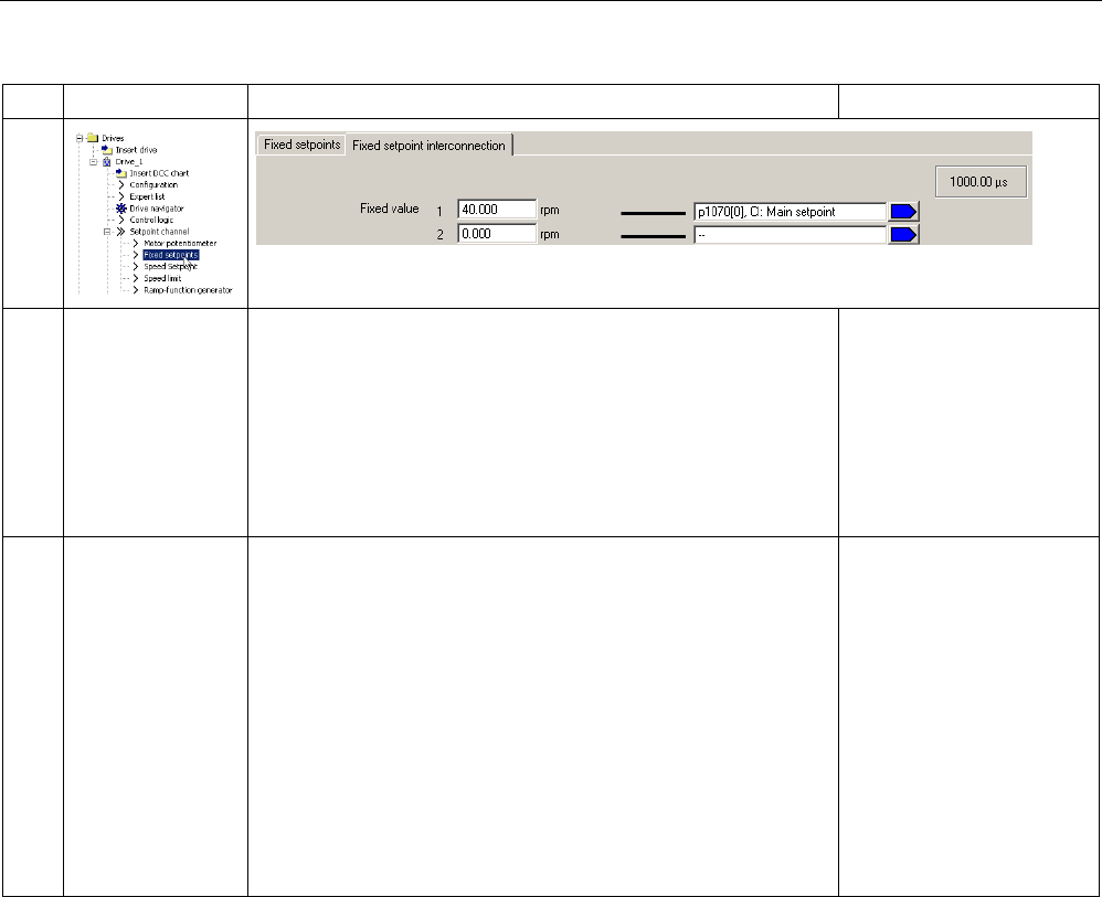
Commissioning
3.6 Commissioning U/f vector control booksize format for the first time
STARTER Commissioning Manual
142 Commissioning Manual, (IH1), 07/2016, 6SL3097-4AF00-0BP5
What?
How?
Comment
7 Save the parame-
ters on the device
1. Select the drive unit in the project tree.
2. Call the "Connect target device" shortcut menu.
3. Call the "Target device > Load into the target device" context
menu.
The "After loading, copy the RAM to ROM" option is active.
Click "Yes" to confirm the backup.
Or
4. Call the "Target device > Copy RAM to ROM" shortcut menu.
Position the cursor on the
drive unit (SINAMICS
S120) and right-click.
8 The motor
starts to run
The drives can be started via the control panel in the STARTER
commissioning tool.
• Line/DC-link identification will be carried out once
the pulses for the infeed have been enabled and line/DC-link
identification has been activated. The infeed then switches in-
to the "Operation" state.
• Once the pulses are enabled, a one-off motor data identifica-
tion run (if activated) is carried out.
• When the pulses are enabled again, optimization with a rotat-
ing motor is carried out, if this is activated.
For more information about
the control panel, see Get-
ting Started.
During motor data identifi-
cation, a current flows
through the motor, which
means that it can align
itself by up to a quarter of a
revolution.
For more information about
line / DC link / motor data
identification, see the
SINAMICS S120 Function
Manual Drive Functions.
Diagnostic functions in the STARTER commissioning tool
Under Component > Diagnostics > Control/status words
● Control/status words
● Status parameters
● Missing enable signals

Commissioning
3.7 Commissioning the vector control chassis format for the first time
STARTER Commissioning Manual
Commissioning Manual, (IH1), 07/2016, 6SL3097-4AF00-0BP5 143
3.7
Commissioning the vector control chassis format for the first time
An example provided in this chapter explains all the configuration and parameter settings, as
well as tests that are required for initial commissioning. Commissioning is carried out using
the STARTER commissioning tool.
Preconditions for commissioning
● The commissioning preconditions (Page 30) have been met.
● The commissioning checklists (Page 32) (Tables 2-1 and 2-2) have been completed and
the points fulfilled.
● The STARTER commissioning tool is installed and activated.
– System prerequisites, refer to the Readme file in the STARTER installation directory.
● The drive system has been wired according to the specifications.
● The communication between the PG/PC and drive system has been prepared.
● The power supply of the Control Unit (24 V DC) has been switched on.

Commissioning
3.7 Commissioning the vector control chassis format for the first time
STARTER Commissioning Manual
144 Commissioning Manual, (IH1), 07/2016, 6SL3097-4AF00-0BP5
3.7.1
Task
A drive in the "chassis" format in vector control with the following components is to be
commissioned for the first time:
Table 3- 5 Component overview
Designation
Component
Article number
Closed-loop control and infeed
Control Unit Control Unit 320-2 PN 6SL3040-1MA01-0AA0
Active Line Module Active Line Module 380 kW /
400 V
6SL3330–7TE36–1AA.
Active Interface Module Active Interface Module 6SL3300–7TE38–4A.0
Drive 1
Motor Module 1
Motor Module 380 A
6SL3320–1TE33–8AA.
Motor 1 Induction motor
• Without brake
• With encoder
Type: 1PL6226-..F..-....
Rated voltage = 400 V
Rated current = 350 A
Rated power = 200 kW
Rated frequency = 59.10 Hz
Rated speed = 1750 rpm
Cooling type = non-ventilated
HTL encoder, 1024 p/r, A/B, R
Drive 2
Motor Module 1
Motor Module 380 A
6SL3320–1TE33–8AA.
Motor 1 Induction motor
• Without brake
• With encoder
Type: 1PL6226-..F..-....
Rated voltage = 400 V
Rated current = 350 A
Rated power = 200 kW
Rated frequency = 59.10 Hz
Rated speed = 1750 rpm
Cooling type = non-ventilated
HTL encoder, 1024 p/r, A/B, R
The enable signals for the infeed and the drive should be implemented via terminals.
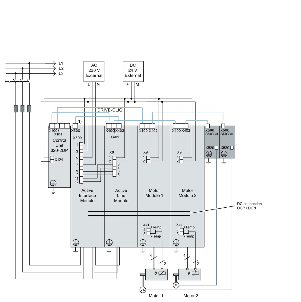
Commissioning
3.7 Commissioning the vector control chassis format for the first time
STARTER Commissioning Manual
Commissioning Manual, (IH1), 07/2016, 6SL3097-4AF00-0BP5 145
3.7.2
Component wiring (example)
The following diagram shows the structure of the components and the appropriate wiring.
The DRIVE-CLiQ wiring is highlighted in bold.
1)
X500 at the Voltage Sensing Module
Image 3-30 Component wiring (example)
For more information on wiring and connecting the encoder system, see the Equipment
Manual.
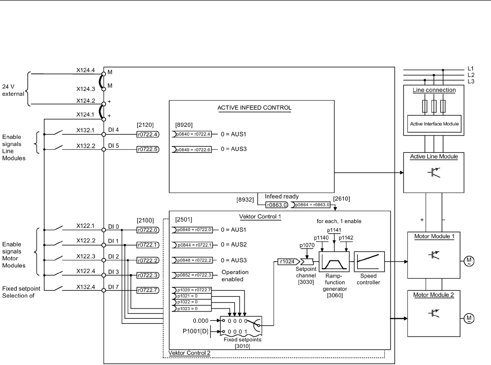
Commissioning
3.7 Commissioning the vector control chassis format for the first time
STARTER Commissioning Manual
146 Commissioning Manual, (IH1), 07/2016, 6SL3097-4AF00-0BP5
3.7.3
Signal flow of the commissioning example
Image 3-31 Signal flow of the commissioning example chassis

Commissioning
3.7 Commissioning the vector control chassis format for the first time
STARTER Commissioning Manual
Commissioning Manual, (IH1), 07/2016, 6SL3097-4AF00-0BP5 147
3.7.4
Commissioning with STARTER (example)
The table below describes the steps for commissioning a drive using the STARTER
commissioning tool.
What?
How?
Comment
1. Creating a new
project
1. Call the "Project > New..." menu.
2. Enter a project name in the "New project" dialog.
3. Click "OK".
-
2. Automatic configu-
ration
1. Call the "Project > Connect to selected target devices" menu.
As there is still no device available in the project, STARTER
offers the option of searching for accessible nodes.
2. Click "Yes".
3. Activate the drive unit accessed by clicking the checkbox.
4. Click "Accept".
The drive unit is transferred into the project window.
5. Call the "Project" > "Connect to selected target devices"
menu again.
You are now connected online with the drive unit.
6. Double-click "Automatic configuration". Click "Configure".
7. During automatic commissioning, the wizard will offer you the
option of selecting the drive object type. As default assign-
ment, select all of the "Vector" components.
8. Click "Create".
9. After the automatic configuration has been completed, you
have the option of going OFFLINE or remaining ONLINE. Se-
lect "Go OFFLINE".
-
3. Configuring
the infeed
1. Double-click "Infeeds" in the project navigator.
2. Double-click the infeed that has been created.
3. Click the yellow "Wizard..." button.
4. To check the automatic settings and to enter additional data,
such as equipment codes, etc. continue with step 3.2.
-
Note:
When the factory setting is p7826 = 1, the firmware is automatically updated to the status on the memory card when a
configured DRIVE-CLiQ component is first booted. This may take a few minutes and is indicated by the READY-LED on
the corresponding components flashing green/red and the LED on the Control Unit flashing orange (0.5 Hz). Once all up-
dates have been completed, the READY-LED on the Control Unit flashes orange at 2 Hz and the corresponding READY-
LED on the components flashes green/red at 2 Hz. For the firmware to be activated, a POWER ON must be carried out for
the components.
For infeed units connected to the drive unit, which during the automatic configuration do not communicate with the Control
Unit via DRIVE-CLiQ, you must manually configure and transfer them into the drive topology. These devices can only be
inserted in the offline mode.

Commissioning
3.7 Commissioning the vector control chassis format for the first time
STARTER Commissioning Manual
148 Commissioning Manual, (IH1), 07/2016, 6SL3097-4AF00-0BP5
What?
How?
Comment
3.1 Inserting
an infeed unit
If there is no DRIVE-CLiQ connection to the Control Unit, then
you must manually enter the data of the infeed unit using the
wizard.
1. Double-click "Infeeds" in the project navigator.
2. Double-click "Insert infeed".
3. Enter a name for the infeed.
4. Select the type.
5. Click "OK".
If the line environment or
DC-link components are
changed, line/DC-link iden-
tification should be repeat-
ed.
3.2 Infeed 1. Assign a component name.
2. Select the line voltage range.
3. Select the cooling type.
4. Select the type.
The available components are now in the selection list.
5. Select the required infeed from the list.
6. Click "Continue >".
-
3.3 Infeed - additional
data
1. Activate the line/DC-link identification when switching-on for
the first time.
2. Accept the device supply voltage from the previous window.
The rated line frequency is determined automatically.
3. Make sure that the "Line filter available" option is activated.
4. If applicable, enter the number of parallel infeeds.
5. Where relevant, select an external Braking Module.
6. Where relevant, select master/slave operation for several
infeeds.
7. Click "Continue >".
-
3.4 Process data ex-
change
(infeed)
One of three telegrams can be selected for communication: 370,
371 and 999.
1. Select the required telegram.
2. Click "Continue >".
-
3.5 Configuration,
summary
Configuration of the infeed unit completed. A summary is dis-
played.
1. Click "Complete".
The infeed unit data can be
copied to the clipboard for
plant documentation pur-
poses and then added to a
text program, for example.
NOTICE
Damage of the infeed
If the infeed is controlled by a different Control Unit than the Motor Modules, this can result
in damage to the infeed.
• In this case, wire the ready signal of the infeed r0863.0 to parameter p0864 "Infeed
ready" of the drive through a digital input/output.

Commissioning
3.7 Commissioning the vector control chassis format for the first time
STARTER Commissioning Manual
Commissioning Manual, (IH1), 07/2016, 6SL3097-4AF00-0BP5 149
What?
How?
Comment
4. Configuring the
drives
You must individually configure the drives in the offline mode.
The wizard displays the data determined automatically from the
electronic type plate.
-
For drives connected to the drive unit, which during the automatic configuration do not communicate with the Control Unit
via DRIVE-CLiQ, you must manually configure and transfer them into the drive topology. These devices can only be in-
serted in the offline mode. In this case, continue commissioning with step 4.1.
If the drives have already been created by the automatic configuration, under the drive, click "Configuration" > "Configure
DDS... ". Then continue from step 4.2. Settings of the power unit data and for motors with DRIVE-
CLiQ interface, the motor
data is also already pre-assigned based on the electronic type plate.
4.1 Inserting drives 1. Double-click "Drives" in the project navigator.
2. Double-click the "Insert drives" entry.
3. Enter a name for the drive.
4. Select "Vector" as drive object type.
5. Click "OK".
-
4.2 Control structure 1. Where relevant, select function modules.
2. Select the control "n-/M control + V/f control, I/f control".
3. Select the control mode "[21] speed control (with encoder)".
4. Click "Continue >".
-
4.3 Power unit 1. Enter a name for the component.
2. Select the DC supply voltage.
3. Select the cooling type.
4. Select the baud rate.
5. Select the required power unit from the list.
6. Click "Continue >".
-
4.4 Configuration,
power unit BICO
interconnection
If an infeed without DRIVE-CLiQ connection is used, a message
is displayed stating that the operating signal must be connected.
1. In the following dialog "Infeed in operation", set parameter
p0864 to the binector output of the digital input to which the
operating feedback signal of the infeed is interconnected.
2. Click "Continue >".
-
4.5 Additional
power unit data
In this window, you can additionally select the following
• Various output filters
• A Voltage Sensing Module
• A parallel connection
With this dialog window,
the configuration of the
Motor Module has been
completed.
NOTICE
Damage to a sine-wave filter if it is not activated during commissioning
The sine-wave filter may be damaged if it is not activated during commissioning.
• Activate use of a sine-wave filter during commissioning via parameter p0230 = 3.

Commissioning
3.7 Commissioning the vector control chassis format for the first time
STARTER Commissioning Manual
150 Commissioning Manual, (IH1), 07/2016, 6SL3097-4AF00-0BP5
What?
How?
Comment
5 Configuration,
drive setting
You can select the motor standard (IEC/NEMA) and power unit
application (duty cycles).
The motor data is selected
and entered.
5.1 Configuring the
motor
1. Enter a name for the motor (e.g. an equipment code).
2. If your motor has its own DRIVE-CLiQ interface, select the
item.
3. Click "Continue >".
When commissioning, the motor data is automatically trans-
ferred to the Control Unit.
You can select a standard
motor from the list of mo-
tors or manually enter the
motor data. You can then
select the motor type.
1. If you use a standard motor select the item, "Select standard
motor from list".
2. Select the standard motor type from the "Motor type" list.
3. Select your motor.
4. Click "Continue >".
1. If your motor is not in the default list, select "Enter motor
data".
2. Click your motor type in the "Motor type" list.
3. Click "Continue >".
5.2 Configuring the
motor data
Enter your motor data according to the data sheet.
If you have no mechanical
data, then the data is esti-
mated based on the type
plate data. The equivalent
circuit diagram data is also
estimated on the basis of
the data on the type plate
or determined by means of
automatic motor data iden-
tification.
Alternatively, after entering the motor data, perform a motor data
identification when commissioning for the first time.
Alternatively, for some motor types you can use motor data from
the motor list.
1. To do so, click the template.
2. Follow the wizard by clicking "Next >".
3. If known, you can enter the mechanical data of the motor and
the drive train or the data of a PE spindle.
4. If necessary, select a complete calculation of the mo-
tor/controller data without equivalent circuit diagram data.
5. For this example, select the simple drive.
5.3 Configuring a
motor brake
1. If you are not using a motor holding brake, click "Continue >".
2. If you are using a motor holding brake, you can select and
configure the brake in this window.
3. Click "Continue >".
For more information, see
SINAMICS S120 Function
Manual Drive Functions.
5.4 Configuring an
encoder
You can connect up to three encoders.
1. If you are using a DRIVE-CLiQ encoder, then select the ap-
propriate item.
2. Click "Next >".
The encoder is automatically identified and configured.
If you are using an encoder
that is not in the list, you
can also manually enter the
data.
By clicking Details, you can
view the data of the encod-
er selected from the the
encoder list.
Alternatively, you can use a standard encoder.
1. Select the encoder from the list.
2. Click "Continue >".

Commissioning
3.7 Commissioning the vector control chassis format for the first time
STARTER Commissioning Manual
Commissioning Manual, (IH1), 07/2016, 6SL3097-4AF00-0BP5 151
What?
How?
Comment
Alternatively, you can use your own encoder.
1. Select Enter data.
2. Click the encoder data.
3. Select the measuring system.
4. Enter the required data and click "OK".
5. Click "Continue >".
5.5 Entering
encoder data
1. Enter the encoder data into the input screen form.
2. Click "OK".
Enter additional encoders
in the same way as de-
scribed above.
5.6 Configuring drive
functions
You can select certain technological applications and the type of
motor data identification.
Your choice of application
influences the calculation
for the open-loop/closed-
loop control parameters.
5.7 Configuring pro-
cess data ex-
change
For communication, you can select the PROFIdrive telegram
from various telegrams.
1. For the example, select "[ 999] Free telegram configuration
with BICO".
2. Click "Continue >".
-
5.8 Important
parameters
In this window, you can specify important parameters as limit
values.
When doing this, observe the general mechanical conditions for
the drive train.
-
5.9 Summary The configuration of the drive train has been completed. A sum-
mary is displayed.
1. Click "Complete".
The drive data can be
copied to the clipboard for
plant documentation pur-
poses and then added to a
text program, for example.
Note
The reference parameters and limit values can be protected from being automatically overwritten in the STARTER com-
missioning tool by setting p0340 = 1. You can find this function in the STARTER commissioning tool under Drive > Config-
uration > Blocked list tab.
6. Enable signals and
BICO interconnec-
tions
The enable signals for the infeed and the two drives must be
implemented via the digital inputs on the Control Unit.
Note:
If an Active Line Module is
used, to enable the infeed
unit, a signal source other
than that used for the Mo-
tor Module must be used.
6.1 Active Line Module • Enable signals for the Active Line Module:
p0840 = 722.4 ON/OFF1
p0844 = 722.5 OFF2
p0852 = 722.6 Enable operation
See function diagram
[8920]
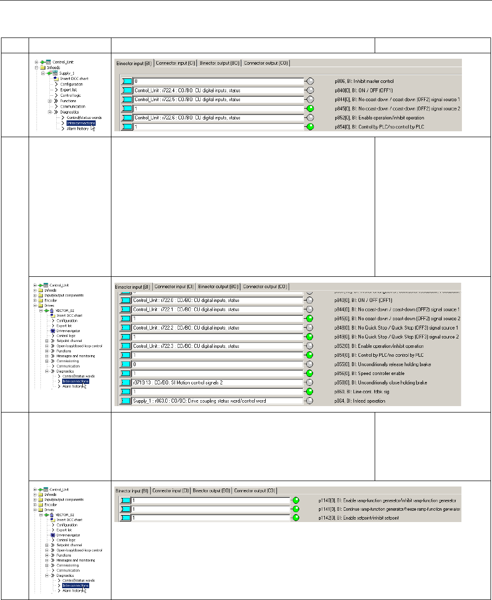
Commissioning
3.7 Commissioning the vector control chassis format for the first time
STARTER Commissioning Manual
152 Commissioning Manual, (IH1), 07/2016, 6SL3097-4AF00-0BP5
What?
How?
Comment
6.2 Enable the Motor
Module
• Enable signals for the Motor Module (drive_1):
p0840 = 722.0 ON/OFF1
p0844 = 722.1 1. OFF2
p0845 = 1 2. OFF2
p0848 = 722.2 1. OFF3
p0849 = 1 2. OFF3
p0852 = 722.3 Enable operation
p0864 = 863.0 Infeed operation
See function diagram
[2501]
6.3 Ramp-function
generator configu-
ration
• Ramp-function generator
p1140 = 1 Ramp-function generator enable
p1141 = 1 Ramp-function generator start
p1142 = 1 Enable setpoint
See function diagram
[3060]
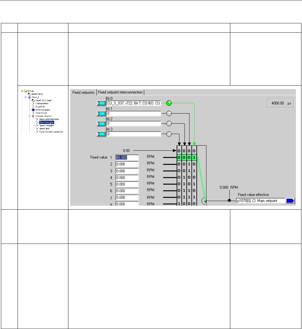
Commissioning
3.7 Commissioning the vector control chassis format for the first time
STARTER Commissioning Manual
Commissioning Manual, (IH1), 07/2016, 6SL3097-4AF00-0BP5 153
What?
How?
Comment
6.4 Setpoint configura-
tion
• Specify setpoint:
p1001 = 0 Fixed setpoint 1
p1002 = 40 Fixed setpoint 2
p1020 = r0722 Fixed speed setpoint selection
r1024 = p1070 Fixed setpoint active
A setpoint of 0 (0 signal) or
40 (1 signal) is defaulted
via digital input 7. This
setpoint is then applied to
the main setpoint p1070.
See function diagram
[3010]
7. Load parameters
to device
1. Select the drive unit in the project navigator.
2. Call the "Connect target device" shortcut menu.
3. Call the "Target device" > "Load to target device" shortcut
menu.
Position the cursor on the
drive unit and right-click.
8. Configuration,
motor temperature
To select a temperature sensor, you must set p0340 = 0.
1. Make the following settings:
– The way in which the motor temperature is received
– The temperature sensor type
– For overtemperature, the response to alarm and fault (no
reduction of Imax)
– The alarm message when a sensor fails
– The delay time to 0.100 s
– The warning threshold to 120.0° C
– The fault threshold to 155.0° C
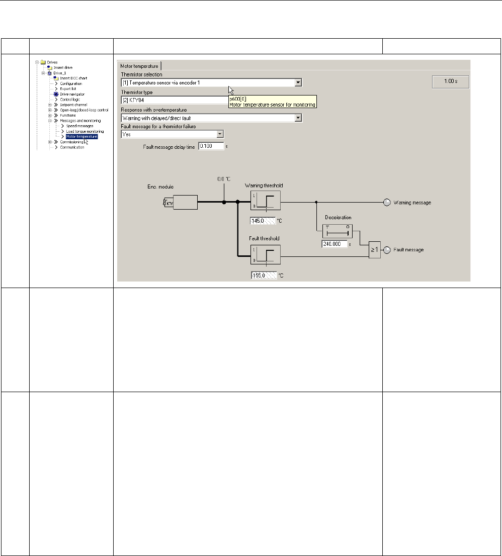
Commissioning
3.7 Commissioning the vector control chassis format for the first time
STARTER Commissioning Manual
154 Commissioning Manual, (IH1), 07/2016, 6SL3097-4AF00-0BP5
What?
How?
Comment
9. Save the parame-
ters on the device
1. Select the drive unit in the project navigator.
2. Call the "Connect target device" shortcut menu.
3. Call the "Target device > Load into the target device" context
menu.
The "After loading, copy the RAM to ROM" option is active.
Click "Yes" to confirm the backup.
Or
4. Call the "Target device > Copy RAM to ROM" shortcut menu.
Position the cursor on the
drive unit (SINAMICS
S120) and right-click.
10 The motor
starts to run
The drives can be started via the control panel in the STARTER
commissioning tool.
• Line/DC-link identification will be carried out once the pulses
for the infeed have been enabled and line/DC-link identifica-
tion has been activated. The infeed then switches into the
"Operation" state.
• When the pulses are enabled, a one-off motor data identifica-
tion run (if activated) is carried out.
• When the pulses are enabled again, optimization with a rotat-
ing motor (if activated) is carried out.
For more information about
the control panel, see Get-
ting Started.
During motor data identifi-
cation, a current flows
through the motor, which
means that it can align
itself by up to a quarter of a
revolution.
For more information about
line / DC-link / motor data
identification, see the
SINAMICS S120 Function
Manual Drive Functions.
Important diagnostic parameters (see the SINAMICS S120/S150 List Manual)
•
r0002
Drive operating display
•
r0046.0...31
CO/BO:Missing enables
For further information, see Chapter "Diagnostics"

Commissioning
3.8 First commissioning vector control AC drive blocksize format
STARTER Commissioning Manual
Commissioning Manual, (IH1), 07/2016, 6SL3097-4AF00-0BP5 155
3.8
First commissioning vector control AC drive blocksize format
An example provided in this chapter explains all the configuration and parameter settings, as
well as tests that are required for initial commissioning. Commissioning is carried out using
the STARTER commissioning tool.
Preconditions for commissioning
● The commissioning preconditions (Page 30) have been met.
● The commissioning checklists (Page 32) (Tables 2-1 and 2-2) have been completed and
the points fulfilled.
● The STARTER commissioning tool is installed and activated.
– System prerequisites, refer to the Readme file in the STARTER installation directory.
● The drive system has been wired according to the specifications.
● The communication between the PG/PC and drive system has been prepared.
● The power supply of the Control Unit (24 V DC) has been switched on.
3.8.1
Task
A drive unit is to be commissioned (vector control, closed-loop speed control), without
DRIVE-CLiQ and without speed encoder with the following components:
Designation
Component
Article number
Closed-loop control
Control Unit Control Unit 310-2 DP 6SL3040-1LA00-0AA0
Operator Panel
Basic Operator Panel BOP20
6SL3055-0AA00-4BA.
Infeed and drive
Power Module
240-2 Power Module
6SL3210-1P...-....
Motor Induction motor
(without DRIVE-CLiQ interface)
1LA7
Commissioning is performed using the BOP20.
The function keys on the BOP20 must be parameterized so that the ON/OFF signal and
speed settings can be defined via these keys.
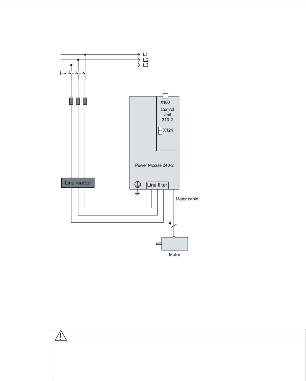
Commissioning
3.8 First commissioning vector control AC drive blocksize format
STARTER Commissioning Manual
156 Commissioning Manual, (IH1), 07/2016, 6SL3097-4AF00-0BP5
3.8.2
Component wiring (example)
The following diagram shows the structure of the components and the appropriate wiring.
Image 3-32 Component wiring (example)
For more information on wiring, see the Equipment Manual.
3.8.3
Quick commissioning using the BOP (example)
WARNING
Danger to life from hazardous axis movements
During the motor data identification, the drive can move the motor uncontrolled.
• Respond to possible malfunctions by applying suitable measures (e.g. EMERGENCY
STOP or EMERGENCY OFF).
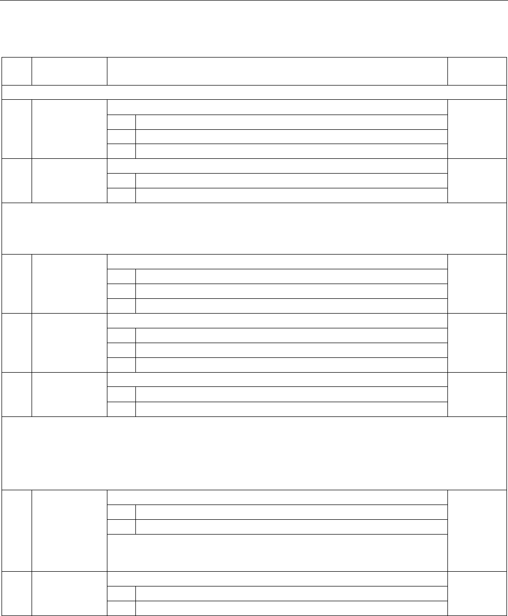
Commissioning
3.8 First commissioning vector control AC drive blocksize format
STARTER Commissioning Manual
Commissioning Manual, (IH1), 07/2016, 6SL3097-4AF00-0BP5 157
Table 3- 6 Quick commissioning for a VECTOR drive without a DRIVE-CLiQ interface
Procedure
Description
Factory
setting
Restore the drive to the factory setting:
1. p0009 = 30
Device commissioning parameter filter
1) 1
0
Ready
1
Device configuration
30
Parameter reset
2. p0976 = 1
Reset and load all parameters
0
0
Not active
1
Start restoring all parameters to their factory settings
After approx. 15 sec. wait time, the BOP display = 35 and the RDY-LED is green. p0009 is automatically set to 1, p0976 to
0.
Note:
As soon as the RDY-LED is green again, the factory setting has been completed and commissioning can start.
3. p0009 = 1
Device commissioning parameter filter
1)
1
0
Ready
1
Device configuration
30
Parameter reset
4. p0097 = 2
Select drive object type
1)
0
0
No selection
1
Drive object type SERVO
2
Drive object type VECTOR
5. p0009 = 0
Device commissioning parameter filter
1)
1
0
Ready
1
Device configuration
Note:
Wait approx. 10 sec. The basic configuration is saved once the RDY lights green. In order to transfer this state into the
ROM, press the "p" button until the display flashes. When the flashing stops, the RDY changes from orange to green and
the transfer has been completed. Alarm A07991 indicates that the motor data identification function has been activated at
drive "DO 2".
To enter the drive parameters:
6. DO = 2
Select drive object (DO) = 2 ( = VECTOR)
1
1
Expert list of the CU
2
Expert list of the drive
To select a drive object (DO), simultaneously press the "Fn" key and the arrow ↑
key.
The selected drive object is displayed at the top left.
7. p0010 = 1
Drive commissioning parameter filter
1)
1
0
Ready
1
Quick commissioning

Commissioning
3.8 First commissioning vector control AC drive blocksize format
STARTER Commissioning Manual
158 Commissioning Manual, (IH1), 07/2016, 6SL3097-4AF00-0BP5
Procedure
Description
Factory
setting
8. p0100 = 0
IEC/NEMA motor standard
0
0 IEC motor (SI units, e.g. kW)
Preset:
Rated motor frequency (p0310): 50 Hz
Specification of the power factor cos φ (p0308)
1 NEMA motor (US units, e.g. hp)
Preset:
Rated motor frequency (p0310): 60 Hz
Specification of the efficiency (p0309)
Note
:
When p0100 is changed, all the rated motor parameters are reset.
9. p03XX[0] = ...
Rated motor data [MDS]
Only when p0300 < 100 (third-party motor)
Enter the rated motor data in accordance with the type plate, e.g.
-
p0304[0]
Rated motor voltage [MDS]
p0305[0]
Rated motor current [MDS]
p0307[0]
Rated motor output [MDS]
p0308[0]
Rated motor power factor [MDS] (only when p0100 = 0)
p0309[0]
Rated motor efficiency [MDS] (only when p0100 = 1)
p0310[0]
Rated motor frequency [MDS]
p0311[0]
Rated motor speed [MDS]
p0335[0] Motor cooling type [MDS] *
0: Natural cooling
1: Forced cooling
2: Water cooling
10. p1900 = 2
Motor data identification and rotating measurement
1)
2
0
Inhibited
1
Motor data identification for rotating motor
2
Motor data identification for a stationary motor
Message A07991 is displayed, motor data identification has been activated.
11. p0010 = 0
Drive commissioning parameter filter
1)
1
0
Ready
1
Quick commissioning
RDY is lit red, fault F07085 signals that a control parameter has been changed.
Parameter p0840[0] can only be changed with access level p0003 = 3.
12. p0840[0] =
r0019.0(DO 1)
BI: ON/OFF1 [CDS]
Sets the signal source for STW1.0 (ON/OFF1)
Interconnection with r0019.000 of the drive object Control Unit (DO 1)
Effect: Signal ON/OFF1 from the BOP
0
13. p1035[0] =
r0019.13 (DO 1)
BI: Motor potentiometer setpoint higher [CDS]
Sets the signal source to increase the setpoint for the motorized potentiometer
Interconnection with r0019.13 of the drive object Control Unit (DO 1)
Effect: Signal, motorized potentiometer setpoint higher from BOP
0

Commissioning
3.8 First commissioning vector control AC drive blocksize format
STARTER Commissioning Manual
Commissioning Manual, (IH1), 07/2016, 6SL3097-4AF00-0BP5 159
Procedure
Description
Factory
setting
14. p1036[0] =
r0019.14 (DO 1)
BI: Motor potentiometer setpoint lower [CDS]
Sets the signal source to reduce the setpoint for the motorized potentiometer
Interconnection with r0019.14 of the drive object Control Unit (DO 1)
Effect: Signal, motorized potentiometer lower setpoint from BOP
0
15. p1070[0] =
r1050 (DO 63)
CI: Main setpoint [CDS]
Sets the signal source for speed setpoint 1 of the speed controller.
Interconnection with r1050.00 to the separate drive object (DO 63)
Effect: Motorized potentiometer supplies the speed setpoint
0
16.
Press "FN" and "P". The display indicates 41, press "O", the display jumps to 31.
17. Start the motor data identification with "I". The drive switches off again after approx. 5 sec., the display goes back
to 41.
18. After pressing "O", 31 is displayed again. The drive is now ready. The drive is switched on by pressing "I", the mo-
tor accelerates by pressing the "↑" key.
19. Save all param-
eters
Press the P key for approx. 5 sec until the display flashes.
1)
These parameters offer more setting options than specified here. For further setting options see the
SINAMICS S120/S150 List Manual.
[CDS] Parameter depends on command data sets (CDS). Data set 0 is preset.
[DDS] Parameter depends on drive data sets (DDS). Data set 0 is preset.
[MDS] Parameter depends on motor data sets (MDS). Data set 0 is preset.
BI binector input
BO binector output
CI connector input
CO connector output

Commissioning
3.9 First commissioning servo control AC drive blocksize format
STARTER Commissioning Manual
160 Commissioning Manual, (IH1), 07/2016, 6SL3097-4AF00-0BP5
3.9
First commissioning servo control AC drive blocksize format
An example provided in this chapter explains all the configuration and parameter settings, as
well as tests that are required for initial commissioning. Commissioning is carried out using
the STARTER commissioning tool.
Preconditions for commissioning
● The commissioning preconditions (Page 30) have been met.
● The commissioning checklists (Page 32) (Tables 2-1 and 2-2) have been completed and
the points fulfilled.
● The STARTER commissioning tool is installed and activated.
– System prerequisites, refer to the Readme file in the STARTER installation directory.
● The drive system has been wired according to the specifications.
● The communication between the PG/PC and drive system has been prepared.
● The power supply of the Control Unit (24 V DC) has been switched on.
3.9.1
Task
A drive unit is to be commissioned (servo control, closed-loop speed control) with the
following components:
Designation
Component
Article number
Closed-loop control
Control Unit Control Unit 310-2 DP 6SL3040-1LA00-0AA0
Operator Panel Basic Operator Panel 20
(BOP20)
6SL3055-0AA00-4BA.
Infeed and drive
Power Module
240-2 Power Module
6SL3210-1P..-....
Motor Synchronous motor with DRIVE-
CLiQ interface
1FK7061–7AF7.–.A..
Motor encoder via DRIVE-CLiQ Incremental encoder sin/cos
C/D
1 Vpp 2048 p/r
1FK7...–.....–.A..
Commissioning is performed using the BOP20.
The Basic Operator Panel (BOP) should be parameterized so that the ON/OFF signal and
the speed setpoints are entered using the function keys.
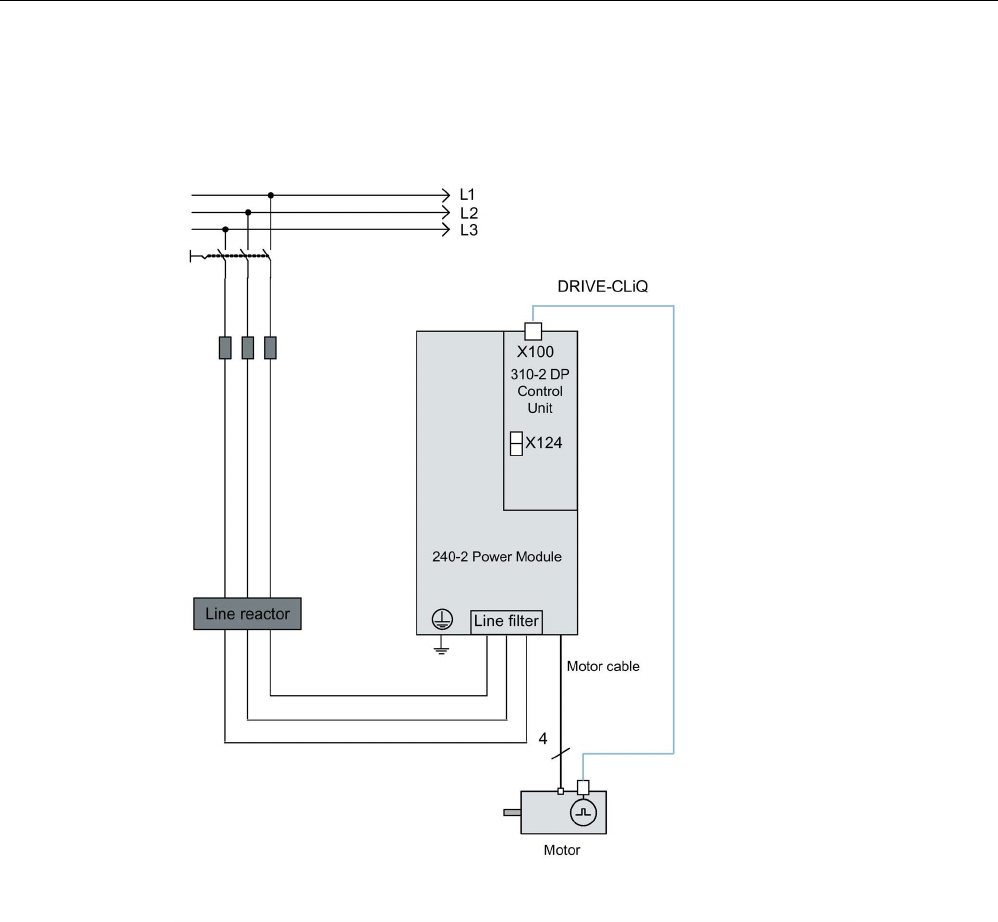
Commissioning
3.9 First commissioning servo control AC drive blocksize format
STARTER Commissioning Manual
Commissioning Manual, (IH1), 07/2016, 6SL3097-4AF00-0BP5 161
3.9.2
Component wiring (example)
The following diagram shows the structure of the components and the appropriate wiring.
Image 3-33 Component wiring with integrated Sensor Module (example)
For more information on wiring and connecting the encoder system, see the Equipment
Manual.
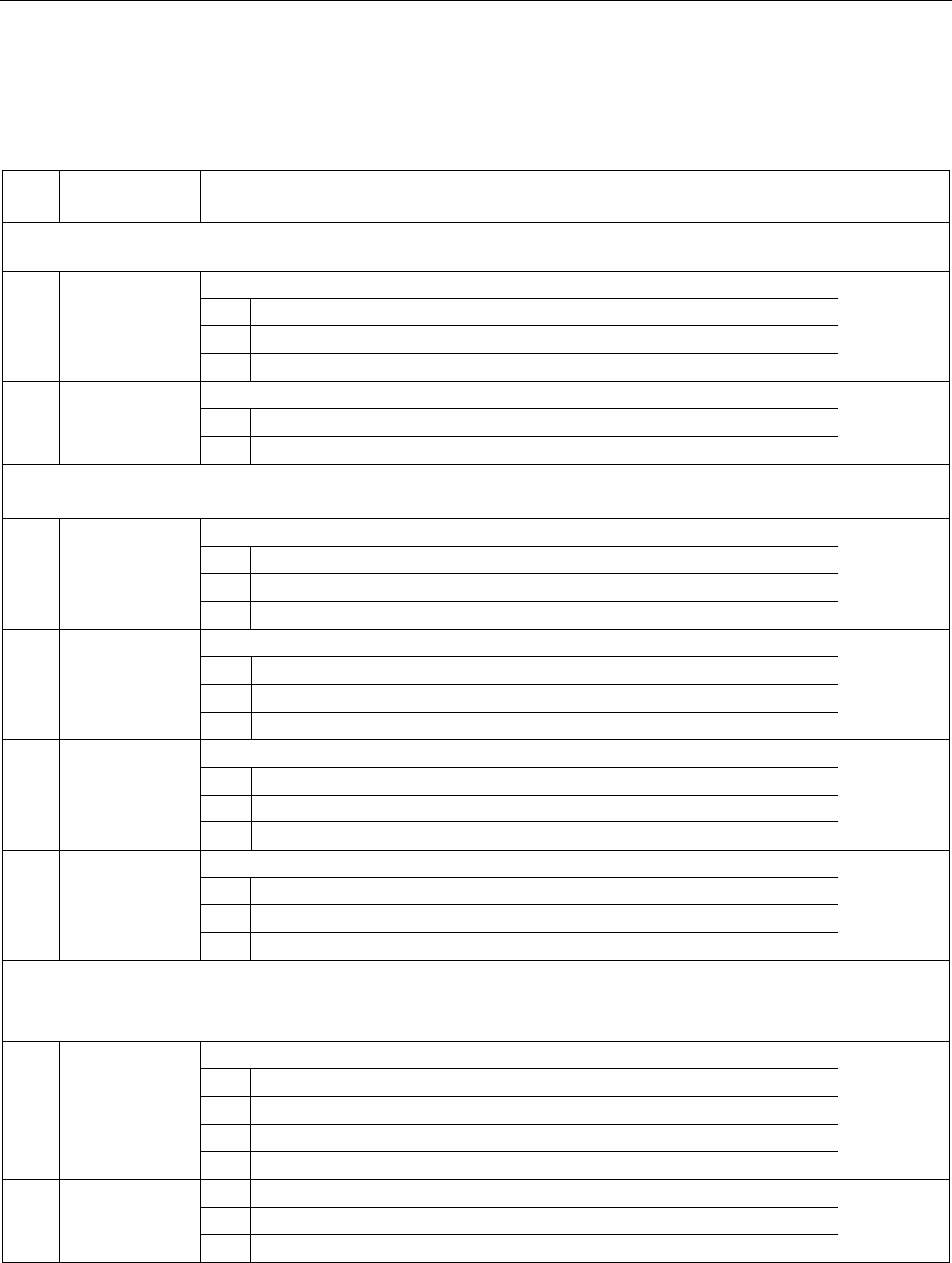
Commissioning
3.9 First commissioning servo control AC drive blocksize format
STARTER Commissioning Manual
162 Commissioning Manual, (IH1), 07/2016, 6SL3097-4AF00-0BP5
3.9.3
Quick commissioning using the BOP (example)
Table 3- 7 Quick commissioning for a servo drive with a DRIVE-CLiQ interface
Procedure
Description
Factory
setting
Note:
Before commissioning for the first time, in the drive mode DO = 1, the drive is restored to the factory setting.
1. p0009 = 30
Device commissioning parameter filter
1
0
Ready
1
Device configuration
30
Parameter reset
2. p0976 = 1
Reset and load all parameters
0
0
Not active
1
Start restoring all parameters to their factory settings
Note:
As soon as the RDY-LED is green again, the factory setting has been established and commissioning can start.
3. p0003 = 3
Access levels
1
1
Standard
2
Extended
3
Expert
4. p0009 = 1
Device commissioning parameter filter
1)
1
0
Ready
1
Device configuration
30
Parameter reset
5. p0097 = 1
Select drive object type
1)
0
0
No selection
1
Drive object type SERVO
2 Drive object type VECTOR
6. p0009 = 0
Device commissioning parameter filter
1)
1
0
Ready
1
Device configuration
30
Parameter reset
Note:
For the firmware to be activated, a POWER ON must be carried out for the components.
The extended setpoint channel must be opened for motorized potentiometer simulation with p0108[1] = H0104
7. p0009 = 2
Device commissioning parameter filter
1)
1
0
Ready
1
Device configuration
2
Defining the drive type / drive options
30
Parameter reset
8. p0108[1] =
0104 hex
Drive object function module
1)
0000 hex
Bit 2
Closed-loop speed/torque control
Bit 8
Extended setpoint channel

Commissioning
3.9 First commissioning servo control AC drive blocksize format
STARTER Commissioning Manual
Commissioning Manual, (IH1), 07/2016, 6SL3097-4AF00-0BP5 163
Procedure
Description
Factory
setting
9. p0009 = 0
Device commissioning parameter filter
1)
1
0 Ready
1
Device configuration
30
Parameter reset
Note:
Wait until the RDY-LED changes from orange to green. To save the setting in the ROM, press the "P" key for approx. 5
seconds until the BOP display flashes, then wait until flashing has stopped. The drive is now ready.
10. DO = 2
Select drive object (DO) 2 ( = SERVO)
1
1
Expert list of the CU
2
Expert list of the servo drive
To select a drive object (DO), simultaneously press the "FN" key and the "Arrow
up" key.
The selected drive object is displayed at the top left.
11. p0840[0] =
r0019.0(DO 1)
BI: ON/OFF1 [CDS]
Sets the signal source for STW1.0 (ON/OFF1)
Interconnection with r0019.0 of the drive object Control Unit (DO 1)
Effect: Signal ON/OFF1 from the BOP
0
12. p1035[0] =
r0019.13 (DO 1)
BI: Motor potentiometer setpoint higher [CDS]
Sets the signal source to increase the setpoint for the motorized potentiometer
Interconnection with r0019.13 of the drive object Control Unit (DO 1)
Effect: Signal, motorized potentiometer setpoint higher from BOP
0
13. p1036[0] =
r0019.14 (DO 1)
BI: Motor potentiometer setpoint lower [CDS]
Sets the signal source to reduce the setpoint for the motorized potentiometer
Interconnection with r0019.14 of the drive object Control Unit (DO 1)
Effect: Signal, motorized potentiometer lower setpoint from BOP
0
14.
p1037 = 6.000
Max. speed, setpoint potentiometer
0.000
15. p1070[0] =
r1050 (DO 63)
CI: Main setpoint [CDS]
Sets the signal source for speed setpoint 1 of the speed controller
Interconnection with r1050 on its own drive object (DO 63)
Effect: Motorized potentiometer supplies the speed setpoint
1024

Commissioning
3.9 First commissioning servo control AC drive blocksize format
STARTER Commissioning Manual
164 Commissioning Manual, (IH1), 07/2016, 6SL3097-4AF00-0BP5
Procedure
Description
Factory
setting
16. p0006 = 0
BOP status display mode
1)
4
0
Operation -> r0021, otherwise r0020 <-> r0021
1
Operation -> r0021, otherwise r0020
2
Operation -> p0005, otherwise p0005 <-> r0020
3
Operation -> r0002, otherwise r0002 <-> r0020
4
p0005
Press "FN" and "P" the display in DO = 2 displays 31.
17. Save all param-
eters
Press the "P" key for approx. 5 sec, 41 is displayed. After pressing the "O" key, the display
jumps to 31 - and the drive is now ready. 10 is displayed in DO = 1.
1)
These parameters offer more setting options than specified here. For further setting options see the
SINAMICS S120/S150 List Manual.
[CDS] Parameter depends on command data sets (CDS). Data set 0 is preset.
[DDS] Parameter depends on drive data sets (DDS). Data set 0 is preset.
BI binector input
BO binector output
CI connector input
CO connector output
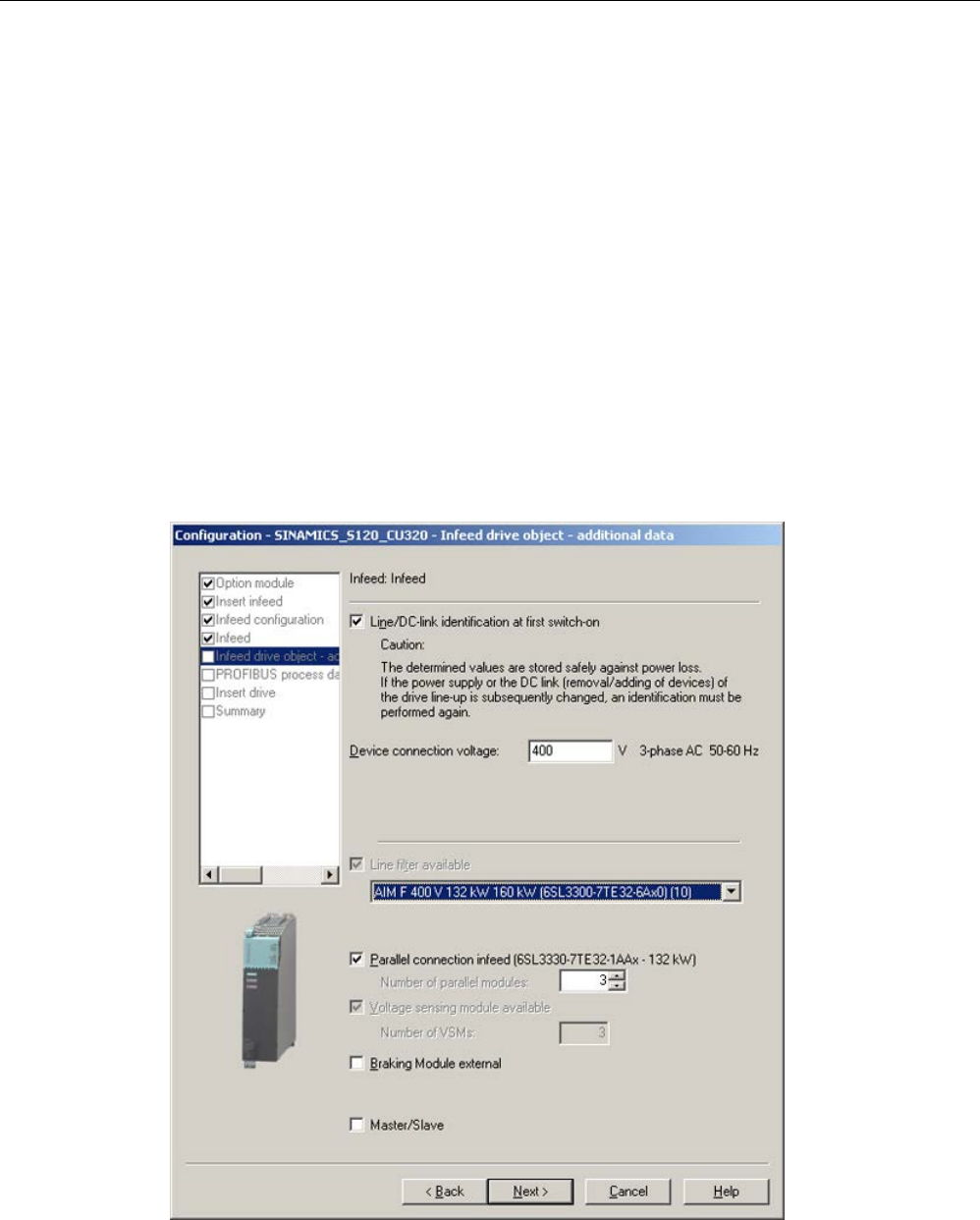
Commissioning
3.10 Commissioning of power units connected in parallel
STARTER Commissioning Manual
Commissioning Manual, (IH1), 07/2016, 6SL3097-4AF00-0BP5 165
3.10
Commissioning of power units connected in parallel
During commissioning, power units connected in parallel are treated like a power unit on the
line or motor side. With parallel connection, the parameter display for the actual values
changes only slightly. Suitable "total values" are derived from the individual values of the
power units.
Only power units in the "chassis" format are released for a parallel connection:
● Infeeds
● Motor Modules for vector control
When commissioning the power units for the first time, activate the parallel connection via
the wizards in the STARTER commissioning tool. Select the parallel connection when
selecting the power unit (infeed and/or Motor Module) according to the following diagrams as
option:
Parallel connection of infeeds in the STARTER commissioning tool
Image 3-34 Example of parallel connection of 3 Active Line Modules (chassis type)

Commissioning
3.10 Commissioning of power units connected in parallel
STARTER Commissioning Manual
166 Commissioning Manual, (IH1), 07/2016, 6SL3097-4AF00-0BP5
You need to specify the number of infeeds to be connected in parallel in the appropriate field
(maximum 4 infeeds are permitted).
Active Line Modules can also be used in the master/slave mode. The master/slave function
can be selected as an option in this window (for further information, refer to the Chapter
"Master/slave function for infeeds" in the SINAMICS S120 Function Manual Drive Functions).
The line filter is offered as an option, depending on the infeed. An Active Interface Module
(AIM) with integrated line filter is required to operate an "Active Line Module" (ALM). We
recommend external line filters to operate the "Basic Line Module" (BLM) and "Smart Line
Module" (SLM) Line Modules.
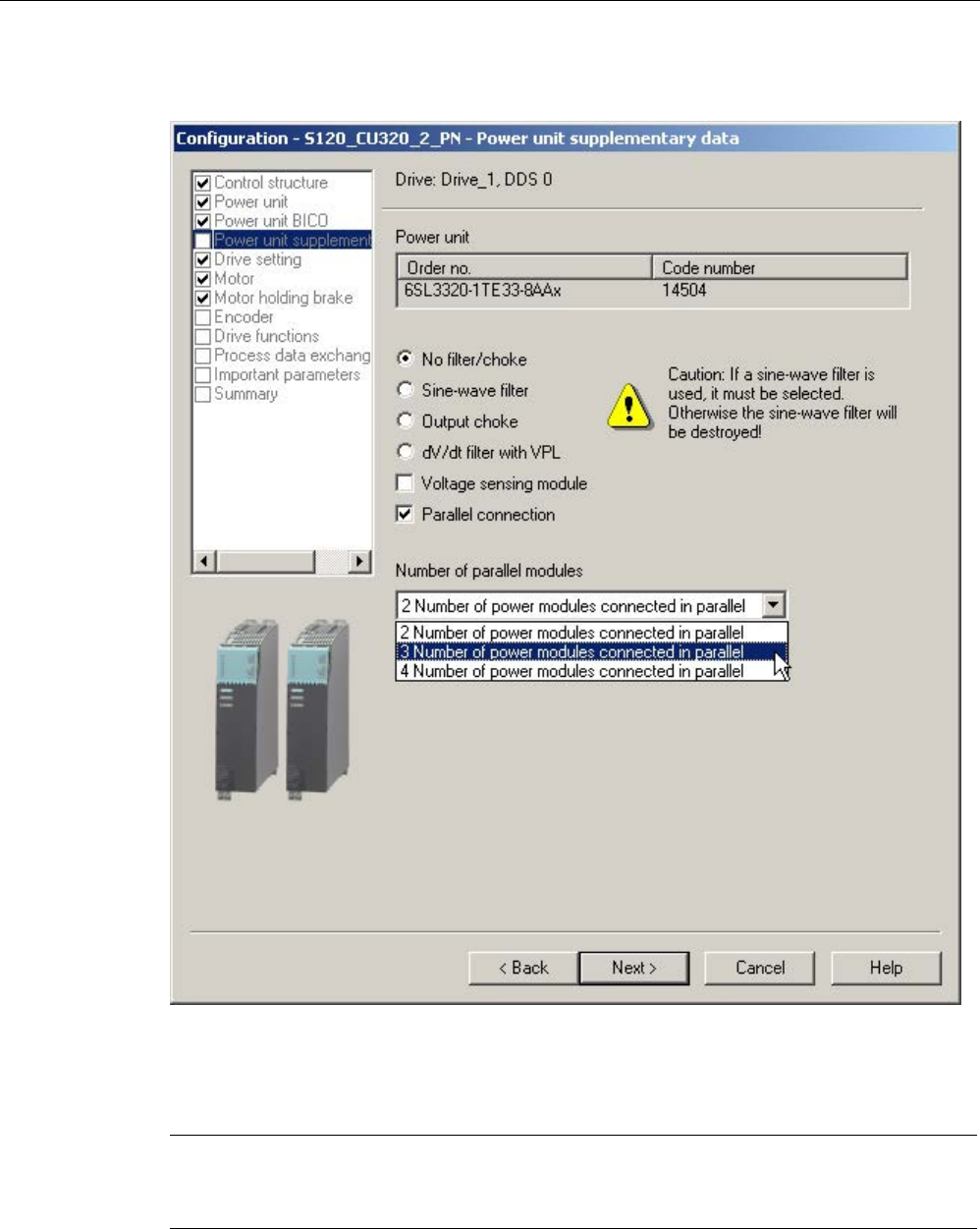
Commissioning
3.10 Commissioning of power units connected in parallel
STARTER Commissioning Manual
Commissioning Manual, (IH1), 07/2016, 6SL3097-4AF00-0BP5 167
Parallel connection of Motor Modules in the STARTER commissioning tool
Image 3-35 Example of a parallel connection of 3 Motor Modules (chassis format, in vector control)
Select the number of Motor Modules connected in parallel in the drop-down list, "Number of
parallel modules" (max. 4 Motor Modules).
Note
For the parallel connection, operation is released for a maximum of 8 power units (max. 4
Motor Modules and max.
4 Line Modules).

Commissioning
3.10 Commissioning of power units connected in parallel
STARTER Commissioning Manual
168 Commissioning Manual, (IH1), 07/2016, 6SL3097-4AF00-0BP5
Configuration of parallel connections using parameters
From the perspective of the higher-level controller, the parallel connection of infeeds
behaves exactly the same as when controlling a single infeed, whose power is the same as
the total power of the individual infeeds connected in parallel.
PROFIdrive telegrams allow the power units to be individually activated and their status
queried using parameter services from a higher-level controller. Infeeds may also be
activated using the appropriate control and status words. They are documented in chapter
"Communication according to PROFIdrive" in the SINAMICS S120 Drive Functions Function
Manual.
Power units should only be activated and deactivated in the event of a fault, for example,
after replacing a failed power unit. This approach is unsuitable for variable power control,
because the Control Unit recalculates the drive line-up control parameters after every
change. Optimal, highly dynamic control behavior of the drive line-up can only be ensured by
recalculation.
The power units can be monitored and parameterized individually:
● Using p0125, you activate or deactivate a power unit from the topology (select using the
topology number).
● With p0895, you specifically activate or deactivate power units via an interconnected
digital input (BI).
● The number of currently active power units in a parallel connection is displayed in r7000.
● After a fault or replacement, parameter p7001 allows you to specifically deactivate or
activate connected power units.
Alarm messages (e.g. as a result of overtemperature) can still be sent in this state. Individual
power units cannot be disabled for motors with separate winding systems (p7003 = 1).
p7001 is reset automatically if a power unit is deactivated with p0125 or p0895.
● You can use parameter r7002 to query whether the pulses in a power unit are inhibited or
enabled.
● The circulating currents of U, V, W at the power units are displayed in parameters r7050,
r7051 and r7052.
● Overload states and various temperature states in the power units can be displayed in
parameters from r7200 up to r7219.
Parallel connection is indicated with a "P" in front of the value shown on the parameter value
display.
Other parameters relevant for the operation and parameterization of power units can be
taken from the SINAMICS S120/S150 List Manual from parameter r7002 or from p0125
onwards.
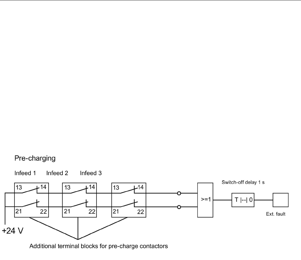
Commissioning
3.10 Commissioning of power units connected in parallel
STARTER Commissioning Manual
Commissioning Manual, (IH1), 07/2016, 6SL3097-4AF00-0BP5 169
Parallel connection with one or two Control Units
If an infeed is deactivated, the pre-charging must be able to charge the remaining infeeds in
the DC link. For example, the charging time is doubled, if only one of the two infeeds
connected in parallel is activated. Configure the infeeds in such a way that one of the parallel
infeeds or, for redundant interconnection (2 Control Units), one subsystem is able to pre-
charge the whole DC link.
The connected capacitance should not be too large. However, pre-charging double an
infeed's rated capacitance (one of two infeeds previously out of operation) will work with no
problems.
Pre-charging contactor monitoring
To monitor the pre-charging contactors (for infeed failure), you must insert the auxiliary
terminal blocks on the pre-charging contactors.
The following diagram shows the basic concept of interconnection:
Image 3-36 Pre-charging contactor monitoring
The contactor states can be monitored using the logic blocks "free blocks" in the SINAMICS
drive. If one of the contactors does not pick up, an external fault message is generated.

Commissioning
3.10 Commissioning of power units connected in parallel
STARTER Commissioning Manual
170 Commissioning Manual, (IH1), 07/2016, 6SL3097-4AF00-0BP5
Operating state of power units connected in parallel
Fault messages and alarms from A05000 or F05000 onwards indicate faults in a power unit.
Power unit faults are stored in the fault buffer in the appropriate Control Unit and can be read
as a fault value using parameter r0949 (interpreted decimally). This fault value corresponds
to the drive object number in the drive line-up topology. The number of the fault occurring is
stored in parameter r0945.
The power unit's operating state (Infeed or Motor Module) is displayed at both front LEDs on
the corresponding Control Interface Module (CIM).
The power unit for a specific drive can be identified using parameter p0124. During
p0124[0...n] = 1, the LED READY on the power unit concerned flashes green/orange or
red/orange at 2 Hz. For parallel connections the parameter index is assigned to one power
unit in each case.
Configuration of power units connected in parallel
Information on the hardware configuration and wiring the power units is provided in the
SINAMICS S120 Manual Chassis Power Units.
You can find information on configuration in "SINAMICS Configuration Manual G130, G150,
S120 Chassis, S120 Cabinet Modules, S150". The installation of power units within a control
cabinet with Line Connection Modules is also described in this manual.

Commissioning
3.11 Learn devices
STARTER Commissioning Manual
Commissioning Manual, (IH1), 07/2016, 6SL3097-4AF00-0BP5 171
3.11
Learn devices
Description
Using a software update, the "learning devices" function amends an existing STARTER (as
of version V4.2) with information about later drive firmware versions.
The update is implemented with a SINAMICS Support Package (SSP) from STARTER
version 4.2. Here, equipment descriptions have been added to the STARTER commissioning
tool, without having to reinstall the tool or change the code and without the drive being
physically available.
A SINAMICS Support Package must be installed if SINAMICS versions are to be supported
by the STARTER commissioning tool that are not included in STARTER version 4.2. You
can download SINAMICS Support Packages on the Internet from the PridaNet pages
(https://pridanet.automation.siemens.com/PridaWeb/) (Product information and data Net).
The existence of new SSPs in Product Support will be announced when a new SINAMICS
version is released for delivery.
SSP (SINAMICS Support Package)
An SSP contains only description files of the devices and drive objects. By installing an SSP,
new drive objects and devices can be added to an existing STARTER installation, without
changing its program code.
After installation, all the functions of the new SINAMICS version can be configured with the
expert list. All screens and wizards are also available for all the functions compatible with the
previous version.
SSP content:
● New drive objects
● New device versions
● New and changed parameters in the expert list
● New and changed faults, alarms and messages
● New and changed sequence parameterizations
● Expansions of the component catalog (new motors, encoders, DRIVE-CLiQ components)
● Expansion of the configuration catalog (SD)
● Changed online help files (parameter help, function diagrams)

Commissioning
3.11 Learn devices
STARTER Commissioning Manual
172 Commissioning Manual, (IH1), 07/2016, 6SL3097-4AF00-0BP5
Installation
All SSPs released for a STARTER version may be installed in any order.
The installed SINAMICS Support Packages are displayed in the Info dialog box of
STARTER.
If a new STARTER version has been created and delivered, this STARTER contains all
SSPs released up until the present time, or is compatible with them.
Compatible SSPs can also be installed a multiple number of times if repairs are necessary,
without functional changes.
The STARTER commissioning tool should not be running during SSP installation. The
installation program should be started and run through. Only after the installation has been
finished and STARTER has been called up again, can you now configure the newly installed
SINAMICS versions offline and operate them online (via "Accessible nodes" for example).

Commissioning
3.12 Selection and configuration of encoders
STARTER Commissioning Manual
Commissioning Manual, (IH1), 07/2016, 6SL3097-4AF00-0BP5 173
3.12
Selection and configuration of encoders
3.12.1
Encoder selection
For a SINAMICS drive system, there are three possibilities of selecting the encoder using the
STARTER commissioning tool:
● Evaluating the motor and encoder data via a DRIVE-CLiQ interface.
The encoder is identified automatically by setting the parameter p0400 = 10000 or 10100.
This means all motor and encoder data required for the configuration is read from the
encoder. For p0400 = 10100, the identification time is not limited.
● Selecting a standard encoder from a list (also possible via the motor article number for
encoder 1/motor encoder). Every encoder type on the list has a code number that can
also be assigned using parameter p0400 (encoder type selection).
● Manually entering user-defined encoder data. In this case, the encoder can be configured
using the encoder-specific input screens in the STARTER commissioning tool.
The encoders can also be configured using the expert list (parameters p0400 to p0499).
Table 3- 8 Assigning encoder type, encoder code and evaluation modules for standard encoders
Encoder type
Encoder code
Encoder evaluation procedure
Evaluation module
DRIVE-CLiQ
encoder
Absolute rotary 202
242
204
244
Abs.,singleturn 20-bit
abs.,singleturn 24-bit
abs.,multiturn 12-bit, singleturn 20-bit)
abs.,multiturn 12-bit, singleturn 24-bit)
-
Resolver Incremental
rotary
1001
1002
1003
1004
Resolver 1-speed
Resolver 2-speed
Resolver 3-speed
Resolver 4-speed
SMC10, SMI10
Encoder with
sin/cos 1Vpp
Incremental
rotary
2001
2002
2003
2005
2010
2048, 1 Vpp, A/B C/D R
2048, 1 Vpp, A/B R
256, 1 Vpp, A/B R
512, 1 Vpp, A/B R
18000, 1 Vpp, A/B R distance-coded
SMC20, SMI20,
SME20, SME120
EnDat en-
coder
Absolute
rotary
2051
2052
2053
2054
2055
2048, 1 Vpp, A/B, EnDat, multiturn 4096
32, 1 Vpp, A/B, EnDat, multiturn 4096
512, 1 Vpp, A/B, EnDat, multiturn 4096
16, 1 Vpp, A/B, EnDat, multiturn 4096
2048, 1 Vpp, A/B, EnDat, singleturn
SMC20, SMC401),
SMI20, SME25
SSI encoder
with
sin/cos 1Vpp
Absolute
rotary
2081
2082
2083
2084
2048, 1 Vpp, A/B, SSI, singleturn
2048, 1 Vpp, A/B, SSI, multiturn 4096
2048, 1 Vpp, A/B, SSI, singleturn, error bit
2048, 1 Vpp, A/B, SSI, multiturn 4096, error
bit
SMC20, SMI20,
SME25, SME125
Linear en-
coder
Incremental
linear
2110
2111
2112
2151
4000 nm, 1 Vpp, A/B R distance-coded
20000 nm, 1 Vpp, A/B R distance-coded
40000 nm, 1 Vpp, A/B R distance-coded
16000 nm, 1 Vpp, A/B, EnDat, resolution
100 nm
SMC20, SMI20,
SME20

Commissioning
3.12 Selection and configuration of encoders
STARTER Commissioning Manual
174 Commissioning Manual, (IH1), 07/2016, 6SL3097-4AF00-0BP5
Encoder type
Encoder code
Encoder evaluation procedure
Evaluation module
Absolute
linear
2151 16000 nm, 1 Vpp, A/B, EnDat,
resolution 100 nm
SMC20, SMI20,
SME25
HTL/TTL
encoders
Incremental
square wave
rotary
3001
3002
3003
3005
3006
3007
3008
3009
3011
3020
1024 HTL A/B R
1024 TTL A/B R
2048 HTL A/B R
1024 HTL A/B
1024 TTL A/B
2048 HTL A/B
2048 TTL A/B
1024 HTL A/B unipolar
2048 HTL A/B unipolar
2048 TTL A/B R, with Sense
SMC30
SSI encoder
absolute
Absolute
rotary
3081
3082
SSI, singleturn, 24 V
SSI, multiturn 4096, 24 V
Not for motor control,
only as a direct measurement system
SMC30
SSI encoder
absolute HTL
Absolute
rotary
3090 4096, HTL, A/B, SSI, singleturn SMC30
Linear en-
coder
Incremental
linear
3109 2000 nm, TTL, A/B R distance-coded SMC20, SMI20,
SME20
SIMAG H2 Incremental
rotary
2002
2003
2004
2005
2006
2007
2008
2048, 1 Vpp, A/B R
256, 1 Vpp, A/B R
400, 1 Vpp, A/B R
512, 1 Vpp, A/B R
192, 1 Vpp, A/B R
480, 1 Vpp, A/B R
800, 1 Vpp, A/B R
SMC20, SMI20,
SME20
1)
The SMC40 can only be completely configured if an associated EnDat 2.2 encoder is connected. Without a connected
encoder, it is not possible to integrate the SMC40 into the topology.
3.12.2
Configuring an encoder
You can configure the encoders using an input screen in the STARTER commissioning tool.
You have three configuration options:
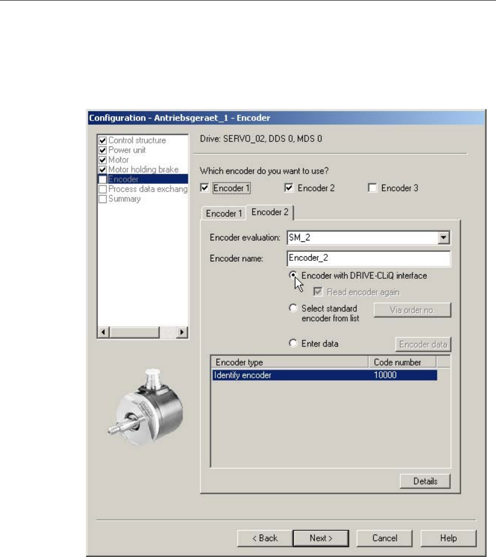
Commissioning
3.12 Selection and configuration of encoders
STARTER Commissioning Manual
Commissioning Manual, (IH1), 07/2016, 6SL3097-4AF00-0BP5 175
Configuration for encoders with DRIVE-CLiQ interface
1. Activate the "Encoder with DRIVE-CLiQ interface" option button with a mouse click.
The encoder with DRIVE-CLiQ interface is then automatically identified in the encoder
configuration screen.
Image 3-37 Identifying DRIVE-CLiQ encoders
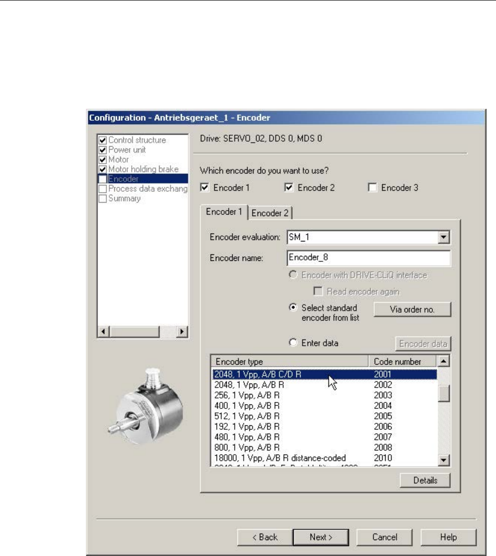
Commissioning
3.12 Selection and configuration of encoders
STARTER Commissioning Manual
176 Commissioning Manual, (IH1), 07/2016, 6SL3097-4AF00-0BP5
Configuration of standard encoders
1. Select the "Select standard encoder from list" option field.
The encoder 1/motor encoder can also be selected and configured at the same time
using the motor article number.
Image 3-38 Standard encoder option
When configuring the drive you can select the standard encoders offered by Siemens
from a list under "encoders". When the encoder type is chosen, all necessary
parameterizations are simultaneously and automatically transferred into the encoder
configuration. The standard encoder type and the corresponding evaluation modules are
shown in the above table.
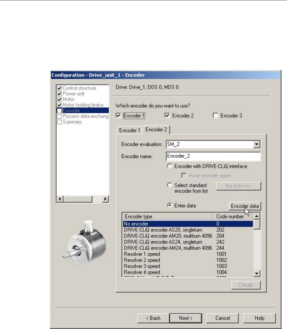
Commissioning
3.12 Selection and configuration of encoders
STARTER Commissioning Manual
Commissioning Manual, (IH1), 07/2016, 6SL3097-4AF00-0BP5 177
Configuration using manually determined user data
1. To manually enter user-defined encoder data, use the mouse to activate the "Enter data"
option field.
In this case, the encoder can be configured using the encoder-specific input screens in
the STARTER commissioning tool.
Image 3-39 User-defined encoder option
2. Click the "Encoder data" button.
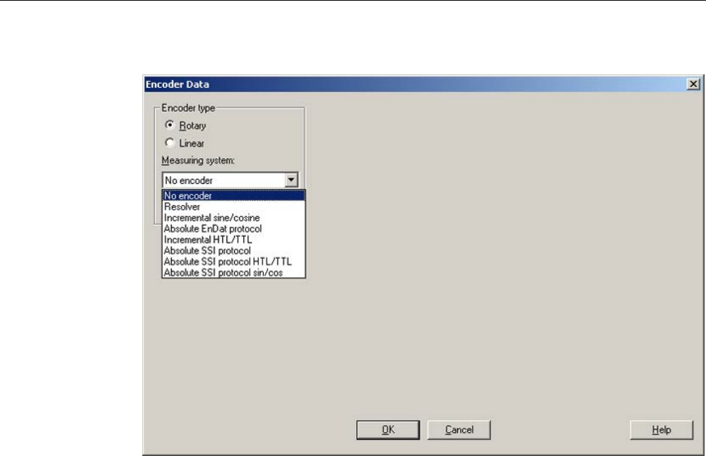
Commissioning
3.12 Selection and configuration of encoders
STARTER Commissioning Manual
178 Commissioning Manual, (IH1), 07/2016, 6SL3097-4AF00-0BP5
The following window opens for encoder data:
Image 3-40 Rotary encoder types
In this window, you can select between "rotary" and "linear" encoders.
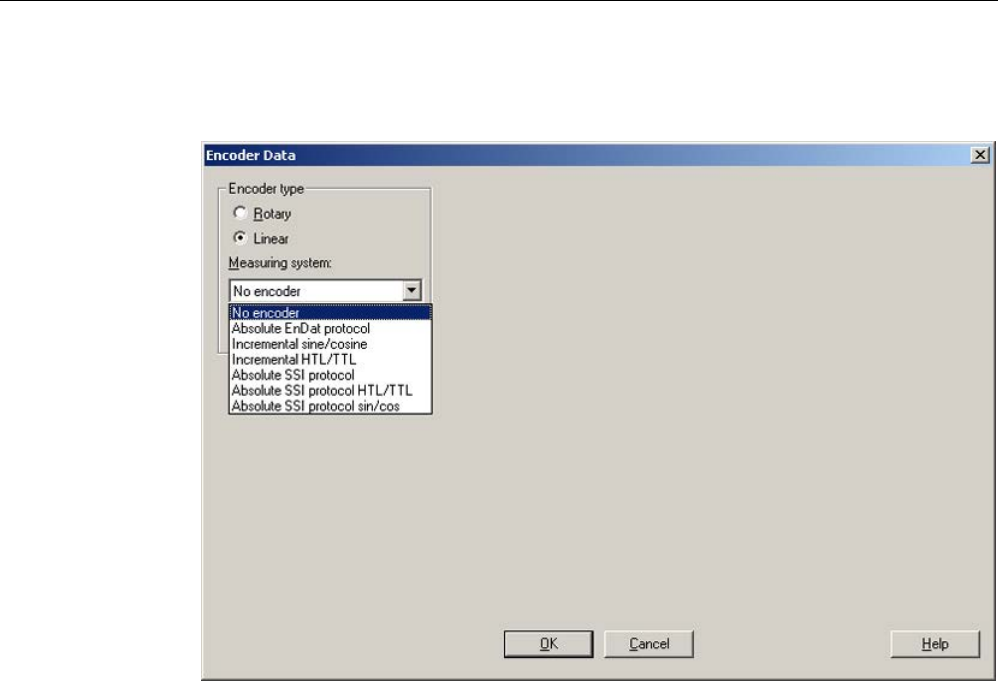
Commissioning
3.12 Selection and configuration of encoders
STARTER Commissioning Manual
Commissioning Manual, (IH1), 07/2016, 6SL3097-4AF00-0BP5 179
3. Select the encoder type by clicking the appropriate option field.
The drop-down list for the "linear" encoder type lists, for example, the following encoders:
Image 3-41 Linear encoder types
4. Select the required encoder from the drop-down list.
The encoder-specific input screens for rotary and linear encoders are self-explanatory and
therefore not explicitly explained here.

Commissioning
3.12 Selection and configuration of encoders
STARTER Commissioning Manual
180 Commissioning Manual, (IH1), 07/2016, 6SL3097-4AF00-0BP5
3.12.3
Example: Commissioning and replacement of a DRIVE-CLiQ encoder
The following describes commissioning and replacing an encoder using the DRIVE-CLiQ
encoder as an example.
Support by STARTER
The STARTER commissioning tool supports encoders with DRIVE-CLiQ interface. Additional
article numbers for the corresponding DRIVE-CLiQ motors are provided in the encoder
overview.
The motor article number is used for an SMI or DQI motor.
When configuring a motor with DRIVE-CLiQ interface, a distinction is not made between SMI
motors and DQI motors.
If you replace a motor with encoder and external DRIVE-CLiQ interface by an SMI motor or
DQI motor, then you must appropriately reparameterize the SMI/DQI motor.
The functional behavior differs for the following encoder changes:
● If the encoders differ due to the measurement principle and the resolution.
● If the encoders are used in applications where the evaluation requires a zero mark (for
example for referencing purposes). The encoder with integrated DRIVE-CLiQ interface
does not supply a separate zero mark, as it involves an absolute encoder. So in these
applications (and/or in the higher-level controllers) the changed behavior must be
selected.
● If an encoder is to be used on an axis with SINAMICS Safety Integrated Extended
functions or SINUMERIK Safety Integrated, because a lower position accuracy (SOS
Safe Operating Stop) and a lower maximum velocity (SLS Safely Limited Speed) is
obtained as a result of the lower resolution of the redundant position value (POS2).
A new commissioning test and, if necessary, new configuration must be carried out for
activated SINAMICS Safety Integrated Extended functions or SINUMERIK Safety Integrated.

Commissioning
3.12 Selection and configuration of encoders
STARTER Commissioning Manual
Commissioning Manual, (IH1), 07/2016, 6SL3097-4AF00-0BP5 181
Commissioning encoders with DRIVE-CLiQ interface
For DRIVE-CLiQ encoders, the properties of a rotary absolute encoder are identified with the
following parameters of the Control Unit:
p0404[0..n]
Encoder configuration active
p0408[0..n]
Rotary encoder pulse No.
p0421[0..n]
Absolute encoder rotary multiturn resolution
p0423[0..n]
Absolute encoder rotary singleturn resolution
This data is pre-assigned according to the preset codes in p0400 (encoder type selection)
from the encoder lists. Parameters p0404, p0408, p0421 and p0423 are checked by the
Control Unit when booting.
Alternatively, this data can be read out of the encoder with the setting p0400 = 10000 or
p0400 = 10100. If the encoder data read out matches a known encoder type, this code is
entered in p0400 using the Control Unit. In the other case, general codes are entered, e.g.
P0400 = 10050 (encoder with EnDat interface 2.1 identified), p0400 = 10058 (digital encoder
(absolute) identified) or p0400 = 10059 (digital encoder (incremental) identified).
A DRIVE-CLiQ encoder is identified by the parameter p0404.10 = 1.
For DRIVE-CLiQ encoders, encoder codes are defined respectively for parameter p0400
(see SINAMICS S120/S150 List Manual and above table).
If the Control Unit identifies a DRIVE-CLiQ encoder type for which no code is stored, during
identification it enters the code p0400 = 10051 (DRIVE-CLiQ encoder identified).
The data is also automatically identified if a DRIVE-CLiQ encoder is found during automatic
commissioning. During identification, the Control Unit reads out the values for p0404, p0421
and p0423 from the DRIVE-CLiQ encoder. The Control Unit uses this data to determine the
contents of p0400. The newly defined codes are not stored in the DRIVE-CLiQ encoder.
Replacing a SINAMICS Sensor Module Integrated
If a defect occurs in a SINAMICS Sensor Module Integrated (SMI) or in a DRIVE-CLiQ
Sensor Integrated (DQI), contact your local Siemens office for a repair.

Commissioning
3.13 Commissioning of SIMOTICS L-1FN3 linear motors
STARTER Commissioning Manual
182 Commissioning Manual, (IH1), 07/2016, 6SL3097-4AF00-0BP5
3.13
Commissioning of SIMOTICS L-1FN3 linear motors
3.13.1
Safety instructions for commissioning linear motors
WARNING
Danger to life as a result of unintended motor movement
Unexpected movements of the motor may cause death, serious injury (crushing) and/or
property damage.
• Do not work in the danger area while a machine is switched on.
• Keep persons away from moving parts and areas where there is a danger of crushing.
• Ensure the free axis travel path.
• Observe the instructions on commutation.
• Limit the motor currents.
• Set the speed limitation to small values.
• Monitor the end positions of the motor.
WARNING
Risk of burn injuries on hot surfaces
Touching the surfaces of the motor can cause serious injury.
• Do not touch the motor during or immediately after operation.
• Attach the "Hot Surface Do Not Touch" (DW-026) warning sign close to the source of
danger where it can be easily seen.
WARNING
Danger to life due to electric shock
Every movement of the primary part compared with the secondary part and vice versa
produces an induced voltage. If you touch cable connections, you could suffer an electric
shock, which can result in death or serious injury.
• Secure the primary section so that it cannot move before you touch the cable
connections.
• Connect the cable connections of the motor correctly and insulate them correctly.

Commissioning
3.13 Commissioning of SIMOTICS L-1FN3 linear motors
STARTER Commissioning Manual
Commissioning Manual, (IH1), 07/2016, 6SL3097-4AF00-0BP5 183
3.13.2
Checklists for commissioning
Checklists for commissioning 1FN3 linear motors
Please thoroughly familiarize yourself with the safety instructions and observe the checklists
below before starting any work.
Table 3- 9 Checklist (1) - general checks
Check
OK
Are all of the necessary components of the configured drive line-up available, correctly dimensioned,
correctly installed and connected?
Are the manufacturer's documentation for the system components (e.g. drive system, encoder, cooling
system, brake) and the "SIMOTICS L-1FN3 linear motors" Configuration Manual available?
Are the following up-to-date SINAMICS documents available?
• SINAMICS S120 Commissioning Manual
• SINAMICS S120 Getting Started
• SINAMICS S120 Function Manual Drive Functions
• SINAMICS S120/S150 List Manual
Was the Chapter "Checklists for commissioning SINAMICS S" taken into account?
Is the motor type to be commissioned known?
(e.g. 1FN3 _ _ _ – _ _ _ _ _ – _ _ _ _)
As a minimum, is the following data for the motor known, if it involves a "third-party motor"?
(A "third-party motor" is every motor that is not saved as standard in the Siemens commissioning soft-
ware.)
• Rated motor current
• Motor rated velocity
• Motor polar distance
• Motor force constant
• Motor maximum speed
• Maximum motor current
• Motor limit current
• Motor weight
• Plase resistance of the cold motor winding
• Phase inductance of the winding
Are the environmental conditions in accordance with "SIMOTICS L-1FN3 linear motors" Operating In-
structions in the permitted range?
Is it guaranteed that the maximum permitted temperature of the secondary part does not exceed 70° C?
Is it guaranteed that at least two people work together?

Commissioning
3.13 Commissioning of SIMOTICS L-1FN3 linear motors
STARTER Commissioning Manual
184 Commissioning Manual, (IH1), 07/2016, 6SL3097-4AF00-0BP5
Table 3- 10 Checklist (2) - checking the mechanical system
Check
OK
Has the motor been correctly installed according to the motor manufacturer's specifications and is it
ready to be switched on?
Can the axis move freely over the complete travel range?
Have all the screws been tightened to the specified torque?
Does the air gap between the secondary section track and the primary and section correspond to the
motor manufacturer's data?
If there is a motor holding brake, does it function correctly?
Has the position measuring system been correctly mounted and adjusted according to the manufactur-
er's specifications?
Important associated information is also contained in the "SIMOTICS L-1FN3 linear motors" Configura-
tion Manual.
Has a cooling system, required for liquid-cooled motors, been connected according to the manufactur-
er's specifications and is it functioning correctly?
Does the cooling medium comply with the requirements listed in the "Cooling media" chapter of the
"SIMOTICS L-1FN3 linear motors" Configuration Manual?
Were the cooling circuits flushed before been filled with the cooling medium?
Is it ensured that the permitted pressure in the cooling circuit is not exceeded (here, refer to "Technical
features" in the "SIMOTICS L-1FN3 Linear Motors" Configuration Manual)?
Are moving cables correctly routed in a tow chain?
Have the power cables been connected properly to the terminals with the specified torque?
Have measures been taken to relieve strain on the cables?
Table 3- 11 Checklist (3) - checking the electrical system
Check
OK
Has all wiring work been successfully completed?
Is the protective conductor correctly connected?
Is the motor ground directly connected to the Power Module ground (short distance in order to avoid
high leakage currents)?
Are all connectors correctly plugged in and screwed in place?
Are the motors connected with shielded power cables?
Are the power cable shields connected as closely as possible to the terminal box across a wide area?
Are all cable shields connected to the respective housing through a large surface area?
Have the control cables been connected in accordance with the required interface configuration and
the shield applied?
Have the motor power cables been correctly connected to the Power Module with the phase sequence
UVW (clockwise rotating field)?
Do the temperature monitoring circuits fulfill the specifications of protective separation?
Additional important information on the Temp-S and Temp-F temperature monitoring circuits can be
found in the "SIMOTICS L-1FN3 Linear Motors" Configuration Manual.
Before commissioning and before switching on the DC-link voltage for the first time, have you checked
the temperature monitoring circuits to ensure that they correctly trip / shut down?
Is the position measuring system correctly connected?

Commissioning
3.13 Commissioning of SIMOTICS L-1FN3 linear motors
STARTER Commissioning Manual
Commissioning Manual, (IH1), 07/2016, 6SL3097-4AF00-0BP5 185
Check
OK
Are the digital and analog signals routed using separate cables?
Has the distance between the power cables and the signal lines been observed?
Is it guaranteed that temperature-
sensitive parts (electric cables, electronic components) are not placed
on hot surfaces?
Have the line-side and motor-side power cables been dimensioned and routed in accordance with the
environmental and routing conditions?
Have the maximum permitted cable lengths between the frequency converter and the motor (depend-
ing on the type of cables used) been observed?
3.13.3
General information for setting the commutation
You can use the following two pole position identification techniques for all frame sizes of
SIMOTICS L-1FN3 linear motors:
● The motion-based technique
● The saturation-based technique (1st harmonic)
Irrespective of which of these two techniques is deployed, you can also use a Hall sensor
box to determine the pole position.
Note
Fine synchronization is recommended for precise commutation
Use either a measuring system with a zero mark that can be evaluated or an absolute
measuring system.
Motion-based technique
This technique can also be used during commissioning when the commutation angle offset is
initially determined or when it is checked in conjunction with an absolute measuring system.
The technique can be applied for horizontal and inclined axes whose load cannot be lowered
in an uncontrolled manner when the machine is disconnected from the power supply. In this
case, the axes must be able to be freely moved and not be braked. (static friction < 10% of
the rated motor force).
In the worst-case scenario, the axes can move in the range of ± 5 degrees when this
technique is used.
WARNING
Danger to life from vertical or inclined axes
With vertical or inclined axes, the load can fall down and cause death or severe injury when
a motion-based technique is used.
• Ensure that nobody is in the danger zone.
• Use the saturation-based technique for vertical axes.
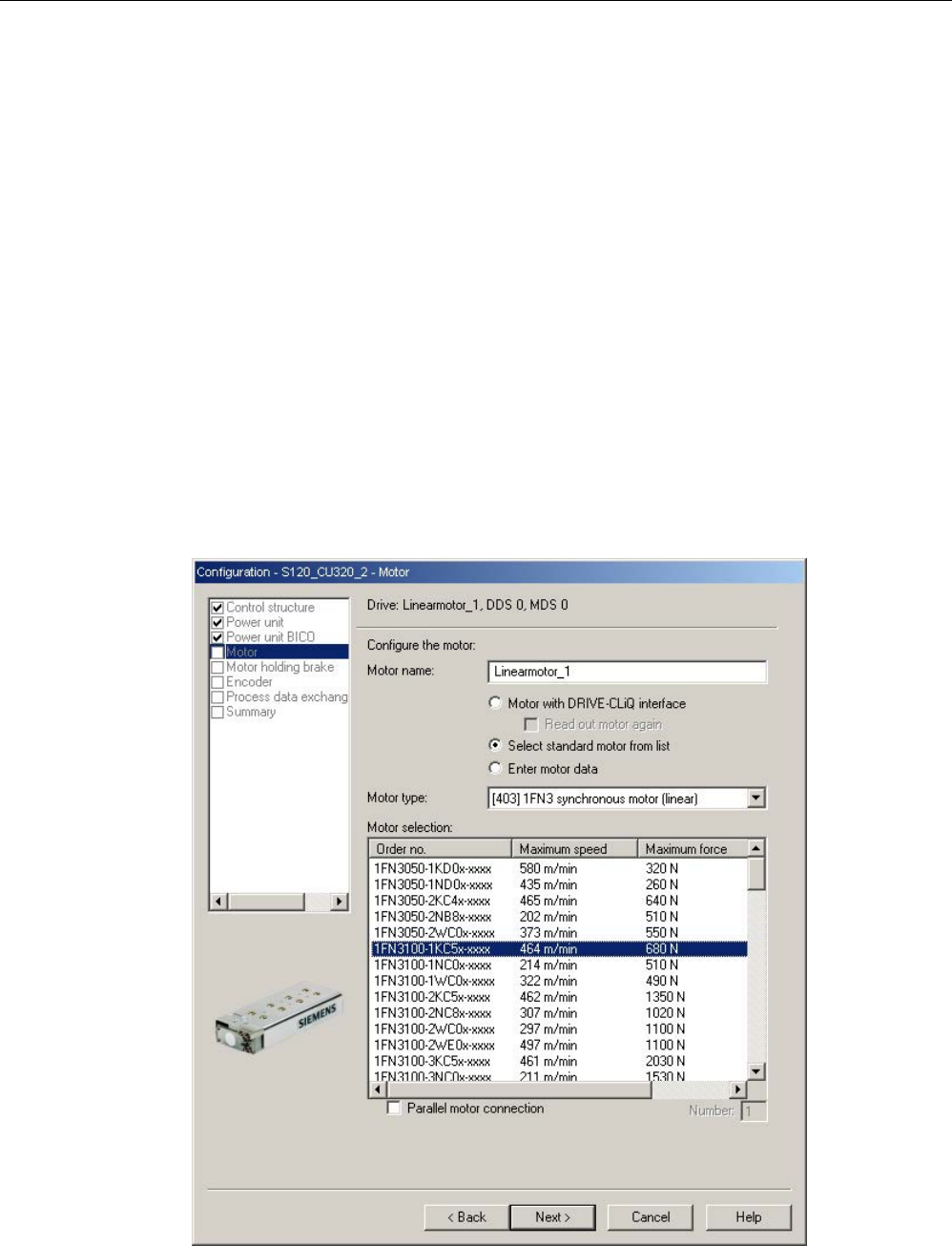
Commissioning
3.13 Commissioning of SIMOTICS L-1FN3 linear motors
STARTER Commissioning Manual
186 Commissioning Manual, (IH1), 07/2016, 6SL3097-4AF00-0BP5
Saturation-based technique
This technique does not require any axis movement and so it can also be used for axes that
are locked (e.g. using a brake). Axes movements, however, can occur for axes that are not
locked. Depending on the actual design, this technique can result in a higher noise level
when the axes are powered up during the identification routine.
3.13.4
Parameterizing a motor and encoder
Configuring data for a standard motor
You must individually configure the drives.
1. Double-click in the project navigator on "Drives" > "Drive name" > "Configuration" >
"Configure DDS" one after the other.
2. Select the standard motor provided for the commissioning from the list.
The associated motor data is stored and does not need to be entered manually.
Image 3-42 Screen to configure a motor - selecting a standard motor
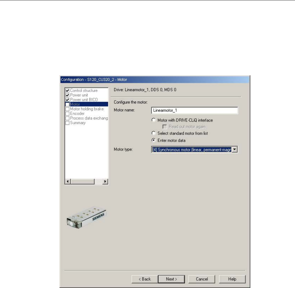
Commissioning
3.13 Commissioning of SIMOTICS L-1FN3 linear motors
STARTER Commissioning Manual
Commissioning Manual, (IH1), 07/2016, 6SL3097-4AF00-0BP5 187
Configuring data for a third-party motor
1FN3 linear motors are not included in the list if they are customer-specific special motors or
new developments.
1. Please take the motor data from the attached motor data sheet and make the following
settings:
Image 3-43 Screen to configure the motor – setting for a third-party motor
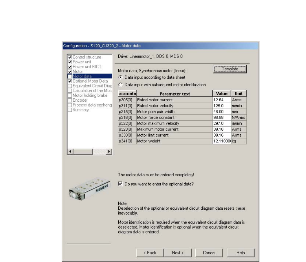
Commissioning
3.13 Commissioning of SIMOTICS L-1FN3 linear motors
STARTER Commissioning Manual
188 Commissioning Manual, (IH1), 07/2016, 6SL3097-4AF00-0BP5
2. Enter the following data for a linear permanent-magnet synchronous motor:
Image 3-44 Example of motor data that has been entered
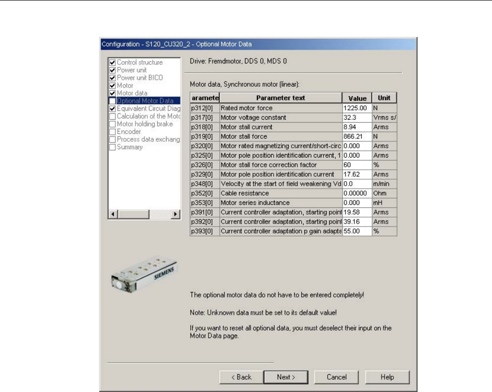
Commissioning
3.13 Commissioning of SIMOTICS L-1FN3 linear motors
STARTER Commissioning Manual
Commissioning Manual, (IH1), 07/2016, 6SL3097-4AF00-0BP5 189
Image 3-45 Example of optional motor data that has been entered
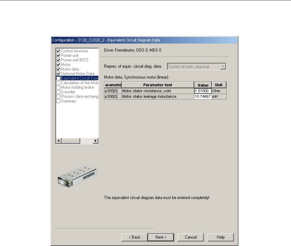
Commissioning
3.13 Commissioning of SIMOTICS L-1FN3 linear motors
STARTER Commissioning Manual
190 Commissioning Manual, (IH1), 07/2016, 6SL3097-4AF00-0BP5
Entering equivalent circuit diagram data
Image 3-46 Example of equivalent circuit diagram data that has been entered
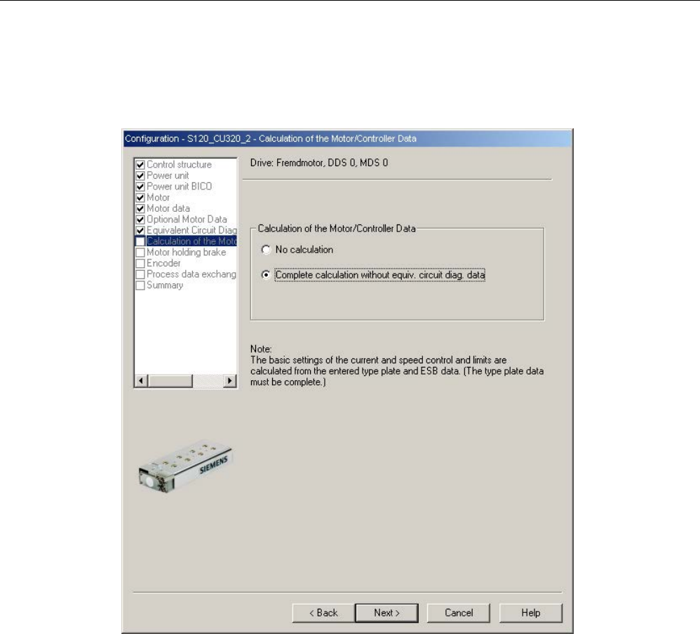
Commissioning
3.13 Commissioning of SIMOTICS L-1FN3 linear motors
STARTER Commissioning Manual
Commissioning Manual, (IH1), 07/2016, 6SL3097-4AF00-0BP5 191
Calculating controller data
After selecting the motor and entering the motor data, completely calculate the controller
data.
Image 3-47 Screen form for calculating the motor/controller data
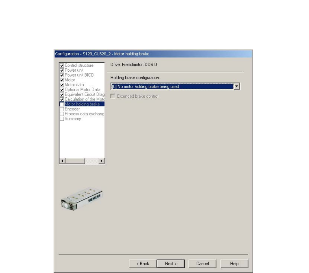
Commissioning
3.13 Commissioning of SIMOTICS L-1FN3 linear motors
STARTER Commissioning Manual
192 Commissioning Manual, (IH1), 07/2016, 6SL3097-4AF00-0BP5
Configuring the motor holding brake
If a motor holding brake is being used, configure it in the following window.
Image 3-48 Screen form for configuring a motor holding brake
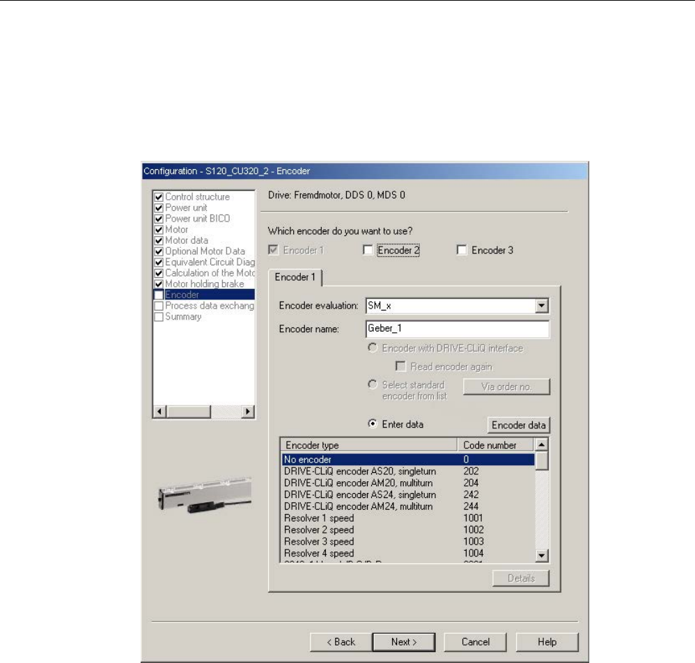
Commissioning
3.13 Commissioning of SIMOTICS L-1FN3 linear motors
STARTER Commissioning Manual
Commissioning Manual, (IH1), 07/2016, 6SL3097-4AF00-0BP5 193
Configuring encoder data
1. Note the data of the encoder manufacturer and the information in Chapter "Selecting and
configuring encoders (Page 173)" in this manual.
2. Configure the encoder data for the linear motor using the "Encoder data" screen form. To
do this, click the "Encoder data" button in the dialog.
Image 3-49 Screen form to configure an encoder
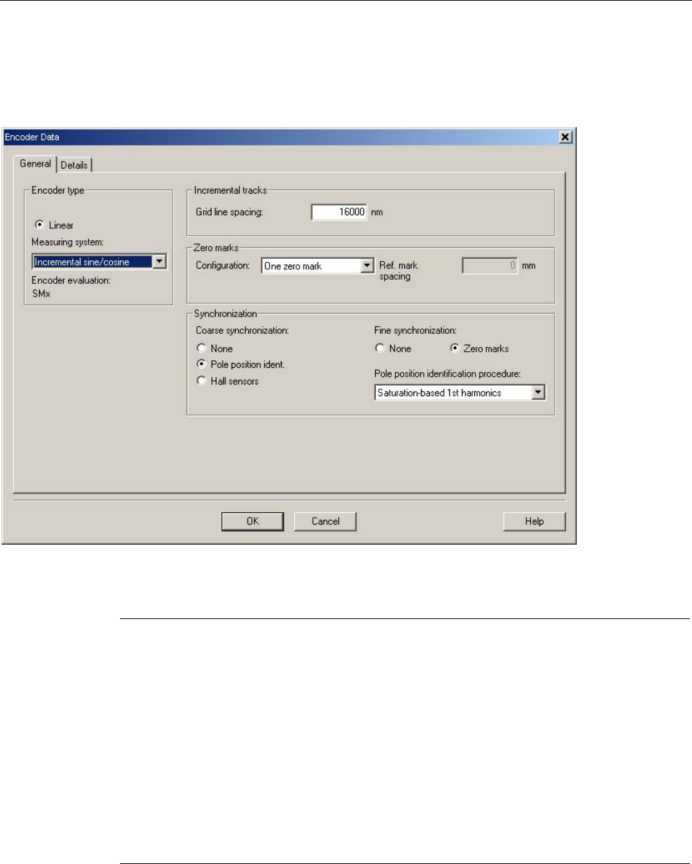
Commissioning
3.13 Commissioning of SIMOTICS L-1FN3 linear motors
STARTER Commissioning Manual
194 Commissioning Manual, (IH1), 07/2016, 6SL3097-4AF00-0BP5
Incremental measuring system
Example of an incremental sine/cosine encoder with a lattice pitch of 16000 nm and a zero
mark:
Image 3-50 Screen form for entering the encoder data
Note
A pole position identification is required for SIMOTICS L-1FN3 linear motors with
incremental measuring systems
The following techniques are possible to do this:
•
The motion-based technique
•
The saturation-based technique (1st harmonic)
For incremental measuring systems, generally, fine synchronization is perfor
med at the zero
mark. When commissioning the system for the first time, the angular commutation offset
(p0431) must be pre
-assigned, see Chapter "Determining the angular commutation offset /
maintaini
ng the tolerance (Page 204)".
For third
-party motors, a pole position identification routine to determine the angular
commutation offset cannot be entered.
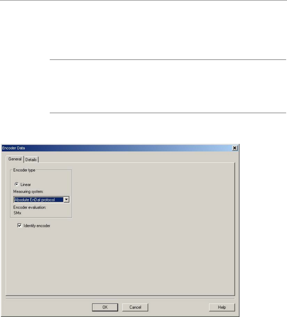
Commissioning
3.13 Commissioning of SIMOTICS L-1FN3 linear motors
STARTER Commissioning Manual
Commissioning Manual, (IH1), 07/2016, 6SL3097-4AF00-0BP5 195
Absolute measuring system
The encoder is detected by the Control Unit as long as it is a DRIVE-CLiQ encoder. For all
other encoder types, you must use the SINAMICS Sensor Module in accordance with the
encoder interface in order to transfer the encoder signals to the Control Unit.
Note
SINAMICS Sensor Modules in conjunction with EnDat encoders of Heidenhain Corp.
SMC20, SME25 and SME125: EnDat encoders with incremental signals, article designation
EnDat02 or EnDat01.
SMC40: EnDat encoder with EnDat protocol 2.2 without incremental signals, article
designation Endat22.
The following inputs must be made in the configuration screen form after clicking the
"Encoder data" button.
Image 3-51 Screen form to configure an absolute encoder with EnDat protocol
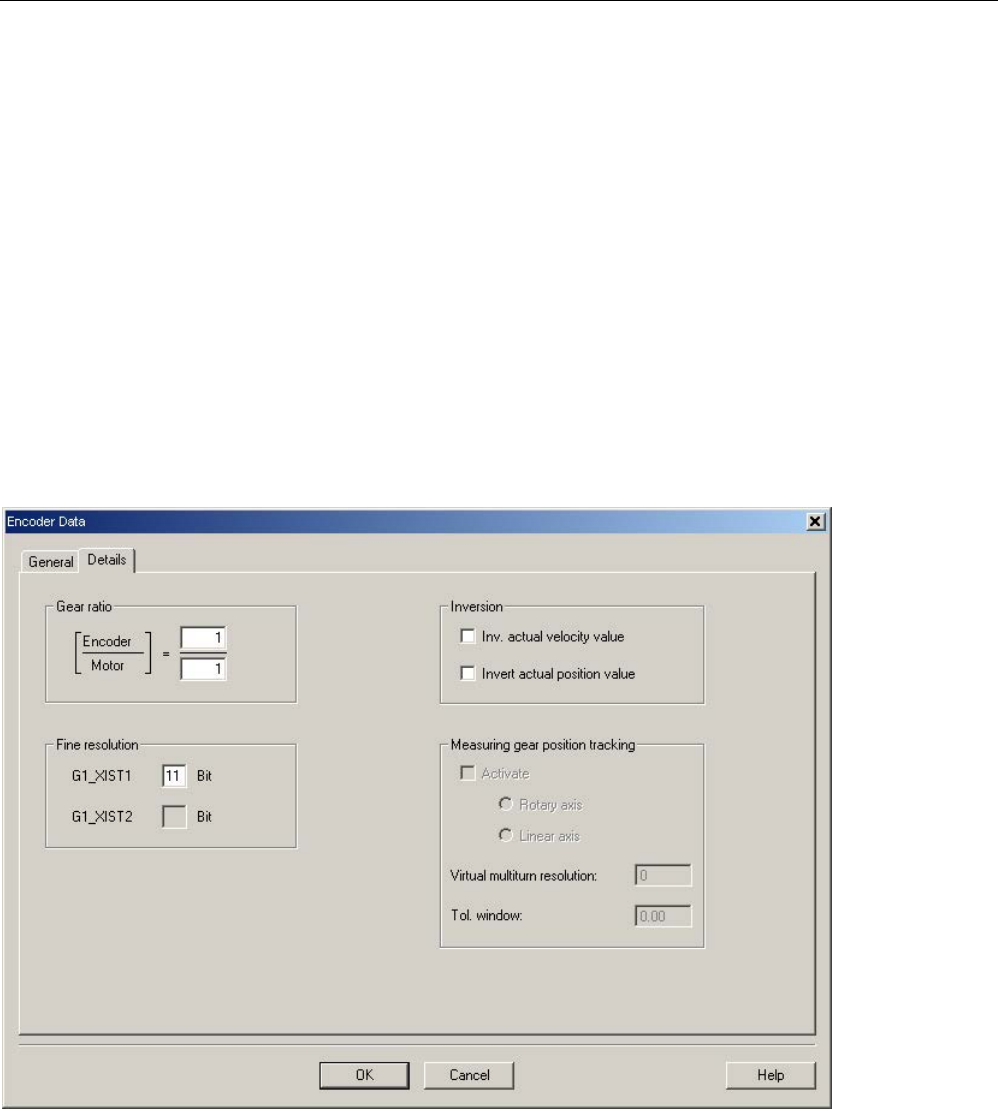
Commissioning
3.13 Commissioning of SIMOTICS L-1FN3 linear motors
STARTER Commissioning Manual
196 Commissioning Manual, (IH1), 07/2016, 6SL3097-4AF00-0BP5
Definition of the control sense
The control sense of an axis is correct if the positive direction of the drive (= clockwise
rotating field U, V, W) coincides with the positive counting direction of the measuring system.
If the positive direction of the drive and positive counting direction of the measuring system
do not match, then you must invert the actual speed value in the "Encoder configuration -
details" screen form when the drive is being commissioned (p0410.0 or p0410.1). See the
"Screen form for entering additional encoder data (Page 196)" figure.
Setting additional encoder data
1. If necessary, use "Encoder data" and "Details" to invert the actual speed and position
value.
This allows the control sense to be changed.
2. To do this, first click the "Encoder data" button in the screen form used for the encoder
configuration.
Image 3-52 Screen form for entering additional encoder data
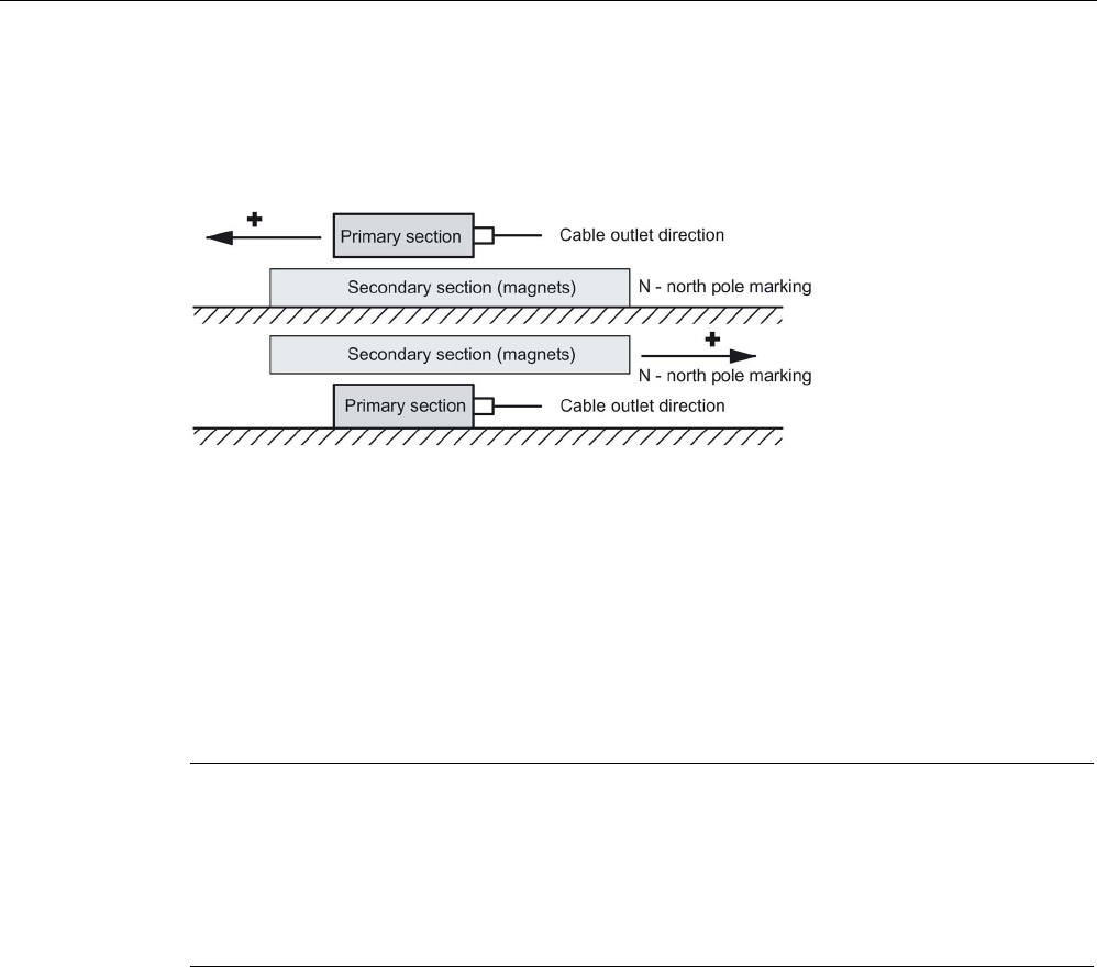
Commissioning
3.13 Commissioning of SIMOTICS L-1FN3 linear motors
STARTER Commissioning Manual
Commissioning Manual, (IH1), 07/2016, 6SL3097-4AF00-0BP5 197
Determining the drive direction
The direction of the drive rotation is positive if the primary section moves relative to the
secondary section in the opposite direction to the cable outlet direction.
Image 3-53 Determining the positive direction of the drive
Determining the counting direction of the measuring system
The counting direction depends on the measuring system and the mounting position. The
counting direction of the measuring system must match the travel direction of the motor. If
necessary, you must adapt the counting direction by making the appropriate parameter
assignment. Please refer to the manufacturer's documentation for the measuring system. If
necessary, you must invert the counting direction, as described in the "Screen form to enter
additional encoder data" (Page 196) figure.
Note
Checking the counting direction of the measuring system
The measuring system counting direction can also be checked, by first parameterizing the
drive, and then manually moving it with the enable signals inhibited.
If the axis is moved in the positive direction, the actual speed value must also count in th
e
positive direction.
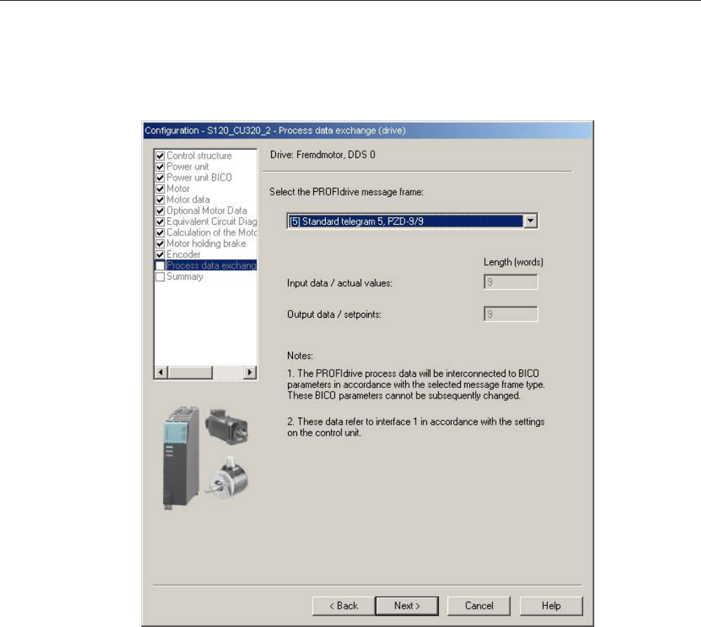
Commissioning
3.13 Commissioning of SIMOTICS L-1FN3 linear motors
STARTER Commissioning Manual
198 Commissioning Manual, (IH1), 07/2016, 6SL3097-4AF00-0BP5
Completing parameterization
1. The selection of the PROFIdrive telegram and the summary closes the parameterization
of the drive.
Image 3-54 Screen form for selecting the telegram for the process data exchange
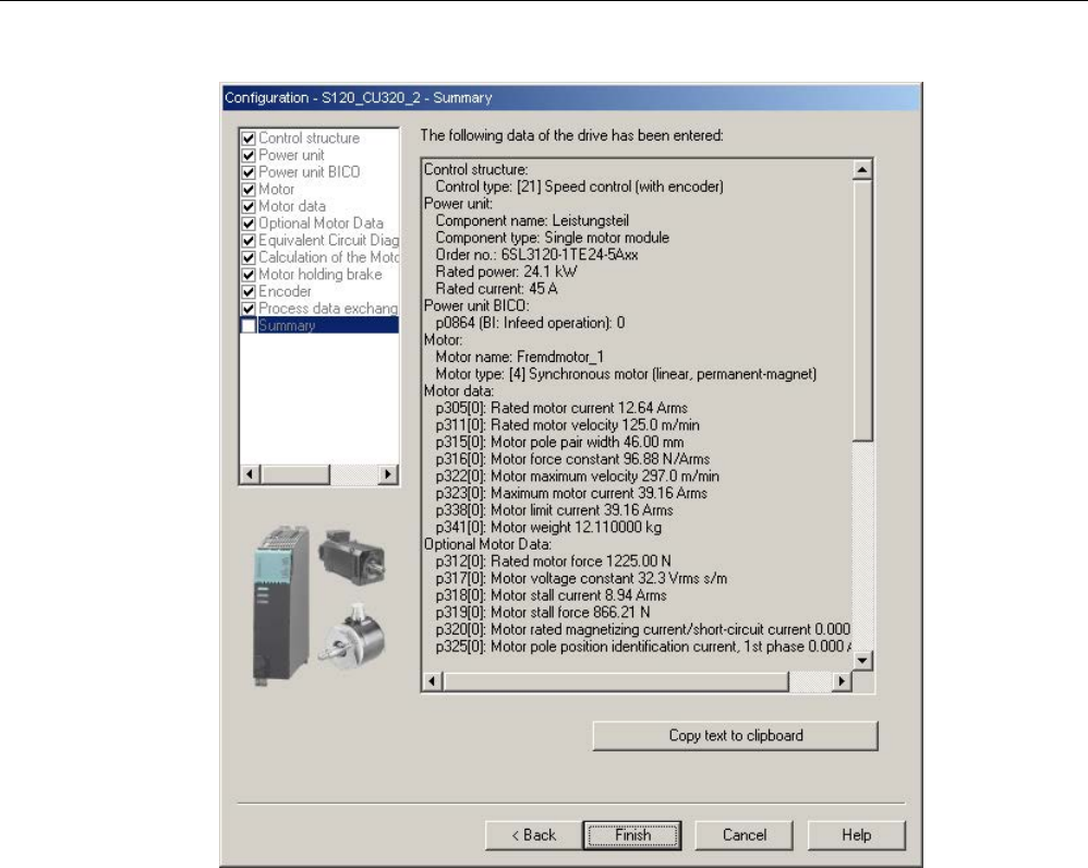
Commissioning
3.13 Commissioning of SIMOTICS L-1FN3 linear motors
STARTER Commissioning Manual
Commissioning Manual, (IH1), 07/2016, 6SL3097-4AF00-0BP5 199
Image 3-55 Summary of the configuration
2. The created offline project must now be loaded into the drive. In STARTER, go online
with the target device.
If an absolute measuring system with EnDat protocol was selected, then after
establishing an online connection, the encoder serial number is loaded and the
corresponding encoder parameters are set.

Commissioning
3.13 Commissioning of SIMOTICS L-1FN3 linear motors
STARTER Commissioning Manual
200 Commissioning Manual, (IH1), 07/2016, 6SL3097-4AF00-0BP5
3.13.5
Parameterizing and testing the temperature sensors
SME12x Sensor Module External
The connection of the SME modules is described in the "System integration" chapter in the
"SIMOTICS L-1FN3 Linear Motors" Configuration Manual. Information on the SME12x
Sensor Module External can be found in the "SINAMICS S120 Equipment Manual for Control
Units and Additional System Components" in Chapter "Sensor Module External 120
(SME120)" and in Chapter "Sensor Module External 125 (SME125)".
The parameterization of the temperature sensors is explained in detail in Chapter
"Temperature sensors for SINAMICS components (Page 282)".
A parameterizing example of a linear motor with a PT1000 (or alternatively: KTY 84) and a
PTC sensor, connected to a SME12x Sensor Module External is provided below.
Use the expert list to parameterize the drive.
Table 3- 12 Parameterization in the drive:
Parameter
Input
p0600
Motor temperature sensor for monitoring
1: Temperature sensor via encoder 1
p0601
Motor temperature sensor, sensor type
10: Evaluation via several temperature channels SME12x
p0604
Motor temperature alarm threshold
Sets the alarm threshold for monitoring the motor temperature.
For motors from the motor list (p0301), this parameter is automatically pre-assigned
(120° C).
p0605
Motor temperature fault threshold
Sets the fault threshold for monitoring the motor temperature.
For motors from the motor list (p0301), this parameter is automatically pre-assigned
(155° C).
p0606
Motor temperature timer
0...2 s
Setting the timer for the alarm threshold for the motor temperature monitoring, if
alarm with timer was selected in the parameters p4600...4603.
This timer is started if the temperature alarm threshold (p0604) is exceeded.
If the timer has expired, and in the meantime the temperature alarm threshold has
not been undershot, then fault F07011 is output.

Commissioning
3.13 Commissioning of SIMOTICS L-1FN3 linear motors
STARTER Commissioning Manual
Commissioning Manual, (IH1), 07/2016, 6SL3097-4AF00-0BP5 201
Parameter
Input
p0607
Temperature sensor fault timer
Setting the timer for timing the period between output of the alarm and fault when a
temperature sensor fault is detected.
If a sensor fault has been detected, this timer is started.
If the sensor fault persists when the timer has expired, the relevant fault is output.
p4600...4603
Motor temperature sensor 1...4 sensor type
Sets the temperature sensor type for the motor temperature monitoring. Channels 2
... 4 are used for the Sensor Module External SME12x. Channel 1 remains free.
The following values are possible for linear motors:
0: No sensor
10: PTC fault
12: PTC alarm & timer
20: KTY 84
60: PT1000
If you make a selection with timer, you must pre-assign parameter p0606 with the
corresponding timer for a maximum of 2 s.
Example: SIMOTICS L-1FN3 standard linear motors
p4600
0:
No sensor
p4601
60:
PT1000 (or alternatively 20: KTY 84)
p4602
10:
PTC fault
p4603
0:
No sensor
If you are not using a standard motor, then you must parameterize parameters
p0600...p0606 (see above). Select parameters p4600...p4603 to match the sensor types or
temperature channels of the Sensor Module External SME12x.
Checking the temperature sensors for the Sensor Module External SME12x
In the online mode, you can read out the temperatures of the sensors at the channels of the
Sensor Module External SME12x in parameter r4620[0…3] using the STARTER
commissioning tool.
The maximum motor temperature can also be read in r0035. This parameter indicates the
highest value from parameters r4620[0…3].
For a parameterized PTC sensor type, irrespective of the actual temperature in r4620, -200°
C is always displayed.
The temperature values shown in parameters r0035 or r4620[1] provide information about
whether a parameterized temperature sensor does not match the temperature sensor
actually connected (connection to the wrong temperature sensor):
Parameterized
temperature sensor
Connected
temperature sensor
Displayed value in °C
at room temperature 25°C
KTY 84
PTC
-40 ... -80 °C
PT1000
PTC
-100 ... -200 °C
KTY 84
PT1000
+115°C
PT1000
KTY 84
-100°C

Commissioning
3.13 Commissioning of SIMOTICS L-1FN3 linear motors
STARTER Commissioning Manual
202 Commissioning Manual, (IH1), 07/2016, 6SL3097-4AF00-0BP5
Checking the PTC sensor type
You can simulate a sensor responding to an overtemperature condition (high ohmic state) by
disconnecting the connections. You can disconnect the connections for the temperature
sensors by removing the Sensor Module External SME12x (connector, interface X200).
If the sensor type is parameterized as PTC fault, then fault "F07011 drive: Motor
overtemperature" is immediately displayed independent of the setting of p0604...p0606. If
the sensor type is parameterized as PTC alarm with timer, after the time parameterized in
p0606, fault F07011 is generated.
Test for sensor type PT1000 or KTY
If you withdraw the connector of interface X200 and have therefore disconnected the
PT1000 connection (or KTY connection), after the time parameterized in p0607 has expired,
fault "F07016 drive: Motor temperature sensor fault" is displayed in the alarm window of the
STARTER commissioning tool.
Check the wiring of the temperature sensors by checking the resistance values at connector
interface X200. The wiring is OK for the following resistance values:
PT1000 at 20 °C approx. 1080 Ω
KTY 84 at 20 °C approx. 580 Ω
PTC for 20 °C 120 Ω...300 Ω
The assignment of connector interface X200 can be found in the "SINAMICS S120 Manual
Control Units and Additional System Components".
Terminal Module TM120
Terminal Module TM120 is a DRIVE-CLiQ component for temperature evaluation with safe
isolation, see also "SINAMICS S120 Manual for Control Units and Additional System
Components" in Chapter "System components".
TM120 is an autonomous input/output component. You can freely assign the temperature
channels to any Motor Module.
You can assign every channel to the following sensor types:
● PTC
● KTY 84
● PT1000
● Bimetallic NC contact

Commissioning
3.13 Commissioning of SIMOTICS L-1FN3 linear motors
STARTER Commissioning Manual
Commissioning Manual, (IH1), 07/2016, 6SL3097-4AF00-0BP5 203
Parameterization
For a standard configuration with correct pre-assignment of the temperature channels, the
Terminal Module TM120 must be located between the Sensor Module and the Motor Module
(DRIVE-CLiQ).
If this is not the case, you must parameterize all of the required temperature channels in both
the Motor Module and Terminal Module TM120.
You must always carefully check the temperature shutdown circuits (e.g. by disconnecting
the sensors) before commissioning the motor for the first time.
Use the expert list to parameterize the drive.
Table 3- 13 Parameterization in the drive:
Parameter
Input
p0600
Motor temperature sensor for monitoring
20: Temperature sensor via BICO interconnection p0608
p0601
Motor temperature sensor, sensor type
11: Evaluation via several temperature channels BICO
p0606
Motor temperature timer
0...2 s
Sets the timer for the alarm threshold for the motor temperature monitoring, if alarm with timer was
selected in p4610...4613.
This timer is started when the temperature alarm threshold (p0604) is exceeded.
If the timer expires before the temperature falls below the alarm threshold, then fault F07011 is out-
put.
p0608
[0...3] CI: Motor temperature, signal source 2
Sets the signal source 2 for the evaluation of the motor temperature via a BICO interconnection, e.g.
[0]: Motor temperature channel 1 TM120 . r4105[0]
[1]: Motor temperature channel 2 TM120 . r4105[1]
[2]: Motor temperature channel 3 TM120 . r4105[2]
[3]: Motor temperature channel 4 TM120 . r4105[3]
p4610...p4613
Motor temperature sensor 1...4 sensor type
Sets the temperature sensor type for the motor temperature monitoring. The following values are
possible for linear motors:
0: No sensor
10: PTC fault
12: PTC alarm & timer
20: KTY84, PT100, PT1000
30: Bimetallic NC contact fault
32: Bimetallic NC contact alarm & timer
If you make a selection with timer, you must pre-assign parameter p0606 with the corresponding
timer for a maximum of 2 s.

Commissioning
3.13 Commissioning of SIMOTICS L-1FN3 linear motors
STARTER Commissioning Manual
204 Commissioning Manual, (IH1), 07/2016, 6SL3097-4AF00-0BP5
Table 3- 14 Parameterization in the expert list of the Terminal Module TM120
Parameter
Input
p4100[0...3]
TM120 temperature evaluation, sensor type
Sets the temperature evaluation of Terminal Module TM120.
This means that the temperature sensor type is selected and the evaluation is activated. The follow-
ing values are possible:
0: Evaluation deactivated
1: PTC thermistor
2: KTY84
4: Bimetal NC contact
6: PT1000
Check the temperature sensors in the same way as described for the SME12x Sensor
Module External (see section "Checking the temperature sensors for the Sensor Module
External SME12x"). Test each individual temperature channel by separating the connection.
3.13.6
Determining the angular commutation offset / maintaining the tolerance
NOTICE
Material damage as a result of an incorrectly commutated drive
When the system is commissioned for the first time or after an encoder/motor has been
replaced, it is possible that the drive could be incorrectly commutated if the angular
commutation offset has not yet been adjusted. Current is fed into the motor at the incorrect
time for an incorrectly commutated motor. This means it can perform inadvertent
movements. For example, it can turn with high speed in the wrong direction and so damage
a workpiece.
• Set the current limit using the p0640 parameter to 20% of p0323 (motor maximum
current).
• Therefore, to complete commissioning, it is imperative that you check the angular
commutation offset according to the following description.
You can determine the pole position, required for synchronous motors, for the SIMOTICS L-
1FN3 linear motors using a software-based automatic pole position identification technique.
The following two techniques are suitable for all frame sizes of the SIMOTICS L-1FN3 linear
motors:
● The motion-based technique p1980 = 10
● The saturation-based technique (1st harmonic) p1980 = 1
Also refer to the information in Chapter "General information for the commutation setting"
(Page 185).

Commissioning
3.13 Commissioning of SIMOTICS L-1FN3 linear motors
STARTER Commissioning Manual
Commissioning Manual, (IH1), 07/2016, 6SL3097-4AF00-0BP5 205
Making parameter entries / commutation setting
Incremental measuring system
1. Activate automatic determination of the commutation angle offset with p1990 = 1.
Alarm A07971 is output while the commutation angle offset is being determined.
2. Set the drive enable signals (OFF3, OFF2, OFF1).
This results in coarse synchronization. A successful coarse synchronization is indicated
by the parameter r1992.9.
3. Move the drive over the zero mark.
When the drive moves over the zero mark, the angular commutation offset is entered into
p0431. p1990 is automatically set to 0 after the angular commutation offset has been
determined. Alarm A07965 is displayed as a prompt to save the change in a non-volatile
fashion.
Absolute measuring system
Set p1990 = 1 before activating the enable signals.
By activating the enable signals, the angular commutation offset entered into p0431 and
p1990 is automatically set to 0. Alarm A07965 (N) is displayed as a prompt to save the
change in non-volatile storage.
3.13.6.1
Checking the commutation angle offset with STARTER
Note
Coarse synchronization means that the pole positio
n identification has been carried out, but
the drive has not yet been moved over the zero mark. After the drive has been moved over
the zero mark, the drive is finely synchronized. Fine synchronization is omitted when an
absolute measuring system is being
used, because the drive is always fine synchronized
after being switched on. A coarse synchronization is required only for the initial
commissioning for the commutation angle offset determination (p0431).

Commissioning
3.13 Commissioning of SIMOTICS L-1FN3 linear motors
STARTER Commissioning Manual
206 Commissioning Manual, (IH1), 07/2016, 6SL3097-4AF00-0BP5
Checking the pole position identification
You can check the pole position identification with p1983 in the finely-synchronized state.
1. Position the drive at different points in an electrical period (pole pitch) and set parameter
p1983 = 1. For example, start at 0° and perform a measurement every 30°.
This means that a pole position identification is performed again and the deviation
determined is displayed in parameter p1984.
After completion of the pole position identification, parameter p1983 is set to 0 again. The
angular difference read out of parameter p1984 must lie in the interval [-10°...+10°].
The average of the measured angle differences must be added to the commutation angle
offset entered in p0431. (Note the sign of the commutation angle offset.)
For a change to parameter p0431, p0010 must be set to 4 (see the "Representation of
the tolerance field for the pole position angle (Page 216)" figure).
2. Perform a coarse and fine synchronization again. The fine synchronization is not
applicable for an absolute measuring system.
3.13.6.2
Checking the commutation angle offset with an oscilloscope
Checking the EMF voltages
If you have commissioned the motor according to the appropriate instructions, and in spite of
this, unexpected messages are output, you must first check the individual EMF voltages of
the motor. To do this, the following techniques are described:
● "Record the phase voltage and the pole position angle using an oscilloscope"
● "Record the phase voltage and the pole position angle using the STARTER trace
function"
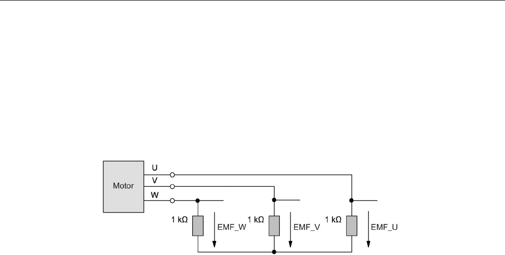
Commissioning
3.13 Commissioning of SIMOTICS L-1FN3 linear motors
STARTER Commissioning Manual
Commissioning Manual, (IH1), 07/2016, 6SL3097-4AF00-0BP5 207
Recording the phase voltage and the pole position angle using an oscilloscope
1. Switch the drive line-up into a no-current condition.
2. After the DC link has completely discharged, disconnect the motor cables from the
converter.
If motors are connected in parallel, then disconnect them.
3. Form an artificial neutral point using 1 kΩ resistors (for a parallel connection, for each
motor).
Image 3-56 Arrangement for measuring
4. Move the drive with a constant speed in the positive direction. The direction of the drive
rotation is positive if the primary section moves relative to the secondary section in the
opposite direction to the cable outlet direction (see also the "Determining the positive
direction of the drive (Page 197)" figure).
Checking the phase sequence
For the positive direction of the drive, the phase sequence must be as follows:
EMF phase U - EMF phase V - EMF phase W

Commissioning
3.13 Commissioning of SIMOTICS L-1FN3 linear motors
STARTER Commissioning Manual
208 Commissioning Manual, (IH1), 07/2016, 6SL3097-4AF00-0BP5
Checking phase relation
The phase displacement of the individual voltages EMC phase U – EMC phase V –
EMC phase W to each other is 120° in the following figure.
Image 3-57 Phase sequence, EMF phase U - EMF phase V - EMF phase W
Checking the phase relation for parallel-connected motors
The phase relations EMC phase U – EMC phase V – EMC phase W of the individual
motors to each other must match.
● EMF phase U motor 1 with EMF phase U motor 2
● EMF phase V motor 1 with EMF phase V motor 2
● EMF phase W motor 1 with EMF phase W motor 2
The deviation within a particular phase position may be a maximum of 10°.

Commissioning
3.13 Commissioning of SIMOTICS L-1FN3 linear motors
STARTER Commissioning Manual
Commissioning Manual, (IH1), 07/2016, 6SL3097-4AF00-0BP5 209
Image 3-58 Phase U motor 1 may not lag behind EMF phase U motor 2 by more than 10°
Image 3-59 EMF phase U motor 1 may not lead EMF phase U motor 2 by more than 10°

Commissioning
3.13 Commissioning of SIMOTICS L-1FN3 linear motors
STARTER Commissioning Manual
210 Commissioning Manual, (IH1), 07/2016, 6SL3097-4AF00-0BP5
Determining the angular commutation offset by making a measurement
In the event of a fault and for a parallel connection, you must check the angular commutation
offset as follows.
1. The drive with an incremental measuring system must be fine synchronized. To do this,
connect the motor and enable the controller for coarse synchronization.
2. Then move the drive over the zero mark.
3. Remove power from the drive as described for the "Checking the phase voltage and the
pole position angle using an oscilloscope" technique.
Please note that for this technique, it is not permissible that the control voltage for the
Control Unit is shut down; however the infeed must be disconnected from the line supply.
You can determine the angular commutation offset by measuring the EMF and the
normalized electrical pole position angle via the analog output. The normalized electrical
pole position angle allows you to parameterize the test socket connections T0 to T2 and
retrieve the signals (see Chapter "Measuring sockets (Page 355)").
Definition of channels (Ch1 ... Ch4):
● Ch1: EMF phase U with respect to the neutral point
● Ch2: EMF phase V with respect to the neutral point
● Ch3: EMF phase W with respect to the neutral point
● Ch4: Normalized electrical angular pole position via analog output
Image 3-60 Setting measuring socket T0 on CU320
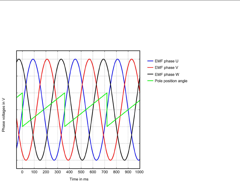
Commissioning
3.13 Commissioning of SIMOTICS L-1FN3 linear motors
STARTER Commissioning Manual
Commissioning Manual, (IH1), 07/2016, 6SL3097-4AF00-0BP5 211
The status of the coarse and fine synchronization can be read out online via parameter
r1992: r1992.8 (fine synchronization carried out) and r1992.9 (coarse synchronization carried
out).
Image 3-61 Ideal characteristic of EMF voltages and the pole position angle of an optimally commutated drive
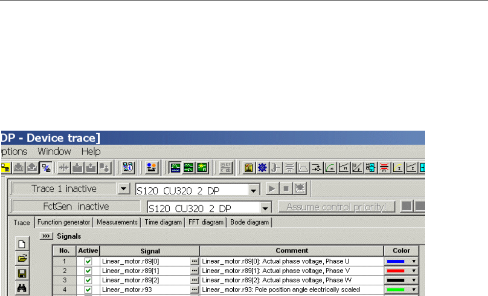
Commissioning
3.13 Commissioning of SIMOTICS L-1FN3 linear motors
STARTER Commissioning Manual
212 Commissioning Manual, (IH1), 07/2016, 6SL3097-4AF00-0BP5
Recording the phase voltage and the pole position angle using the STARTER trace function
An oscilloscope is not used for this technique. You do not need to disconnect the motor.
However, this technique is less accurate, as the motor voltages are not directly measured,
but calculated from the transistor turn-on duration. This technique is not permitted for
parallel-connected motors, see Chapter "Special case parallel connection (Page 218)".
1. Set the following parameters:
Image 3-62 Assignment of trace channels to check the angular commutation offset
The drive is operated force-controlled. The following parameterization is required:
2. Set p0640 = 0, to limit the motor current to 0.
3. Set p1545 = 1, to activate the travel to fixed stop.
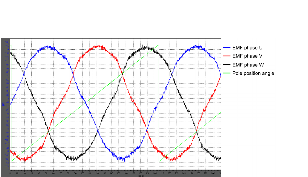
Commissioning
3.13 Commissioning of SIMOTICS L-1FN3 linear motors
STARTER Commissioning Manual
Commissioning Manual, (IH1), 07/2016, 6SL3097-4AF00-0BP5 213
4. The motor must be in closed-loop control and traveled externally.
Image 3-63 Example of an optimally commutated drive (recorded using the trace function of the STARTER commissioning
tool)
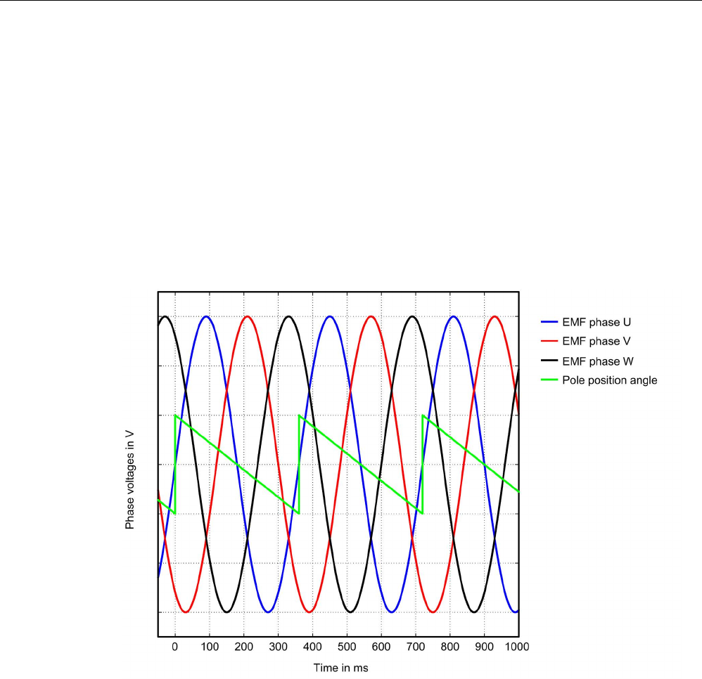
Commissioning
3.13 Commissioning of SIMOTICS L-1FN3 linear motors
STARTER Commissioning Manual
214 Commissioning Manual, (IH1), 07/2016, 6SL3097-4AF00-0BP5
Evaluation of the results (applies to both measuring techniques)
For a positive drive direction (definition, refer to the diagram "Determining the positive
direction of the drive (Page 197)", the sawtooth must increase monotonously between 0° and
360°, refer to the diagram "Ideal characteristic of the EMF voltages and the pole position
angle for an optimally commutated drive (Page 211)."
If the curve is falling monotonously, and the phase sequence is EMF phase U - EMF phase
V - EMF phase W, then you must change the control sense of the drive if necessary via
p0410 bit 0 "Invert speed actual value". If the position controller is being used, then you must
also check p0410 bit 1 "Invert actual position value". See the "Screen form for entering
additional encoder data (Page 196)" figure in Chapter "Parameterizing a motor and
encoder".
Image 3-64 EMF for incorrect speed actual value inversion

Commissioning
3.13 Commissioning of SIMOTICS L-1FN3 linear motors
STARTER Commissioning Manual
Commissioning Manual, (IH1), 07/2016, 6SL3097-4AF00-0BP5 215
If the curve is monotonously decreasing, and the phase sequence is EMF phase U –
EMF phase W – EMF phase V (i.e. if the phase sequence of V and W is interchanged), then
according to the diagram "Determining the positive direction of the drive" (Page 197) in
Chapter "Parameterizing a motor and encoder", the drive direction is negative (i.e. the
primary section moves relative to the secondary section in the cable outlet direction).
Image 3-65 EMC for the negative travel direction

Commissioning
3.13 Commissioning of SIMOTICS L-1FN3 linear motors
STARTER Commissioning Manual
216 Commissioning Manual, (IH1), 07/2016, 6SL3097-4AF00-0BP5
Displaying the commutation angle tolerance
For a finely synchronized drive, the difference between EMF phase U and the normalized,
electrical pole position angle may be a maximum of 10°. This means that the zero points of
the falling edge of the sawtooth and EMF phase U may differ by a maximum of 10° electrical.
For motors connected in parallel, this maximum permitted deviation for the EMF, phase U is
valid for each motor connected in parallel.
If the difference is greater, then you must adapt the angular commutation offset. If, when
moving over the zero mark, fault message "F31130 (N, A) encoder 1: Zero mark and position
error from the coarse synchronization" is output, then the deviation of the commutation is
greater than 60° electrical. You must check the commutation angle again using the
techniques described.
Image 3-66 Tolerance envelope for the pole position angle
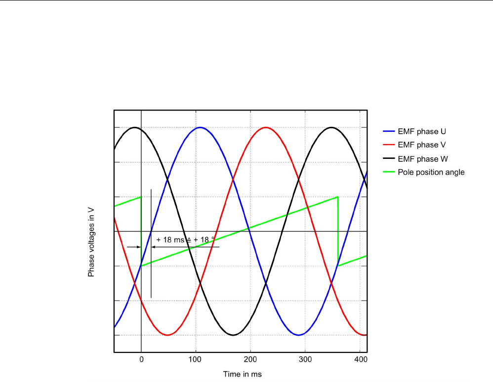
Commissioning
3.13 Commissioning of SIMOTICS L-1FN3 linear motors
STARTER Commissioning Manual
Commissioning Manual, (IH1), 07/2016, 6SL3097-4AF00-0BP5 217
Commutation angle outside the tolerance
Example: The falling edge of the sawtooth voltage (pole position angle) leads the zero
crossing of EMF phase U by approx. 18° electrical.
Image 3-67 Example of an incorrectly commutated drive
Adapt the incorrect commutation shown in the figure above according to Chapter "Checking
the commutation angle offset with STARTER (Page 205)".
p0431 = p0431 - 18

Commissioning
3.13 Commissioning of SIMOTICS L-1FN3 linear motors
STARTER Commissioning Manual
218 Commissioning Manual, (IH1), 07/2016, 6SL3097-4AF00-0BP5
3.13.7
Special case of a parallel connection
Note
Parallel connection
Only linear motors with the same "primary section format", the same "winding
type" and the
same "air gap" may be switched in parallel.
The article numbers of the primary sections 1FN3...
-....0-0☐A1 may differ only by the
placeholder shown as "⃞".
For more information and connection diagrams, refer to the "SIMOTICS L
-1FN3 linear
motors" Configuration Manual in Chapter "Parallel connection
of motors".
The following requirements must be met in order to operate several linear motors in parallel
on a SINAMICS Motor Module:
● The motors must be arranged according to the data in the "SIMOTICS L-1FN3 linear
motors" Configuration Manual.
● The travel direction of the parallel-connected motors must match the details in the
"SIMOTICS L-1FN3 linear motors" Configuration Manual. For a Janus arrangement,
when connecting the stoker, phases V and W must be interchanged so that the stoker
has the same travel direction as the master, also refer to the "SIMOTICS L-1FN3 linear
motors" Configuration Manual, Chapter "Parallel connection of motors".
● Ensure the position of the EMF voltages of the parallel-connected motors as described in
Chapter "Checking the angular commutation with an oscilloscope (Page 206)"; it is
imperative that you check these carefully. Maintain the maximum deviation of the phase
angle between the EMF voltages of the motors according to Chapter "Checking the
angular commutation offset with an oscilloscope". You may only connect the motors to
the converter after the deviation of the commutation angle for all of the motors to be
connected in parallel lies within the limit value.
● Before commissioning and switching-on the DC voltage for the first time, note that the
temperature monitoring circuits must be carefully checked to ensure that they correctly
trip.
Then commission the system using the STARTER commissioning tool according to Chapter
"Parameterizing a motor and encoder (Page 186)". The parallel connection for the
SIMOTICS L-1FN3 linear motors selected from the motors list can be activated using the
"Motor parallel connection" checkbox below it. Enter the desired number of motors to be
connected in parallel in the "Number" field. Alternatively, you can also parameterize the
parallel connection in the expert list of the drive.
After changing p0306, you must adapt the control parameters for a motor from the list by the
automatic calculation with p0340 = 1. For a third-party motor not contained in the list, this
setting, however, would cause the data of the electrical equivalent circuit diagram to be lost.
Consequently, select the setting p0340 = 3 for a third-party motor.
Detailed information about parameter p0306 is contained in the STARTER commissioning
tool help and in the SINAMICS S120/S150 List Manual.

Commissioning
3.13 Commissioning of SIMOTICS L-1FN3 linear motors
STARTER Commissioning Manual
Commissioning Manual, (IH1), 07/2016, 6SL3097-4AF00-0BP5 219
If p0306 is changed during quick commissioning (p0010 = 1), then the maximum current
p0640 is appropriately pre-assigned. This is not the case in the motor commissioning
(p0010 = 3)!
The motor data displayed in the STARTER commissioning tool is only valid for one motor
and is only internally interpolated up to N motors connected in parallel.
3.13.8
Optimization of the closed-loop control
When running through the drive configuration, in the step "Calculating the motor/controller
data", drive-specific controller parameters are calculated, see the "Screen form to calculate
motor/controller data (Page 191)" figure. However, to be able to use the optimal performance
of the machine, a subsequent optimization of the controller parameters is required. You can
achieve higher positioning/machining accuracy and reduce cycle times by means of
optimized settings.
Controller optimization may only be performed by experienced specialists.
In the control, for optimizing the controller, there is the possibility of measuring frequency
responses or recording setpoint steps. Especially the frequency response measurement
allows machine-specific natural frequencies that restrict the bandwidth of the closed-loop
control to be taken into account.
You can ask your local Siemens office regarding optimization of the closed-loop control as a
service.
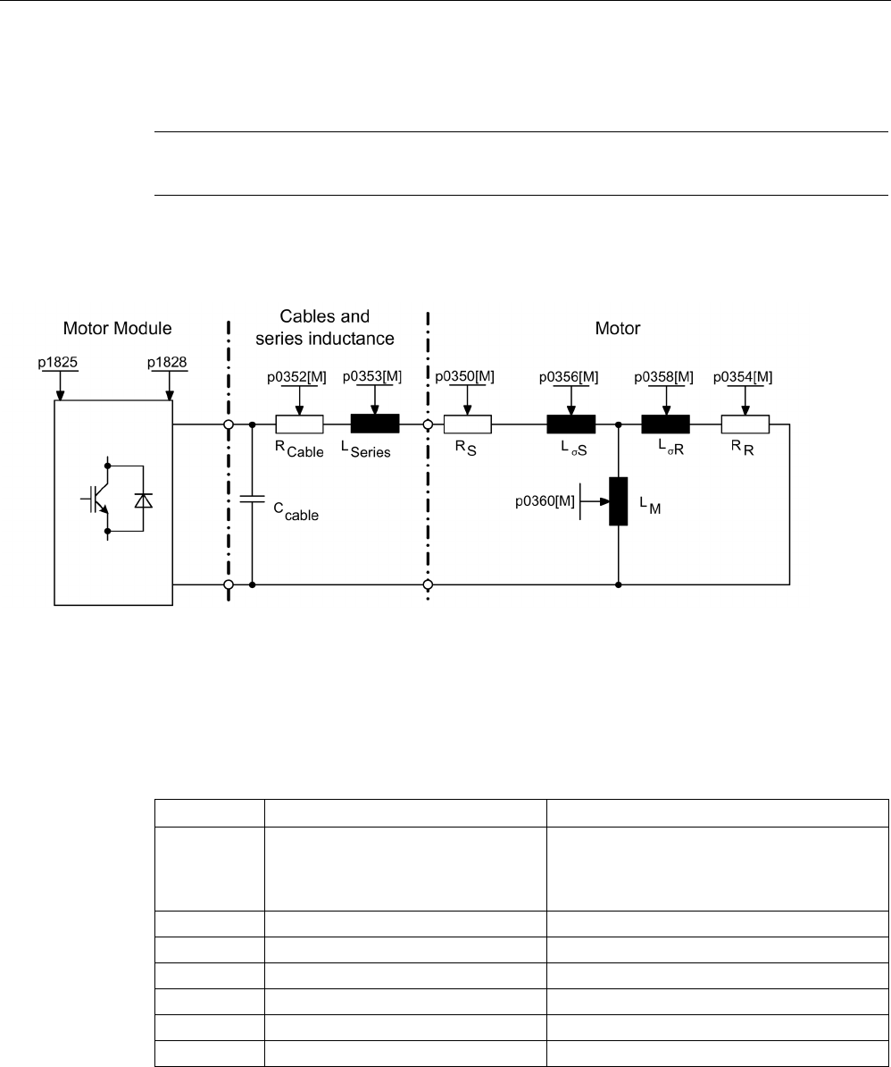
Commissioning
3.14 Commissioning induction motors (ASM)
STARTER Commissioning Manual
220 Commissioning Manual, (IH1), 07/2016, 6SL3097-4AF00-0BP5
3.14
Commissioning induction motors (ASM)
Note
Induction motors are commissioned in vector control.
Equivalent circuit diagram for induction motor and cable
Image 3-68 Equivalent circuit diagram for induction motor and cable
Induction motors, rotating
The following parameters must be entered in the commissioning wizard of STARTER:
Table 3- 15 Motor data type plate
Parameter
Description
Comment
p0304 Rated motor voltage If this value is not known, a "0" can also be
entered. Using this value, the stator leakage
inductance can be more precisely calculated
(p0356, p0357).
p0305
Rated motor current
-
p0307
Rated motor power
-
p0308
Rated motor power factor
-
p0310
Rated motor frequency
-
p0311
Motor rated speed
-
p0335
Motor cooling type
-

Commissioning
3.14 Commissioning induction motors (ASM)
STARTER Commissioning Manual
Commissioning Manual, (IH1), 07/2016, 6SL3097-4AF00-0BP5 221
The following parameters can be optionally entered:
Table 3- 16 Optional motor data
Parameter
Description
Comment
p0320 Motor rated magnetizing current / short-
circuit current
-
p0322
Maximum motor speed
-
p0341
Motor moment of inertia
-
p0342 Moment of inertia ratio between the total
and motor
-
p0344
Motor weight (for thermal motor type)
-
p0352
Cable resistance (component of the stator
resistance)
• Especially for vector control without
encoder (SLVC) this parameter has a
significant influence on the quality of
the closed-loop control at low speeds.
• This parameter is required for the
correct function of flying restart oper-
ating mode.
p0353
Motor series inductance
-
Table 3- 17 Equivalent circuit diagram for motor data
Parameter
Description
Comment
p0350
Motor stator resistance, cold
-
p0354
Motor rotor resistance, cold
-
p0356
Motor stator leakage inductance
-
p0358
Motor rotor leakage inductance
-
p0360
Motor magnetizing inductance
-

Commissioning
3.14 Commissioning induction motors (ASM)
STARTER Commissioning Manual
222 Commissioning Manual, (IH1), 07/2016, 6SL3097-4AF00-0BP5
Features
● Field weakening up to approx. 1.2 * rated speed (this depends on the drive converter
supply voltage and the motor data, also refer to supplementary conditions)
● Flying restart
● Vector closed-loop speed and torque control
● Vector V/f control
● Motor data identification
● Speed controller optimization (rotating measurement)
● Thermal protection via temperature sensor (PTC/KTY/PT1000)
● All encoders that can be connected to an SMC10, SMC20 or SMC30 are supported.
● Operation with or without encoder is possible
Depending on the terminal voltage and load cycle, the maximum torque can be taken from
the motor data sheets / configuration instructions.
Commissioning
To commission induction motors, motor identification and rotating measurement are
recommended. Make the following setting for this:
1. Configure p1900 = 1.
For induction motors, motor data identification (p1910 = 1) and rotating measurement
(p1960) are activated automatically.
- OR -
2. Activate both functions individually:
– Configure the zero speed measurement: p1910 = 1.
– Configure the rotating measurement p1960 = 0,1,2 (depending on p1300).
The optional motor data can be entered if it is known. Otherwise, it is estimated using the
type plate data or is determined using a motor data identification routine or speed controller
optimization.

Commissioning
3.15 Commissioning of synchronous reluctance motors 1FP1 without a damper cage
STARTER Commissioning Manual
Commissioning Manual, (IH1), 07/2016, 6SL3097-4AF00-0BP5 223
3.15
Commissioning of synchronous reluctance motors 1FP1 without a
damper cage
Unlike induction motors, reluctance motors cannot be operated by entering rating plate data
on any drive. For reluctance motors, the characteristic saturation properties must be known
and stored in the drive. SIEMENS reluctance motors of the series 1FP1 can be operated in
vector control with or without an encoder.
Configuring the reluctance motor as a standard motor
You must individually configure the drives.
1. Double-click in the project navigator on "Drives" > "Drive name" > "Configuration" >
"Configure DDS" one after the other.
2. Select the standard motor to be commissioned from the list.
The associated motor data is stored and does not to be entered manually.
3. Select a "[600] 1FP1 standard reluctance motor" for the "Motor type" as the standard
motor.
Commissioning sequence
1. Motor identification is preset for commissioning synchronous reluctance motors. The first
time the motor is switched on after commissioning, a zero speed measurement (p1900) is
therefore performed automatically. The non-linearities of the converter and the stator
resistance of the machine are measured.
2. If the drive has an encoder, automatic encoder adjustment is performed and the
commutation angle offset (p0431) is also determined the 2nd time the motor is switched
on. The following encoders are supported:
Incremental en-
coder
• HTL/TTL with zero mark
• sin/cos with zero mark and/or CD track
Absolute encoder • EnDat
3. Moreover, a rotating measurement is recommended to optimize the speed loop setting.
Configure the rotating measurement p1960 = 0,1,2 (depending on p1300).

Commissioning
3.15 Commissioning of synchronous reluctance motors 1FP1 without a damper cage
STARTER Commissioning Manual
224 Commissioning Manual, (IH1), 07/2016, 6SL3097-4AF00-0BP5
Overview of important parameters (see SINAMICS S120/S150 List Manual)
•
p0300[0...n]
Mot
or type selection
•
p0301[0...n]
Motor code number selection
•
p0325[0...n]
Motor pole position identification current 1st phase
•
p0329[0...n]
Motor pole position identification current
•
p0431[0...n]
Commutation angle offset
•
p1900
Motor data identification
and rotating measurement
•
p1910
Motor data identification selection
•
p1960
Rotating measurement selection
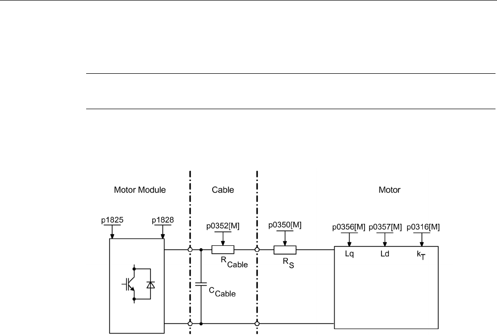
Commissioning
3.16 Commissioning permanent-magnet synchronous motors
STARTER Commissioning Manual
Commissioning Manual, (IH1), 07/2016, 6SL3097-4AF00-0BP5 225
3.16
Commissioning permanent-magnet synchronous motors
Note
Permanent
-magnet synchronous motors are commissioned in vector control.
Equivalent circuit diagram for synchronous motor and cable
Image 3-69 Equivalent circuit diagram for synchronous motor and cable
Permanent-magnet synchronous motors, rotating
Permanent-magnet synchronous motors with or without encoder are supported.
The following encoder types are supported:
● Encoder with absolute position information (e.g. without CD track or reference signal)
● Encoder without absolute position information
For operation without encoders or with encoders without absolute position information, pole
position identification must be carried out (see Section "Pole position identification
(Page 232)" for further details).
Typical applications include direct drives with torque motors, which are characterized by high
torque at low speeds. When these drives are used, gear units and mechanical parts subject
to wear can be dispensed with if the application allows this.
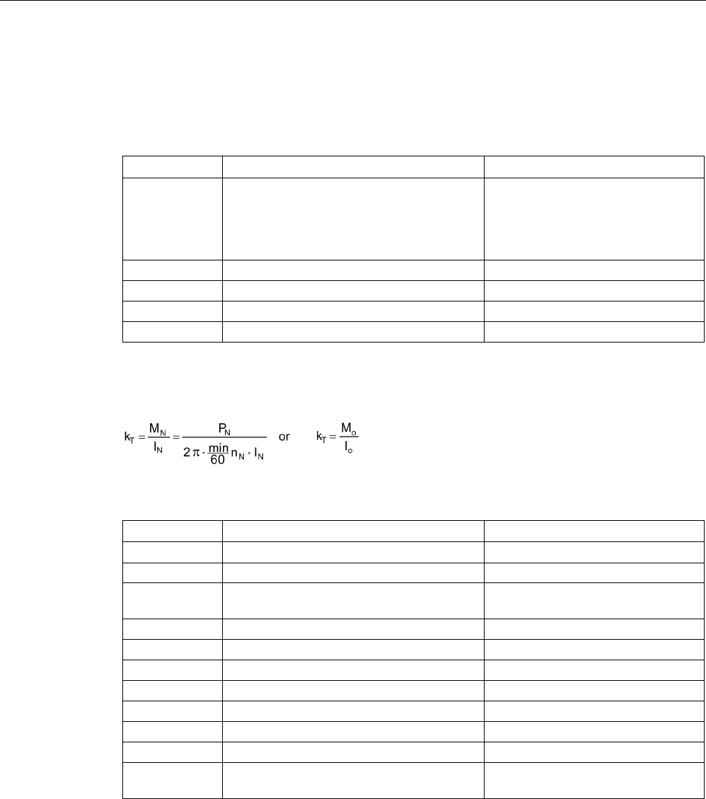
Commissioning
3.16 Commissioning permanent-magnet synchronous motors
STARTER Commissioning Manual
226 Commissioning Manual, (IH1), 07/2016, 6SL3097-4AF00-0BP5
Temperature protection can be implemented using a temperature sensor
(KTY/PT1000/PTC). In order to achieve a high torque accuracy, we recommend that a KTY
or PT1000 temperature sensor is used.
Table 3- 18 Motor data
Parameter
Description
Comment
p0304 Rated motor voltage If this value is not known, a "0" can
also be entered. Using this value, the
stator leakage inductance can be
more precisely calculated (p0356,
p0357).
p0305
Rated motor current
-
p0307
Rated motor power
-
p0310
Rated motor frequency
-
p0311
Rated motor speed
-
If the torque constant kT is not stamped on the type plate or specified in the data sheet, you
can calculate this value from the rated motor data (index n) or from the stall current Io and
stall torque Mo as follows:
Table 3- 19 Optional data
Parameter
Description
Comment
p0314 Motor pole pair number -
p0316
Motor torque constant
-
p0320 Motor rated magnetizing current / short-
circuit current
This is used for the field weakening
characteristic
p0322
Maximum motor speed
Maximum mechanical speed
p0323
Maximum motor current
Demagnetization protection
p0325
Motor pole position information
-
p0327
Optimum motor load angle
-
p0328
PE spindle, reluctance torque constant
-
p0329
Motor pole position identification current
-
p0341
Motor moment of inertia
For speed controller precontrol
p0342 Moment of inertia ratio
total to motor
-

Commissioning
3.16 Commissioning permanent-magnet synchronous motors
STARTER Commissioning Manual
Commissioning Manual, (IH1), 07/2016, 6SL3097-4AF00-0BP5 227
Table 3- 20 Equivalent circuit diagram for motor data
Parameter
Description
Comment
p0350
Motor stator resistance, cold
-
p0356 Motor stator leakage inductance -
p0357
Motor stator inductance, d axis
-
Features
● Field weakening up to approx. 1.2 * rated speed (this depends on the drive converter
supply voltage and the motor data, also refer to supplementary conditions)
● Flying restart (for operation without encoder, only possible with additional VSM)
● Vector closed-loop speed and torque control
● Vector V/f control for diagnostics
● Motor data identification
● Automatic rotating encoder adjustment (the zero encoder position is calibrated)
● Speed controller optimization (rotating measurement)
● Thermal protection via temperature sensor (PTC/KTY/PT1000)
● All encoders that can be connected to an SMC10, SMC20 or SMC30 are supported.
● Operation with or without encoder is possible.
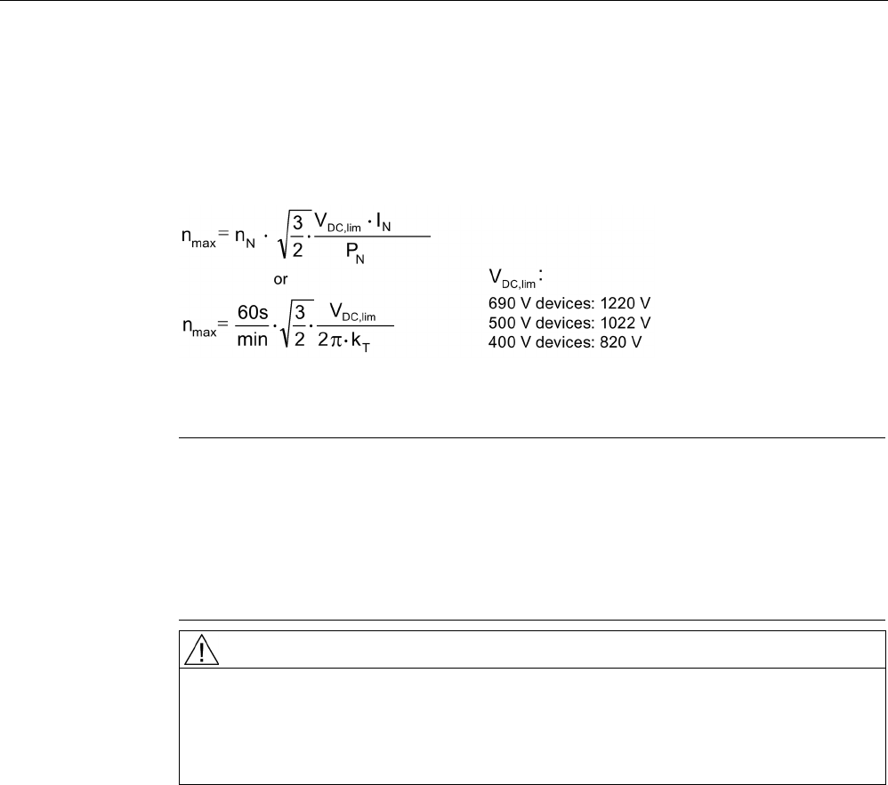
Commissioning
3.16 Commissioning permanent-magnet synchronous motors
STARTER Commissioning Manual
228 Commissioning Manual, (IH1), 07/2016, 6SL3097-4AF00-0BP5
Supplementary conditions
● Maximum speed or maximum torque depend on the converter output voltage available
and the back EMF of the motor (calculation specifications: EMF must not exceed Urated
converter).
● Calculating the maximum speed:
Image 3-70 Formula vector maximum speed
Calculating kT see "Commissioning".
Note
If pulse inhibition of the converter occurs (fault or OFF2), synchronous motors can
generate high terminal voltages in the field
-weakening range, which could lead to
overvoltage in the DC link. The following possibilities exist to p
rotect the drive system
from being destroyed due to overvoltage:
1.
Restrict (p0643 = 0) maximum speed (p1082)
2.
External voltage limiter or chopper or other measures appropriate to the application.
WARNING
Dangerous overvoltage
With p0643 = 1, it must be ensured that there is sufficiently high and suitable
overvoltage protection. If necessary, system-side precautions should be taken.
Do not enter the working area of the motor.
● Depending on the terminal voltage and load cycle, the maximum torque can be taken
from the motor data sheets / configuration instructions.

Commissioning
3.16 Commissioning permanent-magnet synchronous motors
STARTER Commissioning Manual
Commissioning Manual, (IH1), 07/2016, 6SL3097-4AF00-0BP5 229
Commissioning
WARNING
Danger to life as a result of motor movement during motor data identification
Motor data identification causes movements of the drive that can result in death, serious
injury, or damage to property.
• Ensure that nobody is in the danger zone and that the mechanical parts can move
freely.
• Respond to possible malfunctions by applying suitable measures (e.g. EMERGENCY
STOP or EMERGENCY OFF).
To commission permanent-magnet synchronous motors, motor identification, rotating
measurement, and encoder adjustment are recommended. Make the following setting for
this:
1. Configure p1900 = 1.
For permanent-magnet synchronous motors, motor data identification (p1910 = 1),
rotating measurement (p1960), and encoder adjustment (p1990 = 1) are activated
automatically.
- OR -
2. Activate the functions individually:
– Configure the zero speed measurement: p1910 = 1.
– Configure the rotating measurement: p1960 = 0,1,2 (depending on p1300).
– Start encoder adjustment: p1990 = 1.
Note
During initial commissioning and every time the encoder is replaced, the encoder must
be adjusted
(p1990).
The optional motor data can be entered if it is known. Otherwise, it is estimated using the
type plate data or is determined using a motor data identification routine or speed controller
optimization.

Commissioning
3.16 Commissioning permanent-magnet synchronous motors
STARTER Commissioning Manual
230 Commissioning Manual, (IH1), 07/2016, 6SL3097-4AF00-0BP5
3.16.1
Encoder adjustment in operation
This function can only be used for permanent-magnet synchronous motors operating in the
"vector control" mode. You can use this function to readjust encoders that have been
replaced in operation. The encoders can be adjusted within a motor line-up. The adjustment
is also possible when coupled to the load.
Adjusting a new encoder
1. After mounting the encoder, set p1990 = 3 to select a new adjustment.
– The encoder adjustment is automatically selected when switching on the next time.
2. Enable the pulses.
– The pole position identification determines the offset.
– If the zero mark position of the encoder is not known you are prompted to specify a
setpoint to start the drive.
3. In this case, specify a setpoint.
– The drive then starts with the specified setpoint.
– The zero mark position of the encoder is determined.
– The pulse inhibit is set.
– The commutation angle offset is determined from the offset and position of the zero
mark.
– The commutation angle offset is written automatically to parameter p0431.
– p1990 = 0 is set automatically at the end of the adjustment and the result saved to the
RAM.
The encoder module checks the consistency of the encoder pulses and zero mark. With this
technique, you can achieve an accuracy of approx. ±15° electrical. This accuracy is sufficient
for starting with maximum 95% rated torque. A fine calibration/adjustment is required for
higher starting torques.
If, after two motor revolutions, a zero mark has not been detected, the drive switches off with
fault F07970.

Commissioning
3.16 Commissioning permanent-magnet synchronous motors
STARTER Commissioning Manual
Commissioning Manual, (IH1), 07/2016, 6SL3097-4AF00-0BP5 231
Fine adjustment
1. The fine adjustment is started when the motor rotates with p1905 = 90.
The measurement takes approx.1 minute. The actual steps of the fine encoder
adjustment are displayed using alarm A07976. During the measurement, the difference
between the encoder and the EMF model is determined. The fine adjustment can also be
carried out in no-load operation (idle operation).
Note
Maintain the minimum motor speed
During the rotating measurement, the motor speed must exceed 4
0% of the rated speed.
The torque must remain below half of the rated torque.
The parameter setting p1905 = 0 is made automatically at the end of the measurement,
which completes the fine adjustment. An additional alarm informs you that the result from
p0431 will be written to the RAM at the next pulse inhibit.
2. To back up the new values, perform a "RAM to ROM" after the adjustment.
The adjustment result is also valid if, when the plant starts, the motor is driven by other
motors in the group of motors through the material web coupling. By correctly evaluating
the encoder, the Control Unit identifies the pole position and speed of the motor.
Note
1FW4 permanent-magnet synchronous motors
1FW4 motors are optimized for operation with this function. When commissioning with the
STARTER commissioning tool, all of the required data are automatically transferred to
the Control Unit.

Commissioning
3.16 Commissioning permanent-magnet synchronous motors
STARTER Commissioning Manual
232 Commissioning Manual, (IH1), 07/2016, 6SL3097-4AF00-0BP5
3.16.2
Automatic encoder adjustment
The pole wheel-oriented closed-loop control of the synchronous motor requires information
about the pole wheel position angle. Automatic encoder adjustment must be used in the
following cases:
● The pole wheel position encoders are not mechanically adjusted
● After a motor encoder has been replaced
Automatic encoder adjustment only makes sense for encoders with absolute position
information and/or zero mark. The following encoder types are supported:
● Sin/Cos encoder with A/B-, R-track as well as with A/B-, C/D-, R-track
● Resolver
● Absolute encoder (e.g. EnDat, DRIVE-CLiQ encoder, SSI)
● Incremental encoder with zero mark
Encoder adjustment using a zero mark
If an incremental encoder with zero mark is being used, after the zero mark has been
passed, the position of the zero mark can be calibrated. Commutation with the zero mark is
activated via p0404.15.
Commissioning the encoder
Automatic encoder adjustment is activated with p1990 = 1. When the pulses are enabled the
next time, the measurement is carried out and the angular difference determined (p1984) is
entered into p0431. For p1990 = 2 the determined angular difference (p1984) is not entered
into p0431 and has not effect on the closed-loop motor control. Using this function, the
angular difference - entered into p0431 - can be checked. For extremely high moments of
inertia, the run time can be scaled higher using p1999.
WARNING
Danger to life as a result of motor movement during measurement
The measurement can trigger rotation or movement of the motor. This can cause death or
serious injury.
• Ensure that nobody is in the danger zone of the motor.
3.16.3
Pole position identification
The pole position identification routine is used to determine the rotor position at start up. This
is required when no pole position information is available. If, for example, incremental
encoders are used or operation without encoder is employed, then pole position identification
is started automatically. For operation with encoder, pole position identification can be
started via p1982 = 1, or via p1780.6 = 1, for operation without encoder .

Commissioning
3.16 Commissioning permanent-magnet synchronous motors
STARTER Commissioning Manual
Commissioning Manual, (IH1), 07/2016, 6SL3097-4AF00-0BP5 233
If possible, pole position identification should be carried out in decoupled state. If there is no
large moment of inertia and there is only negligible friction, then the identification can also be
carried out in coupled state.
If there is negligible friction and high moment of inertia, then the dynamic response for the
speed encoder can be adjusted to the moment of inertia by increasing p1999.
If there is high friction torque or an active load, then an adjustment is only possible in
decoupled state.
Traversing
Four pole position identification techniques can be selected:
● p1980 = 1, voltage pulsing, first harmonic
This technique functions for magnetically isotropic motors if adequate iron saturation can
be achieved.
● p1980 = 4, voltage pulsing, 2-stage
This technique functions with motors that are magnetically anisotropic. During the
measurement, the motor must be at a standstill. The measurement is carried out the next
time that the pulses are enabled.
Note
Using this type of identification, the motor can emit a significant amount
of noise.
● p1980 = 6, voltage pulsing, 2-stage inverse
● p1980 = 10, DC current impression
This technique functions for all motors; however, it takes more time than the
measurement selected via p1980 = 4. During the measurement, the motor must be able
to rotate. The measurement is carried out the next time that the pulses are enabled. For
extremely high moments of inertia, the run time can be scaled higher via p1999.
WARNING
Danger to life as a result of motor movement during measurement
The measurement can trigger rotation or movement of the motor. This can cause death
or serious injury.
• Ensure that nobody is in the danger zone of the motor.

Commissioning
3.16 Commissioning permanent-magnet synchronous motors
STARTER Commissioning Manual
234 Commissioning Manual, (IH1), 07/2016, 6SL3097-4AF00-0BP5
3.16.4
Overview of the important parameters
Overview of important parameters (see SINAMICS S120/S150 List Manual)
•
p0300[0...n]
Motor type selection
•
p0301[0...n]
Motor code number s
election
•
p0304[0...n]
Rated motor voltage
•
p0305[0...n]
Rated motor current
•
p0307[0...n]
Rated motor power
•
p0311[0...n]
Rated motor speed
•
p0312[0...n]
Rated motor torque
•
p0314[0...n]
Motor pole pair number
•
p0322[0...n]
Maximum motor speed
•
p0323[0...n]
Maximum motor current
•
p0324[0...n]
Winding maximum speed
•
p0431[0...n]
Commutation angle offset
•
p1905
Parameter tuning selection
•
p1990
Encoder adjustment, determine commutation angle offset
Pole position identification
•
p0325[0..n]
Motor pole positi
on identification current 1st phase
•
p0329[0..n]
Motor pole position identification current
•
p1780[0..n].6
Motor model adaptation configuration;
selects pole position identification PMSM without an encoder
•
p1980[0..n]
PolID procedure
•
p1982[0..n]
PolID s
election
•
r1984
PolID angular difference
•
r1985
PolID saturation curve
•
r1987
PolID trigger curve
•
p1999[0..n]
Commutation angle offset calibration and PolID scaling
Automatic encoder adjustment
•
p0404[0..n].15
Encoder configuration;
commutation with zero mark (not induction motor)
•
p0431[0...n]
Commutation angle offset
•
p1990
Encoder adjustment, determine commutation angle offset
•
p1999[0...n]
Commutation angle offset calibration and PolID scaling

Commissioning
3.17 Commissioning separately-excited synchronous motors
STARTER Commissioning Manual
Commissioning Manual, (IH1), 07/2016, 6SL3097-4AF00-0BP5 235
3.17
Commissioning separately-excited synchronous motors
Note
Separately excited synchronous motor
Please consult Siemens technical support if you wish to commission a separately
-excited
synchronous motor.
Commissioning
3.18 Commissioning SIMOTICS T-1FW6 built-in torque motors
STARTER Commissioning Manual
236 Commissioning Manual, (IH1), 07/2016, 6SL3097-4AF00-0BP5
3.18
Commissioning SIMOTICS T-1FW6 built-in torque motors
3.18.1
Safety instructions for commissioning of built-in torque motors
WARNING
Danger to life as a result of unintended motor movement
Unexpected movements of the motor may cause death, serious injury (crushing) and/or
property damage.
• Do not work in the danger area while a machine is switched on.
• Keep persons away from rotating parts and areas where there is a danger of crushing.
• Ensure the free axis travel path.
• Observe the instructions on commutation.
• Limit the motor currents.
• Set the speed limitation to small values.
• Monitor the end positions of the motor.
WARNING
Risk of burn injuries on hot surfaces
Touching the surfaces of the motor can cause serious injury.
• Do not touch the motor during or immediately after operation.
• Attach the "Hot Surface Do Not Touch" (DW-026) warning sign close to the source of
danger where it can be easily seen.
WARNING
Danger to life due to electric shock
Every movement of the rotor compared with the stator and vice versa produces an induced
voltage. If you touch cable connections, you could suffer an electric shock, which can result
in death or serious injury.
• Secure the rotor so that it cannot move before you touch the cable connections.
• Connect the cable connections of the motor correctly and insulate them correctly.

Commissioning
3.18 Commissioning SIMOTICS T-1FW6 built-in torque motors
STARTER Commissioning Manual
Commissioning Manual, (IH1), 07/2016, 6SL3097-4AF00-0BP5 237
3.18.2
Checklists for commissioning
Checklists for commissioning 1FW6 built-in torque motors
Please thoroughly familiarize yourself with the safety instructions and observe the checklists
below before starting any work.
Table 3- 21 Checklist (1) - general checks
Check
OK
Are all of the necessary components of the configured drive line-up available, correctly dimensioned,
correctly installed and connected?
Are the manufacturer's documentation for the system components (e.g. drive system, encoder, cooling
system, brake) and the "SIMOTICS T-1FW6 built-in torque motors" Configuration Manual available?
Are the following up-to-date SINAMICS documents available?
• SINAMICS S120 Commissioning Manual
• SINAMICS S120 Getting Started
• SINAMICS S120 Function Manual Drive Functions
• SINAMICS S120/S150 List Manual
Was the Chapter "Checklists for commissioning SINAMICS S" taken into account?
Is the motor type to be commissioned known?
(e.g. 1FW6 _ _ _ – _ _ _ _ _ – _ _ _ _)
As a minimum, is the following data for the motor known, if it involves a "third-party motor"?
(A "third-party motor" is every motor that is not saved as standard in the Siemens commissioning soft-
ware.)
• Rated motor current
• Rated motor speed
• Motor pole pair number
• Motor torque constant
• Maximum motor speed
• Maximum motor current
• Motor limit current
• Motor moment of inertia
• Motor stator resistance, cold
• Motor stator leakage inductance
Are the environmental conditions in accordance with "SIMOTICS T-1FW6 built-in torque motors" Operat-
ing Instructions in the permitted range?
Is it guaranteed that the maximum permitted temperature of the rotors does not exceed 120° C?
Is it guaranteed that at least two people work together?

Commissioning
3.18 Commissioning SIMOTICS T-1FW6 built-in torque motors
STARTER Commissioning Manual
238 Commissioning Manual, (IH1), 07/2016, 6SL3097-4AF00-0BP5
Table 3- 22 Checklist (2) - checking the mechanical system
Check
OK
Has the motor been correctly installed according to the motor manufacturer's specifications and is it
ready to be switched on?
Were the transport locks removed according to the installation chapter of the "SIMOTICS T-1FW6 built-
in torque motors" Configuration Manual?
Can the axis freely rotate over the complete rotational range?
Have all the screws been tightened to the specified torque?
Are the stator and rotor centered with respect to one another corresponding to the motor manufacturer's
specifications?
If there is a motor holding brake, does it function correctly?
Has the encoder been correctly mounted and adjusted according to the manufacturer's specifications?
Important information on the encoders can also be found in the "SIMOTICS T-1FW6 built-in torque mo-
tors" Configuration Manual.
Has a cooling system, required for liquid-cooled motors, been conne
cted according to the manufacturer's
specifications and is it functioning correctly?
Does the cooling medium comply with the requirements listed in Chapter "Cooling media" in the
"SIMOTICS T-1FW6 built-in torque motors" Configuration Manual?
Were the cooling circuits flushed before been filled with the cooling medium?
Is it ensured that the permitted pressure in the cooling circuit is not exceeded (here, refer to "Technical
features" in the "SIMOTICS T-1FW6 built-in torque motors") Configuration Manual?
Are moving cables correctly routed in a tow chain?
Have the power cables been properly connected to the component terminals with the specified torque?
Have measures been taken to relieve strain on the cables?
Table 3- 23 Checklist (3) - checking the electrical system
Check
OK
Has all wiring work been successfully completed?
Is the protective conductor correctly connected?
Is the motor ground directly connected to the Power Module ground (short distance in
order to avoid high
leakage currents)?
Are all connectors correctly plugged in and screwed in place?
Are the motors connected with shielded power cables?
Are the power cable shields connected as closely as possible to the terminal box across a wide area?
Are all cable shields connected to the respective housing through a large surface area?
Have the control cables been connected in accordance with the required interface configuration and the
shield applied?
Have the motor power cables been correctly connected to the Power Module with the phase sequence
UVW (clockwise rotating field)?
Do the temperature monitoring circuits fulfill the specifications of protective separation?
Additional information on temperature monitoring circuits Temp-S and Temp-F can be found in the
"SIMOTICS T-1FW6 built-in torque motors" Configuration Manual.
Before commissioning and before switching on the DC-link voltage for the first time, have you checked
the temperature monitoring circuits to ensure that they correctly trip / shut down?

Commissioning
3.18 Commissioning SIMOTICS T-1FW6 built-in torque motors
STARTER Commissioning Manual
Commissioning Manual, (IH1), 07/2016, 6SL3097-4AF00-0BP5 239
Check
OK
Is the encoder correctly connected?
Are the digital and analog signals routed using separate cables?
Has the distance between the power cables and the signal lines been observed?
Is it guaranteed that temperature-sensitive parts (electric cables, electronic components) are not placed
on hot surfaces?
Have the line-side and motor-side power cables been dimensioned and routed in accordance with the
environmental and routing conditions?
Have the maximum permitted cable lengths between the frequency converter and the motor (depending
on the type of cables used) been observed?
3.18.3
General information for setting the commutation
You can use the following two pole position identification techniques for all frame sizes of
SIMOTICS T-1FW6 built-in torque motors:
● The motion-based technique
● The saturation-based technique (1st harmonic)
Note
Fine synchronization is recommended for precise commutation
Use either a meas
uring system with a zero mark that can be evaluated or an absolute
measuring system.
Motion-based technique
This technique can also be used during commissioning when the commutation angle offset is
initially determined or when it is checked in conjunction with an absolute measuring system
(e.g. RCN 85xx from Heidenhain).
The technique can be applied for vertical and horizontal axes whose load cannot be reduced
in an uncontrolled manner when the machine is disconnected from the power supply. In this
case, the axes must be able to be freely moved and not be braked. (static friction < 10% of
the rated motor torque).
In the worst-case scenario, the rotor can move in the range of ± 5 degrees when this
technique is used.
WARNING
Danger to life from vertical or inclined axes
With vertical or inclined axes, the load can fall down and cause death or severe injury when
a motion-based technique is used.
• Ensure that nobody is in the danger zone.
• Use the saturation-based technique for vertical axes.
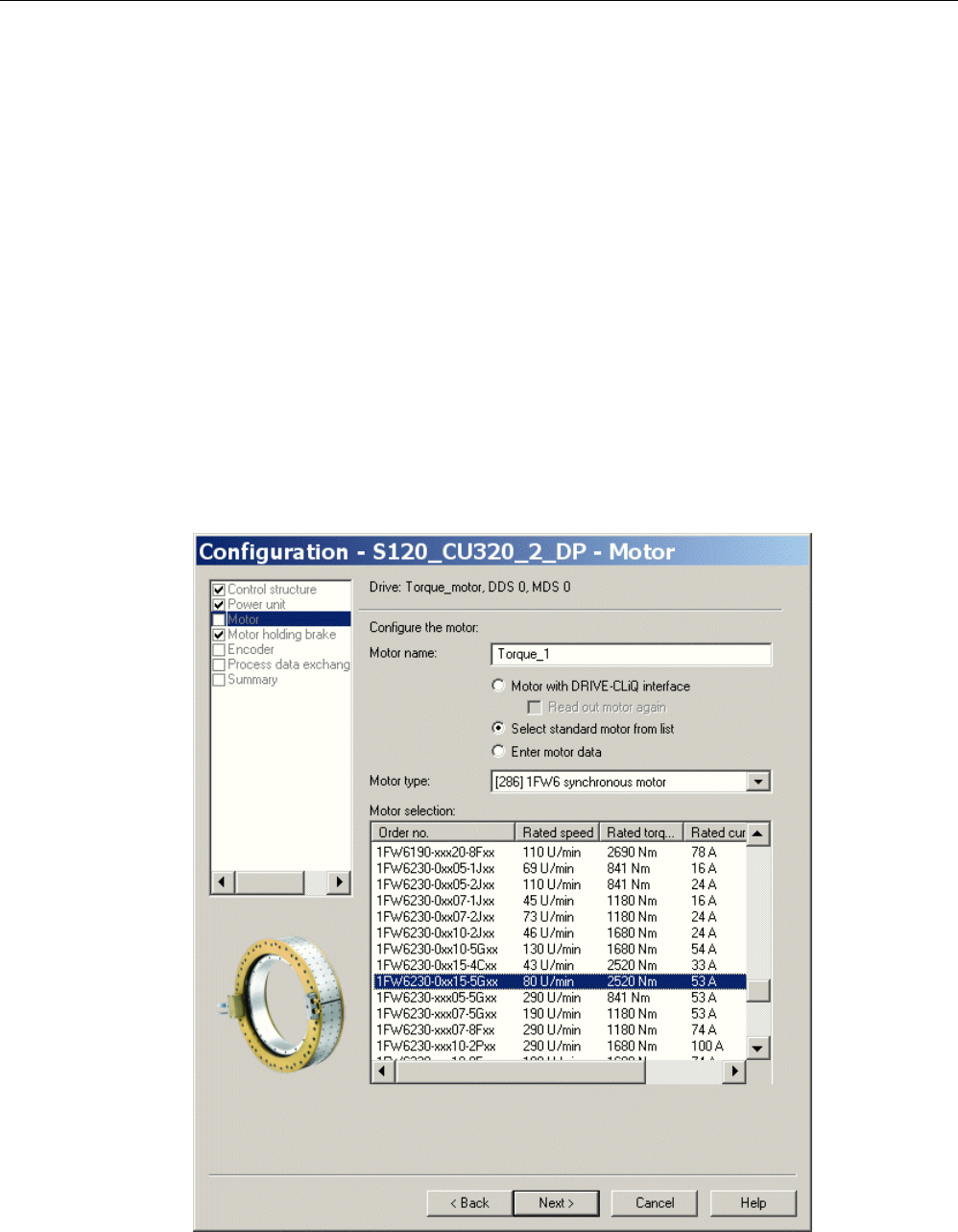
Commissioning
3.18 Commissioning SIMOTICS T-1FW6 built-in torque motors
STARTER Commissioning Manual
240 Commissioning Manual, (IH1), 07/2016, 6SL3097-4AF00-0BP5
Saturation-based technique
This technique does not require the rotor to move, which means that it can also be used for
axes that are locked (e.g. using a brake). Axes that are not locked can rotate, however.
Depending on the actual design, this technique can result in a higher noise level when the
axes are powered up during the identification routine.
3.18.4
Parameterizing a motor and encoder
Configuring data for a standard motor
You must individually configure the drives.
1. Double-click in the project navigator on "Drives" > "Drive name" > "Configuration" >
"Configure DDS" one after the other.
2. Select the standard motor to be commissioned from the list.
The associated motor data is stored and does not to be entered manually.
Image 3-71 Screen to configure a motor - selecting a standard motor
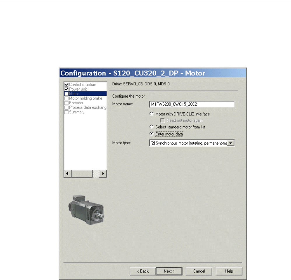
Commissioning
3.18 Commissioning SIMOTICS T-1FW6 built-in torque motors
STARTER Commissioning Manual
Commissioning Manual, (IH1), 07/2016, 6SL3097-4AF00-0BP5 241
Configuring data for a third-party motor
1FW6 built-in torque motors are not included in the list if they are customer-specific special
motors or new developments.
1. Please take the motor data from the attached motor data sheet and make the following
settings:
Image 3-72 Screen to configure the motor – setting for a third-party motor
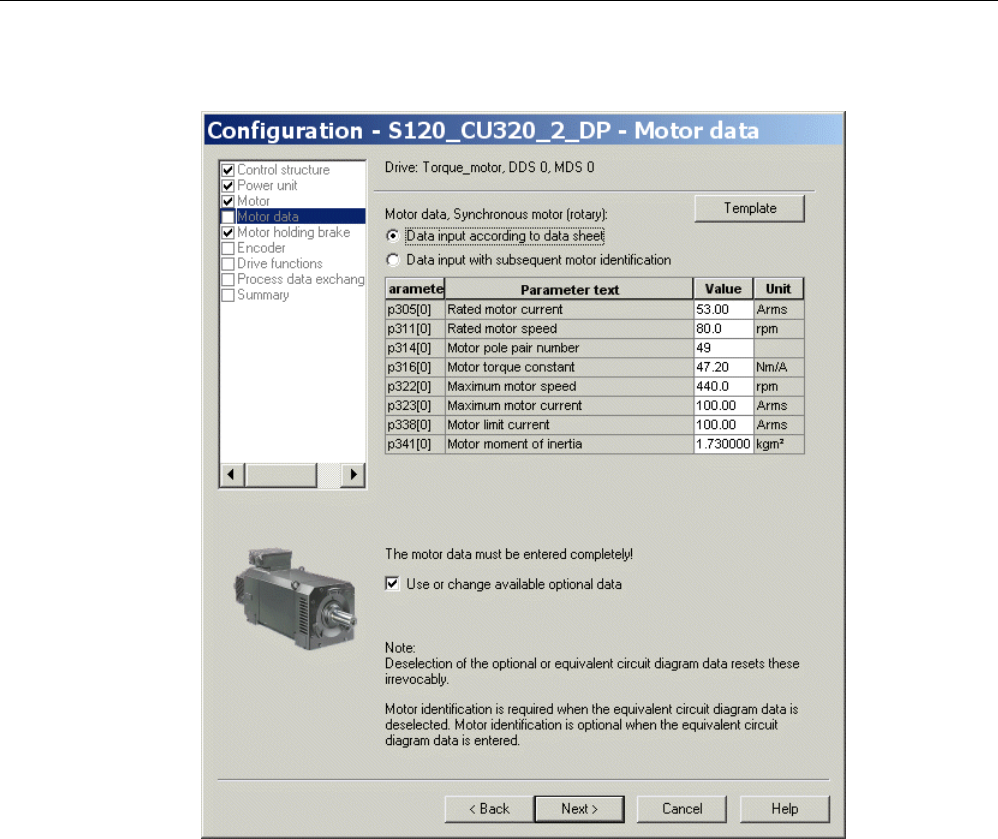
Commissioning
3.18 Commissioning SIMOTICS T-1FW6 built-in torque motors
STARTER Commissioning Manual
242 Commissioning Manual, (IH1), 07/2016, 6SL3097-4AF00-0BP5
2. Enter the following data for a rotating permanent-magnet synchronous motor:
Image 3-73 Example of motor data that has been entered
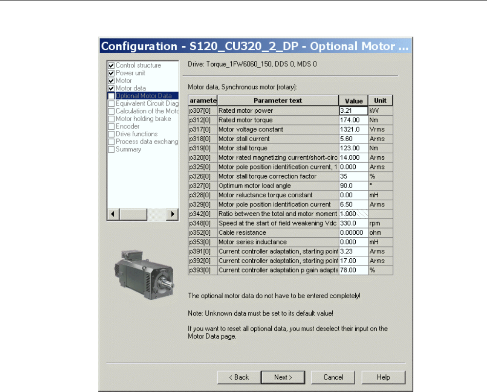
Commissioning
3.18 Commissioning SIMOTICS T-1FW6 built-in torque motors
STARTER Commissioning Manual
Commissioning Manual, (IH1), 07/2016, 6SL3097-4AF00-0BP5 243
Image 3-74 Example of optional motor data that has been entered
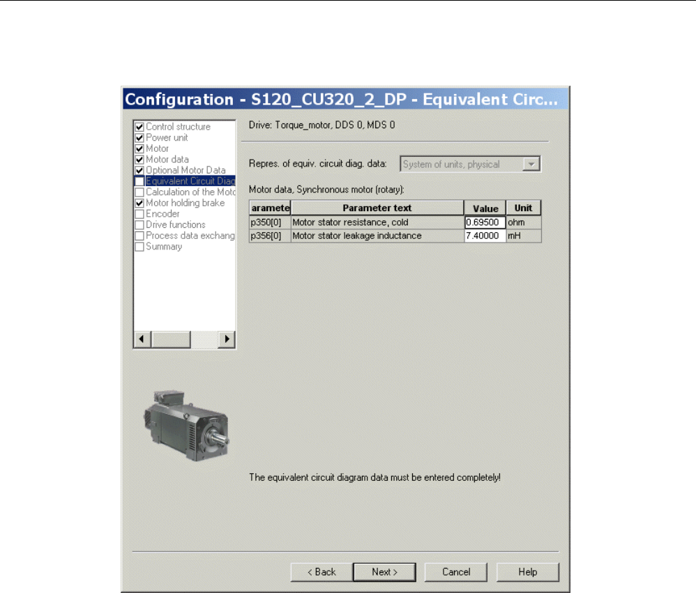
Commissioning
3.18 Commissioning SIMOTICS T-1FW6 built-in torque motors
STARTER Commissioning Manual
244 Commissioning Manual, (IH1), 07/2016, 6SL3097-4AF00-0BP5
Entering equivalent circuit diagram data
Image 3-75 Example of equivalent circuit diagram data that have been entered
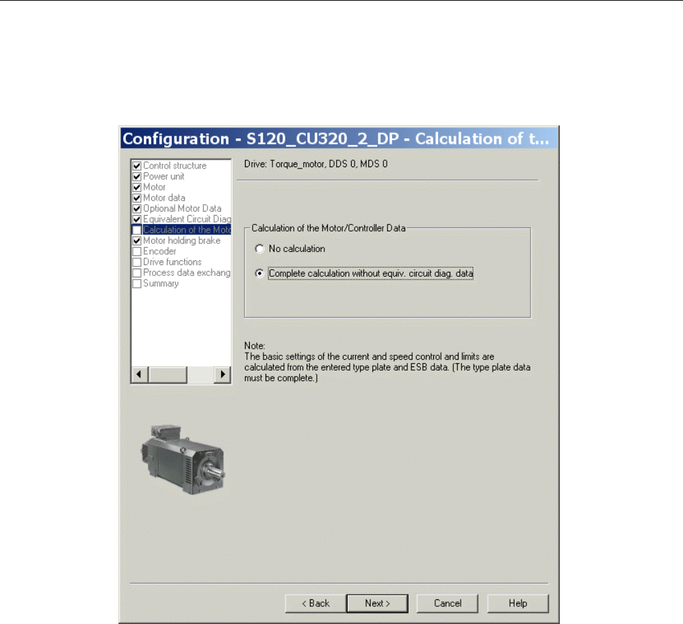
Commissioning
3.18 Commissioning SIMOTICS T-1FW6 built-in torque motors
STARTER Commissioning Manual
Commissioning Manual, (IH1), 07/2016, 6SL3097-4AF00-0BP5 245
Calculating controller data
After selecting the motor and entering the motor data, completely calculate the controller
data.
Image 3-76 Screen form for calculating the motor/controller data
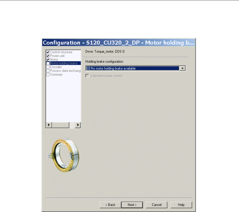
Commissioning
3.18 Commissioning SIMOTICS T-1FW6 built-in torque motors
STARTER Commissioning Manual
246 Commissioning Manual, (IH1), 07/2016, 6SL3097-4AF00-0BP5
Configuring the motor holding brake
If a motor holding brake is being used, configure it in the following window.
Image 3-77 Screen form for configuring a motor holding brake
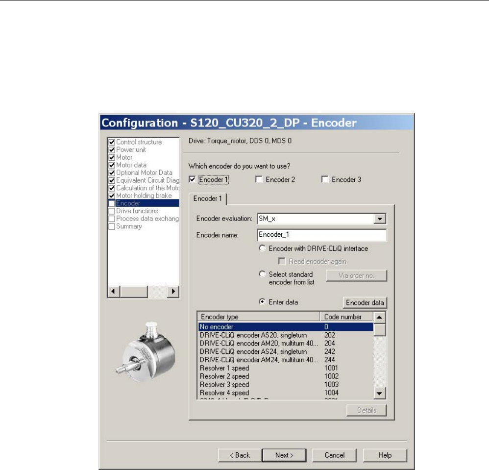
Commissioning
3.18 Commissioning SIMOTICS T-1FW6 built-in torque motors
STARTER Commissioning Manual
Commissioning Manual, (IH1), 07/2016, 6SL3097-4AF00-0BP5 247
Configuring encoder data
1. Note the data of the encoder manufacturer and the information in Chapter "Selecting and
configuring encoders (Page 173)" in this manual.
2. Configure the encoder data for the torque motor using the "Encoder data" screen form.
To do this, click the "Encoder data" button in the dialog.
Image 3-78 Screen form to configure an encoder
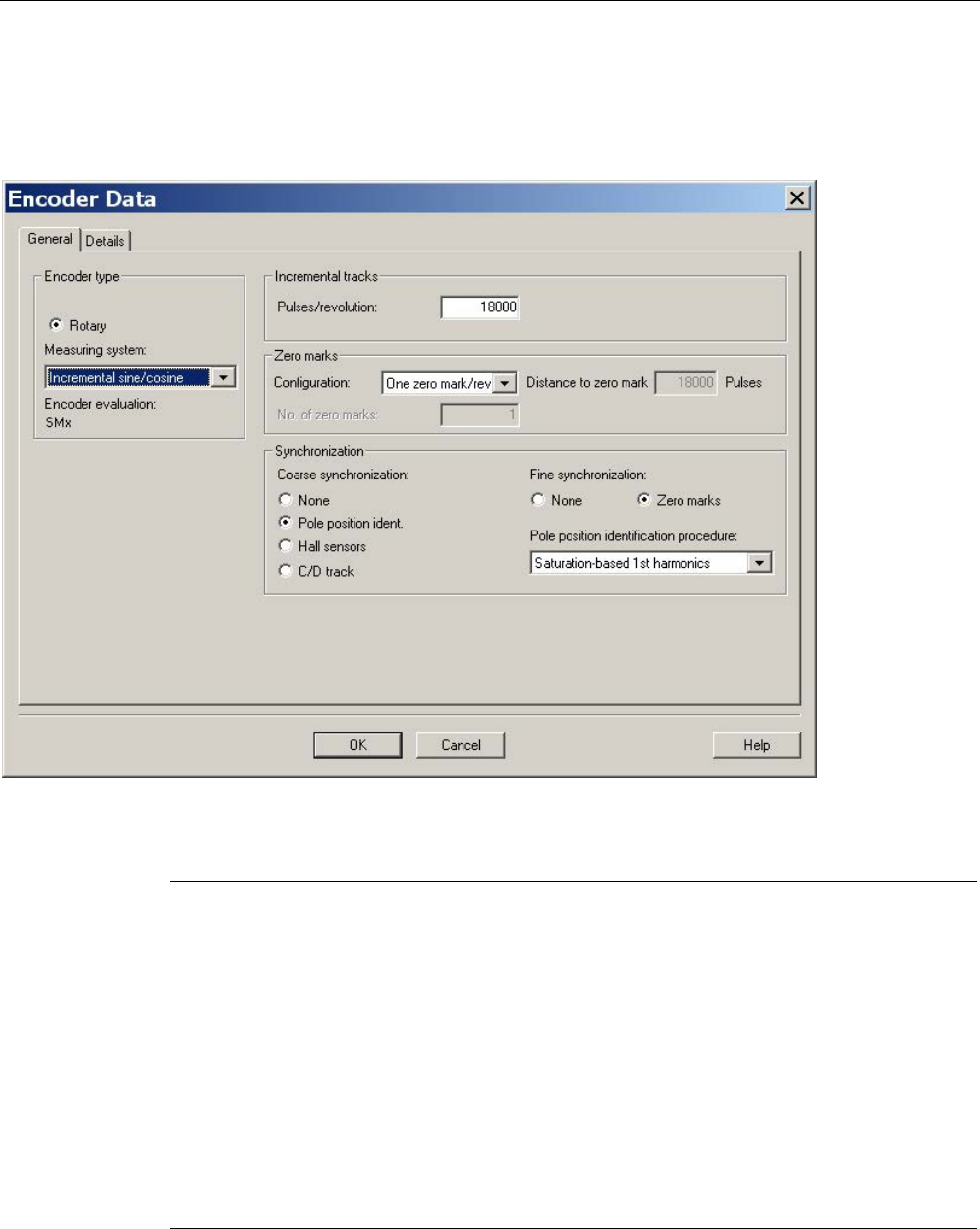
Commissioning
3.18 Commissioning SIMOTICS T-1FW6 built-in torque motors
STARTER Commissioning Manual
248 Commissioning Manual, (IH1), 07/2016, 6SL3097-4AF00-0BP5
Incremental measuring system
Example of an incremental sine/cosine encoder with 18,000 pulses per revolution with one
zero mark per revolution:
Image 3-79 Screen form for entering the encoder data
Note
Pole position identification is required for SIMOTICS T-1FW6 built-in torque motors with
incremental measuring systems.
The following techniques are possible to do this:
•
The motion-based technique
•
The saturation-based technique (1st harmonic)
For incremental measuring systems, generally, fine synchronization is pe
rformed at the zero
mark. When commissioning the system for the first time, the angular commutation offset
(p0431) must be pre
-assigned, see Chapter "Determining the angular commutation offset /
maint
aining the tolerance (Page 258)".
For third
-party motors, a pole position identification routine to determine the angular
commutation offset cannot be entered.
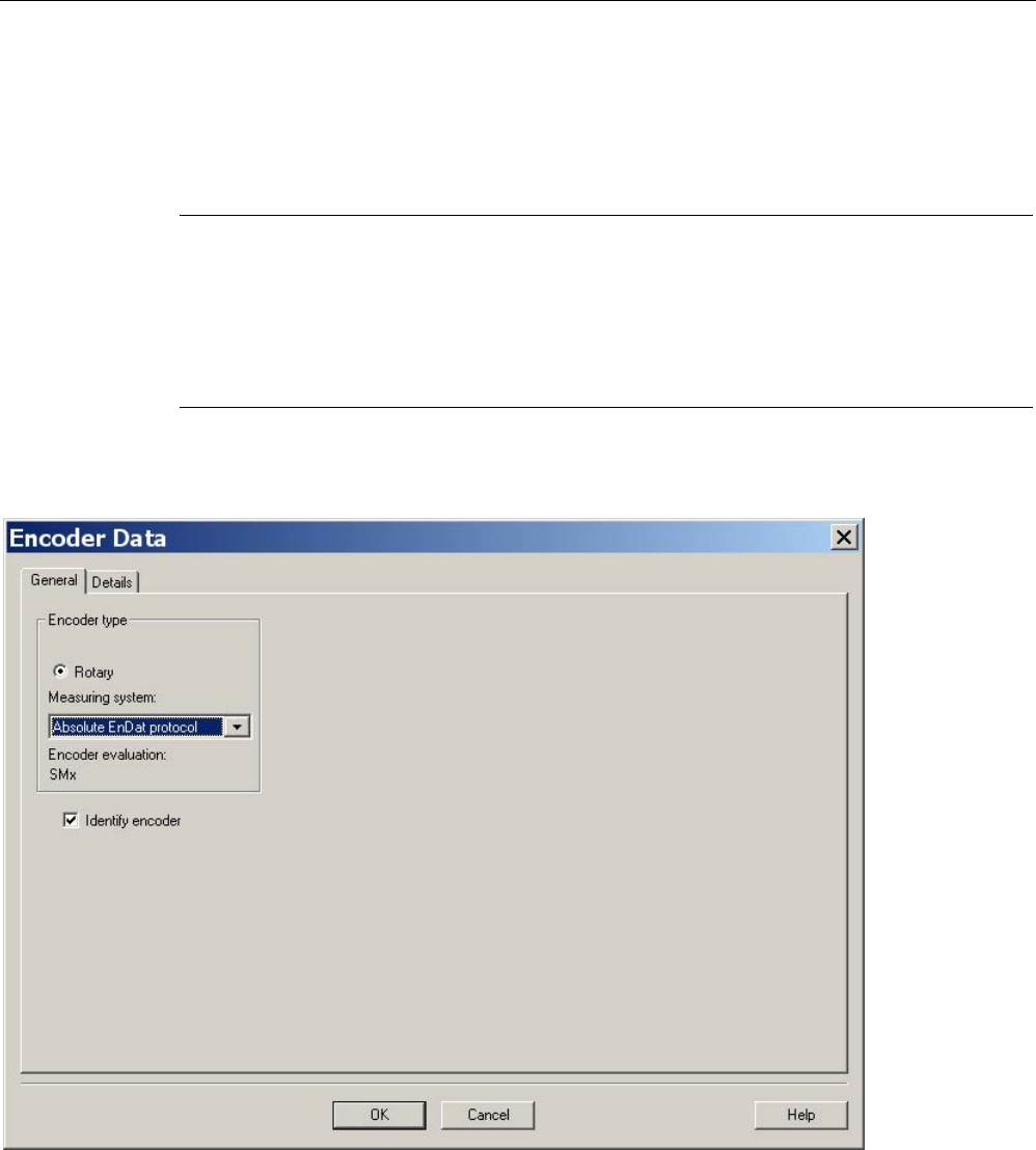
Commissioning
3.18 Commissioning SIMOTICS T-1FW6 built-in torque motors
STARTER Commissioning Manual
Commissioning Manual, (IH1), 07/2016, 6SL3097-4AF00-0BP5 249
Absolute measuring system
The encoder is detected by the Control Unit as long as it is a DRIVE-CLiQ encoder. For all
other encoder types, you must use the SINAMICS Sensor Module in accordance with the
encoder interface in order to transfer the encoder signals to the Control Unit.
Note
SINAMICS Sensor Modules in conjunction with EnDat encoders of Heidenhain Corp.
SMC20, SME25 and SME125: EnDat encoders with incremental signals, article designation
EnDat02 or EnDat01.
SMC40: EnDat encoder with EnDat protocol 2.2 without incremental signals, art
icle
designation Endat22.
The following inputs must be made in the configuration screen form after clicking the
"Encoder data" button.
Image 3-80 Screen form to configure an absolute encoder with EnDat protocol
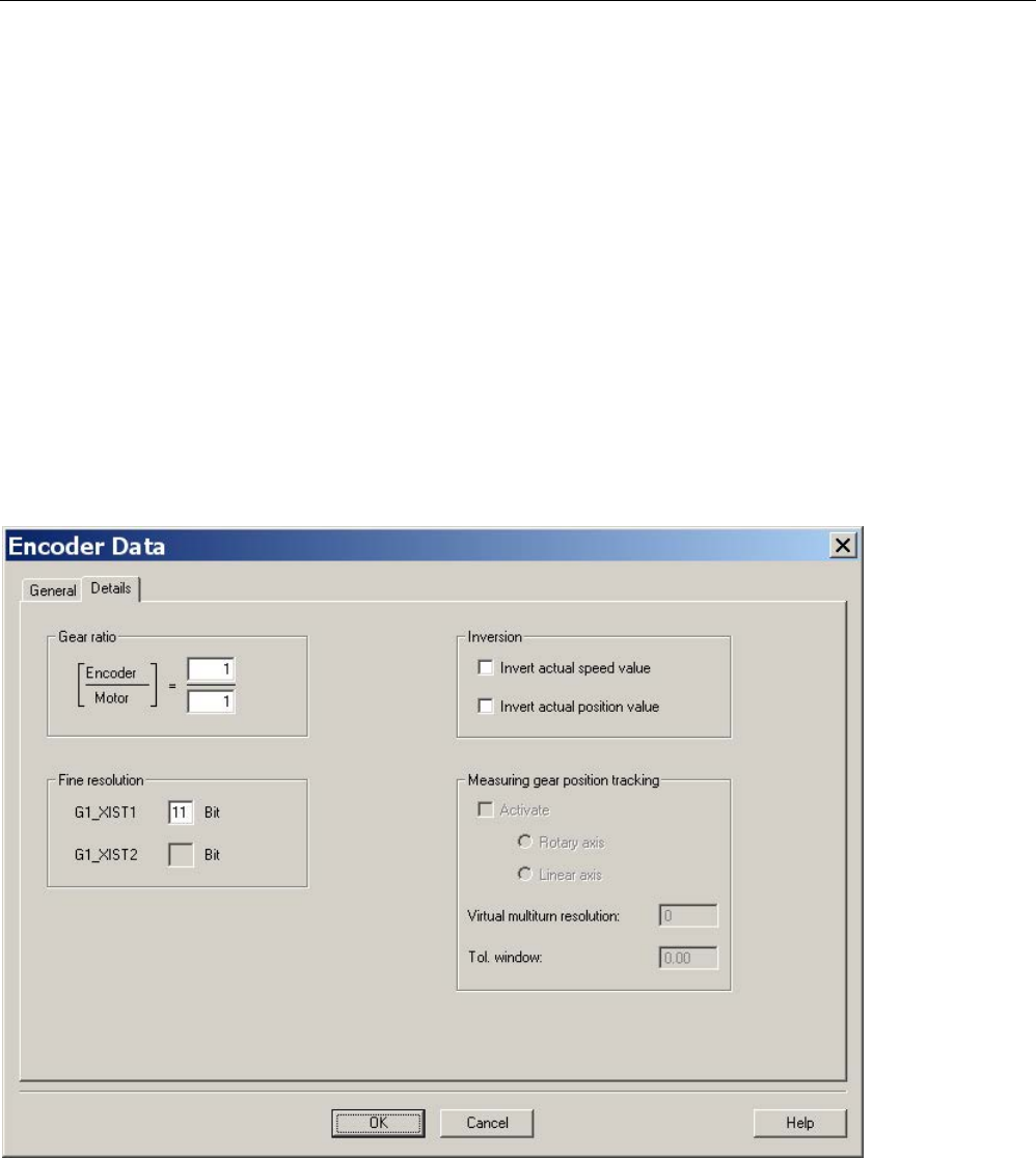
Commissioning
3.18 Commissioning SIMOTICS T-1FW6 built-in torque motors
STARTER Commissioning Manual
250 Commissioning Manual, (IH1), 07/2016, 6SL3097-4AF00-0BP5
Definition of the control sense
The control sense of an axis is correct if the positive direction of the drive (= clockwise
rotating field U, V, W) coincides with the positive counting direction of the measuring system.
If the positive direction of the drive and positive counting direction of the measuring system
do not match, then you must invert the actual speed value in the "Encoder configuration -
details" screen form when the drive is being commissioned (p0410.0 or p0410.1). See the
"Screen form for entering additional encoder data (Page 250)" figure.
Setting additional encoder data
1. If necessary, use "Encoder data" and "Details" to invert the actual speed and position
value.
This allows the control sense to be changed.
2. To do this, first click the "Encoder data" button in the screen form used for the encoder
configuration.
Image 3-81 Screen form for entering additional encoder data
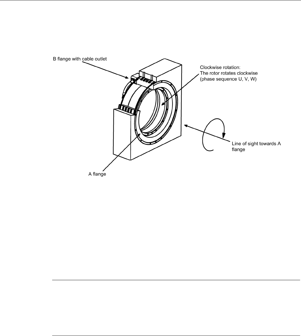
Commissioning
3.18 Commissioning SIMOTICS T-1FW6 built-in torque motors
STARTER Commissioning Manual
Commissioning Manual, (IH1), 07/2016, 6SL3097-4AF00-0BP5 251
Determining the drive direction
The direction of the drive is positive, if when viewing the DE flange, the rotor is rotating
clockwise.
Image 3-82 Determining the positive direction of the drive
Determining the counting direction of the measuring system
The counting direction depends on the measuring system and the mounting position. The
counting direction of the measuring system must match the direction of rotation of the motor.
If necessary, you must adapt the counting direction by making the appropriate parameter
assignment. Please refer to the manufacturer's documentation for the measuring system. If
necessary, you must invert the counting direction as described in Image 3-81 Screen form
for entering additional encoder data (Page 250).
Note
Checking the counting direction of the measuring system
The measuring system counting direction can also
be checked, by first parameterizing the
drive, and then manually moving it with the enable signals inhibited.
If the axis is rotated in the positive direction, the actual speed value must also count in the
positive direction.
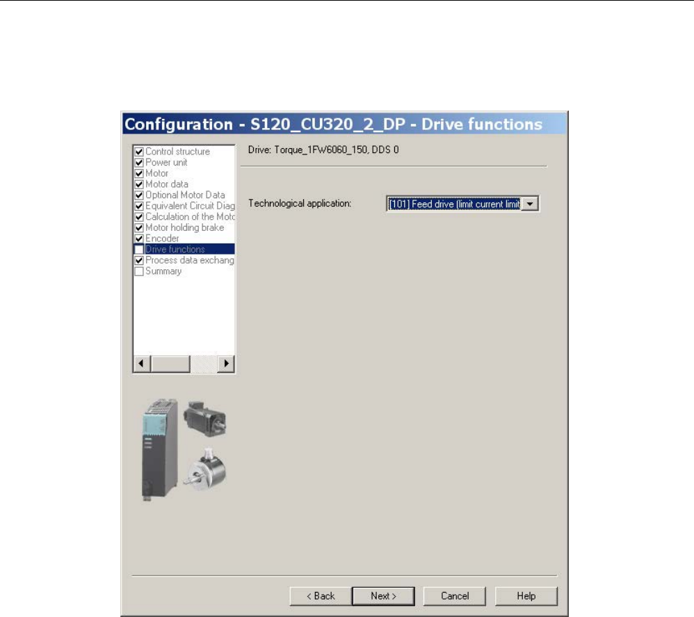
Commissioning
3.18 Commissioning SIMOTICS T-1FW6 built-in torque motors
STARTER Commissioning Manual
252 Commissioning Manual, (IH1), 07/2016, 6SL3097-4AF00-0BP5
Completing parameterization
SIMOTICS T-1FW6 built-in torque motors are feed drives (maximum current limiting).
Image 3-83 Screen form to select the application
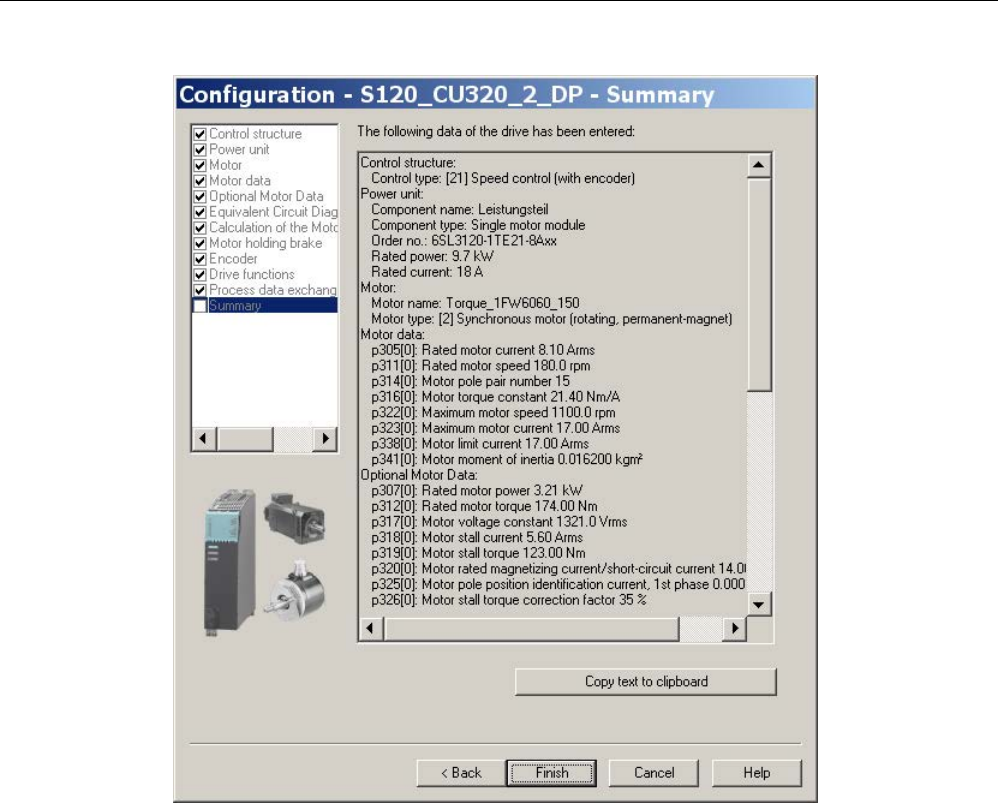
Commissioning
3.18 Commissioning SIMOTICS T-1FW6 built-in torque motors
STARTER Commissioning Manual
Commissioning Manual, (IH1), 07/2016, 6SL3097-4AF00-0BP5 253
Image 3-84 Summary of the configuration
The created offline project must now be loaded into the drive. In STARTER, go online with
the target device.
If an absolute measuring system with EnDat protocol was selected, then after establishing
an online connection, the encoder serial number is loaded and the corresponding encoder
parameters are set.

Commissioning
3.18 Commissioning SIMOTICS T-1FW6 built-in torque motors
STARTER Commissioning Manual
254 Commissioning Manual, (IH1), 07/2016, 6SL3097-4AF00-0BP5
3.18.5
Parameterizing and testing the temperature sensors
SME12x Sensor Module External
The connection of the SME modules is described in Chapter "System integration" in the
"SIMOTICS T-1FW6 built-in torque motors" Configuration Manual. Information on the
SME12x Sensor Module External can be found in the "SINAMICS S120 Equipment Manual
for Control Units and Additional System Components" in Chapter "Sensor Module External
120 (SME120)" and in Chapter "Sensor Module External 125 (SME125)".
The parameterization of the temperature sensors is explained in detail in Chapter
"Temperature sensors for SINAMICS components (Page 282)".
A parameterizing example of a torque motor with a PT1000 (or alternatively: KTY 84) and
two PTC sensors, connected to a SME12x Sensor Module External is provided below.
Use the expert list to parameterize the drive.
Table 3- 24 Parameterization in the drive:
Parameter
Input
p0600
Motor temperature sensor for monitoring
1: Temperature sensor via encoder 1
p0601
Motor temperature sensor, sensor type
10: Evaluation via several temperature channels SME12x
p0604
Motor temperature alarm threshold
Sets the alarm threshold for monitoring the motor temperature.
For motors from the motor list (p0301), this parameter is automatically pre-assigned
(120° C).
p0605
Motor temperature fault threshold
Sets the fault threshold for monitoring the motor temperature.
For motors from the motor list (p0301), this parameter is automatically pre-assigned
(155° C).
p0606
Motor temperature timer
0...2 s
Setting the timer for the alarm threshold for the motor temperature monitoring, if
alarm with timer was selected in the parameters p4600...4603.
This timer is started if the temperature alarm threshold (p0604) is exceeded.
If the timer has expired, and in the meantime the temperature alarm threshold has
not been undershot, then fault F07011 is output.

Commissioning
3.18 Commissioning SIMOTICS T-1FW6 built-in torque motors
STARTER Commissioning Manual
Commissioning Manual, (IH1), 07/2016, 6SL3097-4AF00-0BP5 255
Parameter
Input
p0607
Temperature sensor fault timer
Setting the timer for timing the period between output of the alarm and fault when a
temperature sensor fault is detected.
If a sensor fault has been detected, this timer is started.
If the sensor fault persists when the timer has expired, the relevant fault is output.
p4600...p4603
Motor temperature sensor 1...4 sensor type
Sets the temperature sensor type for the motor temperature monitoring. Channels 2
... 4 are used for the Sensor Module External SME12x. Channel 1 remains free.
The following values are possible for torque motors:
0: No sensor
10: PTC fault
12: PTC alarm & timer
20: KTY 84
60: PT1000
If you make a selection with timer, you must pre-assign parameter p0606 with the
corresponding timer for a maximum of 2 s.
Example: Standard SIMOTICS T-1FW6 built-in torque motors
p4600
0:
No sensor
p4601
60:
PT1000 (or alternatively 20: KTY 84)
p4602
10:
PTC fault (PTC 130 °C)
p4603
10:
PTC fault (PTC 150 °C)
If you are not using a standard motor, then you must parameterize parameters
p0600...p0606 (see above). Select parameters p4600...p4603 to match the sensor types or
temperature channels of the Sensor Module External SME12x.
Checking the temperature sensors for the Sensor Module External SME12x
In the online mode, you can read out the temperatures of the sensors at the channels of the
Sensor Module External SME12x in parameter r4620[0…3] using the STARTER
commissioning tool.
The maximum motor temperature can also be read in r0035. This parameter indicates the
highest value from parameters r4620[0…3].
For a parameterized PTC sensor type, irrespective of the actual temperature in
r4620, -200° C is always displayed.
The temperature values shown in parameters r0035 or r4620[1] provide information about
whether a parameterized temperature sensor does not match the temperature sensor
actually connected (connection to the wrong temperature sensor):
Parameterized
temperature sensor
Connected
temperature sensor
Displayed value in °C
at room temperature 25°C
KTY 84
PTC
-40 ... -80 °C
PT1000
PTC
-100 ... -200 °C
KTY 84
PT1000
+115°C
PT1000
KTY 84
-100°C

Commissioning
3.18 Commissioning SIMOTICS T-1FW6 built-in torque motors
STARTER Commissioning Manual
256 Commissioning Manual, (IH1), 07/2016, 6SL3097-4AF00-0BP5
Checking the PTC sensor type
You can simulate a sensor responding to an overtemperature condition (high ohmic state) by
disconnecting the connections. You can disconnect the connections for the temperature
sensors by removing the Sensor Module External SME12x (connector, interface X200).
If the sensor type is parameterized as PTC fault, then fault "F07011 drive: Motor
overtemperature" is immediately displayed independent of the setting of p0604...p0606. If
the sensor type is parameterized as PTC alarm with timer, after the time parameterized in
p0606, fault F07011 is generated.
Test for sensor type PT1000 or KTY
If you withdraw the connector of interface X200 and have therefore disconnected the
PT1000 connection (or KTY connection), after the time parameterized in p0607 has expired,
fault "F07016 drive: Motor temperature sensor fault" is displayed in the alarm window of the
STARTER commissioning tool.
Check the wiring of the temperature sensors by checking the resistance values at connector
interface X200. The wiring is OK for the following resistance values:
PT1000 at 20 °C approx. 1080 Ω
KTY 84 at 20 °C approx. 580 Ω
PTC for 20 °C 120 Ω...300 Ω
The assignment of connector interface X200 can be found in the "SINAMICS S120 Manual
Control Units and Additional System Components".
Terminal Module TM120
Terminal Module TM120 is a DRIVE-CLiQ component for temperature evaluation with safe
isolation, see also "SINAMICS S120 Manual for Control Units and Additional System
Components" in Chapter "System components".
TM120 is an autonomous input/output component. You can freely assign the temperature
channels to any Motor Module.
You can assign every channel to the following sensor types:
● PTC
● KTY 84
● PT1000
● Bimetallic NC contact
Parameterization
For a standard configuration with correct pre-assignment of the temperature channels, the
Terminal Module TM120 must be located between the Sensor Module and the Motor Module
(DRIVE-CLiQ).
If this is not the case, you must parameterize all of the required temperature channels in both
the Motor Module and Terminal Module TM120.

Commissioning
3.18 Commissioning SIMOTICS T-1FW6 built-in torque motors
STARTER Commissioning Manual
Commissioning Manual, (IH1), 07/2016, 6SL3097-4AF00-0BP5 257
You must always carefully check the temperature shutdown circuits (e.g. by disconnecting
the sensors) before commissioning the motor for the first time.
Use the expert list to parameterize the drive.
Table 3- 25 Parameterization in the drive:
Parameter
Input
p0600
Motor temperature sensor for monitoring
20: Temperature sensor via BICO interconnection p0608
p0601
Motor temperature sensor, sensor type
11: Evaluation via several temperature channels BICO
p0606
Motor temperature timer
0...2 s
Sets the timer for the alarm threshold for the motor temperature monitoring, if alarm with timer was
selected in p4610...4613.
This timer is started when the temperature alarm threshold (p0604) is exceeded.
If the timer expires before the temperature falls below the alarm threshold, then fault F07011 is out-
put.
p0608
[0...3] CI: Motor temperature, signal source 2
Sets the signal source 2 for the evaluation of the motor temperature via a BICO interconnection, e.g.
[0]: Motor temperature channel 1 TM120 . r4105[0]
[1]: Motor temperature channel 2 TM120 . r4105[1]
[2]: Motor temperature channel 3 TM120 . r4105[2]
[3]: Motor temperature channel 4 TM120 . r4105[3]
p4610...p4613
Motor temperature sensor 1...4 sensor type
Sets the temperature sensor type for the motor temperature monitoring. The following values are
possible for torque motors:
0: No sensor
10: PTC fault
12: PTC alarm & timer
20: KTY84, PT100, PT1000
30: Bimetallic NC contact fault
32: Bimetallic NC contact alarm & timer
If you make a selection with timer, you must pre-assign parameter p0606 with the corresponding
timer for a maximum of 2 s.
Table 3- 26 Parameterization in the expert list of the Terminal Module TM120
Parameter
Input
p4100[0...3]
TM120 temperature evaluation, sensor type
Sets the temperature evaluation of Terminal Module TM120.
This means that the temperature sensor type is selected and the evaluation is activated. The follow-
ing values are possible:
0: Evaluation deactivated
1: PTC thermistor
2: KTY84
4: Bimetal NC contact
6: PT1000

Commissioning
3.18 Commissioning SIMOTICS T-1FW6 built-in torque motors
STARTER Commissioning Manual
258 Commissioning Manual, (IH1), 07/2016, 6SL3097-4AF00-0BP5
Check the temperature sensors in the same way as described for the SME12x Sensor
Module External (see section "Checking the temperature sensors for the Sensor Module
External SME12x"). Test each individual temperature channel by separating the connection.
3.18.6
Determining the angular commutation offset / maintaining the tolerance
NOTICE
Material damage as a result of an incorrectly commutated drive
When the system is commissioned for the first time or after an encoder/motor has been
replaced, it is possible that the drive could be incorrectly commutated if the angular
commutation offset has not yet been adjusted. Current is fed into the motor at the incorrect
time for an incorrectly commutated motor. This means it can perform inadvertent
movements. For example, it can turn with high speed in the wrong direction and so damage
a workpiece.
• Set the current limit using the p0640 parameter to 20% of p0323 (motor maximum
current).
• Therefore, to complete commissioning, it is imperative that you check the angular
commutation offset according to the following description.
You can determine the pole position, required for synchronous motors, for the SIMOTICS T-
1FW6 built-in torque motors using a software-based automatic pole position identification
technique.
The following two techniques are suitable for all frame sizes of SIMOTICS T-1FW6 built-in
torque motors:
● The motion-based technique p1980 = 10
● The saturation-based technique (1st harmonic) p1980 = 1
Also refer to the information in Chapter "General information for setting the commutation
(Page 239)."

Commissioning
3.18 Commissioning SIMOTICS T-1FW6 built-in torque motors
STARTER Commissioning Manual
Commissioning Manual, (IH1), 07/2016, 6SL3097-4AF00-0BP5 259
Making parameter entries / commutation setting
Incremental measuring system
1. Activate automatic determination of the commutation angle offset with p1990 = 1.
Alarm A07971 is output while the commutation angle offset is being determined.
2. Set the drive enable signals (OFF3, OFF2, OFF1).
This results in coarse synchronization. A successful coarse synchronization is indicated
by the parameter r1992.9.
3. Move the drive over the zero mark.
When the drive moves over the zero mark, the angular commutation offset is entered into
p0431. p1990 is automatically set to 0 after the angular commutation offset has been
determined. Alarm A07965 is displayed as a prompt to save the change in a non-volatile
fashion.
Absolute measuring system
Set p1990 = 1 before activating the enable signals.
By activating the enable signals, the angular commutation offset entered into p0431 and
p1990 is automatically set to 0. Alarm A07965 is displayed as a prompt to save the change
in a non-volatile fashion.

Commissioning
3.18 Commissioning SIMOTICS T-1FW6 built-in torque motors
STARTER Commissioning Manual
260 Commissioning Manual, (IH1), 07/2016, 6SL3097-4AF00-0BP5
3.18.6.1
Checking the commutation angle offset with STARTER
Note
Coarse synchronization means that the pole position identification h
as been carried out, but
the drive has not yet been moved over the zero mark. After the drive has been moved over
the zero mark, the drive is finely synchronized. When an absolute measuring system is used,
the drive is always fine synchronized after being
switched on. A coarse synchronization is
required only for the initial commissioning for the commutation angle offset determination
(p0431).
Checking the pole position identification
You can check the pole position identification with p1983 in the finely-synchronized state.
1. Position the drive at different points in an electrical period (pole pitch) and set parameter
p1983 = 1. For example, start at 0° and perform a measurement every 30°.
This means that a pole position identification is performed again and the deviation
determined is displayed in parameter p1984.
After completion of the pole position identification, parameter p1983 is set to 0 again. The
angular difference read out of parameter p1984 must lie in the interval [-10°...+10°].
The average of the measured angle differences must be added to the commutation angle
offset entered in p0431. (Note the sign of the commutation angle offset.)
To change parameter p0431, p0010 must be set to 4 (see "Image 3-95 Tolerance
envelope for the pole position angle (Page 270)").
2. Perform a coarse and fine synchronization again. The fine synchronization is not
applicable for an absolute measuring system.
3.18.6.2
Checking the commutation angle offset with an oscilloscope
Checking the EMF voltages
If you have commissioned the motor according to the appropriate instructions, and in spite of
this, unexpected messages are output, you must first check the individual EMF voltages of
the motor. To do this, the following techniques are described:
● "Record the phase voltage and the pole position angle using an oscilloscope"
● "Record the phase voltage and the pole position angle using the STARTER trace
function"

Commissioning
3.18 Commissioning SIMOTICS T-1FW6 built-in torque motors
STARTER Commissioning Manual
Commissioning Manual, (IH1), 07/2016, 6SL3097-4AF00-0BP5 261
Recording the phase voltage and the pole position angle using an oscilloscope
1. Switch the drive line-up into a no-current condition.
2. After the DC link has completely discharged, disconnect the motor cables from the
converter.
If motors are connected in parallel, then disconnect them.
3. Form an artificial neutral point using 1 kΩ resistors (for a parallel connection, for each
motor).
Image 3-85 Arrangement for measuring
4. Turn the rotor with the most constant speed possible in the clockwise direction. The rotor
is turning in a clockwise direction if, when viewing the DE flange, it rotates clockwise (see
also the "Determining the positive direction of the drive (Page 251)" figure).
Checking the phase sequence
For the positive direction of the drive, the phase sequence must be as follows:
EMF phase U - EMF phase V - EMF phase W
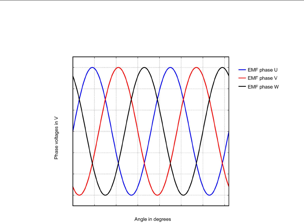
Commissioning
3.18 Commissioning SIMOTICS T-1FW6 built-in torque motors
STARTER Commissioning Manual
262 Commissioning Manual, (IH1), 07/2016, 6SL3097-4AF00-0BP5
Checking phase relation
The phase displacement of the individual voltages EMC phase U – EMC phase V –
EMC phase W to each other is 120° in the following figure.
Image 3-86 Phase sequence, EMF phase U - EMF phase V - EMF phase W
Checking the phase relation for parallel-connected motors
The phase relations EMC phase U – EMC phase V – EMC phase W of the individual
motors to each other must match.
● EMF phase U motor 1 with EMF phase U motor 2
● EMF phase V motor 1 with EMF phase V motor 2
● EMF phase W motor 1 with EMF phase W motor 2
The deviation within a particular phase position may be a maximum of 10°.
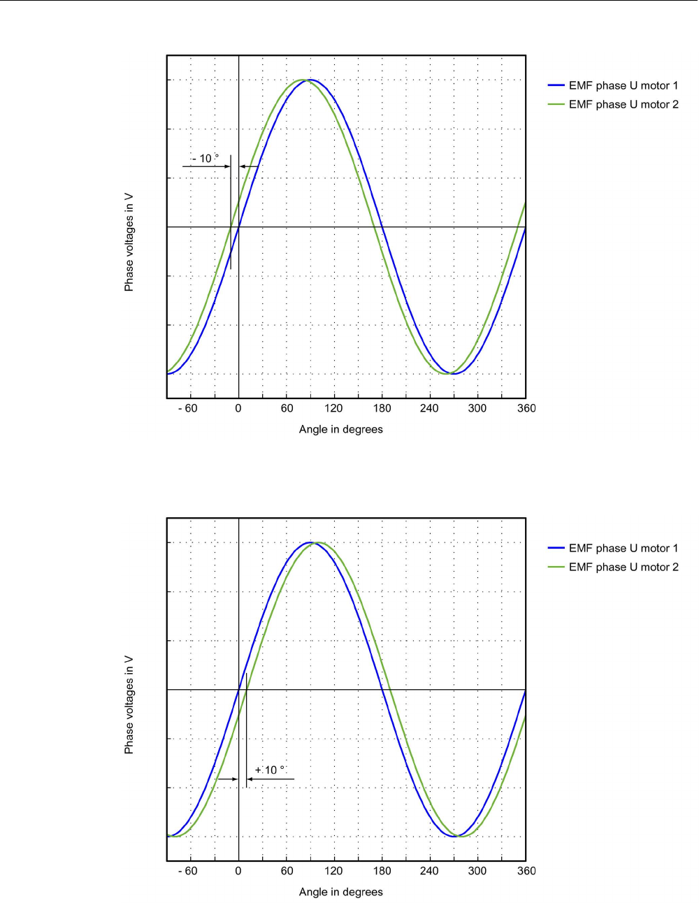
Commissioning
3.18 Commissioning SIMOTICS T-1FW6 built-in torque motors
STARTER Commissioning Manual
Commissioning Manual, (IH1), 07/2016, 6SL3097-4AF00-0BP5 263
Image 3-87 Phase U motor 1 may not lag behind EMF phase U motor 2 by more than 10°
Image 3-88 EMF phase U motor 1 may not lead EMF phase U motor 2 by more than 10°
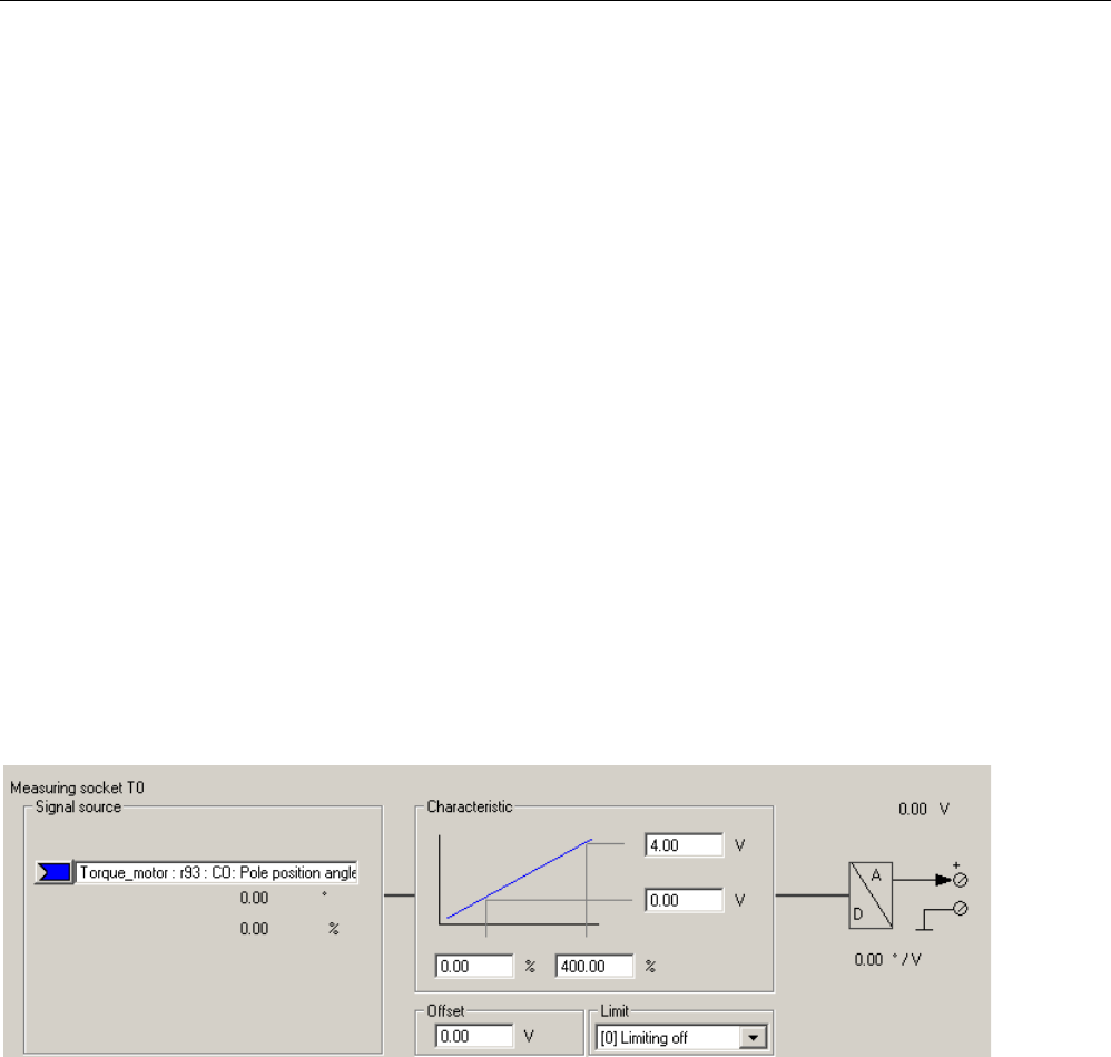
Commissioning
3.18 Commissioning SIMOTICS T-1FW6 built-in torque motors
STARTER Commissioning Manual
264 Commissioning Manual, (IH1), 07/2016, 6SL3097-4AF00-0BP5
Determining the angular commutation offset by making a measurement
In the event of a fault and for a parallel connection, you must check the angular commutation
offset as follows.
1. The drive with an incremental measuring system must be fine synchronized. To do this,
connect the motor and enable the controller for coarse synchronization.
2. Then move the drive over the zero mark.
3. Remove power from the drive as described for the "Checking the phase voltage and the
pole position angle using an oscilloscope" technique.
Please note that for this technique, it is not permissible that the control voltage for the
Control Unit is shut down; however the infeed must be disconnected from the line supply.
You can determine the angular commutation offset by measuring the EMF and the
normalized electrical pole position angle via the analog output. The normalized electrical
pole position angle allows you to parameterize the test socket connections T0 to T2 and
retrieve the signals (see Chapter "Measuring sockets (Page 355)").
Definition of channels (Ch1 ... Ch4):
● Ch1: EMF phase U with respect to the neutral point
● Ch2: EMF phase V with respect to the neutral point
● Ch3: EMF phase W with respect to the neutral point
● Ch4: Normalized electrical angular pole position via analog output
Image 3-89 Setting measuring socket T0 on CU320
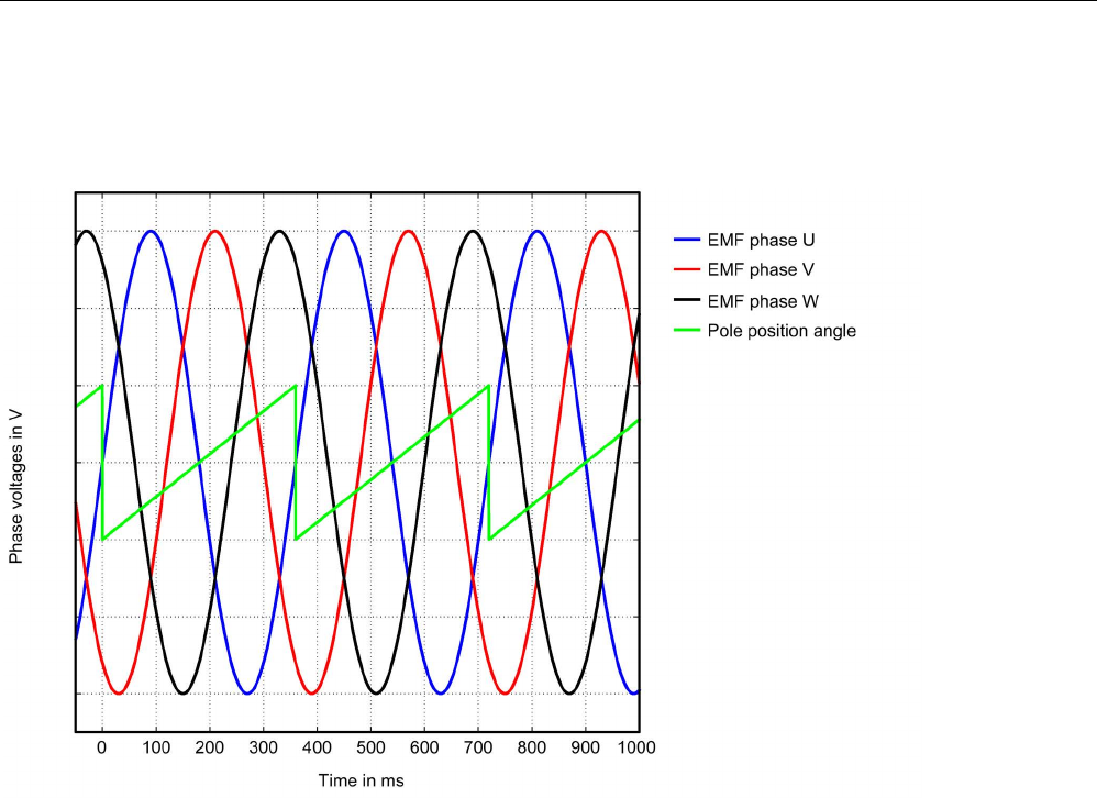
Commissioning
3.18 Commissioning SIMOTICS T-1FW6 built-in torque motors
STARTER Commissioning Manual
Commissioning Manual, (IH1), 07/2016, 6SL3097-4AF00-0BP5 265
The status of the coarse and fine synchronization can be read out online via parameter
r1992: r1992.8 (fine synchronization carried out) and r1992.9 (coarse synchronization carried
out).
Image 3-90 Ideal characteristic of EMF voltages and the pole position angle of an optimally commutated drive

Commissioning
3.18 Commissioning SIMOTICS T-1FW6 built-in torque motors
STARTER Commissioning Manual
266 Commissioning Manual, (IH1), 07/2016, 6SL3097-4AF00-0BP5
Recording the phase voltage and the pole position angle using the STARTER trace function
An oscilloscope is not used for this technique. You do not need to disconnect the motor.
However, this technique is less accurate, as the motor voltages are not directly measured,
but calculated from the transistor turn-on duration. This technique is not permitted for
parallel-connected motors, see Chapter "Special case parallel connection (Page 272)".
1. Set the following parameters:
Image 3-91 Assignment of trace channels to check the angular commutation offset
The drive is operated in the open-loop torque controlled mode. The following
parameterization is required:
2. Set p0640 = 0, to limit the motor current to 0.
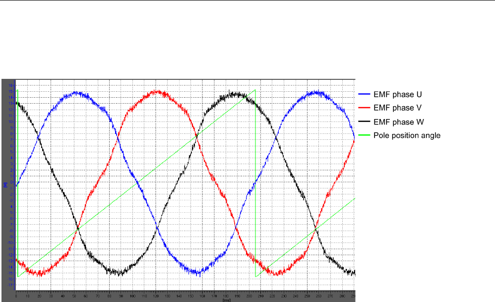
Commissioning
3.18 Commissioning SIMOTICS T-1FW6 built-in torque motors
STARTER Commissioning Manual
Commissioning Manual, (IH1), 07/2016, 6SL3097-4AF00-0BP5 267
3. Set p1545 = 1, to activate the travel to fixed stop.
4. The motor must be in closed-loop control and rotated externally.
Image 3-92 Example of an optimally commutated drive (recorded using the trace function of the STARTER commissioning
tool)

Commissioning
3.18 Commissioning SIMOTICS T-1FW6 built-in torque motors
STARTER Commissioning Manual
268 Commissioning Manual, (IH1), 07/2016, 6SL3097-4AF00-0BP5
Evaluation of the results (applies to both measuring techniques)
For a positive drive direction (definition, refer to the "Determining the positive direction of the
drive (Page 251)" figure, the sawtooth must increase monotonously between 0° and 360°,
refer to the "Ideal characteristic of the EMF voltages and the pole position angle for an
optimally commutated drive (Page 265)" figure.
If the curve is decreasing monotonously, and the phase sequence is EMF phase U - EMF
phase V - EMF phase W, then you must change the control sense of the drive if necessary
via p0410 bit 0 "Invert actual speed value". If the position controller is being used, then you
must also check p0410 bit 1 "Invert actual position value". See the "Screen form for entering
additional encoder data (Page 250)" figure in Chapter "Parameterizing a motor and
encoder".
Image 3-93 EMF for incorrect actual speed value inversion
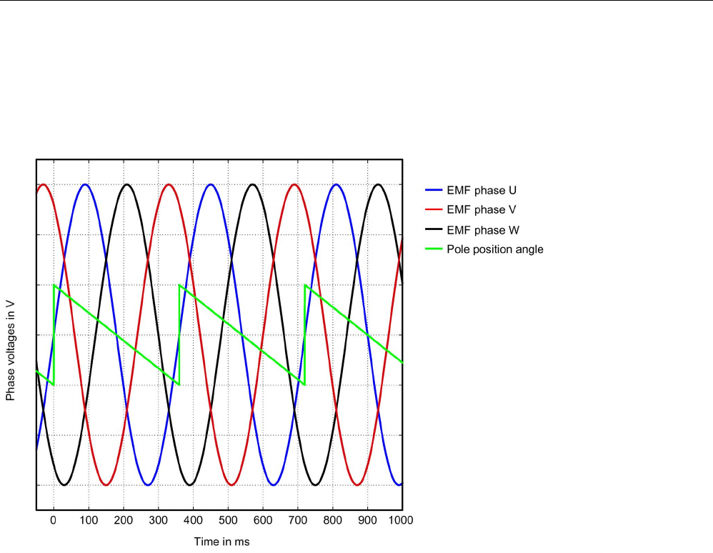
Commissioning
3.18 Commissioning SIMOTICS T-1FW6 built-in torque motors
STARTER Commissioning Manual
Commissioning Manual, (IH1), 07/2016, 6SL3097-4AF00-0BP5 269
If the curve is monotonously decreasing, and the phase sequence is EMF phase U –
EMF phase W – EMF phase V (i.e. if the phase sequence of V and W is interchanged), then
according to the "Determining the positive direction of the drive (Page 251)" figure in Chapter
"Parameterizing a motor and encoder", the drive direction is negative (i.e. when viewing the
DE flange the axis is rotating counterclockwise).
Image 3-94 EMC for the negative direction of rotation
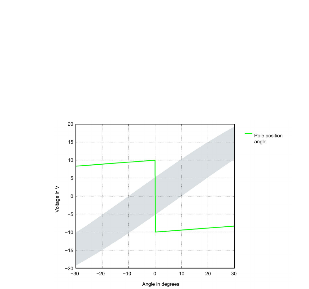
Commissioning
3.18 Commissioning SIMOTICS T-1FW6 built-in torque motors
STARTER Commissioning Manual
270 Commissioning Manual, (IH1), 07/2016, 6SL3097-4AF00-0BP5
Displaying the commutation angle tolerance
For a finely synchronized drive, the difference between EMF phase U and the normalized,
electrical pole position angle may be a maximum of 10°. This means that the zero points of
the falling edge of the sawtooth and EMF phase U may differ by a maximum of 10° electrical.
For motors connected in parallel, this maximum permitted deviation for the EMF, phase U is
valid for each motor connected in parallel.
If the difference is greater, then you must adapt the angular commutation offset. If, when
moving over the zero mark, fault message "F31130 (N, A) encoder 1: Zero mark and position
error from the coarse synchronization" is output, then the deviation of the commutation is
greater than 60° electrical. You must check the commutation angle again using the
techniques described.
Image 3-95 Tolerance envelope for the pole position angle
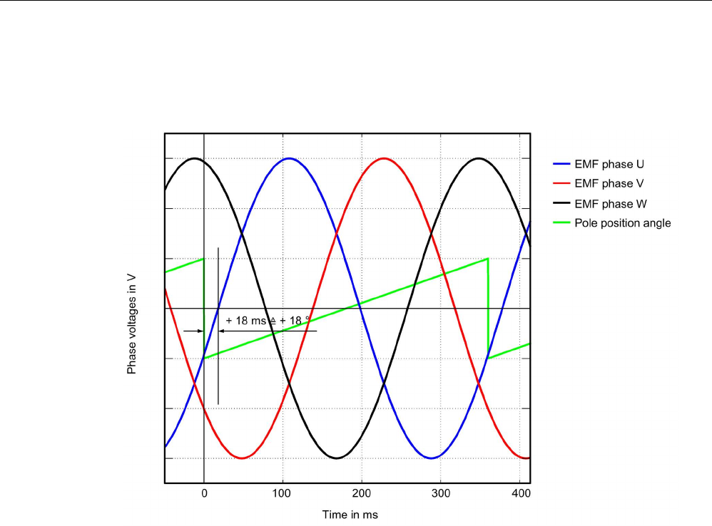
Commissioning
3.18 Commissioning SIMOTICS T-1FW6 built-in torque motors
STARTER Commissioning Manual
Commissioning Manual, (IH1), 07/2016, 6SL3097-4AF00-0BP5 271
Commutation angle outside the tolerance
Example: The falling edge of the sawtooth voltage (pole position angle) leads the zero
crossing of EMF phase U by approx. 18° electrical.
Image 3-96 Example of an incorrectly commutated drive
Adapt the incorrect commutation shown in the figure above according to Chapter "Checking
the commutation angle offset with STARTER (Page 260)".
p0431 = p0431 - 18

Commissioning
3.18 Commissioning SIMOTICS T-1FW6 built-in torque motors
STARTER Commissioning Manual
272 Commissioning Manual, (IH1), 07/2016, 6SL3097-4AF00-0BP5
3.18.7
Special case of a parallel connection
Note
Parallel connection
Only torque motors that are the same size and have the same current requirements (same
winding design) can be connected in parallel. The article numbers of the motors must only
differ with regard to the position "comp
onent (position of the interfaces)".
For more information and connection diagrams, refer to the "SIMOTICS T
-1FW6 built-in
Torque Motors" Configuration Manual in Chapter "Coupled motors".
The following requirements must be met in order to operate several torque motors in parallel
on a SINAMICS Motor Module:
● The motors must be arranged according to the data in the "SIMOTICS T-1FW6 built-in
torque motors" Configuration Manual.
● The direction of rotation of parallel-connected motors must match the data in the
"SIMOTICS T-1FW6 built-in torque motors" Configuration Manual. For a Janus
arrangement, when connecting the stoker, phases V and W must be interchanged so that
the stoker has the same direction of rotation as the master, also refer to the
"SIMOTICS T-1FW6 built-in torque motors" Configuration Manual in Chapter "Power and
signal connection for parallel operation".
● Ensure the position of the EMF voltages of the parallel-connected motors as described in
Chapter "Checking the angular commutation with an oscilloscope (Page 260)"; it is
imperative that you check these carefully. Maintain the maximum deviation of the phase
angle between the EMF voltages of the motors according to Chapter "Check angular
commutation offset by taking measurements". You may only connect the motors to the
converter after the deviation of the commutation angle for all of the motors to be
connected in parallel lies within the limit value.
● Before commissioning and switching-on the DC voltage for the first time, note that the
temperature monitoring circuits must be carefully checked to ensure that they correctly
trip.
Then commission the system using the STARTER commissioning tool according to Chapter
"Parameterizing a motor and encoder (Page 240)". The parallel connection for the
SIMOTICS T-1FW6 built-in torque motors selected from the motor list can only be
parameterized in the expert list of the drive.
After completing the configuration, in the STARTER commissioning tool, open the expert list
of the drive and assign parameter p0306 = N, where N is the number of motors to be
operated in parallel. The number of motors set must correspond to the number of motors that
are actually connected in parallel.
After changing p0306, you must adapt the control parameters for a motor from the list by the
automatic calculation with p0340 = 1. For a third-party motor not contained in the list, this
setting, however, would cause the data of the electrical equivalent circuit diagram to be lost.
Consequently, select the setting p0340 = 3 for a third-party motor.
Detailed information about parameter p0306 is contained in the STARTER commissioning
tool help and in the SINAMICS S120/S150 List Manual.

Commissioning
3.18 Commissioning SIMOTICS T-1FW6 built-in torque motors
STARTER Commissioning Manual
Commissioning Manual, (IH1), 07/2016, 6SL3097-4AF00-0BP5 273
If p0306 is changed during quick commissioning (p0010 = 1), then the maximum current
p0640 is appropriately pre-assigned. This is not the case in the motor commissioning
(p0010 = 3)!
The motor data displayed in the STARTER commissioning tool is only valid for one motor
and is only internally interpolated up to N motors connected in parallel.
3.18.8
Optimization of the closed-loop control
When running through the drive configuration, in the step "Calculating the motor/controller
data", drive-specific controller parameters are calculated, see the "Screen form to calculate
motor/controller data (Page 245)" figure. However, to be able to use the optimal performance
of the machine, a subsequent optimization of the controller parameters is required. Higher
positioning/machining accuracy can be achieved and cycle times can be reduced by means
of optimized settings.
Controller optimization may only be performed by experienced specialists.
In the control, for optimizing the controller, there is the possibility of measuring frequency
responses or recording setpoint steps. Especially the frequency response measurement
allows machine-specific natural frequencies that restrict the bandwidth of the closed-loop
control to be taken into account.
You can ask your local Siemens office regarding optimization of the closed-loop control as a
service.

Commissioning
3.19 Commissioning of SSI encoders
STARTER Commissioning Manual
274 Commissioning Manual, (IH1), 07/2016, 6SL3097-4AF00-0BP5
3.19
Commissioning of SSI encoders
3.19.1
Notes on commissioning SSI encoders
Using error bits
The number and position of error bits can vary for SSI (Synchronous Serial Interface)
encoders. In the event of faults, error codes may even sometimes be transferred within the
position information.
It is therefore essential that you assess all the error bits present (see "Parameterization" and
"Limitations" in this chapter) as otherwise an error code may be interpreted as position
information if faults are present.
Hardware requirements
● SMC20 Sensor Module Cabinet Mounted
● SME25 Sensor Module External
● SMC30 Sensor Module Cabinet Mounted
● SME125 Sensor Module External
● Control Unit (CU320-2, CU310-2 or CUA32): Either the Sensor Module must be
connected using DRIVE-CLiQ or an SSI encoder evaluation integrated in the Control
Unit.

Commissioning
3.19 Commissioning of SSI encoders
STARTER Commissioning Manual
Commissioning Manual, (IH1), 07/2016, 6SL3097-4AF00-0BP5 275
Types of encoder that can be connected
Encoder
evaluation
using the module
Incremental tracks
Absolute position
Voltage supply for
encoder
SSI baud rate
Remarks
SMC20
sin/cos, 1 Vpp
SSI not cyclic
1)
5 V
100 kBaud
-
SME25 sin/cos, 1 Vpp SSI not cyclic 1) 5 V 100 kBaud SME25 is only
suited to direct
measuring
systems
SMC30 Square or
no incremental
tracks
SSI not cyclic 1), 3)
SSI, cyclic 2)
5 V or 24 V 100-
250 kBaud
-
SME125 sin/cos, 1 Vpp SSI not cyclic 1) 5 V 100 kBaud SME125 is only
suited to direct
measuring sys-
tems
1)
"not cyclic" means that the absolute position is only read when initializing the Sensor Module, after which the position is
only calculated by the incremental tracks.
2)
"cyclic" means that the absolute position is read permanently (usually in the PROFIBUS or position controller cycle) and
the position (X_IST1) formed from this.
3) The SSI protocol is cyclically read-out for the plausibility checks.
Note
Only encoders that support a transfer rate of 100 kHz and that have a high level in idle s
tate
may be used.
The monoflop time should be parameterized such that it is greater than or equal to the
specified monoflop time of the encoder. This must lie in the range between 15
– 30 µs.
The level during the monoflop time must be low.

Commissioning
3.19 Commissioning of SSI encoders
STARTER Commissioning Manual
276 Commissioning Manual, (IH1), 07/2016, 6SL3097-4AF00-0BP5
Ramp-up time of the encoder
In order to ensure that the correct sensor data is received, the encoder evaluation module
checks whether the connected encoder is activated and ready for operation:
● After the power supply is switched on at the encoder, no signals are evaluated for a
waiting period of 800 ms.
● After the waiting period has expired, test signals are applied to the clock cable and the
response of the data line observed. As long as the encoder is not ready, the encoder
holds the data line permanently in the idle state (as a rule, "high").
It is expected that the encoder has reached its ready state by this time.
● If the encoder has not signaled that it is in the ready state after approx. 10 seconds, the
encoder evaluation module signals a timeout error.
The waiting period starts again when:
● The 5 V power supply is applied to the encoder.
● Switchover to 24 V power supply after completed ramp-up of the encoder evaluation in
accordance with the parameterized voltage level.
Note
The activation routine is started each t
ime that the encoder is inserted. The activation routine
has been completed with the ready message to the evaluation module.
Note
An external 24 V encoder supply is permitted.
Parameterization
●
Predefined encoders
Various predefined SSI encoders are available for commissioning. These can be selected
in the commissioning windows of the STARTER commissioning tool.
●
User-defined encoders
If there are no predefined entries for the encoder used, user-defined encoder data can be
entered via windows using the commissioning wizard.

Commissioning
3.19 Commissioning of SSI encoders
STARTER Commissioning Manual
Commissioning Manual, (IH1), 07/2016, 6SL3097-4AF00-0BP5 277
Special settings
● Error bits (special case, several error bits)
If an SSI encoder has several error bits, the evaluation is activated in the list of experts as
follows using parameter p0434[x]:
Value = dcba
ba: Position of error bit in protocol (0 ... 63)
c: Level (0: Low level 1: High level)
d: Status of evaluation (0: Off, 1: On with 1 error bit, 2: On with 2 error bits ... 9: On with 9
error bits)
For several error bits, the following applies:
– The position specified under ba and the additional bits are assigned in ascending
order.
– The level set under c is applicable for all error bits.
Example:
p0434 = 1013
--> the evaluation is activated, and the error bit is at position 13 with low level.
p0434 = 1113
--> the evaluation is activated, and the error bit is at position 13 with high level.
p0434 = 2124
--> the evaluation is activated, and the 2 error bits are at a high level from position 24.
● Fine resolution p0418 and p0419
In order to make full use of the entire traversing range of the absolute encoder, the
position information, including fine resolution, must not exceed 32 bits.
Example:
An SSI encoder without incremental tracks is used. The encoder has a singleturn
resolution of 16 bits and a multiturn resolution of 14 bits. The absolute position resolution
is therefore 30 bits.
Consequently, only a fine resolution of 2 bits can be set. Parameters p0418[x] and
p0419[x] in the list of experts should therefore be set to the value 2.

Commissioning
3.19 Commissioning of SSI encoders
STARTER Commissioning Manual
278 Commissioning Manual, (IH1), 07/2016, 6SL3097-4AF00-0BP5
Diagnostics
Example 1
An SSI encoder without incremental tracks is used. The encoder has a singleturn resolution
of 16 bits and a multiturn resolution of 14 bits. The fine resolution p0418[x] and p0419[x] is
set to the value 2. In parameter r0482[x] (X_IST1), the product is formed from "pulses per
revolution" and fine resolution p0418[x]. If using SSI encoders without incremental tracks, the
number of pulses and singleturn resolution are identical. In our example, the actual position
value X_IST1 (r0482[x]) must therefore have changed by the following value after one
encoder revolution:
Single turn resolution * fine resolution = 216 * 22 = 262144
Example 2
An SSI encoder with incremental tracks is used. In this case, incorrect SSI protocol settings
can be seen, e.g. by the fact that once the system has been switched on a different absolute
position is indicated from that before it was last deactivated.
The absolute position X_IST2 (r0483[x]) must be considered by way of a check. Following
PROFIdrive, however, just one value is displayed in this parameter if bit 13 (request absolute
value in cycles) is set to the value 1 in the encoder control word p0480[x].
This bit can be set, e.g. with the aid of the binector-connector converter.
Once switched on, the SSI encoder is now turned a few revolutions. Once switched off and
on again, the absolute position of X_IST2 (r0483[x]) must indicate an unchanged value. Only
minor deviations may occur in the fine resolution area.
3.19.2
Encoder identification for SSI encoders without incremental tracks
The SSI (Synchronous Serial Interface) is used to transfer the absolute value for absolute
value encoders. Because the data transfer format is not standardized for SSI, the
manufacturers of encoder systems can define the format themselves. Consequently, a
universal parameterization of SSI encoders was introduced for the SINAMICS drive system
so that the largest possible number of different encoders and manufacturers are supported.
The encoder identification for SSI encoders simplifies the encoder configuring. Two different
techniques are available for the encoder identification.
Moving the axis manually
The manual technique is particularly suitable for easily accessible axes as well as rotary
axes without a holding brake.
For this technique, the axis must be turned or moved using a defined movement. For a rotary
encoder, this movement corresponds to one encoder revolution. For a linear encoder, it is
25 mm.
Precondition
The encoder/motor must be easily accessible and it must be possible to rotate the axis
(released brake).

Commissioning
3.19 Commissioning of SSI encoders
STARTER Commissioning Manual
Commissioning Manual, (IH1), 07/2016, 6SL3097-4AF00-0BP5 279
Moving the axis by the converter
The technique is particularly suitable for large and poorly accessible axes as well as rotary
axes with a holding brake.
For this technique, the axis must be moved with a defined speed or velocity. The speed for
the rotary encoder is 60 rpm or the velocity for the linear encoder is 1.5 m * rpm.
Precondition
The drive has been completely commissioned and can be traveled. If the SSI encoder is
used as motor encoder, the control type must have been set previously to "encoderless"
(p1300).
Once the encoder has been identified, the pulses are locked again automatically.
Procedure
Note
The "x" serves as plac
eholder for the encoder number in the following description. Encoder
numbers 1, 2 or 3 are possible.
1. Proceed as follows:
– p0010:= 4 (start encoder commissioning)
– p0400[x] = 9999 (user-defined encoder)
2. Set the not identified properties (linear/rotary, 5 V / 24 V) and the "SSI encoder" property:
– p0404[x].0 = 0: Rotary
– p0404[x].0 = 1: Linear
– p0404[x].9 = 1: SSI encoder
– p0404[x].20 = 1: Voltage level 5 V
– p0404[x].21 = 1: Voltage level 24 V
3. Start the encoder identification using p0400[x] = 10100 (identify encoder (waiting)).
4. Depending on the technique, perform a defined movement (see "Moving the axis
manually" or "Moving the axis by the converter" technique).
5. After the identification, check the encoder configuration.
The associated parameters are listed in the Section "Overview of the important
parameters" (Page 280).
– In particular, compare the parameters of the encoder lines or spacing with the
documentation of the encoder, and correct these parameters if necessary. For rotary
encoder, these are p0408, p0421 and p0423. For linear encoders, these are p0407
and p0422.
– If special bits are identified in the SSI telegram (p0448), the first special bit is
configured as a fault bit (p0434) and the second special bit as an alarm bit (p0435).
Compare this setting with the documentation of the encoder, and correct the above
parameters if necessary.

Commissioning
3.19 Commissioning of SSI encoders
STARTER Commissioning Manual
280 Commissioning Manual, (IH1), 07/2016, 6SL3097-4AF00-0BP5
Note
The alarm A07569 "Encoder identification active" remains pe
nding while the identification
task has not yet completed.
Note
If the connected SSI encoder cannot be identified, alarm F3x153 "Encoder x: Identification
failed" is issued and the value 0, "No encoder", is entered in parameter p0400. This encoder
must
then be configured manually.
3.19.3
Overview of important parameters
Overview of important parameters (see SINAMICS S120/S150 List Manual)
•
p0400[0...n]1)
Encoder type selection
•
p0404[0...n]1)
Encoder configuration active
•
p0407[0...n]1)
Linear encoder scale
•
p0408[0...n]1)
Rotary encoder pulse No.
•
p0421[0...n]1)
Absolute encoder rotary multiturn resolution
•
p0422[0...n]1)
Absolute encoder linear measuring increments resolution
•
p0423[0...n]1)
Absolute encoder rotary singleturn resolution
•
p0427[0...n]
SSI e
ncoder baud rate
•
p0428[0...n]
SSI encoder monoflop time
•
p0429[0...n]1)
SSI encoder configuration
•
p0434[0...n]1)
SSI encoder error bit
•
p0435[0...n]1)
SSI encoder alarm bit
•
p0436[0...n]1)
SSI encoder parity bit
•
p0446[0...n]
SSI encoder bit count before
the absolute value
•
p0447[0...n]1)
SSI encoder bit count absolute value
•
p0448[0...n]1)
SSI encoder bit count after the absolute value
•
p0449[0...n]1)
SSI encoder bit count filler bits
1) Changed for SSI encoder identification

Commissioning
3.20 Commissioning of a 2-pole resolver as absolute encoder
STARTER Commissioning Manual
Commissioning Manual, (IH1), 07/2016, 6SL3097-4AF00-0BP5 281
3.20
Commissioning of a 2-pole resolver as absolute encoder
Description
You can use 2-pole (1 pole pair) resolvers as singleturn absolute encoders. The absolute
encoder position actual value is provided in Gn_XIST2 (r0483[x]).
Actual position value format
The factory setting for the fine resolution of Gn_XIST1 differs from the fine resolution in
Gn_XIST2 (p0418 = 11, p0419 = 9). This may cause a slight displacement of the encoder
position after switching the drive unit off/on.
Therefore, when using a 2-pole resolver as an absolute encoder, we recommend that the
fine resolution for Gn_XIST1 (p0418) is set the same as the fine resolution for Gn_XIST2
(p0419), e.g. p0418 = p0419 =11.
2-pole resolvers are automatically entered in the PROFIdrive profile (r0979) as singleturn
absolute encoders.
Position tracking
You can also activate position tracking for a 2-pole resolver. Please note, however, that the
resolver may not be moved more than half an encoder revolution (pole width) when switched
off. The activation and configuration of the position tracking is described in the chapter
"Position tracking".
EPOS - absolute encoder adjustment
If the 2-pole resolver is used as an absolute encoder for basic positioning (EPOS), the
absolute encoder adjustment must be performed in the expert list.
To do this, set reference point coordinate p2599 to the value corresponding to the
mechanical system and request the adjustment with p2507 = 2.
You will then need to back up the data from RAM to ROM.

Commissioning
3.21 Temperature sensors for SINAMICS components
STARTER Commissioning Manual
282 Commissioning Manual, (IH1), 07/2016, 6SL3097-4AF00-0BP5
3.21
Temperature sensors for SINAMICS components
WARNING
Danger to life due to electric shock in the event of voltage flashovers on the temperature
sensor cable
Voltage flashovers to the signal electronics can occur in motors without safe electrical
separation of the temperature sensors.
• Use temperature sensors that satisfy the specifications of the protective separation in
accordance with IEC 61800-5-1.
• If protective separation cannot be guaranteed (with linear motors or third-party motors,
for example), use a Sensor Module External (SME120 or SME125) or the TM120
Terminal Module.
The following table provides an overview of the SINAMICS drive system components
available with temperature sensor connections.
Table 3- 27 Temperature sensor connections for SINAMICS components
Module
Interface
Pin
Signal name
Technical specifications
SMC10/SMC20
X520 (sub D) 13
25
+Temp
-Temp
Temperature sensor
KTY84-1C130/PTC/PT1000
SMC30
X520 (sub D)
Temperature chan-
nel 2
1
8
+Temp
-Temp
Temperature sensor
KTY84-
1C130/PTC/PT1000/bimetallic
switch with NC contact
X531 (terminal)
Temperature chan-
nel 1
3
4
-Temp
+Temp
Temperature sensor
KTY84-
1C130/PTC/PT1000/bimetallic
switch with NC contact
CU310-2 DP
CU310-2 PN
X23 (sub D) 1
8
+Temp
-Temp
Temperature sensor
KTY84-1C130 /PTC/PT1000
X120 (terminal) 1
2
+Temp
-Temp
Temperature sensor
KTY84-1C130/PTC/PT1000
CUA31
X210 (terminal) 1
2
+Temp
-Temp
Temperature sensor
KTY84-1C130/PTC/PT1000
CUA32
X210 (terminal)
Temperature chan-
nel 2
1
2
+Temp
-Temp
Temperature sensor
KTY84-
1C130/PTC/PT1000/bimetallic
switch with NC contact
X220 (sub D)
Temperature chan-
nel 1
1
8
+Temp
-Temp
Temperature sensor
KTY84-
1C130/PTC/PT1000/bimetallic
switch with NC contact
TM31
X522 (terminal) 7
8
+Temp
-Temp
Temperature sensor
KTY84-1C130/PTC/PT1000

Commissioning
3.21 Temperature sensors for SINAMICS components
STARTER Commissioning Manual
Commissioning Manual, (IH1), 07/2016, 6SL3097-4AF00-0BP5 283
Module
Interface
Pin
Signal name
Technical specifications
TM120
X524 (terminal) 1
2
-Temp
+Temp
Temperature sensor connection
KTY84-1C130/PTC/PT1000/ bi-
metallic switch with NC contact
For linear motor applications, here
the motor temperature sensor
Connect KTY84-1C130/PT1000
3
4
-Temp
+Temp
5
6
-Temp
+Temp
7
8
-Temp
+Temp
TM150
X531 1
2
3
4
+Temp
-Temp
+Temp
-Temp
KTY84-1C130/PTC/bimetallic NC
contact/PT100/PT1000
Information on interconnecting the
temperature channels can be
found below
X532 1
2
3
4
+Temp
-Temp
+Temp
-Temp
X533 1
2
3
4
+Temp
-Temp
+Temp
-Temp
X534 1
2
3
4
+Temp
-Temp
+Temp
-Temp
X535 1
2
3
4
+Temp
-Temp
+Temp
-Temp
X536 1
2
3
4
+Temp
-Temp
+Temp
-Temp
SME20
Measuring system
interface
7
9
-Temp
+Temp
Temperature sensor
KTY84-1C130 / PTC
connection cable with article num-
ber 6FX8002-2CA88-.... neces-
sary
1)
SME120/SME125
X200 (connector)
Temperature chan-
nel 2
1
2
-Temp
+Temp
Temperature sensor
KTY84-
1C130/PTC/PT1000/bimetallic
switch with NC contact
X200 (connector)
Temperature chan-
nel 3
3
4
+Temp
-Temp
Temperature sensor
KTY84-
1C130/PTC/PT1000/bimetallic
switch with NC contact
X200 (connector)
Temperature chan-
nel 4
5
6
+Temp
-Temp
Temperature sensor
KTY84-
1C130/PTC/PT1000/bimetallic
switch with NC contact

Commissioning
3.21 Temperature sensors for SINAMICS components
STARTER Commissioning Manual
284 Commissioning Manual, (IH1), 07/2016, 6SL3097-4AF00-0BP5
Module
Interface
Pin
Signal name
Technical specifications
Active Line Module
Booksize
X21 (terminal)
1
2
+Temp
-Temp
Active Line Module temperature
sensor
Temperature switch type: bimetal-
lic switch with NC contact
Chassis
X41 (terminal)
4
3
+Temp
-Temp
Smart Line Module
Booksize
X21 (terminal)
1
2
+Temp
-Temp
Active Line Module temperature
sensor
Temperature switch type: bimetal-
lic switch with NC contact
Chassis
X41 (terminal)
4
3
+Temp
-Temp
Basic Line Module
Booksize
X21 (terminal)
1
2
+Temp
-Temp
Basic Line Module temperature
sensor Temperature switch type:
bimetallic switch with NC contact
Chassis
X41 (terminal)
4
3
+Temp
-Temp
Motor Module
Booksize
X21/X22 (terminal)
1
2
+Temp
-Temp
Temperature sensor
KTY84–1C130/PTC/PT1000
Bimetallic switch with NC contact:
Alarm and timer (only for tempera-
ture evaluation via MM)
PT100 temperature sensor
The following ap-
plies to chassis:
X41 (terminal)
4
3
+Temp
-Temp
1) Cable for connection to direct measurement systems: Article number 6FX.002-2CB54-....
Commissioning information
The index [0...n] used in the following identifies either the motor data set or the encoder data
set.
SMC10/SMC20
You can use the STARTER screen (\messages and monitoring \ motor temperature) to
parameterize the motor temperature evaluation via SUB-D socket X520.
SMC30 (as of article number 6SL3055-0AA00-5CA2)
In addition to temperature evaluation via terminal X531 (temperature channel 1), this module
also has temperature evaluation at SUB-D socket X520 (temperature channel 2).
In the default setting (p0600 = 1 "Temperature via encoder 1" and p0601 = 2 "KTY" or p0601
= 6 "PT1000"), the temperature is evaluated via the first temperature channel. The
temperature sensor is connected to terminal X531 on the SMC30. The temperature is shown
via r0035.

Commissioning
3.21 Temperature sensors for SINAMICS components
STARTER Commissioning Manual
Commissioning Manual, (IH1), 07/2016, 6SL3097-4AF00-0BP5 285
The parameterization of the motor temperature evaluation via the sub D socket X520 must
be performed in the expert list as follows:
● p0600[0...n]: Selection of the encoder (1, 2 or 3) to which the SMC30 that is used for the
temperature evaluation, is assigned (n = motor data set).
● p0601[0...n] = 10 (evaluation via several temperature channels), n = motor data set.
● p4601[0...n]: Select the temperature sensor type for temperature channel 2 (depends on
encoder data set n, not the motor data set).
Note
With several encoders, the index [n] of the relevant encoder / encoder data set, via which
the temper
ature evaluation is performed, must be used.
The temperature is displayed in parameter r4620[1] (temperature channel 2). For multiple
temperature channels (use of temperature channels 1 and 2 on SMC30), parameter r0035
shows the maximum temperature.
Example:
A KTY temperature sensor is connected at the sub D socket X520 on the SMC30 of Encoder
1.
This is parameterized via:
● p0600[0...n] = 1 / p0601[0...n] = 10 / p4601[0...n] = 20
Both temperature channels (X520 and X531) can be used at the same time. In addition to
the above parameterization, the temperature sensor type connected at terminal X531 must
be entered in p4600[0...n]. The maximum value is then generated for the motor temperature
and displayed in r0035.
Note
With several encoders, the index [n] of the relevant encoder / encoder data set, via which the
temperature evaluation is performed, must be used.
CU310-2 DP/CU310-2 PN
The Control Unit 310-2 has an integrated SMC30 encoder interface. This encoder interface
is accessed via the 15-pin Sub-D-contact X23 and is evaluated as temperature channel 1.

Commissioning
3.21 Temperature sensors for SINAMICS components
STARTER Commissioning Manual
286 Commissioning Manual, (IH1), 07/2016, 6SL3097-4AF00-0BP5
There are three options available to evaluate the temperature:
Option
The following parameter settings must be made:
Temperature channel 1 via the SMC30
encoder interface X23.
• p0600[0...n] = 1: Selection of the encoder (1, 2 or 3), which is assigned
to encoder interface X23 and via which the temperature is evaluated, n =
motor data set
• p0601[0...n] = 1 or 2: Selection of the temperature sensor type, n = mo-
tor data set
• r0035: Display of the temperature value
Temperature channel 1 via terminal X120,
for example, if an encoder is being used.
• p0600[0...n] = 11: Activation from temperature channel 1 via terminal
X120
• p0601[0...n] = 1 or 2: Selection of the temperature sensor type, n = mo-
tor data set
• r0035: Display of the temperature value
Two temperature channels via X23 and
X120. Encoder interface X23 is assigned to
temperature channel 1 and terminal X120 is
assigned to temperature channel 2.
• p0600[0...n] = 1: Selection of the encoder (1, 2 or 3), which is assigned
to encoder interface X23 and via which the temperature is evaluated, n =
motor data set
• p0601[0...n] = 10: Evaluation via several temperature channels
• p4600[0...n]: Selection of the temperature sensor type from temperature
channel 1, n = encoder data set
• p4601[0...n]: Selection of the temperature sensor type from temperature
channel 2, n = encoder data set
• r4620[0...3]: Reading the temperature values
– Index n = 0 temperature channel 1
– Index n = 1 temperature channel 2
• r0035: Display of the higher temperature value of temperature channels
1 and 2
CUA31
The parameterization of the temperature evaluation via terminal X210 can be performed
using the STARTER screen (messages and monitoring > motor temperature). "Temperature
sensor via Motor Module (11)" should be selected in the "Temperature sensor selection"
field. The temperature of the sensor is displayed in r0035.
CUA32
The parameterization of the temperature evaluation via terminal X210 or sub D socket X220
is performed using two temperature channels.
p0600 = 11: Temperature sensor via Motor Module
For the SINAMICS S120 AC Drive (AC/AC) and if Control Unit Adapter CUA31/CUA32 is
used, the temperature sensor connection is on the adapter (X210).
TM31
A Terminal Module 31 (TM31) is used when additional digital and analog inputs/outputs are
required. The sensor type used is set via p4100 and the temperature signal interconnected
via r4105.

Commissioning
3.21 Temperature sensors for SINAMICS components
STARTER Commissioning Manual
Commissioning Manual, (IH1), 07/2016, 6SL3097-4AF00-0BP5 287
TM120
If the temperature sensors in the installed motors do not have protective separation, then
you require a Terminal Module 120 (TM120). Up to 4 different temperature sensors can be
connected to the TM120. The TM120 senses the temperature values, evaluates them, and
sends them via DRIVE-CLiQ to the Control Unit. The actual temperature values measured
using KTY84 or PT1000 are evaluated in the range from -140° C to +188.6° C. Actual
temperature values outside this range are not taken into account. The fault and alarm
thresholds (p4102) of the temperature values can be set from -48° C to 251° C.
Settings for the measurement:
● With p0600 = 20 or 21, the motor temperature sensing is activated using an external
sensor.
● With p0601 = 11, the evaluation is set over several temperature channels.
● In p0604, the motor temperature alarm threshold is set.
● In p0605, the motor temperature fault threshold is set.
● With p0608 and p0609, the temperature channels are assigned to the signal sources for
the motor temperatures.
– With p4100[0...3] = 1, temperature sensor type PTC is set to the corresponding
channel 1 to 4 and the evaluation activated.
– With p4100[0...3] = 2, temperature sensor type KTY84 is set to the corresponding
channel 1 to 4 and the evaluation activated.
– With p4100[0...3] = 4, the temperature sensor type bimetal NC contact is set and the
evaluation activated.
– With p4100[0...3] = 6, temperature sensor type PT1000 is set to the corresponding
channel 1 to 4 and the evaluation activated.
● The actual resistance value of the particular temperature sensor is displayed in parameter
r4101[0...3].
● For p4102[0...7] = 251° C, the evaluation of the associated threshold is deactivated.
For sensor type "PTC thermistor" (p4100[0...3] = 1), the following applies:
To activate the associated alarm or fault, p4102[0...7] ≤ 250° C must be set.
● The actual temperature value of the temperature evaluation is displayed in parameter
r4105[0...3]. If no sensor has been selected, or if the actual temperature value is invalid,
then the value -300° C is in parameter r4105[0...3].
● With p4610[0...n] to p4613[0...n], the temperature sensors are assigned to the motor and
the response defined.
TM150
The Terminal Module 150 (TM150) has 6x 4-pole terminals for temperature sensors.
Temperature sensors can be connected in a 2, 3 or 4-wire system. Up to 12 input channels
can be evaluated if two 2-wire sensors are connected to the 4 poles at the input terminal
strips. Twelve (12) input channels can be evaluated in the factory setting. The temperature
channels of a TM150 can be subdivided into 3 groups and evaluated together.

Commissioning
3.21 Temperature sensors for SINAMICS components
STARTER Commissioning Manual
288 Commissioning Manual, (IH1), 07/2016, 6SL3097-4AF00-0BP5
When using 2-wire sensors, to increase the measuring accuracy, the cable resistance can
be measured and saved. To do this, short-circuit the sensor cable as close as possible to the
sensor. The technique is described in the SINAMICS S120/150 List Manual in p4109[0...11].
The measured cable resistance is then taken into account when evaluating the temperature.
The cable resistance value is saved in p4110[0...11].
The TM150 can acquire the signals from KTY84, PTC, bimetallic NC contact, PT100 and
PT1000 temperature sensors and evaluate them. The fault and alarm thresholds of the
temperature values can be set from -99° C to 251° C. The temperature sensors are
connected at terminal strip X531 to X536 according to the table above. For further
information on the configuration and the connections, refer to the function diagrams 9625,
9626 and 9627 in the SINAMICS S120/S150 List Manual.
● p4100[0...11] sets the sensor type for the respective temperature channel.
Value of p4100[0...11]
Temperature sensor
Temperature display range r4105[0...11]
0
Evaluation disabled
-
1 PTC thermistor -50° C or +250° C
2
KTY84
-99° C to +250° C
4
Bimetallic NC contact
-50° C or +250° C
5
PT100
-99° C to +250° C
6
PT1000
-99° C to +250° C
● r4105[0...11] indicates the actual value of the temperature channel.
For switching temperature sensors, such as PTC and bimetallic NC contact, two limit
values are displayed symbolically:
– r4105[0...11] = -50°C: The actual temperature value is below the rated response
temperature.
– r4105[0...11] = +250°C: The actual temperature value is above the rated response
temperature.
Note
For PTC and bimetal NC contact the following applies:
What is shown in r4105[0...11] does not correspond to the actual temperature value.
● With p4108[0...5] = 0, you evaluate a sensor in a 2-wire system at a 4-wire connection at
terminals 1 and 2. Terminals 3 and 4 remain open.
● With p4108[0...5] = 2, you evaluate a sensor in a 3-wire system at a 4-wire connection at
terminals 3 and 4. The measuring cable is connected at terminal 1. You must short-circuit
terminals 2 and 4.
● With p4108[0...5] = 3, you evaluate a sensor in a 4-wire system at a 4-wire connection at
terminals 3 and 4. The measuring cable is connected at terminals 1 and 2.
You can find additional information in function diagram 9626 in the SINAMICS S120/S150
List Manual and in the SINAMICS S120 Function Manual Drive Functions in Chapter
"Thermal motor protection".
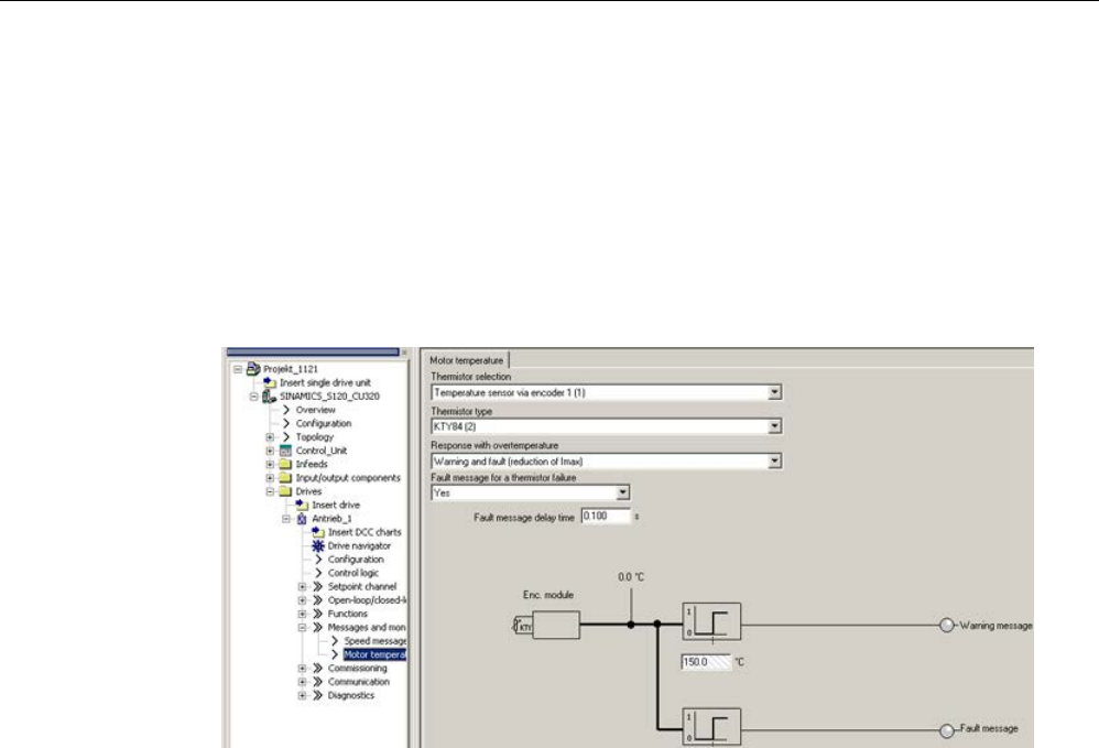
Commissioning
3.21 Temperature sensors for SINAMICS components
STARTER Commissioning Manual
Commissioning Manual, (IH1), 07/2016, 6SL3097-4AF00-0BP5 289
SME20
The evaluation of KTY, PT1000, or PTC temperature sensors can be parameterized using
the STARTER screen (Messages and monitoring > Motor temperature):
● Temperature sensor selection (≙ p0600[0...n]): Selection of the source to which the SME
module is assigned (temperature sensor via encoder (1, 2 or 3), temperature sensor via
BICO interconnections or temperature sensor via Motor Module).
● Temperature sensor type (≙ p0601[0...n]): Sets the sensor type for motor temperature
monitoring.
Image 3-97 Selection of temperature sensor for SME20 modules
SME120/SME125
For modules with several temperature sensor connections (SME modules), the temperature
sensor is selected depending on encoder data set n via parameters
p4601[0...n]..p4603[0...n]. A maximum of three motor temperature sensors can be evaluated
simultaneously via terminal X200.
The parameterization of the motor temperature evaluation via terminal X200 must be
performed in the expert list as follows:
● p0600[0...n]: Selection of the encoder (1, 2 or 3) to which the SMC used for the
temperature evaluation is assigned, n = motor data set.
● p0601[0...n] = 10 (evaluation via several temperature channels), n = motor data set.
● p4601[0...n]-p4603[0...n]: Selection of the temperature sensor type of temperature
channels 2-4, depending on encoder data set n.
Only temperature channels 2-4 are available at terminal X200.
● Parameter r4620[0...3] Motor temperatures SME
Displays the current temperatures in the motor, measured via an SME120 or SME125.
The indices mean:
[1] = SME temperature channel 2 / motor temperature sensor 2
[2] = SME temperature channel 3 / motor temperature sensor 3
[3] = SME temperature channel 4 / motor temperature sensor 4

Commissioning
3.21 Temperature sensors for SINAMICS components
STARTER Commissioning Manual
290 Commissioning Manual, (IH1), 07/2016, 6SL3097-4AF00-0BP5
Diagnostic parameters r0458[0...2] Sensor Module properties
Index [0...2]: Encoder 1...encoder 3
Parameter r0458 allows the following properties to be queried at the temperature sensor
modules:
Bit
Feature
02
Temperature sensor connection present
03
Connection for PTC for motors with DRIVE-CLiQ also present
04
Module temperature available
08 Evaluation set up across several temperature channels
Selection of several temperature channels p4601 ... p4603 is only possible, for example,
when parameter p0601 = 10 is set. This can be checked using the entry r0458.8 = 1.
You can find further information on parameter r0458 in: SINAMICS S 120/S150 List Manual.
Active Line Module, Basic Line Module, Smart Line Module, Motor Module (chassis)
Parameter p0601 "Motor temperature sensor type" enables the setting for the sensor type for
the temperature measurement at input X21 (booksize) or X41 (chassis). The measured
value is displayed in r0035.
Faults and alarms
F07011 drive: Motor overtemperature
KTY or PT1000 sensor:
The motor temperature has exceeded the fault threshold (p0605) or the timer stage (p0606)
after the alarm threshold was exceeded (p0604) has expired.
This results in the response parameterized in p0610.
PTC sensor + bimetallic switch:
The response threshold of 1650 Ohm was exceeded and the timer stage (p0606) has
expired.
This results in the response parameterized in p0610.
If an SME is used (p0601 = 10), parameter r0949 displays the number of the sensor channel
that has triggered the message.
A07015 drive: Motor temperature sensor alarm
A fault was detected when evaluating the temperature sensor set in p0600 and p0601.
When the fault occurs, the time in p0607 is started. If the fault still exists after this time has
expired, fault F07016 is output – however, not until at least 50 ms after alarm A07015.
If an SME is used (p0601 = 10), parameter r2124 displays the number of the sensor channel
that has triggered the message.
F07016 drive: Motor temperature sensor fault
A fault was detected when evaluating the temperature sensor set in p0600 and p0601.

Commissioning
3.21 Temperature sensors for SINAMICS components
STARTER Commissioning Manual
Commissioning Manual, (IH1), 07/2016, 6SL3097-4AF00-0BP5 291
If alarm A07015 is present, the time in p0607 is started. If the fault still exists after this time
has expired, fault F07016 is output – however, not until at least 50 ms after alarm A07015.
If an SME is used (p0601 = 10), parameter r0949 displays the number of the sensor channel
that has triggered the message.
Function diagrams (see SINAMICS S120/S150 List Manual)
•
8016
Signals and monitoring functions
- thermal monitoring motor,
Mot_temp ZSW F/A
Overview of important parameters (see SINAMICS S120/S150 List Manual)
•
r0035
CO: Motor temperature
•
r0458[0...2]
Sensor Module properties
•
p0600[0...n]
Motor temperature sensor for monitoring
•
p0601[0...n]
Motor temperature sensor type
•
p0603
CI: Motor temperature signal source
•
p0604[0...n]
Mot_temp_mod 2: Sensor alarm threshold
•
p0605[0...n]
Mot_temp_mod 1/2 sensor threshold and temperature value
•
p0606[0...n]
Mot_temp_mod 2: Sensor timer
•
p0607[0...n]
Temperature sensor fault timer
•
p0610[0...n]
Motor overtemperature response
•
p4100[0...3]
TM120 temperature evaluation, sensor type
•
p4100
TM31 sensor type
•
p4102[0...7]
TM120 fault threshold / alarm threshold
•
r4105[0...3]
CO:TM120 actual temperature value
•
r4105
CO:TM31 actual temperature value
•
p4600[0...n]
Motor temperature sen
sor 1 sensor type
•
p4601[0...n]
Motor temperature sensor 2 sensor type
•
p4602[0...n]
Motor temperature sensor 3 sensor type
•
p4603[0...n]
Motor temperature sensor 4 sensor type
•
r4620[0...3]
Motor temperature measured
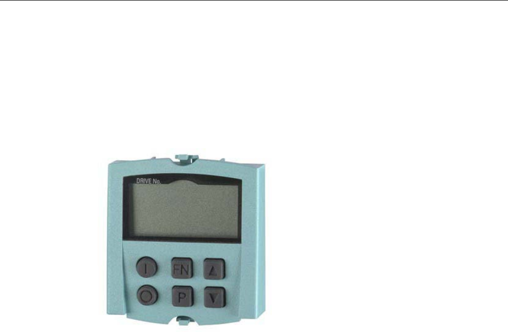
Commissioning
3.22 Basic Operator Panel 20 (BOP20)
STARTER Commissioning Manual
292 Commissioning Manual, (IH1), 07/2016, 6SL3097-4AF00-0BP5
3.22
Basic Operator Panel 20 (BOP20)
Brief description
The Basic Operator Panel 20 (BOP20) has six keys and a two-line display unit with
background lighting. The BOP20 can be plugged onto the SINAMICS Control Unit and
operated.
Image 3-98 BOP20
The BOP20 supports the following functions:
● Input and changing parameters
● Display of operating modes, parameters and alarms
● Display and acknowledgment of faults
● Powering-up/powering-down while commissioning
● Simulation of a motorized potentiometer
3.22.1
Operation with BOP20 (Basic Operator Panel 20)
3.22.1.1
General information about the BOP20
The BOP20 can be used to switch on and switch off drives during the commissioning phase
as well as to display and modify parameters. Faults can be diagnosed as well as
acknowledged.
The BOP20 is snapped onto the Control Unit. To do this, the blanking cover must be
removed (for additional information on mounting, please refer to the SINAMICS S120
Manual Control Units and Supplementary System Components).
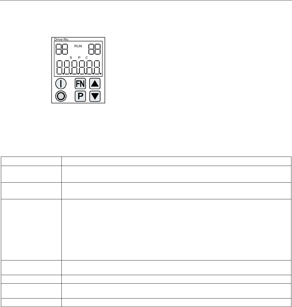
Commissioning
3.22 Basic Operator Panel 20 (BOP20)
STARTER Commissioning Manual
Commissioning Manual, (IH1), 07/2016, 6SL3097-4AF00-0BP5 293
Displays and keys
Image 3-99 Overview of displays and keys
Information on the displays
Table 3- 28 LED
Display
Meaning
top left
2 positions
The active drive object of the BOP is displayed here.
The displays and key operations always refer to this drive object.
RUN Lit if at least one drive in the drive line-up is in the RUN state (in operation).
RUN is also displayed via bit r0899.2 of the drive.
top right
2 positions
The following is displayed in this field:
• More than 6 digits: Characters that are still present but are invisible
(e.g. "r2" ––> 2 characters to the right are invisible, "L1" ––> 1 character to the left is invisible)
• Faults: Selects/displays other drives with faults
• Designation of BICO inputs (bi, ci)
• Designation of BICO outputs (bo, co)
• Source object of a BICO interconnection to a drive object different than the active one.
S Is (bright) if at least one parameter was changed and the value was not transferred into the non-
volatile memory.
P
Is lit (bright) if, for a parameter, the value only becomes effective after pressing the P key.
C Is light (bright) if at least one parameter was changed and the calculation for consistent data
management has still not been initiated.
Below, 6 digit
Displays, e.g. parameters, indices, faults and alarms.
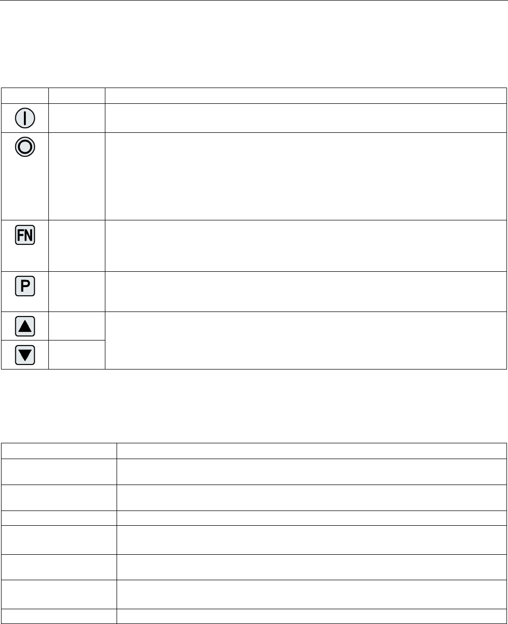
Commissioning
3.22 Basic Operator Panel 20 (BOP20)
STARTER Commissioning Manual
294 Commissioning Manual, (IH1), 07/2016, 6SL3097-4AF00-0BP5
Information on the keys
Table 3- 29 Keys
Key
Name
Meaning
ON Powering up the drives for which the command "ON/OFF1" should come from the BOP.
Binector output r0019.0 is set using this key.
OFF Powering down the drives for which the commands "ON/OFF1", "OFF2" or "OFF3" should come
from the BOP.
The binector outputs r0019.0, .1 and .2 are simultaneously reset when this key is pressed. After
the key has been released, binector outputs r0019.1 and .2 are again set to a "1" signal.
Note
:
The effectiveness of these keys can be defined by appropriately parameterizing the BICO (e.g.
using these keys it is possible to simultaneously control all of the existing drives).
Functions The significance of this key depends on the actual display.
Note
:
The effectiveness of this key to acknowledge faults can be defined using the appropriate BiCo
parameterization.
Parameter The significance of this key depends on the actual display.
If this key is pressed for 3 s, the "Copy RAM to ROM" function is executed. The "S" displayed on
the BOP disappears.
Raise The significance of these keys is dependent on the actual display and is used to increase or
decrease values.
Lower
BOP20 functions
Table 3- 30 Functions
Name
Description
Backlighting The backlighting can be set using p0007 in such a way that it switches itself off automatically
after the set time if no actions are carried out.
Changeover active drive From the BOP perspective the active drive is defined using p0008 or using the keys "FN" and
"Arrow up".
Units
The units are not displayed on the BOP.
Access level The access level for the BOP is defined using p0003.
The higher the access level, the more parameters can be selected using the BOP.
Parameter filter Using the parameter filter in p0004, the available parameters can be filtered corresponding to
their particular function.
Selecting the operating
display
Actual values and setpoints are displayed on the operating display.
The operating display can be set using p0006.
User parameter list
Using the user parameter list in p0013, parameters can be selected for access.

Commissioning
3.22 Basic Operator Panel 20 (BOP20)
STARTER Commissioning Manual
Commissioning Manual, (IH1), 07/2016, 6SL3097-4AF00-0BP5 295
Name
Description
Unplug while voltage is
present
The BOP can be withdrawn and inserted under voltage.
• The ON key and OFF key have a function.
When withdrawing, the drives are stopped.
After inserting, the drives must be switched on again.
• The ON key and OFF key have no function.
Withdrawing and inserting has no effect on the drives.
Actuating keys The following applies to the "P" and "FN" keys:
• When used in a combination with another key, "P" or "FN" must be pressed first and then
the other key.
Overview of important parameters (see SINAMICS S120/S150 List Manual)
All drive objects
•
p0005[0...1]
BOP status display selection
•
p0006
BOP status display mode
•
p0013[0...49]
BOP user
-defined list
•
p0971
Save drive object parameters
Drive object, Control Unit
•
r0002
Control Unit status display
•
p0003
BOP access level
•
p0004
BOP display
filter
•
p0007
BOP backlighting
•
p0008
BOP drive object after powering up
•
p0009
Device commissioning parameter filter
•
p0011
BOP password input (p0013)
•
p0012
BOP password confirmation (p0013)
•
r0019.0...14
CO/BO: Control word, BOP
•
p0977
Save all paramete
rs
Other drive objects (e.g. SERVO, VECTOR, X_INF, TM41 etc.)
•
p0010
Drive, commissioning parameter filter

Commissioning
3.22 Basic Operator Panel 20 (BOP20)
STARTER Commissioning Manual
296 Commissioning Manual, (IH1), 07/2016, 6SL3097-4AF00-0BP5
3.22.1.2
Displays and using the BOP20
Features
● Status indicator
● Changing the active drive object
● Displaying/changing parameters
● Displaying/acknowledging faults and alarms
● Controlling the drive using the BOP20
Status indicator
The operating display for each drive object can be set using p0005 and p0006. Using the
operating display, you can change into the parameter display or to another drive object. The
following functions are possible:
● Changing the active drive object
– Press key "FN" and "Arrow up" -> the drive object number at the top left flashes
– Select the required drive object using the arrow keys
– Acknowledge using the "P" key
● Parameter display
– Press the "P" key.
– The required parameters can be selected using the arrow keys.
– Press the "FN" key -> "r00000" is displayed
– Press the "P" key -> changes back to the operating display
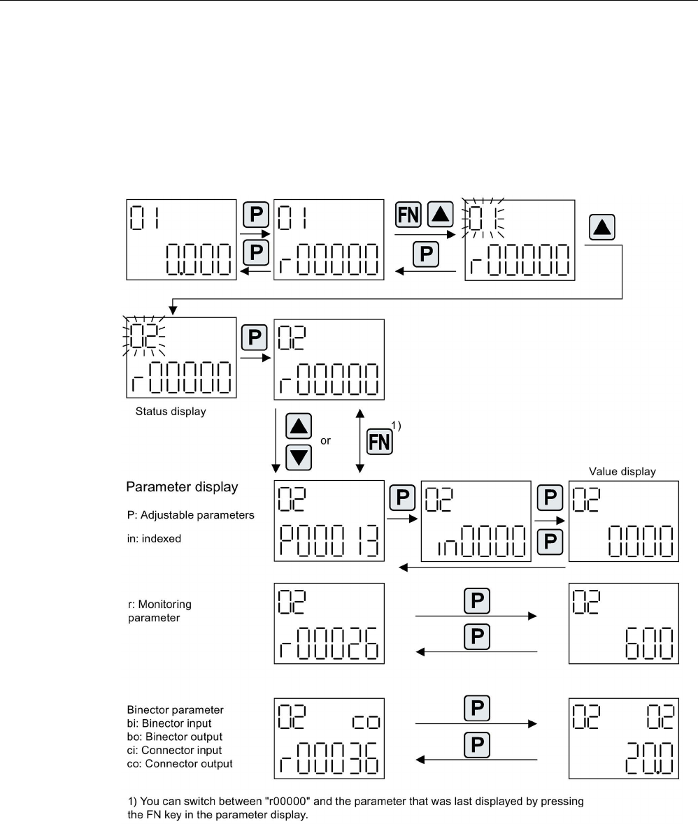
Commissioning
3.22 Basic Operator Panel 20 (BOP20)
STARTER Commissioning Manual
Commissioning Manual, (IH1), 07/2016, 6SL3097-4AF00-0BP5 297
Parameter display
The parameters are selected in the BOP20 using the number. The parameter display is
reached from the operating display by pressing the "P" key. Parameters can be searched for
using the arrow keys. The parameter value is displayed by pressing the "P" key again. You
can toggle between the drive objects by simultaneously pressing the "FN" key and an arrow
key. You can toggle between "r00000" and the parameter that was last displayed by
pressing the "FN" key in the parameter display.
Image 3-100 Parameter display
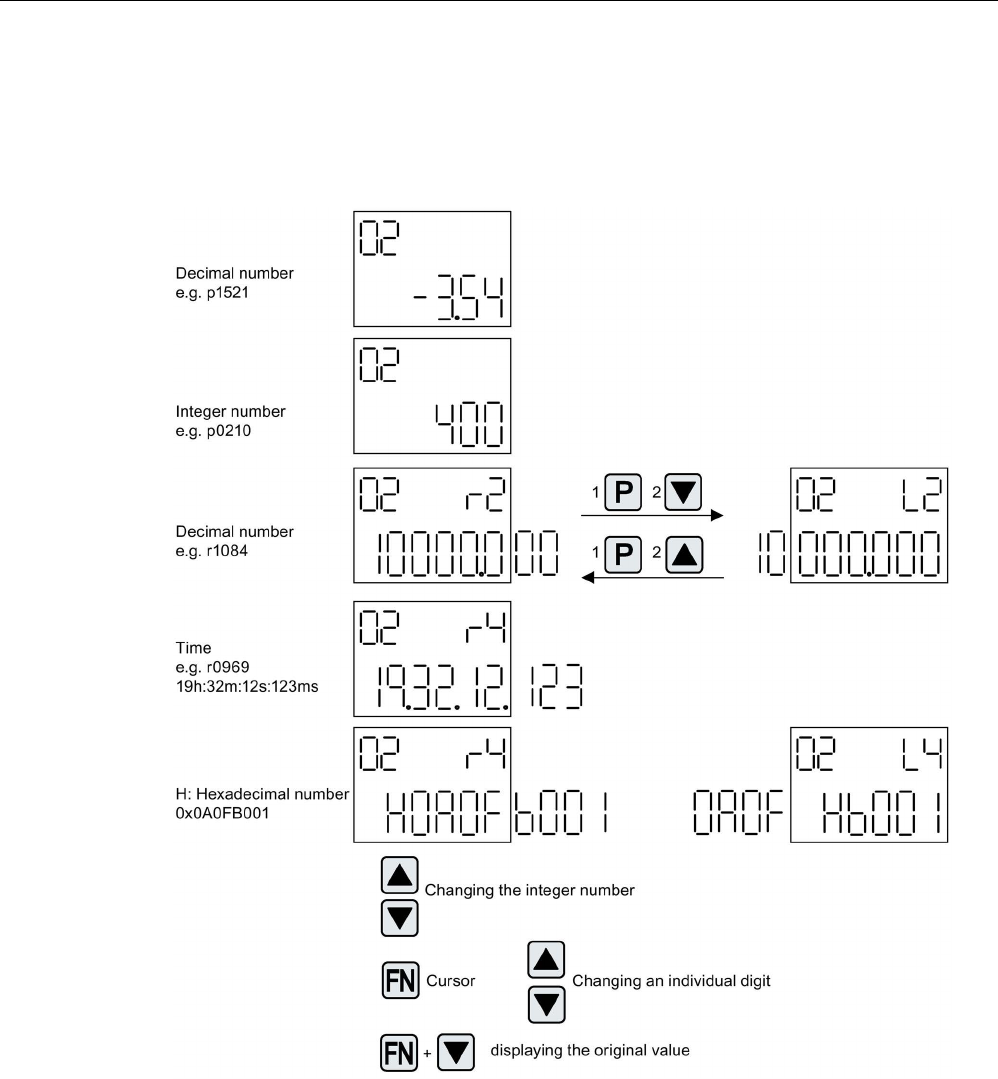
Commissioning
3.22 Basic Operator Panel 20 (BOP20)
STARTER Commissioning Manual
298 Commissioning Manual, (IH1), 07/2016, 6SL3097-4AF00-0BP5
Value display
To switch from the parameter display to the value display, press the "P" key. In the value
display, the values of the adjustable parameters can be increased and decreased using the
arrow. The cursor can be selected using the "FN" key.
Image 3-101 Value display
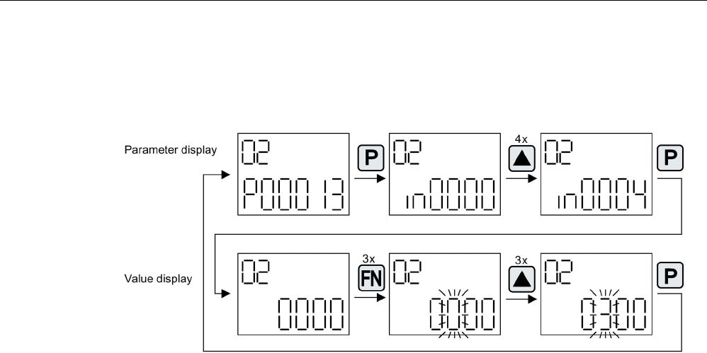
Commissioning
3.22 Basic Operator Panel 20 (BOP20)
STARTER Commissioning Manual
Commissioning Manual, (IH1), 07/2016, 6SL3097-4AF00-0BP5 299
Example: Changing a parameter
Precondition: The appropriate access level is set
(for this particular example, p0003 = 3).
Image 3-102 Example: Changing p0013[4] from 0 to 300
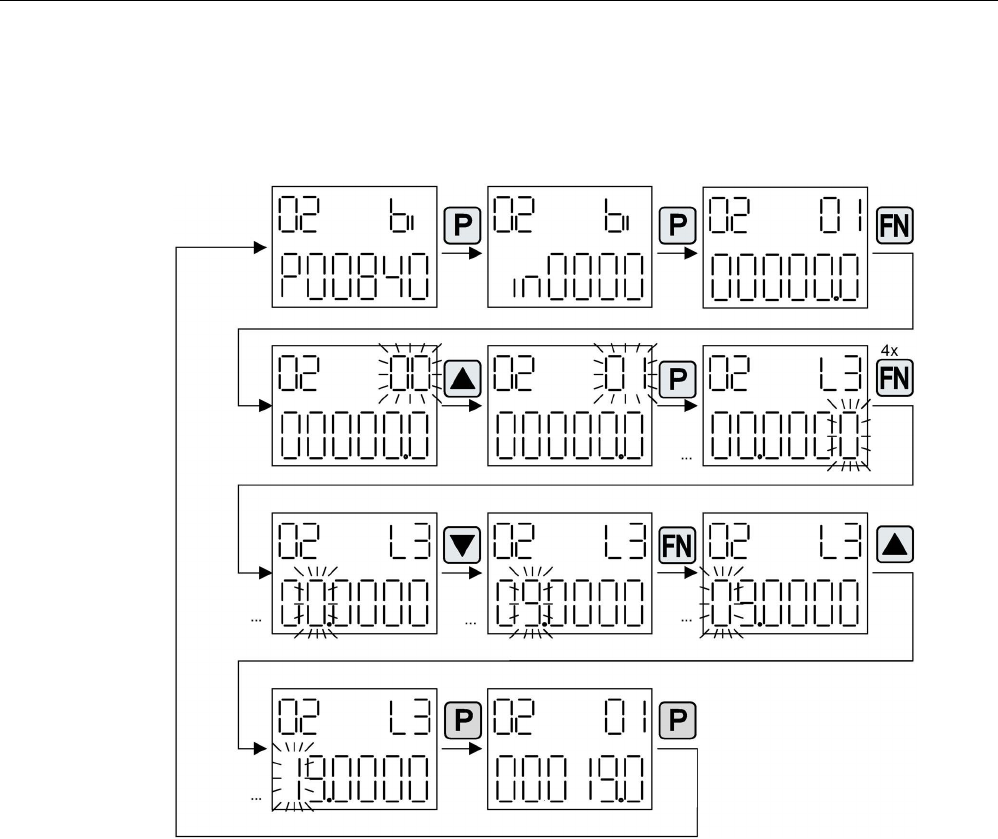
Commissioning
3.22 Basic Operator Panel 20 (BOP20)
STARTER Commissioning Manual
300 Commissioning Manual, (IH1), 07/2016, 6SL3097-4AF00-0BP5
Example: Changing binector and connector input parameters
For the binector input p0840[0] (OFF1) of drive object 2 binector output r0019.0 of the
Control Unit (drive object 1) is interconnected.
Image 3-103 Example: Changing indexed binector parameters
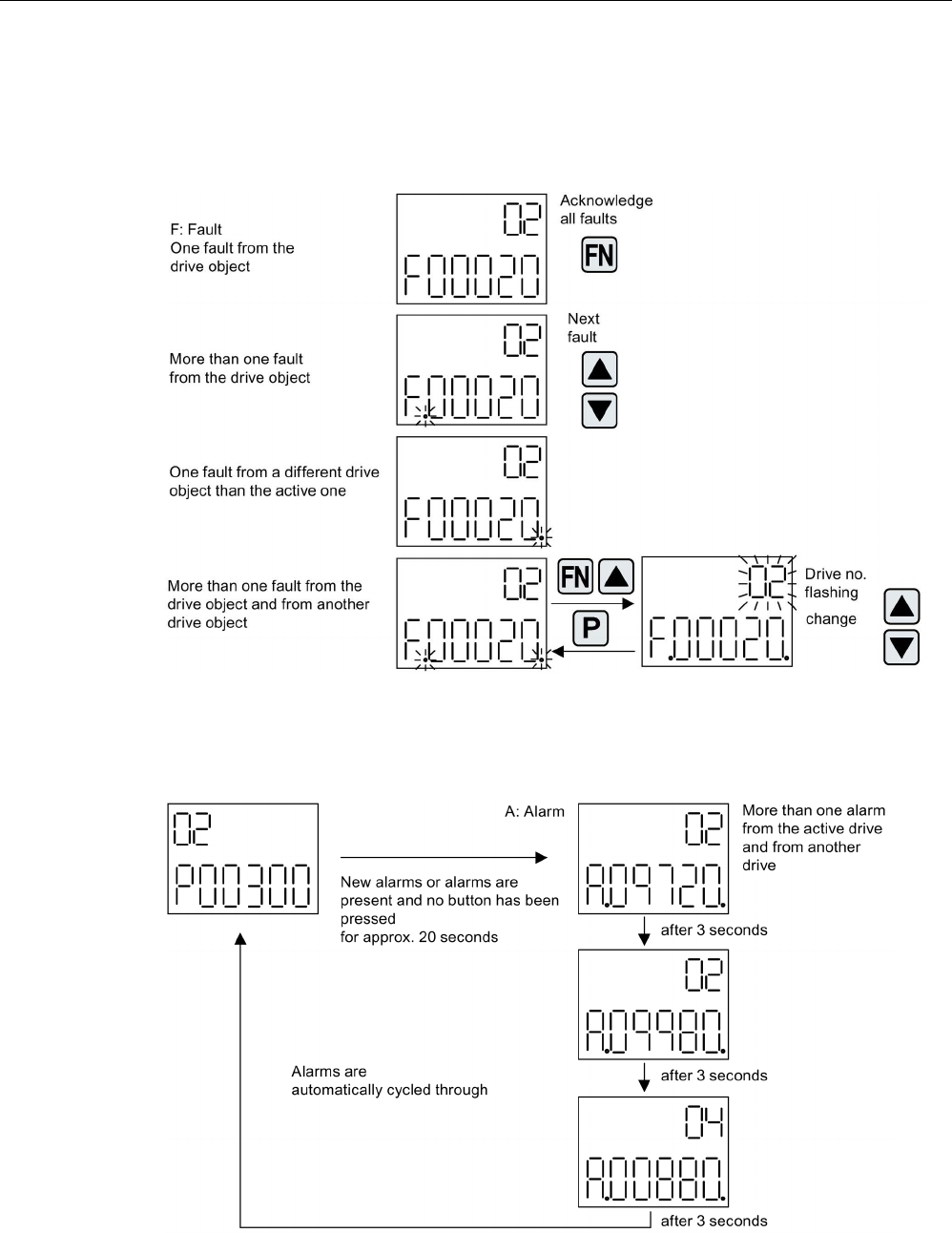
Commissioning
3.22 Basic Operator Panel 20 (BOP20)
STARTER Commissioning Manual
Commissioning Manual, (IH1), 07/2016, 6SL3097-4AF00-0BP5 301
3.22.1.3
Fault and alarm displays
Displaying faults
Image 3-104 Faults
Displaying alarms
Image 3-105 Alarms

Commissioning
3.22 Basic Operator Panel 20 (BOP20)
STARTER Commissioning Manual
302 Commissioning Manual, (IH1), 07/2016, 6SL3097-4AF00-0BP5
3.22.1.4
Controlling the drive using the BOP20
When commissioning the drive, it can be controlled via the BOP20. A control word is
available on the Control Unit drive object (r0019) for this purpose, which can be
interconnected with the appropriate binector inputs of e.g. the drive.
The interconnections do not function if a standard PROFIdrive telegram was selected as its
interconnection cannot be disconnected.
Table 3- 31 BOP20 control word
Bit (r0019)
Name
Example, interconnection parameters
0
ON / OFF (OFF1)
p0840
1
No coast down/coast down (OFF2)
p0844
2
No fast stop/fast stop (OFF3)
p0848
7 Acknowledge fault (0 -> 1) p2102
13
Motorized potentiometer, raise
p1035
14
Motorized potentiometer, lower
p1036
Note
For simple commissioning, only bit 0 should be interconnected. When interconnecting bits 0
... 2, then the system is powered
-down according to the following priority: OFF2, OFF3,
OFF1.
3.22.2
Important functions via BOP20
Description
The BOP20 can be used to execute the following functions (via parameters) that help you
handle your project:
● Restoring the factory settings
● Copy RAM to ROM
● Identification via LED
● Acknowledging faults
Restoring the factory settings
The factory setting of the complete device can be established in the drive object CU.
● p0009 = 30
● p0976 = 1

Commissioning
3.22 Basic Operator Panel 20 (BOP20)
STARTER Commissioning Manual
Commissioning Manual, (IH1), 07/2016, 6SL3097-4AF00-0BP5 303
Copy RAM to ROM
You can initiate the saving of all parameters to the non-volatile memory (memory card) in the
drive object CU:
● Press the P key for 3 seconds,
or
● p0009 = 0
● p0977 = 1
Note
This parameter is not accepted if an identification run (e.g. motor data identification) has
been selected on a drive.
Identification via LED
The main component of a drive object (e.g. Motor Module) can be identified using the index
of p0124. The "Ready" LED on the component starts to flash. The index matches the index
in p0107. The drive object type can be identified via this parameter.
On the drive objects, the components can also be identified via the following parameters:
● p0124 Power unit detection via LED
● p0144 Voltage Sensing Module detection via LED
● p0144 Sensor Module detection via LED
Acknowledging faults
To acknowledge all the faults that have been rectified, press the Fn key.

Commissioning
3.22 Basic Operator Panel 20 (BOP20)
STARTER Commissioning Manual
304 Commissioning Manual, (IH1), 07/2016, 6SL3097-4AF00-0BP5
STARTER Commissioning Manual
Commissioning Manual, (IH1), 07/2016, 6SL3097-4AF00-0BP5 305
Diagnostics
4
This chapter describes the following diagnostic features of the SINAMICS S drive system:
● Diagnostics via LEDs
● Diagnostics via STARTER
● Diagnostic buffer
● Diagnostics of uncommissioned axes
● Fault and alarm messages
● Encoder troubleshooting

Diagnostics
4.1 Diagnostics via LEDs
STARTER Commissioning Manual
306 Commissioning Manual, (IH1), 07/2016, 6SL3097-4AF00-0BP5
4.1
Diagnostics via LEDs
4.1.1
Control Units
4.1.1.1
Description of the LED states of a CU320-2
The various states of the Control Units CU320-2 DP and CU320-2 PN during power-up and
during operation are displayed using LEDs on the Control Unit. The duration of the individual
statuses varies.
Table 4- 1 LEDs
LED
Function
RDY
Ready
DP/PN
PROFIdrive cyclic operation via PROFIBUS (DP) or PROFINET (PN)
OPT
OPTION
● If an error occurs, the booting procedure is terminated and the cause is indicated
accordingly via the LEDs.
● Once the unit has successfully booted up, all the LEDs are switched off briefly.
● Once the unit has booted up, the LEDs are controlled via the loaded software.
Control Unit 320-2 DP while powering up
Table 4- 2 Load software
LED
State
Comment
RDY
DP
OPT
Red Orange Orange Reset Hardware reset
RDY LED lights up red, all other LEDs light
up orange
Red
Red
Off
BIOS loaded
–
Red flashing
light 2 Hz
Red Off BIOS error • Error occurred while loading the BIOS
Red flashing
light 2 Hz
Red
Flashing
light 2 Hz
Off File error • Memory card not inserted or faulty
• Software on memory card not present
or corrupted
Red Orange
flashing
light
Off FW loading RDY LED lights up red, PN LED flashes
orange without fixed frequency
Red
Off
Off
FW loaded
–

Diagnostics
4.1 Diagnostics via LEDs
STARTER Commissioning Manual
Commissioning Manual, (IH1), 07/2016, 6SL3097-4AF00-0BP5 307
LED
State
Comment
RDY
DP
OPT
Off Red Off FW checked
(no CRC
error)
–
Red flashing
light 0.5 Hz
Red flash-
ing light 0.5
Hz
Off FW checked
(CRC error)
• CRC invalid
Table 4- 3 Firmware
LED
State
Comment
RDY
DP
OPT
Orange
Off
Off
Initializing
–
Alternating
Running
See the table below
Control Unit 320-2 DP in operation
Table 4- 4 Control Unit CU320-2 DP – Description of the LEDs after booting
LED
Color
State
Description, cause
Remedy
RDY
(READY)
– OFF Electronic power supply is missing or outside
permissible tolerance range.
Check power supply
Green Continuous
light
The component is ready for operation and cyclic
DRIVE-CLiQ communication is taking place.
–
Flashing
light
0.5 Hz
Commissioning/reset –
Flashing
light
2 Hz
Writing to the memory card –
Red Flashing
light
2 Hz
General errors Check parameterization /
configuration data
Red/
green
Flashing
light
0.5 Hz
Control Unit is ready for operation.
However, there are no software licenses.
Obtain licenses
Orange Flashing
light
0.5 Hz
Updating the firmware of the DRIVE-CLiQ compo-
nents
–
Flashing
light
2 Hz
DRIVE-CLiQ component firmware update com-
plete. Wait for POWER ON for the components in
question.
Turn POWER ON for the
components in question

Diagnostics
4.1 Diagnostics via LEDs
STARTER Commissioning Manual
308 Commissioning Manual, (IH1), 07/2016, 6SL3097-4AF00-0BP5
LED
Color
State
Description, cause
Remedy
Green/
orange
or
red/
orange
Flashing
light
2 Hz
Component detection via LED is activated
(p0124[0]).
Note
:
Both options depend on the LED status when
component recognition is activated via p0124[0] =
1.
–
DP
PROFIdrive
cyclic
operation
– Off Cyclic communication has not (yet) taken place.
Note:
PROFIdrive is ready for communication when the
Control Unit is ready (see LED RDY).
–
Green Continuous
light
Cyclic communication is taking place. –
Flashing
light
0.5 Hz
Full cyclic communication has not yet taken place.
Possible causes:
• The controller is not transferring any setpoints.
• During isochronous operation, no global con-
trol (GC) or a faulty global control (GC) is
transferred by the controller.
–
Red Flashing
light
0.5 Hz
PROFIBUS master is sending wrong parameteri-
zation/configuration data
Adapt configuration be-
tween master/controller and
CU
Flashing
light
2 Hz
Cyclic bus communication has been interrupted or
could not be established
Remedy fault
OPT
(OPTION)
– Off Electronic power supply is missing or outside
permissible tolerance range.
Component is not ready.
Option board not installed or no associated drive
object has been created.
Check power supply and/or
component
Green Continuous
light
Option board is ready. –
Flashing
light
0.5 Hz
Depends on the option board used. –
Red Flashing
light
2 Hz
This component has at least one fault.
The Option Board is not ready (e.g. after switching
on).
Remedy and acknowledge
fault
RDY and DP Red Flashing
light
2 Hz
Bus error - communication has been interrupted Remedy fault
RDY and OPT Orange Flashing
light
0.5 Hz
Firmware update in progress for connected Option
Board CBE20
–

Diagnostics
4.1 Diagnostics via LEDs
STARTER Commissioning Manual
Commissioning Manual, (IH1), 07/2016, 6SL3097-4AF00-0BP5 309
Control Unit 320-2 PN while powering up
Table 4- 5 Load software
LED
Status
Comment
RDY
PN
OPT
Red Orange Orange Reset Hardware reset
RDY LED lights up red, all other LEDs
light up orange
Red
Red
Off
BIOS loaded
–
Red flashing
light 2 Hz
Red Off BIOS error • Error occurred while loading the BIOS
Red flashing
light 2 Hz
Red
flashing
light 2 Hz
Off File error • Memory card not inserted or faulty
• Software on memory card not present
or corrupted
Red Orange
flashing
light
Off FW loading RDY LED lights up red, PN LED flashes
orange without fixed frequency
Red
Off
Off
FW loaded
–
Off Red Off FW checked
(no CRC error)
–
Red flashing
light 0.5 Hz
Red flash-
ing light
0.5 Hz
Off FW checked
(CRC error)
• CRC invalid
Table 4- 6 Firmware
LED
Status
Comment
RDY
PN
OPT
Orange
Off
Off
Initializing
–
Alternating
Running
See the table below

Diagnostics
4.1 Diagnostics via LEDs
STARTER Commissioning Manual
310 Commissioning Manual, (IH1), 07/2016, 6SL3097-4AF00-0BP5
Control Unit 320-2 PN in operation
Table 4- 7 Control Unit CU320-2 PN – Description of the LEDs after booting
LED
Color
State
Description, cause
Remedy
RDY
(READY)
– OFF
The electronics power supply is missing or outside
the permissible tolerance range.
Check power supply
Green Continu-
ous light
The component is ready for operation and cyclic
DRIVE-CLiQ communication is taking place.
–
Flashing
light
0.5 Hz
Commissioning/reset –
Flashing
light
2 Hz
Writing to the memory card –
Red Flashing
light
2 Hz
General fault Check parameterization /
configuration
Red/
green
Flashing
light
0.5 Hz
Control Unit is ready for operation.
However, there are no software licenses.
Obtain licenses
Orange Flashing
light
0.5 Hz
Updating the firmware of the DRIVE-CLiQ compo-
nents.
–
Flashing
light
2 Hz
DRIVE-CLiQ component firmware update com-
plete. Wait for POWER ON for the components in
question.
Turn POWER ON for the
components in question
Green/
orange
or
red/
orange
Flashing
light
2 Hz
Component detection via LED is activated
(p0124[0]).
Note
:
Both options depend on the LED status when
component recognition is activated via p0124[0] =
1.
–
PN
PROFIdrive
cyclic
operation
– Off Cyclic communication has not (yet) taken place.
Note:
PROFIdrive is ready for communication when the
Control Unit is ready (see LED RDY).
–
Green Continu-
ous light
Cyclic communication is taking place. –
Flashing
light
0.5 Hz
Full cyclic communication has not yet taken place.
Possible causes:
• The controller is not transferring any setpoints.
• During isochronous operation, no global con-
trol (GC) or a faulty global control (GC) is
transferred by the controller.
• "Shared Device" is selected (p8929=2) and
only one controller connected.
–

Diagnostics
4.1 Diagnostics via LEDs
STARTER Commissioning Manual
Commissioning Manual, (IH1), 07/2016, 6SL3097-4AF00-0BP5 311
LED
Color
State
Description, cause
Remedy
Red Flashing
light
0.5 Hz
Bus fault,
incorrect parameter assignment/configuration.
Adapt configuration between
controller and devices
Flashing
light
2 Hz
Cyclic bus communication has been interrupted or
could not be established.
Remove the fault
OPT
(OPTION)
– Off The electronics power supply is missing or outside
the permissible tolerance range.
Component is not ready.
Option board not installed or no associated drive
object has been created.
Check power supply and/or
component
Green Continu-
ous light
Option board is ready. –
Flashing
light
0.5 Hz
Depends on the option board used. –
Red Flashing
light
2 Hz
This component has at least one fault.
The Option Board is not ready (e.g. after switching
on).
Remove the fault and
acknowledge
RDY and DP Red Flashing
light
2 Hz
Bus fault - communication has been interrupted. Remove the fault
RDY and OPT Orange Flashing
light
0.5 Hz
Firmware update in progress for connected Option
Board CBE20.
–
4.1.1.2
Description of the LED states of a CU310-2
There are four LEDs on the front panel of the CU310-2 DP housing.
Table 4- 8 LEDs
RDY
Ready
COM
Option Board
OUT > 5V
Encoder current supply > 5 V (TTL/HTL)
MOD
Operating mode (reserved)
The various LEDs are switched either on or off as the Control Unit powers up (depending on
the phase that the system is currently in). When switched on, the color of the LEDs shows
the status of the corresponding power-up phase.
In the event of a fault, power up will be ended in the corresponding phase. The LEDs that
are switched on retain their colors so that the fault can be determined on the basis of the
combination of the color LEDs that are lit and unlit.
All the LEDs go out briefly if the CU310-2 DP has powered up without fault. The system is
ready for operation when the LED "RDY" is permanently green.
All the LEDs are controlled by the loaded software during operation.

Diagnostics
4.1 Diagnostics via LEDs
STARTER Commissioning Manual
312 Commissioning Manual, (IH1), 07/2016, 6SL3097-4AF00-0BP5
Control Unit 310-2 DP while powering up
Table 4- 9 Load software
LED
State
Comment
RDY
COM
OUT > 5V
MOD
Orange
Orange
Orange
Orange
POWER ON
All LEDs light up for approx. 1 s
Red Red Off Off Hardware
reset
After pressing the RESET button the
LEDs light up for approx. 1 s
Red
Red
Off
Off
BIOS loaded
-
Red
Flashing light 2
Hz
Red Off Off BIOS error Fault occurred while loading the
BIOS
Red
Flashing light 2
Hz
Red
Flashing light 2
Hz
Off Off File error
Memory card not inserted or faulty
Software on memory card not pre-
sent or corrupted
Table 4- 10 Firmware
LED
State
Comment
RDY
COM
OUT > 5V
MOD
Red Orange Off Off Firmware
loading
COM-LED flashing without specific
flashing frequency
Red Off Off Off Firmware
loaded
-
Off Red Off Off Firmware
check
(no CRC
error)
-
Red
Flashing light
0.5 Hz
Red
Flashing light
0.5 Hz
Off Off Firmware
check
(CRC error)
CRC is incorrect
Orange Off Off Off Firmware
initialization
-
Control Unit 310-2 DP in operation
Table 4- 11 Description of the LEDs during operation of the CU310-2 DP
LED
Color
State
Description / cause
Remedy
RDY
(READY)
- Off Electronic power supply is missing or outside per-
missible tolerance range.
Check the power
supply
Green
Continuous light The unit is ready for operation.
Cyclic DRIVE-CLiQ communication is in progress.
-
Flashing light
0.5 Hz
Commissioning/reset -

Diagnostics
4.1 Diagnostics via LEDs
STARTER Commissioning Manual
Commissioning Manual, (IH1), 07/2016, 6SL3097-4AF00-0BP5 313
LED
Color
State
Description / cause
Remedy
Flashing light 2
Hz
Writing to the memory card. -
Red Flashing light
2 Hz
General errors Check parameter
assign-
ment/configuration
Red/green Flashing light
0.5 Hz
The control unit is ready for operation, but there
are no software licenses.
Install the missing
licenses.
Orange
Flashing light
0.5 Hz
Updating the firmware of the DRIVE-CLiQ compo-
nents.
-
Flashing light
2 Hz
DRIVE-CLiQ component firmware update complet-
ed. Waiting for POWER ON of the corresponding
components.
Switch on the compo-
nent.
Green /
orange
or
red /
orange
Flashing light
2 Hz
Detection of the component via LED is activated
(p0124[0]).
Note:
Both options depend on the LED status when
module recognition is activated via p0124[0] = 1.
-
COM - Off Cyclic communication is not (yet) running.
Note:
The PROFIdrive is ready for communication when
the Control Unit is ready for operation (see LED:
RDY).
-
Green
Continuous light
Cyclic communication is taking place.
-
Flashing light
0.5 Hz
Cyclic communication is not yet fully up and run-
ning.
Possible causes:
- The controller is not transmitting any setpoints.
-
In isochronous mode, the controller is not sending
a GC (Global Control) or it is sending a defective
GC
-
Red
Flashing light
0.5 Hz
The PROFIBUS master is sending a faulty parame-
ter assignment or the configuration file is corrupted.
Modify the configura-
tion between the mas-
ter/controller and the
Control unit.
Flashing light
2 Hz
Cyclic bus communication has been interrupted or
could not be established.
Rectify the fault in bus
communication.
MOD
-
Off
-
-
OUT > 5 V
-
Off
-
-
Orange Continuous light The voltage of the electronics power supply for the
measuring system is 24 V.

Diagnostics
4.1 Diagnostics via LEDs
STARTER Commissioning Manual
314 Commissioning Manual, (IH1), 07/2016, 6SL3097-4AF00-0BP5
Control Unit 310-2 PN while powering up
Table 4- 12 Load software
LED
State
Comment
RDY
COM
OUT>5V
MOD
Orange
Orange
Orange
Orange
POWER ON
All LEDs light up for approx. 1 s
Red Red Off Off Hardware reset After pressing the RESET button
the LEDs light up for approx. 1 s
Red
Red
Off
Off
BIOS loaded
-
Red
Flashing light 2
Hz
Red Off Off BIOS error Error occurred while loading the
BIOS
Red
Flashing light 2
Hz
Red
Flashing light 2
Hz
Off Off File error
Memory card not inserted or faulty
Software on memory card not
present or corrupted
Table 4- 13 Firmware
LED
State
Comment
RDY
COM
OUT>5V
MOD
Red Orange Off Off Firmware load-
ing
COM-LED flashing without specific
flashing frequency
Red Off Off Off Firmware load-
ed
-
Off Red Off Off Firmware
check
(no CRC error)
-
Red
Flashing light
0.5 Hz
Red
Flashing light
0.5 Hz
Off Off Firmware
check
(CRC error)
CRC is incorrect
Orange Off Off Off Firmware ini-
tialization
-
Control Unit 310-2 PN in operation
Table 4- 14 Description of the LEDs during operation of the CU310-2 PN
LED
Color
State
Description / cause
Remedy
RDY
(READY)
- Off Electronic power supply is missing or outside
permissible tolerance range.
Check the power sup-
ply
Green
Continuous light The unit is ready for operation.
Cyclic DRIVE-CLiQ communication is in pro-
gress.
-
Flashing light 0.5
Hz
Commissioning/reset -
Flashing light 2 Hz
Writing to the memory card.
-

Diagnostics
4.1 Diagnostics via LEDs
STARTER Commissioning Manual
Commissioning Manual, (IH1), 07/2016, 6SL3097-4AF00-0BP5 315
LED
Color
State
Description / cause
Remedy
Red Flashing light
2 Hz
General errors Check parameter
assignment/
configuration
Red/green Flashing light
0.5 Hz
The control unit is ready for operation, but there
are no software licenses.
Install the missing
licenses.
Orange
Flashing light
0.5 Hz
Updating the firmware of the DRIVE-CLiQ com-
ponents.
-
Flashing light
2 Hz
DRIVE-CLiQ component firmware update com-
pleted. Waiting for POWER ON of the corre-
sponding components.
Switch on the
component.
Green /
orange
or
red /
orange
Flashing light
2 Hz
Component detection via LED is activated
(p0124[0]).
Note:
Both options depend on the LED status when
component recognition is activated via p0124[0]
= 1.
-
COM - Off Cyclic communication has not (yet) taken place.
Note:
PROFIdrive is ready for communication when
the Control Unit is ready (see LED: RDY).
-
Green
Continuous light
Cyclic communication is taking place.
-
Flashing light
0.5 Hz
Full cyclic communication is not yet taking place.
Possible causes:
• The controller is not transferring any set-
points.
• During isochronous operation, the controller
is transmitting no GC (Global Control) or a
faulty GC.
-
Red
Flashing light
0.5 Hz
The PROFIBUS master is sending a faulty pa-
rameter assignment or the configuration file is
corrupted.
Modify the configura-
tion between the mas-
ter/controller and the
Control unit.
Flashing light
2 Hz
Cyclic bus communication has been interrupted
or could not be established.
Rectify the fault in bus
communication.
MOD
-
Off
-
-
OUT > 5 V
-
Off
-
-
Orange Continuous light The voltage of the electronics power supply for
the measuring system is 24 V.
Diagnostics
4.1 Diagnostics via LEDs
STARTER Commissioning Manual
316 Commissioning Manual, (IH1), 07/2016, 6SL3097-4AF00-0BP5
4.1.2
Power units
4.1.2.1
Safety instructions for diagnostic LEDs of the power units
WARNING
Danger to life if the fundamental safety instructions and residual risks are not carefully
observed
The non-observance of the fundamental safety instructions and residual risks stated in
Chapter 1 can result in accidents with severe injuries or death.
• Adhere to the fundamental safety instructions.
• When assessing the risk, take into account residual risks.
WARNING
Danger to life when live parts of the DC link are touched
Irrespective of the status of the "DC LINK" LED, hazardous DC link voltages can be
present. This means that the touching of live parts can result in death or serious injury.
• Observe the warning information on the component.
4.1.2.2
Active Line Module booksize
Table 4- 15 Meaning of the LEDs on the Active Line Module
State
Description, cause
Remedy
Ready
DC link
Off Off Electronic power supply is missing or outside permissible
tolerance range.
–
Green Off The component is ready for operation and cyclic DRIVE-CLiQ
communication is taking place.
–
Orange The component is ready for operation and cyclic DRIVE-CLiQ
communication is taking place.
The DC link voltage is present.
–
Red The component is ready for operation and cyclic DRIVE-CLiQ
communication is taking place.
The DC link voltage is too high.
Check the line voltage
Orange
Orange
DRIVE-CLiQ communication is being established.
–
Red – At least one fault is present in this component.
Note:
LED is controlled irrespective of the corresponding messages
being reconfigured.
Remedy and acknowledge
fault

Diagnostics
4.1 Diagnostics via LEDs
STARTER Commissioning Manual
Commissioning Manual, (IH1), 07/2016, 6SL3097-4AF00-0BP5 317
State
Description, cause
Remedy
Ready
DC link
Green / red
flashing light
0.5 Hz
– Firmware is being downloaded. –
Green / red
flashing light
2 Hz
– Firmware download is complete. Wait for POWER ON. Carry out a POWER ON
Green /
orange
or
Red / orange
– Component detection via LED is activated (p0124).
Note:
Both options depend on the LED status when module recog-
nition is activated via p0124 = 1.
–
4.1.2.3
Basic Line Module booksize
Table 4- 16 Meaning of the LEDs on the Basic Line Module
State
Description, cause
Remedy
Ready
DC link
Off Off Electronic power supply is missing or outside permissible
tolerance range.
–
Green Off The component is ready for operation and cyclic DRIVE-CLiQ
communication is taking place.
–
Orange The component is ready for operation and cyclic DRIVE-CLiQ
communication is taking place.
The DC link voltage is present.
–
Red The component is ready for operation and cyclic DRIVE-CLiQ
communication is taking place.
The DC link voltage is too high.
Check the line voltage.
Orange
Orange
DRIVE-CLiQ communication is being established.
–
Red – At least one fault is present in this component.
Note:
LED is controlled irrespective of the corresponding messages
being reconfigured.
Remedy and acknowledge
fault.
Green / red
flashing light
0.5 Hz
– Firmware is being downloaded. –
Green / red
flashing light
2 Hz
– Firmware download is complete. Wait for POWER ON. Carry out a POWER ON
Green /
orange
or
Red / orange
flashing light
– Component detection via LED is activated (p0124).
Note:
Both options depend on the LED status when module recog-
nition is activated via p0124 = 1.
–

Diagnostics
4.1 Diagnostics via LEDs
STARTER Commissioning Manual
318 Commissioning Manual, (IH1), 07/2016, 6SL3097-4AF00-0BP5
4.1.2.4
Smart Line Modules booksize 5 kW and 10 kW
Table 4- 17 Meaning of the LEDs at the Smart Line Modules 5 kW and 10 kW
LED
Color
State
Description, cause
Remedy
READY – Off Electronic power supply is missing or outside permissi-
ble tolerance range.
–
Green Continuous
light
Component is ready to operate. –
Yellow Continuous
light
Pre-charging not completed.
Bypass relay dropped out
EP terminals not supplied with 24 VDC.
–
Red Continuous
light
Overtemperature
Overcurrent
Diagnose fault (via output
terminals) and
acknowledge it (via input
terminal)
DC LINK – Off Electronic power supply is missing or outside permissi-
ble tolerance range.
–
Yellow Continuous
light
DC link voltage within permissible tolerance range. –
Red Continuous
light
DC link voltage outside permissible tolerance range.
Line supply fault.
Check the line voltage.
4.1.2.5
Smart Line Modules booksize 16 kW to 55 kW
Table 4- 18 Meaning of the LEDs at the Smart Line Modules ≥ 16 kW
State
Description, cause
Remedy
Ready
DC link
Off Off Electronic power supply is missing or outside permissible
tolerance range.
–
Green Off The component is ready for operation and cyclic DRIVE-
CLiQ communication is taking place.
–
Orange The component is ready for operation and cyclic DRIVE-
CLiQ communication is taking place.
The DC link voltage is present.
–
Red The component is ready for operation and cyclic DRIVE-
CLiQ communication is taking place.
The DC link voltage is too high.
Check the line voltage
Orange
Orange
DRIVE-CLiQ communication is being established.
–
Red – At least one fault is present in this component.
Note:
LED is controlled irrespective of the corresponding messag-
es being reconfigured.
Remedy and acknowledge
fault
Green / red
flashing light
0.5 Hz
– Firmware is being downloaded. –

Diagnostics
4.1 Diagnostics via LEDs
STARTER Commissioning Manual
Commissioning Manual, (IH1), 07/2016, 6SL3097-4AF00-0BP5 319
State
Description, cause
Remedy
Ready
DC link
Green / red
flashing light
2 Hz
– Firmware download is complete. Wait for POWER ON. Carry out a POWER ON
Green /
orange
or
Red / orange
flashing light
– Component detection via LED is activated (p0124).
Note:
Both options depend on the LED status when module
recognition is activated via p0124 = 1.
–
4.1.2.6
Single Motor Module / Double Motor Module / Power Module
Table 4- 19 Meaning of the LEDs on the Motor Module
State
Description, cause
Remedy
Ready
DC link
Off Off Electronic power supply is missing or outside permissible
tolerance range.
–
Green Off The component is ready for operation and cyclic DRIVE-
CLiQ communication is taking place.
–
Orange The component is ready for operation and cyclic DRIVE-
CLiQ communication is taking place.
The DC link voltage is present.
–
Red The component is ready for operation and cyclic DRIVE-
CLiQ communication is taking place.
The DC link voltage is too high.
Check the line voltage
Orange
Orange
DRIVE-CLiQ communication is being established.
–
Red – At least one fault is present in this component.
Note:
LED is controlled irrespective of the corresponding messag-
es being reconfigured.
Remedy and acknowledge
fault
Green / red
flashing light
0.5 Hz
– Firmware is being downloaded. –
Green / red
flashing light
2 Hz
– Firmware download is complete. Wait for POWER ON. Carry out a POWER ON
Green /
orange
or
Red / orange
– Component detection via LED is activated (p0124).
Note:
Both options depend on the LED status when module
recognition is activated via p0124 = 1.
–

Diagnostics
4.1 Diagnostics via LEDs
STARTER Commissioning Manual
320 Commissioning Manual, (IH1), 07/2016, 6SL3097-4AF00-0BP5
4.1.2.7
Braking Module in booksize format
Table 4- 20 Meaning of the LEDs on the Braking Module booksize
LED
Color
State
Description, cause
Remedy
READY – Off Electronic power supply is missing or outside permissible
tolerance range.
Component deactivated via terminal.
–
Green Continuous
light
Component is ready to operate. –
Red Continuous
light
Enable signal missing (input terminal)
Overtemperature
Overcurrent trip
I2t monitoring responded
Ground fault/short circuit
Note:
In the event of an overtemperature, the error cannot be
acknowledged until after a cooling down time.
Diagnose fault (via
output terminals) and
acknowledge it (via
input terminal)
DC LINK – Off There is no DC link voltage or the electronic power supply is
missing or outside permissible tolerance range.
Component not active.
–
Green Flashing
light
Component active (DC link discharge via braking resistor in
progress).
–
4.1.2.8
Smart Line Module booksize compact format
Table 4- 21 Meaning of the LEDs on the Smart Line Module booksize compact
State
Description, cause
Remedy
RDY
DC LINK
Off Off Electronic power supply is missing or outside permissible
tolerance range.
–
Green – The component is ready for operation and cyclic DRIVE-
CLiQ communication is taking place.
–
Orange The component is ready for operation and cyclic DRIVE-
CLiQ communication is taking place.
The DC link voltage is present.
–
Red The component is ready for operation and cyclic DRIVE-
CLiQ communication is taking place.
The DC link voltage is too high.
Check the line voltage
Orange
Orange
DRIVE-CLiQ communication is being established.
–
Red – At least one fault is present in this component.
Note:
LED is controlled irrespective of the corresponding messag-
es being reconfigured.
Remedy and acknowledge
fault
Green/red
(0.5 Hz)
– Firmware is being downloaded. –

Diagnostics
4.1 Diagnostics via LEDs
STARTER Commissioning Manual
Commissioning Manual, (IH1), 07/2016, 6SL3097-4AF00-0BP5 321
State
Description, cause
Remedy
RDY
DC LINK
Green/red
(2 Hz)
– Firmware download is complete. Wait for POWER ON. Carry out a POWER ON
Green/
orange
or
red/
orange
– Identifying whether the component is activated using the
LED (p0124)
Note:
Both options depend on the LED status when module
recognition is activated via p0124 = 1.
–
4.1.2.9
Motor Module booksize compact format
Table 4- 22 Meaning of the LEDs on the Motor Module booksize compact
Status
Description, cause
Remedy
RDY
DC LINK
Off Off The electronics power supply is missing or outside the per-
missible tolerance range.
–
Green – The component is ready for operation. Cyclic DRIVE-CLiQ
communication is taking place.
–
Orange The component is ready for operation. Cyclic DRIVE-CLiQ
communication is taking place.
The DC link voltage is present.
–
Red The component is ready for operation. Cyclic DRIVE-CLiQ
communication is taking place.
The DC link voltage is outside the permissible tolerance
range.
Check the line supply voltage.
Orange
Orange
DRIVE-CLiQ communication is being established.
–
Red – This component has at least one fault.
Note:
The LED is activated regardless of whether the correspond-
ing messages have been reconfigured.
Resolve and acknowledge the
fault.
Green/red
(0.5 Hz)
– Firmware is being downloaded. –
Green/red (2
Hz)
– Firmware download has been completed. The system waits
for POWER ON.
Carry out a POWER ON.
Green/
orange
or
red/orange
– Component recognition via LED is activated1).
Note:
Both options depend on the LED status when component
recognition is activated using the parameter.
–
1) See SINAMICS S120/S150 List Manual for the parameters to activate the recognition of components via LED

Diagnostics
4.1 Diagnostics via LEDs
STARTER Commissioning Manual
322 Commissioning Manual, (IH1), 07/2016, 6SL3097-4AF00-0BP5
4.1.2.10
Control Interface Module in the Active Line Module chassis format
Table 4- 23 Meaning of the LEDs "READY" and "DC LINK" on the Control Interface Module in the Active Line Module
LED, state
Description
Ready
DC link
Off Off The electronic power supply is missing or lies outside the permissible tolerance range.
Green Off The component is ready for operation and cyclic DRIVE-CLiQ communication is taking
place.
Orange The component is ready for operation and cyclic DRIVE-CLiQ communication is taking
place.
The DC link voltage is present.
Red The component is ready for operation and cyclic DRIVE-CLiQ communication is taking
place.
The DC link voltage is too high.
Orange
Orange
DRIVE-CLiQ communication is being established.
Red --- At least one fault is present in this component.
Note:
LED is activated irrespective of any reconfiguring of the corresponding messages.
Green / red
flashing light
0.5 Hz
--- Firmware is being downloaded.
Green / red
flashing light
2 Hz
--- Firmware download is complete. Wait for POWER ON.
Green /
orange
or
red / orange
flashing light
2 Hz
--- Component detection using LED is activated (p0124).
Note:
Both options depend on the LED state when module recognition is activated via p0124 = 1.
Table 4- 24 Meaning of the LED "POWER OK" on the Control Interface Module in the Active Line Module
LED
Color
State
Description
POWER OK Green
Off
DC link voltage < 100 V and voltage at -X9:1/2 less than 12 V.
On
The component is ready for operation.
Flashing
light
There is a fault. If the LED continues to flash after you have performed a
POWER ON, please contact your Siemens service center.

Diagnostics
4.1 Diagnostics via LEDs
STARTER Commissioning Manual
Commissioning Manual, (IH1), 07/2016, 6SL3097-4AF00-0BP5 323
4.1.2.11
Control Interface Module in the Basic Line Module chassis format
Table 4- 25 Meaning of the LEDs "Ready" and "DC Link" on the Control Interface Module in the Basic Line Module
LED, state
Description
Ready
DC link
Off Off The electronic power supply is missing or lies outside the permissible tolerance range.
Green Off The component is ready for operation and cyclic DRIVE-CLiQ communication is taking
place.
Orange The component is ready for operation and cyclic DRIVE-CLiQ communication is taking
place.
The DC link voltage is present.
Red The component is ready for operation and cyclic DRIVE-CLiQ communication is taking
place.
The DC link voltage is too high.
Orange
Orange
DRIVE-CLiQ communication is being established.
Red --- At least one fault is present in this component.
Note:
LED is activated irrespective of any reconfiguring of the corresponding messages.
Green / red
flashing light
0.5 Hz
--- Firmware is being downloaded.
Green / red
flashing light
2 Hz
--- Firmware download is complete. Wait for POWER ON.
Green /
orange
or
red / orange
flashing light
2 Hz
--- Component detection using LED is activated (p0124).
Note:
Both options depend on the LED state when module recognition is activated via p0124 = 1.
Table 4- 26 Meaning of the LED "POWER OK" on the Control Interface Module in the Basic Line Module
LED
Color
State
Description
POWER OK Green
Off
DC link voltage < 100 V and voltage at -X9:1/2 less than 12 V.
On
The component is ready for operation.
Flashing
light
There is a fault. If the LED continues to flash after you have performed a
POWER ON, please contact your Siemens service center.

Diagnostics
4.1 Diagnostics via LEDs
STARTER Commissioning Manual
324 Commissioning Manual, (IH1), 07/2016, 6SL3097-4AF00-0BP5
4.1.2.12
Control Interface Module in the Smart Line Module chassis format
Table 4- 27 Meaning of the LEDs "READY" and "DC LINK" on the Control Interface Module in the Smart Line Module
LED, state
Description
READY
DC LINK
Off Off The electronic power supply is missing or lies outside the permissible tolerance range.
Green Off The component is ready for operation and cyclic DRIVE-CLiQ communication is taking
place.
Orange The component is ready for operation and cyclic DRIVE-CLiQ communication is taking
place.
The DC link voltage is present.
Red The component is ready for operation and cyclic DRIVE-CLiQ communication is taking
place.
The DC link voltage is too high.
Orange
Orange
DRIVE-CLiQ communication is being established.
Red --- At least one fault is present in this component.
Note:
LED is activated irrespective of any reconfiguring of the corresponding messages.
Flashing
light
0.5 Hz:
Green / red
--- Firmware is being downloaded.
Flashing
light
2 Hz:
Green / red
--- Firmware download is complete. Wait for POWER ON.
Flashing
light
2 Hz:
Green /
orange
or
red / orange
--- Component detection using LED is activated (p0124).
Note:
Both options depend on the LED state when module recognition is activated via p0124 = 1.
Table 4- 28 Meaning of the LED "POWER OK" on the Control Interface Module in the Smart Line Module
LED
Color
State
Description
POWER OK Green
Off
DC link voltage < 100 V and voltage at -X9:1/2 less than 12 V.
On
The component is ready for operation.
Flashing
light
There is a fault. If the LED continues to flash after you have performed a
POWER ON, please contact your Siemens service center.

Diagnostics
4.1 Diagnostics via LEDs
STARTER Commissioning Manual
Commissioning Manual, (IH1), 07/2016, 6SL3097-4AF00-0BP5 325
4.1.2.13
Control Interface Module in the Motor Module chassis format
Table 4- 29 Meaning of the LEDs "Ready" and "DC Link" on the Control Interface Module in the Motor Module
LED, state
Description
Ready
DC link
Off Off The electronic power supply is missing or lies outside the permissible tolerance range.
Green Off The component is ready for operation and cyclic DRIVE-CLiQ communication is taking
place.
Orange The component is ready for operation and cyclic DRIVE-CLiQ communication is taking
place.
The DC link voltage is present.
Red The component is ready for operation and cyclic DRIVE-CLiQ communication is taking
place.
The DC link voltage is too high.
Orange
Orange
DRIVE-CLiQ communication is being established.
Red --- At least one fault is present in this component.
Note:
LED is activated irrespective of any reconfiguring of the corresponding messages.
Green / red
flashing light
0.5 Hz
--- Firmware is being downloaded.
Green / red
flashing light
2 Hz
--- Firmware download is complete. Wait for POWER ON.
Green /
orange
or
red / orange
flashing light
2 Hz
--- Component detection using LED is activated (p0124).
Note
:
Both options depend on the LED status when module recognition is activated via p0124 = 1.
Table 4- 30 Meaning of the LED "POWER OK" on the Control Interface Module in the Motor Module
LED
Color
State
Description
POWER OK Green
Off
DC link voltage < 100 V and voltage at -X9:1/2 less than 12 V.
On
The component is ready for operation.
Flashing
light
There is a fault. If the LED continues to flash after you have performed a
POWER ON, please contact your Siemens service center.

Diagnostics
4.1 Diagnostics via LEDs
STARTER Commissioning Manual
326 Commissioning Manual, (IH1), 07/2016, 6SL3097-4AF00-0BP5
4.1.2.14
Control Interface Module in the Power Module chassis format
Table 4- 31 Meaning of the LEDs "READY" and "DC LINK" on the Control Interface Module in the Power Module
LED, state
Description
READY
DC LINK
Off Off The electronic power supply is missing or lies outside the permissible tolerance range.
Green Off The component is ready for operation and cyclic DRIVE-CLiQ communication is taking
place.
Orange The component is ready for operation and cyclic DRIVE-CLiQ communication is taking
place.
The DC link voltage is present.
Red The component is ready for operation and cyclic DRIVE-CLiQ communication is taking
place.
The DC link voltage is too high.
Orange
Orange
DRIVE-CLiQ communication is being established.
Red --- At least one fault is present in this component.
Note
:
LED is controlled irrespective of the corresponding messages being reconfigured.
Flashing
light
0.5 Hz:
Green / red
--- Firmware is being downloaded.
Flashing
light 2 Hz:
Green / red
--- Firmware download is complete. Wait for POWER ON.
Flashing
light 2 Hz:
Green /
orange
or
red / orange
--- Component detection using LED is activated (p0124).
Note
:
Both options depend on the LED status when module recognition is activated via p0124 = 1.
Table 4- 32 Meaning of the LED "POWER OK" on the Control Interface Module in the Power Module
LED
Color
State
Description
POWER OK Green
Off
DC link voltage < 100 V and voltage at -X9:1/2 less than 12 V.
On
The component is ready for operation.
Flashing
light
There is a fault. If the LED continues to flash after you have performed a
POWER ON, please contact your Siemens service center.

Diagnostics
4.1 Diagnostics via LEDs
STARTER Commissioning Manual
Commissioning Manual, (IH1), 07/2016, 6SL3097-4AF00-0BP5 327
4.1.3
Additional modules
4.1.3.1
Control Supply Module
Table 4- 33 Control Supply Module – description of the LEDs
LED
Color
State
Description, cause
Remedy
READY – off Electronic power supply is missing or outside permissible
tolerance range.
–
Green Continuous
light
Component is ready to operate. –
DC LINK – off Electronic power supply is missing or outside permissible
tolerance range.
–
Orange Continuous
light
DC link voltage within permissible tolerance range. –
Red Continuous
light
DC link voltage outside permissible tolerance range. –
4.1.3.2
Sensor Module Cabinet SMC10 / SMC20
Table 4- 34 Sensor Module Cabinet 10/20 (SMC10/SMC20) – description of the LEDs
LED
Color
State
Description, cause
Remedy
RDY
READY
– off Electronic power supply is missing or outside permissible
tolerance range.
–
Green Continu-
ous light
The component is ready for operation and cyclic DRIVE-
CLiQ communication is taking place.
–
Orange Continu-
ous light
DRIVE-CLiQ communication is being established. –
Red Continu-
ous light
At least one fault is present in this component.
Note:
LED is controlled irrespective of the corresponding messag-
es being reconfigured.
Remedy and
acknowledge fault
Green/red Flashing
light 0.5
Hz
Firmware is being downloaded. –
Flashing
light 2 Hz
Firmware download is complete. Wait for POWER ON Carry out a POWER
ON
Green/
orange
or
Red/
orange
Flashing
light
Component recognition via LED is activated (p0144).
Note:
Both options depend on the LED status when module
recognition is activated via p0144 = 1.
–

Diagnostics
4.1 Diagnostics via LEDs
STARTER Commissioning Manual
328 Commissioning Manual, (IH1), 07/2016, 6SL3097-4AF00-0BP5
4.1.3.3
Sensor Module Cabinet SMC30
Table 4- 35 Meaning of LEDs on the Sensor Module Cabinet SMC30
LED
Color
Status
Description, cause
Remedy
RDY
READY
– Off The electronics power supply is missing or outside the per-
missible tolerance range.
–
Green Continu-
ous light
The component is ready for operation. Cyclic DRIVE-CLiQ
communication is taking place.
–
Orange Continu-
ous light
DRIVE-CLiQ communication is being established. –
Red Continu-
ous light
This component has at least one fault.
Note:
LED is controlled irrespective of the corresponding messag-
es being reconfigured.
Remedy and
acknowledge fault
Green/red Flashing
light 0.5
Hz
Firmware is being downloaded. –
Green/red Flashing
light 2 Hz
Firmware download is complete. The system waits for
POWER ON.
Carry out a POWER
ON
Green/
orange
or
Red/orange
Flashing
light
Component recognition via LED is activated1).
Note:
Both options depend on the LED status when component
recognition is activated.
–
OUT > 5
V
– Off The electronic power supply is missing or outside permissi-
ble tolerance range.
Power supply ≤ 5 V.
–
Orange Continu-
ous light
The electronics power supply for the encoder system is
available.
Power supply > 5 V
–
1)
The parameters for activating component recognition using LEDs can be taken from the following reference:
Reference: /LH1/ SINAMICS S120/S150 List Manual
4.1.3.4
Sensor Module Cabinet SMC40
Table 4- 36 Meaning of the LEDs on the Sensor Module Cabinet-Mounted SMC40
LED
Color
Status
Description, cause
Remedy
RDY
READY
– Off The electronics power supply is missing or outside the per-
missible tolerance range.
–
Green Continuous
light
The component is ready for operation. Cyclic DRIVE-CLiQ
communication is taking place.
–
Orange Continuous
light
DRIVE-CLiQ communication is being established. –
Red Continuous
light
This component has at least one fault.
Note:
LED is controlled irrespective of the corresponding messag-
es being reconfigured.
Remove and
acknowledge the fault.

Diagnostics
4.1 Diagnostics via LEDs
STARTER Commissioning Manual
Commissioning Manual, (IH1), 07/2016, 6SL3097-4AF00-0BP5 329
LED
Color
Status
Description, cause
Remedy
Green/red Flashing
light
2 Hz
Firmware download is complete. The system waits for
POWER ON.
Carry out a POWER
ON.
Green/
orange
or
Red/
orange
Flashing
light
Component recognition via LED is activated1).
Note:
Both options depend on the LED status when component
recognition is activated.
–
1)
The parameter for activating component recognition can be taken from the following reference:
Reference: /LH1/ SINAMICS S120/S150 List Manual
Each channel has a multifunction LED.
4.1.3.5
Communication Board CBC10 for CANopen
Table 4- 37 Meaning of the LEDs on the Communication Board CAN CBC10
LED
Color
State
Description, cause
Remedy
OPT
on the
Control
Unit
– Off Electronic power supply is missing or outside permissible
tolerance range.
Communication Board either defective or not inserted.
–
Green
LED ON
OPERATIONAL
–
LED Blinking PREOPERATIONAL
No PDO communication possible
–
LED Single
flash
STOPPED
Only NMT communication possible
–
Red LED ON BUS OFF Check baud rate
Check cabling
LED Single
flash
ERROR PASSIVE MODE
The error counter for "error passive" has reached the value
127. After the SINAMICS drive system was booted no fur-
ther active CAN component was on the bus.
Check baud rate
Check cabling
LED Double
flash
Error Control Event, a Guard Event has occurred Check connection to
CANopen master

Diagnostics
4.1 Diagnostics via LEDs
STARTER Commissioning Manual
330 Commissioning Manual, (IH1), 07/2016, 6SL3097-4AF00-0BP5
4.1.3.6
Communication Board Ethernet CBE20
Meaning of the LEDs on the CBE20 Communication Board Ethernet
Table 4- 38 Meaning of the LEDs at ports 1 to 4 of the X1400 interface
LED
Color
Status
Description
Link port – Off The electronics power supply is missing or outside the permissible tolerance range
(link missing or defective).
Green Continu-
ous light
A different device is connected to port x and a physical connection exists.
Activity
port
– Off The electronics power supply is missing or outside the permissible tolerance range
(no activity).
Yellow Flashing
light
Data is being received or sent at port x.
Table 4- 39 Meaning of the Sync and Fault LEDs on the CBE20
LED
Color
Status
Description
Fault – Off If the link port LED is green:
The CBE20 is operating normally, data is being exchanged with the configured IO
Controller.
Red Flashing
light
• The response monitoring interval has elapsed.
• Communications is interrupted.
• The IP address is incorrect.
• Incorrect or no configuration.
• Incorrect parameter settings.
• Incorrect or missing device name.
• IO Controller not connected/switched off, although an Ethernet connection has
been established.
• Other CBE20 faults
Continu-
ous light
CBE20 fault error
• No physical connection to a subnet/switch.
• Incorrect transmission rate
• Full duplex transmission is not activated.
Sync – Off If the link port LED is green:
The Control Unit task system is not synchronized with the IRT clock. An internal
substitute clock is generated.
Green Flashing
light
The Control Unit task system has synchronized with the IRT clock and data is being
exchanged.
Continu-
ous light
The Task system and the MC-PLL have synchronized with the IRT clock.

Diagnostics
4.1 Diagnostics via LEDs
STARTER Commissioning Manual
Commissioning Manual, (IH1), 07/2016, 6SL3097-4AF00-0BP5 331
Table 4- 40 Meaning of the OPT LED on the Control Unit
LED
Color
Status
Description, cause
Remedy
OPT – OFF The electronics power supply is missing or outside the per-
missible tolerance range.
CBE20 either defective or not inserted.
–
Green Continu-
ous light
CBE20 is ready and cyclic communication is taking place. –
Flashing
light
0.5 Hz
CBE20 is ready but cyclic communication is not running.
Possible causes:
• Communication is being established.
• At least one fault is present.
–
Red Continu-
ous light
Cyclic communication via PROFINET has not yet been
established. However, non-cyclic communications are pos-
sible. SINAMICS is waiting for a parameteriza-
tion/configuration telegram.
–
Flashing
light
0.5 Hz
The firmware update into the CBE20 has been completed
with an error.
Possible causes:
• The memory card for the control unit is defective.
• The CBE20 is defective.
In this state CBE20 cannot be used.
–
Flashing
light
2 Hz
There is a communications error between the Control Unit
and the CBE20.
Possible causes:
• The CBE20 was withdrawn after booting.
• The CBE20 is defective.
Correctly insert the
board, if required,
replace.
Orange Flashing
light
0.5 Hz
Firmware of the CBE20 currently being updated. –

Diagnostics
4.1 Diagnostics via LEDs
STARTER Commissioning Manual
332 Commissioning Manual, (IH1), 07/2016, 6SL3097-4AF00-0BP5
4.1.3.7
Communication Board Ethernet CBE25
Meaning of the LEDs on the Communication Board Ethernet CBE25
Table 4- 41 Meaning of the LEDs on Ethernet ports 1-2
LED
Color
State
Description
Link port – Off Electronics power supply is missing or outside the permissible tolerance range (link
missing or defective).
Green Continu-
ous light
A different device is connected to port x and a physical connection exists.
Activity
port
– Off Electronics power supply is missing or outside the permissible tolerance range (no
activity).
Yellow Flashing
light
Data is being received or sent at port x.
Table 4- 42 Meaning of the Bus Sync/PN Sync and Bus Fault on the CBE25
LED
Color
State
Description
Bus Fault – Off If the link port LED is green:
The CBE25 is operating normally, data is being exchanged with the configured IO
Controller.
Red Flashing
light
• The response monitoring interval has elapsed.
• Communications is interrupted.
• The IP address is incorrect.
• Incorrect or no configuration.
• Incorrect parameter settings.
• Incorrect or missing device name.
• IO Controller not connected/switched off, although an Ethernet connection has
been established.
• Other CBE25 errors
Continuous
light
CBE25 bus fault
• No physical connection to a subnet/switch.
• Incorrect transmission rate
• Full duplex transmission is not activated.
Bus
Sync/PN
Sync
– Off If the link port LED is green:
The Control Unit task system is not synchronized with the IRT clock. An internal
substitute clock is generated.
Green Flashing
light
The Control Unit task system has synchronized with the IRT clock and data is being
exchanged.
Continuous
light
The Task system and the MC-PLL have synchronized with the IRT clock.

Diagnostics
4.1 Diagnostics via LEDs
STARTER Commissioning Manual
Commissioning Manual, (IH1), 07/2016, 6SL3097-4AF00-0BP5 333
Table 4- 43 Meaning of the OPT LED on the Control Unit
LED
Color
State
Description, cause
Remedy
OPT – OFF The electronics power supply is missing or outside the per-
missible tolerance range.
Communication Board either defective or not inserted.
–
Green Continuous
light
Communication Board is ready and cyclic communication is
taking place.
–
Flashing
light
0.5 Hz
The Communication Board is ready, but cyclic communica-
tions is not running.
Possible causes:
• Communication is being established.
• At least one fault is present.
–
Red Continuous
light
Cyclic communication via PROFINET has not yet been
established. However, non-cyclic communications are pos-
sible. SINAMICS waits for a parameterizing/configuring
telegram
–
Flashing
light
0.5 Hz
The firmware update into the CBE25 has been completed
with an error.
Possible causes:
• The CBE25 is defective.
• The memory card for the Control Unit is defective.
In this state the CBE25 cannot be used.
–
Flashing
light
2 Hz
There is a communications error between the Control Unit
and the CBE25.
Possible causes:
• The CBE25 is defective.
• The CBE25 was withdrawn after booting.
Correctly insert the
board, if required,
replace.
Orange Flashing
light
0.5 Hz
Firmware is being updated. –

Diagnostics
4.1 Diagnostics via LEDs
STARTER Commissioning Manual
334 Commissioning Manual, (IH1), 07/2016, 6SL3097-4AF00-0BP5
4.1.3.8
Voltage Sensing Module VSM10
Table 4- 44 Meanings of the LEDs on the Voltage Sensing Module VSM10
LED
Color
Status
Description, cause
Remedy
READY – Off The electronics power supply is missing or outside the per-
missible tolerance range.
–
Green Continuous
light
The component is ready for operation. Cyclic DRIVE-CLiQ
communication is taking place.
–
Orange Continuous
light
DRIVE-CLiQ communication is being established. –
Red Continuous
light
This component has at least one fault.
Note:
LED is controlled irrespective of the corresponding messag-
es being reconfigured.
Remove and
acknowledge the fault.
Green/red Flashing
light 0.5 Hz
Firmware is being downloaded. –
Flashing
light 2 Hz
Firmware download is complete. The system waits for
POWER ON.
Carry out a POWER
ON.
Green/
orange
or
Red/
orange
Flashing
light
Detection of the component via LED is activated (p0144 =
1).
Note:
Both options depend on the LED status when component
recognition is activated.
–
4.1.3.9
DRIVE-CLiQ Hub Module DMC20
Table 4- 45 Description of the LEDs on the DRIVE-CLiQ Hub Module DMC20
LED
Color
Status
Description, cause
Remedy
READY – Off The electronics power supply is missing or outside the per-
missible tolerance range.
–
Green Continuous
light
The component is ready for operation. Cyclic DRIVE-CLiQ
communication is taking place.
–
Orange Continuous
light
DRIVE-CLiQ communication is being established. –
Red Continuous
light
This component has at least one fault.
Note:
LED is controlled irrespective of the corresponding messag-
es being reconfigured.
Remove and
acknowledge the fault.
Green/red Flashing
light 0.5 Hz
Firmware is being downloaded. –
Flashing
light 2 Hz
Firmware download is complete. The system waits for
POWER ON.
Carry out a POWER
ON.

Diagnostics
4.1 Diagnostics via LEDs
STARTER Commissioning Manual
Commissioning Manual, (IH1), 07/2016, 6SL3097-4AF00-0BP5 335
LED
Color
Status
Description, cause
Remedy
Green/
orange
or
Red/
orange
Flashing
light
Component recognition via LED is activated (p0154 = 1).
Note:
Both options depend on the LED status when component
recognition is activated.
–
4.1.4
Terminal Module
4.1.4.1
Terminal Module TM15
Table 4- 46 Meanings of the LEDs on the Terminal Module TM15
LED
Color
Status
Description, cause
Remedy
READY - Off The electronics power supply is missing or outside the per-
missible tolerance range.
–
Green Continuous
light
The component is ready for operation. Cyclic DRIVE-CLiQ
communication is taking place.
–
Orange Continuous
light
DRIVE-CLiQ communication is being established. –
Red Continuous
light
This component has at least one fault.
Note:
The LED is activated irrespective of whether the correspond-
ing messages have been reconfigured.
Remove and
acknowledge the
fault.
Green/red Flashing
light 0.5 Hz
Firmware is being downloaded. –
Flashing
light 2 Hz
Firmware download is complete. The system waits for
POWER ON.
Carry out a POWER
ON.
Green/
orange
or
Red/orange
Flashing
light
Component recognition via LED is activated1).
Note:
Both options depend on the LED status when component
recognition is activated.
–
1)
The parameters for activating component recognition using LEDs can be taken from the following reference:
Reference: /LH1/ SINAMICS S120/S150 List Manual

Diagnostics
4.1 Diagnostics via LEDs
STARTER Commissioning Manual
336 Commissioning Manual, (IH1), 07/2016, 6SL3097-4AF00-0BP5
4.1.4.2
Terminal Module TM31
Table 4- 47 Meanings of the LEDs on the Terminal Module TM31
LED
Color
Status
Description, cause
Remedy
READY - Off The electronics power supply is missing or outside the
permissible tolerance range.
–
Green Continuous
light
The component is ready for operation. Cyclic DRIVE-CLiQ
communication is taking place.
–
Orange Continuous
light
DRIVE-CLiQ communication is being established. –
Red Continuous
light
This component has at least one fault.
Note:
The LED is activated irrespective of whether the corre-
sponding messages have been reconfigured.
Remove and
acknowledge the fault.
Green/red Flashing
light 0.5 Hz
Firmware is being downloaded. –
Flashing
light 2 Hz
Firmware download is complete. The system waits for
POWER ON.
Carry out a POWER
ON.
Green/
orange
or
Red/
orange
Flashing
light
Component recognition via LED is activated1).
Note:
Both options depend on the LED status when component
recognition is activated.
–
1)
The parameters for activating component recognition using LEDs can be taken from the following reference:
Reference: /LH1/ SINAMICS S120/S150 List Manual
4.1.4.3
Terminal Module TM120
Table 4- 48 Meaning of the LEDs on the Terminal Module TM120
LED
Color
Status
Description, cause
Remedy
READY - Off The electronics power supply is missing or outside the per-
missible tolerance range.
Check the power
supply.
Green Continuous
light
The component is ready for operation. Cyclic DRIVE-CLiQ
communication is taking place.
-
Orange Continuous
light
DRIVE-CLiQ communication is being established. -
Red
Continuous
light
This component has at least one fault.
Note:
The LED is activated irrespective of whether the correspond-
ing messages have been reconfigured.
Remove and
acknowledge the
fault.
Green/
red
Flashing
light
0.5 Hz
Firmware is being downloaded. -
Flashing
light
2 Hz
Firmware download is complete. The system waits for
POWER ON.
Carry out a POWER
ON.

Diagnostics
4.1 Diagnostics via LEDs
STARTER Commissioning Manual
Commissioning Manual, (IH1), 07/2016, 6SL3097-4AF00-0BP5 337
LED
Color
Status
Description, cause
Remedy
Green/
orange
or
red/
orange
Flashing
light
2 Hz
Component recognition via LED is activated1).
Note:
Both options depend on the LED status when component
recognition is activated.
-
1)
The parameters for activating component recognition using LEDs can be taken from the following reference:
Reference: /LH1/ SINAMICS S120/S150 List Manual
4.1.4.4
Terminal Module TM150
Table 4- 49 Meaning of the LEDs at the Terminal Module TM150
LED
Color
State
Description, cause
Remedy
READY
– Off Electronic power supply is missing or outside permissible
tolerance range.
Check power supply
Green Continu-
ous light
The component is ready for operation and cyclic DRIVE-
CLiQ communication is taking place.
–
Orange Continu-
ous light
DRIVE-CLiQ communication is being established. –
Red
Continu-
ous light
This component has at least one fault.
Note:
LED is controlled irrespective of the corresponding messag-
es being reconfigured.
Remedy and
acknowledge fault
Green/
Red
Flashing
light
0.5 Hz
Firmware is being downloaded. –
Flashing
light
2 Hz
Firmware has been downloaded.
Wait for POWER ON.
Carry out a POWER
ON
Green/
orange
or
red/
orange
Flashing
light
2 Hz
Component recognition via LED is activated (p0154).
Note:
Both options depend on the LED status when module
recognition is activated via p0154 = 1.
–

Diagnostics
4.1 Diagnostics via LEDs
STARTER Commissioning Manual
338 Commissioning Manual, (IH1), 07/2016, 6SL3097-4AF00-0BP5
4.1.4.5
Terminal Module TM41
Table 4- 50 Meaning of the LEDs on the Terminal Module TM41
LED
Color
Status
Description, cause
Remedy
READY - Off The electronics power supply is missing or outside the
permissible tolerance range.
–
Green Continuous
light
The component is ready for operation. Cyclic DRIVE-CLiQ
communication is taking place.
–
Orange Continuous
light
DRIVE-CLiQ communication is being established. –
Red Continuous
light
This component has at least one fault.
Note:
The LED is activated irrespective of whether the corre-
sponding messages have been reconfigured.
Remove and
acknowledge the fault.
Green/red Flashing
light 0.5 Hz
Firmware is being downloaded. –
Flashing
light 2 Hz
Firmware download is complete. The system waits for
POWER ON.
Carry out a POWER
ON.
Green/
orange
or
Red/
orange
Flashing
light
Component recognition via LED is activated1).
Note:
Both options depend on the LED status when component
recognition is activated.
–
Z pulses – Off The zero mark was found and the system waits for the
zero mark output.
OR
The component is switched off.
–
Red Continuous
light
The zero mark has not been released, or the zero mark
search is running.
–
Green Continuous
light
The system stops at the zero mark. –
Flashing
light
The zero mark is output at each virtual revolution. –
1)
The parameters for activating component recognition using LEDs can be taken from the following reference:
Reference: /LH1/ SINAMICS S120/S150 List Manual

Diagnostics
4.1 Diagnostics via LEDs
STARTER Commissioning Manual
Commissioning Manual, (IH1), 07/2016, 6SL3097-4AF00-0BP5 339
4.1.4.6
Terminal Module TM54F
Table 4- 51 Meaning of the LEDs on the Terminal Module TM54F
LED
Color
Status
Description, cause
Remedy
READY - Off The electronics power supply is missing or outside the
permissible tolerance range.
–
Green Continuous
light
The component is ready for operation, cyclic DRIVE-
CLiQ communication is taking place.
–
Orange Continuous
light
DRIVE-CLiQ communication is being established. –
Red Continuous
light
This component has at least one fault.
Remark:
The LED is activated irrespective of whether the corre-
sponding messages have been reconfigured.
Remedy and
acknowledge
fault or safely
acknowledge
the fault
Green/red Flashing light
0.5 Hz
Firmware is being downloaded. –
Flashing light 2
Hz
Firmware download is complete. Wait for POWER ON. Carry out a
POWER ON
Green / orange
or
Red / orange
Flashing light 1
Hz
Component recognition via LED is activated
(p0154 = 1).
Remark:
Both options depend on the LED status when compo-
nent recognition is activated.
Green / orange: Component is operating without any
faults
Red/orange: Component signals a fault
–
L1+, L2+ – Off The controllable sensor power supply is functioning
fault-free.
–
Red Continuous
light
There is a fault in the controllable sensor power supply. –
L3+
–
Off
The sensor power supply is operating fault-free.
Red Continuous
light
The sensor power supply has a fault.

Diagnostics
4.1 Diagnostics via LEDs
STARTER Commissioning Manual
340 Commissioning Manual, (IH1), 07/2016, 6SL3097-4AF00-0BP5
LED
Color
Status
Description, cause
Remedy
Fail-safe inputs / double inputs
F_DI z
(input x,
(x+1)+,
(x+1)-)
LED
LED
–
x
x+1
NC contact/NC contact
1)
: (z = 0 … 9, x = 0, 2, … 18)
– Red Continuous
light
Different signal states at input x and x+1
–
–
Off
No signal at input x and no signal at input x+1
NC contact/NO contact
1)
: (z = 0 … 9, x = 0, 2, … 18)
– Red Continuous
light
Same signal states at input x and x+1
–
–
Off
No signal at input x and no signal at input x+1
LED
LED
x
x+1
NC contact/NC contact
1)
: (z = 0 … 9, x = 0, 2, … 18)
Green Green Continuous
light
One signal at input x and one signal at input x+1
NC contact/NO contact
1)
: (z = 0 … 9, x = 0, 2, … 18)
Green Green Continuous
light
One signal at input x and no signal at input x+1 –
Single digital inputs, not fail-safe
DI x
–
Off
No signal at digital input x (x = 20 ... 23)
–
Green Continuous
light
Signal at digital input x –
Fail-safe digital outputs with associated readback channel
F_DO y
(0+..3+,
0-..3-)
Green Continuous
light
Output y (y = 0 … 3) has an active signal –
Readback input DI 2y for output F_DO y (y = 0 ... 3) for test stop.
The status of the LEDs also depends on the type of external circuit.
DI 2y – Off One of the two output lines y+ or y- or both lines of
output y carry a signal
–
Green Continuous
light
Both output lines y+ and y- carry no signal –
1)
Inputs x+1 (DI 1+, 3+, .. 19+) can be individually set using a parameter
Additional information can be taken from the following reference:
Reference: /LH1/ SINAMICS S120/S150 List Manual

Diagnostics
4.2 Diagnostics via STARTER
STARTER Commissioning Manual
Commissioning Manual, (IH1), 07/2016, 6SL3097-4AF00-0BP5 341
4.2
Diagnostics via STARTER
The diagnostic functions support commissioning and service personnel during
commissioning, troubleshooting, diagnostics and service activities.
Precondition
● Online operation of the STARTER commissioning tool.
Diagnostic functions
The following diagnostic functions are available in the STARTER commissioning tool:
● Specifying signals with the ramp-function generator
● Signal recording with the trace function
● Analyzing the control response with the measuring function
● Outputting voltage signals for external measuring devices via test sockets
4.2.1
Function generator
The function generator is part of the STARTER commissioning tool.
The ramp-function generator can be used, for example, for the following tasks:
● To measure and optimize control loops.
● To compare the dynamic response of coupled drives.
● To specify a simple traversing profile without a traversing program.
The ramp-function generator can be used to generate different signal shapes.
In the "Connector output" operating mode (r4818), the output signal can be injected into the
control loop via the BICO interconnection.
For vector control, corresponding to the selected operating mode, this setpoint can also be
fed into the control structure as, for example, a current setpoint, disturbing torque, or current
setpoint. The impact of superimposed control loops is automatically suppressed.
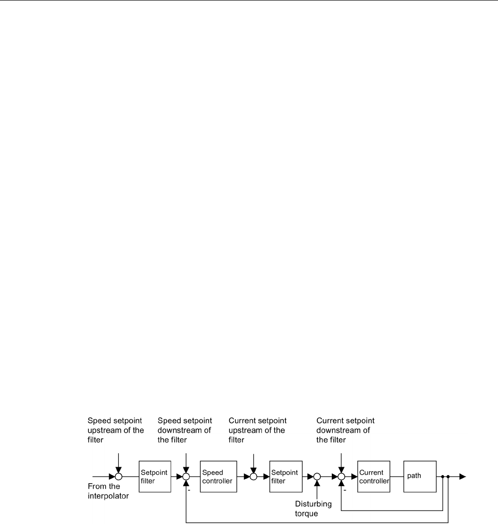
Diagnostics
4.2 Diagnostics via STARTER
STARTER Commissioning Manual
342 Commissioning Manual, (IH1), 07/2016, 6SL3097-4AF00-0BP5
Properties
● Operating modes of the ramp-function generator for SERVO and VECTOR drive types:
– Connector output
● Operating modes of the function generator for a SERVO drive:
– Speed setpoint downstream of filter (speed setpoint filter)
– Speed setpoint upstream of filter (speed setpoint filter)
– Disturbing torque (downstream of current setpoint filter)
– Current setpoint downstream of filter (current setpoint filter)
– Current setpoint upstream of filter (current setpoint filter)
● Connecting to each drive of the topology is possible.
● The following parameterizable signal shapes can be set:
– Square-wave
– Staircase
– Triangular
– Sinusoidal
– PRBS (pseudo random binary signal, white noise)
● An offset is possible for each signal. The ramp-up to the offset is parameterizable. Signal
generation begins after the ramp-up to the offset.
● Restriction of the output signal to the minimum and maximum value settable.
Injection points of the function generator
Image 4-1 Injection points of the ramp-function generator
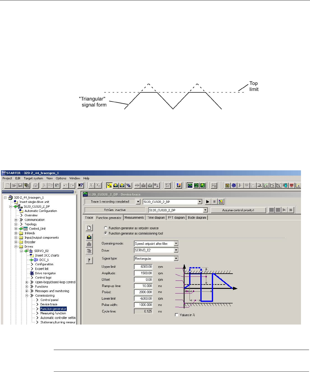
Diagnostics
4.2 Diagnostics via STARTER
STARTER Commissioning Manual
Commissioning Manual, (IH1), 07/2016, 6SL3097-4AF00-0BP5 343
Further signal shapes
Additional signal waveforms can be generated.
Example:
The "triangular" signal form can be parameterized with "upper limitation" to produce a
triangle with no peak.
Image 4-2 "Triangular" signal without peak
Parameterizing and operating the ramp-function generator
You operate and parameterize the function generator using the STARTER commissioning
tool.
Image 4-3 Function generator
Note
Please refer to the online help for more information about parameterizing and operation.
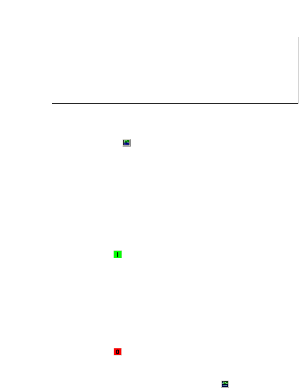
Diagnostics
4.2 Diagnostics via STARTER
STARTER Commissioning Manual
344 Commissioning Manual, (IH1), 07/2016, 6SL3097-4AF00-0BP5
Starting/stopping the ramp-function generator
NOTICE
Damage to property due to unexpected movements while the function generator is active
Some monitoring functions are deactivated when the function generator is activated.
Incorrect parameterization of the function generator can result in unexpected movements of
the motor, which damage the machine.
• Do not leave the machine unattended while the function generator is active.
• Ensure that the parameter assignments are correct.
Start function generator:
1. Load the function generator.
– Click on the symbol .
or
– In the project navigator, double-click on "Drives" > "Drive_xy" > "Commissioning" >
"Function generator".
2. Select "Function generator as a commissioning tool".
3. Select an operating mode e.g. "Speed setpoint after filter".
4. Select a drive, for instance "SERVO_02".
5. Set a signal shape, for example, "Squarewave".
6. Click the "Assume control priority!" button.
7. For "Sign of life monitoring" click on the "Accept" button.
(the control priority button then changes to yellow).
8. Click on the symbol "Drive on".
9. Start the function generator by clicking on the triangle next to the red zero ( "Start
FctGen" button).
10.Carefully read the "Caution" note and confirm with "Yes".
The drive starts and executes the selected trace function.
Trace recordings are now possible.
Stopping the function generator:
1. Click on the "Stop FctGen" button.
Or
2. Click on the symbol "Drive off" in order to stop the drive.
Parameterization
The "Function generator" parameter screen is selected with the symbol in the toolbar of
the STARTER commissioning tool.
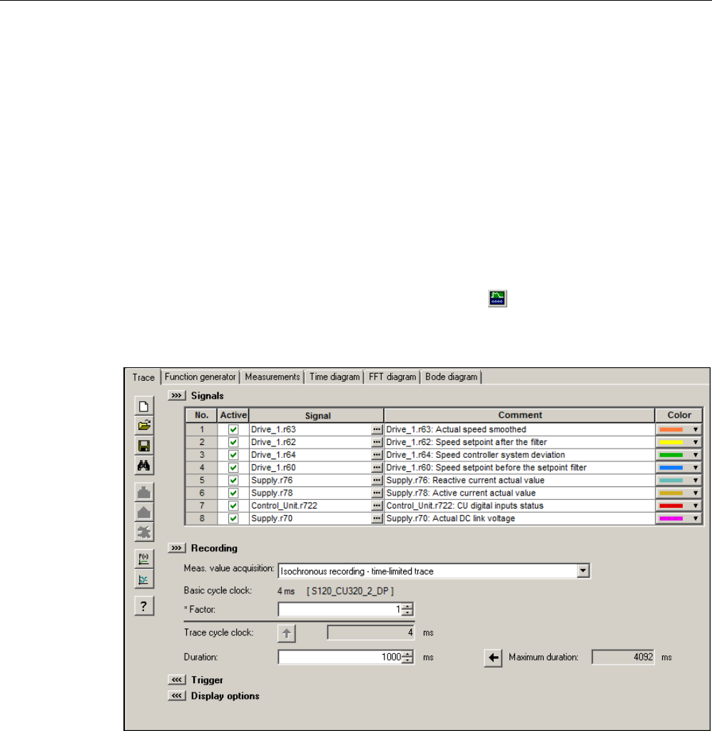
Diagnostics
4.2 Diagnostics via STARTER
STARTER Commissioning Manual
Commissioning Manual, (IH1), 07/2016, 6SL3097-4AF00-0BP5 345
4.2.2
Trace function
4.2.2.1
Single trace
You can use the trace function to record measured values over a defined period, depending
on trigger conditions. Alternatively, the measured values can also be recorded using
immediate recording.
In the STARTER commissioning tool you can parameterize the trace function by using the
"Trace" parameterizing screen form.
Calling the "Trace" parameterizing screen form
1. In the STARTER commissioning tool, click the symbol (device trace-function
generator).
The "Trace" parameterizing screen form is then displayed. Example:
Image 4-4 Trace function
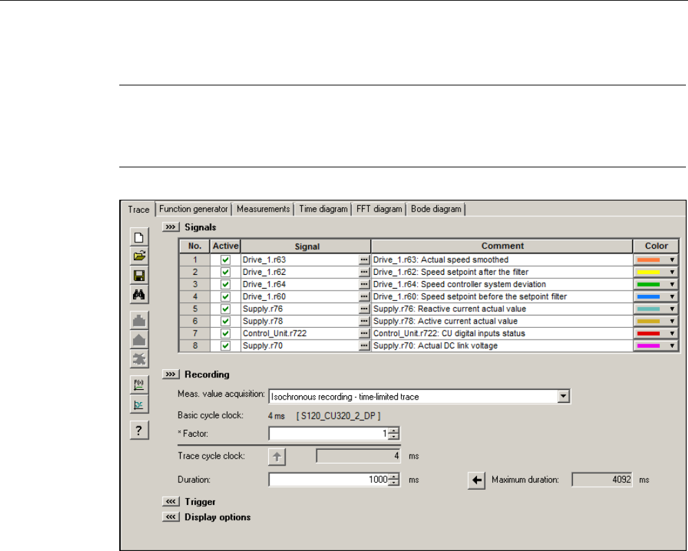
Diagnostics
4.2 Diagnostics via STARTER
STARTER Commissioning Manual
346 Commissioning Manual, (IH1), 07/2016, 6SL3097-4AF00-0BP5
Parameterizing and using the trace function
Note
Detailed information on how to parameterize and operate the trace function is available in
the STARTER online help in Chapter "Trace, measuring functions and automatic controller
setting".
Image 4-5 Trace function
The unit cycle time display flashes 3 times at around 1 Hz when the time slice is changed
from < 4 ms to ≥ 4 ms (see description under "Properties"). The display also flashes in the
inverse direction from ≥ 4 ms to < 4 ms.

Diagnostics
4.2 Diagnostics via STARTER
STARTER Commissioning Manual
Commissioning Manual, (IH1), 07/2016, 6SL3097-4AF00-0BP5 347
Properties
● Two independent traces per Control Unit
● Up to 8 recording channels for each trace
When more than 4 channels per single trace are used, the trace's device clock cycle is
switched automatically from 0.125 ms (0.250 ms for vector control) to 4 ms. As a
consequence, the performance of the SINAMICS S120 is not influenced too strongly by
the trace function.
● Single trace:
Device clock cycles of the SINAMICS S120 trace
Up to 4 channels: 0.125 ms (servo control)/0.250 ms (vector control)
≥ 5 channels: 4 ms (servo control/vector control)
The specified trace cycles can be increased.
● Endless trace:
The parameter data is written to the memory until it is full. Additional parameter data is
then lost.
A ring buffer can be selected in order to avoid this. When the ring buffer is activated, then
the STARTER commissioning tool automatically starts again from the beginning to write
to the trace memory after the last trace parameter was saved.
Device cycle of the SINAMICS S120 trace for an endless trace:
– Up to 4 channels: 2 ms (servo control/vector control)
– ≥ 5 channels: 4 ms (servo control/vector control)
The specified trace cycles can be increased.
If the 4 ms time slice is not available, then the next higher time slice is selected.
● Triggering
– Without triggering (recording immediately after start)
– Triggering on signal with edge or on level
● STARTER commissioning tool
– Automatic or adjustable scaling of display axes
– Signal measurement via cursor
● Adjustable trace cycle: Integer multiples of the basic sampling time

Diagnostics
4.2 Diagnostics via STARTER
STARTER Commissioning Manual
348 Commissioning Manual, (IH1), 07/2016, 6SL3097-4AF00-0BP5
4.2.2.2
Multiple trace
A multiple trace consists of individual, completed consecutive traces. Using multiple tracing
on a card, it is possible to cyclically record (a specific number) traces with the same trace
configuration (number of channels, sample depth, recording cycle,..), and to save these
traces persistently on the drive memory card.
The functions "endless trace", "individual trace" and "multiple-trace" cannot be used at the
same time. With a correspondingly incorrect configuration, alarm "A02097" is output.
However, a multiple trace with a cycle of 1 is nothing more than a single trace with saved
measurement results.
Note
Shorter service life of memory cards as a result of multiple traces
The service life of the cards can be shortened by the multiple traces because the memory
media is subject to wear
as a result of the write access operations from a technical point of
view.
Note
The performance of the complete system can be negatively influenced by a continuous
multiple trace.
Precondition
A multiple trace is only possible if the memory card is plugged in and not blocked. In this
case, alarm "A02098 MTrace: cannot be saved" is output with alarm value "1".
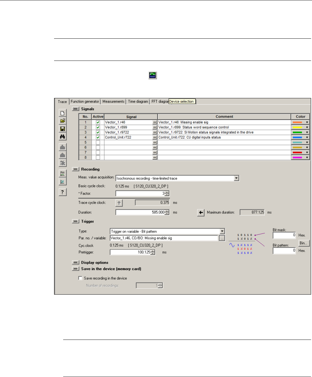
Diagnostics
4.2 Diagnostics via STARTER
STARTER Commissioning Manual
Commissioning Manual, (IH1), 07/2016, 6SL3097-4AF00-0BP5 349
Activating a multiple trace
Note
The multiple trace can be activated or set separately for each trace recorder.
1. In STARTER, click the symbol (device trace-function generator).
The "Trace" parameterizing screen form is then displayed.
Image 4-6 Multiple trace in STARTER
2. Activate the "Save the recording in the device" option.
3. Enter the number of cycles in the "Number of recordings" field.
Note
Detailed information on how to parameterize and operate the trace function is available in
the STARTER online help in Chapter "Trace, measuring functions and automatic
controller setting".
4. Make the required trace settings and save the settings.
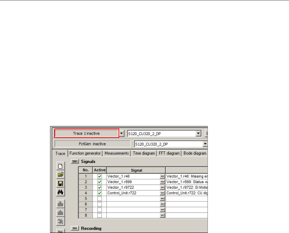
Diagnostics
4.2 Diagnostics via STARTER
STARTER Commissioning Manual
350 Commissioning Manual, (IH1), 07/2016, 6SL3097-4AF00-0BP5
Sequence of multiple trace
1. A multiple trace is started just like a conventional single trace using the STARTER
"Trace" screen form.
2. The multiple trace component saves the measurement result after the trigger condition
has occurred and the trace data has been completely recorded.
3. The single trace that has actually been completed is now automatically restarted from the
multiple trace component. In this case, the same trace configuration (trigger condition,
recording cycle, etc.) is used as before. The trace buffer of the previous single trace is
emptied in the process.
Trace status
The status of the multiple trace is displayed in the screen form (red frame):
Image 4-7 Trace status in STARTER
4.2.2.3
Startup trace
A startup trace basically consists of a conventional single trace with all of its configuration
options (number of channels, sampling depth, recording cycle, etc.). With the appropriate
configuration, a startup trace is automatically active after a drive restarts.
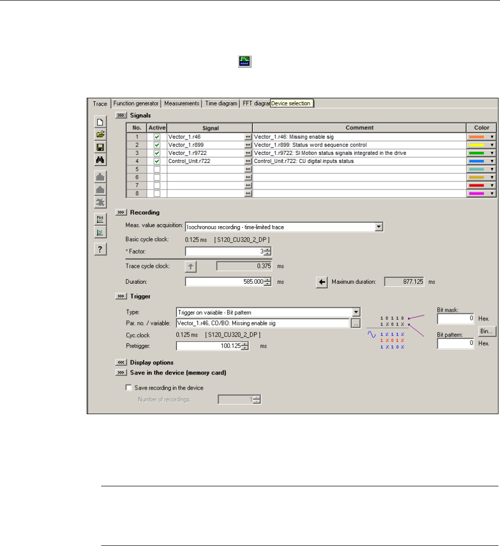
Diagnostics
4.2 Diagnostics via STARTER
STARTER Commissioning Manual
Commissioning Manual, (IH1), 07/2016, 6SL3097-4AF00-0BP5 351
Configure startup trace
1. In STARTER, click the symbol (device trace-function generator).
The "Trace" parameterizing screen form is then displayed.
Image 4-8 Startup trace in STARTER
2. Activate the "Save the recording in the device" option.
3. Enter a number ≥ 1 in the "Number of recordings" field.
Note
Detailed information on how to parameterize and operate the trace function is available in
the STARTER online help in Chapter "Trace, measuring functions and automatic
controller setting".
4. Make the required trace settings and save the settings.
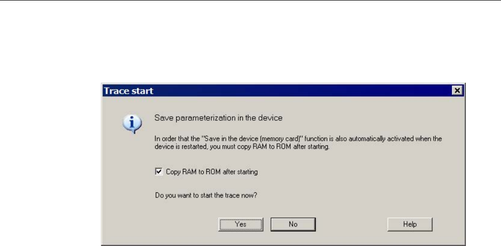
Diagnostics
4.2 Diagnostics via STARTER
STARTER Commissioning Manual
352 Commissioning Manual, (IH1), 07/2016, 6SL3097-4AF00-0BP5
5. Start the trace.
This is followed by the prompt whether the parameterization in the device should be
saved.
Image 4-9 Trace save prompt in STARTER
6. Activate the "Copy RAM to ROM after starting" option.
7. Click "Yes" to start the trace.
After the drive restarts, a new trace is immediately started (without any additional user
action).
4.2.2.4
Overview of important alarms and faults
Overview of important alarms and faults (see SINAMICS S120/S150 List Manual)
•
A02097
MTrace 1: multiple trace cannot be activated
•
A02098
MTrace 1: cannot be saved
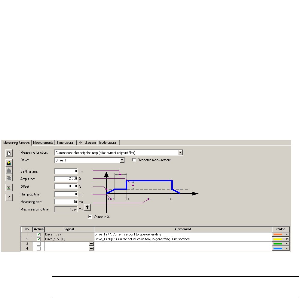
Diagnostics
4.2 Diagnostics via STARTER
STARTER Commissioning Manual
Commissioning Manual, (IH1), 07/2016, 6SL3097-4AF00-0BP5 353
4.2.3
Measuring function
The measuring function is used for optimizing the drive controller. By parameterizing the
measuring function, the impact of superimposed control loops can be suppressed selectively
and the dynamic response of the individual drives analyzed. The ramp-function generator
and trace function are linked for this purpose. The control loop is supplied with the ramp-
function generator signal at a given point (e.g. speed setpoint) and recorded by the trace
function at another (e.g. actual speed value). The trace function is parameterized
automatically when the measuring function is parameterized. Specific predefined operating
modes for the trace function are used for this purpose.
Parameterizing and using the measuring function
The measuring function is parameterized and operated via the STARTER commissioning
tool.
Image 4-10 "Measuring function" initial screen
Note
Please refer to the online help for more information about parameterizing and operation.

Diagnostics
4.2 Diagnostics via STARTER
STARTER Commissioning Manual
354 Commissioning Manual, (IH1), 07/2016, 6SL3097-4AF00-0BP5
Measuring functions
● Speed controller reference frequency response (downstream of the speed setpoint filter)
● Speed controller path (excitation downstream of current setpoint filter)
● Speed controller interference frequency response (fault downstream of the current
setpoint filter)
● Speed controller reference frequency response (upstream of the speed setpoint filter)
● Speed controller setpoint change (downstream of the speed setpoint filter)
● Speed controller disturbance step change (fault downstream of the current setpoint filter)
● Current controller reference frequency response (downstream of the current setpoint
filter)
● Current controller setpoint change (downstream of the current setpoint filter)
Starting/stopping the measuring function
NOTICE
Damage to property due to unexpected movements while the measurement function is
active
Some monitoring functions are deactivated when the measurement function is activated.
Incorrect parameterization of the measurement function can result in unexpected
movements of the motor that damage the machine.
• Do not leave the machine unattended while the measurement function is active.
• Ensure that the parameter assignments are correct.
To start the measuring function:
1. Set the preconditions for starting the measuring function.
2. Select the drive in the project navigator.
3. In the project navigator, double-click "Drive" > "Commissioning" > "Measuring function".
4. Set the required measuring function.
5. Download the settings to the target device by clicking the symbol "Download
parameterization".
6. Start the function generator ("Start measuring function" button).
To stop the measuring function:
The measuring function runs for a limited time and then automatically stops.
1. If you wish to stop immediately, click the "Stop measuring function" button.
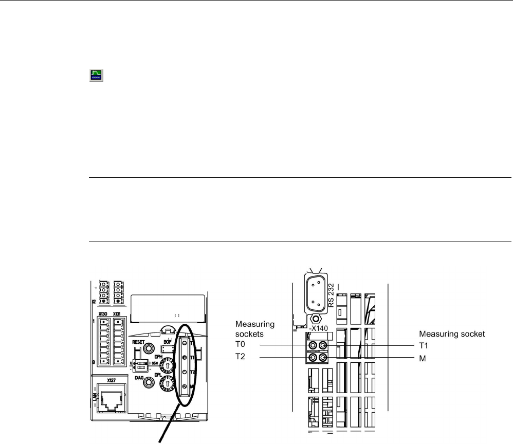
Diagnostics
4.2 Diagnostics via STARTER
STARTER Commissioning Manual
Commissioning Manual, (IH1), 07/2016, 6SL3097-4AF00-0BP5 355
Parameterization
The "Measurement function" parameterizing screen form is selected via the following symbol
in the toolbar of the STARTER commissioning tool.
4.2.4
Measuring sockets
The 3 measuring sockets are used to output analog signals. Any interconnectable analog
signal can be output at each measuring socket on the Control Unit.
Note
Use of the measuring sockets
The measuring sockets are intended for commissioning and diagnostic functions.
Connection for operational purpos
es can violate the EMC limits.
Front view
View from below
Image 4-11 CU310-2 DP/PN measuring sockets, CU320-2 DP/PN measuring sockets
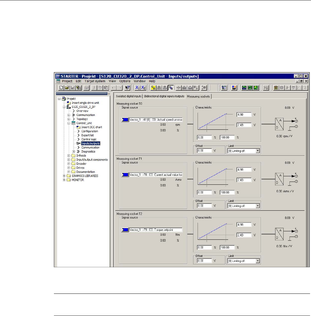
Diagnostics
4.2 Diagnostics via STARTER
STARTER Commissioning Manual
356 Commissioning Manual, (IH1), 07/2016, 6SL3097-4AF00-0BP5
Parameterizing and using the measuring sockets
The measuring sockets are parameterized and operated via the STARTER commissioning
tool. You can access the operating window for the measuring sockets in the project window
under "Control Unit" > "Inputs/outputs". In the inputs/outputs window, click the "Test sockets"
tab.
Image 4-12 "Measuring sockets" initial screen
Note
You can find additional information on parameterizing and operating in the online help.

Diagnostics
4.2 Diagnostics via STARTER
STARTER Commissioning Manual
Commissioning Manual, (IH1), 07/2016, 6SL3097-4AF00-0BP5 357
Properties
● Resolution: 8-bit
● Voltage range: 0 V to +4.98 V
● Measuring cycle: Depends on the measuring signal
(e.g. actual speed value in speed controller cycle 125 μs)
● Short-circuit-proof
● Parameterizable scaling
● Adjustable offset
● Adjustable limitation
Signal chart for measuring sockets
The signal characteristic for measuring sockets is shown in function diagram 8134 (see
SINAMICS S120/S150 List Manual).
Which signal can be output via measuring sockets?
The signal to be output via a measuring socket is specified by parameterizing the connector
input p0771[0...2].
Important measuring signals (examples):
r0060
CO: Speed setpoint before speed setpoint filter
r0063
CO: Actual speed value
r0069[0...2] CO: Actual phase currents value
r0075
CO: Field-generating current setpoint
r0076 CO: Actual field-generating current value
r0077
CO: Torque-generating current setpoint
r0078
CO: Actual torque-generating current value
Scaling
Scaling specifies how the measuring signal is processed. A straight line with 2 points must
be defined for this purpose.
Example:
x1 / y1 = 0.0% / 2.49 V x2 / y2 = 100.0% / 4.98 V (default setting)
0.0 %
is mapped to 2.49 V
100.0 %
is m
apped to 4.98 V
– 100.0 %
is mapped to 0.00 V

Diagnostics
4.2 Diagnostics via STARTER
STARTER Commissioning Manual
358 Commissioning Manual, (IH1), 07/2016, 6SL3097-4AF00-0BP5
Offset
The offset is applied additively to the signal to be output. The signal to be output can thus be
displayed within the measuring range.
Limitation
● Limitation On
If signals are output outside the permissible measuring range, the signal is limited to 4.98
V or to 0V.
● Limitation Off
The output of signals outside the permissible measuring range causes a signal overflow.
In the event of an overflow, the signal jumps from 0 V to 4.98 V or from 4.98 to 0 V.
Example of measured value output via a measuring socket
The actual speed (r0063) is to be output for a drive via measuring socket T1.
The following settings should be made:
1. Connect and set the measuring device.
2. Interconnect the signal (e.g. STARTER).
Interconnect the connector input (CI) belonging to the measuring socket with the desired
connector output (CO):
CI: p0771[1] = CO: r0063
3. Parameterize the signal characteristic (scaling, offset, limitation).
Function diagrams (see SINAMICS S120/S150 List Manual)
•
8134
Diagnostics
- measuring sockets (T0, T1, T2)

Diagnostics
4.2 Diagnostics via STARTER
STARTER Commissioning Manual
Commissioning Manual, (IH1), 07/2016, 6SL3097-4AF00-0BP5 359
Overview of important parameters (see SINAMICS S120/S150 List Manual)
Adjustable parameters
•
p0771[0...2]
CI: Measuring sockets signal source
•
p0777[0...2]
Measuring sockets characteristic value x1
•
p0778[0...2]
Measuring sockets characteristic value y1
•
p0779[0...2]
Measuring sockets characteristic value x2
•
p0780[0...2]
Measuring sockets characteristic value y2
•
p0783[0...2]
Measuring sockets offset
•
p0784[0...2]
Measuring sockets limit on/off
Display parameters
•
r0772[0...2]
Measuring sockets signal to be output
•
r0774[0...2]
Measuring sockets output voltage
•
r0786[0...2]
Measuring sockets normalization per volt

Diagnostics
4.3 Diagnostic buffer
STARTER Commissioning Manual
360 Commissioning Manual, (IH1), 07/2016, 6SL3097-4AF00-0BP5
4.3
Diagnostic buffer
The diagnostic buffer can be used to log important operating events as a logbook.
(Restriction: The availability of the diagnostics buffer mechanism is also dependent on the
hardware release of the Control Unit).
The diagnostic buffer is in the non-volatile memory, so data written to it can be read out for
subsequent analysis of a malfunction (including pre-history).
The essential events recorded in the buffer are:
● Faults
● Important changes to the boot status (end status) and partial booting of DOs
● Commissioning procedures
● State change of PROFIBUS/PROFINET communication
● Exceptions
The entries in the diagnostic buffer can be called up via the drive unit properties (symbol in
project navigator --> right-click) under the menu option "Target device" > "Device
diagnostics".
Note
STEP 7 full version
Devic
e diagnostics in the STARTER commissioning tool is only displayed when you have
installed the full version of STEP 7.
Events recorded by the diagnostic buffer
The following list shows the entries defined for SINAMICS drive units. Additional information
is marked with <>.
Faults
An entry is defined for each possible DO number. The fault code and fault value are entered
in the additional information.
Example:
Fault DO 5: Fault code 1005 fault value 0x30012
Alarms are not saved in the diagnostic buffer. Propagated faults (faults which are signaled to
all DOs) are only stored in the diagnostic buffer once.

Diagnostics
4.3 Diagnostic buffer
STARTER Commissioning Manual
Commissioning Manual, (IH1), 07/2016, 6SL3097-4AF00-0BP5 361
Booting procedures and booting status changes
In principle, only start and completion are recorded for booting procedures. Booting status
(see r3988) are only recorded when an end status arises that can only be exited by user
action (r3988 = 1, 10, 200, 250, 325, 370, 800). Booting statuses and booting status
changes are:
● POWER ON
● Error in booting (r3988 = 1)
● Fatal error in booting (r3988 = 10)
● Waiting for first commissioning (r3988 = 200)
● Topology error in booting (r3988 = 250)
● Waiting for entry of drive type (r3988 = 325)
● Waiting until p0009 = 0 is set (r3988 = 370)
● Boot status r3988 = <state at which 670 or 680> reached
● Booting finished, cyclic operation
● Reason for new boot < 0 = Internal reason; 1 = Warm start; 2 = Booting from saved data;
3 = Booting after download>
● Drive reset via p0972 = <Mode>
● Partial booting DO started <DO number>
● Partial booting DO <DO number> finished
Commissioning procedures
● Device commissioning: New status p0009 = <new value p0009>
● Commissioning DO <DO number>: New status p0010 = <new value p0010>
● Ram2Rom DO <0 for all DOs> started
● Ram2Rom DO <0 for all DOs> completed
● Project download started
● DO <DO_Number> deactivated
● DO <DO_Number> reactivated
● Component <Component number> deactivated
● Component <Component number> reactivated
● Power Off / Power On required after firmware update (DO <DO number>
Component < Component number >)
● DO <DO-No> deactivated and not available
● Component <component number> deactivated and not available

Diagnostics
4.3 Diagnostic buffer
STARTER Commissioning Manual
362 Commissioning Manual, (IH1), 07/2016, 6SL3097-4AF00-0BP5
Communication (PROFIBUS, PROFINET, ...)
● PZD <IF1 or IF2> cyclic data exchange started
● PZD <IF1 or IF2> cyclic data exchange completed
● Changeover to UTC time for operating hours count status <Days> <Milliseconds>
● Time correction (correct) by <correction value> seconds
Exceptions
Exceptions can be taken from the crash diagnostics already available in the new boot run.
The exceptions are always entered into the diagnostic buffer first, even before the entry
"POWER ON".
● Data Abort Exception Address: <Content Program Counter>
● Floating Point Exception Address: <Content Program Counter>
● Prefetch Abort Exception Address: <Content Program Counter>
● Exception type <Type coding> Info: <Info depends on type>
Treatment of the time stamp
After successful time synchronization (in cyclic operation), the UTC time is used as a time
stamp. Up until this time (POWER ON and switching to UTC time) the operating hours
counter is used for all entries. The UTC time is entered for following entries.

Diagnostics
4.4 Diagnostics of uncommissioned axes
STARTER Commissioning Manual
Commissioning Manual, (IH1), 07/2016, 6SL3097-4AF00-0BP5 363
4.4
Diagnostics of uncommissioned axes
To be able to identify uncommissioned drive objects of the classes "Infeeds", "Motor
Module", "SERVO" and "VECTOR", there is an operating display in parameter r0002.
● r0002 "Infeed operating display" = 35: Carry out the first startup
● r0002 "Drive operating display" = 35: Carry out the first startup
The parameter r0002 "drive operating display" = 35 is then displayed if p3998[D]=0 is in any
data set. Parameter p3998 specifies whether the first commissioning of the drive is still to be
carried out (0 = yes, 2 = no).
Parameter p3998 is set to the value 2 when the calculation of the motor and control
parameters for all data sets has been completed without errors (see r3925 bit0 = 1) and the
encoder selection p0400 is not at 10100 (encoder identification).
The limitation that all drive data sets (DDS) must be commissioned in order to exit
commissioning is ensured by checking the parameters involved (see also F07080 in the
SINAMICS S120/S150 List Manual).
Infeed Module
An infeed (Active Line Modules, Basic Line Modules or Smart Line Modules with DRIVE-
CLiQ) is considered commissioned when the line voltage and line frequency have been
parameterized with appropriate values. A basic setting of 50 Hz or 60 Hz is expected for the
line frequency.
The line voltage p0210 may need to be adjusted to the existing power supply.
To exit the state r0002 "Infeed operating display" = 35, set parameter p3900 "completion of
quick commissioning" to the value 3, after any necessary adjustment to the line voltage.
For a 400 V unit, for example, the voltage p0210 is always initialized with 400 V. Although it
is possible to switch on when connected to all line supplies from 380 V to 480 V, operation is
not always optimal and/or alarm messages are displayed (see SINAMICS S120/S150 List
Manual).
If the unit is not connected to a 400 V line supply, then the rated voltage p0210 should be
adjusted. This can also be done after the first time the unit is switched on, by setting
p0010 = 1.

Diagnostics
4.4 Diagnostics of uncommissioned axes
STARTER Commissioning Manual
364 Commissioning Manual, (IH1), 07/2016, 6SL3097-4AF00-0BP5
Motor Module
A drive is considered to have been commissioned when in every drive data set (DDS) the
motor and encoder data sets have been assigned valid data:
● Motor data sets (MDS):
p0131, p0300, p0301 etc. (see SINAMICS S120/S150 List Manual)
● Encoder data sets (EDS):
p0141, p0142, p0400 etc. (see SINAMICS S120/S150 List Manual)
After parameterizing the motor and encoder data via quick commissioning
(p0010 = 1 ->0) use p3900 "completion of quick commissioning" > 0 to exit.
If commissioning should not be run using quick commissioning, the motor data should be
entered via p0010 = 3 (p0340[0...n] "Automatic calculation of motor/control parameters" =1)
after entering the type plate data, and the encoder data entered via p0010 = 4.
If the above conditions are not met, in r0002 of the drive concerned, the value r0002 = 35:
"Carry out first commissioning" will be displayed.
It is not taken into account whether at switch on (pulse enable) required BICO sources are
already parameterized, or are still at the value 0. Example:
● p0840 "BI: ON/OFF1" or
● p0864 "BI: Infeed operation"
If, after commissioning all DDSs, parameter p0010 is set once more to a value greater than
0, in r0002 the value r0002 = 46: "Switching on inhibited - exit the commissioning mode
(p0009, p0010)" will be displayed.
The drive has been commissioned, however the pulses cannot be enabled.
Note on p0010 = 1 (quick commissioning):
Quick commissioning with p3900 > 0 (when p0010 = 1) works for all DDSs, where motor and
encoder data has been entered.
This means that if quick commissioning is carried out a second or third time (or more),
previously calculated and possibly user-adjusted data will be overwritten or recalculated.
For this reason we recommend carrying out any subsequent commissioning of a certain
DDS (e.g. changing the motor), specifically using p0010 = 3 and p0010 = 4 instead of
p0010 = 1.
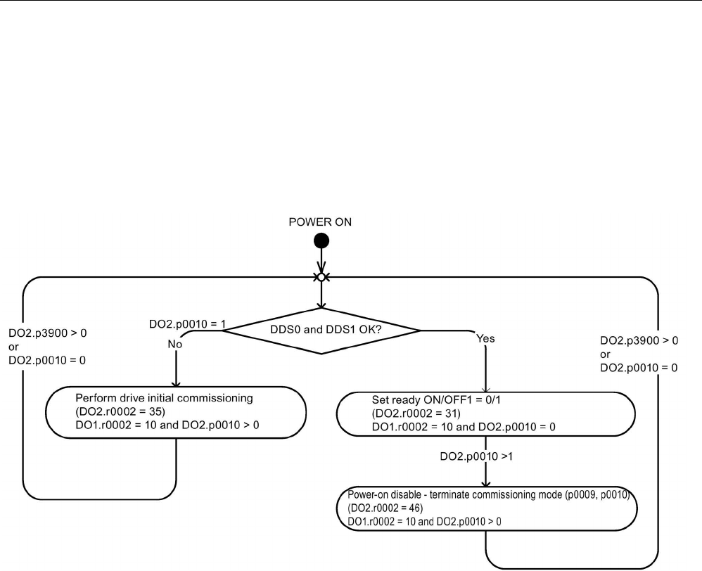
Diagnostics
4.4 Diagnostics of uncommissioned axes
STARTER Commissioning Manual
Commissioning Manual, (IH1), 07/2016, 6SL3097-4AF00-0BP5 365
Example
The image below shows a diagram of the diagnostic performance of uncommissioned
infeeds and drives. A configuration with one power unit (DO2) and respectively two DDSs,
MDSs and EDSs has been assumed. DO1 represents the CU.
The unit has already been commissioned.
The number of data sets and the components assigned to the DO2 have already been
entered and the data set allocated.
Image 4-13 Diagnostics of uncommissioned axes

Diagnostics
4.5 Fault and alarm messages
STARTER Commissioning Manual
366 Commissioning Manual, (IH1), 07/2016, 6SL3097-4AF00-0BP5
4.5
Fault and alarm messages
4.5.1
General information about faults and alarms
The errors and states detected by the individual components of the drive system are
indicated by messages.
The messages are categorized into faults and alarms.
Note
The individual faults and alarms are described in Chapter "Faults and alarms" in the
SINAMICS S120/S150 List Manual. Function diagrams for the fault buffer, alarm buffer, fault
trigger and fault configuration are also contained in th
e Section "Function diagrams" -
"Faults
and alarms".
Properties of faults and alarms
● Faults (code F01234)
– Are identified by Fxxxxx.
– Can lead to a fault reaction.
– Must be acknowledged once the cause has been remedied.
– Status via Control Unit and LED RDY.
– Status via PROFIBUS status signal ZSW1.3 (fault active).
– Entry in the fault buffer.
● Alarms (code A56789)
– Are identified by Axxxxx.
– Have no further effect on the drive.
– The alarms are automatically reset once the cause has been remedied. No
acknowledgement is required.
– Status via PROFIBUS status signal ZSW1.7 (alarm active).
– Entry in the alarm buffer.
● General properties of faults and alarms
– Can be configured (e.g. change fault to alarm, fault reaction).
– Triggering on selected messages possible.
– Initiation of messages possible via an external signal.
– Contains the component number for identifying the SINAMICS component involved
– Contains diagnostic information on the message involved

Diagnostics
4.5 Fault and alarm messages
STARTER Commissioning Manual
Commissioning Manual, (IH1), 07/2016, 6SL3097-4AF00-0BP5 367
Acknowledging faults
The list of faults and alarms specifies how each fault is acknowledged after the cause has
been remedied.
● Acknowledgement of faults by "POWER ON"
– Switch the drive on/off (POWER ON)
– Press the RESET button on the Control Unit
● Acknowledgement of faults by "IMMEDIATE"
– Via a PROFIdrive control signal:
STW1.7 (reset fault memory): 0/1 edge
Set STW1.0 (ON/OFF1) = "0" and "1"
– Via external input signal
Binector input and interconnection with digital input
p2103 = "Requested signal source"
p2104 = "Requested signal source"
p2105 = "Requested signal source"
Across all of the drive objects (DO) of a Control Unit
p2102 = "Requested signal source"
● Acknowledge faults with "PULSE INHIBIT"
– The fault can only be acknowledged with a pulse inhibit (r0899.11 = 0).
– The same possibilities are available for acknowledging as described under
acknowledge IMMEDIATELY.
Note
The drive can only resume operation after all active faults have been acknowledged.
4.5.2
Buffer for faults and alarms
Note
A fault and alarm bu
ffer is provided for each drive. The drive and device-specific messages
are entered in these buffers.
The contents of the fault buffer are saved to non
-volatile memory when the Control Unit is
powered down, i.e. the fault buffer history is still available
when the unit is powered up again.
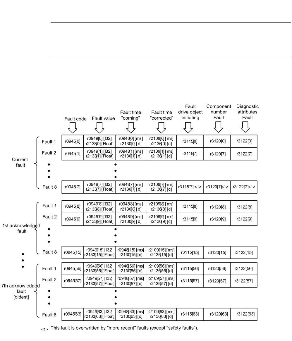
Diagnostics
4.5 Fault and alarm messages
STARTER Commissioning Manual
368 Commissioning Manual, (IH1), 07/2016, 6SL3097-4AF00-0BP5
Note
The entry in the fault/alarm buffer is made after a delay. For this reason, the fault/alarm
buffer should not be read until a change in the buffer is also recognized (r0944, r2121) after
"Fault active"/"Alarm a
ctive" is output.
Fault buffer
Faults which occur are entered in the fault buffer as follows:
Image 4-14 Structure of the fault buffer

Diagnostics
4.5 Fault and alarm messages
STARTER Commissioning Manual
Commissioning Manual, (IH1), 07/2016, 6SL3097-4AF00-0BP5 369
Properties of the fault buffer:
● A new fault incident encompasses one or more faults and is entered in "Current fault
incident".
● The entries are arranged in the buffer according to the time at which they occurred.
● If a new fault incident occurs, the fault buffer is reorganized. The history is recorded in
"Acknowledged fault incident" 1 to 7.
● If the cause of at least one fault in "Current fault incident" is remedied and acknowledged,
the fault buffer is reorganized. Faults that have not been remedied remain in "Current
fault incident".
● If "Current fault incident" contains eight faults and a new fault occurs, the fault in the
parameters in index 7 is overwritten by the new fault.
● r0944 is incremented each time the fault buffer changes.
● A fault value (r0949) can be output for a fault. The fault value is used to diagnose the fault
more accurately; please refer to the fault description for details of the meaning.
Clear fault buffer
● Delete fault buffer for all drive objects:
p2147 = 1 --> p2147 = 0 is automatically set after execution.
● Delete fault buffer for a specific drive object:
p0952 = 0 --> The parameter belongs to the specified drive object.
The fault buffer contents are automatically deleted for the following events:
● Restore factory setting (p0009 = 30 and p0976 = 1).
● Change drive object type
● Upgrade firmware to later version.
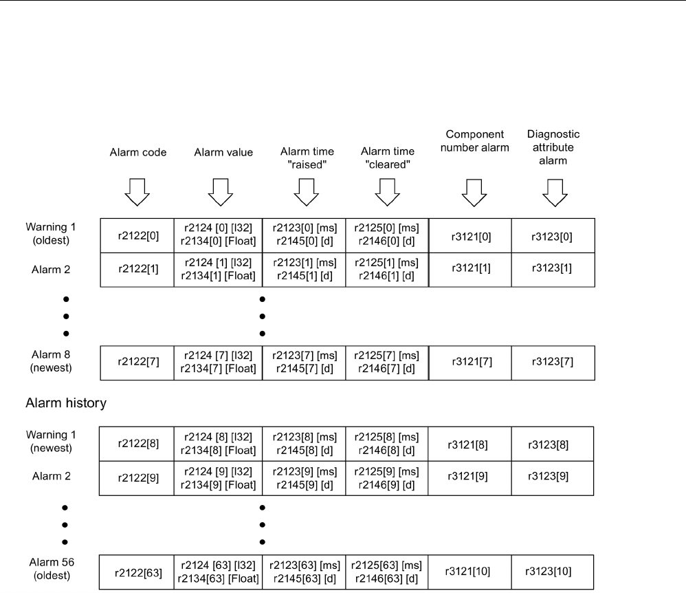
Diagnostics
4.5 Fault and alarm messages
STARTER Commissioning Manual
370 Commissioning Manual, (IH1), 07/2016, 6SL3097-4AF00-0BP5
Alarm buffer, alarm history
An alarm in the alarm buffer comprises the alarm code, the alarm value and the alarm time
(received, resolved). The alarm history occupies the last indices ([8...63]) of the parameter.
Image 4-15 Structure of alarm buffer
Alarms that occur are entered in the alarm buffer as follows:
A maximum of 64 alarms are displayed in the alarm buffer:
● Index 0 ... 6: The first 7 alarms are displayed.
● Index 7: The most recent alarm is displayed.
A maximum of 56 alarms are displayed in the alarm history:
● Index 8: The most recent alarm is displayed.
● Index 9 .. 63: The first 55 alarms are displayed.

Diagnostics
4.5 Fault and alarm messages
STARTER Commissioning Manual
Commissioning Manual, (IH1), 07/2016, 6SL3097-4AF00-0BP5 371
Properties of the alarm buffer/alarm history:
● The alarms in the alarm buffer are arranged from 7 to 0 according to the time that they
occurred. In the alarm history, this is from 8 to 63.
● If 8 alarms have been entered into the alarm buffer, and a new alarm is received, then the
alarms that have been resolved are transferred into the alarm history.
● r2121 is incremented each time the alarm buffer changes.
● An alarm value (r2124) can be output for an alarm. The alarm value is used to diagnose
the alarm more accurately; please refer to the alarm description for details of the
meaning.
Deleting the alarm buffer, index [0...7]:
● The alarm buffer index [0...7] is reset as follows: p2111 = 0
4.5.3
Configuring messages
The properties of the faults and alarms in the drive system are permanently defined.
For several messages, in a specific scope defined by the drive system, the properties can be
changed as follows:
Change message type (example)
Select message
Set message type
p2118[5] = 1001
p2119[5]
= 1: Fault (F)
= 2: Alarm (A)
= 3: No message (N)
Change fault reaction (example)
Select message
Set fault response
p2100[3] = 1002
p2101[3]
= 0: None
= 1: OFF1
= 2: OFF2
= 3: OFF3
= 4: STOP1 (available soon)
= 5: STOP2
= 6: IASC/DC brake
Internal armature short
-
circuit braking or
DC brake
= 7: ENCODER (p0491)
Change acknowledgement (example)
Select message
Set acknowledgement
p2126[4] = 1003
p2127[4]
= 1: POWER ON
= 2: IMMEDIATELY
= 3: PULSE INHIBIT

Diagnostics
4.5 Fault and alarm messages
STARTER Commissioning Manual
372 Commissioning Manual, (IH1), 07/2016, 6SL3097-4AF00-0BP5
19 message types per drive object can be changed.
Note
If BICO interconnections exist between drive objects, all interconnected objects must be
configured.
Example:
The TM31 has BICO interconnections with drive 1 and 2 and F35207 is t
o be reconfigured
as an alarm.
•
p2118[n] = 35207 and p2119[n] = 2
•
These settings are required for for TM31, drive 1 and drive 2.
Note
Only those messages which are listed in the indexed parameters can be changed as
desired. All other message settings re
tain their factory settings or are reset to the factory
settings.
Examples:
•
In the case of messages listed via p2128[0...19], the message type can be changed. The
factory setting is set for all other messages.
•
The fault response of fault F12345 has been changed via p2100[n]. The factory settings
should be restored (p2100[n] = 0).
Triggering on messages (example)
Select message
Trigger signal
p2128[0] = 1001
BO: r2129.0
or
p2128[1] = 1002
BO: r2129.1
Note
The value fr
om CO: r2129 can be used as group trigger.
CO: r2129 = 0 No selected message has been output.
CO: r2129 > 0 Group trigger.
At least one selected message has been output.
The individual binector outputs BO: r2129 should be investigated.

Diagnostics
4.5 Fault and alarm messages
STARTER Commissioning Manual
Commissioning Manual, (IH1), 07/2016, 6SL3097-4AF00-0BP5 373
External triggering messages
If the appropriate binector input is interconnected with an input signal, fault 1, 2 or 3 or alarm
1, 2 or 3 can be triggered via an external input signal.
Once an external fault (1 to 3) has been triggered on the Control Unit drive object, this fault
is also present on all associated drive objects. If one of these external faults is triggered on a
different drive object, it is only present on that particular drive object.
BI: p2106
––> External fault 1
––> F07860(A)
BI: p2107
––> External fault 2
––> F07861(A)
BI: p2108
––> External fault 3
––> F07862(A)
BI: p2112
––> External alarm 1
––> A07850(F)
BI: p2116 ––> External alarm 2 ––> A07851(F)
BI: p2117
––> External alarm 3
––> A07852(F)
Note
An exte
rnal fault or alarm is triggered by a 1/0 signal.
An external fault and alarm do not usually mean that an internal drive message has been
generated. The cause of an external fault and warning should, therefore, be remedied
outside the drive.

Diagnostics
4.5 Fault and alarm messages
STARTER Commissioning Manual
374 Commissioning Manual, (IH1), 07/2016, 6SL3097-4AF00-0BP5
4.5.4
Overview of important function diagrams and parameters
Overview of important function diagrams (see SINAMICS S120/S150 List Manual)
•
8050
Diagnosis
- Overview
•
8060
Diagnostics
- fault buffer
•
8065
Diagnostics
- alarm buffer
•
8070
Diagnostics
- faults/alarms trigger word (r2129)
•
8075
Diagnostics
- faults/alarms configuration
•
8134
Diagnostics
- measuring sockets (T0, T1, T2)
Overview of important parameters (see SINAMICS S120/S150 List Manual)
•
r0944
CO: Counter for fault buffer changes
•
p0952
Fault cases, counte
r
•
p2100[0...19]
Changing the fault reaction, fault number
•
r2139.0...15
CO/BO: Status word, faults/alarms 1
•
r3120[0...63]
Component fault
•
r3121[0...63]
Component alarm
•
r3122[0...63]
Diagnostic attribute fault
•
r3123[0...63]
Diagnostic attribute alarm

Diagnostics
4.5 Fault and alarm messages
STARTER Commissioning Manual
Commissioning Manual, (IH1), 07/2016, 6SL3097-4AF00-0BP5 375
4.5.5
Propagation of faults
In the case of faults that are, for example, triggered by the Control Unit or a Terminal
Module, central functions of the drive are also often affected. As a result of propagation,
faults that are triggered by one drive object are therefore forwarded to other drive objects.
This behavior also applies to the faults that are set in a DCC on the Control Unit with the aid
of the DCC block.
There are the following types of propagation:
● BICO
The fault is propagated to all active drive objects with closed-loop control functions
(infeed, drive) to which there is a BICO interconnection.
● DRIVE
The fault is propagated to all active drive objects with closed-loop control functions.
● GLOBAL
The fault is propagated to all active drive objects.
● LOCAL
The behavior of this propagation type is dependent on parameter p3116.
– With binector input p3116 = 0 (factory setting) the following applies:
The fault is propagated to the first active drive object with closed-loop control
functions.
– With binector input p3116 = 1 signal, the following applies:
The fault is not propagated.

Diagnostics
4.5 Fault and alarm messages
STARTER Commissioning Manual
376 Commissioning Manual, (IH1), 07/2016, 6SL3097-4AF00-0BP5
4.5.6
Alarm classes
Fault and alarm classes
There are differentiated alarm messages in the cyclic telegrams between the former alarm
classes "Alarm" and "Fault".
The alarm classes have been extended to give three additional levels of alarm between the
pure alarm and the fault.
The function permits higher-level control (SIMATIC, SIMOTION, SINUMERIK, etc.) to have
different control reactions to alarm messages from the drive.
The new statuses act as alarms for the drive, therefore there is NO immediate reaction from
the drive (like for the former level "alarm").
Information on alarm classes are described in status word ZSW2 at bit positions bit 5/6 (for
SINAMICS) or bit 11/12 (SIMODRIVE 611) (see also "ZSW2" in Chapter "Cyclic
communication" for PROFIdrive communication in the SINAMICS S120 Function Manual
Drive Functions).
ZSW2: Valid for SINAMICS Interface Mode p2038 = 0 (function diagram 2454)
Bit 5 - 6 Alarm classes alarms
= 0: Alarm (former alarm level)
= 1: Alarm class A alarms
= 2: Alarm class B alarms
= 3: Alarm class C alarms
ZSW2: Valid for SIMODRIVE 611 Interface Mode p2038 = 1 (function diagram 2453)
Bit 11 - 12 Alarm classes alarms
= 0: Alarm (former alarm level)
= 1: Alarm class A alarms
= 2: Alarm class B alarms
= 3: Alarm class C alarms
These attributes for differentiating the alarms are implicitly assigned to the appropriate alarm
numbers. The reaction to the existing alarm classes in the alarm is defined by the user
program in the higher-level control.

Diagnostics
4.5 Fault and alarm messages
STARTER Commissioning Manual
Commissioning Manual, (IH1), 07/2016, 6SL3097-4AF00-0BP5 377
Explanations of the alarm classes
● Alarm class A: Drive operation currently not limited
– E.g. alarm when measurement systems inactive
– No limitation on current movement
– Prevent possible switching to the defective measuring system
● Alarm class B: Time-limited operation
– E.g. prewarning temperature: Without further action the drive may need to be switched
off
– After a timer stage -> additional fault
– After exceeding a switch-off threshold -> additional fault
● Alarm class C: Functionally limited operation
– E.g. reduced voltage/current/torque/speed limits (i2t)
– E.g. continue with reduced accuracy / resolution
– E.g. continue without encoder

Diagnostics
4.6 Troubleshooting for encoders
STARTER Commissioning Manual
378 Commissioning Manual, (IH1), 07/2016, 6SL3097-4AF00-0BP5
4.6
Troubleshooting for encoders
If an encoder fault is present, it can be acknowledged separately according to encoder
channels in a PROFIdrive telegram via the encoder interface (Gn_STW.15) or the drive
interface of the appropriate drive object.
Configuration example: 2-encoder system
● Encoder G1 motor measurement system
● Encoder G2 direct measurement system
Case considered: All encoders signal encoder faults.
● The faults are entered in the encoder interface - and from there in encoder channel n of
the PROFIDRIVE telegram. Bit15 of the encoder status word (Gn_ZSW.15 = 1) is set.
● The faults are transferred to the drive object.
● Motor measuring system faults set the drive object to fault (ZSW1 bit3), the faults are
additionally signaled via the drive interface. An entry is made in fault buffer p0945. The
parameterized fault response is initiated internally.
● Direct measuring system faults are converted by the assigned drive object into the
"Alarm" message type and signaled via the drive interface (ZSW1 bit7). An entry is made
in alarm buffer r2122.
No drive responses are initiated.
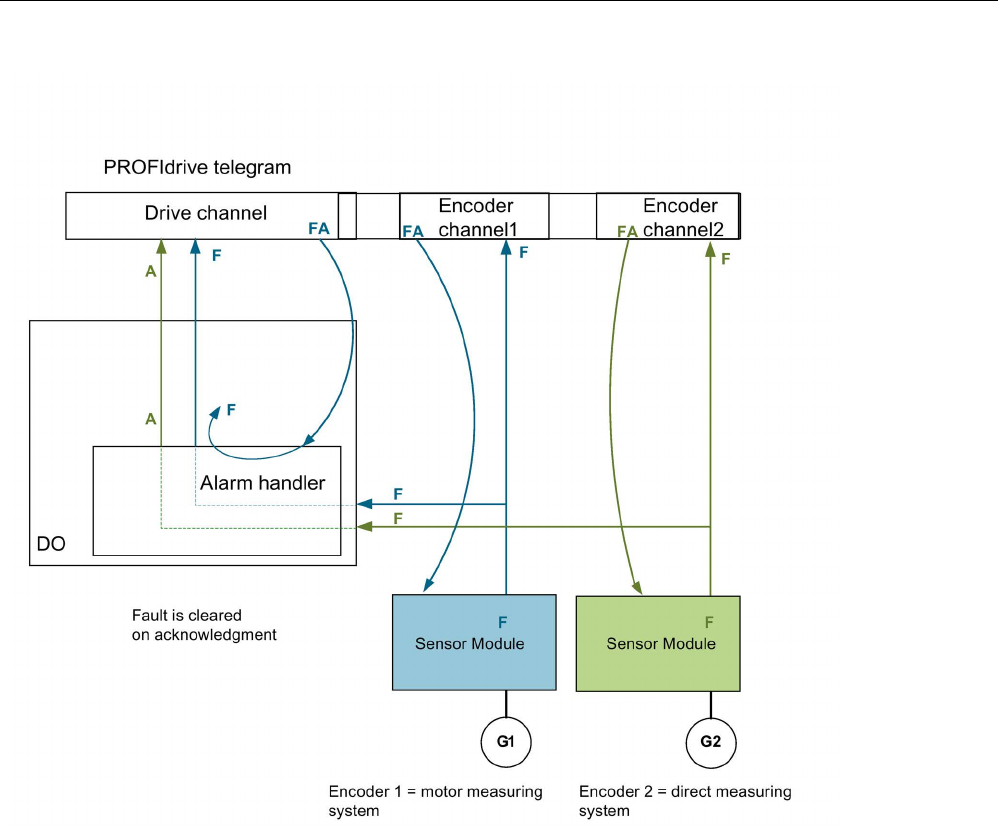
Diagnostics
4.6 Troubleshooting for encoders
STARTER Commissioning Manual
Commissioning Manual, (IH1), 07/2016, 6SL3097-4AF00-0BP5 379
Image 4-16 Encoder fault handling
Alarm A:
The alarm is cancelled immediately, if the encoder fault was able to be acknowledged.
Fault F:
The fault remains active at the drive object until it is acknowledged via the cyclic interface.

Diagnostics
4.6 Troubleshooting for encoders
STARTER Commissioning Manual
380 Commissioning Manual, (IH1), 07/2016, 6SL3097-4AF00-0BP5
Cyclic acknowledgement
Acknowledgement using the encoder interface (Gn_STW.15)
The following responses are possible:
● The encoder is set to fault-free if a fault is no longer active. The fault bit in the encoder
interface is acknowledged. The evaluation modules indicate RDY LED = green after
acknowledgement.
This behavior is valid for all encoders connected to the encoder interface, irrespective of
the measurement system type (motor or direct).
● If the fault still exists, or if other faults exist, the acknowledgement is not successful – and
the highest priority fault (can be the same or another fault entry) is transferred via the
encoder interface.
The RDY LED on the evaluation modules is continuously red.
This behavior is valid for all encoders connected via the encoder interface, irrespective of
the measuring system type (motor or direct).
● The drive object is not detected via the encoder interface. Faults set in the drive object
remain, the drive does not even start with the encoder which in the meantime is fault-free.
The drive object must also be acknowledged via the drive interface (fault memory
RESET).
Acknowledgement using the drive interface (STW1.7 (cyclic) or p3981(acyclic))
The following responses are possible:
● If no more faults exist, the encoder is set to fault-free and the fault bit in the drive interface
is acknowledged. The evaluation modules indicate RDY LED = green.
Acknowledgement takes place on all encoders that are logically assigned to the drive.
● If the fault still exists, or other faults exist, then the acknowledgement is not successful;
the next, highest priority fault is transferred via the drive interface and also via the
encoder interface involved.
● The RDY LED on the evaluation modules is continuously red.
● The encoder interfaces of the assigned encoders are NOT reset by acknowledgement at
the drive interface; the set faults remain.
● The encoder interfaces must also be acknowledged via the corresponding encoder
control word Gn_STW.15.
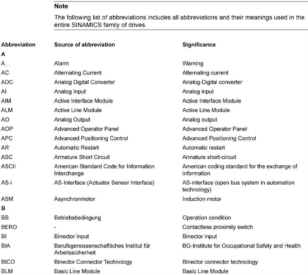
STARTER Commissioning Manual
Commissioning Manual, (IH1), 07/2016, 6SL3097-4AF00-0BP5 381
Appendix
A
A.1
List of abbreviations
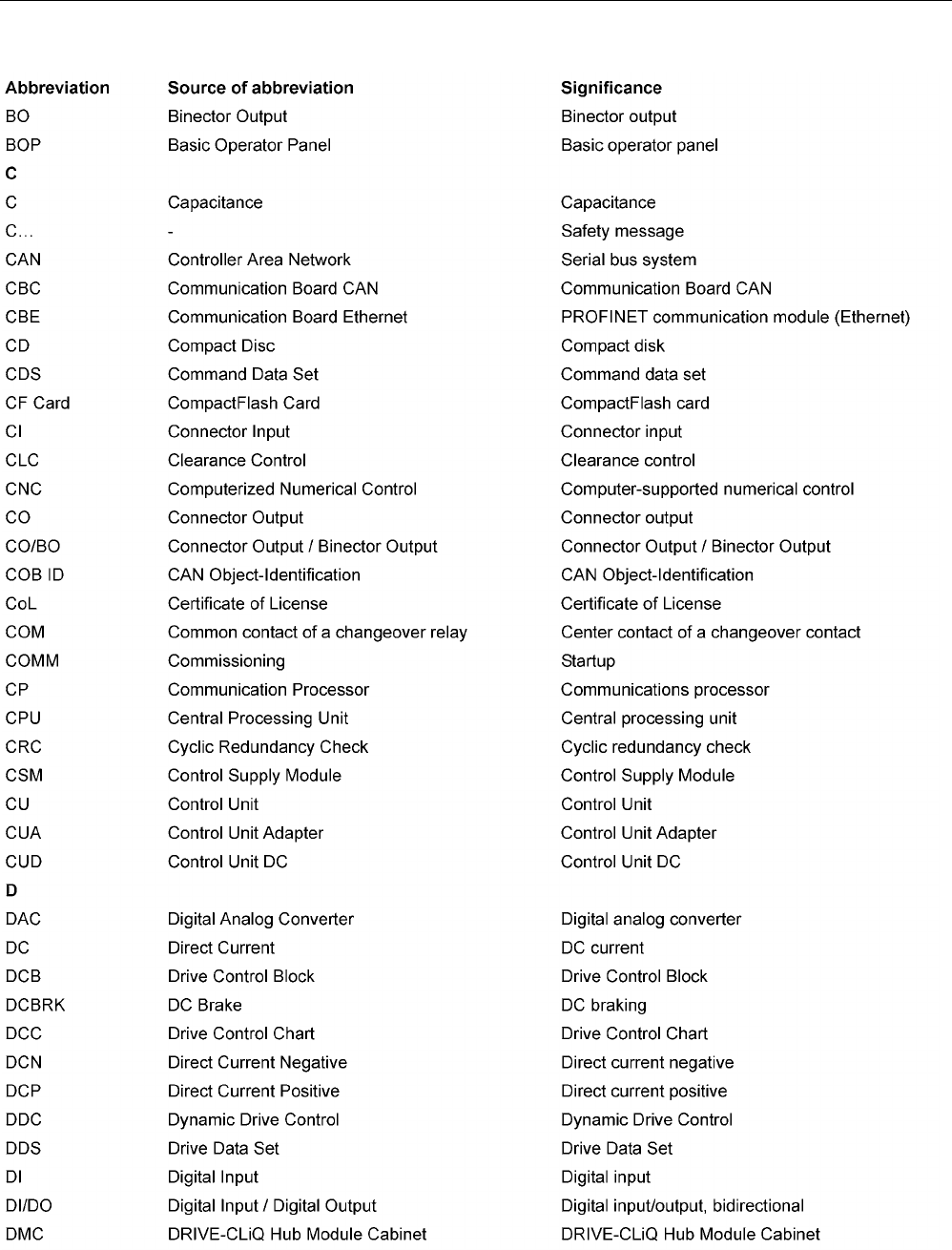
Appendix
A.1 List of abbreviations
STARTER Commissioning Manual
382 Commissioning Manual, (IH1), 07/2016, 6SL3097-4AF00-0BP5
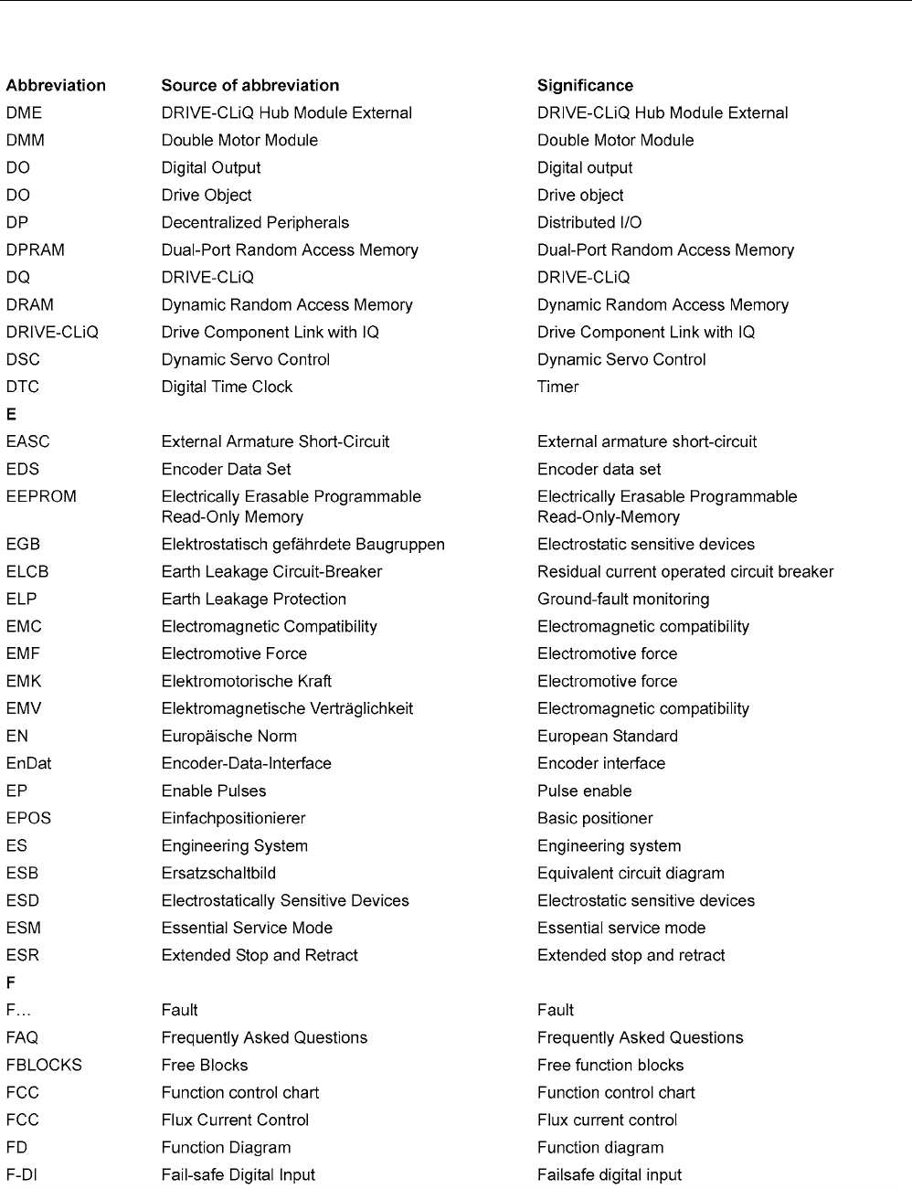
Appendix
A.1 List of abbreviations
STARTER Commissioning Manual
Commissioning Manual, (IH1), 07/2016, 6SL3097-4AF00-0BP5 383
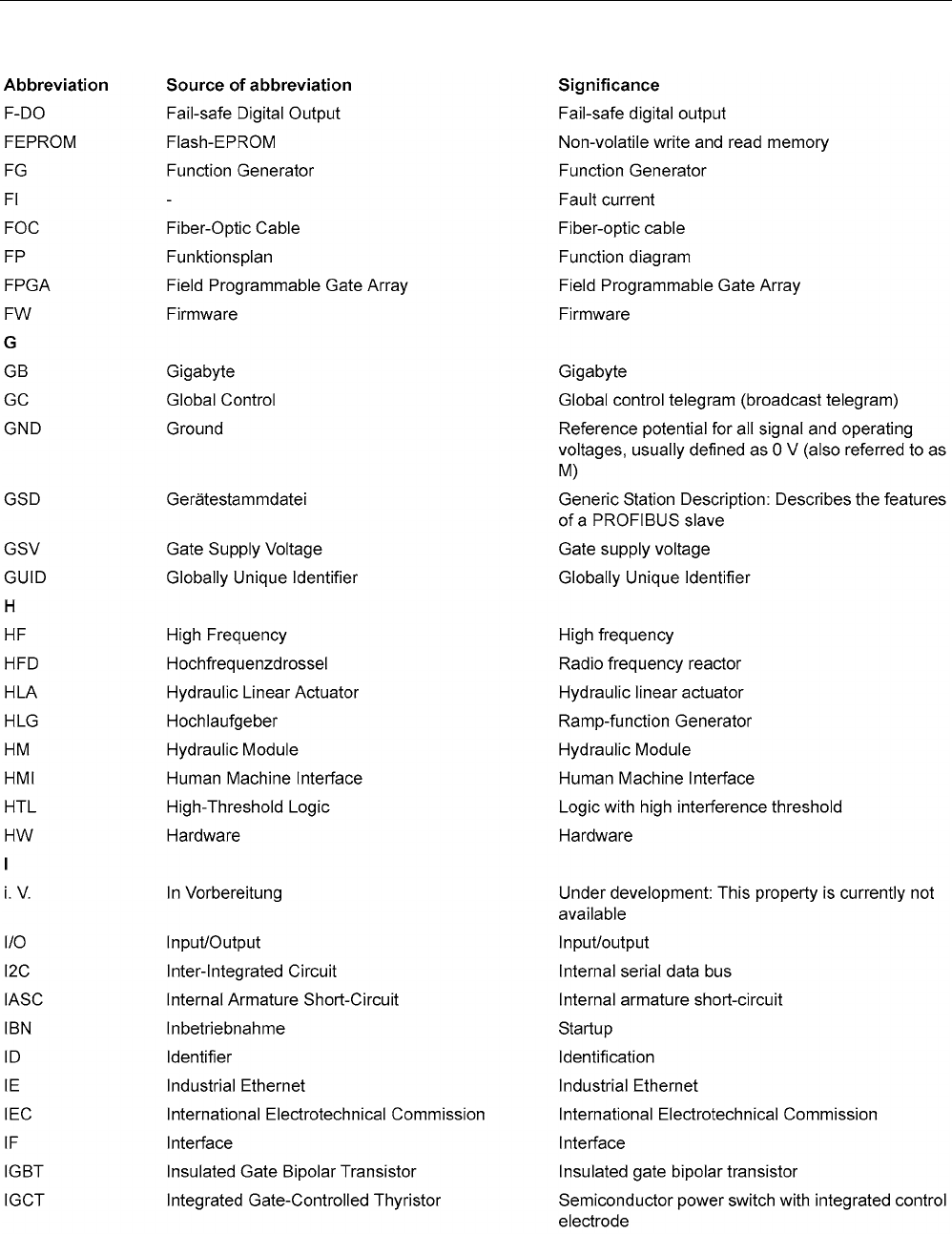
Appendix
A.1 List of abbreviations
STARTER Commissioning Manual
384 Commissioning Manual, (IH1), 07/2016, 6SL3097-4AF00-0BP5
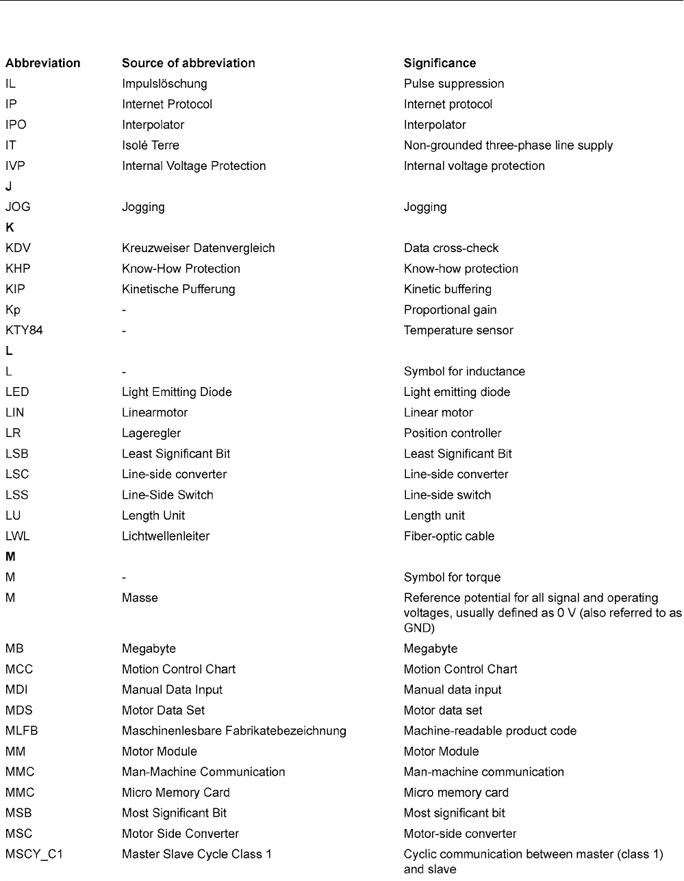
Appendix
A.1 List of abbreviations
STARTER Commissioning Manual
Commissioning Manual, (IH1), 07/2016, 6SL3097-4AF00-0BP5 385
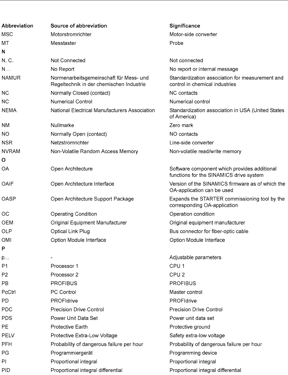
Appendix
A.1 List of abbreviations
STARTER Commissioning Manual
386 Commissioning Manual, (IH1), 07/2016, 6SL3097-4AF00-0BP5
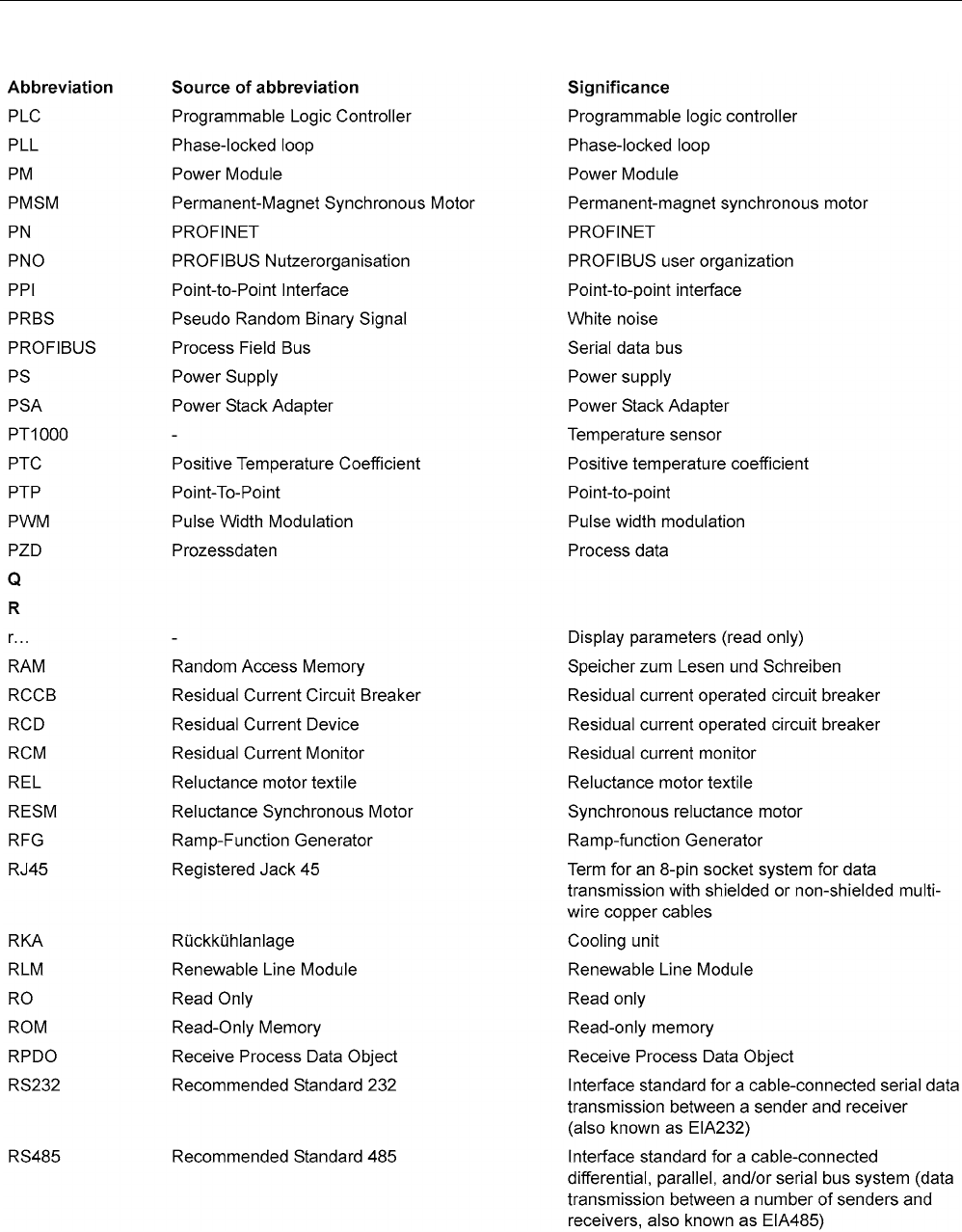
Appendix
A.1 List of abbreviations
STARTER Commissioning Manual
Commissioning Manual, (IH1), 07/2016, 6SL3097-4AF00-0BP5 387
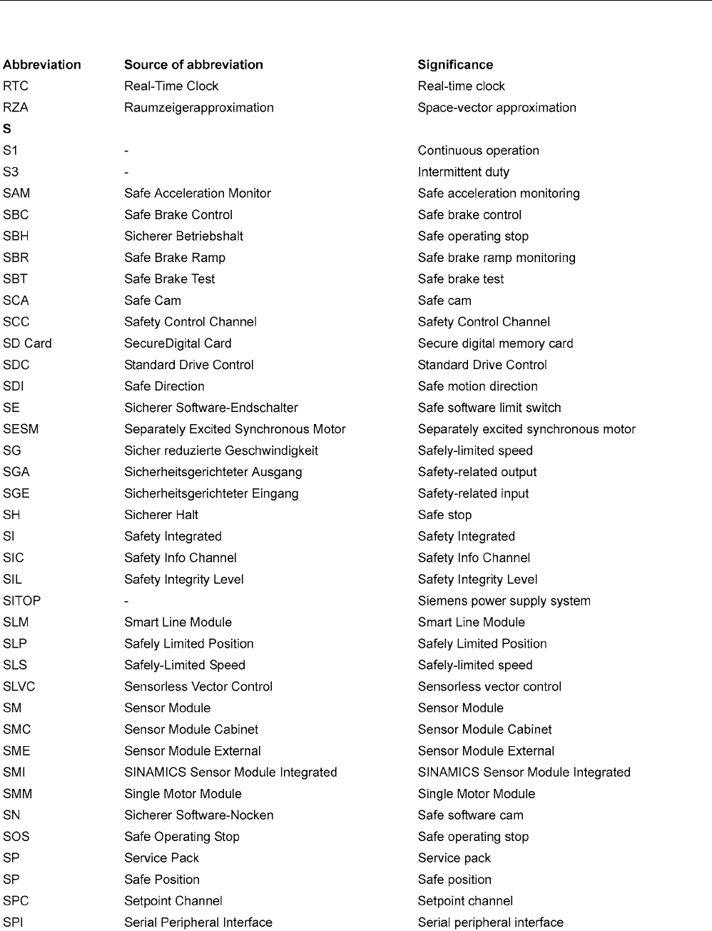
Appendix
A.1 List of abbreviations
STARTER Commissioning Manual
388 Commissioning Manual, (IH1), 07/2016, 6SL3097-4AF00-0BP5
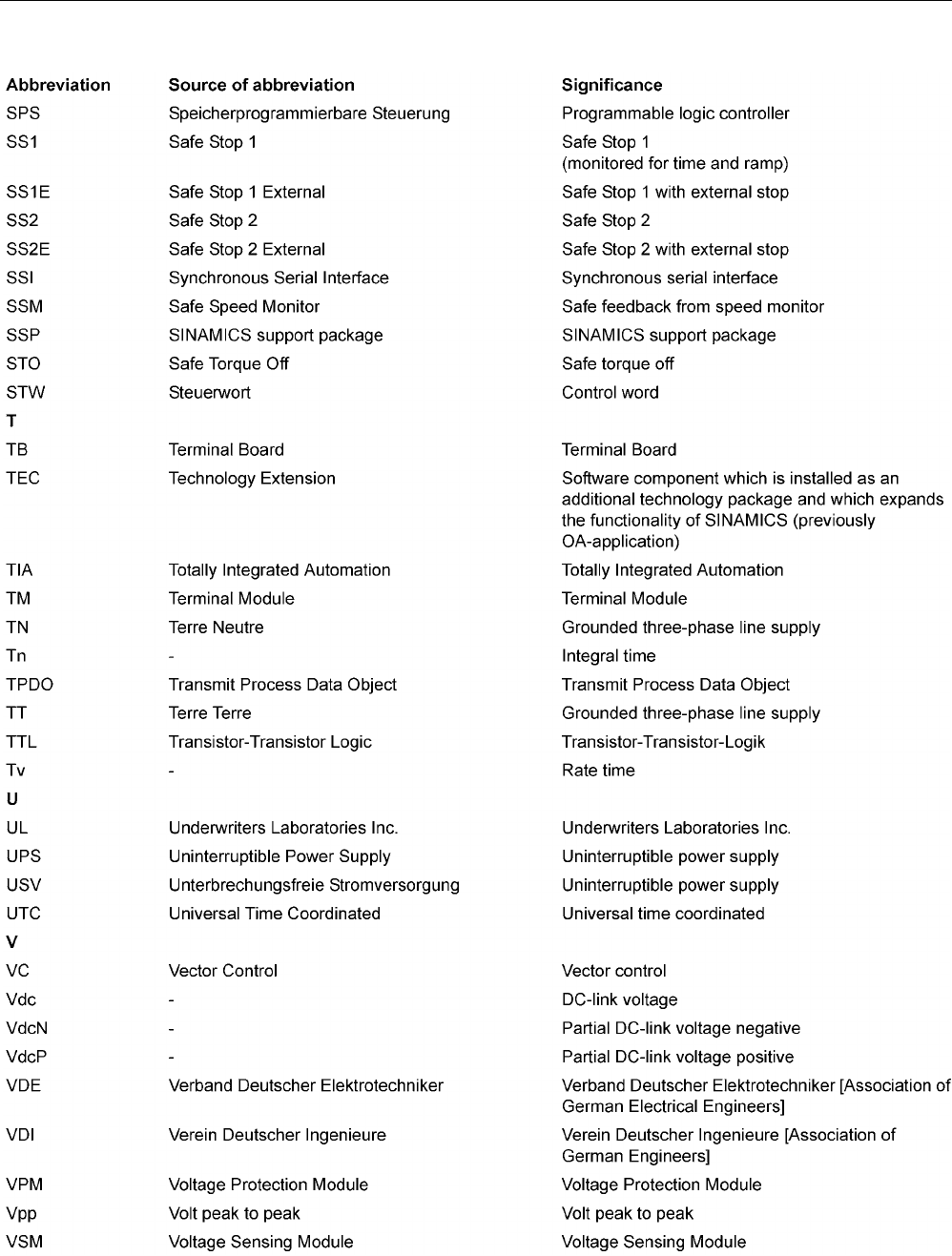
Appendix
A.1 List of abbreviations
STARTER Commissioning Manual
Commissioning Manual, (IH1), 07/2016, 6SL3097-4AF00-0BP5 389
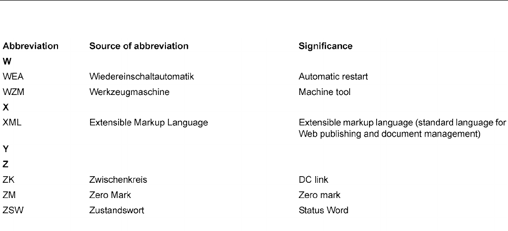
Appendix
A.1 List of abbreviations
STARTER Commissioning Manual
390 Commissioning Manual, (IH1), 07/2016, 6SL3097-4AF00-0BP5
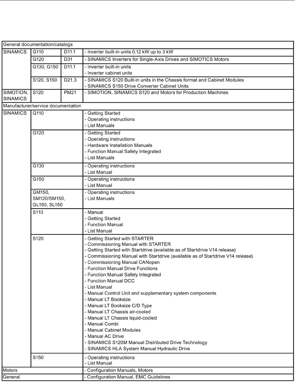
Appendix
A.2 Documentation overview
STARTER Commissioning Manual
Commissioning Manual, (IH1), 07/2016, 6SL3097-4AF00-0BP5 391
A.2
Documentation overview

Appendix
A.3 Availability of hardware components
STARTER Commissioning Manual
392 Commissioning Manual, (IH1), 07/2016, 6SL3097-4AF00-0BP5
A.3
Availability of hardware components
Table A- 1 Hardware components available as of 03.2006
No.
Hardware component
Article number
Version
Revisions
1
AC Drive (CU320, PM340)
refer to the Catalog
New
2 SMC30 6SL3055-0AA00-5CA1 With SSI support
3
DMC20
6SL3055-0AA00-6AA.
New
4 TM41 6SL3055-0AA00-3PA. New
5 SME120
SME125
6SL3055-0AA00-5JA.
6SL3055-0AA00-5KA.
New
6
BOP20
6SL3055-0AA00-4BA.
New
7
CUA31
6SL3040-0PA00-0AA.
New
Table A- 2 Hardware components available as of 08.2007
No.
Hardware component
Article number
Version
Revisions
1
TM54F
6SL3055-0AA00-3BA.
New
2 Active Interface Module
(booksize)
6SL3100-0BE..-.AB. New
3
Basic Line Module (booksize)
6SL3130-1TE..-0AA.
New
4
DRIVE-CLiQ encoder
6FX2001-5.D..-0AA.
New
5 CUA31
Suitable for Safety Extended
functions via PROFIsafe and
TM54
6SL3040-0PA00-0AA1 New
6
CUA32
6SL3040-0PA01-0AA.
New
7
SMC30 (30 mm wide)
6SL3055-0AA00-5CA2
New
Table A- 3 Hardware components available as of 10.2008
No.
Hardware component
Article number
Version
Revisions
1
TM31
6SL3055-0AA00-3AA1
New
2
TM41
6SL3055-0AA00-3PA1
New
3
DME20
6SL3055-0AA00-6AB.
New
4
SMC20 (30 mm wide)
6SL3055-0AA00-5BA2
New
5 Active Interface Module
booksize 16 kW
6SL3100-0BE21-6AB. New
6 Active Interface Module
booksize 36 kW
6SL3100-0BE23-6AB. New
7 Smart Line Modules booksize
compact
6SL3430-6TE21-6AA. New

Appendix
A.3 Availability of hardware components
STARTER Commissioning Manual
Commissioning Manual, (IH1), 07/2016, 6SL3097-4AF00-0BP5 393
No.
Hardware component
Article number
Version
Revisions
8 Motor Modules booksize com-
pact
6SL3420-1TE13-0AA.
6SL3420-1TE15-0AA.
6SL3420-1TE21-0AA.
6SL3420-1TE21-8AA.
6SL3420-2TE11-0AA.
6SL3420-2TE13-0AA.
6SL3420-2TE15-0AA.
New
9 Power Modules blocksize liquid
cooled
6SL3215-1SE23-0AA.
6SL3215-1SE26-0AA.
6SL3215-1SE27-5UA.
6SL3215-1SE31-0UA.
6SL3215-1SE31-1UA.
6SL3215-1SE31-8UA.
New
10 Reinforced DC-link busbars for
50 mm components
6SL3162-2DB00-0AA. New
11 Reinforced DC-link busbars for
100 mm components
6SL3162-2DD00-0AA. New
Table A- 4 Hardware components available as of 11.2009
No.
Hardware component
Article number
Version
Revisions
1 Control Unit 320-2DP 6SL3040-1MA00-0AA1
Actual 2014: 6SL3040-1MA00-0AA0
4.3 New
2
TM120
6SL3055-0AA00-3KA0
4.3
New
3 SMC10 (30 mm wide) 6SL3055-0AA00-5AA3 4.3 New
Table A- 5 Hardware components available as of 01.2011
No.
Hardware component
Article number
Version
Revisions
1 Control Unit 320-2PN 6SL3040-1MA01-0AA1
Actual 2014: 6SL3040-1MA01-0AA0
4.4 New
2 Braking Module booksize com-
pact
6SL3100-1AE23-5AA0 4.4 New
3
SLM 55kW booksize
6SL3130-6TE25-5AA.
4.4
New
4 TM120 evaluation of up to four
motor temperature sensors
6SL3055-0AA00-3KA. 4.4 New

Appendix
A.3 Availability of hardware components
STARTER Commissioning Manual
394 Commissioning Manual, (IH1), 07/2016, 6SL3097-4AF00-0BP5
Table A- 6 Hardware components available as of 04.2011
No.
Hardware component
Article number
Version
Revisions
1 S120 Combi three axes
Power Module
6SL3111-3VE21-6FA0
6SL3111-3VE21-6EA0
6SL3111-3VE22-0HA0
4.4 New
2 S120 Combi four axes
Power Module
6SL3111-4VE21-6FA0
6SL3111-4VE21-6EA0
6SL3111-4VE22-0HA0
4.4 New
3 S120 Booksize Compact power
units
Single Motor Module
6SL3420-1TE13-0AA0
6SL3420-1TE15-0AA0
6SL3420-1TE21-0AA0
6SL3420-1TE21-8AA0
4.4 New
4 S120 Booksize Compact power
units
Double Motor Module
6SL3420-2TE11-7AA0
6SL3420-2TE13-0AA0
6SL3420-2TE15-0AA0
4.4 New
5
Braking Module booksize
6SL3100-1AE31-0AB0
4.4
New
Table A- 7 Hardware components available as of 01.2012
No.
Hardware component
Article number
Version
Revisions
1 TM150 evaluation of up to 12
temperature sensors
6SL3055- 0AA0-3LA0 4.5 New
2
CU310-2 PN
6SL3040-1LA01-0AA0
4.5
New
3
CU310-2 DP
6SL3040-1LA00-0AA0
4.5
New
Table A- 8 Hardware components available as of Q4 2012
No.
Hardware component
Article number
Version
Revisions
1
Adapter Module 600
6SL3555-2BC10-0AA0
4.5
New
Table A- 9 Hardware components available as of 01.2013
No.
Hardware component
Article number
Version
Revisions
1 300% overload, booksize up to
18 A
6SL312.-.....-...4
for Motor Modules with 50 mm and:
3 A, 5 A, 9 A, 18 A, 2x3 A, 2x5 A,
2x9 A
4.6 New
2 SINAMICS S120M 6SL3532-6DF71-0R..
6SL3540-6DF71-0R..
6SL3542-6DF71-0R..
6SL3562-6DF71-0R..
6SL3563-6DF71-0R..
4.6 New

Appendix
A.3 Availability of hardware components
STARTER Commissioning Manual
Commissioning Manual, (IH1), 07/2016, 6SL3097-4AF00-0BP5 395
Table A- 10 Hardware components available as of 04.2014
No.
Hardware component
Article number
Version
Revisions
1 S120 Combi:
New power unit
6SL3111-4VE21-0EA
Four axis Power Modules with high
amperage:
24 A, 12 A, 12 A, 12 A
4.7 New
2 Power Module PM240-2 6SL321.-.P..-....
FSA, FSB and FSC for 200 V and
400 V
4.7 New
Table A- 11 Hardware components available as of 04.2015
Nr
Hardware component
Article number
Version
Changes
1
TM31 Terminal Module
6SL3055-0AA00-3AA1
4.7 SP2
Revised
2
TM41 Terminal Module
6SL3055-0AA00-3PA1
4.7 SP2
Revised
3 DRIVE-CLiQ Hub Module
DMC20
6SL3055-0AA00-6AA1 4.7 SP2 Revised
Table A- 12 Hardware components available as of 10.2015
Nr
Hardware component
Article number
Version
Changes
1 Motor Module with up to 2x over-
load (Booksize redesign)
6SL3120-1TE21-8AC. (18 A)
6SL3120-1TE23-0AC. (30 A)
6SL3120-2TE21-8AC. (2 x 18 A)
- New
2 Motor Module with up to 3x over-
load (Booksize redesign)
6SL3120-1TE13-0AD. (3 A)
6SL3120-1TE15-0AD. (5 A)
6SL3120-1TE21-0AD. (9 A)
6SL3120-1TE21-8AD. (18 A)
6SL3120-1TE23-0AD. (30 A)
6SL3120-2TE13-0AD. (2 x 3 A)
6SL3120-2TE15-0AD. (2 x 5 A)
6SL3120-2TE21-0AD. (2 x 9 A)
6SL3120-2TE21-8AD. (2 x 18 A)
- New
3 Motor plug connector with push-
in connection
6SL3162-2MB00-0AC0 - New
4 Motor plug connector with screw-
type connection
6SL3162-2MA00-0AC0 - New

Appendix
A.3 Availability of hardware components
STARTER Commissioning Manual
396 Commissioning Manual, (IH1), 07/2016, 6SL3097-4AF00-0BP5
Table A- 13 Hardware components available as of 07.2016
No.
Hardware component
Article number
Version
Changes
1 PM240-2 Power Module 6SL321.-.P..-....
FSD, FSE and FSF for 200 V, 400 V
and 690 V
4.8 New
2 TM31 Terminal Module 6SL3055-0AA00-3AA1 4.8 Revised
3
TM41 Terminal Module
6SL3055-0AA00-3PA1
4.8
Revised
4
TM54F Terminal Module
6SL3055-0AA00-3BA.
4.8
Revised
5 DMC20 DRIVE-CLiQ Hub Mod-
ule
6SL3055-0AA00-6AA1 4.8 Revised
6
VSM10 Voltage Sensing Module
6SL3053-0AA00-3AA1
4.8
Revised

Appendix
A.4 Availability of SW functions
STARTER Commissioning Manual
Commissioning Manual, (IH1), 07/2016, 6SL3097-4AF00-0BP5 397
A.4
Availability of SW functions
Table A- 14 New functions, firmware 4.3
No.
SW function
SERVO
VECTOR
HW component
1
The 1FN6 motor series is supported
x
-
-
-2 DRIVE-CLiQ motors with star-delta changeover are supported x - -
3 Referencing with several zero marks per revolution via the encod-
er interface
x - -
4 Permanent-
magnet synchronous motors can be controlled down to
zero speed without having to use an encoder
- x -
5 "SINAMICS Link": Direct communication between several
SINAMICS S120
x x -
6 Safety Integrated:
• Control of the Basic Functions via PROFIsafe
• SLS without encoder for induction motors
• SBR without encoder for induction motors
• Own threshold value parameters for SBR:
Up until now, SSM used parameter p9546
x x -
7 Drive object encoder:
An encoder can now be directly read-in via the encoder drive ob-
ject and can then be evaluated by SIMOTION using the TO exter-
nal encoder.
- x -
8 Support of new components
• CU320-2
• TM120
x x -
9
GSDML file expanded for Profisafe
x
x
-
10
USS protocol at interface X140
x
x
-
11
V/f diagnostics (p1317) permitted as regular operating mode
x
-
-
12 Setpoint-based utilization display, instead of the previous actual
value-based utilization display
x x -
13 A performance license is required from the 4th axis (for ser-
vo/vector) or from the 7th U/f axis, instead of from a utilization of
50% and higher – which was the case up until now.
x x -
14 Tolerant encoder monitoring, 2nd part:
• Monitoring, tolerance band, pulse number
• Switchable edge evaluation for square-wave encoders
• Setting the zero speed measuring time for pulse encoder sig-
nal evaluation
• Changeover measuring procedure, actual value acquisition for
square-wave encoder
• "LED check" encoder monitoring
x x -

Appendix
A.4 Availability of SW functions
STARTER Commissioning Manual
398 Commissioning Manual, (IH1), 07/2016, 6SL3097-4AF00-0BP5
Table A- 15 New functions, firmware 4.4
No.
SW function
SERVO
VECTOR
HW component
1 Safety Integrated functions
• SDI (Safe Direction) for induction motors (with and without
encoder), for synchronous motors with encoder.
• Supplementary condition for Safety without encoder (for induc-
tion motors): Only possible with devices in booksize and
blocksize format. Not for devices in chassis format.
x x -
2 Communication
• PROFINET address can be written via parameter (e.g. when
completely generating the project offline)
• Shared device for SINAMICS S PROFINET modules:
CU320-2 PN, CU310-2 PN
x x -
3
Emergency retraction (ESR = Extended Stop and Retract)
x
x
-
4 TM41: Rounding for pulse encoder emulation (gear ratio; also
resolver as encoder)
x x -
5 Further pulse frequencies for servo control and isochronous op-
eration (3.2 / 5.33 / 6.4 kHz)
x - -
6 Chassis format: Current controller in 125 µs for servo control for
higher speeds (up to approx. 700 Hz output frequency)
x - -
7
Propagation of faults
x
x
-
Table A- 16 New functions, firmware 4.5
No.
SW function
SERVO
VECTOR
HW component
1
Support for new components, CU310-2
x
x
Refer to Appendix A1
2
Support for new components, TM150
x
x
-
3 Support for high-frequency spindles with pulse frequencies up to
32 kHz (a current controller cycle of 31.25 µs)
x - -
4
PROFINET: Support for the PROFIenergy profile
x
x
-
5
PROFINET: Improved usability for Shared Device
x
x
-
6
PROFINET: Smallest selectable send cycle 250 µs
x
x
-
7 PROFINET: Bumpless media redundancy with CU310-2 PN,
CU320-2 PN and CU320-2 with CBE20
x x -
8
Ethernet/IP communication extension via CBE20
x
x
-
9
SINAMICS Link: Smallest adjustable send clock 0.5 ms
x
x
-
10 Parameterization of SINAMICS Link connections without POWER
ON
x x -
11
Write protection
x
x
-
12 Know-how protection x x -
13
PMSM (old: PEM) encoderless up to n = 0 rpm
x
x
-
14 Decoupling of the pulse frequency from the current controller cy-
cle,
valid only for power units in the chassis format
- x -

Appendix
A.4 Availability of SW functions
STARTER Commissioning Manual
Commissioning Manual, (IH1), 07/2016, 6SL3097-4AF00-0BP5 399
No.
SW function
SERVO
VECTOR
HW component
15 Expansion of the number of process data words for infeeds up to
10 words for the send and receive directions
x x -
Safety Integrated functions
16
CU310-2 safety functionality via terminals and PROFIsafe
x
x
-
17 Permanent activation of the speed limit and the safe direction of
rotation without PROFIsafe or TM54F
x x -
18
Safely Limited Position (SLP)
x
x
-
19
Transfer of the Safely Limited Position via PROFIsafe
x
x
-
20
Variably adjustable SLS limit
x
x
-
21
New PROFIsafe telegrams 31, 901, 902
x
x
-
Table A- 17 New functions, firmware 4.6
No.
Software function
SERVO
VECTOR
Hardware component
1 Integrated Web server for SINAMICS
Project and firmware download via Ethernet on the memory card
Protection against power failure while updating via the Web server
x x -
2 Replacing a part with know-how protection: Encrypted loading into
the file system
x x -
3 Parameterizable bandstop filters for Active Infeed control, chassis
format
x x -
4
Current setpoint filter
x
-
-
5
Shortened rotating measurement
-
x
-
6
Redundant data backup on the memory card
x
x
-
7
Multiple trace
x
x
-
8
Brake control adaptation
x
x
-
9 Fast flying restart - x -
10
Diagnostic alarms for PROFIBUS
x
x
-
11 DCC SINAMICS:
Support of DCB libraries generated from the SINAMICS DCB
Studio
x x -
12
SMC40 (EnDat 2.2)
x
x
-
13
CANopen expansions
x
x
-
14
Support of new components S120M
x
-
-
Safety Integrated functions
15
Safety Integrated Extended functions with two TTL/HTL encoders
x
x
-
16
Safety: Safe Brake Test
x
x
-
17
Safety Info Channel
x
x
-

Appendix
A.4 Availability of SW functions
STARTER Commissioning Manual
400 Commissioning Manual, (IH1), 07/2016, 6SL3097-4AF00-0BP5
Table A- 18 New functions, firmware 4.7
No.
Software function
SERVO
VECTOR
Hardware component
1 Separately excited synchronous machine: New operating mode,
only with HTL encoder and VSM
- x -
2 S120 Combi support x - New power unit:
6SL3111-4VE21-0EA
3
Identification & Maintenance data sets (I&M 0...4) support
x
x
-
4
Isochronous support for IRT devices
-
x
-
5 Dynamic IP address assignment (DHCP) and temporary device
names for PROFINET
x x -
6
Fast flying restart with voltage measurement
x
x
-
7
One button tuning
x
-
-
8
Online tuning
x
-
-
9
Adaptive current setpoint filter for online tuning
x
-
-
10 Independent setting of the pulse frequency and the PROFIBUS
and PROFINET cycles
x x -
11
PROFIenergy for SINAMICS S120
x
x
-
12 Activation of network functionality for booksize modules for renew-
able energies
x x -
13 New mode for ramp-
function generator tracking with torque, power
or current limit
- x -
Safety Integrated functions
14 Parameterizable line contactor activation for STO x x -
15
Extension of the safe gearbox switchover
x
x
-
16
Execute test stop automatically during ramp-up
x
x
-
17 Safety Integrated Extended Functions with two TTL/HTL encoders
for booksize and blocksize
x x -
18
Uniform behavior for component replacement
x
x
-
19
SINAMICS S120 hydraulic drive with Safety Integrated
x
-
-

Appendix
A.4 Availability of SW functions
STARTER Commissioning Manual
Commissioning Manual, (IH1), 07/2016, 6SL3097-4AF00-0BP5 401
Table A- 19 New functions, firmware 4.8
No.
Software function
SERVO
VECTOR
Hardware component
1
Synchronous reluctance motors
-
x
-
2 Moment of inertia precontrol of the moment of inertia estimator - x -
3
Expansion of the thermal motor models
x
x
-
4 Communication via MODBUS TCP x x -
5
PROFINET system redundancy
x
x
6
Expansion of SINAMICS Link functionality
x
x
-
7
Optimization of the web server functionality
x
x
-
8
Cogging torque compensation (under license)
x
-
-
9
Advanced Positioning Control (APC) (under license)
x
-
-
Safety Integrated functions
10
SBR can now also be selected for SS1/SS2 with encoder
x
x
-
11
Basic Functions controllable via TM54F
x
x
-
12
Safe Stop 2 with external stop (SS2E)
x
x
-

Appendix
A.4 Availability of SW functions
STARTER Commissioning Manual
402 Commissioning Manual, (IH1), 07/2016, 6SL3097-4AF00-0BP5
STARTER Commissioning Manual
Commissioning Manual, (IH1), 07/2016, 6SL3097-4AF00-0BP5 403
Index
A
Acknowledgment, 367
Actual position value format
2-pole resolver, 281
Alarm buffer, 370
Alarm classes
Faults and alarms, 376
Alarm history, 370
Alarm value, 370
Alarms, 366
Alarm buffer, 370
Alarm history, 370
Configuring, 371
Automatic encoder adjustment
Vector, 232
B
Basic Line Module
Vdc_max controller, 82
BICO interconnection, 86
Blocksize
PM, 34
Booksize
Booksize power unit, 32
BOP20
Control word, drive, 302
Important functions, 292, 302
C
Chassis, 32
Closed-loop control
Optimization, 219, 273
Commissioning
Checklist blocksize, 34
Checklist booksize, 32
Checklist chassis, 32
First commissioning, 123, 133, 143, 155, 160
Linear motors, 183
Linear motors checklist, 183
Parallel connection of Infeed Modules, 165
Parallel connection of Motor Modules, 165
Parallel connection of power units, 165
Reluctance motors, 223
Torque motors, 237
Torque motors checklist, 237
With STARTER, 84
Commutation angle offset
Check, 205, 206, 207, 212, 260, 260, 261, 266
Incorrect commutation, 204, 258
Measurement results, 214, 268
Parameterization, 204, 258
Commutation setting, 185, 239
Control Unit CU320-2 DP
LEDs after booting, 307
LEDs during booting, 306
Control Unit CU320-2 PN
LEDs after booting, 310
LEDs during booting, 309
Controller data
Linear motor, 191
Torque motor, 245
Counting direction of the measuring system
Linear motor, 197
Torque motor, 251
Creating a project
Offline with PROFIBUS, 115
Offline with PROFINET, 117
D
DDS
Drive data set, 364
Detail view, 85
Diagnostic buffer, 360
Diagnostic function, 341
Function generator, 341
Measuring sockets, 355
Diagnostics
via Starter, 355
Via Starter, 341, 341, 345, 353
Diagnostics via LEDs
Active Line Modules, 316
Basic Line Modules, 317
Braking Module Booksize, 320
CBE20 Ethernet Communication Board, 330
Communication Board CBC10, 329
Communication Board Ethernet CBE25, 332
Control Supply Module, 327
Control Unit CU310-2 DP, 311
Control Unit CU320-2 DP, 307
Control Unit CU320-2 PN, 310

Index
STARTER Commissioning Manual
404 Commissioning Manual, (IH1), 07/2016, 6SL3097-4AF00-0BP5
DRIVE-CLiQ Hub Module DMC20, 334
Motor Module booksize compact, 321
Motor Modules, 319
Sensor Module Cabinet 10, 327
Sensor Module Cabinet 20, 327
Sensor Module Cabinet SMC30, 328
Sensor Module Cabinet SMC40, 328
Smart Line Module Booksize Compact, 320
Smart Line Modules 16 kW and higher, 318
Smart Line Modules 5 kW and 10 kW, 318
Terminal Module TM120, 336
Terminal Module TM15, 335
Terminal Module TM150, 337
Terminal Module TM31, 336
Terminal Module TM41, 338
Terminal Module TM54F, 339
Voltage Sensing Module VSM10, 334
Diagnostics via Starter
Function generator, 341
Measuring function, 353
Measuring sockets, 355
Trace function, 345, 350
Drive direction
Linear motor, 197
Torque motor, 251
Drive interface, 378
DRIVE-CLiQ
Check connections, 75
Diagnostics, 75
Wiring rules, 48
DRIVE-CLiQ encoder, 180
E
EDS
Encoder data set, 364
Encoder
Configuration, 174
Linear, 179
Rotary, 178
Troubleshooting, 378
User-defined, 177
Encoder adjustment, 230
Fine adjustment, 231
Encoder data
Linear motor, 193
Torque motor, 247
Encoder interface, 378
Encoder selection, 173
Encoder types, 275
EPOS
Absolute encoder adjustment, 281
F
Fault buffer, 368
Fault value, 368
Faults, 366
Acknowledge, 367
Configuring, 371
Fault buffer, 368
Faults and alarms
Alarm classes, 376
Forwarding, 375
Propagation, 375
First commissioning, 123, 133, 143, 155, 160
Function generator, 343
Properties, 342
G
Generator for signals, 341
I
Initialization
Initializing the interface, 106
L
Learning devices, 171
LEDs
Active Line Modules, 316, 322, 322
Basic Line Modules, 317, 323, 323
Braking Module Booksize, 320
CBE20 Ethernet Communication Board, 330
Communication Board CBC10, 329
Communication Board Ethernet CBE25, 332
Control Unit CU310-2 DP, 311
Control Unit CU320-2 DP, 307
Control Unit CU320-2 PN, 310
DRIVE-CLiQ Hub Module DMC20, 334
Motor Module booksize compact, 321
Motor Modules, 319, 325, 325
On the Control Supply Module, 327
On the Sensor Module Cabinet 10, 327
On the Sensor Module Cabinet 20, 327
Power Modules, 326, 326
Sensor Module Cabinet SMC30, 328
Sensor Module Cabinet SMC40, 328
Smart Line Module Booksize Compact, 320
Smart Line Modules, 324, 324
Smart Line Modules 16 kW and higher, 318
Smart Line Modules 5 kW and 10 kW, 318

Index
STARTER Commissioning Manual
Commissioning Manual, (IH1), 07/2016, 6SL3097-4AF00-0BP5 405
Terminal Module TM120, 336
Terminal Module TM15, 335
Terminal Module TM150, 337
Terminal Module TM31, 336
Terminal Module TM41, 338
Terminal Module TM54F, 339
Voltage Sensing Module VSM10, 334
Line protection, 33
Power unit, 33
Linear motors
Connecting in parallel, 218
M
MDS
Motor data set, 364
Measuring sockets, 355
Messages, 366
Configuring, 371
External triggering, 373
Trigger on, 372
Motor data
Parameterizing linear motors, 186, 187
Parameterizing torque motors, 240, 241
Motor holding brake
Linear motor, 192
Torque motor, 246
Motor Modules
Parallel connection, commissioning, 167
Motor temperature monitoring
CU310-2, 285
CUA31/32, 286
Faults/alarms, 290
Motor temperature, 33
SMC10/20, 284
SMC30, 284
SME120/125, 289
SME20, 289
TM120, 287
TM150, 287
TM31, 286
N
Number of controllable drives
Notes, 58
O
Online operation with STARTER, 108
P
Parallel connection
Linear motors, 218
Torque motors, 272
Parameterizing
Calculating controller data, 191, 245
Commutation angle offset, 204, 258
Complete, 198, 252
Configuring encoder data, 193, 247
Configuring the motor holding brake, 192, 246
Determining the counting direction of the measuring
system, 197, 251
Determining the drive direction, 197, 251
Internal LAN interface, 107
Motor data for standard linear motors, 186
Motor data for standard torque motors, 240
Motor data for third-party linear motors, 187
Motor data for third-party torque motors, 241
Terminal Module, 202, 256
With STARTER, 84
Parameterizing the internal LAN interface
Internal LAN interface, 107
Parameterizing with BOP, 292
Pole position identification
Vector, 233
Pole position identification technique, 185, 239
Position tracking
2-pole resolver, 281
Power units
Parallel connection, commissioning, 168
PROFIBUS
Components, 35
Project navigator, 85
Propagation type, 375
Pulse frequency
Setting, 45
R
Ramp-up with partial topology, 55
Reluctance motor, 223
RESM, 223
Resolver
2-pole, 281
S
Sampling times, 37
Setting, 46
Setting the IP address, 103
Signal recording with the trace function, 341

Index
STARTER Commissioning Manual
406 Commissioning Manual, (IH1), 07/2016, 6SL3097-4AF00-0BP5
SINAMICS Support Package, 171
Singleturn absolute encoder, 281
SME12x Sensor Module External, 200, 254
Sockets for measurement, 355
SSI encoder, 274
Encoder identification, 278
Moving the axis by the converter, 279
Moving the axis manually, 278
SSP, 171
STARTER, 84
Important functions, 95
Online operation via PROFINET, 108
Status display
Uncommissioned drive objects, 363
Switching off, 76
Switching on, 76
Synchronous motors
Permanent-magnet, 225
System sampling times, 37
CU31/CU32, 64
DCC, 63
EPOS, 63
Mixed operation, 62
Servo control, 58
V/f control, 62
Vector control, 60
T
T0, T1, T2, 355
Temperature monitoring
Temperature monitoring circuit, 33
Temperature sensors
SINAMICS components, 282
Testing, 200, 201, 254, 255
Terminal Module
Testing, 202, 256
Terminal Module TM120, 202, 256
Time stamp, 362
Tools
STARTER, 84
Torque motors
Connecting in parallel, 272
Trace function
Call trace function, 345, 349, 350
Multiple trace, 349
Operation of the trace function, 346
Parameter, 352
Properties of the trace function, 347
Signal recording, 341
Single trace, 345
Startup trace, 350
U
User interface, 85
V
Vector
Permanent-magnet synchronous motors, 225
W
Wiring rules
DRIVE-CLiQ, 48
Work area, 85