Sm580j 01 580J*04 12
User Manual: 580J*04--12
Open the PDF directly: View PDF ![]() .
.
Page Count: 73
580J*04--12
NOMINAL 3 TO 10 TONS
WITH PURONr(R--410A) REFRIGERANT
Service and Maintenance Instructions
TABLE OF CONTENTS
SAFETY CONSIDERATIONS 1....................
UNIT ARRANGEMENT AND ACCESS 2...........
SUPPLY FAN (BLOWER) SECTION 4..............
COOLING 5....................................
PURONR(R--410A) REFRIGERANT 8..............
COOLING CHARGING CHARTS 9.................
CONVENIENCE OUTLETS 15....................
SMOKE DETECTORS 16.........................
SENSOR AND CONTROLLER TESTS 19...........
PROTECTIVE DEVICES 22.......................
GAS HEATING SYSTEM 23......................
ECONOMIZER SYSTEMS 33.....................
PRE START--UP 42..............................
START--UP, GENERAL 42........................
OPERATING SEQUENCES 43.....................
FASTENER TORQUE VALUES 45.................
WIRING DIAGRAMS 46.........................
APPENDIX I. MODEL NUMBER SIGNIFICANCE 48.
APPENDIX II. PHYSICAL DATA 49................
APPENDIX III. FAN PERFORMANCE 55...........
APPENDIX IV. ELECTRICAL DATA 65.............
APPENDIX V. WIRING DIAGRAM LIST 70.........
APPENDIX VI. MOTORMASTER SENSOR
LOCATIONS 71.................................
UNIT START-UP CHECKLIST 73..................
SAFETY CONSIDERATIONS
Installation and servicing of air-conditioning equipment
can be hazardous due to system pressure and electrical
components. Only trained and qualified service personnel
should install, repair, or service air-conditioning
equipment. Untrained personnel can perform the basic
maintenance functions of replacing filters. Trained service
personnel should perform all other operations.
When working on air-conditioning equipment, observe
precautions in the literature, tags and labels attached to
the unit, and other safety precautions that may apply.
Follow all safety codes. Wear safety glasses and work
gloves. Use quenching cloth for unbrazing operations.
Have fire extinguishers available for all brazing
operations.
Follow all safety codes. Wear safety glasses and work
gloves. Use quenching cloth for brazing operations. Have
fire extinguisher available. Read these instructions
thoroughly and follow all warnings or cautions attached to
the unit. Consult local building codes and National
Electrical Code (NEC) for special requirements.
Recognize safety information. This is the safety--alert
symbol . When you see this symbol on the unit and in
instructions or manuals, be alert to the potential for
personal injury.
Understand the signal words DANGER, WARNING, and
CAUTION. These words are used with the safety--alert
symbol. DANGER identifies the most serious hazards
which will result in severe personal injury or death.
WARNING signifies a hazard which could result in
personal injury or death. CAUTION is used to identify
unsafe practices which may result in minor personal
injury or product and property damage. NOTE is used to
highlight suggestions which will result in enhanced
installation, reliability, or operation.
FIRE, EXPLOSION HAZARD
Failure to follow this warning could result in
personal injury, death and/or property damage.
Refer to the User’s Information Manual provided
with this unit for more details.
Do not store or use gasoline or other flammable
vapors and liquids in the vicinity of this or any other
appliance.
What to do if you smell gas:
DO NOT try to light any appliance.
DO NOT touch any electrical switch, or use any
phone in your building.
IMMEDIATELY call your gas supplier from a
neighbor’s phone. Follow the gas supplier’s
instructions.
If you cannot reach your gas supplier, call the fire
department.
!WARNING
2
ELECTRICAL OPERATION HAZARD
Failure to follow this warning could result in personal
injury or death.
Before performing service or maintenance operations
on unit, turn off main power switch to unit. Electrical
shock and rotating equipment could cause injury.
!WARNING
ELECTRICAL OPERATION HAZARD
Failure to follow this warning could result in personal
injury or death.
Units with convenience outlet circuits may use
multiple disconnects. Check convenience outlet for
power status before opening unit for service. Locate
its disconnect switch, if appropriate, and open it.
Tag--out this switch, if necessary.
!WARNING
UNIT OPERATION AND SAFETY HAZARD
Failure to follow this warning could cause personal
injury, death and/or equipment damage.
Puron (R--410A) refrigerant systems operate at higher
pressures than standard R--22 systems. Do not use
R--22 service equipment or components on Puron
refrigerant equipment.
!WARNING
FIRE, EXPLOSION HAZARD
Failure to follow this warning could result in personal
injury or death.
Disconnect gas piping from unit when pressure testing
at pressure greater than 0.5 psig. Pressures greater
than 0.5 psig will cause gas valve damage resulting in
hazardous condition. If gas valve is subjected to
pressure greater than 0.5 psig, it must be replaced
before use. When pressure testing field-supplied gas
piping at pressures of 0.5 psig or less, a unit connected
to such piping must be isolated by closing the manual
gas valve(s).
!WARNING
UNIT ARRANGEMENT AND ACCESS
General
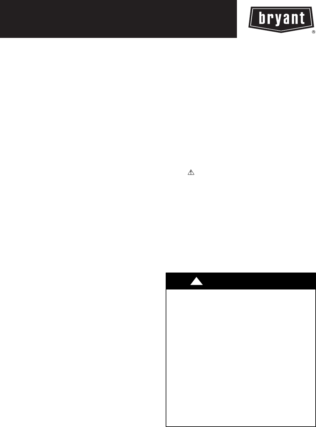
Fig. 1 and Fig. 2 show general unit arrangement and
access locations.
FILTER ACCESS PANEL
OUTDOOR-AIR OPENING AND
INDOOR COIL ACCESS PANEL
COMPRESSOR
ACCESS PANEL (04-07 only)
C08449
Fig. 1 -- Typical Access Panel Locations
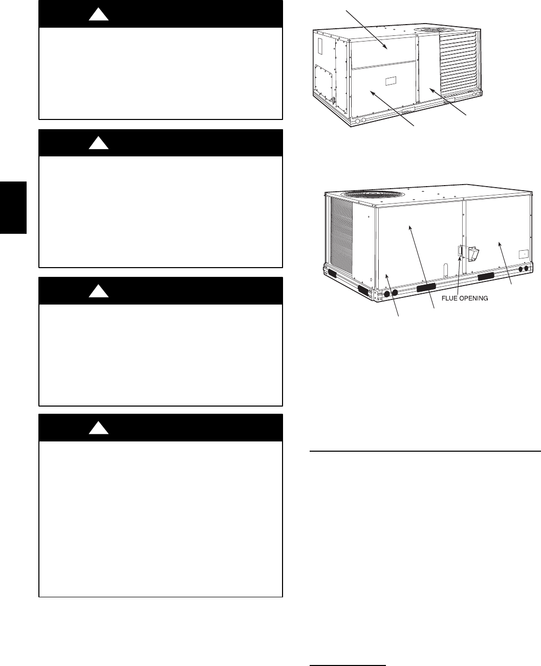
BLOWER
ACCESS
PANEL
CONTROL BOX
COMPRESSOR
(08-12 only)
C08450
Fig. 2 -- Blower Access Panel Location
Routine Maintenance
These items should be part of a routine maintenance
program, to be checked every month or two, until a
specific schedule for each can be identified for this
installation:
Quarterly Inspection (and 30 days after initial start)
SReturn air filter replacement
SOutdoor hood inlet filters cleaned
SBelt tension checked
SBelt condition checked
SPulley alignment checked
SFan shaft bearing locking collar tightness checked
SCondenser coil cleanliness checked
SCondensate drain checked
Seasonal Maintenance
These items should be checked at the beginning of each
season (or more often if local conditions and usage
patterns dictate):
Air Conditioning
SCondenser fan motor mounting bolts tightness
SCompressor mounting bolts
SCondenser fan blade positioning
SControl box cleanliness and wiring condition
580J
3
SWire terminal tightness
SRefrigerant charge level
SEvaporator coil cleaning
SEvaporator blower motor amperage
Heating
SHeat exchanger flue passageways cleanliness
SGas burner condition
SGas manifold pressure
SHeating temperature rise
Economizer or Outside Air Damper
SInlet filters condition
SCheck damper travel (economizer)
SCheck gear and dampers for debris and dirt
Air Filters and Screens
Each unit is equipped with return air filters. If the unit has
an economizer, it will also have an outside air screen. If a
manual outside air damper is added, an inlet air screen
will also be present.
Each of these filters and screens will need to be
periodically replaced or cleaned.
Return Air Filters
Return air filters are disposable fiberglass media type.
Access to the filters is through the small lift--out panel
located on the rear side of the unit, above the
evaporator/return air access panel. (See Fig. 1.)
To remove the filters:
1. Grasp the bottom flange of the upper panel.
2. Lift up and swing the bottom out until the panel dis-
engages and pulls out.
3. Reach inside and extract the filters from the filter
rack.
4. Replace these filters as required with similar replace-
ment filters of same size.
To re--install the access panel:
1. Slide the top of the panel up under the unit top panel.
2. Slide the bottom into the side channels.
3. Push the bottom flange down until it contacts the top
of the lower panel (or economizer top).
IMPORTANT: DO NOT OPERATE THE UNIT
WITHOUT THESE FILTERS!
Outside Air Hood
Outside air hood inlet screens are permanent
aluminum--mesh type filters. Check these for cleanliness.
Remove the screens when cleaning is required. Clean by
washing with hot low--pressure water and soft detergent
and replace all screens before restarting the unit. Observe
the flow direction arrows on the side of each filter frame.
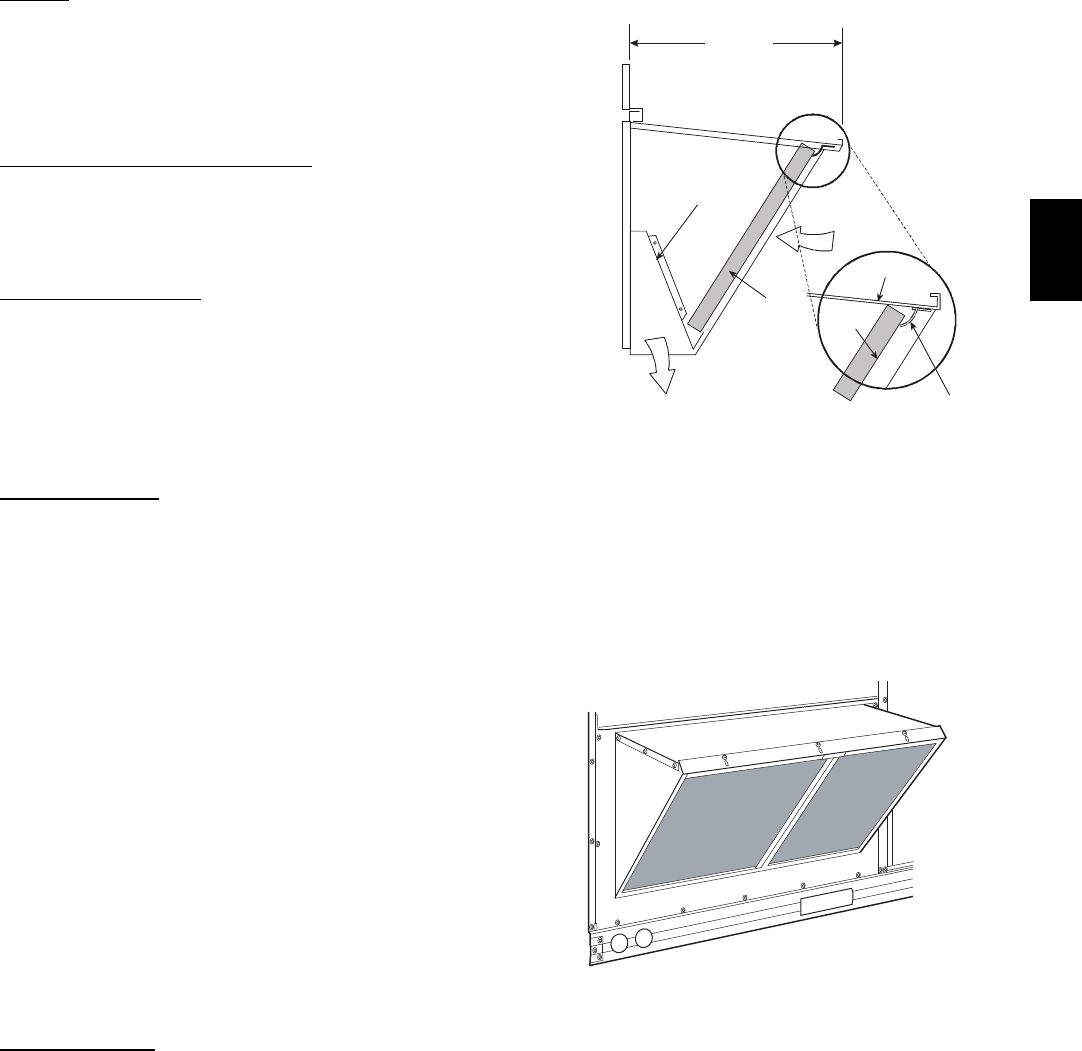
Economizer Inlet Air Screen
This air screen is retained by spring clips under the top
edge of the hood. (See Fig. 3.)
17 1/4”
DIVIDER
BAROMETRIC
RELIEF
CLEANABLE
ALUMINUM
FILTER FILTER
HOOD
FILTE
R
CLIP
OUTSIDE
AIR
C06027
Fig. 3 -- Filter Installation
To remove the filter, open the spring clips. Re--install the
filter by placing the frame in its track, then closing the
spring clips.
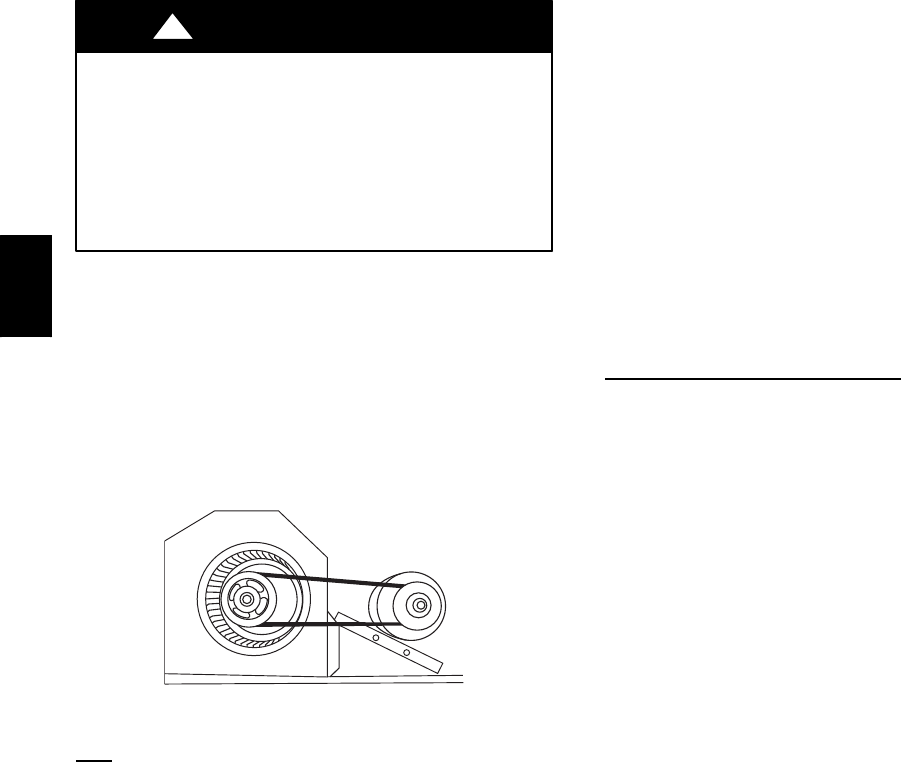
Manual Outside Air Hood Screen
This inlet screen is secured by a retainer angle across the
top edge of the hood. (See Fig. 4.)
C07156
Fig. 4 -- Screens Installed on Outdoor--Air Hood
(Sizes 7--1/2 to 12--1/2 Tons Shown)
To remove the screen, loosen the screws in the top retainer
and slip the retainer up until the filter can be removed.
580J
4
Re--install by placing the frame in its track, rotating the
retainer back down and tighten all screws.
SUPPLY FAN (BLOWER) SECTION
ELECTRICAL SHOCK HAZARD
Failure to follow this warning could cause personal
injury or death.
Before performing service or maintenance operations
on the fan system, shut off all unit power and tag--out
the unit disconnect switch. Do not reach into the fan
section with power still applied to unit.
!WARNING
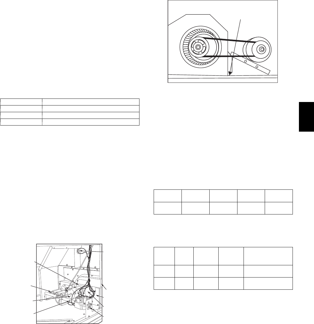
Supply Fan (Belt--Drive)
The supply fan system consists of a forward--curved
centrifugal blower wheel on a solid shaft with two
concentric type bearings, one on each side of the blower
housing. A fixed--pitch driven pulley is attached to the fan
shaft and an adjustable--pitch driver pulley is on the
motor. The pulleys are connected using a “V” type belt.
(See Fig. 5.)
C07087
Fig. 5 -- Belt Drive Motor Mounting
Belt
Check the belt condition and tension quarterly. Inspect the
belt for signs of cracking, fraying or glazing along the
inside surfaces. Check belt tension by using a spring--force
tool (such as Browning’s Part Number “Belt Tension
Checker” or equivalent tool); tension should be 6--lbs at a
5/8--in. deflection when measured at the centerline of the
belt span. This point is at the center of the belt when
measuring the distance between the motor shaft and the
blower shaft.
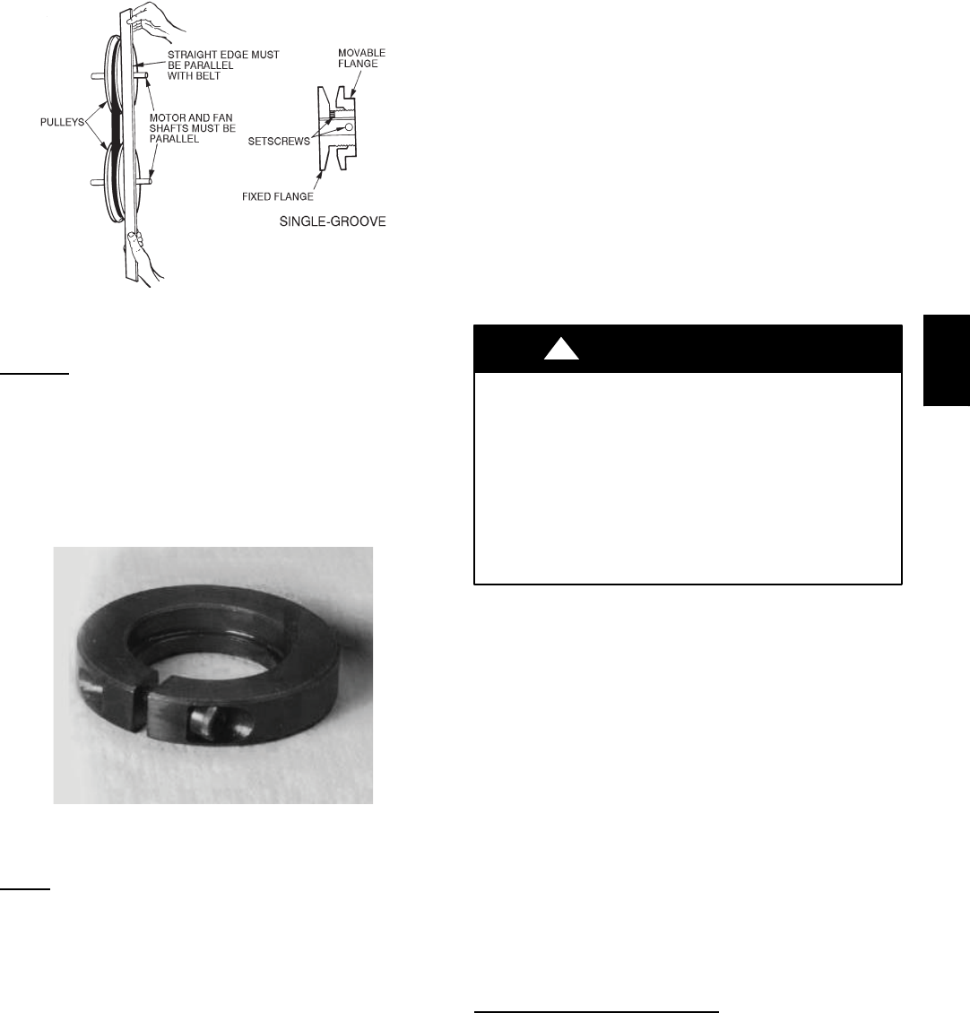
NOTE: Without the spring--tension tool, place a straight
edge across the belt surface at the pulleys, then deflect the
belt at mid--span using one finger to a 1/2--in. deflection.
Adjust belt tension by loosening the motor mounting plate
front bolts and rear bolt and sliding the plate toward the
fan (to reduce tension) or away from fan (to increase
tension). Ensure the blower shaft and the motor shaft are
parallel to each other (pulleys aligned). Tighten all bolts
when finished.
To replace the belt:
1. Use a belt with same section type or similar size. Do
not substitute a “FHP” type belt. When installing the
new belt, do not use a tool (screwdriver or pry--bar) to
force the belt over the pulley flanges, this will stress
the belt and cause a reduction in belt life.
2. Loosen the motor mounting plate front bolts and rear
bolts.
3. Push the motor and its mounting plate towards the
blower housing as close as possible to reduce the cen-
ter distance between fan shaft and motor shaft.
4. Remove the belt by gently lifting the old belt over
one of the pulleys.
5. Install the new belt by gently sliding the belt over
both pulleys and then sliding the motor and plate
away from the fan housing until proper tension is
achieved.
6. Check the alignment of the pulleys, adjust if neces-
sary.
7. Tighten all bolts.
8. Check the tension after a few hours of runtime and
re--adjust as required.
Adjustable--Pitch Pulley on Motor
The motor pulley is an adjustable--pitch type that allows a
servicer to implement changes in the fan wheel speed to
match as--installed ductwork systems. The pulley consists
of a fixed flange side that faces the motor (secured to the
motor shaft) and a movable flange side that can be rotated
around the fixed flange side that increases or reduces the
pitch diameter of this driver pulley. (See Fig. 6.)
As the pitch diameter is changed by adjusting the position
of the movable flange, the centerline on this pulley shifts
laterally (along the motor shaft). This creates a
requirement for a realignment of the pulleys after any
adjustment of the movable flange. Also reset the belt
tension after each realignment.
Check the condition of the motor pulley for signs of wear.
Glazing of the belt contact surfaces and erosion on these
surfaces are signs of improper belt tension and/or belt
slippage. Pulley replacement may be necessary.
To change fan speed:
1. Shut off unit power supply.
2. Loosen belt by loosening fan motor mounting nuts.
(See Fig. 5.)
3. Loosen movable pulley flange setscrew. (See Fig. 6.)
4. Screw movable flange toward fixed flange to increase
speed and away from fixed flange to decrease speed.
Increasing fan speed increases load on motor. Do not
exceed maximum speed specified.
5. Set movable flange at nearest keyway of pulley hub
and tighten setscrew to torque specifications.
To align fan and motor pulleys:
1. Loosen fan pulley setscrews.
2. Slide fan pulley along fan shaft. Make angular align-
ment by loosening motor from mounting.
3. Tighten fan pulley setscrews and motor mounting
bolts to torque specifications.
4. Recheck belt tension.
580J
5
C07075
Fig. 6 -- Supply--Fan Pulley Adjustment
Bearings
This fan system uses bearings featuring concentric split
locking collars. The collars are tightened through a cap
screw bridging the split portion of the collar. The cap
screw has a Torx T25 socket head. To tighten the locking
collar: Hold the locking collar tightly against the inner
race of the bearing and torque the cap screw to 65--70
in--lb (7.4--7.9 Nm). See Fig. 7.
C08121
Fig. 7 -- Tightening Locking Collar
Motor
When replacing the motor, also replace the external--tooth
lock washer (star washer) under the motor mounting base;
this is part of the motor grounding system. Ensure the
teeth on the lock washer are in contact with the motor’s
painted base. Tighten motor mounting bolts to 120 +/-- 12
in--lbs.
Changing fan wheel speed by changing pulleys: The
horsepower rating of the belt is primarily dictated by the
pitch diameter of the smaller pulley in the drive system
(typically the motor pulley in these units). Do not install a
replacement motor pulley with a smaller pitch diameter
than provided on the original factory pulley. Change fan
wheel speed by changing the fan pulley (larger pitch
diameter to reduce wheel speed, smaller pitch diameter to
increase wheel speed) or select a new system (both
pulleys and matching belt(s)).
Before changing pulleys to increase fan wheel speed,
check the fan performance at the target speed and airflow
rate to determine new motor loading (bhp). Use the fan
performance tables or use the Packaged Rooftop Builder
software program. Confirm that the motor in this unit is
capable of operating at the new operating condition. Fan
shaft loading increases dramatically as wheel speed is
increased.
To reduce vibration, replace the motor’s adjustable pitch
pulley with a fixed pitch pulley (after the final airflow
balance adjustment). This will reduce the amount of
vibration generated by the motor/belt--drive system.
COOLING
UNIT OPERATION AND SAFETY HAZARD
Failure to follow this warning could cause personal
injury, death and/or equipment damage.
This system uses PuronRrefrigerant which has
higher pressures than R--22 and other refrigerants. No
other refrigerant may be used in this system. Gauge
set, hoses, and recovery system must be designed to
handle Puron refrigerant. If unsure about equipment,
consult the equipment manufacturer.
!WARNING
Condenser Coil
The condenser coil is fabricated with round tube copper
hairpins and plate fins of various materials and/or coatings
(see Model Number Format in the Appendix to identify
the materials provided in this unit). The coil may be
one--row or composite--type two--row. Composite two--row
coils are two single--row coils fabricated with a single
return bend end tubesheet.
Condenser Coil Maintenance and Cleaning
Recommendation
Routine cleaning of coil surfaces is essential to maintain
proper operation of the unit. Elimination of contamination
and removal of harmful residues will greatly increase the
life of the coil and extend the life of the unit. The
following maintenance and cleaning procedures are
recommended as part of the routine maintenance activities
to extend the life of the coil.
Remove Surface Loaded Fibers
Surface loaded fibers or dirt should be removed with a
vacuum cleaner. If a vacuum cleaner is not available, a
soft non--metallic bristle brush may be used. In either
case, the tool should be applied in the direction of the fins.
Coil surfaces can be easily damaged (fin edges can be
easily bent over and damage to the coating of a protected
coil) if the tool is applied across the fins.
NOTE: Use of a water stream, such as a garden hose,
against a surface loaded coil will drive the fibers and dirt
into the coil. This will make cleaning efforts more
580J
6
difficult. Surface loaded fibers must be completely
removed prior to using low velocity clean water rinse.
Periodic Clean Water Rinse
A periodic clean water rinse is very beneficial for coils
that are applied in coastal or industrial environments.
However, it is very important that the water rinse is made
with a very low velocity water stream to avoid damaging
the fin edges. Monthly cleaning as described below is
recommended.
Routine Cleaning of Coil Surfaces
Periodic cleaning with TotalineRenvironmentally sound
coil cleaner is essential to extend the life of coils. This
cleaner is available from Bryant Replacement
Components Division as part number P902--0301 for a one
gallon container, and part number P902--0305 for a 5
gallon container. It is recommended that all coils,
including standard aluminum, pre--coated, copper/copper
or E--coated coils be cleaned with the Totaline
environmentally sound coil cleaner as described below.
Coil cleaning should be part of the unit’s regularly
scheduled maintenance procedures to ensure long life of
the coil. Failure to clean the coils may result in reduced
durability in the environment.
Avoid use of:
Scoil brighteners
Sacid cleaning prior to painting
Shigh pressure washers
Spoor quality water for cleaning
Totaline environmentally sound coil cleaner is
nonflammable, hypo allergenic, non bacterial, and a
USDA accepted biodegradable agent that will not harm
the coil or surrounding components such as electrical
wiring, painted metal surfaces, or insulation. Use of
non--recommended coil cleaners is strongly discouraged
since coil and unit durability could be affected.
One--Row Coil
Wash coil with commercial coil cleaner. It is not
necessary to remove top panel.
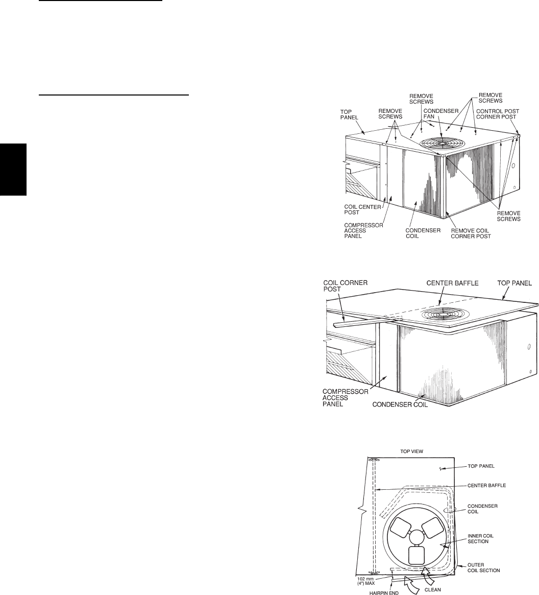
Two--Row Coils
Clean coil as follows:
1. Turn off unit power, tag disconnect.
2. Remove top panel screws on condenser end of unit.
3. Remove condenser coil corner post. See Fig. 8. To
hold top panel open, place coil corner post between
top panel and center post. See Fig. 9.
4. Remove screws securing coil to compressor plate and
compressor access panel.
5. Remove fastener holding coil sections together at re-
turn end of condenser coil. Carefully separate the out-
er coil section 3 to 4 in. from the inner coil section.
See Fig. 10.
6. Use a water hose or other suitable equipment to flush
down between the 2 coil sections to remove dirt and
debris. Clean the outer surfaces with a stiff brush in
the normal manner.
7. Secure inner and outer coil rows together with a
field--supplied fastener.
8. Reposition the outer coil section and remove the coil
corner post from between the top panel and center
post. Reinstall the coil corner post and replace all
screws.
C08205
Fig. 8 -- Cleaning Condenser Coil
C08206
Fig. 9 -- Propping Up Top Panel
C08207
Fig. 10 -- Separating Coil Sections
Totaline Environmentally Sound Coil Cleaner
Application Equipment
S2--1/2 gallon garden sprayer
SWater rinse with low velocity spray nozzle
580J

7
UNIT DAMAGE HAZARD
Failure to follow this caution may result in accelerated
corrosion of unit parts.
Harsh chemicals, household bleach or acid or basic
cleaners should not be used to clean outdoor or indoor
coils of any kind. These cleaners can be very difficult
to rinse out of the coil and can accelerate corrosion at
the fin/tube interface where dissimilar materials are in
contact. If there is dirt below the surface of the coil,
use the Totaline environmentally sound coil cleaner.
CAUTION
!
UNIT DAMAGE HAZARD
Failure to follow this caution may result in reduced
unit performance or unit shutdown.
High velocity water from a pressure washer, garden
hose, or compressed air should never be used to
clean a coil. The force of the water or air jet will
bend the fin edges and increase airside pressure drop.
CAUTION
!
Totaline Environmentally Sound Coil Cleaner
Application Instructions
1. Proper eye protection such as safety glasses is recom-
mended during mixing and application.
2. Remove all surface loaded fibers and dirt with a vacu-
um cleaner as described above.
3. Thoroughly wet finned surfaces with clean water and
a low velocity garden hose, being careful not to bend
fins.
4. Mix Totaline environmentally sound coil cleaner in a
2--1/2 gallon garden sprayer according to the instruc-
tions included with the cleaner. The optimum solution
temperature is 100_F.
NOTE: Do NOT USE water in excess of 130_F, as the
enzymatic activity will be destroyed.
5. Thoroughly apply Totaline environmentally sound
coil cleaner solution to all coil surfaces including
finned area, tube sheets and coil headers.
6. Hold garden sprayer nozzle close to finned areas and
apply cleaner with a vertical, up--and--down motion.
Avoid spraying in horizontal pattern to minimize po-
tential for fin damage.
7. Ensure cleaner thoroughly penetrates deep into finned
areas.
8. Interior and exterior finned areas must be thoroughly
cleaned.
9. Finned surfaces should remain wet with cleaning
solution for 10 minutes.
10. Ensure surfaces are not allowed to dry before rinsing.
Reapplying cleaner as needed to ensure 10--minute
saturation is achieved.
11. Thoroughly rinse all surfaces with low velocity clean
water using downward rinsing motion of water spray
nozzle. Protect fins from damage from the spray
nozzle.
Evaporator Coil
Cleaning the Evaporator Coil
1. Turn unit power off. Install lockout tag. Remove
evaporator coil access panel.
2. If economizer or two--position damper is installed, re-
move economizer by disconnecting Molex plug and
removing mounting screws.
3. Slide filters out of unit.
4. Clean coil using a commercial coil cleaner or dish-
washer detergent in a pressurized spray canister. Wash
both sides of coil and flush with clean water. For best
results, back--flush toward return--air section to re-
move foreign material. Flush condensate pan after
completion.
5. Reinstall economizer and filters.
6. Reconnect wiring.
7. Replace access panels.
Evaporator Coil Metering Devices
The metering devices are multiple fixed--bore devices
(Acutrolt) swedged into the horizontal outlet tubes from
the liquid header, located at the entrance to each
evaporator coil circuit path. These are non--adjustable.
Service requires replacing the entire liquid header
assembly.
To check for possible blockage of one or more of these
metering devices, disconnect the supply fan contactor
(IFC) coil, then start the compressor and observe the
frosting pattern on the face of the evaporator coil. A frost
pattern should develop uniformly across the face of the
coil starting at each horizontal header tube. Failure to
develop frost at an outlet tube can indicate a plugged or a
missing orifice.
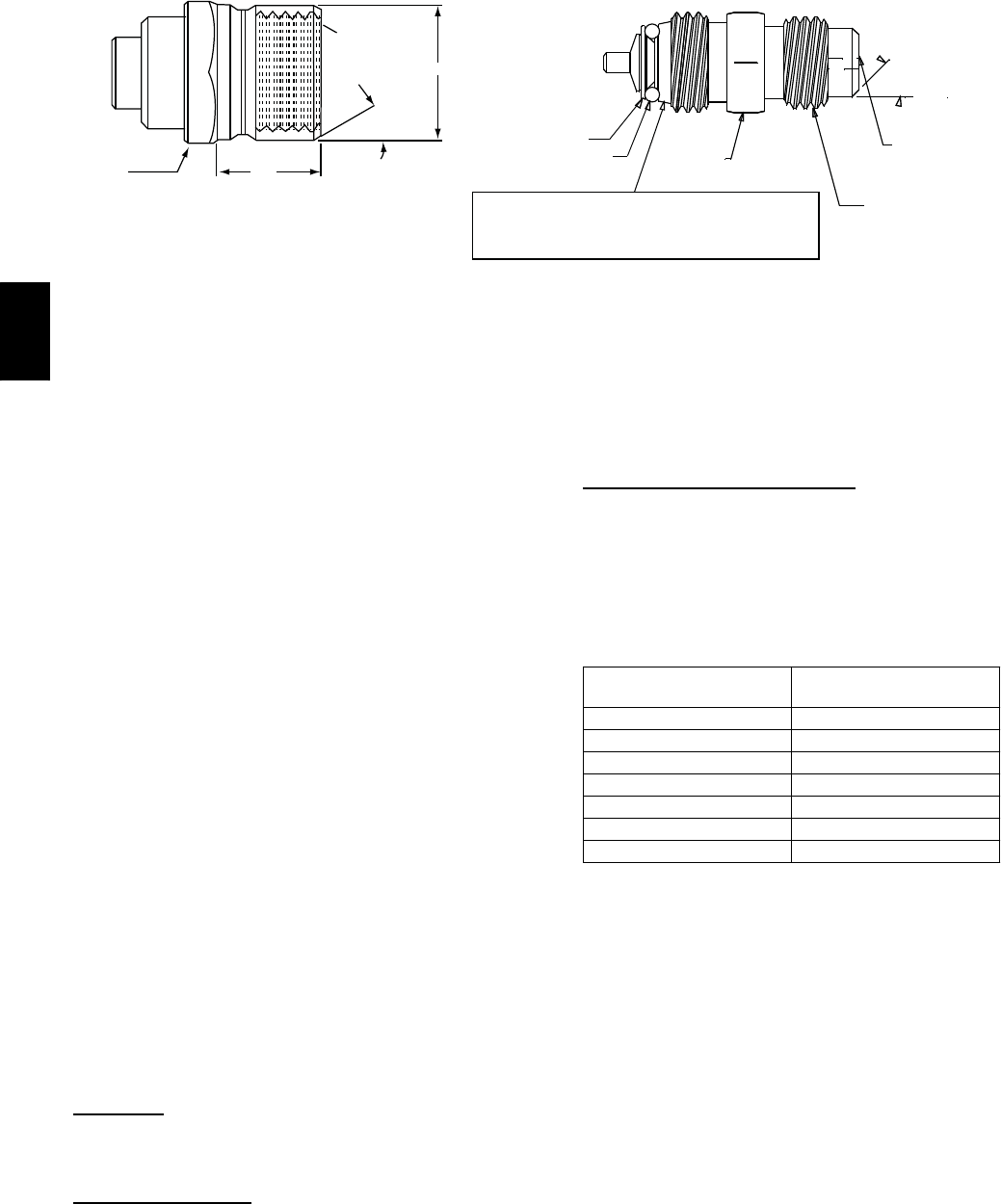
Refrigerant System Pressure Access Ports
There are two access ports in the system -- on the suction
tube near the compressor and on the discharge tube near
the compressor. These are brass fittings with black plastic
caps. The hose connection fittings are standard 1/4 SAE
Male Flare couplings.
The brass fittings are two--piece High Flow valves, with a
receptacle base brazed to the tubing and an integral
spring--closed check valve core screwed into the base.
(See Fig. 11.) This check valve is permanently assembled
into this core body and cannot be serviced separately;
replace the entire core body if necessary. Service tools are
available from RCD that allow the replacement of the
check valve core without having to recover the entire
system refrigerant charge. Apply compressor refrigerant
oil to the check valve core’s bottom o--ring. Install the
fitting body with 96 +/--10 in--lbs of torque; do not
overtighten.
580J
8
1/2-20 UNF RH
30
0.596
.47
5/8” HEX
SEAT CORE
WASHER DEPRESSOR PER ARI 720
+.01/-.035
FROM FACE OF BODY
7/16-20 UNF RH
O-RING
45
torqued into the seat. Appropriate handling is
required to not scratch or dent the surface.
1/2" HEX
This surface provides a metal to metal seal when
o
o
(Part No. EC39EZ067)
C08453
Fig. 11 -- CoreMax Access Port Assembly
PURONR(R--410A) REFRIGERANT
This unit is designed for use with Puron (R--410A)
refrigerant. Do not use any other refrigerant in this
system.
Puron (R--410A) is provided in pink (rose) colored
cylinders. These cylinders are available with and without
dip tubes; cylinders with dip tubes will have a label
indicating this feature. For a cylinder with a dip tube,
place the cylinder in the upright position (access valve at
the top) when removing liquid refrigerant for charging.
For a cylinder without a dip tube, invert the cylinder
(access valve on the bottom) when removing liquid
refrigerant.
Because Puron (R--410A) is a blend, it is strongly
recommended that refrigerant always be removed from
the cylinder as a liquid. Admit liquid refrigerant into the
system in the discharge line. If adding refrigerant into the
suction line, use a commercial metering/expansion device
at the gauge manifold; remove liquid from the cylinder,
pass it through the metering device at the gauge set and
then pass it into the suction line as a vapor. Do not remove
Puron (R--410A) from the cylinder as a vapor.
Refrigerant Charge
Amount of refrigerant charge is listed on the unit’s
nameplate. Refer to GTAC2--5 Charging, Recovery,
Recycling and Reclamation training manual and the
following procedures.
Unit panels must be in place when unit is operating during
the charging procedure.
No Charge
Use standard evacuating techniques. After evacuating
system, weigh in the specified amount of refrigerant.
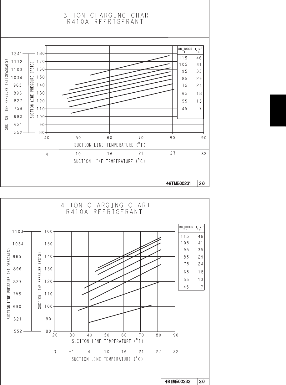
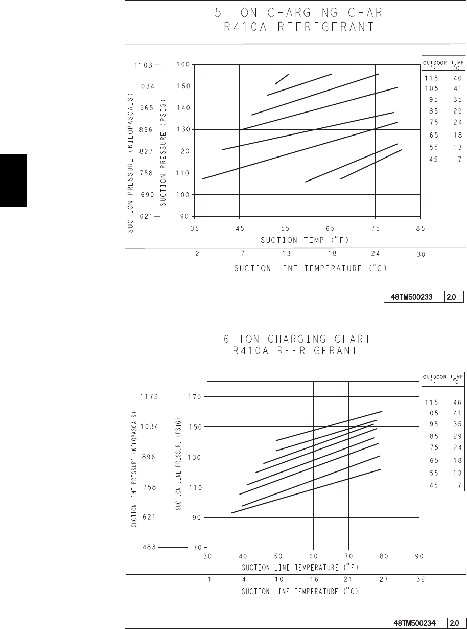
Low--Charge Cooling
Using Cooling Charging Charts, Fig. 12, vary refrigerant
until the conditions of the appropriate chart are met. Note
the charging charts are different from type normally used.
Charts are based on charging the units to the correct
superheat for the various operating conditions. Accurate
pressure gauge and temperature sensing device are
required. Connect the pressure gauge to the service port
on the suction line. Mount the temperature sensing device
on the suction line and insulate it so that outdoor ambient
temperature does not affect the reading. Indoor--air cfm
must be within the normal operating range of the unit.
To Use Cooling Charging Charts
Take the outdoor ambient temperature and read the
suction pressure gauge. Refer to chart to determine what
suction temperature should be. If suction temperature is
high, add refrigerant. If suction temperature is low,
carefully recover some of the charge. Recheck the suction
pressure as charge is adjusted.
SIZE DESIGNATION NOMINAL TONS
REFERENCE
04A,B,C 3
05A,B,C 4
06A,B,C 5
07A,C 6
08A,C 7.5
09A,C 8.5
12A,C 10
EXAMPLE:
Model 580J*04A (3 ton)
Outdoor Temperature 85_F(29_C)..................
Suction Pressure 140 psig (965 kPa).................
Suction Temperature should be 60_F(16_C)..........
580J
9
COOLING CHARGING CHARTS
C08203
C08204
Fig. 12 -- Cooling Charging Charts
580J
10
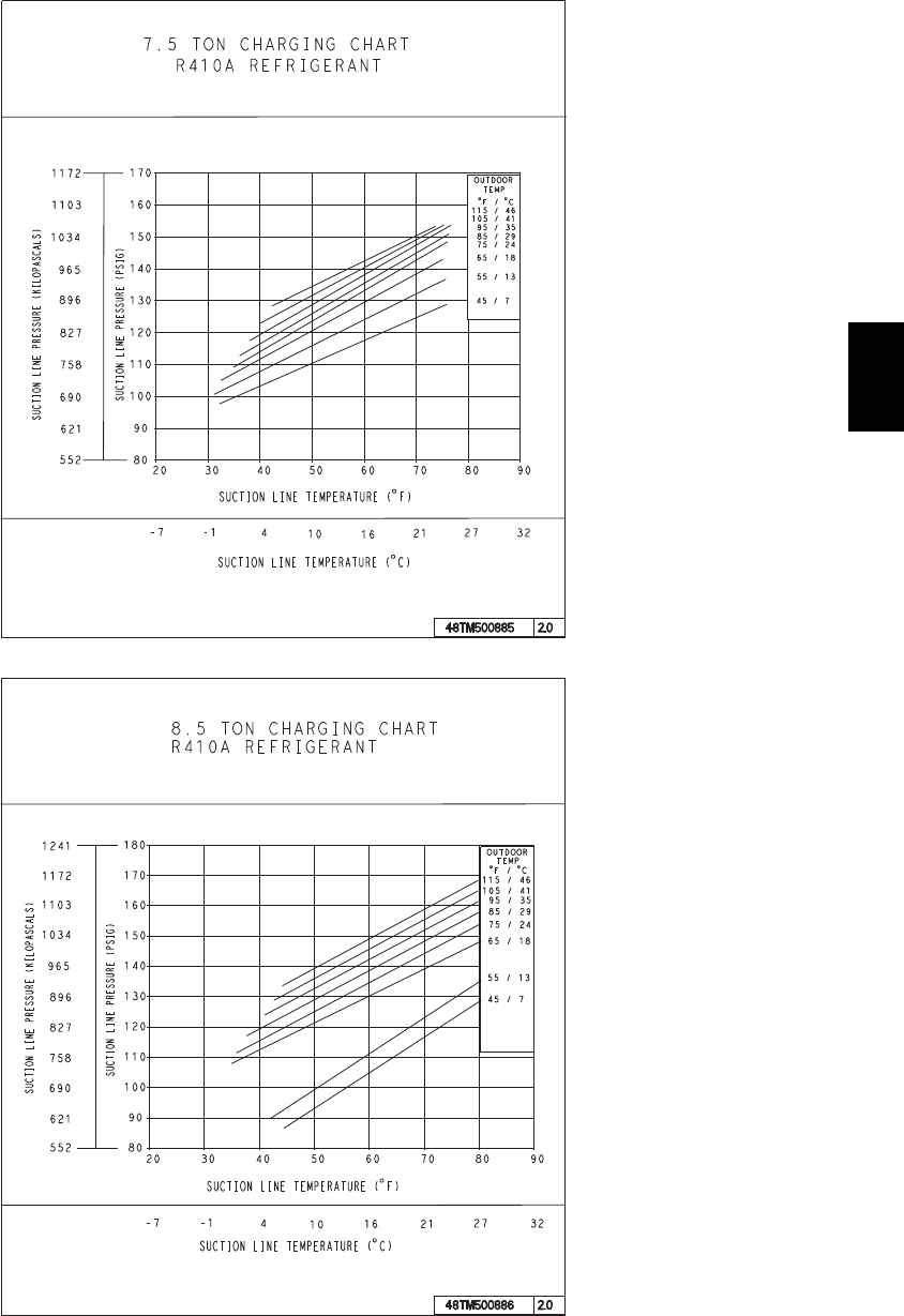
COOLING CHARGING CHARTS (cont)
C08228
C08229
Fig. 12 -- Cooling Charging Charts (cont.)
580J
11
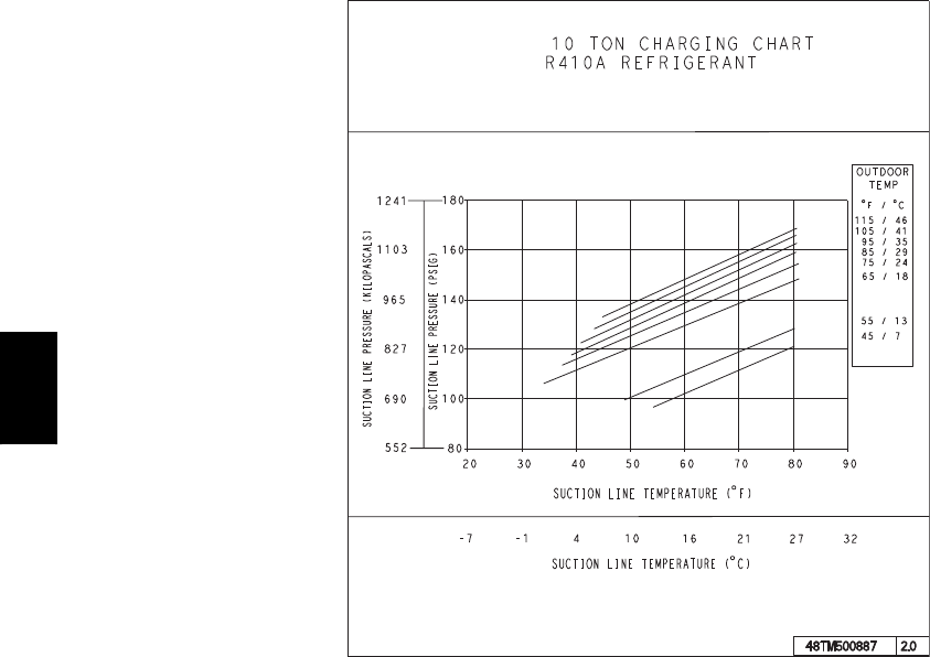
COOLING CHARGING CHARTS (cont.)
C08437
C08438
Fig. 12 -- Cooling Charging Charts (cont.)
580J
12
COOLING CHARGING CHARTS (cont.)
C08439
Fig. 12 -- Cooling Charging Charts (cont.)
580J
13
Compressor
Lubrication
The compressor is charged with the correct amount of oil
at the factory.
UNIT DAMAGE HAZARD
Failure to follow this caution may result in damage to
components.
The compressor is in a PuronRrefrigerant system and
uses a polyolester (POE) oil. This oil is extremely
hygroscopic, meaning it absorbs water readily. POE
oils can absorb 15 times as much water as other oils
designed for HCFC and CFC refrigerants. Avoid
exposure of the oil to the atmosphere.
CAUTION
!
Replacing Compressor
The compressor used with Puron refrigerant contains a
POE oil. This oil has a high affinity for moisture. Do not
remove the compressor’s tube plugs until ready to insert
the unit suction and discharge tube ends.
Compressor mounting bolt torque is 65--75 ft--lbs.
Compressor Rotation
On 3--phase units with scroll compressors, it is important
to be certain compressor is rotating in the proper
direction. To determine whether or not compressor is
rotating in the proper direction:
1. Connect service gauges to suction and discharge pres-
sure fittings.
2. Energize the compressor.
3. The suction pressure should drop and the discharge
pressure should rise, as is normal on any start--up.
NOTE: If the suction pressure does not drop and the
discharge pressure does not rise to normal levels:
4. Note that the evaporator fan is probably also rotating
in the wrong direction.
5. Turn off power to the unit.
6. Reverse any two of the unit power leads.
7. Reapply power to the compressor.
The suction and discharge pressure levels should now
move to their normal start--up levels.
NOTE: When the compressor is rotating in the wrong
direction, the unit makes an elevated level of noise and
does not provide cooling.
Filter Drier
Replace whenever refrigerant system is exposed to
atmosphere. Only use factory specified liquid--line filter
driers with working pressures no less than 650 psig. Do
not install a suction--line filter drier in liquid line. A
liquid--line filter drier designed for use with Puron
refrigerant is required on every unit.
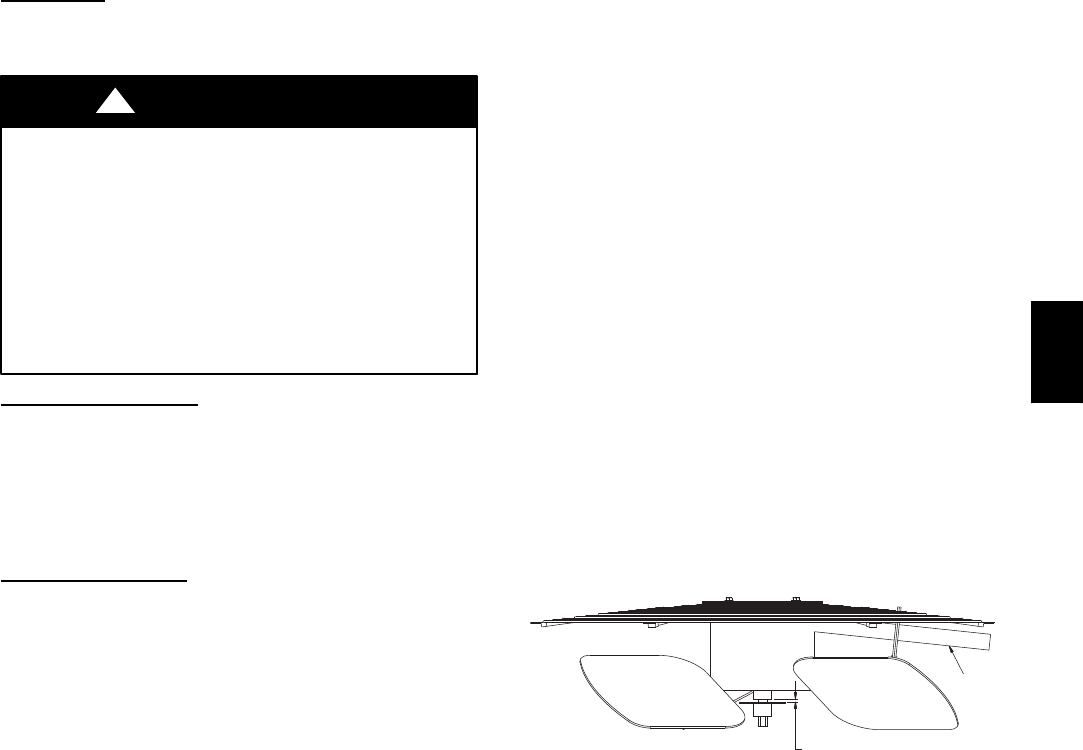
Condenser--Fan Location
See Fig. 13.
1. Shut off unit power supply. Install lockout tag.
2. Remove condenser--fan assembly (grille, motor, and
fan).
3. Loosen fan hub setscrews.
4. Adjust fan height as shown in Fig. 13.
5. Tighten setscrews.
6. Replace condenser--fan assembly.
Conduit
0.14 in + 0.0 / -0.03
C08448
Fig. 13 -- Condenser Fan Adjustment
Troubleshooting Cooling System
Refer to Table 1 for additional troubleshooting topics.
580J

14
Table 1 – Cooling Service Analysis
PROBLEM CAUSE REMEDY
Compressor and Condenser
Fan Will Not Start.
Power failure. Call power company.
Fuse blown or circuit breaker tripped. Replace fuse or reset circuit breaker.
Defective thermostat, contactor, transformer,
or control relay. Replace component.
Insufficient line voltage. Determine cause and correct.
Incorrect or faulty wiring. Check wiring diagram and rewire correctly.
Thermostat setting too high. Lower thermostat setting below room temperature.
Compressor Will Not Start But
Condenser Fan Runs.
Faulty wiring or loose connections in compres-
sor circuit. Check wiring and repair or replace.
Compressor motor burned out, seized, or
internal overload open. Determine cause. Replace compressor.
Defective run/start capacitor, overload, start
relay. Determine cause and replace.
Onelegofthree---phasepowerdead. Replace fuse or reset circuit breaker. Determine
cause.
Compressor Cycles (other
than normally satisfying
thermostat).
Refrigerant overcharge or undercharge. Recover refrigerant, evacuate system, and recharge
to nameplate.
Defective compressor. Replace and determine cause.
Insufficient line voltage. Determine cause and correct.
Blocked condenser. Determine cause and correct.
Defective run/start capacitor, overload, or start
relay. Determine cause and replace.
Defective thermostat. Replace thermostat.
Faulty condenser--- fan motor or capacitor. Replace.
Restriction in refrigerant system. Locate restriction and remove.
Compressor Operates
Continuously.
Dirty air filter. Replace filter.
Unit undersized for load. Decrease load or increase unit size.
Thermostat set too low. Reset thermostat.
Low refrigerant charge. Locate leak; repair and recharge.
Leaking valves in compressor. Replace compressor.
Air in system. Recover refrigerant, evacuate system, and recharge.
Condenser coil dirty or restricted. Clean coil or remove restriction.
Excessive Head Pressure.
Dirty air filter. Replace filter.
Dirty condenser coil. Clean coil.
Refrigerant overcharged. Recover excess refrigerant.
Air in system. Recover refrigerant, evacuate system, and recharge.
Condenser air restricted or air short---cycling. Determine cause and correct.
Head Pressure Too Low.
Low refrigerant charge. Check for leaks; repair and recharge.
Compressor valves leaking. Replace compressor.
Restrictioninliquidtube. Remove restriction.
Excessive Suction Pressure.
High head load. Check for source and eliminate.
Compressor valves leaking. Replace compressor.
Refrigerant overcharged. Recover excess refrigerant.
Suction Pressure Too Low.
Dirty air filter. Replace filter.
Low refrigerant charge. Check for leaks; repair and recharge.
Metering device or low side restricted. Remove source of restriction.
Insufficient evaporator airflow. Increase air quantity. Check filter and replace if
necessary.
Temperature too low in conditioned area. Reset thermostat.
Outdoor ambient below 25˚F. Install low---ambient kit.
Evaporator Fan Will Not
Shut Off. Time off delay not finished. W a i t f o r 3 0 --- s e c o n d o f f d e l a y.
Compressor Makes Excessive
Noise. Compressor rotating in wrong direction. Reversethe3---phasepowerleads.
580J
15
CONVENIENCE OUTLETS
ELECTRICAL OPERATION HAZARD
Failure to follow this warning could result in personal
injury or death.
Units with convenience outlet circuits may use
multiple disconnects. Check convenience outlet for
power status before opening unit for service. Locate
its disconnect switch, if appropriate, and open it.
Tag--out this switch, if necessary.
!WARNING
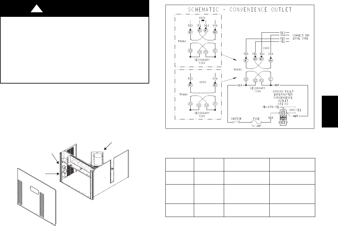
Two types of convenience outlets are offered on 580J
models: Non--powered and unit--powered. Both types
provide a 125--volt GFCI (ground--fault
circuit--interrupter) duplex receptacle rated at 15--A
behind a hinged waterproof access cover, located on the
end panel of the unit. See Fig. 14.
Pwd-CO Transformer
Conv Outlet
GFCI
Pwd-CO
Fuse
Switch
C08128
Fig. 14 -- Convenience Outlet Location
Non--powered type: This type requires the field
installation of a general--purpose 125--volt 15--A circuit
powered from a source elsewhere in the building. Observe
national and local codes when selecting wire size, fuse or
breaker requirements and disconnect switch size and
location. Route 125--v power supply conductors into the
bottom of the utility box containing the duplex receptacle.
Unit--powered type: A unit--mounted transformer is
factory--installed to stepdown the main power supply
voltage to the unit to 115--v at the duplex receptacle. This
option also includes a manual switch with fuse, located in
a utility box and mounted on a bracket behind the
convenience outlet; access is through the unit’s control
box access panel. See Fig. 14.
The primary leads to the convenience outlet transformer
are not factory--connected. Selection of primary power
source is a customer--option. If local codes permit, the
transformer primary leads can be connected at the
line--side terminals on a unit--mounted non--fused
disconnect or HACR breaker switch; this will provide
service power to the unit when the unit disconnect switch
or HACR switch is open. Other connection methods will
result in the convenience outlet circuit being de--energized
when the unit disconnect or HACR switch is open. See
Fig. 15.
CO8283
Fig. 15 -- Powered Convenience Outlet Wiring
UNIT
VOLTAGE
CONNECT
AS
PRIMARY
CONNECTIONS
TRANSFORMER
TERMINALS
208,
230 240 L1: RED +YEL
L2: BLU + GRA
H1 + H3
H2 + H4
460 480
L1: RED
Splice BLU + YEL
L2: GRA
H1
H2 + H3
H4
575 600 L1: RED
L2: GRA
H1
H2
Duty Cycle: The unit--powered convenience outlet has a
duty cycle limitation. The transformer is intended to
provide power on an intermittent basis for service tools,
lamps, etc; it is not intended to provide 15--amps loading
for continuous duty loads (such as electric heaters for
overnight use). Observe a 50% limit on circuit loading
above 8--amps (i.e., limit loads exceeding 8--amps to 30
minutes of operation every hour).
Maintenance: Periodically test the GFCI receptacle by
pressing the TEST button on the face of the receptacle.
This should cause the internal circuit of the receptacle to
trip and open the receptacle. Check for proper grounding
wires and power line phasing if the GFCI receptacle does
not trip as required. Press the RESET button to clear the
tripped condition.
Fuse on powered type: The factory fuse is a Bussman
“Fusetron” T--15, non--renewable screw--in (Edison base)
type plug fuse.
Using unit--mounted convenience outlets: Units with
unit--mounted convenience outlet circuits will often
require that two disconnects be opened to de--energize all
power to the unit. Treat all units as electrically energized
until the convenience outlet power is also checked and
de--energization is confirmed. Observe National Electrical
Code Article 210, Branch Circuits, for use of convenience
outlets.
580J
16
SMOKE DETECTORS
Smoke detectors are available as factory--installed options
on 580J models. Smoke detectors may be specified for
Supply Air only or for Return Air without or with
economizer or in combination of Supply Air and Return
Air. Return Air smoke detectors are arranged for vertical
return configurations only. All components necessary for
operation are factory--provided and mounted. The unit is
factory--configured for immediate smoke detector
shutdown operation; additional wiring or modifications to
unit terminal board may be necessary to complete the unit
and smoke detector configuration to meet project
requirements.
System
The smoke detector system consists of a four--wire
controller and one or two sensors. Its primary function is
to shut down the rooftop unit in order to prevent smoke
from circulating throughout the building. It is not to be
used as a life saving device.
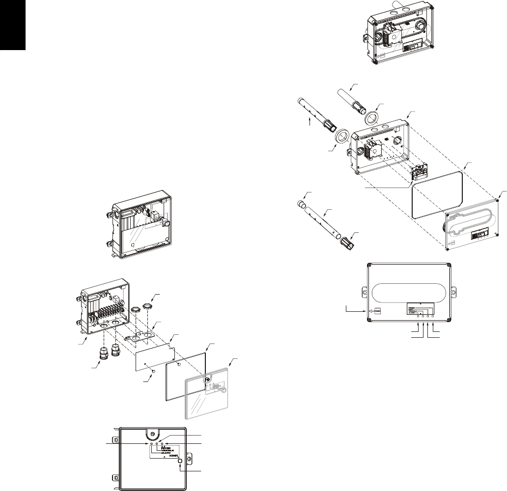
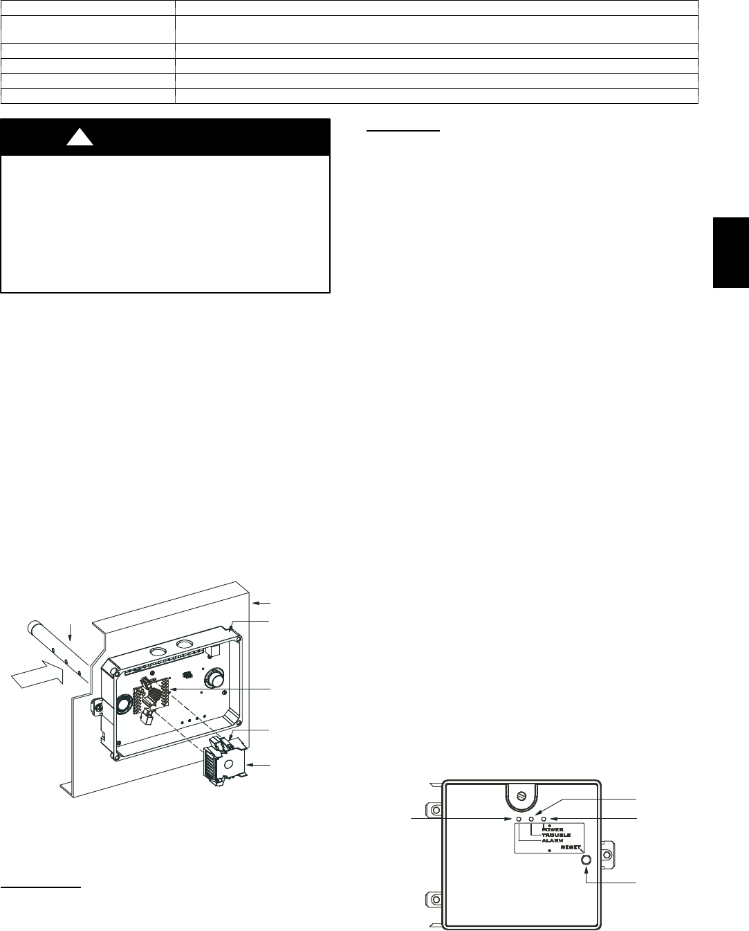
Controller
The controller (see Fig. 16) includes a controller housing,
a printed circuit board, and a clear plastic cover. The
controller can be connected to one or two compatible duct
smoke sensors. The clear plastic cover is secured to the
housing with a single captive screw for easy access to the
wiring terminals. The controller has three LEDs (for
Power, Trouble and Alarm) and a manual test/reset button
(on the cover face).
Duct smoke sensor
controller
Fastener
(2X)
Controller cover
Conduit nuts
(supplied by installer)
Conduit support plate
Cover gasket
(ordering option)
Conduit couplings
(supplied by installer)
Terminal block cover
Controller housing
and electronics
Alarm Power
Test/reset
switch
Trouble
C08208
Fig. 16 -- Controller Assembly
Sensor
The sensor (see Fig. 17) includes a plastic housing, a
printed circuit board, a clear plastic cover, a sampling
tube inlet and an exhaust tube. The sampling tube (when
used) and exhaust tube are attached during installation.
The sampling tube varies in length depending on the size
of the rooftop unit. The clear plastic cover permits visual
inspections without having to disassemble the sensor. The
cover attaches to the sensor housing using four captive
screws and forms an airtight chamber around the sensing
electronics. Each sensor includes a harness with an RJ45
terminal for connecting to the controller. Each sensor has
four LEDs (for Power, Trouble, Alarm and Dirty) and a
manual test/reset button (on the left--side of the housing).
Duct smoke sensor
See
Detail A
Exhaust tube
Plug
Sampling tube
(ordered separately)
Intake
gasket Cover gasket
(ordering option)
TSD-CO2
(ordering option)
Sensor housing
and electronics
Exhaust gasket
Coupling
Sensor cover
Detail A
Magnetic
test/reset
switch
Alarm
Trouble
Power
Dirty
C08209
Fig. 17 -- Smoke Detector Sensor
Air is introduced to the duct smoke detector sensor’s
sensing chamber through a sampling tube that extends into
the HVAC duct and is directed back into the ventilation
system through a (shorter) exhaust tube. The difference in
air pressure between the two tubes pulls the sampled air
through the sensing chamber. When a sufficient amount of
smoke is detected in the sensing chamber, the sensor
signals an alarm state and the controller automatically
takes the appropriate action to shut down fans and
blowers, change over air handling systems, notify the fire
alarm control panel, etc.
The sensor uses a process called differential sensing to
prevent gradual environmental changes from triggering
false alarms. A rapid change in environmental conditions,
580J
17
such as smoke from a fire, causes the sensor to signal an
alarm state but dust and debris accumulated over time
does not.
For installations using two sensors, the duct smoke
detector does not differentiate which sensor signals an
alarm or trouble condition.
Smoke Detector Locations
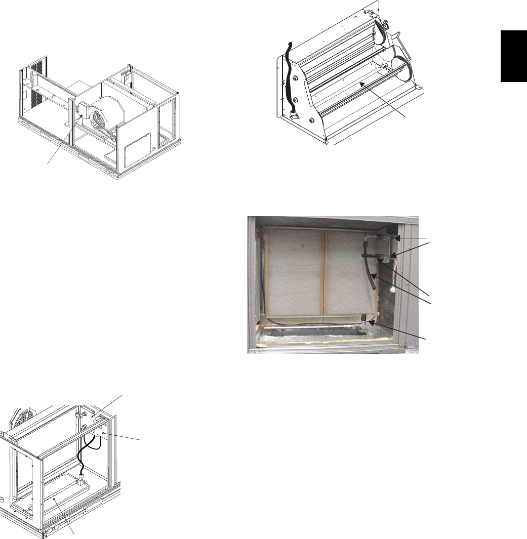
Supply Air — The Supply Air smoke detector sensor is
located to the left of the unit’s indoor (supply) fan. See
Fig. 18. Access is through the fan access panel. There is
no sampling tube used at this location. The sampling tube
inlet extends through the side plate of the fan housing
(into a high pressure area). The controller is located on a
bracket to the right of the return filter, accessed through
the lift--off filter panel.
Smoke Detector Sensor
C08245
Fig. 18 -- Typical Supply Air Smoke Detector Sensor
Location
Return Air without Economizer — The sampling tube is
located across the return air opening on the unit basepan.
See Fig. 19. The holes in the sampling tube face
downward, into the return air stream. The sampling tube is
connected via tubing to the return air sensor that is
mounted on a bracket high on the partition between return
filter and controller location. (This sensor is shipped in a
flat--mounting location. Installation requires that this
sensor be relocated to its operating location and the tubing
to the sampling tube be connected. See installation steps
below.)
Return Air Detector Sampling Tube
Controller module
Return Air Detector module
(shipping position shown)*
*RA detector must be moved from shipping position to operating position by installer
C07307
Fig. 19 -- Typical Return Air Detector Location
Return Air with Economizer — The sampling tube is
inserted through the side plates of the economizer
housing, placing it across the return air opening on the
unit basepan. See Fig. 20. The holes in the sampling tube
face downward, into the return air stream. The sampling
tube is connected via tubing to the return air sensor that is
mounted on a bracket high on the partition between return
filter and controller location. (This sensor is shipped in a
flat--mounting location. Installation requires that this
sensor be relocated to its operating location and the tubing
to the sampling tube be connected. See installation steps
below.)
Return Air
Sampling Tube
C08129
Fig. 20 -- Return Air Sampling Tube Location
Completing Installation of Return Air Smoke
Sensor:
Flexible
Exhaust Tubes
Screws
Sample Tube
C08126
Fig. 21 -- Return Air Detector Shipping Position
1. Unscrew the two screws holding the Return Air
Sensor detector plate. See Fig. 21. Save the screws.
2. Remove the Return Air Sensor and its detector plate.
3. Rotate the detector plate so the sensor is facing out-
wards and the sampling tube connection is on the bot-
tom. See Fig. 22.
4. Screw the sensor and detector plate into its operating
position using screws from Step 1. Make sure the
sampling tube connection is on the bottom and the ex-
haust tube is on the top. See Fig. 22.
5. Connect the flexible tube on the sampling inlet to the
sampling tube on the basepan.
6. For units with an economizer, the sampling tube is in-
tegrated into the economizer housing but the connec-
580J
18
tion of the flexible tubing to the sampling tube is the
same.
C08127
Fig. 22 -- Return Air Sensor Operating Position
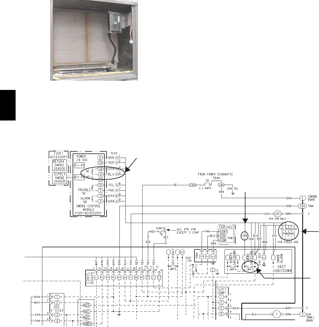
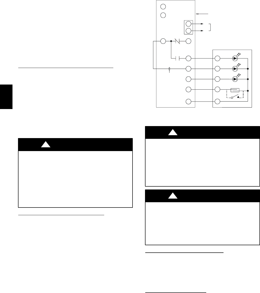
FIOP Smoke Detector Wiring and Response
All units: FIOP smoke detector is configured to
automatically shut down all unit operations when smoke
condition is detected. See Fig. 23, Smoke Detector
Wiring.
Highlight A: JMP 3 is factory--cut, transferring unit
control to smoke detector.
Highlight B: Smoke detector NC contact set will open on
smoke alarm condition, de--energizing the ORN
conductor.
Highlight C: 24--v power signal via ORN lead is removed
at Smoke Detector input on LCTB; all unit operations
cease immediately.
Using Remote Logic: Five conductors are provided for
field use (see Highlight D) for additional annunciation
functions.
Additional Application Data — Refer to Catalog No.
HKRNKA--1XA for discussions on additional control
features of these smoke detectors including multiple unit
coordination. See Fig. 23.
A
D
C
B
C08435
Fig. 23 -- Typical Smoke Detector System Wiring
580J

19
SENSOR AND CONTROLLER TESTS
Sensor Alarm Test
The sensor alarm test checks a sensor’s ability to signal an
alarm state. This test requires that you use a field provided
SD--MAG test magnet.
OPERATIONAL TEST HAZARD
Failure to follow this caution may result in personnel
and authority concern.
This test places the duct detector into the alarm state.
Unless part of the test, disconnect all auxiliary
equipment from the controller before performing the
test. If the duct detector is connected to a fire alarm
system, notify the proper authorities before
performing the test.
CAUTION
!
Sensor Alarm Test Procedure
1. Hold the test magnet where indicated on the side of
the sensor housing for seven seconds.
2. Verify that the sensor’s Alarm LED turns on.
3. Reset the sensor by holding the test magnet against
the sensor housing for two seconds.
4. Verify that the sensor’s Alarm LED turns off.
Controller Alarm Test
The controller alarm test checks the controller’s ability to
initiate and indicate an alarm state.
OPERATIONAL TEST HAZARD
Failure to follow this caution may result in personnel
and authority concern.
This test places the duct detector into the alarm state.
Disconnect all auxiliary equipment from the controller
before performing the test. If the duct detector is
connected to a fire alarm system, notify the proper
authorities before performing the test.
CAUTION
!
Controller Alarm Test Procedure
1. Press the controller’s test/reset switch for seven
seconds.
2. Verify that the controller’s Alarm LED turns on.
3. Reset the sensor by pressing the test/reset switch for
two seconds.
4. Verify that the controller’s Alarm LED turns off.
Dirty Controller Test
The dirty controller test checks the controller’s ability to
initiate a dirty sensor test and indicate its results.
OPERATIONAL TEST HAZARD
Failure to follow this caution may result in personnel
and authority concern.
Pressing the controller’s test/reset switch for longer
than seven seconds will put the duct detector into the
alarm state and activate all automatic alarm responses.
CAUTION
!
Dirty Controller Test Procedure
1. Press the controller’s test/reset switch for two
seconds.
2. Verify that the controller’s Trouble LED flashes.
Dirty Sensor Test
The dirty sensor test provides an indication of the sensor’s
ability to compensate for gradual environmental changes.
A sensor that can no longer compensate for environmental
changes is considered 100% dirty and requires cleaning or
replacing. You must use a field provided SD--MAG test
magnet to initiate a sensor dirty test. The sensor’s Dirty
LED indicates the results of the dirty test as shown in
Table 2.
OPERATIONAL TEST HAZARD
Failure to follow this caution may result in personnel
and authority concern.
Holding the test magnet against the sensor housing for
more than seven seconds will put the duct detector
into the alarm state and activate all automatic alarm
responses.
CAUTION
!
Table 2 – Dirty LED Test
FLASHES DESCRIPTION
10--- 25% dirty. (Typical of a newly installed detector)
225--- 50% dirty
351--- 75% dirty
476--- 99% dirty
Dirty Sensor Test Procedure
1. Hold the test magnet where indicated on the side of
the sensor housing for two seconds.
2. Verify that the sensor’s Dirty LED flashes.
OPERATIONAL TEST HAZARD
Failure to follow this caution may result in personnel
and authority concern.
Changing the dirty sensor test operation will put the
detector into the alarm state and activate all automatic
alarm responses. Before changing dirty sensor test
operation, disconnect all auxiliary equipment from the
controller and notify the proper authorities if
connected to a fire alarm system.
CAUTION
!
580J
20
Changing the Dirt Sensor Test
By default, sensor dirty test results are indicated by:
SThe sensor’s Dirty LED flashing.
SThe controller’s Trouble LED flashing.
SThe controller’s supervision relay contacts toggle.
The operation of a sensor’s dirty test can be changed so
that the controller’s supervision relay is not used to
indicate test results. When two detectors are connected to
a controller, sensor dirty test operation on both sensors
must be configured to operate in the same manner.
To Configure the Dirty Sensor Test Operation
1. Hold the test magnet where indicated on the side of
the sensor housing until the sensor’s Alarm LED turns
on and its Dirty LED flashes twice (approximately 60
seconds).
2. Reset the sensor by removing the test magnet then
holding it against the sensor housing again until the
sensor’s Alarm LED turns off (approximately 2
seconds).
Remote Station Test
The remote station alarm test checks a test/reset station’s
ability to initiate and indicate an alarm state.
OPERATIONAL TEST HAZARD
Failure to follow this caution may result in personnel
and authority concern.
This test places the duct detector into the alarm state.
Unless part of the test, disconnect all auxiliary
equipment from the controller before performing the
test. If the duct detector is connected to a fire alarm
system, notify the proper authorities before
performing the test.
CAUTION
!
SD--TRK4 Remote Alarm Test Procedure
1. Turn the key switch to the RESET/TEST position for
seven seconds.
2. Verify that the test/reset station’s Alarm LED turns
on.
3. Reset the sensor by turning the key switch to the
RESET/TEST position for two seconds.
4. Verify that the test/reset station’s Alarm LED turns
off.
Remote Test/Reset Station Dirty Sensor Test
The test/reset station dirty sensor test checks the test/reset
station’s ability to initiate a sensor dirty test and indicate
the results. It must be wired to the controller as shown in
Fig. 24 and configured to operate the controller’s
supervision relay. For more information, see “Changing
sensor dirty test operation.”
1
12
14
13
19
15
2
20
3
Reset/Test
Trouble
Power
Alarm
Supervision relay
contacts [3]
5
4
1
3
2
SD-TRK4
2
1
TB3
18 Vdc ( )
+
18 Vdc ( )
−
Auxiliary
equipment
+
−
Wire must be
added by installer
Smoke Detector Controller
C08247
Fig. 24 -- Remote Test/Reset Station Connections
OPERATIONAL TEST HAZARD
Failure to follow this caution may result in personnel
and authority concern.
If the test/reset station’s key switch is left in the
RESET/TEST position for longer than seven seconds,
the detector will automatically go into the alarm state
and activate all automatic alarm responses.
CAUTION
!
OPERATIONAL TEST HAZARD
Failure to follow this caution may result in personnel
and authority concern.
Holding the test magnet to the target area for longer
than seven seconds will put the detector into the alarm
state and activate all automatic alarm responses.
CAUTION
!
Dirty Sensor Test Using an SD--TRK4
1. Turn the key switch to the RESET/TEST position for
two seconds.
2. Verify that the test/reset station’s Trouble LED
flashes.
Detector Cleaning
Cleaning the Smoke Detector
Clean the duct smoke sensor when the Dirty LED is
flashing continuously or sooner if conditions warrant.
580J
21
Table 3 – Detector Indicators
CONTROL OR INDICATOR DESCRIPTION
Magnetic test/reset switch Resets the sensor when it is in the alarm or trouble state. Activates or tests the sensor when it is in the
normal state.
Alarm LED Indicates the sensor is in the alarm state.
Trouble LED Indicates the sensor is in the trouble state.
Dirty LED Indicates the amount of environmental compensation used by the sensor (flashing continuously = 100%)
Power LED Indicates the sensor is energized.
OPERATIONAL TEST HAZARD
Failure to follow this caution may result in personnel
and authority concern.
If the smoke detector is connected to a fire alarm
system, first notify the proper authorities that the
detector is undergoing maintenance then disable the
relevant circuit to avoid generating a false alarm.
CAUTION
!
1. Disconnect power from the duct detector then remove
the sensor’s cover. (See Fig. 25.)
2. Using a vacuum cleaner, clean compressed air, or a
soft bristle brush, remove loose dirt and debris from
inside the sensor housing and cover.
Use isopropyl alcohol and a lint--free cloth to remove
dirt and other contaminants from the gasket on the
sensor’s cover.
3. Squeeze the retainer clips on both sides of the optic
housing then lift the housing away from the printed
circuit board.
4. Gently remove dirt and debris from around the optic
plate and inside the optic housing.
5. Replace the optic housing and sensor cover.
6. Connect power to the duct detector then perform a
sensor alarm test.
Airow
HVAC duct
Sampling
tube
Retainer
clip
Optic
plate
Optic
housing
Sensor
housing
C07305
Fig. 25 -- Sensor Cleaning Diagram
Indicators
Normal State
The smoke detector operates in the normal state in the
absence of any trouble conditions and when its sensing
chamber is free of smoke. In the normal state, the Power
LED on both the sensor and the controller are on and all
other LEDs are off.
Alarm State
The smoke detector enters the alarm state when the
amount of smoke particulate in the sensor’s sensing
chamber exceeds the alarm threshold value. (See Table 3.)
Upon entering the alarm state:
SThe sensor’s Alarm LED and the controller’s Alarm LED
turn on.
SThe contacts on the controller’s two auxiliary relays
switch positions.
SThe contacts on the controller’s alarm initiation relay
close.
SThe controller’s remote alarm LED output is activated
(turned on).
SThe controller’s high impedance multiple fan shutdown
control line is pulled to ground Trouble state.
The SuperDuct duct smoke detector enters the trouble
state under the following conditions:
SA sensor’s cover is removed and 20 minutes pass before
it is properly secured.
SA sensor’s environmental compensation limit is reached
(100% dirty).
SA wiring fault between a sensor and the controller is
detected.
An internal sensor fault is detected upon entering the
trouble state:
SThe contacts on the controller’s supervisory relay switch
positions. (See Fig. 26.)
SIf a sensor trouble, the sensor’s Trouble LED the
controller’s Trouble LED turn on.
SIf 100% dirty, the sensor’s Dirty LED turns on and the
controller’s Trouble LED flashes continuously.
SIf a wiring fault between a sensor and the controller, the
controller’s Trouble LED turns on but not the sensor’s.
Alarm Power
Test/reset
switch
Trouble
C07298
Fig. 26 -- Controller Assembly
580J

22
NOTE: All troubles are latched by the duct smoke
detector. The trouble condition must be cleared and then
the duct smoke detector must be reset in order to restore it
to the normal state.
Resetting Alarm and Trouble Condition Trips:
Manual reset is required to restore smoke detector systems
to Normal operation. For installations using two sensors,
the duct smoke detector does not differentiate which
sensor signals an alarm or trouble condition. Check each
sensor for Alarm or Trouble status (indicated by LED).
Clear the condition that has generated the trip at this
sensor. Then reset the sensor by pressing and holding the
reset button (on the side) for 2 seconds. Verify that the
sensor’s Alarm and Trouble LEDs are now off. At the
controller, clear its Alarm or Trouble state by pressing and
holding the manual reset button (on the front cover) for 2
seconds. Verify that the controller’s Alarm and Trouble
LEDs are now off. Replace all panels.
Troubleshooting
Controller’s Trouble LED is On
1. Check the Trouble LED on each sensor connected to
the controller. If a sensor’s Trouble LED is on, de-
termine the cause and make the necessary repairs.
2. Check the wiring between the sensor and the control-
ler. If wiring is loose or missing, repair or replace as
required.
Controller’s Trouble LED is Flashing
1. One or both of the sensors is 100% dirty.
2. Determine which Dirty LED is flashing then clean
that sensor assembly as described in the detector
cleaning section.
Sensor’s Trouble LED is On
1. Check the sensor’s Dirty LED. If it is flashing, the
sensor is dirty and must be cleaned.
2. Check the sensor’s cover. If it is loose or missing, se-
cure the cover to the sensor housing.
3. Replace sensor assembly.
Sensor’s Power LED is Off
1. Check the controller’s Power LED. If it is off, de-
termine why the controller does not have power and
make the necessary repairs.
2. Check the wiring between the sensor and the control-
ler. If wiring is loose or missing, repair or replace as
required.
Controller’s Power LED is Off
1. Make sure the circuit supplying power to the control-
ler is operational. If not, make sure JP2 and JP3 are
set correctly on the controller before applying power.
2. Verify that power is applied to the controller’s supply
input terminals. If power is not present, replace or re-
pair wiring as required.
Remote Test/Reset Station’s Trouble LED Does Not
flash When Performing a Dirty Test, But the
Controller’s Trouble LED Does
1. Verify that the remote test/station is wired as shown
in Fig. 23. Repair or replace loose or missing wiring.
2. Configure the sensor dirty test to activate the control-
ler’s supervision relay. See “Changing sensor dirty
test operation.”
Sensor’s Trouble LED is On, But the Controller’s
Trouble LED is OFF
Remove JP1 on the controller.
PROTECTIVE DEVICES
Compressor Protection
Overcurrent
The compressor has internal linebreak motor protection.
Overtemperature
The compressor has an internal protector to protect it
against excessively high discharge gas temperatures.
High Pressure Switch
The system is provided with a high pressure switch
mounted on the discharge line. The switch is
stem--mounted and brazed into the discharge tube. Trip
setting is 630 psig +/-- 10 psig (4344 +/-- 69 kPa) when
hot. Reset is automatic at 505 psig (3482 kPa).
Low Pressure Switch
The system is protected against a loss of charge and low
evaporator coil loading condition by a low pressure switch
located on the suction line near the compressor. The
switch is stem--mounted. Trip setting is 54 psig +/-- 5 psig
(372 +/-- 34 kPa). Reset is automatic at 117 +/-- 5 psig
(807 +/-- 34 kPa).
Evaporator Freeze Protection
The system is protected against evaporator coil frosting
and low temperature conditions by a temperature switch
mounted on the evaporator coil hairpin. Trip setting is
30_F+/--5_F(--1_C+/--3_C). Reset is automatic at 45_F
(7_C).
Supply (Indoor) Fan Motor Protection
Disconnect and lockout power when servicing fan motor.
The standard supply fan motor is equipped with internal
overcurrent and overtemperature protection. Protection
devices reset automatically.
The High Static option supply fan motor is equipped with
a pilot--circuit Thermix combination
overtemperature/overcurrent protection device. This
device resets automatically. Do not bypass this switch to
correct trouble. Determine the cause and correct it.
Condenser Fan Motor Protection
The condenser fan motor is internally protected against
overtemperature.
Relief Device
A soft solder joint at the suction service access port
provides pressure relief under abnormal temperature and
pressure conditions (i.e., fire in building). Protect this
joint during brazing operations near this joint.
580J
23
Control Circuit, 24--V
The control circuit is protected against overcurrent
conditions by a circuit breaker mounted on control
transformer TRAN. Reset is manual.
GAS HEATING SYSTEM
580J unit heating systems are referenced here according to
unit Gas Heat Option (defined in the unit model number
Position#8) and Heat Level (input capacity, defined in
Positions #9--10--11). See Appendix 1 for a complete unit
model number nomenclature chart.
POSITION #8 GAS HEAT OPTION
ANat. Gas / Standard HX and Heat
BNat. Gas / SS HX and Low NOxHeat
CNat. Gas / SS HX and Standard Heat
General
The heat exchanger system consists of a gas valve feeding
multiple inshot burners off a manifold. The burners fire
into matching primary tubes. The primary tubes discharge
into combustion plenum where gas flow converges into
secondary tubes. The secondary tubes exit into the
induced draft fan wheel inlet. The induced fan wheel
discharges into a flue passage and flue gases exit out a
flue hood on the side of the unit. The induced draft fan
motor includes a Hall Effect sensor circuit that confirms
adequate wheel speed via the Integrated Gas Control
(IGC) board. Safety switches include a Rollout Switch (at
the top of the burner compartment) and a limit switch
(mounted through the fan deck, over the tubes). (See Fig.
27 and Fig. 28.)
INDUCED-
DRAFT
MOTOR
MOUNTING
PLATE
INDUCED-
DRAFT
MOTOR
MANIFOLD
PRESSURE
TAP
VESTIBULE
PLATE
FLUE
EXHAUST
ROLLOUT
SWITCH
BLOWER
HOUSING
GAS
VALVE
BURNER
SECTION
C06152
Fig. 27 -- Burner Section Details
Limit Switch
and Shield
C08284
Fig. 28 -- Limit Switch Location
Fuel Types and Pressures
Natural Gas — The 580J unit is factory--equipped for use
with Natural Gas fuel at elevation under 2000 ft (610 m).
See section Orifice Replacement for information in
modifying this unit for installation at elevations above
2000 ft (610 m).
Gas line pressure entering the unit’s main gas valve must
be within specified ranges. Adjust unit gas regulator valve
as required or consult local gas utility.
Table 4 – Natural Gas Supply Line Pressure Ranges
580J SIZE GAS
HEAT OPT
HEAT
LEVEL MIN MAX
All All All 4.0 in. wg
(996 Pa)
13.0 in. wg
(3240 Pa)
Manifold pressure is factory--adjusted for NG fuel use.
Adjust as required to obtain best flame characteristic.
Table 5 – Natural Gas Manifold Pressure Ranges
GAS
HEAT
OPT
HEAT
LEVEL
HIGH
FIRE
LOW
FIRE RANGE
A, C All 3.5 in. wg
(872 Pa)
1.7 in. wg
(423 Pa){
2.0--- 5.0 in. wg (Hi)
(498--- 1245 Pa)
BAll 3.5 in. wg
(872 Pa) NA 2.0--- 5.0 in. wg (Hi)
(498--- 1245 Pa)
NA: Not Available
{3 Phase models only
Liquid Propane — Accessory packages are available for
field--installation that will convert the 580J unit (except
low NOxmodel) to operate with Liquid Propane (LP)
fuels. These kits include new orifice spuds, new springs
for gas valves and a supply line low pressure switch. See
section on Orifice Replacement for details on orifice size
selections.
Low NOxmodels include specially--sized orifices and use
of different flue flow limits and tube baffles. Because of
these extra features, conversion of these models to LP is
not recommended.
Fuel line pressure entering unit gas valve must remain
within specified range.
580J
24
Table 6 – Liquid Propane Supply Line Pressure Ranges
580J SIZE GAS
HEAT OPT
HEAT
LEVEL MIN MAX
All A, C All 11.0 in. wg
(2740 Pa)
13.0 in. wg
(3240 Pa)
All BAll NA NA
Manifold pressure for LP fuel use must be adjusted to
specified range. Follow instructions in the accessory kit to
make initial readjustment.
Table 7 – Liquid Propane Manifold Pressure Ranges
GAS HEAT
OPT HEAT LEVEL HIGH FIRE LOW FIRE
A, C All 10.0 in. wg
(2490 Pa)
5.0 in. wg
(1245 Pa){
BAll NA NA
NA: Not Available
{3 Phase models only
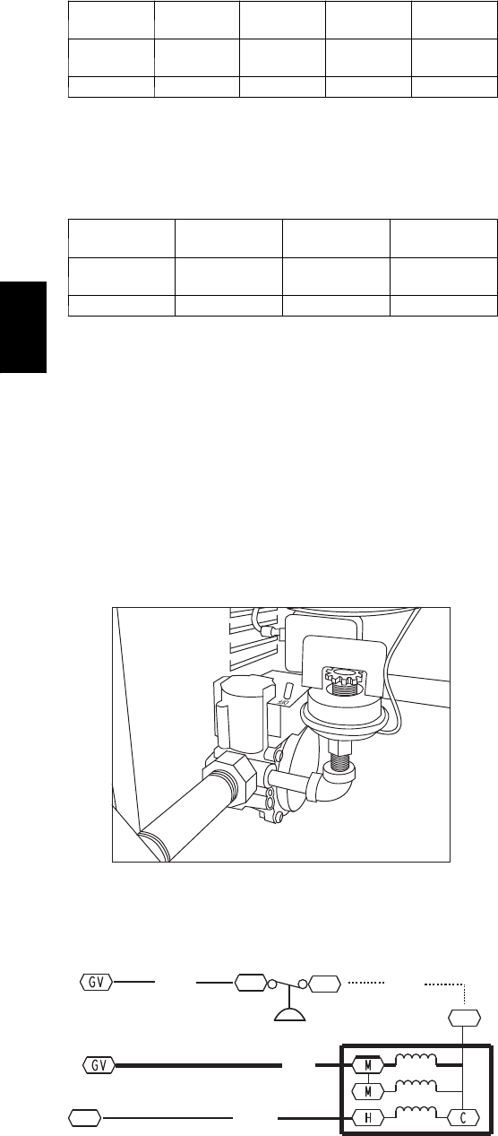
Supply Pressure Switch — The LP conversion kit includes
a supply low pressure switch. The switch contacts (from
terminal C to terminal NO) will open the gas valve power
whenever the supply line pressure drops below the
setpoint. See Fig. 29 and Fig. 30. If the low pressure
remains open for 15 minutes during a call for heat, the
IGC circuit will initiate a Ignition Fault (5 flashes)
lockout. Reset of the low pressure switch is automatic on
rise in supply line pressure. Reset of the IGC requires a
recycle of unit power after the low pressure switch has
closed.
C08238
Fig. 29 -- LP Low Pressure Switch (Installed)
PNK
W2
TSTAT
GRA
BRN
IGC
J2-12
IGC
J2-11
BRN
CNO
MGV
C
LP LPS
C08285
Fig. 30 -- LP Supply Line Low Pressure Switch Wiring
This switch also prevents operation when the propane tank
level is low which can result in gas with a high
concentration of impurities, additives, and residues that
have settled to the bottom of the tank. Operation under
these conditions can cause harm to the heat exchanger
system. Contact your fuel supplier if this condition is
suspected.
Flue Gas Passageways
To inspect the flue collector box and upper areas of the
heat exchanger:
1. Remove the combustion blower wheel and motor as-
sembly according to directions in Combustion--Air
Blower section. See Fig. 31.
2. Remove the flue cover to inspect the heat exchanger.
3. Clean all surfaces as required using a wire brush.
Combustion--Air Blower
Clean periodically to assure proper airflow and heating
efficiency. Inspect blower wheel every fall and
periodically during heating season. For the first heating
season, inspect blower wheel bi--monthly to determine
proper cleaning frequency.
To access burner section, slide the sliding burner partition
out of the unit.
To inspect blower wheel, shine a flashlight into draft hood
opening. If cleaning is required, remove motor and wheel
as follows:
1. Slide burner access panel out.
2. Remove the 7 screws that attach induced--draft motor
housing to vestibule plate. (See Fig. 31.)
3. The blower wheel can be cleaned at this point. If ad-
ditional cleaning is required, continue with Steps 4
and 5.
4. To remove blower from the motor shaft, remove 2
setscrews.
5. To remove motor, remove the 4 screws that hold the
motor to mounting plate. Remove the motor cooling
fan by removing one setscrew. Then remove nuts that
hold motor to mounting plate.
6. To reinstall, reverse the procedure outlined above.
580J
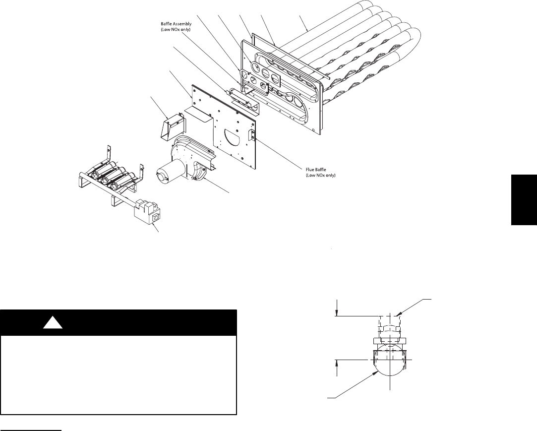
25
Heater Tube
Assembly
Seal Strips, Sponge Rubber
Regulator
Gasket
Regulator
Retainer
Support
Insulation
Assembly
Wind Cap Assembly
(shown inverted,
as shipped)
Burner Assembly
Inducer Fan-Motor
Assembly
C08227
Fig. 31 -- Heat Exchanger Assembly
Burners and Igniters
EQUIPMENT DAMAGE HAZARD
Failure to follow this caution may result in
equipment damage.
When working on gas train, do not hit or plug
orifice spuds.
CAUTION
!
Main Burners
To access burners, remove burner access panel and slide
out burner partition. At the beginning of each heating
season, inspect for deterioration or blockage due to
corrosion or other causes. Observe the main burner flames
and adjust, if necessary.
Orifice projection — Refer to Fig. 32 for maximum
projection dimension for orifice face to manifold tube.
Removal and Replacement of Gas Train
See Fig. 27, Fig. 31 and Fig. 33.
1. Shut off manual gas valve.
2. Shut off power to unit.
3. Slide out burner partition.
4. Disconnect gas piping at unit gas valve.
Orifice
1.00-in
(25.4 mm)
Manifold
Pipe
C08211
Fig. 32 -- Orifice Projection
5. Remove wires connected to gas valve. Mark each
wire.
6. Remove igniter wires and sensor wires at the Integ-
rated Gas Unit Controller (IGC). (See Fig. 34.)
7. Remove the 2 screws that attach the burner rack to
the vestibule plate (Fig. 27).
8. Slide the burner tray out of the unit (Fig. 33).
9. To reinstall, reverse the procedure outlined above.
Cleaning and Adjustment
1. Remove burner rack from unit as described in Re-
moval and Replacement of Gas Train section, above.
2. Inspect burners; if dirty, remove burners from rack.
(Mark each burner to identify its position before re-
moving from the rack.)
3. Use a soft brush to clean burners and cross--over port
as required.
4. Adjust spark gap. See Fig. 35 and Fig. 36.
5. If factory orifice has been removed, check that each
orifice is tight at its threads into the manifold pipe
and that orifice projection does not exceed maximum
valve. See Fig. 32
580J
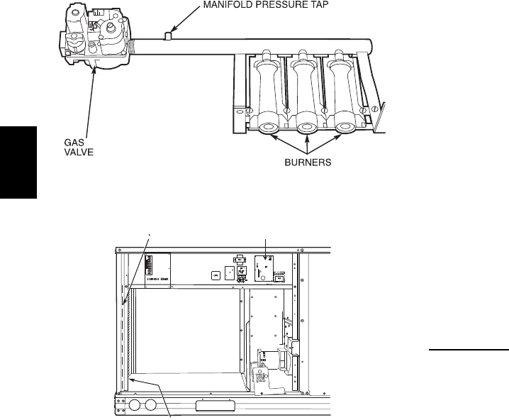
26
6. Reinstall burners on rack in the same locations as
factory--installed. (The outside crossover flame re-
gions of the outermost burners are pinched off to pre-
vent excessive gas flow from the side of the burner
assembly. If the pinched crossovers are installed
between two burners, the flame will not ignite prop-
erly.)
C06153
Fig. 33 -- Burner Tray Details
RACEWAY INTEGRATED GAS UNIT
CONTROLLER (IGC)
HOLE IN END PANEL (HIDDEN)
C08454
Fig. 34 -- Unit Control Box/IGC Location
7. Reinstall burner rack as described in Removal and
Replacement of Gas Train section, above.
Gas Valve — All three--phase models (except Low NOx)
are equipped with 2--stage gas valves. Single--phase
models and all Low NOxmodels are equipped with
single--stage gas valves. See Fig. 37 for locations of
adjustment screws and features on the gas valves.
To adjust gas valve pressure settings:
IMPORTANT: Leak check all gas connections including
the main service connection, gas valve, gas spuds, and
manifold pipe plug. All leaks must be repaired before
firing unit.
Check Unit Operation and Make Necessary Adjust-
ments
NOTE: Gas supply pressure at gas valve inlet must be
within specified ranges for fuel type and unit size. See
Tables 4 and 5.
1. Remove manifold pressure tap plug from manifold
and connect pressure gauge or manometer. (See Fig.
33)
2. Turn on electrical supply.
3. Turn on unit main gas valve.
4. Set room thermostat to call for heat. If unit has two--
stage gas valve, verify high--stage heat operation be-
fore attempting to adjust manifold pressure.
5. When main burners ignite, check all fittings, mani-
fold, and orifices for leaks.
6. Adjust high--stage pressure to specified setting by
turning the plastic adjustment screw clockwise to in-
crease pressure, counter--clockwise to decrease pres-
sure.
7. For Two--Stage Gas Valves set room thermostat to
call for low--stage heat. Adjust low--stage pressure to
specified setting.
8. Replace regulator cover screw(s) when finished.
9. With burner access panel removed, observe unit heat-
ing operation in both high stage and low stage opera-
tion if so equipped. Observe burner flames to see if
they are blue in appearance, and that the flames are
approximately the same for each burner.
10. Turn off unit, remove pressure manometer and re-
place the 1/8 in. pipe fitting on the gas manifold. See
Fig. 33.
Limit Switch
Remove blower access panel. Limit switch is located on
the fan deck. See Fig. 28.
Burner Ignition
Unit is equipped with a direct spark ignition 100% lockout
system. Integrated Gas Unit Controller (IGC) is located in
the control box. See Fig. 34. The IGC contains a
self--diagnostic LED (light--emitting diode). A single LED
(see Fig. 38) on the IGC provides a visual display of
operational or sequential problems when the power supply
is uninterrupted. When a break in power occurs, the IGC
will be reset (resulting in a loss of fault history) and the
indoor (evaporator) fan ON/OFF times will be reset. The
LED error code can be observed through the viewport.
During servicing refer to the label on the control box
cover or Table 8 for an explanation of LED error code
descriptions.
If lockout occurs, unit may be reset by interrupting power
supply to unit for at least 5 seconds.
580J
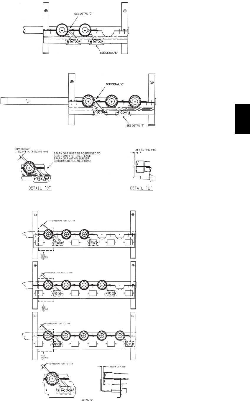
27
72,000 BTUH INPUT AND 60,000 BTUH INPUT
115,000 BTUH INPUT,
150,000 BTUH INPUT,
90,000BTUH INPUT AND
120,000 BTUH INPUT
LOW HEAT
MEDIUM AND HIGH HEAT
C06154
Fig. 35 -- Spark Adjustment, 04--07
125,000/90,000 BTUH INPUT
180,000/120,000 BTUH INPUT
240,000/180,000 BTUH INPUT
250,000/200,000 BTUH INPUT
C08447
Fig. 36 -- Spark Adjustment, 08--12
580J
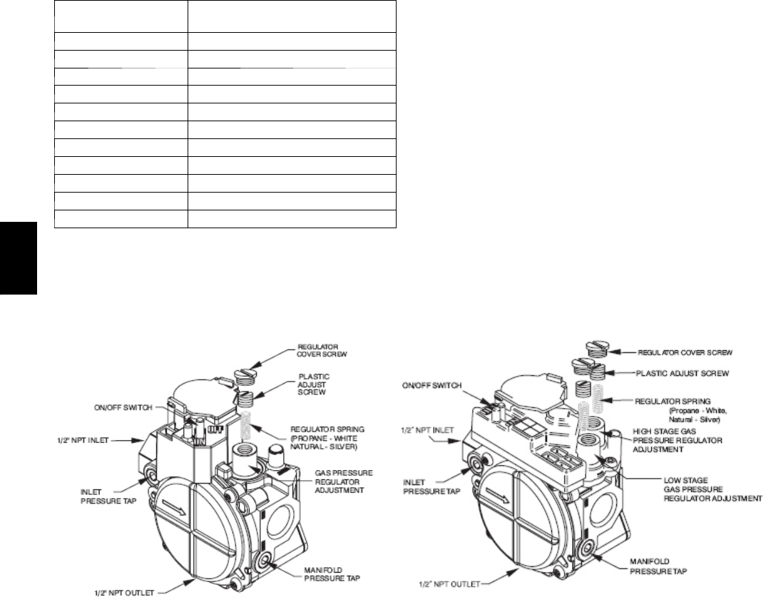
28
Table 8 – LED Error Code Description*
LED INDICATION ERROR CODE
DESCRIPTION
ON Normal Operation
OFF Hardware Failure
1Flash{Evaporator Fan On/Off Delay Modified
2Flashes Limit Switch Fault
3Flashes Flame Sense Fault
4Flashes 4 Consecutive Limit Switch Faults
5Flashes Ignition Lockout Fault
6Flashes Induced--- Draft Motor Fault
7Flashes Rollout Switch Fault
8Flashes Internal Control Fault
9Flashes Software Lockout
LEGEND
LED --- L i g h t E m i t t i n g D i o d e
* A 3---second pause exists between LED error code flashes. If
more than one error code exists, all applicable codes will be
displayed in numerical sequence.
{Indicates a code that is not an error. The unit will continue to
operate when this code is displayed.
IMPORTANT: Refer to Troubleshooting Table 13 and
Table 14 for additional information.
Orifice Replacement
This unit uses orifice type LH32RFnnn (where nnn
indicates orifice reference size). When replacing unit
orifices, order the necessary parts via RCD. See Table 10
for available orifice sizes. See Table 11 and Table 12 for
orifice sizes for Natural Gas and LP fuel usage at various
elevations above sea level.
Check that each replacement orifice is tight at its threads
into the manifold pipe and that orifice projection does not
exceed maximum value. See Fig. 32.
Single Stage 2 Stage
C08210
Fig. 37 -- Gas Valves
580J
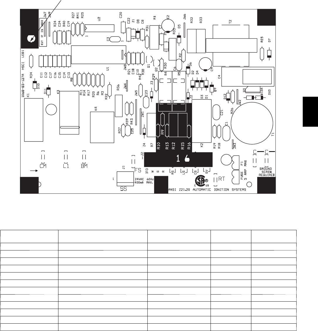
29
Red LED-Status
C08452
Fig. 38 -- Integrated Gas Control (IGC) Board
Table 9 – IGC Connections
TERMINAL LABEL POINT DESCRIPTION SENSOR LOCATION TYPE OF I/O CONNECTION
PIN NUMBER
INPUTS
RT, C Input power from TRAN 1 control box 24 VAC —
SS Speed sensor gas section analog input J1, 1-3
FS, T1 Flame sensor gas section switch input —
WHeat stage 1 LCTB 24 VAC J2, 2
RS Rollout switch gas section switch input J2, 5-6
LS Limit switch fan section switch input J2, 7-8
CS Centrifugal switch (not used) —switch input J2, 9-10
OUTPUTS
L1, CM Induced draft combustion motor gas section line VAC
IFO Indoor fan control box relay J2, 1
GV Gas valve (heat stage 1) gas section relay J2, 11-12
580J

30
Table 10 – Orifice Sizes
ORIFICE
DRILL SIZE
BRYANT
PART NUMBER
DRILL
DIA. (in.)
#30 LH32RF129 0.1285
1/8 LH32RF125 0.1250
#31 LH32RF120 0.1200
#32 LH32RF116 0.1160
#33 LH32RF113 0.1130
#34 LH32RF111 0.1110
#35 LH32RF110 0.1100
#36 LH32RF105 0.1065
#37 LH32RF104 0.1040
#38 LH32RF102 0.1015
#39 LH32RF103 0.0995
#40 LH32RF098 0.0980
#41 LH32RF096 0.0960
#42 LH32RF094 0.0935
#43 LH32RF089 0.0890
#44 LH32RF086 0.0860
#45 LH32RF082 0.0820
#46 LH32RF080 0.0810
#47 LH32RF079 0.0785
#48 LH32RF076 0.0760
#49 LH32RF073 0.0730
#50 LH32RF070 0.0700
#51 LH32RF067 0.0670
#52 LH32RF065 0.0635
#53 LH32RF060 0.0595
#54 LH32RF055 0.0550
#55 LH32RF052 0.0520
#56 LH32RF047 0.0465
#57 LH32RF043 0.0430
#58 LH32RF042 0.0420
Table 11 – Altitude Compensation* (04--07) -- Small Chassis
ELEVATION
ft (m)
72,000 BTUH
Nominal
115,000 BTUH
Nominal
150,000 BTUH
Nominal
NG
Orifice Size
LP
Orifice Size
NG
Orifice Size
LP
Orifice Size
NG
Orifice Size
LP
Orifice Size
0 --- 2000 (610) 331514331503†30 463
2000 (610) 351514351514†30 473
3000 (914) 351524351514311473
4000 (1219) 361524361514311483
5000 (1524) 361524361514311483
6000 (1829) 372524372524311483
7000 (2134) 382534382524321493
8000 (2438) 392534392524331493
9000 (2743) †40 534†40 534341503
10000 (3048) †41 544†41 534351503
11000 (3353) †42 544†42 534361514
12000 (3658) †43 544†43 544372514
13000 (3962) †43 554†43 544382524
14000 (4267) 442†56 442554†40 534
580J
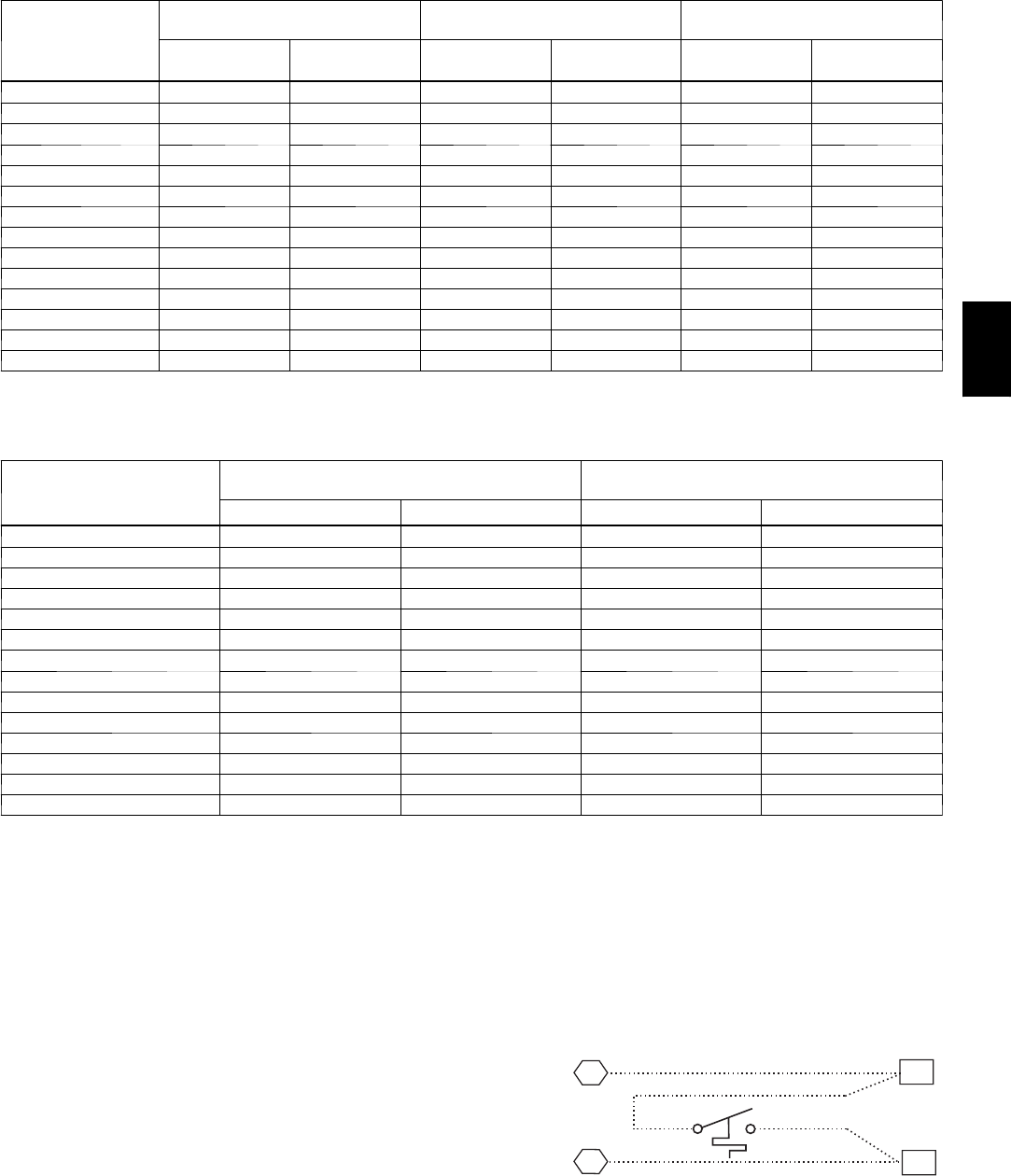
31
Table 11 (cont.) -- Altitude Compensation* (A08--A12)
ELEVATION
ft (m)
125,000
BTUH Nominal
250,000
BTUH Nominal
180,000, 224,000
BTUH Nominal
NG Orifice
Size
LP Orifice
Size
NG Orifice
Size
LP Orifice
Size
NG Orifice
Size
LP Orifice
Size
0 --- 2000 (610) 311493†30 463311483
2000 (610) 321503†30 473321493
3000 (914) 321503311473321493
4000 (1219) 331503311483331493
5000 (1524) 331514311483331503
6000 (1829) 341514311483341503
7000 (2134) 351514321493351503
8000 (2438) 361524331493361514
9000 (2743) 372524341503372514
10000 (3048) 382524351503382524
11000 (3353) 392534361514392524
12000 (3658) †41 534372514†41 534
13000 (3962) †42 544382524†42 534
14000 (4267) †43 544†40 534†43 544
Table 12 – Altitude Compensation* (04--06) -- Low NOxUnits
ELEVATION
ft (m)
60,000, 90,000
BTUH Nominal
120,000
BTUH Nominal
NG Orifice Size LP Orifice Size NG Orifice Size LP Orifice Size
0 --- 2000 (610) 382534321503
2000 (610) 392544331514
3000 (914) †40 544341514
4000 (1219) †41 544351514
5000 (1524) †41 544351514
6000 (1829) †42 544361524
7000 (2134) †42 544361524
8000 (2438) †43 554372524
9000 (2743) †43 554382534
10000 (3048) 442554†40 534
11000 (3353) 442554†41 534
12000 (3658) 452†56 †42 544
13000 (3962) 473†56 †43 544
14000 (4267) 483†56 †43 554
LEGEND:
NG = Natural Gas LP = Liquid Propane 1 = CRLPELEV001A00
* As the height above sea level increases, there is less oxygen per cubic
ft. of air. Therefore, heat input rate should be reduced at higher altitudes.
2 = CRLPELEV002A00
3 = CRLPELEV003A00
{Not included in kit. May be purchased separately through dealer. 4 = CRLPELEV004A00
Minimum heating entering air temperature
When operating on first stage heating, the minimum
temperature of air entering the dimpled heat exchanger is
50_F continuous and 45_F intermittent for standard heat
exchangers and 40_F continuous and 35_F intermittent for
stainless steel heat exchangers. To operate at lower
mixed--air temperatures, a field--supplied outdoor--air
thermostat must be used to initiate both stages of heat
when the temperature is below the minimum required
temperature to ensure full fire operation. Wire the
outdoor--air thermostat (part no. HH22AG106) in series
with the second stage gas valve as shown below. Set the
outdoor--air thermostat at 35_F for stainless steel heat
exchangers or 45_F for standard heat exchangers. This
temperature setting will bring on the second stage of heat
whenever the ambient temperature is below the thermostat
setpoint. Indoor comfort may be compromised when
heating is initiated using low entering air temperatures
with insufficient heating temperature rise.
LCTB
W2
Thermostat
TH1
TH2
W1
W1
W2
OALT
C08442
Troubleshooting Heating System
Refer to Table 13 and Table 14 for additional
troubleshooting topics.
580J

32
Table 13 – Heating Service Analysis
PROBLEM CAUSE REMEDY
Burners Will Not Ignite.
Misaligned spark electrodes. Check flame ignition and sensor electrode positioning.
Adjust as needed.
No gas at main burners.
Check gas line for air, purge as necessary. After purging
gas line of air, allow gas to dissipate for at least 5 minutes
before attempting to relight unit.
Check gas valve.
Water in gas line. Drain water and install drip leg to trap water.
No power to furnace. Check power supply, fuses, wiring, and circuit breaker.
No 24 v power supply to control
circuit.
Check transformer. Transformers with internal overcurrent
protection require a cool down period before resetting.
Miswired or loose connections. Check all wiring and wire nut connections.
Burned--- out heat anticipator in
thermostat. Replace thermostat.
Broken thermostat wires. Run continuity check. Replace wires, if necessary.
Inadequate Heating.
Dirty air filter. Clean or replace filter as necessary.
Gas input to unit too low.
Check gas pressure at manifold. Clock gas meter for input.
If too low, increase manifold pressure, or replace with
correct orifices.
Unit undersized for application. Replace with proper unit or add additional unit.
Restricted airflow. Clean filter, replace filter, or remove any restrictions.
Blower speed too low. Use high speed tap, increase fan speed, or install optional
blower, as suitable for individual units.
Limitswitchcyclesmainburners. Check rotation of blower, thermostat heat anticipator
settings, and temperature rise of unit. Adjust as needed.
Too much outdoor air. Adjust minimum position.
Check economizer operation.
Poor Flame
Characteristics.
Incomplete combustion (lack of
combustion air) results in: Alde-
hyde odors, CO, sooting flame, or
floating flame.
Check all screws around flue outlets and burner
compartment. Tighten as necessary.
Cracked heat exchanger.
Overfired unit — reduce input, change orifices, or adjust
gas line or manifold pressure.
Check vent for restriction. Clean as necessary.
Check orifice to burner alignment.
Burners Will Not Turn
Off.
Unit is locked into Heating mode
for a one minute minimum.
Wait until mandatory one---minute time period has elapsed
or reset power to unit.
580J
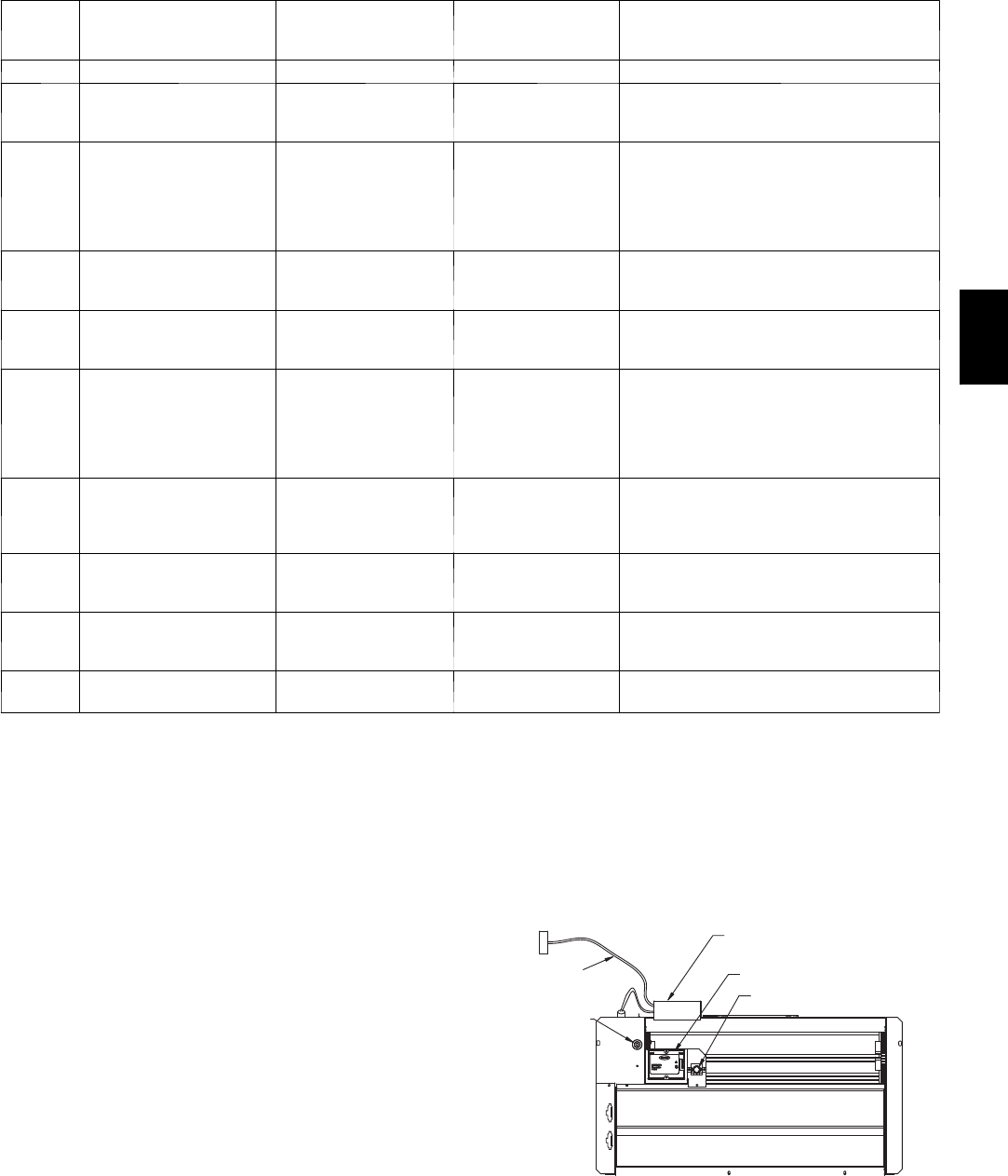
33
Table 14 – IGC Board LED Alarm Codes
LED
FLASH
CODE
DESCRIPTION ACTION TAKEN BY
CONTROL RESET METHOD PROBABLE CAUSE
On Normal Operation — — —
Off Hardware Failure No gas heating. —
Loss of power to the IGC. Check 5 amp fuse
on IGC, power to unit, 24V circuit breaker,
transformer, and wiring to the IGC.
2Flashes Limit Switch Fault
Gas valve and igniter Off.
Indoor fan and inducer
On.
Limit switch closed, or
heat call (W) Off.
High temperature limit switch is open. Check
the operation of the indoor (evaporator) fan
motor.
Ensure that the supply-air temperature rise is
within the range on the unit nameplate. Check
wiring and limit switch operation.
3Flashes Flame Sense Fault Indoor fan and inducer
On.
Flame sense normal.
Power reset for LED
reset.
The IGC sensed a flame when the gas valve
should be closed. Check wiring, flame sensor,
and gas valve operation.
4Flashes Four Consecutive Limit
Switch Fault No gas heating.
Heat call (W) Off.
Power reset for LED
reset.
4 consecutive limit switch faults within a single
call for heat. See Limit Switch Fault.
5Flashes Ignition Fault No gas heating.
Heat call (W) Off.
Power reset for LED
reset.
Unit unsuccessfully attempted ignition for 15
minutes. Check igniter and flame sensor elec-
trode spacing, gaps, etc. Check flame sense
and igniter wiring. Check gas valve operation
and gas supply. Check gas valve connections
to IGC terminals. BRN lead must be on Pin 11.
6Flashes Induced Draft Motor Fault
If heat off: no gas
heating.
If heat on: gas valve Off
and inducer On.
Inducer sense normal,
or heat call (W) Off.
Inducer sense On when heat call Off, or induc-
er sense Off when heat call On. Check wiring,
voltage, and operation of IGC motor. Check
speed sensor wiring to IGC.
7Flashes Rollout Switch Lockout
Gas valve and igniter Off.
Indoor fan and inducer
On.
Power reset.
Rollout switch has opened. Check gas valve
operation. Check induced-draft blower wheel is
properly secured to motor shaft.
8Flashes Internal Control Lockout No gas heating. Power reset.
IGC has sensed internal hardware or software
error. If fault is not cleared by resetting 24 v
power, replace the IGC.
9Flashes Temporary Software
Lockout No gas heating. 1 hour auto reset, or
power reset.
Electrical interference is disrupting the IGC
software.
LEGEND
IGC --- Integrated Gas Unit Control
LED --- L i g h t --- E m i t t i n g D i o d e
NOTES:
1. There is a 3---second pause between alarm code displays.
2. If more than one alarm code exists, all applicable alarm codes will be displayed in numerical sequence.
3. Alarm codes on the IGC will be lost if power to the unit is interrupted.
ECONOMIZER SYSTEMS
The 580J units may be equipped with a factory--installed
or accessory (field--installed) economizer system. Two
types are available: with a logic control system
(EconoMi$er IV) and without a control system
(EconoMi$er2). See Fig. 39 and Fig. 40 for component
locations on each type. See Fig. 41 and Fig. 42 for
economizer section wiring diagrams.
Both economizers use direct--drive damper actuators.
ECONOMI$ER IV
CONTROLLER
OUTSIDE AIR
TEMPERATURE SENSOR
LOW AMBIENT
SENSOR
A
CTUATOR
WIRING
HARNESS
C06021
Fig. 39 -- EconoMi$er IV Component Locations
580J
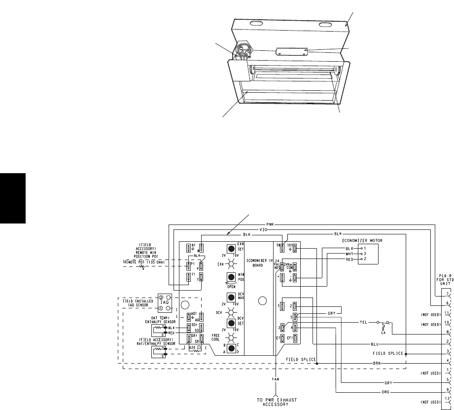
34
ECONOMI$ER2
PLUG
BAROMETRIC
RELIEF
DAMPER
OUTDOOR
AIR HOOD
HOOD
SHIPPING
BRACKET
GEAR DRIVEN
DAMPER
C06022
Fig. 40 -- EconoMi$er2 Component Locations
FOR OCCUPANCY CONTROL
REPLACE JUMPER WITH
FIELD-SUPPLIED TIME CLOCK
LEGEND
DCV— Demand Controlled Ventilation
IAQ — Indoor Air Quality
LA — Low Ambient Lockout Device
OAT — Outdoor-Air Temperature
POT — Potentiometer
RAT — Return-Air Temperature
Potentiometer Defaults Settings:
Power Exhaust Middle
Minimum Pos. Fully Closed
DCV Max. Middle
DCV Set Middle
Enthalpy C Setting
NOTES:
1. 620 ohm, 1 watt 5% resistor should be removed only when using differential
enthalpy or dry bulb.
2. If a separate field-supplied 24 v transformer is used for the IAQ sensor power
supply, it cannot have the secondary of the transformer grounded.
3. For field-installed remote minimum position POT, remove black wire jumper
between P and P1 and set control minimum position POT to the minimum
position.
8
7
C06028
Fig. 41 -- EconoMi$er IV Wiring
580J
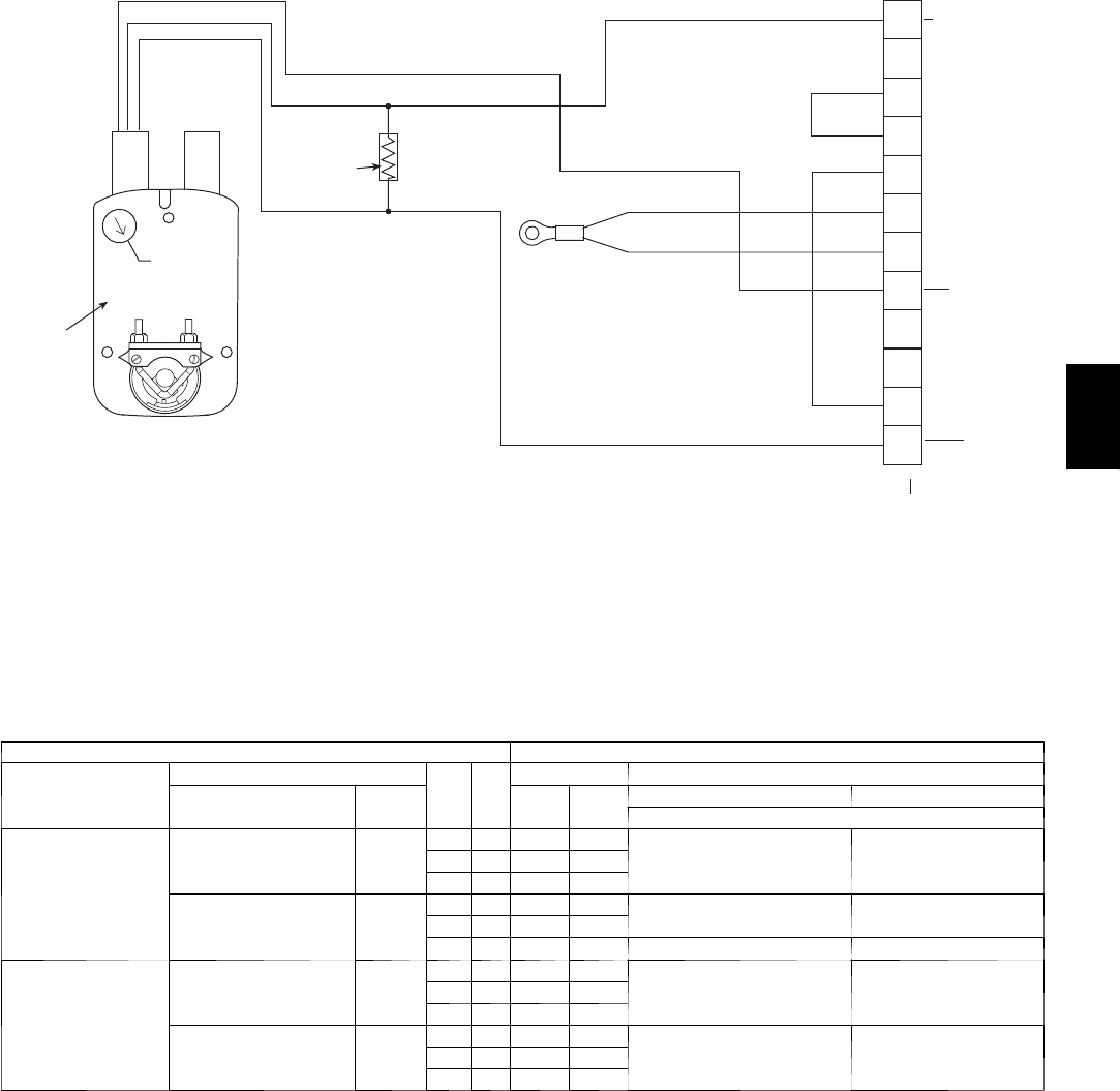
35
4
3
5
2
8
6
7
1
10
11
9
12
PINK
VIOLET
BLACK
BLUE
YELLOW
NOTE 1
NOTE 3
RUN
500 OHM
RESISTOR
50HJ540573
ACTUATOR
ASSEMBLY
RED
WHITE
ECONOMISER2 PLUG
DIRECT DRIVE
ACTUATOR 4-20mA SIGNAL
OAT SENSOR
4-20 mA
position
input signal
24 VAC
TRANSFORMER
GROUND
NOTES:
1. Switch on actuator must be in run position for economizer to operate.
2. 50HJ540573 actuator consists of the 50HJ540567 actuator and a harness with 500-ohm resistor.
C08436
Fig. 42 -- EconoMi$er2 with 4 to 20 mA Control Wiring
Table 15 – EconoMi$er IV Input/Output Logic
INPUTS OUTPUTS
Demand Control
Ventilation (DCV)
Enthalpy*
Y1 Y2
Compressor NTerminal†
Outdoor Return Stage
1
Stage
2
Occupied Unoccupied
Damper
Below set
(DCV LED Off)
High
(Free Cooling LED Off) Low
On On On On
Minimum position ClosedOn Off On Off
Off Off Off Off
Low
(Free Cooling LED On) High
On On On Off Modulating** (between min.
position and full-open)
Modulating** (between
closed and full-open)
On Off Off Off
Off Off Off Off Minimum position Closed
Above set
(DCV LED On)
High
(Free Cooling LED Off) Low
On On On On Modulating†† (between min.
position and DCV
maximum)
Modulating†† (between
closed and DCV
maximum)
On Off On Off
Off Off Off Off
Low
(Free Cooling LED On) High
On On On Off
Modulating*** Modulating†††On Off Off Off
Off Off Off Off
* For single enthalpy control, the module compares outdoor enthalpy to the ABCD setpoint.
† Power at N terminal determines Occupied/Unoccupied setting: 24 vac (Occupied), no power (Unoccupied).
** Modulation is based on the supply-air sensor signal.
†† Modulation is based on the DCV signal.
*** Modulation is based on the greater of DCV and supply-air sensor signals, between minimum position and either maximum position (DCV)
or fully open (supply-air signal).
††† Modulation is based on the greater of DCV and supply-air sensor signals, between closed and either maximum position (DCV) or fully
open (supply-air signal).
580J
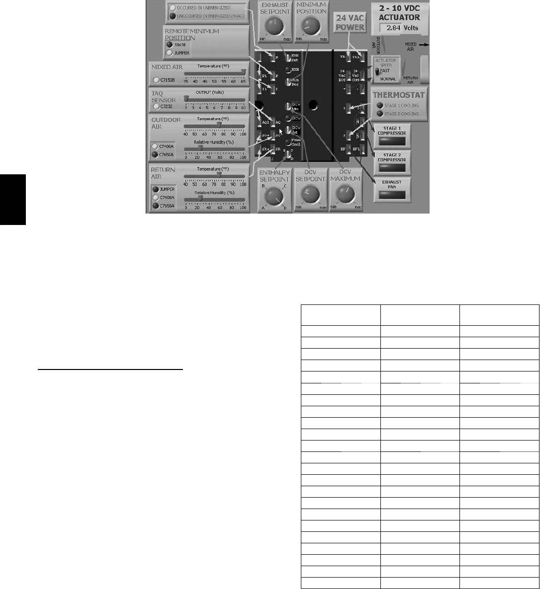
36
C06053
Fig. 43 -- EconoMi$er IV Functional View
EconoMi$er IV
Table 15 provides a summary of EconoMi$er IV.
Troubleshooting instructions are enclosed.
A functional view of the EconoMi$er is shown in Fig. 43.
Typical settings, sensor ranges, and jumper positions are
also shown. An EconoMi$er IV simulator program is
available from Bryant to help with EconoMi$er IV
training and troubleshooting.
EconoMi$er IV Standard Sensors
Outdoor Air Temperature (OAT) Sensor
The outdoor air temperature sensor (HH57AC074) is a 10
to 20 mA device used to measure the outdoor-air
temperature. The outdoor-air temperature is used to
determine when the EconoMi$er IV can be used for free
cooling. The sensor is factory-installed on the
EconoMi$er IV in the outdoor airstream. (See Fig. 44.)
The operating range of temperature measurement is 40_to
100_F(4_to 38_C).
Supply Air Temperature (SAT) Sensor
The supply air temperature sensor is a 3 K thermistor
located at the inlet of the indoor fan. (See Fig. 44.) This
sensor is factory installed. The operating range of
temperature measurement is 0°to 158_F(--18_to 70_C).
See Table 16 for sensor temperature/resistance values.
Table 16 – Thermistor Resistance vs Temperature
Values for Space Temperature Sensor, Supply Air
Temperature Sensor, and Outdoor Air Temperature
Sensor
TEMP
(C)
TEMP
(F)
RESISTANCE
(Ohms)
--- 4 0 --- 4 0 335,651
--- 3 5 --- 3 1 242,195
--- 3 0 --- 2 2 176,683
--- 2 5 --- 1 3 130,243
--- 2 0 --- 4 96,974
--- 1 5 572,895
--- 1 0 14 55,298
--- 5 23 42,315
032 32,651
541 25,395
10 50 19,903
15 59 15,714
20 68 12,494
25 77 10,000
30 86 8,056
35 95 6,530
40 104 5,325
45 113 4,367
50 122 3,601
55 131 2,985
60 140 2,487
65 149 2,082
70 158 1,752
580J
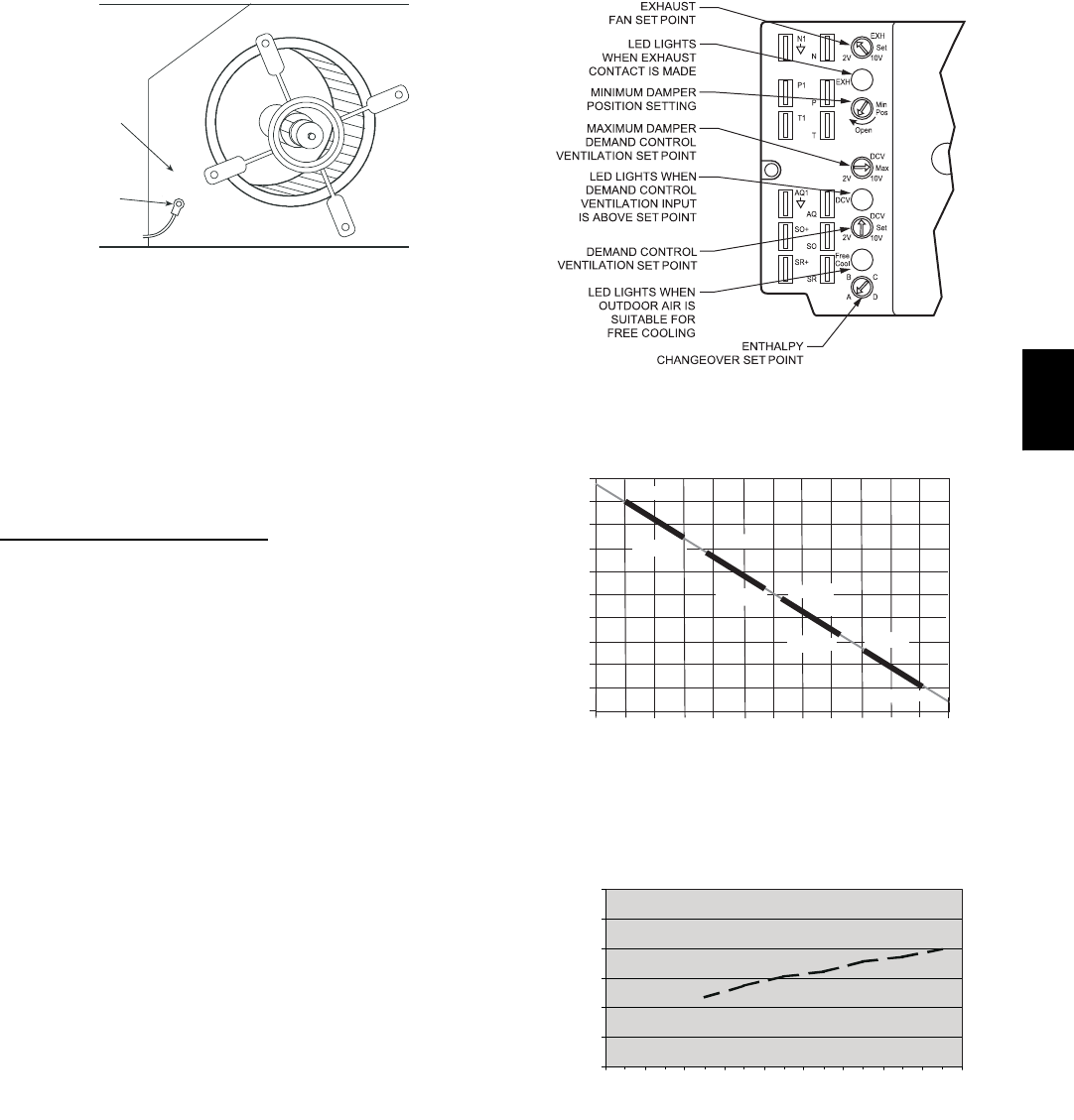
37
SUPPLY AIR
TEMPERATURE
SENSOR
MOUNTING
LOCATION
SUPPLY AIR
TEMPERATURE
SENSOR
C06033
Fig. 44 -- Supply Air Sensor Location
The temperature sensor looks like an eyelet terminal with
wires running to it. The sensor is located in the “crimp
end” and is sealed from moisture.
Outdoor Air Lockout Sensor
The EconoMi$er IV is equipped with an ambient
temperature lockout switch located in the outdoor
airstream which is used to lock out the compressors below
a42_F(6_C) ambient temperature. (See Fig. 38.)
EconoMi$er IV Control Modes
IMPORTANT: The optional EconoMi$er2 does not
include a controller. The EconoMi$er2 is operated by a 4
to 20 mA signal from an existing field-supplied controller.
See Fig. 42 for wiring information.
Determine the EconoMi$er IV control mode before set up
of the control. Some modes of operation may require
different sensors. (See Table 17.) The EconoMi$er IV is
supplied from the factory with a supply--air temperature
sensor and an outdoor--air temperature sensor. This allows
for operation of the EconoMi$er IV with outdoor air dry
bulb changeover control. Additional accessories can be
added to allow for different types of changeover control
and operation of the EconoMi$er IV and unit.
Outdoor Dry Bulb Changeover
The standard controller is shipped from the factory
configured for outdoor dry bulb changeover control. The
outdoor air and supply air temperature sensors are
included as standard. For this control mode, the outdoor
temperature is compared to an adjustable setpoint selected
on the control. If the outdoor-air temperature is above the
setpoint, the EconoMi$er IV will adjust the outside air
dampers to minimum position. If the outdoor-air
temperature is below the setpoint, the position of the
outside air dampers will be controlled to provided free
cooling using outdoor air. When in this mode, the LED
next to the free cooling setpoint potentiometer will be on.
The changeover temperature setpoint is controlled by the
free cooling setpoint potentiometer located on the control.
(See Fig. 45.) The scale on the potentiometer is A, B, C,
and D. See Fig. 46 for the corresponding temperature
changeover values.
C06034
Fig. 45 -- EconoMi$er IV Controller Potentiometer
and LED Locations
LED ON
LED ON
LED ON
LED ON
LED OFF
19
18
LED OFF
LED OFF
LED OFF
17
16
15
14
13
12
11
10
9
40 45 50 55 60 65 70 75 80 85 90 95 100
DEGREES FAHRENHEIT
mA
D
C
B
A
C06035
Fig. 46 -- Outside Air Temperature Changeover
Setpoints
0
5
10
15
20
25
30
0.13 0.20 0.22 0.25 0.30 0.35 0.40 0.45 0.50
STATIC PRESSURE (in. wg)
FLOW IN CUBIC FEET PER MINUTE (cfm)
C06031
Fig. 47 -- Outdoor--Air Damper Leakage
Differential Dry Bulb Control
For differential dry bulb control the standard outdoor dry
bulb sensor is used in conjunction with an additional
accessory dry bulb sensor (part number
CRTEMPSN002A00). The accessory sensor must be
mounted in the return airstream. (See Fig. 48.) Wiring is
580J
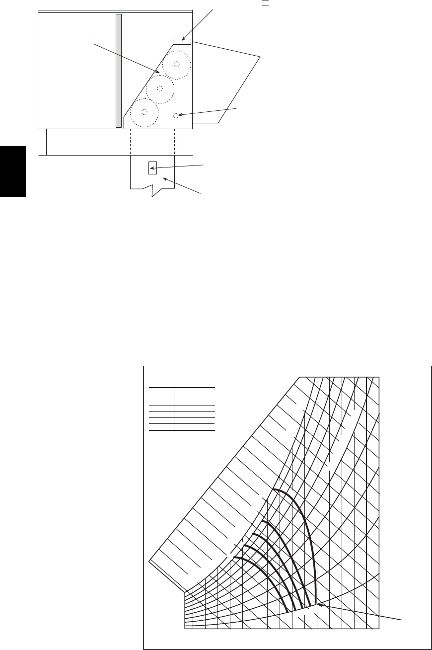
38
provided in the EconoMi$er IV wiring harness. (See Fig.
38.)
ECONOMI$ERIV
ECONOMI$ERIV
CONTROLLER
GROMMET
RETURN AIR
SENSOR
RETURN DUCT
(FIELD-PROVIDED)
C07085
Fig. 48 -- Return Air Temperature or Enthalpy Sensor
Mounting Location
In this mode of operation, the outdoor-air temperature is
compared to the return-air temperature and the lower
temperature airstream is used for cooling. When using this
mode of changeover control, turn the enthalpy setpoint
potentiometer fully clockwise to the D setting. (See Fig.
45.)
Outdoor Enthalpy Changeover
For enthalpy control, accessory enthalpy sensor (part
number HH57AC078) is required. Replace the standard
outdoor dry bulb temperature sensor with the accessory
enthalpy sensor in the same mounting location. (See Fig.
39.) When the outdoor air enthalpy rises above the
outdoor enthalpy changeover setpoint, the outdoor-air
damper moves to its minimum position. The outdoor
enthalpy changeover setpoint is set with the outdoor
enthalpy setpoint potentiometer on the EconoMi$er IV
controller. The setpoints are A, B, C, and D. (See Fig. 46.)
The factory-installed 620-ohm jumper must be in place
across terminals SRand SR+ on the EconoMi$er IV
controller.
Differential Enthalpy Control
For differential enthalpy control, the EconoMi$er IV
controller uses two enthalpy sensors (HH57AC078 and
CRENTDIF004A00), one in the outside air and one in the
return air duct. The EconoMi$er IV controller compares
the outdoor air enthalpy to the return air enthalpy to
determine EconoMi$er IV use. The controller selects the
lower enthalpy air (return or outdoor) for cooling. For
example, when the outdoor air has a lower enthalpy than
the return air, the EconoMi$er IV opens to bring in
outdoor air for free cooling.
Replace the standard outside air dry bulb temperature
sensor with the accessory enthalpy sensor in the same
mounting location. (See Fig. 39.) Mount the return air
enthalpy sensor in the return air duct. (See Fig. 48.)
Wiring is provided in the EconoMi$er IV wiring harness.
(See Fig. 41.) The outdoor enthalpy changeover setpoint is
set with the outdoor enthalpy setpoint potentiometer on
the EconoMi$er IV controller. When using this mode of
changeover control, turn the enthalpy setpoint
potentiometer fully clockwise to the D setting.
CONTROL
CURVE
A
B
C
D
CONTROL POINT
APPROX.
deg. F (deg. C)
AT 50% RH
73 (23)
70 (21)
67 (19)
63 (17)
12 14 16 18 20 22 24 26 28 30 32 34 36 38 40 42 44 46
90
100
80
70
60
50
40
30
20
10
ENTHALPY BTU PER POUND DRY AIR
85
(29) 90
(32) 95
(35) 100
(38) 105
(41) 110
(43)
35
(2)
35
(2)
40
(4)
40
(4)
105
(41) 110
(43)
45
(7)
45
(7)
50
(10)
50
(10)
55
(13)
55
(13)
60
(16)
60
(16)
65
(18)
65
(18)
70
(21)
70
(21)
75
(24)
75
(24)
80
(27)
80
(27)
85
(29) 90
(32) 95
(35) 100
(38)
A
A
B
B
C
C
D
D
RELATIVE HUMIDITY (%)
HIGH LIMIT
CURVE
APPROXIMATE DRY BULB TEMPERATURE--degrees F (degrees C)
C06037
Fig. 49 -- Enthalpy Changeover Setpoints
580J
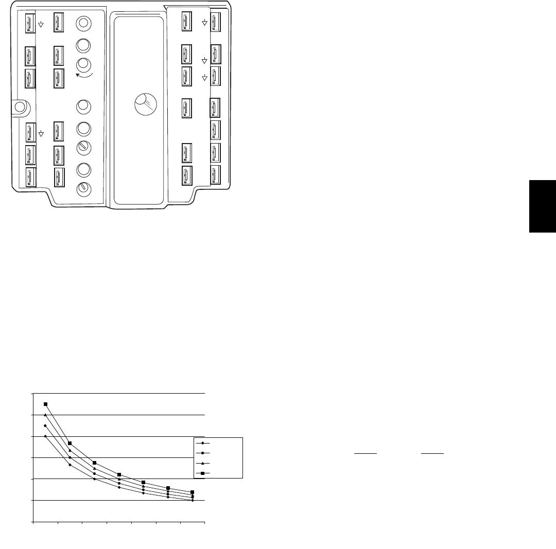
39
TR1
24 Vac
COM
TR
24
Va c
HOT
12
34
5
EF EF1
+_
P1
T1
P
T
N
EXH
2V 10V
EXH
Set
Set
2V 10V
2V 10V
DCV
DCV
Free
Cool
BC
AD
SO+
SR+
SR
SO
AQ1
AQ
DCV
Min
Pos
Open
Max
N1
C06038
Fig. 50 -- EonoMi$er IV Control
Indoor Air Quality (IAQ) Sensor Input
The IAQ input can be used for demand control ventilation
control based on the level of CO2measured in the space
or return air duct.
Mount the accessory IAQ sensor according to
manufacturer specifications. The IAQ sensor should be
wired to the AQ and AQ1 terminals of the controller.
Adjust the DCV potentiometers to correspond to the DCV
voltage output of the indoor air quality sensor at the
user-determined setpoint. (See Fig. 51.)
0
1000
2000
3000
4000
5000
6000
2345678
800 ppm
900 ppm
1000 ppm
1100 ppm
RANGE CONFIGURATION (ppm)
DAMPER VOLTAGE FOR MAX VENTILATION RATE
CO SENSOR MAX RANGE SETTING
2
C06039
Fig. 51 -- CO2Sensor Maximum Range Settings
If a separate field-supplied transformer is used to power
the IAQ sensor, the sensor must not be grounded or the
EconoMi$er IV control board will be damaged.
When using demand ventilation, the minimum damper
position represents the minimum ventilation position for
VOC (volatile organic compounds) ventilation
requirements. The maximum demand ventilation position
is used for fully occupied ventilation.
When demand ventilation control is not being used, the
minimum position potentiometer should be used to set the
occupied ventilation position. The maximum demand
ventilation position should be turned fully clockwise.
Exhaust Setpoint Adjustment
The exhaust setpoint will determine when the exhaust fan
runs based on damper position (if accessory power
exhaust is installed). The setpoint is modified with the
Exhaust Fan Setpoint (EXH SET) potentiometer. (See Fig.
45.) The setpoint represents the damper position above
which the exhaust fans will be turned on. When there is a
call for exhaust, the EconoMi$er IV controller provides a
45 ±15 second delay before exhaust fan activation to
allow the dampers to open. This delay allows the damper
to reach the appropriate position to avoid unnecessary fan
overload.
Minimum Position Control
There is a minimum damper position potentiometer on the
EconoMi$er IV controller. (See Fig. 45.) The minimum
damper position maintains the minimum airflow into the
building during the occupied period.
When using demand ventilation, the minimum damper
position represents the minimum ventilation position for
VOC (volatile organic compound) ventilation
requirements. The maximum demand ventilation position
is used for fully occupied ventilation.
When demand ventilation control is not being used, the
minimum position potentiometer should be used to set the
occupied ventilation position. The maximum demand
ventilation position should be turned fully clockwise.
Adjust the minimum position potentiometer to allow the
minimum amount of outdoor air, as required by local
codes, to enter the building. Make minimum position
adjustments with at least 10_F temperature difference
between the outdoor and return-air temperatures.
To determine the minimum position setting, perform the
following procedure:
1. Calculate the appropriate mixed air temperature
using the following formula:
(TOx
OA )+(TRxRA )=T
M
100 100
TO= Outdoor-Air Temperature
OA = Percent of Outdoor Air
TR= Return-Air Temperature
RA = Percent of Return Air
TM= Mixed-Air Temperature
As an example, if local codes require 10% outdoor
air during occupied conditions, outdoor-air
temperature is 60_F, and return-air temperature is
75_F.
(60 x .10) + (75 x .90) = 73.5_F
2. Disconnect the supply air sensor from terminals T
and T1.
3. Ensure that the factory-installed jumper is in place
across terminals P and P1. If remote damper
positioning is being used, make sure that the
terminals are wired according to Fig. 41 and that the
minimum position potentiometer is turned fully
clockwise.
4. Connect 24 vac across terminals TR and TR1.
580J

40
5. Carefully adjust the minimum position
potentiometer until the measured mixed air
temperature matches the calculated value.
6. Reconnect the supply air sensor to terminals T and
T1.
Remote control of the EconoMi$er IV damper is desirable
when requiring additional temporary ventilation. If a
field-supplied remote potentiometer (Honeywell part
number S963B1128) is wired to the EconoMi$er IV
controller, the minimum position of the damper can be
controlled from a remote location.
To control the minimum damper position remotely,
remove the factory-installed jumper on the P and P1
terminals on the EconoMi$er IV controller. Wire the
field-supplied potentiometer to the P and P1 terminals on
the EconoMi$er IV controller. (See Fig. 41.)
Damper Movement
Damper movement from full open to full closed (or vice
versa) takes 2--1/2 minutes.
Thermostats
The EconoMi$er IV control works with conventional
thermostats that have a Y1 (cool stage 1), Y2 (cool stage
2), W1 (heat stage 1), W2 (heat stage 2), and G (fan). The
EconoMi$er IV control does not support space
temperature sensors. Connections are made at the
thermostat terminal connection board located in the main
control box.
Occupancy Control
The factory default configuration for the EconoMi$er IV
control is occupied mode. Occupied status is provided by
the black jumper from terminal TR to terminal N. When
unoccupied mode is desired, install a field--supplied
timeclock function in place of the jumper between TR and
N. (See Fig. 41.) When the timeclock contacts are closed,
the EconoMi$er IV control will be in occupied mode.
When the timeclock contacts are open (removing the 24--v
signal from terminal N), the EconoMi$er IV will be in
unoccupied mode.
Demand Control Ventilation (DCV)
When using the EconoMi$er IV for demand controlled
ventilation, there are some equipment selection criteria
which should be considered. When selecting the heat
capacity and cool capacity of the equipment, the
maximum ventilation rate must be evaluated for design
conditions. The maximum damper position must be
calculated to provide the desired fresh air.
Typically the maximum ventilation rate will be about 5 to
10% more than the typical cfm required per person, using
normal outside air design criteria.
A proportional anticipatory strategy should be taken with
the following conditions: a zone with a large area, varied
occupancy, and equipment that cannot exceed the required
ventilation rate at design conditions. Exceeding the
required ventilation rate means the equipment can
condition air at a maximum ventilation rate that is greater
than the required ventilation rate for maximum
occupancy. A proportional-anticipatory strategy will cause
the fresh air supplied to increase as the room CO2level
increases even though the CO2setpoint has not been
reached. By the time the CO2level reaches the setpoint,
the damper will be at maximum ventilation and should
maintain the setpoint.
In order to have the CO2sensor control the economizer
damper in this manner, first determine the damper voltage
output for minimum or base ventilation. Base ventilation
is the ventilation required to remove contaminants during
unoccupied periods. The following equation may be used
to determine the percent of outside air entering the
building for a given damper position. For best results there
should be at least a 10 degree difference in outside and
return-air temperatures.
(TOx
OA )+(TRxRA )=T
M
100 100
TO= Outdoor-Air Temperature
OA = Percent of Outdoor Air
TR= Return-Air Temperature
RA = Percent of Return Air
TM= Mixed-Air Temperature
Once base ventilation has been determined, set the
minimum damper position potentiometer to the correct
position.
The same equation can be used to determine the occupied
or maximum ventilation rate to the building. For example,
an output of 3.6 volts to the actuator provides a base
ventilation rate of 5% and an output of 6.7 volts provides
the maximum ventilation rate of 20% (or base plus 15 cfm
per person). Use Fig. 51 to determine the maximum
setting of the CO2sensor. For example, an 1100 ppm
setpoint relates to a 15 cfm per person design. Use the
1100 ppm curve on Fig. 51 to find the point when the CO2
sensor output will be 6.7 volts. Line up the point on the
graph with the left side of the chart to determine that the
range configuration for the CO2sensor should be 1800
ppm. The EconoMi$er IV controller will output the 6.7
volts from the CO2sensor to the actuator when the CO2
concentration in the space is at 1100 ppm. The DCV
setpoint may be left at 2 volts since the CO2sensor
voltage will be ignored by the EconoMi$er IV controller
until it rises above the 3.6 volt setting of the minimum
position potentiometer.
Once the fully occupied damper position has been
determined, set the maximum damper demand control
ventilation potentiometer to this position. Do not set to the
maximum position as this can result in over-ventilation to
the space and potential high humidity levels.
CO2Sensor Configuration
The CO2sensor has preset standard voltage settings that
can be selected anytime after the sensor is powered up.
(See Table 17.)
Use setting 1 or 2 for Bryant equipment. (See Table 17.)
1. Press Clear and Mode buttons. Hold at least 5
seconds until the sensor enters the Edit mode.
2. Press Mode twice. The STDSET Menu will appear.
580J
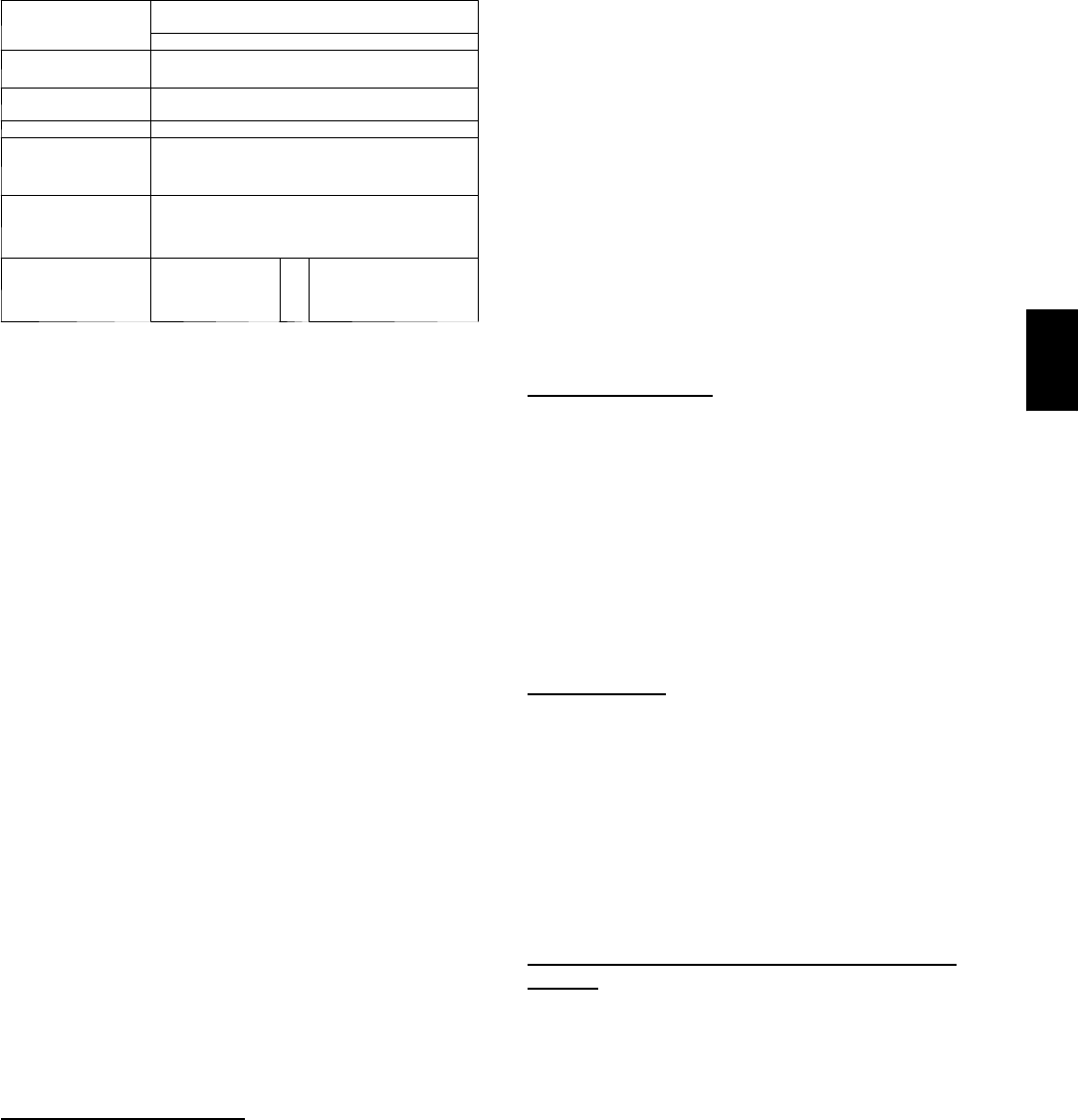
41
Table 17 – EconoMi$er IV Sensor Usage
APPLICATION
ECONOMI$ER IV WITH OUTDOOR AIR
DRY BULB SENSOR
Accessories Required
Outdoor Air
Dry Bulb
None. The outdoor air dry bulb sensor
is factory installed.
Differential
Dry Bulb CRTEMPSN002A00*
Single Enthalpy HH57AC078
Differential
Enthalpy
HH57AC078
and
CRENTDIF004A00*
CO2for DCV
Control using a
Wall-Mounted
CO2Sensor
33ZCSENCO2
CO2for DCV
Control using a
Duct-Mounted
CO2Sensor
33ZCSENCO2†
and
33ZCASPCO2**
O
RCRCBDIOX005A00††
* CRENTDIF004A00 and CRTEMPSN002A00 accessories are
used on many different base units. As such, these kits may
contain parts that will not be needed for installation.
† 33ZCSENCO2 is an accessory CO2sensor.
** 33ZCASPCO2 is an accessory aspirator box required for duct-
mounted applications.
†† CRCBDIOX005A00 is an accessory that contains both
33ZCSENCO2 and 33ZCASPCO2 accessories.
3. Use the Up/Down button to select the preset
number. (See Table 17.)
4. Press Enter to lock in the selection.
5. Press Mode to exit and resume normal operation.
The custom settings of the CO2sensor can be changed
anytime after the sensor is energized. Follow the steps
below to change the non-standard settings:
1. Press Clear and Mode buttons. Hold at least 5
seconds until the sensor enters the Edit mode.
2. Press Mode twice. The STDSET Menu will appear.
3. Use the Up/Down button to toggle to the NONSTD
menu and press Enter.
4. Use the Up/Down button to toggle through each of
the nine variables, starting with Altitude, until the
desired setting is reached.
5. Press Mode to move through the variables.
6. Press Enter to lock in the selection, then press Mode
to continue to the next variable.
Dehumidification of Fresh Air with DCV (Demand
Controlled Ventilation) Control
If normal rooftop heating and cooling operation is not
adequate for the outdoor humidity level, an energy
recovery unit and/or a dehumidification option should be
considered.
EconoMi$er IV Preparation
This procedure is used to prepare the EconoMi$er IV for
troubleshooting. No troubleshooting or testing is done by
performing the following procedure.
NOTE: This procedure requires a 9--v battery, 1.2
kilo--ohm resistor, and a 5.6 kilo--ohm resistor which are
not supplied with the EconoMi$er IV.
IMPORTANT: Be sure to record the positions of all
potentiometers before starting troubleshooting.
1. Disconnect power at TR and TR1. All LEDs should
be off. Exhaust fan contacts should be open.
2. Disconnect device at P and P1.
3. Jumper P to P1.
4. Disconnect wires at T and T1. Place 5.6 kilo--ohm
resistor across T and T1.
5. Jumper TR to 1.
6. Jumper TR to N.
7. If connected, remove sensor from terminals SO and +.
Connect 1.2 kilo--ohm 4074EJM checkout resistor
across terminals SO and +.
8. Put 620--ohm resistor across terminals SR and +.
9. Set minimum position, DCV setpoint, and exhaust po-
tentiometers fully CCW (counterclockwise).
10. Set DCV maximum position potentiometer fully CW
(clockwise).
11. Set enthalpy potentiometer to D.
12. Apply power (24 vac) to terminals TR and TR1.
Differential Enthalpy
To check differential enthalpy:
1. Make sure EconoMi$er IV preparation procedure has
been performed.
2. Place 620--ohm resistor across SO and +.
3. Place 1.2 kilo--ohm resistor across SR and +. The
Free Cool LED should be lit.
4. Remove 620--ohm resistor across SO and +. The Free
Cool LED should turn off.
5. Return EconoMi$er IV settings and wiring to normal
after completing troubleshooting.
Single Enthalpy
To check single enthalpy:
1. Make sure EconoMi$er IV preparation procedure has
been performed.
2. Set the enthalpy potentiometer to A (fully CCW). The
Free Cool LED should be lit.
3. Set the enthalpy potentiometer to D (fully CW). The
Free Cool LED should turn off.
4. Return EconoMi$er IV settings and wiring to normal
after completing troubleshooting.
DCV (Demand Controlled Ventilation) and Power
Exhaust
To check DCV and Power Exhaust:
1. Make sure EconoMi$er IV preparation procedure has
been performed.
2. Ensure terminals AQ and AQ1 are open. The LED for
both DCV and Exhaust should be off. The actuator
should be fully closed.
3. Connect a 9--v battery to AQ (positive node) and AQ1
(negative node). The LED for both DCV and Exhaust
should turn on. The actuator should drive to between
90 and 95% open.
4. Turn the Exhaust potentiometer CW until the Exhaust
LED turns off. The LED should turn off when the po-
tentiometer is approximately 90%. The actuator
should remain in position.
5. Turn the DCV setpoint potentiometer CW until the
DCV LED turns off. The DCV LED should turn off
580J

42
when the potentiometer is approximately 9--v. The ac-
tuator should drive fully closed.
6. Turn the DCV and Exhaust potentiometers CCW until
the Exhaust LED turns on. The exhaust contacts will
close 30 to 120 seconds after the Exhaust LED turns
on.
7. Return EconoMi$er IV settings and wiring to normal
after completing troubleshooting.
DCV Minimum and Maximum Position
To check the DCV minimum and maximum position:
1. Make sure EconoMi$er IV preparation procedure has
been performed.
2. Connect a 9--v battery to AQ (positive node) and AQ1
(negative node). The DCV LED should turn on. The
actuator should drive to between 90 and 95% open.
3. Turn the DCV Maximum Position potentiometer to
midpoint. The actuator should drive to between 20
and 80% open.
4. Turn the DCV Maximum Position potentiometer to
fully CCW. The actuator should drive fully closed.
5. Turn the Minimum Position potentiometer to mid-
point. The actuator should drive to between 20 and
80% open.
6. Turn the Minimum Position Potentiometer fully CW.
The actuator should drive fully open.
7. Remove the jumper from TR and N. The actuator
should drive fully closed.
8. Return EconoMi$er IV settings and wiring to normal
after completing troubleshooting.
Supply--Air Sensor Input
To check supply--air sensor input:
1. Make sure EconoMi$er IV preparation procedure has
been performed.
2. Set the Enthalpy potentiometer to A. The Free Cool
LED turns on. The actuator should drive to between
20 and 80% open.
3. Remove the 5.6 kilo--ohm resistor and jumper T to
T1. The actuator should drive fully open.
4. Remove the jumper across T and T1. The actuator
should drive fully closed.
5. Return EconoMi$er IV settings and wiring to normal
after completing troubleshooting.
EconoMi$er IV Troubleshooting Completion
This procedure is used to return the EconoMi$er IV to
operation. No troubleshooting or testing is done by
performing the following procedure.
1. Disconnect power at TR and TR1.
2. Set enthalpy potentiometer to previous setting.
3. Set DCV maximum position potentiometer to previ-
ous setting.
4. Set minimum position, DCV setpoint, and exhaust po-
tentiometers to previous settings.
5. Remove 620--ohm resistor from terminals SR and +.
6. Remove 1.2 kilo--ohm checkout resistor from termin-
als SO and +. If used, reconnect sensor from termin-
als SO and +.
7. Remove jumper from TR to N.
8. Remove jumper from TR to 1.
9. Remove 5.6 kilo--ohm resistor from T and T1. Recon-
nect wires at T and T1.
10. Remove jumper from P to P1. Reconnect device at P
and P1.
11. Apply power (24 vac) to terminals TR and TR1.
WIRING DIAGRAMS
See Fig. 52 and Fig. 53 for typical wiring diagrams.
PRE--START--UP
PERSONAL INJURY HAZARD
Failure to follow this warning could result in personal
injury or death.
1. Follow recognized safety practices and wear pro-
tective goggles when checking or servicing refri-
gerant system.
2. Do not operate compressor or provide any electric
power to unit unless compressor terminal cover is
in place and secured.
3. Do not remove compressor terminal cover until
all electrical sources are disconnected.
4. Relieve all pressure from system before touching
or disturbing anything inside terminal box if refri-
gerant leak is suspected around compressor ter-
minals.
5. Never attempt to repair soldered connection while
refrigerant system is under pressure.
6. Do not use torch to remove any component. Sys-
tem contains oil and refrigerant under pressure.
To remove a component, wear protective goggles
and proceed as follows:
a. Shut off electrical power and then gas to unit.
b. Recover refrigerant to relieve all pressure from
system using both high--pressure and low
pressure ports.
c. Cut component connection tubing with tubing
cutter and remove component from unit.
d. Carefully unsweat remaining tubing stubs
when necessary. Oil can ignite when exposed
to torch flame.
!WARNING
Proceed as follows to inspect and prepare the unit for
initial start--up:
1. Remove all access panels.
2. Read and follow instructions on all WARNING,
CAUTION, and INFORMATION labels attached to,
or shipped with, unit.
3. Make the following inspections:
a. Inspect for shipping and handling damages such
as broken lines, loose parts, or disconnected
wires, etc.
580J

43
b. Inspect for oil at all refrigerant tubing connec-
tions and on unit base. Detecting oil generally
indicates a refrigerant leak. Leak--test all refri-
gerant tubing connections using electronic leak
detector, halide torch, or liquid--soap solution.
c. Inspect all field--wiring and factory--wiring con-
nections. Be sure that connections are completed
and tight. Be sure that wires are not in contact
with refrigerant tubing or sharp edges.
d. Inspect coil fins. If damaged during shipping and
handling, carefully straighten fins with a fin
comb.
4. Verify the following conditions:
a. Make sure that condenser--fan blade are correctly
positioned in fan orifice. See Condenser--Fan
Adjustment section for more details.
b. Make sure that air filter(s) is in place.
c. Make sure that condensate drain trap is filled
with water to ensure proper drainage.
d. Make sure that all tools and miscellaneous loose
parts have been removed.
START--UP, GENERAL
Unit Preparation
Make sure that unit has been installed in accordance with
installation instructions and applicable codes.
Gas Piping
Check gas piping for leaks.
UNIT OPERATION AND SAFETY HAZARD
Failure to follow this warning could result in personal
injury or death.
Disconnect gas piping from unit when leak testing at
pressure greater than 1/2 psig. Pressures greater than
1/2 psig will cause gas valve damage resulting in
hazardous condition. If gas valve is subjected to
pressure greater than 1/2 psig, it must be replaced
before use. When pressure testing field--supplied gas
piping at pressures of 1/2 psig or less, a unit connected
to such piping must be isolated by manually closing
the gas valve.
!WARNING
Return--Air Filters
Make sure correct filters are installed in unit (see
Appendix II -- Physical Data). Do not operate unit without
return--air filters.
Outdoor--Air Inlet Screens
Outdoor--air inlet screen must be in place before operating
unit.
Compressor Mounting
Compressors are internally spring mounted. Do not loosen
or remove compressor hold down bolts.
Internal Wiring
Check all electrical connections in unit control boxes.
Tighten as required.
Refrigerant Service Ports
Each unit system has two 1/4” SAE flare (with check
valves) service ports: one on the suction line, and one on
the compressor discharge line. Be sure that caps on the
ports are tight.
Compressor Rotation
On 3--phase units with scroll compressors, it is important
to be certain compressor is rotating in the proper
direction. To determine whether or not compressor is
rotating in the proper direction:
1. Connect service gauges to suction and discharge pres-
sure fittings.
2. Energize the compressor.
3. The suction pressure should drop and the discharge
pressure should rise, as is normal on any start--up.
If the suction pressure does not drop and the discharge
pressure does not rise to normal levels:
1. Note that the evaporator fan is probably also rotating
in the wrong direction.
2. Turn off power to the unit and install lockout tag.
3. Reverse any two of the unit power leads.
4. Re--energize to the compressor. Check pressures.
The suction and discharge pressure levels should now
move to their normal start--up levels.
NOTE: When the compressor is rotating in the wrong
direction, the unit will make an elevated level of noise
and will not provide cooling.
Cooling
Set space thermostat to OFF position. To start unit, turn on
main power supply. Set system selector switch at COOL
position and fan switch at AUTO. position. Adjust
thermostat to a setting below room temperature.
Compressor starts on closure of contactor.
Check unit charge. Refer to Refrigerant Charge section.
Reset thermostat at a position above room temperature.
Compressor will shut off. Evaporator fan will shut off
after a 30--second delay.
To shut off unit, set system selector switch at OFF
position. Resetting thermostat at a position above room
temperature shuts unit off temporarily until space
temperature exceeds thermostat setting.
Main Burners
Main burners are factory set and should require no
adjustment.
To check ignition of main burners and heating controls,
move thermostat setpoint above room temperature and
verify that the burners light and evaporator fan is
energized. Check heating effect, then lower the thermostat
580J

44
setting below the room temperature and verify that the
burners and evaporator fan turn off.
Refer to Table 11 and Table 12 for the correct orifice to
use at high altitudes.
Heating
1. Purge gas supply line of air by opening union ahead
of the gas valve. If gas odor is detected, tighten union
and wait 5 minutes before proceeding.
2. Turn on electrical supply and manual gas valve.
3. Set system switch selector at HEAT position and fan
switch at AUTO. or ON position. Set heating temper-
ature lever above room temperature.
4. The induced--draft motor will start.
5. After a call for heating, the main burners should light
within 5 seconds. If the burner does not light, then
there is a 22--second delay before another 5--second
try. If the burner still does not light, the time delay is
repeated. If the burner does not light within 15
minutes, there is a lockout. To reset the control, break
the 24 v power to W1.
6. The evaporator--fan motor will turn on 45 seconds
after burner ignition.
7. The evaporator--fan motor will turn off in 45 seconds
after the thermostat temperature is satisfied.
8. Adjust airflow to obtain a temperature rise within the
range specified on the unit nameplate.
NOTE: The default value for the evaporator--fan motor
on/off delay is 45 seconds. The Integrated Gas Unit
Controller (IGC) modifies this value when abnormal limit
switch cycles occur. Based upon unit operating conditions,
the on delay can be reduced to 0 seconds and the off delay
can be extended to 180 seconds. When one flash of the
LED is observed, the evaporator--fan on/off delay has
been modified.
If the limit switch trips at the start of the heating cycle
during the evaporator on delay, the time period of the on
delay for the next cycle will be 5 seconds less than the
time at which the switch tripped. (Example: If the limit
switch trips at 30 seconds, the evaporator--fan on delay for
the next cycle will occur at 25 seconds.) To prevent
short--cycling, a 5--second reduction will only occur if a
minimum of 10 minutes has elapsed since the last call for
heating.
The evaporator--fan off delay can also be modified. Once
the call for heating has ended, there is a 10--minute period
during which the modification can occur. If the limit
switch trips during this period, the evaporator--fan off
delay will increase by 15 seconds. A maximum of 9 trips
can occur, extending the evaporator--fan off delay to 180
seconds.
To restore the original default value, reset the power to the
unit.
To shut off unit, set system selector switch at OFF
position. Resetting heating selector lever below room
temperature will temporarily shut unit off until space
temperature falls below thermostat setting.
Ventilation (Continuous Fan)
Set fan and system selector switches at ON and OFF
positions, respectively. Evaporator fan operates
continuously to provide constant air circulation. When the
evaporator--fan selector switch is turned to the OFF
position, there is a 30--second delay before the fan turns
off.
OPERATING SEQUENCES
Cooling, Unit Without Economizer
When thermostat calls for cooling, terminals G and Y1 are
energized. The indoor--fan contactor (IFC) and
compressor contactor are energized and indoor--fan motor,
compressor, and outdoor fan start. The outdoor fanmotor
runs continuously while unit is cooling.
Heating, Unit Without Economizer
When the thermostat calls for heating, terminal W1 is
energized. To prevent thermostat short--cycling, the unit is
locked into the Heating mode for at least 1 minute when
W1 is energized. The induced--draft motor is energized
and the burner ignition sequence begins. The indoor
(evaporator) fan motor (IFM) is energized 45 seconds
after a flame is ignited. On units equipped for two stages
of heat, when additional heat is needed, W2 is energized
and the high--fire solenoid on the main gas valve (MGV)
is energized. When the thermostat is satisfied and W1 is
deenergized, the IFM stops after a 45--second time--off
delay.
Cooling, Unit With EconoMi$er IV
For Occupied mode operation of EconoMi$er IV, there
must be a 24--v signal at terminals TR and N (provided
through PL6--3 from the unit’s IFC coil). Removing the
signal at N places the EconoMi$er IV control in
Unoccupied mode.
During Occupied mode operation, indoor fan operation
will be accompanied by economizer dampers moving to
Minimum Position setpoint for ventilation. If indoor fan is
off, dampers will close. During Unoccupied mode
operation, dampers will remain closed unless a Cooling
(by free cooling) or DCV demand is received.
Integrated EconoMi$er IV operation on 580J single
compressor model requires a 2--stage thermostat (Y1 and
Y2 switches).
When free cooling using outside air is not available, the
unit cooling sequence will be controlled directly by the
space thermostat as described above as Cooling, Without
Economizer. Outside air damper position will be closed or
Minimum Position as determined by occupancy mode and
fan signal.
When free cooling is available as determined by the
appropriate changeover command (dry bulb, outdoor
enthalpy, differential dry bulb or differential enthalpy), a
call for cooling (Y1 closes at the thermostat) will cause
the economizer control to modulate the dampers open and
closed to maintain the unit supply air temperature at 50 to
55_F. Compressor will not run.
580J

45
During free cooling operation, a supply air temperature
(SAT) above 50_F will cause the dampers to modulate
between Minimum Position setpoint and 100% open. With
SAT from 50_Fto45_F, the dampers will maintain at the
Minimum Position setting. With SAT below 45_F, the
outside air dampers will be closed. When SAT rises to
48_F, the dampers will re--open to Minimum Position
setting.
Should 100% outside air not be capable of satisfying the
space temperature, space temperature will rise until Y2 is
closed. The economizer control will call for compressor
operation. Dampers will modulate to maintain SAT at 50
to 55_F concurrent with compressor operation. The Low
Ambient Lockout Thermostat will block compressor
operation with economizer operation below 42_F outside
air temperature.
When space temperature demand is satisfied (thermostat
Y1 opens), the dampers will return to Minimum Damper
position if indoor fan is running or fully closed if fan is
off.
If accessory power exhaust is installed, the power exhaust
fan motors will be energized by the economizer control as
the dampers open above the PE--On setpoint and will be
de--energized as the dampers close below the PE--On
setpoint.
Damper movement from full closed to full open (or vice
versa) will take between 1--1/2 and 2--1/2 minutes.
Heating With EconoMi$er IV
During Occupied mode operation, indoor fan operation
will be accompanied by economizer dampers moving to
Minimum Position setpoint for ventilation. If indoor fan is
off, dampers will close. During Unoccupied mode
operation, dampers will remain closed unless a DCV
demand is received.
When the room temperature calls for heat (W1 closes), the
heating controls are energized as described in Heating,
Unit Without Economizer above.
Demand Controlled Ventilation
If a field--installed CO2sensor is connected to the
EconoMi$er IV control, a Demand Controlled Ventilation
strategy will operate automatically. As the CO2level in
the space increases above the CO2setpoint (on the
EconoMi$er IV controller), the minimum position of the
dampers will be increased proportionally, until the
Maximum Ventilation setting is reached. As the space
CO2level decreases because of the increase in fresh air,
the outdoor--damper will follow the higher demand
condition from the DCV mode or from the free--cooling
mode.
DCV operation is available in Occupied and Unoccupied
periods with EconoMi$er IV. However, a control
modification will be required on the 580J unit to
implement the Unoccupied period function.
FASTENER TORQUE VALUES
See Table 18 for torque values.
Table 18 – Torque Values
Supply fan motor mounting 1 2 0 + / --- 1 2 i n --- l b s
Supply fan motor adjustment plate 1 2 0 + / --- 1 2 i n --- lb s
Motor pulley setscrew 7 2 + / --- 5 i n --- l b s
Fan pulley setscrew 7 2 + / --- 5 i n --- l b s
Blower wheel hub setscrew 7 2 + / --- 5 i n --- l b s
Bearing locking collar setscrew 6 5 --- 7 0 i n --- l b s
Compressor mounting bolts 6 5 --- 7 5 i n --- l b s
Condenser fan motor mounting bolts 2 0 + / --- 2 i n --- l b s
Condenser fan hub setscrew 8 4 + / --- 1 2 i n --- l b s
580J
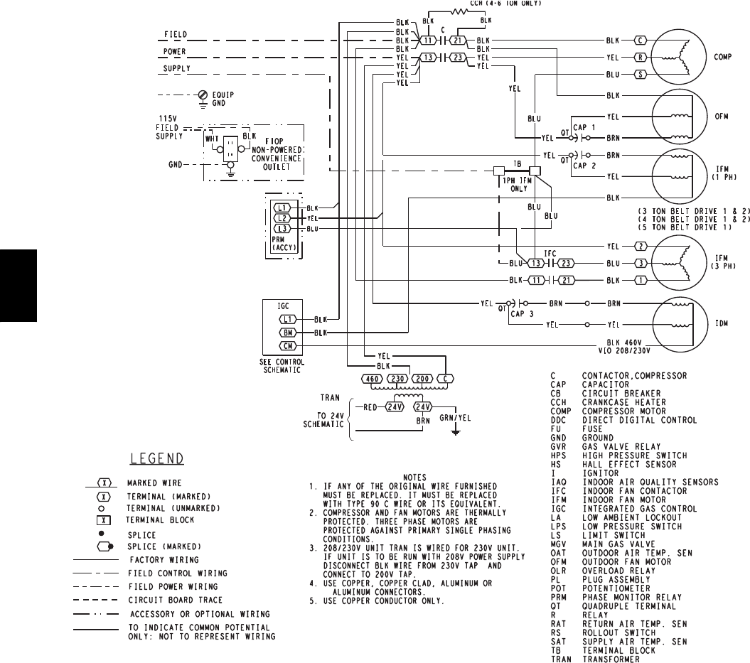
46
C08308
Fig. 52 -- 580J Typical Unit Wiring Diagram -- Power (06A, B, C 208/230--3--60)
580J
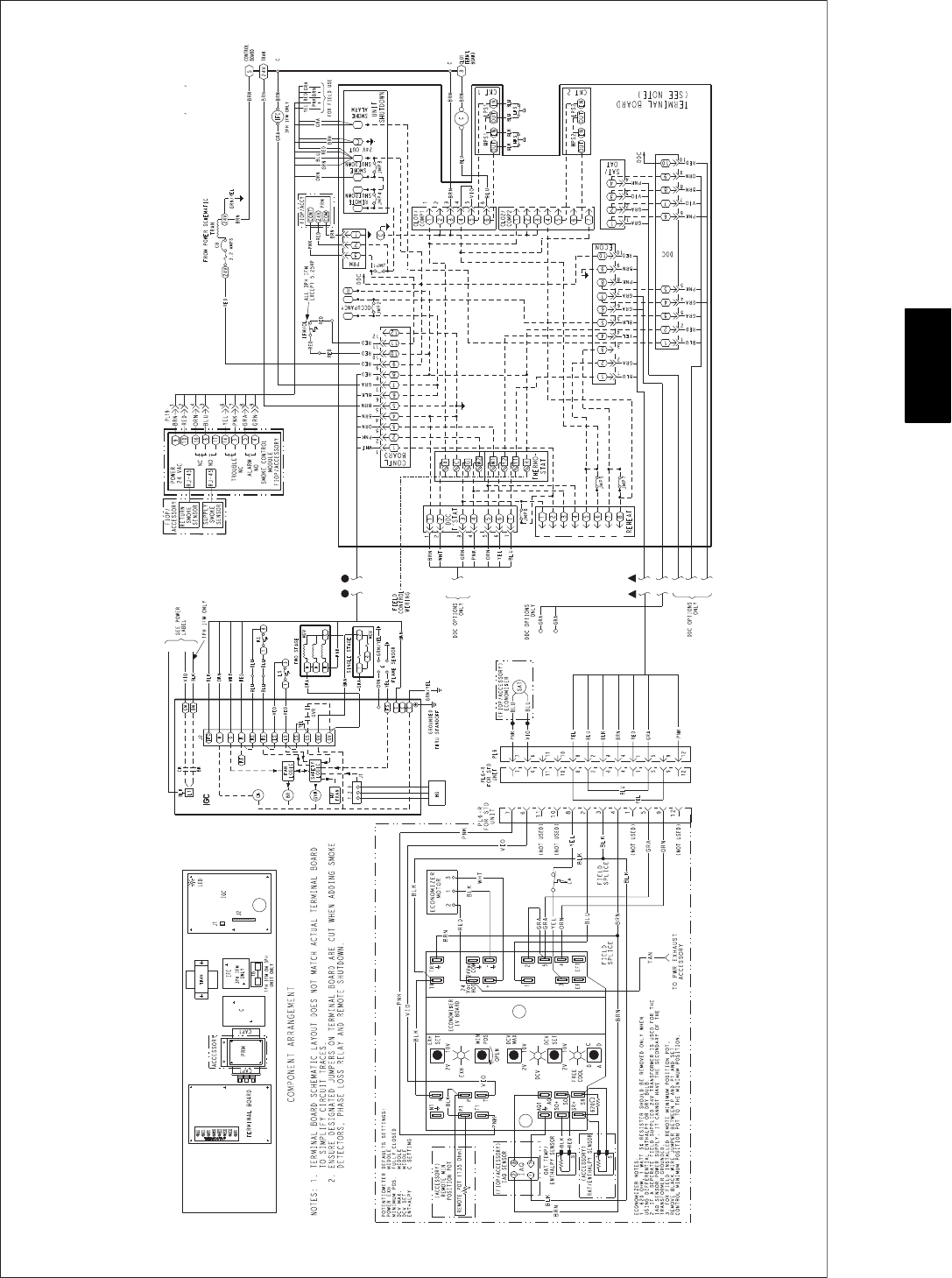
47
C08317
Fig. 53 -- 580J Unit Wiring Diagram -- Control (06A, B, C)
580J

48
APPENDIX I. MODEL NUMBER SIGNIFICANCE
Model Number Nomenclature
123456789101112131415161718
5 8 0 J E 0 6 A 0 7 2 A 1 A 0 A A --
____________ ______ ________ ______
Unit Type
580J = Std Eff gas heat RTU Design Revision
Voltage --- = First Revision
E = 4 6 0 --- 3 --- 6 0
J = 208/230--- 1--- 60 Packaging
P = 208/230--- 3--- 60 A=Standard
T = 5 7 5 --- 3 --- 6 0 B=LTL
Cooling Tons Factory Installed Options
04 = 3 Ton 08 = 7.5 Ton
05 = 4 Ton 09 = 8.5 Ton
06 = 5 Ton 12 = 10 Ton
07 = 6 Ton Outdoor Air Options
A=None
Refrig. System/Gas Heat Options B=Tempeconow/barorelief
A = Standard refrig system coil/Nat gas heat E=Tempeconow/barorelief&CO
21
B = Standard refrig system coil/Low NOxheat H = Enthalpy econo w/ baro relief
C = Standard refrig system coil/SS HX heat L = Enthalpy econo w/ baro relief & CO21
Q = Motorized 2 pos damper w/ baro relief
Heat Level
060 = 60,000 Indoor Fan Options
072 = 72,000 1 = Standard static option
090 = 90,000 2 = Medium static option
115 = 115,000 3 = High static option
120 = 120,000
150 = 150,000
Coil Options (Indoor Coil --- Outdoor Coil)
A = Al/Cu ---Al/Cu
B = P r e c o a t A l / C u --- A l / C u
C = E --- c o a t A l / C u --- A l / C u
D = E --- c o a t A l / C u --- E --- c o a t A l / C u
E = C u / C u --- A l/ C u
F = Cu/Cu --- Cu/Cu
M = A l / C u --- A l / C u --- L o u v e r e d h a i l g u a r d s
N = P r e c o a t A l / C u --- A l / C u --- L o u v e r e d H a i l G u a r d s
P = E c o a t A l / C u --- A l / C u --- L o u v e r e d H a i l G u a r d s
Q = E c o a t A l / C u --- E c o a t A l / C u --- L o u v e r e d H a i l G u a r d s
R = C u / C u --- A l / C u --- L o u v e r e d H a i l G u a r d s
A = C u / C u --- C u / C u --- L o u v e r e d H a i l G u a r d s 1Future availability
Serial Number Format
POSITION NUMBER 12345678910
TYPICAL 1208G12346
POSITION DESIGNATES
1--- 2 Week of manufacture (fiscal calendar
3--- 4 Year of manufacture (“08” = 2008)
5 Manufacturing location (G = ETP, Texas, USA)
6---10 Sequential number
580J
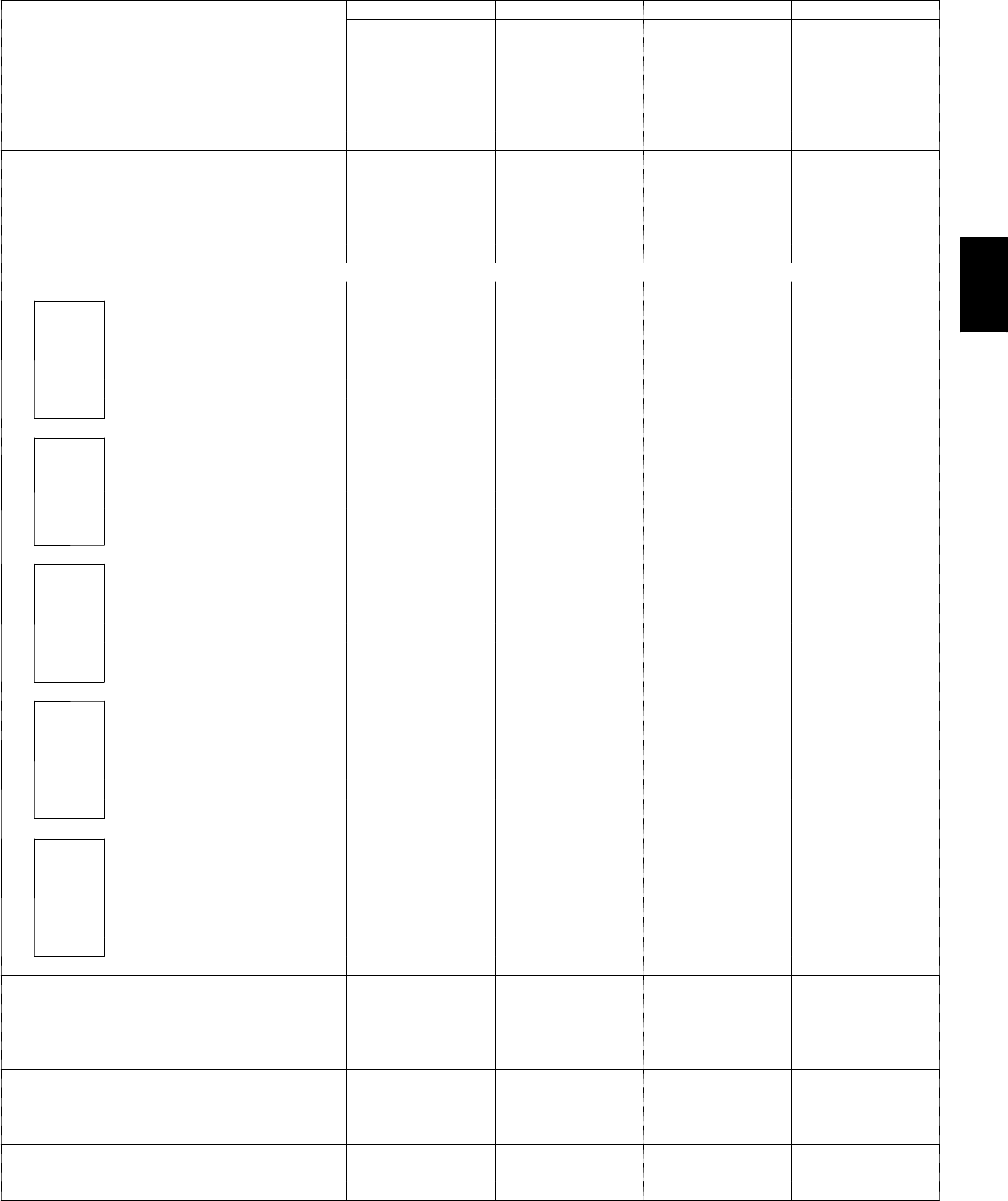
49
APPENDIX II. PHYSICAL DATA
Physical Data (Cooling) 3 -- 6 TONS -- Standard Refrigeration System
580J*04 580J*05 580J*06 580J*07
Refrigeration System
#Circuits/#Comp./Type 1/1/Scroll 1/1/Scroll 1/1/Scroll 1/1/Scroll
Puron (R--- 410A) charge A/B (lbs) 5.6 8.5 10.7 14.1
Oil A/B (oz) 25 42 42 56
Metering Device Acutrol Acutrol Acutrol Acutrol
High--- press. Trip / Reset (psig) 630 / 505 630 / 505 630 / 505 630 / 505
Low---press. Trip / Reset (psig) 54 / 117 54 / 117 54 / 117 54 / 117
Evap. Coil
Material Cu / Al Cu / Al Cu / Al Cu / Al
Coil type 3/8” RTPF 3/8” RTPF 3/8” RTPF 3/8” RTPF
Rows / FPI 2 / 15 2/15 4/15 4/15
To t al Fa c e A r e a ( f t 2)5.5 5.5 5.5 7.3
Condensate Drain Conn. Size 3/4” 3/4” 3/4” 3/4”
Evap. Fan and Motor
Standard Static
1phase
Motor Qty / Drive Type 1/Belt 1/Belt 1/Belt ---
Max BHP 1.2 1.2 1.2 ---
RPM Range 560--- 854 560--- 854 770--- 1175 ---
Motor Frame Size 48 48 48 ---
Fan Qty / Type 1/Centrifugal 1/Centrifugal 1/Centrifugal ---
Fan Diameter (in) 10 x 10 10 x 10 10 x 10 ---
Standard Static
3phase
Motor Qty / Drive Type 1/Belt 1/Belt 1/Belt 1/Belt
Max BHP 1.2 1.2 1.2 2.4
RPM Range 560--- 854 560--- 854 770---1175 1073--- 1457
Motor Frame Size 48 48 48 56
Fan Qty / Type 1/Centrifugal 1/Centrifugal 1/Centrifugal 1/Centrifugal
Fan Diameter (in) 10 x 10 10 x 10 10 x 10 10 x 10
Medium Static
1phase
Motor Qty / Drive Type 1/Belt 1/Belt 1/Belt ---
Max BHP 1.2 1.2 1.5 ---
RPM Range 770--- 1175 770--- 1175 1035--- 1466 ---
Motor Frame Size 48 56 56 ---
Fan Qty / Type 1/Centrifugal 1/Centrifugal 1/Centrifugal ---
Fan Diameter (in) 10 x 10 10 x 10 10 x 10 ---
Medium Static
3phase
Motor Qty / Drive Type 1/Belt 1/Belt 1/Belt 1/Belt
Max BHP 1.2 1.2 2.4 2.9
RPM Range 770--- 1175 770--- 1175 1035---1466 1173--- 1788
Motor Frame Size 48 48 56 56
Fan Qty / Type 1/Centrifugal 1/Centrifugal 1/Centrifugal 1/Centrifugal
Fan Diameter (in) 10 x 10 10 x 10 10 x 10 10 x 10
High Static
3phase
Motor Qty / Drive Type 1/Belt 1/Belt 1/Belt 1/Belt
Max BHP 2.4 2.4 2.9 3.7
RPM Range 1035--- 1466 1035--- 1466 1303--- 1687 1474--- 1788
Motor Frame Size 56 56 56 56
Fan Qty / Type 1/Centrifugal 1/Centrifugal 1/Centrifugal 1/Centrifugal
Fan Diameter (in) 10 x 10 10 x 10 10 x 10 10 x 10
Cond. Coil
Material Cu / Al Cu / Al Cu / Al Cu / Al
Coil type 3/8” RTPF 3/8” RTPF 3/8” RTPF 3/8” RTPF
Rows / FPI 1 / 17 2/17 2/17 2/17
To t al Fa c e A r e a ( f t 2) 14.6 12.6 16.5 21.3
Cond. fan / motor
Qty / Motor Drive Type 1/ Direct 1/ Direct 1/ Direct 1/ Direct
Motor HP / RPM 1/4 / 1100 1/4 / 1100 1/4 / 1100 1/4 / 1100
Fan diameter (in) 22 22 22 22
Filters
RAFilter#/Size(in) 2/16x25x2 2/16x25x2 2/16x25x2 4/16x16x2
OA inlet screen # / Size (in) 1/20x24x1 1/20x24x1 1/20x24x1 1/20x24x1
580J

50
APPENDIX II. PHYSICAL DATA (cont.)
Physical Data (Cooling) 7.5 -- 10 TONS -- Standard Refrigeration System
580J*08 580J*09 580J*12
Refrigeration System
#Circuits/#Comp./Type 1/1/Scroll 1/1/Scroll 1/1/Scroll
Puron (R --- 410A) charge A/B (lbs) 13.75 15.25 20.0
Oil A/B (oz) 60 85 110
Metering Device Acutrol Acutrol Acutrol
High--- press. Trip / Reset (psig) 630 / 505 630 / 505 630 / 505
Low---press. Trip / Reset (psig) 54 / 117 54 / 117 54 / 117
Evap. Coil
Material Cu / Al Cu / Al Cu / Al
Coil type 3/8” RTPF 3/8” RTPF 3/8” RTPF
Rows / FPI 3 / 15 3/15 4/15
To t al Fa c e A r e a ( f t 2)8.9 11.1 11.1
Condensate Drain Conn. Size 3/4” 3/4” 3/4”
Evap. Fan and Motor
Standard Static
3phase
Motor Qty / Drive Type 1/Belt 1/Belt 1/Belt
Max BHP 1.7 1.7 2.4
RPM Range 489--- 747 518--- 733 591--- 838
Motor Frame Size 56 56 56
Fan Qty / Type 1/Centrifugal 1/Centrifugal 1/Centrifugal
Fan Diameter (in) 15 x 15 15 x 15 15 x 15
Medium Static
3phase
Motor Qty / Drive Type 1/Belt 1/Belt 1/Belt
Max BHP 2.9 2.4 3.7
RPM Range 733--- 949 690---936 838---1084
Motor Frame Size 56 56 56
Fan Qty / Type 1/Centrifugal 1/Centrifugal 1/Centrifugal
Fan Diameter (in) 15 x 15 15 x 15 15 x 15
High Static
3phase
Motor Qty / Drive Type 1/Belt 1/Belt 1/Belt
Max BHP 5.25 3.7 5.25
RPM Range 909--- 1102 838--- 1084 1022--- 1240
Motor Frame Size 145TY 56 145TY
Fan Qty / Type 1/Centrifugal 1/Centrifugal 1/Centrifugal
Fan Diameter (in) 15 x 15 15 x 15 15 x 15
Cond. Coil
Material Cu / Al Cu / Al Cu / Al
Coil type 3/8” RTPF 3/8” RTPF 3/8” RTPF
Rows / FPI 2 / 17 2/17 2/17
To t al Fa c e A r e a ( f t 2) 20.5 21.4 25.1
Cond. fan / motor
Qty / Motor Drive Type 2 / Direct 2/Direct 2/Direct
Motor HP / RPM 1/4 / 1100 1/4 / 1100 1/4 / 1100
Fan diameter (in) 22 22 22
Filters
RAFilter#/Size(in) 4/16x20x2 4/20x20x2 4/20x20x2
OA inlet screen # / Size (in) 1/20x24x1 1/20x24x1 1/20x24x1
580J

51
APPENDIX II. PHYSICAL DATA (cont.)
Physical Data (Heating) 3 -- 6 TONS
580J*04 580J*05 580J*06 580J*07
Gas Connection
#ofGasValves 1 1 1 1
Connection size 1/2” NPT 1/2” NPT 1/2” NPT 1/2” NPT
Nat. gas supply line press (in. w.g.)/(PSIG) 5 --- 1 3 / 0 . 1 8 --- 0 . 4 7 5 --- 1 3 / 0 . 1 8 --- 0 . 4 7 5 --- 1 3 / 0 . 1 8 --- 0 . 4 7 5 --- 1 3 / 0 . 1 8 --- 0 . 4 7
LP supply line press (in. w.g.)/(PSIG) 11--- 13 / 0.40---0.47 11---13 / 0.40--- 0.47 11--- 13 / 0.40---0.47 11---13 / 0.40--- 0.47
Heat Anticipator Setting (Amps)
1st stage 0.14 0.14 0.14 0.14
2nd stage 0.14 0.14 0.14 0.14
Natural Gas Heat
LOW
#ofstages/#ofburners(total) 1/2 1/2 1/2 1/2
Rollout switch opens / Closes 195 / 115 195 / 115 195 / 115 195 / 115
Te m p e ra t u r e r i se 25 / 55 25 --- 55 25 --- 55 25 --- 55
MED
#ofstages/#ofburners(total) 1or2/3 1/3 1/3 1/3
Rollout switch opens / Closes 195 / 115 195 / 115 195 / 115 195 / 115
Te m p e ra t u r e r i se 55 / 85 35 / 65 35 / 65 35 / 65
HIGH
#ofstages/#ofburners(total) --- 1or2/3 1or2/3 1or2/3
Rollout switch opens / Closes --- 195 / 115 195 / 115 195 / 115
Te m p e ra t u r e r i se --- 50 / 80 50 / 80 50 / 80
Liquid Propane Heat
LOW
#ofstages/#ofburners(total) 1/2 1/2 1/2 1/2
Rollout switch opens / Closes 195 / 115 195 / 115 195 / 115 195 / 115
Te m p e ra t u r e r i se 25 / 55 25 --- 55 25 --- 55 25 --- 55
MED
#ofstages/#ofburners(total) 1or2/3 1or2/3 1or2/3 1or2/3
Rollout switch opens / Closes 195 / 115 195 / 115 195 / 115 195 / 115
Te m p e ra t u r e r i se 55 / 85 35 / 65 35 / 65 35 / 65
HIGH
#ofstages/#ofburners(total) --- 1or2/3 1or2/3 1or2/3
Rollout switch opens / Closes --- 195 / 115 195 / 115 195 / 115
Te m p e ra t u r e r i se --- 50 / 80 50 / 80 50 / 80
Low NOxGas Heat
LOW
#ofstages/#ofburners(total) 1/2 1/2 1/2 ---
Rollout switch opens / Closes 195 / 115 195 / 115 195 / 115 ---
Te m p e ra t u r e r i se 20 / 50 20 / 50 20 / 50 ---
MED
#ofstages/#ofburners(total) 1/3 1/3 1/3 ---
Rollout switch opens / closes 195 / 115 195 / 115 195 / 115 ---
Te m p e ra t u r e r i se 30 / 60 30 / 60 30 / 60 ---
HIGH
#ofstages/#ofburners(total) --- 1/3 1/3 ---
Rollout switch opens / Closes --- 195 / 115 195 / 115 ---
Te m p e ra t u r e r i se --- 40 / 70 40 / 70 ---
580J

52
APPENDIX II. PHYSICAL DATA (cont.)
Physical Data (Heating) 7.5 -- 10 TONS
580J*04 580J*05 580J*06 580J*07
Gas Connection
#ofGasValves 1 1 1 1
Nat. gas supply line press (in. w.g.)/(PSIG) 4 --- 1 3 / 0 . 1 8 --- 0 . 4 7 4 --- 1 3 / 0 . 1 8 --- 0 . 4 7 4 --- 1 3 / 0 . 1 8 --- 0 . 4 7 4 --- 1 3 / 0 . 1 8 --- 0 . 4 7
LP supply line press (in. w.g.)/(PSIG) 11--- 13 / 0.40---0.47 11---13 / 0.40--- 0.47 11--- 13 / 0.40---0.47 11---13 / 0.40--- 0.47
Heat Anticipator Setting (Amps)
1st stage 0.14 0.14 0.14 0.14
2nd stage 0.14 0.14 0.14 0.14
Natural Gas Heat
Connection size 1/2” NPT 1/2” NPT 1/2” NPT 1/2” NPT
LOW
#ofstages/#ofburners(total) 1/2 1/2 1/2 1/2
Rollout switch opens / Closes 195 / 115 195 / 115 195 / 115 195 / 115
Temperature rise (min/max) 25 / 55 25 --- 55 25 --- 55 25 --- 55
Connection size 1/2” NPT 1/2” NPT 1/2” NPT 1/2” NPT
MED
#ofstages/#ofburners(total) 1or2/3 1/3 1/3 1/3
Rollout switch opens / Closes 195 / 115 195 / 115 195 / 115 195 / 115
Temperature rise (min/max) 55 / 85 35 / 65 35 / 65 35 / 65
Connection size 1/2” NPT 1/2” NPT 1/2” NPT 1/2” NPT
HIGH
#ofstages/#ofburners(total) --- 1or2/3 1or2/3 1or2/3
Rollout switch opens / Closes --- 195 / 115 195 / 115 195 / 115
Temperature rise (min/max) --- 50 / 80 50 / 80 50 / 80
Liquid Propane Heat
Connection size 1/2” NPT 1/2” NPT 1/2” NPT 1/2” NPT
LOW
#ofstages/#ofburners(total) 1/2 1/2 1/2 1/2
Rollout switch opens / Closes 195 / 115 195 / 115 195 / 115 195 / 115
Temperature rise (min/max) 25 / 55 25 --- 55 25 --- 55 25 --- 55
Connection size 1/2” NPT 1/2” NPT 1/2” NPT 1/2” NPT
MED
#ofstages/#ofburners(total) 1or2/3 1or2/3 1or2/3 1or2/3
Rollout switch opens / Closes 195 / 115 195 / 115 195 / 115 195 / 115
Temperature rise (min/max) 55 / 85 35 / 65 35 / 65 35 / 65
Connection size 1/2” NPT 1/2” NPT 1/2” NPT 1/2” NPT
HIGH
#ofstages/#ofburners(total) --- 1or2/3 1or2/3 1or2/3
Rollout switch opens / Closes --- 195 / 115 195 / 115 195 / 115
Temperature rise (min/max) --- 50 / 80 50 / 80 50 / 80
Low NOxGas Heat
Connection size 1/2” NPT 1/2” NPT 1/2” NPT 1/2” NPT
LOW
#ofstages/#ofburners(total) 1/2 1/2 1/2 ---
Rollout switch opens / Closes 195 / 115 195 / 115 195 / 115 ---
Temperature rise (min/max) 20 / 50 20 / 50 20 / 50 ---
Connection size 1/2” NPT 1/2” NPT 1/2” NPT 1/2” NPT
MED
#ofstages/#ofburners(total) 1/3 1/3 1/3 ---
Rollout switch opens / closes 195 / 115 195 / 115 195 / 115 ---
Temperature rise (min/max) 30 / 60 30 / 60 30 / 60 ---
Connection size 1/2” NPT 1/2” NPT 1/2” NPT 1/2” NPT
HIGH
#ofstages/#ofburners(total) --- 1/3 1/3 ---
Rollout switch opens / Closes --- 195 / 115 195 / 115 ---
Temperature rise (min/max) --- 40 / 70 40 / 70 ---
580J

53
APPENDIX III. FAN PERFORMANCE
General Fan Performance Notes:
1. Interpolation is permissible. Do not extrapolate.
2. External static pressure is the static pressure difference between the return duct and the supply duct plus the static
pressure caused by any FIOPs or accessories.
3. Tabular data accounts for pressure loss due to clean filters, unit casing, and wet coils. Factory options and accessories
may add static pressure losses.
4. The Fan Performance tables offer motor/drive recommendations. In cases when two motor/drive combinations would
work, Bryant recommended the lower horsepower option.
5. For information on the electrical properties of Bryant’s motors, please see the Electrical information section of this
book.
580J
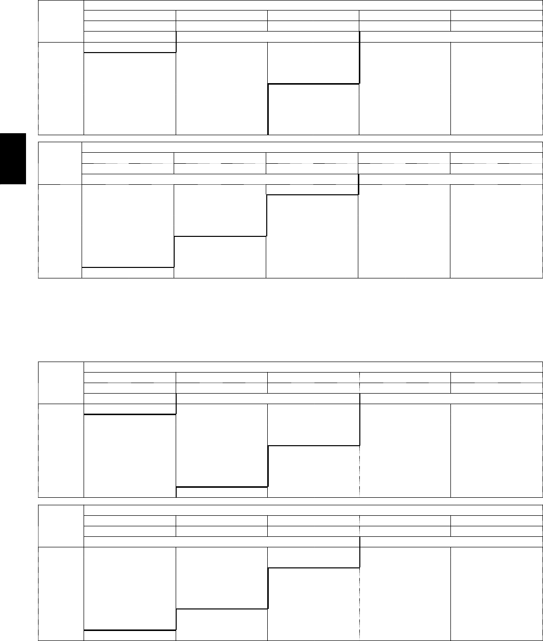
54
APPENDIX III. FAN PERFORMANCE (cont.)
580J*04 1 Phase 3 Ton Horizontal Supply
CFM
AVAILABLEEXTERNALSTATICPRESSURE(in.wg)
0.2 0.4 0.6 0.8 1.0
RPM BHP RPM BHP RPM BHP RPM BHP RPM BHP
F i e l d --- S u p p l i e d D r i v e 1Standard Static Option Medium Static Option
900 553 0.14 681 0.22 782 0.32 870 0.42 948 0.53
975 575 0.16 700 0.25 801 0.35 888 0.46 965 0.57
1050 597 0.18 720 0.28 820 0.38 906 0.49 983 0.61
1125 620 0.21 741 0.31 839 0.42 925 0.54 1001 0.66
1200 643 0.23 762 0.34 859 0.46 944 0.58 1020 0.71
1275 667 0.27 783 0.38 879 0.50 963 0.63 1038 0.76
1350 691 0.30 805 0.42 900 0.55 983 0.68 1057 0.82
1425 715 0.34 827 0.47 920 0.60 1002 0.74 1076 0.88
1500 740 0.38 849 0.52 941 0.66 1023 0.80 1096 0.95
CFM
AVAILABLEEXTERNALSTATICPRESSURE(in.wg)
1.2 1.4 1.6 1.8 2.0
RPM BHP RPM BHP RPM BHP RPM BHP RPM BHP
Medium Static Option F i e l d --- S u p p l i e d D r i v e 2
900 1019 0.64 1084 0.76 1146 0.89 1203 1.02 1258 1.16
975 1036 0.69 1101 0.81 1162 0.94 1219 1.08 --- ---
1050 1053 0.74 1118 0.86 1179 1.00 1236 1.14 --- ---
1125 1071 0.79 1135 0.92 1196 1.06 1253 1.20 --- ---
1200 1089 0.84 1153 0.98 1213 1.12 --- --- --- ---
1275 1107 0.90 1171 1.04 1231 1.19 --- --- --- ---
1350 1126 0.96 1189 1.11 --- --- --- --- --- ---
1425 1144 1.03 1208 1.18 --- --- --- --- --- ---
1500 1163 1.10 --- --- --- --- --- --- --- ---
NOTE: For more information, see General Fan Performance Notes on page 53.
Boldface indicates field--- supplied drive is required.
1. Recommend using field--- supplied fan pulley (part number KR11AG006) and belt (part number KR30AE039).
2. Recommend using field ---supplied motor pulley (part number KR11HY161) and belt (part number KR30AE035).
580J*04 1 Phase 3 Ton Vertical Supply
CFM
AVAILABLEEXTERNALSTATICPRESSURE(in.wg)
0.2 0.4 0.6 0.8 1.0
RPM BHP RPM BHP RPM BHP RPM BHP RPM BHP
F i e l d --- S u p p l i e d D r i v e 1Standard Static Option Medium Static Option
900 567 0.15 688 0.22 786 0.30 871 0.37 947 0.44
975 591 0.17 710 0.26 807 0.34 891 0.42 966 0.49
1050 615 0.20 732 0.29 828 0.38 911 0.47 985 0.55
1125 641 0.23 755 0.33 849 0.42 931 0.52 1005 0.61
1200 666 0.26 778 0.37 871 0.47 952 0.57 1025 0.67
1275 693 0.29 802 0.41 893 0.53 974 0.63 1046 0.74
1350 719 0.33 826 0.46 916 0.58 995 0.70 1067 0.81
1425 746 0.38 850 0.51 939 0.64 1017 0.76 1088 0.89
1500 773 0.42 875 0.57 963 0.70 1040 0.84 1110 0.96
CFM
AVAILABLEEXTERNALSTATICPRESSURE(in.wg)
1.2 1.4 1.6 1.8 2.0
RPM BHP RPM BHP RPM BHP RPM BHP RPM BHP
Medium Static Option F i e l d --- S u p p l i e d D r i v e 2
900 1016 0.51 1080 0.57 1139 0.64 1195 0.71 1249 0.77
975 1034 0.57 1098 0.64 1157 0.72 1213 0.79 1266 0.86
1050 1053 0.63 1116 0.71 1176 0.79 1231 0.87 1284 0.95
1125 1073 0.70 1135 0.79 1194 0.87 1250 0.96 1302 1.04
1200 1093 0.77 1155 0.87 1213 0.96 1268 1.05 1321 1.14
1275 1113 0.85 1174 0.95 1232 1.05 1287 1.15 --- ---
1350 1133 0.92 1194 1.03 1252 1.14 --- --- --- ---
1425 1154 1.01 1215 1.12 --- --- --- --- --- ---
1500 1175 1.09 --- --- --- --- --- --- --- ---
NOTE: For more information, see General Fan Performance Notes on page 53.
Boldface indicates field--- supplied drive is required.
1. Recommend using field--- supplied fan pulley (part number KR11AG006) and belt (part number KR30AE039).
2. Recommend using field ---supplied motor pulley (part number KR11HY161) and belt (part number KR30AE035).
580J
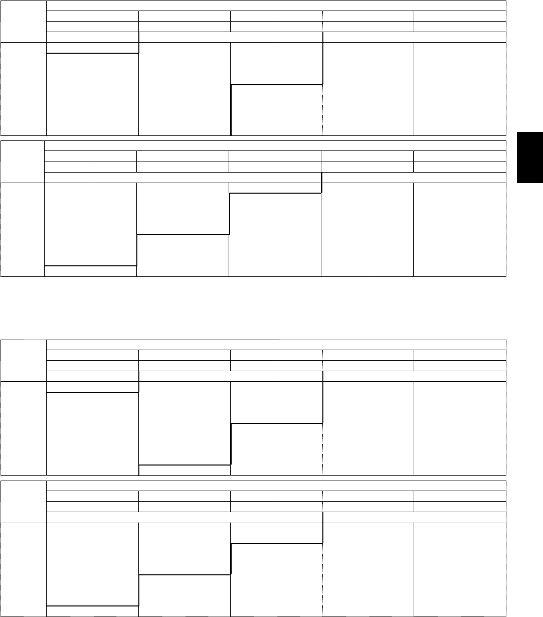
55
APPENDIX III. FAN PERFORMANCE (cont.)
580J*04 3 Phase 3 Ton Horizontal Supply
CFM
AVAILABLEEXTERNALSTATICPRESSURE(in.wg)
0.2 0.4 0.6 0.8 1.0
RPM BHP RPM BHP RPM BHP RPM BHP RPM BHP
F i e l d --- S u p p l i e d D r i v e 1Standard Static Option Medium Static Option
900 553 0.14 681 0.22 782 0.32 870 0.42 948 0.53
975 575 0.16 700 0.25 801 0.35 888 0.46 965 0.57
1050 597 0.18 720 0.28 820 0.38 906 0.49 983 0.61
1125 620 0.21 741 0.31 839 0.42 925 0.54 1001 0.66
1200 643 0.23 762 0.34 859 0.46 944 0.58 1020 0.71
1275 667 0.27 783 0.38 879 0.50 963 0.63 1038 0.76
1350 691 0.30 805 0.42 900 0.55 983 0.68 1057 0.82
1425 715 0.34 827 0.47 920 0.60 1002 0.74 1076 0.88
1500 740 0.38 849 0.52 941 0.66 1023 0.80 1096 0.95
CFM
AVAILABLEEXTERNALSTATICPRESSURE(in.wg)
1.2 1.4 1.6 1.8 2.0
RPM BHP RPM BHP RPM BHP RPM BHP RPM BHP
Medium Static Option High Static Option
900 1019 0.64 1084 0.76 1146 0.89 1203 1.02 1258 1.16
975 1036 0.69 1101 0.81 1162 0.94 1219 1.08 1274 1.22
1050 1053 0.74 1118 0.86 1179 1.00 1236 1.14 1290 1.28
1125 1071 0.79 1135 0.92 1196 1.06 1253 1.20 1307 1.35
1200 1089 0.84 1153 0.98 1213 1.12 1270 1.27 1324 1.42
1275 1107 0.90 1171 1.04 1231 1.19 1287 1.34 1341 1.50
1350 1126 0.96 1189 1.11 1249 1.26 1305 1.42 1358 1.58
1425 1144 1.03 1208 1.18 1267 1.34 1323 1.50 1376 1.66
1500 1163 1.10 1226 1.25 1285 1.41 1341 1.58 1394 1.75
NOTE: For more information, see General Fan Performance Notes on page 53.
1. Recommend using field--- supplied drive (part number KR11AG006) and belt (part number KR30AE039)
580J*04 3 Phase 3 Ton Vertical Supply
CFM
AVAILABLEEXTERNALSTATICPRESSURE(in.wg)
0.2 0.4 0.6 0.8 1.0
RPM BHP RPM BHP RPM BHP RPM BHP RPM BHP
F i e l d --- S u p p l i e d D r i v e 1Standard Static Option Medium Static Option
900 567 0.15 688 0.22 786 0.30 871 0.37 947 0.44
975 591 0.17 710 0.26 807 0.34 891 0.42 966 0.49
1050 615 0.20 732 0.29 828 0.38 911 0.47 985 0.55
1125 641 0.23 755 0.33 849 0.42 931 0.52 1005 0.61
1200 666 0.26 778 0.37 871 0.47 952 0.57 1025 0.67
1275 693 0.29 802 0.41 893 0.53 974 0.63 1046 0.74
1350 719 0.33 826 0.46 916 0.58 995 0.70 1067 0.81
1425 746 0.38 850 0.51 939 0.64 1017 0.76 1088 0.89
1500 773 0.42 875 0.57 963 0.70 1040 0.84 1110 0.96
CFM
AVAILABLEEXTERNALSTATICPRESSURE(in.wg)
1.2 1.4 1.6 1.8 2.0
RPM BHP RPM BHP RPM BHP RPM BHP RPM BHP
Medium Static Option High Static Option
900 1016 0.51 1080 0.57 1139 0.64 1195 0.71 1249 0.77
975 1034 0.57 1098 0.64 1157 0.72 1213 0.79 1266 0.86
1050 1053 0.63 1116 0.71 1176 0.79 1231 0.87 1284 0.95
1125 1073 0.70 1135 0.79 1194 0.87 1250 0.96 1302 1.04
1200 1093 0.77 1155 0.87 1213 0.96 1268 1.05 1321 1.14
1275 1113 0.85 1174 0.95 1232 1.05 1287 1.15 1339 1.25
1350 1133 0.92 1194 1.03 1252 1.14 1307 1.25 1358 1.35
1425 1154 1.01 1215 1.12 1272 1.24 1326 1.35 1378 1.46
1500 1175 1.09 1235 1.22 1292 1.34 1346 1.46 1397 1.58
NOTE: For more information, see General Fan Performance Notes on page 53.
Boldface indicates field--- supplied drive is required.
1. Recommend using field--- supplied fan pulley (part number KR11AG006) and belt (part number KR30AE039).
580J

56
APPENDIX III. FAN PERFORMANCE (cont.)
580J*05 1 Phase 4 Ton Horizontal Supply
CFM
AVAILABLEEXTERNALSTATICPRESSURE(in.wg)
0.2 0.4 0.6 0.8 1.0
RPM BHP RPM BHP RPM BHP RPM BHP RPM BHP
Standard Static Option Medium Static Option
1200 643 0.23 762 0.34 859 0.46 944 0.58 1020 0.71
1300 675 0.28 790 0.40 886 0.52 969 0.65 1044 0.78
1400 707 0.33 819 0.45 913 0.58 996 0.72 1070 0.86
1500 740 0.38 849 0.52 941 0.66 1023 0.80 1096 0.95
1600 773 0.45 879 0.59 970 0.73 1050 0.88 1123 1.04
1700 807 0.52 910 0.67 999 0.82 1078 0.98 1150 1.14
1800 841 0.59 942 0.75 1029 0.91 1106 1.08 1177 1.25
1900 875 0.68 974 0.85 1059 1.02 1135 1.19 1205 1.37
2000 910 0.77 1006 0.95 1090 1.13 1165 1.31 1234 1.49
CFM
AVAILABLEEXTERNALSTATICPRESSURE(in.wg)
1.2 1.4 1.6 1.8 2.0
RPM BHP RPM BHP RPM BHP RPM BHP RPM BHP
Medium Static Option F i e l d --- S u p p l i e d D r i v e 1
1200 1089 0.84 1153 0.98 1213 1.12 --- --- --- ---
1300 1113 0.92 1177 1.06 --- --- --- --- --- ---
1400 1138 1.01 1201 1.15 --- --- --- --- --- ---
1500 1163 1.10 --- --- --- --- --- --- --- ---
1600 1189 1.20 --- --- --- --- --- --- --- ---
1700 --- --- --- --- --- --- --- --- --- ---
1800 --- --- --- --- --- --- --- --- --- ---
1900 --- --- --- --- --- --- --- --- --- ---
2000 --- --- --- --- --- --- --- --- --- ---
NOTE: For more information, see General Fan Performance Notes on page 53.
Boldface indicates field--- supplied drive is required.
1. Recommend using field ---supplied motor pulley (part number KR11HY161) and belt (part number KR30AE035).
580J*05 1 Phase 4 Ton Vertical Supply
CFM
AVAILABLEEXTERNALSTATICPRESSURE(in.wg)
0.2 0.4 0.6 0.8 1.0
RPM BHP RPM BHP RPM BHP RPM BHP RPM BHP
Standard Static Option Medium Static Option
1200 666 0.26 778 0.37 871 0.47 952 0.57 1025 0.67
1300 701 0.31 810 0.43 901 0.54 981 0.65 1053 0.76
1400 737 0.36 842 0.49 931 0.62 1010 0.74 1081 0.86
1500 773 0.42 875 0.57 963 0.70 1040 0.84 1110 0.96
1600 810 0.49 909 0.65 994 0.79 1070 0.94 1140 1.08
1700 847 0.57 943 0.73 1027 0.89 1101 1.05 1170 1.20
1800 885 0.66 978 0.83 1060 1.00 1133 1.16 1200 1.32
1900 923 0.75 1014 0.94 1093 1.11 1165 1.29 1231 1.46
2000 962 0.85 1049 1.05 1127 1.24 1198 1.42 1263 1.61
CFM
AVAILABLEEXTERNALSTATICPRESSURE(in.wg)
1.2 1.4 1.6 1.8 2.0
RPM BHP RPM BHP RPM BHP RPM BHP RPM BHP
Medium Static Option F i e l d --- S u p p l i e d D r i v e 1
1200 1093 0.77 1155 0.87 1213 0.96 1268 1.05 1321 1.14
1300 1119 0.87 1181 0.98 1239 1.08 1294 1.18 --- ---
1400 1147 0.98 1208 1.09 --- --- --- --- --- ---
1500 1175 1.09 --- --- --- --- --- --- --- ---
1600 --- --- --- --- --- --- --- --- --- ---
1700 --- --- --- --- --- --- --- --- --- ---
1800 --- --- --- --- --- --- --- --- --- ---
1900 --- --- --- --- --- --- --- --- --- ---
2000 --- --- --- --- --- --- --- --- --- ---
NOTE: For more information, see General Fan Performance Notes on page 53.
Boldface indicates field--- supplied drive is required.
1. Recommend using field ---supplied motor pulley (part number KR11HY161) and belt (part number KR30AE035).
580J
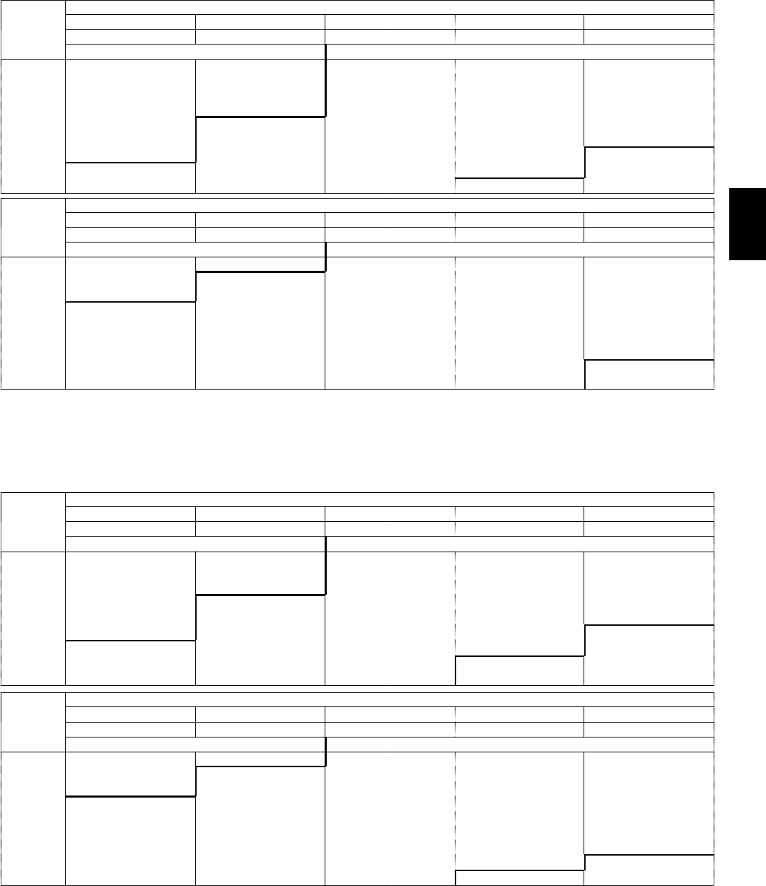
57
APPENDIX III. FAN PERFORMANCE (cont.)
580J*05 3 Phase 4 Ton Horizontal Supply
CFM
AVAILABLEEXTERNALSTATICPRESSURE(in.wg)
0.2 0.4 0.6 0.8 1.0
RPM BHP RPM BHP RPM BHP RPM BHP RPM BHP
Standard Static Option Medium Static Option
1200 643 0.23 762 0.34 859 0.46 944 0.58 1020 0.71
1300 675 0.28 790 0.40 886 0.52 969 0.65 1044 0.78
1400 707 0.33 819 0.45 913 0.58 996 0.72 1070 0.86
1500 740 0.38 849 0.52 941 0.66 1023 0.80 1096 0.95
1600 773 0.45 879 0.59 970 0.73 1050 0.88 1123 1.04
1700 807 0.52 910 0.67 999 0.82 1078 0.98 1150 1.14
1800 841 0.59 942 0.75 1029 0.91 1106 1.08 1177 1.25
1900 875 0.68 974 0.85 1059 1.02 1135 1.19 1205 1.37
2000 910 0.77 1006 0.95 1090 1.13 1165 1.31 1234 1.49
CFM
AVAILABLEEXTERNALSTATICPRESSURE(in.wg)
1.2 1.4 1.6 1.8 2.0
RPM BHP RPM BHP RPM BHP RPM BHP RPM BHP
Medium Static Option High Static Option
1200 1089 0.84 1153 0.98 1213 1.12 1270 1.27 1324 1.42
1300 1113 0.92 1177 1.06 1237 1.21 1293 1.36 1347 1.52
1400 1138 1.01 1201 1.15 1261 1.31 1317 1.47 1370 1.63
1500 1163 1.10 1226 1.25 1285 1.41 1341 1.58 1394 1.75
1600 1189 1.20 1252 1.36 1310 1.53 1365 1.70 1418 1.87
1700 1216 1.31 1277 1.48 1335 1.65 1390 1.83 1442 2.01
1800 1242 1.42 1303 1.60 1361 1.78 1415 1.96 1467 2.15
1900 1270 1.55 1330 1.73 1387 1.92 1441 2.11 1493 2.30
2000 1297 1.68 1357 1.87 1414 2.07 1467 2.26 --- ---
NOTE: For more information, see General Fan Performance Notes on page 53.
Boldface indicates field--- supplied drive is required.
1. Recommend using field --- supplied fan pulley (part no. KR11AZ506), motor pulley (part no. KR11HY181) and belt (part no. KR30AE041).
580J*05 3 Phase 4 Ton Vertical Supply
CFM
AVAILABLEEXTERNALSTATICPRESSURE(in.wg)
0.2 0.4 0.6 0.8 1.0
RPM BHP RPM BHP RPM BHP RPM BHP RPM BHP
Standard Static Option Medium Static Option
1200 666 0.26 778 0.37 871 0.47 952 0.57 1025 0.67
1300 701 0.31 810 0.43 901 0.54 981 0.65 1053 0.76
1400 737 0.36 842 0.49 931 0.62 1010 0.74 1081 0.86
1500 773 0.42 875 0.57 963 0.70 1040 0.84 1110 0.96
1600 810 0.49 909 0.65 994 0.79 1070 0.94 1140 1.08
1700 847 0.57 943 0.73 1027 0.89 1101 1.05 1170 1.20
1800 885 0.66 978 0.83 1060 1.00 1133 1.16 1200 1.32
1900 923 0.75 1014 0.94 1093 1.11 1165 1.29 1231 1.46
2000 962 0.85 1049 1.05 1127 1.24 1198 1.42 1263 1.61
CFM
AVAILABLEEXTERNALSTATICPRESSURE(in.wg)
1.2 1.4 1.6 1.8 2.0
RPM BHP RPM BHP RPM BHP RPM BHP RPM BHP
Medium Static Option High Static Option
1200 1093 0.77 1155 0.87 1213 0.96 1268 1.05 1321 1.14
1300 1119 0.87 1181 0.98 1239 1.08 1294 1.18 1346 1.28
1400 1147 0.98 1208 1.09 1265 1.21 1320 1.32 1371 1.43
1500 1175 1.09 1235 1.22 1292 1.34 1346 1.46 1397 1.58
1600 1204 1.21 1263 1.35 1320 1.48 1373 1.61 1424 1.74
1700 1233 1.34 1292 1.49 1348 1.63 1401 1.77 1451 1.91
1800 1262 1.48 1321 1.64 1376 1.79 1428 1.94 1479 2.09
1900 1293 1.63 1350 1.79 1405 1.96 1457 2.12 1506 2.28
2000 1323 1.79 1380 1.96 1434 2.13 1486 2.31 --- ---
NOTE: For more information, see General Fan Performance Notes on page 53.
Boldface indicates field--- supplied drive is required.
1. Recommend using field --- supplied fan pulley (part no. KR11AZ506), motor pulley (part no. KR11HY181) and belt (part no. KR30AE041).
580J
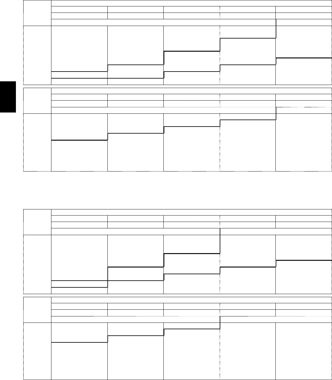
58
APPENDIX III. FAN PERFORMANCE (cont.)
580J*06 1 Phase 5 Ton Horizontal Supply
CFM
AVAILABLEEXTERNALSTATICPRESSURE(in.wg)
0.2 0.4 0.6 0.8 1.0
RPM BHP RPM BHP RPM BHP RPM BHP RPM BHP
Standard Static Option Medium Static Option
1500 800 0.39 904 0.49 999 0.60 1087 0.72 1169 0.85
1625 849 0.48 947 0.59 1038 0.70 1122 0.83 1201 0.96
1750 899 0.59 992 0.70 1078 0.82 1159 0.95 1235 1.08
1875 950 0.70 1038 0.82 1120 0.95 1198 1.08 1271 1.22
2000 1001 0.84 1085 0.96 1163 1.09 1238 1.23 1309 1.38
2125 1053 0.99 1133 1.12 1208 1.26 1280 1.40 --- ---
2250 1106 1.16 1182 1.29 1254 1.44 --- --- --- ---
2375 1159 1.34 1231 1.49 --- --- --- --- --- ---
2500 --- --- --- --- --- --- --- --- --- ---
CFM
AVAILABLEEXTERNALSTATICPRESSURE(in.wg)
1.2 1.4 1.6 1.8 2.0
RPM BHP RPM BHP RPM BHP RPM BHP RPM BHP
Medium Static Option
1500 1247 0.98 1320 1.13 1390 1.28 1457 1.44 --- ---
1625 1276 1.10 1348 1.24 1416 1.40 --- --- --- ---
1750 1308 1.22 1377 1.38 --- --- --- --- --- ---
1875 1342 1.37 --- --- --- --- --- --- --- ---
2000 --- --- --- --- --- --- --- --- --- ---
2125 --- --- --- --- --- --- --- --- --- ---
2250 --- --- --- --- --- --- --- --- --- ---
2375 --- --- --- --- --- --- --- --- --- ---
2500 --- --- --- --- --- --- --- --- --- ---
NOTE: For more information, see General Fan Performance Notes on page 53.
Boldface indicates field--- supplied drive is required.
580J*06 1 Phase 5 Ton Vertical Supply
CFM
AVAILABLEEXTERNALSTATICPRESSURE(in.wg)
0.2 0.4 0.6 0.8 1.0
RPM BHP RPM BHP RPM BHP RPM BHP RPM BHP
Standard Static Option Medium Static Option
1500 848 0.42 968 0.55 1069 0.68 1158 0.80 1238 0.94
1625 897 0.51 1013 0.65 1111 0.79 1198 0.93 1277 1.07
1750 947 0.61 1059 0.76 1155 0.91 1240 1.06 1318 1.21
1875 997 0.72 1105 0.89 1199 1.05 1283 1.21 1359 1.37
2000 1048 0.85 1153 1.03 1244 1.20 1326 1.37 --- ---
2125 1100 1.00 1201 1.19 1290 1.37 --- --- --- ---
2250 1152 1.16 1250 1.36 --- --- --- --- --- ---
2375 1205 1.34 --- --- --- --- --- --- --- ---
2500 --- --- --- --- --- --- --- --- --- ---
CFM
AVAILABLEEXTERNALSTATICPRESSURE(in.wg)
1.2 1.4 1.6 1.8 2.0
RPM BHP RPM BHP RPM BHP RPM BHP RPM BHP
Medium Static Option F i e l d --- S u p p l i e d D r i v e 1
1500 1312 1.07 1380 1.20 1445 1.34 1506 1.48 --- ---
1625 1350 1.21 1418 1.35 1482 1.50 --- --- --- ---
1750 1390 1.36 --- --- --- --- --- --- --- ---
1875 --- --- --- --- --- --- --- --- --- ---
2000 --- --- --- --- --- --- --- --- --- ---
2125 --- --- --- --- --- --- --- --- --- ---
2250 --- --- --- --- --- --- --- --- --- ---
2375 --- --- --- --- --- --- --- --- --- ---
2500 --- --- --- --- --- --- --- --- --- ---
NOTE: For more information, see General Fan Performance Notes on page 53.
Boldface indicates field--- supplied drive is required.
1. Recommend using field ---supplied motor pulley (part number KR11HY171) and belt (part number KR30AE039).
580J
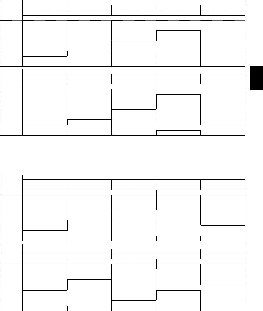
59
APPENDIX III. FAN PERFORMANCE (cont.)
580J*06 3 Phase 5 Ton Horizontal Supply
CFM
AVAILABLEEXTERNALSTATICPRESSURE(in.wg)
0.2 0.4 0.6 0.8 1.0
RPM BHP RPM BHP RPM BHP RPM BHP RPM BHP
Standard Static Option Medium Static Option
1500 800 0.39 904 0.49 999 0.60 1087 0.72 1169 0.85
1625 849 0.48 947 0.59 1038 0.70 1122 0.83 1201 0.96
1750 899 0.59 992 0.70 1078 0.82 1159 0.95 1235 1.08
1875 950 0.70 1038 0.82 1120 0.95 1198 1.08 1271 1.22
2000 1001 0.84 1085 0.96 1163 1.09 1238 1.23 1309 1.38
2125 1053 0.99 1133 1.12 1208 1.26 1280 1.40 1348 1.55
2250 1106 1.16 1182 1.29 1254 1.44 1323 1.59 1389 1.74
2375 1159 1.34 1231 1.49 1300 1.64 1367 1.80 1430 1.96
2500 1212 1.55 1281 1.70 1348 1.86 1412 2.02 1473 2.19
CFM
AVAILABLEEXTERNALSTATICPRESSURE(in.wg)
1.2 1.4 1.6 1.8 2.0
RPM BHP RPM BHP RPM BHP RPM BHP RPM BHP
Medium Static Option High Static Option
1500 1247 0.98 1320 1.13 1390 1.28 1457 1.44 1522 1.61
1625 1276 1.10 1348 1.24 1416 1.40 1481 1.56 1544 1.73
1750 1308 1.22 1377 1.38 1444 1.53 1507 1.70 1569 1.87
1875 1342 1.37 1409 1.52 1473 1.69 1536 1.86 1596 2.03
2000 1377 1.53 1442 1.69 1505 1.86 1565 2.03 1624 2.21
2125 1414 1.71 1477 1.87 1538 2.04 1597 2.22 1654 2.40
2250 1452 1.91 1514 2.08 1573 2.25 1630 2.43 1686 2.62
2375 1492 2.12 1551 2.30 1609 2.48 1665 2.66 1719 2.85
2500 1533 2.36 1591 2.54 1647 2.73 --- --- --- ---
NOTE: For more information, see General Fan Performance Notes on page 53.
Boldface indicates field--- supplied drive is required.
1. Recommend using field ---supplied fan pulley (part number KR11AZ506), motor pulley (part number KR11HY191) and belt (part number
KR30AE042).
580J*06 3 Phase 5 Ton Vertical Supply
CFM
AVAILABLEEXTERNALSTATICPRESSURE(in.wg)
0.2 0.4 0.6 0.8 1.0
RPM BHP RPM BHP RPM BHP RPM BHP RPM BHP
Standard Static Option Medium Static Option
1500 848 0.42 968 0.55 1069 0.68 1158 0.80 1238 0.94
1625 897 0.51 1013 0.65 1111 0.79 1198 0.93 1277 1.07
1750 947 0.61 1059 0.76 1155 0.91 1240 1.06 1318 1.21
1875 997 0.72 1105 0.89 1199 1.05 1283 1.21 1359 1.37
2000 1048 0.85 1153 1.03 1244 1.20 1326 1.37 1401 1.54
2125 1100 1.00 1201 1.19 1290 1.37 1370 1.55 1444 1.73
2250 1152 1.16 1250 1.36 1336 1.55 1415 1.75 1487 1.94
2375 1205 1.34 1299 1.55 1384 1.76 1460 1.96 1532 2.17
2500 1258 1.54 1349 1.76 1431 1.98 1506 2.20 1576 2.41
CFM
AVAILABLEEXTERNALSTATICPRESSURE(in.wg)
1.2 1.4 1.6 1.8 2.0
RPM BHP RPM BHP RPM BHP RPM BHP RPM BHP
Medium Static Option High Static Option
1500 1312 1.07 1380 1.20 1445 1.34 1506 1.48 1564 1.62
1625 1350 1.21 1418 1.35 1482 1.50 1542 1.64 1600 1.79
1750 1390 1.36 1457 1.51 1520 1.67 1580 1.83 1637 1.98
1875 1430 1.53 1496 1.69 1559 1.86 1618 2.02 1675 2.19
2000 1471 1.72 1536 1.89 1598 2.06 1657 2.24 1713 2.41
2125 1513 1.92 1577 2.10 1638 2.28 1696 2.47 1752 2.65
2250 1555 2.13 1619 2.33 1679 2.52 1736 2.72 --- ---
2375 1598 2.37 1661 2.57 1720 2.78 --- --- --- ---
2500 1642 2.63 1704 2.84 --- --- --- --- --- ---
NOTE: For more information, see General Fan Performance Notes on page 53.
Boldface indicates field--- supplied drive is required.
1. Recommend using field ---supplied fan pulley (part number KR11AZ506), motor pulley (part number KR11HY191) and belt (part number
KR30AE042).
580J
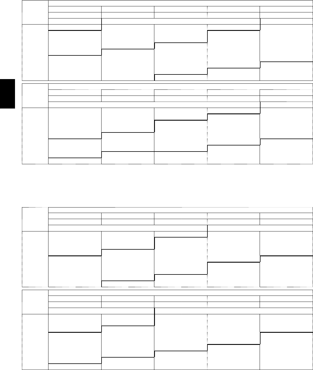
60
APPENDIX III. FAN PERFORMANCE (cont.)
580J*07 3 Phase 6 Ton Horizontal Supply
CFM
AVAILABLEEXTERNALSTATICPRESSURE(in.wg)
0.2 0.4 0.6 0.8 1.0
RPM BHP RPM BHP RPM BHP RPM BHP RPM BHP
F i e l d --- S u p p l i e d D r i v e 1Standard Static Option Medium Static Option
1800 913 0.64 1010 0.80 1098 0.98 1178 1.16 1252 1.35
1950 972 0.78 1065 0.96 1148 1.14 1226 1.34 1298 1.54
2100 1032 0.95 1120 1.14 1200 1.33 1275 1.54 1345 1.75
2250 1093 1.14 1177 1.34 1254 1.55 1325 1.76 1393 1.98
2400 1155 1.36 1234 1.57 1308 1.78 1377 2.01 1443 2.24
2550 1217 1.60 1293 1.82 1363 2.05 1430 2.28 1494 2.53
2700 1280 1.87 1352 2.10 1420 2.34 1484 2.59 1546 2.84
2850 1343 2.17 1412 2.42 1477 2.67 1539 2.93 1599 3.19
3000 1406 2.50 1472 2.76 1535 3.03 1595 3.29 1653 3.57
CFM
AVAILABLEEXTERNALSTATICPRESSURE(in.wg)
1.2 1.4 1.6 1.8 2.0
RPM BHP RPM BHP RPM BHP RPM BHP RPM BHP
Medium Static Option High Static Option
1800 1322 1.56 1388 1.77 1451 1.98 1510 2.21 1568 2.44
1950 1366 1.75 1430 1.97 1491 2.20 1550 2.43 1606 2.67
2100 1411 1.97 1473 2.20 1533 2.43 1590 2.67 1645 2.92
2250 1457 2.21 1518 2.45 1576 2.69 1632 2.94 1686 3.20
2400 1505 2.48 1564 2.73 1621 2.98 1676 3.24 1729 3.51
2550 1554 2.78 1612 3.03 1667 3.30 1721 3.57 --- ---
2700 1604 3.10 1660 3.37 1715 3.64 --- --- --- ---
2850 1656 3.46 --- --- --- --- --- --- --- ---
3000 --- --- --- --- --- --- --- --- --- ---
NOTE: For more information, see General Fan Performance Notes on page 53.
Boldface indicates field--- supplied drive is required.
1. Recommend using field ---supplied fan pulley (part number KR11AZ406), motor pulley (part number KR11HY151) and belt (part number
KR29AF035).
580J*07 3 Phase 6 Ton Vertical Supply
CFM
AVAILABLEEXTERNALSTATICPRESSURE(in.wg)
0.2 0.4 0.6 0.8 1.0
RPM BHP RPM BHP RPM BHP RPM BHP RPM BHP
Standard Static Option Medium Static Option
1800 967 0.63 1075 0.80 1170 0.97 1255 1.13 1333 1.28
1950 1029 0.77 1132 0.96 1223 1.14 1306 1.32 1382 1.49
2100 1091 0.93 1189 1.14 1278 1.33 1358 1.52 1433 1.71
2250 1154 1.11 1248 1.33 1333 1.55 1411 1.75 1484 1.96
2400 1218 1.32 1308 1.55 1390 1.78 1466 2.01 1537 2.23
2550 1283 1.55 1369 1.80 1448 2.05 1521 2.29 1590 2.52
2700 1348 1.80 1431 2.07 1507 2.33 1578 2.59 1645 2.84
2850 1414 2.09 1493 2.37 1566 2.65 1636 2.92 1701 3.19
3000 1479 2.40 1556 2.70 1627 3.00 1694 3.29 1757 3.57
CFM
AVAILABLEEXTERNALSTATICPRESSURE(in.wg)
1.2 1.4 1.6 1.8 2.0
RPM BHP RPM BHP RPM BHP RPM BHP RPM BHP
Medium Static Option High Static Option
1800 1406 1.43 1475 1.58 1540 1.72 1601 1.87 1660 2.00
1950 1454 1.65 1521 1.82 1585 1.98 1645 2.13 1703 2.29
2100 1502 1.89 1568 2.07 1631 2.25 1690 2.42 1747 2.59
2250 1552 2.15 1617 2.35 1678 2.54 1737 2.73 1793 2.92
2400 1603 2.44 1666 2.65 1727 2.86 1784 3.06 1839 3.26
2550 1655 2.75 1717 2.98 1776 3.20 1833 3.42 1887 3.64
2700 1709 3.09 1769 3.33 1827 3.57 --- --- --- ---
2850 1763 3.45 --- --- --- --- --- --- --- ---
3000 --- --- --- --- --- --- --- --- --- ---
NOTE: For more information, see General Fan Performance Notes on page 53.
Boldface indicates field--- supplied drive is required.
1. Recommend using field ---supplied fan pulley (part number KR11AZ506), motor pulley (part number KR11HY191) and belt (part number
KR29AF042).
580J
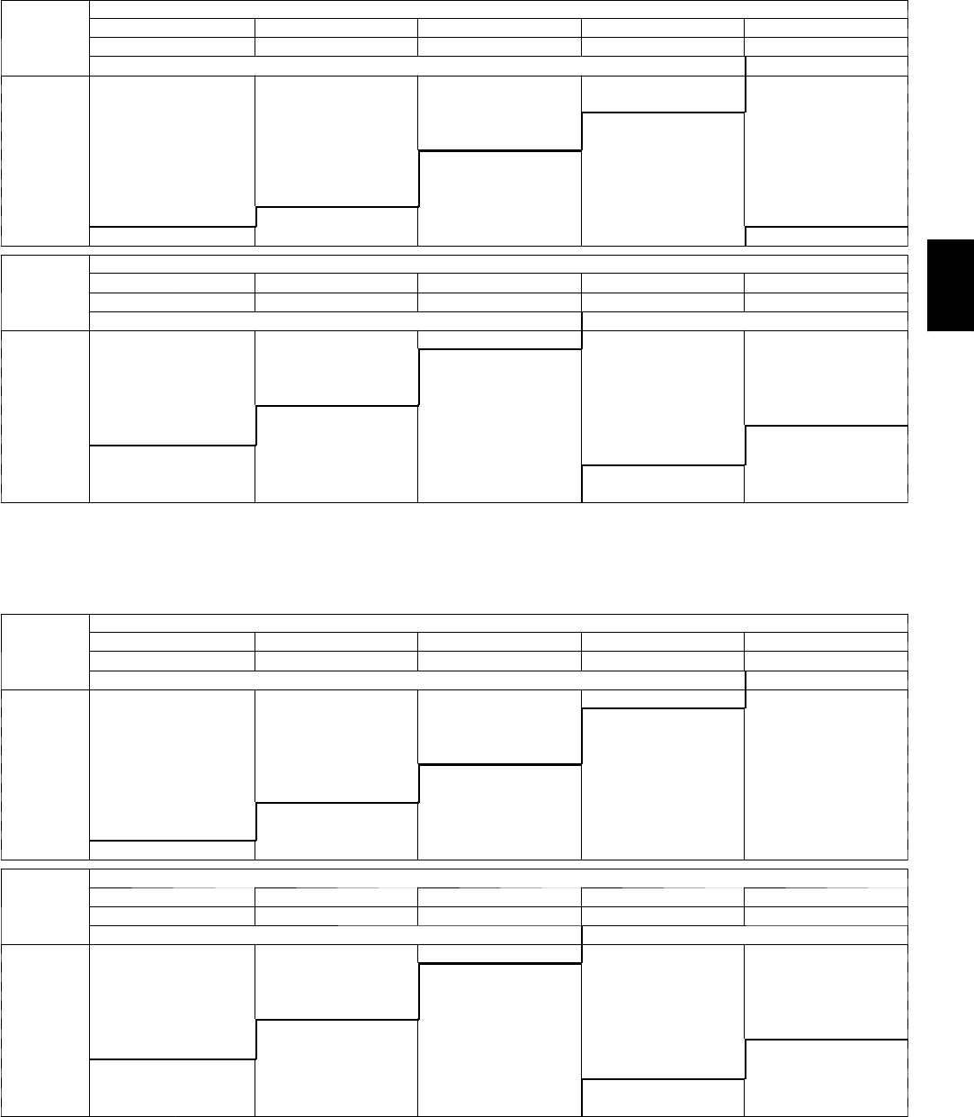
61
APPENDIX III. FAN PERFORMANCE (cont.)
580J*08 3 PHASE 7.5 TON HORIZONTAL SUPPLY
CFM
AVAILABLEEXTERNALSTATICPRESSURE(in.wg)
0.2 0.4 0.6 0.8 1.0
RPM BHP RPM BHP RPM BHP RPM BHP RPM BHP
Standard Static Option Medium Static Option
2250 505 0.52 586 0.73 657 0.97 722 1.22 782 1.50
2438 533 0.62 610 0.85 679 1.09 742 1.36 800 1.65
2625 562 0.74 635 0.98 701 1.23 762 1.51 819 1.81
2813 591 0.88 661 1.13 725 1.39 783 1.68 839 1.98
3000 621 1.03 688 1.29 749 1.57 806 1.87 859 2.18
3188 652 1.21 715 1.48 774 1.77 829 2.07 881 2.40
3375 682 1.40 743 1.68 800 1.98 853 2.30 903 2.63
3563 713 1.61 772 1.91 826 2.22 878 2.55 927 2.89
3750 745 1.85 801 2.15 853 2.48 903 2.82 951 3.18
CFM
AVAILABLEEXTERNALSTATICPRESSURE(in.wg)
1.2 1.4 1.6 1.8 2.0
RPM BHP RPM BHP RPM BHP RPM BHP RPM BHP
Medium Static Option High Static Option
2250 838 1.81 891 2.12 941 2.46 988 2.82 1033 3.19
2438 854 1.96 906 2.28 955 2.63 1001 2.99 1046 3.37
2625 872 2.12 922 2.46 970 2.81 1016 3.17 1060 3.56
2813 890 2.31 940 2.65 986 3.01 1031 3.38 1074 3.77
3000 910 2.51 958 2.86 1004 3.23 1048 3.61 1090 4.01
3188 930 2.74 977 3.10 1022 3.47 1065 3.86 1107 4.26
3375 951 2.99 997 3.35 1041 3.74 1083 4.13 1124 4.54
3563 973 3.26 1018 3.63 1061 4.02 1103 4.43 1143 4.85
3750 996 3.55 1040 3.93 1082 4.34 1122 4.75 1162 5.18
NOTE: For more information, see General Fan Performance Notes on page 53.
Boldface indicates field--- supplied drive is required.
1. Recommend using field--- supplied fan pulley (part no. KR11AZ002) and belt (part no. KR29AF054).
580J*08 3 PHASE 7.5 TON VERTICAL SUPPLY
CFM
AVAILABLEEXTERNALSTATICPRESSURE(in.wg)
0.2 0.4 0.6 0.8 1.0
RPM BHP RPM BHP RPM BHP RPM BHP RPM BHP
Standard Static Option Medium Static Option
2250 513 0.54 595 0.76 665 1.01 728 1.27 786 1.56
2438 541 0.65 620 0.89 688 1.14 750 1.42 806 1.71
2625 570 0.77 645 1.02 712 1.29 772 1.58 827 1.88
2813 600 0.91 672 1.18 736 1.46 794 1.76 848 2.07
3000 629 1.07 699 1.35 761 1.64 818 1.95 871 2.28
3188 660 1.25 726 1.54 787 1.85 842 2.17 894 2.51
3375 690 1.45 754 1.75 813 2.07 867 2.41 917 2.76
3563 721 1.67 783 1.98 840 2.32 892 2.67 941 3.03
3750 752 1.91 812 2.24 867 2.59 918 2.95 966 3.32
CFM
AVAILABLEEXTERNALSTATICPRESSURE(in.wg)
1.2 1.4 1.6 1.8 2.0
RPM BHP RPM BHP RPM BHP RPM BHP RPM BHP
Medium Static Option High Static Option
2250 839 1.86 889 2.18 935 2.52 980 2.87 1022 3.23
2438 858 2.02 907 2.35 953 2.70 997 3.06 1039 3.43
2625 878 2.20 926 2.54 972 2.89 1015 3.26 1056 3.64
2813 899 2.40 946 2.75 991 3.11 1033 3.49 1074 3.88
3000 920 2.62 966 2.98 1010 3.35 1052 3.74 1093 4.14
3188 942 2.86 987 3.23 1031 3.61 1072 4.01 1112 4.42
3375 964 3.12 1009 3.50 1052 3.89 1093 4.30 1132 4.72
3563 988 3.41 1032 3.80 1074 4.20 1114 4.61 1152 5.04
3750 1011 3.71 1054 4.11 1096 4.53 1135 4.95 --- ---
NOTE: For more information, see General Fan Performance Notes on page 53.
Boldface indicates field--- supplied drive is required.
1. Recommend using field--- supplied fan pulley (part no. KR11AZ002) and belt (part no. KR29AF054).
580J
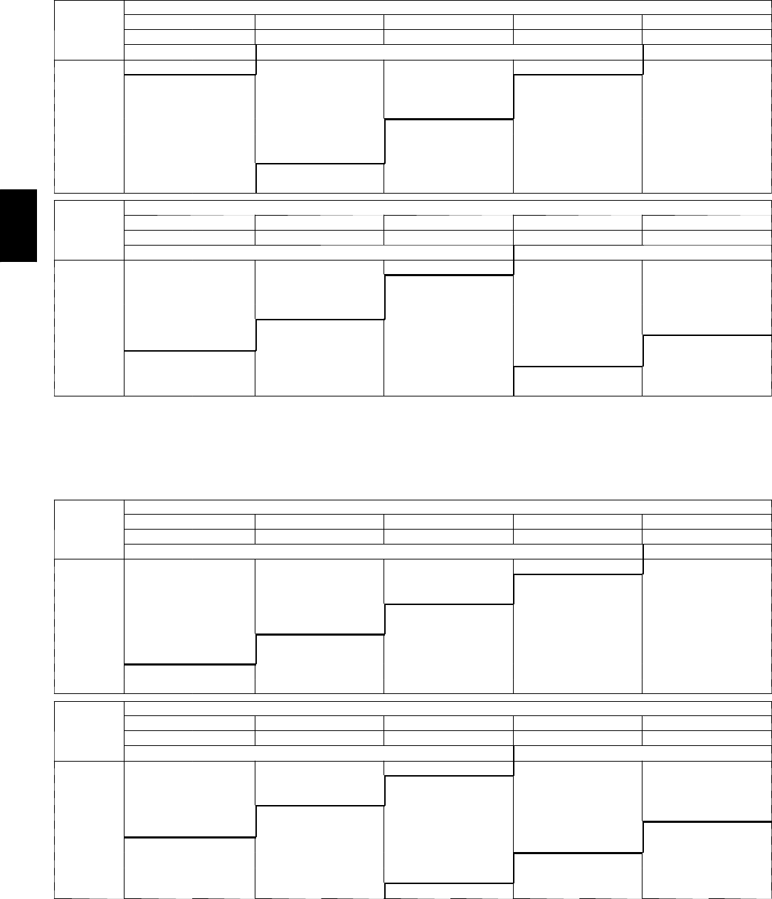
62
APPENDIX III. FAN PERFORMANCE (cont.)
580J*09 3 PHASE 8.5 TON HORIZONTAL SUPPLY
CFM
AVAILABLEEXTERNALSTATICPRESSURE(in.wg)
0.2 0.4 0.6 0.8 1.0
RPM BHP RPM BHP RPM BHP RPM BHP RPM BHP
F i e l d --- S u p p l i e d D r i v e 1Standard Static Option Medium Static Option
2550 497 0.48 579 0.61 651 0.75 717 0.90 777 1.05
2763 524 0.58 602 0.72 671 0.87 735 1.03 794 1.19
2975 551 0.70 626 0.86 693 1.01 754 1.18 812 1.35
3188 580 0.84 651 1.00 716 1.17 775 1.34 831 1.52
3400 609 1.00 677 1.17 739 1.35 797 1.53 851 1.71
3613 638 1.17 703 1.35 763 1.54 819 1.73 871 1.93
3825 668 1.37 730 1.56 788 1.76 842 1.96 893 2.16
4038 698 1.59 758 1.79 813 2.00 866 2.20 915 2.42
4250 728 1.83 786 2.04 839 2.26 890 2.47 938 2.70
CFM
AVAILABLEEXTERNALSTATICPRESSURE(in.wg)
1.2 1.4 1.6 1.8 2.0
RPM BHP RPM BHP RPM BHP RPM BHP RPM BHP
Medium Static Option High Static Option
2550 833 1.21 886 1.38 936 1.56 984 1.74 1029 1.93
2763 849 1.36 900 1.53 950 1.72 996 1.90 1041 2.10
2975 865 1.52 916 1.70 964 1.89 1010 2.09 1054 2.29
3188 883 1.70 933 1.89 980 2.09 1025 2.29 1068 2.50
3400 902 1.90 950 2.10 996 2.30 1041 2.51 1083 2.73
3613 921 2.13 969 2.33 1014 2.54 1057 2.76 1099 2.98
3825 941 2.37 988 2.58 1032 2.80 1075 3.02 1116 3.25
4038 963 2.63 1008 2.86 1051 3.08 1093 3.31 1133 3.55
4250 984 2.92 1029 3.15 1071 3.39 1112 3.63 1152 3.87
NOTE: For more information, see General Fan Performance Notes on page 53.
Boldface indicates field--- supplied drive is required.
1. Recommend using field--- supplied fan pulley (part no. KR11AK012) and belt (part no. KR29AF055).
2. Recommend using field ---supplied motor pulley (part no. KR11HY310), fan pulley (part no. KR11AZ002) and belt (part no. KR29AF054).
580J*09 3 PHASE 8.5 TON VERTICAL SUPPLY
CFM
AVAILABLEEXTERNALSTATICPRESSURE(in.wg)
0.2 0.4 0.6 0.8 1.0
RPM BHP RPM BHP RPM BHP RPM BHP RPM BHP
Standard Static Option Medium Static Option
2550 526 0.51 600 0.65 666 0.79 727 0.93 783 1.07
2763 557 0.62 627 0.77 690 0.92 749 1.08 804 1.23
2975 588 0.75 655 0.91 716 1.08 772 1.24 825 1.40
3188 621 0.90 684 1.07 743 1.25 797 1.42 848 1.60
3400 653 1.06 714 1.25 770 1.44 822 1.62 872 1.81
3613 687 1.25 744 1.45 798 1.65 849 1.84 897 2.04
3825 720 1.45 775 1.67 827 1.88 876 2.09 922 2.30
4038 754 1.69 807 1.91 856 2.13 904 2.35 949 2.57
4250 788 1.94 839 2.17 886 2.41 932 2.64 976 2.88
CFM
AVAILABLEEXTERNALSTATICPRESSURE(in.wg)
1.2 1.4 1.6 1.8 2.0
RPM BHP RPM BHP RPM BHP RPM BHP RPM BHP
Medium Static Option High Static Option
2550 836 1.20 886 1.34 934 1.48 979 1.61 1022 1.74
2763 855 1.37 904 1.52 950 1.67 995 1.82 1037 1.97
2975 875 1.56 923 1.72 968 1.88 1012 2.04 1053 2.20
3188 897 1.77 943 1.94 987 2.11 1030 2.29 1071 2.46
3400 919 1.99 964 2.18 1007 2.36 1049 2.55 1089 2.73
3613 943 2.24 986 2.44 1029 2.63 1069 2.83 1108 3.02
3825 967 2.51 1010 2.71 1051 2.92 1090 3.13 1129 3.34
4038 992 2.80 1034 3.02 1074 3.24 1112 3.46 1150 3.68
4250 1018 3.11 1058 3.34 1097 3.57 --- --- --- ---
NOTE: For more information, see General Fan Performance Notes on page 53.
Boldface indicates field--- supplied drive is required.
1. Recommend using field ---supplied motor pulley (part no. KR11HY310), fan pulley (part no. KR11AZ002) and belt (part no. KR29AF054).
580J
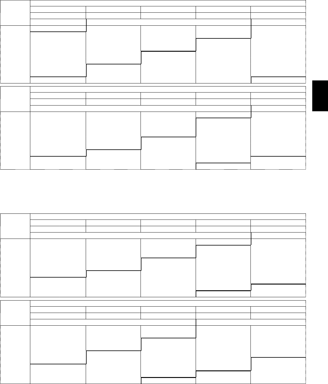
63
APPENDIX III. FAN PERFORMANCE (cont.)
580J*12 3 PHASE 10 TON HORIZONTAL SUPPLY
CFM
AVAILABLEEXTERNALSTATICPRESSURE(in.wg)
0.2 0.4 0.6 0.8 1.0
RPM BHP RPM BHP RPM BHP RPM BHP RPM BHP
F i e l d --- S u p p l i e d D r i v e 1Standard Static Option Medium Static Option
3000 579 0.70 660 0.89 732 1.09 799 1.29 860 1.50
3250 613 0.85 690 1.06 760 1.27 823 1.49 883 1.71
3500 648 1.03 721 1.25 788 1.48 850 1.71 907 1.95
3750 683 1.23 753 1.47 817 1.71 877 1.96 933 2.21
4000 719 1.45 786 1.71 848 1.97 905 2.23 959 2.50
4250 756 1.71 819 1.98 879 2.26 934 2.53 987 2.81
4500 792 1.99 853 2.28 910 2.57 964 2.87 1015 3.16
4750 830 2.31 888 2.62 943 2.92 995 3.23 1044 3.54
5000 867 2.66 923 2.98 976 3.30 1026 3.63 1074 3.95
CFM
AVAILABLEEXTERNALSTATICPRESSURE(in.wg)
1.2 1.4 1.6 1.8 2.0
RPM BHP RPM BHP RPM BHP RPM BHP RPM BHP
Medium Static Option High Static Option
3000 917 1.70 970 1.91 1021 2.13 1070 2.34 1117 2.56
3250 938 1.93 991 2.16 1041 2.38 1089 2.61 1134 2.85
3500 961 2.18 1013 2.42 1062 2.66 1108 2.91 1153 3.15
3750 985 2.46 1035 2.71 1083 2.97 1129 3.23 1173 3.49
4000 1011 2.76 1059 3.03 1106 3.30 1151 3.58 1194 3.85
4250 1037 3.09 1084 3.38 1130 3.66 1174 3.95 1216 4.24
4500 1064 3.46 1110 3.76 1155 4.06 1198 4.36 1239 4.66
4750 1091 3.85 1137 4.16 1180 4.48 1222 4.80 1263 5.12
5000 1120 4.28 1164 4.61 1207 4.94 --- --- --- ---
NOTE: For more information, see General Fan Performance Notes on page 53.
Boldface indicates field--- supplied drive is required.
1. Recommend using field--- supplied fan pulley (part no. KR11AD912) and belt (part no. KR29AF051).
2. Recommend using field ---supplied motor pulley (part no. KR11HY410).
580J*12 3 PHASE 10 TON VERTICAL SUPPLY
CFM
AVAILABLEEXTERNALSTATICPRESSURE(in.wg)
0.2 0.4 0.6 0.8 1.0
RPM BHP RPM BHP RPM BHP RPM BHP RPM BHP
Standard Static Option Medium Static Option
3000 616 0.79 689 0.97 757 1.16 821 1.36 882 1.57
3250 655 0.96 724 1.16 788 1.37 849 1.58 907 1.80
3500 695 1.17 760 1.38 821 1.60 879 1.83 934 2.06
3750 736 1.41 797 1.63 855 1.86 910 2.10 963 2.35
4000 777 1.68 834 1.91 889 2.16 942 2.41 993 2.67
4250 818 1.98 873 2.23 925 2.49 976 2.75 1025 3.02
4500 860 2.32 912 2.58 962 2.85 1010 3.13 1057 3.41
4750 902 2.69 951 2.97 999 3.26 1046 3.55 1091 3.84
5000 944 3.11 991 3.40 1037 3.70 1082 4.00 1125 4.31
CFM
AVAILABLEEXTERNALSTATICPRESSURE(in.wg)
1.2 1.4 1.6 1.8 2.0
RPM BHP RPM BHP RPM BHP RPM BHP RPM BHP
Medium Static Option High Static Option
3000 939 1.79 994 2.01 1047 2.24 1098 2.47 1147 2.71
3250 962 2.03 1015 2.26 1066 2.50 1115 2.75 1163 3.00
3500 987 2.30 1038 2.54 1088 2.80 1135 3.05 1181 3.32
3750 1014 2.60 1063 2.86 1111 3.12 1157 3.39 1202 3.66
4000 1042 2.93 1090 3.20 1136 3.48 1180 3.76 1224 4.04
4250 1072 3.30 1118 3.58 1162 3.87 1205 4.16 1247 4.46
4500 1103 3.70 1147 4.00 1190 4.29 1232 4.60 1273 4.91
4750 1135 4.14 1177 4.45 1219 4.76 1259 5.08 --- ---
5000 1167 4.63 1209 4.95 --- --- --- --- --- ---
NOTE: For more information, see General Fan Performance Notes on page 53.
Boldface indicates field--- supplied drive is required.
1. Recommend using field ---supplied motor pulley (part no. KR11HY410).
580J

64
APPENDIX III. FAN PERFORMANCE (cont.)
Pulley Adjustment
UNIT MOTOR/DRIVE
COMBO
MOTOR PULLEY TURNS OPEN
0.0 0.5 1.0 1.5 2.0 2.5 3.0 3.5 4.0 4.5 5.0
04
1phase
Standard Static 854 825 795 766 736 707 678 648 619 589 560
Medium Static 1175 1135 1094 1054 1013 973 932 892 851 811 770
High Static --- --- --- --- --- --- --- --- --- --- ---
3phase
Standard Static 854 825 795 766 736 707 678 648 619 589 560
Medium Static 1175 1135 1094 1054 1013 973 932 892 851 811 770
High Static 1466 1423 1380 1337 1294 1251 1207 1164 1121 1078 1035
05
1phase
Standard Static 854 825 795 766 736 707 678 648 619 589 560
Medium Static 1175 1135 1094 1054 1013 973 932 892 851 811 770
High Static --- --- --- --- --- --- --- --- --- --- ---
3phase
Standard Static 854 825 795 766 736 707 678 648 619 589 560
Medium Static 1175 1135 1094 1054 1013 973 932 892 851 811 770
High Static 1466 1423 1380 1337 1294 1251 1207 1164 1121 1078 1035
06
1phase
Standard Static 1175 1135 1094 1054 1013 973 932 892 851 811 770
Medium Static 1466 1423 1380 1337 1294 1251 1207 1164 1121 1078 1035
High Static --- --- --- --- --- --- --- --- --- --- ---
3phase
Standard Static 1175 1135 1094 1054 1013 973 932 892 851 811 770
Medium Static 1466 1423 1380 1337 1294 1251 1207 1164 1121 1078 1035
High Static 1687 1649 1610 1572 1533 1495 1457 1418 1380 1341 1303
07
3phase
Standard Static 1457 1419 1380 1342 1303 1265 1227 1188 1150 1111 1073
Medium Static 1518 1484 1449 1415 1380 1346 1311 1277 1242 1208 1173
High Static 1788 1757 1725 1694 1662 1631 1600 1568 1537 1505 1474
08
3phase
Standard Static 747 721 695 670 644 618 592 566 541 515 489
Medium Static 949 927 906 884 863 841 819 798 776 755 733
High Static 1102 1083 1063 1044 1025 1006 986 967 948 928 909
09
3phase
Standard Static 733 712 690 669 647 626 604 583 561 540 518
Medium Static 936 911 887 862 838 813 788 764 739 715 690
High Static 1084 1059 1035 1010 986 961 936 912 887 863 838
12
3phase
Standard Static 838 813 789 764 739 715 690 665 640 616 591
Medium Static 1084 1059 1035 1010 986 961 936 912 887 863 838
High Static 1240 1218 1196 1175 1153 1131 1109 1087 1066 1044 1022
NOTE: Do not adjust pulley further than 5 turns open.
--- F a c t o r y s e t t i n g s
580J

65
APPENDIX IV. ELECTRICAL DATA
580J*04 3 TONS
V --- P h --- H z
VOLTAGE COMP (ea) OFM (ea) IFM
RANGE RLA LRA WATTS FLA TYPE Max
WATTS
Max
AMP Draw EFF at Full Load FLA
MIN MAX
2 0 8 --- 1 --- 6 0 187 253 16.6 79 325 1.5 Std Static 1000 5.1 70% 4.9
Med Static 1000 5.1 70% 4.9
2 3 0 --- 1 --- 6 0 187 253 16.6 79 325 1.5 Std Static 1000 5.1 70% 4.9
Med Static 1000 5.1 70% 4.9
2 0 8 --- 3 --- 6 0 187 253 10.4 73 325 1.5
Std Static 1000 5.1 70% 4.9
Med Static 1000 5.1 70% 4.9
High Static 2120 5.5 80% 5.2
2 3 0 --- 3 --- 6 0 187 253 10.4 73 325 1.5
Std Static 1000 5.1 70% 4.9
Med Static 1000 5.1 70% 4.9
High Static 2120 5.5 80% 5.2
4 6 0 --- 3 --- 6 0 414 506 5.8 38 325 0.8
Std Static 1000 2.2 70% 2.1
Med Static 2120 2.7 80% 2.6
High Static 2120 2.7 80% 2.6
5 7 5 --- 3 --- 6 0 518 633 3.8 37 325 0.6
Std Static 1000 2.0 71% 1.9
Med Static 2120 2.1 80% 2.0
High Static 2120 2.1 80% 2.0
580J*05 4 TONS
V --- P h --- H z
VOLTAGE COMP (ea) OFM (ea) IFM
RANGE RLA LRA WATTS FLA TYPE Max
WATTS
Max
AMP Draw EFF at Full Load FLA
MIN MAX
2 0 8 --- 1 --- 6 0 187 253 21.8 117 325 1.5 Std Static 1000 5.1 70% 4.9
Med Static 1850 7.4 78% 7.0
2 3 0 --- 1 --- 6 0 187 253 21.8 117 325 1.5 Std Static 1000 5.1 70% 4.9
Med Static 1850 7.4 78% 7.0
2 0 8 --- 3 --- 6 0 187 253 13.7 83 325 1.5
Std Static 1000 5.1 70% 4.9
Med Static 1000 5.1 70% 4.9
High Static 2120 5.5 80% 5.2
2 3 0 --- 3 --- 6 0 187 253 13.7 83 325 1.5
Std Static 1000 5.1 70% 4.9
Med Static 1000 5.1 70% 4.9
High Static 2120 5.5 80% 5.2
4 6 0 --- 3 --- 6 0 414 506 6.2 41 325 0.8
Std Static 1000 2.2 70% 2.1
Med Static 2120 2.7 80% 2.6
High Static 2120 2.7 80% 2.6
5 7 5 --- 3 --- 6 0 518 633 4.8 37 325 0.6
Std Static 1000 2.0 71% 1.9
Med Static 2120 2.1 80% 2.0
High Static 2120 2.1 80% 2.0
580J

66
APPENDIX IV. ELECTRICAL DATA (cont.)
580J*06 5 TONS
V --- P h --- H z
VOLTAGE COMP (ea) OFM (ea) IFM
RANGE RLA LRA WATTS FLA TYPE Max
WATTS
Max
AMP Draw EFF at Full Load FLA
MIN MAX
2 0 8 --- 1 --- 6 0 187 253 26.2 134 325 1.5 Std Static 1000 5.1 70% 4.9
Med Static 1850 7.4 78% 7.0
2 3 0 --- 1 --- 6 0 187 253 26.2 134 325 1.5 Std Static 1000 5.1 70% 4.9
Med Static 1850 7.4 78% 7.0
2 0 8 --- 3 --- 6 0 187 253 15.6 110 325 1.5
Std Static 1000 5.1 70% 4.9
Med Static 2120 5.5 80% 5.2
High Static 2615 7.9 81% 7.5
2 3 0 --- 3 --- 6 0 187 253 15.6 110 325 1.5
Std Static 1000 5.1 70% 4.9
Med Static 2120 5.5 80% 5.2
High Static 2615 7.9 81% 7.5
4 6 0 --- 3 --- 6 0 414 506 7.7 52 325 0.8
Std Static 2120 2.7 80% 2.6
Med Static 2615 3.6 81% 3.4
High Static 2615 3.6 81% 3.4
5 7 5 --- 3 --- 6 0 518 633 5.8 39 325 0.6
Std Static 2120 2.1 80% 2.0
Med Static 3775 2.9 81% 2.8
High Static 3775 2.9 81% 2.8
580J*07 6 TONS
V --- P h --- H z
VOLTAGE COMP (ea) OFM (ea) IFM
RANGE RLA LRA WATTS FLA TYPE Max
WATTS
Max
AMP Draw EFF at Full Load FLA
MIN MAX
2 0 8 --- 3 --- 6 0 187 253 19.0 12 325 1.5
Std Static 2120 5.5 80% 5.2
Med Static 2615 7.9 81% 7.5
High Static 3775 10.7 81% 10.2
2 3 0 --- 3 --- 6 0 187 253 19.0 12 325 1.5
Std Static 2120 5.5 80% 5.2
Med Static 2615 7.9 81% 7.5
High Static 3775 10.7 81% 10.2
4 6 0 --- 3 --- 6 0 414 506 9.7 62 325 0.8
Std Static 2120 2.7 80% 2.6
Med Static 2615 3.6 81% 3.4
High Static 3775 5.0 81% 4.8
5 7 5 --- 3 --- 6 0 518 633 7.4 50 325 0.6
Std Static 2120 2.1 80% 2.0
Med Static 3775 2.9 81% 2.8
High Static 3775 2.9 81% 2.8
580J

67
APPENDIX IV. ELECTRICAL DATA (cont.)
580J*08 7.5 TONS
V --- P h --- H z
VOLTAGE
RANGE
COMP (ea) OFM (ea) IFM
RLA LRA WATTS FLA TYPE Max
WATTS
Max
AMP Draw
EFF at
Full
Load
FLA
MIN MAX
2 0 8 --- 3 --- 6 0 187 253 25.0 164 325 1.5
Std Static 1448 5.5 80% 5.2
Med Static 2278 7.9 81% 7.5
High Static 4559 15.8 81% 15.0
2 3 0 --- 3 --- 6 0 187 253 25.0 164 325 1.5
Std Static 1448 5.5 80% 5.2
Med Static 2278 7.9 81% 7.5
High Static 4559 15.8 81% 15.0
4 6 0 --- 3 --- 6 0 414 506 12.2 100 325 0.8
Std Static 1448 2.7 80% 2.6
Med Static 2278 3.6 81% 3.4
High Static 4559 7.8 81% 7.4
5 7 5 --- 3 --- 6 0 518 633 9.0 78 325 0.6
Std Static 1379 2.5 80% 2.4
Med Static 3775 2.9 81% 2.8
High Static 1870 5.9 81% 5.6
580J*09 8.5 TONS
V --- P h --- H z
VOLTAGE
RANGE
COMP (ea) OFM (ea) IFM
RLA LRA WATTS FLA TYPE Max
WATTS
Max
AMP Draw EFF at Full Load FLA
MIN MAX
2 0 8 --- 3 --- 6 0 187 253 29.5 195 325 1.5
Std Static 1448 5.5 80% 5.2
Med Static 2120 5.5 80% 5.2
High Static 2694 10.5 80% 10.0
2 3 0 --- 3 --- 6 0 187 253 29.5 195 325 1.5
Std Static 1448 5.5 80% 5.2
Med Static 2120 5.5 80% 5.2
High Static 2694 10.5 80% 10.0
4 6 0 --- 3 --- 6 0 414 506 14.7 95 325 0.8
Std Static 1448 2.7 80% 2.6
Med Static 2120 2.7 80% 2.6
High Static 2694 4.6 80% 4.4
5 7 5 --- 3 --- 6 0 518 633 12.2 80 325 0.6
Std Static 1379 2.5 80% 2.4
Med Static 1390 2.1 80% 2.0
High Static 3775 2.9 81% 2.8
580J*12 10 TONS
V --- P h --- H z
VOLTAGE
RANGE
COMP (ea) OFM (ea) IFM
RLA LRA WATTS FLA TYPE Max
WATTS
Max
AMP Draw EFF at Full Load FLA
MIN MAX
2 0 8 --- 3 --- 6 0 187 253 30.1 225 325 1.5
Std Static 2120 5.5 80% 5.2
Med Static 3775 10.5 81% 10.0
High Static 4559 15.8 81% 15.0
2 3 0 --- 3 --- 6 0 187 253 30.1 225 325 1.5
Std Static 2120 5.5 80% 5.2
Med Static 3775 10.5 81% 10.0
High Static 4559 15.8 81% 15.0
4 6 0 --- 3 --- 6 0 414 506 16.7 114 325 0.8
Std Static 2120 2.7 80% 2.6
Med Static 3775 4.6 81% 4.4
High Static 4559 7.8 81% 7.4
5 7 5 --- 3 --- 6 0 518 633 12.2 80 325 0.6
Std Static 1390 2.1 80% 2.0
Med Static 3775 2.9 81% 2.8
High Static 1870 5.9 81% 5.6
580J

68
APPENDIX IV. ELECTRICAL DATA (cont.)
MCA/MOCP Determination No C.O. or UNPWRD C.O.
UNIT
NOM.
V --- P h --- H z
IFM
TYPE
COMBUSTION
FAN MOTOR
FLA
POWER
EXHAUST
FLA
NO C.O. or UNPWRD C.O.
NO P.E. w/ P.E. (pwrd fr/ unit)
MCA MOCP DISC. SIZE MCA MOCP DISC. SIZE
FLA LRA FLA LRA
580J*04
208/230---1---60 STD 0.48 1.9 27.2 40.0 26 95 29.1 45.0 29 97
MED 27.2 40.0 26 95 29.1 45.0 29 97
208/230---3---60
STD
0.48 1.9
19.4 25.0 19 89 21.3 30.0 22 91
MED 19.4 25.0 19 89 21.3 30.0 22 91
HIGH 19.7 30.0 20 107 21.6 30.0 22 109
4 6 0 --- 3 --- 6 0
STD
0.25 1.0
10.2 15.0 10 46 11.2 15.0 11 47
MED 10.2 15.0 10 46 11.2 15.0 11 47
HIGH 10.7 15.0 11 55 11.7 15.0 12 56
5 7 5 --- 3 --- 6 0
STD
0.24 1.9
7.3 15.0 744 9.2 15.0 946
MED 7.3 15.0 744 9.2 15.0 946
HIGH 7.4 15.0 750 9.3 15.0 10 52
580J*05
208/230---1---60 STD 0.48 1.9 33.7 50.0 32 133 35.6 50.0 35 135
MED 33.7 50.0 32 133 35.6 50.0 35 135
208/230---3---60
STD
0.48 1.9
23.5 30.0 23 99 25.4 30.0 25 101
MED 23.5 30.0 23 99 25.4 30.0 25 101
HIGH 23.8 30.0 23 117 25.7 30.0 25 119
4 6 0 --- 3 --- 6 0
STD
0.25 1.0
10.7 15.0 10 49 11.7 15.0 12 50
MED 10.7 15.0 10 49 11.7 15.0 12 50
HIGH 11.2 15.0 11 58 12.2 15.0 12 59
5 7 5 --- 3 --- 6 0
STD
0.24 1.9
8.5 15.0 844 10.4 15.0 11 46
MED 8.5 15.0 844 10.4 15.0 11 46
HIGH 8.6 15.0 950 10.5 15.0 11 52
580J*06
208/230---1---60 STD 0.48 1.9 39.2 60.0 37 150 41.1 60.0 40 152
MED 41.3 60.0 40 175 43.2 60.0 42 177
208/230---3---60
STD
0.48 1.9
25.9 30.0 25 126 27.8 40.0 27 128
MED 26.2 40.0 26 144 28.1 40.0 28 146
HIGH 28.5 40.0 29 170 30.4 45.0 30 172
4 6 0 --- 3 --- 6 0
STD
0.25 1.0
12.5 20.0 12 60 13.5 20.0 13 61
MED 13.0 20.0 13 69 14.0 20.0 14 70
HIGH 13.8 20.0 14 82 14.8 20.0 15 83
5 7 5 --- 3 --- 6 0
STD
0.24 1.9
9.8 15.0 10 46 11.7 15.0 12 48
MED 9.9 15.0 10 52 11.8 15.0 13 54
HIGH 10.7 15.0 11 63 12.6 15.0 13 65
580J*07
208/230---3---60
STD
0.48 1.9
30.5 45.0 30 157 32.4 50.0 32 159
MED 32.8 50.0 32 183 34.7 50.0 34 185
HIGH 32.8 50.0 32 183 34.7 50.0 34 185
4 6 0 --- 3 --- 6 0
STD
0.25 1.0
15.5 25.0 15 79 16.5 25.0 16 80
MED 16.3 25.0 16 92 17.3 25.0 17 93
HIGH 17.3 25.0 17 101 18.3 25.0 18 102
5 7 5 --- 3 --- 6 0
STD
0.24 1.9
11.9 15.0 12 63 13.8 20.0 14 65
MED 12.7 20.0 12 74 14.6 20.0 15 76
HIGH 12.7 20.0 12 74 14.6 20.0 15 76
See notes on next page.
580J
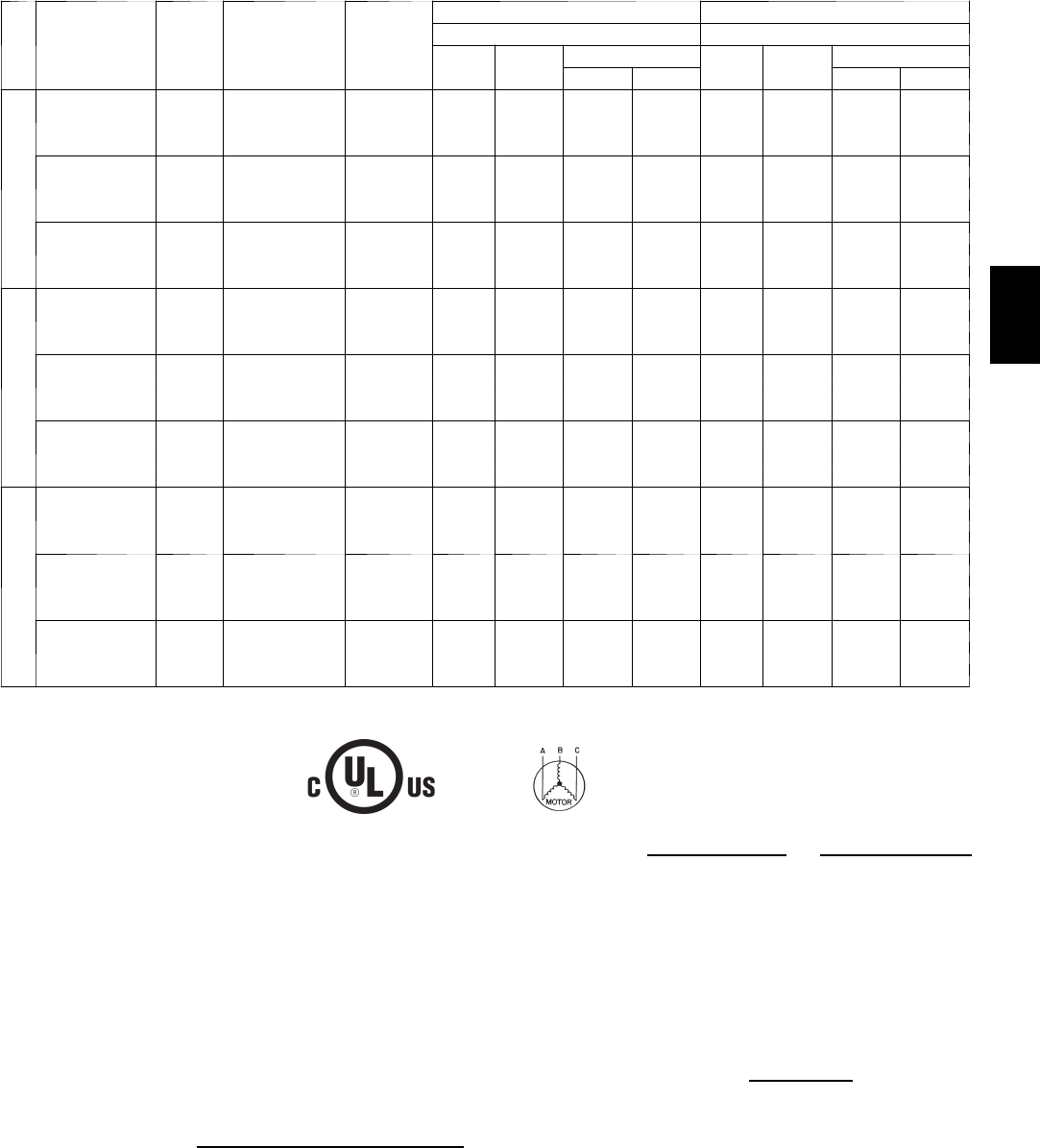
69
APPENDIX IV. ELECTRICAL DATA (cont.)
MCA/MOCP DETERMINATION NO C.O. OR UNPWRD C.O.
UNIT
NOM.
V --- P h --- H z
IFM
TYPE
COMBUSTION
FAN MOTOR
FLA
POWER
EXHAUST
FLA
NO C.O. or UNPWRD C.O. NO C.O. or UNPWRD C.O.
NO P.E. w/ P.E. (pwrd fr/ unit)
MCA MOCP DISC. SIZE MCA MOCP DISC. SIZE
FLA LRA FLA LRA
580J*08
208/230---3---60
STD
0.48 3.8
39.5 60 38 191 43.3 60 43 195
MED 41.8 60 41 228 45.6 60 45 232
HIGH 49.3 60 49 254 53.1 60 54 258
4 6 0 --- 3 --- 6 0
STD
0.25 1.8
19.5 30 19 113 21.3 30 21 115
MED 20.3 30 20 132 22.1 30 22 134
HIGH 24.3 30 24 145 26.1 30 26 147
5 7 5 --- 3 --- 6 0
STD
0.24 3.8
14.9 20 14 89 18.7 25 19 93
MED 15.3 20 15 104 19.1 25 19 108
HIGH 18.1 25 18 118 21.9 30 23 122
580J*09
208/230---3---60
STD
0.48 3.8
45.1 60 43 222 48.9 60 48 226
MED 45.1 60 43 233 48.9 60 48 237
HIGH 49.9 60 49 276 53.7 80 53 280
4 6 0 --- 3 --- 6 0
STD
0.25 1.8
22.6 30 22 108 24.4 30 24 110
MED 22.6 30 22 114 24.4 30 24 116
HIGH 24.4 30 24 136 26.2 30 26 138
5 7 5 --- 3 --- 6 0
STD
0.24 3.8
18.9 30 18 91 22.7 30 23 95
MED 18.5 30 18 95 22.3 30 22 99
HIGH 19.3 30 19 106 23.1 30 23 110
580J*12
208/230---3---60
STD
0.48 3.8
45.8 60 44 263 49.6 60 48 267
MED 50.6 60 50 306 54.4 80 54 310
HIGH 55.6 80 55 315 59.4 80 60 319
4 6 0 --- 3 --- 6 0
STD
0.25 1.8
25.1 30 24 133 26.9 40 26 135
MED 26.9 40 26 155 28.7 45 28 157
HIGH 29.9 45 30 159 31.7 45 32 161
5 7 5 --- 3 --- 6 0
STD
0.24 3.8
18.5 30 18 95 22.3 30 22 99
MED 19.3 30 19 106 23.1 30 23 110
HIGH 22.1 30 22 120 25.9 30 26 124
1Fuse or breaker
LEGEND:
CO --- Convenient outlet
DISC --- Disconnect
FLA --- Full load amps
IFM --- Indoor fan motor
LRA --- Locked rotor amps
MCA --- Minimum circuit amps
MOCP --- Maximum over current protection
P E --- P o w e r e x h a u s t
UNPWRD CO --- Unpowered convenient outlet
NOTES:
1. In compliance with NEC requirements for multimotor and
combination load equipment (refer to NEC Articles 430 and
440), the overcurrent protective device for the unit shall be
fuse or HACR breaker. Canadian units may be fuse or circuit
breaker.
2. Unbalanced 3-Phase Supply Voltage
Never operate a motor where a phase imbalance in supply
voltage is greater than 2%. Use the following formula to de-
termine the percentage of voltage imbalance.
% Voltage Imbalance = 100 x
max voltage deviation from average voltage
average voltage
Example: Supply voltage is 230-3-60
AB = 224 v
BC = 231 v
AC = 226 v
Average Voltage =
(224 + 231 + 226)
=
681
33
= 227
Determine maximum deviation from average voltage.
(AB) 227 – 224 = 3 v
(BC) 231 – 227 = 4 v
(AC) 227 – 226 = 1 v
Maximum deviation is 4 v.
Determine percent of voltage imbalance.
% Voltage Imbalance = 100 x
4
227
= 1.76%
This amount of phase imbalance is satisfactory as it is below the
maximum allowable 2%.
IMPORTANT: If the supply voltage phase imbalance is more than
2%, contact your local electric utility company immediately.
580J

70
APPENDIX V. WIRING DIAGRAM LIST
Wiring Diagrams
580J
SIZE VOLTAGE CONTROL POWER
04
208/230---1---60 48TM500213.05 48TM500749.08
208/230---3---60 48TM500213.05 48TM500748.08
460---3---60 48TM500213.05 48TM500748.08
575---3---60 48TM500213.05 48TM500215.08
05
208/230---1---60 48TM500213.05 48TM500749.08
208/230---3---60 48TM500213.05 48TM500748.08
460---3---60 48TM500213.05 48TM500748.08
575---3---60 48TM500213.05 48TM500215.08
06
208/230---1---60 48TM500213.05 48TM500749.08
208/230---3---60 48TM500213.05 48TM500748.08
460---3---60 48TM500213.05 48TM500748.08
575---3---60 48TM500213.05 48TM500215.08
07
208/230---3---60 48TM500213.05 48TM500748.08
460---3---60 48TM500213.05 48TM500748.08
575---3---60 48TM500213.05 48TM500215.08
08
208/230---3---60 48TM500929.05 48TM500803.05
460---3---60 48TM500929.05 48TM500803.05
575---3---60 48TM500929.05 48TM500804.05
09
208/230---3---60 48TM500929.05 48TM500803.05
460---3---60 48TM500929.05 48TM500803.05
575---3---60 48TM500929.05 48TM500804.05
12
208/230---3---60 48TM500929.05 48TM500803.05
460---3---60 48TM500929.05 48TM500803.05
575---3---60 48TM500929.05 48TM500804.05
NOTE: Component arrangement on Control; Legend on Power Schematic
580J
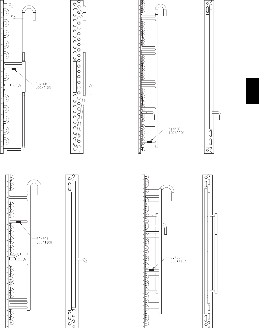
71
APPENDIX VI. MOTORMASTER SENSOR LOCATIONS
C08259
Fig. 54 -- 580J*04(A, B, C) Outdoor Circuiting
C08260
Fig. 55 -- 580J*05/06(A, B, C) Outdoor Circuiting
C08261
Fig. 56 -- 580J*07(A, C) Outdoor Circuiting
C08262
Fig. 57 -- 580J*08(A, C) Outdoor Circuiting
580J
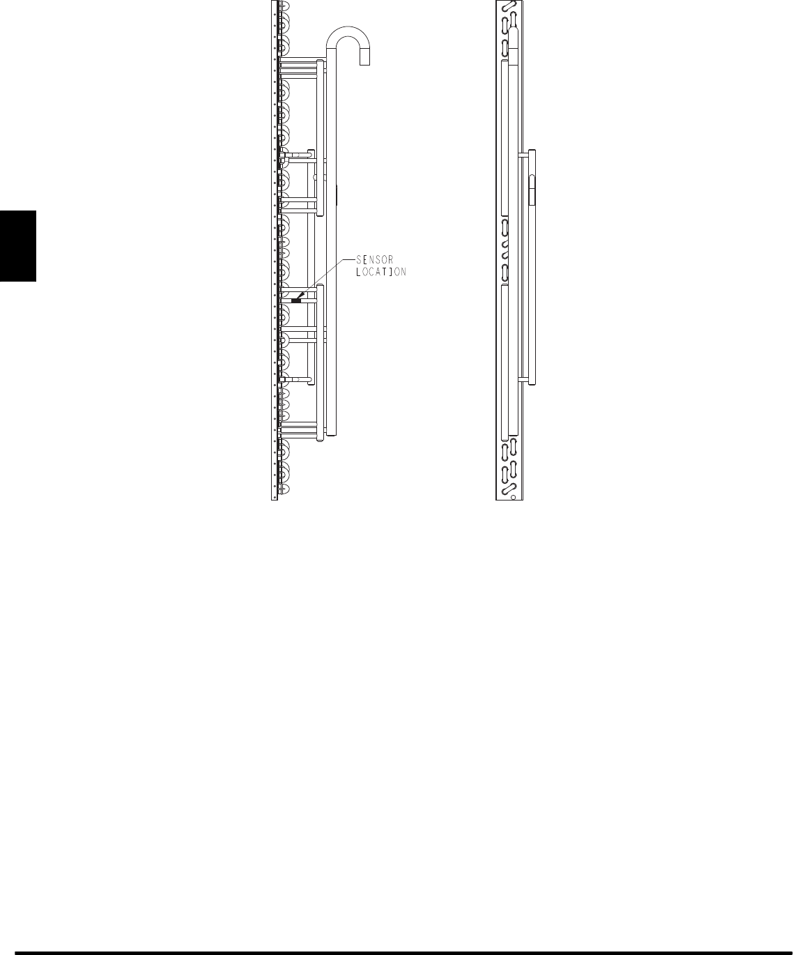
72
APPENDIX VI. MOTORMASTER SENSOR LOCATIONS (cont.)
C08263
Fig. 58 -- 580J*09/12(A, C) Outdoor Circuiting
Manufacturer reserves the right to discontinue, or change at any time, specifications or designs without notice and without incurring obligations.
E2008 Bryant Heating & Cooling Systems D7310 W. Morris St. DIndianapolis, IN 46231 Printed in U.S.A. Edition Date: 07/08
Replaces: NEW
Catalog No. SM580J---01
580J

73
START-UP CHECKLIST
(Remove and Store in Job File)
I. PRELIMINARY INFORMATION
MODEL NO.: SERIAL NO.:
DATE: TECHNICIAN:
BUILDING LOCATION:
II. PRE-START-UP (insert checkmark in box as each item is completed)
jVERIFY THAT ALL PACKAGING MATERIALS HAVE BEEN REMOVED FROM UNIT
jVERIFY THAT CONDENSATE CONNECTION IS INSTALLED PER INSTALLATION INSTRUCTIONS
jVERIFY THAT FLUE HOOD IS INSTALLED
jCHECK ALL ELECTRICAL CONNECTIONS AND TERMINALS FOR TIGHTNESS
jCHECK TO ENSURE NO WIRES ARE TOUCHING REFRIGERANT TUBING OR SHARP EDGES
jCHECK GAS PIPING FOR LEAKS
jCHECK THAT RETURN--AIR FILTER IS CLEAN AND IN PLACE
jVERIFY THAT UNIT INSTALLATION IS LEVEL
jCHECK FAN WHEEL AND PROPELLER FOR LOCATION IN HOUSING/ORIFICE AND VERIFY SETSCREW IS
TIGHT
jVERIFY PULLEY ALIGNMENT AND BELT TENSION ARE CORRECT
III. START-UP
ELECTRICAL
SUPPLY VOLTAGE L1-L2 L2-L3 L3-L1
COMPRESSOR AMPS L1 L2 L2
INDOOR FAN AMPS L1 L2 L2
TEMPERATURES
OUTDOOR-AIR TEMPERATURE DB WB
RETURN-AIR TEMPERATURE DB WB
COOLING SUPPLY AIR DB WB
GAS HEAT SUPPLY AIR DB
PRESSURES
GAS INLET PRESSURE IN. WG
GAS MANIFOLD PRESSURE IN. WG (LOW FIRE) IN. WG (HI FIRE)
REFRIGERANT SUCTION PSIG TEMP _F
REFRIGERANT DISCHARGE PSIG TEMP _F
jVERIFY PULLEY ALIGNMENT AND BELT TENSION ARE CORRECT
jVERIFY REFRIGERANT CHARGE USING CHARGING CHARTS
jVERIFY THAT 3--PHASE SCROLL COMPRESSOR IS ROTATING IN CORRECT DIRECTION
Manufacturer reserves the right to discontinue, or change at any time, specifications or designs without notice and without incurring obligations.
E2008 Bryant Heating & Cooling Systems D7310 W. Morris St. DIndianapolis, IN 46231 Printed in U.S.A. Edition Date: 07/08
Replaces: NEW
Catalog No. SM580J---01
580J
