Solution Air Handling Units 200 To 100,000 CFM (Indoor & Outdoor S), Engineering Guide, 102.20 QG1 060 Solutions Ahu
User Manual: 060
Open the PDF directly: View PDF ![]() .
.
Page Count: 84
FORM 102.20-QG1 (808)
SOLUTION AIR HANDLING UNITS
2000 TO 100,000 CFM
(Indoor & Outdoor Models)
ld08301
FPC
HFDP XA FS XA CC HCXA RF FEMB
V
F
DV
F
D
Split
SA
EA
RA
VC XA HC RF MB
VFD
FE
FS DI RF XA DP
Split
Split
RA
EA
ld08302

JOHNSON CONTROLS
2
FORM 102.20-QG1 (808)
TABLE OF CONTENTS
GENERAL INFORMATION
Introduction ............................................................3
A Proud History of Experience & Qualifi cations .....3
Assurance of Johnson Controls Backing ...............3
Computer Selection Programs ...............................4
Innovative Engineering & Design ...........................5
Flexibility of Design ................................................6
Superior Casing Performance ................................6
Pre-engineered Packaged Controls .......................7
Customized Variable Size Openings ......................7
Airfl ow Measurement Performance ........................8
State-of-the-Art Certifi cation & Testing ...................8
New Sound Testing Laboratory ..............................8
Quality Construction Equals Improved IAQ ............9
Multi-Sloped Drain Pans ........................................9
Raceways ...............................................................9
Improve Cost Savings ............................................9
A Complete Line of Filters ....................................10
Energy Saving Fan Options .................................10
Energy Consumption ............................................11
Sound Attenuation ................................................13
Inertia Base ..........................................................13
Quick Selection ....................................................14
FAN APPLICATION REVIEW
Fan Laws .............................................................15
Variable Air Volume ..............................................16
Component Temperature Margins ........................17
Fan Motor Heat ....................................................17
COIL OPTIONS
Cooling Coils ........................................................18
Heating Coils ........................................................19
Typical Application of AH Coils .............................20
SOLUTION SEGMENT IDENTIFICATION
Segment Listing ...................................................21
Unit & Coil Hand Selection ...................................21
FAN SEGMENTS – FS, FR, FE
Fan Applications ...................................................22
Dual Fan Considerations ......................................22
Dual Fan Applications ..........................................22
Door and Discharge Locations .............................23
Single Fan DWDI Options ....................................24
Single Fan SWSI Options ....................................25
Dual Fan DWDI Options .......................................26
Dual Fan SWSI Options .......................................27
SWSI vs. DWDI ....................................................28
Fan Motor Control Methods .................................29
COIL SEGMENTS
Cooling (CC) ........................................................30
Heating (HC) ........................................................30
Vertical Coil (VC) ..................................................31
STAGGERED COIL OPTIONS
Angle Wall ............................................................32
Back-to-Back ........................................................32
Multizone (MC) .....................................................33
HEATING SEGMENTS
Integral Face & Bypass ........................................34
Indirect Gas-Fired ................................................35
Turndown Examples and Guidelines....................36
Electric Heat Options & Applications ....................37
ENERGY RECOVERY
Heat Wheel ..........................................................40
FILTER SEGMENTS
Applications & Options Table ...............................41
Mechanical Air Filters ...........................................42
MERV Analysis .....................................................43
MIXING SEGMENTS & ECONOMIZERS
Mixing Box /Economizers .....................................44
Mixing Box Optimization Chart .............................46
Typical Economizer Application ............................47
Building Pressurization .........................................47
Methods of Pressurization Control .......................48
Economizer Arrangements ...................................48
Face Damper .......................................................49
Inlet Plenum .........................................................49
ACCESSORY SEGMENTS
Diffuser Segment .................................................50
Access Segment ..................................................50
Vertical Plenum ...................................................51
Discharge Plenum ................................................51
Sound Attenuator .................................................52
Noise and Vibration ..............................................53
Air Blender - Mixers ..............................................54
Face & Bypass Damper Segment ........................55
Turning Segments ................................................56
Humidifi er Segment ..............................................56
UV Segment .........................................................57
Pipe Chase Enclosure ..........................................58
Roof Curb .............................................................58
Special Curb Requests ........................................59
CONTROLS
F. P. Controls & Motor Control Centers ................60
Typical FPC Wiring ...............................................60
Software Process .................................................61
Field Equipment Controller ...................................61
Power Wiring Options ..........................................62
INDUSTRY FORMULAS
Miscellaneous Industry Formulas .........................63
GUIDE SPECIFICATIONS WITH TIPS
Part 1 - General ....................................................64
Part 2 - Products ..................................................67
Part 3 - Execution .................................................81

JOHNSON CONTROLS 3
FORM 102.20-QG1 (808)
GENERAL INFORMATION
Introduction
This Equipment Guide will provide engineers with
a summary of Solution air handling information in the
most convenient, time-saving manner possible. The
guide will direct you to various sources of data and infor-
mation helpful in solving questions concerning product
options, design application, as well as installation and
operation.
A Proud History of Experience & Qualifi cations
Johnson Controls combined with YORK heating, ventila-
tion, air-conditioning, and refrigeration (HVAC&R) sys-
tems and solutions creates the largest global provider of
integrated products, systems and services for the $200
billion global building environment industry.
Johnson Controls/YORK is:
• A global leader in control systems and services
for heating, ventilating, air conditioning (HVAC),
lighting, security and fi re management for non-
residential buildings, facility management and
consulting services.
• Represented in over 125 countries, including
North America, Asia, Europe, the Middle East,
Africa and Latin America and in all markets.
YORK® Solution® air-handling units (AHUs) from John-
son Controls–the only names you need to know for a line
that has no limits. Johnson Controls/YORK engineers
have developed an AHU line that is so fl exible, and able
to deliver such high standards of performance, that it can
handle virtually any application. Whatever the air-han-
dling challenge–IAQ, acoustics, energy, controls, you
name it–Johnson Controls/YORK can build a Solution
AHU that will meet your needs.
Solution® AHU’s from Johnson Controls
comprise a complete AHU line to meet commercial,
institutional and industrial indoor and outdoor unit
applications. For more than 50 years, YORK air
handling units have been installed in every type of facility to
handle any type of requirement; manufacturing, education,
healthcare, life sciences and process manufacturing.
Solution® AHU’s come equipped with industry-leading
Metasys® controls that are installed and commissioned
at the factory. Factory installation assures superior
quality, saves time on the jobsite and delivers accurate
performance. Plus, you can count on seamless opera-
tion with a Metasys building management system.
Assurance of Johnson Controls Backing
With every Solution system, you get the support and
resources that come from dealing with a worldwide
manufacturer – JOHNSON CONTROLS. You are not
tied to the limitations of a regional supplier. Instead, you
get the fl exibility being able to design in one part of the
country, and buy and install in another location.
Johnson Controls Factory Service
Turn to the experts at Johnson Controls/YORK.
Johnson Controls/York carries the burden of single-
source responsibility since Johnson Controls/YORK
packages the total system, including custom air han-
dlers, chillers, controls, and variable air-volume boxes
and building automation systems. For added peace
of mind, Johnson Controls/YORK offers Inspection
Only, Preventive Maintenance and Inspection, or Total
Service Contracts to meet your specifi c fi nancing and
management requirements. Johnson Controls service
can also provide certifi ed technicians available locally
for factory start-up, drawing from over 700 factory-
trained service technicians in 100 strategically-located
offi ces nationwide – a capability not offered by indepen-
dent manufacturers.
Full Service Support
Because JOHNSON CONTROLS factory packaged
devices and motor controls are an integral part of the
equipment, who better to troubleshoot and service the
system than a professional Johnson Controls Service
Technician. The Johnson Controls Service technician
knows not only the equipment and the hardware, but
also has a working knowledge of equipment applica-
tion and operation. Every unit is backed by this kind of
professional support.
Development and Preparation of Service Literature
Johnson Controls/YORK produces quality product
literature to ensure proper installation, operation and
maintenance. Installation, Operation and Maintenance
manuals must be followed to realize the full capacity
and life of the units. In addition, literature supplements
of special characteristics and features are distributed as
required to support regular product enhancements.
JOHNSON CONTROLS
4
FORM 102.20-QG1 (808)
GENERAL INFORMATION
Computer Selection Programs
YORKworks™ software is the primary source for the
latest product design and performance data.
1. Includes the latest innovations, updates, and ef-
fi ciencies of YORK® products
2. Includes general functionality used to select
equipment factory packaged controls.
3. Sound data for air-handling units
4. All screens are interconnected and are continually
updated according to confi guration inputs.
This powerful software tool brings fl exibility and com-
puting power to the desktop of designers. The software
allows you and the customer to make product decisions
and view performance data in a user-friendly, step-by-
step, screen-driven environment.
YORKworksCE™ software is a necessity for your
customer’s engineering toolbox. YORKworks revolution-
izes the way you specify HVAC equipment. Johnson
Controls/YORK can optimize the selection of any air
handling unit for a specifi c job requirement with its
computer selection programs.
Literature Reference — see ‘Sales Guide – YORK works CE’ Form 70.02-SG1
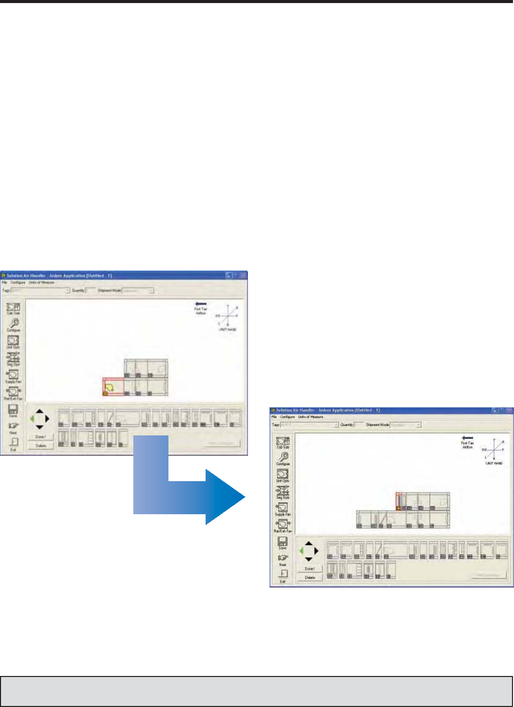
Quick and Easy selection
• Save Time – choose components and
complete confi gurations with a couple
of clicks.
• Reduce Errors – use pre-programmed
rules and guidelines for component
selection.
Just Click to
select and add
components
JOHNSON CONTROLS 5
FORM 102.20-QG1 (808)
Innovative Engineering & Design
Solution Air Handlers are not just ‘fans-in-a-box’!
1. Solution is a structure that withstands defl ection
2. Solution is a sound/noise barrier
3. Solution is a container of clean and conditioned air
4. Solution is an integral part of a building’s fi re and
safety plans
5. Solution’s Variable Aspect Ratio eliminates the
need for costly modifi cations.
6. Solution fi ts the specifi cation and the space!
Innovative Engineering & Design allows you to choose
from a limitless variety of confi gurations. See con-
fi gurations below for some of the popular applications
designed to meet your particular need.
FS
VC XA HC FM
XAFS
DPAT
XA
TN
TN
EH MBRF
FS CC XA HC FF MB
FS CC
DI
XA
DP
HF RF
MB
FS CC XA HC
DI
XA
RF
DP
AF EE FR
XA
DP
FS CC AFHM IG
XA
EE FE
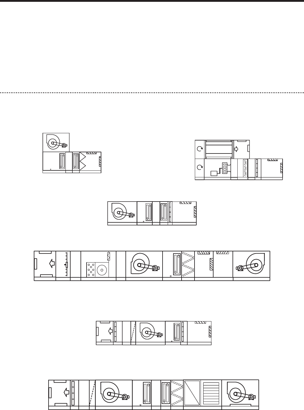
Confi guration 1 (Stacked Unit) –
Mechanical room favorite. Reduced footprint with tiered
supply fan
Confi guration 2 (Stacked Unit) –
Ultra-quiet design with plenum fan and U-shaped
cabinet
Confi guration 3 – Minimum frills. Maximum IAQ
Confi guration 5 – Cooling-only lab design with HEPA fi ltration
Confi guration 6 – Classic hospital design with return fan economizer operation.
Confi guration 4 – Exhaust air fl exibility with gas-heat and humidifi cation
JOHNSON CONTROLS
6
FORM 102.20-QG1 (808)
GENERAL INFORMATION
Flexibility of Design
Solution AHUs offer the ultimate in dimensional, mate-
rial, and component fl exibility. Solution AHUs have the
same appeal for both “standard” and “custom” markets.
How an air-handling unit is designed and built deter-
mines how well it performs.
Engineering Flexibility
• Variable cabinet dimensions
• Material and component fl exibility
• Full line of factory packaged controls installed,
tested and commissioned by Johnson Controls
certifi ed technicians
• Variable sized inlet and discharge openings
• Indoor and outdoor constructions
• Tiered (stacked) and custom confi gurations
• Panels are individually removable without affect-
ing structural integrity.
Dimensional Flexibility
You can design Solution AHUs to fi t the application and
the space. Length, height and width can all be varied
to match building constraints. With hundreds of cross-
sectional possibilities, you choose the best match for the
application. In addition, all Solution AHU components
have been designed with a variable-aspect ratio to meet
your space and air-velocity requirements.
Material Flexibility
A complete line of construction materials are available,
including galvanized steel, aluminum, painted steel,
stainless steel, and more. Solution AHUs can handle
a multitude of environments, from the most benign to
the most corrosive. NOTE: All units/unit segments are
shrink-wrapped to protect unit from contamination dur-
ing shipping
Component Flexibility
AHUs are responsible for providing
the environment with quality indoor
air, in an energy effi cient and quiet
manner. Solution AHUs help meet
that responsibility by offering every
available component, from energy
wheels to air-monitoring stations
to specialty-purpose filters. As
technology creates new capabilities, Johnson Controls/
YORK will apply these to our Solution line.
Superior Casing Performance
The foam injected panels of our Solution air handling
units enhance performance, maximizing the indoor air
quality and help to create ASHRAE 62-2000 compliant
designs while reducing costs. The direct result of the
foam injection insulation is a rigid panel, low leakage,
high pressure air handler, with increased energy sav-
ings, and reduced initial cost.
Better IAQ
Defl ection presents a potential in leaks that form over
time from the operational pressure. The foam injected
Solution panels are 20% more rigid (L/240 vs. L/200)
then the typical fi berglass or foam board construction.
In addition the smaller defl ections can be achieved using
lighter sheet metal gauges then required by fi berglass
construction. The result is a lower initial cost unit with
greater performance.
Lower leakage reduces the infi ltration of unfi ltered and
unconditioned air into the space. The infi ltration of un-
conditioned air can lead to condensation in unit walls,
crevices and/or insulation. When the infi ltration occurs
in a negative pressure atmosphere downstream of the
fi lter, it will lead to unfi ltered air being supplied to the
space. Maintaining a low leakage for positive pressure
segments reduces the loss of conditioned air to a po-
tentially warm and humid ambient environment, causing
increased condensation. Condensation can lead to
premature corrosion as well as IAQ concerns.
The Solution foam injected wall panels help to seal and
maintain the leakage at maximum of 1% with a minimum
+/-8” of static pressure. Options for a maximum leakage
rate of 1/2% at a minimum of +/-10” of static pressure
are available for those projects which demand it.
Coil carryover, humidifi cation, and periodic wash downs
are all instances where water is present in the unit.
Foam insulated panels will not absorb, and retain water,
like a fi berglass insulated panel will. In addition the ther-
mal properties of foam are not degraded by an incident
where the insulation comes in contact with water.
JOHNSON CONTROLS 7
FORM 102.20-QG1 (808)
Energy Savings
The energy savings associated with high performing air
handler construction is directly associated with leakage
and insulating properties.
The infi ltration of unconditioned air downstream of a coil,
or the loss of conditioned air downstream of a coil are
just two examples of reduced energy effi ciency in an air
handler. The foam injected panel helps to reduce both
of these potential losses by creating a more rigid, lower
leakage air handling over the life of the unit.
Another form of energy loss associated with air handlers
is the thermal energy that is lost through the cabinet of
the air handler. The Solution foam injected panels lower
energy consumption with better insulating properties.
With the standard R-12.5 and optional R-18.8, or R-25,
the Solution can help to reduce the energy usage. The
injected panel provides additional thermal advantages in
that the foam will fi ll voids, and gaps that aren’t reached
with fi berglass or foam board type constructions.
Solution air handler units are capable of being factory
tested to prove out both leakage and defl ection. With
the Solution product it’s not all about construction, it’s
also about performance.
Pre-engineering Packaged Controls
Pre-engineering of sensors ensures the most accurate
performance. There are great advantages to selecting
factory mounted and wired end devices for your Solution
air handling units.
1. Factory mounting maintains leakage performance
2. Factory wiring is plug and play
3. Factory testing of each mounted and wired device
4. Factory generated control diagrams specifi cally
for each unit
Literature Reference — see Application Guide ‘Applying VSO Option to Solution Air Handling Units’ - Form
102.20-AG14
Factory Installation
Factory installation improves quality and saves time.
While a Solution AHU is being manufactured, Johnson
Controls technicians can easily access all its segments.
So there are no accessibility problems to cramp the
quality of the controls installation, which often occurs
on the jobsite.
All sensor probes have been pre-engineered to deter-
mine the best mounting location, ensuring accurate and
reliable readings.
This improves performance of the unit while eliminat-
ing unwanted air leakage common in fi eld-mounted
solutions.
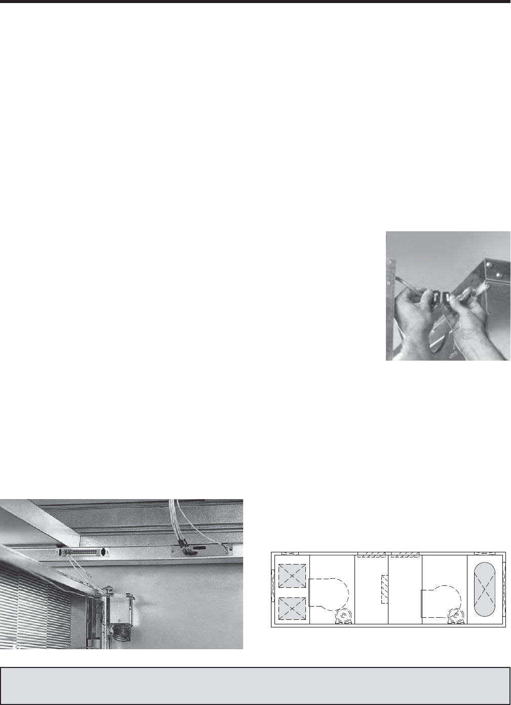
Factory engineering speeds fi eld connections
The goal is to provide
you with an AHU that
simplifi es fi eld connec-
tion of the controls. For
example, coil valves
are shipped uninstalled,
but pre-wired with quick
connects. If an AHU is
too large to ship in one
piece, you can still count
on fast and easy assem-
bly of Metasys controls
because labeled quick connects come standard on all
shipping splits.
Customized variable size openings
Solution offers the most comprehensive option for facto-
ry provided openings. Custom size, custom location and
custom shapes along with custom sized dampers,are
designed to lower installation costs and risk while dra-
matically improving the quality of the application and
performance of the air handler.
DP FS EE EE FR IP
JOHNSON CONTROLS
8
FORM 102.20-QG1 (808)
GENERAL INFORMATION
Literature Reference — see Application Guide ‘AMS60 for use with Solution AHU’ - Form 102.20-AG1
State-of-the-Art Certifi cation & Testing
Solution Air Handlers are subject to stringent testing
using certifi ed, comprehensive and industry recognized
testing laboratories. Testing is in accordance with ARI
Standard 430 which evaluates the performance of the
entire unit. This assures that each Certifi ed Solution unit
will indeed perform with certainty and reliability.
Solution AHUs have also undergone extensive and rigor-
ous testing to verify conformance with all U.S. and Cana-
dian safety standards, and they bear the ETL Label.
Extensive testing includes:
• ARI 430 certifi ed performance
• ARI 260 sound data
• Full line of ARI 410 certifi ed coils
• ETL listing for product safety per UL 1995
• ASHRAE 90.1 compliant
• ASHRAE 62 compliant coil and drain pan design
maximizes indoor air quality
• Outstanding thermal capacity proven through
independent testing
• HEPA fi ltration system exceeds the most stringent
military DOP tests
• AMCA 611 certifi ed airfl ow measurement stations
• ISO Quality Certifi cation
• Seismic certifi cate of compliance
Labeled Solution units are tested and listed by ETL in
accordance with UL 1995, Standard for Safety Heating
and Cooling Equipment, and thereby fully complying
with NFPA 90A material requirements.
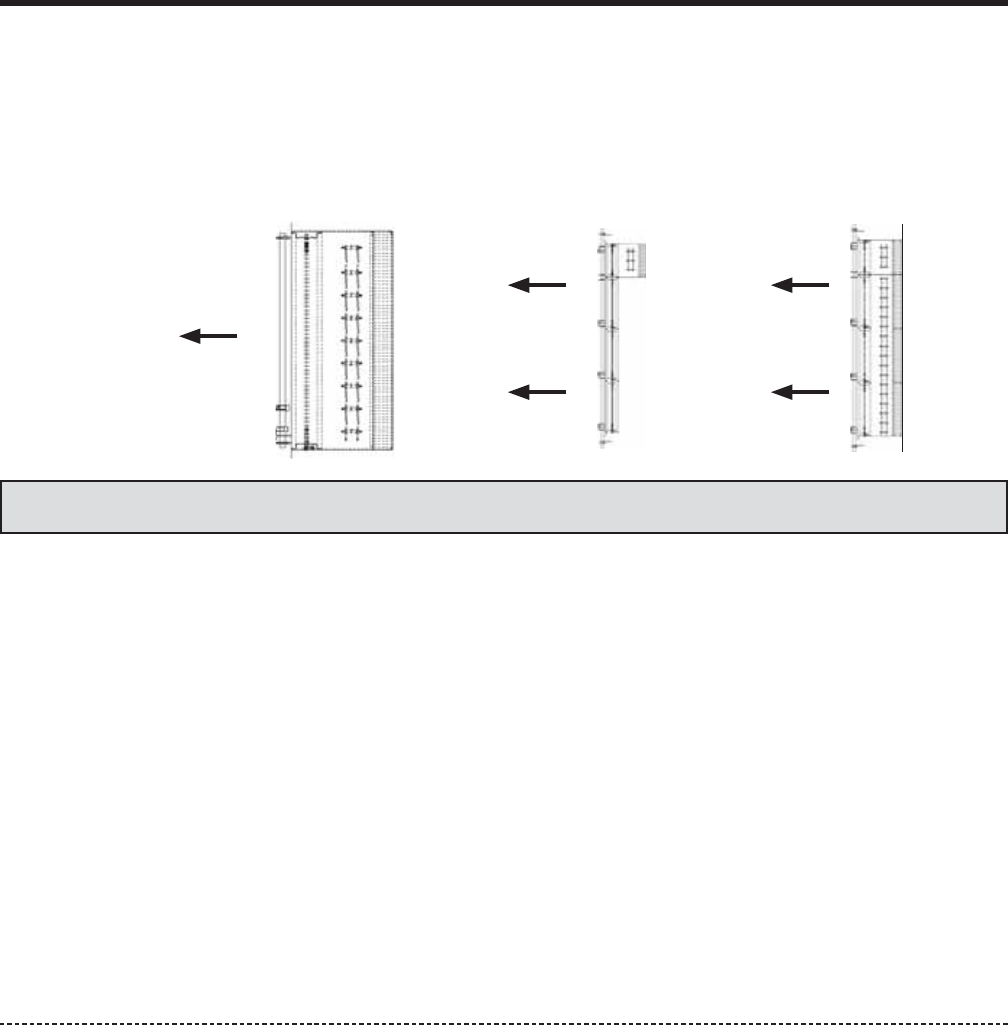
Airfl ow Measurement Performance
Solution AMS-60 qualifi es to bear the AMCA Ratings
Seal for Airfl ow Measurement Performance. Ventilation
air fl ow can be controlled dynamically with the Solution
AMS-60 which is tested to AMCA Standard 611-95.
The Solution AMS-60 continues to be the best integral
air-fl ow station offered for air handling units which is in-
corporated into mixing box and economizer segments to
meet the most stringent ASHRAE 90.1 requirements
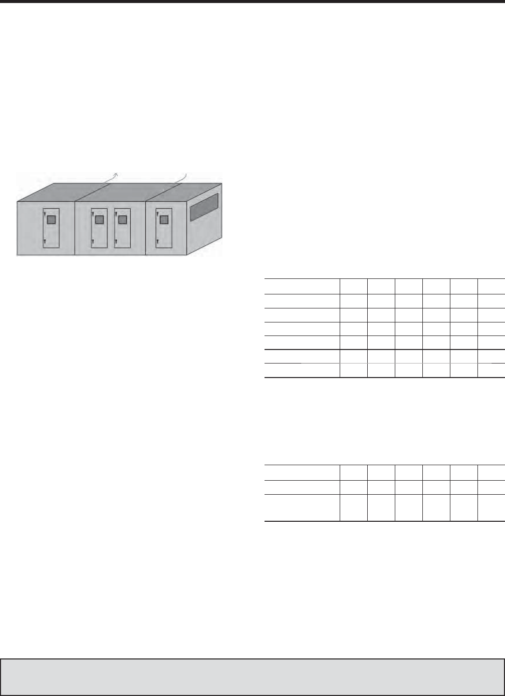
There are 3 damper options to give various measure-
ments of air fl ow. See FIG. 1.
NOTE: Dampers are split vertically
FIG. 1 – DAMPER OPTIONS
100%
25%
75%
25%
75%
New Sound Testing Laboratory
The new AHU laboratory at the Johnson Controls
Grantley Park Tech Center includes the capability for
sound power measurements on Air Handling Units up to
100,000 CFM in accordance with ARI 260. The facility
will also include the capability for testing unit airfl ow in
accordance with AMCA 210 to 100,000 CFM. For fan
alone testing, the facility will also have AMCA 300 and
AMCA 210 accreditation. All of this capability will be
available for product development testing and for cus-
tomer witness testing on critical projects. This facility
will allow verifi cation and calibration of sound models
used for unique features of Solution units, which will
increase the accuracy of our predictions and ensure that
our customers will continue to obtain the best available
Solution sound data in the marketplace.
This facility will be the largest AHU sound test facility in
the world. Note that in order for a laboratory to measure
ARI 260 sound data, the laboratory must be pure tone
qualifi ed to 50 Hz. This facility will be pure tone quali-
fi ed to 50 Hz. Pure tone qualifi cation ensures that the
test facility is capable of accurately measuring a noise
source producing tones – such as a fan. Not qualifying
the facility for pure tone response could lead to errone-
ous results with a tonal noise source. This is why ARI
requires pure tone qualifi cation of reverberation rooms in
the HVAC industry for anything other than VAV boxes.
VIEWED
FROM
TOP
JOHNSON CONTROLS 9
FORM 102.20-QG1 (808)
Quality Construction Equals Improved IAQ
Quality construc-
tion is a key to a
minimum amount of
AHU leakage. Leak-
age is an adversary
of indoor air quality.
It will depreciate the
quality of the supply
air by allowing dirty,
unfi ltered air to seep
into the air-stream
downstream of the
fi lters.
To prevent this leakage, the rigid, thermally superior
panels of Solution AHUs are matched with a rugged
framework to provide an extraordinary casing perfor-
mance.
The maximum allowable air leakage is less than 1% at
+/- 8" w.g. and a maximum L/240 defl ection.
The Shell of Solution is made up of double wall panels
and doors.
• Standard liner material is galvanized
• Stainless liners are optional
• Perforated aluminum liners are optional
The fl oor is a double wall construction, with a galvanized
steel walk-on surface.
• Optional stainless steel
• Optional aluminum tread plate
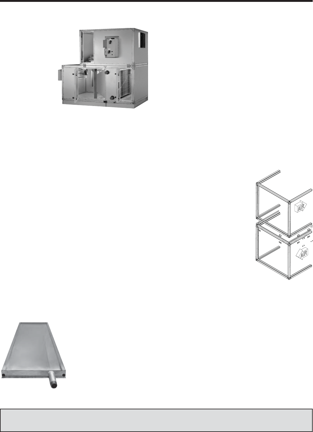
Multi-Sloped Drain Pans
The way to control micro-organisms, which can fl ourish
in drain pans, is to control the moisture of cooling-coil
condensate which can remain in the pan during “off” or
“heating” cycles.
Poorly designed drain pans
are often breeding grounds
for mold and poor IAQ.
ASHRAE 62-2001, section
5.11.1 states that drain pans
“...shall be sloped at least
1/8" per foot from the hori-
zontal toward the drain outlet
whether the fan is in the on or
off position.” Section 5.11.2
states that “The drain pan outlet shall be located at the
lowest point(s) of the pan.”
Solution units remove the condensate with a multi-sloped
drain pan that ensures positive drainage. Our pan design
also offers the highest level of accessibility for periodic
cleaning, now required by ASHRAE Standard 62.
Raceways
Raceways are used as the exterior skeletal construction
of Solution.
• Raceways provide the form and shape as well as
structural support for panels, base and internal.
• Raceway material is Galvanized
Solution is offered with a full-perimeter base-rail with
integral lifting lugs.
• Optional base-rails
• Lifting lugs are provided
as necessary for material
handling
A ‘Curb Rest’ is provided to
direct, guide and indicates align-
ment when setting a unit on the
curb.
• Galvanized steel strip at-
tached to the raceway or
base-rail
• ‘Curb Rest’ is not to be
considered a fl ashing
receiver for the curb.
Improve Cost Savings
Solution UV-C light options
eliminate the potential for a build-up of microbiological
agents.
1. Heat exchangers continue to operate at high-
effi ciency levels due to sustainable, like-new,
reduced pressure drop.
2. HVAC equipment operates for shorter periods of
time saving cost on electricity.
3. Improved IAQ as the fi rst line of defense against
sick building syndrome.
Installation of UV-C lamps promotes a cleaner, healther,
more productive work environment.
More detailed information on page 57 of this manual.
Literature Reference — see Application Guide ‘Solution IAQ Series General AHU Construction’ - Form 102.20-
AG3
JOHNSON CONTROLS
10
FORM 102.20-QG1 (808)
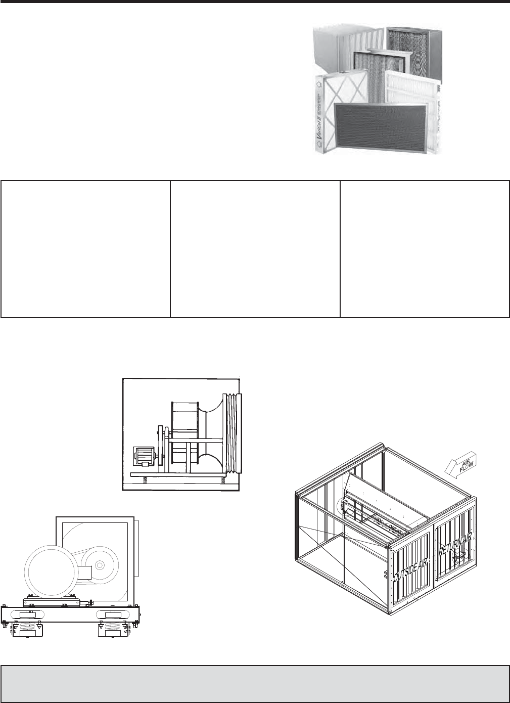
A Complete Line of Filters
A complete line of clean air solutions for industrial plants,
hospitals, schools, pharmaceutical process, airports and
commercial buildings are available to control or remove
airborne contaminants from the air stream.
Achieving acceptable indoor air quality is more involved
than calculating and applying the appropriate ventilation
rate. Specifi c AHU performance and other common
sense specifi cation items, tied to ASHRAE 62.1 rec-
ommendations, can help achieve the healthy indoor air
quality environment desired.
GENERAL INFORMATION
Light pre-fi ltering duty:
– pleated
– extended surface
Higher fi ltration effi cient
– 60% to 95%
– 11 to 14 MERV
– rigid & bags
Stringent fi ltration requirements:
– HEPA
– Ultra-HEPA
– 17 to 18 MERV
– 0.3 & 0.1 microns respectively
– 99.97% & 99.99 % effectiveness
Odor or VOC removal
– Activated carbon
Air purifi cation systems
High-performance
– Near-HEPA performance
– Germicidal capability
– Low-resistance-to-airfl ow (initial
pressure drop equal to a low-end
pre-fi lter).
Energy-Saving Fan Options
In any AHU, the fan is the largest energy consumer.
Solution fans offer a range
of energy-saving options
through fan types and con-
trols.
– Light aluminum fan
wheels
– Direct-drive plenum
fans, which eliminate
belt-and-pulley energy
losses
To assure the quietest
possible operation,
fans and motors are
common base isolated
from the cabinet.
Economizers (EE) provide an exhaust path for return
air, allowing the outdoor air conditions, when suitable,
to take advantage of 100% outside air for “free” cooling,
allowing the chillers to be turned off a percentage of the
time during the cooling season. Return and exhaust
fans are available to meet the needs of varying building
pressurization requirements.
Literature Reference — see Application Guide ‘Solution - Reducing AHU Energy Consumption’ - Form 102.20-
AG13
JOHNSON CONTROLS 11
FORM 102.20-QG1 (808)
Energy Consumption
The HVAC industry has taken a leadership role by creat-
ing energy-performance guidelines, such as ASHRAE
90.1. Solution AHUs are designed with ASHRAE 90.1
in mind.
In extreme ambient conditions, heat transfer through
the casing must be controlled. Solution casing offers
maximum thermal performance in the fl oors, walls and
roof. To prevent energy-robbing air leaks, Solution units
are designed for a maximum casing leakage of less
than 1%.
For every 1% of air leakage at the AHU, 1% more air
must be conditioned, and 1% more energy is con-
sumed.
Comparing Apples-to-Apples
Competitors claim “Air leakage rates between 1/2 and
1 percent” on their AHUs, but they don’t mention at what
pressure this performance is achievable, nor do they
even specify a leakage rate for the air units.
This typically makes it diffi cult to analyze their leakage
performance by not qualifying it based on air pressure.
However, if we reference to SMACNA class 3 air leakage
this is a good place to begin our analyses.
SMACNA class 3 refers to a standardized method
of classifying duct leakage. While this classifi cation
doesn’t technically apply to AHUs, it is a useful method
of comparing the performance claims of different manu-
facturers. According to SMACNA Duct Leakage Test
Procedures (1985), duct leakage is calculated using
the equation:
Eq. 1 Lmax = CLP0.65
where,
Lmax = maximum permitted leakage in cfm/100ft2 duct surface area;
CL = duct leakage class, cfm/100ft2 at 1 in-w.c.
P0.65 = test pressure in in-w.c.
Literature Reference — see Application Guide Form 102.20-MG1. See also M-42-06.
Rearranging Equation 1 to solve for duct leakage class:
Eq. 2 CL = Lmax/P0.65
CL = (0.5 cfm/ft2 x 100 ft2)/50.65
CL = 17.6
According to this, regardless of unit size or capacity,
this type air-unit is roughly equivalent to a SMACNA
leakage class of 18.
Analyzing Solution units is a little more complex than
analyzing the other typical unit, since Solution strives
for a maximum leakage rate of 1% of the unit design
airfl ow at ± 8 in-w.c. That means that the leakage in
cfm/100 ft2 of unit casing varies based on the size and
capacity of the unit. A 4,000 cfm Solution unit will have
a maximum leakage rate of 40 cfm, whether the unit is
8’ long or 10’ long. Therefore, the 10’ long unit will have
an inherently lower cfm/100 ft2 leakage rate than the 8’
long unit, as shown in Table 1.
Using the Solution performance at ± 8 in-w.c. we can use
the SMACNA leakage class as a standard comparator.
By plugging the values from Table 1 into Equation 2, we
fi nd the leakage class for the various Solution units as
shown in Table 2.
Even on large AHUs, the leakage class of a Solution
unit is lower than that of most competition. Many design
engineers don’t realize this, because when they compare
YORK’s performance to others they aren’t comparing
apples-to-apples unless the performance is translated
into the common language of leakage class.
Table 1. Comparative Solution Leakage Rates
Unit CFM: 4000 4000 16000 16000 32000 32000
H (Inches) 36 36 66 66 114 114
W (inches) 54 54 96 96 102 102
L (inches) 98 124 105 132 125 150
Area (ft2)150 182 324 385 537 612
1% Leakage (cfm) 40 40 160 160 320 320
Leakage (cfm/ft²) 0.27 0.22 0.49 0.42 0.60 0.52
Table 2. Solution AHU Leakage Classes
Unit CFM: 4000 4000 16000 16000 32000 32000
Leakage (cfm/ft²) 0.27 0.22 0.49 0.42 0.60 0.52
Leakage Class
at ± 8 in-w.c 7 6 13 11 15 14
JOHNSON CONTROLS
12
FORM 102.20-QG1 (808)
3. Eliminates need for motor
starter panels.
4. Improved system control
and response – DDC
controls with LED digital
display.
5. Proven reliability.
Typically HVAC systems consume
a third of the energy used in com-
mercial buildings. Therefore an
energy-effi cient HVAC system can
represent a signifi cant savings in
building operating costs. ASHRAE
90.1 provides architects and engi-
neers with guidelines for the design
of energy effi cient buildings, with
the exception of low-rise residential
buildings.
GENERAL INFORMATION
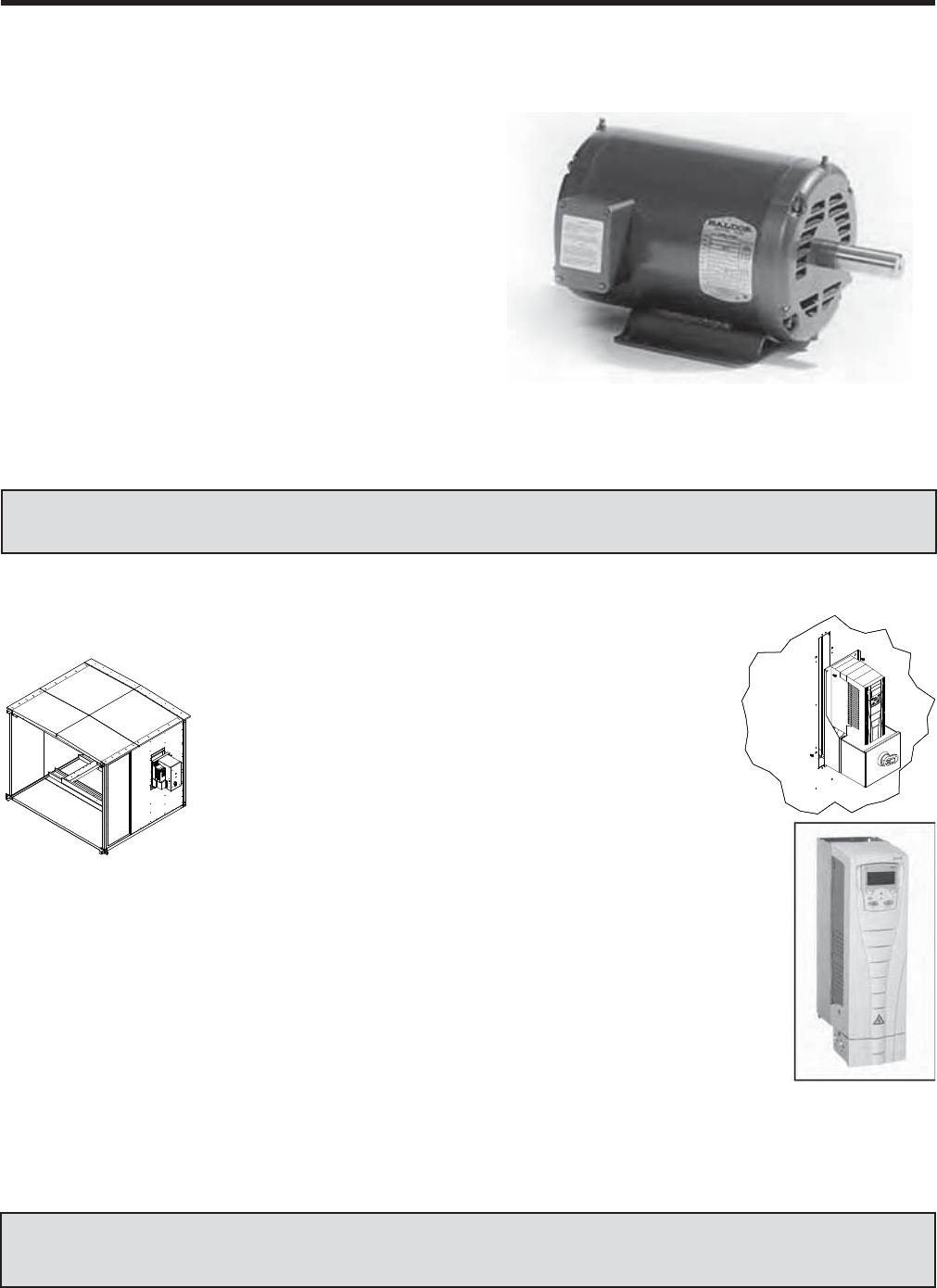
EPAct Effi cient Performance
Consumption of energy can also be reduced by more
efficient motors. Solution AHU motors meet EPAct
effi cient performance standards for general purpose
motors. Standard Solution EPAct effi cient and Premium-
effi ciency motors can be specifi ed and used with fre-
quency control as listed by NEMA Standards Publication
MG 1-2006 (Motors and Generators):
• MG 1-2006 Part 30
Application Considerations for General Purpose
Motors used with Adjustable - Voltage OR Adjust-
able - Frequency Controls or Both
• MG 1-2006 Part 31
Defi nite-Purpose Inverter-Fed Poly-phase Motors
Literature Reference — see Application Guide ‘Solution Air Handling Units AC Induction Motor Data’ -
Form 102.20-AG15.
Literature Reference — See Application Guides ‘ASHRAE 90.1 Guidelines’ – Form 102.20-AG2 & ‘Understand-
ing AHU Casing Leakage’ – Form M-42-06
Energy Saving Air-Modulator™
When the air system is de-
signed for variable-air vol-
ume (VAV), Solution offers
the most effi cient method of
VAV fan control with our Air-
Modulator™ drive, which is
mounted, wired and tested in
our factory.
Fans characteristically require
much less power as the speed
is reduced. With the Air-Modulator™, any reduction in
fan speed results in a cubic reduction in fan horsepower.
For example, a 10% speed reduction results in a 27%
fan horsepower reduction!
Air Modulator benefi ts include:
1. Extended Equipment Life – soft start of motor and
fan.
2. Quieter Fan Operation –
fan operating at reduced speed and constant line
of effi ciency.
JOHNSON CONTROLS 13
FORM 102.20-QG1 (808)
Sound Attenuation
An important component of indoor environmental qual-
ity (IEQ) is acoustics. There are very few constants
when it comes to acoustics, however it is always less
expensive to design and install a system correctly the
fi rst time than it is to make the system quiet after it is
installed. The best way to reduce noise is not to create
it in the fi rst place.
ARI 260 requires that the unit be rated across its entire
operating range according to the AMCA 300 test method.
Johnson Controls/YORK has been and continues to be
fully engaged in a rigorous ARI 260 testing program.
Solution testing includes a wide variety of fan types,
unit sizes and confi gurations. As a result, Solution can
with assurance say sound power levels are reported in
accordance with ARI 260.
Solution AHU offers a variety of noise-reducing tech-
nologies.
Solution AHUs are available
with a nearly endless array
of fan types, all custom
selected for the exacting
requirements of your project.
Direct drive plenum fans
can reduce vibration and
drive noise by eliminating
the belt-and-pulley mecha-
nism. A range of fan-base
construction and isolation techniques are available to
help control sound.
Source attenuation
is the fi rst sound-re-
duction method that
should be consid-
ered, and is typical-
ly least expensive.
Since the fan is the
primary moving part
in an air-handling
system, it’s the fi rst
place to look when
reducing noise.
What little noise is left can be further reduced with direct
methods of sound
attenuation. Using
perforated sound-
absorbing walls as
sound traps in the
fan and discharge-
plenum sections,
Johnson Controls/
YORK equipment
engineers can help
you design units
to meet your criti-
cal sound require-
ments.
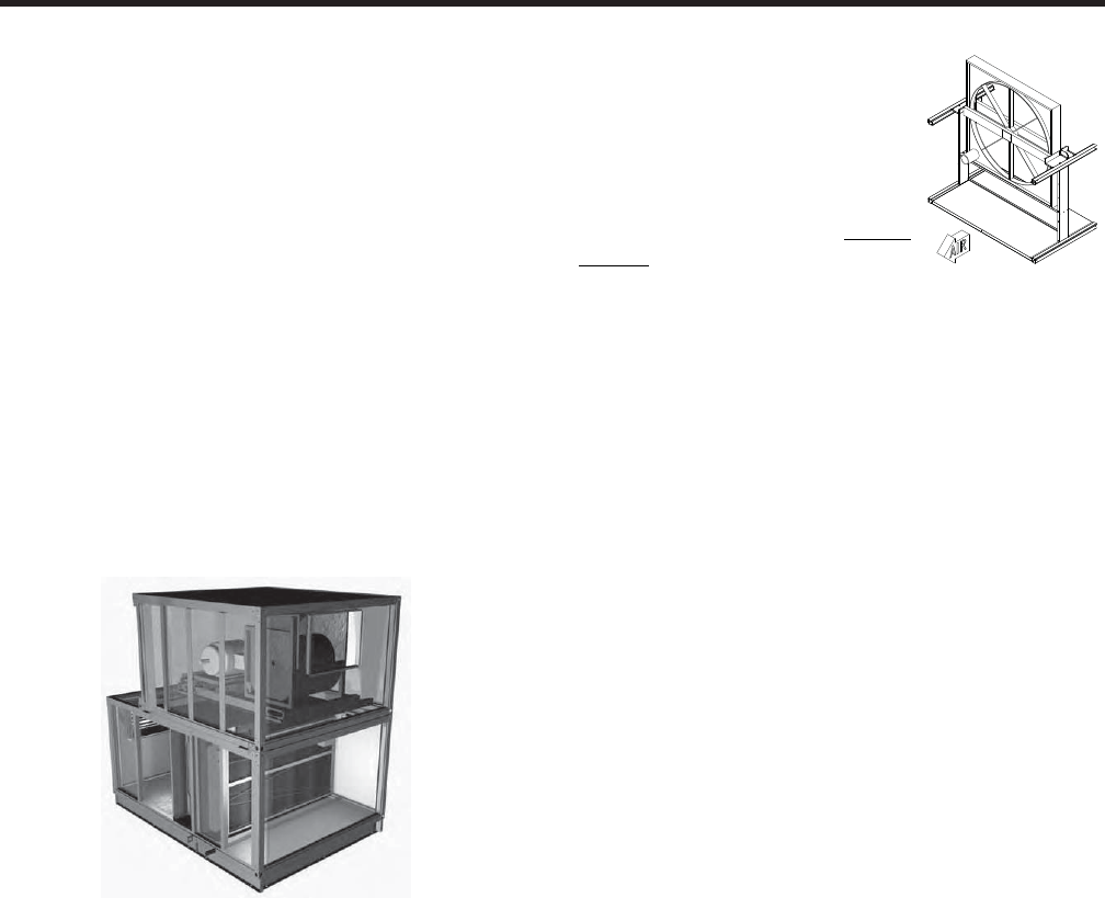
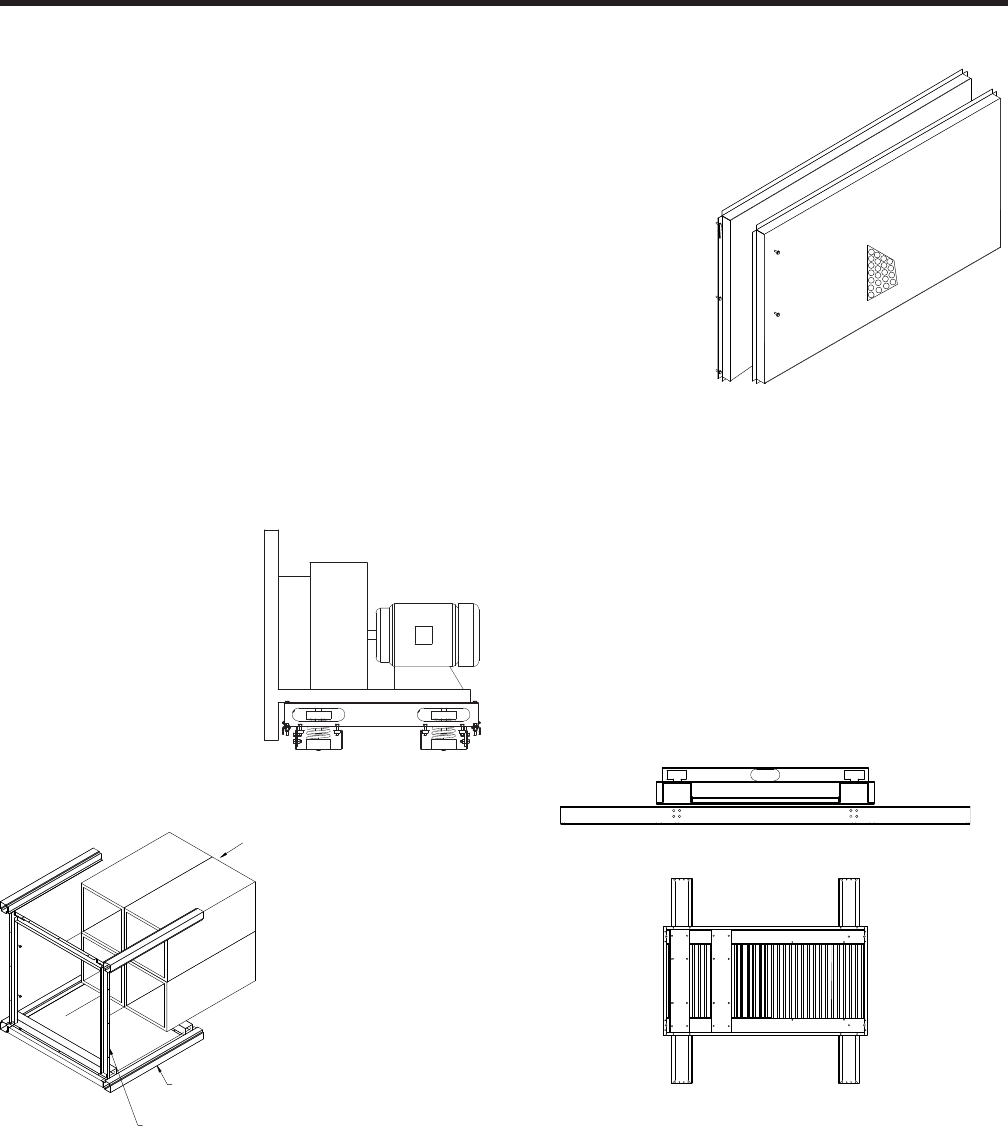
Inertia Base
A concrete inertia base, which is inserted between the
fan and its supportive structure, can be quickly and eco-
nomically installed in all Solution unit cabinet sizes.
– Inertia fan bases will accommodate both belt
driven and direct drive fans
– The added mass of the inertia base allows for a
softer isolation system and greater isolation ef-
fi ciencies as well as an effective means of damp-
ening mechanical noise.
– Concrete fi ll is furnished by contractor.
Application Note - As a rule of thumb the inertia base
should be used when:
• Class II & III fans with 40” diameter wheel or larger
• All centrifugal fans driven by motors of 75HP or
larger
RACEWAY ASY
BULKHEAD ASY
SOUND
ATTENUATION
JOHNSON CONTROLS
14
FORM 102.20-QG1 (808)
Quick Selection
The Quick Selection Guide for the Solution AHU was developed and intended to aid the Consulting Engineer, Ar-
chitect, Design/Build Contractor, and Equipment /Controls Engineer in establishing overall estimates for (minimally)
footprint dimensions, unit weight, & max motor horsepower.
Contents consist of:
– Applications, Features & Benefi ts
– Instructions
– Data
– Notes
– Reference Formulas and Conversions
GENERAL INFORMATION
Literature Reference — See Quick Select Tool – Solution Slide Chart – Form 102.20-SC1
JOHNSON CONTROLS 15
FORM 102.20-QG1 (808)
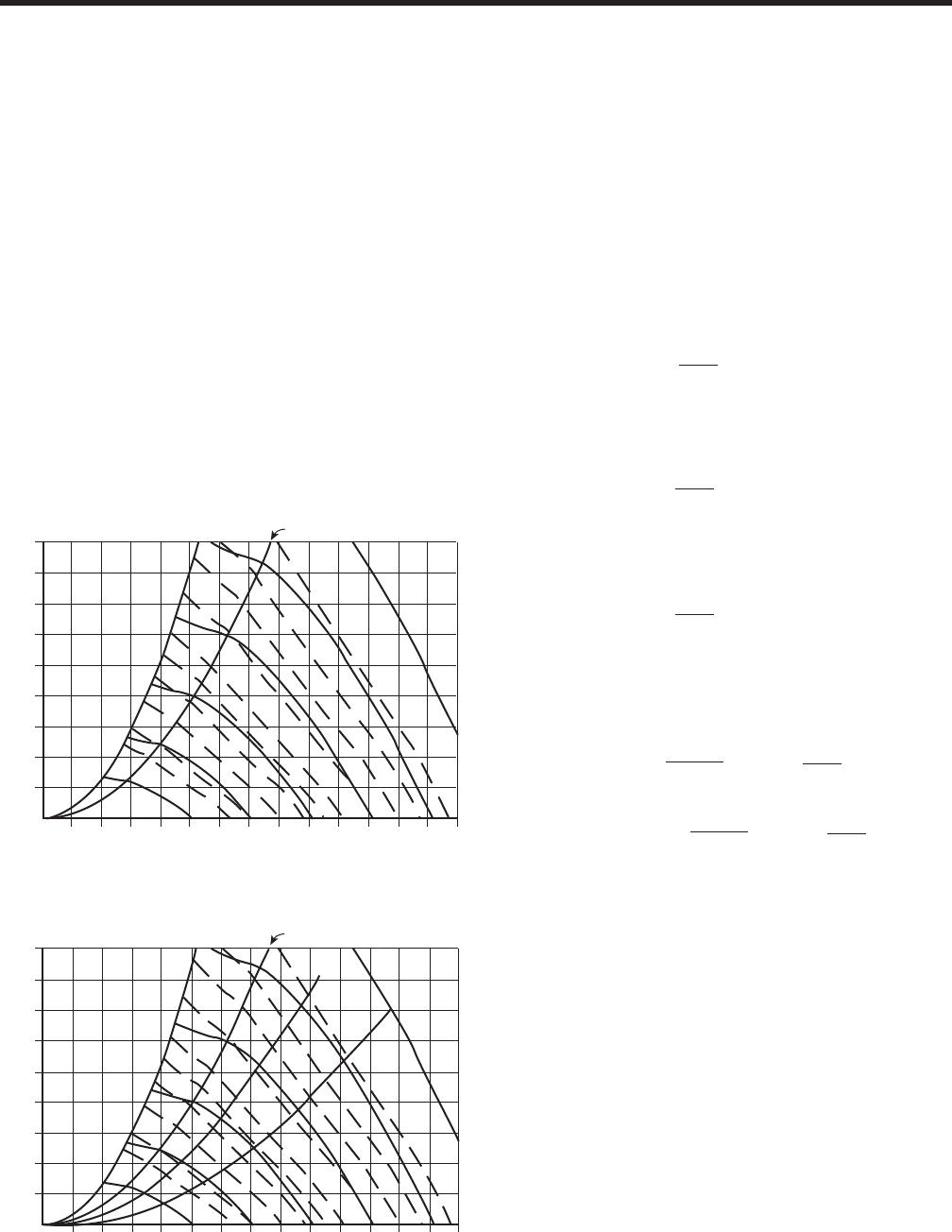
Fan Laws (Recommended Accepted Practice)
The fan laws are used to calculate performance char-
acteristics; fan speed (RPM), fan air capacity (CFM),
static pressure (SP) and brake horsepower (BHP) of
a particular fan at conditions other than those at which
the data was taken.
By using the fan laws in conjunction with a fan curve, the
fan performance can be calculated accurately at various
operating conditions. Every fan has its own unique fan
curve. FIG. 2 shows a fan curve at various RPMs.
The system resistance curve relates the total pres-
sure loss in an air handling system to the fl ow rate of
air through the system. The system curve is unique to
each system because it expresses the pressure losses
associated with the system. (AHU cabinet, coils, fi lters,
supply and return ductwork, grilles and diffusers).The
SP and CFM values are used to create the system curve
for the particular system. FIG. 3 represents a fan curve
with 2 system curves identifi ed.
FAN APPLICATION REVIEW
System curves will always have a square function slope
(parabola) because the SP varies as a square of the
CFM. The point where the system curve intersects the
RPM curve is the operating point of the fan (point A).
If the system resistance changes (i.e., dirty fi lters or
change in ductwork), the operating point will move along
the RPM curve to a different operating point and there-
fore, new system curve (point B). With a fi xed system,
the effects of change in RPM, air density of BHP can
be calculated and plotted on the system curve by using
the following fan laws:
• The CFM varies directly with the RPM:
• The SP varies as a square of the RPM:
• The BHP varies as a cube of the RPM:
• The SP and BHP are directly proportional to the
air density:
The fan laws can only be used to project performance
along a specifi c system curve. Referencing FIG. 3, Point
A can be used to project the performance of Point C and
similarly, Point B can be used to project the performance
of Point D. Point A cannot be used to predict any other
point on the RPM curve, it can only project performance
on the system curve created by Point A.
PEAK EFFICIENCY LINE
9
8
7
6
5
4
3
2
1
50 100 150 200 250 300 350 400 450 500 550 600 650 700
AIRFLOW – CFM (100)
STATIC PRESS. – (IN. WG)
500
7.5
10
15
700
900
20
25
30
D
System 1
System 2
40
B50
60
A
1100
1300
75 MAX. HP
1500
FIG. 3 – FAN CURVE WITH TWO SYSTEM CURVES
PEAK EFFICIENCY LINE
9
8
7
6
5
4
3
2
1
50 100 150 200 250 300 350 400 450 500 550 600 650 700
AIRFLOW – CFM (100)
STATIC PRESS. – (IN. WG)
500 RPM
700 RPM
7.5 HP
10 HP
10 HP
20HP
900 RPM
25 HP
30 HP
40 HP
50 HP
1100 RPM
60 HP
1300 RPM
75 MAX. HP
1500 RPM
FIG. 2 – CURVE AT VARIOUS RPMs
CFM2 = CFM1 x RPM2
RPM1
lm
SP2 = SP1 x RPM2
RPM1
2
lm
BHP2 = BHP1 x RPM2
RPM1
3
lm
SP2 = SP1 x RPM2
RPM1
2
Density2
Density1
x
lmlm
BHP2 = BHP1 x Density2
Density1
RPM2
RPM1
3
x
lmlm

JOHNSON CONTROLS
16
FORM 102.20-QG1 (808)
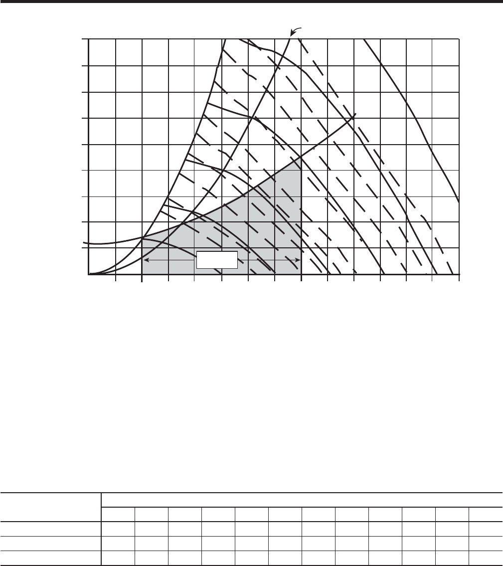
Variable Air Volume
A common mistake when selecting a fan with variable
air volume is to assume a fan with VAV will follow a
constant design system curve (passing through the point
0 CFM and 0 TSP) to maintain control. VAV systems
do not have a constant system line, but rather a range
of operating points necessary to satisfy the building
requirements. In VAV systems, the operating point will
continue to move based on the air modulation and as
the CFM and SP change, the fan is modulated to match
the new requirements, developing its own system curve.
This modulation is accomplished by using inlet vanes,
variable speed drives or discharge dampers. Before
fi nalizing the fan selection, plot the new VAV system
curve to confi rm the modulation range required does
not enter into the instability range of operation.
Example
Calculate the minimum CFM and at least 2 arbitrary
points which fall within the stable operating range of
the curve (using equations below) and plot these points
along with the design points to create the new VAV
system. (See FIG. 4.)
Design CFM = 40,000 CFM = CFMd
Design TSP = 4.5 in WG = SPd
Static Pressure Control Point = 1.25 in WG = SPd
FAN APPLICATION REVIEW
Select the most effi cient fan that can deliver both the
design and minimum CFM requirements. If the initial
selection does not provide suffi cient “turn down”, select
the next smallest fan and re-plot the VAV system for the
smaller fan and re-evaluate. Typically, the largest fan that
can supply the required modulation is the most effi cient.
Each application should be considered individually and
evaluated to be sure the fan will not be forced into the
unstable region at modulated condition.
For variable speed drive (VSD) applications, the fan
drive assembly is selected to operate approximately in
the middle of the VSD’s range. When selecting a fan to
be used with a VSD, if the RPM is close to or approach-
ing the Class I limit, select the Class II fan. Selection of
a Class I fan may result in premature bearing failure.
1st: Calculate the Minimum CFM:
Min CFM = CFMd x
SPS
SP1 x CFMd
2
+ SPS – SPd
=
m
where: CFM1, SP1 = arbitrary point located on surge line
Min CFM = 10,517
40,000 x
1.25
3 x 40,000 2
+ 1.25 – 4.5
= 10,517
15,000m
CFM1
ll
2nd: Calculate the Arbitrary Points:
where: CFM2 = 30,000
30,000 CFM 20,000 CFM
SP2 = CFM2
2
x (SPd – SPs) + SPs
m
CFMd
l
where: CFM3 = 20,000
SP3 = CFM3
2
x (SPd – SPs) + SPs
m
CFMd
SP2 = 30,000 2
x (4.5 – 1.25) + 1.25
m
l
40,000
SP2 = 3.1
SP3 = 20,000 2
x (4.5 – 1.25) + 1.25
m
40,000
SP3 = 2.1
l
l
JOHNSON CONTROLS 17
FORM 102.20-QG1 (808)
Solution Component Temperature Margins
• Standard motors (Class B Insulation) -104°F.
• Motors with Class F Insulation -140°F.
• Power Wiring - 140°F.
• Controls & Control Wiring - 140°F.
• Pre-fi lters - 150°F.
• High Effi ciency Filters - 200°F.
• Fan Bearings - 120°F (FC), 180°F (AF)
• Gasketing - 200°F
• Foam - Flash Point: 415°F (213°C)
MODULATION
RANGE
9
8
7
6
5
4
3
2
1
50 100 150 200 250 300 350 400 450 500 550 600 650 700
AIRFLOW – CFM (100)
STATIC PRESS. – (IN. WG)
Minimum CFM Design CFM
PEAK EFFICIENCY LINE
Static Pressure
Control Point
10 HP
20 HP
25 HP
30 HP
300 RPM
1100 RPM
1300 RPM
40 HP
50 HP
60 HP
75 MAX. HP
Design Pt.
1500 RPM
FIG. 4 – FAN CURVE AT VARIOUS RPMs
Fan Motor Heat (MBH)
HEAT Horsepower
5 7.5 10 15 20 25 30 40 50 60 75 100
Fan Motor 2.8 3.6 4.4 6.2 7.5 8.7 9.4 13.0 16.0 19.0 21.0 25.0
Fan 12.7 19.1 24.5 38.2 51.0 63.6 76.3 102.0 127.0 153.0 191.0 254.0
Fan & Fan Motor 15.5 22.7 28.9 44.4 58.5 72.3 85.7 115.0 143.0 172.0 212.0 279.0
JOHNSON CONTROLS
18
FORM 102.20-QG1 (808)
Flexibility and Performance illustrate the variety of coils
which are available to meet every application. These
carefully engineered coils are designed for an optimum
balance between air pressure drop and heat transfer
coeffi cient, to allow the maximum amount of cooling
or heating capacity without the added expense of high
air-pressure drops. The coil designs are subjected to
constant extensive evaluation studies comparing dif-
ferent fi n corrugations with various tube arrangements.
The Johnson Controls/YORK Equipment Engineer in
your area will welcome the opportunity to assist you
with your coil applications.
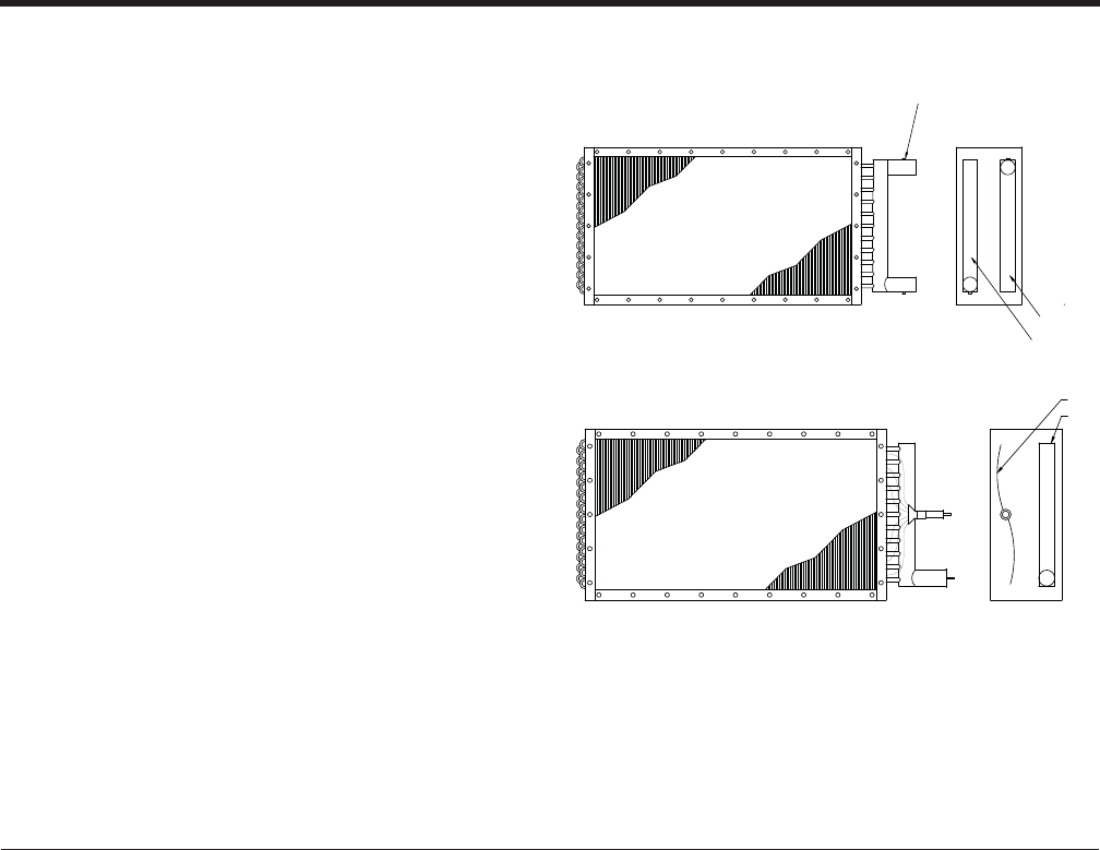
Cooling Coils – Water and Direct Expansion
Solution optimizes coil performance with customized coil
options. Solution coils are offered in a wide variety of
types, sizes, arrangements and materials. Coil software
optimizes capacity and pressure drop requirements.
AHU Chilled water cooling coil
• Available in CC, VC, MZ segments
AHU Hot water heating coil
• Available in CC, VC, HC, MZ segments
AHU (DX) Direct Expansion cooling coil
• Available in CC, VC, MZ segments
Coil Performance is certifi ed in accordance with ARI
Standard 410.
Chilled water / Hot water
Direct expansion (DX)
COIL OPTIONS
Header material:
• Copper
• Red Brass
Connector material:
• Red brass
• Steel
Connection Type:
• MPT
• Grooved
Fin type:
• 5/8” tube: Sine or Flat
• 1/2” tube: Sine corrugated only
Fin Material & Thickness:
• Aluminum - 0.006”, 0.008”, 0.010”
• Copper - 0.006”
Notes & Options
Hand of Unit determines connection side of coil. See page 21.
Fin Spacing:
• A vast range of fi ns per inch available
Fin Coatings: (Coatings reduce max face velocities)
• Electro-fi n
• Phenolic
Coil Casing:
• Galvanized
• Stainless Steel
Choice of heat transfer medium:
• Water, Glycol (Ethylene glycol coils are ARI
certifi ed)
• DX – (a variety of refrigerants to choose from)
1/4" FPT PLUGGED
VENT FITTING
RETURN
SUPPLY
SUPPLY
RETURN
JOHNSON CONTROLS 19
FORM 102.20-QG1 (808)
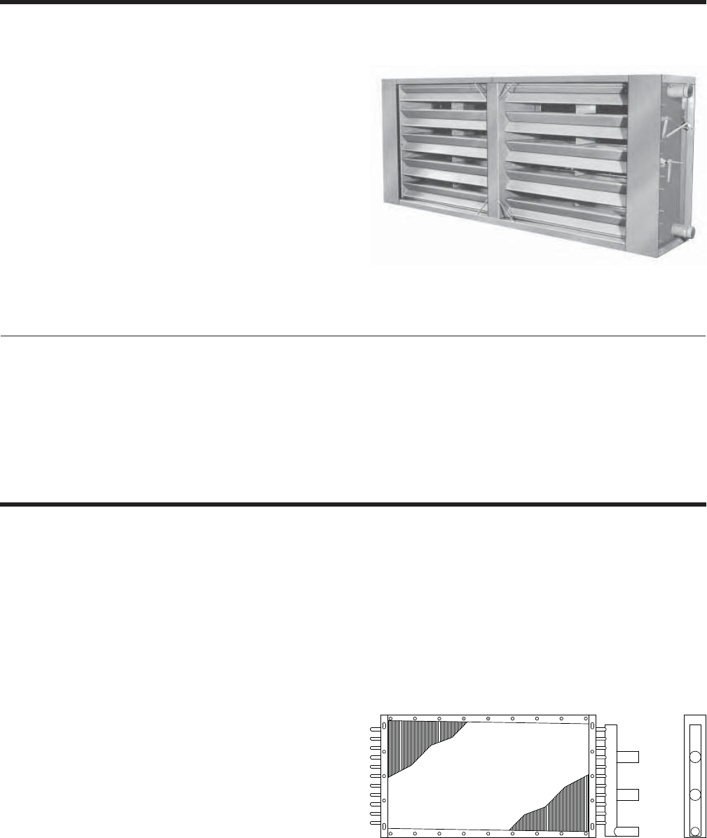
Heating Coils – Integral face and bypass
Integral face and bypass coils have alternating channels
of heat transfer surface and bypass zones. The air fl ow
is directed over the heat transfer surface or through the
by-pass zone by modulating dampers that are integral
with the coil construction.
Integral face and bypass coil (IFB/VIFB)
• Coils are available in the ‘IC’ segment
• Tubes either Vertical or Horizontal
• Coils for maximum freeze protection
• Hot water or Steam coils
• Multiple rows deep
Heating Coils – Steam Distributing
The construction of a Steam Distributing Coil is entirely
different than that of a Standard Steam.
Everyplace that you see an outside tube or header, there
is an inside tube and header that you can’t see. Steam is
distributed through these inside tubes and headers and
slowly released to the outside tubes as the steam turns
to condensate. The condensate then fl ows back down
the outside tubes in the same direction that the entering
steam comes from. The idea is that all the steam in the
inside tubes keeps the condensate in the outside tubes
from freezing when air passes across the coil at less
than 32ºF. However, under exactly the correct conditions,
even steam distributing coils can freeze.
Steam Distributing - 1” diameter tube
• Available in CC, VC, HC, MZ segments
• A vast range of fi ns per inch available
• Multiple tube wall thickness options
Coil Style:
• IFB
• VIFB
Coil Type:
• Water (Glycol)
• Steam
Notes & Options
Rows:
• 1,2,3,4
Connection:
• SCH 40 pipe
Thermostat:
• None
• Electric
Fin Material:
• Aluminum
Fin Spacing:
• A range of fi ns per inch available
Coil Casing:
• Galvanized
Steam
Steam or Hot Water
INTEGRAL FACE & BYPASS (IFB) COIL

JOHNSON CONTROLS
20
FORM 102.20-QG1 (808)
COIL OPTIONS
Typical Application of Air Handling Coils
Heating Coils
Heating coils can use steam or hot water to add heat
to the air stream. In a cooling-only VAV system, the
heating coil is generally placed in the ‘preheat’ position
between the fi lters and cooling coil. The preheat coil
can be omitted in this system if the minimum outside
air requirement is low and would not result in a mixed
air temperature below 50ºF to 55ºF.
Heating coil capacity is controlled by means of a modu-
lating control valve in the water or steam piping. The
control valve position is usually controlled by means of
a thermostat in the supply air duct in sequence with the
cooling coil control valve.
Cooling Coils
Cooling coils remove both sensible and latent heat from
the mixed air and can use chilled water, chilled brine, or
refrigerant as the cooling source. In the case of chilled
water, the supply water temperature generally ranges
from 42ºF to 50ºF, depending on the latent load to be
removed. Brine or a solution of ethylene or propylene
glycol in water is traditionally used at temperatures of
32ºF to 40ºF for applications in which piping is exposed
to freezing temperatures. Control of the cooling coil ca-
pacity at the air-handling unit is achieved by means of
a two-way ‘throttling’ or three-way ‘mixing’ control valve.
In VAV systems, a supply duct thermostat is typically
used to modulate the control valve so as to maintain
a constant temperature of air leaving the unit, usually
55ºF to 60ºF.
When refrigerant is used as the cooling source, it enters
the coil in liquid form from a condensing unit and pro-
vides cooling by a process called ‘direct expansion’. The
liquid refrigerant evaporates as the warmer air moves
across the coil, removing heat from the air during the
process. The evaporated refrigerant is then compressed
in the condensing unit, which also houses the condens-
ing coil where the heat is rejected to the outside. Control
of the coil capacity is typically by means of a series of
solenoid valves in the refrigerant liquid lines, which are
energized to shut-off the fl ow of refrigerant to part of the
coil. There are several problems with the application of
VAV to a direct expansion (DX) coil which require the
designer to take special precautions when considering
this system. First, the balance point temperature for
the DX coil will change as the air fl ow rate changes.
Assuming constant coil capacity, reducing the CFM will
reduce the suction temperature and pressure, making
close control of air temperature diffi cult. In addition,
compressor unloading at reduced load will cause step
changes in capacity and suction temperature, which
can cause hunting in the fl ow control loop. In short, the
use of variable air fl ows with a DX coil requires careful
consideration of the effect air fl ow changes make to the
system. Balance point temperatures must be carefully
considered.
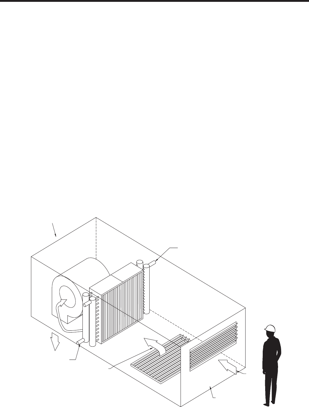
Design Considerations
In order to insure predicted coil performance, air distri-
bution must be uniform. There are two design checks
for this:
1. ‘45 degree rule’ – This rule states that the perfor-
mance of the coil will not be affected as long as the
diffusion angle from the most restrictive block-off to
the fi nned portion of the coil is 45 degrees or less.
This rule holds true unless there are unusual fl ow
fi elds, caused by such components as upstream
fans or mixing boxes where not applied properly.
2. ‘Uniform pressure rule’ – This rule states that the
performance of the coil will not be affected as long as
the maximum difference in upstream, downstream,
and combined static pressure due to local velocity
pressure at any one point on the coil compared to
another point that does not exceed 10 percent of
the pressure drop through the coil. The basis for
this rule is that the fl ow rate through the coils at any
one point is a function of the local upstream and
downstream pressures, and if pressure differences
are small, distribution will be uniform.
Literature Reference — See “DX Piping Guide” – Form 050.40-ES2
JOHNSON CONTROLS 21
FORM 102.20-QG1 (808)
FAN SECTION
LEFT HAND (LH)
COIL CONNECTION
RIGHT HAND (RH)
COIL CONNECTION
RETURN AIR
INLET SECTION
OUTSIDE AIR
DRIVE HAND AND COIL HAND DETERMINED
BY FACING THE INLET SECTION
RIGHT
REAR
LEFT
FRONT
FAN SEGMENTS
• FS – Supply
• Forward Curved
• Airfoil
• Industrial Airfoil
• SWSI Plenum
(Belt and Direct Drive)
• FR – Return
• Forward Curved
• Airfoil
• Industrial Airfoil
• SWSI Plenum
(Belt and Direct Drive)
• FE – Exhaust
• Forward Curved
• Airfoil
• Industrial Airfoil
COIL SEGMENTS
• CC – Cooling Coil
• HC – Heating Coil
• VC – Vertical Coil
• MZ - Multizone
Unit & Coil Hand Identifi cation
HEAT SEGMENTS
• IC – Integral Face & Bypass Coil
• IG – Indirect Gas Fired Furnace
• EH – Electric Heater
ENERGY RECOVERY
• ER – Energy Recovery
FILTER SEGMENTS
• FF – Flat Filter (2” or 4”)
• AF – Angle Filter (2” & 4”)
• RF – High Effi ciency Filter
• Rigid Filter (12”)
• Bag Filter (21”)
• Mini-Pleat Filter (4”)
• HF – HEPA Filter
INLET SEGMENTS
• MB – Mixing Box
• FM – Filter/Mixing Box
• EF – Filter/Economizer
• EE – Economizer
• IP – Inlet Plenum
• VE – Vertical Economizer
• VF – Vertical Filter/Economizer
ACCESSORY SEGMENTS
• VP – Vertical Plenum
• DP – Discharge Plenum
• TN – Turning Plenum
• DI – Diffuser
• XA – Access segment
• AB- Air Blender
• EB – External Bypass
• IB – Internal Bypass
• FD – Face Damper
• AT – Attenuator
• HM - Humidifi er
• UV - UVC Lamps
SOLUTION SEGMENT IDENTIFICATION

JOHNSON CONTROLS
22
FORM 102.20-QG1 (808)
Fan Applications
Fan segments are available as supply, return and or exhaust applications. Unit confi gurations have a segment op-
tion of utilizing a single fan or a dual fan arrangement. Isolation consists of 1" or 2" springs with a seismic snubber
option. Thrust restraints and OSHA belt guards are available as required.
Double-width/Double-inlet (DWDI)
• Forward Curve or Airfoil centrifugal
• Belt Driven
Single-width/Single-inlet (SWSI)
• Airfoil plenum
• Belt Drive or Direct Drive
SINGLE FAN SEGMENT – FS, FR AND FE
Bearing options for fans with lubricating bearings: (refer
to Notes & Options)
• Extended Lube Line
• External Lube Line
In most fan systems a segment with a single fan is
adequate for the required system design and rating.
Methods of control can vary and may include dampers
or variable speed drives. Also included in a single fan
design may be the allowance for future expansions.
In some situations, there may be a need for a system design using multiple fans in a cabinet. The following are some
reasons to consider a dual fan arrangement:
Dual Fan Considerations
1. One fan may be too large and not fi t into the desired
space, or it may weigh too much if supported on
upper levels.
2. The required operating range of the system may
necessitate multiple fans instead of one large fan
controlled over a wide operating range.
3. Multiple fans for capacity control may be more eco-
nomical if cost of operation is critical, especially at
very low fl ow rates for long time intervals.
4. Critical systems are often equipped with redundant
or back-up fans in case of a fi re or accident or some
other emergency that requires a sudden increase in
fl ow. Redundant fans are also used to eliminate down-
time during fan maintenance.
5. Some systems for process applications may require
pressures that are greater than a single fan can pro-
duce or when noise may be a special concern.
Dual Fan Applications
Solution dual fan application methods include 50/50 where both fans operate together to share the load equally or
100/100 where only one fan at a time is in operation.
• In a 50/50 application, the failure of one fan will re-
sult in a condition where the other fan will continue
to operate. The single fan will provide partial load
capabilities
• In a 100/100 application, the failure of one fan will
result in the operation of the other (standby) fan to
provide full capacity
Literature Reference — see Application Guide ‘AHU Dual Fan Options’ - Form 102.20-AG17
JOHNSON CONTROLS 23
FORM 102.20-QG1 (808)
Door and Discharge Locations
Fan and fan motor may be oriented in the fan
segment. Consideration must be given to which
orientation is used where. Upstream/downstream
usage follow.
Where Doors are used:
Rear/rear-inverted discharge – Upstream
Top/bottom discharge – Downstream
Front/front inverted discharge – Downstream
Top-inverted/bottom-inverted discharge –
Upstream
REAR (R)
HINGES
DOOR
DOOR
DOOR
DOOR DOOR
DOOR
HINGES
HINGES
HINGES
HINGES
HINGES
TOP (T) BOTTOM (B)
REAR INVERTED (RI) TOP INVERTED (TI) BOTTOM INVERTD (BI)
DOOR
DOOR
HINGES
HINGES
FRONT (F)
FRONT INVERTED (FI)
AIRFLOW
JOHNSON CONTROLS
24
FORM 102.20-QG1 (808)
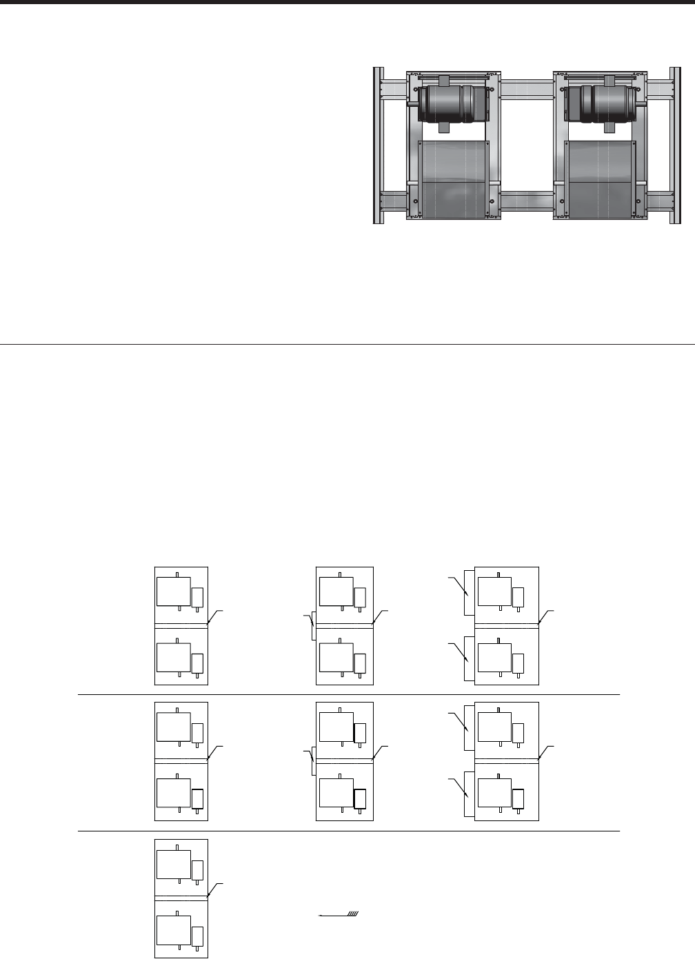
Double-width/Double-inlet (DWDI) Options – Belt Drive
Fan and fan motor may be oriented in the fan segments as shown. Consideration must be given to which orientation
is used where. Upstream/downstream images shown below.
Motor Beside Motor Behind
1. If a discharge plenum is immediately downstream of a fan
section and the discharge plenum has a top discharge, the fan
section will be rear inverted discharge.
2. If the discharge plenum has a rear, side or bottom discharge,
the fan will be rear discharge.
3. When a diffuser is ordered immediately downstream of a fan
section, the fan will be rear or rear inverted discharge.
4. Door width is sized to remove max HP motor with connection
box removed.
NOTE: Doors follow motor location. See door locations illustration
on page 23.
Fan type available
• Forward Curve centrifugal
• Airfoil centrifugal
Class I (S) construction
• Permanently sealed bearings
• Fan sizes: 7x7 thru 18x18 (Forward Curve)
Class 1 Construction
• Lubricating bearings
• Fan sizes: 20x15 thru 40x40
Class II construction
• Lubricating bearings
• Fan sizes: 7x7 thru 40x40
Thrust restraints are optional for rear and front discharge airfoil fans
only.
• Not available for FC fans.
• Required for AF with TSP over 6”
Notes & Options (DWDI)
SINGLE FAN SEGMENT – FS, FR AND FE
JOHNSON CONTROLS 25
FORM 102.20-QG1 (808)
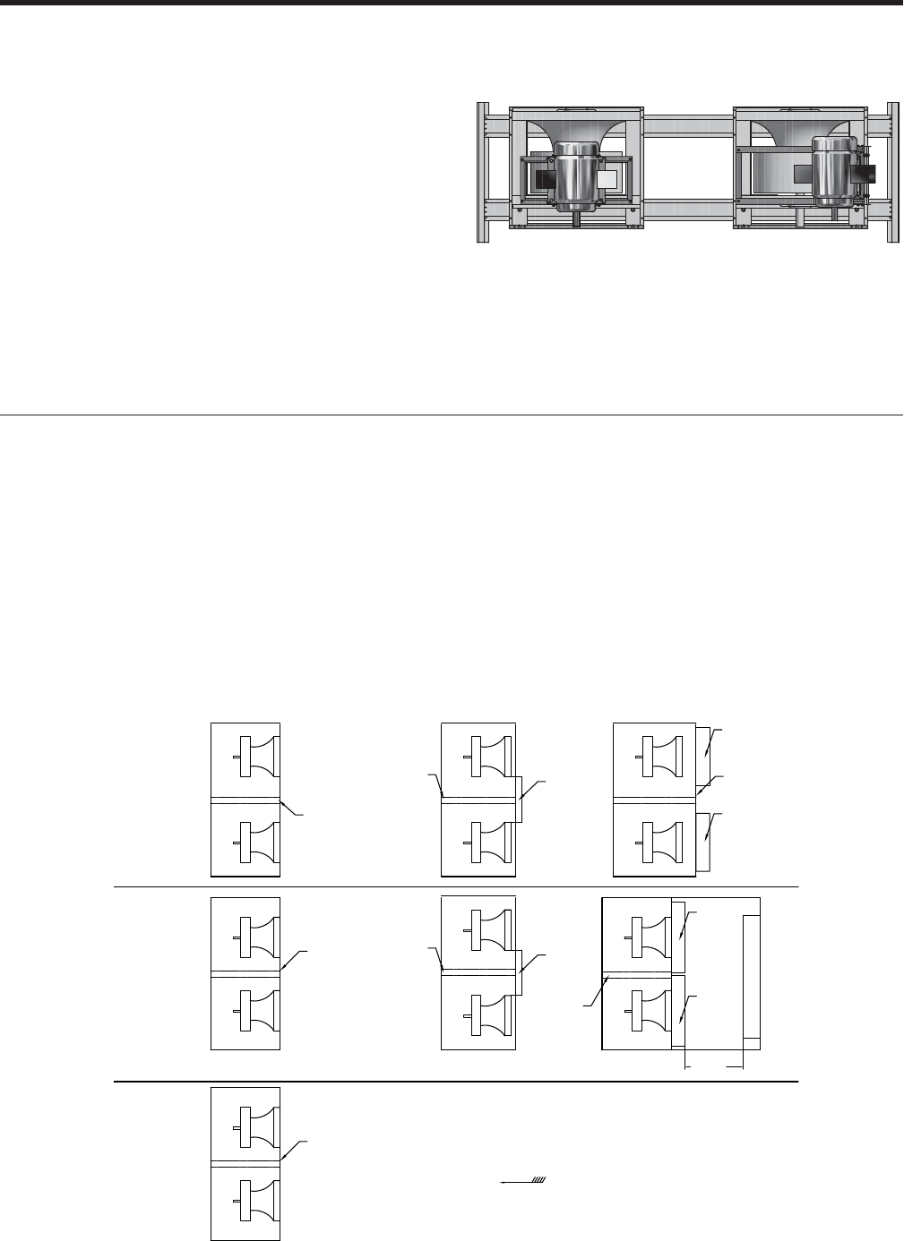
Single-width/Single-inlet (SWSI) Options
Fan and fan motor may be oriented in the fan segments as shown. Consideration must be given to which orientation
is used where. Upstream/downstream images shown below.
1. The plenum fan segments can accommodate multiple duct
outlets, thus reducing the amount of fi eld duct work and
transitions.
2. When any fi lter segment (EF, FM, FF, AF, RF, or HF) or coil
segment (CC or HC) is located upstream of a FS-SWSI,
FR-SWSI or FE-SWSI, suffi cient transition length will be
required between the FS segment and the fi lter segment.
3. Fan discharge locations - rear, front, bottom, top, left and right.
4. Single Width, Single-Inlet (SWSI) air foil plenum fans are
available as Class I, II & III. (with lubricating bearings)
5. Thrust restraints are required with TSP over 3”.
Notes & Options (SWSI)
Belt Drive Direct Drive
JOHNSON CONTROLS
26
FORM 102.20-QG1 (808)
Double-width/Double-inlet (DWDI) Options – Belt Drive
Access doors are provided on both sides of the segment.
• Allow suffi cient access-to and clearance-around the segment
for motor removal from either side.
Separation Panel Option
• Optional safeguard when servicing requires that the system be
in a running status. A separation panel is positioned between
the fans.
Flow Isolation Options
• Optional isolation method to prevent air from an energized fan
going back through a fan that is not energized.
• DWDI option is mounted on fan discharge.
•Note: Not available with fan exhaust (FE)
• Option is required with 100 %/100 % method.
Options include (depending on type of fan):
1. Manual sliding panel
2. Back-draft damper with counter balance
3. Mechanical Control damper
Notes & Options
DUAL FAN SEGMENT – FS, FR AND FE
Fan type available:
• Forward Curve centrifugal
• Airfoil centrifugal
Class I (S) construction
• Fan sizes: 7x7 thru 18x18 (Forward Curve)
Class 1 construction
• Fan sizes: 20x15 thru 22x22
Class II construction
• Fan sizes: 7x7 thru 22x22
DWDI motor location – Behind only
Motor Behind
FS
FR
FE DIRECTION OF AIRFLOW
SLIDING
WALL OPTIONAL
ISOLATION
WALL
DAMPER
DAMPER
DUAL FAN
WITH NO
DAMPER
DUAL FAN
WITH SLIDING
PANEL
DUAL FAN
WITH DISCHARGE
DAMPERS
OPTIONAL
ISOLATION
WALL
OPTIONAL
ISOLATION
WALL
OPTIONAL
ISOLATION
WALL
OPTIONAL
ISOLATION
WALL
OPTIONAL
ISOLATION
WALL
DAMPER
DAMPER
OPTIONAL
ISOLATION
WALL
SLIDING
WALL
NOTES:
1. DAMPER OPTIONS ARE ONLY
AVAILABLE FOR FRONT/FRONT INVERTED/
REAR/REAR INVERTED DISCHARGE.
2. DAMPERS OPTIONS ARE NOT
AVAILABLE FOR TOP/TOP INVERTED/
BOTTOM/BOTTOM INVERTED DISCHARGE.
JOHNSON CONTROLS 27
FORM 102.20-QG1 (808)
Single-width/Single-inlet (SWSI) Options – Belt-Drive or Direct Drive
Access doors are provided on both sides of the segment.
• Allow suffi cient access-to and clearance-around the segment
for motor removal from either side.
Separation Panel Option
• Optional safeguard when servicing requires that the system be
in a running status. A separation panel is positioned between
the fans.
Flow Isolation Options
• Optional isolation method to prevent air from an energized fan
going back through a fan that is not energized.
• SWSI option is mounted on fan inlet.
•Note: Not available with fan exhaust (FE)
• Option is required with 100 %/100 % method.
Options include (depending on type of fan):
1. Manual sliding panel
2. Back-draft damper with counter balance
3. Mechanical Control damper
Notes & Options
Fan type available:
• Standard Airfoil (AF) 10" – 30"
• *Industrial Airfoil (AF) 12" – 30"
• Class I, II, *III
SWSI motor location:
• 10" to 16" fans - behind motor only
• 18" to 30" fans -top motor only
• Fans with top motor location will require thrust
restraint
FS
FR
SLIDING
WALL
DAMPER
DAMPER
FE DIRECTION OF AIRFLOW
DUAL FAN
WITH INLET
DAMPERS
DUAL FAN
WITH NO
DAMPER
DUAL FAN
WITH SLIDING
PANEL
INLET
DAMPER
DAMPER
1 WHEEL
DIAMETER
OPTIONAL
ISOLATION
WALL
OPTIONAL
ISOLATION
WALL OPTIONAL
ISOLATION
WALL
OPTIONAL
ISOLATION
WALL
OPTIONAL
ISOLATION
WALL
OPTIONAL
ISOLATION
WALL
OPTIONAL
ISOLATION
WALL SLIDING
WALL

JOHNSON CONTROLS
28
FORM 102.20-QG1 (808)
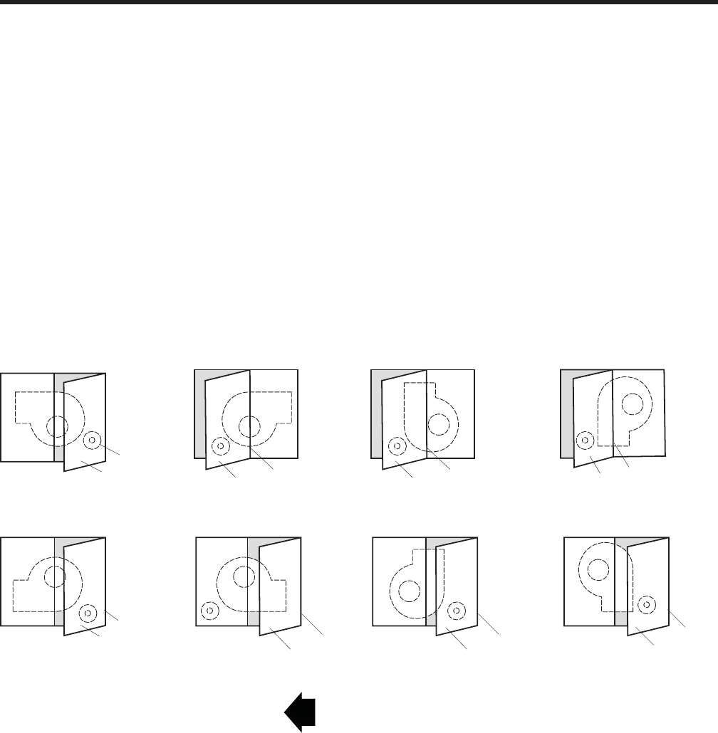
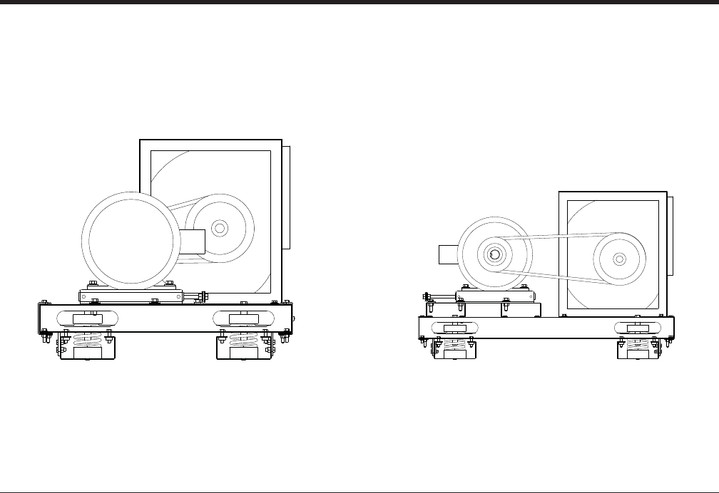
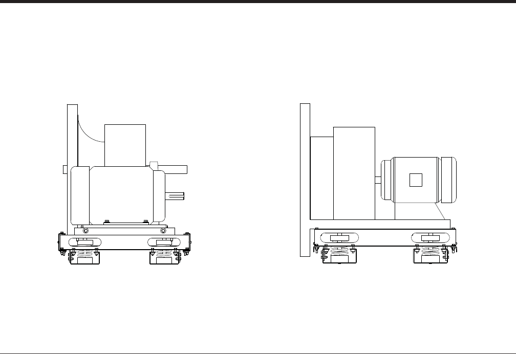
SWSI Plenum vs. DWDI Housed Fan Application
SWSI Plenum airfoil fans offer superior performance
for many applications. Typical concerns with fan per-
formance are effi ciency, noise, and air velocity profi le
through components. Plenum fans offer advantages
for all three concerns. Additionally, these fans provide
fl exibility with outlet confi gurations, reduced mechanical
space footprint, and the benefi t of direct-drive.
Effi ciency:
DWDI housed fans use a scroll to increase their effi -
ciency. However, optimizing this fan requires a process
referred to as “static regain”. Housed fans are tested
with an outlet duct of 2.5 to 3.5 times the wheel diam-
eter in length. This outlet duct allows the “static regain”
process, where velocity pressure is converted to static
pressure. Housed fans applied without this outlet duct
will require a system effect factor (SEF) which decreases
the fan effi ciency. Housed fans in blow-through positions
will also require an air diffuser which decreases the ef-
fi ciency further. The combination of these two system
effects brings even the best housed DWDI airfoil fan
effi ciency to, or below that, of the SWSI plenum fan,
thereby eliminating the benefi t of the fan scroll.
Noise:
Plenum fans have the benefi t of effectively utilizing the
entire unit as the fan housing, which offers superior at-
tenuation. The same factors that decrease the housed
fan’s effi ciency discussed above also increase the noise
level of the housed fan. Also, since the SWSI plenum
fan has no scroll, typically there is room within the air
handling unit for a larger wheel (33” SWSI plenum vs. 27”
DWDI housed, for example), which generally produces
better sound characteristics. For design pressures at or
below 6.00 in. W.C., it is very common to see supply air
sound power levels lower when using a SWSI plenum
airfoil fan instead of the DWDI housed airfoil fan. Ad-
ditionally, perforated liners may be used in plenum fan
sections for greater attenuation.
Velocity Profi le:
Due to the relatively small outlet/blast area of housed
DWDI fans, an air diffuser must be applied to the dis-
charge of the fan to obtain an acceptable velocity profi le
through the next component. Air diffusers add static
pressure which decreases fan effi ciency and increases
fan noise levels. SWSI plenum fans positively pressurize
the entire cabinet, they do not require a diffuser with its
associated performance losses.
Outlet Flexibility:
SWSI Plenum fans serve to pressure the entire fan ple-
num, allowing for multiple duct take-off from the AHU.
Additionally, these openings can be tailored to match
virtually any duct confi guration, be it rectangular or round
/ fl at-oval with bellmouth fi ttings for improved acoustic
and optimized pressure drop performance.
Mechanical Space Optimization:
A housed DWDI fan requires a straight run of duct per
AMCA guidelines at the outlet of the fan before elbows
can be applied. This constraint imposes restrictions on
duct layout and mechanical space design which gener-
ally increase overall footprint requirements. The ducted
take-offs from pressurized plenums, as in the case of
aSWSI plenum fan, does not have a requirement for a
straight run and affords greater fl exibility to the architect
and engineer in ductwork design.
Direct-Drive Benefi t:
Specialty housed DWDI fans can be used in direct-drive
arrangements, where the fan wheel is directly mounted
onto the motor shaft, most-typically, housed fans are
driven by a belt and sheave system. Belt-drive systems
typically allow for 3-5% of effi ciency loss and impose
maintenance requirements not present in direct-drive
systems. Additionally, belts wear and give off debris in
the form of belt dust. Anymore, discerning engineer’s
apply direct-driven SWSI plenum fans with VFD’s
for effi cient variable air volume duty and trouble-free
maintenance.
FAN SEGMENT – FS, FR AND FE

JOHNSON CONTROLS 29
FORM 102.20-QG1 (808)
Disconnect
This is a device for the source of power (line voltage
as provided through the building electrical utility)
from the controlled device (motor).
• Low Cost
• Constant Volume
• No BAS control needed
Across-the-line Starter
Motor Controller will provide a start / stop operation
of a motor. An integral disconnect (shall incorporate
a “lockout/tag-out” system) shall provide discon-
necting of “line side” power from the electrical utility
system.
The motor controller will also contain the proper
short circuit and thermal overload protection for the
motor that it is controlling.
• Higher Cost
• Constant Volume
• Start/Stop controlled remotely
• Thermal Overload Protection
• Under/over Voltage Relay
• Disconnect Option - Fused only
Indoor Enclosure - NEMA 3R
Indoor Voltages - 200, 208, 230, 380, 460, 575
Outdoor Enclosure - NEMA 3R
Outdoor Voltages - 200, 208, 230, 380, 460, 575
Variable Frequency Drive (VFD)
The Air-Modulator type controller varies speed of the
motor by pulse width modulation of the alternating
current waveform.
An integral disconnect (incorporates a “lockout/tag-
out” system) provides disconnecting of “line side”
power from the electrical utility system.
This motor controller will also contain the proper
short circuit and thermal overload protection for the
motor that it is controlling.
• Highest Cost
• Variable Volume
• Start/Stop controlled remotely
• Integrated basic unitary controller (can also integrate with BAS)
• Comprehensive Protection
• Disconnect Options -Fused, Non-fused, or None
Indoor Enclosure - NEMA 1
Voltages - 200, 208, 230, 460
Outdoor Enclosure - NEMA 3R
Outdoor Voltages - 200, 208, 230, 380, 460, 575
Fan Motor Control Methods
Motor control options can be explained as any one of the 3 items described below.
Literature Reference — See Engineering Guide – ‘Air Modulators’ – Form 100.42-EG1
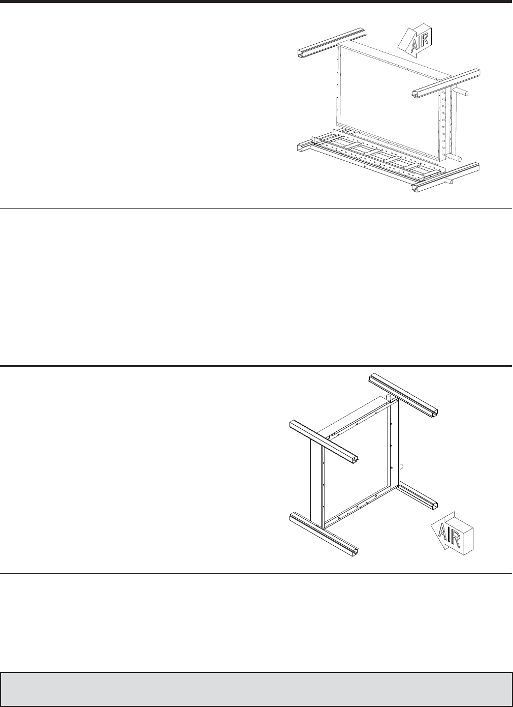
JOHNSON CONTROLS
30
FORM 102.20-QG1 (808)
Cooling Coil – (CC)
When cooling 100% OA there are precautions required.
Summer design conditions are such that when air is
cooled down to normal coil leaving temperatures, there is
a considerable amount of condensate generated. Many
applications suggest cooling coils should be selected
for an air velocity under 500 FPM. If the unit is selected
as a 100% OA application, the drainage area for larger
face area coils will be increased to properly compensate
for the probable condensate.
COIL SEGMENT – CC, HC AND VC
Coils
• A combination of Water and DX coils in the same segment
requires all coils to be of the same tube diameter.
• Multiple Water coils confi gured in the same segment must be
of the same tube diameter.
• Steam coils may be confi gured with 5/8” tube coils. A spacer
must be used between a steam coil and any water coil or DX
coil.
Headers
• Usual header location is drive side.
• All headers in the same segment must exit the unit on the
same side.
Door
• Usual door location is drive side
• With pipe chase, the door is always opposite the pipe chase
IAQ drain pans material options:
Liner – Galvanized or Stainless Steel
Notes & Options
Heating Coil – (HC)
When heating only is required the heating coil segment
is an excellent minimally sized housing which shall ac-
commodate a single heating coil. Coils are offered with
left or right hand connections. Coils will be individually
mounted and easily removable.
Coil segment panels (side panels and top panel) shall
be easily removable to allow for removal and replace-
ment of coils, without affecting the structural integrity
of the unit.
Coils
• Only hot water and steam coils are available in the HC seg-
ment.
• Only one coil (hot water or steam) is permitted per segment.
Headers
• Usual header location is on the drive side.
Doors
• Doors are not available.
Drain pans
• Auxiliary drain pan is optional.
• Usual drain location is header side.
• The drain is always opposite the pipe chase.
Notes & Options
Literature Reference — See Service Guide – ‘Field Assembly ad Disassembly Indoor/Outdoor’ –
Form 102.20-FA1 & Installation Manual Form 102.20-NOM1
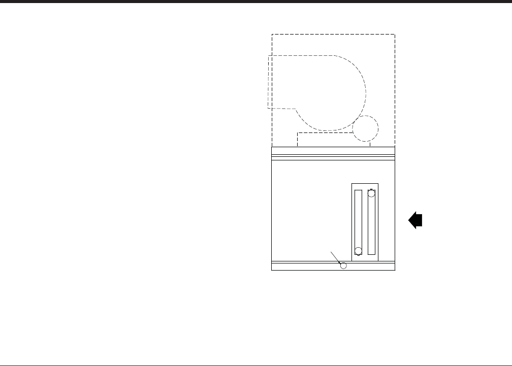
JOHNSON CONTROLS 31
FORM 102.20-QG1 (808)
Coils
• All coils located in the same coil segment must have the same
coil hand.
• Multiple Water coils confi gured in the same segment must be
of the same tube diameter.
• A combination of Water and DX coils in the same segment
requires all coils to be of the same tube diameter.
• The steam coil is available for use in the VC segment. Steam
coils may be confi gured with 5/8” tube coils. A spacer must be
used between a steam coil and any water coil or DX coil.
Headers
• Usual header location is on the drive side.
• All headers in the same segment must exit the unit on the
same side.
Doors
• Usual door location is on the drive side.
• Doors are always last in the air stream of the segment
• With pipe chase, the door is always opposite the pipe chase
Drain pans
• IAQ drain pan liner - Galvanized or Stainless Steel
• Usual drain location is on header side
• With pipe chase, the drain is always opposite the pipe chase
Notes & Options
RIGHT HAND OPPOSITE
LEFT HAND SHOWN
AIRFLOW
CONDENSATE DRAIN
CONNECTION 1 1/4" MPT
SIDE VIEW
FS
FAN
SEGMENT
VC
SEGMENT
Vertical Coil – (VC)
This segment shall provide for a 90-degree change in
airfl ow direction from horizontal to vertical, after passing
air through the coil space.
Coils are confi gured for horizontal air fl ow to minimize
segment length. Drains pans are extended to assure
complete condensate drainage and coil access. Coil
segment panels (side panels) shall be easily removable
to allow for removal and replacement of coils, without
affecting the structural integrity of the unit.
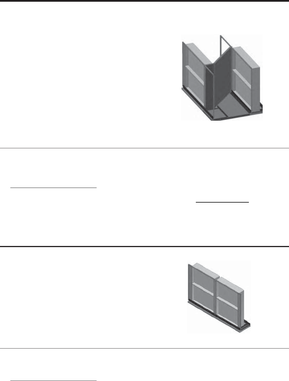
JOHNSON CONTROLS
32
FORM 102.20-QG1 (808)
Staggered Coil confi gurations are available as an option for both the indoor and outdoor Solution® units. Angled Wall
or Back-to-Back confi gurations are available in both heating and cooling coil segments.
Coils
• A staggered coil can not be combined with a non-staggered
coil in the same segment.
• Each coil bank will be located over a drain pan.
• Not available as a reduced face coil option.
Controls
• Optional control valve and valve jack (manifolded together
external of unit).
Drain pans
• Pan connection hand follows coil hand except for outside units
where the drain connection is opposite the coil hand.
• If coil connections are on both sides, the drain pan connection
follows the ”primary” side of the unit.
Headers
• Coil connections can be on the same side or opposite sides.
• Optional factory extended piping connections for each coil to
the exterior of the unit.
• Optional insulation for extended piping.
• Extended piping does not apply to DX coils.
Notes & Options
Coils
• A staggered coil can not be combined with a non-staggered
coil in the same segment.
• Not available as a reduced face coil option.
Drain pans
• The drain pan connection follows the ”primary” side of the unit.
Headers
• Coil connections can be on the same side or opposite sides.
Notes & Options
STAGGERED COIL OPTION – CC, HC, AND VC
Angle Wall
Staggered coil design increases coil face area and al-
lows increased CFM without having to increase cabinet
size.
Back-to-Back
Staggered coil design is specifi cally for a reduced coil
pull distance and for opposite side connections. Two
shorter coils will be used in place of one longer coil.

JOHNSON CONTROLS 33
FORM 102.20-QG1 (808)
Multi-zone Segment – (MZ)
MZ heating and air conditioning units offer design and
application advantages over various smaller single
zone units. The Solution unit is designed to carry on
that tradition by including a MZ segment into the design
of the unit.
MZ and Dual Deck air-handling units can be confi gured
for heating and cooling, or cooling and ventilation, or
ventilation and heating applications.
Rear or Top discharge MZ confi gurations:
• The bottom tier is the cold deck and contains a
diffuser and a cooling coil space.
• The top tier is the hot deck and contains a heating
coil mounted horizontally at the upstream side of
the hot deck.
Air enters the diffuser then splits into two streams.
• One stream turns up through the hot deck coil
and exits the rear or top through the hot deck
damper.
• The other stream continues horizontally through
the cooling coil and exits the rear or top through
the cold deck damper.
The MZ unit is optionally available less the zone damp-
ers for use on dual duct or other blow-thru systems. If a
hot deck opening is not required, it may be blanked-off
in the fi eld.
COLD DECK DAMPER
(FULL WIDTH)
HOT DECK DAMPER
(FULL WIDTH)
HOT DECK
CC
(COLD DECK)
XA DI DWDI < AIR FLOW
-OR-
SWSI < AIR FLOW
The MZ segment is for indoor applications only and will be the last
segment in air-stream.
Air pressure drop balance plates shall be used to equalize pressure
drop across the hot and cold deck coils when required.
Door is optional for cold deck.
Discharge options:
• Top with damper or without damper
• Rear with damper or without damper
Notes & Options
Literature Reference — See Application Guide – ‘Multizone Application of Solution Units’ – Form 102.20-AG12
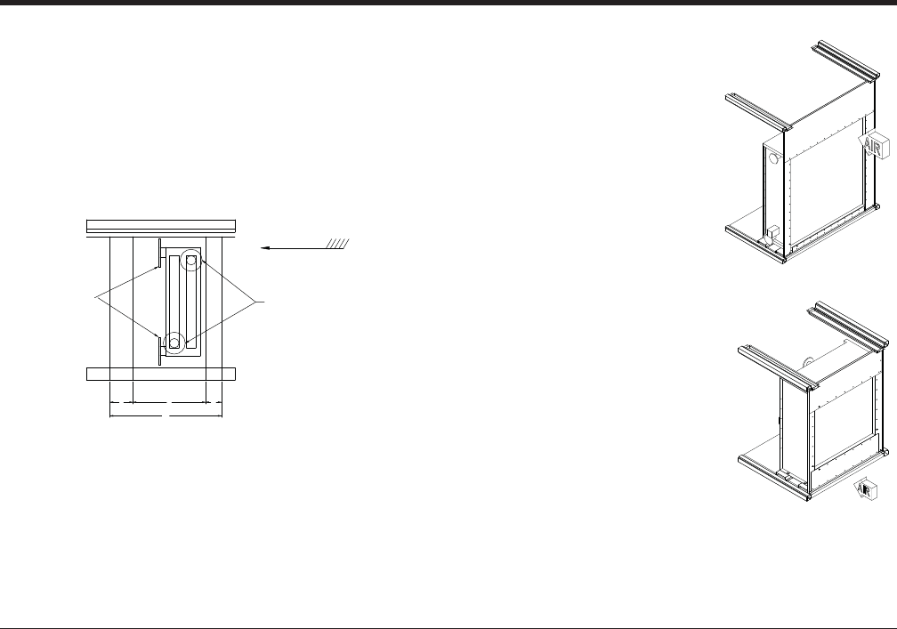
JOHNSON CONTROLS
34
FORM 102.20-QG1 (808)
Applications ideally suited for:
1. Make-up Air
2. Combustion Air Make-up
3. Penthouse units
4. Air conditioning preheat and
heating/ventilating units.
Features & Benefi ts:
• Maximum freeze protection
• Constant volume
• Minimum temperature
override
• Minimum stratifi cation
• Accurate temperature
control
HEATING SEGMENTS
Integral Face & Bypass – (IC)
The Integral Face & Bypass coil controls air temperature
while full steam pressure or water fl ow is maintained in
the coil at all times. The temperature of the discharge
air is controlled by proportioning the entering air through
the multiple heating and by pass channels.
RIGHT HAND OPPOSITE
LEFT HAND SHOWN
AIRFLOW
L
LE
J
WIREWAY
RACEWAY
K
VIFB COIL CONECTIONS
IFB COIL CONNECTIONS
1. Coil connections must be located opposite the access door.
2. All piping to be supplied by fi eld, coil connections are internal
from factory.
3. Optional pipe chase with outdoor units
4. Pipe chase is not intended for trapping or piping, but for the
connections only.
Headers:
Usual header location is on the drive side. Header location must
be opposite the access door.
Coils:
Only hot water and steam applications are available for this seg-
ment.
Doors:
Access doors and viewing ports must be located in adjacent seg-
ments.
A door is required in the immediate downstream segment from the
IC segment.
Auxiliary Drain pans:
An auxiliary drain pan is optional.
Usual drain location:
• With pipe chase, the drain is always opposite the pipe chase
• IFB on header side
• VIFB on left side of the unit
Notes & Options
IFB
VIFB
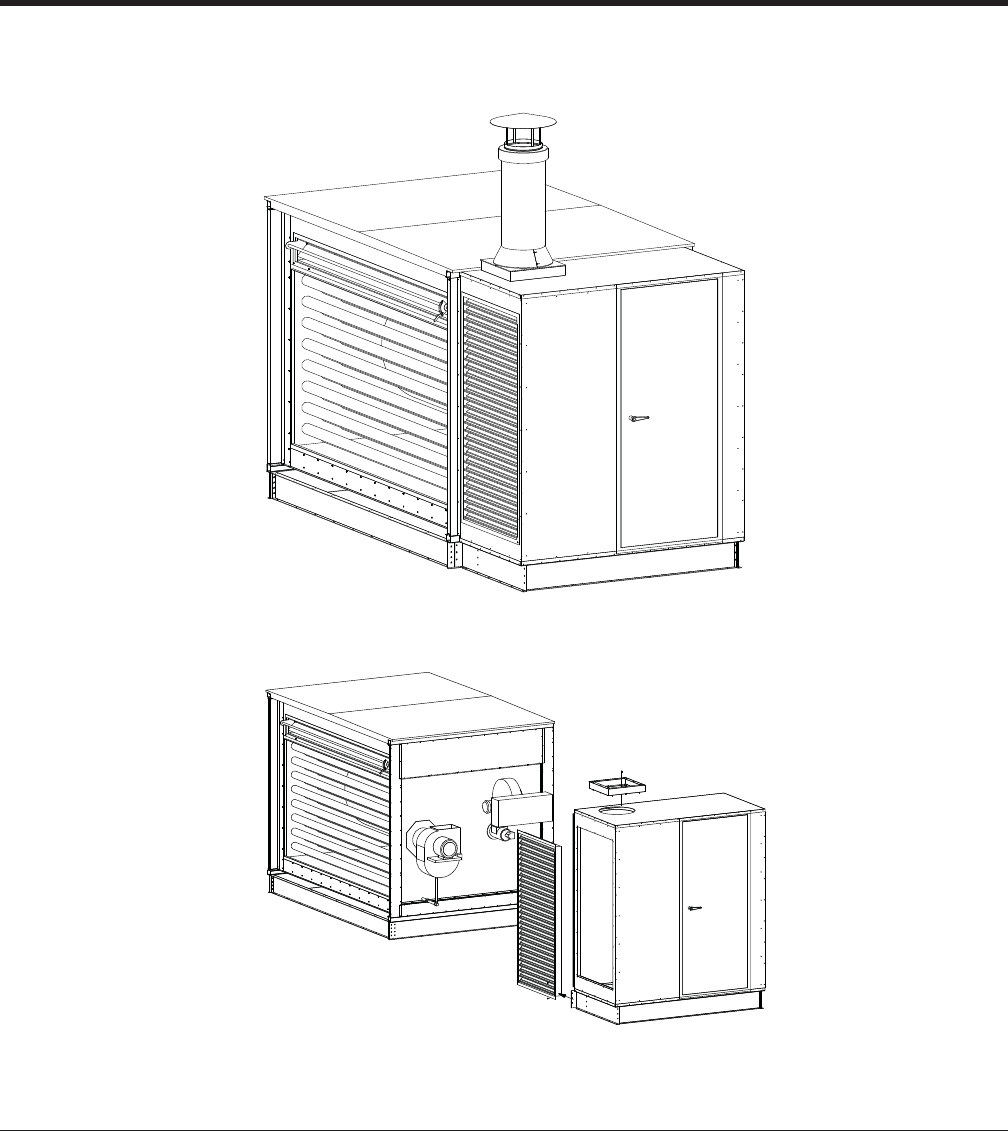
JOHNSON CONTROLS 35
FORM 102.20-QG1 (808)
Indirect Gas-Fired Furnace – (IG)
The IG segment must be positive pressure. (Fan segment is not al-
lowed downstream of the IG Segment.)
Furnaces in VAV applications are designed to be used only with 100%
supply fan airfl ow.
– Use of furnace in reduced airfl ow operation may result in seri-
ous damage to equipment and may be hazardous.
– Indirect Gas-Fired Furnace Maximum Temperature rise = 90F
– Indirect Gas-Fired Furnace Maximum A.P.D. = 2.00” W.C.
– The Maximum Temperature at the IG segment discharge =
190F
Furnace includes a series stainless steel primary heat exchanger. A
secondary stainless steel heat exchanger is also included.
– An access door is required upstream of any IG segment.
– Gas pipe train options are available
The IG segment pipe chase is a single pipe chase that covers only
the IG segment.
– The pipe chase is not intended for trapping or piping, but for
the connections only.
– Pipe chase enclosure is optional for indoor units and required
for Outdoor units.
Notes & Options
I.D. FAN
CONTROL
PANEL
DOOR
HEAT EX.

JOHNSON CONTROLS
36
FORM 102.20-QG1 (808)
Turndown Examples and Guidelines – (IG)
Description
Indirect Fired Gas Heater section consists of the stain-
less steel primary and secondary heat exchanger with
the power burner design. The basic design allows the
power burner to inject the correct ratio of air and gas into
the primary heat exchanger where the main combustion
occurs. The heated products of combustion then pass
through the multiple secondary tubes heating each tube
for maximum heat transfer. The products of combustion
then pass to the inducer draft fan and through the fl ue.
The air is heated by passing around the primary and
secondary tubes for optimal heat transfer. The heater
is designed for 80% effi ciency.
• The furnace comes wired with all necessary
safety controls and valves installed.
• The controls vary based on the BTU level and
Insurance Requirements selected.
• These units are designed to handle Natural Gas
as a standard.
• The gas pressure available at the unit needs to be
considered when ordering the equipment.
Equations:
• BTU Output Required = CFM x 1.08 x Tempera-
ture Rise Required
• BTU Input = BTU Output ÷ .80
The Solution furnaces are available with burner fi ring
arrangements:
• 3-1 MODULATION: The burner will modulate for
100% - 33% of full fi re
• 10-1 MODULATION: The burner will modulate
from 100% - 10% of full fi re
• 25-1 MODULATION: The burner will modulate
from 100% - 4% of full fi re
Choosing Considerations
When choosing the proper turn down three issues should
be considered.
1. Greater modulation provides improved temperature
control. If the furnace is modulated to its minimum
fi re position, and controls determine there is too
much furnace capacity, then the furnace is staged
on and off, on carefully chosen time delays, to satisfy
the light load heating requirements. The 3-1 option is
generally suffi cient particularly if design temperature
rise does not exceed 30-40 degrees.
2. The greater the range of modulation the greater
the cost.
3. Experience requires that a furnace should not turn
down to a temperature rise less than 5-8 degrees.
Greater modulation decreases the fl ue stack tempera-
ture at low fi re, increases the amount of condensation,
and can decrease the life of the heat exchanger even
though all Solution furnaces utilizes a stainless steel
primary and stainless steel secondary heat exchanger
tubes along with condensate drains.
The condensate line must be adequately sized, trapped,
along with drainage of the condensate per local code.
Literature Reference — See Installation Operation Manual – Form 102.20-NOM1
HEATING SEGMENTS
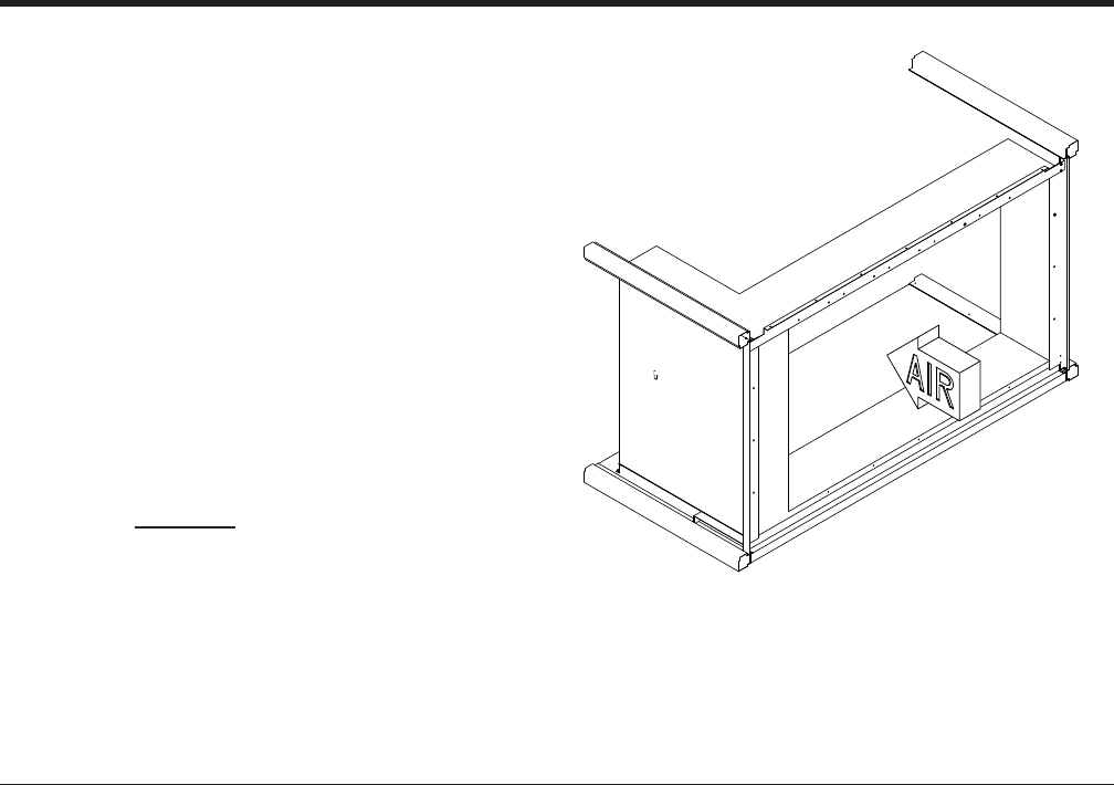
JOHNSON CONTROLS 37
FORM 102.20-QG1 (808)
Electric Heat – (EH)
The EH segment can be installed in either a draw
through or blow through arrangement.
Remote Mounted terminal panels
• An electric heat control panel may be selected as
a remote panel.
• In this case the panel will be shipped separate to
the customer for fi eld installation.
An optional wide access door may be ordered on the
opposite side of the electric heater control panel.
An SCR Controller is available on all heaters with a
height dimension greater than 26.5”.
Delta T = kW x 3160
CFM
• Electric heaters are of “open coil” construction, with 80% nickel,
20% chromium coil elements machine crimped to stainless steel
terminals and amply supported on ceramic bushing isolators.
Open coil heaters are furnished with a disk-type, automatic reset
thermal cutout for primary over-temperature protection. Heaters
are also being furnished with disk-type, load-carrying manual
reset thermal cutouts, factory wired in series with heater stages
for secondary protection.
• Heaters are rated for the voltage, phase and number of heating
stages indicated in the schedule. All three-phase heaters will
have equal, balanced, three-phase stages.
• Finned tubular construction - optional
• All internal wiring shall be stranded copper with 105°C minimum
insulation and shall be terminated in crimped connectors or box
lugs.
• Power and control terminal blocks shall be provided and clearly
marked for all fi eld wiring and shall be sized for installation of
75°C copper wire rated in accordance with NEC Table 310-16,
not more than three conductors in a conduit.
• Heaters shall be furnished with built-in fuses per NEC. Heaters
with loads greater than 48 amps will be furnished with built-in
fusing. Heaters shall be sub-circuited into a maximum of 48
amps per circuit. Low resistance single element fuses will be
mounted in phenolic fuse blocks fi tted with extra tension springs
to assure cool connections. Fuses shall be sized at least 125%
of the load.
Notes & Options

JOHNSON CONTROLS
38
FORM 102.20-QG1 (808)
Typical Applications
An electric heating system will use either an open wire
element or an element encased in a sheathed ceramic
material. For most applications either construction can
be used, however, in applications with potentially high
humidity (i.e.100% OA application), the encased ele-
ment will have a longer life expectancy and is recom-
mended.
Selection of the proper unit, heating load and tempera-
ture control system is dependent on the application of
the unit.
1. Make-up Air Unit is used for heating 100% OA air
to the indoor design temperature with a typical dis-
charge temperature of 55-70° F.
2. Space Heating Unit is used for heating 100% RA
from the conditioned space to make up for building
heat loss.
3. Combination Make-up Air & Space Heating
is used to heat OA & RA combined through a
mixing box.
Optional Control Methods
1. Proportional step control – multi-staging control of
circuits
2. SCR Controller – a time proportioning type controller
that modulates the heater and supplies the exact
amount of power to match the heat demand. Preci-
sion controlled from zero to 100% in direct response
to the modulating thermostat signal system. 100%
step-less and noise-less operation. *Note – SCR’s
are limited to a maximum KW. Multiple SCR’s may
be applied to larger heaters. Multiple SCR’s do not
imply full face control. See “Special Application
Considerations”.
3. Vernier Proportional Control – used on larger KW
heaters where very close heat control is required.
The system employs a combination of SCR and non-
SCR steps. This is accomplished by satisfying most
of the heat requirement through the non-SCR steps
and then the last portion of the heat requirement is
“fi ne-tuned” by the modulating SCR controller. The
SCR step is nominally equal to the KW of a non-SCR
step to provide an even transition between steps.
*Special Application Considerations:
(contact factory for special applications)
It is always important to ensure the proper control
method so that the heater effectively treats the required
amount of outdoor air regardless of temperature, with-
out risking over heating and or tripping the low limit
thermostat.
1. In applications where air fl ow varies and temperature
ranges are extreme, the face area of the heater
should be designed for full face simultaneous con-
trol, thus avoiding problems of air and temperature
stratifi cation. This is extremely relevant on heaters
with large face areas. The full face control method,
for a partial of fully active electric heat coil, elimi-
nates the concern of air bypass through inactive
circuits. Thus, almost any load split can be safely
achieved.
2. With lower airfl ows under VFD control, one must
assure there is even air fl ow across the face area of
the heater. This may require special consideration
of the air-inlet position and size, (i.e. inlet to be
centered on the front of the unit).
a. Instability in temperature can easily occur if the
variation in the air fl ow characteristic is exces-
sive. Large temperature variations can occur
as specifi c stages and circuits are modulated
on and off. In extreme cases, this instability can
cascade and cause extreme over-heating on the
complete heater face or in spots of the heater
face due to low-air-fl ow augmented by unit inlet
opening locations and distance.
HEATING SEGMENTS

JOHNSON CONTROLS 39
FORM 102.20-QG1 (808)
Recommended Safety Control Options:
A fan relay and an airfl ow switch provide added protec-
tion for applications listed above.
– Fan relay provides the advantage of being a posi-
tive electrical interlock between the fan and the
heater.
– Airfl ow switch is normally used to prevent a
heater from operating unless air is fl owing.
Minimum Air Flows
Electric heaters differ from steam or hot water coils in
that the heat output is constant as long as the heater
is energized. Therefore, suffi cient air fl ow must be pro-
vided to prevent overheating and nuisance tripping of
the thermal cutouts.
The minimum required velocity is determined from the
graph on the basis of entering air temperature and watts
per square foot of cross segmental heating coil area.
EXAMPLE:
Determine whether the minimum air velocity requirement
is met for a 108 kW heater installed for an air handling
unit operating at 18,000cfm at a maximum inlet tem-
perature of 65°F.
1. Heating Coil Area = 33 sq. ft.
2. kW / sq ft. = 108 kW = 3.3 kW / sq. ft. 33 sq. ft.
3. Use top curve (below 80°F inlet air). Find 3.3 kW
per square foot on the vertical axis.
Read the minimum face velocity required, which
in this case is 250 feet per minute (fpm).
4. AHU FV = 18,000 cfm = 545 fpm 33 sq. ft.
Since 545 FPM exceeds the minimum velocity require-
ment of 250 FPM, this installation is satisfactory for
heater operation.
Equations: Use these formulas as rough guidelines for
estimating purposes only:
EQUATION 1: MBH = kW x 3.412
EQUATION 2: T = kW x 3160
Scfm
EQUATION 3: Actual kW = Rated kW x V actual
V rated
EQUATION 4: Load Amps = kW x 1000
V x 1.732
Literature Reference — See Application Guide ‘Electric Heaters for Air Handling Units’ – Form 102.20-AG4
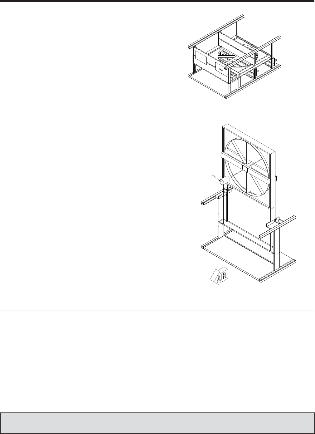
JOHNSON CONTROLS
40
FORM 102.20-QG1 (808)
ENERGY RECOVERY – ER
Energy Recovery
An HVAC system that utilizes energy recovery is more
energy effi cient, improves humidity control, and reduces
peak demand charges.
Solution Energy Recovery wheels:
– Improve building HVAC system performance by
effi ciently preconditioning the outdoor air supply.
The ER segment transfers heat & humidity from adjacent
exhaust air & outside air streams.
– Improves HVAC system effi ciency up to 40%
– Improves de-humidifi cation capacity up to 75%
Thermal performance is certifi ed by the manufacturer
in accordance with ASHRAE Standard 84, Method of
Testing Air-to-Air Heat Exchangers and ARI Standard
1060, Rating Air-to-Air Energy Recovery Ventilation
Equipment
Horizontal wheel segment
Vertical wheel segment
ER has only one type of confi guration – supply air fan draw-thru and
exhaust air fan draw-thru for indoor and outdoor applications.
1. Indoor - Vertical wheel segment with stacked construction
a. All doors are usually on drive side with two on top tier
(both sides of wheel) and two on bottom tier (both sides of
wheel).
2. Indoor and Outdoor - Horizontal wheel segment with single
tier construction
a. Outside Air inlet is located on both sides of segment
b. Access door is usually on drive side for horizontal wheel
segments.
Wheel control
• Damper control
• VFD
– Auxiliary drain pan – none
– Purge function – Optional
Notes & Options
Literature Reference — See Application Guide “Energy Recovery Wheels” – Form 102.20-AG6
HEATWHEEL MOTOR
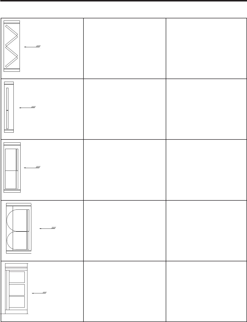
JOHNSON CONTROLS 41
FORM 102.20-QG1 (808)
FILTER SEGMENTS – AF, FF, RF AND HF
Application and Options Table
AF - ANGLE FILTER
Application: (AF)
– Pre-fi lter side-load negative pressure
confi guration
– Single stage fi ltration
Options:
– Auxiliary Drain pan options
– 2” & 4” Low Effi cient media
– 4” High Effi cient media
FF - FLAT FILTER
Application: (FF)
– Pre-fi lter side-load negative pressure
confi guration
– Single stage fi ltration
Options:
– Auxiliary Drain pan
– 2” & 4” media
– Low Effi cient media
RF - RIGID FILTER
Application: (RF)
– Pre fi lter negative pressure confi gura-
tions:
Side-load, front load and rear load
– Final fi lter positive pressure confi gu-
rations:
Front-load (upstream access required)
Rear-load (downstream access required)
Side-load
Options:
– 2-stage fi ltration.
– Auxiliary Drain pan
– 4” & 12” High Effi cient Media
(65%-95%)
RF - BAG FILTER
Application: (Bag)
– Pre fi lter negative pressure confi gura-
tions:
Side-load, front load and rear load
– Final fi lter positive pressure confi gu-
rations:
Front-load (upstream access required)
Rear-load (downstream access required)
Side-load
Options:
– 2-stage fi ltration.
– Auxiliary Drain pan
– High Effi cient Media (65%-95%)
HF - HEPA FILTER
Application: (HF)
– Pre fi lter negative pressure confi gura-
tions:
Front-load (upstream access re-
quired)
– Final fi lter positive pressure confi gu-
rations: Front-load (upstream access
required)
– Face velocity - maximum 500 fpm
– Single stage fi ltration
Options:
– Auxiliary Drain-pan
– Media effi ciency 99.97% & 99.99%
AIRFLOW
Side loading only
AIRFLOW
Side loading only
AIRFLOW
Rear, Front or side loading
(length includes 2" prefilter)
AIRFLOW
Rear, Front or side loading
(length includes 2" prefilter)
AIRFLOW
Front loading
Caution – Never place a blow-thru fi nal fi lter segment directly downstream of a cooling coil with a saturated leaving air tem-
perature. Once the relative humidity has reached 100%, adiabatic cooling applies to the expanding air and associated tem-
perature drop. Moisture deposits may form on fi nal fi lters.
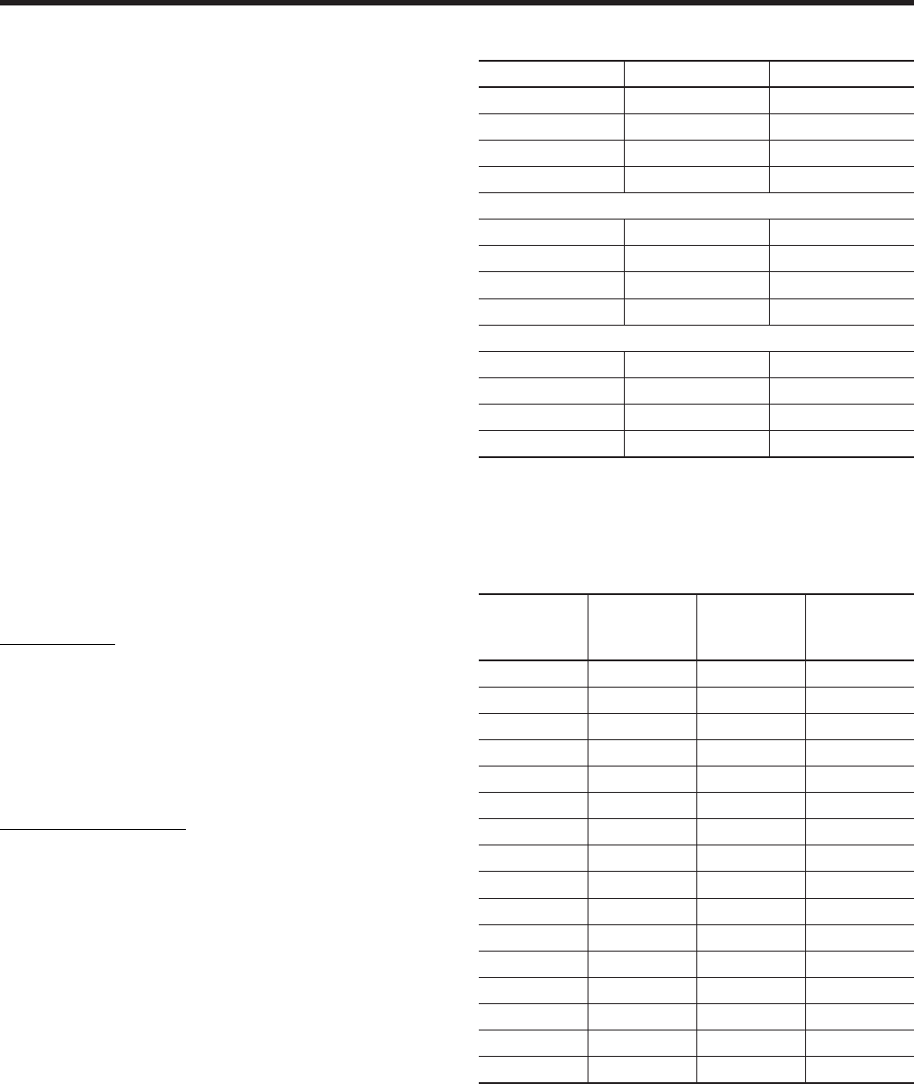
JOHNSON CONTROLS
42
FORM 102.20-QG1 (808)
Mechanical Air Filters
Mechanical air fi lters remove dust by capturing it on
the fi lter medium, the fi lter element. A mechanical air
fi lter is any type of dry media fi lter. All of the throwaway
air fi lters used in HVAC systems and Air Handlers are
mechanical air fi lters. Any man made or natural fi ber
fi lter is a mechanical air fi lter. This includes HEPA air
fi lters as well.
Comparing Various Air Filters To MERV Ratings
Dry-media fi lters exhibit an increase in effi ciency as they
collect dirt and dust. A dry media fi lter is at the lowest
effi ciency rating when it is ‘clean’. The increase in ef-
fi ciency corresponds to a decrease in open area as the
media collects fi bers and particles. In dust critical envi-
ronments the user typically can’t wait for the increased
effi ciency. As a result of this type issue, ASHRAE 52.2
defi ned the minimum effi ciency reporting value (MERV)
to describe fi lter performance.
The MERV is based on the worst case performance of
a fi lter through all six stages of dust loading and all par-
ticles 0.3-10 microns. Because the rating represents the
worst-case performance, end users can use it to assure
performance in applications where a maximum particle
count must be maintained over the fi lter’s entire life.
ASHRAE 52.1 arrestance and dust-spot tests used ei-
ther weights or times to generate a ratio, or effi ciency.
This effi ciency was an easy way to describe a fi lter’s per-
formance. Thus, a 50 percent fi lter would stop a nominal
50 percent of the particles in the air stream as averaged
over the test period. Unfortunately, this average over
time told a user nothing about performance for a specifi c
particle size at a specifi c stage in a fi lter’s life.
ASHRAE Standard 52.2 rates fi lter arrestance differently.
Standard 52.2 testing protocol includes the reliable and
consistent testing of fi lter performance on particles of nomi-
nal 0.3-10 microns in diameter. This testing provides an
accurate and clear description of arrestance at each stage,
rather than the average produced by Standard 52.1.
ASHRAE 52.2 Particle Size Ranges
Range Size (in microns) Group
1 0.30 to 0.40 E1
2 0.40 to 0.55 E1
3 0.55 to 0.70 E1
4 0.70 to 1.00 E1
5 1.00 to 1.30 E2
6 1.30 to 1.60 E2
7 1.60 to 2.20 E2
8 2.20 to 3.00 E2
9 3.00 to 4.00 E3
10 4.00 to 5.50 E3
11 5.50 to 7.00 E3
12 7.00 to 10.00 E3
The effi ciency of the fi lter is measured on 12 particle size
ranges. The twelve size ranges are then placed in three
larger groups (E1, E2, E3) and the percentages in each
group are averaged
MERV
Value
Group 1
Av. Eff.%
0.3 to 1
Group 2
Av. Eff.%
1 to 3
Group 3
Av. Eff.%
3 to 10
1 n/a n/a E3<20
2 n/a n/a E3<20
3 n/a n/a E3<20
4 n/a n/a E3<20
5 n/a n/a 20<35
6 n/a n/a 35<50
7 n/a n/a 50<70
8 n/a n/a 70
9 n/a E2<50 85
10 n/a 50<65 85
11 n/a 65<80 85
12 n/a 80 90
13 E1<75 90 90
14 75<85 90 90
15 85<95 90 90
16 95 95 95
The average is called the Particle Size Effi ciency which
is used to determine the Minimum Effi ciency Reporting
Value (MERV).
FILTER SEGMENTS – AF, FF, RF AND HF
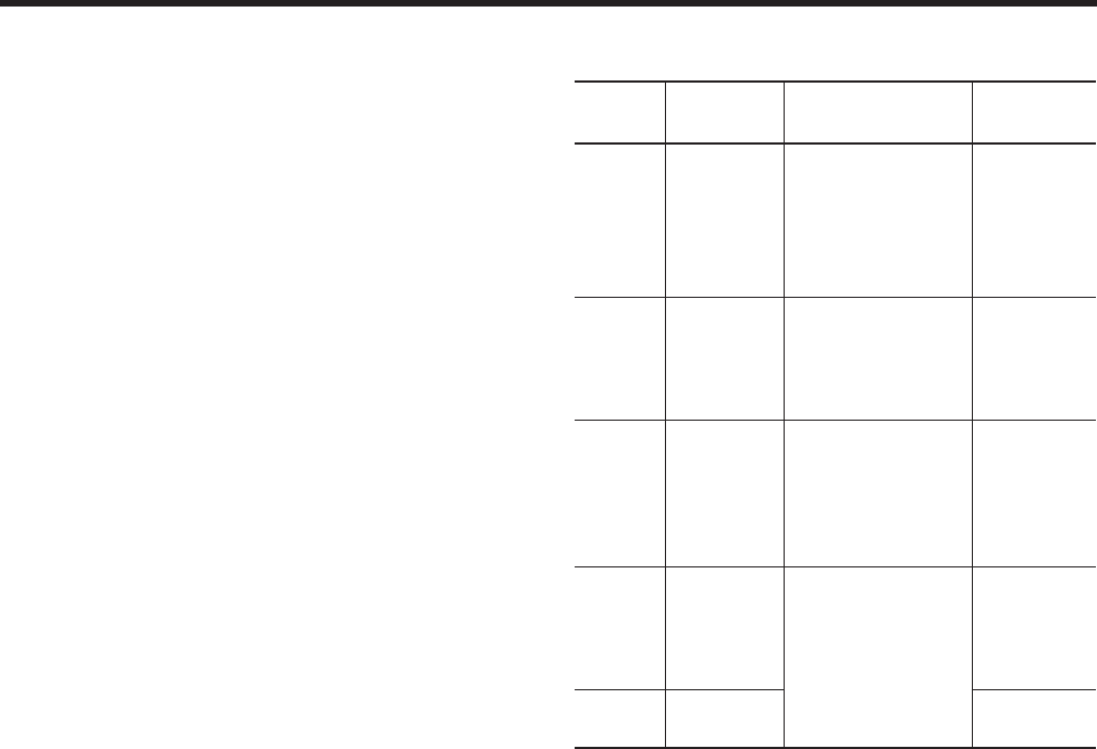
JOHNSON CONTROLS 43
FORM 102.20-QG1 (808)
MERV Analysis
The required MERV rating for fi lters will follow directly
from the maximum allowable particle concentrations in
the three bands of 0.3-1.0 microns, 1.0-3.0 microns and
3.0-10.0 microns.
1. A rating of MERV 10 corresponds to 50-65 percent
effi ciency for particles 1-3 microns and above 85
percent effi ciency for particles 3-10 microns.
2. A rating of MERV 13 corresponds to less than 75
percent arrestance effi ciency for particles 0.3-1
microns, above 90 percent effi ciency for particles
1-3 microns, and above 90 percent effi ciency for
particles 3-10 microns.
3. A rating of MERV 15 corresponds to 85-95 percent
arrestance effi ciency for particles 0.3-1.0 microns,
above 90 percent effi ciency for particles 1-3 mi-
crons, and above 90 percent effi ciency for particles
3-10 microns.
4. Ratings of MERV 16 to MERV 20 correspond to
HEPA and ULPA fi lters.
Note: The entire list of MERV ratings based on particle ar-
restance effi ciency is found in Table 12-1 of Standard 52-2.
As an example, if you are concerned with pulling out a
high percentage of molds, mold varies in size from about
4 microns to 40 microns.
• The greatest numbers of mold spores are less than
10 microns in diameter.
• The chart indicates a MERV 8 fi lter will pull out at
least an average of 70% of the particles down to 3
microns.
• Pleated fi lters are available in a MERV 11. The
MERV 11 would give you an average of at least
85% mold removal.
The following comparisons are not meant to be defi nitive:
MERV
Rating
Particle
Size Applications
Filter
Type
1-4 >10 um Residential
Light Commercial
Equipment
Fiberglass
Poly Panel
Permanent
Metal
Foam
5-8 3 to 10 um Commercial
Industrial
Better Res.
Paint Booth
Pleated
Filters
9-12 1 to 3 um Res. – Best
Commercial
Telecommunica-
tions
Industrial
Best
Pleated
Rigid Box
Rigid cell
Bag
13-16 0.3 to 1 um
Smoke Removal
General Surgery
Hospitals
Health Care
Rigid Cell
Bags
V-Cell
Mini-pleat
16-20 0.3 um HEPA /
ULPA
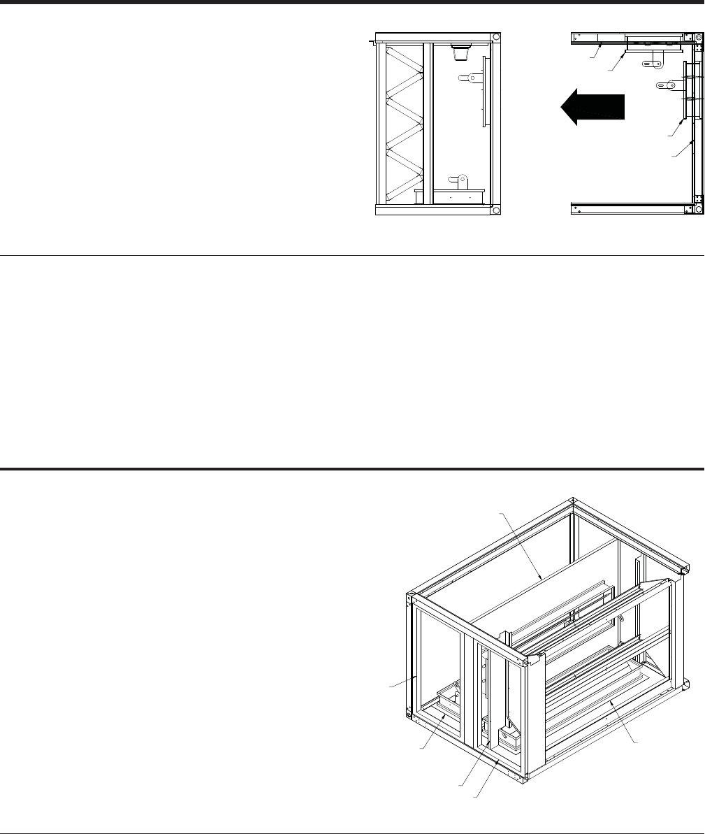
JOHNSON CONTROLS
44
FORM 102.20-QG1 (808)
MIXING SEGMENTS & ECONOMIZERS – MB, FM, EE, EF, FD, IP, VE AND VF
Mixing Box/Mixing Segment (MB/FM)
Solution has designed a mixing box (MB) which com-
bines fresh air and re-circulated air by means of inter-
connected dampers.
Solution’s space saving combination fi lter mixing seg-
ment (FM) offers an angle fi lter as an integral part of
the mixing segment to economically provide fi ltering
and mixing capability.
FRONT DAMPER
TOP DAMPER
END WALL PANEL
ROOF PANEL
ANGLE FILTER ASY
ECONOMIZER WALL
DAMPER
DOOR
DOOR
DAMPER
• The MB/FM Segment typically must be the fi rst segment in
direction of airfl ow.
• Access doors are optional.
• Auxiliary drain pans optional except when bottom opening is
selected
• Combination fi lter mixing segment (FM) provides a full-height
access door for fi lter service.
• Variable size openings and dampers are optional.
• Safety grate option for bottom openings
Hood application – only the following outdoor segments are avail-
able
• Mixing box (MB or FM) Economizer (EE or EF) outside air
(OA) inlet openings.
Hood Options
• Bird screen is standard with all hoods
• Moisture eliminator is available as an option
Note: When the moisture eliminator option is selected the mois-
ture eliminator acts as the bird screen. A separate bird screen will
not be required.
Notes & Options
• The EE or EF segment may be fi rst in the air-stream or may
be used in conjunction with other segments in an economizer
application.
Hood application – only the following outdoor segments are avail-
able with hoods
• Fan Exhaust (FE) discharge openings
• Economizer (EE or EF) exhaust air (EA) discharge openings
Hood Options
• Bird screen is standard with all hoods
• Moisture eliminator is available as an option
Note: When the moisture eliminator option is selected the mois-
ture eliminator acts as the bird screen. A separate bird screen will
not be required.
Notes & Options
Economizer
Solution offers numerous economizer confi gurations
for various ventilation applications. The economizer is
designed with factory packaged controls in-mind. Cor-
rectly set-up economizers will constantly track building
pressurization as well as both indoor and outdoor air
temperatures using transducers, mixed air sensors
and enthalpy control that monitors air temperature and
humidity.
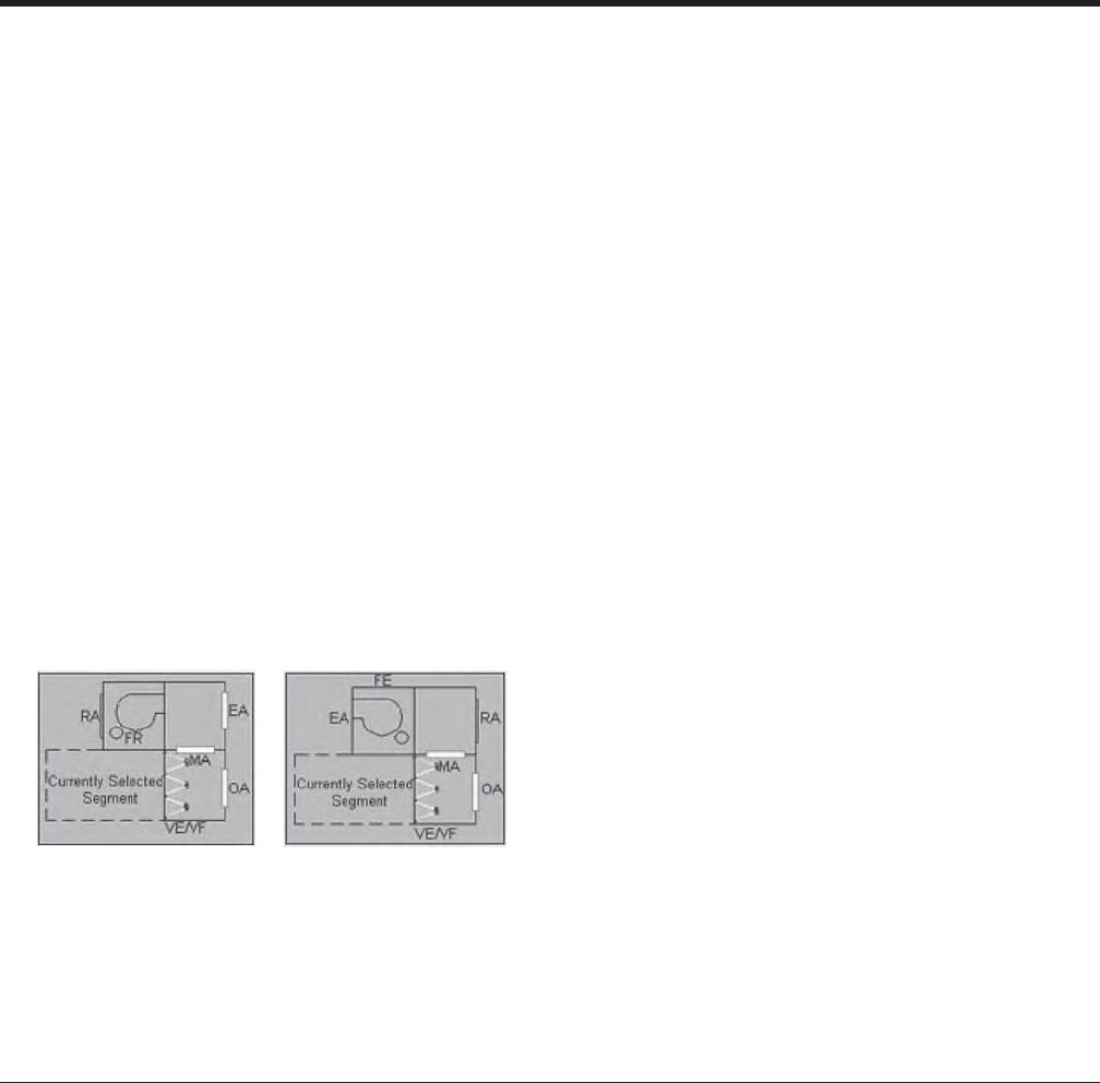
JOHNSON CONTROLS 45
FORM 102.20-QG1 (808)
• VE segment will have the same construction materials as the
MB or FM segment.
•No optional auxiliary drain pain.
• Optional Access Doors & View-ports.
• Auxiliary drain pans optional except when bottom opening is
selected
• Variable size openings and dampers are optional.
• Safety grate option for bottom openings
Notes & Options
General Considerations:
1. VE segment shall be available for all Solution unit
sizes provided engineering rules for stacking allow
the top section of VE segment to be tiered.
2. VE segment shall be designed for the confi gurations
described in the sketches below.
Vertical Economizer
Solution offers a Vertical Economizer arrangement which consists of tiered segments; top and bottom. Both top and
bottom segments are designed to be of minimum length required. The VE arrangement is designed to be fi rst in the
air-stream unless it is immediately preceded by XA, FR (DWDI), FR (SWSI), FE (DWDI), FE (SWSI).
The VE segment must be confi gured in a top tier arrangement per the following rules:
1. Only one VE per unit
2. Must be tiered over the MB or FM segment
3. MB or FM segment must have a top damper
3. Both top and bottom sections of the VE segment
shall be designed to be of minimum length required.
The design shall allow the two sections of VE seg-
ment to be of different lengths.
4. Sound data shall be provided for all confi gurations
of VE segment.
5. Controls shall be available on VE segment for both
top and bottom sections.
6. Filter option shall be available in the bottom section
of the VE segment similar to FM segment.
7. Doors are available as an option for indoor units
and are required for outdoor units.
JOHNSON CONTROLS
46
FORM 102.20-QG1 (808)
This Mixing Box Optimization chart provides techniques and suggestions to meet the desired needs for your spe-
cifi c mixing box design process. It is a decision-making process in which the effectiveness of a mixing box must be
considered. Ideally, mixing boxes should provide adequate mixing.
MIXING BOX OPTIMIZATION CHART
Mixing Box
Assessment
Mixing
Effectiveness
Advantages Disadvantages
Standard Mixing
Box
with/without
Angle Filter
GOOD APPLICATION
Most effective
1. In constant volume system
• Parallel blade control damper
• Blade orientation and rotation
promotes mixing
• Lowest fi rst cost
• Space saving
• Risk of low mixing effective-
ness
• with fi lter
• with VAV
• Risk of nuisance low limit
tripping
• Risk of stratifi cation
Standard Mixing
Box without fi lters
and
*Sequenced
Controlled
Dampers
(sequence listed
below)
BETTER APPLICATION
Most effective
1 In VAV system
2. With Min Max damper
3. With opposed blade control
damper
* Sequenced damper control is most
suitable for low air fl ow – low veloc-
ity applications
• Lower fi rst cost
• Mixes outside and return air
more proportionately
• Improves system perfor-
mance at low fl ow rates
• Sequence will add stability
to the control loop
• Risk of nuisance low limit
tripping
• Risk of possible stratifi ca-
tion
Standard Mixing
Box
without fi lters and
Static
Air Mixer (blender)
BEST APPLICATION
Most effective
1. Outside air designs at freezing
and sub-freezing temperatures
2. Constant or VAV systems
*Sequenced opposed control
dampers are recommended for
VAV systems
• Greatly improves mixing of
sub-freezing air streams
• Greatly reduces, if not elimi-
nates, stratifi cation in short
distances
• Works effectively and con-
sistently
• Higher fi rst cost among
damper designs
• Increases unit length
• Some additional static
pressure loss
*Suggested sequence of operation as follows:
1) Start the fan with the return air damper fully open and the outdoor air damper fully closed.
a) An independent signal shall be sent to the Outdoor air damper
i) Minimum open position
b) An independent signal shall be sent to the Return air damper
i) Full open position
2) The outdoor air damper shall modulate further open to admit additional outdoor air as required to satisfy the (mixed air), (discharge air)
temperature sensor or IAQ requirements.
3) Once the outdoor air damper is fully open, if additional outdoor air is required, the return air damper shall modulate toward its closed
position.

JOHNSON CONTROLS 47
FORM 102.20-QG1 (808)
Typical Economizer Application
ASHRAE Standards Demanding Economizer Consid-
erations:
ASHRAE 90 - The ‘standard’ details requirements for
a high performance & energy-effi cient design of build-
ings (which includes equipment as part of the building
system).
What is high performance?
• Lower energy usage
• Lower life cycle cost
• Durable
• Healthy
• Productive
How buildings use energy?
• Different building types use it differently
• Occupancy & equipment schedule
• Internal vs. external load dominated buildings
• Building occupants
ASHRAE 62 - The ‘standard’ details Indoor Air Quality
issues with the purpose to establish acceptable ventila-
tion procedures & standard-of care.
What are ventilation procedures?
• Mechanical ventilation systems shall include con-
trols, manual or automatic, that enable the fan
system to operate whenever the spaces served are
occupied
• The system shall be designed to maintain the
minimum outdoor airfl ow as required under any load
condition
What is a standard-of-care?
• Guidelines to designers addressing contaminant
source control, minimum maintenance activity &
frequency, fi ltration and managing relative humidity
Building Pressurization
Building Pressurization – is defi ned as the relative air
pressure in a building, as compared to the exterior or am-
bient air pressure. A design amount of outside air must
be introduced to insure design building ventilation.
This difference in pressure has a large impact on how the
building operates and it can have undesirable if not pe-
culiar impacts on building operations. Over-pressurized
buildings will have doorways which are transformed into
wind tunnels. Under-pressurization will create a building
that has become negatively pressurized and infi ltration
makes indoor climate control diffi cult.
The difference between the amount of OA and EA must
remain constant at all operating conditions to maintain
proper building ventilation and pressurization.
Over Pressurization caused by -
• Too much OA
• Not enough EA
Results in -
• Excessive energy consumption
• Perimeter doors opening
Under Pressurization caused by -
• Too little OA
• Too much EA
Results in -
• Ventilation problems with occupants
• Excessive building odors
• Poor temperature control (infi ltration)
• Excessive energy costs
• Diffi culty in opening doors
Knowing how to correct and avoid pressurization prob-
lems can prevent minor, inconvenient and comfort re-
lated issues from growing into insurmountable problems
and liability issues.
MIXING SEGMENTS & ECONOMIZERS – MB, FM, EE, EF, FD, IP, VE AND VF
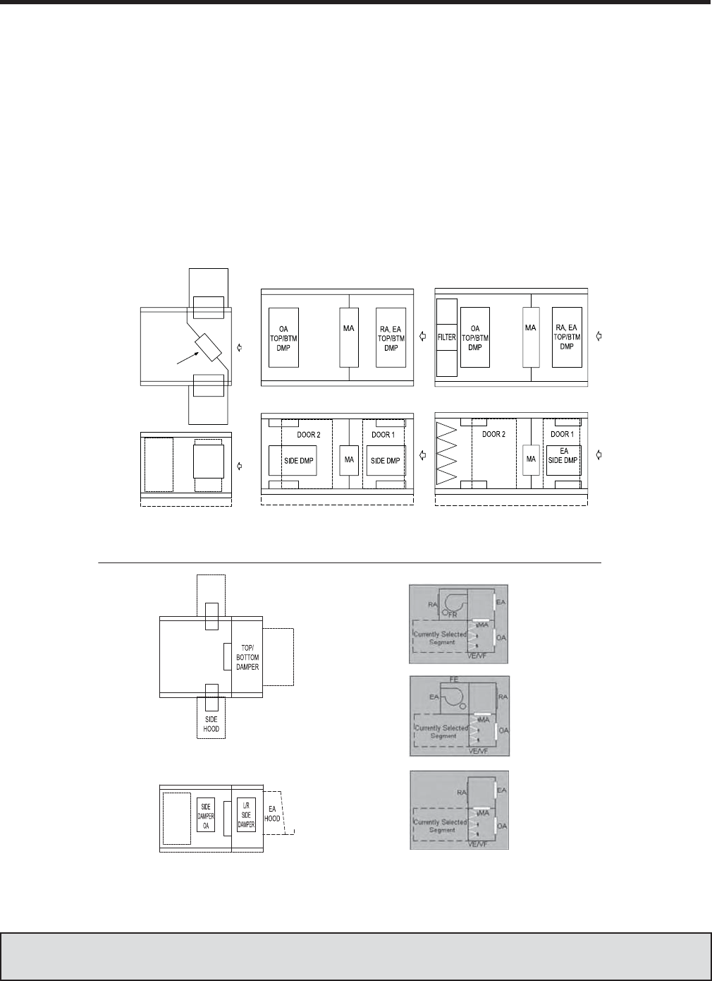
JOHNSON CONTROLS
48
FORM 102.20-QG1 (808)
Methods of Pressurization Control
Full Return Air Fan Economizer -
Handles pressure losses through
• Return air system
• Exhaust dampers
Supply Fan handles pressure losses through
• Outside air dampers
• Mixed air dampers
Dedicated Exhaust Fan Economizer -
Fan runs only when economizer opens the OA dampers
Handles pressure losses through
• Return air system when in exhaust mode
• Exhaust air path
Building pressurization provides insight in identifying,
diagnosing, correcting and most importantly, avoiding
some unusual building operational problems.
Literature Reference — See Application Guide ‘Return & Exhaust Fan Economizers and Building Pressuriza-
tion’ – Form 100.00-AG3
MIXING SEGMENTS & ECONOMIZERS – MB, FM, EE, EF, FD, IP, VE AND VF
Economizer Arrangements
LD08032
TOP
VIEW
SIDE
VIEW
L/R SIDE
DAMPER
ANGLED
MIXING
DAMPER
EE - Economizer with
angled mixing damper.
EE - Economizer with vertical
mixing damper. NOTE: Top damp-
ers not available for outdoor units.
EF - Filter/Economizer
EE - Inlet/Economizer
(50% OA on each side with barometric exhaust)
VE - Vertical Economizer
43080DL33080DL
53080DL
TOP
VIEW
SIDE
VIEW
SIDE
VIEW
(100% OA, 100% EA) )AE %001 ,AO %001()AE %001 ,AO %001(
NOTE: VF (VerticalFilter Economizer) is available with filtration.
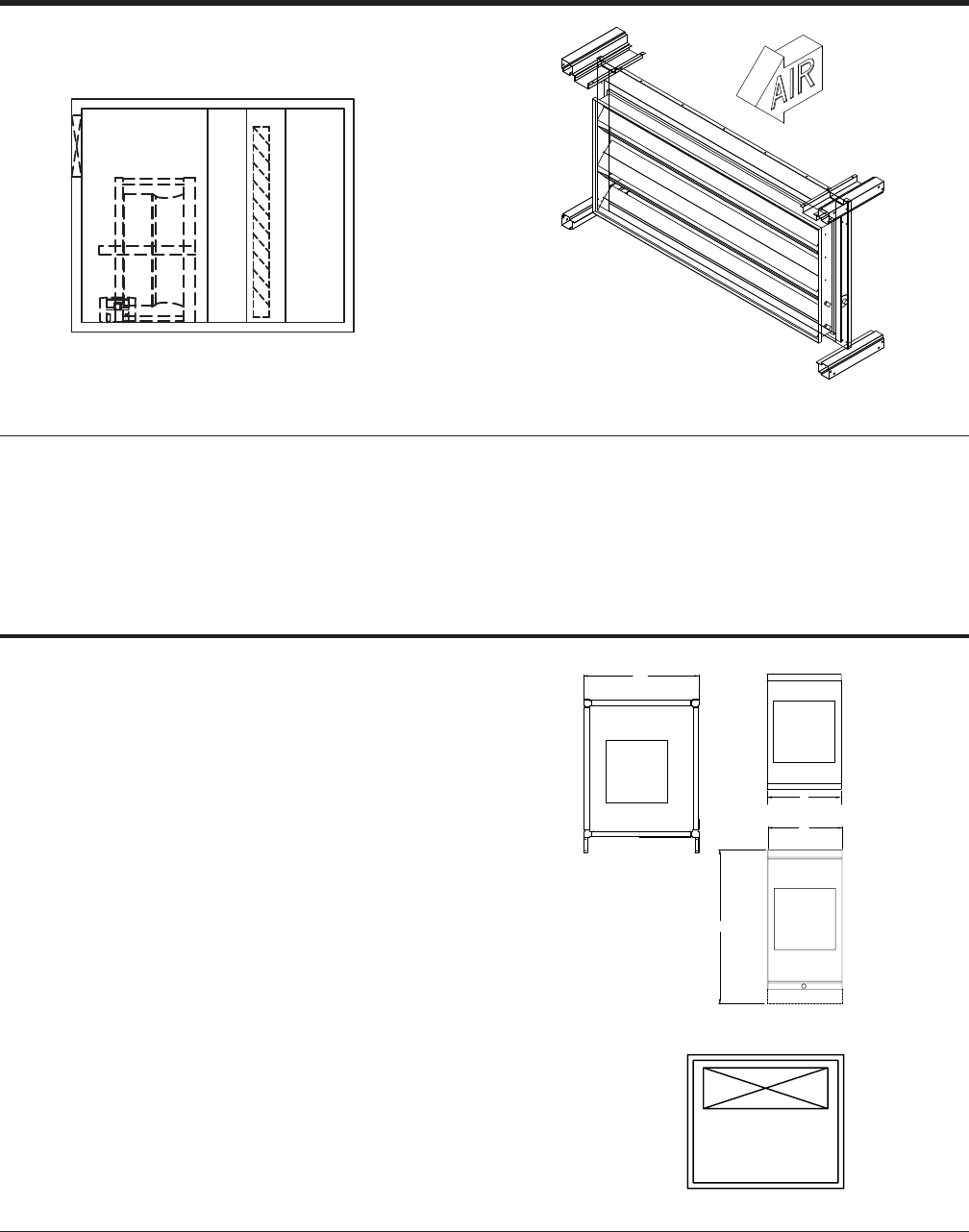
JOHNSON CONTROLS 49
FORM 102.20-QG1 (808)
Face Damper – (FD)
The FD segment contains a full face damper
• Face dampers are sized to cover whole components down-
stream within tunnel.
The FD is available for both indoor and outdoor applications.
• The FD can be located fi rst in air stream or last in air stream,
only with indoor applications.
Access doors and viewing ports must be located in adjacent seg-
ments.
• Access is required immediately upstream of the FD segment
to access damper actuator and linkage.
Damper material option:
• Galvanized
• Aluminum
Notes & Options
FS XA FD XA
Inlet Plenum – (IP)
The Inlet Plenum is as its name implies; a segment
used to provide a proper means of air entry into the air
handler.
Openings may be applied to top, bottom, front, left side
and right side.
The variable size opening option allows the opening to
be properly aligned and sized for airfl ow convergence
and or divergence.
If a plenum fan is used as a return fan and return air is ducted, an IP
segment must be provided upstream of the plenum fan.
• Dampers are not available as an option
• Access Door - Optional
• Auxiliary Drain Pans – Optional
Notes & Options
W
H
FRONT INTAKE
FRONT VIEW
SIDE VIEW
TOP/BOTTOM
INTAKE
L
L
TOP VIEW
LEFT / RIGHT
SIDE INTAKE
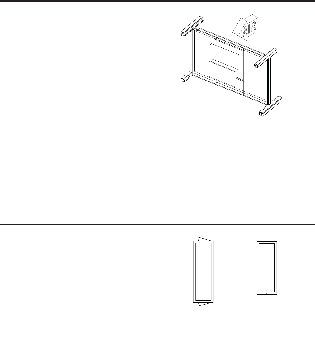
JOHNSON CONTROLS
50
FORM 102.20-QG1 (808)
ACCESSORY SEGMENTS
Diffuser Segment – (DI)
The diffuser segment is constructed of heavy gauge
galvanized steel with a built-in perforated plate, which
prevents high velocities through the center of the down-
stream component. This segment is mainly used for
blow-thru type applications immediately after a DWDI
fan or locations where even air distribution across the
unit cross section is a necessity.
The Diffuser Segment must be placed immediately downstream of
a DWDI fan segment when fi lters, attenuators, humidifi ers, electric
heater and/or coils immediately follow the fan.
• Auxiliary Drain Pan - Optional
• Access Door – Optional
Notes & Options
XA
Access Segment – (XA)
The Access Segment is a functional segment provided
to allow access-to or inspection-of any component in
adjacent segments. The access segment assists in de-
termining the best segment arrangement for a specifi c
function and or layout.
It is designed for fl exibility with full sized access doors
and variable segment length.
Access Segments may be used at any point in the unit confi gura-
tion; positive pressure (blow thru) or negative pressure (draw thru)
confi gurations.
Access segments may be provided for maintenance, cleaning, service
and or spacing for correct air fl ow requirements.
• Auxiliary Drain Pan - Optional (minimum segment length ap-
plies)
• Access Door – Optional (both sides of the unit -minimum seg-
ment length applies)
Notes & Options
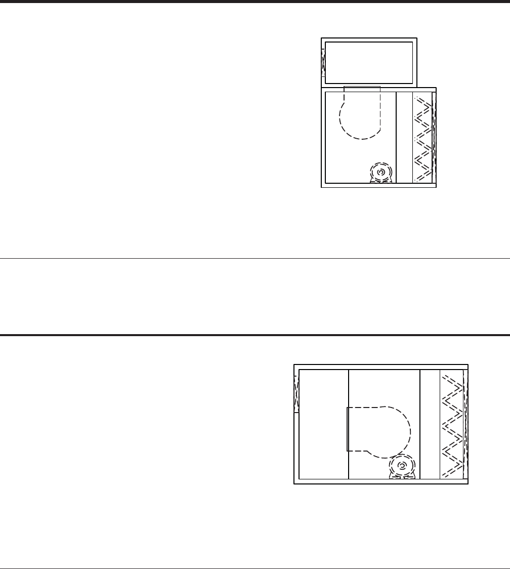
JOHNSON CONTROLS 51
FORM 102.20-QG1 (808)
Vertical Plenum – (VP)
The Vertical Plenum (VP) is a segment designed for
vertical confi gurations (top tier) with unique discharge
arrangements.
Multiple and variable size supply air openings are avail-
able through the VP segment.
The VP segment may be applied as an acoustical
chamber, with perforated panel option, that dampens
low frequency sound. In addition, the air stream expan-
sion reduces turbulence and creates an acoustical end
refl ection.
VP
FS XA AF
Discharge locations available are top, front, rear, left side and right
side.
Discharge opening options are rectangular, round and oval.
Doors are optional (Inward opening for positive pressure)
Notes & Options
Discharge Plenum – (DP)
The Discharge Plenum (DP) is a segment designed
for horizontal confi gurations with unique discharge ar-
rangements.
Multiple and variable size supply air openings are avail-
able through the DP segment.
The DP segment may be applied as an acoustical
chamber, with perforated panel option, that dampens
low frequency sound. In addition, the air stream expan-
sion reduces turbulence and creates an acoustical end
refl ection.
DP FS XA AF
Discharge locations available are top, bottom, rear, left side and
right side.
Discharge opening options are rectangular, round and oval.
• Auxiliary Drain Pan - Optional
• Access Door – Optional (both sides of the unit - Inward open-
ing for positive pressure)
Notes & Options
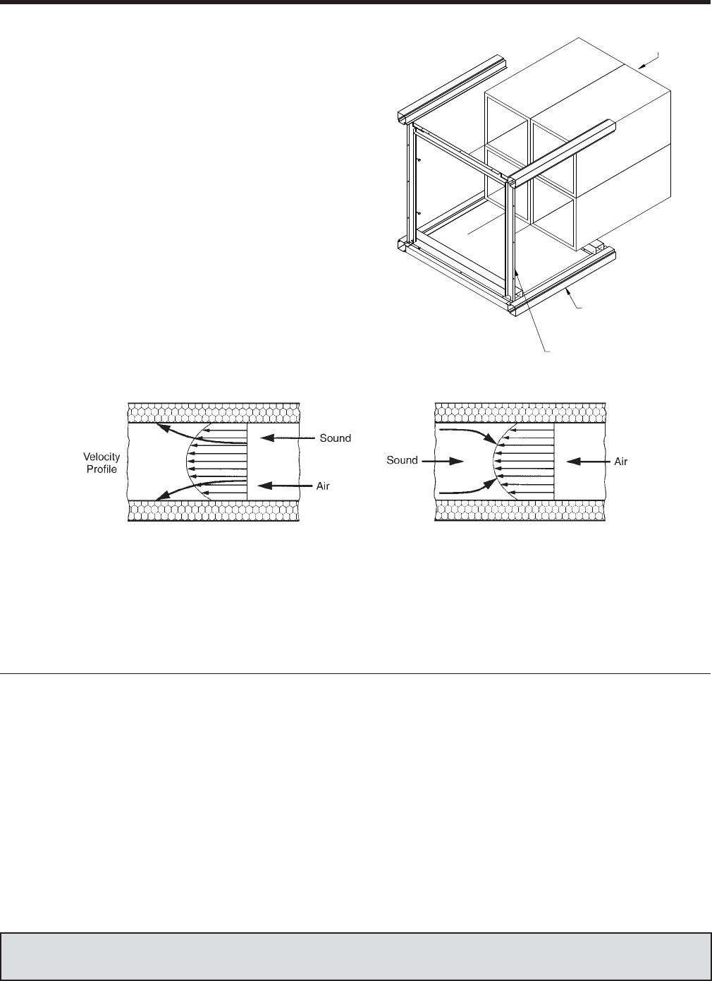
JOHNSON CONTROLS
52
FORM 102.20-QG1 (808)
Sound Attenuator – (AT)
Sound Attenuators are rated for two fl ow conditions,
FORWARD and REVERSE.
• Forward fl ow occurs when air and sound-waves
travel in the same direction, as in a supply air duct
or fan discharge.
• Reverse fl ow occurs when sound-waves and
air travel in opposing directions, as in a typical
return-air system.
Because attenuation values are generally higher in
the fi rst fi ve octave bands in the reverse fl ow mode,
compared to the forward fl ow mode, more economical
silencer selections can often be made on the return-air
systems. These phenomena are illustrated below.
RACEWAY ASSEMBLY
SOUND
ATTENUATOR
BULKHEAD ASSEMBLY
Under FORWARD FLOW conditions, high-
frequency sound is refracted into the duct-
silencer walls.
Under REVERSE FLOW conditions, sound is
refracted away from the walls and toward the
center of the duct-silencer.
Silencer Length Options:
• 3ft, 5ft, 7ft
Face Velocity
• Low
• Ultra Low
Media Types:
• Standard
• Film-lined (Hospital media)
• None (No media)
Frequency Range
• Normal
• Low
Casing Materials:
• Galvanized
• Stainless Steel
Access doors and viewing ports must be located in adjacent segments.
When AT segment is located immediate downstream of DWDI fan
segment a Diffuser segment is needed to ensure even airfl ow dis-
tribution.
Notes & Options
Literature Reference — See Application Guide ‘Acoustichecks for Air Handling Projects’ – Form 100.00-AG2 &
‘Fundamentals of Acoustics’ – Form 102.20-AG4
ACCESSORY SEGMENTS
FORWARD FLOW REVERSE FLOW
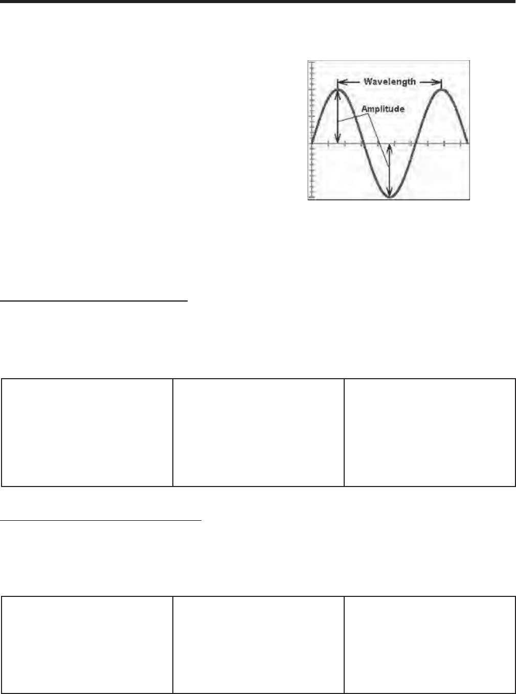
JOHNSON CONTROLS 53
FORM 102.20-QG1 (808)
Noise & Vibration
Any mechanical device is capable of generating noise
and vibration for a variety of reasons. The air handler
unit noise emanates simultaneously from three distinct
sources: aerodynamic, mechanical, and electrical.
Noise generally applies to any problem in which the ears
are the main sensor. Noise is made up of many different
sound frequencies at various loudness levels. Noise
when compared to vibration is similar in that they both
have amplitude and frequency. Usually noise is a much
lower amplitude and energy content which is measured
in db referenced to Watts. Typically noise has a much
wider frequency range and a higher upper limit than
vibration (63Hz – 8KHz)
Vibration generally applies to any problem in which
the hands or touching are the main sensor. Amplitude
is large when there is a problem. It has much greater
energy content with a smaller frequency range (3Hz
– 500Hz)
Aerodynamic
Generated noise is caused by turbu-
lence, high velocities, and instabilities
due to pulsation and surge. Technically
speaking it relates to pressure pulsa-
tions and is characterized by a continu-
ous broadband frequency spectrum
with an objectionable superimposed
pure tone.
Mechanical
Generated noise has a different sound
quality and characteristic. It can have
a metallic sound caused by metal-to-
metal contact or working noise radiating
from belts and bearings. This noise may
be constant or intermittent.
Electrical
Generated noise is a function of motors,
relays, motor controls, or unbalanced
line voltages into the motor
Vibration Considerations and Characteristics
Rotating devices, such as air handling units, all create
vibration which can be transmitted to other parts of the
structure. The magnitude of this vibration is subject to
a number of things, the most signifi cant of which is the
amount of unbalance of the rotating components. The
frequency at which this occurs is the operating RPM of
the components. There are many different sources of
vibration. One of the most diffi cult tasks is the systematic
identifi cation of the vibration characteristic; amplitude,
frequency, location or direction.
Aerodynamic
Vibration is generated when a forced
vibration in which the energy and char-
acteristics of the air-stream are large
enough to cause turbulence, pulsations
or a blade frequency tone. Vibration can
also be the result of a resonance (rever-
beration).
Mechanical
Vibration may occur from unbalance,
resonance, looseness and rubbing.
Electrical
Vibration generated occurs from torsion
fl uctuations, eddy current induced fi elds
and improper wiring.
Noise Considerations and Characteristics
Mechanical and electrical noise sources usually begin
as vibration and are later transferred into airborne noise.
To avoid unsatisfactory noise levels, many factors should
be considered at the design stage. Noise is generally
considered low quality, unwanted sound. Characteristic
words such as tone, pitch, steady, unsteady and inter-
mittent help to defi ne whether the source of the noise
is aerodynamic, mechanical or electrical.
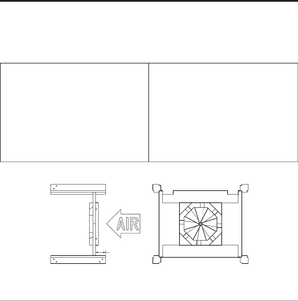
JOHNSON CONTROLS
54
FORM 102.20-QG1 (808)
Features & Benefi ts:
– Provides most mixing in shortest possible dis-
tance
– Requires negligible energy (typical application is
between 0.10 - 0.20” w.g.)
– Provides expected mixing for every cabinet size
– Provides reliable pressure drop rating which
includes the effect of mixer to plenum area ratio.
Applications (When used):
– Eliminates air stratifi cation
– Reduces low limit-stat nuisance trips
– Improves accuracy of temperature control sys-
tems
– Mixes outside ventilation air into supply air stream
to satisfy IAQ/IEQ requirements
– Allows for greater use of economizer operation
– Provides uniform velocity profi le for even fi lter
loading and enhanced coil performance
AB segment should be applied immediately after the mixing box/econo-
mizer segment. AB segment is designed to mix air from openings on
any combinations of: top, bottom, end and sides.
Minimum velocity through a mixer is 400 FPM.
Air mixer arrangements may include one mixer, two horizontal mixers,
three horizontal mixers, two vertical mixers or three vertical mixers.
The arrangement depends upon upstream segment confi guration.
Door - optional
Drain pan - optional
Mixer material option: Aluminum or Stainless Steel
Notes & Options
ACCESSORY SEGMENTS
placed just after the mixing segment improves mixing
outside and return air streams. Mixers work effectively
and consistently. There are no moving parts.
Air Blender/Mixers – (AB)
The static mixer provides a high level of mixing in a
minimal distance and at a low pressure drop. Mixers
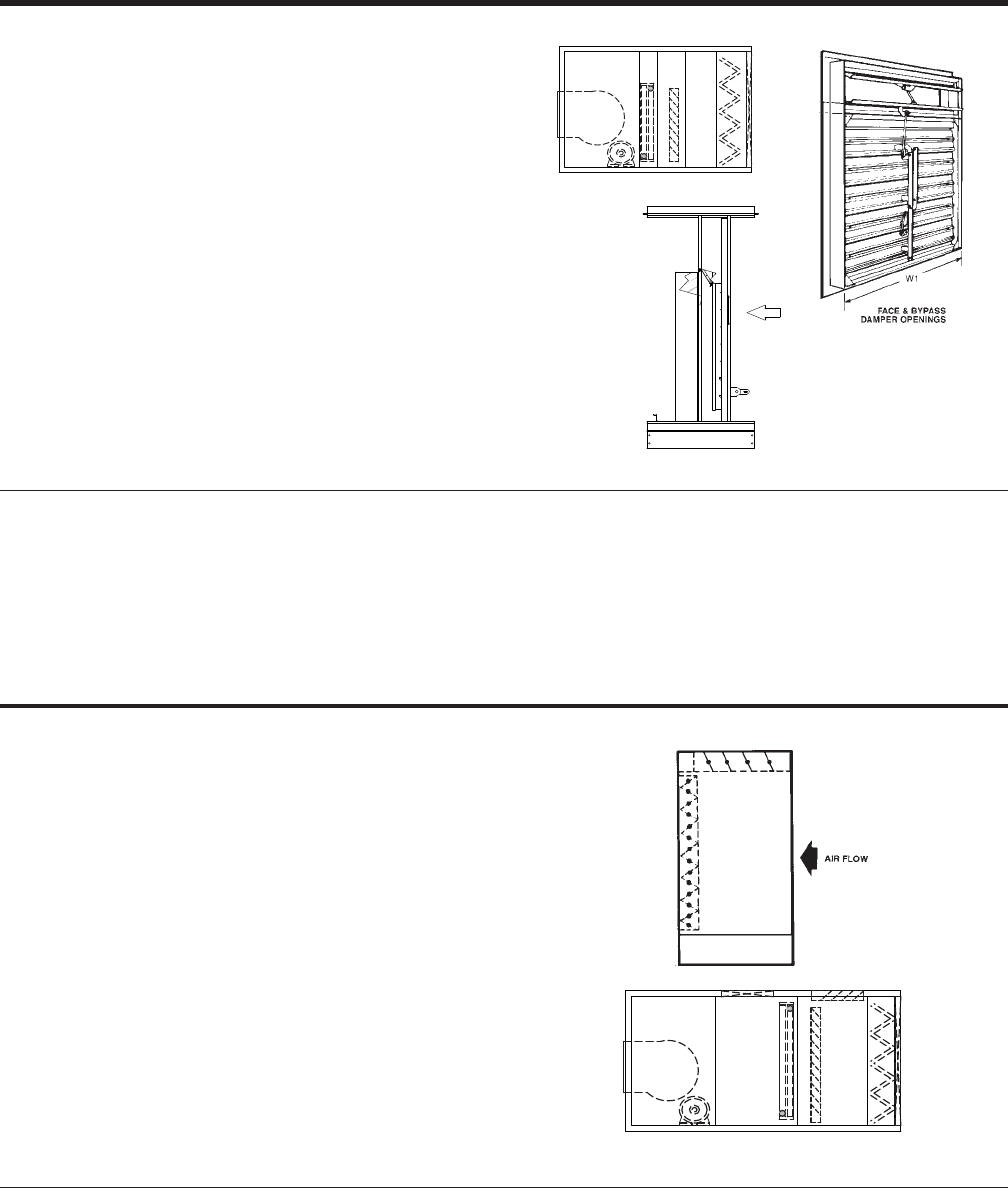
JOHNSON CONTROLS 55
FORM 102.20-QG1 (808)
Face & Bypass Damper Segments – (IB), (EB)
Internal Face & Bypass – (TB)
The IB Segment must be located immediately upstream
of a reduced face coil.
• Available for indoor or outdoor applications.
• Designed to divert airfl ow around a coil.
When a full face coil is required downstream of the re-
duced face coil, access segment(s) must be included
between the coils.
IB segment is used to control
• Humidity
• Low temperature fl ows across water coils
Access doors and viewing ports must be located in adjacent seg-
ments.
• An 18” access door is required immediately upstream of the IB
segment to access damper actuator and linkage.
Damper material option:
• Galvanized
• Aluminum
Notes & Options
External Face & Bypass – (EB)
Each EB segment must be confi gured with a “bypass air
inlet” downstream in the confi guration for reintroducing
the bypassed air to the unit. The EB segment cannot
exist without such a “bypass air inlet” partner.
• The EB segment is available for indoor
application only
The external face and bypass damper is located up-
stream of a full-face coil. External Bypass damper is
a balanced opposed blade face damper with intercon-
necting linkage.
• Bypass duct is to be fi eld supplied
Damper material option:
• Galvanized
• Aluminum
Drain pan is optional
Door is optional
• It is designed to divert airfl ow through an external bypass duct.
• External Bypass segment assumes ‘top’ outlet.
Notes & Options
FS HC EB AF
FS HC IB XA AF
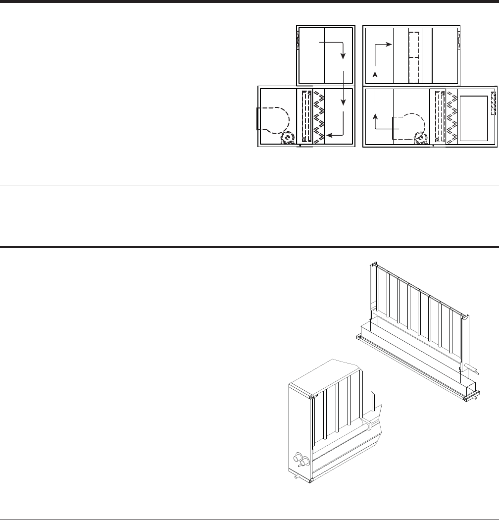
JOHNSON CONTROLS
56
FORM 102.20-QG1 (808)
Turning Segments – (TN)
The purpose of the Turning Segment is to assist air
turning in a vertical direction.
A Turning Segment (TN) can only be located at the end
of a unit confi guration.
Segment lengths are engineered for a variety of tiered
space saving confi gurations.
• Electric, gas and steam-to-steam generator types
• Optional auxiliary drain pan
• Optional access doors
• Optional controls
• The recommended location of the HM segment is downstream
of the HC segment but upstream of the CC segment.
• The humidifi er segment can not be confi gured upstream of a
HEPA fi lter segment.
• The humidifi er segment may be confi gured upstream of RF,
FF, and AF fi lter segments.
• Valve package shall be supplied and shipped loose. Field
Installation and wiring is required.
• The Humidifi er Vendor humidifi er selection software shall size
the valve package.
• Valves cannot be selected as an off-the-shelf item; each valve
has a specifi c plate/orifi ce specifi cally cut per order specifi ca-
tions.
• Control valve actuation shall be electronic and shall be
compatible with either a 0-10V DC signal or a 4-20 mA control
signal.
• Factory mounted controls are not available in the Humidifi er
segment. Any FMED device in a downstream segment should
be located at least the absorption distance away from the
humidifi er manifold.
• Usual humidifi er headers are located the same side as coil
headers.
• Optional stainless steel supports and liner
Notes & Options
DPXAHFXATN
TN FS CC AF MB
FS CC AF TN
TNIP
TN segments are available for confi guring in both top and bottom
tiers.
Drain pan is optional for bottom tier segments.
Access Door – Optional (both sides of the unit - Inward opening for
positive pressure)
Notes & Options
Humidifi er Segment – (HM)
Adding humidifi cation for full winter comfort and produc-
tivity is just as important as air conditioning in the sum-
mer months. Temperature control must be combined with
humidity control to maintain proper comfort parameters.
ASHRAE 62 indicates that relative humidity is part of
acceptable ventilation procedures & standard-of care
Solution provides a standard steam injection distribution
type humidifi er with a short absorption manifold for use
where short steam absorption distances are critical.
• Steam is distributed evenly through the full length
of the manifold.
• The header size, number and spacing of distribu-
tion tubes shall be determined so that all steam
is absorbed by the air before reaching the next
component in the air stream depth.
ACCESSORY SEGMENTS
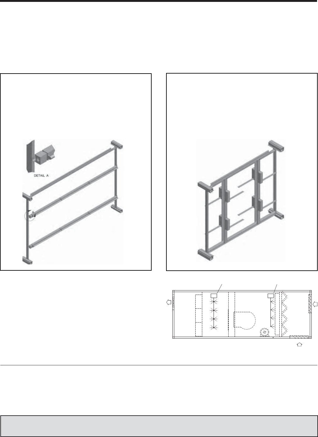
JOHNSON CONTROLS 57
FORM 102.20-QG1 (808)
Literature Reference — See Application Guide — ‘Solution® Air-Handling Units UV-C Light Options’ – Form:
102.20-AG16 & Specifi cation Sheet – Form: 102.20-S16
UV Segment – (UV)
Johnson Controls has developed UV-C lighting options that control the growth and transfer of surface and airborne
microbial agents. By incorporating UV light options into your air handling unit it is now possible to control micro-
biological infestations, using ultraviolet light technology to disinfect the unit, thereby maintaining the cleanliness of
the unit and the re-circulated air of the space being conditioned. By eliminating a multitude of micro-organisms, IAQ
is improved and occupants are healthier.
Surface Decontamination Option – is done by
incorporating UV-C lights in the coil segment down-
stream of all cooling coils and above all drain pans.
In this application refl ectivity of the UV light is of
dominant importance. Exposure time is unlimited. Any
increase in refl ectivity enhances the UV effectiveness
and effi ciency. The kill rate increases dramatically
with this application method.
Airborne Inactivation Option – is accomplished
by installing the stand-alone “Airborne Inactivation”
segment upstream and/or downstream of all cooling
coil segments to control airborne microbial agents.
UV-C lights for this type of application are of higher
intensity and are designed for “On-the-fl y” kill of air-
borne contaminates. Lamps are confi gured for 360°
UV irradiance for maximum air-stream cleansing.
Combining Both Options – If both Surface Decon-
tamination and Airborne Inactivation options are used
together, they can virtually clean your unit and the air
you breathe. Working together with various fi ltration sys-
tems and complying with the requirements of ASHRAE
Standard 62.1 will assure the best possible IAQ when
a designer combines all of these technologies.
DP HF XA DI FS CC AF MB
OA
SA
RA
UV UV
AIRBORNE OPTION SURFACE OPTION
Optional Radiometer
• Radiometer detects and measures intensity of radiant thermal
energy
Optional Access Door
• Access is optional for servicing the UV lights.
• Mechanical interlock switch to assure that the UVC assembly
will be de-energized when accessed.
• Optional View-port
Optional stainless steel supports and rails
Notes & Options
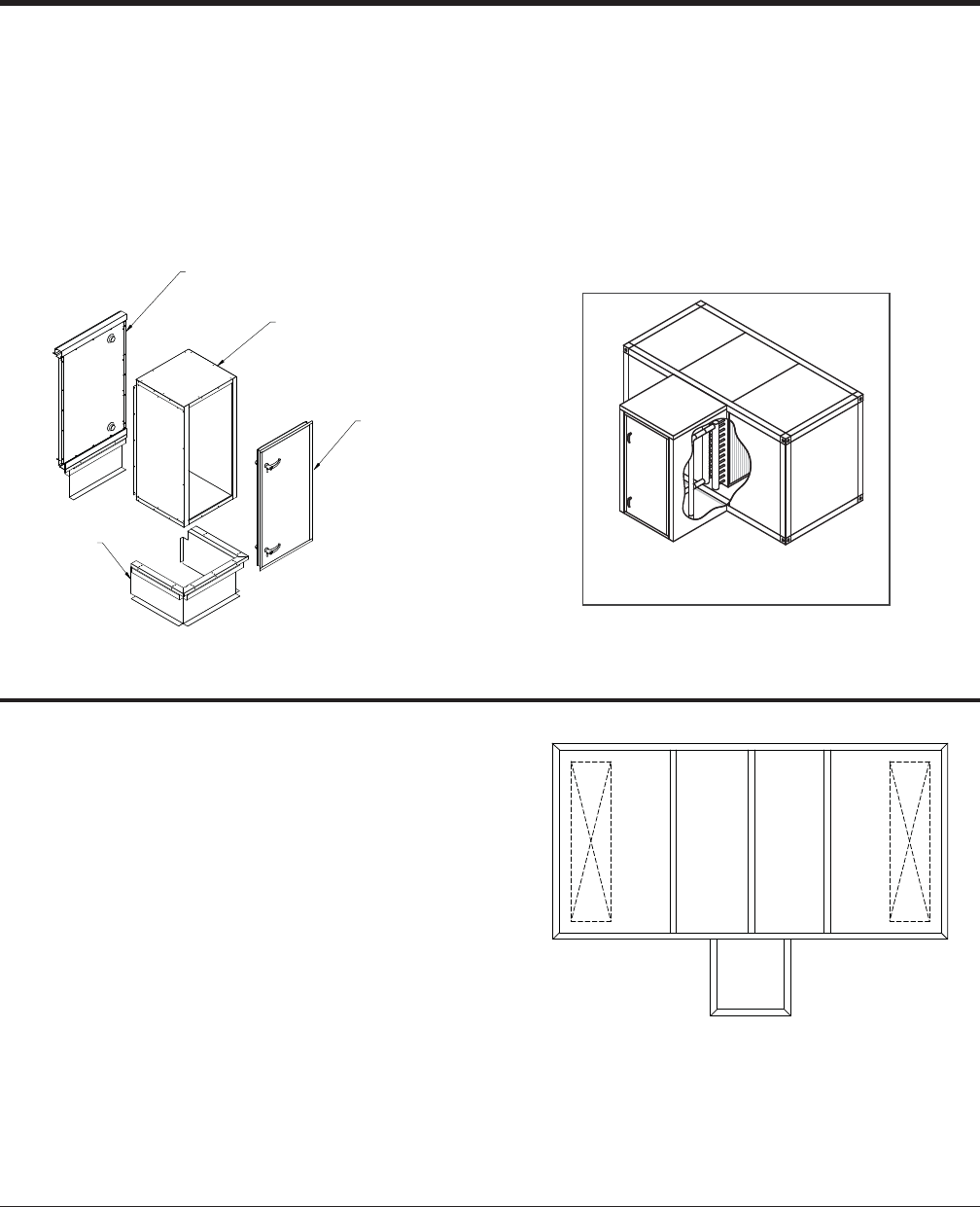
JOHNSON CONTROLS
58
FORM 102.20-QG1 (808)
ACCESSORY SEGMENTS
Pipe Chase Enclosure
1. The Pipe Chase may be selected in various
depths.
2. The Pipe Chase may be applied to XA, HC, CC,
VC, IC or IG segment.
a. These segments must be on the bottom tier of
an indoor or outdoor unit.
3. Roof, fl oor, side and end panels will be double
wall construction.
4. Pipe chase doors
• All pipe chases must have at least one door.
5. Pipe chase curb
• The pipe curb under a pipe chase will be level
with the curb under the unit.
WALL PANEL WITH
COIL OUTLETS
PIPE CHASE
CURB ASSY
PIPE CHASE
ACCESS DOOR
PIPE CHASE
PANEL ASSEMBLY
Roof Curb
Johnson Controls recommends that an HVAC factory
curb always be provided. Solution curbs are built to fi t
the unique footprint of each air handler. Solution also
provides specifi c drawing and specifi cation data for each
unit and curb. These documents provide vital data such
as unit dimensions, weight, component details, cross
braces, supply & return opening layout dimensions, and
notes which are unique to each unit.
Although insulated curbs are specifi ed in many cases,
the contractor responsible for the roof typically supplies
the insulation function.
1. Johnson Controls does not recommend vibration isolation be
provided on both the fan skid, inside the unit, and the curb,
outside the unit, without credible testing results.
2. Using improperly designed internal and external isolation
springs can increase vibration.
3. Dual vibration isolation applications must be designed by a
licensed Professional Engineer specializing in vibration isola-
tion design.
4. Units with a baserail and a bottom opening: duct connection is
fl ush with the bottom of the unit, not fl ush with the baserail.
Notes & Options
OUTDOOR: DRAIN CONNECTION IS ALWAYS ON SIDE OPPOSITE PIPE CHASE.
INDOOR: DRAIN CONNECTION IS ALWAYS SAME SIDE AS PIPE CHASE.
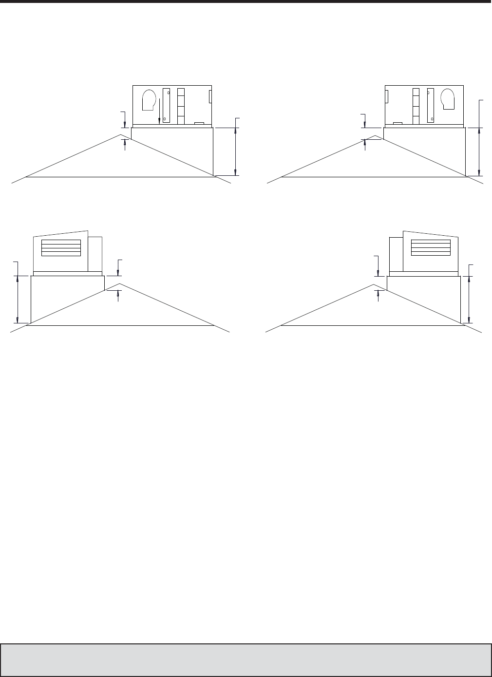
JOHNSON CONTROLS 59
FORM 102.20-QG1 (808)
Literature Reference — See Application Guide —‘Roof Curb & Unit Application’ – Form 100.00-AG11
Special Curb Requests
Spring isolation curbs
Roof curbs that incorporate adjustable spring isolators
into the curb as a single component. Most isolation curbs
are designed for 1” static defl ection springs. The springs
are mechanically fastened and sized within the frame
to ensure uniform defl ection for the entire system. The
vibration eleimination portion of the curb is constructed
of structural steel and should be designed to match the
bottom of the rooftop unit. Usual operating height is 21”
with options for different heights.
Seimic isolation curbs
Roof Curbs that incorporate seismic isolation as a fully
adjustable support system specifi cally designed for unit
vibration and seismic/wind restraint. Seismic isolation
curbs are designed to meet superimposed live and
dead loads, including equipment and other construction
loads to be supported by the curb. The curb contains
mountings designed and rated to resist seismic forces
in all directions.
SUPPLY
AIR
RETURN
AIR
OUTSIDE
AIR
ROOFTOP
SUPPLY > RETURN RETURN > SUPPLY
ROOFTOP
OUTSIDE
AIR
RETURN
AIR SUPPLY
AIR
ROOFTOP ROOFTOP
RETURN
AIR IN
RETURN
AIR IN
PIPE
CHASE
PIPE
CHASE
RIGHT > LEFT LEFT > RIGHT
WIDTH-WISE SLOPE
LENGTH-WISE SLOPE
SLOPED CURB
4
2
14"
MIN
42"
MAX
*14"
14"
MIN
42"
MAX
14"
MIN 42"
MAX
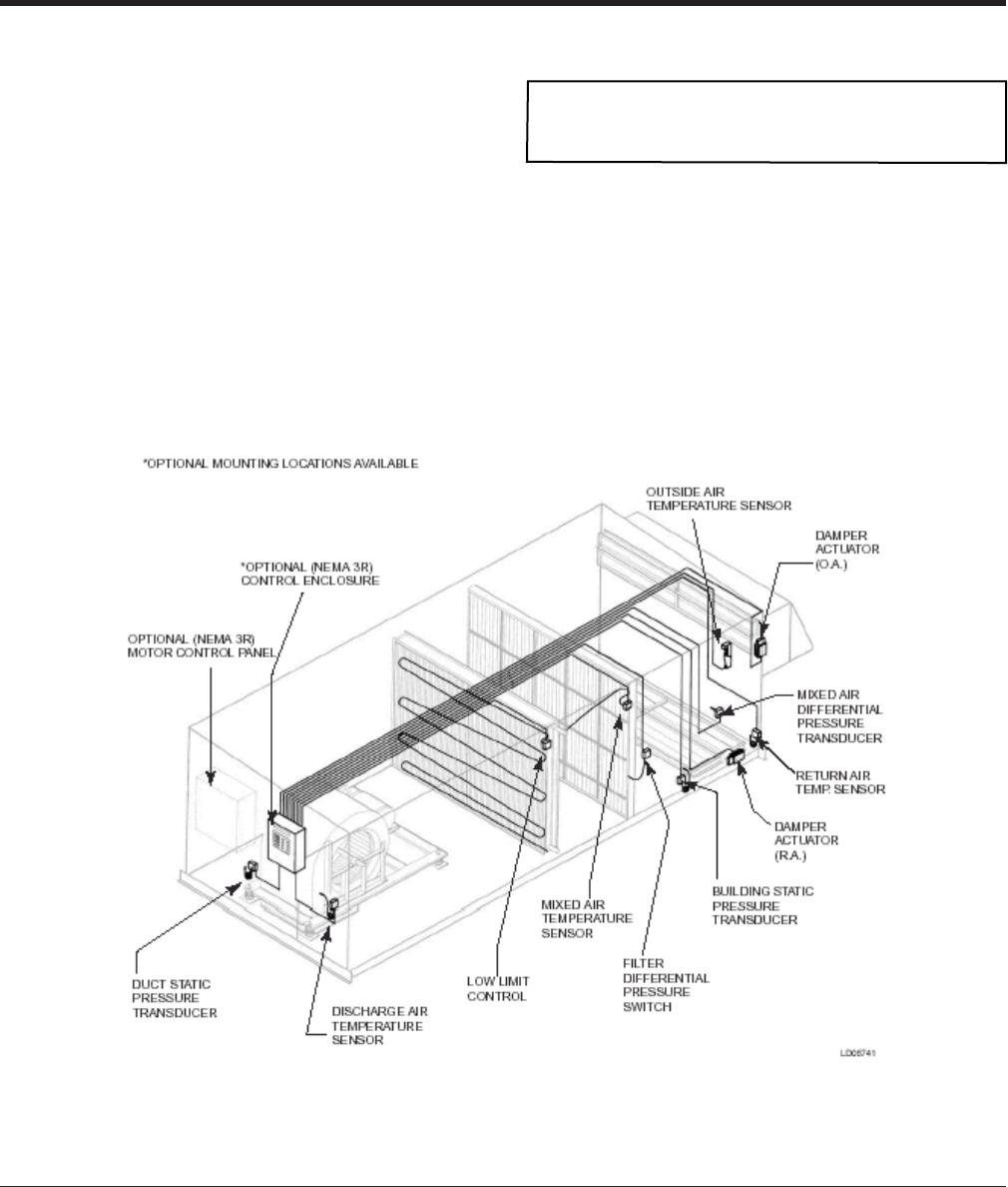
JOHNSON CONTROLS
60
FORM 102.20-QG1 (808)
Factory-Packaged Controls – (FPC)
YORK Factory-Packaged Controls assure you of get-
ting:
• A complete factory-engineered system
• Reduce costs by taking the guesswork out of
control installation
• A higher quality control system direct from the fac-
tory
• Full service support
Factory mounted devices are available as packaged ‘Standards’ kits,
which are defi ned as pre-engineered system applications. Most likely
several ‘Standards’ will “fi t” a given AHU confi guration.
Devices are available in a variety of options from mount-only with no
control panel to a complete mounted, wired and factory-tested with
the Johnson Controls Metasys FEC series controller.
Notes & Options
CONTROLS
Location of wiring harnesses are typically opposite the
high voltage. See “Power-Wiring Options diagram on
page 62.
Typical FPC Wiring
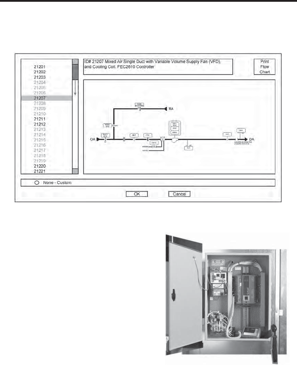
JOHNSON CONTROLS 61
FORM 102.20-QG1 (808)
Software Process
The software process will automatically apply the devices to the functional segments required for the control
method.
Field Equipment Controller (FEC)
Our open design FEC conrollers use the industry stan-
dard BACnet MS/TP open communication protocol
– customers can use devices from other vendors on
the network, don’t have to stay with one vendor which
provides wider options to the customer and consulting
engineer
On time, on budget – Standards reduce engineering
and installation time and result in the lowest possible
installed cost. New tools like CCT reduce confi guration
and commissioning time.
Minimize issues – Johnson Controls builds reliability into
each device. Our documentation and training are excel-
lent so the devices are installed correctly the fi rst time.
Reduce operating costs – With adaptive tuning, the sys-
tem uses process condition information it acquires and
adapts for improved control without manual intervention.
State-based control reduces wear and tear on actuators
and other components by allowing the system to be in
only one mode at a time. For example, only heating or
only cooling.
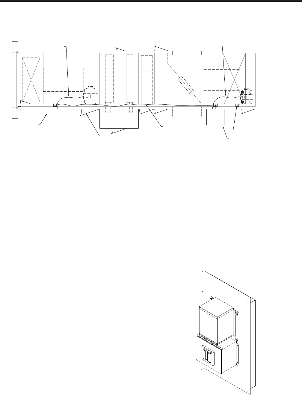
JOHNSON CONTROLS
62
FORM 102.20-QG1 (808)
FAN SEGMENT PRIMARY ACCESS DOOR.
SUPPLY FAN MCC CABINET.
SUPPLY FAN MOTOR WIRING.
CDW - COOLING
CDW - HEATING
ALTERNATE MOTOR WIRING CUTOUT LOCATION
RETURN FAN MCC CABINET.
MOTOR WIRING
OPTIONAL SINGLE POINT
EMAL
RETURN FAN MOTOR WIRING.
LOW VOLTAGE
TOP VIEW
HIGH VOLTAGE
LOW VOLTAGE
Power Wiring Options
All motor wiring will be sized and installed based upon National
Electrical Code requirements. The wire-ways will be categorized as
follows:
• High Voltage – (120V and higher) is usually on drive side of the
product
• Low Voltage – (24V) is usually on opposite drive side.
• All motor wiring will be installed neatly in perpendicular and/or
parallel planes with the unit walls and fl oors.
Single Point Power (SPP) is defi ned as:
1. ALL electrical loads in a specifi c unit confi guration wired to a
common point of connection through the proper motor control
protection devices. This requires the customer to bring only one
source of power to the unit.
2. Where motor controls (VFD, starter or wired disconnect) are NOT
selected, no motor wiring shall be provided. Should 120V or 24V
elements be selected where motor controls are not included, they
shall require fi eld wiring.
3. Where multiple motor control devices are selected, optionally,
single point power connections shall be provided. The fi eld power
supply point shall be the supply fan segment.
4. Where an external wired disconnect option is selected for either
supply or return/exhaust fans (or both), single point wiring shall
NOT be available.
There are three different sizes of transformers available; 150VA,
500VA, and 2000VA.
• The transformer being the device, used to transform power
from a primary voltage of 460 volts, 230 volts, or 575 volts, to
a secondary voltage level. An example of a secondary voltage
would be 120 volts.
A disconnect panel will be required anytime there are (2) or (3)
3-phase loads that require a common factory terminated wiring con-
nection. A maximum of (3) 3-phase loads are allowed for single point
power option.
3-phase loads are as follows:
i. Supply Fan Motor Controller
ii. Return / Exhaust Fan Motor Controller.
iii. Gas Heater.
iv. Electric Heater.
v. Energy Wheel Motor Controller.
Notes & Options
CONTROLS

JOHNSON CONTROLS 63
FORM 102.20-QG1 (808)
INDUSTRY FORMULAS
Electrical
Watts ÷ Amps = Volts
Volts x Amps = Watts
Watts ÷ Volt = Amps
Volt (V) = a measure of electrical potential
Watt (W) = a measure of power an electrical device
consumes
Amp (A) = a measurement of rate of fl ow of electrons along
a wire
Kilowatt (kw) = a thousand watts
BTU = KW x 3415
1KW = 1.34 HP
1 HP = 2545 BTUH
PUMP KW = FLOW (gpm) x PD (ft)
5311 x E pump x E motor
FAN KW = .7457 x BHP
E motor
1.73 = 3 FOR THREE PHASE SERVICE
PUMP HP = FLOW (gpm) x HEAD (ft
5311 x E pump x E motor
FAN HP = CFM x SP
6350 x E fan
FAN STATIC EFF = CFM x SP
6350 x BHP
FAN MECH EFF = CFM x TP
6350 x BHP
Basic Fan Laws
CFM varies directly as the RPM
CFM1 = RPM1
CFM2 RPM2
Static pressure varies as the square of the RPM
SP1 = (RPM1)2 = (CFM1)2
SP2 (RPM2)2 (CFM2)2
HP varies as the cube of the RPM
BHP1 = (RPM1)3 = (CFM1)3
BHP2 (RPM2)3 (CFM2)3
Drive Calculations
Motor RPM x Motor Pulley PD = Blower RPM x Blower
Pulley PD
Example:
1,750 x 7.2 = 1,190 Blower RPM
10.6
10% too much CFM:
1,750 x 7.2 = 11.8 “ PD Blower Pulley
1,190 x (0.90)
Air
TOTAL COOLING LOAD (MBH) = 4.5 x CFM STANDARD AIR x (ENTHALPY ENT. AIR - ENTHALPY LVG. AIR) / 1000
4.5 = 0.075 (WT. OF STD. AIR, # / FT3) x 60 (MIN./HR.)
SENSIBLE COOLING LOAD (MBH) = CFM x 1.08 x (EDB-LDB)
1000
1.08 = 0.075 (WT. OF STD. AIR, # / FT3) x 60 (MIN./HR.) x .24 (Specifi c Heat of dry air)
SENSIBLE HEAT RATIO = SH
MBH/Sq. Ft. x FA x 1000
TOTAL COOLING LOAD (BTW/HR) = GPM x 500 x (EWT-LWT)
500 = 8.33 (WT. OF H20 @ 60 deg F, # / GAL) x 60 (MIN./HR.) x 1.0 (Specifi c heat of water)
Metric Conversions
CFM x 1.6992 = m3/hr Ft/min x 0.00508 = m/s BTU x 0.00029 = kWh
CFM x 0.4719 = L/s Inch x 25.4 = mm Gpm x 0.063 = L/s
HP x 0.7457 = kW Lb x 0.4535 = kg

JOHNSON CONTROLS
64
FORM 102.20-QG1 (808)
GUIDE SPECIFICATIONS
PART 1 GENERAL
1.01 SECTION INCLUDES
A. Indoor and outdoor air handling units and components as scheduled and shown
on drawings.
B. Motor disconnects, motor starters, and variable frequency drives.
1.02 RELATED SECTIONS
A. The requirements of the General Conditions, Supplementary Conditions, Divi-
sion 1, equipment schedules, and drawings apply.
1.03 REFERENCES
A. AMCA 99 – Standard Handbook
B. AMCA 210 – Laboratory Methods of Testing Fans for Rating Purposes
C. AMCA 500 – Test Methods for Louvers, Dampers, and Shutters
D. AMCA 611-95 – Methods of Testing Airfl ow Measurement Stations for Rating
E. ANSI/AFBMA 9 – Load Ratings and Fatigue Life for Ball Bearings
F. ANSI/UL 900 – Test Performance of Air Filter Units
G. ARI 260 – Sound Rating of Ducted Air Moving and Conditioning Equipment
H. ARI 410 – Forced-Circulation Air Cooling and Air Heating Coils
I. ARI 430 – Testing and Rating of Central-Station Air Handling Units
J. ASHRAE 52.1/52.2 – Method of Testing General Ventilation Air Cleaning
Devices for Removal Effi ciency by Particle Size
K. ASHRAE 62 – Ventilation for Acceptable Indoor Air Quality
L. ASHRAE 90.1 – Energy Standard for Buildings Except Low-Rise Residential
Buildings
M. ASTM-C 1338 – Standard Test Method for Determining Fungi Resistance of
Insulation Material and Facings.
N. NFPA 70 – National Electric Code (conductors, equipment and raceways)
O. NFPA 90A – Installation of Air Conditioning and Ventilation Systems
P. SMACNA – HVAC Duct Construction Standards
Q. UL-181 – Mold Growth and Humidity Test
R. UL-1995 – Standard for Safety for Heating and Cooling Equipment
S. ISO/PWD 13261-3 – Sound Power Rating of air-conditioning and air-source
heat pump equipment: Part 3, Ducted Equipment.
T. ISO 9614 – Determination of sound power levels of noise sources using sound
intensity: Part 1, Measurement at discrete points; Part 2, Measurement by scan-
ning, and Part 3, Precision method for measurement by scanning.
1.04 QUALITY ASSURANCE
A. Manufacturer shall have a minimum of 25 years of experience in designing,
manufacturing, and servicing air-handling units.

JOHNSON CONTROLS 65
FORM 102.20-QG1 (808)
B. The design indicated on the schedules and shown on the drawings is based upon
the products of the named manufacturer. Alternate equipment manufacturers
are acceptable if equipment meets scheduled performance requirements and
dimensional requirements.
C. If equipment is supplied by a manufacturer other than the one named, coordinate
with the General Contractor and affected subcontractors to ensure the specifi ed
performance is met. This coordination shall include (but is not limited to) the
following:
1. Structural supports for units
2. Size and location of concrete bases/housekeeping pads
3. Location of roof curbs, unit supports and roof penetrations
4. Ductwork sizes and connection locations
5. Piping size and connection/header locations
6. Interference with existing or planned ductwork, piping and wiring
7. Electrical power requirements and wire/conduit and over current protection
sizes.
8. Trap height requirements
D. The Mechanical Contractor shall be responsible for costs incurred by the General
Contractor, Subcontractors, and Consulting Engineers to accommodate units fur-
nished by a manufacturer other than manufacturer named as basis of design.
1.05 RATINGS AND CERTIFICATIONS
A. Air Handling Unit safety: ETL or UL 1995
B. Air Handling Unit energy use: ASHRAE 90.1
C. Fans: AMCA 210
D. Air Coils: ARI 410
E. Air Handling Unit certifi cation program: ARI 430
F. Filter media: ANSI/UL 900 listed Class I or Class II
G. Control wiring: NEC codes & ETL requirements
H. Motors: Federally mandated Energy Policy Act (EPACT).
I. Airfl ow Monitoring Stations: AMCA 611-95
1.06 SUBMITTAL DOCUMENTATION REQUIRED
A. Furnish fan performance ratings and fan curves with specifi ed operating point
clearly plotted.
B. Furnish drawings indicating unit dimensions, required clearances, fi eld connec-
tion locations, wiring diagrams, shipping drawings, and curb drawings.
C. Furnish performance report showing fan, motor, coil, and component performance
details. Performance report shall detail unit casing performance and include
materials, gauges, and fi nishes.
D. Furnish operation and maintenance data, including instructions for lubrication,
fi lter replacement, motor and drive replacement, and condensate pan cleaning;
spare parts lists, and wiring diagrams.
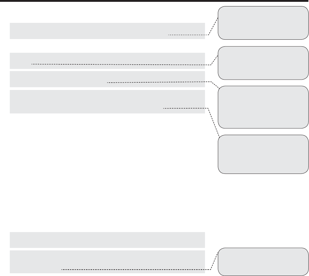
JOHNSON CONTROLS
66
FORM 102.20-QG1 (808)
E. Adjust and report performance ratings for the proper altitude of operation.
F. Report air-handling unit performance ratings in accordance with ARI-430
(static pressure, airfl ow, fan speed, and fan brake horsepower).
G. Report static pressure profi les by component section.
H. Report coil ratings in accordance with ARI-410 (capacities and pressure
drops).
I. Report and rate sound power levels in accordance with ARI-260 (ducted dis-
charge, ducted inlet, free inlet sound).
J. Airfl ow measuring device performance shall be certifi ed and rated in accordance
with AMCA-611. Report data in accordance with AMCA-611. Provide AMCA
Certifi ed Rating Seal for Airfl ow Measurement Performance.
K. Report panel defl ection at +/-8” w.g., stated in terms of ‘L/X’ where ‘L’ is the
casing panel length and ‘X’ is a constant provided by the AHU manufacturer.
L. Report casing leakage rate at +/-8” w.g., specifi ed in terms of percentage of
design airfl ow.
M. Report weight loads and distributions by component section.
N. Report product data for fi lter media, fi lter performance data, fi lter assembly, and
fi lter frames.
O. Report electrical requirements for power supply wiring including wiring dia-
grams for interlock and control wiring, clearly indicating factory-installed and
fi eld-installed wiring.
P. Report motor electrical characteristics.
1.07 DELIVERY, STORAGE AND HANDLING
A. Comply with ASHRAE 62, Section 5 (mold and corrosion resistant casings,
fi lters upstream of wetted surfaces, and drain pan design).
B. Comply with ASHRAE 62, Section 7 (practices to be followed during construc-
tion and startup). Protect equipment from moisture by appropriate in-transit and
on-site procedures.
C. Follow manufacturer’s recommendations for handling, unloading and storage.
D. Protect, pack, and secure loose-shipped items within the air-handling units.
Include detailed packing list of loose-shipped items, including illustrations and
instructions for application.
E. Protect, pack and secure controls devices, motor control devices and other elec-
tronic equipment. Do not store electronic equipment in wet or damp areas even
when they are sealed and secured.
F. Enclose and protect control panels, electronic or pneumatic devices, and variable
frequency drives; and pack with desiccant bags. Replace desiccant bags every 60
days. For equipment stored in an environment with a relative humidity greater
than 60%, change bags every 30 days. Do not store equipment in wet or damp
areas even when they are sealed and secured.
G. Seal openings to protect against damage during shipping, handling and stor-
age.
[Tip 5]: ASHRAE 62 established
minimum standards for designing, building
and operating a building to help ensure ac-
ceptable indoor air quality.
[Tip 1]: ARI 430 established testing,
rating and conformance requirements for
AHUs. To claim compliance, manufacturers
must periodically submit production AHUs
to ARI for testing.
[Tip 2]: ARI 410 established testing,
rating and reporting standards for air coils.
This includes special attention to heating
and cooling capacity as well as air and fl uid
pressure drops.
[Tip 3]: ARI 260 standardized the
measurement and reporting of sound data
for AHUs. It does not require manufacturers
to adhere to a certifi cation program to claim
compliance. It does require an extensive
testing program. (Note: AMCA 300 applies
to sound for bare fans only)
[Tip 4]: AMCA 611 details the require-
ments for certifying the performance of
airfl ow measuring stations. It assures buy-
ers that the reported data is accurate and
reliable. Testing is performed by AMCA or
by an independent AMCA certifi ed facility.
GUIDE SPECIFICATIONS
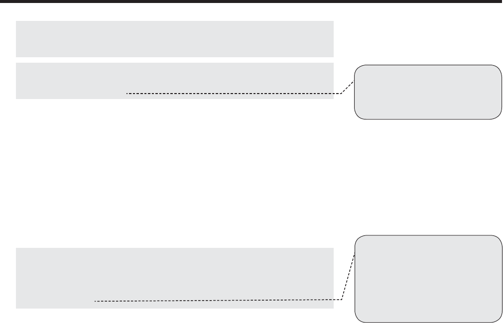
JOHNSON CONTROLS 67
FORM 102.20-QG1 (808)
H. Provide shrink-wrap around unpainted units. The membrane shall cover entire
AHU during shipping and storage. Cover equipment, regardless or size or shape.
Tarping is not acceptable.
I. Shrink-wrap equipment, including electrical components, for protection against
rain, snow, wind, dirt, sun fading, road salt/chemicals, rust and corrosion. Keep
equipment clean and dry.
J. Tarp painted units to protect against rain and road debris during shipping.
K. Clearly mark AHU sections with unit tag number, segment sequence number,
and direction of airfl ow. Securely affi x safety-warning labels.
1.08 EXTRA MATERIALS
A. Provide one set of fi lters for balancing, and one additional set for fi nal turnover
to owner.
B. Provide one extra set of belts, in addition to the factory-installed set.
1.09 WARRANTY
A. Provide warranty for 18 months from date of shipment. Warranty shall cover
manufacturer defects. Warranty shall include labor for 12 months from date of
shipment. Warranty work shall be performed by manufacturer’s factory-trained
and factory-employed technician. Service technician must be based within 50
miles of job site.
B. Include factory-provided controls in the parts and labor warranties.
C. Parts associated with routine maintenance, such as belts and air fi lters shall be
excluded.
1.10 SYSTEM STARTUP
A. Do not operate units for any purpose, temporary or permanent, until ductwork
is clean, fi lters are in place, bearings lubricated, and fan has been test run under
observation.
B. Comply with manufacturer’s start-up requirements to ensure safe and correct
operation and integrity of warranty.
PART 2 PRODUCTS
2.01 ACCEPTABLE MANUFACTURERS
A. YORK Solution
B. Approved Equal (Prior written approval by engineer of record is required)
2.02 GENERAL DESCRIPTION
A. Air Handling Unit (AHU) consists of a structural base, insulated casing, access
doors, fans, motors, motor controls, coils, fi lters, dampers, controls, components,
and accessories; as shown on drawings, schedules, and specifi cations.
B. Provide AHU to meet the specifi ed levels of performance for scheduled items
including airfl ow, static pressure, cooling capacity, heating capacity, electrical
characteristics, sound, casing leakage, panel defl ection and casing thermal per-
formance.
[Tip 6]: ASHRAE 62 Section 7.1.3
recommends the protection of equipment
on site and during transport. Shrink wrap is
a cost-effective, high-quality way to comply
with this recommendation.
[Tip 7]: Specifying an 18 month
warranty helps to ensure that the owner will
benefi t from a full 12 months of warranty.
Specifying labor warranty ensures that the
manufacturer will stand by their product
for quality and performance during that
time. Specifying local service support helps
ensure quick response when service is
desired or needed.
JOHNSON CONTROLS
68
FORM 102.20-QG1 (808)
[Tip 9]: This spec item also found in
ASHRAE standard 62, section 5.5.1.
C. AHU shall maintain structural integrity when wall panels are removed.
D. Provide internal components and accessories as specifi ed and scheduled. Com-
ponents and accessories shall be installed by the AHU manufacturer in an ISO-
9002 certifi ed facility.
E. Ship units in one piece. Split units only where necessary for shipping and instal-
lation.
F. Manufacturer shall provide detailed, step-by-step instructions for disassembly
and reassembly.
G. For AHU segments that must be broken down for rigging and installation: seg-
ment shall be disassembled and reassembled by manufacturer’s factory-trained
service personnel.
H. Manufacturer shall perform a fi eld leakage test to confi rm 1% leakage per section
2.25.
I. Manufacturer shall provide a written statement confi rming that the unit is built
to the manufacturer’s factory standards and that the unit will carry the full war-
ranty.
2.03 STANDARDS COMPLIANCE
A. Comply with ratings and certifi cations referenced in this specifi cation.
B. Manufacturers who do not comply with ARI-430 shall factory test EACH unit
to verify brake horsepower rating, airfl ow performance and total static pressure
performance. See specifi cation Section 2.23 (VERIFICATION OF PERFOR-
MANCE) for testing requirements.
C. Manufacturers who do not conform to requirements of ARI 260 for ducted dis-
charge and return air sound shall submit EACH unit to an independent sound
test laboratory for ARI 260 testing. The test laboratory shall conform to ARI
260, Section 4.4, Test Equipment and Facilities.
2.04 BASE RAIL
A. Provide a structural base rail under the full perimeter of the unit, formed from
mill galvanized steel.
B. Provide clearance for proper external trapping of drain pans steam conden-
sate.
C. Provide base rail and lifting lug system that does not require additional support
for rigging. Include base rail lifting lugs at each side shipping splits and at unit
corners.
2.05 CASING
A. Provide double wall AHU casing. Exposed insulation is not acceptable.
B. Panel assembly shall meet UL standard 1995 for fi re safety. Panel assembly
shall comply with the requirements of NFPA 90A.
C. Provide an insulation system that is resistant to mold growth in accordance with
a standardized test method such as UL 181 or ASTM C 1338.
D. Encapsulate insulation with sheet metal so that air does not contact insulation.
Panels insulated with fi berglass shall be sealed at each corner and around their
entire perimeter, to eliminate airfl ow through the panel and to eliminate microbial
growth potential within the casing wall.
[Tip 8]: ARI 430 established testing,
rating and conformance requirements for
AHUs. To claim compliance, manufacturers
must periodically submit production AHUs
to ARI for testing.
GUIDE SPECIFICATIONS
JOHNSON CONTROLS 69
FORM 102.20-QG1 (808)
E. Provide casing with minimum thermal resistance (R-value) of 12 hr-ft2-°F/
BTU.
F. Roof, wall, fl oor, and access door panels shall be galvanized or stainless
steel.
G. Provide an additional .125” aluminum diamond tread plate fl oor liner in access
areas.
H. Provide perforated liner in the fan section and other sections as shown on the
drawings. The perforated panel shall enclose matte-faced fi berglass insulation.
I. Provide a unit frame of galvanized steel that provides the overall structure of
the unit and does not rely on the casing panels for structural integrity. Insulate
frame in the same manner as panels, roof, and fl oors.
J. Provide AHU casing that leaks no more than 1% of design airfl ow at +/-8”
w.g.
K. Provide wall panels and access doors that defl ect no more than L/240 when
subjected to +/- 8” w.g. ‘L’ is the panel-span length and ‘L/240’ is the defl ection
at panel midpoint.
L. Provide fl oors and roofs that defl ects no more than L/240 when subjected to a
300 lb load at mid-span. ‘L’ is the panel-span length and ‘L/240’ is the defl ection
at panel midpoint.
M. Provide outdoor AHUs with a roof system that defl ects no more than L/240 when
subjected to a snow load of 30 lb/ft2. ‘L’ is defi ned as the panel-span length and
‘L/240’ is the defl ection at the panel midpoint.
N. Provide outdoor AHUs with a roof sloped at a minimum pitch of 1/4” per foot.
The roof shall overhang side and end panels by a minimum of 2”.
O. Provide an exterior fi nish on outdoor units that shows a breakdown of less than
1/8” on either side of a scribed line when subjected to ASTM B117 500 hour,
5% salt spray conditions. This is equivalent to an ASTM D1654 rating of ‘6’.
2.06 PRIMARY DRAIN PANS
A. Provide drain pans that comply with requirements for the AHU casing (Section
2.07).
B. Comply with the stated intent of ASHRAE Standard 62.
C. Provide a drain pan under each cooling coil and humidifi er. Drain pans for cooling
coils and humidifi ers shall meet the requirements of ASHRAE 62.
D. Provide drain connection made of same material as drain pan. Do not use dis-
similar metals because of the risk of galvanic corrosion. Weld connection to the
drain pan.
E. Drain pan shall be double wall with an R-value of 12 hr-ft2-°F/BTU. The entire
area of the drain pan shall have this level of thermal performance.
F. Insulate plumbing associated with drain pan drains and connections.
G. Provide drain pan under the complete width and length of cooling coil and
humidifi er sections.
H. Drain pan shall allow visual inspection and physical cleaning on 100% of the
pan surface without removal of the coil or humidifi er.
[Tip 10]: Casing thermal performance
has a direct impact on the owner’s utility bill.
Spec R-12 for the utmost in energy savings.
Many manufacturers employ 2” walls with
foam insulation to achieve this high thermal
performance. With fi berglass insulation, 4”
walls may be required to achieve R-12.
[Tip 11]: Some manufacturers do not
insulate the frames of their units, leaving
the casing vulnerable to sweating and
energy loss.
[Tip 12]: Some manufacturer’s cas-
ings leak 5% or more. Ensure that energy
is not wasted by outward leakage and that
conditioned air is not contaminated by
inward leakage. Leaky units are also prone
to sweating at their leak points. 1% leakage
at design static pressure is a very common
benchmark for leak integrity.
[Tip 13]: When static pressure in a
unit changes and panels defl ect, leakage
occurs. Over time, panels experience metal
fatigue, leading to even more leakage.
This wastes energy and compromises IAQ.
Spec L/240 for the most rigid and leak-free
casing. Specifying sheet metal gauges does
not guarantee rigid panels. Foam-insu-
lated panels may be required to meet this
performance.
[Tip 15]: On outdoor units, roof panels
are more prone to leakage than wall panels
due to high thermal stress and snow loads.
Ensure that performance is achieved on the
roof by specifying L/200 or higher.
[Tip 14]: Floor systems are the most
prone to leakage than the other panels of
the casing. Every time someone walks on
the AHU fl oor, panels defl ect, leading to
leakage and sweating. Spec L/240 for the
most rigid and leak-free fl oor. Specifying
sheet metal gauges does not guarantee
rigid a rigid fl oor. Foam-insulated panels
may be required to meet this performance.
[Tip 16]: Poorly designed drain pans
are often breeding grounds for mold and
poor IAQ. ASHRAE 62-2001, section 5.11.1
states that drain pans “…shall be sloped
at least 1/8” per foot from the horizontal to-
ward the drain outlet…whether the fan is in
the on or off position.” Section 5.11.2 states
that “The drain pan outlet shall be located at
the lowest point(s) of the pan.”
[Tip 17]: Some drain pan designs may
call for less insulation at the lowest points
of the pan.
[Tip 18]: This plumbing is diffi cult to
access and service. Uninsulated connec-
tions may lead to sweating and puddling
beneath the unit.

JOHNSON CONTROLS
70
FORM 102.20-QG1 (808)
I. Provide a minimum of 1” clearance between the drain pan and any coil casing,
coil support or any other obstruction.
J. Provide drain pan that allows the design rate of condensate drainage regardless
of fan status.
K. Provide drain pan sloped in at least two planes by at least 1/8” per foot toward
a single drain. Locate drain connection at the lowest point of the pan. Pan shall
have no horizontal surfaces.
2.07 ACCESS DOORS
A. Provide access door(s) that meet requirements for the AHU casing.
B. Provide industrial style stainless steel hinges that permit 180 degrees of door
swing.
C. Provide latches with roller cam mechanisms that ensure a tight seal. Rotating
knife-edge or “paw” latches are not acceptable.
D. Provide each door with a single handle linked to multiple latching points or a
separate handle for each latching point. Doors serving access segments shall
have an interior latch handle.
E. Provide access doors with a locking hasp to accommodate a lockout device.
F. Provide double-pane viewing windows as shown on the elevation view drawings.
Windows shall be a non-condensing type consisting of an integrated silica desic-
cant dehumidifi cation layer. Minimum dimension shall be 3” x 8”.
2.08 PIPE CHASE CABINET
A. Provide pipe chases with double wall, insulated panels. Pipe chase shall have
the same thermal performance as the unit casing.
B. Provide a perimeter base rail and/or roof curb under the pipe chase(s) that meets
requirements for the AHU base rail and/or roof curb.
C. Manufacturer may combine the pipe chase enclosures of adjacent segments.
D. Provide a minimum pipe chase depth, as shown on drawings. Pipe chase depth is
the clear inside dimension from inner pipe chase surface to outer unit surface.
E. Manufacturer may ship pipe chases separate from AHU if the chases are pro-
vided with lifting lugs for fi eld installation per the AHU base rail requirements.
Manufacturer shall provide step-by-step instructions with illustrations for proper
pipe chase installation.
2.09 ROOF CURBS
A. Provide factory-fabricated galvanized steel roof curb for outdoor units. Roof
curb shall support the full-perimeter of the air handling equipment, including
pipe chases.
B. Match roof curb to roof slope. Curb surface shall be level in both axes.
C. Provide wood nailing strip to which roofer may nail roof fl ashing.
D. Ship roof curb loose for fi eld installation prior to unit placement.
2.10 FANS
A. Provide double width double inlet (DWDI) housed fans or single width single
inlet (SWSI) plenum fans as equipment schedule and drawings.
[Tip 19]: YORK recommends this
clearance so that the drain pan can be
cleaned and inspected without requiring coil
removal. ASHRAE 62 recommends annual
inspection during the cooling season and
cleaning if necessary.
GUIDE SPECIFICATIONS
JOHNSON CONTROLS 71
FORM 102.20-QG1 (808)
[Tip 22]: L-50 implies that bear-
ings have a 50% chance of failure during
200,000 hours of operation. L-10 bearings
have only a 10% chance of failure during
the same time period.
[Tip 23]: L-50 implies that bear-
ings have a 50% chance of failure during
200,000 hours of operation. L-10 bearings
have only a 10% chance of failure during
the same time period.
[Tip 24]: Direct drive plenum fans
provide higher levels of effi ciency and are
typically quieter than belt-driven fans.
B. Airfoil fans shall comply with AMCA standard 99 2408 69 and 99 2401 82.
Provide an AMCA Seal on airfoil fans. Airfoil fan performance shall be based
on tests made in accordance with AMCA standards 210 and comply with the
requirements of the AMCA certifi ed ratings program for air performance.
C. Provide fans with true airfoil blades unless otherwise scheduled.
D. Provide fans with the following accessories:
1. Fan inlet screens in the inlets of fan housing (REQUIRED on SWSI plenum
fans)
2. Access door inlet screen (on AHU casing)
3. OSHA-compliant belt guard enclosing the fan motor and drive
E. Provide airfoil fans with blades formed of extruded aluminum, as scheduled.
Bent sheet metal blades are not acceptable.
F. Provide an access door in the fan scroll, as shown on drawings.
G. Provide fans with polished steel shafts with fi rst critical shaft speed at least 125%
of the maximum operating speed for the fan pressure class. Shaft shall have an
anti-corrosion coating.
H. Provide fan motor on an adjustable base to allow adjustable and consistent belt
tension.
I. Mount the fan and motor assembly on a common adjustable base.
This common base shall attach to vibration isolators, which mount to structural
support channels. These channels shall span the AHU fl oor and mount directly
to the AHU frame. Manufacturers not complying with this requirement must
submit detailed structural and weight data to a licensed structural engineer for
review and stamped certifi cation. The mechanical engineer shall review these
engineers’ fi nal reports prior to submittal approval.
J. Provide vibration isolation springs with 1” or 2” static defl ection, as scheduled.
K. Connect DWDI fans to the unit casing or bulkheads with canvas fl exible con-
nection.
L. Provide horizontal thrust restraints between AHU casing and fan housings with
end discharge. This requirement applies to the following cases:
1. SWSI fans operating at greater than 3” of total static pressure
2. DWDI airfoil fans operating at greater than 6” of total static pressure
3. DWDI airfoil fans operating at greater than 3” of total static pressure
2.11 BEARINGS AND DRIVES
A. Provide bearings complying with ANSI/AFBMA 9 for fatigue life ratings.
B. Provide fan bearings with an average life L50 of at least 200,000 hours.
C. Provide fan bearings with an average life L10 of at least 200,000 hours, as
scheduled.
D. Provide permanently lubricated bearings on forward curved fans smaller than
18.” On other fans, provide re-greaseable bearings with hydraulic grease fi ttings
and lube lines extended to the motor side of the fan or to the exterior of the unit
(primary access side).
E. Provide plenum fans with direct-drive transmissions.
[Tip 20]: True airfoil fans are desirable
as they offer higher effi ciency and have a
non-overloading fan characteristic.
[Tip 21]: Under no circumstances
should the fan and motor assembly mount
to the AHU casing fl oor. This would lead
to excess casing vibration poor acoustics,
panel fatigue and air leakage.

JOHNSON CONTROLS
72
FORM 102.20-QG1 (808)
F. Provide drives selected with a 1.5 service factor. Sheaves shall be machined from
a close grain cast iron and statically balanced by the manufacturer. Provide a
fi xed pitch sheave on the motor.
G. Provide fi xed pitch sheaves on both the fan and motor. Fans with motors rated
at 15 hp or less may be fi eld balanced using variable pitch sheaves. Provide
fi xed pitch sheaves when fi nal balance is complete. Air balancer shall select and
provide fi nal set of sheaves.
H. Provide multiple belt drives on belt driven fans with motors 10 hp or greater.
Belts shall be V-type, precision molded, raw edge construction, anti-static, oil-
resistant and heat-resistant.
2.12 ELECTRICAL MOTORS
A. Provide fan motors built in accordance with the latest standards of the NEMA
and IEEE.
B. Provide AHU and fan motors in compliance with ASHRAE 90.1.
C. Provide fan motors with the following characteristics:
1. 60 hertz, 1750 rpm operation
2. Service factor of 1.15
3. Premium effi ciency, or as required to meet ASHRAE 90.1
4. NEMA design ball bearing type
5. Rated for continuous duty at full load in a 104°F (40°C) ambient
6. Open drip proof (ODP) or totally enclosed, fan cooled (TEFC) as
scheduled.
7. Suitable for use in variable frequency application, per NEMA MG-1 Part
30
8. Inverter ready per NEMA STD MG1 PART 31.4.4.2
D. Provide direct drive plenum fans coupled to motors with matching speed, as
scheduled.
2.13 FAN-MOTOR DISCONNECTS
A. Provide UL or ETL listed fan-motor disconnects and associated components, as
scheduled and shown on drawings. Disconnects shall comply with applicable
provisions of the National Electric Code.
B. Provide fused or non-fused fan-motor disconnects in NEMA 1, NEMA 3R,
NEMA 4, or NEMA 12 enclosures, as scheduled and shown on drawings.
C. Mount disconnects on the primary access side of the associated fan segment.
1. Mount unit main disconnect (on units with single point power) on the primary
access side of supply fan section.
D. Disconnect shall be suitable for use as an OSHA lockout/tagout disconnect when
applied in accordance with part IV, Department of Labor OSHA 29 CFR Part 1910,
Control of Hazardous Energy Source (lockout/tagout): fi nal rule.
E. Disconnect handles shall be lockable in the “off” position with up to three pad-
locks. Switch mechanism shall be directly lockable in the “off” position via
padlock when door is open.
[Tip 25]: ASHRAE 90.1 has a detailed
requirement for motor effi ciency – typi-
cally requiring what manufacturer’s call
“premium” effi ciency motors. 90.1 also has
a detailed requirement for motor SIZE,
depending on the application, static pres-
sure, etc.
GUIDE SPECIFICATIONS

JOHNSON CONTROLS 73
FORM 102.20-QG1 (808)
F. Provide disconnects with integral ground lug.
1. Provide two (2) #14 ground wires on 16A to 100A disconnects.
2. Provide one (1) #6-250 ground wire on 200A to 400A disconnects.
G. Provide auxiliary contacts, as scheduled.
2.14 FAN-MOTOR STARTERS
A. Provide UL or ETL listed motor starters and associated components, as scheduled
and shown on drawings. Starters shall comply with applicable provisions of the
National Electric Code.
B. Provide starter in a NEMA 3R enclosure.
C. Mount starter on the primary access side of its associated fan section, and wire
starter to motor, unless shown otherwise on drawings.
D. Provide the following features in each starter panel:
1. Main power block
2. Motor contactor(s)
3. Individual starter short circuit and overload protection devices
4. Two primary control fuses, one secondary control line size fuse
5. Three phase ambient compensated overload heater elements
6. 115-volt control power transformer with primary and secondary protection
7. Five-point terminal strip for fi eld control connections
8. Factory wired, non-fused or fused main power disconnect, integral with
starter panel
9. Integrated on/off auto switch.
10. Wiring to fan motor
E. Starters on outdoor units shall be suitable for use in ambient temperatures from
5°F to 104°F:
1. Provide low ambient temperature kit suitable for use down to -20°F.
2. Provide high ambient temperature kit suitable for use up to 135°F.
2.15 FAN-MOTOR VARIABLE FREQUENCY DRIVES (VFDS)
A. Provide UL or ETL listed VFDs and associated components, as scheduled and
shown on drawings. VFDs shall comply with applicable provisions of the Na-
tional Electric Code.
B. Mount VFDs in a dedicated NEMA 1 compartment located on the primary ac-
cess side of its associated fan section and wire VFD to motor, unless otherwise
indicated on drawings.
C. Enclose outdoor VFDs in a NEMA-3R enclosure.
D. VFDs on outdoor units shall be suitable for use in ambient temperatures from
5°F to 104°F:
1. Provide low ambient temperature kit suitable for use down to -20°F.
2. Provide high ambient temperature kit suitable for use up to 135°F.

JOHNSON CONTROLS
74
FORM 102.20-QG1 (808)
E. After unit installation, VFD shall be started and programmed by a factory trained
and employed service technician. Refer to Section 3.05.
F. Provide the following VFD disconnect and bypass option:
1. Fused main disconnect
2. 2 contactor VFD bypass
3. 2 contactor VFD bypass with fused disconnect
4. 2 contactor VFD bypass with non-fused disconnect
G. Provide harmonic distortion feedback protection:
1. Equivalent 5% impedance input line reactor
2. Integral RFI/EMI fi ltering to meet EMC EN61800-3 for First Environ-
ment
H. Provide a user interface with the following features:
1. 30 Character multi-lingual alphanumeric display
2. Parameter set-up and operating data
3. Display data shall include:
a. output frequency (Hz)
b. speed (RPM)
c. motor current
d. calculated % motor torque
e. calculated motor power (kW)
f. DC bus voltage
g. output voltage
h. heat sink temperature
i. elapsed time meter (re-settable)
j. kWh (re-settable)
k. input / output terminal monitor
l. PID actual value (feedback) & error
m. fault text
n. warning text
o. scalable process variable display
I. Provide VFD with the following protection circuits:
1. over current
2. ground fault
3. over voltage
4. under voltage
5. over temperature
6. input power loss of phase
7. loss of reference/feedback
[Tip 26]: Select from item a, b, c or d.
Consider that VFDs are a mature, proven
and highly reliable technology. Bypass
packages are therefore not as important as
they used to be. Perhaps specifying a spare
drive in lieu of bypass packages on drives is
a better value for the owner.
GUIDE SPECIFICATIONS

JOHNSON CONTROLS 75
FORM 102.20-QG1 (808)
8. adjustable current limit regulator
J. VFD shall be UL 508C approved for electronic motor overload (12t).
K. Provide high input transient protection and surge suppression
1. 4 MOVs ahead of diode bridge
2. 120 Joule rated 1600V diode module
3. Compliant with UL 1449 / ANSI 61.4
L. Provide the following communication features:
1. Two programmable analog inputs
2. Six programmable digital inputs
3. Two programmable analog output
4. Three programmable digital relay outputs
5. Modbus RTU Communications protocol
6. Adjustable fi lters on analog inputs and outputs
7. Input speed signals, including 4-20 mA and 0-10 VDC
8. Accel/Decel contacts (fl oating point control)
9. Auto restart (customer selectable and adjustable)
10. Start/Stop options shall include 2 wire (dry contact closure), 3 wire (mo-
mentary contacts), application of input power, and application of reference
signal (PID sleep/wake-up)
11. Integrated control interface for Siemens FLN, Johnson N2, Modbus RTU,
or BACnet MS/TP or LONworks over RS-485.
M. Provide the following functions:
1. Premagnetization on start
2. DC braking/hold at stop
3. Ramp or coast to stop
4. Seven preset speeds
5. Three critical frequency lockout bands
6. Start function shall include ramp, fl ying start, automatic torque boost, and
automatic torque boost with fl ying start
2.16 FACTORY INSTALLED ELECTRICAL ACCESSORIES
A. In addition to motor power terminals, provide an independent power terminal for
convenience receptacles and lights. Provide switches as shown on drawings.
B. Provide incandescent or fl uorescent lights in segments as scheduled or shown
on drawings. Provide light switches as scheduled or shown on drawings.
C. Provide a 1-hour timer on external light switches.
D. Provide a 120v convenience receptacle on supply fan segment.
2.17 HEATING AND COOLING COMPONENTS
A. Provide coils manufactured by AHU manufacturer, except where noted in contract
documents.
JOHNSON CONTROLS
76
FORM 102.20-QG1 (808)
[Tip 30]: Coil penetrations are a very
common leakage point. Not only can air
leak through the casing, but it can also leak
into individual panels. This leads to a loss
in IAQ and energy effi ciency performance.
Spec a tight seal by specifying coil connec-
tions that are extended through the casing,
and by specifying a spool-shaped grommet
seal that isolates the coil connection from
the panel, and that isolates the interior of
the unit from the exterior. Coil penetrations
are a very common leakage point. Not only
can air leak through the casing, but it can
also leak into individual panels. This leads
to a loss in IAQ and energy effi ciency per-
formance. Spec a tight seal by specifying
coil connections that are extended through
the casing, and by specifying a spool-
shaped grommet seal that isolates the coil
connection from the panel, and that isolates
the interior of the unit from the exterior.
B. Coils shall meet or exceed performance scheduled on drawings.
1. When applicable, provide coils with performance certifi ed in accordance
with ARI Standard 410 for coil capacity and pressure drop. Circuit coils
such that the fl uid velocity is within the range of certifi ed rating conditions
at design fl ow.
C. Provide cooling coils with a maximum face velocity of 550 fpm or 500 fpm or
450 fpm. Face velocity calculations shall be based on the fi nned area of the
coil.
D. Provide cooling coil drain pan that is suffi cient to contain coil condensate. Drain
pan shall extend a minimum of 6” or 10” or 14” downstream of the face of the
coil.
E. Provide coil segment casing to accommodate full-face or reduced-face coils as
scheduled. Provide face and bypass coil segments with factory installed bypass
damper.
F. Provide at least 18” or 24” or 30” of access between coils. Provide an easily
operable access panel or door, as shown on drawings.
G. Provide coil segment casing that meets or exceeds casing performance of the
unit.
H. Provide panels that are easily removable with no special tools.
I. Locate access doors to provide clearance for pipe insulation, connectors, and
accessories. Space shall allow a minimum of 90 degrees of door swing.
J. Provide coils built in their own full perimeter frame. Tube sheets on each end
shall have fully drawn collars to support and protect tubes. Horizontal coil casing
and support members shall allow moisture to drain. Casing and support members
shall not block fi nned area.
K. Individual coils shall be removable from the side of the AHU.
L. Provide an intermediate drain pan on stacked cooling coils. Intermediate drain
pan shall slope in a minimum of two planes toward a single drain connection.
M. Provide a single intermediate vertical coil support on coils with a fi nned length
greater than 62”. Provide two vertical supports on coils with a fi nned length
greater than 100”, and three vertical supports on coils with a fi nned length greater
than 141”.
N. Extend coil connections through AHU casing. Provide a 1/4” FPT plugged
vent/drain tap on each connection. Circuiting shall allow complete draining and
venting when installed. Vent and drain connections shall be on the coil connec-
tion extension outside of the unit casing.
O. Insulate gap between coil stub out connection and AHU casing with a spool-
shaped sleeve grommet. Adhesive rings applied the casing walls are not accept-
able.
P. Water and glycol coils shall be operable at 250 psig working pressure and up to
300° F. Factory test water and glycol coils with 325 psig compressed air under
water.
Q. Direct expansion (DX) coils shall conform to ANSI B9.1 (Safety Code for Me-
chanical Refrigeration) when operating with a maximum refrigerant pressure of
250 psig. Factory test DX coils with 325 psig compressed air under water.
[Tip 27]: Coils with higher face
velocities are more vulnerable to moisture
carryover. A coil’s vulnerability to conden-
sate carryover depends on the coil design.
Coils with densely packed fi ns (12 or 14 fpi)
are more vulnerable. Coils with staggered
tube arrangements (YORK standard) are
less vulnerable. The cleanliness of a coil
also matters.
[Tip 28]: YORK coils are designed
and selected to prevent moisture carryover.
However, dirty coils or coils operating
under non-design conditions may lead
to carryover moisture. Therefore, YORK
recommends at least 6” of drain pan down-
stream to catch moisture. More drain pan is
better, as it will keep moisture from reaching
downstream components such as fans and
fan motors.
[Tip 29]: Because the coil segment is
the coldest part of the AHU, thermal perfor-
mance, leakage and defl ection are critical
here. Cooling coil drainpans are typically
the root of an AHU’s IAQ problems, making
performance even more critical.
GUIDE SPECIFICATIONS

JOHNSON CONTROLS 77
FORM 102.20-QG1 (808)
[Tip 32]: Face loading fi lters offer a
tighter seal and less air bypass than side
loading fi lters. For performance reasons,
it is best to not use side loading fi lters in
downstream or “fi nal” positions, where the
fi lters typically have high effi ciencies. Be
sure to specify generous access, as they
require space upstream or downstream of
the rack to change fi lters.
R. Steam distributing coils shall be operable at 50 psig pressure and a corresponding
saturated steam temperature of 298° F. Factory test steam coils with 315 psig
compressed air under water. Dehydrate and seal coils prior to shipping.
S. Provide steam-distributing coils with a tube outer diameter (OD) of 1” and an
inner distribution tube of 5/8” O.D. Circuit coils for gravity drain of condensate
without trapping. Steam shall discharge in the direction of condensate fl ow to
ensure even heat transfer across each tube.
T. Provide water, glycol and DX coils with a tube OD of 5/8” or 1/2”. Mechanically
expand tubes to form fi n bond and provide burnished, work-hardened interior
surface. Tubes shall have a minimum tube wall thickness of 0.020” or 0.025” or
0.035” or 0.049” for 5/8” tubes, and 0.016” or 0.020” or 0.032” for 1/2” tubes.
U. Provide coils with copper tube return bends with the following fi nal minimum
thicknesses:
1. 0.035” for 5/8” diameter tubes
2. 0.032” for 1/2” diameter tubes with 0.020” or 0.032” tube wall thick-
nesses
3. 0.020” for 1/2” diameter tubes with 0.016” tube wall thickness.
V. Provide water, glycol and steam coil headers made of seamless copper or brass
tubing. Pipe connections shall be steel or red brass. Header connections (tubes
and piping connections) shall be silver-brazed or TIG welded.
W. Provide DX coils with brass distributor and solder-type connections. Suction
and discharge connections shall be on the same end regardless of coil depth.
Mount refrigerant specialties outside of unit. Provide DX coils with a hot gas
bypass port on distributor.
X. Provide coils with die-formed, continuous aluminum or copper fi ns. Fins shall
have fully drawn collars to accurately space fi ns and protect tubes. Fins shall be
0.006” or 0.008 or 0.01” thick.
Y. Provide coil coatings as scheduled or indicated on drawings.
2.18 FILTERS
A. Provide fi lter segments and fi lters as scheduled.
B. Provide side loading fi lters for fi lter segments located upstream of coil segment(s)
with an access door on the drive side through which fi lters can be easily loaded.
C. Provide face loading fi lters for segments located downstream of coil segment(s).
Provide an 18” (minimum) access plenum and access door on the drive side
through which face loading fi lters can be easily loaded.
D. Provide fi lter racks integral to the unit and constructed of galvanized steel or
stainless steel.
E. Provide Class 2 or Class 1 fi lter media per U.L. 900 and as required by local
codes.
F. Filter types, effi ciencies, and nominal depths shall be as follows:
1. Flat fi lters – 2” throwaway, 2” permanent cleanable, 2” 30% pleated, or 4”
30% pleated fi lters, as scheduled.
2. Angled fi lters – 2” throwaway, 2” permanent cleanable, or 2” 30% pleated
fi lters, as scheduled.
[Tip 31]: The outer radius of a coil
tube’s return bend can be very vulnerable to
premature failure. Tubes that are machine
bent to create a return bend are especially
susceptible to failure, as the outer radius of
the bend is stretched and has a fi nal thick-
ness that is signifi cantly thinner than the
initial tube thickness. Specifying and enforc-
ing a FINAL thickness of .035” at the outer
radius of the return bend will help ensure a
robust and long-lasting coil

JOHNSON CONTROLS
78
FORM 102.20-QG1 (808)
3. Rigid fi lters – 4” mini pleated, 12” rigid, or 22” bag fi lters with effi ciencies
of 60-65% (MERV 11), 80-85% (MERV 13), 90-95% (MERV 14), or 90-
95% (MERV 15), respectively; as scheduled.
a. Provide a pre-fi lter rack in rigid fi lter segments. Pre-fi lters shall have 2”
throwaway, 2” permanent cleanable, 2” 30% pleated, or 4” 30% pleated
fi lters as scheduled.
4. Carbon fi lters – 2” deep rechargeable, incinerable, or disposable panels fi lled
with 60% activity carbon, as scheduled.
a. Carbon fi ltration system shall be designed for a minimum contact ef-
fi ciency of 99% with a residence time of at least 0.08 seconds.
b. Provide post-fi lter and/or pre-fi lter rack in carbon fi lter segments with 2”
throwaway, 2” permanent cleanable, 2” 30% pleated, or 4” 30% pleated
fi lters, as scheduled.
5. HEPA fi lters – 12” 99.97%, or 99.99% effi cient media, as scheduled.
a. Performance of installed fi ltration system shall be certifi ed via a DOP test
and classifi ed as UL Class 1 when tested in accordance with UL Standard
586.
b. Filter frame shall be specifi cally developed for HEPA fi lters, with ap-
propriate quantities of fi lter clamps.
G. Provide a fl ush mounted, factory installed magnahelic differential pressure gage
on the drive side of unit to measure pressure drop across fi lters. Manufacturer
shall provide fully functional gauges, complete with tubing.
2.19 DAMPERS
A. Provide dampers tested in accordance with AMCA 500.
B. Provide factory-installed dampers, as shown on drawings.
C. Dampers shall have airfoil blades, extruded vinyl edge seals, and fl exible metal
compressible jamb seals.
D. Dampers shall have a maximum leakage rate of 4 CFM/square foot at 1” w.g.,
and shall comply with ASHRAE 90.1.
E. Damper blades shall be parallel acting unless otherwise indicated.
F. Damper blades shall be galvanized steel or aluminum, as scheduled.
2.20 AIRFLOW MONITORING STATIONS
A. Provide airfl ow monitoring stations, as scheduled or shown on drawings.
B. Provide airfl ow monitoring stations tested in accordance with AMCA Standard
611 in an AMCA registered laboratory. Airfl ow monitoring stations shall bear
the AMCA Ratings Seal for Airfl ow Measurement Performance.
C. If airfl ow station incorporates a control damper, control damper shall comply
with leakage rates per ASHRAE 90.1 and with specifi cation section 2.19 DAMP-
ERS.
D. Provide a factory-installed transducer that sends a CFM-proportional, 4-20 mA
or 0-10V signal, as specifi ed.
2.21 DIFFUSERS
A. Provide diffuser segments as shown on drawings.
GUIDE SPECIFICATIONS

JOHNSON CONTROLS 79
FORM 102.20-QG1 (808)
B. Diffuser plates shall ensure proper air fl ow across components downstream of
DWDI fans.
2.22 APPURTENANCES
A. Provide rain hoods on outdoor unit air intakes, as shown on drawings. Provide
moisture screens on outdoor air inlet rain hoods.
B. Provide safety grates over bottom openings, as shown on drawings.
1. Safety grates shall be capable of supporting a 300 lb. center load.
2.23 FINISHES
A. Manufacturer shall clean the exterior surfaces of units prior to fi nishing, painting,
or shipment.
B. Manufacturer shall paint outdoor units prior to shipment. Manufacturer shall
paint indoor units, as scheduled or shown on drawings.
1. Manufacturer shall apply a primer prior to painting units.
2. Manufacturer shall apply a fi nish coat of acrylic polyurethane paint.
3. Finished unit shall exceed 500-hour salt spray solution (5%) test without
any sign of red rust when tested in accordance with ASTM B-117.
2.24 TESTS AND INSPECTIONS
A. Manufacturer shall dynamically balance fan/motor/base assembly.
1. Balance constant volume fan assemblies at design RPM.
2. Balance variable volume fan assemblies from 10% to 100% of design
RPM.
3. Take fi lter-in measurements in the horizontal and vertical axes on the drive
and opposite-drive sides of fan shafts.
4. Take fi lter-out measurements in the horizontal, vertical, and axial axes on
the drive and opposite-drive side of fan shafts.
5. Constant speed fan vibration limits: fi lter-in measurements shall not exceed
4 mils. Filter-out measurements shall not exceed 6 mils in the horizontal
and vertical axes, and 7 mils in the axial axis.
6. Variable speed fan vibration limits: fi lter -in measurements shall not exceed
7 mils. Filter-out measurements shall not exceed 9.5 mils.
B. Manufacturer shall hipot test wiring intended to carry voltages greater than
30Vac.
2.25 VERIFICATION OF PERFORMANCE
A. Factory test one out of every fi ve AHUs (or a minimum of one unit) to verify
compliance with airfl ow, static pressure, casing leakage, and panel defl ection
requirements. Owner and engineer reserve the right to select units to be tested.
Manufacturer shall pay food, lodging, and travel expenses for up to two wit-
nesses.
1. Alternatively, fi eld test units to verify compliance with airfl ow, static pres-
sure, casing leakage, and panel defl ection requirements. Follow testing pro-
cedures outlined in this specifi cation. Manufacturer shall hire a mechanical
engineer of record to supervise testing.
JOHNSON CONTROLS
80
FORM 102.20-QG1 (808)
[Tip 34]: It is not practical or reason-
able to test for thermal performance or
sweating. However a manufacturer should
know their performance capabilities and
should willingly write this letter.
B. One representative from both the owner and the engineer shall witness the test.
Manufacturer shall pay food, lodging and transportation expenses for two wit-
nesses.
C. Perform test on a fully assembled unit with sections joined per manufacturer’s
installation instructions. Use of additional material (tape, sealant, caulk) is not
acceptable.
D. Perform tests to verify the following performance criteria:
1. Casing leaks no more than 1% of design CFM at +/-8” w.g.
2. Casing panels defl ect no more than L/240 at +/-8” w.g. ‘L’ is defi ned as the
panel span length and ‘L/X’ is the defl ection at panel midpoint.
E. Unit shall meet the Large Missile Impact Test for AHU casing (walls, roof, and
doors) and base. Unit shall carry a Notice of Acceptance (NOA) from the Mi-
ami-Dade County Product Control Division. Label equipment per NOA labeling
instructions.
F. Provide written letter of guarantee from manufacturer stating that no condensa-
tion will form on the exterior of units, under given design conditions.
G. Should a unit fail a test, treat unit with a permanent remedy at manufacturer’s
expense until test is successfully passed.
2.26 FACTORY TEST SETUP AND METHODS
A. AHU Preparation
1. Assemble and seal AHU sections per manufacturer’s installation manual.
2. Close and latch access doors. No additional sealing is permitted.
3. Seal duct, damper and louver openings.
4. Blank off and seal supply fan opening(s).
5. Blank off and seal supply fan bulkhead to isolate positive and negative
pressure sections.
B. Pressurization procedure
1. Pressurize positive pressure side to specifi ed static pressures using a pres-
sure blower.
2. Pressurize negative pressure side to specifi ed static pressures using a pres-
sure blower.
3. Measure and monitor differential pressure exerted on the cabinet with a
pressure gage.
C. Test measurement
1. Measure panel defl ections at the centers (length and width) or four panels
chosen by owner and engineer.
2. Measure pressure drop through an ASME long radius nozzle, mounted n
the test module.
3. Monitor leakage at the same time panel defl ection is measured.
D. While under pressure, inspect units failing to meet specifi ed leakage and defl ec-
tion. Treat failing areas with a permanent remedy. Repeat test and inspection.
Re-treat unit as necessary to pass both tests.
E. Provide test data and results in a complete report to the owner.
[Tip 33]: Make sure that bidders to
your specifi cation are held accountable for
their performance. Specifying leakage and
defl ection tests are an important part of
ensuring the owner gets the performance
that was specifi ed.
GUIDE SPECIFICATIONS
JOHNSON CONTROLS 81
FORM 102.20-QG1 (808)
[Tip 35]: Improper storage can de-
grade the longevity and performance of an
AHU. Rust and bacteria may form if units
are not kept dry. IAQ and energy effi ciency
may be negatively impacted once improp-
erly stored AHUs are operating.
[Tip 36]: A thorough inspection and
necessary corrections ensure a proper
installation. A proper installation is neces-
sary to fully realize the energy, IAQ and
acoustical benefi ts of a high-performance
AHU and system.
PART 3 EXECUTION
3.01 INSTALLATION
A. Install equipment per industry standards, applicable codes, and manufacturer’s
instructions.
B. Do not use AHUs for temporary heating, cooling or ventilation prior to complete
inspection and startup performed per this specifi cation.
C. Install AHUs on a concrete pad, roof curb, or structural steel base, as shown on
drawings.
D. Install AHUs with manufacturer’s recommended clearances for access, coil pull,
and fan removal.
E. Provide one complete set of fi lters for testing, balancing, and commissioning.
Provide second complete set of fi lters at time of transfer to owner.
F. Install AHU plumb and level. Connect piping and ductwork according to
manufacturer’s instructions.
G. Install seismic restraints and anchors per applicable local building codes. Refer
to specifi cation Section 230548 (15240 / 15070) for product and installation
requirements.
H. Install pipe chases per manufacturer’s instructions.
3.02 FIELD QUALITY CONTROL
A. Store per AHU manufacturer’s written recommendations. Store AHUs indoors in
a warm, clean, dry place where units will be protected from weather, construc-
tion traffi c, dirt, dust, water and moisture. If units will be stored for more than
6 months, follow manufacturer’s instruction for long-term storage.
B. Rig and lift units according manufacturer’s instructions.
3.03 AHU INSPECTION
A. Hire manufacturer’s factory-trained and factory-employed service technician to
perform an inspection of unit and installation prior to startup. Technician shall
inspect and verify the following as a minimum:
1. Damage of any kind
2. Level installation of unit
3. Proper reassembly and sealing of unit segments at shipping splits.
4. Tight seal around perimeter of unit at the roof curb
5. Installation of shipped-loose parts, including fi lters, air hoods, bird screens
and mist eliminators.
6. Completion and tightness of electrical, ductwork and piping connections
7. Tight seals around wiring, conduit and piping penetrations through AHU
casing.
8. Supply of electricity from the building’s permanent source
9. Integrity of condensate trap for positive or negative pressure operation
10. Condensate traps charged with water
11. Removal of shipping bolts and shipping restraints

JOHNSON CONTROLS
82
FORM 102.20-QG1 (808)
[Tip 37]: A thorough inspection and ad-
justment of the fan assembly helps ensure
that the energy, IAQ and acoustical benefi ts
of a high-performance AHU and system are
realized.
12. Sealing of pipe chase fl oor(s) at penetration locations.
13. Tightness and full motion range of damper linkages (operate
manually)
14. Complete installation of control system including end devices and
wiring
15. Cleanliness of AHU interior and connecting ductwork
16. Proper service and access clearances
17. Proper installation of fi lters
18. Filter gauge set to zero
B. Resolve any non-compliant items prior to proceeding with the inspection of the
fan assembly.
3.04 INSPECTION AND ADJUSTMENT: AHU FAN ASSEMBLY
A. Hire the manufacturer’s factory-trained and factory-employed service technician
perform an inspection of the AHU fan assembly subsequent to general AHU
inspection and prior to startup. Technician shall inspect and verify the following
as a minimum:
1. Fan isolation base and thrust restraint alignment
2. Tight set screws on pulleys, bearings and fan
3. Tight fan bearing bolts
4. Tight fan and motor sheaves
5. Tight motor base and mounting bolts
6. Blower wheel tight and aligned to fan shaft
7. Sheave alignment and belt tension
8. Fan discharge alignment with discharge opening
9. Fan bearing lubrication
10. Free rotation of moving components (rotate manually)
B. Manufacturer shall perform service to bring fan performance within factory
specifi cations.
3.05 STARTUP SERVICE AND OWNER TRAINING
A. Manufacturer’s factory-trained and factory-employed service technician shall
startup AHUs. Technician shall perform the following steps as a minimum:
1. Energize the unit disconnect switch
2. Verify correct voltage, phases and cycles
3. Energize fan motor briefl y (“bump”) and verify correct direction of rota-
tion.
4. Re-check damper operation; verify that unit cannot and will not operate
with all dampers in the closed position.
5. Energize fan motors and verify that motor FLA is within manufacturer’s
tolerance of nameplate FLA for each phase.
GUIDE SPECIFICATIONS
JOHNSON CONTROLS 83
FORM 102.20-QG1 (808)
[Tip 38]: A fi eld leakage test is a pru-
dent step to ensure that the AHU performs
as promised. The test is a fi nal confi rmation
that the AHU will perform. Field testing con-
fi rms that the AHU withstood the stresses
of shipping, rigging and installation and can
still provide high performance.
B. Provide a minimum of 4 hours of training for owner’s personnel by manufac-
turer’s factory-trained and factory-employed service technician. Training shall
include AHU controls, motor starter, VFD, and AHU.
C. Training shall include startup and shutdown procedures as well as regular opera-
tion and maintenance requirements.
D. If AHU is provided with a factory-mounted variable frequency drive (VFD), hire
the VFD manufacturer’s factory-trained and factory-employed service technician
to inspect, test, adjust, program and start the VFD. Ensure that critical resonant
frequencies are programmed as ‘skip frequencies’ in the VFD controller.
E. Submit a startup report summarizing any problems found and remedies per-
formed.
3.06 FIELD PERFORMANCE VERIFICATION
A. Leakage: Pressurize casing to +/-8” w.g. and measure leakage. Pressurize casing
to –8”w.g. and measure leakage. If leakage exceeds 1% of design airfl ow, seal
leakage points with a permanent solution. Repeat test. If the AHU still does not
pass, contact the manufacturer to seal unit.
B. Submit a fi eld test report with testing data recorded. Include description of cor-
rective actions taken.
3.07 CLEANING
A. Clean unit interior prior to operating. Remove tools, debris, dust and dirt.
B. Clean exterior prior to transfer to owner.
3.08 DOCUMENTATION
A. Provide Installation, Operation & Maintenance Manuals in the supply fan
section of each unit. Provide six additional copies for owner’s project system
manual.
B. Provide six copies of Spare Parts Manual for owner’s project system manual.

Printed on recycled paper
Form: 102.20-QG1 (808) Supersedes: 102.20-QG1 (707)
© 2008 Johnson Controls, Inc. P.O. Box 423, Milwaukee, WI 53201 Printed in USA
www.johnsoncontrols.com
