SR22_DS 2ed Insert Sheet / Quick Start Guide – Web Version Stellar SR22 Series Compact Soft Starter Ds Qsg
User Manual: Stellar SR22 series Compact Soft Starter Quick-Start Guide Compact Soft Starters Installation Instructions and Insert Sheets
Open the PDF directly: View PDF ![]() .
.
Page Count: 2
Stellar SR22 Compact Soft Starter Quick-Start Guide (SR22_DS 2nd Edition – 01/26/2017)
M-7G44-A
Ready
(23/24)
+24V
Run
(green LED)
~ 0.25s
VStart
t - Stop
+A1
Error
(red LED)
VL1, L2, L3
t - Start
VT1, T2, T3
EN
A
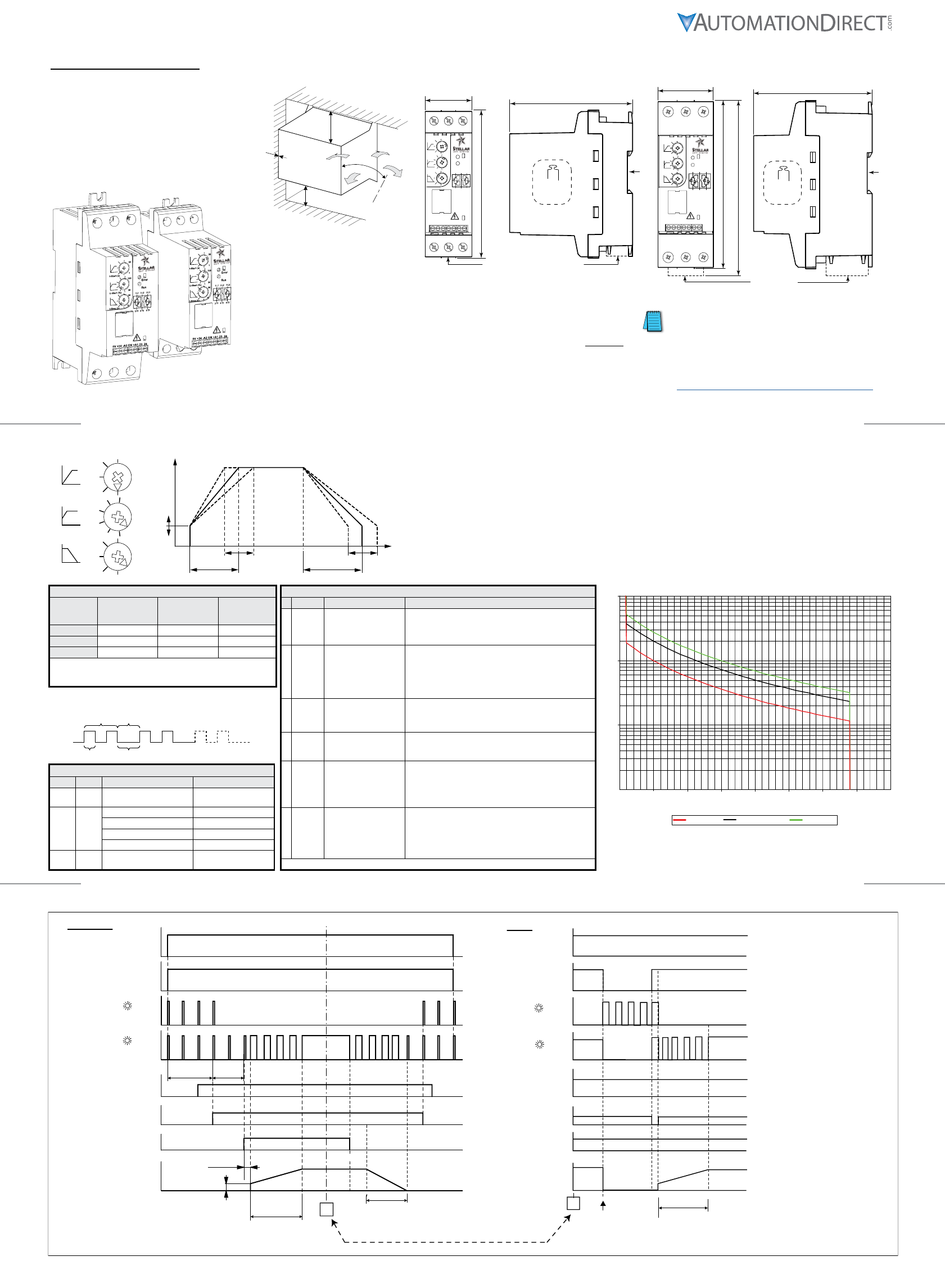
Operation
Initialization
Ready for operation
In ramp
Top of ramp
Fault
t - Start
A
Fault
Ready
(23/24)
+24V
Run
(green LED)
+A1
Error
(red LED)
VL1, L2, L3
VT1, T2, T3
EN
Stellar SR22 Soft Starter LED Indications
LED Color Status Flash Speed
RUN
& Error
Green
& Red Initialization (not enabled) approx 1/(2s)
RUN Green
Ready for Operation approx 1/(2s)
Soft Starting or Soft Stopping approx 1/ second
Approaching O/L Trip approx 1/(0.5s)
Running @ Full Voltage constant
Error Red Faults 1–6
(see Fault Table)
approx 1/s with
approx 2s between errors
Stellar SR22 Soft Starter Fault Table
#Name Description Corrective Action
1SCR or
Supply
Missing phase on the
input or output terminals,
OR a fault with the
internal switching device.
1. Verify 3-phase input voltage is present at L1, L2 & L3.
2. Verify the motor is properly connected to T1, T2 & T3.
3. Isolate the soft starter and measure resistance between L1–
T1, and between L3–T3. If R < 10Ω, replace the starter.
2Too Hot
Internal temperature of
starter exceeded trip limit
for 1 second (approx),
OR surrounding air
temperature is too high.
1. Increase the time between starts.
2. Install a cooling fan on the starter. (SR22-FAN-45 or -55)
3. Reduce the load on the motor.
4. Increase the size of the starter.
5. Check for sufficient cooling within the enclosure.
6. Replace the starter.
3
Control
Supply
Low
Volts
Control supply voltage
less than 19V (approx).
1. Verify that DC voltage > 19VDC.
2. If DC voltage > 19VDC & fault will not clear, replace
starter.
4
Bypass
Relay
Fail
Internal bypass failed to
close at the end of the
start ramp time.
1. Replace the starter.
5Shear Pin
Motor current exceeded
4.4 X rated current for
200 ms (approx).
1. Inspect the load for mechanical binding or jam condition.
2. Correct the source of mechanical binding or remove jam.
3. Uncouple the motor from the load and run the motor.
4. Verify motor current exceeds 4.4 X rated current.
5. If motor current is < 4.4 X rated current, replace starter.
6Over-
current
Motor current exceeded
the overcurrent profile
for the starter. (Refer
to SR22 over current
protection for addtn’l
info)
1. Inspect the load for mechanical binding or jam condition.
2. Correct the source of mechanical binding or remove jam.
3. Lengthen the start time
4. Verify motor current exceeds the profile for the starter. If
motor current does not exceed the profile, replace starter.
NOTE: Reset faults by cycling the enable input.
Recommended General Purpose Settings
Setting
Loaded
Conveyor
(O/L Class 20)
Centrifugal
Pump
(O/L Class 10)
Blower (O/L
Class 2 or 10)
t-start (s) approx 25s approx 10s approx 15s
V-start (%) approx 30% approx 30% approx 50%
t-stop (s) approx 30s approx 20s 0s
NOTE: These settings are typical for general purpose
applications. Appropriate settings for specific
applications may vary.
V-
Start
V
t-Start t-Stop
t
30
1
100
30
30
0
t-Start (s)
V-Start (%)
t-Stop (s)
20
10
50
70
10
20
After trip, SR22 will ash the Error LED (red) to indicate Fault Code.
EX: If SR22 trips “Too Hot” (Fault Code 2),
Error LED will ash twice as shown:
Fault Code Pause
1 sec 2 sec
SR22 Overcurrent Trip Curve
0.1
1
10
100
1 1.5 2 2.5 3 3.5 4 4.5 5
Time (s)
Hot Curve Standard Curve Cold Curve
Overcurrent Level
Overcurrent Protection:
SR22 soft starters include internal overcurrent protection, which becomes active
when the motor current exceeds 110% of the starter’s rating. The RUN (green)
LED flashes rapidly.
Trip Curves:
Cold Curve (green) – ambient 20ºC [68ºF]; start frequency 1/hr
Standard Curve (black) – ambient 40ºC [104ºF]; start frequency 10/hr
Hot Curve (red) – ambient 40ºC [104ºF]; start frequency 20/hr (no derating)
Cooling Time:
Cooling Time partially determined by severity of overcurrent.
Max Cooling Time: 6 min without fan; 1 min with optional cooling fan.
Function:
SR22 soft starters are designed for
reduced-voltage start/stop control of
3-phase AC induction motors.
They use thyristors for controlled
reduced-voltage starting and stopping,
and then switch to internal contacts
for efficient running at rated speed.
AutomationDirect Stellar SR22 Digital Soft Starters
Installation Instructions
Mounting Clearances
30° max
55 mm
[2.2 in]
55 mm
[2.2 in]
5 mm
[0.2 in]
These devices are suitable for
use in industrial environments
;
EN 55011/22 Class A.
Run
Error
30
0
t-Stop (s)
100
30
U-Start (%)
30
1
t-Start (s)
1 L1
3 L2
5 L3
2 T1
4 T2
6 T3
0V +24 -A2 EN +A1 23 24
Mounting Centers 30mm x 130mm
45 mm
[1.8 in]
143 mm
[5.63 in]
117.8 mm
[4.64 in]
Fan (optional)
does not increase dimensions
of size 45 soft starter
35mm DIN rail mounting
400g
[14.1 oz]
Run
Error
30
0
t-Stop (s)
100
30
U-Start (%)
30
1
t-Start (s)
1 L1
3 L2
5 L3
2 T1
4 T2
6 T3
0V +24 -A2 EN +A1 23 24
Mounting Centers 40mm x 155mm
55 mm
[2.2 in]
167.5 mm
[6.59 in]
177.5 mm
[6.99 in]
Fan (optional)
117.8 mm
[4.64 in]
35mm DIN rail mounting
650g
[22.9 oz]
Size 45 mm: 5A to 16A *
WARNING: These are Class 2 ratings!!
These Amp ratings do not necessarily
represent motor FLA.
Size 55 mm: 22A to 40A *
SR22-05: 5A @ 208–460V
SR22-07: 7A @ 208–460V
SR22-09: 9A @ 208–460V
SR22-12: 12A @ 208–460V
SR22-16: 16A @ 208–460V
SR22-22: 22A @ 208–460V
SR22-30: 30A @ 208–460V
SR22-36: 36A @ 208–460V
SR22-40: 40A @ 208–460V
* Soft Starter selection must be based on motor voltage & horsepower, load type, and O/L trip class.
Please visit the AutomationDirect website for soft starter selection: https://www.automationdirect.com/selectors/softstarters
SR22 Soft Starter Quick-Start Guide – 1b
SR22 Soft Starter Quick-Start Guide – 1c
SR22 Soft Starter Quick-Start Guide – 1a
Stellar SR22 Compact Soft Starter Quick-Start Guide (SR22_DS 2nd Edition – 01/26/2017)
M-7G44-A
Where several conductors are to be connected, the difference between the wires/cables used
must not exceed one DIN Standard size level.
1 x 0.5 – 2.5 / 20 – 14
2 x 0.5 – 1.5 / 20 – 16
mm2/ AWG mm / inch N·m / lb·in mm
6 / ¼ 0.4 / 3.5 0.6 x 3.5 mm2 / AWG mm / inch N·m / lb·in mm
1 or 2 x 1 – 4 / 18 – 12 9 / 3/8" 1.3 / 12 1 x 6 PZ2
M4 x 10 mm
(approx length)
mm2 / AWG mm / inch N·m / lb·in mm
1 or 2 x 2.5 – 10 / 12 – 8 12 / ½" 2.5 / 22 1 x 6 PZ2
M5 x 12 mm
(approx length)
DANGER! Hazardous Voltage. Will cause death or serious injury. Hazardous voltage is also present in the
OFF/STOP status of the soft starter when the supply voltage is switched on (Ve).
DANGER ! Tension dangereuse. Danger de mort ou risque de blessures graves. En cas de tension
d’alimentation (Ue) enclenchée, la tension dangereuse existe aussi en position d’Arrêt à la sortie du démarreur
progressif.
¡PELIGRO! Tensión peligrosa. Puede causar la muerte o lesiones graves. Si la tensión de alimentación está
conectada (Ue), existe también en la salida tensión peligrosa con el arrancador suave en estado OFF/ON.
Signaling relay – (23, 24)
VImin Vmin
250 VAC 0.2A 2.5A 10 mA 100 VAC
30 VDC 0.7A 3.0A 100 mA 5VDC
75°C wire
CU only
SR22-05 to SR22-16 (45 mm)
1 L1, 3 L2, 5 L3
2 T1, 4 T2, 6 T3
SR22-22 to SR22-40 (55 mm)
1 L1, 3 L2, 5 L3
2 T1, 4 T2, 6 T3
SR22 Control Terminals
+24, 0V
+A1, EN, -A2
23, 24 (captive)
Inductive Resistive
75°C wire
CU only
Maximum Overcurrent Protection Devices *
for 5kA @ 480V Short Circuit Rating
Soft Starter
Model
Number
Max Non-Time-Delay Trip Rating *
Fuse * – Class J or T
(600V rated)
Circuit Breaker *
(600V rated)
SR22-05 15A
N/A
SR22-07 15A
SR22-09 30A
SR22-12 40A
SR22-16 50A
SR22-22 80A 80A
SR22-30 100A 100A
SR22-36 125A 125A
SR22-40 150A 150A
* Maximum allowable trip ratings for non-time-delay
overcurrent protection devices.
Maximum ratings for time-delay devices are 225% of
Full Load Current.
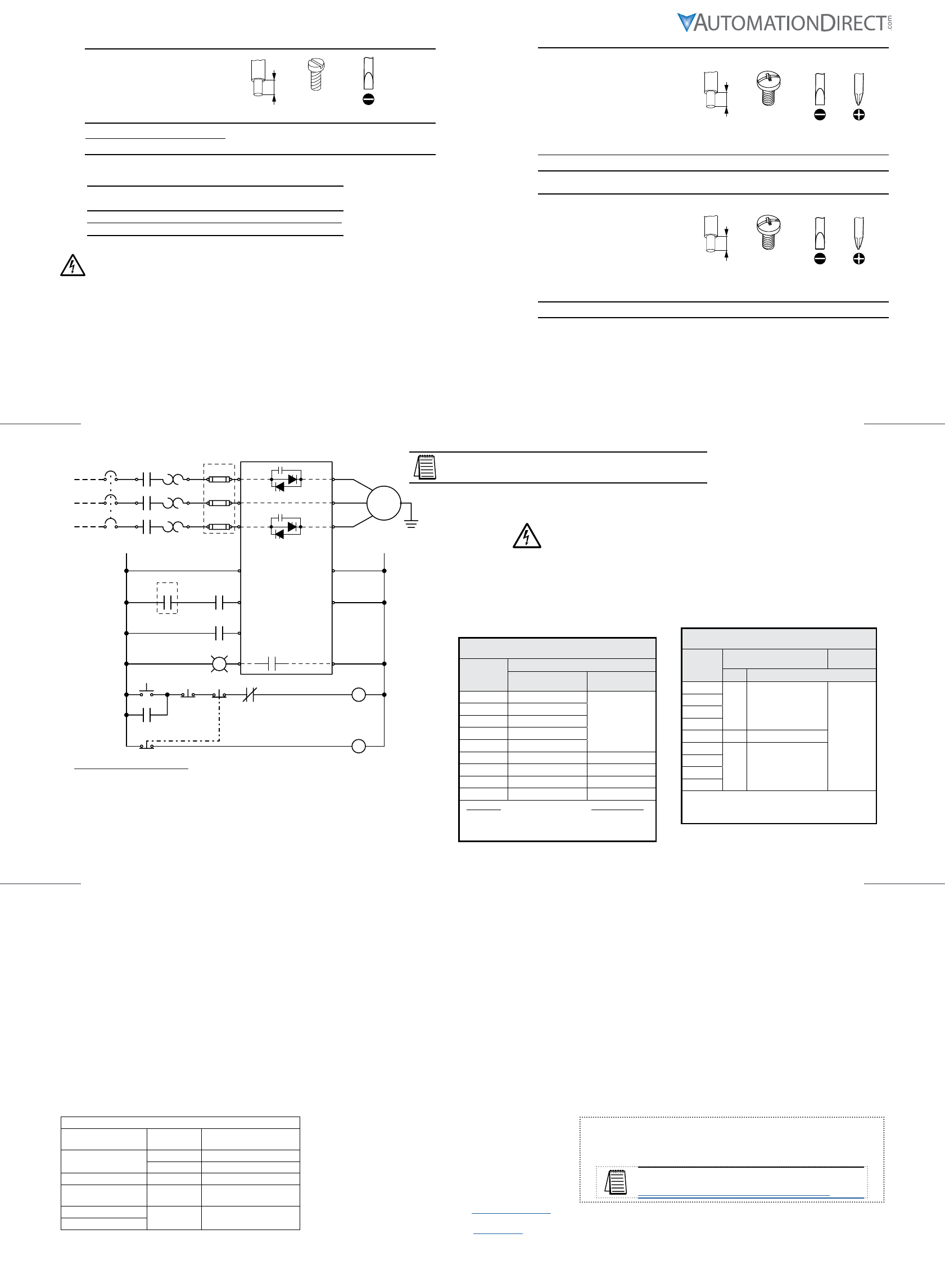
L1
Q1
SR22-xx
L2
L3
+24V 0V
3Ø
motor
M
<100m
1L1
3L2
5L3
+24
EN
+A1
23
2T1
4T2
6T3
0V
-A2
24
(24VDC)
(enable)
(start/stop)
(fault relay)
(common)
external power supply
required (fuse @ 4A max)
External Control Elements:
C1 = E-Stop contactor
CR1 = Start contactor
E1 = Optional switch to allow trip reset without opening main breaker Q1
F1 = Optional semiconductor fuse for Type 1 Coordination (in addition to Q1)
O/L = Overload relay
Q1 = Cable protection circuit breaker
L1 = Indicator lamp: ON = Ready; OFF = Fault
E-Stop/Start/Stop = E-Stop/Start/Stop pushbuttons
F1
L1
O/L
CR1
Start Stop
Q1E1
CR1
CR1
O/L
C1
C1
E-Stop
E-Stop
Electric shock risk. Danger!
Only skilled or instructed persons may carry out the following operations.
Tension électrique dangereuse !
Seules les personnes qualifées et averties doivent exécuter les travaux ci-après.
¡Corriente eléctrica! ¡Peligro de muerte!
El trabajo descrito a continuación debe ser realizado por personas cualificadas.
UL Requirement
Short Circuit Rating 5kA @ 480V when
protected by equivalent fuses or circuit
breakers as indicated in the following table:
Recommended Semiconductor Fuses *
for 5kA Short Circuit Coordination Type 1
Soft
Starter
Model #
Fuse – Class gRB-URB
(690V rated) Fuse Block
Trip Ferraz Shawmut Equivalent
SR22-05
40A 6,9 URB 00 D08L 040
SI 00 DIN 80
SR22-07
SR22-09
SR22-12
SR22-16 50A 6,9 URB 00 D08L 050
SR22-22
125A 6,9 URB 00 D08L 125
SR22-30
SR22-36
SR22-40
*NOTE: These fuses must be mounted in all three
phases of the incoming power supply for optional
Type-1 short circuit protection of the semiconductors.
5kA Coordination Type 1
Recommended equivalent semiconductor fuses
(for optional Type 1 short-circuit coordination)
The soft starter must be connected to a 3-phase power supply and a
3-phase load for proper operation. Attempted starts will result in a starter
fault if either the 3-phase power or the 3-phase load is not connected.
SR22 Soft Starter Quick-Start Guide – 2b
SR22 Soft Starter Quick-Start Guide – 2c
SR22 Soft Starter Quick-Start Guide – 2a
Rated Impulse Withstand Voltage (Vimp)2.5 kV
Rated Insulation Voltage (Vi)500V
Pollution Degree 2
Rated Short-Circuit Current (Iq)* 5kA
Short-Circuit Coordination * Type 1
Surrounding Air
Temperature
0°C to 40°C [32ºF to 104ºF]
Above 40°C de-rate linearly by 2% of unit FLC per °C to a derate of 40% at 60°C (not UL)
Transport and Storage -25°C to +60°C [-13ºF to +140ºF]
Altitude 1000m – 1000-2000m de-rate 1% of unit FLC per 100m to 2000m
Humidity max 85% non-condensing, not exceeding 50% at 40°C
IP Rating IP20
Design Standards IEC 60947-4-2; EN60947-4-2
“AC Semiconductor Motor Controllers and Starters” United States Standard UL508
* When protected by recommended semiconductor fuse
EMC EMISSION AND IMMUNITY LEVELS
ESD immunity IEC 61000-4-2 4kV contact
8kV air discharge
R F immunity IEC 61000-4-6 140 dBuV over 0.15–80 MHz
IEC 61000-4-3 10V/m over 80–1000 MHz
Fast Transient immunity IEC 61000-4-4 2kV/5kHz
Surge immunity IEC 61000-4-5 2kV line to ground
1kV line to line
Conducted R F emissions EN 55011 CLASS A
Radiated R F emissions
Cooling Time
Cooling Time is partially determined by the severity of overcurrent.
• Max Cooling Time without fan: 6 minutes
• Max Cooling Time with optional cooling fan: 1 minute
Optional Cooling Fans
Cooling Fans do not run continuously.
Cooling Fans are temperature controlled.
• Fan turns on when soft starter reaches 45°C [113°F] or higher.
Optional cooling fans are available from AutomationDirect.com.
Li sted Soft Starters can be used when fitted with fan part numbers
as detailed in fan instruction document SR22-FAN_DS.
Operational Voltage (Ve)208–460 VAC rms 3-phase (-15% +10%)
Rated Frequency 50–60Hz ±2Hz Form Designation: Form 1
Index Rating AC53b: 3–5: 355
Overcurrent (maximum) = 3 x Irated for 5 seconds
Control Supply Vs24VDC approx 4VA supplied to terminals 0V – +24V
Enable Control 24VDC galvanically isolated terminals -A2 – EN
(opto-coupled sinking input; requires sourcing +24VDC)
Start/Stop Control 24VDC galvanically isolated terminals -A2 – +A1
(opto-coupled sinking input; requires sourcing +24VDC)
Auxiliary Circuits relay Ready/Fault – 23/24: 250VAC 2.5A (resistive AC11)
Indication LEDs: Green = Run Red = Error
t-Start 1 to 30 seconds
V-Start 30% to 100%
t-Stop 0 to 30 seconds
Power Terminals IP20 Rated wire clamping terminals
Start Duty 3 x FLC for 5 seconds at standard rating
Starts/Hour*
(Maximum)
standard (w/o fan) 10 starts per hour or 5 starts + 5 soft stops per hour
with optional fan 60 starts per hour or 30 starts + 30 soft stops per hour
* Maximum starts per hour are required to be evenly spaced over one hour.
WARNING: These are Class 2 ratings (for lightly-loaded motors)!!
Please see our website for proper sizing information:
https://www.automationdirect.com/selectors/softstarters
