T100u Users Guide
User Manual:
Open the PDF directly: View PDF ![]() .
.
Page Count: 66
- 1. PREFACE
- 2. SPECIFICATIONS, APPROVALS AND WARRANTY
- 3. GETTING STARTED
- 4. T100U OPERATING INSTRUCTIONS
- 5. CALIBRATION PROCEDURES
- 6. EPA PROTOCOL CALIBRATION
- 7. INSTRUMENT MAINTENANCE
- 8. TROUBLESHOOTING AND SERVICE
- 9. PRINCIPLES OF OPERATION

Model T100U
Trace Level Sulfur Dioxide Analyzer
Addendum to T100 Operation Manual, PN 06807
Also supports operation of:
Model T108U Analyzer
(when used in conjunction with both the T100 manual, PN 06807,
and the T108 addendum, PN 07268)
© TELEDYNE API (TAPI)
9970 Carroll Canyon Road
SAN DIEGO, CA 92131-1106
USA
Toll-free Phone: 800-324-5190
Phone: +1 858-657-9800
Fax: +1 858-657-9816
Email: api-sales@teledyne.com
Website: http://www.teledyne-api.com/
Copyright 2010-2011 06840B DCN 6201
Teledyne API 11 August 2011

i
WARRANTY
See Warranty page in the T100 Manual - P/N 06807
ABOUT THIS MANUAL
This manual is to be used in conjunction with the Model T100 operation manual,
part number 06807. Where operation of the Model T100U diverges from that of
the Model T100, this manual addendum takes precedence. This T100U
addendum is comprised of multiple documents, assembled as follows:
Part No.
Rev
Name/Description
06840 B T100U Addendum to T100 Operation Manual
[See T100 manual for Appendix A, Menu Tree and related software documentation]
06846 8/9/2011 Spare Parts List (in Appendix B of this addendum)
05946 A Recommended Spares Stocking Levels (in Appendix B of this addendum)
05930 B Appendix C, Repair Form
Documents included in Appendix D:
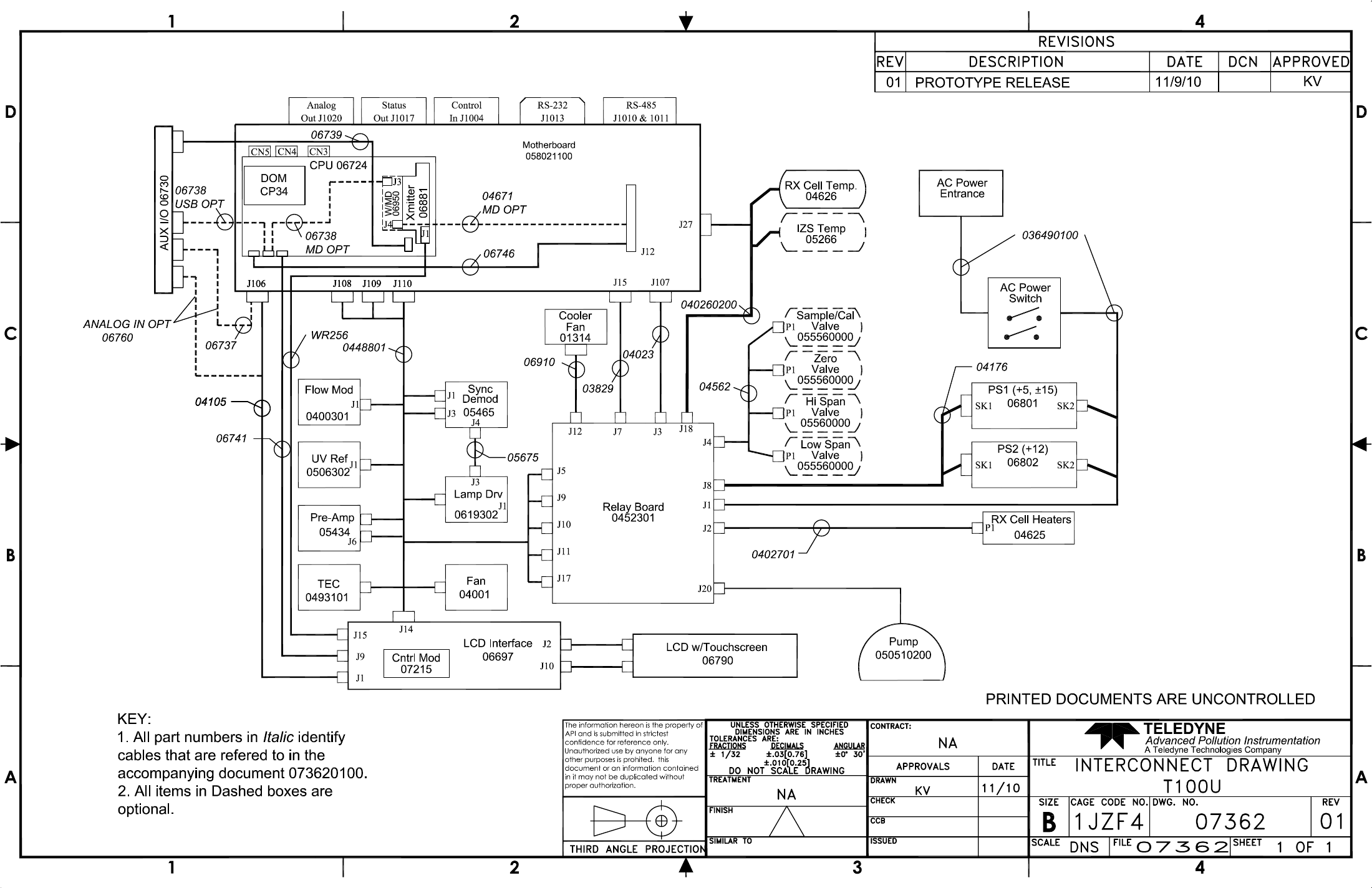
0736201 01 Interconnect List
07362 01 Interconnect Diagram
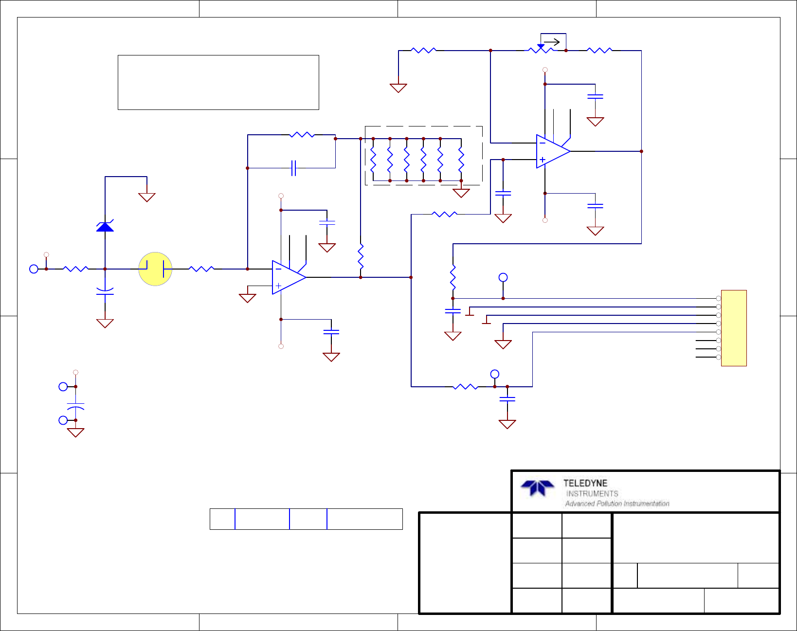
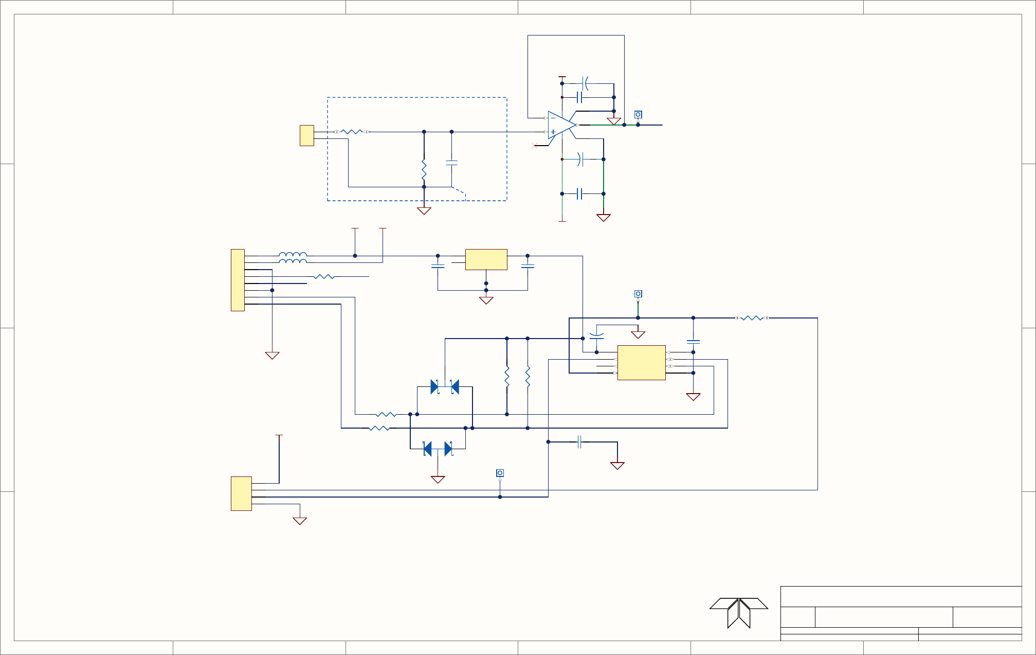
0506402 A UV Ref PCA
05435 C Internal PMT Preamp PCA
05466 B Sync/Demod PCA
0591602 C Bursting UV Lamp Drv Schem
06840B DCN 6201
Teledyne API - T100U Manual, Addendum to T100 Manual P/N 06807
ii
REVISION HISTORY
2011, August 10, T100U Addendum, 06840 Rev B, DCN Updates
Document
PN
Rev
DCN
Change Summary
T100U Addendum 06840 B 6201 Administrative Updates:
• Reformatted layout.
• Renamed “Theory of Operation” to “Principles of
Operation” and moved to end (last section).
• Renamed “Troubleshooting & Repair” to
“Troubleshooting and Service”.
• Corrected cross-references to sections/figures in
T100 Operation Manual, 06807.
Technical updates:
• Removed reference to “shutter”.
• Added North American Certifications to specs table
Replaced Spare Parts List 06846 with most recent
output to spreadsheet.
Replaced Internal PMT Preamp schem 05435 Rev B
with Rev C
Replaced Sync/Demod PCA schem 05466 Rev A
with Rev B.
2010, November 15, T100U Manual, PN06840 Rev A, DCN5908 Initial Release
06840B DCN 6201

iii
TABLE OF CONTENTS
1. PREFACE .............................................................................................................................................................................. 7
1.1 Reference Numbering Convention ............................................................................................................................ 7
2. SPECIFICATIONS, APPROVALS AND WARRANTY ........................................................................................................... 9
2.1 Specifications ............................................................................................................................................................ 9
2.2 EPA Equivalency Designation ................................................................................................................................. 10
2.3 CE Mark Compliance .............................................................................................................................................. 10
3. GETTING STARTED ............................................................................................................................................................ 11
3.1 Unpacking the T100U ............................................................................................................................................. 11
3.2 Internal Layouts ...................................................................................................................................................... 11
3.3 Functional Check of the T100U ............................................................................................................................... 13
3.3.1 Test Functions .................................................................................................................................................... 13
4. T100U OPERATING INSTRUCTIONS ................................................................................................................................. 15
4.1 Additional Test Parameters ..................................................................................................................................... 15
4.2 STBL MENU: Setup for the Three Stability Functions ............................................................................................. 15
5. CALIBRATION PROCEDURES ........................................................................................................................................... 17
6. EPA PROTOCOL CALIBRATION ....................................................................................................................................... 19
7. INSTRUMENT MAINTENANCE ........................................................................................................................................... 21
8. TROUBLESHOOTING AND SERVICE ................................................................................................................................ 23
8.1.1 Fault Diagnosis with Warning Messages ............................................................................................................ 23
8.1.2 Fault Diagnosis with Test Functions ................................................................................................................... 24
8.1.3 Fault Diagnosis with Sync Demod PCA LEDs .................................................................................................... 25
8.2 Other Performance Problems ................................................................................................................................. 25
8.3 Additional Repair Procedures ................................................................................................................................. 25
8.3.1 UV Lamp Adjustment and/or Replacement ........................................................................................................ 25
8.3.1.1 Adjusting the UV Lamp (Peaking the Lamp) ............................................................................................. 26
8.3.1.2 Replacing the UV Lamp ............................................................................................................................ 28
8.3.2 Replacing the UV Filter/Lens .............................................................................................................................. 29
8.3.3 Replacing the PMT, HVPS or TEC ..................................................................................................................... 30
8.3.4 T100U PMT Hardware Calibration (Factory Cal) ................................................................................................ 32
8.4 Technical Assistance .............................................................................................................................................. 33
9. PRINCIPLES OF OPERATION ............................................................................................................................................ 35
9.1 Electronic Operation................................................................................................................................................ 35
9.1.1 Sensor Module ................................................................................................................................................... 35
9.1.1.1 Sample Chamber ...................................................................................................................................... 38
06840B DCN 6201

Contents Teledyne API - T100U Manual, Addendum to T100 Manual P/N 06807
iv
LIST OF FIGURES
Figure 3-1: T100U Internal Layout .................................................................................................................12
Figure 3-2: T100U Test Functions .................................................................................................................14
Figure 4-1: Accessing the STBL Menu ..........................................................................................................16
Figure 8-1: UV Lamp Adjustment ...................................................................................................................27
Figure 8-2: Disassembling the Sample Chamber/UV Source Assembly .......................................................29
Figure 8-3: PMT Assembly - Exploded View ..................................................................................................30
Figure 9-1: Sensor Block Diagram .................................................................................................................36
Figure 9-2: T100U Sensor Module Assembly ................................................................................................37
Figure 9-3: T100U Sample Chamber Exploded View ....................................................................................38
LIST OF TABLES
Table 2-1: Model T100U Basic Unit Specifications ......................................................................................... 9
Table 3-1: Test Functions Defined ................................................................................................................13
Table 8-1: Test Functions - Possible Causes for Out-Of-Range Values ......................................................24
Table 8-2: Relay PCA Status LED Failure Indications ..................................................................................25
06840B DCN 6201

v
LIST OF APPENDICES
APPENDIX A: Menu Trees and Software Documentation (refer to Appendix A of the T100 manual)
APPENDIX B: Spare Parts List and Recommended Spares Stocking Levels
APPENDIX C: Warranty Repair Questionnaire
APPENDIX D: Schematics (contains those unique to T100U; other schematics in T100 manual)
06840B DCN 6201

Contents Teledyne API - T100U Manual, Addendum to T100 Manual P/N 06807
vi
This page intentionally left blank.
06840B DCN 6201

7
1. PREFACE
Note The information contained in this addendum is pertinent to T100U
analyzers running software revision Gc4. Some or all of the information
may not be applicable to later revisions of software. The software
revision that your analyzer is running is displayed in the Mode field of the
display any time the analyzer is in SETUP mode.
This addendum is based on the Model T100 Operators Manual (P/N 06807). In most
ways the T100U is identical to the T100 in design and operation; therefore, most of the
basic set up information, operating instructions as well as calibration, maintenance,
troubleshooting and repair methods are found in that manual. This addendum
documents only those areas where the T100U is different in design or operating method
from the T100.
Therefore, this addendum includes instructions and information regarding:
• Additional Test Functions
• Adjusting the PMT HV for “Factory Calibrations”
• Differences in theory of operation
1.1 REFERENCE NUMBERING CONVENTION
Unless otherwise specified, section, figure and table reference numbers referred to
within this text are relative to this manual.
EXAMPLE: “Figure 2-1” refers to the figure within this document labeled as
Figure 2-1.
References to sections, figures and tables in the T100 manual will be labeled as such.
EXAMPLE: “Figure 6-1 of the T100 Operators Manual” (P/N 06807).
06840B DCN 6201

Preface Teledyne API - T100U Manual, Addendum to T100 Manual P/N 06807
8
This page intentionally left blank.
06840B DCN 6201

9
2. SPECIFICATIONS, APPROVALS AND
WARRANTY
2.1 SPECIFICATIONS
Table 2-1: Model T100U Basic Unit Specifications
PARAMETER
SPECIFICATION
Ranges
(Physical Analog Output) Min: 0-5 ppb Full scale
Max: 0-20 000 ppb Full scale (selectable, dual ranges and auto ranging supported)
Measurement Units ppb, ppm, µg/m
3
, mg/m
3
(selectable)
Zero Noise
2
25 ppt RMS (50 ppt RMS with 360 nm filter installed)
Span Noise
2
0.5% of reading RMS, above 5 ppb
Lower Detectable Limit
3
50 ppt RMS
Zero Drift (24 hours) < 0.2 ppb (<.4 ppb with 360 nm filter installed)
Span Drift (24 hours) < 0.5% of full scale
Lag Time
1
30 seconds
Rise/Fall Time
1
< 140 seconds to 95%
Linearity 1% of full scale
Precision 0.5% of reading
Sample Flow Rate 650 cm
3
/min. ±10%
AC Power Rating 100 V-120V, 220 – 240 V, 50/60 Hz
Analog Output Ranges 10 V, 5 V, 1 V, 0.1 V,
2-20 or 4-20 mA isolated current loop.
All Ranges with 5% Under/Over Range
Recorder Offset: ±10%
Standard I/O
1 Ethernet: 10/100Base-T
2 RS-232 (300 – 115,200 baud)
2 USB device ports
8 opto-isolated digital status outputs
6 opto-isolated digital control inputs (3 defined, 3 spare)
4 analog outputs
Optional I/O
1 USB com port
1 RS485
8 analog inputs (0-10V, 12-bit)
4 digital alarm outputs
Multidrop RS232
3 4-20mA current outputs
06840B DCN 6201

Specifications, Approvals and Warranty Teledyne API - T100U Manual, Addendum to T100 Manual P/N 06807
10
PARAMETER
SPECIFICATION
Analog Output Resolution 1 part in 4096 of selected full-scale voltage
Temperature Coefficient < 0.1% per
o
C
Temperature Range 5-40
o
C
Humidity Range 0 - 95% RH, non-condensing
Dimensions H x W x D 7" x 17" x 23.5" (178 mm x 432 mm x 597 mm)
Weight, Analyzer
(Basic Configuration) 45 lbs (20.5 kg) w/internal pump
Environmental Installation category (over-voltage category) II; Pollution degree 2
Certifications EQSA-0495-100
EN61326 (1997 w/A1: 98) Class A,
FCC Part 15 Subpart B Section 15.107 Class A,
ICES-003 Class A (ANSI C63.4 1992) & AS/NZS 3548 (w/A1 & A2; 97)
Class A.
IEC 61010-1:90 + A1:92 + A2:95,
North American Certifications:
• cNEMKO (Canada): CAN/CSA-C22.2 No. 61010-1-04
• NEMKO-CCL (us): UL No. 61010-1 (2nd Edition)
1
As defined by the USEPA
2 25 samples taken, 10 sec. interval
3 Twice zero noise
2.2 EPA EQUIVALENCY DESIGNATION
Teledyne API’s T100U trace level sulfur dioxide analyzer is designated as a reference
method for SO2 measurement, as defined in 40 CFR Part 53, when operated under the
conditions defined for the T100 analyzer (manual PN 06807).
2.3 CE MARK COMPLIANCE
The T100U analyzer emissions and safety compliance are the same as those for the T100
analyzer.
06840B DCN 6201

11
3. GETTING STARTED
3.1 UNPACKING THE T100U
Unpack the T100U as per the directions in Section 3.1 of the T100 Manual, with the
following change: There are two redheaded shipping screws that hold down the
PMT/Sensor assembly and must be removed prior to operation. They are located along
the base of the PMT housing adjacent to the chassis.
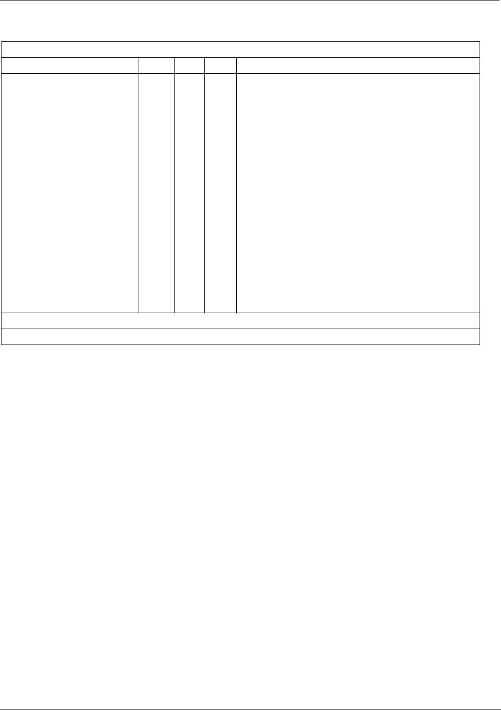
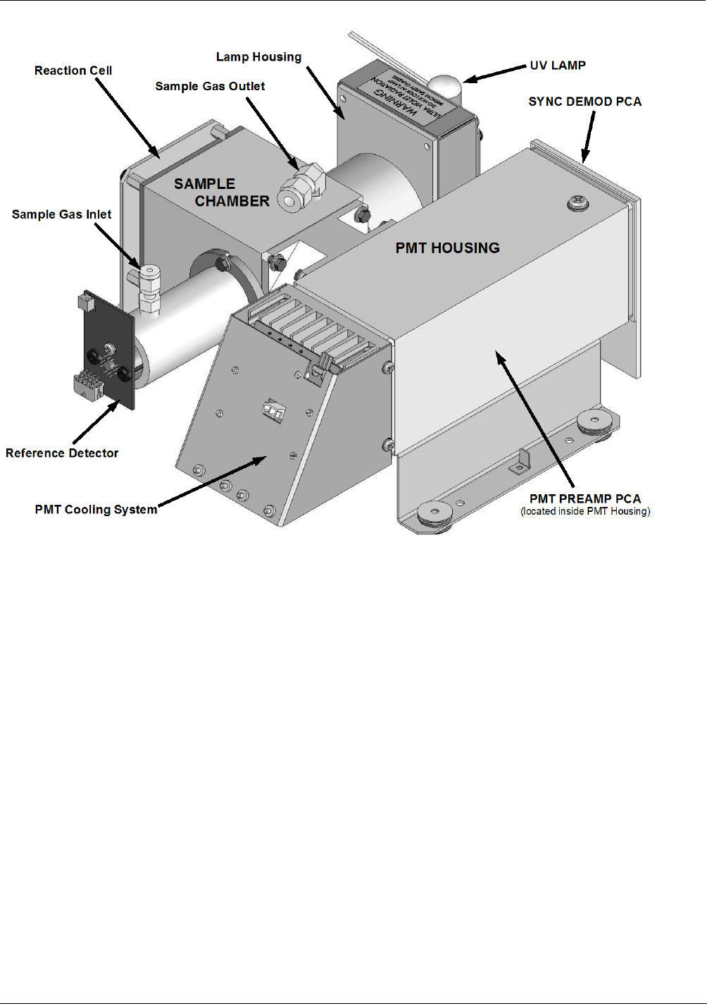
3.2 INTERNAL LAYOUTS
Figures 3-1 replaces Figure 3-5 in the T100 manual. The primary difference between
the T100U and T100 layouts is the differences in the PMT Housing, the location of the
PMT preamp PCA and the addition of a Sync Demodulator PCA.
06840B DCN 6201
Getting Started Teledyne API - T100U Manual, Addendum to T100 Manual P/N 06807
12
Figure 3-1: T100U Internal Layout
06840B DCN 6201

Teledyne API - T100U Manual, Addendum to T100 Manual P/N 06807 Getting Started
13
3.3 FUNCTIONAL CHECK OF THE T100U
To perform an initial functional check of the T100U follow the steps contained in
Section 3.4 of the T100 Manual, but use the Test functions described in below.
3.3.1 TEST FUNCTIONS
Table 3-1 of this addendum supersedes Table 4-2 in Section 4.1.1 of the T100 manual,
and Figure 3.2 in this addendum replaces Figure 3-24 of the T100 Manual.
Table 3-1: Test Functions Defined
DISPLAY
PARAMETER
UNITS
DESCRIPTION
RANGE
RANGE
- -
RANGE1
RANGE2
PPB,
PPM,
UGM &
MGM
The Full Scale limit at which the reporting range of the analyzer’s
ANALOG OUTPUTS is currently set.
THIS IS NOT the Physical Range of the instrument. See Section
4.6 of T100 manual for more information.
If DUAL or AUTO Range modes have been selected, two
RANGE functions will appear, one for each range.
STABIL STABILITY ppb Standard deviation of SO2 Concentration readings. Data points
are recorded every ten seconds. The calculation uses the last
25 data points.
STABIL2 STABILITY ppb Standard deviation of SO2 Concentration readings, per EPA.
Data points are recorded every 120 seconds. The calculation
uses the last 25 data points.
PRES SAMPLE PRESSURE in-Hg-A The current pressure of the sample gas as it leaves the sample
chamber.
SAMP FL SAMPLE FLOW cm³/min
(cc/m) The flow rate of the sample gas through the sample chamber.
PMT
PMT Signal mV The raw output voltage of the PMT.
NORM PMT NORMALIZED PMT
Signal mV The output voltage of the PMT after normalization for offset and
temperature/pressure compensation (if activated).
UV LAMP Source UV Lamp
Intensity mV The output voltage of the UV reference detector.
UV STAB Stability of UV Lamp
Intensity mV Standard deviation of UV reference detector output. Data points
are recorded every ten seconds. The calculation uses the last
25 data points.
LAMP RATIO UV Source lamp ratio % The current output of the UV reference detector divided by the
reading stored in the CPU’s memory from the last time a UV
Lamp calibration was performed.
STR. LGT Stray Light ppb The offset due to stray light recorded by the CPU during the last
zero-point calibration performed.
DRK PMT Dark PMT mV The PMT output reading recorded as the lamp pulses off during
normal measurement.
DRK LMP Dark UV Source Lamp mV The UV reference detector output reading recorded as the lamp
pulses off during normal measurement.
SLOPE SO2 measurement Slope - The sensitivity of the instrument as calculated during the last
calibration activity. The slope parameter is used to set the span
calibration point of the analyzer.
OFFSET SO2 measurement Offset - The overall offset of the instrument as calculated during the last
calibration activity. The offset parameter is used to set the zero
point of the analyzer response.
HVPS
HVPS V The PMT high voltage power supply.
06840B DCN 6201
Getting Started Teledyne API - T100U Manual, Addendum to T100 Manual P/N 06807
14
DISPLAY
PARAMETER
UNITS
DESCRIPTION
RCELL TEMP SAMPLE CHAMBER
TEMP °C The current temperature of the sample chamber.
BOX TEMP BOX TEMPERATURE °C The ambient temperature of the inside of the analyzer case.
PMT TEMP PMT TEMPERATURE °C The current temperature of the PMT.
IZS TEMP1 IZS TEMPERATURE1 °C The current temperature of the internal zero/span option. Only
appears when IZS option is enabled
TEST2
TEST SIGNAL
2
mV Signal of a user-defined test function on output channel A4.
TIME CLOCK TIME hh:mm:ss The current day time for DAS records and calibration events.
To view the TEST Functions press the following menu selection sequence:
RANGE
STABIL
STABIL2
PRES
SAMP FL
PMT
NORM PMT
UV LAMP
UV STB
LAMP RATIO
STR. LGT
DARK PMT
DARK LMP
SLOPE
OFFSET
HVPS
RCELL TEMP
BOX TEMP
PMT TEMP
IZS TEMP
1
TEST
2
TIME
SAMPLE RANGE = 500.0 PPB SO2 =XXX.X
< TST TST > CAL SETUP
1
Only appears if IZS option is
installed.
2
Only appears if analog output
A3 is actively reporting a test
function
Toggle <TST TST> buttons
to scroll through list of
Figure 3-2: T100U Test Functions
06840B DCN 6201

15
4. T100U OPERATING INSTRUCTIONS
Note For the most part the operation instructions for the T100U are the same
as those described in the T100 Manual with the exception that there are
additional test parameters and setup procedures.
4.1 ADDITIONAL TEST PARAMETERS
Please see Section 3.3 of this addendum for details on the additional test parameters.
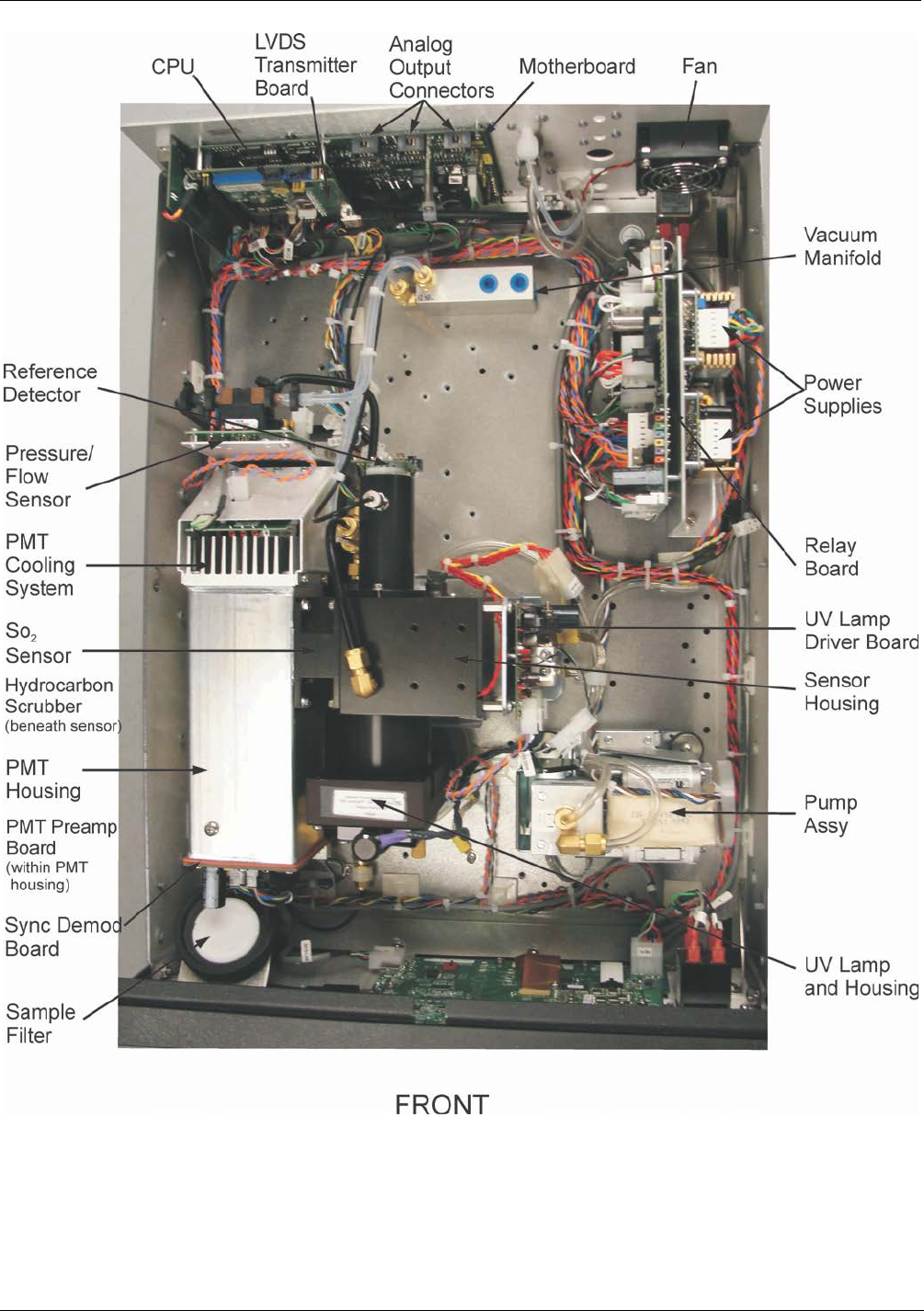
4.2 STBL MENU: SETUP FOR THE THREE STABILITY
FUNCTIONS
There is an additional submenu on the Secondary Setup Menu in the T100U’s software.
The STBL menu, see Figure 4-1 allows the user to modify the settings for the three
stability calculations that are displayed as Test Functions on the front panel and are
available via the serial data port and that can be logged with the DAS. Test Function
STABIL, CONC1 in the menus below, is equivalent to the standard T100 STABIL
function and is useful when conducting calibrations and other operations in which the
operator has limited time to view the display. CONC2, which is the same as the
STABIL2 test function has been configured so that it calculates stability in the same way
as required by the EPA. STABIL2 is useful when comparing instruments against the
EPA standard but is very slow and difficult to use for calibration or other activities
where the operator must wait for analyzer to settle to the desired value. UVLAMP is
the same as UV STAB on the front panel is a diagnostic that can be used to understand
the stability of the UV lamp.
06840B DCN 6201
T100U Operating Instructions Teledyne API - T100U Manual, Addendum to T100 Manual P/N 06807
16
SETUP X.X
SECONDARY SETUP MENU
COMM VARS DIAG STBL EXIT
SETUP X.X
PRIMARY SETUP MENU
CFG DAS RNGE PASS CLK MORE EXIT
SAMPLE RANGE = 500.000 PPB SO2 =XXX.X
< TST TST > CAL SETUP
EXIT returns
to the PRIMARY
SETUP MENU
EXIT returns
to the main
SAMPLE
display
SETUP X.X
CONC1, 10SEC, 25 SAMPLES
NEXT EDIT PRNT EXIT
SETUP X.X
UVLAMP, 10SEC, 25 SAMPLES
PREV EDIT PRNT EXIT
CONC2 is
setup for
STABIL2 test
function,
UVLAMP for
UV STAB test
function
SETUP X.X
CONC2, 120SEC, 25 SAMPLES
PREV NEXT EDIT PRNT EXIT
Figure 4-1: Accessing the STBL Menu
06840B DCN 6201

17
5. CALIBRATION PROCEDURES
Calibration of the T100U should be performed according to the procedures described in
the T100 Manual. However, delivering span and zero gases for the lower ranges that the
T100U is designed for can be difficult. For best results when calibrating the T100U, wait
one hour for the instrument to stabilize when delivering zero and span gases before
pressing the zero and span buttons. Attention must be paid to the quality of the gasses,
the level of contaminants in the gases as well as the history and conditioning of the gas
delivery components. Only Teflon or glass should be used for any “wetted” surfaces
that the calibration gasses contact. All delivery system components should be
conditioned by running span gas for a minimum of four hours before conducting actual
span calibrations.
06840B DCN 6201

Calibration Procedures Teledyne API - T100U Manual, Addendum to T100 Manual P/N 06807
18
This page intentionally left blank.
06840B DCN 6201

19
6. EPA PROTOCOL CALIBRATION
For EPA Protocol calibration please refer to Section 10 of the T100 manual.
06840B DCN 6201

EPA Protocol Calibration Teledyne API - T100U Manual, Addendum to T100 Manual P/N 06807
20
This page intentionally left blank.
06840B DCN 6201

21
7. INSTRUMENT MAINTENANCE
Instrument maintenance is almost identical to that in the T100. The T100U uses a 1 micron sample filter,
instead of the 5 micron sample filter used in the T100. Replacement part numbers are shown below.
Part Number Description
009690200 AKIT, TFE FLTR ELEMENT, 47MM, 1UM (100)
05920 UV Zinc LAMP, T100U
For all other maintenance questions, please refer to section 8 in the T100 manual.
06840B DCN 6201

Instrument Maintenance Teledyne API - T100U Manual, Addendum to T100 Manual P/N 06807
22
This page intentionally left blank.
06840B DCN 6201
23
8. TROUBLESHOOTING AND SERVICE
This section includes various troubleshooting and repair information that either
supplements or is in addition to that included in Section 12 of the T100 Manual
CAUTION
The operations outlined in this Section must be performed by qualified
maintenance personnel only.
Please read Section 12 of the T100 Manual before attempting the
following trouble shooting or repair procedures
WARNING - RISK OF ELECTRICAL SHOCK.
Some operations need to be carried out with the analyzer open and
running.
Exercise caution to avoid electrical shocks and electrostatic or
mechanical damage to the analyzer.
Do not drop tools into the analyzer or leave those after your procedures.
Do not shorten or touch electric connections with metallic tools while
operating inside the analyzer.
Use common sense when operating inside a running analyzer.
8.1.1 FAULT DIAGNOSIS WITH WARNING MESSAGES
The warning messages for the T100U are identical to those included in Section 12.1.1 of
the T100 Manual.
06840B DCN 6201

Troubleshooting and Service Teledyne API - T100U Manual, Addendum to T100 Manual P/N 06807
24
8.1.2 FAULT DIAGNOSIS WITH TEST FUNCTIONS
The following table supersedes Table 12.2 of the T100 Manual.
Table 8-1: Test Functions - Possible Causes for Out-Of-Range Values
TEST
FUNCTION
NOMINAL
VALUE(S)
POSSIBLE CAUSE(S)
STABIL
(STANDARD)
≤0.075 ppb with zero
air
Faults that cause high stability values are: pneumatic leak; low or very unstable UV lamp
output; light leak; faulty HVPS; defective preamp board; aging PMT; PMT recently exposed to
room light; dirty/contaminated reaction cell.
STABIL2
(EPA DEF)
≤0.075 ppb with zero
air Same as STABIL
SAMPLE FL 650 cm
3
/min
± 10% Faults can be caused by: clogged critical flow orifice; pneumatic leak; faulty flow sensor;
sample line flow restriction.
PMT -20 TO 150 mV with
zero air
High or noisy readings could be due to: calibration error; pneumatic leak; light leak (improper
assembly); aging UV filter; low UV reference output; PMT recently exposed to room light; light
leak in reaction cell; reaction cell contaminated; HVPS problem.
It takes 24-48 hours for a PMT exposed to ambient light levels to return to normal functioning.
NORM PMT - - Noisy Norm PMT value (assuming unchanging SO2 concentration of sample gas):
Calibration error; HVPS problem; PMT problem; UV reference problem; UV lamp problem.
UV LAMP 2000 - 4400 mV
This is the instantaneous reading of the UV lamp intensity. Low UV lamp intensity could be
due to: aging UV lamp; UV lamp position out of alignment; faulty lamp transformer; aging or
faulty UV detector; dirty optical components.
Intensity lower than 600 mV will cause UV LAMP WARNING.
UV STAB 0 to 100 mV Unstable lamp or failed UV lamp driver.
LAMP RATIO ___
The current output of the UV reference detector divided by the reading stored in the CPU’s
memory from the last time a UV Lamp calibration was performed. Out of range lamp ratio
could be due to: malfunctioning UV lamp; UV lamp position out of alignment; faulty lamp
transformer; aging or faulty UV detector; dirty optical components; pin holes or scratches in the
UV optical filters; light leaks.
STR LGT <100 ppb High stray light could be caused by: aging UV filter; contaminated reaction cell; light leak;
pneumatic leak.
DRK PMT 200 - 325 mV High dark PMT reading could be due to: light leak; high pmt temperature; high electronic
offset.
DRK LMP -50 - 200 mV High dark UV detector could be caused by: light leak; high electronic offset.
HVPS ≈ 400 V to 900 V Incorrect HVPS reading could be caused by; HVPS broken; preamp board circuit problems.
RCELL TEMP 50ºC ± 1ºC Incorrect temperature reading could be caused by: malfunctioning heater; relay board
communication (I2C bus); relay burnt out
BOX TEMP ambient
+ ~ 5ºC Incorrect temperature reading could be caused by: Environment out of temperature
operating range; broken thermistor; runaway heater
PMT TEMP 7ºC ± 2ºC constant Incorrect temperature reading could be caused by: TEC cooling circuit broken; High chassis
temperature; 12V power supply
IZS TEMP
(OPTION) 50ºC ± 1ºC Malfunctioning heater; relay board communication (I1C bus); relay burnt out
PRESS ambient
± 2 IN-HG-A
Incorrect SAMPLE pressure could be due to: pneumatic leak; malfunctioning valve;
malfunctioning pump; clogged flow orifices; sample inlet overpressure; faulty pressure
sensor
SLOPE 1.0 ± 0.3 Slope out of range could be due to: poor calibration quality ; span gas concentration incorrect;
leaks; UV Lamp output decay.
OFFSET < 250 mV High offset could be due to: incorrect span gas concentration/contaminated zero air/leak; low-
level calibration off; light leak; aging UV filter; contaminated reaction cell; pneumatic leak.
TIME OF DAY Current time Incorrect Time could be caused by: Internal clock drifting; move across time zones; daylight
savings time?
06840B DCN 6201

Teledyne API - T100U Manual, Addendum to T100 Manual P/N 06807 Troubleshooting and Service
25
8.1.3 FAULT DIAGNOSIS WITH SYNC DEMOD PCA LEDS
There are four green Light Emitting Diodes (LEDs) on the bottom left side of the Sync
Demodulator PCA. They indicate various statuses and can be used to troubleshoot
problems associated with the board.
Table 8-2: Relay PCA Status LED Failure Indications
Indicator
Function
Description
Action
DS4 Watchdog Toggles on or off
every second Steady on or off controller on PCA has crashed, PMT
temp. control still operates but PMT, REF and PMT Temp
voltages as shown in test functions will be XXXX. Press
reset button on sync demod to restart; if problem
continues check power supply voltages on PCA or PCA is
failing and must be replaced.
DS3 I2C Activity Flashes each time
sync demod is polled
by instrument CPU
once every 1 to 1.5
seconds
Steady on or off indicates I2C bus failure check wiring
harness taking I2C to motherboard, another I2C device is
hanging bus, I2C transceiver on motherboard has failed, or
CPU has problem.
DS2 A/D Status 1 Short frequent
flashes tracks timing
of A/D converter
Lack of flash indicates internal failure of A/D or firmware.
Press reset button on sync demod to restart; if problem
continues check power supply voltages on PCA or PCA is
failing and must be replaced.
DS1 A/D Status 2
8.2 OTHER PERFORMANCE PROBLEMS
Please refer to Section 12.5 of the T100 manual for information.
8.3 ADDITIONAL REPAIR PROCEDURES
The following repair procedures are in addition to those listed in Section 12.7 of the
T100 Manual,
8.3.1 UV LAMP ADJUSTMENT AND/OR REPLACEMENT
There are two ways in which ambient conditions can affect the UV Lamp output and
therefore the accuracy of the SO2 concentration measurement: lamp aging and lamp
positioning.
LAMP AGING
Over a period of months, the UV energy will show a downward trend, usually 30% -
50% in the first 90 days, and then a slower rate, until the end of useful life of the lamp.
Periodically running the UV lamp calibration routine (see Section 5.9.6 of the T100
Manual) will compensate for this until the lamp output becomes too low to function at
all, 2-3 years nominally.
06840B DCN 6201

Troubleshooting and Service Teledyne API - T100U Manual, Addendum to T100 Manual P/N 06807
26
LAMP POSITIONING
The UV output level of the lamp is uneven across the entire length of the lamp. Some
portions of the lamp shine slightly more brightly than others. At the factory the position
of the UV lamp is adjusted to optimize the amount of UV light shining through the UV
filter/lens and into the reaction cell. Changes to the physical alignment of the lamp can
affect the analyzer’s ability to accurately measure SO2. See Section 12.7.2.5 of the T100
Manual for instructions on adjusting the lamp position.
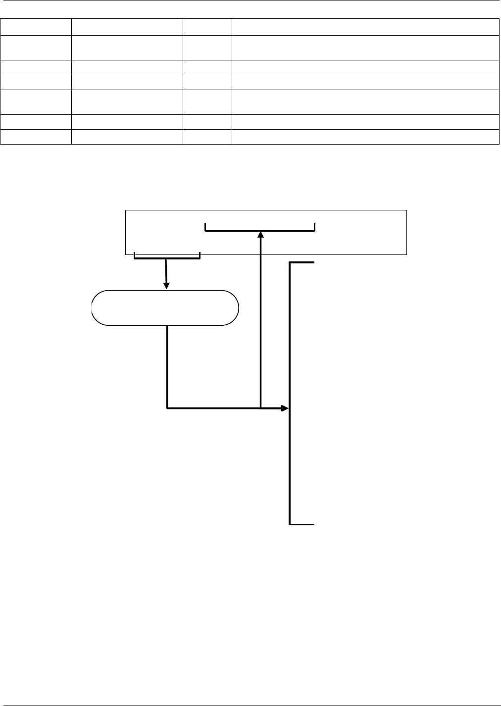
8.3.1.1 Adjusting the UV Lamp (Peaking the Lamp)
CAUTION – GENERAL SAFETY HAZARD
Always wear safety glasses made with UV blocking material when
working with the UV Lamp assembly. (Generic plastic safety glasses are
not adequate).
1. Set the analyzer display to show the signal I/O function, UVLAMP_SIGNAL (see
Section 12.1.3 of the T100 Manual.
2. Slightly loosen the large brass thumbscrew located on the shutter housing (see
Figure 8-1) so that the lamp can be moved.
3. While watching the UVLAMP_SIGNAL reading, slowly rotate the lamp or move it
back and forth vertically until the UVLAMP_SIGNAL reading is at its maximum.
• Best peak intensity will occur when the dot (or arrow) on top of the lamp is pointing in the
direction of the reaction cell.
• Ideally, the reading should be 4000mV±200mV.
• If UVLAMP_SIGNAL is lower than 600mV, replace the lamp.
• If UVLAMP_SIGNAL is greater than 4400 mV, adjust the pot on the UV reference board
down until the output reads 4400 mV, and then continue to peak the lamp.
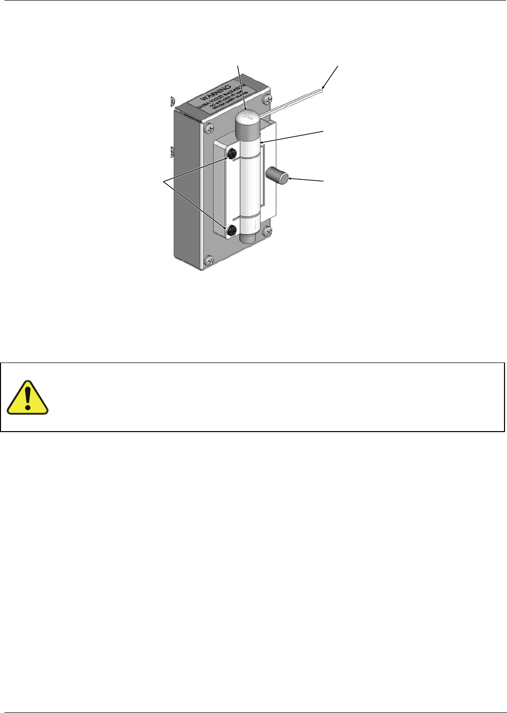
ATTENTION COULD DAMAGE INSTRUMENT AND VOID WARRANTY
DO NOT grasp the UV lamp by its cap when changing its position -
always grasp the main body of the lamp (refer to Figure 8-1). Inattention
to this detail could twist and potentially disconnect the lamp’s power
supply wires.
06840B DCN 6201
Teledyne API - T100U Manual, Addendum to T100 Manual P/N 06807 Troubleshooting and Service
27
DO NOT
Use Lamp Cap to
adjust Lamp position
UV Lamp
Power Supply
Wires
Thumb screw
UV Lamp
Bracket
Mounting
Screws
Adjust Lamp
Position by
grasping Lamp
body ONLY
Figure 8-1: UV Lamp Adjustment
4. Finger tighten the thumbscrew.
CAUTION - GENERAL SAFETY HAZARD
DO NOT over tighten the thumbscrew, as over-tightening can cause
breakage to the lamp and consequently release mercury into the area.
06840B DCN 6201
Troubleshooting and Service Teledyne API - T100U Manual, Addendum to T100 Manual P/N 06807
28
8.3.1.2 Replacing the UV Lamp
CAUTION – GENERAL SAFETY HAZARD
Always wear safety glasses made with UV blocking material when
working with the UV Lamp assembly. (Generic plastic safety glasses are
not adequate).
1. Turn off the analyzer.
2. Disconnect the UV lamp from its power supply.
• You can find the power supply connector by following the two, white UV Lamp
power supply wires from the lamp to the power supply.
3. Loosen, but do not remove the two UV lamp bracket screws, and the large brass
thumbscrew located on the shutter housing (see Figure 8-2) so that the lamp can be
moved.
ATTENTION COULD DAMAGE INSTRUMENT AND VOID WARRANTY
Do not grasp the UV lamp by its cap when changing its position (see
Figure 8-2). Always grasp the main body of the lamp. Inattention to this
detail could twist and potentially disconnect the lamp’s power supply
wires.
4. Remove the UV Lamp by pulling it straight up.
5. Insert the new UV lamp into the bracket.
6. Tighten the two UV lamp bracket screws, but leave the brass thumb screw un-
tightened.
7. Connect the new UV lamp to the power supply.
8. Turn the instrument on and perform the UV adjustment procedure as defined in
section 8.3.1.1 of this addendum.
9. Finger tighten the thumbscrew.
CAUTION - GENERAL SAFETY HAZARD
DO NOT over tighten the thumbscrew, as over-tightening can cause
breakage to the lamp and consequently release mercury into the area.
10. Perform a lamp calibration procedure (see Section 4.8.7 of the T100 Manual) and a
zero point and span point calibration (see Section 9 of the T100 Manual).
06840B DCN 6201
Teledyne API - T100U Manual, Addendum to T100 Manual P/N 06807 Troubleshooting and Service
29
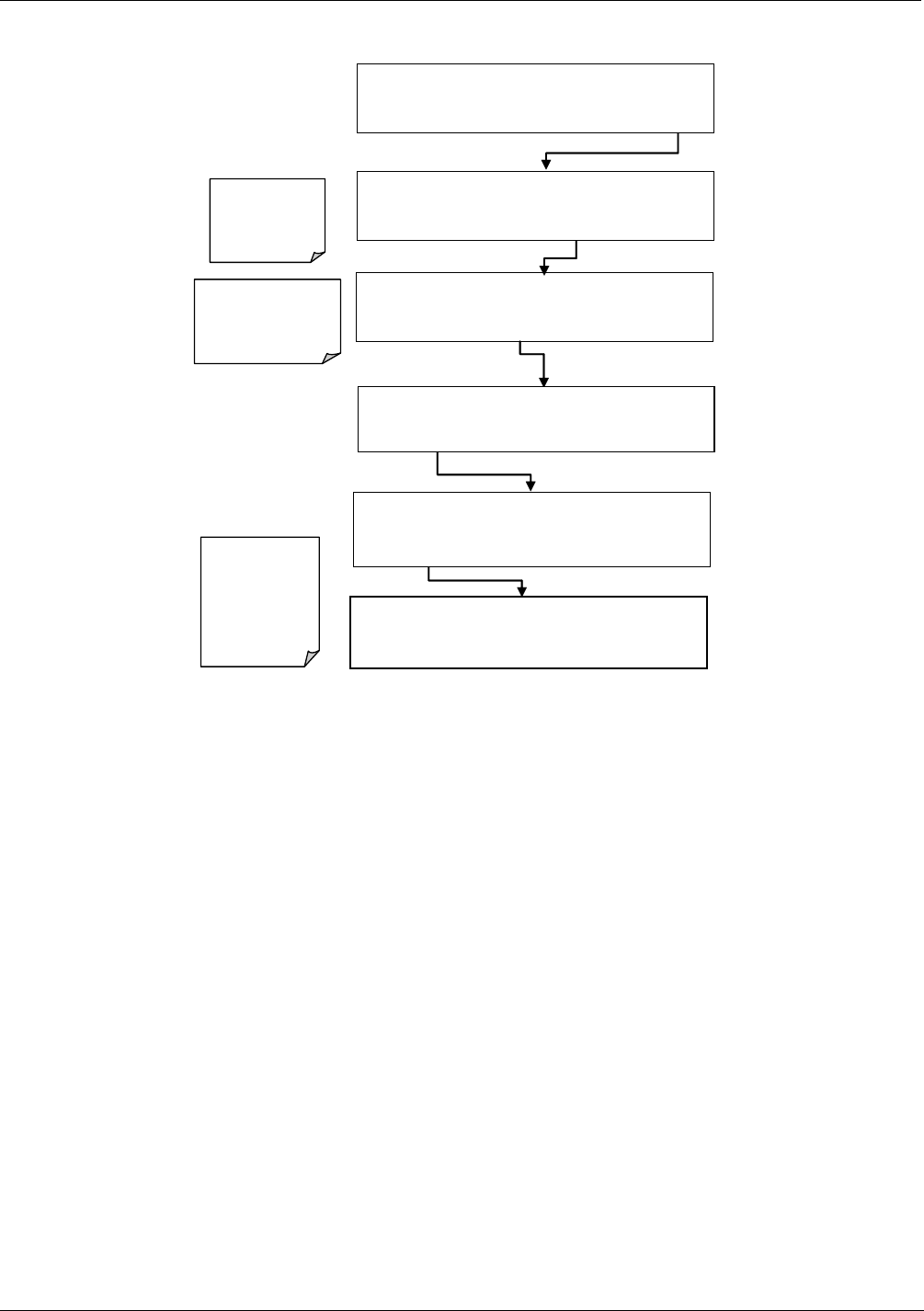
8.3.2 REPLACING THE UV FILTER/LENS
IMPORTANT IMPACT ON READINGS OR DATA
Be careful not to leave thumbprints on the i
nterior of the sample
chamber. The various
oils that make up fingerprints fluoresce brightly
under UV light and will significantly affect the accuracy of the analyzer’s
SO2 measurement.
1. Turn off the instrument’s power and remove the power cord from the instrument.
2. Unplug the J4 connector from the motherboard to allow tool access.
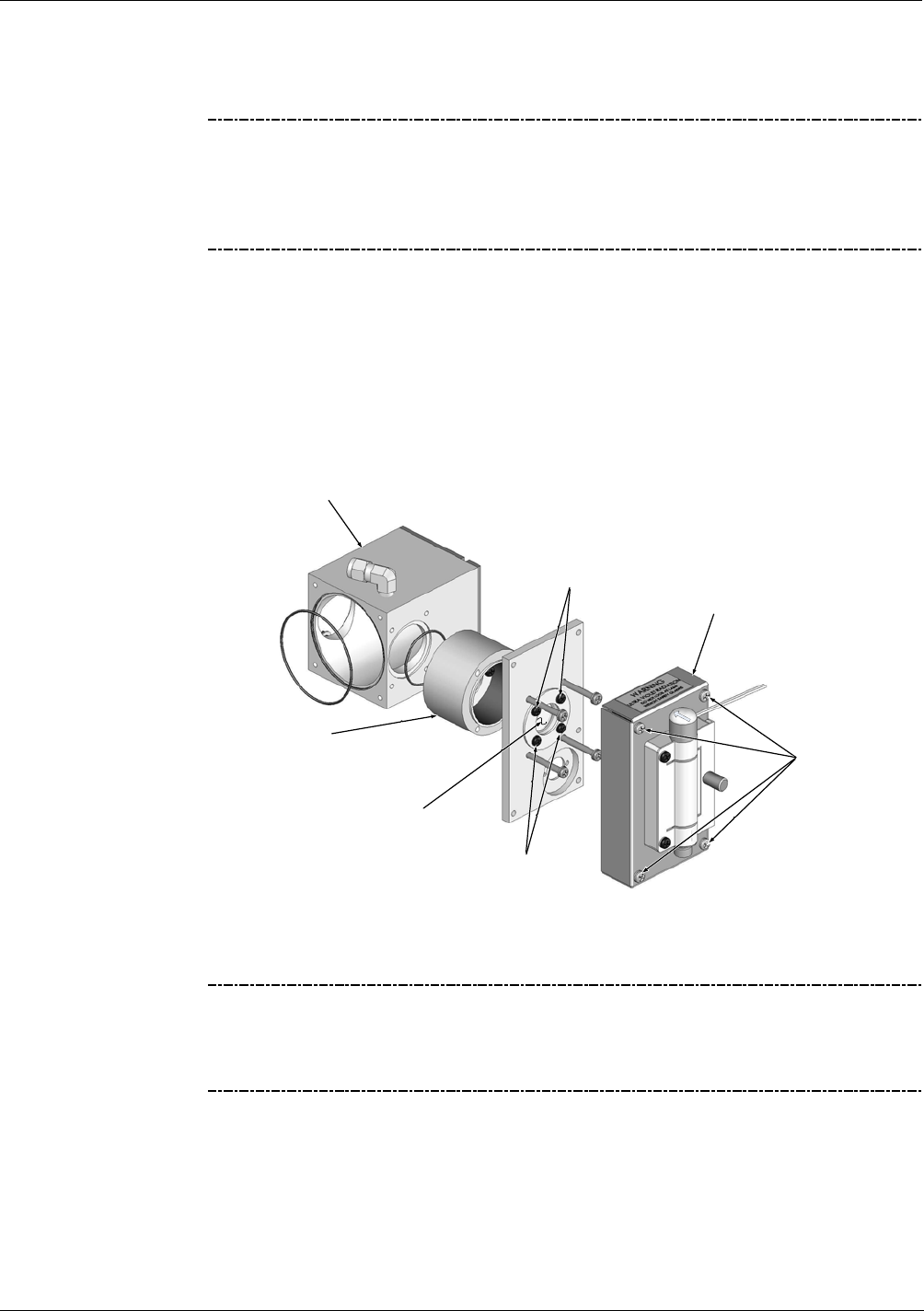
3. Remove 4 screws from the lamp housing cover (see Figure 8-2) and remove the
cover .
4. Remove 4 screws from the UV filter retainer.
UV Filter Retainer
Screws
Lamp Housing
UV Filter
Lamp Housing
Cover Screws
UV Filter Retainer
Screws
UV Filter Retainer
and Lens Housing
Reaction
Cell
Figure 8-2: Disassembling the Sample Chamber/UV Source Assembly
IMPORTANT IMPACT ON READINGS OR DATA
Never touch the filter’s surface; fingertips can leave oily residue and will
significantly affect the accuracy of the analyzer’s SO2 measurement.
Handle carefully by the outer edges.
5. Carefully remove the UV filter.
6. Install the UV filter with arrow pointing towards reaction cell. Handle carefully and
never touch the filter’s surface. The UV filter’s wider ( ring ) side should be facing
out. Install the UV filter retainer and tighten screws.
7. Install the lamp housing cover and mini-fit connector. Tighten 4 screws.
8. Re-plug J4 connector into the motherboard.
06840B DCN 6201
Troubleshooting and Service Teledyne API - T100U Manual, Addendum to T100 Manual P/N 06807
30
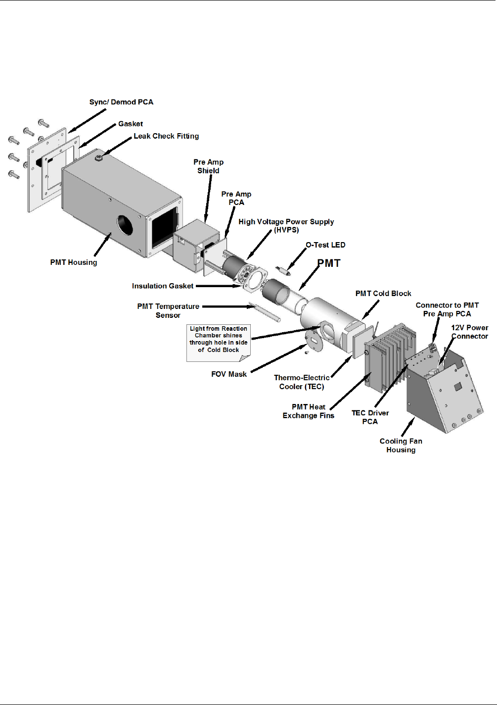
8.3.3 REPLACING THE PMT, HVPS OR TEC
The PMT should last for the lifetime of the analyzer. However, in some cases, the high
voltage power supply (HVPS) or the thermo-electric cooler (TEC) may fail. To replace
the PMT, the HVPS or the TEC:
Figure 8-3: PMT Assembly - Exploded View
1. Power down the analyzer, disconnect the power cord, remove the cover and discon-
nect all pneumatic and electrical connections from the sensor assembly.
2. Remove the entire sensor module assembly from the analyzer.
3. Remove the fluorescence cell assembly.
4. Remove the two connectors on the Sync Demod board.
5. Remove the Sync Demod Board (6 screws with plastic washers). Disconnect the
electrical connector that leads to the preamp board further inside the housing.
6. Remove all of the desiccant bags inside the PMT housing.
7. Along with the plate, slide out the OPTIC TEST LED and the thermistor that
measures the PMT temperature.
• The thermistor will be coated with a white, thermal conducting paste. Do not
contaminate the inside of the housing or the PMT tube with this grease.
06840B DCN 6201

Teledyne API - T100U Manual, Addendum to T100 Manual P/N 06807 Troubleshooting and Service
31
8. Unscrew the PMT assembly. It is held to the cold block by two plastic screws.
• Because the threads of the plastic screws are easily damaged it is highly
recommended to use new screws when reassembling the unit.
9. Carefully take out the assembly consisting of the HVPS, the gasket, preamp
assembly and the PMT.
10. Change the PMT or the HVPS or both, clean the PMT glass tube with a clean, anti-
static wipe and do not touch it after cleaning.
11. If the cold block or TEC is to be changed, disconnect the TEC driver board from the
preamplifier board:
a) Remove the cooler fan duct (4 screws on its side) including the driver board.
b) Disconnect the driver board from the TEC and set the sub-assembly aside.
c) Remove the end plate with the cooling fins (4 screws) and slide out the PMT
cold block assembly, which contains the TEC.
d) Unscrew the TEC from the cooling fins and the cold block and replace it with a
new unit.
12. Re-assemble the TEC subassembly in reverse order.
ATTENTION COULD DAMAGE INSTRUMENT AND VOID WARRANTY
The thermo-electric cooler needs to be mounted flat to the heat sink. If
there is any significant gap, the TEC might burn out. Make sure to apply
heat sink paste before mounting it and tighten the screws evenly and
cross-wise.
a) Make sure to use thermal pads (HW-405) between the TEC and the cooling fins
as well as between the TEC and the cold block.
b) Align the side opening in the cold block with the hole in the PMT housing where
the sample Chamber attaches.
c) Evenly tighten the long mounting screws for good thermal conductivity.
13. Re-insert the TEC subassembly.
• Make sure that the O-ring is placed properly and the assembly is tightened
evenly.
14. Insert the LED and thermistor into the cold block.
15. Re-insert the PMT/HVPS subassembly.
• Don’t forget the gasket between HVPS and PMT.
• Use new plastic screws to mount the PMT assembly on the PMT cold block.
16. Insert the new desiccant bags.
17. Reconnect the cable from the preamp board to the back of the Sync Demod board
then carefully reattach the Sync Demod board to the housing.
• Make sure that the gasket is between the back of the board and the front of the
PMT housing.
• Be sure to tighten these screws evenly,
18. Reconnect the cables and the reaction cell.
06840B DCN 6201

Troubleshooting and Service Teledyne API - T100U Manual, Addendum to T100 Manual P/N 06807
32
19. Replace the sensor assembly into the chassis and fasten with four screws and
washers.
20. Reconnect all electrical and pneumatic connections, leak check the system and
power up the analyzer.
• Verify the basic operation of the analyzer using the ETEST and OTEST features
(see Section 5.9.4 & 5.9.5 of the T100 Manual) or by measuring calibrated zero
and span gases.
21. Perform a PMT Hardware calibration (see Section 8.3.4 of this addendum).
22. Perform a zero point and span calibration (See Section 9 of the T100 Manual - P/N
06807).
8.3.4 T100U PMT HARDWARE CALIBRATION (FACTORY CAL)
This procedure supersedes the one contained in the T100 Manual.
The sensor module hardware calibration adjusts the slope of the PMT output when the
Instruments slope and offset values are outside of the acceptable range and all other
more obvious causes for this problem have been eliminated. Because the PMT HV is
remotely controlled and there is no PMT preamp gain adjust, this procedure is done
automatically through the analyzer software.
1. Set the instrument reporting range to SNGL & 500 ppb (see Section 5.4.3 of the
T100 Manual)
2. Perform a full zero–point calibration using zero air (see Section 9 of the T100
Manual).
3. Let the instrument stabilize by allowing it to run for one hour.
4. Adjust the UV Lamp. (See Section 8.3.1.1 of this addendum)
5. Perform a LAMP CALIBRATION procedure (see Section 5.9.6 of the T100
Manual).
6. Feed 400 ppb span gas into the analyzer.
7. Wait approximately 30-60 minutes (or until the stability reads ≤ 0.1 ppb), then under
the DIAG menu select PMT CALIBRATION.
8. Either press ENTR if you are using 400 ppb or change the concentration value to
what is appropriate and then press ENTR.
9. Select the range that you wish to setup (low or high).
10. Wait two to three minutes until you get a message that indicates the HV has been
adjusted successfully.
IMPORTANT IMPACT ON READINGS OR DATA
If a reporting range other than 500 ppb is used in this procedure:
Use a span gas equal to 80% of the reporting range and adjust the PMT to
a target NORM PMT value of twice the ppb value of the span gas.
EXAMPLE -
If the reporting range is 800 ppb then set the target
concentration to 640 ppb for this procedure.
11. Wait until the STABIL value is ≤ 0.1 ppb.
06840B DCN 6201

Teledyne API - T100U Manual, Addendum to T100 Manual P/N 06807 Troubleshooting and Service
33
12. Scroll to the NORM PMT value and verify that it is approximately twice the ppb
value of the span gas.
13. Perform a zero / span calibration.
14. Check the slope and offset values and compare them to the values in Table 9-5 of
the T100 Manual.
15. Steps 7 - 14 may have to be performed more than once in order to compensate for
any over/undershooting of the PMT reading based on the adjusted HVPS drive
voltage. Best results occur after performing the PMT calibration (steps 7 - 14) at
least two consecutive times.
8.4 TECHNICAL ASSISTANCE
If this addendum and its trouble-shooting / repair sections do not solve your problems,
technical assistance may be obtained from:
Teledyne API (TAPI)
Technical Support
9970 Carroll Canyon Road
San Diego, California 92131-1106 USA
Toll-free Phone: 800-324-5190
Phone:
+1 858-657-9800
Fax: +1 858-657-9816
Email: sda_techsupport@Teledyne.com
Website:
http://www.Teledyne-API.com
Before you contact Teledyne Instruments’ Technical Support, fill out the problem report form in Appendix C,
which is also available online for electronic submission at http://www.Teledyne-API.com/forms/p-fmapicom.asp.
06840B DCN 6201

Troubleshooting and Service Teledyne API - T100U Manual, Addendum to T100 Manual P/N 06807
34
This page intentionally left blank.
06840B DCN 6201

35
9. PRINCIPLES OF OPERATION
The T100U is a modified T100. The primary differences are the way in which the PMT
and UV reference signals are acquired and processed. The T100U has no shutter but
rather employs synchronous demodulation to capture the dark and light PMT and UV
reference signals several times per second. A printed circuit board, the Sync
Demodulator, attached to the end of the PMT housing, on the sensor assembly, includes
circuitry that digitizes the PMT and UV reference signals and synchronizes the operation
of the UV source with these measurements. This method of signal processing minimizes
the error that changing offsets could make in an instrument that is designed to operate
near its detection limit.
9.1 ELECTRONIC OPERATION
The following information is in addition to that contained in Section 13.5.2 of the T100
Manual.
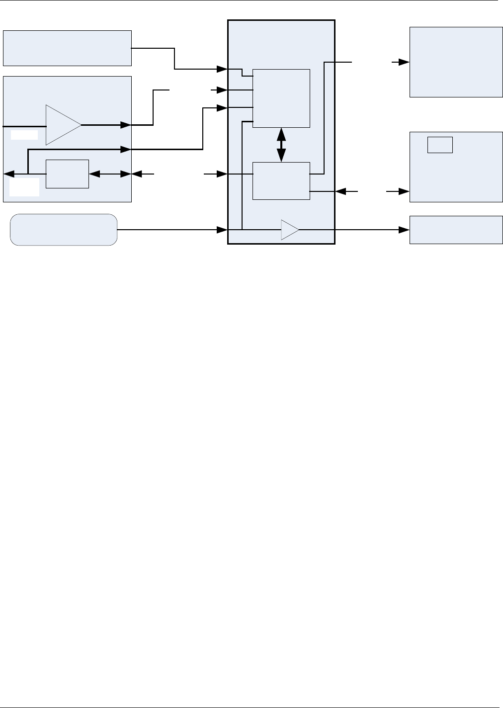
9.1.1 SENSOR MODULE
At the heart of the T100U’s signal processing, illustrated in Figure 9-1 below, is the
Synchronous Demodulator PCA (Sync Demod board). The PCA is attached to the end
of the PMT housing and serves to seal the end of the PMT housing. The sync
demodulator controls the operation of the UV Lamp driver, digitizes the analog output
signals from the PMT UV reference detector and PMT temperature sensor, controls the
PMT cooler (thermo-electric cooler, TEC), controls the PMT HV via a local I2C bus,
and communicates with the analyzer’s CPU over the master I2C bus. Digitized and
processed data from the UV reference and PMT are passed to the analyzer’s CPU over
the master I2C bus and data for control of the PMT HV control DAC is passed from the
CPU to the DAC on the PMT preamp via the microcontroller on the Sync Demod board.
06840B DCN 6201
Principles of Operation Teledyne API - T100U Manual, Addendum to T100 Manual P/N 06807
36
SYNC DEMOD PCA
(End of PMT Housing)
PMT Signal
UV REF PCA
(End of Sensor Module)UV REF
Local I2C Bus
A/D
Converter
Micro
Controller
UV LAMP DRIVER
PCA
(Side of Sensor Assy)
Master
I2C Bus
PMT PREAMP PCA
(Inside PMT Housing)
8 bit DAC
PMT HV
Control I2C
PMT IN
MOTHERBOARD
(Rear Panel)
CPU
PMT Temp Sensor
(Inside PMT Housing)
`
Lamp Sync
PMT Cooler
(End of PMT Housing)
PMT HV
Monitor
Figure 9-1: Sensor Block Diagram
06840B DCN 6201
Teledyne API - T100U Manual, Addendum to T100 Manual P/N 06807 Principles of Operation
37
Figure 9-2: T100U Sensor Module Assembly
These components are divided into two significant subassemblies. The sample chamber
and the PMT assembly.
Figure 9-3 shows an exploded view of the sample chamber assembly.
Figure 8-3 shows an exploded view of the PMT assembly.
06840B DCN 6201
Principles of Operation Teledyne API - T100U Manual, Addendum to T100 Manual P/N 06807
38
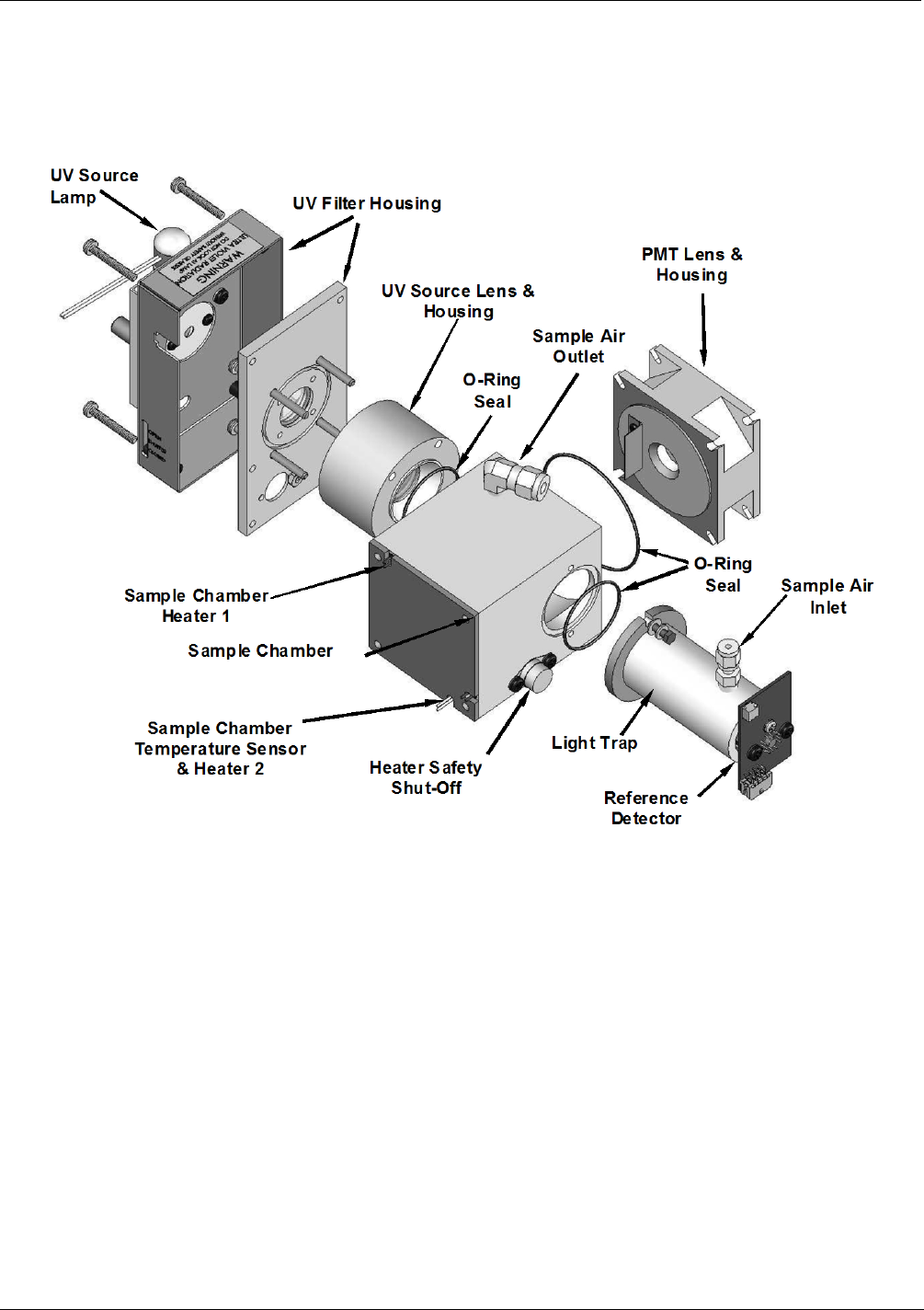
9.1.1.1 Sample Chamber
The main electronic components of the sample chamber are the reference detector (see
Section 13.1.4 of the T100 Manual); the UV Lamp (see Section 13.1.6 of the T100
Manual); and the sample chamber heating circuit,
Figure 9-3: T100U Sample Chamber Exploded View
06840B DCN 6201
APPENDIX A - Version Specific Software Documentation
Appendix A of the T100 manual applies to the T100U.
A-1
06840B DCN6201
A-2
This page intentionally left blank.
06840B DCN6201

APPENDIX B - Spare Parts
Note
Use of replacement parts other than those supplied by Teledyne Advanced
Pollution Instrumentation (TAPI) may result in non-compliance with European
standard EN 61010-1.
Note
Due to the dynamic nature of part numbers, please refer to the TAPI Website at
http://www.teledyne-api.com or call Customer Service at 800-324-5190 for more
recent updates to part numbers.
06840B DCN6201
B-1
This page intentionally left blank.
B-2
06840B DCN6201
LIST, SPARE PARTS, T100U
PARTNUMBER DESCRIPTION
045230200 PCA, RELAY CARD
046250000 ASSY, RXCELL HEATER/FUSE
046260000 ASSY, THERMISTOR, RXCELL (KB)
048830000 AKIT, EXP KIT, EXHAUST CLNSR, SILCA GEL
049310100 PCA,TEC DRIVER,PMT,(KB)
050610100 OPTION, 100-120V/60Hz (KB)
050610200 OPTION, 100-120V/50Hz (KB)
050610300 OPTION, 220-240V/50Hz, (KB)
050610400 OPTION, 220-240V/60Hz (KB)
050630200 PCA, REF DET w/OP20, DUAL OUT
051990000 ASSY, SCRUBBER, INLINE EXHAUST, DISPOS
052660000 ASSY, HEATER/THERM, IZS
054340000 PCA, PRECISION INT. PMT PREAMP
054650000 PCA, SYNC/DEMOD
055100200 ASSY, OPTION, PUMP, 240V *
055560000 ASSY, VALVE, VA59 W/DIODE, 5" LEADS
055920000 ASSY, SO2 SENSOR, ULTRA (KB)
056080000 ASSY, HVPS, PMT
058021100 PCA, MOTHERBD, GEN 5-ICOP
059200000 ASSY, UV LAMP, 10K, "ULTRA"
061930200 PCA, UV LAMP DRIVER, GEN-2, 48mA
066970000 PCA, INTRF. LCD TOUCH SCRN, F/P
067240000 CPU, PC-104, VSX-6154E, ICOP *(KB)
067300000 PCA, AUX-I/O BD, ETHERNET, ANALOG & USB
067300100 PCA, AUX-I/O BOARD, ETHERNET
067300200 PCA, AUX-I/O BOARD, ETHERNET & USB
067900000 LCD MODULE, W/TOUCHSCREEN(KB)
068230100 DOM, w/SOFTWARE, STD, T100U *
068810000 PCA, LVDS TRANSMITTER BOARD
069500000 PCA, SERIAL & VIDEO INTERFACE BOARD
072150000 ASSY. TOUCHSCREEN CONTROL MODULE
072770000 KIT, T100U MANUAL
CN0000073 POWER ENTRY, 120/60 (KB)
043570000 AKIT, EXPENDABLES
042410200 ASSY, PUMP, INT, SOX/O3/IR *
040030100 PCA, PRESS SENSORS (1X), w/FM4
040010000 ASSY, FAN REAR PANEL
037860000 ORING, TEFLON, RETAINING RING, 47MM (KB)
016300700 ASSY, SAMPLE FILTER, 47MM, ANG BKT
016290000 WINDOW, SAMPLE FILTER, 47MM (KB)
014750000 AKIT, EXP KIT, IZS
014400100 OPTION, ZERO AIR SCRUBBER
013570000 THERMISTOR HOUSING ASSY SOX/NOX(KB)
(Reference: 068460000, 8/9/2011 10:21 AM)
06840B DCN6201
B-3
LIST, SPARE PARTS, T100U
PARTNUMBER DESCRIPTION
(Reference: 068460000, 8/9/2011 10:21 AM)
013420000 ASSY, ROTARY SOLENOID
013400000 CD, PMT, SO2, (KB)
013390000 ASSY, KICKER
013210000 ASSY, VACUUM MANIFOLD
013140000 ASSY, COOLER FAN (NOX/SOX)
009690300 AKIT, TFE FLTR ELEM (FL19, 30=1) 47mm
009690200 AKIT, TFE FLTR ELEM (FL19,100=1) 47mm
005960000 AKIT, EXP, 6LBS ACT CHARCOAL (2 BT=1)
003290000 THERMISTOR, BASIC (VENDOR ASSY)(KB)
002720000 CD, FILTER, 330NM (KB)
002700000 CD, LENS, BI-CON (KB)
002690000 CD, LENS, PL-CON (KB)
000940800 CD, ORIFICE, .012 (NO PAINT)
000940100 CD, ORIFICE, .003 GREEN
CN0000458 PLUG, 12, MC 1.5/12-ST-3.81 (KB)
CN0000520 PLUG, 10, MC 1.5/10-ST-3.81 (KB)
FL0000001 FILTER, SS (KB)
FL0000003 FILTER, DFU (KB)
FM0000004 FLOWMETER (KB)
HW0000005 FOOT
HW0000020 SPRING
HW0000036 TFE TAPE, 1/4" (48 FT/ROLL)
HW0000453 SUPPORT, CIRCUIT BD, 3/16" ICOP
HW0000685 LATCH, MAGNETIC, FRONT PANEL
KIT000093 AKIT, REPLCMNT(3187)214NM FLTR (BF)
KIT000095 AKIT, REPLACEMENT COOLER
KIT000219 AKIT, 4-20MA CURRENT OUTPUT
KIT000253 ASSY & TEST, SPARE PS37
KIT000254 ASSY & TEST, SPARE PS38
OP0000031 WINDOW, QUARTZ, 1/2"DIA, .063" THICK (KB)
OR0000001 ORING, 2-006VT *(KB)
OR0000004 ORING, 2-029V
OR0000006 ORING, 2-038V
OR0000007 ORING, 2-039V
OR0000015 ORING, 2-117V
OR0000016 ORING, 2-120V
OR0000025 ORING, 2-133V
OR0000027 ORING, 2-042V
OR0000039 ORING, 2-012V
OR0000046 ORING, 2-019V
OR0000083 ORING, 105M, 1MM W X 5 MM ID, VITON
OR0000084 ORING, 2-020V
OR0000094 ORING, 2-228V, 50 DURO VITON(KB)
B-4
06840B DCN6201
LIST, SPARE PARTS, T100U
PARTNUMBER DESCRIPTION
(Reference: 068460000, 8/9/2011 10:21 AM)
PU0000022 REBUILD KIT, FOR PU20 & 04241 (KB)
RL0000015 RELAY, DPDT, (KB)
SW0000025 SWITCH, POWER, CIRC BREAK, VDE/CE *(KB)
SW0000059 PRESSURE SENSOR, 0-15 PSIA, ALL SEN
WR0000008 POWER CORD, 10A(KB)
06840B DCN6201
B-5
(Reference: 05946A) UNITS
PART NO DESCRIPTION 1 2-5 6-10 11-20 21-30
000940800 Orifice, 12 Mil 1 2 4 4
002720000 Filter, 330 NM 1 2 3
013140000 Cooler Fan 1 1 2 4 4
013400000 PMT, SO2 1 1
014080100 Assy, HVPS, NOX/SOX 1
014610000 Kit, Replacement Cooler 1
040010000 Assy, Fan, Rear Panel, E Series 1 1 2 4 4
040030100 PCA, Press Sensors (1X), Flow, E Series 1 2 4 4
041710000 CPU, Configuration E Series 1 1
042410400 Assy, Pump, Internal, E Series, 115/240V 1
042580000 PCA, Keyboard 1 1
045230200 PCA, Relay Board w/Diode Protection 1 1 2
050630200 PCA, M100EU UV Ref Det, Dual Out 1 2
054340000 PCA, Prescision INT, PMT Preamp 1 1
054650000 PCA, Sync/Demod 1 1
054710000 Assy, UV Lamp, M100E 1 2 4 4
055120200 PCA, Bursting UV Driver, M100EU 1 1 2 2
057020100 PCA, Motherboard, E Series, GEN 4 1 2
DS0000025 Display 1 1
IZS/ZS Option
055560000 ASSY, VALVE, VA59 W/DIODE, E-SERIES 1 2 2 4
RECOMMENDED SPARE PARTS STOCKING LEVELS
Model 100EU
B-6
06840B DCN6201
Appendix C
Warranty/Repair Questionnaire
T100U, M100EU
(05930B DCN5798)
TELEDYNE API CUSTOMER SERVICE
Email: api-customerservice@teledyne.com
PHONE: (858) 657-9800 TOLL FREE: (800) 324-5190 FAX: (858) 657-9816
C-1
CUSTOMER: _________________________________ PHONE: __________________________________________________
CONTACT NAME: ____________________________ FAX NO. __________________________________________________
SITE ADDRESS: _________________________________________________________________________________________
MODEL SERIAL NO.: _______________________ FIRMWARE REVISION: ____________________________________
1. ARE THERE ANY FAILURE MESSAGES? _______________________________________________________________
________________________________________________________________________________________________________
________________________________________________________________________________________________________
2. PLEASE COMPLETE THE FOLLOWING TABLE: (NOTE: DEPENDING ON OPTIONS INSTALLED, NOT ALL TEST
PARAMETERS BELOW WILL BE AVAILABLE IN YOUR INSTRUMENT)
Parameter
*IF OPTION IS INSTALLED
Recorded Value Acceptable Value
RANGE PPB/PPM 0-500 PPB Standard
STABIL PPB 0.3 PPB with ZERO AIR
STABIL2 PPB <= 1 PPB with ZERO AIR
PRESS IN-HG-A AMBIENT (- 2) IN-HG-A
SAMPLE FLOW cm3/MIN 650 ± 10%
PMT SIGNAL WITH
ZERO AIR
mV -20 TO 150 mV
PMT SIGNAL AT
SPAN GAS CONC
mV
PPB/PPM
0-5000 mV
0-20000 PPB
NORM PMT AT SPAN
GAS CONC
mV
PPB/PPM
0-5000 mV
0-20000 PPB
UV LAMP mV 2000 TO 4000 mV
UV STAB mV < 15mV
LAMP RATIO mV 30 TO 120%
STR. LGT PPB ≤ 100 PPB/ ZERO AIR
DARK PMT mV 200-325
DARK LAMP mV -50 TO 200 mV
SLOPE 1.0 ± 0.5
OFFSET mV < 250 mV
HVPS V ≈ 400 – 800
RCELL TEMP ºC 50ºC ± 1
BOX TEMP ºC AMBIENT ± 5
PMT TEMP ºC 9.5ºC ± 2º CONSTANT
IZS TEMP* ºC 50ºC ± 1
ETEST mV 2000 mV ± 1000
OTEST mV 2000 mV ± 1000
Values are in the Signal I/O
REF_4096_MV mV 4096mv±2mv and Must be Stable
REF_GND mV 0± 0.5 and Must be Stable
06840B DCN6201

Appendix C
Warranty/Repair Questionnaire
T100U, M100EU
(05930B DCN5798)
TELEDYNE API CUSTOMER SERVICE
Email: api-customerservice@teledyne.com
PHONE: (858) 657-9800 TOLL FREE: (800) 324-5190 FAX: (858) 657-9816
C-2
3. WHAT IS THE SAMPLE FLOW & SAMPLE PRESSURE W/SAMPLE INLET ON REAR OF MACHINE CAPPED?
SAMPLE FLOW - CC SAMPLE PRESS - IN-HG-A
4. WHAT ARE THE FAILURE SYMPTOMS? ______________________________________________________________
___________________________________________________________________________________________________
___________________________________________________________________________________________________
___________________________________________________________________________________________________
___________________________________________________________________________________________________
___________________________________________________________________________________________________
___________________________________________________________________________________________________
___________________________________________________________________________________________________
___________________________________________________________________________________________________
___________________________________________________________________________________________________
5. IF POSSIBLE, PLEASE INCLUDE A PORTION OF A STRIP CHART PERTAINING TO THE PROBLEM. CIRCLE
PERTINENT DATA.
THANK YOU FOR PROVIDING THIS INFORMATION. YOUR ASSISTANCE ENABLES TELEDYNE API TO RESPOND
FASTER TO THE PROBLEM THAT YOU ARE ENCOUNTERING.
06840B DCN6201

D-1
APPENDIX D – Electronic Schematics
Contains schematics for the T100U addendum; other schematics are located in Appednix D of the
T100 Operators Manual (07268).
06840B DCN6201

D-2
This page intentionally left blank.
06840B DCN6201

Interconnect List, T100U
(Reference 0736201Rev 01)
Revision Checked Date DCN
01 KV 11/10/10
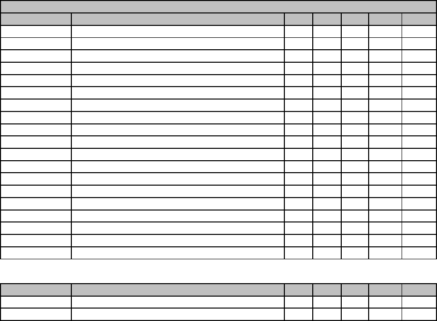
Cable PN Signal Assembly PN J/P Pin Assembly PN J/P Pin
0364901 CBL ASSY, AC POWER
AC Line Power Entry CN0000073 L Power Switch SW0000025 L
AC Neutral Power Entry CN0000073 N Power Switch SW0000025 N
Power Grnd Power Entry CN0000073 Shield
Power Grnd Power Entry CN0000073 Chassis
AC Line Switched Power Switch SW0000025 L PS2 (+12) 068020000 SK2 1
AC Neu Switched Power Switch SW0000025 N PS2 (+12) 068020000 SK2 3
Power Grnd Power Entry CN0000073 PS2 (+12) 068020000 SK2 2
AC Line Switched Power Switch SW0000051 L PS1 (+5, ±15) 068010000 SK2 1
AC Neu Switched Power Switch SW0000025 N PS1 (+5, ±15) 068010000 SK2 3
Power Grnd Power Entry CN0000073 PS1 (+5, ±15) 068010000 SK2 2
AC Line Switched Power Switch SW0000025 L Relay PCA 045230100 J1 1
AC Neu Switched Power Switch SW0000025 N Relay PCA 045230100 J1 3
Power Grnd Power Entry CN0000073 Relay PCA 045230100 J1 2
03829 CBL ASSY, DC POWER TO MOTHERBOARD
DGND Relay PCA 045230100 J7 1 Motherboard 058021100 J15 1
+5V Relay PCA 045230100 J7 2 Motherboard 058021100 J15 2
AGND Relay PCA 045230100 J7 3 Motherboard 058021100 J15 3
+15V Relay PCA 045230100 J7 4 Motherboard 058021100 J15 4
AGND Relay PCA 045230100 J7 5 Motherboard 058021100 J15 5
-15V Relay PCA 045230100 J7 6 Motherboard 058021100 J15 6
+12V RET Relay PCA 045230100 J7 7 Motherboard 058021100 J15 7
+12V Relay PCA 045230100 J7 8 Motherboard 058021100 J15 8
Chassis Gnd Relay PCA 045230100 J7 10 Motherboard 058021100 J15 9
04023 CBL, I2C, RELAY BOARD TO MOTHERBOARD
I2C Serial Clock Motherboard 058021100 P107 3 Relay PCA 045230100 P3 1
I2C Serial Data Motherboard 058021100 P107 5 Relay PCA 045230100 P3 2
I2C Reset Motherboard 058021100 P107 2 Relay PCA 045230100 P3 4
I2C Shield Motherboard 058021100 P107 6 Relay PCA 045230100 P3 5
0402602 CBL, IZS HTR/TH, RXCELL & OB TH
RTHA Motherboard 058021100 P27 7 RX Cell Thermistor 046260000 2
RTHB Motherboard 058021100 P27 14 RX Cell Thermistor 046260000 1
IZTA Motherboard 058021100 P27 6 IZS Therm/Htr 052660000 2
IZTB Motherboard 058021100 P27 13 IZS Therm/Htr 052660000 3
IZS-L Relay PCA 045230100 P18 1 IZS Therm/Htr 052660000 4
IZS-N Relay PCA 045230100 P18 2 IZS Therm/Htr 052660000 1
GND Relay PCA 045230100 P18 11 Shield
O2-L Relay PCA 045230100 P18 6 O2 Sensor Therm/Htr 043420000 4
O2-N Relay PCA 045230100 P18 7 O2 Sensor Therm/Htr 043420000 2
TS3 Relay PCA 045230100 P18 3 Relay PCA 045230100 P18 4
TS4 Relay PCA 045230100 P18 8 Relay PCA 045230100 P18 9
N/C Relay PCA 045230100 P18 12 Shield
O2TA Motherboard 058021100 P27 4 O2 Sensor Therm/Htr 043420000 3
O2TB Motherboard 058021100 P27 11 O2 Sensor Therm/Htr 043420000 1
0402701 CBL, RX CELL HEATERS
RH1B Relay PCA 045230100 P2 1 RX Cell Heaters 046250000 4
RH2B Relay PCA 045230100 P2 1 RX Cell Heaters 046250000 6
RH1A Relay PCA 045230100 P2 2 RX Cell Heaters 046250000 3
RTS1 Relay PCA 045230100 P2 3 RX Cell Heaters 046250000 1
RTS2 Relay PCA 045230100 P2 4 RX Cell Heaters 046250000 2
RH2A Relay PCA 045230100 P2 5 RX Cell Heaters 046250000 5
Relay PCA 045230100 P2 13 Relay PCA 045230100 P2 14
Relay PCA 045230100 P2 8 Relay PCA 045230100 P2 9
04105 CBL, KEYBD TO MTHBRD
Kbd Interupt LCD Interface PCA 066970000 J1 7 Motherboard 058021100 J106 1
DGND LCD Interface PCA 066970000 J1 2 Motherboard 058021100 J106 8
SDA LCD Interface PCA 066970000 J1 5 Motherboard 058021100 J106 2
SCL LCD Interface PCA 066970000 J1 6 Motherboard 058021100 J106 6
Shld LCD Interface PCA 066970000 J1 10 Motherboard 058021100 J106 5
04176 CBL, DC POWER TO RELAY BOARD
DGND Relay PCA 045230100 P8 1 Power Supply Triple 068010000 J1 3
+5V Relay PCA 045230100 P8 2 Power Supply Triple 068010000 J1 1
+15V Relay PCA 045230100 P8 4 Power Supply Triple 068010000 J1 6
AGND Relay PCA 045230100 P8 5 Power Supply Triple 068010000 J1 4
-15V Relay PCA 045230100 P8 6 Power Supply Triple 068010000 J1 5
+12V RET Relay PCA 045230100 P8 7 Power Supply Single 068020000 J1 3
+12V Relay PCA 045230100 P8 8 Power Supply Single 068020000 J1 1
04437 CBL, PREAMPLIFIER TO TEC
Preamp TEC drive VREF Preamp PCA 041800400 J1 1 TEC PCA 049310100 J3 1
Preamp TEC drive CTRL Preamp PCA 041800400 J1 2 TEC PCA 049310100 J3 2
Preamp TEC drive AGND Preamp PCA 041800400 J1 3 TEC PCA 049310100 J3 3
FROM TO
Description
Initial Release
D-3
06840B DCN6201

Interconnect List, T100U
(Reference 0736201Rev 01)
Cable PN Signal Assembly PN J/P Pin Assembly PN J/P Pin
FROM TO
044880100 CBL, MAIN HARNESS
AGND Relay PCA 045230100 P5 1 O2 Sensor 049210000 P1 5
-V15 Relay PCA 045230100 P5 2 O2 Sensor 049210000 P1 6
Relay PCA 045230100 P5 3 UV Ref PCA 050630100 P1 4
O2 SIGNAL- Motherboard 058021100 P109 7 O2 Sensor 049210000 P1 9
O2 SIGNAL+ Motherboard 058021100 P109 1 O2 Sensor 049210000 P1 10
Motherboard 058021100 P109 10 Shield
CH2 Motherboard 058021100 P109 2 UV Ref PCA 050630100 P1 5
+15V Relay PCA 045230100 P10 4 UV Ref PCA 050630100 P1 2
-15V Relay PCA 045230100 P10 6 UV Ref PCA 050630100 P1 3
TEC +12V RET Relay PCA 045230100 P10 7 TEC PCA 049310100 2
TEC +12V Relay PCA 045230100 P10 8 TEC PCA 049310100 1
DISP RET Relay PCA 045230100 P10 1 LCD Interface PCA 066970000 P14 8
+5 DISP Relay PCA 045230100 P10 2 LCD Interface PCA 066970000 P14 1
EGND Shield LCD Interface PCA 066970000 P14 4
SDA Sync Demod 054650000 P1 5 LCD Interface PCA 066970000 P14 5
SCL Sync Demod 054650000 P1 3 LCD Interface PCA 066970000 P14 6
DGND Relay PCA 045230100 P11 1 LCD Interface PCA 066970000 P14 2
VCC Relay PCA 045230100 P11 2 LCD Interface PCA 066970000 P14 3
+12RET Relay PCA 045230100 P11 7 Fan 040010000 1
+12V Relay PCA 045230100 P11 8 Fan 040010000 2
AGND Relay PCA 045230100 P11 3 Flow Module PCA 040030100 P1 3
+15V Relay PCA 045230100 P11 4 Flow Module PCA 040030100 P1 6
PRESS SIGNAL 1 Motherboard 058021100 P110 6 Flow Module PCA 040030100 P1 2
PRESS SIGNAL 2 Motherboard 058021100 P110 5 Flow Module PCA 040030100 P1 4
FLOW SIGNAL 1 Motherboard 058021100 P110 4 Flow Module PCA 040030100 P1 5
FLOW SIGNAL 2 Motherboard 058021100 P110 3 Flow Module PCA 040030100 P1 1
SHIELD Motherboard 058021100 P110 12 Shield
SHIELD Motherboard 058021100 P110 9 Shield
TC SIGNAL 1 Motherboard 058021100 P110 2 Relay PCA 045230100 P17 1
TC 1 SIGNAL DGND Motherboard 058021100 P110 8 Relay PCA 045230100 P17 2
TC SIGNAL 2 Motherboard 058021100 P110 1 Relay PCA 045230100 P17 3
TC 2 SIGNAL DGND Motherboard 058021100 P110 7 Relay PCA 045230100 P17 4
UV Ref PCA 050630100 P1 1 Sync Demod 054650000 P3 6
AGND Shield Sync Demod 054650000 P3 9
AGND Shield Sync Demod 054650000 P3 7
DGND Relay PCA 045230100 P9 1 Sync Demod 054650000 P3 1
VCC Relay PCA 045230100 P9 2 Sync Demod 054650000 P3 2
+15V Relay PCA 045230100 P9 4 Sync Demod 054650000 P3 3
AGND Relay PCA 045230100 P9 5 Sync Demod 054650000 P3 4
-15V Relay PCA 045230100 P9 6 Sync Demod 054650000 P3 5
+12RET Relay PCA 045230100 P9 7 Lamp Driver PCA 061930000 P1 2
+12V Relay PCA 045230100 P9 8 Lamp Driver PCA 061930000 P1 1
04562 CBL, Z/S IZS VALVES
Sample Valve +12V Relay PCA 045230100 P4 1 SMP/CAL 055560000 1
Sample Valve +12V RET Relay PCA 045230100 P4 2 SMP/CAL 055560000 2
Zero/Span valve +12V Relay PCA 045230100 P4 3 ZS/HI S 055560100 1
Zero/Span valve +12V RE
T
Relay PCA 045230100 P4 4 ZS/HI S 055560100 2
Low Span Valve +12V Relay PCA 045230100 P4 5 Lo Span 055560100 1
Low Span Valve +12V RE
T
Relay PCA 045230100 P4 6 Lo Span 055560100 2
AutoZero Valve +12V Relay PCA 045230100 P4 7 Zero 055560000 1
AutoZero Valve +12V RET Relay PCA 045230100 P4 8 Zero 055560000 2
04671 CBL, MOTHERBOARD TO XMITTER BD (MULTIDROP OPTION)
GND Motherboard 058021100 P12 2 Xmitter bd w/Multidrop 069500000 J4 2
RX0 Motherboard 058021100 P12 14 Xmitter bd w/Multidrop 069500000 J4 14
RTS0 Motherboard 058021100 P12 13 Xmitter bd w/Multidrop 069500000 J4 13
TX0 Motherboard 058021100 P12 12 Xmitter bd w/Multidrop 069500000 J4 12
CTS0 Motherboard 058021100 P12 11 Xmitter bd w/Multidrop 069500000 J4 11
RS-GND0 Motherboard 058021100 P12 10 Xmitter bd w/Multidrop 069500000 J4 10
RTS1 Motherboard 058021100 P12 8 Xmitter bd w/Multidrop 069500000 J4 8
CTS1/485- Motherboard 058021100 P12 6 Xmitter bd w/Multidrop 069500000 J4 6
RX1 Motherboard 058021100 P12 9 Xmitter bd w/Multidrop 069500000 J4 9
TX1/485+ Motherboard 058021100 P12 7 Xmitter bd w/Multidrop 069500000 J4 7
RS-GND1 Motherboard 058021100 P12 5 Xmitter bd w/Multidrop 069500000 J4 5
RX1 Motherboard 058021100 P12 9 Xmitter bd w/Multidrop 069500000 J4 9
TX1/485+ Motherboard 058021100 P12 7 Xmitter bd w/Multidrop 069500000 J4 7
RS-GND1 Motherboard 058021100 P12 5 Xmitter bd w/Multidrop 069500000 J4 5
D-4
06840B DCN6201

Interconnect List, T100U
(Reference 0736201Rev 01)
Cable PN Signal Assembly PN J/P Pin Assembly PN J/P Pin
FROM TO
05675 CBL, UV LAMP CONTROL, M100EU
Sync/Demd 054650000 P4 1 UV Driver Board 061930200 Pigtail 2
Sync/Demd 054650000 P4 4 UV Driver Board 061930200 Pigtail 1
06737 CBL, I2C to AUX I/O (ANALOG IN OPTION)
ATX- Motherboard 058021100 J106 1 Aux I/O PCA 067300000 J2 1
ATX+ Motherboard 058021100 J106 2 Aux I/O PCA 067300000 J2 2
LED0 Motherboard 058021100 J106 3 Aux I/O PCA 067300000 J2 3
ARX+ Motherboard 058021100 J106 4 Aux I/O PCA 067300000 J2 4
ARX- Motherboard 058021100 J106 5 Aux I/O PCA 067300000 J2 5
LED0+ Motherboard 058021100 J106 6 Aux I/O PCA 067300000 J2 6
LED1+ Motherboard 058021100 J106 8 Aux I/O PCA 067300000 J2 8
06738 CBL, CPU COM to AUX I/O (USB OPTION)
RXD CPU PCA 067240000 COM1 1 Aux I/O PCA 0673000 or -02 J3 1
DCD CPU PCA 067240000 COM1 2 Aux I/O PCA 0673000 or -02 J3 2
DTR CPU PCA 067240000 COM1 3 Aux I/O PCA 0673000 or -02 J3 3
TXD CPU PCA 067240000 COM1 4 Aux I/O PCA 0673000 or -02 J3 4
DSR CPU PCA 067240000 COM1 5 Aux I/O PCA 0673000 or -02 J3 5
GND CPU PCA 067240000 COM1 6 Aux I/O PCA 0673000 or -02 J3 6
CTS CPU PCA 067240000 COM1 7 Aux I/O PCA 0673000 or -02 J3 7
RTS CPU PCA 067240000 COM1 8 Aux I/O PCA 0673000 or -02 J3 8
RI CPU PCA 067240000 COM1 10 Aux I/O PCA 0673000 or -02 J3 10
06738 CBL, CPU COM to AUX I/O (MULTIDROP OPTION)
RXD CPU PCA 067240000 COM1 1 Xmitter bd w/Multidrop 069500000 J3 1
DCD CPU PCA 067240000 COM1 2 Xmitter bd w/Multidrop 069500000 J3 2
DTR CPU PCA 067240000 COM1 3 Xmitter bd w/Multidrop 069500000 J3 3
TXD CPU PCA 067240000 COM1 4 Xmitter bd w/Multidrop 069500000 J3 4
DSR CPU PCA 067240000 COM1 5 Xmitter bd w/Multidrop 069500000 J3 5
GND CPU PCA 067240000 COM1 6 Xmitter bd w/Multidrop 069500000 J3 6
CTS CPU PCA 067240000 COM1 7 Xmitter bd w/Multidrop 069500000 J3 7
RTS CPU PCA 067240000 COM1 8 Xmitter bd w/Multidrop 069500000 J3 8
RI CPU PCA 067240000 COM1 10 Xmitter bd w/Multidrop 069500000 J3 10
06739 CBL, CPU ETHERNET TO AUX I/O
ATX- CPU PCA 067240000 LAN 1 Aux I/O PCA 06730XXXX J2 1
ATX+ CPU PCA 067240000 LAN 2 Aux I/O PCA 06730XXXX J2 2
LED0 CPU PCA 067240000 LAN 3 Aux I/O PCA 06730XXXX J2 3
ARX+ CPU PCA 067240000 LAN 4 Aux I/O PCA 06730XXXX J2 4
ARX- CPU PCA 067240000 LAN 5 Aux I/O PCA 06730XXXX J2 5
LED0+ CPU PCA 067240000 LAN 6 Aux I/O PCA 06730XXXX J2 6
LED1 CPU PCA 067240000 LAN 7 Aux I/O PCA 06730XXXX J2 7
LED1+ CPU PCA 067240000 LAN 8 Aux I/O PCA 06730XXXX J2 8
06741 CBL, CPU USB TO FRONT PANEL
GND CPU PCA 067240000 USB 8 LCD Interface PCA 066970000 J9
LUSBD3+ CPU PCA 067240000 USB 6 LCD Interface PCA 066970000 J9
LUSBD3- CPU PCA 067240000 USB 4 LCD Interface PCA 066970000 J9
VCC CPU PCA 067240000 USB 2 LCD Interface PCA 066970000 J9
06746 CBL, MB TO 06154 CPU
GND Motherboard 058021100 P12 2 Shield
RX0 Motherboard 058021100 P12 14 CPU PCA 067240000 COM1 1
RTS0 Motherboard 058021100 P12 13 CPU PCA 067240000 COM1 8
TX0 Motherboard 058021100 P12 12 CPU PCA 067240000 COM1 4
CTS0 Motherboard 058021100 P12 11 CPU PCA 067240000 COM1 7
RS-GND0 Motherboard 058021100 P12 10 CPU PCA 067240000 COM1 6
RTS1 Motherboard 058021100 P12 8 CPU PCA 067240000 COM2 8
CTS1/485- Motherboard 058021100 P12 6 CPU PCA 067240000 COM2 7
RX1 Motherboard 058021100 P12 9 CPU PCA 067240000 COM2 1
TX1/485+ Motherboard 058021100 P12 7 CPU PCA 067240000 COM2 4
RS-GND1 Motherboard 058021100 P12 5 CPU PCA 067240000 COM2 6
RX1 Motherboard 058021100 P12 9 CPU PCA 067240000 485 1
TX1/485+ Motherboard 058021100 P12 7 CPU PCA 067240000 485 2
RS-GND1 Motherboard 058021100 P12 5 CPU PCA 067240000 485 3
06910 CBL, COOLER FAN
+12V RET Relay PCA 045230100 P12 7 Cooler Fan 013140000 2
+12V Relay PCA 045230100 P12 8 Cooler Fan 013140000 1
WR256 CBL, XMITTER TO INTERFACE
LCD Interface PCA 066970000 J15 Transmitter PCA 068810000 J1
D-5
06840B DCN6201
This page intentionally left blank.
D-6
06840B DCN6201
D-7
06840B DCN6201
1 2 3 4
A
B
C
D
4
321
D
C
B
A
APPROVALS
DRAWN
CHECKED
APPROVED
DATE
SIZE DRAWING NO. REVISION
SHEET
The information herein is the
property of API and is
submitted in strictest con-
Unauthorized use by anyone
fidence for reference only.
for any other purposes is
prohibited. This document or
any information contained
in it may not be duplicated
without proper authorization.
M100EU UV REF PCA, DUAL OUT
050640200 A
1 114-Mar-2007
LAST MOD.
A
of
USA
+15V
D1
PHOTOCELL
R12
4.99M
C9
180 pF
-15V
+15V
+C6
1.0uf
C7
0.1uf
C8
0.1uf
-15V
3
26
1
5
7 4
U2
OPA124
R11
1.0K
+
C4
1.0uF
R8
1.0K
R13
100
1
2
3
4
5
6
7
8
J1
MICROFIT
+15V-15V
REF_OUT
C10
N/I
TP4
REF
TP2
+15V
TP1
-15V
PHOTO_ABS
TP5
AGND
R9
100 C2
N/I
-15V
+15V
C1
0.1uf
C3
0.1uf
3
26
1
5
7 4
U1
OPA124
CW
VR1
5K
R7
1.0K
R14
7.5K
TP3
ABS
R6
1K R5
2K R4
4K R3
8K R2
15.8K R1
34K
Note: Once detector is installed and calibrated, the board and
detector are a matched set. Do not swap detectors.
CR1
12V ZENER
R10
100
C5
N/I
FACTORY SELECT
R15
1.0K
Rev A: Initial Release CAC 2/7/07
PRINTED DOCUMENTS ARE UNCONTROLLED
D-8
06840B DCN6201
1
1
2
2
3
3
4
4
5
5
6
6
D D
C C
B B
A A
Title
Number RevisionSize
B
Date: 10/21/2010 Sheet of
File: N:\PCBMGR\05433cc\source\05435_c.sch Drawn By:
R6
100M
R7 4.99K
+
C6 10uF/25V
+
C10
10uF/25V
4.7 pF, Film
C7
-15V
+15V
GUARD RING
PMT
TP3
*
0.68 uF
C9
0.68 uF
C8
1
2
J3
sma?
PMT Signal Connector
+
C3
10uF/25V
R2
100
TP2
*
HIGH VOLTAGE SUPPLY CONTROL
VDD
1
VOUTA
2
VOUTB
3
REFIN
4GND 5
SDA 6
SCL 7
A0 8
U1
AD5337BRM
+15V -15V
PMT
C2
0.5 uF
C4
0.5 uF
hvps_control
AGND
SDA2
SCL2
1
2
3
4
J2
MICROFIT-4
HVPS_REF
HVPS_REF
R1
10
R3
10
R5
20K
R4
20K
C1
TP1
*
OUT 1
NCNC
IN
8
2,3,6,7
4,5
GND
U2
LM78L05ACM
C5
0.5 uF
SDA
SCL
+15V
D2
BAS70-05
D1
BAS70-06
1
2
3
4
5
6
7
8
J1
MICROFIT-8
hvps_control
3
2
6
74
8
1
5
U3
OPA124UA
10mH
L1
10mHL2
R8 10
05435_c.sch
11
Schematic, M100EU Internal PMT Preamp
C
CAC
PRINTED DOCUMENTS ARE UNCONTROLLED
Teledyne API 9480 Carroll Park Drive, San Diego, CA 92121-5201
DCN5889
D-9
06840B DCN6201
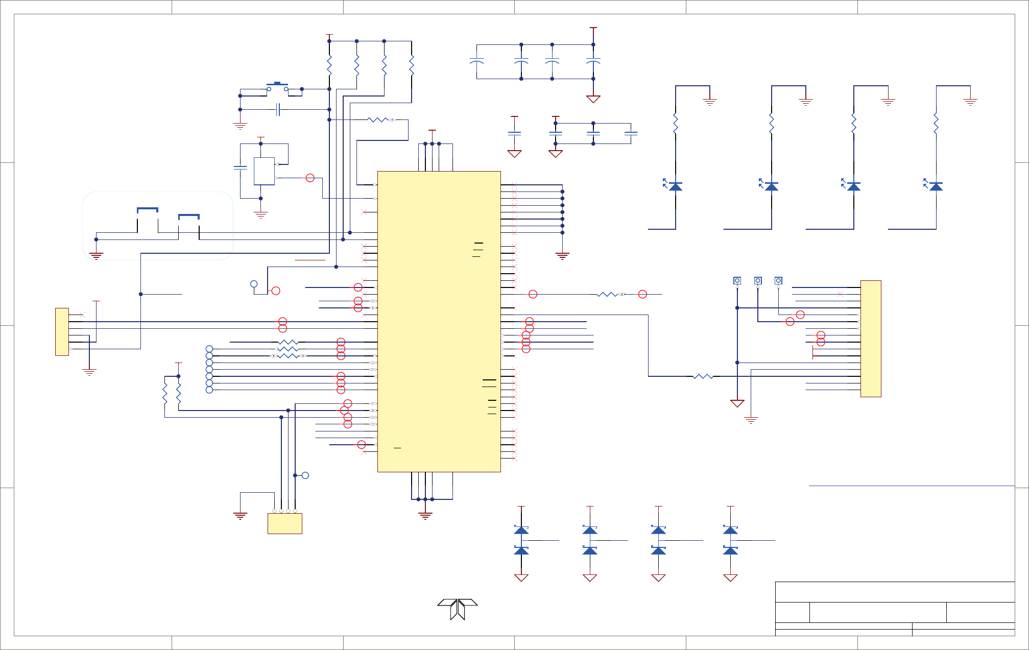
1
1
2
2
3
3
4
4
5
5
6
6
D D
C C
B B
A A
Title
Number RevisionSize
B
Date: 12/3/2010 Sheet of
File: N:\PCBMGR\..\05466p1_b.schdoc Drawn By:
REV
CHANGE ENG
1 12/19/05 CAC
VCC
RE1/WR/AD9 3
RE0/RD/AD8 4
RG0/CCP3 5
RG1/TX2/CK2 6
RG2/RX2/DT2 7
RG3/CCP4 8
MCLR/VPP
9
RG4/CPP5 10
VSS
11
VDD 12
RD7/PSP7/AD7 63
RD6/PSP6/AD6 64
RD5/PSP5/AD5 65
RD4/PSP4/AD4 66
RD3/PSP3/AD3 67
RD2/PSP2/AD2 68
RD1/PSP1/AD1 69
RD0/PSP0/AD0 72
AVDD 25
AVSS
26
RA3/AN3/VREF+
27 RA2/AN2/VREF-
28 RA1/AN1
29 RA0/AN0
30
VSS
31
VDD 32
RA5/AN4/LVDIN
33 RA4/T0CKI
34
RC1/T1OSI/CCP2
35 RC0/T1OSO/T13CLK
36
RC6/TX1/CK1
37
RC7/RX1/DT1
38
RC2/CCP1
43
RC3/SCK/SCL
44
RC4/SDI/SDA
45
RC5/SDO
46
RB7/KBI3/PGD
47
VDD 48
OSC1/CLKI
49
OSC2/CLKO/RA6
50
VSS
51
RB6/KBI2/PGC
52 RB5/KB11/PGM
53 RB4/KBI0
54 RB3/INT3/CCP2
55 RB2/INT2
56 RB1/INT1
57 RB0/INT0
58
RF7/SS
13 RF6/AN11
14 RF5/AN10/CVREF
15 RF4/AN9
16 RF3/AN8
17 RF2/AN7/C1OUT
18 RF1/AN6/C2OUT
23
VSS
70
VDD 71
RF0/AN5
24
RE7/CCP2/AD15 73
RE6/AD14 74
RE5/AD13 75
RE4/AD12 76
RE3/AD11 77
RE2/CS/AD10 78
RH6/AN14 20
RH5/AN13 21
RH4/AN12 22
RH3/A19 2
RH2/A18 1
RH1/A17 80
RH0/A16 79
RH7/AN15 19
RJ3/WRH 59
RJ2/WRL 60
RJ1/OE 61
RJ0/ALE 62
RJ4/BA0 39
RJ5/CE 40
RJ6/LB 41
RJ7/UB 42
U4
PIC18F8720
IC__286
VCCVCC
1
2
3
4
5
6
J2
520425-3
VCC
ICD/PGM CONN
VCC
R16
10.2k
1
2
3
4
S1
MCLR
C3
N/I
1
2
3
4
J4
HEADER 4 PIN
R4
10.2k
DEFAULTS
VCC
2
OUT 3
4
OE 1
X1
MI100HH-25
EL0000022
C25
0.1 uF, 50V
C15
1 uF, 10V
C17
1uF, 10V
OSC in ECIO Mode
Initial Release
lampEnable
CPU ALIVE
DS4
GRN
1K
R8
1
TP9
SET_DEFAULTS
R3
10.2k
R27
10.2k
JP1
JP2
I2C Address Jumpers Hardware Version Index
Teledyne - API
M100EU Sync/Demod PCA
05466 B
15
RT
1
2
3
4
5
6
7
8
9
10
11
12
13
14
15
16
J5
MICROFIT-16
preamp connector (inside housing)
SDA3
SCL3
HVPSGND
1k
R44
VCC
DIGITAL LAMP ENABLE AND I2C SIGNALS TO LAMP DRIVER
HVPS_MON
SCL2
SDA2
osc_out
I2C STATUS1
DS3
GRN
1K
R7
I2C_STATUS2
DS2
GRN
1K
R6
ALIVE
I2C_STATUS1
I2C_STATUS2
ALIVE I2C_STATUS1 I2C_STATUS2
I2C STATUS3
DS1
GRN
1K
R5
I2C_STATUS3
I2C_STATUS3
VCC
SDA3 SCL3
R57
2k
R41
2k
VCC
iNet Class
iNet Class
iNet Class
iNet Class
iNet Class
iNet Class
iNet Class
iNet Class
iNet Class
iNet Class
iNet Class
iNet Class
iNet Class
iNet Class
iNet Class
iNet Class
iNet Class
iNet Class
iNet Class
I2C_SCLI2C_SDA
I2C_SDA
I2C_SCL
SDA2
SCL2
OTEST
ETEST
POT_CS
MUX_A0
MUX_A1
MUX_A2
AD1_CS
SPI_SCK
SPI_SDI
SPI_SDO
PMT
PMTGND
OT_LED_DRIVE
OT_LED_RETURN
THERMISTOR+
MCLR
This schematic refers to 05464 PCB Rev B, 05465 PCA
REV 2 4/2/06 CACFixed planes on solder and comp layers
SPI_SDI2
SPI_SDO2
SPI_SCK2
iNet Class
iNet Class
iNet Class
TP14
TP6
TP17
TP20
TP11
TP15
TP10
TP21
TP26
*
TP18
*
TP19
*
-12V
+12V
REV A 2/12/07 RJE-test, PMT Gain, Anti-Alias Fliter, Misc Cleanup
1
3
2
D8
BAS70-04
1
3
2
D9
BAS70-04
1
3
2
D12
BAS70-04
1
3
2
D11
BAS70-04
VCC VCC
1kR29
1k
R24
1kR2
1kR17
iNet Class
iNet Class
iNet Class
iNet Class
iNet Class
iNet Class
iNet Class
R63
1k
PGN
HVPWR
HVGND
+
10uF,35V
C101
C102
1uF, 10V
C104
1uF, 10V
+
10uF,35V
C106 +
10uF,35V
C105 +
10uF,35V
C103
VCC
PRINTED DOCUMENTS ARE UNCONTROLLED
DCN5897
9480 Carroll Park Drive, San Diego, CA 92121-5201
REV B 12/03/10 Added C46,47,48 & R65,66, fixed U11 power pins. RT
D-10
06840B DCN6201
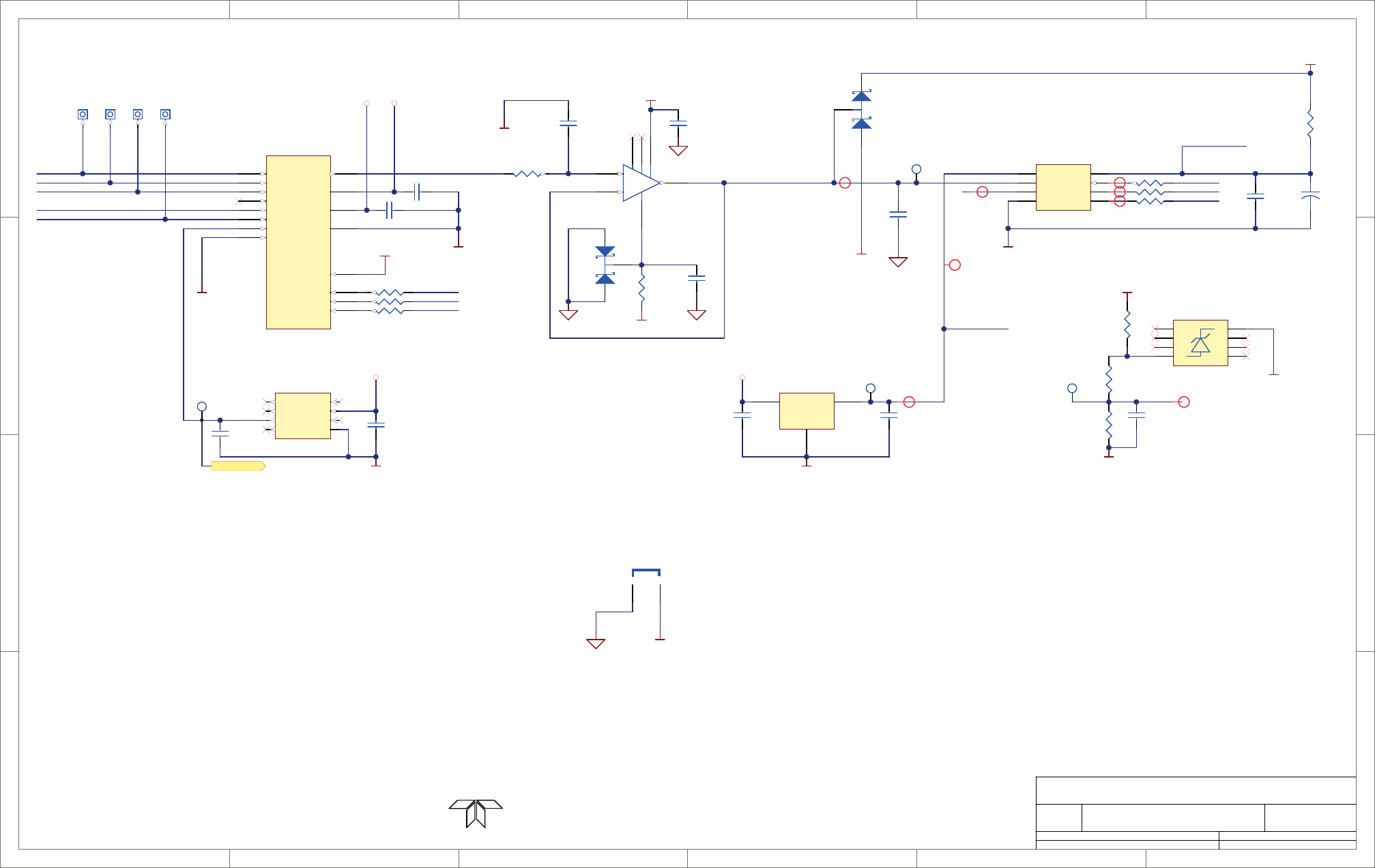
1
1
2
2
3
3
4
4
5
5
6
6
D D
C C
B B
A A
Title
Number RevisionSize
B
Date: 12/3/2010 Sheet of
File: N:\PCBMGR\..\05466p2_b.schdoc Drawn By:
C9
0.15, 25V
C12
0.15, 25V
C1
0.15, 25V
-12V +12V
C18
1.0uF,10V
NC 1
VIN 2
TRIM
5VOUT
6NR 3
NC
8
GND 4
NC
7
U5
VOLTAGE REF
C21
1.0uF,25V
REF_4.096
+12V
1
TP7
REF 4.096
TP3
IN
1
GND
3
OUT 2
U9
LT1460KCS3-5
C26
0.15, 25V
Vref
1
+IN
2
-IN
3
GND
4CS 5
DOUT 6
DCLK 7
VCC 8
U6
ADS8320
VCC
R25
49.9 Ohm
+
C11
10/16V
C22
0.15, 25V
50 PPM/DEG C
C10
0.15, 25V
TP4
-12V
R10
4.99K
R18
100
C4
0.15, 25V
-50MV_REF
-50MV_REF
+12V
REF_4.096
NC
1
NC
2
NC
3
A
4NC 5
NC 6
NC 7
K8
U1
LM285M-2.5
R11
10.2k
NOTE: GROUNDS TIED TOGETHER CLOSE TO U4, PIN 4
3.0k
R20
IN 3
6+VSS 13
IN 5
12 IN 4
7
IN 2
5IN 1
4
ENB 2
A0 1
A1 16
A2 15
IN 6
11
GND 14
IN 8
9
-VSS 3
OUT 8
IN 7
10
U3
HI-548
Teledyne - API
M100EU Sync/Demod PCA
05466 B
25 RT
JP3
AGROUND
AGROUND
AGROUND
AGROUND
AGROUND
AGROUND
AGROUND
AGROUND
UVLAMP
PMT1
PMT2
HVPS_MON
PMT_TEMP
TP23
*
iNet Class
iNet Class
iNet Class
+5_REF
MUX_A0
MUX_A1
MUX_A2
AD1_CS
SPI_SCK
SPI_SDI
AGROUND
R22
1K
R23
1K
R19
1k
R21
1K
R28
1k
R14
C8
N/I
TP13
VCC
TP12
*TP25
*TP2
*
-
+
7
2
3
4
6
8
1
U7
LT1677
VCC_ADC
1
3
2
D2
BAS70-04
D4
BAS70-05
1.1k
R26
C27
0.15, 25V
-12V
iNet Class
iNet Class
iNet Class
iNet Class
iNet Class
VCC_ADC
C46
1000 pF
AGROUND
PRINTED DOCUMENTS ARE UNCONTROLLED
DCN5897
9480 Carroll Park Drive, San Diego, CA 92121-5201
06840B DCN6201
D-11
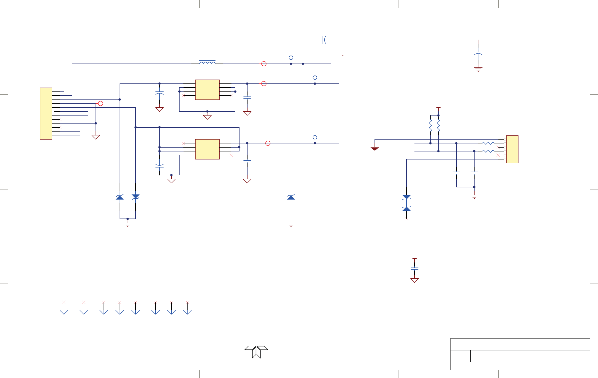
1
1
2
2
3
3
4
4
5
5
6
6
D D
C C
B B
A A
Title
Number RevisionSize
B
Date: 12/3/2010 Sheet of
File: N:\PCBMGR\..\05466p3_b.schdoc Drawn By:
1
2
3
4
5
6
7
8
9
10
11
12
J1
MICROFIT 12
DGND
VCC
+15V_in
-15V_in
MAIN INPUT CONNECTOR
EXTERNAL SIGNALS
1
2
3
4
5
6
J3
HEADER 6
R39
2.00K
R35
2.00K
VCC
1SMB5.0AT3
D1
TVS 5.0
D5
TVS 16V
D3
TVS 16V
12
+C16
22 uF, 25V
VCC
CA_154
1.0uF
C2 MODULE_RESET
VCC
C14
0.1 uF, 50V
Teledyne - API
M100EU Sync/Demod PCA
05466 B
35RT
L1 4.7 uH
D6
BAS70-05
VCC_IN
+12V
-12V
TEC_OUT
UVLAMP
iNet Class
iNet Class
iNet Class
iNet Class
I2C_SCL
I2C_SDA
MCLR
TP24
TP1
TP5
+12V 1
GND 2
GND 3
N/C 4
Vin
8
GND
7
GND
6
N/C
5
VR2
LM78L12ACM
Vout 1
Vin 2
Vin 3
N/C 4
N/C
8
Vin
7
Vin
6
GND
5
VR1
L79L12ACD
+
10uF,35V
C13
1.0uF
C34
+
10uF,35V
C39
MT1
Plug
MT2
Plug
MT3
Plug
MT4
Plug
MT5
Plug
MT6
Plug
MT7
Plug
MT8
Plug
+
1000uF,50V
C45
HVGND
HVPWR
R6549.9
C47
1000pF
R6649.9
PRINTED DOCUMENTS ARE UNCONTROLLED
DCN5897
9480 Carroll Park Drive, San Diego, CA 92121-5201
C48
1000pF
D-12
06840B DCN6201
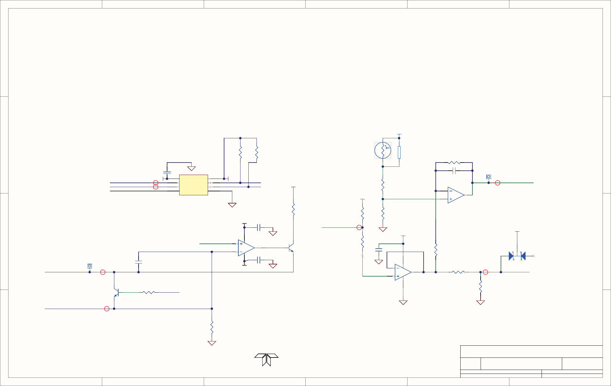
1
1
2
2
3
3
4
4
5
5
6
6
D D
C C
B B
A A
Title
Number RevisionSize
B
Date: 12/3/2010 Sheet of
File: N:\PCBMGR\..\05466p4_b.schdoc Drawn By:
R61
56.2K
R15
10k
R37
51.1K
Q1
PN2222
+12V
R58
10.2k
R43
10.2k
R62
49.9K
R45
100K
2.00K
R59
0.1 uF
C38
0.1 uFC37
2
3
1
U14A
LF353, OPAMP
5
6
7
4 8
U14B
LF353, OPAMP
R46
2.00K
VCC
TP8
*
TP16
*
TH1
R36
10.2k
FSV
PMT TEMPERATURE FEEDBACK
TO TEC BOARD
M100EU Sync/Demod PCA
45
05466 B
OT_LED_CONTROLV
C5
1uF, 10V
ETEST/OTEST CONTROL
VDD
1
VOUTA
2
VOUTB
3
REFIN
4GND 5
SDA 6
SCL 7
A0 8
U2
AD5337BRM
VCCVCC
OT_LED_CONTROLV
Q2
PN2222
+12V
R1
499
R9
1.1K
0.1 uF
C6
R13
21.5K
R12
21.5K
D13
BAS70-05
TEC_OUT
PMT_TEMP
iNet Class
iNet Class
iNet Class
iNet Class
iNet Class
iNet Class
iNet Class
SCL2
SDA2ET_SIGNAL
REF_4.096
OTEST
OT_LED_RETURN
OT_LED_DRIVE
THERMISTOR+
+12V
+12V
3
2
1
v-
11 v+ 4
U12A
OPA4277UA
0.1 uF
C7
-12V
+12V
0.1 uF
C44
Teledyne - API
PRINTED DOCUMENTS ARE UNCONTROLLED
DCN5897
RT
9480 Carroll Park Drive, San Diego, CA 92121-5201
06840B DCN6201
D-13
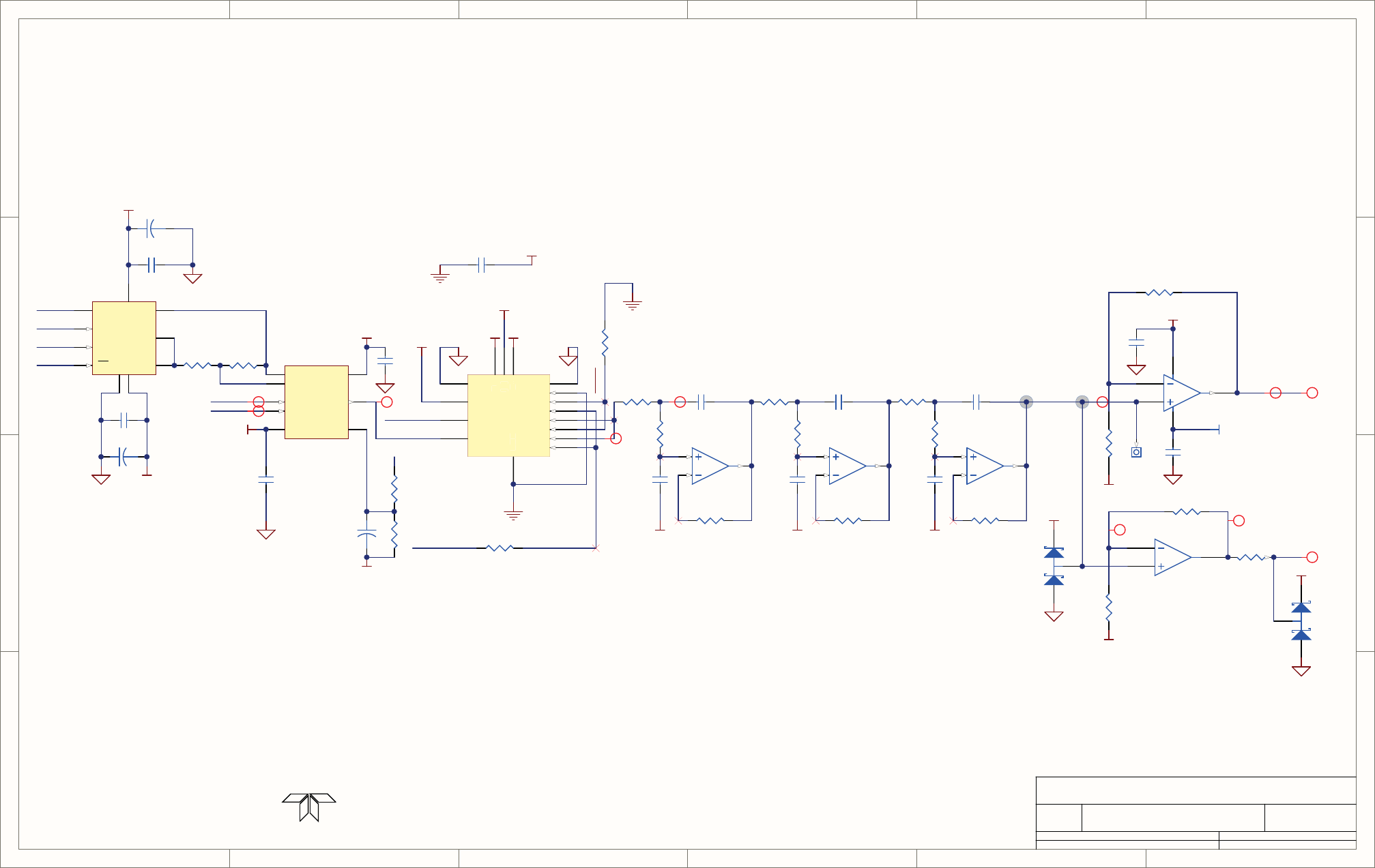
1
1
2
2
3
3
4
4
5
5
6
6
D D
C C
B B
A A
Title
Number RevisionSize
B
Date: 12/3/2010 Sheet of
File: N:\PCBMGR\..\05466p5_b.schdoc Drawn By:
NOTES: UNLESS OTHERWISE SPECIFIED
3.
2.
1.
RESISTANCE IS IN OHMS.
RESISTORS ARE 1%, 1/4W.
CAPACITANCE IS IN MICROFARADS.
THIS CIRCUIT MUST BE USED
AS A MATCHED PAIR WITH THE
TEC CONTROL CIRCUIT
4.
20.5K
R55
+12V
0.1 uF
C35
0.15 uF
C28
-12V
4.99K
R31
0.1 uF C36
TP22
*
VCC
R33
N/I
M100EU Sync/Demod PCA
55
05466 B
-12V
0.68 uF
C32
0.68 uF
C31
4.99K
R47
47.5K
R48
AGROUND
N/I
R30
AGROUND
PMT Gain Conditioning
499
R49
VCC
+12V
PMT1
PMT2
iNet Class
iNet Class
PMTGND
PMT
5
6
7
U11B
OPA2277UA OPAMP DUAL SO8
3
2
1
8 4
U11A
OPA2277UA OPAMP DUAL SO8
-V
4
IN+
3IN-
2OUT 6
REF 5
RG
1
RG
8+V 7
U10
INA121U
4.99K
R38
22 Ohms
R40
+
10uF,10V
C33
+5_REF
V- 4
GND
5V(L) 12
V+ 13
V
-
G
N
D
V
(
L
)
V
+
IN1 1
D1 2
S1
3
S4
6D4 7
IN 4 8
IN 3 9
D3 10
S3
11
S2
14 D2 15
IN2 16
U13
DG444DY
-12V+12V
VCC
ET_SIGNAL
ETEST
VCC
ETEST
VSS
3
B2
SDO
8
VDD 9
W10
A1
CS
5
CLK
6
GND
4
SDI
7
U8
AD5290 34.8k
R32
-12V
+12V
+
10uF,16V
C19
0.1 uF
C24
0.1 uF
C23
SPI_SDI2
SPI_SDO2
SPI_SCK2
POT_CS
+
10uF,16V
C20
4.99K
R56
1
3
2
D7
N/I
1
3
2
D10
N/I
VCC
(Chan 2 acting as inverter)
Anti Alias Filter - 6 pole - 500 Hz
12
13
14
U12D
OPA4277UA
8
9
10
U12C
OPA4277UA
5
6
7
U12B
OPA4277UA
20.5K
R54
24.9K
R53
.01 uF
C42
9100 pF
C43
22.6K
R60
24.9K
R51
6800 pF
C40
22.6K
R52
24.9K
R42
2400 pF
C30
34.8K
R34
34.8K
R50
9100 pF
C41
9100 pF
C29
Digital Pot 50K
Instrumentation Amp
Analog Switch
AGROUND
AGROUND AGROUND AGROUND
Selectable gain stages
iNet Class iNet Class
iNet Class
4.99K
R64
iNet Class
iNet Class
iNet Class
iNet Class
iNet Class
iNet Class
Teledyne - API
PRINTED DOCUMENTS ARE UNCONTROLLED
DCN5897
RT
9480 Carroll Park Drive, San Diego, CA 92121-5201
D-14
06840B DCN6201
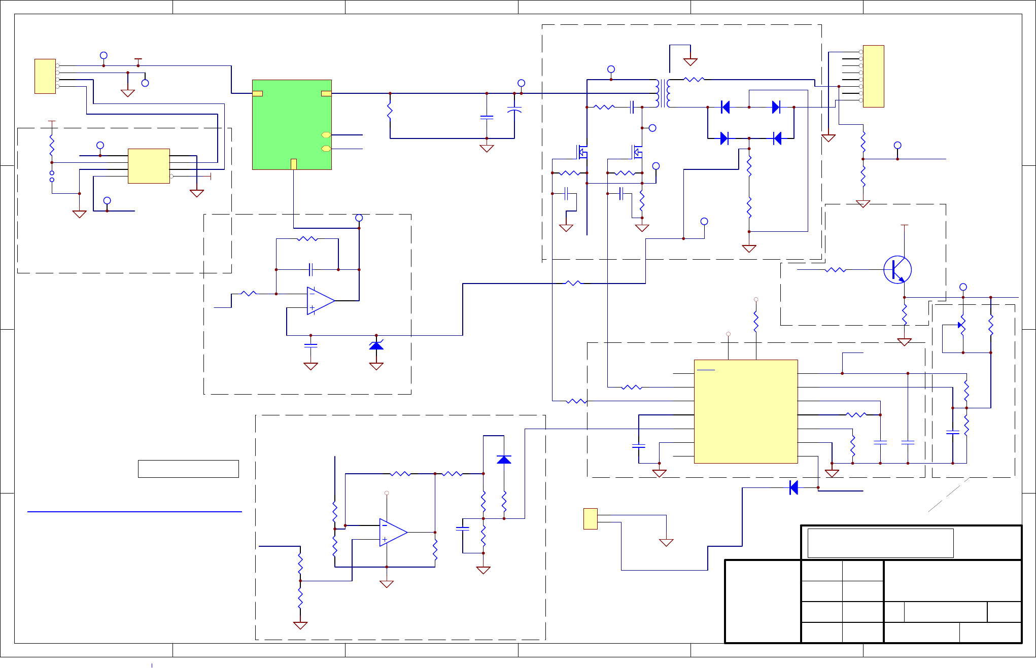
1 2 3 4 5 6
A
B
C
D
6
54321
D
C
B
AAPPROVALS
DRAWN
CHECKED
APPROVED
DATE
SIZE DRAWING NO. REVISION
SHEET
Error : LOGO.BMP file not found.
The information herein is the
property of API and is
submitted in strictest con-
Unauthorized use by anyone
fidence for reference only.
for any other purposes is
prohibited. This document or
any information contained
in it may not be duplicated
without proper authorization.
Sch, Bursting UV Lamp Drv, M100EU
059160200 C
1 214-Mar-2007
LAST MOD.
B
of
T1
PE-6196
Q3
IRF520
Q2
IRF520
R2
N/I
R3
N/I
R4
100
C4
0.01 uF
R12
249
R13
249
R20
2.7k, 25W
+12V
R14
10
+12V
R16
3.9K
R15
232
C11
0.0047 uF
C12
0.1 uF
C9
0.1 uF
3
21
84
U1A
LM358
5
67
U1B
LM358
C6
0.03 uF
C5
0.01 uF
+12V
D3
1N4148
D5
1N4148
D4
1N4148
D6
1N4148
R6
75, 1/4W
1
2
3
4
5
6
7
8
P2
LAMP OUTPUT
C2
0.1 uF
CAC 2/7/07
1 2
RP2A
4.7K
3 4
RP2B
4.7K
7 8
RP2D
4.7K
DATE CHANGE DESCRIPTION INITIALREV.
2/7/07 CREATED CACA
Vdd
1
A0
2
A1
3
Vout
4PD 5
SCL 6
SDA 7
GND 8
U3
AD5321-RM8
VREF
OUTPUT A
11
OUPUT B
14
SOFT START
8
INV. INPUT
1
SHUTDOWN
10 GROUND 12
RT 6
DISCHARGE 7
CT 5
NONINV. INPUT 2
VREF 16
VCC 15
VC 13
SYNC
3
OSC. OUTPUT
4COMP 9
U2
SG3525
TP1
TEST_PLUG
TP2
TEST_PLUG
TP3
TEST_PLUG
TP4
TEST_PLUG
R7
3.9K
VREF
VREF
1
2
3
4
P1
HEADER 4
JP1
JUMPER2
R10
75, 1/4W
Applies to PCA: 05512-02
R21
0.2 Ohms, 2W
TP8
Primary Current
TP11
Lamp Current
R1
N/I
R5
N/I
TP9
Lamp Voltage
TP5
Drive Voltage
TP6
Q2 Drain V
TP7
Q3 Drain V
VREF
R17
47K
R18
40k
R11
47K
R22
30K
R25
10K,1%
Q6
NPN
C7
0.01 uF
ACOMP
R29
100K
R31
47K
C14
1 uF
R30
47K
D8
1N914
R34
40K
R35
40K
VDAC
R27
40K
VSET
R32
40K
R33
40K
ACOMP
+12V
LAMP_FDBACK
R8 10k
VDAC
VREF
+12V
VDRIVE
VLAMP
D9
1N914
IPRIMARY
VCOMP
VCOMP
LAMP POWER CONTROL DAC
LAMP CURRENT FEEDBACK AMPLIFIER
BLINK MULTIVIBRATOR
PWM CONTROLLER
CC STAGE AMPLIFIER FOR COMP
LAMP DRIVE POWER STAGE
HYSTERIESIS SET RESISTORS FOR PWM ERROR COMPARATOR
R28
5.1K
R36
20K
TP10
PreReg_Control
+12V VDRIVE
LAMP_FDBACK
VREF
ACOMP_2
05916_p2
05916_p2.sch
+
C3
220
R26
50K
TP12
ACOMP
D7
7V
VREF
ACOMP
C23 N/I C24
N/I
Used for PCA 05512-02
1
2
P3
CON2
PRINTED DOCUMENTS ARE UNCONTROLLED
D-15
06840B DCN6201
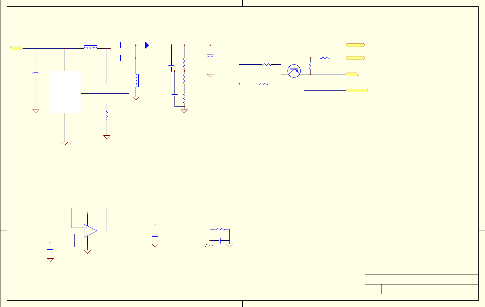
1 2 3 4 5 6
A
B
C
D
6
54321
D
C
B
A
Title
Number RevisionSize
B
Date: 14-Mar-2007 Sheet of
File: N:\PCBMGR\059160200cc\source\059160200C.ddbDrawn By:
VIN 5
GND
3
SW 4
FB 2
VCOMP 1
U5
LT1268
L1
25 uH
L2
25 uH
C21
4.7 uF
C18
4.7 uF
R41
1k
R42
25.5K
R43
2k
C15
0.68 uF
LAMP_FDBACK
D10
DIODE
R37
1k
+C20
1000 uF
+
C17
100 uF
+12V VDRIVE
C19
N/I
C8
0.1 uF
+12V
3
21
84
U4A
LM358
+12V
+12V
C10
0.1 uF C13
0.1 uF
R44
0
+12V VDRIVE
lamp_fdback
VSWITCH R45
5.1K
C22
N/I
R23
5.1K
VREF
ACOMP_2
R47
100K
R46
50K
Q1 PN3645_PNP
C059160200
Sch, Bursting UV Lamp Drv, M100EU
2 2
D-16
06840B DCN6201
