Tcp380_2 Tcp380
User Manual: tcp380
Open the PDF directly: View PDF ![]() .
.
Page Count: 43
Betriebsanleitung
Operating Instructions
Mode d´emploi
Antriebselektronik
Electronic Drive Unit
Commande électronique
TCP 380
PM 800 188 BN/E (9810)
--_
..
Inhalt
Contents
Contenu
Allgemeines
General
Generalites
2
Technische
Daten
2
Technical
Data
2
Caracteristiques
techniques
2.1
Technische
Daten/Optionen
2.1 Technical Data,
Options
2.1
Caracteristiques
techniques
optionnelles
3
Einsatzarten
3
Types
of
Application
3.1 Einsatz
ohne
Pumpstandsteue-
3.1
Application
without
Pumping
3
Utilisations
possibles
rung
Unit
Control 3.1
Utilisation
sans
commande
de
3.2
Einsatz
mit
Pumpstandsteuerge-
3.2
Application
with
Pumping
Unit
groupe
de
pompage
rat
TCS
303
Control
TCS
303
3.2
Utilisation
avec
commande
de
3.3
Einsatz
mit
Pumpstandsteuerge-
3.3
Application
with
Pumping
Unit
groupe
de
pompage
TCS
303
rat TCS
304/304R
Coctrol
TCS
304/304R
3.3
Utilisation
avec
commande
de
groupe
de
pompage
TCS
304/
4
AnschlUsse
4
Connections
304R
4.1 Netz 4.1
Mains
4
Raccordements
4.1
.1
Belegung
der
Netzsteckerleiste
4.1.1 Pin
Assignment
of
Mains
Con-
X4
nectar
X4
4.1
Branchement
secteur
4.2
Turbopumpe
4.2
Turbo
Pump 4.1.1
Affectation
des
broches
du
4.3
Luftkuhlung
4.3
Air
Cooling
connecteur
X4
4.4
Flutventil
4.4
Venting
Valve
4.2
Pompe
turbomoleculaire
4.5
Heizung
Turbopumpe
4.5
Heater
for
Turbo Pump
4.3
Refroidissement
par
air
4.6
Remotestecker
4.6
Remote
Plug
4.4
Vanne de
remise
a
I'air
4.7
Serielle
Schnittstelle
(Option)
4.7
Serial
Interface
(Option)
4.5
Chaufferette
de
la
pompe
turbo
4.8
Pumpstandsteuergerat
TCS
303
4.8
Pumping
Unit
Control
TCS
303
4.6
Connecteur
de
telecommande
und
304
and
304
4.7
Interface
serie
(Option)
4.8
Commandes
de
groupe
de
pom-
5
Uberwachung
5
Monitoring
page
TCS
303
et
304
5.1
Uberwachungsrelais
K2 5.1
Monitoring
Relay K2 5
Surveillance
5.1.1
yerriegelung
K2 5.1
.1
Interlock
K2 5.1 Relais
de
surveillance
K2
5.2
Uberwachungsrelais
K 1
5.2
Monitoring
Relay
Kl
5.1.
Verrouillage
K2
6
Bedienungselemente
und
6
Control
Elements
and
LC
5.2
Relais
de
surveillance
K 1
LC-Anzeigefeld
Display
Panel
6
Elements
de
manoeuvre
et
6.1 Bed
ienungselemente
6.1
Control
Elements
panneau
d'affichage
LCD
6.2
LC-Anzeigefeld
6.2
LC
Display
Panel 6.1
Elements
de
manoeuvre
7
Betrieb
7
6.2
Panneau
d'affichage
LCD
Operation
7.1 Einschalten 7.1
Switching
on
7
Service
7.2
Fernbedienung
7.2
Remote
Control
7.1
Mise
en
marche
7.3.
Stand-by
7.3
Stand-by
7.2
Telecommande
7.4
Reset
7.4
Reset
7.3
Stand-by
7.5
Funktion
der
DIL-Schalter
7.5
Function
of
the
OIL
Switches
7.4
Reset
7.6
Ausschalten
7.6
Switch
i ng
off
7.5
Fonction
des
commutateurs
DIP
7.7
Verzogertes
Fluten
mit
Flutsteu-
7.7
Delayed
Venting
using
Venting
7.6
Arret
ergerat
TCF
Control
Unit
TCF
7.7
Remise a
I'air
temporisee
avec
7.8
Andern
der
Anzeige
und
der
7.8
Changing
the
Display
and Para-
commande
TCF
Parameter
meters
7.8
Alteration
des
parametres
et
de
8
Weitere
Betriebsarten
8
Further
Operating
Modes
I'affichage
8.1
Remote-Betrieb
8.1
Remote
Operation
8
Autres
modes
d'
operation
8.2
Betrieb
uber
Schnittstellen
8.2
Operation
via
Interfaces
8.1
Operation
a
distance
(Remote)
(Option) (Option)
8.2
Operation
par
interfaces
(Option)
9
Fehlersuche
9
Trouble-Shooting
9.1
Selbsttest
9.1 Self-Testing 9
Depistage
d'erreurs
9.2
Fehlerliste
9.2
List
of
Errors 9.1
Auto-test
9.3
Ausgewertete
Analogspannun-
9.3
Analyzed
Analogue
Voltages
9.2
Liste des
messages
d'erreurs
gen
beim
Selbsttest
during
Self-Testing
9.3
Tensions
analogiques
evaluees
9.4
Erweiterte
Testmoglichkeiten
9.4
Extended Testing
Possibilities
lars
de
I'auto-test
9.5
Gestorter
Betrieb
9.5
Defective
Operation
9.4
Autres
possibilites
de
tests
9.6
Einsendung
zur
Reparatur
ins
9.6
Returning
to
Service
Center
for
9.5
Service en
"derangement
Service
Center
Repair
9.6
Renvoi au Centre
de
Service
Apres-Vente
pour
reparation
10
Ersatzteile
10
Spare
Parts
10
Pieces
de
rechange
11
Schaltpliine
11
Wiring
Diagrams
Schemas
de
connexions
11
.1
Legende
zu
den
Schaltplanen
11
.1
Legend
for
wiring
diagrams
11
11
.1
Legende
pour
les
schemas
de
12
Zubehor
12
Accessories
connexions
12
Accessoires
Bestell-Nr.
/
Order
nr.
/
Numero
de
commande:
PM COl
490
Betriebsanweisung
fur
Antriebselektronik
rep
380
Wichtige
Hinweise
Prufen
Sie
sotort
nach
dem
Auspak-
ken,
ob
die
Sendung
mit
den
Angaben
auf
dem
Lieferschein
ubereinstimmt.
Lesen
Sie
die
Betriebsanweisung,
Sie
das
Gerat in
Betrieb
nehmen.
Befolgen
Sie
die
Anweisungen
in
allen
Punkten.
-
Aile
Gerate
entsprechen
dem
Gesetz
uber
technische
Arbeitsmittel,
§3.
Sie
sind
nach
Schutzklasse
1
aufgebaut.
-Das
Gerat
wurde
einer
Stuckprufung
mit
1500
V
AC,
einer
Isolationspru-
tung
mit
500
V DC
und
einer
PrOfung
der
Schutzleiterverbindungen
mit
25
A
unterzogen.
-
Werden
die
Signale
der
TCP
extern
genutzt
und
wird
doppelte
Isolation
verlangt
(z.B.
gemall.
DIN
VDE
0411)
muB
Rucksprache
mit
dem
Hersteller
genom
men
werden.
-
Die
Betriebsanweisung
ist
nach
DIN
841
8
erstellt.
Wenn
Sie
selbst
Reparatur-
oder
War-
tungsarbeiten
an
den
Geraten
vorneh-
men,
die
mit
gesundheitsschadlichen
Stoffen
in
Beruhrung
gekommen
sind,
dann
beachten
Sie
die
entsprechenden
Vorschriften.
Bei
Geraten,
die
Sie
an
uns
zu
Repara-
tur-
oder
Wartungsarbeiten
einschik-
ken,
beachten
Sie
folgendes:
-
kontaminierte
Gerate
(radioaktiv,
che-
misch
etc.)
sind
vor
der
Einsendung
entsprechend
den
Strahlenschutzvor-
schriften
zu
dekontaminieren.
-
Zur
Reparatur
oder
Wartung
einge-
hende
Gerate
mussen
mit
deutlich
sichtbarem
Vermerk
"Frei von
Schad-
stoffen"versehen
sein.
Derselbe
Ver-
merk
ist
auch
auf
dem
Lieferschein
und
Anschreiben
anzubringen.
-
"Schadstoffe"
sind:
Stoffe
und
Zube-
reitungen
gemafS
EG-Richtlinie
vom
18.09.1979,
Artikel
2.
Technische
Anderungen
behalten
wir
uns
vor.
Operating
Instructions
for
Electronic Drive
Unit
rep
380
Important Information
Please
check
immediately
after
unpacking
whether
the
consignment
conforms
to
the
information
given
on
the
delivery
note.
Please
read
the
operating instructions
before
you
operate
the
unit
and
follow
them
in
all
respects.
-
All
units
comply
with
the
law
concern-
ing
technical
implements,
Section
3.
They
have
been
designed
in
accor-
dance
to
protection
grade
1.
-
The
device
has
undergone
a
routine
test
with
1500
V AC, an
isolation
test
with
500
V DC
and
also
a
protective
earthing
conductor
test
with
25
A.
-
If
the
TCP
signals
are
used
externally
and
if
double
insulation
is
requested
(for
example
DIN VDE
0411),
the
manufacturer
must
be
consulted.
-
The
operating
instructions
have
been
prepared
in
accordance
with
DIN
8418.
If
you
perform
repair or
maintenance
work on
units
which
have
come
into
contact
with
substances
which
are
detrimental
to
health,
please
observe
the
relevant
regulations.
If
you
return
units
to
us
for
repair
or
maintenance
work,
please
follow
the
instructions
below:
-
contaminated
units
(radioactively
or
chemically
etc.)
must
be
decontami-
nated
in
accordance
with
the
radiation
protection
regulations
before
they
are
returned.
-
Units
returned
for
repair
or
mainte-
nance
must
bear
a
clearly
visible
note
"Free from
harmful
substances".
This
note
must
also
be
provided
on
the
delivery
note
and
accompanying
letter.
-
"Harmful
substances"
are
defined
as:
materials
and
preparations
in
accor-
dance
with
the
EEC
Specification
dated
18
September
1979,
Article
2.
Technical
modifications
reserved.
Instruction
de
service
de la
commande
electronique
rep
380
Directives
importantes
A la
reception
de
i'envoi,
s'assurer
au
debal/age
que
Ie
contenu
du
(des)
colis
corresponde
bien
aux
articles
enume-
res
sur
Ie
bon
de
livraison.
Avant
que
de
mettre
I'appareil
en
ser-
vice,
lire
attentivement
/'instruction
de
service
et
s'y
conformer
en
taus
points.
-
Tous
nos
appareils
repondent
aux
prescriptions
legales
§
3,
relatives
aux
appareillages
techniques.
lis
sont
dimensionnes
d'apres
categorie
de
protection
1.
-
L'appareil
ete
soumis
a un
essai
indivi-
duel
avec
1500
V CA,
1':1
un
essai
d'
isolation
avec
500
V CC
et
a un essai
des
conducteurs
de
protection
avec
25A.
-
Si
les
signclUx
de
In
TCP
sont
utilises
de
externe
et
on
demande
un
double
isolement
(suivant
a la DIN
VDE
0411
par
exemple),
il
faut
consul-
ter
de
producteur.
-
L'instruction
de
service
est
redigee
en
concordance
avec
la
norme
DIN
8418.
L'utilisateur
procede-t-il
lui-meme
a
des
travaux
de
reparation
ou
d'entre-
tien
sur
des
appareils
qui
auraient
ete
en
contact
avec
des
matieres
toxiques,
il
est
alars
tenu
de
respecter
les
pres-
criptions
afferentes.
Au
renvoi
de
tous
appareils
a
reparer
ou
a
reviser,
priere
de
tenir
compte
des
points
suivants:
-
les
appareils
cantamines
(radioactive-
ment,
chimiquement,
etc.)
sont
preala-
blement
a
decontaminer
en
vertu
de
la
legislation
relative
a la
protection
contre
les
emissions
radioactives.
-Les
appareils
envoyes
pour
reparation
ou
maintenance
doivent
etre
pourvus
d'une
etiquette
bien
visible
certifiant
qu'ils
sont
"exempts
de
matieres
taxi-
ques':
La
meme
indication
est
apposer
sur
Ie
bon
de
livraison
et
sur
toute
la
correspondance
aff9rente.
-Les
"matieres
toxiques"
sont
celles
enumerees
par
I'article
2
de
la
pres-
cription
de
la C.E.E
en
date
du
18
sep-
tembre
1979.
Modifications
techniques
reservees.
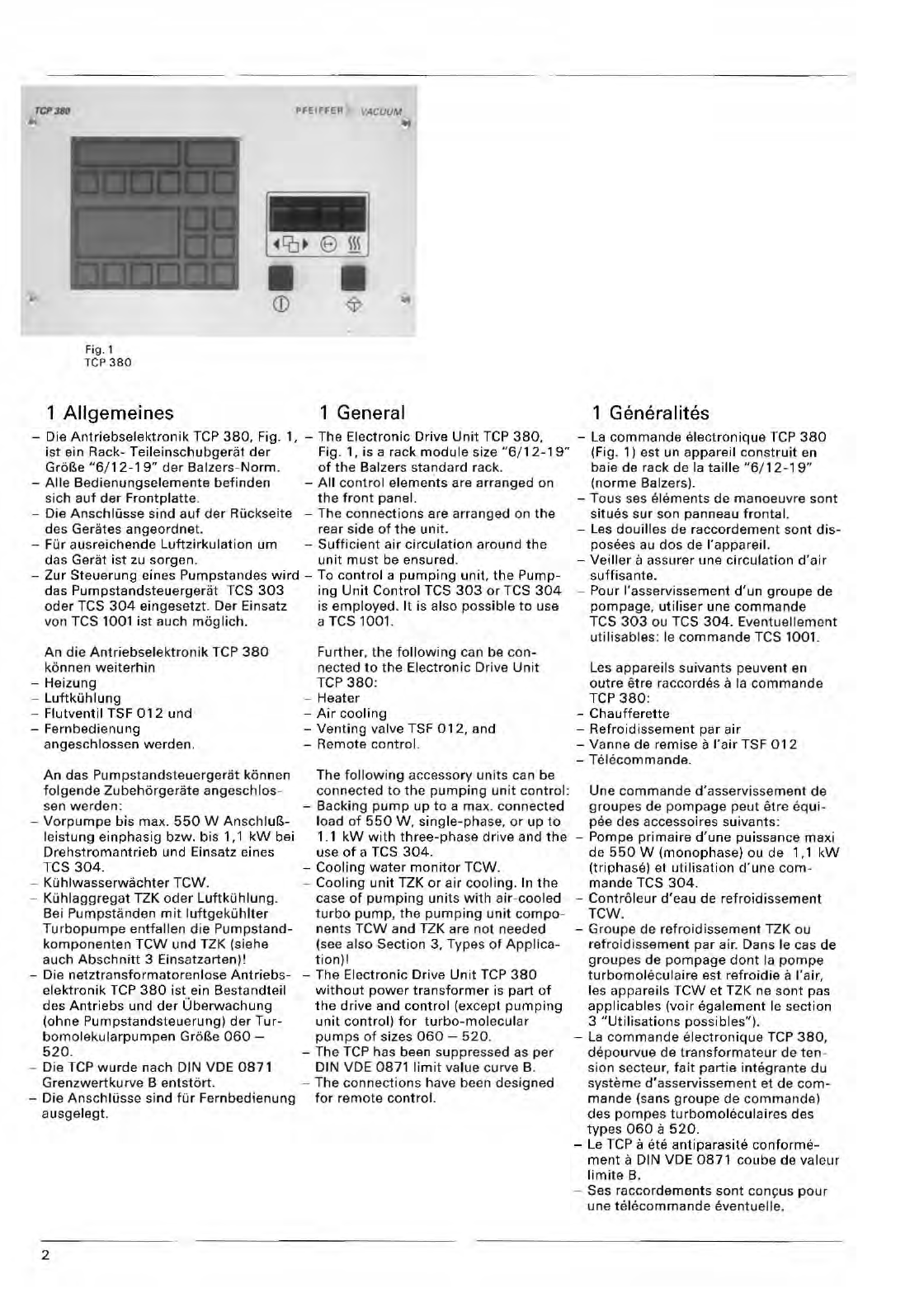
Fig. 1
rep
380
1 Aligemeines
PFEIFFER VACUUM
1 General
-
Di
e
Antriebselektronik
TCP
380,
Fig. 1, -The Electronic Drive
Unit
TCP
380,
i
st
ein Rack- Teileinsch ubger
at
der
Fig . 1, is a rack
module
si ze
"6/12-1
9"
Gre!>e
"6/12-19"
der
Balzers-
Norm.
of
the
Bal zers standard
ra
ck,
-Aile Bedie
nungselem
e
nte
befinden
- A ll
contro
l
elements
are arra
nged
on
sich
auf
der
Frontplatt
e.
th
e
front
panel.
-Die
Anschlusse
sind a
uf
der
Ru
ckse
it
e - The
connections
are
arranged
on
the
des Gerates
angeordnet.
rear side
of
the
unit.
-Fur ausreichende
Luftzirkulation
urn -
Sufficient
air
circulation
around
the
das Gerat
ist
zu
sorgen.
unit
mu
st
be ensured.
-
Zur
St
euerung eines Pumpstandes
wird
-To
control
a
pumping
unit.
the
Pump-
das
Pumpstandsteuergeriit
TCS
303
ing
Unit
Control
TCS
303
or
TCS
304
ode
r
TeS
304
eingesetzt . Dar Einsatz
is
employed.
It is also possible
to
use
von T
CS
1001 ist auch meg lich. a
TC
S 1001.
An
die
Antriebselektronik
TCP
380
konnen
we
iterhin
-He
iz
un g
-
Luftkuhlung
-
Flu
tve
ntil
TSF
012
und
- Fernbedien ung
angeschlossen
werd
en.
Further, t he
following
ca n be
con-
nected
to
the Electronic Drive
Unit
TCP
380:
-Heater
-
Air
cooling
-Venting valve TSF
012,
and
-Remote control.
An
das
Pumpstandsteuergerat
konnen The
following
accessory
units
ca
n be
fol
ge
nde
Zubehorgerate
angeschlos-
connected t o
the
pumping
unit
control:
sen
werden:
- Backing
pump
up
to
a max. connected
-
Vorpumpe
bis max.
550
W
Anschlu"-
load
of
550
W,
single-phase,
or
up
to
leistung
einphasig
bzw. bis 1,1
kW
bei 1.1
kW
with
three-phase
drive and
the
Drehstromantrieb
und
Ein
sa
tz eines u
se
of a TCS
304.
T
CS
304.
-Cooling
water
monitor
TCW.
-KOhlwasserw8chter TCW. -Cooling
unit
TZK
or
air
cooling.
In
the
-Kuhlaggregat TZK
oder
Luftkuhlung.
case
of
pumping
units
with
a
ir
-
coole
d
Bei
Pump
stan
den
mit
luftg
ek
uhlter
turbo
pu
mp
,
the
pumping
unit
compo-
Turbopump
e e
ntfallen
die
Pumpsta
nd-
na
nt
s
TeW
and
UK
are not needed
komponenten
TCW
und TZK (siehe (see also Sec
tion
3, Types
of
Applica-
auch
Abschnitt
3
Ein
satzarten)!
ti
on)!
-Die
netztransformatorenlose
Antriebs-
-The
El
ectron ic Drive
Unit
TCP
380
el
ektro
nik
TCP
380
ist
ein Besta ndteil
without
power
transform
er
is
part
of
des
Antriebs
und
der
Uberwachung
th
e drive and
control
(e
xcept pu
mping
(ohne
Pumpstandsteuerung)
der
Tur-
unit
cont
ro
l)
for
turbo-m
olecular
bom
olekularpumpen Gre!>e
060
-
pumps
of
sizes
060
-
520
.
520
. - The
TCP
has been suppressed as
per
-Die
TCP
wurde
nach DIN VDE
0871
DIN VDE
0871
limit
va
lue c
ur
ve B.
Grenzwertkurve
B
entst6rt
. - The
con
necti
ons have been
designed
-Die
Anschllisse
sind
fUr Fe
rnb
edienung
for
remote co
nt
rol.
ausgelegt.
2
1 Generalites
-
La
comman
de
electroniqu
e
TCP
380
(Fig. 1) est
un
appareil
construit
en
baie de rack de
la
taille
"6/12
-19
"
(norme
Balzers).
- Taus
seS
elem e
nts
de
manoeuvre so
nt
situes s
ur
son panneau frontal.
-
Le
s
douilles
de raccordement sont
dis-
posees
au
dos de I'appareil.
-
Veiller
a assu rer une
circulation
d'air
suffisanle.
-Pour I'asservissement
d'un
groupe
de
pompage,
ut
i
liser
une
commande
TCS
303
ou
TeS
304.
Eventuellement
utili
sables: Ie
co
mmand
e T
CS
1001.
Les appareils su ivants peuvent en
outre
etre raccordes a
la
commande
TCP
380
:
-
Chauffer
e
tt
e
-Refroi disseme
nt
par
air
-Vanne de remise a
!'air
TSF 0 12
- T
elecomma
nde.
Une
comman
de
d'asservis
s
ement
de
groupes
de
pompage
peut eIre eq ui-
pee des accessoir
es
suivants:
-Pompe
primaire
d'une
puissance maxi
de
550
W (monophase) ou de 1,1
kW
(triphase)
el
utilisation
d'un
e co m -
mande TCS
30
4.
-Controle
ur
d'eau de
refroidissement
T
eW.
-
Groupe
de
r
efroidisse
ment TZK
ou
re
froidi
sse
ment
par air. Dans Ie cas
de
g
roup
es
de
pompage
dont
la
pompe
turbomoleculaire
est
refroidia
a !'air,
les
appare
il s
TCW
et TZK ns son t pas
appli
cabl
es
(voir
egalement
Ie sec
tion
3
"Utilisations
possibles").
-
La
commande
elec
troniqu
e TCP
380,
depourvue
de
transformat
e
ur
de
ten
-
sion secteu
r,
fa
it
partie
int
egra
nt
e
du
systeme
d'asservissement
e1
de
com-
mande
(sans
gro
upe de
commands)
des
pampas
turbo
mole
cul aires des
typ
es
060
a
520.
-
Le
TCP a eta
antiparasite
conforme-
ment
a DIN VDE
0871
coube de valeur
limit
e
B.
-Ses
raccordements
sont
concus
pour
une tel
ecom
mande
eventuelle.
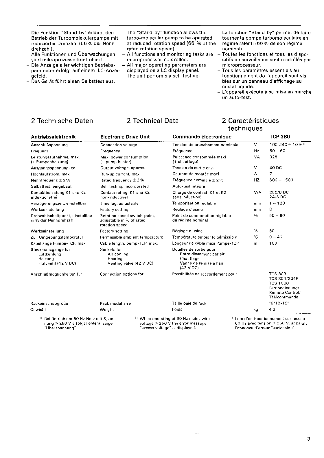
-Die Funktion
"Stand-by"
erlaubt
den -
The
"Stand-by"
function
allows
the
-
La
fonction
"Stand-by"
permet
de
faire
tourner
la
pompe
turbomoleculaire
en
regime
ralenti
(66
% de son
regime
nominal).
Betrieb
der
Turbomolekularpumpe
mit
turbo-molecular
pump
to
be
operated
reduzierter
Drehzahl
(66
%
der
Nenn-
at
reduced
rotation
speed
(66
%
of
the
drehzahl). rated
rotation
speed).
-
Aile
Funktionen und
Uberwachungen
-
All
functions
and
monitoring
tasks
are
sind
mikroprozessorkontrolliert.
microprocessor-controlled.
-Die
Anzeige
aller
wichtigen
Betriebs-
-
All
major
operating
parameters
are
-
Toutes
les
fonctions
et
tous
les
dispo-
sitifs
de
surveillance
sont
cant
roles
par
microprocesseur.
parameter
erfolgt
auf
einem
LC-Anzei-
displayed
on a
LC
display
panel.
gefeld.
-The
unit
performs
a
self-testing.
-Tous les
parametres
essentiels au
fonctionnement
de
I'appareil
sont
visi-
bles
sur
un panneau
d'affichage
au
cristal
liquide.
-Das Gerat fOhrt sinen
Selbsttest
aus.
-
L'appareil
execute a
sa
mise
en
marche
un
auto-test.
2 Technische Daten
Antriebselektronik
AnschluG.spannung
Frequenz
Leistungsaufnahme,
max.
(+
Pumpenheizung)
Ausgangsspannung,
ca.
Hochlaufstrom,
max.
Nennfrequenz
± 2 %
Selbsttest,
eingebaut
Kontaktbelastung
Kl
und K2
induktionsfrei!
Verzogerungszeit,
einstellbar
Werkseinstellung
Drehzahlschaltpunkt.
einstellbar
in %
der
Nenndrehzahl
Werkseinstellung
Zul.
Umgebungstemperatur
Kabellange
Pumpe-TCP, max.
Steckerausgange
fur
Luftkuhlung
Heizung
Flutventil
(42
V DC)
AnschluG.moglichkeiten
fur
Rackeinschubgr6G.e
Gewicht
2 Technical Data 2 Caracteristiques
techniques
Electronic Drive Unit
Connection
voltage
Frequency
Max.
power
consumption
(+
pump
heater)
Output
voltage,
approx.
Run-up
current,
max.
Rated
frequency
± 2 %
Self
testing,
incorporated
Contact
rating,
Kl
and
K2
non-inductive!
Time
lag,
adjustable
Factory
setting
Rotation
speed
switch-point,
adjustable
in %
of
rated
rotation
speed
Factory
setting
Permissible
ambient
temperature
Cable
length,
pump-TCP,
max.
Sockets
for
Air
cooling
Heating
Venting
valve
(42
V DC)
Connection
options
for
Rack
modul
size
Weight
Commande
electronique
Tension
de
branchement
nominaJe
Fn3quence
Puissance
consommee
maxi
(+
chauffage)
Tension
de
sortie
env.
Courant
de
montee
maxi.
Frequence
nomina
Ie
± 2 %
Auto-test
integre
Charge
de
contact,
K1
et
K2
sans
induction!
Temporisation
reglable
Reglage
d'usine
Point
de
commutation
reglable
du
regime
nominal
Reglage
d'usine
Temperature
ambiante
admissible
Longeur
de cable maxi Pompe-TCP
Douilles
de
sortie
pour
Refroidissement
par
air
Chauffage
Vanne
de
remise
a
I'air
(42
V
DC)
Possibilites
de
raccordement
pour
Taille baie de
rack
Poids
V
Hz
VA
V
A
HZ
VIA
min
min
%
%
'C
m
kg
TCP380
100-240
±
10%1)
50-
60
325
40
DC
7
600-1500
250/6
DC
2416
DC
1 -
120
8
50
-
90
80
0-40
100
TCS
303
TCS
304/304R
TeS
1000
Fernbedienungl
Remote
Controll
Telecommande
"6/12-19"
4,2
1)
Bei
Betrieb
am
60
Hz Netz
mit
Span-
nung
>
250
V
erfolgt
Fehleranzeige
"Uberspannung"
.
1)
When
operating
at
60
Hz
mains
with
voltage>
250
V
the
error
message
"excess
voltage"
is
displayed.
1)
Lors
d'un
fonctionnement
sur
reseau
60
Hz avec
tension>
250
V,
apparalt
I'annonce
d'erreur
"surtension".
3
3
II
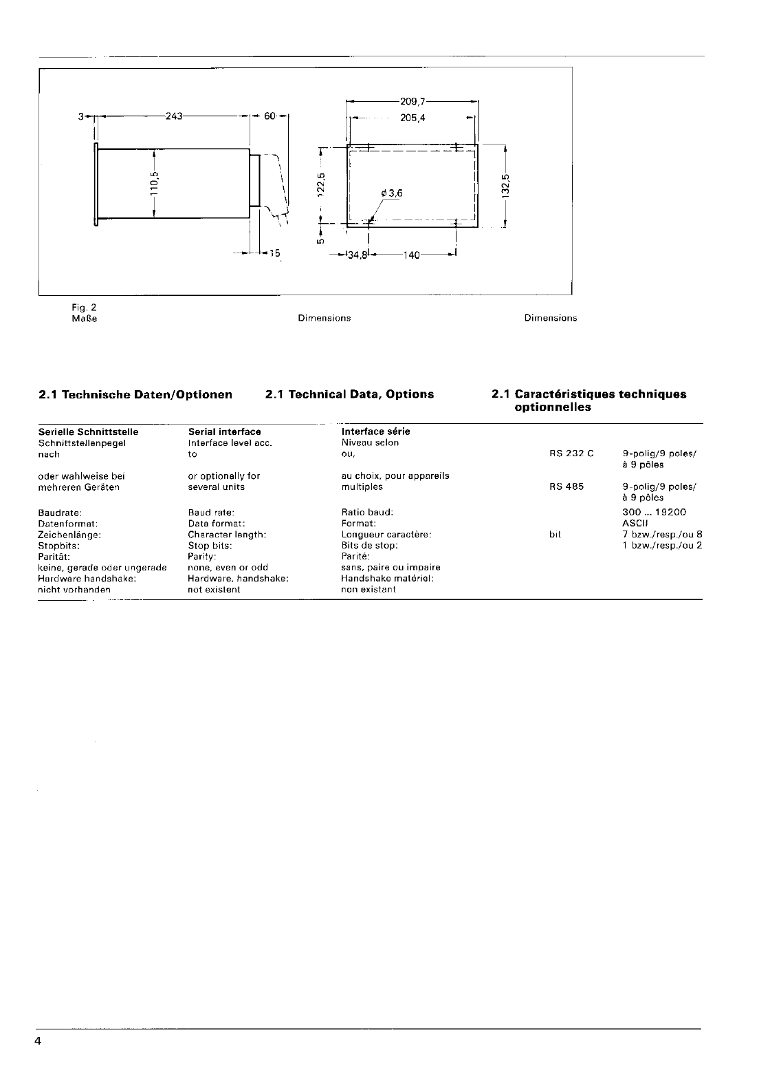
Fig.2
1
6
T
243 T
6O
-
-,
\
\
\
\
. . 205,4
r
r-=--------1=,
I
N
N
"3,6
/
L
-1
---
----.ct--
I I
--134,81-..--140-------1
Dimensions
2.1
Technische
Daten/Optionen
2.1
Technical
Data,
Options
Serielle
Schnittstelle
Sch
nittstellenpegel
nach
oder
wahlweise
bei
mehreren
Geraten
Baudrate:
Datenformat:
Zeichenlange:
Stopbits:
Paritat:
keine, gerade oder ungerade
Hardware handshake:
nicht
vorhanden
4
Serial interface
Interface
level acc.
to
or
optionally
for
several
units
Baud rate:
Data
format:
Character
length:
Stop
bits:
Parity:
none,
even
or
odd
Hardware,
handshake:
not
existent
Interface
serie
Niveau
selon
OU,
au
choix,
pour
appareils
multiples
Ratio
baud:
Format:
Longueur
caractere:
Bits
de
stop:
Parite:
sans,
paire
ou
impaire
Handshake
materiel:
non
existant
1
N'
'"
J
Dimensions
2.1
Caracteristiqu8s
techniques
optionnelles
RS
232
C
RS
485
bit
9-poligj9
poles/
a 9
poles
9-polig/9
poles/
a 9 pOles
300
...
19200
ASCII
7
bzw./resp./ou
8
1
bzw./resp./ou
2
3 Einsatzarten 3 Types
of
Application 3 Utilisations possibles
3.'
Einsatz
ohne
Pumpstand-
3.1
Application
without
Pumping
3.1
Utilisation
sans
commands
de
steuerung
Unit
Control
groupe
de
pompage
Als
Antriebselektronik
nach
Schaltplan
As an
electronic
drive
unit
as
per
wir-
Commande
electronique
cablee selon
PM
021949
-S: ing
diagram
PM 021
949
-S:
Ie
schema
de
connexions
Es
k6nnen The
following:
PM 021
949
-S:
-Heizung -
Heater
-
Chaufferette,
-
Luftkuhlung
und
-
Air
cooling,
and -
Refroidissement
par
air
et
-
Flutventil
TSF
012
direkt
am TCP
380
-
Venting
valve TSF
012
can be
con-
-Vanne de
remise
a
rair
TSF
012
peu-
angeschlossen
werden.
nected
directly
to
the
TCP
380.
vent
etre raccordes
directement
sur
la
-Der
AnschluB
einer
Vorvakuumpumpe
-
Connection
of
a
backing
pump
and a TCP
380.
und
eines
Ventilsteuergerates,
sowie
valve
control
unit, and
their
interlock-
-
Le
raccordement
d'une
pompe
pri-
deren
Verriegelung
mit
der
Turbo-
ing
with
the
turbo
pump
are
not
poss-
maire
et
d'un
appareil
de
commande
pumpe
ist
nicht
m6glich.
ible.
des
vannes, y
compris
leur
verrouillage
-Einsatzart 3.1
muB
auf
Ausnahmen
Type
of
application
3.1
must
be res- avec
la
pompe
turbomohkulaire,
n'est
beschrankt
bleiben.
Durch
die
fehlende
tricted
to
exceptional
cases. Due
to
the
pas possible.
Verriegelung
kann die
Turbopumpe
missing
interlock,
the
turbo
pump
may
-
Ce
genre
d'utilisation
3.1 ne
do
it
etre
durch
Betriebsmitteldampfe
verunrei-
be
contaminated
by
operating
medium
qu'occasionnel
et
se
limiter
a
quelques
nigt
werden.
vapors. rares
exceptions:
par
suite
de
I'ab-
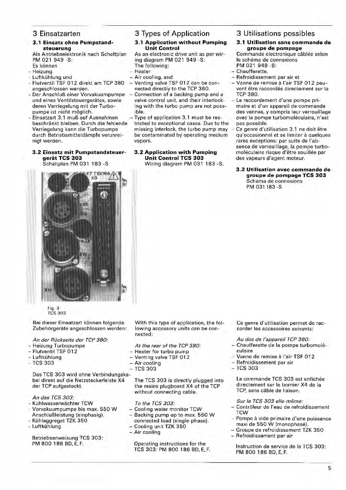
3.2
Einsatz
mit
Pumpstandsteuer-
geriit
TCS
303
Schaltplan
PM 031
183-S
Fig.3
TCS
303
Bei
dieser
Einsatzart
kbnnen
folgende
Zubehbrgerate
angeschlossen
werden:
An
der
Ruckseite
der
rep
380:
-Heizung
Turbopumpe
-
Flutventil
TSF
012
-
Luftkuhlung
-TCS
303
3.2
Application
with
Pumping
Unit
Control
TCS
303
Wiring
diagram
PM
031
183
-So
With
this
type
of
application,
the
fol-
lowing
accessory
units
can be
con-
nected:
At
the
rear
of
the
rep
380:
-
Heater
for
turbo
pump
-
Venting
valve TSF
012
-
Air
cooling
-TCS
303
Das TCS
303
wird
ohne
Verbindungska-
bel
direkt
auf
die
Netzsteckerleiste
X4
der
lCP
aufgesteckt.
The TCS
303
is
directly
plugged
into
the
mains
plugboard
X4
of
the
TCP
without
connecting
cable.
An
das
res
303:
-
Kuhlwasserwachter
TCW
-
Vorvakuumpumpe
bis max.
550
W
AnschluBleistung
(einphasig).
-
Kuhlaggregat
TZK
350
-
Luftkuhlung
Betriebsanweisung
TCS
303:
PM
800
186
BD,
E,
F.
ro
the
res
303:
-
Cooling
water
monitor
TCW
-Backing
pump
up
to
max.
550
W
connected
load
(single-phase).
-
Cooling
unit
lZK
350
-
Air
cooling
Operating
instructions
for
the
lCS
303:
PM
800
186
BD,
E,
F.
sence de
verrouillage,
la
pompe
turbo-
moleculaire
risque
d'etre
souillee
par
des vapeurs
d'agent
moteur.
3.2
Utilisation
avec
com
man
de
de
groupe
de
pompage
TCS
303
Schema
de
connexions
PM
031183-S
Ce
genre
d'utilisation
permet
de rac-
corder
les accessoires
suivants:
Au
dos
de
i'appareil
rep
380:
-
Chaufferette
de la
pompe
turbomole-
culaire
-Vanne de remise a
I'air
TSF
012
-
Refroidissement
par
air
-
lCS
303
La
commande
TCS
303
est
enfichee
directement
sur
Ie
bornier
X4
de
la
TCP,
sans
dlble
de liaison.
Sur
la
res
303
elle-meme:
-
Controleur
de I'eau de
refroidissement
TCW
-Pompe a
vide
primaire
d'une
puissance
maxi de
550
W
(monophase).
-
Groupe
de
refroidissement
TZK
350
-
Refroidissement
par
air
Instruction
de service de
la
TCS
303:
PM
800
186
BD,
E,
F.
5
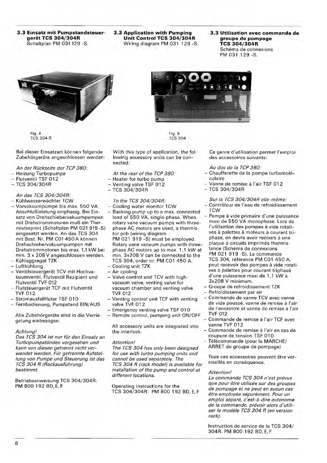
3.3
Einsatz
mit
Pumpstandsteuer-
geriit
TCS
304/304R
SchaUplan PM
031129
-So
Fig. 4
T
CS
304
R
Bei
dieser
Einsatzart kbnnen
folgende
Zubehbrgerate
angeschl
oss
en
werden:
An
der Ruckseite
der
rep
380:
-
Heizung
Turbopumpe
-Flutv
entil
TSF
012
-TCS
304
/
304R
An
das
res
304/304R
:
-
KOhlwasserwachter
TCW
-
Vorv
a
kuumpumpe
bis
max
.
550
VA
Anschluf5leistung
einphasig
. Bei Ein-
satz von
Drehschiebervakuumpumpen
mit
Drehstrommotoren
muP..
ein
Ther-
mi
s
torprint
(Schaltplan
PM 021 919
-S)
eing
ese
tzt
werden.
An
das
TeS
304
mit
Best. Nr. PM COl
45
0 A kannen
Dreh sc
hiebervakuumpumpen
mit
Dreh s
trommotoren
bis
max
.
1,1
kW
bei
min. 3 x
208
V
angeschlossen
werden.
-
Kuhlaggregat
TZK
-
Luftkuhlung
-
Ventil
s
teuergerat
leV
mit
Ho
c
hva-
kuumventil.
Flutventil
Re
z
ipient
und
Flutve
ntil
TVF 012
-
Flutsteuergerat
TCF
mit
Flutventil
TVF
012
-
Stromausfallfluter
TSF 01 0
-Fernbe
dienung,
Pump
st and
EIN/AUS
Aile
Zub
e
h6rgerate
sind in
die
Verrie-
ge
lun9
einbezogen.
Achtung
l
Das
TeS
304
ist
nur
filr
den Einsatz an
Turbopumpstanden
vor
gesehen
und
kann von diesen
getrennl
ni
c
ht
ver-
wendet
werden.
Fur
getrennte
Aufstel-
lung
von
Pumpe
und
Steu
er
ung
ist
das
r
es
304
R (Rackausfuhrung)
bestimmt
.
Betrieb
s
anweisung
TCS
304
/
304R:
PM
800
192
BD, E, F
6
3,3
Application
with
Pumping
Unit
Control
TCS
304/304R
Wiring
diagram
PM 031
129
-So
Fi
g . 5
'
rc
s
30
4
With
thi s
type
of
application.
the
fol-
lowing
accessory
units
C(;ln
be
con-
nected:
At
the rear
of
the
rep
380
:
- He
ater
for
turbo
pump
-
Venting
valve
lSF
012
-
lCS
304
/
304R
ro
th
e
res
304/304R:
-
Cooling
water
monitor
TCW
3.3
Utilisation
avec
commande
de
groupe
de
pompage
TCS
304/304R
Schema
de
connexion
s
PM
031
129
-5.
Ce
genre
d'utilisation
permet
I'emploi
des access oires
suivants:
Au
dos de la
rep
380:
-
Chautferette
de la
pompa
culair
e
-Vanne
de
re
mise
a I'air TSF
012
-TCS
304
/
304R
Sur
la
res
304/304R
ell
e-me
me:
-Contr61 e
ur
de I'eau de
refroidissement
TCW
-Backing
pump
up
to
a ma
x.
connected
load
of
550
VA,
single-phase
.
When
-Pompe a vide
primaire
d'une
pui ss ance
rotary
vane
vacuum
pumps
w
ith
three-
maxi
de
550
VA
monopha
se. Lars de
phase AC
motors
are used, a
thermis-
I'utilisation
des
pam
pes
a
vide
rotati-
tor pcb
(wiring
diagram
ves it
palette
s it
moteurs
it c
ourant
tri
-
PM 021
919
-S)
must
be
empl
oyed. ph a
se
, on devra
avoir
reco
ur
s a
une
Rotary vane
vacuum
pump
s
with
three-
plaqu
e
iI
Circuits
imprimes
th
e
rmi
s-
ph as e AC
motors
up
to ma x.
1.1
kW
at
tance
(Schema de
connexions
min
.
3x
2
08
V can be conn e
ct
ed
to
the
PM 021
919
-S).
La
commande
TCS
304,
order
nr. PM COl 4
50
A. TCS
304
, reference PM COl
450
A,
_
Cooling
unit
TZK pe
ut
recev
oir
des
pam
pes a
vide
rotati-
_
Air
coo
ling
ves it
palettes
pour
courant
tri
phase
_ Valve
control
unit
leV
with
high
- d'
une
pui
ss
ance
maxi
de
1,1
kWa
va
cuum
valv
e,
venting
valve
for
3
x2
08
V
minimum.
v
acuum
chamber
and venti
ng
va
lve -
Groupe
de
refroidissement
TZ
K
TVF 012 -
Refroidi
ss
ement
par
air
-
Venting
c
ontrol
unit
TCF
with
venting
-
Comm
ande de vanne TCV avec vanne
valve TVF
012
de vide pousse, vanne de remise a
I'air
_
Em
erg ency
venting
valve TSF
01
0 de I'enc
eintre
et
vanne de re
mi
se
a
I'air
-Rem ote co ntrol,
pumping
unit
ON
/
OFF
TVF 012
All
acces
sory
units
are
integrated
into
the
interlock
.
Attent
i
on!
rhe
r e s
304
has
only
been designed
for
use
with
turbo
pumping
units
and
cannot
be
used
separately
. The
res
304
R (rack model)
is
a
va
ilable
for
installation
of the
pump
and
co n
trol
at
differ
e
nt
lo
cations.
Oper
a
ting
instructions
for
the
TCS
304
/
304R:
PM
800
192
BD,
E,
F
-
Commande
de remise a
I'air
TeF
avec
vanne TVF
012
-
Comm
a
nd
e
de
remise
a I'a
ir
en ca s
de
coupure
de
tension
TSF
010
-Telec
ommande
(pour
10
MARCHE/
ARRET du
groupe
de
pomp
a
gel
Tous ces accessoires
peuvent
e
tr
e ver-
en consequence.
Attent
i
on
l
La co
mmande
TeS
304
n'
est
prevue
que
pour
e
tre
utilisee
sur
des
groupes
de
p o
mpsge
et
ne
peut
en aucun cas
eIre
empl
oyee separement. Po
ur
un
emploi
separe,
c'est-a-dire
autonome
de
la
commande,
pre
voir
alors
d'utili
-
ser
Ie
m o
dele
TeS
304
R (en vers
ion
rack).
Instruction
de
service
de
la TCS
304
/
304R
: PM
800
192
BD,
E,
F
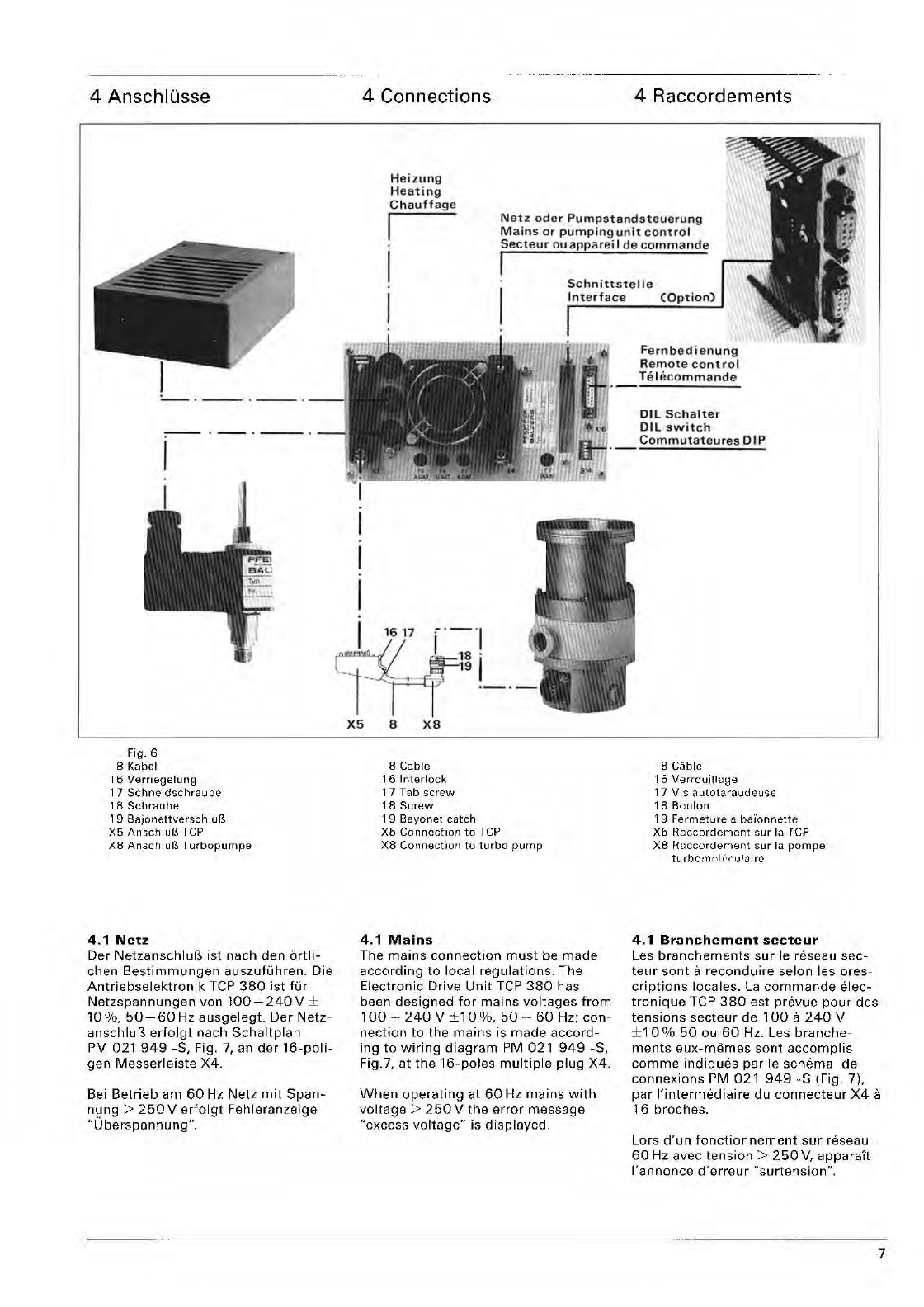
4 AnschlOsse
Fig.6
8 Kabel
16
Verriegelung
17
Schneidschraube
, 8
Schraube
19
X5
AnschluP., TCP
X8
Anschlur.!.
Turbopumpe
4.1
Net.
Der
NetzanschluB
ist
nach
den
ortli-
chen
Bestimmungen
auszufuhren.
Die
Antriebselektronik
Tep
380
ist
fUr
Netzspannungen
von
100-240V
±
10%.50-60
Hz
ausgelegt.
Der
Netz-
anschluB
erfolgt
nach
Schaltplan
PM
021
949
oS,
Fig.
7,
an
der
16-poli-
geo
Messerleiste
X4.
Bei
Betrieb
am
60
Hz
Netz
mit
Span-
nung
>
250
V
erfolgt
Fehleranzeige
"Uberspannung".
4
Connections
H
eizung
H
ea
ting
Chauffage
4
Raccordements
I
Netz
ode
r
Pump
s
tand
steue
ru
ng
M
ains
or
pumping
unit
con
tr
o l
Secteur
ouappareil
de
commande
I
I
I I
Schnittste
ll e
Int
erface
X5
8
X8
8 Cable
16
Interlock
17
Tab
screw
18
Screw
1 9
Bayonet
catch
X5
Connection
to
TCP
X8
Connection
to
turbo
pump
4.1
Mains
The
mains
connection
must
be
made
according
to
local
regulations.
The
Electronic
Drive
Unit
TCP
380
has
been
designed
for
mains
voltages
from
100
-
240
V
±1
0 %,
50
-
60
Hz;
con-
nection
to
the
mains
is
made
accord-
ing
to
wiring
diagram
PM 021
949
-5,
Fig.7,
at
the
16-poles
multiple
plug
X4.
When
operating
at
60
Hz
mains
with
voltage>
250
V
the
error
message
"excess
voltage"
is
displayed.
F
er
nbedi
e
nung
R
emote
co
n t
rol
Te l
ecommande
Dll
Schalter
OIL
s
wit
c h
Commutateures
DIP
8
Cable
16
Verrouilluge
17
Vis aLitotaraudeuse
18
Boulon
19
Fermeture
a
bai'onnette
X5
Raccordement
sur
la TCP
X8
RuCGordement
sur
18
pompe
tLi
rbo
III
(\
11"c
Lila
i re
4.1
Branchement
secteur
Les
branchements
sur
Ie
reseau
sec-
teur
sont
a
reconduire
selon
les
pres-
criptions
locales.
La
commande
elec-
tronique
TCP
380
est
prevue
pour
des
tensions
secteur
de
100
a
240
V
±1
0 %
50
ou
60
Hz. Les
branche-
ments
eux-memes
sont
accomplis
comme
indiques
par
Ie
schema
de
connexions
PM 021
949
-5
(Fig.
7).
par
I'intermediaire
du
connecteur
X4
a
16
broches.
Lors
d'un
fonctionnement
sur
reseau
60
Hz avec
tension>
250
V,
apparalt
!'annonce
d'erreur
"surtension".
7
4.
1.
1
Be/egung
der
Netzsteckerleiste
X4:
a1
Netzphase
(L 1) bei
Direkteinspei-
sung
a2
Netzneutral
IN)
a3
Heizung
extern
a4
Hochlaufzeitsperre,
Hochlaufzeit-
liberwachung
ist
nicht
aktiv
solange
dieser
Eingang
mit
a5
(0
V)
verbun-
den
ist.
a5
Geratemasse,
0 V
a6
Stand-by
extern,
Stand-by
Betrieb
solange
dieser
Eingang
mit
a5
ver-
bunden
ist.
a7
42
V
Ausgang,
zur
Ansteuerung
des
Relais
im
TCS
303,
wird
im
Storungsfall
stromlos,
kurzschluB-
fest
durch
Kaltleiter.
a8
SchutzleiteranschluB
(PE)
bl
Schaltseite
Netzschalter
b2
Netzphase
IL
1) bei
Schalterbetrieb
b3
Schaltseite
Netzschalter
b4
Kontakt
Uberwachungsrelais
K2
b5
Gemeinsamer
AnschluB
der
Kon-
takte
von
Uberwachungs-
und
Schaltpunktrelais
Kl
und
K2
b6
Kontakt
Schaltpunktrelais
K1
b7
Uberwachung
Pumpstand,
nur
in
Verbindung
mit
TCS
303,
304
lie-
fert
die
Fehlerinformation
von
Klihl-
wasserwachter
und
Vorvakuum-
pumpe
an
die
TCP
380.
b8
Reset
extern,
Quittierung
eines
Fehlers.
4.
1.
1 Pin
Assignment
of
the
Mains
Connector
X4:
a1
Mains
phase
(L 1)
for
direct
supply
a2
Mains
neutral
(N)
a3
Heater,
external
a4
Run-up
time
lock,
run-up
time
monitoring
not
active
as
long
as
this
input
is
connected
to
a5
(0 V).
a5
Unit
ground,
0 V.
a6
Stand-by,
external;
stand-by
opera-
tion
as
long
as
this
input
is
con-
nected
to
a5.
a7
42
V
output,
to
control
the
relay
of
TCS
303,
is
currentless
during
an
error,
short-circuit
proof
due
to
PTC
resistor.
a8
Protective
earth
connection
(PE).
bl
Switching
side,
power
switch
b2
Mains
phase
(L 1)
for
switch
opera-
tion.
b3
Switching
side,
power
switch.
b4
Contact,
monitoring
relay K2
b5
Common
connection
of
the
con-
tacts
of
monitoring
and
switch-
point
relays
Kl
and K2.
b6
Contact.
switch-point
relay
Kl
b7
Pumping
unit
monitoring,
only
together
with
TCS
303, 304,
provi-
des
the
error
messages
from
the
cooling
water
monitor
and
backing
pump
to
the
TCP
380.
b8
Reset
external,
error
acknowledg-
ment.
4.1.1
Affectation
des
broches
du
connecteur
X4:
a1
Phase
secteur
(L 1), en
cas
d'ali-
mentation
directe.
a2
Neutre
IN).
a3
Chaufferette
externe.
a4
Retardeur
de
demarrage,
Ie
dispo-
sitif
de
surveillance
du
demarrage
n'etant
pas
actif
tant
que
cette
entree
est
reliee avec
a5
(OV).
a5
Masse
des
appareils,
av.
a6
Stand-by
externe,
fonctionnement
Stand-by
tant
que
cette
entree
est
reliee avec
a5.
a7
Sortie
42
V,
pour
I'asservissement
des
relais
de
la TCS
303,
est
placee
hors
courant
en cas
de
detaillance,
resiste
aux
court-
circuits
(circuit
PTC).
a8
Circuit
de
protection
(PE).
bl
Commutateur
secteur,
cote
inter-
rupteur.
b2
Phase
secteur
(L 1), en
fonctionne-
ment
avec
commutateur.
b3
Commutateur
secteur,
cote
inter-
rupteur.
b4
Contact
du
relais
de
surveillance
K2
b5
Broche
sommune
des
contacts
des
relais
de
surveillance
et
de
commu-
tation
de
regime
Kl
et
K2.
b6
Contact
du
relais
de
commutation
de
regime
Kl.
b7
Surveillance
du
groupe
de
pompa-
ge,
seulement
en
relation
avec la
commande
TCS
303
ou
304,
livre
it
la TCP
380
les
messages
d'erreur
du
controleur
de
I'eau
de
refroidisse-
ment
et
de
la
pompe
a
vide
primaire.
b8
Reset
externe,
acquittement
d'une
erreur
intervenue.
1 1
'1
"'e'"
I "
_
IA
B [ 0
[II
K L
f'
["
G N
..
I I I I I I
..---TI
I I I I I
XB
f-t-fl f f f f f
I-H-f-f
r r 8
I'--T-'
-f
I J'
X2
1 4 1
---P-M-0-31
0::':"
y"
y" y"
y,
y"
Y'l
X5
-
'"
J'
0
,
, <
, ,
'!
" j
, !
, 0
" " 0.', • "
,;
r
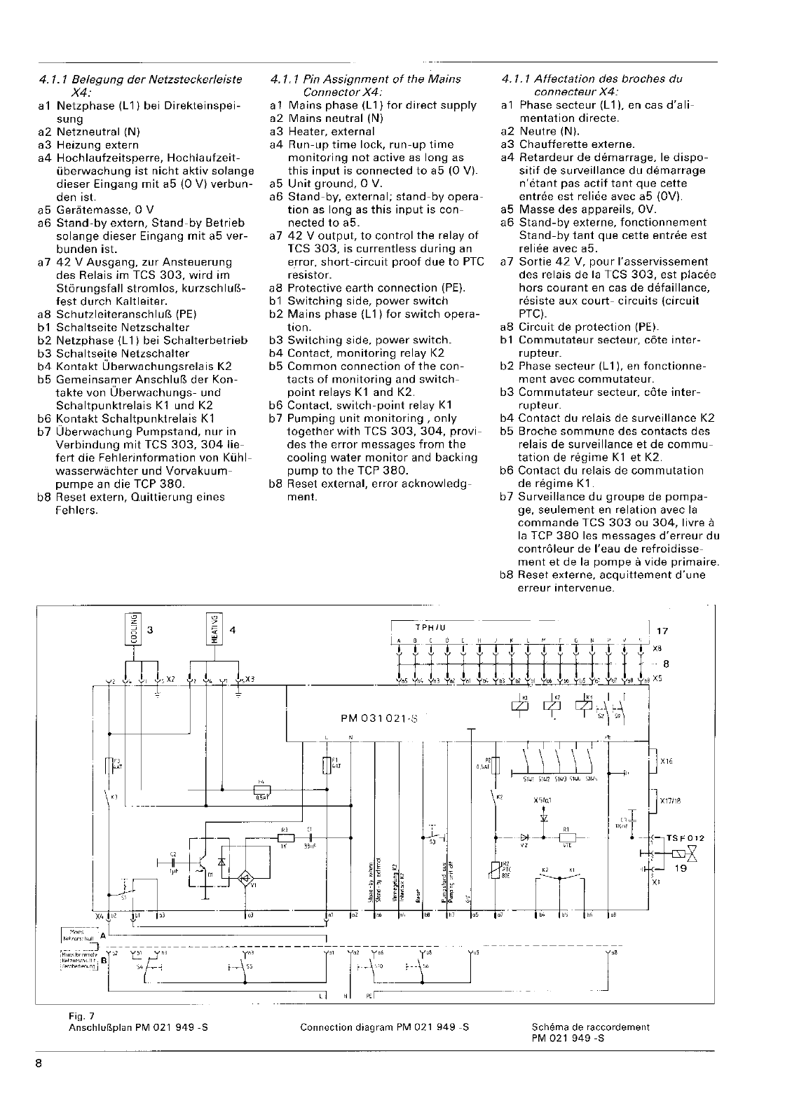
Fig.7
Anschluf1plan PM
021
949-S
Connection
diagram
PM
021
949
-S
8
XC,IUl
±
"'
w-l-c:::J-
Vl
"7E
r
Schema
de
raccordement
PM
021949-S
4.2
Turbopumpe
-
AnschluBkabel
8
beidseitig
mit
Steck-
verbindung;
maximale
Kabellange
100
m.
-
AnschluB
an
der
Tep
Steckverbindung
X5,
an
der
Turbopumpe
Steckverbin-
dung
X8.
Fig.
6.
-
Stecker
X5
und
Steckdose
X8
mussen
nach
dem
Einstecken
verriegelt
bzw.
vor
dem
Trennen
entriegelt
werden.
-
Verriegelung
X5:
Verriegelung
16
ein-
legen
und
mit
Schneidschraube
17
anschrauben.
-
Verriegelung
X8:
Nach
dem
Einrasten
des
Bajonettverschlusses
Schraube
18
leicht
anziehen.
-Die
Verriegelungsteile
werden
als
Bei-
pack
mitgeliefert.
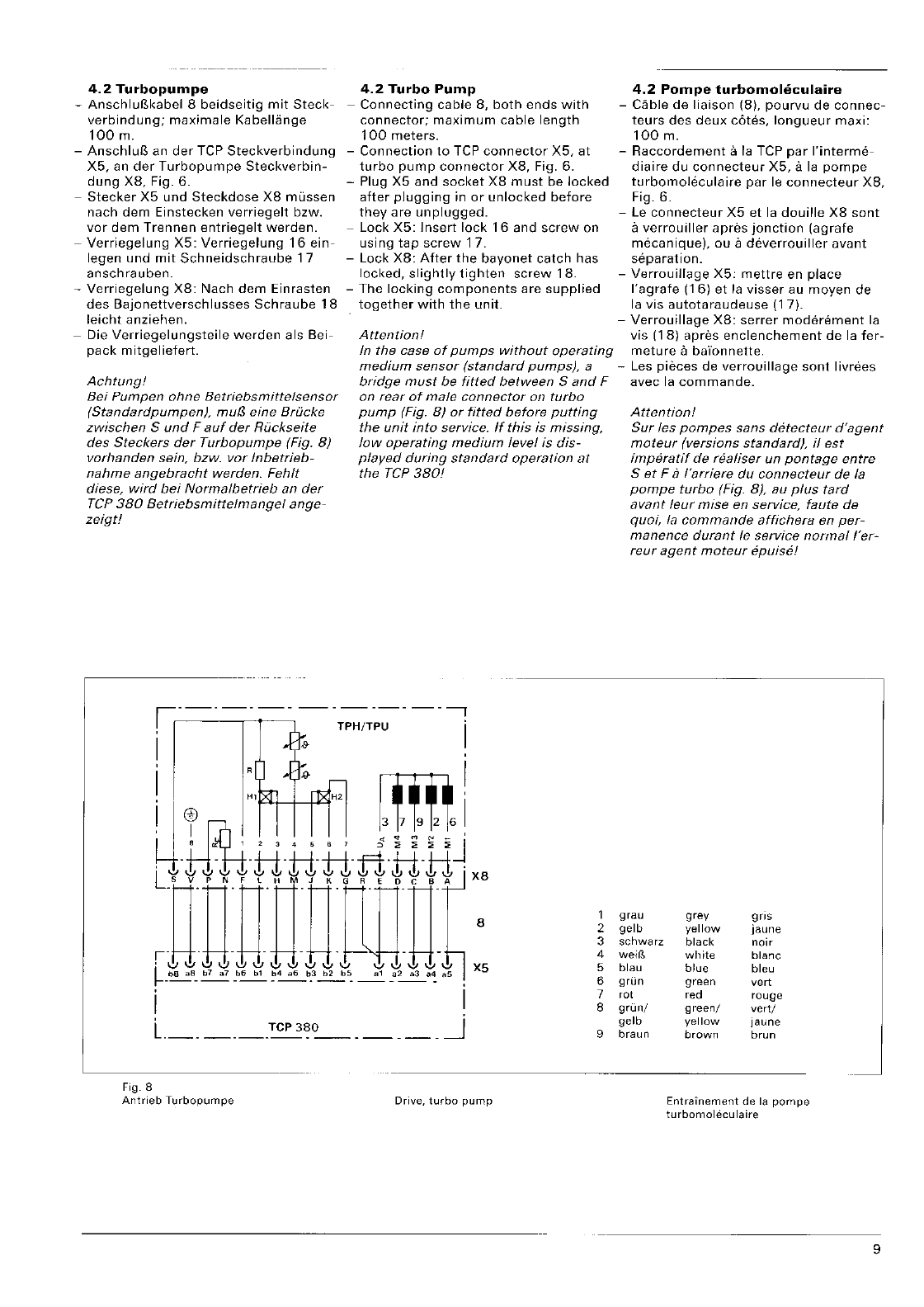
Achtung!
Be;
Pumpen
ohne
Betriebsmittelsensor
(Standardpumpen),
mu13
eine
Brucke
zwischen S
und
F
auf
der
RiJckseite
des
Steckers
der
Turbopumpe
(Fig.
8)
vorhanden sein, bzw. var Inbetrieb-
nahme
angebracht
werden.
Fehlt
diese,
wird
bei
Normalbetrieb
an
der
rep
380
Betriebsmittelmangel
ange-
zeigt!
4.2
Turbo
Pump
-
Connecting
cable
8,
both
ends
with
connector;
maximum
cable
length
100
meters.
-
Connection
to
TCP
connector
X5,
at
turbo
pump
connector
X8,
Fig.
6.
-Plug
X5
and
socket
X8
must
be
locked
after
plugging
in
or
unlocked
before
they
are
unplugged.
-
Lock
X5:
Insert
lock
16
and
screw
on
using
tap
screw
17.
-
Lock
X8:
After
the
bayonet
catch
has
locked,
slightly
tighten
screw
18.
-
The
locking
components
are
supplied
together
with
the
unit.
4.2
Pompe
turbomoleculaire
-
Cable
de
liaison
(8),
pourvu
de
connec-
teurs
des
deux
cotes,
longueur
maxi:
100
m.
-
Raccordement
a la TCP
par
I'interme-
diaire
du
connecteur
X5,
a la
pompe
turbomoJeculaire
par
Ie
connecteur
X8,
Fig.
6.
-Le
connecteur
X5
et
la
douille
X8
sont
a
verrouiller
apres
jonction
(agrafe
mecanique),
ou
a
deverrouiller
avant
separation.
-
Verrouillage
X5:
mettre
en
place
I'agrafe
(16)
et
la
visser
au
moyen
de
la vis
autotaraudeuse
(17).
-
Verrouillage
X8:
serrer
moderement
la
Attention!
vis
(18)
apres
enclenchement
de
la
fer-
In
the
case
of
pumps
without
operating
meture
a baYonnette.
medium
sensor
(standard
pumps),
a -Les
pieces
de
verrouillage
sont
livrees
bridge
must
be
fitted
between
Sand
F
avec
la
commande.
on
rear
of
male
connector
on
turbo
pump
(Fig.
8)
or
fitted
before
putting
the
unit
into
service.
If
this
;s
missing,
low
operating
medium
level
is
dis-
played
during
standard
operation
at
the
TCP
380!
Attention!
Sur
les
pompes
sans
dt§tecteur
d'agent
moteur
(versions
standard),
if
est
imperatif
de
realiser
un
pontage
entre
Set
Fa
I'arriere
du
connecteur
de
la
pompe
turbo
(Fig.
8),
au
plus
tard
avant
leur
mise
en
service,
faute
de
quoi,
fa
commande
affichera
en
per-
manence
durant
fe
service
normal
/'er-
reur
agent
moteur
epuise!
_._._._.,
TP H/TPU i
.j
, -l
1;,
-
"'
xr
15<
H'
@
I
X8
8 1
2
3
4
X5
5
6
7
8
9
Fig.8
Antrieb
Turbopumpe
Drive,
turbo
pump
grau
gelb
schwarz
blau
grun
cot
grun/
gelb
braun
grey
gns
yellow
jaune
black
noir
white
blanc
blue
bleu
green
vert
ced
rouge
green/
vert/
yellow
jaune
brown
brun
Entrainement
de
la
pompe
turbomoleculaire
9
4.3
luftklihlung
4.3
Air
Cooling
4.3
Refroidissement
par
air
-Bei den TPH/TPU
060,
180
H,
190,
-For
the
turbo-molecular
pumps
TPH/
-
Sur
les
pompes
turbomoleculaire
TPH/
240,450
H
und
520
die
Luftkuh-
TPU
060,
180
H,
190.240,450
Hand
TPU
060,
180
H.
190,240,
450
H
et
lung
gemiif3,
Netzspannung
ausgewahlt
520,
the
air
cooling
must
be selected
520,
il
convient
de
selectionner
refroi-
werden!
according
to
the
mains
voltage!
dissement
par
air en
fonction
de
la
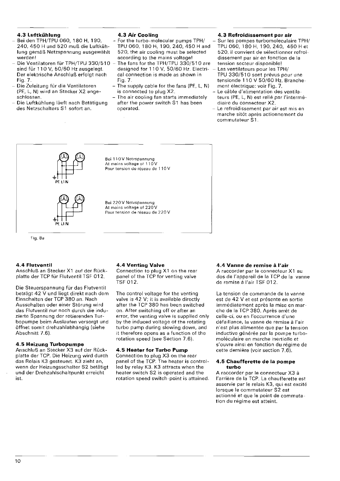
-Die
Ventilatoren
fur
TPH/TPU
330/510
-The fans
for
the
TPH/TPU
330/510
are
tension
secteur
disponible!
sind
fur
110
V,
50/60
Hz
ausgelegt.
designed
for
110
V,
50/60
Hz. Electri- -Les
ventilateurs
pour
les TPH/
Der
elektrische
AnschluB
erfolgt
nach cal
connection
is
made
as
shown
in TPU
330/510
sont
prevus
pour
une
Fig. 7. Fig. 7.
tensionde
110
V
50/60
Hz.
Branche-
-Die
Zuleitung
fur
die
Ventilatoren
-The
supply
cable
for
the
fans
(PE,
L,
N)
ment
electrique:
voir
Fig.
7.
(PE,
L,
N)
wird
an
Stecker
X2
ange-
is
connected
to
plug
X2.
-
Le
dible
d'alimentation
des
ventila-
schlossen. -The air
cooling
fan
starts
immediately
teurs
(PE,
L,
N)
est
relie
par
I'interme-
-Die
Luftkuhlung
lauft
nuch
Betatigung
after
the
power
switch
Sl
has been
diaire
du
connecteur
X2.
des
Netzschalters
Sl
sofort
an. operated. -
Le
refroidissement
par
air
est
mis
en
8ei
110V
Netzspannung
At
mains
voltage
ot
11
OV
Pour
tension
de
reseau
de
110
V
PE
llN
Bei
220V
Netzsrannung
At
mains
voltage
of
220
V
Pour
tension
de
res8<Ju
de
220
V
PE
II
N
Fig.8a
4.4
Flutventil
AnschluP.,
an
Stecker
Xl
auf
der
ROck-
platte
der
TCP
fur
Flulventil
TSF
012.
Die
Steuerspannung
fur
das
Flutventil
betragt
42
V
und
liegt
direkt
nach
dem
Einschalten
der
TCP
380
an. Nach
Ausschalten
oder
einer
Stbrung
wird
das
Flutventil
nur
noch
durch
die
indu-
zierte
Spannung
der
rotierenden
Tur-
bopumpe
beim
Auslaufen
versorgt
und
6ffnet
somit
drehzahlabhangig
(siehe
Abschnitt
7.6).
4.5
Heizung
Turbopumpe
AnschluB
an
Stecker
X3
auf
der
Ruck-
platte
der
TCP. Die Heizung
wird
durch
das Relais K3
gesteuert.
K3
zieht
an,
wenn
der
Heizungsschalter
S2
betatigt
und
der
Orehzahlschaltpunkt
erreicht
ist.
10
4.4
Venting
Valve
Connection
to
plug
X 1 on
the
rear
panel
of
the
TCP
for
venting
valve
TSF
012.
The
control
voltage
for
the
venting
valve is
42
V;
it
is available
directly
after
the
TCP
380
has been
switched
on.
After
switching
off
or
after
an
error,
the
venting
valve is
supplied
only
by
the
induced
voltage
of
the
rotating
turbo
pump
during
slowing
down,
and
it
therefore
opens
as a
function
of
the
rotation
speed (see
Section
7.6).
4.5
Heater
for
Turbo
Pump
Connection
to
plug
X3
on
the
rear
panel
of
the
TCP.
The
heater
is
control-
led
by
relay K3. K3
attracts
when
the
heater
switch
S2
is
operated
and
the
rotation
speed
switch-point
is attained.
marche
sit6t
apres
actionnement
du
commutateur
Sl.
4.4
Vanne
de
remise
a
I'air
A
raccorder
par
Ie
connecteur
Xl
au
dos
de
I'appareil
de
la
TCP de
la
vanne
de remise a
I'air
TSF
012.
La
tension
de
commande
de
la
vanne
est de
42
V
et
est presente en
sortie
immediatement
apres
la
mise en
mar-
che de
la
TCP
380.
Apres
arret
de
celle-ci,
ou en
I'occurrence
d'une
detaillance,
la
vanne de remise a
I'air
n'est
plus
alimentee
que
par
la
tension
inductive
g€mere8
par
la
pompe
turbo-
moleculaire
en
marche
inertielle
et
s'ouvre
ainsi
en
fonction
du
regime
de
cette
derniere
(voir
section
7.6).
4.5
Chaufferette
de
la
pompe
turbo
A
raccorder
par
Ie
connecteur
X3
a
I'arriere de
la
TCP.
La
chaufferette
est
asservie
par
Ie
relais K3,
qui
est excite
lorsque
Ie
commutateur
52
est
actionne
et
que
Ie
point
de
commuta-
tion
du
regime
est
atteint.
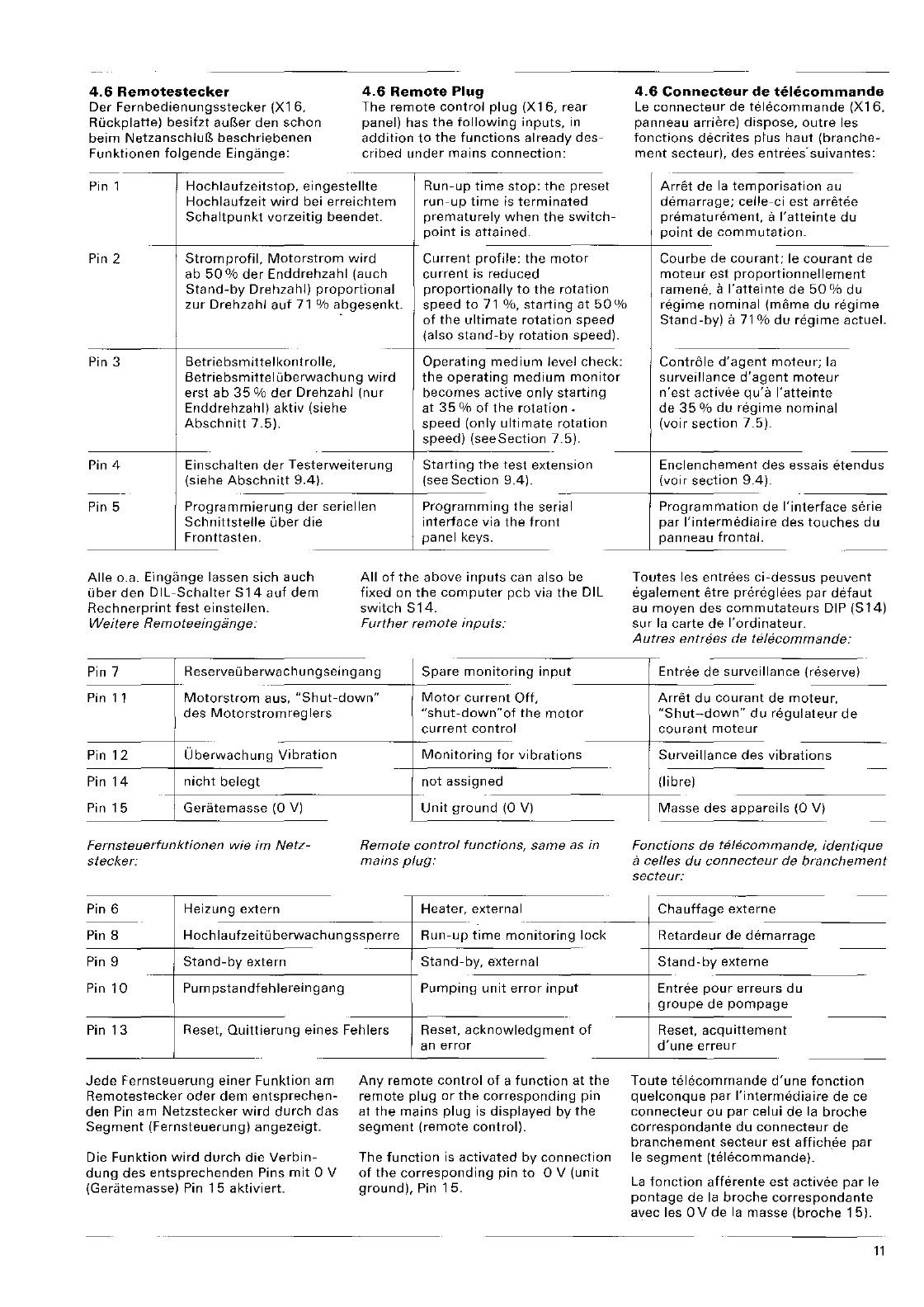
4.6
Remotestecker
Der
Fernbedienungsstecker
(X16,
Ruckplatte)
besitzt
auBer
den
schon
beim
NetzanschluB
beschriebenen
Funktionen
folgende
Eingange:
4.6
Remote
Plug
The
remote
control
plug
(X
16,
rear
panel) has
the
following
inputs,
in
addition
to
the
functions
already
des-
cribed
under
mains
connection:
Pin 1
Hochlaufzeitstop,
eingestellte
Run-up
time
stop:
the
preset
Hochlaufzeit
wird
bei
erreichtem
run-up
time
is
terminated
4.6
Connecteur
de
telecommande
Le
connecteur
de
telecommande
(X16,
panneau
arriere)
dispose,
outre
les
fonctions
decrites
ptus
haut
(branche-
ment
secteur),
des
entrees'suivantes:
Schaltpunkt
vorzeitig
beendet.
prematurely
when
the
switch-
Arret
de
la
ternporisation
au
demarrage;
celle-ci
est
arretee
prematurement,
a
I'atteinte
du
point
de
commutation.
Pin 2
Stromprofil,
Motorstrom
wird
ab
50%
der
Enddrehzahl
(auch
Stand-by
Drehzahl)
proportional
zur
Drehzahl
auf
71 %
abgesenkt.
point
is
attained.
Current
profile:
the
motor
current
is
reduced
proportionally
to
the
rotation
speed
to
71
%,
starting
at
50
-----
Courbe
de
courant;
Ie
courant
de
rnoteur
est
proportionnellement
ramene,
a
I'atteinte
de
50
%
du
of
the
ultimate
rotation
speed
%
regime
nominal
(merne
du
regime
Stand-bY)
a
71
%
du
regime
actuel.
(also
stand-by
rotation
speed)
Pin 3
Betriebsmittelkontrolle,
Operating
medium
level
chec
Betriebsmitteluberwachung
wird
the
operating
medium
manito
k:
Controle
d'agent
moteur;
la
surveillance
d'agent
moteur
n'est
activee
qu'a
I'atteinte
de
35
%
du
regime
nominal
(voir
section
7.5).
erst
ab
35
%
der
Drehzahl
(nur
becomes
active
only
starting
Enddrehzahl)
aktiv
(siehe
at
35
%
of
the
rotation.
Abschnitt
7.5).
speed
(only
ultimate
rotation
speed)
(see
Section
7.5).
Pin 4
Einschalten
der
Testerweiterung
Starting
the
test
extension
(siehe
Abschnitt
9.4).
(see
Section
9.4).
---
Pin 5
Programmierung
der
seriellen
Programming
the
serial
Schnittstelle
uber
die
Fronttasten.
Aile
o.a.
Eingange
lassen
sich
auch
Ober
den
OIL-Schalter
S14
auf
dem
Rechnerprint
fest
einstellen.
Weitere
Remoteeingange:
interface
via
the
front
panel
keys.
All
of
the
above
inputs
can
also
be
fixed
on
the
computer
pcb
via
the
OIL
switch
S14.
Further
remote
inputs:
Pin 7 R ese rve 0 be rwa c
hun
9 sei n 9 a n 9
Spare
monitoring
input
Pin
11
Motorstrom
aus,
"Shut-down"
Motor
current
Off,
des
Motorstromreglers
Pin
12
Uberwachung
Vibration
Pin
14
nicht
belegt
Pin
15
Geratemasse
(0
V)
Fernsteuerfunktionen wie im
Netz-
stecker:
"shut-down"of
the
motor
current
control
Monitoring
for
vibrations
not
assigned
Unit
ground
(0 V)
Remote
control functions,
same
as
in
mains
plug:
Enclenchement
des
essais
etendus
(voir
section
9.4).
Programmation
de
I'interface
serie
par
I'intermediaire
des
touches
du
panneau
frontal.
Toutes
les
entrees
ci-dessus
peuvent
egalement
etre
prereglees
par
detaut
au
moyen
des
cornmutateurs
DIP
(S
14)
sur
la
carte
de
I'ordinateur.
Autres
entrees
de
telecommande:
Entree
de
surveillance
(reserve)
Arret
du
courant
de
moteur,
"Shut-down"
du
regulateur
de
courant
moteur
Surveillance
des
vibrations
(libre)
Masse
des
appareils
(0
V)
Fonctions
de
telecommande,
identique
a celles
du
connecteur
de
branchement
secteur:
Pin 6
Heizung
extern
Heater,
external
Chauffage
externe
----------
Pin 8
Hoc
h la
ufze
itu
berwa
c
hun
9 sspe rre
Run-up
time
monitoring
loc
k
Retardeur
de
demarrage
Pin 9
Stand-by
extern
Stand-by,
e·xternal
Stand-byexterne
-------------
Pin
10
Pum
pstandfehlereingang
Pumping
unit
error
input
Pin
13
Reset,
Quittierung
eines
Fehlers Reset,
acknowledgment
of
Jede
Fernsteuerung
einer
Funktion
am
Remotestecker
oder
dem
entsprechen-
den Pin
am
Netzstecker
wird
durch
das
Segment
(Fernsteuerung)
angezeigt.
Die
Funktion
wird
durch
die
Verbin-
dung
des
entsprechenden
Pins
mit
0 V
(Gen3.temasse) Pin
15
aktiviert.
an
error
Any
remote
control
of
a
function
at
the
remote
plug
or
the
corresponding
pin
at
the
mains
plug
is
displayed
by
the
segment
(remote
control).
The
function
is
activated
by
connection
of
the
corresponding
pin
to
0 V
(unit
ground).
Pin
15.
Entree
pour
erreurs
du
groupe
de
pompage
Reset,
acquittement
d'une
erreur
Toute
telecommande
d'une
fonction
quelconque
par
I'intermediaire
de
ce
connecteur
ou
par
celui
de
la
broche
correspondante
du
connecteur
de
branchement
secteur
est
affich.ee par
Ie
segment
(telecommande).
La
fonction
afferente
est
activee
par
Ie
pontage
de
la
broche
correspondante
avec les
OV
de
la
masse
(broche
15).
11
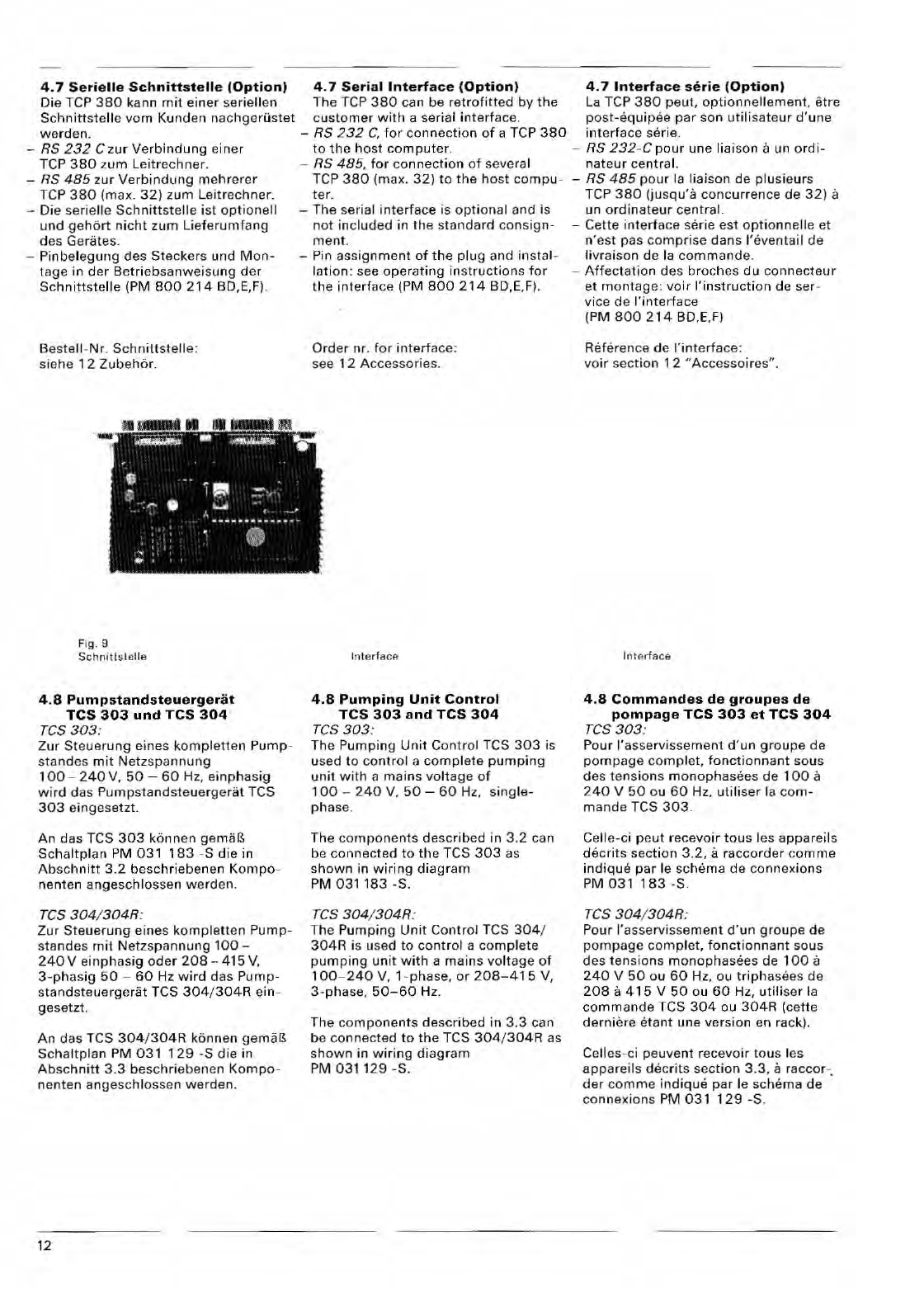
4.7
Serielle
Schnittstelle
IOptionl
4.7
Serial
Interface
IOptionl
4.7
Interface
serie
IOptionl
Die
Tep
380
kann
mit
einer
seriellen
The
rep
380
can be
retrofitted
by
the
La
Tep
380
peut,
optionnellement.
etre
Schnittstelle
vom
Kunden nachgerOstet
customer
with
a serial
interf
ace. post-equ
ip
ee
par
son
utilisateur
d'une
werden.
-
RS
232
C,
for
connection
of
a
rep
380
interfa
ce serie.
-
RS
232
Czur
Verbindung
a
iner
to
the
host
computer.
-
RS
232
-
Cpour
une
liaison
a un
ordi-
Tep
380
zu
rn
Leitrechner
. -
RS
485.
for
connection
of
several
nateur
central.
-
RS
48
5
lur
Verbindung
mehrerer
Tep
380
(max.
32)
to
the
host
compu-
-
RS
485
pour
la
liaison
de
plusieurs
Tep
380
(max.
32)
zurn
Leitr
ec
hner.
ter.
Tep
380
(jusqu'a
concurrence
de
32)
a
-
Die
sari elle
Schnittstelle
i
st
optionell
-
The
serial
interface
is
optional
and
is un
ordinateur
central.
und
geh6rt
nicht
zurn
Lieferumfang
not
included
in
the
s
tandard
consign-
-
Cette
interfa
ce
se
rie
est
optionnelle
et
des
Gerates.
ment
. n
'est
pas
comprise
dans
I'e
venta
il
de
-
Pinbelegung
des
Steck
ers
und
Mon-
-Pin
assignme
nt
of
the
plug
and
instal-
livrais
on de la
commande.
tage
in
der
Betriebsanwei
su
ng
der
lation
: see
operating
instruction
s
for
-
Affectati
on
des
broches
du
connecteur
Schnittstelle
(PM
800
214
BD,E,F).
the
interf
ace (PM
800
214
BD,E,F). et
mont
age:
voir
I'instruction
de
se r-
vice
de
I'int
er
face
Bestell
-Nr.
Schnittstelle
:
sie
he
1 2
Zubehor.
Fig . 9
Schn
itl
sl c
ll
e
4.8
Pumpstandsteuergerat
TCS
303
und
TCS
304
res
303:
Zur
Steuerung
eines
kompletlen
Pump-
sta
nd
es
mit
Netzspannung
100
-
240
V,
50
-
60
Hz
,
einph.sig
wird
das
Pumpstandsleuergerat
TCS
303
eingesetzt.
An
d.s
TCS
303
kenn
en
Schaltplan
PM
031
183
-S
die
in
Abschnitt
3.2
beschriebenen
Kompo-
nenlen
angeschlossen
werden.
res
304
/
304R:
Zur
Steuerung
eines
komplett
en
Pump-
slandes
mit
Netzspannung
100-
240Veinphasig
oder
208-415V,
3-phasig
50
-
60
Hz
wird
das
Pump·
standsteuergeriit
TCS
304/304R
ein-
gesetzl.
An
das
TCS
304/304R
kennan
Schallplan
PM
031
129
·S
die
in
Ab
sc
hnitt
3.3
beschri
ebe
nen
Kompo-
nenten
angeschlossen
werden.
12
Order
nr
.
for
interface
:
see
12
Accessories.
Int
e
rfa
ce
4.8
Pumping
Unit
Control
TCS
303
and
TCS
304
res
303:
The
Pumping
Unit
Contr
ol TCS
303
is
used
to
contro
l a
complete
pumping
unit
wit
h a
mains
voltage
of
100
-
240
V,
50
-
60
Hz.
s
ingle-
ph
ase .
The
compone
nts
describ
ed in
3.2
can
be
connected
to
the
TCS
303
as
shown
in
wiring
diagram
PM
031183
·S.
res
304
/
304R:
The
Pumping
Unit
Cant
rot TCS
304
/
304R
is used
to
control
a
co
mplete
pumping
unit
with
a
mains
voltage
of
100
-
240
V,
1-phase,
or
208-41
5 V,
3·phase,
50-60
Hz.
The
compo
nents
described
in
3.3
can
be
connected
to
the
TCS
304
/
304R
as
shown
in
wiring
diagram
PM
031129
-So
(PM
800
214
BD,E,F)
Reference
de
!'interface
:
vo
ir
sectio
n
12
"Accesso
ire
s" .
I
nt
Ar f
ace
4.8
Commandes
de
groupes
de
pompage
TCS
303
et
TCS
304
res
303:
Pour
I'asservissement
d'un
groupe
de
pompage
co
mplet
,
fonctionnant
sous
de
s t ens
ion
s
monophasee
s
de
100
a
240
V
50
au
60
Hz
,
utiliser
la
co
m-
mand
e TCS
303.
Celle-ci
peut
recevoir
taus
les
appareils
decrits
section
3.2,
a
raccorder
com
me
indique
par
Ie
schema
de
connexions
PM
031
183
-S.
res
304
/
304R:
Pour
I'as
serv
isse
ment
d'un
groupe
de
pompage
cam
plet,
fonctionnant
sous
des
ten
sions
monophasees
de
100
a
240
V
50
au
60
Hz,
au
triphasees
de
208
a
415
V
50
au
60
Hz,
utiliser
la
comm
ande
TCS
304
au
304R
(cette
dernier
e e
tant
une
version
en rack).
Celles-ci
peuvent
recev
o ir
tous
l
es
appareils
decrits
section
3.3,
a
raecor
-,
der
co
mme
indique
par
Ie
schema
de
connexions
PM
031
129
-S.
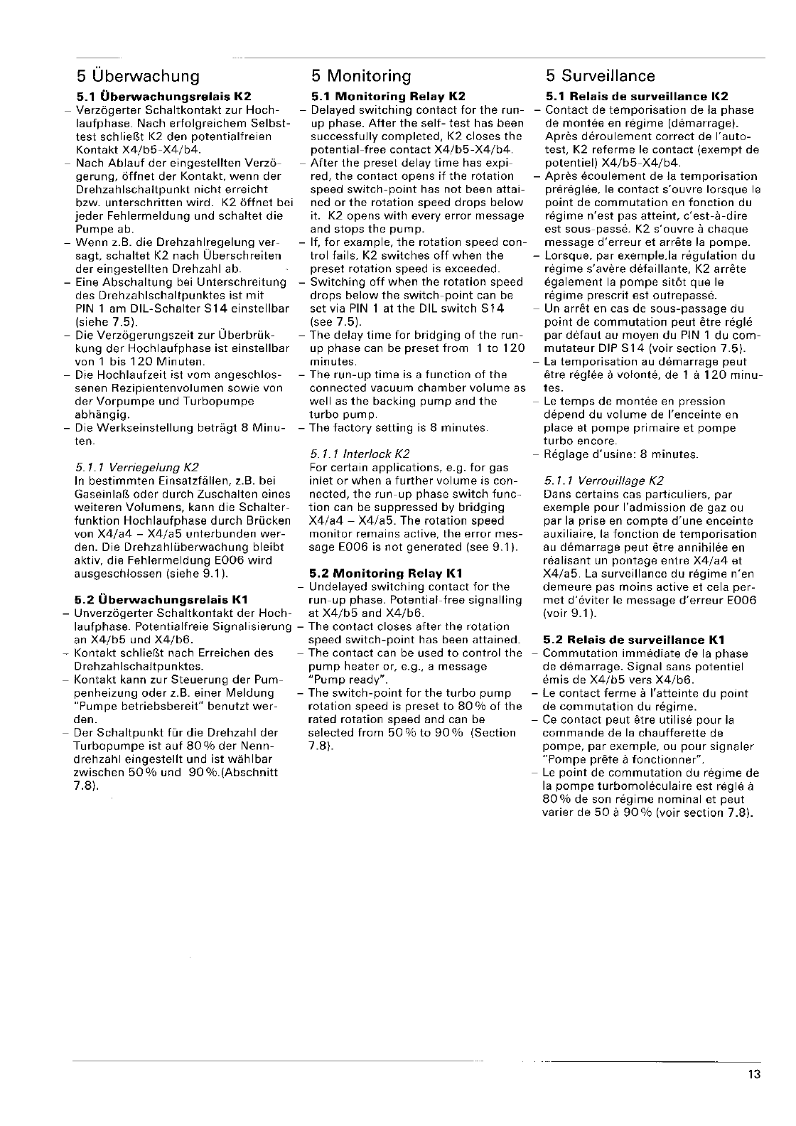
5
Uberwachung
5.1
Uberwachungsrelais
K2
-
Verzbgerter
Schaltkontakt
zur
Hoch-
laufphase.
Nach
erfolgreichem
Selbst-
test
schliefSt K2
den
potentialfreien
Kontakt
X4/b5-X4/b4.
-
Nach
Ablauf
der
eingestellten
Verz6-
gerung,
affnet
der
Kontakt,
wenn
der
Drehzahlschaltpunkt
nicht
erreicht
bzw.
unterschritten
wird.
K2
affnet
bei
jeder
Fehlermeldung
und
schaltet
die
Pumpe
abo
-
Wenn
z.B.
die
Drehzahlregelung
ver-
sagt,
schaltet
K2
nach
Oberschreiten
der
eingestellten
Drehzahl
abo
-Eine
Abschaltung
bei
Unterschreitung
des
Drehzahlschaltpunktes
ist
mit
PIN
1
am
DIL-Schaller
S14
einslellbar
(siehe
7.5).
-Die
Verzogerungszeit
zur
Uberbrlik-
kung
der
Hochlaufphase
ist
einstellbar
von
1
bis
120
Minuten.
-Die
Hochlaufzeit
ist
vom
angeschlos-
senen
Rezipientenvolumen
sowie
von
der
Vorpumpe
und
Turbopumpe
abhangig.
-Die
Werkseinstellung
betragt
8
Minu-
ten.
5.
1.
1 Verriegelung K2
In
bestimmten
Einsatzfallen, z.B. bei
GaseinlaB
oder
durch
Zuschalten
eines
weiteren
Volumens,
kann
die
Schalter-
funktion
Hochlaufphase
durch
Brucken
von
X4/a4
-
X4/a5
unterbunden
wer-
den. Die
Drehzahlliberwachung
bleibt
aktiv,
die
Fehlermeldung
E006
wird
ausgeschlossen
(siehe
9.1).
5
Monitoring
5.1
Monitoring
Relay
K2
-Delayed
switching
contact
for
the
run-
up phase.
After
the
self-
test
has been
successfully
completed,
K2
closes
the
potential-free
contact
X4/b5-X4/b4.
-
After
the
preset
delay
time
has
expi-
red,
the
contact
opens
if
the
rotation
speed
switch-point
has
not
been
attai-
ned
or
the
rotation
speed
drops
below
it. K2
opens
with
every
error
message
and
stops
the
pump.
-If,
for
example,
the
rotation
speed
con-
trol
fails,
K2
switches
off
when
the
preset
rotation
speed is exceeded.
-
Switching
off
when
the
rotation
speed
drops
below
the
switch-point
can be
sel
via
PIN
1
al
the
DIL
switch
S
14
(see
7.5).
-The
delay
time
for
bridging
of
the
run-
up
phase
can be
preset
from
1
to
120
minutes.
-The
run-up
time
is a
function
of
the
connected
vacuum
chamber
volume
as
well
as
the
backing
pump
and
the
turbo
pump.
-The
factory
setting
is 8
minutes.
5.
1.
1 Interlock K2
For
certain
applications,
e.g.
for
gas
inlet
or
when
a
further
volume
is
con-
nected,
the
run-up
phase
switch
func-
tion
can be
suppressed
by
bridging
X4/a4
-
X4/a5.
The
rotation
speed
monitor
remains
active,
the
error
mes-
sage
E006
is
not
generated
(see
9.1).
5.2
Monitoring
Relay
1{1
-
Undelayed
switching
contact
for
the
5.2
Uberwachungsrelais
K1
run-up
phase.
Potential-free
signalling
-
Unverzogerler
Schallkonlakl
der
Hoch-
al
X4/b5
and
X4/b6.
laufphase.
Potentialfreie
Signalisierung
-The
contact
closes
after
the
rotation
an
X4/b5
und
X4/b6.
speed
switch-point
has been
attained.
-
Kontakt
schlieBt
nach Erreichen
des
-The
contact
can be used
to
control
the
Drehzahlschaltpunktes.
pump
heater
or, e.g., a
message
-
Kontakt
kann
zur
Steuerung
der
Pum-
"Pump
ready".
penheizung
oder
z.B.
einer
Meldung
-The
switch-point
for
the
turbo
pump
"Pumpe
betriebsbereit"
benutzt
wer-
rotation
speed is
preset
to
80
%
of
the
den.
rated
rotation
speed and can be
-Der
Schaltpunkt
fur
die
Drehzahl
der
selected
from
50
%
to
90
%
(Section
Turbopumpe
ist
auf
80
%
der
Nenn-
7.8).
drehzahl
eingestellt
und
ist
wahlbar
zwischen
50%
und
90%.(Abschnitt
7.8).
5 Surveillance
5.1
Relais
de
surveillance
1(2
-
Contact
de
temporisation
de
la
phase
de
mantee
en
regime
(demarrage).
Apres
deroulement
correct
de
I'auto-
test, K2
referme
Ie
contact
(exempt
de
potentiel)
X4/b5-X4/b4.
-
Apres
ecoulement
de
la
temporisation
prereglee,
Ie
contact
s'ouvre
lorsque
Ie
point
de
commutation
en
fonction
du
regime
n'est
pas
atteint,
c'est-a-dire
est
sous-passe.
K2
s'ouvre
a
chaque
message
d'erreur
et
arrete
la
pompeo
-
Lorsque,
par
exemple,la
regulation
du
regime
s'avere
detaillante,
K2
arrete
egalement
la
pompe
sit6t
que
Ie
regime
prescrit
est
outrepasse.
-Un
arret
en cas de
sous-passage
du
point
de
commutation
peut
etre
regh§
par
detaut
au
moyen
du
PIN 1
du
com-
mutateur
DIP
S14
(voir
section
7.5).
-
La
temporisation
au
demarrage
peut
etre
reg lee a
volonte,
de
1 it
120
minu-
tes.
-
Le
temps
de
montee
en
pression
depend
du
volume
de
I'enceinte
en
place
et
pompe
primaire
et
pompe
turbo
encore.
-Reglage
d'usine:
8
minutes.
5.
1.
1
Verrouillage
K2
Dans
certains
cas
particuliers,
par
exemple
pour
I'admission
de
gaz ou
par
la
prise
en
compte
d'une
enceinte
auxiliaire, la
fonction
de
temporisation
au
demarrage
peut
etre
annihilee
en
realisant
un
pontage
entre
X4/a4
et
X4/a5.
La
surveillance
du
regime
n'en
demeure
pas
mains
active
et cela
per-
met
d'eviter
Ie
message
d'erreur
E006
(voir
9.1).
5.2
Relais
de
surveillance
K1
-
Commutation
immediate
de
la
phase
de
demarrage.
Signal
sans
potentiel
emis
de
X4/b5
vers
X4/b6.
-Le
contact
ferme
a
I'atteinte
du
point
de
commutation
du
regime.
-
Ce
contact
peut
etre
utilise
pour
la
commande
de
la
chaufferette
de
pompe,
par
exemple,
ou
pour
signaler
"Pompe
prete
a
fonctionner".
-
Le
point
de
commutation
du
regime
de
la
pompe
turbomoleculaire
est regie a
80
%
de
son
regime
nominal
et
peut
varier
de
50
a
90
% (voir
section
7.8).
13
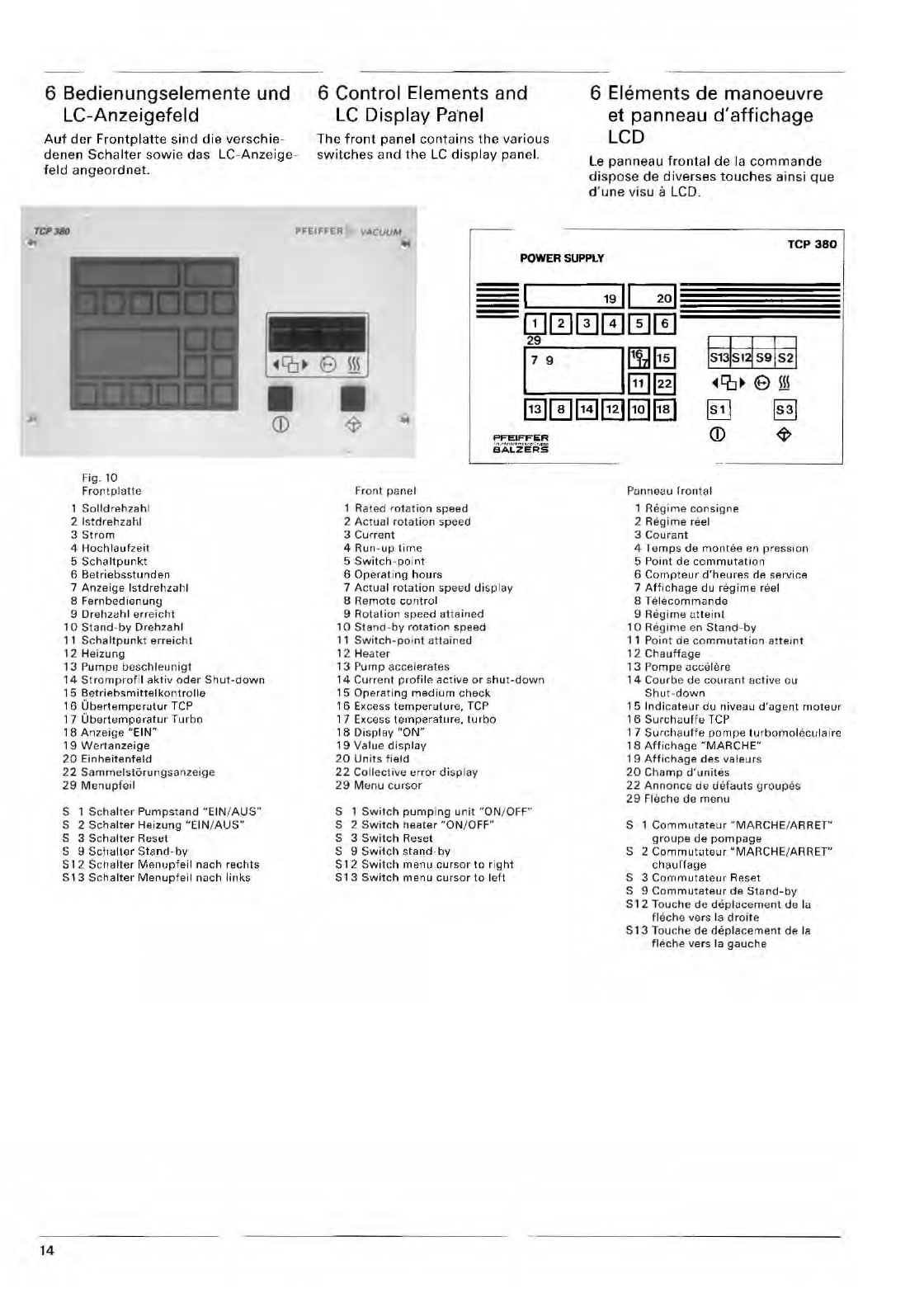
6 Bedienungselemente und
LC-Anzeigefeld
Auf
der
Frontplatte
sind
die
verschie-
denen
Schalter
sowi
e
da
s LC-
Anzeige-
fe ld a
nge
or
dnet.
6
Control
Elements and
LC
Display Panel
The
front
panel
contain
s
th
e
various
switches
and
the
LC
display
panel.
TCP380
PFEIFFER
VACUUM
OJ
6 Elements de manoeuvre
et panneau
d'affichage
LCD
Le panneau
frontal
de
la
commande
di
spose
de
diverses
touch
es ainsi
que
d' une visu a LCD.
TCP
380
POWER SUPPlY
14
Fig. 10
Fr
ontp
l
atle
So
lld
re
hzah
l
2 I
strlr
ehzahl
3
Strom
4
Hochlaufzeit
5 Sc
haltpunkt
6
Betriebsstunden
7
Anzeige
Istdrehz
ilh
l
8
Fernbedienung
9 Drehz<lhl e
rr
ei
cht
10 Sta
nd
-
by
Oreh
za
hl
11
Sc
ha
ltpunk
t
erreicht
12 He
izung
13 P
um
pe bcsc
hleu
nigt
14
Stromp
r
of
il
aktiv
oder
Shut-down
15
Betriebsmittelkontrolle
1 6
Ubertemperiltur
TCP
17
Ub
er
te
mperatur
Turbo
18
Anzeige
"EIN"
19
Wertanz
eige
20
Einheifenfeld
2 2
Samme
lst
orul1g
sanze
i
ge
29
Men
upf
e
il
S 1
Scha
l
le
r
Pump
stand
S 2
Schalt
er
He
izu
ng
"EIN/
AUS"
S 3 Scha
lter
Reset
5 9
Sc
halter
Stand
-
by
S 1 2 Sc
halter
Menupf
eil nach
rec
hts
S
13
Sch
alter
Menup
feil
nuch
links
Fr
on
t
pane
l
R
ated
ro
t
at
i
on
spee
d
2
Act
ual rot a
ti
o n sp
eed
3
Current
4 Run -
up
time
5
Sw
it
ch -
point
6
Opera
ting
hours
PFI!:IFFIiR
eA'L'Zi!"Rs
7
Actua
l
rotation
spe
eu
di
spl ay
8
Remote
control
9
Rotation
speed
attain
ed
10
Stand
-b y
ro
tati
on
speed
11
Sw
it
ch
-po
i
nt
atta
i
ned
12 He
ate
r
13
Pump
acc
elerates
14
Cu r
rent
profile
active
or
s
hut-down
15
Ore
rati
ng
medium
check
16 Excess
temperuture,
TCP
17 E
XCesS
temperatur
e,
turb
o
18
Disp
lay
"ON"
, 9
Value
display
20
Un
it
s fi
eld
22
Collective
err or d isp lay
29
M
l:lfl
U c
ur
so
r
S 1
Sw
it
ch
pump
ing
unit
"ON/
OFf"
5 2
Switch
h
eate
r
"ON
/ O
FF
"
S 3
Swi
tc h Reset
S 9
Sw
it
c h
standby
S 1 2
Sw
it
c h
menu
cursor
t o
right
513
Switc
h
menu
cur
sor
to
l
eft
591s21
e ill
§]
CD
PUlluoau
Ir
o n t
al
1 Regi
me
cons
ig
ne
2 Reg
im
e reel
3
Couran
t
4
ramps
de
mantee
en
press
ion
5
Point
de
commut
a
ti
on
6
Compte
uf
d'heures
de SAr
vice
7 A
ff
ic
hage
du
regim
e reel
8 Te l
ecomman
de
9
Regime
u
tte
i
nl
10 Regi
me
en
Sta
nd
-
by
11 Po
in
t
de
com
mu
Tat
ion
att
ei n t
1 2
Chauffage
13
Pompe
i.
H.;(;e
li
ne
14
Courbe
de
cou
r
ant
act
iv
e ou
Shut
-
down
1 5 In d ica
teur
du
niveau
d'ug
e
nt
moteur
16
Surc
hauffe
TCP
17 S
urchauffe
pompe
tu
rbomo
l
ecu
laire
18
Affichage
"MARCHE"
1 9
Aft
i
chage
des
va l
eurs
20
Cha
mp
d
'u
nit
es
22
Annonce
de
detauts
gro
up
es
29
Fl
ec
he de m e
nu
S 1
Commuta
te
ur
"MARC
HE
/ A RRE
T"
groupe
de
pompa
ge
S 2 Co
mmututeur
"MAR
CHE/ARRET"
ch a
urfage
S 3
Comm
ut
ateur
Re
set
S 9
Commuta
teur
de
Stand
-
by
S
12
Touc
he
de de
p l
ilce
m e
nt
d a lu
fl
ec
he
vers
la
droit
e
S 13 To
uche
de
depl
acement
de
la
fl
p.c
he v
ers
la
gauche
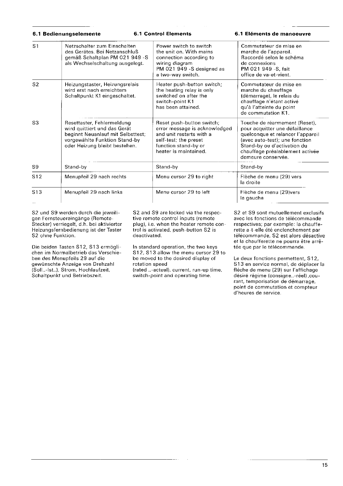
6.1
Bedienungselemente
6.1
Control
Elements
Sl
Netzschalter
zum
Einschalten
Power
switch
to
switch
des
Gerates. Bei
the
unit
on.
With
mains
Schaltplan
PM
021
949
-S
connection
according
to
als
Wechselschaltung
ausgelegt.
wiring
diagram
PM
021
949
-S
designed
as
a
two-way
switch.
S2
Heizungstaster,
Heizungsrelais
Heater
push-button
switch;
wird
erst
nach
erreichtem
the
heating
relay is
only
Schaltpunkt
Kl
eingeschaltet.
switched
on
after
the
switch-point
K1
has been
attained.
---
S3
Resettaster,
Fehlermeldung
Reset
push-button
switch;
wird
quittiert
und
das
Gerat
error
message
is
acknowledged
beginnt
Neuanlauf
mit
Selbsttest;
and
unit
restarts
with
a
vorgewahlte
Funktion
Stand-by
self-test;
the
preset
oder
Heizung
bleibt
bestehen.
function
stand-by
or
S9
Stand-by
S12
Menupfeil
29
nach
rechts
S13
Menupfeil
29
nach
links
S2
und
S9
werden
durch
die
jeweili-
gen
Fernsteuereingange
(Remote-
Stecker)
verriegelt,
d.h. bei
aktivierter
Heizungsfernbedienung
ist
der
Taster
S2
ohne
Funktion.
Die
beiden
Tasten
512,
513
ermogli-
chen
im
Normalbetrieb
das
Verschie-
ben
des
Menupfeils
29
auf
die
gewOnschte
Anzeige
von
Drehzahl
(Soll
..
-Isl..).
Strom,
Hochlaufzeit,
Schaltpunkt
und
Betriebszeit.
heater
is
maintained.
Stand-by
Menu
cursor
29
to
right
Menu
cursor
29
to
left
52
and
59
are
locked
via
the
respec-
tive
remote
control
inputs
(remote
plug),
i.e.
when
the
heater
remote
con-
trol
is
activated,
push-button
52
is
deactivated.
In
standard
operation.
the
two
keys
S12,
S13
allow
the
menu
cursor
29
to
be
moved
to
the
desired
display
of
rotation
speed
(rated
..
-actual),
current.
run-up
time.
switch-point
and
operating
time.
6.1
Elements
de
manoeuvre
Commutateur
de
mise
en
marche
de
I'appareil.
Raccorde
selon
Ie
schema
de
con
nexions
PM
021
949
-S,
fait
office
de
va-et-vient.
Commutateur
de
mise
en
marche
du
chauffage
(demarrage).
Ie
relais
du
chauffage
n'etant
active
qu'a
I'atteinte
du
point
de
commutation
Kl.
--
Touche
de
rearmement
(Reset),
pour
acquitter
une
detaillance
quelconque
et
relancer
I'appareil
(avec
auto-test);
une
fonction
Stand-by
ou
d'activation
du
chauffage
prealablement
activee
demeure
conservee.
---
---
Stand-by
Fleche
de
menu
(29)
vers
la
droite
Fleche de
menu
(29)vers
la
gauche
S2
et
S9
sont
mutuellement
exclusifs
avec les
fonctions
de
telecommande
respectives;
par
exemple:
la
chauffe-
rette
a-t-elle
Me
enclenchement
par
telecommande,
52
est
alors
desactive
et
la
chaufferette
ne
pourra
etre
arre-
tee
que
par
Ie
telecommande.
Le
deux
fonctions
permettent.
512,
513
en
service
normal,
de
deplacer
la
fleche
de
menu
(29)
sur
I'affichage
desire
regime
(consigne
..
-reel)
,cou-
rant,
temporisation
de
demarrage,
point
de
commutation
et
compteur
d'heures
de
service.
15
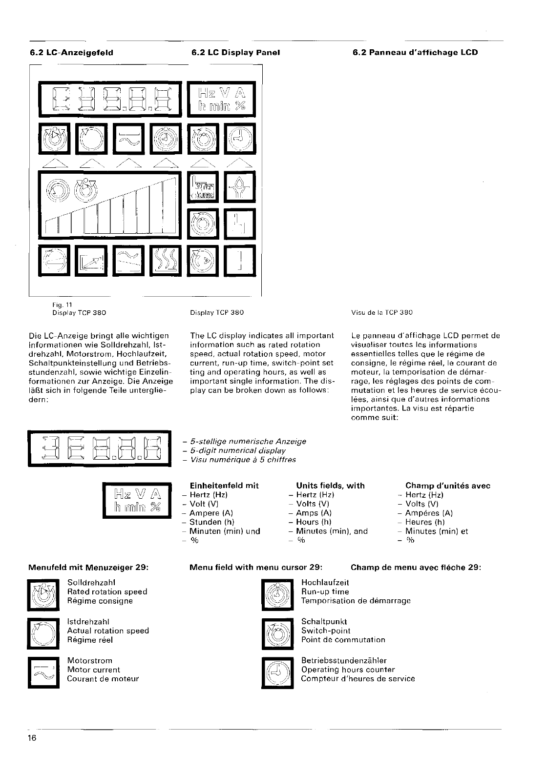
6.2
LC·Anzeigefeld
Fig.
11
Display
Tep
380
Die
LC-Anzeige
bringt
aile
wichtigen
Informationen
wie
Solldrehzahl.
Ist-
drehzahl,
Motorstrom,
Hochlaufzeit,
Schaltpunkteinstellung
und
Betriebs-
stundenzahl,
sowie
wichtige
Einzelin-
formationen
zur
Anzeige.
Die
Anzeige
larM
sich
in
folgende
Teile
unterglie-
dern:
Bi
Ili
liffililii:
J(i:
Menufeld
mit
Menuzeiger
29:
16
Solldrehzahl
Rated
rotation
speed
Regime
consigne
Istdrehzahl
Actual
rotation
speed
Regime
feel
Motorstrom
Motor
current
Courant
de
moteur
6.2
LC
Display
Panel
rTl.
L2.J
DisrlflY
Tep
380
The
LC
displny
indicates
all
important
information
such
as
rated
rotation
speed,
actual
rotation
speed,
motor
current
fun-up
time,
switch-point
set
ting
and
operating
hours,
as
well
as
important
single
information.
The
dis-
play
can be
broken
down
as
follows:
-
5-stellige
numerische
Anzeige
-
5-digit
numerical display
-Visu
numerique
a 5 chiffres
6.2
Panneau
d'affichage
LCD
Visu
de la
Tep
380
Le
panneau
d'affichage
LCD
permet
de
visualiser
toutes
les
informations
essentielles
telles
que
Ie
regime
de
consigne,
Ie
regime
reel, Ie
courant
de
moteur,
la
temporisation
de
demar-
rage, les
reglages
des
points
de
com-
mutation
et les
heures
de
service
ecou-
lees,
ainsi
que
d'autres
informations
importantes.
La
visu
est
repartie
comme
suit:
Einheitenfeld
mit
-
Hertz
(Hz)
Units
fields,
with
-
Hertz
(Hz)
Champ
d'unites
avec
-
Hertz
(Hz)
-
Volt
(V) -
Volts
(V) -
Volts
(V)
-
Ampere
(A) -
Amps
(A) -
Amperes
(A)
-
Stunden
(h) -
Hours
(h) -
Heures
(h)
-
Minuten
(min)
und
-
Minutes
(min), and -
Minutes
(min)
et
-%
-%
- %
Menu
field
with
menu
cursor
29:
Champ
de
menu
avec
fleche
29:
Hochlaufzeit
Run-up
time
Temporisation
de
demarrage
Schaltpunkt
Switch-point
Point
de
commutation
Betrie
bsstu
nde
nza h Ie r
Operating
hours
counter
Compteur
d'heures
de
service
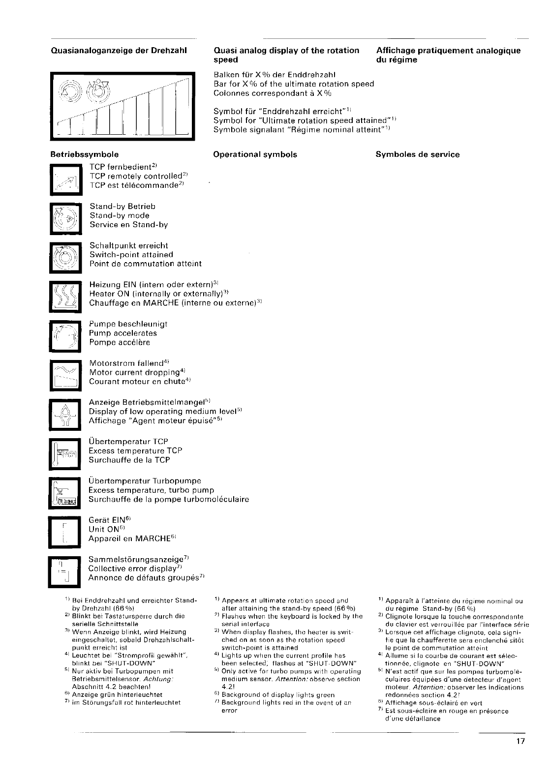
Quasianaloganzeige
der
Drehzahl Quasi analog
display
of
the
rotation
speed
Balken fOr X %
der
Enddrehzahl
Bar
for
X%
of
the
ultimate
rotation
speed
Colonnes
correspondant
a x %
Symbol
fur
"Enddrehzahl
erreicht"ll
Affichage
pratiquement
analogique
du
regime
Symbol
for
"Ultimate
rotation
speed
attained"l)
Symbole
signalant
"Regime
nominal
atteint"l)
Betriebssymbole
TCP
fernbedient
2)
TCP
remotely
controlled
2)
TCP
est
telecommande
2)
Stand-by
Betrieb
Stand-by
mode
Service
en
Stand-by
Schaltpunkt
erreicht
Switch-point
attained
Point
de
commutation
atteint
Operational
symbols
Heizung
EIN
(intern
oder
extern)3)
Heater
ON
(internally
or
externally):l)
Chauffage
en
MARCHE
(interne
ou
externe)31
Pumpe
beschleunigt
Pump
accelerates
Pompe
accelere
Motorstrom
fallend
4)
Motor
current
dropping
4)
Courant
moteur
en
chute
41
Anzeige
Betriebsmittelmangel!l)
Display
of
low
operating
medium
level5)
Affichage
"Agent
moteur
epuise"51
Ubertemperatur
TCP
Excess
temperature
TCP
Surchauffe
de
la TCP
Ubertemperatur
Turbopumpe
Excess
temperature,
turbo
pump
Surchauffe
de
la
pompe
turbomoleculaire
Gerat
EIN61
Unit
ON6)
Appareil
en MARCHEGI
Sam
melstorungsa
nzeige
7)
Collective
error
displ
ay
7)
Annonce
de
detauts
groupes
71
11
Bei
Enddrehzuhl
und
errelchter
Stand-
by
Drehzahl
(66
%)
2.1
Blinkt
bei
Tastatursperre
durch
die
serielle
Schnittstelle
Wenn
Anzeige
blinkt,
wird
Heizung
eingeschaltet,
sob<.lld
Drehzuhlschalt-
punkt
erreicht
ist
41
Leuchtet
bei
"Stromprofil
gewahlt",
blinkt
bel
"SHUT-DOWN"
51
Nur
aktiv
bei
Turbopumpen
mit
Betriebsmittelsensor.
Achtung
Abschnitt
4.2
beachten!
61
Anzeige
grun
hinterleuchtet
71
im
Storungsfuli
rot
hlnterleuchtet
11
Appears
at
ultimate
rotation
speed
and
after
attaining
the
stand-by
speed
(66
%)
'I
Flushes
when
the
keyboard
is
locked
hy
the
serial
interf<.lce
31
When
display
flashes,
the
he<.lter is
swit-
ched
on
as
soon
as
the
rotation
speed
switch-point
is
attained
41
Lights
up
when
the
current
profile
has
been
selected;
flashes
at
"SHUT
-DOWN"
.'II
Only
active
for
turbo
pumps
with
oper<.lting
medium
sensor.
Attention:
observe
section
4.21
61
Background
of
display
lights
green
/I
Background
lights
red in
the
event
uf
un
error
Symboles
de
service
11
Apparait
a
I'atteinte
du
regllne
norninul
au
du
regime
Stand-by
(66
0J0)
21
Clignote
lorsque
lu
touche
correspond
ante
du
claVier
est
verrouillee
par
I'interface
serie
31
Lorsque
cet
affichage
cligrlOte,
celu
signi-
fie
que
la
chaufferette
sera
enclenche
sitat
Ie
point
de
commutation
atteint
41
Allume
Sl
la
courbe
de
courant
est
selec-
tionnee,
clignote
en
"SHUT-DOWN"
51
N'est
actif
que
sur
les
pompes
turbomole-
culuires
equipees
d'une
detecteur
d'agent
moteur.
Attention:
observer
les
indications
redonnees
section
4.21
61
Affichage
sous-eclaire
en
vert
71
Est
sous-eclaire
en
rouge
en
presence
d'une
detCllliance
17
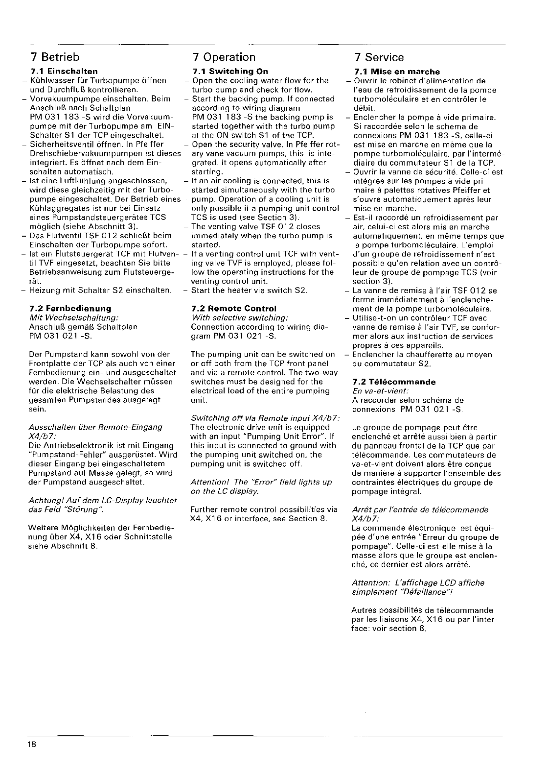
7 Betrieb 7 Operation
7.1
Einschalten
7.1
Switching
On
-
Kuhlwasser
fur
Turbopumpe
bffnen
-
Open
the
cooling
water
flow
for
the
und
kontrollieren.
turbo
pump
and
check
for
flow.
-
Vorvakuumpumpe
einschalten.
Beirn -
Start
the
backing
pump.
If
connected
AnschlufS nach
Schaltplan
according
to
wiring
diagram
PM
031
183
-5
wird
die
Vorval<uum-
PM
031
183
-S
the
backing
pump
is
pumpe
mit
der
Turbopumpe
am
EIN-
started
together
with
the
turbo
pump
Schalter
S 1
der
TCP
eingeschaltet.
at
the
ON
switch
S 1
of
the
TCP.
-
Sicherheitsventil
bffnen.
In
Pfeiffer
-
Open
the
security
valve. In
Pfeiffer
rot-
Drehschiebervakuumpumpen
ist
dieses
ary
vane
vacuum
pumps,
this
is
inte-
integriert.
Es
dffnet
nach
dem
Ein-
grated.
It
opens
automatically
after
schalten
automatisch.
starting.
-
1st
eine
Luftkuhlung
angeschlossen,
-
If
an
air
cooling
is
connected,
this
is
wird
diese
gleichzeitig
mit
der
Turbo-
started
simultaneously
with
the
turbo
pumpe
eingeschaltet.
Der
Betrieb
eines
pump.
Operation
of
a
cooling
unit
is
Kuhlaggregates
ist
nur
bei Einsatz
only
possible
if
a
pumping
unit
control
eines
Pumpstandsteuergerates
TeS TeS
is used (see
Section
3).
moglich
(siehe
Abschnitt
3). -
The
venting
valve
TSF
012
closes
-Das
Flutventil
TSF
012
schlief3t
beim
immediately
when
the
turbo
pump
is
Einschalten
der
Turbopumpe
sofort.
started.
-
1st
ein
Flutsteuergerat
TeF
mit
Flutven-
-
If
a
venting
control
unit
TeF
with
vent-
til
TVF
eingesetzt,
beachten
Sie
bitte
ing
valve TVF is
employed,
please
fol-
Betriebsanweisung
zum
Flutsteuerge-
low
the
operating
instructions
for
the
rat.
venting
control
unit.
-
Heizung
mit
Schalter
S2
einschalten.
-
Start
the
heater
via
switch
S2.
7.2
Fernbedienung
Mit
Wechselschaltung:
Anschluf3
gemaB
Schaltplan
PM
031021
-So
Der
Pumpstand
kann
sowohl
von
der
Frontplatte
der
Tep
als
auch
von
einer
Fernbedienung
ein-
und
ausgeschaltet
werden.
Die
Wechselschalter
mussen
fur
die
elektrische
Belastung
des
gesamten
Pumpstandes
ausgelegt
sein.
Ausschalten
uber
Remote-Eingang
X4/b7:
Die
Antriebselektronik
ist
mit
Eingang
"Pumpstand-Fehler"
ausgerustet.
Wird
dieser
Eingang
bei
eingeschaltetem
Pumpstand
auf
Masse
gelegt,
so
wird
der
Pumpstand
ausgeschaltet.
Achtung!
Auf
dem
LC-Display
leucl1tet
das Feld
"St6rung
".
Weitere
Moglichkeiten
der
Fernbedie-
nung
uber
X4,
X16
oder
Schnittstelle
siehe
Abschnitt
8.
18
7.2
Remote
Control
With
selective
switching:
Connection
according
to
wiring
dia-
gram
PM
031
021
-So
The
pumping
unit
can be
switched
on
or
off
both
from
the
Tep
front
panel
and via a
remote
control.
The
two-way
switches
must
be
designed
for
the
electrical
load
of
the
entire
pumping
unit.
Switching
off
via
Remote
input
X4/b
7:
The
electronic
drive
unit
is
equipped
with
an
input
"Pumping
Unit
Error".
If
this
input
is
connected
to
ground
with
the
pumping
unit
switched
on,
the
pumping
unit
is
switched
off.
Attention!
The
"Error"
field
fights
up
on the LC display.
Further
remote
control
possibilities
via
X4,
X16
or
interface,
see
Section
8.
7 Service
7.1
Mise
en
marche
-
Ouvrir
Ie
robinet
d'alimentation
de
I'eau
de
refroidissement
de
la
pompe
turbomoleculaire
et
en contr61er Ie
debit.
-
Enclencher
la
pompe
a
vide
prima
ire.
Si
raccordee
selon
Ie
schema
de
connexions
PM
031
183
-S,
celle-ci
est
mise
en
marche
en
meme
que
la
pompe
turbomoleculaire,
par
I'interme-
diaire
du
commutateur
Sl
de
la TCP.
-
Ouvrir
la
vanne
de
securite.
Celle-ci
est
integree
sur
les
pompes
a
vide
pri-
maire
a
palettes
rotatives
Pfeiffer
et
s'ouvre
automatiquement
apres
leur
mise
en
marche.
-
Est-il
raccorde
un
refroidissement
par
air,
celui-ci
est
alers
mis
en
marche
automatiquement,
en
meme
temps
que
la
pompe
turbomoleculaire.
L'emploi
d'un
groupe
de
refroidissement
n'est
possible
qu'en
relation
avec un
contr6-
leur
de
groupe
de
pompage
TeS
(voir
section
3).
-
La
vanne
de
remise
a
I'air
TSF
012
se
ferme
immediatement
a
I'enclenche-
ment
de
la
pompe
turbomoleculaire.
-
Utilise-t-on
un contr61eur
TeF
avec
vanne
de
remise
a
I'air
TVF, se
confor-
mer
alors
aux
instruction
de
services
propres
aces
appareils.
-
Enclencher
la
chaufferette
au
moyen
du
commutateur
S2.
7.2
En
va-et-vient:
A
raccorder
selon
schema
de
connexions
PM
031 021
-So
Le
groupe
de
pompage
peut
etre
enclenche
et
arrete
aussi
bien
it
partir
du
panneau
frontal
de
la
Tep
que
par
telecommande.
Les
commutateurs
de
va-et-vient
doivent
alors
etre
de
maniere
a
supporter
I'ensemble
des
contraintes
electriques
du
groupe
de
pompage
integral.
Arret
par
f'entree de
tfi/ecommande
X4/b7:
La
commande
electronique
est
equi-
pee
d'une
entree
"Erreur
du
groupe
de
pompage".
Celle-ci
est-elle
mise
a la
masse
alors
que
Ie
groupe
est
enclen-
che, ce
dernier
est
alors
arrete.
Attention:
L'affichage
LCD
affiche
simplement
"Defail/ance"!
Autres
possibilites
de
telecommande
par
les
liaisons
X4,
X16
ou
par
I'inter-
face:
voir
section
8.

7.3
Stand-by
-
Stand-by
wird
auf
der
Frontplatte
mit
Schalter
59
eingeschaltet.
-Die
Turbopumpe
kann
mit
der
Einrich-
tung
Stand-by
wahlweise
mit
66
%
der
Nenndrehzahl
(Stand-by
EIN)
oder
mit
der
Nenndrehzahl
(Stand-by
AUS)
betrieben
werden.
-
Wird
Stand-by
ausgeschaltet,
wird
die
Hochlaufzeit
mit
dem
halben
einge-
5tellten
Wert
neu
gesetzt.
Die
Pumpe
beschleunigt
auf
Nenndrehzahl.
-
Stand-by
kann
auch
uber
einen
exter-
nen
Schalter.
angeschlossen
zwischen
X4/a5
-
X4/a6
oder
Liber einen
Remo-
testecker
(X16/9
-
X16/15)
geschal-
tet
werden.
7.4
Reset
Bei
Stbrungen
wird
der
Antrieb
intern
ausgeschaltet.
Mit
"Reset"
kann
die
Pumpe
erneut
gestartet
werden.
Die
Reset-Funktion
wird aktiviert
durch:
-
BehHigung
des
Tasters
53
"Fehlerquit-
tierung"
.
-
Wegnahme
der
Netzspannung
fur
eine
Zeit
2
Sekunden.
z.B.
mit
Netzschal-
ter
S 1.
-
Betatigung
des
extern
angeschlosse-
nen
"Reset"-Tasters
S6
(zwischen
X4/a5
-
X4/b8)
oder
am
Remoteein-
ga ng X 1
6/1
3 - X 1
6/1
5. Bei
Aktivie-
rung
von
"Reset"
mit
Reset-
Taster
mu!3
die
TCP
mit
Spannung
versorgt
sein.
7.5
Funktion
der
DIL-Schalter
S
14
auf
der
Gerateruckseite
(5-polig)
Fig.12
Ruckseite
TCP
380
7.3
Stand-by
-
Stand-by
is
switched
on via
the
front
panel
switch
S9.
-
With
the
stand-by
feature,
the
turbo
pump
can
be
operated
optionally
at
66
%
of
the
rated
rotation
speed
(Stand-by
ON)
or
at
rated
rotation
speed
(Stand-by
OFF).
-
When
stand-by
is
switched
off,
the
run-up
time
is
reset
to
half
the
preset
value.
The
pump
accelerates
up
to
rated
rotation
speed.
-
Stand-by
can
also
be
switched
via an
external
switch,
connected
between
X4/a5
-
X4/a6,
or
via a
remote
plug
(X16/9
-
X16/15).
7.4
Reset
During
errors,
the
drive
is
stopped
internally.
With
"Reset",
the
pump
can
be
restarted.
The
Reset
function
is
activated
by:
-
Operating
the
push-button
S3
"Error
acknowledgment"
.
-
Disconnecting
the
mains
voltage
for
a
time
of
2
seconds,
e.g. via
mains
7.3
Stand-by
-Le
mode
Stand-by
est
enclenche
par
I'intermediaire
du
commutateur
59.
-La
pompe
turbomohkulaire
peut
etre
activee
sod
en
service
normal,
soit
en
service
Stand-by
a
66
%
de
son
regime
nominal,
dans
la
mesure
ou
elle
est
equipee
d'un
tel
dispositif.
-Le
Stand-by
est-il
desactive,
Ie
temps
de
demarrage
est
alors
redetini
a
une
valeur
egale
a la
moitie
de
celie
prere-
glee
pour
Ie
mode
Stand-by.
La
pompe
accelere
alors
jusqu'a
atteindre
son
regime
nominal.
-Le
mode
Stand-by
peut
egalement
etre
active
par
un
commutateur
externe,
a
raccorder
entre
les
barnes
X4/a5
et
X4/a6.
ou
par
telecommande
(X16/9
-X16/15).
7.4
Reset
En
cas
de
d8faillances,
la
commclnde
est
internement
arretee.
Au
moyen
de
la
fonction
de
rearmement,
c'est-a-dire
de
"Reset",
elle
peut
alors
etre
relan-
cee.
switch
S 1. La
tonction
Reset
est
activee
par:
-
Operating
the
externally
connected
-
Une
action
sur
la
touche
S3
"Acquitte-
"Reset"
push-button
S6
(between
ment"
X4/a5
-
X4/b8),
or
at
the
remote
input
-La
suppression
de
la
tension
d'alimen
X16/13
-
X16/15.
When
"Reset"
is
tation
pour
une
duree
egale
ou
supe-
activated
via
the
reset
button,
the
TCP
rieure
a 2
secondes,
pm
exemple
au
must
be
supplied
with
voftage.
moyen
du
commutateur
51.
7.5
Function
of
the
DIL
Switches
S
14
on
the
Bacl(
Panel
of
the
Unit
(5-poles)
Rear, TCP
380
-
Une
action
sur
la
touche
de
rearme-
ment
exterieure
S6,
si
raccordee
(entre
X4/a5
et
X4/b8).
ou
par
telecom-
mande
(entree
X16/13
-
X16/15).
Si
fa
fonetion
Reset
est
aecomplie
au
moyen
de
la
touche
53,
fa
TCP
dait
afars
Mre
pfacee
sous
tension!
7.5
Fonction
des
commutateurs
DIP
S14
au
dos
de
I'appareil
(5
broches)
Polnneau
arriere
de
la TCP
380
19
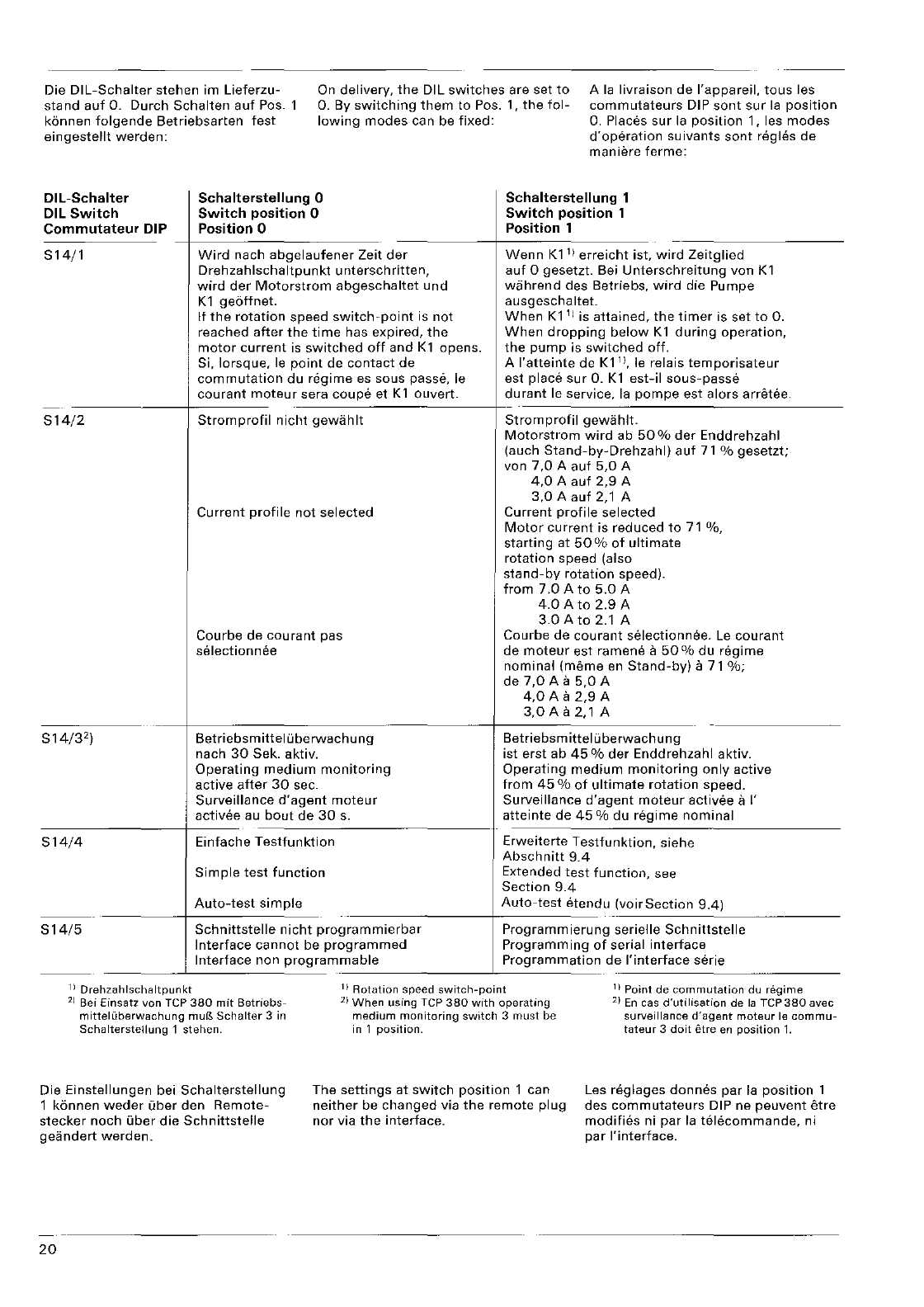
Die
DIL-Schalter
stehen im Lieferzu-
stand
auf
O.
Durch
Schalten
auf
Pas.
k6nnen
folgende
Betriebsarten
fest
eingestellt
werden:
On
delivery,
the
DIL
switches
are set
to
0. By
switching
them
to
Pos. 1,
the
fol-
lowing
modes
can be
fixed:
Ala
livraison de I'appareil.
tous
les
commutateurs
DIP
sont
sur
la
position
O.
Places
sur
la
position
1, les
modes
d'operation
suivants
sont
regles de
maniere
ferme:
DIL-Schalter
DIL
Switch
Commutateur
DIP
514/1
Schalterstellung
°
Switch
position 0
Position 0
Wird
nach
abgelaufener
Zeit
der
Drehzahlschaltpunkt
u ntersch ritten,
wird
der
Motorstrom
abgeschaltet
und
K 1
geoffnet.
If
the
rotation
speed
switch-point
is
not
reached
after
the
time
has expired,
the
motor
current
is
switched
off
and
Kl
opens.
Si, lorsque,
Ie
point
de
contact
de
commutation
du
regime
es sous passe,
Ie
courant
moteur
sera
coupe
et
Kl
ouvert.
Schalterstellung
1
Switch
position
1
Position 1
Wenn
K1
1)
erreicht
ist.
wird
Zeitglied
auf
0 gesetzt. Bei
Unterschreitung
von
Kl
wahrend
des Betriebs,
wird
die Pumpe
ausgeschaltet.
When
K1
1) is
attained,
the
timer
is set
to
O.
When
dropping
below
K1
during
operation,
the
pump
is
switched
off.
A
I'atteinte
de
K11),
Ie
relais
temporisateur
est place
sur
O.
K1
est-il
sous-passe
durant
Ie
service,
la
pompe
est alors arratee.
----+---
514/2
514/3
2)
S14/4
S14/5
11
Drehzahlschaltpunkt
Stromprofil
nicht
gewahlt
Current
profile
not
selected
Courbe de
courant
pas
selection
nee
Betriebs
mittel
L.i
be
rwach
u
ng
nach
30
Sek. aktiv.
Operating
medium
monitoring
active
after
30
sec.
Surveillance
d'agent
moteur
activee au
bout
de
30
s.
Einfache
Testfunktion
Simple
test
function
Stromprofil
gewahlt.
Motorstrom
wird
ab
50
%
der
Enddrehzahl
lauch
Stand-by-Drehzahl)
auf
71
%
gesetzt;
von
7,0
A
auf
5,0
A
4,0
A
auf
2,9
A
3,0
A
auf
2,1 A
Current
profile
selected
Motor
current
is
reduced
to
71
%,
starting
at
50
%
of
ultimate
rotation
speed (also
stand-by
rotation
speed).
from
7.0Ato
5.0A
4.0
A
to
2.9
A
3.0
A
to
2.1 A
Courbe de
courant
selectionnee.
Le
courant
de
moteur
est ramene a
50
%
du
regime
nominal
(meme
en
Stand-by)
it
71
%;
de
7,0
A a
5,0
A
4,0
A a
2,9
A
3,0
A a 2,1 A
Betrie bsm
ittel
L.i
berwach
u n 9
ist
erst ab
45
%
der
Enddrehzahl aktiv.
Operating
medium
monitoring
only
active
from
45
%
of
ultimate
rotation
speed.
Surveillance
d'agent
moteur
activee it I'
atteinte
de
45
% du
regime
nominal
Erweiterte
Testfunktion,
siehe
Abschnitt
9.4
Extended
test
function,
see
Section
9.4
Auto-test
simple
Auto-test
etendu
(voir
Section
9.4)
Schnittstelle
nicht
programmierbar
Programmierung
serielle
Schnittstelle
Interface
cannot
be
programmed
Programming
of
serial
interface
Interface
non
programmable
Programmation
de
I'interface
serie
---------
1)
Rotation
speed
switch-point
1)
Point
de
commutation
du
regime
21
Bei
Einsatz
von TCP
380
mit
Betriebs-
mitteluberwachung
mu(l,
Schalter
3 in
Schalterstellung
1
stehen.
21
When
using
TCP
380
with
operating
medium
monitoring
switch
3
must
be
in 1
position.
2)
En
cas
d'utilisation
de
la
TCP380
avec
surveillance
d'agent
moteur
Ie
commu-
tateur
3
doit
etre
en
position
1.
Die
Einstellungen
bei
Schalterstellung
1 k6nnen
weder
uber
den
Remote-
stecker
noch
uber
die
Schnittstelle
geandert
werden.
20
The
settings
at
switch
position
1 can
neither
be
changed
via
the
remote
plug
nor
via
the
interface.
Les reglages
donnes
par
la
position
1
des
commutateurs
DIP ne
peuvent
etre
modifies
ni
par
la
telecommande,
ni
par
I'interface.
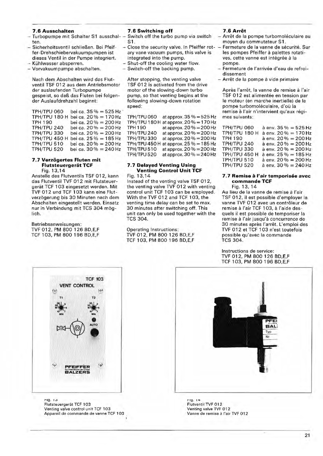
7.6
Ausschalten
7.6
Switching
off
-
Turbopumpe
mit
Schalter
S 1
ten.
ausschal-
-
Switch
off
the
turbo
pump
via
switch
S1.
-
Sicherheitsventil
schlieBen. Bei
Pfeif
-
fer
-
Dreh
sc
hiebervakuumpumpen
ist
dieses
Ventil
in
der
Pumpe
integriert.
-
Kuhlw
asser absperren.
-Close
the
security
valve. In
Pfeiffer
rot-
ary
vane vac
uum
pumps,
this
valve
is
integrated
into
the
pump.
-
Shut-off
the
coolin
g
water
flow,
-
Vorvakuumpumpe
abschalten.
-
Switch-off
the
backing
pump.
Nach
dem
Abschalten
wird
das
Flut-
ventil
TSF
012
aus
dem
Antriebsmotor
dar
auslaufenden Turbopumpe
gespeist.
so daB
das
Fluten bei
folgen-
der
Auslaufdrehzahl
beginnt:
TPH
/TPU
060
TPH
/TPU
180
H
TPH
190
TPH
/
TPU
240
TPH
/
TPU
330
TPH/TPU
450
H
TPH/TPU
510
TPH/TPU
520
bei ca.
35
%
525
Hz '
bei ca.
20
%
170
Hz
bei ca.
20
%
200
Hz
bei ca.
20
%
200
Hz
bei ca.
20
%
200
Hz
beica
.
25%
185Hz
bei ca.
20%
200
Hz
bei ca.
30%
240
Hz
7.7
Verzogertes
Fluten
mit
Flutsteuergerat
TCF
Fig ,
13,14
An stelle des
Flutventils
TSF
012,
kann
das
Flutventil
TVF
012
mit
Flutsteuer-
gerat
TeF
103
eingesetzt
werden.
Mit
TVF
012
und
TeF
103
kann eine Flut-
verzo
gerung
bis
30
Minuten
nach
dem
Ab
sc
halten
eingestellt
werden.
Einsatz
nur
in
Verbindung
mit
TeS
304
mog-
lich.
Betrieb
sa
nwei
su
ngen:
TVF
012,
PM
800
126
BD,
E,F
TeF
103
, PM
800
196
BD,E,F
TeF
103
VENT
CONTROl
"
"
TO
..
..
I"lg
.
l,j
After
s
topping,
the
venting
valve
TS F
012
is
activated
from
the
drive
motor
of
the
s
lowing-down
turbo
pump,
so
that
venting
begins
at
the
following
slowing-down
rotation
speed:
TPH
/
TPU
060
at approx.
35
%
525
Hz
TPH
/
TPU
180
H at approx.
20
%
170
Hz
TPH
190
at approx.
20
%
200
Hz
TPH/TPU
240
at approx.
20
%
200
Hz
TPH
/
TPU
330
at approx.
20
%
200
Hz
TPH
/
TPU
450
H at approx.
25
%
185
Hz
TPH
/
TPU
51
0 at appro
x.
20
%
200
Hz
TPH
/
TPU
520
at approx.
30
%
240
Hz
7,7
Delayed
Venting
Using
Venting
Control
Unit
TCF
Fig,
13
,
14
In
stead
of
th
e
venting
valve TSF
012,
th
e
venting
valve TVF
012
with
venting
contr
ol
unit
TeF
103
can be
employed,
With
the
TVF
012
and
TeF
103,
the
venting
time
delay
can be set
to
max.
30
minutes
after
switching
off.
This
unit
can
only
be used
together
with
the
Tes
304.
Operating
Instructions
:
TVF
012
, PM
800
126
BD,E,F
TeF
103
,
PM
800
196
BD,
E,F
ny.
ILl-
7.6
Arret
-
Arret
de
la
pompe
turbomohkulaire
au
moyen
du
commutateur
S 1 .
-Ferme
ture
de
la vanne
de
securite.
Sur
les
pompes
Pfeiffer
a
palettes
rotati-
ves, ce
tte
va
nne
est a la
po
mpe
,
-
Fermeture
de I'a rrivee
d'eau
de
refro
i-
dissem
en
t
-
Arret
de la
pompe
a
vide
primaire
Apres
I'a rret.
la
vanne de remise a
I'air
TSF
012
est
alimentee
en
tension
par
Ie
moteur
(en
marche
inertielle) de
la
pompa
turbomoleculaira,
d'ol!
la
remi
se a I'a
ir
n
'in
tervient
qu'aux
regi-
mes
suivants:
TPH
/
TPU
060
TPH/TPU 1
80
H
TPH
190
TPH/TPU
240
TPH/TPU
330
TPH/TPU
450
H
T
PH
/TPU
510
TPH/TPU
520
a env.
35%
525Hz
a env.
20%
170Hz
a env.
20%
200Hz
a env.
20%
200Hz
a env,
20%
200Hz
a env.
25
%
185
Hz
a env.
20
0
/0
=
200
Hz
a env.
30%
240Hz
7.7
Remise
a
.'air
temporisee
avec
commande
TCF
Fig,
13,
14
Au
lieu de la vanne de remise a
I'air
TSF
012,
il
est
possible
d'employer
I.
vanne TVF
012
avec un
contraleur
de
remi
se
a I'
air
TCF
103,
a
I'aide
des-
quels
il est
possible
de
temporiser
la
remise a
I'air
jusqu'a
concurrence
de
30
minutes
apras I'arret.
L'emploi
des
TVF
012
et
TeF
103
n'est
toutefois
possible
qu
'avec la commande
TeS
304
.
Instructions
de
service:
TVF
012,
PM
800
1
26
BD,E,F
TeF
103
, PM
800
196
BD,
E,F
Flutsteuergerat
TCF
103
Venting
valve
control
unit
TeF
103
Appareil
de
comma
nde
de
vanne TCF
103
Flutventil
TVF
012
Venting
valve TVF
012
Vanne de
remise
a
I'air
TVF 0
12
21
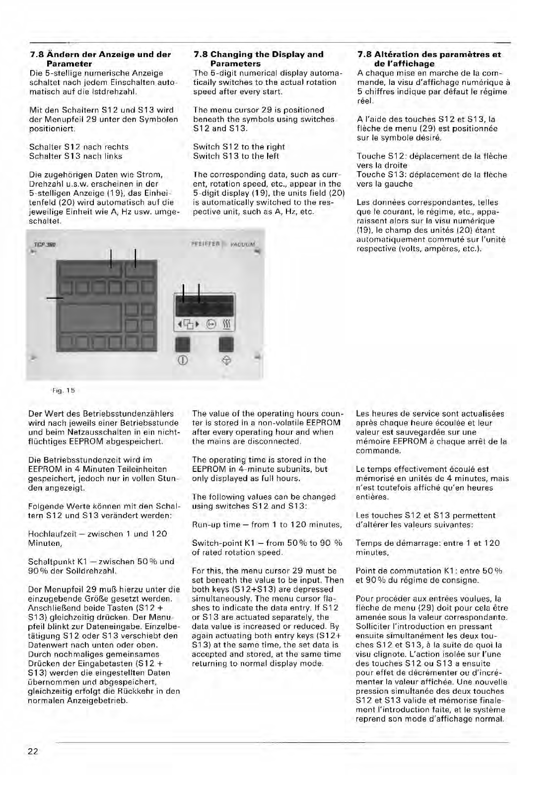
19 20
29
S13 S12
7.8
Andern
der
Anzeige
und
der
Parameter
Die
5-stellige
numerische
Anzeige
schaltet
nach
jedem
Einschalten
auto-
matisch
auf
die
Istdrehzahl.
Mit
den
5chaltern
512
und
513
wird
der
Menupfeil
29
unter
den
Symbolen
positioniert.
Sch81ter
S12
nach
rechts
Schalter
S13
nach
links
Die
zugehorigen
Daten
wie
Strom,
Drehzahl
U.S.W.
erscheinen
in
der
5-stelligen
Anzeige
(19),
das
Einhei-
tenfeld
(20)
wird
automatisch
auf
die
jeweilige
Einheit
wie
A, Hz
usw.
umge-
schaltet.
TCP3BO
Fig.
15
Der
Wert
des
Betriebsstundenzahlers
wird
nach
jeweils
einer
Betriebsstunde
und
beim
Netzausschalten
in ein
nicht-
fluchtiges
EEPROM abgespeichert.
Die
Betriebsstundenzeit
wird
im
EEPROM in 4
Minuten
Teileinheiten
gespeichert,
jedoch
nur
in
vollen
5tun-
den
angezeigt.
Foigende
Werte
kennen
mit
den
Schal-
tern
S12
und
S13
verandert
werden:
Hochlaufzeit
-
zwischen
1
und
120
Minuten,
5chaltpunkt
K1
-
zwischen
50
%
und
90
%
der
50lldrehzahl.
Der
Menupfeil
29
muB
hierzu
unter
die
einzugebende
GroBe
gesetzt
werden.
AnschlieBend
beide
Tasten
(512
+
513)
gleichzeitig
drjjcken.
Der
Menu-
pfeil
blinkt
zur
Dateneingabe.
Einzelbe-
tatigung
512
oder
513
verschiebt
den
Datenwert
nach
unten
oder
oben.
Durch
nochmaliges
gemeinsames
Drucken
der
Eingabetasten
(512
+
513)
werden
die
eingestellten
Daten
Libernommen
und
abgespeichert,
gleichzeitig
erfolgt
die
Ruckkehr
in den
normalen
Anzeigebetrieb.
22
7.8
Changing
the
Display
and
Parameters
The
5-digit
numerical
display
automa-
tically
switches
to
the
actual
rotation
speed
after
every
start.
The
menu
cursor
29
is
positioned
beneath
the
symbols
using
switches
512and513.
Switch
S
12
to
the
right
5witch
513
to
the
left
The
corresponding
data,
such
as
curr-
ent,
rotation
speed, etc.,
appear
in
the
5-digit
display
(19).
the
units field (20)
is
automatically
switched
to
the
res-
pective
unit,
such
as A, Hz, etc.
PFEIFFER
VACUUM
The
value
of
the
operating
hours
coun-
ter
is
stored
in a
non-volatile
EEPROM
after
every
operating
hour
and
when
the
mains
are
disconnected.
The
operating
time
is
stored
in
the
EEPROM in
4-minute
subunits,
but
only
displayed
as
full
hours.
The
following
values
can be
changed
using
switches
512
and
513:
Run-up
time
-
from
1
to
120
minutes,
5witch-point
K1
-
from
50%
to
90
%
of
rated
rotation
speed.
For
this,
the
menu
cursor
29
must
be
set
beneath
the
value
to
be
input.
Then
both
keys
(512+513)
are depressed
simultaneously.
The
menu
cursor
fla-
shes
to
indicate
the
data
entry.
If
512
or
513
are
actuated
separately,
the
data
value
is
increased
or
reduced.
By
again
actuating
both
entry
keys
(512+
513)
at
the
same
time,
the
set
data
is
accepted
and
stored,
at
the
same
time
returning
to
normal
display
mode.
7.8
Alteration
des
parametres
et
de
I'
affichage
A
chaque
mise
en
marche
de
la
com-
mande,
la visu
d'affichage
numerique
a
5
chiffres
indique
par
detaut
Ie
regime
reel.
A
I'aide
des
touches
512
et
513,
la
fhkhe
de
menu
(29)
est
position
nee
su r Ie sym
bole
desi
reo
Touche
512:
deplacement
de
la
fleche
vers
la
droite
Touche
513:
deplacement
de
la
fleche
vers la
gauche
Les
donnees
correspond
antes,
telles
que
Ie
courant,
Ie
regime,
etc.,
appa-
raissent
alors
sur
la
visu
numerique
(19).
Ie
champ
des unites (20)
etant
automatiquement
commute
sur
I'unite
respective
(volts,
amperes,
etc.).
Les
heures
de
service
sont
actualisees
apres
chaque
heure
ecoulee
et
leur
valeur
est
sauvegardee
sur
une
memoire
EEPROM a
chaque
arret
de
la
commande.
Le
temps
effectivement
ecoule
est
memorise
en
unites
de
4
minutes,
mais
n'est
toutefois
affiche
qu'en
heures
entieres.
Les
touches
512
et
513
permettent
d'alterer
les
valeurs
suivantes:
Temps
de
demarrage:
entre
1
et
120
minutes,
Point
de
commutation
K1
:
entre
50
%
et
90
% du
regime
de
consigne.
Pour
proceder
aux
entrees
voulues,
la
fleche
de
menu
(29)
do
it
pour
cela
etre
amenee
so us la
valeur
correspond
ante.
50lliciter
I'introduction
en
pressant
ensuite
simultanement
les
deux
tou-
ches
512
et
513,
a la
suite
de
quoi
la
visu
clignote.
L'action
isolee
sur
rune
des
touches
512
ou
513
a
ensuite
pour
effet
de
decrementer
au
d'incre-
menter
la
valeur
affichee.
Une
nouvelle
pression
simultanee
des
deux
touches
512
et
513
valide
et
memorise
finale-
ment
I'introduction
f8ite,
et Ie
systeme
reprend
son
mode
d'affichage
normal.
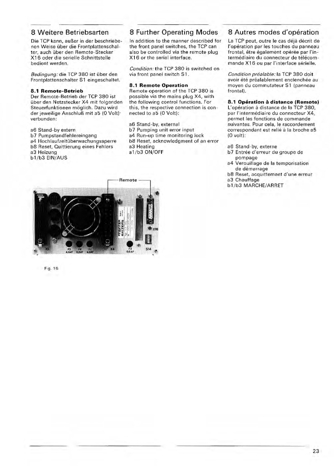
8
Weitere
Betriebsarten
Die
Tep
kann,
auBer
in
der
beschrieb
e·
ne n
Weise
uber
die
Frontplattenschal
-
ter,
auch
Liber
den
R
emote-
Stecker
X16
oder
die
serialle
Sch
nittstelle
be
dient
werden.
Bedingung
:
die
Tep
380
i
st
fiber
den
Fr
ontp
latten
sc
ha
lt
er
S1
ein
gescha
lt
et.
8.1
Remote-Betrieb
Der
Remote
-
Bet
rieb
der
Tep
380
i
st
uber
den
Netzst
ecker
X4
mit
folgend
en
Steue
rfunktionen
m O
glich.
Dazu
wird
der
jeweilige
An
sc
hluB
mit
a5
(0
Volt)
-
verbunden:
a6
S
tand-b
y ex
tern
b 7 Pumps
tandf
ehlere
ingang
a4
H
ochlaufzeiWberwachungssperre
b8
Reset,
Quittierun
g
eines
Fehlers
a3
Heizung
bl/b3
EIN/AUS
Fig.
16
8 Further Operating
Modes
In
addit
ion
to
the
man
ner
described
for
the
front
panel
switches,
the
Tep
can
also be
controlled
via
the
re
mote
plug
X 16 or
the
serial
int
erface.
Condition:
the
TCP
380
is
switched
o n
via
front
panel
switc
h S 1 .
8 .1
Remote
Operation
Remote
o
perati
on
of
th
e TCP
380
is
possible
via
the
mains
plug
X4,
with
the
following
contr
ol
functions.
For
this,
the
respecti
ve
connectio
n is
con
-
nected
to
a5
(0
Volt)
:
a6
Stand-by
. ex
tern
al
b7
Pumping
unit
e
rror
input
a4
Run-up
tim
e mo
nitorin
g
lock
b8
Reset,
acknowled
g
ment
of an
error
a3
He
ating
.1/b3
ON/OFF
8
Autres
modes
d'operation
La
Tep
peut,
outre
Ie cas deja
decrit
de
I
'operatio
n
par
les
tou
c
hes
du
panneau
frontal,
etre
egalem
en t
ope
ree
par
l'in-
termedia
ire
du
connect
e
ur
de
telecom
-
mande
X16
au
par
I'interface
ser
ielle.
Condition
paialable
: la TCP
380
doi.
avoir
ate
prealablement
enclenchee
au
moyen
du
commutateur
S 1
tpanneau
frontal).
8.1
Operation
a
distance
(Remote)
L
'ope
ration
a
dist
ance
de la TCP
380,
par
I'
intermediaire
du
connecteur
X4,
permet
les
foncti
o
ns
de
commande
s
ui
va
ntes
.
Pour
ce
la, Ie
raccordement
corre
s
pondant
est
relie
a la
broche
a5
(0
vo
lt) :
a6
Stand-by,
extern
e
b7
Entree
d'erreur
du
groupe
de
pompage
a4
Verouillage
de
la
temporisation
de
demarrage
b8
Reset,
acquittement
d'une
erreur
03
Chauffage
b 1/
b3
MARCHE/
AR
RET
23
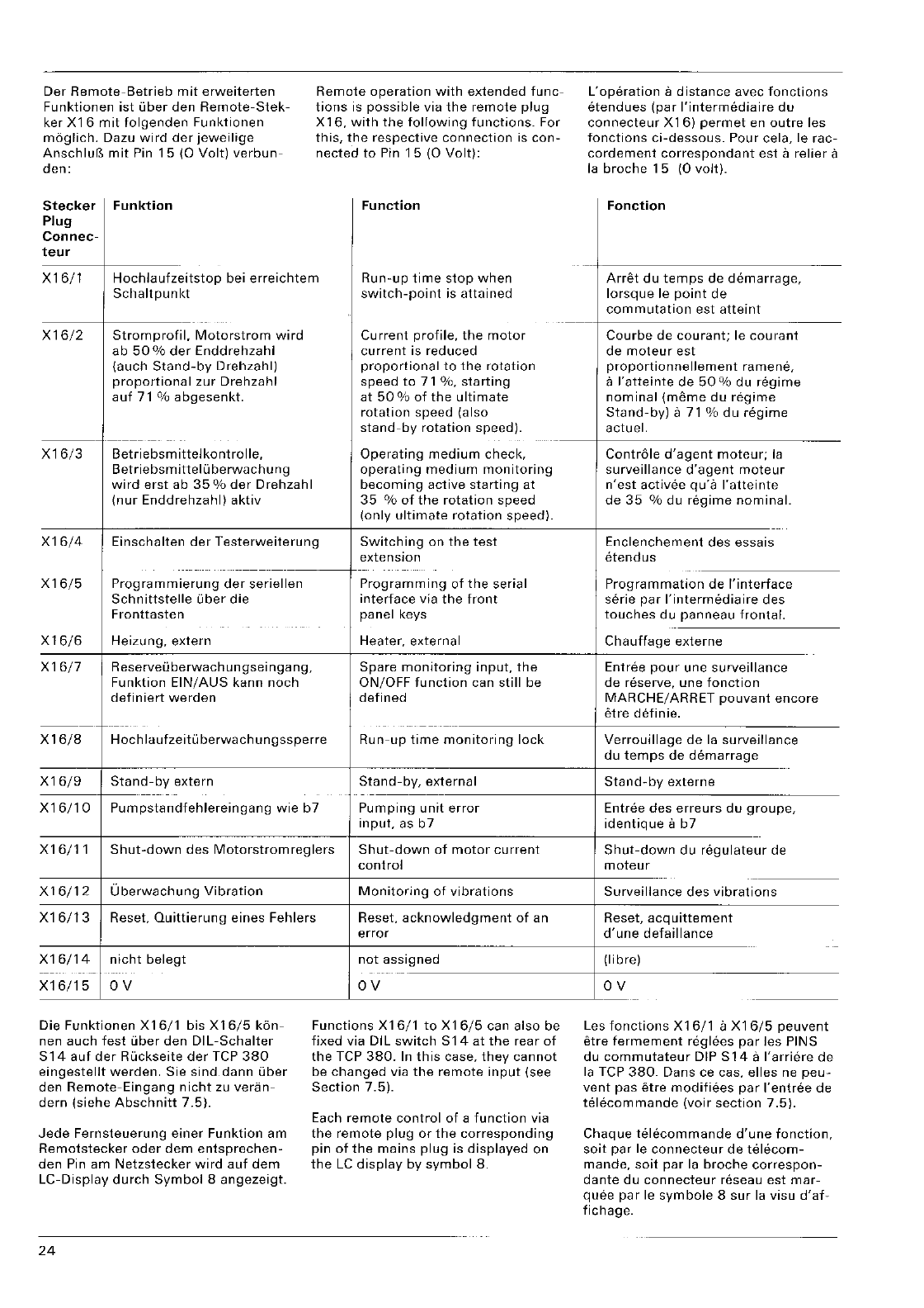
Oer
Remote-Betrieb
mit
erweiterten
Funktionen
ist
uber
den
Remote-Stek-
ker
X16
mit
folgenden
Funktionen
moglich.
Oazu
wird
der
jeweilige
AnschlufS
mit
Pin
15
(0
Volt)
verbun-
den:
Stecker
Funktion
Plug
Connec-
teur
Remote
operation
with
extended
func-
tions
is
possible
via
the
remote
plug
X16,
with
the
following
functions.
For
this,
the
respective
connection
is
con-
nected
to
Pin
15
(0
Volt):
Function
X16/1
Hochlaufzeitstop
bei
erreichtem
Run-up
time
stop
when
Schaltpunkt
switch-point
is
attained
X16/2
Stromprofil.
Motorstrom
wird
Current
profile,
the
motor
ab
50
%
der
Enddrehzahl
current
is
reduced
(auch
Stand-by
Drehzahl)
proportional
to
the
rotation
proportional
zur
Orehzahl
speed
to
71
%,
starting
auf
71 %
abgesenkt.
at
50
%
of
the
ultimate
rotation
speed (also
stand-by
rotation
speed).
--
X16/3
Betri
e
bsm
ittel
ko
nt
ro lie,
Operating
medium
check,
Betrie
bsm
ittel
u
berwa
ch u n g
operating
medium
monitoring
wird
erst
ab
35
%
der
Orehzahl
becoming
active
starting
at
(nur
Enddrehzahl)
aktiv
35
%
of
the
rotation
speed
(only
ultimate
rotation
speed).
X16/4
Einschalten
der
Testerweiterung
Switching
on
the
test
extension
-----------
X16/5
Programmierung
der
seriellen
Programming
of
the
serial
Schnittstelle
uber
die
interface
via
the
front
Fronttasten
panel
keys
X16/6
Heizung,
extern
Heater,
external
X16j7
R eserveu
berwach
u n
gse
i nga ng,
Spare
monitoring
input,
the
Funktion
EIN/AUS
kann
noch
ON/OFF
function
can
still
be
definiert
werden
defined
---
------
-----------
X16/8
Hoc
h I a
ufze
itu
berwa
ch u n 9 sspe rre
Run-up
time
monitoring
lock
X16/9
Stand-by
extern
Stand-by,
external
----
Xl
6/1
0
Pumpstandfehlereingang
wie
b7
Pumping
unit
error
input,
as
b7
X16/11
Shut-down
des
Motorstromreglers
Shut-down
of
motor
current
control
X16/12
Uberwachung
Vibration
Monitoring
of
vibrations
X16/13
Reset,
Quittierung
eines
Fehlers
Reset,
acknowledgment
of
an
X16/14
nicht
belegt
---
-
--
--
I
X16/15
OV
Die
Funktionen
X16/1
bis
X16/5
kon-
nen
auch
fest
uber
den
OIL-Schalter
S14
auf
der
Ruckseite
der
TCP
380
eingestellt
werden.
Sie
sind
dann
liber
den
Remote-Eingang
nicht
zu
veran-
dern
(siehe
Abschnitt
7.5).
Jede
Fernsteuerung
einer
Funktion
am
Remotstecker
oder
dem
entsprechen-
den
Pin
am
Netzstecker
wird
auf
dem
LC-Display
durch
Symbol
8
angezeigt.
24
error
not
assigned
OV
Functions
X16j1
to
X16/5
can
also
be
fixed
via OIL
switch
S14
at
the
rear
of
the
TCP
380.
In
this
case,
they
cannot
be
changed
via
the
remote
input
(see
Section
7.5).
Each
remote
control
of
a
function
via
the
remote
plug
or
the
corresponding
pin
of
the
mains
plug
is
displayed
on
the
LC
display
by
symbol
8.
L'operation
a
distance
avec
fonctions
etendues
(par
I'intermediaire
du
connecteur
X16)
permet
en
outre
les
fonctions
ci-dessous.
Pour cela, Ie
rac-
cordement
correspondant
est
a
relier
a
la
broche
15
(0
volt).
Fonction
--
Arret
du
temps
de
demarrage,
lorsque
Ie
point
de
commutation
est
atteint
Courbe
de
courant;
Ie
courant
de
moteur
est
proportionnellement
ramene,
a
I'atteinte
de
50
%
du
regime
nominal
(meme
du
regime
Stand-by)
a
71
%
du
regime
actuel.
Controle
d'agent
moteur;
la
surveillance
d'agent
moteur
n'est
activee
qu'a
I'atteinte
de
35
%
du
regime
nominal.
Enclenchement
des
essais
etendus
Programmation
de
I'interface
serie
par
I'intermediaire
des
touches
du
panneau
frontal.
Chauffage
externe
Entree
pour
une
surveillance
de
reserve,
une
fonction
MARCHE/
ARRET
pouvant
encore
etre
detinie.
Verrouillage
de
la
surveillance
du
temps
de
demarrage
Stand-byexterne
Entree
des
erreurs
du
groupe,
identique
a
b7
Shut-down
du
regulateur
de
moteur
Surveillance
des
vibrations
Reset,
acquittement
d'une
defaillance
--
(Iibre)
OV
Les
fonctions
X16/1
a
X16/5
peuvent
etre
fermement
reglees
par
les PINS
du
commutateur
DIP
S14
a
I'arriere
de
la TCP
380.
Dans ce cas, elles ne
peu-
vent
pas
etre
modifiees
par
I'entree
de
telecommande
(voir
section
7.5).
Chaque
telecommande
d'une
fonction,
soit
par
Ie
connecteur
de
telecom-
mande,
soit
par
la
broche
correspon-
dante
du
connecteur
reseau
est
mar-
quee
par
Ie
symbole
8
sur
la visu
d'af-
fichage.
8.2
Betrieb
uber
Schnittstellen
(Option)
Die TCP
380
kann
uber
die serielle
Schnittstelle
RS
232
-C
oder
RS
485
tiber
Rechner
gesteuert
werden.
Folgende
Befehle
werden ausgefilhrt:
-Reset
-Heizung EIN /
AUS
-
Stand-by
EIN /
AUS
-
Stromsperre
EIN /
AUS
-
HochlaufzeitOberwachung
EIN /
AUS
-
Hochlauizeitstop
EIN /
AUS
-
Stromprofil
EIN
/
AUS
-
BetriebsmittelOberwachung
EIN
/
AUS
-
Tastatursperre
EIN /
AUS
-
Fehlerquittierung
Fo/gende SOllwertvorgaben
k6nnen
eingestellt
werden:
-
Hochlaufzeit
-
Schaltpunkt
8.2
Operation
via
Interfaces
(Option)
The TCP
380
can be
computer-control-
led via
the
serial
interface
RS
232
-C
or
RS
485.
The following
commands
are
exe-
cuted:
-Reset
-
Heater
ON /
OFF
-
Stand-by
ON
/
OFF
-
Current
lock
ON /
OFF
-
Run-up
time
monitoring
ON
/
OFF
-
Run-up
time
stop
ON
/
OFF
-
Current
profile
ON
/
OFF
-
Operating
medium
monitoring
ON
/
OFF
-Keyboard
lock
ON
/
OFF
-Error
acknowledgment
The following
reference
inputs
can
be
preset:
-
Run-up
time
Folgende
Statusabfragen
sind
moglich: -
Switch-point
-Gerat
fernbedient
-
Betriebsmittelmangel
-
Schaltpunkt
erreicht
-
Fehlermeldung
-
Obertemperatur
TCP
-
Obertemperatur
Pumpe
-Enddrehzahl
erreicht
-
Pumpe
beschleunigt
-
Solldrehzahl
-
Istdrehzahl
-
Motorstrom
-
Betriebsstunden
-
Softwareversion
Die serielle
Schnittstelle
ist
Option,
Best.-Nr. PM
021
872
-T.
Montage
und
Bedienung
siehe
zugehorige
Betriebs-
anweisung.
The fol/owing
status
requests
are
possible:
-
Unit
remotely
controlled
-
Low
operating
medium
level
-
Switch-point
attained
-Error message
-Excess
temperature,
TCP
-Excess
temperature,
pump
-
Ultimate
rotation
speed
attained
-Pump accelerates
-Rated
rotation
speed
-
Actual
rotation
speed
-
Motor
current
-
Operating
hours
-
Software
version
The serial
interface
is an
option,
order
code PM 021
872
-1.
For
installation
8.2
Operation
par
interfaces
(Option)
La
TCP
380
peut
egalement
etre
asser-
vie
par
un
ordinateur
central
par
I'intermediaire
d'une
interface
serie
RS
232-C
au
RS
485.
Les instructions
suivantes
peuvent
etre
ex/kuMes:
-
Rearmement
(Reset)
-
Chaufferette
MARCHE/ARRET
-
Stand-by
MARCHE/ARRET
-
Verrouillage
de
courant
MARCHE/
ARRET
-
Surveillance
de
demarrage
MARCHE/
ARRET
-
Arret
du
temps
de
demarrage
MAR-
CHE/ARRET
-Courbe de
courant
MARCHE/ARRET
-
Surveillance
d'agent
moteur
MARCHE/
ARRET
-
Verrouillage
du clavier
MARCHE/
ARRET
-
Acquittement
des
erreurs
Les
va
leurs
de
consigne
suivantes
peu-
vent
etre
regtees
par
I'interface:
-
Temps
de
demarrage
-Point de
commutation
Les interrogations
d'etat
suivantes
sont
possibles:
-
Appareil
tEl!lecommande
-Niveau
d'agent
moteur
-Point de
commutation
atteint
-Message
d'erreurs
-
Surchauffe
TCP
-
Surchauffe
pompe
-Regime
nominal
atteint
-Pompe accelere
-
Regime
de
consigne
-
Regime
reel
-
Courant
de
moteur
and
operation,
see
the
corresponding
-Heures de service
operating
instructions.
-
N°
de version
logicielle
L'interface
serie
n'est
livree
qu'en
option
(reference: PM
021
872
-
TJ.
Montage
et
operation:
voir
instructions
de service
afferentes.
25
9 Fehlersuche
9.1
Selbsttest
Das
Gerat
Tep
380
ist
mit
einem
Selbsttest
ausgerOstet.
Nach
dem
Ein-
schalten
des
Gerates
wird
ein
groBer
Teil
der
elektronischen
Regelung
und
der
Leistungshalbleiter
in
einem
Test-
programm
auf
Fehler
liberprlift.
Wird
ein
Fehler
erkannt
ist
die
weitere
Inbe-
triebnahme
des
Gerates
blockiert
und
auf
dem
LC
-
Display
erscheint
Fehler-
meldung
25
und
eine
Fehlernummer.
Die
Uberprufung
basiert
im
wesentli-
chen
auf
Spannungsmessung
an
wich-
tigen
Punkten
des
Gerates
unter
ver-
schiedenen
eingestellten
Betriebsbe-
dingungen.
1m
einzelnen
wird
iiberprilft:
Hbhe
der
Netzspannung,
der
Zwi-
schenkreisspannung
(48Vl.
dar
Refe-
renzspannung,
der
internen
Versor-
gung
(15V),
der
Hallsondenversor-
gung,
der
Programmierspannung,
der
Motorspannung
und
der
Drehzahlreg-
lerspannung.
Hierdurch
ergeben
sich
wichtige
Ruck-
schlusse
uber
die
korrekte
Funktion
des
Gerates,
Fehler
im
gesamten
Bereich
des
Drehzahlreglers,
der
Motorstromregelung
(PIC),
der
Motor-
endstufen
und
der
Hallsonden
werden
sofort
erkannt
und
schutzen
das
Gerat
und
die
Pumpe
vor
weiteren
Schaden.
26
9
Trouble-Shooting
9.1
Self·Testing
The
TCP
380
is
equipped
with
a
self·
test.
After
the
unit
has been
switched
on, a
major
part
of
the
electronic
con-
trol
and
the
power
semi-conductors
is
checked
for
errors
by
a
test
program.
When
an
error
is
detected,
further
operation
of
the
unit
is
blocked,
and
error
message
25
and
an
error
number
appears
on
the
LC
display.
This
test
is
mainly
based on
measurement
of
the
voltage
at
important
points
in
the
unit
under
different
preset
operating
condi-
tions.
In detail,
the
following
is
checked:
Level
of
the
mains
voltage,
intermedi-
ate
circuit
voltage
(48V),
reference
voltage,
internal
supply
(15V),
Hall
probe
supply,
programming
voltage,
motor
voltage
and
rotation
speed
con-
trol
voltage.
This
allows
important
conclusions
to
be
drawn
concerning
the
correct
func-
tioning
of
the
unit;
errors
in
the
whole
areel
of
rotation
speed
control,
motor
current
control
(PIC),
motor
output
sta-
ges
and Hall
probes
are
immediately
detected,
thus
protecting
the
unit
and
the
pump
from
any
further
damage.
9 Depistage d'erreurs
9.1
Auto·test
La
commande
TCP
380
est
pourvue
d'un
systeme
d'auto-test,
permettant,
sitet
I'appareil
enclenche,
de
tester
la
majeure
partie
des
composants
elec-
troniques
de
regulation
ainsi
que
les
semi-conducteurs
Quant a
leurs
pro-
prietes.
Une
erreur
est-elle
detectee,
la
commande
ne
peut
pas
etre
mise
en
marche
et un
message
d'erreur
appro-
prie
est
emis
sur
la visu
(25).
Cet
auto-
test
est
essentiellement
base
sur
des
mesures
de
tension
aux
pOints
impor-
tants,
sous
diverses
conditions
d'utili-
sation
simulees.
Tests
effectues:
Niveau
de
la
tension
secteur,
de
la
ten-
sion
des
circuits
intermediaires
(48
V),
de
la
tension
de
reference,
de
celie
ser-
vant
a
I'alimentation
interne
(15
V),
de
I'alimentation
de
la
sonde
de
Hall,
de
la
tension
de
programmation,
de la
tension
moteur
et
de la
tension
du
regulateur
de
regime.
Ces
mesures
donnent
des
resultats
precieux
Quant au
bon
fonctionnement
de
I'appareil.
Des
erreurs
eventuelles
au
niveau
du
regulateur
de
regime,
du
regulateur
de
courant
moteur
(PIC),
des
etages
finaux
du
moteur
ainsi
que
des
sondes
de
Hall
sont
immediate-
ment
detectees
et
protegent
la
pompe
ainsi
que
la
commande
-
celle-ci
ne
pouvant
pas
etre
mise
en
marche
-
d'autres
endommagements
eventuels.
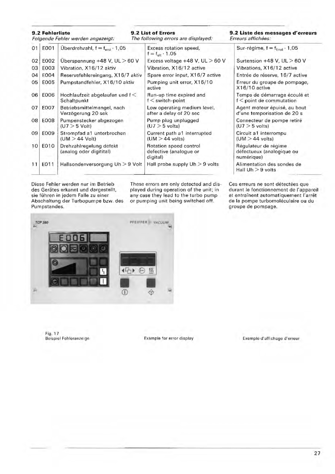
9,2
Fahlarliste
Folgende
Fehler
werden
angezeigt:
9.2
List
of
Errors
The
following
e
rrors
are
displayed:
9.2
Liste
des
messages
d"erreurs
Erreurs
affichees
:
----
--,-
--
--------
----
------
01 EOOI
Uberdrehzahl,
f f.
,d
-
1,05
Excess
rotation
speed,
f = fult . 1 .
05
02
E00
2
Uber
s
pannung
+48
V,
UL >
60
V Excess vo
lt
age
+48
V,
UL
>
60
V
Vibration,
X16/12
aclive
03
E003
Vibra
li
on,
X16/12
akliv
04
E004
Re
se
rvefehlereingang.
X16
/ 7
aktiv
Spare
e
rr
o r
in
put,
X16/7
active
Pumping
unit
error,
X16/1
0
05
E
005
Pu
mpslandtehler,
X16
/ 1 0
akliv
active
06
E
006
Hochlaufzeit
abgelaufen
und
f <
Run-up
time
expired and
f < s
witch-point
Schallpunkl
07
E
00
7
Betriebsmittelmangel,
nach
Verz6gerun
g
20
sek
OS
EOOS
Pumpenstecker
abgezogen
IU7
> 5
Voll)
09
E
009
Stroml1fad
a1
unterbrochen
(UM
>
44
Vo
lt
)
10
E010
Dreh
z
ah
lregelung
defekt
(a
nalog
oder
digitital)
L
ow
operat
ing
medium
level,
after
a
delay
ot
20
sec
Pump
plug
unplugged
IU7
> 5
volts)
Current
pa
th
a 1
interrupted
(
UM
>
44
vo
ll
s)
R
ota
ti
on
speed
co
ntrol
defecti
ve (ana l
og
ue
or
digit
al)
11 E011 Hall
sondenve
r
so
rgung
Uh
> 9
Vo
lt
Hall
probe
s
upply
Uh
> 9 vo
lt
s
Diese Fehl
er
werden
nur
im
Betrieb
des Gerates
erkannt
und
dargestellt,
sie fUhren in
jedem
Faile zu
einer
Abschaltung
de
r
Turbopumpe
bzw. des
Pumps
tandes
.
rCl'
3110
'!t
Fig
.17
Bei::;pie ! Fehleranzei
ge
These
errors
are
only
detected
and
dis-
played
during
operation
of
the
unit;
in
any
case
they
lead
to
the
turbo
pump
or
pumping
unit
be
ing
switched
off.
PFEIFFER VACUUM
OJ
Example
for
erro
r
display
Sur
-
regime
. f = ff
lna
l .
1.05
Su
rt
ens
ion
+
4S
V, UL >
60
V
Vibrations,
X 16 /
12
active
Entree
de
reserve.
16
/ 7
active
Erreur
du
groupe
de
pompage,
X
16/1
0 aClive
Temps
de
demarrage
eCQule
et
f <
point
de
commutat
ion
Agent
moteur
epuise, au
bout
d'une
temporisation
de
20
s
Connecteur
de
pompe
retire
IU7
> 5
volts)
Circuit
a 1
interrompu
(UM
>
44
vo
lt
s)
Regulateur
de
regime
def
ec
tu
eux (ana l
ogiq
ue
au
num
erique)
Alimentation
des
so
ndes
de
Hall
Uh
> 9 vo
lt
s
Ces
er
re
urs
ne sont
que
dur
ant
Ie
fonctionnement
de
I'appareil
et
entrainent
automatiqueme
nt
I'arret
de
la
pompe
tur
bomo
leculaire
au
du
groupe
de
pompage.
Exemp
le (j
'uff
l
chage
lJ
'e
rreur
27
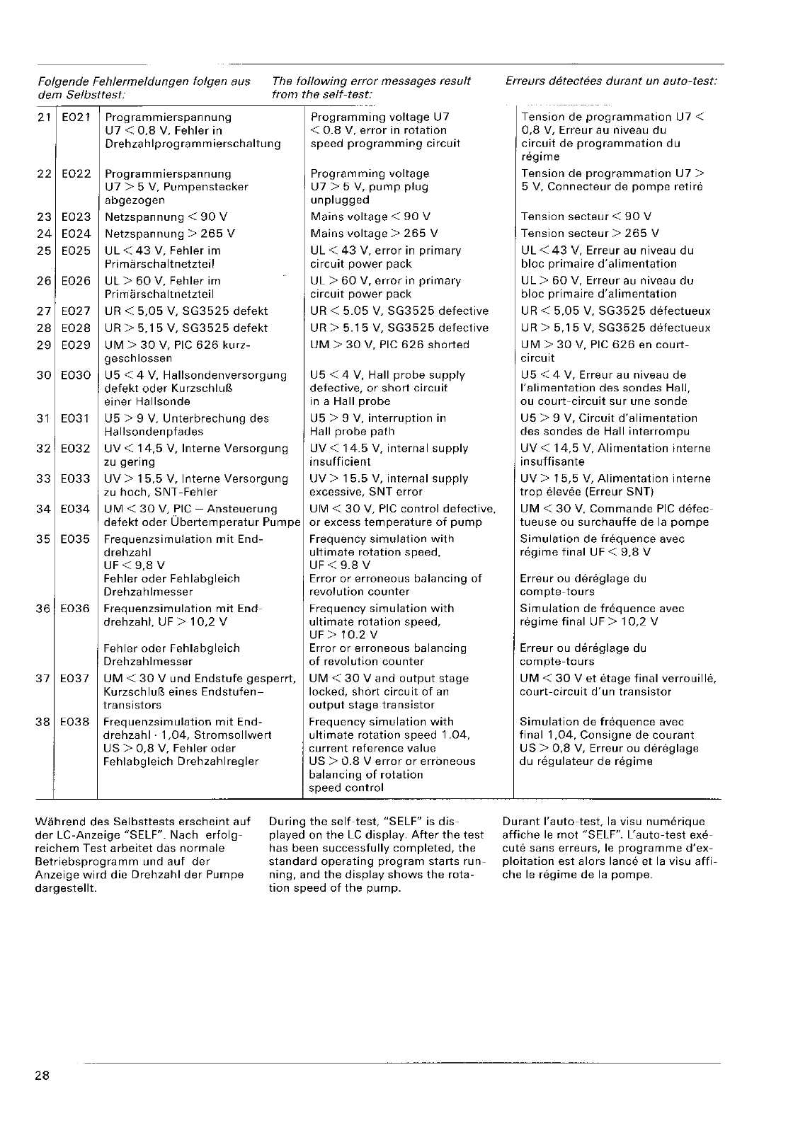
Folgende
Fehlermeldungen
folgen
aus
dem
Selbsttest:
21
E021
Programmierspan
nu ng
U7
<
0.8
V.
Fehler
in
The
following
error
messages
result
from
the
self-test:
Programming
voltage
U7
<
0.8
V,
error
in
rotation
Drehzah
Iprogram
m
ierschaltung
speed
programming
circuit
22
E022
Program
m
ierspannung
Programming
voltage
U7
> 5 V,
Pumpenstecker
U7
> 5 V,
pump
plug
abgezogen
unplugged
23
E023
Netzspannung
<
90
V
Mains
voltage
<
90
V
24
E024
Netzspannung
>
265
V
Mains
voltage>
265
V
25
E025
UL
<
43
V,
Fehler
im
UL
<
43
V,
error
in
primary
Pri
ma
rsch a It
netztei
I
circuit
power
pack
26
E026
UL>
60
V,
Fehler
im
UL
>
60
V,
error
in
primary
Pri ma
rschaltnetzteil
circuit
power
pack
27
E027
UR <
5,05
V,
SG3525
defekt
UR <
5.05
V,
SG3525
defective
28
E028
UR >
5.15
V,
SG3525
defekt
UR >
5.15
V,
SG3525
defective
29
E029
UM
>
30
V,
PIC
626
kurz-
UM
>
30
V,
PIC
626
shorted
geschlossen
30
E030
U5
< 4 V,
Hallsondenversorgung
U5
< 4 V, Hall
probe
supply
defekt
oder
KurzschluB
defective,
or
short
circuit
einer
Hallsonde
in a Hall
probe
31
E031
U5
> 9 V.
Unterbrechung
des
U5
> 9 V,
interruption
in
Hallsondenpfades
Hall
probe
path
32
E032
UV
<
14,5
V,
Interne
Versorgung
UV
<
14.5
V,
internal
supply
zu
gering
insufficient
33
E033
UV>
15,5
V,
Interne
Versorgung
UV>
15.5
V,
internal
supply
zu
hoch,
SNT
-Fehler
excessive,
SNT
error
34
E034
UM
<
30
V,
PIC
-
Ansteuerung
UM
<
30
V,
PIC
control
defective.
defekt
oder
Ubertemperatur
Pumpe
or
excess
temperature
of
pump
35
E035
Frequenzsimulation
mit
End-
Frequency
simulation
with
drehzahl
ultimate
rotation
speed,
UF <
9,8
V UF <
9.8
V
Fehler
oder
Fehlabgleich
Error
or
erroneous
balancing
of
Drehzahlmesser
revolution
counter
36
E036
Frequenzsimulation
mit
End-
Frequency
simulation
with
drehzahl.
UF >
10,2
V
ultimate
rotation
speed,
UF>
10.2
V
Fehler
oder
Fehlabgleich
Error
or
erroneous
balancing
Drehzahlmesser
of
revol
ution
cou
nter
37
E037
UM
<
30
V
und
Endstufe
gesperrt,
UM
<
30
V
and
output
stage
KurzschlufS
eines
Endstufen-
locked,
short
circuit
of
an
transistors
output
stage
transistor
38
E038
Frequenzsimulation
mit
End-
Frequency
simulation
with
drehzahl·
1,04,
Stromsollwert
ultimate
rotation
speed
1.04,
US>
0,8
V,
Fehler
oder
current
reference
value
Fehlabgleich
Drehzahlregler
US >
0.8
V
error
or
erroneous
balancing
of
rotation
speed
control
Wahrend
des
Selbsttests
erscheint
auf
der
LC-Anzeige
"SELF".
Nach
erfolg-
reichem
Test
arbeitet
das
normale
Betriebsprogramm
und
auf
der
Anzeige
wird
die
Drehzahl
der
Pumpe
dargestellt.
During
the
self-test,
"SELF"
is
dis-
played
on
the
LC
display.
After
the
test
has been
successfully
completed,
the
standard
operating
program
starts
run-
ning,
and
the
display
shows
the
rota-
tion
speed
of
the
pump.
28
Erreurs
detectees
durant
un
auto-test:
Tension
de
programmation
U7
<
0,8
V,
Erreur
au
niveau
du
circuit
de
programmation
du
regime
Tension
de
programmation
U7
>
5 V,
Connecteur
de
pompe
retire
Tension
secteur
<
90
V
Tension
secteur
>
265
V
UL
<
43
V,
Erreur
au
niveau
du
bloc
primaire
d'alimentation
UL>
60
V,
Erreur
au
niveau
du
bloc
primaire
d'alimentation
UR <
5,05
V,
SG3525
detectueux
UR >
5,15
V,
SG3525
defectueux
UM
>
30
V,
PIC
626
en
court-
circuit
U5
< 4 V,
Erreur
au
niveau
de
I'alimentation
des
sondes
Hall,
ou
court-circuit
sur
une
sonde
U5
> 9 V,
Circuit
d'alimentation
des
sondes
de Hall
interrompu
UV
<
14,5
V,
Alimentation
interne
insuffisante
UV>
15,5
V,
Alimentation
interne
trop
elevee (Erreur SNT)
UM
<
30
V.
Commande
PIC
detec-
tueuse
ou
surchauffe
de
la
pompe
Simulation
de
frequence
avec
regime
final
UF <
9,8
V
Erreur
ou
dereglage
du
compte-tours
Simulation
de
frequence
avec
regime
final
UF >
10,2
V
Erreur ou
dereglage
du
compte-tours
UM
<
30
V
et
etage
final
verrouille,
court-circuit
d'un
transistor
Simulation
de
frequence
avec
final
1,04,
Consigne
de
courant
US>
0,8
V,
Erreur
ou
dereglage
du
regulateur
de
regime
Durant
I'auto-test,
la visu
numerique
affiche
Ie
mot
"SELF".
L'auto-test
exe-
cute
sans
erreurs,
Ie
programme
d'ex-
ploitation
est
alors
lance
et la visu
affi-
che
Ie
regime
de
la pompeo
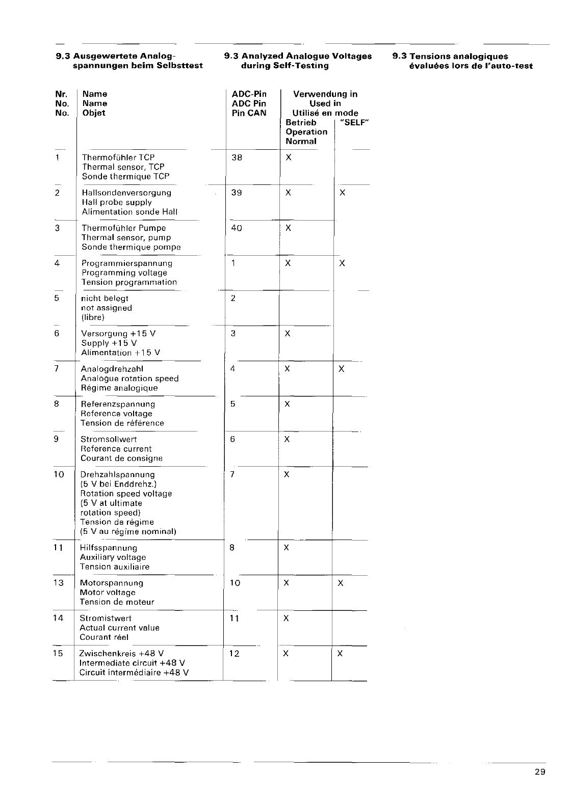
9.3
Ausgewertete
Analog-
spannungen
beim
5elbsttest
Nr.
Name
No.
Name
No.
Objet
Therm
Therm
Sonde
ofuhler
TCP
al
sensor,
TCP
thermique
TCP
2
Hallso
ndenversorgung
Hall p
Alime
robe
supply
ntation
sonde
Hall
3
Therm
ofLihler
Pumpe
Therm
Sonde
al sensor,
pump
thermique
pompe
4 Progra
mmierspannung
Progra
Tensio
mming
voltage
n
programmation
elegt
5
nicht
b
not
as
(Iibre)
signed
6
Verso
rgung
+15
V
Y
+15
V
Suppl
Alimen
tation
+15
V
7
Analog
drehzahl
ue
rotation
speed
Analog
Regim
--+
e
analogique
8 Refere
Refere
Tensio
nzspannung
nee
voltage
n de
reference
9
Strom
sollwert
Refere
Coura
nee
current
nt
de
consigne
10
Drehza
hlspannung
ei
Enddrehz.)
(5
V b
Rotatio
(5 V at
rotatio
Tensio
(5
Vau
n
speed
voltage
ultimate
n speed)
n de
regime
regime
nominal)
11
Hilfssp
annung
Auxilia
Tensio
ry
voltage
n
auxiliaire
13
Motors
pannung
Motor
Tensio
voltage
n
de
moteur
14
Strom
istwert
Actual
Couran
current
value
t reel
15
Zwisch
enkreis
+48
V
Interm
Circuit
ediate
circuit
+48
V
intermediaire
+48
V
9.3
Analvzed
Analogue
Voltages
during
5elf-
Testing
ADC-Pin
Verwendung
in
ADC
Pin
Used
in
Pin
CAN
Utilise en
mode
Betrieb "SELF"·
Operation
Normal
38
X
._--
39
X X
40
X
1 X X
--
2
3 X
4 X X
5 X
6 X
7 X
8 X
10
X X
11
X
12
X X
9.3
Tensions
analogiques
evaluees
lors
de
I'auto-test
29
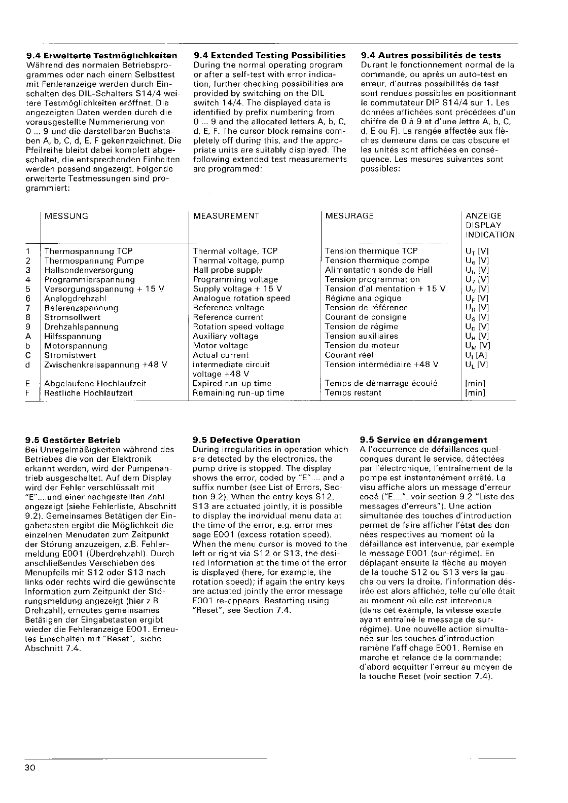
9.4
Erweiterte
Testmoglichl(eiten
Wahrend
des
normalen
Betriebspro-
grammes
oder
nach
einem
Selbsttest
mit
Fehleranzeige
werden
durch
Ein-
schalten
des
DIL-Schalters
S14/4
wei-
tere
Testmoglichkeiten
eroffnet.
Die
angezeigten
Daten
werden
durch
die
vorausgestellte
Nummerierung
von
0 ... 9
und
die
darstellbaren
Buchsta-
ben A, b,
C,
d,
E,
F
gekennzeichnet.
Die
Pfeilreihe
bleibt
dabei
komplett
abge-
schaltet,
die
entsprechenden
Einheiten
werden
passend
angezeigt.
Foigende
erweiterte
Testmessungen
sind
pro-
grammiert:
MESSUNG
1
Thermospannung
TCP
2
Thermospannung
Pumpe
3 H
aliso
n de
nverso
rg u n 9
4
Programm
ierspan
nu ng
5
Versorgungsspannung
+
15
V
6
Analogdrehzahl
7
Referenzspannung
8
Stromsollwert
9
Drehzahlspannung
A
Hilfsspannung
b
Motorspannung
C
Stromistwert
d
Zwischenkreisspannung
+48
V
E
Abgelaufene
Hochlaufzeit
F
Restliche
Hochlaufzeit
-
9.5
Gestorter
Betrieb
Bei Unregelmaf?,igkeiten
wahrend
des
Betriebes
die
von
der
Elektronik
erkannt
werden,
wird
der
Pumpenan-
trieb
ausgeschaltet.
Auf
dem
Display
wird
der
Fehler
verschllisselt
mit
"E"
....
und
einer
nachgestellten
Zahl
angezeigt
(siehe
Fehlerliste,
Abschnitt
9.2).
Gemeinsames
Betatigen
der
Ein-
gabetasten
ergibt
die
Moglichkeit
die
einzelnen
Menudaten
zum
Zeitpunkt
der
Storung
anzuzeigen,
z.B.
Fehler-
meldung
E001
[Uberdrehzahl).
Durch
anschlieBendes
Verschieben
des
Menupfeils
mit
S12
oder
S13
nach
links
oder
rechts
wird
die
gewlinschte
Information
zum
Zeitpunkt
der
Sto-
rungsmeldung
angezeigt
(hier
z.B.
Drehzahl),
erneutes
gemeinsames
Betatigen
der
Eingabetasten
ergibt
wieder
die
Fehleranzeige
E001.
Erneu-
tes
Einschalten
mit
"Reset",
siehe
Abschnitl
7.4.
30
9.4
Extended
Testing
Possibilities
During
the
normal
operating
program
or
after
a
self-test
with
error
indica-
tion,
further
checking
possibilities
are
provided
by
switching
on
the
OIL
switch
14/4.
The
displayed
data
is
identified
by
prefix
numbering
from
o
...
9 and
the
allocated
letters
A, b,
C,
d,
E,
F.
The
cursor
block
remains
com-
pletely
off
during
this,
and
the
appro-
priate
units
are
suitably
displayed.
The
following
extended
test
measurements
are
programmed:
9.4
Autres
possibilites
de
tests
Durant
Ie
fonctionnement
normal
de
la
commande,
ou
apres
un
auto-test
en
erreur,
d'autres
possibilites
de
test
sont
rendues
possibles
en
positionnant
Ie
commutateur
DIP
S14/4
sur
1. Les
donnees
affichees
sont
precedees
d'un
chiffre
de
0 a 9 et
d'une
lettre
A, b,
C,
d, E au
F).
La
rangee
affectee
aux
fle-
ches
demeure
dans
ce cas
obscure
et
les
unites
sont
affichees
en
conse-
quence.
Les
mesures
suivantes
sont
possibles:
MEASUREMENT
MESURAGE ANZEIGE
DISPLAY
INDICATION
Thermal voltage,
TCP
Tension
thermique
TCP UT [V]
Thermal
voltage,
pump
Tension
thermique
pompe
U6 [V]
Hall
probe
supply
Alimentation
sonde
de
Hall
U"
[V]
Programming
voltage
Tension
programmation
U7 [V]
Supply
voltage
+
15
V
Tension
d'alimentation
+
15
V Uv [V]
Analogue
rotation
speed
Regime
analogique
UF [V]
Reference
voltage
Tension
de
reterence
UR [V]
Reference
current
Courant
de
consigne
Us [V]
Rotation
speed
voltage
Tension
de
regime
Uo [V]
Auxiliary
voltage
Tension
auxiliaires
UH [V]
Motor
voltage
Tension
du
moteur
UM [V]
Actual
current
Courant
reel
U,
[A]
Intermediate
circuit
Tension
intermediaire
+48
V UL [V]
voltage
+48
V
Expired
run-up
time
Temps
de
demarrage
ecoule
[min]
Remaining
run-up
time
Temps
restant
[min]
9.5
Defective
Operation
During
irregularities
in
operation
which
are
detected
by
the
electronics,
the
pump
drive
is
stopped.
The
display
shows
the
error,
coded
by
"E"
.... and a
suffix
number
(see
List
of
Errors,
Sec-
tion
9.2).
When
the
entry
keys
512,
S13
are
actuated
jointly,
it
is
possible
to
display
the
individual
menu
data
at
the
time
of
the
error,
e.g.
error
mes-
sage
EOOl (excess
rotation
speed).
When
the
menu
cursor
is
moved
to
the
left
or
right
via S
12
or
S
13,
the
desi-
red
information
at
the
time
of
the
error
is
displayed
(here,
for
example,
the
rotation
speed);
if
again
the
entry
keys
are
actuated
jointly
the
error
message
EOOl
re-appears.
Restarting
using
"Reset",
see
Section
7.4.
9.5
Service
en
derangement
A
I'occurrence
de
detaillances
quel-
conques
durant
Ie service,
detectees
par
I'electronique,
l'entraTnement
de
la
pompe
est
instantanement
arrete.
La
visu
affiche
alors
un
message
d'erreur
code
("E ....
",
voir
section
9.2
"Liste
des
messages
d'erreurs").
Une
action
simultanee
des
touches
d'introduction
permet
de
faire
afficher
I'etat
des
don-
nees
respectives
au
moment
au la
detail
lance
est
intervenue,
par
exemple
Ie
message
EOOl
(sur-regime).
En
deplayant
ensuite
la
fleche
au
moyen
de
la
touche
S
12
ou S
13
vers la
gau-
che
ou
vers la
droite,
I'information
des-
iree
est
alars
affichee,
telle
qu'elle
etait
au
moment
au
elle
est
intervenue
(dans
cet
exemple,
la
vitesse
exacte
ayant
entraine
Ie
message
de
sur-
regime).
Une
nouvelle
action
simulta-
nee
sur
les
touches
d'introduction
ramene
I'affichage
E001.
Remise en
marche
et
relance
de
la
commande:
d'abord
acquitter
I'erreur
au
moyen
de
la
touche
Reset
(voir
section
7.4).
Jede
erkannte
Betriebsstorung
fuhrt
zum
Sperren
der
Motorendstufe
und
Motorstromregelung.
Es
werden
gene-
rell
aile
Relais
ausgeschaltet.
Zur
Anzeige
des
gestorten
Betriebes
leuch-
tet
die
rote
Sammelstorungsmeldung
22
auf.
Auf
dem
LC-Display
bleiben
aile
Sta-
tusanzeigen
zum
Zeitpunkt
der
Sto-
rung
erhalten,
nur
auf
der
Quasianalo-
ganzeige
(Abschnitt
6.2)
wird
standig
der
aktuelle
Drehzahlwert
angezeigt.
Bei
St6rungen
im
Rechnerbereich
wird
eine
Sicherheitsabschaltung
aktiv, wei'::
che den
Motorstromregler
und
die
Motorendstufe
abschaltet
sowie
einen
dauernden
Prozessor-Reset
erzeugt.
Fehlsteuerungen
durch
den
Mikropro-
zessor
werden
dadurch
ausgeschlos-
sen.
Am
LC-Display
konnen
diese
Fehler
nicht
definiert
angezeigt
werden.
Kann
durch
Aus-
und
Einschalten
der
Fehler
nicht
behoben
werden,
liegt
ein
Defekt
im
Rechnerbereich
vor. Das
Gerat
muf3.
dann
ausgetauscht
werden.
9.6
Einsendung
zur
Reparatur
ins
Service-Center
Verstandigen
Sie
bitte
bei
auftreten-
den
Schwierigkeiten
Ihren
zustandigen
Balzers-Service.
Reparaturauftrage
werden
ausschliefS-
lich
aufgrund
unserer
[Il1gemeinen Lie-
ferungsbedingungen
durchgefuhrt.
Fur
Reparaturen
gilt
eine
Gewahrleistungs-
zeit
von
6
Monaten.
Reparaturen
wer-
den
ohne
Ruckfrage
ausgefuhrt,
wenn
die
Reparaturkosten
nicht
mehr
als
50%
des
Artikel-Neuwertes
bzw.
nicht
mehr
als
DM
5.000,--
betragen.
Every
time
irregular
operation
is
detected,
the
motor
output
stage
and
motor
current
control
are
blocked.
Generally, all relays are
switched
off.
To
display
irregular
operation,
the
red
collective
error
display
22
lights
up.
On
the
LC
display,
all
status
displays
at
the
time
of
the
error
are
maintained,
and
the
actual
rotation
speed is
conti-
nuously
provided
by
the
quasi
analo-
gue
display
(Section
6.2)
only.
In
the
case
of
errors
in
the
computer
area, a
safety
shut-down
feature
becomes
active
which
switches
off
the
motor
current
control
and
the
motor
output
stage
and
produces
a
continu-
ous
processor
reset.
This
prevents
incorrect
controls
by
the
microproces-
sor.
On
the
LC
display,
these
errors
cannot
be
displayed
in a
defined
manner.
If
the
error
cannot
be
corrected
by
switching
off
and
on,
there
is a
compu-
ter
defect.
The
unit
must
be
exch[ln-
ged.
9.6
Returning
to
Service
Center
for
Repair
We
request
th8t
you
contact
the
Balzers
Service
Center
responsible
for
you
should
problems
arise.
All
repairs
orders
are
carried
out
on
the
basis
of
our
General
Terms
of
Delivery
only.
For
repairs
the
warranty
period
is 6
months.
Repair
work
is
per-
formed
without
checkback
if
the
repair
costs
do
not
exceed
50
%
of
the
nomi-
nal
value
of
the
article
or
DM
5,000.00.
Toute
erreur
d8tectee
entraine
Ie
ver-
rouillage
de
1'8tage
final
du
moteur
et
de
la
regulation.
Tous
les relais
sont
desactives.
Pour
indiquer
un
service
en
derangement,
Ie
temoin
rouge
(22)
est
allume.
L8
visu
affiche
tous
les
Mats
au
moment
ou
I'erreur
est
intervenue,
seule
I'instrument
analogique
(Section
6.2)
continue
d'afficher
Ie
regime
actuel.
En
cas
de
defaillances
de
I'ordinateur,
un
[)fret
de
securite
est
alors
active,
agissant
sur
Ie
regulateur
du
moteur
et
sur
I'etage
final
de
celui-ci,
et
une
rou-
tine
de
relance
du
processeur
est
alors
activee. Ceci
permet
d'eviter
tout
ris-
que
de
controle
errone
de la
part
du
microprocesseur.
La
visu
de
permet
pas
toutefois
de
faire
afficher
ces
erreurs
de
maniere
definie.
Une
erreur
qui
ne
pourrait
etre
annulee
par
Ie
simple
arret
et la
remise
en
marche
de
la
commande
provient
vraisemblablement
d'une
defaillance
au
niveau
de
I'ordinateur.
Dans ce cas
il
faudra
echanger
purement
et
simple-
ment
I'appareil.
9.6
Renvoi
au
Centre
de
Service
Apres-Vente
pour
reparation
En
cas
de
problemes
quelconques,
n'hesitez
pas a
contacter
I'agence
Balzers la
plus
proche
dans
votre
district.
Les
ordres
de
reparation
ne
peuvent
etre
reconduits
que
sur
la base
de
nos
conditions
generales.
Nous
accordons
aux
appareils
repares
par
nos
services
apres
vente
une
garantie
de
6
mois.
Un
ordre
de
reparation
est
execute
sans
que
I'accord
du
client
ne
soit
sollicite,
dans
la
mesure
ou
les
frais
entraines
par
cette
reparation
n'excedent
pas
50%
du
prix
neuf
de
I'article
concerne
et
ne
depassent
pas
la
somme
de
5.000,00
DM.
31
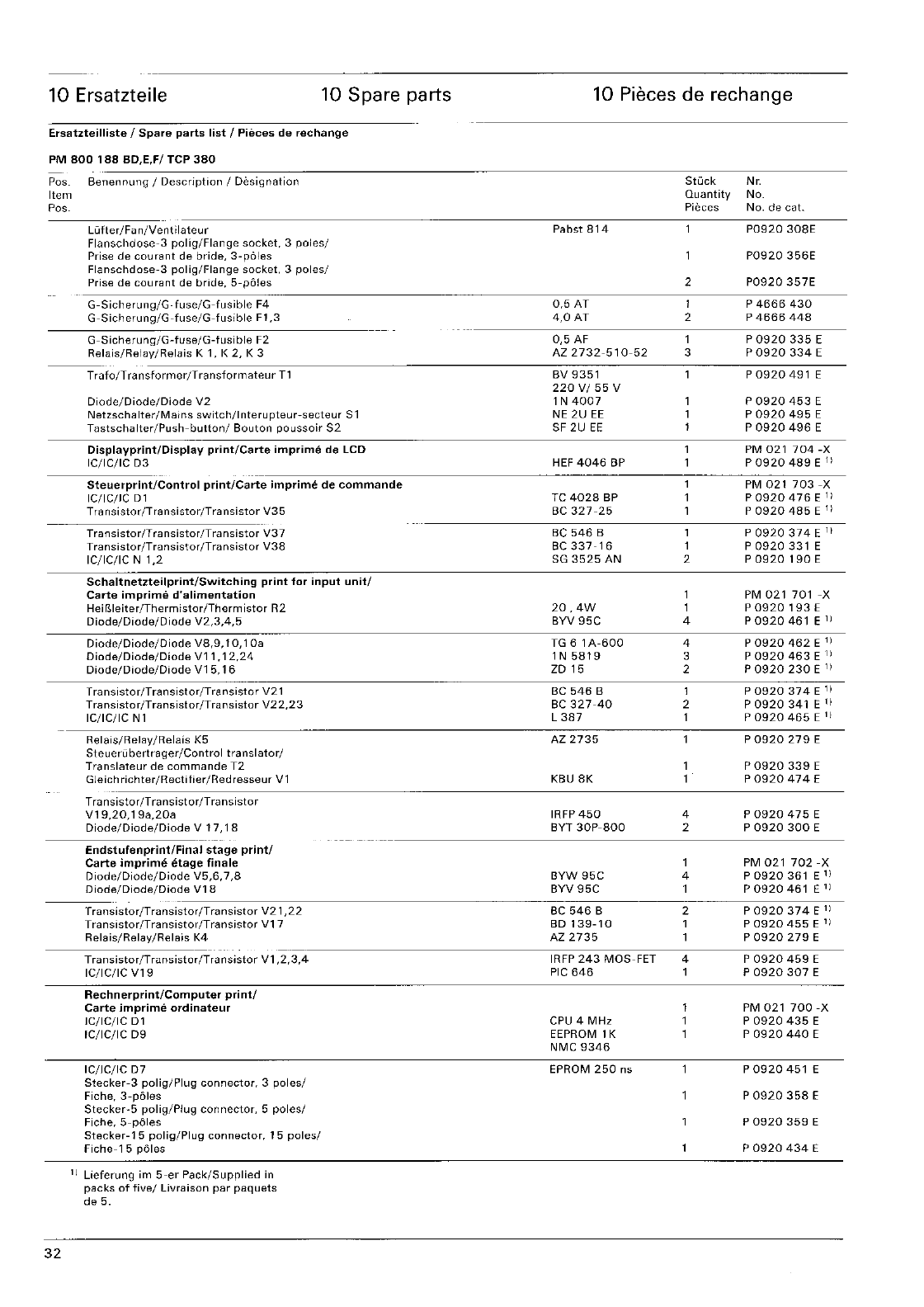
10 Ersatzteile 10 Spare parts
Ersa1zteilliste
I
Spare
parts
list
/
Pieces
de
rechange
PM
800
188
BO,E.F/ TCP
380
Pos.
Benennung
I
Description
/ Designation
Item
Pos.
Lutter
/Fil
n/Vent
ilateur
Flanschdose-3
polig/Flange
socket,
3
poles/
Prise
de
courant
de
bride,
3-poles
Flanschdose-3
polig/Flange
socket,
3
poles/
Prise de
courant
de
bride,
5-poles
G-Sicherung/G-fuse/G-fusible
F4
G-Sicherung/G-fuse/G-fusible
F 1 ,3
G-Sicherung/G-fuse/G-fusible
F2
Relais/Relay/Relais
K 1, K
2,
K 3
---
Trafo/T
ransformer/Transformateur
T1
Diode/Diode/Diode
V2
Netzschalter/Mains
switch/lnterupteur-secteur
S1
Tastschalter/Push-button/
Bouton
poussoir
S2
Displayprint/Display
print/Carte
imprime
de
LCD
IC/IC/IC
03
Steuerprint/Control
print/Carte
imprime
de
com
man
de
IC/IG/IC
Dl
T
ra
nsistor/Tra nsistor/Tra
nsistor
V35
Transistor/T
ra
nsistor
IT
ransistor
V37
Transistor/Transistor/Transistor
V38
IC/IC/IC N
1,2
Schaltnetzteilprint/Switching
print
for
input
unit/
Carte
imprime
d'alimentation
Heir..leiter/Thermistor/Thermistor
R2
Diode/Diode/Diode
V2,3,4,5
Diode/Diode/Diode
VB,9,
1 0,1
Oa
Diode/Diode/Diode
V11,
12,24
Diode/Diode/Diode
V15,
16
Transistor/Transistor/Transistor
V21
Transistor
/Transistor/T
ransistor
V2
2,2
3
le/lc/lc
N 1
Relais/Relay/Relais
K5
Steueni
bertrager/Control
tra
nslator/
Translateur
de
commande
T2
Gleich
richter/Rectifier/Red
resseur
V 1
Transistor
/T
ransistor
/T
ransistor
V19,20,19a,20a
Diode/Diode/Diode
V
17,18
Endstufenprint/Final
stage
print/
Carte
imprime
etage
finale
Diode/Diode/Diode
V5,6,7,8
Diode/Diode/Diode
V18
10 Pieces de rechange
Stuck
Nc.
Quantity
No.
Pieces
No. de cat.
Pabst
814
P0920
30SE
P0920
356E
2
P0920
357E
0,5
AT
1 P
4666
430
4,0
AT
2 P
4666
448
0,5
AF
1 P
0920335
E
AZ
2732-510-52
3 P
0920334
E
BV
9351
P
0920
491
E
220V/55V
1 N
4007
P
0920
453
E
NE
2U
EE
P
0920
495
E
SF
2U
EE
P
0920
496
E
PM
021704-X
HEF
4046
BP
P
0920
489
E
11
PM
021703-X
TC
4028
BP
P0920476El)
Be
327-25
P
0920
485
E
11
Be
546
B 1 P
0920
374
E
1)
BC337-16
1 P
0920
331 E
SG
3525
AN
2 P
0920
190
E
PM
021701
-X
20,4W
P0920193E
BVV
95C
4 P
0920
461 E
1)
TG 6 1 A-BOO 4 P
0920
462
E
1)
1 N
5819
3 P
0920
463
E
11
ZD
15 2 P
0920
230
E
11
Be
546
B 1 P
0920
374
E
1)
BC
327-4D
2 P
0920
341 E
1)
L
387
1 P
0920
465
E
1)
AZ
2735
P
0920279
E
P
0920339
E
KBU
BK
P
0920
474
E
IRFP
450
4 P
0920
475
E
BYT 30P-BOO 2 P
0920
300
E
1 PM
021702-X
BYW
95C
4
P0920361
El)
BYV
95C
1
P0920461
Ell
BC
546
B 2 P
0920374
E
11
Trilnsistor/Transistor/T
ransistor
V21
,22
32
Transistor/Transistor/Transistor
V17
Relais/Relay/Relais
K4
Transistor/Transistor/Transistor
V1
,2,3,4
IC/IC/IC
V19
Rechnerprint/Computer
print/
Carte
imprime
ordinateur
IC/le/le
01
IC/IC/IC D9
Ie/Ie/Ie
07
Stecker-3
polig/Plug
connector,
3
poles/
Fiche,3-poles
Stecker-5
polig/Plug
connector,
5
poles/
Fiche,
5-poles
Stecker-15
polig/Plug
connector,
15
poles/
Fiche-l
5
poles
11
Lieferung
im
5-er
Pack/Supplied
in
packs
of
five/
Livraison
par
paquets
de
5.
BD
139-10
P
0920
455
E
11
AZ
2735
P
0920279
E
IRFP
243
MOS-FET 4 P
0920
459
E
PIC
646
P
0920
307
E
PM
021
700-X
CPU 4
MHz
P
D920
435
E
EEPROM
1 K P
0920
440
E
NMC
9346
EPROM
250
ns
P
0920
451
E
P
0920
358
E
P
0920
359
E
P
0920
434
E
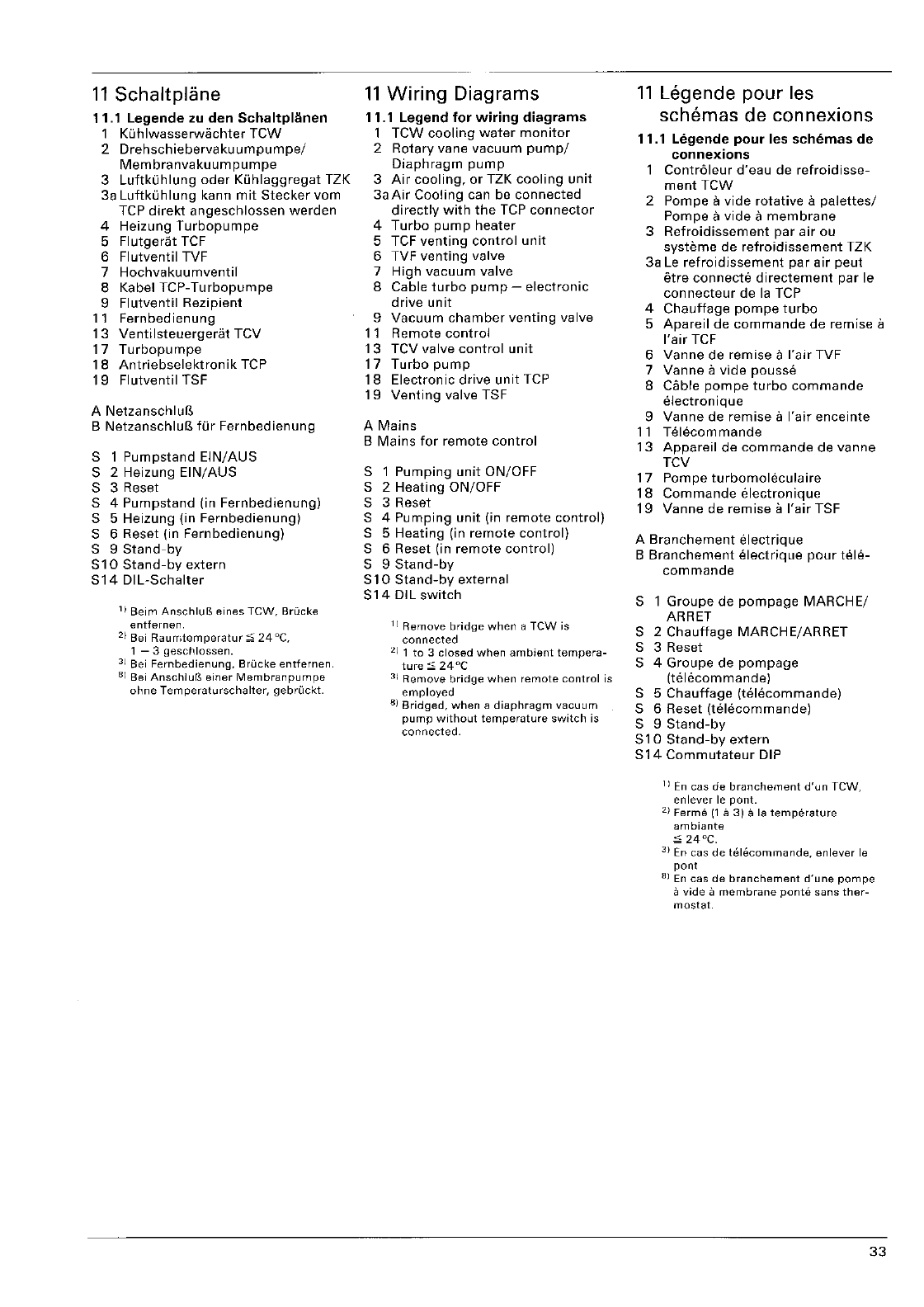
11
Sehaltplane
11.1
Legende
zu
den
1 Ki..ihlwasserwachter
leW
2
Drehschiebervakuumpumpe!
Membranvakuumpumpe
3
Luftkuhlung
oder
Kiihlaggregat
TZK
3a Luftki..ihlung kann
mit
Stecker
vom
TCP
direkt
angeschlossen
werden
4 Heizung
Turbopumpe
5
Flutgerat
TCF
6 Flutventil TVF
7
Hochvakuurnventil
8 Kabel
TCP-Turbopumpe
9
Flutventil
Rezipient
11
Fernbedienung
13
Ventilsteuergerat
TeV
17
Turbopumpe
18
Antriebselektronik
TCP
19
Flutventil TSF
A
NetzanschluB
B
NetzanschluB
fOr
Fernbedienung
S 1
Pumpstand
EIN/AUS
S 2 Heizung
EIN/AUS
S 3 Reset
S 4
Pumpstand
(in
Fernbedienung)
S 5 Heizung (in
Fernbedienung)
S 6 Reset (in
Fernbedienung)
S 9
Stand-by
S10
Stand-by
extern
S14
DIL-Schalter
1)
Beim
AnschluB
eines
TCW,
Brucke
entfernen.
2)
Bei
Raurntemperatur
24°C,
1 - 3
geschlossen.
3)
Bei
Fernbedienung,
Brucke
entfernen.
8)
Bei
AnschlulS
siner
Membranpumpe
ohne
Temperaturschalter,
gebruckt.
11
Wiring
Diagrams
11.1
Legend
for
wiring
diagrams
1
leW
cooling
water
monitor
2 Rotary vane
vacuum
pump/
Diaphragm
pump
3
Air
cooling,
or
TZK
cooling
unit
3aAir
Cooling
can be
connected
directly
with
the
TCP
connector
4
Turbo
pump
heater
5 TCF
venting
control
unit
6 TVF
venting
valve
7
High
vacuum
valve
8 Cable
turbo
pump
-
electronic
drive
unit
9
Vacuum
chamber
venting
valve
11
Remote
control
13 TCV valve
control
unit
17
Turbo
pump
18
Electronic
drive
unit
TCP
19
Venting
valve TSF
A
Mains
B
Mains
for
remote
control
S 1
Pumping
unit
ON/OFF
S 2
Heating
ON/OFF
S 3 Reset
S 4
Pumping
unit
(in
remote
control)
S 5 Heating (in
remote
control)
S 6 Reset (in
remote
control)
S 9
Stand-by
S 1 0
Stand-by
external
S14
DIL
switch
1)
Remove
bridge
when
a TCW is
connected
2)
1
to
3
closed
when
ambient
tempera-
ture
24°C
31
Remove
bridge
when
remote
control
is
employed
6)
Bridged,
when
a
diaphragm
vacuum
pump
without
temperature
switch
is
connected.
11
Legende pour les
sehemas de eonnexions
11.1
Legende
pour
les
scMmas
de
connexions
Contr61eur
d'eau
de
refroidisse-
ment
TCW
2 Pompe a
vide
rotative
a
palettes/
Pompe
a
vide
a
membrane
3
Refroidissement
par
air
ou
systeme
de
refroidissement
TZK
3a
Le
refroidissement
par
air
peut
etre
connecte
directement
par
Ie
connecteur
de
la
TCP
4
Chaullage
pompe
turbo
5
Apareil
de
commande
de remise a
I'air
TCF
6 Vanne de remise a
I'air
TVF
7 Vanne a
vide
pousse
8 Cable
pompe
turbo
commande
electronique
9
Vanne
de
remise
a
I'air
enceinte
11
Telecommande
13
Appareil
de
commande
de vanne
TCV
17
Pompe
turbomoleculaire
18
Commande
electronique
19
Vanne de
remise
a
I'air
TSF
A
Branchement
elect rique
B
Branchement
elect
rique
pour
tele-
commande
S 1
Groupe
de
pompage
MARCHE/
ARRET
S 2
Chauffage
MARCHE/ARRET
S 3 Reset
S 4
Groupe
de
pompage
(telecommande)
S 5
Chauffage
(telecommande)
S 6 Reset
(telecommande)
S 9
Stand-by
S
10
Stand-by
extern
S
14
Commutateur
DIP
11
En
cas
de
branchement
d'un
TeW,
enlever
Ie
pont.
2)
Ferme
(1
a
3)
a
18
temperature
ambiante
24°C.
3)
En
cas
de
h§;lE.kommande,
enlever
Ie
pont
6)
En
cas
de
branchement
d'une
pompe
a
vide
a
membrane
ponte
sans
ther-
mostat.
33
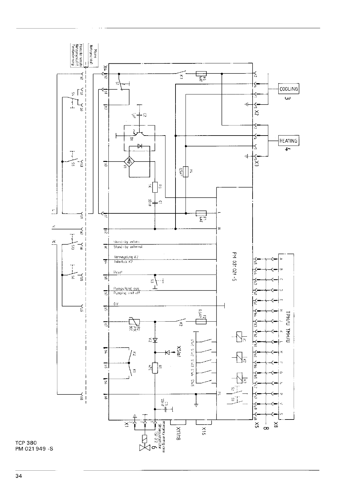
3
Y2
Y4
YI
7
m
f-
Kl
(2
I'
,
F4
,--,
'----J
0,5/>,-:-
Pi
"
C1
II
II
33nF
N
m
fl
4J4AT
;:;
ii
0
r---
TPH/U
TMH/U
K r G ,. P
IT
X8
' • H J
'L
I
iii
Y L
4-+111'1rrir1rl+I,8
t X
Xl"
_ _ . 6
yb5
yb5
'Cd
Yb7
yeS
XS
• • • b4 Y
t3
y
b2
Y
..1Y-,,'
__
_
V05
yo!.
__
PM
03'
021
-5
r
c:'
....
C\
'"
§ ,
" " >
-0
cZJ
9 \ ,
9' I
\1
P:'
\1\
\ \
X16
I'
5'_:'2
...
'3
';o-"i"
S>;5
XSIal
X17I18
r
""
StromoJsbllflut:>r
V2
47E
'J
is:
3
Xl
MClns
Nptzors:hlUJ
K1
_
I,"
1
,5
; 07 . . .
+;--+I-:;-----.J
b't
bS
It6
oB
.2
,b
04
b8
X4
b2
bl'
b-;---
T y
b3
.--p:----
_ ,3 1
,,",ummo'
r
I-
t
)2
t
,3
,e,b,d,",,,,,
'
SC
_"
yo3
-
, r
yw
'--\"
I
L I
(f)
'"
..-
0'"
00-
",N
0.
0
U:;;:
..-
1-
a. C'l
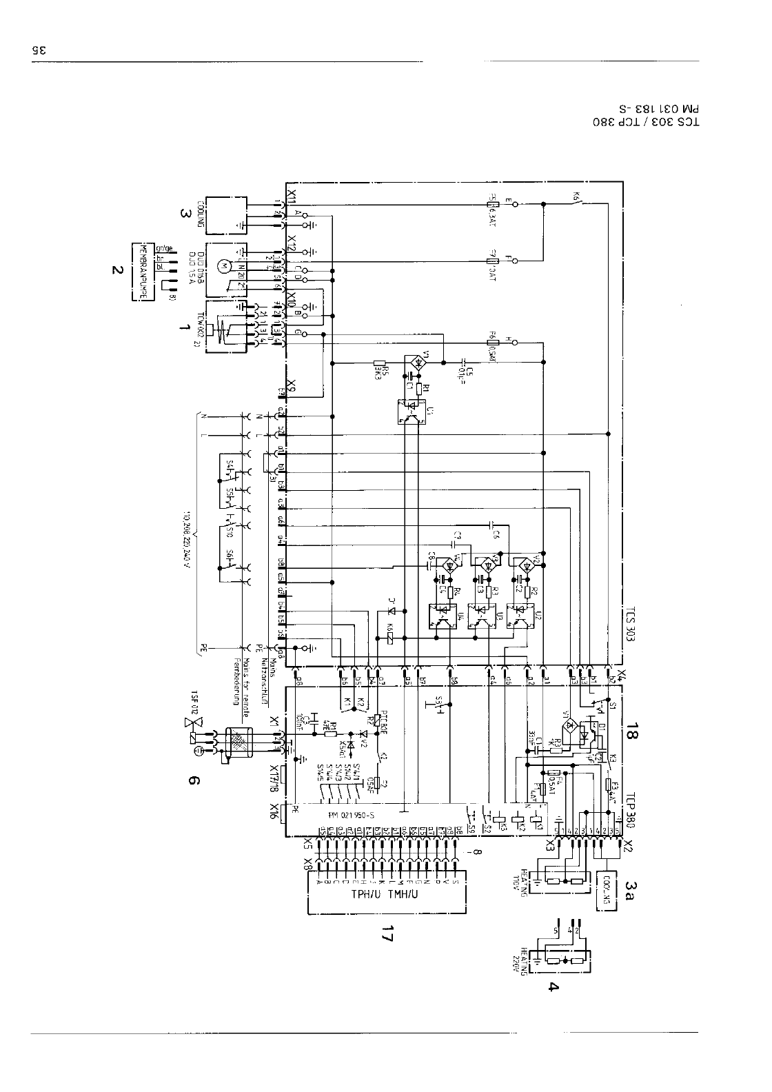
w
<.n
s:n
aU>
WW
,n
U>-o
W
co
a
I
"I
I 1 1 . , • I : I
'II
4
I ,
[1
Fl
-
J1i1
" , " ,
-l::..,\C'I-
___
l"J:lo,:F-+f+-_-":..AT
----u-
.
......J
.--1
...-
.
'nK2
HEATING
HEATIN5
0'1
'
::{P
'I
llGV
220'1
I
'11I16.W
'lll1'OAT
F61110.5ATI
+----1
C5
J..,C6
T aI,.,
-T-
$2
,
"I
i-l
I
I
I
[1 -
1,'1
1
' I
Jl(=l1
f: I
,
-,
I
iF
1
J
::
P
[BOE
"
---ci-
J'
11
117
RI
lK3
I
Ih
JH
56
,'''
lUl,!'
6,
,1,31-
)l,3l:i
, 7
20,:1-,
r
'0IDl
L..--J
__
COOLING
OJ']
0160
T[I./002
21
3
OJJ15A
1
•
ME
MBRA
N:JU:;:J
C,_,,,j
2
4 R
CSAF
'-';'
t!.
i:
Vi 0
Ho..
S·
5'411,
01
E
I-
,
,K'
X5io
j
=r=!
I'
514.'5
I
'J1
3:=A
'
,
'c\
,
X5
XSL-,--.J
_
PE.
'.
Mains
be
remote
/-
,,-'-
"-----"-------v
PE
I
TSF
012
.......
T'
6
'1))08,m,240'i
2S-M
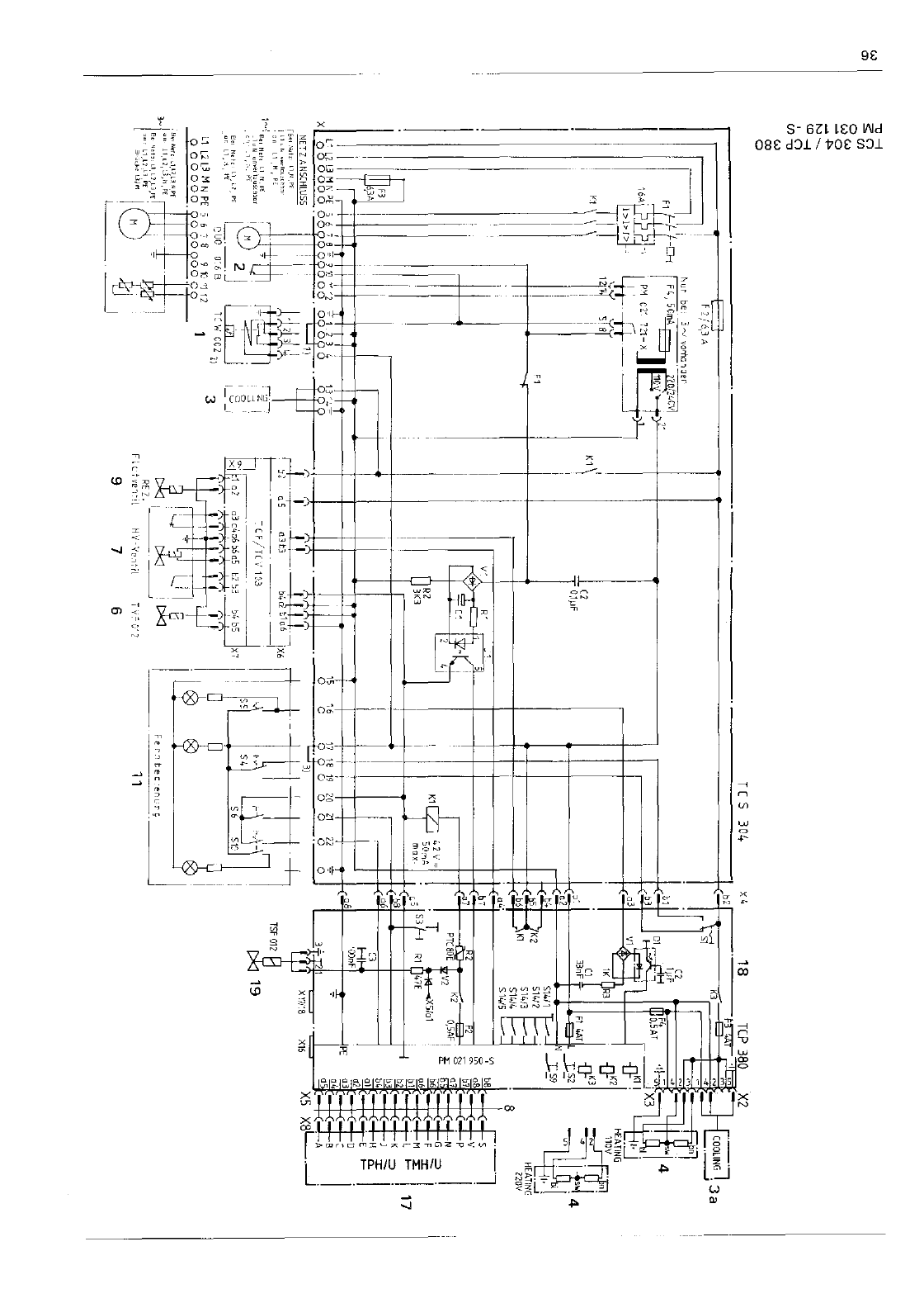
,..)
m
-0--<
,;("")
'"
0",
--I'>
"'--<
,("")
"'-0
'"
CO
o
i
'"
o
F2
1
_
-f-<2
I
PTCaoE
lV2
K2
i
R2
3K3
K11
/!
42\1",
max_
I
e6
!
••
0"0
ooW
,.J
I
1
1
" ,
l-
i
<.
1]
ij
1'7
1€
19
20
21
22
000
o 0 ? 0
"",,"
","
:
.'
'
t:::::t
a ' I
,
..
".........
,,' '
.,;
"':":::,,,;:''.';.',,
.'
,I
i
*-.
} +
u·
'W
;
,'"
.J"'"''''
I
-TIl
r
j!-"
..
,'"
"
1M
.-''''''
1 05
,H-
I II' . t::
"
"'."
,,!," " 2 I I z 1 I . - ,
,.
'1-
.
_._
j . .
,g.
.
_.
'"
, 06 iX6
'1LOl3
M N
PE
_
CUO
O'&B
I;n
I
,C
-CF,/TC\' 1:'3
-I
000000
•
."
9K
L'HC2-
--'
Xl
h1e
"
, a a
00
"12"
r '
e3","6e5
c-
-
.'CII.O.
1 3 l.
,mY'
AJ;
X7
,,"""
""
'-++-1
' fif
,n
...
,::.","1
",
$'
' U"
I 1
F'",',n"
. H
V'-'{e,l7il
--
9 7
,'"C'2
6
-'II
Fer,tec
11
5101
17
Sicherheitsinformation
fur
die
Rucksendung
von
Vakuumgeraten
und
-komponenten
Allgemeine
Information
Der
Unternehmer
(Betreiber)
tragt
die
Verantwortung
fur
die
Gesundheit
und
Sicherheit
seiner
Arbeitnehmer.
Sie
erstreckt
sich
auch
auf
das
Personal,
das
bei
der
Reparatur
und/oder
War-
tung
der
Vakuumgerate
und
-kompo-
nenten
beim
Betreiber
oder
beim
Her-
steller
mit
diesen
in BerOhrung
kommt.
Die
Kontaminierung
der
Vakuumgerate
und
-komponenten
muB
kenntlich
gemacht
werden,
und
die
Erklarung
uber
Kontaminierung
ist
auszuflillen.
Erklarung
uber
Kontaminierung
Das Personal,
das
die
Reparatuf
und/
oder
die
Wartung
durchfuhrt,
muB
vor
Aufnahme
der
Arbeiten
Ober
den
Zustand
der
Vakuumgerate
und
-kom-
ponenten
informiert
werden.
Dazu
dient
die 'Erklarung Ober Kontaminie-
rung
von
Vakuumgeraten
und
-kompo-
nenten'.
Diese
Erklarung
ist
dem
Hersteller
oder
der
von
ihm
beauftragten
Firma
direkt
zuzusenden.
Ein
zweites
Exemplar
muB
den
Begleitpapieren
beigefugt
werden.
Versand
Bei
Versand
von
kontaminierten
Vakuumgeraten
und
-komponenten
sind
die
in
der
Betriebsanweisung
angegebenen
Versandvorschriften
zu
beachten,
so
zum
Beispiel:
-
Betriebsmittel
ablassen,
-
Pumpe
durch
Spulen
mit
Gas
neutra-
lisieren,
-
Filtereinsatze
entfernen,
-
aile
Offnungen
luftdicht
verschlieBen,
-in
geeignete
Schutzfolie
einschweiBen,
-
Versand
in
geeigneten
Transportcon-
tainern.
Safety
information
for
the
return
of
vacuum
systems
and
compo-
nents
General
Introduction
The
employer
(user) is
responsible
for
the
Health
and
Safety
of
his
employees.
This
also
applies
to
all
those
persons
that
come
into
contact
with
the
vacuum
components
either
at
the
user,
or
manufacturer's
premises
during
repair
or
service. The
contami-
nation
of
vacuum
systems
and
compo-
nents
has
to
be
declared
and
the
Health
and
Safety
Declaration
form
completed.
Health and
Safety
Declaration
Those
persons
carrying
out
repair
or
service
have
to
be
informed
of
the
con-
dition
of
the
components.
This
is
the
purpose
of
the
'Declaration
of
Conta-
mination
of
Vacuum
Equipment'.
This
declaration
must
be
sent
directly
to
the
manufacturer
or
representative
company.
A
second
copy
must
be
sent
with
the
equipment.
Despatch
When
returning
equipment
the
proce-
dures
set
out
in
the
Operating
Instruc-
tions
must
be
followed.
For
example:
-
drain
the
pump
operating
agent,
-
neutralise
by
flushing
with
gas,
-
remove
filter
elements,
-seal all
outlets,
-seal in
heavy
gauge
polythene
or
a
bag,
-
despatch
in
suitable
transport
contai-
ner.
Information
de
securite
sur
I'etat
d'appareils
et
de
composants
de
tech-
nique
du
vide
a
retour-
ner
a
I'usine
Information
gElnerale
L'employeur
(I'utilisateur)
est
respon-
sable
de
la
securite
et
de
la sante
de
ses
employes.
Cette
responsabilite
s'etend
egalement
aux
personnes
char-
ges
de
la
reparation
ou
de
I'entretien
des
appareils
et
des
composants
de
technique
du
vide
chez
I'utilisateur
ou
en usine.
Le
degre
de
contamination
doit
etre
detini
et
specifie
sur
Ie
certifieat
sur
I'Stat
de
contamination.
Certificat
sur
I'etat de
contamination
II
est
obligatoire
d'informer
tout
d'abord
Ie
personnel,
charge
des
repa-
rations/de
I'entretien,
de
I'Stat
des
composants
a
traiter,
d'Oll
I'importance
de ce
certifieat;
il
doit
etre
envoye
au
fournisseur
ou a la
societe
en
charge
de
reparation
ou
de
decontamination.
Une
copie
doit
aecompagner
I'equipe-
ment
a reparer.
Le
transport
Lors
d'un
retour
de
materiel
contamine
il
faut
strictement
respecter
les
pres-
criptions
donnees
dans
I'instruction
de
service
par
exemple:
-
vidange
d'huile
de la
pompe
primaire,
-
de
la
pompe
par
gaz
neutre,
-
changement
de
la
cartouche
filtre,
-
obturation
de
taus
les
orifices,
-
emballage
hermetique
du
materiel
sous
feuille
plastique,
-
transport
dans
colis
adequats.
c::.
101,
J.jlf
Herstellererkliirung
im
Sinne
folgender
EU-Richtlinien:
-Maschinen
89/392/EWG
-Elektromagnetische Vertriiglichkeit
89/336/EWG
-Niederspannung
73/23/EWG
PFEIFFERF
VACUUM
Pfeiffer Vacuum Grnbf
Emmeliusstr.33
fJ-35614 Asslar
Hlermit erklaren
wir,
des
unten aufgefUhrte Produkt
zurn
Einbau
in
eine
Maschine bestimmt ist
und
daB
deren
Inbetriebnahme
so
lange
unters<Jgt
is!,
bis
[!;lstgeslelll wurdll,
daB
das
Endprodukt
den
Bestimmungen
der
EU-Richtlinie
89j392/EWG,
Anhang
II
B entspricht.
Wir bestatigen Konformitat
mit
der
EU-Niederspannungsrichtlinie
73j23/EWG,
Bei
der Baumusterprufung wurde
mit
Zusatzausrustung Konformitilt
mit
der
EU-Rictllllllie uber
!;11!;lk[romiJ-
gnctischc Vertraglichkeit
S9/392}EWG
die
auch
bei
Einhaltung
der
Installationsvorschriften arreicht wird.
Die
angewandten Richtlinien, harmonisierten Normen, nationalen
NOlmen
und
Spezifikationen
sind
unten aufgefiihrt.
c::
ill]),
Manufacturers
declaration
pursuant
to
the
following
EU
directives:
-Machinery Directive
89/392/EEC
-Electromagnetic Compatibility Directive
89/336/EEC
-Low Voltage Directive
73/23/EEC
We
hereby certify that the product specified below
is
intended for installation
in
a machine which
is
forbidden
to
be
put
into
operation until sllch
time
as
it
has
been
determined that
the
end
product
is
in
accordance with the provision
of
EU
Directive
89/392/EEC,
Annex
II
B.
We
certify conformity with
EU
Low
Voltage
Directive
73/23/EEC.
During
a certifying test with additional equipmelll conformity with
the
EU-directive relating
10
EMI
89/392/EEC
was
found.
This
will
be
reached too if the installation instructions
are
followed.
The
gUidelines,
harmonised standards, national standards
and
splJclfications which
havlJ
blJen
applied
are
listed
below.
¢
[;::2
Declaration
du
constructeur
conformement
aux
directives
CE
suivantes:
-directive machine
CE
89/392/CEE
-
directive
CE
89/336/CEE
concernant
la
compatibilite
electromagnetique
-
directive
CE
13/23/CEE
concernant
la
basse
tension
Nous
dcclarons
par
la
presente
que
Ie
prodult mentionne ci-dessous
est
prevu
pour
Ie
montage
sur
une
machine
et
que
sa
mise
en
service est interdite tant qu'il
n'a
pas
ete
determine
que
Ie
produit final
repond
bien
aux
dispositions
de
la
directive
CE
B9/392/CEE,
append
ice
liB.
NOlls
confirmons
la
conformitil
du
produit
avec
la
directive
CE
73/23/CEE
concernant
la
basse
tension.
La
conformitc
requise
avec
la
directive
UE
rcgissant
la
compatibilitc cloctroma-
gnetique
89/392/CE,
qUI
est egalement
obtenue
en
observant
les
directives
en
matiere d'instaliation, a
ete
constatee
lors
du
processus d'homologation realise
avec
un
equipement
complementaire
Les
directives a ppliquees,
normlJs
harmonistllJs IJlles
nurrlllJS
et spilcifications
natiunallJs
appllquE!lJ:S
figurlJnl
ci-des:suu:s.
¢
IJlf
Dichiarazione
del
costruttore
ai sensi
delle
seguenti
direttive
UE:
-Macchinari
89/392/CEE
-CDmpatibilit. elellrDmagnetica
89/336/CEE
-
Bassa
tensione
73/23/CEE
Si
dichiara
che
il
prod
otto
qui
menzionato e destinato
al
montaggio
in
una
macchina e
che
la
sua
messa
in
funzione e vietata
sin
quando
non
e
stato
accertato
che
il
prodotto finale
non
rispetta
Ie
disposizioni
della
direttiva U E
B9j392/CEE,
Appendice
II
B.
Attestlamo
la
conform
ita
con
la
direttiva
UE
sulla
bassa
tensione
73/23/CEE.
Durante
la
prova
di
omologazione
e
stata
accertata,
con
equipaggiamento supplementare,
la
conformita
conla dlrettiva
UE
relativa alia compatibilita elettromagnetica
89/392/CEE,
che
si
ottiene
anche
nell'osservanza
delle
norme
di
installalione".
Sono
riportate
in
basso
Ie
direttive aplica-
te,
Ie
norme
standardizzate nonche
Ie
norme
e
Ie
specific
he
nazionali utilizatte.
¢
Declaracion
del
fabricante
al
tenor
de
las
siguientes
Directivas
de
la
UE:
-Maquinarias
89/392/MCE
-CDmpatibilidad Electromagnetica
89/336/MCE
-Baja Tension
73/23/MCE
Por
la
presente declaramos
que
el
producto mencionado
mas
abajo
esta
previsto
para
ser
incorporado
en
una
maquina
y
que
la
puesta
en
servicio
de
la
misma
queda
prohibida
en
tanto
que
no
se
haya
verificado
que
el
producto final concuerda
con
las
disposiciones resultantes
de
la
Directiva
89/392/MCE
de
la
UE,
Apendice
II
B
De
nuestra
parte
certificamos
la
conformidad
con
la
Directiva
73/23/MCE
de
la
UE
sobre
Baja
Tension.
En
la
comprobacion
del
modelo
de
construccion,
se
ha
constatado
con
equipa-
miento
adicionalla conformidad
con
la
directiva
de
la
UE
sobre
compatibilidad electromagnetica
89/392/MCE,
que
se
consigue tambien cumpliendo
las
prescripciones
de
instalacion.
Las
directivas aplicadas,
normas
armonizadas y
las
normas
y especificaciones nacionales aplicadas
se
rnencionan
abajo.
¢[im.
Verklaring
van de
fabrikant
in
de
zin van de
volgende
EU-richtlijnen:
-machinerichtlijn
89/392/EEG
-richtlijn over elektromagnetische cDmpatibiliteit
89/336/EEG
-richtlijn over laagspanning
73/23/EEG
Hlermee
verk.laren
wlj
dat
het
hleronder
genoemde
produkt
is
beltoeld
om
te
worden ingebouwd
In
een
machine
en
dat
de
ingebruikneming hiervan
zolang
verboden
is,
totdat
is
vast-
gesteld dat het eindprodukt voldoet
aan
de
bepalingen
van
EU-richtlijn
89/392/EEG,
appendix
II
B.
Wij bevestigen
de
conformiteit
met
de
EEG-richtlijn over
laagspa
nning
73/23/EEG.
Bij
de
bouwtypekeuring
is
met
aanvullende uitrusting conformiteit vastgesteld
met
de
EU-richtlijn over
elektromagnetische compatibiliteit
89/392/EEG,
die
ook
wordt bereikt
bij
het
in
acht
nemen
van
de
De
tnr.gepaste rrchtlijnen, geharmonlseerde
normen
en
de
toegepaste nationale
norm
en en
specificaties lijn hierna aangegeven.
¢
Producenterkhering
i
henhold
til
folgende
EU-direktiver:
-Maskiner
89/392/EWG
-ElektrDmagnetisk kompatihilitet
89/336/EWG
-Lavsp"mding
73/23/EWG
Hermed
IJrklccrer
vi,
at det
nedensLafHJde
produkl
er
beregneL
til
indbygning i
en
rnaskine
og
at
dermes
idriftsa:ltelse
er
lorbudt, indtil det er fastslaet,
at
slutproduktet er i overensstem-
melse
med
EU-direktiv
89/392/EWG
till<eg
II
B.
Vi
attesterer konformitet
med
EU-Iavsp<endingsdirektiv
73/23/EWG.
Ved
konstrllktionsprovelwntrollen er
der
med
ekstra
udstyr blevet fastslaet konformitet
med
EU-direktivet vedroren-
de
elektromagnetisk kompatibilitet
89/392/EWG,
hvad
der
ogs1l
kan
opnas
ved
overholdelse
af
installationsforskrifterne
De
anvendte direktiver, harmoniserede
sta
ndarder
og
de
anvendte
nationale standarder
og
specifikationer er angivet
nedenfor.
c:')
i0ll:
TIliverkarens lorklaring enligt loljande EG-direktiv:
-
Maskindirektiv
89/392/EEC
-
Elektromagnetisk
toleran.
89/336/EEC
-lagspanning
73!23/EEC
Harmed
ftirklararvi, attden nedan
namnda
pruduklen ar
avsedd
for inmontering i
en
maskin
uch
att
denna
maskin
mts
t5rt<.15
i drift lorran det har konstaterats,
art
silltprodilkten
sHim-
mer
overens
med
EG's
direktiv
B9/392/EEC,
iJnn!;lX
II
B.
Vi
bekriiftar konformitet
med
EG's
lagspanningsdirekllv
73!23jEEC.
I
samband
med
typprovningen faststiilldes ocksil
med
extru ulruslning konformitct
med
EU-dlrektivet
om
elmagnetiskt
tolcrans
89/392/EEC,
som
aven
uppnas
om
instaliatlonsforl;lskriflerna bcaktas
Dc
riktlllljer, 8npassade standarder, nationella standarder
o{;h
spccifikationer
som
har hllVlt accepterade,
anges
har
nedan
.-:>
Valmistajan vakuutus seuraavien EU-direktiivien mukaisesti:
-
konedirektiivi
89/392/ETY
-
sahkijmagneeHinen
siedeHavyy.
89/336/ETY
-
pienjiinnite
73/23/ETY
Vakuutammf! taten, etta allamainittu tuote
on
tarkolltlllu <lsonnottavaksi koneeseen
ja
sen
kiiyttoonotto
on
kielletty kunlles
on
todettu,
!;lLli:l
lopullinen
Luolc
vastaa
EU-direktlivin
B9/392/EtY
vaatimuksia.
V;JtlVistarnrnc
vaatimllstenmukaisuuden EU-pienjiinnitedirektiivlll
73/23/ETY
k(:l[l;;sa.
Rakcnncmaliitarkastuksessa todettiin lisavarustuksella vaatimustenmukalsuus sahkomagn8eLtlse-
stiJ
yhteensopivuudesta annetull EU-direktiivin
89/392}ETY
kanssa,
jolla Silavutet<l<JIl
myos
ascnnllsmaaraykslfi noudattamalla.
Soveltamamnw suuntaviitat,
ha
rmonisoidut standardit, kansalliset standardit
ja
rakennemaaraykset
on
lutcltu alempana
¢
IPit
do
labrieante, de aeordo com
as
seguintes Direetivas
CEo
-
Moquinas,
na
89/392/CEE
-
Compatibilidade
electromagnetica,
na
89/336/CEE
-
Baixa
tensao,
na
redacc;ao
73J23/CEE
Com
a presente, declaramos
que
0 produto abaixo indlc<ldo
se
dtlsLirla
a montagcm
nLima
maquina e
que
e proibida a coloca!fao
em
servl!fo
da
mesma
<lrlttlS
de
Stl
ter declarado,
que
0
produto final estii
em
conformidade
com
0 disposto
na
CE,
rlC!
redac!fao
89/392/CEE,
Allendice
II
B.
CerLijicarnos haver cOrlformidade
com
0 disposto
na
Directiva
CE
sobre
baixa
na
73/23/CEE.
Ao
fazer-se 0
exame
do
tipo
de
com
um
equipamerlto adicio-
nal
consLaLou-se
cxistlr conformidade
com
a directriz
CE
sobre a compatibilldade electromagnetica
89/392/CEE,
a
qual
tambem
se
con
segue,
mantendo-se
as
disposi!foes referentes a
Abaixo, da-se irldica!fao
das
dircctivas aplicadas,
das
normas harmonizadas e
das
normas e
especifIG<J<;ues
aplicadcs
no
respectivo
pais.
¢
ffl'Jl
Mj).,WOllKOlOOl(('UOO"lrl
KOTO
TO
VOllj.lO
TWV
£f,!)<;
OOrjYtWV
rrK
E£'
. nEpi
j.lr))(<:ntWv
89/l92/E.O.K.
-
nE:pi
fjM:IITPOj.IOVVrrmu'K
"lJl.IfkrrClTfjTac;
B9{3S6/E.O.K.
"flO::pi
TOOl)<;
73/2l/E.O.K.
mv
rapouad
0111U101l
[lcflcmINol!)J€
OTi
TO
1«("11WrcpJ.J OVo<:p",popSVO
npo'ov
npoopil,C101 ylO HI\)
npOOdPfJOYrl
O{:
pio
6AAr]
<.If))(QVr'),
XOI
OTlll
Til\;
onayopcucTdl.
fl(:)(fW;
(JIG\)
OIOflIOTW8c;,
(')fi
TO
-:JUYKP0lrijJO
QVTOnOKpivCl(]l
CIOU",
IOx0cVT€-<; KOVOVIO!J0uS
Hll,
o6rjylQ(
Til<:
[E.
fl9(1Q:I/r.ox,
IICpapHliJa
jl
B
KaTa
TOV
00(11.100"1"11:0
t."Acyxo
TI1t;
IJC
i5lOnlorr.i.lBI")KoC
11
OVTOOOKPIOIl
j.Ie
Tr)V
OOI1Yio
EE
8Q/3Q2/F..O.K.
OXoCTlKO
IJE:
II")V
1171E:I:TpoIJOVVI)TIKt)
11
onoia
oCKfl7II)PWVE:1
KOI
KCVOVIOJ.lOUc;
oe:yXOTOorOOI')<;.
Ot
£qlOPlJ008CIITE:(,"'
I:QIIOVIOI-IOt,
01
E:VOp;,JOVIOIJE;VE:(,"'
npoOIOVpO<;lE(,"'
KOI
01
e:o;>0pjJoogeioe(,"' e9vIICt..:;
1(01
T£XVIKt.o:;
KaTUJT£PW:
Prod
u
kt/
Prod
u
ct/P
rod
u it/Prodo
tto/P
rod
u
eta/
P
ro
d u
kt/P
ro
d u
kt/P
rod
uto/
TCP
380
Angewendete
Richtlinien, harmonisierte
Normen
und
angewendete,
nationale
Normen
in
Spraehen
und
Spezifikationen:
Guidelines,
harmonised
standards,
national
standards
in
languages
and
specifications which
have
been
applied:
Les
directives
appliquees,
normes
harmonisees
et
les
normes
nationales
appliquees
en
langues
et
specifications:
Direttive aplicate,
norme
standardizzate
e
norme
nazionali
utilizzate
in
lingue
e specifiche:
Directivas
aplieadas,
normas
armonizadas
y
normas
naeionales
aplicadas
en
idiomas
y espeeifieaciones:
Toegepaste
richtlijnen,
geharmoniseerde
normen
en
toegepaste
nationale
normen
met
betrekking
tot
talen
en
specificaties:
Anvendte
direktiver,
harmoniserede
standarder
og
de
anvendte
nationale
standarder
med
sprog
og
specifikationer:
Direetivas
aplicadas,
normas
harmonizadas
e
normas
aplieadas
na
linguagem
e
nas
do
respectivo
pafs:
E,.,apj.lao9cVTcC; KOVOlll0j.loi,
KOI
Of:
Kel
r£KvIKcc;
EN
61010
U
nte
rsc
h
rifte
n/S
i 9 n
atu
res/S
i 9 n
atu
re/Fi
rm
e/Fi
rm
a
s/H
a n
dte
ke
n i
ng
e
n/U
nd
e rskrifte r /
Ass
i n
atu
r a
s/
Y
noyptlqlcc;:
GcschaftsfUhrer
(W.
Dondorf)
Managing Director
Ger<Jrlt
d'affairs
Gerente
Administrerellde Direktor
Gerente
AlleklrjoitukseL
Herst.f1/9606
Dlrecteur
Verkstiillande Direktiir
Underskrift
DTP
Form.
Nr.
10120/ (9606)
PFEIFFER
I;"VACUUM
;:
...
Sicherheitshinweise TCP 380
GEFAHR Die
im
TCP 380 benutzten Kleinspannungen
von
40V ± 15V
und
5V
sind
von
Netz
galvanisch
getrennt,
kennen aber
im
einfachen Fehlerfall Netzspannungspotential
annehmen.
Hiervon
betroffen
kennen aile Stecker
am
Gerat sein.
Die Stecker X1, X2, X3
und
X5 am
TCP
durfen
nur
mit
den
original
Zubeherteilen,
die
zum
AnschluB
daran
vorgesehen
sind,
verbunden
werden. Diese erfullen
die
Isolationsanforderungen.
Werden
im
Netzstecker
X4
Schaltfunktionen
benutzt,
wie
in 4.11. beschrieben, so
sind
diese
gegen
300 V
zu
isolieren. Dies
gilt
sinngemiiB
auch
fur
den Netzstecker X9 des TCS 303, falls dieses Gerat
wie
unter
3.2.
beschrieben
zusammen
mit
TCP
380 eingesetzt
wird.
Ebenso mussen die Anschlusse an X16, deren Funktion
unter
4.6. beschrieben ist,
sowie
die
der
seriellen
Schnittstelle gegen 300V
isoliert
werden.
Safety Instructions, TCP 380
The
low
voltages
of
40V ± 15V and
5V
used in
the
TCP
380 are
galvanically
separated
from
the
mains
but
can, in a
simple
malfunction
situation, take
voltage
potential
from
the
mains
supply. This
Plugs X1, X2, X3 and X5 on
the
TCP
may
only
be connected
with
those
original
accessory parts pro-
vided
for
the
connection
purposes. This ensures
compliance
with
the
insulation
requirements.
can
apply
to
all
plugs
on
the
unit.
If
the
switching
functions
are used in
mains
plug
X4, as described in section 4.11,
they
should
also be insulated
against 300V.
This
also
applies
of
course
to
the
mains
plug X9 in
the
TCS 303 in
the
event
this
unit
is
being
operated
together
with
the
TCP 380 as described in section 3.2
..
The
connections
to
X16
whose
functions
are described in section 4.6 and also
the
serial interface
must
also be
insulated
against
300V in
the
same way.
Indications de securite TCP 380
rc==O=AN=G=ER==il
Les
tensions
inferieures de 40V ± 15V et 5V utilisees dans TCP 380,
sont
separees
galvanique
du
reseau,
mais
peuvent
recevoir
un potentiel de
tension
de reseau en cas de
detauts
simples.
Peuvent
etre concernees,
toutes
les fiches a I'appareil.
Les fiches X1, X2, X3 et X5 au
TCP
ne
doivent
etre reliees
que
seulement
avec les accessoires ori-
ginaux
qui
sont
prevus
pour
Ie
raccordement. Ceux-ci
remplissent
les exigences
d'isolation.
Si
dans la
fiche
secteur X4, des
fonctions
de
commutation
sont
utilisees, com
me
decrit
dans
Ie
chapitre
4.11.,
elles
seront
a
isoler
contre
300V.
Ce
qui
est
egalement
valable
pour
la fiche secteur X9 de TCS 303, si cet
appareil est
utilise
avec TCP 380
comme
decrit dans
Ie
chapitre 3.2
..
Doivent
etre
egalement
isoles contre 300V, les raccordement a X16,
dont
les
fonctions
sont
decrites dans 4.6.
ainsi
que
les interfaces serielles.
PM
800 475 BN/A 9701

Zentrale/Headquarters
Pfeiffer Vacuum GmbH
Emmeliusstrasse 33
D-35614 Asslar
Telefon 06441/802-0
Telefax 06441/802-202
Hotline 06441/802-333
Internet:
http://www.pfeiffer-vacuum.de
India
Pfeiffer Vacuum India Ltd.
25-E Nicholson Road, Tarbund
Secunderabad 500 009,
telephone 0091 / 40 775 0014, telefax 0091 / 40 775 7774
Israel
Eastronics Ltd., 11 Rozanis Street, P.O. Box 39 300,
Tel Aviv 61392,
telephone 00972 / 3 6458 777,
telefax 00972 / 3 6458 666
Italy
Pfeiffer Vacuum Italia S.p.a.
Via San Martino, 44 I-20017 RHO (Milano)
telephone 0039 / 2 93 99 051, telefax 0039 / 2 93 99 05 33
Japan
Hakuto Co. Ltd., C.P.O. Box 25,
Vacuum & Scientific Instruments Division
Tokyo Central 100-91,
telephone 0081 / 3 32 258 910,
telefax 0081 / 3 32 259 009
Korea
Pfeiffer Vacuum Korea Ltd., 3F Haein Building 453,
Dokok-Dong, Kang Nam-Ku, Seoul, 135-270
telephone 0082 / 2 3461 0671,
telefax 0082 / 2 3461 0676
Netherlands
Pfeiffer Vacuum Nederland BV
Veldzigt 30a, NL-3454 PW De Meern,
telephone 0031 / 30 6666050, telefax 0031 / 30 6662794
Peru
Ing. E. Brammertz S.C.R.L., José Pardo 182,
Apartado 173, PE-18 Miraflores,
telephone 0051 / 1 445 8178
telefax 0051 / 1 445-1931
Poland
Softrade Sp.z.o.o, ul. Malwowa 35,
PL-60-175 Poznan, telephone 0048 / 61 8677 168,
telefax 0048 / 61 8677 111
Portugal
Unilaser Lda, Taguspark
Núcleo Central, sala no268, Estrada Cacém-
Porto Salvo, P-2780 Oeiras
telephone 00351 / 1 421 7733,
telefax 00351 / 1 421 7744
Singapore
APP Systems Services Pte. Ltd, 2 Corporation Road
06-14 Corporation Place, Singapore 618494,
telephone 0065 / 268 2024, telefax 0065 / 268 6621
Spain
Tecnovac
Tecnologia de Vacio S.L., Ronda de Poniente, 6 Bajo F
Centro Empresarial Euronova
E-28760 Tres Cantos (Madrid)
telephone 0034 / 91 804 11 34,
telefax 0034 / 91 804 30 91
Sweden
Pfeiffer Vacuum Scandinavia AB
Magasinsgatan 35, Box 10412
S-43424 Kungsbacka
telephone 0046 / 300 710 80
telefax 0046 / 300 172 85
Service Hotline: 0046 / 300 710 85
Switzerland
Pfeiffer Vacuum Schweiz S.A.
Förrlibuckstraße 30, CH-8005 Zürich
telephone 0041 / 1 444 2255,
telefax 0041 / 1 444 2266
Service Hotline: 0041 / 1 2730119
South Africa
Labotec Pty Ltd., P.O. Box 6553,
Halfway House
1685 Midrand
telephone 0027 / 11 315 5434
telefax 0027 / 11 315 5882
Taiwan
S & T Hitech Ltd. Hsinchu office
No. 103, Hsien Chen 11th Street, Jubei City,
HsinChu County, Taiwan, R.O.C.
(zip/postal code: 302)
telephone 00886 / 3 554 1020
telefax 00886 / 3 554 0867
Thailand
S & T Enterprises (Thailand) Ltd.
18th Floor, Chokchail Intíl Bldg.
690 Sukhumvit Road
Klongton, Klongtoey
Bangkok 10110
telephone 00662 / 259 4623
telefax 00662 / 259 6243
U.S.A.
Pfeiffer Vacuum Technology, Inc.
24 Trafalgar Square
Nashua, NH 03063-1988
USA
telephon 001/ 603 578 6500
telefax 001/ 603 578 6550
Venezuela
Secotec S.A., Apartado 3452, Caracas 1010-A,
telephone 0058 / 2 573 8687
telefax 0058 / 2 573 1932
Other countries
AVI - Applied Vaccuum Industries GmbH
Leginglenstrasse 17A; CH-7320 Sargans
Switzerland
telefon 0041 / 81 710 03 80
telefax 0041 81 710 03 81
Scope of represented countries
Armenia, Azerbaijan, Bangladesh, Belarus, Bulgaria,
Cambodia, Estonia, Georgia, Hong Kong, Kazakhstan,
Kingdom of Nepal, Kirghizia, Latvia, Lithuania, Maldavia,
Philippines, P.R. China, Rumania, Russia, Tajikistan,
Turkmenistan, Ukraine, Uzbekistan, Vietnam
A.E.M.S.
Advanced Equipment Materials and Systems
P.O. Box 25
Föhrenweg 18
FL-9496 Balzers
telephon 0041 / 75 380 0550
telefax 0041 / 75 380 0551
Scope of represented countries
Bahrain, Egypt, Iraq, Iran, Jordan, Kuwait, Lebanon,
Lybia, Oman, Pakistan, Saudi-Arabia, Sudan, Syria,
Turkey, United Arab Emirates, Yemen
Argentina
ARO S.A., Casilla de Correo 4890,
1000 Buenos Aires, telephone 0054 / 1 331 3918,
telefax 0054 / 1 331 3572
Australia
Balzers Australia Pty. Ltd., Level 1,
3, Northcliff Street, Milsons Point, NSW 2061,
telephone 0061 / 2 9954 1925, telefax 0061 / 2 9954 1939
Austria
Pfeiffer Vacuum Austria GmbH
Diefenbachgasse 35, A-1150 Wien,
telephone 0043 / 1 8941 704, telefax 0043 / 1 8941 707
Service Hotline: 0043 / 1 8941704
Belgium / Luxemburg
Pfeiffer Vacuum Belgium N.V./S.A.
Minervastraat 14, B-1930 Zaventem
telephone 0032 / 2 725 0525, telefax 0032 / 2 725 0873
Service Hotline: 0032 / 2 725 3545
Brazil
Elmi Tec
Assistencia Técnica e Representação S/C Ltda.
Rua Bernadino de Compos, 551
CEP 04620-002 São Paulo, SP - Brasil
telephone 0055 / 11 532 0740
telefax 0055 / 11 535 3598
Chile
BERMAT S.A., Coyancura 2283, piso 6
Providencia, P.O. Box 9781, Santiago
telephone 0056 / 2 231 8877,
telefax 0056 / 2 231 4294
Colombia
Arotec Colombiana S.A., Carrera 15 No.38-17
P.O. Box 050 862, Santafe de Bogota / D.C.
telephone 0057 / 1 288 7799, telefax 0057 / 1 285 3604
Denmark
Pfeiffer Vacuum Scandinavia AB, Vesterengen 2,
DK-2630 Taastrup, telephone 0045 / 43 52 38 00,
telefax 0045 / 43 52 38 50
France
Pfeiffer Vacuum France SAS
45, rue Senouque, BP 139 F-78531 BUC Cedex
telephone 0033 / (0)1 30 83 04 00,
telefax 0033 / (0)1 30 83 04 04
Germany
Pfeiffer Vacuum Vertriebs GmbH,
Emmeliusstrasse 33, D-35614 Asslar
telephone 0049 / 6441 802 400
telefax 0049 / 6441 802 399
Service Hotline: 0049 / 6441 802 333
Great Britain
Pfeiffer Vacuum Ltd.
Bradbourne Drive, Tilbrook,
Milton Keynes, MK7 8AZ, United Kingdom
telephone 0044 / 1 908 373 333
telefax 0044 / 1 908 377 776
Greece
Analytical Instruments S.A., 1 Mantzarou St.,
GR-15451 Athens,
telephone 0030 / 1 674 8973, telefax 0030 / 1 674 8978
(0299)
