Tcu40 80
User Manual: tcu40-80
Open the PDF directly: View PDF ![]() .
.
Page Count: 76
Declaration
of
Conformity
We,
Edwards
High
Vacuum
International,
One
Edwards
Park
301
Ballardvale
St.
Wilmington,
MA
01887
declare
under
our
sole
responsibility
that
the
product(s)
TCU
40/80
Temperature
Control
Unit
W95000000
to
which
this
declaration
relates
is
in
confonnity
with
the
following
standard(s)
or
other
normative
document(s)
BSIEC1010-1
BS
EN50O81-1
BSEN50082-1
following
the
provisions
of
89/392/EEC
89/336/EEC
73/023/EEC
Safety
Requirements
for
Electrical
Equipment
for
Measurement,
Control
and
Laboratory
Use.
Electromagnetic
Compatibility,
General
Emission
Standard.
Generic
Standard
Class:
Domestic,
Commercial
&
Light
Industry.
Electromagnetic
Compatibility,
General
Immunity
Standard.
Generic
Standard
Class:
Domestic,
Commercial
&
Light
Industry
Machinery
Safety
Directive
Electromagnetic
Compatibility
Directive
Low
Voltage
Directive
0
Dr.
A.
P.
Troup,
Director
of
Technology
Date
and
Place
This
product
has
been
manufactured
under
a
quality
system
registered
to
ISO900I
EDWARDS
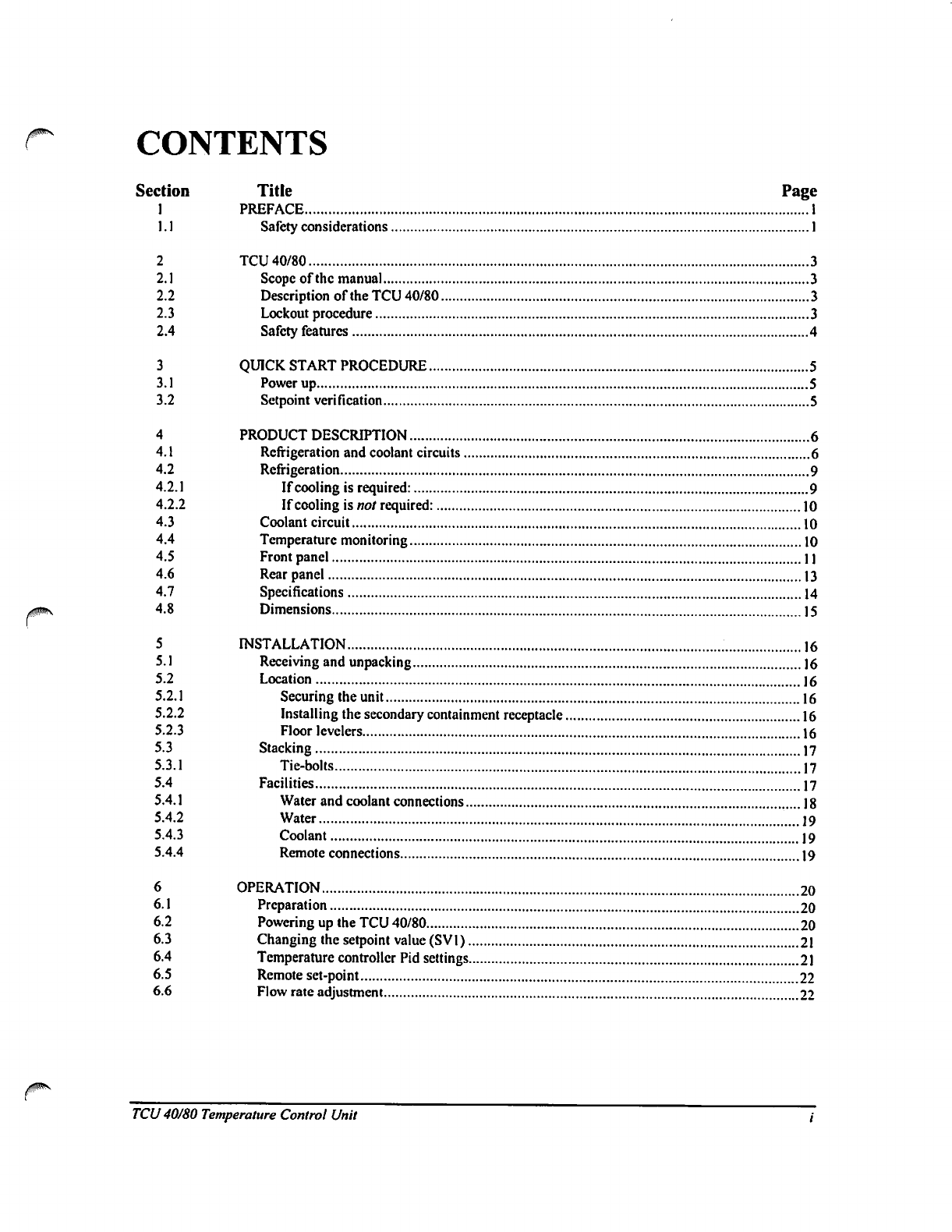
CONTENTS
Section
Title
Page
1
PREFACE
1
1.1
Safety
considerations
1
2
TCU
40/80
3
2.1
Scope
of
the
manual
3
2.2
Description
of
the
TCU
40/80
3
2.3
Lockout
procedure
3
2.4
Safety
features
4
3
QUICK
START
PROCEDURE
5
3.1
Power
up
5
3.2
Sctpoint
verification
5
4
PRODUCT
DESCRIPTION
6
4.1
Refrigeration
and
coolant
circuits
6
4.2
Refrigeration
9
4.2.1
If
cooling
is
required:
9
4.2.2
If
cooling
is
not
required:
10
4.3
Coolant
circuit
10
4.4
Temperature
monitoring
10
4.5
Front panel
1
]
4.6
Rear
panel
13
4.7
Specifications
14
4.8
Dimensions
15
5
INSTALLATION
]6
5.1
Receiving
and
unpacking
16
5.2
Location
16
5.2.1
Securing
the
unit
16
5.2.2 Installing
the
secondary
containment
receptacle
16
5.2.3
Floor
levclers
16
5.3
Stacking
17
5.3.1
Tie-bolts
17
5.4
Facilities
17
5.4.1
Water
and
coolant
connections
18
5.4.2
Water
19
5.4.3
Coolant
19
5.4.4
Remote
connections
19
6
OPERATION
20
6.1
Preparation
20
6.2
Powering
up
the
TCU
40/80
20
6.3
Changing
the
setpoint
value
(SV1)
21
6.4
Temperature
controller
Pid
settings
21
6.5
Remote
set-point
22
6.6
Flow
rate
adjustment
22
/?^v
TCU
40/80
Temperature
Control
Unit
7
MAINTENANCE
23
7.1
Hazard
warnings
23
7.2
Hazards
25
7.3
Filling
the
reservoir
26
7.4
Draining/bleeding
the
coolant
reservoir
26
7.5
Temperature
probe
calibration
27
7.6
Preventive
maintenance
schedule
27
7.7
Semi-annual
preventative
maintenance
28
7.7.1
Required
equipment
28
7.7.2
Preparation
28
7.7.3
Verify
system
status
28
7.7.4
Refrigeration
leak
check
28
7.7.5
Fluorinert
leak
check
28
7.7.6
Water
leak
check
28
7.7.7
Insulation repair
28
7.7.8
Lamp
check/replacement
29
7.8
Annual
preventative
maintenance
30
7.8.1
Required
equipment
30
7.8.2
Required
supplies
30
7.8.3
Solenoid
valve
coil
replacement
30
7.8.4
System
check
32
7.9
Preventive
maintenance
checklist
41
8
TROUBLESHOOTING
42
9
ACCESSORIES
AND
SPARE
PARTS
52
APPENDIX
54
Return
of
Edwards
Equipment
-
Procedure
(Form
HS1)
58
Return
of
Edwards
Equipment-
Declaration
(FormHS2)
59
Legal
notices,
limitations
and
disclaimers
60
MSDS
(material
safety
data
sheet)-
"SUVA"
HP62
61
'-""5\
TCU
40/80
Temperature
Control
Unit
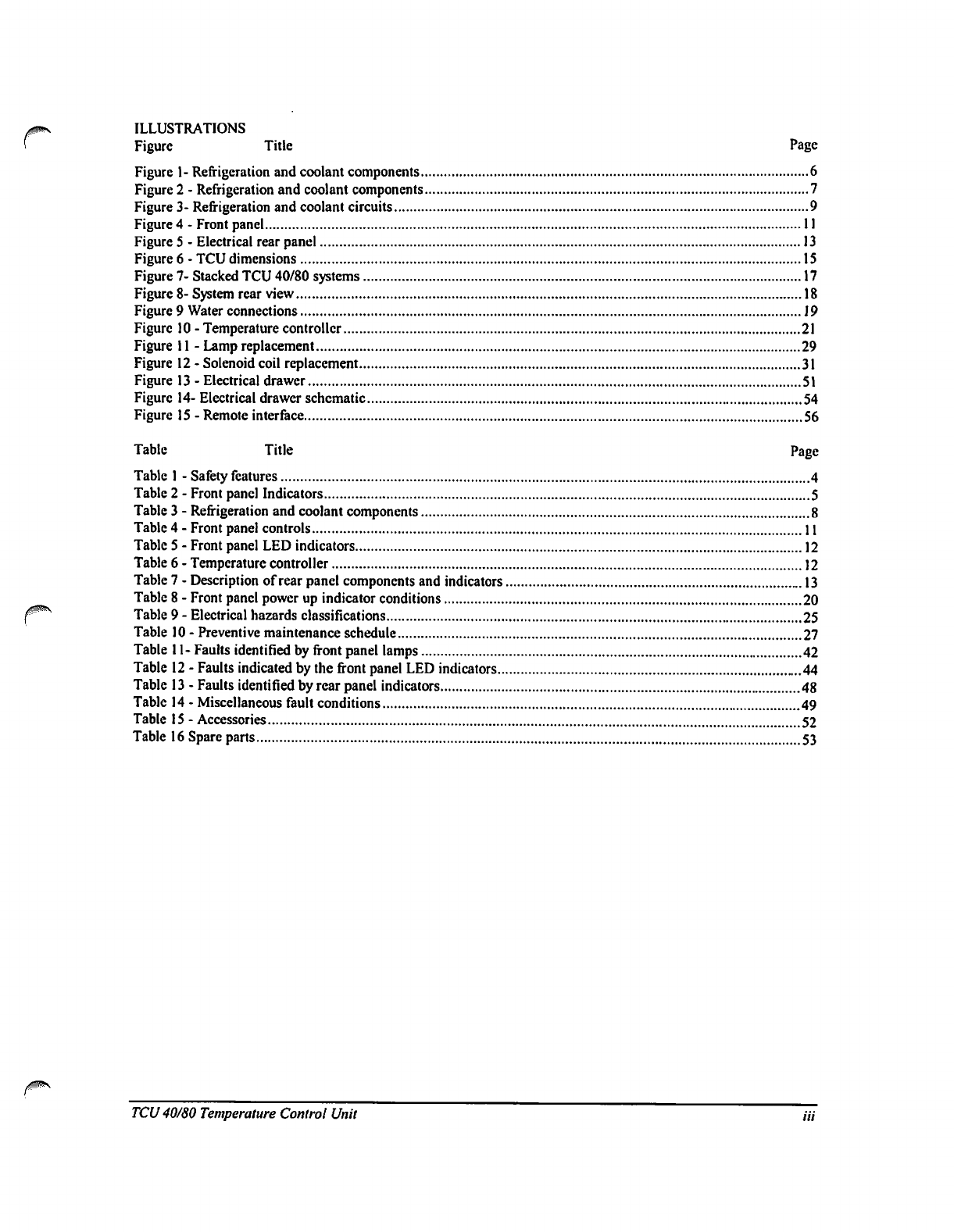
ILLUSTRATIONS
Figure
Title
Page
Figure
1-
Refrigeration
and
coolant
components
6
Figure
2
-
Refrigeration
and
coolant
components
7
Figure
3-
Refrigeration
and
coolant
circuits
9
Figure
4
-
Front panel
11
Figure
5
-
Electrical
rear
panel
13
Figure
6
-
TCU
dimensions
15
Figure
7-
Stacked
TCU
40/80
systems
17
Figure
8-System
rear
view
18
Figure
9
Water
connections
J9
Figure
10
-
Temperature
controller
21
Figure
11
-
Lamp
replacement
29
Figure
12
-
Solenoid
coil
replacement
31
Figure
13
-Electrical
drawer
51
Figure
14-Electrical
drawer
schematic
54
Figure
15
-
Remote
interface
56
Table
Title
Page
Table
1
-
Safety
features
4
Table2
-Frontpanel
Indicators
5
Table
3
-
Refrigeration
and
coolant
components
8
Table
4
-
Front
panel
controls
11
Table
5
-
Front
panel
LED
indicators
12
Table
6
-
Temperature
controller
12
Table
7
-
Description
of
rear
panel
components
and
indicators
13
Table
8
-
Front panel
power
up
indicator
conditions
20
Table
9
-
Electrical
hazards
classifications
25
Table
10
-
Preventive
maintenance
schedule
27
Table
11-
Faults
identified
by
front
panel
lamps
42
Table
12
-
Faults
indicated
by
the
front
panel
LED
indicators
44
Table
13
-Faults
identified
by
rear
panel
indicators
48
Table
14
-
Miscellaneous
fault
conditions
49
Table
15
-Accessories
52
Table
16
Spare
parts
53
TCU
40/80
Temperature
Control
Unit
Hi
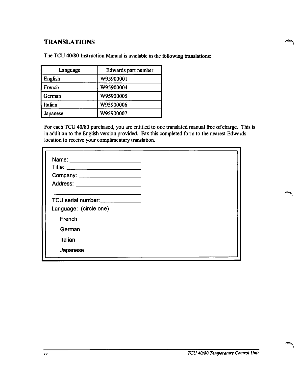
TRANSLATIONS
The
TCU
40/80
Instruction
Manual
is
available
in
the
following
translations:
Language
English
French
German
Italian
Japanese
Edwards
part
number
W95900001
W95900004
W95900005
W95900006
W95900007
For
each
TCU
40/80
purchased,
you
are
entitled
to
one
translated
manual
free
of
charge.
This
is
in
addition
to
the
English
version
provided.
Fax
this
completed
form
to
the
nearest
Edwards
location
to
receive
your
complimentary
translation.
Name:
Title:
Company:
Address:
TCU
serial
number:
Language:
(circle
one)
French
German
Italian
Japanese
TCU
40/80
Temperature
Control
Unit
1
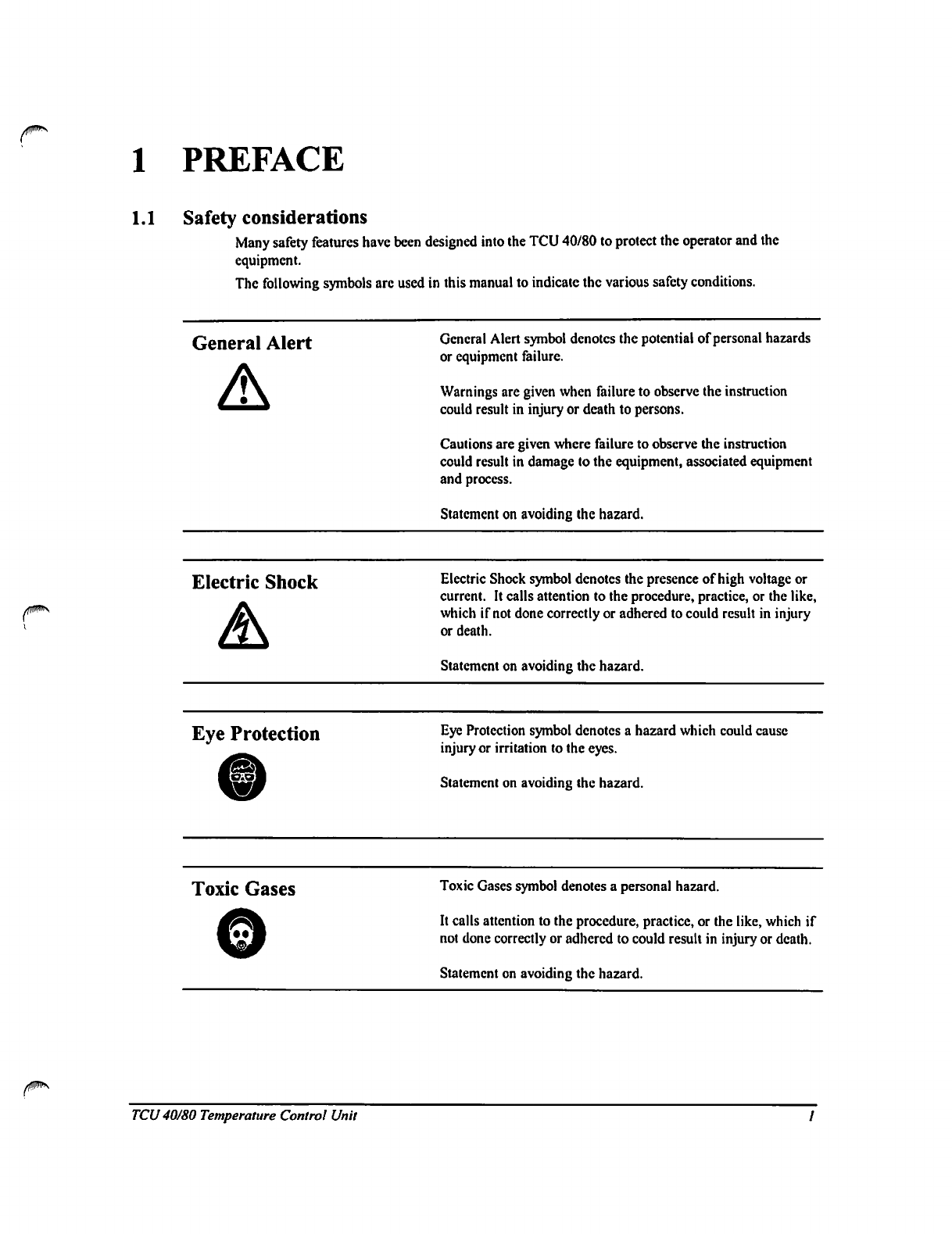
PREFACE
1.1
Safety
considerations
Many
safety features
have
been
designed
into
the
TCU
40/80
to
protect
the
operator
and
the
equipment.
The
following
symbols
are
used
in
this
manual
to
indicate
the
various
safety
conditions.
General
Alert
General
Alert
symbol
denotes
the
potential
of
personal
hazards
or
equipment
failure.
Warnings
are
given
when
failure
to
observe
the
instruction
could
result
in
injury
or
death
to
persons.
Cautions
are
given
where
failure
to
observe
the
instruction
could
result
in
damage
to
the
equipment,
associated
equipment
and
process.
Statement
on
avoiding
the
hazard.
Electric
Shock
Electric
Shock
symbol
denotes
the
presence
of
high
voltage
or
current.
It
calls
attention
to
the
procedure,
practice,
or
the
like,
which
if
not
done
correctly
or
adhered
to
could
result
in
injury
or
death.
Statement
on
avoiding
the
hazard.
Eye
Protection
Eye
Protection
symbol
denotes
a
hazard
which
could
cause
injury
or
irritation
to
the
eyes.
Statement
on
avoiding
the
hazard.
Toxic
Gases
Toxic
Gases
symbol
denotes
a
personal
hazard.
It
calls
attention
to
the
procedure,
practice,
or
the
like,
which
if
not
done
correctly
or
adhered
to
could
result
in
injury or death.
Statement
on
avoiding
the
hazard.
TCU
40/80
Temperature
Control
Unit
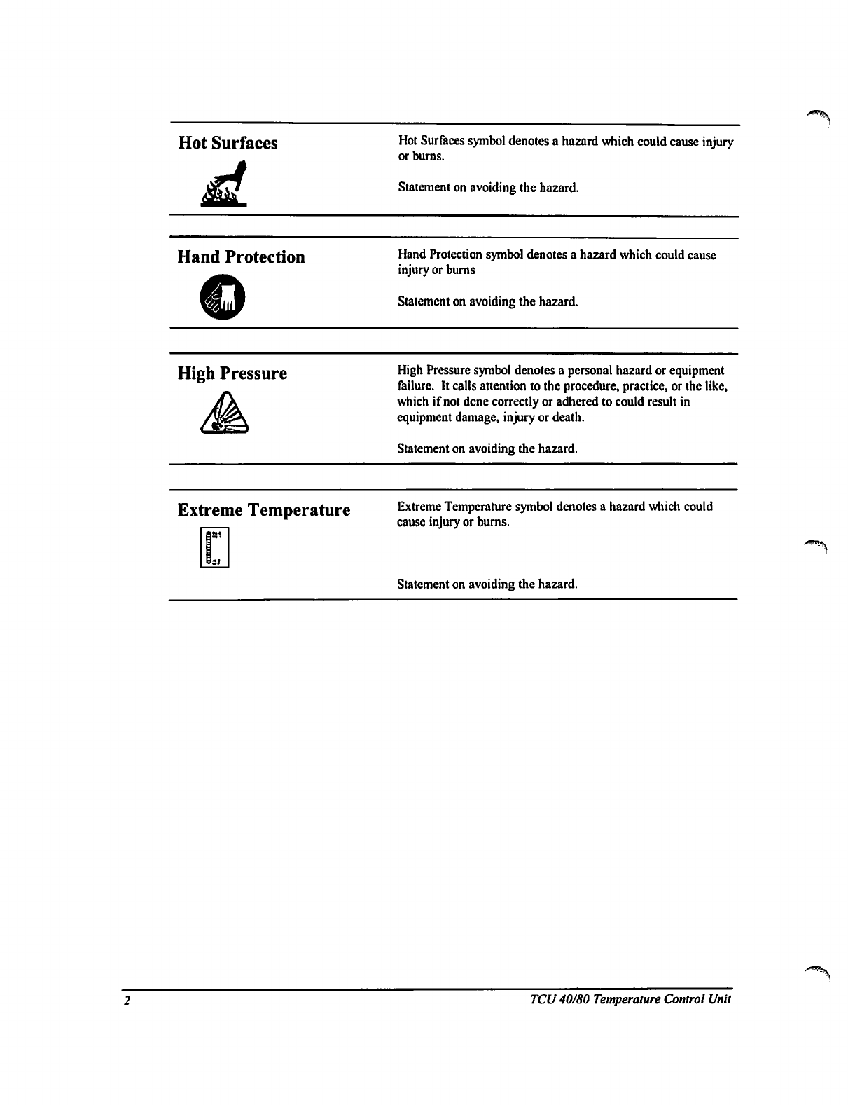
Hot
Surfaces
Hot
Surfaces
symbol
denotes a
hazard
which
could
cause
injury
or burns.
Statement
on
avoiding
the
hazard.
Hand
Protection
Hand
Protection
symbol
denotes a
hazard
which
could
cause
injury
or
burns
Statement
on
avoiding
the
hazard.
High
Pressure
High
Pressure
symbol
denotes
a
personal
hazard
or
equipment
failure.
It
calls
attention
to
the
procedure,
practice,
or
the
like,
which
if
not
done
correctly
or
adhered
to
could
result
in
equipment
damage,
injury
or death.
Statement
on
avoiding
the
hazard.
Extreme
Temperature
Extreme
Temperature
symbol
denotes
a
hazard
which
could
cause
injury
or
burns.
Statement
on
avoiding
the
hazard.
^
TCU
40/80
Temperature
Control
Unit
2
TCU
40/80
2.1
Scope
of
the
manual
This
manual
provides
information
on
the
installation,
start-up
and
operation
of
Edwards
High
Vacuum
Model
40/80
Temperature
Control
Unit
(TCU
40/80).
The
Quick
Start
Procedure
on
page
5
is
a
step
by
step
guide
for
the
start
up
and
use
of an
installed,
working
system.
Installation,
starting
on
page
16,
provides
instructions
and
information
for
installing
the
system.
The
installer
must
have
sufficient
technical
understanding
of
electrical
and
mechanical
systems
to
properly
use
this
information.
Operation,
starting
on page
20,
provides
more
complete
instructions
on
the
preparation
and
use
of
the
system.
2.2
Description
of
the
TCU
40/80
The
TCU
40/80
is
a
single-channel
temperature
control
unit
engineered
for
temperature
control
of
remote
heat
loads.
From
distances
up
to
SO
feet,
the
TCU
40/80
can
cool
the
heat
load
generated
by
the
process
equipment.
The
coolant
circulates
through
the
TCU
40/80,
where
it
is
cooled
or
heated
as
required,
then
is
transferred
to
the
process
equipment,
and
returns
in
a closed
loop.
The
TCU
40/80
maintains
supply
coolant
at
a
temperature
between
-40
°C
and
+80
°C,
selectable
in
0.1
°C
increments,
with
a
tolerance
of
±1.0
°C.
2.3
Lockout
procedure
To
prevent
accidental
or
unauthorized
starting
of
the
TCU
40/80
during
maintenance,
disconnect
the
power
cord
from
the
receptacle
and
install
an
appropriate
lock-out
device
(Hubbell
Small
Plugout™
or
equivalent)
on
the
end
of
the
power
cord.
0
TCU
40/80
Temperature
Control
Unit
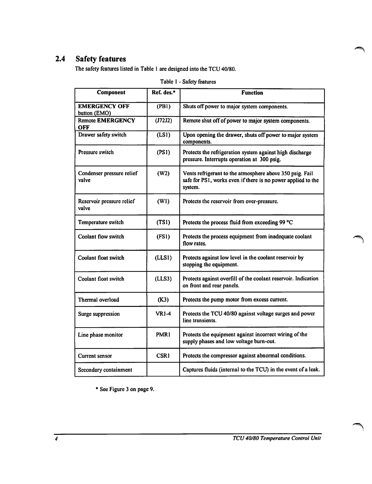
2.4
Safety
features
The
safety
features
listed
in
Table
1
are
designed
into
the
TCU
40/80.
Table
I
-
Safety
features
Component
EMERGENCY
OFF
button
(EMO)
Remote
EMERGENCY
OFF
Drawer
safety
switch
Pressure
switch
Condenser
pressure
relief
valve
Reservoir
pressure
relief
valve
Temperature
switch
Coolant
flow
switch
Coolant
float
switch
Coolant
float
switch
Thermal
overload
Surge
suppression
Line
phase
monitor
Current
sensor
Secondary
containment
Ref.
des.*
(PB1)
(J72J2)
(LSD
(PS1)
(W2)
(Wl)
(TS1)
(FS1)
(LLS1)
(LLS3)
(K3)
VR1-4
PMR1
CSR1
Function
Shuts
off
power
to
major
system
components.
Remote
shut
off
of
power
to
major
system
components.
Upon
opening
the
drawer,
shuts
off
power
to
major
system
components.
Protects
the
refrigeration
system
against
high
discharge
pressure.
Interrupts
operation
at
300
psig.
Vents
refrigerant
to
the
atmosphere
above
350
psig.
Fail
safe
for
PS1,
works
even
if
there
is
no
power
applied
to
the
system.
Protects
the
reservoir
from
over-pressure.
Protects
the
process
fluid
from
exceeding
99
°C
Protects
the
process
equipment
from
inadequate
coolant
flow
rates.
Protects
against
low
level
in
the
coolant
reservoir
by
stopping
the
equipment.
Protects
against
overfill
of
the
coolant
reservoir.
Indication
on
front
and
rear
panels.
Protects
the
pump
motor
from
excess
current.
Protects
the
TCU
40/80
against voltage
surges
and
power
line
transients.
Protects
the
equipment
against
incorrect
wiring
of
the
supply
phases
and low
voltage
burn-out.
Protects
the
compressor
against
abnormal
conditions.
Captures
fluids
(internal
to
the
TCU)
in
the
event
of
a
leak.
•
See
Figure
3
on
page
9.
TCU
40/80 Temperature
Control
Unit
3
QUICK
START
PROCEDURE
This
Quick
Start
procedure
is
for
easy
start
up
and
operation
of an
installed
and
fully
working
TCU
40/80.
If
your
TCU
40/80
is
not
installed,
go
to
Installation
on
page
16.
Detailed
operating
instructions
are
in
Operation
on page
20.
If
at
any
time an
alarm
occurs,
press
STOP
and
correct
the
fault
indicated
by
the
display
as
directed
in
the
Troubleshooting
Guide
on
page
42.
Press
RESET
and
START
to
continue
operation.
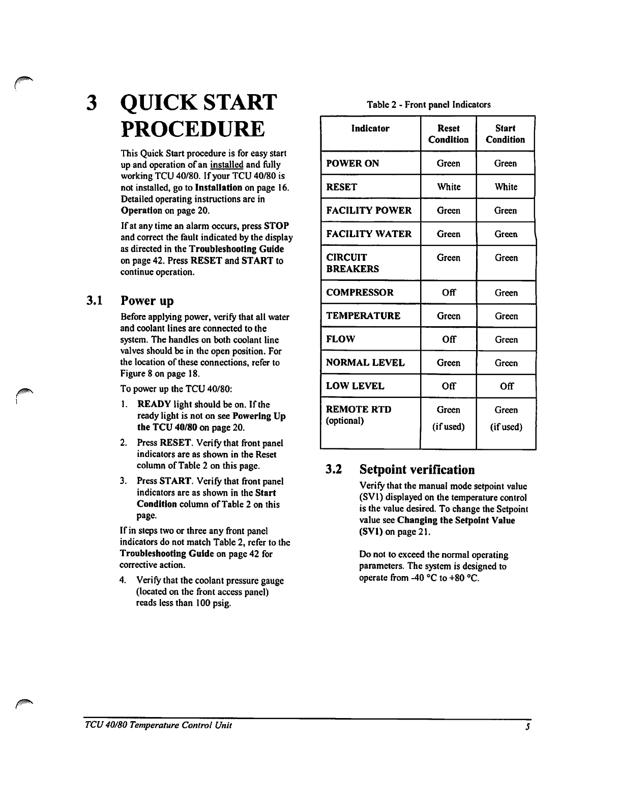
3.1
Power
up
Before
applying
power,
verify
that
all
water
and
coolant
lines
are
connected
to
the
system.
The
handles
on
both
coolant
line
valves
should
be
in
the
open
position.
For
the
location
of
these
connections,
refer
to
Figure
8
on
page
18.
To
power up
the
TCU
40/80:
1.
READY
light
should
be
on.
If
the
ready
light
is
not
on
see
Powering
Up
the
TCU
40/80
on
page
20.
2.
Press
RESET.
Verify
that
front
panel
indicators
are
as
shown
in
the
Reset
column
of
Table
2
on
this
page.
3.
Press
START.
Verify
that front
panel
indicators
are
as
shown
in
the
Start
Condition
column
of
Table
2
on
this
page.
If in
steps
two
or
three
any
front
panel
indicators
do
not
match
Table
2,
refer
to
the
Troubleshooting
Guide
on
page
42
for
corrective
action.
4.
Verify
that
the
coolant
pressure
gauge
(located
on
the
front
access
panel)
reads
less
than
100
psig.
Table 2
-
Front
panel
Indicators
Indicator
POWER
ON
RESET
FACILITY
POWER
FACILITY
WATER
CIRCUIT
BREAKERS
COMPRESSOR
TEMPERATURE
FLOW
NORMAL
LEVEL
LOW
LEVEL
REMOTE
RTD
(optional)
Reset
Condition
Green
White
Green
Green
Green
Off
Green
Off
Green
OfT
Green
(if
used)
Start
Condition
Green
White
Green
Green
Green
Green
Green
Green
Green
Off
Green
(if
used)
3.2
Setpoint
verification
Verify
that
the
manual
mode
setpoint
value
(SV1)
displayed
on
the
temperature
control
is
the
value
desired.
To
change
the
Setpoint
value
see
Changing
the Setpoint
Value
(SVl)onpage21.
Do
not
to
exceed
the
normal
operating
parameters.
The
system
is
designed
to
operate
from
-40
°C
to
+80
°C.
TCU
40/80
Temperature
Control
Unit
4
PRODUCT
DESCRIPTION
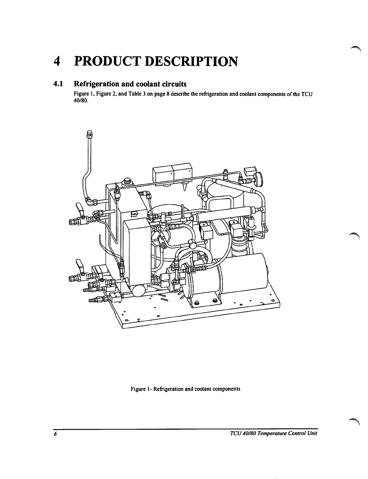
4.1
Refrigeration
and
coolant
circuits
Figure
1,
Figure
2,
and
Table
3
on page
8
describe
the
refrigeration
and
coolant
components
of
the
TCU
40/80.
Figure
1-
Refrigeration
and
coolant
components
TCU40/80
Temperature
Control
Unit
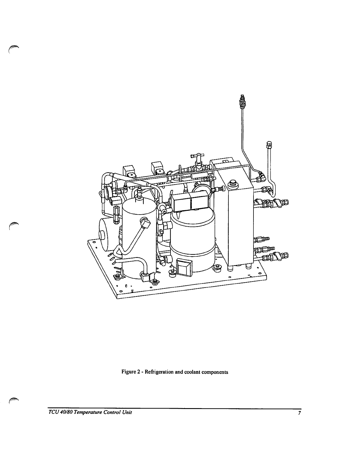
Figure
2
-
Refrigeration
and
coolant
components
TCU
40/80
Temperature
Control
Unit
/^\
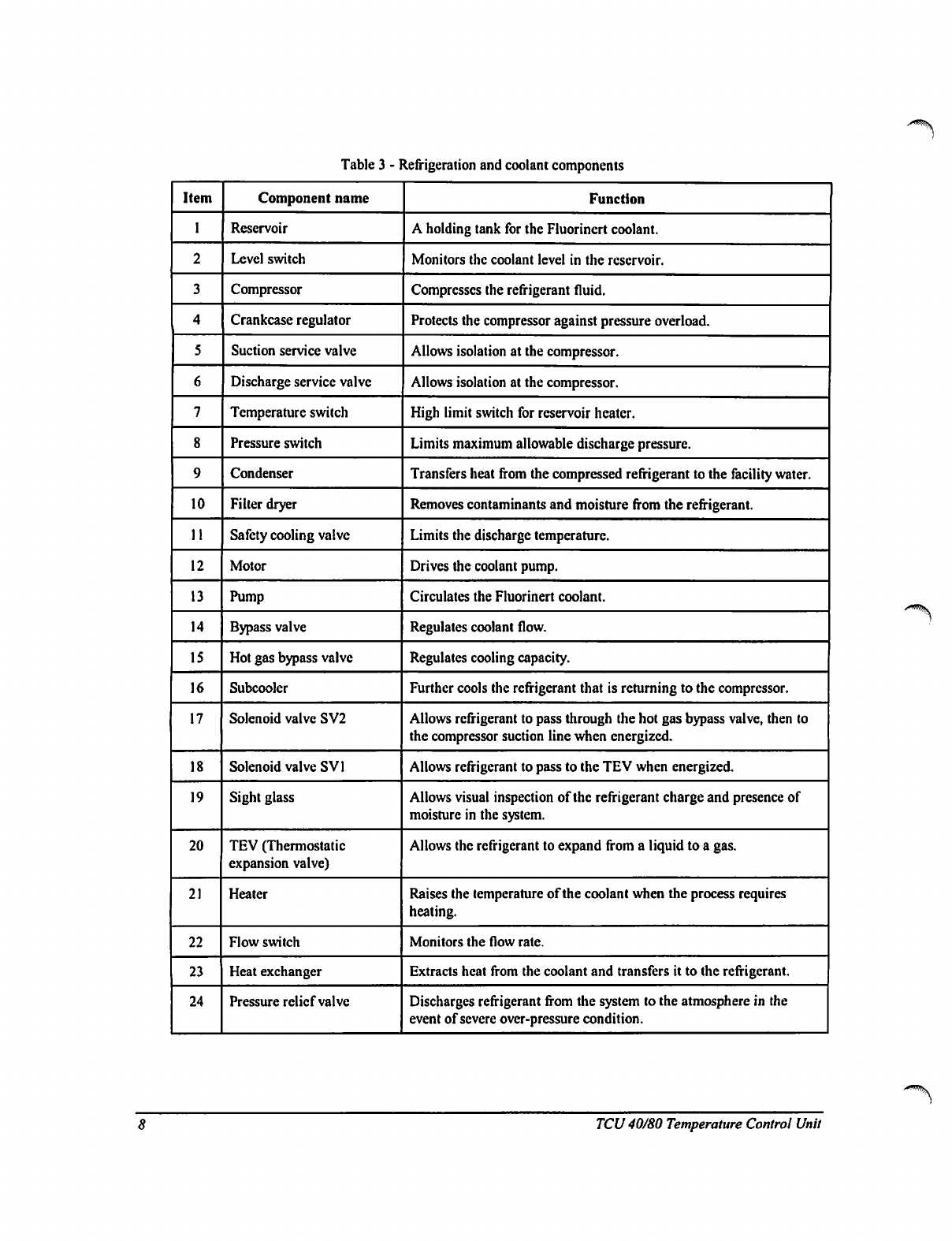
Table
3
-
Refrigeration
and
coolant
components
Item
I
2
3
4
5
6
7
8
9
10
11
12
13
14
15
16
17
18
19
20
21
22
23
24
Component
name
Reservoir
Level
switch
Compressor
Crankcase
regulator
Suction
service
valve
Discharge
service
valve
Temperature
switch
Pressure
switch
Condenser
Filter
dryer
Safety
cooling
valve
Motor
Pump
Bypass
valve
Hot
gas
bypass
valve
Subcooler
Solenoid
valve
SV2
Solenoid
valve
SV1
Sight
glass
TEV
(Thermostatic
expansion
valve)
Heater
Flow
switch
Heat
exchanger
Pressure
relief
valve
Function
A
holding
tank
for
the
Fluorinert
coolant.
Monitors
the
coolant
level
in
the
reservoir.
Compresses
the
refrigerant
fluid.
Protects
the
compressor
against
pressure
overload.
Allows
isolation
at
the
compressor.
Allows
isolation
at
the
compressor.
High
limit
switch
for
reservoir
heater.
Limits
maximum
allowable
discharge
pressure.
Transfers
heat
from
the
compressed
refrigerant
to
the
facility
water.
Removes
contaminants
and
moisture
from
the
refrigerant.
Limits
the
discharge
temperature.
Drives
the
coolant
pump.
Circulates
the
Fluorinert
coolant.
Regulates
coolant
flow.
Regulates
cooling
capacity.
Further
cools
the
refrigerant
that
is
returning
to
the
compressor.
Allows
refrigerant
to
pass
through
the
hot
gas bypass
valve,
then
to
the
compressor
suction
line
when
energized.
Allows
refrigerant
to
pass
to
the
TEV
when
energized.
Allows
visual
inspection
of
the
refrigerant
charge
and
presence
of
moisture
in
the
system.
Allows
the
refrigerant
to
expand
from
a
liquid
to
a
gas.
Raises
the
temperature
of
the
coolant
when
the
process
requires
heating.
Monitors
the
flow
rate.
Extracts
heat
from
the
coolant
and
transfers
it
to
the
refrigerant.
Discharges
refrigerant
from
the
system
to
the
atmosphere
in
the
event
of
severe
over-pressure
condition.
TCU
40/80
Temperature
Control
Unit

/
Bypass
vaSn
Oran
valve
I
RID
temperature
probe
Profisure
Gwlttfc
Figure
3-
Refrigeration
and
coolant
circuits
4.2
Refrigeration
(see
figure
3
above)
1.
Refrigerant
gas
enters
the
compressor
at
low
temperature
and
pressure.
It
leaves the
compressor
at
high
pressure
and
temperature.
2.
The
gas
passes
into
the
condenser,
where
heat
is
removed
by
the
external
water
supply,
causing
the
gas
to
condense
into
a
liquid.
3.
The
cool
liquid
refrigerant
exits
the
condenser
and
passes
through
a
filter
dryer
that
removes
any
residual
moisture
or
contaminants.
4.2.1
If
cooling
is
required:
1.
Solenoid
valve
SV1
opens
(coil
energized),
allowing
the
refrigerant
to
flow
into
the
Thermostatic
Expansion
Valve
(TEV).
The
pressure
drop
across
the
TEV
causes
the
refrigerant
to
change
from
a
liquid
to
a
mixture
of
liquid
and
gas.
2.
The
liquid
and
gas
mixture
enters
the
heat
exchanger
where
it
becomes
entirely
a
gas.
The
process
of
expansion
from
a
liquid
to
a
gas
reduces
the
temperature
by
absorbing
energy.
3.
The
refrigerant
leaving
the
heat
exchanger
returns
to
the
compressor
through
the
subcooler
and
a
crankcase
pressure
regulator.
The
subcoolcr
further
cools
the
refrigerant
entering
the
TEV.
TCU
40/80
Temperature
Control
Unit
4.2.2
If
cooling
is
not
required:
1.
Solenoid
valve
SVl
closes
(coil
de-energized).
2.
Hot
refrigerant
from
the
compressor
is
passed
through
SV2
(coil
energized)
and
a
hot
gas
bypass
valve
before
returning
to
the
compressor
suction
line.
This
bypassing
allows
the
compressor
to
run
continuously.
3.
Cooling,
required
to
prevent
the
compressor
from
overheating,
is
provided
by
allowing
some
of
the
liquid
from
the
condenser
to
pass
through
the
safety
cooling
automatic
expansion
valve
into
the
suction
line,
thus
maintaining
the
discharge
gas
temperature
below
99
°C.
4.3
Coolant
circuit
Coolant
is
pulled
from
the
reservoir
by
the
circulation
pump
and
transferred
to
the
heat
exchanger
where
it
is
cooled
by
the
refrigeration
system
as
required.
It
then
flows
to
the
process
equipment
by
means
of
the
coolant
supply
hose.
The
coolant
returns
to
the
TCU
40/80
reservoir
by
means
of
the
coolant
return
hose.
The
coolant
system
requires
8
liters
of
coolant
for
the
reservoir,
plus
the
volume
of
the
circulation
lines
and
any
other
spaces
filled
with
coolant
that
are
attached
to
the
TCU
40/80.
To
increase
the
coolant
temperature,
the
reservoir
uses
an
electrical
resistance
heater
that
is
controlled
by
the
temperature
controller.
The
heater
must
be
fully
submerged
at
all
times,
and
if
the
coolant
in
the
reservoir
falls
below
3.S
liters,
a
level
switch causes
the
status
alarm
signal
to
automatically
shut
down
the
TCU
40/80.
A
three-float
level
switch,
a
thermostat,
and
a
flow
sensor
provide
coolant
status
signals
to
the
TCU
40/80
control
system.
4.4
Temperature
monitoring
A
Resistance
Temperature
Device
(RTD)
monitors
the
temperature
of
the
coolant
leaving
the
TCU
40/80
and
transmits
this
information
to
the
temperature
controller.
The
TCU
40/80
compares
the
output
of
the
RTD
to
the
selected
process
temperature
(SVl)
and
determines
if
the
coolant
needs
to
be
cooled
or
heated.
The
temperature
controller
then
operates
the
main
cooling
solenoid
valve
or
heater.
The
coolant
temperature
at
the
supply
port
on
the
rear
panel
is
measured
by
a
local,
internally
connected
RTD.
If
sensing
of
process
equipment
temperature
is
needed,
connect
an
RTD
to
J72J3
at
the
rear
panel
(see
Figure
5
on page
13).
For
remote
connection
schematic
details,
see
Figure
IS
on
page
56.
^WIITV
10
TCU
40/80
Temperature
Control
Unit
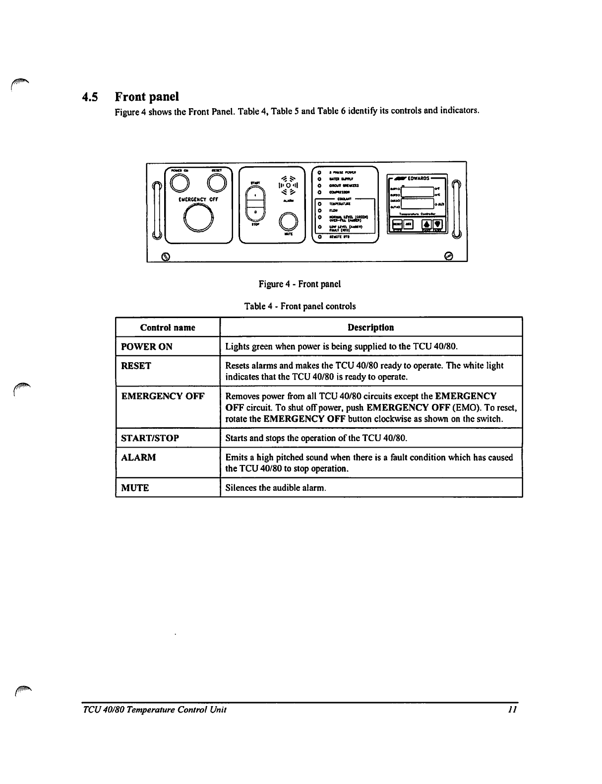
4.5
Front
panel
Figure
4 shows
the
Front
Panel.
Table
4,
Table
5
and
Table
6
identify
its
controls
and
indicators.
|M
O
<
?
5
>
mat
mu
0
aw-"
Figure
4
-
Front panel
Table
4
-
Front panel
controls
Control
name
POWER
ON
RESET
EMERGENCY
OFF
START/STOP
ALARM
MUTE
Description
Lights
green
when
power
is
being
supplied
to
the
TCU
40/80.
Resets
alarms
and
makes
the
TCU
40/80
ready
to
operate.
The
white
light
indicates
that
the
TCU
40/80
is
ready
to
operate.
Removes
power
from
all
TCU
40/80
circuits
except
the
EMERGENCY
OFF
circuit.
To
shut
off
power,
push
EMERGENCY
OFF
(EMO).
To
reset,
rotate
the
EMERGENCY
OFF
button
clockwise
as
shown
on
the
switch.
Starts
and
stops
the
operation
of
the
TCU
40/80.
Emits
a
high
pitched
sound
when
there
is
a
fault
condition
which
has
caused
the
TCU
40/80
to
stop operation.
Silences
the
audible
alarm.
TCU
40/80
Temperature
Control
Unit
II
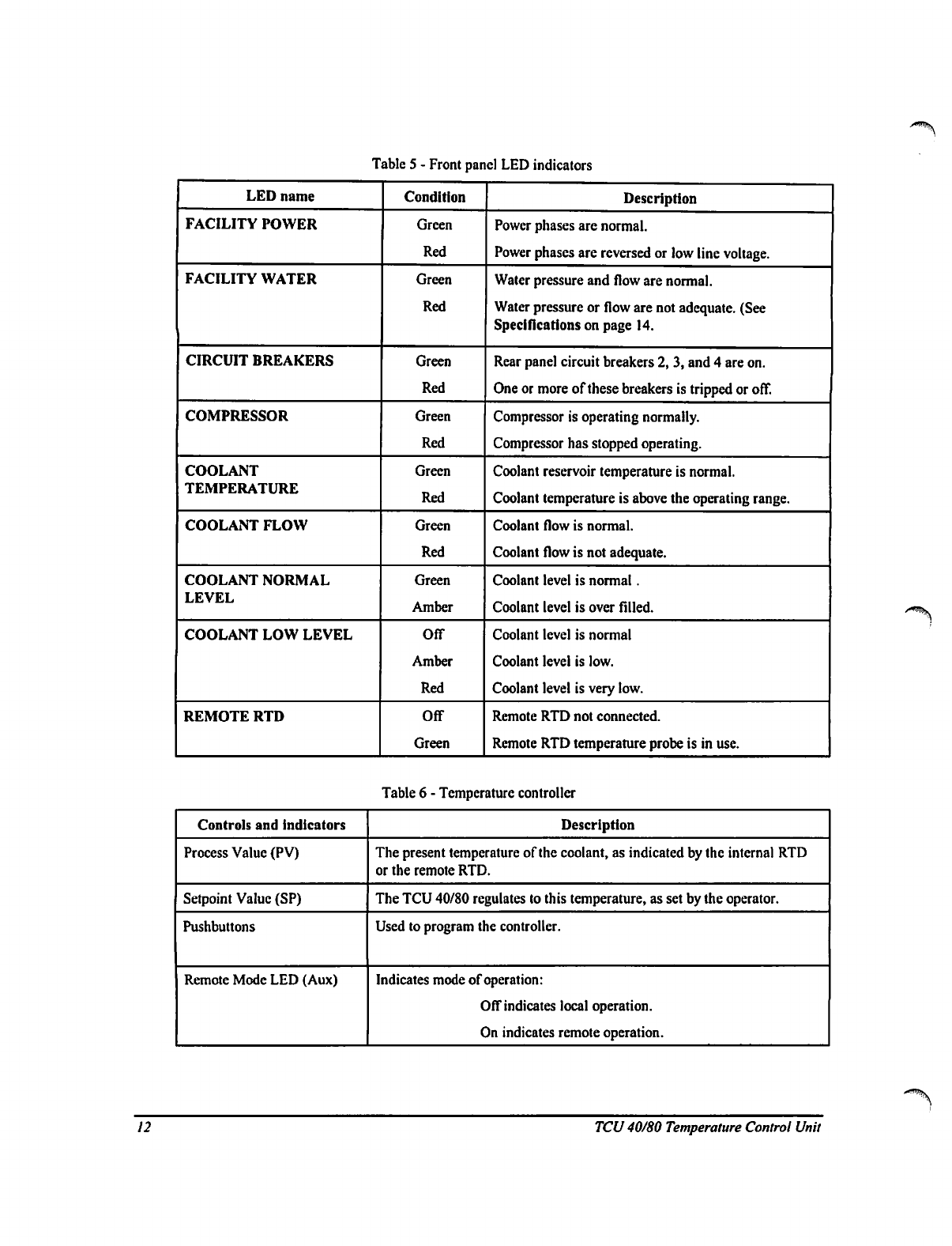
Table
5
-
Front
panel
LED
indicators
LED
name
FACILITY
POWER
FACILITY
WATER
CIRCUIT
BREAKERS
COMPRESSOR
COOLANT
TEMPERATURE
COOLANT
FLOW
COOLANT
NORMAL
LEVEL
COOLANT
LOW
LEVEL
REMOTE
RTD
Condition
Green
Red
Green
Red
Green
Red
Green
Red
Green
Red
Green
Red
Green
Amber
Off
Amber
Red
Off
Green
Description
Power
phases
are
normal.
Power
phases
are
reversed
or
low
line
voltage.
Water
pressure
and
flow
are
normal.
Water
pressure
or
flow
are
not
adequate.
(See
Specifications
on page
14.
Rear
panel
circuit
breakers
2, 3,
and
4
are
on.
One
or
more
of
these
breakers
is
tripped
or
off.
Compressor
is
operating
normally.
Compressor
has
stopped
operating.
Coolant
reservoir
temperature
is
normal.
Coolant
temperature
is
above
the
operating
range.
Coolant
flow
is
normal.
Coolant
flow
is
not
adequate.
Coolant
level
is
normal.
Coolant
level
is
over
filled.
Coolant
level
is
normal
Coolant
level
is
low.
Coolant
level
is
very
low.
Remote
RTD
not
connected.
Remote
RTD
temperature
probe
is
in
use.
Table
6
-
Temperature
controller
Controls
and
indicators
Process
Value
(PV)
Setpoint
Value
(SP)
Pushbuttons
Remote
Mode
LED
(Aux)
Description
The
present
temperature
of
the
coolant,
as
indicated
by
the
internal
RTD
or
the
remote
RTD.
The
TCU
40/80
regulates
to this
temperature,
as
set
by
the
operator.
Used
to
program
the
controller.
Indicates
mode
of
operation:
Off
indicates
local
operation.
On
indicates
remote
operation.
12
TCU
40/80
Temperature
Control
Unit
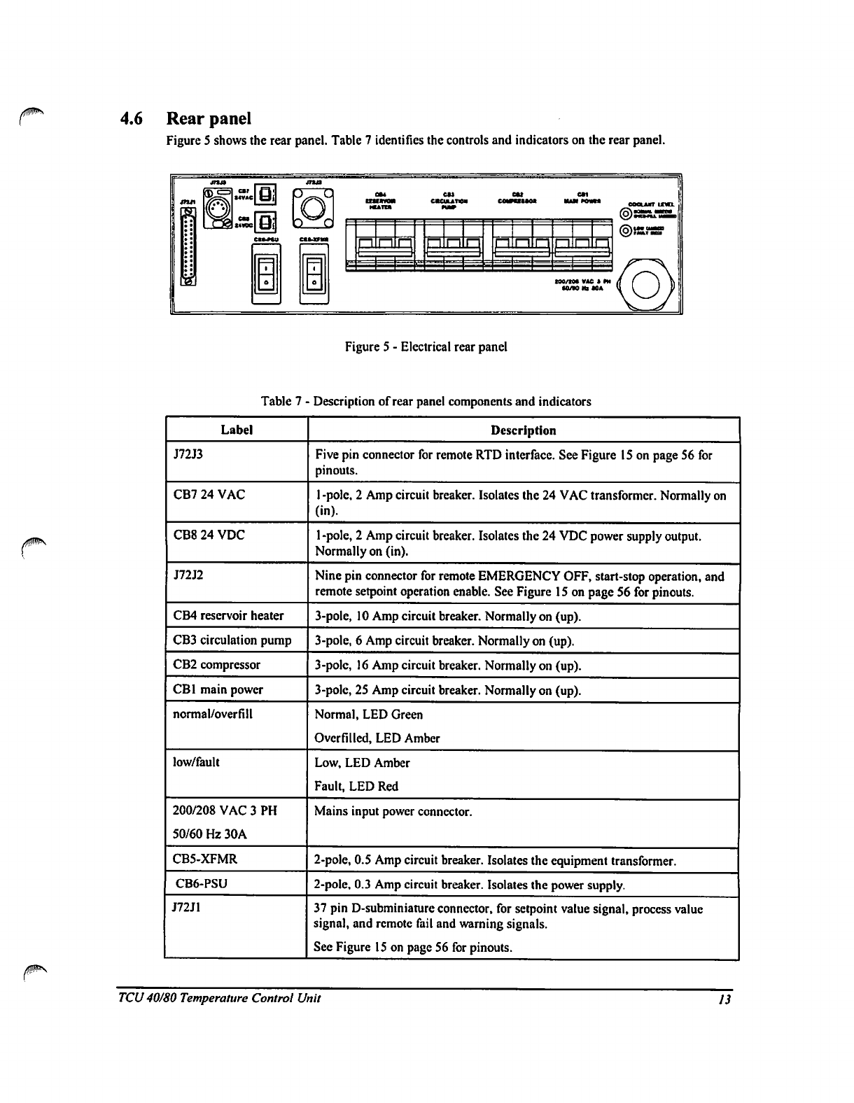
4.6
Rear
panel
Figure
5
shows
the
rear
panel.
Table
7
identifies
the
controls
and
indicators
on
the
rear
panel.
D
G
t
Fj
cocuurr
iml
p
n
n
pi
n
p!
=
H
t90/t0*
VAC
» *M
•0/W
Hi
*0A
Figure
5
-
Electrical
rear
panel
Table
7
■
Label
J72J3
CB7
24
VAC
CB8
24
VDC
J72J2
CB4
reservoir
heater
CB3
circulation
pump
CB2
compressor
CB1
main
power
normal/overfill
low/fault
200/208
VAC
3
PH
50/60
Hz
30A
CB5-XFMR
CB6-PSU
J72J1
■
Description
of
rear
panel
components
and
indicators
Description
Five
pin
connector
for
remote
RTD
interface.
See
Figure
15
on
page
56
for
pinouts.
1
-pole,
2
Amp
circuit
breaker.
Isolates
the
24
VAC
transformer.
Normally
on
(in).
l-pole,
2
Amp
circuit
breaker.
Isolates
the
24
VDC
power
supply
output.
Normally
on
(in).
Nine
pin
connector
for
remote
EMERGENCY
OFF,
start-stop
operation,
and
remote
setpoint
operation
enable.
See
Figure
15
on
page
56
for
pinouts.
3-pole,
10
Amp
circuit
breaker.
Normally
on
(up).
3-pole,
6
Amp
circuit
breaker.
Normally
on
(up).
3-pole,
16
Amp
circuit
breaker.
Normally
on
(up).
3-pole,
25
Amp
circuit
breaker.
Normally
on
(up).
Normal,
LED
Green
Overfilled,
LED
Amber
Low,
LED
Amber
Fault,
LED
Red
Mains
input
power
connector.
2-pole,
0.5
Amp
circuit
breaker.
Isolates
the
equipment
transformer.
2-poIe,
0.3
Amp
circuit
breaker.
Isolates
the
power
supply.
37
pin
D-subminiature
connector,
for
setpoint
value
signal,
process
value
signal,
and
remote
fail
and
warning
signals.
See
Figure
15
on
page
56
for
pinouts.
TCU
40/80
Temperature
Control
Unit
13
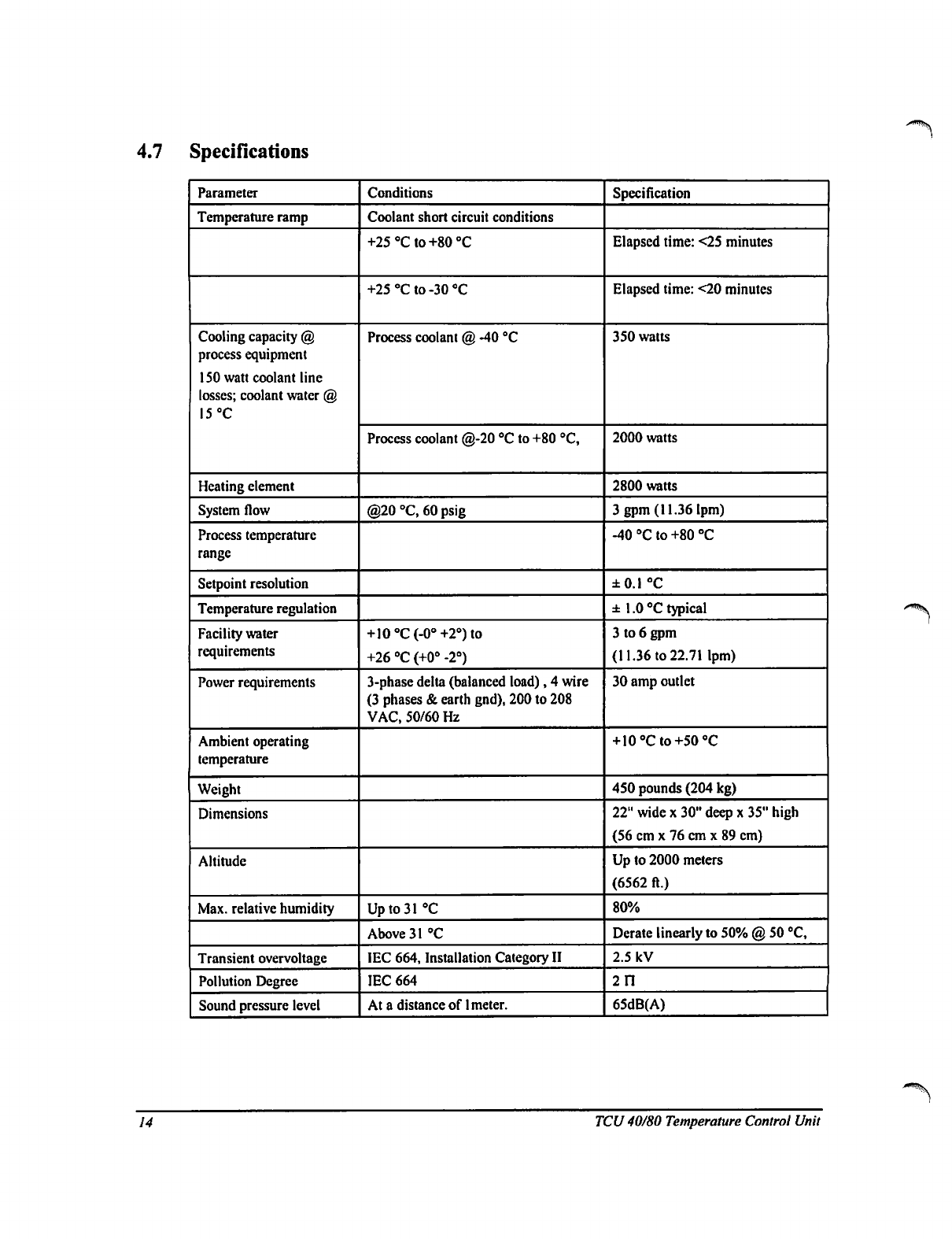
4.7
Specifications
Parameter
Temperature
ramp
Cooling
capacity
@
process
equipment
ISO
watt
coolant
line
losses;
coolant
water
@
15
°C
Heating element
System
flow
Process
temperature
range
Setpoint
resolution
Temperature
regulation
Facility
water
requirements
Power
requirements
Ambient
operating
temperature
Weight
Dimensions
Altitude
Max.
relative
humidity
Transient
overvoltage
Pollution
Degree
Sound
pressure
level
Conditions
Coolant
short
circuit
conditions
+25°Cto+80°C
+25°Cto-30°C
Process
coolant
@
-40
°C
Process
coolant
@-20
°C
to
+80
"C,
@20
°C,
60
psig
+10oC(-0°+2°)to
+26
"C
(+0°
-2°)
3-phase
delta
(balanced
load),
4
wire
(3
phases
&
earth
gnd),
200
to
208
VAC,
50/60
Hz
Up
to
31
"C
Above31°C
IEC
664,
Installation
Category
II
IEC
664
At
a
distance
of
1
meter.
Specification
Elapsed
time:
<25
minutes
Elapsed
time:
<20
minutes
350
watts
2000
watts
2800
watts
3
gpm
(11.36
lpm)
-40°Cto+80°C
±0.1
°C
±
1.0
°C
typical
3
to
6
gpm
(11.36
to
22.71
lpm)
30
amp
outlet
+
10°Cto+50°C
450
pounds
(204
kg)
22"
wide
x
30"
deep
x
35"
high
(56
cm
x
76
cm
x
89
cm)
Up
to
2000
meters
(6562
ft.)
80%
Derate
linearly
to
50%
@
50
°C,
2.5
kV
211
65dB(A)
14
TCU
40/80
Temperature
Control
Unit
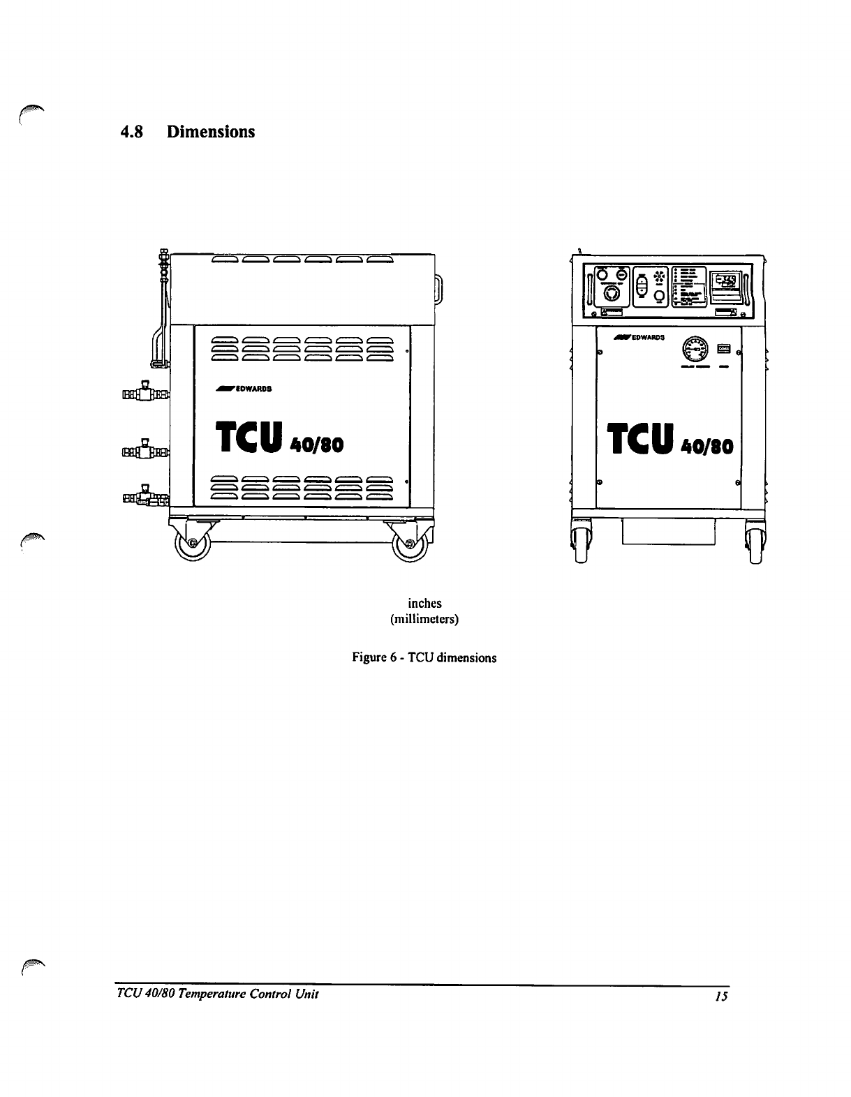
4.8
Dimensions
TCU
40/80
TCU
40/80
inches
(millimeters)
Figure
6
-
TCU
dimensions
TCU
40/80
Temperature
Control
Unit
15
5
INSTALLATION
5.1
Receiving
and
unpacking
Do
a
complete
visual
inspection
of
the
TCU
40/80
for
any
damage.
Do
not
use
the
TCU
40/80
if
physical
damage
is
evident.
If
there
is
any
damage,
notify
your
supplier
and
the
carrier
in
writing
within
three
days;
state
the
item
number
of
the
TCU
40/80
together
with
your
order
number
and
supplier's
invoice
number.
Retain
all
packing
materials
for
inspection.
Caution
When
using
a
forklift
to
move
or
position
the
TCU
40/80,
do
not
install
the
secondary
containment
receptacle
until
the
TCU
40/80
is
in
position.
Failure
to
follow
these
instructions
may
lead
to
damage
of
the
secondary
containment
receptacle
caused
by
the
forks
of
the
forklift.
5.2
Location
Allow
a
space
46"
wide
x
54"
deep
for
the
TCU
40/80
cable
and
coolant
connections.
The
TCU
40/80
should
have
at
least
two
feet
of
clearance
at
the
rear
and
one
foot
along
the
sides
of
the
unit.
Be
sure
that
the
mounting
surface
can
safely
support
the
weight
of
the
TCU
40/80
(450
pounds
evenly
distributed).
The
center
of
gravity
is
approximately
the
center
of
the
refrigeration
compartment.
When
using
a
fork-lift
to
move
the
TCU
40/80,
position
the
forks
from
the
side
of
the
unit.
The
TCU
40/80
weighs
450
pounds
(204
kg).
Failure
to
take
proper
care
in
moving
or
lifting
these
units
can
result
in
serious
bodily
injury.
A
3
foot
(1m)
service
length
of
the
power
cable
is
required
to
fully
open
the
electrical
drawer.
Therefore,
do
not
install
the
TCU
40/80
further
than
7
feet
(2.1
m)
from
the
power
source.
5.2.1
Securing
the
unit
The
four
lockable
casters
of
the
TCU
40/80
swivel
to
provide
maximum
maneuverability.
Make
sure
that
all
four
casters
are
turned
inward
and
locked
in
position
once
Ihe
TCU
40/80
is
situated.
5.2.2
Installing
the
secondary
containment
receptacle
The
secondary
containment
receptacle
slides
into
the
base
from
the
rear
of
the
unit.
5.2.3
Floor
levelers
An
optional
floor
leveler
kit
is
available
to
compensate
for
uneven
surfaces.
See
Table
15
on
page
52
for
ordering
information.
16
TCU
40/80
Temperature
Control
Unit
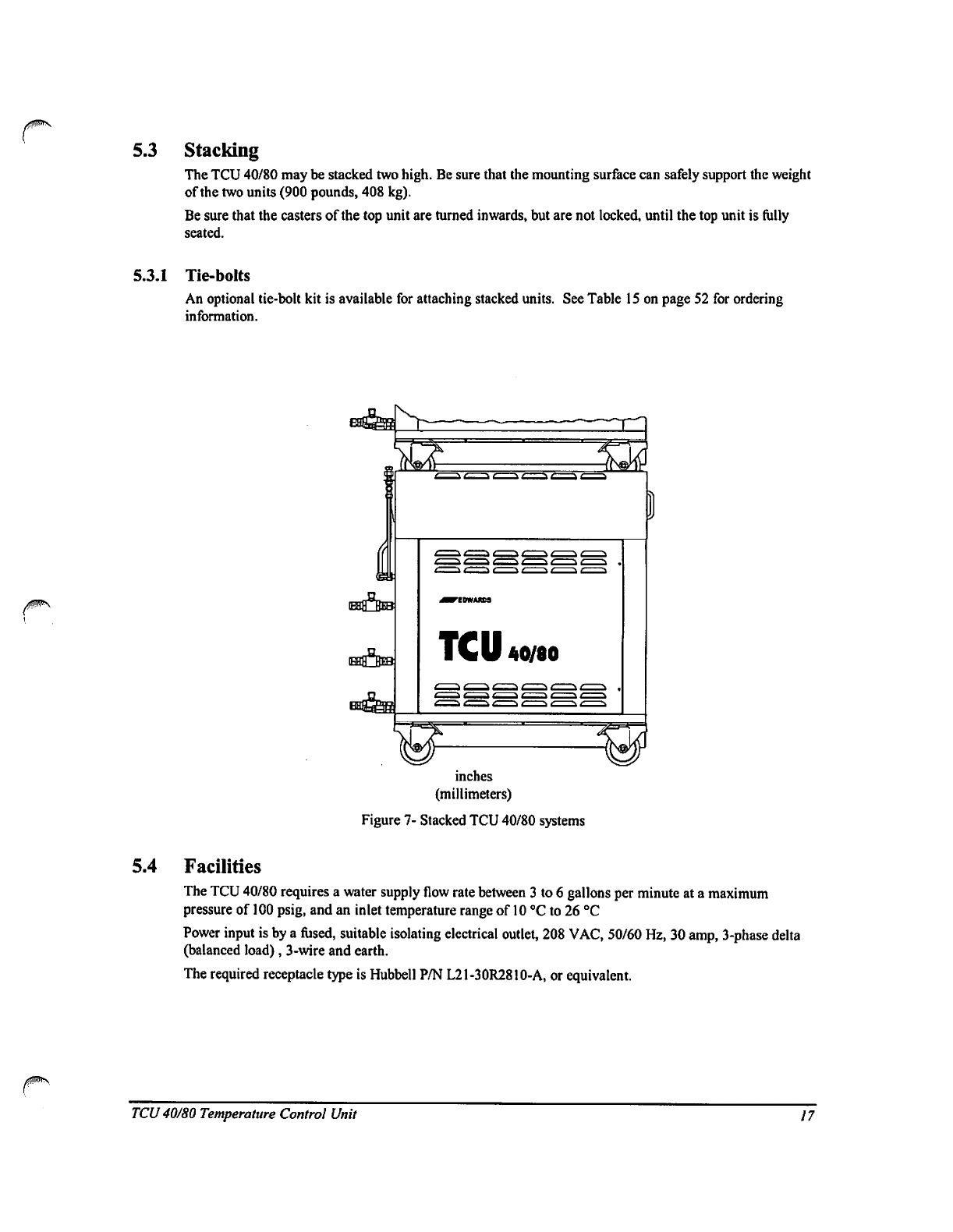
5.3
Stacking
The
TCU
40/80
may
be
stacked
two
high.
Be
sure
that
the
mounting
surface
can
safely
support
the
weight
of
the
two
units
(900
pounds,
408
kg).
Be
sure
that
the
casters
of
the
top
unit
are
turned
inwards,
but
are
not
locked,
until
the
top
unit
is
fully
seated.
5.3.1
Tie-bolts
An
optional
tie-bolt
kit
is
available
for
attaching
stacked
units.
See
Table
15
on
page
52
for
ordering
information.
TCU
40/80
inches
(millimeters)
Figure
7-
Stacked
TCU
40/80
systems
5.4
Facilities
The
TCU
40/80
requires
a
water
supply
flow
rate
between
3 to
6
gallons
per
minute
at
a
maximum
pressure
of
100
psig,
and
an
inlet
temperature
range
of
10
°C
to
26
°C
Power
input
is
by
a
fused,
suitable
isolating
electrical
outlet,
208
VAC,
50/60
Hz,
30
amp,
3-phase
delta
(balanced
load),
3-wire
and
earth.
The
required
receptacle
type
is
Hubbell
P/N
L21-30R2810-A,
or
equivalent.
TCU
40/80
Temperature
Control
Unit
17
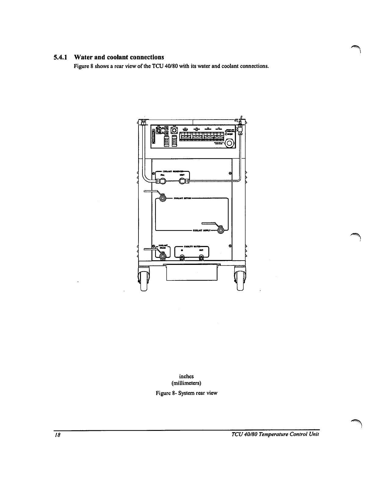
5.4.1
Water
and
coolant
connections
Figure
8
shows
a
rear
view
of
the
TCU
40/80
with
its
water
and
coolant
connections.
inches
(millimeters)
Figure
8-
System
rear
view
18
j
TCU
40/80
Temperature
Control
Unit
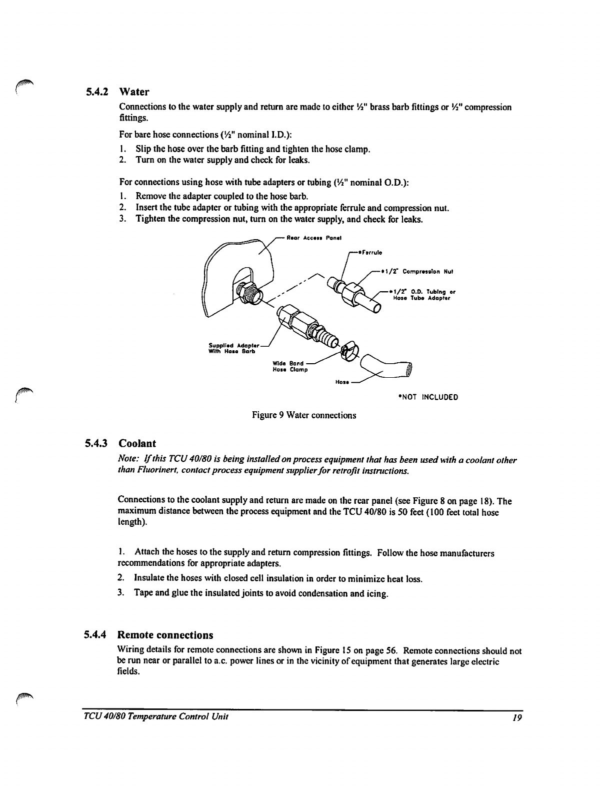
5.4.2
Water
/JWN
Connections
to
the
water
supply
and
return
are
made
to
either
Vi"
brass
barb
fittings
or
Vi"
compression
fittings.
For
bare
hose
connections
("A"
nominal
I.D.):
1.
Slip
the
hose
over
the
barb
fitting
and
tighten
the
hose
clamp.
2.
Turn
on
the
water
supply
and
check
for
leaks.
For
connections
using
hose
with
tube
adapters
or
tubing
('/i"
nominal
O.D.):
1.
Remove
the
adapter
coupled
to
the
hose
barb.
2.
Insert
the
tube
adapter
or
tubing
with
the
appropriate
ferrule
and
compression
nut.
3.
Tighten
the
compression
nut,
turn
on
the
water
supply,
and
check
for
leaks.
Rear
Acctii
Pantl
F»rrulo
•
1/2'
Compr.jslon
Nut
•
1/2"
O.O.
Tubing
or
Hose
Tuba
Adaptor
Supplied
Adaptor
With
Hoie
Barb
♦NOT
INCLUDED
Figure 9
Water
connections
5.4.3
Coolant
Note:
If
this
TCU
40/80
is
being
installed
on
process
equipment
that
has
been used
mth
a
coolant
other
than
Fluorinert.
contact
process
equipment
supplier
for
retrofit
instructions.
Connections
to
the
coolant
supply
and
return
are
made
on
the
rear
panel
(see
Figure
8
on
page
18).
The
maximum
distance
between
the
process
equipment
and
the
TCU
40/80
is
50
feet
(100
feet
total
hose
length).
1.
Attach
the
hoses
to
the
supply
and
return
compression
fittings.
Follow
the
hose
manufacturers
recommendations
for
appropriate
adapters.
2.
Insulate
the
hoses
with
closed
cell
insulation
in
order
to
minimize
heat
loss.
3.
Tape
and
glue
the
insulated
joints
to
avoid
condensation
and
icing.
5.4.4
Remote
connections
Wiring
details
for
remote
connections
are
shown
in
Figure
15
on
page
56.
Remote
connections
should
not
be
run near
or
parallel
to
a.c.
power
lines
or
in
the
vicinity
of
equipment
that
generates
large
electric
fields.
TCU
40/80
Temperature
Control
Unit
19
6
OPERATION
6.1
Preparation
Verify
that
water
and
coolant
connections
are
made
at
both
ends,
that
the
drain
valve
is
closed
and
the
coolant
supply
and
return
valves
are
open.
Connect
the
remote
interfaces
if
required.
1.
To
use
an
external
RTD
probe,
attach
it
to
connector
J72J3.
Refer
to
Figure
15
on
page
56.
Verify
that
the
plug
J72J2
is
installed.
2.
Press
the
EMERGENCY
OFF
button
on
the
front
panel.
3.
Plug
the
TCU
40/80
power
cord
into
a
fused,
switchable,
30
amp,
3-phase,
208
VAC
outlet.
4.
Ensure
that
all
circuit
breakers
on
the
rear
panel
are
in
the
ON
position.
CB7
and
CB8
are
non-
switchable
circuit
breakers
and
will
trip
when
there
is
a
problem.
They
cannot
be
turned
on
or
off,
but
they
are
re-settablc.
6.2
Powering
up
the
TCU
40/80
1.
Verify
that
the
POWER
ON
lamp
on
the
front
panel
is
illuminated.
2.
Release
the
EMERGENCY
OFF
button.
If
the
Facility
Power
LED
illuminates,
the
line
voltage
is
low,
or the
phase
of
the
main
power
supply
is
reversed.
Adjust
the
line
voltage,
if
it
is
low.
Correct
the
phases
by
swapping
two
phases
in
the
electrical
outlet.
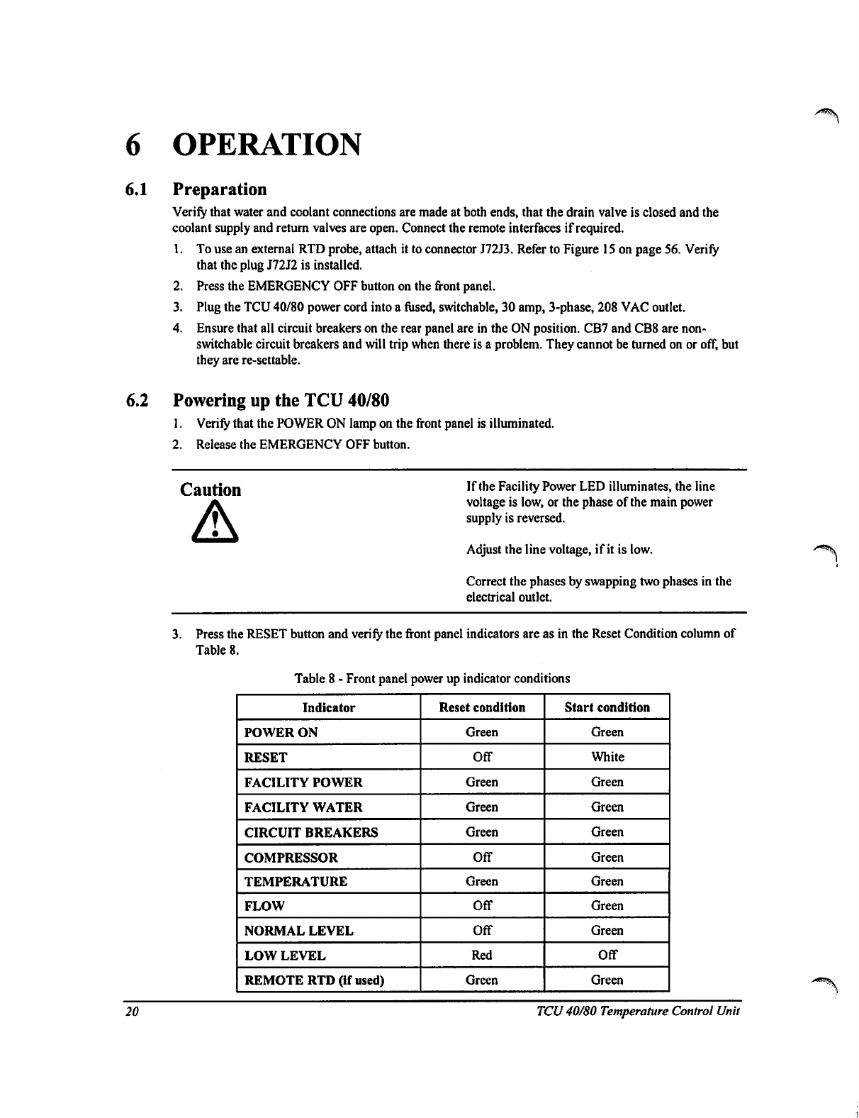
3.
Press
the
RESET
button
and
verify
the
front
panel
indicators
are as
in
the
Reset
Condition
column
of
Table
8.
Table
8
-
Front
panel
power up
indicator
conditions
Indicator
POWER
ON
RESET
FACILITY
POWER
FACILITY
WATER
CIRCUIT
BREAKERS
COMPRESSOR
TEMPERATURE
FLOW
NORMAL
LEVEL
LOW
LEVEL
REMOTE
RTD
(if
used)
Reset
condition
Green
Off
Green
Green
Green
Off
Green
Off
Off
Red
Green
Start
condition
Green
White
Green
Green
Green
Green
Green
Green
Green
Off
Green
20
TCU
40/80
Temperature
Control
Unit
4.
Press
MUTE
to
silence
the
alarm.
The
TCU
40/80
is
shipped
without
coolant.
The
coolant
level
alarm
will
sound
and
the
front
panel
Reservoir
Coolant
Low
Level
LED
will
be
red
indicating
that
the
reservoir
must
be
filled.
5.
Fill
the
coolant
reservoir
using
the
procedure
Filling
the
Reservoir
on page
26.
6.
Press
the
START
button
and
verify
the
front
panel
indicators
are
as
in
the
Start
Condition
column
of
Table
8.
7.
Use
a
halogen
leak detector
to
check
all
supply
and
return
line
connections
at
both
the
TCU
and
process
equipment,
around
the
pump
head
assembly,
drain
valve,
heater,
flow
switch,
vent
line,
fill
line,
and
reservoir
pressure
relief
valve.
6.3
Changing
the
setpoint
value
(SV1)
The
following
instructions
are
for
local
temperature
control
only.
Do
not
exceed
the
temperature
range
of-40
°C
to
+80
This
is
the
normal
operating
range
of
the
TCU
40/80.
To
change
the
temperature
settings
press
page
up
or
page
down
to
cither
increase
or
decrease
the
temperature.
The
red
display
"PV"
indicates
the
process
value.
The
green
display
"SP"
indicates
the
current
setpoint.
Note:
The
temperature
controller
has
been
programmed
to
prevent
the
setpoint
from
exceeding
the
normal
operating
range
of
the
TCU
40/80.
The
controller
is
also
protected
from
unauthorized
changes
to
the
Pid
and
other
settings,
Contact
the
process
equipment
supplier
for
access
to
these
settings
and
other
information.
'P
EDWARDS
0UT1O
OUT
tO
OUH.
F
-j
-71
-■
HUBI
MB
4
:
mb
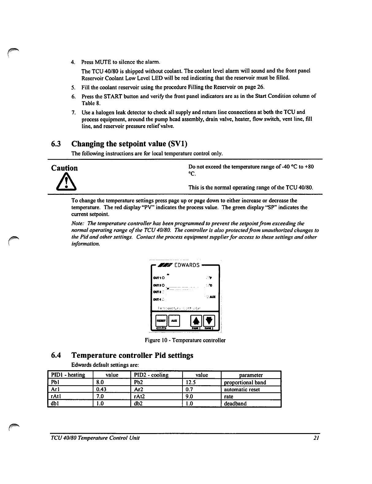
Figure
10
-
Temperature
controller
6.4
Temperature
controller
Pid
settings
Edwards
default
settings
are:
PID1
-
heating
Pbl
Arl
rAtl
dbl
value
8.0
0.43
7.0
1.0
PID2
-
cooling
Pb2
Ar2
rAt2
db2
value
12.5
0.7
9.0
1.0
parameter
proportional
band
automatic
reset
rate
deadband
TCU
40/80
Temperature
Control
Unit
21
6.5
Remote
set-point
To
use
the
remote
set-point,
wire
the
J72J2
mating
connector
as
illustrated
on
page
56.
24vac
must
be
applied
to
pins
3
and
4.
The
AUX
LED
on
the
temperature
controller
will
illuminate
indicating
remote
setpoint
enable
mode
as
soon
as
the
mating
connector
is
installed.
6.6
Flow
rate
adjustment
Caution
Do
not
exceed
coolant
pressure
of
100
psi.
Exceeding
the
coolant
pressure
may
result
in
damage
to
the
pump.
The
Fluorinert
flow
rate
of
the
TCU
40/80
is
factory
set
to
provide
approximately
3
gpm
at
60
psig/20°C
for
a
unit
operating
at
208vac/3-ph/60Hz.
If
the
flow
rate
requires
adjustment
to
accommodate
the
process
equipment
suppliers
recommendations,
follow
the
steps
below.
The
flow
rate
may
be
measured
using
a
flow
meter
external
to
the
TCU
40/80.
1.
Open
the
left
side
access
door.
2.
Peel
back
the
insulation
covering
the
by-pass
valve.
Refer
to
Figure
1
on
page
6.
3.
The
valve
handle
can
be
found
in
the
plastic
bag
secured
to
the
pump.
Reduce
the
flow
by
turning
the
valve
stem
clockwise.
To
increase
the
flow,
turn
the
stem
counter
clockwise.
The
valve
is
a
1/4
turn
valve.
4.
Once
the
required
flow
rate
has
been
achieved,
return
the
valve
handle
to
the
bag
for
future
use,
glue
the
insulation
back
in
place,
and
secure
the
access
door.
22
TCU40/80
Temperature
Control
Unit
7
MAINTENANCE
This
section
contains
information
that
will
allow
you
to
safely
keep
your
TCU
40/80
in
working
order.
It
contains
important
Hazard
Warnings,
a
Preventive
Maintenance
Schedule
on
page
27,
and
a
Troubleshooting
Guide
on
page
41.
Maintenance
to
the
electrical
system
of
the
TCU40/80
should
be
performed
by
qualified
personnel
only.
Warning
The
refrigeration
units
are
scaled
and
are
not
user
serviceable.
Only
trained
and
licensed
refrigeration
personnel
should
perform
repairs
on
this
equipment.
All
applicable
EPA
regulations
apply.
7.1
Hazard
warnings
High
Pressure
Water and
the
coolant
arc
pressurized
within
this
equipment.
Water
pressure
will
depend
upon
utility
supply,
but
usually
is
up
to
60
psig.
The
coolant
can
be
at
pressures
up
to
100
psig.
Refrigerant
pressures
can
be
up
to
300
psig.
Do
not
open
lines
with
pressure
present.
Toxic
Gases
The
coolant
breaks
down
above
215
°C.
If
the
coolant
is
allowed
to
reach
these
temperatures,
toxic
gasses
may
be
discharged
from
the
unit.
Refer
to
the
Appendix
for
Material
Safety
Data
Sheets
for
the
coolant
and
refrigerant
used
in
this
system.
High
Pressure
The
reservoir
may
become
pressurized
due
to
changes
in
temperature.
Under
no
circumstances
should
the
reservoir
pressure
relief
valve
be
removed
or
capped
off.
TCU
40/80
Temperature
Control
Unit
23
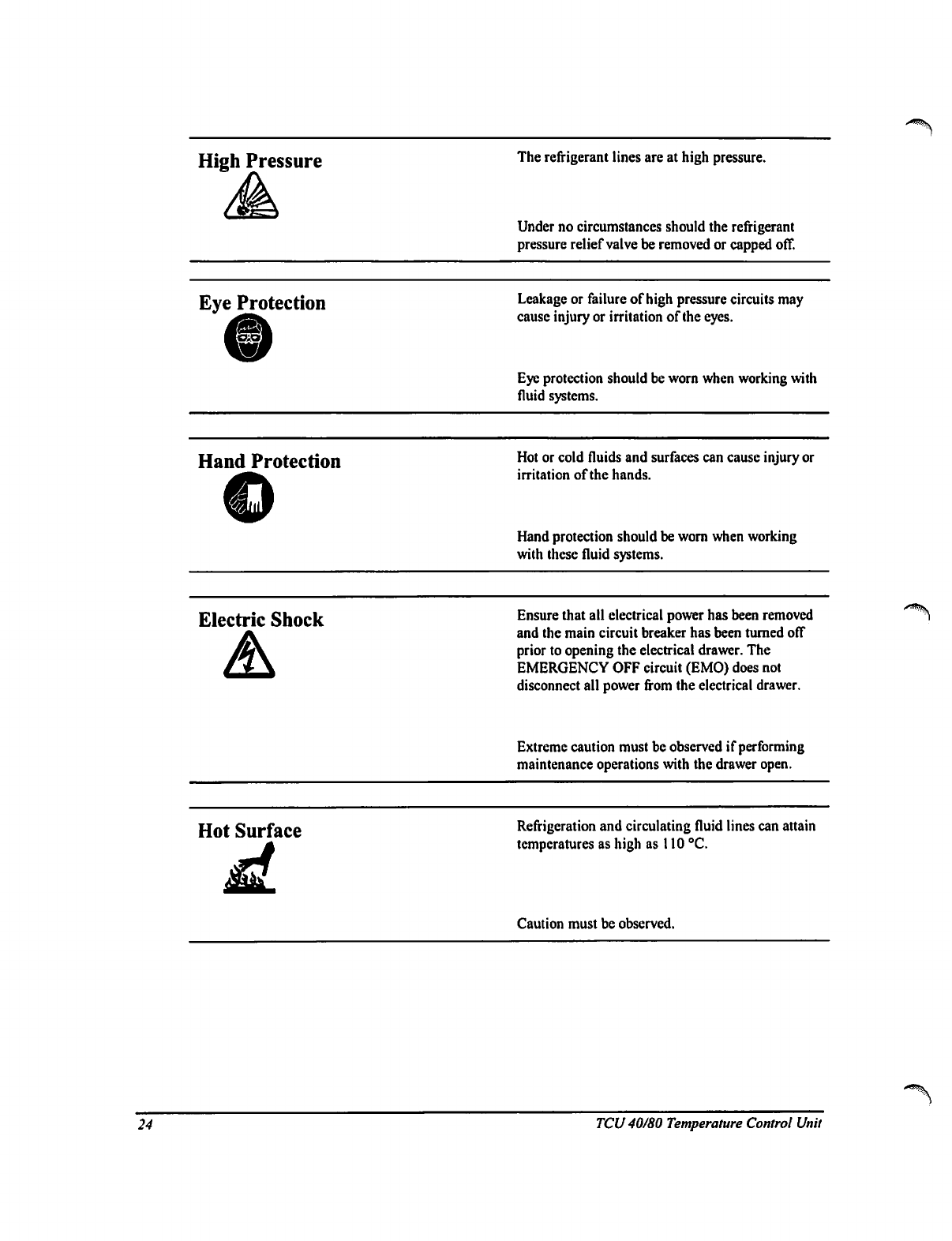
High
Pressure
The
refrigerant
lines
are
at
high
pressure.
Under
no
circumstances
should
the
refrigerant
pressure
relief
valve
be
removed
or
capped
off.
Eye
Protection
Hand
Protection
Leakage
or
failure
of
high
pressure
circuits
may
cause
injury
or
irritation
of
the
eyes.
Eye
protection
should
be
worn
when
working
with
fluid
systems.
Hot
or
cold
fluids
and
surfaces
can
cause
injury or
irritation
of
the
hands.
Hand
protection
should
be
worn
when
working
with
these
fluid
systems.
Electric
Shock
Ensure
that
all
electrical
power
has
been
removed
and
the
main
circuit
breaker
has
been
turned
off
prior
to
opening
the
electrical
drawer.
The
EMERGENCY
OFF
circuit
(EMO)
does
not
disconnect
all
power
from
the
electrical
drawer.
Extreme
caution
must
be
observed
if
performing
maintenance
operations
with
the
drawer
open.
Hot
Surface
Refrigeration
and
circulating
fluid lines
can
attain
temperatures
as
high
as
110
°C.
Caution
must
be
observed.
24
TCU
40/80
Temperature
Control
Unit
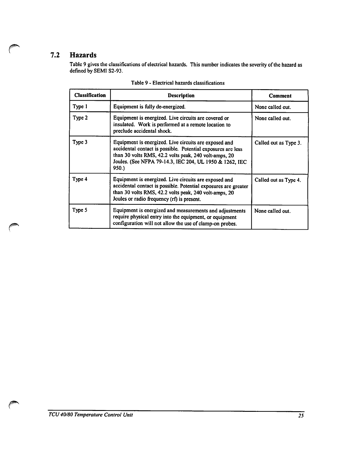
7.2
Hazards
Table
9
gives
the
classifications
of
electrical
hazards.
This
number
indicates
the
severity
of
the
hazard
as
defined
by
SEMI
S2-93.
Table
9
-
Electrical
hazards
classifications
Classification
Typel
Type
2
Type
3
Type
4
Type
5
Description
Equipment
is
fully
de-energized.
Equipment
is
energized.
Live
circuits
are
covered
or
insulated.
Work
is
performed
at
a
remote
location
to
preclude
accidental
shock.
Equipment
is
energized.
Live
circuits
are
exposed
and
accidental
contact
is
possible.
Potential
exposures
are
less
than
30
volts
RMS,
42.2
volts
peak,
240
volt-amps,
20
Joules.
(See
NFPA
79-14.3,
IEC
204,
UL
1950
&
1262,
IEC
950.)
Equipment
is
energized.
Live
circuits
are
exposed
and
accidental
contact
is
possible.
Potential
exposures
are
greater
than
30
volts
RMS,
42.2
volts
peak,
240
volt-amps,
20
Joules
or
radio
frequency
(rf)
is
present.
Equipment
is
energized
and
measurements
and
adjustments
require
physical
entry
into
the
equipment,
or
equipment
configuration
will
not
allow
the
use
of
clamp-on
probes.
Comment
None
called
out.
None
called
out.
Called
out as
Type
3.
Called
out
as
Type
4.
None
called
out.
TCU
40/80
Temperature
Control
Unit
25
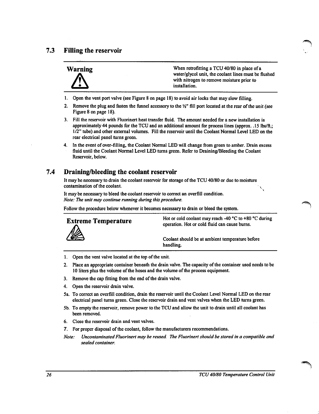
7.3
Filling
the
reservoir
Warning
When
retrofitting
a
TCU
40/80
in
place
of
a
water/glycol
unit,
the
coolant
lines
must
be
flushed
with
nitrogen
to
remove
moisture
prior
to
installation.
1.
Open
the
vent
port
valve
(see
Figure
8
on
page
18)
to
avoid
air
locks
that
may
slow
filling.
2.
Remove
the
plug
and
fasten
the
funnel
accessory
to
the
Vi"
fill
port
located
at
the
rear
of
the
unit (see
Figure
8
on
page
18).
3.
Fill
the
reservoir
with
Fluorinert
heat
transfer
fluid.
The
amount
needed
for
a
new
installation
is
approximately
44
pounds
for
the
TCU
and
an
additional
amount
for
process
lines
(approx.
.15
lbs/ft.;
1/2"
tube)
and
other
external
volumes.
Fill
the
reservoir
until
the
Coolant
Normal
Level
LED
on
the
rear
electrical
panel
turns
green.
4.
In
the
event
of
over-filling,
the
Coolant
Normal
LED
will
change
from
green
to
amber.
Drain
excess
fluid
until
the
Coolant
Normal
Level
LED
turns
green.
Refer
to
Draining/Bleeding
the
Coolant
Reservoir,
below.
7.4
Draining/bleeding
the
coolant
reservoir
It
may
be
necessary
to
drain
the
coolant
reservoir
for
storage
of
the
TCU
40/80
or
due
to
moisture
contamination
of
the
coolant.
v
It
may
be
necessary
to
bleed
the
coolant
reservoir
to
correct
an
overfill
condition.
Note:
The
unit
may
continue
running
during
this
procedure.
Follow
the
procedure
below
whenever
it
becomes
necessary
to
drain
or
bleed
the
system.
Firtreme
Temnerature
Hot
or
cold
coolant
may
reach
"40
°C
t0
+80
°C
during
UXtreme
1
emperature
operation.
Hot
or
cold
fluid
can
cause
burns.
Coolant
should
be
at
ambient
temperature
before
handling.
1.
Open
the
vent
valve
located
at
the
top
of
the
unit.
2.
Place
an
appropriate
container
beneath
the
drain
valve.
The
capacity
of
the container
used
needs
to
be
10
liters
plus
the
volume
of
the
hoses
and
the
volume
of
the
process
equipment.
3.
Remove
the
cap
fitting
from
the
end
of
the
drain
valve.
4.
Open
the
reservoir
drain
valve.
5a.
To
correct
an
overfill
condition,
drain
the
reservoir
until
the
Coolant
Level
Normal
LED
on
the
rear
electrical
panel
turns
green.
Close
the
reservoir
drain
and
vent
valves
when
the
LED
turns
green.
5b.
To
empty
the
reservoir,
remove
power
to
the
TCU
and
allow
the
unit
to
drain
until
all
coolant
has
been
removed.
6.
Close
the
reservoir
drain
and
vent
valves.
7.
For
proper
disposal
of
the
coolant,
follow
the
manufacturers
recommendations.
Note:
Uncontaminated
Fluorinert
may
be
reused.
The
Fluorinert
should
be
stored
in
a
compatible
and
sealed
container.
26
TCU
40/80
Temperature
Control
Unit
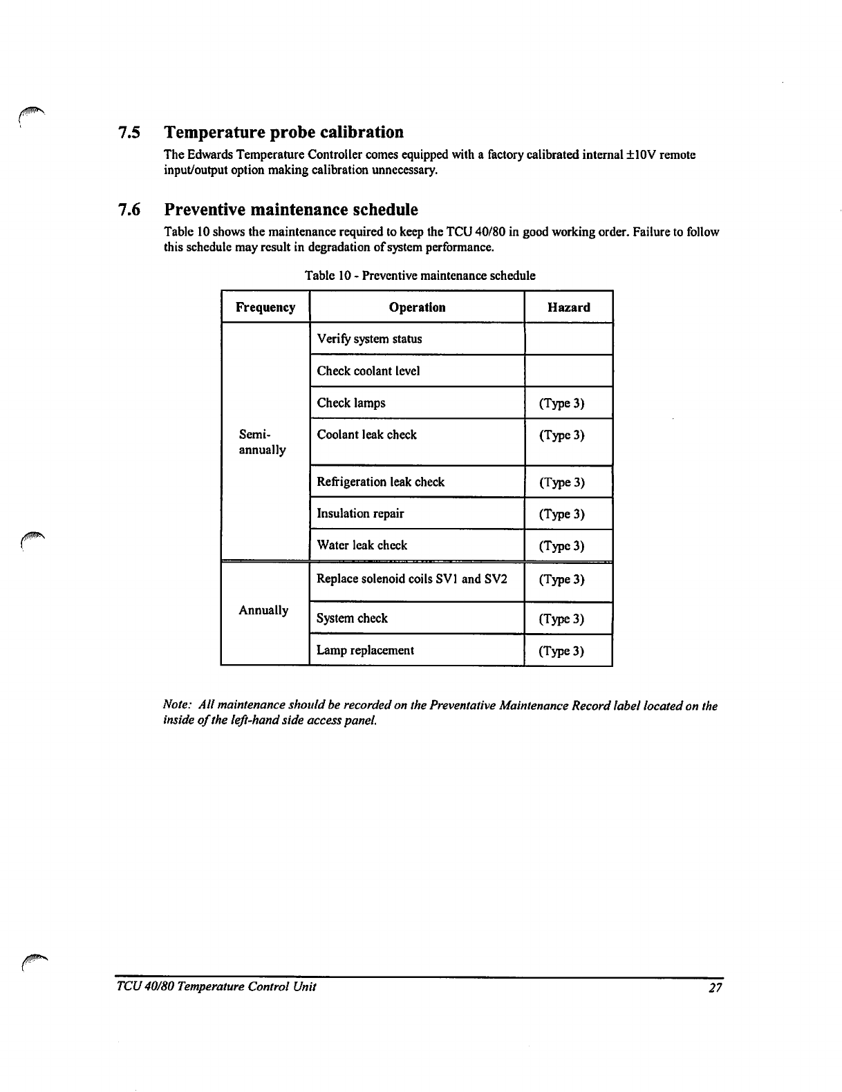
7.5
Temperature
probe
calibration
The
Edwards
Temperature
Controller
comes
equipped
with
a
factory
calibrated
internal
+10V
remote
input/output
option
making
calibration
unnecessary.
7.6
Preventive
maintenance
schedule
Table
10
shows
the
maintenance
required
to
keep
the
TCU
40/80
in
good
working
order.
Failure
to
follow
this
schedule
may
result
in
degradation
of
system
performance.
Table
10
-
Preventive
maintenance
schedule
Frequency
Semi
annual
ly
Annually
Operation
Verify
system
status
Check
coolant
level
Check
lamps
Coolant
leak
check
Refrigeration
leak
check
Insulation
repair
Water
leak
check
Replace
solenoid
coils
SV1
and
SV2
System
check
Lamp
replacement
Hazard
(Type
3)
(Type
3)
(Type
3)
(Type
3)
(Type
3)
(Type
3)
(Type
3)
(Type
3)
Note:
All
maintenance
should be
recorded
on
the
Preventative
Maintenance
Record
label
located
on
the
inside
of
the
left-hand
side
access
panel.
TCU
40/80
Temperature
Control
Unit
27
1
7.7
Semi-annual
preventative
maintenance
Refer
to
the
Troubleshooting
section
on
page
42
when
results
for
any
of
the
following
checkpoints
are
not
as
expected.
7.7.1
Required
equipment
•
12"
slotted
screwdriver
•
Spare
lamps
(24
vac
/
60
mA)
•
4"
slotted
screwdriver
•
Fluorinert
•
Two
10"
adjustable
wrenches
•
Insulation
Tape
•
Halogen
leak
detector
7.7.2
Preparation
•
Locate
the
two
screws
securing
each
of
the
side
access
panels
and
loosen
to
open
doors.
•
Listen
for
excessive
or
questionable
noise
or
sounds
coming
from
the
pump
assembly, motor,
compressor,
or
solenoid
valves
(SV1
and
SV2).
7.7.3
Verify
system
status
•
Verify
system
status
led
indicators
on
the
front
electrical
panel.
(See
-
Front
panel
power
up
indicator
conditions
table
on
page
20.)
7.7.4
Refrigeration
leak
check
•
Visually
check
for
signs
of
compressor
oil
on
the
base,
insulation,
and
on
all
refrigeration
pipework.
•
Using
a
halogen
leak
detector
check around
the
discharge
and
suction
service
valves
of
the
compressor,
and
all
accessible
refrigeration
pipework.
7.7.5
Fluorinert
leak
check
•
Use
a
halogen
leak
detector
to
check
all
supply
and
return
line
connections
at
both
the
TCU
and
process
equipment,
around
the
pump
head
assembly,
drain
valve,
heater,
flow
switch,
vent
line,
fill
line,
and
reservoir
pressure
relief
valve.
7.7.6
Water
leak
check
•
Visually
check
for
signs
of
water
leaks
at
all
water
line
connections
external
to
the
TCU
and
at
the
condenser
connections
inside
the
unit.
7.7.7
Insulation
repair
Note:
If
ice
formation
is
excessive,
it
may
be
necessary
to
correct
this
condition
before
insulation
can
be
repaired.
•
Visually
inspect
refrigeration
and
process
fluid
lines
both
inside
the
TCU
cabinet
and
at
the
supply
and
return
line
connections
for
signs
of
ice
formation.
Correct
insulation
as
necessary.
28
TCU
40/80 Temperature
Control
Unit
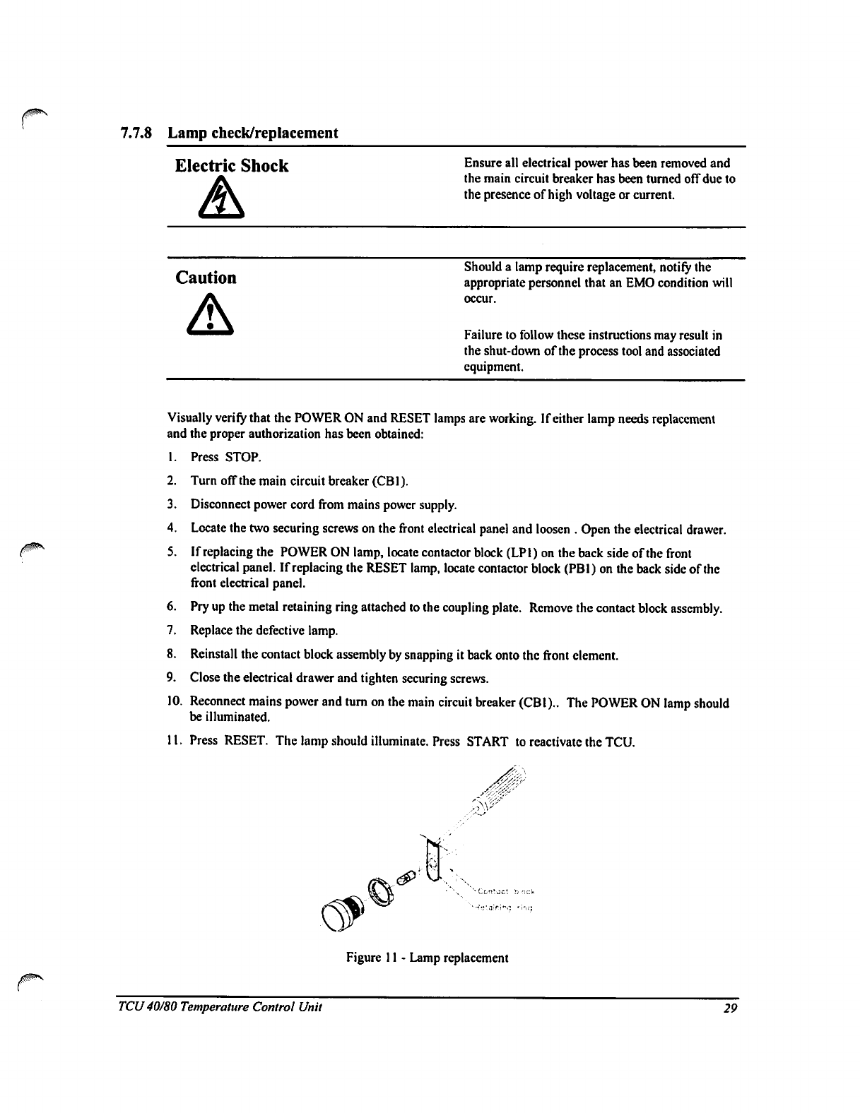
7.7.8
Lamp
check/replacement
Electric
Shock
Ensure
all
electrical
power
has
been
removed
and
the
main
circuit
breaker
has
been
turned
off
due
to
the
presence
of
high
voltage
or
current.
Caution
Should
a
lamp
require
replacement,
notify
the
appropriate
personnel
that
an
EMO
condition
will
occur.
Failure
to
follow
these
instructions
may
result
in
the
shut-down
of
the
process
tool
and
associated
equipment.
Visually
verify
that
the
POWER
ON
and
RESET
lamps
are
working.
If either
lamp
needs
replacement
and
the
proper
authorization
has
been
obtained:
1.
Press
STOP.
2.
Turn
off
the
main
circuit
breaker
(CB1).
3.
Disconnect
power
cord
from
mains
power
supply.
4.
Locate
the
two
securing
screws
on
the
front
electrical
panel
and
loosen
.
Open
the
electrical
drawer.
5.
If
replacing
the
POWER
ON
lamp,
locate
contactor
block
(LPl)
on
the
back
side
of
the
front
electrical
panel.
If
replacing
the
RESET
lamp,
locate
contactor
block
(PBl)
on
the
back
side
of
the
front
electrical
panel.
6.
Pry
up
the
metal
retaining
ring attached
to
the
coupling
plate.
Remove
the
contact
block
assembly.
7.
Replace
the
defective
lamp.
8.
Reinstall
the
contact
block
assembly
by
snapping
it
back
onto
the
front
clement.
9.
Close
the
electrical
drawer
and
tighten
securing
screws.
10.
Reconnect
mains
power
and
turn
on
the
main
circuit
breaker
(CBI)..
The
POWER
ON
lamp
should
be
illuminated.
11.
Press
RESET.
The
lamp
should
illuminate.
Press
START
to
reactivate
the
TCU.
Figure
11
-
Lamp
replacement
TCU40/80
Temperature
Control
Unit
29
7.8
Annual
preventative
maintenance
Refer
to
the
Troubleshooting
section
on
page
42
when
results
for
any
of
the
following
check
points
are
not
as
expected.
7.8.1
Required
equipment
12"
slotted
screwdriver
4"
slotted
screwdriver
7"
slotted
screwdriver
8"
phillips
screwdriver
Two
10"
adjustable
wrenches
Wire
strippers
(14
AWG)
Two
test
clips
w/12"
leads
Miniature
diagonal
cutters
Halogen
leak
detector
3\8"
open-ended
wrench
1\4"
open-ended
wrench
Wire
crimpers
-
Insulated
terminal
Digital
multimeter
(DMM)
Remote
RTD
connector
plug
(J72J3)
7.8.2
Required
supplies
•
Preventative
Maintenance
Kit
(P60153005)
•
Fluorinert
•
Insulation
Tape
7.8.3
Solenoid
valve
coil
replacement
Electric
Shock
Ensure
all
electrical
power
has
been
removed
and
the
main
circuit
breaker
has
been
turned
off
due
to
the
presence
of high
voltage
or
current.
Caution
Should
a
solenoid
valve
coil
require
replacement,
notify
the
appropriate
personnel
that
an
EMO
condition
will
occur.
Failure
to
follow
these
instructions
may
result
in
the
shut-down
of
the
process
tool
and
associated
equipment.
30
1.
Press
STOP..
Turn
off the
main
circuit
breaker
(CB1).
2.
Disconnect
the
power
cord
from
the
mains power
supply.
3.
Locate
the
main
cooling
solenoid
valve
(SV1)
from
the
left
side
access
door.
4.
Remove
the
junction
box
attachment
screw.
Slide
off the
junction
box
cover.
5.
Back
off the
strain relief
retaining
nut.
6.
Unfasten
the
ground
screw.
Cut
off the
wire
butt
splices
(ensuring
that
the
wire
labels
remain
attached
to
the
base
assembly)
and
pull
the
wires
through
the
junction
box.
7.
Remove
the
solenoid
valve
coil
lock
nut.
Lift
off
the
spacer
cup.
Separate
the
coil
from
the
solenoid
valve
body
by
gently
pulling
up
on
the
coil.
8.
Remove
replacement
solenoid
valve
coil
from
packaging.
9.
Remove
the
junction
box.
10.
Note
the
location
of
the
conduit
hole
on
the
coil
removed
and
remove
the
appropriate
"knock-out"
on
the
replacement
coil.
TCU
40/80 Temperature
Control
Unit
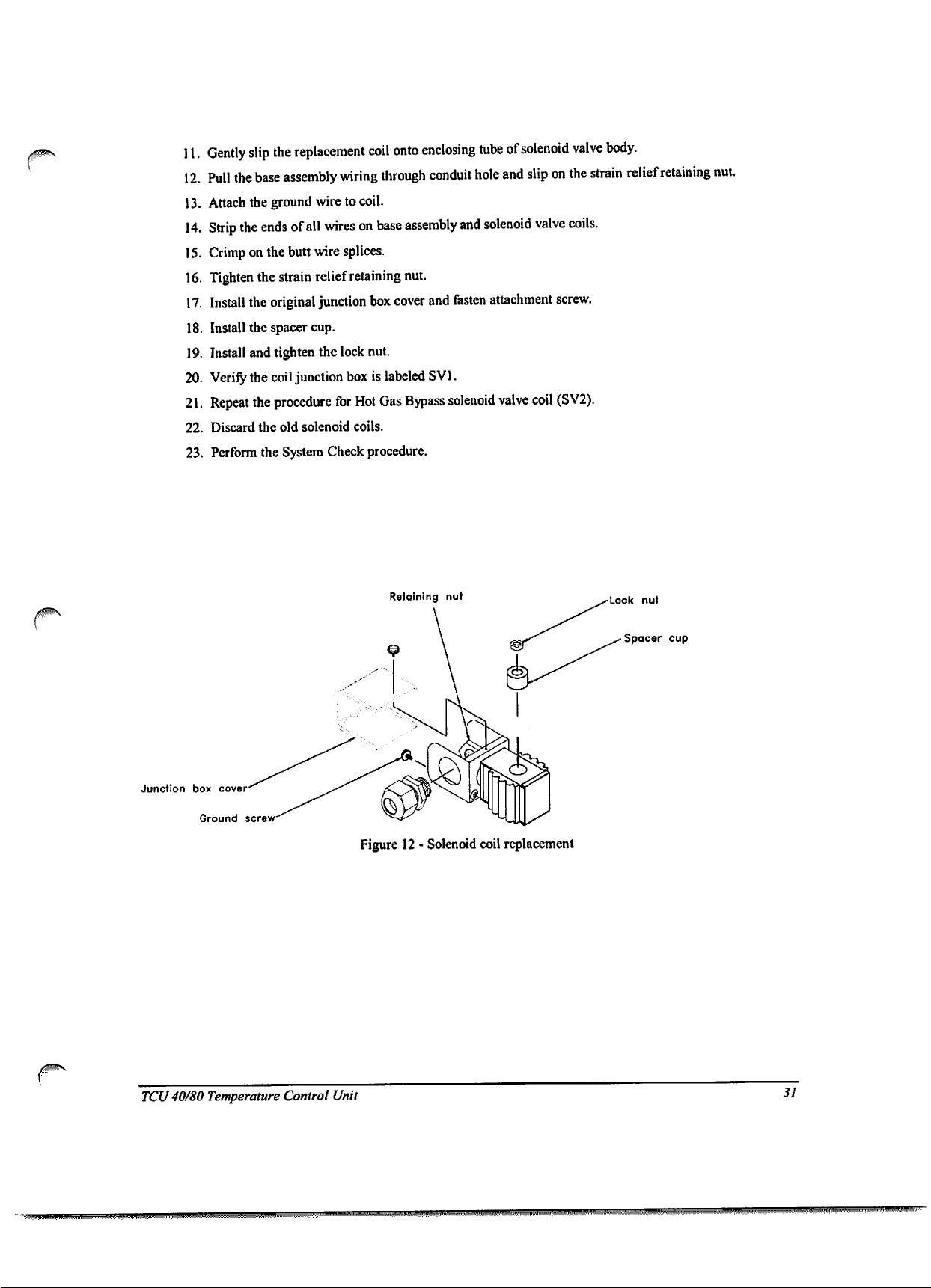
11.
Gently
slip
the
replacement
coil
onto
enclosing
tube
of
solenoid
valve
body.
12.
Pull
the
base
assembly
wiring
through
conduit
hole
and
slip
on
the
strain
relief
retaining
nut.
13.
Attach
the
ground
wire
to
coil.
14.
Strip
the
ends
of
all
wires
on
base
assembly
and
solenoid
valve
coils.
15.
Crimp
on
the
butt
wire
splices.
16.
Tighten
the
strain relief
retaining
nut.
17.
Install
the
original
junction
box
cover
and
fasten
attachment
screw.
18.
Install
the
spacer
cup.
19.
Install
and
tighten
the
lock
nut.
20.
Verify
the
coil
junction
box
is
labeled
SV1.
21.
Repeat
the
procedure
for
Hot
Gas
Bypass
solenoid
valve
coil
(SV2).
22.
Discard
the old
solenoid
coils.
23.
Perform
the
System
Check
procedure.
Retaining
nut
Junction
box
cover
Ground
screw
Lock
nut
Spacer
cup
Figure 12
-
Solenoid
coil
replacement
TCU
40/80
Temperature
Control
Unit
31
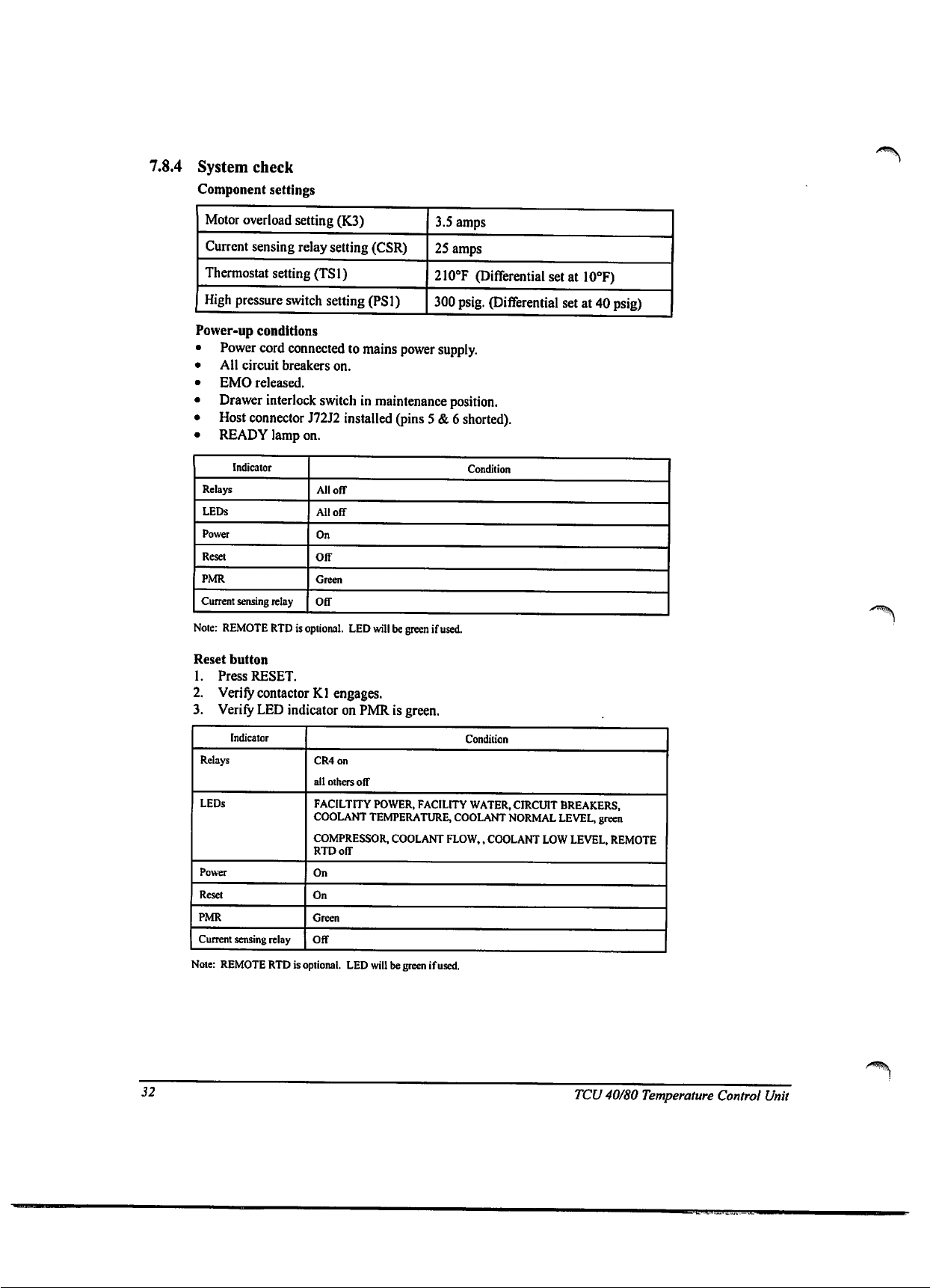
7.8.4
System
check
Component
settings
Motor
overload
setting
(K3)
Current sensing
relay
setting
(CSR)
Thermostat
setting
(TS1)
High
pressure
switch
setting
(PS1)
3.S
amps
25
amps
210°F
(Differential
set
at
10°F)
300
psig.
(Differential
set
at
40
psig)
Power-up
conditions
•
Power
cord
connected
to
mains power
supply.
•
All
circuit
breakers
on.
•
EMO
released.
•
Drawer
interlock
switch
in
maintenance
position.
•
Host
connector
J72J2
installed
(pins
5
&
6
shorted).
•
READY
lamp
on.
Indicator
Relays
LEDs
Power
Reset
PMR
Current
sensing
relay
Condition
All
off
All
off
On
Off
Green
Off
Note:
REMOTE
RTD
is
optional.
LED
will
be
green
if
used.
Reset
button
1.
Press
RESET.
2.
Verify
contactor
Kl
engages.
3.
Verify
LED
indicator
on
PMR
is
green.
\
Indicator
Relays
LEDs
Power
Reset
PMR
Current
sensing
relay
Condition
CR4on
all
others
off
FACILTITY
POWER,
FACILITY
WATER,
CIRCUIT
BREAKERS,
COOLANT
TEMPERATURE,
COOLANT
NORMAL
LEVEL,
green
COMPRESSOR,
COOLANT
FLOW,,
COOLANT
LOW
LEVEL,
REMOTE
RTD
off
On
On
Green
Off
Note:
REMOTE
RTD
is
optional.
LED
will
be
green
if
used.
32
TCU
40/80 Temperature
Control
Unit
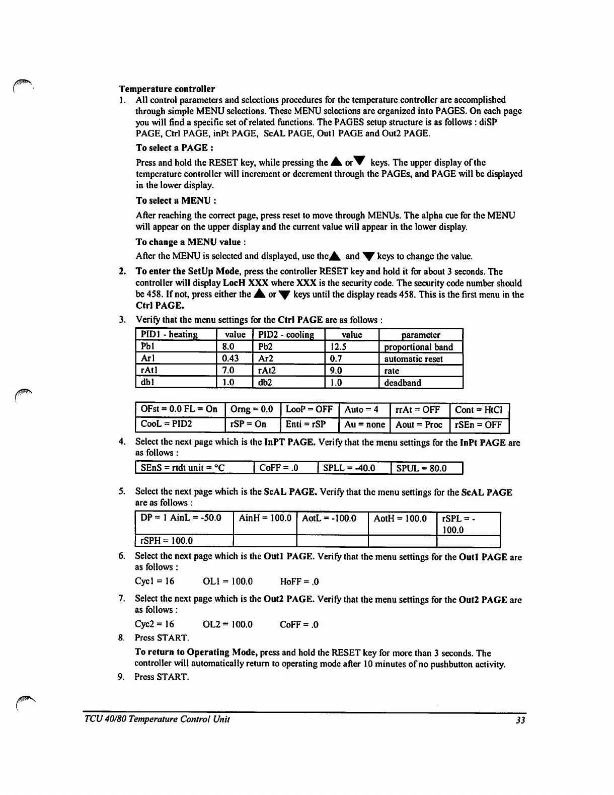
Temperature
controller
1.
2.
All
control
parameters
and
selections
procedures
for
the
temperature
controller
are
accomplished
through
simple
MENU
selections.
These
MENU
selections
are
organized
into
PAGES.
On
each
page
you
will
find
a
specific
set
of
related
functions.
The
PAGES
setup
structure
is
as
follows
:
diSP
PAGE,
Ctrl
PAGE,
inPt
PAGE, ScAL
PAGE,
Outl
PAGE
and Out2
PAGE.
To
select
a
PAGE
:
Press
and
hold
the
RESET
key,
while
pressing
the
^
otW
keys.
The
upper
display
of
the
temperature
controller
will
increment
or
decrement
through
the
PAGEs,
and
PAGE
will
be
displayed
in
the
lower
display.
To
select
a
MENU
:
After
reaching
the
correct
page,
press
reset
to
move
through
MENUs.
The
alpha cue
for
the
MENU
will
appear
on
the
upper
display
and
the
current
value
will
appear
in
the
lower
display.
To
change
a
MENU
value
:
After
the
MENU
is
selected
and
displayed,
use
the^
and
*V
keys
to
change
the
value.
To
enter
the
SetUp
Mode,
press
the
controller
RESET
key
and
hold
it
for
about
3
seconds.
The
controller
will
display
LocH
XXX
where
XXX
is
the
security
code.
The
security
code
number
should
be
458.
If
not,
press
either
the
JLot^
keys
until
the
display
reads
458.
This
is
the
first
menu
in
the
Ctrl
PAGE.
Verify
that
the
menu
settings
for
the
Ctrl
PAGE
are as follows
:
PID1
-heatinR
Pbl
Arl
rAtl
dbl
value
8.0
0.43
7.0
1.0
PID2
-
cooling
Pb2
Ar2
rAt2
db2
value
12.5
0.7
9.0
1.0
parameter
proportional
band
automatic
reset
rate
deadband
OFst
=
CooL
=
0.0
FL
=
=
PID2
On
Orng
rSP
=
=
0.0
On
LooP
Enti
=
=
OFF
rSP
Auto
=
4
Au
=
none
rrAt
Aout
=
OFF
=
Proc
Cont
rSEn
=
HtCI
=
OFF
4.
Select
the
next
page
which
is
the
InPT
PAGE.
Verify
that
the
menu
settings
for
the
InPt
PAGE
are
as
follows:
I
SEnS
=
rtdt
unit
=
°C
CoFF
=
.0
1
SPLL =
-40.0
|
SPUL
=
80.0
5.
Select
the
next
page
which
is
the
ScAL
PAGE.
Verify
that
the
menu
settings
for
the
ScAL
PAGE
are
as
follows:
DP=
1
rSPH
=
AinL
=
100.0
-50.0
AinH
=
100.0
AotL
=
-100.0
AotH
=
100.0
rSPL=-
100.0
6.
Select
the
next
page
which
is
the
Outl
PAGE.
Verify
that
the
menu
settings
for
the
Outl
PAGE
are
as
follows:
Cycl
=
16
OL1
=
100.0
HoFF
=
.0
7.
Select
the
next
page
which
is
the
Out2
PAGE.
Verify
that
the
menu
settings
for
the
Out2
PAGE
arc
as
follows:
Cyc2
=16
OL2
=
100.0
CoFF
=
.0
8.
Press
START.
To
return
to
Operating
Mode,
press
and
hold
the
RESET
key
for
more
than
3
seconds.
The
controller
will
automatically
return
to
operating
mode
after
10
minutes
of
no
pushbutton
activity.
9.
Press
START.
TCU
40/80
Temperature
Control
Unit
33
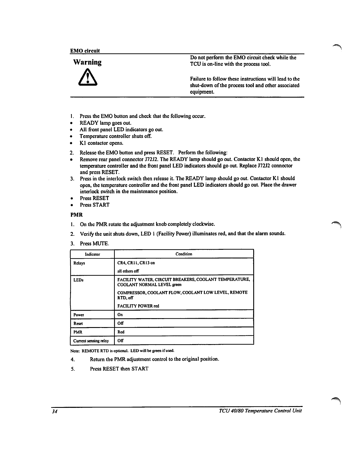
EMO
circuit
Do
not
perform
the
EMO
circuit
check
while
the
TCU
is
on-line
with
the
process
tool.
Failure
to
follow
these
instructions
will
lead
to
the
shut-down
of
the
process
tool
and
other
associated
equipment.
1.
Press
the
EMO
button
and
check
that
the
following
occur.
•
READY
lamp
goes
out.
•
All
front
panel
LED
indicators
go
out.
•
Temperature
controller
shuts
off.
•
Kl
contactor
opens.
2.
Release
the
EMO
button
and
press
RESET.
Perform
the
following:
•
Remove
rear
panel
connector
J72J2.
The
READY
lamp
should
go
out.
Contactor
Kl
should
open,
the
temperature
controller
and
the
front
panel
LED
indicators
should
go
out.
Replace
J72J2
connector
and
press
RESET.
3.
Press
in
the
interlock
switch
then
release
it.
The
READY
lamp
should
go
out.
Contactor
Kl
should
open,
the
temperature
controller
and
the
front
panel
LED
indicators
should
go
out.
Place
the
drawer
interlock
switch
in
the
maintenance
position.
•
Press
RESET
•
Press
START
PMR
1.
On
the
PMR
rotate
the
adjustment
knob
completely
clockwise.
2.
Verify
the
unit
shuts
down,
LED
1
(Facility
Power)
illuminates
red,
and
that
the
alarm
sounds.
3.
Press
MUTE.
Indicator
Relays
LEDs
Power
Reset
PMR
Current
sensing
relay
Condition
CR4,CRll,CRI3on
all
others off
FACILITY
WATER,
CIRCUIT
BREAKERS,
COOLANT
TEMPERATURE,
COOLANT
NORMAL
LEVEL
green
COMPRESSOR,
COOLANT
FLOW,
COOLANT
LOW
LEVEL,
REMOTE
RTD.off
FACIL1TY
POWER
red
On
Off
Red
Off
Note:
REMOTE
RTD
is
optional.
LED
will
be
green
if
used.
4.
Return
the
PMR
adjustment
control
to
the
original
position.
5.
Press
RESET
then
START
34
TCU
40/80
Temperature
Control
Unit
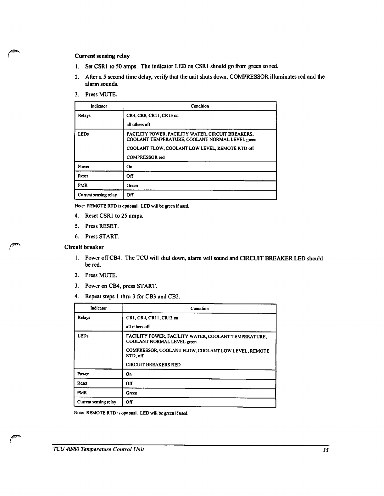
Current
sensing
relay
1.
Set
CSRI
to
SO
amps.
The
indicator
LED
on
CSRI
should
go
from
green
to
red.
2.
After
a
5
second
time
delay,
verily
that
the
unit
shuts
down,
COMPRESSOR
illuminates
red
and
the
alarm
sounds.
3.
Press
MUTE.
Indicator
Relays
LEDs
Power
Reset
PMR
Current
sensing
relay
Condition
CR4.CR8.CRll.CR13
on
alt
others off
FACILITY
POWER,
FACILITY
WATER,
CIRCUIT
BREAKERS,
COOLANT
TEMPERATURE,
COOLANT
NORMAL
LEVEL
green
COOLANT
FLOW,
COOLANT
LOW
LEVEL,
REMOTE
RTD
off
COMPRESSOR
red
On
Off
Green
Off
Note:
REMOTE
RTD
is
optional.
LED
will
be
green
if
used.
4.
Reset
CSRI
to
25
amps.
5.
Press
RESET.
6.
Press
START.
Circuit
breaker
1.
Power
off
CB4.
The
TCU
will
shut
down,
alarm
will
sound
and
CIRCUIT
BREAKER
LED
should
be
red.
2.
Press
MUTE.
3.
Power
on
CB4,
press
START.
4.
Repeat
steps
1
thru
3
for
CB3
and
CB2.
Indicator
Relays
LEDs
Power
Reset
PMR
Current
sensing
relay
Condition
CRI,CR4,CRH,CR13on
all
others
off
FACILITY
POWER,
FACILITY
WATER,
COOLANT
TEMPERATURE,
COOLANT
NORMAL
LEVEL
green
COMPRESSOR,
COOLANT
FLOW,
COOLANT
LOW
LEVEL,
REMOTE
RTD,
off
CIRCUIT
BREAKERS
RED
On
Off
Green
Off
Note:
REMOTE
RTD
is
optional.
LED
will
be
green
if
used.
TCU
40/80
Temperature
Control
Unit
35
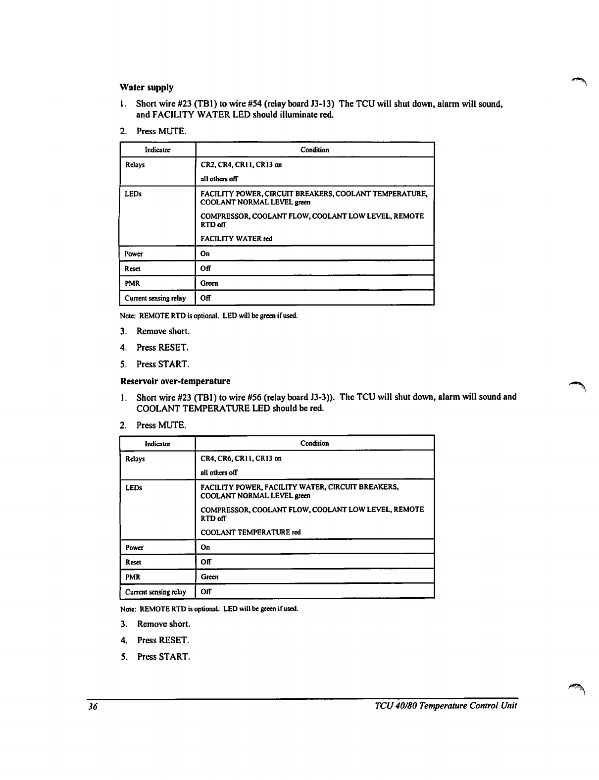
Water
supply
1.
Short
wire
#23
(TBl)
to
wire
#54
(relay
board
J3-13)
The
TCU
will
shut
down,
alarm
will
sound,
and
FACILITY
WATER
LED
should
illuminate
red.
2.
Press
MUTE.
■^"^V
Indicator
Relays
LEDs
Power
Reset
PMR
Cuirait
sensing
relay
Condition
CR2.CR4,CRll,CR13on
all
others
off
FACILITY
POWER,
CIRCUIT
BREAKERS,
COOLANT
TEMPERATURE.
COOLANT
NORMAL
LEVEL
green
COMPRESSOR.
COOLANT
FLOW,
COOLANT
LOW
LEVEL,
REMOTE
RTD
off
FACILITY
WATER
red
On
Off
Green
Off
Note:
REMOTE
RTD
is
optional.
LED
will
be
green
if
used.
3.
Remove
short.
4.
Press
RESET.
5.
Press
START.
Reservoir
over-temperature
1.
Short
wire
#23
(TBl)
to
wire
#56
(relay
board
J3-3)).
The
TCU
will
shut
down,
alarm
will
sound
and
COOLANT
TEMPERATURE
LED
should
be
red.
2.
Press
MUTE.
Indicator
Relays
LEDs
Power
Reset
PMR
Current
sensing
relay
Condition
CR4,CR6.CRll,CRI3on
all
others
off
FACILITY
POWER,
FACILITY
WATER,
CIRCUIT
BREAKERS,
COOLANT
NORMAL
LEVEL
green
COMPRESSOR.
COOLANT
FLOW,
COOLANT
LOW
LEVEL,
REMOTE
RTD
off
COOLANT
TEMPERATURE
red
On
Off
Green
Off
Note:
REMOTE
RTD
is
optional.
LED
will
be
green
if
used.
3.
Remove
short.
4.
Press
RESET.
5.
Press
START.
36
TCU
40/80 Temperature
Control
Unit
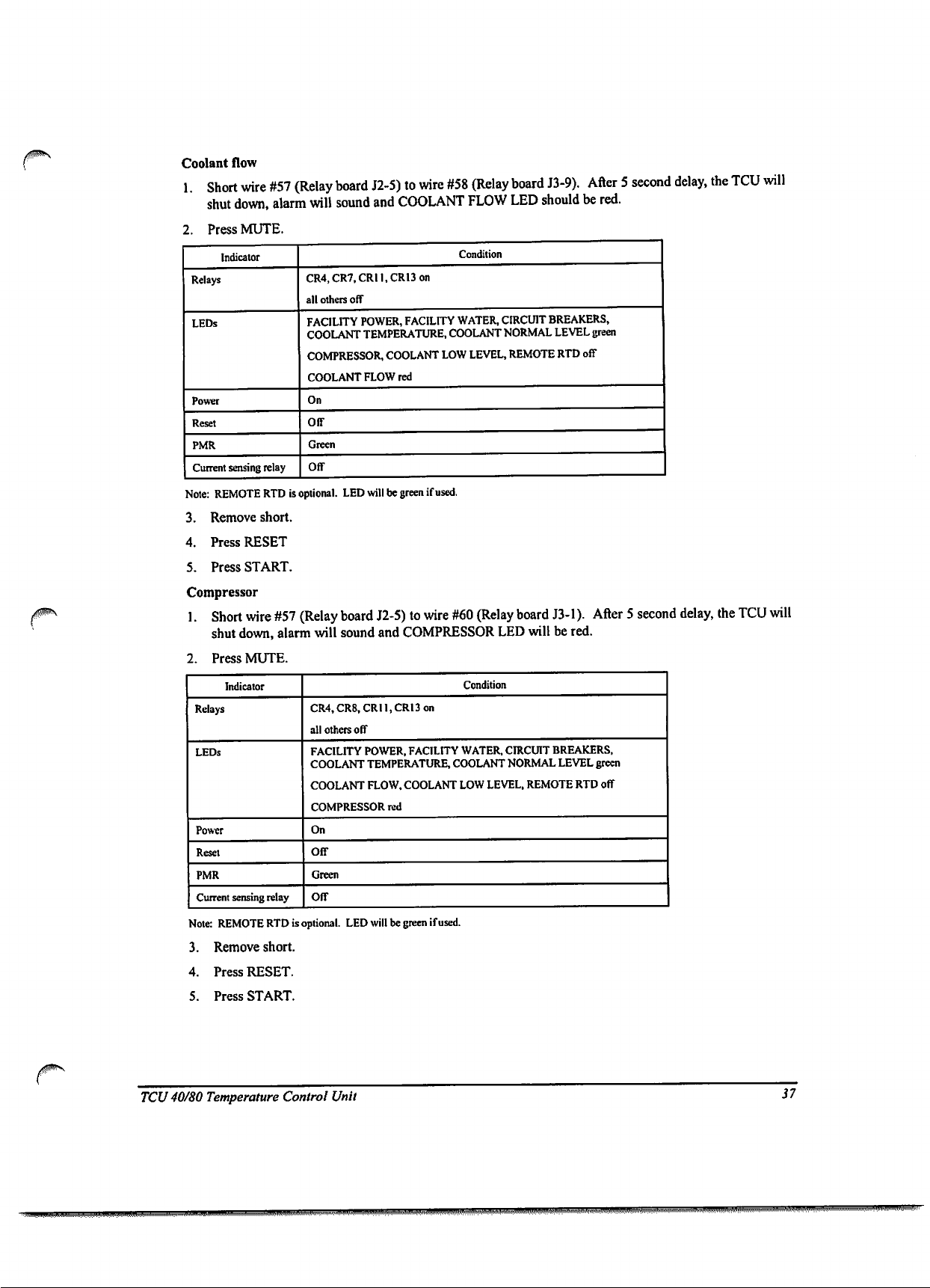
Coolant
flow
1
Short
wire
#57
(Relay
board
J2-5)
to
wire
#58
(Relay
board
J3-9).
After
5
second
delay,
the
TCU
will
shut
down,
alarm
will
sound
and
COOLANT
FLOW
LED
should
be
red.
2.
Press
MUTE.
Indicator
Relays
LEDs
Power
Reset
PMR
Current
sensing
relay
Condition
CR4,CR7,CRll,CR13on
all
others
off
FACILITY
POWER,
FACILITY
WATER,
CIRCUIT
BREAKERS,
COOLANT
TEMPERATURE,
COOLANT
NORMAL
LEVEL
green
COMPRESSOR,
COOLANT
LOW
LEVEL,
REMOTE
RTD
off
COOLANT
FLOW
red
On
Off
Green
Off
Note:
REMOTE
RTD
is
optional.
LED
will
be
green
if
used.
3.
Remove
short.
4.
Press
RESET
5.
Press
START.
Compressor
1.
Short
wire
#57
(Relay
board
J2-5)
to
wire
#60
(Relay
board
J3-1).
After
5
second
delay,
the
TCU
will
shut
down,
alarm
will
sound
and
COMPRESSOR
LED
will
be
red.
2.
Press
MUTE.
Indicator
Relays
LEDs
Power
Reset
PMR
Current
sensing
relay
Condition
CR4,CR8,CRll,CR13on
all
others
off
FACILITY
POWER,
FACILITY
WATER,
CIRCUIT
BREAKERS,
COOLANT
TEMPERATURE,
COOLANT
NORMAL
LEVEL
green
COOLANT
FLOW,
COOLANT
LOW
LEVEL,
REMOTE
RTD
off
COMPRESSOR
red
On
Off
Green
Off
Note:
REMOTE
RTD
is
optional.
LED
will
be
green
if
used.
3.
Remove
short.
4.
Press
RESET.
5.
Press
START.
/0
TCU
40/80
Temperature
Control
Unit
37
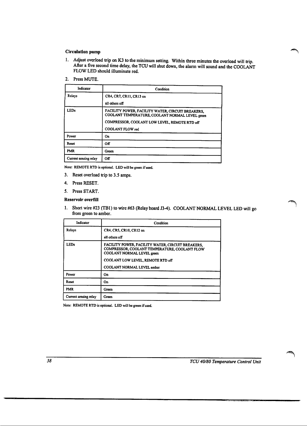
Circulation
pump
1.
Adjust
overload
trip
on
K3
to
the
minimum
setting.
Within
three
minutes
the
overload
will
trip.
After
a
five
second
time
delay,
the
TCU
will
shut
down,
the
alarm
will
sound
and
the
COOLANT
FLOW
LED
should
illuminate
red.
2.
Press
MUTE.
Indicator
Relays
LEDs
Power
Reset
PMR
Current
sensing
relay
Condition
CR4,CR7,CRU,CRI3on
all
others
off
FACILITY
POWER,
FACILITY
WATER,
CIRCUIT
BREAKERS,
COOLANT
TEMPERATURE,
COOLANT
NORMAL
LEVEL
green
COMPRESSOR,
COOLANT
LOW
LEVEL,
REMOTE
RTD
off
COOLANT
FLOW
red
On
Off
Green
Off
Note:
REMOTE
RTD
is
optional.
LED
will
be
green
if
used.
3.
Reset
overload
trip
to
3.5
amps.
4.
Press
RESET.
5.
Press
START.
Reservoir
overfill
1.
Short
wire
#23
(TBl)towire#63
(Relay
board
J3-4).
COOLANT
NORMAL
LEVEL
LED
will
go
from
green
to
amber.
Indicator
Relays
LEDs
Power
Reset
PMR
Current
sensing
relay
Condition
CR4,CR5,CR10,CRI2on
all
others ofT
FACILITY
POWER,
FACILITY
WATER,
CIRCUIT
BREAKERS,
COMPRESSOR,
COOLANT
TEMPERATURE,
COOLANT
FLOW
COOLANT
NORMAL
LEVEL
green
COOLANT
LOW
LEVEL,
REMOTE
RTD
off
COOLANT
NORMAL
LEVEL
amber
On
On
Green
Green
Note:
REMOTE
RTD
is
optional.
LED
will
be
green
if
used.
38
TCU
40/80
Temperature
Control
Unit
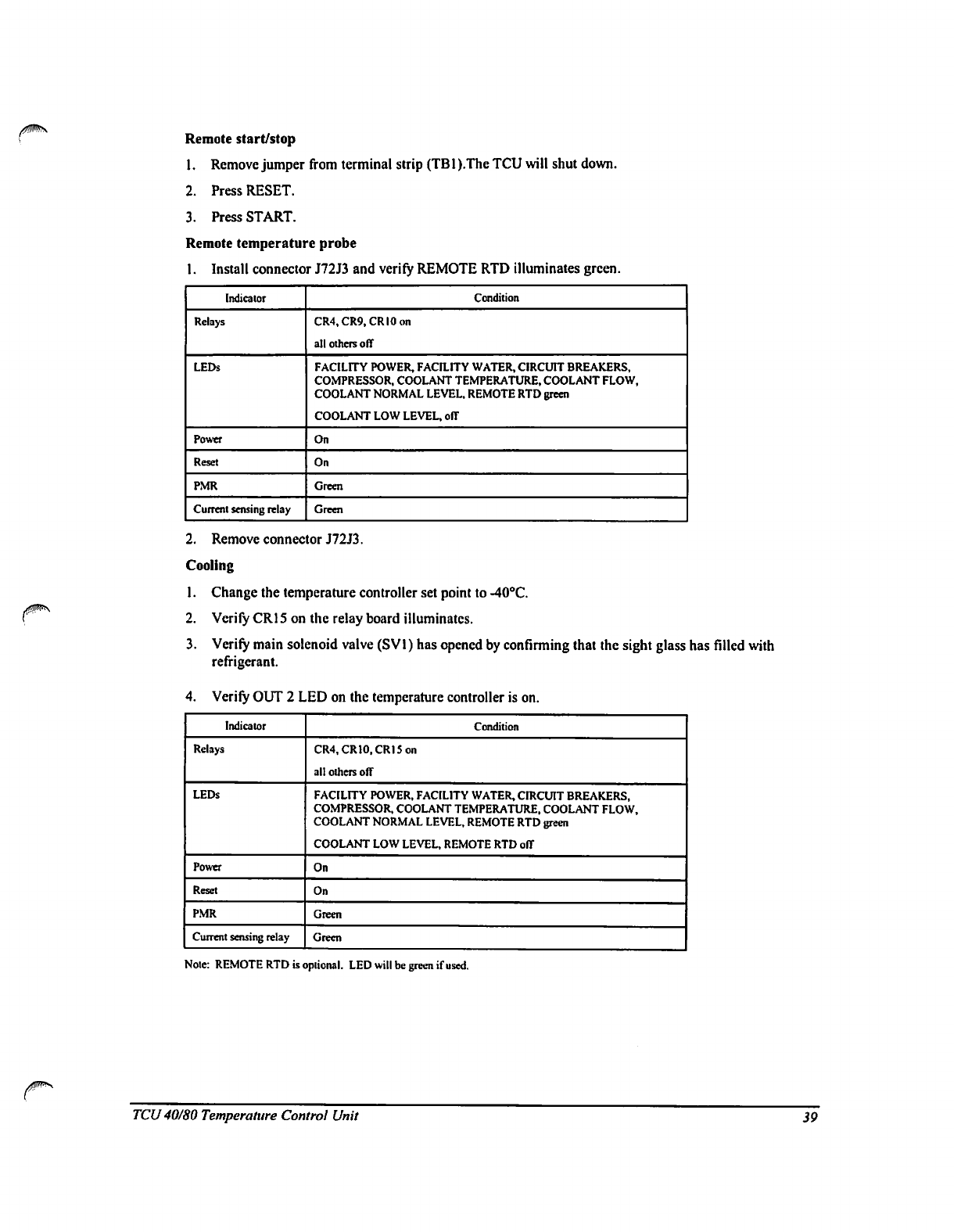
Remote
start/stop
1.
Remove
jumper
from
terminal
strip
(TB1
).The
TCU
will
shut
down.
2.
Press
RESET.
3.
Press
START.
Remote
temperature
probe
1.
Install
connector
J72J3
and
verify
REMOTE
RTD
illuminates
green.
Indicator
Relays
LEDs
Power
Reset
PMR
Current
sensing
relay
Condition
CR4,CR9,CRI0on
all
others
off
FACILITY
POWER,
FACILITY
WATER,
CIRCUIT
BREAKERS,
COMPRESSOR,
COOLANT
TEMPERATURE,
COOLANT
FLOW,
COOLANT
NORMAL
LEVEL,
REMOTE
RTD
green
COOLANT
LOW
LEVEL,
off
On
On
Green
Green
2.
Remove
connector
J72J3.
Cooling
1.
Change
the
temperature
controller
set
point
to
-40°C.
2.
Verify
CR15
on
the
relay
board
illuminates.
3.
Verify
main
solenoid
valve
(SVl)
has
opened by
confinning
that
the
sight glass
has
filled
with
refrigerant.
4.
Verify
OUT
2
LED
on
the
temperature
controller
is
on.
Indicator
Relays
LEDs
Power
Reset
PMR
Current
sensing
relay
Condition
CR4,CR10,CRI5on
all
others
off
FACILITY
POWER,
FACILITY
WATER,
CIRCUIT
BREAKERS,
COMPRESSOR,
COOLANT
TEMPERATURE.
COOLANT
FLOW,
COOLANT
NORMAL
LEVEL,
REMOTE
RTD
green
COOLANT
LOW
LEVEL,
REMOTE
RTD
off
On
On
Green
Green
Note:
REMOTE
RTD
is
optional.
LED
will
be
green
if
used.
TCU
40/80
Temperature
Control
Unit
39
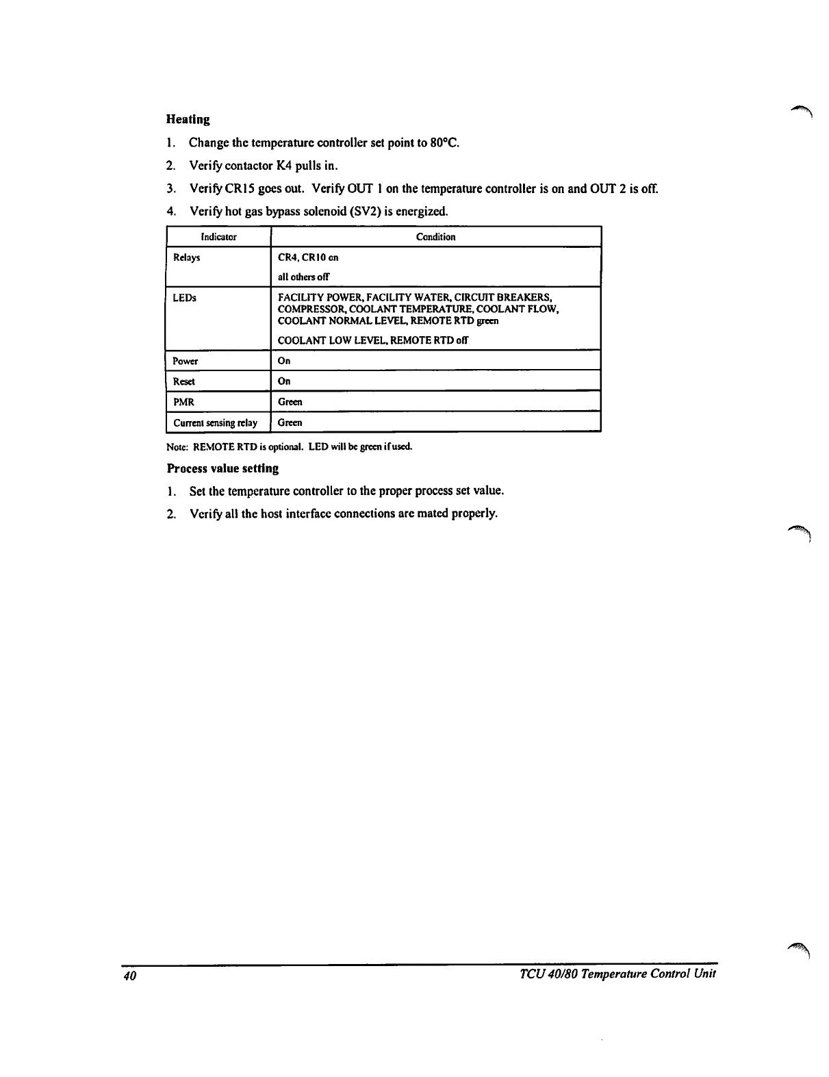
Heating
1.
Change
the
temperature
controller
set
point
to
80°C.
2.
Verify
contactor
K4
pulls
in.
3.
Verify
CR15
goes
out.
Verify
OUT
1
on
the
temperature
controller
is
on
and
OUT
2
is
off.
4.
Verify
hot
gas
bypass
solenoid
(SV2)
is
energized.
Indicator
Relays
LEDs
Power
Reset
PMR
Current
sensing
relay
Condition
CR4,CRI0on
all
others
off
FACILITY
POWER,
FACILITY
WATER,
CIRCUIT
BREAKERS,
COMPRESSOR,
COOLANT
TEMPERATURE,
COOLANT
FLOW,
COOLANT
NORMAL
LEVEL,
REMOTE
RTD
green
COOLANT
LOW
LEVEL,
REMOTE
RTD
off
On
On
Green
Green
Note:
REMOTE
RTD
is
optional.
LED
will
be
green
(fused
Process
value
setting
1.
Set the
temperature
controller
to
the
proper
process
set
value.
2.
Verify
all
the host
interface
connections
are
mated
properly.
40
TCU
40/80 Temperature
Control
Unit
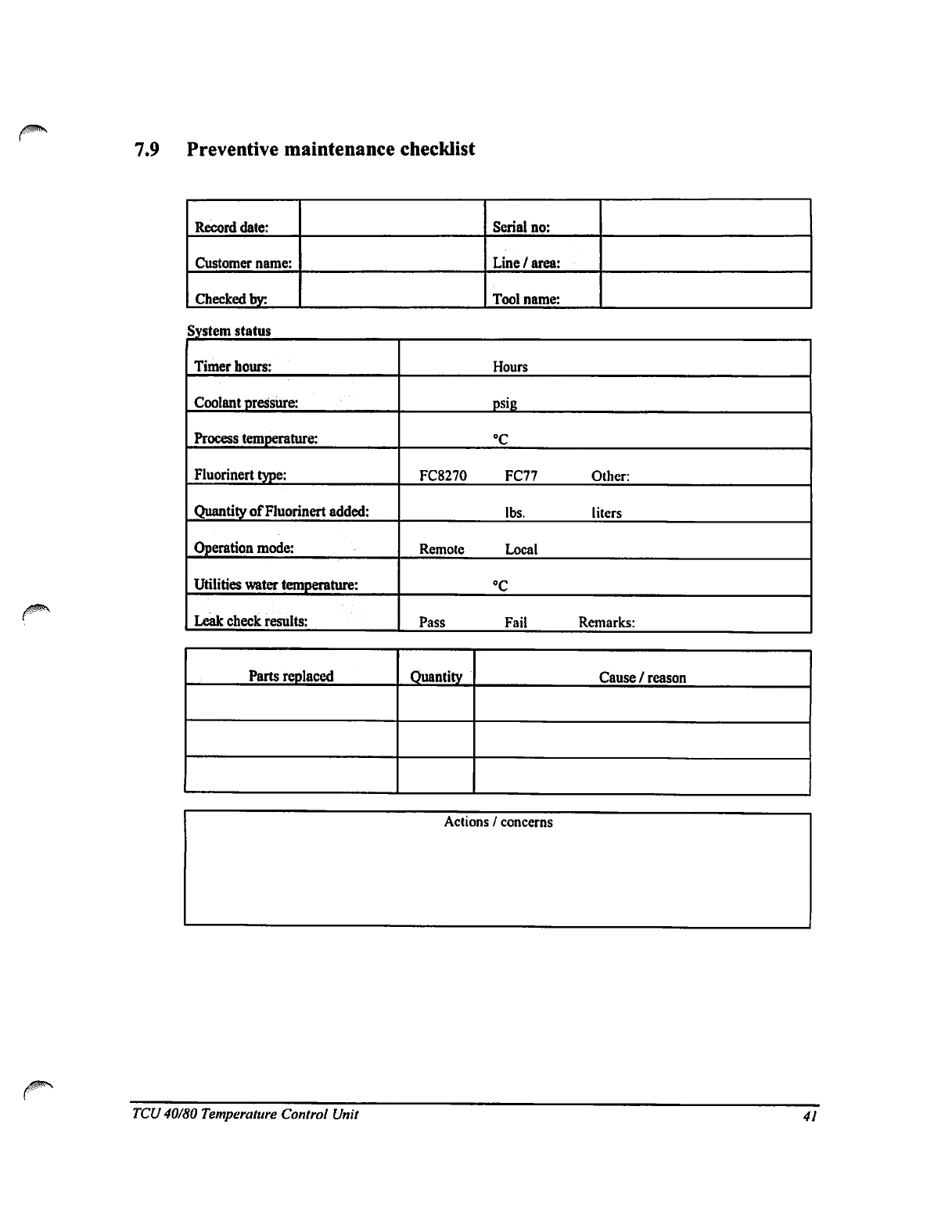
7.9
Preventive
maintenance
checklist
Record
date:
Customer
name:
Checked
by:
Serial
no:
Line
/
area:
Tool
name:
System
status
Timer
hours:
Coolant
pressure:
Process
temperature:
Fluonnert
type:
Quantity
of
Fluonnert
added:
Operation
mode:
Utilities
water
temperature:
Leak
check
results:
FC8270
Remote
Pass
Hours
psig
°C
FC77
lbs.
Local
°C
Fail
Other:
liters
Remarks:
Parts
replaced
Quantity
Cause
/
reason
Actions
/
concerns
TCU
40/80
Temperature
Control
Unit
41
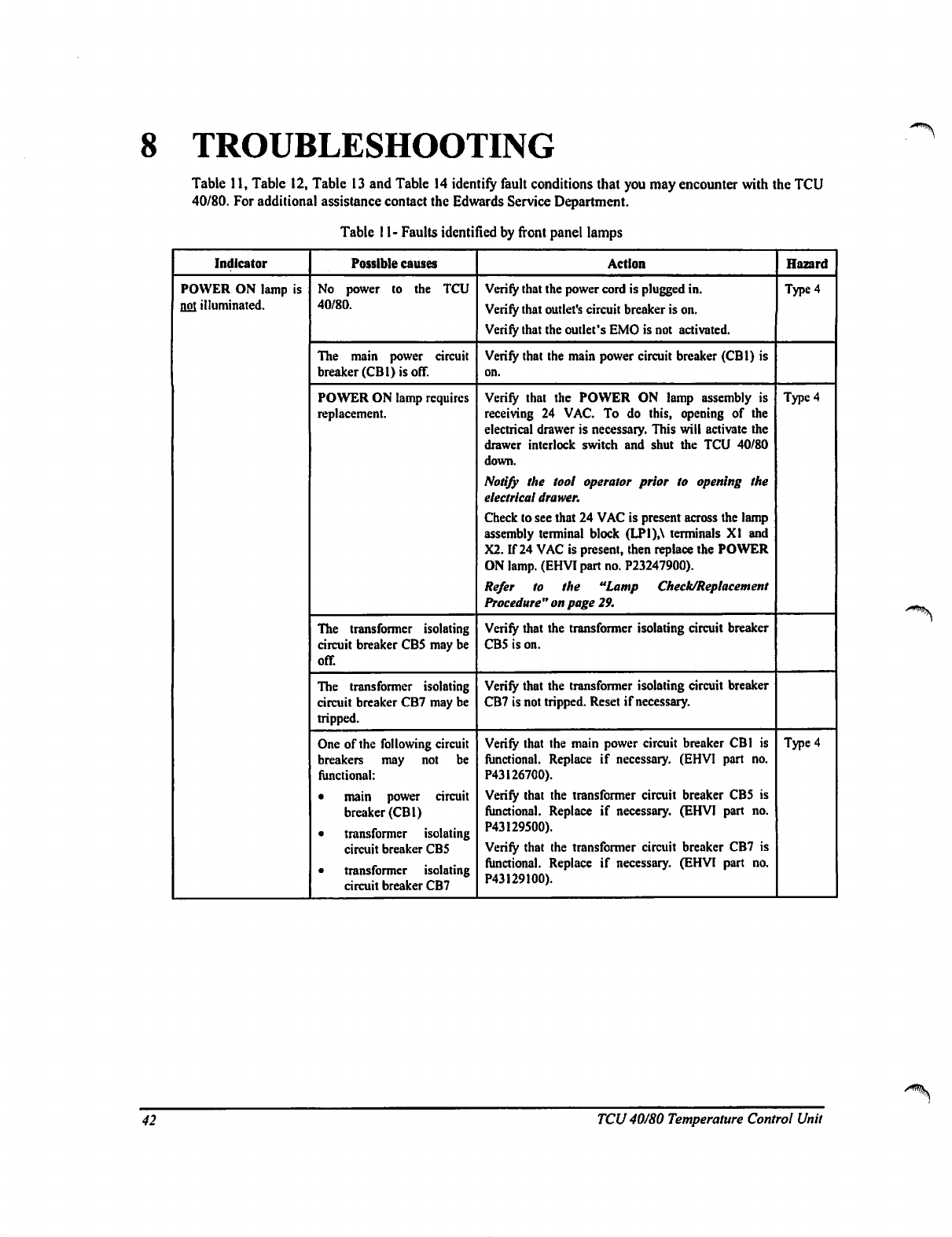
8
TROUBLESHOOTING
>*%k
Table
11,
Table
12,
Table
13
and
Table
14
identify
fault
conditions
that
you
may
encounter
with
the
TCU
40/80.
For
additional
assistance
contact
the
Edwards
Service
Department.
Table
11-
Faults
identified
by
front
panel
lamps
Indicator
POWER
ON
lamp
is
not
illuminated.
Possible
causes
No
power
to
the
TCU
40/80.
The
main
power
circuit
breaker
(CB1)
is
off.
POWER
ON
lamp
requires
replacement.
The
transformer
isolating
circuit
breaker
CBS
may
be
off.
The
transformer
isolating
circuit
breaker
CB7
may
be
tripped.
One
of
the
following
circuit
breakers
may
not
be
functional:
•
main
power
circuit
breaker
(CB1)
•
transformer
isolating
circuit
breaker
CB5
•
transformer
isolating
circuit
breaker
CB7
Action
Verify
that
the
power
cord
is
plugged
in.
Verify
that
outlet's
circuit
breaker
is
on.
Verify
that
the
outlet's
EMO
is
not
activated.
Verify
that
the
main
power
circuit
breaker
(CB1)
is
on.
Verify
that
the
POWER
ON
lamp
assembly
is
receiving
24
VAC.
To
do
this,
opening
of
the
electrical
drawer
is
necessary.
This
will
activate
the
drawer
interlock
switch
and
shut
the
TCU
40/80
down.
Notify
the
tool
operator
prior
to
opening
the
electrical
drawer.
Check
to
see
that
24
VAC
is
present
across
the
lamp
assembly
terminal
block
(LPI),\
terminals
XI
and
X2.
If
24
VAC
is
present,
then
replace
the
POWER
ON
lamp.
(EHVI
part
no.
P23247900).
Refer
to
the
"Lamp
Check/Replacement
Procedure
"
on
page
29.
Verify
that
the
transformer
isolating
circuit
breaker
CBS
is
on.
Verify
that
the
transformer
isolating
circuit
breaker
CB7
is
not
tripped.
Reset
if
necessary.
Verify
that
the
main
power
circuit
breaker
CB1
is
functional.
Replace
if
necessary.
(EHVI
part
no.
P43I26700).
Verify
that
the
transformer
circuit
breaker
CBS
is
functional.
Replace
if
necessary.
(EHVI
part
no.
P43129500).
Verify
that
the
transformer
circuit
breaker
CB7
is
functional.
Replace
if
necessary.
(EHVI
part
no.
P43129100).
Hazard
Type
4
Type
4
Type
4
42
TCU
40/80 Temperature
Control
Unit
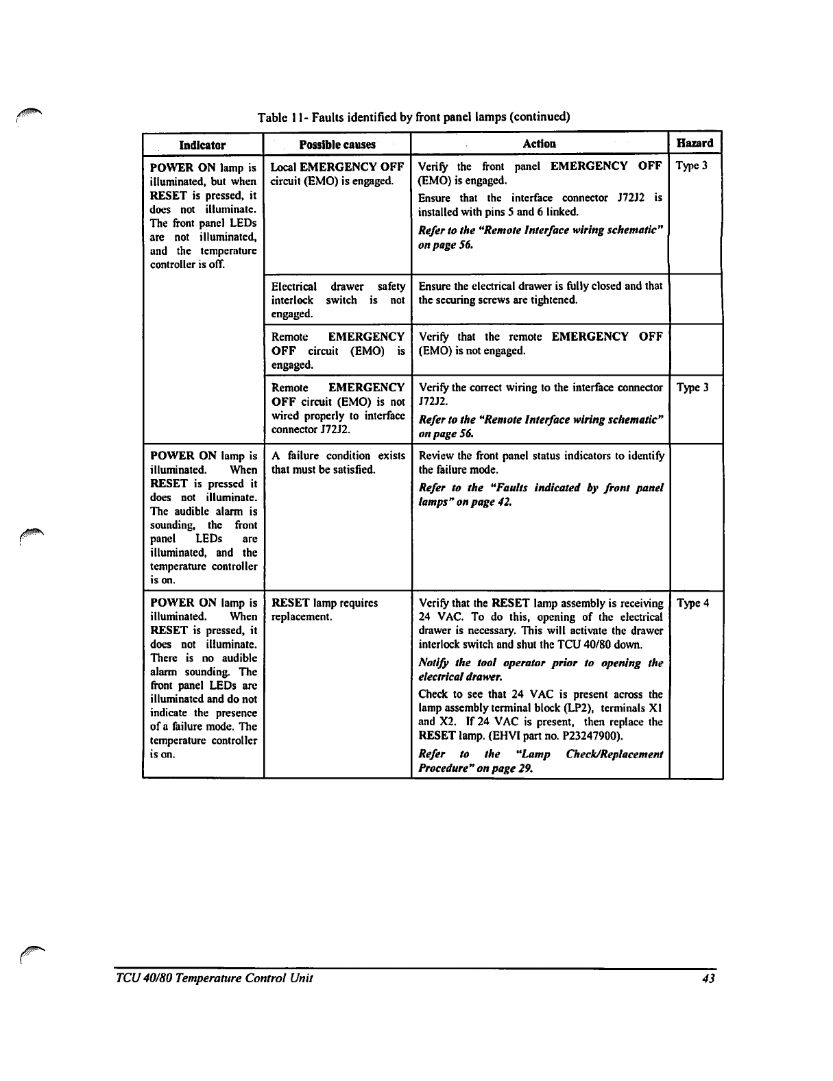
Table
11-
Faults
identified
by
front
panel
lamps
(continued)
Indicator
POWER
ON
lamp
is
illuminated,
but
when
RESET
is
pressed,
it
does
not
illuminate.
The
front
panel
LEDs
are not
illuminated,
and
the
temperature
controller
is off.
POWER
ON
lamp
is
illuminated.
When
RESET
is
pressed
it
does
not
illuminate.
The
audible
alarm
is
sounding,
the
front
panel
LEDs
are
illuminated,
and
the
temperature
controller
is
on.
POWER
ON
lamp
is
illuminated.
When
RESET
is
pressed,
it
does
not
illuminate.
There
is
no
audible
alarm
sounding.
The
front
panel
LEDs
are
illuminated
and
do
not
indicate
the
presence
of
a
failure
mode.
The
temperature
controller
is
on.
Possible
causes
Local
EMERGENCY
OFF
circuit
(EMO)
is
engaged.
Electrical
drawer
safety
interlock
switch
is
not
engaged.
Remote
EMERGENCY
OFF
circuit
(EMO)
is
engaged.
Remote
EMERGENCY
OFF
circuit
(EMO)
is
not
wired
properly
to
interface
connector
J72J2.
A
failure
condition
exists
that
must
be
satisfied.
RESET
lamp
requires
replacement.
Action
Verify
the
front
panel
EMERGENCY
OFF
(EMO)
is
engaged.
Ensure
that
the
interface
connector
J72J2
is
installed
with
pins
5
and
6
linked.
Refer
to
the
"Remote
Interface
wiring
schematic"
on
page
56.
Ensure
the
electrical
drawer
is
fully
closed
and
that
the
securing
screws
are
tightened.
Verify
that
the
remote
EMERGENCY
OFF
(EMO)
is
not
engaged.
Verify
the
correct
wiring
to
the
interface
connector
J72J2.
Refer
to
the
"Remote
Interface
wiring
schematic"
on page
56.
Review
the
front
panel
status
indicators
to
identify
the
failure
mode.
Refer
to
the
"Faults
indicated
by
front
panel
lamps"
on
page
42.
Verify
that
the
RESET
lamp
assembly
is
receiving
24
VAC. To
do
this,
opening
of
the
electrical
drawer
is
necessary.
This
will activate
the
drawer
interlock
switch
and
shut
the
TCU
40/80
down.
Notify
the
tool
operator
prior
to
opening
the
electrical
drawer.
Check
to
see
that
24
VAC
is
present
across
the
lamp
assembly
terminal
block
(LP2),
terminals
XI
and
X2.
If
24
VAC
is
present,
then
replace
the
RESET
lamp.
(EHVI
part
no.
P23247900).
Refer
to
the
"Lamp
Check/Replacement
Procedure"
on page
29.
Hazard
Type
3
Type
3
Type
4
TCU
40/80
Temperature
Control
Unit
43
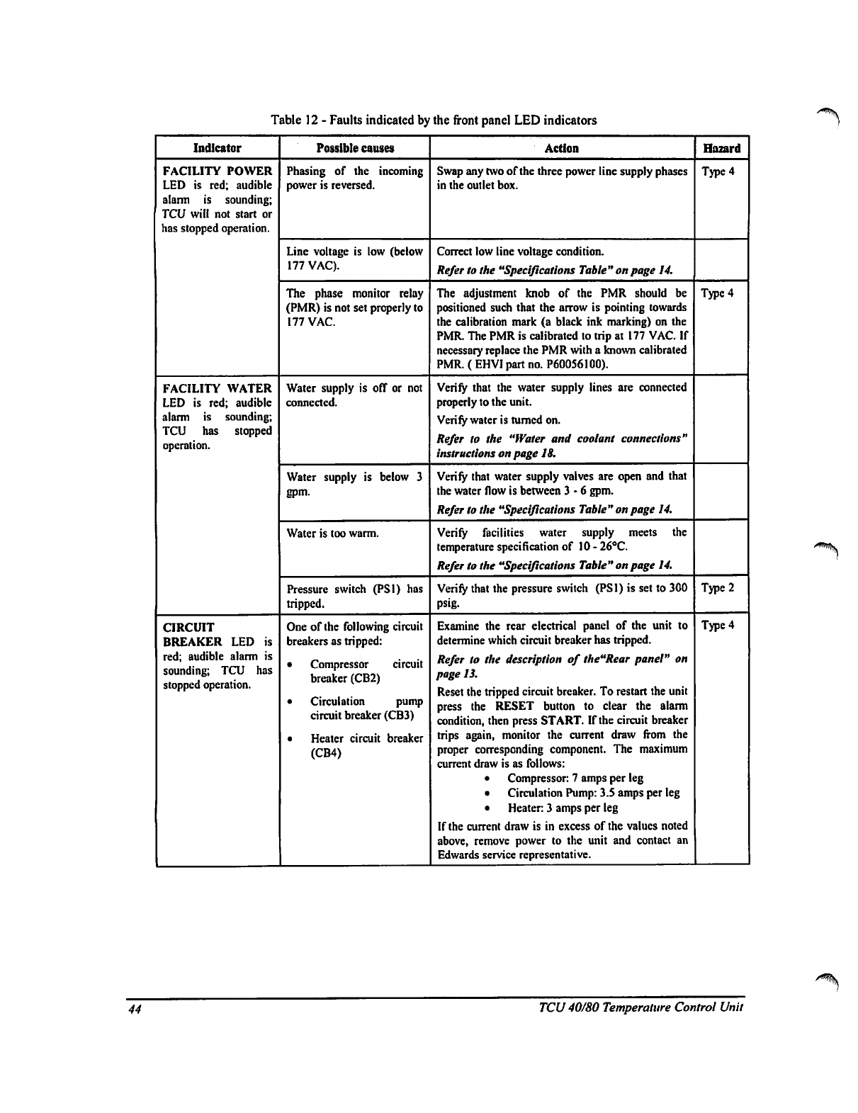
Table
12
-
Faults
indicated
by
the
front
panel
LED
indicators
t
Indicator
FACILITY
POWER
LED
is
red;
audible
alarm
is
sounding;
TCU
will
not
start
or
has
stopped
operation.
FACILITY
WATER
LED
is
red;
audible
alarm
is
sounding;
TCU
has
stopped
operation.
CIRCUIT
BREAKER
LED
is
red;
audible
alarm
is
sounding;
TCU
has
stopped
operation.
Possible
causes
Phasing
of
the
incoming
power
is
reversed.
Line
voltage
is
low
(below
177
VAC).
The
phase
monitor
relay
(PMR)
is
not
set
properly
to
177
VAC.
Water
supply
is
off
or not
connected.
Water
supply
is
below
3
gpm.
Water
is
too
warm.
Pressure switch
(PS1)
has
tripped.
One
of
the
following
circuit
breakers
as
tripped:
•
Compressor
circuit
breaker
(CB2)
•
Circulation
pump
circuit
breaker
(CB3)
•
Heater
circuit
breaker
(CB4)
Action
Swap
any two
of
the
three
power
line
supply
phases
in
the
outlet
box.
Correct
low
line
voltage
condition.
Refer
to
the
"Specifications
Table"
on page
14.
The
adjustment
knob
of
the
PMR
should
be
positioned
such
that
the
arrow
is
pointing
towards
the
calibration
mark
(a
black
ink
marking)
on
the
PMR.
The
PMR
is
calibrated
to
trip
at
177
VAC.
If
necessary
replace
the
PMR
with
a
known
calibrated
PMR.
(
EHVJ
part
no.
P60056100).
Verify
that
the
water
supply
lines
are
connected
properly
to
the
unit.
Verify
water
is
turned
on.
Refer
to
the
"Water
and
coolant
connections"
instructions
on
page
IS.
Verify
that
water
supply
valves
are
open
and
that
the
water
flow
is
between
3-6
gpm.
Refer
to
the
"Specifications
Table"
on
page
14.
Verify
facilities
water
supply
meets
the
temperature
specification
of
10
-
26°C.
Refer
to
the
"Specifications
Table"
on
page
14.
Verify
that
the
pressure
switch
(PS1)
is
set
to
300
psig.
Examine
the
rear
electrical
panel
of
the
unit
to
determine
which
circuit
breaker
has
tripped.
Refer
to
the
description
of
the"Rear
panel"
on
page
13.
Reset
the
tripped
circuit
breaker.
To
restart
the
unit
press
the
RESET
button
to
clear
the
alarm
condition,
then
press
START.
If
the
circuit
breaker
trips
again,
monitor
the
current
draw
from
the
proper
corresponding
component.
The
maximum
current
draw
is
as
follows:
•
Compressor:
7
amps
per
leg
•
Circulation
Pump:
3.S
amps
per
leg
•
Heater
3
amps
per
leg
If
the
current
draw
is
in
excess
of
the
values
noted
above,
remove
power
to
the
unit
and
contact
an
Edwards
service
representative.
Hazard
Type
4
Type 4
Type
2
Type
4
44
TCU
40/80
Temperature
Control
Unit
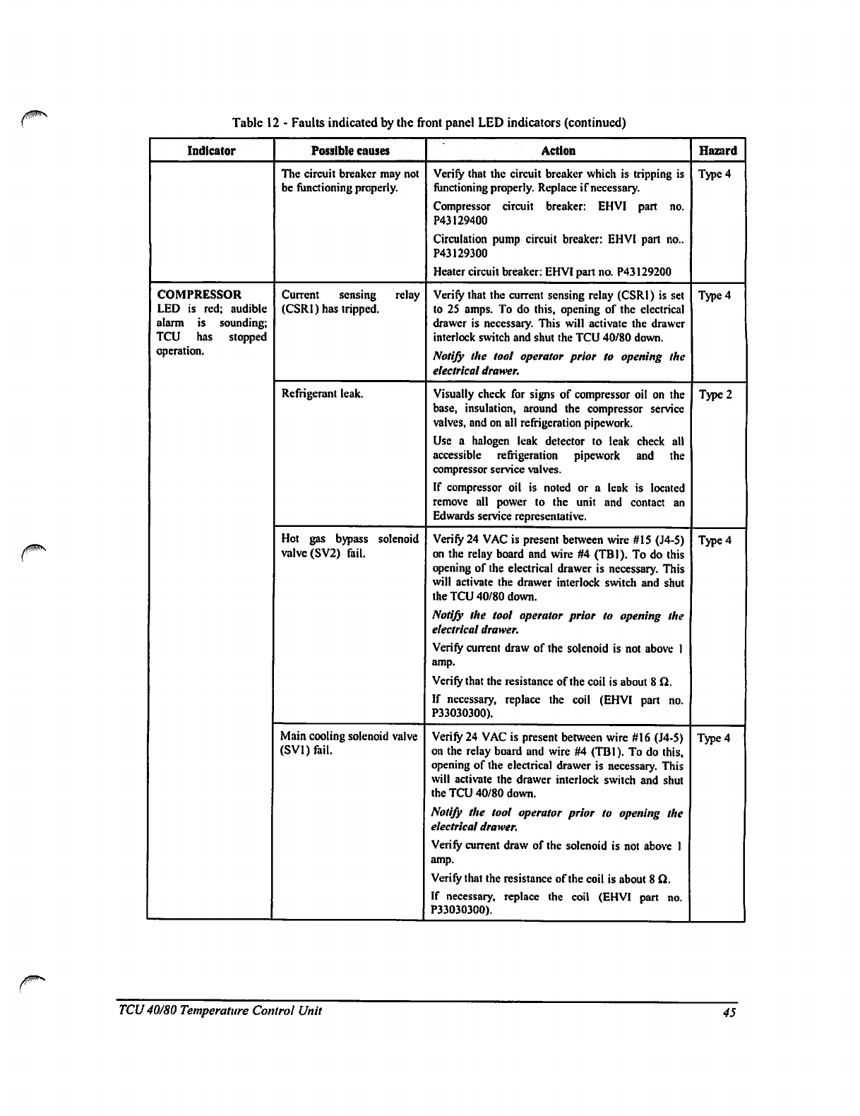
Table
12
-
Faults
indicated
by
the
front
panel
LED
indicators
(continued)
Indicator
COMPRESSOR
LED
is
red;
audible
alarm
is
sounding;
TCU
has
stopped
operation.
Possible
causes
The
circuit
breaker
may
not
be
functioning
properly.
Current
sensing
relay
(CSRI)
has
tripped.
Refrigerant
leak.
Hot
gas
bypass
solenoid
valve
(SV2)
fail.
Main
cooling
solenoid
valve
(SVI)
fail.
Action
Verify
that
the
circuit
breaker
which
is
tripping
is
functioning
properly.
Replace
if
necessary.
Compressor
circuit
breaker:
EHVI
part
no.
P43129400
Circulation
pump
circuit
breaker:
EHVI
part
no..
P43129300
Heater
circuit
breaker:
EHVI
part
no.
P43129200
Verify
that
the
current
sensing
relay
(CSRI)
is
set
to
25
amps.
To
do
this,
opening
of
the
electrical
drawer
is
necessary.
This
will
activate
the
drawer
interlock
switch
and
shut
the
TCU
40/80
down.
Notify
the
tool
operator
prior
to
opening
the
electrical
drawer.
Visually
check
for
signs
of
compressor
oil
on
the
base,
insulation,
around
the
compressor
service
valves,
and
on
all
refrigeration
pipework.
Use
a
halogen
leak detector
to
leak
check
all
accessible
refrigeration
pipework
and
the
compressor
service
valves.
If
compressor
oil
is
noted
or a
leak
is
located
remove
all
power
to
the
unit
and
contact
an
Edwards
service
representative.
Verify
24
VAC
is
present
between
wire
#15
(J4-5)
on
the
relay
board
and
wire
#4
(TBI).
To
do
this
opening of
the
electrical
drawer
is
necessary.
This
will
activate
the
drawer
interlock
switch
and
shut
the
TCU
40/80
down.
Notify the
tool
operator
prior
to
opening
the
electrical
drawer.
Verify
current
draw
of
the
solenoid
is
not
above
1
amp.
Verify
that
the
resistance
of
the
coil
is
about
8
Cl.
If
necessary,
replace
the
coil
(EHVI
part
no.
P33030300).
Verify
24
VAC
is
present
between
wire
#16
(J4-5)
on
the
relay
board
and
wire
#4
(TBI).
To
do
this,
opening
of
the
electrical
drawer
is
necessary.
This
will
activate
the
drawer
interlock
switch
and
shut
the
TCU
40/80
down.
Notify
the
tool
operator
prior
to
opening
the
electrical
drawer.
Verify
current
draw
of
the
solenoid
is
not
above
1
amp.
Verify
that
the
resistance
of
the
coil
is
about
8
Cl.
If
necessary,
replace
the
coil
(EHVI
part
no.
P33O3O3OO).
Hazard
Type
4
Type
4
Type
2
Type
4
Type
4
TCU
40/80
Temperature
Control
Unit
45
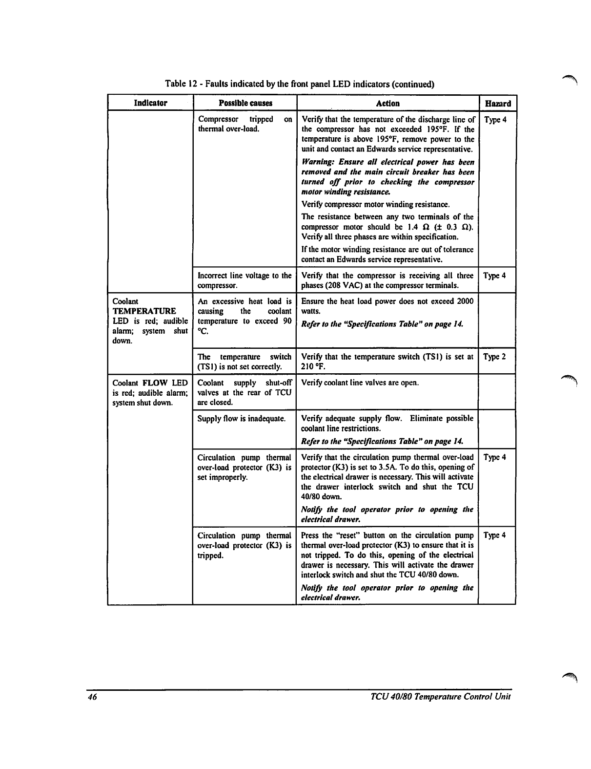
Table
12
-
Faults
indicated
by
the
front
panel
LED
indicators
(continued)
'■V
Indicator
Coolant
TEMPERATURE
LED
is
red;
audible
alarm;
system
shut
down.
Coolant
FLOW
LED
is
red;
audible
alarm;
system
shut
down.
Possible
causes
Compressor
tripped
on
thermal
over-load.
Incorrect
line
voltage
to
the
compressor.
An
excessive
heat load
is
causing
the
coolant
temperature
to
exceed
90
°C.
The
temperature
switch
(TSI)
is
not
set
correctly.
Coolant
supply
shut-off
valves
at
the
rear
of
TCU
are
closed.
Supply
flow
is
inadequate.
Circulation
pump
thermal
over-load
protector
(K3)
is
set
improperly.
Circulation
pump
thermal
over-load
protector
(K3)
is
tripped.
Action
Verify
that
the
temperature
of
the
discharge
line
of
the
compressor
has
not
exceeded
195°F.
If
the
temperature
is
above
195°F,
remove
power
to
the
unit
and
contact
an
Edwards
service
representative.
Warning:
Ensure
all
electrical
power
has
been
removed
and
the
main
circuit
breaker
has been
turned
off
prior
to
checking
the
compressor
motor
winding
resistance.
Verify
compressor
motor
winding
resistance.
The
resistance
between
any two
terminals
of
the
compressor
motor
should
be
1.4
ft
(±
0.3
fl).
Verify
all
three
phases
are
within
specification.
If
the
motor
winding
resistance
are
out
of
tolerance
contact
an
Edwards
service
representative.
Verify
that
the
compressor
is
receiving
all
three
phases
(208
VAC)
at
the
compressor
terminals.
Ensure
the
heat
load
power
does
not
exceed
2000
watts.
Refer
to
the
"Specifications
Table"
on
page
14.
Verify
that
the
temperature
switch
(TSI)
is
set
at
210
°F.
Verify
coolant
line
valves
are
open.
Verify
adequate
supply
flow.
Eliminate
possible
coolant
line
restrictions.
Refer
to
the
"Specifications
Table"
on page
14.
Verify
that
the
circulation
pump
thermal
over-load
protector
(K3)
is
set
to
3.SA.
To
do
this,
opening
of
the
electrical
drawer
is
necessary.
This
will
activate
the
drawer
interlock
switch
and
shut
the
TCU
40/80
down.
Notify
the
tool
operator
prior
to
opening
the
electrical
drawer.
Press
the
"reset"
button
on
the
circulation
pump
thermal
over-load
protector
(K3)
to
ensure
that
it
is
not
tripped.
To
do
this,
opening
of
the
electrical
drawer
is
necessary.
This
will
activate
the
drawer
interlock
switch
and
shut
the
TCU
40/80
down.
Notify
the
tool
operator
prior
to
opening
the
electrical
drawer.
Hazard
Type
4
Type
4
Type
2
Type
4
Type
4
46
TCU
40/80 Temperature
Control
Unit
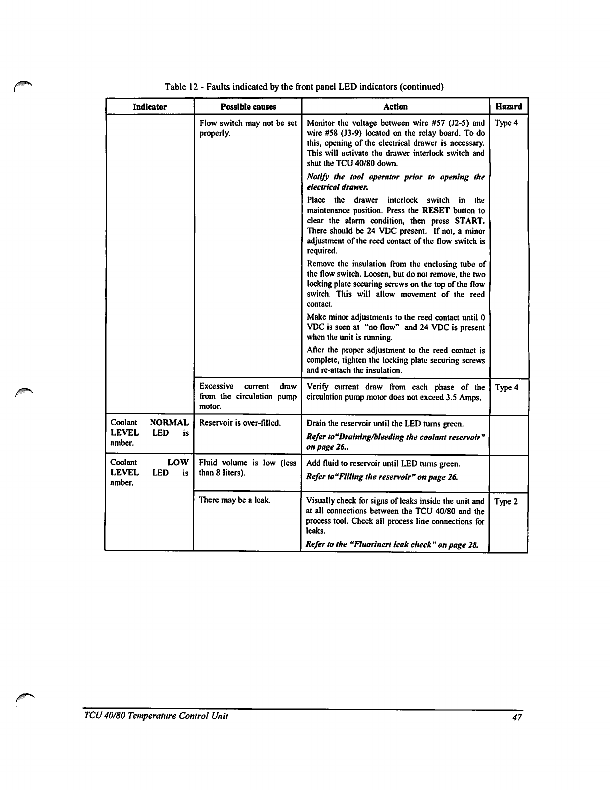
Table
12
-
Faults
indicated
by
the
front
panel
LED
indicators
(continued)
Indicator
Coolant
NORMAL
LEVEL
LED
is
amber.
Coolant
LOW
LEVEL
LED
is
amber.
Possible
causes
Flow
switch
may
not
be
set
properly.
Excessive
current
draw
from
the
circulation
pump
motor.
Reservoir
is
over-filled.
Fluid
volume
is
low
(less
than
8
liters).
There
may
be
a
leak.
Action
Monitor
the
voltage
between
wire
#57
(J2-S)
and
wire
#58
(J3-9)
located
on
the
relay
board.
To
do
this,
opening
of
the
electrical
drawer
is
necessary.
This
will
activate
the
drawer
interlock
switch
and
shut
the
TCU
40/80
down.
Notify
the
tool
operator
prior
to
opening
the
electrical
drawer.
Place
the
drawer
interlock
switch
in
the
maintenance
position.
Press
the
RESET
button
to
clear
the
alarm
condition,
then
press
START.
There
should
be
24
VDC
present.
If
not,
a
minor
adjustment
of
the
reed
contact
of
the
flow
switch
is
required.
Remove
the
insulation
from
the
enclosing
tube
of
the
flow
switch.
Loosen,
but
do
not
remove,
the
two
locking
plate
securing
screws
on
the
top
of
the
flow
switch.
This
will
allow
movement
of
the
reed
contact.
Make
minor
adjustments
to
the
reed
contact
until
0
VDC
is
seen
at
"no
flow"
and
24
VDC
is
present
when
the
unit
is
running.
After
the
proper
adjustment
to
the
reed
contact
is
complete,
tighten
the
locking
plate
securing
screws
and
re-attach
the
insulation.
Verify
current
draw
from
each
phase
of
the
circulation
pump
motor
does
not
exceed
3.5
Amps.
Drain
the
reservoir
until
the
LED
turns
green.
Refer
to"Draining/bleeding
the
coolant
reservoir"
on
page
26..
Add
fluid
to
reservoir
until
LED
turns
green.
Refer
toTilling
the
reservoir"
on page
26.
Visually
check
for
signs
of
leaks
inside
the
unit
and
at
all
connections
between
the
TCU
40/80
and
the
process
tool.
Check
all
process
line
connections
for
leaks.
Refer
to
the
"Fluorinert
leak
check
"
on
page
28.
Hazard
Type
4
Type
4
Type
2
TCU
40/80
Temperature
Control
Unit
47
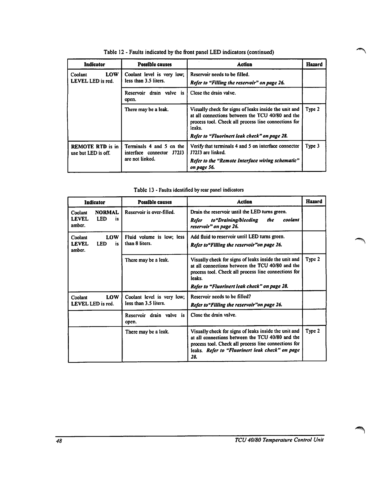
Table
12
-
Faults
indicated
by
the
front
panel
LED
indicators
(continued)
Indicator
Coolant
LOW
LEVEL
LED
is
red.
REMOTE
RTD
is
in
use
but
LED
is
off.
Possible
causes
Coolant
level
is
very
low;
less
than
3.5
liters.
Reservoir
drain
valve
is
open.
There
may
be
a
leak.
Terminals
4 and
5
on
the
interface
connector
J72J3
are
not
linked.
Action
Reservoir
needs
to
be
filled.
Refer
to
"Filling
the
reservoir"
on
page
26.
Close
the
drain
valve.
Visually
check
for
signs
of
leaks
inside
the
unit
and
at
all
connections
between
the
TCU
40/80
and
the
process
tool.
Check
all
process
line
connections
for
leaks.
Refer
to
"Fluoriaert
leak
check"
on
page
28.
Verify
that
terminals
4
and
5
on
interface
connector
J72J3
are
linked.
Refer
to
the
"Remote
Interface
wiring
schematic"
on page
56.
Hazard
Type
2
Type
3
Table
13
-
Faults
identified
by
rear
panel
indicators
Indicator
Coolant
NORMAL
LEVEL
LED
is
amber.
Coolant
LOW
LEVEL
LED
is
amber.
Coolant
LOW
LEVEL
LED
is
red.
Possible
causes
Reservoir
is
over-filled.
Fluid
volume
is
low;
less
than
8
liters.
There
may
be
a
leak.
Coolant
level
is
very
low;
less
than
3.5
liters.
Reservoir
drain
valve
is
open.
There
may
be
a
leak.
Action
Drain
the
reservoir
until
the
LED
turns
green.
Refer
to"Draining/bleedlng
the
coolant
reservoir
"
on page
26.
Add
fluid
to
reservoir
until
LED
rums
green.
Refer
touFilling
the
reservoir"on
page
26.
Visually
check
for
signs
of
leaks
inside
the
unit
and
at
all
connections
between
the
TCU
40/80
and
the
process
tool.
Check
all
process
line
connections
for
leaks.
Refer
to
"Fluorinert
leak
check
"
on
page
28.
Reservoir
needs
to
be
filled?
Refer
to"Filling
the
reservoir"on
page
26.
Close
the
drain
valve.
Visually
check
for
signs
of
leaks
inside
the
unit
and
at
all
connections
between
the
TCU
40/80
and
the
process
tool.
Check
all
process
line
connections
for
leaks.
Refer
to
"Fluorinert
leak
check"
on
page
28.
Hazard
Type
2
Type
2
48
TCU
40/80 Temperature
Control
Unit
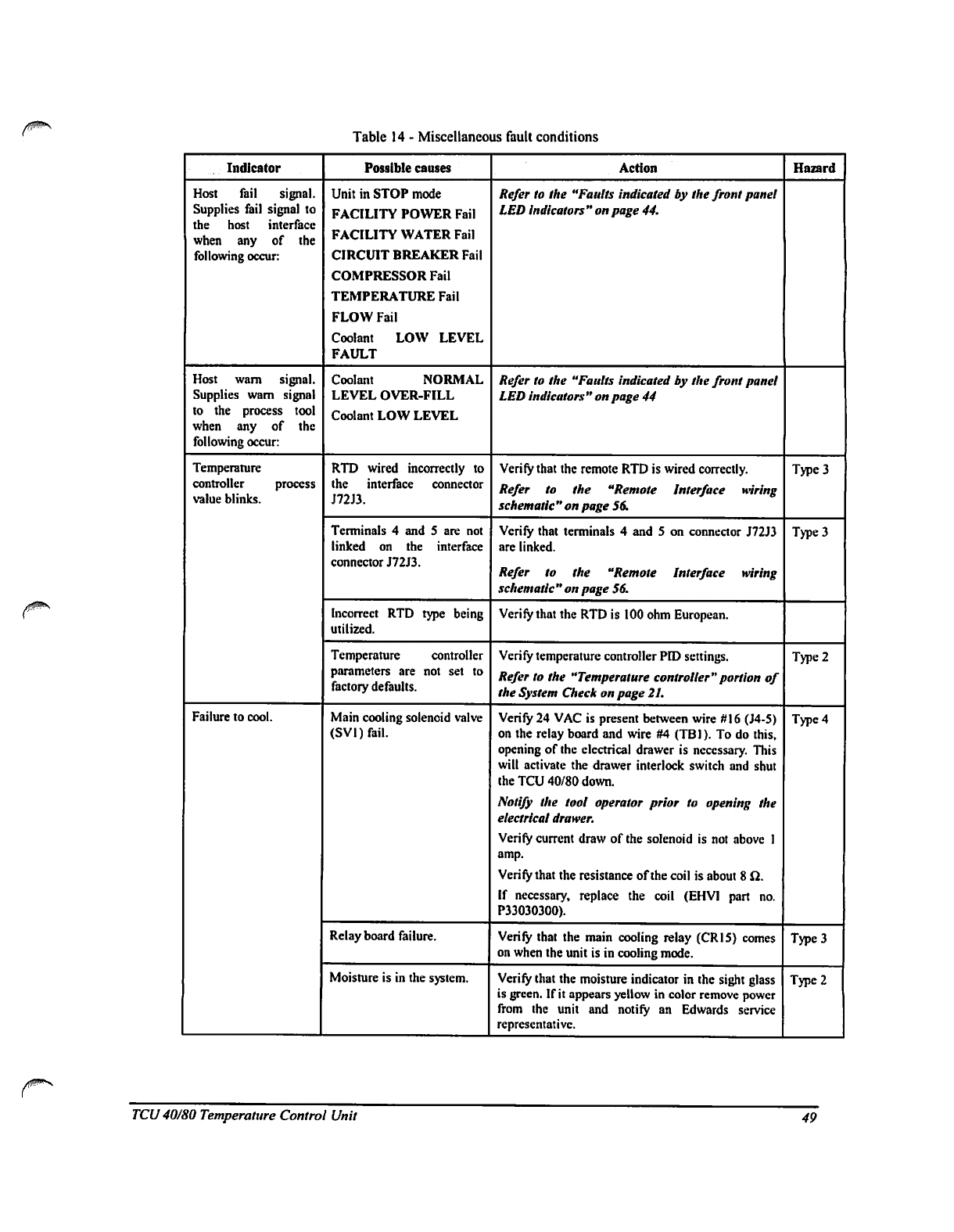
Table
14
-
Miscellaneous
fault
conditions
Indicator
Host
fail
signal.
Supplies
fail
signal
to
the
host
interface
when
any
of
the
following
occur:
Host
wam
signal.
Supplies
wam
signal
to
the
process
tool
when
any
of
the
following
occur:
Temperature
controller
process
value
blinks.
Failure
to
cool.
Possible
causes
Unit
in
STOP
mode
FACILITY
POWER
Fail
FACILITY
WATER
Fail
CIRCUIT
BREAKER
Fail
COMPRESSOR
Fail
TEMPERATURE
Fail
FLOW
Fail
Coolant
LOW
LEVEL
FAULT
Coolant
NORMAL
LEVEL
OVER-FILL
Coolant
LOW
LEVEL
RTD
wired
incorrectly
to
the
interface
connector
J72J3.
Terminals
4
and
5 are
not
linked
on
the
interface
connector
J72J3.
Incorrect
RTD
type
being
utilized.
Temperature
controller
parameters
are
not
set
to
factory
defaults.
Main
cooling
solenoid
valve
(SVl)fail.
Relay
board
failure.
Moisture
is
in
the
system.
Action
Refer
to
the
"Faults
indicated
by
the
front
panel
LED
indicators"
on
page
44.
Refer
to
the
"Faults
indicated
by
the
front
panel
LED
indicators"
on
page
44
Verify
that
the
remote
RTD
is
wired
correctly.
Refer
to
the
"Remote
Interface
wiring
schematic"
on page
56.
Verify
that
terminals
4 and
5
on
connector
J72J3
are
linked.
Refer
to
the
"Remote
Interface
wiring
schematic"
on
page
56.
Verily
that
the
RTD
is
100
ohm
European.
Verify
temperature
controller
PID
settings.
Refer
to
the
"Temperature
controller"
portion
of
the
System
Check
on
page
21.
Verify
24
VAC
is
present
between
wire
#16
(J4-5)
on
the
relay
board
and
wire
#4
(TB1).
To
do
this,
opening
of
the
electrical
drawer
is
necessary.
This
will
activate
the
drawer
interlock
switch
and
shut
the
TCU
40/80
down.
Notify
the
tool
operator
prior
to
opening
the
electrical
drawer.
Verify
current
draw
of
the
solenoid
is
not
above
1
amp.
Verify
that
the
resistance
of
the
coil
is
about
8
Q.
If
necessary,
replace
the
coil
(EHVI
part
no.
P3303O3OO).
Verify
that
the
main
cooling
relay
(CR15)
comes
on
when
the
unit
is
in
cooling
mode.
Verify
that
the
moisture
indicator
in
the
sight
glass
is
green.
If
it
appears
yellow
in
color
remove
power
from
the
unit
and
notify
an
Edwards
service
representative.
Hazard
Type
3
Type
3
Type
2
Type
4
Type
3
Type
2
TCU
40/80
Temperature
Control
Unit
49
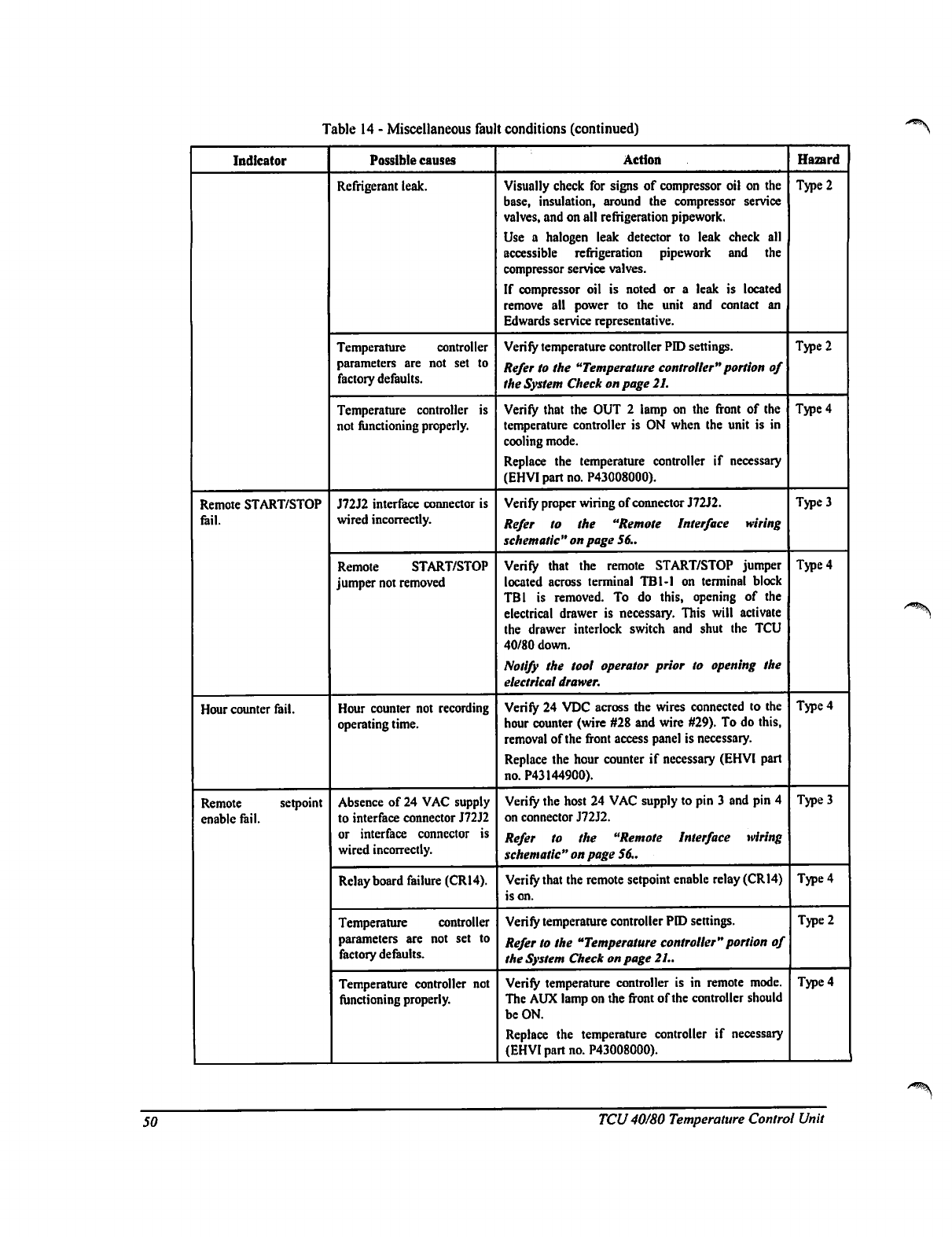
Table
14
-
Miscellaneous
fault
conditions
(continued)
Indicator
Remote
START/STOP
fail.
Hour
counter
fail.
Remote
setpoint
enable
fail.
Possible
causes
Refrigerant
leak.
Temperature
controller
parameters
are
not
set
to
factory
defaults.
Temperature
controller
is
not
functioning
properly.
J72J2
interface
connector
is
wired
incorrectly.
Remote
START/STOP
jumper
not
removed
Hour
counter
not
recording
operating
time.
Absence
of
24
VAC
supply
to
interface
connector
J72J2
or
interface
connector
is
wired
incorrectly.
Relay
board
failure
(CR14).
Temperature
controller
parameters
are
not
set
to
factory
defaults.
Temperature
controller
not
functioning
properly.
Action
Visually
check
for
signs
of
compressor
oil
on
the
base,
insulation,
around
the
compressor
service
valves,
and
on
all
refrigeration
pipework.
Use
a
halogen
leak detector
to
leak
check
all
accessible
refrigeration
pipework
and
the
compressor
service
valves.
If
compressor
oil
is
noted
or
a
leak
is
located
remove
all
power
to
the
unit
and
contact
an
Edwards
service
representative.
Verify
temperature
controller
PID
settings.
Refer
to
the
"Temperature
controller"
portion
of
the
System
Check
on
page
21.
Verify
that
the
OUT
2
lamp
on
the
front
of
the
temperature
controller
is
ON
when
the
unit
is
in
cooling
mode.
Replace
the
temperature
controller
if
necessary
(EHVI
part
no.
P43008000).
Verify
proper
wiring
of
connector
J72J2.
Refer
lo
the
"Remote
Interface
wiring
schematic
"
on page
56..
Verify
that
the
remote
START/STOP
jumper
located
across
terminal
TB1-I
on
terminal
block
TB1
is
removed.
To
do
this,
opening
of
the
electrical
drawer
is
necessary.
This
will
activate
the
drawer
interlock
switch
and
shut
the
TCU
40/80
down.
Notify
the
tool
operator
prior
to
opening
the
electrical
drawer.
Verify
24
VDC
across
the
wires
connected
to
the
hour
counter (wire
#28
and
wire
#29).
To
do
this,
removal
of
the
front
access
panel
is
necessary.
Replace
the
hour
counter
if
necessary
(EHVI
part
no.
P43144900).
Verify
the
host
24
VAC
supply
to
pin
3
and
pin
4
on
connector
J72J2.
Refer
to
the
"Remote
Interface
wiring
schematic"
on
page
S6..
Verify
that
the
remote
setpoint
enable
relay
(CR14)
is
on.
Verify
temperature
controller
PID
settings.
Refer
to
the
"Temperature
controller"
portion
of
the
System
Check
on
page
21..
Verify
temperature
controller
is
in
remote
mode.
The
AUX
lamp
on
the
front
of
the
controller
should
be
ON.
Replace
the
temperature
controller
if
necessary
(EHVI
part
no.
P43008000).
Hazard
Type
2
Type
2
Type
4
Type
3
Type
4
Type
4
Type
3
Type
4
Type
2
Type
4
50
TCU
40/80
Temperature
Control
Unit
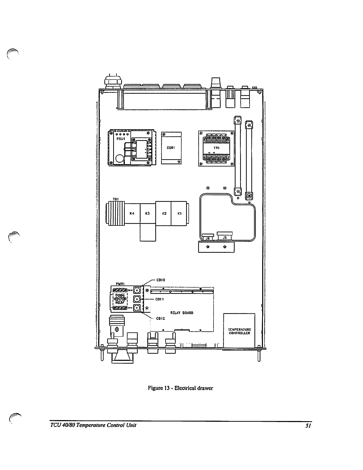
M
TBl
K4
KJ
<2
K1
Figure
13
-
Electrical
drawer
TCU
40/80
Temperature
Control
Unit
51
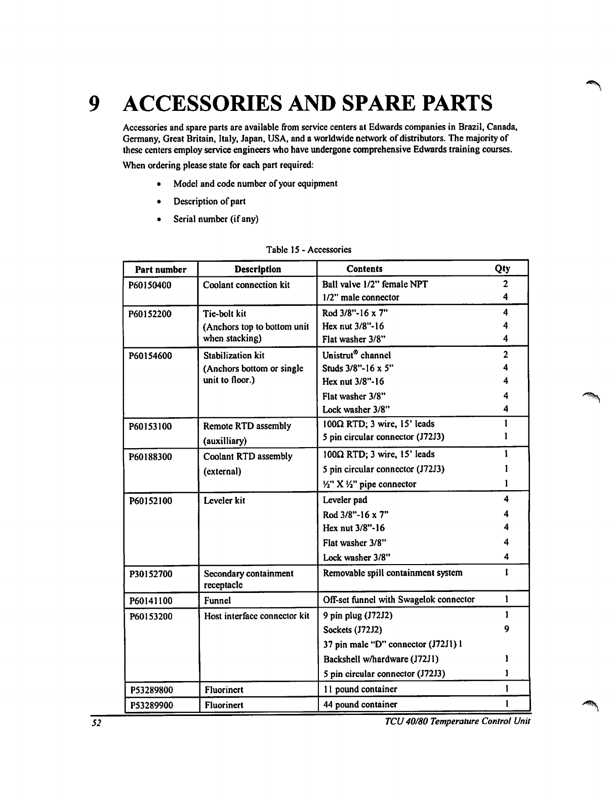
9
ACCESSORIES
AND
SPARE
PARTS
Accessories
and
spare
parts
are
available
from
service
centers
at
Edwards
companies
in
Brazil,
Canada,
Germany,
Great
Britain,
Italy,
Japan,
USA,
and
a
worldwide
network
of
distributors.
The
majority
of
these
centers
employ
service
engineers
who
have
undergone
comprehensive
Edwards
training
courses.
When
ordering
please
state
for
each
part
required:
•
Model
and
code
number
of
your
equipment
•
Description
of
part
•
Serial
number
(if
any)
Table
15
-
Accessories
Part
number
P60150400
P60152200
P60154600
P60153100
P60188300
P60152100
P30152700
P60141100
P60153200
P53289800
P53289900
Description
Coolant
connection
kit
Tie-bolt
kit
(Anchors
top
to
bottom
unit
when
stacking)
Stabilization
kit
(Anchors
bottom
or
single
unit
to
floor.)
Remote
RTD
assembly
(auxiliary)
Coolant
RTD
assembly
(external)
Leveler
kit
Secondary
containment
receptacle
Funnel
Host
interface
connector
kit
Fluorincrt
Fluorinert
Contents
Qty
Ball
valve
1/2"
female
NPT
2
1/2"
male
connector
4
Rod
3/8"-16
x
7"
4
Hex
nut
3/8"-16 4
Flat
washer
3/8"
4
Unistrut®
channel
2
Studs3/8"-16x5"
4
Hex
nut
3/8"-16
4
Flat
washer
3/8"
4
Lock
washer
3/8"
4
100Q
RTD;
3
wire,
15'
leads
1
5
pin
circular
connector
(J72J3)
1
100*2
RTD;
3
wire,
15"
leads
1
5
pin
circular
connector
(J72J3)
1
Vi"
X
Vi"
pipe
connector
1
Leveler
pad
4
Rod3/8"-16x7"
4
Hex
nut
3/8"-16
4
Flat
washer
3/8"
4
Lock
washer
3/8"
4
Removable
spill
containment
system
I
Off-set
funnel
with
Swagelok
connector
1
9
pin
plug
(J72J2)
1
Sockets
(J72J2)
9
37
pin
male
"D"
connector
(J72J1)
1
Backshell
w/hardware
(J72J1)
1
5
pin
circular
connector
(J72J3)
1
11
pound
container
1
44
pound
container
1
52
TCU
40/80
Temperature
Control
Unit
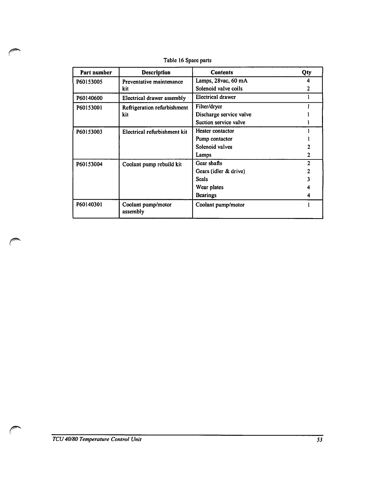
Table
16
Spare
parts
Part
number
P60153005
P60140600
P60153001
P60153003
P60153004
P60140301
Description
Preventative
maintenance
kit
Electrical
drawer
assembly
Refrigeration
refurbishment
kit
Electrical
refurbishment
kit
Coolant
pump
rebuild
kit
Coolant
pump/motor
assembly
Contents
Qty
Lamps,
28vac,
60
mA
4
Solenoid
valve
coils
2
Electrical
drawer
1
Filter/dryer
I
Discharge
service
valve
1
Suction
service
valve
1
Heater
contactor
1
Pump
contactor
1
Solenoid
valves
2
Lamps
2
Gear
shafts
2
Gears
(idler
&
drive)
2
Seals
3
Wear
plates
4
Bearings
4
Coolant
pump/motor
1
TCU
40/80
Temperature
Control
Unit
53
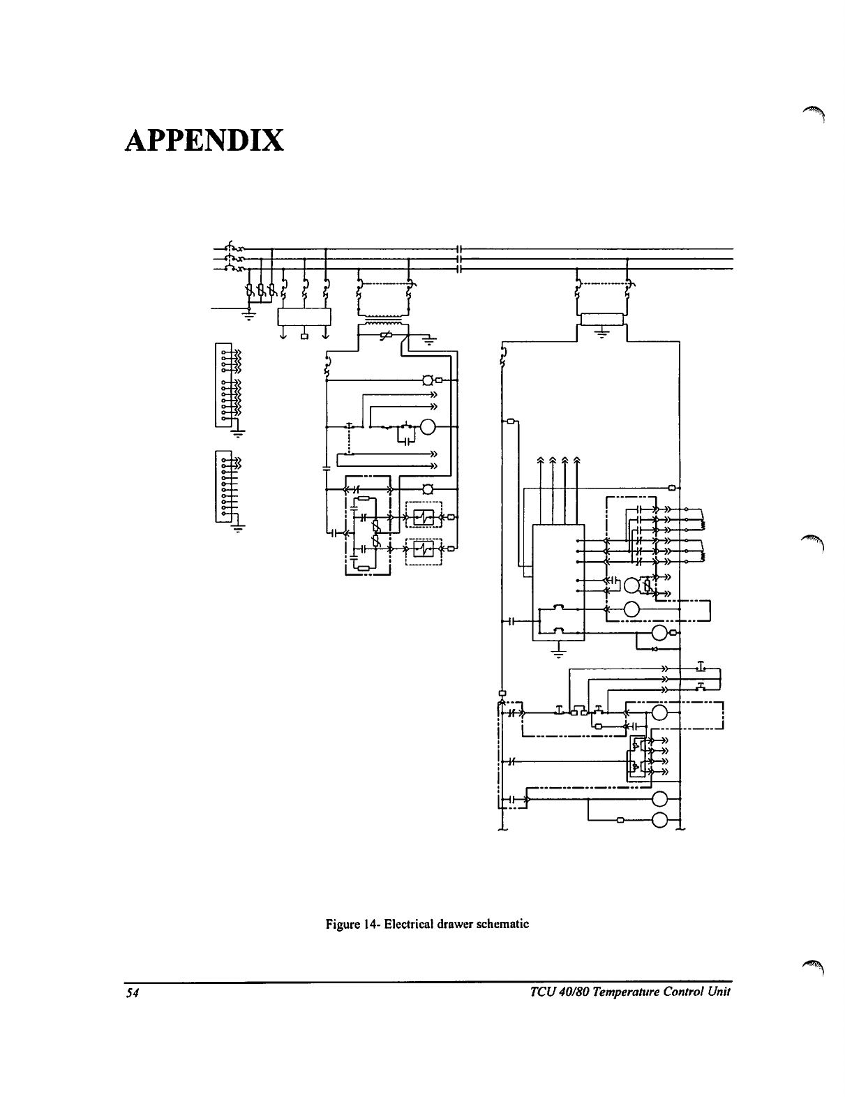
APPENDIX
Figure
14-
Electrical
drawer
schematic
54
TCU
40/80
Temperature
Control
Unit
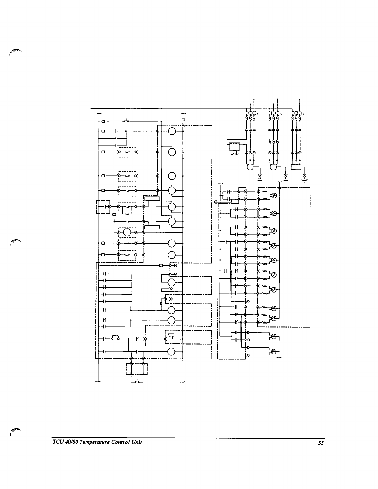
TCU
40/80
Temperature
Control
Unit
55
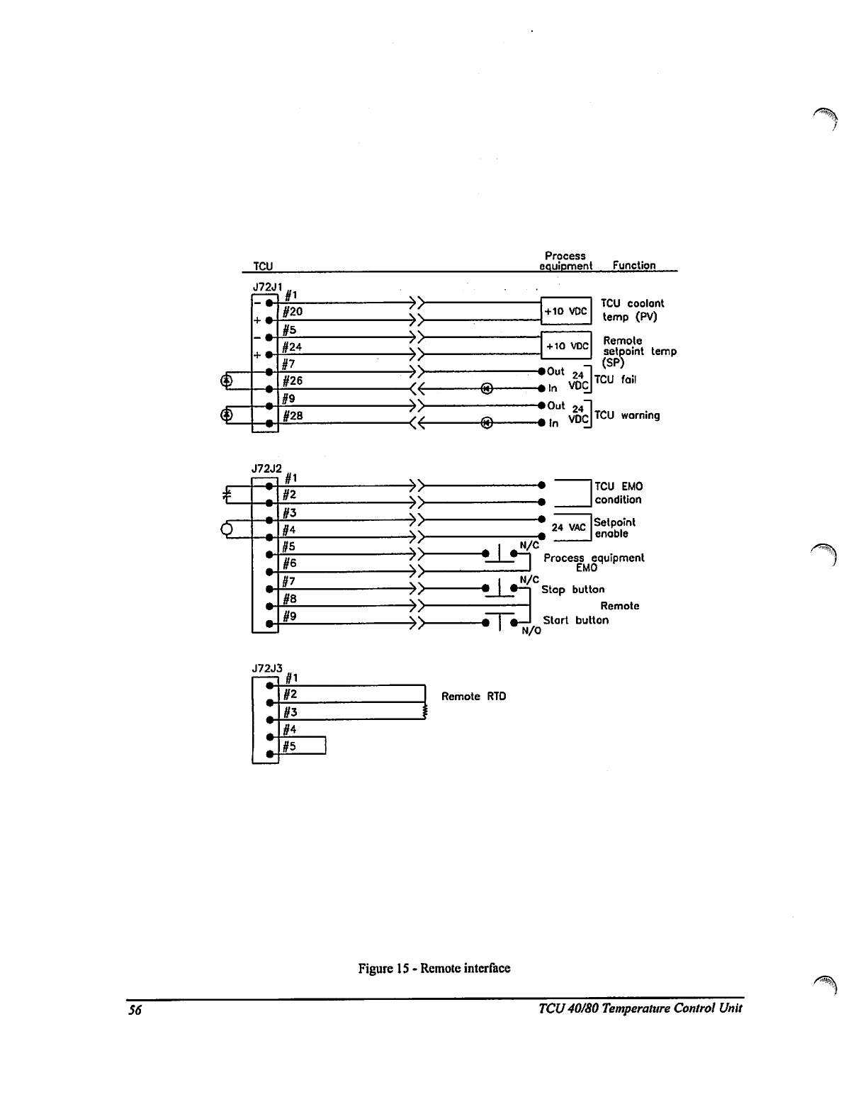
TCU
Process
equipment
Function
J72J1
#1
#20
#24
#7
#26
#28
■¥>
■«-
-©
+10
VDC
+10 VDC
-•Out
.1
TCU
coolant
temp
(PV)
Remote
setpoint
temp
«ln VOC
?n4JTCU
fail
•Out
24~l
,,„
VDCJTCU
wornin9
o
J72J2
u<
i
n
■
n
iH
#5
#6
§7
#8
#9
/ /
''
g
i~l
•
N/C
Lr
N/Cr
L?
rv-
<
N/O
24
VAC
TCU
EMO
condition
Setpoint
enable
Process
equipment
EMO
Stop
button
Remote
Start
button
J72J3
#5
Remote
RTO
56
Figure
15
-
Remote
interface
TCU
40/80
Temperature
Control
Unit
V
TCU
40/80
Temperature
Control
Unit
57
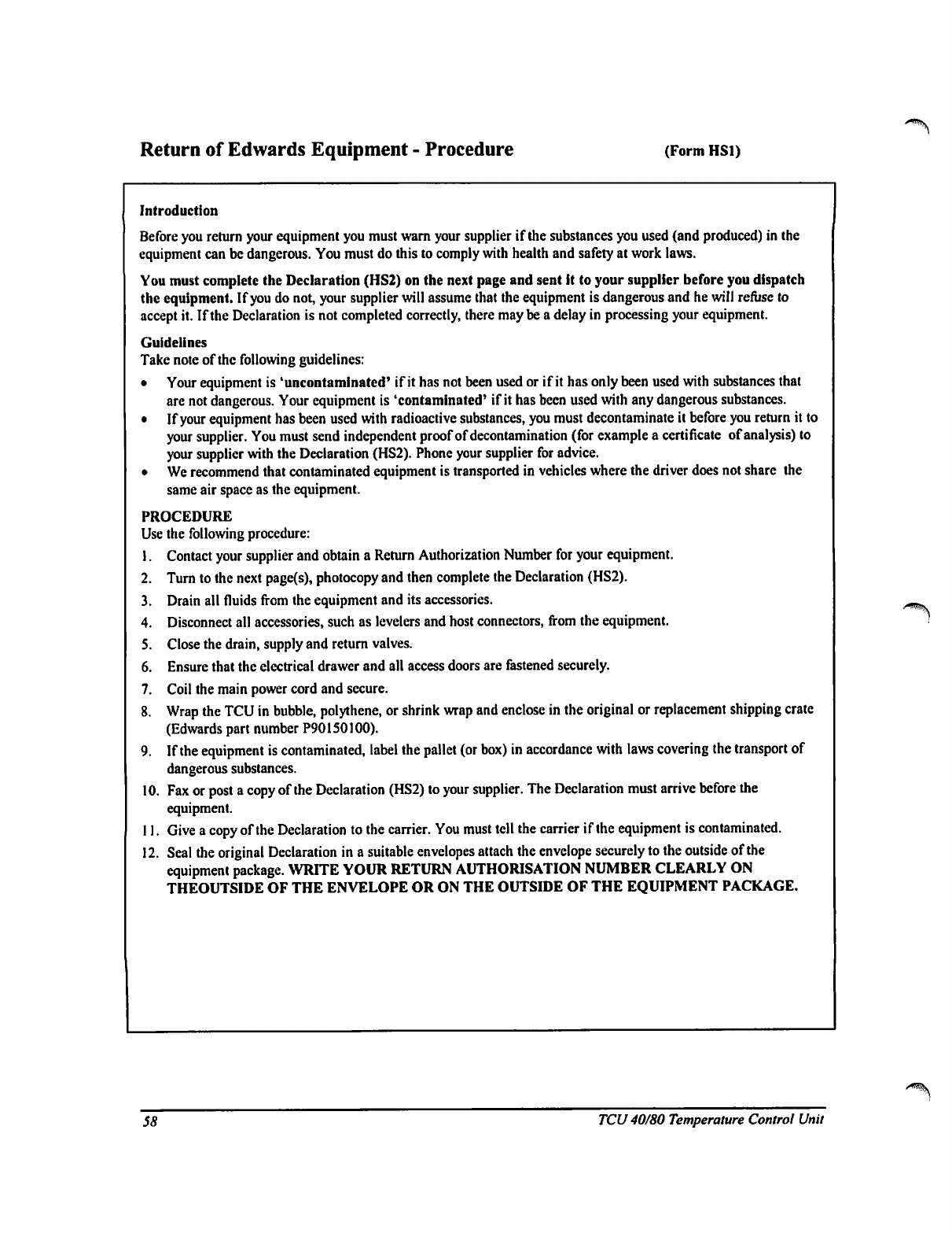
Return
of
Edwards
Equipment
-
Procedure
(Form
HS1)
i^"ft\
Introduction
Before
you
return
your
equipment
you
must
warn
your
supplier
if
the
substances
you
used
(and
produced)
in
the
equipment
can
be
dangerous.
You
must
do
this
to
comply
with
health
and
safety
at
work
laws.
You
must
complete
the
Declaration
(HS2)
on
the
next
page
and
sent
it
to
your
supplier
before
you
dispatch
the
equipment.
If
you
do
not,
your
supplier
will
assume
that
the
equipment
is
dangerous
and
he
will
refuse
to
accept
it.
If
the
Declaration
is
not
completed
correctly,
there
may
be
a
delay
in
processing
your
equipment.
Guidelines
Take
note
of
the
following
guidelines:
•
Your
equipment
is
'uncontaminatcd'
if
it
has
not
been used
or
if
it
has
only
been
used
with
substances
that
are
not
dangerous.
Your
equipment
is
'contaminated'
if
it
has
been
used
with
any
dangerous
substances.
•
If
your
equipment
has
been
used
with
radioactive substances,
you
must
decontaminate
it
before
you
return
it
to
your
supplier.
You
must
send
independent
proof
of
decontamination
(for
example
a
certificate
of
analysis)
to
your
supplier
with
the
Declaration
(HS2).
Phone
your
supplier
for
advice.
•
We
recommend
that
contaminated
equipment
is
transported
in
vehicles
where
the
driver
does
not
share
the
same
air
space
as
the
equipment.
PROCEDURE
Use
the
following
procedure:
1.
Contact
your
supplier
and
obtain
a
Return
Authorization
Number
for
your
equipment.
2.
Turn
to
the
next
page(s),
photocopy
and
then
complete
the
Declaration
(HS2).
3.
Drain
all
fluids
from
the
equipment
and
its
accessories.
4.
Disconnect
all
accessories,
such
as
levelers
and
host
connectors,
from
the
equipment.
5.
Close
the
drain,
supply
and
return
valves.
6.
Ensure
that
the
electrical
drawer
and
all
access
doors
are
fastened
securely.
7.
Coil
the
main
power
cord
and
secure.
8.
Wrap
the
TCU
in
bubble,
polythene,
or
shrink
wrap
and
enclose
in
the
original
or
replacement
shipping
crate
(Edwards
part
number
P90150100).
9.
If
the
equipment
is
contaminated,
label
the
pallet
(or
box)
in
accordance
with
laws
covering
the
transport
of
dangerous
substances.
10.
Fax
or
post
a
copy
of
the
Declaration
(HS2)
to
your
supplier.
The
Declaration
must
arrive
before the
equipment.
11.
Give
a
copy
of
the
Declaration
to
the
carrier.
You
must
tell
the
carrier
if
the
equipment
is
contaminated.
12.
Seal
the
original
Declaration
in
a
suitable
envelopes
attach
the
envelope
securely
to
the
outside
of
the
equipment
package.
WRITE
YOUR
RETURN
AUTHORISATION
NUMBER
CLEARLY
ON
THEOUTSIDE
OF
THE
ENVELOPE
OR
ON
THE
OUTSIDE
OF
THE
EQUIPMENT
PACKAGE.
58
TCU
40/80
Temperature
Control
Unit
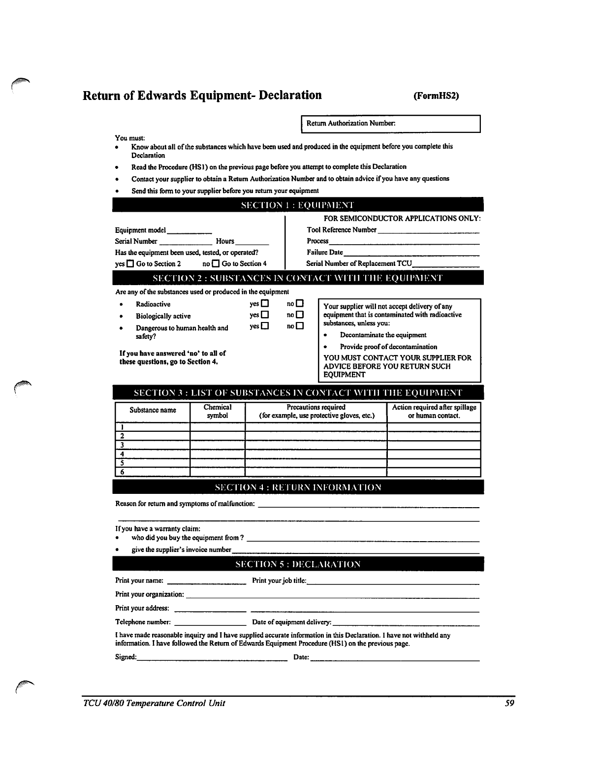
Return
of
Edwards
Equipment-
Declaration
(FormHS2)
/0
Return
Authorization
Number
You
must:
•
Know
about
all
of
the
substances
which
have
been
used
and
produced
in
the
equipment
before
you
complete
this
Declaration
•
Read
the
Procedure
(HS1)
on
the
previous
page
before
you
attempt
to
complete
this
Declaration
•
Contact
your
supplier
to
obtain
a
Return
Authorization
Number
and
to
obtain
advice
if
you
have
any
questions
•
Send
this
form
to
your
supplier
before
you
return
your
equipment
SECTION
1
:
EQUIPMENT
Equipment
model
_
Serial
Number
Hours
Has
the
equipment
been
used,
tested,
or
operated?
yes
□
Go
to
Section
2
no
□
Go
to
Section
4
FOR
SEMICONDUCTOR
APPLICATIONS
ONLY:
Tool
Reference
Number
Process
Failure
Date
Serial
Number
of
Replacement
TCU
SKCTION
2
:
SUBSTANCES
IN
CONTACT
WITH
THE
EQUIPMENT
Are any
of
the
substances
used
or
produced
in
the
equipment
•
Radioactive
yesQ
noQ
•
Biologically
active
yesD
noD
•
Dangerous
to
human
health
and
yesQ
noD
safety?
If
you
have
answered
'no'
to
all
of
these
questions,
go
to
Section
4.
Your
supplier
will
not
accept
delivery
of
any
equipment
that
is
contaminated
with
radioactive
substances,
unless
you:
•
Decontaminate
the
equipment
•
Provide
proof
of
decontamination
YOU
MUST
CONTACT
YOUR
SUPPLIER
FOR
ADVICE
BEFORE
YOU
RETURN
SUCH
EQUIPMENT
SECTION
3
:
LIST
OK
SUBSTANCES
IN
CONTACT
WITH
THE
EQUIPMENT
Substance
name
1
2
3
4
5
6
Chemical
symbol
Precautions
required
(for
example,
use
protective
gloves,
etc.)
Action
required
after
spillage
or
human
contact.
SECTION
4
:
RETURN
IN!
ORMATION
Reason
for
return
and
symptoms
of
malfunction:
If
you
have
a
warranty
claim:
•
who
did
you
buy
the
equipment
from
?
•
give
the
supplier's
invoice
number
Print
your
name:
Print
your
organization:
Print
your
address:
Telephone
number:
SECTION
5
:
DECLARATION
Print
your
job
title:_
Dale
of
equipment
delivery:
_
I
have
made
reasonable
inquiry
and
I
have
supplied
accurate
information
in
this
Declaration.
I
have
not
withheld
any
information.
I
have
followed
the
Return
of
Edwards
Equipment
Procedure
(HSl) on
the
previous
page.
Signed:_
Date:
TCU
40/80
Temperature
Control
Unit
59
Legal
notices,
limitations
and
disclaimers
For
a
period
of
twelve
(12)
months
from
the
date
of
original
shipment
to
Purchaser,
the
apparatus
and
each
part
of
component
manufactured
be Edward's
High
Vacuum
International
(Edwards)
is
warranted
to
be
free
from
functional
defects
in
materials
and workmanship.
The
foregoing
warranty
is
subject
to
the
condition
that
regular
periodic
maintenance
and
service
be
performed
or
replacements
made
in
accordance
with
instructions
provided
by
Edwards.
The
foregoing
warranty
shall
not
apply
to
any
apparatus,
part,
or
component
that
has
been
repaired
other
than
by
Edwards
or
an
authorized
Edwards
representative or
in
accordance
with
written
instructions
provided
by
Edwards,
that
has
been
altered
by
anyone
other
than
Edwards
or
that
has
been
subject
to
improper
installation
or
abuse,
misuse,
negligence,
accident,
or
corrosion.
Purchaser's
sole
and
exclusive
remedy
under
the
above
warranty
is
limited
to,
at
Edward's
option,
repair
or
replacement
of
defective
parts
of
components
or
return
to
Purchaser
of
the
price
of
the
apparatus.
The
defect
must
be
promptly
reported
to
Edwards
or
Purchaser
must
return
the
part
or
component
with
a
statement
of
the
observed
deficiency
no
later
than
seven
(7)
days
after
the
expiration
date
of
the
warranty
to
the
address
designated
by
Edwards,
transportation
charges
prepaid.
In the
event
that
Edwards
elects
to
refund
the
purchase
price,
the
apparatus
shall
be
the
property
of
Edwards
and
shall
be
shipped
to
Edwards
at
Edward's
expense.
This
Mechanical
Warranty
shall
be
void
and
the
apparatus
shall
be
deemed
to
be
purchased
AS
IS
in
the
event
that
the
entire
purchase
price
has
not
been
paid
within
thirty
(30)
days
of
original
shipment
of
apparatus.
THERE
ARE
NO
EXPRESS
OR
IMPLIED
WARRANTIES
THAT
EXTEND
BEYOND
THE
WARRANTY
HEREIN
ABOVE
SET
FORTH.
THERE
IS
NO
PARTICULAR
WARRANTY
OF
MERCHANT
ABILITY
OR
FITNESS
FOR
A
PARTICULAR
PURPOSE
WITH
RESPECT
TO
THE
APPARATUS
OR
ANY
PART
OR
COMPONENT
THEREOF
AND
NO
WARRANTY
SHALL
BE
IMPLIED
BY
LAW.
Items
not
of
Edwards's
manufacture
but
resold
by
Edwards
are
the
products
of
other
manufacturers
and
their
warranty,
if
any,
shall
apply.
THERE
ARE
NO
WARRANTIES
OF
ANY
KIND
ON
PRODUCTS
OF
OTHER
MANUFACTURERS
RESOLD
BY
EDWARDS
EXCEPT
THE
WARRANTY
OF
TITLE.
AND
NO
WARRANTIES
SHALL
BE
IMPLIED
BY
LAW.
THERE
IN
NOT
EXPRESS
OR
IMPLIED
WARRANTY
OF
MERCHANT
ABILITY
OR
OF
FITNESS
FOR
A
PARTICULAR
PURPOSE
WITH
RESPECT
TO
PRODUCTS
OF
OTHER
MANUFACTURERS.
In
no
event
shall
the
Purchaser
be
entitled
to
any
special,
indirect,
or
consequential
damages.
60
TCU
40/80 Temperature
Control
Unit
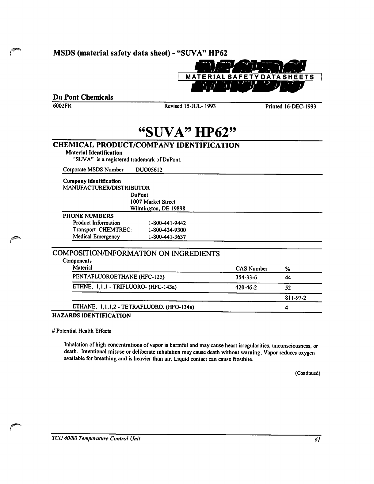
MSDS
(material
safety
data
sheet)
-
"SUVA"
HP62
MATERIAL
SAFETY
DATA
SHEETS
Du
Pont
Chemicals
6002FR
Revised
15-JUL-
1993
Printed
16-DEC-1993
"SUVA"
HP62"
CHEMICAL
PRODUCT/COMPANY
IDENTIFICATION
Material
Identification
"SUVA"
is
a
registered
trademark
of
DuPont.
Corporate
MSDS
Number
DUO05612
Company
identification
MANUFACTURER/DISTRIBUTOR
DuPont
1007
Market
Street
Wilmington,
DE
19898
PHONE
NUMBERS
Product
Information
1
-800-441
-9442
Transport
CHEMTREC:
1-800-424-9300
Medical
Emergency
1-800-441-3637
COMPOSITION/INFORMATION
ON
INGREDIENTS
Components
Material
PENTAFLUOROETHANE
(HFC-125)
ETHNE,
1,1,1-
TRIFLUORO-
(HFC-143a)
ETHANE,
1,1,1,2
-
TETRAFLUORO.
(HFO-134a)
HAZARDS
IDENTIFICATION
CAS
Number
354-33-6
420-46-2
%
44
52
811-97-2
4
#
Potential
Health
Effects
Inhalation
of
high
concentrations
of
vapor
is
harmful
and
may
cause
heart
irregularities,
unconsciousness,
or
death.
Intentional
misuse
or
deliberate
inhalation
may
cause
death
without
warning,
Vapor
reduces
oxygen
available
for
breathing
and
is
heavier
than
air.
Liquid
contact
can
cause
frostbite.
(Continued)
TCU
40/80
Temperature
Control
Unit
61
HAZARDS
IDENTIFICATION
(Continued)
HUMAN
HEALTH
EFFECTS:
Overexposure
to
the
vapors
by
inhalation
may
include
temporary
nervous
system
depression
with
anesthetic
effects
such
as
dizziness,
headaches,
confusion
,
incoordination,
and
loss
of
consciousness.
Higher
exposures
to
the
vapors
may
cause
temporary
alteration
of
the
heart's
electrical
activity
with
irregular
pulse, palpitations,
or
inadequate
circulation;
or
fatality
from
gross
overexposure.
Contact
with
the
liquid
may
cause
frostbite.
Individuals
with
preexisting
diseases
of
the
central
nervous
or
cardiovascular
system
may
have
increased
susceptibility
to
the
toxicity
of
increase
exposures.
Carcinogenicity
Information
None
of
the
components
present
in
this
material
at
concentrations
equal
to
or
greater
than
0.1%
are
listed
by
I
ARC,
NTP,
OSHA
or
ACGIH
as a
carcinogen.
FIRST
AID
MEASURES
First
Aid
INHALATION
If
high
concentrations
are
inhaled,
immediately
remove
to
fresh
air.
Keep
person
calm.
If
not
breathing,
give
artificial
respiration. If
breathing
is
difficult,
give
oxygen.
Call
a
physician.
SKIN
CONTACT
Flush
skin
with
water
for
at
least
15
minutes
after
excessive
contact.
Treat
for
frostbite
if
necessary
by
gently
wanning
affected
area.
Call
a
physician
if
irritation
is
present.
EYE
CONTACT
In
case
of
contact,
immediately
flush
eyes
with
plenty
of
water
for
at
least
15
minutes.
Call
a
physician.
INGESTION
Ingestion
is
not
considered
a
potential
route
of
exposure.
_
Notes
to
Physicians
Because of
possible
disturbances
of
cardiac
rhythm,
catecholamine
drugs,
such
as
epinephrine,
should
only
be used
with
special
caution
in
situations
of
emergency
life
support.
(Continued)
62
TCU
40/80
Temperature
Control
Unit
FIRE
FIGHTING
MEASURES
Flammable
Properties
Flash
Point
will
not
burn
Method
TOC
Flammable
limits
in
Air
%
by
Volume
LEL
Not
applicable
UEL
Not
applicable
Autoignition
Not
determined
Fire
and
Explosion
Hazards:
Cylinders
may
rupture
under
fire
conditions.
Decomposition
may
occur.
Potential
Combustibility:
"SUVA"
HP62
is
not
flammable
at
temperatures
up
to
80
deg
C
(176
deg
F)
and
at
atmospheric
pressure.
Data
are
not
available
at
higher
temperatures
and
pressures.
However,
one
of
the
components,
HFC-143a
is
flammable.
Another,
HFC-134a,
has
been
shown
in
tests
to
be
combustible
at
pressures
as
low
as
6o
psig
at
ambient
temperature
when
mixed
with
air
at
concentrations
of 65
volume
%
air.
Therefore,
"SUVA"
HP82
should
not
be
mixed
with
air
for
leak
testing.
In
general,
it
should
not
be
used
or
allowed
to
be
present
with
high
concentrations
of
air
above
atmospheric
pressures.
Experimental
data
have
also
been
reported
which
indicate
combustibility
of
HFC-134a
in
the
presence
of
certain
concgntrations
of
chlorine.
Extinguishing
Media
As
appropriate
for
combustible
in
area.
Fire
Fighting
Instructions
f
Cool
cylinder
with
water
spray
or
fog.
Self-contained
breath
ng
apparatus
(SCBA)
is
required
if
cylinders
rupture
and
contents
are
released
under
fire
conditions.
ACCIDENTAL
RELEASE
MEASURES
Safeguards
(Personnel)
NOTE:
Review
FIRE
FIGHTING
MEASURES
and
HANDLING
(PERSONNEL)
sections
before
proceeding
with
clean-up.
Use
appropriate
PERSONAL
PROTECTIVE
EQUIPMENT
during
clean-up.
Accidental
Release
Measures
Ventilate
area,
especially
low
or
enclosed
places
where
heavy
vapors
might
collect.
Remove
open
flames.
Use
self-contained
breathing apparatus
(SCBA)
for
large
spills
or
releases.
(Continued)
^^
TCU
40/80
Temperature
Control
Unit
63

HANDLING
AND
STORAGE
Handling
(Personnel)
Avoid-breathing
vapor.
Avoid
liquid
contact
with
eyes
and
skin.
Use
with
sufficient
ventilation
to
keep
employees
exposure
below
recommended
limits.
Contact with
chlorine
or
other
strong oxidizing
agents
should
also
be
avoided.
See
Fire
and
Explosion
Data
section.
Storage
Clean,
dry
area.
Do
not
heat
above
52
deg
C
(125
deg
F).
EXPOSURE
CONTROLS/PERSONAL
PROTECTION
Engineering
Controls
Avoid
breathing
vapors.
Avoid
contact
with
skin
or
eyes.
Use
with
sufficient
ventilation to
keep
employee
exposure
below
the
recommended
exposure
limit.
Local
exhaust
should
be
used
if
large
amounts
are
released.
Mechanical
ventilation
should
be
used
in
low
or
enclosed
places..
Personal
Protective
Equipment
Impervious
gloves
should
be
used
to
avoid
prolonged
or
repeated
exposure.
Chemical
Splash
goggles
should
be
available
for
use
as
needed
to
prevent
eye
contact.
Under
normal
manufacturing
conditions,
no
respiratory
protection
is
required
when
using
this
product.
Self-contained
breathing
apparatus
(SCBA)
is
required
if
a
large
release
occurs.
Exposure
Guidelines
Applicable
Exposure
Limits
PENTAFLUOROETHANE
(HFC-125)
PEL
(OSHA)
None
Established
TLV
(ACGIH)
None
Established
AEL
*
(Du
Pont)
1000
ppm,
8
&
12
Hr.
TWA
ETHANE.
1, 1,
l-TRIFLUORO-(HFC-143a)
PEL
(OSHA)
None
Established
^
TLV
(ACGIH)
None
Established-.
'
AEL*
(DuPont)
1000ppm,
8&12Hr.
TWA
ETHANE,
1, 1,
1,2-TETRAFLUORO-
(HFC-134a)
PEL
(OSHA)
None
Established
TLV
(ACGIH)
None
Established
AEL
•
(Du
Pont)
1000
ppm,
8
&
12
Hr.
TWA
WEEL
(AIHA)
1000
ppm,
8 Hr.
TWA
*
AEL
is
DuPont's
Acceptable
Exposure
Limit.
Where
governmental
imposed
occupational
exposure
limits
which
are
lower
than
the
AEL
are
in
effect,
such
limits
shall
take
precedence.
(Continued)
64
TCU
40/80
Temperature
Control
Unit
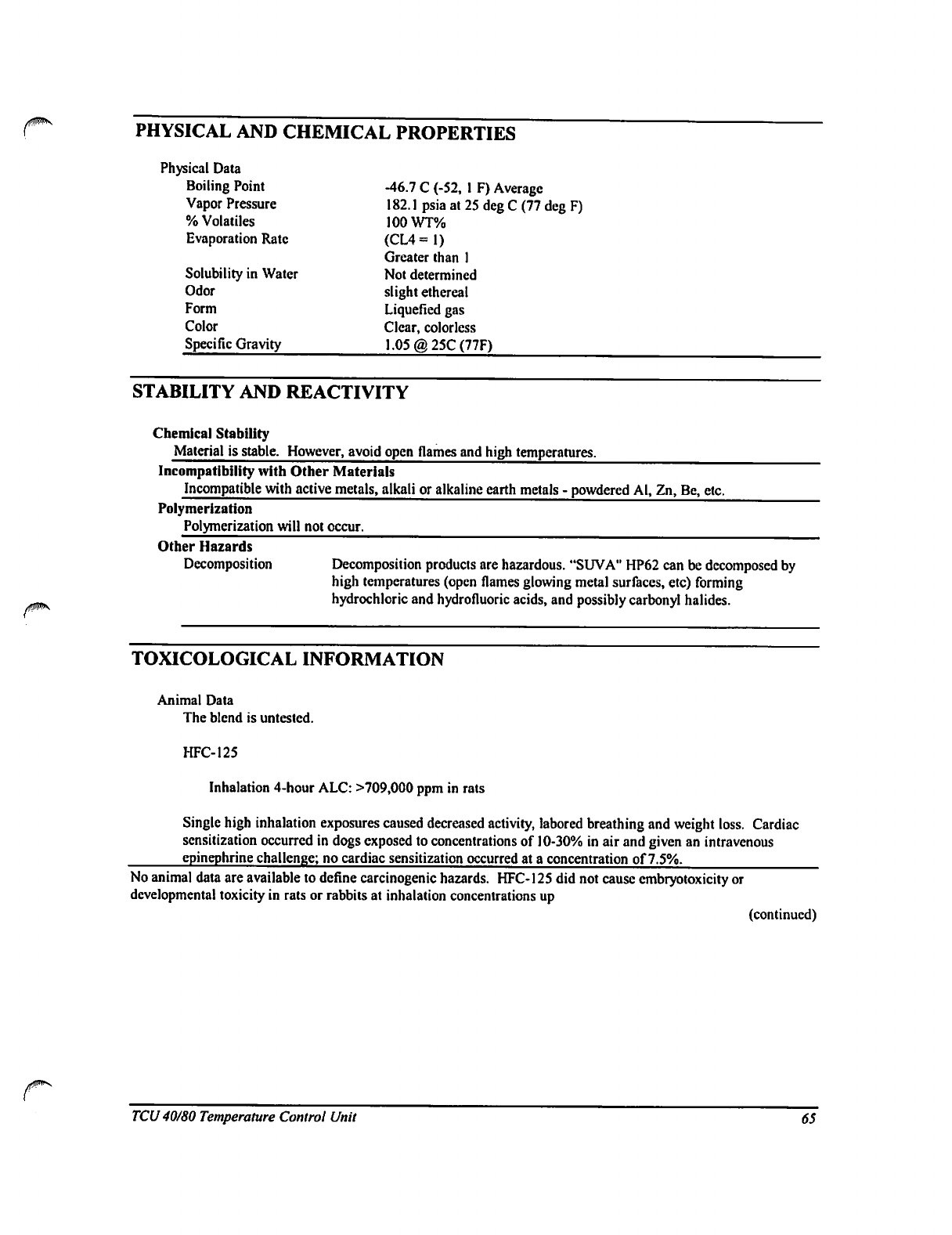
PHYSICAL
AND
CHEMICAL
PROPERTIES
Physical
Data
Boiling
Point -46.7
C
(-52,
1
F)
Average
Vapor
Pressure
182.1
psia
at
25
deg
C
(77
deg
F)
%Volatiles
100WT%
Evaporation
Rate
(CL4
=
1)
Greater
than
1
Solubility
in
Water
Not
determined
Odor
slight
ethereal
Form
Liquefied
gas
Color
Clear,
colorless
Specific
Gravity
1.05
@25C(77F)
STABILITY
AND
REACTIVITY
Chemical
Stability
Material
is
stable.
However,
avoid
open
flames
and
high
temperatures.
Incompatibility
with
Other
Materials
Incompatible
with
active
metals,
alkali
or
alkaline
earth
metals
-
powdered
Al,
Zn,
Be,
etc.
Polymerization
Polymerization
will
not
occur.
Other
Hazards
Decomposition
Decomposition
products
are
hazardous.
"SUVA"
HP62
can
be
decomposed by
high
temperatures (open
flames
glowing
metal
surfaces,
etc)
forming
hydrochloric
and
hydrofluoric
acids,
and
possibly
carbonyl
halides.
TOXICOLOGICAL
INFORMATION
Animal
Data
The
blend
is
untested.
HFC-125
Inhalation
4-hour
ALC:
>709,000
ppm
in
rats
Single
high
inhalation
exposures
caused
decreased
activity,
labored
breathing
and
weight
loss.
Cardiac
scnsitization
occurred
in
dogs
exposed
to
concentrations
of
10-30%
in
air
and
given
an
intravenous
epinephrine
challenge;
no
cardiac
sensitization
occurred
at
a
concentration
of
7.5%.
No
animal
data are
available
to
define
carcinogenic
hazards.
HFC-125
did not
cause
cmbryotoxicity
or
developmental
toxicity
in
rats
or
rabbits
at
inhalation
concentrations
up
(continued)
TCU
40/80
Temperature
Control
Unit
65
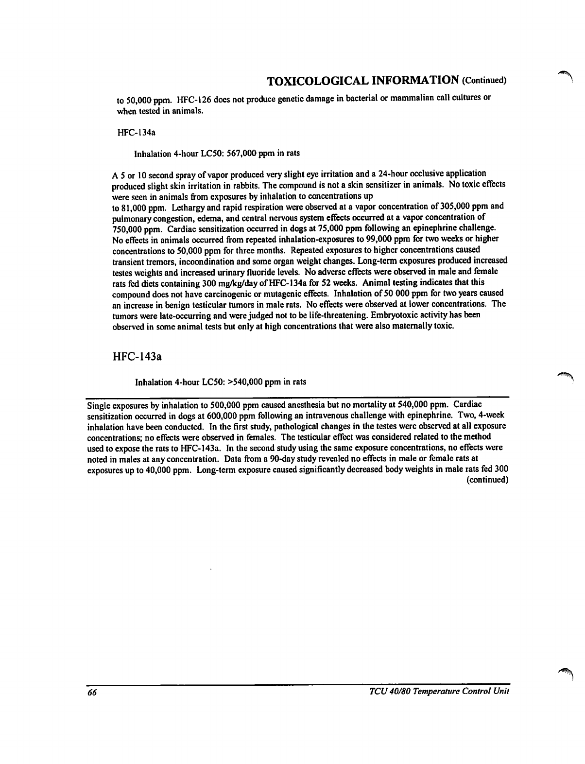
TOXICOLOGICAL
INFORMATION
(Continued)
to
50,000
ppm.
HFC-126
does
not
produce
genetic
damage
in
bacterial
or
mammalian
call
cultures
or
when
tested
in
animals.
HFC-134a
Inhalation
4-hour
LC50:
567,000
ppm
in rats
A
5
or
10
second
spray
of
vapor
produced
very
slight
eye
irritation
and
a
24-hour
occlusive
application
produced
slight
skin
irritation
in
rabbits.
The
compound
is
not
a
skin
sensitizer
in
animals.
No
toxic
effects
were
seen
in
animals
from
exposures
by
inhalation
to
concentrations
up
to
81,000
ppm.
Lethargy
and
rapid
respiration
were
observed
at
a
vapor
concentration
of
305,000
ppm
and
pulmonary
congestion,
edema,
and
central
nervous
system
effects
occurred
at
a
vapor
concentration
of
750,000
ppm.
Cardiac
sensitization
occurred
in
dogs
at
75,000
ppm
following
an
epinephrine
challenge.
No
effects
in
animals
occurred
from
repeated
inhalation-exposures
to
99,000
ppm
for
two
weeks
or
higher
concentrations
to
50,000
ppm
for
three
months.
Repeated
exposures
to
higher
concentrations
caused
transient
tremors,
incoondination
and
some
organ
weight
changes.
Long-term
exposures
produced
increased
testes
weights
and
increased
urinary
fluoride
levels.
No
adverse
effects
were
observed
in
male
and
female
rats
fed
diets
containing
300
mg/kg/day
of
HFC-134a
for
52
weeks.
Animal
testing
indicates
that
this
compound
does
not
have
carcinogenic
or
mutagenic
effects.
Inhalation
of
50
000
ppm
for
two
years
caused
an
increase
in
benign
testicular
tumors
in
male
rats.
No
effects
were
observed
at
lower
concentrations.
The
tumors
were
late-occurring
and
were
judged
not
to
be
life-threatening.
Embryotoxic
activity
has
been
observed
in
some
animal
tests
but
only
at
high
concentrations
that
were
also
maternally
toxic.
HFC-143a
Inhalation
4-hour
LC50:
>540,000
ppm
in rats
Single
exposures
by
inhalation
to
500,000
ppm
caused
anesthesia
but
no
mortality
at
540,000
ppm.
Cardiac
sensitization
occurred
in
dogs
at
600,000
ppm
following
an
intravenous
challenge
with
epinephrine.
Two,
4-week
inhalation
have
been
conducted.
In the
first
study,
pathological
changes
in
the
testes
were
observed
at
all
exposure
concentrations;
no
effects
were
observed
in
females.
The
testicular
effect
was
considered
related
to
the
method
used
to
expose
the
rats
to
HFC-143a.
In
the
second
study using
the
same
exposure
concentrations,
no
effects
were
noted
in
males
at
any
concentration.
Data from
a
90-day
study
revealed
no
effects
in
male
or
female
rats
at
exposures
up
to
40,000
ppm.
Long-term
exposure
caused
significantly
decreased
body
weights
in
male
rats
fed
300
(continued)
66
TCU
40/80 Temperature
Control
Unit
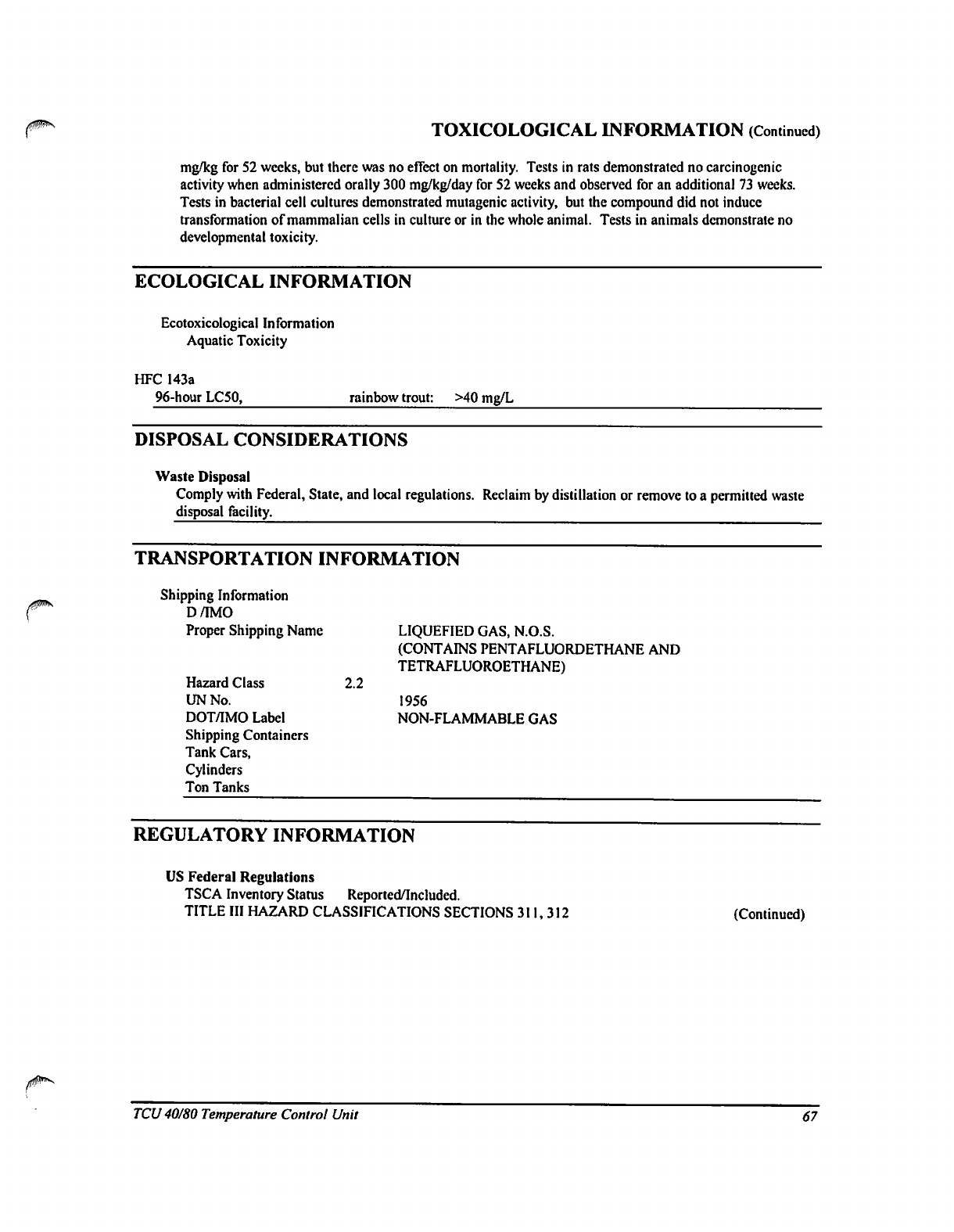
TOXICOLOGICAL
INFORMATION
(Continued)
mg/kg
for
52
weeks,
but
there
was
no
effect
on
mortality.
Tests
in
rats
demonstrated
no
carcinogenic
activity
when
administered
orally
300
mg/kg/day
for
52
weeks and
observed
for
an
additional
73 weeks.
Tests
in
bacterial
cell
cultures
demonstrated
mutagenic
activity,
but
the
compound
did not
induce
transformation
of
mammalian
cells in
culture
or
in
the
whole
animal.
Tests
in
animals
demonstrate
no
developmental
toxicity.
ECOLOGICAL
INFORMATION
Ecotoxicological
Information
Aquatic
Toxicity
HFC
143a
96-hour
LC50,
rainbow
trout:
>40
mg/L
DISPOSAL
CONSIDERATIONS
Waste
Disposal
Comply
with
Federal,
State,
and
local
regulations.
Reclaim
by
distillation
or
remove
to
a
permitted
waste
disposal
facility.
TRANSPORTATION
INFORMATION
Shipping
Information
D/MO
Proper
Shipping
Name
LIQUEFIED
GAS,
N.O.S.
(CONTAINS
PENTAFLUORDETHANE
AND
TETRAFLUOROETHANE)
Hazard
Class
2.2
UN
No.
1956
DOT/IMO
Label
NON-FLAMMABLE
GAS
Shipping
Containers
Tank
Cars,
Cylinders
Ton
Tanks
REGULATORY
INFORMATION
US
Federal
Regulations
TSCA
Inventory
Status
Reported/Included.
TITLE
III
HAZARD
CLASSIFICATIONS
SECTIONS
311,312
(Continued)
TCU
40/80
Temperature
Control
Unit
67
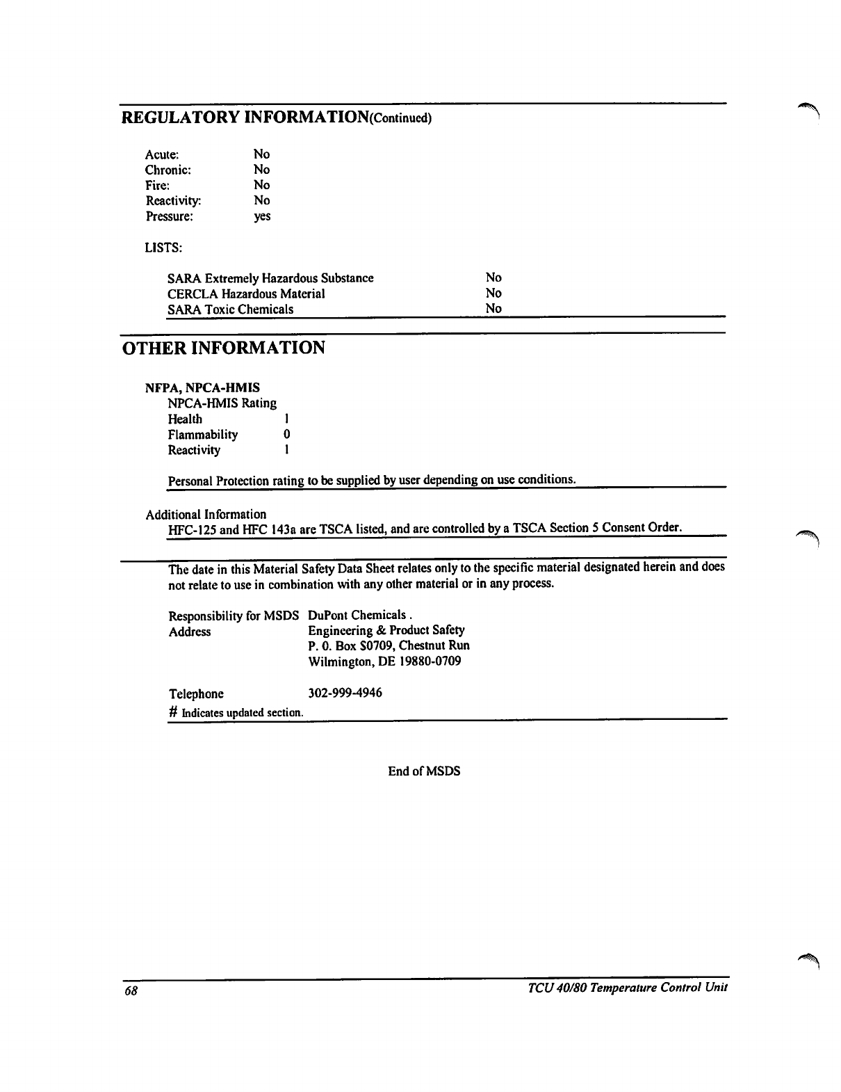
REGULATORY
INFORMATION(Continued)
Acute:
Chronic:
Fire:
Reactivity:
Pressure:
LISTS:
No
No
No
No
yes
SARA
Extremely
Hazardous
Substance
CERCLA
Hazardous
Material
SARA
Toxic
Chemicals
No
No
No
OTHER
INFORMATION
NFPA,
NPCA-HMIS
NPCA-HMIS
Rating
Health
1
Flammability
0
Reactivity
1
Personal
Protection
rating
to
be
supplied
by
user
depending
on
use
conditions.
Additional
Information
HFC-125
and
HFC
143a
are
TSCA
listed,
and
are
controlled
by
a
TSCA
Section
5
Consent
Order.
The
date
in
this
Material
Safety
Data
Sheet
relates
only
to
the
specific
material
designated
herein
and
does
not
relate
to
use
in
combination
with
any
other
material
or
in
any
process.
Responsibility
for
MSDS
DuPont
Chemicals.
Address
Engineering
&
Product
Safety
P.
0.
Box
S0709,
Chestnut
Run
Wilmington,
DE
19880-0709
Telephone
302-999-4946
#
Indicates
updated
section.
End
of
MSDS
<$#
TCU
40/80
Temperature
Control
Unit
NOTES:
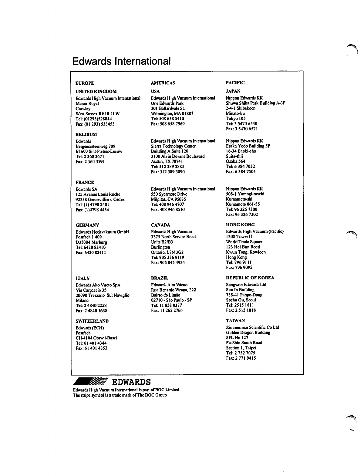
Edwards
International
EUROPE
UNITED
KINGDOM
Edwards
High
Vacuum
International
Manor
Royal
Crawlcy
West
Sussex
RHI0
2LW
Tel:
(01293)528844
Fax:(01293)533453
BELGIUM
Edwards
Bergensesteenweg
709
BI600
Sint-Pieters-Leeuw
Tel:
2
360
3671
Fax:
2
360
3591
FRANCE
Edwards
SA
125
Avenue
Louis
Roche
92238
Germevilliers.
Cedex
Tel:
(1)4798
2401
Fax:
(1)4798
4454
GERMANY
Edwards
Hochvakuum
GmbH
Poslfach
1
409
D3S004
Marburg
Tel:
6420
82410
Fax:
6420
82411
ITALY
Edwards
Alto
Vuoto
SpA
Via
Carpaccio
35
20090
Trczzano
SulNaviglio
Milano
Tel:
2
4840
2258
Fax:
2
4840
1638
SWITZERLAND
Edwards
(ECH)
Posi
fiich
CH-4l04Obrwil-Basel
Tel:
61
401
4344
Fax: 61
401
4352
AMERICAS
USA
Edwards
High
Vacuum
International
One
Edwards
Park
301
BaltardvaleSl
Wilmington,
MA
01887
Tel:
508
658
5410
Fax:
508 658
7969
Edwards
High
Vacuum
International
Sierra
Technology
Center
Building
A
Suite
120
3100
Alvin
Devane
Boulevard
Austin,
TX
78741
Tel:
512 389
3883
Fax:
512 389
3890
Edwards
High
Vacuum
International
550
Sycamore
Drive
Milpitas,CA
95035
Tel:
408
946
4707
Fax:
408
946
8510
CANADA
Edwards
High
Vacuum
3375
North
Service
Road
Units
B2/B3
Burlington
Ontario,
L7N3G2
Tel:
905 336
9119
Fax:
905
845
4924
BRAZIL
Edwards
Alto
Vacuo
Rua
Benardo
Wrona,
222
Bairro
do
LimSo
02710
-Sao
Paulo
-SP
Tel:
11
858
0377
Fax:
11
265
2766
PACIFIC
JAPAN
Nippon
Edwards
KK
Shuwa
Shiba
Park
Building
A-3F
2-4-1
Shibakoen
Minato-ku
Tokyo
105
Tel:
3
5470
6530
Fax: 3
5470
6521
Nippon
Edwards
KK
Esaka
Yodo
Building
5F
16-34Enoki-cho
Suita-shii
Osaka
564
Tel:
6
384
7052
Fax:
6
384
7504
Nippon
Edwards
KK
508-1
Yomogi-machi
Kumamoto-shi
Kumamoto
861-55
Tel:
96
326
7300
Fax:
96 326
7302
HONG KONG
Edwards
High
Vacuum
(Pacific)
1308
Tower
II
World
Trade
Square
123
Hoi
Bun
Road
Kwun
Tong,
Kowlocn
Hong
Kong
Tel:
796
9111
Fax:
796
9095
REPUBLIC
OF KOREA
Songwon
Edwards
Ltd
Sun
In
Building
738-41
Panpo-Dong
Sochu
Gu,
Seoul
Tel:
2515
18)1
Fax:2
515
1818
TAIWAN
Zimmerman
Scientific
Co
Ltd
Golden
Dragon
Building
8FLNol27
Fu-Shin
South
Road
Section
1,
Taipei
Tel:
2
752
7075
Fax: 2
771
9415
EDWARDS
Edwards
High
Vacuum
International
is
port
of
BOC
Limited
The
stripe
symbol
is
a
trade
mark
of
The
BOC
Group
