TELES.iGATE Teles Igate Gsmbox Manual 130
User Manual:
Open the PDF directly: View PDF ![]() .
.
Page Count: 235 [warning: Documents this large are best viewed by clicking the View PDF Link!]
- Contents
- 1 TELES.iGATE Systems Manual 13.0
- 2 Safety and Security Precautions
- 3 Overview
- 4 Installation
- 5 Configuration Files
- 5.1 Configuration File ip.cfg
- 5.1.1 System Section Configuration
- 5.1.2 Ethernet Interface Configuration
- 5.1.3 Bridge Configuration
- 5.1.4 NAT Configuration
- 5.1.5 PPPoE Configuration
- 5.1.6 Firewall Settings
- 5.1.7 Bandwidth Control
- 5.1.8 DHCP Server Settings
- 5.1.9 PPP Configuration for ISDN and CDMA Dial-Up
- 5.1.10 VLAN Configuration
- 5.1.11 Examples
- 5.2 Configuration File pabx.cfg
- 5.3 Configuration File route.cfg
- 5.1 Configuration File ip.cfg
- 6 TELES.iGATE Routing Examples
- 7 Mobile Configuration Options
- 7.1 Connection to a TELES.vGATE
- 7.2 Module Distribution of Various Mobile Networks
- 7.3 Network-Specific Mobile Routing
- 7.4 Incoming Voice Calls from Mobile
- 7.5 Calling Line Identification Restriction (CLIR)
- 7.6 Blocking Ports
- 7.7 Setting Limits
- 7.8 Automatic SIM Switching
- 7.9 Defining Time Limits for Calls
- 7.10 Pause between Two Calls
- 7.11 Time-Controlled SIM Switching
- 7.12 Mobile-User PBX Callback
- 7.13 Optional Mobile Quality Parameters
- 7.14 Deactivating Class 2 Re-Routing
- 7.15 Checking Ports/Mobile Channels
- 7.16 Recharging Prepaid SIMs
- 8 Signaling and Routing Features
- 8.1 Digit Collection (Enblock/Overlap Receiving)
- 8.2 Rejecting Data Calls and Specified Numbers
- 8.3 Routing CLIP and CLIR Calls
- 8.4 Routing Calls without CLIR
- 8.5 Conversion of Call Numbers
- 8.6 Setting Number Type in OAD/DAD
- 8.7 Setting the Screening Indicator
- 8.8 Setting a Default OAD
- 8.9 Setting or Removing Sending Complete Byte in Setup
- 8.10 Miscellaneous Routing Methods
- 8.11 Changing Cause Values
- 9 Additional VoIP Parameters
- 10 System Maintenance and Software Update
- 10.1 Configuration Errors
- 10.2 Status and Error Messages
- 10.3 Software Update
- 10.4 Trace
- 11 Feature Packages
- 11.1 Activating the License
- 11.2 DLA/Callback Services
- 11.2.1 Call Connector and Callback Server
- 11.2.1.1 Special Announcement
- 11.2.1.2 DLA with DTMF
- 11.2.1.3 DLA with Fixed Destination Number
- 11.2.1.4 Callback with DTMF and OAD as Callback Number
- 11.2.1.5 Callback with DTMF and Pre-Configured Callback Number
- 11.2.1.6 Callback to OAD and Fixed Second Leg
- 11.2.1.7 DLA with DTMF and PIN for First Leg and Callback for Second Leg
- 11.2.1.8 Using a PIN in Front of the Call Number
- 11.2.1 Call Connector and Callback Server
- 11.3 Least Cost Routing
- 11.4 Online Traffic Monitor
- 11.5 SMS Gateway
- 11.5.1 Sending SMS via E-mail
- 11.5.2 Receiving SMS Messages
- 11.5.3 Incoming USSD (Unstructured Supplementary Services Data)
- 11.5.4 Sending Messages via E-mail
- 11.5.5 Setting Up Connections via E-Mail
- 11.5.6 Sending Anouncements via E-Mail
- 11.5.7 Displaying Incoming Calls
- 11.5.8 Sending Automatic SMS for Unconnected Calls
- 11.6 Ported Number Screening
- 11.7 SS7-Specific Settings
- 11.7.1 General SS7 Terminology
- 11.7.2 What is SS7?
- 11.7.3 Signaling Types
- 11.7.4 Signaling Points
- 11.7.5 SS7 Protocol Stack
- 11.7.5.1 Message Transfer Part
- 11.7.5.2 ISDN User Part
- 11.7.5.3 Telephone User Part
- 11.7.5.4 Signaling Connection Control Part
- 11.7.5.5 Transaction Capabilities Application Part
- 11.7.5.6 Operations, Maintenance and Administration Part
- 11.7.5.7 Mobile Application Part
- 11.7.5.8 Intelligent Network Application Protocol
- 11.7.6 SS7 and the TELES.iGATE
- 11.7.7 SS7 Routing Entries
- 12 Optional Function Modules

TELES.iGATE
Systems
Manual
For System Software Version 13.0
Berlin

TELES AG provides this document “as is,” with no representations or warranties,
either explicit or implied, including but not limited to the implied warranties of mer-
chantability, title, or fitness for a particular purpose.
TELES AG reserves the right to make changes in product software, hardware, or
documentation at any time, with no obligation to inform any persons or entities of
such changes. Every effort has been made to ensure that the information in this
manual is accurate. However, TELES AG assumes no responsibility for any loss-
es, whether electronic, financial or other, that might accrue from inadvertent inac-
curacies that the software or documentation might contain.
The hardware and software described in this publication is protected by interna-
tional copyright law. Use is intended solely for the legitimate owner. Unauthorized
distribution or use may result in civil and criminal penalties and will be prosecuted.
© Copyright 2007 TELES AG Berlin. All rights reserved.
TELES®, IntraSTAR®, Intra*®, iSWITCH® and iGATE® are registered trade-
marks of TELES AG. All other trademarks used are the property of their respective
owners.

© 2007 by TELES AG Berlin, Version 13.0/SH-e/04.16, Issue: April 2007 Page i
Contents
1 TELES.iGATE Systems Manual 13.0 .............................................. 1
1.1 What’s New in Version 13.0 ............................................................................. 1
1.2 About this Manual ............................................................................................ 2
2 Safety and Security Precautions .................................................... 3
2.1 Safety Measures ............................................................................................... 3
2.2 Tips for EMC Protection .................................................................................. 3
2.3 System Security ............................................................................................... 4
2.4 Servicing the System ....................................................................................... 4
2.4.1 Replacing Components............................................................................... 5
2.4.2 Protecting the Operating System ................................................................ 5
2.5 CDR Files .......................................................................................................... 5
2.6 Network Security .............................................................................................. 6
3 Overview ........................................................................................... 9
3.1 Features .......................................................................................................... 10
3.2 How TELES.iGATE Works ............................................................................. 11
3.3 Supported Implementation Scenarios .......................................................... 11
4 Installation ...................................................................................... 14
4.1 Checklist ......................................................................................................... 14
4.2 Package Contents .......................................................................................... 14
4.3 Hardware Description .................................................................................... 15
4.4 Installation Requirements ............................................................................. 17
4.4.1 Ethernet Wiring ......................................................................................... 18
4.4.2 PRI Wiring ................................................................................................. 19
4.4.2.1 TELES to TBR12 ................................................................................ 19
4.4.2.2 Former TELES Assignment to Current TELES Assignment ............... 20
4.4.3 Analog Wiring............................................................................................ 20
4.4.4 BRI Wiring ................................................................................................. 20
4.4.5 Antenna Connection.................................................................................. 21
4.4.6 SIM Cards ................................................................................................. 21
4.4.6.1 The SIM-Card Carrier Module............................................................. 21

Page ii © 2007 by TELES AG Berlin, Version 13.0/SH-e/04.16, Issue: April 2007
4.5 Preparing for Installation ...............................................................................25
4.6 Hardware Connection .....................................................................................25
4.7 Startup with TELES.Quickstart ......................................................................25
4.7.1 Installing TELES.Quickstart....................................................................... 26
4.7.2 Configuration with TELES.Quickstart ........................................................ 27
4.8 Startup via FTP ................................................................................................29
4.9 LED Functionality ...........................................................................................30
4.9.1 TELES.iLCR Base Board PRI Port LEDs .................................................. 30
4.9.2 TELES.iGATE 4 Mobile Board SIM-Card LEDs ........................................ 30
4.10 Remote Access and Access Security .........................................................32
4.10.1 TELES.GATE Manager ......................................................................... 32
4.10.2 FTP.......................................................................................................... 33
4.10.3 Setting a Password for Remote Access .................................................. 34
4.10.4 4.8.3 Self Provisioning with TELES.NMS ................................................ 35
5 Configuration Files .........................................................................36
5.1 Configuration File ip.cfg .................................................................................38
5.1.1 System Section Configuration ................................................................... 38
5.1.2 Ethernet Interface Configuration................................................................ 39
5.1.3 Bridge Configuration.................................................................................. 39
5.1.4 NAT Configuration ..................................................................................... 40
5.1.5 PPPoE Configuration................................................................................. 42
5.1.6 Firewall Settings ........................................................................................ 42
5.1.7 Bandwidth Control ..................................................................................... 44
5.1.8 DHCP Server Settings............................................................................... 46
5.1.9 PPP Configuration for ISDN and CDMA Dial-Up....................................... 47
5.1.10 VLAN Configuration................................................................................. 48
5.1.11 Examples................................................................................................. 49
5.1.11.1 Default Configuration.........................................................................49
5.1.11.2 Active Ethernet Bridge.......................................................................49
5.1.11.3 Integrated DSL-Router Scenario for VoIP Traffic with an Active DHCP
Server and Firewall.....................................................................................................50
5.1.11.4 VLAN Scenario..................................................................................51
5.2 Configuration File pabx.cfg ...........................................................................52
5.2.1 System Settings......................................................................................... 52
5.2.1.1 Life Line...............................................................................................52
5.2.1.2 Log Files..............................................................................................53
5.2.1.3 Night Configuration..............................................................................55
5.2.1.4 Controllers ...........................................................................................55
5.2.1.5 Subscribers .........................................................................................60
5.2.1.6 Global Settings ....................................................................................63
5.2.2 SMTP-Client Configuration........................................................................ 66
5.2.3 Number Portability Settings ....................................................................... 68
5.2.4 SNMP Settings .......................................................................................... 69

© 2007 by TELES AG Berlin, Version 13.0/SH-e/04.16, Issue: April 2007 Page iii
5.2.5 Time-Controlled Configuration Settings .................................................... 69
5.3 Configuration File route.cfg .......................................................................... 71
5.3.1 Entries in the [System] Section ................................................................. 71
5.3.1.1 Mapping .............................................................................................. 71
5.3.1.2 Restrict................................................................................................ 72
5.3.1.3 Redirect............................................................................................... 74
5.3.1.4 Setting the Time-Controlled Sections ................................................. 75
5.3.2 VoIP Profiles ............................................................................................. 77
5.3.3 Gatekeeper Profiles .................................................................................. 80
5.3.4 Registrar Profiles....................................................................................... 82
5.3.5 Radius Profiles .......................................................................................... 83
6 TELES.iGATE Routing Examples ................................................. 84
6.1 TELES.iGATE Integration in a Carrier Network ........................................... 84
6.2 TELES.iGATE Integration with SIM-Card Switching in an H.323 Carrier
Network .................................................................................................................... 86
6.3 TELES.iGATE as a Second-Generation LCR with VoIP .............................. 88
7 Mobile Configuration Options ...................................................... 90
7.1 Connection to a TELES.vGATE ..................................................................... 90
7.2 Module Distribution of Various Mobile Networks ....................................... 90
7.3 Network-Specific Mobile Routing ................................................................. 92
7.3.1 Using a Fixed Mobile Port Address........................................................... 92
7.3.2 Using the LAIN as the Mobile Port Address.............................................. 93
7.3.3 Fixed LAIN for a Mobile Port ..................................................................... 94
7.4 Incoming Voice Calls from Mobile ................................................................ 94
7.5 Calling Line Identification Restriction (CLIR) .............................................. 95
7.6 Blocking Ports ................................................................................................ 95
7.7 Setting Limits .................................................................................................. 96
7.8 Automatic SIM Switching .............................................................................. 97
7.8.1 Switching SIMs.......................................................................................... 98
7.8.2 Cyclical SIM Switching .............................................................................. 98
7.8.3 Immediate SIM Switching.......................................................................... 98
7.8.4 Count Status Information .......................................................................... 99
7.9 Defining Time Limits for Calls ....................................................................... 99
7.10 Pause between Two Calls .......................................................................... 100
7.11 Time-Controlled SIM Switching ................................................................ 100

Page iv © 2007 by TELES AG Berlin, Version 13.0/SH-e/04.16, Issue: April 2007
7.12 Mobile-User PBX Callback .........................................................................102
7.13 Optional Mobile Quality Parameters .........................................................103
7.14 Deactivating Class 2 Re-Routing ...............................................................104
7.15 Checking Ports/Mobile Channels ..............................................................104
7.16 Recharging Prepaid SIMs ...........................................................................105
7.16.1 Recharge Preparation ........................................................................... 106
7.16.1.1 Checking the Active SIM .................................................................106
7.16.1.2 Addressing SIMs Using Port- and Controller-Specific Routing .......107
7.16.1.3 Blocking the Port Containing the Recharging SIM ..........................107
7.16.2 Recharging Procedure........................................................................... 107
7.16.2.1 Direct Recharging via Call...............................................................107
7.16.2.2 Indirect Recharging via TELES.GATE Manager .............................108
7.16.3 Prepaid Account Status Query .............................................................. 113
7.16.3.1 Direct Account-Status Query...........................................................113
7.16.3.2 Indirect Account-Status Query ........................................................114
7.16.3.3 Saving /Forwarding the Account Status ..........................................114
8 Signaling and Routing Features .................................................115
8.1 Digit Collection (Enblock/Overlap Receiving) ............................................115
8.2 Rejecting Data Calls and Specified Numbers ............................................115
8.3 Routing CLIP and CLIR Calls .......................................................................115
8.4 Routing Calls without CLIR ..........................................................................116
8.5 Conversion of Call Numbers ........................................................................116
8.6 Setting Number Type in OAD/DAD ..............................................................117
8.7 Setting the Screening Indicator ...................................................................119
8.8 Setting a Default OAD ...................................................................................119
8.9 Setting or Removing Sending Complete Byte in Setup ............................120
8.10 Miscellaneous Routing Methods ...............................................................120
8.10.1 Routing Calls without a Destination Number ......................................... 121
8.10.2 Routing Calls Based on an Extension Prefix or on the Length of the
Destination Number................................................................................................. 121
8.11 Changing Cause Values .............................................................................122
9 Additional VoIP Parameters ........................................................124
9.1 Signaling Parameters ..................................................................................124

© 2007 by TELES AG Berlin, Version 13.0/SH-e/04.16, Issue: April 2007 Page v
9.2 Registrar Parameters ................................................................................... 128
9.3 Routing Parameters ..................................................................................... 130
9.4 Quality Parameters ....................................................................................... 130
9.5 Compression Parameters ............................................................................ 136
9.6 Fax/Modem Parameters ............................................................................... 137
9.7 DTMF Parameters ......................................................................................... 138
10 System Maintenance and Software Update ............................. 139
10.1 Configuration Errors .................................................................................. 139
10.2 Status and Error Messages ....................................................................... 139
10.3 Software Update ......................................................................................... 147
10.4 Trace ............................................................................................................ 148
10.4.1 ISDN Trace Output................................................................................ 150
10.4.2 POTS Trace Output .............................................................................. 150
10.4.2.1 Trace Types.................................................................................... 150
10.4.2.2 sst Trace Output ............................................................................. 151
10.4.2.3 app Trace Output............................................................................ 151
10.4.2.4 mid Trace Output ............................................................................ 152
10.4.2.5 ton Trace Output............................................................................. 152
10.4.3 GSM/CDMA/UMTS Trace Output ......................................................... 152
10.4.4 VoIP Trace Output ................................................................................ 154
10.4.4.1 Interface IP Network ....................................................................... 155
10.4.4.2 Internal Protocol Interface (to ISDN, POTS, Mobile) ...................... 161
10.4.4.3 H.245 Messages............................................................................. 162
10.4.4.4 RAS (Registration, Admission, Status) ........................................... 167
10.4.4.5 ENUM Output.................................................................................. 172
10.4.4.6 Examples ........................................................................................ 172
10.4.5 Remote Output...................................................................................... 176
10.4.6 SMTP Trace Output .............................................................................. 177
10.4.7 Number Portability Trace Output........................................................... 180
10.4.8 DTMF Tone Trace Output ..................................................................... 181
11 Feature Packages ...................................................................... 184
11.1 Activating the License ............................................................................... 184
11.2 DLA/Callback Services .............................................................................. 185
11.2.1 Call Connector and Callback Server ..................................................... 185
11.2.1.1 Special Announcement................................................................... 186
11.2.1.2 DLA with DTMF............................................................................... 186
11.2.1.3 DLA with Fixed Destination Number............................................... 187
11.2.1.4 Callback with DTMF and OAD as Callback Number....................... 187

Page vi © 2007 by TELES AG Berlin, Version 13.0/SH-e/04.16, Issue: April 2007
11.2.1.5 Callback with DTMF and Pre-Configured Callback Number ...........188
11.2.1.6 Callback to OAD and Fixed Second Leg.........................................188
11.2.1.7 DLA with DTMF and PIN for First Leg and Callback for Second Leg....
188
11.2.1.8 Using a PIN in Front of the Call Number .........................................189
11.3 Least Cost Routing .....................................................................................190
11.3.1 Carrier Selection.................................................................................... 190
11.3.1.1 Routing Entries................................................................................190
11.3.2 Alternative Routing Settings .................................................................. 191
11.3.3 Charge Models ...................................................................................... 192
11.3.4 Generating Charges with the TELES.iGATE......................................... 194
11.4 Online Traffic Monitor .................................................................................197
11.4.1 ASR Calculation and Resetting Statistic Values.................................... 197
11.4.2 Generating and Retrieving CDRs .......................................................... 198
11.4.2.1 Call Log ...........................................................................................199
11.4.2.2 Missed Calls List .............................................................................202
11.4.3 Generating Online CDRs....................................................................... 203
11.4.3.1 Sending CDRs via TCP/IP ..............................................................203
11.4.3.2 Sending CDRs via E-Mail................................................................204
11.5 SMS Gateway ..............................................................................................205
11.5.1 Sending SMS via E-mail........................................................................ 205
11.5.2 Receiving SMS Messages..................................................................... 206
11.5.2.1 SMS to E-Mail .................................................................................206
11.5.2.2 SMS to SMS....................................................................................207
11.5.2.3 SMS to File......................................................................................207
11.5.3 Incoming USSD (Unstructured Supplementary Services Data) ............ 207
11.5.4 Sending Messages via E-mail ............................................................... 207
11.5.5 Setting Up Connections via E-Mail ........................................................ 208
11.5.6 Sending Anouncements via E-Mail........................................................ 209
11.5.7 Displaying Incoming Calls ..................................................................... 209
11.5.8 Sending Automatic SMS for Unconnected Calls ................................... 210
11.6 Ported Number Screening ..........................................................................212
11.6.1 System Requirements ........................................................................... 212
11.6.2 Routing and Configuration..................................................................... 212
11.7 SS7-Specific Settings .................................................................................214
11.7.1 General SS7 Terminology ..................................................................... 214
11.7.2 What is SS7?......................................................................................... 214
11.7.3 Signaling Types ..................................................................................... 214
11.7.3.1 Associated Signaling .......................................................................214
11.7.3.2 Quasi-Associated Signaling ............................................................215
11.7.4 Signaling Points..................................................................................... 215
11.7.4.1 Signaling End Points .......................................................................215
11.7.4.2 Signaling Transfer Points ................................................................215
11.7.4.3 Service Control Points.....................................................................215
11.7.5 SS7 Protocol Stack................................................................................ 216
11.7.5.1 Message Transfer Part....................................................................216

© 2007 by TELES AG Berlin, Version 13.0/SH-e/04.16, Issue: April 2007 Page vii
11.7.5.2 ISDN User Part ............................................................................... 217
11.7.5.3 Telephone User Part....................................................................... 217
11.7.5.4 Signaling Connection Control Part.................................................. 217
11.7.5.5 Transaction Capabilities Application Part ....................................... 217
11.7.5.6 Operations, Maintenance and Administration Part ......................... 217
11.7.5.7 Mobile Application Part ................................................................... 218
11.7.5.8 Intelligent Network Application Protocol.......................................... 218
11.7.6 SS7 and the TELES.iGATE .................................................................. 219
11.7.7 SS7 Routing Entries.............................................................................. 220
12 Optional Function Modules ....................................................... 222
12.1 Overview ..................................................................................................... 222
12.2 SNMP Agent ................................................................................................ 223
12.3 DNS Forwarder ........................................................................................... 223
12.4 ipupdate - DynDNS Client .......................................................................... 223

Page viii © 2007 by TELES AG Berlin, Version 13.0/SH-e/04.16, Issue: April 2007

© 2007 by TELES AG Berlin, Version 13.0/SH-e/04.16, Issue: April 2007 Page 1
TELES.iGATE Systems Manual 13.0 What’s New in Version 13.0
1 TELES.iGATE Systems Manual 13.0
Congaratulations on the purchase of your new TELES.iGATE! This manual is set
up to guide you through the step-by-step installation of your TELES.iGATE, so
that you can follow it through from the front to the back. Quick-installation in-
structions appear in Chapter 4.7, “Startup with TELES.Quickstart”. Make sure
you familiarize yourself thoroughly with the safety and security precautions de-
tailed in Chapter 2 before you begin to install your TELES.iGATE. TELES is not
liable for any damage or injury resulting from a failure to follow these safety and
security instructions!
1.1 What’s New in Version 13.0
This manual includes descriptions of the following new features implemented
since Version 12.0:
• New kernel and file system to improve system performance
• New GUI (Graphical User Interface
• Parameters in configuration files no longer case sensitive
• UMTS: Monitoring of temperature and power supply
• Data transfer via UMTS
• Support of quad band GSM modules
• Supports routing priority for SIMs from TELES.vGATE
• Supports prepaid SIM management from TELES.vGATE
• Supports new protocol parameters from TELES.vGATE
• New VoIP functionality SIP:
• Immediate switch to t.38 possible for interconnection with a fax server
• Renegotiation of codecs in a fax if peer does not support t.38.
• Refer method (RFC 3515)
• VoipP-Preferred-Identity and P-Asserted-Identity (RFC 3325)
• Additional possibilities for address type manipulations for OAD and DAD
• DTMF relay with SIP INFO messages
• Possible to set SIP transaction/dialog matching will occur strictly as per
RFC3261
• Radius support
• New VoIP functionality H323
• Gatekeeper Registration: Terminal alias contains RasID plus prefixes
• Radius support
• Support of STUN for gatekeeper

Page 2 © 2007 by TELES AG Berlin, Version 13.0/SH-e/04.16, Issue: April 2007
About this Manual TELES.iGATE Systems Manual 13.0
1.2 About this Manual
The chapters in this manual contain the following information:
•Chapter 1, “TELES.iGATE Systems Manual 13.0”
Introduces the TELES.iGATE Systems Manual and how it is set up.
•Chapter 2, “Safety and Security Precautions”
Contains information about security issues relevant to connection with the IP
network.
•Chapter 3, “Overview”
Briefly describes the TELES.iGATE and its implementation scenarios.
•Chapter 4, “Installation”
Contains information on how to connect and configure the system so that it is
ready for operation.
•Chapter 5, “Configuration Files”
Describes the TELES.iGATE’s individual configuration files and parameters.
•Chapter 6, “TELES.iGATE Routing Examples”
Contains useful examples and descriptions of scenario-based configurations in
the route.cfg.
•Chapter 7, “Mobile Configuration Options”
Describes mobile configuration entries.
•Chapter 8, “Signaling and Routing Features”
Describes configuration settings in the route.cfg used for adjusting PRI
signaling and customizing the configuration for specific scenarios.
•Chapter 9, “Additional VoIP Parameters”
Contains additional configuration entries to fine-tune communication with the
VoIP peer.
•Chapter 10, “System Maintenance and Software Update”
Describes system messages that are saved in the protocol file, as well as trace
options.
•Chapter 11, “Feature Packages”
Contains a description of options that expand the TELES.iGATE’s functional-
ity.
•Chapter 12, “Optional Function Modules”
Contains a description of expansion modules.

© 2007 by TELES AG Berlin, Version 13.0/SH-e/04.16, Issue: April 2007 Page 3
Safety and Security Precautions Safety Measures
2 Safety and Security Precautions
Please be sure and take time to read this section to ensure your personal safety and
proper operation of your TELES Infrastructure System.
To avoid personal injury or damage to the system, please follow all safety instruc-
tions before you begin working on your TELES Infrastructure System.
TELES Infrastructure Systems are CE certified and fulfill all relevant security re-
quirements. The manufacturer assumes no liability for consequential damages or
for damages resulting from unauthorized changes.
This chapter applies for all TELES.Systems. Information that applies only for in-
dividual TELES.Systems specifies the system for which it applies.
2.1 Safety Measures
Danger of electric shock - the power supplies run on 230 V. Unplug the TELES
Infrastructure System from its power source before working on the power supply
or extension socket.
Make sure to install the system near the power source and that the power source
is easily accessible.
Bear in mind that telephone and WAN lines are also energized and can cause elec-
tric shocks.
Wire your system using only the cables included in the package contents. Use only
proper ISDN and Ethernet cables.
Do not insert foreign objects into openings in the device. Conductible objects can
cause short circuits that result in fire, electric shock or damage to the device.
Do not open the TELES Infrastructure System except to install an additional
TELES.Component. Changes in the device are not permitted.
Be sure to respect country-specific regulations, standards or guidelines for acci-
dent prevention.
2.2 Tips for EMC Protection
Use shielded cables.
Do not remove any housing components. They provide EMC protection.

Page 4 © 2007 by TELES AG Berlin, Version 13.0/SH-e/04.16, Issue: April 2007
System Security Safety and Security Precautions
2.3 System Security
This section describes all points crucial to the TELES Infrastructure System’s sys-
tem security.
The system’s location must support normal operation of TELES Infrastructure
Systems according to EN ETS 300 386. Be sure to select the location with the fol-
lowing conditions in mind:
Location: Make sure you install the system horizontally in a clean, dry, dust-free
location. If possible, the site should be air-conditioned. The site must be free of
strong electrical or magnetic fields, which cause disrupted signals and, in extreme
cases, system failure.
Temperature: The site must maintain a temperature between 0 and 45°C. Be sure
to guard against temperature fluctuations. Resulting condensation can cause short
circuiting. The humidity level may not exceed 80%.
To avoid overheating the system, make sure the site provides adequate ventilation.
Power: The site must contain a central emergency switch for the entire power
source.
The site’s fuses must be calculated to provide adequate system security. The elec-
trical facilities must comply with applicable regulations.
The operating voltage and frequency may not exceed or fall below what is stated
on the label.
Antenna: TELES.iGATE contains no provision or protective device against pow-
er surges or lightning strikes.
The installation of the antenna must fulfill all necessary safety requirements. Em-
ploy the services of a professional antenna installer.
2.4 Servicing the System
Regular servicing ensures that your TELES.System runs trouble-free. Servicing
also includes looking after the room in which the system is set up. Ensure that the
air-conditioning and its filter system are regularly checked and that the premises
are cleaned on a regular basis.

© 2007 by TELES AG Berlin, Version 13.0/SH-e/04.16, Issue: April 2007 Page 5
Safety and Security Precautions CDR Files
2.4.1 Replacing Components
If your TELES.System contains any of the following components, replace them
according to the following table:
2.4.2 Protecting the Operating System
Changing configuration data and/or SIM card positions may lead to malfunctions
and/or misrouting, as well as possible consequential damage. Make changes at
your own risk. TELES is not liable for any possible damage resulting from or in
relation to such changes. Please thoroughly check any changes you or a third party
have made to your configuration!
Make sure your hard disk or flash disk contains enough storage space. Download-
ing the log files and deleting them from the system on a regular basis will ensure
your system’s reliability.
Be careful when deleting files that you do not delete any files necessary for system
operation.
TELES.vGATE Control Unit:
Do not use Ctrl/Alt/Del (Task Manager) to shut down vGateDesktop or
vGateCtrl. Do not perform queries on the database. This can result in damages to
the database. Do not use any MySQL tools, such as MySQL-Front to make chang-
es in or perform tests on the database.
2.5 CDR Files
Call Detail Records are intended for analysis of the system’s activity only. They
are not designed to be used for billing purposes, as it may occur that the times they
record are not exact.
Note: Inaccuracies in the generation of CDRs may occur for active connec-
tions if traffic is flowing on the system while modifications in con-
figuration or routing files are activated.
Table 2-1 Component Life Span
Component Life span
Filter pads 6 months
Power adapter 5 years
Fan 5 years

Page 6 © 2007 by TELES AG Berlin, Version 13.0/SH-e/04.16, Issue: April 2007
Network Security Safety and Security Precautions
2.6 Network Security
Every day hackers develop new ways to break into systems through the Internet.
While TELES takes great care to ensure the security of its systems, any system
with access through the Internet is only as secure as its user makes it. Therefore,
to avoid unwanted security breaches and resulting system malfunctions, you must
take the following steps to secure your TELES.System if you connect it to the In-
ternet:
• Use an application gateway or a packet firewall.
• To limit access to the system to secure remote devices, delete the default route
and add individual secure network segments.
• Access to the system via Telnet, FTP, HTTP, TELES.GATE Manager or re-
mote vGateDesktop must be password protected. Do not use obvious pass-
words (anything from sesame to your mother-in-laws maiden name).
Remember: the password that is easiest to remember is also likely to be easiest
to crack.
The firewall must support the following features:
• Protection against IP spoofing
• Logging of all attempts to access the system
The firewall must be able to check the following information and only allow trust-
ed users to access the TELES.System:
• IP source address
• IP destination address
• Protocol (whether the packet is TCP, UDP, or ICMP)
• TCP or UDP source port
• TCP or UDP destination port
• ICMP message type

© 2007 by TELES AG Berlin, Version 13.0/SH-e/04.16, Issue: April 2007 Page 7
Safety and Security Precautions Network Security
For operation and remote administration of your TELES.System, open only the
following ports only when the indicated services are used:
Table 2-2 Ports Used for Specific Services
Service Protocol Port
For all TELES.Systems except TELES.vGATE
FTP TCP 21 (default, can be set)
Telnet (for TELES debug
access only)
TCP 23
SMTP TCP 25
DNS Forward UDP 53
HTTP TCP 80 (default, can be set)
SNTP UDP 123
SNMP UDP 161
H.225 Registration, Ad-
mission, Status
UDP 1719 (default, can be set)
H.225 Signaling TCP 1720 (default, can be set)
Radius Access UDP 1812 (default, can be set)
Radius Accounting UDP 1813 (default, can be set)
TELES.GATE Manager TCP 4445 (default, can be set)
SIP Signaling UDP / TCP 5060 (default, can be set)
RTP/RTCP UDP 29000-29120 (default, can
be set)
Communication from
TELES.iGATE products to
TELES.iGATE products
UDP 29417
TELES.vGATE Control
Unit
TCP 57343
For TELES.vGATE Control Unit
FTP TCP 21
Telnet TCP 23
MySQL database TCP 3306
TELES.iGATE signaling TCP 57342, 57343
Remote vGateDesktop TCP 57344

Page 8 © 2007 by TELES AG Berlin, Version 13.0/SH-e/04.16, Issue: April 2007
Network Security Safety and Security Precautions
Note: Connection from a TELES.vGATE Control Unit to a TELES.iGATE
requires ICMP access. The TCP filters listed above are activated in
the default configuration of the TELES.vGATE Control Unit or the
TELES.NMS server.
Remote vGateDesktop
(read only)
TCP 57345
For TELES.vGATE Sim Unit
TELES.vGATE Control
Unit plus TELES.iGATE
TCP 51500
For TELES.NMS
FTP TCP 21
Telnet TCP 23
The following ports are used for communication between the TELES.NMS Desktop
and TELES.NMS:
MySQL database TCP 3306
TELES.NMS protocol TCP 5000
TELES.NMS update TCP 5001
TELES.NMS task TCP 5002
TELES.NMS task TCP 5003
Table 2-2 Ports Used for Specific Services (continued)
Service Protocol Port
© 2007 by TELES AG Berlin, Version 13.0/SH-e/04.16, Issue: April 2007 Page 9
Overview
3Overview
Mobile phone charges have
become an important cost fac-
tor for many carriers and com-
panies. Connections from the
fixed network to mobile net-
works share a considerable
amount of these costs.
The TELES.iGATE can help
reduce these costs up to 70%,
because calls from mobile network to mobile network cost significantly less than
calls from the fixed network to mobile networks. Fixed-to-mobile calls that travel
through the TELES.iGATE are routed and billed as if they occurred within the
same mobile network. You can insert SIM cards from any carrier into the SIM4
or SIM24 module.
Depending on whether your system includes TELES.iGATE 4 GSM Boards,
TELES.iGATE 4 CDMA Boards or TELES.iGATE 4 UMTS Boards, each
TELES.iGATE can provide direct access to the GSM, CDMA or UMTS mobile
network with up to 32 mobile channels – 4 mobile channels per TELES.iGATE 4
Mobile Board or up to 8 TELES.iGATE 4 Mobile Boards per TELES.iGATE. The
TELES.iGATE Antenna Splitter Board combines the antennas so that only one or
two antennas leave the system.
The TELES.iGATE has 2 optional PRI ports, optional BRI ports and VoIP func-
tionality, which provides up to 32 VoIP channels, so connection of the mobile
gateway occurs by VoIP. The TELES.iGATE combines the cost savings resulting
from implementation of the TELES.iGATE with those of Voice over IP transmis-
sion. TELES.iGATEs can be set up in various national or international locations.
The TELES.iGATE features packages are modular expansion applications that
provide services in addition to those offered with the standard software. Feature
packages can be activated separately or in combination with one another, so that
you can design your system according to your own needs.
The TELES.iGATE supports all of the following standards:
• GSM (Global System for Mobile Communications)
• CDMA (Code-Division Multiple Access)
• UMTS (Universal Mobile Telecommunications System)
Throughout this manual, the following boards will be referred to as
TELES.iGATE 4 Mobile Board, unless otherwise specified:
• TELES.iGATE 4 GSM Board

Page 10 © 2007 by TELES AG Berlin, Version 13.0/SH-e/04.16, Issue: April 2007
Features Overview
• TELES.iGATE 4 CDMA Board
• TELES.iGATE 4 UMTS Board
3.1 Features
• Easy installation with TELES.Quickstart
• Conversion of PRI (optional) or VoIP to up to 32 mobile channels and vice ver-
sa
• Requires only two antennas for 32 mobile channels with TELES.iGATE An-
tenna Splitter Board
• Centralized SIM management with TELES.vGATE
• Call distribution/rerouting of temporarily unavailable mobile channels
• Automatic use (configurable) of the defined SIM cards per mobile channel
• Enblock and overlap receiving
• Conversion of call numbers
• Inband tone detection
• Can block specified telephone numbers and services
• Summarizes reject causes based on definable cause values
• Remote administration via Ethernet or ISDN
• Online monitoring, management and configuration via TELES.GATE Manag-
er and TELES.NMS (Network Management System)
• Generates CDRs and transmits online CDRs (optional)
• Time-controlled configuration (optional)
• Built-in cutting edge LCR: Full-featured TELES least cost routing between
PBX and PSTN (optional)
• Optional 24 SIM-card carrier can handle up to 24 SIM cards on 4 mobile chan-
nels; SIMs can be randomly distributed at will (optional)
• Callback function supported (optional)
• Direct Line Access function (optional)
• Number Portability (optional)
• International SS7: Q.767 (optional)
VoIP
• Modular 8 to 32 channels
• H.323 v.4 / SIP signaling (RFC 3261)
• Various audio codecs: G.729, G.726, G.711, mobile, T.38 (fax)
• Gatekeeper support
• Registrar support
• RTP multiplexing
• STUN (support for non-static IP addresses)
• ENUM (changes phone numbers into IP addresses)
© 2007 by TELES AG Berlin, Version 13.0/SH-e/04.16, Issue: April 2007 Page 11
Overview How TELES.iGATE Works
3.2 How TELES.iGATE Works
The TELES.iGATE is connected to the PSTN or an IP network and to the mobile
network.
• During outgoing calls from the PSTN or IP network to mobile, dialed digits
are compared with the routing-table entries for various mobile networks. The
calls are then routed through the corresponding SIMs in the TELES.iGATE
and forwarded to the number dialed.
• Only the connection from the SIM in the TELES.iGATE to the mobile number
in the same mobile network is charged.
3.3 Supported Implementation Scenarios
In each of the following scenarios, calls are routed through individual gateways
into the mobile network:
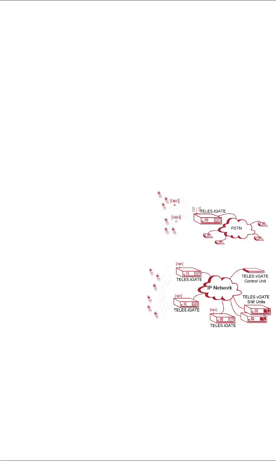
a) Integration in a carrier network:
One or more mobile gateways are
connected to the carrier network.
The carrier network routes mobile
connections to the individual mo-
bile gateways, which then termi-
nate the mobile calls.
b) Connection to a centralized SIM
server (TELES.vGATE): The mo-
bile gateways are integrated in the
TELES.vGATE through the IP net-
work. All SIM cards in the
TELES.vGATE network are in-
stalled in and maintained from a
central server, so that it is no longer
necessary to install SIM cards into
each TELES.iGATE. The vGateDesktop makes it possible to assign SIMs vir-
tually to random ports and various times without physically removing the
SIMs from the TELES.vGATE Sim Unit.
Page 12 © 2007 by TELES AG Berlin, Version 13.0/SH-e/04.16, Issue: April 2007
Supported Implementation Scenarios Overview
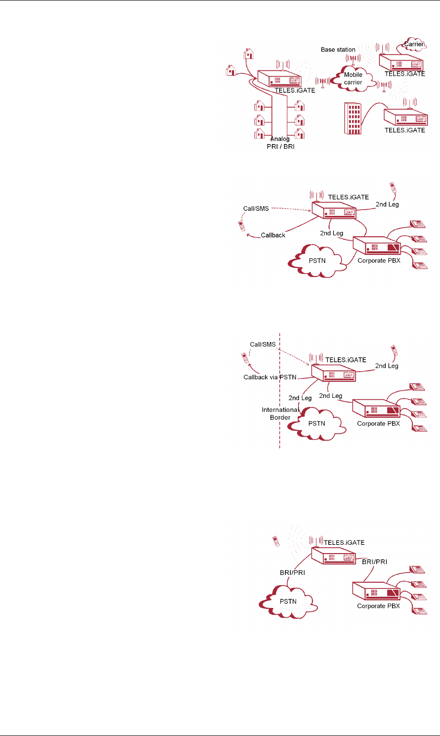
c) Last mile connection via mobile:
The mobile gateways are set up at
specific locations. The mobile
gateway can multiplex the avail-
able mobile channels, as well as di-
rectly connect analog and/or ISDN
subscribers (voice connections
only).
d) Callback with DTMF: The user
calls a number that is defined so
that the user will be called back
based on his OAD. An alerting oc-
curs. The user hangs up and is
called back. After the user has tak-
en the call, the destination number
is entered using DTMF tones.
When he has finished dialing, the
connection to the destination number is established.
e) Callback for international roam-
ing: The user with an international
mobile (prepaid SIM) calls a pre-
defined number in the system. An
alerting occurs. The user hangs up
and is called back based on her
OAD. After she accepts the call,
she enters the destination number,
which is in the same country as the
system. This scenario is for employees who travel abroad, as it eliminates high
international roaming fees.
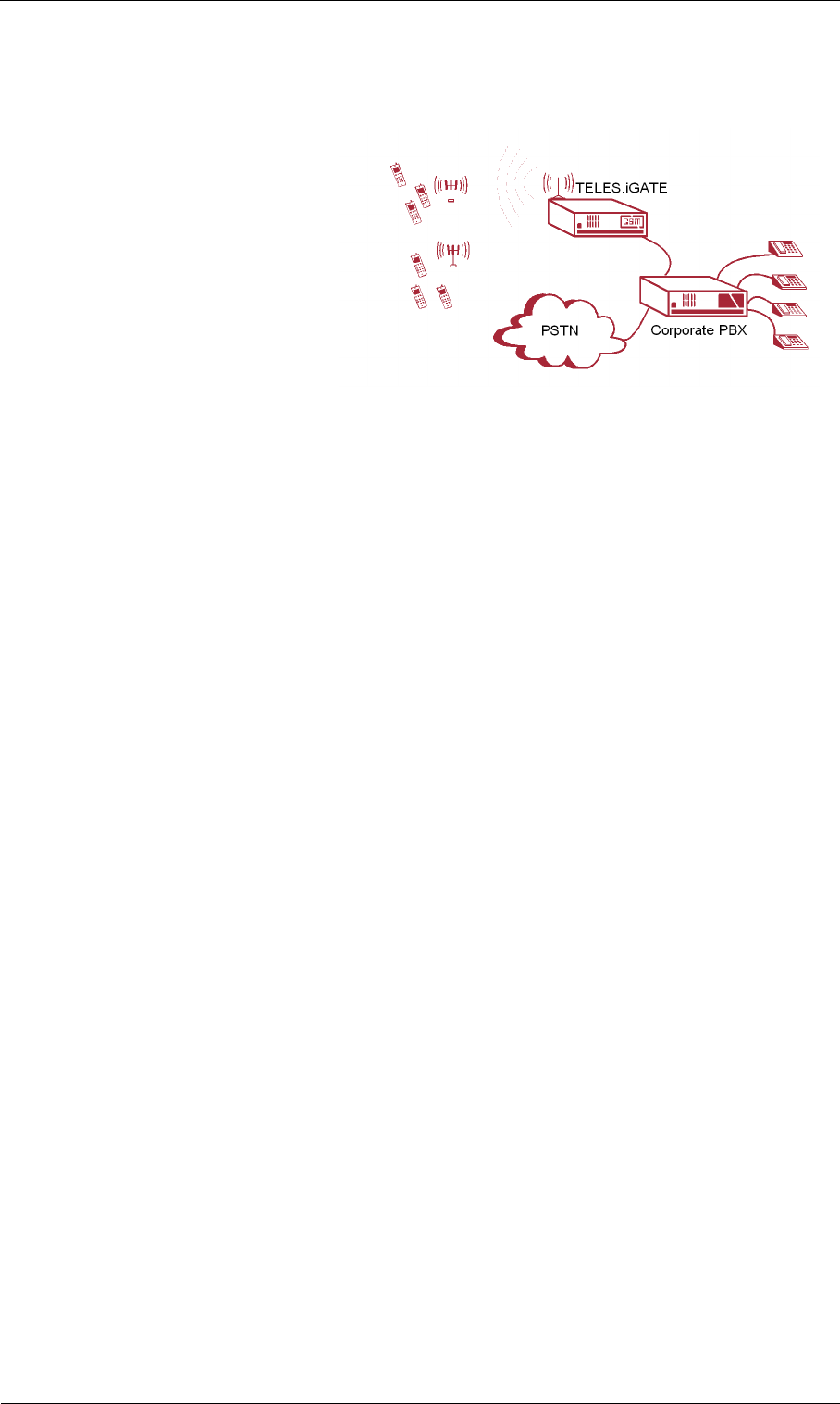
f) Least Cost Routing for termina-
tion of mobile calls: The mobile
gateway with integrated LCR is set
up between the existing PBX and
the PSTN. The system’s LCR rec-
ognizes calls to the mobile network
and sends them through the mobile
gateway to the mobile network.
© 2007 by TELES AG Berlin, Version 13.0/SH-e/04.16, Issue: April 2007 Page 13
Overview Supported Implementation Scenarios
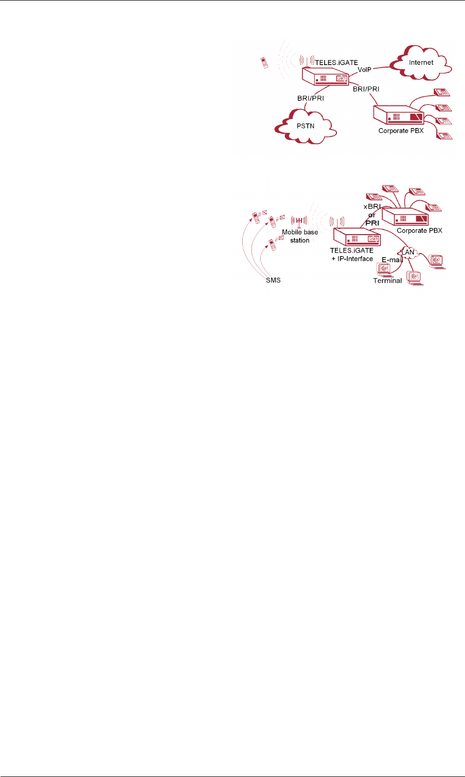
g) 2nd Generation LCR with VoIP:
One or more mobile gateways are
connected to the carrier’s IP back-
bone or the public Internet by VoIP.
The carrier network routes mobile
connections to the individual mo-
bile gateways, which then termi-
nate the mobile calls accordingly.
h) SMS connection by e-mail: The
mobile gateway is connected by
Ethernet to the IT network. It im-
plements an SMTP server (e-mail
server). E-mail messages sent to
this SMTP server are forwarded to
the recipient as SMS messages
through the mobile gateway.

Page 14 © 2007 by TELES AG Berlin, Version 13.0/SH-e/04.16, Issue: April 2007
Checklist Installation
4Installation
This section contains information on basic installation and configuration of your
TELES.iGATE. Follow the easy instructions to set up your TELES.iGATE in a
matter of minutes.
Implementation of individual scenarios requires adjustments to the appropriate in-
terfaces. Tips for basic settings are described here. Links to relevant chapters are
provided for more specific configuration changes.
4.1 Checklist
The following checklist provides step-by-step installation instructions.
1. Check the package contents
2. Install the device
3. Connect the Ethernet
4. Connect the E1 trunks (optional)
5. Connect the analog lines (optional)
6. Connect the BRI lines (optional)
7. Connect the antennas
8. Using TELES.Quickstart, set the configuration (IP address)
9. Check functionality (using the LEDs)
10. Secure the LAN connection
11. Secure connection with the configuration program
4.2 Package Contents
Your TELES.iGATE package contains the following components. Check the con-
tents to make sure everything is complete and undamaged. Immediately report any
visible transport damages to customer service. If damage exists, do not attempt op-
eration without customer-service approval:
• 1 TELES.iGATE
• 1 power supply cable
• 1 or 2 RJ-45 ISDN cables with gray connectors; 5 meters (optional)
• 1 or 2 RJ-45 ISDN cables with green and blue connectors; 5 meters (optional)
• 1 RJ-45 LAN cable with gray connectors; 3 meters
• 1 copy of quick installation instructions
• 1 CD containing TELES.Quickstart, TELES.GATE Manager, system manual
and default configuration files
• Mobile antennas (optional)
© 2007 by TELES AG Berlin, Version 13.0/SH-e/04.16, Issue: April 2007 Page 15
Installation Hardware Description
4.3 Hardware Description
Throughout this manual, the following boards will be referred to as
TELES.iGATE 4 Mobile Board, unless otherwise specified:
• TELES.iGATE 4 GSM Board
• TELES.iGATE 4 CDMA Board
• TELES.iGATE 4 UMTS Board
The TELES.iGATE is available in expansion levels from 4 to 32 mobile channels.
The following pages describe installation of the TELES.iGATE.
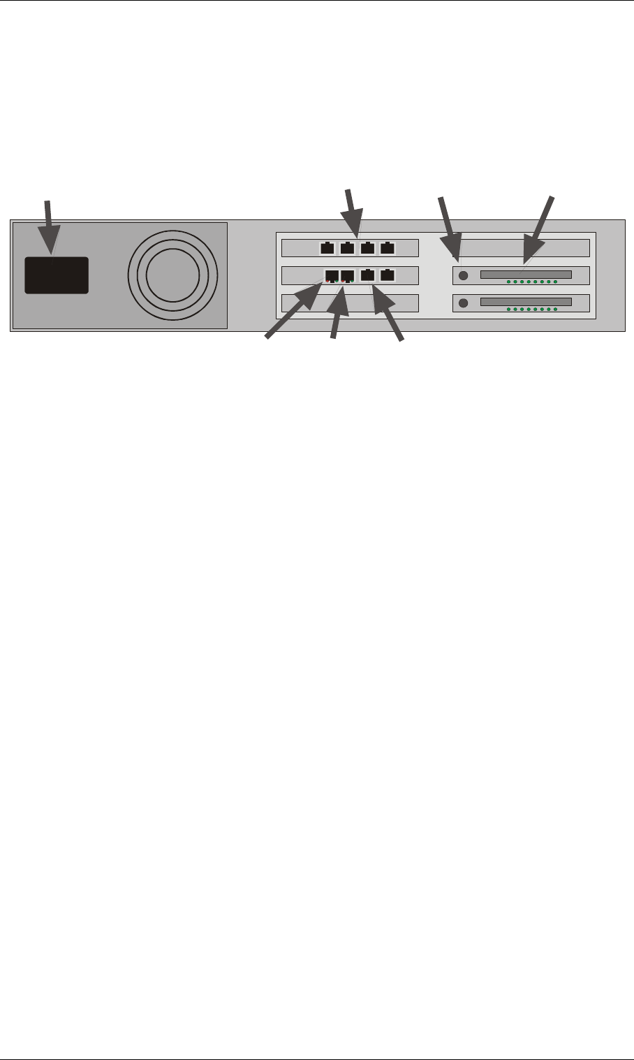
Figure 4-1 shows the rear view of a TELES.iGATE, which contains the following
boards:
Left side from top to bottom:
• TELES.iGATE 4 Mobile Board (for mobile channels 1-4)
• TELES.iLCR Base Board
• Optional TELES.iGATE Antenna Splitter Board
Right side from top to bottom:
• Optional TELES.iGATE 4 Mobile Board (for mobile channels 13-16)
• Optional TELES.iGATE 4 Mobile Board (for mobile channels 9-12)
• Optional TELES.iGATE 4 Mobile Board (for mobile channels 5-8)
Figure 4-1 2 HU TELES.iGATE: Rear View
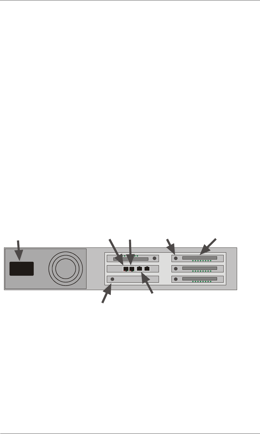
Figure 4-2 shows the rear view of a TELES.iGATE BRI, which contains the fol-
lowing boards:
Left side from top to bottom:
• TELES.iLCR 4BRI Board
• TELES.iLCR Base Board
• One empty slot
Right side from top to bottom:
Power PRI 2
PRI 1
Ethernet
10/100 Base-T
A
ntenna
SIM-Card
Carrier
Antenna
Page 16 © 2007 by TELES AG Berlin, Version 13.0/SH-e/04.16, Issue: April 2007
Hardware Description Installation
• One empty slot
• TELES.iGATE 4 Mobile Board (for mobile channels 5-8)
• Optional TELES.iGATE 4 Mobile Board (for mobile channels 1-4)
Figure 4-2 2 HU TELES.iGATE BRI
Power
PRI 2
(opt.)
PRI 1
(opt.)
Ethernet
10/100 Base-T
A
ntenna
SIM-Card
Carrier
(opt.)
4 BRI
Ports
© 2007 by TELES AG Berlin, Version 13.0/SH-e/04.16, Issue: April 2007 Page 17
Installation Installation Requirements
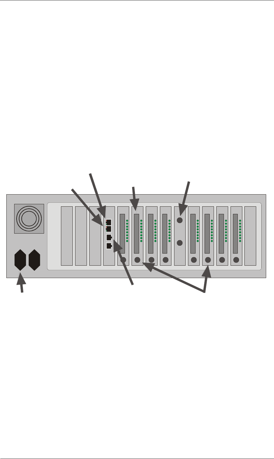
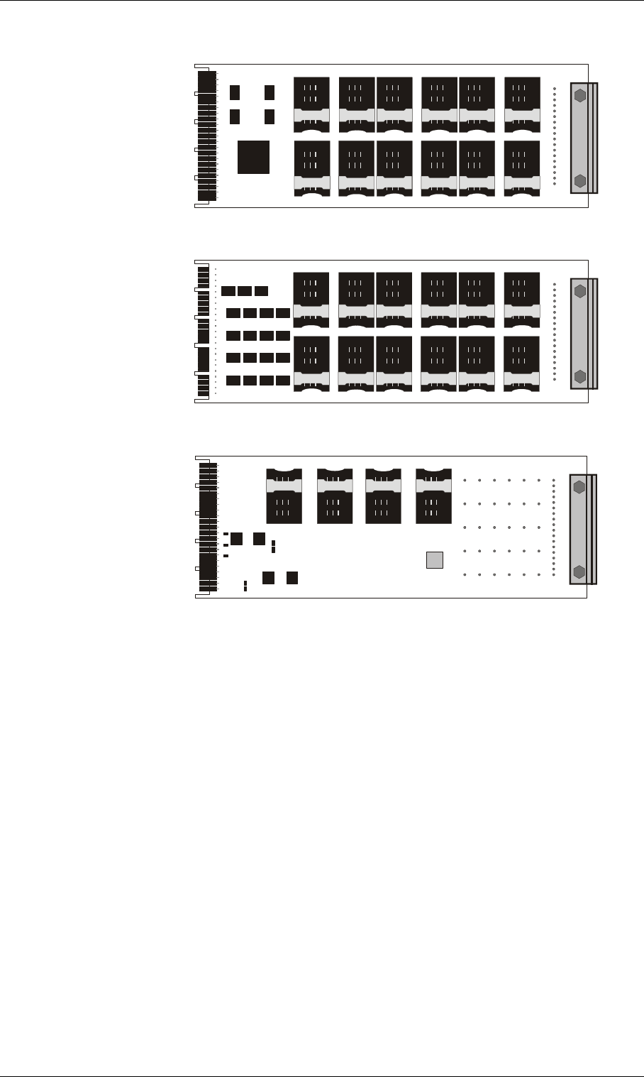
Figure 4-3 shows the rear view of a TELES.iGATE, which contains the following
boards:
From left to right:
• TELES.iLCR Base Board
• TELES.iGATE 4 Mobile Board (for mobile channels 1-4)
• TELES.iGATE 4 Mobile Board (for mobile channels 5-8)
• TELES.iGATE 4 Mobile Board (for mobile channels 9-12)
• TELES.iGATE 4 Mobile Board (for mobile channels 13-16)
• Optional TELES.iGATE Antenna Splitter Board
• TELES.iGATE 4 Mobile Board (for mobile channels 17-20)
• Optional TELES.iGATE 4 Mobile Board (for mobile channels 21-24)
• Optional TELES.iGATE 4 Mobile Board (for mobile channels 25-28)
• Optional TELES.iGATE 4 Mobile Board (for mobile channels 29-32)
Figure 4-3 4HU TELES.iGATE
4.4 Installation Requirements
Before installing your TELES.iGATE, make sure you have the following connec-
tions in place:
• Ethernet connection
• Antenna connection(s)
• Optional ISDN PRI connection to PSTN and/or to the PBX
•Power
• If the system is not connected to a TELES.vGATE, insert the SIM cards into
Power Antenna
SIM-Card
Carrier
Ethernet
10/100 Base-T
PRI 2
PRI 1
A
ntenna

Page 18 © 2007 by TELES AG Berlin, Version 13.0/SH-e/04.16, Issue: April 2007
Installation Requirements Installation
the SIM-card carrier, the SIM-card carrier into the TELES.iGATE 4 Mobile
Board.
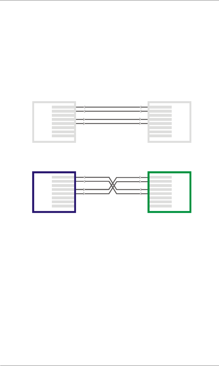
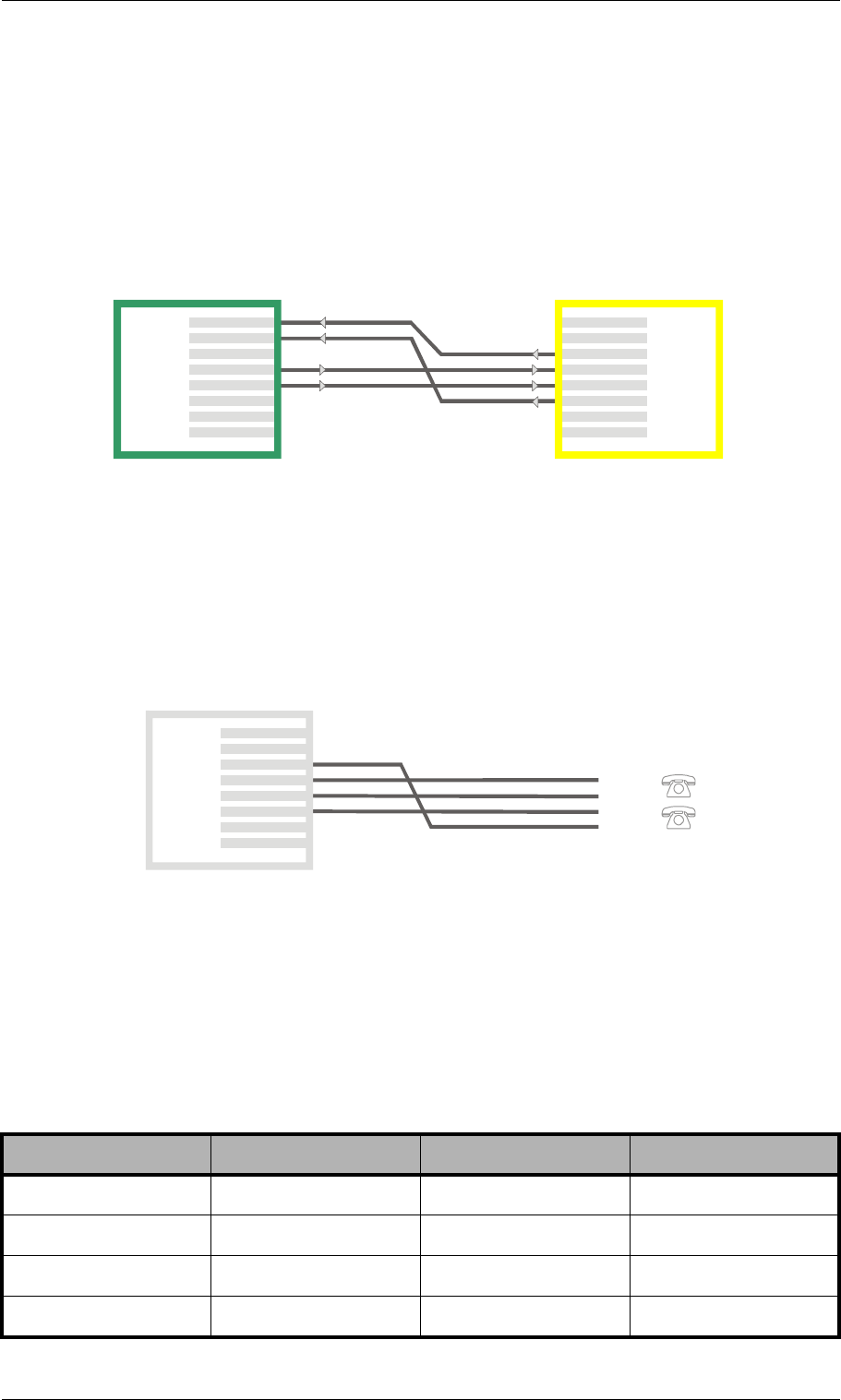
4.4.1 Ethernet Wiring
To connect the TELES.iGATE’s Ethernet port to your local network, connect the
system to an Ethernet switch or hub in your network. Use the three meter cable
with gray connectors.
If you want to connect the TELES.iGATE directly to your computer and a con-
nection cannot be established, use a cable with the following pin assignment:
1
2
7
8
3
4
5
6
7
8
3
4
5
6
1
2
RX+
RX-
TX+
TX- TX-
TX+
RX+
RX-
Connector 1 Connector 2
Abbreviations: TX - Transmit / RX - Receive
© 2007 by TELES AG Berlin, Version 13.0/SH-e/04.16, Issue: April 2007 Page 19
Installation Installation Requirements
4.4.2 PRI Wiring
4.4.2.1 TELES to TBR12
If you are connecting a TELES.iGATE to E1 and need to change the assignment
of an adapter, assign the pins as follows. Connectors on cables included with the
TELES.iGATE will be gray for TELES TE and gray for NT on the remote device,
blue for TELES NT, and green for TE on the remote device:
7
8
3
4
5
6
RX
RX
Network
Interface
1
2
7
8
3
4
RX
5
RX
6
TX
Te r mi na l
Interface
1
2
TX
TX
TX
TELES System/TE TBR12/N
T
Abbreviations: TX - Transmit / RX - Receive
Gray Gray
1
2
7
8
3
4
RX
5
RX
6
TX
TX
7
8
3
4
5
6
RX
Network
Interface
1
2
TX
TX
RX
Te r mi na l
Interface
TELES System/NT TBR12/T
E
Abbreviations: TX - Transmit / RX - Receive
GreenBlue
Page 20 © 2007 by TELES AG Berlin, Version 13.0/SH-e/04.16, Issue: April 2007
Installation Requirements Installation
4.4.2.2 Former TELES Assignment to Current TELES As-
signment
If you are connecting a system with the former TELES assignment to one with the
current TELES assignment, connectors will be yellow for former TE or NT and
green for current TE or NT. Pin assignment will be as follows:
4.4.3 Analog Wiring
If your system contains optional analog boards, the connection to FXO or FXS
lines occurs with the RJ45 connectors. Each connector’s pin out is for two analog
lines:
4.4.4 BRI Wiring
If your system contains optional TELES.iLCR 4BRI Board, the connection to the
PBX or PSTN lines occurs with the RJ45 connectors. Each connector's pin out is
for BRI line:
Table 4-1 BRI Wiring
RJ-45 TE NT Polarity
3Transmit Receive +
4Receive Transmit +
5Receive Transmit -
6Transmit Receive -
1
2
7
8
3
4
5
6
RX
RX
TX
TX
7
8
3
4
5
6
1
2
TX
TX
RX
RX
TELES System
Former TELES
Equipment
Abbreviations: TX - Transmit / RX - Receive
Green Yellow
1
2
7
8
3
4
5
6
Line 2
Line 1
Line 1
Line 2
Tip
Ring
Tip
Ring

© 2007 by TELES AG Berlin, Version 13.0/SH-e/04.16, Issue: April 2007 Page 21
Installation Installation Requirements
Pins 1, 2, 7, and 8 are not used. TE refers to terminal endpoint (connection to
PSTN). NT refers to network termination Layer 1 (connection to PBX).
4.4.5 Antenna Connection
Plug an antenna cable into each of the SMA jacks. If the system contains a
TELES.iGATE Antenna Splitter Board, plug the antenna(s) in there. If not, plug
them into the jacks on the TELES.iGATE 4 Mobile Board.
Note: Antennas connected to the TELES.iGATE must be installed by a qu-
laified technician according to all necessary safety requirements and
the antenna’s installation specifications. The antenna adaptor does
not provide power surge protection.
4.4.6 SIM Cards
Each TELES.iGATE 4 Mobile Board has a slot for a SIM-card carrier. Insert the
SIMs in the SIM-card carrier and then insert the SIM-card carrier into the
TELES.iGATE 4 Mobile Board.
If the system is connected to a TELES.vGATE, the SIM cards will be inserted into
the TELES.vGATE Sim Unit and not into the TELES.iGATE.
Note: You must configure the PINs in the pabx.cfg before inserting the
SIM-card carrier unless the SIM has no PIN or the PIN is 0000.
4.4.6.1 The SIM-Card Carrier Module
The SIM-card carrier module contains the SIM cards for the individual mobile
channels. Each TELES.iGATE 4 Mobile Board (standard) contains one module,
which can be inserted into and removed from the back of the TELES.iGATE 4
Mobile Board during operation. Depending on the modules specifications and ver-
sion, up to six SIM cards can be implemented in each mobile channel or you can
assign SIMs to individual mobile channels as you wish (see <SIMV> in Table
5-16).
SIM cards are mounted on the front and back of the SIM24 module (optional) or
the front of the SIM4 module (Figure 4-4). As a guide to help you distinguish top
from bottom on the SIM24 module, SIM0-5 and SIM12-17 are printed in the
upper corner near the module’s blue handle, as shown in Figure 4-4. The SIMs on
the SIM4 module are numbered from right to left, with one SIM assigned to each
mobile channel in ascending order. You can select the SIM cards you would like
to use via software. Individual SIM cards on each channel can be active in differ-
ent Timezones, or they can be reassigned following a time limit or call.
Page 22 © 2007 by TELES AG Berlin, Version 13.0/SH-e/04.16, Issue: April 2007
Installation Requirements Installation
Figure 4-4 SIM-Card Carrier Modules
Note: Insert ONLY the SIM-card carrier module into the
TELES.iGATE 4 Mobile Board!
678 910 11
012 34 5
12 13 14 15 16 17
18 19 20 21 22 23
SIM0-5
SIM6-11
SIM12-17
SIM18-23
03 2 1
SIM24 Module
Front View
SIM24 Module
Rear View
SIM4 Module

© 2007 by TELES AG Berlin, Version 13.0/SH-e/04.16, Issue: April 2007 Page 23
Installation Installation Requirements
If a SIM24 carrier is used, entries in the subscriber line of the configuration file
pabx.cfg or in nightfiles refer to the SIM positions for each mobile controller.
The SIM positions and mobile controllers correspond with the physical SIM slots
on the SIM-card carrier module as shown in Table 4-2:
Example: In the following example, SIMs from various SIM positions in the
Table 4-2 SIM-Card Positions
Slot Physical
Mobile Port
per Board
SIM-Card
Position
011
121
231
341
412
522
632
742
813
923
10 3 3
11 4 3
12 1 4
13 2 4
14 3 4
15 4 4
16 1 5
17 2 5
18 3 5
19 4 5
20 1 6
21 2 6
22 3 6
23 4 6

Page 24 © 2007 by TELES AG Berlin, Version 13.0/SH-e/04.16, Issue: April 2007
Installation Requirements Installation
SIM24 carrier are assigned to individual GSM controllers. Bear in
mind that the first GSM controller on the TELES.iGATE 4 GSM
Board has the physical controller number 00 in the system. SIM 1,
which corresponds with slot 0 on the SIM24 carrier, is assigned to the
first GSM controller.
Physical Control-
ler Number in the
System
Mobile Controller
on the
TELES.iGATE 4
Mobile Board
SIM Card Position
for the Mobile
Controller
Slot in the SIM24
Carrier
08 110
09 239
10 326
11 4623
Subscriber08 = TRANSPARENT ROUTER GSM[0000,00000,+00000,1,1,1,SIM24] CHADDR ALARM NEXT
Subscriber09 = TRANSPARENT ROUTER GSM[0000,00000,+00000,3,1,1,SIM24] CHADDR ALARM
Subscriber10 = TRANSPARENT ROUTER GSM[0000,00000,+00000,2,1,1,SIM24] CHADDR ALARM
Subscriber11 = TRANSPARENT ROUTER GSM[0000,00000,+00000,6,1,1,SIM24] CHADDR ALARM

© 2007 by TELES AG Berlin, Version 13.0/SH-e/04.16, Issue: April 2007 Page 25
Installation Preparing for Installation
4.5 Preparing for Installation
Each computer that is to communicate with the TELES.iGATE requires a network
connection. Please have the following information for connection to your network
available:
• IP address in the local network for the TELES.iGATE to be configured
• Netmask for the TELES.iGATE to be configured
• Default gateway for TELES.iGATE to be configured
• DNS server address
• NTP server address
Note: Bear in mind that the preconfigured TELES.iGATE’s default IP ad-
dress is 192.168.1.2. If it is already being used in your local network,
you must run TELES.Quickstart without a connection to your local
network. This can occur using a back-to-back Ethernet connection
from your computer to the TELES.iGATE. If the desired IP address
for the TELES.iGATE is not in your network, you must assign your
computer a temporary IP address from this range.
4.6 Hardware Connection
• Connect your computer with the local network
• Connect the TELES.iGATE with the local network
• If you choose to connect the TELES.iGATE to ISDN, use the ISDN connec-
tion cables included in the package contents to connect the TELES.iGATE
with your PBX and/or the PSTN according to the required port configuration.
• Connect the TELES.iGATE to the power supply.
4.7 Startup with TELES.Quickstart
TELES.Quickstart is an application that helps you to configure the basic settings
of your TELES.iGATE quickly and conveniently. TELES.Quickstart can be in-
stalled on any of the following operating systems:
• Windows 98 SE
• Windows NT
• Windows ME
• Windows 2000
• Windows XP
If you are using any of these operating systems, please follow the instructions in
this chapter. If you are using a non-Windows operating system (e.g. Linux) follow
the instructions in Chapter 4.8.
Page 26 © 2007 by TELES AG Berlin, Version 13.0/SH-e/04.16, Issue: April 2007
Startup with TELES.Quickstart Installation
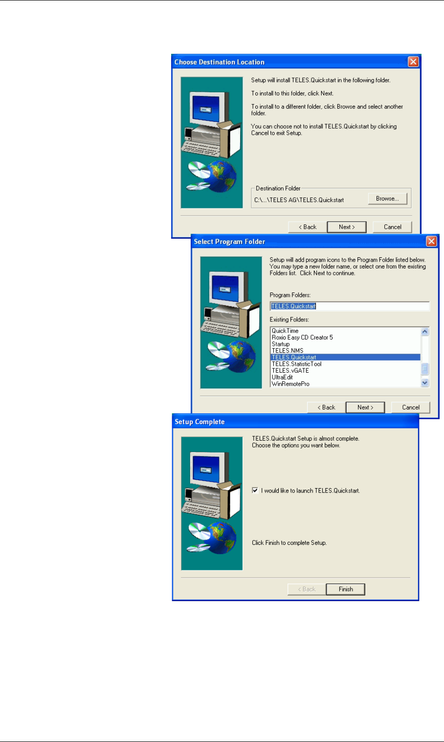
4.7.1 Installing TELES.Quickstart
Make sure the TELES.GATE
Manager is not running on
your computer. To install
TELES.Quickstart on your
computer, insert the CD and
select TELES.Quickstart
from the menu. Follow the
Windows instructions to be-
gin installation of the
TELES.Quickstart. Once in-
stallation begins, click Next
to install TELES.Quickstart
in the predefined folder. To
install it in another location,
click Browse and select a
folder from the browser that
appears. Then click Next.
The next dialog asks you
where you want to install the
program’s icons. To install
them in the folder that ap-
pears, click Next. If you want
to install them in another lo-
cation, select a folder from
the list or enter a new folder
name. Then click Next.
To start TELES.Quickstart
immediately following instal-
lation, activate the checkbox
I would like to launch
TELES.Quickstart. Make
sure the checkbox is inactive
if you do not want to start the
program now. Click Finish.Figure 4-5 TELES.Quickstart Installation
© 2007 by TELES AG Berlin, Version 13.0/SH-e/04.16, Issue: April 2007 Page 27
Installation Startup with TELES.Quickstart
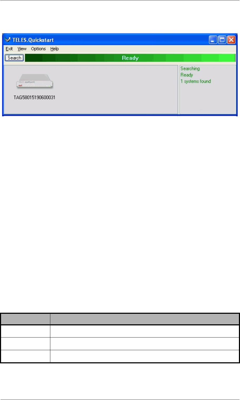
4.7.2 Configuration with TELES.Quickstart
Figure 4-6 TELES.Quickstart
Now you can use TELES.Quickstart, to set up your TELES.iGATE’s IP configu-
ration. Open TELES.Quickstart.exe. The program will automatically search for
your TELES.iGATE in the local network. For TELES.Quickstart, the source UDP
port is 57445. It might be necessary to change the firewall rules on your system.
Click the Search button if you would like to restart the search. When the program
has found your TELES.iGATE, it will appear in the window. As soon as it ap-
pears, you can end the search by clicking Stop.
The system’s icon will appear in gray if it is unconfigured. Once it has been con-
figured, it will appear in green. The serial number appears as the system’s name.
The TELES.iGATE is partially preconfigured. The configuration files
pabx.cfg and route.cfg are already on the system. Only the system’s IP-
related entries must be set. Individual port adjustments are to be made manually
later. Port properties can be changed and parameters can be assigned then.
To change the appearance of the window, select Large Icons, Small Icons or De-
tails from the View menu. In the following description, we will use the Details
View, which contains the following columns:
Table 4-3 TELES.Quickstart Details View Columns
Heading Definition
Identifier This column lists the TELES.iGATE’s serial number.
IP Address This column lists the TELES.iGATE’s IP address.
Configured An X means the TELES.iGATE contains the configuration files.
Page 28 © 2007 by TELES AG Berlin, Version 13.0/SH-e/04.16, Issue: April 2007
Startup with TELES.Quickstart Installation
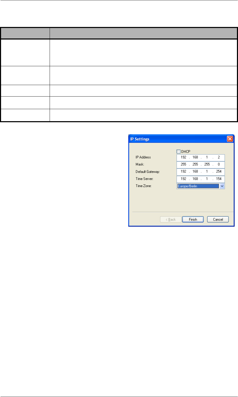
To perform the initial configuration of the
TELES.iGATE, double-click the icon or
right-click and select Configure. The IP
Settings dialog will appear. The default
IP address appears in the IP Address box.
Enter a new IP address. If the address you
enter already exists in the network, you
will be notified to choose another address
at the end of the configuration process.
Enter the TELES.iGATE’s netmask in the
Mask dialog box. Enter the IP address for
the Default Gateway and the Time Serv-
er in the corresponding dialog boxes. Se-
lect the Time Zone for the location of the
TELES.iGATE. Click Finish.
There is no internal time generation for the system when the power is interrupted.
That means the default time is used when the system is restarted or rebooted!
Therefore it is important to set the system time with an NTP server.
Now the TELES.iGATE is configured; all other processes run automatically.
First the TELES.iGATE’s IP address will be changed and then the system will
start with the new IP address. As soon as the system can be reached at the new IP
address, you can set up a TELES.GATE Manager connection to the system and
check all system information, such as the mobile port status. You can also config-
ure routing entries.
For information on TELES.GATE Manager access, see Chapter 4.10. For a de-
scription of configuration entries, see Chapter 5. You will find configuration ex-
amples in Chapter 6.If you right-click the system’s icon in the main window, you
# of VoIP Ctrls This column lists the number of TELES.G729 Modules installed in
the TELES.iGATE. Each TELES.G729 Module represents one
VoIP controller.
VoIP Channels This column shows the number of VoIP channels per
TELES.G729 Module.
Type Lists the type of the system.
Box An X means the system is a TELES.VoIPBOX.
CF Mounted An X means the TELES.iGATE contains a compact flash disk.
Table 4-3 TELES.Quickstart Details View Columns
Heading Definition
Figure 4-7 TELES.Quickstart Con-
figuration: IP Settings

© 2007 by TELES AG Berlin, Version 13.0/SH-e/04.16, Issue: April 2007 Page 29
Installation Startup via FTP
can also choose Temporarily Configure IP Address, only the IP address for the
system’s first Ethernet interface address and the netmask will be temporary
changed. This can be helpful if you want to set up local remote access to the sys-
tem and use other IP settings on the remote device than the system’s IP configu-
ration in the network. Bear in mind that the functions on the system’s first Ethernet
interface work with the new settings.
4.8 Startup via FTP
If you are using a computer that does not use a Windows operating system, you
can preconfigure the TELES.iGATE via FTP. The TELES.iGATE’s default IP ad-
dress is 192.168.1.2. To configure the TELES.iGATE using FTP, you must assign
your computer an IP address from network range 192.168.1.0 Class C and then ac-
cess the TELES.iGATE via FTP.
The default user is teles and the default password is tcs-ag. To configure the
system, use the default configuration file example on the CD in the
Configfiles directory and the following four subdirectories:
•IPconfig
This subdirectory contains the file (ip.cfg) responsible for configuration of
the Ethernet interface.
•carrier
This subdirectory contains a configuration (pabx.cfg, route.cfg) for
TELES.iGATE 32 with TELES.iGATE 4 GSM Boards and VoIP.
•corporate
This subdirectory contains a configuration (pabx.cfg, route.cfg) for
TELES.iGATE 16 with TELES.iGATE 4 GSM Boards.
•umts_system
This subdirectory contains a configuration (pabx.cfg, route.cfg) for
TELES.iGATE 16 with TELES.iGATE 4 UMTS Boards.
•bri_system
This subdirectory contains a configuration (pabx.cfg, route.cfg) for
TELES.iGATE 8 with TELES.iGATE 4 GSM Boards and an optional
TELES.iLCR 4BRI Board.
To edit the default configuration, follow the directions in Chapter 5. Upload the
configuration files into the /boot directory.
Page 30 © 2007 by TELES AG Berlin, Version 13.0/SH-e/04.16, Issue: April 2007
LED Functionality Installation
4.9 LED Functionality
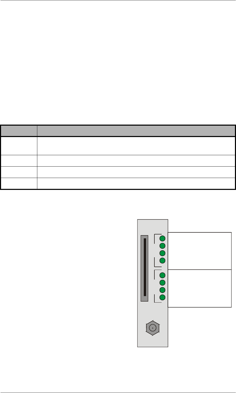
4.9.1 TELES.iLCR Base Board PRI Port LEDs
Each PRI port has one red and one green LED to show the port’s status.
The red LED displays the status of the bypass relay that connects the ports with
each other when the PRI port’s relays are off. That means when the system is con-
nected between a PBX and the PSTN, it is transparent when the LED is red.
The green LED displays whether or not layer 1 is active on the PRI port’s connect-
ed cable.
4.9.2 TELES.iGATE 4 Mobile Board SIM-Card LEDs
On the spine of the TELES.iGATE 4 Mobile
Board, to the right of the SIM card module,
two columns of green LEDs display the sta-
tus of each mobile channel.
The LEDs in the upper column show the gen-
eral operational status of the SIM cards,
while the status of the mobile channels is dis-
played in the lower column.
Table 4-5 contains a description of the LEDs
and what they mean:
Table 4-4 TELES.iLCR Base Board PRI Port LEDs
LED Description
Red on The system and bypass relay are inactive (normally during the startup
phase).
Red off The system has started and the bypass relay is active.
Green on Layer 1 is active.
Green off Layer 1 is inactive.
SIM
GSM
GSM Channel 1
GSM Channel 2
GSM Channel 3
GSM Channel 4
GSM Channel 1
GSM Channel 2
GSM Channel 3
GSM Channel 4
Operation
LEDs
Connection
LEDs
Ant

© 2007 by TELES AG Berlin, Version 13.0/SH-e/04.16, Issue: April 2007 Page 31
Installation LED Functionality
Table 4-5 TELES.iGATE 4 Mobile Board LEDs
Operational
Status
Connection
Status
Definition
Off Off The mobile channel is not operational because:
• No external power supply
• SIM module slot is empty
•No SIM card
Off Blinking slowly Not possible
Off Blinking quickly Not possible
Off On Not possible
Blinking slowly Off The SIM card is attached, but the mobile chan-
nel is not operational because:
• Mobile channel is in logon phase
• Mobile channel’s status is unknown
Blinking slowly Blinking slowly Not possible
Blinking slowly On Not possible
Blinking quickly Off The mobile channel is not operational because:
• SIM card has been blocked
• Reception field strength below limit
Blinking quickly Blinking slowly Not possible
Blinking quickly Blinking quickly Status during initializing phase (e.g. system
start up). Display changes when status of mo-
bile changes.
Blinking quickly On Not possible
On Off The mobile channel is operational, the SIM card
has logged on.
On Blinking slowly Not possible
On Blinking quickly The mobile channel is operational, the SIM card
has logged on, a connection is being set up on
this channel
On On The mobile channel is operational, the SIM card
has logged on, a connection has been set up on
this channel
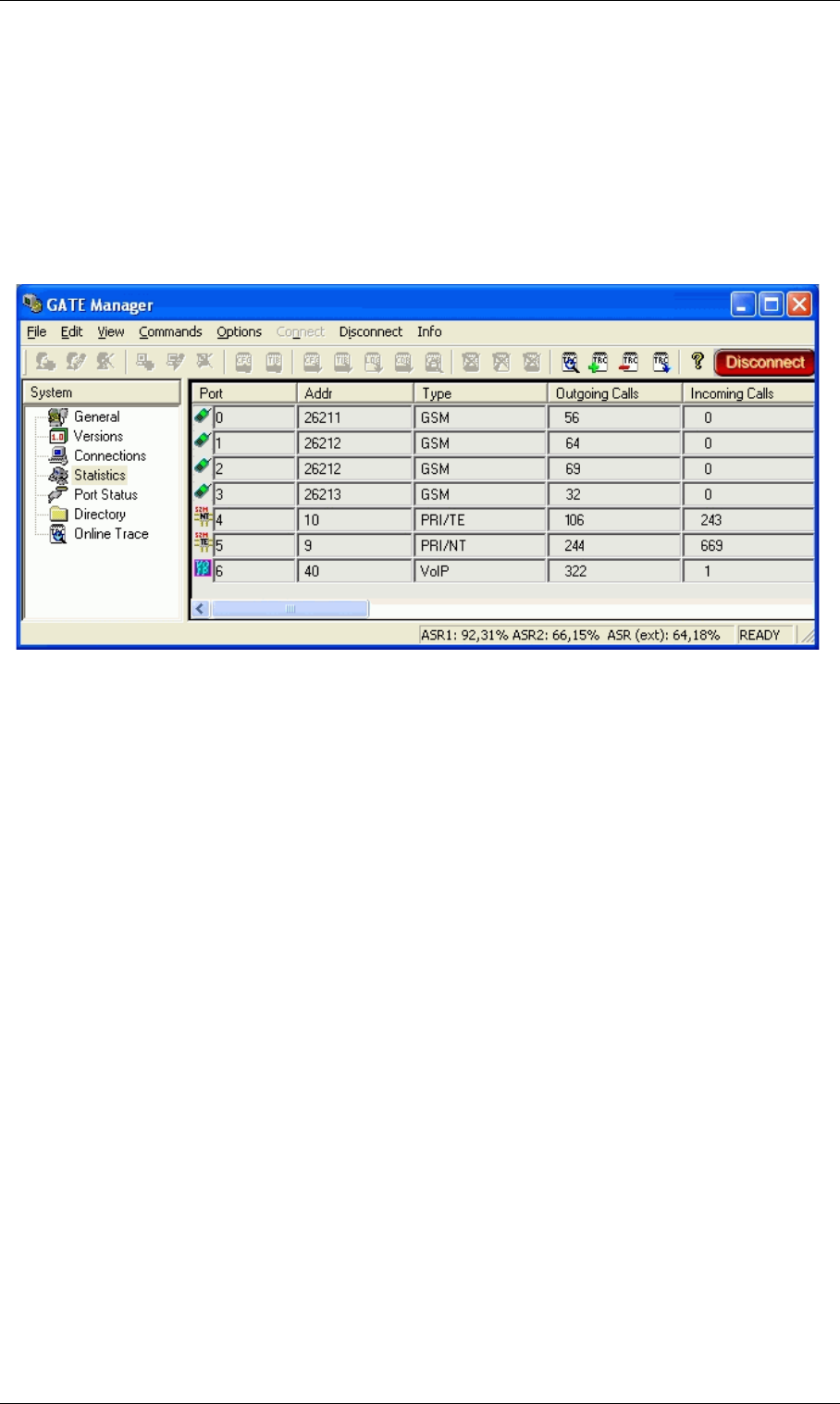
Page 32 © 2007 by TELES AG Berlin, Version 13.0/SH-e/04.16, Issue: April 2007
Remote Access and Access Security Installation
4.10 Remote Access and Access Security
After the system has been configured and all cables are connected, remote admin-
istration and maintenance can occur with the TELES.GATE Manager (Chapter
4.10.1) or via FTP (Chapter 4.10.2).
4.10.1 TELES.GATE Manager
Figure 4-8 TELES.GATE Manager
The TELES.GATE Manager administration and maintenance software offers a
broad range of functions. The TELES.GATE Manager is user friendly and can be
customized to suit your needs.
The following maintenance functions are possible:
• Display system information and network element status.
• Retrieve and display configuration files.
• Restart network elements.
• Use of a trace option for checking functions and fault diagnosis. Option to use
an external tool, e.g. to display and break down trace data.
• Update the system software (firmware) and configuration tables.
• Retrieve CDRs (Call Detail Records).
• Display the current connections (status).
• Display statistical information for network elements and interfaces.
• Display the status of the interfaces.
Use the CD enclosed in your package contents to install the TELES.GATE Man-
ager. For a detailed description of installation and implementation of the
TELES.GATE Manager, please refer to the TELES.GATE Manager and Utilities
Programs Manual.
TELES.GATE Manager remote access can occur via IP or ISDN. TELES.GATE

© 2007 by TELES AG Berlin, Version 13.0/SH-e/04.16, Issue: April 2007 Page 33
Installation Remote Access and Access Security
Manager access via IP uses port 4444 as origination TCP port and port 4445 as
destination port. The following default value (4445) is configured in the
pabx.cfg file for the system’s port:
In the default configuration, ISDN access is disabled. To configure the system so
that certain data calls are received as remote administration calls, make the follow-
ing changes in the pabx.cfg:
RemoteCode=BBB
MapAll<num>=BBB DATA
Make the following entries in the route.cfg if the system is to handle all data
calls as remote-administration calls:
For a detailed description of ISDN configuration, see the TELES Infrastructure
Systems Parameters and Hardware Manual.
4.10.2 FTP
Remote access can also occur via FTP. You can use FTP to transfer configuration
files. You can also carry out functions and traces with raw commands. Use the
user name teles and the defined password to connect to the system with FTP.
The following entries ensure the security of your FTP access:
MoipPort=4445
MapAll0=BBB DATA
MapAll1=BBB DATA
MapAll2=BBB DATA
MapAll3=BBB DATA
MapAll4=BBB DATA
MapAll5=BBB DATA
MapAll6=BBB DATA
MapAll7=BBB DATA
MapAll8=BBB DATA
MapAll9=BBB DATA
Table 4-6 FTP Security Entries
FTP Security
FtpdPort=<port>
Defines the FTP access port (default 21).

Page 34 © 2007 by TELES AG Berlin, Version 13.0/SH-e/04.16, Issue: April 2007
Remote Access and Access Security Installation
Once you have access to the system, you will be in the folder /home/teles. To
upload or download configuration files change to the directory /boot. To down-
load log files, change to the directory /data if the system contains a flash disk.
Otherwise change to the directory /boot.
The following commands can be carried out via FTP access:
4.10.3 Setting a Password for Remote Access
The following entry ensures the security of your remote access. Use the mkp-
wd.exe tool to generate the password. You will find it on the enclosed CD in the
directory pwd.
Start the program in a command window with the entry mkpwd <password>.
The output shows the encrypted password. Enter the encrypted password in the
configuration file pabx.cfg’s parameter line as follows:
When the file has been transferred to the system and the configuration has been
activated, access to the system can occur only with the password. Don’t forget to
memorize the password!
RemotePassword=<password>
Defines the password for FTP and TELES.GATE Manager access. Please refer to
Chapter 4.10.3 for instructions on how to enter an encrypted password in the
pabx.cfg. If you do not define a password, access to the system via
TELES.GATE Manager occurs without a password, and FTP access occurs with
the default password tcs-ag.
Table 4-7 FTP Commands
Command Function
SITE xgboot Boots the entire system.
SITE xgact Activates the configuration.
SITE xgact 1-19 Activates the Night section corresponding with the
number 1-19.
SITE xgtrace 0 Deactivates trace.
SITE xgtrace 1 Activates layer 2 trace.
SITE xgtrace 2 Activates layer 3 trace.
RemotePassword=<crypt>
Table 4-6 FTP Security Entries (continued)
FTP Security

© 2007 by TELES AG Berlin, Version 13.0/SH-e/04.16, Issue: April 2007 Page 35
Installation Remote Access and Access Security
If you do not define a password, access to the system via TELES.GATE Manager
occurs without a password, and FTP access occurs with the default password
tcs-ag.
4.10.4 4.8.3 Self Provisioning with TELES.NMS
With a management connection to the TELES.NMS (Network Management Sys-
tem), the TELES.iGATE can retrieve its configuration files from the configured
TELES.NMS. That means that custom configuration of the device occurs auto-
matically when the device is started. The following setting must be made in the
[System] section of the pabx.cfg:
AlarmCallback=<ip address NMS server>
RemoteCallback=<ip address NMS server> <time> <days of
week + holiday>
As soon as the device is started, it connects automatically with the TELES.NMS,
which uses the device’s TAG number to send a prepared configuration. For further
information on configuration of the TELES.NMS, please refer to the
TELES.NMS Systems Manual.

Page 36 © 2007 by TELES AG Berlin, Version 13.0/SH-e/04.16, Issue: April 2007
Configuration Files
5 Configuration Files
This chapter describes the basic setup and the most commonly used entries for the
configuration files. Configuration of TELES.iGATEs is managed in the following
three files:
Note: Changing configuration data and/or SIM card positions may
lead to malfunctions and/or misrouting, as well as possible conse-
quential damage. All changes are made at own risk. TELES is not
liable for any possible damage out of or in relation with such
changes. Please do therefore thoroughly check any changes you
or a third party have made to your configuration.
The system comes without the file ip.cfg. The default configuration with the IP
address 192.168.1.2 is active when this file is not on the system. You can config-
ure the system using TELES.Quickstart, TELES.GATE Manager or via FTP (user
teles, password tcs-ag). If you use the HTTP user interface to make config-
uration changes, the files will be adjusted automatically.
Make sure you secure the system with new passwords following configuration and
remember to memorize the passwords!
These configuration files contain all system-specific settings and are used when
the system starts. Comments included in these files must begin with a semicolon.
They do not need to be at the beginning of a line. Configuration files must end
with an empty line.
Please save a backup of the files pabx.cfg and route.cfg before starting
configuration.
Table 5-1 Configuration Files
File Function
ip.cfg This file is for the basic configuration of the Ethernet interfaces.
pabx.cfg This file is for system-specific and port-specific settings.
route.cfg This file is for routing entries.

© 2007 by TELES AG Berlin, Version 13.0/SH-e/04.16, Issue: April 2007 Page 37
Configuration Files
The configuration files follow these conventions: Individual files are divided into
sections. These sections always begin with a line entry in square brackets. The ba-
sic required sections are in these files:
Table 5-2 Required Configuration File Sections
Section File Function
[System] pabx.cfg
route.cfg
ip.cfg
This section contains the system’s basic settings.
[Night<num>]
EXAMPLE:
[Night1]
[Night2]
pabx.cfg
route.cfg
This section contains time dependent entries that
only apply for limited times.
[emac0] ip.cfg This section contains the IP configuration for the
first Ethernet interface.

Page 38 © 2007 by TELES AG Berlin, Version 13.0/SH-e/04.16, Issue: April 2007
Configuration File ip.cfg Configuration Files
5.1 Configuration File ip.cfg
The basic settings for the two Ethernet interfaces are entered here. One interface
usually suffices. The second interface can be used for special requirements, e.g. as
a hub port, DSL router or vLAN interface. Generally, these settings are entered
once and then left unchanged.
This file contains the following sections, which must appear in the order given:
5.1.1 System Section Configuration
The [System] section contains entries that define the default gateway and/or
special routing entries.
To define the standard gateway, use the following entry to set the IP address:
Table 5-3 Sections in the ip.cfg File
Section Function
[System] (required) This section contains entries that define the default gate-
way and/or special routing entries.
[emac0] (required)
[emac1] (optional)
The Ethernet Media Access Controller section(s) define
the physical Ethernet interface(s).
[nat] (optional) This section includes settings for Network Address Trans-
lation.
[bridge0] (optional) These section(s) contain settings for the second Ethernet
controller in bridge mode.
[pppoe<x>] (optional) These sections contain settings for direct connection be-
tween the system and the DSLAM when the PPPoE pro-
tocol is used. <x> can be 0 or 1.
[firewall] (optional) This section contains settings for activating the system’s
firewall.
[altqd] (optional) This section enables prioritization of VoIP packets in the
TELES.iGATE through an IP network using bandwidth
control.
[dhcpd] (optional) This sections contains a list of parameters and settings
for the DHCP server in the system. It is divided into global
settings for the server and parameters for the DHCP sub-
net.
[xppp<x>] (optional) This section contains settings for point-to-point dial-up
setup via ISDN.
[vlan<x>] (optional) These section(s) contain settings for the virtual networks.
<x> can be anything from 0 to 9.

© 2007 by TELES AG Berlin, Version 13.0/SH-e/04.16, Issue: April 2007 Page 39
Configuration Files Configuration File ip.cfg
DefaultGw=<ip addr>
Example:
If you must route specific net ranges to gateways other than what is defined in the
default route, make the following entries in the [System] section:
Route=<target range> -netmask <ip mask> <ip gateway>
Example:
If only certain routes apply, leave the line DefaultGw empty.
5.1.2 Ethernet Interface Configuration
The system includes two Ethernet interfaces (EMAC0 and EMAC1). Only the first
is active in the default configuration. Therefore, make sure you plug the cable into
the right controller. The second Ethernet interface can be configured as needed.
The following settings are possible for the sections [emac0] (matched to the first
Ethernet controller) and [emac1] (matched to the second Ethernet controller):
IpAddress=<ip addr>/<netmask>
The IP address is entered in decimal notation, followed by a slash (/) and the net-
mask in bit notation.
Example:
The following entry is used to allocate an IP address via DHCP:
IpAddress=dhcp
The following entry is used in the [emac1] section if operation of the system is
occurs in bridge mode.
IpAddress=up
5.1.3 Bridge Configuration
A bridge can connect two networks with each other. A bridge works like a hub,
forwarding traffic from one interface to another. Multicast and broadcast packets
[System]
DefaultGw=192.168.1.254
[System]
DefaultGw=192.168.1.254
Route=10.0.0.0 -netmask 255.0.0.0 192.168.1.1
IpAddress=192.168.1.2/24
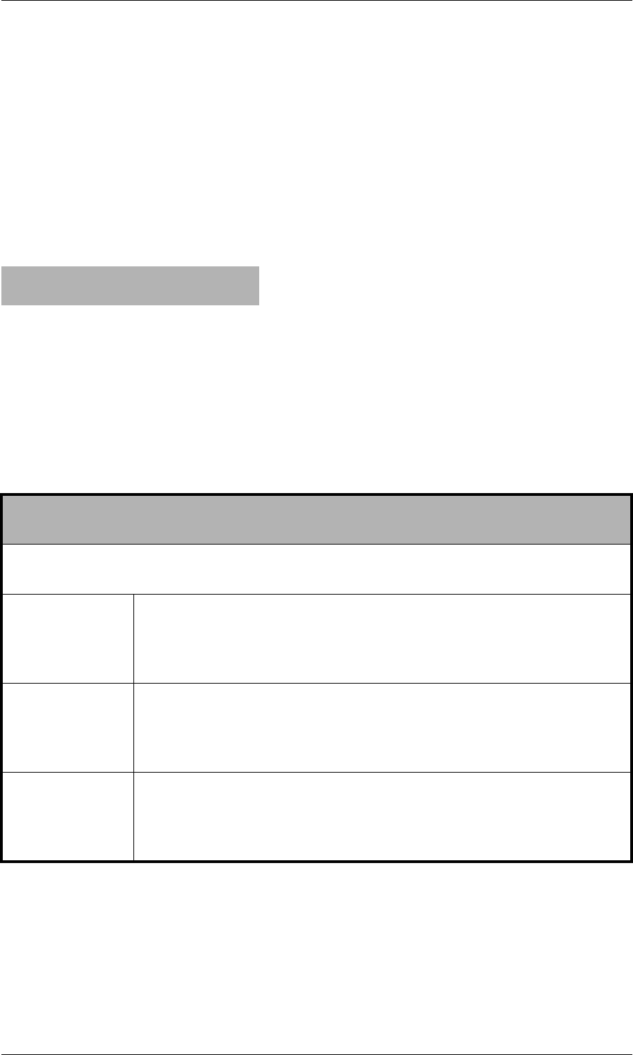
Page 40 © 2007 by TELES AG Berlin, Version 13.0/SH-e/04.16, Issue: April 2007
Configuration File ip.cfg Configuration Files
are always forwarded to all interfaces that are part of the bridge. This can occur
on the Ethernet or VLAN level:
BrConfig=add <interface-x> add <interface-y> up
Activating another Ethernet interface in this way is useful, for example, when the
Ethernet switch does not have any more ports available for connection of the sys-
tem. You can simply unplug a cable and plug it into the system’s second Ethernet
interface.
Example:
5.1.4 NAT Configuration
The NAT (Network Address Translation) module translates IP addresses from the
local network to an IP address or range on a public interface. All rules are defined
in the [nat] section:
[bridge0]
BrConfig=add emac0 add emac1 up
Table 5-4 NAT Configuration
map=<interface> <local network address/mask> -> <public
network address/mask> <optional entries>
This parameter maps the IP address in the local network to the IP address in the pub-
lic network.
<interface> Defines the translated interface or protocol:
emac1 The system’s second Ethernet interface
pppoe0 Protocol used for DSL connections
xppp<0> Protocol used for ISDN and CDMA dial-up connections
<local
network
address/
mask>
The IP address is entered in decimal notation, followed by a slash
(/) and the netmask in bit notation. The entire local network range
is configured.
<public
network
address/
mask>
Defines the public network range, with network address and mask
(usually exactly one address), into which the local IP addresses
are to be translated. The IP address is entered in decimal notation,
followed by a slash (/) and the netmask in bit notation.

© 2007 by TELES AG Berlin, Version 13.0/SH-e/04.16, Issue: April 2007 Page 41
Configuration Files Configuration File ip.cfg
Example: The following NAT settings are for a system in which PPPoE (DSL)
is used toward the Internet. The local network range 192.168.1.0
Class C is translated with the following rules:
• The proxy mode is used for FTP.
• All other TCP and UDP packets are mapped to the external ports
40000 to 60000.
• There are no special rules for any other services.
• Incoming requests to port 80 and 443 in the public IP address
192.168.1.100 are redirected to ports 80 and 443 in the local
IP address 192.168.1.100.
<optional
entries>
Special rules can be defined for some services or protocols. The
system can serve as a proxy for FTP:
proxy port ftp ftp/tcp
Special ports for the public address(es) can be assigned for the
protocols TCP and UDP. The range is defined by the start and end
ports:
portmap tcp/udp <start port>:<end port>
If no optional entry is defined, all other addresses will be translated
without special rules.
rdr=<interface> <public network address/mask> port <port> ->
<local network address/mask> port <port_number> <protocol>
This parameter redirects packets from one port and IP address to another.
<interface> Defines the translated interface or protocol:
emac1 The system’s second Ethernet interface
pppoe0 Protocol used for DSL connections
Protocol used for ISDN and CDMA dial-up connections
<public
network
address/
mask>
Defines the public network range, with network address and mask
(usually exactly one address), into which the local IP addresses
are to be translated. The IP address is entered in decimal notation,
followed by a slash (/) and the netmask in bit notation.
<port> Defines the port number.
<local
network
address/
mask>
The IP address is entered in decimal notation, followed by a slash
(/) and the netmask in bit notation. The entire local network range
is configured.
<protocol> Defines the protocol. tcp and udp are possible.
Table 5-4 NAT Configuration (continued)

Page 42 © 2007 by TELES AG Berlin, Version 13.0/SH-e/04.16, Issue: April 2007
Configuration File ip.cfg Configuration Files
5.1.5 PPPoE Configuration
The protocol Point-to-Point over Ethernet is used for DSL communication with
the DSLAM. That means the system can connect directly with the carrier network
and terminate VoIP traffic directly.
All necessary information for setup of the PPPoE connection is defined in the
[pppoe<x>] section. That means username, password and authentication proto-
col are set here. The Ethernet interface is emac1 and the gateway can also be de-
fined. The parameter PppoeIf defines the physical Ethernet interface used
(always emac1). The settings are entered as follows:Bear in mind that configura-
tion of the firewall, the NAT module and prioritization of the VoIP packets must
be considered when routing voice and data through the DSL line.
Example: The following entry will create the interface pppoe0, with the user-
name user and the password pwd. The PAP authentication protocol
is used. The default route occurs via DSL:
5.1.6 Firewall Settings
The firewall settings provide options for limiting or denying access to and from
the system. If you do not configure this section, the firewall is inactive and access
is unlimited.
WA R N I N G : Make sure you configure the firewall rules carefully. The rules are
processed from top to bottom. If you use the option quick, you will break the
sequence. We recomend that you put the most restrictive rule at the end of the con-
figuration.
Example: In the following example, only port 4445 allows incoming connec-
[nat]
map=emac1 192.168.1.0/24 -> 0/32 proxy port ftp ftp/tcp
map=emac1 192.168.1.0/24 -> 0/32 portmap tcp/udp 40000:60000
map=emac1 192.168.1.0/24 -> 0/32
rdr=emac1 0/0 port 80 -> 192.168.1.100 port 80 tcp
rdr=emac1 0/0 port 443 -> 192.168.1.100 port 443 tcp
[pppoe0]
PppoeIf=emac1
User=user
Pwd=pwd
AuthProto=pap
Route=0.0.0.0

© 2007 by TELES AG Berlin, Version 13.0/SH-e/04.16, Issue: April 2007 Page 43
Configuration Files Configuration File ip.cfg
tions from the IP address 192.168.1.10. All others will be blocked.
[firewall]
fw=pass in quick on emac0 proto tcp from 192.168.1.10/32 to any port
eq 4445 flags S keepstate keep frags
fw=block in log quick on emac0 all
Table 5-5 Settings in the [firewall] Section of the ip.cfg
[firewall]
fw=<mode> <direction> <list>
<mode> Two modes are possible for permitting or denying access:
pass permits access
block denies access
<direction> Possible directions are in and out:
in external to internal
out internal to external
<list> All other entries specify the other settings for the corresponding
firewall rules and are optional. The order in the line is as listed be-
low:
log
Records non-matching packets.
quick
Allows short-cut rules in order to speed up the filter or override later rules. If
a packet matches a filter rule that is marked as quick, this rule will be the last rule
checked, allowing a short-circuit path to avoid processing later rules for this pack-
et. If this option is missing, the rule is taken to be a "fall-through rule, meaning
that the result of the match (block/pass) is saved and that processing will continue
to see if there are any more matches.
on <interface>
The firewall rule is used only for the defined interface (e.g. emac0, pppoe0).
from <networkaddress/mask>
to <networkaddress/mask>
from defines the source IP-address range for incoming packets. to defines the
target IP-address range for outgoing packets. The IP address appears in decimal
notation, followed by a slash (/) and the netmask in bit notation. any stands for all
IP addresses (e.g.: to any).
NOTE: If you use the rule pass in/out in combination with the option from
<ip> to <ip>, you must specify a protocol number with proto and a port
number. If you not specify the port, the system may not be reachable. EXAMPLE:
fw=pass in quick on pppoe0 proto tcp from any to any port eq 4445
proto <protocol>
defines the protocol, for which the rule is valid (e.g.: proto tcp, proto udp, proto ic-
mp).

Page 44 © 2007 by TELES AG Berlin, Version 13.0/SH-e/04.16, Issue: April 2007
Configuration File ip.cfg Configuration Files
Example:
5.1.7 Bandwidth Control
In many implementation scenarios, the TELES.iGATE in router mode (e.g. as
DSL router) sends voice and data traffic through a connection with limited band-
width. This can lead to lost voice packets that arrive too late to be used in the voice
stream. To avoid lost packets, this QOS setting prioritizes packet transmission.
You must set the priority for voice signaling and for the voice packets. That means
you must prioritize SIP/H.323, RTP and RTCP. You will find the ports used in Ta-
ble 5-13, in the following entries:
H225Port
port eq <num>
<num> defines the port as number (e.g.: port eq 4445).
keep state
Ensures that the firewall checks packets from the beginning to the end of a ses-
sion. This is necessary, as the firewall does not know when a session begins or
ends.
flags S
Only syn. packets are accepted and recorded in the state table. In conjunction with
keep state, packets from sessions that have been inactive will also be routed. The
advantage of this entry is that random packets will not be accepted.
keep frags
Fragmented packets are also routed.
[firewall]
; loopback
fw=pass in quick on emac0 all
fw=pass out quick on emac0 all
; traffic to outgoing
fw=pass out quick on pppoe0 proto tcp all flags S keep state keep frags
fw=pass out quick on pppoe0 proto udp all keep state keep frags
fw=pass out quick on pppoe0 proto icmp all keep state keep frags
; incoming traffic
fw=pass in quick on pppoe0 proto tcp from 10.4.0.0/16 to any port eq 21 flags S keep
state keep frags
fw=pass in quick on pppoe0 proto tcp from 10.4.0.0/16 to any port eq 23 flags S keep
state keep frags
fw=pass in quick on pppoe0 proto tcp from 10.4.0.0/16 to any port eq 4445 keep state
; icmp traffic
fw=pass in quick on pppoe0 proto icmp all keep state
; other will be blocked
fw=block in log quick on pppoe0 all
fw=block out log quick on pppoe0 all
Table 5-5 Settings in the [firewall] Section of the ip.cfg (continued)
[firewall]
fw=<mode> <direction> <list>

© 2007 by TELES AG Berlin, Version 13.0/SH-e/04.16, Issue: April 2007 Page 45
Configuration Files Configuration File ip.cfg
SipPort
VoipRtp Port
VoipRtpPortSpacing
Different ports can be used for RTP and RTCP, depending on the configuration.
The parameter VoipRtpPort shows the first RTP port used. The corresponding
RTCP port is the next one up. The parameter VoipRtpPortSpacing shows
the next RTP port (RTP port + port spacing).
Example: In the following example, prioritization is set for a thirty-channel
VoIP connection. The SIP signaling port 5060 and the RTP/RTCP
ports 29000 to 29059 are prioritized at level 7. All other services are
Table 5-6 Settings in the [altqd] Section of the ip.cfg
interface <interface> bandwidth <bw> priq
Defines the interface for which the rule applies.
<interface> Sets the interface for which prioritization apples (e.e. pppoe0).
<bw> Sets the bandwidth that is available on the interface in Kbit/s (e.g.
256K).
priq Priority qeueing. A higher priority class is always served first.
class priq <interface> <class> root priority <prio>
Defines the priority of the filter entries.
<class> Two types can be set:
• realtime_class (VoIP packets)
• regular_class (data packets)
<prio> Enter a value between 0 and 15. The higher the value (e.g. 15), the
higher the priority.
filter <interface> <class> <values>
Defines the individual rules for the class.
<values> The individual values are divided into the following entries. A 0 can
be entered as a wildcard, in which case all values are possible:
•<dest_addr> (can be followed by netmask <mask>)
• <dest_port>
•<src_addr> (can be followed by netmask <mask>)
• <src_port>
•<protocol tos value>:
6 for TCP
17 for UDP

Page 46 © 2007 by TELES AG Berlin, Version 13.0/SH-e/04.16, Issue: April 2007
Configuration File ip.cfg Configuration Files
set at level 0:
5.1.8 DHCP Server Settings
The DHCP (Dynamic Host Configuration Protocol) server provides a mechanism
for allocation of IP addresses to client hosts. The section [dhcpd] contains a list
of parameters and settings for the DHCP server in the system. It is divided into
global settings for the server and parameters for the DHCP subnet.
[altqd]
interface pppoe0 bandwidth 512K priq
class priq pppoe0 realtime_class root priority 7
filter pppoe0 realtime_class 0 5060 0 0 0
filter pppoe0 realtime_class 0 0 0 5060 0
filter pppoe0 realtime_class 0 29000 0 0 17
filter pppoe0 realtime_class 0 0 0 29000 17
filter pppoe0 realtime_class 0 29001 0 0 17
filter pppoe0 realtime_class 0 0 0 29001 17
....
filter pppoe0 realtime_class 0 29058 0 0 17
filter pppoe0 realtime_class 0 0 0 29058 17
filter pppoe0 realtime_class 0 29059 0 0 17
filter pppoe0 realtime_class 0 0 0 29059 17
class priq pppoe0 regular_class root priority 0 default
Table 5-7 Settings in the [dhcpd] Section of the ip.cfg
; Global dhcp parameters
allow unknown-clients;
All DHCP queries are accepted and the configured settings are transmitted to the
clients.
ddns-update-style none;
Deactivates dynamic update of the domain name system as per RFC 2136.
; Parameters for the Subnet
subnet <network address> netmask <mask for network range> {
<list>
}
In <list> you can enter any of the following specific network settings activated by
the DHCP server. Each oprion must begin in a new line and end with a semicolon (;).
range <start IP address> <end IP address>;
The DHCP network range is defined by the first and last address in the range. Cli-
ent assignment begins with the last address.
option broadcast-address <IP address>;
Defines the broadcast address for the clients in the subnet..
option domain-name "<string>";
Defines the domain name used in the network.
© 2007 by TELES AG Berlin, Version 13.0/SH-e/04.16, Issue: April 2007 Page 47
Configuration Files Configuration File ip.cfg
Example:
5.1.9 PPP Configuration for ISDN and CDMA Dial-Up
The point-to-point protocol is used for dial-up connection via ISDN lines or via a
mobile CDMA connection. That means the system can set up an Internet connec-
tion, which can be used for all local users or to transmit VoIP calls via ISDN dial-
up. Make sure you configure the firewall and NAT options accordingly.
The advantages of VoIP over ISDN can be seen especially in corporate implemen-
tation. For example, it is useful when a very high number of connections occurs
option domain-name-servers <IP address>;
Defines the DNS-server address to be assigned (as per RFC 1035)
All of the following optional entries defining server addresses are also transmitted
as per RFC 1035. Separate multiple addresses per server with a comma:
… <IP address>, <IP address>;
(this also applies for all other optional entries with IP addresses).
option netbios-name-servers <IP address>
Defines the WINS-server address to be assigned.
option ntp-servers <ip address>;
Defines the NTP-server address to be assigned.
option time-servers <ip address>;
Defines the time-server address to be assigned (RFC 868).
option routers <IP address>;
Defines the router address to be assigned.
option subnet-mask <net mask>;
Defines the netmask to be assigned (as per RFC 950).
option tftp-server-name "<link>";
Defines the TFTP server name (option 66), as per RFC 2132.
EXAMPLE: option tftp-server-name "http://192.168.0.9";
[dhcpd]
; Global dhcp parameters
allow unknown-clients;
ddns-update-style none;
; Parameter for the Subnet
subnet 192.168.1.0 netmask 255.255.255.0 {
range 192.168.1.3 192.168.1.20;
option broadcast-address 192.168.1.255;
option domain-name "company.de";
option domain-name-servers 192.168.1.100;
option routers 192.168.1.2;
option subnet-mask 255.255.255.0;
}
Table 5-7 Settings in the [dhcpd] Section of the ip.cfg (continued)
; Global dhcp parameters

Page 48 © 2007 by TELES AG Berlin, Version 13.0/SH-e/04.16, Issue: April 2007
Configuration File ip.cfg Configuration Files
between subsidiaries and one subsidiary does not have a broadband Internet con-
nection. An ISDN B-channel can be connected to the Internet and up to six voice
calls can occur simultaniously over one ISDN line. All necessary information for
setup of the PPP connection is defined in the section [xppp<num>].
The settings are entered as follows:
Example:
5.1.10 VLAN Configuration
A VLAN (Virtual Local Area Network) is a virtual LAN within a physical net-
work. Each VLAN is assigned a unique number (VLAN ID) and defined in the
[vlan<x>] section with
Table 5-8 Settings in the [xppp] Section of the ip.cfg
[xppp<num>]
Dad=<num>
Enter the dial-up number.
User=<username>
Enter a username.
Pwd=<password>
Enter a password.
Route=<ip-addr>
Enter the target IP address range, e.g. 0.0.0.0 (default route).
AuthProto=<protocol>
Enter chap or pap for the protocol used for authentication.
IdleTO=<sec>
Enter the number of seconds without traffic before the interface tears down the
connection.
MTU=<int>
Maximum Transfer Unit. We recommend the following default values:
1500 for ISDN dial-up and 120 for CDMA dial-up.
Rfc1662=<val>
Framing to be used:
0 for ISDN or 1 for CDMA
[xppp0]
Dad=12345
User=user
Pwd=pwd
Route=0.0.0.0
AuthProto=chap
IdleTO=60
MTU=1500
Rfc1662=0

© 2007 by TELES AG Berlin, Version 13.0/SH-e/04.16, Issue: April 2007 Page 49
Configuration Files Configuration File ip.cfg
Tag: value between 1 and 4095
Priority: value between 0 and 7 (0 is lowest and 7 is the highest priority)
[vlan0]
IfConfig=vlan <tag>,<priority> vlanif <interface>
Example: The following entry will create the interface vlan1, with VLAN tag
10 and priority 7, on the Ethernet interface emac0. Following this
configuration, IP addresses (and/or other protocols) can be assigned
to the vlan1 interface:
5.1.11 Examples
5.1.11.1 Default Configuration
In the following example, the system’s IP address is 192.168.1.1, the netmask is
255.255.255.0, and the standard gateway is 192.168.1.254:
5.1.11.2 Active Ethernet Bridge
In the following example a two-port Ethernet bridge is configured. The system’s
IP address is 192.168.1.1, the netmask is 255.255.255.0, and the standard gateway
is 192.168.1.254,
The emac1 interface is active and both Ethernet interfaces are set to bridge mode
in the [bridge0] section:
[vlan1]
IfConfig=vlan 10,7 vlanif emac0
IpAddress=192.168.199.1
[System]
DefaultGw=192.168.1.254
[emac0]
IpAddress=192.168.1.1/24
[System]
DefaultGw=192.168.1.254
[emac0]
IpAddress=192.168.1.1/24
[emac1]
IpAddress=up
[bridge0]
BrConfig=add emac0 add emac1 up

Page 50 © 2007 by TELES AG Berlin, Version 13.0/SH-e/04.16, Issue: April 2007
Configuration File ip.cfg Configuration Files
5.1.11.3 Integrated DSL-Router Scenario for VoIP Traffic
with an Active DHCP Server and Firewall
In the following example, the system is connected to the local IP network through
emac0. The DSL modem is connected to the emac1 interface, which enables the
system to connect directly to the carrier network without an additional router when
the connection is used only for VoIP data. A DHCP server is used for dynamic IP-
address allocation:
[System]
[emac0]
IpAddress=192.168.0.2/24
[emac1]
IpAddress=up
[pppoe0]
PppoeIf=emac1
User=usertelekom
Pwd=pwd
AuthProto=chap
Route=default
[nat]
map=pppoe0 192.168.0.0/24 -> 0/32 proxy port ftp ftp/tcp
map=pppoe0 192.168.0.0/24 -> 0/32 portmap tcp/udp 40000:60000
map=pppoe0 192.168.0.0/24 -> 0/32
[firewall]
; loopback
fw=pass in quick on emac0 all
fw=pass out quick on emac0 all
; traffic to outgoing
fw=pass out quick on pppoe0 proto tcp all flags S keep state keep frags
fw=pass out quick on pppoe0 proto udp all keep state keep frags
fw=pass out quick on pppoe0 proto icmp all keep state keep frags
; incoming traffic
fw=pass in quick on pppoe0 proto tcp from 10.4.0.0/16 to any port eq 21 flags S keep
state keep frags
fw=pass in quick on pppoe0 proto tcp from 10.4.0.0/16 to any port eq 23 flags S keep
state keep frags
fw=pass in quick on pppoe0 proto tcp from 10.4.0.0/16 to any port eq 4445 keep state
; icmp traffic
fw=pass in quick on pppoe0 proto icmp all keep state
; other will be blocked
fw=block in log quick on pppoe0 all
fw=block out log quick on pppoe0 all
[dhcpd]
; Global dhcp parameters
allow unknown-clients;
ddns-update-style none;
; Parameter for the Subnet
subnet 192.168.1.0 netmask 255.255.255.0 {
range 192.168.1.3 192.168.1.20;
option broadcast-address 192.168.1.255;
option domain-name "company.de";
option domain-name-servers 192.168.1.100;
option routers 192.168.1.2;
option subnet-mask 255.255.255.0;

© 2007 by TELES AG Berlin, Version 13.0/SH-e/04.16, Issue: April 2007 Page 51
Configuration Files Configuration File ip.cfg
5.1.11.4 VLAN Scenario
In the following example, the system is connected to the IP backbone through
emac0. One Computer is connected to the emac1 interface. You can separate voice
and data traffic with two different VLANs (vlan0 with tag 10 for voice, vlan1 with
tag 11 for data). All traffic coming from emac1 will be sent to vlan1. Voice and
data will not be mixed:
[System]
[emac0]
IpAddress=192.168.1.12/16
[emac1]
IpAddress=up
[vlan0]
IfConfig=vlan 10,7 vlanif emac0
IpAddress=10.0.1.2/24
[vlan1]
IfConfig=vlan 11,1 vlanif emac0
IpAddress=172.16.4.5/16
[bridge0]
BrConfig=add vlan1 add emac1 up

Page 52 © 2007 by TELES AG Berlin, Version 13.0/SH-e/04.16, Issue: April 2007
Configuration File pabx.cfg Configuration Files
5.2 Configuration File pabx.cfg
The pabx.cfg file contains system-specific settings and the port configuration.
It is divided into the [System] and [Night<num>] sections.
5.2.1 System Settings
The [System] section is divided into several categories to ensure clarity.
• Life line (relay)
• Log files
• Night configuration
• Controllers
• Subscribers
• Global settings
• SMTP-client configuration
• Number portability settings
The following subchapters contain a detailed description of these categories.
5.2.1.1 Life Line
The entry in this category is responsible for the life-line (bypass) functionality of
the PRI port’s relay when the system is on. When the system is off, both PRI ports
are connected to each other, which means that it provides a transparent connection
between the PBX and the PSTN. When the system is on, all routing algorithms are
active.
Bypass=ON/OFF
ON: PRI relay is on (system controls both PRI ports).
OFF: PRI relay is off (both PRI ports are connected to each other, regardless of
whether or not the system is running).
Note: This parameter should always be set to ON.

© 2007 by TELES AG Berlin, Version 13.0/SH-e/04.16, Issue: April 2007 Page 53
Configuration Files Configuration File pabx.cfg
5.2.1.2 Log Files
CDRs, unconnected calls, system events, trace output and statistics can be saved
into files.
The following entries are necessary to generate log files:
The path in the example refers to an optional external flash disk. If there is no ex-
ternal flash disk, the path will be: boot.
Example: ActionLog=/boot/protocol.log
Note: The available internal memory is approximately 2 MB if the
TELES.iGATE does not contain optional memory expansion. Make
sure you monitor the available memory.
You can define how the log files are to be divided. There are two possibilities for
saving entries into a new file:
• In increments of time (twice-daily, daily, weekly, monthly)
• Depending on the size of the file
You can also define a maximum number of up to 35 files to be generated.
A dash (-) appears in place of information that is to be ignored.
Table 5-9 pabx.cfg: Log File Entries
Entry Description
ActionLog=/data/protocol.log System events
Log=/data/cdr.log CDR entries
RRufLog=/data/failed.log Unconnected calls
TraceLog=/data/trace.log System trace
MsgLog=/data/msg.log Incoming SMS and USSD messages
Table 5-10 pabx.cfg: Log Parameters
Log=/data/<file.log> <saved> <size> <number>
<file> The name of the log file is generated as follows:
[file]yymmdd[0-9|A-Z].log.
<saved> Refers to the frequency with which the file is saved. The following
options are possible:
halfdailyEvery day at 11:59 and 23:59
daily Every day at 23:59
weekly Sunday at 23:59
monthly The last day of the month at 23:59

Page 54 © 2007 by TELES AG Berlin, Version 13.0/SH-e/04.16, Issue: April 2007
Configuration File pabx.cfg Configuration Files
Example 1 In the following entry, the files cdr.log and failed.log are re-
named every day or when the file reaches 180kB, whichever comes
first. Up to 7 CDR files will be saved on the system. If the file size
reaches 180kB on one day, the second file will have the same date.
Only the running number will be increased.
Example 2 In the following entry, the file protocol.log is renamed every
day or when the file reaches 60 kB. Up to 21 failed files will be saved
on the system.
Example 3 In the following entry, the file trace.log is renamed every day
when the file has reached 600kB. Up to seven log files will be saved
on the system.
Example 4 In the following entry, the statistic values are reset daily at 12:00 mid-
night and saved in the asr.log.
Note: Please remember to keep track of how much memory is available on
the system.
<size> Regardless of the value entered in <saved>, the file will be saved
when the <file size> has been reached.
NOTE: We recommend a file size of a multiple of 60kB.
<number> Refers to the number of files that will be saved in the system (be-
tween 5 and 35) before the first file is overwritten. This setting is
useful not only for limited file size, but also for files that store
events. Normally size can be limited for these files, e.g. 5 files of
1MB each. If the fifth file is full, the first one will automatically be
overwritten.
Log=/data/cdr.log daily 180 7
RrufLog=/data/failed.log daily 180 7
ActionLog=/data/protocol.log daily 60 21
TraceLog=/data/trace.log daily 600 7
StatisticTime=/data/asr.log 00:00 11111111
Table 5-10 pabx.cfg: Log Parameters (continued)
Log=/data/<file.log> <saved> <size> <number>

© 2007 by TELES AG Berlin, Version 13.0/SH-e/04.16, Issue: April 2007 Page 55
Configuration Files Configuration File pabx.cfg
5.2.1.3 Night Configuration
The sections for the time-dependent configuration changes and time-controlled
routings are defined here.
A maximum of 19 additional daily configuration zones are possible (Night1 to
Night19). The entry NightResetTime reactivates the original configuration
contained in the System section.
The entry will have the following syntax:
Example: The configuration section is activated Fridays, Wednesdays and
Mondays at noon unless the day in question is a holiday:
Night2=12:00 00101010
The configuration section switches back to the default configuration
(System section) every day at 8:00 p.m:
NightResetTime=20:00 11111111
Note: Any defined Night sections must be set in the files pabx.cfg and
route.cfg. If there are no changes in these sections, you must
copy them from the System section. The complete Subscriber
section must appear in the Night section of the pabx.cfg (see
Chapter 5.2.5 on page 69). The active route(s) (MapAll,
Restrict and Redirect entries) and VoIP, registrar and gate-
keeper profiles must appear in the Night section of the
route.cfg (see Chapter 5.3 on page 71).
5.2.1.4 Controllers
This category defines the parameters that apply to the ports. The order of the ports
is defined as follows: The TELES.iGATE contains integrated TELES.iGATE 4
Mobile Boards, each of which contain four mobile modules. Each TELES.iGATE
Table 5-11 pabx.cfg: Night Parameters
Night<num>=<time> <day>
<num> Enter a value between 1 and 19 to define which configuration is to
be loaded.
<time> If there is a time set with the format hh:mm after this entry, this con-
figuration is loaded at that time on the defined day.
<day> Use a bitmask to set the weekdays on which the configuration ap-
plies here. The daymap appears in the following order:
HoSaFrThWeTuMoSu.

Page 56 © 2007 by TELES AG Berlin, Version 13.0/SH-e/04.16, Issue: April 2007
Configuration File pabx.cfg Configuration Files
4 Mobile Board’s mobile channels are configured as additional controllers. That
means four controllers are configured for each board. Beginning with 0, these con-
trollers are defined as the first controllers in the section. Next the PRI controllers
are defined, followed by the VoIP controllers. All controllers are defined in as-
cending order.
Table 5-12 describes the order for additional boards.
The individual ports are defined with the following parameter:
Table 5-12 Configuration Order: Controller Parameters
Function Number of Controllers
TELES.iLCR 4BRI BoardsUp to 4 (optional)
TELES.iGATE 4 Mobile BoardsUp to 32 (optional)
TELES.iLCR Base Board (PRI) 2
TELES.iLCR Base Board (VoIP) Up to 4 (optional)
DTMF (virtual) Up to 1 (optional)
Table 5-13 pabx.cfg: Controller Parameters
Controller<port>=<bus> <type> <mode> <line_type> ADR:<address>
IRQ:<interrupt> UNIT: VALUE:
<port> Defines the running (physical) port number.
<bus> Defines the configured (virtual) port number. In the default config-
uration, PRI TE ports are 9 and PRI NT ports are 10. VoIP ports
are 40.
<type> Defines the connection type:
TES2M PRI external (terminal endpoint)
NTS2M PRI internal (network termination)
VOIP VoIP module
GSM GSM port
CDMA CDMA port
UMTS UMTS port
TE BRI external (if you change from NT to TE or vice versa,
you must change the DIP switches for the respective
port on the TELES.iLCR 4BRI Board)
NT BRI internal
DTMF virtual controller for activating DTMF tone recognition
<mode> Defines the protocol variation for PRI and BRI lines:
DSS1
SS7 (only for PRI lines)

© 2007 by TELES AG Berlin, Version 13.0/SH-e/04.16, Issue: April 2007 Page 57
Configuration Files Configuration File pabx.cfg
Ports set to the same type can have the same bus number. In this case they will
form a trunk group. If you change this parameter in the configuration, you must
restart the system.
Example 1 Each TELES.iGATE 4 Mobile Board contains 4 controllers. The
hardware address and the interrupt are defined behind the first con-
trollers, which are defined in the configuration before the
TELES.iLCR Base Board. In the following example, the system con-
tains four TELES.iGATE 4 Mobile Boards. One PRI controller is
configured for TE and one for NT. The protocol used is DSS1, and
<line_type> Switches CRC4 mode for PRI lines on or off:
CRC4 CRC4 on
DF double frame: CRC4 off
Switches Point-to-Point or Point-to-Multipoint for BRI lines:
PMP Point-to-Multipoint (default)
PP Point-to-Point
Additional entry for SS7 only:
FIS Increases the volume FISU messages. To avoid a high
volume of D-channel traffic on these controllers, use
this keyword only if necessary.
<address> (Optional) Defines the hardware address used for the first control-
ler on an additional TELES.iGATE 4 Mobile Board. These entries
are preconfigured and cannot be changed.
<interrupt> (Optional) Defines the interrupt used for the first controller on an
additional TELES.iGATE 4 Mobile Board. These entries are pre-
configured and cannot be changed.
UNIT: (Optional) Defines the currency for the charges (default EUR). Spe-
cial charge generation is possible. Special charge generation is
possible for:
France UNIT:&F
Spain UNIT:&SP
Portugal UNIT:&P
Greece UNIT:&G
Switzerland
UNIT:&CH
Netherlands
UNIT:&NL
Italy UNIT:&I
VALUE: (Optional) Defines the charges that accumulate by unit (default
12).
Table 5-13 pabx.cfg: Controller Parameters (continued)
Controller<port>=<bus> <type> <mode> <line_type> ADR:<address>
IRQ:<interrupt> UNIT: VALUE:

Page 58 © 2007 by TELES AG Berlin, Version 13.0/SH-e/04.16, Issue: April 2007
Configuration File pabx.cfg Configuration Files
CRC4 is active. One TELES.G729 Module is attached.
Example 2 Each TELES.iGATE 4 CDMA Board contains 4 controllers. The
hardware address and the interrupt are defined behind the first con-
trollers. These are defined in the configuration before the optional
TELES.iLCR 4BRI Board. The hardware address and the interrupt
for this board is also defined behind its first controller. The last con-
trollers are for the TELES.iLCR Base Board. In the following exam-
ple, the system contains 2 TELES.iGATE 4 CDMA Boards, a
TELES.iLCR 4BRI Board with 4 controllers. One PRI controller is
configured for TE and one for NT. The protocol used is DSS1, and
CRC4 is active.
Example 3 Each TELES.iGATE 4 UMTS Board contains 4 controllers. The
hardware address and the interrupt are defined behind the first con-
trollers, which are defined in the configuration before the
TELES.iLCR Base Board controllers. In the following example, the
system contains 2 TELES.iGATE 4 UMTS Boards. One PRI control-
ler is configured for TE and one for NT. The protocol used is DSS1,
and CRC4 is active. One TELES.G729 Module is attached.
Controller00=20 GSM ADR:D800 IRQ:5
Controller01=20 GSM
Controller02=20 GSM
Controller03=20 GSM
Controller04=20 GSM ADR:D900 IRQ:7
Controller05=20 GSM
Controller06=20 GSM
Controller07=20 GSM
Controller08=20 GSM ADR:DA00 IRQ:5
Controller09=20 GSM
Controller10=20 GSM
Controller11=20 GSM
Controller12=20 GSM ADR:DB00 IRQ:7
Controller13=20 GSM
Controller14=20 GSM
Controller15=20 GSM
Controller16=9 TES2M DSS1 CRC4
Controller17=10 NTS2M DSS1 CRC4
Controller18=40 VoIP
Controller00=30 NT DSS1 PMP ADR:C000 IRQ:11
Controller01=30 NT DSS1 PMP
Controller02=30 NT DSS1 PMP
Controller03=30 NT DSS1 PMP
Controller04=20 CDMA ADR:D800 IRQ:5
Controller05=20 CDMA
Controller06=20 CDMA
Controller07=20 CDMA
Controller08=20 CDMA ADR:D900 IRQ:7
Controller09=20 CDMA
Controller10=20 CDMA
Controller11=20 CDMA
Controller12=9 TES2M DSS1 CRC4
Controller13=10 NTS2M DSS1 CRC4

© 2007 by TELES AG Berlin, Version 13.0/SH-e/04.16, Issue: April 2007 Page 59
Configuration Files Configuration File pabx.cfg
Controller00=20 UMTS ADR:D800 IRQ:5
Controller01=20 UMTS
Controller02=20 UMTS
Controller03=20 UMTS
Controller04=20 UMTS ADR:D900 IRQ:7
Controller05=20 UMTS
Controller06=20 UMTS
Controller07=20 UMTS
Controller08=9 TES2M DSS1 CRC4
Controller09=10 NTS2M DSS1 CRC4
Controller10=40 VoIP

Page 60 © 2007 by TELES AG Berlin, Version 13.0/SH-e/04.16, Issue: April 2007
Configuration File pabx.cfg Configuration Files
5.2.1.5 Subscribers
Various functions for individual interfaces (ISDN or VOIP) are defined in each
controller’s Subscriber line. The order of the subscriber lines is the same as
the order of the controller lines (see Chapter 5.2.1.4 on page 55). Most changes
become active following a restart. If it suffices to activate the configuration, this
is noted in the parameter description: Additional parameters for mobile control-
lers are described in Table 5-15 and Table 5-16. The parameters listed in Table
5-15 are required for mobile controllers and those listed in Table 5-16 are optional,
depending on the implementation scenario.
Table 5-14 pabx.cfg: Subscriber Parameters
Subscriber<port>=<list>
<port> Defines the running (physical) port number.
The <list> variable may contain one or more of the following keywords:
DEFAULT The standard configuration will be used. No other parameters
in this table are set.
TRANSPARENT
ROUTER
Only the number is sent as caller ID (without the virtual port ad-
dress). Activate configuration suffices to activate changes.
ALARM Activates the monitoring mode for the respective port. If a rele-
vant error occurs at the port, a remote call is placed to the num-
ber defined in RemoteCallBack. Activate configuration
suffices to activate changes.
SWITCH Changes internal port handling. In the default configuration, the
VoIP controller is set to NT. You can use this parameter to
change it from NT to TE. Restart the system to activate the
changes.
CHMAX[xx] Defines the number of channels per VoIP controller
(TELES.G729 Module), e.g. 16 or for the virtual DTMF control-
ler. This figure must be entered in double digits. A maximum of
six concurrent channels are possible for DTMF recognition.
NOTE: If all six channels are used, no PPP dialup or remote
access via ISDN is possible.
DTMF[<sec>,/
<dir>/
<file>]
Please refer to Chapter 11.2.1.1.

© 2007 by TELES AG Berlin, Version 13.0/SH-e/04.16, Issue: April 2007 Page 61
Configuration Files Configuration File pabx.cfg
Required Mobile Parameters
Specific settings for each mobile interface appear in square brackets behind the
keywords GSM, UMTS or CDMA. These parameters are separated with a com-
ma.
The following parameters are required:
Table 5-15 Required Parameters in pabx.cfg
Subscriber<port>=<type>
[<pin>,<lain>,<SMSC>,<sim>,<loudGSM>,<loudPCM>,SIM<x>,...]
<port> Defines the running (physical) port number.
<type> Defines whether a GSM, CDMA or UMTS module is used.
<pin> Defines the SIM card’s PIN. The PIN is always four digits. If no PIN
is defined for a SIM card, the PIN 0000 must be used.
NOTE: An error message appears in the protocol.log file
when a PIN is incorrectly configured.
<lain> Defines the LAIN (Local Area Identification Number) – the mobile
network to be used. This prevents roaming into another mobile
network. The LAIN is always five digits. If the LAIN is set at 00000,
roaming will not be prevented. The LAIN configuration prevents
accidental logon of the SIM card with another network and the use
of false SIM cards.
<SMSC> Defines the SMS center’s access number. The number must al-
ways begin with + and the country code.
<SIM> Defines the SIM card to be used. You can enter the values 1, 2, 3,
4, 5, 6 (optional when using the 24 SIM card carrier). Default 1. Do
not change the default entry if you use the parameter SIM4 or
SIMS. Activate configuration suffices to activate changes.
NOTE: Please see the example following Table 5-16 for informa-
tion on numbering SIM cards.
<loudGSM> Defines the volume level for the mobile line. The values 0 to 3 are
possible. 0 is loudest and 3 is the least loud.
<loudPCM> Defines the volume level to the fixed network. The values 0 to 7
are possible. 7 is loudest and 0 is the least loud.
SIM4 Defines the SIM-card carrier used. The number entered (4) refers
to the number of slots. The SIM-cards can be distributed among
the 4 mobile channels at will.
NOTE: This parameter cannot be used in combination with
SIM24, SIMS and SIMV.

Page 62 © 2007 by TELES AG Berlin, Version 13.0/SH-e/04.16, Issue: April 2007
Configuration File pabx.cfg Configuration Files
Optional Mobile Parameters
In addition to the usual parameters, you can enter the following optional mobile
parameters. Separate each parameter with a comma.
Example: The following example has two groups of SIMs. Different SMS cen-
ter numbers are set for controllers 00-07 and 08-15. TELES.SIM 24
Carriers are used, so that several SIMs can be used for each mobile
channel. SIM-position 1 is used in the TELES.SIM 24 Carrier for the
first, third and fourth TELES.iGATE 4 Mobile Board (SIM-slots 0-
3). SIM-position 2 is used in the second TELES.iGATE 4 Mobile
SIM24 Defines the SIM-card carrier used. The number entered (24) re-
fers to the number of slots. The SIM-cards can be distributed
among the 4 mobile channels at will.
NOTE: This parameter cannot be used in combination with SIM4,
SIMS and SIMV.
Table 5-16 Optional Parameters in pabx.cfg
Optional Mobile Parameters
<IMSI>
This keyword causes the IMSIs to be recorded in each CDR. This parameter ap-
pears after SIM<x>. Activate configuration suffices to activate changes.
SIMS
Define this keyword to connect the system to a TELES.vGATE. SIM1 must be de-
fined in the appropriate mobile controller Subscriber line.
NOTE: This parameter cannot be used with the following parameters: SIM24,
SIM4 and SIMV. Bear in mind that no SIM-card carrier is to be inserted in the
TELES.iGATE.
EXAMPLE: Subscriber00=TRANSPARENT ROUTER GSM[0000,00000,<SMSC>,1,1,1,SIMS]
SIMV
Define this keyword to assign a SIM to a mobile controller. The specific SIM (1-24)
must also be defined. NOTE: This parameter cannot be used with the following
parameters: SIM24, SIM4 and SIMS.
EXAMPLE: Subscriber00=TRANSPARENT ROUTER GSM[0000,00000,<SMSC>,12,1,1,SIMV]
BAND(<int>)
Defines the mobile standard used and (<int>) can have the following values:
0 = autonegotiation (default)
1 = UMTS
3 = GSM
NOTE: This parameter applies only for TELES.iGATE 4 UMTS Boards.
Table 5-15 Required Parameters in pabx.cfg (continued)
Subscriber<port>=<type>
[<pin>,<lain>,<SMSC>,<sim>,<loudGSM>,<loudPCM>,SIM<x>,...]

© 2007 by TELES AG Berlin, Version 13.0/SH-e/04.16, Issue: April 2007 Page 63
Configuration Files Configuration File pabx.cfg
Board SIM-slots 4-7). Routing to mobile is based on the LAIN
(CHADDR):
Note: For a detailed description of the configuration of the TELES.iGATE
4 Mobile Board, including the keywords CHADDR, NEXT, LIMIT
and CONTINUE, please refer to Chapter 7 on page 90.
5.2.1.6 Global Settings
This category contains the following system parameters:
Subscriber00 = TRANSPARENT ROUTER GSM[0000,00000,+491555555,1,1,1,SIM4,IMSI] CHADDR ALARM NEXT
Subscriber01 = TRANSPARENT ROUTER GSM[0000,00000,+491555555,1,1,1,SIM4,IMSI] CHADDR ALARM
Subscriber02 = TRANSPARENT ROUTER GSM[0000,00000,+491555555,1,1,1,SIM4,IMSI] CHADDR ALARM
Subscriber03 = TRANSPARENT ROUTER GSM[0000,00000,+491555555,1,1,1,SIM4,IMSI] CHADDR ALARM
Subscriber04 = TRANSPARENT ROUTER GSM[0000,00000,+491555555,2,1,1,SIM4,IMSI] CHADDR ALARM
Subscriber05 = TRANSPARENT ROUTER GSM[0000,00000,+491555555,2,1,1,SIM4,IMSI] CHADDR ALARM
Subscriber06 = TRANSPARENT ROUTER GSM[0000,00000,+491555555,2,1,1,SIM4,IMSI] CHADDR ALARM
Subscriber07 = TRANSPARENT ROUTER GSM[0000,00000,+491555555,2,1,1,SIM4,IMSI] CHADDR ALARM
Subscriber08 = TRANSPARENT ROUTER GSM[0000,00000,+491666666,1,1,1,SIM4,IMSI] CHADDR ALARM NEXT
Subscriber09 = TRANSPARENT ROUTER GSM[0000,00000,+491666666,1,1,1,SIM4,IMSI] CHADDR ALARM
Subscriber10 = TRANSPARENT ROUTER GSM[0000,00000,+491666666,1,1,1,SIM4,IMSI] CHADDR ALARM
Subscriber11 = TRANSPARENT ROUTER GSM[0000,00000,+491666666,1,1,1,SIM4,IMSI] CHADDR ALARM
Subscriber12 = TRANSPARENT ROUTER GSM[0000,00000,+491666666,1,1,1,SIM4,IMSI] CHADDR ALARM
Subscriber13 = TRANSPARENT ROUTER GSM[0000,00000,+491666666,1,1,1,SIM4,IMSI] CHADDR ALARM
Subscriber14 = TRANSPARENT ROUTER GSM[0000,00000,+491666666,1,1,1,SIM4,IMSI] CHADDR ALARM
Subscriber15 = TRANSPARENT ROUTER GSM[0000,00000,+491666666,1,1,1,SIM4,IMSI] CHADDR ALARM
Subscriber16 = TRANSPARENT ROUTER ALARM
Subscriber17 = TRANSPARENT ROUTER ALARM
Subscriber18 = TRANSPARENT ROUTER SWITCH CHMAX[16] ALARM
Table 5-17 pabx.cfg: IP Configuration System Parameters
System Parameters
VoipGlobalMaxChan=<count>
Max. number of channels for the entire system.
VoipRtpPort=<port>
Defines the starting UDP port used to transmit RTP packets (default 29000).
VoipRtpPortSpacing=<count>
Defines the space between the ports used for individual RTP streams (default 2).
H225Port=<port>
Endpoint-to-endpoint port (default 1720).
SipPort=<port>
Sip signaling port (default 5060).

Page 64 © 2007 by TELES AG Berlin, Version 13.0/SH-e/04.16, Issue: April 2007
Configuration File pabx.cfg Configuration Files
VoipMaximumBandwidth=<int>
Defines an upper limit for available bandwidth for the VoIP profiles to be config-
ured (see VoipBandwidthRestriction in Table 9-6) if traffic shaping is active
for the corresponding VoIP profile. Individual codecs are assigned the following
values:
g711a, f711u, trp: 8
g72632, t38: 4
g72624 3
g72616, gsm 2
Other 1
You must define the list of codecs to be used in the VoIP profiles, whereby the co-
dec with the highest priority must be defined first. Calls will be set up using the
codec with the highest priority as long as the sum of the values for individual calls
remains lower than defined here. If the sum is greater, the next call will be set up
with, and existing calls will be switched to, a higher compression rate. Bear in
mind that the VoIP peer must support this feature.
VoipStrictRfc3261=<mode>
If yes is set, the SIP transaction/dialog matching will occur strictly as per
RFC3261. You must disable this feature for peers that use RFC2543 (from and to
name). Default is no.
StunServerAddress=<ip addr>
When this parameter is active, the TELES.iGATE looks for a (NAT) firewall in the
network and figures out how to bypass it without requiring changes. All ports for
signaling, RTP and RTCP are checked. The parameter VoipGlobalMaxChan
defines the number of ports for RTP and RTCP.
NOTE: This is not a solution for all firewall types.
StunServerPollInterval=<sec>
Interval (in seconds) for the stun request at each port (default 600).
Radius=<mode>
On (default) activates the Radius service.
RadiusAuthPort=<num>
Port used for Radius authentication (default 1812).
RadiusAcctPort=<num>
Port used for Radius accounting (default 1813).
NameServer=<ip addr>
IP-address configuration for the DNS server. Enter your network or ISP’s DNS
server. If you don’t know it, you can also enter another DNS server. If you have
more than one address, enter this parameter up to three times on different lines.
Table 5-17 pabx.cfg: IP Configuration System Parameters (continued)
System Parameters

© 2007 by TELES AG Berlin, Version 13.0/SH-e/04.16, Issue: April 2007 Page 65
Configuration Files Configuration File pabx.cfg
Timezone=<continent/city>
Defines the time difference between the TELES.iGATE’s time zone and time zone
0 (Greenwich Mean Time). Enter the continent and a large city (usually the capital)
in the time zone.
NtpServer=<ip addr>
Sets the IP address at which the TELES.iGATE’s SNTP server queries the stan-
dard time. The query occurs every four hours.
NOTE: If your system is not attached to an NTP server, you can enter the following
configuration to query the time on an attached PBX via a TE port:
Subscriber=...TIME
Clockmaster=<type>
Enter S0 to take the system clock from the BRI port if the system has an additional
BRI board and special firmware installed on which at least one controller is con-
nected to the PSTN in TE mode. This parameter only makes sense if the system
does not have a PRI port connected to the PSTN.
S2MLongHaul=<mode>
The attenuation of the PRI ports is set to be more sensitive before Long Haul ap-
plications. The default value is No (Short Haul).
MoipPort=<port>
Defines the TELES.GATE Manager access port (default 4445).
FtpdPort=<port>
Defines the FTP access port (default 21).
TelnetdPort=<port>
Defines the TELNET access port (default 23).
TftpdPort=<port>
Defines the TFTP access port (default 69).
Ftpd=<mode>
Activates (on) or deactivates (off) FTP access. Default on.
Telnetd=<mode>
Activates (on) or deactivates (off) TELNET access. Default on.
Tftpd=<mode>
Activates (on) or deactivates (off) FTP access. Default off.
RemotePassword=<password>
Defines the password for FTP and TELES.GATE Manager access. Please refer
to Chapter 4.10.3 for instructions on how to enter an encrypted password in the
pabx.cfg. If you do not define a password, access to the system via
TELES.GATE Manager occurs without a password, and FTP access occurs with
the default password tcs-ag.
Table 5-17 pabx.cfg: IP Configuration System Parameters (continued)
System Parameters

Page 66 © 2007 by TELES AG Berlin, Version 13.0/SH-e/04.16, Issue: April 2007
Configuration File pabx.cfg Configuration Files
Example:
Note: There is no internal time generation for the system when the power is
interrupted. That means the default time is used when the system is
restarted or rebooted!
Therefore it is important to set the system time with an NTP server.
If the system is connected via BRI or PRI, a clock may come from the
network connected to the corresponding port. Enter !TIME in the
pabx.cfg’s subscriber line and then activate the configuration
to block this clock.
5.2.2 SMTP-Client Configuration
The following entries in the pabx.cfg’s [Mail] section are used to send e-
mail messages from the TELES.iGATE. The connection to the SMTP server can
be used to send CDR files, incoming SMS to an e-mail account or alarm messages.
Note: You must restart the system after making changes to activate the set-
SimCtrlUnitAddress=<ip addr>
Enter the TELES.vGATE Control Unit’s IP address. For a detailed description of
TELES.iGATE configuration for connection to a TELES.vGATE, see Chapter 7.1.
DialTone=<country>
If the system is used in a corporate settings and attached through a PBX to the
PSTN, it may be necessary to generate the carrier’s dial tone. It depends on
whether the system sends the dialed digits to the PSTN or whether it waits for a
routing entry to take the call.
The following values can be entered:
GE
DE
IR
UK
US
FR
IT
VoipGlobalMaxChan=60
H225Port=1720
SipPort=5060
VoipRtpPort=29000
VoipRtpPortSpacing=2
NameServer=192.168.0.254
Timezone=Europe/Berlin
NtpServer=192.168.0.254
DialTone=GE
Table 5-17 pabx.cfg: IP Configuration System Parameters (continued)
System Parameters

© 2007 by TELES AG Berlin, Version 13.0/SH-e/04.16, Issue: April 2007 Page 67
Configuration Files Configuration File pabx.cfg
tings.
The following features are possible:
• Sending SMS via e-mail
• Receiving SMS in an e-mail, SMS or in a file
• Sending and receiving USSD text messages
• Displaying incoming calls via e-mail
• Setting up connections using e-mail
• Sending announcements via e-mail
• Sending automatic SMS for unconnected calls
• Sending CDRs via e-mail
• Sending alarm messages via e-mail
SmtpServer=<ip addr>
In <ip addr>, enter the IP address of the destination SMTP server that is to re-
ceive the e-mail messages.
MailRcpt=<domain>
In <domain>, enter the destination domain, the destination address and an @
sign. If the destination address is already complete (with an @ sign), <domain>
is not added.
MailFrom=<domain>
In <domain>, enter the source domain, the source address and an @ sign. If the
source address is already complete (with an @ sign), <domain> is not added.
MailRcvMax=<count>
Maximum number of incoming e-mails queued for transmission via SMS or USSD.
MailRcptMax=<count>
Number of "RCPT TO" entries in e-mails that come from the LAN (a message is
sent to the LCR for each "RCPT TO" entry in each incoming e-mail).
MaxMailsToHost=<count>
Maximum number of e-mail messages sent to the LCR simultaneously.
MailToHostDelay=<count>
Milliseconds until en e-mail message is sent to the LCR (this timer runs separately
for each MaxMailsToHost message).
MailToHostRetries=<count>
Number of retries when SMS transmission is not successful. When the limit en-
tered is reached, an error message is sent to the e-mail sender (default 3).
MailSendMax=<count>
Length of the queue for e-mails that are sent to the SMTP server.
MailSendRetries=<count>
Number of times an attempt is made to send an e-mail.

Page 68 © 2007 by TELES AG Berlin, Version 13.0/SH-e/04.16, Issue: April 2007
Configuration File pabx.cfg Configuration Files
Example:
Sending Alarm Messages via E-mail
With the appropriate configuration, you can send e-mails containing alarm mes-
sages that are written into the log file. The sender is given as alarm and the sys-
tem’s name appears in the subject box. The text box contains the alarm message.
The following entry in the configuration file activates this function:
5.2.3 Number Portability Settings
The [NumberPortability] section includes the parameters necessary for
communication with the database server. For a description of the functionality and
configuration of this feature, please see Chapter 11.6.
MailMaxIncomingClients=<count>
Defines the maximum number of clients that can access the system simultaneous-
ly. If 0 is entered, the SMTP port (25) will be blocked for incoming sessions. De-
fault 5.
MailTcpRcvTimeout=<sec>
Defines the number of seconds after which a session will be terminated following
a possible receiving error in the data stream. Default 0 (immediately).
MailTcpSndTimeout=<sec>
Defines the number of seconds after which a session will be terminated following
a possible transmission error in the data stream. Default 0 (immediately).
MailAllowedPeers=<ip addr>
Defines IP addresses from which incoming SMTP connections will be accepted.
Separate IP addresses with a space. If a dash (-) is entered, the SMTP port (25)
will be blocked for incoming sessions. If this parameter is left empty (default), in-
coming connections will be accepted from all IP addresses.
MailPropPort=<num>
Enter the port number for a TELES proprietary mail protocol.
[Mail]
SmtpServer=172.16.0.10
MailRcpt=teles.de
MailFrom=172.16.0.100
MailRcvMax=500
MailRcptMax=100
MaxMailsToHost=2
MailToHostDelay=3000
MailToHostRetries=10
MailSendMax=10
MailSendRetries=10
MailAllowedPeers=172.16.0.10
...
ActionLog=/data/protocol.log daily 1000 5 @<e-mail account>
...

© 2007 by TELES AG Berlin, Version 13.0/SH-e/04.16, Issue: April 2007 Page 69
Configuration Files Configuration File pabx.cfg
Note: You must restart the system after making changes to activate the set-
tings.
Example:
5.2.4 SNMP Settings
The Simple Network Management Protocol facilitates network management and
monitoring of TELES.iGATE network devices and their functions. For a detailed
description of SNMP configuration, please refer to Chapter 12.2.
Note: You must restart the system after making changes to activate the set-
tings.
5.2.5 Time-Controlled Configuration Settings
The [Night<num>] section is reserved for prospective time-controlled config-
uration changes. In the pabx.cfg file, the Night sections contain all of the sys-
tem’s Subscriber entries.
MNPQAddress=<ip addr>
Enter the IP address to which the number portability query is to be sent. The ser-
vice comes from an external provider. It is also used as the TELES.iMNP address
if the parameter MNPQSum=Yes is set.
MNPQPort=<port>
Enter the port to which the number portability query is to be sent.
MNPQAddress2=<ip addr>
Enter the IP address to which the second number portability query is to be sent
when ! appears in the mapping entry. A second database will then be queried, for
example if the first on is not online.
MNPQPort2=<port>
Enter the port to which the second number portability query is to be sent.
MNPQSum=<mode>
This parameter must be activated (Yes) if a TELES.iMNP is used.
E2EMRSAddress=<ip addr>
Enter the IP address to which the number portability query is to be sent. The ser-
vice comes from an external provider.
E2EMRSPort=<port>
Enter the port to which the number portability query is to be sent.
[NumberPortability]
MNPQAddress=172.16.0.100
MNPQPort=9003
MNPQSum=Yes


© 2007 by TELES AG Berlin, Version 13.0/SH-e/04.16, Issue: April 2007 Page 71
Configuration Files Configuration File route.cfg
5.3 Configuration File route.cfg
The system’s routing information is saved in the route.cfg. The file contains
the following sections:
•[System]
Contains all routing entries (MapAll, Restrict, Redirect) that are to be
active when the default configuration is used.
•[Night<num>]
Contains all routing entries (MapAll, Restrict, Redirect), and VoIP, gatekeeper
and registrar profiles that are to be active with the defined time configuration.
Bear in mind that you must also copy all routing and profile settings that may
already appear in the das System section or in the individual profile sections,
even if they do not change!
•[VoIP=<name>]
Contains all settings necessary for communication with the VoIP peer.
•[GateKeeper=<name>]
Contains all settings for the gatekeeper. This profile is then assigned to the
VoIP profiles.
•[Registrar=<name>]
Contains all settings to register with the registrar.
5.3.1 Entries in the [System] Section
The[System]section contains the following entries.
5.3.1.1 Mapping
Mapping entries begin with the keyword MapAll.
Table 5-18 route.cfg: Map Parameters
MapAll<direct>=<num> <mode>
<direct> Defines the prefix or telephone number for which the entry applies.
<num> Defines the following in the order given:
• Destination port’s controller number
• Optional VoIP profile name followed by a colon if the call is ter-
minated via VoIP
• Optional prefix
• Part of the number on the left that is to appear on the right
The special symbol ? may be used as a wildcard to represent any
digit.
<mode> VOICE Applies for calls with the service indicator voice.
DATA Applies for calls with the service indicator data.

Page 72 © 2007 by TELES AG Berlin, Version 13.0/SH-e/04.16, Issue: April 2007
Configuration File route.cfg Configuration Files
Example: In the following example, all mobile calls with the prefix 01555 are
transmitted to the mobile controllers (20). All international calls are
sent to the VoIP carrier (40) with the profile name DF. All national
calls are sent to the PRI controller with the number 9:
If CHADDR appears in the mobile port’s Subscriber lines, the entry will look
like this:
MapAll<num>=<lain><num>
Example: In the following example, all calls with the prefixes 01555 and 01556
are sent to the mobile controllers with the LAIN 26212. All calls with
the prefixes 01444 and 01445 are sent to the mobile controllers with
the LAIN 26213. Digit collection is activated:
Note: Make sure that the numbers for the carriers are routed to the correct
ports! For detailed information on digit collection and enblock/over-
lap receiving, see Chapter 8.1.
5.3.1.2 Restrict
This entry is for controller-specific routing entries. These entries apply only for a
single controller and can be set for an OAD base number or an MSN:
MapAll01555=|2001555<<14
MapAll00=40DF:00
MapAll0=90
MapAll01555=|2621201555<<17
MapAll01556=|2621201556<<17
MapAll01444=|2621301444<<17
MapAll01445=|2621301445<<17
Table 5-19 route.cfg: Restrict Parameters
Restrict<ns>=<pl> <sin>
<ns> Defines the virtual controller number plus an optional base number
or a specific calling number.
<pl> Stands for a virtual placeholder used for the mapping entry that
routes calls for the the Restrict command.
© 2007 by TELES AG Berlin, Version 13.0/SH-e/04.16, Issue: April 2007 Page 73
Configuration Files Configuration File route.cfg
Example: In the following example, all calls from PRI controller 9 (PSTN) are
sent to PRI controller 10 (PBX) without regard to the routing file:
Example: In the following example, calls from mobile controllers with the
LAIN 26212 are sent to PRI controller 10 (PBX), extension 0. This
is imperative, since the caller cannot dial an extension directly with
mobile:
For a detailed description, see Chapter 7.4.
<sin> The service indicator variable sin restricts the command to a ser-
vice. Without a sin, the Restrict command is valid for all ser-
vices.
Possible service indicator values are:
00 All services
01 Telephony
02 Analog services
03 X.21-services
04 Telefax group 4
05 64 kbps videotext or TELES-specific SMS services
06 TELES-specific USSD services
07 Data transfer 64 kbps
08 X.25-services
09 Teletext 64
10 Mixed mode
15 Videotext (new standard)
16 Video telephone
<time> Optional. For type 2 redirect entries, a timer (in seconds) can be
defined after the service indicator entry.
NOTE: In the entry is to apply for all service indicators, the value
00 must be defined for <sin>.
Restrict9=pl
MapAllpl=10
Restrict26212=100
Table 5-19 route.cfg: Restrict Parameters (continued)
Restrict<ns>=<pl> <sin>

Page 74 © 2007 by TELES AG Berlin, Version 13.0/SH-e/04.16, Issue: April 2007
Configuration File route.cfg Configuration Files
5.3.1.3 Redirect
This entry facilitates alternative routing when the first destination cannot be
reached or is busy. A placeholder appears to the right of the equal sign. The rout-
ing entry (MapAll) can be defined for the redirect using the placeholder entered:
Note: This function requires the LCR license.
Example: In the following example all mobile calls with the prefix 01555 are
transmitted to the mobile carrier with the LAIN 26212. Digit collec-
tion is activated. If the carrier cannot be reached or is busy, the redi-
rect command activates the second target mapping with the
placeholder A and the call is automatically sent to PRI controller 9.
Table 5-20 route.cfg: Redirect Parameters
Redirect<type><num>=<redirect> <sin> <time>
<type> Enter 2, 3 or 5 to set the following types:
2call forwarding no answer
3call forwarding when busy
5call forwarding when busy and no answer
<num> Defines the number for which calls will be redirected.
<redirect> Defines the placeholder used in the two-target routing entry and
the number to which calls to <x> will be redirected.
<sin> The service indicator variable sin restricts the command to a ser-
vice. Without a sin, the Restrict command is valid for all servic-
es.
Possible service indicator values are:
01 Telephony
02 Analog services
03 X.21-services
04 Telefax group 4
05 Videotext (64 kbps)
07 Data transfer 64 kbps
08 X.25-services
09 Teletext 64
10 Mixed mode
15 Videotext (new standard)
16 Video telephone
NOTE: Fax forwarding must be set for analog and telephony ser-
vices because incoming fax calls from the analog network may ar-
rive with either telephony or analog service indicators.
<time> Enter a number of seconds between 1 and 60. For type 2 only.
MapAll01555=|2621201555<<17
Redirect326212=A
MapAllA=9

© 2007 by TELES AG Berlin, Version 13.0/SH-e/04.16, Issue: April 2007 Page 75
Configuration Files Configuration File route.cfg
Excluding Busy Calls or Specific Cause Values from Redirect
Defines a hexadecimal cause value according to DSS1. When connections to the
destination are rejected because of the reason defined by the cause value, the
TELES.iGATE sends a busy signal to the attached PBX. Alternative routing is not
carried out.
To avoid second-choice routings when the called-party number is busy, set the fol-
lowing parameter in the first-choice port’s Subscriber line in the pabx.cfg:
Example: In the following example, all outgoing calls over controller 04 are re-
jected with the cause value 91 when the called party is busy. Alterna-
tive routing is not carried out.
Subscriber04=....BUSY[91]
5.3.1.4 Setting the Time-Controlled Sections
If you use a time-configured route on the system, please see Chapter 5.2.1.3 for a
definition of individual configuration zones. The active route is configured in the
route.cfg file.
The following example contains three sections ([System], [Night1] and
[Night2]), in which the route changes. All international calls are sent to the
VoIP carrier DF in the default configuration. Digit collection is actived. In the
time span for [Night1], these international calls are routed to VoIP carrier Ni,
and in the time span for [Night2] they are routed through the PRI controller to
the carrier with the prefix 010xx. National calls are always sent to VoIP carrier DF
and local calls are routed to the outside line.
BUSY[<cause>] Defines a hexadecimal cause value according to DSS1.
When connections to the destination are rejected because of
the reason defined by the cause value, the TELES.iGATE
sends a busy signal to the attached PBX. Alternative routing
is not carried out. You can also define a range of consecutive
cause values:
BUSY[<cause>-<cause>]

Page 76 © 2007 by TELES AG Berlin, Version 13.0/SH-e/04.16, Issue: April 2007
Configuration File route.cfg Configuration Files
Example:
Note: Any defined Night configurations must be set in the files
pabx.cfg and route.cfg. If there are no changes in these sec-
tions, you must copy them from the System section. The complete
Subscriber section must appear in the Night section of the
pabx.cfg (see Chapter 5.2.5 on page 69). The active route must ap-
pear in the route.cfg (see Chapter 5.3 on page 71).
[System]
MapAll00=|40DF:00<<24
MapAll0=|40DF:0<<24
MapAll?=9?
[Night1]
MapAll00=|40Ni:00<<24
MapAll0=|40DF:0<<24
MapAll?=9?
[Night2]
MapAll00=9010xx00
MapAll0=|40DF:0<<24
MapAll?=9?

© 2007 by TELES AG Berlin, Version 13.0/SH-e/04.16, Issue: April 2007 Page 77
Configuration Files Configuration File route.cfg
5.3.2 VoIP Profiles
This section includes all of the most important parameters for communication
with the VoIP peer.
Basic Parameters
Table 5-21 route.cfg: VoIP Basic Parameters
VoIP Basic Parameters
[Voip=<name>]
Name of the routing profile.
VoipDirection=<mode>
Defines the direction in which VoIP calls can be set up. Possible options: In, Out,
IO, None).
VoipPeerAddress=<ip addr> or <name>
The peer’s IP address or name.
VoipIpMask=<ip mask>
The subnetmask is used to determine the size of the IP address range for incom-
ing traffic. The syntax is 0x followed by the mask in hexadecimal notation. Exam-
ple of a Class C mask entry: 0xffffff00.
VoipSignalling=<int>
Determines the profile’s signaling protocol for outgoing VoIP calls. In the case of
incoming calls, autorecognition ensures that each call from the peer is accepted,
regardless of the protocol:
0=H.323 (default), 1=SIP udp, 2=SIP tcp.

Page 78 © 2007 by TELES AG Berlin, Version 13.0/SH-e/04.16, Issue: April 2007
Configuration File route.cfg Configuration Files
VoipCompression=<list>
The compression to be used, in order of preference. At least one matching codec
with the peer must be defined.
Voice:
g729, g729a, g729b, g729ab
These codecs have a bit rate of 8 kbit/s (compression ratio 1:8). A stands
for Annex A and B for Annex B.
g72616, g72624, g72632
These ADPCM codecs have various bit rates: g72616 = 16kBit/s (com-
pression ratio 1:4), g72624 = 24kBit/s and g72632 = 32kBit/s (compres-
sion ratio 1:2).
g728
The Codec has a bit rate of 16kBit/s (compression ratio 1:4).
g711a, g711u
This PCM codec has a bit rate of 64kBit/s. No voice compression occurs.
a stands for a-law and u for µ-law.
gsm
GSM-FR (full rate) has a bit rate of 13 kbit/s.
The following additional voice codecs are also possible: g721, nc48, nc56, nc64,
nc72, nc80, nc88, nc96
Fax:
t38
T.38 (Fax over IP) allows the transfer of fax documents in real time be-
tween 2 fax machines over IP. Following fax detection during a call, the
voice codec will switch to T.38.
Data:
trp
Transparent or clear mode. Transparent relay of 64 kbit/s data streams.
Define a special profile for data call origination or destination numbers.
Bear in mind that the Echo canceller in that VoIP profile might be switched
off (VoipECE=no).
VoipMaxChan=<count>
Maximum number of channels that can be used with the profile. If this parameter
is not defined (default), there will be no limit.
VoipSilenceSuppression=<mode>
Yes (default) activates silence suppression, CNG (comfort noise generation) and
VAD (voice activity detection). No deactivates silence suppression.
NOTE: In SIP signaling, silence suppression is negotiated as per RFC3555.
VoipTxM=<num> or <list> fix
The multiplication factor (1-12) for the frame size for transmission of RTP packets
(default is 4). 10ms is the default frame size. A list can be defined if different frame
sizes are to be used for different codecs in the VoIP profile. The list must corre-
spond with the list in the parameter VoipCompression.
Normally the peer’s frame size will be used if it is smaller than the one defined. If
you enter fix, the configured factor will always be used.
Table 5-21 route.cfg: VoIP Basic Parameters (continued)
VoIP Basic Parameters

© 2007 by TELES AG Berlin, Version 13.0/SH-e/04.16, Issue: April 2007 Page 79
Configuration Files Configuration File route.cfg
Please refer to Chapter 9 for information on other possible entries.
Management Parameters
Table 5-22 route.cfg: VoIP Management Parameters
VoIP Management Parameters
VoipGk=<list>
Name of the assigned gatekeeper profile. You can assign a profile to several gate-
keepers to define backup gatekeepers for a VoIP profile. In this case, the next
gatekeeper will be used if the previous one fails.
VoipProxy=<ip addr>
Enter the IP address of the SIP server.
VoipUser=<user name>
Define the user name for the remote device if authentication is required (SIP only).
VoipPwd=<password>
Define the password for the remote device if authentication is required (SIP only).
VoipRegistrar=<name>
Enter the name of a registrar to be used for the VoIP profile.
VoipRadiusAuthenticate=<name>
Enter the name of the Radius server to activate user authentication.
VoipRadiusAccounting=<name>
Enter the name of the Radius server to activate accounting.
VoipIpLogging=<mode>
Enter Yes to activate recording IP addresses in the CDRs (default is No). The first
IP address is the signaling address and the second is the RTP address. The IMSI
appears after the IP addresses if the keyword IMSI is defined in the pabx.cfg.
Example of a CDR entry:
12.05.05-10:23:46,11.05.05-
10:23:48,40,912345,192.168.0.2:192.168.0.2,0101,2,90,0
Example of a failed log entry:
12.05.05-10:25:51,40,912345,192.168.0.2:192.168.0.2,0101,ff,8,1

Page 80 © 2007 by TELES AG Berlin, Version 13.0/SH-e/04.16, Issue: April 2007
Configuration File route.cfg Configuration Files
5.3.3 Gatekeeper Profiles
Gatekeeper profiles are used to connect the TELES.iGATE to several systems by
using a gatekeeper if the protocol is H.323. It is possible to configure different
gatekeepers for different destinations and to define backup gatekeepers. These
gatekeeper profiles are then assigned to the VoIP profiles:
Table 5-23 route.cfg: Gatekeeper Parameters
Gatekeeper Parameters
[Gatekeeper=<name>]
Name of the gatekeeper profile.
RasPort=<port>
Indicates the port the gatekeeper uses (default 1719) for registration, admission
and status.
OwnRasPort=<port>
Indicates the port the system uses (default 1719) for registration, admission and
status.
RasPrefix=<list>
TELES.iGATE’s defined prefix(es). Use a space to separate entries.
RasId=<name>
The alias used for gatekeeper registration.
GkId=<name>
The gatekeeper’s alias.
GkPwd=<name>
Password to log onto the gatekeeper. If you do not use authentication, leave this
entry blank.
GkAdd=<ip addr>
The gatekeeper’s IP address.
GkTtl=<sec>
Gatekeeper time to live (default 0 means infinite).
GkMaxChan=<count>
Max. number of channels used for this gatekeeper. If this parameter is not defined
(default), there will be no limit.
GkDynMaxChan=<mode>
The static number of available channels in the gatekeeper profile
(GkMaxChan=<count>) is replaced with a dynamic number of active mobile ports
(up to the number entered in GkMaxChan) when Yes is entered here. Default is
No.
GkUseStun=<mode>
Enter yes (default) to use the STUN values for the GK profile.

© 2007 by TELES AG Berlin, Version 13.0/SH-e/04.16, Issue: April 2007 Page 81
Configuration Files Configuration File route.cfg
GkTerminalAliasWithPrefix=<mode>
Some gatekeepers may require that prefixes are listed in the It might be neces-
sary for some Gks to have the Prefix list in the Terminal Alias section That param-
eter will activate that; default value is No).
GkTerminalTypeWithPrefix=<mode>
Enter no to deactivate sending the Dialed Prefix Information in the Registration
Request (default yes).
Table 5-23 route.cfg: Gatekeeper Parameters (continued)
Gatekeeper Parameters

Page 82 © 2007 by TELES AG Berlin, Version 13.0/SH-e/04.16, Issue: April 2007
Configuration File route.cfg Configuration Files
5.3.4 Registrar Profiles
Registrar profiles are used to register the TELES.iGATE with a SIP registrar. It is
possible to configure different registrars for different destinations and to define
backup registrars. These registrar profiles are then assigned to the VoIP profiles:
Table 5-24 route.cfg: Registrar Parameters
Registrar Parameters
[Registrar=<name>]
The name of the registrar profile.
RegId=<name or ip addr>
Host name or IP address used in the register’s request header. Bear in mind that
the DNS service must be active if you enter the host name.
RegOwnId=<name@ip addr/domain>
Typically a host name or telephone number followed by an @ sign and a domain
name or IP address. The entry used in the From: field. The default setting is
VoipUser@VoipPeerAddress.
RegContact=<name or ip addr>
Used in the Contact: field.
RegUser=<name>
Enter a username for authorization.
RegPwd=<password>
Enter a password for authorization.
RegProxy=<name or ip addr>
Enter an alternative IP address if you want the request to be sent to an address
other than the one entered in RegId.
RegExpires=<sec>
Enter the number of seconds registration is to be valid. Default 0 means infinite.
RegPing=<sec>
Interval (in seconds) for the registrar ping. The TELES.VoIPBOX sends an empty
UDP packet to the registrar’s IP address. The packet is essentially an alive packet
to avoid possible firewall problems.

© 2007 by TELES AG Berlin, Version 13.0/SH-e/04.16, Issue: April 2007 Page 83
Configuration Files Configuration File route.cfg
5.3.5 Radius Profiles
Radius profiles are used to connect the TELES.iGATE to a Radius server. You
can use a Radius server for different destinations and for access and/or accounting.
These Radius profiles are then assigned to the VoIP profiles:
Table 5-25 route.cfg: Radius Parameters
Radius Parameters
[Radius=<name>]
The name of the Radius server profile assigned to one or more VoIP profiles.
Host=<name or ip addr>
Radius server’s host name or IP address. Bear in mind that the DNS service must
be active if you enter the host name.
User=<name>
Enter a username for authorization.
Pwd=<password>
Enter a password for authorization.
Secret=<secret>
Enter the shared secret.
OwnId=<name or ip addr>
Host name or IP address used in the NAS identifier or NAS IP address (Cisco VSA
gateway ID).
ServiceType=<num>
As defined in RFC2865, Chapter 5.6.
RequestTimeout=<sec>
Number of seconds during which the request is repeated if the Radius server does
not respond.
RequestRetries=<count>
Number of packet retries sent at one time.
StopOnly=<mode>
When yes is entered, only Accounting Request Messages with the status type
stop are transmitted to the Radius server.
AlwaysConected=<mode>
Enter No (default) to set the value for the field ConnectedTime to that of the field
DisconnectedTime in accounting-stop messages when the call was not con-
nected.
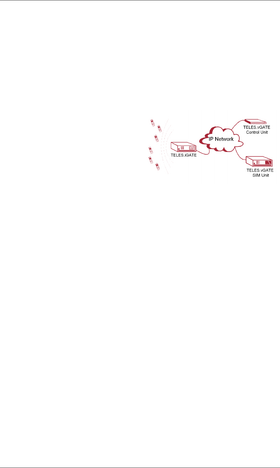
Page 84 © 2007 by TELES AG Berlin, Version 13.0/SH-e/04.16, Issue: April 2007
TELES.iGATE Integration in a Carrier Network TELES.iGATE Routing Examples
6TELES.iGATE Routing Examples
The following examples describe possible implementation scenarios for the
TELES.iGATE.
Note: The parameter VoipUseIpStack must be set in the VoIP profile.
6.1 TELES.iGATE Integration in a Carrier Network
In the following example, a
TELES.iGATE32 is integrated in a
carrier network via DSS1. It is con-
nected to a TELES.vGATE and re-
ceives SIM-card information from a
centralized SIM-card server. The IP
address for the TELES.vGATE Con-
trol Unit is 172.16.0.100. The parame-
ter SIMS is used in SIM<x> to
connect the mobile controller with the TELES.vGATE. All calls coming from
ISDN are sent to two different mobile networks: Calls with the prefixes 01555 and
01556 are sent to the carrier with the LAIN 26212 at controllers 0-15. Calls with
the prefixes 01444 and 01445 are sent to the carrier with the LAIN 26313 (con-
trollers 16-31). Digit collection is activated, so that incoming calls with overlap
dialing are not transmitted until the number is complete or a wait timer (5 seconds)
has run out. The NEXT parameter makes sure that calls are distributed evenly to
the individual mobile channels in the trunk group. The parameter CHADDR en-
sures that calls are not misrouted, since the controller definition changes to the
SIM-card’s LAIN when a SIM card is mistakenly used for another mobile control-
ler. Problems can occur when SMS messages are also sent, as service center num-
bers are definitively configured.

© 2007 by TELES AG Berlin, Version 13.0/SH-e/04.16, Issue: April 2007 Page 85
TELES.iGATE Routing Examples TELES.iGATE Integration in a Carrier Network
Configuration in the pabx.cfg
Configuration in the route.cfg
Subscriber00 = TRANSPARENT ROUTER GSM[0000,00000,+491555555,1,1,1,SIMS,IMSI] CHADDR ALARM NEXT
Subscriber01 = TRANSPARENT ROUTER GSM[0000,00000,+491555555,1,1,1,SIMS,IMSI] CHADDR ALARM
....
Subscriber16 = TRANSPARENT ROUTER GSM[0000,00000,+491666666,1,1,1,SIMS,IMSI] CHADDR ALARM NEXT
Subscriber17 = TRANSPARENT ROUTER GSM[0000,00000,+491666666,1,1,1,SIMS,IMSI] CHADDR ALARM
....
Subscriber32 = TRANSPARENT ROUTER ALARM
Subscriber33 = TRANSPARENT ROUTER ALARM
SimCtrlUnitAddress=172.16.0.100
[System]
DTMFWaitDial=5
MapAll01555=|2621201555<<17
MapAll01556=|2621201556<<17
MapAll01444=|2621301444<<17
MapAll01445=|2621301445<<17

Page 86 © 2007 by TELES AG Berlin, Version 13.0/SH-e/04.16, Issue: April 2007
TELES.iGATE Integration with SIM-Card Switching in an H.323 Carrier Network
6.2 TELES.iGATE Integration with SIM-Card Switching
in an H.323 Carrier Network
In the following example, a
TELES.iGATE32 is integrated in a
carrier network via H.323. The system
contains six SIM cards for each mo-
bile channel, and the TELES.SIM 24
Carrier is used. All calls coming from
VoIP are routed to the mobile net-
work. Four TELES.G729 Modules
with 16 media channels each are at-
tached in the system. H.323 is used as the signaling protocol and a gatekeeper is
used in the VoIP network. Because the gatekeeper assigns and authorizes the peer,
only one VoIP profile is necessary. Since the peers may use various compression
algorithms, you can define several if you so choose. The codec with the highest
priority is G.729. If the peer does not support it, G.726 32Bit/sec, G.711a, G.711u
are also possible. Silence suppression is active. The gatekeeper’s IP address is
192.168.0.10. This gatekeeper profile can handle up to 30 simultaneous VoIP
calls. This value is dynamic and changes depending on the number of active SIM
cards. The TELES.iGATE’s alias is iGATE01. The prefix list is 01555 01556
01444 01445. The gatekeeper’s alias is GK1 and no password is used. Calls with
the prefixes 01555 and 01556 are sent to the carrier with the LAIN 26212 at con-
trollers 0-15. Calls with the prefixes 01444 and 01445 are sent to the carrier with
the LAIN 26313 (controllers 16-31). Digit collection is activated, so that incoming
calls with overlap dialing are not transmitted until the number is complete or a
wait timer (5 seconds) has run out. The NEXT parameter makes sure that calls are
distributed evenly to the individual mobile channels in the trunk group. The pa-
rameter CHADDR ensures that calls are not misrouted, since the controller defini-
tion changes to the SIM-card’s LAIN when a SIM card is mistakenly used for
another mobile controller. Problems can occur when SMS messages are also sent,
as service center numbers are definitively configured. The parameter LIMIT is set
so that the system automatically switches to the mobile controllers’ SIM cards
when the active SIM card has been used for 3600 seconds. The parameter
CONTINUE makes sure the mobile channel switches to the first SIM card after the
limit has been reached on the last SIM card. The SIM card will not switch until
currently active calls have been disconnected.

© 2007 by TELES AG Berlin, Version 13.0/SH-e/04.16, Issue: April 2007 Page 87
TELES.iGATE Routing Examples TELES.iGATE Integration with SIM-Card Switching
Configuration in the pabx.cfg
Configuration in the route.cfg
Subscriber00 = TRANSPARENT ROUTER GSM[0000,00000,+00000,1,1,1,SIM24,IMSI] CHADDR
LIMIT[3600] CONTINUE ALARM NEXT
Subscriber01 = TRANSPARENT ROUTER GSM[0000,00000,+00000,1,1,1,SIM24,IMSI] CHADDR
LIMIT[3600] CONTINUE ALARM
....
Subscriber16 = TRANSPARENT ROUTER GSM[0000,00000,+00000,1,1,1,SIM24,IMSI] CHADDR
LIMIT[3600] CONTINUE ALARM NEXT
Subscriber17 = TRANSPARENT ROUTER GSM[0000,00000,+00000,1,1,1,SIM24,IMSI] CHADDR
LIMIT[3600] CONTINUE ALARM
....
Subscriber34 = TRANSPARENT ROUTER SWITCH CHMAX[16] ALARM
Subscriber35 = TRANSPARENT ROUTER SWITCH CHMAX[16] ALARM
Subscriber36 = TRANSPARENT ROUTER SWITCH CHMAX[16] ALARM
Subscriber37 = TRANSPARENT ROUTER SWITCH CHMAX[16] ALARM
ChargeUnitGenerate=1
LimitWODisc=ON
[System]
DTMFWaitDial=5
MapAll01555=|2621201555<<17
MapAll01556=|2621201556<<17
MapAll01444=|2621301444<<17
MapAll01445=|2621301445<<17
[Voip=DF]
VoipDirection=In
VoipPeerAddress=10.0.0.0
VoipIpMask=0xffff0000
VoipSignalling=0
VoipCompression=g729 g72632 g711a g711u
VoipSilenceSuppression=Yes
VoipMaxChan=30
VoipTxM=2
VoipGk=GK1
[Gatekeeper=GK1]
RasPort=1719
OwnRasPort=1719
RasId=iGATE01
RasPrefix=01555 01556 01444 01445
GkId=GK
GkAdd=192.168.0.10
GkPwd=
GkTtl=300
GkMaxChan=30
GkDynMaxChan=Yes
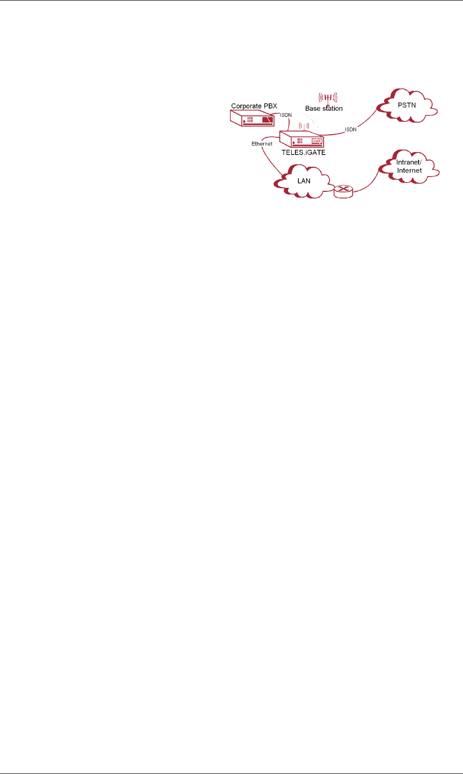
Page 88 © 2007 by TELES AG Berlin, Version 13.0/SH-e/04.16, Issue: April 2007
TELES.iGATE as a Second-Generation LCR with VoIPTELES.iGATE Routing Exam-
6.3 TELES.iGATE as a Second-Generation LCR with
VoIP
In the following example of a PBX
connection, all mobile calls are termi-
nated through the mobile channels.
Eight mobile channels form a group
for one mobile network. One SIM
card is available on each mobile chan-
nel. Digit collection is activated, so
that incoming calls with overlap dial-
ing are not transmitted until the num-
ber is complete or a wait timer (5 seconds) has run out. The NEXT parameter
makes sure that calls are distributed evenly to the individual mobile channels in
the trunk group. If all of a carrier’s SIM cards are busy, rerouting (redirect3)
via PSTN is automatically initiated. All international calls are terminated to VoIP
(40). The system contains two TELES.G729 Modules, for a total of 32 media
channels. The VoIP carrier profile DF and the SIP protocol are used. National calls
are routed through the carrier with the prefix 010xx. All other calls are sent to the
PSTN unchanged. All calls from the PSTN or from a VoIP carrier are sent directly
to the NT controller, to which the PBX is attached. All incoming calls from the
mobile networks are routed to the PBX’s central number (001). For the VoIP pro-
file DF, the system uses the registrar reg and registers with user@sip-
carrier.de, username user and password pwd. SIP UDP is used for signal-
ing. A maximum of 30 media channels with the G.729 codec can be used. The
Peer is sip-carrier.de.

© 2007 by TELES AG Berlin, Version 13.0/SH-e/04.16, Issue: April 2007 Page 89
TELES.iGATE Routing Examples TELES.iGATE as a Second-Generation LCR with
Configuration in the pabx.cfg
Configuration in the route.cfg
Subscriber00 = TRANSPARENT ROUTER GSM[0000,00000,+00000,1,1,1,SIM4,IMSI] CHADDR ALARM NEXT
Subscriber01 = TRANSPARENT ROUTER GSM[0000,00000,+00000,1,1,1,SIM4,IMSI] CHADDR ALARM
....
Subscriber08 = TRANSPARENT ROUTER GSM[0000,00000,+00000,1,1,1,SIM4,IMSI] CHADDR ALARM NEXT
Subscriber09 = TRANSPARENT ROUTER GSM[0000,00000,+00000,1,1,1,SIM4,IMSI] CHADDR ALARM
....
Subscriber16 = TRANSPARENT ROUTER ALARM
Subscriber17 = TRANSPARENT ROUTER ALARM
Subscriber18 = TRANSPARENT ROUTER SWITCH CHMAX[16] ALARM
Subscriber19 = TRANSPARENT ROUTER SWITCH CHMAX[16] ALARM
[system]
DTMFWaitDial=5
Restrict9=10
Restrict40=10
Restrict26212=10001
Restrict26213=10001
MapOut01555=|2621201555<<17
MapOut01556=|2621201556<<17
MapOut01666=|2621301666<<17
MapOut01665=|2621301665<<17
MapOut00=40DF:00
MapOut0=010xx0
MapOut?=9?
Redirect326212=A
Redirect326213=A
MapAllA=9
[Voip=DF]
VoipDirection=IO
VoipPeerAddress=sip-carrier.de
VoipIpMask=0xffffffff
VoipSignalling=1
VoipCompression=g729 t38
VoipSilenceSuppression=Yes
VoipMaxChan=60
VoipTxM=4
VoipOwnAddress=user@sip-carrier.de
VoipUser=user
VoipPwd=pwd
VoipRegistrar=reg
[Registrar=reg]
RegId=sip-carrier.de
RegOwnId=user@sip-carrier.de
RegContact=user@sip-carrier.de
RegUser=user
RegPwd=pwd

Page 90 © 2007 by TELES AG Berlin, Version 13.0/SH-e/04.16, Issue: April 2007
Connection to a TELES.vGATE Mobile Configuration Options
7 Mobile Configuration Options
Be sure to save a backup copy of the configuration files before making chang-
es.
Changing configuration data and/or SIM-card positions may lead to mal-
functions and/or misrouting, as well as possible consequential damages.
Make changes at your own risk. TELES is not liable for any damages result-
ing from or related to such changes. Therefore, please thoroughly check any
configuration changes you or a third party have made.
7.1 Connection to a TELES.vGATE
The TELES.vGATE is a system that enables more convenient management of a
network of TELES.iGATE systems. All SIM cards in the network are installed in
and maintained at a central server, so that it is no longer necessary to install SIM
cards into each gateway. The TELES.iGATEs connected to the TELES.vGATE
do not require SIM-card carriers, as the TELES.vGATE contains SIM-card carri-
ers for the entire network.
Note: Bear in mind that no SIM-card carriers are to be inserted in
TELES.iGATEs connected to a TELES.vGATE.
The following parameters must be configured in the pabx.cfg of each
TELES.iGATE connected to the TELES.vGATE. After the parameters have been
entered, you must restart the TELES.iGATE to activate the changes:
7.2 Module Distribution of Various Mobile Networks
You can assign each mobile port in the TELES.iGATE system either one mobile
network or different access groups to different mobile networks. The port num-
bers in the TELES.iGATE must be the same for the individual groups.
The keyword NEXT ensures equal distribution of calls.
SIMS
Enter this keyword in the Subscriber lines of the mobile controllers to connect
the system to a TELES.vGATE.
EXAMPLE:
Subscriber00=TRANSPARENT ROUTER GSM[0000,00000,+00000,1,1,1,SIMS] CHADDR ALARM
SimCtrlUnitAddress=<ip addr>
Enter the TELES.vGATE Control Unit’s IP address. Set this parameter in the IP
configuration section.
EXAMPLE:
SimCtrlUnitAddress=192.168.0.1

© 2007 by TELES AG Berlin, Version 13.0/SH-e/04.16, Issue: April 2007 Page 91
Mobile Configuration Options Module Distribution of Various Mobile Networks
The following configuration samples (from the pabx.cfg configuration file)
show the changes:
Example 1 All ports in the following example must have the same number for all
mobile channels to route calls to the same mobile network. The
subscriber line of the first port must also contain the keyword
NEXT to ensure the equal distribution of calls.
...
Controller00=20 GSM
Controller01=20 GSM
Controller02=20 GSM
Controller03=20 GSM
Controller04=20 GSM
Controller05=20 GSM
Controller06=20 GSM
Controller07=20 GSM
Controller08=20 GSM
Controller09=20 GSM
Controller10=20 GSM
Controller11=20 GSM
Controller12=20 GSM
Controller13=20 GSM
Controller14=20 GSM
Controller15=20 GSM
...
Subscriber00=TRANSPARENT ROUTER GSM[0000,00000,<SMSC>,1,1,1,SIM4] ALARM NEXT
Subscriber01=TRANSPARENT ROUTER GSM[0000,00000,<SMSC>,1,1,1,SIM4] ALARM
Subscriber02=TRANSPARENT ROUTER GSM[0000,00000,<SMSC>,1,1,1,SIM4] ALARM
Subscriber03=TRANSPARENT ROUTER GSM[0000,00000,<SMSC>,1,1,1,SIM4] ALARM
Subscriber04=TRANSPARENT ROUTER GSM[0000,00000,<SMSC>,1,1,1,SIM4] ALARM
Subscriber05=TRANSPARENT ROUTER GSM[0000,00000,<SMSC>,1,1,1,SIM4] ALARM
Subscriber06=TRANSPARENT ROUTER GSM[0000,00000,<SMSC>,1,1,1,SIM4] ALARM
Subscriber07=TRANSPARENT ROUTER GSM[0000,00000,<SMSC>,1,1,1,SIM4] ALARM
Subscriber08=TRANSPARENT ROUTER GSM[0000,00000,<SMSC>,1,1,1,SIM4] ALARM
Subscriber09=TRANSPARENT ROUTER GSM[0000,00000,<SMSC>,1,1,1,SIM4] ALARM
Subscriber10=TRANSPARENT ROUTER GSM[0000,00000,<SMSC>,1,1,1,SIM4] ALARM
Subscriber11=TRANSPARENT ROUTER GSM[0000,00000,<SMSC>,1,1,1,SIM4] ALARM
Subscriber12=TRANSPARENT ROUTER GSM[0000,00000,<SMSC>,1,1,1,SIM4] ALARM
Subscriber13=TRANSPARENT ROUTER GSM[0000,00000,<SMSC>,1,1,1,SIM4] ALARM
Subscriber14=TRANSPARENT ROUTER GSM[0000,00000,<SMSC>,1,1,1,SIM4] ALARM
Subscriber15=TRANSPARENT ROUTER GSM[0000,00000,<SMSC>,1,1,1,SIM4] ALARM
...

Page 92 © 2007 by TELES AG Berlin, Version 13.0/SH-e/04.16, Issue: April 2007
Network-Specific Mobile Routing Mobile Configuration Options
Example 2 In the following example, a group of 16 mobile channels is assigned
to three different mobile networks. The subscriber line of the
first port in each group must contain the keyword NEXT to ensure the
equal distribution of calls.
7.3 Network-Specific Mobile Routing
7.3.1 Using a Fixed Mobile Port Address
The customer’s network routes calls to the mobile network with a defined prefix.
Because this code is not always uniform, the TELES.iGATE might have to con-
vert it. Conversion requires the following information:
• The mobile network’s access number
• Destination number format (with or without prefixes, national or international)
conversion occurs according to the following formula:
converted as:
...
Controller00=20 GSM
Controller01=20 GSM
Controller02=20 GSM
Controller03=20 GSM
Controller04=20 GSM
Controller05=20 GSM
Controller06=22 GSM
Controller07=22 GSM
Controller08=22 GSM
Controller09=22 GSM
Controller10=22 GSM
Controller11=22 GSM
Controller12=24 GSM
Controller13=24 GSM
Controller14=24 GSM
Controller15=24 GSM
...
Subscriber00=TRANSPARENT ROUTER GSM[0000,00000,<SMSC>,1,1,1,SIM4] ALARM NEXT
Subscriber01=TRANSPARENT ROUTER GSM[0000,00000,<SMSC>,1,1,1,SIM4] ALARM
Subscriber02=TRANSPARENT ROUTER GSM[0000,00000,<SMSC>,1,1,1,SIM4] ALARM
Subscriber03=TRANSPARENT ROUTER GSM[0000,00000,<SMSC>,1,1,1,SIM4] ALARM
Subscriber04=TRANSPARENT ROUTER GSM[0000,00000,<SMSC>,1,1,1,SIM4] ALARM
Subscriber05=TRANSPARENT ROUTER GSM[0000,00000,<SMSC>,1,1,1,SIM4] ALARM
Subscriber06=TRANSPARENT ROUTER GSM[0000,00000,<SMSC>,1,1,1,SIM4] ALARM NEXT
Subscriber07=TRANSPARENT ROUTER GSM[0000,00000,<SMSC>,1,1,1,SIM4] ALARM
Subscriber08=TRANSPARENT ROUTER GSM[0000,00000,<SMSC>,1,1,1,SIM4] ALARM
Subscriber09=TRANSPARENT ROUTER GSM[0000,00000,<SMSC>,1,1,1,SIM4] ALARM
Subscriber10=TRANSPARENT ROUTER GSM[0000,00000,<SMSC>,1,1,1,SIM4] ALARM
Subscriber11=TRANSPARENT ROUTER GSM[0000,00000,<SMSC>,1,1,1,SIM4] ALARM
Subscriber12=TRANSPARENT ROUTER GSM[0000,00000,<SMSC>,1,1,1,SIM4] ALARM NEXT
Subscriber13=TRANSPARENT ROUTER GSM[0000,00000,<SMSC>,1,1,1,SIM4] ALARM
Subscriber14=TRANSPARENT ROUTER GSM[0000,00000,<SMSC>,1,1,1,SIM4] ALARM
Subscriber15=TRANSPARENT ROUTER GSM[0000,00000,<SMSC>,1,1,1,SIM4] ALARM
...
<national/international><prefix[incoming]>=<destination number>
<port><mobile network access number><destination number>

© 2007 by TELES AG Berlin, Version 13.0/SH-e/04.16, Issue: April 2007 Page 93
Mobile Configuration Options Network-Specific Mobile Routing
Be sure to make the following entry in the pabx.cfg configuration file to con-
figure this conversion:
The TELES.iGATE system converts national into one zero and international into
two zeros.
The following configuration exemplifies this conversion as it might occur in Ger-
many:
This example shows how the customer’s network provides the prefix
international+49+1555+destination number for one mobile net-
work, and international+49+1556 for the other. The configuration entries
see to it that 00491555+destination number is converted to
2001555+destination number and 00491556+destination
number is converted to 2101556+destination number. The calls to the
carrier with prefix 01555 are routed to ports with the number 20 and calls to the
carrier with prefix 01556 are routed to the ports with the number 21.
7.3.2 Using the LAIN as the Mobile Port Address
Use the LAIN as controller with the CHADDR parameter to prevent logging onto
the wrong SIM card. This will ensure that routing is network specific. The follow-
ing example is based on the German country code. One carrier’s LAIN is 26212
and the other carrier’s LAIN is 26213:
MapAll<nat./int.>prefix[incoming]>=<port><mobile network access number>
...
MapAll00491555=2001555
MapAll00491556=2101556
...

Page 94 © 2007 by TELES AG Berlin, Version 13.0/SH-e/04.16, Issue: April 2007
Incoming Voice Calls from Mobile Mobile Configuration Options
pabx.cfg
Note: If you remove the keyword CHADDR from the pabx.cfg, you must
restart the system. Controllers belonging to the same trunk group
must have the same address. You must delete all routing entries based
on port addresses when using the LAIN as controller.
route.cfg
7.3.3 Fixed LAIN for a Mobile Port
Enter CHADDR[<addr>] to remove a mobile controller belonging to an LAIN
group from the standard routing process (e.g. for specific routes or only for SMS
transmission). The port address can be set to <addr>.
Example:
7.4 Incoming Voice Calls from Mobile
Incoming mobile calls (service indicator 01 represents voice calls) can be routed
to a specified number. This enables each mobile controller to receive a unique
identifier. It will then be mapped to a number:
...
Controller00=20 GSM
Controller01=20 GSM
Controller02=20 GSM
Controller03=20 GSM
Controller04=20 GSM
Controller05=20 GSM
Controller06=20 GSM
Controller07=20 GSM
...
Subscriber00=TRANSPARENT ROUTER GSM[0000,00000,+49556,1,1,1,SIM4] CHADDR ALARM
Subscriber01=TRANSPARENT ROUTER GSM[0000,00000,+49556,1,1,1,SIM4] CHADDR ALARM
Subscriber02=TRANSPARENT ROUTER GSM[0000,00000,+49556,1,1,1,SIM4] CHADDR ALARM
Subscriber03=TRANSPARENT ROUTER GSM[0000,00000,+49556,1,1,1,SIM4] CHADDR ALARM
Subscriber04=TRANSPARENT ROUTER GSM[0000,00000,+49555,1,1,1,SIM4] CHADDR ALARM
Subscriber05=TRANSPARENT ROUTER GSM[0000,00000,+49555,1,1,1,SIM4] CHADDR ALARM
Subscriber06=TRANSPARENT ROUTER GSM[0000,00000,+49555,1,1,1,SIM4] CHADDR ALARM
Subscriber07=TRANSPARENT ROUTER GSM[0000,00000,+49555,1,1,1,SIM4] CHADDR ALARM
...
...
MapAll01555=2621201555
...
MapAll01556=2621301556
...
Subscriber05=TRANSPARENT ROUTER GSM[0000,00000,
+49555
,1,1,1,SIM4] CHADDR[444] ALARM
MapAllSMS=444 05
Restrict20=90123 01
Restrict21=91234 01

© 2007 by TELES AG Berlin, Version 13.0/SH-e/04.16, Issue: April 2007 Page 95
Mobile Configuration Options Calling Line Identification Restriction (CLIR)
The mobile controllers can also have the same identifier, so that all voice calls
(service indicator 01) from controller 20 are sent to number 1111 at port 9. This
number could, for example, serve a call center.
7.5 Calling Line Identification Restriction (CLIR)
Setting a hash (#) in front of a call number makes it possible to restrict the identi-
fication of calls transmitted into the mobile network.
The following sytax is used: MapIn<num>=#<port><num>
Example: The following example shows an appropriate configuration:
With this entry, all calls beginning with 00491555 are sent to the port with the ad-
dress 22 and the identification of the number is restricted.
7.6 Blocking Ports
This function allows you to block a port, so that the corresponding mobile channel
is omitted from the distribution of calls. The function is particularly useful when
mobile channels fail or SIM cards cannot be immediately replaced.
To block a port (i.e. a mobile channel), enter the keyword CHINC[...] in the
Subscriber line.
In Example 1, port 10 is blocked.
Example 1
To activate the port, remove the entry and enter Activate configuration.
It is also possible to block an entire port with the remote administration program
TELES.GATE Manager. The CHINC[...] function is not necessary with this
application. The port’s status is displayed by remote administration. You can re-
move the block with Activate a configuration or with the Unblock option.
Restrict20=91111 01
MapIn00491555=#2200491555
...
Subscriber10=TRANSPARENT ROUTER GSM[0000,00000,<SMSC>,1,1,1,SIM4] CHADDR ALARM
CHINC[01,01]
...

Page 96 © 2007 by TELES AG Berlin, Version 13.0/SH-e/04.16, Issue: April 2007
Setting Limits Mobile Configuration Options
7.7 Setting Limits
This function enables you to monitor time limits. A limit can be set, either to the
defined time interval or in 10-second intervals (default value). When this value is
reached, the current connection is torn down either immediately or when the call
has been terminated; no more connections will be set up. An alarm also goes off
and an entry is generated in the log file.
Setting SIM Time Limits
In the following example, the mobile channel shuts down when 6,000 intervals of
10 seconds each have passed:
Setting the Default Time Window
In the following example, the mobile channel shuts down when a calculated num-
ber of seconds has been reached. If ChargeUnitGenerate=<sec> is config-
ured, the mobile channel will shut down when the value entered in LIMIT
multiplied by the value entered here is reached. The default value for this param-
eter is 10 seconds. Bear in mind that the value entered in LIMIT may not exceed
65535. In the example, the mobile channel will shut down at 60,000 seconds.
Setting Start Units
The following example shows how you can use the keyword
ChargeUnitFirst=<seconds> to configure a starting unit for LIMIT. The
following entries are used for SIM card tariffs where the first defined number of
seconds are always charged (e.g. the first minute), followed by charges calculated
in defined intervals (e.g. every 10 seconds):
Information about the active SIM cards can be found in TELES.GATE Manager
and Port Status.
To remove limits from the configuration, follow these steps:
...
Subscriber00=TRANSPARENT ROUTER GSM[0000,00000,<SMSC>,1,1,1,SIM4] CHADDR ALARM NEXT
LIMIT[6000]
...
...
ChargeUnitGenerate=1
...
Subscriber00=TRANSPARENT ROUTER GSM[0000,00000,<SMSC>,1,1,1,SIM4] CHADDR ALARM NEXT
LIMIT[60000]...
...
ChargeUnitFirst=60
ChargeUnitGenerate=10
...
Subscriber00=TRANSPARENT ROUTER GSM[0000,00000,<SMSC>,1,1,1,SIM24] LIMIT[6000] ALARM NEXT...
...

© 2007 by TELES AG Berlin, Version 13.0/SH-e/04.16, Issue: April 2007 Page 97
Mobile Configuration Options Automatic SIM Switching
•Enter LIMIT[-].
• Activate the configuration.
• Delete the entry LIMIT[-].
• Activate the configuration again.
7.8 Automatic SIM Switching
This function enables you to monitor time quotas. A limit can be set, either to the
defined time interval or in 10-second intervals (default value). When this value is
reached, the current connection is torn down either immediately or when the call
has been terminated; either no more connections will be set up or the system will
switch to another SIM card. An alarm also goes off and an entry is generated in
the log file.
You can configure different limits for each SIM card per mobile channel. To ac-
tivate this function, enter the keyword
LIMIT[<val1>,<val2>,<val3>,<val4>,<val5>,<val6>] at
subscriber for the corresponding port. <valx> defines a number of units as
a threshold value for the respective SIM card. If only one limit is entered, this limit
will apply for all SIM cards at this port.
Note: Make sure the SIM24 card carrier is inserted and the size of the SIM-
card carrier (SIM24) is entered in the Subscriber line.
If a ’-’ is entered for <valx>, no limit will apply for the corresponding SIM card.
If only two values are entered, a ’-’ must be entered for the other SIM cards; these
SIMs will have no limit. A corresponding alarm message is generated when the
limit on each card has been reached. If the keyword CHANGE is configured, the
mobile channel will not switch beyond the sixth SIM card.
Different settings are possible for the various SIM-card carriers. The number en-
tered (4, 24) refers to the number of slots. The respective number of SIMs per mo-
bile channel is 1 or 6.
The following configurations are possible. Settings shown here are for the SIM-
24 carrier:
Table 7-1 SIM Switching Configurations
Configuration Definition
LIMIT[10,20,30,40,10,20]
CHANGE Each SIM card has a defined limit.
LIMIT[10] CHANGE Each SIM has the same limit.
LIMIT[10,-,-,-,-,-]
CHANGE The first SIM has a defined limit, the second has none.

Page 98 © 2007 by TELES AG Berlin, Version 13.0/SH-e/04.16, Issue: April 2007
Automatic SIM Switching Mobile Configuration Options
If the keyword CONTINUE is configured, the mobile channel will switch beyond
the sixth SIM card. When the limit on the last card has been reached, the mobile
channel will switch back to the first card.
7.8.1 Switching SIMs
In the following example, the mobile channel shuts down and switches to the next
SIM card when 6,000 intervals of 10 seconds each have passed. The port is
blocked after the limit has been reached on the last SIM card:
7.8.2 Cyclical SIM Switching
In the following example, the mobile channel shuts down and switches to the next
SIM card when 6,000 intervals of 10 seconds each have passed. The mobile chan-
nel switches to the first SIM card after the limit has been reached on the last SIM
card. To reset the counter on a monthly basis, see 11.4.1 on page 11-197:
In the following example, only two SIM cards are inserted in the SIM-card carrier.
These SIMs are used alternately in intervals of 3600 seconds each:
7.8.3 Immediate SIM Switching
In the following example, the mobile channel shuts down after the call has been
disconnected, and switches to the next SIM card when 6,000 intervals of 10 sec-
onds each have passed. When the parameter LimitWODisc is ON, the call will
be torn down when the calling party hangs up. If it is set at OFF, the call will be
LIMIT[10,20,0,0,10,20]
CHANGE SIMs 1, 2, 5 and 6 have defined limits. The SIMs in po-
sitions 3 and 4 are not used.
...
Subscriber00=TRANSPARENT ROUTER GSM[0000,00000,<SMSC>,1,1,1,SIM24] CHADDR ALARM NEXT
LIMIT[6000] CHANGE...
...
Subscriber00=TRANSPARENT ROUTER GSM[0000,00000,<SMSC>,1,1,1,SIM24] CHADDR ALARM NEXT
LIMIT[6000] CONTINUE...
...
ChargeUnitGenerate=1
Subscriber00=TRANSPARENT ROUTER GSM[0000,00000,<SMSC>,1,1,1,SIM24] CHADDR ALARM NEXT
LIMIT[3600,3600,0,0,0,0] CONTINUE...
Table 7-1 SIM Switching Configurations
Configuration Definition

© 2007 by TELES AG Berlin, Version 13.0/SH-e/04.16, Issue: April 2007 Page 99
Mobile Configuration Options Defining Time Limits for Calls
terminated immediately when the limit is reached:
7.8.4 Count Status Information
To find information about the current counts and limits for each mobile channel,
click Statistics in the TELES.GATE Manager.
For mobile ports:
•Count A-F For each mobile channel. Counts are the time slices (from 0 to the
limit value) for the individual SIM cards (1-6). When a SIM’s set time limit is
reached, the channel will disconnect and the next SIM will log on.
• Click Reset/Set Counters in the Statistics context menu in TELES.GATE
Manager to reset the counters (default value is 0). You can also configure the
counters to reset automatically (see Chapter 11.4.1 on page 11-197).
Note: If LIMIT is configured, bear in mind that SIM 1 must be configured
in the pabx.cfg for the corresponding mobile port.
7.9 Defining Time Limits for Calls
By entering the parameter CALL in the Subscriber line, you can terminate calls
that reach a defined time limit. For each call the limit is reset at 0. You can define
a value anywhere within <limit>-<random>, and you can define a maximum
value for <random>.
If this parameter is configured once, it will be set in each configuration file. If you
prefer not to use it for all SIMs, set the limit higher than any call is likely to last
(e.g. 360,000 seconds).
Example:
The following entry is required if the TELES.iGATE is used in conjunction with
a TELES.vGATE:
LimitWODisc=OFF
...
Subscriber00=TRANSPARENT ROUTER GSM[0000,00000,<SMSC>,1,1,1,SIM24] CHADDR ALARM NEXT
LIMIT[6000] CHANGE...
...
ChargeUnitGenerate=1;defines the factor for the limit entry (600*1=600sec)
ChargeUnitDivisor=5 ;random value that defines the maximum call duration between 595
and 600secs
...
Subscriber05=TRANSPARENT ROUTER GSM[0000,00000,+000000,1,1,1,SIM24] CALL[600]
Subscriber05=TRANSPARENT ROUTER GSM[0000,00000,+000000,1,1,1,SIMS] CALL[600]

Page 100 © 2007 by TELES AG Berlin, Version 13.0/SH-e/04.16, Issue: April 2007
Pause between Two Calls Mobile Configuration Options
Note: This function cannot be used in conjunction with the
LIMIT function described in Chapter 7.8.
7.10 Pause between Two Calls
If the parameter WAIT appears in the Subscriber line, the mobile controller
will not be used after a successful connection for a random amount of time be-
tween 1 and 30 seconds
Example:
7.11 Time-Controlled SIM Switching
You can define a time at which a mobile channel will change to another SIM card
(up to six SIM cards are possible for this option). Before proceeding, please refer
to Chapter 5.2.1.3 for basic information.
You must define all time windows you would like to use in the [System] sec-
tion of the pabx.cfg, in the subsection night configuration.
The following entry in the configuration file pabx.cfg is necessary:
Night<num>=<time> <day>
Example: In the following example, six time windows are defined. The stan-
dard configuration is active every day from 12:00 midnight to 4:00
a.m.. The time window Night1 is active from 4:00 to 8:00 a.m., etc.
To generate a NightConfiguration section for SIM switching, copy the
complete Subscriber subsection from the [System] section after making
the appropriate entries in the [Nightx] section.
Finally, enter the SIM-card number (1-6 for the TELES.SIM 24 Carrier) that is to
be active during the specified time period in the mobile port’s subscriber entry.
Example: In the following example, SIM cards change in the individual time
windows (as configured above). Only the Subscriber lines for
controllers 12-15 are presented in simplified form. In a proper con-
figuration, all Subscriber lines must be defined.
Subscriber04=TRANSPARENT ROUTER GSM[0000,00000,+00000,1,1,1,SIM24,IMSI] CHADDR WAIT ALARM
;Night configuration
; ---------------------
Night1=04:00 11111111
Night2=08:00 11111111
Night3=12:00 11111111
Night4=16:00 11111111
Night5=20:00 11111111
NightResetTime=00:00 11111111

© 2007 by TELES AG Berlin, Version 13.0/SH-e/04.16, Issue: April 2007 Page 101
Mobile Configuration Options Time-Controlled SIM Switching
The only difference is in the active SIM card. Activate the configuration after the
required files have been copied onto the system.
Bear in mind, that you must also make the appropriate entries in the corresponding
route.cfg sections. For more information, please refer to Chapter 5.3.
Note: This function cannot be used in conjunction with the
LIMIT function described in Chapter 7.8.
Time-Controlled Logoff of a Mobile Channel or SIM Card
If a dash (-) is entered in the SIM-card position, the SIM card will log off auto-
matically. Time-controlled activation of configuration files makes it possible to
shut off unneeded SIMs, for example at night.
[System]
...
Subscriber12=TRANSPARENT ROUTER GSM[0000,00000,+49555,1,1,1,SIM24] ALARM
Subscriber13=TRANSPARENT ROUTER GSM[0000,00000,+49555,1,1,1,SIM24] ALARM
Subscriber14=TRANSPARENT ROUTER GSM[0000,00000,+49555,1,1,1,SIM24] ALARM
Subscriber15=TRANSPARENT ROUTER GSM[0000,00000,+49555,1,1,1,SIM24] ALARM
...
[Night1]
...
Subscriber12=TRANSPARENT ROUTER GSM[0000,00000,+49555,2,1,1,SIM24] ALARM
Subscriber13=TRANSPARENT ROUTER GSM[0000,00000,+49555,2,1,1,SIM24] ALARM
Subscriber14=TRANSPARENT ROUTER GSM[0000,00000,+49555,2,1,1,SIM24] ALARM
Subscriber15=TRANSPARENT ROUTER GSM[0000,00000,+49555,2,1,1,SIM24] ALARM
...
[Night2]
...
Subscriber12=TRANSPARENT ROUTER GSM[0000,00000,+49555,3,1,1,SIM24] ALARM
Subscriber13=TRANSPARENT ROUTER GSM[0000,00000,+49555,3,1,1,SIM24] ALARM
Subscriber14=TRANSPARENT ROUTER GSM[0000,00000,+49555,3,1,1,SIM24] ALARM
Subscriber15=TRANSPARENT ROUTER GSM[0000,00000,+49555,3,1,1,SIM24] ALARM
...
[Night3]
...
Subscriber12=TRANSPARENT ROUTER GSM[0000,00000,+49555,4,1,1,SIM24] ALARM
Subscriber13=TRANSPARENT ROUTER GSM[0000,00000,+49555,4,1,1,SIM24] ALARM
Subscriber14=TRANSPARENT ROUTER GSM[0000,00000,+49555,4,1,1,SIM24] ALARM
Subscriber15=TRANSPARENT ROUTER GSM[0000,00000,+49555,4,1,1,SIM24] ALARM
...
[Night4]
...
Subscriber12=TRANSPARENT ROUTER GSM[0000,00000,+49555,5,1,1,SIM24] ALARM
Subscriber13=TRANSPARENT ROUTER GSM[0000,00000,+49555,5,1,1,SIM24] ALARM
Subscriber14=TRANSPARENT ROUTER GSM[0000,00000,+49555,5,1,1,SIM24] ALARM
Subscriber15=TRANSPARENT ROUTER GSM[0000,00000,+49555,5,1,1,SIM24] ALARM
...
[Night5]
...
Subscriber12=TRANSPARENT ROUTER GSM[0000,00000,+49555,6,1,1,SIM24] ALARM
Subscriber13=TRANSPARENT ROUTER GSM[0000,00000,+49555,6,1,1,SIM24] ALARM
Subscriber14=TRANSPARENT ROUTER GSM[0000,00000,+49555,6,1,1,SIM24] ALARM
Subscriber15=TRANSPARENT ROUTER GSM[0000,00000,+49555,6,1,1,SIM24] ALARM
...

Page 102 © 2007 by TELES AG Berlin, Version 13.0/SH-e/04.16, Issue: April 2007
Mobile-User PBX Callback Mobile Configuration Options
Example:
7.12 Mobile-User PBX Callback
When the TELES.iGATE is implemented in a corporate network and connected
to a PBX or between a PBX and the outside line, the following configuration entry
activates a feature, that uses a mobile caller’s OAD to connect with the last PBX
extension the caller unsuccessfully dialed:
DialBack=<hours>
The callback list is active for the number of hours entered.
Example: In the following example, the callback list is active for the previous
five hours. The German country code is used for the LAINs. All calls
with the prefixes 1111 and 2222 are terminated through the carrier
with the LAIN 26212. Calls with the prefix 3333 are terminated
through the carrier with the LAIN 26213:
Note: Make sure that no Restrict entries are configured for these mobile
controllers.
[System]
Subscriber12=ALARM GSM[0000,00000,+49555,1,1,1,SIM24]
Subscriber13=ALARM GSM[0000,00000,+49555,1,1,1,SIM24]
Subscriber14=ALARM GSM[0000,00000,+49555,1,1,1,SIM24]
Subscriber15=ALARM GSM[0000,00000,+49555,1,1,1,SIM24]
[Night1]
Subscriber12=ALARM GSM[0000,00000,+49555,2,1,1,SIM24]
Subscriber13=ALARM GSM[0000,00000,+49555,2,1,1,SIM24]
Subscriber14=ALARM GSM[0000,00000,+49555,2,1,1,SIM24]
Subscriber15=ALARM GSM[0000,00000,+49555,2,1,1,SIM24]
[Night2]
Subscriber12=ALARM GSM[0000,00000,+49555,-,1,1,SIM24]
Subscriber13=ALARM GSM[0000,00000,+49555,-,1,1,SIM24]
Subscriber14=ALARM GSM[0000,00000,+49555,-,1,1,SIM24]
Subscriber15=ALARM GSM[0000,00000,+49555,-,1,1,SIM24]
DialBack=5
MapAll1111=262121111
MapAll2222=262122222
MapAll3333=262133333

© 2007 by TELES AG Berlin, Version 13.0/SH-e/04.16, Issue: April 2007 Page 103
Mobile Configuration Options Optional Mobile Quality Parameters
7.13 Optional Mobile Quality Parameters
The following table describes specific signaling and quality parameters for con-
figuration of the mobile interface.
Table 7-2 Optional Mobile Parameters
GSM=...
Enter any of the following parameters after the equal sign for the following functions.
Entries may appear in any order, but all entries must appear in the same line and in
double-digit notation as follows:
GSM=RSSI[10] STOP[18,08] ANNOUNCE[00,08] FAX[a2] ASR[20,35]
ALERT[<sec>] Set this parameter to generate alert signal in the D channel im-
mediately after dial-end signal. If you enter optional square
brackets containing a number of seconds, the alert signal will
occur when the number entered has passed.
ANNOUNCE Set this parameter to define what happens when a recorded an-
nouncement is recognized:
•No ANNOUNCE entry (default)
A D-channel PROGRESS message stating Inband Informa-
tion Available will be generated
• ANNOUNCE[<cause>]
The connection will be rejected with the defined ISDN cause
value.
• ANNOUNCE[00,<sec>]
A timeout for voice recognition is defined in seconds (default
value: 120 seconds). After the interval entered has passed,
the connection is torn down.
ASR[<limit>,
<calls>]
Allows you to change the default value (40 calls at 30% ASR).
For a definition of ASR, see Chapter 11.4.1.
FAX[<cause>] This entry allows you to reject fax calls with the defined cause
value.
RSSI[<limit>] Configure this parameter to set a limit for the reception field
strength. When the reception field strength falls below this limit,
the mobile channel will be blocked. If the field strength is above
the limit, the mobile channel will log on with the mobile carrier
again. The values used are 0 to 31, which represent the follow-
ing field strengths: -113dBm to -51 dBm. An error is generated
in the protocol log. The result must be divided by 2.
EXAMPLE: To define a field strength of -95 dBm, subtract -95
from-113 and divide the result by 2:
- 113dB - (-95dB) = -18dB / 2 = 9
Enter RSSI[9]

Page 104 © 2007 by TELES AG Berlin, Version 13.0/SH-e/04.16, Issue: April 2007
Deactivating Class 2 Re-Routing Mobile Configuration Options
7.14 Deactivating Class 2 Re-Routing
Configuring Class2Next=Off in the pabx.cfg file ensures that calls reject-
ed with a class 2 cause value are not re-routed to the next available port.
7.15 Checking Ports/Mobile Channels
Monitoring ASR for Mobile Ports
ASR monitoring of the last 40 calls occurs for all mobile ports. If the ASR (ASR2)
is lower than 30 percent, an alarm is generated at the corresponding port and the
port is blocked. The port is then restarted and a corresponding entry appears in the
protocol.log file (ASR). The port is then unblocked.
The following entry in the pabx.cfg causes the mobile port to block automati-
cally when this error occurs three times in a row:
ASRBlock=On
When ASRBlock=Off is used, the port will be restarted and will remain open.
The following parameter in the pabx.cfg file allows you to change the default
value (30% for 40 calls):
GSM=ASR[<percent>,<number of calls>]
STOP[<val1>,
<val2>]
This entry allows you to define a maximum number of connec-
tion setups that always result in a recorded message (<val1>)
without a call-connected signal or successful connection setup,
or that are always accepted (<val2>). The mobile port is
blocked when the defined value is reached and an entry is re-
corded in the log file (...Err: Voice). In this way inactive SIM
cards that are forwarded to a recording (with or without a con-
nect from the mobile carrier) can be recognized and blocked so
that they are removed from the routing process. The default sta-
tus of this function is off.
NOCP When this option is configured and the call is from ISDN to GSM,
the Call Proceeding signaling message will be eliminated from
signaling. This may be necessary if the ISDN peer does not sup-
port Call Proceeding. Bear in mind that the peer’s Setup Ack
Timer is usually set at 5 seconds, which means that an Alert
must be generated as follows: GSM=ALERT[5]
GSM=ASR[20,35]
Table 7-2 Optional Mobile Parameters (continued)
GSM=...

© 2007 by TELES AG Berlin, Version 13.0/SH-e/04.16, Issue: April 2007 Page 105
Mobile Configuration Options Recharging Prepaid SIMs
7.16 Recharging Prepaid SIMs
Prepaid SIM cards are an alternative to mobile telephone SIMs with a contract. In-
stead of being billed retroactively, prepaid SIMs are paid for in advance and then
recharged when they run out.
The advantages of prepaid SIMs are:
• No monthly basic fee
• Cost control
• No surprises resulting from unexpectedly high mobile telephone bills
When the account is empty, it can be recharged. The recharging methods for pre-
paid SIM cards of different carriers vary:
• Recharging via SMS/USSD
• Recharging via call to a defined number
• Recharging via DTMF
• Automatic recharging via direct debit
When prepaid SIMs that do not recharge automatically (e.g. through a credit card)
are used in a TELES.iGATE, it is possible to recharge them directly from the sys-
tem. The following requirements apply:
• The SIM is registered and no connection is active.
• Exact knowledge of the mobile carrier-specific recharging procedure exists.
• One valid prepaid voucher exists for one recharge.
Warning: Transmission errors, truncated connections, incorrect or altered re-
charging procedures can prevent successful recharging. Please bear
in mind that 3 incorrect recharge attempts (per SIM) can result in
blocked SIMs. Recharge SIMs at your own risk. TELES is not liable
for any possible loss.
TELES.iGATEs support of the following procedures:
• USSD message to the mobile carrier's account manager
The TELES.GATE Manager sends the configured USSD message through the
TELES.iGATE to the account manager. USSD recharging is the recommended
and most reliable procedure, as it consists of a digital message. Unfortunately,
only a few mobile carriers currently support USSD recharging. Please ask your
mobile carrier if he supports USSD recharging.
• SMS message to the mobile carrier's account manager
The TELES.GATE Manager sends the configured SMS containing the vouch-
er number through the TELES.iGATE to the account manager. Unfortunately,
only a few mobile carriers currently support SMS recharging. Please ask your
mobile carrier if he supports SMS recharging.
• Connection setup to the account manager with subsequent menu selection and
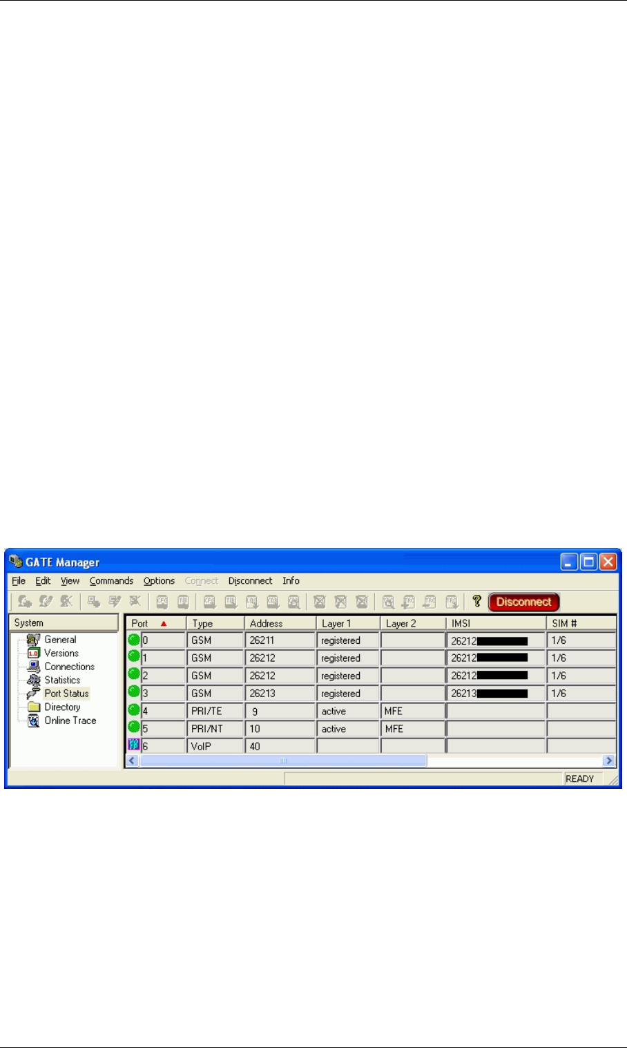
Page 106 © 2007 by TELES AG Berlin, Version 13.0/SH-e/04.16, Issue: April 2007
Recharging Prepaid SIMs Mobile Configuration Options
DTMF-tone transmission of the voucher number
• Direct recharging: Connection setup from a telephone through the
TELES.iGATE to the account manager and manual DTMF-tone transmis-
sion.
• Indirect recharging using the TELES.GATE Manager: The TELES.GATE
Manager sets up a connections through the TELES.iGATE to the account
manager and sends the configured DTMF tones automatically.
Note: Direct recharging is the simplest procedure. Since a direct connection
exists, it is possible to react to commands and error messages imme-
diately. Indirect recharging by means of USSD is the most reliable
and quickest way to recharge SIMs if the configuration in the
TELES.GATE Manager and TELES.iGATE is correct.
7.16.1 Recharge Preparation
7.16.1.1 Checking the Active SIM
To avoid recharging the wrong SIM card, be sure to check the mobile controller's
active SIM using the TELES.GATE Manager:
TELES.GATE Manager
Figure 7-1 TELES.GATE Manager Port Status
Connect to the system and go to the Port Status window. The active position in
the SIM-card carrier is displayed in the SIM # column. The mobile controller's ac-
tive SIM is displayed in the IMSI column.

© 2007 by TELES AG Berlin, Version 13.0/SH-e/04.16, Issue: April 2007 Page 107
Mobile Configuration Options Recharging Prepaid SIMs
7.16.1.2 Addressing SIMs Using Port- and Controller-Spe-
cific Routing
SIM recharging for a specific mobile controller requires configuration and activa-
tion of port- and controller-specific routing entries in the route.cfg or pabx.cfg
configuration file. Usually SIM cards are assigned to a carrier's trunk group and
all calls through the carrier's network are evenly divided between the mobile con-
trollers in the group. This would also apply to recharge calls.
The routing entry defined here sets up a connection to the network:
MapAll<in>=<port>*<ctrl>01:<num>
When the number <in> is dialed, a connection to <num> is set up through
<port>*<ctrl>01: You can now manually enter DTMF tones using a tele-
phone.
To recharge all SIMs in the TELES.iGATE, configure the following mapping,
whereby 4400 is an example for a number that matches the first controller and
12345 is the number for the account manager:
7.16.1.3 Blocking the Port Containing the Recharging SIM
If a call is active on the mobile port containing the SIM to be recharged, the re-
charging process will not occur. For this reason it is better to block the port before
recharging the SIM. In the Connections window, you must check the status No
Connection on the mobile port. Block Port does not tear down a connection, it only
prevents a new connection from being set up.
Note: Port- and controller-specific routing has a higher priority than the
Block Port command. This ensures that normal calls are blocked, but
recharge calls can be sent through the defined mobile port.
7.16.2 Recharging Procedure
7.16.2.1 Direct Recharging via Call
This is the easiest method when it is possible to set up a telephone connection to
the TELES.iGATE system via PSTN or VoIP. This call can be connected with the
MapAll4400=20*0001:12345
MapAll4401=20*0101:12345
MapAll4402=20*0201:12345
MapAll4403=20*0301:12345
MapAll4404=20*0401:12345
MapAll4405=20*0501:12345
MapAll4406=20*0601:12345
.......
MapAll4431=20*0631:12345

Page 108 © 2007 by TELES AG Berlin, Version 13.0/SH-e/04.16, Issue: April 2007
Recharging Prepaid SIMs Mobile Configuration Options
carrier's account manager over a defined mobile controller. This means the call is
set up over the controller's active SIM. Then you simply follow the account man-
ager's recharge instructions. After the SIM has been successfully recharged, it can
be used again for a certain amount of time.
The call can be set up using a number of methods. This is also possible if there are
not enough available telephone numbers to handle all of the system's available
mobile controllers.
•DLA via DTMF
The user calls a defined number in the system. The called number is connected
with the DTMF platform. The digits that are transmitted via DTMF match
those in the routing entries. When the connection to the account manager has
been established, both legs will be connected (See Chapter 7.16.1.2).
• TELES.GATE Manager (described in Chapter 7.16.2.2 below)
That means no BRI connection is necessary for a telephone that is connected di-
rectly to the system!
7.16.2.2 Indirect Recharging via TELES.GATE Manager
This chapter describes automatic recharging of prepaid SIMs using the
TELES.GATE Manager. It is not necessary to set up a telephone connection to the
TELES.iGATE. The TELES.GATE Manager can set up its own connection to the
carrier's account manager and send the pattern of DTMF tones or a USSD mes-
sage.
Recharging via Call and Transmission of Preconfigured DTMF Tones
This procedure requires exact knowledge of the when and what information the
mobile carrier requests. The corresponding pauses following the connect, for
menu selection, between the DTMF tones, for correct repetition of the DTMF
tones must be correctly configured in the TELES.GATE Manager before the call
is set up.
This DTMF-tone pattern can be established by testing the recharging process on
a mobile phone or by following the directions in Chapter 2.1 and noting the pauses
and transmitted digits.
After a connection has been set up between the TELES.iGATE and the
TELES.GATE Manager, select Commands | Send Call. The window must con-
tain either General, Version or Directory.
Send Call opens a dialog to initiate calls or recharge SIMs.
To recharge SIMs, the 1st Number (e.g. 12345) is the mapping to the prepaid
platform through a defined controller (e.g. MapAll12345=20*0101:12345).
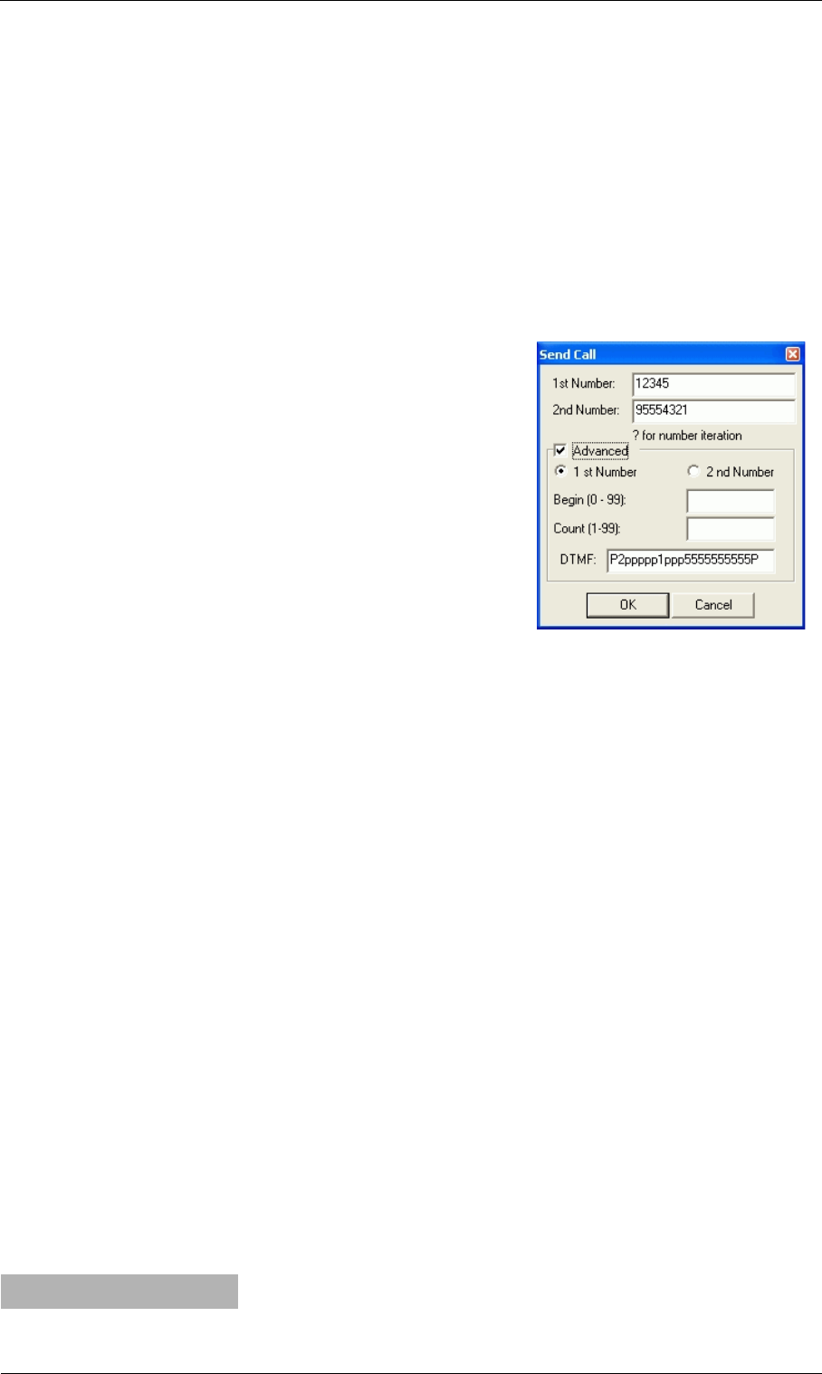
© 2007 by TELES AG Berlin, Version 13.0/SH-e/04.16, Issue: April 2007 Page 109
Mobile Configuration Options Recharging Prepaid SIMs
Optional: You can set up a second connection to hear the announcement from the
prepaid platform if you enter your own number into the box 2nd Number. Both
connections will be torn down when the second number disconnects. If no number
is entered in this box, the call will disconnect when the last DTMF tone has been
transmitted or when the last pause interval has passed.
Activate the checkbox Advanced to open the DTMF box
Enter a series of DTMF tones in the DTMF box. Enter a p for a pause of 1 second
and a P for a pause of 10 seconds.
Example: The number for the prepaid platform's
account manager is 12345. The tele-
phone number to listen along to the
accounting procedure is 5554321, set
up through controller 9 (no special
routing configuration is defined in the
configuration files). Leave this dialog
box empty if the accounting process
is not to be monitored.
The voucher key is: 55555555555 (a
short pause can also be defined be-
tween individual digits: for example,
5p5p5p5p5p5p5p5p5p5p5).
To get to the voucher key query, the
following pattern must be transmitted: P2ppppp1ppp. Following
transmission of the voucher key and a 10-second pause, the call will
be torn down.
Note: Bear in mind that DTMF tones are only generated with connections
into the mobile network. Test calls over the PRI, BRI or VoIP inter-
faces do not transmit DTMF tones and no tones can be heard!
Recharging via USSD Code (Unstructured Supplementary Services
Data)
Recharging prepaid SIMs using the TELES.GATE Manager and USSD is the
most convenient solution if the prepaid carrier offers this service. The USSD mes-
sages contains the prepaid voucher number.
Configure an additional controller in the last position for DTMF functionality as
follows:
Example:
Controller36=41DTMF
Figure 7-2 Recharging with
DTMF Tones
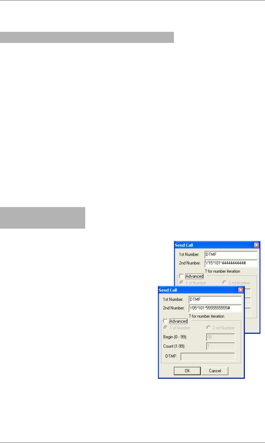
Page 110 © 2007 by TELES AG Berlin, Version 13.0/SH-e/04.16, Issue: April 2007
Recharging Prepaid SIMs Mobile Configuration Options
The corresponding Subscriber line will look like this:
The configuration file pabx.cfg must contain the following entry in the
[System] section:
MapAllDTMF=<dtmf port>DTMF
MapAll<place>??=<port>*??01:
or
MapAll<place>??=<LAIN>*??01:
First a placeholder is defined, followed by ?? so that one mapping entry applies
for the entire group of the carrier's mobile controllers. The right side of the map-
ping entry begins with the mobile port number or the port's LAIN.
Example: In the following example, prepaid SIMs from 2 different carriers are
used in the system. The letters Y and Z are used as placeholders, and
the carrier's LAINs are 26212 and 26213 (based on the German coun-
try code):
Set up a connection to the system through the
TELES.GATE Manager and select Com-
mands | Send Call. Enter DTMF in the 1st
Number dialog box. In the 2nd Number dia-
log box, enter the carrier's placeholder (Y or
Z) and the number of the controller in which
the SIM card is active (15 or 05). Enter a 0 in
front of single-digit controller numbers. Then
enter the carrier's USSD code (*101*) and the
voucher number (44444444444 or
55555555555). The USSD command ends
with #.
Warning: Incorrect USSD commands can
result in blocked SIMs or failure
in the mobile module!
Configuration entries for recharging confir-
mation are described in Chapter 3.
Subscriber36=TRANSPARENT ROUTER CHMAX[5]
MapAllDTMF=41DTMF
MapAllY??=26212*??01:
MapAllZ??=26213*??01:
Figure 7-3 Recharging with
USSD Codes
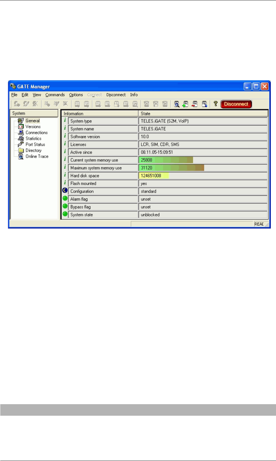
© 2007 by TELES AG Berlin, Version 13.0/SH-e/04.16, Issue: April 2007 Page 111
Mobile Configuration Options Recharging Prepaid SIMs
Recharging via SMS (Short Message Service)
First of all, please check whether you have the license to send SMS messages on
your system.
You will find it in the General view under Licenses when you connect to the sys-
tem via TELES.GATE Manager.
Figure 7-4 TELES.GATE Manager General View
The name for the license is SMS. This entry is required to send SMS.
You must configure the mail service in the [Mail] section of the file pabx.cfg
if you want to send the SMS messages with an e-mail client through a mail server
or directly to the TELES.iGATE:
[Mail]
SmtpServer=<server addr>
MailRcpt=<domain>
MailFrom=<own address or name>
Note: This entry is not necessary when using only the GateManager's Send
SMS command.
The third entry in the mobile controller's Subscriber line is the SMS center
number:
Subscriber00=TRANSPARENT ROUTER GSM[0000,00000,+00000,1,1,1,SIMS,IMSI] CHADDR ALARM
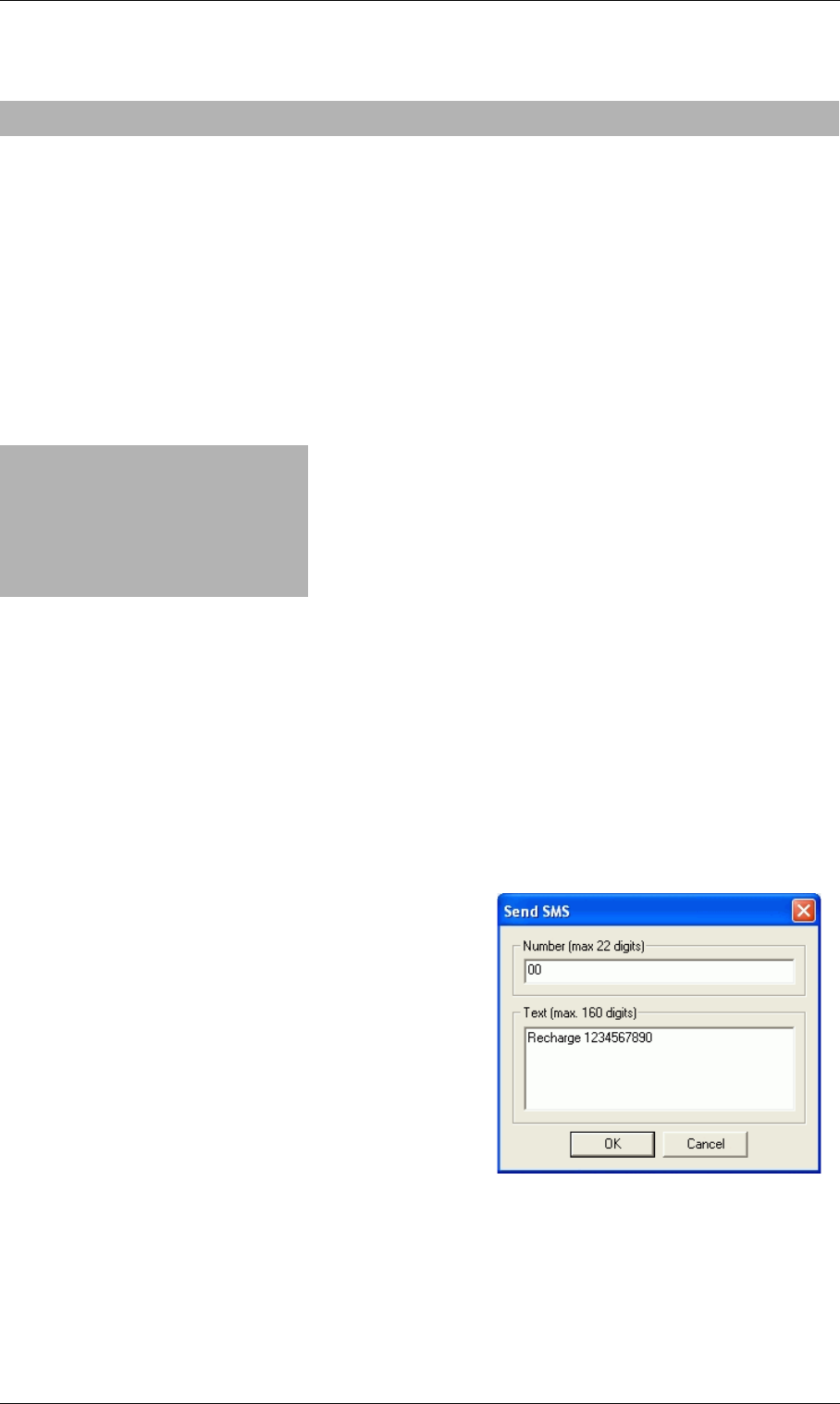
Page 112 © 2007 by TELES AG Berlin, Version 13.0/SH-e/04.16, Issue: April 2007
Recharging Prepaid SIMs Mobile Configuration Options
German example:
You must restart the system to activate the changes.
Then enter the port-specific SMS settings:
MapAllSMS<shortnumber>=LAIN*0001:<number>
MapAllSMS<shortnumber>=port*0001:<number>
Example: In the following German example with LAIN numbers, the short
number 00 is routed to the first controller. The number 12345 is sent
to the SMS center.
If the SMS is sent with a normal e-mail client, the keyword SMS will appear in
the To dialog box, followed by the short number, which indicates the mobile con-
troller. An @ sign and the TELES.iGATE's IP address or name if the system is
attached to a DNS server will follow. The message box contains the recharge code
in the carrier's syntax.
SMS00@<ipaddr>
SMS00@<domain>
If the SMS is used with the Send SMS com-
mand in the TELES.GATE Manager's Com-
mands menu, use only the short number and
not the keyword SMS.
To save the recharge platform's confirmation
e-mail, the e-mail can be sent to an account us-
ing the following entry in the route.cfg:
Restrict<port>=@<addressee> 05
It can also be saved into a file using the fol-
lowing entry in the pabx.cfg:
MsgLog=/data/msg.log
To save it into a file, the following entry in the route.cfg is also required:
Restrict<port>=@FILE 05
Subscriber00=TRANSPARENT ROUTER GSM[0000,00000,+491721111,1,1,1,SIMS,IMSI] CHADDR ALARM
MapAllSMS00=26212*0001:12345
MapAllSMS01=26212*0101:12345
MapAllSMS02=26212*0201:12345
MapAllSMS03=26212*0301:12345
MapAllSMS04=26212*0401:12345
MapAllSMS05=26212*0501:12345
MapAllSMS06=26212*0601:12345
……
Figure 7-5 Send SMS

© 2007 by TELES AG Berlin, Version 13.0/SH-e/04.16, Issue: April 2007 Page 113
Mobile Configuration Options Recharging Prepaid SIMs
Example: In the following example for saving the SMS into a file, all incoming
SMS to LAIN 26212 is saved into the file msg.log:
If the e-mail is sent to an account, the routing entry will look like this:
Use the following entries in the pabx.cfg to connect the TELES.iGATE to an
e-mail server:
[Mail]
SmtpServer=<server address>
MailRcpt=<domain>
MailFrom=<own address or name>
7.16.3 Prepaid Account Status Query
After a SIM card has successfully been recharged, you can query its current ac-
count status. The following variations are possible:
• Direct query via call
• Indirect query with the TELES.GATE Manager
• Listening in on the TELES.GATE Manager connection
• USSD account-status query
7.16.3.1 Direct Account-Status Query
The same basic settings apply here as have already been described for SIM re-
charging.
That means routing configurations must be entered that set up a connection be-
tween the caller and the carrier's prepaid platform. Use the same routing configu-
ration described in Chapter 7.16.2. The only difference is that you will select the
account-status query instead of account recharging from the menu.
Restrict26212=@FILE 05
Restrict26212=@nase 05
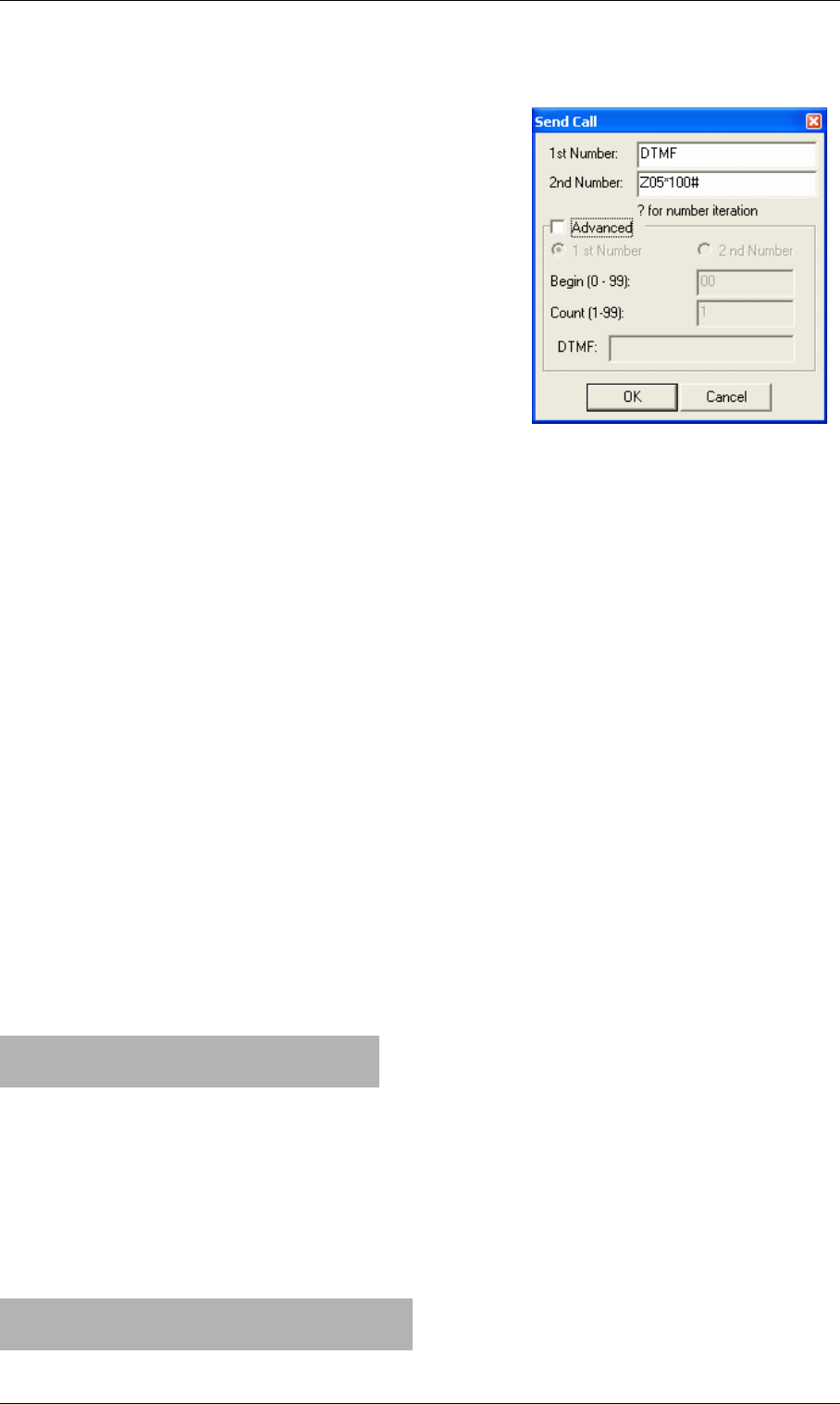
Page 114 © 2007 by TELES AG Berlin, Version 13.0/SH-e/04.16, Issue: April 2007
Recharging Prepaid SIMs Mobile Configuration Options
7.16.3.2 Indirect Account-Status Query
The indirect method with the TELES.GATE
Manager and listening in on the connection re-
quires a change in the pattern of DTMF tones.
You must, of course, know what the pattern is be-
forehand, and then you must configure it in the
Send Call dialog.
The indirect USSD account-status query corre-
sponds with the USSD recharging procedure with
altered USSD account-status-query command in-
stead of the recharging command with cash code
(voucher number).
Note: The USSD recharging procedure re-
sults in an immediate USSD response message, so that the
TELES.iGATE does not require an explicit query following USSD
recharging.
7.16.3.3 Saving /Forwarding the Account Status
Account-status information can be saved to a file in the TELES.iGATE. The fol-
lowing entry in the pabx.cfg is required:
MsgLog=/data/msg.log
The corresponding routing entries in the route.cfg configuration file will look
like this:
Restrict<port>=@FILE 06
Restrict<LAIN>=@FILE 06
Example: The following example shows incoming USSD messages for 2 carri-
ers:
The USSD entry in the file will appear in 2 lines as follows:
Date Time [Port] IMSI
USSD Message Text
Example:
Restrict26212=@FILE 06
Restrict26213=@FILE 06
14.02.05-17:40:06 [04] 262125555555555
Current Cash Account: 143,83 Euros
Figure 7-6 Status Query

© 2007 by TELES AG Berlin, Version 13.0/SH-e/04.16, Issue: April 2007 Page 115
Signaling and Routing Features Digit Collection (Enblock/Overlap Receiving)
8 Signaling and Routing Features
8.1 Digit Collection (Enblock/Overlap Receiving)
This function makes it possible to collect digits and transmit calls when a specific
number of digits has been dialed. The entire call number is required for the call to
be set up with a mobile phone or the mobile gateway. Since most numbers have a
uniform number of digits, the mobile gateway can collect digits when calls enter
the gateway in overlap mode. Digit collection occurs through the following map-
ping command:
The example above shows a call with the prefix 01555. The | (pipe) signifies that
the following digits will be collected before they are transmitted. The 14 at the end
is the sum of the port digits and the digits of the called party number (e.g. |#20=3,
01555899666=11, 3+11=14). This figure must be entered in double digits (e.g.
<<08 for 8 digits). The parameter DTMFWaitDial defines the amount of time
the system waits between the individual digits. The system forwards the call to the
mobile channel as soon as the correct number of digits has been dialed. Please bear
in mind that you can configure a maximum of 11 digits in the first part of the com-
mand and 19 (including a special character, e.g. #) in the second. The call will be
forwarded as soon as the specified number of digits has been dialed or a time-out
limit has been reached.
8.2 Rejecting Data Calls and Specified Numbers
The following configuration enables you to reject calls with bearer capability data
and calls that should not be directed to specified numbers:
8.3 Routing CLIP and CLIR Calls
This function allows you to route calls with Calling Line Identification Presenta-
tion (CLIP) differently from calls with Calling Line Identification Restriction
(CLIR). For example, all CLIP calls can be rejected, so that only calls that do not
present the calling number or calls without a calling party number (e.g. analog) are
...
MapAll01555=|#2001555<<14
...
DTMFWaitDial=5
...
...
MapAll00491555=&aa DATA
...
MapAll004915551234=&aa VOICE

Page 116 © 2007 by TELES AG Berlin, Version 13.0/SH-e/04.16, Issue: April 2007
Routing Calls without CLIR Signaling and Routing Features
transmitted through the TELES.iGATE.
Use the following configuration to define the various routing methods:
InsertCLIR=On activates this mode. 01 is the service indicator for telephony
(analog and ISDN) and is used to differentiate these calls from remote administra-
tion calls. Restrict9=OK 01 means that all telephony calls without a calling
number are put through. Restrict|9=OK 01 means that all CLIR telephony
calls are put through. Restrict90=FAIL 01 means that all CLIP telephony
calls are rejected with No Channel Available as rejection cause when they are
mapped to MapInFAIL=&aa.
8.4 Routing Calls without CLIR
This function enables you to bypass CLIR for calls through the defined mobile
port. The following configuration in pabx.cfg activates this function:
Note: When this function is configured, the SIM’s telephone number (and
not originating telephone) is always transmitted to the B subscriber.
8.5 Conversion of Call Numbers
The conversion of call numbers makes it possible, for example, to implement
number portability or to redirect calls when the user can be reached at another
number. In the following mapping command, the call number 015550123456
is changed to 015559876543 and sent to the mobile channel
(MapAll...=20..):
Example 1
Example 2 presents an alternative, in which the routing file is searched through
again after conversion of the call number to determine the route for the prefix
01555. Please bear in mind that you can configure a maximum of 1499 mapping
...
InsertCLIR=On
...
Restrict9=OK 01
Restrict|9=OK 01
Restrict90=FAIL 01
...
MapInOK00491555=2200491555
MapInFAIL=&aa
...
Subscriber<xx>=...GSM[...,!CLIR]...
...
MapAll015550123456=20015559876543
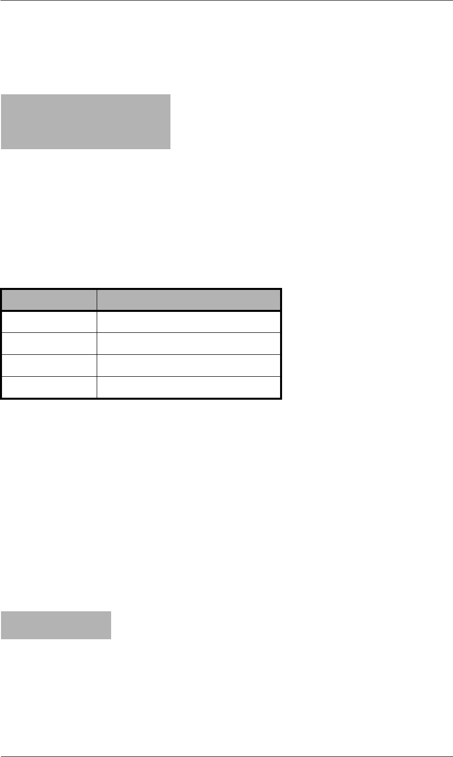
© 2007 by TELES AG Berlin, Version 13.0/SH-e/04.16, Issue: April 2007 Page 117
Signaling and Routing Features Setting Number Type in OAD/DAD
entries with no more than 11 digits in the first part of the command and 19 in the
second.
Example 2
8.6 Setting Number Type in OAD/DAD
In some cases it may be necessary to set a specific number type for the OAD or
DAD. There are different methods for the various interfaces. The following num-
ber types can be set:
OAD
Use the following entry to set a specific number type in the OAD:
Restrict<port><num>=<type> 15
For the national and international types, remove the 0(s) at the beginning of the
number:
Restrict<port>0=n 15
Restrict<port>00=i 15
Example: In the following example, the bit is set in the caller’s origination num-
ber for a call via BRI controller 01:
Example:
You can set a u (unknown type of number) in the Restrict entry to change
transmission of the national/international bit to 0 or 00 at the beginning of the
OAD. As in a mapping entry, the national/international bit will always appear left
...
MapAll015550123451=$Reception
MapAll015550123452=$Reception
MapAll015550123453=$Reception
MapAllReception=015559876543
Table 8-1 Number Types
Type Definition
uUnknown
sSubscriber number
nNational number
iInternational number
Restrict90=n 15
Restrict900=i 15

Page 118 © 2007 by TELES AG Berlin, Version 13.0/SH-e/04.16, Issue: April 2007
Setting Number Type in OAD/DAD Signaling and Routing Features
of the equal sign as 0 or 00.
Restrict<port>0=u0 15
Restrict<port>00=u00 15
In the following example, the area code 030 with a 0 at the beginning of the OAD
of the PBX’s extension is set as a digit and transmitted along with the number:
Note: Restrict entries are handled from general to specific from top to
bottom.
DAD
Enter one of the four specific number types in the DAD as follows:
MapAll<num>=<port><type><num>
In the case of a VoIP controller, enter the following:
MapAll<num>=<port><voip profile>:<type><num>
The number type will then be defined at the port. For the national and international
types, remove the 0(s) at the beginning of the number:
Example: In the following example, the international bit is set for all calls to It-
aly (0039) and the number is transmitted with 39. For the area code
012, the national bit is set and the number is transmitted with 12:
General Example
Example: In the following example, a 1:1 routing entry for the individual PRI
controllers to VoIP appears in addition to the international flag from
PRI to VoIP. A placeholder routing entry is used (bla or blu), in
which the PRI ports are directly assigned to a mapping. Traffic at PRI
port 9 is sent directly to VoIP port 40 with the VoIP profile iG1.
Traffic from PRI port 10 is sent to VoIP port 40 with the profile iG2:
Note: The restrict entries for the individual ports must appear in the
following order: placeholder, OAD international flag, DAD routing
Restrict10555=u030555 15
MapAll0039=40iG1:i39 VOICE
MapAll012=40iG1:n12 VOICE
Restrict9=bla
Restrict900=i 15
Restrict10=blu
Restrict1000=i 15
MapAllbla00=40iG1:i
MapAllblu00=40iG2:i

© 2007 by TELES AG Berlin, Version 13.0/SH-e/04.16, Issue: April 2007 Page 119
Signaling and Routing Features Setting the Screening Indicator
with international flag.
8.7 Setting the Screening Indicator
You can set the screening indicator to define whether the calling-party number
sent is specified as user provided verified and passed or network
provided:
User provided verified and passed: v
Example: In the following Restrict example, the calling party number sent
is specified as user provided verified and passed:
Network provided: p
Example: In the following Restrict example, the calling party number sent
is specified as network provided:
If you also want to define a number type (see Chapter 8.6), it must appear in front
of the screening indicator:
Example: In the following Restrict example, the screening indicator is
specified as network provided, and the number type is
international:
Example: Please bear in mind that this entry will not work if you set a minus
sign (-) behind VoipOad=<num>.
8.8 Setting a Default OAD
Use the Restrict command to set a default origination number (*<oad> 15)
when the OAD is restricted (<num>):
Restrict<port><oad>=*<num> 15
Example: In the following example, 12345 replaces the original OAD. When
the destination number begins with 030, the call is sent through con-
troller 10:
Restrict10=v 15
Restrict10=p 15
Restrict10=ip 15
Restrict9=*12345 15
MapAll030=10030

Page 120 © 2007 by TELES AG Berlin, Version 13.0/SH-e/04.16, Issue: April 2007
Setting or Removing Sending Complete Byte in SetupSignaling and Routing Features
Use the entry Restrict<port><oad>=<num> 15 if digits at the beginning
of the OAD are the only ones to be restricted.
Example: In the following example, the digits 004930 are replaced with 030
followed by the remaining digits. The destination number begins
with 030 and is sent through port 10.
8.9 Setting or Removing Sending Complete Byte in
Setup
In some cases the ISDN or H323 peer system may require this byte for routing, or
the byte may disrupt signaling.
Setting Sending Complete
The following entry ensures that the Setup includes a Sending Complete:
MapAll<direct>=)<num>
The ) causes inclusion of Sending Complete in the ISDN Setup or in the H323 Set-
up.
Example: In the following example, all calls beginning with 0 are sent with a
Setup Complete to controller 9:
Removing Sending Complete
The following entry ensures that the Setup never includes a Sending Complete:
MapAll<direct>=(<num>
The ( causes removal of Sending Complete in the ISDN Setup or in the H323 Set-
up.
Example: In the following example, all calls beginning with 0 are sent without
a Setup Complete to VoIP controller 40. The VoIP profile is DF:
8.10 Miscellaneous Routing Methods
In the following scenarios it may occur that some call numbers must be routed
with differing lengths or that some call numbers may require additional number
conversion:
Restrict9004930=030 15
MapAll030=10030
MapAll0=)90
MapAll0=(40DF:0

© 2007 by TELES AG Berlin, Version 13.0/SH-e/04.16, Issue: April 2007 Page 121
Signaling and Routing Features Miscellaneous Routing Methods
• Calls without a destination number
• Connection to a PBX with an extension prefix
• Routing based on the length of the destination number
8.10.1 Routing Calls without a Destination Number
Enter the following configuration in the route.cfg if the TELES.iGATE must
route calls that come in without a destination number:
Restrict<port>=<pl>
MapAll<pl><num>=<port><num>
MapAll<pl>=<port>
Incoming calls from the configured port will be assigned a placeholder and then
all calls beginning with the placeholder will be routed to the placeholder’s place-
holder’s mapping.
Example: In the following example, all calls from controller 9 are routed to con-
troller 10, regardless of whether a destination number appears in the
setup:
8.10.2 Routing Calls Based on an Extension Prefix or on
the Length of the Destination Number
To route calls with a DAD differently from those with a DAD, you must activate
the block feature in the pabx.cfg and restart the system:
Block=1
Set all other parameters in the route.cfg. First define the port from which the
incoming calls are to be routed. Incoming calls from the configured port will be
assigned a placeholder and then digit collection will occur for all calls beginning
with the placeholder. The $ in the mapping entry, followed by the defined place-
holder (MMM), causes a second search of the routing file when the number is com-
plete:
DTMFWaitDial=<sec>
Restrict<port>=<pl>
MapAll<pl>=|$MMM<<98
The second routing-file search is based on the routing entry with the leading place-
holder (MMM):
Restrict9=pl
MapAllpl=10

Page 122 © 2007 by TELES AG Berlin, Version 13.0/SH-e/04.16, Issue: April 2007
Changing Cause Values Signaling and Routing Features
MapAllMMM<digits>=<dest><digits>
Example: In the following example, digit collection is activated for all calls that
come into port 9. Calls with the destination number 2222 are sent to
the VoIP controller with the profile DF and the destination number is
replaced with the SIP account Betty. Calls with the num-ber 3333
are sent to VoIP with the SIP account Al. All other calls with a des-
tination number are sent to controller 10. Calls without a destination
number are sent to the number 12345 at port 10:
8.11 Changing Cause Values
It is possible to group cause values together into a single defined cause value so
that rejected calls can be handled in a specified manner by the switch sending the
call to the TELES.iGATE. The following cause value groups can be defined in the
pabx.cfg:
Group 0 Cause Values
All connections that are rejected with a group 0 cause value (0x80-0x8f) can
be mapped to a single cause value by entering TranslateG0Cause=<cau>,
whereby <cau> represents a cause value in hexadecimal form.
Group 1 Cause Values
All connections that are rejected with a group 1 cause value (0x90-0x9f) can
be mapped to a single cause value by entering TranslateG1Cause=<cau>,
whereby <cau> represents a cause value in hexadecimal form.
Group 2 Cause Values
All connections that are rejected with a group 2 cause value (0xa0-0xaf) can
be mapped to a single cause value by entering TranslateG2Cause=<cau>,
whereby <cau> represents a cause value in hexadecimal form.
DTMFWaitDial=5
Restrict9=pl
MapAllpl=|$MMM<<98
MapAllMMM2222=40DF:Betty
MapAllMMM3333=40DF:Al
MapAllMMM0=100
MapAllMMM1=101
MapAllMMM2=102
MapAllMMM3=103
MapAllMMM4=104
MapAllMMM5=105
MapAllMMM6=106
MapAllMMM7=107
MapAllMMM8=108
MapAllMMM9=109
MapAllMMM=1012345

© 2007 by TELES AG Berlin, Version 13.0/SH-e/04.16, Issue: April 2007 Page 123
Signaling and Routing Features Changing Cause Values
Group 3 Cause Values
All connections that are rejected with a group 3 cause value (0xb0-0xbf) can
be mapped to a single cause value by entering TranslateG3Cause=<cau>,
whereby <cau> represents a cause value in hexadecimal form.

Page 124 © 2007 by TELES AG Berlin, Version 13.0/SH-e/04.16, Issue: April 2007
Signaling Parameters Additional VoIP Parameters
9 Additional VoIP Parameters
You can enter the following additional parameters in the route.cfg to adjust
the configuration for improved communication with the VoIP peer.
9.1 Signaling Parameters
Table 9-1 Customized Parameters: Protocol-Independent VoIP Signaling
Protocol-Independent VoIP Signaling Parameters
VoipDad=<num>
The digits/numbers defined here will appear in front of the original DAD. If the pa-
rameter is to be valid in only one direction, you must set another profile without
this parameter for the other direction.
VoipOad=<num>
The digits/numbers defined here will be transmitted in front of the original OAD. If
a minus (-) is entered, the original OAD will not appear. Only the digits entered in
front of the minus sign will be displayed. If the parameter is to be valid in only one
direction, you must set another profile without this parameter for the other direc-
tion.
To limit this feature to OADs consisting of a certain number of digits, enter a !, fol-
lowed by the number of digits, at the end of the entry. In the following example,
the digits 567 will appear only if the OAD has at least 6 digits:
EXAMPLE: VoipOad=567!6
To modify the original OAD, enter randomx, whereby x represents a number of
random digits that will appear in the OAD.
EXAMPLE: VoipOad=567random2-
VoipProgress=<int>
For H.323: 1 (default)=progress indicator is transmitted. 0=progress indicator is
not transmitted
For SIP: 0=183 response ignored and not sent. 1=183 response changed to a
progress message with inband-info-available at the ISDN interface (default).
2=183 response changed to an address-complete message at the ISDN interface.
VoipComprMaster=<mode>
This parameter defines which side the first matching codec comes from:
Yes: Default. Priority is determined by the order of the system’s parameter list.
No: Priority is determined by the peer.
VoipHideOadByRemove=<mode>
If Yes is configured and call setup is to VoIP, the OAD will be removed from sig-
naling if presentation restricted or user-provided, not screened
is set in the calling party’s presentation or screening indicator. No (default) means
no change will occur.

© 2007 by TELES AG Berlin, Version 13.0/SH-e/04.16, Issue: April 2007 Page 125
Additional VoIP Parameters Signaling Parameters
VoipSignalCLIR=<string>
When the configured string appears at the beginning of the OAD and the param-
eter VoipHideOadByRemove is set, the OAD is removed from signaling, regard-
less of the presentation bits in the calling party field. If the parameter
VoipHideOadByRemove is not set (default), the presentation bits are set at
presentation restricted (CLIR) if <string> is -. If the string matches the
first digits of the OAD and it comes in with CLIP, the call will be sent to VoIP using
CLIR. If the call comes in with CLIR, the string will be added to the beginning of
the OAD and CLIR will be removed in the signaling.
VoipSingleTcpSession=<mode>
Enter Yes to send all outgoing VoIP connections in a single TCP session. Enter
No (default) for an extra TCP session for each VoIP connection.
VoipIgnoreDADType=<mode>
Enter yes to change the DAD type to unknown, e.g. from international. The type
is lost, e.g. the leading 00 bit is removed. Default no.
VoipSuppressInbandInfoAvailableIndicatorInCallProceeding
=
<mode>
Enter yes to send or receive the Progress Indicator in the Q.931 Call Proceeding
message. Default no.
VoipG72616PayloadType=<num>
Changes the SIP payload type for G.726 16 b/s. Default is 35. A common value is
102.
VoipG72624PayloadType=<num>
Changes the SIP payload type for G.726 24 b/s. Default is 36. A common value is
99.
VoipTrpPayloadType=<num>
Defines the payload type for data calls when trp (transparent/clear mode) is used
as codec in VoipCompression=<list>. Default is 56. A common value is 102.
Table 9-1 Customized Parameters: Protocol-Independent VoIP Signaling (continued)
Protocol-Independent VoIP Signaling Parameters

Page 126 © 2007 by TELES AG Berlin, Version 13.0/SH-e/04.16, Issue: April 2007
Signaling Parameters Additional VoIP Parameters
Table 9-2 Customized Parameters: H.323 Signaling
H.323 Signaling Parameters
VoipServiceOut=0x<service indicator>
This parameter sets the barrier capability. For example, it can be used for calls
coming from VoIP with the barrier capability data. You can define the service indi-
cator as it is in the 1TR6 code:
101 - ISDN 3,1kHz
102 - analog
103 - ISDN 7kHz
201 - Fax 2
202 - Fax 3
203 - Fax 4
700 - Data
Normally 101 is used. You can send another value to a switch that wants to handle
VoIP calls differently from PSTN calls.
EXAMPLE:
VoipServiceOut=0x101
VoIPOwnIpAddress=<ip addr>
If the system is behind a NAT firewall that does not translate H.323, the NAT fire-
wall’s public IP address is transmitted as own IP address in the H.323 protocol
stack (not the private IP address). In this case, the public IP address must be de-
fined. Bear in mind that the NAT firewall transmits the ports for signaling and voice
data to the TELES.iGATE’s private IP address.
VoipMapOadType=<mode>
For calls from PSTN to VoIP only. Enter yes to change the 00 at the beginning of
a number to international and 0 to national.
VoipSetupAck=<int>
1=setup acknowledge is transmitted; 0= setup acknowledge is not transmitted; 2
(default) =transmitted with H.323 information.
VoipH245Transport=<int>
This option determines the H.245 offer. 0 (default)=all signaling variants are of-
fered; 1=FastStart only; 2=H.245 tunneling only; 3=extra session.
Table 9-3 Customized Parameters: SIP Signaling
SIP Signaling Parameters
VoipOwnAddress=<account@domain>
Used for the From field in Sip-Invite and Sip-Response messages.

© 2007 by TELES AG Berlin, Version 13.0/SH-e/04.16, Issue: April 2007 Page 127
Additional VoIP Parameters Signaling Parameters
VoipOwnDisplay=<string>
The entry is sent as Display Name in the From Field in SIP transmissions. The
keyword MSN causes the calling telephone’s MSN to be transmitted as Display
Name.
Beispiel: From: "John" <sip:493011111@teles.de>
VoipContact=<account@domain>
Used for the Contact field in Sip-Invite and Sip-Response messages.
VoipP-Preferred-Identity=<string>
Sets the P-Preferred-Identity field in the SIP invite message. The following set-
tings are possible toward SIP:
* The OAD coming from ISDN/POTS is transmitted.
<string> The defined string is transmitted
A combination of both is possible.
Examples: 030* or tel:* or sip:user@carrier.de
VoipP-Asserted-Identity=<string>
Sets the P-Asserted-Identity field in the SIP invite message. The following settings
are possible toward SIP:
* The OAD coming from ISDN is transmitted.
<string> The defined string is transmitted
A combination of both is possible.
Examples: 030* or tel:* or sip:user@carrier.de
VoipOadSource=<int>
SIP only: defines the field from which field the calling party number coming from
SIP is to be taken:
0 = From: field (default)
1 = Remote-Party-ID
2 = P-Preferred-Identity
4 = P-Asserted-Identity
NOTE: If 2 or 4 are entered, the number in the field must begin with tel:
Going to SIP, the OAD is written in the following field:
0 = From: field (default)
1 = Remote-Party-ID (if VoipOwnAddress is not set)
for the fields P-Preferred-Identity and P-Asserted-Identity, please check the cor-
responding parameters.
VoipDadSource=<int>
SIP only: defines the field from which field the called party number coming from
SIP is to be taken:
0 = URL
1 = To: field
2 = Remote-Party-ID with party = called
Table 9-3 Customized Parameters: SIP Signaling (continued)
SIP Signaling Parameters

Page 128 © 2007 by TELES AG Berlin, Version 13.0/SH-e/04.16, Issue: April 2007
Registrar Parameters Additional VoIP Parameters
9.2 Registrar Parameters
The following parameters can be used in the VoIP profile when the SIP agent
wants to register with the TELES.iGATE.
VoipUseMPTime=<mode>
SIP only. Enter yes to set the field mptime (max packet time) with the values set
in VoipTxm (ptime). Default no.
The parameter VoipUseMaxPTime is used when VoipUseMPTime is 0, 1 or 2.
VoipUseMPTime=<int>
This parameter is used to configure packet time signaling in SDP:
0 = set attribute ptime with each individual codec description (default).
1 = set attribute ptime once as the first attribute after the m- line (media type).
2 = set attribute mptime (multiple ptime) once as the first attribute with the list of
the codecs’ corresponding ptimes.
3 = remove attribute ptime or mptime in SDP signaling.
The parameter VoipUseMaxPTime is used when VoipUseMPTime is 0, 1 or 2.
VoipPrack=<mode>
SIP only: Enter yes to activate Provisional Response Messages in the signaling,
as per RFC 3262 "Reliability of Provisional Responses in the Session Initiation
Protocol (SIP)". Default is no.
VoipOverlap=<mode>
SIP only. Enter yes to activate signaling with overlap sending, as per draft-zhang-
sipping-overlap-00.txt. That means digit collection is no longer necessary in the
routing when the digets come from ISDN/POTS with overlap sending. When this
parameter is active, VoipPrack is automatically set to yes. Default is no.
VoipInfoSamOnly=<mode>
This parameter determines the behavior in the case of overlap sending
(VoipOverlap must also be set). Yes means that the contents of the
SubsequentNumber field in info method will be attached to the URI’s available
digits or to the invite message’s To field. No (default) means that the digit contents
of the SubsequentNumber field will be used.
VoipAllow=<list>
The allow header shows the supported methods and can be set here.
EXAMPLE: VoipAllow=INVITE,BYE
The default setting includes the following:
INVITE,ACK,CANCEL,BYE,UPDATE,REGISTER,PRACK,INFO
It may be necessary to remove some of these entries for some peers.
VoipDelayDisc=<mode>
Yes (default) delays confirmation transmission during call teardown. That means
the release tone is audible when the peer tears down the call.
Table 9-3 Customized Parameters: SIP Signaling (continued)
SIP Signaling Parameters

© 2007 by TELES AG Berlin, Version 13.0/SH-e/04.16, Issue: April 2007 Page 129
Additional VoIP Parameters Registrar Parameters
Table 9-4 Customized Parameters: Registrar
Registrar Parameters
VoipOwnUser=<string>
Defines the username the agent uses to register.
VoipOwnPwd=<string>
Defines the password the agent uses to register.
VoipExpires=<sec>
Defines the maximum number of seconds the agent’s registration applies (default
3600).
VoipAuth=<mode>
Defines the authentication procedure www (default) or proxy.

Page 130 © 2007 by TELES AG Berlin, Version 13.0/SH-e/04.16, Issue: April 2007
Routing Parameters Additional VoIP Parameters
9.3 Routing Parameters
9.4 Quality Parameters
Table 9-5 Customized Parameters: VoIP Routing
VoIP Basic Parameters
VoipOadMask=<num>
VoipDadMask=<num>
It is also possible to define the profile by destination or origination number (and
not only by the IP address). That means you can use different parameters not only
for different IP addresses, but also for different numbers (e.g. other codec,
WaitForConnect, etc.). For example, you can define a number for the head of
the company, so that her MSN always uses G.711.
It is possible to configure a list of numbers for a total of up to 80 characters per
line. You must define the entry again if you need more numbers. Use a coma to
separate the numbers. Example:
VoipDadMask=123, 345, 567, ....,
VoipDadMask=912, 913, 914, ....,
....
Bear in mind that you must enter numbers from specific to global (as for normal
routing in the route.cfg). That means you must enter a profile with more spe-
cific numbers above a profile with more global numbers.
VoipUseIpStack=<mode>
Enter Yes to facilitate direct use of an xDSL or dial-up connection if the corre-
sponding profile is defined. Default is No.
VoipUseEnum=<mode>
Enter yes (default no) to activate an ENUM query to the called number before the
call is set up via VoIP or PSTN. Using a standard DNS query, ENUM changes tele-
phone numbers into Internet addresses. If a number is found, the call is set up via
VoIP. If not, call setup occurs via PSTN or with another VoIP profile.
NOTE: The query must include country and area codes.
VoipUseStun=<mode>
Enter yes (default yes) to use the STUN values for the VoIP profile.
Table 9-6 Customized Parameters: VoIP Quality
VoIP Quality Parameters
VoipSilenceSuppression=<mode>
Activates silence suppression (see Table 5-21).
VoipBandwidthRestriction=<mode>
Enter Yes to include the VoIP profile in traffic shaping. Default is No. For a descrip-
tion of the functionality, please refer to VoipMaximumBandwidth in Table 5-17.

© 2007 by TELES AG Berlin, Version 13.0/SH-e/04.16, Issue: April 2007 Page 131
Additional VoIP Parameters Quality Parameters
VoipMediaWaitForConnect=<mode>
For H.323: No (default)=RTP data is transmitted immediately after negotiation of
the logical channel. Yes=RTP data is sent only after the connection has been es-
tablished. Tone=The VoIP peer requires generation of inband signaling tones
(alert, busy, release). This may occur when the peer does not generate its own
tones.
NOTE: If tone is entered, the VoIP media channel cannot be released following
an ISDN call disconnect as long as the tones are being transmitted. This can re-
sult in CDR errors on the peer side.
If the system is to generate an alert tone in the direction of the ISDN, analog or
mobile interface, the following applies:
If the port is in NT mode, the parameter switch must be set in the Subscriber
line. If the port is in TE mode, the parameter switch must be removed from the
Subscriber line.
For SIP: No (default): sdp is sent with a 180 and 200 message.
Yes: sdp is sent only with a 200 message.
VoipRtpTos=<num>
Enter a value between 0 and 255 to set the TOS (type of service) field in the RTP
packet IP header. Possible values are described in Table 9-7. If your IP network
uses diferentiated services, you can also define the DSCP (differentiated services
codepoint) for the RTP packets. The DSCP is the first six bits in the TOS octet.
NOTE: VoipUseIpStack must be 0 (default).
VoipRtcpTos=<num>
Enter a value between 0 and 255 to set the TOS (type of service) field in the RTCP
packet IP header. Possible values are described in Table 9-7. If your IP network
uses diferentiated services, you can also define the DSCP (differentiated services
codepoint) for the RTCP packets. The DSCP is the first six bits in the TOS octet.
NOTE: VoipUseIpStack must be 0 (default).
VoipPCMPacketInterval=<int>
This parameter changes the default interval for PCM codecs (G.711, G.726). That
means the VoipTxm factor is muliplied using this interval:
For 16-channel chips:
0 = 20ms (default)
1 = 5 ms
2 = 10 ms
3 = 20 ms
For 8-channel chips:
0 = 10ms (default))
1 = 5 ms
2 = 10 ms
3 = 20 ms
VoipCallGroup=<name>
All outgoing VoIP calls for VoIP profiles with the same VoipCallGroup name are
distributed cyclically to these profiles.
Table 9-6 Customized Parameters: VoIP Quality (continued)
VoIP Quality Parameters

Page 132 © 2007 by TELES AG Berlin, Version 13.0/SH-e/04.16, Issue: April 2007
Quality Parameters Additional VoIP Parameters
VoipOverflow=<name>
When the value entered in VoipMaxChan is reached, all overflow calls will be
sent to the profile defined here. An alternative VoIP profile can also be used if the
default profile can no longer be used as a result of poor quality.
VoipDJBufMinDelay=<count>
Enter a value in milliseconds (0-320) to set a minimum jitter buffer limit (default
35). For fax transmission (t.38) it is fixed to 200ms.
NOTE: VoipDJBufMaxDelay must be greater than VoipDJBufMinDelay.
VoipDJBufMaxDelay=<count>
Enter a value in milliseconds (0-320) to set a maximum jitter buffer limit (default
150). For fax transmission (t.38) it is fixed to 200ms.
NOTE: VoipDJBufMaxDelay must be greater than VoipDJBufMinDelay.
VoipDJBufOptFactor=<count>
Enter a value between 0 and 13 to set the balance between low frame erasure
rates and low delay (default 7).
VoipConnBrokenTimeout=<sec>
An entry is generated in the protocol.log file and the connection is terminated
after a connection broken exists for the number of seconds entered (default 90).
If 0 is entered, no entry will be generated and the connection will not be terminat-
ed.
VoipTcpKeepAlive=<mode>
Enter yes (default) to send the RoundTripDelayRequest message every 10
seconds (necessary for long calls with firewalls using TCP aging).
VoipT303=<sec>
If this parameter is entered in a SIP profile, transmission of the INVITE is canceled
after the number of seconds entered has passed. The call can then be redirected,
for example to PSTN. This improves the reliability of the system when an IP or
VoIP carrier’s service fails.
EXAMPLE:
Redirect340DF:=A
MapAllA=9
[Voip:DF]
.....
VoipT303=5
VoipIntrastar=<mode>
Enter Yes to activate the IntraSTAR feature. When the IP connection results in
poor quality, an ISDN call is sent to the peer and the voice data is automatically
transmitted via ISDN.
VoipBrokenDetectionTimeout=<ms>
When this parameter is set, the system recognizes an interruption in the transmis-
sion of RTP/RTCP data in the VoIP connection following the set number of milli-
seconds. This parameter is necessary to set up an IntraSTAR call immediately
when the IP connection is disrupted. Bear in mind that
VoipSilenceSuppression=No must appear in the VoIP profile.
Table 9-6 Customized Parameters: VoIP Quality (continued)
VoIP Quality Parameters

© 2007 by TELES AG Berlin, Version 13.0/SH-e/04.16, Issue: April 2007 Page 133
Additional VoIP Parameters Quality Parameters
VoipAGC=<x y z>
This parameter allows automatic gain control of input signals from PSTN or IP. En-
abling this feature compensates for near-far gain differences:
x - direction (0 for signals from TDM, 1 for signals from IP)
y - gain slope (controls gain changing ratio in -dBm/sec, values 0 to 31, default 0)
z - target energy (determines attempted signal energy value in -dBm, values 0 to
63, default 19
Gain Slope:
0 - 00.25dB
1 - 00.50dB
2 - 00.75dB
3 - 01.00dB
4 - 01.25dB
5 - 01.50dB
6 - 01.75dB
7 - 02.00dB
8 - 02.50dB
9 - 03.00dB
10 - 03.50dB
11 - 04.00dB
12 - 04.50dB
13 - 05.00dB
14 - 05.50dB
15 - 06.00dB
16 - 07.00dB
17 - 08.00dB
18 - 09.00dB
19 - 10.00dB
20 - 11.00dB
21 - 12.00dB
22 - 13.00dB
23 - 14.00dB
24 - 15.00dB
25 - 20.00dB
26 - 25.00dB
27 - 30.00dB
28 - 35.00dB
29 - 40.00dB
30 - 50.00dB
31 - 70.00dB
VoipVoiceVolume=<num>
The volume of VoIP calls coming from the Ethernet. The range is 0-63. The default
value of 32 is 0 dB.
Table 9-6 Customized Parameters: VoIP Quality (continued)
VoIP Quality Parameters

Page 134 © 2007 by TELES AG Berlin, Version 13.0/SH-e/04.16, Issue: April 2007
Quality Parameters Additional VoIP Parameters
VoipInputGain=<num>
The volume of VoIP calls coming from ISDN, POTS or mobile. The range is 0-63.
The default value of 32 is 0 dB.
VoipQualityCheck=<type minsamples limit recovertime>
type
Enter one of the following: ASR1, ASR2, RoundTripDelay, Jitter or
FractionLost
When type is ASR1 or ASR2:
minsamples
Minimum number of calls for which ASR shall be calculated with:
limit
A value between 0 and 100
recovertime
Seconds to block the profile.
When type is RoundTripDelay:
minsamples
Minimum number of seconds RTD must be above:
limit
The highest acceptable value for RTD (in milliseconds)
recovertime
Seconds to block the profile.
When type is Jitter:
minsamples
Minimum number of seconds jitter must be above:
limit
The highest acceptable value for jitter (in milliseconds)
recovertime
Seconds to block the profile.
When type is FractionLost:
minsamples
Minimum number of seconds FL must be above:
limit
The highest acceptable value for FL (percentage between o and 100)
recovertime
Seconds to block the profile
NOTE: If you base VoipQualityCheck on the ASR values: During setup, calls
are calculated as not connected, which lowers the number of connected calls.
Example: If minsamples is set at 20, with a limit of 80%, 4 calls in the setup
phase will lower the ASR of the previous 20 calls to 80% and the profile will be
blocked.
VoipECE=<mode>
Enter yes (default) to set echo cancellation. Enter no to disable echo cancella-
tion.
Table 9-6 Customized Parameters: VoIP Quality (continued)
VoIP Quality Parameters

© 2007 by TELES AG Berlin, Version 13.0/SH-e/04.16, Issue: April 2007 Page 135
Additional VoIP Parameters Quality Parameters
The following specifications for Quality of Service correspond with RFC791 and
RFC1349.
Table 9-7 Quality of Service Values
Bit
Distribution
01234567
Precedence TOS MBZ
Bit Description
0-2 Precedence
3TOS: 0=normal delay, 1=low delay
4TOS: 0=normal throughput, 1=high throughput
5TOS: 0=normal reliability, 1=high reliability
6TOS: 0=normal service, 1=minimize monetary cost
7MBZ: must be 0 (currently not used)
Precedence Description
111 Network control
110 Internetwork control
101 CRITIC/ECP
100 Flash override
011 Flash
010 Immediate
001 Priority
000 Routine

Page 136 © 2007 by TELES AG Berlin, Version 13.0/SH-e/04.16, Issue: April 2007
Compression Parameters Additional VoIP Parameters
9.5 Compression Parameters
The following parameters are for RTP multiplexing, which aggregates RTP pack-
ets (voice user data) for individual VoIP calls into a packet. The header (for Ether-
net, IP, UDP and RTP) is sent only once for all calls instead of for each individual
call. The relationship between header and payload benefits the payload when sev-
eral calls occur simultaneously. This compression does not result in any loss in
voice quality.
This feature is possible with a Teles peer and requires the following entries in the
VoIP profile:
Table 9-8 Customized Parameters: VoIP Compression
VoIP Compression Parameters
VoipAggRemoteRtpPort=<port>
Enter the port for the VoIP peer that is the first RTP port. The next port is always
the corresponding RTCP port. The port that is two numbers higher will be used for
the next VoIP channel. Default 29000.
VoipAggRemoteDataPort=<port>
VoipAggRemoteDataPort=29500
Enter the port for the VoIP peer that is used for aggregated packets (compressed
data). Default: 29500.
VoipAggOwnDataPort=<port>
VoipAggOwnDataPort=29500
Enter the own port number used for aggregated packets. Default: 29500.
VoipAggRemoteRtpPortSpacing=<count>
Defines the space between the ports used for the peer’s individual RTP streams
(default 2).

© 2007 by TELES AG Berlin, Version 13.0/SH-e/04.16, Issue: April 2007 Page 137
Additional VoIP Parameters Fax/Modem Parameters
9.6 Fax/Modem Parameters
Table 9-9 Customized Parameters: VoIP Fax
VoIP Fax/Modem Parameters
VoipFaxTransport=<int>
Enter 2 and signaling will switch to G.711a (framesize 40ms) when the peer can-
not handle fax transmission with T.38. The codec will change when the system de-
tects a fax or modem connection on the channel. 0 = disabled; 1 = relay (default).
T.38 is always used.
NOTE: Bear in mind that if T.38 is defined in the VoipCompression= line of the
VoIP profile, the system will switch only when it detects a modem connection. Fax
calls will still be transmitted using T.38.
VoipFaxBypassPayloadType=<num>
Defined the payload type for a fax’s RTP packets when T.38 is not used (default
102).
VoipFaxMaxRate=<num>
If the peer does not support auto negotiation or has a fixed transmission rate, you
can define the fixed rate:
0 - 2400 Bit/sec
1 - 4800
2 - 7200
3 - 9600
4 - 12000
5 - 14400 (default)
EXAMPLE:
VoipFaxMaxRate=5
VoipFaxECM=<mode>
You can use this parameter to disable the error correction mode for fax transmis-
sion: yes=enabled (default), no=disabled.
The following parameters are responsible to set the modem transport method if a
modem connection is detected.
VoipV21Transport=<mode>
0=disabled (must be set to 0).
VoipV22Transport=<mode>
0=disabled, 2=bypass (default).
VoipV23Transport=<mode>
0=disabled, 2=bypass (default).
VoipV32Transport=<mode>
0=disabled, 1=relay (default), 2=bypass .
VoipV34Transport=<mode>
0=disabled, 1=fallback to v32, 2= bypass (default).

Page 138 © 2007 by TELES AG Berlin, Version 13.0/SH-e/04.16, Issue: April 2007
DTMF Parameters Additional VoIP Parameters
9.7 DTMF Parameters
Table 9-10 Customized Parameters: VoIP DTMF
VoIP DTMF Parameters
VoipIBSDetectDir=<int>
Enter 1 and DTMF tones (and all other inband signaling) will be detected from the
Ethernet side. Enter 0 for DTMF tones to be detected from the PCM side (default).
DTMF tones from the Ethernet side are transmitted to the host as ISDN dialing
information only if 1 is entered. In this case, VoipDtmfTransport should be 1
or 3.
NOTE: If 1 is entered, fax detection is not supported.
VoipDtmfTransport=<int>
0 (H323) = DTMF and MF taken from audio stream and not relayed.
0 (SIP) = DTMF relayed with SIP INFO.
1 = DTMF and MF taken from audio stream and relayed to remote.
2 (default) = DTMF and MF kept in audio stream and not relayed.
3 = DTMF and MF taken from audio stream and relayed to remote as per
RFC2833.
VoipDtmfFallback=<int>
If VoipDtmfTransport=3 is set and the peer does not support DTMF transmis-
sion according to RFC 2833, the following settings apply:
2 = automatic fallback to inband
0 = automatic fallback to signaling messages (default)
VoipRFC2833PayloadType=<num>
This parameter changes the DTMF payload type. The default value is 96, a com-
mon value is 101.

© 2007 by TELES AG Berlin, Version 13.0/SH-e/04.16, Issue: April 2007 Page 139
System Maintenance and Software Update Configuration Errors
10 System Maintenance and Software Update
10.1 Configuration Errors
When typographical errors are made in the configuration files, an entry appears in
the protocol.log when the configuration is activated. This entry includes the
line number and its contents.
10.2 Status and Error Messages
The protocol.log file – assigned as the file for logging the protocol in the
configuration file (ActionLog=file) – contains information on all activities
within the system. In the example below, you can see that all activities are record-
ed beginning with the date and time. If functions were activated by key combina-
tions from terminal devices you can identify these along with the service ID.
16.05.06-11:51:31,[990]Start STATUS - TELES.iGATE V11.7a (007f)
16.05.06-12:10:57,[01A]ERR: Layer1
16.05.06-12:10:58,[000]ERR: OK
16.05.06-12:10:58,[010]ERR: OK
16.05.06-12:12:06,Remote Control from IP 192.168.1.2
16.05.06-12:12:06,Remote Control: OK
16.05.06-12:12:16,Activate Configuration System
16.05.06-12:16:26,Remote Control Terminated
16.05.06-14:00:00,Activate Configuration Night2
16.05.06-14:00:00,Time Switch Operation
16.05.06-18:00:00,Activate Configuration Night3
16.05.06-18:00:00,Time Switch Operation

Page 140 © 2007 by TELES AG Berlin, Version 13.0/SH-e/04.16, Issue: April 2007
Status and Error Messages System Maintenance and Software Update
Table 10-1 Event Log Messages
Message NMS Definition
Status Program
[990] Start
STATUS
XTELES system software and status program have
been started.
System Start
[999] System-Boot XSystem restarted by timer.
[999] Remote
Control: Reboot
System restarted by remote administration com-
mand.
Configuration Changes
Activate
configuration
<num> OK
Configuration <num> successfully loaded. Initiator
displayed in next line.
Activate
configuration
<num> failed
[<err>]
Configuration <num> could not be loaded.
Remote Control:
Date & Time
changed
Date and/or time were changed via remote admin-
istration.
Time Switch
Operation
The configuration change was made by the timer.
Remote Administration
Remote Control
from <peer>,
<RemoteCode>,
<service>, 0
Remote administration access from number or IP
address.
Remote Control:
OK
Successful remote administration access.
[993]Remote
Control: wrong
password
XRemote administration access was denied be-
cause of a wrong password.
[994]Remote
Control: wrong
number
XRemote administration access was denied be-
cause the call originated from an unauthorized
number (RemoteOrigination).

© 2007 by TELES AG Berlin, Version 13.0/SH-e/04.16, Issue: April 2007 Page 141
System Maintenance and Software Update Status and Error Messages
The following options are available for monitoring the TELES.iGATE 4 Mobile
Boards’ status or the status of each mobile channel. You can access status infor-
mation through data recorded in the protocol.log file or in the Layer 1 col-
umn in the TELES.GATE Manager’s Port Status window.
Remote Control
Terminated <start
time>,<end time>,
<num>,
<RemoteCode>,
<service>, 0
Remote administration session from <num> ended.
Session length is indicated by start time and end
time.
Errors Reported by the Status Program
[<port><i>] ERR:
Problem at Port
<num>
XA Layer 1 or Layer 2 error occurred on <num>.
<i> indicates error type:
ALayer 1 error
;Layer 2 error
0Layer 1&2 operational.
4RSSI (for mobile only)
Should the error persist, a differentiation is possi-
ble through 'status of the ports'.
If this message appears, status inquiry connec-
tions via remote administration are accepted and
NMS downloads the protocol.log file.
NOTE: If the RSSI falls below the value configured
in the pabx.cfg, the port will shut down automat-
ically.
Attention: No
Callback-Call
<num> Arrived
Callback with DTMF: the Callback Provider <num>
did not call back within approx. 20 sec.
Direct Line Access with DTMF: the call was accept-
ed but disconnected again within x sec. (as defined
by MapCallBack-WaitDisc).
Write error Access to the disk drive on which the data is to be
stored was not possible because it is set for read-
only, full or because of faulty hardware or software.
[995] Msg-Memory
> 75%
XThis message appears when message memory is
over 75% full.
If this message appears, status inquiry connec-
tions via remote administration are accepted and
NMS downloads the protocol.log file.
Table 10-1 Event Log Messages (continued)
Message NMS Definition

Page 142 © 2007 by TELES AG Berlin, Version 13.0/SH-e/04.16, Issue: April 2007
Status and Error Messages System Maintenance and Software Update
Table 10-2 Status Entries
Definition Protocol Log TELES.GATE Manager
mobile channel is in initializ-
ing phase
initialising
SIM card carrier module has
not been inserted
ERR: SIM-Card not reg., no sim
Power supply to the
TELES.iGATE 4 Mobile
Board is not available
not reg., no power
SIM card could not log on be-
cause of incorrectly config-
ured PIN
wrong PIN 1x
wrong PIN 2x
SIM card is logged on, mobile
channel is not
not reg.
SIM card is logged on, mobile
channel is searching for a
base station
sim exists
SIM card is logged on, but
barred (e.g. insufficient field
strength)
Barred reg.barred
SIM card is logged on, mobile
channel registers as roaming
ERR: OK roaming
SIM card is logged on, mobile
channel is logged on
ERR: OK registered
No SIM card detected or in-
serted
ERR: layer 1 no SIM
SIM card is logged off, mobile
channel is logged off
ERR: layer 1 on hold
No mobile channel was avail-
able for the call.
ERR: No Chan
Values have fallen below the
parameter’s settings; the Mo-
bile channel will be restarted.
ERR: ASR

© 2007 by TELES AG Berlin, Version 13.0/SH-e/04.16, Issue: April 2007 Page 143
System Maintenance and Software Update Status and Error Messages
The following status and error messages appear in the protocol.log file when
ALARM appears in the VoIP port’s subscriber line:
Table 10-3 Protocol Log Status and Error Messages
Message Definition
System Configuration (a)
config: <num> duplicate
profile
Specified line in pabx.cfg or route.cfg con-
tains duplicate profile.
config: <num> invalid Specified line in pabx.cfg or route.cfg is in-
valid.
config: evaluation
errcode <num>
Internal error.
Port-Specific Entries
[<port>]Unblock Port The <port> has been unblocked. This can occur
via remote access for all controller types or auto-
matically via TELES.vGATE for mobile channels.
[<port>]Block Port The <port> has been blocked. This can occur via
remote access for all controller types or automati-
cally via TELES.vGATE for mobile channels.
[<port>]Restart Port The <port> has been blocked. This can occur via
remote access for all controller types or automati-
cally via TELES.vGATE for mobile channels.
Ethernet Interface
[99d]ERR:
emac<num><state>
The Ethernet controller’s status is checked every
minute and any change in status is noted.
<num> Number of the EMAC interface (0 or 1).
<state> up Ethernet link is active
down Ethernet link is inactive
!resolve ip-address ARP request for specified IP address failed.
pingcheck failed Ping to configured server failed for configured
amount of time; host might reboot this port.
Voice Packetizer Task (b)
[<port>]ERR: OK,
<count> devices
The number (<count>) of DSPs were loaded dur-
ing startup without errors. The first VoIP controller
appears in [<port>].
[<port>]ERR: init
failed
A DSP could not be loaded. This DSP or the first
VoIP controller is defined in [<port>].
VP: <channel> <msg> Voice-packetizer chips report fatal error on speci-
fied channel, with specified message.
VoIP (c)

Page 144 © 2007 by TELES AG Berlin, Version 13.0/SH-e/04.16, Issue: April 2007
Status and Error Messages System Maintenance and Software Update
GK <name> URC Successful UnRegister from specified gatekeeper.
GK <name> GRJ <num> GatekeeperRequest was rejected
GK <name> RCF Successful RegistrationRequest (RegistrationCon-
firm).
GK <name> RRJ <num> RegistrationRequest was rejected.
GK <name> ARJ <dad>
<num>
AdmissionRequest was rejected.
GK <name> !ACF dad AdmissionRequest was not answered.
GK <name> !GCF GatekeeperRequest was not answered.
no profile for
ipaddress
Incoming VoIP call from specified IP address was
rejected due to no matching VoIP profile.
registrar <name>:
registration done
Successful registration at SIP registrar.
registrar <name>: wrong
auth-type <num>
Registrar does not perform MD5 for authentication.
registrar <name>: gives
no nonce
Nonce missing in response from registrar (possible
error in registrar configuration).
registrar <name>:
registration forbidden
Registration with specified registrar is not allowed.
registrar <name> not
answering
Specified registrar does not respond.
voipconn oad->dad
broken
Voice codec chips report broken RTP connection.
voip FdInitAll failed
<cause>
Internal failure.
voip ISDNListen failed Internal failure.
voipIpSocketInit
failed
Internal failure.
!DNS-lookup <hostname> DNS lookup for specified host name failed (DNS
not activated? Missing or invalid DNS server?).
message from <ip addr>
not decodable
H323, ASN1 packet cannot be decoded.
vGATE
[99]ERR: SimUnit
!connect
An outgoing connection to the TELES.vGATE Sim
Unit could not be established.
Table 10-3 Protocol Log Status and Error Messages (continued)
Message Definition

© 2007 by TELES AG Berlin, Version 13.0/SH-e/04.16, Issue: April 2007 Page 145
System Maintenance and Software Update Status and Error Messages
[99]ERR: ControlUnit
<ip addr> !connect
An outgoing connection to the TELES.vGATE Con-
trol Unit could not be established.
Number Portability
[99i]ERR: np !connect Connection to the TELES.iMNP could not be estab-
lished.
[99i]ERR: np connect
<ip addr>
Connection to the TELES.iMNP reestablished.
System Kernel (e)
task <name> suspended specified task was suspended due to internal error;
host might reboot this port.
Mail (f)
cdr !connect <ip addr> sending CDR: TCP connect to specified IP address
failed.
mail !connect <ip addr> sending e-mail: TCP connect to specified IP ad-
dress failed.
hostmsg2mail qeue
overflow
(MailSendMax=<num>)
Sending e-mail: could not accept request from host
due to overflow.
Radius (g)
!DNS-lookup <hostname> DNS lookup for specified host name failed (DNS
not activated? Missing or invalid DNS server?).
timeout auth <ip addr> Authentication request to specified Radius server
failed due to timeout.
timeout acnt <ip addr> Accounting request to specified Radius server
failed due to timeout.
!rsp-auth <ip addr> Response authenticator from specified Radius
server was invalid (wrong secret/password?).
!auth <ip addr> <num> Authentication denied by specified Radius server.
Configuration Errors in the ip.cfg
Error in ip.cfg line <line>: section [<section_name>] unknown
Error in ip.cfg line <line>: parameter "<parameter_name>" in
[<section_name>] unknown
Error in ip.cfg line <line>: parameter "<parameter_name>" does
not belong to any Section
Table 10-3 Protocol Log Status and Error Messages (continued)
Message Definition

Page 146 © 2007 by TELES AG Berlin, Version 13.0/SH-e/04.16, Issue: April 2007
Status and Error Messages System Maintenance and Software Update
There is an error in the NAT Configuration
The NAT was not loaded, please check the Configuration for
mistakes
There is an error in the DHCPD Configuration
The DHCP SERVER was not loaded, please check the Configuration
for mistakes
There is an error in the ALTQD Configuration
The ALTQD SERVER was not loaded, please check the Configuration
for mistakes
There is an error in the FIREWALL Configuration
The FIREWALL was not loaded, please check the Configuration for
mistakes
Error in <dsl_interface> Connection failed. Please, connect a
cable in the <ethernet> port
Error in <dsl_interface>: Connection Failed. Please, revise
your Username/Password configuration
Error in <dsl_interface>: Connection Failed. Please, revise the
DSL Modem
Table 10-3 Protocol Log Status and Error Messages (continued)
Message Definition

© 2007 by TELES AG Berlin, Version 13.0/SH-e/04.16, Issue: April 2007 Page 147
System Maintenance and Software Update Software Update
10.3 Software Update
You may find that you would like to implement features that are only possible
with a more recent software version. To update the software on your system, fol-
low these instructions.
Warning: Make sure no traffic is running on the system while updating the sys-
tem. Do not turn the system off during the update.
Check the software version running on your system to make sure the one you want
to install is newer. The basic software consists of the following files:
start
netbsdz
netbsd.gz
TELES.iGATE GSM: igate.tz1
TELES.iGATE CDMA: cgate.tz1
TELES.iGATE UMTS: igate.tz1
Once you have the same version number of all of these files, you can upload them
via TELES.GATE Manager. This is better than uploading them vie FTP, especial-
ly in the case of low bandwidth, because the old files will not be overwritten until
the new file has been completely uploaded onto the system. It may take some time
to upload and verify all of the files.
Once the files have been completely transferred, check the file size and reboot the
system. As soon as you can reach the system via TELES.GATE Manager again,
check the version number of the running software.
An update of the following optional function modules (see Chapter 15) occurs in
the same way. Make sure the file extension has the same running number as that
of the file on the system:
• HTTP user interface:
httpd.tz2
httpd.izg
• DNS forwarder:
dnsmasg.tz2
• SNMP agent:
snmpd.tz0
• IP update:
ipupdate.tz2
The only exception is that you must shut down the modules that have *.izg files
before updating. To shut down these modules, change the name of or delete the
corresponding *.tz* file and restart the system.
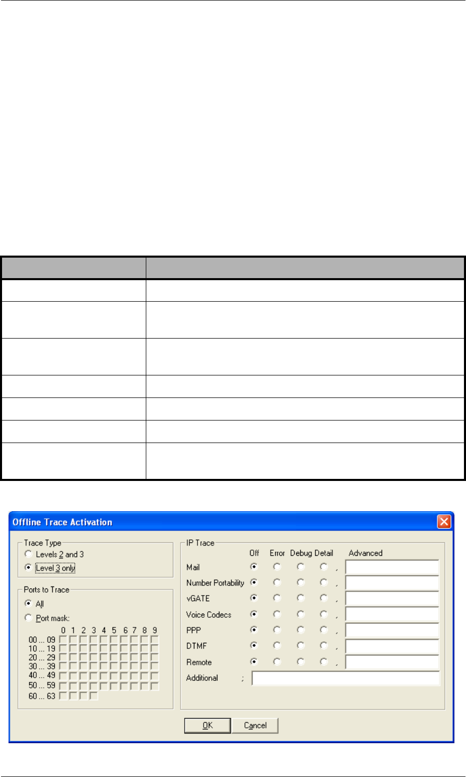
Page 148 © 2007 by TELES AG Berlin, Version 13.0/SH-e/04.16, Issue: April 2007
Trace System Maintenance and Software Update
Following transfer of the *.izg file, you must rename the *.tz.* file again and
restart the system.
10.4 Trace
During operation, the trace readouts of the TELES.iGATE can be saved in a file
or transmitted with remote maintenance directly. The trace options must be turned
on in the TELES.GATE Manager (offline or online trace) or via FTP raw com-
mands (see Chapter 4.10.2). Trace results presented here are for PRI,VoIP, FXS,
FXO, GSM/CDMA/UMTS interfaces and for the following services in various
levels:
Table 10-4 Trace Options
Option Definition
Mail Output for all SMTP packets.
NumberPortability Opuput of all packets for communication with the
TELES.iMNP.
vGATE Ouput of all packets for communication with the
TELES.vGATE.
VoiceCodecs Output of RTCP information described under VP module.
PPP Output of PPP connection information.
DTMF Output for DTMF tone recognition.
Remote Output for TELES.GATE Manager and TELES.NMS
communication.

© 2007 by TELES AG Berlin, Version 13.0/SH-e/04.16, Issue: April 2007 Page 149
System Maintenance and Software Update Trace
Figure 10-1 TELES.GATE Manager: Offline Trace Activation Window
TELES.iGATEs offer two different types of trace:
• Online - trace information is immediately displayed in the TELES.GATE
Manager’s trace window.
• Offline - trace information is written to a file on the TELES.iGATE.
TELES.iGATE systems create trace files when the TraceLog=file entry is
present in the pabx.cfg. Traces can be activated via remote administration
(TELES.GATE Manager or FTP).
Note: Please bear in mind that the volume of trace readouts can grow quite
large, so that faulty transmission of the trace data may result with re-
mote maintenance. A trace at full capacity can cause the system to
crash.
Trace Output Format
The following entries appear at the beginning and end of each trace:
•DD.MM.YY-hh:mm:ss.ss, Start
•DD.MM.YY-hh:mm:ss.ss, End
•DD = day
•hh = hour
•MM = month
•mm = minute
•YY = year
•ss.ss = hundredths of seconds
Traces appear in the following format:
•[<hh:mm:ss>] <module>[<port>]: <trace>
•<module>
•s = send for PRI/BRI or mobile ports
•r = receive for PRI/BRI or mobile ports
•x = send to VoIP destinations
•y = receive from VoIP destinations
•i = information messages and internal trace outputs between VoIP and the
other interfaces (ISDN, POTS, mobile)
•a = VoIP controllers RTCP output
•m = mail output
•g = remote output
•<port>
• port number (controller number in the pabx.cfg) or 255 if a service is
used

Page 150 © 2007 by TELES AG Berlin, Version 13.0/SH-e/04.16, Issue: April 2007
Trace System Maintenance and Software Update
•<trace>
• output in the defined syntax for the module
10.4.1 ISDN Trace Output
Trace output for DSS1 and SS7 are in hexadecimal notation. You can use the ex-
ternal tool TraceView.exe to translate offline trace output. You will find the
tool in the Software folder on the enclosed CD. The TELES.GATE Manager’s
trace window can also display translated online traces.
Example: The following example shows an untranslated DSS1 trace:
10.4.2 POTS Trace Output
Trace output for FXS and FXO controllers is in ASCII (text notation. the
<trace> part (see Chapter 10.4) is consists of <trace type>, followed di-
rectly by <trace output>.
10.4.2.1 Trace Types
Possible notations for <trace type> are described in Table 10-5.
17.05.06-09:54:40,Start 11.7a (L3)
[09:55:14.58] r[00]: 00 01 02 02 08 02 00 02 05 04 03 80 90 a3 18 03 a1 83 81 6c 02
81 31 70 06 81 31 32 33 34 35 7d 02 91 81
[09:55:14.58] s[00]: 02 01 02 04 08 02 80 02 0d 18 03 a9 83 81
[09:55:14.58] s[01]: 00 01 a8 9a 08 02 00 46 05 04 03 80 90 a3 18 03 a1 83 89 6c 02
81 31 70 06 81 31 32 33 34 35 7d 02 91 81
[09:55:14.58] r[01]: 02 01 9a aa 08 02 80 46 0d 18 03 a9 83 89
[09:55:14.86] r[01]: 02 01 9c aa 08 02 80 46 01
[09:55:14.86] s[00]: 02 01 04 04 08 02 80 02 01
[09:55:16.73] r[01]: 02 01 9e aa 08 02 80 46 07 29 05 05 07 01 09 33 4c 07 01 81 31
32 33 34 35
[09:55:16.73] s[01]: 00 01 aa a0 08 02 00 46 0f
[09:55:16.73] s[00]: 02 01 06 04 08 02 80 02 07 29 05 05 07 01 09 32 4c 07 01 81 31
32 33 34 35
[09:55:16.73] r[00]: 00 01 04 08 08 02 00 02 0f
[09:55:44.30] r[00]: 00 01 06 08 08 02 00 02 45 08 02 80 90
[09:55:44.35] s[01]: 00 01 ac a0 08 02 00 46 45 08 02 80 90
[09:55:46.71] r[01]: 02 01 a0 ae 08 02 80 46 4d
[09:55:46.71] s[01]: 00 01 ae a2 08 02 00 46 5a
[09:55:46.71] s[00]: 02 01 08 08 08 02 80 02 4d
[09:55:46.71] r[00]: 00 01 08 0a 08 02 00 02 5a
17.05.06-09:51:33,End
Table 10-5 POTS Trace Type
Trace Type Description
stt Output related to a status change in the POTS controller.
app Output related to the driver.
mid Output from the interface to the physical layer.
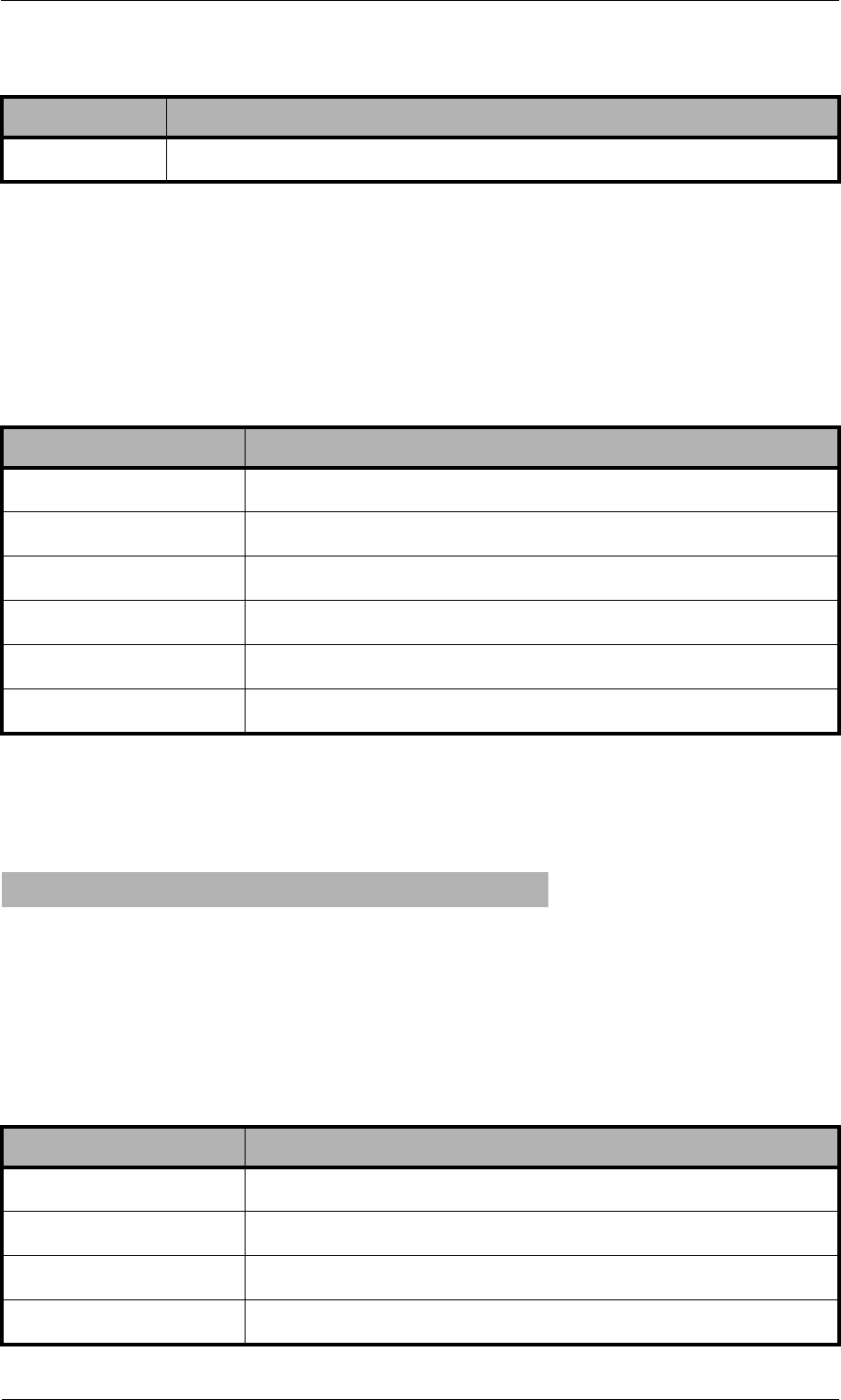
© 2007 by TELES AG Berlin, Version 13.0/SH-e/04.16, Issue: April 2007 Page 151
System Maintenance and Software Update Trace
10.4.2.2 sst Trace Output
The most important information appears in the controller status output stt,
which appears only if the controller’s state changes. Table 10-6 contains a descrip-
tion of possible trace output.
Example: In the following output example, FXS controller 05 (calling party)
has been in the ALERT state. This state changes to CONNECT as soon
as the called party picks up the phone:
10.4.2.3 app Trace Output
The application output app provides important information about the connection
process.
ton Information about tone recognition in the B-channel.
Table 10-6 sst Trace Output
Trace Output Description
IDLE Idle state.
UP A-subscriber has picked up the phone.
DIAL A-subscriber is dialing.
ALERT Alert state.
CONNECT Connecting.
AWAIT_HOOKDOWN Waiting for A-subscriber to hang up the phone.
[20:33.54] i[05]: sttALERT -> CONNECT
Table 10-7 app Trace Output
Trace Output Description
CONN_IND Connect indication
CONN_REQ Connect request
CONN_ACK Connect acknowledgment
ALRT_IND Alert indication
Table 10-5 POTS Trace Type (continued)
Trace Type Description
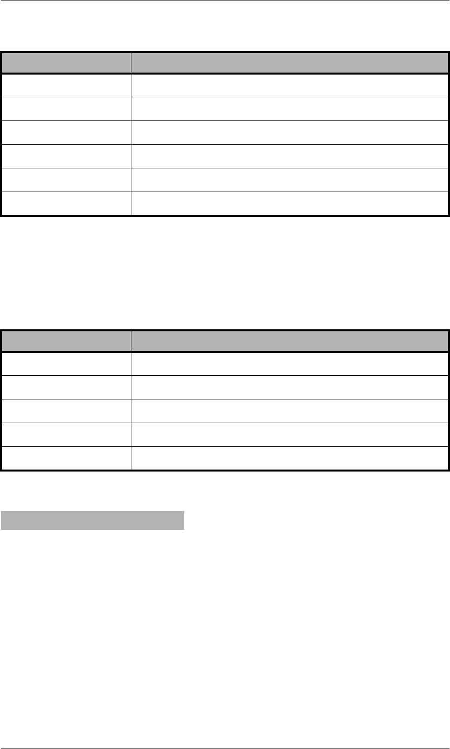
Page 152 © 2007 by TELES AG Berlin, Version 13.0/SH-e/04.16, Issue: April 2007
Trace System Maintenance and Software Update
10.4.2.4 mid Trace Output
mid traces are intended for monitoring the state of the physical layer and are de-
scribed in Table 10-8.
Example: In the following example, the digit 0 has been dialed:
10.4.2.5 ton Trace Output
The trace output ton provides information about tone recognition in the B-chan-
nel. Since they appear unabridged and are not of importance, no description is nec-
essary.
10.4.3 GSM/CDMA/UMTS Trace Output
The trace output for GSM appears in hexadecimal notation. Its format is the same
as that for ISDN output. Table 10-9 and Table 10-10 describe the contents of GSM
CONN_CNF Connect confirmation
CONN_RSP Connect response
DSC_IND Disconnect indication
DSC_REQ disconnect request
DSC_CNF Disconnect confirmation
info: Dialed digit
Table 10-8 mid Trace Output
Trace Output Description
+A-subscriber has picked up the phone.
bchan B-channel is connected.
up ’<DTMF>’ A-subscriber has entered a digit via DTMF.
dn cif <count> Number of impulses for each charge unit.
-A-subscriber has hung up the phone.
[30:23.21] i[05]: midup '0'
Table 10-7 app Trace Output (continued)
Trace Output Description
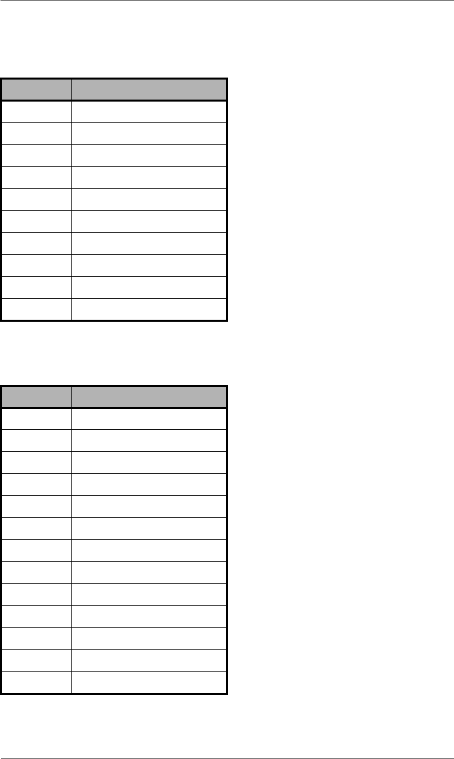
© 2007 by TELES AG Berlin, Version 13.0/SH-e/04.16, Issue: April 2007 Page 153
System Maintenance and Software Update Trace
trace output.
Example: The following example shows a GSM call through the fourth GSM
Table 10-9 Request Messages to the GSM Module
Hex Value Description
00 Setup
01 Connect
02 Disconnect
03 SMS
04 DTMF
05 Set Config
06 Get Config
07 LED
08 Restart
09 Switch SIM
Table 10-10 Incoming, Indication Message from the GSM Module
Hex Value Description
0B Alert
0C Voice Indication
0D Connect
0E DTMF
0F Setup
10 Disconnect
11 SMS
12 SMS Confirmation
13 Error
16 Get Config Confirmation
18 Dial-In Call Proceeding
19 USSD
1A Restart Indication

Page 154 © 2007 by TELES AG Berlin, Version 13.0/SH-e/04.16, Issue: April 2007
Trace System Maintenance and Software Update
controller:
10.4.4 VoIP Trace Output
As described above in Chapter 10.4, there are four modules for VoIP traces. The
groups x (send), y (receive) and i (information and internal output) appear when
a Layer2 or Layer3 offline or online trace is started. Group a (RTCP output) only
appears when the module Voice Codecs is active.
Particularly in the case of VoIP connections (protocols H.323 and SIP), the trace
output is quite extensive and abbreviations make it difficult to keep track of the
results. The following list contains a description of H.323 output.
Output for the signaling protocol SIP is transmitted in ASCII and translated for
better legibility. Since they are displayed unabridged, no description is necessary.
Information and internal output traces correspond with the H.323 output and are
described in the following tables. For ENUM, please refer to Chapter 10.4.4.5.
In general, the following rules apply for this trace output:
Status Request
[14:57:51.80] s[04]: 06
Status Information:
[14:57:51.80] r[04]: 16
Setup Request:
[14:57:52.29] s[04]: 00 4c 93 04 00 00 00 35 36 36 37 00 35 38 2c 36 34 36 2c 33 30
2c 2c 2c 30 2c 2c 2c 30 2c 32 36 32 2c 30 37 2c 00 72 64 09 75 70 20 7b 64 35 7d 20
27 2e 2e 2b 43 43 45 44 3a 20 32 36 32 2c 30 37 2c 34
Dial End:
[14:57:55.47] r[04]: 18
Alert:
[14:57:55.63] r[04]: 0b
Connect Indication:
[14:57:56.63] r[04]: 0d
Disconnect Request:
[14:59:54.13] s[04]: 02 4c 93 00
Disconnect Indication:
[14:59:54.19] r[04]: 10
Table 10-11 H.323 Output
Packet Description
h225 H.225-protocol messages.
h245 H.245-protocol messages.
pstn Messages of the internal protocol interface that provides the inter-
face to the other interfaces PRI, BRI and GSM.
rcv Coming from the IP network or the internal protocol interface; ap-
pears with <dir> in the trace lines.
snd Sending to the IP network or the internal protocol interface; appears
with <dir> in the trace lines.
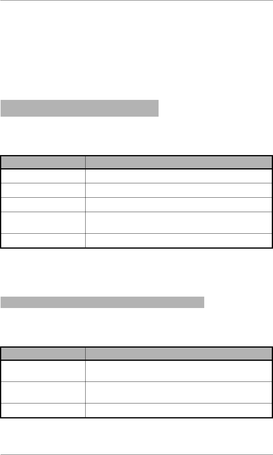
© 2007 by TELES AG Berlin, Version 13.0/SH-e/04.16, Issue: April 2007 Page 155
System Maintenance and Software Update Trace
The information is thoroughly analyzed where it is received (all rcv messages).
10.4.4.1 Interface IP Network
Establish H.323 Session
Usually there is trace output that displays a new H.323 session. The direction is
crucial (whether the call is going into or coming out of the IP network).
H.225 Signaling Output
The following trace results are for a call coming from the IP network. rcv will
appear at <dir> and signifies the direction:
h225connect to <ip address> cr <cr> s <si>
h225accept from <ip address> s <si>
Table 10-12 H.323 Session
Trace Output Description
connect to Outgoing VoIP call
accept from Incoming VoIP call
<ip address> Peer's IP address
cr <cr> Call reference (corresponds with the internal protocol in-
terface's PSTN call reference)
s <si> Session ID
h225<dir> tpkt msg 0x<mt> h225cr <cr> addr <ip address>
Table 10-13 H.225 Signaling
Trace Output Description
<mt> The ETS message type in hexadecimal; can consist of
values listed in Table 10-14.
<hcr> H.225 call reference in hexadecimal (does not have to be
unique when calls come from multiple peers).
<ip address> The peer's IP address.
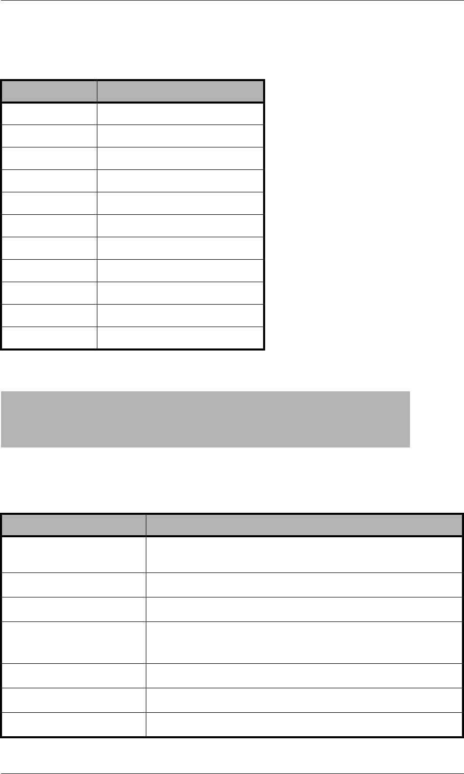
Page 156 © 2007 by TELES AG Berlin, Version 13.0/SH-e/04.16, Issue: April 2007
Trace System Maintenance and Software Update
The following lines show the packet contents in detail:
Table 10-14 ETS Message Types
Hex Value Message Type
1Alerting
2Call Proceeding
3Progress
5Setup
7Connect
DSetup Acknowledge
5A Release Complete
62 Facility
6E Notify
7B Information
7D Status
h225 decode rc 0, q931 msg 0x<mt> = 0, len <length>
h225<type> <mt> voipcfg addr <ip address> rc 0 compr <codec>
h225<type> <mt> h225cr <hcr> FS:<bool> (<codec>,<ip address>,<port>)
TUNN:<bool> H245:<bool>(<ip address>,<port>)
h225<type> <mt> h225cr <hcr> cr <cr>
Table 10-15 Incoming VoIP Calls
Trace Output Description
<mt> Message type in hexadecimal as per ETS standard (see
Table 10-14) or written out as a name.
len <length> Packet length in bytes.
h225<type> H.225 rcv or send; received or sent from the IP network.
addr <ip
address>
Peer's IP address.
compr <codec> Peer's compression list (see Table 10-16).
FS<bool> FastStart offered in the signaling packet or not.
(<codec>, Lists codecs offered (seeTable 10-33).

© 2007 by TELES AG Berlin, Version 13.0/SH-e/04.16, Issue: April 2007 Page 157
System Maintenance and Software Update Trace
<ip address>, Peer's IP address for RTP data.
<port>) Peer's port for RTP Data.
Tunn<bool> Shows whether or not tunneling is offered as a signaling
variant.
H245<bool> Shows an extra H.245 session.
(ip address, Peer's IP address.
port) Peer's port.
h225cr <hcr> H.225 message's call reference (does not have to be
unique when calls come from multiple VoIP peers).
cr <cr> Internal call reference (always unique for the call).
Table 10-16 Compression Codecs Used
Synonym Codec
AG.711Alaw64k
BG.711Ulaw64k
CG.7231
DG.7 28
EG.7 29
FgsmFullRate
GT.38fax
HNC48
INC56
JNC64
KNC72
LNC80
MNC88
NNC96
OG.729A
PG.72616
Table 10-15 Incoming VoIP Calls (continued)
Trace Output Description
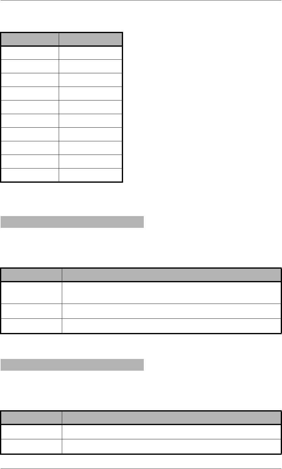
Page 158 © 2007 by TELES AG Berlin, Version 13.0/SH-e/04.16, Issue: April 2007
Trace System Maintenance and Software Update
When the call is sent in the direction of the IP network, the trace will include only
the most important information:
Or:
QG.72624
RG.72632
SG.729B
TG.729AB
UG.729E
VG.723L
WTransparent
XG.721
YiLBC20
ZiLBC30
h225<type> <mt1> dad <num> cr <cr>
Table 10-17 Calls to the IP Network 1
Trace Output Description
<mt> Message type written out; if a decimal number appears here, it will
be translated as per Table 10-14.
<num> Called party number.
<cr> Call reference.
h225<type> callproc typ <mt> cr <cr>
Table 10-18 Calls to the IP Network 2
Trace Output Description
<mt> The ETS message type in hexadecimal.
<cr> Call reference.
Table 10-16 Compression Codecs Used (continued)
Synonym Codec
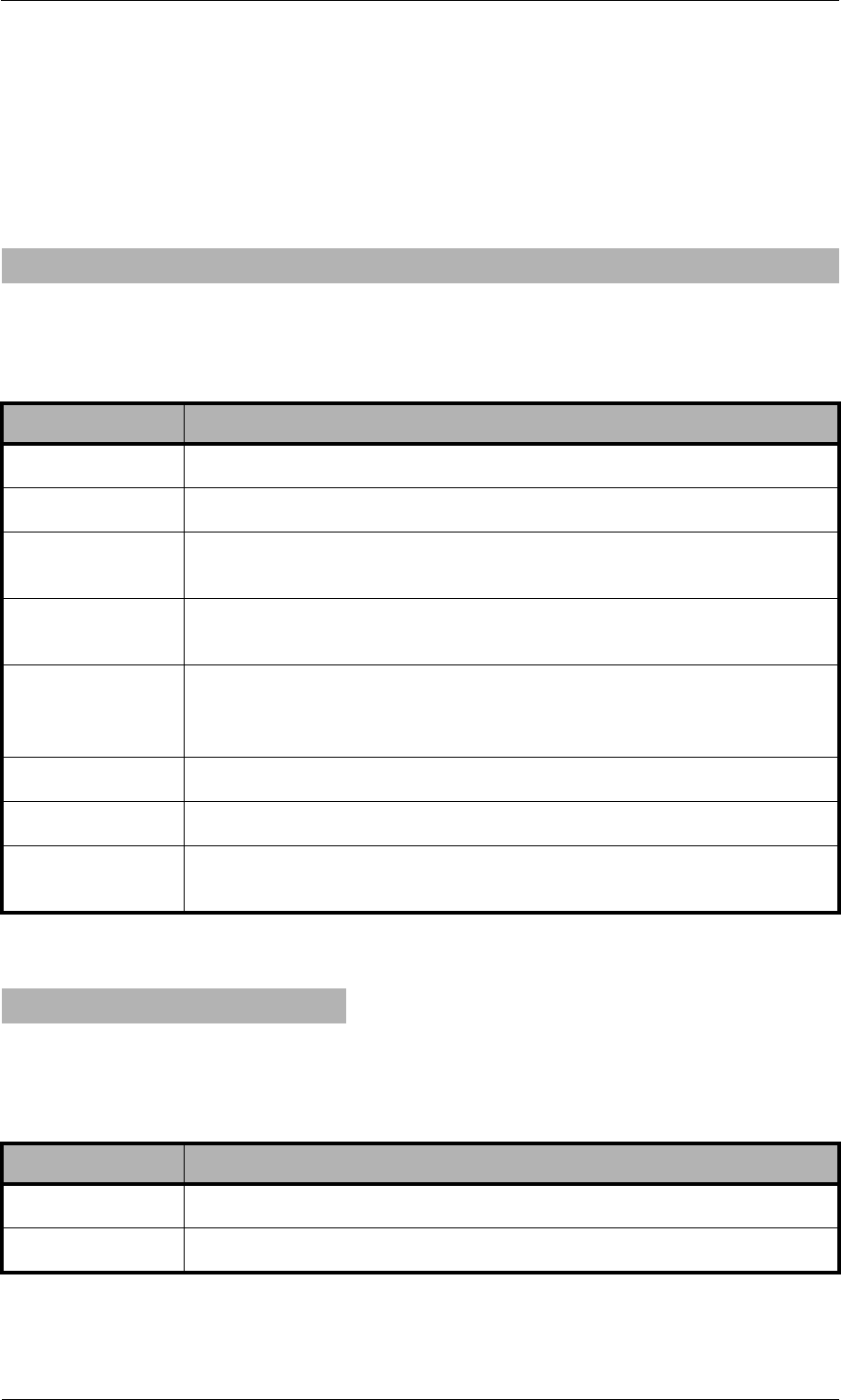
© 2007 by TELES AG Berlin, Version 13.0/SH-e/04.16, Issue: April 2007 Page 159
System Maintenance and Software Update Trace
RTP/RTCP Output
The RTP/RTCP output displays whether the signaling information corresponds
with the contents of the compression chips. The output occurs when a media chan-
nel is set up or torn down:
VP Module
rtp start cr <cr> ch <ch> li <li> ri <ri> st <st> fx <fx> cp <comp> txm <factor>
Table 10-19 RTP/RTCP Output
Trace Output Description
<cr> Call reference.
<ch> The internal media channel used.
<li> 1 appears when the local RTP address (and port) has been de-
fined.
<ri> 1 appears when the remote RTP address (and port) have been
established.
<st> 0 appears if the channel's voice packetizer has not yet been start-
ed. 1 appears if the voice packetizer can receive, but not send. 2
appears when the voice packetizer can receive and send.
<fx> 1 appears when T.38 (fax) is used, otherwise 0.
<comp> The codec used, as per Table 10-16.
<factor> Multiplication factor for default frame size (20ms, 30 ms for
G.723).
rtp stop cr <cr>1 ch <ch>
Table 10-20 RTP Stop Message
Trace Output Description
<cr> Call reference.
<ch> The internal media channel used.
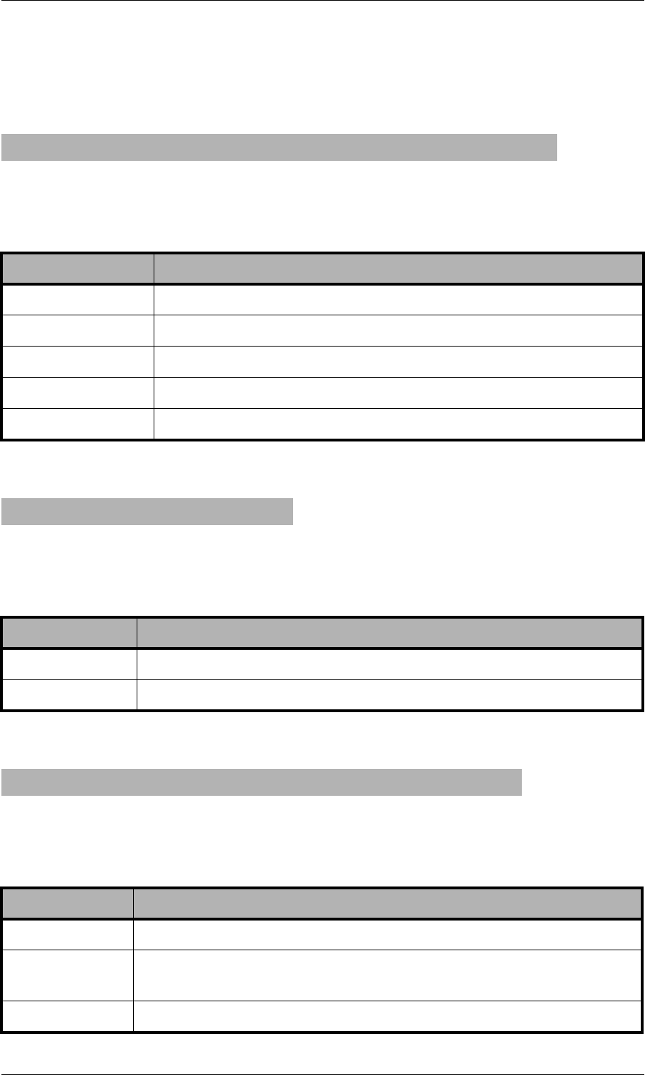
Page 160 © 2007 by TELES AG Berlin, Version 13.0/SH-e/04.16, Issue: April 2007
Trace System Maintenance and Software Update
This module's output shows the controller packets for the voice connections. That
means that the RTCP packets and relevant information also appear.
The following results occur for a new RTP connection:
Sent and received bytes appear with the following output results:
vp start(val) ch=<ch> local=<port> remote=<ip address>:<port> agg=<bool>
Table 10-21 RTP/RTCP Output (VP Module)
Trace Output Description
<val> Shows which connection is set up.
<ch> The internal media channel used.
<port> RTP port.
<ip address> Peer's IP address in hexadecimal.
agg=<bool> 1 means an RTP-multiplex connection is used (default 0).
vp iostat <ch>: in <byte> out <byte>
Table 10-22 RTP Packet Statistics
Trace Output Description
<ch> The internal media channel used.
<byte> The call's received or sent bytes.
rtcp <ch>: SR <dir> pc <pc> oc <oc> ji <ji> rt <rt> fl <fl> cl <cl>
Table 10-23 RTCP Packet Statistics
Trace Output Description
<ch> The internal media channel used.
SR<dir> Rx sender report (received) is more interesting, since it comes
from the peer. Tx sender report (transmitted).
<pc> Packet count (number of packets transmitted/received).
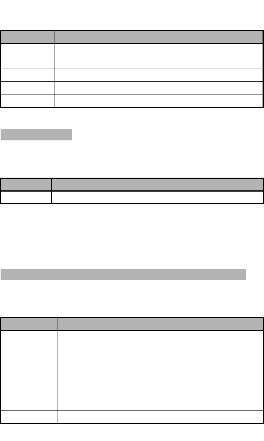
© 2007 by TELES AG Berlin, Version 13.0/SH-e/04.16, Issue: April 2007 Page 161
System Maintenance and Software Update Trace
An RTP connection has ended when the following trace output appears:
10.4.4.2 Internal Protocol Interface (to ISDN, POTS, Mobile)
These trace outputs always begin with the keyword pstn, followed by the direc-
tion and the message type. The message is then either concluded or other informa-
tion follows:
<oc> Octet count (number of octets transmitted/received).
<ji> Delay jitter [msec].
<rt> Round-trip local<->remote, round-trip delay [msec].
<fl> Fraction lost: Fraction of packets lost [8lsb].
<cl> Cumulative lost: number of lost packets [24lsb].
vp stop ch=<ch>
Table 10-24 RTP Stop Message (VP Module)
Trace Output Description
<ch> The internal media channel used.
pstn<type> <mt1> dad <num> oad <num> cr <cr> s <si> ch <chan> isdncr<icr>
Table 10-25 Internal Protocol Interface
Trace Output Description
<type> Direction from (rcv) or to (snd) the internal protocol interface.
<mt1> Message type written out; if a decimal number appears, it will be
translated as per Table 10-14.
<num> DAD<num> = called party number, OAD<num> = calling party
number.
<cr> Call reference.
<si> Session ID.
<chan> Media channel used.
Table 10-23 RTCP Packet Statistics (continued)
Trace Output Description
Page 162 © 2007 by TELES AG Berlin, Version 13.0/SH-e/04.16, Issue: April 2007
Trace System Maintenance and Software Update
Output also appears when a call comes from the internal protocol interface and is
assigned to a VoIP profile. The characters appear in front of the colon in the rout-
ing entry:
Assignment of media channel used for the internal interface and the ISDN call ref-
erence for the VoIP call's appears as follows:
10.4.4.3 H.245 Messages
The following trace output is possible:
<icr> Call reference for the internal protocol interface (DSS1).
pstnrcv get_voipcfg <voip profile>
Table 10-26 Received from PSTN 1
Trace Output Description
<voip profile> Defines the VoIP profile to be used.
pstnrcv bchanind cr <cr> ch <chan> isdncr <icr>
Table 10-27 Received from PSTN 2
Trace Output Description
<cr> Call reference.
<chan> Media channel used for the internal protocol interface (DSS1).
<icr> Call reference for the internal protocol interface (DSS1).
h245<dir>(<tt>) cr <cr>
Table 10-25 Internal Protocol Interface (continued)
Trace Output Description
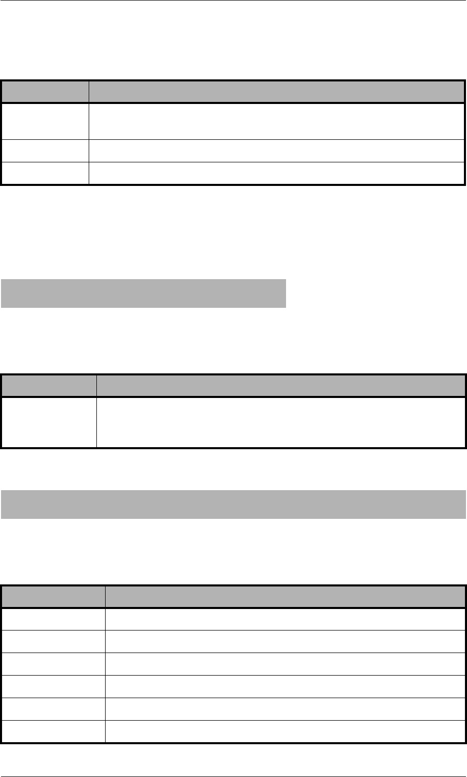
© 2007 by TELES AG Berlin, Version 13.0/SH-e/04.16, Issue: April 2007 Page 163
System Maintenance and Software Update Trace
Following this trace output, either a detailed description of the message and its
corresponding message type, including negotiating information, or trace output el-
ements that are explained later appear. The most important message types that
contain further information elements are as follows:
Table 10-28 H.245 Messages
Trace Output Description
<dir> The message's direction; rcv (incoming from the peer) or snd (sent
message).
<tt> H.245 transport type.
<cr> Internal call reference.
... TerminalCapabilitySet peer=<comp> cfg=<comp>
... TerminalCapabilitySet <comp>
Table 10-29 Codec Used
Trace Output Description
<comp> List of compression codecs offered (see Table 10-16), the list of the
peer's codecs appears behind peer, and cfg shows which codecs
are defined in the VoIP profile
... OpenLogicalChannel cn=<cn> cpr=<comp> sessid=<sid> ctrl=<ip address>:<rtcp port>
... OpenLogicalChannelAck cn=<cn> sessid=<sid> media=<ip address>:<rtp port>
Table 10-30 Logical Channel Parameters
Trace Output Description
<cn> H.245 channel number per H.225 connection.
<sid> Session ID.
<comp> Codec used (see Table 10-16).
<ip address> Protocol peer IP address.
<rtcp port> Port used for the protocol RTCP.
<rtp port> Port used for the protocol RTP.
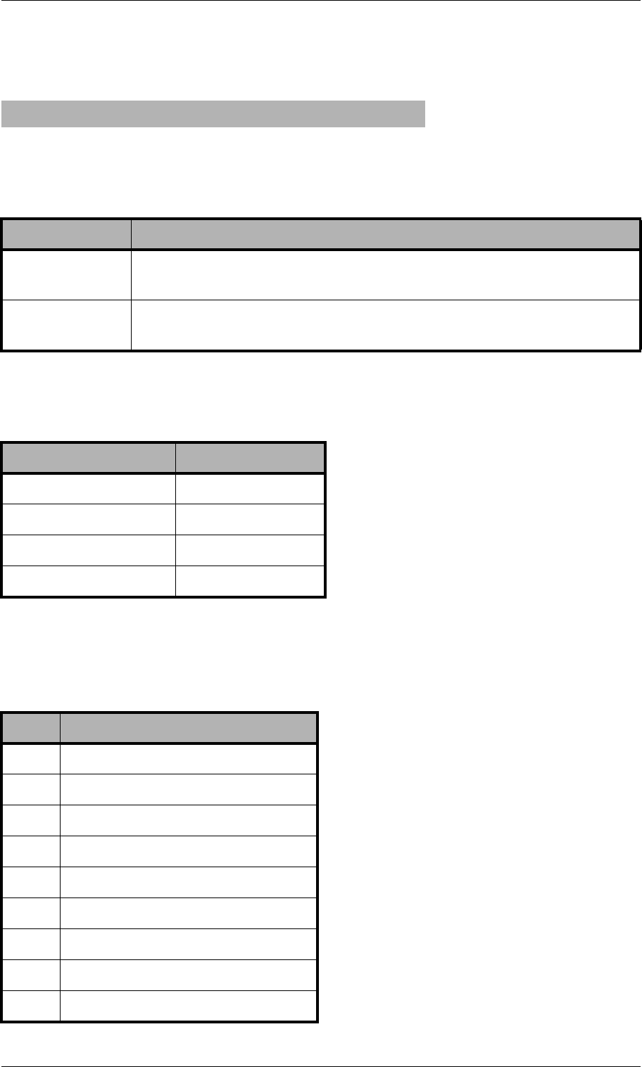
Page 164 © 2007 by TELES AG Berlin, Version 13.0/SH-e/04.16, Issue: April 2007
Trace System Maintenance and Software Update
The trace output is as follows when the message type is not translated or is ig-
nored:
Depending on the system control message type, one of the following message IDs
appear:
h245<dir>(<tt>) cr <cr> unknown msg <hmt> <hmi>
Table 10-31 H.245 Parameters
Trace Output Description
hmt The H.245 message type (multimedia system control message
type), (Table 10-32).
hmi The H.245 message ID (see Table 10-33, Table 10-34, Table
10-35, Table 10-36).
Table 10-32 Multimedia System Control Message Types
ID Message
0 (Table 10-33) Request
1 (Table 10-34) Response
2 (Table 10-35) Command
3 (Table 10-36) Indication
Table 10-33 Message IDs for Request Message
ID Message
0NonStandard
1MasterSlaveDetermination
2TerminalCapabilitySet
3OpenLogicalChannel
4CloseLogicalChannel
5RequestChannelClose
6MultiplexEntrySend
7RequestMultiplexEntry
8RequestMode

© 2007 by TELES AG Berlin, Version 13.0/SH-e/04.16, Issue: April 2007 Page 165
System Maintenance and Software Update Trace
9RoundTripDelayRequest
10 MaintenanceLoopRequest
11 CommunicationModeRequest
12 ConferenceRequest
13 MultilinkRequest
14 LogicalChannelRateRequest
Table 10-34 Message IDs for Response Message
ID Message
0NonStandard
1MasterSlaveDeterminationAck
2MasterSlaveDeterminationReject
3TerminalCapabilitySetAck
4TerminalCapabilitySetReject
5OpenLogicalChannelAck
6OpenLogicalChannelReject
7CloseLogicalChannelAck
8RequestChannelCloseAck
9RequestChannelCloseReject
10 MultiplexEntrySendAck
11 MultiplexEntrySendReject
12 RequestMultiplexEntryAck
13 RequestMultiplexEntryReject
14 RequestModeAck
15 RequestModeReject
16 RoundTripDelayResponse
17 MaintenanceLoopAck
18 MaintenanceLoopReject
19 CommunicationModeResponse
Table 10-33 Message IDs for Request Message (continued)
ID Message
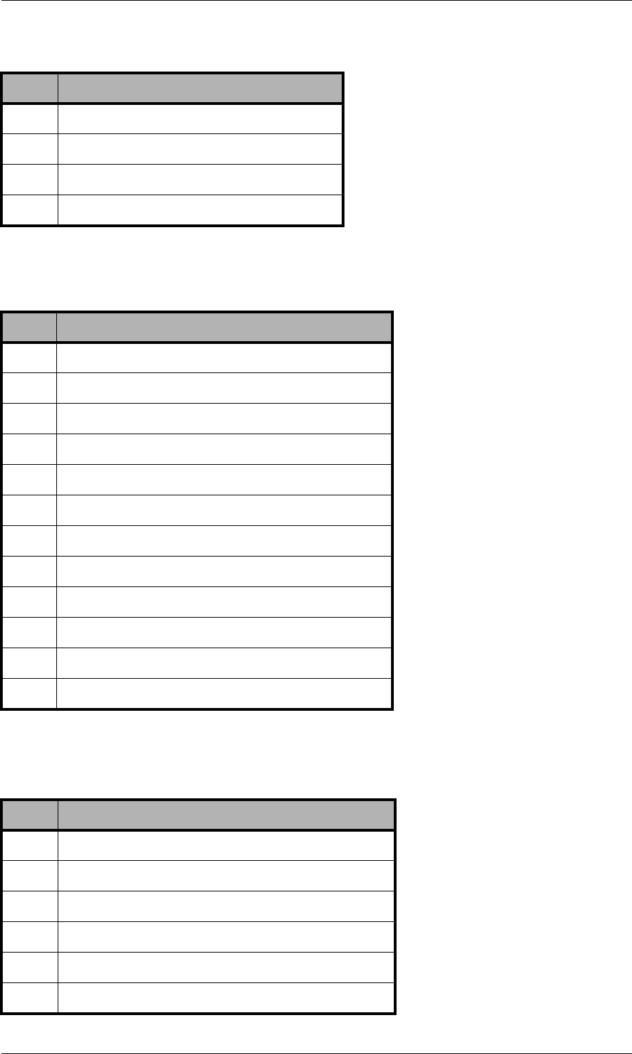
Page 166 © 2007 by TELES AG Berlin, Version 13.0/SH-e/04.16, Issue: April 2007
Trace System Maintenance and Software Update
20 ConferenceResponse
21 MultilinkResponse
22 LogicalChannelRateAcknowledge
23 LogicalChannelRateReject
Table 10-35 Message IDs for Command Message
ID Message
0NonStandard
1MaintenanceLoopOffCommand
2SendTerminalCapabilitySet
3EncryptionCommand
4FlowControlCommand
5EndSessionCommand
6MiscellaneousCommand
7CommunicationModeCommand
8ConferenceCommand
9h223MultiplexReconfiguration
10 NewATMVCCommand
11 MobileMultilinkReconfigurationCommand
Table 10-36 Message IDs For Indication Message
ID Message
0NonStandard
1FunctionNotUnderstood
2MasterSlaveDeterminationRelease
3TerminalCapabilitySetRelease
4OpenLogicalChannelConfirm
5RequestChannelCloseRelease
Table 10-34 Message IDs for Response Message (continued)
ID Message
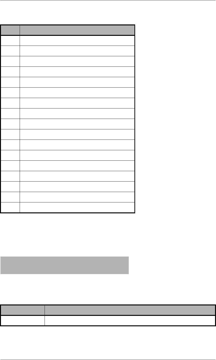
© 2007 by TELES AG Berlin, Version 13.0/SH-e/04.16, Issue: April 2007 Page 167
System Maintenance and Software Update Trace
10.4.4.4 RAS (Registration, Admission, Status)
As a general rule, the most important terminal and gatekeeper messages appear
written out with the gatekeeper's IP address (<ip addr>):
6MultiplexEntrySendRelease
7RequestMultiplexEntryRelease
8RequestModeRelease
9MiscellaneousIndication
10 JitterIndication
11 h223SkewIndication
12 NewATMVCIndication
13 UserInput
14 h2250MaximumSkewIndication
15 McLocationIndication
16 ConferenceIndication
17 VendorIdentification
18 FunctionNotSupported
19 MultilinkIndication
20 LogicalChannelRateRelease
21 FlowControlIndication
22 MobileMultilinkReconfigurationIndication
H225 GatekeeperRequest to <ip addr> (s 131)
H225 GatekeeperConfirm <ip addr>
H225 GatekeeperReject <ip addr> reason <reason>
Table 10-37 RAS
Trace Output Description
<reason> Gatekeeper reject reason, see Table 10-41.
Table 10-36 Message IDs For Indication Message (continued)
ID Message
Page 168 © 2007 by TELES AG Berlin, Version 13.0/SH-e/04.16, Issue: April 2007
Trace System Maintenance and Software Update
All other messages appear as follows:
H225 GkRegistration to <ip addr>
H225 RegistrationConfirm <ip addr>
H225 RegistrationReject <ip addr> reason <reason>
Table 10-38 Gatekeeper 1
Trace Output Description
<reason> Registration reject reason, see Table 10-42.
H225 GkResourcesAvailableIndicate to <ip addr> (<act chan> <max chan>)
H225 ResourcesAvailableConfirm <ip addr>
H225 GkAdmission cr <cr> to <ip addr>
H225 AdmissionConfirm <ip addr> cr <cr>
H225 AdmissionReject <ip addr> reason <reason>
Table 10-39 Gatekeeper 2
Trace Output Description
<reason> Admission reject reason, see Table 10-43.
H225 GkDisengage cr <cr> to <ip addr>
H225 DisengageConfirm <ip addr>
H225 UnregistrationRequest <ip addr>
H225 GkUnregistrationConf to <ip addr>
H225 unknown msg from Gk <ip addr>: <code>
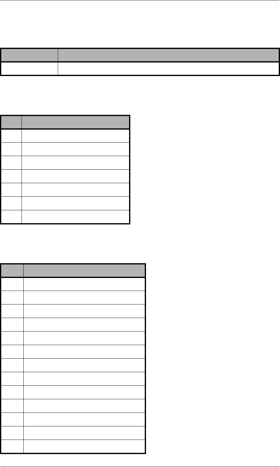
© 2007 by TELES AG Berlin, Version 13.0/SH-e/04.16, Issue: April 2007 Page 169
System Maintenance and Software Update Trace
Table 10-40 Gatekeeper 3
Trace Output Description
<code> Unknown gatekeeper message, see Table 10-44.
Table 10-41 Gatekeeper Reject Reason
ID Reject Reason
0resourceUnavailable
1terminalExcluded
2invalidRevision
3undefinedReason
4securityDenial
5genericDataReason
6neededFeatureNotSupported
Table 10-42 Registration Reject Reason
ID Reject Reason
0DiscoveryRequired
1InvalidRevision
2InvalidCallSignalAddress
3InvalidRASAddress
4DuplicateAlias
5InvalidTerminalType
6UndefinedReason
7TransportNotSupported
8TransportQOSNotSupported
9ResourceUnavailable
10 InvalidAlias
11 SecurityDenial
12 RullRegistrationRequired
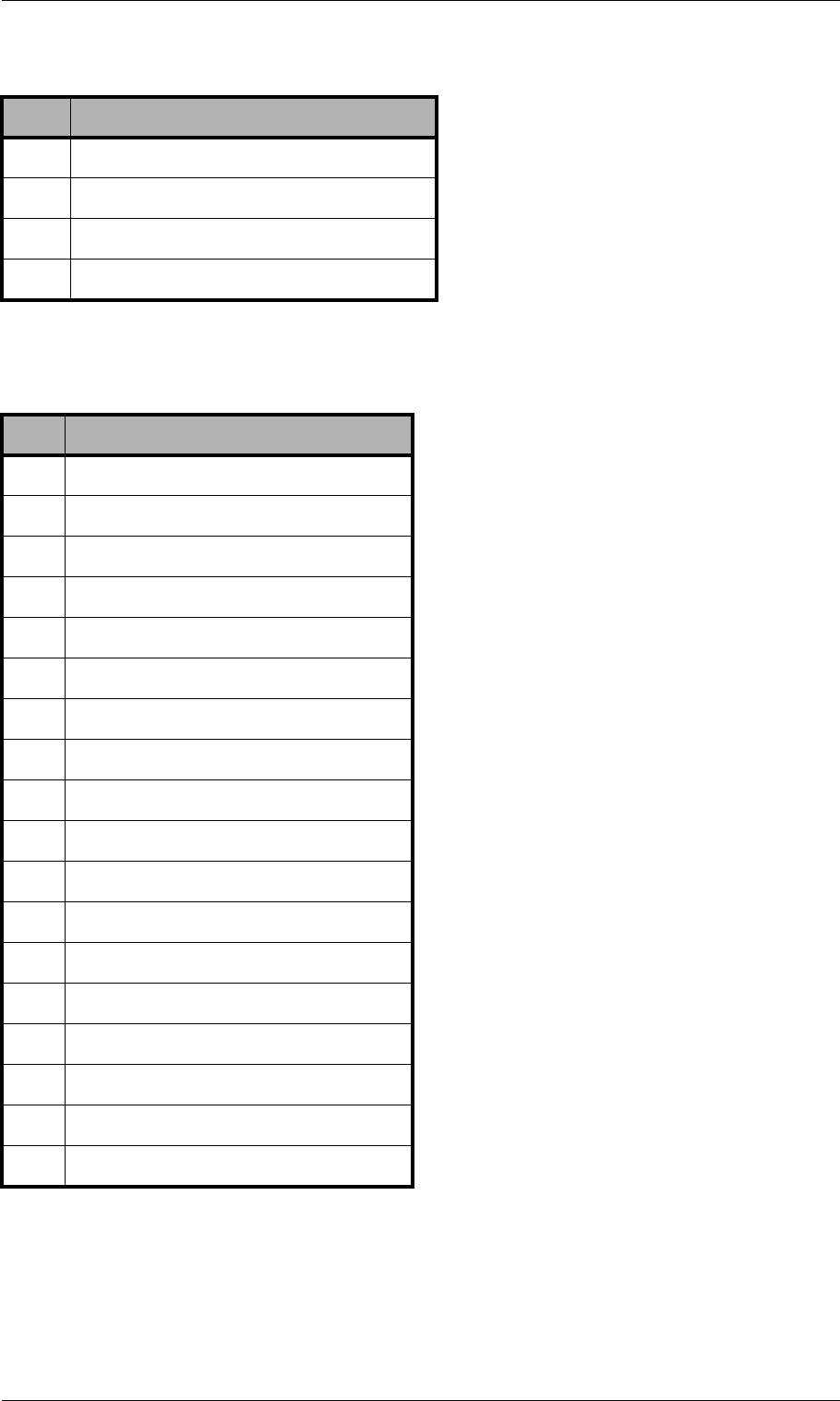
Page 170 © 2007 by TELES AG Berlin, Version 13.0/SH-e/04.16, Issue: April 2007
Trace System Maintenance and Software Update
13 AdditiveRegistrationNotSupported
14 InvalidTerminalAliases
15 GenericDataReason
16 NeededFeatureNotSupported
Table 10-43 Admission Reject Reason
ID Reject Reason
0CalledPartyNotRegistered
1InvalidPermission
2RequestDenied
3UndefinedReason
4CallerNotRegistered
5RouteCallToGatekeeper
6InvalidEndpointIdentifier
7ResourceUnavailable
8SecurityDenial
9QosControlNotSupported
10 IncompleteAddress
11 AliasesInconsistent
12 RouteCallToSCN
13 ExceedsCallCapacity
14 CollectDestination
15 CollectPIN
16 GenericDataReason
17 NeededFeatureNotSupported
Table 10-42 Registration Reject Reason (continued)
ID Reject Reason

© 2007 by TELES AG Berlin, Version 13.0/SH-e/04.16, Issue: April 2007 Page 171
System Maintenance and Software Update Trace
Table 10-44 Unknown Gatekeeper Messages
ID Message
0GatekeeperRequest
1GatekeeperConfirm
2GatekeeperReject
3RegistrationRequest
4RegistrationConfirm
5RegistrationReject
6UnregistrationRequest
7UnregistrationConfirm
8UnregistrationReject
9AdmissionRequest
10 AdmissionConfirm
11 AdmissionReject
12 BandwidthRequest
13 BandwidthConfirm
14 BandwidthReject
15 DisengageRequest
16 DisengageConfirm
17 DisengageReject
18 LocationRequest
19 LocationConfirm
20 LocationReject
21 InfoRequest
22 InfoRequestResponse
23 NonStandardMessage
24 UnknownMessageResponse
25 RequestInProgress
26 ResourcesAvailableIndicate
27 ResourcesAvailableConfirm
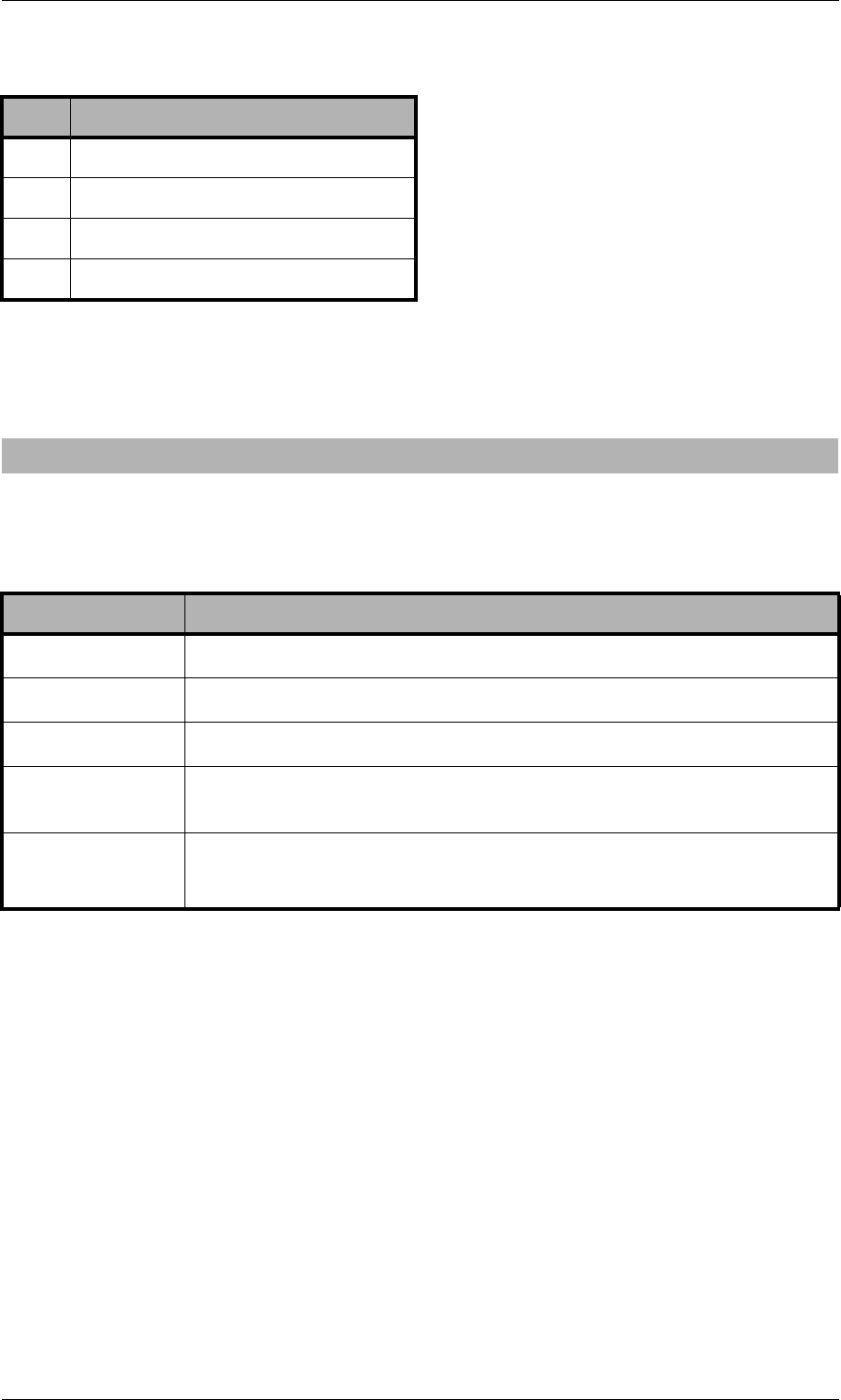
Page 172 © 2007 by TELES AG Berlin, Version 13.0/SH-e/04.16, Issue: April 2007
Trace System Maintenance and Software Update
10.4.4.5 ENUM Output
This output is assigned to group i and occurs with Layer2 and Layer3 traces:
10.4.4.6 Examples
The following examples are offline traces. You can generate them using the
TELES.GATE Manager or FTP commands. The filename is trace.log. The
following cases appear in the examples:
•Incoming H323 Call with FastStart
•Outgoing H323 Call with FastStart
•Fax Call
28 InfoRequestAck
29 InfoRequestNak
30 ServiceControlIndication
31 ServiceControlResponse
i[<controller>]: enum_query cr <CR> ch <CH>: <num> -> <length> <<answer pattern>>
Table 10-45 ENUM Output
Trace Output Description
<cr> Call reference.
<ch> Media channel.
<num> Phone number converted into ENUM domain format.
<length> Length of the answer field in the DNS response in bytes. 0 ap-
pears if the number was not found.
<answer
pattern>
Displays the DNS response. 0 appears if the number was not
found.
Table 10-44 Unknown Gatekeeper Messages (continued)
ID Message

© 2007 by TELES AG Berlin, Version 13.0/SH-e/04.16, Issue: April 2007 Page 173
System Maintenance and Software Update Trace
Incoming H323 Call with FastStart
[15:25:13.65] i[02]: h225accept from 172.16.0.200 s 4
[15:25:13.75] y[02]: h225rcv tpkt msg 5 h225cr 8006 addr 172.16.0.200 pt 0
[15:25:13.75] y[02]: h225 decode rc 0, q931 msg 5 (0), len 364
[15:25:13.75] y[02]: h225rcv setup voipcfg addr 172.16.0.200 rc 0 <DF> compr EABG
[15:25:13.75] y[02]: h225rcv faststart <A1B1E1G0>
[15:25:13.75] y[02]: h225rcv setup oad 01 00 <111> <> dad 01 <123456> rad <> bc
038090a3 0101
[15:25:13.75] y[02]: h225rcv setup h225cr 8006 FS:1(E,172.16.0.200,29000) TUNN:1
H245:0(0,0)
[15:25:13.75] y[02]: h225rcv setup h225cr 8006 cr 7
[15:25:13.75] i[02]: pstnsnd setup dad 123456 oad 1 cr 7 s 4
[15:25:13.75] s[00]: 00 01 52 4c 08 02 00 08 05 04 03 80 90 a3 18 03 a1 83 87 6c 04
81 31 31 31 70 07 81 31 32 33 34 35 36 7d 02 91 81
[15:25:13.75] i[02]: pstnrcv connresp cr 7 acc 5 ch 1
[15:25:13.75] x[02]: h225snd callproc typ d cr 7 pri 0
[15:25:13.75] r[00]: 00 01 01 54
[15:25:13.75] r[00]: 02 01 4c 54 08 02 80 08 0d 18 03 a9 83 87
[15:25:13.75] s[00]: 02 01 01 4e
[15:25:14.33] r[00]: 02 01 4e 54 08 02 80 08 01
[15:25:14.33] s[00]: 02 01 01 50
[15:25:14.33] i[02]: pstnrcv alert cr 7 cls ff
[15:25:14.33] i[02]: rtp start cr 7 ch 1 li 1 ri 1 st 2 fx 0 cp E txm 1
[15:25:14.33] x[02]: h225snd callproc typ 1 cr 7 pri 8
[15:25:14.34] a[02]: vp start(201) ch=0 local=29000 remote=ac1000c8:29000 agg=0
pcm=0
[15:25:14.38] a[02]: vp rtcp 0: RR Tx pc 0 oc 0 ji -1 rt 0 fl -1 cl -1
[15:25:14.38] a[02]: vp ch 0: in 0 out 74
[15:25:15.57] r[00]: 02 01 50 54 08 02 80 08 07 29 05 06 03 18 0f 17 4c 06 01 81 31
37 33 31
[15:25:15.57] s[00]: 00 01 54 52 08 02 00 08 0f
[15:25:15.57] i[02]: pstnrcv connresp cr 7 acc 10 ch 255
[15:25:15.57] x[02]: h225snd callproc typ 7 cr 7 pri 0
[15:25:15.58] r[00]: 00 01 01 56
[15:25:17.01] a[02]: vp rtcp 0: SR Rx pc 110 oc 1816 ji 158 rt -1 fl 2 cl 1
[15:25:20.09] a[02]: vp rtcp 0: SR Tx pc 277 oc 5496 ji 164 rt 0 fl 0 cl 0
[15:25:20.09] a[02]: vp ch 0: in 18166 out 20646
[15:25:20.09] a[02]: vp rtcp 0: SR Rx pc 258 oc 4634 ji 208 rt -1 fl 0 cl 1
[15:25:23.32] a[02]: vp rtcp 0: SR Tx pc 441 oc 8776 ji 176 rt 0 fl 0 cl 0
[15:25:23.32] a[02]: vp ch 0: in 28966 out 32900
[15:25:24.68] y[02]: h225rcv tpkt msg 5a h225cr 8006 addr 172.16.0.200 pt 800e7800
[15:25:24.68] y[02]: h225 decode rc 0, q931 msg 5a (5), len 33
[15:25:24.68] y[02]: h225rcv relack h225cr 8006 FS:0(-,0,0) TUNN:1 H245:0(0,0)
[15:25:24.68] y[02]: h225rcv relack h225cr 8006 cau 0x10
[15:25:24.68] i[02]: rtp hold cr 7 ch 1
[15:25:24.68] s[00]: 00 01 56 52 08 02 00 08 45 08 02 80 90
[15:25:24.68] i[02]: h225 connection 4 terminated
[15:25:24.69] r[00]: 00 01 01 58
[15:25:25.89] r[00]: 02 01 52 58 08 02 80 08 4d
[15:25:25.89] s[00]: 00 01 58 54 08 02 00 08 5a
[15:25:25.94] i[02]: pstnrcv terminate connection (3201) cr 7 cau 1 err 16 state 17
ch 1 rsid 1
[15:25:25.94] i[02]: rtp stop cr 7 ch 1
[15:25:25.94] r[00]: 00 01 01 5a
[15:25:25.94] a[02]: vp ch 0: in 34096 out 38154
[15:25:25.94] a[02]: vp stop ch=0

Page 174 © 2007 by TELES AG Berlin, Version 13.0/SH-e/04.16, Issue: April 2007
Trace System Maintenance and Software Update
Outgoing H323 Call with FastStart
[15:04:09.12] r[00]: 02 01 46 48 08 02 22 54 05 04 03 80 90 a3 18 03 a9 83 94 6c 06
01 81 31 31 31 31 70 04 81 33 32 31 7d 02 91 81
[15:04:09.12] s[00]: 02 01 01 48
[15:04:09.12] s[00]: 00 01 48 48 08 02 a2 54 0d 18 03 a9 83 94
[15:04:09.12] i[02]: pstnrcv setup dad DF:321 oad 1111 cc 0 id 15d006
[15:04:09.12] i[02]: pstnrcv get_voipcfg <DF>
[15:04:09.12] i[02]: h225connect to 172.16.0.200 cr 6
[15:04:09.12] x[02]: h225snd setup dad 1 cr 6
[15:04:09.12] r[00]: 00 01 01 4a
[15:04:09.15] y[02]: h225rcv tpkt msg d h225cr 6 addr 172.16.0.200 pt 80412800
[15:04:09.15] y[02]: h225 decode rc 0, q931 msg d (11), len 32
[15:04:09.15] y[02]: h225rcv msg d (11) h225cr 6 FS:0(-,0,0) TUNN:1 H245:0(0,0)
[15:04:09.50] y[02]: h225rcv tpkt msg 1 h225cr 6 addr 172.16.0.200 pt 80412800
[15:04:09.50] y[02]: h225 decode rc 0, q931 msg 1 (3), len 121
[15:04:09.50] y[02]: h225rcv faststart <E1>
[15:04:09.50] y[02]: h225rcv alert h225cr 6 FS:1(E,172.16.0.200,29000) TUNN:1
H245:0(0,0)
[15:04:09.50] i[02]: rtp start cr 6 ch 1 li 1 ri 1 st 2 fx 0 cp E txm 1
[15:04:09.50] s[00]: 00 01 4a 48 08 02 a2 54 01 1e 02 80 88
[15:04:09.50] a[02]: vp start(201) ch=0 local=29000 remote=ac1000c8:29000 agg=0
pcm=0
[15:04:09.50] r[00]: 00 01 01 4c
[15:04:09.53] a[02]: vp rtcp 0: RR Tx pc 0 oc 0 ji -1 rt 0 fl -1 cl -1
[15:04:09.53] a[02]: vp ch 0: in 0 out 74
[15:04:11.79] y[02]: h225rcv tpkt msg 7 h225cr 6 addr 172.16.0.200 pt 80412800
[15:04:11.79] y[02]: h225 decode rc 0, q931 msg 7 (2), len 79
[15:04:11.79] y[02]: h225rcv connect h225cr 6 FS:0(-,0,0) TUNN:1 H245:0(0,0)
[15:04:11.79] i[02]: pstnsnd connect cr 6
[15:04:11.79] s[00]: 00 01 4c 48 08 02 a2 54 07
[15:04:11.80] r[00]: 02 01 48 4e 08 02 22 54 0f
[15:04:11.80] s[00]: 02 01 01 4a
[15:04:12.50] a[02]: vp rtcp 0: SR Rx pc 21 oc 394 ji 201 rt -1 fl 0 cl 0
[15:04:16.13] a[02]: vp rtcp 0: SR Tx pc 192 oc 3236 ji 196 rt 0 fl 0 cl 0
[15:04:16.13] a[02]: vp ch 0: in 14612 out 13796
[15:04:17.98] y[02]: h225rcv tpkt msg 5a h225cr 6 addr 172.16.0.200 pt 80412800
[15:04:17.98] y[02]: h225 decode rc 0, q931 msg 5a (5), len 33
[15:04:17.98] y[02]: h225rcv relack h225cr 6 FS:0(-,0,0) TUNN:1 H245:0(0,0)
[15:04:17.98] y[02]: h225rcv relack h225cr 6 cau 0x10
[15:04:17.98] i[02]: rtp hold cr 6 ch 1
[15:04:17.98] s[00]: 00 01 4e 4a 08 02 a2 54 45 08 02 80 90
[15:04:17.98] i[02]: h225 connection 4 terminated
[15:04:17.99] r[00]: 00 01 01 50
[15:04:18.04] r[00]: 02 01 4a 50 08 02 22 54 4d 08 02 84 90
[15:04:18.04] s[00]: 00 01 50 4c 08 02 a2 54 5a
[15:04:18.06] i[02]: pstnrcv terminate connection (3201) cr 6 cau 90 err 16 state
17 ch 1 rsid 1
[15:04:18.06] i[02]: rtp stop cr 6 ch 1
[15:04:18.06] r[00]: 00 01 01 52
[15:04:18.06] a[02]: vp ch 0: in 21288 out 20708
[15:04:18.06] a[02]: vp stop ch=0

© 2007 by TELES AG Berlin, Version 13.0/SH-e/04.16, Issue: April 2007 Page 175
System Maintenance and Software Update Trace
Fax Call
[16:00:40.44] i[02]: h225accept from 172.20.0.200 s 4
[16:00:40.49] y[02]: h225rcv tpkt msg 5 h225cr 8007 addr 172.20.0.200 pt 0
[16:00:40.49] y[02]: h225 decode rc 0, q931 msg 5 (0), len 251
[16:00:40.49] y[02]: h225rcv setup voipcfg addr 172.20.0.200 rc 0 <DF> compr EABG
[16:00:40.49] y[02]: h225rcv faststart <E0G0>
[16:00:40.49] y[02]: h225rcv setup oad 00 00 <> <> dad 01 <123456> rad <> bc 038090a3 0101
[16:00:40.49] y[02]: h225rcv setup h225cr 8007 FS:1(E,172.20.0.200,29000) TUNN:1
H245:0(0,0)
[16:00:40.49] y[02]: h225rcv setup h225cr 8007 cr 14
[16:00:40.49] i[02]: pstnsnd setup dad 123456 oad cr 14 s 4
[16:00:40.49] s[00]: 00 01 5a 54 08 02 00 09 05 04 03 80 90 a3 18 03 a1 83 88 70 07 81
31 32 33 34 35 36 7d 02 91 81
[16:00:40.49] i[02]: pstnrcv connresp cr 14 acc 5 ch 1
[16:00:40.49] x[02]: h225snd callproc typ d cr 14 pri 0
[16:00:40.50] r[00]: 02 01 54 5c 08 02 80 09 0d 18 03 a9 83 88
[16:00:40.67] r[00]: 02 01 56 5c 08 02 80 09 01
[16:00:40.67] i[02]: pstnrcv alert cr 14 cls ff
[16:00:40.67] i[02]: rtp start cr 14 ch 1 li 1 ri 1 st 2 fx 0 cp E txm 2
[16:00:40.67] x[02]: h225snd callproc typ 1 cr 14 pri 8
[16:00:40.70] a[02]: vp start(201) ch=0 local=29000 remote=ac1000c8:29000 agg=0 pcm=0
[16:00:40.74] a[02]: vp rtcp 0: RR Tx pc 0 oc 0 ji -1 rt 0 fl -1 cl -1
[16:00:40.74] a[02]: vp ch 0: in 0 out 74
[16:00:40.90] r[00]: 02 01 58 5c 08 02 80 09 07 29 05 06 03 18 0f 3b 4c 08 01 81 31 32
33 34 35 36
[16:00:40.90] s[00]: 00 01 5c 5a 08 02 00 09 0f
[16:00:40.90] i[02]: pstnrcv connresp cr 14 acc 10 ch 255
[16:00:40.90] x[02]: h225snd callproc typ 7 cr 14 pri 0
[16:00:41.98] a[02]: vp rtcp 0: SR Rx pc 134 oc 1340 ji 195 rt -1 fl 0 cl 0
[16:00:43.29] y[02]: h225rcv tpkt msg 62 h225cr 8007 addr 172.20.0.200 pt 80410800
[16:00:43.29] y[02]: h225 decode rc 0, q931 msg 62 (6), len 123
[16:00:43.29] y[02]: h225rcv facility h225cr 8007 FS:0(-,0,0) TUNN:1 H245:0(0,0)
[16:00:43.29] i[02]: h245rcv(1) cr 14 TerminalCapabilitySet peer=<EG> cfg=<EABG>
[16:00:43.29] i[02]: h245snd(1) cr 14 TerminalCapabilitySetAck
[16:00:43.29] i[02]: h245snd(1) cr 14 TerminalCapabilitySet <EABG>
[16:00:43.51] y[02]: h225rcv tpkt msg 62 h225cr 8007 addr 172.20.0.200 pt 80410800
[16:00:43.51] y[02]: h225 decode rc 0, q931 msg 62 (6), len 63
[16:00:43.51] y[02]: h225rcv facility h225cr 8007 FS:0(-,0,0) TUNN:1 H245:0(0,0)
[16:00:43.51] i[02]: h245rcv(1) cr 14 TerminalCapabilitySetAck
[16:00:43.72] y[02]: h225rcv tpkt msg 62 h225cr 8007 addr 172.20.0.200 pt 80410800
[16:00:43.72] y[02]: h225 decode rc 0, q931 msg 62 (6), len 74
[16:00:43.72] y[02]: h225rcv facility h225cr 8007 FS:0(-,0,0) TUNN:1 H245:0(0,0)
[16:00:43.72] i[02]: h245rcv(1) cr 14 RequestMode t38=1
[16:00:43.72] i[02]: h245snd(1) cr 14 RequestModeAck
[16:00:43.73] i[02]: h245snd(1) cr 14 CloseLogicalChannel cn=1
[16:00:43.73] i[02]: h245snd(1) cr 14 OpenLogicalChannel cn=1 cpr=G sessid=1
ctrl=172.20.0.100:29001
[16:00:43.73] y[02]: h225rcv tpkt msg 62 h225cr 8007 addr 172.20.0.200 pt 80410800
[16:00:43.73] y[02]: h225 decode rc 0, q931 msg 62 (6), len 68
[16:00:43.73] y[02]: h225rcv facility h225cr 8007 FS:0(-,0,0) TUNN:1 H245:0(0,0)
[16:00:43.73] i[02]: h245rcv(1) cr 14 CloseLogicalChannel cn=1 (1)
[16:00:43.73] i[02]: h245snd(1) cr 14 CloseLogicalChannelAck cn=1
[16:00:43.73] y[02]: h225rcv tpkt msg 62 h225cr 8007 addr 172.20.0.200 pt 80410800
[16:00:43.73] y[02]: h225 decode rc 0, q931 msg 62 (6), len 92
[16:00:43.73] y[02]: h225rcv facility h225cr 8007 FS:0(-,0,0) TUNN:1 H245:0(0,0)
[16:00:43.73] i[02]: h245rcv(1) cr 14 OpenLogicalChannel cn=1 cpr=G sessid=1
ctrl=172.20.0.200:29001
[16:00:43.73] i[02]: h245snd(1) cr 14 OpenLogicalChannelAck cn=1 sessid=1
media=172.20.0.100:29000
[16:00:43.73] y[02]: h225rcv tpkt msg 62 h225cr 8007 addr 172.20.0.200 pt 80410800
[16:00:43.73] y[02]: h225 decode rc 0, q931 msg 62 (6), len 64
[16:00:43.73] y[02]: h225rcv facility h225cr 8007 FS:0(-,0,0) TUNN:1 H245:0(0,0)
[16:00:43.73] i[02]: h245rcv(1) cr 14 CloseLogicalChannelAck cn=1
[16:00:43.73] y[02]: h225rcv tpkt msg 62 h225cr 8007 addr 172.20.0.200 pt 80410800
[16:00:43.73] y[02]: h225 decode rc 0, q931 msg 62 (6), len 83
[16:00:43.73] y[02]: h225rcv facility h225cr 8007 FS:0(-,0,0) TUNN:1 H245:0(0,0)
[16:00:43.73] i[02]: h245rcv(1) cr 14 OpenLogicalChannelAck cn=1 sessid=1
media=172.20.0.200:29000

Page 176 © 2007 by TELES AG Berlin, Version 13.0/SH-e/04.16, Issue: April 2007
Trace System Maintenance and Software Update
10.4.5 Remote Output
This trace option provides output for communication with the TELES.GATE
Manager or TELES.NMS. To activate this option, activate the section Remote in
the TELES.GATE Manager. You can choose the depth of the trace output: Error
is limited to error messages; Debug provides information; Detail provides the en-
tire packet.
Output is defined with a g, and the port number is 99.
The following output shows an established TELES.GATE Manager connection:
[16:00:43.73] i[02]: rtp start cr 14 ch 1 li 1 ri 1 st 3 fx 0 cp G txm 2
[16:00:43.73] i[02]: rtp start cr 14 ch 1 li 1 ri 1 st 3 fx 1 cp G txm 2
[16:00:43.74] a[02]: vp start2 ch=0 remote=ac1000c8:29000
[16:00:43.74] a[02]: vp start(401) ch=0 local=29000 remote=ac1000c8:29000 agg=0 pcm=0
[16:00:47.70] a[02]: vp rtcp 0: SR Tx pc 13 oc 352 ji 132 rt 0 fl 0 cl 0
[16:00:53.63] a[02]: vp rtcp 0: RR Tx pc 13 oc 352 ji -1 rt 0 fl -1 cl -1
[16:00:59.14] a[02]: vp rtcp 0: RR Tx pc 13 oc 352 ji -1 rt 0 fl -1 cl -1
[16:01:02.12] a[02]: vp rtcp 0: RR Tx pc 13 oc 352 ji -1 rt 0 fl -1 cl -1
[16:01:07.16] a[02]: vp rtcp 0: RR Tx pc 13 oc 352 ji -1 rt 0 fl -1 cl -1
[16:01:11.82] a[02]: vp rtcp 0: RR Tx pc 13 oc 352 ji -1 rt 0 fl -1 cl -1
[16:01:18.06] a[02]: vp rtcp 0: RR Tx pc 13 oc 352 ji -1 rt 0 fl -1 cl -1
[16:01:21.15] a[02]: vp rtcp 0: RR Tx pc 13 oc 352 ji -1 rt 0 fl -1 cl -1
[16:01:26.10] a[02]: vp rtcp 0: RR Tx pc 13 oc 352 ji -1 rt 0 fl -1 cl -1
[16:01:28.89] a[02]: vp rtcp 0: RR Tx pc 13 oc 352 ji -1 rt 0 fl -1 cl -1
[16:01:33.14] y[02]: h225rcv tpkt msg 5a h225cr 8007 addr 172.20.0.200 pt 80410800
[16:01:33.14] y[02]: h225 decode rc 0, q931 msg 5a (5), len 33
[16:01:33.14] y[02]: h225rcv relack h225cr 8007 FS:0(-,0,0) TUNN:1 H245:0(0,0)
[16:01:33.14] y[02]: h225rcv relack h225cr 8007 cau 0x10
[16:01:33.14] i[02]: rtp hold cr 14 ch 1
[16:01:33.15] s[00]: 00 01 5e 5a 08 02 00 09 45 08 02 80 90
[16:01:33.15] i[02]: h225 connection 4 terminated
[16:01:33.19] r[00]: 02 01 5a 60 08 02 80 09 4d
[16:01:33.19] s[00]: 00 01 60 5c 08 02 00 09 5a
[16:01:33.19] i[02]: pstnrcv terminate connection (3201) cr 14 cau 1 err 16 state 17 ch
1 rsid 1
[16:01:33.19] i[02]: rtp stop cr 14 ch 1
[16:01:33.23] a[02]: vp ch 0: in 85542 out 4346
[16:01:33.23] a[02]: vp stop ch=0
g[99]:moip: accept rc=2 ipad=<ip address> port=<port>
Table 10-46 Remote Output
Trace Output Description
<ip address> Remote system’s IP address with TELES.GATE Manager.
<port> Origination port for the TELES.GATE Manager connection.
g[99]:moip: <direction> <length>

© 2007 by TELES AG Berlin, Version 13.0/SH-e/04.16, Issue: April 2007 Page 177
System Maintenance and Software Update Trace
All other trace output appears in detail mode in ASCII and are also translated.
10.4.6 SMTP Trace Output
This trace option provides output for communication with the mail server that oc-
curs when status information or files are sent, or in the other direction, which e-
mails are received and converted to SMS or USSD.
To activate this option, activate the section Mail in the TELES.GATE Manager.
You can choose the depth of the trace output: Error is limited to error messages;
Debug provides information; Detail provides the entire packet.
Output is defined with a m, and the port number is 99.
Sending Files or Status Information
Global message output:
Detailed message output:
Table 10-47 Remote Output
Trace Output Description
<direction> recv Packets received from the remote system
send Packets sent to the remote system
write Output for communication with the internal remote in-
terface
read Output for communication from the internal remote
interface
<length> Data length in bytes.
m[99]:mail: sendmail (<length>)
Table 10-48 SMTP Output: Sending Files or Status Info
Trace Output Description
<length> Data length in bytes.
m[99]:mail: sendmail: <Faccount> <ip address> <Taccount> <domain> <subject> <content>
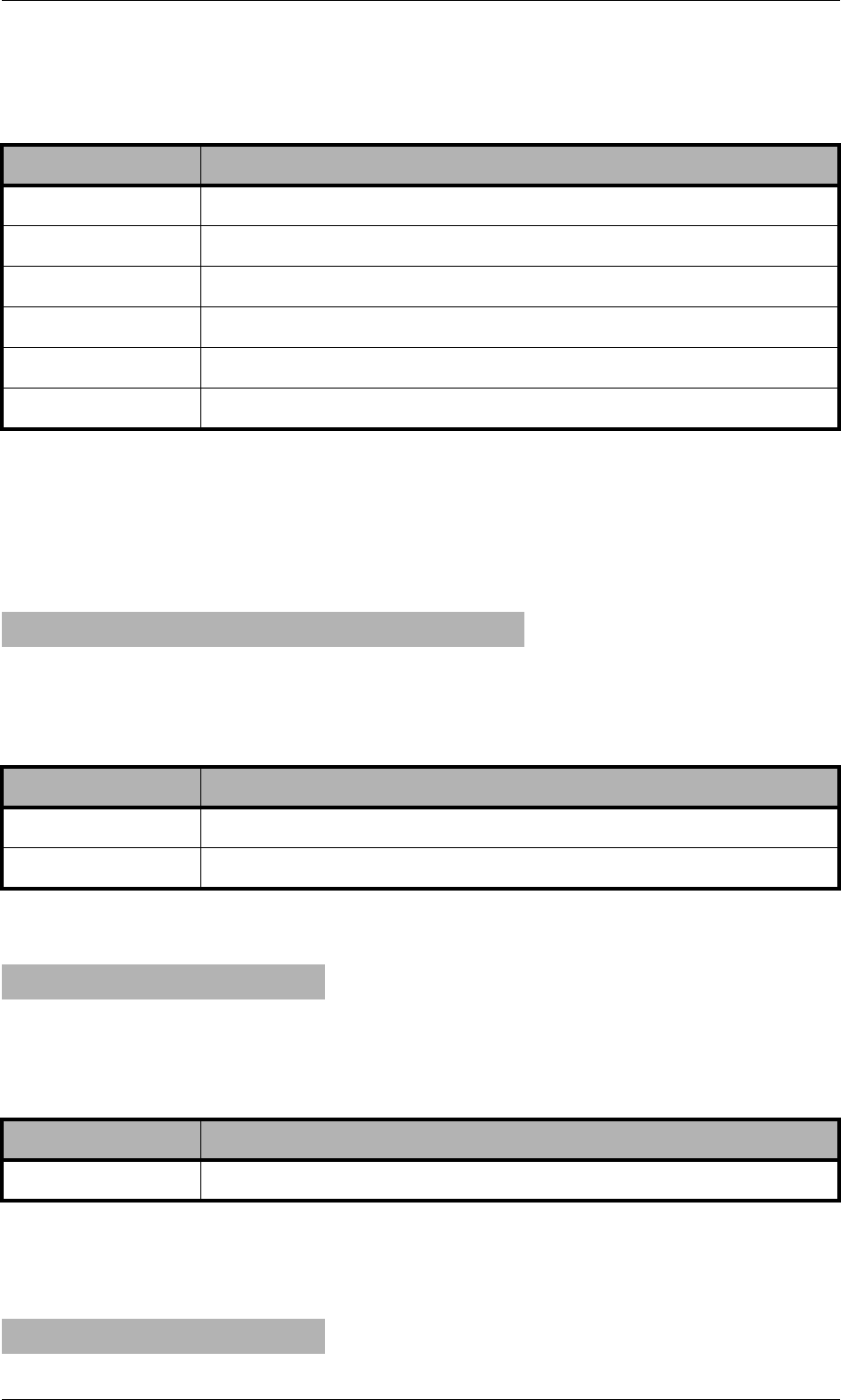
Page 178 © 2007 by TELES AG Berlin, Version 13.0/SH-e/04.16, Issue: April 2007
Trace System Maintenance and Software Update
All other trace output appears in detail mode in ASCII and are also translated.
Receiving E-Mail Messages and Sending Them as SMS or USSD
The following output displays communication of an incoming SMTP connection:
The following output displays which packets are sent to the SMTP peer:
All other trace output appears in detail mode in ASCII and are also translated.
The following output displays which packets are received from the SMTP peer:
Table 10-49 SMTP Output: Sending Files or Status Info
Trace Output Description
<Faccount> Sender’s e-mail account (cdr, alarm, file, etc.).
<ip address> SMTP server’s IP address.
<Taccount> Recipient’s e-mail account.
<domain> Recipient’s domain.
<subject> Content of the subject field; serial number of the sender system.
<content> Content of the message’s body.
m[99]:mail: accept: ipad=<ip address> port=<port>
Table 10-50 SMTP Output: Receiving E-Mail and Sending as SMS or USSD
Trace Output Description
<ip address> The SMTP peer system’s IP address.
<port> The SMTP peer system’s origination port.
m[99]:mail: mysend <<content>>
Table 10-51 SMTP Output: Receiving E-Mail and Sending as SMS or USSD
Trace Output Description
<content> Content of the transmitted packet.
m[99]:mail: recv (<length>)
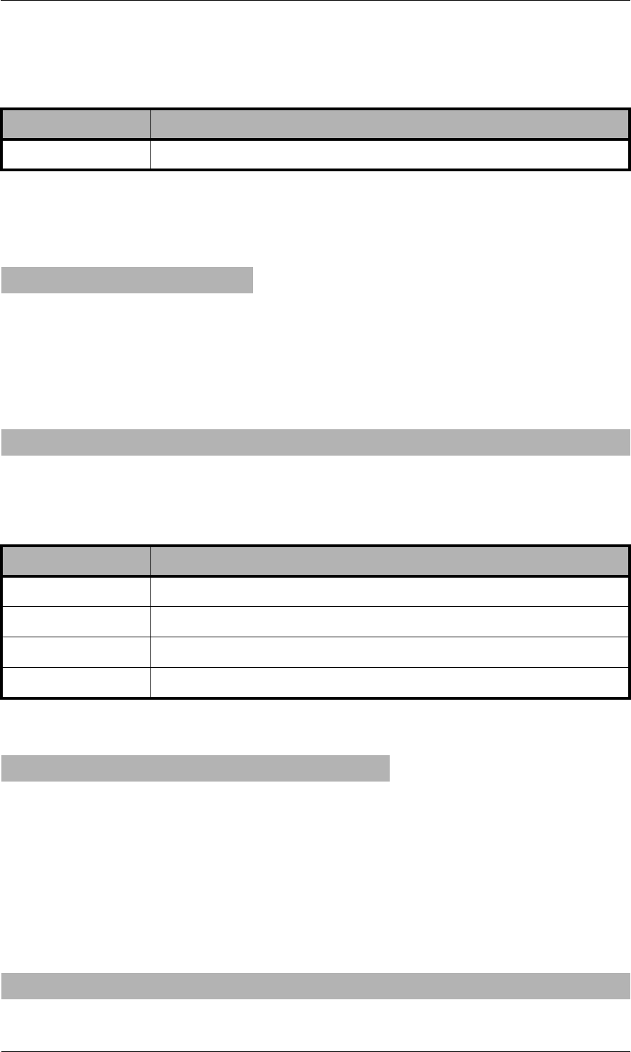
© 2007 by TELES AG Berlin, Version 13.0/SH-e/04.16, Issue: April 2007 Page 179
System Maintenance and Software Update Trace
All other trace output appears in detail mode in ASCII and are also translated.
The following output shows that the SMTP connection is being closed:
The mail module now converts the e-mail message to the internal format and then
sent as SMS or USSD. Bulk mail (several recipient entries for the same e-mail)
appear as individual messages:
The following output appears when the message has been successfully sent:
This is converted in the confirmation message, with the subject sent. The output
in the subsequent communication with the mail server are identical to those de-
scribed above in “Sending Files or Status Information”.
The following output appears when errors occur during transmission of the SMS
or USSD message:
Message transmission was faulty and will be repeated:
Table 10-52 SMTP Output: Receiving E-Mail and Sending as SMS or USSD
Trace Output Description
<length> Data length in bytes.
m[99]:mail: terminate_session
m[99]:mail: newMail2Host r=<Taccount> f=<Faccount> s=<subject> d=<content>
Table 10-53 SMTP Output: Receiving E-Mail and Sending as SMS or USSD
Trace Output Description
<Faccount> One entry from the sender’s To field.
<Taccount> Content of the From field.
<subject> Content of the subject field; usually not used.
<content> Content of the message’s body; is sent as SMS or USSD.
m[99]:mail: rcvmail <Faccount> -> <Taccount>, done
m[99]:mail: rcvmail <Faccount> -> <Taccount>, failed, will retry (<num>)
Page 180 © 2007 by TELES AG Berlin, Version 13.0/SH-e/04.16, Issue: April 2007
Trace System Maintenance and Software Update
Retried message transmission was also faulty, and an e-mail will be generated:
The output in the subsequent communication with the mail server are identical to
those described above in “Sending Files or Status Information”.
Receiving SMS or USSD and Sending as E-Mail
The following output shows the internal format when an SMS or USSD message
is sent to the mail module. This output is generated when transmission of the SMS
or USSD message was not possible:
All other trace output appears in detail mode in ASCII and are also translated. The
output in the subsequent communication with the mail server are identical to those
described above in “Sending Files or Status Information”.
10.4.7 Number Portability Trace Output
This trace option provides output for the communication with the TELES.iMNP
database. To activate this option, activate the section Number Portability in the
TELES.GATE Manager. Output is defined with an n, and the port number is 99.
The following output appears when the system sets up a TCP session with the
TELES.iMNP is being set up:
Table 10-54 SMTP Output: Transmission Error
Trace Output Description
<num> Current number of retries.
m[99]:mail: rcvmail <Faccount> -> <Taccount>, failed <num> times
m[99]:mail: DATA_IND (<length>)
n[99]:np: connecting to <ip addr>
Table 10-55 Number Portability Output: Connection with TELES.iMNP
Trace Output Description
<ip address> The TELES.iMNP system’s IP address.
© 2007 by TELES AG Berlin, Version 13.0/SH-e/04.16, Issue: April 2007 Page 181
System Maintenance and Software Update Trace
The following output shows that the connection has been established:
The following output shows that the connection attempt failed:
The following output shows a keep alive packet from the TELES.iMNP to keep
the TCP session open:
Response to a number portability request that results in the call’s routing:
10.4.8 DTMF Tone Trace Output
Output about the setup of connections with the DTMF module and DTMF tone
recognition are debugged. The output differentiates between the groups err and
inf. Output is defined with a d, and the port number is that of the virtual DTMF
controller:
The following output shows incoming call setup to the DTMF module:
n[99]:np: connect to <ip addr> ok
n[99]:np: connect to <ip addr> failed
n[99]:np: recv <>
n[99]:np: recv <N<num>>
Table 10-56 Number Portability Output: Response
Trace Output Description
<num> Ported or unported number provided by the database.
d[<ctrl>]: dtmf: msg <call state>, unknown id <id>, from 14
Table 10-57 DTMF Output: Incoming Call Setup
Trace Output Description
<ctrl> The virual controller’s running number.
<call state> 3101 Incoming setup
3201 Disconnect request
<id> Call identification number.
Page 182 © 2007 by TELES AG Berlin, Version 13.0/SH-e/04.16, Issue: April 2007
Trace System Maintenance and Software Update
The following output shows transmitted signaling messages depending on the call
state:
The following output shows that the media channel has been designated for
DTMF tone recognition:
d[<ctrl>]: dtmf <message type> <id> <call state> 0
Table 10-58 DTMF Output: Signaling Messages
Trace Output Description
<message
type>
Send_d_connectFor setup acknowledge and connect.
send_alert_indFor alert.
send_disconnectFor disconnect
<id> Call identification number.
<call state> 3110 Incoming setup
3102 Disconnect request
3804 Alert
3202 Disconnect confirmation
d[<ctrl>]: dtmf send_alloc <b_chan id_unset> <ctrl>/<b chan>
Table 10-59 DTMF Output: Media Channel Designation
Trace Output Description
<b chan> Internal media channel used.
<b_chan
id_unset>
Media channel identification (in unset state).
d[<ctrl>]: dtmf: msg <msg>, id <b_chan id>, from 1, id <id>/<b_chan id_unset>
Table 10-60 DTMF Output: Media Channel Designation
Trace Output Description
<msg> 502 Media channel confirmation
102 Connect confirmation
602 Media channel free confirmation

© 2007 by TELES AG Berlin, Version 13.0/SH-e/04.16, Issue: April 2007 Page 183
System Maintenance and Software Update Trace
The following output shows the output for negotiated DTMF tones:
d[<ctrl>]: dtmf send_info_ind <id> <<dtmf tone>>

Page 184 © 2007 by TELES AG Berlin, Version 13.0/SH-e/04.16, Issue: April 2007
Activating the License Feature Packages
11 Feature Packages
The TELES.iGATE feature packages are modular expansion applications that
provide services in addition to those offered with the standard software. Feature
packages can be activated separately or in combination with one another, so that
you can design your system according to your own needs.
The following feature packages are available:
• Dial-In/Callback Services (see Chapter 11.2 on page 185)
• Least Cost Routing (see Chapter 11.3 on page 190)
• Online Traffic Monitor (see Chapter 11.4 on page 197)
• SMS Gateway (see Chapter 11.5 on page 205)
• SS7-Specific Settings (see Chapter 11.7 on page 214)
• Ported Number Screening (see Chapter 11.6 on page 212)
11.1 Activating the License
Each feature package requires a license. Once you have ordered a feature package,
you can activate the license:
The /boot/ directory of each system contains a file called license.key,
which contains information on the system’s ID, the included components, which
feature packages are active and the license number:
Example:
You will receive a new license.key file any time you order a new license
package. Simply save the new file, overwriting the old file, and restart the system.
[IDENTIFICATION]
SYSTEM: TELES.iGATE
SERNO: VT810011
AUTOR: create Wed Sep 09 15:01:09 2006
[COMPONENTS]
...
CARD99:11 d1 S0 PB900034
...
[FEATURES]
PRI:Max
SS7:0
GSM:Max
IP:Max
VoIP:Max
SIM manager: On
DDI and call back: Off
least cost routing: On
statistics and CDR: On
SMS gateway: On
ported number screening: Off
roaming: Off
[SIGNATURE]
00000000000license0number00000000000

© 2007 by TELES AG Berlin, Version 13.0/SH-e/04.16, Issue: April 2007 Page 185
Feature Packages DLA/Callback Services
Note: Deleting or making changes in the license.key file will delete
any feature package licenses, causing the system to revert to the stan-
dard configuration!
11.2 DLA/Callback Services
This package contains money-saving features that expand the functionality of
your TELES.iGATE to include callback capability and DTMF services. It is par-
ticularly useful for companies with employees who travel often, because it elimi-
nates expensive roaming fees:
11.2.1 Call Connector and Callback Server
Depending on your TELES.iGATE, various intelligent solutions as a call server
are possible. The most important scenarios and properties are described here. The
scenarios can also be combined to suit your needs.
• Special announcement
• DLA with DTMF
• DLA with fixed destination number
• Callback with DTMF for the second leg number (known OAD or fixed call-
back number)
• Callback with DTMF and OAD as callback number
• Callback with DTMF and pre-configured callback number
• Callback for a fixed second leg
• DLA with DTMF and PIN for the first leg and callback for the second leg
• Using a PIN in front of the call number
• Callback via SMS
• Callback via HTTP
Numbers transmitted using DTMF tones can be ended by entering a # sign. Oth-
erwise, a 5-second timer is set, after which DTMF transmission will automatically
end.
If the callback call is set up from the mobile network, the SIM must be available
24 hours a day. We recommend that you reserve a SIM for this service. Otherwise,
another call could block the call initiating callback, which limits the effectiveness
of the service.
Note: CDR entries for calls routed as Callback with DTMF include the con-
nection times for the A and B subscribers. The times are separated by
a slash (/). If no connection is established to the B subscriber, an en-
try recording the A subscriber’s connection time is generated in the
failed.log file.

Page 186 © 2007 by TELES AG Berlin, Version 13.0/SH-e/04.16, Issue: April 2007
DLA/Callback Services Feature Packages
Activating DTMF Tone Recognition
The TELES.iGATE can recognize DTMF tones and initiate calls with these tones.
In the pabx.cfg, enter a virtual DTMF controller, as described in Table 5-13.
The corresponding Subscriber entry contains the options:
TRANSPARENT ROUTER CHMAX[5]
The 5 refers to the maximum number of simultaneous channels used for DTMF
recognition.
Example:
The TELES.iGATE must be restarted to activate this configuration.
11.2.1.1 Special Announcement
An announcement can be played immediately after the connection has been estab-
lished. The announcement can be defined in the virtual DTMF controller’s
Subscriber line using the following entry:
In the pabx.cfg file:
DTMF[<sec>,/<dir>/<file>]
<sec> refers to the maximum number of seconds that may pass before the next
DTMF tone is entered, <dir> refers to the directory, in which the announcement
file is saved. boot or data are possible. The file extension must be 711.
Note: The file’s sound format must be PCM!
Example: In this example, a maximum of 5 channels can recognize DTMF
tones and change them into dialing data. The announcement is named
DTMF.711 and is saved in the boot directory:
11.2.1.2 DLA with DTMF
The user dials a number in the system that is connected with the DTMF platform.
She then enters the number with which she would like to be connected.
Make the following entries in pabx.cfg to connect a call directly:
MapAll<number>=<DTMFport>DTMF
MapAllDLA=<port>
...
Controller06 = 41 DTMF
...
Subscriber06 = TRANSPARENT ROUTER CHMAX[5]
...
Subscriber06 = TRANSPARENT ROUTER DTMF[30,/boot/DTMF.711] CHMAX[5]

© 2007 by TELES AG Berlin, Version 13.0/SH-e/04.16, Issue: April 2007 Page 187
Feature Packages DLA/Callback Services
Example: In the following example, the call from the number 123 is connected
to the DTMF platform and the call that comes in as DTMF tones is
directed to port 9:
11.2.1.3 DLA with Fixed Destination Number
The user dials a number in the system that is connected directly with a fixed ex-
ternal number (e.g. international subsidiary number). Make the following entry in
the route.cfg:
MapAll<num>=<port><fixed num>
Example: In the following example, the call comes into the number 123456 and
is connected to the number 004311111 at port 9.
11.2.1.4 Callback with DTMF and OAD as Callback Number
The user calls a number that is defined so that the user will be called back based
on his OAD. An alerting occurs. The user hangs up and is called back. After the
user has taken the call, the destination number is entered using DTMF tones.
When he has finished dialing, the connection to the destination number is estab-
lished.
The following entries in route.cfg will initiate callback to the calling party’s
number:
MapAllDTMF=<DTMFport>DTMF
MapAllDLA=<port>
MapAll<number>=CALLB
MapAllCB=<port>
Example: In this example, the call with the number 123 is connected with the
OAD and the number that comes in as DTMF is directed to port 9:
MapAll123=41DTMF
MapAllDLA=9
MapAll123456=9004311111
MapAllDTMF=41DTMF
MapAllDLA=9
MapAll123=CALLB
MapAllCB=9

Page 188 © 2007 by TELES AG Berlin, Version 13.0/SH-e/04.16, Issue: April 2007
DLA/Callback Services Feature Packages
11.2.1.5 Callback with DTMF and Pre-Configured Callback
Number
The user calls a predefined number that is mapped to a defined callback number.
An alerting occurs. The user hangs up and is called back at a fixed number. After
the user has accepted the call, she must enter the destination number via DTMF.
The connection is set up when she finishes dialing.
Make the following entries in route.cfg to initiate callback to a fixed number:
MapAllDTMF=<DTMFport>DTMF
MapAllDLA=<port>
MapAll<number>=CALL<callbacknumber>
Example: In the following example, the call with the number 123 is connected
with the number 03012345. The number that comes in as DTMF is
directed to port 9:
11.2.1.6 Callback to OAD and Fixed Second Leg
The user calls a predefined number in the system. An alerting occurs. The user
hangs up and is called back based on her OAD. After the user accepts the call, she
is connected to a fixed, preconfigured number (e.g. operator or corporate central
office.
Make the following entries in route.cfg:
MapAllDTMF=<port><num>
MapAll<num>=CALLB
MapAllCB=<port>
Example: In the following example, the caller dials 123456 and her OAD is
called back through port 9. She is then connected with the operator’s
number 0 through port 10.
11.2.1.7 DLA with DTMF and PIN for First Leg and Callback
for Second Leg
The user dials a number in the system that is connected to the DTMF platform. He
then enters a predefined PIN that maps him to a predefined fixed number that is to
MapAllDTMF=41DTMF
MAPAllDLA=9
MapAll123=CALL903012345
MapAllDTMF=100
MAPAll123456=CALLB
MapAllCB=9

© 2007 by TELES AG Berlin, Version 13.0/SH-e/04.16, Issue: April 2007 Page 189
Feature Packages DLA/Callback Services
be called back. He then hangs up. After he takes the callback, he can enter the sec-
ond leg number using DTMF tones.
Make the following entries in route.cfg:
MapAllDTMF=<DTMFport>DTMF
MapAll<num>=<DTMFport>DTMF VOICE
MapAllDLA<num>=CALL<num> VOICE
MapAllDLA=<port> VOICE
Example: The number 123456 is dialed and the PIN 123# is entered. The call is
then connected to the number 004930123456. The destination num-
ber can now be transmitted through port 9 using DTMF tones:
Note: The user must enter a # following the PIN. Otherwise the callback to
the predefined number will not occur.
11.2.1.8 Using a PIN in Front of the Call Number
To prevent abuse, the following entry can be made to configure a PIN in front of
the actual call number:
MapAllDLA=$PIN
MapAllPIN<pin>=<port>
Example: In the following example, the DTMF tones are analyzed, whereby the
first 4 (1111) corresponds with the PIN. The call to subscriber B is
initiated when the PIN has been entered correctly. All other DTMF
tones are directed to port 9:
MapAllDTMF=41DTMF
MAPAll123456=41DTMF VOICE
MapAllDLA123=CALL9004930123456 VOICE
MapAllDLA=9 VOICE
MapAllDLA=$PIN
MapAllPIN1111=9

Page 190 © 2007 by TELES AG Berlin, Version 13.0/SH-e/04.16, Issue: April 2007
Least Cost Routing Feature Packages
11.3 Least Cost Routing
TELES.iGATEs are connected between the customer’s private branch exchange
(PBX) and the public telephone network (ISDN) and/or VoIP. The customer saves
connection charges and can effortlessly and automatically connect to the corpo-
rate network as needed using one of six routing methods:
• Carrier selection
• Dedicated lines
• Direct line access with subaddressing
• Direct line access with DTMF
• Callback with subaddressing
• Callback with DTMF
This manual contains information only on carrier selection. If you would like to
configure any other variation, please contact TELES or refer to the TELES Infra-
structure Systems Manual Version 4.5, Chapter 3.
Calls are routed transparently for the PBX and its users. TELES.iGATEs can gen-
erate charges and route calls using alternate settings in case of network failures.
The provider can access the system via ISDN for routine maintenance and moni-
toring.
The following additional services are supported by this feature package:
• Generation of charges
• Time-controlled configuration
• Alternative routing
11.3.1 Carrier Selection
Carrier selection is currently one of the most commonly used routing methods
supported by the TELES.iGATE. In the TELES.iGATE, this routing process also
includes direct calls into the mobile network or through a VoIP network. That
means the system is a full-fledged second generation LCR.
11.3.1.1 Routing Entries
Use the MapAll command to route calls using Carrier Selection.
a) Use the following syntax for connections routed via the provider:
MapAll<AreaCode>=9<CarrierSelection><AreaCode>
where <AreaCode> is the number or number range to be routed and
<CarrierSelection> is the access number required to reach the provid-
er’s network.
b) For unrouted connections (placed via the public telephone network), use:

© 2007 by TELES AG Berlin, Version 13.0/SH-e/04.16, Issue: April 2007 Page 191
Feature Packages Least Cost Routing
MapAll<AreaCode>=9<AreaCode>
c) To block undesired carrier selection prefixes use:
MapAll<CarrierSelection>=&91;(Busy signal)
In the following example, calls to international destinations are terminated
through the VoIP interface. The profile names iG1 and iG2 in the routing entries
refer to different VoIP carriers. Calls to the mobile network (01555 and 01556)
are routed directly through SIM cards for the corresponding mobile carriers
(LAIN 26212 and 26213). All other national long distance and local calls are rout-
ed through an alternative carrier (01019). All calls from the PSTN to the PBX are
put through transparently.
Example:
Note: Be sure to enter phone numbers in the routing file in ascending order.
11.3.2 Alternative Routing Settings
Alternative routing refers to the ability to establish connections using a different
(alternative) network in case of provider failure (e.g. all mobile controllers are in
use). Alternative routing ensures uninterrupted operation of the attached PBX. In
such cases, connections are often made via the public network using the
Redirect command:
MapAll<num>=<port><num>
Redirect3<port><num>=<placeholder>
MapAll<placeholder>=<alt port><num>
Example:
MapAll001=40iG1:001
MapAll0044=40iG2:0044
...
MapAll01555=2621201555
MapAll01556=2621301556
...
MapAll01=90101901
MapAll02=90101902
...
MapAll09=90101909
MapAll1=9010191
MapAll2=9010192
...
MapAll9=9010199
Restrict9=10
MapAll01555=2621201555
Redirect32621201555=A
MapAllA=901555

Page 192 © 2007 by TELES AG Berlin, Version 13.0/SH-e/04.16, Issue: April 2007
Least Cost Routing Feature Packages
11.3.3 Charge Models
TELES.iGATEs can either generate charge information or transmit received
charges from the public or corporate networks to the attached PBX. Charge sim-
ulation is achieved using variables, which ensure a great degree of flexibility for
the implementation of many different charge models including:
• Charge units per time unit
• Flat rate (initial charge without time interval)
• Initial charge plus time interval
• Initial charge plus time interval after delay
• Time interval and/or flat rate plus received charges
• Received charges only or no charge information
• Initial toll-free period with retroactive charge generation afterwards
• Price-per-minute (with whole second accuracy)
In this chapter, unit means that charge information is transmitted as a whole-num-
bered value, and currency means that the charge information is sent as a currency
amount (e.g. EUR 3.45). The charge impulse generation options can be set for
each mapping by adding charge-specific arguments to the MapAll commands as
shown below. The use of each variable is explained in Table 11-1.
MapAllsrc=dst mode time start/wait and
MapCallBackOutprovsrc=dst mode time start/wait.
Any external charges can be added to the generated charges by adding 128 to the
start value. (The value range for the initial unit level is still set from 0 to 127). The
maximum supported number of units per connection is 32767 units.
Table 11-1 Charge Variables
Variable Purpose
time Determines the length of each time interval (how long each unit lasts).
The value is entered in seconds and hundredths or thousandths of a
second (the maximum value accepted is 655.35 seconds, 65.535 if
thousandths are entered). If time is set to zero or not present no charg-
es are generated, external charge information is passed through if re-
ceived.
start Sets the initial unit level. Enter a value between 0 and 127 whole units.
If you want to use a flat rate, set the desired number of units here and
set the wait to 255 to turn off the time interval.
wait Determines the delay after which charge generation begins. Once this
time has elapsed, charge impulses are sent in the interval determined
with time. Enter a value between 0 and 254 seconds. 255 deactivates
the charge pulse. In this case, the time variable is ignored.

© 2007 by TELES AG Berlin, Version 13.0/SH-e/04.16, Issue: April 2007 Page 193
Feature Packages Least Cost Routing
Additional adjustments may be made to allow for the implementation of new
charge models.
• When charge information is sent as Currency, values can be expressed in
thousandths for greater precision in charge calculation.
For the internal Layer 3 protocols, charges can be specified to the third decimal
place (thousandth) using the /Value option (Example: /Value:1.056). In
this fashion, charges can be generated for units of currency requiring accuracy
to the third decimal place or for fractions such as tenths of a cent. This allows
for greater flexibility in the transmission of charges to terminal devices. In or-
der to make use of this option, connected devices must support “AOC-D Cur-
rency”. In the current version, this option is only available for the DSS1
protocol.
• A multiplication factor can be specified for received or generated charges.
During the charge generation process, each charge unit is multiplied by a pre-
set factor. This factor appears in the mapping entry after the time and start/wait
variables (MapAllsrc=dst mode time start/wait*factor).
Each unit, for example, can be converted to 12 cents. The following example
illustrates the use of this feature:
In the above example, all received charge units are multiplied by 12 and passed
on. If AOC-Currency is set on the internal port, each unit appears as 12 cents.
The multiplication factor is also used to implement two new charge models:
• If the factor value exceeds 128, this marks the use of an initial toll-free phase
followed by retroactive charge generation.
• If the multiplication factor is set to 255, a “minute price” is used in place of
the time variable.
These charge models are explained on page 194.
...
MapAll1=91 1 128/255*12
...

Page 194 © 2007 by TELES AG Berlin, Version 13.0/SH-e/04.16, Issue: April 2007
Least Cost Routing Feature Packages
11.3.4 Generating Charges with the TELES.iGATE
To generate charges for the attached PBX, add the charge variables described in
Table 11-1 to the MapAll commands according to the necessities of the corporate
network environment.
Example 1 MapAll0172=9123450172 1.65 131/0
(time=1.65, start=131, wait=0)
In the mapping example above, 3 initial tariff units (131-128) are
transmitted upon connection and a new unit is generated every 1.65
seconds and transmitted the next full second. Charges received from
the public network for the connection to the corporate network dial-
in node are added and transmitted (because 128 has been added to the
start variable’s value).
Example 2 MapAll0172=9123450172 1.65 131/10
(time=1.65, start=131, wait=10)
Upon connection establishment, 3 initial tariff units (131-128) are
transmitted. Then a 10-second delay (wait=10) elapses before charge
impulses are generated according to the time variable (a new unit is
generated every 1.65 seconds and transmitted the next full second).
Charges received from the public network for the connection to the
corporate network dial-in node are added and transmitted (because
128 has been added to the start variable’s value).
New charge models can be implemented by taking advantage of the multiplication
factor in conjunction with the time and start/wait variables.
• Retroactive charge generation after initial toll-free period
The charge generation process has been expanded to allow for the implemen-
tation of this new charge model. In this scenario, an initial period is free of
charge, but after this period charges are calculated for the entire call. For ex-
ample: the first minute is free, but as soon as the second minute begins, charges
are incurred for the first minute as well.
The multiplication factor is set to a base value of 128. If the value exceeds this
base, the remaining value represents the number of units charged with each
time interval. The following configuration generates one unit (129-128) per
minute (time=60 seconds) retroactively after the first minute (wait=60 sec.):
...
MapAll030=901019030 60 0/60*129
...

© 2007 by TELES AG Berlin, Version 13.0/SH-e/04.16, Issue: April 2007 Page 195
Feature Packages Least Cost Routing
• “Price per minute”
A price per minute charge model can be implemented as of version 5.01 in one
of two ways:
• either the attached PBX supports Advice of Charges as Currency
• or if not, the PBX can be configured to assign one thousandth (¹⁄1000) of a
currency unit (€0.001 or ¹⁄10 of a cent) to each charge unit.
Note: If thousandths are defined, a maximum value of 65.535 is possible. If
tenths are defined, a maximum value of 6553.5 is possible.
This model does not always guarantee whole second accuracy (depending on
the rates), but it is significantly more precise than the standard charge genera-
tion method.
If the attached PBX supports Advice of Charges as Currency, include the fol-
lowing line in the TELES.iGATE’s pabx.cfg:
If the PBX does not support this AOC model, but allows for the assignment of
one thousandth (¹⁄1000) of a currency unit (€0.001 or ¹⁄10 of a cent) for each
charge unit, the above entry need not be present. The configuration entries
must make use of the multiplication factor for a single unit as shown below:
If the minute price does not allow generated charges to “fit” evenly into a sec-
ond (such as 20 cents per minute or 0.33 cents per second), the system can be
configured to generate 10 “points” every 3 seconds (€0.01 or 1 cent):
The “points” method allows for a more precise calculation of smaller intervals.
The price per minute can also be explicitly specified in each routing entry by
setting the multiplication factor to 255, to signalize to the system that a minute
price is being used instead of the interval usually specified with the time vari-
able. The attached PBX must support Advice of Charges as Currency, and the
appropriate settings must be made in the TELES.iGATE’s pabx.cfg as de-
scribed on page 195. The examples below show sample entries with rates of
18 and 9 cents per minute:
...
Controller01=10 NTS2M DSS1 CRC4 UNIT:€ VALUE:0.001
...
...
MapAll902=90103002 1.00 0/0*4 ; each second costs €0.004 (€0.24 / minute)
MapAll909=90108809 1.00 0/0*5 ; each second costs €0.005 (€0.30 / minute)
...
...
MapAll902=90101302 3.00 0/0*10 ; 3 seconds cost €0.01 (€0.20 / minute)
MapAll909=90105009 2.00 0/0*3 ; 2 seconds cost €0.003 (€0.09 / minute)
...

Page 196 © 2007 by TELES AG Berlin, Version 13.0/SH-e/04.16, Issue: April 2007
Least Cost Routing Feature Packages
and
If greater precision is desired (¹⁄1000 of a currency unit – $0.001 or ¹⁄10 of a cent),
use settings such as the following:
and
...
MapAll902=90101302 0.18 0/0*255 ; €0.18 / minute
MapAll909=90105009 0.09 0/0*255 ; €0.09 / minute
...
...
Controller01=10 NTS2M DSS1 CRC4 UNIT:€ VALUE:0.010
...
...
MapAll902=90101302 1.80 0/0*255 ; €0.18 / minute
MapAll909=90105009 0.90 0/0*255 ; €0.09 / minute
...
...
Controller01=10 NTS2M DSS1 CRC4 UNIT:€ VALUE:0.001
...

© 2007 by TELES AG Berlin, Version 13.0/SH-e/04.16, Issue: April 2007 Page 197
Feature Packages Online Traffic Monitor
11.4 Online Traffic Monitor
The Online Traffic Monitor allows you to collect and monitor statistics and call
detail records (CDRs). The following functions are possible with this feature
package:
• ASR calculation
• Generation of CDRs
• Generation of online CDRs using TCP/IP
• Generation of online CDRs using e-mail
11.4.1 ASR Calculation and Resetting Statistic Values
When this function is configured in the pabx.cfg file, statistical values, such as
the number of minutes, number of calls, ASR (Answer Seizure Ratio), etc., are
calculated for the entire system at a defined time. These statistics are then copied
into a specified file and reset at 0.
This information can also be sent to an e-mail or SMS recipient. The following
syntax must be used:
StatisticTime=/data/asr.log <hh:mm> <day> @<account>
ASR2 is the ratio of connected calls to total calls, and ASR1 is the ratio of total
calls to connected calls disconnected by the A party. ASR1 values are intended to
provide you with an idea of the availability of the mobile network.
Example: In the following example, the system’s statistic values are saved daily
into the file asr.log and sent to an e-mail account.
Example: In the following example, the system’s statistic values are saved
monthly into the file asr.log and sent to an SMS recipient.
Example: If ?? appears instead of a specified hour, the ASR is written into the
asr.log file once every hour. The values are reset to zero in the
twenty-third hour:
Example: The next example shows how the statistics appear in the file into
which they are copied. The following information is listed in the fol-
lowing order: day and time of the entry, followed by the system
name. Calls: connected calls followed by the total number of calls in
StatisticTime=/data/asr.log 00:00 11111111 @<account>
StatisticTime=/data/asr.log 00:00 01. @SMS<mobile number>
StatisticTimeReset=/data/asr.log ??:00

Page 198 © 2007 by TELES AG Berlin, Version 13.0/SH-e/04.16, Issue: April 2007
Online Traffic Monitor Feature Packages
parentheses. The total number of minutes terminated by the system,
followed by the ASR1 value, the external ASR for the traffic source
(ext) and the internal ASR for the TELES.iGATE (int). These values
can differ if a significant number of calls cannot be routed through
the TELES.iGATE or an insufficient number of channels is available
for a prefix. Finally, the average call duration (ACD) appears in the
entry:
StatisticTimeReset=/data/asr.log <hh:mm> <day> performs
the same function as the StatisticTime parameter, but also resets the
counters (A-F).
Example: In the following example, the system’s statistic values are saved on
the 15th of every month into the file asr.log.
Note: It is not possible to configure both StatisticTimeReset and
StatisticTime.
ASR values reset to 0 when the SIM card is changed using the
TELES.GATE Manager.
11.4.2 Generating and Retrieving CDRs
With the Log and RrufLog commands, you save CDRs and unconnected calls
in the TELES.iGATE.
For these parameters (Log and RrufLog), a folder and file name must always be
specified after the equal sign. The function is not active (no data is recorded) until
a file name is specified.
Example:
Note: With recording of files, system maintenance increases. You have to
be sure to download or delete files and ensure that there is enough
disk space left on the hard drive.
The service indicator listed in the call log and missed calls list describes the type
of connection as a four digit hexadecimal number. The coding is conducted ac-
cording to the 1TR6 standard. A few frequently used values are listed below:
26.10.04-00:00:00,iGATE810000: Calls: 19351 (29716) - Minutes: 46647 - ASR1: 65.12%
- ASR(ext): 65.12% - ASR(int): 65.30% - ACD: 144.63s
StatisticTimeReset=/data/asr.log 00:00 15.
Log=/data/cdr.log
RRufLog=/data/failed.log

© 2007 by TELES AG Berlin, Version 13.0/SH-e/04.16, Issue: April 2007 Page 199
Feature Packages Online Traffic Monitor
0101 ISDN-telephony 3.1 kHz
0102 analog telephony
0103 ISDN-telephony 7 kHz
0200 Fax group 2
0202 Fax group 3
0203 Data via modem
0400 Telefax group 4
0500 SMS or BTX (64 kbps)
0700 Data transfer 64 kbps
07… Bit rate adaptation
1001 Video telephone – audio 3.1 kHz
1002 Video telephone – audio 7 kHz
1003 Video telephone – video
For detailed information on how to automatically divide the files (e.g. on a daily
basis), please refer to the Chapter 5.2.1.2.
11.4.2.1 Call Log
The following entry in the pabx.cfg configuration file activates the capability
to generate CDRs in the TELES.iGATE:
Log=/data/cdr.log
The cdr.log file is stored in the data directory. New entries are always added
to the end of the file. The file is open only during editing.
Each line represents an outgoing call:
DD.MM.YY-hh:mm:ss[Start],DD.MM.YY-hh:mm:ss[End],src,dst,ser-
vice,dur,cause,charge_publine,[charge_sys]
The charge is specified in units. The service indicator listed will be one of the val-
ues shown on page 198. The example below shows a sample log file.
DD – Day hh – Hour src – source/extension dur – duration
MM – Month mm – Minute dst – destination cause – reason for teardown
YY – Year ss – Seconds service – service indicator charge_publine – from the
public line
charge_sys – generated by the
system

Page 200 © 2007 by TELES AG Berlin, Version 13.0/SH-e/04.16, Issue: April 2007
Online Traffic Monitor Feature Packages
To differentiate between ports with the same number in the CDRs, a specific node
number must be defined. You can expand the subscriber configuration line
with the keyword NODE[<no.>] for this purpose. <no.> can be a string of be-
tween 1 and 15 characters:
Subscriber<xx>=... NODE[<num>]
Example:
In the above formula, <num> consists of a four-digit number that is included in
the CDR.
Example: The following example shows the pabx.cfg configuration file
changed according to the formula:
The CDR can contain the IMSI (International Mobile Subscriber Identity), which
identifies each SIM card used:
Example:
The following example shows the pabx.cfg configuration file changed accord-
ing to the formula:
28.01.05-19:38:51,28.01.05-19:44:51,10611,9010193333333,0101,360,90,10
28.01.05-19:43:55,28.01.05-19:44:55,10610,26212015551111111,0101,60,90,3
28.01.05-19:32:54,28.01.05-19:44:55,10612,40iG2:004498989898,0101,721,90,15
28.01.05-19:41:34,28.01.05-19:45:34,10616,9010190123456,0101,240,90,4
28.01.05-19:44:19,28.01.05-19:45:49,10615,26212015553333333,0101,90,90,5
28.01.05-19:44:58,28.01.05-19:45:58,10610,26213015562222222,0101,60,90,3
28.01.05-19:46:01,28.01.05-19:47:12,10610,9010194444444,0101,71,90,5
28.01.05-19:46:18,28.01.05-19:47:48,10615,40iG1:001232323232323,0101,90,90,4
28.01.05-19:47:03,28.01.05-19:48:07,10610,9010195555555,0101,64,90,4
28.01.05-19:48:07,28.01.05-19:49:07,10610,9010190306666666,0101,60,90,3
29.08.05-09:45:24,29.08.05-09:46:33,923456789,[0007:01]01771111111,0101,69,0
...
Subscriber00=TRANSPARENT ROUTER GSM[0000,00000,<SMSC>,1,1,1,
SIM24] CHADDR
ALARM NEXT NODE[0001]
Subscriber01=TRANSPARENT ROUTER GSM[0000,00000,<SMSC>,1,1,1
,SIM24] CHADDR
ALARM NODE[0002]
Subscriber02=TRANSPARENT ROUTER GSM[0000,00000,<SMSC>,1,1,1
,SIM24] CHADDR
ALARM NODE[0003]
Subscriber03=TRANSPARENT ROUTER GSM[0000,00000,<SMSC>,1,1,1
,SIM24] CHADDR
ALARM NODE[0004]
Subscriber04=TRANSPARENT ROUTER GSM[0000,00000,<SMSC>,1,1,1
,SIM24] CHADDR
ALARM NODE[0005]
Subscriber05=TRANSPARENT ROUTER GSM[0000,00000,<SMSC>,1,1,1
,SIM24] CHADDR
ALARM NODE[0006]
Subscriber06=TRANSPARENT ROUTER GSM[0000,00000,<SMSC>,1,1,1
,SIM24] CHADDR
ALARM NODE[0007]
Subscriber07=TRANSPARENT ROUTER GSM[0000,00000,<SMSC>,1,1,1
,SIM24] CHADDR
ALARM NODE[0008]
Subscriber08=TRANSPARENT ROUTER GSM[0000,00000,<SMSC>,1,1,1
,SIM24] CHADDR
ALARM NODE[0009]
Subscriber09=TRANSPARENT ROUTER GSM[0000,00000,<SMSC>,1,1,1
,SIM24] CHADDR
ALARM NODE[0010]
Subscriber10=TRANSPARENT ROUTER GSM[0000,00000,<SMSC>,1,1,1
,SIM24] CHADDR
ALARM NODE[0011]
Subscriber11=TRANSPARENT ROUTER GSM[0000,00000,<SMSC>,1,1,1
,SIM24] CHADDR
ALARM NODE[0012]
Subscriber12=TRANSPARENT ROUTER GSM[0000,00000,<SMSC>,1,1,1
,SIM24] CHADDR
ALARM NODE[0013]
Subscriber13=TRANSPARENT ROUTER GSM[0000,00000,<SMSC>,1,1,1
,SIM24] CHADDR
ALARM NODE[0014]
Subscriber14=TRANSPARENT ROUTER GSM[0000,00000,<SMSC>,1,1,1
,SIM24] CHADDR
ALARM NODE[0015]
Subscriber15=TRANSPARENT ROUTER GSM[0000,00000,<SMSC>,1,1,1
,SIM24] CHADDR
ALARM NODE[0016]
...
08.02.05-09:42:15,08.02.05-09:46:19,912345678,01721111111,111111111111111,0101,244,0

© 2007 by TELES AG Berlin, Version 13.0/SH-e/04.16, Issue: April 2007 Page 201
Feature Packages Online Traffic Monitor
Example:
Note: If you remove the keyword IMSI from the pabx.cfg, you must re-
start the system.
The CDR contains the IP addresses for signaling and voice data. If the entry also
contains the mobile controller’s IMSI, it will appear behind the IP addresses:
Example:
The following example shows the pabx.cfg configuration file changed accord-
ing to the formula:
Example:
In the case of CDR entries for DLA/Callback calls, the beginning and ending
times for the first call leg is always used as the call time. The call time in seconds
appears first for the first leg, followed by a slash and the connection time for the
second leg.
Example:
...
Subscriber00=TRANSPARENT ROUTER GSM[0000,00000,<SMSC>,1,1,1,IMSI,SIM24] CHADDR ALARM NEXT
Subscriber01=TRANSPARENT ROUTER GSM[0000,00000,<SMSC>,1,1,1,IMSI,SIM24] CHADDR ALARM
Subscriber02=TRANSPARENT ROUTER GSM[0000,00000,<SMSC>,1,1,1,IMSI,SIM24] CHADDR ALARM
Subscriber03=TRANSPARENT ROUTER GSM[0000,00000,<SMSC>,1,1,1,IMSI,SIM24] CHADDR ALARM
Subscriber04=TRANSPARENT ROUTER GSM[0000,00000,<SMSC>,1,1,1,IMSI,SIM24] CHADDR ALARM
Subscriber05=TRANSPARENT ROUTER GSM[0000,00000,<SMSC>,1,1,1,IMSI,SIM24] CHADDR ALARM
Subscriber06=TRANSPARENT ROUTER GSM[0000,00000,<SMSC>,1,1,1,IMSI,SIM24] CHADDR ALARM
Subscriber07=TRANSPARENT ROUTER GSM[0000,00000,<SMSC>,1,1,1,IMSI,SIM24] CHADDR ALARM
Subscriber08=TRANSPARENT ROUTER GSM[0000,00000,<SMSC>,1,1,1,IMSI,SIM24] CHADDR ALARM
Subscriber09=TRANSPARENT ROUTER GSM[0000,00000,<SMSC>,1,1,1,IMSI,SIM24] CHADDR ALARM
Subscriber10=TRANSPARENT ROUTER GSM[0000,00000,<SMSC>,1,1,1,IMSI,SIM24] CHADDR ALARM
Subscriber11=TRANSPARENT ROUTER GSM[0000,00000,<SMSC>,1,1,1,IMSI,SIM24] CHADDR ALARM
Subscriber12=TRANSPARENT ROUTER GSM[0000,00000,<SMSC>,1,1,1,IMSI,SIM24] CHADDR ALARM
Subscriber13=TRANSPARENT ROUTER GSM[0000,00000,<SMSC>,1,1,1,IMSI,SIM24] CHADDR ALARM
Subscriber14=TRANSPARENT ROUTER GSM[0000,00000,<SMSC>,1,1,1,IMSI,SIM24] CHADDR ALARM
...
12.05.05-10:23:46,11.05.05-10:23:48,40,991783,172.20.25.110:172.20.25.110,0101,2,90,0
[Voip=Default]
VoipDirection=IO
VoipPeerAddress=192.168.0.2
VoipIpMask=0xffffffff
VoipCompression=g729 t38
VoipMaxChan=30
VoipSilenceSuppression=Yes
VoipSignalling=0
VoipTxM=4
VoipIPLogging=Yes
20.10.05-15:27:36,20.10.05-
15:30:36,2621201555555555,DLA1234567890,0101,180/168,10,0

Page 202 © 2007 by TELES AG Berlin, Version 13.0/SH-e/04.16, Issue: April 2007
Online Traffic Monitor Feature Packages
11.4.2.2 Missed Calls List
All incoming calls that are not connected can be recorded in a list to facilitate re-
turn calls. Recording is activated using the RRufLog=<name> entry in the
pabx.cfg. Specify a file name, e.g. RRufLog=failed.log. Once this set-
ting is made, recording begins at once.
A new line of the following format is created for each incoming call that is not ac-
cepted:
DD.MM.YY-hh:mm:ss,src,dst,cause,dur,att
The reason the connection could not be established is specified using DSS1 codes:
91 – (user busy)
ff – call not answered (disconnected by calling party)
When callback with DTMF is configured and no connection is established to the
B subscriber, an entry recording the A subscriber’s connection time is generated
in the failed.log file:
The CDR contains the IP addresses for signaling and voice data. The first IP ad-
dress is the signaling address and the second one is the RTP address.The IMSI is
written behind the IP addresses if the keyword IMSI is defined in the pabx.cfg:
Example:
In the case of missed-call entries for DLA/Callback calls, dur is the connection
DD – Day hh – Hour src – source/extension cause – reason for tear
down
MM – Month mm – Minute dst – destination dur – duration of call at-
tempt
YY – Year ss – Seconds service – service indicator att – number of attempts
16.01.05-13:58:52,9030399281679,10111,0101,ff,0,1
16.01.05-14:04:06,9030399281679,10111,0101,91,0,1
16.01.05-14:04:15,9,10111,0101,91,0,1
16.01.05-14:04:39,9030399281679,10111,0101,ff,0,1
16.01.05-14:04:50,903039904983,100,0101,ff,0,1
16.01.05-14:05:02,9030399281679,10111,0101,ff,0,1
16.01.05-14:05:03,9,100,0101,ff,0,1
16.01.05-14:05:14,903039904983,100,0101,91,0,1
20.04.05-16:21:10,[4545]981776,2->10200,0101,ff,0,1
20.04.05-16:21:20,[4545]981776,1->10120,0101,ff,0,1
20.02.05-10:47:52,[0004:01]00491721234567,[0005:01]DLA0307654321,0101,ff,34,1
12.05.05-10:25:51,40,991783,172.20.25.110:172.20.25.110,0101,ff,8,1

© 2007 by TELES AG Berlin, Version 13.0/SH-e/04.16, Issue: April 2007 Page 203
Feature Packages Online Traffic Monitor
time for the first leg.
Example:
11.4.3 Generating Online CDRs
11.4.3.1 Sending CDRs via TCP/IP
CDRs for connected calls and calls for which no connection was set up can be
transmitted online to a database. The CDRs can be sent over a TCP connection
from the system to the iCDR or another application. TCP port 6609 is used, and
the system sets up the TCP connection automatically. The following configuration
entries are required:
In the file pabx.cfg:
Log=/boot/cdr.log @DB<ip_address>
RRufLog=/boot/failed.log @DB<ip_address>
...
[Mail]
MailServer=yes
The iCDR uses the following format for CDR entries, whereby nr represents the
number of the CDR, name refers to the name of the system. Individual lines end
with LF:
S(0,nr,dd.mm.yy-hh:mm:ss:lll,0.LCR,nr,name,0)
{A(<CDR as generated by TELES.iGATE>)}
Example:
If you use the application cdrd.exe to transfer the online CDRs to a Windows-
based PC, use the command line to call up the tool as follows:
cdrd <filename>
20.10.05-15:00:06,9004930555555,DLA262121111111,0101,92,24,1
S(0,0,04.02.05-13:44:48:000,4,0){
A(04.02.05-
13:42:44:000){a=20,0101,,,,siap1612345610,,si66610,;c=0,9;n=;p=255;s=edss1;}
B(04.02.05-
13:42:44:000){a=23,0101,,,,siap1612345610,,si66610,;c=0,11;n=;p=255;s=edss1;}
C(04.02.05-
13:42:44:000){a=23,0101,,,,siap1612345610,,si66610,;c=0,11;d=124000;n=;p=255;s=ed
ss1;}
D(04.02.05-
13:44:48:000){f=B,CAU_NCC;t=A,CAU_NCC;a=23,0101,,,,siap1612345610,,si66610,;a=20,
0101,,,,siap1612345610,,si66610,;}
E(04.02.05-13:44:48:000);

Page 204 © 2007 by TELES AG Berlin, Version 13.0/SH-e/04.16, Issue: April 2007
Online Traffic Monitor Feature Packages
Two files are generated, whereby one contains the original CDR format and the
other contains the iCDR format described above. The original CDR entry appears
as follows:
11.4.3.2 Sending CDRs via E-Mail
With an appropriate configuration, you can send corresponding CDRs of outgoing
and incoming calls as e-mail. Bear in mind that the mail server must be configured
in the [Mail] section of the pabx.cfg, as described in Chapter 5.2.2. The
sender is given as cdr and the system’s name appears in the subject box. The text
box contains the CDR information according to the format for the entry in Log=/
data/cdr.log @<account> @<domain>. A space must appear between
cdr.log and @<account>; @<domain> is optional. You can also send CDR
entries via e-mail to an e-mail recipient.
Enter an @ sign to send each CDR entry as e-mail:
Log=/data/cdr.log @<e-mail account>@<domain>
If you enter a ! the entire cdr.log will be sent as an e-mail attachment:
Log=/data/cdr.log !<e-mail account>@<domain>
04.10.04-13:42:44,04.02.05-13:44:48,1612345610,1111111,0101,124,0

© 2007 by TELES AG Berlin, Version 13.0/SH-e/04.16, Issue: April 2007 Page 205
Feature Packages SMS Gateway
11.5 SMS Gateway
The SMS Gateway allows you to use your TELES.iGATE to send and receive
SMS. The following functions are possible with this feature package:
• Sending SMS via e-mail
• Receiving SMS to e-mail, SMS or to a file
• Sending and receiving USSD text messages
• Setting up connections using e-mail
• Sending announcements via e-mail
• Sending automatic SMS for unconnected calls
Note: Bear in mind that the parameters for connection to the SMTP server
must be configured in the pabx.cfg’s [Mail] section (see Chap-
ter 5.2.2).
11.5.1 Sending SMS via E-mail
This function makes it possible to send SMS via a TELES.iGATE with an ordi-
nary e-mail client. SMS messages are recorded in the CDR log with the service
indicator 0500. The destination address with the keyword SMS, the call number,
the @ sign and the IP address or the IP name of the TELES.iGATE must be en-
tered.
Note: To use this function, you must first set the parameter <smsc> in the
pabx.cfg (see Table 5-15 on page 5-61).
In the following example, an SMS is sent to the mobile number 015553456789,
whereby sms-mail.server.de must correspond with the IP address
172.172.172.172:
Example: SMS015553456789@172.172.172.172 or
SMS015553456789@sms-mail.server.de
The SMS text must be entered in the text box. The subject box is not used. If the
e-mail program supports sending the same e-mail to more than one address, the
SMS messages are sent in intervals of one second. The TELES.iGATE’s algo-
rithms evenly distribute the SMS messages to the available mobile modules.
If the TELES.iGATE rejects the SMS, an e-mail alerting an aborted SMS will be
transmitted to the sender and the attempt will be entered in the corresponding log
file (RRufLog=). If transmission is successful, a positive response will be sent
when the SMS is accepted by the SMS service center. sent will then appear in
the subject dialog. A corresponding CDR will be entered with a destination ad-
dress beginning with SMS.
A request to set up a connection with the service ’telephony’ and the element ’us-

Page 206 © 2007 by TELES AG Berlin, Version 13.0/SH-e/04.16, Issue: April 2007
SMS Gateway Feature Packages
er-to-user’ enables the SMS text to be sent to the TELES.iGATE. All
TELES.iGATEs are supported that allow for SMS messages to be sent by the pro-
cess described above. According to the restrictions of the ISDN signaling proto-
col, text length is limited to approximately 110-120 characters. Longer texts will
be cut off accordingly.
The following entry must appear in the route.cfg configuration file for SMS
transmission to be possible: MapAllSMS=<port number>.
Sent SMS will also be recorded if the call log is active on the system. The formats
are describe in chapter 11.4.2.1 and 11.4.2.2.
Example 1 In the following example, SMS-transmission to the number
01721111111 from the e-mail account j.smith was successful:
Example 2 In the following example, SMS-transmission to the number
01721111111 from the e-mail account j.smith was unsuccessful. the
output -1 as cause value means that no routing entry was configured:
11.5.2 Receiving SMS Messages
This function makes it possible to receive SMS messages via a mobile gateway
with an ordinary e-mail client, to forward them to another mobile telephone, or to
save them to a file.
11.5.2.1 SMS to E-Mail
The destination number in the TELES.iGATE system must correspond with an e-
mail account. The e-mail recipient’s name contains the keyword ’sms’ and the
destination number. The subject box contains the SIM card’s IMSI and the caller’s
number.
Example:
From: sms262124915553230618@gsm.teles.de
Subject: SMS 262123203500514 4915553230618
The SMS text must be received in a connection setup as a user-to-user message.
A mapping entry must indicate an e-mail account with a prefixed @. The follow-
ing syntax is used:
Restrict<port>=@<addressee> 05
12.07.06-09:59:10,12.07.06-09:59:11,SMS01721111111,j.smith,0500,1,06,0
12.07.06-09:04:11,SMS01721111111,j.smith,0500,00,-1,0

© 2007 by TELES AG Berlin, Version 13.0/SH-e/04.16, Issue: April 2007 Page 207
Feature Packages SMS Gateway
As an alternative, the @ sign can be substituted with a colon (:) in the recipient’s
address. If only a destination account is given, the configured domain name is
used.
11.5.2.2 SMS to SMS
This configuration makes it possible to forward SMS messages via a mobile gate-
way to another mobile telephone.
Restrict<port>=@-><port><mobile number> 05
Example:
11.5.2.3 SMS to File
Using this configuration, you can save SMS messages via a mobile gateway to a
file.
Make the following entry in the pabx.cfg:
MsgLog=/data/msg.log
The following entry in the Route.cfg is also required:
Restrict<port>=@FILE 05
11.5.3 Incoming USSD (Unstructured Supplementary Ser-
vices Data)
Incoming USSD can either be saved to a file, sent as an SMS to an e-mail address
or to a telephone that supports this service.
Make the following entry in the pabx.cfg:
MsgLog=/data/msg.log
The following entry in the Route.cfg is also required:
Restrict<port>=@FILE 06
11.5.4 Sending Messages via E-mail
This function makes it possible to send text messages via the ISDN signaling
channel gateway. The destination address with the keyword MSG, the @ sign and
the IP address or the IP name of the TELES.iGATE system with mobile gateway
Restrict20=@->200155512345678 05
Restrict20=@FILE 06

Page 208 © 2007 by TELES AG Berlin, Version 13.0/SH-e/04.16, Issue: April 2007
SMS Gateway Feature Packages
must be entered.
In the following example, a message is sent to the call number 0123456789,
whereby msg-mail.server.de must correspond with the IP address
172.172.172.172:
Example: MSG0123456789@172.172.172.172 or
MSG0123456789@msg-mail.server.de
The message must be entered in the text box. The subject box is not used. If the e-
mail program used supports sending the same e-mail to more than one address, the
messages are sent in intervals of one second. The TELES.iGATE system’s algo-
rithms evenly distribute the messages to the available ISDN ports.
If the recipient rejects the call, an e-mail alerting an aborted message will be trans-
mitted to the sender and the attempt will be entered in the corresponding log file
(RRufLog=). If transmission is successful, a corresponding CDR will be entered
with a destination address beginning with MSG.
A request to set up a connection with the service ’telephony’ and the element ’us-
er-to-user’ enables the message to be sent to the recipient. All terminal devices and
PBXes are supported that allow for messages to be sent by the process described
above. According to the restrictions of the ISDN signaling protocol, text length is
limited to approximately 110-120 characters. Longer texts will be cut off accord-
ingly.
Note: The following entry must appear in the pabx.cfg:
MapAllMSG=<port>
11.5.5 Setting Up Connections via E-Mail
This function sets up a connection between subscriber A and subscriber B via e-
mail. Subscriber A is identified by an e-mail address and is dialed first. Subscriber
B is called when the connection to subscriber A has been set up.
A connection can be set up via e-mail with the keyword ’CALL,’ the destination
number, the @ sign, and the IP address or the TELES.iGATE system’s IP name.
The following example shows a connection with the destination number
0123456789, whereby msg-mail.server.de must correspond with the IP address
172.172.172.172.
Example: CALL0123456789@172.172.172.172 or
CALL0123456789@msg-mail.server.de
Any text contained in the text box will be sent to subscriber A as user-to-user in-
formation. The subject box is not used.
Subscriber A is identified by an e-mail address and must be activated in the

© 2007 by TELES AG Berlin, Version 13.0/SH-e/04.16, Issue: April 2007 Page 209
Feature Packages SMS Gateway
TELES.iGATE system. The subscriber’s name must appear before the @ sign.
This name must be assigned a corresponding MapOut command.
Example: Subscriber’s e-mail address is meier@server.de. Subscriber’s exten-
sion is 555. Configure MapAll@555=meier.
In addition to CTI capability, this function allows for callback via e-mail.
11.5.6 Sending Anouncements via E-Mail
It is possible to send announcements using e-mail. An audio file with Teles G.711
A-law encoding is simply sent as an attachment. The destination address begins
with the keyword play, followed by the telephone number, the @ sign and final-
ly the TELES.System’s IP address or name.
Example: the e-mail address will look like this:
or
Make the following entry in the pabx.cfg:
MapAllplay<number>=<port><number>
Example: In the following example, a connection to 123456 is set up through
controller 9:
After the call has been successfully established, the system generates an e-mail
that contains the keyword play<num> in the from line. The keyword
connected appears in the subject line.
If an error occurs, the keyword error appears in the subject line. For example,
errors may occur when the called number is occupied. Bear in mind that the sys-
tem will attempt to resend the message as often as is defined in the parameter
MailToHostRetries.
To distinguish between voice calls and announcement calls in the CDRs, the key-
word play appears in front of the DAD in the CDRs.
11.5.7 Displaying Incoming Calls
With this function, you can use e-mail to signal incoming calls. Two signaling
types are possible:
play123456@192.168.0.1
play123456@anouncement.server.de
MapAllplay123456=9123456

Page 210 © 2007 by TELES AG Berlin, Version 13.0/SH-e/04.16, Issue: April 2007
SMS Gateway Feature Packages
• Display all incoming calls that receive a busy or ringing signal. Enter the key-
word CTI[001.000.000.000] in the VoIP controller’s Subscriber
line of the TELES.iGATE system’s pabx.cfg configuration file.
• Display all unsuccessful incoming calls (callback list) that receive a busy sig-
nal or remain unanswered. Enter the keyword CTI[002.000.000.000]
in the VoIP controller’s subscriber line of the TELES.iGATE system’s
pabx.cfg configuration file.
The destination is the address of the called subscriber configured in a correspond-
ing map entry. A callback can be initiated when the recipient responds to the e-
mail.
11.5.8 Sending Automatic SMS for Unconnected Calls
When the TELES.iGATE is implemented in a corporate network and connected
to a PBX or between a PBX and the outside line, the following configuration entry
activates a feature, wherby the system automatically sends an SMS message to di-
aled mobile numbers that are unreachable or not answering.
A configurable text containing the callers OAD is sent in the SMS message, so
that the mobile user knows who called him through the TELES.iGATE’s interface
and can return the call.
The parameter SMSInfo activates this feature. The text can be configured on an
individual basis, and the caller’s number is automatically generated when you en-
ter %s. You must enter the text that is to be sent in quotation marks:
SMSInfo="<text>%s<text>"
Note: No SMS will be generated for unconnected calls if the service code
VOICE or DATA appears in the mapping entry.
The SMS center number must be defined (see Table 5-15 on page
5-61), and the routing entry for sending SMS must be configured.
At least two SIM cards must be activated in the TELES.iGATE for
this feature to work.
In the following example, SMS messages for mobile users are generated only
when calls cannot be connected. The network prefix is 0155 and the LAIN is
26212. The company’s mobile prefix is 57777.
No other mobile targets for mobile carriers with the LAIN 26212 and 26213 re-
ceive SMS, since the parameter VOICE has been defined in the mapping entry:

© 2007 by TELES AG Berlin, Version 13.0/SH-e/04.16, Issue: April 2007 Page 211
Feature Packages SMS Gateway
SMSInfo="You got a call from %s . Please call back."
MapAllSMS=26212
MapAll015557777=|26212015557777<<17
MapAll01555=|2621201555<<17 VOICE
MapAll01556=|2621201556<<17 VOICE
MapAll01444=|2621301444<<17 VOICE
MapAll01445=|2621301445<<17 VOICE

Page 212 © 2007 by TELES AG Berlin, Version 13.0/SH-e/04.16, Issue: April 2007
Ported Number Screening Feature Packages
11.6 Ported Number Screening
Ported Number LCR Extension is a function that enables you to map defined des-
tination call numbers to other destination numbers or networks (number portabil-
ity). This function is used to allow telecommunications subscribers to change
carriers without having to change their telephone numbers.
Number portability is used in the fixed network, as well as in the mobile network.
Usually the numbers are mapped in their respective networks. Implementation of
this information and the corresponding routing processes result in significant cost
savings, as tariff differences between calls to ’normal’ and ported subscribers are
eliminated.
The database of ported numbers runs on the TELES.iMNP, which provides the
data online for the entire network. You can also choose an external provieder.
The TELES.iGATE automatically routes calls through specific ports, so that all
calls through the same carrier (including ported numbers) are routed through the
port containing that carrier’s SIM card.
11.6.1 System Requirements
Ported number screening requires the following:
• An active license package for number portability.
• A TELES.iMNP server or another appropriate server
11.6.2 Routing and Configuration
To connect to the number portability database, you must set the entries described
in Chapter 5.2.3.
An appropriate routing entry in the route.cfg file is required to activate Ported
Number LCR Extension. This includes activation of digit collection and the fol-
lowing mapping configuration:
...
DTMFWaitDial=<sec>
MapAll<num>=|$ph<<<count>
MapAllph=|D@<num><<01
The routing entries for the TELES.iMNP results contain the keyword QN, fol-
lowed by the query result, an equal sign and the controller:
MapAllQN<query>=<controller>
...

© 2007 by TELES AG Berlin, Version 13.0/SH-e/04.16, Issue: April 2007 Page 213
Feature Packages Ported Number Screening
Example: The following example uses digit collection (11 digits plus $ph). Ev-
ery incoming call with a leading digit of 0 results in an TELES.iMNP
query. The SIM-card LAINs are used instead of controller numbers.
All numbers that come back from the TELES.iMNP with the LAIN
for Carrier_1 (26211) are then routed through Carrier_1’s SIM card
with CLIR. The same applies for Carrier_2 (26212), Carrier_3
(26213) and Carrier_4 (26214). Numbers that the TELES.iMNP
sends back as non-existing (00000) are rejected. Numbers that may
exist but are not found in the database (99999) are routed as they
come in (normal). If the TELES.iMNP does not respond within two
seconds (D@0), the call is routed as it comes in, whether it is ported
or not:
DTMFWaitDial=5
MapAll0=|$ph<<14
MapAllph=|D@0<<01
MapAllQN26211=#26211
MapAllQN26212=#26212
MapAllQN26213=#26213
MapAllQN26214=#26214
MapAllQN00000=&81
MapAllQN99999=$normal
MapAllD@0=$normal1
; not in Database
;Carrier_1
MapAllnormal0151=#262110151
MapAllnormal0160=#262110160
MapAllnormal0170=#262110170
MapAllnormal0171=#262110171
MapAllnormal0175=#262110175
;Carrier_2
MapAllnormal0152=#262120152
MapAllnormal0162=#262120162
MapAllnormal0172=#262120172
MapAllnormal0173=#262120173
MapAllnormal0174=#262120174
;Carrier_3
MapAllnormal0155=#262130155
MapAllnormal0163=#262130163
MapAllnormal0177=#262130177
MapAllnormal0178=#262130178
;Carrier_4
MapAllnormal0159=#262140159
MapAllnormal0176=#262140176
MapAllnormal0179=#262140179

Page 214 © 2007 by TELES AG Berlin, Version 13.0/SH-e/04.16, Issue: April 2007
SS7-Specific Settings Feature Packages
11.7 SS7-Specific Settings
This chapter provides a general introduction to SS7, including a description of its
basic structure and implementation.
11.7.1 General SS7 Terminology
Table 11-2 provides an overview of basic SS7 terms.
11.7.2 What is SS7?
SS7 (Signaling System #7), also known as CCS#7 (Common Channel Signaling
#7), is a signaling protocol for calls in a circuit-switched network. SS7 is imple-
mented around the world in most digital networks and is used primarily for com-
munication between network infrastructure devices.
With SS7, signaling links can be individually defined. One SS7 signaling link can
handle traffic on many trunks, so that signaling links do not have to follow the
same path as the trunks carrying the traffic they handles.
11.7.3 Signaling Types
There are essentially two types of signaling: associated and quasi-associated.
11.7.3.1 Associated Signaling
With this type of signaling, the user parts in two signaling points communicate
over a direct signaling route, i.e. the signaling route runs parallel to the signaling
relation.
Table 11-2 General SS7 Terminology
Term Explanation
Protocol A standardized set of rules that govern the logic used for communica-
tion between two devices.
E1 line A line that carries information at a rate of 2.048 MB/second. Each E1
is divided into 32 timeslots, or channels, numbered from 0 to 31.
Timeslot A unit of 64 Kb/second.
B-channel Bearer channel. A channel that carries voice or data traffic.
D-channel Data channel. A channel that carries signaling.
Link One or several timeslots carrying signaling.
Trunk Bundle of bearer channels.

© 2007 by TELES AG Berlin, Version 13.0/SH-e/04.16, Issue: April 2007 Page 215
Feature Packages SS7-Specific Settings
11.7.3.2 Quasi-Associated Signaling
With quasi-associated signaling, user parts communicate over a signaling route
consisting of a string of signaling link sets connecting several STPs.
Quasi-associated signaling is the most efficient type of signaling, because it in-
cludes all SS7 advantages and eliminates the problems presented by associated
signaling.
11.7.4 Signaling Points
Signaling points (SP) are the nodes in the SS7 network, i.e. switches or other net-
work nodes such as databases.
Each SP is assigned a 14-bit code (SPC), meaning that up to 16384 SPs can be ad-
dressed within a signaling network. Three signaling networks, identified by a Net-
work Indicator (NI), can be created for an SP.
A physical node in a network can have more than one SPC. A gateway switch be-
tween a national and international signaling network has SPCs from both net-
works (one international and one national).
There are three types of SP - Signaling End Point (SEP), Signaling Transfer Point
(STP) and Service Control Point (SCP).
11.7.4.1 Signaling End Points
SEPs are the source and destination points of signaling messages, i.e. signaling re-
lations exist between SEPs. All nodes in a telecommunications network exchange
signaling information and are, as such, SEPs, regardless of their position in the
network hierarchy. Therefore, both local and transit switches can be considered
SEPs.
11.7.4.2 Signaling Transfer Points
STPs are network nodes that transfer signaling messages to other nodes without
changing the content of the messages. Independent nodes (standalones) can be
used to carry out this function in a network, or it can be integrated into an SEP.
11.7.4.3 Service Control Points
SCPs form an integral part of IN architecture, providing centralized control of ser-
vices for an telecommunications network. This enables a network to perform ad-
vanced tasks, such as toll-free or pre-paid processing without having to implement
the functions on each switch in the system.
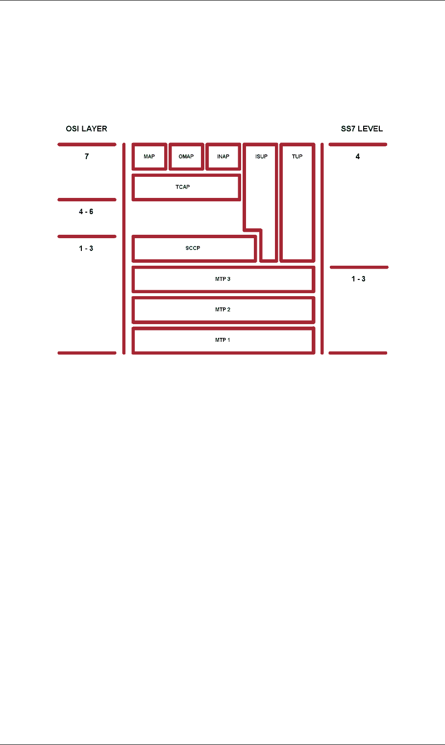
Page 216 © 2007 by TELES AG Berlin, Version 13.0/SH-e/04.16, Issue: April 2007
SS7-Specific Settings Feature Packages
11.7.5 SS7 Protocol Stack
SS7 is divided into various parts, which are stacked into levels that resemble the
seven OSI (Open Systems Interconnect) layers defined by the ISO (International
Standards Organization). Each part of the SS7 protocol stack serves to maintain
the network or to deliver the functions it offers.
Figure 11-1 SS7 Levels
11.7.5.1 Message Transfer Part
The Message Transfer Part (MTP) provides the basic functions required to trans-
mit signaling messages and manage the signaling network. It consists of the fol-
lowing three levels that must be implemented for the network to function:
MTP Level 1
This is where the physical and electrical characteristics for the network's signaling
links are determined and defined. MTP Level 1 can be compared with the OSI
Physical Layer.
MTP Level 2
performs the same tasks as the OSI Data Link Layer. It checks the links' function-
ality and ensures that communication between signaling points is operating prop-
erly.
MTP Level 3
contains the functions and procedures for the signaling network, divided into sig-
naling message handling and signaling network management. Signaling message

© 2007 by TELES AG Berlin, Version 13.0/SH-e/04.16, Issue: April 2007 Page 217
Feature Packages SS7-Specific Settings
handling switches the messages in the network, while signaling network manage-
ment is responsible for managing the network and dealing with any problems that
occur.
11.7.5.2 ISDN User Part
ISDN User Part (ISUP) defines the protocol used for connection setup and tear-
down for all ISDN services and to regulate service indicators. Though its name
suggests otherwise, ISUP is used for ISDN and non-ISDN calls.
11.7.5.3 Telephone User Part
Telephone User Part (TUP) performs most, but not all, of the functions carried out
by ISUP. It defines the protocol used for connection setup and teardown for ISDN
services and to regulate certain service indicators. TUP is only used for interna-
tional traffic to specific countries.
11.7.5.4 Signaling Connection Control Part
Signaling Connection Control Part (SCCP) handles connectionless and connec-
tion-oriented signaling information. The SCCP sets up logical, not physical, con-
nections to exchange local references and SPCs before the physical connection is
set up. Together with MTP, it performs OSI layers 1 to 3 tasks. It also provides
Global Title Translation (GTT), which translates virtual numbers, like 800 num-
bers or calling-card numbers, into actual destination point codes and subsystem
numbers.
11.7.5.5 Transaction Capabilities Application Part
Transaction Capabilities Application Part (TCAP), which is transported by SCCP,
supports transactions for application processes that are distributed throughout the
network. Transaction capabilities are functions and processes that transfer non-
user channel network information between different types of facilities. For exam-
ple, SEPs and SCPs exchange TCAP messages to query and transmit routing in-
formation for 800 and other virtual numbers.
11.7.5.6 Operations, Maintenance and Administration Part
Operations, Maintenance and Administration Part (OMAP) provides functions for
maintenance, service, administration and testing of the individual signaling
points. OMAP-defined messages are used to determine the functionality of rout-
ing databases and to find inconsistencies in links. They also carry out management

Page 218 © 2007 by TELES AG Berlin, Version 13.0/SH-e/04.16, Issue: April 2007
SS7-Specific Settings Feature Packages
functions controlled by a telecommunications management network.
11.7.5.7 Mobile Application Part
Mobile Application Part (MAP) is currently the most important user of TCAP. It
supports user channel-independent functions, e.g. database queries, in mobile sys-
tems, which allow a device to receive and make mobile calls anywhere in Europe
without necessarily knowing the current location of the subscriber. This informa-
tion is stored in a database, which is queried each time a connection is being set
up to the mobile number.
11.7.5.8 Intelligent Network Application Protocol
Intelligent Network Application Protocol (INAP) supports call control within in-
telligent networks. IN architecture is designed to facilitate the introduction, con-
trol and management of new services in an efficient and cost-effective manner.
INAP acts as the interface between the various IN functions.

© 2007 by TELES AG Berlin, Version 13.0/SH-e/04.16, Issue: April 2007 Page 219
Feature Packages SS7-Specific Settings
11.7.6 SS7 and the TELES.iGATE
TELES.iGATEs support the SS7 protocol for internal communication between
switches in the corporate network. The system is connected to the network as a
Service End Point (SEP). The synchronization timeslot is 0. No hardware changes
are necessary for SS7 use on a system. Only configuration changes in the
pabx.cfg file, as well as a license activation are required.
The following adjustments must be made to the Controller and
Subscriber commands in the PABX.CFG:
1. For each of the SS7 ports, add the SS7 keyword to the Controller com-
mand after TES2M or NTS2M.
2. Using the Subscriber command, configure the SS7 ports using the fol-
lowing keywords: SubscriberPort=SS7[OPC,DPC,SSV,SLC,CIC,
type,ST]
The point codes (OPC,DPC) can appear in the following format: 4 bit-3 bit-4
bit-3 bit. All other values are hexadecimal, with a leading zero, but no leading
format identifier 0x.
Table 11-3 SS7 Keywords
Keyword Meaning
OPC Own Point Code: distinctly identifies the port within the corporate net-
work. Use a different four-digit hexadecimal value for each port.
DPC Destination Point Code: used to distinctly identify the target port within
the corporate network. Specify a four-digit hexadecimal number for
each port.
SSV Subservice for the target port:
80 for national – port on the corporate network (NAT0)
00 for international – port on a foreign network
C0 for test (NAT1)
SLC Signaling Link Code: used to distinctly identify the lines running in the
same direction on Layer 3. Specify a hex value from 00 to 0F.
CIC Circuit Identification Code: used to identify B channels to the remote
switch. Specify a four-digit hexadecimal number.
type TRUNK – standard line (no signaling)
LINK – for standard usage and signaling in one line
For each connection, at least one LINK must be configured in corre-
spondence with the configuration used by the remote switch.
ST Signaling Timeslot: timeslot used for signaling (default 16). Must ap-
pear in the following format: Dxx, whereby xx refers to the timeslot in
double digits (e.g. D16).
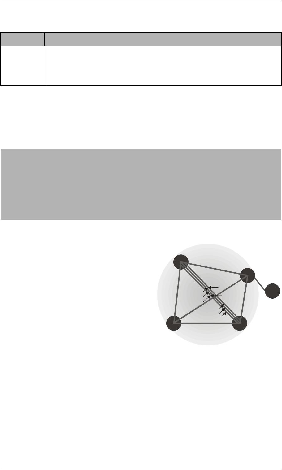
Page 220 © 2007 by TELES AG Berlin, Version 13.0/SH-e/04.16, Issue: April 2007
SS7-Specific Settings Feature Packages
Note: Use timeslots 1-15 and 17-31 as voice channels. Timeslot 16 cannot
be used as a voice channel in a trunk configuration.
Figure 11-2 shows four switches commu-
nicating via SS7:
11.7.7 SS7 Routing Entries
It may be necessary for certain options to be sent with SS7 IAMs. These options
appear in specific routing entries.
Calls with Continuity Check
A continuity check feature tests a channel to determine if it exists from beginning
to end point. Use the following entry for incoming calls with this feature:
STP Signaling Transfer Point (optional). You can enter an STP’s unique
identifier at the end of the square brackets
NOTE: Make sure you do not enter upper-case letters. This entry may
never begin with an upper-case D!
Table 11-4 Sample of pabx.cfg
; 5) Controllers
; --------------
Controller00=9 TES2M SS7
Controller01=9 TES2M SS7
; 6) Subscribers
; --------------
; TELES.3PRI board(s)
; ---------------------
Subscriber00=SS7[1-7-a-3,1-7-a-1,80,00,0000,LINK,D16,3-b-2-a] TRANSPARENT ROUTER ALARM
Subscriber01=SS7[1-7-a-3,1-7-a-1,80,01,0020,LINK,D16,3-b-2-a] TRANSPARENT ROUTER ALARM
Table 11-3 SS7 Keywords (continued)
Keyword Meaning
1
1
2
3
4
OPC
Controller 04
Controller 05
DPC 4 DPC 3
80
national
international
00
SLC 1
SLC 2
SLC 3
Trunk
Trunk
Link&Trunk
DPC 2
OPC OPC
OPC
Figure 11-2 SS7 Switch Communica-
tion

© 2007 by TELES AG Berlin, Version 13.0/SH-e/04.16, Issue: April 2007 Page 221
Feature Packages SS7-Specific Settings
MapAll<num>=$<pl>
MapAll<pl>W=<port>
MapAll<pl>=<port>
A placeholder mapping is set up (pl) and a new search of the routing table occurs
($). The placeholder pl is replaced with a W for calls with a continuity check if a
W appears at the end of the controller’s subscriber line. Calls without a conti-
nuity check are sent directly to the port.
Example: The following example shows a routing configuration in which a
continuity check occurs at controller 01.
Example: In the following example, all calls beginning with 0 are mapped to the
placeholder pl and sent to port 10 following a new routing-file
search. The W routing process is used for calls with continuity check:
; 5) Controllers
; --------------
Controller00=9 TES2M SS7
Controller01=9 TES2M SS7
; 6) Subscribers
; --------------
; TELES.3PRI board(s)
; ---------------------
Subscriber00=SS7[1-7-a-3,1-7-a-1,80,00,0000,LINK,D16,] TRANSPARENT ROUTER ALARM
Subscriber01=SS7[1-7-a-3,1-7-a-1,80,01,0020,LINK,D16,W] TRANSPARENT ROUTER ALARM
MapAll0=$pl
MapAllplW=10
MapAllpl=10

Page 222 © 2007 by TELES AG Berlin, Version 13.0/SH-e/04.16, Issue: April 2007
Overview Optional Function Modules
12 Optional Function Modules
This chapter contains a description of modules that expand the functionality of the
TELES.iGATE, such as:
• SNMP agent
• DNS forwarder
• ipupdate - DynDNS client
Since these features are only required in individual cases, they are not part of the
default software packet. They can be installed as stand-alone modules for the de-
sired function. The description of the functionality of individual modules appears
in their respective chapters.
12.1 Overview
The modules can be downloaded using FTP. The access data for each module is
as follows:
• DNS Forwarder
ftp://195.4.12.80
user: dnsmasq
password: dnsmasq
• snmp agent
ftp://195.4.12.80
user: snmp
password: snmp
• ipupdate
ftp://195.4.12.80
user: ipupdate
password: ipupdate
Install the respective software package on the TELES.iGATE using
TELES.GATE Manager. For a description of how to update the software, please
refer to Chapter 10.3. Make sure the module’s file ending is correct before instal-
lation. The number in the file ending shows the starting order of the modules. Do
NOT change this number if it is 0! All other modules can simply be numbered in
ascending order.
For instance, the ending for the optional function module will be tz2 or higher:
• tz2
• tz3
Following completion of transmission, you must adjust the module’s configura-
tion and restart the TELES.iGATE. Once you have restarted the system, you can
use the required features.

© 2007 by TELES AG Berlin, Version 13.0/SH-e/04.16, Issue: April 2007 Page 223
Optional Function Modules SNMP Agent
12.2 SNMP Agent
This module allows you to connect the systems and their functions to an SNMP-
based network monitoring system. With this module, SNMP requests are an-
swered and alarm messages (E.g. Layer 1 errors on E1 lines) and error recovery
messages are sent via SNMP trap. Bear in mind that the keyword ALARM must be
entered in the appropriate PRI, BRI, POTS or mobile port’s Subscriber line in
the pabx.cfg. The MIBs (Management Information Bases) are included on the
product CD in the folder MIB. The module name snmpd.tz0 must have the
ending tz0!
The following settings are possible in the section [snmpd]:
12.3 DNS Forwarder
With this module, the system can function as a DNS server for the clients in the
local network. The system in the local network sent the DNS query to the
TELES.iGATE, which forwards the queries to a known DNS server address if no
valid entry for the query is known.
The advantage is that the clients always enter the TELES.iGATE’s address as
DNS server address, so that no public DNS server address is required. The
TELES.iGATE functions in this scenario as a router.
Of course, the DNS server’s address can also be transmitted to the clients using
the integrated DHCP server. If the TELES.iGATE is used as a DSL router or if it
sets up a dial-up connection, no entry is required in the pabx.cfg for the param-
eter NameServer. The DNS server’s address that is negotiated through this con-
nection will be used.
12.4 ipupdate - DynDNS Client
This function allows you to assign a defined hostname to an IP address that chang-
es dynamically. That means that you can always reach a device or service through
Table 12-1 Settings in the Section [snmpd]
Parameter Definition
Port=<port> Defines the target port for the trap server (default 161).
TrapServer=<ip addr> Enter the SNMP trap server’s IP address. Example for
listing more than one:
TrapServer:192.168.0.10 192.168.0.12
Community=<password> Enter a password for a community (group). The default
password is public.

Page 224 © 2007 by TELES AG Berlin, Version 13.0/SH-e/04.16, Issue: April 2007
ipupdate - DynDNS Client Optional Function Modules
the public IP network, even if, for example, it is a common DSL connection with
dynamic IP address allocation. Several providers support this service.
Make the following entries in the system’s pabx.cfg, in the [DynDNS] sec-
tion:
Table 12-2 pabx.cfg: DynDNS
DynDNS Parameters
service=<type>
Specifies which provider is used. The following providers are supported:
dhs
dyndns
dyndns-static
dyns
ezip
easydns
easydns-partner
gnudip
heipv6tb
hn
pgpow
ods
tzo
zoneedit
http://www.dhs.org
http://www.dyndns.org
http://www.dyns.cx
http://www.ez-ip.net
http:/www.easydns.com
http://www.gnudip.cheapnet.net
http://www.hn.org
http:www.justlinux.com
http://ods.org
http://www.tzo.com
http://zoneedit.com
user=<username:password>
Defines the username and password for the DNS service provider.
host=<domain_name_of_dns_service>
Enter the domain name that is used.
interface=<If>
Defines the interface to be used. Possible entries are emac0, emac1, pppoe0.
The dynamic IP address for this interface is transmitted to the service provider.
max-interval=<sec>
Defines the value in seconds in which actualization of the name in the DNS data-
base must occur. 2073600 seconds (24 days) is the default value. The shortest
interval allowed is 60 seconds. Bear in mind that this setting may cause the pro-
vider to block the domain name, since multiple registrations in short intervals are
often not allowed. You must clear this with your provider.

© 2007 by TELES AG Berlin, Version 13.0/SH-e/04.16, Issue: April 2007 Page 225
Optional Function Modules ipupdate - DynDNS Client
Example: In the following example, the DynDNS service is used and the do-
main name is host.domain.de; the username is user and the
password is pwd. The TELES.iGATE works as DSL router and the
dynamically allocated IP address of the PPPoE interface is used:
Included in the possible uses for this feature is remote access to the
TELES.iGATE when the IP connection does not have a fixed IP address. In this
case, you can access the system, for example with the TELES.GATE Manager, if
the host name is used in the Remote Number dialog. Example entry in the Remote
Number dialog: IP:host.domain.de
[DynDNS]
service=dyndns
user=user:pwd
host=host.domain.de
interface=pppoe0
max-interval=2073600
