Titan Assembly Guide
User Manual:
Open the PDF directly: View PDF ![]() .
.
Page Count: 5
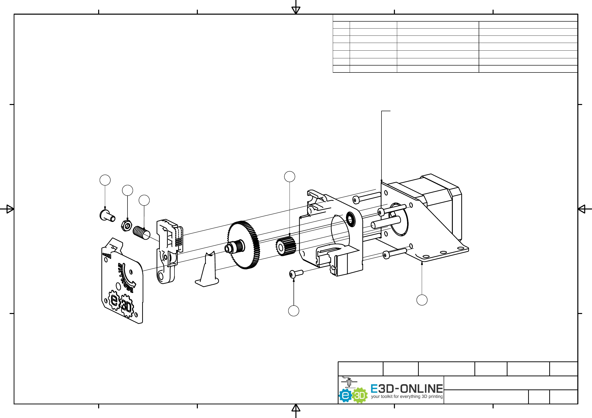
PARTS LIST
DESCRIPTIONPART NUMBERQTYITEM
M3 x 8 Dome Head Socket Cap Screw
M3 x 8112
M4 x 10 Dome Head Socket Cap ScrewM4 x 10
1
13
M4 Hex NutM4 Hex Nut114
Extruder Idler Spring
EX_SPRING115
Extruder Pinion Gear (Steel)EX_PINION
1
16
Extruder Bracket - Printed Example
EX_BRACKET117
1
1
2
2
3
3
4
4
5
5
6
6
A A
B B
C C
D D
E3D Titan - Supplementary Drawings
ASM_EX_2
E3D Online - JR 16/02/2016
Designed by Checked by Approved by Date
8 / 13
Edition Sheet
Date
Copyright (C) E3D-Online Ltd (e3d-online.com)
These drawings are free hardware: you can redistribute it and/or modify it under the terms of the GNU General Public License as
published by the Free Software Foundation, either version 3 of the License, or (at your option) any later version.
13
14
15
12
16
17
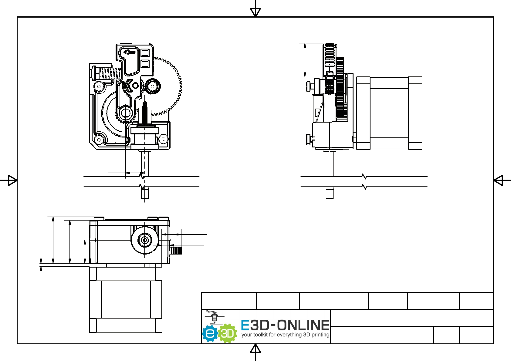
NOTE: A SPACER IS ALWAYS REQUIRED
1. THICKNESS: 2 MIN - 4.5 MAX
2. MAX ASSUMES MOTOR SHAFT LENTH 22.2
3. SUPPLIED FIXINGS FOR THICKNESS OF 2
NOTE: THESE DRAWINGS ARE FOR REFERENCE ONLY.
REFER TO http://wiki.e3d-online.com/wiki/Titan_Assembly FOR ASSEMBLY INFORMATION
ASSEMBLY OVERVIVEW
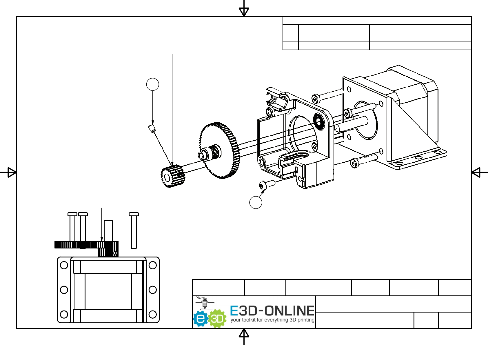
PARTS LIST
DESCRIPTIONPART NUMBERQTYITEM
M3 x 8 Dome Head Socket Cap Screw
M3 x 8112
M3 x 4 Socket Set ScrewM3 x 4 Grub Screw
1
26
E3D Titan - Supplementary Drawings
ASM_EX_2
E3D Online - JR 16/02/2016
Designed by Checked by Approved by Date
9 / 13
Edition Sheet
Date
Copyright (C) E3D-Online Ltd (e3d-online.com)
These drawings are free hardware: you can redistribute it and/or modify it under the terms of the GNU General Public License as
published by the Free Software Foundation, either version 3 of the License, or (at your option) any later version.
THE TOP SURFACES OF THE
TWO GEARS MUST BE FLUSH
ADJUST THE PINION ACCORDINGLY
26
12
Assembly Steps:
1. Present motor up to mounting bracket.
2. Present body to mounting bracket and install the M3 x 8 Screw to hold the body in place
3. Fit the small pinion gear onto the motor shaft.
Fit the large gear into the bearing on the body and use this to set the position of the pinion gear.
4. Tighten up the grub screw on the pinion gear.
NOTE:
The gear must go on the correct way around.
The grub screw hole must be towards the motor face.
ASSEMBLY STEPS 1-4
B-B ( 1 : 1 )
C ( 2 : 1 )
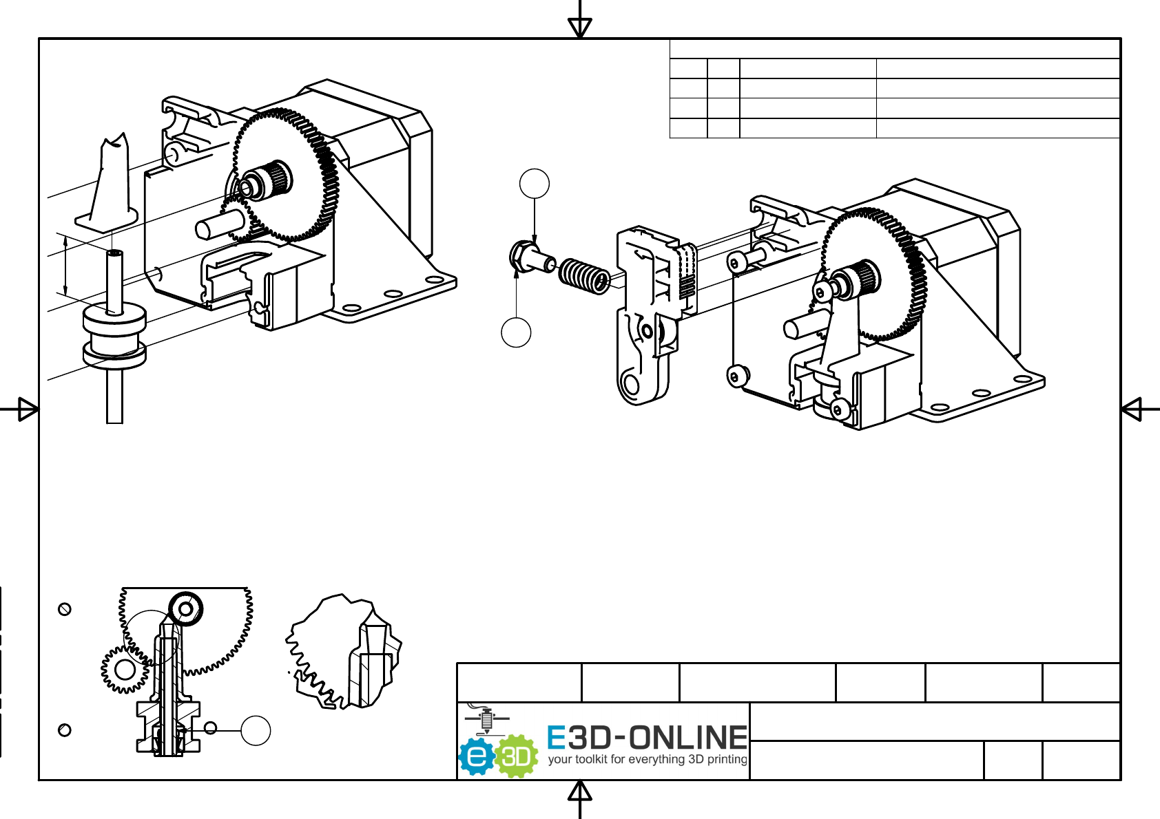
PARTS LIST
DESCRIPTIONPART NUMBERQTYITEM
M4 Hex NutM4 Hex Nut114
M4 x 10 Dome Head Socket Cap ScrewM4 x 10
1
13
PTFE127
B
B
E3D Titan - Supplementary Drawings
ASM_EX_2
E3D Online - JR 16/02/2016
Designed by Checked by Approved by Date
10 / 13
Edition Sheet
Date
Copyright (C) E3D-Online Ltd (e3d-online.com)
These drawings are free hardware: you can redistribute it and/or modify it under the terms of the GNU General Public License as
published by the Free Software Foundation, either version 3 of the License, or (at your option) any later version.
Assembly Steps:
5. Install the filament guide and HotEnd into the extruder body.
For the 1.75mm version, make sure the PTFE goes all the
way up into the filament guide. See cutout below.
Rotate the HotEnd if necessary to insert.
Note: The diagram shows a bowden adaptor for a bowden setup,
if you are using a direct, there will be a HotEnd in place of this part.
Assembly Steps:
6. Slide the lever onto the motor shaft.
7. Screw the M4 Nut fully onto the M4 x 10 Screw
8. Slide the spring onto the screw and insert the assembly into the slot as shown.
Note: This bit is fiddly. Don't add any tension to the spring,
it will fly across the room to be lost forever.
13
14
27
1
6
ASSEMBLY STEPS 5-8
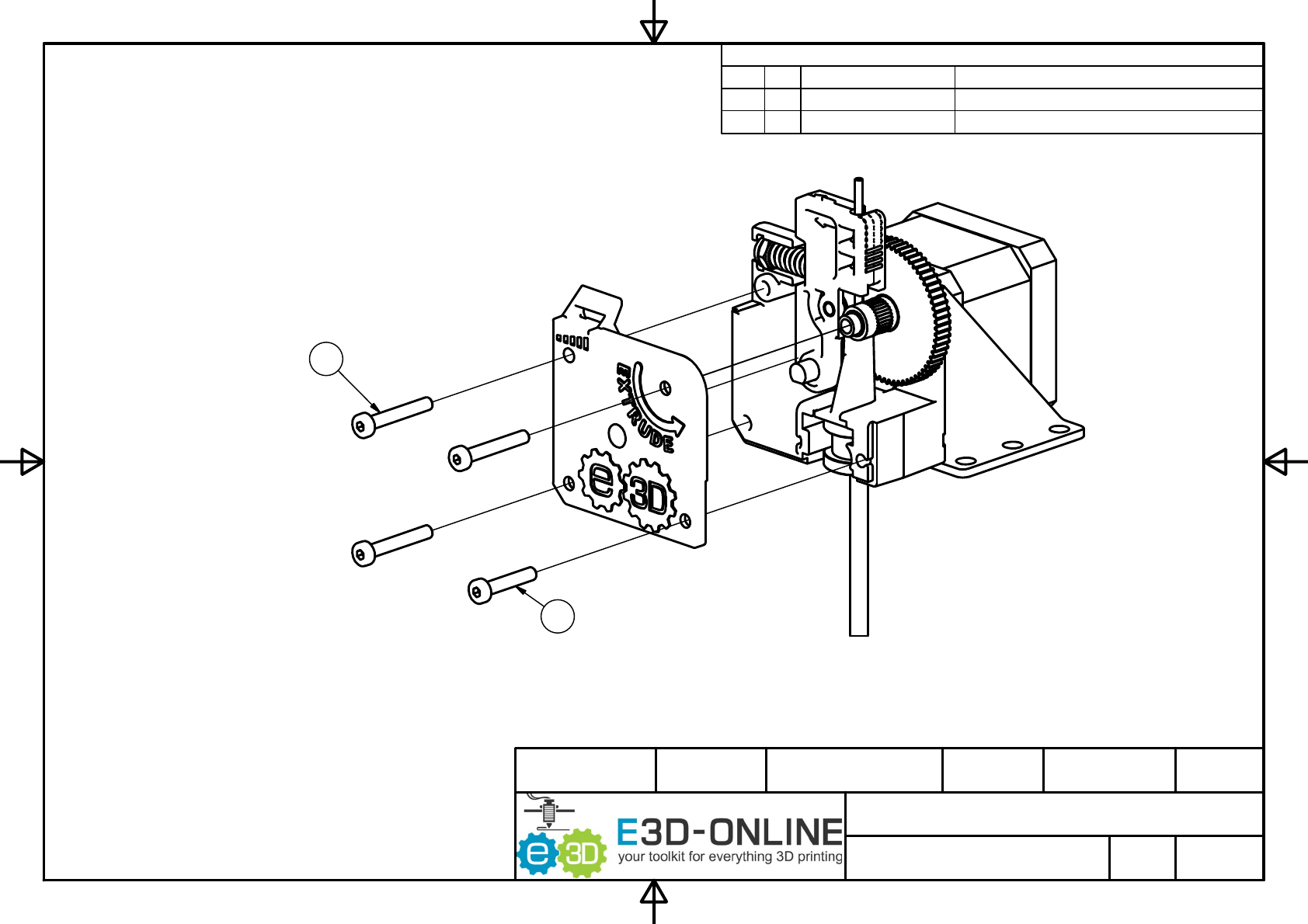
PARTS LIST
DESCRIPTIONPART NUMBERQTYITEM
M3 x 25 Low Head Socket Cap Screw
M3 x 25129
M3 x 30 Low Head Socket Cap ScrewM3 x 30 330
E3D Titan - Supplementary Drawings
ASM_EX_2
E3D Online - JR 16/02/2016
Designed by Checked by Approved by Date
11 / 13
Edition Sheet
Date
Copyright (C) E3D-Online Ltd (e3d-online.com)
These drawings are free hardware: you can redistribute it and/or modify it under the terms of the GNU General Public License as
published by the Free Software Foundation, either version 3 of the License, or (at your option) any later version.
Assembly Steps:
9. The lid is held on with 4 screws. Note the bottom right screw is shorter than the others.
ASSEMBLY STEP 9
30
29
E3D Titan - Supplementary Drawings
ASM_EX_2
E3D Online - JR 16/02/2016
Designed by Checked by Approved by Date
12 / 13
Edition Sheet
Date
Copyright (C) E3D-Online Ltd (e3d-online.com)
These drawings are free hardware: you can redistribute it and/or modify it under the terms of the GNU General Public License as
published by the Free Software Foundation, either version 3 of the License, or (at your option) any later version.
11.1
2 MIN
4.6
11.4
25
27
19.5
TITAN EXTRENAL DIM'S
13.5
