1.75mm Direct Titan Assembly Guide 19 En
User Manual:
Open the PDF directly: View PDF ![]() .
.
Page Count: 19
- 1.75mm Direct Titan Assembly
- TOOLS:
- PARTS:
- Step 1 — Prep: Mounting Your Titan
- Step 2 — Gather Titan Body
- Step 3 — Attach Pinion Gear to Motor
- Step 4
- Step 5 — Place Drive Shaft
- Step 6 — Gather Direct Parts
- Step 7 — Slide in PTFE Tubing
- Step 8 — Cut Tubing and Prep Filament Guide
- Step 9 — Slot Hotend into Extruder
- Step 10 — Gather Idler
- Step 11 — Prep Idler
- Step 12 — Assemble Idler
- Step 13 — Gather Lid Parts
- Step 14 — Assemble Lid
- Step 15 — Screw in Lid 1
- Step 16 — Screw in Lid 2
- Step 17 — Screw in Lid 3
- Step 18 — Gear Alignment Check
- Step 19 — Check for Backlash
- Step 20 — PTFE Idler
- Step 21 — Firmware Configuration
1.75mm Direct Titan Assembly
Learn how to assemble your Titan for use with 1.75mm filament in a direct configuration.
Written By: Gabe S.
1.75mm Direct Titan Assembly
© 2018 e3d-online.dozuki.com/ Page 1 of 19

TOOLS:
Hex Wrench, 1.5mm (1)
Hex Wrench, 2.5mm (1)
Hex Wrench 3mm (1)
Craft Knife (1)
Any sharp knife will do (scissors as last resort)
PARTS:
Titan Extruder Body (1)
Steel Pinion Gear (1)
Delrin Gear with Filament Drive Shaft (1)
M3 Grub Screw (1)
M3x10 Socket Dome Screw (1)
PTFE Tubing (2)
Titan Filament Guide (1)
1.75mm
Labled either "1.75L" or "1.75R"
M3x30 Screws (1)
Titan Idler Lever (1)
M4 Thumbscrew (1)
Idler Spring (1)
M4x10 Button Head Screw (1)
M3 Nut (1)
Titan Lid (1)
M3x25 Screw (1)
Compact but powerful motor (optional
extra) (1)
1.75mm Direct Titan Assembly
© 2018 e3d-online.dozuki.com/ Page 2 of 19

Step 1 — Prep: Mounting Your Titan
Before beginning your build, make sure that you have an appropriate mount for your extruder. If
you have a commonly upgraded printer (Ultimaker 2, Taz 5/6, Prusa i3, etc) you'll likely be able to
find 3D models of well designed Titan mounts on your favourite 3D model sharing site.
When installing the Titan, you must have something to separate the motor from the extruder body
by 2 mm. Typically, a piece of your mounting bracket will attach here and provide this space (for
reference take a look at our Prusa Mounting Bracket). Having a separation of more than 2mm will
mean you need longer screws to hold the assembly together.
Please note that there may be extra bolts in the titan fixing kit bag that will be unused.
1.75mm Direct Titan Assembly
© 2018 e3d-online.dozuki.com/ Page 3 of 19
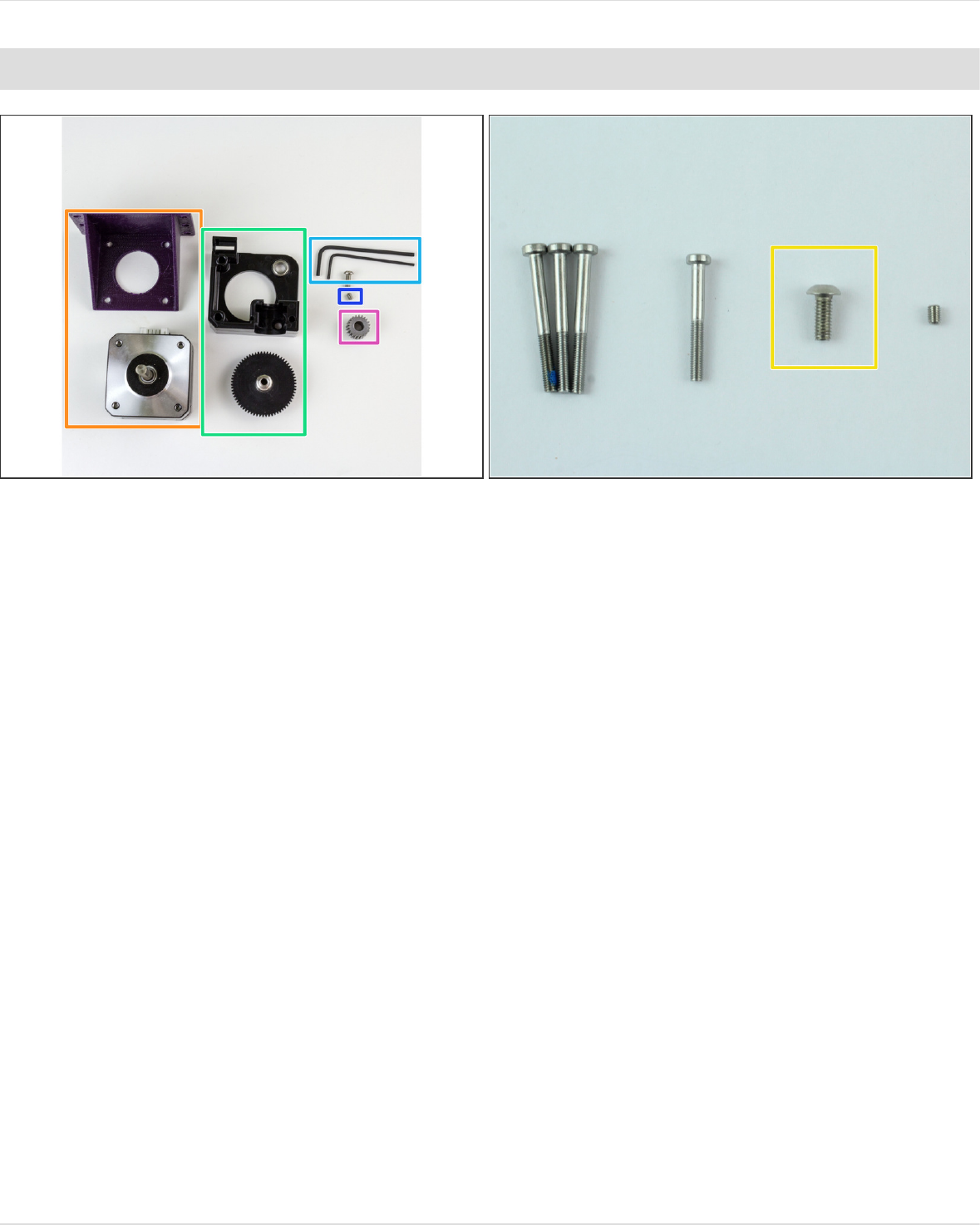
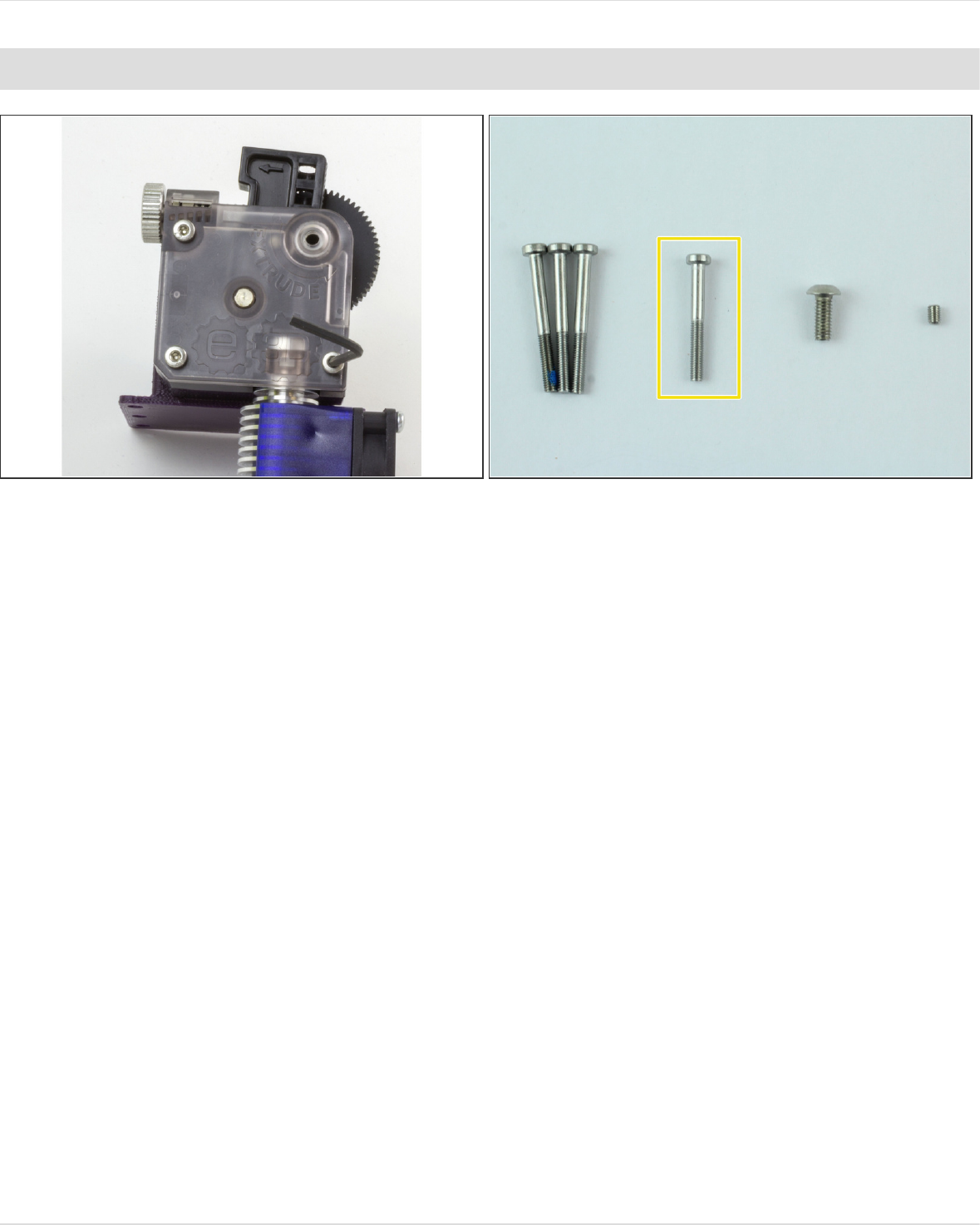
Step 2 — Gather Titan Body
Gather
The motor you'll be using + mounting bracket
Extruder Body + Large Gear
M3x8mm Screw
M3 Grub Screw
Pinion Gear
The Smallest, 1.5mm Hex Wrench, and Mid-sized, 2.5mm Hex Wrench
1.75mm Direct Titan Assembly
© 2018 e3d-online.dozuki.com/ Page 4 of 19
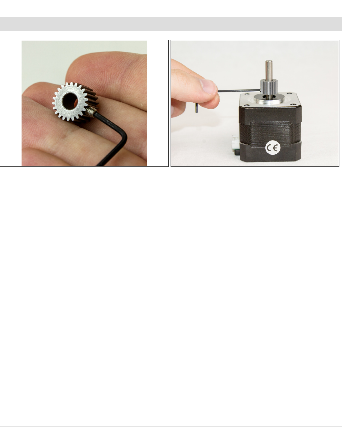
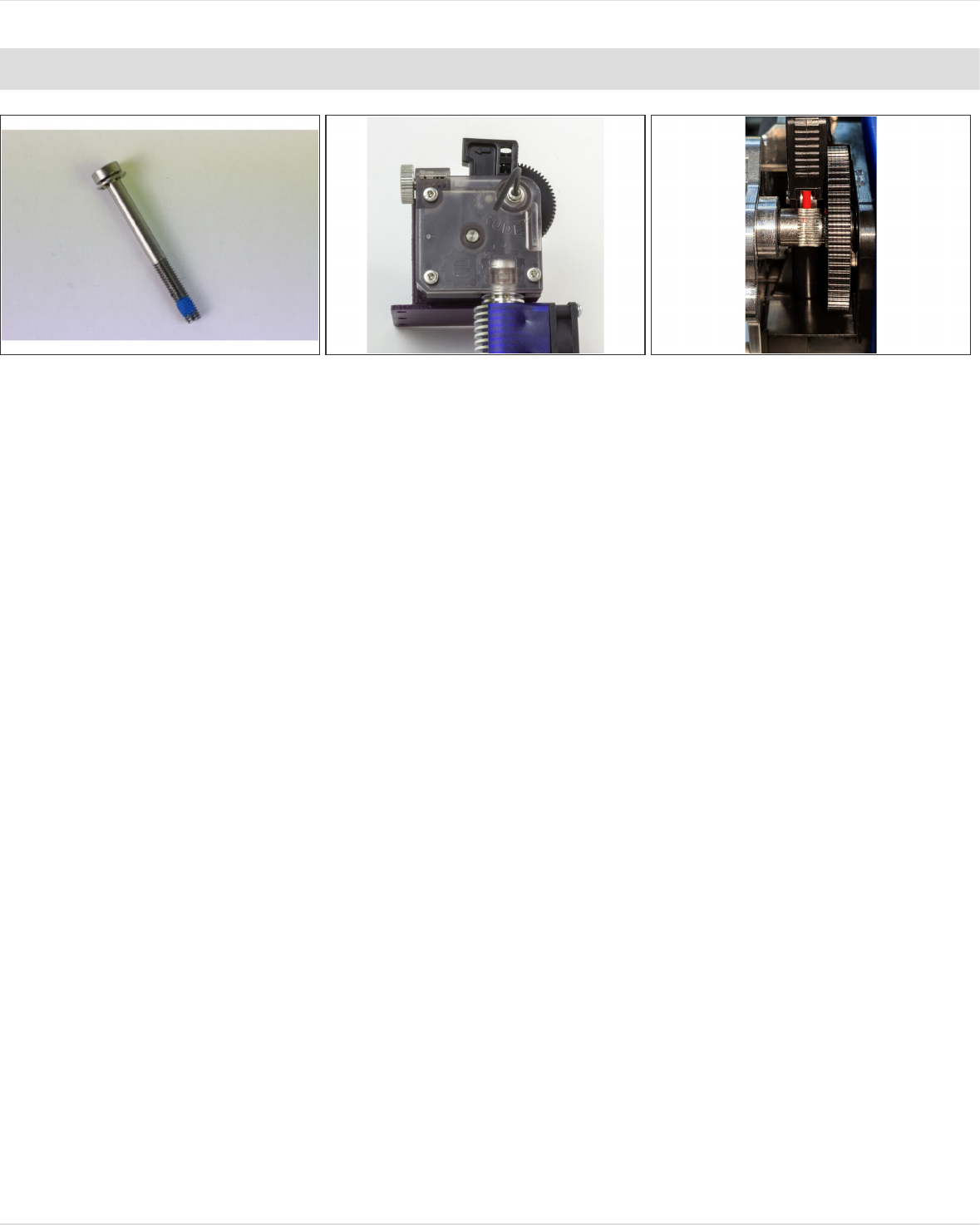
Step 3 — Attach Pinion Gear to Motor
Thread the M3 grub screw into the pinion gear slightly so you don't lose it
Slip the pinion gear onto the motor shaft with the grub screw facing down, towards the motor.
Slide it about 3/4 of the way down the shaft and tighten the screw.
The compact but powerful motor has a fully round shaft. - some of the older kits used the slimline
motor which has a flat on the shaft.
1.75mm Direct Titan Assembly
© 2018 e3d-online.dozuki.com/ Page 5 of 19
Step 4
Take your M3 screw that you picked
out before and slip it through the
hole extruder body in the groove
mount (lower leftmost screw hole).
Slip the screw through your
mounting bracket (including spacer if
you're using one) and screw it into
your motor.
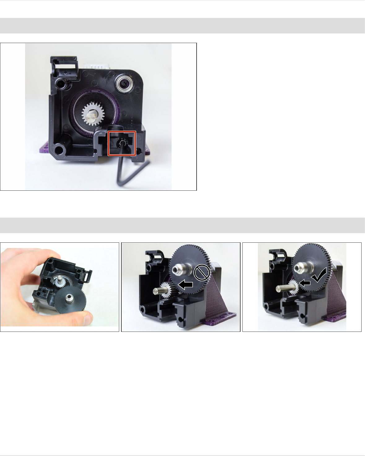
Step 5 — Place Drive Shaft
Slot in the drive shaft (attached to the other gear)
You need to have the top of the pinion gear flush with the top of the drive shaft gear.
If it isn't—and it likely won't be on the first try—loosen the grub screw and adjust the positioning of
the pinion gear on the motor's shaft. You may need to unscrew the extruder body to get at the grub
screw.
When you think you've got it, try pressing down on the drive shaft lightly to see how it will fare
when the whole extruder is screwed in and make sure it's still flush.
1.75mm Direct Titan Assembly
© 2018 e3d-online.dozuki.com/ Page 6 of 19
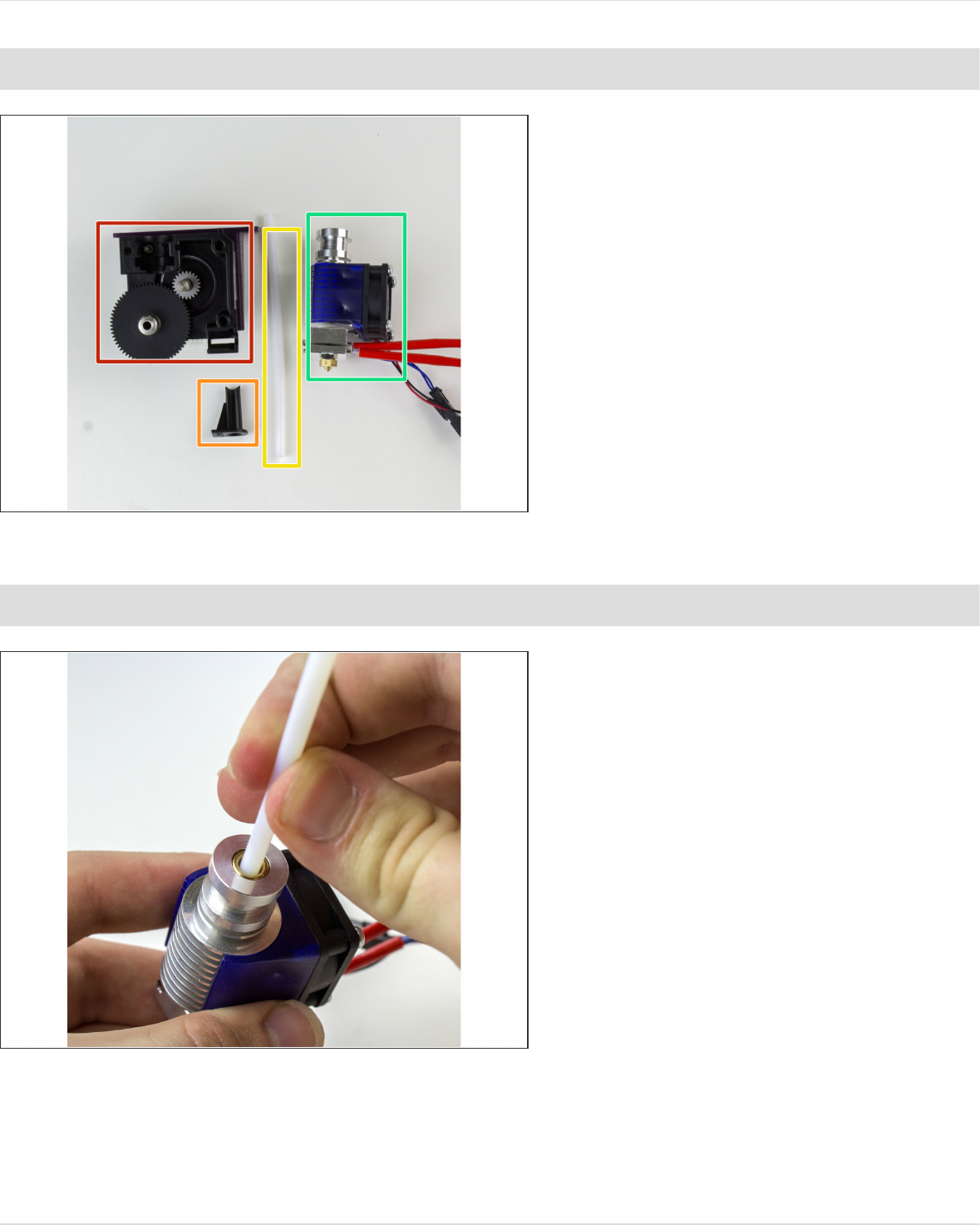
Step 6 — Gather Direct Parts
Gather:
Titan Body
1.75mm Guide Tube (Marked "L"
or "R")
PTFE Tubing
V6 Hotend
Do not use a collet or clip.
Step 7 — Slide in PTFE Tubing
Slide the PTFE tubing into your
heatsink until it touches the heat
break (as far as it will go).
You should NOT have the little black
collet installed.
1.75mm Direct Titan Assembly
© 2018 e3d-online.dozuki.com/ Page 7 of 19
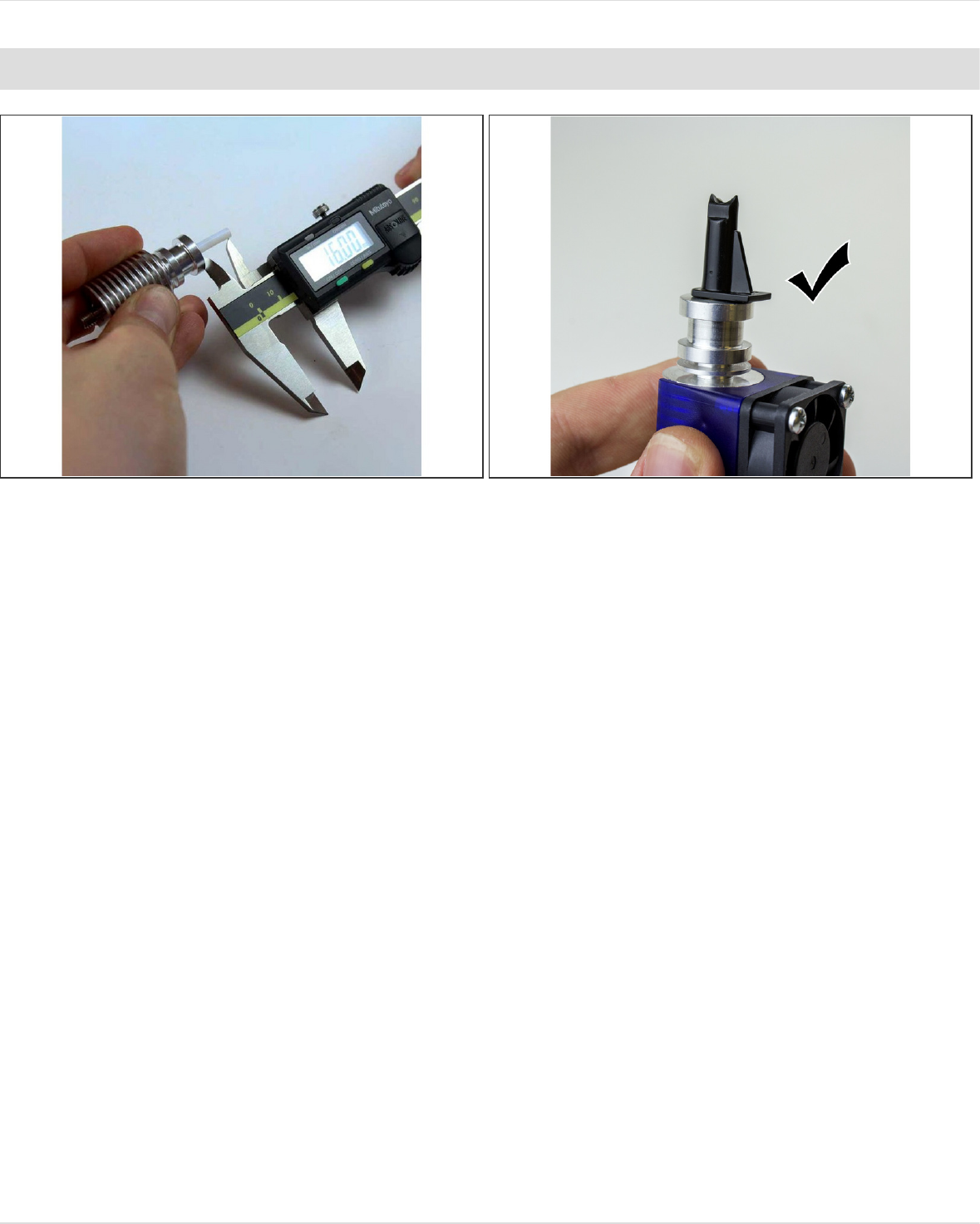
Step 8 — Cut Tubing and Prep Filament Guide
Measure 16mm of PTFE tubing from the top of your heatsink/hotend and use a sharp knife to cut it
there (so as not to deform the tubing).
Make sure that you save a length of PTFE tubing for later, you'll need it for the last step.
If the tubing is too long, the end will be crushed, potentially causing extrusion issues. If it's too
short, you may have some slight difficulty loading filament. Of the two, slightly too short is better.
Pop on the filament guide to check the length.
1.75mm Direct Titan Assembly
© 2018 e3d-online.dozuki.com/ Page 8 of 19
Step 9 — Slot Hotend into Extruder
Slide the finished assembly into your extruder body. Make sure that the round side of the filament
guide is facing down, into the extruder body.
1.75mm Direct Titan Assembly
© 2018 e3d-online.dozuki.com/ Page 9 of 19
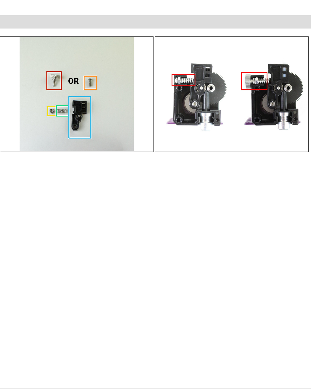
Step 10 — Gather Idler
Gather:
M4 Thumbscrew
OR M4 Button Head Screw
M4 Nut
Spring
Idler Lever
The only difference between the thumbscrew and the button head one is ease of use vs. space. If
you can, we suggest using the thumbscrew.
1.75mm Direct Titan Assembly
© 2018 e3d-online.dozuki.com/ Page 10 of 19
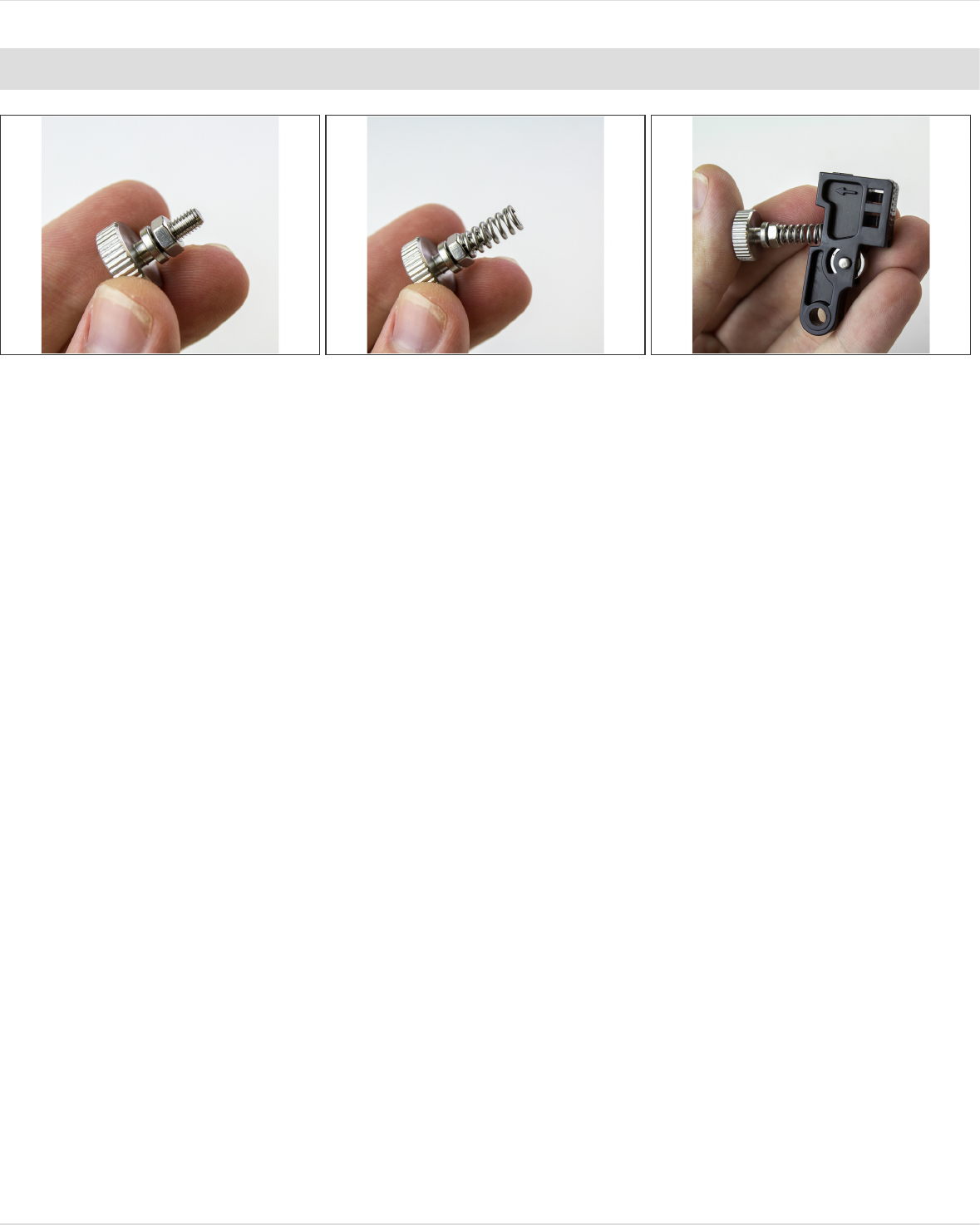
Step 11 — Prep Idler
Screw the M4 nut all the way onto the M4 Screw or Thumbscrew.
Push the spring over the threaded part of the screw. The nut will eventually let you adjust the
tension on your extruder by travelling down the screw and compressing the spring.
Position the other end of the spring on the little bump on the idler lever.
1.75mm Direct Titan Assembly
© 2018 e3d-online.dozuki.com/ Page 11 of 19
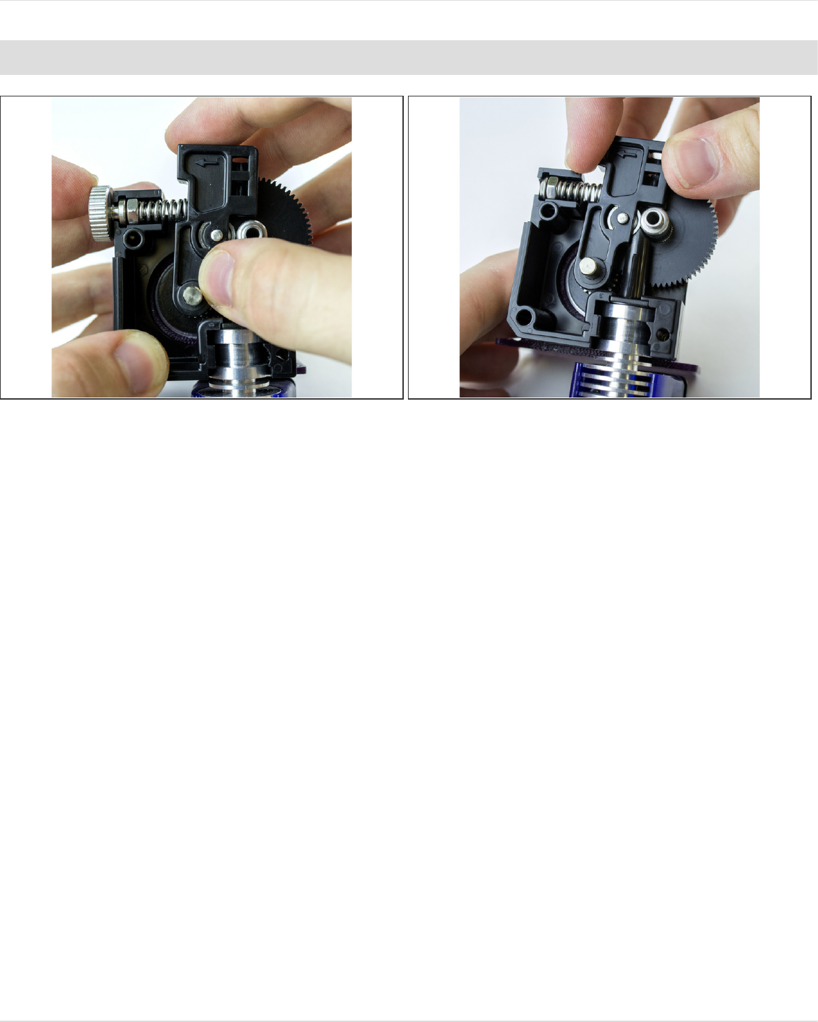
Step 12 — Assemble Idler
Drop this assembly into the extruder body.
The screw will slot into the nut-channel in the extruder body, and the idler arm will slip onto the
motor shaft.
It is normal that the shaft sticks out slightly from the lever.
Make sure that the nut slots into the channel fully and that the idler arm is pressed all the way onto
the motor shaft.
Your assembly may look like either photo above, depending on whether you're using the
thumbscrew or the dome screw.
Do not compress the spring without the Titan lid on!!! It will go flying out and you will lose it. And it
could hit someone in the face.
1.75mm Direct Titan Assembly
© 2018 e3d-online.dozuki.com/ Page 12 of 19
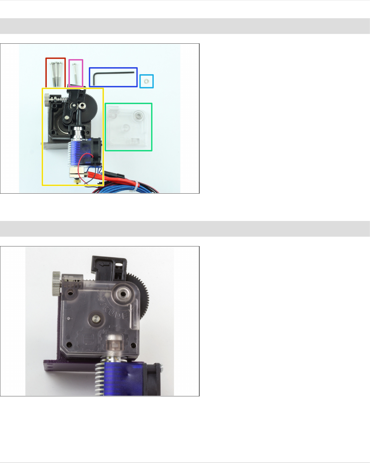
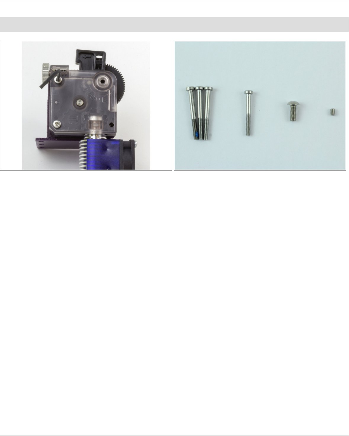
Step 13 — Gather Lid Parts
Gather:
M3x30 Screws
Extruder Assembly
Titan Lid
Shake-proof washer
M3x25 Screw (the shortest M3
Screw)
The mid-sized 2.5mm Hex
Wrench.
Step 14 — Assemble Lid
Press on the lid to your extruder. It
should be flush with all the sides of
the body.
1.75mm Direct Titan Assembly
© 2018 e3d-online.dozuki.com/ Page 13 of 19
Step 15 — Screw in Lid 1
Screw the two longer M3 screws that don't have blue patch lock on them into the left two holes on
the lid.
Because the extruder is only attached to the motor by one screw at the moment, you may need to
wiggle it a little to get them to thread into the motor.
1.75mm Direct Titan Assembly
© 2018 e3d-online.dozuki.com/ Page 14 of 19
Step 16 — Screw in Lid 2
Screw the second longest screw into the right hand corner of the lid.
This screw goes into the brass insert on the back of the extruder body, not your motor. It just holds
the hotend in place.
1.75mm Direct Titan Assembly
© 2018 e3d-online.dozuki.com/ Page 15 of 19
Step 17 — Screw in Lid 3
Slip the shake-proof washer onto the screw with the blue patch lock on it.
WARNING - this screw goes through the bearings and so when it is tightened it creates an axial
load on the bearings, if this screws is overtightened even once it may cause permanent damage to
your bearings which will result in bearing failure -PROCEED WITH CAUTION.
Screw in this screw until it is finger tight and no more.
The shake-proof washer will prevent this screw from coming loose.
There may be some slight visual misalignment of the idler and teeth, this is due to an
inconsequential machining error of the filament drive gear. The toothed portion of the shaft is wide
enough to accommodate this minor misalignment with no effect on how the teeth engage the
filament.
1.75mm Direct Titan Assembly
© 2018 e3d-online.dozuki.com/ Page 16 of 19
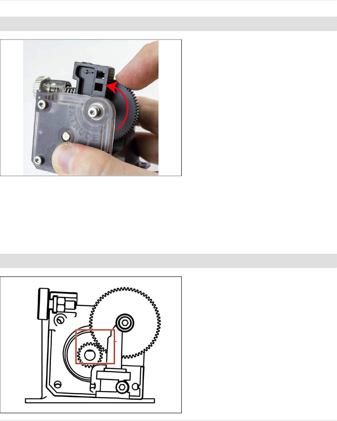
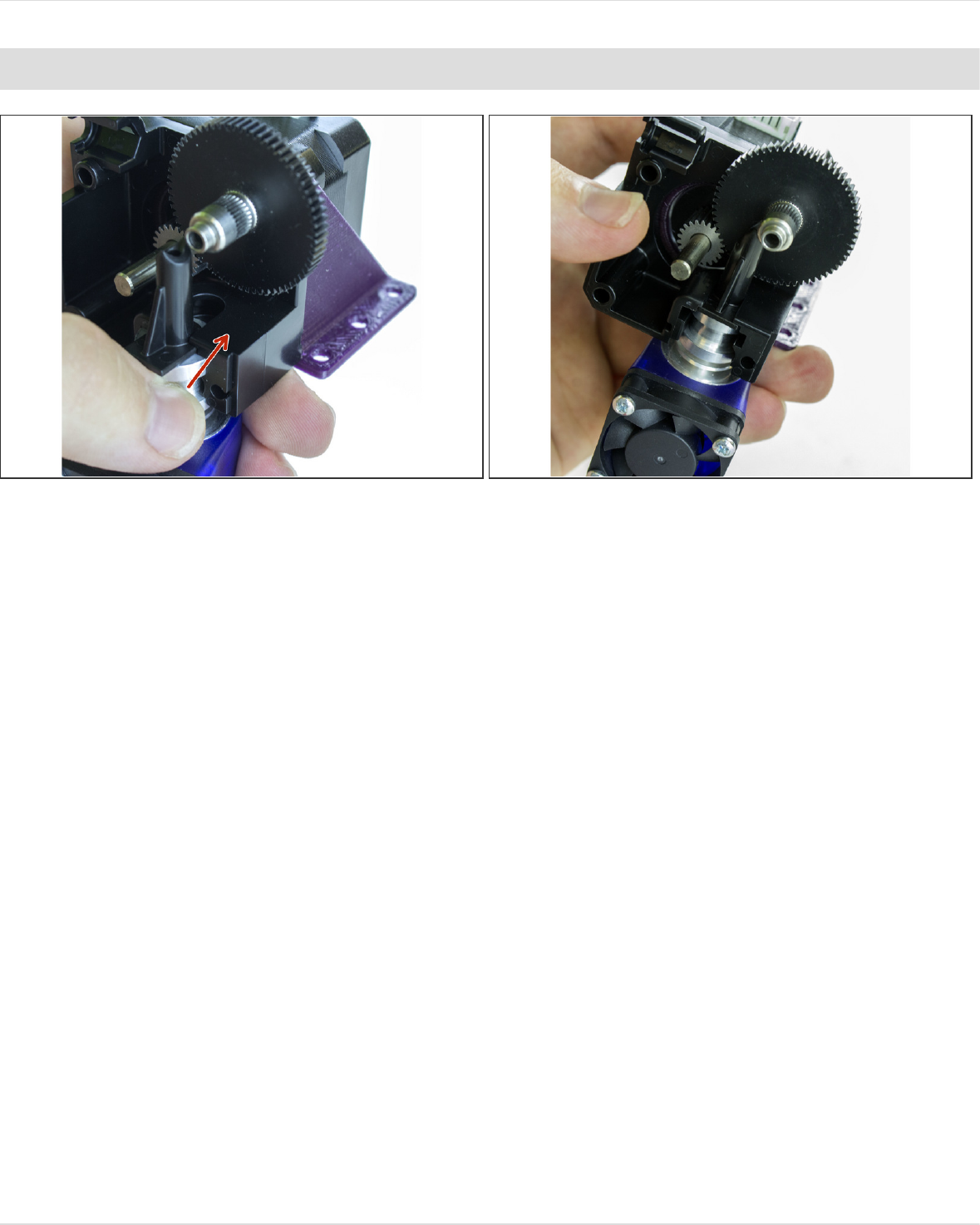
Step 18 — Gear Alignment Check
Try to rotate the large acetal gear to
see if it moves smoothly.
If it is hard to rotate, check the
position of the steel pinion gear, it
may be too far forward. Adjust it so
that it is flush with the front face of
the acetal gear and try again.
If this does not solve the issue, then
the screw with the shake-proof
washer on it may have been
overtightened. If loosening this
screw allows the acetal gear to run
smoothly then the screw has been
overtightened and permanent
damage may have been caused to
the bearings; seek replacement
bearings if this is the case.
Step 19 — Check for Backlash
If the large gear exhibits “backlash”
(there's play between the large
acetal gear and the metal one on the
drive shaft), loosen all screws on the
lid and rotate the body such that the
gears fully mesh.
Re-tighten the screws as described
in the previous steps.
1.75mm Direct Titan Assembly
© 2018 e3d-online.dozuki.com/ Page 17 of 19
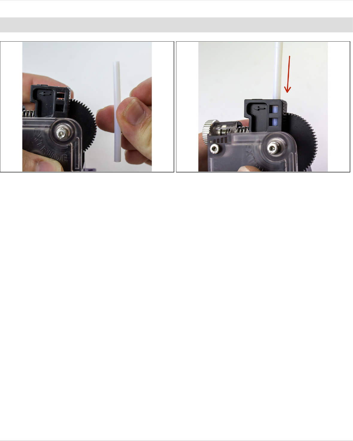
Step 20 — PTFE Idler
If you're printing 1.75mm filament, you can guide it a little better by putting a length of PTFE
tubing in the top of the idler lever
Press the tubing into the lever.
It may be a very tight fit. You can file down the tube if it helps.
1.75mm Direct Titan Assembly
© 2018 e3d-online.dozuki.com/ Page 18 of 19

This document was last generated on 2018-09-25 07:05:07 AM.
Step 21 — Firmware Configuration
You're done with the mechanical assembly! All that's left is to calibrate your new extruder by
updating your firmware and EEPROM. Click on one of the links below to start working on your
firmware.
Marlin
Repetier
Smoothieware
RepRap Firmware
1.75mm Direct Titan Assembly
© 2018 e3d-online.dozuki.com/ Page 19 of 19
