Tmh520tmu
User Manual: tmh520tmu
Open the PDF directly: View PDF ![]() .
.
Page Count: 19
Operating Instructions
Turbomolecular Drag Pumps
TMH 520 / TMU 520
TMH 520 P / TMU 520 P
PM 800 309 BE/J (0008)

2
1. Safety Precautions................................... 3
1.1. For Your Orientation............................................................ 3
1.2. Pictogram Definitions ......................................................... 3
2. Understanding The Pumps
TMH 520 / TMU 520 .................................. 4
2.1. Main Features...................................................................... 4
2.2. Differences Between The Pump Types........................... 4
3. Installation................................................ 5
3.1. Preparations For Installation............................................. 5
3.2. Assembling The Pump,
Connecting The High Vacuum Side.................................. 5
Fitting The Splinter Shield.................................................. 6
3.3. Connecting The Fore-Vacuum Side ................................. 6
3.4. Connecting The Cooling Unit............................................. 7
Cooling Water From The Mains ........................................ 7
Cooling With The Recycled
Water Cooling Unit TZK (Accessory)............................... 7
Air Cooling (Accessory) ..................................................... 7
3.5. Connecting The Venting Valves........................................ 8
3.6. Connecting The Electronic Drive Unit.............................. 8
3.7. Connecting The Sealing Gas Valve.................................. 8
4. Operations................................................. 9
4.1. Before Switching ON.......................................................... 9
4.2. Switching ON ....................................................................... 9
4.3. Heating (Only Pumps With Heating Sleeves) ................. 9
4.4. Switching OFF And Venting ............................................... 9
4.5. Shutting Down For Longer Periods .................................. 9
5. What To Do In Case
Of Breakdowns ? .................................... 10
6. Maintenance........................................... 11
6.1. Changing The Lubricant Reservoir................................. 11
7. Service..................................................... 12
8. Technical Data........................................ 13
8.1. Dimensions......................................................................... 13
9. Accessories ............................................ 14
10. Spare Parts ............................................. 15
Declaration Of Contamination...................... 17
Manufacturer's Declaration ...........(last page)
INDEX
Page Page
3
1. Safety Precautions
☞Read and follow all the instructions in this manual.
☞Inform yourself regarding:
– Hazards which can be caused by the pump;
– Hazards which can arise in your system;
– Hazards which can be caused by the medium being
pumped.
☞Avoid exposing any part of your body to vacuum.
☞Comply with all safety and accident prevention
regulations.
☞Check regularly that all safety requirements are being
complied with.
☞Do not operate the pump with open high vacuum flange.
☞Do not carry out any unauthorised conversions or modifi-
cations on the pump.
☞When returning the pump to us please note the shipping
instructions.
☞Use at least four bracket screws to connect the high vacu-
um flange.
☞Fix down the pump in accordance with the instructions on
installation.
☞Do not disconnect the pump cable during operations.
☞When the pump is open, disconnect the electronic drive
unit from the mains.
☞If a heater is in use temperatures of up to 120 °C can be
present in the area of the high vacuum flange. Take care to
avoid burns !
☞During operations, temperatures of up to 65 °C can arise in
the lower part of the turbopump. Take care to avoid burns!
☞Keep leads and cables well away from hot
surfaces ( > 70 °C).
☞After switching off the pump, disconnect the electronic
drive unit only once the rotor is at rest.
☞When working on the pump, only open the high vacuum
flange once the rotor is at rest.
☞When using sealing gas, limit the pressure in the hose
connection to 2 bar via the overflow valve.
Modifications reserved.
1.1. For Your Orientation
Instruction in the text
➡Working instruction: Here, you have to do something.
Symbols used
The following symbols are used throughout in the
illustrations:
High vacuum flange
Fore-vacuum flange
Flutanschluß
Venting connection
Air cooling
Power connection
Sealing gas connection
Position numbers
Identical pump and accessory parts have the same position
numbers in all illustrations.
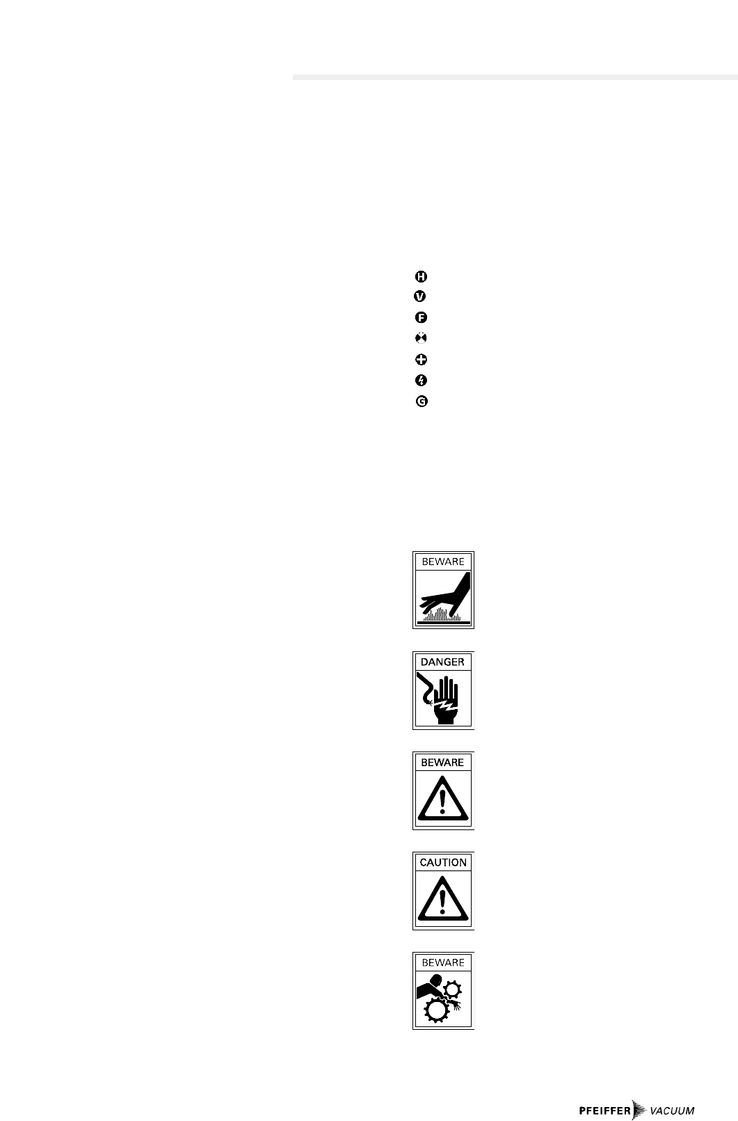
1.2. Pictogram Definitions
Danger of burns from touching hot parts.
Danger of an electric shock.
Danger of personal injury.
Danger of damage to the pump or system.
Danger of injury from rotating parts.
4
2. Understanding The Pumps TMH 520 / TMU 520
2.1. Main Features
Cooling
Standard: Water cooling.
Alternative: Air cooling as an accessory.
Integrated excess temperature safety feature:
Electronic drive unit reduces
rotor rotation speed to zero.
Bearings
High vacuum side: Wear free permanent magnetic bearing.
Fore-vacuum side: Oil circulatory lubricated bearings with
ceramic balls.
Pumps for sealing gas operations
The pump types TMH 520 P and TMU 520 P (see the rating
plate) are designed for connection of an inert sealing gas.
The connection is described in Section 3.7.
Proper use
– The Turbomolecular Pumps TMH 520 / TMU 520 may only
be used for the purpose of generating vacuum.
– The turbopumps may only be used to pump those media
against which they are chemically resistant. For other
media the operator is required to qualify the pumps for the
processes involved.
– If the process produces dust, the maintenance intervals
must be specified accordingly and sealing gas must be
used (only for version ”P”).
– The Turbomolecular Pumps TMH 520 / TMU 520 may only
be operated with a PFEIFFER Electronic Drive Unit and
relevant cables.
– The turbopump must be connected to a backing pump as
per Section 3.3..
Improper use
Certain types of use are regarded as improper, e.g.:
– Pumping corrosive or explosive gases.
– Operating the pump where explosive processes are
involved.
– The pumping of gases and vapours which attack the
materials of the pumps.
– The pumping of corrosive gases without sealing gas.
– The pumping of condensating vapours.
– Operations involving impermissibly high levels of gas
loads.
– Operations with impermissibly high fore-vacuum pressure.
– Operations with improper gas modes.
– Operations involving too high levels of heat radiation
power (see Section 8. ”Technical Data”).
– Using accessories not named in this manual and/or not
authorised by the manufacturer.
Improper use will cause any rights regarding liability and
guarantees to be forfeited.
2.2. Differences Between The Pump Types
Feature TMH 520 TMU 520
HV-flange ISO-K CF-F
HV seal Elastomer Metal
Attainable < 1 · 10-8 mbar < 5 · 10-11 mbar
final pressure (without baking out) (with baking out)
Abbreviations on the rating plate of the pump
Suffix ”P”: Pumps with the designation TMH/TMU 260 P
have been designed for the connection
of purge gas (see Section 3.7.).
1
4
3 6
5
2
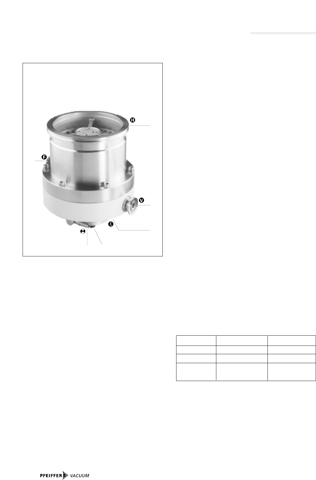
Turbomolecular Pumps TMH 520
1 High vacuum flange
2 Fore-vacuum flange
3 Cooling water connection
4 Venting connection
5 Power connection
6 Rubber feet (underside)
3. Installation
3.1. Preparations For Installation
Do not carry out any unauthorised conversions
or modifications on the pump.
– The maximum permissible rotor temperature of the pump is
90 °C. If the vacuum chamber or parts in the vacuum
chamber are heated must be fitted if necessary, suitable
shielding in the vacuum chamber before the turbopump
(constructional suggestions available on request).
– Only remove blank flanges on the high and fore-vacuum
side just before connecting.
– TMH 520/TMU 520 turbopumps are supplied with lubricant
reservoirs fitted and filled.
– Appropriate shielding must be provided (available on
request) if magnetic fields >5,0 mT are involved.
– If the pump is baked out, the heating sleeve and the body
of the pump must be insulated to prevent burning.
– In the event of a sudden standstill of the rotor, torques of
up to 2550 Nm can arise and these must be taken up by the
turbopump and frame. Pumps must be anchored as
follows:
– ISO flange with 4 bracket screws,
or
– CF flange with the complete set of M8 screws,
or
– Underside of the pump with 4 screws M5,
screws quality 8.8.
3.2. Assembling The Pump, Connecting The
High Vacuum Side
Important:
Maintain the utmost cleanliness when fitting all high vacuum
parts. Unclean components prolong the pumping time.
Use of the splinter shield
A splinter shield in the high vacuum flange protects the turbo-
pump against foreign particles emanating from the vacuum
chamber but it does reduce the pumping speed of the pump
by approx. 15%.
For fitting please refer to "Fitting The Splinter Shield".
The high vacuum side can be flanged directly to the vacuum
chamber or via a bellows or a vibration compensator (please
see ”Accessories”).
Connecting via a bellows
If the high vacuum side is to be flanged via a bellows, the tur-
bopump must be secured for example via the holes on the
underside of the turbopump must be secured for example via
the holes on the underside of the pump. The fastening must
be able to withstand the torque referred to in Section 3.1.
H
V
V
H
11
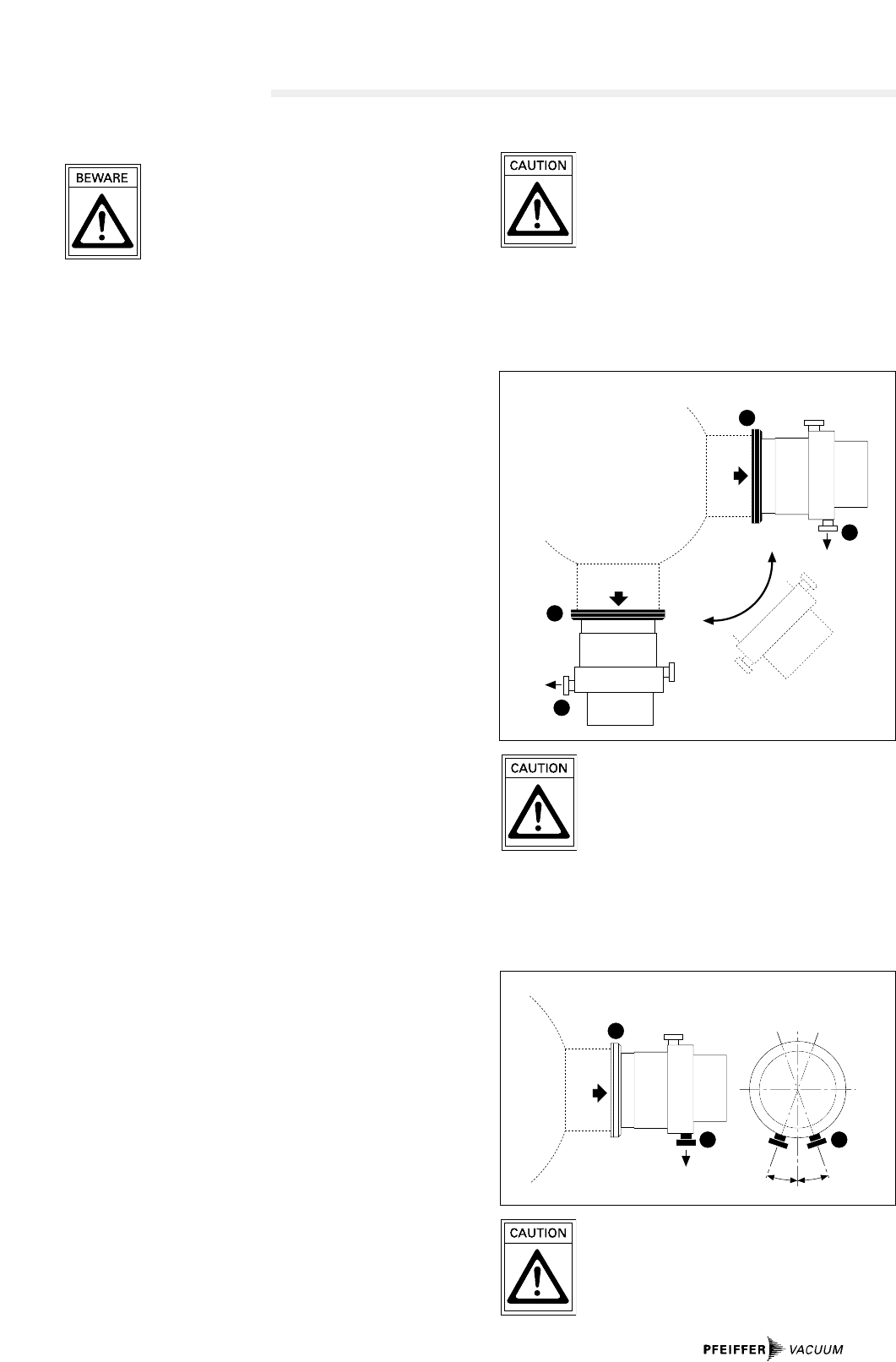
Permissible turbopump installation positioning
11 Vacuum chamber
Maximum high vacuum flange axial loading
capacity 1000 N (corresponds to 100 kg).
No asymmetrical loading on the high vacuum
flange.
With horizontal pump installation and oil-sealed backing
pump (e.g. rotary vane pumps) the fore-vacuum flange of the
turbopump must be aligned vertically downwards (deviation
max. ± 20˚), otherwise the turbopump could become dirty.
20°20°
H
VV
Installation position with oil-sealed backing pump
No forces must be transmitted from the pipe
system to a pump which is anchored.
Support or suspend all piping leading to the
pump.
5
Connecting via a vibration compensator
The maximum permissible temperature at the
vibration compensator is 100 °C.
Where a vibration compensator is in use, a freely suspended
turbopump can be flanged onto the vacuum chamber.
Additional fastening is unnecessary.
Directly flanging the pump
6
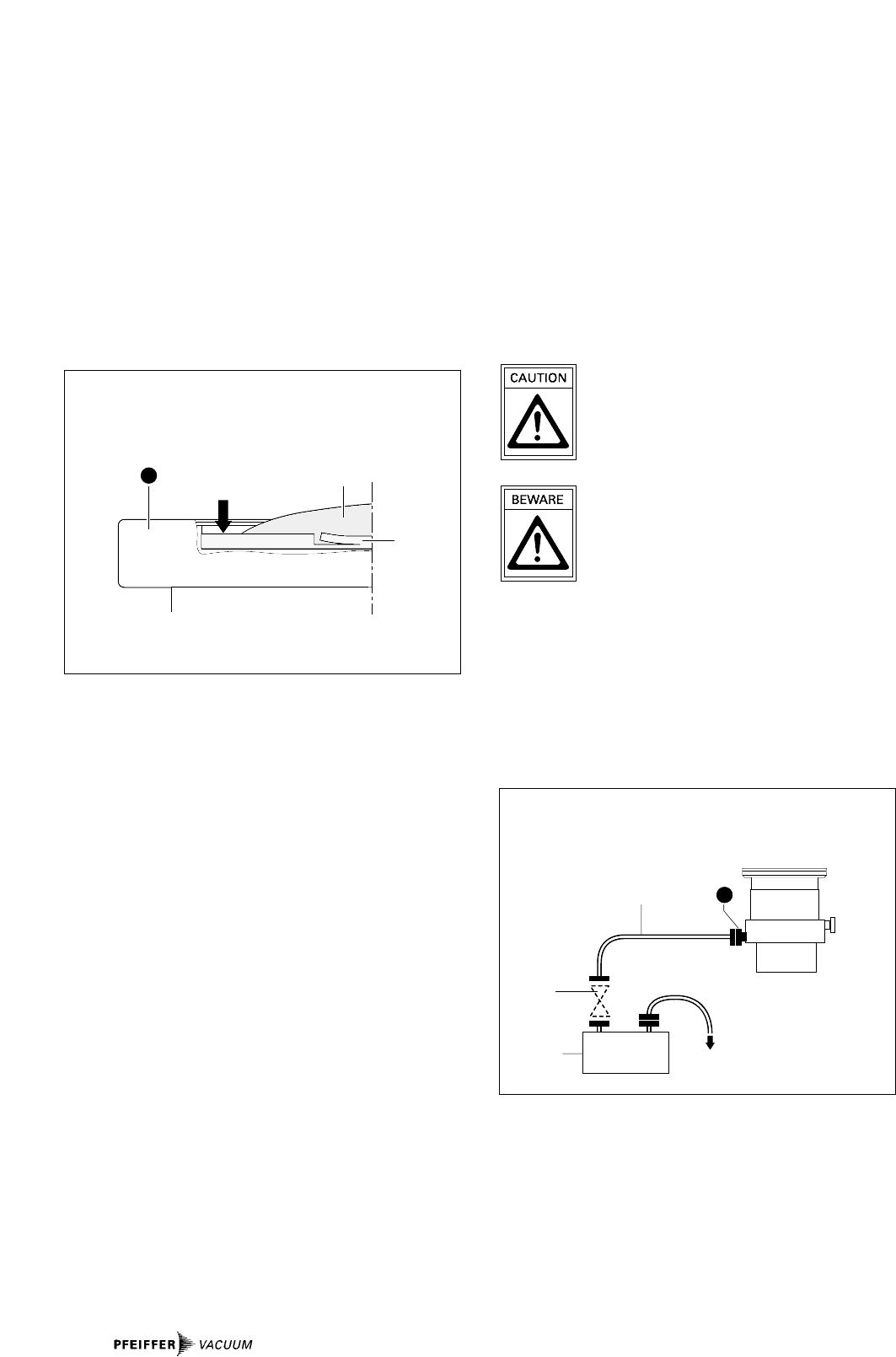
Fitting The Splinter Shield
Highvacuum flanges DN 100 and DN 160
Insert the splinter shield in the high vacuum flange so that the
curvature of the grill faces outwards.
➡Bend clamping lugs slightly outwards so that the splinter
shield will sit firmly in the high vacuum flange (preventing
noise).
➡Insert splinter shield in the high vacuum flange with clam-
ping lugs bent slightly inwards.
➡Press splinter shield outer ring into the high vacuum
flange up to the stop limit.
12a
12
H
Inserting the splinter shield
12 Splinter shield
12a Clamping lug
3.3. Connecting The Fore-Vacuum Side
Backing pump: Vacuum pressure ≤5 mbar
Recommended backing pump: Oil free Diaphragm Pump
or rotary vane pump
from the PFEIFFER product
range (note installation
position of the turbopump,
see Section 3.2.).
Connecting the backing pump
All fore-vacuum line connections: With normal small flange
components or screwed hose connections..
Exhaust gases from the backing pump must be
conducted away. Ensure the full width of the
fore-vacuum flange remains unhindered by
other components.
The exhausted process gases and vapours can
represent a health hazard and can also be envi-
ronmentally damaging.
Comply with all gas manufacture's safety
instructions.
➡Fit the vacuum safety valve in the fore-vacuum line (in
PFEIFFER rotary vane vacuum pumps already integrated).
This prevents vacuum chamber venting via the backing
pump.
➡With rigid pipe connections: Fit bellows in the connecting
line to reduce vibration.
➡Backing pump power connection: see operating
instructions for the electronic drive unit.
22
23
21
DN 25 KF
G 1⁄4"
V
≤ 5 mbar
Connecting the backing pump
21 Backing pump
22 Vacuum safety valve
23 Suction line
3.4. Connecting The Cooling Unit
The turbopumps are water cooled as standard.
Cooling water either
– From the mains or
– From Recycled Water Cooling Unit TZK with closed circuit.
As an accessory: Air cooling (with an ambient temperature
of <35 °C).
Cooling Water From The Mains
Cooling water must be filtered to prevent deposits forming in
the pump.
Minimum cooling water requirements:
Mechanically clean, optically clear, no turbidity, no sediment,
chemically neutral and temperature > dew point.
Minimum oxygen content max. 4 mg/kg
Maximum chloride content max. 100 mg/kg
Maximum carbonate hardness: max. 10 ° dH
Maximum consumption of:
potassium permanganate: max. 10 mg/kg
Carbon dioxide absent
Ammonia: absent
pH-value: 7 – 9
Max. fore-line over pressure: max. 6 bar
Minimum flow rate at max. gas throughput: 50 l/h at 15 °C
Connecting to the water mains
➡Fit dirt trap (accessory) in the fore-line.
➡Using circlips, connect fore-line to one of the two cooling
water connections.
➡Connect Cooling Water Monitor TCW 002 (accessory) in
the return line.
➡Connect return line to the other cooling water connection
of the turbopump.
➡Tighten all circlips and ensure hose lines are seated firmly.
➡Tighten the hollow screws on the cooling water
connection to a torque of 20 Nm.
34
33
31
32
3
Cooling from the water mains
3 Cooling water connections
31 Fore-line
32 Return line
33 Dirt trap
34 Cooling Water Monitor TCW 002
Cooling With The Recycled Water Cooling
Unit TZK (Accessory)
Connecting to the TZK
A dirt trap in the fore-line is not permissible.
All other steps: As for connection to the water mains.
3
34 35
TZK
Cooling with the Recycled Water Cooling Unit TZK
3 Cooling water connections
34 Cooling Water Monitor TCW 002 in the return line
35 Recycled Water Cooling Unit TZK
Air Cooling (Accessory)
Air cooling only if ambient temperature
< 35 °C.
Ensure adequate air circulation and ventilation.
Fitting the air cooling
➡Place turbopump (blank flanged to prevent damage to the
sealed surface) on its high vacuum flange.
➡Unscrew rubber feet from the base of the pump. The fan
must be parallel to the axis fore-vacuum connection - ven-
ting connection (see illustration below).
➡Screw air cooling to holder with 4xM5 screws and spring
washers onto the turbopump.
36
37 38
36 V
F
V
Power connection, air cooling
Please see the operating instructions, Electronic Drive Unit
TCP 380 or TCP 600.
Fitting the air cooling
36 Fan
37 Holder
38 M5 screw and spring washers (4x)
7
8
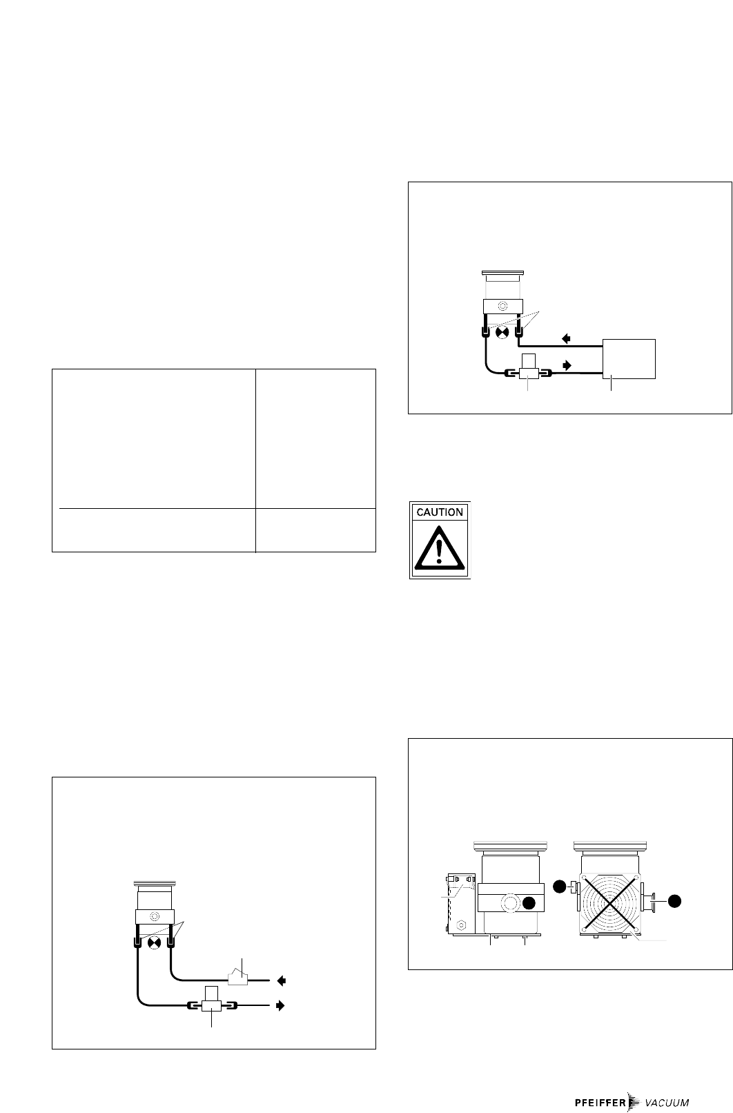
3.5. Connecting The Venting Valves
– Manual venting to atmospheric pressure:
With standard venting screw in the venting connection
(without additional venting valve).
– Automatic venting on switching off and power failure:
Fitting a venting valve (accessory).
Venting Valve Control Unit Electronic Venting Procedure
Drive Unit After Switching Off Or
Power Failure
TSF 010 not Independent Immediate;
required Venting valve
remains open
TSF 012 not TCP 380/600 Delayed (venting
required begins at approx.
20% of the rated rotation
speed); venting valve;
remains open
TVF 012 TCF/TCV TCP 380/600 Delayed; adjustable
103 (with TCS 304)
Fitting the venting valves
See the operating instructions for the respective unit.
Where flange size DN 10-KF is involved, use Adapter
PM 033 737-T.
43
42
41
44
F
Power connections
See the operating instructions for the respective unit.
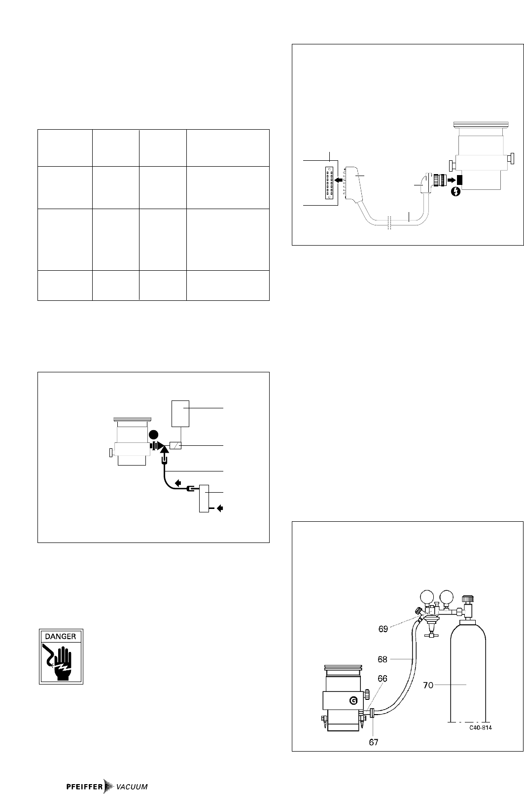
3.6. Connecting The Electronic Drive Unit
Voltages of >100 V can be present on the open
electrical contacts on a running down pump.
There is danger of an electrical shock if the
contacts are touched.
Disconnect the plug to the electronic drive unit
only once the pump is completely at rest and the electronic
drive unit has been disconnected from the mains.
➡Plug in connecting cable between the electronic drive unit
and the turbopump. For details please see the operating
instructions for the electronic drive unit.
Connecting the venting valve
41 Valve control unit
42 Venting valve
43 Connection hose
44 Drying Unit TTV 001
3.7. Connecting The Sealing Gas Valve
The pump types TMH 520 P and TMU 520 P (see the rating
plate) are designed for connection of sealing gas.
To protect the turbopump, particulary where corrosive or dust
producing processes are involved, it is necessary to use sea-
ling gas. Connection is made via the sealing gas valve (please
see "Accessories").
➡Adjust the sealing gas volume (see operating instructions
for the sealing gas valve, PM 800 229 BN).
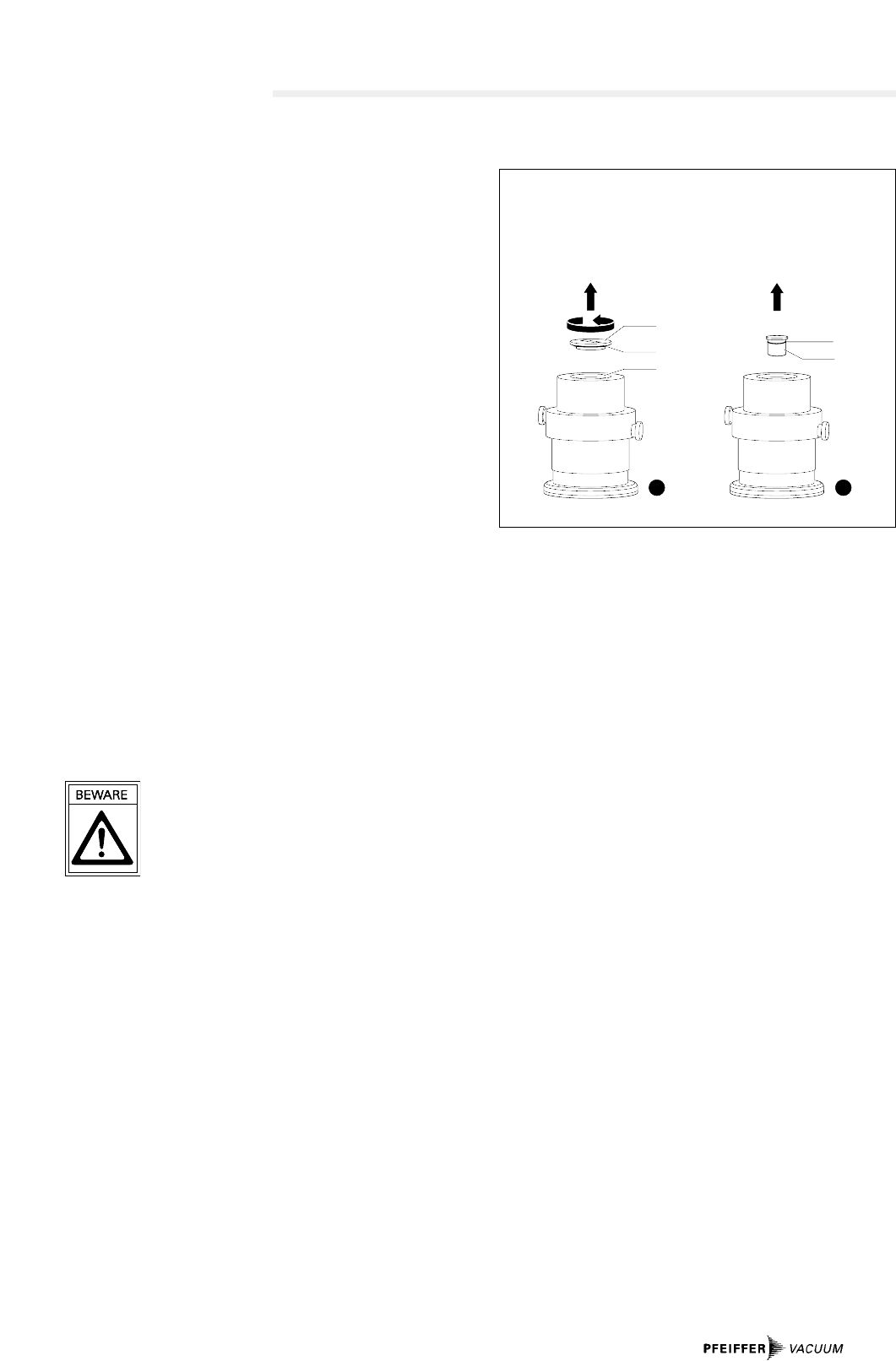
➡Unscrew locking screw from sealing gas connection.
➡Screw in sealing gas valve with seal.
➡Remove sealing gas valve blank flange.
➡Flange on hose nipple (DN 16 ISO-KF-10; accessory).
➡Make hose connection from pressure reducer to sealing
gas valve.
51 53
52
50
Connecting the electronic drive unit to the turbopump
50 Electronic Drive Unit TCP
51 Male multipoint connector
52 Connecting cable
53 Bayonet plug --> turbopump
Connecting the sealing gas valve
66 Sealing gas valve
67 Hose nipple
68 Hose connection
69 Pressure reducer
70 Gas canister
4. Operations
4.1. Before Switching ON
Turbopump rotors rotate at high speed. When
the high vacuum flange is open there is a dan-
ger of injury and of objects falling into the
pump. Therefore never operate the pump with
open high vacuum flange.
➡With water cooling: Open cooling water supply and check
flow.
4.2. Switching ON
➡Switch on the turbopump with switch S1 on the electronic
drive unit.
– With air cooling the cooling fan of the electronic drive unit
is also switched on.
– When Pumping Station Control Unit TCS 303/304 is in use,
the turbopump, the backing pump and the recycled water
cooling unit (if fitted) are started at the same time.
Take care when pumping hazardous gases.
Comply with all the gas manufacturer's safety
instructions.
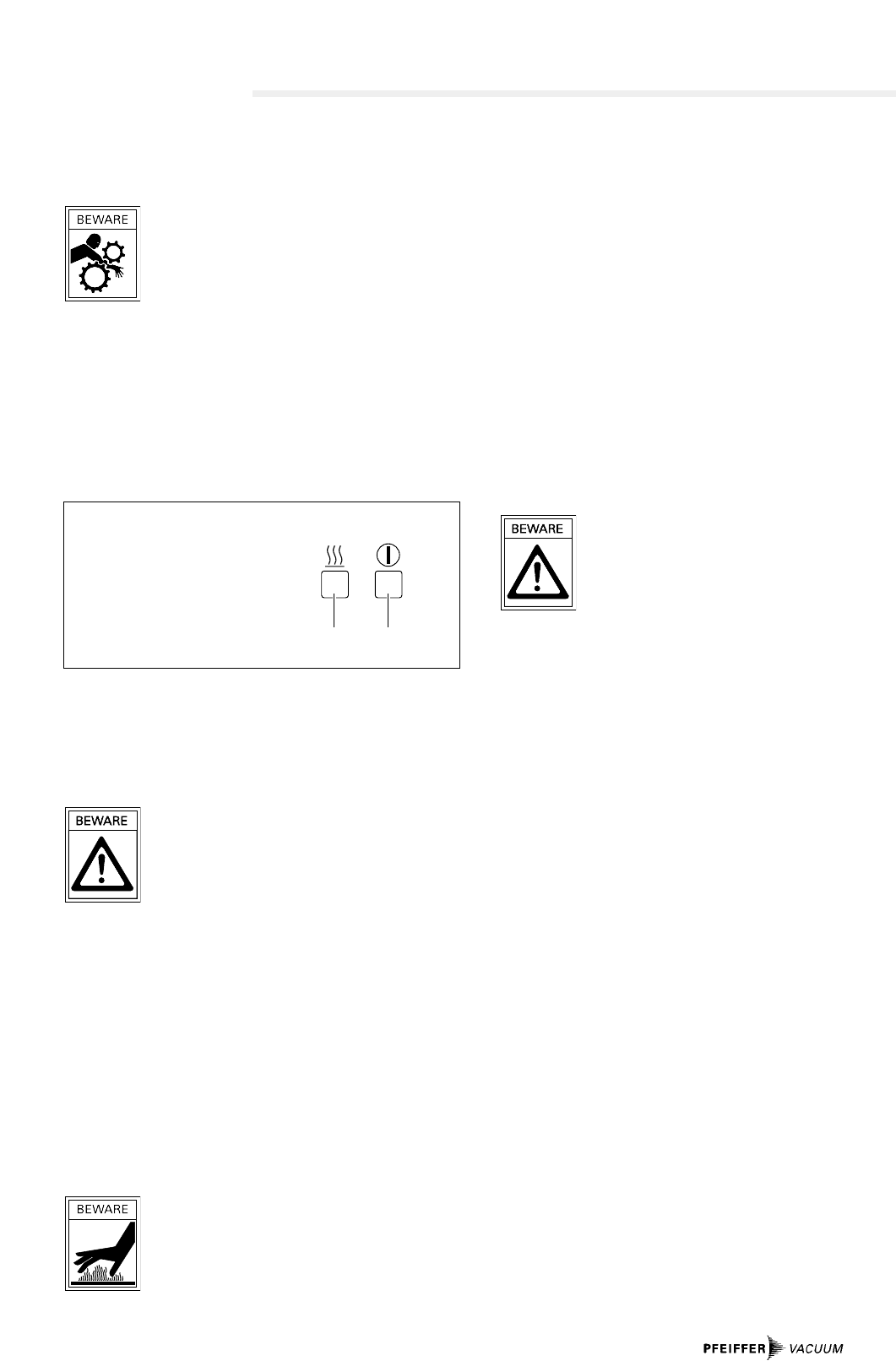
4.3. Heating (Only Pumps With Heating
Sleeves)
Heating turbopumps and vacuum chambers accelerates the
attainment of final pressures.
The heating period is dependent on the level of contamination
and the required final pressure. Heat for at least four hours.
➡Switch on turbopump heating via switch S2 on the electro-
nic drive unit.
High temperatures are generated when turbo
pump or vacuum chamber are baked out.
Contact with hot parts can cause burns, even
when the heating has been switched off.
Heating sleeves, pump casing and vacuum
chamber should all be insulated when fitting.
Do not touch heating sleeves, pump casing and vacuum
chambers during baking out.
S2 S1
The electronic drive unit switches (schematically)
S1 ON/OFF switch, turbopump
S2 ON/OFF switch, heating
4.4. Switching OFF And Venting
To avoid contamination occurring when switching off, the
pump should be vented with dry venting gas before shut-
down.
➡Close the vacuum safety valve in the fore-vacuum line.
➡Switch off both turbopump and the electronic drive unit at
the same time with switch S1.
➡Open locking screw or venting valve in the venting
connection (with PFEIFFER venting valves the turbopump is
vented automatically).
➡With water cooling: Shut off water supply.
4.5. Shutting Down For Longer Periods
Vacuum pumps are sometimes used to pump
aggressive or hazardous gases. There is a dan-
ger of personal injury resulting from coming into
contact with process gases. Before removing a
turbopump from the system, first:
– Vent the turbopump with a neutral gas or dry air.
– Ensure that there is no residual process gas in the system
nor in the feeder lines.
If the turbopump is to be shut down for more than a year:
➡Remove turbopump from the system.
➡Change the lubricant reservoir (see Section 6.1.).
Please note: Lubricant TL 011 must no longer be used after
2 years of non operations.
➡Close high vacuum flange and evacuate pump via the fore-
vacuum flange.
➡Close the high vacuum flange and evacuate the turbopump
via the fore-vacuum flange.
➡Vent turbopump via the venting connection with nitrogen
or dry air.
➡Close fore-vacuum connection by blank flanging.
➡Place the pump vertically on its rubber feet.
➡In rooms with moist or aggressive atmospheres, the turbo-
ypump must be air-sealed in a plastic bag together with a
bag of dessicant, e.g silicagel.
Important:
If the pump has been shut down for 3 years a bearing change
must be carried out (please get in touch with PFEIFFER
service).
9

10
Problem Possible Cause Remedy
Pump doesn't start • Power supply interrupted • Check fuse in the
electronic drive unit
• Check plug contacts on the pump
and the electronic drive unit
• Check supply lines
Pump doesn't attain rated • Fore-vacuum pressure to high • Check backing pump function
rotation speed; • Leak or too much gas • Check seals
Pump cuts out during operations • Seek leak and repair
• Rotor stiff because bearing defective • Check bearings (noisy ?):
Request PFEIFFER to replace
• Run-up phase in the Electronic
Drive Unit TCP too short • Extend run-up phase setting time
• Thermal overloading caused by
– Water cooling: Flow not safe
guarded • Ensure free flow
– Air cooling: Air supply restricted • Ensure adequate air supply
– Fore-vacuum pressure too high • Reduce fore-vacuum pressure
– Ambient temperature too high • Reduce ambient temperature
Pump doesn't attain final pressure • Pump dirty • Bake out pump
• If seriously contaminated:
Request PFEIFFER to clean
• Leak in vacuum chamber, • Seek leak, starting with vacuum chamber
lines or pump • Repair leak
Unusual operating noises • Bearings damaged • Inform PFEIFFER of need for repair
• Rotor damaged • Inform PFEIFFER of need for repair
• Splinter shield (if fitted) • Check splinter shield: Press clamping
not seated firmly lugs away from each other (see Section 3.2.)
5. What To Do In Case Of Breakdowns?
6. Maintenance
Important:
No liability for personal injury nor material damage will be
accepted for damages and operational interruptions which
have been caused by improper maintenance; in addition, all
guarantees become invalid.
– You can change the lubricant reservoir yourself (see
Section 6.6.).
– Your pump can be cleaned on the spot if it is not very dirty.
Your local PFEIFFER Center can advise you regarding
cleaning procedures and any other maintenance and service
work with might be necessary.
6.1. Changing The Lubricant Reservoir
The lubricant reservoir should be replaced at least once a
year. Where extreme operating conditions or unclean proces-
ses are involved, the replacement interval should be checked
with your PFEIFFER Service Center.
➡Switch off the turbopump, vent to atmospheric pressure
(see Section 4.4.) and allow to cool as necessary.
➡If necessary, remove the turbopump from the system.
➡Using a big screwdriver, unscrew the locking cover 90 on
the underside of the pump; take care with the O-ring 91.
➡With the help of two screwdrivers, lever out the lubricant
reservoir.
Lubricant reservoirs can contain toxic
substances from the medium pumped. Lubricant
reservoirs must be disposed of in accordance
with the respective regulations.
Safety instructions data sheet on request.
90
91
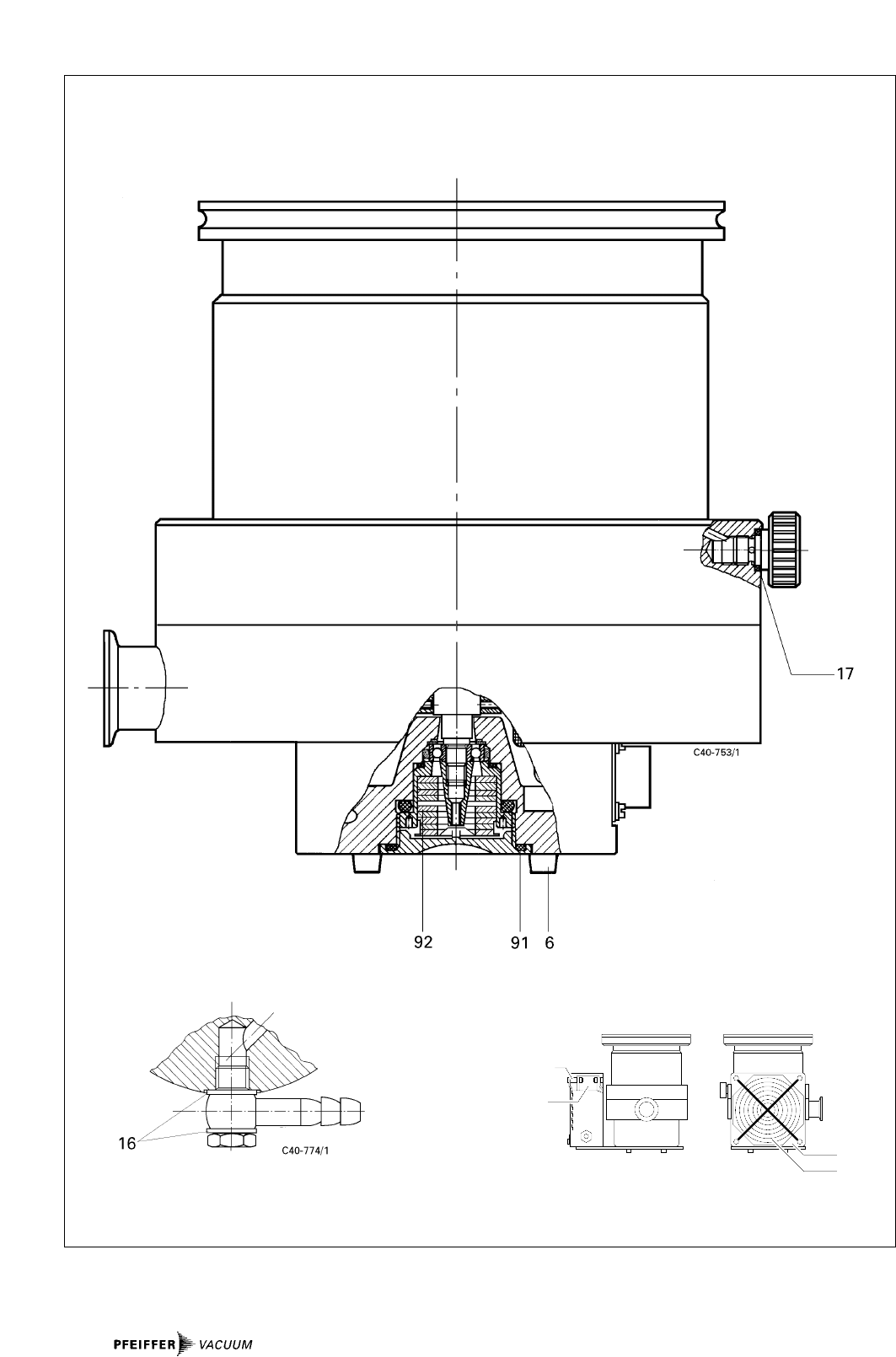
92 92
H H
93
Detaching the locking cover and removing the lubricant reservoir
90 Locking cover
91 O-ring
92 Lubricant reservoir
93 O-ring
➡Remove contamination on the pump and locking cover
using a clean, fluff-free cloth.
➡Press in new lubricant reservoir 92 up to the O-ring 93 in
the pump. The lubricant reservoir comes filled with
Lubricant TL 011.
➡Screw in locking cover 90 with O-ring 91. The lubricant
reservoir is brought into the correct axial position by the
locking cover.
11

12
7. Service
Do make use of our service facilities
In the event that repairs are necessary a number of options
are available to you to ensure any system down time is kept
to a minimum:
– Have the pump repaired on the spot by our PFEIFFER
Service Engineers;
– Return the pump to the manufacturer for repairs;
– Replace with a new value pump.
Local PFEIFFER representatives can provide full details.
Before returning:
➡Please attach a clearly visible notice "Free of harmful sub-
stances" (both on the unit and also on the delivery note
and any accompanying letters).
"Harmful substances" are defined in the current, local regula-
tions; in the U.S.A. as "materials in accordance with the Code
of Federal Regulations (CFR) 49 Part 173.240 Definition and
Preparation".
We will carry out the decontamination and invoice this work
to you if you have not attached this note. This also applies
where the operator does not have the facilities to carry out
the decontamination work. Units which are contaminated
microbiologically, explosively or radioactively cannot be
accepted as a matter of principle.
Fill out the contamination declaration
➡In every case the "Contamination Declaration" must be
completed diligently and truthfully.
➡A copy of the completed declaration must accompany the
unit; any additional copies must be sent to your local
PFEIFFER Service Center.
Please get in touch with your local PFEIFFER representatives
if there are any questions regarding contamination.
Decontaminate units before returning or possi-
ble disposal. Do not return any units which are
microbiologically, explosively or radioactively
contaminated.
Returning contaminated units
If contaminated have to be returned for maintenance/repair,
the following instructions concerning shipping must be
followed:
➡Neutralise the pump by flushing with nitrogen or dry air.
➡Seal all openings to the air.
➡Seal pump or unit in suitable protective foil.
➡Ship units only in appropriate transport containers.
Please note:
Repair orders are carried out according to our general condi-
tions of sale and supply. If repairs are necessary, please send
the pump to your nearest PFEIFFER Service Center.
Contact addresses and telephone hotline
Contact addresses and telephone numbers can be found on
the back cover of these operating instructions.
8. Technical Data
Feature Unit TMH 520 TMH 520
TMU 520 TMU 520
Connection nominal diameter
Inlet DN 100 ISO-K DN 160 ISO-K
DN 100 CF-F DN 160 CF-F
Outlet DN 25 ISO-KF DN 25 ISO-KF
G 1/4“ G 1/4“
Electronic Drive Unit TCP 380/TCP 600
Final pressure,
backing pump mbar < 5 < 5
Max. permissible rotor
temperature °C 90
Permissible heat radiation power W 10,5
Pumping speed for
Nitrogen N2l/s 300 500
Helium He l/s 400 500
Hydrogen H2l/s 400 480
Compression ration for
N2> 10 12 > 10 12
He 5 · 10 75 · 10 7
H25 · 10 65 · 10 6
Max. fore-vacuum pressure
N2mbar 16 16
He mbar 14 14
H2mbar 7 7
Max. gas throughput 1)
N2mbar l/s 3 3
He mbar l/s 4 4
Final pressure2)
with rotary vane vacuum pump mbar 5 · 10-11 5 · 10-11
with diaphragm vacuum pump mbar 5 · 10-11 5 · 10-11
Nominal rotation speed 1/min 50000 50000
Stand-by rotation speedl 1/min 33000 33000
Run-up time (up to 90% of the
rated rotation speed
with TCP 380/TCP 600) min 7/5 7/5
Cooling type, standard water
Max. cooling water requirements
with water at 15 °C3) l/h 50 50
Cooling water temperature ˚C 5 - 25
Air cooling option
Permissible ambient
temperature with air cooling ˚C 0 - 35
Heating power consumption W 100 100
Noise level dB (A) < 50 < 50
Lubricant TL 011
Permissible magnetic field mT 5,0 5,0
Weight kg 12,5 13
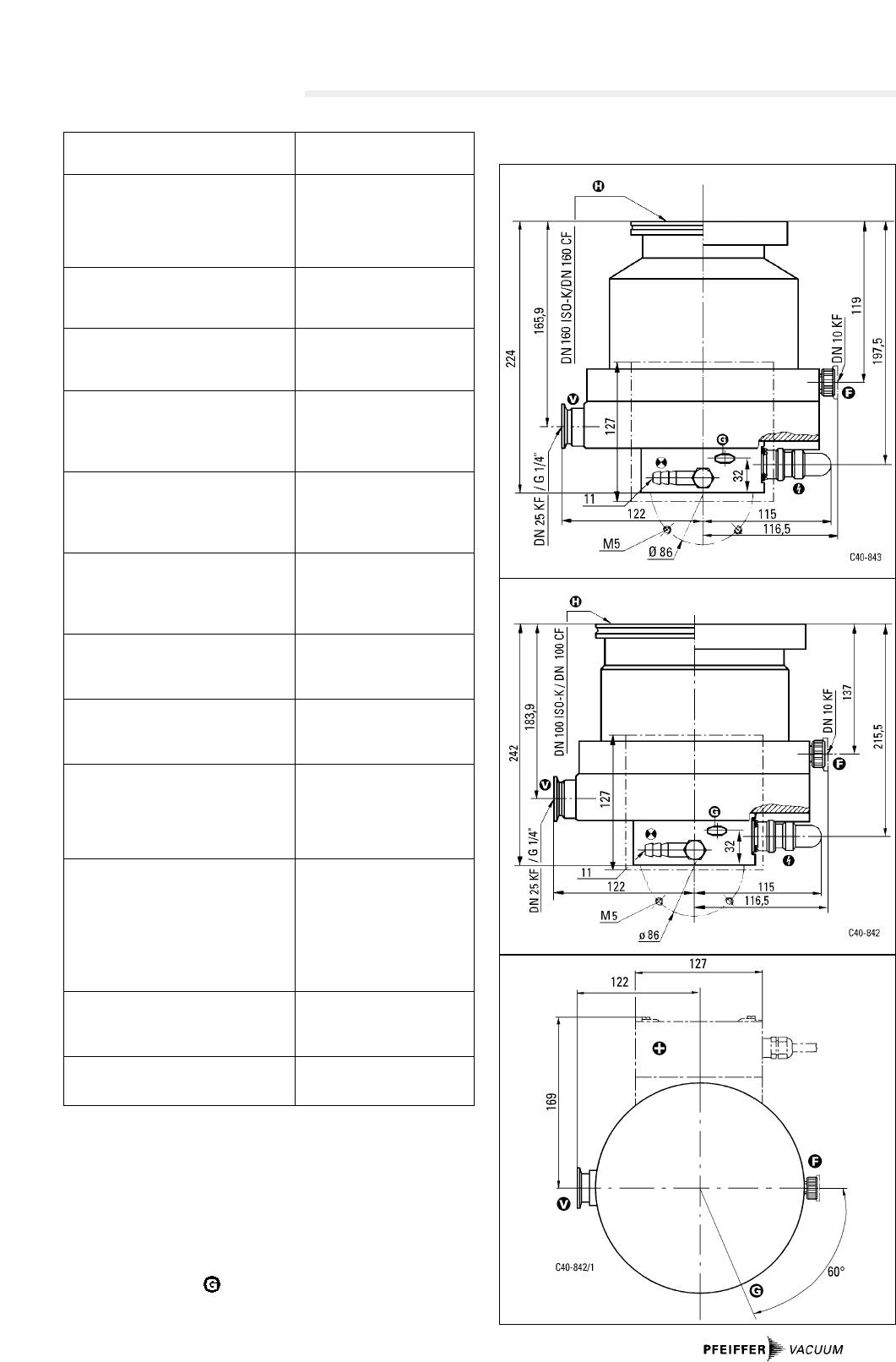
8.1. Dimensions
1) Measured with rotary vane vacuum pump 1,5 m3/h,
higher gas throughputs with reduced rotation speed.
2) In accordance with DIN 28 428 the final pressure of a
turbomolecular pump is that pressure which is attained in
a measuring dome 48 hours after baking out.
3) With max. gas throughput.
DN 160
DN 100
13
Only pump types TMH 520 P / TMU 520 P
(see the rating plate).

14
9. Accessories
Description Size Number Comments/ Order Quantity
Operating instructions
Electronic Drive Unit TCP 380 100 - 240 V; 50/60 Hz PM C01 490 PM 800 188 BN
TCP 600 100 - 240 V; 50/60 Hz PM C01 320 PM 800 234 BN
Connecting cable
Turbopump - TCP 380 3 m PM 011 232 -X Other lengths on request
Turbopump - TCP 600 3 m PM 031 803 -T Other lengths on request)
Heating sleeve 115 V/230 V PM 043 445 -T
Vibration compensator, TMH DN 100 ISO-K PM 006 459 AX
TMU DN 100 CF-F PM 006 488 -X
TMH DN 160 ISO-K PM 006 492 -X
TMU DN 160 CF-F PM 006 493 -X
Splinter shield DN 100 PM 006 125 AX
DN 160 PM 006 771 -X
Protective grill DN 100 PM 006 596 -R
DN 160 PM 006 823
Sealing ring for TMH DN 100 ISO-K PF 303 110 -T
DN 160 ISO-K PF 303 116 -T
Collar flange with retaining ring TMH DN 100 ISO-F PF 307 110 -T
DN 160 ISO-F PF 307 116 -T
CU seal (10 pieces), TMU DN 100 CF PF 501 410 -T
DN 160 CF PF 501 416 -T
Set of screws, TMU DN 100 CF PF 505 003 -T
DN 160 CF PF 505 003 -T
Pumping Station Controller TCS 130 205, 220, 380, 400, 415 V;
50/60 Hz PM C01 551 PM 800 205 BN
TCS 304 R 100 - 240 V; 50/60 Hz PM C01 537 PM 800 192 BN
TCS 304 R 208 - 415 V; 50/60 Hz PM C01 537 (Only with thermistor
print PM 021 721-X)
Fore-Vacuum Safety Valve TVV 001 115 V PM Z01 206 PM 800 263 BN
230 V PM Z01 205
Sealing gas valve
(only for pump types TMH/TMU 520 P) DN 10 ISO-KF PM Z01 142 PM 800 229 BN
Hose nipple for the sealing gas valve DN 16 ISO-FKF-10 PF 144 020
Components for cooling
Cooling Water Monitor TCW 002 110 V; 50/60 Hz PM C00 131 PM 800 133 BN
220 V; 50/60 Hz PM C00 130
240 V; 50/60 Hz PM C00 132
Connection component set for the
TCW 002 PM 006 802-T
Dirt trap R 3/8” P 4161 300 2R
Recycled Water Cooling Unit TZK 400 230 V; 50 Hz PM Z01 245 PM 800 369 BN
Component set for the air cooling 230 V; 50/60 Hz PM Z01 221
115 V; 50/60 Hz PM Z01 222
Components for venting
Venting Control Unit TCF 103 110/220 - 240 V; 50/60 Hz PM C01 356 PM 800 196 BN
Venting and Valve Control Unitt
TCV 103 110/220 - 240 V; 50/60 Hz PM C01 366 PM 800 196 BN
Venting valve,:
open after pressure equalisation:
(only with TCF 103 or TCV 103)
TVF 012 G 1/8” PM Z01 082 PM 800 126 BN
DN 10 ISO-KF PM Z01 080
Venting valve, closed after
pressure equalisation: TVF 012 G 1/8” PM Z01 087 PM 800 126 BN
DN 10 ISO-KF PM Z01 085
Mains Power Failure Venting Unit
TSF 010 110 V; 60 Hz, G 1/8” PM Z01 110 PM 800 032 BN
110 V; 60 Hz, DN 10 ISO-KF PM Z01 017
220 V; 50/60 Hz, G 1/8” PM Z01 111
220 V; 50/60 Hz, DN 10 ISO-KF PM Z01 010
240 V; 50/60 Hz, G 1/8” PM Z01 112
240 V; 50/60 Hz, DN 10 ISO-KF PM Z01 016
Venting Valve TSF 012 G 1/8” PM Z01 106 PM 800 168 BN
DN 10 ISO-KF PM Z01 105
Drier TTV 001 PM Z00 121 PM 800 022 BN
(filled with zeolite)
Venting flange DN 10 ISO-KF PM 033 737-T

10.Spare Parts
Pos. Description Pieces Size Number Comments Ordering Quantity
Spare Parts TMH/TMU 520
Set of seals 1 PM 063 176-T
6 Rubber feet 4 P 3695 700 ZE
16 USIT-ring 4 U 12,7/18x1,5 P 3529 142
17 QUAD-ring 1 VI 10,82x1,78 P 4081 630 C
91 O-ring 1 Vi 38x3 P 4070 621 PV
92 Lubricant reservoir 1 PM 063 265-T
Spare Parts, Air Cooling
Air cooling set 1 230 V; 50/60 Hz PM Z01 221
1 115 V; 50/60 Hz PM Z01 222
36 Fan 1 230 V P 5099 251-R7
1 115 V P 5099 251-R1
36a Finger protector 2 P 5099 251 Z4
36b Buffer 4 P 3695 705 LB
When ordering accessories and spare parts please be sure to
state the full part number. When ordering spare parts please
state additionally the unit type and unit number (see rating
plate). Please use this list as an order form (by taking a copy).
15
16
36b
36
36
36a
Spare parts TMH 520/TMU 520
33
Tradename Chemical name Danger class Precautions associated Action if spillage or human
Product name (or Symbol) with substance contact
Manufacturer
1.
2.
3.
4.
5.
5. Legally Binding Declaration
I hereby declare that the information supplied on this form is complete and accurate. The despatch of equipment will be in
accordance with the appropriate regulations covering Packaging, Transportation and Labelling of Dangerous Substances.
Name of Organisation: _______________________________________________________________________________
Address: _____________________________________ Post code: _____________________________________
Tel.: ______________________________________________________________________________________
Fax: _____________________________________ Telex: ________________________________________
Name: ______________________________________________________________________________________
Job title: ______________________________________________________________________________________
Date: _____________________________________ Company stamp: ________________________________
Legally binding signature: _____________________________________________________________________________
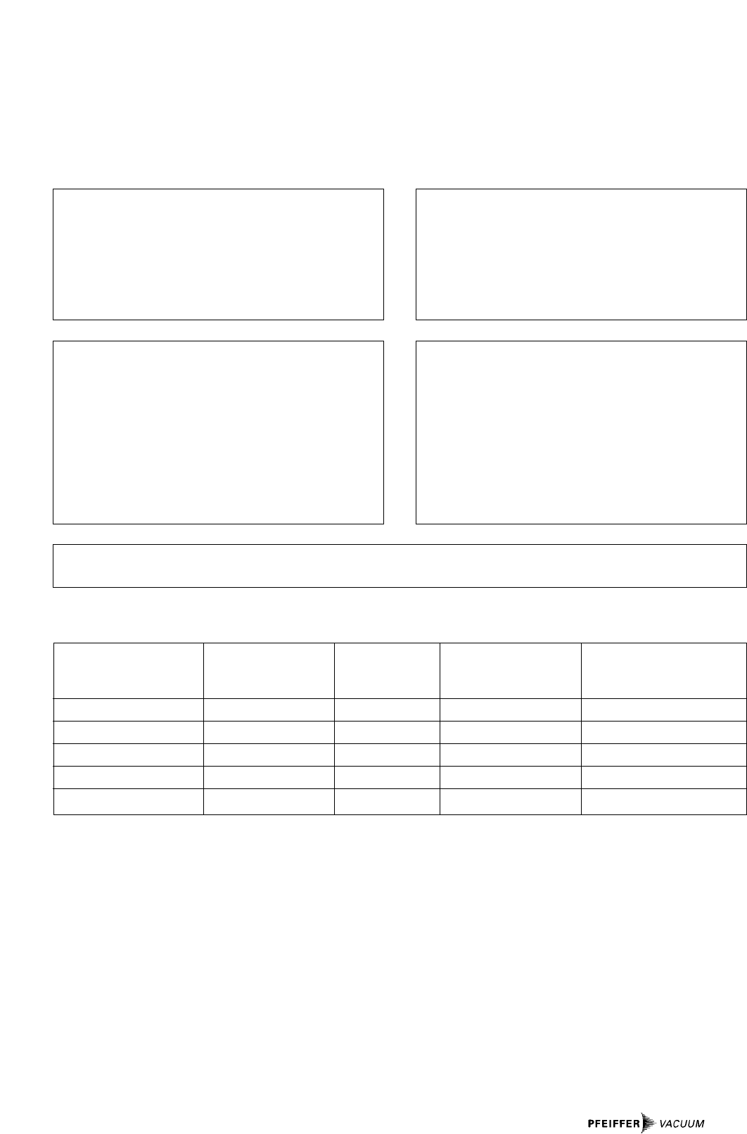
Declaration of Contamination of Vacuum Equipment and Components
The repair and/or service of vacuum components will only be
carried out if a correctly completed declaration has been
submitted. Non-completion will result in delay.
The manufacturer could refuse to accept any equipment
without a declaration.
This declaration can only be completed and signed by authorised and qualified staff:
1. Description of component:
- Equipment type/model: _________________________
- Code No.: __________________________
- Serial No.: __________________________
- Invoice No.: __________________________
- Delivery Date: __________________________
3. Equipment condition
- Has the equipment been used?
yes ❐no ❐
- What type of pump oil was used?
___________________________________________
- Is the eqipment free from potentially harmful
substances?
yes ❐(go to section 5)
no ❐(go to section 4)
4. Process related contamination
of equipment
- toxic yes ❐no ❐
- corrosive yes ❐no ❐
- microbiological hazard*) yes ❐no ❐
- explosive*) yes ❐no ❐
- radioactive*) yes ❐ no ❐
- other harmful substances yes ❐no ❐
*) We will not accept delivery of any equipment that has been radioactively or microbiologically contaminated without written
evidence of decontamination!
2. Reason for return:
_____________________________________________
_____________________________________________
_____________________________________________
_____________________________________________
_____________________________________________
Please list all substances, gases and by-products which may have come into contact with the equipment:
im Sinne folgender EU-Richtlinien:
pursuant to the following EU directives:
- Maschinen/Machinery 98/37/EG
- Elektromagnetische Verträglichkeit/Electromagnetic Compatibility
89/336/EWG
- Niederspannung/Low Voltage 73/23/EWG
Hiermit erklären wir, daß das unten aufgeführte Produkt zum Einbau in eine Maschine bestimmt ist und
daß deren Inbetriebnahme so lange untersagt ist, bis festgestellt wurde, daß das Endprodukt den
Bestimmungen der EU-Richtlinie 98/37/EG, Anhang II B entspricht.
Wir bestätigen Konformität mit der EU-Richtlinie über elektromagnetische Verträglichkeit 89/336/EWG
und der EU-Niederspannungsrichtlinie 73/23/EWG.
We hereby certify that the product specified below is intended for installation in a machine which is
forbidden to be put into operation until such time as it has been determined that the end product is in
accordance with the provision of EU Directive 98/37/EEC, Annex II B.
We certify conformity with EU Electromagnetic Compatibility Directive 89/336/EEC and EU Low Voltage
Directive 73/23/EEC.
Produkt/Product:
TMH 520 / TMU 520
TMH 520 P / TMU 520 P
Angewendete Richtlinien, harmonisierte Normen und angewendete, nationale Normen:
Guidelines, harmonised standards, national standards in which have been applied:
EN 292-1, EN 292-2, EN 294,
EN 1012-2, EN 61010
Unterschrift/Signature:
Unterschriften:
(W. Dondorf)
Geschäftsführer
Managing Director
Pfeiffer-Vacuum GmbH
Emmeliusstrasse 33
35614 Asslar
Germany
Herstellererklärung
Manufacturer´s Declaration
Herst.I/2000
Pfeiffer Vacuum Technology AG · Headquarters/Germany
Tel. +49-(0) 64 41-8 02-0 · Fax +49-(0) 64 41-8 02-2 02 · info@pfeiffer-vacuum.de · www.pfeiffer-vacuum.net
Your Vacuum Technology Experts in
Turbo Pumps
Rotary Vane Vacuum Pumps
Roots Pumps
Dry Vacuum Pumps
Leak Test Units
Valves
Flanges, Feedthroughs
Vacuum Measurement
Gas Analysis
System Technology
Service
