Ucm62xx User Manual
User Manual:
Open the PDF directly: View PDF ![]() .
.
Page Count: 426 [warning: Documents this large are best viewed by clicking the View PDF Link!]
- DOCUMENT PURPOSE
- CHANGE LOG
- Firmware Version 1.0.19.21
- Firmware Version 1.0.18.13
- Firmware Version 1.0.18.12
- Firmware Version 1.0.18.9
- Firmware Version 1.0.17.16
- Firmware Version 1.0.16.20
- Firmware Version 1.0.16.18
- Firmware Version 1.0.15.16
- Firmware Version 1.0.14.24
- Firmware Version 1.0.14.23
- Firmware Version 1.0.14.21
- Firmware Version 1.0.13.14
- Firmware Version 1.0.12.19
- Firmware Version 1.0.11.27
- Firmware Version 1.0.0.7
- WELCOME
- PRODUCT OVERVIEW
- INSTALLATION
- GETTING STARTED
- SYSTEM SETTINGS
- PROVISIONING
- EXTENSIONS
- EXTENSION GROUPS
- ANALOG TRUNKS
- VOIP TRUNKS
- SLA STATION
- CALL ROUTES
- CONFERENCE
- VIDEO CONFERENCE
- IVR
- LANGUAGE SETTINGS FOR VOICE PROMPT
- VOICEMAIL
- RING GROUP
- PAGING AND INTERCOM GROUP
- CALL QUEUE
- PICKUP GROUPS
- MUSIC ON HOLD
- FAX SERVER
- BUSY CAMP-ON
- PRESENCE
- FOLLOW ME
- SPEED DIAL
- DISA
- EMERGENCY
- CALLBACK
- BLF AND EVENT LIST
- DIAL BY NAME
- ACTIVE CALLS AND MONITOR
- CALL FEATURES
- PBX SETTINGS
- SIP SETTINGS
- IAX SETTINGS
- INTERFACE SETTINGS
- API Configuration
- CTI SERVER
- ASTERISK MANAGER INTERFACE (RESTRICTED ACCESS)
- CRM INTEGRATION
- PMS INTEGRATION
- WAKEUP SERVICE
- ANNOUNCEMENTS CENTER
- STATUS AND REPORTING
- USER PORTAL
- MAINTENANCE
- EXPERIENCING THE UCM6200 SERIES IP PBX

Grandstream Networks, Inc.
UCM6200 Series IP PBX
User Manual

P a g e | 1
UCM6200 Series User Manual
Version 1.0.19.21
COPYRIGHT
©2019 Grandstream Networks, Inc. http://www.grandstream.com
All rights reserved. Information in this document is subject to change without notice. Reproduction or transmittal
of the entire or any part, in any form or by any means, electronic or print, for any purpose without the express
written permission of Grandstream Networks, Inc. is not permitted.
The latest electronic version of this user manual is available for download here:
http://www.grandstream.com/support
Grandstream is a registered trademark and Grandstream logo is trademark of Grandstream Networks, Inc. in
the United States, Europe and other countries.
CAUTION
Changes or modifications to this product not expressly approved by Grandstream, or operation of this product
in any way other than as detailed by this User Manual, could void your manufacturer warranty.
WARNING
Please do not use a different power adaptor with your devices as it may cause damage to the products and
void the manufacturer warranty.

P a g e | 2
UCM6200 Series User Manual
Version 1.0.19.21
GNU GPL INFORMATION
UCM6200 firmware contains third-party software licensed under the GNU General Public License (GPL).
Grandstream uses software under the specific terms of the GPL. Please see the GNU General Public License
(GPL) for the exact terms and conditions of the license.
Grandstream GNU GPL related source code can be downloaded from Grandstream web site from:
http://www.grandstream.com/support/faq/gnu-general-public-license/gnu-gpl-information-download

P a g e | 3
UCM6200 Series User Manual
Version 1.0.19.21
Table of Content
DOCUMENT PURPOSE ........................................................................... 25
CHANGE LOG ......................................................................................... 26
Firmware Version 1.0.19.21................................................................................................................ 26
Firmware Version 1.0.18.13................................................................................................................ 26
Firmware Version 1.0.18.12................................................................................................................ 26
Firmware Version 1.0.18.9.................................................................................................................. 26
Firmware Version 1.0.17.16................................................................................................................ 27
Firmware Version 1.0.16.20................................................................................................................ 28
Firmware Version 1.0.16.18................................................................................................................ 28
Firmware Version 1.0.15.16................................................................................................................ 29
Firmware Version 1.0.14.24................................................................................................................ 30
Firmware Version 1.0.14.23................................................................................................................ 30
Firmware Version 1.0.14.21................................................................................................................ 30
Firmware Version 1.0.13.14................................................................................................................ 30
Firmware Version 1.0.12.19................................................................................................................ 31
Firmware Version 1.0.11.27 ................................................................................................................ 32
Firmware Version 1.0.0.7 .................................................................................................................... 33
WELCOME ............................................................................................... 34
PRODUCT OVERVIEW ............................................................................ 35
Technical Specifications ..................................................................................................................... 35
INSTALLATION ........................................................................................ 38
Equipment Packaging ......................................................................................................................... 38
Connect Your UCM6200 ..................................................................................................................... 38
Connect The UCM6202 .............................................................................................................. 38
Connect The UCM6204 .............................................................................................................. 39
Connect The UCM6208 .............................................................................................................. 40
Safety Compliances ............................................................................................................................ 41
Warranty ............................................................................................................................................. 41
GETTING STARTED ................................................................................ 42
Use the LCD Menu ............................................................................................................................. 42
Use the LED Indicators ....................................................................................................................... 44
Use the Web GUI ............................................................................................................................... 45

P a g e | 4
UCM6200 Series User Manual
Version 1.0.19.21
Access Web GUI ......................................................................................................................... 45
Setup Wizard............................................................................................................................... 47
Web GUI Configurations ............................................................................................................. 47
Web GUI Languages .................................................................................................................. 48
Web GUI Search Bar .................................................................................................................. 48
Save and Apply Changes............................................................................................................ 49
Make Your First Call ........................................................................................................................... 49
SYSTEM SETTINGS ................................................................................ 50
HTTP Server ....................................................................................................................................... 50
Network Settings ................................................................................................................................ 51
Basic Settings ............................................................................................................................. 51
DHCP Client List ......................................................................................................................... 56
802.1X ......................................................................................................................................... 57
Static Routes ............................................................................................................................... 59
Port Forwarding .......................................................................................................................... 61
OpenVPN® ......................................................................................................................................... 63
DDNS Settings ................................................................................................................................... 65
Security Settings ................................................................................................................................. 67
Static Defense ............................................................................................................................. 67
Dynamic Defense ........................................................................................................................ 70
Fail2ban ...................................................................................................................................... 72
SSH Access ................................................................................................................................ 73
LDAP Server ....................................................................................................................................... 74
LDAP Server Configurations ....................................................................................................... 75
LDAP Phonebook ........................................................................................................................ 76
LDAP Client Configurations ........................................................................................................ 79
Time settings ...................................................................................................................................... 82
Auto time updating ...................................................................................................................... 82
Set Time Manually ...................................................................................................................... 83
NTP Server ................................................................................................................................. 84
Office Time .................................................................................................................................. 84
Holiday ........................................................................................................................................ 85
Email Settings ..................................................................................................................................... 87
Email settings .............................................................................................................................. 87
Email Templates .......................................................................................................................... 89
Email Send Log ........................................................................................................................... 91
PROVISIONING ....................................................................................... 94
Overview ............................................................................................................................................. 94
Configuration Architecture for End Point Device ................................................................................ 94

P a g e | 5
UCM6200 Series User Manual
Version 1.0.19.21
Auto Provisioning Settings.................................................................................................................. 95
Discovery ............................................................................................................................................ 98
Uploading Devices List ..................................................................................................................... 100
Managing discovered devices: ......................................................................................................... 100
Global configuration .......................................................................................................................... 101
Global policy.............................................................................................................................. 101
Global Templates ...................................................................................................................... 110
Model configuration .......................................................................................................................... 112
Model templates ........................................................................................................................ 112
Model Update ............................................................................................................................ 114
Device Configuration ........................................................................................................................ 116
Create New Device ................................................................................................................... 116
Manage Devices ....................................................................................................................... 117
Sample Application ........................................................................................................................... 124
EXTENSIONS ......................................................................................... 129
Create New User .............................................................................................................................. 129
Create New SIP Extension ....................................................................................................... 129
Create New IAX Extension ....................................................................................................... 137
Create New FXS Extension ...................................................................................................... 141
Batch Add Extensions ....................................................................................................................... 146
Batch Add SIP Extensions ........................................................................................................ 146
Batch Add IAX Extensions ........................................................................................................ 149
Batch Extension Resetting Functionality .......................................................................................... 152
Search and Edit Extension ............................................................................................................... 152
Export Extensions ............................................................................................................................. 153
Import Extensions ............................................................................................................................. 153
Extension Details .............................................................................................................................. 161
E-mail Notification ............................................................................................................................. 161
Multiple Registrations per Extension ................................................................................................ 163
SMS Message Support ..................................................................................................................... 164
EXTENSION GROUPS ........................................................................... 165
Configure Extension Groups ............................................................................................................ 165
Using Extension Groups ................................................................................................................... 166
ANALOG TRUNKS ................................................................................ 167
Analog Trunk Configuration .............................................................................................................. 167
PSTN Detection ................................................................................................................................ 171
VOIP TRUNKS ....................................................................................... 174

P a g e | 6
UCM6200 Series User Manual
Version 1.0.19.21
VoIP Trunk Configuration .................................................................................................................. 174
Trunk Groups .................................................................................................................................... 185
Direct Outward Dialing (DOD) .......................................................................................................... 186
SLA STATION ........................................................................................ 188
Create/Edit SLA Station .................................................................................................................... 188
Sample Configuration ....................................................................................................................... 189
CALL ROUTES ...................................................................................... 191
Outbound Routes ............................................................................................................................. 191
Configuring Outbound Routes .................................................................................................. 191
Outbound Blacklist .................................................................................................................... 194
PIN Groups ............................................................................................................................... 195
Inbound Routes ................................................................................................................................ 199
Inbound Rule Configurations .................................................................................................... 200
Inbound Route: Prepend Example ............................................................................................ 204
Inbound Route: Multiple Mode .................................................................................................. 205
Inbound Route: Route-Level Mode ........................................................................................... 206
Inbound Route: Inbound Mode BLF Monitoring ........................................................................ 207
Inbound Route: Import/Export Inbound Route .......................................................................... 208
FAX Intelligent Route ................................................................................................................ 209
FAX with Two Media .................................................................................................................. 209
Blacklist Configurations ............................................................................................................. 209
CONFERENCE ....................................................................................... 211
Conference Room Configurations .................................................................................................... 211
Conference Call Operations ............................................................................................................. 213
Join a Conference Call .............................................................................................................. 213
Invite Other Parties to Join Conference .................................................................................... 214
During The Conference ............................................................................................................. 215
Google Service Settings Support .............................................................................................. 216
Conference Schedule ....................................................................................................................... 219
Cleaner Options ........................................................................................................................ 221
Show/Hide Conference Schedule Table ................................................................................... 221
Conference Recordings .................................................................................................................... 223
VIDEO CONFERENCE ........................................................................... 224
Basic Settings ................................................................................................................................... 224
Video Conference Room Configurations .......................................................................................... 225
Conference Schedule ....................................................................................................................... 225
Wave WebRTC Video Calling & Conferencing ................................................................................. 227

P a g e | 7
UCM6200 Series User Manual
Version 1.0.19.21
IVR ......................................................................................................... 229
Configure IVR ................................................................................................................................... 229
Black/White List in IVR ..................................................................................................................... 232
Create Custom Prompt ..................................................................................................................... 234
LANGUAGE SETTINGS FOR VOICE PROMPT .................................... 235
Download and Install Voice Prompt Package................................................................................... 235
Customize Specific Prompt .............................................................................................................. 237
User Name Prompt Customization ................................................................................................... 237
Upload User Name Prompt File from Web GUI ........................................................................ 237
Record User Name via Voicemail Menu ................................................................................... 238
VOICEMAIL ............................................................................................ 239
Configure Voicemail .......................................................................................................................... 239
Access Voicemail .............................................................................................................................. 241
Leaving Voicemail ............................................................................................................................. 242
Extension Voicemail Count ............................................................................................................... 243
Voicemail Email Settings .................................................................................................................. 243
Configure Voicemail Group............................................................................................................... 244
RING GROUP ......................................................................................... 246
Configure Ring Group ....................................................................................................................... 246
Remote Extension in Ring Group ..................................................................................................... 249
PAGING AND INTERCOM GROUP ....................................................... 252
Configure Paging/Intercom Group .................................................................................................... 252
Configure Multicast Paging ....................................................................................................... 252
Configure 2-way Intercom ......................................................................................................... 253
Configure 1-way Paging ............................................................................................................ 254
Configure Announcement Paging ............................................................................................. 255
Paging/Intercom Group Settings ............................................................................................... 256
Configure a Scheduled Paging/Intercom .......................................................................................... 257
CALL QUEUE ........................................................................................ 258
Configure Call Queue ....................................................................................................................... 258
Call Center Settings and Enhancements ......................................................................................... 264
Queue Statistics ............................................................................................................................... 265
Switchboard ...................................................................................................................................... 267
PICKUP GROUPS .................................................................................. 270

P a g e | 8
UCM6200 Series User Manual
Version 1.0.19.21
Configure Pickup Groups ................................................................................................................. 270
Configure Pickup Feature Code ....................................................................................................... 270
MUSIC ON HOLD ................................................................................... 272
FAX SERVER ......................................................................................... 275
Configure Fax/T.38 ........................................................................................................................... 275
Receiving Fax ................................................................................................................................... 277
Sample Configuration to Receive Fax from PSTN Line ........................................................... 277
Sample Configuration for Fax-To-Email .................................................................................... 279
FAX Sending ..................................................................................................................................... 281
BUSY CAMP-ON .................................................................................... 282
PRESENCE ............................................................................................ 283
FOLLOW ME .......................................................................................... 286
SPEED DIAL .......................................................................................... 288
DISA ....................................................................................................... 289
EMERGENCY ......................................................................................... 291
CALLBACK ............................................................................................ 293
BLF AND EVENT LIST ........................................................................... 294
BLF ................................................................................................................................................... 294
Event List .......................................................................................................................................... 294
DIAL BY NAME ...................................................................................... 297
Dial by Name Configuration.............................................................................................................. 297
ACTIVE CALLS AND MONITOR ........................................................... 300
Active Calls Status ............................................................................................................................ 300
Hang Up Active Calls ........................................................................................................................ 302
Call Monitor ...................................................................................................................................... 302
CALL FEATURES .................................................................................. 304
Feature Codes .................................................................................................................................. 304
Parking Lot ....................................................................................................................................... 309

P a g e | 9
UCM6200 Series User Manual
Version 1.0.19.21
Call Park ........................................................................................................................................... 311
Park a Call................................................................................................................................. 311
Retrieve Parked Call ................................................................................................................. 311
Monitor Call Park CID Name Information (GXP21xx Phones Only) ......................................... 311
Call Recording .................................................................................................................................. 312
Enable Spy ....................................................................................................................................... 312
Shared Call Appearance (SCA) ........................................................................................................ 313
PBX SETTINGS ..................................................................................... 317
PBX Settings/General Settings ........................................................................................................ 317
PBX Settings/RTP Settings .............................................................................................................. 319
RTP Settings ............................................................................................................................. 319
Payload ..................................................................................................................................... 320
PBX Settings/Voice Prompt Customization ...................................................................................... 320
Record New Custom Prompt .................................................................................................... 320
Upload Custom Prompt ............................................................................................................. 321
Download All Custom Prompt ................................................................................................... 321
PBX Settings/ Call Failure Tone Settings ......................................................................................... 322
SIP Trunk Prompt Tone ............................................................................................................. 322
General Call Prompt Tone......................................................................................................... 323
PBX Settings/Jitter Buffer ................................................................................................................. 324
PBX Settings/Recordings Storage ................................................................................................... 325
PBX Settings/NAS ............................................................................................................................ 327
SIP SETTINGS ....................................................................................... 328
SIP Settings/General ........................................................................................................................ 328
SIP Settings/MISC ............................................................................................................................ 328
SIP Settings/Session Timer .............................................................................................................. 329
SIP Settings/TCP and TLS ............................................................................................................... 330
SIP Settings/NAT .............................................................................................................................. 331
SIP Settings/TOS .............................................................................................................................. 331
Transparent Call-Info header ............................................................................................................ 333
IAX SETTINGS ....................................................................................... 334
IAX Settings/General ........................................................................................................................ 334
IAX Settings/Registration .................................................................................................................. 334
IAX Settings/Security ........................................................................................................................ 335
INTERFACE SETTINGS ......................................................................... 336
API Configuration ................................................................................. 339

P a g e | 10
UCM6200 Series User Manual
Version 1.0.19.21
API Configuration Parameters .......................................................................................................... 339
Upload Voice Prompt via API ........................................................................................................... 340
CTI SERVER .......................................................................................... 342
ASTERISK MANAGER INTERFACE (RESTRICTED ACCESS) ............ 343
CRM INTEGRATION .............................................................................. 344
SugarCRM ........................................................................................................................................ 344
vTigerCRM ........................................................................................................................................ 346
ZohoCRM ......................................................................................................................................... 349
Salesforce CRM ............................................................................................................................... 351
ACT! CRM ........................................................................................................................................ 353
PMS INTEGRATION ............................................................................... 354
HMobile PMS Connector .................................................................................................................. 354
HSC PMS ......................................................................................................................................... 355
Mitel PMS ......................................................................................................................................... 356
PMS API ........................................................................................................................................... 357
Connecting to PMS ........................................................................................................................... 358
PMS Features ................................................................................................................................... 359
Room Status ............................................................................................................................. 359
Wake Up Service ...................................................................................................................... 360
Mini Bar ..................................................................................................................................... 361
WAKEUP SERVICE ............................................................................... 364
WakeUp Service using Admin Login ................................................................................................ 364
WakeUp Service from User Portal .................................................................................................... 365
WakeUp Service using Feature Code .............................................................................................. 366
ANNOUNCEMENTS CENTER ............................................................... 367
Announcements Center Settings ...................................................................................................... 368
Group Settings .................................................................................................................................. 368
STATUS AND REPORTING ................................................................... 371
PBX Status ....................................................................................................................................... 371
Trunks ....................................................................................................................................... 372
Extensions................................................................................................................................. 373
Interfaces Status ....................................................................................................................... 374
System Status .................................................................................................................................. 375
General ..................................................................................................................................... 375

P a g e | 11
UCM6200 Series User Manual
Version 1.0.19.21
Network ..................................................................................................................................... 375
Storage Usage .......................................................................................................................... 376
Resource Usage ....................................................................................................................... 377
System Events .................................................................................................................................. 378
Alert Events List ........................................................................................................................ 378
Alert Log .................................................................................................................................... 380
Alert Contact ............................................................................................................................. 381
CDR .................................................................................................................................................. 381
CDR Improvement .................................................................................................................... 386
Downloaded CDR File .............................................................................................................. 387
CDR Export Customization ....................................................................................................... 388
Statistics .................................................................................................................................... 389
Recording Files ......................................................................................................................... 390
API Configuration ...................................................................................................................... 391
USER PORTAL ...................................................................................... 392
Basic Information .............................................................................................................................. 394
Personal Data ................................................................................................................................... 394
Value-added Features ...................................................................................................................... 394
MAINTENANCE ..................................................................................... 396
User Management ............................................................................................................................ 396
User Information ....................................................................................................................... 396
Custom Privilege ....................................................................................................................... 397
Concurrent Multi-User Login ..................................................................................................... 400
Change Password ..................................................................................................................... 400
Change binding Email ............................................................................................................... 401
Login Settings ........................................................................................................................... 402
Operation Log ................................................................................................................................... 403
Upgrading ......................................................................................................................................... 405
Upgrading Via Network ............................................................................................................. 405
Upgrading Via Local Upload ..................................................................................................... 407
No Local Firmware Servers ...................................................................................................... 408
Backup .............................................................................................................................................. 409
Backup/Restore ........................................................................................................................ 409
Data Sync .................................................................................................................................. 411
Restore Configuration from Backup File ................................................................................... 413
System Cleanup/Reset ..................................................................................................................... 414
Reset and Reboot ..................................................................................................................... 414
Cleaner ...................................................................................................................................... 414
USB/SD Card Files Cleanup ..................................................................................................... 416

P a g e | 12
UCM6200 Series User Manual
Version 1.0.19.21
System Recovery ............................................................................................................................. 417
Syslog ............................................................................................................................................... 419
Network Troubleshooting .................................................................................................................. 419
Ethernet Capture ....................................................................................................................... 419
IP Ping ....................................................................................................................................... 420
Traceroute ................................................................................................................................. 421
Signaling Troubleshooting ................................................................................................................ 422
Analog Record Trace ................................................................................................................ 422
Service Check .................................................................................................................................. 423
Network Status ................................................................................................................................. 424
EXPERIENCING THE UCM6200 SERIES IP PBX ................................. 425

P a g e | 13
UCM6200 Series User Manual
Version 1.0.19.21
Table of Tables
Table 1: Technical Specifications ........................................................................................................................ 35
Table 2: UCM6200 Equipment Packaging .......................................................................................................... 38
Table 3: LCD Menu Options ................................................................................................................................ 43
Table 4: UCM6202/UCM6204 LED Indicators .................................................................................................... 44
Table 5: UCM6208 LED Indicators ...................................................................................................................... 44
Table 6: HTTP Server Settings ............................................................................................................................ 50
Table 7: UCM6200 Network Settings→Basic Settings........................................................................................ 51
Table 8: UCM6200 Network Settings→802.1X ................................................................................................... 59
Table 9: UCM6200 Network Settings→Static Routes ......................................................................................... 59
Table 10: UCM6200 Network Settings→Port Forwarding ................................................................................... 61
Table 11: UCM6200 System Settings→Network Settings→OpenVPN® ............................................................ 64
Table 12: UCM6200 Firewall→Static Defense→Current Service ....................................................................... 68
Table 13: Typical Firewall Settings ...................................................................................................................... 68
Table 14: Firewall Rule Settings .......................................................................................................................... 70
Table 15: UCM6200 Firewall Dynamic Defense ................................................................................................. 71
Table 16: Fail2Ban Settings ................................................................................................................................ 73
Table 17: Time Auto Updating ............................................................................................................................. 82
Table 18: Create New Office Time ...................................................................................................................... 84
Table 19: Create New Holiday............................................................................................................................. 86
Table 20: Email Settings ...................................................................................................................................... 87
Table 21: Email Log ............................................................................................................................................. 92
Table 22: Auto Provision Settings ....................................................................................................................... 97
Table 23: Global Policy Parameters – Localization ........................................................................................... 102
Table 24: Global Policy Parameters – Phone Settings ..................................................................................... 103
Table 25: Global Policy Parameters – Contact List ........................................................................................... 103
Table 26: Global Policy Parameters – Maintenance ......................................................................................... 105
Table 27: Global Policy Parameters – Network Settings .................................................................................. 107
Table 28: Global Policy Parameters – Customization ....................................................................................... 108
Table 29: Global Policy Parameters – Communication Settings....................................................................... 109
Table 30: Create New Template ........................................................................................................................ 110
Table 31: Create New Model Template ............................................................................................................. 112
Table 32: SIP Extension Configuration Parameters→Basic Settings ............................................................... 130
Table 33: SIP Extension Configuration Parameters→Media ............................................................................ 131
Table 34: SIP Extension Configuration Parameters→Features ........................................................................ 133
Table 35: SIP Extension Configuration Parameters→Specific Time ................................................................. 137
Table 36: IAX Extension Configuration Parameters→Basic Settings ............................................................... 137
Table 37: IAX Extension Configuration Parameters→Media ............................................................................ 138
Table 38: IAX Extension Configuration Parameters→Features ........................................................................ 139

P a g e | 14
UCM6200 Series User Manual
Version 1.0.19.21
Table 39: IAX Extension Configuration Parameters→Specific Time ................................................................. 141
Table 40: FXS Extension Configuration Parameters→Basic Settings .............................................................. 141
Table 41: FXS Extension Configuration Parameters→Media ........................................................................... 143
Table 42: FXS Extension Configuration Parameters→Features ....................................................................... 144
Table 43: FXS Extension Configuration Parameters→Specific Time ............................................................... 146
Table 44: Batch Add SIP Extension Parameters ............................................................................................... 146
Table 45: Batch Add IAX Extension Parameters ............................................................................................... 149
Table 46: SIP extensions Imported File Example ............................................................................................. 154
Table 47: IAX extensions Imported File Example ............................................................................................. 157
Table 48: FXS Extensions Imported File Example ............................................................................................ 159
Table 49: Analog Trunk Configuration Parameters ........................................................................................... 167
Table 50: PSTN Detection for Analog Trunk ..................................................................................................... 173
Table 51: Create New SIP Trunk ....................................................................................................................... 174
Table 52: SIP Register Trunk Configuration Parameters .................................................................................. 176
Table 53: SIP Peer Trunk Configuration Parameters ........................................................................................ 179
Table 54: Create New IAX Trunk ....................................................................................................................... 182
Table 55: IAX Register Trunk Configuration Parameters .................................................................................. 182
Table 56: IAX Peer Trunk Configuration Parameters ........................................................................................ 184
Table 57: SLA Station Configuration Parameters ............................................................................................. 188
Table 58: Outbound Route Configuration Parameters ...................................................................................... 191
Table 59: Outbound Routes/PIN Group ............................................................................................................ 195
Table 60: Inbound Rule Configuration Parameters ........................................................................................... 200
Table 61: Conference Room Configuration Parameters ................................................................................... 211
Table 62: Conference Settings .......................................................................................................................... 213
Table 63: Conference Caller IVR Menu ............................................................................................................ 215
Table 64: Conference Schedule Parameters .................................................................................................... 219
Table 65: Video Conference Basic Settings ...................................................................................................... 224
Table 66: Video Conference room Configuration Parameters .......................................................................... 225
Table 67: Video Conference Schedule Parameters .......................................................................................... 225
Table 68: IVR Configuration Parameters .......................................................................................................... 230
Table 69: Voicemail Settings ............................................................................................................................. 240
Table 70: Voicemail IVR Menu .......................................................................................................................... 241
Table 71: Voicemail Email Settings ................................................................................................................... 243
Table 72: Voicemail Group Settings .................................................................................................................. 245
Table 73: Ring Group Parameters .................................................................................................................... 246
Table 74: Multicast Paging Configuration Parameters ...................................................................................... 253
Table 75: 2-way Intercom Configuration Parameters ........................................................................................ 254
Table 76: 1-way Paging Configuration Parameters .......................................................................................... 255
Table 77: Announcement Paging Configuration Parameters ............................................................................ 256
Table 78: Schedule Paging / Intercom Settings ................................................................................................ 257
Table 79: Call Queue Configuration Parameters .............................................................................................. 258

P a g e | 15
UCM6200 Series User Manual
Version 1.0.19.21
Table 80: Static Agent Limitation ....................................................................................................................... 263
Table 81: Call Center Parameters ..................................................................................................................... 264
Table 82: Switchboard Parameters ................................................................................................................... 268
Table 83: FAX/T.38 Settings .............................................................................................................................. 275
Table 84: SIP Presence Status ......................................................................................................................... 284
Table 85: Follow Me Settings ............................................................................................................................ 287
Table 86: Follow Me Options ............................................................................................................................. 287
Table 87: DISA Settings .................................................................................................................................... 290
Table 88: Emergency Numbers Parameters ..................................................................................................... 292
Table 89: Callback Configuration Parameters................................................................................................... 293
Table 90: Event List Settings ............................................................................................................................. 294
Table 91: UCM6200 Feature Codes ................................................................................................................. 304
Table 92 : Parking Lot ....................................................................................................................................... 310
Table 93: Add SCA Private Number .................................................................................................................. 316
Table 94: Editing the SCA Number ................................................................................................................... 316
Table 95: Internal Options/General ................................................................................................................... 317
Table 96: Internal Options/RTP Settings ........................................................................................................... 319
Table 97: Internal Options/Payload ................................................................................................................... 320
Table 98: Internal Options/Jitter Buffer .............................................................................................................. 324
Table 99: NAS Settings ..................................................................................................................................... 327
Table 100: SIP Settings/General ....................................................................................................................... 328
Table 101: SIP Settings/Misc ............................................................................................................................ 328
Table 102: SIP Settings/Session Timer ............................................................................................................. 329
Table 103: SIP Settings/TCP and TLS .............................................................................................................. 330
Table 104: SIP Settings/NAT ............................................................................................................................. 331
Table 105: SIP Settings/ToS .............................................................................................................................. 331
Table 106: IAX Settings/General ....................................................................................................................... 334
Table 107: IAX Settings/Registration ................................................................................................................ 334
Table 108: IAX Settings/Static Defense ............................................................................................................ 335
Table 109: PBX Interface Settings .................................................................................................................... 336
Table 110: API Configuration Parameters ......................................................................................................... 339
Table 111: SugarCRM Settings ......................................................................................................................... 344
Table 112: vTigerCRM Settings ......................................................................................................................... 346
Table 113: ZohoCRM Settings .......................................................................................................................... 349
Table 114: Salesforce Settings .......................................................................................................................... 351
Table 115: PMS Supported Features ................................................................................................................ 354
Table 116: PMS Basic Settings ......................................................................................................................... 358
Table 117: PMS Wake up Service ..................................................................................................................... 360
Table 118: Create New Mini Bar........................................................................................................................ 361
Table 119: Create New Maid ............................................................................................................................. 362
Table 120: Wakeup Service .............................................................................................................................. 365

P a g e | 16
UCM6200 Series User Manual
Version 1.0.19.21
Table 121: Max Wakeup Members .................................................................................................................... 365
Table 122: Announcements Center Settings ..................................................................................................... 368
Table 123: Group Settings................................................................................................................................. 368
Table 124: Trunk Status .................................................................................................................................... 372
Table 125: Extension Status.............................................................................................................................. 373
Table 126: Interface Status Indicators ............................................................................................................... 374
Table 127: System Status→General ................................................................................................................. 375
Table 128: System Status→Network................................................................................................................. 376
Table 129: CDR Filter Criteria ........................................................................................................................... 382
Table 130: CDR Statistics Filter Criteria ............................................................................................................ 389
Table 131: API Configuration Files .................................................................................................................... 391
Table 132: User Management→Create New User ............................................................................................ 397
Table 133: Change Binding Email option .......................................................................................................... 402
Table 134: Operation Log Column Header ....................................................................................................... 404
Table 135: Network Upgrade Configuration ...................................................................................................... 406
Table 136: Data Sync Configuration ................................................................................................................. 412
Table 137: Cleaner Configuration ..................................................................................................................... 415
Table 138: USB/SD Card Files Cleanup ........................................................................................................... 417
Table 139: Ethernet Capture ............................................................................................................................. 420

P a g e | 17
UCM6200 Series User Manual
Version 1.0.19.21
Table of Figures
Figure 1: UCM6202 Front View ........................................................................................................................... 38
Figure 2: UCM6202 Back View ........................................................................................................................... 39
Figure 3: UCM6204 Front View ........................................................................................................................... 39
Figure 4: UCM6204 Back View ........................................................................................................................... 40
Figure 5: UCM6208 Front View ........................................................................................................................... 41
Figure 6: UCM6208 Back View ........................................................................................................................... 41
Figure 7: UCM6202 Web GUI Login Page .......................................................................................................... 45
Figure 8: Default Random Password .................................................................................................................. 46
Figure 9: UCM6200 Setup Wizard ...................................................................................................................... 47
Figure 10: UCM6200 Web GUI Language .......................................................................................................... 48
Figure 11: Web GUI Search Bar ......................................................................................................................... 49
Figure 12: UCM6202 Network Interface Method: Route ..................................................................................... 55
Figure 13: UCM6202 Network Interface Method: Switch .................................................................................... 55
Figure 14: UCM6202 Network Interface Method: Dual ....................................................................................... 56
Figure 15: DHCP Client List ................................................................................................................................ 56
Figure 16: Add MAC Address Bind ..................................................................................................................... 57
Figure 17: Batch Add MAC Address Bind ........................................................................................................... 57
Figure 18: UCM6200 Using 802.1X as Client ..................................................................................................... 58
Figure 19: UCM6200 Using 802.1X EAP-MD5 ................................................................................................... 58
Figure 20: UCM6204 Static Route Sample ......................................................................................................... 60
Figure 21: UCM6204 Static Route Configuration................................................................................................ 61
Figure 22: Create New Port Forwarding ............................................................................................................. 62
Figure 23: UCM6200 Port Forwarding Configuration ......................................................................................... 63
Figure 24: GXP2160 Web Access using UCM6202 Port Forwarding ................................................................. 63
Figure 25: Open VPN® feature on the UCM6200 .............................................................................................. 65
Figure 26: Register Domain Name on noip.com ................................................................................................. 66
Figure 27: UCM6200 DDNS Setting ................................................................................................................... 66
Figure 28: Using Domain Name to Connect to UCM6200 .................................................................................. 67
Figure 29: Create New Firewall Rule .................................................................................................................. 69
Figure 30: Configure Dynamic Defense .............................................................................................................. 71
Figure 31: Fail2ban Settings ............................................................................................................................... 72
Figure 32: SSH Access ....................................................................................................................................... 74
Figure 33: LDAP Server Configurations .............................................................................................................. 75
Figure 34: Default LDAP Phonebook DN ............................................................................................................ 75
Figure 35: Default LDAP Phonebook Attributes .................................................................................................. 76
Figure 36: LDAP Server→LDAP Phonebook ...................................................................................................... 76
Figure 37: Add LDAP Phonebook ....................................................................................................................... 77
Figure 38: Edit LDAP Phonebook ....................................................................................................................... 77

P a g e | 18
UCM6200 Series User Manual
Version 1.0.19.21
Figure 39: Import Phonebook.............................................................................................................................. 77
Figure 40: Phonebook CSV File Format ............................................................................................................. 78
Figure 41: LDAP Phonebook After Import ........................................................................................................... 78
Figure 42: Export Selected LDAP Phonebook .................................................................................................... 79
Figure 43: LDAP Client Configurations ............................................................................................................... 80
Figure 44: GXP2170 LDAP Phonebook Configuration ....................................................................................... 81
Figure 45: Set Time Manually ............................................................................................................................. 83
Figure 46: Create New Office Time ..................................................................................................................... 84
Figure 47: Settings→Time Settings→Office Time ............................................................................................... 85
Figure 48: Create New Holiday ........................................................................................................................... 86
Figure 49: Settings→Time Settings→Holiday ..................................................................................................... 87
Figure 50: UCM6200 Email Settings ................................................................................................................... 89
Figure 51: Email Templates ................................................................................................................................. 90
Figure 52: Conference Schedule Template ......................................................................................................... 91
Figure 53: Email Send log ................................................................................................................................... 92
Figure 54: Email Logs ......................................................................................................................................... 93
Figure 55: Zero Config Configuration Architecture for End Point Device ........................................................... 95
Figure 56: UCM6200 Zero Config ....................................................................................................................... 96
Figure 57: Auto Provision Settings ...................................................................................................................... 97
Figure 58: Auto Discover ..................................................................................................................................... 99
Figure 59: Discovered Devices ........................................................................................................................... 99
Figure 60: Device list - CSV file sample ............................................................................................................ 100
Figure 61: Managing Discovered Devices ........................................................................................................ 100
Figure 62: Global Policy Categories ................................................................................................................. 102
Figure 63: Edit Global Template ......................................................................................................................... 111
Figure 64: Edit Model Template ........................................................................................................................ 113
Figure 65: OEM Models .................................................................................................................................... 114
Figure 66: Template Management .................................................................................................................... 115
Figure 67: Upload Model Template Manually .................................................................................................... 116
Figure 68: Create New Device .......................................................................................................................... 117
Figure 69: Manage Devices .............................................................................................................................. 117
Figure 70: Edit Device ....................................................................................................................................... 118
Figure 71: Edit Customize Device Settings ....................................................................................................... 120
Figure 72: Add P Value in Customize Device Settings ..................................................................................... 121
Figure 73: Modify Selected Devices - Same Model .......................................................................................... 122
Figure 74: Modify Selected Devices - Different Models .................................................................................... 123
Figure 75: Device List in Zero Config ................................................................................................................ 124
Figure 76: Zero Config Sample - Global Policy................................................................................................. 125
Figure 77: Zero Config Sample - Device Preview 1 .......................................................................................... 126
Figure 78: Zero Config Sample - Device Preview 2 .......................................................................................... 127
Figure 79: Zero Config Sample - Device Preview 3 .......................................................................................... 128

P a g e | 19
UCM6200 Series User Manual
Version 1.0.19.21
Figure 80: Create New Device .......................................................................................................................... 129
Figure 81: Manage Extensions ......................................................................................................................... 152
Figure 82: Export Extensions ............................................................................................................................ 153
Figure 83: Import Extensions ............................................................................................................................ 154
Figure 84: Import File ........................................................................................................................................ 154
Figure 85: Import Error ...................................................................................................................................... 160
Figure 86: Extension Details ............................................................................................................................. 161
Figure 87: E-mail Notification - Prompt Information .......................................................................................... 162
Figure 88: Account Registration Information and QR Code .............................................................................. 162
Figure 89: LDAP Client Information and QR Code ........................................................................................... 163
Figure 90: Multiple Registrations per Extension ............................................................................................... 163
Figure 91: Extension - Concurrent Registration ................................................................................................ 164
Figure 92: SMS Message Support .................................................................................................................... 164
Figure 93: Edit Extension Group ....................................................................................................................... 165
Figure 94: Select Extension Group in Outbound Route .................................................................................... 166
Figure 95: UCM6200 FXO Tone Settings ......................................................................................................... 171
Figure 96: UCM6200 PSTN Detection .............................................................................................................. 171
Figure 97: UCM6200 PSTN Detection: Auto Detect ......................................................................................... 172
Figure 98: UCM6200 PSTN Detection: Semi-Auto Detect ............................................................................... 172
Figure 99: Trunk Group ..................................................................................................................................... 185
Figure 100: Trunk Group Configuration ............................................................................................................ 186
Figure 101: DOD extension selection ............................................................................................................... 187
Figure 102: Edit DOD ........................................................................................................................................ 187
Figure 103: SLA Station .................................................................................................................................... 188
Figure 104: Enable SLA Mode for Analog Trunk ............................................................................................... 189
Figure 105: Analog Trunk with SLA Mode Enabled .......................................................................................... 189
Figure 106: SLA Example - SLA Station ........................................................................................................... 190
Figure 107: SLA Example - MPK Configuration ................................................................................................ 190
Figure 108: Country Codes ............................................................................................................................... 194
Figure 109: Blacklist Import/Export ................................................................................................................... 195
Figure 110: Create New PIN Group .................................................................................................................. 196
Figure 111: PIN Members ................................................................................................................................. 196
Figure 112: Outbound PIN ................................................................................................................................ 197
Figure 113: CDR Record ................................................................................................................................... 197
Figure 114: Importing PIN Groups from CSV files ............................................................................................ 198
Figure 115: Incorrect CSV File .......................................................................................................................... 198
Figure 116: CSV File Format ............................................................................................................................. 199
Figure 117: CSV File Successful Upload .......................................................................................................... 199
Figure 118: Inbound Route feature: Prepend .................................................................................................... 204
Figure 119: Inbound Route - Multiple Mode ...................................................................................................... 205
Figure 120: Inbound Route - Multiple Mode Feature Codes ............................................................................. 206

P a g e | 20
UCM6200 Series User Manual
Version 1.0.19.21
Figure 121: Inbound Route - Route-Level Mode .............................................................................................. 206
Figure 122: Global Inbound Mode .................................................................................................................... 207
Figure 123: Inbound Mode - Default Mode ....................................................................................................... 208
Figure 124: Inbound Mode - Mode 1 ................................................................................................................. 208
Figure 125: Import/Export Inbound Route ......................................................................................................... 208
Figure 126: Blacklist Configuration Parameters................................................................................................ 210
Figure 127: Blacklist csv File............................................................................................................................. 210
Figure 128: Conference .................................................................................................................................... 213
Figure 129: Conference Invitation from Web GUI ............................................................................................. 214
Figure 130: Google Service Settings→OAuth2.0 Authentication ...................................................................... 216
Figure 131: Google Service→New Project ....................................................................................................... 217
Figure 132: Google Service→Create New Credential ...................................................................................... 218
Figure 133: Google Service→OAuth2.0 Login .................................................................................................. 218
Figure 134: Conference Schedule .................................................................................................................... 222
Figure 135: Conference Recording ................................................................................................................... 223
Figure 136: Video Conference Basic settings ................................................................................................... 224
Figure 137: Video Conference Schedule .......................................................................................................... 226
Figure 138: Enabling WebRTC Feature ............................................................................................................ 227
Figure 139: Enabling WebRTC on Extensions ................................................................................................. 227
Figure 140: Granstream Wave Interface ........................................................................................................... 228
Figure 141: Create New IVR ............................................................................................................................. 229
Figure 142: Key Pressing Events ...................................................................................................................... 232
Figure 143: Black/White List ............................................................................................................................. 233
Figure 144: Click on Prompt to Create IVR Prompt .......................................................................................... 234
Figure 145: Language Settings for Voice Prompt ............................................................................................. 235
Figure 146: Voice Prompt Package List ............................................................................................................ 236
Figure 147: New Voice Prompt Language Added ............................................................................................. 236
Figure 148: Upload Single Voice Prompt for Entire Language Pack ................................................................ 237
Figure 149: Voicemail Settings.......................................................................................................................... 239
Figure 150: Voicemail Count ............................................................................................................................. 243
Figure 151: Voicemail Email Settings ............................................................................................................... 244
Figure 152: Voicemail Group............................................................................................................................. 245
Figure 153: Ring Group ..................................................................................................................................... 246
Figure 154: Ring Group Configuration .............................................................................................................. 248
Figure 155: Sync LDAP Server option .............................................................................................................. 250
Figure 156: Manually Sync LDAP Server ......................................................................................................... 251
Figure 157: Ring Group Remote Extension ...................................................................................................... 251
Figure 158: Multicast Paging............................................................................................................................. 252
Figure 159: 2-way Intercom .............................................................................................................................. 253
Figure 160: 1-way Paging ................................................................................................................................. 254
Figure 161: Announcement Paging .................................................................................................................. 255

P a g e | 21
UCM6200 Series User Manual
Version 1.0.19.21
Figure 162: Page/Intercom Group Settings ...................................................................................................... 256
Figure 163: Schedule Paging/Intercom page.................................................................................................... 257
Figure 164: Creating a scheduled paging/intercom call .................................................................................... 257
Figure 165: Call Queue ..................................................................................................................................... 258
Figure 166: Static Agents limitation ................................................................................................................... 262
Figure 167: Agent Login Settings ...................................................................................................................... 263
Figure 168: Call Queue Statistics ..................................................................................................................... 266
Figure 169: Automatic Download Settings - Queue Statistics .......................................................................... 267
Figure 170: Switchboard Summary ................................................................................................................... 267
Figure 171: Call Queue Switchboard ................................................................................................................ 268
Figure 172: Edit Pickup Group .......................................................................................................................... 270
Figure 173: Edit Pickup Feature Code .............................................................................................................. 271
Figure 174: Music On Hold Default Class ......................................................................................................... 272
Figure 175: Play Custom Prompt ...................................................................................................................... 273
Figure 176: Information Prompt ........................................................................................................................ 273
Figure 177: Record Custom Prompt ................................................................................................................. 274
Figure 178: Fax Settings ................................................................................................................................... 275
Figure 179: Configure Analog Trunk without Fax Detection ............................................................................. 277
Figure 180: Configure Extension for Fax Machine: FXS Extension ................................................................. 278
Figure 181: Configure Extension for Fax Machine: Analog Settings ................................................................ 278
Figure 182: Configure Inbound Rule for Fax ..................................................................................................... 279
Figure 183: Create Fax Extension .................................................................................................................... 279
Figure 184: Inbound Route to Fax Extension ................................................................................................... 280
Figure 185: List of Fax Files .............................................................................................................................. 280
Figure 186: Fax Sending in Web GUI ............................................................................................................... 281
Figure 187: Fax Send Progress ........................................................................................................................ 281
Figure 188: SIP Presence Configuration .......................................................................................................... 283
Figure 189: SIP Presence Feature Code .......................................................................................................... 284
Figure 190: Presence Status CDR .................................................................................................................... 285
Figure 191: Edit Follow Me ............................................................................................................................... 286
Figure 192: Speed Dial Destinations ................................................................................................................ 288
Figure 193: List of Speed Dial ........................................................................................................................... 288
Figure 194: Create New DISA........................................................................................................................... 289
Figure 195: Emergency Number Configuration ................................................................................................ 291
Figure 196: 911 Emergency Sample ................................................................................................................. 292
Figure 197: Create New Event List ................................................................................................................... 295
Figure 198: Create Dial by Name Group .......................................................................................................... 297
Figure 199: Configure Extension First Name and Last Name .......................................................................... 298
Figure 200: Dial By Name Group In IVR Key Pressing Events ........................................................................ 299
Figure 201: Dial By Name Group In Inbound Rule ........................................................................................... 299
Figure 202: Status→PBX Status→Active Calls - Ringing ................................................................................. 300

P a g e | 22
UCM6200 Series User Manual
Version 1.0.19.21
Figure 203: Status→PBX Status→Active Calls – Call Established .................................................................. 300
Figure 204: Call Connection less than half hour ............................................................................................... 301
Figure 205: Call Connection between half an hour and one hour .................................................................... 301
Figure 206: Call Connection more than one hour ............................................................................................. 302
Figure 207: Configure to Monitor an Active Call ............................................................................................... 302
Figure 208: Enable/Disable Feature codes ....................................................................................................... 309
Figure 209: Parking Lot ..................................................................................................................................... 309
Figure 210: New Parking Lot ............................................................................................................................ 310
Figure 211: Monitored call park CID name ....................................................................................................... 311
Figure 212: Download Recording File from CDR Page .................................................................................... 312
Figure 213: Download Recording File from Recording Files Page ................................................................... 312
Figure 214: Enabling SCA option under Extension’s Settings .......................................................................... 313
Figure 215: SCA Number Configuration ........................................................................................................... 314
Figure 216: SCA Private Number Configuration ............................................................................................... 314
Figure 217: SCA Options .................................................................................................................................. 315
Figure 218: Record New Custom Prompt ......................................................................................................... 320
Figure 219: Upload Custom Prompt ................................................................................................................. 321
Figure 220: Download All Custom Prompt ........................................................................................................ 322
Figure 221: SIP Trunk Prompt Tone .................................................................................................................. 323
Figure 222: General call Failure Prompts ......................................................................................................... 324
Figure 223: Settings→Recordings Storage ...................................................................................................... 325
Figure 224: Recordings Storage Prompt Information ....................................................................................... 326
Figure 225: Recording Storage Category ......................................................................................................... 326
Figure 226: Transparent Call-Info ..................................................................................................................... 333
Figure 227: FXS Ports Signaling Preference .................................................................................................... 336
Figure 228: FXO Ports ACIM Settings .............................................................................................................. 336
Figure 229: DAHDI Settings .............................................................................................................................. 338
Figure 230: Upload Prompt User Configuration ................................................................................................ 341
Figure 231: CTI Server Listening port ............................................................................................................... 342
Figure 232: SugarCRM Basic Settings ............................................................................................................. 344
Figure 233: CRM User Settings ........................................................................................................................ 345
Figure 234: vTigerCRM Basic Settings ............................................................................................................. 346
Figure 235: CRM User Settings ........................................................................................................................ 347
Figure 236: ZohoCRM Basic Settings ............................................................................................................... 349
Figure 237: CRM User Settings ........................................................................................................................ 350
Figure 238: Salesforce Basic Settings .............................................................................................................. 351
Figure 239: Salesforce User Settings ............................................................................................................... 352
Figure 240: Enabling ACT! CRM ....................................................................................................................... 353
Figure 241: Enabling CRM on the User Portal.................................................................................................. 353
Figure 242: UCM & PMS interaction ................................................................................................................. 355
Figure 243: UCM & HSC PMS interaction ........................................................................................................ 356

P a g e | 23
UCM6200 Series User Manual
Version 1.0.19.21
Figure 244: UCM & Mitel PMS interaction ........................................................................................................ 356
Figure 245: Enable PMSAPI ............................................................................................................................. 357
Figure 246: Create New Room ......................................................................................................................... 359
Figure 247: Room Status .................................................................................................................................. 359
Figure 248: Add batch rooms ............................................................................................................................ 360
Figure 249: Create New Wake Up Service ....................................................................................................... 360
Figure 250: Wakeup Call executed ................................................................................................................... 361
Figure 251: Create New Mini Bar ...................................................................................................................... 361
Figure 252: Create New Maid ........................................................................................................................... 362
Figure 253: Create New Consumer Goods ....................................................................................................... 362
Figure 254: Mini Bar .......................................................................................................................................... 363
Figure 255: Create New Wakeup Service ......................................................................................................... 364
Figure 256: Announcements Center ................................................................................................................. 367
Figure 257: Announcements Center Group Configuration ................................................................................ 369
Figure 258: Announcements Center Code Configuration ................................................................................. 369
Figure 259: Announcements Center Example .................................................................................................. 370
Figure 260: Status→PBX Status ....................................................................................................................... 371
Figure 261: Trunk Status ................................................................................................................................... 372
Figure 262: Extension Status ............................................................................................................................ 373
Figure 263: UCM6204 Interfaces Status ........................................................................................................... 374
Figure 264: System Status→Storage Usage .................................................................................................... 377
Figure 265: System Status→Resource Usage ................................................................................................. 377
Figure 266: System Events→Alert Events Lists: Disk Usage ........................................................................... 378
Figure 267: System Events→Alert Events Lists: External Disk Usage............................................................. 379
Figure 268: System Events→Alert Events Lists: Memory Usage ..................................................................... 379
Figure 269: System Events→Alert Events Lists: System Crash ....................................................................... 380
Figure 270: System Events→Alert Log ............................................................................................................. 380
Figure 271: Filter for Alert Log .......................................................................................................................... 381
Figure 272: CDR Filter ...................................................................................................................................... 382
Figure 273: Call Report ..................................................................................................................................... 384
Figure 274: Call Report Entry with Audio Recording File .................................................................................. 385
Figure 275: Automatic Download Settings ........................................................................................................ 386
Figure 276: CDR Report ................................................................................................................................... 386
Figure 277: Detailed CDR Information .............................................................................................................. 387
Figure 278: Downloaded CDR File Sample ...................................................................................................... 387
Figure 279: Downloaded CDR File Sample - Source Channel and Dest Channel 1 ........................................ 387
Figure 280: Downloaded CDR File Sample - Source Channel and Dest Channel 2 ........................................ 388
Figure 281: CDR Export File data ..................................................................................................................... 388
Figure 282: CDR Statistics ................................................................................................................................ 389
Figure 283: CDR→Recording Files................................................................................................................... 390
Figure 284: Edit User Information by Super Admin .......................................................................................... 392

P a g e | 24
UCM6200 Series User Manual
Version 1.0.19.21
Figure 285: User Portal Login ........................................................................................................................... 393
Figure 286: User Portal Layout ......................................................................................................................... 394
Figure 287: User Management Page Display ................................................................................................... 396
Figure 288: Create New User ........................................................................................................................... 396
Figure 289: User Management – New Users .................................................................................................... 397
Figure 290: Assign Backup permission to "Admin" users ................................................................................. 398
Figure 291: General User .................................................................................................................................. 399
Figure 292: Create New Custom Privilege ........................................................................................................ 400
Figure 293: Multiple User Operation Error Prompt ........................................................................................... 400
Figure 294: Change Password.......................................................................................................................... 401
Figure 295: Change Binding Email ................................................................................................................... 402
Figure 296: Login Timeout Settings .................................................................................................................. 403
Figure 297: Operation Logs .............................................................................................................................. 404
Figure 298: Operation Logs Filter ..................................................................................................................... 405
Figure 299: Network Upgrade ........................................................................................................................... 406
Figure 300: Local Upgrade................................................................................................................................ 407
Figure 301: Upgrading Firmware Files .............................................................................................................. 407
Figure 302: Reboot UCM6200 .......................................................................................................................... 408
Figure 303: Create New Backup ....................................................................................................................... 409
Figure 304: Restore Warning ............................................................................................................................ 410
Figure 305: Backup / Restore ........................................................................................................................... 410
Figure 306: Local Backup ................................................................................................................................. 411
Figure 307: Data Sync ...................................................................................................................................... 412
Figure 308: Restore UCM6200 from Backup File ............................................................................................. 413
Figure 309: Reset and Reboot .......................................................................................................................... 414
Figure 310: Cleaner .......................................................................................................................................... 415
Figure 311: USB/SD Card Files Cleanup .......................................................................................................... 417
Figure 312: UCM6202 Recovery Web Page ..................................................................................................... 418
Figure 313: Recovery Mode .............................................................................................................................. 418
Figure 314: Ethernet Capture............................................................................................................................ 420
Figure 315: Ping ................................................................................................................................................ 421
Figure 316: Traceroute ...................................................................................................................................... 421
Figure 317: Troubleshooting Analog Trunks ..................................................................................................... 422
Figure 318: A Key Dial-up FXO ......................................................................................................................... 423
Figure 319: Service Check ................................................................................................................................ 424
Figure 320: Network Status............................................................................................................................... 424

P a g e | 25
UCM6200 Series User Manual
Version 1.0.19.21
DOCUMENT PURPOSE
This document describes UCM6200 series specifications, features and will help you to configure your system
via Web GUI menu to fully manipulate the supported features. The intended audiences of this document are
device administrators. To learn more about UCM6200 series features, please visit
http://www.grandstream.com/support to download available how-to guides.
This guide covers following main topics:
• Product overview
• Installation
• Getting started
• System settings
• Provisioning
• Extensions
• Extension groups
• Analog Trunks
• VoIP Trunks
• SLA station
• Call routes
• Conference room.
• Conference schedule
• IVR
• Language settings for voice prompt
• Voicemail
• Ring group
• Paging and intercom group
• Call queue
• Pickup groups
• PIN Groups
• Music on hold
• Fax Server
• Busy camp-on
• Presence
• Follow me
• Speed Dial
• DISA
• Callback
• BLF and event list
• Dial by name
• Active calls and monitor
• Call features
• Call recording
• CTI Server
• Asterisk manager interface (AMI)
• CRM integration
• PMS integration
• Wakeup service
• Announcements center
• Status and reporting
• CDR (Call Details Record)
• User Portal
• Upgrading and maintenance
• Backup/restore
• Troubleshooting

P a g e | 26
UCM6200 Series User Manual
Version 1.0.19.21
CHANGE LOG
This section documents significant changes from previous versions of the UCM6200 user manuals. Only major
new features or major document updates are listed here. Minor updates for corrections or editing are not
documented here.
Firmware Version 1.0.19.21
• Optimized system performance for UCM6202 and UCM6204 models, which now support up to 50 and
75 concurrent calls respectively. [Maximum Call Capacity]
• Added ACT! CRM support. [ACT! CRM]
• Added Email-to-Fax Blacklist/Whitelist. [Email-to-Fax Blacklist/Whitelist]
• Added digit prepending and stripping support for Emergency calls. [EMERGENCY]
• Added new functionalities to Grandstream Wave Web. [Wave WebRTC Video Calling & Conferencing]
• Added LDAPS protocol support. [Technical Specifications] [LDAP Server]
• Added support for .conf and .ovpn files for OpenVPN. [OpenVPN®]
• Added Announcement Paging type. [Configure Announcement Paging]
• Added PMS API as a PMS options. [PMS API]
• Added ability to clear agents call counters. [Reset Agent Call Counter - Enable]
• Added Set CallerID option. [Set Caller ID Info]
• Added ability to monitor and change the inbound mode of individual inbound routes and toggle/monitor
them via BLF. [Inbound Mode] [Inbound Route: Route-Level Mode] [Inbound Route: Inbound Mode BLF
Monitoring]
• Added search functionality to the web portal to quickly find settings. [Web GUI Search Bar]
• Added HT818 model template to Zero Config Models Templates. [PROVISIONING]
• Added the ability to associate differently named OEM models with their original GS models for
provisioning purposes. [OEM device models]
Firmware Version 1.0.18.13
• No major changes.
Firmware Version 1.0.18.12
• CDR API configuration page moved from CDR to Value-Added Features.
• Added ability to upload voice prompt files via API. [Upload Voice Prompt via API]
• Added ability to transfer to custom numbers, not just extensions using Grandstream Wave Web [Wave
WebRTC Video Calling & Conferencing]
Firmware Version 1.0.18.9
• Added new AMI commands. [ASTERISK MANAGER INTERFACE (RESTRICTED ACCESS)]

P a g e | 27
UCM6200 Series User Manual
Version 1.0.19.21
• Added ability to customize the data columns included in exported CDR reports. [CDR Export
Customization]
• Added ability to view a specified extension’s membership in Call Queues/Ring Groups and other details.
[Extension Details]
• Added ability to disable audio files for Music on Hold. [MUSIC ON HOLD]
• Added Timeout Destination and Ring-All Callback on Timeout options to Parking Lot page. [Parking Lot]
• Added inbound rule importing/exporting functionality. [Inbound Route: Import/Export Inbound Route]
• Added GS Wave WebRTC video calling and video conferencing functionality. [Wave WebRTC Video
Calling & Conferencing]
Firmware Version 1.0.17.16
• Added RTX codec support. [Technical Specifications][Codec Preference]
• Emergency calls will no longer be logged into CRM servers. [CRM INTEGRATION]
• Added batch extension resetting functionality. [Batch Extension Resetting Functionality]
• Added FAX Resend Support. [Enable Fax Resend] [Max Resend Attempts]
• Fail2ban now supports up to 20 whitelist entries. [Fail2Ban Whitelist]
• Added FXO Frequency Tolerance option to Analog Hardware page. [FXO Frequency Tolerance]
• Added NAS support for call recording backup. [NAS]
• Added paging/intercom scheduling functionality. [Configure a Scheduled Paging/Intercom]
• Added Multicast Paging support. [PAGING AND INTERCOM GROUP]
• Added Failover Destination under call parking options. [Failover Destination]
• Added Timeout Callback Ringing All options under call parking options. [Ring All Callback on Timeout]
• Added ability to view CID of parked calls on VPKs/MPKs configured as monitored call park. [Monitor Call
Park CID Name Information (GXP21xx Phones Only)]
• Added support for endpoint call forwarding under ring group. [Endpoint Call Forwarding Support]
• Added batch operations and searching functionality to the Inbound/Outbound Blacklist pages.
Operations include deleting rules and importing/exporting entire blacklists. [Outbound Blacklist][Blacklist
Configurations]
• Added ability to monitor and toggle inbound routing modes via BLF. [Inbound Mode BLF Monitoring]
• Added Shared Call Appearance functionality. [Shared Call Appearance]
• Added Forward HOLD Requests option under Misc page. [Forward HOLD Requests]
• Added support for Trunk Groups. [Trunk Groups]
• Added Forward Voicemail to Peered UCMs option. [Forward Voicemail to Peered UCMs]
• Added a new Voicemail Password field under Voicemail settings. [Voicemail Password]
• Added Catalan language support under voice prompt. [LANGUAGE SETTINGS FOR VOICE PROMPT]
• Added DOD Name field under VoIP trunk settings. [Direct Outward Dialing (DOD)]
• Changed the default value of Max Wait Time to 60. [Max Wait Time]
• Added “SCA” action type to filtering CDR options. [Action Type]
• Added a prompt asking whether to delete all recording files or not on CDR. [CDR]
• Added a 64-character limit to Conference → Extension field. [Extension]
• Added a 3-character limit to Extension Incrementation field. [Extension Incrementation]

P a g e | 28
UCM6200 Series User Manual
Version 1.0.19.21
• Added a maximum limit of 500 entries to the IVR blacklist and whitelist. [Black/White List in IVR]
• Added character restrictions to LDAP Number Attributes field to ensure correct input. [LDAP Client
Configurations]
• Added maximum limit of 99,999 to parking timeout. [Parking Timeout]
• Added a 63-character limit to the Room Number field. [Room Number]
• Editing an already executed wakeup service will automatically change the service’s status to
“Programmed”. [Action Status]
• Adding UCM disconnection when an SSH client changes the password for the connected user.
• LCD display will show “Recovery Mode” instead of “No Provision” when the UCM is in recovery mode.
[System Recovery]
• Capture files saved on external devices will have “capture” prepended to file names. [Ethernet Capture]
• Added dashes and + characters to Fax, Home Number, and Mobile Phone Number fields.
• Updated external number to accepts only letters, numbers and special characters. [External Number]
• Added a 64-charcter limit to Custom Presence Status field. [Custom Presence Status]
• Increased the character limit for provider name field to 64 characters during creation. [Provider Name]
• Updated From Domain field to accept special characters. [From Domain]
• User Name Prompt filename character limit changed to 18. [User Name Prompt Customization]
• Increased the character limit for the wakeup service name field to 64 characters. [Wakeup Service]
• Users can now upload custom prompts directly to pages without having to get redirected to the Voice
Prompt → Custom Prompt page. [Custom Prompt]
• Added character restrictions to device firmware file names. [firmware file name]
• Added Email-to-Fax support. [Email-to-Fax]
Firmware Version 1.0.16.20
• Added an option to enable/disable remote voicemail access function. [Voicemail Remote Access]
Firmware Version 1.0.16.18
• Added support for emergency calls. [EMERGENCY]
• Added support for vTigerCRM [vTigerCRM]
• Added support for ZohoCRM [ZohoCRM]
• Added support for HSC PMS [HSC PMS]
• Added support for Direct Callback. [Direct Callback] [Direct Callback] [Direct Callback]
• Added option to disable call waiting under extensions. [Enable Call Waiting]
• Added option to passthrough SIP PAI Header. [Passthrough PAI Header]
• Added option to copy device settings in zero config. [Managing discovered devices]
• Added support for call failure prompts customization. [General Call Prompt Tone]
• Added option to automatically request HTTP server certificate. [Certificate Options]
• Added support to include more menus on user custom privilege. [Custom Privilege]
• Added possibility to delete CDR records based on search result. [CDR]

P a g e | 29
UCM6200 Series User Manual
Version 1.0.19.21
• Added option to send caller to specific destination when queue is empty. [CALL QUEUE]
• Added XML file type support for importing phonebooks. [LDAP Phonebook]
• Added ability to customize the LDAP name and number attributes in the Phonebook Download
Configurations page [LDAP Client Configurations]
• Added option to download Call Queue Statistics. [Queue Statistics]
• Added option to choose DNS mode during calls. [DNS mode]
• Added ability to batch add devices by importing a CSV file [PROVISIONING]
• Added a Copy Device Configuration option that allows users to copy the configuration of one device to
another device [PROVISIONING]
• Added ability to divide a parking lot extension into multiple lots [Parking Lot]
• Added option to reset extension settings. [Reset single extension]
Firmware Version 1.0.15.16
• Added support to announce name in Dial By Name feature. [DIAL BY NAME]
• Increased maximum number of call queue static agents. [Static Agents limitation]
• Added Queue Log Cleaner. [Cleaner]
• Added operation logs details and remarks. [Operation Log]
• Added extension level voicemail-to-Email setting. [Send Voicemail to Email] [Keep Voicemail after
Emailing]
• Added support for reset certificate. [Reset Certificates]
• Added support for GXP21xx color phone queue login/logout softkey. [Enable Agent Login]
• Added support to add comments to inbound/outbound route patterns. [Pattern] [Pattern]
• Added PPI mode option under SIP trunk advanced settings [PPI Mode]
• Added ability to import PIN groups from CSV files. [Importing PIN Groups from CSV files]
• Added support for wakeup groups. [WAKEUP SERVICE]
• Added support for SYN Flood defense. [SYN-Flood Defense Enable]
• Added Queue Log option to Backup/Restore page. [Backup/Restore]
• Modified Switchboard UI to offer easier access to call Options. [Switchboard]
• Further optimized Call Queue Statistics page to provide a more user-friendly experience and improve
performance. [Queue Statistics]
• Added image uploading support to Email templates [Email Templates]
• Added IPv6 gateway support. [Static Routes]
• Improved Voice Message Responses for failed SIP trunk calls. [voice message responses]
• Added Fail2Ban to support TCP/TLS beside the already-supported UDP. [Fail2ban]
• Restored ability to sort the ringing order of Follow Me numbers. [FOLLOW ME]
• Added option to restrict users from changing their SIP credentials through user portal [Consumer]
• Added option to enable or disable fax-to-mail feature on extension level. [Fax To Email]
• Added IP address whitelist to web GUI configuration. [Enable IP whitelist]
• Added CDR records separation [CDR separation]

P a g e | 30
UCM6200 Series User Manual
Version 1.0.19.21
Firmware Version 1.0.14.24
• Added protection to prevent HTTP rogue login.
Firmware Version 1.0.14.23
• Restored ability to view voicemail count in the Extension/Trunk overview. [Extension Voicemail Count]
• Restored the ability to set custom numbers for call forwarding settings. [Call Forward Unconditional]
[Call Forward No Answer] [Call Forward Busy]
• Restored previous format for entering multiple dial plans (one pattern per line) for inbound/outbound rules.
[Pattern] [Pattern]
• Restored Zero Config’s sorting by column and introduced a search bar. [Managing discovered devices]
Firmware Version 1.0.14.21
• Added support for SIP Presence. [PRESENCE]
• Added support for Call Center feature/Virtual Call Queue. [Call Center Settings and Enhancements]
• Added support for Call Queue position announcement. [Call Center Settings and Enhancements]
• Added support for Call Queue Statistics. [Queue Statistics]
• Added support for Call Queue Auto-Fill. [Queue Auto fill enhancement]
• Added switchboard for call queue monitoring. [Switchboard]
• Added ability to restore blind transfer call to transferrer. [Allow callback when blind transfer fails]
• Added support for external disk cleaner. [System Cleanup/Reset]
• Added option to enable DOD when call is being diverted/forwarded. [Use callee DOD on FWD or Ring
Simultaneously]
• Change follow me settings to extension level settings. [FOLLOW ME]
• Added support for call forward whitelist. [FWD Whitelist]
• Added Fail2Ban defense from web login attack. [Login Attack Defense]
• Added limitation for maximum number of call queue static agents. [Static Agents limitation]
• Added support for wakeup service module in Custom privilege. [Custom Privilege]
• Added IPv6 support for T.38.
• Added DAHDI settings. [DAHDI Settings]
• Added ability to pass through SIP Call-Info header to support GXP phone JPEG_Over_HTTP with
encryption and authentication to open door for GDS3710. [Transparent Call-Info header]
Firmware Version 1.0.13.14
• Added extension whitelist/blacklist for IVR dialing[IVR]
• Added ability to include DOD in PPI Header for SIP trunk. [PPI Mode]
• Added advanced IPv6 support including IPv6-to-IPv4 SIP calls, IPv6 router, IPv6 iptables/Static defense.
• Added ability to customize PAI Header. [PAI Header]
• Added blacklist for outbound calls. [Outbound Blacklist]

P a g e | 31
UCM6200 Series User Manual
Version 1.0.19.21
• Added support to upload/download MOH package from Web GUI. [Music On Hold ]
• Added support to download custom prompts from Web GUI. [Download All Custom Prompt]
• Added option to configure prompt timeout in Dial By Name. [DIAL BY NAME]
• Added description field in ZeroConfig settings to configure Softkey/Line/MPK for GXP series phones.
[PROVISIONING]
• Improved seamless transfer privilege control. [Seamless transfer privilege control]
• Added RTP Keep-alive support. [RTP Keep-alive]
• Added Email Send Log. [Email Send Log]
• Added support for Mitel simulation/protocol interfaces for PMS module. [PMS]
• Added support for up to 10 failover trunks. [Use Failover Trunk]
Firmware Version 1.0.12.19
• Added support for binding a mobile phone number to extension. [Mobile Phone Number]
• Added support OPUS codec.
• Added support call-barging privilege settings based on extensions. [Monitor privilege control]
• Added support for Seamless Transfer. [Seamless Transfer]
• Added support for Custom Call-Info for Auto Answer. [Custom Call-info for Auto Answer]
• Added support for DND Whitelist. [Do Not Disturb]
• Add the Field Description on Softkey, Line keys and MPK from Zero Config.
• Added support to select interval for numbers on Batch add extension. [Extension Incrementation]
• Added support for Batch Add CallerID Number. [CallerID Number]
• Added support for Search Extensions Using CallerID Name.
• Added support to Enable/Disable Inbound and Outbound Route. [Disable This Route/Disable This Route]
• Added support for Outbound Route Time Condition. [Time Condition]
• Added support for IPv6. [IPv6 Address]
• Added Support for MTU configurable. [MTU]
• Added support of CRM. [CRM]
• Added support for Custom Privilege in User Management. [Custom Privilege]
• Added Hotline support for FXS Extension. [Hotline]
• Added support for Separate Wakeup Service. [WAKEUP SERVICE]
• Added ability to provision phones from different network subnets using zero config. [Subnet Whitelist]
• One-key-dial is replaced by Speed Dial to support more than one digit. [SPEED DIAL]
• Added Append extension number in the end of DOD. [Direct Outward Dialing (DOD)]
• Support Japan CID NTT Detect.
• Added support for Ethernet Capture Auto Sync to SFTP Server. [Enable SFTP Data Sync]
• Added support for Ethernet Capture saved to External Storage Device. [Storage to External Device]
• Added support for Disable Extension Range on the Setup Wizard. [Setup Wizard]
• Added more support for Port Forwarding. [Port Forwarding]
• Added support for USB/SD Card Files Cleanup. [USB/SD Card Files Cleanup]
• Added support for A Key Dial-up FXO. [A key Dial-up FXO]

P a g e | 32
UCM6200 Series User Manual
Version 1.0.19.21
• Added support for ACIM Detect Option for FXO. [INTERFACE SETTINGS]
• Added support for some special character on the file name of FW. [Upgrading Via Local Upload]
• Added more search criteria of CDR. [CDR]
• Added support of "Allow outgoing calls if registration failure" for register trunks. [Allow outgoing calls if
registration failure]
• Added support for music on hold playback from webGUI. [Music On Hold ]
• Added support to enable delete recording files for user privilege. [Consumer]
• Added support disk Inode usage in "Storage Usage" page. [Storage Usage]
• Added support foe Ring Group/Call Queue/IVR Display Option for Caller ID. [Replace Display Name |
Replace | Replace Caller ID]
• Added support for compatibility between backup package from UCM61xx and UCM62xx.
[Backup/Restore]
• Added support to Detect talking users in conference. [CONFERENCE]
• Added Support of Mini Bar for PMS. [Mini Bar]
Firmware Version 1.0.11.27
• Added ability to sort extension status on Web GUI.
• Added one click enable / disable feature code. [Feature Codes]
• Added Uruguay time zone support. [Auto time updating]
• Added distinctive ring tone support. [Configure Call Queue] [Configure IVR] [Create New SIP Extension]
• Added special character support for SFTP client account. [Data Sync]
• Added destination directory support for data sync. [Data Sync]
• Added ring group music on hold. [Configure Ring Group]
• Added CDR multi-email / time condition support. [CDR]
• Added blacklist anonymous call block. [Blacklist Configurations]
• Added ability to sort selected extension in Eventlist. [Event List]
• Added Banned User list for Web GUI login attempts. [Login Settings]
• Added Email template support. [Email Templates]
• Added outbound route country restriction.
• Added external disk usage alert option. [Alert Events List]
• Added range IP input support for dynamic defense white list. [Dynamic Defense]
• Added blacklist support for Fail2ban. [Fail2ban]
• Added ability to reboot device from zero config page. [Discovery]
• Added GXP1628B template for zero config. [Model Update]
• Added PIN group support. [PIN Groups]
• Added PMS support. [PMS]
• Added call queue custom prompt support. [Configure Call Queue]
• Added call queue retry time support. [Configure Call Queue]
• Added Support for DHCP Client List. [DHCP Client List]

P a g e | 33
UCM6200 Series User Manual
Version 1.0.19.21
Firmware Version 1.0.0.7
• This is the initial version.

P a g e | 34
UCM6200 Series User Manual
Version 1.0.19.21
WELCOME
Thank you for purchasing Grandstream UCM6200 series IP PBX appliance. The UCM6200 series IP PBX
appliance is designed to bring enterprise-grade voice, video, data, and mobility features to small-to-medium
businesses (SMBs) in an easy-to-manage fashion. This IP PBX series allows businesses to unify multiple
communication technologies, such comprehensive voice, video calling, video conferencing, video surveillance,
data tools and facility access management onto one common network that that can be managed and/or accessed
remotely. The UCM6200 series supports a dual core 1GHz ARM CortexTM A9 and 400Mhz VINETICTM A8
processors, 1GB RAM and 4GB flash. The secure and reliable UCM6200 series delivers enterprise-grade
features without any licensing fees, costs-per-feature or recurring fees.
----------------------------------------------------------------------------------------------------------------------------- ---------------
Caution:
Changes or modifications to this product not expressly approved by Grandstream, or operation of this product in
any way other than as detailed by this User Manual, could void your manufacturer warranty.
Warning:
Please do not use a different power adaptor with the UCM6200 as it may cause damage to the products and
void the manufacturer warranty.
--------------------------------------------------------------------------------------------------------------------------------------------
This document is subject to change without notice. The latest electronic version of this user manual is available
for download here:
http://www.grandstream.com/support
Reproduction or transmittal of the entire or any part, in any form or by any means, electronic or print, for any
purpose without the express written permission of Grandstream Networks, Inc. is not permitted.

P a g e | 35
UCM6200 Series User Manual
Version 1.0.19.21
PRODUCT OVERVIEW
Technical Specifications
The following table resumes all the technical specifications including the protocols / standards supported, voice
codecs, telephony features, languages and upgrade/provisioning settings for UCM6200 series.
Table 1: Technical Specifications
Interfaces
Analog Telephone FXS
Ports
• 2 ports (both with lifeline capability in case of power outage)
• Supports 2 REN per each FXS port.
PSTN Line FXO Ports
• UCM6202: 2 ports
• UCM6204: 4 ports
• UCM6208: 8 ports
Network Interfaces
• UCM6202/6204/6208: Dual Gigabit RJ45 ports with integrated PoE Plus
(IEEE 802.3at-2009)
NAT Router
Yes
Peripheral Ports
USB, SD
LED Indicators
Power/Ready, Network, PSTN Line, USB, SD
LCD Display
128x32 graphic LCD with DOWN and OK button
Reset Switch
Yes
Voice/Video Capabilities
Voice-over-Packet
Capabilities
LEC with NLP Packetized Voice Protocol Unit, 128ms-tail-length carrier grade Line
Echo Cancellation, Dynamic Jitter Buffer, Modem detection and auto-switch to
G.711
Voice and Fax Codecs
G.711 A-law/U-law, G.722, G.723.1 5.3K/6.3K, G.726, G.729A/B, iLBC (30ms
only), GSM, AAL2-G.726-32, RTX, ADPCM; T.38
Video Codecs
H.264, H.265, H.263, H.263+, VP8
QoS
Layer 3 QoS, Layer 2 QoS
Signaling and Control
DTMF Methods
In Audio, RFC2833, and SIP INFO
Provisioning Protocol and
Plug-and-Play
TFTP/HTTP/HTTPS, auto-discovery and auto-provisioning of Grandstream IP
endpoints via ZeroConfig (DHCP Option 66/multicast SIP SUBSCRIBE/mDNS),
eventlist between local and remote trunk
Network Protocols
TCP/UDP/IP, RTP/RTCP, ICMP, ARP, DNS, DDNS, DHCP, NTP, TFTP, SSH,
HTTP/HTTPS, PPPoE, SIP (RFC3261), STUN, SRTP, TLS, LDAP/LDAPS

P a g e | 36
UCM6200 Series User Manual
Version 1.0.19.21
Disconnect Methods
Call Progress Tone, Polarity Reversal, Hook Flash Timing, Loop Current
Disconnect, Busy Tone
Security
Media
SRTP, TLS1.2, HTTPS, SSH
Physical
Universal Power Supply
• Output: 12VDC, 1.5A
• Input: 100-240VAC, 50-60Hz
Dimensions
• UCM6202/6204: 226mm (L) x 155mm (W) x 34.5mm (H)
• UCM6208: 440mm (L) x 185mm (W) x 44mm (H)
Environmental
• Operating: 32 - 104oF / 0 - 40oC, 10-90% (non-condensing)
• Storage: 14 - 140oF / -10 - 60oC
Mounting
• UCM6202/6204: Wall mount and Desktop
• UCM6208: Rack mount and Desktop
Weight
• UCM6202: Unit weight 0.51kg, Package weight 0.94kg
• UCM6204: Unit weight 0.51kg, Package weight 0.94kg
• UCM6208: Unit weight 2.23kg, Package weight 3.09kg
Additional Features
Multi-language Support
English/Simplified Chinese/Traditional Chinese/Spanish/French/
Portuguese/German/Russian/Italian/Polish/Czech for Web GUI; Customizable
IVR/voice prompts for English, Chinese, British English, German, Spanish,
Greek, French, Italian, Dutch, Polish, Portuguese, Russian, Swedish, Turkish,
Hebrew, Arabic;
Customizable language pack to support any other languages
Caller ID
Bellcore/Telcordia, ETSI-FSK, ETSI-DTMF, SIN 227 - BT
Polarity Reversal/ Wink
Yes, with enable/disable option upon call establishment and termination
Call Center
Multiple configurable call queues, automatic call distribution (ACD) based on
agent skills/availability busy level, in-queue announcement
Customizable Auto
Attendant
Up to 5 layers of IVR (Interactive Voice Response)
Maximum Call Capacity
• UCM6202:
Concurrent audio calls up to 50, concurrent WebRTC calls up to 25.
• UCM6204:
Concurrent audio calls up to 75, concurrent WebRTC calls up to 35.
• UCM6208:
Concurrent audio calls up to 100, concurrent WebRTC calls up to 50.
Or up to 66% performance if calls are SRTP encrypted
SIP Devices
• UCM6202/6204 up to 500 registered SIP endpoints.
• UCM6208 up to 800 registered SIP endpoints.

P a g e | 37
UCM6200 Series User Manual
Version 1.0.19.21
Conference Rooms
• UCM6202/6204: Up to 3 password-protected conference rooms allowing up
to 25 simultaneous PSTN or IP participants
• UCM6208: Up to 6 password-protected conference rooms allowing up to 32
simultaneous PSTN or IP participants
Call Features
Call park, call forward, call transfer, DND, ring/hunt group, paging/intercom and
etc
Compliance
• FCC: Part 15 (CFR 47) Class B, Part 68
• CE: EN55022 Class B, EN55024, EN61000-3-2, EN61000-3-3, EN60950-1,
TBR21, RoHS
• A-TICK: AS/NZS CISPR 22 Class B, AS/NZS CISPR 24, AS/NZS 60950,
AS/ACIF S002 and ITU-T K.21 (Basic Level)
• UL 60950 (power adapter)
----------------------------------------------------------------------------------------------------------------------------- ----------------------
Note:
• UCM6200 FXS ports lifeline functionality:
The UCM6200 FXS interfaces are metallic through to the FXO interfaces. If there is power outage, FXS1
port will fail over to FXO 1 port, FXS 2 port will fail over to FXO 2 port. The user can still access the PSTN
connected with the FXO interfaces from FXS interfaces.
----------------------------------------------------------------------------------------------------------------------------- ----------------------
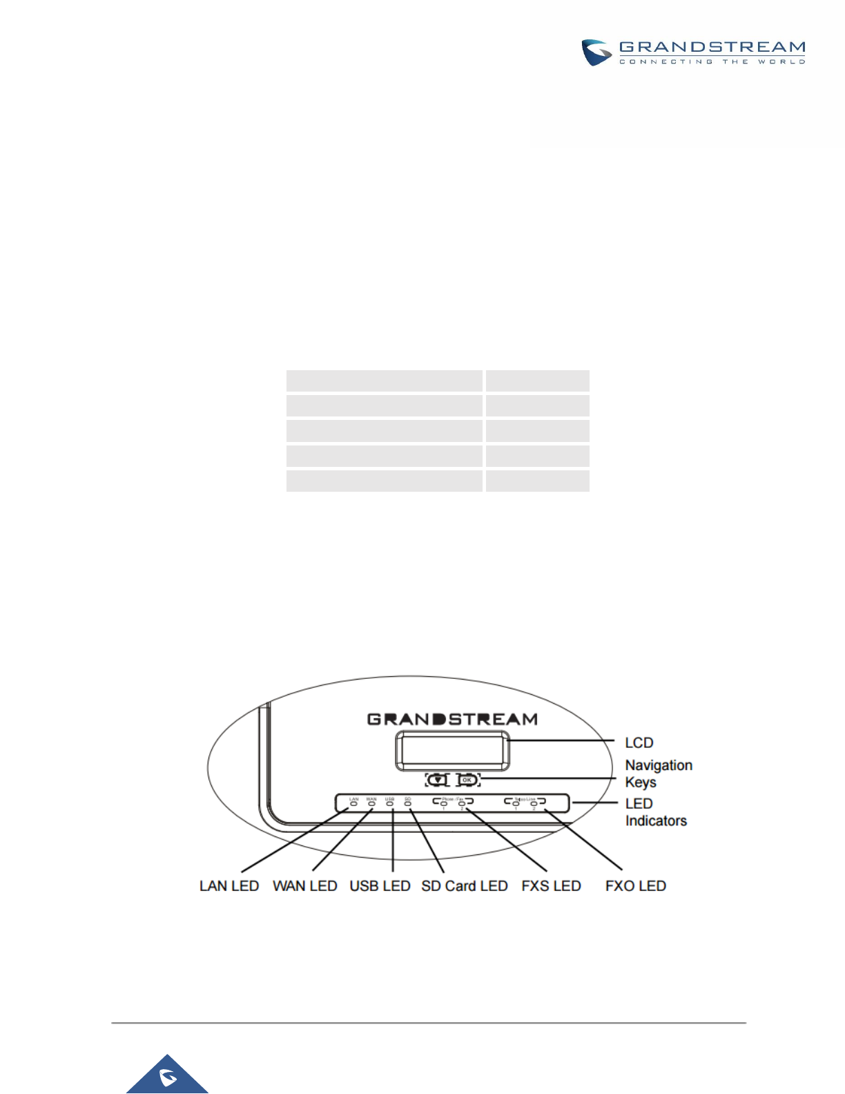
P a g e | 38
UCM6200 Series User Manual
Version 1.0.19.21
INSTALLATION
Before deploying and configuring the UCM6200 series, the device needs to be properly powered up and
connected to network. This section describes detailed information on installation, connection and warranty policy
of the UCM6200 series.
Equipment Packaging
Table 2: UCM6200 Equipment Packaging
Main Case
Yes (1)
Power Adaptor
Yes (1)
Ethernet Cable
Yes (1)
Quick Installation Guide
Yes (1)
GPL License
Yes (1)
Connect Your UCM6200
Connect The UCM6202
Figure 1: UCM6202 Front View

P a g e | 39
UCM6200 Series User Manual
Version 1.0.19.21
Figure 2: UCM6202 Back View
To set up the UCM6202, follow the steps below:
1. Connect one end of an RJ-45 Ethernet cable into the WAN port of the UCM6202.
2. Connect the other end of the Ethernet cable into the uplink port of an Ethernet switch/hub.
3. Connect the 12V DC power adapter into the 12V DC power jack on the back of the UCM6202. Insert the
main plug of the power adapter into a surge-protected power outlet.
4. Wait for the UCM6202 to boot up. The LCD in the front will show the device hardware information when the
boot process is done.
5. Once the UCM6202 is successfully connected to network, the LED indicator for WAN in the front will be in
solid green and the LCD shows up the IP address.
6. (Optional) Connect PSTN lines from the wall jack to the FXO ports; connect analog lines (phone and Fax)
to the FXS ports.
Note: The ground screw needs to be connected.
Connect The UCM6204
Figure 3: UCM6204 Front View

P a g e | 40
UCM6200 Series User Manual
Version 1.0.19.21
Figure 4: UCM6204 Back View
To set up the UCM6204, follow the steps below:
1. Connect one end of an RJ-45 Ethernet cable into the WAN port of the UCM6204.
2. Connect the other end of the Ethernet cable into the uplink port of an Ethernet switch/hub.
3. Connect the 12V DC power adapter into the 12V DC power jack on the back of the UCM6204. Insert the
main plug of the power adapter into a surge-protected power outlet.
4. Wait for the UCM6204 to boot up. The LCD in the front will show the device hardware information when
the boot process is done.
5. Once the UCM6204 is successfully connected to network, the LED indicator for WAN in the front will be
in solid green and the LCD shows up the IP address.
6. (Optional) Connect PSTN lines from the wall jack to the FXO ports; connect analog lines (phone and
Fax) to the FXS ports.
7. Note: The ground screw needs to be connected.
Connect The UCM6208
To set up the UCM6208, follow the steps below:
1. Connect one end of an RJ-45 Ethernet cable into the WAN port of the UCM6208.
2. Connect the other end of the Ethernet cable into the uplink port of an Ethernet switch/hub.
3. Connect the 12V DC power adapter into the 12V DC power jack on the back of the UCM6208. Insert the
main plug of the power adapter into a surge-protected power outlet.
4. Wait for the UCM6208 to boot up. The LCD in the front will show the device hardware information when the
boot process is done.
5. Once the UCM6208 is successfully connected to network, the LED indicator for NETWORK in the front will
be in solid green and the LCD shows up the IP address.
6. (Optional) Connect PSTN lines from the wall jack to the FXO ports; connect analog lines (phone and Fax)
to the FXS ports.
Note: The ground screw needs to be connected.

P a g e | 41
UCM6200 Series User Manual
Version 1.0.19.21
Figure 5: UCM6208 Front View
Figure 6: UCM6208 Back View
Safety Compliances
The UCM6200 series IP PBX complies with FCC/CE and various safety standards. The UCM6200 power adapter
is compliant with the UL standard. Use the universal power adapter provided with the UCM6200 package only.
The manufacturer’s warranty does not cover damages to the device caused by unsupported power adapters.
Warranty
If the UCM6200 series IP PBX was purchased from a reseller, please contact the company where the device
was purchased for replacement, repair or refund. If the device was purchased directly from Grandstream, contact
our Technical Support Team for a RMA (Return Materials Authorization) number before the product is returned.
Grandstream reserves the right to remedy warranty policy without prior notification.
---------------------------------------------------------------------------------------------------------------------------------------------------
Warning:
Use the power adapter provided with the UCM6200 series IP PBX. Do not use a different power adapter as this
may damage the device. This type of damage is not covered under warranty.
---------------------------------------------------------------------------------------------------------------------------------------------------
Navigation Keys
LCD
LED Indicators
8 x FXO Port
SD Card Slot
2 x FXS Port
USB Port
Wan Port
Ground
Reset
DC 12 V
LAN Port
Wan Port

P a g e | 42
UCM6200 Series User Manual
Version 1.0.19.21
GETTING STARTED
The UCM6200 series provides LCD interface, LED indication and Web GUI configuration interface.
• The LCD displays hardware, software and network information. Users could also navigate in the LCD menu
for device information and basic network configuration.
• The LED indication at the front of the device provides interface connection and activity status.
• The Web GUI gives users access to all the configurations and options for UCM6200 series setup.
This section provides step-by-step instructions on how to use the LCD menu, LED indicators and Web GUI of
the UCM6200 series. Once the basic settings are done, users could start making calls from UCM6200 extension
registered on a SIP phone as described at the end of this section.
Use the LCD Menu
• Default LCD Display
When the device is powered up, the LCD will show device model (e.g., UCM6204), hardware version (e.g.,
V1.0A) and IP address. Press "Down" button and the system time will be displayed as well.
• Menu Access
Press "OK" button to start browsing menu options. Please see menu options in [Table 3: LCD Menu Options].
• Menu Navigation
Press the "Down" arrow key to browser different menu options. Press the "OK" button to select an entry.
• Exit
If "Back" option is available in the menu, select it to go back to the previous menu. For "Device Info" "Network
Info" and "Web Info" which do not have "Back" option, simply press the "OK" button to go back to the previous
menu. Also, the LCD will display default idle screen after staying in menu option for 15 seconds.
• LCD Backlight
The LCD backlight will be on upon key pressing. The backlight will go off after the LCD stays in idle for 30
seconds.
The following table summarizes the layout of the LCD menu of UCM.

P a g e | 43
UCM6200 Series User Manual
Version 1.0.19.21
Table 3: LCD Menu Options
View Events
• Critical Events
• Other Events
Device Info
• Hardware: Hardware version number
• Software: Software version number
• P/N: Part number
• WAN MAC: WAN side MAC address
• LAN MAC: LAN side MAC address
• Uptime: System up time
Network Info
• WAN Mode: DHCP, Static IP, or PPPoE
• WAN IP: IP address
• WAN Subnet Mask
• LAN IP: IP address
• LAN Subnet Mask
Network Menu
• WAN Mode: Select WAN mode as DHCP, Static IP or PPPoE
• Static Route Reset: Click to reset the static route setting
Factory Menu
• Reboot
• Factory Reset
• LCD Test Patterns
Press "OK" to start. Then press "Down" button to test different LCD patterns.
When done, press "OK" button to exit.
• Fan Mode
Select "Auto" or "On".
• LED Test Patterns
Select "All On" "All Off" or "Blinking" and check LED status.
• RTC Test Patterns
Select "2022-02-22 22:22" or "2011-01-11 11:11" to start the RTC (Real-
Time Clock) test pattern. Then check the system time from LCD idle screen
by pressing "DOWN" button, or from Web GUI→System Status→General
page. Reboot the device manually after the RTC test is done.
• Hardware Testing
Select "Test SVIP" to perform SVIP test on the device. This is mainly for
factory testing purpose which verifies the hardware connection inside the
device. The diagnostic result will display in the LCD after the test is done.
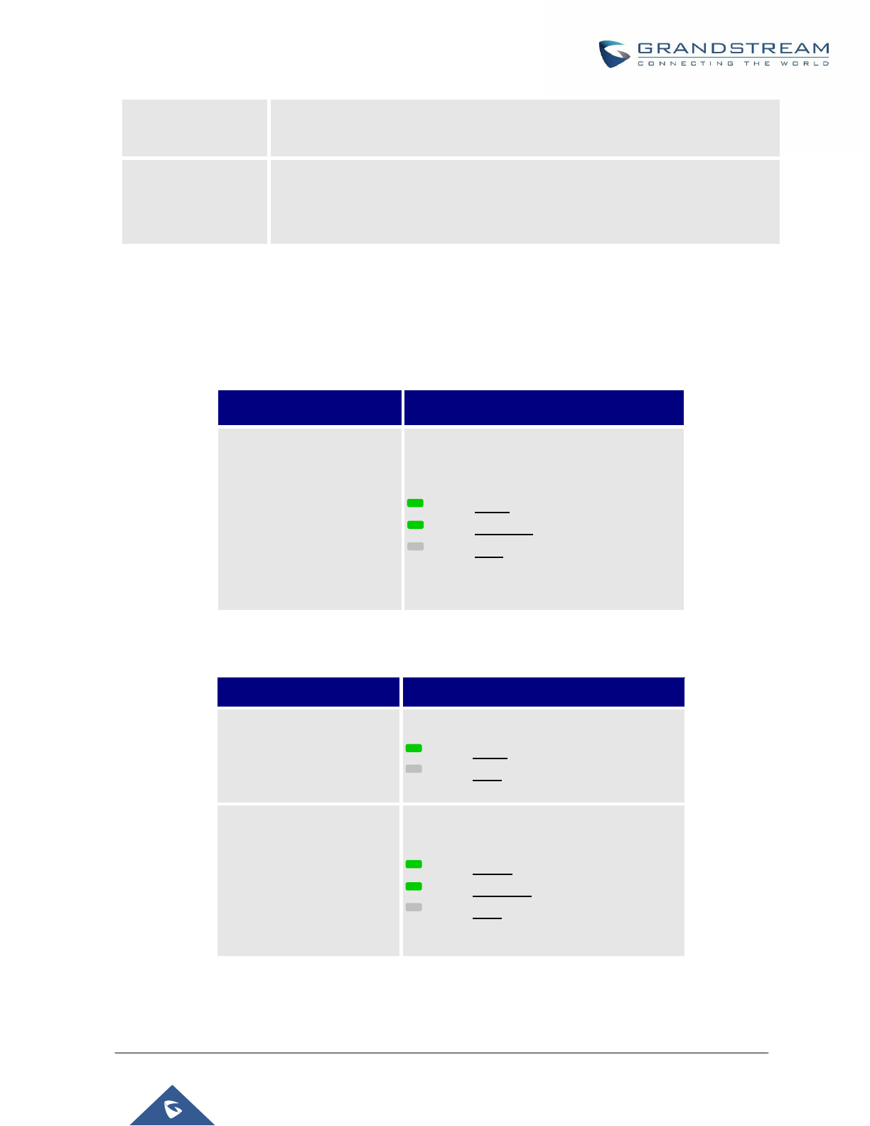
P a g e | 44
UCM6200 Series User Manual
Version 1.0.19.21
Web Info
• Protocol: Web access protocol. HTTP or HTTPS. By default, it's HTTPS
• Port: Web access port number. By default, it's 8089
SSH Switch
• Enable SSH: Enable SSH access.
• Disable SSH: Disable SSH access.
By default, the SSH access is disabled.
Use the LED Indicators
The UCM6200 has LED indicators in the front to display connection status. The following table shows the status
definitions.
Table 4: UCM6202/UCM6204 LED Indicators
LED Indicator
LED Status
LAN
WAN
USB
SD
FXS (Phone/Fax)
FXO (Telco Line)
Solid: Connected
Flashing: Data Transferring
OFF: Not Connected
Table 5: UCM6208 LED Indicators
LED
LED Status
NETWORK
Solid: Connected
OFF: Not Connected
ACT
USB
SD
Phone (FXS)
Line (FXO)
Solid: Connected
Flashing: Data Transferring
OFF: Not Connected
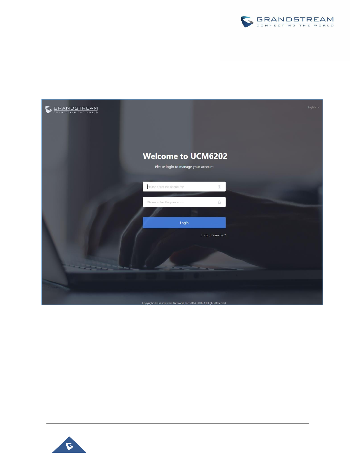
P a g e | 45
UCM6200 Series User Manual
Version 1.0.19.21
Use the Web GUI
Access Web GUI
The UCM6200 embedded Web server responds to HTTP/HTTPS GET/POST requests. Embedded HTML pages
allow users to configure the device through a Web browser such as Microsoft IE, Mozilla Firefox, Google Chrome.
Figure 7: UCM6202 Web GUI Login Page
To access the Web GUI:
1. Connect the computer to the same network as the UCM6200.
2. Ensure the device is properly powered up and shows its IP address on the LCD.
3. Open a Web browser on the computer and enter the Web GUI URL in the following format:
http(s)://IP-Address:Port
where the IP-Address is the IP address displayed on the UCM6200 LCD.
By default, the protocol is HTTPS and the Port number is 8089.

P a g e | 46
UCM6200 Series User Manual
Version 1.0.19.21
For example, if the LCD shows 192.168.40.167, please enter the following in your web browser:
https://192.168.40.167:8089
4. Enter default administrator username “admin” and password.
Note: Units manufactured starting January 2017 have a unique random password printed on the sticker located
on the back of the unit. It is highly recommended to change the default password after login for the first time.
Older units have default password “admin”. See below pictures for the location of the default random password:
Figure 8: Default Random Password
----------------------------------------------------------------------------------------------------------------------------- ----------------------
Note:
By default, the UCM6200 has "Redirect From Port 80" enabled. Therefore, if users type in the UCM6200 IP
address in the web browser, the web page will be automatically redirected to the page using HTTPS and port
8089. For example, if the LCD shows 192.168.40.167, please enter 192.168.40.167 in your web browser and
the web page will be redirected to: https://192.168.40.167:8089
The option "Redirect From Port 80" can be set under the UCM6200 Web GUI→System Settings→HTTP
Server.
----------------------------------------------------------------------------------------------------------------------------- ----------------------
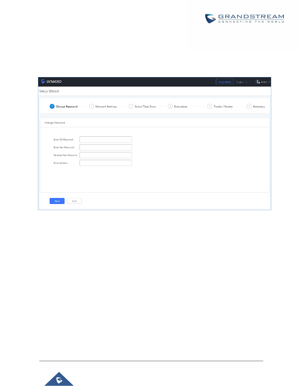
P a g e | 47
UCM6200 Series User Manual
Version 1.0.19.21
Setup Wizard
When the user logs in the UCM6200 Web GUI for the first time, a setup wizard will guide the user to set up basic
configuration. Configurations in setup wizard includes: Time zone, Change password, Network settings,
Extensions, Trunk and routes.
Figure 9: UCM6200 Setup Wizard
Users can disable the Extension Range during configuration on the Extensions.
During the wizard, the user can quit the setup wizard at any time to start over with manual configuration. At the
last step of the wizard, the user will be provided with summary for review, before the configuration is loaded.
Once the setup is completed, the system is ready to go.
Web GUI Configurations
There are eight main sections in the Web GUI for users to view the PBX status, configure and manage the PBX.
• System Status: Displays PBX status, System Status, Active calls and network status.
• Extension/Trunk: To configure extensions, trunks and manage inbound/outbound call routes.
• Call Features: To Configure call features such as ring groups, call queues, IVR ...Etc
• PBX Settings: Extension ranges, SIP Settings, interfaces settings and MOH.
• System Settings: To configure user management, network settings, firewall settings, change password,
LDAP Server, HTTP Server, Email Settings, Time Settings, NTP server and login timeout.
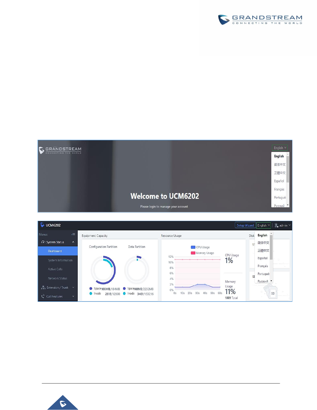
P a g e | 48
UCM6200 Series User Manual
Version 1.0.19.21
• Maintenance: To perform firmware upgrade, backup configurations, cleaner setup, reset/reboot, syslog
setup and troubleshooting.
• CDR: View call statistics and download CDR and call recordings.
• Value-added Features: Zero Config, enable CTI server, CRM, PMS WebRTC.
Web GUI Languages
Currently the UCM6200 series Web GUI supports English, Simplified Chinese, Traditional Chinese,
Spanish, French, Portuguese, Russian, Italian, Polish, German etc.
Users can select the displayed language in Web GUI login page, or at the upper right of the Web GUI after
logging in.
Figure 10: UCM6200 Web GUI Language
Web GUI Search Bar
Users can search for options in the web portal with the search bar on the top right of the page.
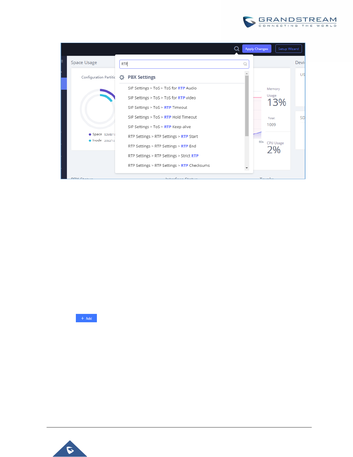
P a g e | 49
UCM6200 Series User Manual
Version 1.0.19.21
Figure 11: Web GUI Search Bar
Save and Apply Changes
Click on "Save" button after configuring the Web GUI options in one page. After saving all the changes, make
sure click on "Apply Changes" button on the upper right of the web page to submit all the changes. If the change
requires reboot to take effect, a prompted message will pop up for you to reboot the device.
Make Your First Call
Power up the UCM6200 and your SIP end point phone. Connect both devices to the network. Then follow the
steps below to make your first call.
1. Log in the UCM6200 Web GUI, go to Extension/Trunk→Extensions.
2. Click on to create a new extension. You will need User ID, Password and Voicemail Password
information to register and use the extension later.
3. Register the extension on your phone with the SIP User ID, SIP server and SIP Password information. The
SIP server address is the UCM6200 IP address.
4. When your phone is registered with the extension, dial *97 to access the voicemail box. Enter the Voicemail
Password once you hear "Password" voice prompt.
5. Once successfully logged in to the voicemail, you will be prompted with the Voice Mail Main menu.
6. You are successfully connected to the PBX system now.

P a g e | 50
UCM6200 Series User Manual
Version 1.0.19.21
SYSTEM SETTINGS
This section explains configurations for system-wide parameters on the UCM6200. System settings are under
“System Settings” tab on UCM6200 Web GUI. System settings include User Management, Network Settings,
Firewall/Security Settings, Change Password, LDAP server, HTTP server, Email settings, Time Settings, NTP
Server, Recordings Storage and Login Timeout settings.
HTTP Server
The UCM6200 embedded web server responds to HTTP/HTTPS GET/POST requests. Embedded HTML pages
allow the users to configure the PBX through a Web browser such as Microsoft IE, Mozilla Firefox and Google
Chrome. By default, the PBX can be accessed via HTTPS using Port 8089 (e.g., https://192.168.40.50:8089).
Users could also change the access protocol and port as preferred under Web GUI→System Settings→HTTP
Server.
Table 6: HTTP Server Settings
Redirect From Port 80
Enable or disable redirect from port 80. On the PBX, the default access
protocol is HTTPS and the default port number is 8089. When this option
is enabled, the access using HTTP with Port 80 will be redirected to
HTTPS with Port 8089. The default setting is "Enable".
Protocol Type
Select HTTP or HTTPS. The default setting is "HTTPS". This is also the
protocol used for zero config when the end point device downloads the
config file from the UCM6200.
Port
Specify port number to access the HTTP server. The default port number
is 8089.
Enable IP whitelist
If enabled, only the IP address on the permitted IP list will be allowed to
access the UCM’s web GUI.
Permitted IP(s)
Add an IP address to the list of allowed IPs to access UCM’s web GUI.
Ex: 192.168.6.233 / 255.255.255.255
Certificate Options
Select the mode to download SSL certificates for web server, two modes
are available:
• Manually Upload certificate: Upload the files while respecting
size and format.
• Automatically request certificate: enter domain from which to
request the certificate files.
TLS Private Key
Upload private key for the built-in http server.
Note: The size of the key file must be under 2MB and the it will be renamed
as "private.pem" automatically.

P a g e | 51
UCM6200 Series User Manual
Version 1.0.19.21
TLS Cert
Upload certificate for the built-in http server and override the existing one.
Note: The size of your certificate must be under 2MB. This is the certificate
file (*.pem format only) for TLS connection and it will be renamed as
"certificate.pem" automatically. It contains private key for the client and
signed certificate for the server.
Domain
Enter the domain name from which to request certificate files then press
on in order to request the files.
Once the change is saved, the web page will be redirected to the login page using the new URL. Enter the
username and password to login again.
Network Settings
After successfully connecting the UCM6200 to the network for the first time, users could login the Web GUI and
go to System Settings→Network Settings to configure the network parameters for the device.
• UCM6200 supports Route/Switch/Dual mode functions.
In this section, all the available network setting options are listed for all models. Select each tab in Web
GUI→System Settings→Network Settings page to configure LAN settings, WAN settings, 802.1X and Port
Forwarding.
Basic Settings
Please refer to the following tables for basic network configuration parameters on UCM6202, UCM6204 and
UCM6208 respectively.
Table 7: UCM6200 Network Settings→Basic Settings
Method
Select "Route", "Switch" or "Dual" mode on the network interface of UCM6200. The default
setting is "Route".
• Route
WAN port interface will be used for uplink connection. LAN port interface will be used
to serve as router.
• Switch
WAN port interface will be used for uplink connection. LAN port interface will be used
as room for PC connection.
• Dual
Both ports can be used for uplink connection. Users will need assign LAN 1 or LAN 2
as the default interface in option "Default Interface" and configure "Gateway IP" for
this interface.

P a g e | 52
UCM6200 Series User Manual
Version 1.0.19.21
MTU
Specifies the Maximum Transmission Unit. (By default, its 1500)
IPv4 Address
Preferred DNS
Server
Enter the preferred DNS server address. If Preferred DNS is used, UCM will try to use it
as Primary DNS server.
WAN (when "Method" is set to "Route")
IP Method
Select DHCP, Static IP, or PPPoE. The default setting is DHCP.
IP Address
Enter the IP address for static IP settings. The default setting is 192.168.0.160.
Subnet Mask
Enter the subnet mask address for static IP settings. The default setting is 255.255.0.0.
Gateway IP
Enter the gateway IP address for static IP settings. The default setting is 0.0.0.0.
DNS Server 1
Enter the DNS server 1 address for static IP settings. The default setting is 0.0.0.0.
DNS Server 2
Enter the DNS server 2 address for static IP settings.
User Name
Enter the user name to connect via PPPoE.
Password
Enter the password to connect via PPPoE.
Layer 2 QoS
802.1Q/VLAN
Tag
Assign the VLAN tag of the layer 2 QoS packets for WAN port. The default value is 0.
Layer 2 QoS
802.1p Priority
Value
Assign the priority value of the layer 2 QoS packets for WAN port. The default value is 0.
LAN (when Method is set to "Route")
IP Address
Enter the IP address assigned to LAN port. The default setting is 192.168.2.1.
Subnet Mask
Enter the subnet mask. The default setting is 255.255.255.0.
DHCP Server
Enable
Enable or disable DHCP server capability. The default setting is "Yes".
DNS Server 1
Enter DNS server address 1. The default setting is 8.8.8.8.
DNS Server 2
Enter DNS server address 2. The default setting is 208.67.222.222.
Allow IP
Address From
Enter the DHCP IP Pool starting address. The default setting is 192.168.2.100.
Allow IP
Address To
Enter the DHCP IP Pool ending address. The default setting is 192.168.2.254.
Default IP
Lease Time
Enter the IP lease time (in seconds). The default setting is 43200.
LAN (when Method is set to "Switch")
IP Method
Select DHCP, Static IP, or PPPoE. The default setting is DHCP.
IP Address
Enter the IP address for static IP settings. The default setting is 192.168.0.160.
Subnet Mask
Enter the subnet mask address for static IP settings. The default setting is 255.255.0.0.
Gateway IP
Enter the gateway IP address for static IP settings. The default setting is 0.0.0.0.

P a g e | 53
UCM6200 Series User Manual
Version 1.0.19.21
DNS Server 1
Enter the DNS server 1 address for static IP settings. The default setting is 0.0.0.0.
DNS Server 2
Enter the DNS server 2 address for static IP settings.
User Name
Enter the user name to connect via PPPoE.
Password
Enter the password to connect via PPPoE.
Layer 2 QoS
802.1Q/VLAN
Tag
Assign the VLAN tag of the layer 2 QoS packets for LAN port. The default value is 0.
Layer 2 QoS
802.1p Priority
Value
Assign the priority value of the layer 2 QoS packets for LAN port. The default value is 0.
LAN 1 / LAN 2 (when Method is set to "Dual")
Default
Interface
If "Dual" is selected as "Method", users will need assign the default interface to be LAN 1
(mapped to UCM6202 WAN port) or LAN 2 (mapped to UCM6202 LAN port) and then
configure network settings for LAN 1/LAN 2. The default interface is LAN 2.
IP Method
Select DHCP, Static IP, or PPPoE. The default setting is DHCP.
IP Address
Enter the IP address for static IP settings. The default setting is 192.168.0.160.
Subnet Mask
Enter the subnet mask address for static IP settings. The default setting is 255.255.0.0.
Gateway IP
Enter the gateway IP address for static IP settings when the port is assigned as default
interface. The default setting is 0.0.0.0.
DNS Server 1
Enter the DNS server 1 address for static IP settings. The default setting is 0.0.0.0.
DNS Server 2
Enter the DNS server 2 address for static IP settings.
User Name
Enter the user name to connect via PPPoE.
Password
Enter the password to connect via PPPoE.
Layer 2 QoS
802.1Q/VLAN
Tag
Assign the VLAN tag of the layer 2 QoS packets for LAN port. The default value is 0.
Layer 2 QoS
802.1p Priority
Value
Assign the priority value of the layer 2 QoS packets for LAN port. The default value is 0.
IPv6 Address
WAN (when "Method" is set to "Route")
IP Method
Select Auto or Static. The default setting is Auto
IP Address
Enter the IP address for static IP settings.
IP Prefixlen
Enter the Prefix length for static settings. Default is 64
DNS Server 1
Enter the DNS server 1 address for static settings.

P a g e | 54
UCM6200 Series User Manual
Version 1.0.19.21
DNS Server 2
Enter the DNS server 2 address for static settings.
LAN (when Method is set to "Route")
DHCP Server
Select Disable, Auto or DHCPv6.
Disable: the DHCPv6 server is disabled.
Auto: Stateless address auto configuration using NDP protocol.
DHCPv6: Stateful address auto configuration using DHCPv6 protocol.
DHCP Prefix
Enter DHCP prefix. (Default is 2001:db8:2:2::)
DHCP
prefixlen
Enter the Prefix length for static settings. Default is 64
DNS Server 1
Enter the DNS server 1 address for static settings. Default is (2001:4860:4860::8888 )
DNS Server 2
Enter the DNS server 2 address for static settings. Default is (2001:4860:4860::8844 )
Allow IP
Address From
Configure starting IP address assigned by the DHCP prefix and DHCP prefixlen.
Allow IP
Address To
Configure the ending IP address assigned by the DHCP Prefix and DHCP prefixlen.
Default IP
Lease Time
Configure the lease time (in second) of the IP address.
LAN (when Method is set to "Switch")
IP Method
Select Auto or Static. The default setting is Auto
IP Address
Enter the IP address for static IP settings.
IP Prefixlen
Enter the Prefix length for static settings. Default is 64
DNS Server 1
Enter the DNS server 1 address for static settings.
DNS Server 2
Enter the DNS server 2 address for static settings.
LAN 1 / LAN 2 (when Method is set to "Dual")
Default
Interface
Users will need assign the default interface to be LAN 1 (mapped to UCM6200 WAN port)
or LAN 2 (mapped to UCM6200 LAN port) and then configure network settings for LAN
1/LAN 2. The default interface is LAN 2.
IP Method
Select Auto or Static. The default setting is Auto
IP Address
Enter the IP address for static IP settings.
IP Prefixlen
Enter the Prefix length for static settings. Default is 64
DNS Server 1
Enter the DNS server 1 address for static settings.
DNS Server 2
Enter the DNS server 2 address for static settings.
• Method: Route
When the UCM6200 has, method set to Route in network settings, WAN port interface is used for uplink
connection and LAN port interface is used as a router. Please see a sample diagram below.
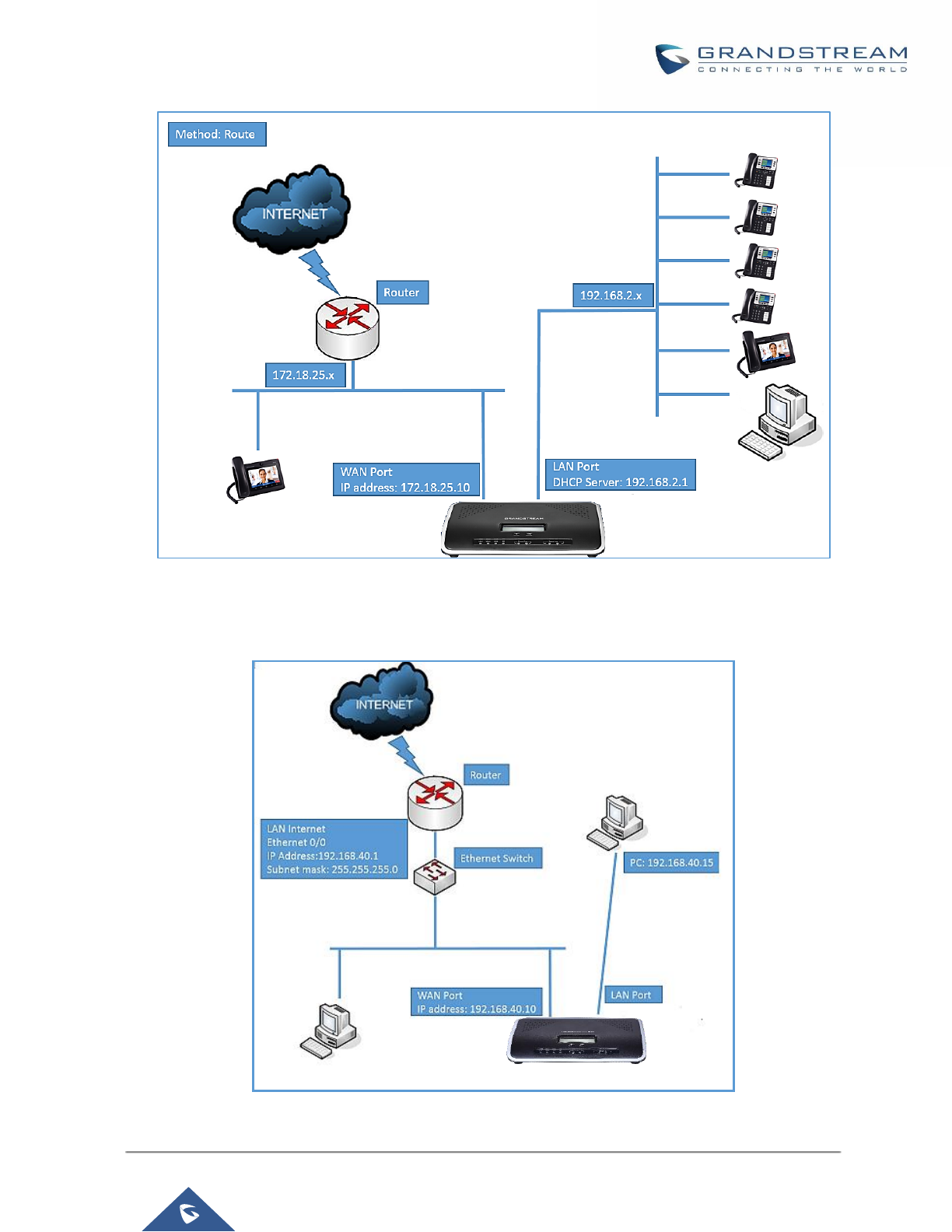
P a g e | 55
UCM6200 Series User Manual
Version 1.0.19.21
Figure 12: UCM6202 Network Interface Method: Route
• Method: Switch
WAN port interface is used for uplink connection; LAN port interface is used as room for PC connection.
Figure 13: UCM6202 Network Interface Method: Switch
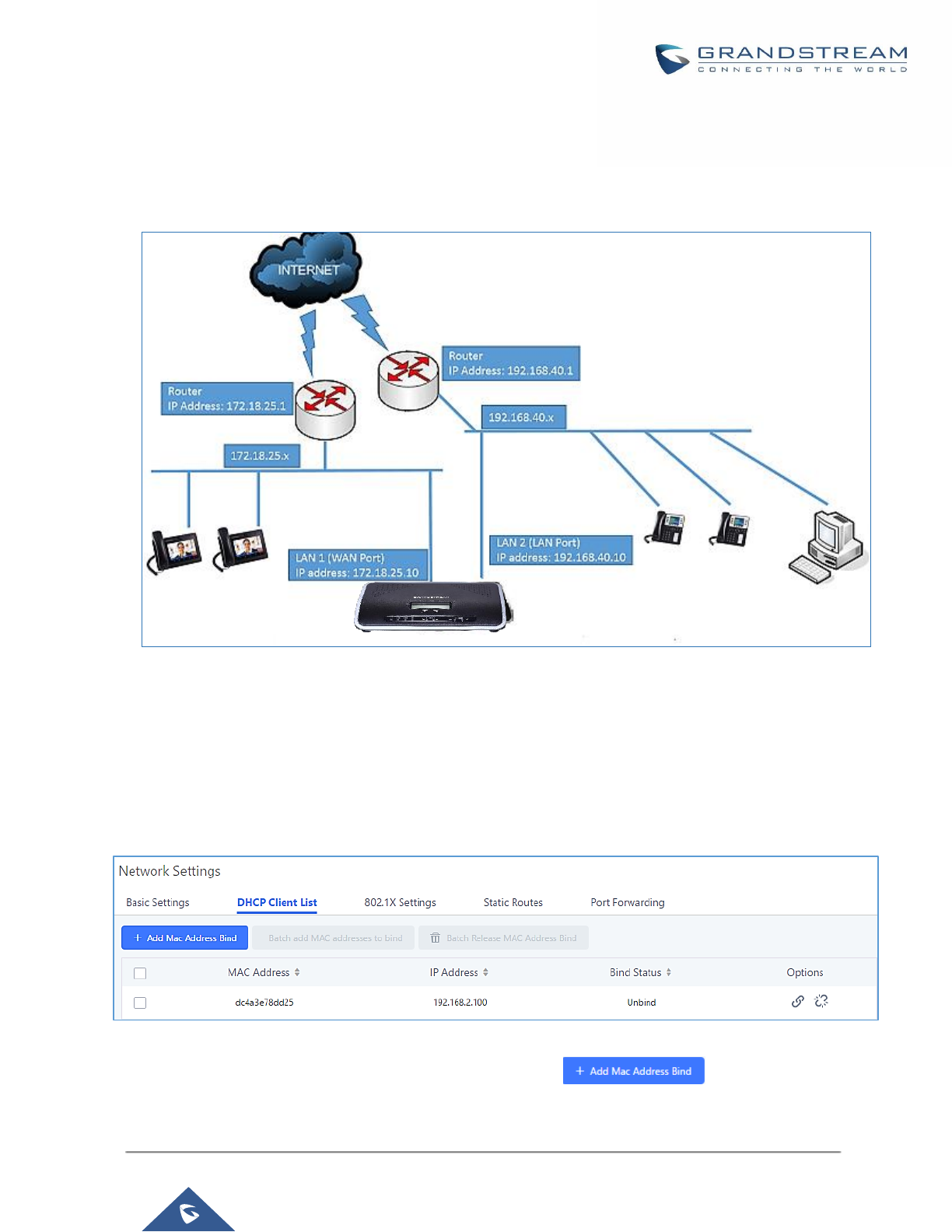
P a g e | 56
UCM6200 Series User Manual
Version 1.0.19.21
• Method: Dual
Both WAN port and LAN port are used for uplink connection. Users will need assign LAN 1 or LAN 2 as the
default interface in option "Default Interface" and configure "Gateway IP" if static IP is used for this interface.
Figure 14: UCM6202 Network Interface Method: Dual
DHCP Client List
This feature can bind MAC to IP addresses on the LAN port when UCM6200 is set to Route mode.
When devices receive IP addresses from LAN port, they will be listed on the webGUI under “System
Settings→Network Settings→DHCP Client List” as shown below.
Figure 15: DHCP Client List
User can bind manually a MAC to an IP address by clicking on , the following figure will
pop up.
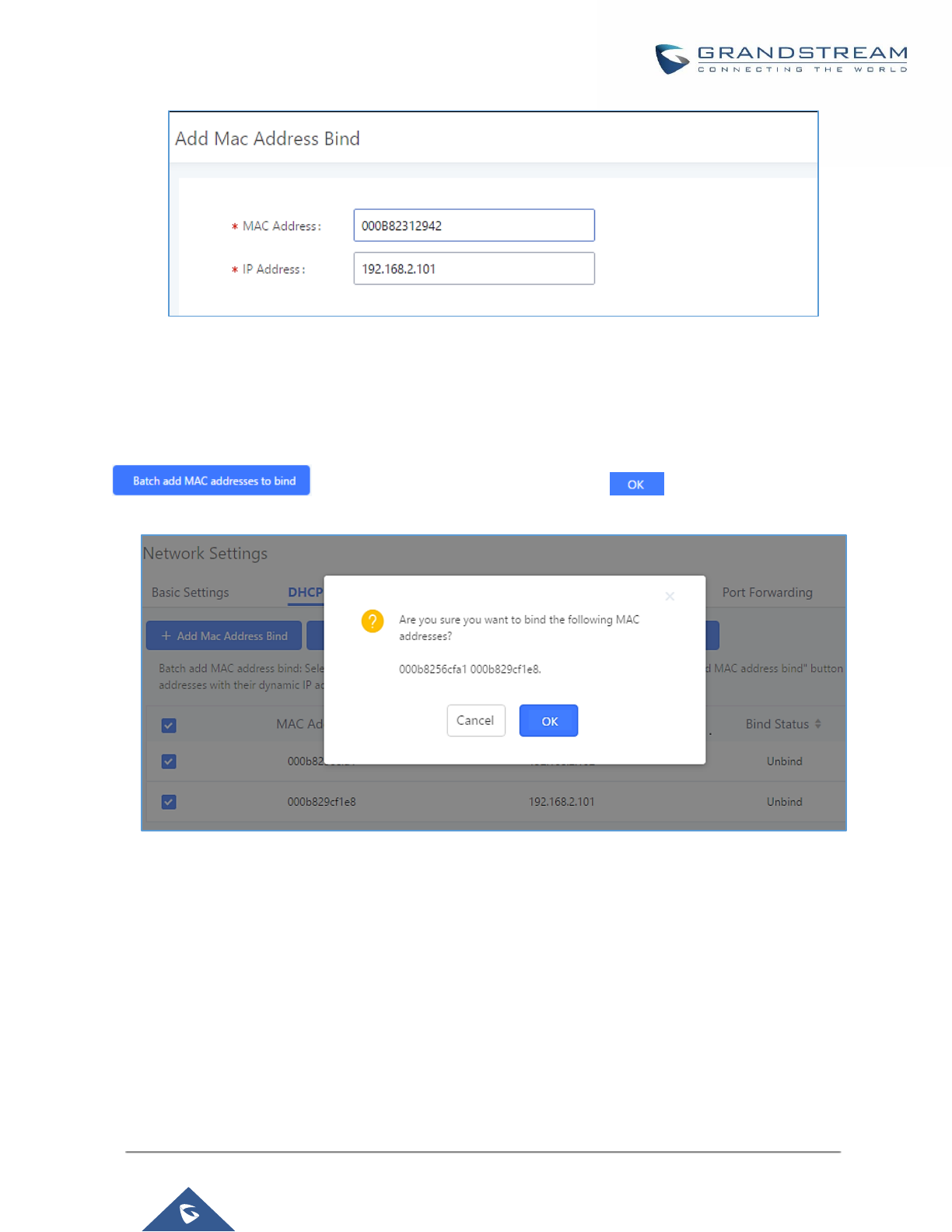
P a g e | 57
UCM6200 Series User Manual
Version 1.0.19.21
Figure 16: Add MAC Address Bind
User needs to set the device MAC address and the IP that will be bound to it (the IP address needs to be within
the UCM6200 DHCP range).
To bind a batch of listed MAC addresses, user needs to check first the MAC addresses to bind and click on
. A confirmation popup will be shown, click to bind the addresses.
Figure 17: Batch Add MAC Address Bind
After Clicking “OK” to confirm the binding, the “Bind Status” will change from “Unbind” to “Binding”.
802.1X
IEEE 802.1X is an IEEE standard for port-based network access control. It provides an authentication
mechanism to device before the device can access Internet or other LAN resources. The UCM6200 supports
802.1X as a supplicant/client to be authenticated. The following diagram and figure show UCM6200 uses 802.1X
mode “EAP-MD5” on WAN port as client in the network to access Internet.
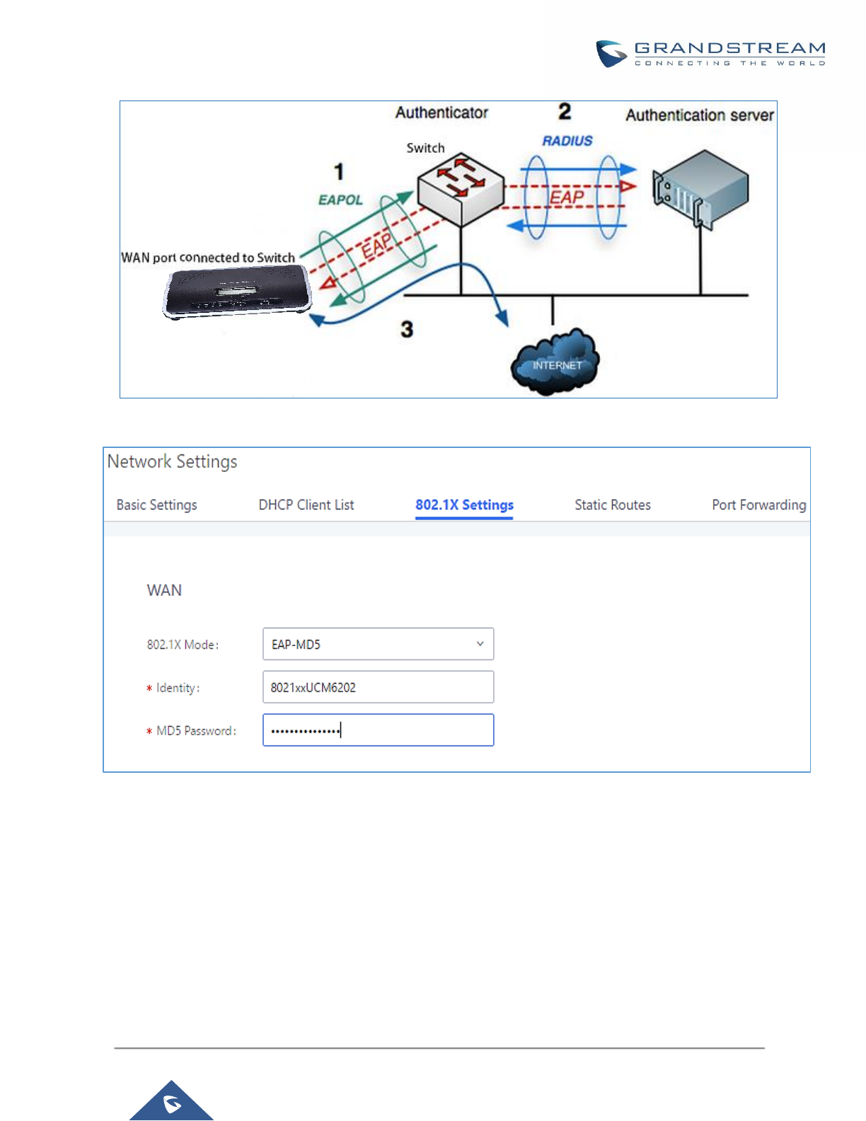
P a g e | 58
UCM6200 Series User Manual
Version 1.0.19.21
Figure 18: UCM6200 Using 802.1X as Client
Figure 19: UCM6200 Using 802.1X EAP-MD5
The following table shows the configuration parameters for 802.1X on UCM6200. Identity and MD5 password
are required for authentication, which should be provided by the network administrator obtained from the
RADIUS server. If “EAP-TLS” or “EAP-PEAPv0/MSCHAPv2” is used as the 802.1X mode, users will also need
to upload 802.1X CA Certificate and 802.1X Client Certificate, which should be also generated from the RADIUS
server.

P a g e | 59
UCM6200 Series User Manual
Version 1.0.19.21
Table 8: UCM6200 Network Settings→802.1X
802.1X Mode
Select 802.1X mode. The default setting is "Disable". The supported 802.1X mode
are:
• EAP-MD5
• EAP-TLS
• EAP-PEAPv0/MSCHAPv2
Identity
Enter 802.1X mode Identity information.
MD5 Password
Enter 802.1X mode MD5 password information.
802.1X Certificate
Select 802.1X certificate from local PC and then upload.
802.1X Client
Certificate
Select 802.1X client certificate from local PC and then upload.
Static Routes
The UCM6200 provides users static routing capability that allows the device to use manually configured routes,
rather than information only from dynamic routing or gateway configured in the UCM6200 Web GUI→System
Settings→Network Settings→Basic Settings to forward traffic. It can be used to define a route when no other
routes are available or necessary, or used in complementary with existing routing on the UCM6200 as a failover
backup, etc.
• Click on to create a new IPv4 static route or click on to
create a new IPv6 static route. The configuration parameters are listed in the table below.
• Once added, users can select to edit the static route.
• Select to delete the static route.
Table 9: UCM6200 Network Settings→Static Routes
Destination
Configure the destination IPv4 address or the destination IPv6 subnet for the
UCM6200 to reach using the static route.
Example:
IPv4 address - 192.168.66.4
IPv6 subnet - 2001:740:D::1/64
Netmask
Configure the subnet mask for the above destination address. If left blank, the
default value is 255.255.255.255.
Example:
255.255.255.0
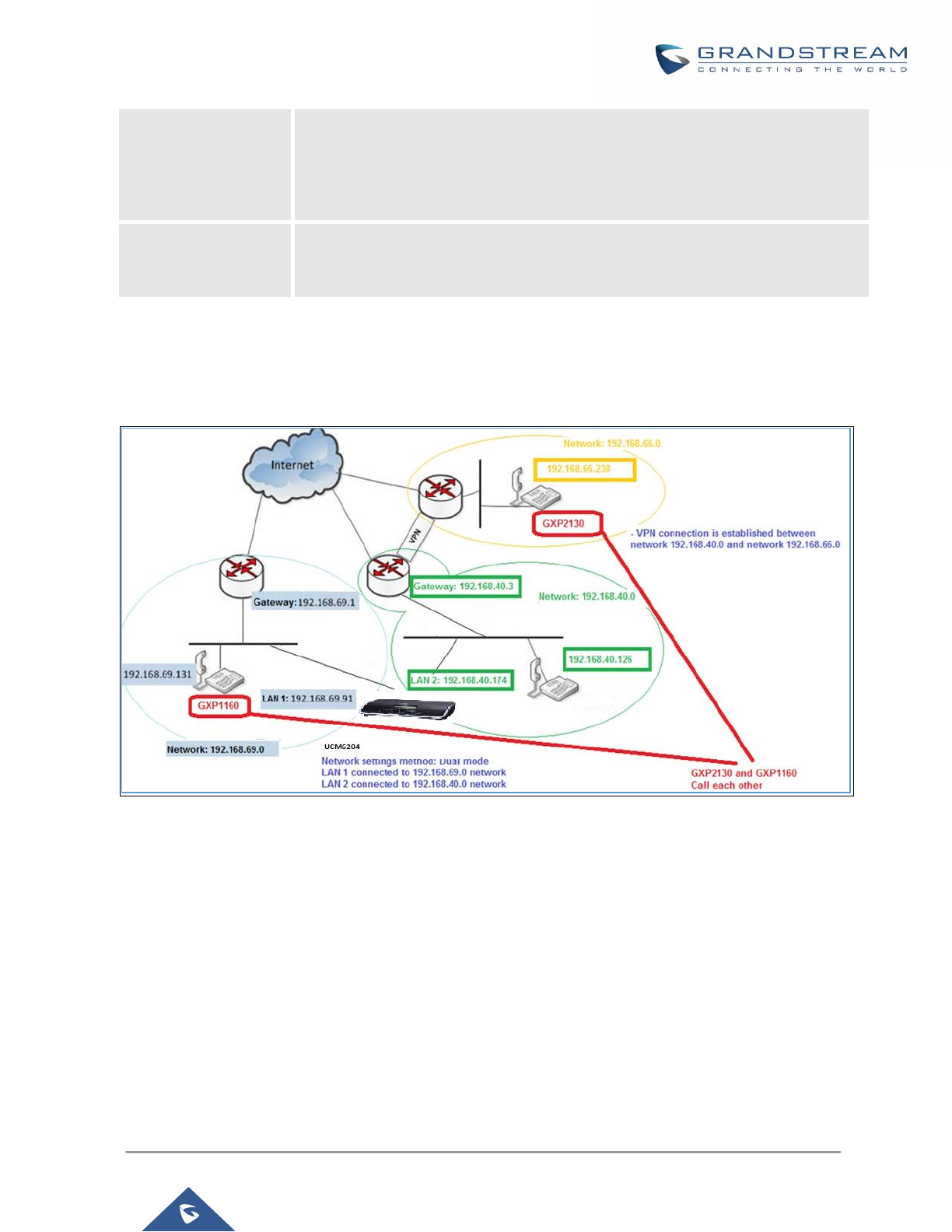
P a g e | 60
UCM6200 Series User Manual
Version 1.0.19.21
Gateway
Configure the IPv4 or IPv6 gateway address so that the UCM6200 can reach the
destination via this gateway. Gateway address is optional.
Example:
192.168.40.5 or 2001:740:D::1
Interface
Specify the network interface on the UCM6200 to reach the destination using the
static route.
LAN interface is eth0; WAN interface is eth1.
Static routes configuration can be reset from LCD menu→Network Menu.
The following diagram shows a sample application of static route usage on UCM6204.
Figure 20: UCM6204 Static Route Sample
The network topology of the above diagram is as below:
• Network 192.168.69.0 has IP phones registered to UCM6204 LAN 1 address
• Network 192.168.40.0 has IP phones registered to UCM6204 LAN 2 address
• Network 192.168.66.0 has IP phones registered to UCM6204 via VPN
• Network 192.168.40.0 has VPN connection established with network 192.168.66.0

P a g e | 61
UCM6200 Series User Manual
Version 1.0.19.21
In this network, by default the IP phones in network 192.168.69.0 are unable to call IP phones in network
192.168.66.0 when registered on different interfaces on the UCM6204. Therefore, we need configure a static
route on the UCM6204 so that the phones in isolated networks can make calls between each other.
Figure 21: UCM6204 Static Route Configuration
Port Forwarding
The UCM network interface supports router function which provides users the ability to do port forwarding. If
LAN mode is set to "Route" under Web GUI→System Settings→Network Settings→Basic Settings page,
port forwarding is available for configuration.
The port forwarding configuration is under Web GUI→System Settings→Network Settings→Port Forwarding
page. Please see related settings in the table below.
Table 10: UCM6200 Network Settings→Port Forwarding
WAN Port
Specify the WAN port number or a range of WAN ports. Unlimited number of ports
can be configured.
Note:
When it is set to a range, WAN port and LAN port must be configured with the
same range, such as WAN port: 1000-1005 and LAN port: 1000-1005, and access
from WAN port will be forwarded to the LAN port with the same port number, for
example, WAN port 1000 will be port forwarding to LAN port 1000.
LAN IP
Specify the LAN IP address.
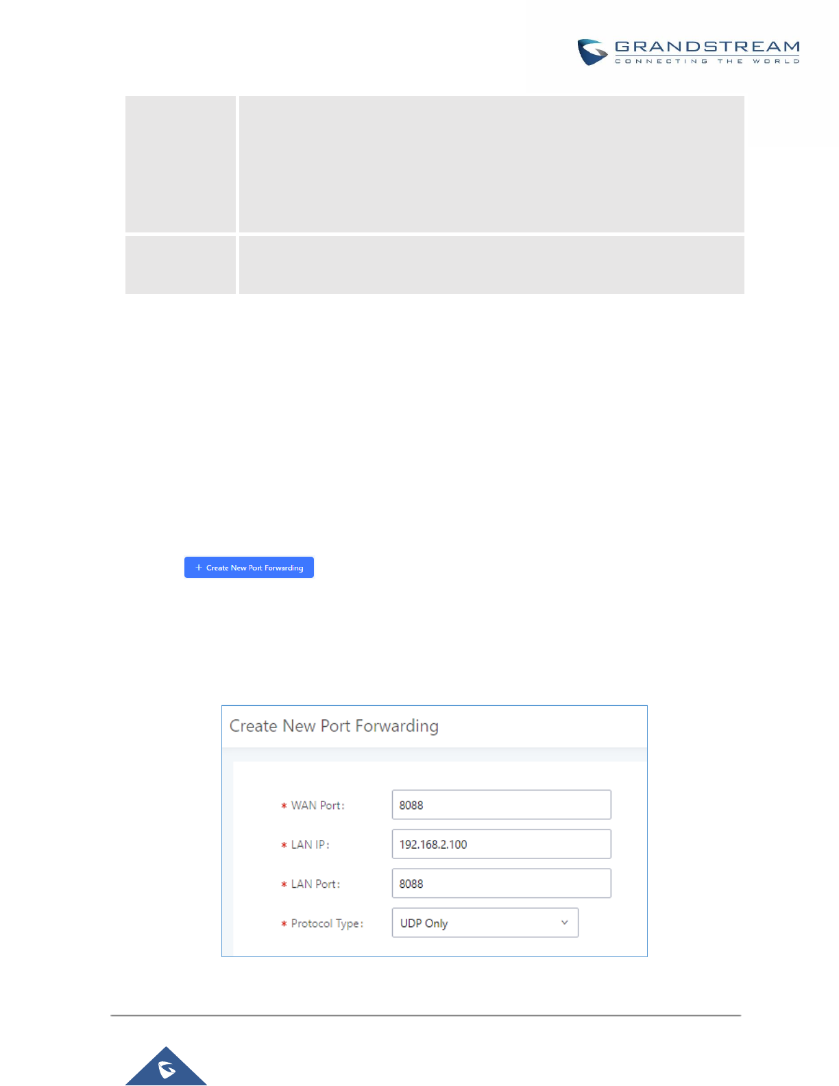
P a g e | 62
UCM6200 Series User Manual
Version 1.0.19.21
LAN Port
Specify the LAN port number or a range of LAN ports.
Note:
When it is set to a range, WAN port and LAN port must be configured with the
same range, such as WAN port: 1000-1005 and LAN port: 1000-1005, and access
from WAN port will be forwarded to the LAN port with the same port number, for
example, WAN port 1000 will be port forwarding to LAN port 1000.
Protocol Type
Select protocol type "UDP Only", "TCP Only" or "TCP/UDP" for the forwarding in
the selected port. The default setting is "UDP Only".
The following figures demonstrate a port forwarding example to provide phone’s Web GUI access to public side.
• UCM6200 network mode is set to “Route”.
• UCM6200 WAN port is connected to uplink switch, with a public IP address configured, e.g. 1.1.1.1.
• UCM6200 LAN port provides DHCP pool that connects to multiple phone devices in the LAN network
192.168.2.x. The UCM6200 is used as a router, with gateway address 192.168.2.1.
• There is a GXP2160 connected under the LAN interface network of the UCM6200. It obtains IP address
192.168.2.100 from UCM6200 DHCP pool.
• On the UCM6200 Web GUI→System Settings→Network Settings→Port Forwarding, configure a port
forwarding entry as the figure shows below.
• Click on
WAN Port: This is the port opened on the WAN side for access purpose.
LAN IP: This is the GXP2160 IP address, under the LAN interface network of the UCM6200.
LAN Port: This is the port opened on the GXP2160 side for access purpose.
Protocol Type: We select TCP here for Web GUI access using HTTP.
Figure 22: Create New Port Forwarding
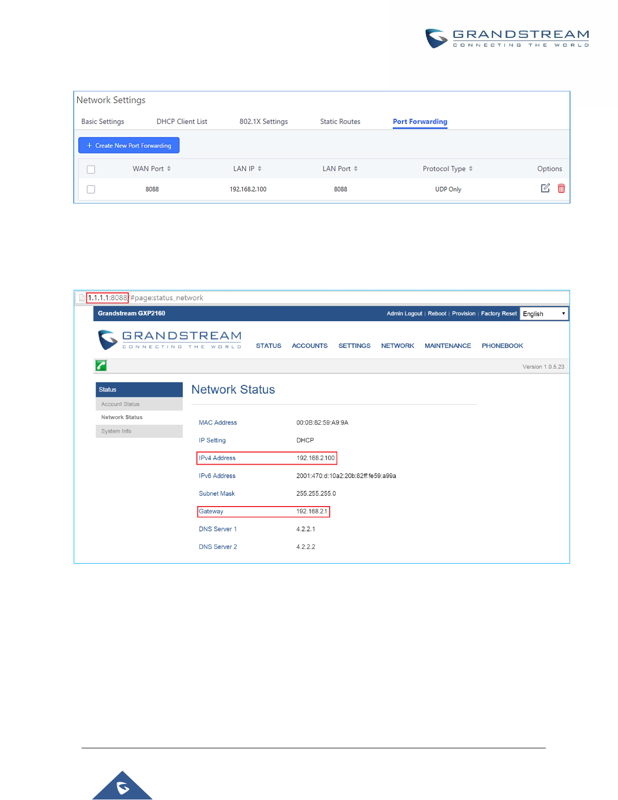
P a g e | 63
UCM6200 Series User Manual
Version 1.0.19.21
Figure 23: UCM6200 Port Forwarding Configuration
This will allow users to access the GXP2160 Web GUI from public side, by typing in public IP address (example:
1.1.1.1:8088).
Figure 24: GXP2160 Web Access using UCM6202 Port Forwarding
OpenVPN®
OpenVPN® settings allow the users to configure UCM6200 to use VPN features, the following table gives details
about the various options in order to configure the UCM as OpenVPN Client.

P a g e | 64
UCM6200 Series User Manual
Version 1.0.19.21
Table 11: UCM6200 System Settings→Network Settings→OpenVPN®
Enable
Enable / Disable the OpenVPN feature.
Configuration
Method
Select OpenVPN configuration method.
Manual Configuration: Allows to configure OpenVPN settings manually.
Upload Configuration File: Allows to upload. ovpn and .conf files to the UCM
and to automatically configure OpenVPN settings.
OpenVPN®
Server Address
Configures the hostname/IP and port of the server. For example: 192.168.1.2:22
OpenVPN®
Server Protocol
Specify the protocol user, user should use the same settings as used on the
server
OpenVPN®
Device mode
Use the same setting as used on the server.
Dev TUN: Create a routed IP tunnel.
Dev TAP: Create an Ethernet tunnel.
OpenVPN® Use
Compression
Compress tunnel packets using the LZO algorithm on the VPN link. Don’t enable
this unless it is also enabled in the server config file.
OpenVPN®
Encryption
Algorithm
Specify the cryptographic cipher. Users should make sure to use the same
setting that they are using on the OpenVPN server.
OpenVPN® CA
Cert
Upload as SSL/TLS root certificate. This file will be renamed as ‘ca.crt’
automatically.
OpenVPN®
Client Cert
Upload a client certificate. This file will be renamed as ‘cliend.crt’ automatically.
OpenVPN®
Client Key
Upload a client private key. This file will be renamed as ‘client.key’ automatically.
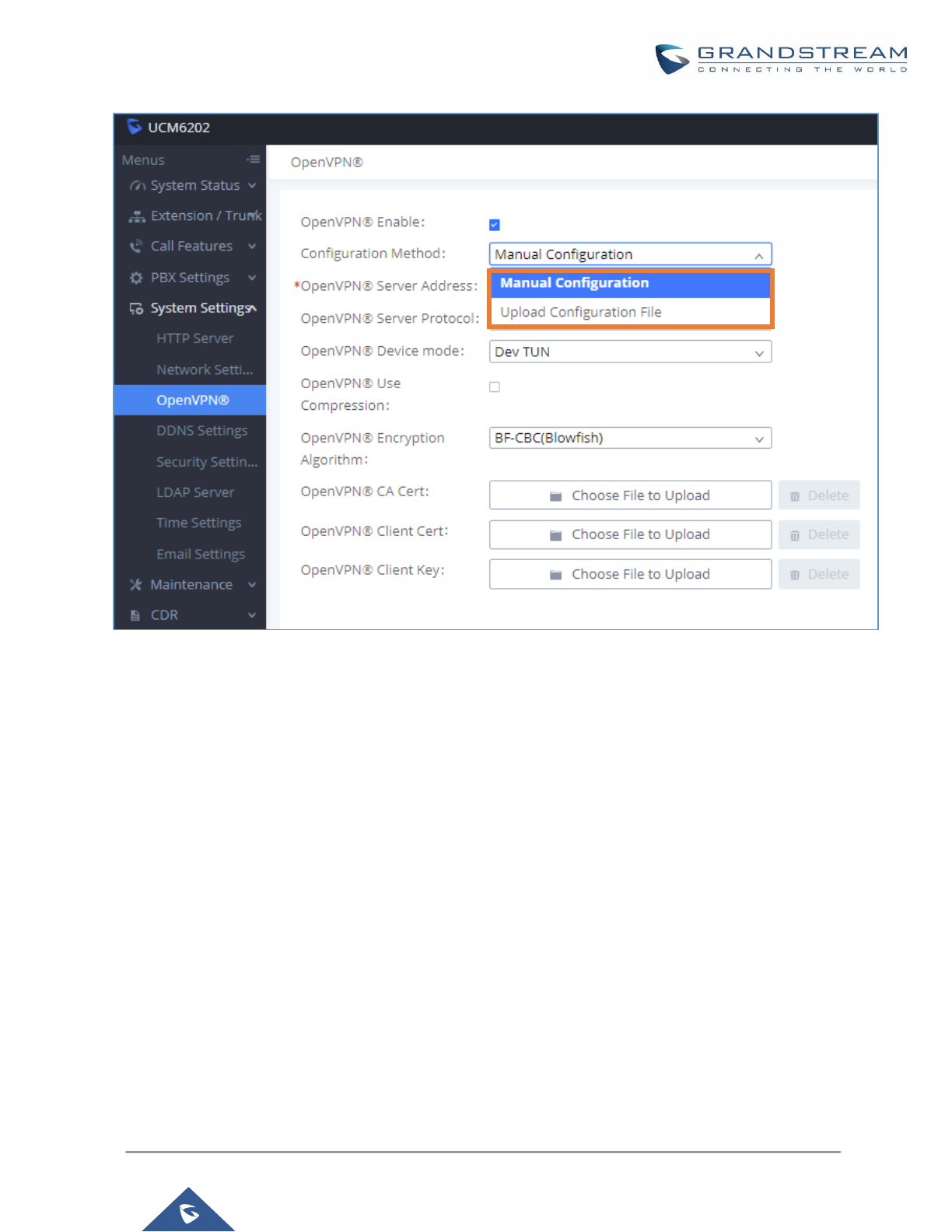
P a g e | 65
UCM6200 Series User Manual
Version 1.0.19.21
Figure 25: Open VPN® feature on the UCM6200
DDNS Settings
DDNS setting allows user to access UCM6200 via domain name instead of IP address.
The UCM supports DDNS service from the following DDNS provider:
• dydns.org
• noip.com
• freedns.afraid.org
• zoneedit.com
• oray.net
Here is an example of using noip.com for DDNS.
1. Register domain in DDNS service provider. Please note the UCM6200 needs to have public IP access.
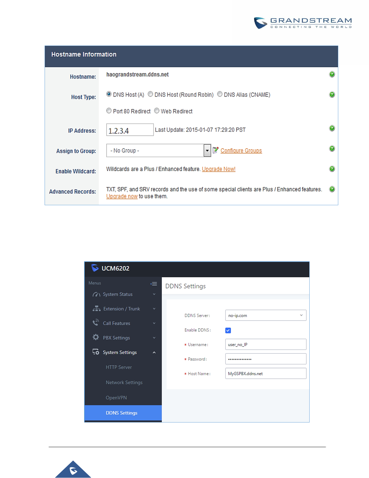
P a g e | 66
UCM6200 Series User Manual
Version 1.0.19.21
Figure 26: Register Domain Name on noip.com
2. On Web GUI→System Settings→Network Settings→DDNS Settings, enable DDNS service and
configure username, password and host name.
Figure 27: UCM6200 DDNS Setting
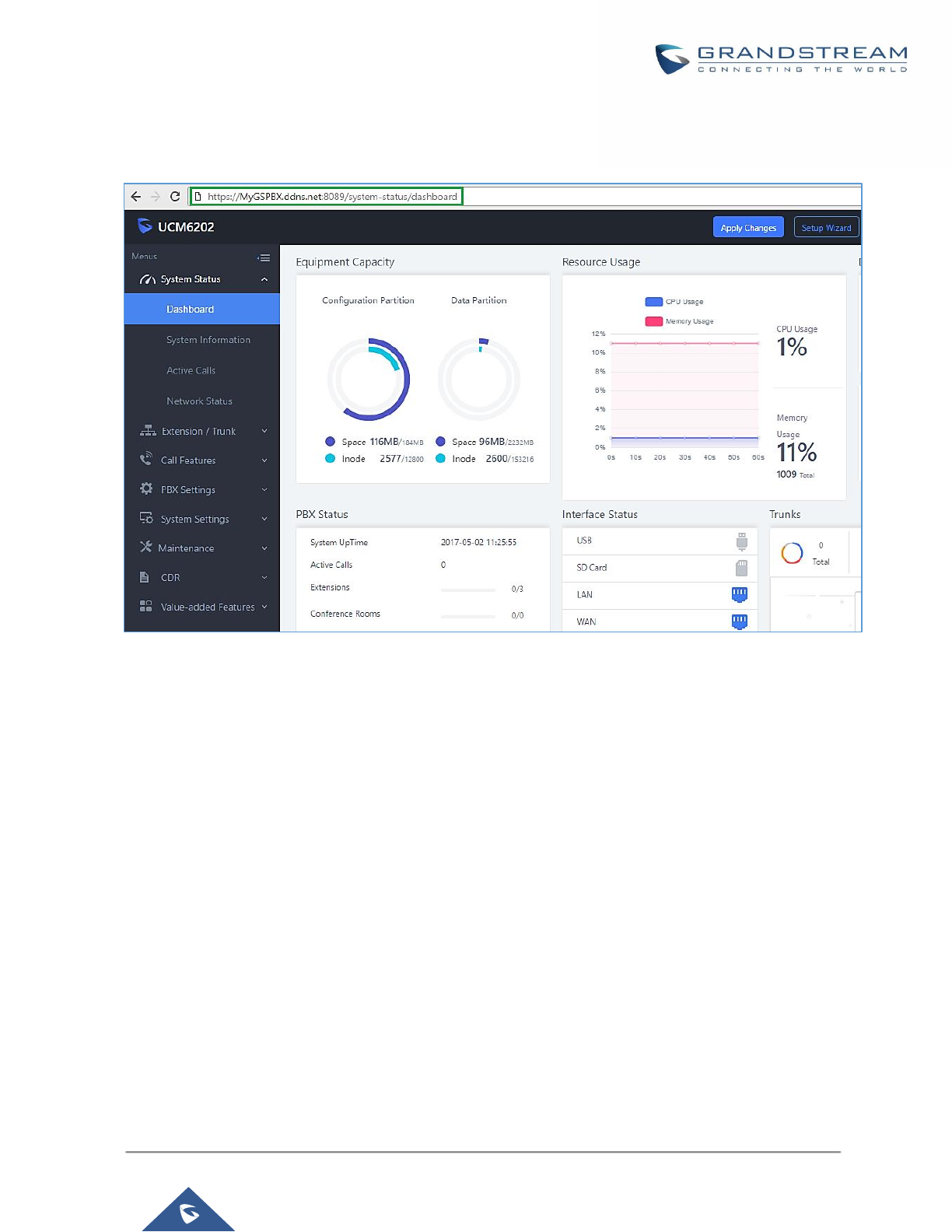
P a g e | 67
UCM6200 Series User Manual
Version 1.0.19.21
3. Now you can use domain name instead of IP address to connect to the UCM6200 Web GUI.
Figure 28: Using Domain Name to Connect to UCM6200
Security Settings
The UCM6200 provides users firewall security configurations to prevent certain malicious attack to the UCM6200
system. Users could configure to allow, restrict or reject specific traffic through the device for security and
bandwidth purpose. The UCM6200 also provides Fail2ban feature for authentication errors in SIP REGISTER,
INVITE and SUBSCRIBE. To configure firewall settings in the UCM6200, go to Web GUI→System
Settings→Security Settings page.
Static Defense
Under Web GUI→System Settings→Security Settings→Static Defense page, users will see the following
information:
• Current service information with port, process and type.
• Typical firewall settings.
• Custom firewall settings.

P a g e | 68
UCM6200 Series User Manual
Version 1.0.19.21
The following table shows a sample current service status running on the UCM6200.
Table 12: UCM6200 Firewall→Static Defense→Current Service
Port
Process
Type
Protocol or Service
7777
Asterisk
TCP/IPv4
SIP
389
Slapd
TCP/IPv4
LDAP
2000
Asterisk
TCP/IPv4
SCCP
22
Dropbear
TCP/IPv4
SSH
80
Lighthttpd
TCP/IPv4
HTTP
8089
Lighthttpd
TCP/IPv4
HTTPS
69
Opentftpd
UDP/IPv4
TFTP
9090
Asterisk
UDP/IPv4
SIP
6060
zero_config
UDP/IPv4
UCM6200 zero_config service
5060
Asterisk
UDP/IPv4
SIP
4569
Asterisk
UDP/IPv4
SIP
5353
zero_config
UDP/IPv4
UCM6200 zero_config service
37435
Syslogd
UDP/IPv4
Syslog
For typical firewall settings, users could configure the following options on the UCM6200.
Table 13: Typical Firewall Settings
Ping Defense
Enable
If enabled, ICMP response will not be allowed for Ping request. The default
setting is disabled. To enable or disable it, click on the check box for the LAN or
WAN (UCM6200) interface.
SYN-Flood
Defense Enable
Allows the UCM6200 to handle excessive amounts of SYN packets from one
source and keep the web portal accessible. There are two options available and
only one of these options may be enabled at one time.
• eth(0)LAN defends against attacks directed to the LAN IP address of the
UCM6200.
• eth(1)WAN defends against attacks directed to the WAN IP address of the
UCM6200.
SYN Flood Defense will limit the amount of SYN packets accepted by the UCM
from one source to 10 packets per second. Any excess packets from that source
will be discarded.
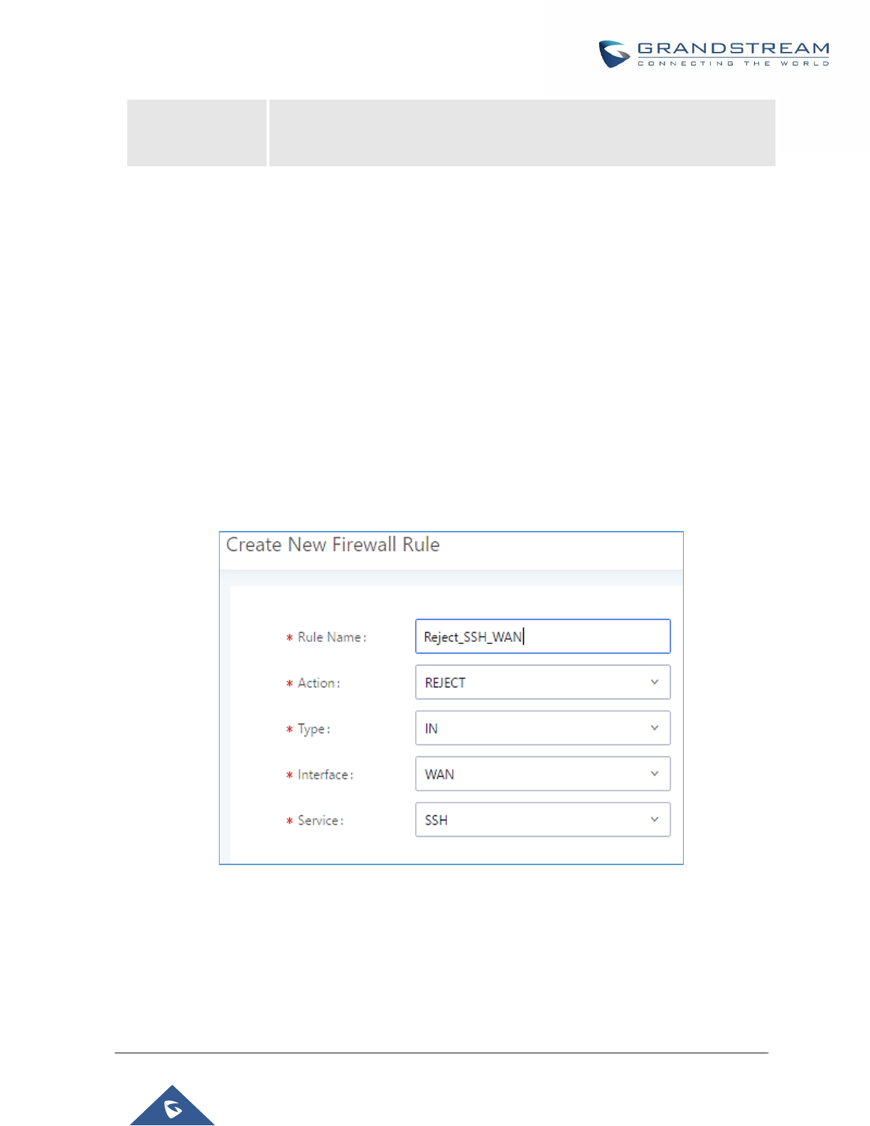
P a g e | 69
UCM6200 Series User Manual
Version 1.0.19.21
Ping-of-Death
Defense Enable
Enable to prevent Ping-of-Death attack to the device. The default setting is
disabled. To enable or disable it, click on the check box for the LAN or WAN
(UCM6200) interface.
Under "Custom Firewall Settings", users could create new rules to accept, reject or drop certain traffic going
through the UCM6200. To create new rule, click on "Create New Rule" button and a new window will pop up for
users to specify rule options.
Right next to "Create New Rule" button, there is a checkbox for option "Reject Rules". If it’s checked, all the rules
will be rejected except the firewall rules listed below. In the firewall rules, only when there is a rule that meets all
the following requirements, the option "Reject Rules" will be allowed to check:
• Action: "Accept"
• Type "In"
• Destination port is set to the system login port (e.g., by default 8089)
• Protocol is not UDP
Figure 29: Create New Firewall Rule

P a g e | 70
UCM6200 Series User Manual
Version 1.0.19.21
Table 14: Firewall Rule Settings
Rule Name
Specify the Firewall rule name to identify the firewall rule.
Action
Select the action for the Firewall to perform.
• ACCEPT
• REJECT
• DROP
Type
Select the traffic type.
• IN
If selected, users will need specify the network interface "LAN" or "WAN"
(for UCM6200) for the incoming traffic.
• OUT
Service
Select the service type.
• FTP
• SSH
• Telnet
• TFTP
• HTTP
• LDAP
• Custom
If "Custom" is selected, users will need specify Source (IP and port),
Destination (IP and port) and Protocol (TCP, UDP or Both) for the service.
Please note if the source or the destination field is left blank, it will be used
as "Anywhere".
Save the change and click on "Apply" button. Then submit the configuration by clicking on "Apply Changes" on
the upper right of the web page. The new rule will be listed at the bottom of the page with sequence number,
rule name, action, protocol, type, source, destination and operation. More operations below:
• Click on to edit the rule.
• Click on to delete the rule.
Dynamic Defense
Dynamic defense is supported on the UCM6200 series. It can blacklist hosts dynamically when the LAN mode
is set to "Route" under Web GUI→System Settings→Network Settings→Basic Settings page. If enabled, the
traffic coming into the UCM6200 can be monitored, which helps prevent massive connection attempts or brute
force attacks to the device. The blacklist can be created and updated by the UCM6200 firewall, which will then
be displayed in the web page. Please refer to the following table for dynamic defense options on the UCM6200.
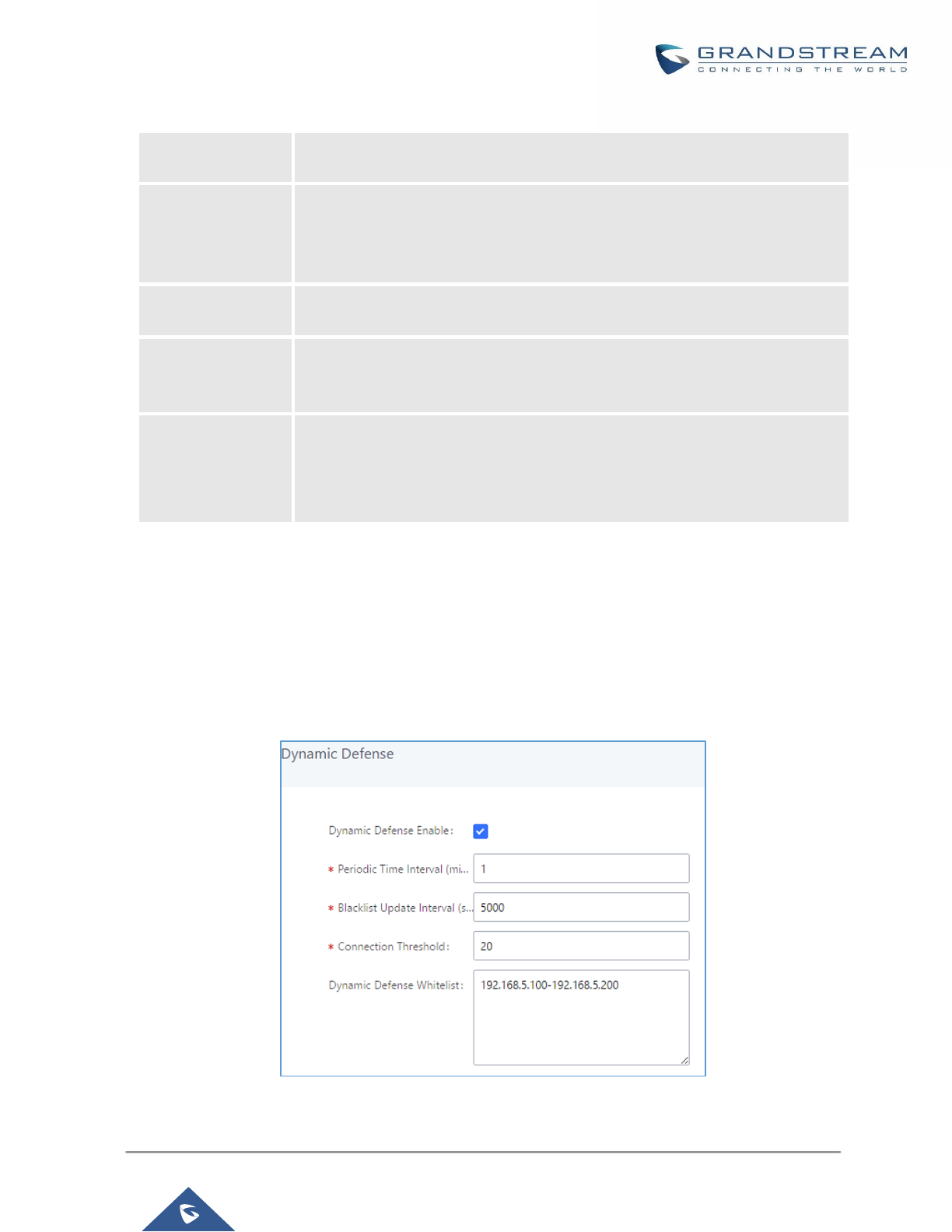
P a g e | 71
UCM6200 Series User Manual
Version 1.0.19.21
Table 15: UCM6200 Firewall Dynamic Defense
Dynamic Defense
Enable
Enable dynamic defense. The default setting is disabled.
Periodical Time
Interval
Configure the dynamic defense periodic time interval (in minutes). If the number
of TCP connections from a host exceeds the connection threshold within this
period, this host will be added into Blacklist. The valid value is between 1 and
59 when dynamic defense is turned on. The default setting is 59.
Blacklist Update
Interval
Configure the blacklist update time interval (in seconds). The default setting is
120.
Connection
Threshold
Configure the connection threshold. Once the number of connections from the
same host reaches the threshold, it will be added into the blacklist. The default
setting is 100.
Dynamic Defense
Whitelist
Allowed IPs and ports range, multiple IP addresses and port range.
For example:
192.168.5.100-
192.168.5.200 1500:2000
The following figure shows a configuration example like this:
• If a host at IP address 192.168.5.7 initiates more than 20 TCP connections to the UCM6200 within 1 minute,
it will be added into UCM6200 blacklist.
• This host 192.168.5.7 will be blocked by the UCM6200 for 500 seconds.
• Since IP range 192.168.5.100-192.168.5.200 is in whitelist, if a host initiates more than 20 TCP connections
to the UCM6200 within 1 minute, it will not be added into UCM6200 blacklist. It can still establish TCP
connection with the UCM6200.
Figure 30: Configure Dynamic Defense
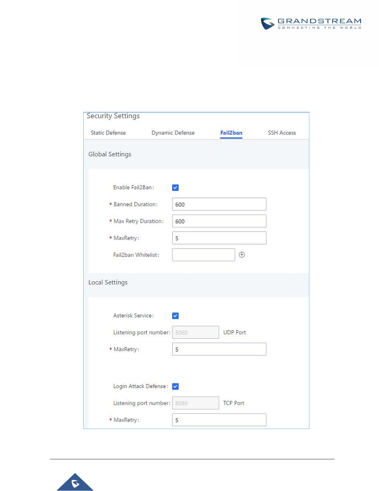
P a g e | 72
UCM6200 Series User Manual
Version 1.0.19.21
Fail2ban
Fail2Ban feature on the UCM6200 provides intrusion detection and prevention for authentication errors in SIP
REGISTER, INVITE and SUBSCRIBE. Once the entry is detected within "Max Retry Duration", the UCM6200
will act to forbid the host for certain period as defined in "Banned Duration". This feature helps prevent SIP brute
force attacks to the PBX system.
Figure 31: Fail2ban Settings

P a g e | 73
UCM6200 Series User Manual
Version 1.0.19.21
Table 16: Fail2Ban Settings
Global Settings
Enable Fail2Ban
Enable Fail2Ban. The default setting is disabled. Please make sure both "Enable
Fail2Ban" and "Asterisk Service" are turned on to use Fail2Ban for SIP
authentication on the UCM6200.
Banned Duration
Configure the duration (in seconds) for the detected host to be banned. The default
setting is 600. If set to 0, the host will be always banned.
Max Retry Duration
Within this duration (in seconds), if a host exceeds the max times of retry as
defined in "MaxRetry", the host will be banned. The default setting is 600.
MaxRetry
Configure the number of authentication failures during "Max Retry Duration" before
the host is banned. The default setting is 5.
Fail2Ban Whitelist
Configure IP address, CIDR mask or DNS host in the whitelist. Fail2Ban will not
ban the host with matching address in this list. Up to 20 addresses can be added
into the list.
Local Settings
Asterisk Service
Enable Asterisk service for Fail2Ban. The default setting is disabled. Please make
sure both "Enable Fail2Ban" and "Asterisk Service" are turned on to use Fail2Ban
for SIP authentication on the UCM6200.
Listening Port
Number
Configure the listening port number for the service. By default, port 5060 will be
used for UDP and TCP, and port 5061 will be used for TLS.
MaxRetry
Configure the number of authentication failures during "Max Retry Duration" before
the host is banned. The default setting is 10. Please make sure this option is
properly configured as it will override the "MaxRetry" value under "Global Settings".
Login Attack Defense
Enables defense against excessive login attacks to the UCM’s web GUI.
The default setting is disabled.
Listening Port
Number
This is the Web GUI listening port number which is configured under System
Settings→HTTP Server→Port. The default is 8089.
MaxRetry
When the number of failed login attempts from an IP address exceeds the
MaxRetry number, that IP address will be banned from accessing the Web GUI.
Blacklist
Black List
Users will be able to view the IPs that have been blocked by UCM.
SSH Access
SSH switch now is available via Web GUI and LCD. User can enable or disable SSH access directly from Web
GUI or LCD screen. For web SSH access, please log in UCM6200 web interface and go to Web GUI→System
Settings→Security Settings→SSH Access. By default, SSH access is disabled for security concerns. It is
highly recommended to only enable SSH access for debugging purpose.
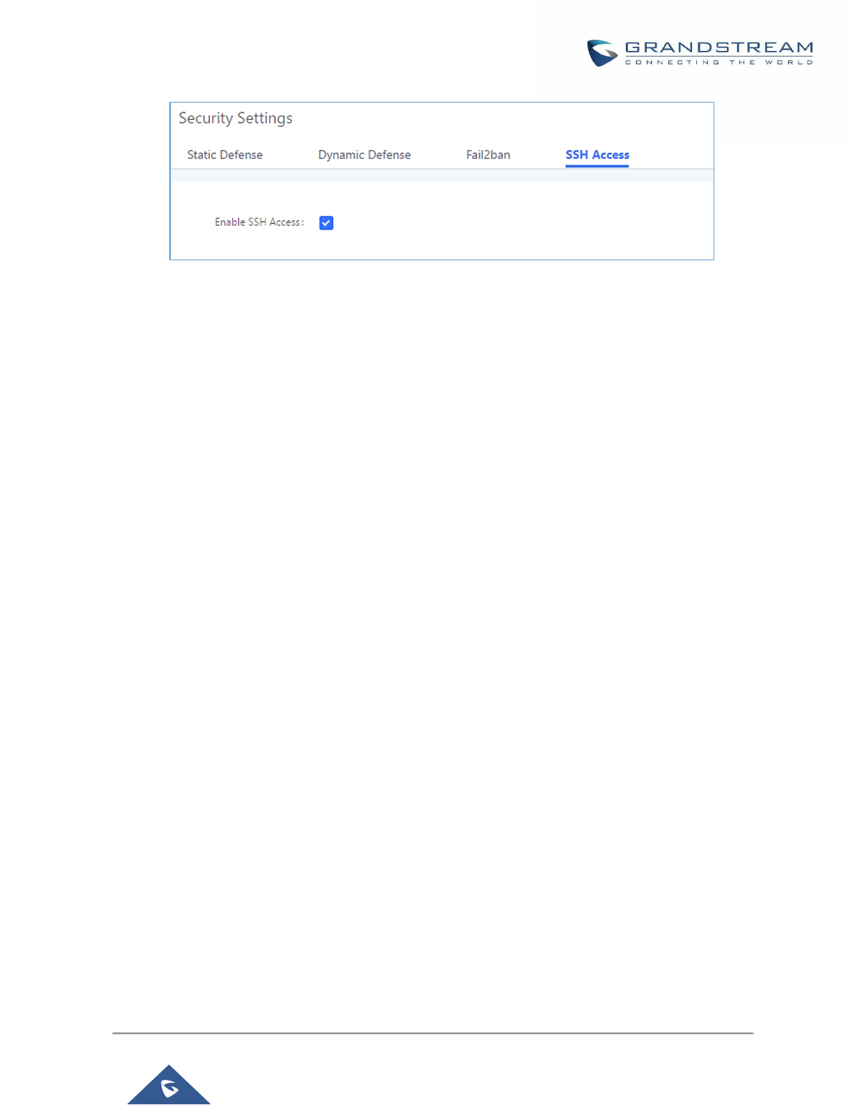
P a g e | 74
UCM6200 Series User Manual
Version 1.0.19.21
Figure 32: SSH Access
LDAP Server
The UCM6200 has an embedded LDAP/LDAPS server for users to manage corporate phonebook in a
centralized manner.
• By default, the LDAP server has generated the first phonebook with PBX DN "ou=pbx,dc=pbx,dc=com"
based on the UCM6200 user extensions already.
• Users could add new phonebook with a different Phonebook DN for other external contacts. For example,
"ou=people,dc=pbx,dc=com".
• All the phonebooks in the UCM6200 LDAP server have the same Base DN "dc=pbx,dc=com".
Term Explanation:
cn= Common Name
ou= Organization Unit
dc= Domain Component
These are all parts of the LDAP data Interchange Format, according to RFC 2849, which is how the LDAP tree
is filtered.
If users have the Grandstream phone provisioned by the UCM6200, the LDAP directory will be set up on the
phone and can be used right away for users to access all phonebooks.
Additionally, users could manually configure the LDAP client settings to manipulate the built-in LDAP server on
the UCM6200. If the UCM6200 has multiple LDAP phonebooks created, in the LDAP client configuration, users
could use "dc=pbx,dc=com" as Base DN to have access to all phonebooks on the UCM6200 LDAP server, or
use a specific phonebook DN, for example "ou=people,dc=pbx,dc=com", to access to phonebook with
Phonebook DN "ou=people,dc=pbx,dc=com " only.
UCM can also act as a LDAP client to download phonebook entries from another LDAP server.
To access LDAP server and client settings, go to Web GUI→Settings→LDAP Server.
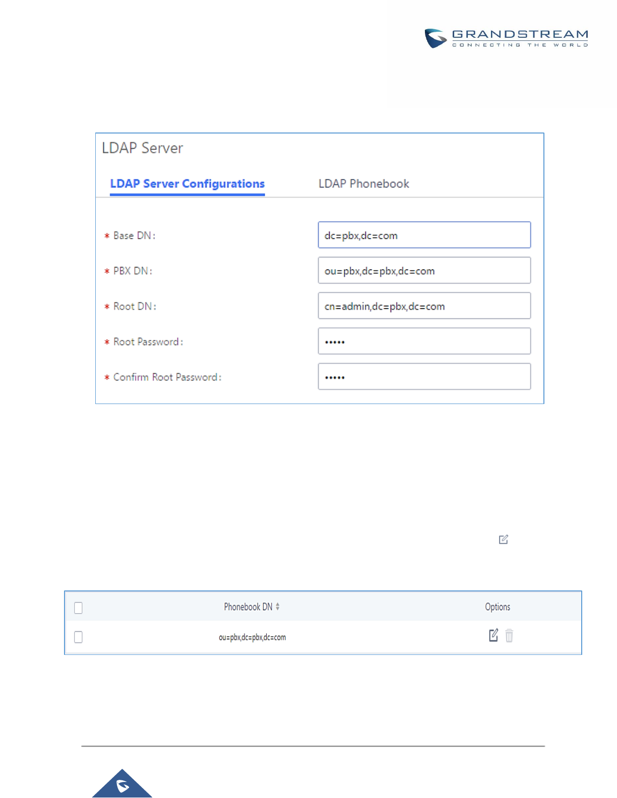
P a g e | 75
UCM6200 Series User Manual
Version 1.0.19.21
LDAP Server Configurations
The following figure shows the default LDAP server configurations on the UCM6200.
Figure 33: LDAP Server Configurations
The UCM6200 LDAP server supports anonymous access (read-only) by default. Therefore, the LDAP client
doesn't have to configure username and password to access the phonebook directory. The "Root DN" and "Root
Password" here are for LDAP management and configuration where users will need provide for authentication
purpose before modifying the LDAP information.
The default phonebook list in this LDAP server can be viewed and edited by clicking on for the first
phonebook under LDAP Phonebook.
Figure 34: Default LDAP Phonebook DN

P a g e | 76
UCM6200 Series User Manual
Version 1.0.19.21
Figure 35: Default LDAP Phonebook Attributes
LDAP Phonebook
Users could use the default phonebook, edit the default phonebook, add new phonebook, import phonebook on
the LDAP server as well as export phonebook from the LDAP server. The first phonebook with default phonebook
dn "ou=pbx,dc=pbx,dc=com" displayed on the LDAP server page is for extensions in this PBX. Users cannot
add or delete contacts directly. The contacts information will need to be modified via Web
GUI→Extension/Trunk→Extensions first. The default LDAP phonebook will then be updated automatically.
Figure 36: LDAP Server→LDAP Phonebook
• Add new phonebook
A new sibling phonebook of the default PBX phonebook can be added by clicking on "Add" under "LDAP
Phonebook" section.
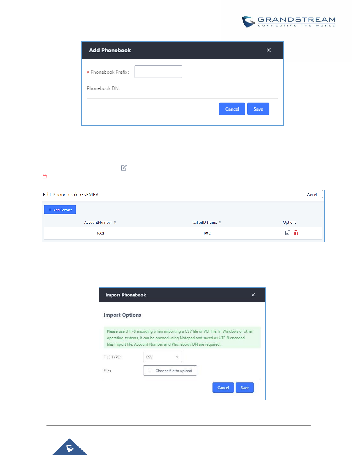
P a g e | 77
UCM6200 Series User Manual
Version 1.0.19.21
Figure 37: Add LDAP Phonebook
Configure the "Phonebook Prefix" first. The "Phonebook DN" will be automatically filled in. For example, if
configuring "Phonebook Prefix" as "people", the "Phonebook DN" will be filled with "ou=people,dc=pbx,dc=com".
Once added, users can select to edit the phonebook attributes and contact list (see figure below), or select
to delete the phonebook.
Figure 38: Edit LDAP Phonebook
• Import phonebook from your computer to LDAP server
Click on “Import Phonebook” and a dialog will prompt as shown in the figure below.
Figure 39: Import Phonebook
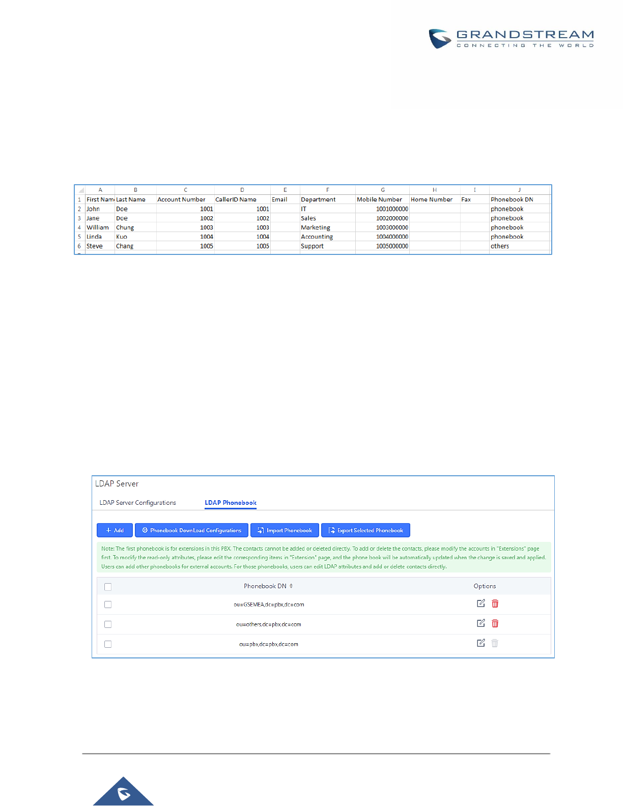
P a g e | 78
UCM6200 Series User Manual
Version 1.0.19.21
The file to be imported must be a CSV, VCF or XML file with UTF-8 encoding. Users can open the file with
Notepad and save it with UTF-8 encoding.
Here is how a sample file looks like. Please note “Account Number” and “Phonebook DN” fields are required.
Users could export a phonebook file from the UCM6200 LDAP phonebook section first and use it as a sample
to start with.
Figure 40: Phonebook CSV File Format
The Phonebook DN field is the same “Phonebook Prefix” entry as when the user clicks on “Add” to create a new
phonebook. Therefore, if the user enters “phonebook” in “Phonebook DN” field in the CSV file, the actual
phonebook DN “ou=phonebook,dc=pbx,dc=com” will be automatically created by the UCM6200 once the CSV
file is imported.
In the CSV file, users can specify different phonebook DN fields for different contacts. If the phonebook DN
already exists on the UCM6200 LDAP Phonebook, the contacts in the CSV file will be added into the existing
phonebook. If the phonebook DN doesn’t exist on the UCM6200 LDAP Phonebook, a new phonebook with this
phonebook DN will be created.
The sample phonebook CSV file in above picture will result in the following LDAP phonebook in the UCM6200.
Figure 41: LDAP Phonebook After Import
As the default LDAP phonebook with DN “ou=pbx,dc=pbx,dc=com” cannot be edited or deleted in LDAP
phonebook section, users cannot import contacts with Phonebook DN field “pbx” if existed in the CSV file.
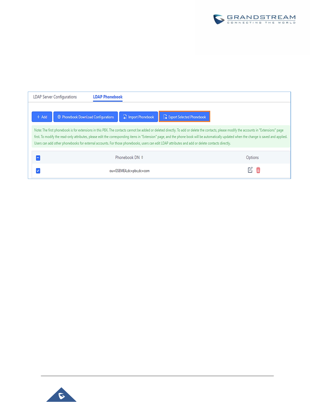
P a g e | 79
UCM6200 Series User Manual
Version 1.0.19.21
• Export phonebook to your computer from UCM6200 LDAP server
Select the checkbox for the LDAP phonebook and then click on “Export Selected Phonebook” to export the
selected phonebook. The exported phonebook can be used as a record or a sample CSV, VFC or XML file for
the users to add more contacts in it and import to the UCM6200 again.
Figure 42: Export Selected LDAP Phonebook
LDAP Client Configurations
The configuration on LDAP client is useful when you use other LDAP servers. Here we provide an example on
how to configure the LDAP client on the UCM.
Assuming the remote server base dn is “dc=pbx,dc=com”, configure the LDAP client as follows:
• LDAP Server : Enter a name for the remote LDAP server
• Server Address : Enter the IP address or domain name for remote LDAP server.
• Base DN: dc=pbx,dc=com
• Username: Enter username if authentication is required
• Password: Enter password if authentication is required
• Filter: Enter the filter. Ex: (|(CallerIDName=%)(AccountNumber=%))
• Port: Enter the port number. Ex:389
• LDAP Name Attributes: Enter the name attributes for remote server
• LDAP Number Attributes: Enter the number attributes for remote server
The following figure gives a sample configuration for UCM acting as a LDAP client.
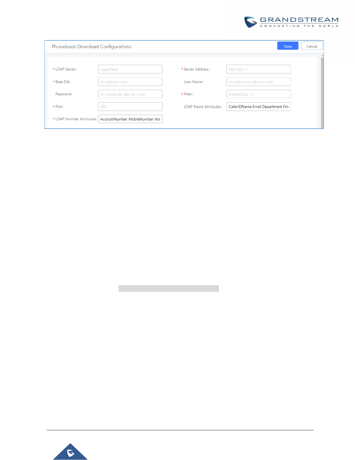
P a g e | 80
UCM6200 Series User Manual
Version 1.0.19.21
Figure 43: LDAP Client Configurations
To configure Grandstream IP phones as the LDAP clients for UCM, please refer to the following example:
• Server Address: The IP address or domain name of the UCM
• Base DN: dc=pbx,dc=com
• User Name: Please leave this field empty
• Password: Please leave this field empty
• LDAP Name Attribute: CallerIDName Email Department FirstName LastName
• LDAP Number Attribute: AccountNumber MobileNumber HomeNumber Fax
• LDAP Number Filter: (AccountNumber=%)
• LDAP Name Filter: (CallerIDName=%)
• LDAP Display Name: AccountNumber CallerIDName
• LDAP Version: If existed, please select LDAP Version 3
• Port: 389
The following figure shows the configuration information on a Grandstream GXP2170 to successfully use the
LDAP server as configured in [Figure 33: LDAP Server Configurations].
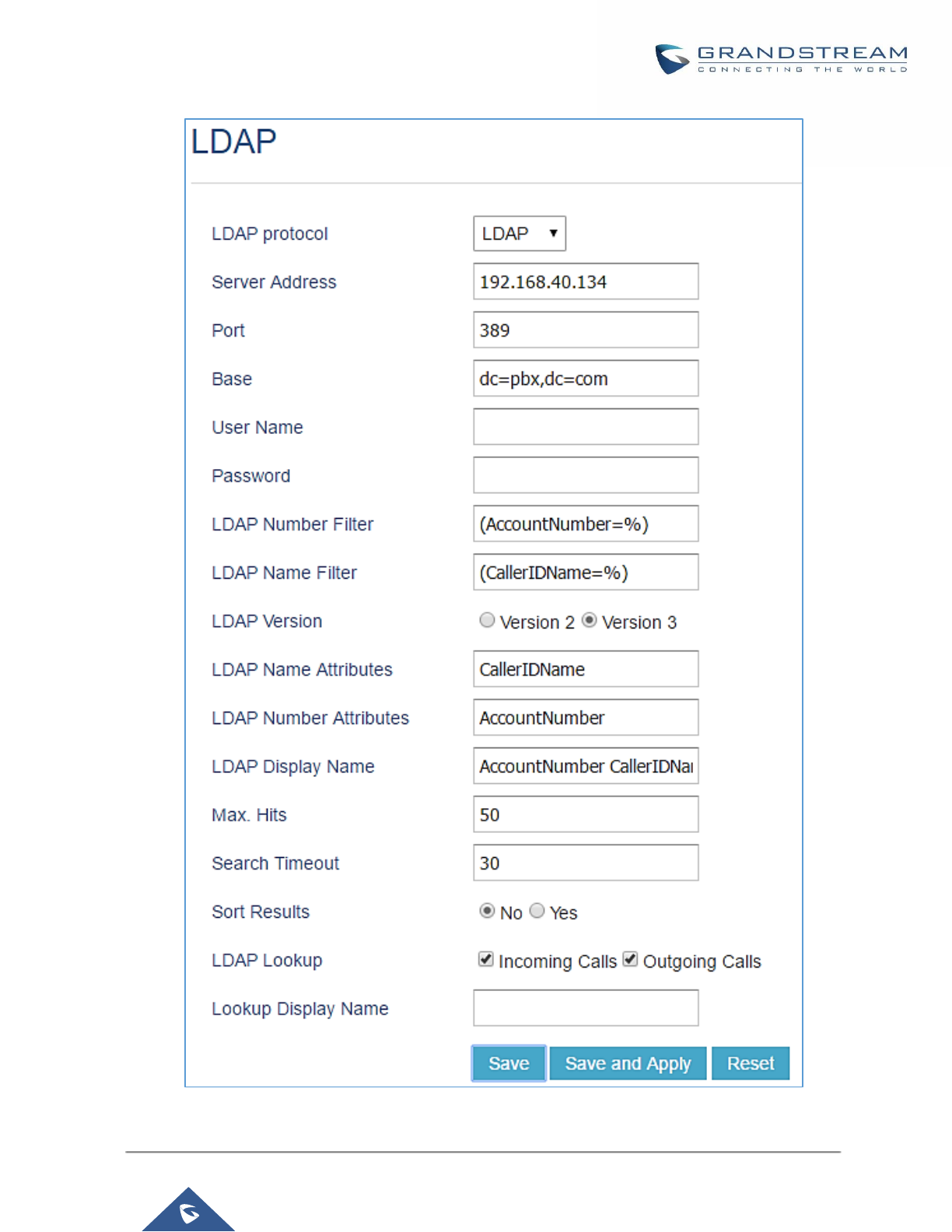
P a g e | 81
UCM6200 Series User Manual
Version 1.0.19.21
Figure 44: GXP2170 LDAP Phonebook Configuration

P a g e | 82
UCM6200 Series User Manual
Version 1.0.19.21
Time settings
Auto time updating
The current system time on the UCM6200 can be found under Web GUI→System Status→Dashboard→PBX
Status.
To configure the UCM6200 to update time automatically, go to Web GUI→System Settings→Time
Settings→Auto Time Updating.
----------------------------------------------------------------------------------------------------------------------------- ----------------------
Note:
The configurations under Web GUI→Settings→Time Settings→Auto Time Updating page require reboot to
take effect. Please consider configuring auto time updating related changes when setting up the UCM6200 for
the first time to avoid service interrupt after installation and deployment in production.
--------------------------------------------------------------------------------------------------------------------------------------------------
Table 17: Time Auto Updating
Remote NTP Server
Specify the URL or IP address of the NTP server for the UCM6200 to
synchronize the date and time. The default NTP server is
ntp.ipvideotalk.com.
Enable DHCP Option 2
If set to "Yes", the UCM6200 can get provisioned for Time Zone from
DHCP Option 2 in the local server automatically. The default setting is
"Yes".
Enable DHCP Option 42
If set to "Yes", the UCM6200 can get provisioned for NTP Server from
DHCP Option 42 in the local server automatically. This will override the
manually configured NTP Server. The default setting is "Yes".
Time Zone
Select the proper time zone option so the UCM6200 can display correct
time accordingly.
If "Self-Defined Tome Zone" is selected, please specify the time zone
parameters in "Self-Defined Time Zone" field as described in below option.
Self-Defined Time Zone
If "Self-Defined Time Zone" is selected in "Time Zone" option, users will
need define their own time zone following the format below.
The syntax is: std offset dst [offset], start [/time], end [/time]
Default is set to: MTZ+6MDT+5,M4.1.0,M11.1.0
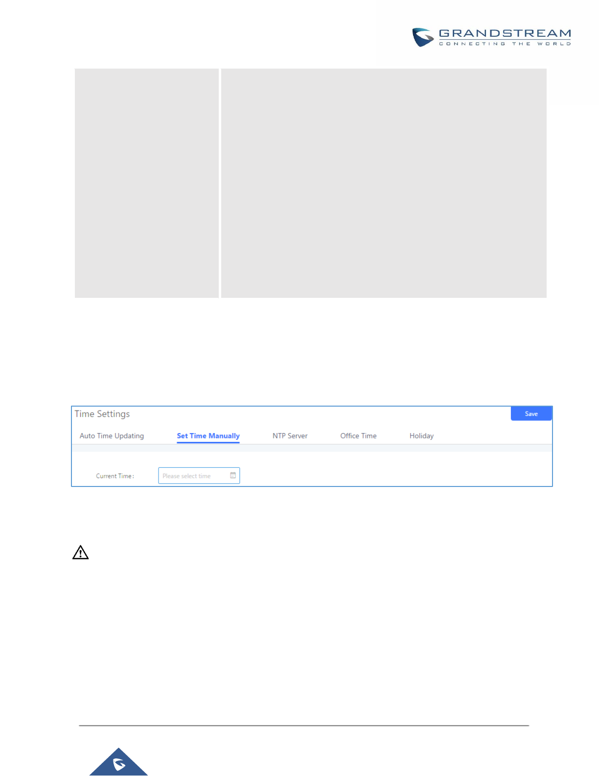
P a g e | 83
UCM6200 Series User Manual
Version 1.0.19.21
MTZ+6MDT+5
This indicates a time zone with 6 hours offset and 1 hour ahead for DST,
which is U.S central time. If it is positive (+), the local time zone is west of
the Prime Meridian (A.K.A: International or Greenwich Meridian); If it is
negative (-), the local time zone is east.
M4.1.0,M11.1.0
The 1st number indicates Month: 1,2,3.., 12 (for Jan, Feb, .., Dec).
The 2nd number indicates the nth iteration of the weekday: (1st Sunday,
3rd Tuesday…). Normally 1, 2, 3, 4 are used. If 5 is used, it means the last
iteration of the weekday.
The 3rd number indicates weekday: 0,1,2,..,6 ( for Sun, Mon, Tues, ...
,Sat).
Therefore, this example is the DST which starts from the First Sunday of
April to the 1st Sunday of November.
Set Time Manually
To manually set the time on the UCM6200, go to Web GUI→System Settings→Time Settings→Set Time
Manually. The format is YYYY-MM-DD HH:MM:SS.
Figure 45: Set Time Manually
----------------------------------------------------------------------------------------------------------------------------- ----------------------
Note:
Manually setup time will take effect immediately after saving and applying change in the Web GUI. If users would
like to reboot the UCM6200 and keep the manually setup time setting, please make sure "Remote NTP Server",
"Enable DHCP Option 2" and "Enable DHCP Option 42" options under Web GUI→Settings→Time
Settings→Auto Time Updating page are unchecked or set to empty. Otherwise, time auto updating settings in
this page will take effect after reboot.
--------------------------------------------------------------------------------------------------------------------------------------------------
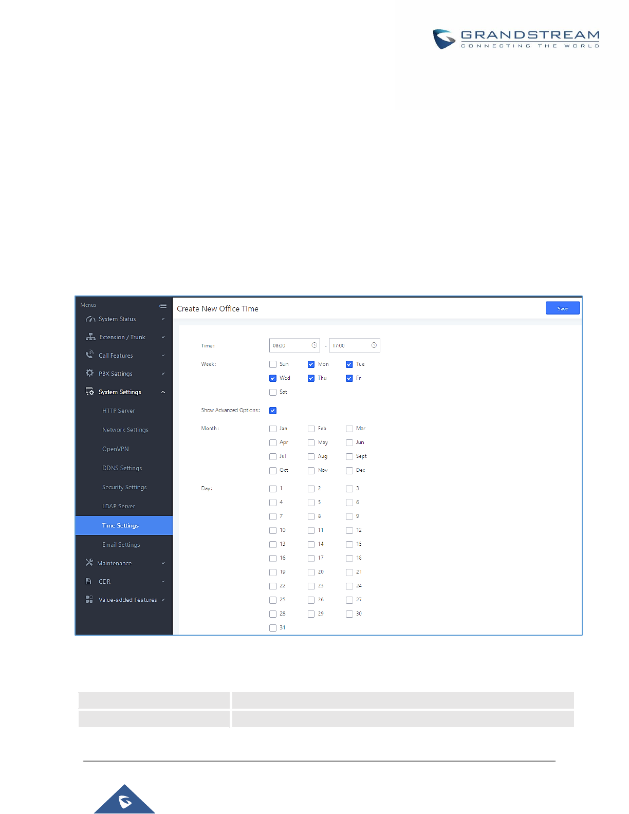
P a g e | 84
UCM6200 Series User Manual
Version 1.0.19.21
NTP Server
The UCM6200 can be used as a NTP server for the NTP clients to synchronize their time with. To configure the
UCM6200 as the NTP server, set "Enable NTP server" to "Yes" under Web GUI→System Settings→Time
Settings→NTP Server. On the client side, point the NTP server address to the UCM6200 IP address or host
name to use the UCM6200 as the NTP server.
Office Time
On the UCM6200, the system administrator can define "office time", which can be used to configure time
condition for extension call forwarding schedule and inbound rule schedule. To configure office time, go to Web
GUI→System Settings→Time Settings→Office Time. Click on "Create New Office Time" to create an office
time.
Figure 46: Create New Office Time
Table 18: Create New Office Time
Start Time
Configure the start time for office hour.
End Time
Configure the end time for office hour
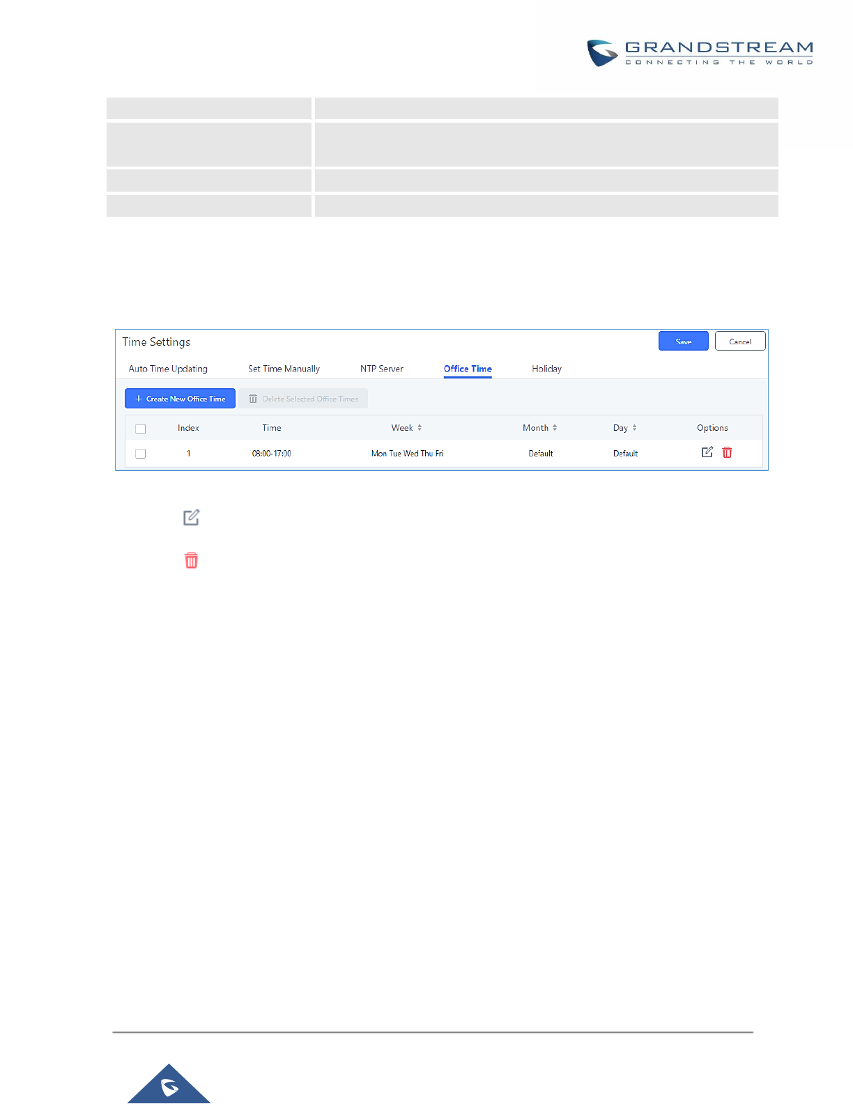
P a g e | 85
UCM6200 Series User Manual
Version 1.0.19.21
Week
Select the work days in one week.
Show Advanced Options
Check this option to show advanced options. Once selected, please
specify "Month" and "Day" below.
Month
Select the months for office time.
Day
Select the work days in one month.
Select "Start Time", "End Time" and the day for the "Week" for the office time. The system administrator can also
define month and day of the month as advanced options. Once done, click on "Save" and then "Apply Change"
for the office time to take effect. The office time will be listed in the web page as the figure shows below.
Figure 47: Settings→Time Settings→Office Time
• Click on to edit the office time.
• Click on to delete the office time.
• Click on "Delete Selected Office Times" to delete multiple selected office times at once.
Holiday
On the UCM6200, the system administrator can define "holiday", which can be used to configure time condition
for extension call forwarding schedule and inbound rule schedule. To configure holiday, go to Web GUI→System
Settings→Time Settings→Holiday. Click on "Create New Holiday" to create holiday time.
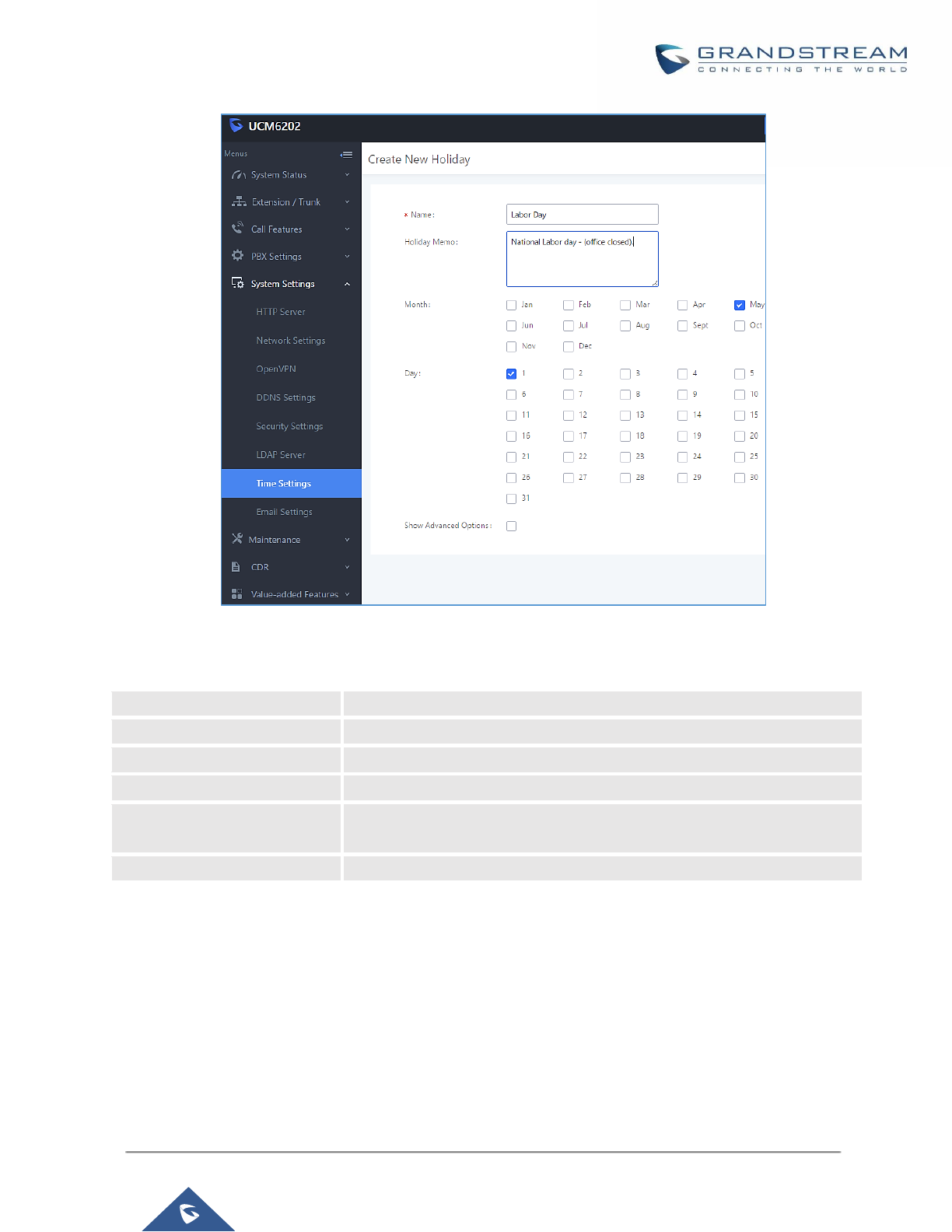
P a g e | 86
UCM6200 Series User Manual
Version 1.0.19.21
Figure 48: Create New Holiday
Table 19: Create New Holiday
Name
Specify the holiday name to identify this holiday.
Holiday Memo
Create a note for the holiday.
Month
Select the month for the holiday.
Day
Select the day for the holiday.
Show Advanced Options
Check this option to show advanced options. If selected, please specify
the days as holiday in one week below.
Week
Select the days as holiday in one week.
Enter holiday "Name" and "Holiday Memo" for the new holiday. Then select "Month" and "Day". The system
administrator can also define days in one week as advanced options. Once done, click on "Save" and then
"Apply Change" for the holiday to take effect. The holiday will be listed in the web page as the figure shows
below.
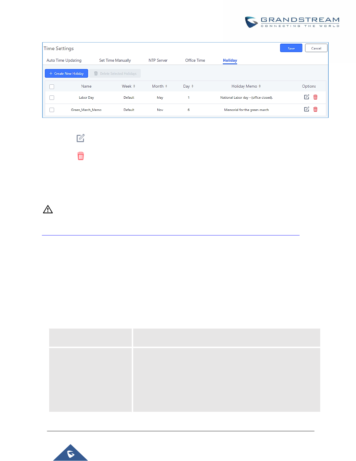
P a g e | 87
UCM6200 Series User Manual
Version 1.0.19.21
Figure 49: Settings→Time Settings→Holiday
• Click on to edit the holiday.
• Click on to delete the holiday.
• Click on "Delete Selected Holidays" to delete multiple selected holidays at once.
----------------------------------------------------------------------------------------------------------------------------- ---------------
Note:
For more details on how to use office time and holiday, please refer to the link below:
http://www.grandstream.com/sites/default/files/Resources/office_time_and_holiday_on_ucm6xxx.pdf
----------------------------------------------------------------------------------------------------------------------------- ---------------
Email Settings
Email settings
The Email application on the UCM6200 can be used to send out alert event Emails, Fax (Fax-To-Email),
Voicemail (Voicemail-To-Email) etc. The configuration parameters can be accessed via Web GUI→System
Settings→Email Settings→Email Settings.
Table 20: Email Settings
TLS Enable
Enable or disable TLS during transferring/submitting your Email to
another SMTP server. The default setting is "Yes".
Type
Select Email type.
• MTA: Mail Transfer Agent. The Email will be sent from the
configured domain. When MTA is selected, there is no need to set
up SMTP server for it or no user login is required. However, the
Emails sent from MTA might be considered as spam by the target
SMTP server.
• Client: Submit Emails to the SMTP server. A SMTP server is

P a g e | 88
UCM6200 Series User Manual
Version 1.0.19.21
required and users need login with correct credentials.
Domain
Specify the domain name to be used in the Email when using type
"MTA".
Server
Specify the SMTP server when using type "Client".
Username
Username is required when using type "Client". Normally it's the Email
address.
Password
Password to login for the above Username (Email address) is required
when using type "Client".
Enable Email-to-Fax
Enable or Disable Email-to-Fax feature.
If enabled, the UCM will monitor the configured email inbox (using
provided [Username] and [Password]) for emails with the subject
"SendFaxMail To XXX". Example: SendFaxMail To 7200
The UCM will extract the attachments of detected emails and send it to
the XXX extension by fax. The attachment must be in PDF/TIF/TIFF
format.
Note: This field will appear when using Type “Client”.
Email-to-Fax
Blacklist/Whitelist
Enables the Email to fax Blacklist/Whitelist functionality.
Internal Blacklist/Whitelist
Specify the Email address blacklist/whitelist for local extensions. This
feature prevents faxing from unauthorized email addresses. The
internal list includes only contacts with local extensions.
External Blacklist/Whitelist
Specify the Email address blacklist/whitelist for non-local contacts. This
feature prevents faxing from unauthorized email addresses. The
external list is for non-local contacts.
Note: Multiple addresses can be separated with semicolon (;) i.e.
" XXX;YYY ".
POP/POP3 Server Address
Configure the POP/POP3 server address for the configured username
Example: pop.gmail.com
POP/POP3 Server Port
Configure the POP/POP3 server port for the configured username
Example: 995
Display Name
Specify the display name in the FROM header in the Email.
Sender
Specify the sender's Email address.
For example: pbx@example.mycompany.com.
The following figure shows a sample Email setting on the UCM6200, assuming the Email is using 192.168.6.202
as the SMTP server.
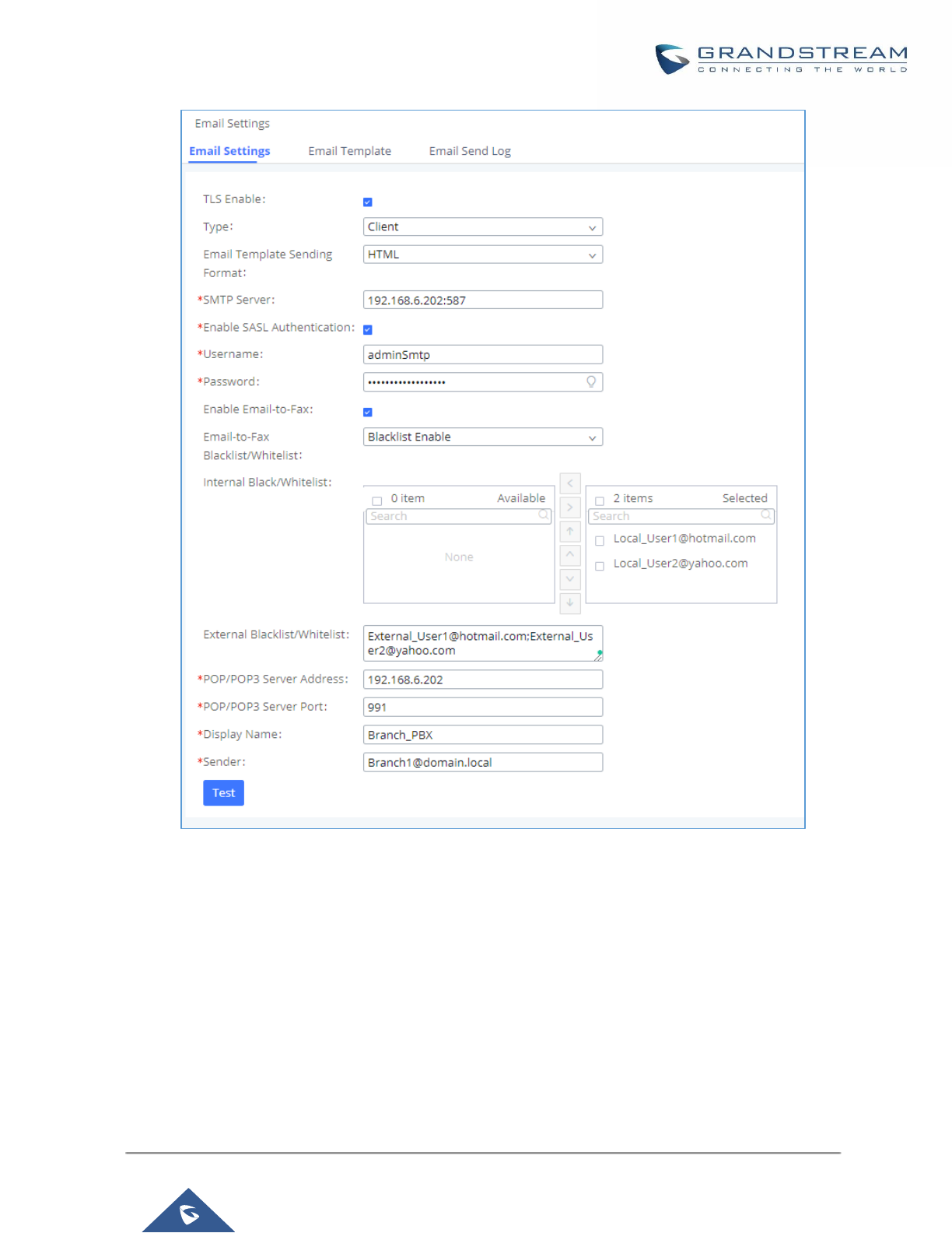
P a g e | 89
UCM6200 Series User Manual
Version 1.0.19.21
Figure 50: UCM6200 Email Settings
Once the configuration is finished, click on "Test". In the prompt, fill in a valid Email address to send a test Email
to verify the Email settings on the UCM6200.
Email Templates
The Email templates on the UCM6200 can be used for email notification the configuration parameters can be
accessed via Web GUI→Settings→Email Settings→Email Templates.
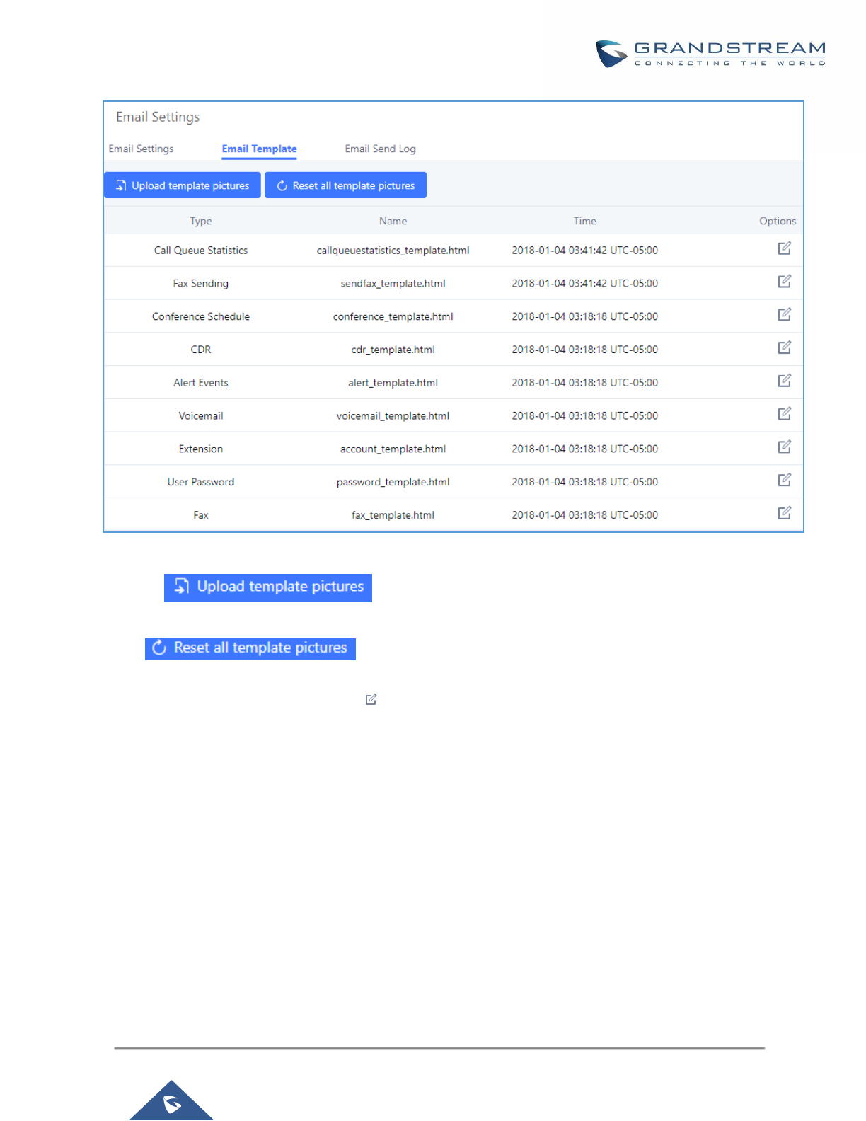
P a g e | 90
UCM6200 Series User Manual
Version 1.0.19.21
Figure 51: Email Templates
Press on to upload pictures to be used on email templates.
Press to reset all email templates to default ones.
To configure the email template, click the button under Options column, and edit the template as desired.
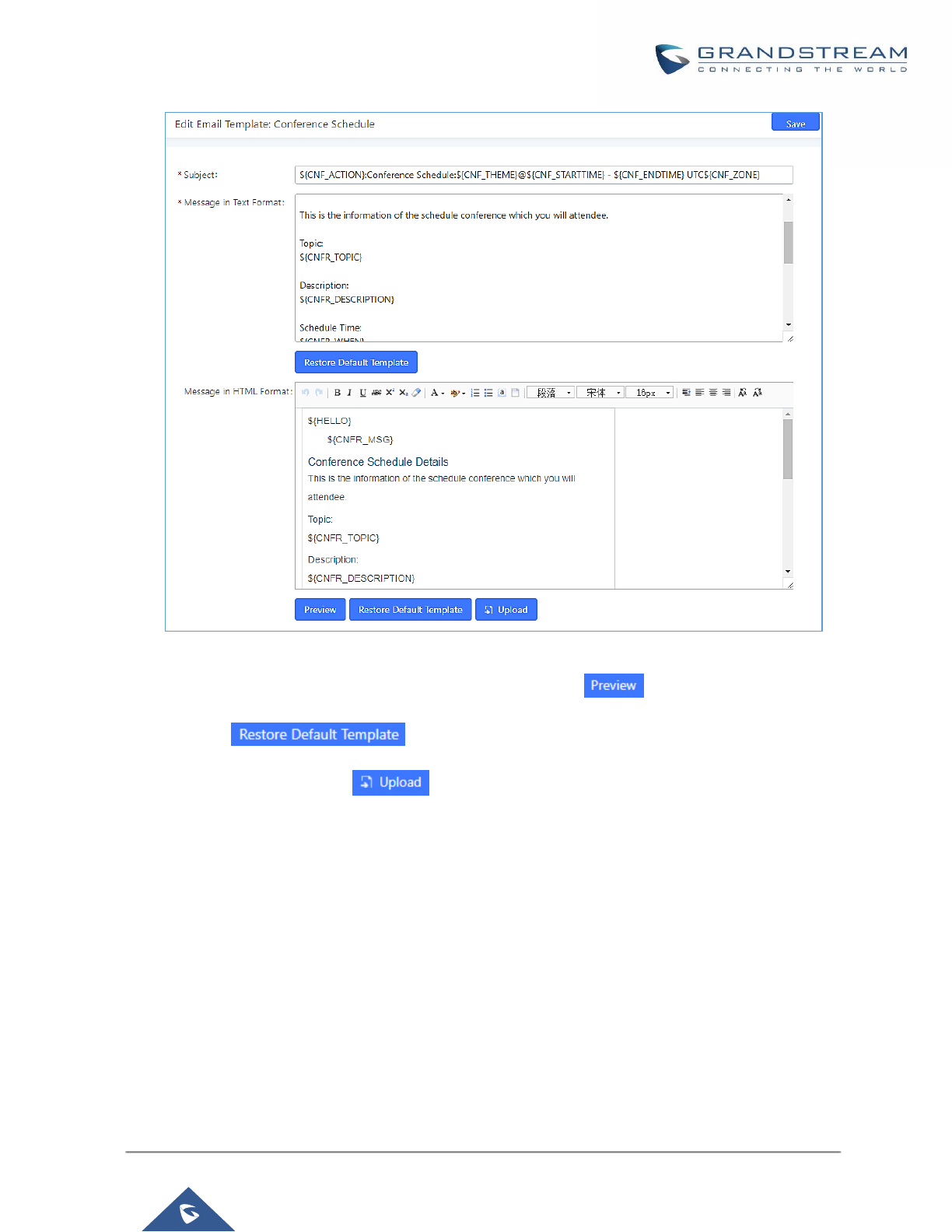
P a g e | 91
UCM6200 Series User Manual
Version 1.0.19.21
Figure 52: Conference Schedule Template
- Users have the ability to preview mail sample by clicking on .
- Click on in order to restore the default email template.
- Finally, users can click on to upload a custom picture to the email template to display their
own logo in the sent mails for example
Email Send Log
Under UCM Web GUI→System Settings→Email Settings→Email Send Log, users could search, filter and
check whether the Email is sent out successfully or not. This page will also display the corresponding error
message if the Email is not sent out successfully.

P a g e | 92
UCM6200 Series User Manual
Version 1.0.19.21
Figure 53: Email Send log
Table 21: Email Log
Field
Description
Start Time
Enter the start time for filter
End Time
Enter the end time for filter
Receivers
Enter the email recipient, while searching for multiple recipients, please
separate then with comma and no spaces.
Send Result
Enter the status of the send result to filter with
Return Code
Enter the email code to filter with
Email Send Module
Select the email module to filter with from the drop-down list, which
contains:
All Modules
Extension
Voicemail
Conference Schedule
User Password
Alert Events
CDR
Fax
Test
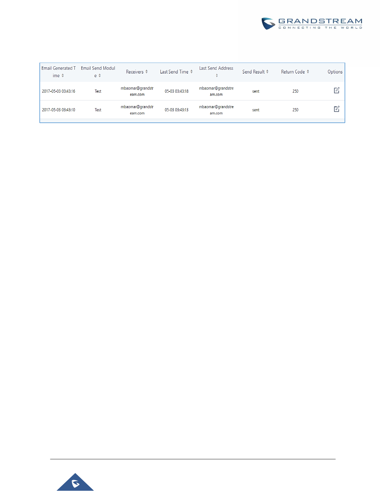
P a g e | 93
UCM6200 Series User Manual
Version 1.0.19.21
Email logs will be shown on bottom of the “Email Send Log” page, as shown on the following figure.
Figure 54: Email Logs

P a g e | 94
UCM6200 Series User Manual
Version 1.0.19.21
PROVISIONING
Overview
Grandstream SIP Devices can be configured via Web interface as well as via configuration file through
TFTP/HTTP/HTTPS download. All Grandstream SIP devices support a proprietary binary format configuration
file and XML format configuration file. The UCM6200 provides a Plug and Play mechanism to auto-provision the
Grandstream SIP devices in a zero-configuration manner by generating XML config file and having the phone to
download it within LAN area. This allows users to finish the installation with ease and start using the SIP devices
in a managed way.
To provision a phone, three steps are involved, i.e., discovery, configuration and provisioning. This section
explains how Zero Config works on the UCM6200. The settings for this feature can be accessed via Web
GUI→Value-added Features→Zero Config.
Configuration Architecture for End Point Device
Started from firmware version 1.0.7.10, the end point device configuration in zero config is divided into the
following three layers with priority from the lowest to the highest:
• Global
This is the lowest layer. Users can configure the most basic options that could apply to all Grandstream SIP
devices during provisioning via Zero config.
• Model
In this layer, users can define model-specific options for the configuration template.
• Device
This is the highest layer. Users can configure device-specific options for the configuration for individual
device here.
Each layer also has its own structure in different levels. Please see figure below. The details for each layer are
explained in sections [Global configuration], [Model configuration] and [Device Configuration].
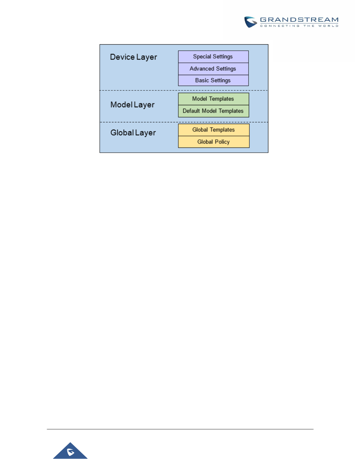
P a g e | 95
UCM6200 Series User Manual
Version 1.0.19.21
Figure 55: Zero Config Configuration Architecture for End Point Device
The configuration options in model layer and device layer have all the option in global layers already, i.e., the
options in global layer is a subset of the options in model layer and device layer. If an option is set in all three
layers with different values, the highest layer value will override the value in lower layer. For example, if the user
selects English for Language setting in Global Policy and Spanish for Language setting in Default Model
Template, the language setting on the device to be provisioned will use Spanish as model layer has higher
priority than global layer. To sum up, configurations in higher layer will always override the configurations
for the same options/fields in the lower layer when presented at the same time.
After understanding the zero-config configuration architecture, users could configure the available options for
end point devices to be provisioned by the UCM6200 by going through the three layers. This configuration
architecture allows users to set up and manage the Grandstream end point devices in the same LAN area in a
centralized way.
Auto Provisioning Settings
By default, the Zero Config feature is enabled on the UCM6200 for auto provisioning. Three methods of
auto provisioning are used.
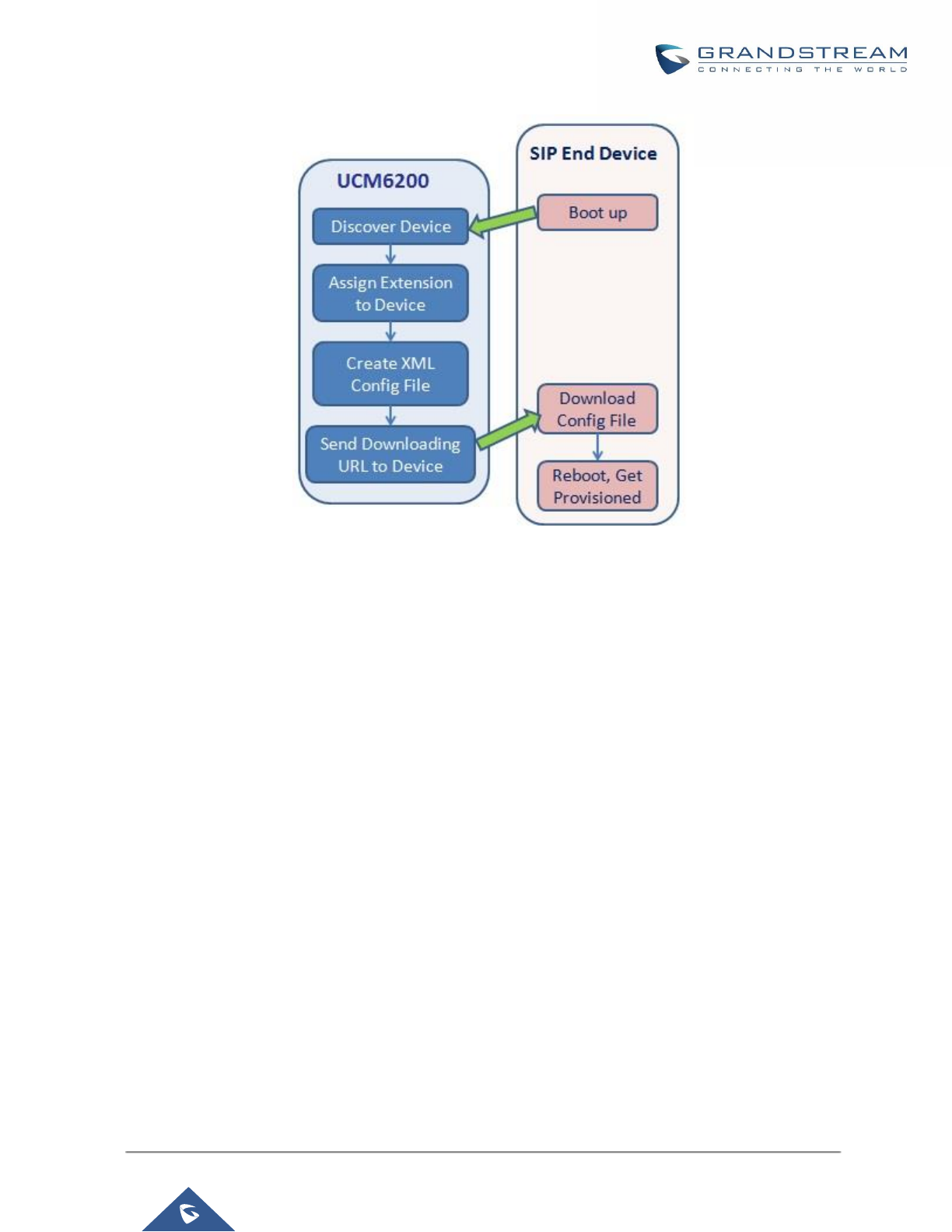
P a g e | 96
UCM6200 Series User Manual
Version 1.0.19.21
Figure 56: UCM6200 Zero Config
• SIP SUBSCRIBE
When the phone boots up, it sends out SUBSCRIBE to a multicast IP address in the LAN. The UCM6200
discovers it and then sends a NOTIFY with the XML config file URL in the message body. The phone will
then use the path to download the config file generated in the UCM6200 and take the new configuration.
• DHCP OPTION 66
Route mode need to be set to use this feature. When the phone restarts (by default DHCP Option 66 is
turned on), it will send out a DHCP DISCOVER request. The UCM6200 receives it and returns DHCP
OFFER with the config server path URL in Option 66, for example, https://192.168.2.1:8089/zccgi/. The
phone will then use the path to download the config file generated in the UCM6200.
• mDNS
When the phone boots up, it sends out mDNS query to get the TFTP server address. The UCM6200 will
respond with its own address. The phone will then send TFTP request to download the XML config file from
the UCM6200.
To start the auto provisioning process, under Web GUI→Value-added Features→Zero Config→Zero Config
Settings, fill in the auto provision information.
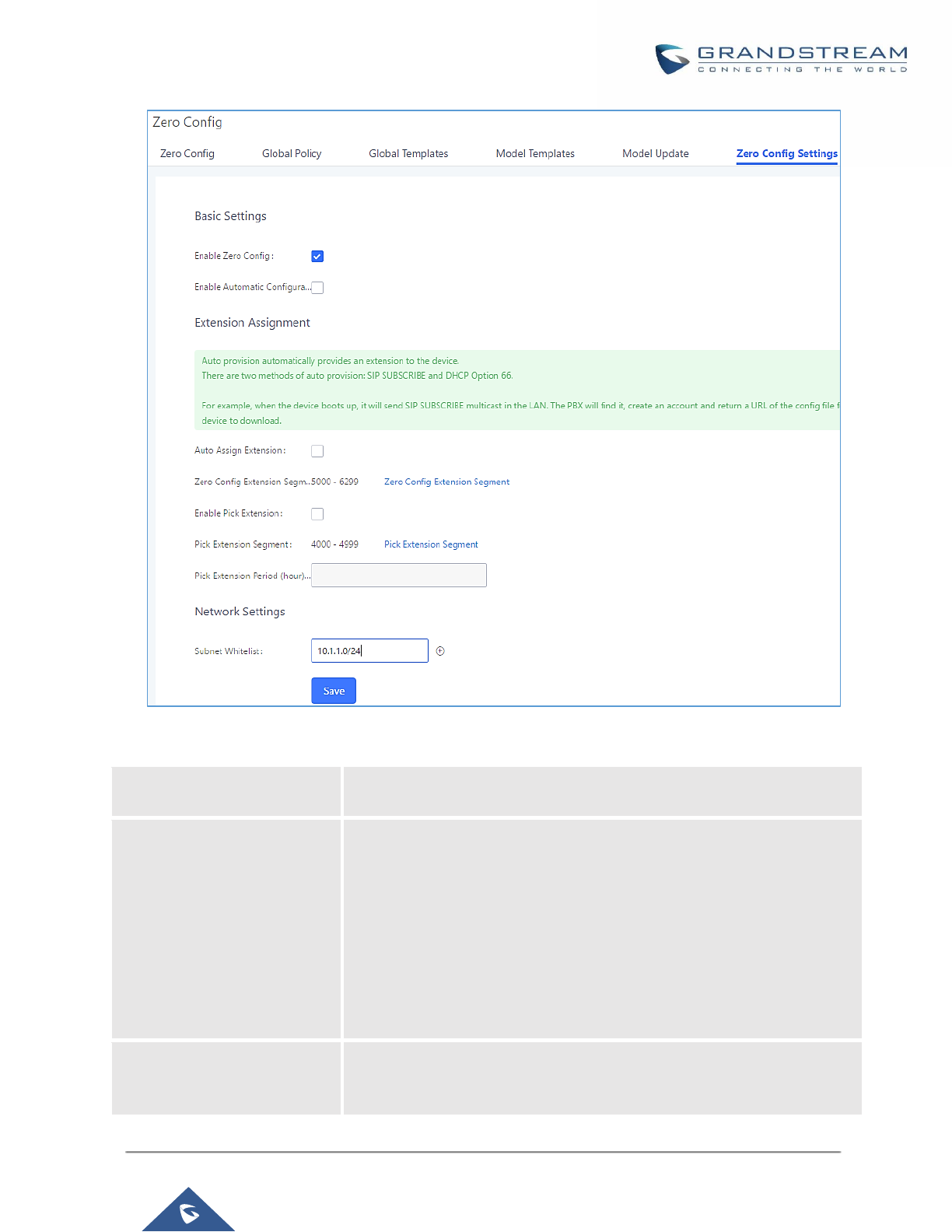
P a g e | 97
UCM6200 Series User Manual
Version 1.0.19.21
Figure 57: Auto Provision Settings
Table 22: Auto Provision Settings
Enable Zero Config
Enable or disable the zero-config feature on the PBX. The default setting
is enabled.
Enable Automatic
Configuration Assignment
By default, this is disabled. If disabled, when SIP device boots up, the
UCM6200 will not send the SIP device the URL to download the config file
and therefore the SIP device will not be automatically provisioned by the
UCM6200.
Note:
When disabled, SIP devices can still be provisioned by manually sending
NOTIFY from the UCM6200 which will include the XML config file URL for
the SIP device to download.
Automatically Assign
Extension
If enabled, when the device is discovered, the PBX will automatically
assign an extension within the range defined in "Zero Config Extension
Segment" to the device. The default setting is disabled.

P a g e | 98
UCM6200 Series User Manual
Version 1.0.19.21
Zero Config Extension
Segment
Click on the link "Zero Config Extension Segment" to specify the extension
range to be assigned if "Automatically Assign Extension" is enabled. The
default range is 5000-6299. Zero Config Extension Segment range can be
defined in Web GUI→PBX Settings→General Settings→General
page→Extension Preference section: "Auto Provision Extensions".
Enable Pick Extension
If enabled, the extension list will be sent out to the device after receiving
the device's request. This feature is for the GXP series phones that support
selecting extension to be provisioned via phone's LCD. The default setting
is disabled.
Pick Extension Segment
Click on the link "Pick Extension Segment" to specify the extension list to
be sent to the device. The default range is 4000 to 4999. Pick Extension
Segment range can be defined in Web GUI→PBX Settings→General
Settings→General page→Extension Preference section: "Pick
Extensions".
Pick Extension Period (hour)
Specify the number of minutes to allow the phones being provisioned to
pick extensions.
Subnet Whitelist
This feature allows the UCM to provision devices in different subnets other
than UCM network.
Enter subnets IP addresses to allow devices within these subnets to be
provisioned. The syntax is <IP>/<CIDR>.
Examples:
10.0.0.1/8
192.168.6.0/24
Note: Only private IP ranges (10.0.0.0 | 172.16.0.0 | 192.168.0.0) are
supported.
Please make sure an extension is manually assigned to the phone or "Automatically Assign Extension" is
enabled during provisioning. After the configuration on the UCM6200 Web GUI, click on "Save" and "Apply
Changes". Once the phone boots up and picks up the config file from the UCM6200, it will take the configuration
right away.
Discovery
Grandstream endpoints are automatically discovered after bootup. Users could also manually discover device
by specifying the IP address or scanning the entire LAN network. Three methods are supported to scan the
devices.
• PING
• ARP
• SIP Message (NOTIFY)
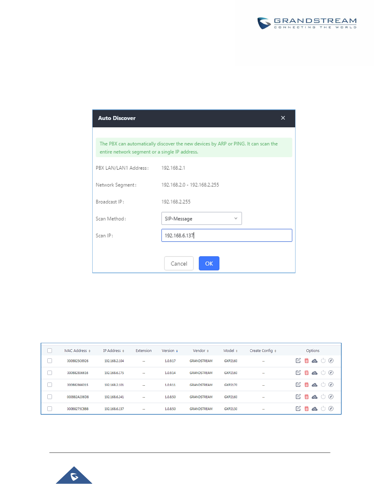
P a g e | 99
UCM6200 Series User Manual
Version 1.0.19.21
Click on "Auto Discover" under Web GUI→Value-added Features→Zero Config→Zero Config, fill in the "Scan
Method" and "Scan IP". The IP address segment will be automatically filled in based on the network mask
detected on the UCM6200. If users need scan the entire network segment, enter 255 (for example,
192.168.40.255) instead of a specific IP address. Then click on "Save" to start discovering the devices within the
same network. To successfully discover the devices, "Zero Config" needs to be enabled on the UCM6200 Web
GUI→Value-added Features→Zero Config→Auto Provisioning Settings.
Figure 58: Auto Discover
The following figure shows a list of discovered phones. The MAC address, IP Address, Extension (if assigned),
Version, Vendor, Model, Connection Status, Create Config, Options (Edit /Delete /Update /Reboot /Access
Device WebGUI) are displayed in the list.
Figure 59: Discovered Devices
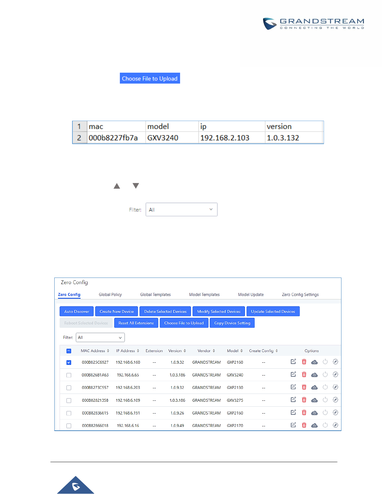
P a g e | 100
UCM6200 Series User Manual
Version 1.0.19.21
Uploading Devices List
Besides the built-in discovery method on the UCM, users could prepare a list of devices on .CSV file and upload
it by clicking on the button , after which a success message prompt should be displayed.
Users need to make sure that the CSV file respects the format as shown on the following figure and that the
entered information is correct (valid IP address, valid MAC address, device model ..etc), otherwise the UCM will
reject the file and the operation will fail:
Figure 60: Device list - CSV file sample
Managing discovered devices:
• Sorting: Press or to sort per MAC Address, IP Address, Version, Vendor, Model or Create
Config columns from lower to higher or higher to lower respectively.
• Filter: Select a filter to display corresponding results.
▪ All: Display all discovered devices.
▪ Scan Results: Display only manually discovered devices. [Discovery]
▪ IP Address: Enter device IP and press Search button.
▪ MAC Address: Enter device MAC and press Search button.
▪ Model: Enter a model name and press Search button. Example: GXP2130.
Figure 61: Managing Discovered Devices
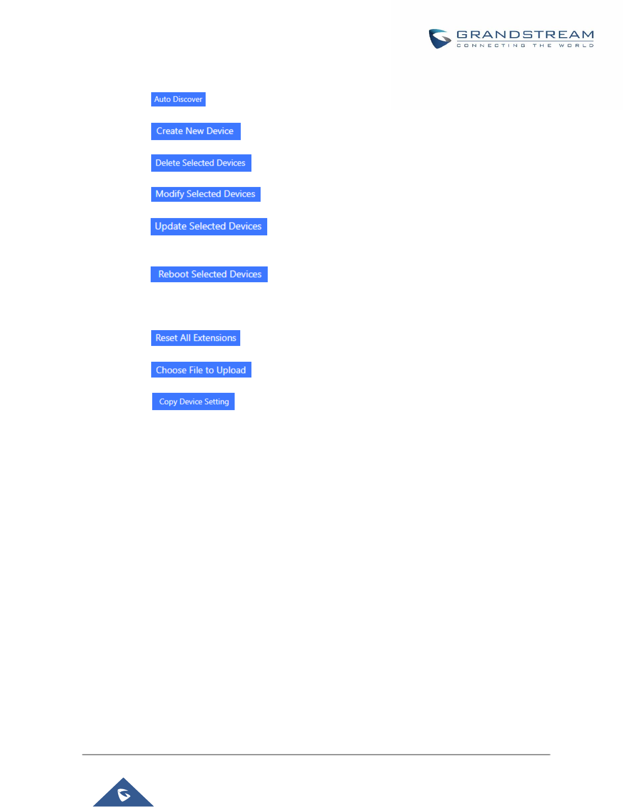
P a g e | 101
UCM6200 Series User Manual
Version 1.0.19.21
From the main menu of zero config, users can perform the following operations:
• Click on in order to access to the discovery menu as shown on [Discovery] section.
• Click on to add a new device to zero config database using its MAC address.
• Click on to delete selected devices from the zero-config database.
• Click on to modify selected devices.
• Click on to batch update a list of devices, the UCM on this case will send SIP
NOTIFY message to all selected devices in order to update them at once.
• Click on to reboot selected devices (the selected devices, should have been
provisioned with extensions since the phone will authenticate the server which is trying to send it reboot
command).
• Click on to clear all devices configurations.
• Click on to upload CSV file containing list of devices.
• Click on to copy configuration from one device to another. This can be useful for
easily replace devices and note that this feature works only between devices of same model.
All these operations will be detailed on the next sections.
Global configuration
Global policy
Global configuration will apply to all the connected Grandstream SIP end point devices in the same LAN with the
UCM6200 no matter what the Grandstream device model it is. It is divided into two levels:
• Web GUI→Value-added Features→Zero Config→Global Policy
• Web GUI→Value-added Features→Zero Config→Global Templates.
• Global Templates configuration has higher priority to Global Policy configuration.
Global Policy can be accessed in Web GUI→Value-added Features→Zero Config→Global Policy page. On
the top of the configuration table, users can select category in the “Options” dropdown list to quickly navigate to
the category. The categories are:
• Localization: configure display language, data and time.
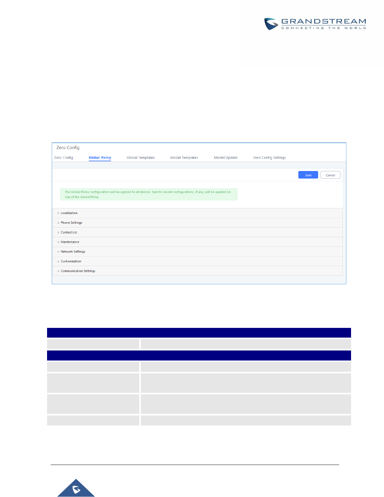
P a g e | 102
UCM6200 Series User Manual
Version 1.0.19.21
• Phone Settings: configure dial plan, call features, NAT, call progress tones and etc.
• Contact List: configure LDAP and XML phonebook download.
• Maintenance: configure upgrading, web access, Telnet/SSH access and syslog.
• Network Settings: configure IP address, QoS and STUN settings.
• Customization: customize LCD screen wallpaper for the supported models.
• Communication Settings: configure Email and FTP settings
Select the checkbox on the left of the parameter you would like to configure to activate the dropdown list for this
parameter.
Figure 62: Global Policy Categories
The following tables list the Global Policy configuration parameters for the SIP end device.
Table 23: Global Policy Parameters – Localization
Language settings
Language
Select the LCD display language on the SIP end device.
Date and Time
Date Format
Configure the date display format on the SIP end device’s LCD.
Time Format
Configure the time display in 12-hour or 24-hour format on the SIP end
device’s LCD.
NTP Server
Configure the URL or IP address of the NTP server. The SIP end device
may obtain the date and time from the server.
Time Zone
Configure the time zone used on the SIP end device.

P a g e | 103
UCM6200 Series User Manual
Version 1.0.19.21
Table 24: Global Policy Parameters – Phone Settings
Default Call Settings
Dial Plan
Configure the default dial plan rule. For syntax and examples, please refer
to user manual of the SIP devices to be provisioned for more details.
Enable Call Features
When enabled, “Do Not Disturb”, “Call Forward” and other call features can
be used via the local feature code on the phone. Otherwise, the ITSP
feature code will be used.
Use # as Dial Key
If set to “Yes”, pressing the number key “#” will immediately dial out the
input digits.
Auto Answer by Call-info
If set to “Yes”, the phone will automatically turn on the speaker phone to
answer incoming calls after a short reminding beep, based on the SIP
Call-Info header sent from the server/proxy.
The default setting is enabled.
NAT Traversal
Configure if NAT traversal mechanism is activated.
User Random Port
If set to “Yes”, this parameter will force random generation of both the
local SIP and RTP ports.
General Settings
Call Progress Tones
Configure call progress tones including ring tone, dial tone, second dial
tone, message waiting tone, ring back tone, call waiting tone, busy tone
and reorder tone using the following syntax:
f1=val, f2=val[, c=on1/ off1[- on2/ off2[- on3/ off3]]];
• Frequencies are in Hz and cadence on and off are in 10ms).
• “on” is the period (in ms) of ringing while “off” is the period of silence.
Up to three cadences are supported.
• Please refer to user manual of the SIP devices to be provisioned for
more details
HEADSET Key Mode
Select “Default Mode” or “Toggle Headset/Speaker” for the Headset key.
Please refer to user manual of the SIP devices to be provisioned for more
details.
Table 25: Global Policy Parameters – Contact List
LDAP Phonebook
Source
Select “Manual” or “PBX” as the LDAP configuration source.
• If “Manual” is selected, the LDAP configuration below will be applied to
the SIP end device.
• If “PBX” is selected, the LDAP configuration built-in from UCM6200
Web GUI→System Settings→LDAP Server will be applied.
Address
Configure the IP address or DNS name of the LDAP server.

P a g e | 104
UCM6200 Series User Manual
Version 1.0.19.21
Port
Configure the LDAP server port. The default value is 389.
Base DN
This is the location in the directory where the search is requested to begin.
Example:
• dc=grandstream, dc=com
• ou=Boston, dc=grandstream, dc=com
User Name
Configure the bind “Username” for querying LDAP servers. The field can
be left blank if the LDAP server allows anonymous binds.
Password
Configure the bind “Password” for querying LDAP servers. The field can be
left blank if the LDAP server allows anonymous binds.
Number Filter
Configure the filter used for number lookups. Please refer to user manual
for more details.
Name Filter
Configure the filter used for name lookups. Please refer to user manual for
more details.
Version
Select the protocol version for the phone to send the bind requests. The
default value is 3.
Name Attribute
Specify the “name” attributes of each record which are returned in the
LDAP search result.
Example:
gn
cn sn description
Number Attribute
Specify the “number” attributes of each record which are returned in the
LDAP search result.
Example:
telephoneNumber
telephoneNumber Mobile
Display Name
Configure the entry information to be shown on phone’s LCD. Up to 3 fields
can be displayed.
Example:
%cn %sn %telephoneNumber
Max Hits
Specify the maximum number of results to be returned by the LDAP server.
Valid range is 1 to 3000. The default value is 50.
Search Timeout
Specify the interval (in seconds) for the server to process the request and
client waits for server to return. Valid range is 0 to 180. Default value is 30.
Sort Results
Specify whether the searching result is sorted or not. Default setting is No.
Incoming Calls
Configure to enable LDAP number searching when receiving calls. The
default setting is No.
Outgoing Calls
Configure to enable LDAP number searching when making calls. The
default setting is No.

P a g e | 105
UCM6200 Series User Manual
Version 1.0.19.21
Lookup Display Name
Configures the display name when LDAP looks up the name for incoming
call or outgoing call.
It must be a subset of the LDAP Name Attributes.
XML Phonebook
Phonebook XML Server
Select the source of the phonebook XML server.
• Disable
Disable phonebook XML downloading.
• Manual
Once selected, users need specify downloading protocol HTTP,
HTTPS or TFTP and the server path to download the phonebook XML
file. The server path could be IP address or URL, with up to 256
characters.
• Local UCM Server
Once selected, click on the Server Path field to upload the phonebook
XML file. Please note: after uploading the phonebook XML file to the
server, the original file name will be used as the directory name and
the file will be renamed as phonebook.xml under that directory.
Phonebook Download
Interval
Configure the phonebook download interval (in Minute). If set to 0,
automatic download will be disabled. Valid range is 5 to 720.
Remove manually-edited
entries on download
If set to “Yes”, when XML phonebook is downloaded, the entries added
manually will be automatically removed.
Table 26: Global Policy Parameters – Maintenance
Upgrade and Provision
Firmware Source
Firmware source via ZeroConfig provisioning could a URL for external
server address, local UCM directory or USB media if plugged in to the
UCM6200.
Select a source to get the firmware file:
• URL
If select to use URL to upgrade, complete the configuration for the
following four parameters: “Upgrade Via”, “Server Path”, “File Prefix”
and “File Postfix”.
• Local UCM Server
Firmware can be uploaded to the UCM6200 internal storage for
firmware upgrade. If selected, click on “Manage Storage” icon next to
“Directory” option, upload firmware file and select directory for the end
device to retrieve the firmware file.

P a g e | 106
UCM6200 Series User Manual
Version 1.0.19.21
• Local USB Media
If selected, the USB storage device needs to be plugged into the
UCM6200 and the firmware file must be put under a folder named
“ZC_firmware” in the USB storage root directory.
• Local SD Card Media
If selected, an SD card needs to be plugged into the UCM6200 and the
firmware file must be put under a folder named “ZC_firmware” in the
USB storage root directory.
Upgrade via
When URL is selected as firmware source, configure upgrade via TFTP,
HTTP or HTTPS.
Server Path
When URL is selected as firmware source, configure the firmware
upgrading server path.
File Prefix
When URL is selected as firmware source, configure the firmware file
prefix. If configured, only the firmware with the matching encrypted prefix
will be downloaded and flashed into the phone, if URL is selected as
firmware source.
File Postfix
When URL is selected as firmware source, configure the firmware file
postfix. If configured, only the configuration file with the matching encrypted
postfix will be downloaded and flashed into the phone.
Allow DHCP Option 43/66
If DHCP option 43 or 66 is enabled on the LAN side, the TFTP server can
be redirected.
Automatic Upgrade
If enabled, the end point device will automatically upgrade if a new firmware
is detected. Users can select automatic upgrading by day, by week or by
minute.
• By week
Once selected, specify the day of the week to check HTTP/TFTP
server for firmware upgrades or configuration files changes.
• By day
Once selected, specify the hour of the day to check the HTTP/TFTP
server for firmware upgrades or configuration files changes.
• By minute
Once selected, specify the interval X that the SIP end device will
request for new firmware every X minutes.
Firmware Upgrade Rule
Specify how firmware upgrading and provisioning request to be sent.
Web Access
Admin Password
Configure the administrator password for admin level login.
End-User Password
Configure the end-user password for the end user level login.
Web Access Mode
Select HTTP or HTTPS as the web access protocol.

P a g e | 107
UCM6200 Series User Manual
Version 1.0.19.21
Web Server Port
Configure the port for web access. The valid range is 1 to 65535.
Security
Disable Telnet/SSH
Enable Telnet/SSH access for the SIP end device. If the SIP end device
supports Telnet access, this option controls the Telnet access of the device;
if the SIP end device supports SSH access, this option controls the SSH
access of the device.
Syslog
Syslog Server
Configure the URL/IP address for the syslog server.
Syslog Level
Select the level of logging for syslog.
Send SIP Log
Configure whether the SIP log will be included in the syslog message.
Table 27: Global Policy Parameters – Network Settings
Basic Settings
IP Address
Configure how the SIP end device shall obtain the IP address. DHCP or
PPPoE can be selected.
• DHCP
Once selected, users can specify the Host Name (option 12) of the SIP
end device as DHCP client, and Vendor Class ID (option 60) used by
the client and server to exchange vendor class ID information.
• PPPoE
Once selected, users need specify the Account ID, Password and
Service Name for PPPoE.
Advanced Setting
Layer 3 QoS
Define the Layer 3 QoS parameter. This value is used for IP Precedence,
Diff-Serv or MPLS. Valid range is 0-63.
Layer 2 QoS Tag
Assign the VLAN Tag of the Layer 2 QoS packets. Valid range is 0 -4095.
Layer 2 QoS Priority Value
Assign the priority value of the Layer 2 QoS packets. Valid range is 0-7.
STUN Server
Configure the IP address or Domain name of the STUN server. Only non-
symmetric NAT routers work with STUN.
Keep Alive Interval
Specify how often the phone will send a blank UDP packet to the SIP server
in order to keep the “ping hole” on the NAT router to open. Valid range is
10-160.

P a g e | 108
UCM6200 Series User Manual
Version 1.0.19.21
Table 28: Global Policy Parameters – Customization
Wallpaper
Screen Resolution 1024 x
600
Check this option if the SIP end device shall use 1024 x 600 resolution for
the LCD screen wallpaper.
• Source
Configure the location where wallpapers are stored.
• File
If “URL” is selected as source, specify the URL of the wallpaper file. If
“Local UCM Server” is selected as source, click to upload wallpaper
file to the UCM6200.
Screen Resolution 800 x 400
Check this option if the SIP end device shall use 800 x 400 resolution for
the LCD screen wallpaper.
• Source
Configure the location where wallpapers are stored.
• File
If “URL” is selected as source, specify the URL of the wallpaper file. If
“Local UCM Server” is selected as source, click to upload wallpaper
file to the UCM6200.
Screen Resolution 480 x 272
Check this option if the SIP end device shall use 480 x 272 resolution for
the LCD screen wallpaper.
• Source
Configure the location where wallpapers are stored.
• File
If “URL” is selected as source, specify the URL of the wallpaper file. If
“Local UCM Server” is selected as source, click to upload wallpaper
file to the UCM6200.
Screen Resolution 320 x 240
Check this option if the SIP end device supports 320 x 240 resolution for
the LCD screen wallpaper.
• Source
Configure the location where wallpapers are stored.
• File
If “URL” is selected as source, specify the URL of the wallpaper file. If
“Local UCM Server” is selected as source, click to upload wallpaper
file to the UCM6200.

P a g e | 109
UCM6200 Series User Manual
Version 1.0.19.21
Table 29: Global Policy Parameters – Communication Settings
Email Settings
SMTP Settings
Check this option to configure the email settings that will be sent to the
provisioned phones:
• Server
IP address of the SMTP server
• Port
SMTP server port
• From E-Mail address
Email address
• Sender User Name
User name of the sender
• Password Recovery Email
Email where recovered password will be sent
• Alarm receive Email 1
Email address where alarms notifications will be sent
• Alarm receive Email 1
Email address where alarms notifications will be sent
• Enable SSL
Enable SSL protocol for SMTP
FTP
FTP
Check this option to configure the FTP settings that will be sent to the
provisioned phones:
• Storage Server Type
Either FTP or Central Storage
• Server
FTP server address
• Port
FTP port to be used
• User Name
FTP user name
• Path
FTP Directory path

P a g e | 110
UCM6200 Series User Manual
Version 1.0.19.21
Global Templates
Global Templates can be accessed in Web GUI→Value-added Features→Zero Config→Global Templates.
Users can create multiple global templates with different sets of configurations and save the templates. Later on,
when the user configures the device in Edit Device dialog→Advanced Settings, the user can select to use one
of the global templates for the device. Please refer to section [Manage Devices] for more details on using the
global templates.
When creating global template, users can select the categories and the parameters under each category to be
used in the template. The global policy and the selected global template will both take effect when generating
the config file. However, the selected global template has higher priority to the global policy when it comes to the
same setting option/field. If the same option/field has different value configured in the global policy and the
selected global template, the value for this option/field in the selected global template will override the value in
global policy.
Click on "Create New Template" to add a global template. Users will see the following configurations.
Table 30: Create New Template
Template Name
Create a name to identify this global template.
Description
Provide a description for the global template. This is optional.
Active
Check this option to enable the global template.
• Click on to edit the global template.
The window for editing global template is shown in the following figure. In the “Options” field, after entering the
option name key word, the options containing the key word will be listed. Users could then select the options to
be modified and click on “Add Option” to add it into the global template.
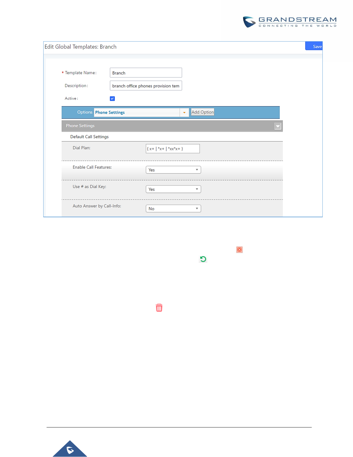
P a g e | 111
UCM6200 Series User Manual
Version 1.0.19.21
Figure 63: Edit Global Template
The added options will show in the list. Users can then enter or select value for each option to be used in the
global template. On the left side of each added option, users can click on to remove this option from the
template. On the right side of each option, users can click on to reset the option value to the default value.
Click on “Save” to save this global template.
• The created global templates will show in the Web GUI→Value-added Features→Zero Config→Global
Templates page. Users can click on to delete the global template or click on “Delete Selected
Templates” to delete multiple selected templates at once.
• Click on “Toggle Selected Template(s)” to toggle the status between enabled/disabled for the selected
templates.

P a g e | 112
UCM6200 Series User Manual
Version 1.0.19.21
Model configuration
Model templates
Model layer configuration allows users to apply model-specific configurations to different devices. Users could
create/edit/delete a model template by accessing Web GUI, page Value-added Features→Zero
Config→Model Templates. If multiple model templates are created and enabled, when the user configures the
device in Edit Device dialog→Advanced Settings, the user can select to use one of the model templates for the
device. Please refer to section [Manage Devices] for more details on using the model template.
For each created model template, users can assign it as default model template. If assigned as default model
template, the values in this model template will be applied to all the devices of this model. There is always only
one default model template that can be assigned at one time on the UCM6200.
The selected model template and the default model template will both take effect when generating the config file
for the device. However, the model template has higher priority to default model template when it comes to the
same setting option/field. If the same option/field has different value configured in the default model template
and the selected model template, the value for this option/field in the selected model template will override the
value in default model template.
• Click on “Create New Template” to add a model template.
Table 31: Create New Model Template
Model
Select a model to apply this template. The supported Grandstream models
are listed in the dropdown list for selection.
Template Name
Create a name for the model template.
Description
Enter a description for the model template. This is optional.
Default Model Template
Select to assign this model template as the default model template. The value
of the option in default model template will be overridden if other selected
model template has a different value for the same option.
Active
Check this option to enable the model template.
• Click on to edit the model template.
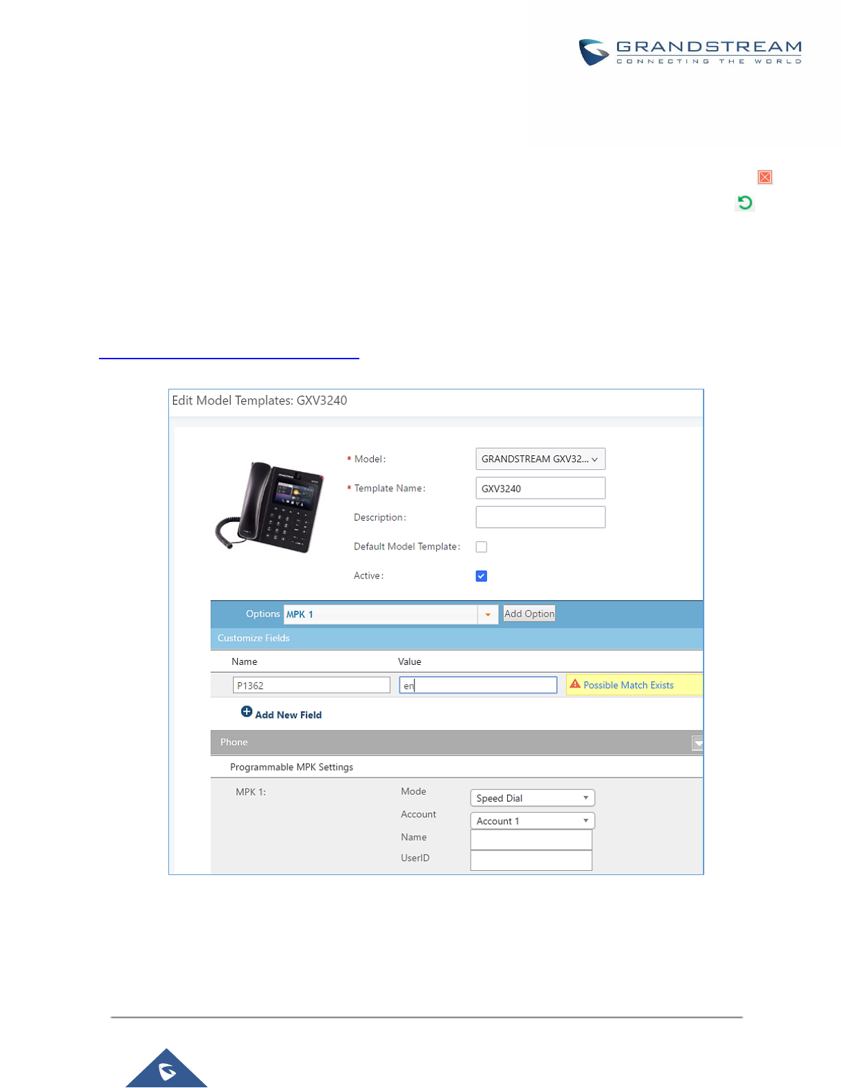
P a g e | 113
UCM6200 Series User Manual
Version 1.0.19.21
The editing window for model template is shown in the following figure. In the “Options” field, enter the option
name key word, the option that contains the key word will be listed. User could then select the option and
click on “Add Option” to add it into the model template.
Once added, the option will be shown in the list below. On the left side of each option, users can click on
to remove this option from the model template. On the right side of each option, users can click on to
reset the option to the default value.
User could also click on “Add New Field” to add a P value number and the value to the configuration. The
following figure shows setting P value “P1362” to “en”, which means the display language on the LCD is set to
English. For P value information of different models, please refer to configuration template here
http://www.grandstream.com/support/tools.
Figure 64: Edit Model Template
• Click on Save when done. The model template will be displayed on Web GUI→Value-added
Features→Zero Config→Model Templates page.
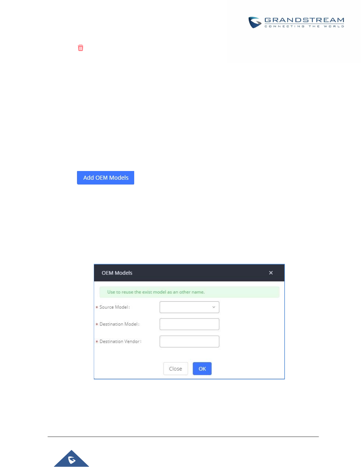
P a g e | 114
UCM6200 Series User Manual
Version 1.0.19.21
• Click on to delete the model template or click on “Delete Selected Templates” to delete multiple selected
templates at once.
• Click on “Toggle Selected Template(s)” to toggle the status between enabled/disabled for the selected model
templates.
Model Update
UCM6200 zero config feature supports provisioning all models of Grandstream SIP end devices including OEM
device models.
OEM Models
Users can associate OEM device models with their original Grandstream-branded models, allowing these OEM
devices to be provisioned appropriately.
• Click on button.
• In the Source Model field, select the Grandstream device that the OEM model is based on from the dropdown
list.
• For the Destination Model and Destination Vendor field, enter the custom OEM model name and vendor
name.
• The newly added OEM model should now be selectable as an option in Model fields.
Figure 65: OEM Models
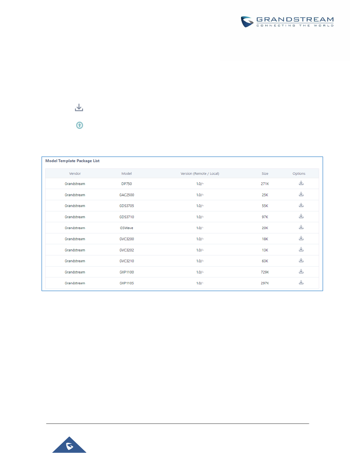
P a g e | 115
UCM6200 Series User Manual
Version 1.0.19.21
Model Template Package List
Templates for most of the Grandstream models are built in with the UCM6200 already. Templates for GS Wave
and Grandstream surveillance products require users to download and install under Web GUI→Value-added
Features→Zero Config→Model Update first before they are available in the UCM6200 for selection. After
downloading and installing the model template to the UCM6200, it will show in the dropdown list for “Model”
selection when editing the model template.
• Click on to download the template.
• Click on to upgrade the model template. Users will see this icon available if the device model has
template updated in the UCM6200.
Figure 66: Template Management
Upload Model Template Package
In case the UCM6200 is placed in the private network and Internet access is restricted, users will not be able to
get packages by downloading and installing from the remote server. Model template package can be manually
uploaded from local device through Web GUI. Please contact Grandstream customer support if the model
package is needed for manual uploading.

P a g e | 116
UCM6200 Series User Manual
Version 1.0.19.21
Figure 67: Upload Model Template Manually
Device Configuration
On Web GUI, page Value-added Features→Zero Config→Zero Config, users could create new device, delete
existing device(s), make special configuration for a single device, or send NOTIFY to existing device(s).
Create New Device
Besides configuring the device after the device is discovered, users could also directly create a new device and
configure basic settings before the device is discovered by the UCM6200. Once the device is plugged in, it can
then be discovered and provisioned. This gives the system administrator adequate time to set up each device
beforehand.
Click on "Create New Device" and the following dialog will show. Follow the steps below to create the
configurations for the new device.
1. Firstly, select a model for the device to be created and enter its MAC address, IP address and firmware
version (optional) in the corresponding field.
2. Basic settings will show a list of settings based on the model selected in step 1. Users could assign
extensions to accounts, assign functions to Line Keys and Multiple-Purposed Keys if supported on the
selected model.
3. Click on “Create New Device” to save the configuration for this device.
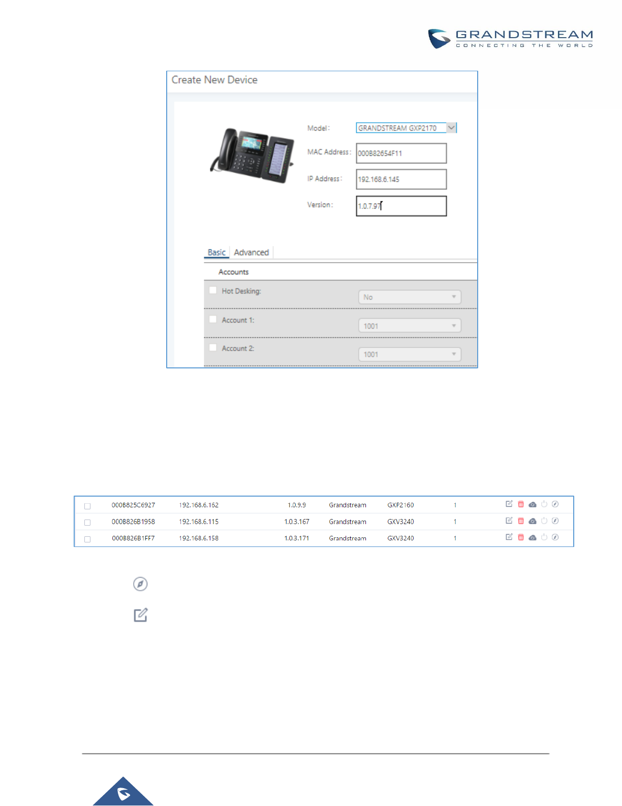
P a g e | 117
UCM6200 Series User Manual
Version 1.0.19.21
Figure 68: Create New Device
Manage Devices
The device manually created or discovered from Auto Discover will be listed in the Web GUI→Value-added
Features→Zero Config→Zero Config page. Users can see the devices with their MAC address, IP address,
vendor, model etc.
Figure 69: Manage Devices
• Click on to access the Web GUI of the phone.
• Click on to edit the device configuration.
A new dialog will be displayed for the users to configure “Basic” settings and “Advanced” settings. “Basic”
settings have the same configurations as displayed when manually creating a new device, i.e., account, line
key and MPK settings; “Advanced” settings allow users to configure more details in a five-level structure.
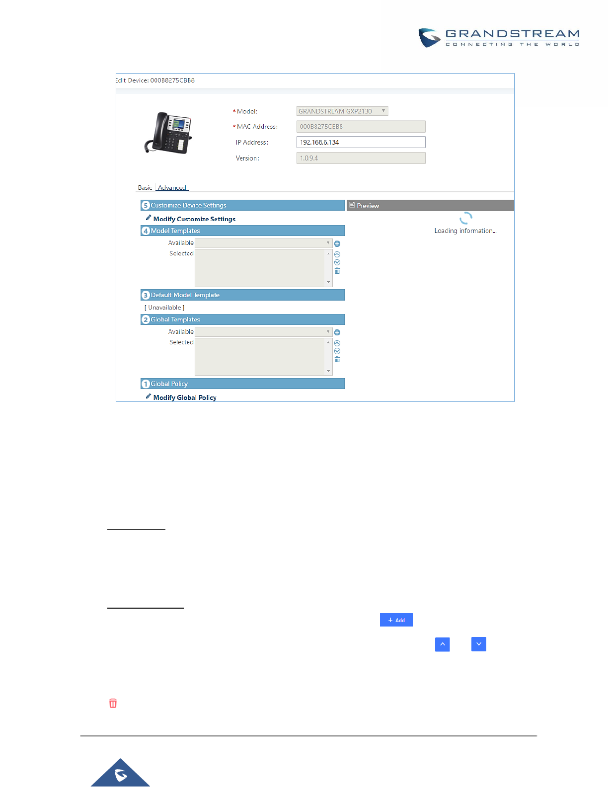
P a g e | 118
UCM6200 Series User Manual
Version 1.0.19.21
Figure 70: Edit Device
A preview of the “Advanced” settings is shown in the above figure. There are five levels configurations as
described in (1) (2) (3) (4) (5) below, with priority from the lowest to the highest. The configurations in all levels
will take effect for the device. If there are same options existing in different level configurations with different
value configured, the higher level configuration will override the lower level configuration.
(1) Global Policy
This is the lowest level configuration. The global policy configured in Web GUI→Value-added
Features→Zero Config→Global Policy will be applied here. Clicking on “Modify Global Policy” to
redirect to page Value-added Features→Zero Config→Global Policy.
(2) Global Templates
Select a global template to be used for the device and click on to add. Multiple global templates
can be selected and users can arrange the priority by adjusting orders via and . All the selected
global templates will take effect. If the same option exists on multiple selected global templates, the
value in the template with higher priority will override the one in the template with lower priority. Click on
to remove the global template from the selected list.

P a g e | 119
UCM6200 Series User Manual
Version 1.0.19.21
(3) Default Model Template
Default Model Template will be applied to the devices of this model. Default model template can be
configured in model template under Web GUI→Value-added Features→Zero Config→Model
Templates page. Please see default model template option in [Table 31: Create New Model Template].
(4) Model Templates
Select a model template to be used for the device and click on to add. Multiple global templates
can be selected and users can arrange the priority by adjusting orders via and . All the selected
model templates will take effect. If the same option exists on multiple selected model templates, the
value in the template with higher priority will override the one in the template with lower priority. Click on
to remove the model template from the selected list.
(5) Customize Device Settings
This is the highest level configuration for the device. Click on “Modify Customize Device Settings” and
following dialog will show.
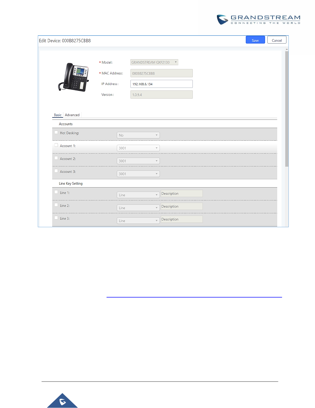
P a g e | 120
UCM6200 Series User Manual
Version 1.0.19.21
Figure 71: Edit Customize Device Settings
Scroll down in the dialog to view and edit the device-specific options. If the users would like to add more options
which are not in the pre-defined list, click on “Add New Field” to add a P value number and the value to the
configuration. The following figure shows setting P value “P1362” to “en”, which means the display language on
the LCD is set to English. The warning information on right tells that the option matching the P value number
exists and clicking on it will lead to the matching option. For P value information of different models, please refer
to configuration template here http://www.grandstream.com/sites/default/files/Resources/config-template.zip.
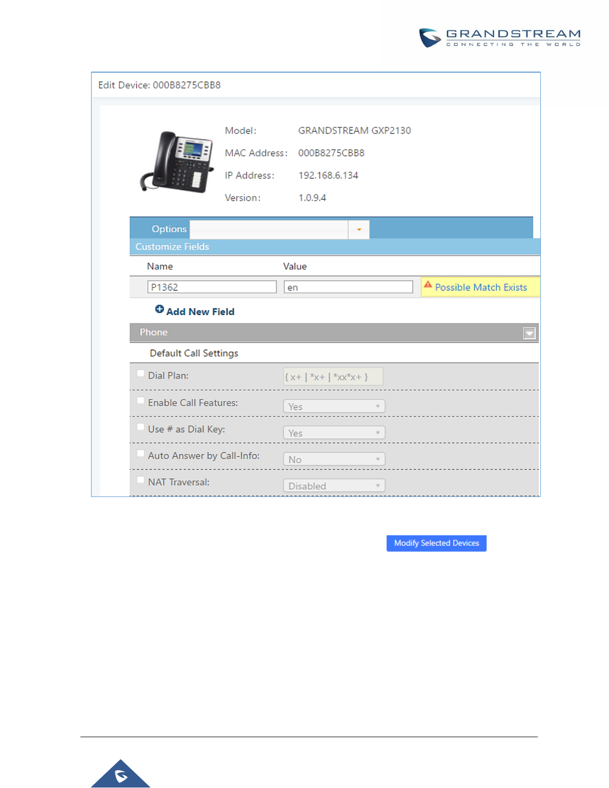
P a g e | 121
UCM6200 Series User Manual
Version 1.0.19.21
Figure 72: Add P Value in Customize Device Settings
• Select multiple devices that need to be modified and then click on to batch modify
devices.
If selected devices are of the same model, the configuration dialog is like the following figure. Configurations in
five levels are all available for users to modify.
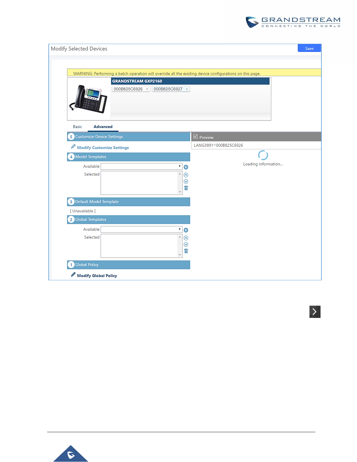
P a g e | 122
UCM6200 Series User Manual
Version 1.0.19.21
Figure 73: Modify Selected Devices - Same Model
If selected devices are of different models, the configuration dialog is like the following figure. Click on to
view more devices of other models. Users are only allowed to make modifications in Global Templates and
Global Policy level.
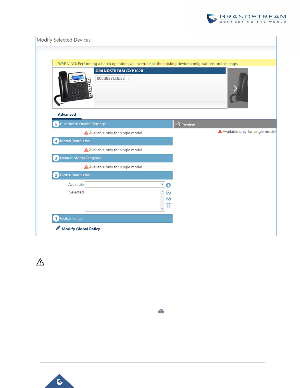
P a g e | 123
UCM6200 Series User Manual
Version 1.0.19.21
Figure 74: Modify Selected Devices - Different Models
---------------------------------------------------------------------------------------------------------------------------------------------------
Note:
Performing batch operation will override all the existing device configuration on the page.
----------------------------------------------------------------------------------------------------------------------------- ----------------------
After the above configurations, save the changes and go back to Web GUI→Value-added Features→Zero
Config→Zero Config page. Users could then click on to send NOTIFY to the SIP end point device and
trigger the provisioning process. The device will start downloading the generated configuration file from the URL
contained in the NOTIFY message.
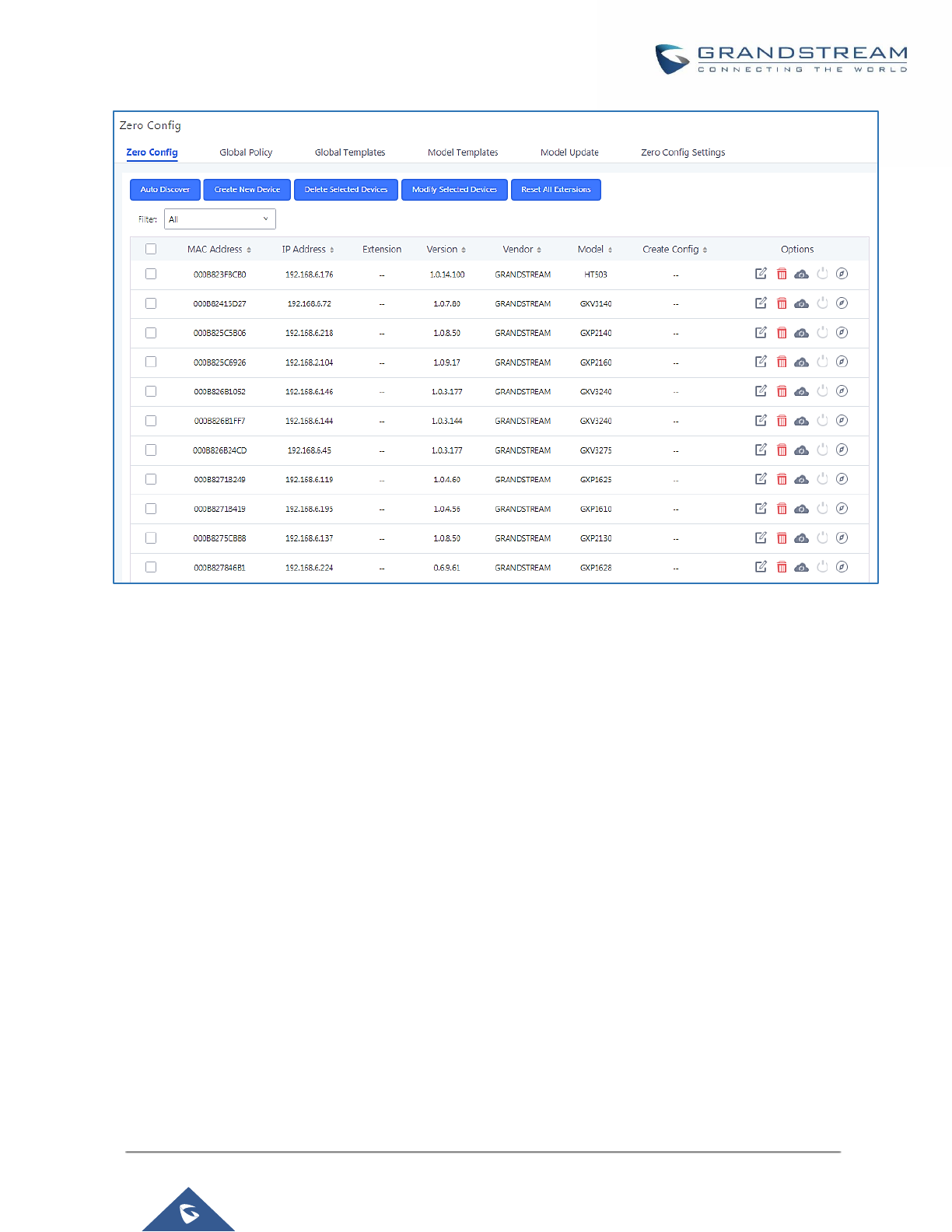
P a g e | 124
UCM6200 Series User Manual
Version 1.0.19.21
Figure 75: Device List in Zero Config
In this web page, users can also click on “Reset All Extensions” to reset the extensions of all the devices.
Sample Application
Assuming in a small business office where there are 8 GXP2140 phones used by customer support and 1
GXV3275 phone used by customer support supervisor. 3 of the 8 customer support members speak Spanish
and the rest speak English. We could deploy the following configurations to provisioning the office phones for
the customer support team.
1. Go to Web GUI→Value-added Features→Zero Config→Zero Config Settings, select “Enable Zero
Config”.
2. Go to Web GUI→Value-added Features→Zero Config→Global Policy, configure Date Format, Time
Format and Firmware Source as follows.
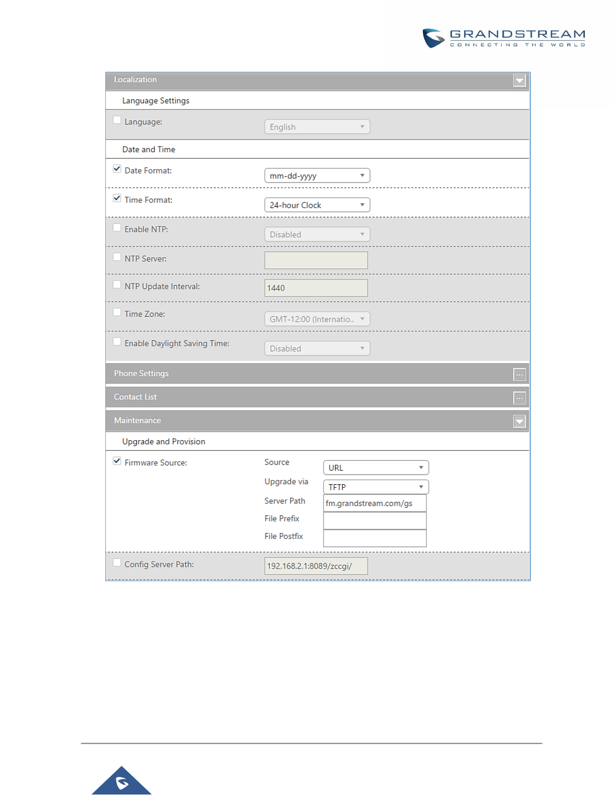
P a g e | 125
UCM6200 Series User Manual
Version 1.0.19.21
Figure 76: Zero Config Sample - Global Policy
3. Go to Web GUI→Value-added Features→Zero Config→Model Templates, create a new model template
“English Support Template” for GXP2140. Add option “Language” and set it to “English”. Then select the
option “Default Model Template” to make it the default model template.
4. Go to Web GUI→Value-added Features→Zero Config→Model Templates, create another model template
“Spanish Support Template” for GXP2140. Add option “Language” and set it to “Español”.
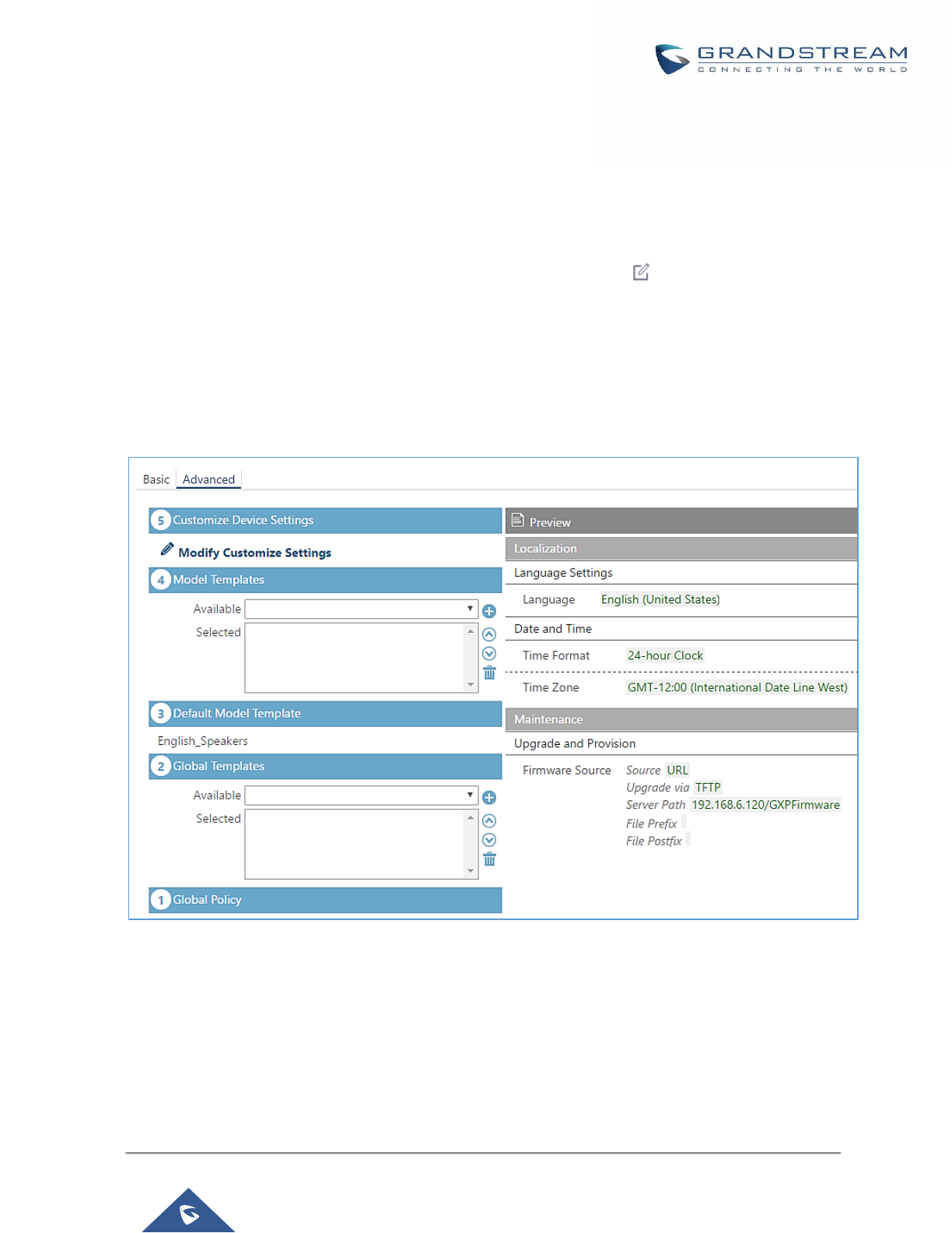
P a g e | 126
UCM6200 Series User Manual
Version 1.0.19.21
5. After 9 devices are powered up and connected to the LAN network, use “Auto Discover” function or “Create
New Device” function to add the devices to the device list on Web GUI→Value-added Features→Zero
Config→Zero Config.
6. On Web GUI→Value-added Features→Zero Config→Zero Config page, users could identify the devices
by their MAC addresses or IP addresses displayed on the list. Click on to edit the device settings.
7. For each of the 5 phones used by English speaking customer support, in “Basic” settings select an available
extension for account 1 and click on “Save”. Then click on “Advanced” settings tab to bring up the following
dialog. Users will see the English support template is applied since this is the default model template. A
preview of the device settings will be listed on the right side.
Figure 77: Zero Config Sample - Device Preview 1
8. For the 3 phones used by Spanish support, in “Basic” settings select an available extension for account 1
and click on “Save”. Then click on “Advanced” settings tab to bring up the following dialog.
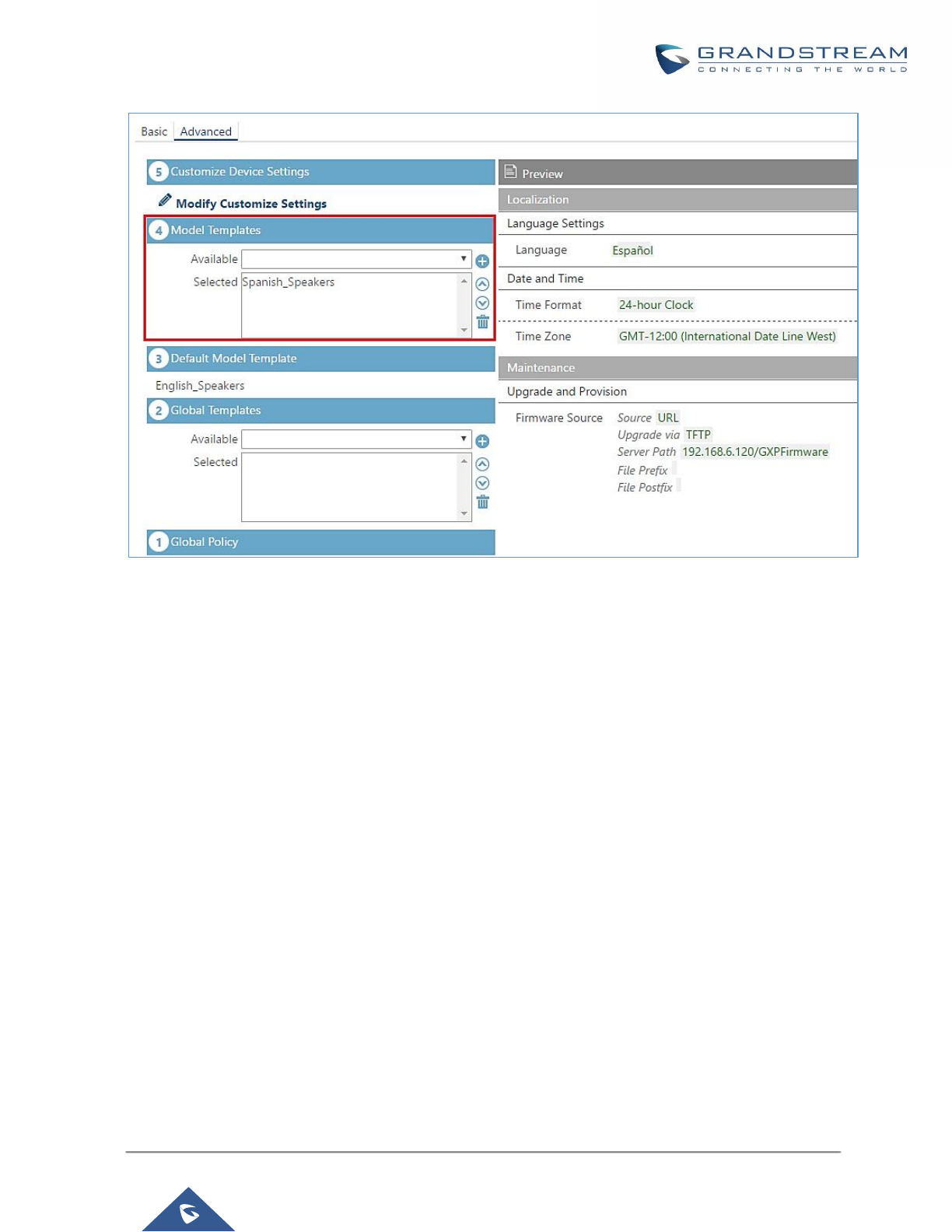
P a g e | 127
UCM6200 Series User Manual
Version 1.0.19.21
Figure 78: Zero Config Sample - Device Preview 2
Select “Spanish Support Template” in “Model Template”. The preview of the device settings is displayed on the
right side and we can see the language is set to “Español” since Model Template has the higher priority for the
option “Language”, which overrides the value configured in default model template.
9. For the GXV3275 used by the customer support supervisor, select an available extension for account 1 on
“Basic” settings and click on “Save”. Users can see the preview of the device configuration in “Advanced”
settings. There is no model template configured for GXV3275.
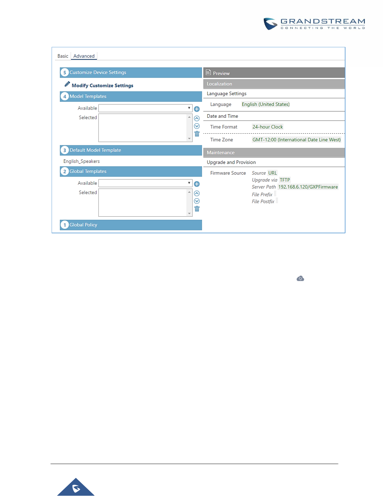
P a g e | 128
UCM6200 Series User Manual
Version 1.0.19.21
Figure 79: Zero Config Sample - Device Preview 3
10. Click on “Apply Changes” to apply saved changes.
11. On the Web GUI→Value-added Features→Zero Config→Zero Config page, click on to send NOTIFY
to trigger the device to download config file from UCM6200.
Now all the 9 phones in the network will be provisioned with an unique extension registered on the UCM6200. 3
of the phones will be provisioned to display Spanish on LCD and the other 5 will be provisioned to display English
on LCD. The GXV3275 used by the supervisor will be provisioned to use the default language on LCD display
since it’s not specified in the global policy.
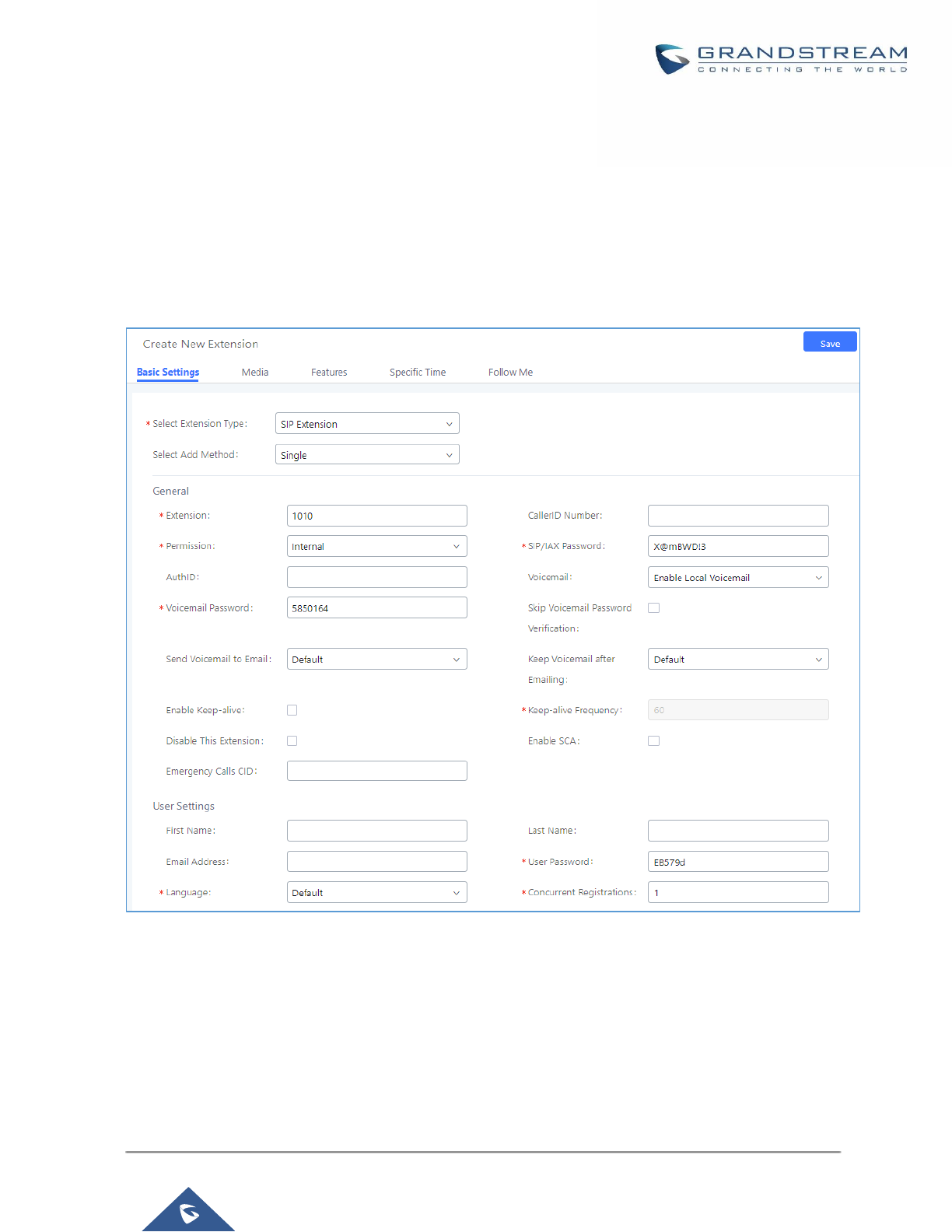
P a g e | 129
UCM6200 Series User Manual
Version 1.0.19.21
EXTENSIONS
Create New User
Create New SIP Extension
To manually create new SIP user, go to Web GUI→Extension/Trunk→Extensions. Click on "Add" and a new
dialog window will show for users to fill in the extension information.
Figure 80: Create New Device
Extension options are divided into four categories:
• Basic Settings
• Media
• Features
• Specific Time
• Follow me

P a g e | 130
UCM6200 Series User Manual
Version 1.0.19.21
Select first which type of extension: SIP Extension, IAX Extension or FXS Extension. The configuration
parameters are as follows.
Table 32: SIP Extension Configuration Parameters→Basic Settings
General
Extension
The extension number associated with the user.
CallerID Number
Configure the CallerID Number that would be applied for outbound calls from this
user.
Note:
The ability to manipulate your outbound Caller ID may be limited by your VoIP
provider.
Permission
Assign permission level to the user. The available permissions are "Internal", "Local",
"National" and "International" from the lowest level to the highest level. The default
setting is "Internal".
Note:
Users need to have the same level as or higher level than an outbound rule's privilege
to make outbound calls using this rule.
SIP/IAX Password
Configure the password for the user. A random secure password will be automatically
generated. It is recommended to use this password for security purpose.
Auth ID
Configure the authentication ID for the user. If not configured, the extension number
will be used for authentication.
Voicemail
Configure Voicemail. There are three valid options and the default option is "Enable
Local Voicemail".
• Disable Voicemail: Disable Voicemail.
• Enable Local Voicemail: Enable voicemail for the user.
• Enable Remote Voicemail: Forward the notify message from remote
voicemail system for the user, and the local voicemail will be disabled. Note:
Remote voicemail feature is used only for Infomatec (Brazil).
Voicemail
Password
Configure voicemail password (digits only) for the user to access the voicemail box.
A random numeric password is automatically generated. It is recommended to use
the random generated password for security purpose.
Skip Voicemail
Password
Verification
When user dials voicemail code, the password verification IVR is skipped. If enabled,
this would allow one-button voicemail access. By default, this option is disabled.
Send Voicemail to
Email
Allows users to send voicemail recording as .wav file attachment to specified email
addresses. Default setting is “No”.
Note: When set to “Default”, the global settings in Call Features → Voicemail →
Voicemail Email Settings will be used.

P a g e | 131
UCM6200 Series User Manual
Version 1.0.19.21
Keep Voicemail
after Emailing
Whether to keep the local voicemail recording after sending them. If set to “Default”,
the global settings will be used.
Note: When set to “Default”, the global settings in Call Features → Voicemail →
Voicemail Email Settings will be used.
Enable Keep-alive
If enabled, empty SDP packet will be sent to the SIP server periodically to keep the
NAT port open. The default setting is "Yes".
Keep-alive
Frequency
Configure the Keep-alive interval (in seconds) to check if the host is up. The default
setting is 60 seconds.
Disable This
Extension
If selected, this extension will be disabled on the UCM6200.
Note:
The disabled extension still exists on the PBX but can’t be used on the end device.
User Settings
First Name
Configure the first name of the user. The first name can contain characters, letters,
digits and _.
Last Name
Configure the last name of the user. The last name can contain characters, letters,
digits and _.
Email Address
Fill in the Email address for the user. Voicemail will be sent to this Email address.
User Password
Configure the password for user portal access. A random numeric password is
automatically generated. It is recommended to use the randomly generated password
for security purpose.
Language
Select the voice prompt language to be used for this extension. The default setting is
"Default" which is the selected voice prompt language under Web GUI→PBX
Settings→Voice Prompt→Language Settings. The dropdown list shows all the
current available voice prompt languages on the UCM6200. To add more languages
in the list, please download voice prompt package by selecting "Check Prompt List"
under Web GUI→PBX Settings→Voice Prompt→Language Settings.
Concurrent
Registrations
The maximum endpoints which can be registered into this extension. For security
concerns, the default value is 1.
Mobile Phone
Number
Configure the phone number for the extension, user can type the related star code for
phone number followed by the extension number to call directly this number.
Example: user can type *881000 to call the mobile number associated with extension
1000.
Table 33: SIP Extension Configuration Parameters→Media
SIP Settings
NAT
Use NAT when the UCM6200 is on a public IP communicating with devices hidden
behind NAT (e.g., broadband router). If there is one-way audio issue, usually it's
related to NAT configuration or Firewall's support of SIP and RTP ports. The default
setting is enabled.

P a g e | 132
UCM6200 Series User Manual
Version 1.0.19.21
Can Direct Media
By default, the UCM6200 will route the media steams from SIP endpoints through
itself. If enabled, the PBX will attempt to negotiate with the endpoints to route the
media stream directly. It is not always possible for the UCM6200 to negotiate
endpoint-to-endpoint media routing. The default setting is "No".
DTMF Mode
Select DTMF mode for the user to send DTMF. The default setting is "RFC2833". If
"Info" is selected, SIP INFO message will be used. If "Inband" is selected, 64-kbit
PCMU and PCMA are required. When "Auto" is selected, RFC2833 will be used if
offered, otherwise "Inband" will be used.
TEL URI
If the phone has an assigned PSTN telephone number, this field should be set to
“User=Phone”. “User=Phone” parameter will be attached to the Request-Line and
“TO” header in the SIP request to indicate the E.164 number. If set to “Enable”, “Tel”
will be used instead of “SIP” in the SIP request.
Alert-Info
When present in an INVITE request, the alert-Info header field specifies and
alternative ring tone to the UAS.
Enable T.38
UDPTL
Enable or disable T.38 UDPTL support.
SRTP
Enable SRTP for the call. The default setting is disabled.
Fax Mode
Select Fax mode. The default setting is “None”.
• None: Disable Fax.
• Fax Detect: Fax signal from the user/trunk during the call can be detected and
the received Fax will be sent to the Email address configured for this extension.
If no Email address can be found for the user, the Fax will be sent to the default
Email address configured in Fax setting page under Web GUI→Call
Features→Fax/T.38.
Fax To Email
• Yes – Allow Fax to Email for this extension. Faxes will be sent to the user’s
email address configured in the extension’s Basic Settings.
• No – Do not send any faxes to the user’s email address configured in the
extension’s Basic Settings.
Strategy
This option controls how the extension can be used on devices within different types
of network. The default setting is "Allow All".
• Allow All
Device in any network can register this extension.
• Local Subnet Only
Only the user in specific subnet can register this extension. Up to three subnet
addresses can be specified.
• A Specific IP Address
Only the device on the specific IP address can register this extension.
Codec Preference
Select audio and video codec for the extension. The available codecs are: PCMU,
PCMA, GSM, AAL2-G.726-32, G,726, G.722, G.729, G.723, iLBC, ADPCM, H.264,
H.265, H.263, H.263p, RTX and VP8.

P a g e | 133
UCM6200 Series User Manual
Version 1.0.19.21
Table 34: SIP Extension Configuration Parameters→Features
Call Transfer
Presence Status
Select which presence status to set for the extension and configure call forward
conditions for each status. Six possible options are possible: “Available”, “Away”,
“Chat”, “Custom”, “DND” and “Unavailable”. More details at [PRESENCE].
Call Forward
Unconditional
Enable and configure the Call Forward Unconditional target number. Available options
for target number are:
• “None”: Call forward deactivated.
• “Extension”: Select an extension from dropdown list as CFU target.
• “Custom Number”: Enter a customer number as target. For example: *97.
• “Voicemail”: Select an extension from dropdown list. Incoming calls will be
forwarded to voicemail of selected extension.
• “Ring Group”: Select a ring group from dropdown list as CFU target.
• “Queues”: Select a queue from dropdown list as CFU target.
• “Voicemail Group”: Select a voicemail group from dropdown list as CFU target.
The default setting is “None”.
CFU Time
Condition
Select time condition for Call Forward Unconditional. CFU takes effect only during the
selected time condition. The available time conditions are “Office Time”, “Out of Office
Time”, “Holiday”, “Out of Holiday”, “Out of Office Time or Holiday” and “Specific”.
Note:
• “Specific” has higher priority to “Office Times” if there is a conflict in terms of time
period.
• Specific time can be configured on the bottom of the extension configuration
dialog. Scroll down the add Time Condition for specific time.
• Office Time and Holiday could be configured on page System Settings→Time
Settings→Office Time/Holiday page.
Call Forward No
Answer
Configure the Call Forward No Answer target number. Available options for target
number are:
• “None”: Call forward deactivated.
• “Extension”: Select an extension from dropdown list as CFN target.
• “Custom Number”: Enter a customer number as target. For example: *97.
• “Voicemail”: Select an extension from dropdown list. Incoming calls will be
forwarded to voicemail of selected extension.
• “Ring Group”: Select a ring group from dropdown list as CFN target.
• “Queues”: Select a queue from dropdown list as CFN target.
• “Voicemail Group”: Select a voicemail group from dropdown list as CFN target.
The default setting is “None”.

P a g e | 134
UCM6200 Series User Manual
Version 1.0.19.21
CFN Time
Condition
Select time condition for Call Forward No Answer. The available time conditions are
“Office Time”, “Out of Office Time”, “Holiday”, “Out of Holiday”, “Out of Office Time or
Holiday” and “Specific”.
Notes:
• “Specific” has higher priority to “Office Times” if there is a conflict in terms of time
period.
• Specific time can be configured on the bottom of the extension configuration
dialog. Scroll down the add Time Condition for specific time.
• Office Time and Holiday could be configured on page System Settings→Time
Settings→Office Time/Holiday page.
Call Forward Busy
Configure the Call Forward Busy target number. Available options for target number
are:
• “None”: Call forward deactivated.
• “Extension”: Select an extension from dropdown list as CFB target.
• “Custom Number”: Enter a customer number as target. For example: *97.
• “Voicemail”: Select an extension from dropdown list. Incoming calls will be
forwarded to voicemail of selected extension.
• “Ring Group”: Select a ring group from dropdown list as CFB target.
• “Queues”: Select a queue from dropdown list as CFB target.
• “Voicemail Group”: Select a voicemail group from dropdown list as CFB target.
The default setting is “None”.
CFB Time
Condition
Select time condition for Call Forward Busy. The available time conditions are “Office
Time”, “Out of Office Time”, “Holiday”, “Out of Holiday”, “Out of Office Time or Holiday”
and “Specific”.
Notes:
• “Specific” has higher priority to “Office Times” if there is a conflict in terms of time
period.
• Specific time can be configured on the bottom of the extension configuration
dialog. Scroll down the add Time Condition for specific time.
• Office Time and Holiday could be configured on page System Settings→Time
Settings→Office Time/Holiday page.
Do Not Disturb
If enabled the extension will ignore all incoming calls
DND Time
Condition
Select time condition for Do Not Disturb. The available time conditions are “Office
Time”, “Out of Office Time”, “Holiday”, “Out of Holiday”, “Out of Office Time or Holiday”
and “Specific”.
Notes:
• “Specific” has higher priority to “Office Times” if there is a conflict in terms of time
period.

P a g e | 135
UCM6200 Series User Manual
Version 1.0.19.21
• Specific time can be configured on the bottom of the extension configuration
dialog. Scroll down the add Time Condition for specific time.
Office Time and Holiday could be configured on page System Settings→Time
Settings→Office Time/Holiday page.
DND Whitelist
If DND is enabled, all calls to this extension will be rejected except the numbers listed
on this list.
Note: The maximum number on the Whitelist is 10.
FWD Whitelist
If call forward is enabled, all calls to this extension will be forwarded except the calls
coming from the specified numbers on this list.
Note: The Maximum number on the whitelist is 10.
CC Settings
Enable CC
If enabled, UCM6200 will automatically alert this extension when a called party is
available, given that a previous call to that party failed for some reason. By default,
it’s disabled.
CC Mode
Two modes for Call Completion are supported:
• Normal: This extension is used as ordinary extension.
• For Trunk: This extension is registered from a PBX.
The default setting is “Normal”.
CC Max Agents
Configure the maximum number of CCSS agents which may be allocated for this
channel. In other words, this number serves as the maximum number of CC requests
this channel can make. The minimum value is 1.
CC Max Monitors
Configure the maximum number of monitor structures which may be created for this
device. In other words, this number tells how many callers may request CC services
for a specific device at one time. The minimum value is 1.
Ring Simultaneously
Ring
Simultaneously
Enable this option to have an external number ring simultaneously along with the
extension. If a register trunk is used for outbound, the register number will be used to
be displayed for the external number as caller ID number.
External Number
Set the external number to be rang simultaneously. ‘-’ is the connection character
which will be ignored.
This field accepts only letters, numbers, and special characters + = * #.

P a g e | 136
UCM6200 Series User Manual
Version 1.0.19.21
Time Condition for
Ring
Simultaneously
Ring the external number simultaneously along with the extension on the basis of this
time condition.
Use callee DOD on
FWD or Ring
Simultaneously
Use the DOD number when calls are being diverted/forwarded to external
destinations or when ring simultaneous is configured.
Monitor privilege control
Allowed to
call-barging
Add members from “Available Extensions” to “Selected Extensions” so that the
selected extensions can spy on the used extension using feature code.
Seamless transfer privilege control
Allowed to
seamless transfer
Any extensions on the UCM can perform seamless transfer. When using Pickup Incall
feature, only extensions available on the “Selected Extensions” list can perform
seamless transfer to the edited extension.
Other Settings
Ring Timeout
Configure the number of seconds to ring the user before the call is forwarded to
voicemail (voicemail is enabled) or hang up (voicemail is disabled). If not specified,
the default ring timeout is 60 seconds on the UCM6200, which can be configured in
the global ring timeout setting under Web GUI→PBX Settings→Voice
Prompt→Custom Prompt: General Preference. The valid range is between 5 seconds
and 600 seconds.
Note: If the end point also has a ring timeout configured, the actual ring timeout used
is the shortest time set by either device.
Auto Record
Enable automatic recording for the calls using this extension. The default setting is
disabled. The recordings can be accessed under Web GUI→CDR→Recording Files.
Skip Trunk Auth
• If set to “yes”, users can skip entering the password when making outbound calls.
• If set to “By Time”, users can skip entering the password when making outbound
calls during the selected time condition.
• If set to “No”, users will be asked to enter the password when making outbound
calls.
Time Condition for
Skip Trunk Auth
If ‘Skip Trunk Auth’ is set to ‘By Time’, select a time condition during which users can
skip entering password when making outbound calls.
Dial Trunk
Password
Configure personal password when making outbound calls via trunk.
Support Hot-
Desking Mode
If enabled, SIP Password will accept only alphabet characters and digits. Auth ID will
be changed to the same as Extension.
Enable LDAP
If enabled, the extension will be added to LDAP Phonebook PBX list.
Enable WebRTC
Support
Enable registration and call from WebRTC.

P a g e | 137
UCM6200 Series User Manual
Version 1.0.19.21
Music On Hold
Specify which Music On Hold class to suggest to the bridged channel when putting
them on hold.
Call Duration Limit
The maximum duration of call-blocking.
Maximum Call
Duration
The maximum call duration (in seconds). The default value 0 means no limit.
Custom Call-info
for Auto Answer
If enabled, when a call is sent to this extension from UCM, the SIP INVITE message
will contain a Call-info header indicating auto answer.
Enable Call
Waiting
If disabled, UCM won't invite the extension when it's already in a call, and will do the
same work as the user is busy.
Note: the option only works when the caller dials the extension directly.
Table 35: SIP Extension Configuration Parameters→Specific Time
Specific Time
Time Condition
Click to add Time Condition to configure specific time for this extension.
Create New IAX Extension
The UCM6200 supports Inter-Asterisk eXchange (IAX) protocol. IAX is used for transporting VoIP telephony
sessions between servers and terminal devices. IAX is like SIP but also has its own characteristic. For more
information, please refer to RFC 5465.
To manually create new IAX user, go to Web GUI→Extension/Trunk→Extensions. Click on "Add" and a new
dialog window will show for users which need to make sure first to select the extension type to be IAX Extension
before proceeding to fill in the extension information. The configuration parameters are as follows.
Table 36: IAX Extension Configuration Parameters→Basic Settings
General
Extension
The extension number associated with the user.
CallerID Number
Configure the CallerID Number that would be applied for outbound calls from this
user.
Note: The ability to manipulate your outbound Caller ID may be limited by your VoIP
provider.
Permission
Assign permission level to the user. The available permissions are "Internal", "Local",
"National" and "International" from the lowest level to the highest level. The default
setting is "Internal".
Note: Users need to have the same level as or higher level than an outbound rule's
privilege to make outbound calls using this rule.

P a g e | 138
UCM6200 Series User Manual
Version 1.0.19.21
SIP/IAX Password
Configure the password for the user. A random secure password will be automatically
generated. It is recommended to use this password for security purpose.
Voicemail
Configure Voicemail. There are three valid options and the default option is "Enable
Local Voicemail".
• Disable Voicemail: Disable Voicemail.
• Enable Local Voicemail: Enable voicemail for the user.
Voicemail
Password
Configure voicemail password (digits only) for the user to access the voicemail box.
A random numeric password is automatically generated. It is recommended to use
the random generated password for security purpose.
Skip Voicemail
Password
Verification
When user dials voicemail code, the password verification IVR is skipped. If enabled,
this would allow one-button voicemail access. By default, this option is disabled.
Disable This
Extension
If selected, this extension will be disabled on the UCM6200.
Note:
The disabled extension still exists on the PBX but can’t be used on the end device.
User Settings
First Name
Configure the first name of the user. The first name can contain characters, letters,
digits and _.
Last Name
Configure the last name of the user. The last name can contain characters, letters,
digits and _.
Email Address
Fill in the Email address for the user. Voicemail will be sent to this Email address.
User Password
Configure the password for user portal access. A random numeric password is
automatically generated. It is recommended to use the randomly generated password
for security purpose.
Language
Select the voice prompt language to be used for this extension. The default setting is
"Default" which is the selected voice prompt language under Web GUI→PBX
Settings→Voice Prompt→Language Settings. The dropdown list shows all the
current available voice prompt languages on the UCM6200. To add more languages
in the list, please download voice prompt package by selecting "Check Prompt List"
under Web GUI→PBX Settings→Voice Prompt→Language Settings.
Table 37: IAX Extension Configuration Parameters→Media
IAX Settings
Max Number of
Calls
Configure the maximum number of calls allowed for each remote IP address.
Require Call
Token
Configure to enable/disable requiring call token. If set to "Auto", it might lock out users
who depend on backward compatibility when peer authentication credentials are
shared between physical endpoints. The default setting is "Yes".
SRTP
Enable SRTP for the call. The default setting is disabled.

P a g e | 139
UCM6200 Series User Manual
Version 1.0.19.21
Fax Mode
Select Fax Mode. The default setting is “None”.
• None: Disable Fax. This is the default setting.
• Fax Detect: Fax signal from the user/trunk during the call can be detected and
the received Fax will be sent to the Email address configured for this extension.
If no Email address can be found for the user, the Fax will be sent to the default
Email address configured in Fax setting page under Web GUI→Call
Features→Fax/T.38.
Strategy
This option controls how the extension can be used on devices within different types
of network.
• Allow All
Device in any network can register this extension.
• Local Subnet Only
Only the user in specific subnet can register this extension. Up to three subnet
addresses can be specified.
• A Specific IP Address
Only the device on the specific IP address can register this extension.
The default setting is "Allow All".
Codec Preference
Select audio and video codec for the extension. The available codecs are: PCMU,
PCMA, GSM, AAL2-G.726-32, G,726, G.722, G.729, G.723, iLBC, ADPCM, H.264,
H.265, H.263, H.263p, RTX and VP8.
Table 38: IAX Extension Configuration Parameters→Features
Call Transfer
Call Forward
Unconditional
Configure the Call Forward Unconditional target number. If not configured, the Call
Forward Unconditional feature is deactivated.
The default setting is deactivated.
CFU Time
Condition
Select time condition for Call Forward Unconditional. CFU takes effect only during the
selected time condition. The available time conditions are “Office Time”, “Out of Office
Time”, “Holiday”, “Out of Holiday”, “Out of Office Time or Holiday” and “Specific”.
Note:
• “Specific” has higher priority to “Office Times” if there is a conflict in terms of time
period.
• Specific time can be configured on the bottom of the extension configuration
dialog. Scroll down the add Time Condition for specific time.
• Office Time and Holiday could be configured on page System Settings→Time
Settings→Office Time/Holiday page.
Call Forward No
Answer
Configure the Call Forward No Answer target number. If not configured, the Call
Forward No Answer feature is deactivated. The default setting is deactivated.

P a g e | 140
UCM6200 Series User Manual
Version 1.0.19.21
CFN Time
Condition
Select time condition for Call Forward No Answer. The available time conditions are
“Office Time”, “Out of Office Time”, “Holiday”, “Out of Holiday”, “Out of Office Time or
Holiday” and “Specific”.
Notes:
• “Specific” has higher priority to “Office Times” if there is a conflict in terms of time
period.
• Specific time can be configured on the bottom of the extension configuration
dialog. Scroll down the add Time Condition for specific time.
• Office Time and Holiday could be configured on page System Settings→Time
Settings→Office Time/Holiday page.
Call Forward Busy
Configure the Call Forward Busy target number. If not configured, the Call Forward
Busy feature is deactivated. The default setting is deactivated.
CFB Time
Condition
Select time condition for Call Forward Busy. The available time conditions are “Office
Time”, “Out of Office Time”, “Holiday”, “Out of Holiday”, “Out of Office Time or Holiday”
and “Specific”.
Notes:
• “Specific” has higher priority to “Office Times” if there is a conflict in terms of time
period.
• Specific time can be configured on the bottom of the extension configuration
dialog. Scroll down the add Time Condition for specific time.
• Office Time and Holiday could be configured on page System Settings→Time
Settings→Office Time/Holiday page.
Ring Simultaneously
Ring
Simultaneously
Enable this option to have an external number ring simultaneously along with the
extension. If a register trunk is used for outbound, the register number will be used to
be displayed for the external number as caller ID number.
External Number
Set the external number to be rang simultaneously. ‘-’ is the connection character
which will be ignored.
Time Condition for
Ring
Simultaneously
Ring the external number simultaneously along with the extension on the basis of this
time condition.
Other Settings
Ring Timeout
Configure the number of seconds to ring the user before the call is forwarded to
voicemail (voicemail is enabled) or hang up (voicemail is disabled). If not specified,
the default ring timeout is 60 seconds on the UCM6200, which can be configured in
the global ring timeout setting under Web GUI→PBX Settings→Voice
Prompt→Custom Prompt: General Preference. The valid range is between 5 seconds
and 600 seconds.
Note: If the end point also has a ring timeout configured, the actual ring timeout used
is the shortest time set by either device.

P a g e | 141
UCM6200 Series User Manual
Version 1.0.19.21
Auto Record
Enable automatic recording for the calls using this extension. The default setting is
disabled. The recording files can be accessed under Web GUI→CDR→Recording
Files.
Skip Trunk Auth
• If set to “Yes”, users can skip entering the password when making outbound calls.
• If set to “By Time”, users can skip entering the password when making outbound
calls during the selected time condition.
• If set to “No”, users will be asked to enter the password when making outbound
calls.
Time Condition for
Skip Trunk Auth
If “Skip Trunk Auth” is set to “By Time”, select a time condition during which users can
skip entering password when making outbound calls.
Dial Trunk
Password
Configure personal password when making outbound calls via trunk.
Enable LDAP
If enabled, the extension will be added to LDAP Phonebook PBX lists.
Music On Hold
Configure the Music On Hold class to suggest to the bridged channel when putting
them on hold.
Call Duration Limit
The maximum duration of call-blocking.
Table 39: IAX Extension Configuration Parameters→Specific Time
Specific Time
Time Condition
Click to add Time Condition to configure specific time for this extension.
Create New FXS Extension
The UCM6200 supports Foreign eXchange Subscriber (FXS) interface. FXS is used when user needs to connect
analog phone lines or FAX machines to the UCM6200.
To manually create new FXS user, go to Web GUI→Extension/Trunk→Extensions. Click on "Add" and a new
dialog window will show for users which need to make sure first to select the extension type to be FXS Extension
before proceeding to fill in the extension information. The configuration parameters are as follows.
Table 40: FXS Extension Configuration Parameters→Basic Settings
General
Extension
The extension number associated with the user.
Analog Station
Select the FXS port to be assigned for this extension.
Caller ID Number
Configure the CallerID Number that would be applied for outbound calls from this
user.
Note: The ability to manipulate your outbound Caller ID may be limited by your VoIP
provider.

P a g e | 142
UCM6200 Series User Manual
Version 1.0.19.21
Permission
Assign permission level to the user. The available permissions are "Internal", "Local",
"National" and "International" from the lowest level to the highest level. The default
setting is "Internal".
Note:
Users need to have the same level as or higher level than an outbound rule's privilege
to make outbound calls using this rule.
Voicemail
Configure Voicemail. There are three valid options and the default option is "Enable
Local Voicemail".
• Disable Voicemail: Disable Voicemail.
• Enable Local Voicemail: Enable voicemail for the user.
Voicemail
Password
Configure voicemail password (digits only) for the user to access the voicemail box.
A random numeric password is automatically generated. It is recommended to use
the random generated password for security purpose.
Skip Voicemail
Password
Verification
When user dials voicemail code, the password verification IVR is skipped. If enabled,
this would allow one-button voicemail access. By default, this option is disabled.
Disable This
Extension
If selected, this extension will be disabled on the UCM6200.
Note: The disabled extension still exists on the PBX but can’t be used on the end
device.
User Settings
First Name
Configure the first name of the user. The first name can contain characters, letters,
digits and _.
Last Name
Configure the last name of the user. The last name can contain characters, letters,
digits and _.
Email Address
Fill in the Email address for the user. Voicemail will be sent to this Email address.
User Password
Configure the password for user portal access. A random numeric password is
automatically generated. It is recommended to use the randomly generated password
for security purpose.
Language
Select the voice prompt language to be used for this extension. The default setting is
"Default" which is the selected voice prompt language under Web GUI→PBX
Settings→Voice Prompt→Language Settings. The dropdown list shows all the
current available voice prompt languages on the UCM6200. To add more languages
in the list, please download voice prompt package by selecting "Check Prompt List"
under Web GUI→PBX Settings→Voice Prompt→Language Settings.

P a g e | 143
UCM6200 Series User Manual
Version 1.0.19.21
Table 41: FXS Extension Configuration Parameters→Media
Analog Settings
Call Waiting
Configure to enable/disable call waiting feature. The default setting is "No".
User ‘#’ as SEND
If configured, the # key can be used as SNED key after dialing the number on the
analog phone. The default setting is "Yes".
RX Gain
Configure the RX gain for the receiving channel of analog FXS port. The valid range
is -30dB to +6dB. The default setting is 0.
TX Gain
Configure the TX gain for the transmitting channel of analog FXS port. The valid range
is -30dB to +6dB. The default setting is 0.
MIN RX Flash
Configure the minimum period of time (in milliseconds) that the hook-flash must
remain unpressed for the PBX to consider the event as a valid flash event. The valid
range is 30ms to 1000ms. The default setting is 200ms.
MAX RX Flash
Configure the maximum period of time (in milliseconds) that the hook-flash must
remain unpressed for the PBX to consider the event as a valid flash event. The
minimum period of time is 256ms and it can't be modified. The default setting is
1250ms.
Enable Polarity
Reversal
If enabled, a polarity reversal will be marked as received when an outgoing call is
answered by the remote party. For some countries, a polarity reversal is used for
signaling the disconnection of a phone line and the call will be considered as Hangup
on a polarity reversal. The default setting is "Yes".
Echo Cancellation
Specify "ON", "OFF" or a value (the power of 2) from 32 to 1024 as the number of
taps of cancellation.
Note: When configuring the number of taps, the number 256 is not translated into
256ms of echo cancellation. Instead, 256 taps mean 256/8 = 32 ms. The default
setting is "ON", which is 128 taps.
3-Way Calling
Configure to enable/disable 3-way calling feature on the user. The default setting is
enabled.
Send CallerID
After
Configure the number of rings before sending CID. Default setting is 1.
Fax Mode
For FXS extension, there are three options available in Fax Mode. The default setting
is “None”.
• None: Disable Fax.
• Fax Detect: Fax signal from the user/trunk during the call can be detected and
the received Fax will be sent to the Email address configured for this extension.
If no Email address can be found for the user, the Fax will be sent to the default
Email address configured in Fax setting page under Web GUI→Call
Features→Fax/T.38.
• Fax Gateway: If selected, the UCM6200 can support conversation and
processing of Fax data from T.30 to T.38 or T.38 to T.30. only for FXS ports.

P a g e | 144
UCM6200 Series User Manual
Version 1.0.19.21
Table 42: FXS Extension Configuration Parameters→Features
Call Transfer
Call Forward
Unconditional
Configure the Call Forward Unconditional target number. If not configured, the Call
Forward Unconditional feature is deactivated. The default setting is deactivated.
CFU Time
Condition
Select time condition for Call Forward Unconditional. CFU takes effect only during the
selected time condition. The available time conditions are “Office Time”, “Out of Office
Time”, “Holiday”, “Out of Holiday”, “Out of Office Time or Holiday” and “Specific”.
Note:
• “Specific” has higher priority to “Office Times” if there is a conflict in terms of time
period.
• Specific time can be configured on the bottom of the extension configuration
dialog. Scroll down the add Time Condition for specific time.
• Office Time and Holiday could be configured on page System Settings→Time
Settings→Office Time/Holiday page.
Call Forward No
Answer
Configure the Call Forward No Answer target number. If not configured, the Call
Forward No Answer feature is deactivated. The default setting is deactivated.
CFN Time
Condition
Select time condition for Call Forward No Answer. The available time conditions are
“Office Time”, “Out of Office Time”, “Holiday”, “Out of Holiday”, “Out of Office Time or
Holiday” and “Specific”.
Notes:
• “Specific” has higher priority to “Office Times” if there is a conflict in terms of time
period.
• Specific time can be configured on the bottom of the extension configuration
dialog. Scroll down the add Time Condition for specific time.
• Office Time and Holiday could be configured on page System Settings→Time
Settings→Office Time/Holiday page.
Call Forward Busy
Configure the Call Forward Busy target number. If not configured, the Call Forward
Busy feature is deactivated. The default setting is deactivated.
CFB Time
Condition
Select time condition for Call Forward Busy. The available time conditions are “Office
Time”, “Out of Office Time”, “Holiday”, “Out of Holiday”, “Out of Office Time or Holiday”
and “Specific”.
Notes:
• “Specific” has higher priority to “Office Times” if there is a conflict in terms of time
period.
• Specific time can be configured on the bottom of the extension configuration
dialog. Scroll down the add Time Condition for specific time.
• Office Time and Holiday could be configured on page System Settings→Time
Settings→Office Time/Holiday page.

P a g e | 145
UCM6200 Series User Manual
Version 1.0.19.21
CC Settings
Enable CC
If enabled, UCM6200 will automatically alert this extension when a called party is
available, given that a previous call to that party failed for some reason.
Ring Simultaneously
Ring
Simultaneously
Enable this option to have an external number ring simultaneously along with the
extension. If a register trunk is used for outbound, the register number will be used to
be displayed for the external number as caller ID number.
External Number
Set the external number to be rang simultaneously. ‘-’ is the connection character
which will be ignored.
Time Condition for
Ring
Simultaneously
Ring the external number simultaneously along with the extension on the basis of this
time condition.
Hotline
Enable Hotline
If enabled, hotline dialing plan will be activated, a pre-configured number will be used
according to the selected Hotline Type.
Hotline Number
Configure the Hotline Number
Hotline Type
Configure the Hotline Type:
• Immediate Hotline:
When the phone is off-hook, UCM6200 will immediately dial the preset number
• Delay Hotline:
When the phone is off-hook, if there is no dialing within 5 seconds, UCM6200 will
dial the preset number.
Other Settings
Ring Timeout
Configure the number of seconds to ring the user before the call is forwarded to
voicemail (voicemail is enabled) or hang up (voicemail is disabled). If not specified,
the default ring timeout is 60 seconds on the UCM6200, which can be configured in
the global ring timeout setting under Web GUI→PBX Settings→Voice
Prompt→Custom Prompt: General Preference. The valid range is between 5 seconds
and 600 seconds.
Note: If the end point also has a ring timeout configured, the actual ring timeout used
is the shortest time set by either device.
Auto Record
Enable automatic recording for the calls using this extension. The default setting is
disabled. The recording files can be accessed under Web GUI→CDR→Recording
Files.

P a g e | 146
UCM6200 Series User Manual
Version 1.0.19.21
Skip Trunk Auth
• If set to “Yes”, users can skip entering the password when making outbound calls.
• If set to “By Time”, users can skip entering the password when making outbound
calls during the selected time condition.
• If set to “No”, users will be asked to enter the password when making outbound
calls.
Time Condition for
Skip Trunk Auth
If “Skip Trunk Auth” is set to “By Time”, select a time condition during which users can
skip entering password when making outbound calls.
Dial Trunk
Password
Configure personal password when making outbound calls via trunk.
Enable LDAP
If enabled, this extension will be added to LDAP Phonebook PBX list; if disabled, this
extension will be skipped when creating LDAP Phonebook.
Music On Hold
Select which Music On Hold class to suggest to extension when putting the active call
on hold.
Call Duration Limit
Configure the maximum duration of call-blocking.
Table 43: FXS Extension Configuration Parameters→Specific Time
Specific Time
Time Condition
Click to add Time Condition to configure specific time for this extension.
Batch Add Extensions
Batch Add SIP Extensions
To add multiple SIP extensions, BATCH add can be used to create standardized SIP extension accounts.
However, unique extension user name can’t be set using BATCH add.
Under Web GUI→Extension/Trunk→Extensions, click on "Add” and select extension type as SIP extension,
and “add method” as Batch.
Table 44: Batch Add SIP Extension Parameters
General
Create Number
Specify the number of extensions to be added. The default setting is 5.
Extension
Incrementation
Select how much to increment successive extensions. For example, if the value is 2,
the extensions will be 1000,1002,1004,...... Note: Up to 3 characters.
Extension
Configure the starting extension number of the batch of extensions to be added.
Permission
Assign permission level to the user. The available permissions are "Internal", "Local",
"National" and "International" from the lowest level to the highest level. The default
setting is "Internal".
Note: Users need to have the same level as or higher level than an outbound rule's
privilege to make outbound calls from this rule.

P a g e | 147
UCM6200 Series User Manual
Version 1.0.19.21
Voicemail
Configure Voicemail. There are three valid options and the default option is "Enable
Local Voicemail".
• Disable Voicemail: Disable Voicemail.
• Enable Local Voicemail: Enable voicemail for the user.
• Enable Remote Voicemail: Forward the notify message from remote
voicemail system for the user, and the local voicemail will be disabled. Note:
Remote voicemail feature is used only for Infomatec (Brazil).
Enable WebRTC
Support
Enable WebRTC support.
SIP/IAX Password
Configure the SIP/IAX password for the users. Three options are available to create
password for the batch of extensions.
• User Random Password.
A random secure password will be automatically generated. It is recommended
to use this password for security purpose.
• Use Extension as Password.
• Enter a password to be used on all the extensions in the batch.
Voicemail
Password
Configure Voicemail password (digits only) for the users.
• User Random Password.
A random password in digits will be automatically generated. It is recommended
to use this password for security purpose.
• Use Extension as Password.
• Enter a password to be used on all the extensions in the batch.
CallerID Number
Configure CallerID Number when adding Batch Extensions.
• Use Extension as Number
Users can choose to use the extension number as CallerID
• Use as Number
Users can choose to set a specific number instead of using the extension number.
Ring Timeout
Configure the number of seconds to ring the user before the call is forwarded to
voicemail (voicemail is enabled) or hang up (voicemail is disabled). If not specified,
the default ring timeout is 60 seconds on the UCM6200, which can be configured in
the global ring timeout setting under Web GUI→PBX Settings→Voice
Prompt→Custom Prompt: General Preference. The valid range is between 5
seconds and 600 seconds.
Note:
If the end point also has a ring timeout configured, the actual ring timeout used is the
shortest time set by either device.
Auto Record
Enable automatic recording for the calls using this extension. The default setting is
disabled. The recording files can be accessed under Web GUI→CDR→Recording
Files.
P a g e | 148
UCM6200 Series User Manual
Version 1.0.19.21
Skip Voicemail
Password
Verification
When user dials voicemail code, the password verification IVR is skipped. If enabled,
this would allow one-button voicemail access. By default, this option is disabled.
Music On Hold
Select which Music On Hold class to suggest to extensions when putting them on
hold.
Enable LDAP
If enabled, the batch added extensions will be added to LDAP Phonebook PBX list; if
disabled, the batch added extensions will be skipped when creating LDAP
Phonebook.
Enable WebRTC
Support
If enabled, extensions will be able to login to user portal and use Web RTC features.
Call Duration Limit
Configure the maximum duration of call-blocking.
SIP Settings
NAT
Use NAT when the PBX is on a public IP communicating with devices hidden behind
NAT (e.g., broadband router). If there is one-way audio issue, usually it's related to
NAT configuration or Firewall's support of SIP and RTP ports.
The default setting is enabled.
Can Direct Media
By default, the PBX will route the media steams from SIP endpoints through itself. If
enabled, the PBX will attempt to negotiate with the endpoints to route the media
stream directly. It is not always possible for the PBX to negotiate endpoint-to-endpoint
media routing. The default setting is "No".
DTMF Mode
Select DTMF mode for the user to send DTMF. The default setting is "RFC2833". If
"Info" is selected, SIP INFO message will be used. If "Inband" is selected, 64-kbit
codec PCMU and PCMA are required. When "Auto" is selected, RFC2833 will be
used if offered, otherwise "Inband" will be used.
Enable Keep-alive
If enabled, empty SDP packet will be sent to the SIP server periodically to keep the
NAT port open. The default setting is "Yes".
Keep-alive
Frequency
Configure the number of seconds for the host to be up for Keep-alive. The default
setting is 60 seconds.
TEL URI
If the end device/phone has an assigned PSTN telephone number, this field should
be set to "User=Phone". Then a "User=Phone" parameter will be attached to the
Request-Line and TO header in the SIP request to indicate the E.164 number. If set
to "Enable", "Tel:" will be used instead of "SIP:" in the SIP request. The default setting
is disabled.

P a g e | 149
UCM6200 Series User Manual
Version 1.0.19.21
Concurrent
Registrations
The maximum endpoints which can be registered into this extension. For security
concerns, the default value is 1.
Other Settings
SRTP
Enable SRTP for the call.
The default setting is "No".
Fax Mode
Select Fax mode for this user. The default setting is “None”.
• None: Disable Fax.
• Fax Detect: Fax signal from the user/trunk during the call can be detected and
the received Fax will be sent to the Email address configured for this extension.
If no Email address can be found for the user, the Fax will be sent to the default
Email address configured in Fax setting page under Web GUI→Call
Features→Fax/T.38.
Strategy
This option controls how the extension can be used on devices within different types
of network. The default setting is "Allow All".
• Allow All
Device in any network can register this extension.
• Local Subnet Only
Only the user in specific subnet can register this extension. Up to three subnet
addresses can be specified.
• A Specific IP Address
Only the device on the specific IP address can register this extension.
Enable T.38
UDPTL
Enable or disable T.38 UDPTL Support.
Skip Trunk Auth
If enable “All”, users do not need to enter password when making an outbound call. If
enable “Follow Me”, the user can dial out via follow me without password.
Codec Preference
Select audio and video codec for the extension. The available codecs are: PCMU,
PCMA, GSM, AAL2-G.726-32, G.722, G.729, G.723, iLBC, ADPCM, LPC10, H.264,
H.265, H.263, H.263p and VP8.
Batch Add IAX Extensions
Under Web GUI→Extension/Trunk→Extensions, click on “Add”, then select extension type as IAX Extension
and the add method to be Batch.
Table 45: Batch Add IAX Extension Parameters
General
Start Extension
Configure the starting extension number of the batch of extensions to be added.
Create Number
Specify the number of extensions to be added. The default setting is 5.

P a g e | 150
UCM6200 Series User Manual
Version 1.0.19.21
Permission
Assign permission level to the user. The available permissions are “Internal”, “Local”,
“National” and “International” from the lowest level to the highest level. The default
setting is “Internal”.
Note: Users need to have the same level as or higher level than an outbound rule’s
privilege in order to make outbound calls from this rule.
Voicemail
Configure Voicemail. There are three valid options and the default option is "Enable
Local Voicemail".
• Disable Voicemail: Disable Voicemail.
• Enable Local Voicemail: Enable voicemail for the user.
SIP/IAX Password
Configure the SIP/IAX password for the users. Three options are available to create
password for the batch of extensions.
• User Random Password.
A random secure password will be automatically generated. It is recommended
to use this password for security purpose.
• Use Extension as Password.
• Enter a password to be used on all the extensions in the batch.
Voicemail
Password
Configure Voicemail password (digits only) for the users.
• User Random Password.
A random password in digits will be automatically generated. It is recommended
to use this password for security purpose.
• Use Extension as Password.
• Enter a password to be used on all the extensions in the batch.
Ring Timeout
Configure the number of seconds to ring the user before the call is forwarded to
voicemail (voicemail is enabled) or hang up (voicemail is disabled). If not specified,
the default ring timeout is 60 seconds on the UCM6200, which can be configured in
the global ring timeout setting under Web GUI→PBX Settings→Voice
Prompt→Custom Prompt: General Preference. The valid range is between 5
seconds and 600 seconds.
Note:
If the end point also has a ring timeout configured, the actual ring timeout used is the
shortest time set by either device.
Auto Record
Enable automatic recording for the calls using this extension. The default setting is
disabled. The recording files can be accessed under Web GUI→CDR→Recording
Files.
Skip Voicemail
Password
Verification
When user dials voicemail code, the password verification IVR is skipped. If enabled,
this would allow one-button voicemail access. By default, this option is disabled.
Music On Hold
Select which Music On Hold class to suggest to extensions when putting them on
hold.

P a g e | 151
UCM6200 Series User Manual
Version 1.0.19.21
Enable LDAP
If enabled, the batch added extensions will be added to LDAP Phonebook PBX list;
if disabled, the batch added extensions will be skipped when creating LDAP
Phonebook.
Call Duration Limit
Configure the maximum duration of call-blocking.
IAX Settings
Max Number of Calls
Configure the maximum number of calls allowed for each remote IP address.
Require Call Token
Configure to enable/disable requiring call token. If set to "Auto", it might lock out
users who depend on backward compatibility when peer authentication credentials
are shared between physical endpoints.
The default setting is "Yes".
Other Settings
SRTP
Enable SRTP for the call. The default setting is "No".
Fax Mode
Select Fax Mode for this user. The default setting is “None”.
• None: Disable Fax.
• Fax Detect: Fax signal from the user/trunk during the call can be detected and
the received Fax will be sent to the Email address configured for this extension.
If no Email address can be found for the user, the Fax will be sent to the default
Email address configured in Fax setting page under Web GUI→Call
Features→Fax/T.38.
Strategy
This option controls how the extension can be used on devices within different types
of network.
• Allow All
Device in any network can register this extension.
• Local Subnet Only
Only the user in specific subnet can register this extension. Up to three subnet
addresses can be specified.
• A Specific IP Address
Only the device on the specific IP address can register this extension.
The default setting is "Allow All".
Skip Trunk Auth
If enable “All”, users do not need to enter password when making an outbound call.
If enable “Follow Me”, the call can dial out via follow me without password.
Codec Preference
Select audio and video codec for the extension. The available codecs are: PCMU,
PCMA, GSM, AAL2-G.726-32, G.722, G.729, G.723, iLBC, ADPCM, LPC10, H.264,
H.265, H.263, H.263p and VP8.
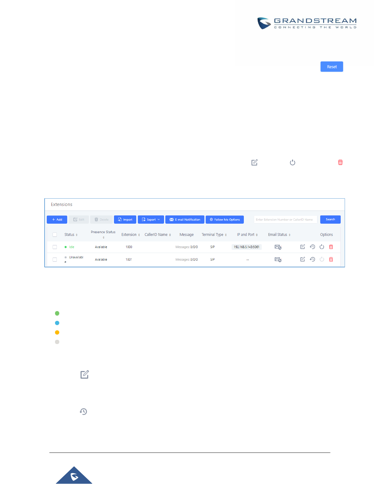
P a g e | 152
UCM6200 Series User Manual
Version 1.0.19.21
Batch Extension Resetting Functionality
Users can select multiple extensions and reset their settings to default by pressing the reset button
and confirm the reset functionality. Once done, all settings in Basic Settings page will be restored to default
values with the exception of Concurrent Registrations. User voicemail password will be reset to Random
Password. User voicemail prompts and recordings will be deleted. User Management settings will also be
restored to default with the exception of usernames and custom privileges
Search and Edit Extension
All the UCM6200 extensions are listed under Web GUI→Extension/Trunk→Extensions, with status, Extension,
CallerID Name, Technology (SIP, IAX and FXS), IP and Port. Each extension has a checkbox for users to "Modify
Selected Extensions" or "Delete Selected Extensions". Also, options "Edit” , "Reboot" and "Delete"
are available per extension. User can search an extension by specifying the extension number to find an
extension quickly.
Figure 81: Manage Extensions
• Status
Users can see the following icon for each extension to indicate the SIP status.
Green: Idle
Blue: Ringing
Yellow: In Use
Grey: Unavailable (the extension is not registered or disabled on the PBX)
• Edit single extension
Click on to start editing the extension parameters.
• Reset single extension
Click on to reset the extension parameters to default (except concurrent registration).
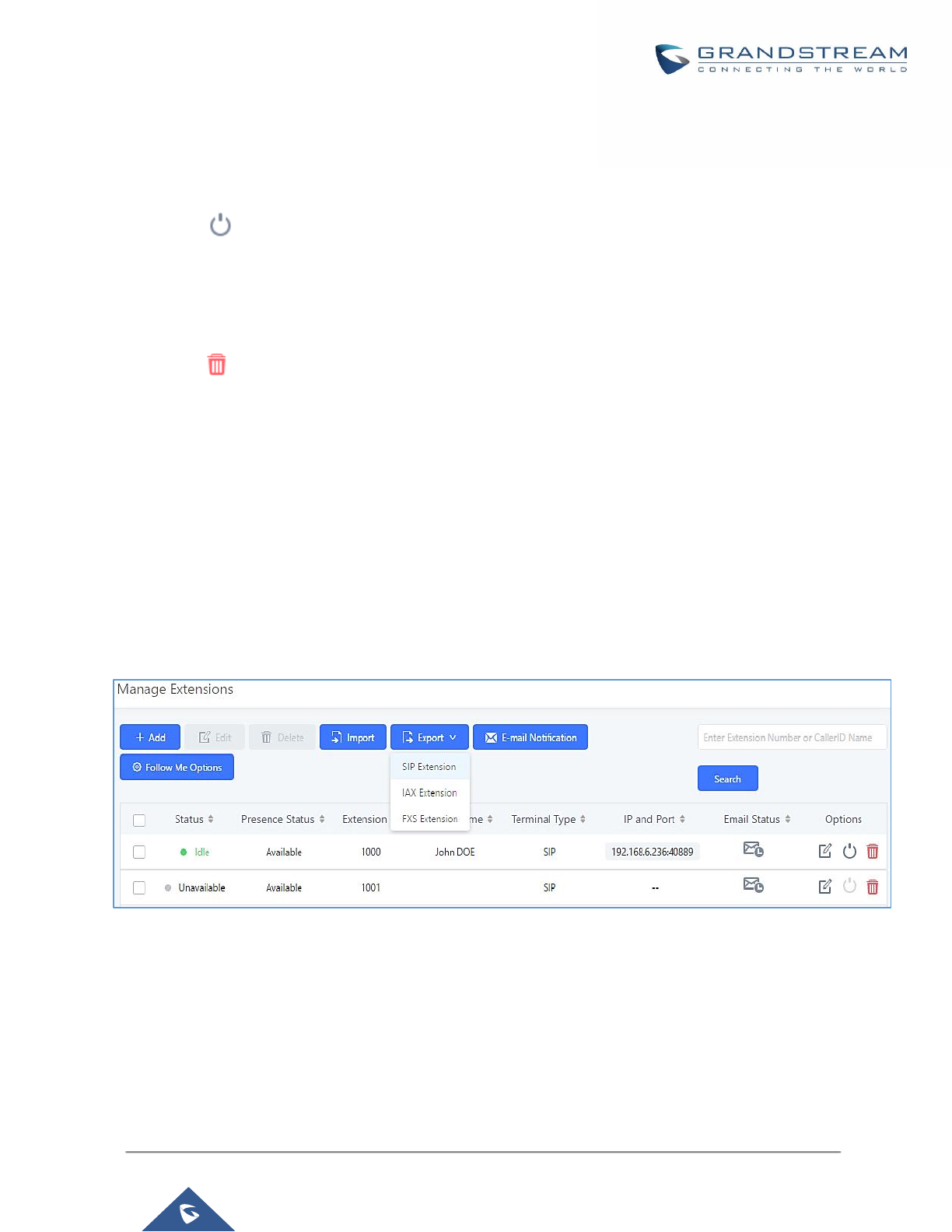
P a g e | 153
UCM6200 Series User Manual
Version 1.0.19.21
Other settings will be restored to default in Maintenance→User Management→User Information except
user name and permissions, and delete the user voicemail prompt and voice messages.
• Reboot the user
Click on to send NOTIFY reboot event to the device which has an UCM6200 extension already
registered. To successfully reboot the user, "Zero Config" needs to be enabled on the UCM6200 Web
GUI→Value-added Features→Zero Config→Zero Config Settings.
• Delete single extension
Click on to delete the extension. Or select the checkbox of the extension and then click on "Delete
Selected Extensions".
• Modify selected extensions
Select the checkbox for the extension(s). Then click on "Edit" to edit the extensions in a batch.
• Delete selected extensions
Select the checkbox for the extension(s). Then click on "Delete " to delete the extension(s).
Export Extensions
The extensions configured on the UCM6200 can be exported to csv format file with selected technology "SIP",
"IAX" or "FXS". Click on "Export Extensions" button and select technology in the prompt below.
Figure 82: Export Extensions
The exported csv file can serve as a template for users to fill in desired extension information to be imported to
the UCM6200.
Import Extensions
The capability to import extensions to the UCM6200 provides users flexibility to batch add extensions with similar
or different configuration quickly into the PBX system.
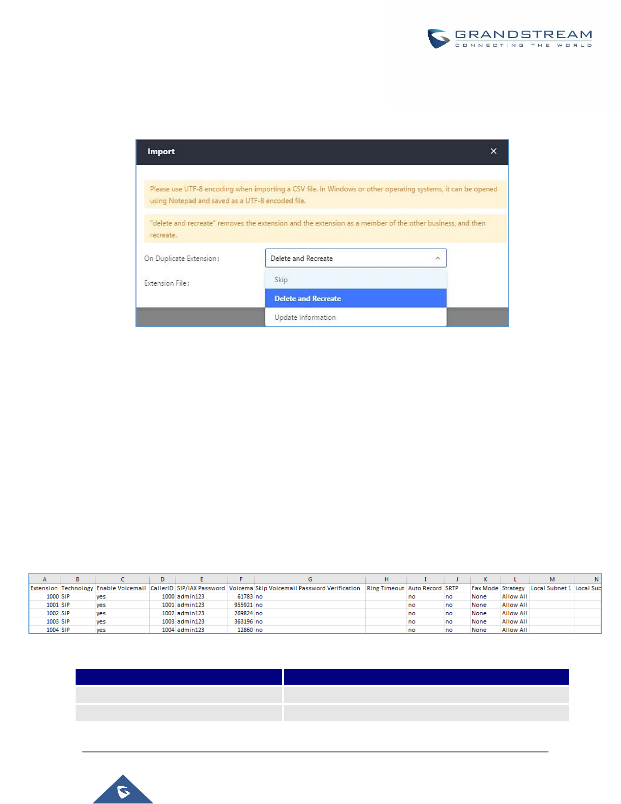
P a g e | 154
UCM6200 Series User Manual
Version 1.0.19.21
1. Export extension csv file from the UCM6200 by clicking on "Export Extensions" button.
2. Fill up the extension information you would like in the exported csv template.
3. Click on "Import Extensions" button. The following dialog will be prompted.
Figure 83: Import Extensions
4. Select the option in "On Duplicate Extension" to define how the duplicate extension(s) in the imported csv
file should be treated by the PBX.
• Skip: Duplicate extensions in the csv file will be skipped. The PBX will keep the current extension
information as previously configured without change.
• Delete and Recreate: The current extension previously configured will be deleted and the duplicate
extension in the csv file will be loaded to the PBX.
• Update Information: The current extension previously configured in the PBX will be kept. However, if
the duplicate extension in the csv file has different configuration for any options, it will override the
configuration for those options in the extension.
5. Click on “Choose file to upload” to select csv file from local directory in the PC.
6. Click on "Apply Changes" to apply the imported file on the UCM6200.
Example of file to import:
Figure 84: Import File
Table 46: SIP extensions Imported File Example
Field
Supported values
Extension
Digits
Technology
SIP/SIP(WebRTC)

P a g e | 155
UCM6200 Series User Manual
Version 1.0.19.21
Enable Voicemail
yes/no/remote
CallerID Number
Digits
SIP/IAX Password
Alphanumeric characters
Voicemail Password
Digits
Skip Voicemail Password Verification
yes/no
Ring Timeout
Empty/ 3 to 600 (in second)
SRTP
yes/no
Fax Mode
None/Fax Detection
Strategy
Allow All/Local Subnet Only/A Specific IP Address
Local Subnet 1
IP address/Mask
Local Subnet 2
IP address/Mask
Local Subnet 3
IP address/Mask
Local Subnet 4
IP address/Mask
Local Subnet 5
IP address/Mask
Local Subnet 6
IP address/Mask
Local Subnet 7
IP address/Mask
Local Subnet 8
IP address/Mask
Local Subnet 9
IP address/Mask
Local Subnet 10
IP address/Mask
Specific IP Address
IP address
Skip Trunk Auth
yes/no/bytime
Codec Preference
PCMU,PCMA,GSM,G.726,G.722,G.729,H.264,
H.265,ILBC,AAL2-G.726-
32,ADPCM,G.723,H.263,H.263p,vp8,opus
Permission
Internal/Local/National/International
NAT
yes/no
DTMF Mode
RFC2833/info/inband/auto
Insecure
Port
Enable Keep-alive
Yes/no
Keep-alive Frequency
Value from 1-3600
AuthID
Alphanumeric value without special characters
TEL URI
Disabled/user=phone/enabled
Call Forward Busy
Digits
Call Forward No Answer
Digits
Call Forward Unconditional
Digits
Support Hot-Desking Mode
Yes/no

P a g e | 156
UCM6200 Series User Manual
Version 1.0.19.21
Dial Trunk Password
Digits
Disable This Extension
Yes/no
CFU Time Condition
All time/Office time/out of office time/holiday/out of
holiday/out of office time or holiday/specific time
CFN Time Condition
All time/Office time/out of office time/holiday/out of
holiday/out of office time or holiday/specific time
CFB Time Condition
All time/Office time/out of office time/holiday/out of
holiday/out of office time or holiday/specific time
Music On Hold
Default/ringbacktone_default
CC Agent Policy
If CC is disabled use: never
If CC is set to normal use: generic
If CC is set to trunk use: native
CC Monitor Policy
Generic/never
CCBS Available Timer
3600/4800
CCNR Available Timer
3600/7200
CC Offer Timer
60/120
CC Max Agents
Value from 1-999
CC Max Monitors
Value from 1-999
Ring simultaneously
Yes/no
External Number
Digits
Time Condition for Ring Simultaneously
All time/Office time/out of office time/holiday/out of
holiday/out of office time or holiday/specific time
Time Condition for Skip Trunk Auth
All time/Office time/out of office time/holiday/out of
holiday/out of office time or holiday/specific time
Enable LDAP
Yes/no
Enable T.38 UDPTL
Yes/no
Max Contacts
Values from 1-10
Enable WebRTC
Yes/no
Alert-Info
None/Ring 1/Ring2/Ring3/Ring 4/Ring 5/Ring 6/Ring 7/ Ring
8/Ring 9/Ring 10/bellcore-dr1/bellcore-dr2/ bellcore-dr3/
bellcore-dr4/ bellcore-dr5/custom
Do Not Disturb
Yes/no
DND Time Condition
All time/Office time/out of office time/holiday/out of
holiday/out of office time or holiday/specific time
Custom Auto answer
Yes/no
Do Not Disturb Whitelist
Empty/digits
User Password
Alphanumeric characters.

P a g e | 157
UCM6200 Series User Manual
Version 1.0.19.21
First Name
Alphanumeric without special characters.
Last Name
Alphanumeric without special characters.
Email Address
Email address
Language
Default/en/zh
Phone Number
Digits
Call-Barging Monitor
Extensions allowed to call barging
Seamless Transfer Members
Extensions allowed to seamless transfer
Table 47: IAX extensions Imported File Example
Field
Supported values
Extension
Digits
Technology
IAX
Enable Voicemail
yes/no
CallerID Number
Digits
SIP/IAX Password
Alphanumeric characters
Voicemail Password
Digits
Skip Voicemail Password Verification
yes/no
Ring Timeout
Empty/ 3 to 600 (in second)
SRTP
yes/no
Fax Mode
None/Fax Detection
Strategy
Allow All/Local Subnet Only/A Specific IP Address
Local Subnet 1
IP address/Mask
Local Subnet 2
IP address/Mask
Local Subnet 3
IP address/Mask
Local Subnet 4
IP address/Mask
Local Subnet 5
IP address/Mask
Local Subnet 6
IP address/Mask
Local Subnet 7
IP address/Mask
Local Subnet 8
IP address/Mask
Local Subnet 9
IP address/Mask
Local Subnet 10
IP address/Mask
Specific IP Address
IP address
Skip Trunk Auth
yes/no/bytime
Codec Preference
PCMU,PCMA,GSM,G.726,G.722,G.729,H.264,
H.265,ILBC,AAL2-G.726-
32,ADPCM,G.723,H.263,H.263p,vp8,opus

P a g e | 158
UCM6200 Series User Manual
Version 1.0.19.21
Permission
Internal/Local/National/International
NAT
yes/no
Call Forward Busy
Digits
Call Forward No Answer
Digits
Call Forward Unconditional
Digits
Require Call Token
Yes/no/auto
Max Number of Calls
Values from 1-512
Dial Trunk Password
Digits
Disable This Extension
Yes/no
CFU Time Condition
All time/Office time/out of office time/holiday/out of holiday/out
of office time or holiday/specific time
CFN Time Condition
CFB Time Condition
All time/Office time/out of office time/holiday/out of holiday/out
of office time or holiday/specific time
Music On Hold
Default/ringbacktone_default
Ring simultaneously
Yes/no
External Number
Digits
Time Condition for Ring Simultaneously
All time/Office time/out of office time/holiday/out of holiday/out
of office time or holiday/specific time
Time Condition for Skip Trunk Auth
All time/Office time/out of office time/holiday/out of holiday/out
of office time or holiday/specific time
Enable LDAP
Yes/no
Limit Max time (s)
empty
Do Not Disturb
Yes/no
DND Time Condition
All time/Office time/out of office time/holiday/out of holiday/out
of office time or holiday/specific time
Do Not Disturb Whitelist
Empty/digits
User Password
Alphanumeric characters.
First Name
Alphanumeric without special characters.
Last Name
Alphanumeric without special characters.
Email Address
Email address
Language
Default/en/zh
Phone Number
Digits
Call-Barging Monitor
Extensions allowed to call barging
Seamless Transfer Members
Extensions allowed to seamless transfer

P a g e | 159
UCM6200 Series User Manual
Version 1.0.19.21
Table 48: FXS Extensions Imported File Example
Field
Supported values
Extension
Digits
Technology
FXS
Analog Station
FXS1/FXS2
Enable Voicemail
yes/no
CallerID Number
Digits
Voicemail Password
Digits
Skip Voicemail Password Verification
yes/no
Ring Timeout
Empty/ 3 to 600 (in second)
Auto Record
yes/no
Fax Mode
None/Fax Detection
Skip Trunk Auth
Yes/no/bytime
Permission
Internal/Local/National/International
Call Forward Busy
Digits
Call Forward No Answer
Digits
Call Forward Unconditional
Digits
Call Waiting
Yes/no
Use # as SEND
Yes/no
RX Gain
Values from -30→6
TX Gain
Values from -30→6
MIN RX Flash
Values from: 30 – 1000
MAX RX Flash
Values from: 40 – 2000
Enable Polarity Reversal
Yes/no
Echo Cancellation
On/Off/32/64/128/256/512/1024
3-Way Calling
Yes/no
Send CallerID After
1/2
Dial Trunk Password
digits
Disable This Extension
Yes/no
CFU Time Condition
All time/Office time/out of office time/holiday/out of holiday/out
of office time or holiday/specific time
CFN Time Condition
All time/Office time/out of office time/holiday/out of holiday/out
of office time or holiday/specific time
CFB Time Condition
All time/Office time/out of office time/holiday/out of holiday/out
of office time or holiday/specific time
Music On Hold
Default/ringbacktone_default

P a g e | 160
UCM6200 Series User Manual
Version 1.0.19.21
CC Agent Policy
If CC is disabled use: never
If CC is set to normal use: generic
If CC is set to trunk use: native
CC Monitor Policy
Generic/never
CCBS Available Timer
3600/4800
CCNR Available Timer
3600/7200
CC Offer Timer
60/120
CC Max Agents
Value from 1-999
CC Max Monitors
Value from 1-999
Ring simultaneously
Yes/no
External Number
Digits
Time Condition for Ring Simultaneously
All time/Office time/out of office time/holiday/out of holiday/out
of office time or holiday/specific time
Time Condition for Skip Trunk Auth
Enable LDAP
Yes/no
Enable Hotline
Yes/no
Hotline Type
Immediate hotline/delay hotline
Hotline Number
digits
Limit Max time (s)
empty
Do Not Disturb
Yes/no
DND Time Condition
All time/Office time/out of office time/holiday/out of holiday/out
of office time or holiday/specific time
Do Not Disturb Whitelist
Empty/digits
User Password
Alphanumeric characters.
First Name
Alphanumeric without special characters.
Last Name
Alphanumeric without special characters.
Email Address
Email address
Language
Default/en/zh
Phone Number
Digits
Call-Barging Monitor
Extensions allowed to call barging
Seamless Transfer Members
Extensions allowed to seamless transfer
The CSV file should contain all the above fields, if one of them is missing or empty, the UCM6200 will display
the following error message for missing fields.
Figure 85: Import Error
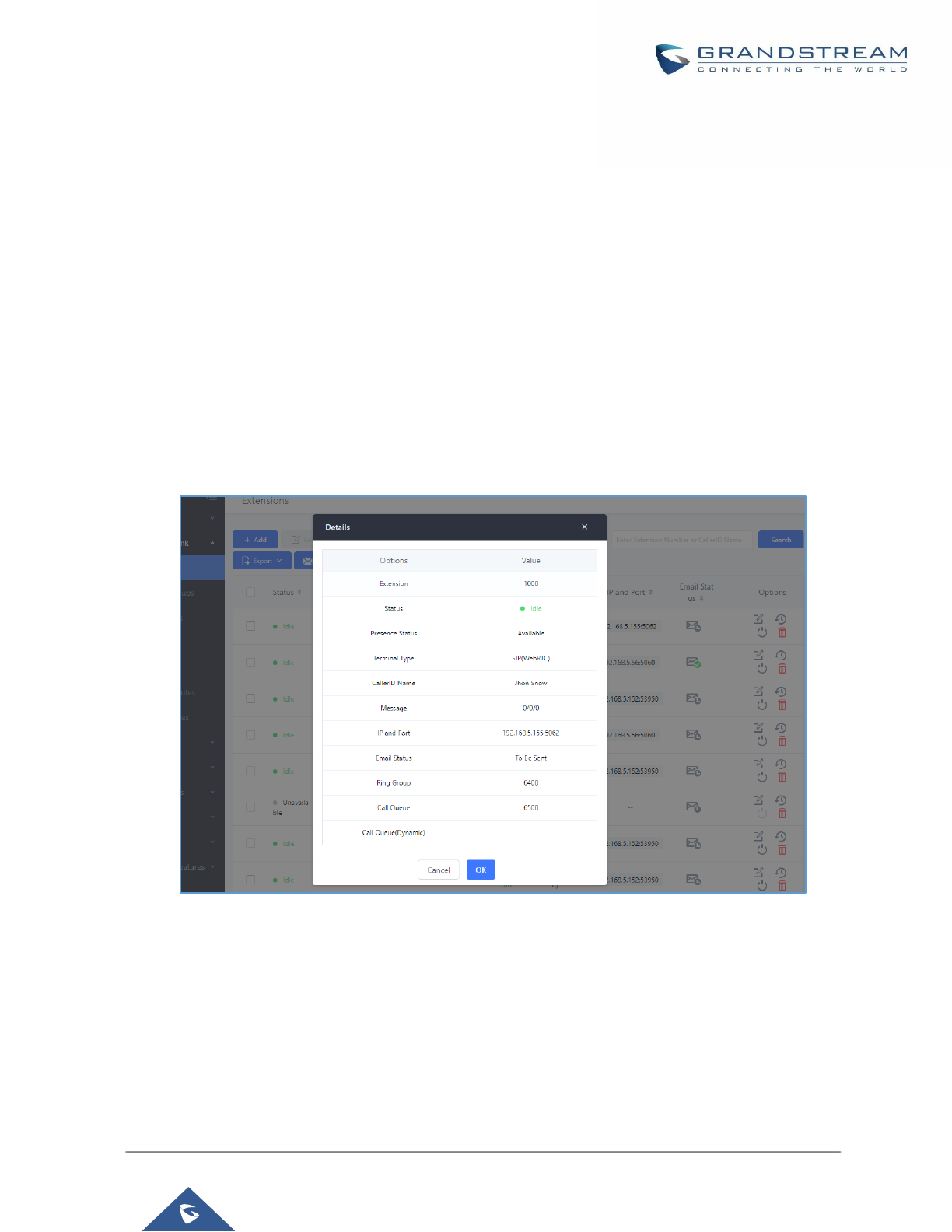
P a g e | 161
UCM6200 Series User Manual
Version 1.0.19.21
Extension Details
Users can click on an extension number in the Extensions list page and quickly view information about it such
as:
• Extension: Shows the Extension number.
• Status: Shows the status of the extension.
• Presence status: Indicates the Presence Status of this extension.
• Terminal Type: Shows the Type of the terminal using this extension (SIP, FXS…etc.).
• Caller ID Name: Reveals the Caller ID Name configured on the extension.
• Messages: Shows the messages stats.
• IP and Port: The IP address and the ports of the device using the extension.
• Email status: Show the Email status (sent, to be sent…etc.).
• Ring Group: Indicates the ring groups that this extension belongs to.
• Call Queue: Indicates the Cal Queues that this extension belongs to.
• Call Queue (Dynamic): Indicates the Call Queues that this extension belongs to as a dynamic agent.
Figure 86: Extension Details
E-mail Notification
Once the extensions are created with Email addresses, the PBX administrator can click on button “E-mail
Notification” to send the account registration and configuration information to the user. Please make sure Email
setting under Web GUI→System Settings→Email Settings is properly configured and tested on the UCM6200
before using “E-mail Notification”.
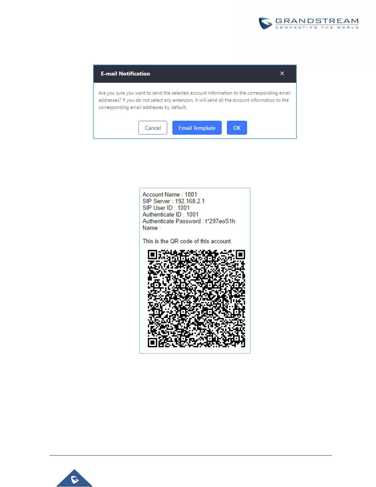
P a g e | 162
UCM6200 Series User Manual
Version 1.0.19.21
When click on “E-mail Notification” button, the following message will be prompted in the web page. Click on OK
to confirm sending the account information to all users’ Email addresses.
Figure 87: E-mail Notification - Prompt Information
The user will receive Email including account registration information and LDAP configuration. A QR code is also
generated for Mobile applications to scan it and get automatically provisioned. QR code provisioning is supported
on Grandstream Softphone GS Wave AndroidTM application and iOS application.
Figure 88: Account Registration Information and QR Code
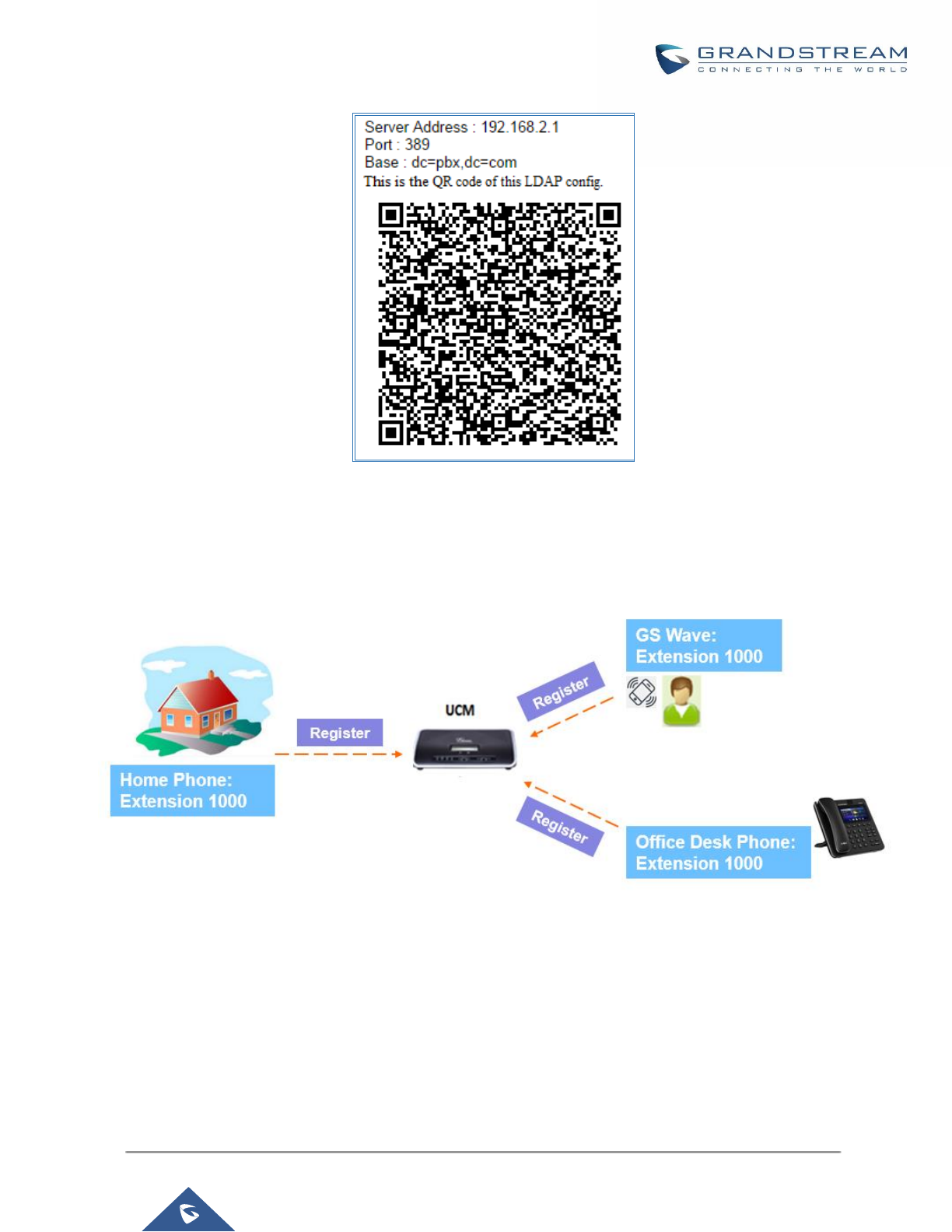
P a g e | 163
UCM6200 Series User Manual
Version 1.0.19.21
Figure 89: LDAP Client Information and QR Code
Multiple Registrations per Extension
UCM6200 supports multiple registrations per extension so that users can use the same extension on devices in
different locations.
Figure 90: Multiple Registrations per Extension
This feature can be enabled by configuring option “Concurrent Registrations” under Web
GUI→Extension/Trunk→Edit Extension. The default value is set to 1 for security purpose. Maximum is 10.
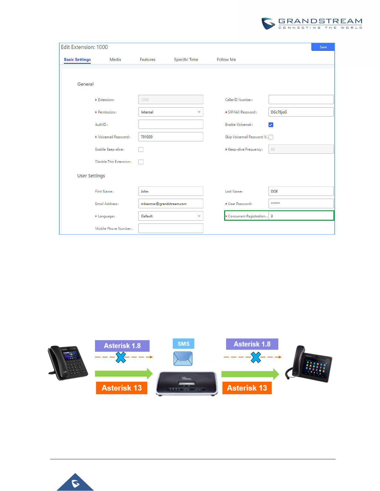
P a g e | 164
UCM6200 Series User Manual
Version 1.0.19.21
Figure 91: Extension - Concurrent Registration
SMS Message Support
The UCM6200 provides built-in SIP SMS message support. For SIP end devices such as Grandstream GXP or
GXV phones that supports SIP message, after an UCM6200 account is registered on the end device, the user
can send and receive SMS message. Please refer to the end device documentation on how to send and receive
SMS message.
SMS Message support is a new feature added since firmware 1.0.10.x which is built with Asterisk 13.
Figure 92: SMS Message Support
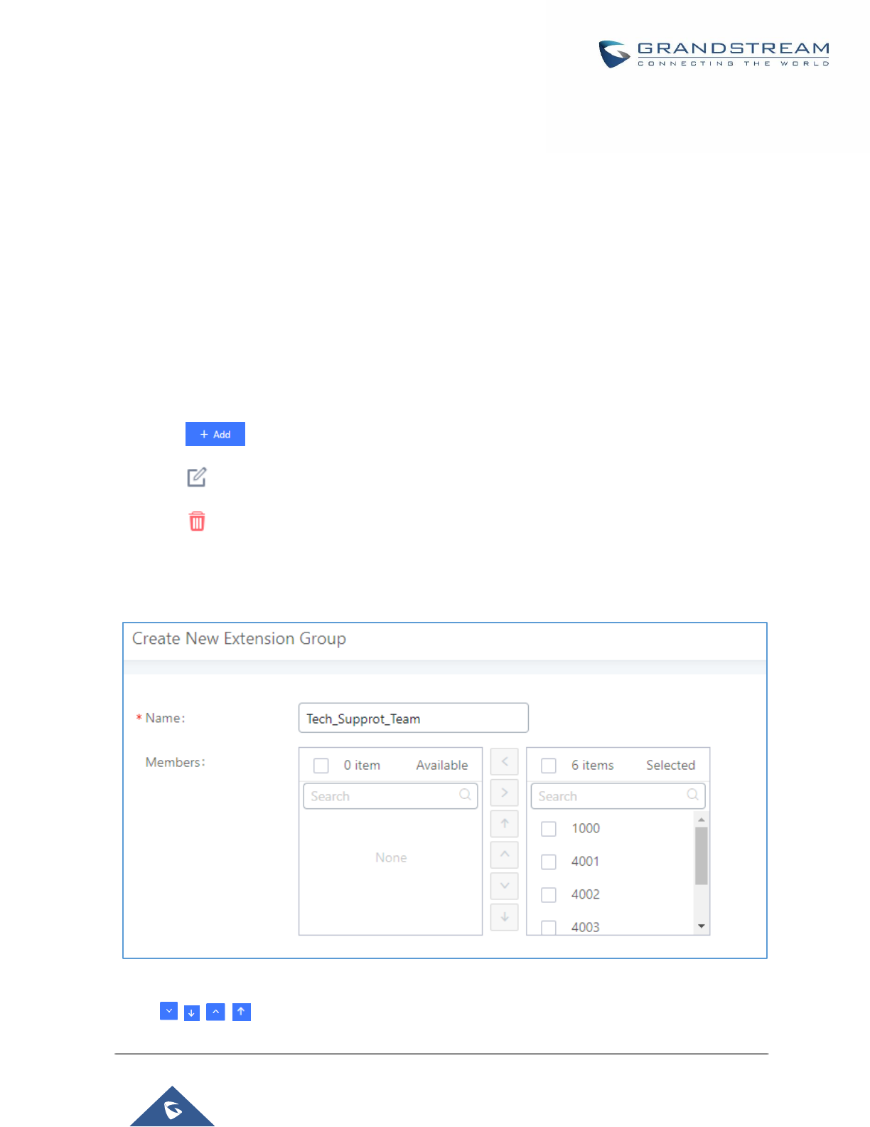
P a g e | 165
UCM6200 Series User Manual
Version 1.0.19.21
EXTENSION GROUPS
The UCM6200 extension group feature allows users to assign and categorize extensions in different groups to
better manage the configurations on the UCM6200. For example, when configuring "Enable Filter on Source
Caller ID", users could select a group instead of each person's extension to assign. This feature simplifies the
configuration process and helps manage and categorize the extensions for business environment.
Configure Extension Groups
Extension group can be configured via Web GUI→Extension/Trunk→Extension Groups.
• Click on to create a new extension group.
• Click on to edit the extension group.
• Click on to delete the extension group.
Select extensions from the list on the left side to the right side.
Figure 93: Edit Extension Group
Click on in order to change the ringing priority of the members selected on the group.

P a g e | 166
UCM6200 Series User Manual
Version 1.0.19.21
Using Extension Groups
Here is an example where the extension group can be used. Go to Web GUI→Extension/Trunk→Outbound
Routes and select "Enable Filter on Source Caller ID". Both single extensions and extension groups will show
up for users to select.
Figure 94: Select Extension Group in Outbound Route
P a g e | 167
UCM6200 Series User Manual
Version 1.0.19.21
ANALOG TRUNKS
Go to Web GUI→Extension/Trunk→Analog Trunks to add and edit analog trunks.
• Click on "Create New Analog Trunk" to add a new analog trunk.
• Click on to edit the analog trunk.
• Click on to delete the analog trunk.
Analog Trunk Configuration
The analog trunk options are listed in the table below.
Table 49: Analog Trunk Configuration Parameters
Channels
Select the channel for the analog trunk.
• UCM6202: 2 channels
• UCM6204: 4 channels
• UCM6208: 8 channels
Trunk Name
Specify a unique label to identify the trunk when listed in outbound rules, incoming
rules and etc.
Advanced Options
SLA Mode
Enable this option to satisfy two primary use cases, which include emulating a simple
key system and creating shared extensions on a PBX. Enable SLA Mode will disable
polarity reversal.
Barge Allowed
The barge option specifies whether other stations can join a call in progress on this
trunk. If enabled, the other stations can press the line button to join the call.
The default setting is Yes.
Hold Access
The hold option specifies hold permissions for this trunk. If set to “Open”, any station
can place this trunk on hold and any other station is allowed to retrieve the call. If set
to “Private”, only the station that places the call on hold can retrieve the call.
The default setting is Yes.
Enable Polarity
Reversal
If enabled, a polarity reversal will be marked as received when an outgoing call is
answered by the remote party. For some countries, a polarity reversal is used for
signaling the disconnection of a phone line and the call will be considered as “Hangup”
on a polarity reversal. The default setting is “No”.

P a g e | 168
UCM6200 Series User Manual
Version 1.0.19.21
Polarity on
Answer Delay
When FXO port answers the call, FXS may send a Polarity Reversal. If this interval is
shorter than the value of “Polarity on Answer Delay”, the Polarity Reversal will be
ignored. Otherwise, the FXO will Onhook to disconnect the call. The default setting is
600ms.
Current
Disconnect
Threshold (ms)
This is the periodic time (in ms) that the UCM6200 will use to check on a voltage drop
in the line. The default setting is 200. The valid range is 50 to 3000.
Ring Timeout
Configure the ring timeout (in ms). Trunk (FXO) devices must have a timeout to
determine if there was a Hangup before the line is answered. This value can be used
to configure how long it takes before the UCM6200 considers a non-ringing line with
Hangup activity. The default setting is 8000.
RX Gain
Configure the RX gain for the receiving channel of analog FXO port. The valid range
is from -13.5 (dB) to + 12.0 (dB). The default setting is 0.
TX Gain
Configure the TX gain for the transmitting channel of analog FXO port. The valid range
is from -13.5 (dB) to + 12.0 (dB). The default setting is 0.
Use CallerID
Configure to enable CallerID detection. The default setting is “Yes”.
Caller ID Scheme
Select the Caller ID scheme for this trunk.
• Bellcore/Telcordia.
• ETSI-FSK During Ringing
• ETSI-FSK Prior to Ringing with DTAS
• ETSI-FSK Prior to Ringing with LR
• ETSI-FSK Prior to Ringing with RP
• ETSI-DTMF During Ringing
• ETSI-DTMF Prior to Ringing with DTAS
• ETSI-DTMF Prior to Ringing with LR
• ETSI-DTMF Prior to Ringing with RP
• SIN 227-BT
• NTT Japan
• Auto Detect
If you are not sure which scheme to choose, please select “Auto Detect”. The default
setting is “Bellcore/Telcordia”.
Fax Mode
Enable to detect Fax signal from the trunk during the call and send the received Fax
to the default Email address in Fax setting page under Web GUI→Call
Features→Fax/T.38. The default setting is “No”.
Note: If enabled, Fax Pass-through cannot be used.
FXO Dial
Delay(ms)
Configure the time interval between off-hook and first dialed digit for outbound calls.
Auto Record
Enable automatic recording for the calls using this trunk. The default setting is
disabled. The recording files can be accessed under Web GUI→CDR→Recording
Files.

P a g e | 169
UCM6200 Series User Manual
Version 1.0.19.21
Disable This Trunk
If selected, the trunk will be disabled and incoming/Outgoing calls via this trunk will
not be possible.
DAHDI Out Line
Selection
This is to implement analog trunk outbound line selection strategy.
Three options are available:
• Ascend
When the call goes out from this analog trunk, it will always try to use the first idle
FXO port. The port order that the call will use to go out would be port 1→port
2→port 10→port 16. Every time it will start with port 1 (if it's idle).
• Poll
When the call goes out from this analog trunk, it will use the port that is not used
last time. And it will always use the port in the order of port
1→2→10→16→1→2→10→16→1→2→10→16..., following the last port being
used.
• Descend
When the call goes out from this analog trunk, it will always try to use the last idle
FXO port. The port order that the call will use to go out would be port 16→port
10→port 2→port 1. Every time it will start with port 16 (if it's idle).
The default setting is “Ascend” mode.
Echo Cancellation
Mode
The Non-Linear Processing (NLP) in echo cancellation helps to remove/suppress
residual echo components that could not be removed by the LEC (Line Echo
Canceller). Following modes are supported:
• Default: The NLP limits the signal level to the background noise level when
active, and the background noise level adjustment is low.
• Custom mode 0: The NLP limits the signal level to the background noise level
when active, and the background noise level adjustment is high.
• Custom mode 1: The NLP sends sign noise when active, and the background
noise level adjustment is high.
• Custom mode 2: The NLP injects white noise when active. The level
corresponds to the background noise level at Sin, and the background noise
level adjustment is high.
Direct Callback
Allows external numbers the option to get directed to the extension that last called
them.
For Example: User 2002 has dialed external number 061234575 but they were not
reachable, once they have received missed call notification on their phone, they
would mostly call back the number, if the option “Direct Callback” is enabled then
they will be directly bridged to user 2002 regardless of the configured inbound
destination.

P a g e | 170
UCM6200 Series User Manual
Version 1.0.19.21
Tone Settings
Busy Detection
Busy Detection is used to detect far end Hangup or for detecting busy signal. The
default setting is "Yes".
Busy Tone Count
If "Busy Detection" is enabled, users can specify the number of busy tones to be
played before hanging up. The default setting is 2. Better results might be achieved if
set to 4, 6 or even 8. Please note that the higher the number is, the more time is
needed to Hangup the channel. However, this might lower the probability to get
random Hangup.
Congestion
Detection
Congestion detection is used to detect far end congestion signal. The default setting
is "Yes".
Congestion Count
If "Congestion Detection" is enabled, users can specify the number of congestion
tones to wait for. The default setting is 2.
Tone Country
Select the country for tone settings. If "Custom" is selected, users could manually
configure the values for Busy Tone and Congestion Tone. The default setting is
"United States of America (USA)".
Busy Tone
Syntax:
f1=val[@level][,f2=val[@level]],c=on1/off1[-on2/off2[-on3/off3]];
Frequencies are in Hz and cadence on and off are in ms.
Frequencies Range: [0, 4000)
Busy Level Range: (-300, 0)
Cadence Range: [0, 16383].
Select Tone Country "Custom" to manually configure Busy Tone value.
Default value:
f1=480@-50,f2=620@-50,c=500/500
Congestion Tone
Syntax:
f1=val[@level][,f2=val[@level]],c=on1/off1[-on2/off2[-on3/off3]];
Frequencies are in Hz and cadence on and off are in ms.
Frequencies Range: [0, 4000)
Busy Level Range: (-300, 0)
Cadence Range: [0, 16383].
Select Tone Country "Custom" to manually configure Busy Tone value.
Default value:
f1=480@-50,f2=620@-50,c=250/250
PSTN Detection
Click on "Detect" to detect the busy tone, Polarity Reversal and Current Disconnect
by PSTN. Before the detecting, please make sure there are more than one channel
configured and working properly. If the detection has busy tone, the "Tone Country"
option will be set as "Custom".
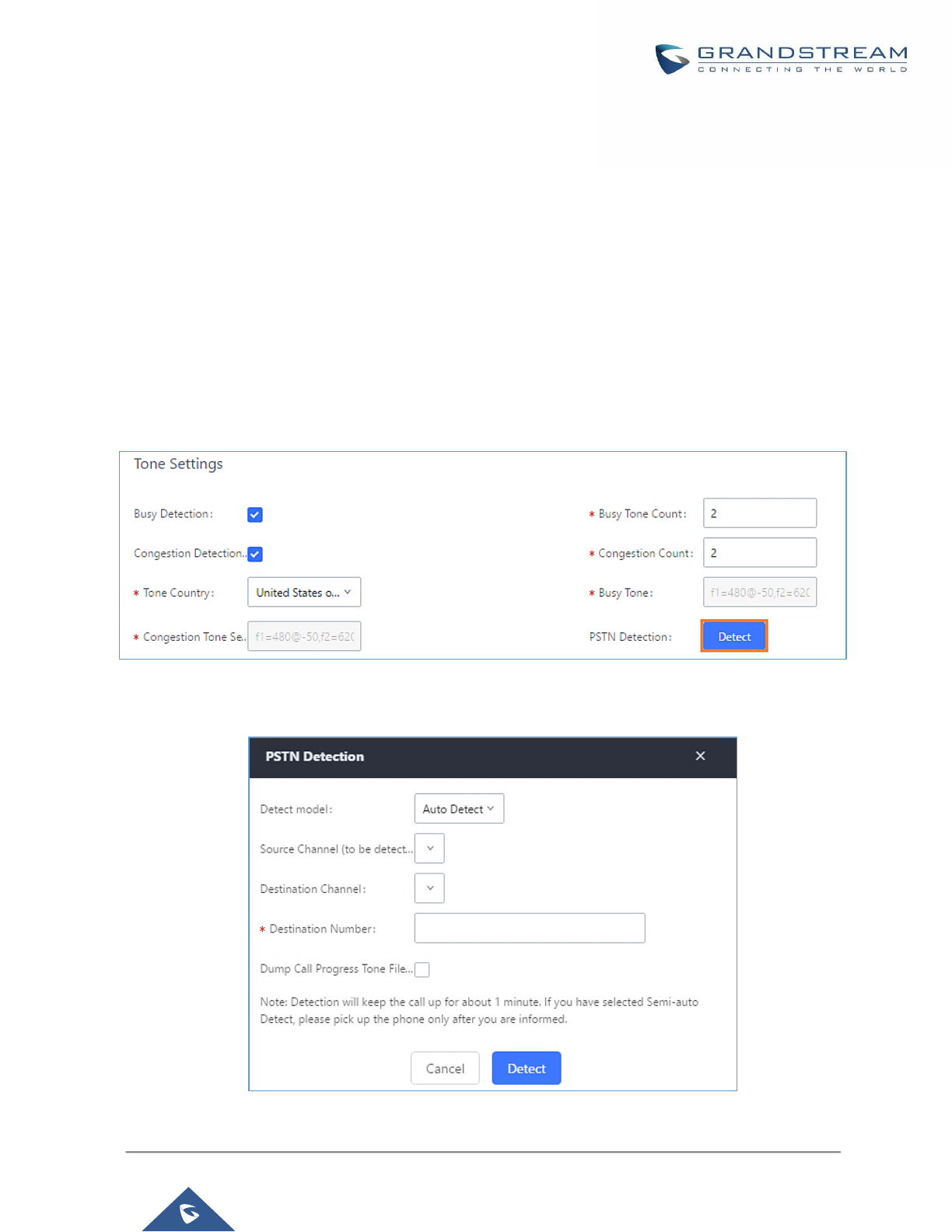
P a g e | 171
UCM6200 Series User Manual
Version 1.0.19.21
PSTN Detection
The UCM6200 provides PSTN detection function to help users detect the busy tone, Polarity Reversal and
Current Disconnect by making a call from the PSTN line to another destination. The detecting call will be
answered and up for about 1 minute. Once done, the detecting result will show and can be used for the UCM6200
settings.
1. Go to UCM6200 Web GUI→Extension/Trunk→Analog Trunks page.
2. Click to edit the analog trunk created for the FXO port.
3. In the dialog window to edit the analog trunk, go to "Tone Settings" section and there are two methods to set
the busy tone.
• Tone Country. The default setting is "United States of America (USA)".
• PSTN Detection.
Figure 95: UCM6200 FXO Tone Settings
4. Click on "Detect" to start PSTN detection.
Figure 96: UCM6200 PSTN Detection
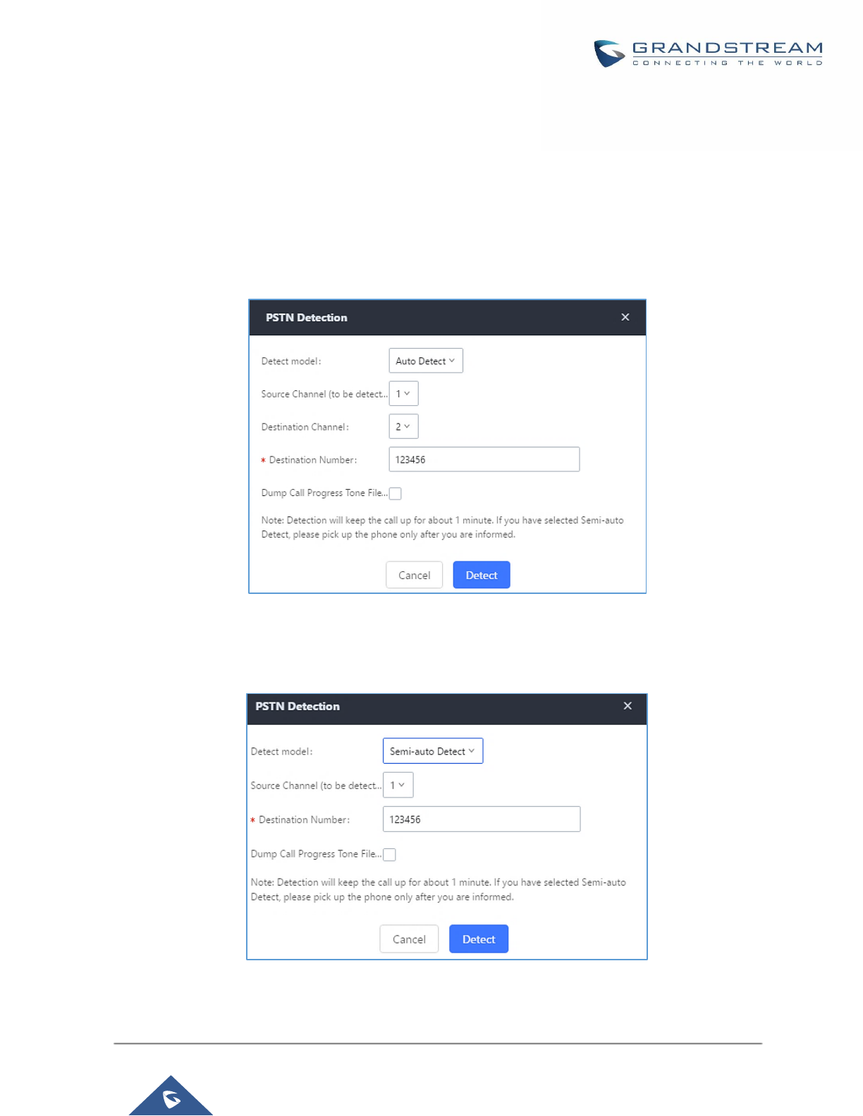
P a g e | 172
UCM6200 Series User Manual
Version 1.0.19.21
• If there are two FXO ports connected to PSTN lines, use the following settings for auto-detection.
Detect Model: Auto Detect.
Source Channel: The source channel to be detected.
Destination Channel: The channel to help detecting. For example, the second FXO port.
Destination Number: The number to be dialed for detecting. This number must be the actual PSTN
number for the FXO port used as the destination channel.
Figure 97: UCM6200 PSTN Detection: Auto Detect
• If there is only one FXO port connected to PSTN line, use the following settings for auto-detection.
Figure 98: UCM6200 PSTN Detection: Semi-Auto Detect

P a g e | 173
UCM6200 Series User Manual
Version 1.0.19.21
Detect Model: Semi-auto Detect.
Source Channel: The source channel to be detected.
Destination Number: The number to be dialed for detecting. This number could be a cell phone number
or other PSTN number that can be reached from the source channel PSTN number.
5. Click "Detect" to start detecting. The source channel will initiate a call to the destination number. For "Auto
Detect", the call will be automatically answered. For "Semi-auto Detect", the UCM6200 Web GUI will display
prompt to notify the user to answer or hang up the call to finish the detecting process.
6. Once done, the detected result will show. Users could save the detecting result as the current UCM6200
settings.
Table 50: PSTN Detection for Analog Trunk
Detect Model
Select "Auto Detect" or "Semi-auto Detect" for PSTN detection.
• Auto Detect
Please make sure two or more channels are connected to the
UCM6200 and in idle status before starting the detection. During the
detection, one channel will be used as caller (Source Channel) and
another channel will be used as callee (Destination Channel). The
UCM6200 will control the call to be established and hang up between
caller and callee to finish the detection.
• Semi-auto Detect
Semi-auto detection requires answering or hanging up the call
manually. Please make sure one channel is connected to the
UCM6200 and in idle status before starting the detection. During the
detection, source channel will be used as caller and send the call to
the configured Destination Number. Users will then need follow the
prompts in Web GUI to help finish the detection.
The default setting is "Auto Detect".
Source Channel
Select the channel to be detected.
Destination Channel
Select the channel to help detect when "Auto Detect" is used.
Destination Number
Configure the number to be called to help the detection.
----------------------------------------------------------------------------------------------------------------------------- ----------------------
Note:
• The PSTN detection process will keep the call up for about 1 minute.
• If "Semi-auto Detect' is used, please pick up the call only after informed from the Web GUI prompt.
• Once the detection is successful, the detected parameters "Busy Tone", "Polarity Reversal" and "Current
Disconnect by PSTN" will be filled into the corresponding fields in the analog trunk configuration.
----------------------------------------------------------------------------------------------------------------------------- ----------------------

P a g e | 174
UCM6200 Series User Manual
Version 1.0.19.21
VOIP TRUNKS
VoIP Trunk Configuration
VoIP trunks can be configured in UCM6200 under Web GUI→Extension/Trunk→VoIP Trunks. Once created,
the VoIP trunks will be listed with Provider Name, Type, Hostname/IP, Username and Options to edit/detect the
trunk.
• Click on "Create New SIP Trunk" or "Create New IAX Trunk" to add a new VoIP trunk.
• Click on to configure detailed parameters for the VoIP trunk.
• Click on to configure Direct Outward Dialing (DOD) for the SIP Trunk.
• Click on to start LDAP Sync.
• Click on to delete the VoIP trunk.
For VoIP trunk example, please refer to the document in the following link:
http://www.grandstream.com/sites/default/files/Resources/ucm6xxx_sip_trunk_guide.pdf
The VoIP trunk options are listed in the table below.
Table 51: Create New SIP Trunk
Type
Select the VoIP trunk type.
• Peer SIP Trunk
• Register SIP Trunk
Provider Name
Configure a unique label (up to 64 character) to identify this trunk when listed in
outbound rules, inbound rules etc.
Host Name
Configure the IP address or URL for the VoIP provider’s server of the trunk.
Keep Original CID
Keep the CID from the inbound call when dialing out. This setting will override
“Keep Trunk CID” option. Please make sure that the peer PBX at the other side
supports to match user entry using “username” field from authentication line.
Keep Trunk CID
If enabled, the trunk CID will not be overridden by extension’s CID when the
extension has CID configured. The default setting is “No”.
NAT
Turn on this setting when the PBX is using public IP and communicating with
devices behind NAT. If there is one-way audio issue, usually it is related to NAT
configuration or SIP/RTP port support on the firewall.

P a g e | 175
UCM6200 Series User Manual
Version 1.0.19.21
Disable This Trunk
If checked, the trunk will be disabled.
Note: If a current SIP trunk is disabled, UCM will send UNREGISTER message
(REGISTER message with expires=0) to the SIP provider.
TEL URI
If the trunk has an assigned PSTN telephone number, this field should be set to
"User=Phone". Then a "User=Phone" parameter will be attached to the Request-
Line and TO header in the SIP request to indicate the E.164 number. If set to
"Enable", "Tel:" will be used instead of "SIP:" in the SIP request. The default setting
is disabled.
Caller ID
Configure the Caller ID. This is the number that the trunk will try to use when
making outbound calls. For some providers, it might not be possible to set the
CallerID with this option and this option will be ignored.
Important Note: When making outgoing calls, the following priority order rule will
be used to determine which CallerID will be set before sending out the call:
From user (Register Trunk Only) → CID from inbound call (Keep Original CID
Enabled) → Trunk Username/CallerID (Keep Trunk CID Enabled) → DOD →
Extension CallerID Number → Trunk Username/CallerID (Keep Trunk CID
Disabled) → Global Outbound CID.
Need Registration
Select whether the trunk needs to register on the external server or not when
"Register SIP Trunk" type is selected. The default setting is No.
Username
Enter the username to register to the trunk from the provider when "Register SIP
Trunk" type is selected.
Password
Enter the password to register to the trunk from the provider when "Register SIP
Trunk" is selected.
Auth ID
Enter the Authentication ID for "Register SIP Trunk" type.
Auto Record
Enable automatic recording for the calls using this trunk (for SIP trunk only). The
default setting is disabled. The recording files can be accessed under Web
GUI→CDR→Recording Files.
Direct Callback
Allows external numbers the option to get directed to the extension that last called
them.
For Example: User 2002 has dialed external number 061234575 but they were not
reachable, once they have received missed call notification on their phone, they
would mostly call back the number, if the option “Direct Callback” is enabled then
they will be directly bridged to user 2002 regardless of the configured inbound
destination.

P a g e | 176
UCM6200 Series User Manual
Version 1.0.19.21
Table 52: SIP Register Trunk Configuration Parameters
Basic Settings
Provider Name
Configure a unique label to identify this trunk when listed in outbound rules,
inbound rules etc.
Host Name
Configure the IP address or URL for the VoIP provider’s server of the trunk.
Transport
Configure the SIP transport protocol to be used in this trunk. The default setting is
"UDP".
• UDP
• TCP
• TLS
Keep Original CID
Keep the CID from the inbound call when dialing out. This setting will override
“Keep Trunk CID” option. Please make sure that the peer PBX at the other side
supports to match user entry using “username” field from authentication line.
Keep Trunk CID
If enabled, the trunk CID will not be overridden by extension’s CID when the
extension has CID configured. The default setting is “No”.
NAT
Turn on this option when the PBX is using public IP and communicating with
devices behind NAT. If there is one-way audio issue, usually it’s related to NAT
configuration or SIP/RTP port configuration on the firewall.
Disable This Trunk
If selected, the trunk will be disabled.
Note:
If a current SIP trunk is disabled, UCM will send UNREGISTER message
(REGISTER message with expires=0) to the SIP provider.
TEL URI
If the trunk has an assigned PSTN telephone number, this field should be set to
"User=Phone". Then a "User=Phone" parameter will be attached to the Request-
Line and TO header in the SIP request to indicate the E.164 number. If set to
"Enable", "Tel:" will be used instead of "SIP:" in the SIP request. The default setting
is disabled.
Need Registration
Select whether the trunk needs to register on the external server or not when
"Register SIP Trunk" type is selected. The default setting is No.
Allow outgoing calls
if registration failure
If enabled outgoing calls even if the registration to this trunk fail will still be able to
go through.
Note that if we uncheck “Need Registration” option, this option will be ignored.
CallerID Name
Configure the new name of the caller when the extension has no CallerID Name
configured.
From Domain
Configure the actual domain name where the extension comes from. This can be
used to override the “From” Header.
For example, "trunk.UCM6200.provider.com" is the From Domain in From Header:
sip:1234567@trunk.UCM6200.provider.com.

P a g e | 177
UCM6200 Series User Manual
Version 1.0.19.21
From User
Configure the actual user name of the extension. This can be used to override the
“From” Header. There are cases where there is a single ID for registration (single
trunk) with multiple DIDs.
For example, "1234567" is the From User in From Header:
sip:1234567@trunk.UCM6200.provider.com.
Username
Enter the username to register to the trunk from the provider when "Register SIP
Trunk" type is selected.
Password
Enter the password to register to the trunk when "Register SIP Trunk" is selected.
Auth ID
Enter the Authentication ID for "Register SIP Trunk" type.
Auth Trunk
If enabled, the UCM will send 401 response to the incoming call to authenticate
the trunk.
Auto Record
Enable automatic recording for the calls using this trunk (for SIP trunk only). The
default setting is disabled. The recording files can be accessed under Web
GUI→CDR→Recording Files.
Direct Callback
Allows external numbers the option to get directed to the extension that last called
them.
For Example: User 2002 has dialed external number 061234575 but they were not
reachable, once they have received missed call notification on their phone, they
would mostly call back the number, if the option “Direct Callback” is enabled then
they will be directly bridged to user 2002 regardless of the configured inbound
destination.
Advanced Settings
Codec Preference
Select audio and video codec for the VoIP trunk. The available codecs are: PCMU,
PCMA, GSM, AAL2-G.726-32, G.726, G.722, G.729, G.723, iLBC, ADPCM,
H.264, H.265, H.263, H.263p and VP8.
Send PPI Header
If enabled, the SIP INVITE message sent to the trunk will contain PPI (P-Preferred-
Identity) header. The default setting is “No”.
Note: “Send PPI Header” and “Send PAI Header” cannot be enabled at the same
time. Only one of the two headers can be contained in SIP INVITE message.
PPI Mode
• Default – Include the trunk’s preferred CID (configured in Basic Settings)
in the PPI Header.
• Original CID – Include the original CID in the PPI Header.
• DOD Number – Include the trunk’s DOD number in the PPI Header. If no
DOD number has been set, the trunk’s preferred CID will be used.
Send PAI Header
If enabled, the SIP INVITE message sent to the trunk will contain PAI (P-Asserted-
Identity) header including configured PAI Header. The default setting is “No”.
Note: “Send PPI Header” and “Send PAI Header” cannot be enabled at the same
time. Only one of the two headers can be contained in the SIP INVITE message.

P a g e | 178
UCM6200 Series User Manual
Version 1.0.19.21
PAI Header
If “Send PAI Header” is enabled and “PAI Header” is configured as “123456” for
instance, the PAI header in the SIP message sent from the UCM will contain
“123456”. If “Send PAI Header” is enabled and “PAI Header” is configured as
“empty”, the PAI header in the SIP message sent from the UCM will contain the
original CID.
Note:
“Send PAI Header” needs to be enabled to use this feature
DOD As From Name
If enabled and "From User" is configured, the INVITE's From header will contain
the DOD number.
Passthrough PAI
Header
If checked and option "Send PAI Header" not checked, the PAI header will be
passthrough from one side to the other side.
Outbound Proxy
Support
Select to enable outbound proxy in this trunk. The default setting is "No".
Outbound Proxy
When outbound proxy support is enabled, enter the IP address or URL of the
outbound proxy.
Remove OBP from
Route
It is used to set if the phone system will remove outbound proxy URI from the route
header. If is set to “Yes”, it will remove the route header from SIP requests. The
default setting is “No”.
DID Mode
Configure where to get the destination ID of an incoming SIP call, from SIP
Request-line or To-header. The default is set to "Request-line".
DTMF Mode
Configure the default DTMF mode when sending DTMF on this trunk.
• Default: The global setting of DTMF mode will be used. The global setting
for DTMF Mode setting is under Web GUI→PBX Settings→SIP
Settings→ToS.
• RFC2833: Send DTMF using RFC2833.
• Info: Send DTMF using SIP INFO message.
• Inband: Send DTMF using inband audio. This requires 64-bit codec, i.e.,
PCMU and PCMA.
• Auto: Send DTMF using RFC2833 if offered. Otherwise, inband will be
used.
Enable Heartbeat
Detection
If enabled, the UCM6200 will regularly send SIP OPTIONS to the device to check
if the device is still online. The default setting is "No".
Heartbeat Frequency
When "Enable Heartbeat Detection" option is set to "Yes", configure the interval
(in seconds) of the SIP OPTIONS message sent to the device to check if the device
is still online. The default setting is 60 seconds.

P a g e | 179
UCM6200 Series User Manual
Version 1.0.19.21
Maximum Number of
Call Lines
The maximum number of concurrent calls using the trunk. The default settings 0,
which means no limit.
Fax Mode
Select Fax mode. The default setting is “None”.
• None: Disable Fax.
• Fax Detect: Fax signal from the user/trunk during the call can be detected and
the received Fax will be sent to the Email address configured for this
extension. If no Email address can be found for the user, the Fax will be sent
to the default Email address configured in Fax setting page under Web
GUI→Call Features→Fax/T.38.
SRTP
Enable SRTP for the VoIP trunk. The default setting is "No".
CC Settings
Enable CC
If enabled, the system will automatically alert the user when a called party is
available, given that a previous call to that party failed for some reason.
CC Max Agents
Configure the maximum number of CCSS agents which may be allocated for this
channel. In other words, this number serves as the maximum number of CC
requests this channel is allowed to make. The minimum value is 1.
CC Max Monitors
Configure the maximum number of monitor structures which may be created for
this device. In other words, this number tells how many callers may request CC
services for a specific device at one time. The minimum value is 1.
Table 53: SIP Peer Trunk Configuration Parameters
Basic Settings
Provider Name
Configure a unique label to identify this trunk when listed in outbound rules,
inbound rules and etc.
Host Name
Configure the IP address or URL for the VoIP provider’s server of the trunk.
Auto Record
Enable automatic recording for the calls using this trunk (for SIP trunk only). The
default setting is disabled. The recording files can be accessed under Web
GUI→CDR→Recording Files.
Keep Original CID
Keep the CID from the inbound call when dialing out, this setting will override “Keep
Trunk CID” option. Please make sure that the peer PBX at the other side supports
to match user entry using “username” field from authentication line.
Keep Trunk CID
If enabled, the trunk CID will not be overridden by extension’s CID when the
extension has CID configured. The default setting is “No”.
NAT
Turn on this option when the PBX is using public IP and communicating with
devices behind NAT. If there is one-way audio issue, usually it’s related to NAT
configuration or SIP/RTP port configuration on the firewall.

P a g e | 180
UCM6200 Series User Manual
Version 1.0.19.21
Disable This Trunk
If selected, the trunk will be disabled.
Note:
If a current SIP trunk is disabled, UCM will send UNREGISTER message
(REGISTER message with expires=0) to the SIP provider.
TEL URI
If the trunk has an assigned PSTN telephone number, this field should be set to
"User=Phone". Then a "User=Phone" parameter will be attached to the Request-
Line and TO header in the SIP request to indicate the E.164 number. If set to
"Enable", "Tel:" will be used instead of "SIP:" in the SIP request. The default setting
is disabled.
Caller ID
Configure the Caller ID. This is the number that the trunk will try to use when
making outbound calls. For some providers, it might not be possible to set the
CallerID with this option and this option will be ignored.
Important Note: When making outgoing calls, the following priority order rule will
be used to determine which CallerID will be set before sending out the call :
• CID from inbound call (Keep Original CID Enabled) → Trunk
Username/CallerID (Keep Trunk CID Enabled) → DOD → Extension CallerID
Number → Trunk Username/CallerID (Keep Trunk CID Disabled) → Global
Outbound CID.
CallerID Name
Configure the name of the caller to be displayed when the extension has no
CallerID Name configured.
Transport
Configure the SIP transport protocol to be used in this trunk. The default setting is
"UDP".
• UDP
• TCP
• TLS
Direct Callback
Allows external numbers the option to get directed to the extension that last called
them.
For Example: User 2002 has dialed external number 061234575 but they were not
reachable, once they have received missed call notification on their phone, they
would mostly call back the number, if the option “Direct Callback” is enabled then
they will be directly bridged to user 2002 regardless of the configured inbound
destination.
Advanced Settings
Codec Preference
Select audio and video codec for the VoIP trunk. The available codecs are: PCMU,
PCMA, GSM, AAL2-G.726-32, G.726, G.722, G.729, G.723, iLBC, ADPCM,
H.264, H.265, H.263, H.263p and VP8.
DID Mode
Configure where to get the destination ID of an incoming SIP call, from SIP
Request-line or To-header. The default is set to "Request-line".

P a g e | 181
UCM6200 Series User Manual
Version 1.0.19.21
DTMF Mode
Configure the default DTMF mode when sending DTMF on this trunk.
• Default: The global setting of DTMF mode will be used. The global setting
for DTMF Mode setting is under Web GUI→PBX Settings→SIP
Settings→ToS.
• RFC2833: Send DTMF using RFC2833.
• Info: Send DTMF using SIP INFO message.
• Inband: Send DTMF using inband audio. This requires 64-bit codec, i.e.,
PCMU and PCMA.
• Auto: Send DTMF using RFC2833 if offered. Otherwise, inband is used.
Enable Heartbeat
Detection
If enabled, the UCM6200 will regularly send SIP OPTIONS to the device to check
if the device is still online. The default setting is "No".
Heartbeat Frequency
When "Enable Heartbeat Detection" option is set to "Yes", configure the interval
(in seconds) of the SIP OPTIONS message sent to the device to check if the device
is still online. The default setting is 60 seconds.
Maximum Number of
Call Lines
The maximum number of concurrent calls using the trunk. The default settings 0,
which means no limit.
Fax Mode
Select Fax mode. The default setting is “None”.
• None: Disable Fax.
• Fax Detect: Fax signal from the user/trunk during the call can be detected and
the received Fax will be sent to the Email address configured for this
extension. If no Email address can be found for the user, the Fax will be sent
to the default Email address configured in Fax setting page under Web
GUI→Call Features→Fax/T.38.
SRTP
Enable SRTP for the VoIP trunk.
The default setting is "No".
Sync LDAP Enable
If enabled, the local UCM6200 will automatically provide and update the local
LDAP contacts to the remote UCM6200 SIP peer trunk. In order to ensure
successful synchronization, the remote UCM6200 peer also needs to enable this
option on the SIP peer trunk.
The default setting is "No".
Sync LDAP
Password
This is the password used for LDAP contact file encryption and decryption during
the LDAP sync process. The password must be the same on both UCM6200 peers
to ensure successful synchronization.
Sync LDAP Port
Configure the TCP port used LDAP sync feature between two peer UCM6200.
LDAP Outbound Rule
Specify an outbound rule for LDAP sync feature. The UCM6200 will automatically
modify the remote contacts by adding prefix parsed from this rule.

P a g e | 182
UCM6200 Series User Manual
Version 1.0.19.21
LDAP Dialed Prefix
Specify the prefix for LDAP sync feature. The UCM6200 will automatically modify
the remote contacts by adding this prefix.
CC Settings
Enable CC
If enabled, the system will automatically alert the user when a called party is
available, given that a previous call to that party failed for some reason.
CC Max Agents
Configure the maximum number of CCSS agents which may be allocated for this
channel. In other words, this number serves as the maximum number of CC
requests this channel can make. The minimum value is 1.
CC Max Monitors
Configure the maximum number of monitor structures which may be created for
this device. In other words, this number tells how many callers may request CC
services for a specific device at one time.
The minimum value is 1.
Table 54: Create New IAX Trunk
Type
Select the VoIP trunk type.
• Peer IAX Trunk
• Register IAX Trunk
Provider Name
Configure a unique label to identify this trunk when listed in outbound rules,
inbound rules etc.
Host Name
Configure the IP address or URL for the VoIP provider’s server of the trunk.
Keep Trunk CID
If enabled, the trunk CID will not be overridden by extension's CID when the
extension has CID configured. The default setting is "No".
Username
Enter the username to register to the trunk from the provider when "Register IAX
Trunk" type is selected.
Password
Enter the password to register to the trunk from the provider when "Register IAX
Trunk" type is selected.
Disable This Trunk
If selected, the trunk will be disabled.
Table 55: IAX Register Trunk Configuration Parameters
Basic Settings
Provider Name
Configure a unique label to identify this trunk when listed in outbound rules,
inbound rules etc.
Host Name
Configure the IP address or URL for the VoIP provider’s server of the trunk.
Keep Trunk CID
If enabled, the trunk CID will not be overridden by extension's CID when the
extension has CID configured.
The default setting is "No".
Disable This Trunk
If selected, the trunk will be disabled.

P a g e | 183
UCM6200 Series User Manual
Version 1.0.19.21
Caller ID
Configure the Caller ID. This is the number that the trunk will try to use when
making outbound calls. For some providers, it might not be possible to set the
CallerID with this option and this option will be ignored.
Important Note: When making outgoing calls, the following priority order rule will
be used to determine which CallerID will be set before sending out the call :
From user (Register Trunk Only) → CID from inbound call (Keep Original CID
Enabled) → Trunk Username/CallerID (Keep Trunk CID Enabled) → DOD →
Extension CallerID Number → Trunk Username/CallerID (Keep Trunk CID
Disabled) → Global Outbound CID.
CallerID Name
Configure the name of the caller to be displayed when the extension has no
CallerID Name configured.
Username
Enter the username to register to the trunk from the provider.
Password
Enter the password to register to the trunk from the provider.
Advanced Settings
Codec Preference
Select audio and video codec for the VoIP trunk. The available codecs are: PCMU,
PCMA, GSM, AAL2-G.726-32, G.726, G.722, G.729, G.723, iLBC, ADPCM,
H.264, H.265, H.263, H.263p and VP8.
Enable Heartbeat
Detection
If enabled, the UCM6200 will regularly send SIP OPTIONS to the device to check
if the device is still online. The default setting is "No".
Heartbeat Frequency
When "Enable Heartbeat Detection" option is set to "Yes", configure the interval
(in seconds) of the SIP OPTIONS message sent to the device to check if the device
is still online. The default setting is 60 seconds.
Maximum Number of
Call Lines
The maximum number of concurrent calls using the trunk. The default settings 0,
which means no limited.
Fax Mode
Select Fax mode. The default setting is “None”.
• None: Disable Fax.
• Fax Detect: Fax signal from the user/trunk during the call can be detected and
the received Fax will be sent to the Email address configured for this
extension. If no Email address can be found for the user, the Fax will be sent
to the default Email address configured in Fax setting page under Web
GUI→Call Features→Fax/T.38.

P a g e | 184
UCM6200 Series User Manual
Version 1.0.19.21
Table 56: IAX Peer Trunk Configuration Parameters
Basic Settings
Provider Name
Configure a unique label to identify this trunk when listed in outbound rules,
inbound rules etc.
Host Name
Configure the IP address or URL for the VoIP provider’s server of the trunk.
Keep Trunk CID
If enabled, the trunk CID will not be overridden by extension's CID when the
extension has CID configured. The default setting is "No".
Disable This Trunk
If selected, the trunk will be disabled.
Caller ID
Configure the Caller ID. This is the number that the trunk will try to use when
making outbound calls. For some providers, it might not be possible to set the
CallerID with this option and this option will be ignored.
Important Note: When making outgoing calls, the following priority order rule will
be used to determine which CallerID will be set before sending out the call :
CID from inbound call (Keep Original CID Enabled) → Trunk Username/CallerID
(Keep Trunk CID Enabled) → DOD → Extension CallerID Number → Trunk
Username/CallerID (Keep Trunk CID Disabled) → Global Outbound CID..
CallerID Name
Configure the name of the caller to be displayed when the extension has no
CallerID Name configured.
Advanced Settings
Codec Preference
Select audio and video codec for the VoIP trunk. The available codecs are: PCMU,
PCMA, GSM, AAL2-G.726-32, G.726, G.722, G.729, G.723, iLBC, ADPCM,
H.264, H.265, H.263, H.263p and VP8.
Enable Heartbeat
Detection
If enabled, the UCM6200 will regularly send SIP OPTIONS to the device to check
if the device is still online. The default setting is "No".
Heartbeat Frequency
When "Enable Heartbeat Detection" option is set to "Yes", configure the interval
(in seconds) of the SIP OPTIONS message sent to the device to check if the device
is still online. The default setting is 60 seconds.
Maximum Number of
Call Lines
The maximum number of concurrent calls using the trunk. The default settings 0,
which means no limited.
Fax Mode
Select Fax mode. The default setting is “None”.
• None: Disable Fax.
• Fax Detect: Fax signal from the user/trunk during the call can be detected and
the received Fax will be sent to the Email address configured for this
extension. If no Email address can be found for the user, the Fax will be sent
to the default Email address configured in Fax setting page under Web
GUI→Call Features→Fax/T.38.
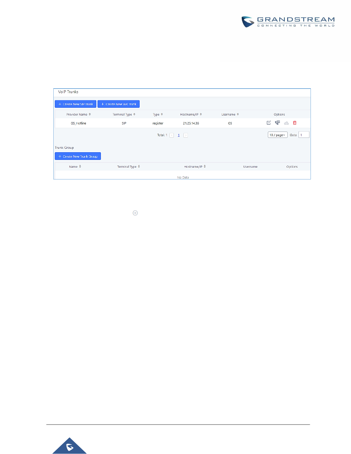
P a g e | 185
UCM6200 Series User Manual
Version 1.0.19.21
Trunk Groups
Users can create VoIP Trunk Groups to register and easily apply the same settings on multiple accounts within
the same SIP server. This can drastically reduce the amount of time needed to manage accounts for the same
server and improve the overall cleanliness of the web UI.
Figure 99: Trunk Group
Once creating the new trunk group and configuring the SIP settings, users can add multiple accounts within the
configured SIP server by pressing button and configuring the username, password and authentication ID
fields.
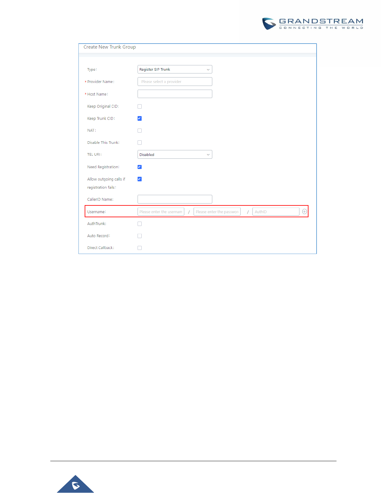
P a g e | 186
UCM6200 Series User Manual
Version 1.0.19.21
Figure 100: Trunk Group Configuration
Direct Outward Dialing (DOD)
The UCM6200 provides Direct Outward Dialing (DOD) which is a service of a local phone company (or local
exchange carrier) that allows subscribers within a company's PBX system to connect to outside lines directly.
Example of how DOD is used:
Company ABC has a SIP trunk. This SIP trunk has 4 DIDs associated to it. The main number of the office is
routed to an auto attendant. The other three numbers are direct lines to specific users of the company. Now
when a user makes an outbound call their caller ID shows up as the main office number. This poses a problem
as the CEO would like their calls to come from their direct line. This can be accomplished by configuring DOD
for the CEO’s extension.
Steps to configure DOD on the UCM6200:
1. To setup DOD go to UCM6200 Web GUI→Extension/Trunk→VoIP Trunks page.
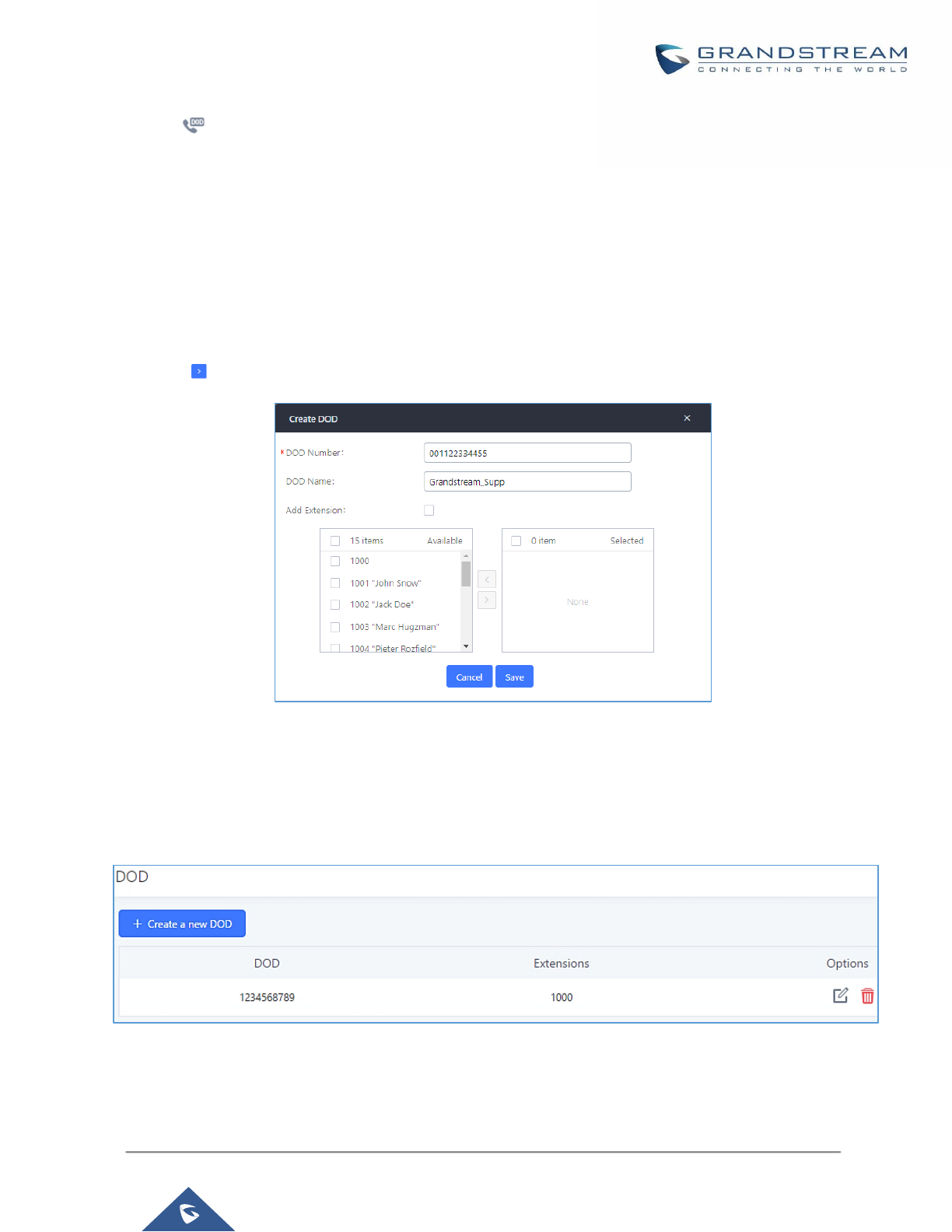
P a g e | 187
UCM6200 Series User Manual
Version 1.0.19.21
2. Click to access the DOD options for the selected SIP Trunk.
3. Click "Create a new DOD" to begin your DOD setup
4. For "DOD Number" enter one of the numbers (DIDs) from your SIP trunk provider. In the example above
Company ABC received 4 DIDs from their provider. ABC will enter in the number for the CEO's direct line.
5. Set the DOD name and If extension number need to be appended to the DID number click on “Add
Extension”.
6. Select an extension from the "Available Extensions" list. Users have the option of selecting more than one
extension. In this case, Company ABC would select the CEO's extension. After making the selection, click
on the button to move the extension(s) to the "Selected Extensions" list.
Figure 101: DOD extension selection
7. Click "Save" at the bottom.
Once completed, the user will return to the EDIT DOD page that shows all the extensions that are associated to
a particular DOD.
Figure 102: Edit DOD
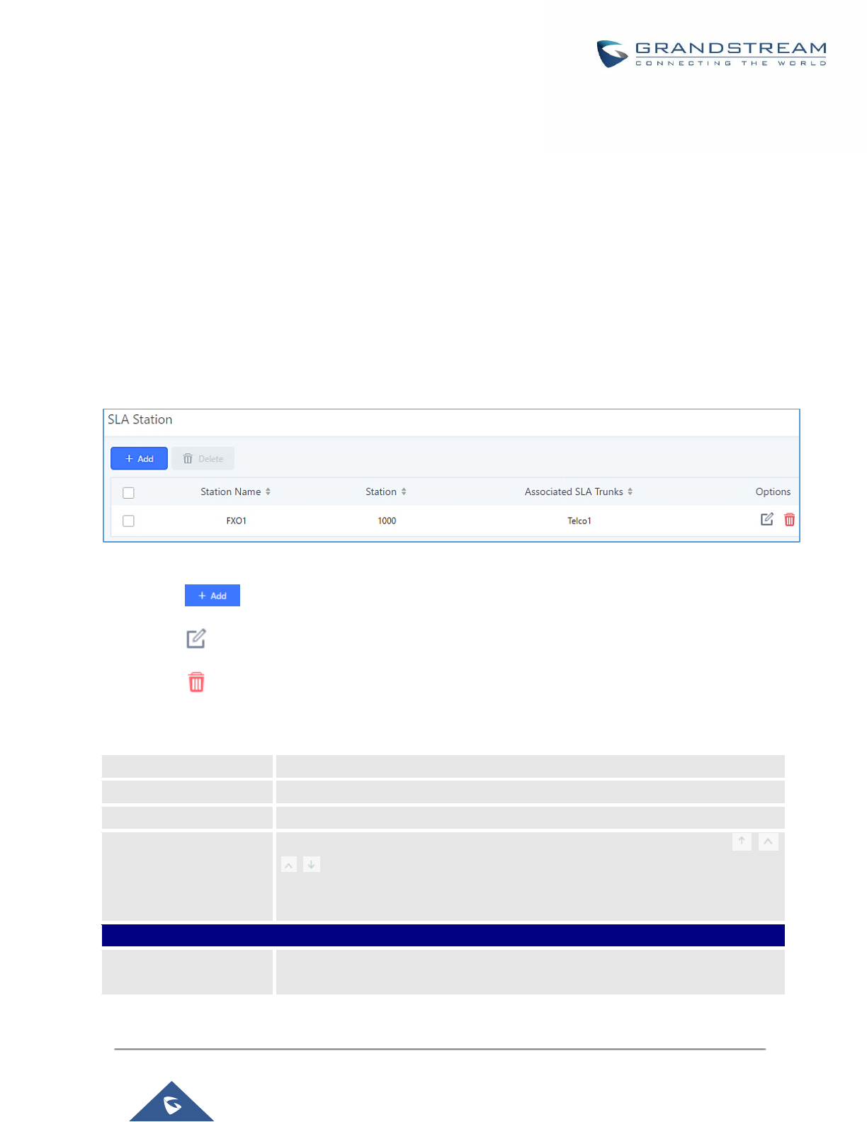
P a g e | 188
UCM6200 Series User Manual
Version 1.0.19.21
SLA STATION
The UCM6200 supports SLA that allows mapping the key with LED on a multi-line phone to different external
lines. When there is an incoming call and the phone starts to ring, the LED on the key will flash in red and the
call can be picked up by pressing this key. This allows users to know if the line is occupied or not. The SLA
function on the UCM6200 is like BLF but SLA is used to monitor external line i.e., analog trunk on the UCM6200.
Users could configure the phone with BLF mode on the MPK to monitor the analog trunk status or press the line
key pick up call from the analog trunk on the UCM6200.
Create/Edit SLA Station
SLA Station can be configured on Web GUI→Extension/Trunk→SLA Station.
Figure 103: SLA Station
• Click on to add a SLA Station.
• Click on to edit the SLA Station. The following table shows the SLA Station configuration parameters.
• Click on to delete the SLA Station.
Table 57: SLA Station Configuration Parameters
Station Name
Configure a name to identify the SLA Station.
Station
Specify a SIP extension as a station that will be using SLA.
Available SLA Trunks
Existing Analog Trunks with SLA Mode enabled will be listed here.
Selected SLA Trunks
Select a trunk for this SLA from the Available SLA Trunks list. Click on
to arrange the order. If there are multiple trunks selected, when there are
calls on those trunks at the same time, pressing the LINE key on the phone will
pick up the call on the first trunk here.
SLA Station Options
Ring Timeout
Configure the time (in seconds) to ring the station before the call is considered
unanswered. No timeout is set by default. If set to 0, there will be no timeout.
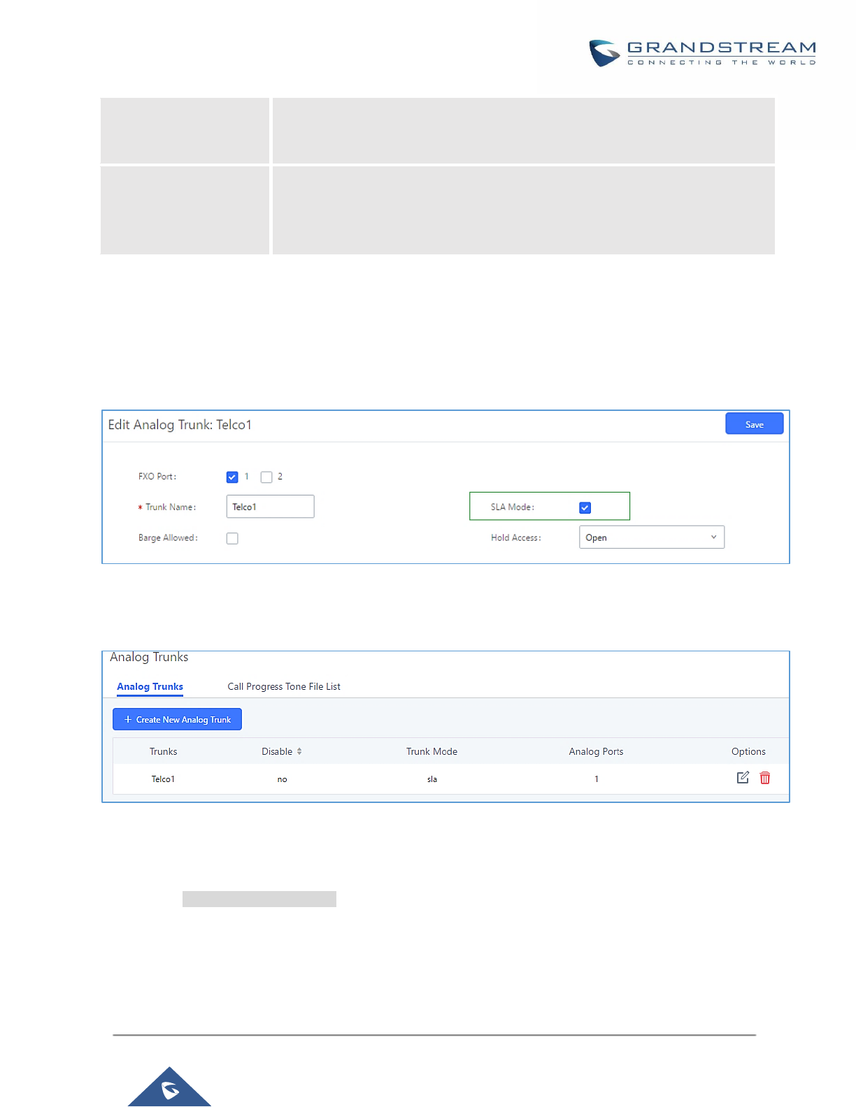
P a g e | 189
UCM6200 Series User Manual
Version 1.0.19.21
Ring Delay
Configure the time (in seconds) for delay before ringing the station when a call
first coming in on the shared line. No delay is set by default. If set to 0, there will
be no delay.
Hold Access
This option defines the competence of the hold action for one particular trunk. If
set to “open”, any station could hold a call on that trunk or resume one held
session; if set to “private”, only the station that places the trunk call on hold could
resume the session. The default setting is “open”.
Sample Configuration
1. On the UCM6200, go to Web GUI→Extension/Trunk→Analog Trunks page. Create analog trunk or edit
the existing analog trunk. Make sure “SLA Mode” is enabled for the analog trunk. Once enabled, this analog
trunk will be only available for the SLA stations created under Web GUI→Extension/Trunk→SLA Station
page.
Figure 104: Enable SLA Mode for Analog Trunk
2. Click on “Save”. The analog trunk will be listed with trunk mode “SLA”.
Figure 105: Analog Trunk with SLA Mode Enabled
3. On the UCM6200, go to Web GUI→Extension/Trunk→SLA Station page, click on “Add”. Please refer to
section [Create/Edit SLA Station] for the configuration parameters. Users can create one or more SLA
stations to monitor the analog trunk. The following figure shows two stations, 1002 and 1005, are configured
to be associated with SLA trunk “fxo1”.

P a g e | 190
UCM6200 Series User Manual
Version 1.0.19.21
Figure 106: SLA Example - SLA Station
4. On the SIP phone 1, configure to register UCM6200 extension 1002. Configure the MPK as BLF mode and
the value must be set to “extension_trunkname”, which is 1002_fxo1 in this case.
5. On the SIP phone 2, configure to register UCM6200 extension 1005. Configure the MPK as BLF mode and
value must be set to “extension_trunkname”, which is 1005_fxo1 in this case.
Figure 107: SLA Example - MPK Configuration
Now the SLA station is ready to use. The following functions can be achieved by this configuration.
• Making an outbound call from the station/extension, using LINE key
When the extension is in idle state, pressing the line key for this extension on the phone to off hook. Then
dial the station’s extension number, for example, dial 1002 on phone 1 (or dial 1005 on phone 2), to hear the
dial tone. Then the users could dial external number for the outbound call.
• Making an outbound call from the station/extension, using BLF key
When the extension is in idle state, pressing the MPK and users could dial external numbers directly.
• Answering call using LINE key
When the station is ringing, pressing the LINE key to answer the incoming call.
• Barging-in active call using BLF key
When there is an active call between an SLA station and an external number using the SLA trunk, other SLA
stations monitoring the same trunk could join the call by pressing the BLF key if “Barge Allowed” is enabled
for the analog trunk.
• Hold/UnHold using BLF key
If the external line is previously put on hold by an SLA station, another station that monitors the same SLA
trunk could UnHold the call by pressing the BLF key if “Hold Access” is set to “open” on the analog trunk and
the SLA station.

P a g e | 191
UCM6200 Series User Manual
Version 1.0.19.21
CALL ROUTES
Outbound Routes
In the following sections, we will discuss the steps and parameters used to configure and manage outbound
rules in UCM6200, these rules are the regulating points for all external outgoing calls initiated by the UCM
through all types of trunks: SIP, Analog and Digital.
Configuring Outbound Routes
In the UCM6200, an outgoing calling rule pairs an extension pattern with a trunk used to dial the pattern. This
allows different patterns to be dialed through different trunks (e.g., "Local" 7-digit dials through a FXO while
"Long distance" 10-digit dials through a low-cost SIP trunk). Users can also set up a failover trunk to be used
when the primary trunk fails.
Go to Web GUI→Extension/Trunk→Outbound Routes to add and edit outbound rules.
• Click on to add a new outbound route.
• Click on to edit the outbound route.
• Click on to delete the outbound route.
On the UCM6200, the outbound route priority is based on “Best matching pattern”. For example, the UCM6200
has outbound route A with pattern 1xxx and outbound route B with pattern 10xx configured. When dialing 1000
for outbound call, outbound route B will always be used first. This is because pattern 10xx is a better match than
pattern 1xxx. Only when there are multiple outbound routes with the same pattern configured.
Table 58: Outbound Route Configuration Parameters
Calling Rule Name
Configure the name of the calling rule (e.g., local, long_distance, and etc). Letters,
digits, _ and - are allowed.
Pattern
• All patterns are prefixed with the "_".
• Special characters:
X: Any Digit from 0-9.
Z: Any Digit from 1-9.
N: Any Digit from 2-9.
".": Wildcard. Match one or more characters.
"!": Wildcard. Match zero or more characters immediately.
Example: [12345-9] - Any digit from 1 to 9.
Notes:
▪ Multiple patterns can be used. Each pattern should be entered in new line.
▪ Users can add comments to a dial plan by typing “/*” and “*/” before and
after each comment respectively.

P a g e | 192
UCM6200 Series User Manual
Version 1.0.19.21
▪ Example:
_X.
_NNXXNXXXXX /* 10-digit long distance */
_818X. /* Any number with leading 818 */
Disable This Route
After creating the outbound route, users can choose to enable and disable it. If the
route is disabled, it will not take effect anymore. However, the route settings will
remain in UCM. Users can enable it again when it’s needed.
Password
Configure the password for users to use this rule when making outbound calls.
Call Duration Limit
Enable to configure the maximum duration for the call using this outbound route.
Maximum Call
Duration
Configure the maximum duration of the call (in seconds). The default setting is 0,
which means no limit.
Warning Time
Configure the warning time for the call using this outbound route. If set to x
seconds, the warning tone will be played to the caller when x seconds are left to
end the call.
Warning Repeat
Interval
Configure the warning repeat interval for the call using this outbound route. If set
to X seconds, the warning tone will be played every x seconds after the first
warning.
Privilege Level
Select privilege level for the outbound rule.
• Internal: The lowest level required. All users can use this rule.
• Local: Users with Local, National, or International level can use this rule.
• National: Users with National or International level can use this rule.
• International: The highest level required. Only users with international level
can use this rule.
• Disable: The default setting is "Disable". If selected, only the matched source
caller ID will be allowed to use this outbound route.
Please be aware of the potential security risks when using "Internal" level, which
means all users can use this outbound rule to dial out from the trunk.
Enable Filter on
Source Caller ID
When enabled, users could specify extensions allowed to use this outbound route.
"Privilege Level" is automatically disabled if using "Enable Filter on Source Caller
ID".
The following two methods can be used at the same time to define the
extensions as the source caller ID.
1. Select available extensions/extension groups from the list. This allows users
to specify arbitrary single extensions available in the PBX.
2. Custom Dynamic Route: define the pattern for the source caller ID. This
allows users to define extension range instead of selecting them one by one.

P a g e | 193
UCM6200 Series User Manual
Version 1.0.19.21
• All patterns are prefixed with the "_".
• Special characters:
X: Any Digit from 0-9.
Z: Any Digit from 1-9.
N: Any Digit from 2-9.
".": Wildcard. Match one or more characters.
"!": Wildcard. Match zero or more characters immediately.
Example: [12345-9] - Any digit from 1 to 9.
Note: Multiple patterns can be used. Patterns should be separated by
comma “,”. Example: _X. , _NNXXNXXXXX , _818X.
Send This Call Through Trunk
Use Trunk
Select the trunk for this outbound rule.
Strip
Allows the user to specify the number of digits that will be stripped from the
beginning of the dialed string before the call is placed via the selected trunk.
Example:
The users will dial 9 as the first digit of a long-distance calls. However, 9 should
not be sent out via analog lines and the PSTN line. In this case, 1 digit should be
stripped before the call is placed.
Prepend
Specify the digits to be prepended before the call is placed via the trunk. Those
digits will be prepended after the dialing number is stripped.
Use Failover Trunk
Failover Trunk
Failover trunks can be used to make sure that a call goes through an alternate
route, when the primary trunk is busy or down. If "Use Failover Trunk" is enabled
and "Failover trunk" is defined, the calls that cannot be placed via the regular trunk
may have a secondary trunk to go through.
UCM62XX support up to 10 failover trunks.
Example:
The user's primary trunk is a VoIP trunk and the user would like to use the PSTN
when the VoIP trunk is not available. The PSTN trunk can be configured as the
failover trunk of the VoIP trunk.
Strip
Allows the user to specify the number of digits that will be stripped from the
beginning of the dialed string before the call is placed via the selected trunk.
Example:
The users will dial 9 as the first digit of a long-distance calls. However, 9 should
not be sent out via analog lines and the PSTN line. In this case, 1 digit should be
stripped before the call is placed.
Prepend
Specify the digits to be prepended before the call is placed via the trunk. Those
digits will be prepended after the dialing number is stripped.
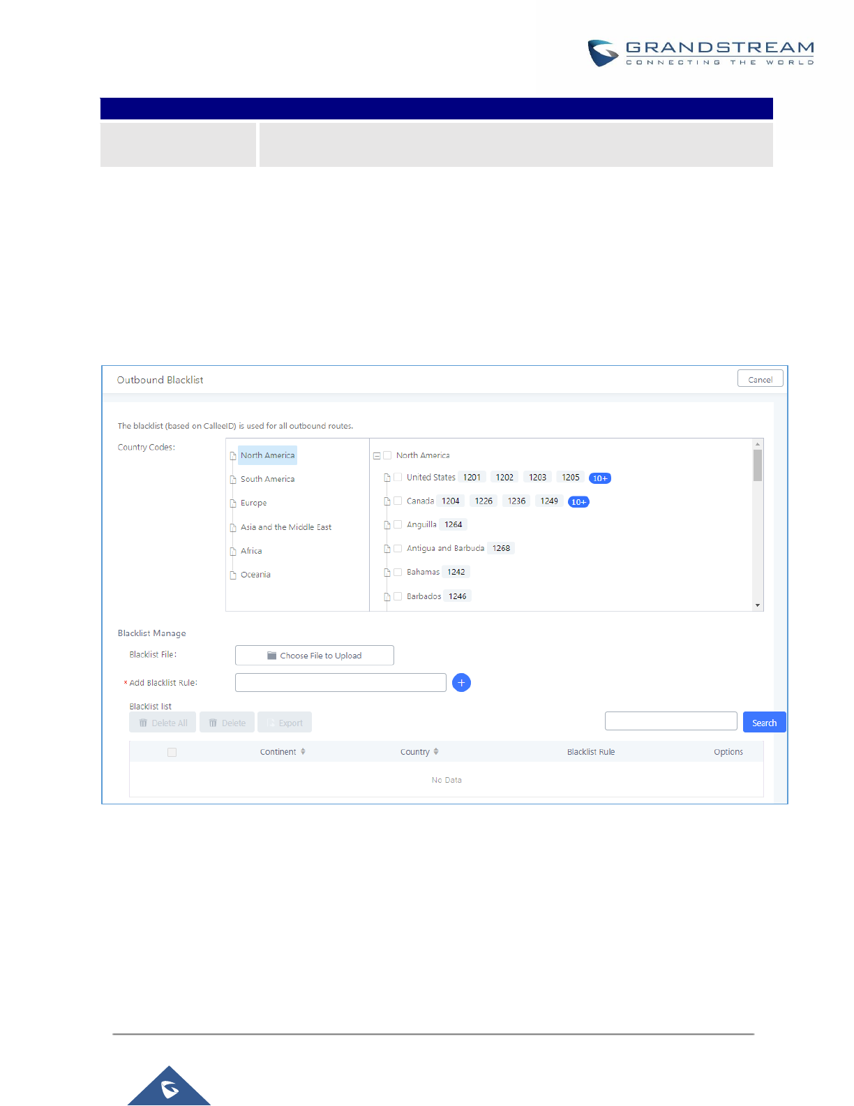
P a g e | 194
UCM6200 Series User Manual
Version 1.0.19.21
Time Condition
Time Condition
Users could customize holiday time, office time or a specified time to allow the
outbound route to be used.
Outbound Blacklist
The UCM6200 allows users to configure blacklist for outbound routes. If the dialing number matches the blacklist
numbers or patterns, the outbound call will not be allowed. The outbound blacklist can be configured under UCM
Web GUI→Extension/Trunk→Outbound Routes: Outbound Blacklist.
Users can configure numbers, patterns or select country code to add in the blacklist. Please note that the blacklist
settings apply to all outbound routes.
Figure 108: Country Codes
Note: Users can export outbound route blacklists and delete all blacklist entries. Additionally, users can also
import blacklists for outbound routes.
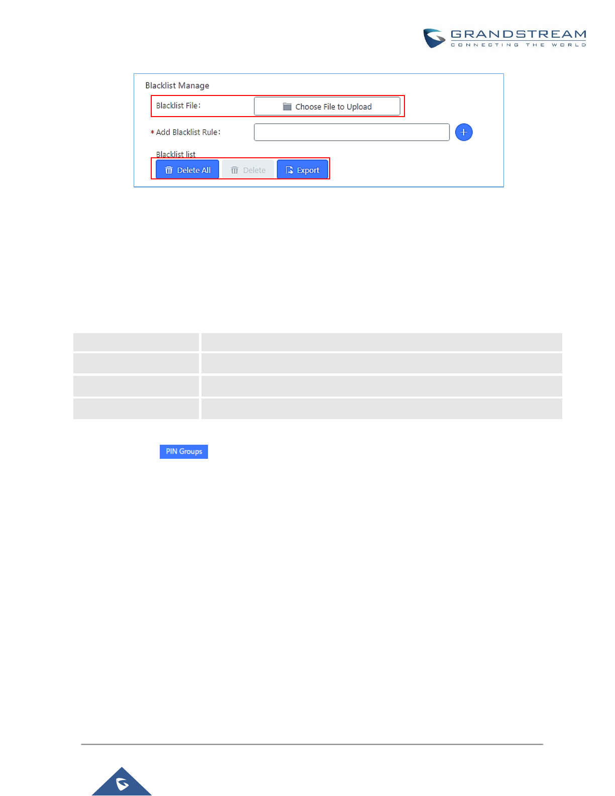
P a g e | 195
UCM6200 Series User Manual
Version 1.0.19.21
Figure 109: Blacklist Import/Export
PIN Groups
The UCM6200 supports pin group. Once this feature is configured, users can apply pin group to specific
outbound routes. When placing a call on pin protected outbound routes, caller will be asked to input the group
pin number, this feature can be found on the webGUI→Extension/Trunk→Outbound Routes→PIN Groups.
Table 59: Outbound Routes/PIN Group
Name
Specify the name of the group
Record In CDR
Specify whether to enable/disable record in CDR
PIN Number
Specify the code that will asked once dialing via a trunk
PIN Name
Specify the name of the PIN
Once user click on the following figure shows to configure the new PIN.
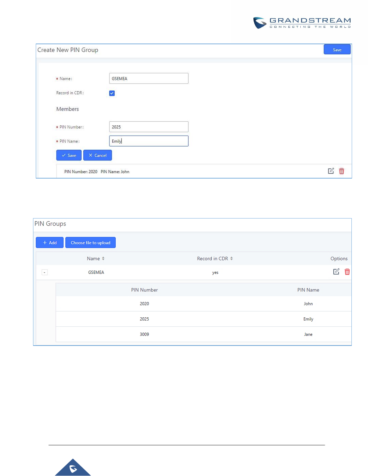
P a g e | 196
UCM6200 Series User Manual
Version 1.0.19.21
Figure 110: Create New PIN Group
The following screenshot shows an example of created PIN Groups and members:
Figure 111: PIN Members
Note:
If PIN group is enabled on outbound route level, password, privilege level and enable filter on source caller ID
will be disabled.
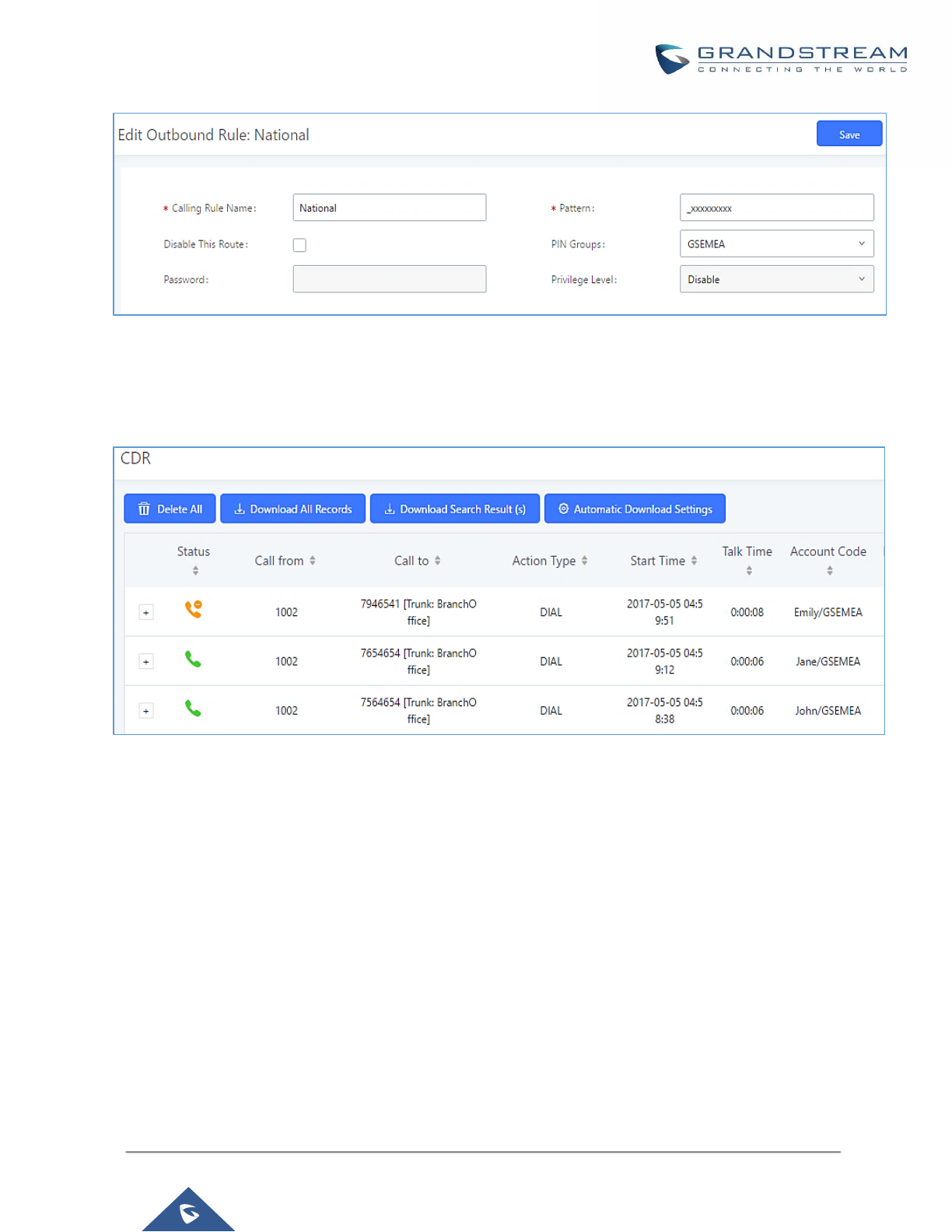
P a g e | 197
UCM6200 Series User Manual
Version 1.0.19.21
Figure 112: Outbound PIN
If PIN group CDR is enabled, the call with PIN group information will be displayed as part of CDR under Account
Code field.
Figure 113: CDR Record
- Importing PIN Groups from CSV files:
User can also import PIN Groups by uploading CSV files for each group. To do this:
1. Navigate to Extension/Trunk→Outbound Routes→PIN Groups and click on the “Choose file to
upload” button.
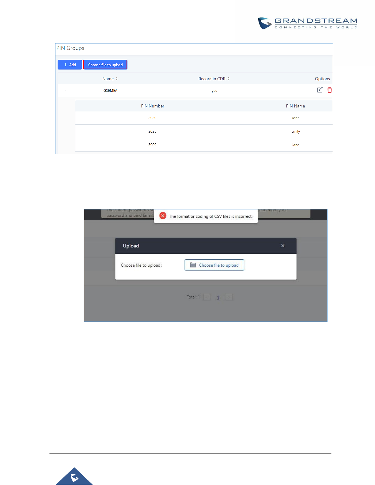
P a g e | 198
UCM6200 Series User Manual
Version 1.0.19.21
Figure 114: Importing PIN Groups from CSV files
2. Select the CSV file to upload. Incorrect file formats and improperly formatted CSV files will result in
error messages such as the one below:
Figure 115: Incorrect CSV File
3. To ensure a successful import, please follow the format in the sample image below
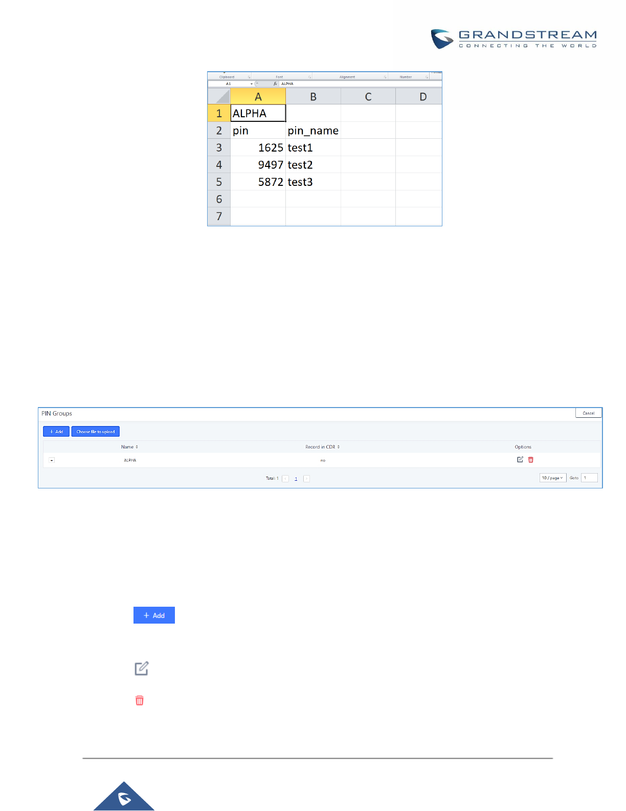
P a g e | 199
UCM6200 Series User Manual
Version 1.0.19.21
Figure 116: CSV File Format
• The top-left value (A1) is the PIN Group name. In this case, it is “ALPHA”.
• Row 2 contains the labels for the modifiable fields: pin and pin_name. These values should not
be changed and will cause an upload error otherwise.
• Rows 3+ contain the user-defined values with Column A holding the PINs and Column B
holding the PIN names. PIN values must consist of at least four digits.
• Once the file is successfully uploaded, the entry will be added to the list of PIN Groups.
Figure 117: CSV File Successful Upload
Inbound Routes
Inbound routes can be configured via Web GUI→Extension/Trunk→Inbound Routes.
• Click on to add a new inbound route.
• Click on "Blacklist" to configure blacklist for all inbound routes.
• Click on to edit the inbound route.
• Click on to delete the inbound route.

P a g e | 200
UCM6200 Series User Manual
Version 1.0.19.21
Inbound Rule Configurations
Table 60: Inbound Rule Configuration Parameters
Trunks
Select the trunk to configure the inbound rule.
Pattern
• All patterns are prefixed with the "_".
• Special characters:
X: Any Digit from 0-9.
Z: Any Digit from 1-9.
N: Any Digit from 2-9.
".": Wildcard. Match one or more characters.
"!": Wildcard. Match zero or more characters immediately.
Example: [12345-9] - Any digit from 1 to 9.
• The pattern can be composed of two parts, Pattern and CallerID Pattern.
The first part is used to specify the dialed number while the second part
is used to specify the caller ID and it is optional, if set it means only the
extension with the specific caller ID can call in or call out. For example,
pattern '_2XXX/1234' means the only extension with the caller ID '1234'
can use this rule.
Notes:
▪ Multiple patterns can be used. Each pattern should be entered in new
line.
▪ Users can add comments to the end of patterns to better organize and
keep track of complex rules by typing “/*” and “*/” before and after each
comment respectively.
▪ Example:
Pattern
CallerID Pattern
_X.
_NNXXNXXXXX /* 10-digit long distance */
_818X. /* Any number with leading 818 */
1000
1001
Disable This Route
After creating the inbound route, users can choose to enable and disable it. If
the route is disabled, it will not take effect anymore. However, the route
settings will remain in UCM. Users can enable it again when it’s needed.
Allowed to seamless transfer
Allows the selected extension to use this function. If an extension is busy, and
a mobile phone is bound to that extension, the mobile phone can pick up calls
to that extension.
Alert-Info
Configure the Alert-Info, when UCM receives an INVITE request, the Alert-
Info header field specifies an alternative ring tone to the UAS.
Prepend Trunk Name
If enabled, the trunk name will be added to the caller id name as the displayed
caller id name.

P a g e | 201
UCM6200 Series User Manual
Version 1.0.19.21
Set Caller ID Info
Manipulates Caller ID (CID) name and/or number within the call flow to help
identify who is calling. When enabled two field will show allowing to
manipulate the CalleID Number and the Caller ID Name.
CalleID Number
Configure the pattern-matching format to manipulate the numbers of incoming
callers or to set a fixed callerID number for calls that go through this inbound
route.
• ${CALLERID(num)}: Default value which indicates the number of an
incoming caller (CID). The CID will not be modified.
• ${CALLERID(num):n}: Skips the first n characters of a CID number,
where n is a number.
• ${CALLERID(num):-n}: Takes the last n characters of a CID number,
where n is a number.
• ${CALLERID(num):s:n}: Takes n characters of a CID number starting
from s+1, where n is a number and s is a character position (e.g.
${CALLERID(num):2:7} takes 7 characters after the second character of
a CID number).
• n${CALLERID(num)}: Prepends n to a CID number, where n is a
number.
CallerID Name
Default string is ${CALLERID(name)},which means the name of a incoming
caller, it's a pattern-matching syntax format.
A${CALLERID(name)}B means Prepend a character 'A' and suffix a
character 'B' to ${CALLERID(name)}.
Not using pattern-matching syntax means setting fix name to incoming caller.
Enable Route-Level Inbound
Gives uses the ability to configure inbound mode per individual route. When
enabled two field will show allowing to set the Inbound mode and the Inbound
mode Suffix.
Note: Global inbound mode must be enabled before users can configure
route-level inbound mode
Inbound Mode
Choose the inbound mode for this route.
Note: Toggling the global inbound mode will not affect routes that have Route-
level Inbound Mode enabled. If all routes have the option enabled, toggling
the global inbound mode via BLF will trigger a voice prompt indicating that
none of the routes will be affected by the global inbound mode change.
Inbound Mode Suffix
Dial "Global Inbound Mode feature code + Inbound Mode Suffix" or a route's
assigned suffix to toggle the route's inbound mode.
The BLF subscribed to the inbound mode suffix can monitor the current
inbound mode.

P a g e | 202
UCM6200 Series User Manual
Version 1.0.19.21
Inbound Multiple Mode
Multiple mode allows user to switch between destinations of the inbound rule
by feature codes. Configure related feature codes as described in [Inbound
Route: Multiple Mode]. If this option is enabled, user can use feature code
to switch between different modes/destinations.
Dial Trunk
This option shows up only when "By DID" is selected. If enabled, the external
users dialing in to the trunk via this inbound route can dial outbound call using
the UCM’s trunk.
Privilege Level
This option shows up only when "By DID" is selected.
• Disable: Only the selected Extensions or Extension Groups are
allowed to use this rule, when enabled Filter on Source Caller ID.
• Internal: The lowest level required. All users are allowed to use this
rule, check this level might be risky for security purpose.
• Local: User with Local level, National or International level are
allowed to use this rule.
• National: Users with National or International Level are allowed to
use this rule.
• International: The highest level required. Only users with
international level are allowed to use this rule.
Allowed DID Destination
This option shows up only when "By DID" is selected. This controls the
destination that can be reached by the external caller via the inbound route.
The DID destination are:
• Extension
• Conference
• Call Queue
• Ring Group
• Paging/Intercom Groups
• IVR
• Voicemail Groups
• Fax Extension
• Dial By Name
• All

P a g e | 203
UCM6200 Series User Manual
Version 1.0.19.21
Default Destination
Select the default destination for the inbound call.
• Extension
• Voicemail
• Conference Room
• Call Queue
• Ring Group
• Paging/Intercom
• Voicemail Group
• Fax
• DISA
• IVR
• External Number
• By DID
When "By DID" is used, the UCM will look for the destination based on
the number dialed, which could be local extensions, conference, call
queue, ring group, paging/intercom group, IVR, voicemail groups and Fax
extension as configured in "DID destination". If the dialed number
matches the DID pattern, the call will be allowed to go through.
7. Dial By Name
8. Callback
Strip
Specify the number of digits to strip from the beginning of the DID. This is
used when "By DID" is selected in "Default Destination".
Prepend
Specify the digits to be prepended before the call is placed via the trunk.
Those digits will be prepended after the dialing number is stripped.
Time Condition
Start Time
Select the start time "hour:minute" for the trunk to use the inbound rule.
End Time
Select the end time "hour:minute" for the trunk to use the inbound rule.
Date
Select "By Week" or "By Day" and specify the date for the trunk to use the
inbound rule.
Week
Select the day in the week to use the inbound rule.
Destination
Select the destination for the inbound call under the defined time condition.
• Extension
• Voicemail
• Conference Room
• Call Queue
• Ring Group
• Paging/Intercom
• Voicemail Group
• Fax
• DISA
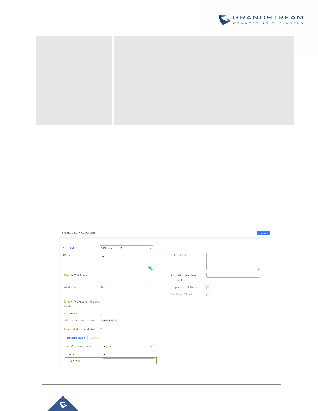
P a g e | 204
UCM6200 Series User Manual
Version 1.0.19.21
• IVR
• By DID
When "By DID" is used, the UCM will look for the destination based on
the number dialed, which could be local extensions, conference, call
queue, ring group, paging/intercom group, IVR, voicemail groups and Fax
extension as configured in "DID destination". If the dialed number
matches the DID pattern, the call will be allowed to go through.
Configure the number of digits to be stripped in "Strip" option.
• Dial By Name
• External Number
• Callback
Inbound Route: Prepend Example
UCM6200 now allows user to prepend digits to an inbound DID pattern, with strip taking precedence over
prepend. With the ability to prepend digits in inbound route DID pattern, user no longer needs to create multiple
routes for the same trunk to route calls to different extensions. The following example demonstrates the process:
1. If Trunk provides a DID pattern of 18005251163.
2. If Strip is set to 8, UCM6200 will strip the first 8 digits.
3. If Prepend is set to 2, UCM6200 will then prepend a 2 to the stripped number, now the number become
2163.
4. UCM6200 will now forward the incoming call to extension 2163.
Figure 118: Inbound Route feature: Prepend
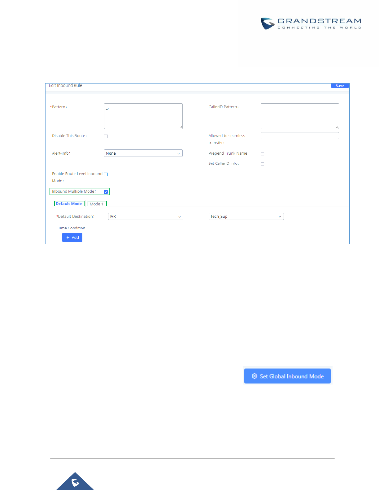
P a g e | 205
UCM6200 Series User Manual
Version 1.0.19.21
Inbound Route: Multiple Mode
In the UCM6200, the user can configure inbound route to enable multiple mode to switch between different
destinations. The inbound multiple mode can be enabled under Inbound Route settings.
Figure 119: Inbound Route - Multiple Mode
When Multiple Mode is enabled for the inbound route, the user can configure a “Default Destination” and a “Mode
1” destination for all routes. By default, the call coming into the inbound routes will be routed to the default
destination.
SIP end devices that have registered on the UCM6200 can dial feature code *62 to switch to inbound route
“Mode 1” and dial feature code *61 to switch back to “Default Destination”. Switching between different mode
can be easily done without Web GUI login.
For example, the customer service hotline destination has to be set to a different IVR after 7PM. The user can
dial *62 to switch to “Mode 1” with that IVR set as the destination before off work.
To customize feature codes for “Default Mode” and “Mode 1”, click on under
“Inbound Routes” page, check “Enable Inbound Multiple Mode” option and change “Inbound Default Mode” and
“Inbound Mode 1” values (By default, *61 and *62 respectively).
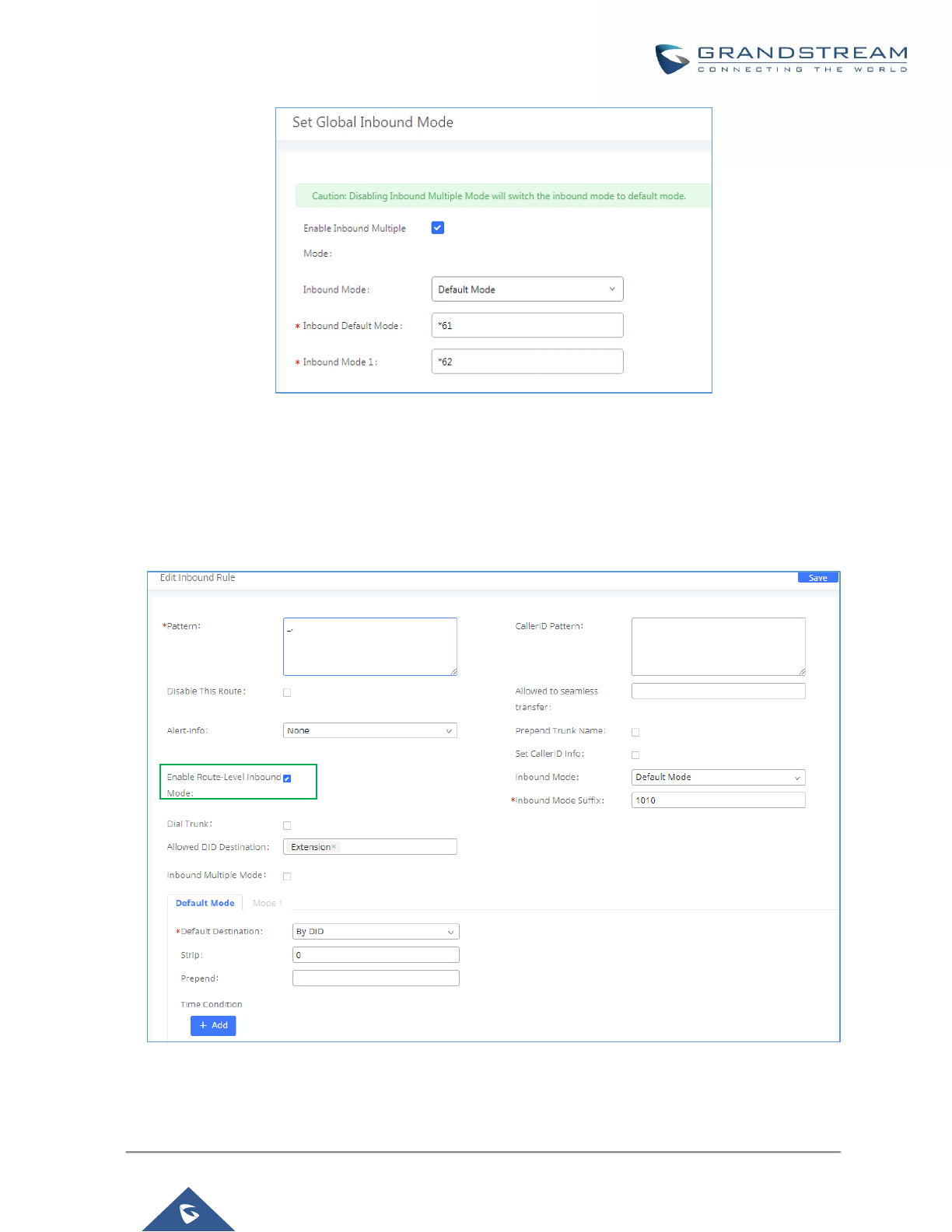
P a g e | 206
UCM6200 Series User Manual
Version 1.0.19.21
Figure 120: Inbound Route - Multiple Mode Feature Codes
Inbound Route: Route-Level Mode
In the UCM6200, users can enable Route-Level Inbound Mode to switch between different destinations for each
individual inbound route. The inbound Route-Level mode can be enabled under Inbound Route settings.
Figure 121: Inbound Route - Route-Level Mode
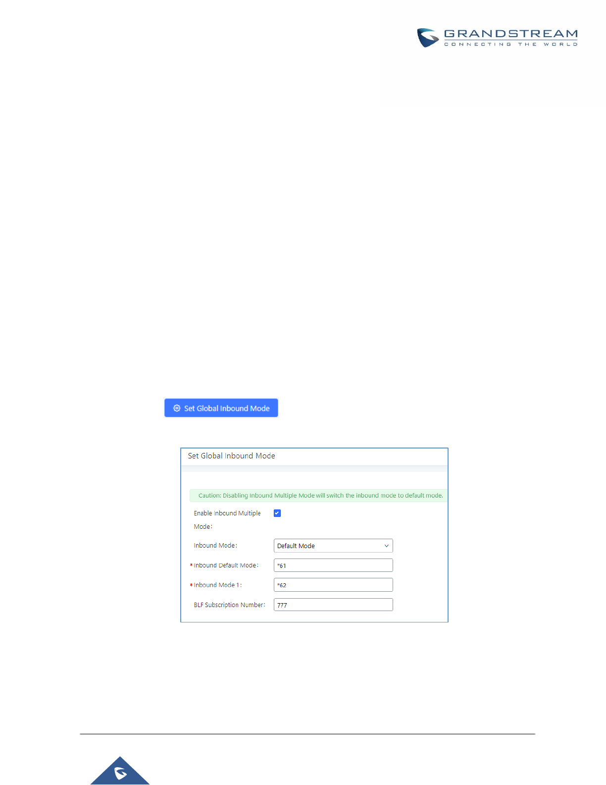
P a g e | 207
UCM6200 Series User Manual
Version 1.0.19.21
Global inbound mode must be enabled before configuring Route-Level Inbound Mode. Additionally, the Mode 1
must be configured as well.
When Route-Level Inbound Mode is enabled, the user can configure a “Default Destination” and a “Mode 1”
destination for each specific route. By default, the call coming into this specific inbound route will be routed to
the default destination.
Users can toggle the route’s inbound mode by dialing "Global Inbound Mode feature code + Inbound Mode
Suffix” and the current inbound route can be monitored by subscribing a BLF to the Inbound Mode Suffix.
For example, Inbound Default Mode feature code is set to *61 and the Inbound Mode suffix for route 1 is set to
1010. To switch the mode of route 1 to Default Mode, users can dial *611010.
Note: Toggling the global inbound mode will not affect routes that have Route-level Inbound Mode enabled. If
all routes have the option enabled, toggling the global inbound mode via BLF will trigger a voice prompt indicating
that none of the routes will be affected by the global inbound mode change.
Inbound Route: Inbound Mode BLF Monitoring
Users can assign MPKs and VPKs to monitor and toggle the current global inbound mode of the UCM.
To do this, please refer to the following steps:
1. Access the UCM web GUI and navigate to Extension/Trunk→Inbound Routes.
2. Click on the button and enable Inbound Multiple Mode.
3. Edit the subscribe number field to the desired BLF value.
Figure 122: Global Inbound Mode
4. Configure the BLF value on a phone’s MPK/VPK. As an example, a GXP2140 with the BLF configured
will show the Inbound Mode status on its screen once configured. The 777 BLF is lit green, indicating
that the current inbound mode is “Default Mode”.
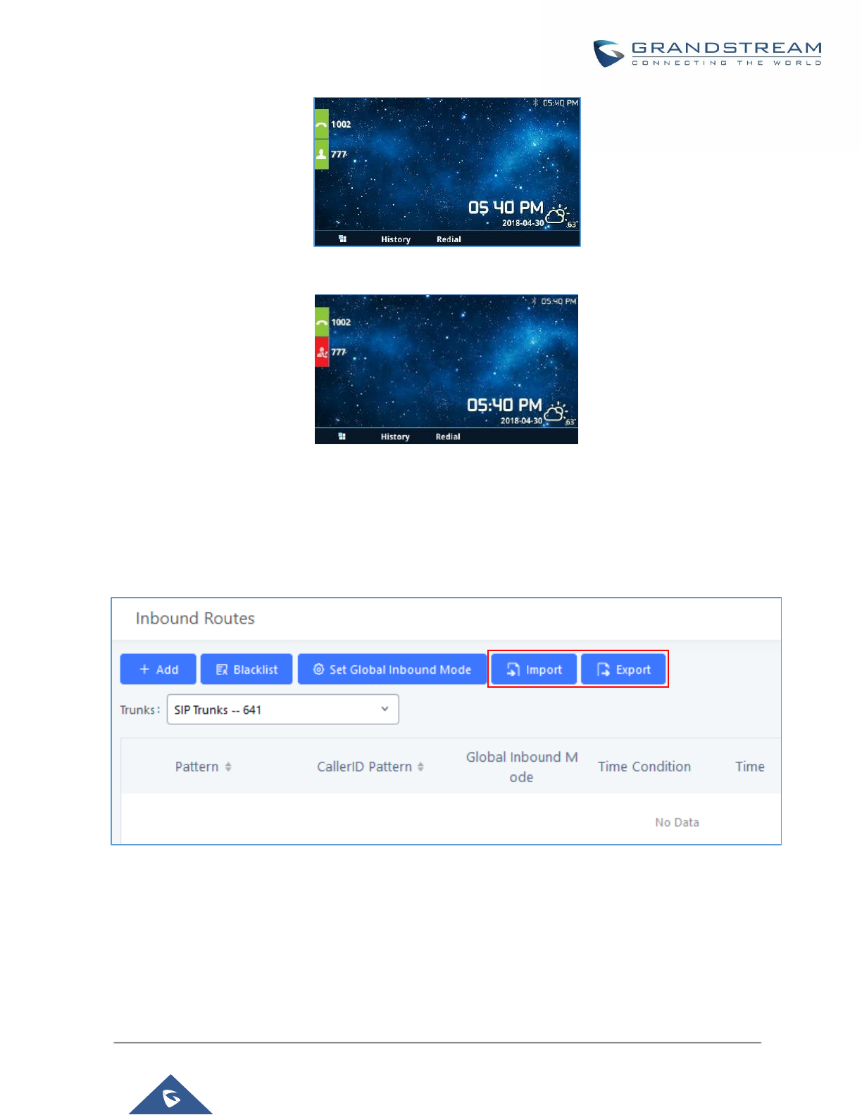
P a g e | 208
UCM6200 Series User Manual
Version 1.0.19.21
Figure 123: Inbound Mode - Default Mode
5. Pressing the key will toggle the inbound mode to “Mode 1”, and the button’s color will change to red.
Figure 124: Inbound Mode - Mode 1
Inbound Route: Import/Export Inbound Route
Users can now import and export inbound routes to quickly set up inbound routing on a UCM or to back up an
existing configuration. An exported inbound route configuration can be directly imported without needing any
manual modifications.
Figure 125: Import/Export Inbound Route
The imported file should be on CSV format and using UTF-8 encoding, the imported file should contain below
columns, and each column should be separated by a comma (It is recommended to use Notepad++ for the
imported file creation):
• Disable This Route: Yes/No.
• Pattern: Always prefixed with _
• CallerID Pattern: Always prefixed with _

P a g e | 209
UCM6200 Series User Manual
Version 1.0.19.21
• Prepend Trunk Name: Yes/No.
• Prepend User Defined Name Enable: Yes/No.
• Prepend User Defined Name: A string.
• Alert-info: None, Ring 1, Ring 2… User should enter an Alert-info string following the values we have in
the Inbound route Alert-Info list.
• Allowed to seamless transfer: [Extension_number]
• Inbound Multiple Mode: Yes/No.
• Default Destination: By DID, Extension, Voicemail… User should enter a Default Destination string
following the values we have in the Inbound route Default Destination list.
• Destination: An Extension number, Ring Group Extension…
• Default Time Condition.
• Mode 1: By DID, Extension, Voicemail… User should enter a Default Destination string following the
values we have in the mode 1 Default Destination list.
• Mode 1 Destination: An Extension number, Ring Group Extension…
• Mode 1 Time Condition.
FAX Intelligent Route
The UCM6200 can automatically detect Fax and phone signal coming from the FXO port, and then forward Fax
or phone signal to the right destination. For example, when a regular phone call is coming, the UCM6200 will be
able to detect the phone signal and forward it through the correct inbound route to the destination; if Fax signal
is coming, the UCM6200 will be able to forward it to the FXS extension where the Fax machine is connected.
FAX with Two Media
The UCM6200 supports Fax re-INVITE with multiple codec negotiation. If a Fax re-INVITE contains both T.38
and PCMA/PCMU codec, UCM6200 will choose T.38 codec over PCMA/PCMU.
Blacklist Configurations
In the UCM6200, Blacklist is supported for all inbound routes. Users could enable the Blacklist feature and
manage the Blacklist by clicking on "Blacklist".
• Select the checkbox for "Blacklist Enable" to turn on Blacklist feature for all inbound routes. Blacklist is
disabled by default.
• Enter a number in "Add Blacklist Number" field and then click to add to the list. Anonymous can also
be added as a Blacklist Number.
• To remove a number from the Blacklist, select the number in "Blacklist list" and click on or click on
button to remove all the numbers on the black list.

P a g e | 210
UCM6200 Series User Manual
Version 1.0.19.21
• User can also export the inbound route black list by pressing on button.
Figure 126: Blacklist Configuration Parameters
• To add blacklist number in batch, click on “choose file to upload” to upload blacklist file in csv format. The
supported csv format is as below.
Figure 127: Blacklist csv File
----------------------------------------------------------------------------------------------------------------------------- ----------------------
Note:
Users could also add a number to the Blacklist or remove a number from the Blacklist by dialing the feature code
for "Blacklist Add' (default: *40) and "Blacklist Remove" (default: *41) from an extension. The feature code can
be configured under Web GUI→Call Features→Feature Codes.
----------------------------------------------------------------------------------------------------------------------------- ----------------------

P a g e | 211
UCM6200 Series User Manual
Version 1.0.19.21
CONFERENCE
The UCM6200 supports conference room allowing multiple rooms used at the same time:
• UCM6202/6204 supports up to 3 conference rooms allowing up to 25 simultaneous PSTN or IP
participants.
• UCM6208 supports up to 6 conference rooms allowing up to 32 simultaneous PSTN or IP participants.
The conference room configurations can be accessed under Web GUI→Call Features→Conference. In this
page, users could create, edit, view, invite, manage the participants and delete conference rooms. The
conference room status and conference call recordings (if recording is enabled) will be displayed in this web
page as well.
Conference Room Configurations
• Click on "Create New Conference Room" to add a new conference room.
• Click on to edit the conference room.
• Click on to delete the conference room.
Table 61: Conference Room Configuration Parameters
Extension
Configure the conference number for the users to dial into the conference.
Note: Up to 64 characters.
Password
When configured, the users who would like to join the conference call must enter
this password before accessing the conference room.
Note:
• If "Public Mode" is enabled, the password is not required to join the conference
room thus this field is invalid.
• The password must be at least 4 characters.
Admin Password
Configure the password to join the conference room as administrator. Conference
administrator can manage the conference call via IVR (if "Enable Caller Menu" is
enabled) as well as invite other parties to join the conference by dialing "0"
(permission required from the invited party) or "1" (permission not required from
the invited party) during the conference call.
Note:
• If "Public Mode" is enabled, the password is not required to join the conference
room thus this field is invalid.
• Password must be at least 4 characters and different than conference
extension number.

P a g e | 212
UCM6200 Series User Manual
Version 1.0.19.21
Enable Caller Menu
If enabled, conference participant could press the * key to access the conference
room menu. The default setting is "No".
Record Conference
If enabled, the calls in this conference room will be recorded automatically in a
.wav format file. All the recording files will be displayed and can be downloaded in
the conference web page. The default setting is "No".
Quiet Mode
If enabled, if there are users joining or leaving the conference, voice prompt or
notification tone won't be played. The default setting is "No".
Note:
"Quiet Mode" and "Announce Callers" cannot be enabled at the same time.
Wait For Admin
If enabled, the participants will not hear each other until the conference
administrator joins the conference. The default setting is "No".
Note:
If "Quiet Mode" is enabled, the voice prompt for "Wait For Admin" will not be
announced.
Enable User Invite
If enabled, users could press 0 to invite other users (with the users' permission) or
press 1 to invite other users (without the user's permission) to join the conference.
The default setting is "No".
Note:
Conference administrator can always invite other users without enabling this
option.
Announce Callers
If enabled, the caller will be announced to all conference participants when there
the caller joins the conference. The default setting is "No".
Note:
"Quiet Mode" and "Announce Callers" cannot be enabled at the same time.
Public Mode
If enabled, no authentication will be required when joining the conference call. The
default setting is "Yes".
Play Hold Music
If enabled, the UCM6200 will play Hold music when there is only one user in the
conference. The default setting is "No".
Music On Hold
Select the music on hold class to be played in conference call. Music On Hold
class can be set up under Web GUI→PBX Settings→Music On Hold.
Skip Authentication
When Inviting User
via Trunk from Web
GUI
If enabled, the invitation from Web GUI for a conference room with password will
skip the authentication for the invited users. The default setting is "No".
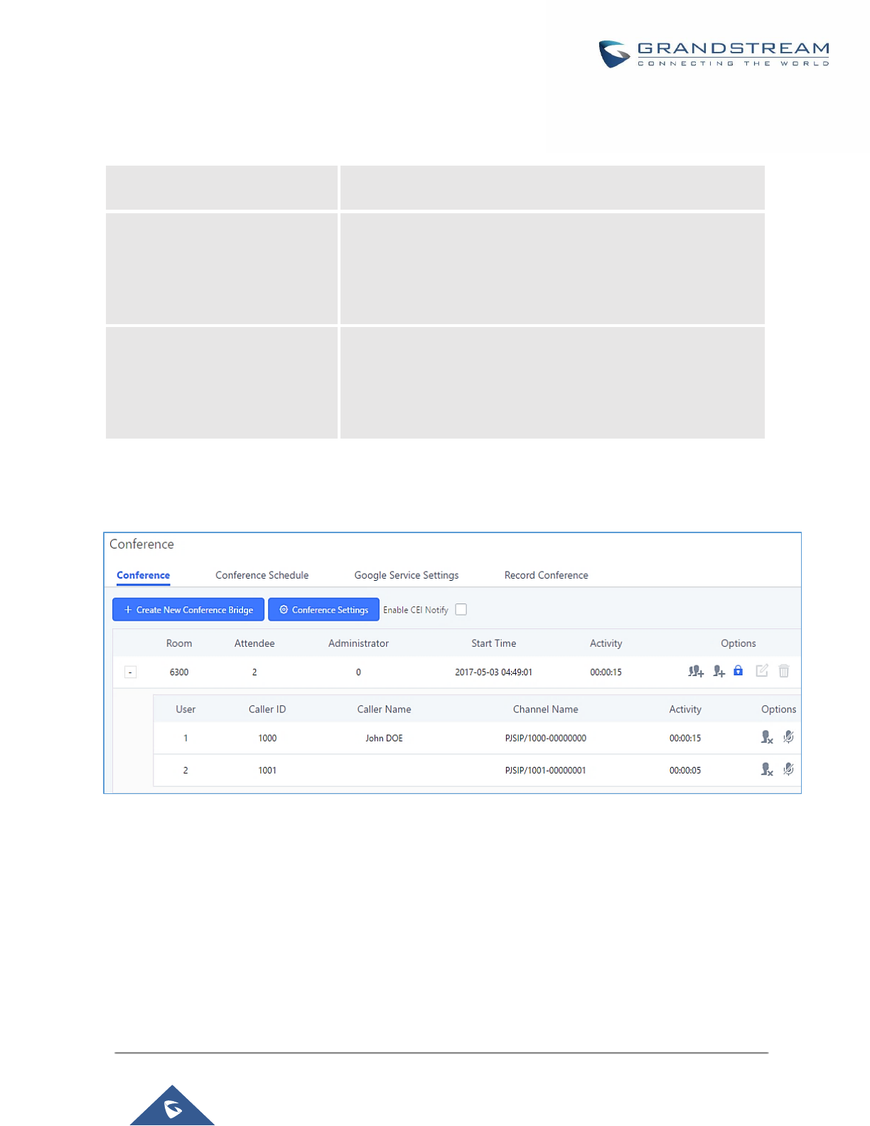
P a g e | 213
UCM6200 Series User Manual
Version 1.0.19.21
Conference Settings contains the following options:
Table 62: Conference Settings
Enable Talk detection
If enabled, the AMI will send the corresponding event when a user
starts or ends talking.
DSP Talking Threshold
The time in milliseconds of sound above what the dsp has
established as base line silence for a user before a user is
considered to be talking. This value affects several operations and
should not be changed unless the impact on call quality is fully
understood, the default value is 128.
DSP Silence Threshold
The time in milliseconds of sound falling within the what the dsp
has established as base line silence before a user is considered
to be silent. This value affects several operations and should not
be changed unless the impact on call quality is fully understood,
the default value is 2500.
Users can check the talking Caller IDs in conference control page (UCM WebUI→Call Features→Conference).
The image will move up and down when the user is talking.
Figure 128: Conference
Conference Call Operations
Join a Conference Call
Users could dial the conference room extension to join the conference. If password is required, enter the
password to join the conference as a normal user, or enter the admin password to join the conference as
administrator.

P a g e | 214
UCM6200 Series User Manual
Version 1.0.19.21
Invite Other Parties to Join Conference
When using the UCM6200 conference room., there are two ways to invite other parties to join the conference.
• Invite from Web GUI.
For each conference room in UCM6200 Web GUI→Call Features→Conference, there is an icon for option
"Invite a participant". Click on it and enter the number of the party you would like to invite. Then click on "Add".
A call will be sent to this number to join it into the conference.
Figure 129: Conference Invitation from Web GUI
• Invite by dialing 0 or 1 during conference call.
A conference participant can invite other parties to the conference by dialing from the phone during the
conference call. Please make sure option "Enable User Invite" is turned on for the conference room first. Enter
0 or 1 during the conference call. Follow the voice prompt to input the number of the party you would like to
invite. A call will be sent to this number to join it into the conference.
0: If 0 is entered to invite other party, once the invited party picks up the invitation call, a permission will be asked
to "accept" or "reject" the invitation before joining the conference.
1: If 1 is entered to invite other party, no permission will be required from the invited party.
---------------------------------------------------------------------------------------------------------------------------------------------------
Note:
Conference administrator can always invite other parties from the phone during the call by entering 0 or 1. To
join a conference room as administrator, enter the admin password when joining the conference. A conference
room can have multiple administrators.
----------------------------------------------------------------------------------------------------------------------------- ----------------------

P a g e | 215
UCM6200 Series User Manual
Version 1.0.19.21
During The Conference
During the conference call, users can manage the conference from Web GUI or IVR.
• Manage the conference call from Web GUI.
Log in UCM6200 Web GUI during the conference call, the participants in each conference room will be listed.
1. Click on to kick a participant from the conference.
2. Click on to mute the participant.
3. Click on to lock this conference room so that other users cannot join it anymore.
4. Click on to invite other users into the conference room.
• Manage the conference call from IVR.
If "Enable Caller Menu" is enabled, conference participant can input * to enter the IVR menu for the conference.
Please see options listed in the table below.
Table 63: Conference Caller IVR Menu
Conference Administrator IVR Menu
1
Mute/unmute yourself.
2
Lock/unlock the conference room.
3
Kick the last joined user from the conference.
4
Decrease the volume of the conference call.
5
Decrease your volume.
6
Increase the volume of the conference call.
7
Increase your volume.
8
More options.
• 1: List all users currently in the conference call.
• 2: Kick all non-Administrator participants from the conference call.
• 3: Mute/Unmute all non-Administrator participants from the conference call.
• 4: Record the conference call.
• 8: Exit the caller menu and return to the conference.
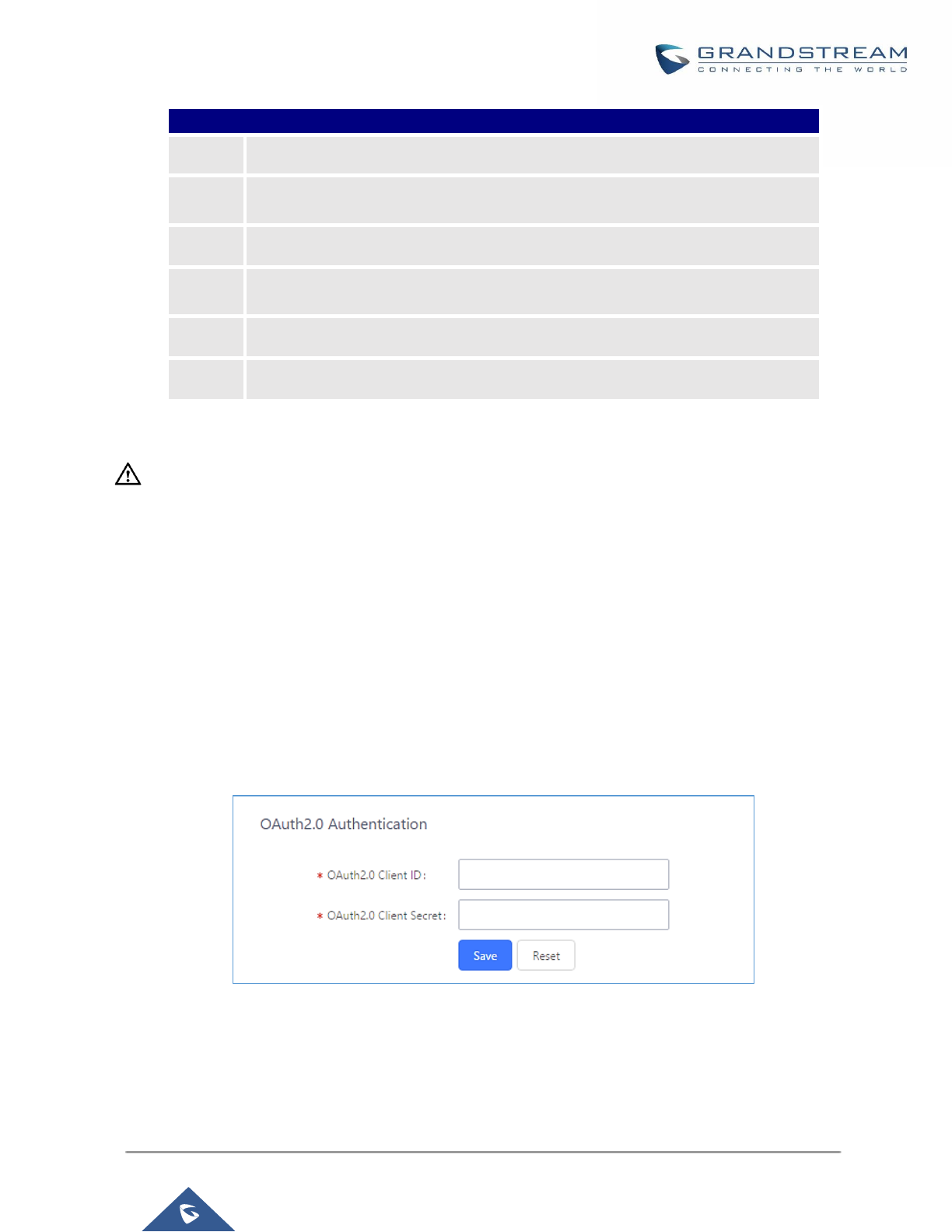
P a g e | 216
UCM6200 Series User Manual
Version 1.0.19.21
Conference User IVR Menu
1
Mute/unmute yourself.
4
Decrease the volume of the conference call.
5
Decrease your volume.
6
Increase the volume of the conference call.
7
Increase your volume.
8
Exit the caller menu and return to the conference.
----------------------------------------------------------------------------------------------------------------------------- --------------------
Note:
When there is participant in the conference, the conference room configuration cannot be modified.
-------------------------------------------------------------------------------------------------------------------------------- -----------------
Google Service Settings Support
UCM6200 now supports Google OAuth 2.0 authentication. This feature is used for supporting UCM6200
conference scheduling system. Once OAuth 2.0 is enabled, UCM6200 conference system can access Google
calendar to schedule or update conference.
Google Service Settings can be found under Web GUI→Call Features→Conference→Google Service
Settings→Google Service Settings.
Figure 130: Google Service Settings→OAuth2.0 Authentication
If you already have OAuth2.0 project set up on Google Developers web page, please use your existing login
credential for “OAuth2.0 Client ID” and “OAuth2.0 Client Secret” in the above figure for the UCM6200 to access
Google Service.
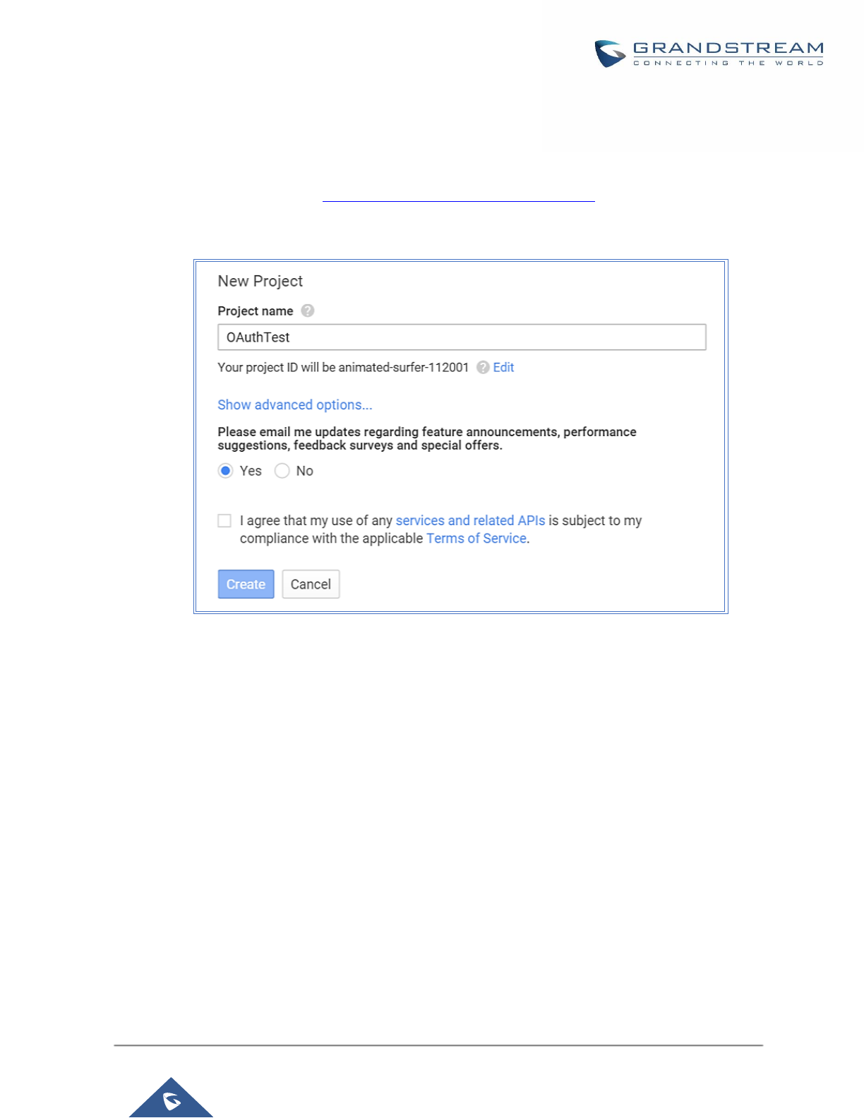
P a g e | 217
UCM6200 Series User Manual
Version 1.0.19.21
If you do not have OAuth2.0 project set up yet, please following the steps below to create new project and obtain
credentials:
1. Go to Google Developers page https://console.developers.google.com/start Create a New Project in Google
Developers page.
Figure 131: Google Service→New Project
2. Enable Calendar API from API Library.
3. Click “Credentials” on the left drop down menu to create new OAuth2.0 login credentials.
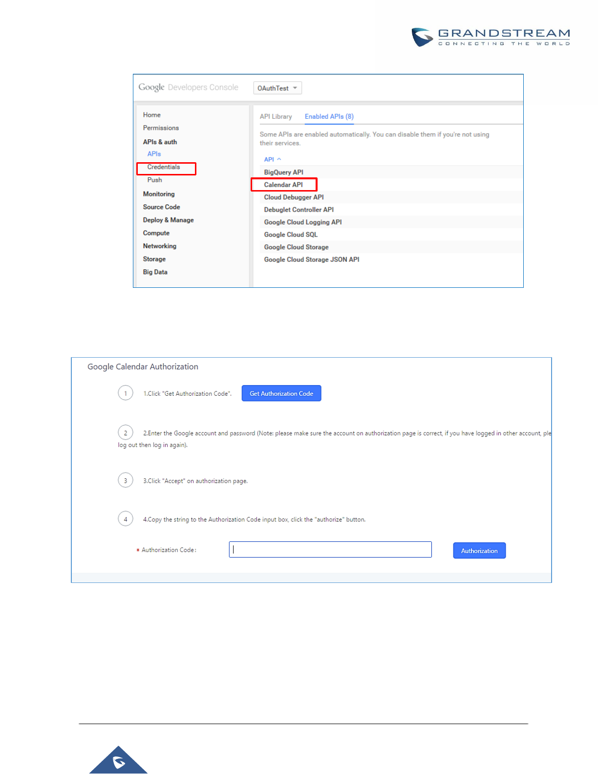
P a g e | 218
UCM6200 Series User Manual
Version 1.0.19.21
Figure 132: Google Service→Create New Credential
4. Use the newly created login credential to fill in “OAuth2.0 Client ID” and “OAuth2.0 Client Secret”.
5. Click “Get Authentication Code” to obtain authentication code from Google Service.
Figure 133: Google Service→OAuth2.0 Login
6. Now UCM6200 is connected with Google Service.
You can also configure the Status update, which refresh automatically your Google Calendar with the configured
time (m). Note: Zero means disable.

P a g e | 219
UCM6200 Series User Manual
Version 1.0.19.21
Conference Schedule
Conference Schedule can be found under UCM6200 Web GUI → Call Features → Conference→ Conference
Schedule. Users can create, edit, view and delete a Conference Schedule.
• Click on “Create New Conference Schedule” to add a new Conference Schedule.
• Click on the scheduled conference to edit or delete the event.
After the user configures UCM6200 with Google Service Settings [Google Service Settings Support] and
enables Google Calendar for Conference Schedule, the conference schedule on the UCM6200 can be
synchronized with Google Calendar for authorized Google account.
Table 64: Conference Schedule Parameters
Schedule Options
Conference Topic
Configure the name of the scheduled conference. Letters, digits, _ and - are
allowed.
Conference Room
Select a conference room for this scheduled conference.
Kick Time(m)
Set kick time before conference starts. When kick time is reached, a warning
prompt will be played for all attendees in the conference room. After 5 minutes,
this conference room will be cleared and locked for the scheduled conference to
begin.
Note: Kick Time cannot be less than 6 minutes to clear the conference room.
Description
The description of scheduled conference.
Repeat
Repeat interval of scheduled conference. By default, it’s set to single event.
Schedule Time
Configure the beginning date and duration of scheduled conference.
Note: Please pay attention to avoid time conflict on schedules in the same
conference room.
Enable Google
Calendar
Select this option to sync scheduled conference with Google Calendar.
Note: Google Service Setting OAuth2.0 must be configured on the UCM6200.
Please refer to section [Google Service Settings Support].
Conference
Administrator
Select the administrator of scheduled conference from selected extensions.
Note:
“Public Mode” must be disabled from Conference Room Options tab.
Local Extension
Select available extensions from the list to attend scheduled conference.
Remote Extension
Select available extensions from the remote peer PBX.
Note:
“LDAP Sync” must be enabled on the UCM6200 to view remote extensions.

P a g e | 220
UCM6200 Series User Manual
Version 1.0.19.21
Special Extension
Add extensions that are not in the list (both local and remote list). If the user
wishes to add the special extension, please match the pattern on the outbound
route.
Remote Conference
Invite a remote conference.
Conference Room Options
Password
Configure conference room password. Please note that if “Public Mode” is
enabled, this option is automatically disabled.
Admin Password
Configure the password to join as conference administrator. Please note that if
“Public Mode” is enabled, this option is automatically disabled.
Enable Caller Menu
If this option is enabled, conference participants will be able to access conference
room menu by pressing the * key.
Record Conference
If this option is enabled, conference call will be recorded in .wav format. The
recorded file can be found from Conference page.
Quiet Mode
If this option is enabled, the notification tone or voice prompt for joining or leaving
the conference won’t be played.
Note:
Option “Quiet Mode” and option “Announce Caller” cannot be enabled at the same
time.
Wait For Admin
If this option is enabled, the participants in the conference won’t be able to hear
each other until conference administrator joins the conference.
Note:
If “Quiet Mode” is enabled, voice prompt for this option won’t be played.
Enable User Invite
If this option is enabled, the user can:
• Press ‘0’ to invite others to join the conference with invited party’s
permission
• Press ‘1’ to invite without invited party’s permission
• Press ‘2’ to create a multi-conference room to another conference room
• Press ‘3’ to drop all current multi-conference rooms.
Note:
Conference Administrator is always allowed to access this menu.
Announce Callers
If this option is enabled, when a participant joins the conference room,
participant’s name will be announced to all members in the conference room.
Note:
Option “Quiet Mode” and option “Announce Caller” cannot be enabled at the same
time.

P a g e | 221
UCM6200 Series User Manual
Version 1.0.19.21
Public Mode
If this option is enabled, no authentication is required for entering the conference
room.
Note:
Please be aware of the potential security risks when turning on this option.
Play Hold Music
If this option is enabled, UCM6200 will play Hold Music while there is only one
participant in the conference room or the conference is not yet started.
Skip Authentication
When Inviting Users
via Trunk from Web
GUI
If this option is enabled, the invitation from Web GUI via a trunk with password
won’t require authentication.
Note:
Please be aware of the potential security risks when turning on this option.
Cleaner Options
Cleaner Options
Enable Conference
Schedules Cleaner
If this option is enabled, conference schedules will be automatically cleaned as
configured.
Conference
Schedules Clean
Time
Enter the clean time (in hours). The valid range is from 0 to 23.
Clean Interval
Enter the clean interval (in days). The valid range is from 1 to 30.
Show/Hide Conference Schedule Table
Enable this option will allow Web GUI to display scheduled conference in Conference Schedule Table. Please
see figure below.
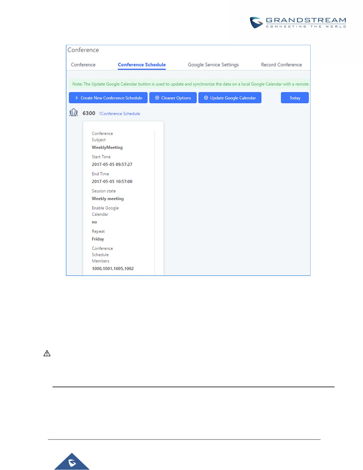
P a g e | 222
UCM6200 Series User Manual
Version 1.0.19.21
Figure 134: Conference Schedule
Once the conference room is scheduled, at the kick time, all users will be removed from conference room and
no extension can join the conference room anymore. At the scheduled conference time, UCM6200 will send
INVITE to the extensions that have been selected for conference.
----------------------------------------------------------------------------------------------------------------------------- ----------------------
Note:
• Please make sure that outbound route is properly configured for remote extensions to join the
conference.
• Once Kick Time is reached, Conference Schedule is locked and cannot be modified.
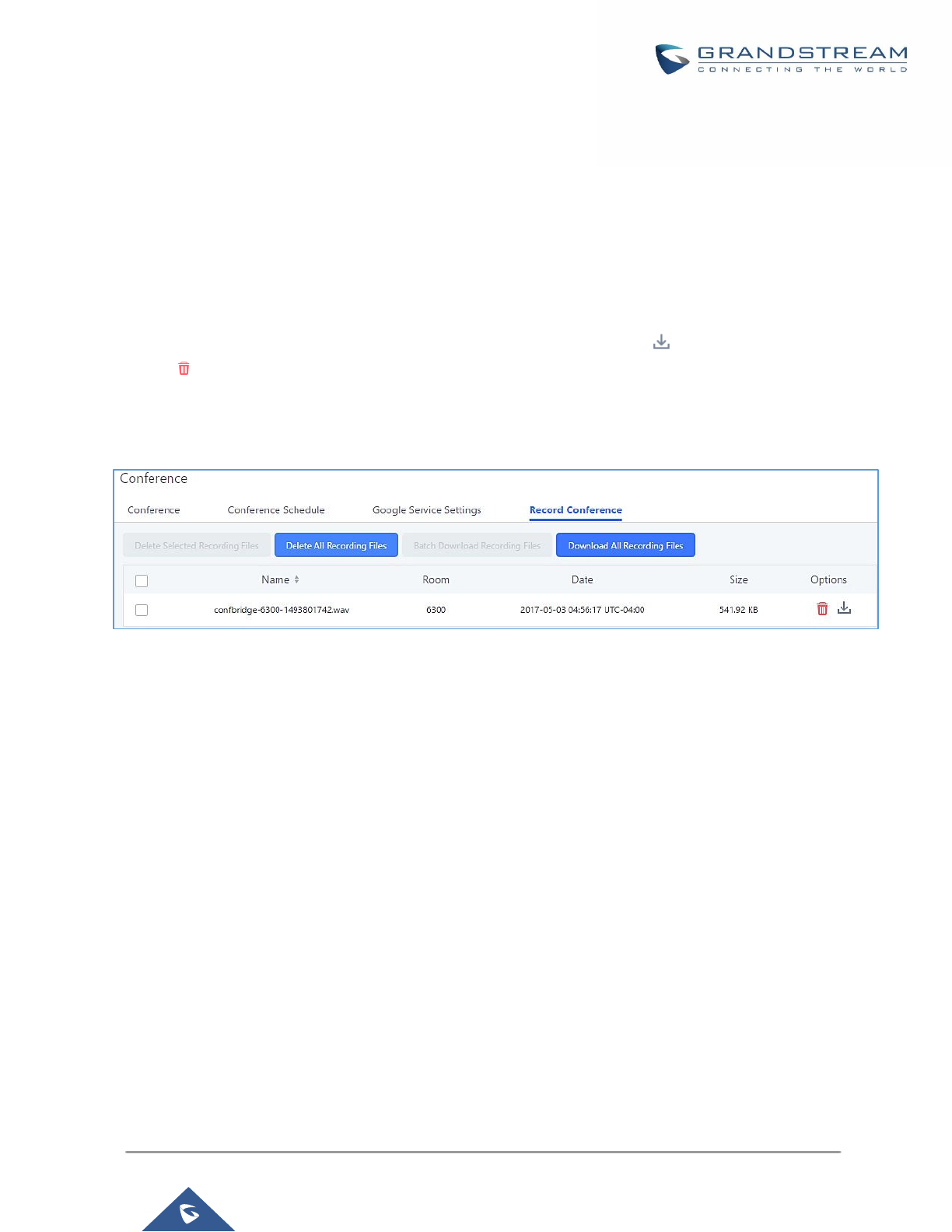
P a g e | 223
UCM6200 Series User Manual
Version 1.0.19.21
Conference Recordings
The UCM6200 allows users to record the conference call and retrieve the recording from Web GUI→Call
Features→Conference→Record Conference.
To record the conference call, when the conference room is in idle, enable "Record Conference" from the
conference room configuration dialog. Save the setting and apply the change. When the conference call starts,
the call will be automatically recorded in .wav format.
The recording files will be listed as below once available. Users could click on to download the recording or
click on to delete the recording. Users could also delete all recording files by clicking on “Delate All
Recording Files”, or delete multiple recording files at once by clicking on “Delete Selected Recording Files” after
selecting the recording files.
Figure 135: Conference Recording
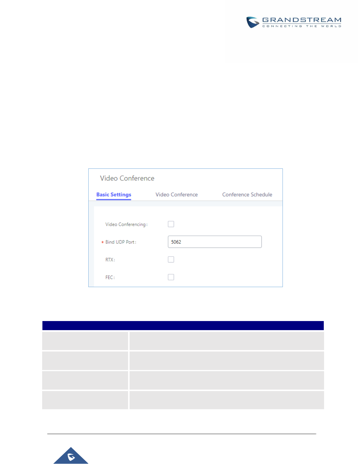
P a g e | 224
UCM6200 Series User Manual
Version 1.0.19.21
VIDEO CONFERENCE
With the UCM you can easily create, schedule, manage, and join video conference calls, from your desktop or
laptop computer. UCM Video conferencing uses WebRTC technology, so all the participants don’t have to
download and install any additional software or plugins. UCM Video Conferencing must be enabled by the
administrator for the concerned extensions. The video conference configurations can be accessed under Web
GUI→Call Features→Video Conference. In this page, users could enable, set the Basic setting, create, edit,
view, manage, delete conference rooms and edit the Conference Schedule.
Basic Settings
Figure 136: Video Conference Basic settings
Table 65: Video Conference Basic Settings
Basic Settings
Video Conferencing
This option should be enabled in order to activate the Video Conference
feature.
Bind UDP Port
Configure the UDP port number for MCM. The standard UDP port for MCM
is 5062.
RTX
If enabled, the RTX Packet Loss Retransmission will be activated. The
default setting is "No".
FEC
If enabled, the Forward Error Correction (FEC) will be activated. The
default setting is "No".

P a g e | 225
UCM6200 Series User Manual
Version 1.0.19.21
Video Conference Room Configurations
• Click on "Create New Conference Room" to add a new conference room.
• Click on to edit the conference room.
• Click on to delete the conference room.
Table 66: Video Conference room Configuration Parameters
Extension
Configure the conference number for the users to dial into the conference.
Note: Up to 64 characters.
Password
When configured, the users who would like to join the conference call must
enter this password before accessing the conference room.
Note:
• Only digits are allowed.
• The password has to be at least 4 characters. All repetitive and
sequential digits (e.g., 0000, 1111, 1234 and 2345) or common digits
(e.g., 111222 and 321321) are not allowed.
Conference Schedule
Conference Schedule can be found under UCM Web GUI → Call Features→Video Conference → Conference
Schedule. Users can create, edit, view and delete a Conference Schedule.
• Click on “Schedule New Conference” to add a new Conference Schedule.
• Click on the scheduled conference to edit or delete the event.
Table 67: Video Conference Schedule Parameters
Schedule Options
Conference Subject
Configure the name of the scheduled conference. Letters, digits, _ and -
are allowed.
Conference Room
Select a conference room for this scheduled conference.
Conference Password
Configure conference room password. Please note that if “Public Mode” is
enabled, this option is automatically disabled.
Kick Time(m)
Configure the time before the scheduled conference. When this time is
reached, a warning prompt will be played, and all attendees currently in
the scheduled conference room will be kicked after 5 mins. The conference
room will be locked until the scheduled conference begins. Default value
is 10 min.
Schedule Time
Configure the beginning date and duration of scheduled conference.
Note: Please pay attention to avoid time conflict on schedules in the same
conference room.
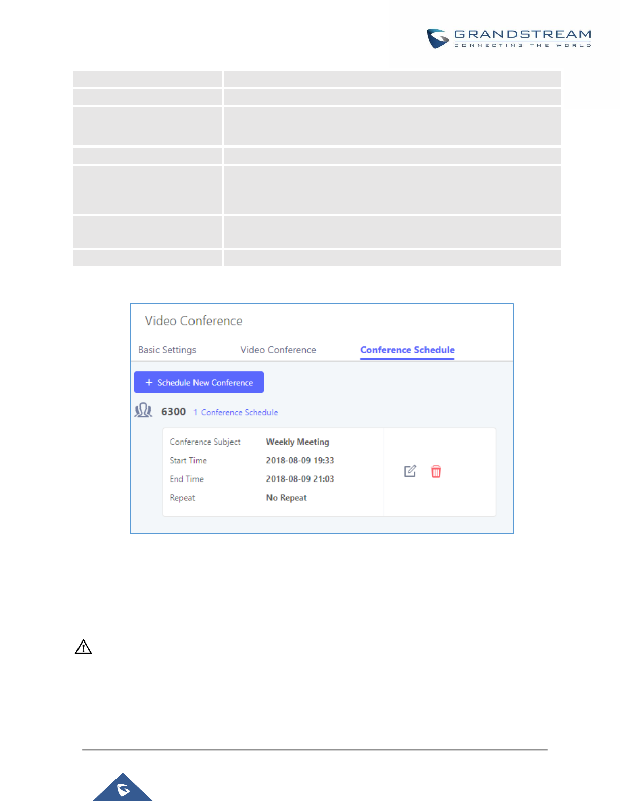
P a g e | 226
UCM6200 Series User Manual
Version 1.0.19.21
Duration
Configure the time duration of the scheduled conference.
Period
Configure the period of scheduled conference.
Host
Set the admin of this scheduled conference from the following list of
members.
Members
Select available extensions from the list to attend scheduled conference.
Special Extension
Add extensions that are not in the list (both local and remote list). If the
user wishes to add the special extension, please match the pattern on the
outbound route.
Shareable Link
Assign the video conference a public IP address and port to allow anyone
with the configured link to participate in the video conference.
Description
Set a description of scheduled conference.
Once created, the Web GUI will display scheduled conference in Conference Schedule.
Please see figure below:
Figure 137: Video Conference Schedule
Once the conference room is scheduled, at the kick time, all users will be removed from conference room and
no extension is allowed to join the conference room anymore. At the scheduled conference time, UCM will send
INVITE to the extensions that have been selected for conference.
----------------------------------------------------------------------------------------------------------------------------- ---------------
Notes:
• Video conferencing can be resource-intensive and may cause performance issues with the UCM when used.
• To ensure the best experience, please use Google Chrome (v67 or higher) or Mozilla Firefox (v60).
----------------------------------------------------------------------------------------------------------------------------- ---------------
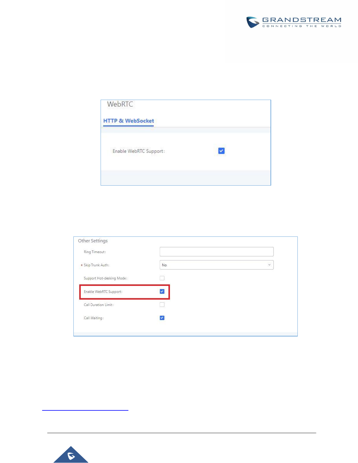
P a g e | 227
UCM6200 Series User Manual
Version 1.0.19.21
Wave WebRTC Video Calling & Conferencing
Web audio and video calls and conferencing can now be achieved through the UCM’s new WebRTC page. for
more details about this feature. To get started with this new feature, please make sure to:
1. Navigate to Value-Added Features → WebRTC and enable WebRTC support.
Figure 138: Enabling WebRTC Feature
2. Enable the WebRTC on the extensions that would use this feature under Extension / Trunk →
Extensions by editing the concerned extensions.
Figure 139: Enabling WebRTC on Extensions
The UCM offers the possibility to login to an extension via Grandstream Wave Portal using user portal password
in addition to SIP registration password, where it offers a sleek interface to host conferences, receive email
reminders for scheduled conferences, manage contacts, initiate calls, call transfer, chat functionality and more.
Access the page by adding “/gswave” after the UCM’s server address and port. (e.g.
https://my.ucm.com:8089/gswave).


P a g e | 229
UCM6200 Series User Manual
Version 1.0.19.21
IVR
Configure IVR
IVR configurations can be accessed under the UCM6200 Web GUI→Call Features→IVR. Users could create,
edit, view and delete an IVR.
• Click on "Create New IVR" to add a new IVR.
• Click on to edit the IVR configuration.
• Click on to delete the IVR.
Figure 141: Create New IVR

P a g e | 230
UCM6200 Series User Manual
Version 1.0.19.21
Table 68: IVR Configuration Parameters
Basic Settings
Name
Configure the name of the IVR. Letters, digits, _ and - are allowed.
Extension
Enter the extension number for users to access the IVR.
Dial Trunk
If enabled, all callers to the IVR can use trunk. The permission must be configured
for the users to use the trunk first. The default setting is "No".
Permission
Assign permission level for outbound calls if "Dial Trunk" is enabled. The available
permissions are "Internal", "Local", "National" and "International" from the lowest
level to the highest level.
The default setting is "Internal". If the user tries to dial outbound calls after dialing
into the IVR, the UCM6200 will compared the IVR's permission level with the
outbound route's privilege level.
If the IVR's permission level is higher than (or equal to) the outbound route's
privilege level, the call will be allowed to go through.
Dial Other
Extensions
This controls the destination that can be reached by the external caller via the
inbound route. The available destinations are:
• Extension
• Conference
• Call Queue
• Ring Group
• Paging/Intercom Groups
• Voicemail Groups
• Fax Extension
• Dial by Name
• All
IVR Black/White
List
If enabled only numbers inside of the White List or outside of the Black List can be
called from IVR.
Internal
Black/White List
Contain numbers, either of Black List or White List.
External
Black/White List
This feature can be used only when Dial Trunk is enabled, it contains external
numbers allowed or denied calling from the IVR, the allowed format is the following:
Number1, number2, number3, ….
Replace Caller ID
If enabled, the UCM will replace the caller display name with the IVR name the
caller know whether the call is incoming from a direct extension or an IVR.
Alert Info
When present in an INVITE request, the alert-Info header field specifies and
alternative ring tone to the UAS.
Welcome Prompt
Select an audio file to play as the welcome prompt for the IVR. Click on "Prompt"
to add additional audio file under Web GUI→PBX Settings→Voice
Prompt→Custom Prompt.

P a g e | 231
UCM6200 Series User Manual
Version 1.0.19.21
Digit Timeout
Configure the timeout between digit entries. After the user enters a digit, the user
needs to enter the next digit within the timeout. If no digit is detected within the
timeout, the UCM6200 will consider the entries complete. The default timeout is 3s.
Response
Timeout
After playing the prompts in the IVR, the UCM6200 will wait for the DTMF entry
within the timeout (in seconds). If no DTMF entry is detected within the timeout, a
timeout prompt will be played. The default setting is 10 seconds.
Response
Timeout Prompt
Select the prompt message to be played when timeout occurs.
Invalid Prompt
Select the prompt message to be played when an invalid extension is pressed.
Response
Timeout Repeat
Loops
Configure the number of times to repeat the prompt if no DTMF input is detected.
When the loop ends, it will go to the timeout destination if configured, or hang up.
The default setting is 3.
Invalid Repeat
Loops
Configure the number of times to repeat the prompt if the DTMF input is invalid.
When the loop ends, it will go to the invalid destination if configured, or hang up.
The default setting is 3.
Language
Select the voice prompt language to be used for this IVR. The default setting is
"Default" which is the selected voice prompt language under Web GUI→PBX
Settings→Voice Prompt→Language Settings. The dropdown list shows all the
current available voice prompt languages on the UCM6200. To add more languages
in the list, please download voice prompt package by selecting "Check Prompt List"
under Web GUI→PBX Settings→Voice Prompt→Language Settings.
Key Pressing Events
Key Press Event:
Press 0
Press 1
Press 2
Press 3
Press 4
Press 5
Press 6
Press 7
Press 8
Press 9
Press *
Select the event for each key pressing for 0-9, *, Timeout and Invalid. The event
options are:
• Extension
• Voicemail
• Conference Rooms
• Voicemail Group
• IVR
• Ring Group
• Queues
• Page Group
• Fax
• Custom Prompt
• Hangup
• DISA
• Dial by Name
• External Number
• Callback
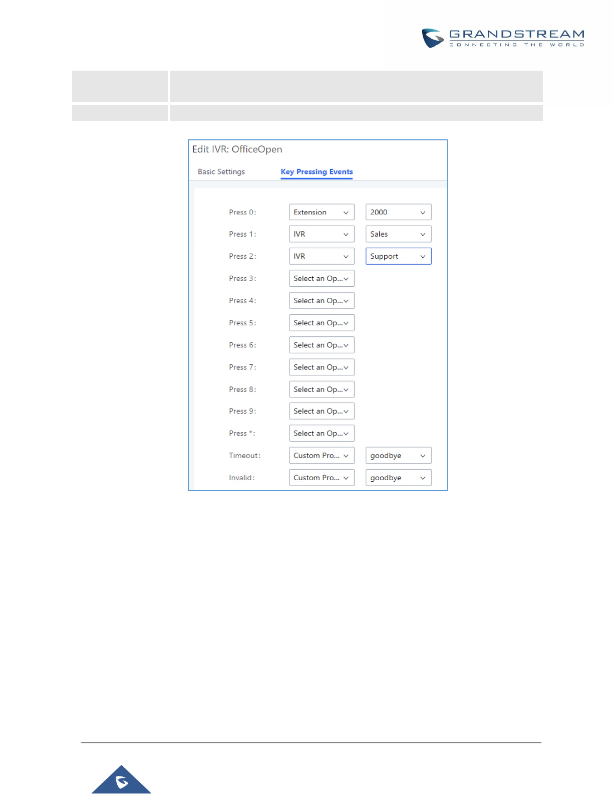
P a g e | 232
UCM6200 Series User Manual
Version 1.0.19.21
Timeout
When exceeding the number of defined answer timeout, IVR will enter the
configured event when timeout. If not configured, then it will Hangup.
Invalid
Configure the destination when the Invalid Repeat Loop is done.
Figure 142: Key Pressing Events
Black/White List in IVR
In some scenarios, the IPPBX administrator needs to restrict the extensions that can be reached from IVR.
For example, the company CEO and directors prefer only receiving calls transferred by the secretary, some
special extensions are used on IP surveillance end points which shouldn’t be reached from external calls via IVR
for privacy reason. UCM has now added blacklist and whitelist in IVR settings for users to manage this.
Note: up to 500 extensions are allowed on the back/white list.
To use this feature, log in UCM Web GUI and navigate to Call Features→IVR→Create/Edit IVR: IVR
Black/White List.
• If the user selects “Blacklist Enable” and adds extension in the list, the extensions in the list will not be
allowed to be reached via IVR.
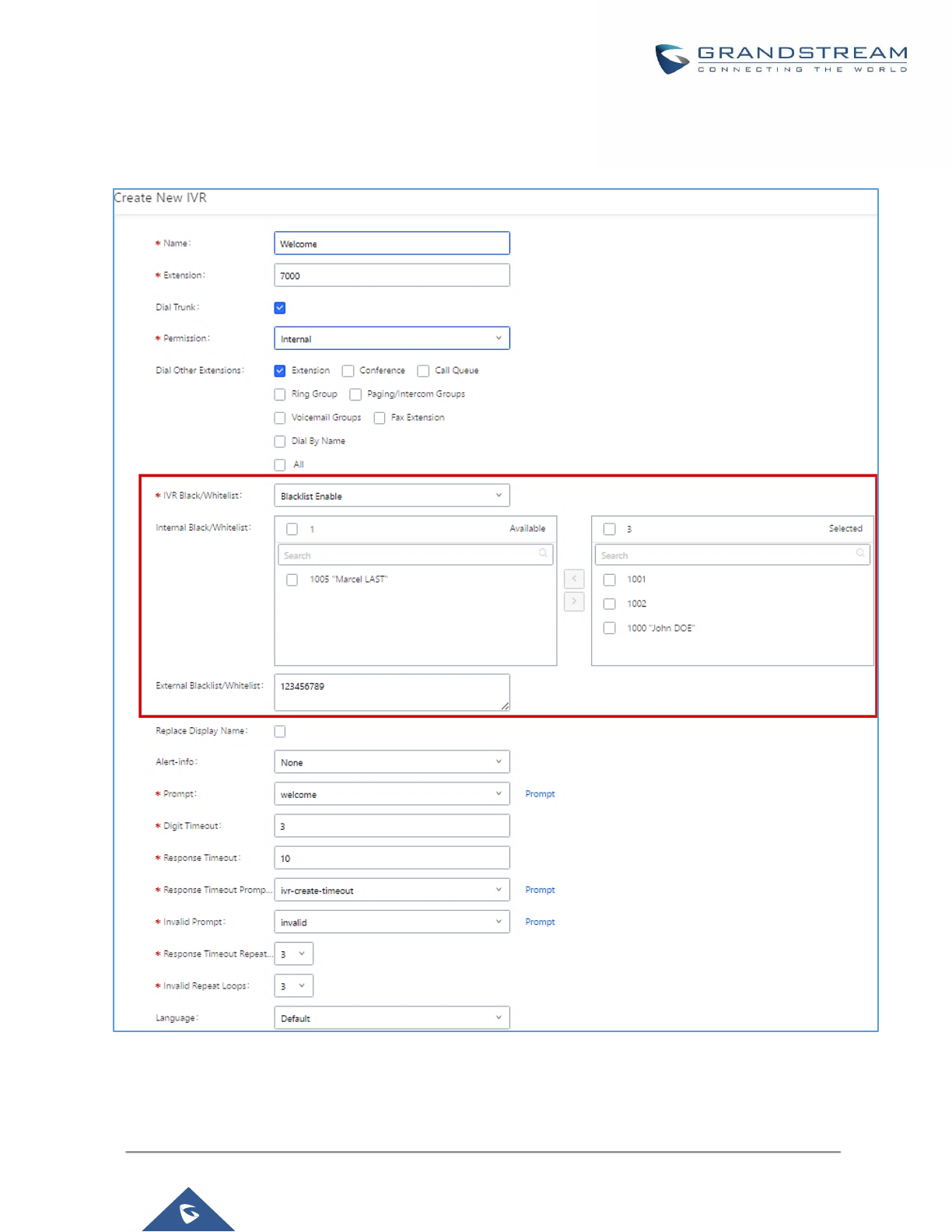
P a g e | 233
UCM6200 Series User Manual
Version 1.0.19.21
• If the user selects “Whitelist Enable” and adds extension in the list, only the extensions in the list can be
allowed to be reached via IVR.
Figure 143: Black/White List
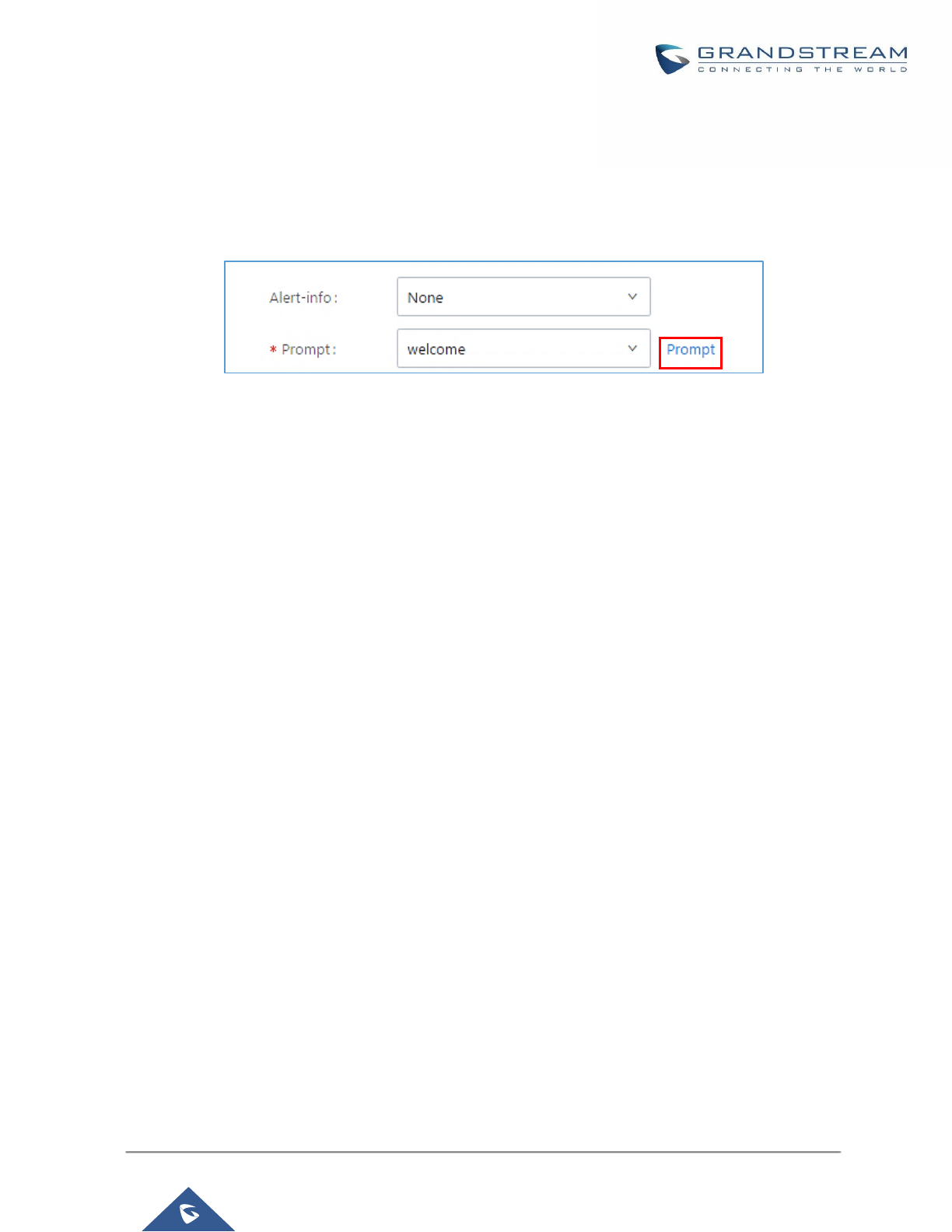
P a g e | 234
UCM6200 Series User Manual
Version 1.0.19.21
Create Custom Prompt
To record new IVR prompt or upload IVR prompt to be used in IVR, click on “Prompt” next to the “Welcome
Prompt” option and the users will be redirected to Custom Prompt page. Or users could go to Web GUI→PBX
Settings→Voice Prompt→Custom Prompt page directly.
Figure 144: Click on Prompt to Create IVR Prompt
Once the IVR prompt file is successfully added to the UCM6200, it will be added into the prompt list options for
users to select in different IVR scenarios.
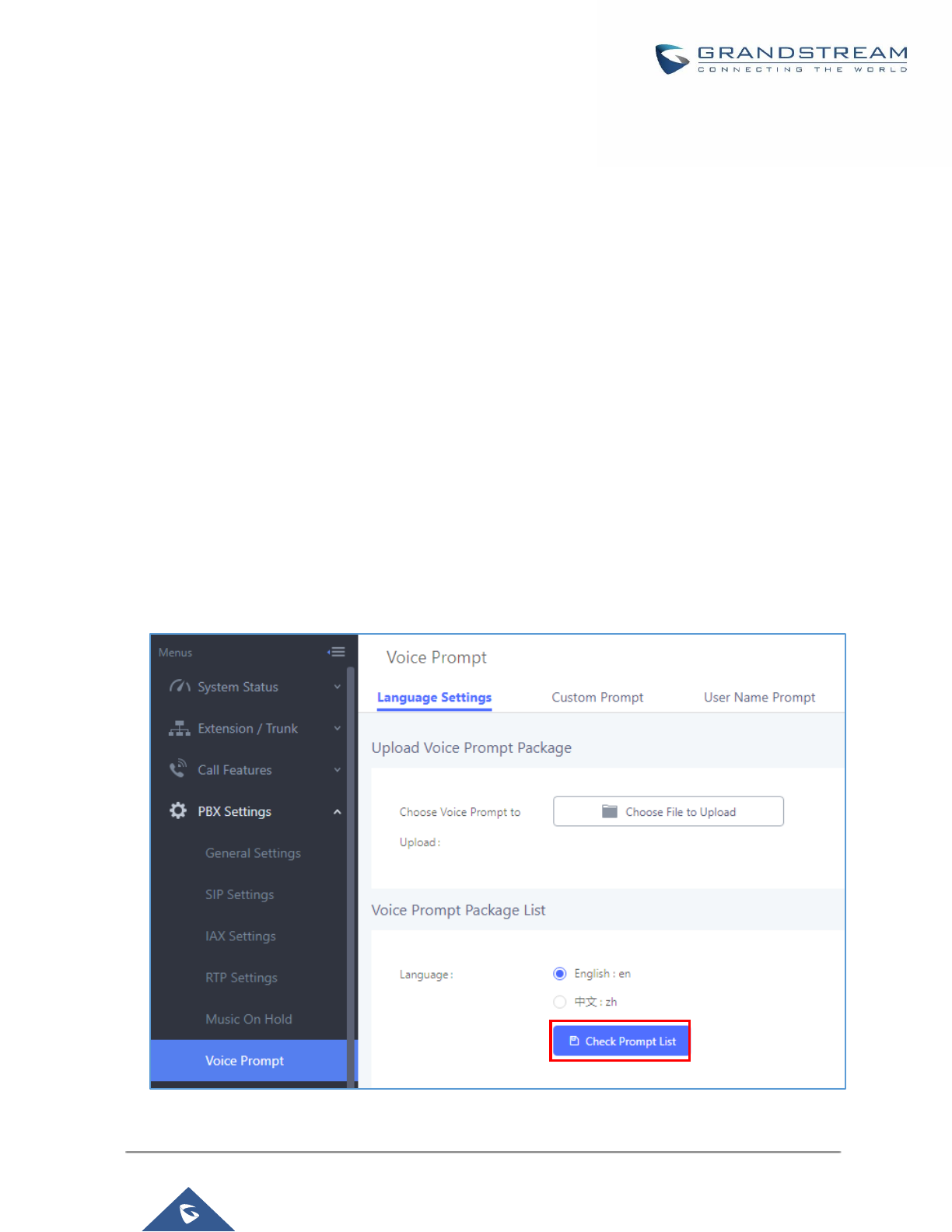
P a g e | 235
UCM6200 Series User Manual
Version 1.0.19.21
LANGUAGE SETTINGS FOR VOICE PROMPT
The UCM6200 supports multiple languages in Web GUI as well as system voice prompt. Currently, there are 16
languages supported in system voice prompt: English (United States), Arabic, Chinese, Dutch, English
(United Kingdom), French, German, Greek, Hebrew, Italian, Polish, Portuguese, Russian, Spanish,
Catalan, Swedish and Turkish.
English (United States) and Chinese voice prompts are built in with the UCM6200 already. The other languages
provided by Grandstream can be downloaded and installed from the UCM6200 Web GUI directly. Additionally,
users could customize their own voice prompts, package them and upload to the UCM6200.
Language settings for voice prompt can be accessed under Web GUI→PBX Settings→Voice
Prompt→Language Settings.
Download and Install Voice Prompt Package
To download and install voice prompt package in different languages from UCM6200 Web GUI, click on "Check
Prompt List" button.
Figure 145: Language Settings for Voice Prompt
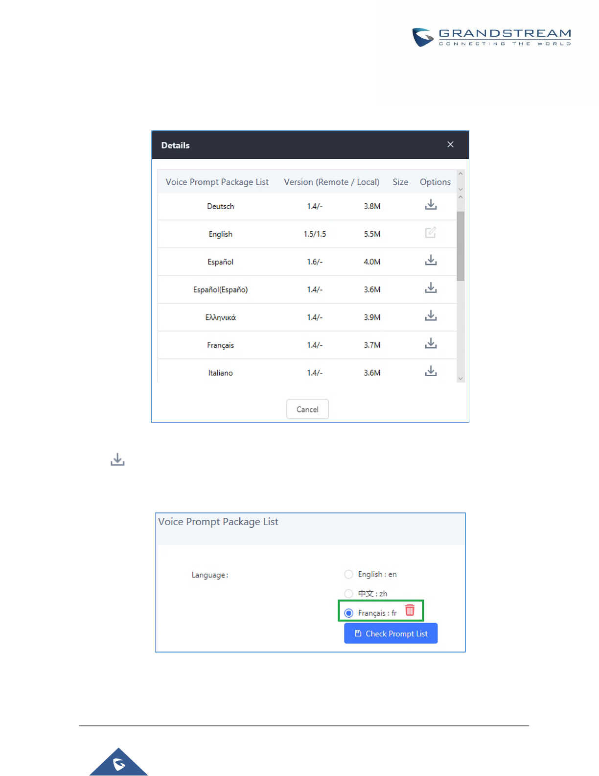
P a g e | 236
UCM6200 Series User Manual
Version 1.0.19.21
A new dialog window of voice prompt package list will be displayed. Users can see the version number (latest
version available V.S. current installed version), package size and options to upgrade or download the language.
Figure 146: Voice Prompt Package List
Click on to download the language to the UCM6200. The installation will be automatically started once the
downloading is finished.
Figure 147: New Voice Prompt Language Added
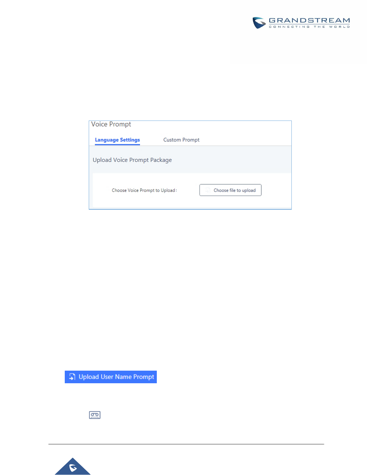
P a g e | 237
UCM6200 Series User Manual
Version 1.0.19.21
A new language option will be displayed after successfully installed. Users then could select it to apply in the
UCM6200 system voice prompt or delete it from the UCM6200.
Customize Specific Prompt
On the UCM6200, if the user needs to replace some specific customized prompt, the user can upload a single
specific customized prompt from Web GUI→PBX Settings→Voice Prompt→Language Settings instead of the
entire language pack.
Figure 148: Upload Single Voice Prompt for Entire Language Pack
User Name Prompt Customization
There are two ways to customize/set new user name prompt:
Upload User Name Prompt File from Web GUI
1. First, Users should have a pre-recorded file respecting the following format:
• PCM encoded / 16 bits / 8000Hz mono.
• In “.GSM” or “.WAV” format.
• File size under 5M.
• Filename must be set as the extension number with 18 characters max. For example, the recorded
file name 1000.wav will be used for extension 1000.
2. Go under web GUI PBX Settings → Voice Prompt → User Name Prompt and click on
button.
3. Select the recorded file to upload it and press Save and Apply Settings.
• Click on to record again the user name prompt.

P a g e | 238
UCM6200 Series User Manual
Version 1.0.19.21
• Click on to play recorded user name prompt.
• Select user name prompts and press to delete specific file or select multiple files for deletion using
the button .
Record User Name via Voicemail Menu
The second option to record user name is using voicemail menu, please follow below steps:
• Dial *98 to access the voicemail
• After entering the desired extension and voicemail password, dial “0” to enter the recordings menu and
then “3” to record a name.
Another option is that each user can record their own name by following below steps:
• The user dials *97 to access his/her voicemail
• After entering the voicemail password, the user can press “0” to enter the recordings menu and then “3”
to record his name.

P a g e | 239
UCM6200 Series User Manual
Version 1.0.19.21
VOICEMAIL
Configure Voicemail
If the voicemail is enabled for UCM6200 extensions, the configurations of the voicemail can be globally set up
and managed under Web GUI→Call Features→Voicemail.
Figure 149: Voicemail Settings

P a g e | 240
UCM6200 Series User Manual
Version 1.0.19.21
Table 69: Voicemail Settings
Max Greeting
Configure the maximum number of seconds for the voicemail greeting. The
default setting is 60 seconds.
Dial ‘0’ For Operator
If enabled, the caller can press 0 to exit the voicemail application and connect
to the configured operator’s extension.
Operator Extension
Select the operator extension, which will be dialed when users press 0 to exit
voicemail application. The operator extension can also be used in IVR.
Max Messages Per
Folder
Configure the maximum number of messages per folder in users’ voicemail. The
valid range 10 to 1000. The default setting is 50.
Max Message Time
Select the maximum duration of the voicemail message. The message will not
be recorded if the duration exceeds the max message time. The default setting
is 15 minutes. The available options are:
• 1 minute
• 2 minutes
• 5 minutes
• 15 minutes
• 30 minutes
• Unlimited
Min Effective Message
Time
Configure the minimum duration (in seconds) of a voicemail message.
Messages will be automatically deleted if the duration is shorter than the Min
Message Time. The default setting is 3 seconds. The available options are:
• No minimum
• 1 second
• 2 seconds
• 3 seconds
• 4 seconds
• 5 seconds
Note: Silence and noise duration are not counted in message time.
Announce Message
Caller-ID
If enabled, the caller ID of the user who has left the message will be announced
at the beginning of the voicemail message. The default setting is "No".
Announce Message
Duration
If enabled, the message duration will be announced at the beginning of the
voicemail message. The default setting is "No".
Play Envelope
If enabled, a brief introduction (received time, received from, and etc) of each
message will be played when accessed from the voicemail application. The
default setting is "Yes".
Play from Last
If enabled, UCM will play from the voice message left most recently; if disabled,
UCM will play from the earliest left voice message
Allow User Review
If enabled, users can review the message following the IVR before sending.

P a g e | 241
UCM6200 Series User Manual
Version 1.0.19.21
Voicemail Remote
Access
If enabled, external callers routed by DID and reaching VM will be prompted by
the UCM with 2 options:
• Press 1 to leave a message.
To leave a message for the extension reached by DID.
• Press 2 to access voicemail management system.
This will allow caller to access any extension VM after entering
extension number and its VM password.
Note: This option applies to inbound call routed by DID only.
The default setting is “Disabled”.
Forward Voicemail to
Peered UCMs
Enables the forwarding of voicemail to remote extensions on peered SIP trunks.
The default setting is “Disabled”.
Voicemail Password
Configures the default voicemail password that will be used when an extension
is reset.
Note: Resetting an extension will reset Voicemail Password, Send Voicemail to Email, and Keep Voicemail after
Emailing values to default. Previous custom voicemail prompts and messages will be deleted.
Access Voicemail
If the voicemail is enabled for UCM6200 extensions, the users can dial the voicemail access number (by default
*97) to access their extension’s voicemail. The users will be prompted to enter the voicemail password and then
can enter digits from the phone keypad to navigate in the IVR menu for different options.
Otherwise the user can dial the voicemail access code (by default *98) followed by the extension number and
password in order to access to that specific extension’s voicemail.
Table 70: Voicemail IVR Menu
Main Menu
Sub Menu 1
Sub Menu 2
1 – New messages
3 - Advanced options
1 - Send a reply
2 - Call the person who sent this message
3 - Hear the message envelop
4 - Leave a message
* - Return to the main menu
5 - Repeat the current message
7 - Delete this message
8 - Forward the message to
another user
9 - Save

P a g e | 242
UCM6200 Series User Manual
Version 1.0.19.21
* - Help
# - Exit
2 – Change folders
0 - New messages
1 - Old messages
2 - Work messages
3 - Family messages
4 - Friend messages
# - Cancel
3 – Advanced options
1 - Send a reply
2 - Call the person who sent
this message
3 - Hear the message envelop
4 - Leave a message
* - Return to the main menu
0 – Mailbox options
1 - Record your unavailable
message
1 - Accept this recording
2 - Listen to it
3 - Re-record your message
2 - Record your busy message
1 - Accept this recording
2 - Listen to it
3 - Re-record your message
3 - Record your name
1 - Accept this recording
2 - Listen to it
3 - Re-record your message
4 - Record temporary greeting
1 - Accept this recording
2 - Listen to it
3 - Re-record your message
5 - Change your password
* - Return to the main menu
Leaving Voicemail
If an extension has voicemail enabled under basic settings “Extension/Trunk → Extensions → Basic Settings”
and after a ring timeout or user not available, the caller will be automatically redirected to the voicemail in order
to leave a message on which case they can press # in order to submit the message.
In case if the caller is calling from an internal extension, they will be directly forwarded to the extension’s
voicemail box. But if the caller is calling from outside the system and the incoming call is routed by DID to the
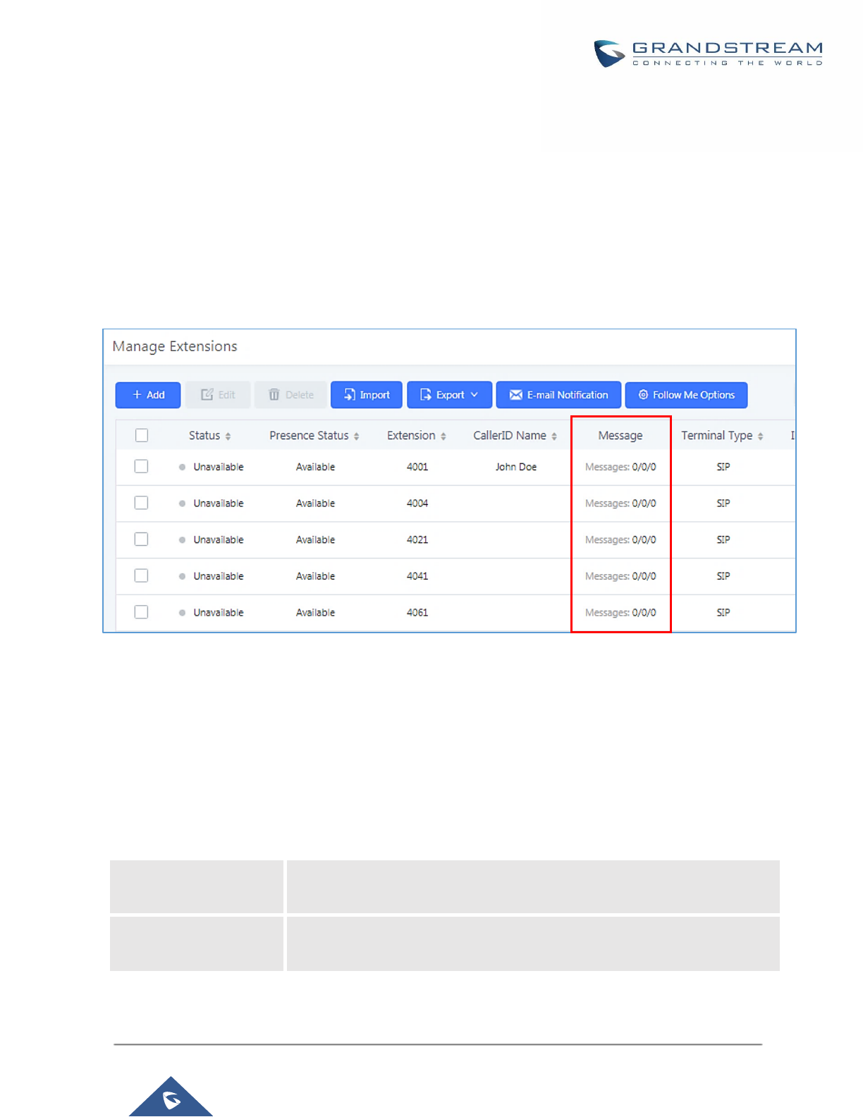
P a g e | 243
UCM6200 Series User Manual
Version 1.0.19.21
destination extension, then the caller will be prompted with the choice to either press1 to access voicemail
management or press 2 to leave a message for the called extension. This feature could be useful for remote
voicemail administration.
Extension Voicemail Count
The UCM62xx provides an easy way to check the number of voicemail messages for each extension directly
from UCM web GUI → Extension/Trunk → Extensions overview page.
Voicemail count (“Message” column) is displayed in the format Urgent / Unread / Read.
Figure 150: Voicemail Count
Voicemail Email Settings
The UCM6200 can be configured to send the voicemail as attachment to Email. Click on "Voicemail Email
Settings" button to configure the Email attributes and content.
Table 71: Voicemail Email Settings
Attach Recordings to
E-Mail
If enabled, voicemails will be sent to user's Email address. The default setting
is "Yes".
Keep Recordings
If enabled, voicemail will be stored in the UCM6200 after the email is sent. The
default setting is “Yes”.
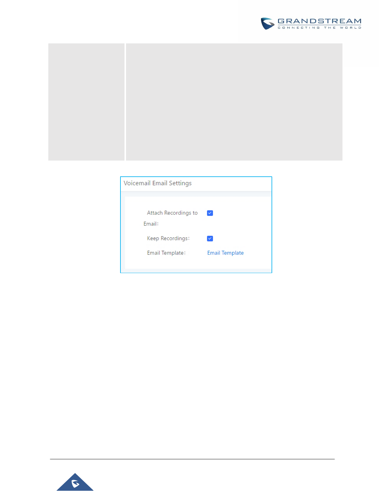
P a g e | 244
UCM6200 Series User Manual
Version 1.0.19.21
Template for Voicemail
Emails
Fill in the "Subject:" and "Message:" content, to be used in the Email when
sending to the user.
The template variables are:
• \t: TAB
• ${VM_NAME}: Recipient's first name and last name
• ${VM_DUR}: The duration of the voicemail message
• ${VM_MAILBOX}: The recipient's extension
• ${VM_CALLERID}: The caller ID of the person who has left the message
• ${VM_MSGNUM}: The number of messages in the mailbox
• ${VM_DATE}: The date and time when the message is left
Figure 151: Voicemail Email Settings
Click on "Load Default Settings" button to view the default template as an example.
Configure Voicemail Group
The UCM6200 supports voicemail group and all the extensions added in the group will receive the voicemail to
the group extension. The voicemail group can be configured under Web GUI→Call
Features→Voicemail→Voicemail Group. Click on "Create New Voicemail Group" to configure the group.
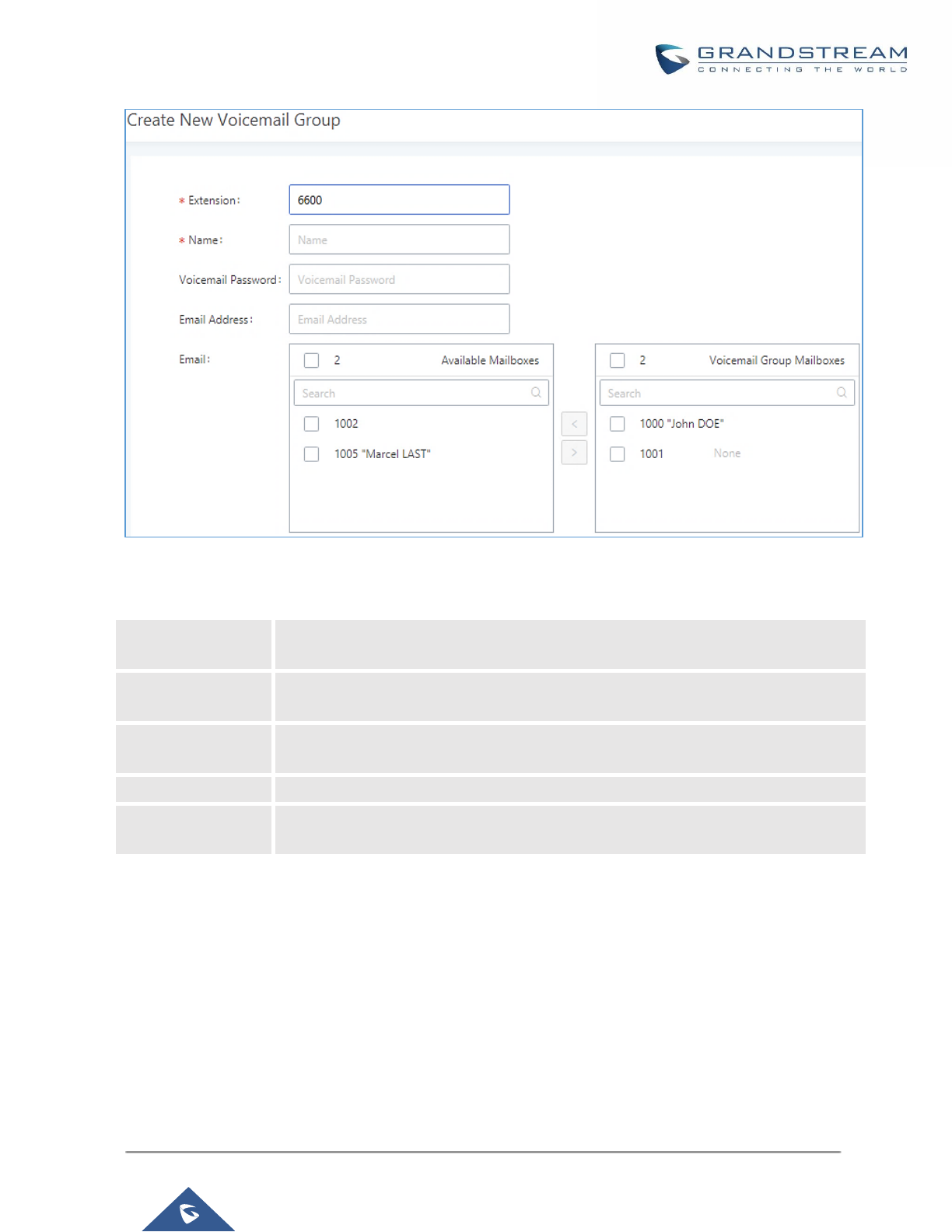
P a g e | 245
UCM6200 Series User Manual
Version 1.0.19.21
Figure 152: Voicemail Group
Table 72: Voicemail Group Settings
Extension
Enter the Voicemail Group Extension. The voicemail messages left to this extension
will be forwarded to all the voicemail group members.
Name
Configure the Name to identify the voicemail group. Letters, digits, _ and - are
allowed.
Voicemail
Password
Configure the voicemail password for the users to check voicemail messages.
Email Address
Configure the Email address for the voicemail group extension.
Voicemail Group
Mailboxes
Select available mailboxes from the left list and add them to the right list. The
extensions need to have voicemail enabled to be listed in available mailboxes list.
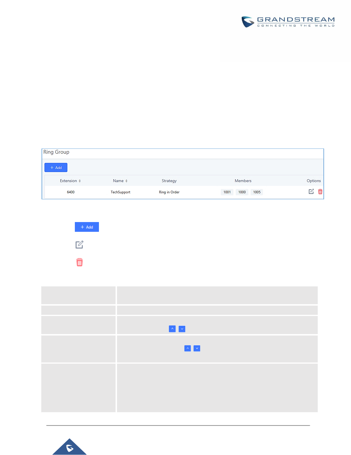
P a g e | 246
UCM6200 Series User Manual
Version 1.0.19.21
RING GROUP
The UCM6200 supports ring group feature with different ring strategies applied to the ring group members. This
section describes the ring group configuration on the UCM6200.
Configure Ring Group
Ring group settings can be accessed via Web GUI→Call Features→Ring Group.
Figure 153: Ring Group
• Click on to add ring group.
• Click on to edit the ring group. The following table shows the ring group configuration parameters.
• Click on to delete the ring group.
Table 73: Ring Group Parameters
Ring Group Name
Configure ring group name to identify the ring group. Letters, digits, _ and –
are allowed.
Extension
Configure the ring group extension.
Members
Select available users from the left side to the ring group member list on the
right side. Click on to arrange the order.
LDAP Phonebook
Select available remote users from the left side to the ring group member list
on the right side. Click on to arrange the order. Note: LDAP Sync must
be enabled first.
Ring Strategy
Select the ring strategy. The default setting is “Ring in order”.
• Ring simultaneously.
Ring all the members at the same time when there is incoming call to the
ring group extension. If any of the member answers the call, it will stop
ringing.

P a g e | 247
UCM6200 Series User Manual
Version 1.0.19.21
• Ring in order.
Ring the members with the order configured in ring group list. If the first
member doesn’t answer the call, it will stop ringing the first member and
start ringing the second member.
Music On Hold
Select the “Music On Hold” Class of this Ring Group, “Music On Hold” can be
managed from the “Music On Hold” panel on the left.
Custom Prompt
This option is to set a custom prompt for a ring group to announce to caller.
Click on ‘Prompt’, it will direct the users to upload the customized voice
prompts.
Note: Users can also refer to the page PBX Settings→Voice
Prompt→Custom Prompt, where they could record new prompt or upload
prompt files.
Ring Timeout on Each
Member
Configure the number of seconds to ring each member. If set to 0, it will keep
ringing. The default setting is 30 seconds.
Note:
The actual ring timeout might be overridden by users if the phone has ring
timeout settings as well.
Auto Record
If enabled, calls on this ring group will be automatically recorded. The default
setting is No. The recording files can be accessed from Web
GUI→CDR→Recording Files.
Endpoint Call
Forwarding Support
This allows the UCM to work with endpoint-configured call forwarding settings
to redirect calls to ring group. For example, if a member wants to receive calls
to the ring group on his mobile phone, he would have to set his endpoint’s call
forwarding settings to his mobile number. By default, it’s disabled.
However, this feature has the following limitations:
• This feature will work only when call forwarding is configured on
endpoints, not on the UCM.
• If the forwarded call goes through an analog trunk, and polarity reversal
is disabled, the other ring group members will no longer receive the call
after it is forwarded.
• If the forwarded call goes through a VoIP trunk, and the outbound route
for it is PIN-protected and requires authentication, the other ring group
members will no longer receive the call after it is forwarded.
• If the forwarded call hits voicemail, the other ring group members will no
longer receive the call.
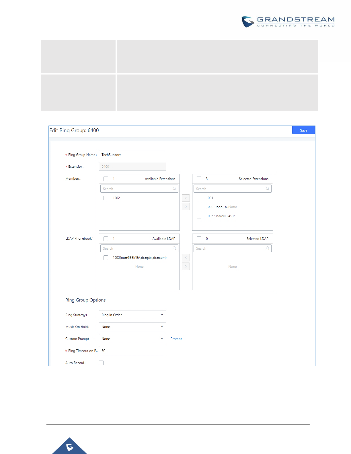
P a g e | 248
UCM6200 Series User Manual
Version 1.0.19.21
Replace Display Name
If enabled, the UCM will replace the caller display name with the Ring Group
name the caller know whether the call is incoming from a direct extension or a
Ring Group.
Enable Destination
If enabled, users could select extension, voicemail, ring group, IVR, call queue,
voicemail group as the destination if the call to the ring group has no answer.
Secret and Email address are required if voicemail is selected as the
destination.
Figure 154: Ring Group Configuration

P a g e | 249
UCM6200 Series User Manual
Version 1.0.19.21
Remote Extension in Ring Group
Remote extensions from the peer trunk of a remote UCM6200 can be included in the ring group with local
extension. An example of Ring Group with peer extensions is presented in the following:
1. Creating SIP Peer Trunk between both UCM6200_A and UCM6200_B. SIP Trunk can be found under Web
GUI→Extension/Trunk→VoIP Trunks. Also, please configure their Inbound/Outbound routes accordingly.
2. Click edit button in the menu , and check if Sync LDAP Enable is selected, this option will allow
UCM6200_A update remote LDAP server automatically from peer UCM6200_B. In addition, Sync LDAP
Password must match for UCM6200_A and UCM6200_B to sync LDAP contact automatically. Port number
can be anything between 0~65535, and use the outbound rule created in step 1 for the LDAP Outbound
Rule option.
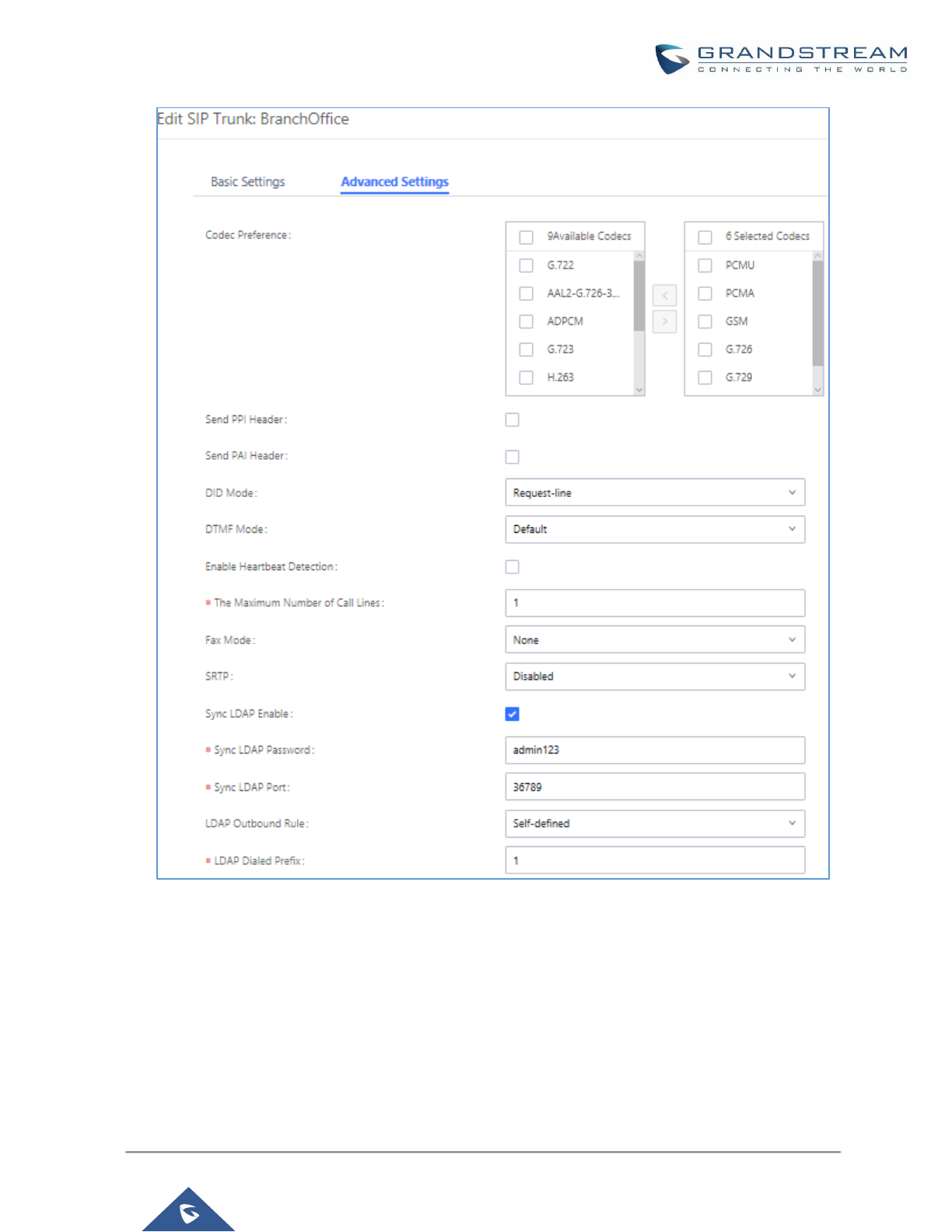
P a g e | 250
UCM6200 Series User Manual
Version 1.0.19.21
Figure 155: Sync LDAP Server option
3. In case if LDAP server doesn’t sync automatically, user can manually sync LDAP server. Under VoIP Trunks
page, click sync button shown in the following figure to manually sync LDAP contacts from peer UCM6200.
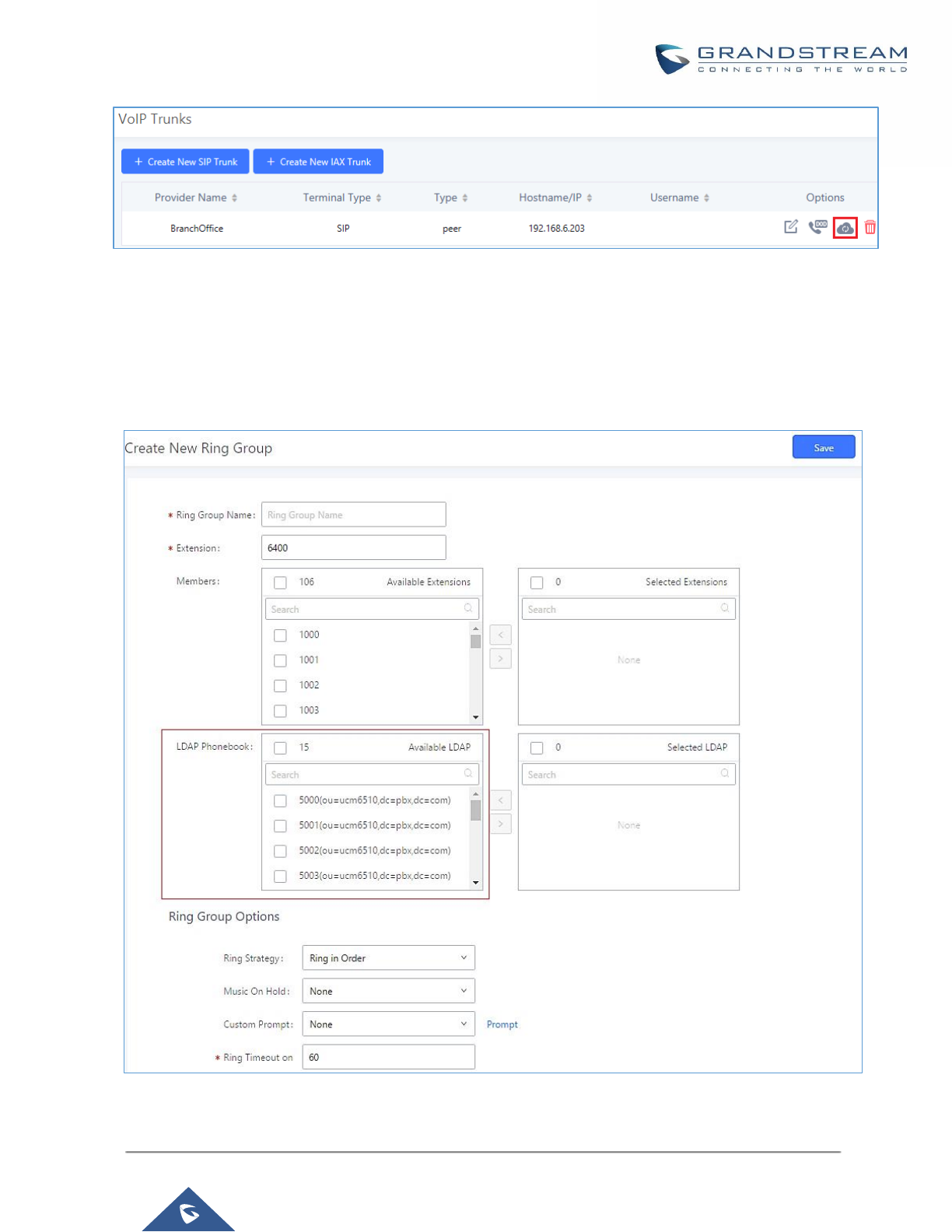
P a g e | 251
UCM6200 Series User Manual
Version 1.0.19.21
Figure 156: Manually Sync LDAP Server
4. Under Ring Groups setting page, click “Add”. Ring Groups can be found under Web GUI→Call
Features→Ring Groups.
5. If LDAP server is synced correctly, Available LDAP Numbers box will display available remote extensions
that can be included in the current ring group. Please also make sure the extensions in the peer UCM6200
can be included into that UCM6200’s LDAP contact.
Figure 157: Ring Group Remote Extension
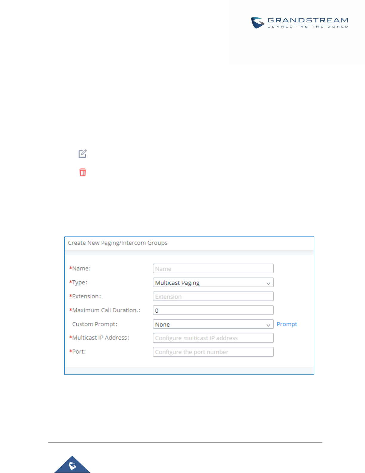
P a g e | 252
UCM6200 Series User Manual
Version 1.0.19.21
PAGING AND INTERCOM GROUP
Paging and Intercom Group can be used to make an announcement over the speaker on a group of phones.
Targeted phones will answer immediately using speaker. The UCM6200 paging and intercom can be used via
feature code to a single extension or a paging/intercom group. This section describes the configuration of
paging/intercom group under Web GUI→Call Features→Paging/Intercom.
Configure Paging/Intercom Group
• Click on "Add" to add paging/intercom group.
• Click on to edit the paging/intercom group.
• Click on to delete the paging/intercom group.
• Click on "Paging/Intercom Group Settings" to edit Alert-Info Header. This header will be included in the SIP
INVITE message sent to the callee in paging/intercom call.
Configure Multicast Paging
Figure 158: Multicast Paging
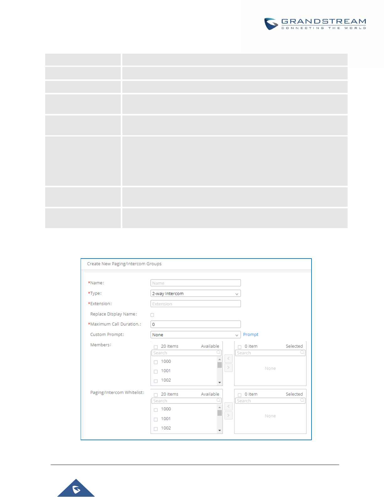
P a g e | 253
UCM6200 Series User Manual
Version 1.0.19.21
Table 74: Multicast Paging Configuration Parameters
Name
Configure paging/intercom group name.
Type
Select “Multicast Paging”.
Extension
Configure the paging/intercom group extension.
Multicast IP Address
The allowed multicast IP address range is 224.0.1.0 - 238.255.255.255.
Note: This field appears only when “Type” is set to “Multicast Paging”.
Maximum Call Duration
Specify the maximum call duration in seconds. The default value 0 means no
limit.
Custom Prompt
This option is to set a custom prompt for a paging/intercom group to announce
to caller. Click on ‘Prompt’, it will direct the users to upload the customized voice
prompts.
Note: Users can also refer to the page PBX Settings→Voice Prompt→Custom
Prompt, where they could record new prompt or upload prompt files.
Multicast IP Address
Select which extensions are allowed to use the paging/intercom feature for this
paging group.
Port
Specify port for multicast paging.
Note: This field appears only when “Type” is set to “Multicast Paging”.
Configure 2-way Intercom
Figure 159: 2-way Intercom
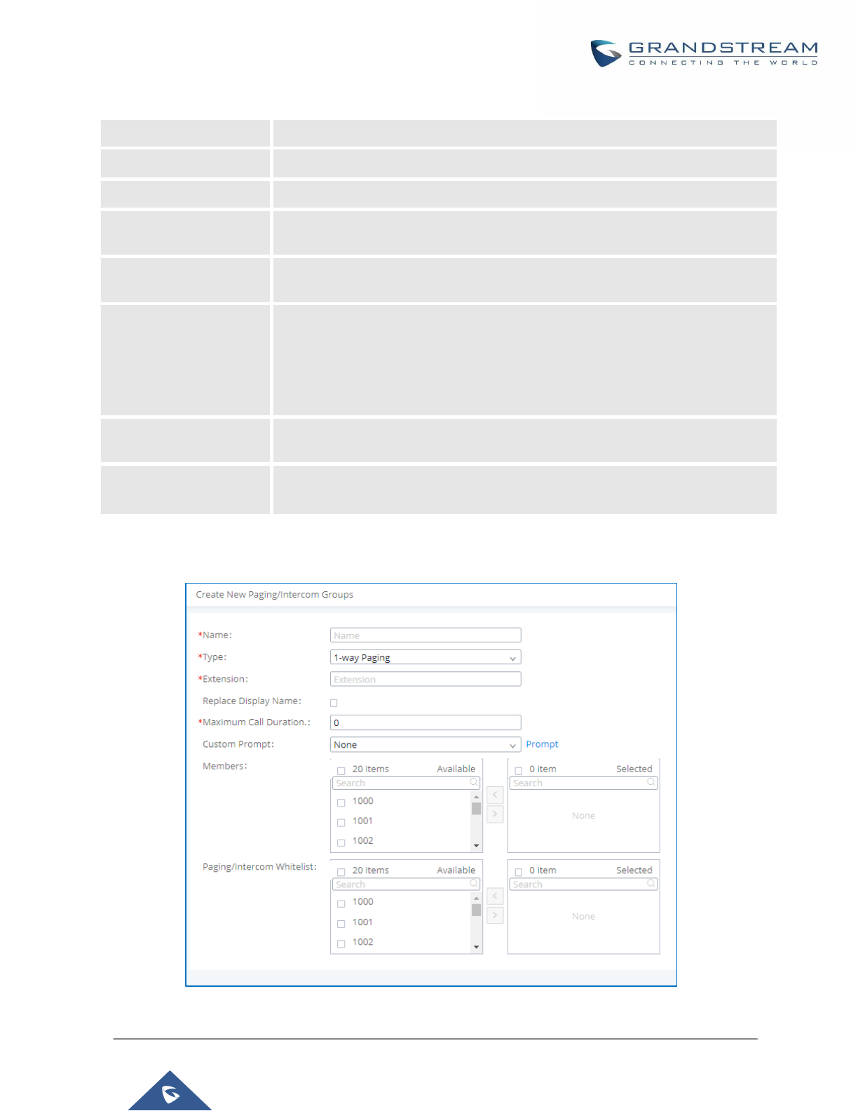
P a g e | 254
UCM6200 Series User Manual
Version 1.0.19.21
Table 75: 2-way Intercom Configuration Parameters
Name
Configure paging/intercom group name.
Type
Select "2-way Intercom".
Extension
Configure the paging/intercom group extension.
Replace Display Name
If enabled, the UCM will replace the caller display name with Paging/Intercom
name.
Maximum Call Duration
Specify the maximum call duration in seconds. The default value 0 means no
limit.
Custom Prompt
This option is to set a custom prompt for a paging/intercom group to announce
to caller. Click on ‘Prompt’, it will direct the users to upload the customized voice
prompts.
Note: Users can also refer to the page PBX Settings→Voice Prompt→Custom
Prompt, where they could record new prompt or upload prompt files.
Members
Select available users from the left side to the paging/intercom group member
list on the right.
Paging/Intercom
Whitelist
Select which extensions are allowed to use the paging/intercom feature for this
paging group.
Configure 1-way Paging
Figure 160: 1-way Paging
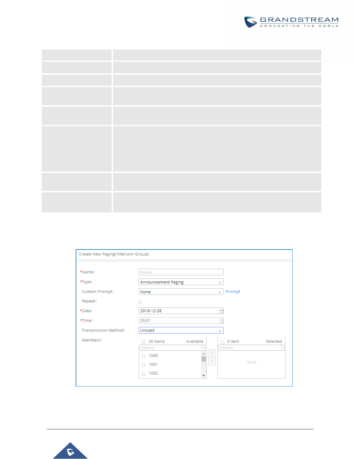
P a g e | 255
UCM6200 Series User Manual
Version 1.0.19.21
Table 76: 1-way Paging Configuration Parameters
Name
Configure paging/intercom group name.
Type
Select "1-way Paging".
Extension
Configure the paging/intercom group extension.
Replace Display Name
If enabled, the UCM will replace the caller display name with Paging/Intercom
name.
Maximum Call Duration
Specify the maximum call duration in seconds. The default value 0 means no
limit.
Custom Prompt
This option is to set a custom prompt for a paging/intercom group to announce
to caller. Click on ‘Prompt’, it will direct the users to upload the customized voice
prompts.
Note: Users can also refer to the page PBX Settings→Voice Prompt→Custom
Prompt, where they could record new prompt or upload prompt files.
Members
Select available users from the left side to the paging/intercom group member
list on the right.
Paging/Intercom
Whitelist
Select which extensions are allowed to use the paging/intercom feature for this
paging group.
Configure Announcement Paging
Figure 161: Announcement Paging
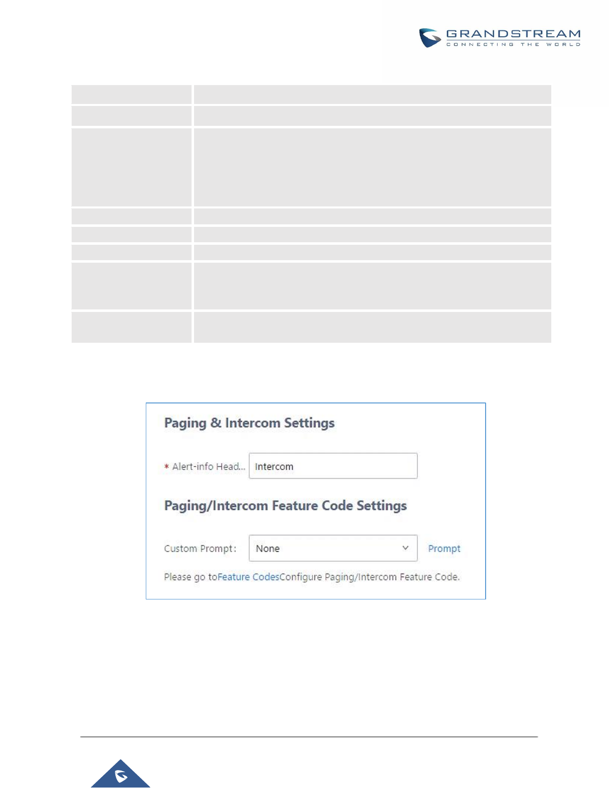
P a g e | 256
UCM6200 Series User Manual
Version 1.0.19.21
Table 77: Announcement Paging Configuration Parameters
Name
Configure paging/intercom group name.
Type
Select "Announcement Paging”
Custom Prompt
This option is to set a custom prompt for a paging/intercom group to announce
to caller. Click on ‘Prompt’, it will direct the users to upload the customized voice
prompts.
Note: Users can also refer to the page PBX Settings→Voice Prompt→Custom
Prompt, where they could record new prompt or upload prompt files.
Repeat
If enabled, the announcement page will be repeated for the selected weekdays.
Date
Configure Announcement Paging Date.
Time
Configure Announcement Paging Time.
Transmission Method
Configure Announcement Paging transmission method.
Unicast: Depending on members selection
Multicast: Depending on Multicast IP address and Port
Members
Select available users from the left side to the paging/intercom group member
list on the right.
Paging/Intercom Group Settings
Figure 162: Page/Intercom Group Settings
The UCM6200 has pre-configured paging/intercom feature code. By default, the Paging Prefix is *81 and the
Intercom Prefix is *80. To edit page/intercom feature code, click on "Feature Codes" in the "Paging/Intercom
Group Settings" dialog. Or users could go to Web GUI→Call Features→Feature Codes directly.
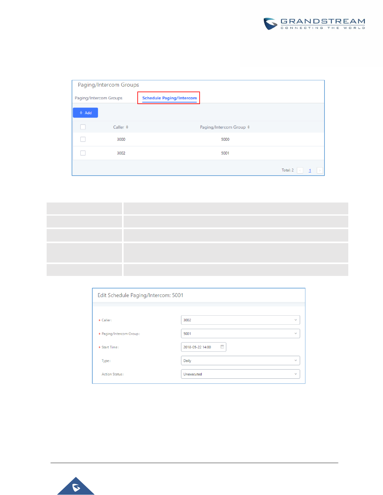
P a g e | 257
UCM6200 Series User Manual
Version 1.0.19.21
Configure a Scheduled Paging/Intercom
Users can schedule paging/intercom calls by using the Schedule Paging/Intercom page. To schedule, click the
Add button on the new page and configure the caller, the group to use, and the time to call out.
Figure 163: Schedule Paging/Intercom page
Table 78: Schedule Paging / Intercom Settings
Figure 164: Creating a scheduled paging/intercom call
Caller
Configure the caller ID for the paging / intercom group.
Paging/Intercom Group
Select the paging / intercom group from the list of the available groups.
Start Time
Configure the start time of the scheduled paging / intercom call.
Type
Select the type for the scheduled paging / intercom call. The available types are:
Single time or Daily basis. Default is “Single”.
Action Status
Display the action status of the scheduled paging / intercom call.
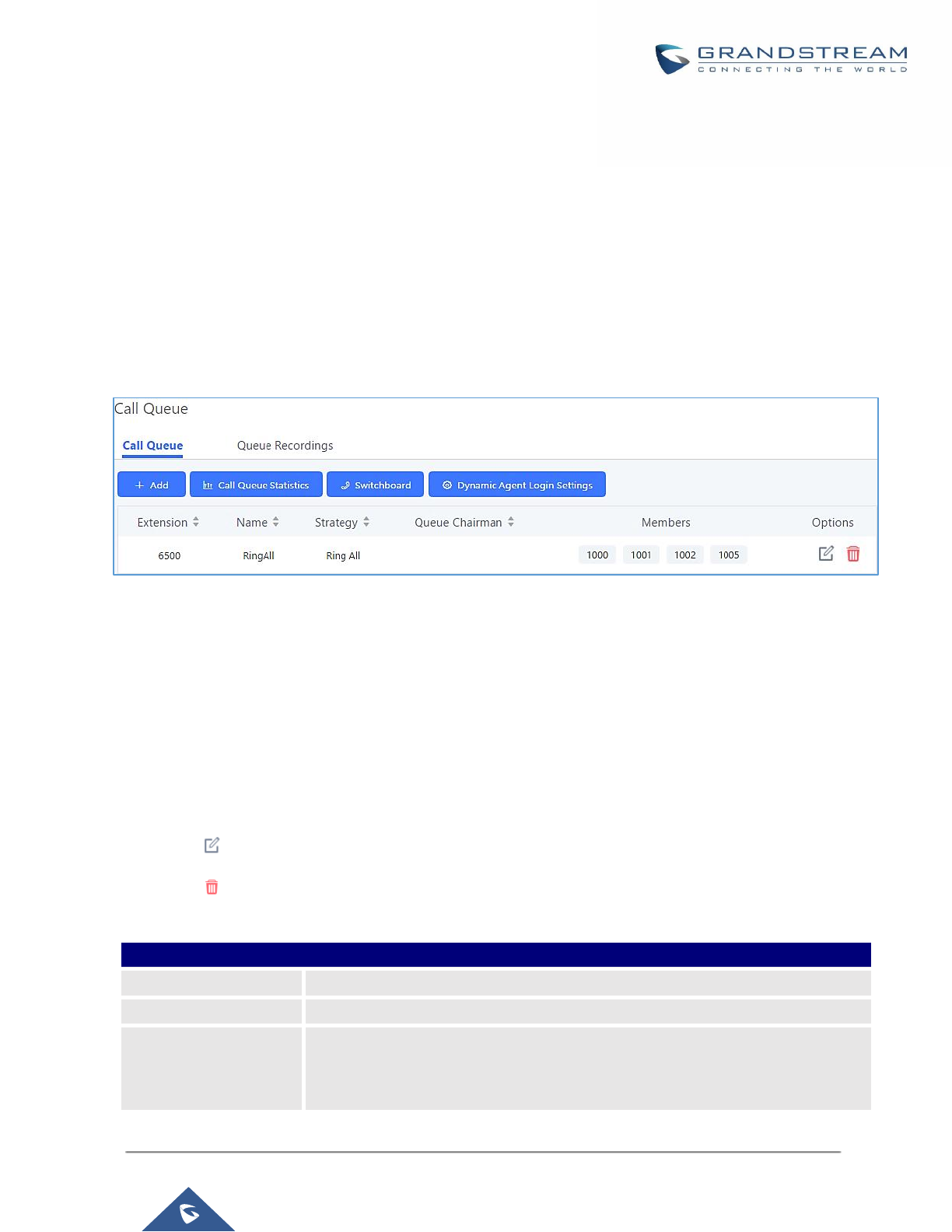
P a g e | 258
UCM6200 Series User Manual
Version 1.0.19.21
CALL QUEUE
The UCM6200 supports call queue by using static agents or dynamic agents. Call Queue system can accept
more calls than the available agents. Incoming calls will be held until next representative is available in the
system. This section describes the configuration of call queue under Web GUI→Call Features→Call Queue.
Configure Call Queue
Call queue settings can be accessed via Web GUI→Call Features→Call Queue.
Figure 165: Call Queue
UCM6200 supports custom prompt feature in call queue. This custom prompt will active after the caller waits for
a period of time in the Queue. Then caller could choose to leave a message/ transfer to default extension or
keep waiting in the queue.
To configure this feature, please go to UCM Web GUI→Call Features→Call Queue→Create New Queue/Edit
Queue→Queue Options→set Enable Destination to Enter Destination with Voice Prompt. Users could configure
the wait time with Voice Prompt Cycle.
• Click on "Create New Queue" to add call queue.
• Click on to edit the call queue. The call queue configuration parameters are listed in the table below.
• Click on to delete the call queue.
Table 79: Call Queue Configuration Parameters
Basic Settings
Extension
Configure the call queue extension number.
Name
Configure the call queue name to identify the call queue.
Strategy
Select the strategy for the call queue.
• Ring All
Ring all available Agents simultaneously until one answers.

P a g e | 259
UCM6200 Series User Manual
Version 1.0.19.21
• Linear
Ring agents in the specified order.
• Least Recent
Ring the agent who has been called the least recently.
• Fewest Calls
Ring the agent with the fewest completed calls.
• Random
Ring a random agent.
• Round Robin
Ring the agents in Round Robin scheduling with memory.
The default setting is "Ring All".
Music On Hold
Select the Music On Hold class for the call queue.
Note: Music On Hold classes can be managed from Web GUI→PBX
Settings→Music On Hold.
Max Queue Length
Configure the maximum number of calls to be queued at once. This number does
not include calls that have been connected with agents. It only includes calls not
connected yet. The default setting is 0, which means unlimited. When the
maximum value is reached, the caller will be treated with busy tone followed by
the next calling rule after attempting to enter the queue.
Wrapup Time
Configure the number of seconds before a new call can ring the queue after the
last call on the agent is completed. If set to 0, there will be no delay between calls
to the queue. The default setting is 10 seconds.
Retry Time
Configure the number of seconds to wait before ringing the next agent.
Ring Time
Configure the number of seconds an agent will ring before the call goes to the
next agent. The default setting is 30 seconds.
Auto Record
If enabled, the calls on the call queue will be automatically recorded. The
recording files can be accessed in Queue Recordings under Web GUI→Call
Features→Call Queue.
Max Wait Time
Configure the timeout after which users will be disconnected from the call queue.
The default setting is "60". 0 means unlimited.
Note: It is recommended to configure "Wait Time" longer than the "Wrapup Time".
Destination
Once Max Wait Time has been configured, select to which destination send the
calls that have timed out. The default is to “Hang up” the call.
Reset Agent Call
Counter - Enable
If this option is checked the agent call counter will be reset according to the
Repeat time settings.
Note: This option is available only when the Strategy is set to “Fewest Calls”
Repeat
Specifies the frequency at which the Agent call counter will be reset.

P a g e | 260
UCM6200 Series User Manual
Version 1.0.19.21
Destination Prompt
Cycle
Configure the voice prompt cycle (in seconds) of the call queue. Once all agents
are busy and the voice prompt will be played and you can press the appropriate
key to transfer to failover destination.
Custom Prompt
When playing a custom prompt, press 1 to transfer to failover destination.
Destination
Select failover destination to send callers after pressing 1 upon hearing the
custom prompt.
Advanced Settings
- Virtual Queue
- Position
Announcement
- Queue Chairman
Refer to Call Center Settings and Enhancements section for detailed
information about these features.
Enable Agent Login
Enables agent login/logout feature for static agents (supported only on GXP21XX
phones with fw higher than 1.0.9.18).
Leave When Empty
Configure whether the callers will be disconnected from the queue or not if the
queue has no agent anymore. The default setting is "Strict".
• Yes
Callers will be disconnected from the queue if all agents are paused or invalid.
• No
Never disconnect the callers from the queue when the queue is empty.
• Strict
Callers will be disconnected from the queue if all agents are paused, invalid
or unavailable.
Dial in Empty Queue
Configure whether the callers can dial into a call queue if the queue has no agent.
The default setting is "No".
• Yes
Callers can always dial into a call queue.
• No
Callers cannot dial into a queue if all agents are paused or invalid.
• Strict
Callers cannot dial into a queue if the agents are paused, invalid or
unavailable.
Failover Destination
Choose the destination where the call will be directed when the queue is empty
or when all the agents are not logged in, here are the destinations that can be
configured:
• Play Sound.
• Extension.
• Voicemail.

P a g e | 261
UCM6200 Series User Manual
Version 1.0.19.21
Static Agents limitation:
To guarantee a high level of audio quality with the call queue feature, UCMs will limit the number of static agents
allowed to be assigned depending on the UCM model used. If the user attempts to configure the number of static
agents to be more than the maximum allowed number, a warning message will appear.
• Queues.
• Ring Group.
• Voicemail Group.
• IVR.
• External Number.
Report Hold Time
If enabled, the UCM6200 will report (to the agent) the duration of time of the call
before the caller is connected to the agent. The default setting is "No".
Replace Display Name
If enabled, the UCM will replace the caller display name with the Call Queue name
so that the caller knows the call is incoming from a Call Queue.
Enable Feature Codes
Enable feature codes option for call queue. For example, *83 is used for “Agent
Pause”
Dynamic Login
Password
If enabled, the configured PIN number is required for dynamic agent to log in. The
default setting is disabled.
Alert-Info
Configure the call destination for the call to be routed to if no agent in this call
queue answers the call.
Agents
Agents
Go to “Agents” Tab and Select the available users to be the static agents in the
call queue. Choose from the available users on the left to the static agents list on
the right. Click on to choose. And use UP and Down arrow to select the
order of the agent within the call queue.
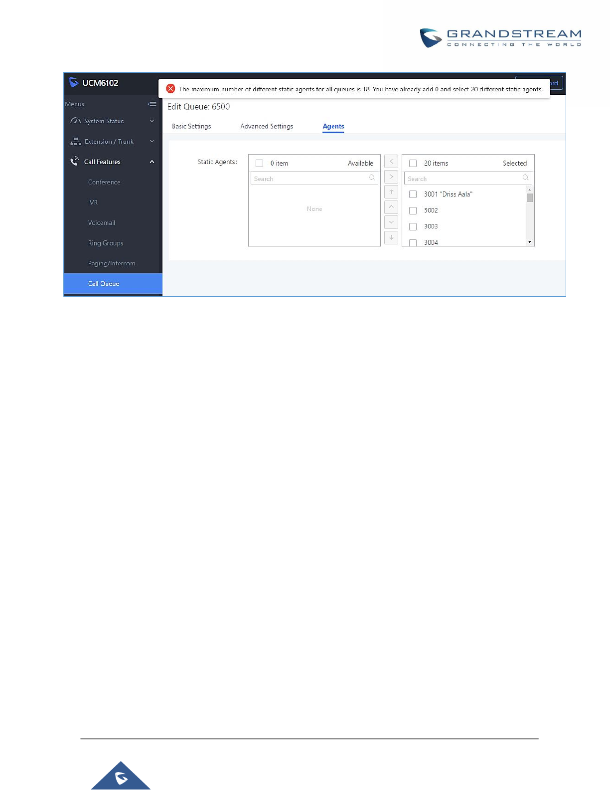
P a g e | 262
UCM6200 Series User Manual
Version 1.0.19.21
Figure 166: Static Agents limitation
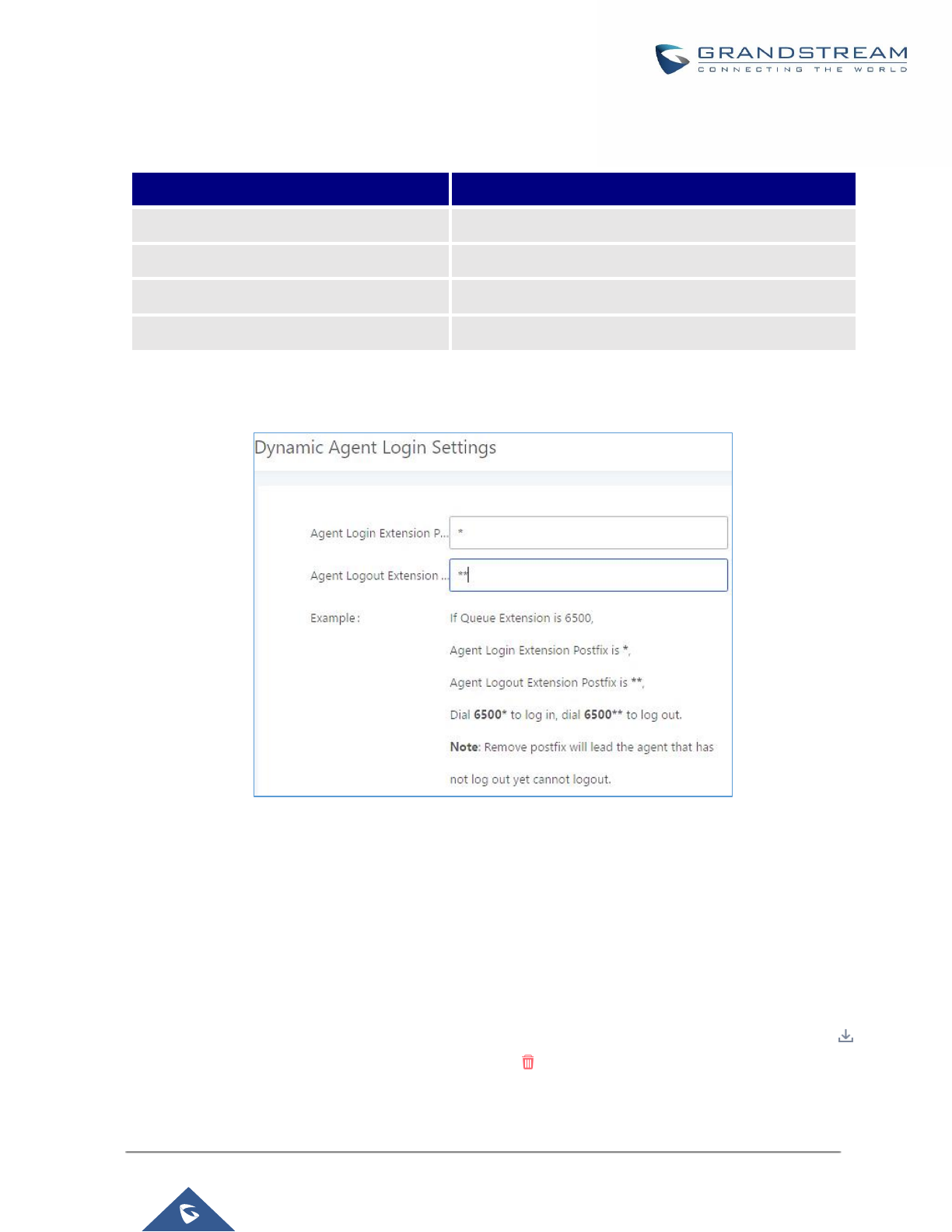
P a g e | 263
UCM6200 Series User Manual
Version 1.0.19.21
The following table lists the maximum number of static agents for each UCM model:
Table 80: Static Agent Limitation
UCM Model
Max Static Agents in Call Queue
UCM6202
23
UCM6204
34
UCM6208
75
UCM6510
150
Click on "Dynamic Agent Login Settings" to configure Agent Login Extension Postfix and Agent Logout Extension
Postfix. Once configured, users could log in the call queue as dynamic agent.
Figure 167: Agent Login Settings
For example, if the call queue extension is 6500, Agent Login Extension Postfix is * and Agent Logout Extension
Postfix is **, users could dial 6500* to login to the call queue as dynamic agent and dial 6500** to logout from
the call queue. Dynamic agent doesn't need to be listed as static agent and can log in/log out at any time.
• Call queue feature code "Agent Pause" and "Agent Unpause" can be configured under Web GUI→Call
Features→Feature Codes. The default feature code is *83 for "Agent Pause" and *84 for "Agent Unpause".
• Queue recordings are shown on the Call Queue page under “Queue Recordings” Tab. Click on to
download the recording file in .wav format; click on to delete the recording file. To delete multiple

P a g e | 264
UCM6200 Series User Manual
Version 1.0.19.21
recording files by one click, select several recording files to be deleted and click on “Delete Selected
Recording Files” or click on “Delete All Recording Files” to delete all recording files.
Call Center Settings and Enhancements
UCM supports light weight call center features including virtual queue and position announcement, allowing the
callers to know their position on the call queue and giving them the option to either stay on the line waiting for
their turn or activate a callback which will be initiated by the UCM one an agent is free.
To configure call center features, press on an existing call queue and go under the advanced settings tab.
Following parameters are available:
Table 81: Call Center Parameters
Enable Virtual Queue
Enable virtual queue to activate call center features.
Virtual Queue Period
Configure the time in (s) after which the virtual queue will take effect and the menu
will be presented to the caller to choose an option. Default is 20s.
Virtual Queue Mode
Offered to caller after timeout: After the virtual queue period passes, the caller
will enter the virtual call queue and be presented with a menu to choose an option,
the choices are summarized below:
• Press * to set current number as callback number.
• Press 0 to set a callback number different than current caller number.
• Press # to keep waiting on the call queue.
Triggered on user request: In this mode, the callers can activate the virtual
queue by pressing 2, then they will be presented with the menu to choose an
option as below:
• Press * to set current number as callback number.
• Press 0 to set a callback number different than current caller number.
• Press # to keep waiting on the call queue.
Virtual Queue
Outbound Prefix
System will add this prefix to dialed numbers when calling back users.
Enable Virtual Queue
Timeout
When this option is enabled and after a caller registers a call back request on the
virtual queue. While all the agents are busy, the UCM will call an agent once
he/she is idle again, this timeout is used for how long the UCM continues calling
the agent and if the agent doesn’t answer the call then the callback request will
timeout and expire.
Write Timeout
Configure the virtual queue callback timeout period in seconds.
Enable Position
Announcement
Enable the announcement of the caller’s position periodically.
Position
Announcement
Configure the period of time in (s) during which the UCM will announce the caller’s
position in the call queue.

P a g e | 265
UCM6200 Series User Manual
Version 1.0.19.21
Queue Auto fill enhancement:
In previous UCM firmware, the call queue has a serial type behavior in that the queue will make all waiting callers
wait in the queue even if there is more than one available member ready to take calls until the head caller is
connected with the member they were trying to get to.
The next waiting caller in line then becomes the head caller, and they are then connected with the next available
member and all available members and waiting callers waits while this happens.
Starting from 1.0.14.x, the waiting callers are connecting with available members in a parallel fashion until there
are no more available members or no more waiting callers.
For example, in a call queue with linear method, if there are two available agents, when two callers call in the
queue at the same time, UCM will assign the two callers to each of the two available agents at the same time,
rather than assigning the second caller to second available agent after the first agent answers the call from the
first caller.
Queue Statistics
Along with call center features, users can also gather detailed call queue statistics allowing them to make better
changes/decision to manage better the call distribution and handling based on time, agent and queue.
To access call queue statistics, go to Web GUI→Call Features→Call Queue and click on “Call Queue Statistics”,
the following page will be displayed:
Interval
CTI Chairman
Select the extension to act as chairman of the queue (monitoring).
Enable Agent Login
When enabled, statics agents can conveniently log in and out of a queue by
configuring a programmable key on their phones as a shortcut.
Notes:
✓ This feature is currently available only for GXP21xx phones on firmware
1.0.9.18 or greater.
✓ After enabling the feature, users need to set the option on GXP21XX phone
under “Account→SIP Settings→Advanced Features→Special Feature”
to “UCM Call Center”. A softkey labeled “UCM-CC” will appear on the
bottom of the phone’s screen.
✓ When this option is enabled, dynamic agent login will be no longer
supported.
✓ In case of concurrent registrations, changing agent status on one phone
(login/logout) will be reflected on all phones.
Autofill
Enable or Disable the autofill feature.
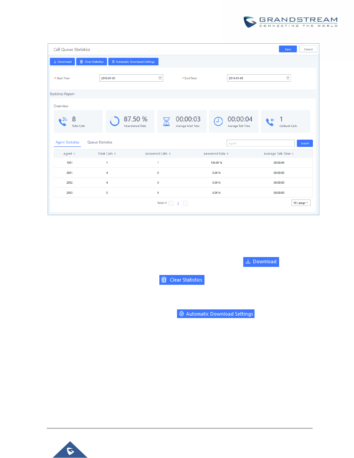
P a g e | 266
UCM6200 Series User Manual
Version 1.0.19.21
Figure 168: Call Queue Statistics
Select the time interval along with the queue(s) and agent(s) to get detailed statistics.
User can download statistics on CSV format by clicking on the download button , also the statistics
can be cleared using “Clear Statistics” button .
The statistics can be automatically sent to a specific email address on a preconfigured Period, this can be done
by clicking on “Automatic Download Settings” button , and user will be directed to
below page where he can configure the download period (Day/Week/Month) and the Email where the statistics
will be sent (Email settings should be configured correctly):

P a g e | 267
UCM6200 Series User Manual
Version 1.0.19.21
Figure 169: Automatic Download Settings - Queue Statistics
Switchboard
Switchboard is a Web GUI tool for call queue monitoring and management, admin can access to it from the
menu Call Features→Call Queue then press « Switchboard ».
Following page will be displayed:
Figure 170: Switchboard Summary
Page above summarizes the available queues statistics and if one of the queues is clicked the user will be
directed to page below:
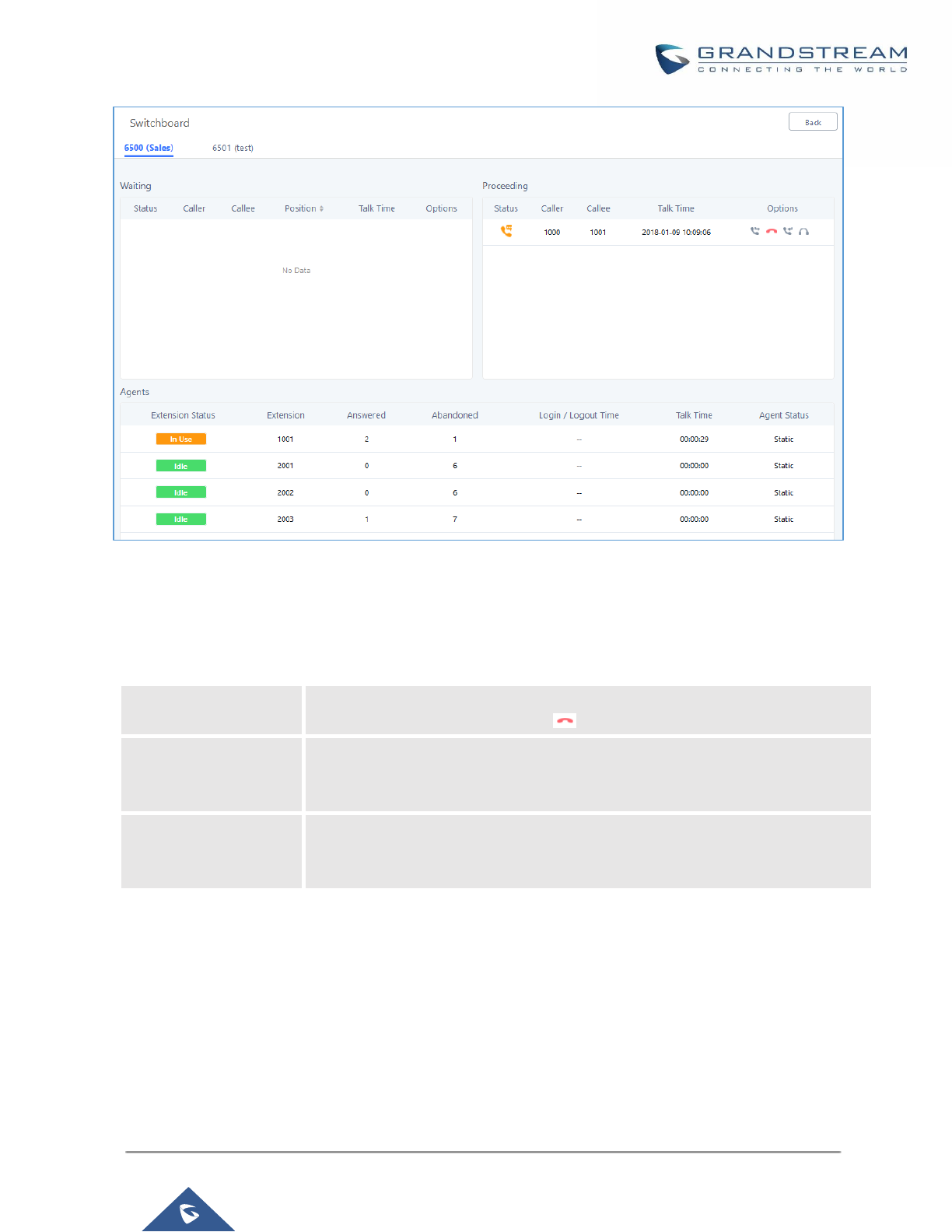
P a g e | 268
UCM6200 Series User Manual
Version 1.0.19.21
Figure 171: Call Queue Switchboard
The table below gives a brief description for the main menus:
Table 82: Switchboard Parameters
There are three different privilege levels for Call Queue management from the switchboard: Super Admin, Queue
Chairman, and Queue Agent.
• Super Admin - Default admin of the UCM. Call queue privileges include being able to view and edit all
queue agents, monitor and execute actions for incoming and ongoing calls for each extension in
Switchboard, and generate Call Queue reports to track performance.
Waiting
This menu shows the current waiting calls along with the caller id and the option
to hang-up call by pressing on the button.
Proceeding
Shows the current established calls along with the caller id and the callee (agent)
as well as the option to hang-up, transfer, add conference or barge-in the call
using the call options buttons.
Agents
Displays the list of agents in the queue and the extension status (idle, ringing, in
use or unavailable) along with some basic call statistics and agent’s mode (static
or dynamic).

P a g e | 269
UCM6200 Series User Manual
Version 1.0.19.21
• Queue Chairman - User appointed by Super Admin to monitor and manage an assigned queue extension
via Switchboard. The Queue Chairman can log into the UCM user portal with his extension number and
assigned user password. To access the Switchboard, click on “Value-added Features” in the side menu and
click on “Call Queue”. In the image below, User 1012 is the Queue Chairman appointed to manage Queue
Extension 6500 and can see all the agents of the queue in the Switchboard.
• Queue Agent - User appointed by Super Admin to be a member of a queue extension. A queue agent can
log into the UCM user portal with his extension number and assigned user password. To access the
Switchboard, click on “Value-added Features” in the side menu and click on “Call Queue”. However, a queue
agent can view and manage only his own calls and statistics, but not other agents’ in the queue extension.
In the image below, User 1007 is a queue agent and can see only his own information in the Switchboard.
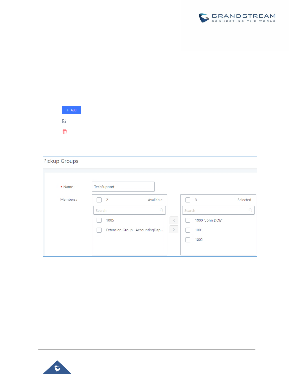
P a g e | 270
UCM6200 Series User Manual
Version 1.0.19.21
PICKUP GROUPS
The UCM6200 supports pickup group feature which allows users to pick up incoming calls for other extensions
if they are in the same pickup group, by dialing "Pickup Extension" feature code (by default *8).
Configure Pickup Groups
Pickup groups can be configured via Web GUI→Call Features→Pickup Groups.
• Click on to create a new pickup group.
• Click on to edit the pickup group.
• Click on to delete the pickup group.
Select extensions from the list on the left side to the right side.
Figure 172: Edit Pickup Group
Configure Pickup Feature Code
When picking up the call for the pickup group member, the user only needs to dial the pickup feature code. It’s
not necessary to add the extension number after the pickup feature code. The pickup feature code is configurable
under Web GUI→Call Features→Feature Codes.
The default feature code for call pickup extension is *8, otherwise if the person intending to pick up the call knows
the ringing extension they can use ** followed by the extension number in order to perform the call pickup
operation.
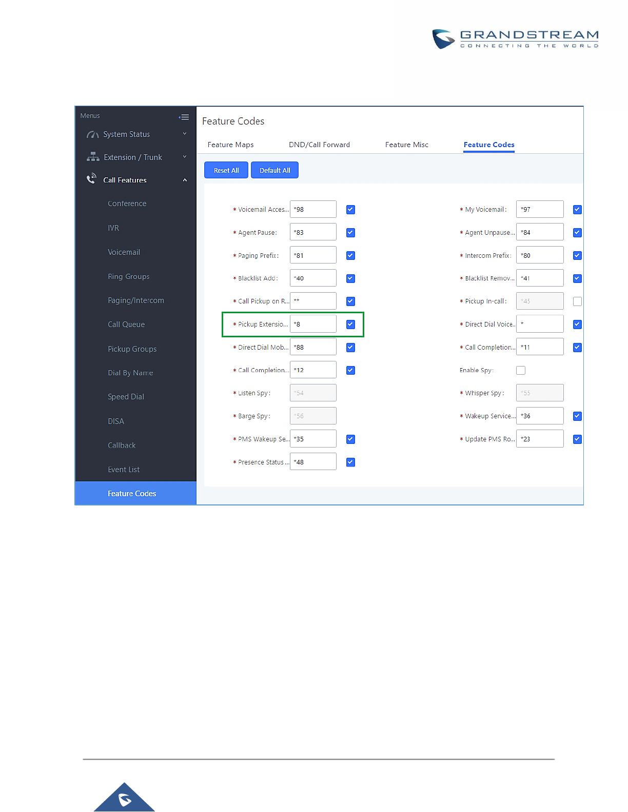
P a g e | 271
UCM6200 Series User Manual
Version 1.0.19.21
The following figure shows where you can customize these features codes
Figure 173: Edit Pickup Feature Code
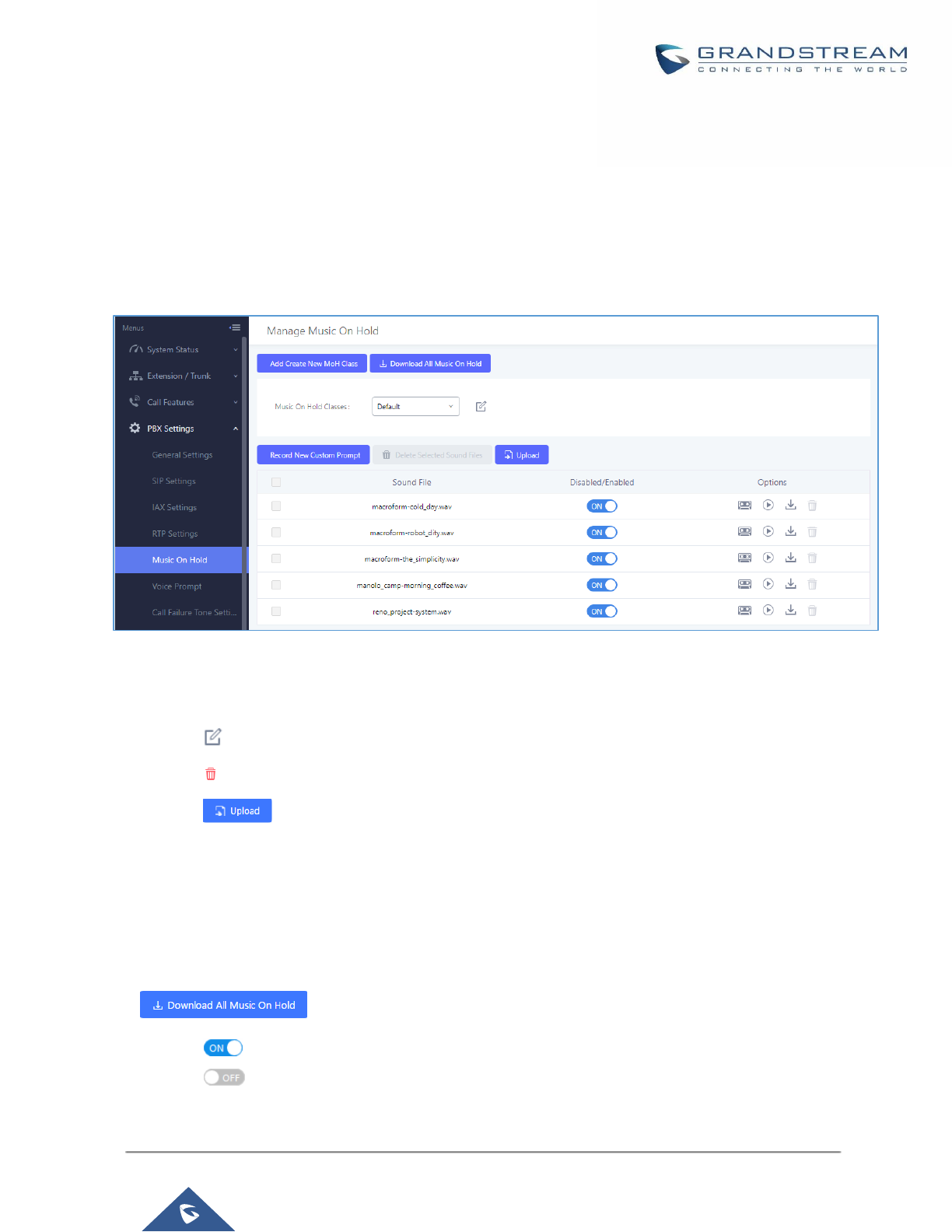
P a g e | 272
UCM6200 Series User Manual
Version 1.0.19.21
MUSIC ON HOLD
Music On Hold settings can be accessed via Web GUI→PBX Settings→Music On Hold. In this page, users
could configure music on hold class and upload music files. The "default" Music On Hold class already has 5
audio files defined for users to use.
Figure 174: Music On Hold Default Class
• Click on "Create New MOH Class" to add a new Music On Hold class.
• Click on to configure the MOH class sort method to be "Alpha" or "Random" for the sound files.
• Click on next to the selected Music On Hold class to delete this Music On Hold class.
• Click on to start uploading. Users can upload:
➢ Single files with 8KHz Mono Music file, or
➢ Music on hold files in a compressed package with .tar, .tar.gz and .tgz as the suffix. The file name can
only be letters, digits or special characters -_
➢ the size for the uploaded file should be less than 30M, the compressed file will be applied to the entire
MoH.
• Users could also download all the music on hold files from UCM. In the Music On Hold page, click on
and the file will be downloaded to your local PC.
• Click on next to the sound file to disable it from the selected Music On Hold Class.
• Click on next to the sound file to enable it from the selected Music On Hold Class.
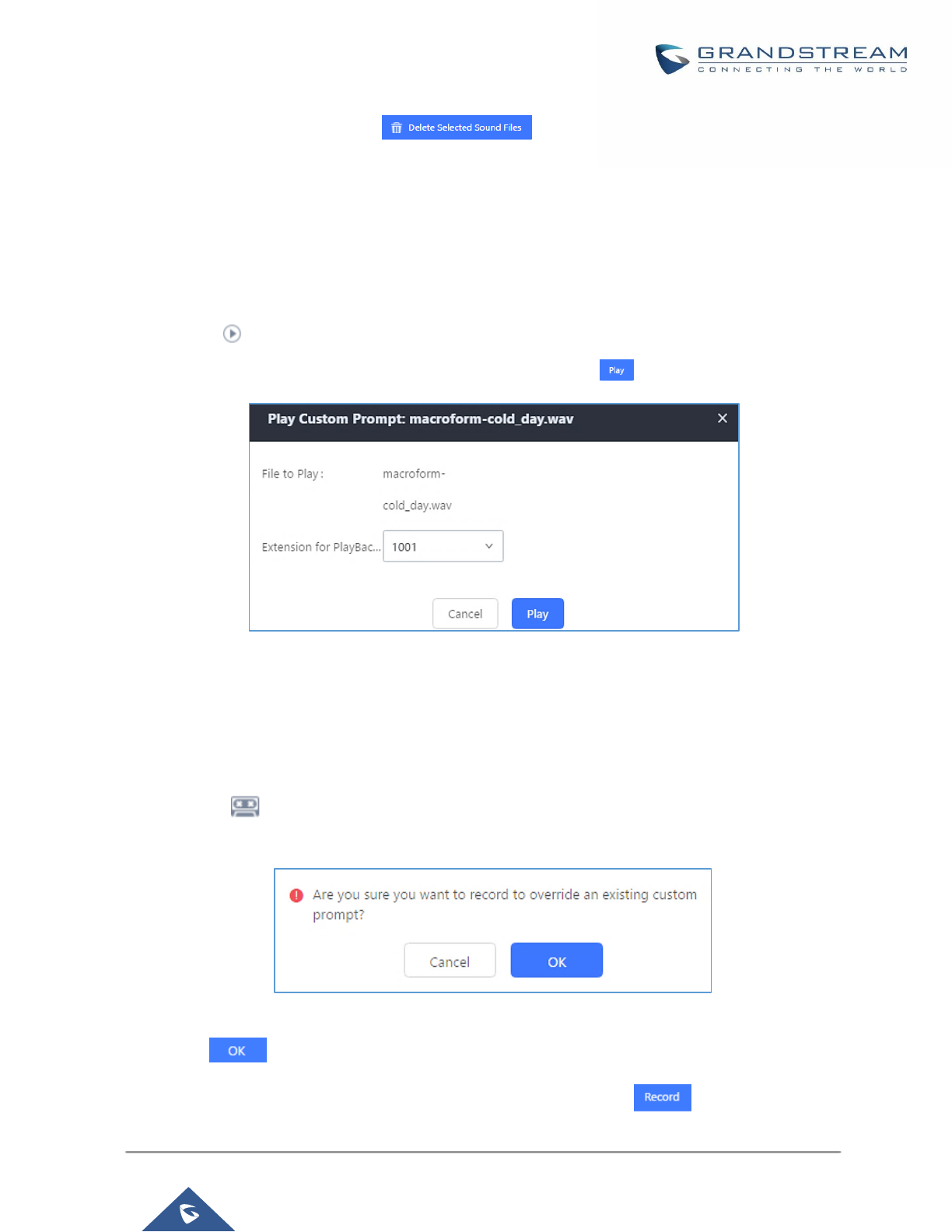
P a g e | 273
UCM6200 Series User Manual
Version 1.0.19.21
• Select the sound files and click on to delete all selected music on hold files.
Note: the size for the uploaded file should be less than 30M, the compressed file will be applied to the entire
MoH.
The UCM6200 allows Users to select the Music on Hold file from WebGUI to play it. The UCM6200 will initiate
a call to the selected extension and play this Music on Hold file once the call is answered.
Steps to play the music on hold file:
1. Click on the button for the Music on Hold file.
2. In the prompted window, select the extension to playback and click .
Figure 175: Play Custom Prompt
3. The selected extension will ring.
4. Answer the call to listen to the music playback.
Users could also record their own Music on hold to override an existing custom prompt, this can be done by
following those steps:
1. Click on .
2. A prompt of confirmation will pop up, as shown below.
Figure 176: Information Prompt
3. Click .
4. In the prompted window, select the extension to playback and click .
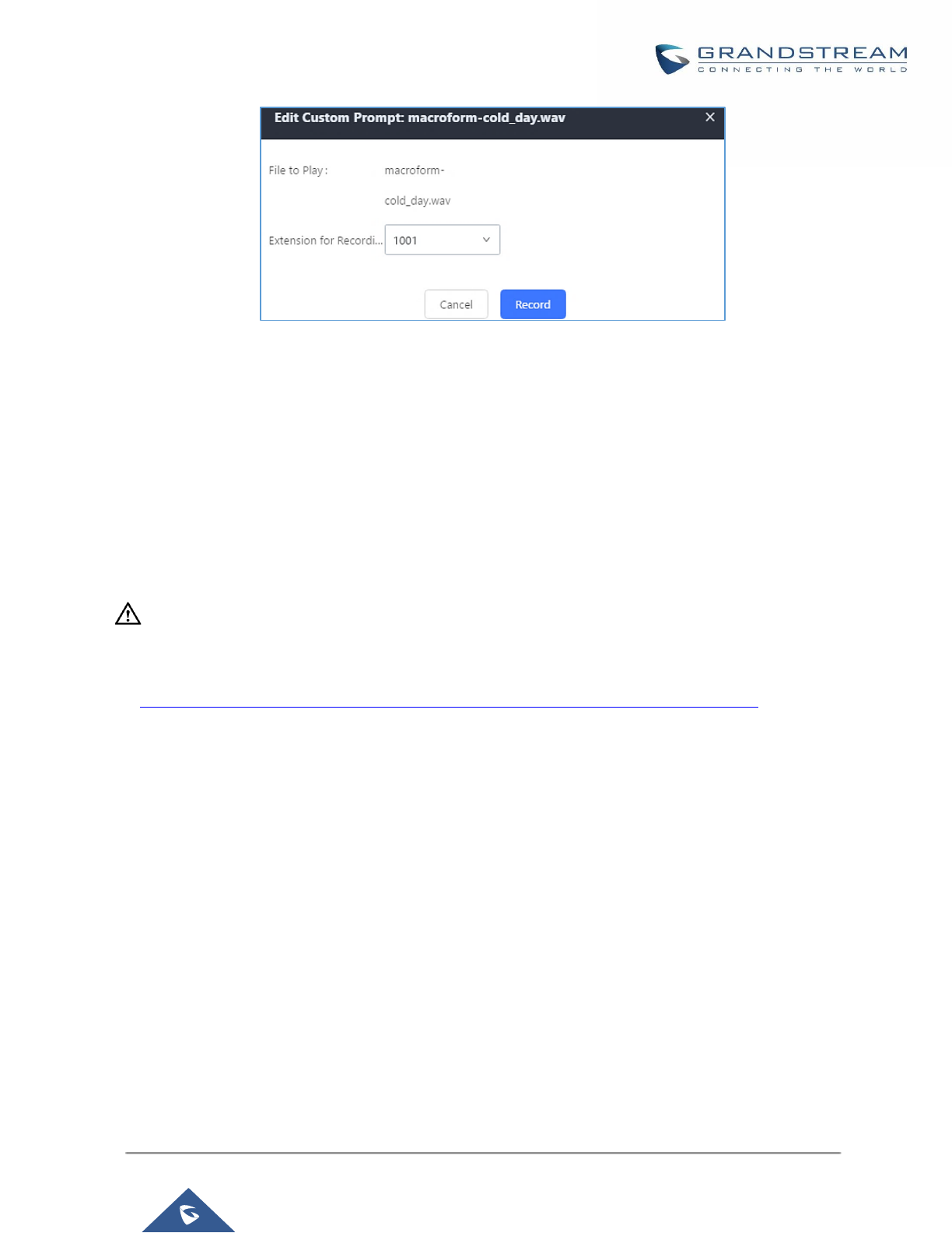
P a g e | 274
UCM6200 Series User Manual
Version 1.0.19.21
Figure 177: Record Custom Prompt
5. Answer the call and start to record your new music on hold.
6. Hangup the call and refresh Music On Hold page then you can listen to the new recorded file.
----------------------------------------------------------------------------------------------------------------------------- --------------------
Notes:
Once the MOH file is deleted, there are two ways to recover the music files.
• Users could download the MOH file from this link:
http://downloads.asterisk.org/pub/telephony/sounds/releases/asterisk-moh-opsound-wav-2.03.tar.gz
After downloading and unzip the pack, users could then upload the music files to UCM.
• Factory reset could also recover the MOH file on the UCM.
--------------------------------------------------------------------------------------------------------------------------------------------------
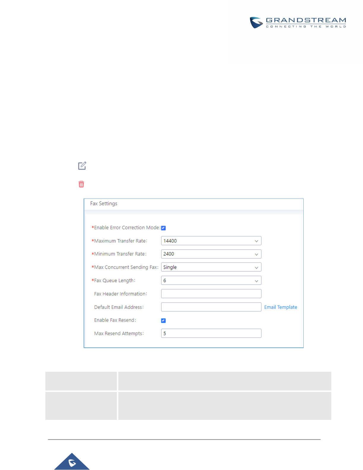
P a g e | 275
UCM6200 Series User Manual
Version 1.0.19.21
FAX SERVER
The UCM6200 supports T.30/T.38 Fax and Fax Pass-through. It can convert the received Fax to PDF format and
send it to the configured Email address. Fax/T.38 settings can be accessed via Web GUI→Call
Features→FAX/T.38. The list of received Fax files will be displayed in the same web page for users to view,
retrieve and delete.
Configure Fax/T.38
• Click on "Create New Fax Extension". In the popped-up window, fill the extension, name and Email address
to send the received Fax to.
• Click on "Fax Settings" to configure the Fax parameters.
• Click on to edit the Fax extension.
• Click on to delete the Fax extension.
Figure 178: Fax Settings
Table 83: FAX/T.38 Settings
Enable Error
Correction Mode
Configure to enable Error Correction Mode (ECM) for the Fax.
The default setting is "Yes".
Maximum Transfer
Rate
Configure the maximum transfer rate during the Fax rate negotiation.
The possible values are 2400, 4800, 7200, 9600, 12000 and 14400.
The default setting is 14400.

P a g e | 276
UCM6200 Series User Manual
Version 1.0.19.21
Minimum Transfer Rate
Configure the minimum transfer rate during the Fax rate negotiation. The
possible values are 2400, 4800, 7200, 9600, 12000 and 14000. The default
setting is 2400.
Max Concurrent
Sending Fax
Configure the concurrent fax that can be sent by UCM6200. Two modes “Only”
and “More” are supported.
• Only
Under this mode, the UCM6200 allows only single user to send fax at a time.
• More
Under this mode, the UCM6200 supports multiple concurrent fax sending by
the users.
By default, this option is set to “only”.
Fax Queue Length
Configure the maximum length of Fax Queue from 6 to 10.
The default setting is 6.
Fax Header Information
Adds fax header into the fax file.
Default Email Address
Configure the Email address to send the received Fax to if user's Email address
cannot be found.
Note:
The extension's Email address or the Fax's default Email address needs to be
configured in order to receive Fax from Email. If neither of them is configured,
Fax will not be received from Email.
Template Variables
Fill in the "Subject:" and "Message:" content, to be used in the Email when
sending the Fax to the users.
The template variables are:
• ${CALLERIDNUM} : Caller ID Number
• ${CALLERIDNAME} : Caller ID Name
• ${RECEIVEEXTEN} : The extension to receive the Fax
• ${FAXPAGES} : Number of pages in the Fax
• ${VM_DATE} : The date and time when the Fax is received
Enable Fax Resend
Enables the fax resend option which allow the UCM to keep attempting to send
faxes up to a specified amount of times. Additionally, if a fax still fails to send, a
Resend button will appear in the File Send Progress list in Value-Added
Features
→
Fax Sending to allow manual resending.
Max Resend Attempts
Configures the maximum attempts number to resend the FAX.
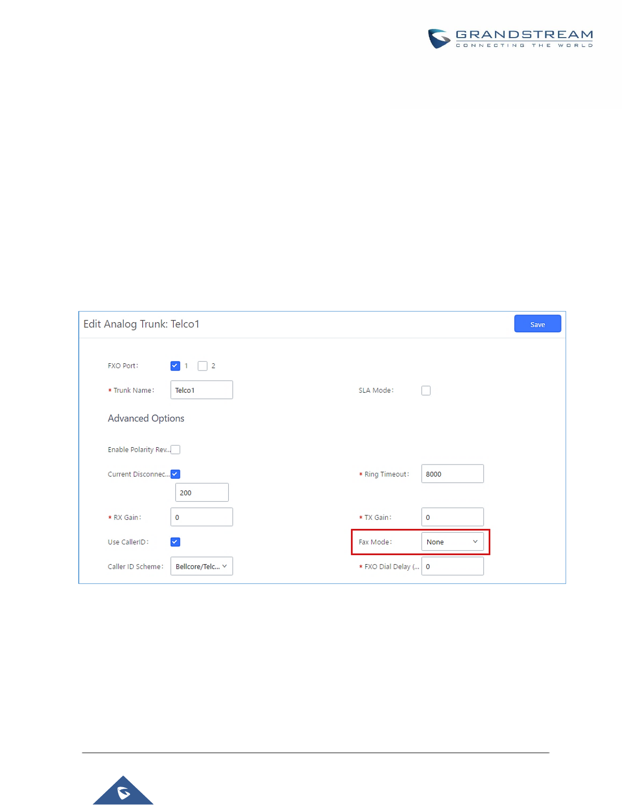
P a g e | 277
UCM6200 Series User Manual
Version 1.0.19.21
Receiving Fax
Sample Configuration to Receive Fax from PSTN Line
The following instructions describe how to use the UCM6200 to receive Fax from PSTN line on the Fax machine
connected to the UCM6200 FXS port.
1. Connect Fax machine to the UCM6200 FXS port.
2. Connect PSTN line to the UCM6200 FXO port.
3. Go to Web GUI→Extension/Trunk page.
4. Create or edit the analog trunk for Fax as below.
Fax Mode: Make sure "Fax Mode" option is set to "None".
Figure 179: Configure Analog Trunk without Fax Detection
5. Go to UCM6200 Web GUI→Extension/Trunk→Extensions page.
6. Create or edit the extension for FXS port.
• Analog Station: Select FXS port to be assigned to the extension. By default, it's set to "None".
• Once selected, analog related settings for this extension will show up in "Analog Settings" section.
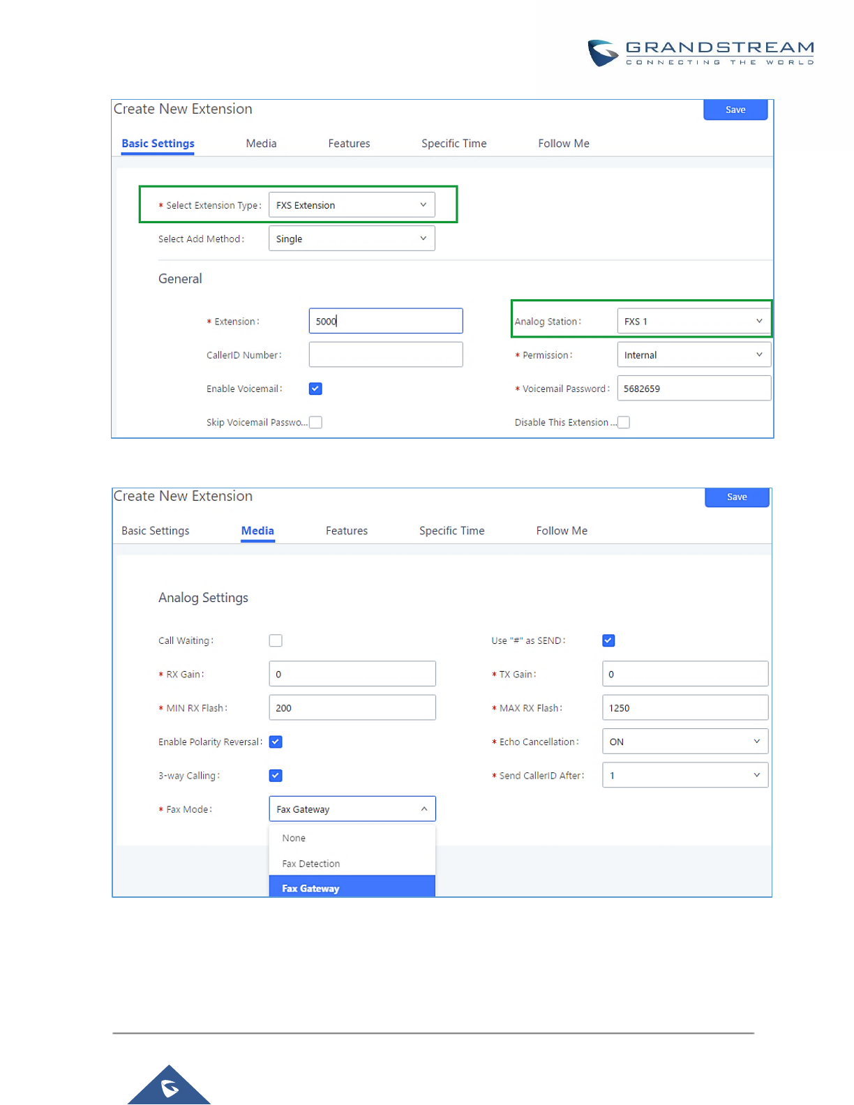
P a g e | 278
UCM6200 Series User Manual
Version 1.0.19.21
Figure 180: Configure Extension for Fax Machine: FXS Extension
Figure 181: Configure Extension for Fax Machine: Analog Settings
7. Go to Web GUI→Extension/Trunk→Inbound Routes page.
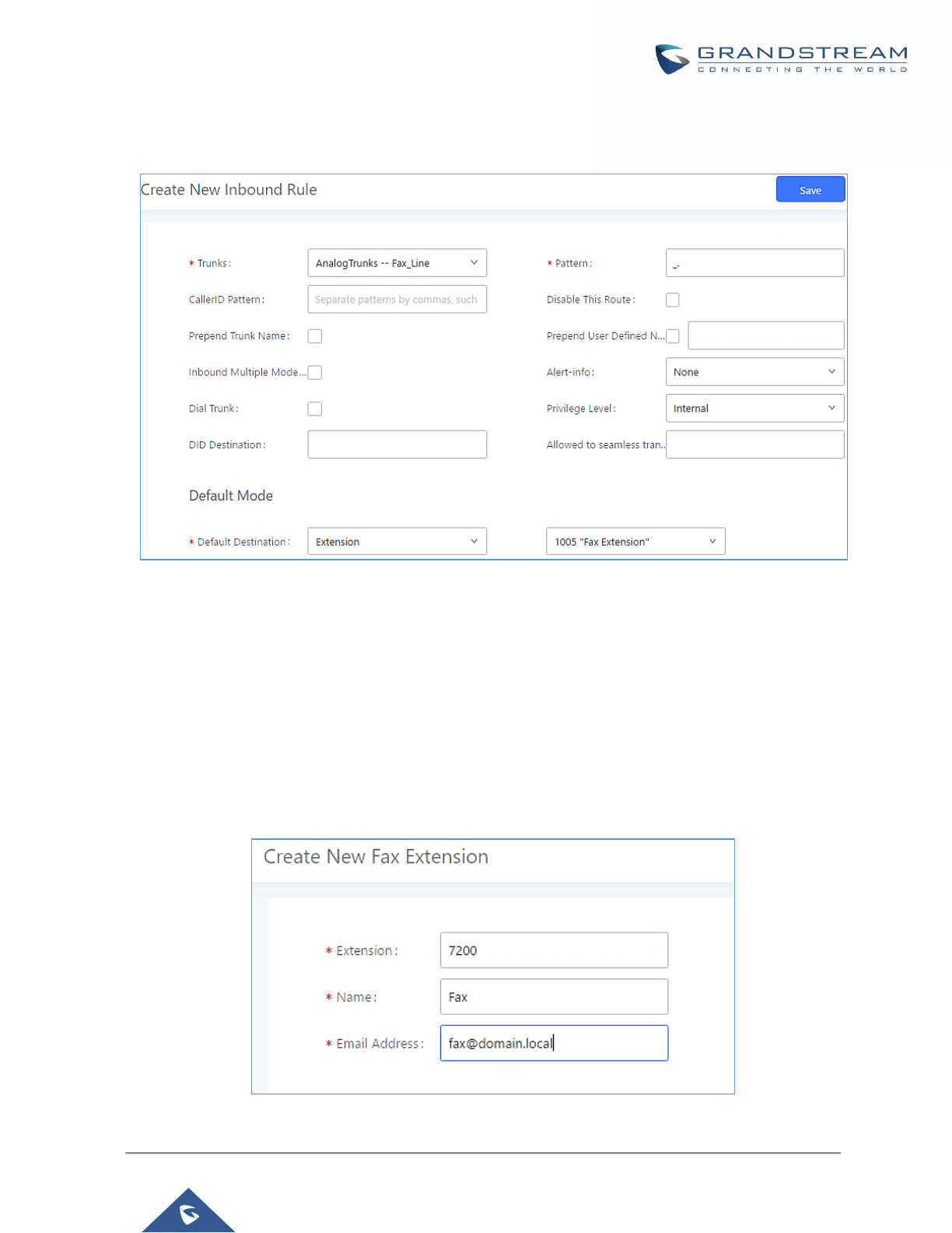
P a g e | 279
UCM6200 Series User Manual
Version 1.0.19.21
8. Create an inbound route to use the Fax analog trunk. Select the created extension for Fax machine in step
4 as the default destination.
Figure 182: Configure Inbound Rule for Fax
Now the Fax configuration is done. When there is an incoming Fax calling to the PSTN number for the FXO port,
it will send the Fax to the Fax machine.
Sample Configuration for Fax-To-Email
The following instructions describe a sample configuration on how to use Fax-to-Email feature on the UCM6200.
1. Connect PSTN line to the UCM6200 FXO port.
2. Go to UCM6200 Web GUI→Call Features→Fax/T.38 page. Create a new Fax extension.
Figure 183: Create Fax Extension
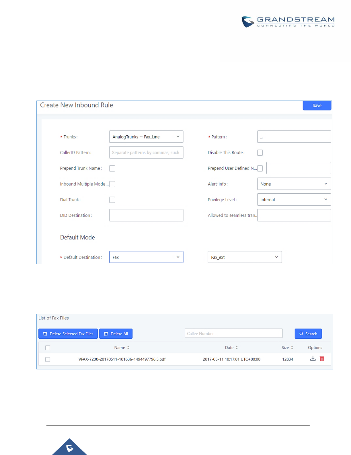
P a g e | 280
UCM6200 Series User Manual
Version 1.0.19.21
3. Go to UCM6200 Web GUI→Extension/Trunk→Analog Trunks page. Create a new analog trunk. Please
make sure "Fax Detection" is set to "No".
4. Go to UCM6200 Web GUI→Extension/Trunk→Inbound Routes page. Create a new inbound route and
set the default destination to the Fax extension.
Figure 184: Inbound Route to Fax Extension
5. Once successfully configured, the incoming Fax from external Fax machine to the PSTN line number will be
converted to PDF file and sent to the Email address fax@domain.local as attachment.
Figure 185: List of Fax Files
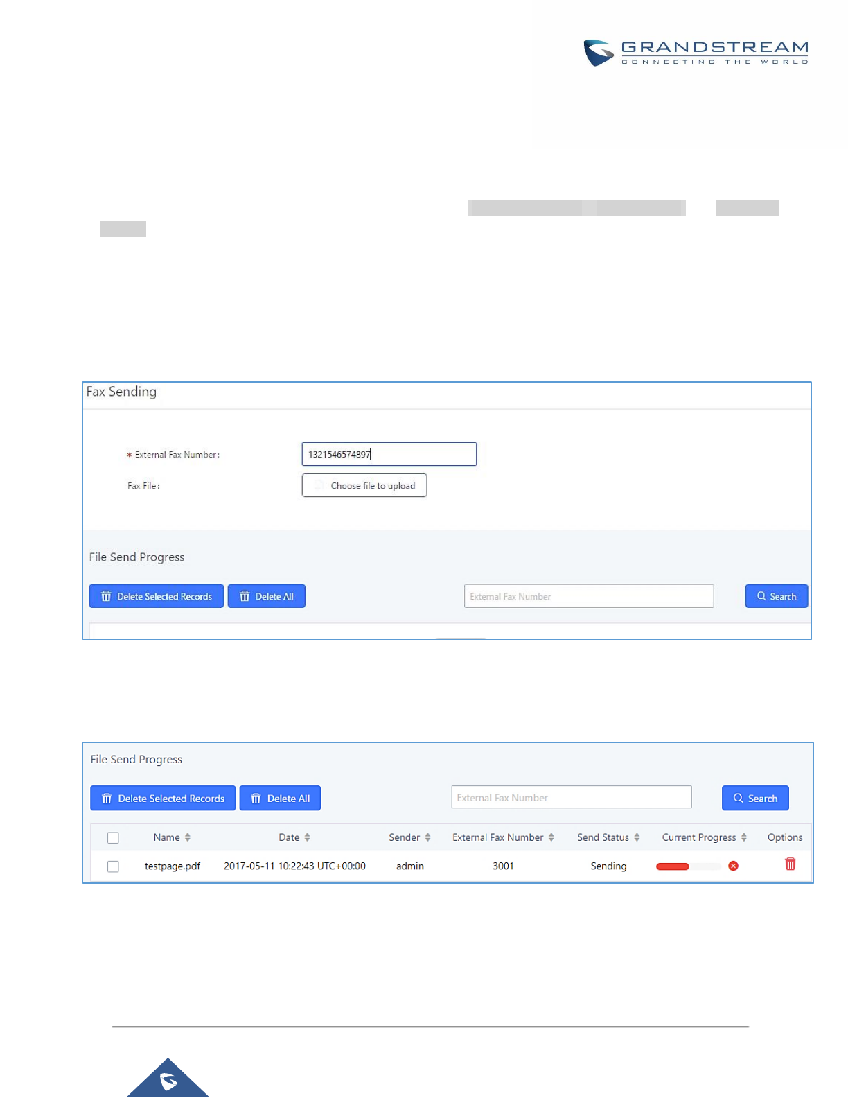
P a g e | 281
UCM6200 Series User Manual
Version 1.0.19.21
FAX Sending
Besides the support of Fax machines, The UCM6200 supports also sending Fax via Web GUI access. This
feature can be found on Web GUI→Value-added Features→Fax Sending page. To send fax, pre-setup for
analog trunk and outbound route is required. Please refer to [ANALOG TRUNKS], [VOIP TRUNKS] and [Outbound
Routes] sections for configuring analog trunk and outbound route.
After making sure analog trunk or VoIP Trunk is setup properly and UCM6200 can reach out to PSTN numbers
via the trunk, on Fax Sending page, enter the fax number and upload the file to be faxed. Then click on “Send”
to start. The progress of sending fax will be displayed in Web GUI. Users can also view the sending history is in
the same web page.
Figure 186: Fax Sending in Web GUI
After that you can see the ongoing sending operation on the progress bar.
Figure 187: Fax Send Progress

P a g e | 282
UCM6200 Series User Manual
Version 1.0.19.21
BUSY CAMP-ON
The UCM6200 supports busy camp-on/call completion feature that allows the PBX to camp on a called party
and inform the caller as soon as the called party becomes available given the previous attempted call has failed.
The configuration and instructions on how to use busy camp-on/call completion feature can be found in the
following guide:
http://www.grandstream.com/sites/default/files/Resources/ucm6xxx_busy_camp_on_guide.pdf

P a g e | 283
UCM6200 Series User Manual
Version 1.0.19.21
PRESENCE
UCM does support SIP presence feature which allows users to advertise their current availability status and
willingness to receive calls, this way other users can use their phones in order to monitor the presence status of
each user and decide whether to call them or not based on their advertised availability.
This feature is different than BLF which is mainly used to monitor the dialog status for each extension (Ringing,
Idle or Busy). Instead the SIP presence module gives more options for users to choose which state they want to
put themselves in.
In order to configure the presence status of an extension from the web GUI, users can access the menu of
configuration using one of the two following methods:
• From admin account, go under the menu Extension/Trunk→Extensions and choose the desired extension
to edit then navigate to the “Features” tab.
OR
• From the User Portal, go under the menu Basic Information→Extensions and navigate to the Features tab
to have the following options.
Figure 188: SIP Presence Configuration
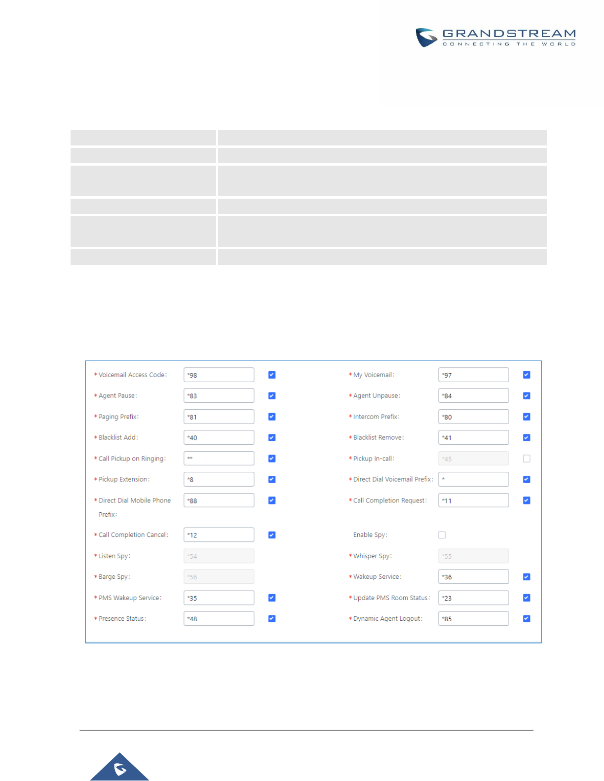
P a g e | 284
UCM6200 Series User Manual
Version 1.0.19.21
Select which status to set from the presence status selection drop list, six options are available and below is a
brief description of these states:
Table 84: SIP Presence Status
Available
The contact is online and can participate in conversations/phone calls.
Away
The contact is currently away (ex: for lunch break).
Chat
The contact has limited conversation flexibility and can only be reached
via chat.
Do Not Disturb
The Contact is on DND (Do Not Disturb) mode.
Custom Presence Status
Please enter the presence status for this mode on the Web GUI. Up to 64
characters.
Unavailable
The contact is unreachable for the moment, please try to contact later.
Another option to set the presence status and which is more practical is using the feature code from the user’s
phone, one the user dials the feature code (default is *48), a prompt will be played to select which status they
want to put themselves in, by pressing the corresponding key.
The feature code can be enabled and customized from the Web GUI→Call Features→Feature Codes.
Figure 189: SIP Presence Feature Code
When a user does change his/her SIP presence status by making a call using presence feature code, the UCM
will create a corresponding CDR entry showing the call as Action type = PRSENCE_STATUS.
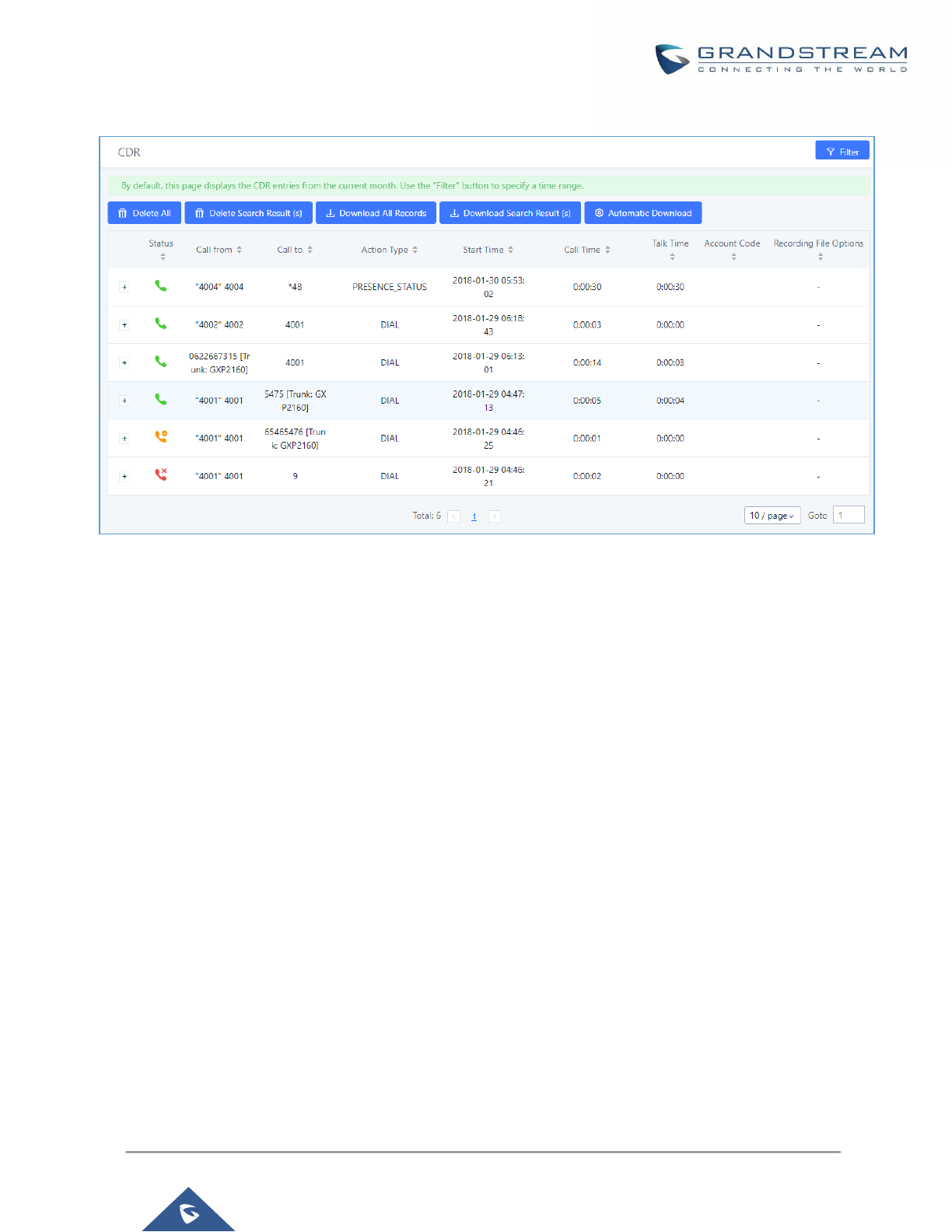
P a g e | 285
UCM6200 Series User Manual
Version 1.0.19.21
Figure 190: Presence Status CDR
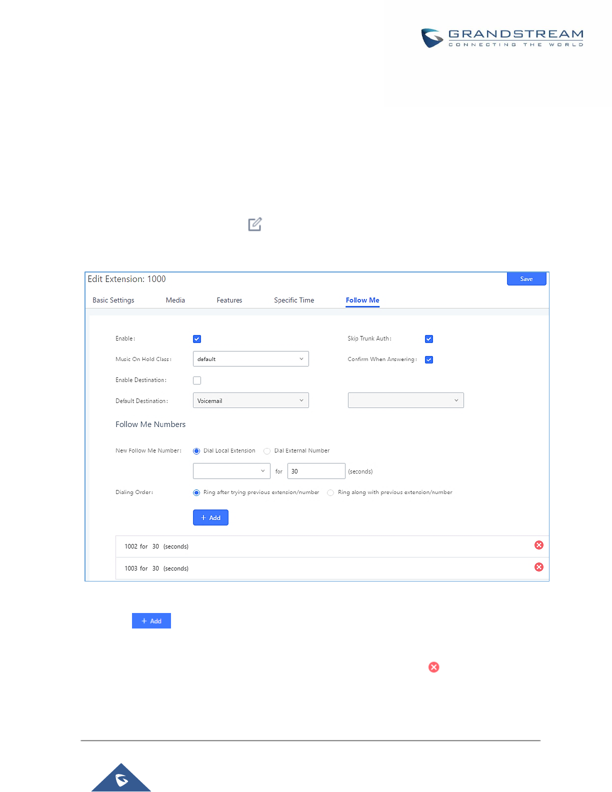
P a g e | 286
UCM6200 Series User Manual
Version 1.0.19.21
FOLLOW ME
Follow Me is a feature on the UCM6200 that allows users to direct calls to other phone numbers and have them
ring all at once or one after the other. Calls can be directed to users’ home phone, office phone, mobile and etc.
The calls will get to the user no matter where they are. Follow Me option can be found under extension settings
page Web GUI→Extension/Trunk→Extensions.
To configure follow me:
1. Choose the extension and click on .
2. Go to the Follow me tab to add destination numbers and enable the feature.
Figure 191: Edit Follow Me
3. Click on to add local extensions or external numbers to be called after ringing the extension
selected in the first step.
4. Once created, it will be displayed on the follow me list. And you can click on to delete the Follow Me.
The following table shows the Follow Me configuration parameters:

P a g e | 287
UCM6200 Series User Manual
Version 1.0.19.21
Table 85: Follow Me Settings
Enable
Configure to enable or disable Follow Me for this user.
Skip Trunk Auth
If external number is added in the Follow Me, please make sure this option is
enabled or the “Skip Trunk Auth” option of the extension is enabled, otherwise
the external Follow Me number cannot be reached.
Music On Hold Class
Configure the Music On Hold class that the caller would hear while tracking users
Confirm When
Answering
By default, it is enabled and user will be asked to press 1 to accept the call or to
press 2 to reject the call after answering a Follow Me call.
If it is disabled, the Follow Me call will be established once after the user
answers.
Enable Destination
When enabled, the call will be routed to the default destination if no one in the
Follow Me extensions answers the call.
Default Destination
Configure the destination if no one in the Follow Me extensions answers the call.
The available options are:
• Extension
• Voicemail
• Queues
• Ring Group
• Voicemail Group
• IVR
• External Number
Follow Me Numbers
The added numbers are listed here. Click on to arrange the order. Click
on to delete the number. Click on to add new numbers.
New Follow Me
Number
Add a new Follow Me number which could be a ‘Local Extension’ or ‘External
Number’. The selected dial plan should have permissions to dial the defined
external number.
Dialing Order
Select the order in which the Follow Me destinations will be dialed to reach the
user: ring all at once or ring one after the other.
Click on “Follow Me Options” under Web GUI→Extension/Trunk→Extension page to enable or disable the
options listed in the following table.
Table 86: Follow Me Options
Playback Incoming
Status Message
If enabled, the PBX will playback the incoming status message before starting
the Follow Me steps.
Record the Caller’s
Name
If enabled, the PBX will record the caller’s name from the phone so it can be
announced to the callee in each step.
Playback Unreachable
Status Message
If enabled, the PBX will playback the unreachable status message to the caller
if the callee cannot be reached.
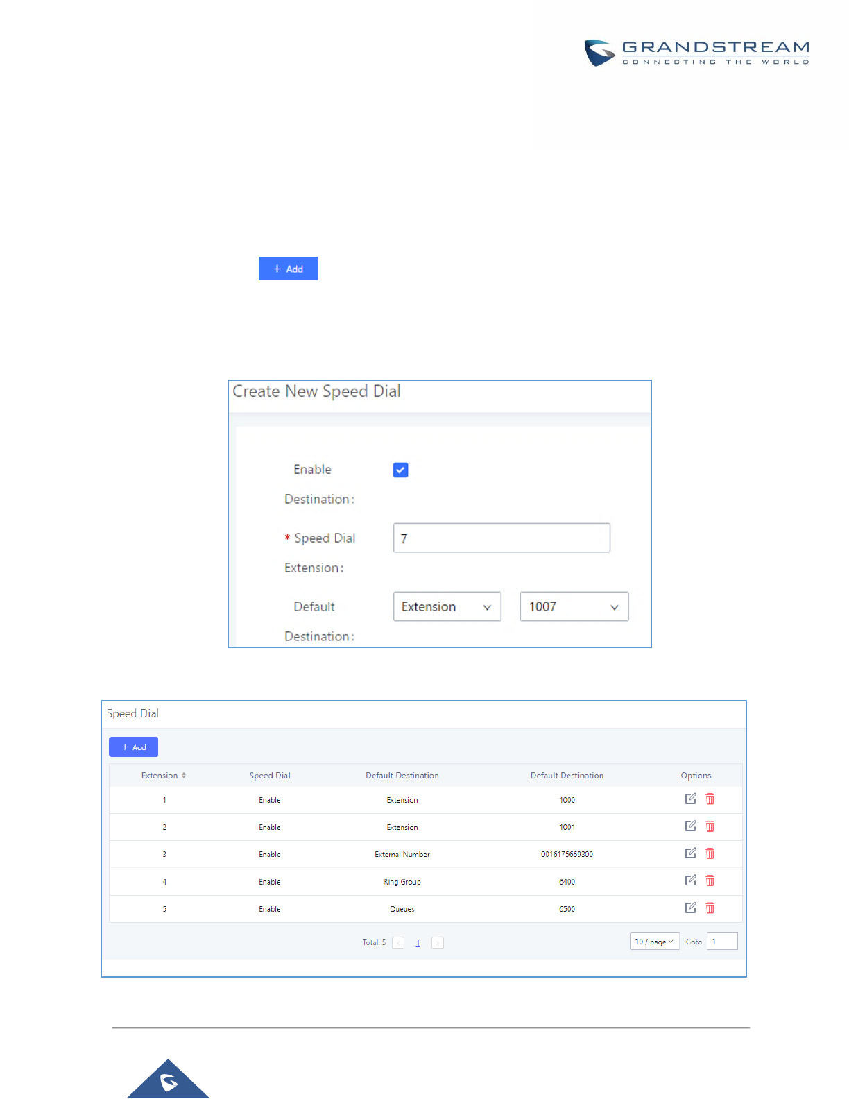
P a g e | 288
UCM6200 Series User Manual
Version 1.0.19.21
SPEED DIAL
The UCM6200 supports Speed Dial feature that allows users to call a certain destination by pressing one or four
digits on the keypad. This creates a system-wide speed dial access for all the extensions on the UCM6200.
To enable Speed Dial, on the UCM6200 Web GUI, go to page Web GUI→Call Features→Speed Dial.
User should first click on . Then decide from one digit up to four digits combination used for Speed
Dial and select a dial destination from “Default Destination”. The supported destinations include extension,
voicemail, conference room, voicemail group, IVR, ring group, call queue, page group, fax, DISA, Dial by Name
and external number.
Figure 192: Speed Dial Destinations
Figure 193: List of Speed Dial
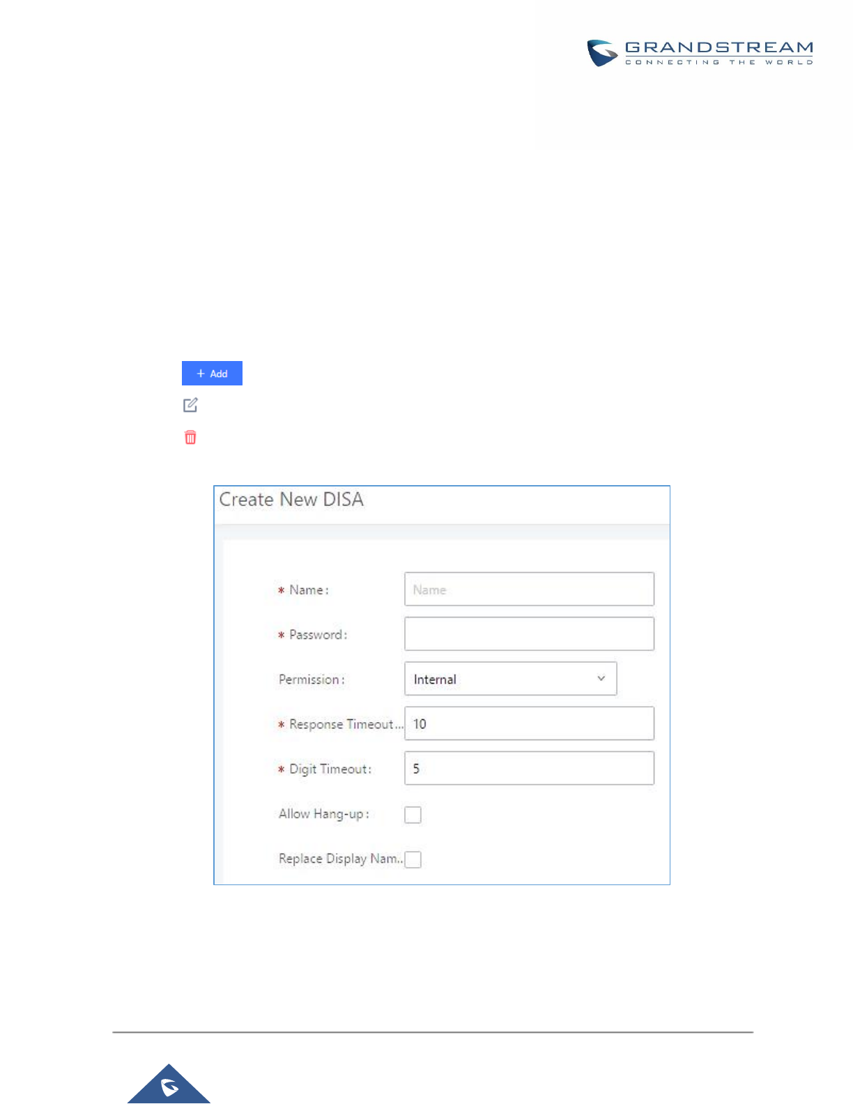
P a g e | 289
UCM6200 Series User Manual
Version 1.0.19.21
DISA
In many situations, the user will find the need to access his own IP PBX resources but he is not physically near
one of his extensions. However, he does have access to his own cell phone. In this case, we can use what is
commonly known as DISA (Direct Inward System Access). Under this scenario, the user will be able to call from
the outside, whether it’s using his cell phone, pay phone, regular PSTN, etc. After calling into UCM6200, the
user can then dial out via the SIP trunk or PSTN trunk connected to UCM6200 as it is an internal extension.
The UCM6200 supports DISA to be used in IVR or inbound route. Before using it, create new DISA under Web
GUI→Call Features→DISA.
• Click on to add a new DISA.
• Click on to edit the DISA configuration.
• Click on to delete the DISA.
Figure 194: Create New DISA
The following table details the parameters to set and configure DISA feature on UCM6200 PBX.

P a g e | 290
UCM6200 Series User Manual
Version 1.0.19.21
Table 87: DISA Settings
Name
Configure DISA name to identify the DISA.
Password
Configure the password (digit only) required for the user to enter before using DISA
to dial out.
Note:
The password must be at least 4 digits.
Permission
Configure the permission level for DISA.
The available permissions are "Internal", "Local", "National" and "International"
from the lowest level to the highest level.
The default setting is "Internal".
If the user tries to dial outbound calls after dialing into the DISA, the UCM6200 will
compared the DISA's permission level with the outbound route's privilege level. If
the DISA's permission level is higher than (or equal to) the outbound route's
privilege level, the call will be allowed to go through.
Response Timeout
Configure the maximum amount of time the UCM6200 will wait before hanging up
if the user dials an incomplete or invalid number.
The default setting is 10 seconds.
Digit Timeout
Configure the maximum amount of time permitted between digits when the user is
typing the extension. The default setting is 5 seconds.
Allow Hangup
If enabled, during an active call, users can enter the UCM6200 Hangup feature
code (by default it's *0) to disconnect the call or hang up directly. A new dial tone
will be heard shortly for the user to make a new call. The default setting is "No".
Replace Display
Name
If enabled, the UCM will replace the caller display name with the DISA name.
Once successfully created, users can configure the inbound route destination as "DISA" or IVR key event as
"DISA". When dialing into DISA, users will be prompted with password first. After entering the correct password,
a second dial tone will be heard for the users to dial out.
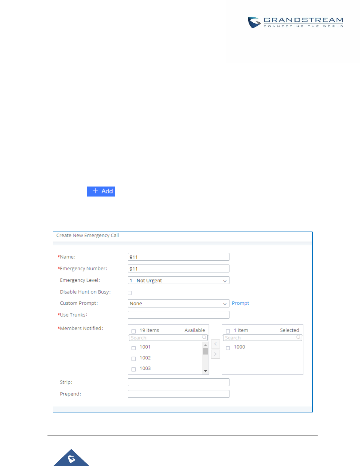
P a g e | 291
UCM6200 Series User Manual
Version 1.0.19.21
EMERGENCY
UCM supports configuration and management of numbers to be called in emergency situation, thus bypassing
the regular outbound call routing process and allowing users in critical situation to dial out for emergency help
with the possibility to have redundant trunks as point of exit in case one of the lines is down.
Also, the module supports notification for other internal users, thus when someone dials an emergency call (ex:
911) a notification call will be sent to other staff to know about the current situation.
Email alerts are also supported after enabling the notification for the event under “Maintenance → System
Events”
To configure emergency numbers, users need to follow below steps:
1. Navigate on the web GUI under “Call Features → Emergency Calls”
2. Click on to add a new emergency number.
3. Configure the required fields “Name, Emergency Number and Trunk(s) to be used to reach the number”.
4. Save and apply the configuration.
Figure 195: Emergency Number Configuration
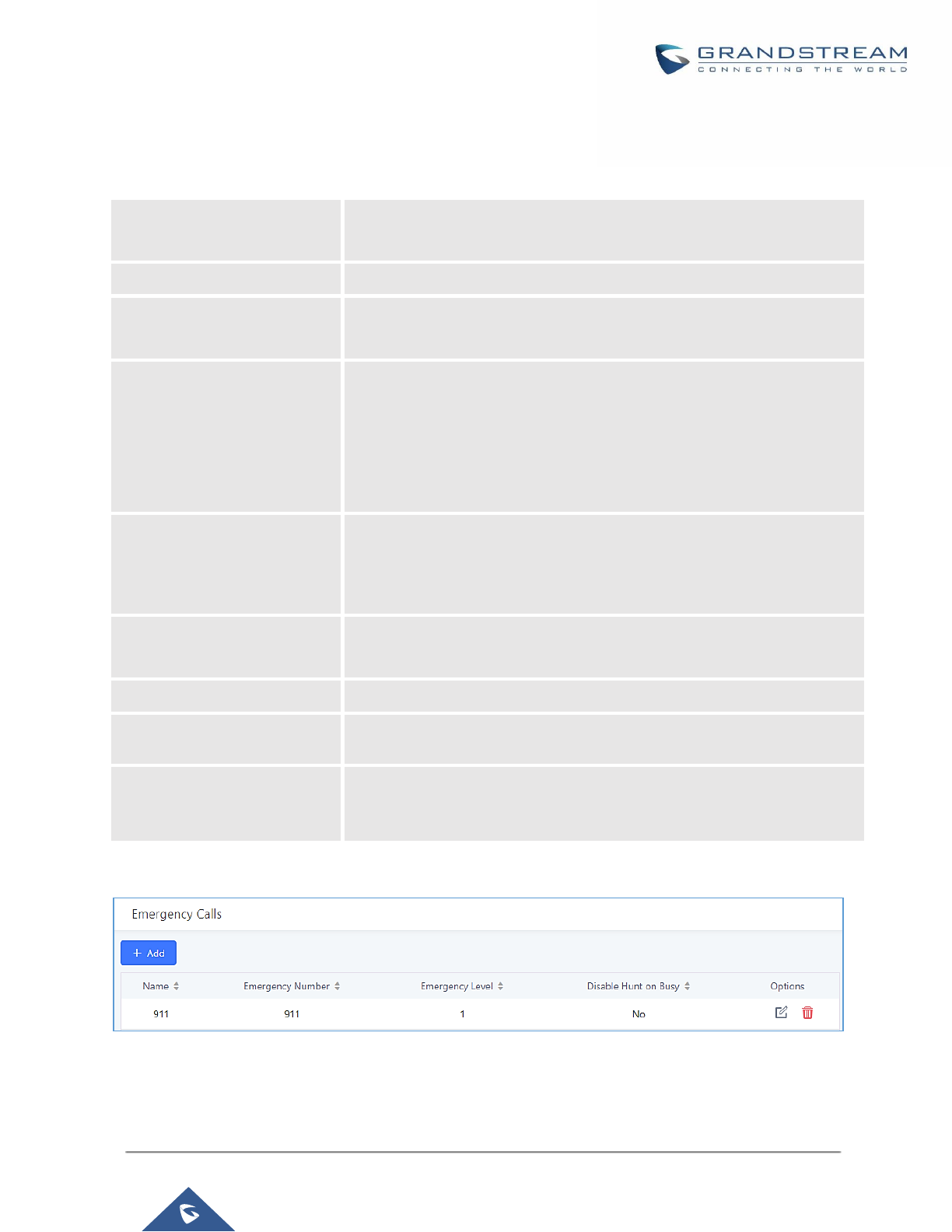
P a g e | 292
UCM6200 Series User Manual
Version 1.0.19.21
The table below gives more description of the configuration Parameters when creating emergency numbers.
Table 88: Emergency Numbers Parameters
Name
Configure the name of the emergency call.
For example, "emergency911","emergency211" and etc.
Emergency Number
Config the emergency service number. For example,"911","211" and etc.
Emergency Level
Select the emergency level of the number. Level "3" means the most
urgent.
Disable Hunt on Busy
If this option is not enabled, when the lines of trunks which the coming
emergency call routes by are completely occupied, the line-grabbing
function will automatically cut off a line from all busy lines so that the
coming emergency call can seize it for dialing out. This option is not
enabled by default.
Custom Prompt
This option sets a custom prompt to be used as an announcement to the
person receiving an emergency call. The file can be uploaded from the
page "Custom Prompt". Click "Prompt" to add additional record.
Use Trunks
Select the trunks for the emergency call. Select one trunk at least, and
select five trunks at most.
Members Notified
Select the members who will be notified when an emergency call occurs.
Strip
Specify the number of digits that will be Stripped from the beginning of the
dialed number before the call is placed via the selected trunk.
Prepend
Specify the digits to be Prepended before the call is placed via the trunk.
Those digits will be prepended after the dialing number is stripped.
Figure 196: 911 Emergency Sample

P a g e | 293
UCM6200 Series User Manual
Version 1.0.19.21
CALLBACK
Callback is mainly designed for users who often use their mobile phones to make long distance or international
calls which may have high service charges. The callback feature provides an economic solution for reduce the
cost from this.
The callback feature works as follows:
1. Configure a new callback on the UCM6200.
2. On the UCM6200, configure destination of the inbound route for analog trunk to callback.
3. Save and apply the settings.
4. The user calls the PSTN number of the UCM6200 using the mobile phone, which goes to callback destination
as specified in the inbound route.
5. Once the user hears the ringback tone from the mobile phone, hang up the call on the mobile phone.
6. The UCM6200 will call back the user.
7. The user answers the call.
8. The call will be sent to DISA or IVR which directs the user to dial the destination number.
9. The user will be connected to the destination number.
In this way, the calls are placed and connected through trunks on the UCM6200 instead of to the mobile phone
directly. Therefore, the user will not be charged on mobile phone services for long distance or international calls.
To configure callback on the UCM6200, go to Web GUI→Call Features→Callback page and click on
. Configuration parameters are listed in the following table.
Table 89: Callback Configuration Parameters
Name
Configure a name to identify the Callback. (Enter at least two characters)
CallerID Pattern
Configure the pattern of the callers allowed to use this callback. The caller who
places the inbound call needs to have the CallerID match this pattern so that the
caller can get callback after hanging up the call.
Note:
If leaving as blank, all numbers are allowed to use this callback.
Outbound Prepend
Configure the prepend digits to be added at before dialing the outside number.
The number with prepended digits will be used to match the outbound route. ‘-’
is the connection character which will be ignored.
Delay Before Callback
Configure the number of seconds to be delayed before calling back the user.
Destination
Configure the destination which the callback will direct the caller to. Two
destinations are available:
• IVR
• DISA
The caller can then enter the desired number to dial out via UCM6200 trunk.

P a g e | 294
UCM6200 Series User Manual
Version 1.0.19.21
BLF AND EVENT LIST
BLF
The UCM6200 supports BLF monitoring for extensions, ring group, call queue, conference room and parking lot.
For example, on the user's phone, configure the parking lot number 701 as the BLF monitored number. When
there is a parked call on 701, the LED for this BLF key will light up in red, meaning a call is parked against this
parking lot. Pressing this BLF key can pick up the call from this parking lot.
----------------------------------------------------------------------------------------------------------------------------- ----------------------
Note:
On the Grandstream GXP series phones, the MPK supports "Call Park" mode, which can be used to park the
call by configuring the MPK number as call park feature code (e.g., 700). MPK "Call Park" mode can also be
used to monitor and pickup parked call if the MPK number is configured as parking lot (e.g., 701).
---------------------------------------------------------------------------------------------------------------------------------------------------
Event List
Besides BLF, users can also configure the phones to monitor event list. In this way, both local extensions on the
same UCM6200 and remote extensions on the VOIP trunk can be monitored. The event list setting is under Web
GUI→Call Features→Event List.
• Click on "Create New Event List" to add a new event list.
• Sort selected extensions manually in the Eventlist
• Click on to edit the event list configuration.
• Click on to delete the event list.
Table 90: Event List Settings
URI
Configure the name of this event list (for example, office_event_list). Please note
the URI name cannot be the same as the extension name on the UCM6200. The
valid characters are letters, digits, _ and -.
Local Extensions
Select the available extensions/Extension Groups listed on the local UCM6200
to be monitored in the event list.
Remote Extensions
If LDAP sync is enabled between the UCM6200 and the peer UCM6200, the
remote extensions will be listed under "Available Extensions". If not, manually
enter the remote extensions under "Special Extensions" field.
Special Extensions
Manually enter the remote extensions in the peer/register trunk to be monitored
in the event list. Valid format: 5000,5001,9000
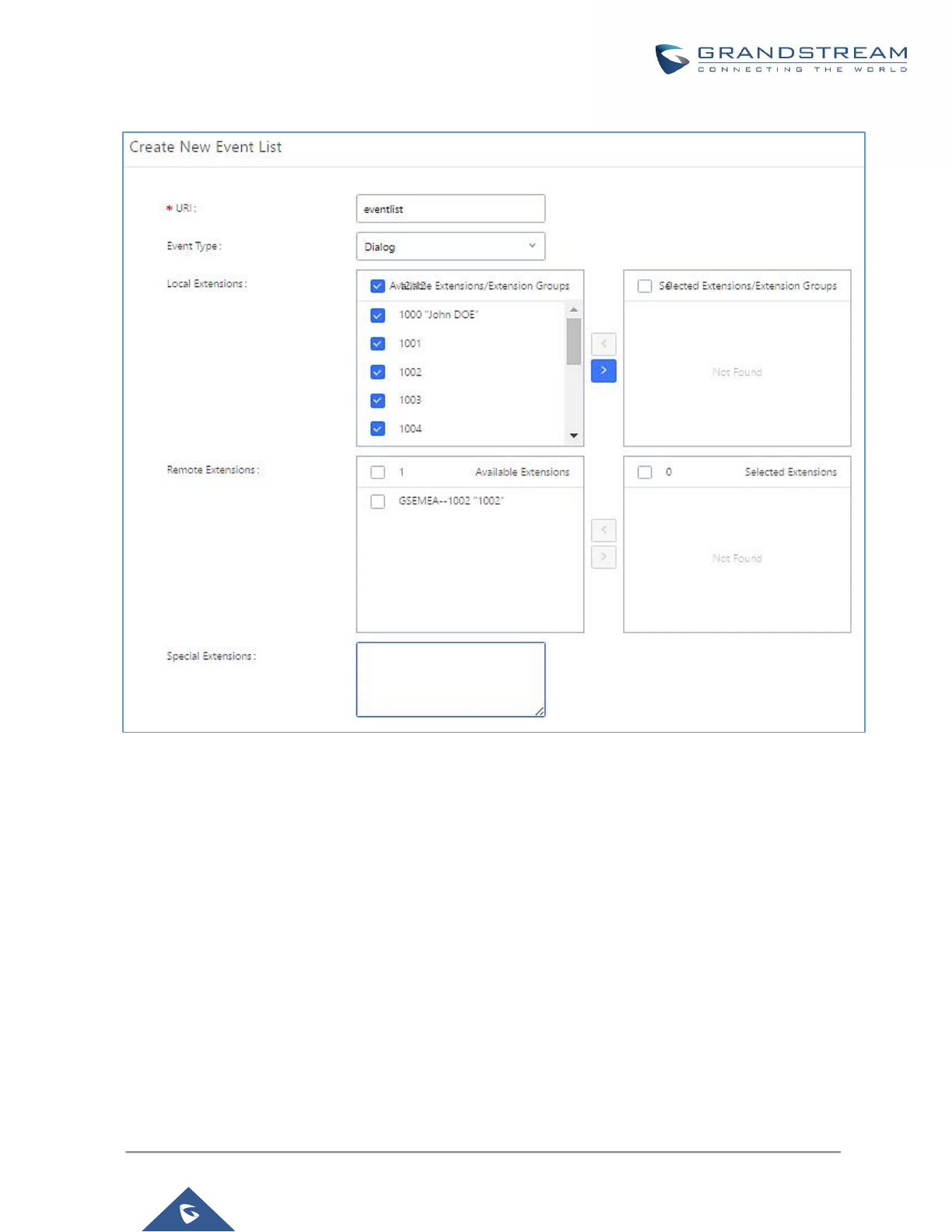
P a g e | 295
UCM6200 Series User Manual
Version 1.0.19.21
Figure 197: Create New Event List
Remote extension monitoring works on the UCM6200 via event list BLF, among Peer SIP trunks or Register SIP
trunks (register to each other). Therefore, please properly configure SIP trunks on the UCM6200 first before
using remote BLF feature. Please note the SIP end points need support event list BLF in order to monitor remote
extensions.
When an event list is created on the UCM6200 and remote extensions are added to the list, the UCM6200 will
send out SIP SUBSCRIBE to the remote UCM6200 to obtain the remote extension status. When the SIP end
points register and subscribe to the local UCM6200 event list, it can obtain the remote extension status from this
event list. Once successfully configured, the event list page will show the status of total extension and
subscribers for each event list. Users can also select the event URI to check the monitored extension's status
and the subscribers' details.

P a g e | 296
UCM6200 Series User Manual
Version 1.0.19.21
----------------------------------------------------------------------------------------------------------------------------- ----------------------
Notes:
• To configure LDAP sync, please go to UCM6200 Web GUI→Extension/Trunk→VoIP Trunk. You will see
"Sync LDAP Enable" option. Once enabled, please configure password information for the remote peer
UCM6200 to connect to the local UCM6200. Additional information such as port number, LDAP outbound
rule, LDAP Dialed Prefix will also be required. Both the local UCM6200 and remote UCM6200 need enable
LDAP sync option with the same password for successful connection and synchronization.
• Currently LDAP sync feature only works between two UCM6200s.
• (Theoretically) Remote BLF monitoring will work when the remote PBX being monitored is non-UCM6200
PBX. However, it might not work the other way around depending on whether the non-UCM6200 PBX
supports event list BLF or remote monitoring feature.
----------------------------------------------------------------------------------------------------------------------------- ----------------------
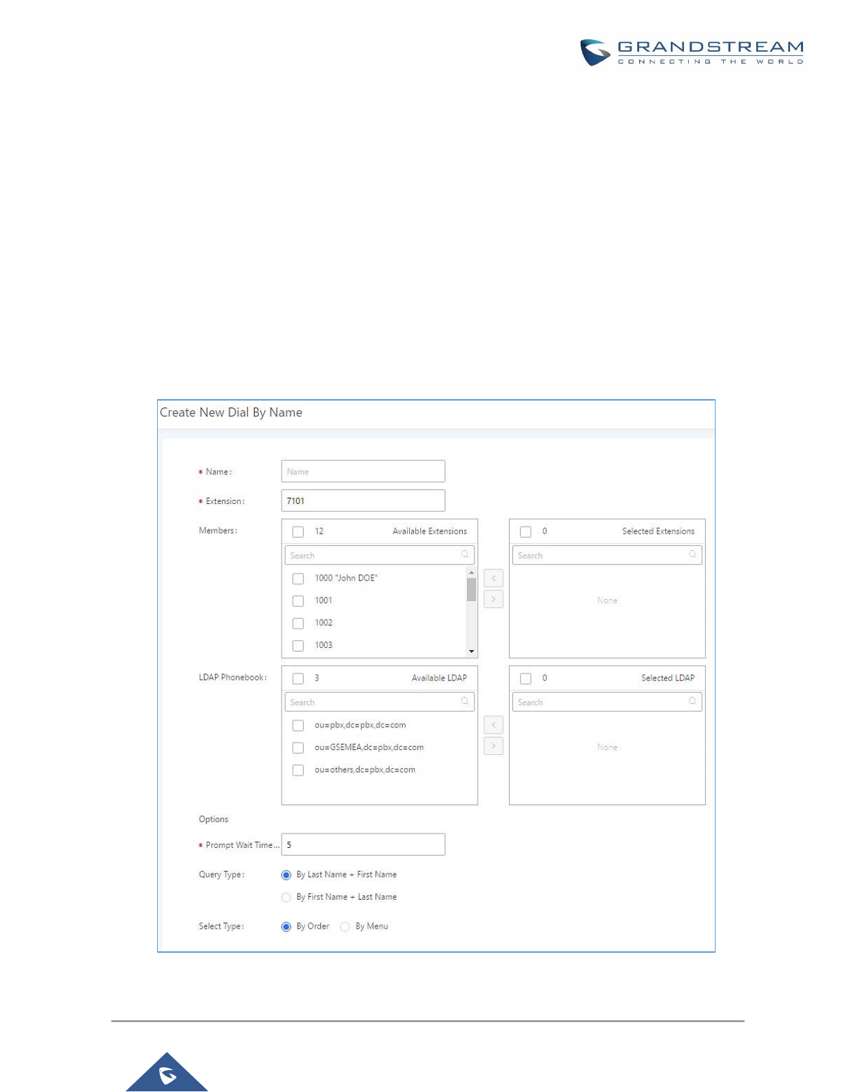
P a g e | 297
UCM6200 Series User Manual
Version 1.0.19.21
DIAL BY NAME
Dial by Name is a feature on the PBX that allows caller to search a person by first or last name via his/her
phone's keypad. The administrator can define the Dial by Name directory including the desired extensions in the
directory and the searching type by "first name" or "last name". After dialing in, the PBX IVR/Auto Attendant will
guide the caller to spell the digits to find the person in the Dial by Name directory. This feature allows
customers/clients to use the guided automatic system to get in touch with the enterprise employees without
having to know the extension number, which brings convenience and improves business image for the
enterprise.
Dial by Name Configuration
The administrators can create the dial by name group under Web GUI→Call Features→Dial By Name.
Figure 198: Create Dial by Name Group
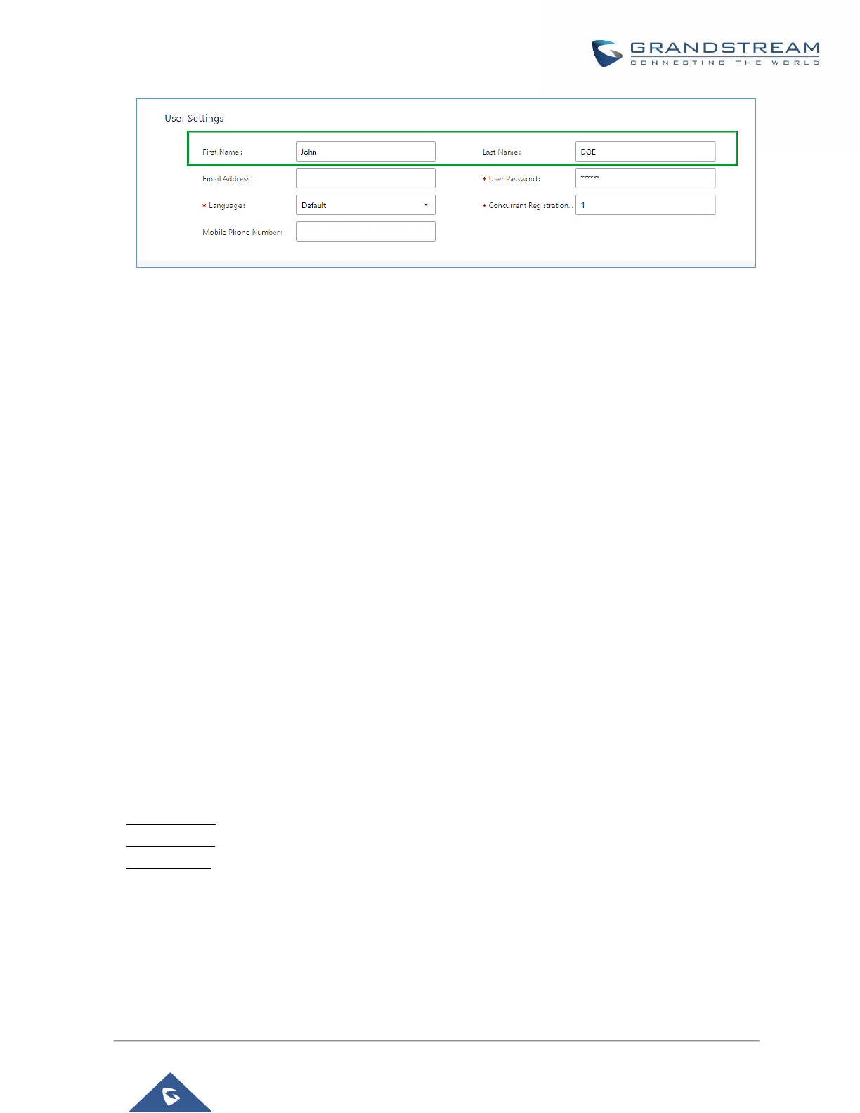
P a g e | 298
UCM6200 Series User Manual
Version 1.0.19.21
Figure 199: Configure Extension First Name and Last Name
1. Name
Enter a Name to identify the Dial by Name group.
2. Extension
Configure the direct dial extension for the Dial By Name group.
3. Available Extensions/Selected Extensions
Select available extensions from the left side to the right side as the directory for the Dial By Name group.
Only the selected extensions here can be reached by the Dial By Name IVR when dialing into this group.
The extensions here must have a valid first name and last name configured under Web
GUI→Extension/Trunk→Extensions in order to be searchable in Dial By Name directory through IVR. By
specifying the extensions here, the administrators can make sure unscreened calls will not reach the
company employee if he/she does not want to receive them directly.
4. Prompt Wait Time
Configure “Prompt Wait Time” for Dial By Name feature. During Dial By Name call, the caller will need to
input the first letters of First/Last name before this wait time is reached. Otherwise, timeout will occur and
the call might hang up. The timeout range is between 3 and 60 seconds.
5. Query Type
Specify the query type. This defines how the caller will need to enter to search the directory.
By First Name: enter the first 3 digits of the first name to search the directory.
By Last Name: enter the first 3 digits of the last name to search the directory.
By Full Name: enter the first 3 digits of the first name or last name to search the directory.
6. Select Type
Specify the select type on the searching result. The IVR will confirm the name/number for the party the caller
would like to reach before dialing out.

P a g e | 299
UCM6200 Series User Manual
Version 1.0.19.21
By Order: After the caller enters the digits, the IVR will announce the first matching party's name and number.
The caller can confirm and dial out if it's the destination party, or press * to listen to the next matching result
if it's not the desired party to call.
By Menu: After the caller enters the digits, the IVR will announce 8 matching results. The caller can press
number 1 to 8 to select and call, or press 9 for results in next page.
The Dial by Name group can be used as the destination for inbound route and key pressing event for IVR. The
group name defined here will show up in the destination list when configuring IVR and inbound route. If Dial by
Name is set as a key pressing event for IVR, user could use ‘*’ to exit from Dial by Name, then re-enter IVR and
start a new event. The following example shows how to use this option.
Figure 200: Dial By Name Group In IVR Key Pressing Events
Figure 201: Dial By Name Group In Inbound Rule
Please refer to [User Name Prompt Customization] for User Name Prompt Customization.
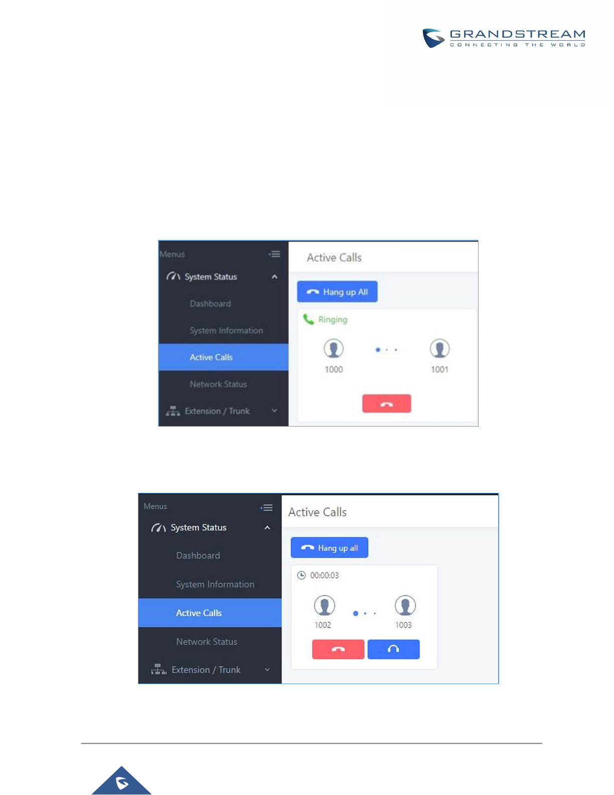
P a g e | 300
UCM6200 Series User Manual
Version 1.0.19.21
ACTIVE CALLS AND MONITOR
The active calls on the UCM6200 are displayed in Web GUI→System Status→Active Calls page. Users can
monitor the status, hang up the call as well as barge in the active calls in real time manner.
Active Calls Status
To view the status of active calls, navigate to Web GUI→System Status→Active Calls. The following figure
shows extension 1000 is calling 1001. 1001 is ringing.
Figure 202: Status→PBX Status→Active Calls - Ringing
The following figure shows the call between 1002 and 1003 is established.
Figure 203: Status→PBX Status→Active Calls – Call Established

P a g e | 301
UCM6200 Series User Manual
Version 1.0.19.21
The green color of the active call means the connection of call time is less than half an hour. It means this call is
normal.
Figure 204: Call Connection less than half hour
The yellow color of the active call means the connection of call time is greater than half an hour but less than
one hour. It means this call is a bit long.
Figure 205: Call Connection between half an hour and one hour
The red color of the active call means the connection of call time is more than one hour. It means this call could
be abnormal.
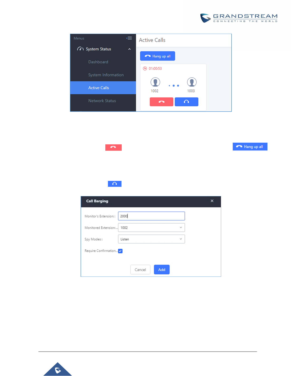
P a g e | 302
UCM6200 Series User Manual
Version 1.0.19.21
Figure 206: Call Connection more than one hour
Hang Up Active Calls
To hang up an active call, click on icon in the active call dialog. Users can also click on
to hang up all active calls.
Call Monitor
During an active call, click on icon and the monitor dialog will pop up.
Figure 207: Configure to Monitor an Active Call
In the “Monitor” dialog, configure the following to monitor an active call:
1. Enter an available extension for “Monitor’s Extension” which will be used to monitor the active call.
2. “Monitored Extension” must be one of the parties in the active call to be monitored.
3. Select spy mode. There are three options in “Spy Mode”.

P a g e | 303
UCM6200 Series User Manual
Version 1.0.19.21
• Listen
In “Listen” mode, the extension monitoring the call can hear both parties in the active call but the audio
of the user on this extension will not be heard by either party in the monitored active call.
• Whisper
In “Whisper” mode, the extension monitoring the call can hear both parties in the active call. The user
on this extension can only talk to the selected monitored extension and he/she will not be heard by the
other party in the active call. This can be usually used to supervise calls.
• Barge
In “Barge” mode, the extension monitoring the call can talk to both parties in the active call. The call will
be established similar to three-way conference.
4. Enable or disable “Require Confirmation” option. If enabled, the confirmation of the invited monitor’s
extension is required before the active call can be monitored. This option can be used to avoid adding
participant who has auto-answer configured or call forwarded to voicemail.
5. Click on “Add”. An INVITE will be sent to the monitor’s extension. The monitor can answer the call and start
monitoring. If “Require Confirmation” is enabled, the user will be asked to confirm to monitor the call.
Another way to monitor active calls is to dial the corresponding feature codes from an extension. Please refer to
[Table 91: UCM6200 Feature Codes] and [Call Recording] section for instructions.

P a g e | 304
UCM6200 Series User Manual
Version 1.0.19.21
CALL FEATURES
The UCM6200 supports call recording, transfer, call forward, call park and other call features via feature code.
This section lists all the feature codes in the UCM6200 and describes how to use the call features.
Feature Codes
Table 91: UCM6200 Feature Codes
Feature Maps
Blind Transfer
• Default code: #1
• Enter the code during active call. After hearing "Transfer", you
will hear dial tone. Enter the number to transfer to. Then the
user will be disconnected and transfer is completed.
• Options:
Disable
Allow Caller: Enable the feature code on caller side only.
Allow Callee: Enable the feature code on callee side only.
Allow Both: Enable the feature code on both caller and callee.
Attended Transfer
• Default code: *2
• Enter the code during active call. After hearing "Transfer", you
will hear the dial tone. Enter the number to transfer to and the
user will be connected to this number. Hang up the call to
complete the attended transfer. In case of the called party
doesn’t answer, users could press *0 to cancel the call and
retrieve the first call leg.
• Options:
Disable
Allow Caller: Enable the feature code on caller side only.
Allow Callee: Enable the feature code on callee side only.
Allow Both: Enable the feature code on both caller and callee.
Seamless Transfer
• Default code: *44 (Disabled by default).
• Seamless Transfer allows user to perform blind transfer using
UCM feature code without having music on hold presented
during the transfer process, it minimizes the interruption during
transfer, making the process smooth and simple.
• During an active call use the feature code (*44 by default)
followed by the number you want to transfer to in order to
perform the seamless transfer.

P a g e | 305
UCM6200 Series User Manual
Version 1.0.19.21
Disconnect
• Default code: *0
• Enter the code during active call. It will disconnect the call.
• Options:
Disable
Allow Caller: Enable the feature code on caller side only.
Allow Callee: Enable the feature code on callee side only.
Allow Both: Enable the feature code on both caller and callee.
Call Park
• Default code: #72
• Enter the code during active call to park the call.
• Options:
Disable
Allow Caller: Enable the feature code on caller side only.
Allow Callee: Enable the feature code on callee side only.
Allow Both: Enable the feature code on both caller and callee.
Audio Mix Record
• Default code: *3
• Enter the code followed by # or SEND to start recording the
audio call and the UCM6200 will mix the streams natively on the
fly as the call is in progress.
• Options:
Disable
Allow Caller: Enable the feature code on caller side only.
Allow Callee: Enable the feature code on callee side only.
Allow Both: Enable the feature code on both caller and callee.
Feature Code Digits Timeout
Set the maximum interval (ms) between digits for feature code
activation
DND/Call Forward
Do Not Disturb (DND) Activate
• Default code: *77
Do Not Disturb (DND) Deactivate
• Default code: *78
Call Forward Busy Activate
• Default Code: *90
• Enter the code and follow the voice prompt. Or enter the code
followed by the extension to forward the call.
Call Forward Busy Deactivate
• Default Code: *91
Call Forward No Answer Activate
• Default Code: *92
• Enter the code and follow the voice prompt. Or enter the code
followed by the extension to forward the call.

P a g e | 306
UCM6200 Series User Manual
Version 1.0.19.21
Call Forward No Answer
Deactivate
• Default Code: *93
Call Forward Unconditional
Activate
• Default Code: *72
• Enter the code and follow the voice prompt. Or enter the code
followed by the extension to forward the call.
Call Forward Unconditional
Deactivate
• Default Code: *73
Feature Codes
Voicemail Access Code
• Default Code: *98
• Enter *98 and follow the voice prompt. Or dial *98 followed by
the extension and # to access the entered extension's voicemail
box.
My Voicemail
• Default Code: *97
• Press *97 to access the voicemail box.
Agent Pause
• Default Code: *83
• Pause the agent in all call queues.
Agent Unpause
• Default Code: *84
• Unpause the agent in all call queues.
Paging Prefix
• Default Code: *81
• To page an extension, enter the code followed by the extension
number.
Intercom Prefix
• Default Code: *80
• To intercom an extension, enter the code followed by the
extension number.
Blacklist Add
• Default Code: *40
• To add a number to blacklist for inbound route, dial *40 and
follow the voice prompt to enter the number.
Blacklist Remove
• Default Code: *41
• To remove a number from current blacklist for inbound route,
dial *41 and follow the voice prompt to remove the number.
Call Pickup on Ringing
• Default Code: **
• To pick up a call for any extension xxxx, enter the code followed
by the extension number xxxx.

P a g e | 307
UCM6200 Series User Manual
Version 1.0.19.21
Pickup In-call
• Default Code: *45 (Disabled by default).
• If “Pickup In-call” feature is enabled, only the extensions added
in “Allowed to seamless transfer” in the extension’s Seamless
Transfer Privilege Control List” can pick up the call.
Pickup Extension
• Default Code: *8
• This code is for the pickup group, which can be assigned for
each extension on the extension configuration page.
• If there is an incoming call to an extension, the other extensions
within the same pickup group can dial *8 directly to pick up the
call.
Direct Dial Voicemail Prefix
• Default Code: *
• This code is for the user to directly dial or transfer to an
extension's voicemail.
• For example, directly dial *5000 will have to call go into the
extension 5000's voicemail. If the user would like to transfer the
call to the extension 5000's voicemail, enter *5000 as the
transfer target number.
Direct Dial Mobile Phone Prefix
• Default Code: *88
• If you have the permission to call mobile phone number, use
this prefix plus the extension number can dial the mobile phone
number of this extension directly.
Call Completion Request
• Default Code: *11
• This code is for the user who wants to use Call Completion to
complete a call.
Call Completion Cancel
• Default Code: *12
• This code is for the user who wants to cancel Call Completion
request.
Enable Spy
Check this box to enable spy feature codes. Disabled by default.
Listen Spy
• Default Code: *54 (“Enable Spy” needs to be checked)
• This is the feature code to listen in on a call to monitor
performance. Monitor’s line will be muted, and neither party will
hear from the monitor’s extension.
Whisper Spy
• Default Code: *55 (“Enable Spy” needs to be checked)
• This is the feature code to speak to one side of the call (for
example, whisper to employees to help them handle a call).
Only one side will be able to hear from the monitor’s extension.

P a g e | 308
UCM6200 Series User Manual
Version 1.0.19.21
Barge Spy
• Default Code: *56 (“Enable Spy” needs to be checked)
• This is the feature code to join in on the call to assist both
parties.
Wakeup Service
• Default Code: *36
• Dial this code to access UCM wakeup service, you can add,
update, activate or deactivate wakeup service.
PMS Wakeup Service
• Default Code: *35
• Dial this code to access UCM PMS wakeup service, you can
add, update, activate or deactivate PMS wakeup service.
Update PMS Room Status
• Default Code: *23
• Use this code with maid code to update PMS room status.
Choose the status to set after hearing the prompt, for example:
for maid 001 dial *23001 and then 1 after hearing the prompt.
Presence Status
• Dial this code to set the presence status of the extension.
• Possible options are:
1:"unavailable"
2:"available"
3:"away"
4:"chat
5:"dnd
6:"userdef"
Dynamic Agent Logout
• Default Code: *85
• Use this code to logout the dynamic agent from all queues.
The UCM6200 also allows user to one click enable / disable specific feature code as shown below:
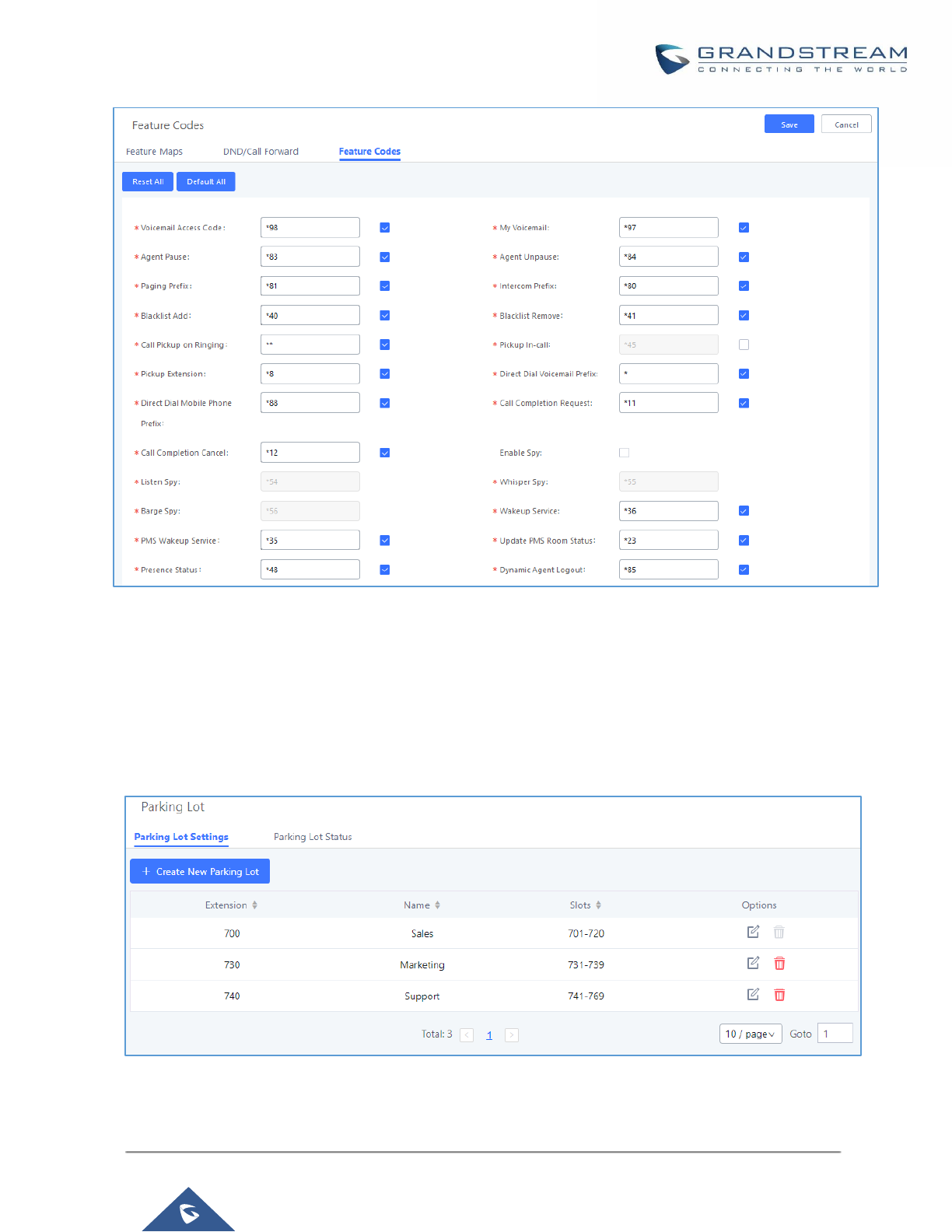
P a g e | 309
UCM6200 Series User Manual
Version 1.0.19.21
Figure 208: Enable/Disable Feature codes
Parking Lot
User can create parking lots and their related slots under Web GUI→ Call Features→ Parking Lot. In the
Parking Lot page, users can create lots of their own. This allows different groups within an organization to have
their own parking lots instead of sharing one large parking lot with others. While creating a new parking lot, users
can assign it a range that they think is appropriate for the group that will use the parking lot.
Figure 209: Parking Lot
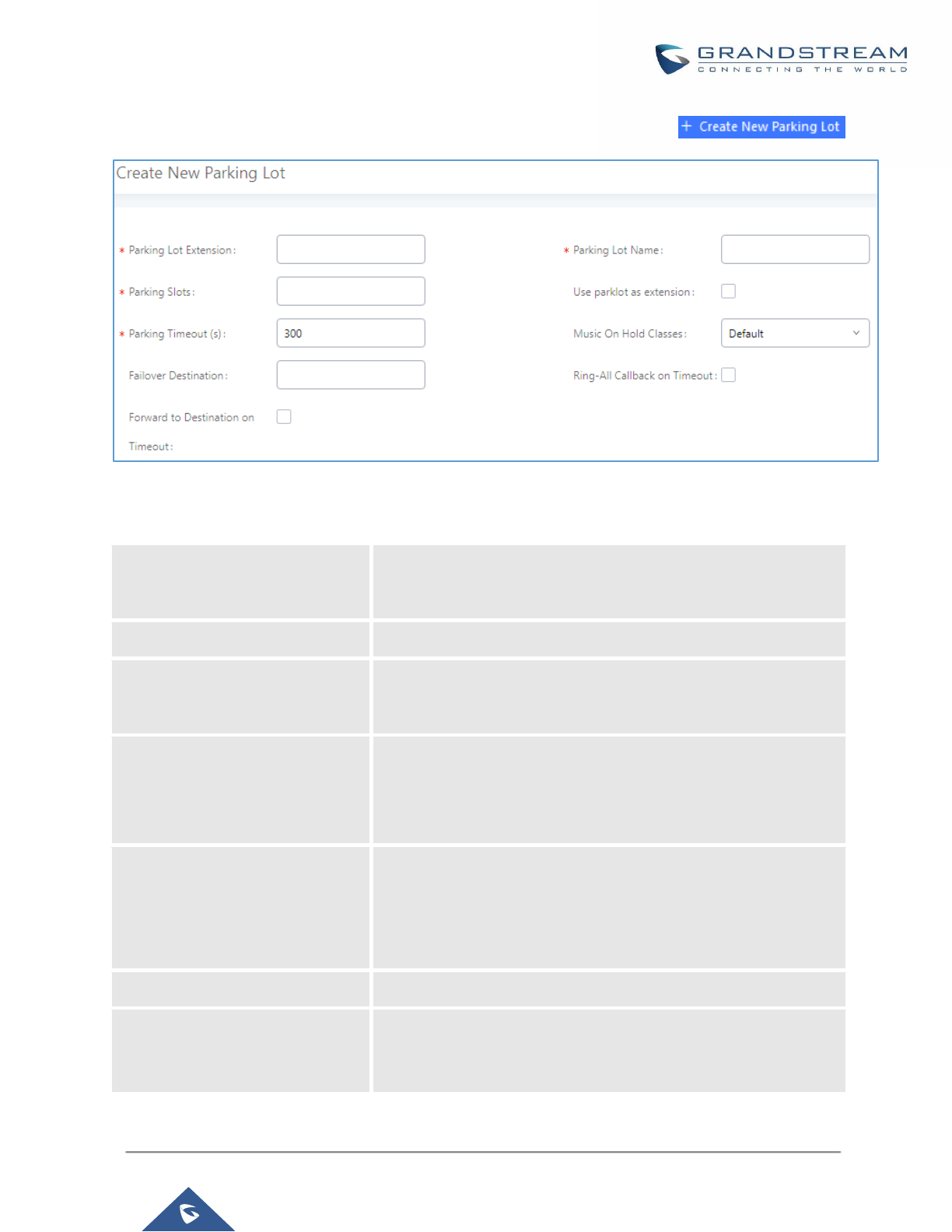
P a g e | 310
UCM6200 Series User Manual
Version 1.0.19.21
User can create a new Parking lot by clicking on button “Create New Parking Lot” :
Figure 210: New Parking Lot
Table 92 : Parking Lot
Parking Lot Extension
• Default Extension: 700
• During an active call, initiate blind transfer and then enter this
code to park the call.
Parking Lot Name
• Set a name to the parking lot
Parked Slots
• Default Extension: 701-720
• These are the extensions where the calls will be parked, i.e.,
parking lots that the parked calls can be retrieved.
Use Parklot as Extension
• If checked, the parking lot number can be used as extension.
The user can transfer the call to the parking lot number to park
the call. Please note this parking lot number range might conflict
with extension range.
Parking Timeout (s)
• Default setting is 300 seconds and the maximum limit is 99.999
seconds.
• This is the timeout allowed for a call to be parked. After the
timeout, if the call is not picked up, the extension who parks the
call will be called back.
Music On Hold Classes
Select the Music on Hold Class.
Failover Destination
Configures a callback failover destination when the extension that
is called back is busy. The call will be routed to the destination
number and this reduces the chance of dropping parked calls.

P a g e | 311
UCM6200 Series User Manual
Version 1.0.19.21
Ring All Callback on Timeout
If enabled, all registered endpoints of the extension will ring when
callback occurs. Otherwise, only the original endpoint will be called
back.
Forward to destination on
timeout
If enabled, the call will be routed to the configured destination upon
timeout. Otherwise, the call will be routed back to the original caller.
Timeout Destination
This option appears once Forward to Destination on Timeout is
enabled. Upon park timeout, the call will be routed to the configured
destination.
Call Park
The UCM6200 provides call park and call pickup features via feature code.
Park a Call
There are two feature codes that can be used to park the call.
• Feature Maps→Call Park (Default code #72)
During an active call, press #72 and the call will be parked. Parking lot number (default range 701 to 720)
will be announced after parking the call.
• Feature Misc→Call Park (Default code 700)
During an active call, initiate blind transfer (default code #1) and then dial 700 to park the call. Parking lot
number (default range 701 to 720) will be announced after parking the call.
Retrieve Parked Call
To retrieve the parked call, simply dial the parking lot number and the call will be established. If a parked call is
not retrieved after the timeout, the original extension who parks the call will be called back.
Monitor Call Park CID Name Information (GXP21xx Phones Only)
Users can see the CID name information of parked calls.
VPK/MPKs must be configured as “Monitored Call Park” with
the desired parking lot extension. The display will alternate
between displaying the parking lot extension and the call’s
CID name. There is no need to configure anything on the
UCM.
Note: This feature requires Grandstream GXP21xx new
firmware support. This new firmware is not available in
Grandstream website yet. Please check GXP21xx upcoming
firmware release information for availability.
Figure 211: Monitored call park CID name
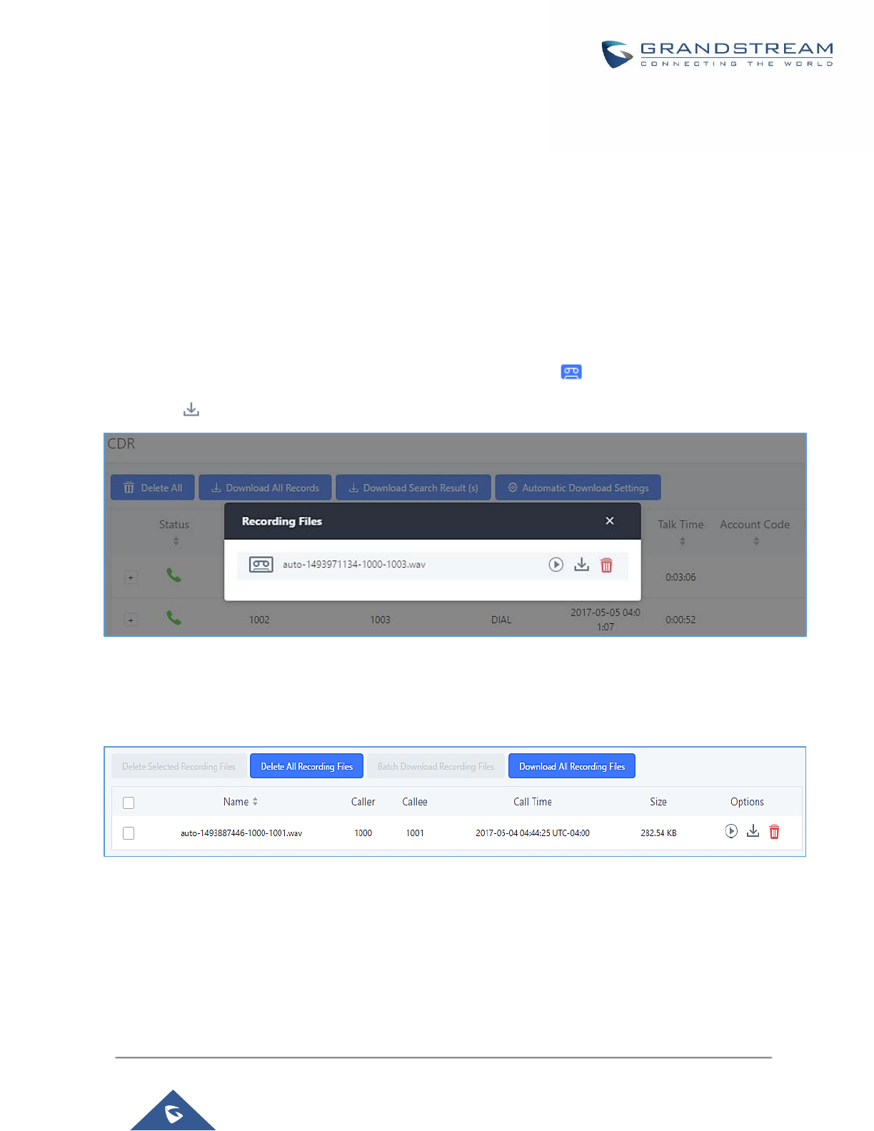
P a g e | 312
UCM6200 Series User Manual
Version 1.0.19.21
Call Recording
The UCM6200 allows users to record audio during the call. If "Auto Record" is turned on for an extension, ring
group, call queue or trunk, the call will be automatically recorded when there is established call with it. Otherwise,
please follow the instructions below to manually record the call.
1. Make sure the feature code for "Audio Mix Record" is configured and enabled.
2. After establishing the call, enter the "Audio Mix Record" feature code (by default it's *3) followed by # or
SEND to start recording.
3. To stop the recording, enter the "Audio Mix Record" feature code (by default it's *3) followed by # or SEND
again. Or the recording will be stopped once the call hangs up.
4. The recording file can be retrieved under Web GUI→CDR. Click on to show and play the recording or
click on to download the recording file.
Figure 212: Download Recording File from CDR Page
The above recorded call's recording files are also listed under the UCM6200 Web GUI→CDR→Recording Files.
Figure 213: Download Recording File from Recording Files Page
Enable Spy
If “Enable Spy” option is enabled, feature codes for Listen Spy, Whisper Spy and Barge Spy are available for
users to dial from any extension to perform the corresponding actions.
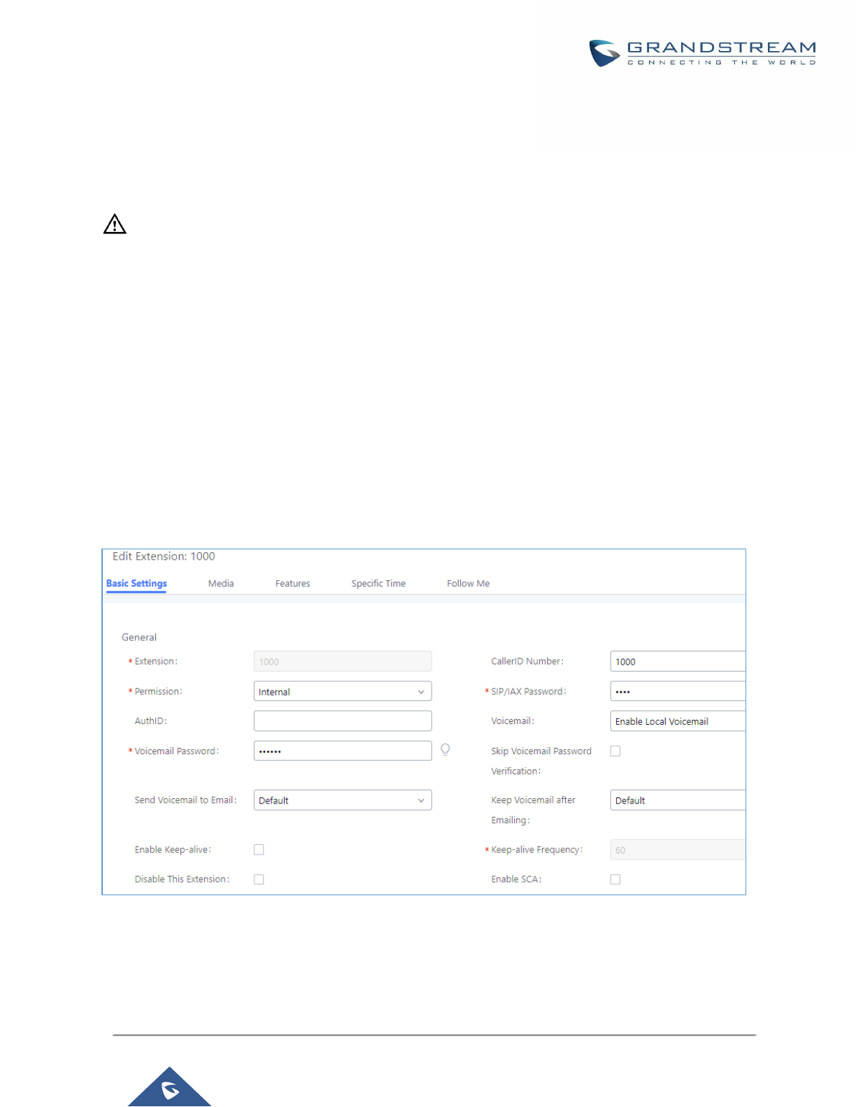
P a g e | 313
UCM6200 Series User Manual
Version 1.0.19.21
Assume a call is on-going between extension A and extension B, user could dial the feature code from extension
C to listen on their call (*54 by default), whisper to one side (*55 by default), or barge into the call (*56 by default).
Then the user will be asked to enter the number to call, which should be either side of the active call, extension
A or B in this example.
---------------------------------------------------------------------------------------------------------------------------------------------------
Caution:
“Enable Spy” allows any user to listen to any call by feature codes. This may result in the leakage of user privacy.
----------------------------------------------------------------------------------------------------------------------------- ----------------------
Shared Call Appearance (SCA)
Shared Call Appearance (SCA) functionality has been added to the UCM. With SCA, users can assign multiple
devices to one extension, configure endpoints to monitor that extension, make actions on behalf of that extension
such as viewing call status and placing and receiving calls, and even barging into existing calls. To configure the
SCA functionality, please follow the steps below:
1. Users can enable SCA by navigating to the Extensions page, editing the desired extension, and enabling
the option SCA.
Note: With SCA enabled, the Concurrent Registrations field can only have a value of 1.
Figure 214: Enabling SCA option under Extension’s Settings
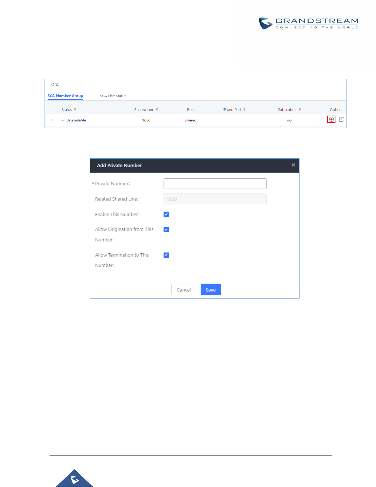
P a g e | 314
UCM6200 Series User Manual
Version 1.0.19.21
2. After enabling the option, navigate to Call Features
→
SCA. The newly enabled SCA extension will be listed.
Click the “+” button under the Options column to add a number that will share the main extension’s call
appearance, which will be called private numbers.
Figure 215: SCA Number Configuration
3. Configure the private number as desired.
Figure 216: SCA Private Number Configuration
4. Once the private number has been created, users must now register a device to it. To properly register a
device to the private number, use the configured private number as the SIP User ID. Auth ID and Password
will be the same as the main extension’s. Once registration is complete, SCA is now configured.
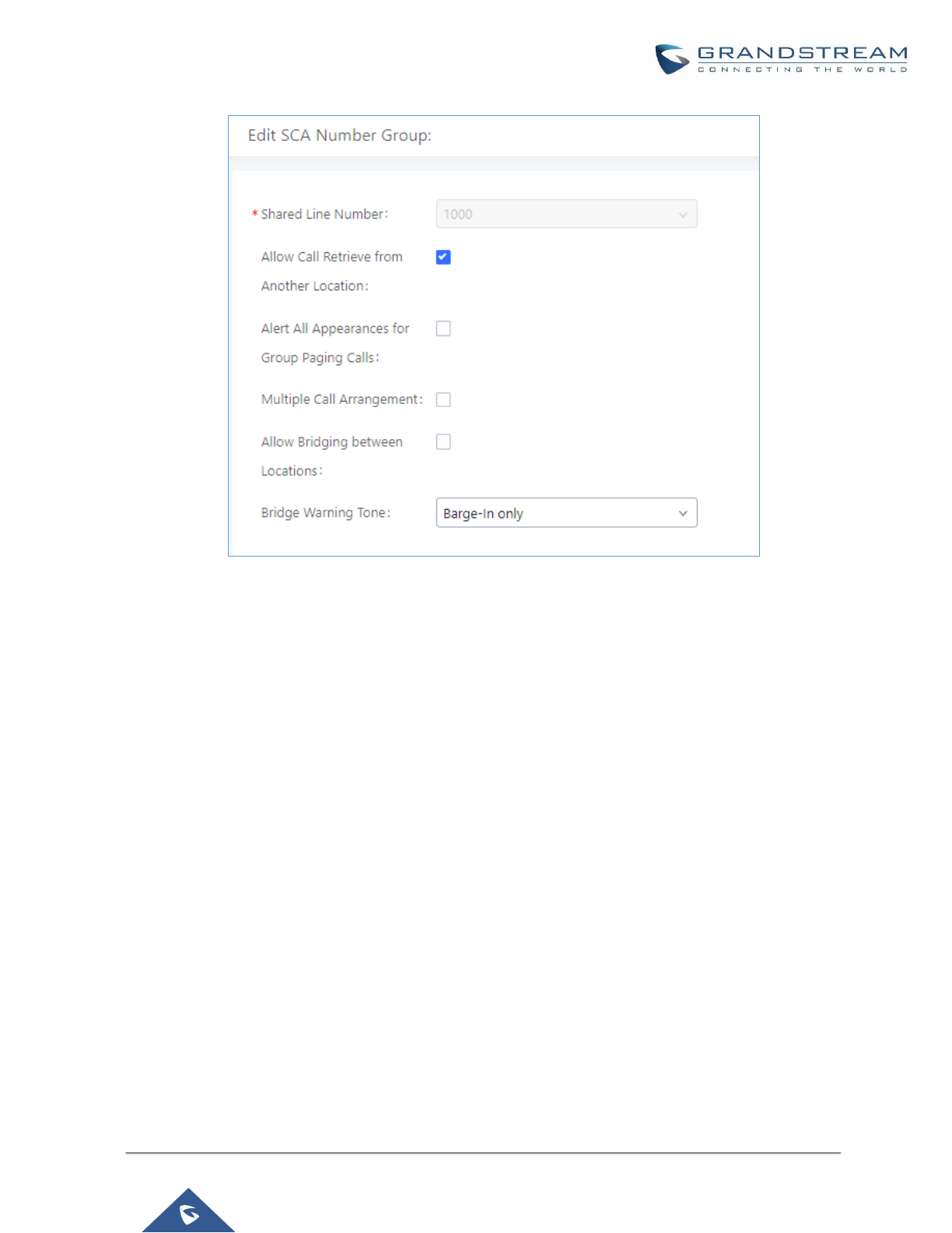
P a g e | 315
UCM6200 Series User Manual
Version 1.0.19.21
Figure 217: SCA Options
SCA has various options to change its behavior:
• Allow Call Retrieve from Another Location – Allows users to retrieve held calls using any device
associated with the SCA extension.
• Alert All Appearances for Group Paging Calls – Alerts all devices associated with the SCA extension.
• Multiple Call Arrangement – Allows all devices associated with the SCA extension to make different
calls at the same time.
• Allow Bridging between Locations – Allows devices associated with the SCA extension to barge into
existing calls of the same SCA group.
• Bridge Warning Tone – Notification sound that will play when a party barges into the call. Three options
are available:
o None – No notification sound will play
o Barge-In Only – The notification sound will play once when a party barges in.
o Barge-In and Repeat – The notification sound will play when a party barges in and will play
again after every 30 seconds.
5. Next, configure the VPK or MPK to Shared for both the main extension and the private number. SCA is
now configured for both endpoint devices.

P a g e | 316
UCM6200 Series User Manual
Version 1.0.19.21
The following table describe the SCA Number configuration setting:
Table 93: Add SCA Private Number
Private Number
Configures the private number for the SCA.
Related Shared Line
Display the related shared line.
Enable This Number
Whether enable this private number. If not enabled, this private
number is only record in DB, it will not affect other system feature.
Allow Origination from This
Number
Enable this option will allow calling from this private number. By
default, it’s enabled.
Allow Termination to This
Number
Enable this option will allows calls to this private number. By default,
it’s enabled.
The following table describes the options available when editing the SCA number:
Table 94: Editing the SCA Number
Shared Line Number
While SCA is enabled, this number will be the same as the
extension number.
Allow Call Retrieve from Another
Location
Allows remote call retrieval. Must be enabled in public hold. By
default, it’s enabled.
Alert All Appearances for Group
Paging Calls
Allows all SCA group members to ring when the SCA shared
number is paged. If disabled, only the SCA shared number will ring
when paged. By default, it’s disabled.
Multiple Call Arrangement
Allows simultaneous calls in an SCA group. By default, it’s disabled.
Allow Bridging between
Locations
Allows location bridging for SCA group. Must be enabled when
using the Barge-In feature. By default, it’s disabled.
Bridge Warning Tone
Configures the notification in the bridge when another party join.
• None: No notification sound.
• Barge-In only: Notification sound will play when another
party join.
• Barge-In and Repeat: Notification sound will play when
another party joins and repeat every 30 seconds.
By default, it’s set to “Barge-In Only”.

P a g e | 317
UCM6200 Series User Manual
Version 1.0.19.21
PBX SETTINGS
This section describes internal options that haven't been mentioned in previous sections yet. The settings in this
section can be applied globally to the UCM6200, including general configurations, jitter buffer, RTP settings,
ports config and STUN monitor. The options can be accessed via Web GUI→PBX Settings→General Settings.
PBX Settings/General Settings
Table 95: Internal Options/General
General Preferences
Global Outbound CID
Configure the global CallerID used for all outbound calls when no other CallerID
is defined with higher priority. If no CallerID is defined for extension or trunk, the
global outbound CID will be used as CallerID.
Global Outbound CID
Name
Configure the global CallerID Name used for all outbound calls. If configured,
all outbound calls will have the CallerID Name set to this name. If not, the
extension's CallerID Name will be used.
Ring Timeout
Configure the number of seconds to ring an extension before the call goes to
the user's voicemail box. The default setting is 60.
Note:
This is the global value used for each extension if "Ring Timeout" field is left
empty on the extension configuration page.
Call Duration Limit
Configure the maximum duration of call-blocking.
Record Prompt
If enabled, users will hear voice prompt before recording is started or stopped.
For example, before recording, the UCM6200 will play voice prompt "The call
will be recorded". The default setting is "No".
Device Name
The name of the UCM you are using.
Extension Preferences
Enforce Strong
Passwords
If enabled, strong password will be enforced for the password created on the
UCM6200. The default setting is enabled.
Strong Password Rules:
1. Password for voicemail, voicemail group, outbound route, DISA, call queue
and conference require non-repetitive and non-sequential digits, with a
minimum length of 4 digits. Repetitive digits pattern (such as 0000, 1111,
1234, 2345, and etc), or common digits pattern (such as 111222, 321321
and etc) are not allowed to be configured as password.

P a g e | 318
UCM6200 Series User Manual
Version 1.0.19.21
2. Password for extension registration, Web GUI admin login, LDAP and
LDAP sync requires alphanumeric characters containing at least two
categories of the following, with a minimum length of 4 characters.
• Numeric digits
• Lowercase alphabet characters
• Uppercase alphabet characters
• Special characters
Enable Random
Password
If enabled, random password will be generated when the extension is created.
The default setting is "Yes". It is recommended to enable it for security purpose.
Enable Auto E-mail
Notification
If enabled, UCM6200 will send Email notification to user automatically after
editing extension settings or adding a new extension.
Disable Extension
Range
If set to "Yes", users could disable the extension range pre-
configured/configured on the UCM6200. The default setting is "No".
Note: It is recommended to keep the system assignment to avoid inappropriate
usage and unnecessary issues.
Extension Ranges
The default extension range assignment is:
• User Extensions: 1000-6299
User Extensions is referring to the extensions created under Web
GUI→Extension/Trunk→Extensions page.
• Pick Extensions: 4000-4999
This refers to the extensions that can be manually picked from end device
when being provisioned by the UCM6200. There are two related options in
zero config page→Auto Provision Settings, "Pick Extension Segment" and
"Enable Pick Extension". If "Enable Pick Extension" under zero config
settings is selected, the extension list defined in "Pick Extension Segment"
will be sent out to the device after receiving the device's request. This "Pick
Extension Segment" should be a subset of the "Pick Extensions" range
here. This feature is for the GXP series phones that support selecting
extension to be provisioned via phone's LCD.
• Auto Provision Extensions: 5000-6299
This sets the range for "Zero Config Extension Segment" which is the
extensions can be assigned on the UCM6200 to provision the end device.
• Conference Extensions: 6300-6399
• Ring Group Extensions: 6400-6499

P a g e | 319
UCM6200 Series User Manual
Version 1.0.19.21
• Queue Extensions: 6500-6599
• Voicemail Group Extensions: 6600-6699
• IVR Extensions: 7000-7100
• Dial By Name Extensions: 7101-7199
• Fax Extensions: 7200-8200
PBX Settings/RTP Settings
RTP Settings
Table 96: Internal Options/RTP Settings
RTP Start
Configure the RTP port starting number. The default setting is 10000.
RTP End
Configure the RTP port ending address. The default setting is 20000.
Strict RTP
Configure to enable or disable strict RTP protection. If enabled, RTP packets
that do not come from the source of the RTP stream will be dropped. The default
setting is "Disable".
RTP Checksums
Configure to enable or disable RTP Checksums on RTP traffic. The default
setting is "Disable".
ICE Support
Configure whether to support ICE. The default setting is enabled.
ICE is the integrated use of STUN and TURN structure to provide reliable VoIP
or video calls and media transmission, via a SIP request/ response model or
multiple candidate endpoints exchanging IP addresses and ports, such as
private addresses and TURN server address.
STUN Server
Configure STUN server address. STUN protocol is a Client/Server and also a
Request/Response protocol. It’s used to check the connectivity between the
two terminals, such as maintaining a NAT binding entries keep-alive agreement.
The default STUN Server is stun.ipvideotalk.com.
Valid format:
[(hostname | IP-address) [':' port]
The default port number is 3478 if not specified.
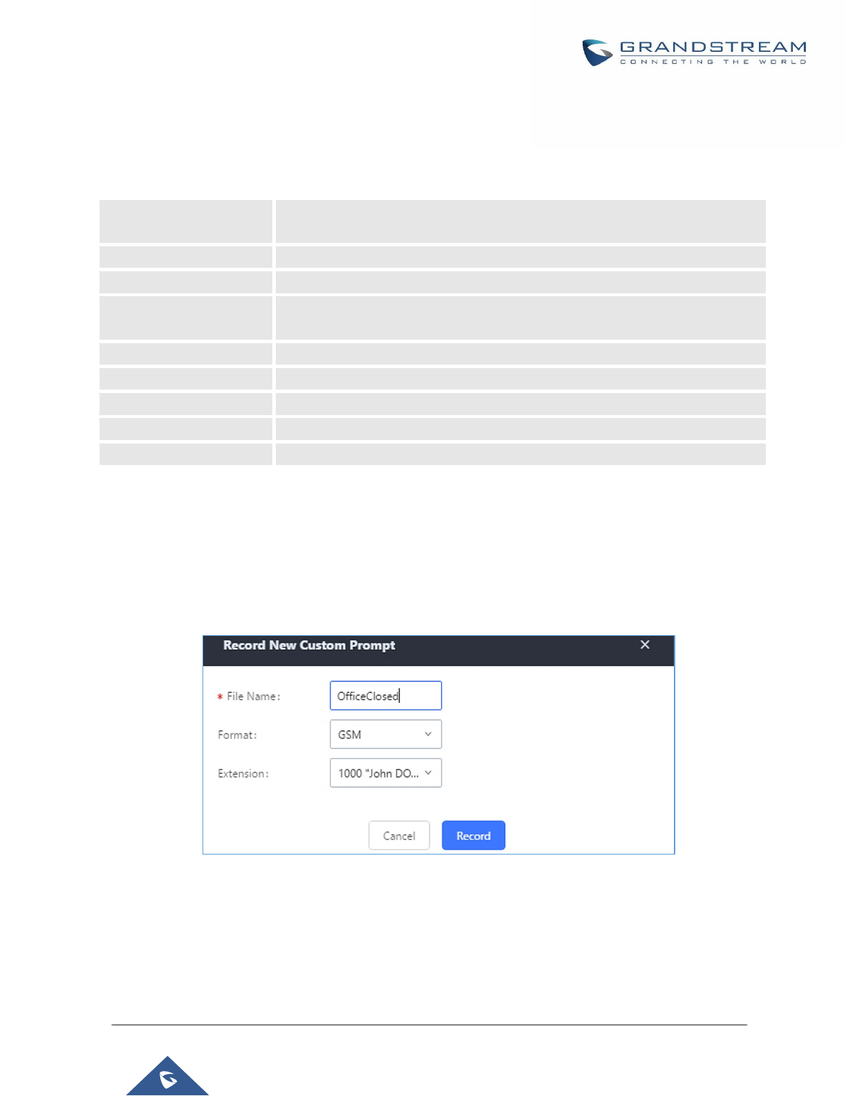
P a g e | 320
UCM6200 Series User Manual
Version 1.0.19.21
Payload
The UCM6200 payload type for audio codecs and video codes can be configured here.
Table 97: Internal Options/Payload
AAL2-G.726
Configure payload type for ADPCM (G.726, 32kbps, AAL2 codeword packing).
The default setting is 112.
DTMF
Configured payload type for DTMF. The default setting is 101.
G.721 Compatible
Configure to enable/disable G.721 compatible. The default setting is Yes.
G.726
Configure the payload type for G.726 if "G.721 Compatible" is disabled. The
default setting is 111.
iLBC
Configure the payload type for iLBC. The default setting is 97.
H.264
Configure the payload type for H.264. The default setting is 99.
H.265
Configure the payload type for H.264. The default setting is 114.
H.263P
Configure the payload type for H.263+. The default setting is 100 103.
VP8
Configure the payload type for VP8. The default settings is 108.
PBX Settings/Voice Prompt Customization
Record New Custom Prompt
In the UCM6200 Web GUI→PBX Settings→Voice Prompt→Custom Prompt page, click on “Record New
Custom Prompt” and follow the steps below to record new IVR prompt.
Figure 218: Record New Custom Prompt
1. Specify the IVR file name.
2. Select the format (GSM or WAV) for the IVR prompt file to be recorded.
3. Select the extension to receive the call from the UCM6200 to record the IVR prompt.
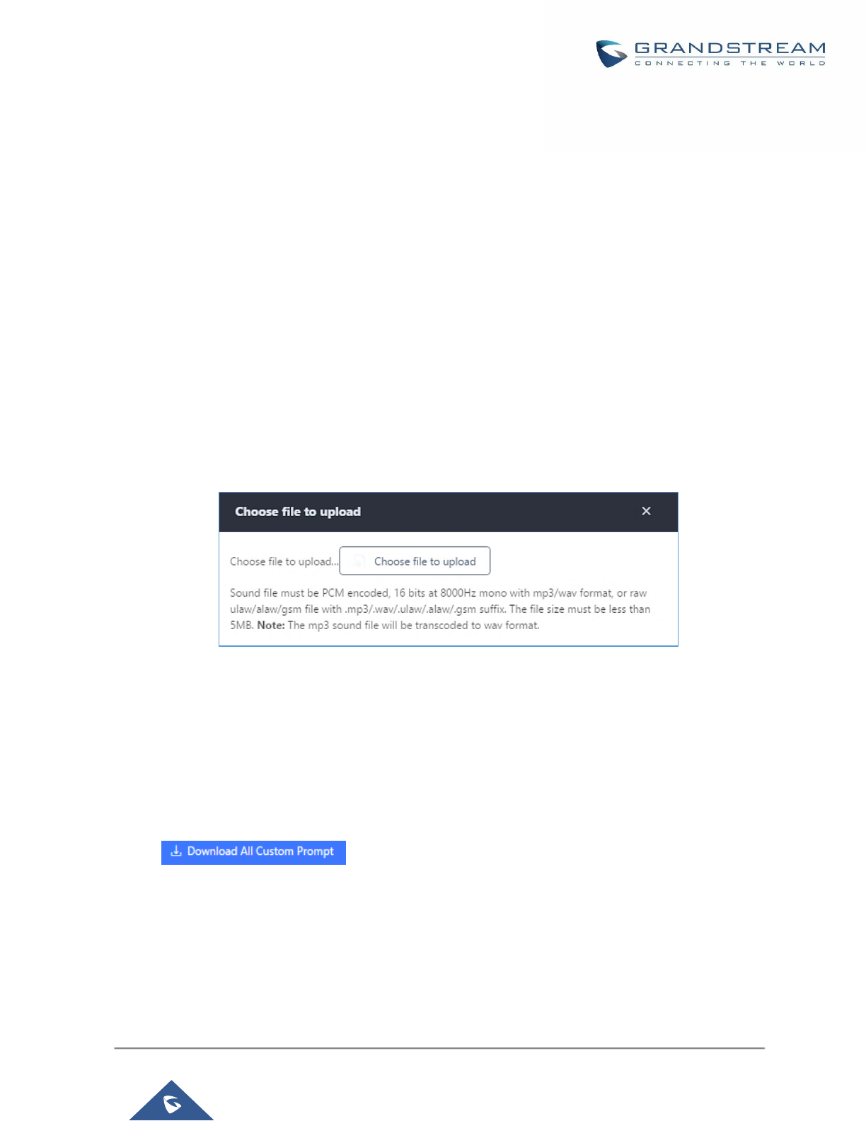
P a g e | 321
UCM6200 Series User Manual
Version 1.0.19.21
4. Click the “Record” button. A request will be sent to the UCM6200. The UCM6200 will then call the extension
for recording the IVR prompt from the phone.
5. Pick up the call from the extension and start the recording following the voice prompt.
6. The recorded file will be listed in the IVR Prompt web page. Users could select to re-record, play or delete
the recording.
Upload Custom Prompt
If the user has a pre-recorded IVR prompt file, click on “Upload Custom Prompt” in Web GUI→PBX
Settings→Voice Prompt→Custom Prompt page to upload the file to the UCM6200. The following are required
for the IVR prompt file to be successfully uploaded and used by the UCM6200:
• PCM encoded.
• 16 bits.
• 8000Hz mono.
• In .mp3 or .wav format; or raw/ulaw/alaw/gsm file with .ulaw or .alaw suffix.
• File size under 5M.
Figure 219: Upload Custom Prompt
Click on “choose file to upload” to start uploading. Once uploaded, the file will appear in the Custom Prompt web
page.
Download All Custom Prompt
On the UCM62XX, the users can download all custom prompts from UCM Web GUI to local PC. To download
all custom prompt, log in UCM Web GUI and navigate to PBX Settings→Voice Prompt→Custom Prompt and
click on . The following window will pop up in order to set a name for the
downloaded file.
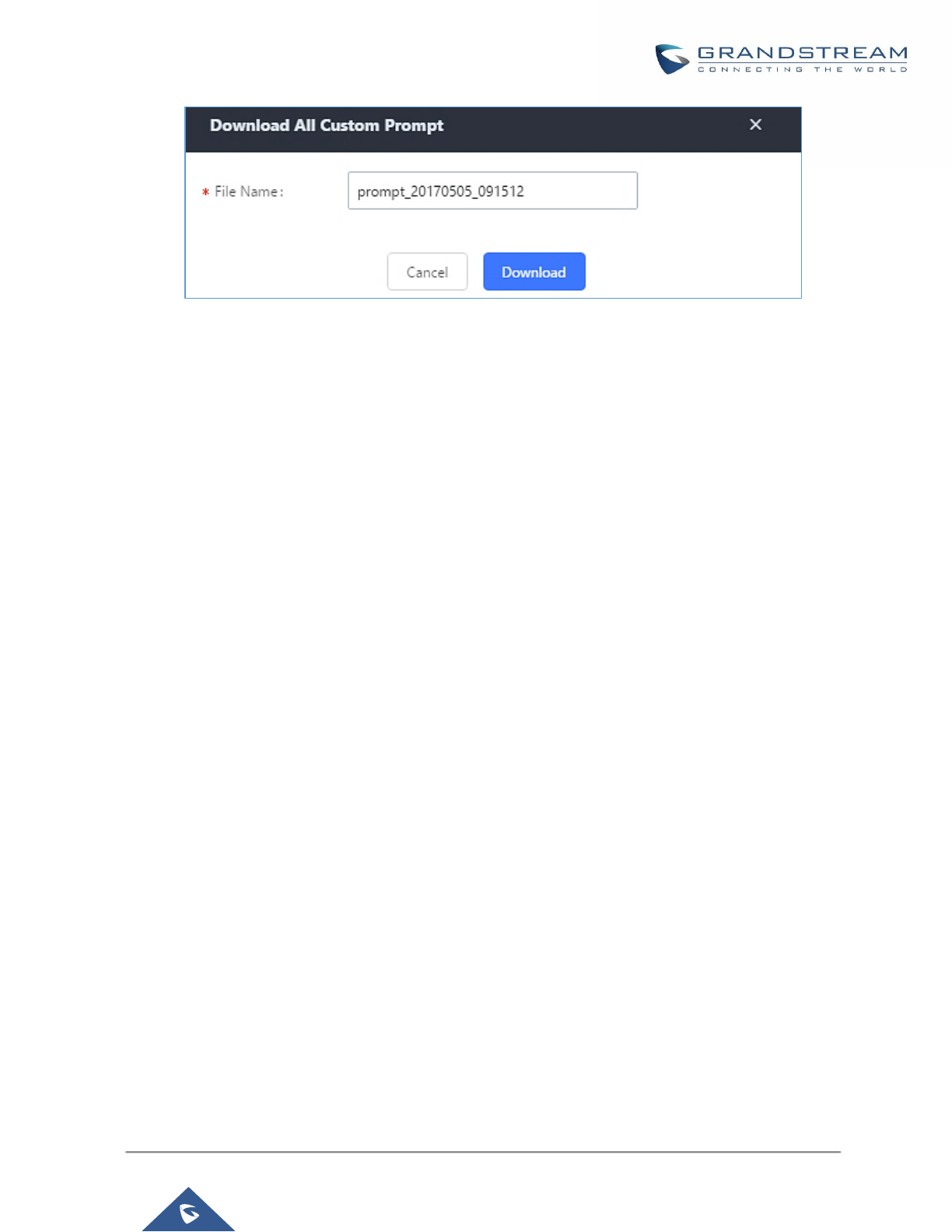
P a g e | 322
UCM6200 Series User Manual
Version 1.0.19.21
Figure 220: Download All Custom Prompt
Note: The downloaded file will have a .tar extension.
PBX Settings/ Call Failure Tone Settings
SIP Trunk Prompt Tone
Prompt Tone Settings tab has been added to the UCM to help users choose which prompt will be played by
the UCM during call failure, the following voice message responses have been added and can be set to be
played for 4XX, 5XX, and 6XX call failures:
• Default for 404 and 604 status codes: “Your call can’t be completed as dialed. Please check the number
and dial again.”
• Default for 5xx status codes: “Server error. Please check your device.”
• Default for 403 and 603 status codes: “The call was rejected by the server. Please try again later.”
• Default for all other status codes: “All circuits are busy now. Please try again later.”
Additionally, custom voice messages recorded and uploaded in PBX Settings→Voice Prompt→Custom
Prompt can be used for these failure responses instead of the default messages.
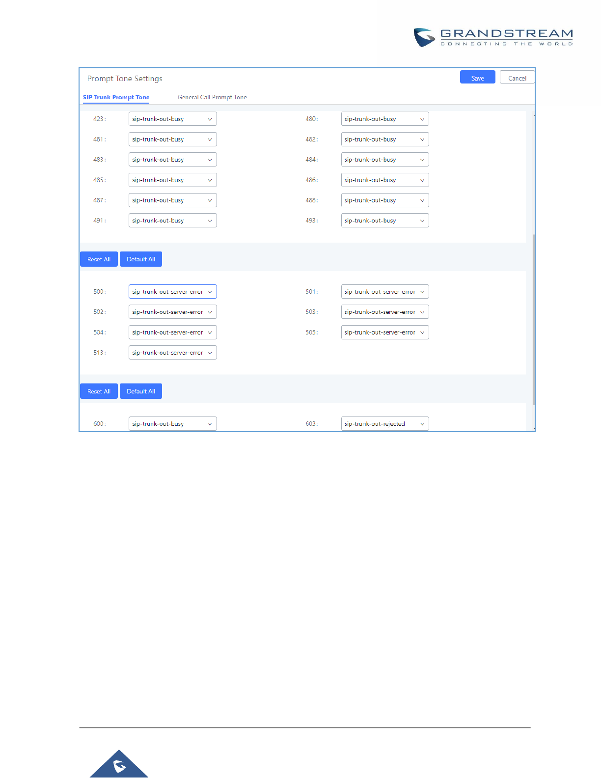
P a g e | 323
UCM6200 Series User Manual
Version 1.0.19.21
Figure 221: SIP Trunk Prompt Tone
General Call Prompt Tone
Moreover, users also have the possibility to customize the prompt for typical call failure reasons like (no
permission to allow outbound calls, busy lines, incorrect number dialed …Etc).
To customize these prompts user could record and upload their own files under “’PBX Settings → Voice Prompt
→ Custom Prompts” then select each one for specific call failure case under “PBX Settings -> Prompt Tone
Settings → General Call Prompt Tone” page as shown on the following figure:
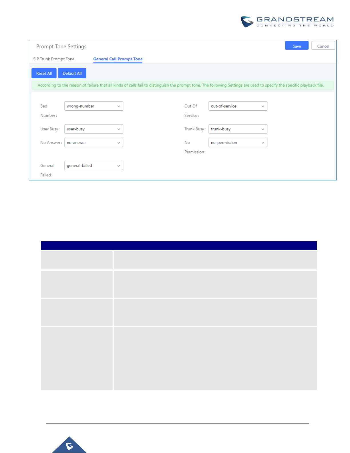
P a g e | 324
UCM6200 Series User Manual
Version 1.0.19.21
Figure 222: General call Failure Prompts
PBX Settings/Jitter Buffer
Table 98: Internal Options/Jitter Buffer
SIP Jitter Buffer
Enable Jitter Buffer
Select to enable jitter buffer on the sending side of the SIP channel. The default
setting is "No".
Jitter Buffer Size
Configure the time (in ms) to buffer. This is the jitter buffer size used in "Fixed"
jitter buffer, or used as the initial time for "adaptive" jitter buffer. The default
setting is 100.
Max Jitter Buffer
Configure the maximum time (in ms) to buffer for "Adaptive" jitter buffer
implementation, or used as the jitter buffer size for "Fixed" jitter buffer
implementation. The default setting is 200.
Implementation
Configure the jitter buffer implementation on the sending side of a SIP channel.
The default setting is "Fixed".
• Fixed
The size is always equal to the value of "Max Jitter Buffer".
• Adaptive
The size is adjusted automatically and the maximum value equals to the
value of "Max Jitter Buffer".
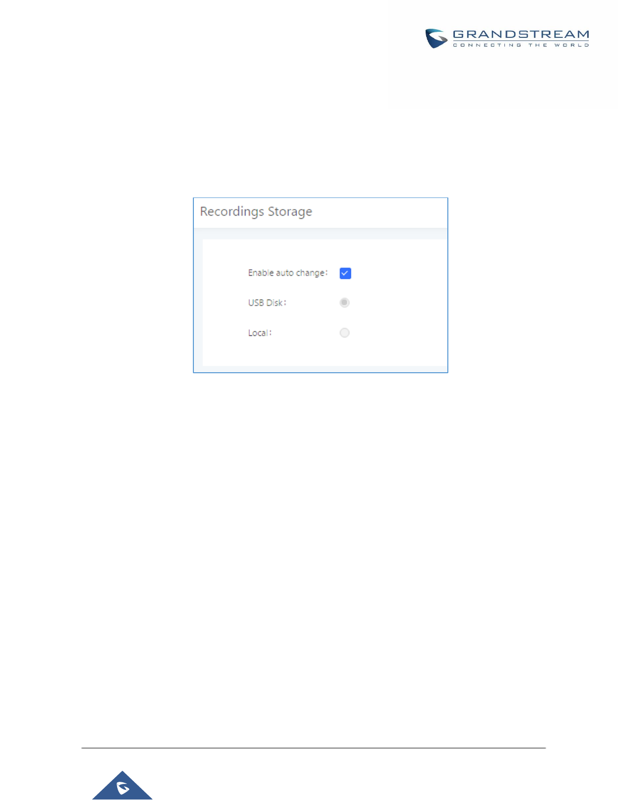
P a g e | 325
UCM6200 Series User Manual
Version 1.0.19.21
PBX Settings/Recordings Storage
The UCM6200 supports call recordings automatically or manually and the recording files can be saved in external
storage plugged in the UCM6200 or on the UCM6200 locally. To manage the recording storage, users can go to
UCM6200 Web GUI→PBX Settings→Recordings Storage page and select whether to store the recording files
in USB Disk, SD card or locally on the UCM6200.
Figure 223: Settings→Recordings Storage
• If “Enable Auto Change” is selected, the recording files will be automatically saved in the available USB
Disk or SD card plugged into the UCM6200. If both USB Disk and SD card are plugged in, the recording
files will be always saved in the USB Disk.
• If “Local” is selected, the recordings will be stored in UCM6200 internal storage.
• If “USB Disk” or “SD Card” is selected, the recordings will be stored in the corresponding plugged in external
storage device. Please note the options “USB Disk” and “SD Card” will be displayed only if they are plugged
into the UCM6200.
Once “USB Disk” or “SD Card” is selected, click on “OK”. The user will be prompted to confirm to copy the
local files to the external storage device.
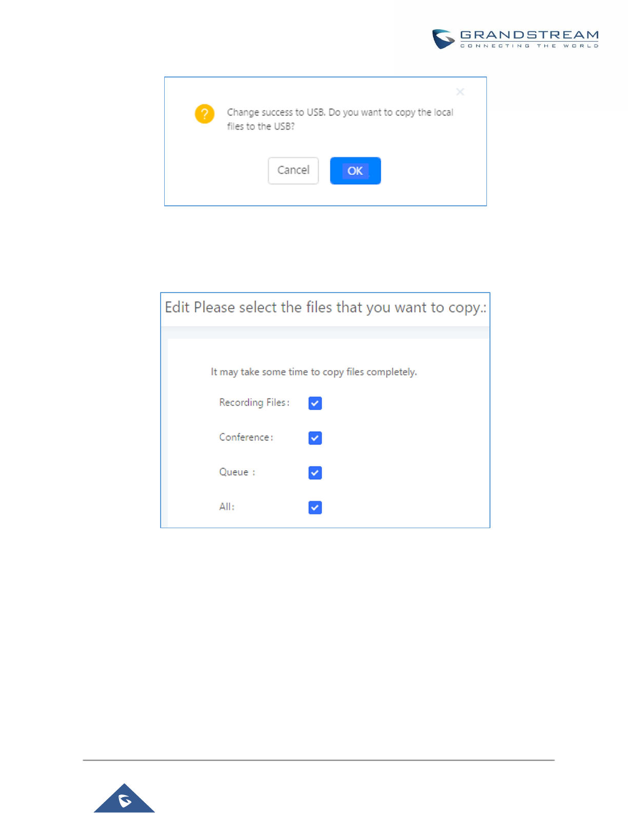
P a g e | 326
UCM6200 Series User Manual
Version 1.0.19.21
Figure 224: Recordings Storage Prompt Information
Click on “OK” to continue. The users will be prompted a new dialog to select the categories for the files to be
copied over.
Figure 225: Recording Storage Category
On the UCM6200, recording files are generated and exist in 3 categories: normal call recording files, conference
recording files, and call queue recording files. Therefore, users have the following options when select the
categories to copy the files to the external device:
- Recording Files: Copy the normal recording files to the external device.
- Conference: Copy the conference recording files to the external device.
- Queue: Copy the call queue recording files to the external device.
- All: Copy all recording files to the external device.

P a g e | 327
UCM6200 Series User Manual
Version 1.0.19.21
PBX Settings/NAS
The UCM supports adding and backing up recordings to a network-attached storage (NAS) server. Following
table describes NAS settings:
Table 99: NAS Settings
Enable
Enabled / Disable the NAS recording functionality.
Host
Configure the Domain or IP address of the NAS server.
Note: Currently, only IP addresses are supported in the Host/IP field.
Share Name
Specify the name of the shared folder.
Username
Specify the account username to access the NAS server.
Password
Configure the account password to access the NAS server.
Status
If configured correctly, the Status field will show “Mounted”, and the newly
added NAS server will be shown on the Mounted Netdisk List. Additionally, the
NAS will appear as a selectable storage option in the PBX Settings→Recording
Storage page and CDR→Recording Files page.

P a g e | 328
UCM6200 Series User Manual
Version 1.0.19.21
SIP SETTINGS
The UCM6200 SIP global settings can be accessed via Web GUI→PBX Settings→SIP Settings.
SIP Settings/General
Table 100: SIP Settings/General
Realm For Digest
Authentication
Configure the host name or domain name for the UCM6200. Realms MUST be
globally unique according to RFC3261. The default setting is Grandstream.
Bind UDP Port
Configure the UDP port used for SIP. The default setting is 5060.
Bind IPv4 Address
Configure the IPv4 address to bind to. The default setting is 0.0.0.0, which means
binding to all addresses.
Bind IPv6 Address
Configure the IPv6 address to bind to. The default is : "[::]" and it means to bind
to all IP addresses.
Allow Guest Calls
If enabled, the UCM6200 allows unauthorized INVITE coming into the PBX and
the call can be made. The default setting is "No".
Warning:
Please be aware of the potential security risk when enabling "Allow Guest Calls"
as this will allow any user with the UCM6200 address to dial into the UCM6200.
Allow Transfer
If set to "No", all transfers initiated by the endpoint in the UCM6200 will be
disabled (unless enabled in peers or users). The default setting is "Yes".
MWI From
When sending MWI NOTIFY requests, this value will be used in the "From:"
header as the "name" field. If no "From User" is configured, the "user" field of
the URI in the "From:" header will be filled with this value.
Enable Diversion
Header
If disabled, the UCM will not forward the diversion header.
SIP Settings/MISC
Table 101: SIP Settings/Misc
Outbound SIP Registrations
Register Timeout
Configure the register retry timeout (in seconds). The default setting is 20.
Register Attempts
Configure the number of registration attempts before the UCM6200 gives up. The
default setting is 0, which means the UCM6200 will keep trying until the server
side accepts the registration request.
Video
Max Bit Rate (kb/s)
Configure the maximum bit rate (in kb/s) for video calls. The default setting is 384.

P a g e | 329
UCM6200 Series User Manual
Version 1.0.19.21
Support SIP Video
Select to enable video support in SIP calls. The default setting is "Yes".
Reject Non-Matching
INVITE
If enabled, when rejecting an incoming INVITE or REGISTER request, the
UCM6200 will always reject with "401 Unauthorized" instead of notifying the
requester whether there is a matching user or peer for the request. This reduces
the ability of an attacker to scan for valid SIP usernames. The default setting is
"No".
SDP Attribute Passthrough
Enable Attribute
Passthrough
If enable, and if the service doesn’t know the attribute of FEC/FECC/BFCP, then
the attribute will be passthrough.
Early Media
Enable Use Final SDP
If enabled, call negotiation will use final response SDP.
Blind Transfer
Allow callback when
blind transfer fails
If enabled, the UCM will call back to the transferrer when blind transfer fails
(reason of failure includes: busy and no answer).
Note: This feature takes effect only on internal calls.
Blind transfer timeout
Configure the timeout in (s) for the transferrer waiting for the destination to
answer. Default is 60s.
DNS
DNS mode
This option affects the DNS query only during Calls. When you choose A&AAAA,
UCM will do both A and AAAA type DNS query; when you chose A, UCM will only
do A type DNS query; and when you chose AAAA, UCM will only do AAAA type
DNS query.
Hold
Forward HOLD
Requests
Configure the UCM to forward HOLD requests instead of processing holds
internally. This serves to meet the standards set by some providers that require
HOLD requests to be passed along from endpoint to endpoint. This option is
disabled by default.
Note: Enabling this option may cause hold retrieval issues and MOH to not be
heard.
SIP Settings/Session Timer
Table 102: SIP Settings/Session Timer
Force Timer
If checked, always request and run session timer.
Timer
If checked, run session timer only when requested by other UA.
Session Expire
Configure the maximum session refresh interval (in seconds).
The default setting is 1800.
Min SE
Configure the minimum session refresh interval (in seconds).
The default setting is 90.

P a g e | 330
UCM6200 Series User Manual
Version 1.0.19.21
SIP Settings/TCP and TLS
Table 103: SIP Settings/TCP and TLS
TCP Enable
Configure to allow incoming TCP connections with the UCM6200. The default
setting is "No".
TCP Bind Address
Configure the IP address for TCP server to bind to. 0.0.0.0 means binding to all
interfaces. The port number is optional. If not specified, 5060 will be used.
TLS Enable
Configure to allow incoming TLS connections with the UCM6200. The default
setting is "No".
TLS Bind Address
Configure the IP address for TLS server to bind to. 0.0.0.0 means binding to all
interfaces. The port number is optional. If not specified, 5061 will be used.
Note:
The IP address must match the common name (hostname) in the certificate.
Please do not bind a TLS socket to multiple IP addresses. For details on how to
construct a certificate for SIP, please refer to the following document:
http://tools.ietf.org/html/draft-ietf-sip-domain-certs
TLS Client Protocol
Select the TLS protocol for outbound client connections. The default setting is
TLSv1.
TLS Do Not Verify
If enabled, the TLS server's certificate won't be verified when acting as a client.
The default setting is "Yes".
TLS Self-Signed CA
This is the CA certificate if the TLS server being connected to requires self-signed
certificate, including server's public key. This file will be renamed as "TLS.ca"
automatically.
Note: The size of the uploaded ca file must be under 2MB.
TLS Cert
This is the Certificate file (*.pem format only) used for TLS connections. It contains
private key for client and signed certificate for the server. This file will be renamed
as "TLS.pem" automatically.
Note: The size of the uploaded certificate file must be under 2MB.
TLS CA Cert
This file must be named with the CA subject name hash value. It contains CA's
(Certificate Authority) public key, which is used to verify the accessed servers.
Note: The size of the uploaded CA certificate file must be under 2MB.
TLS CA List
Display a list of files under the CA Cert directory.

P a g e | 331
UCM6200 Series User Manual
Version 1.0.19.21
SIP Settings/NAT
Table 104: SIP Settings/NAT
External Host
Configure a static IP address and port (optional) used in outbound SIP messages
if the UCM6200 is behind NAT. If it is a host name, it will only be looked up once.
Use IP address in SDP
If enabled, the SDP connection will use the IP address resolved from the external
host.
External TCP Port
Configure the externally mapped TCP port when the UCM6200 is behind a static
NAT or PAT.
External TLS Port
Configures the externally mapped TLS port when UCM6200 is behind a static
NAT or PAT.
Local Network
Address
Specify a list of network addresses that are considered inside of the NAT
network. Multiple entries are allowed. If not configured, the external IP address
will not be set correctly.
A sample configuration could be as follows:
192.168.0.0/16
SIP Settings/TOS
Table 105: SIP Settings/ToS
ToS For SIP
Configure the Type of Service for SIP packets. The default setting is None.
ToS For RTP Audio
Configure the Type of Service for RTP audio packets. The default setting is None.
ToS For RTP Video
Configure the Type of Service for RTP video packets. The default setting is None.
Default
Incoming/Outgoing
Registration Time
Configure the default duration (in seconds) of incoming/outgoing registration.
The default setting is 120.
Max
Registration/Subscrip
tion Time
Configure the maximum duration (in seconds) of incoming registration and
subscription allowed by the UCM6200. The default setting is 3600.
Min
Registration/Subscrip
tion Time
Configure the minimum duration (in seconds) of incoming registration and
subscription allowed by the UCM6200. The default setting is 60.
Enable Relaxed DTMF
Select to enable relaxed DTMF handling. The default setting is "No".

P a g e | 332
UCM6200 Series User Manual
Version 1.0.19.21
DTMF Mode
Select DTMF mode to send DTMF. The default setting is RFC2833. If "Info" is
selected, SIP INFO message will be used. If "Inband" is selected, 64-kbit codec
PCMU and PCMA are required. When "Auto" is selected, "RFC2833" will be used
if offered, otherwise "Inband" will be used. The default setting is "RFC2833".
RTP Timeout
During an active call, if there is no RTP activity within the timeout (in seconds),
the call will be terminated. The default setting is no timeout.
Note:
This setting doesn't apply to calls on hold.
RTP Hold Timeout
When the call is on hold, if there is no RTP activity within the timeout (in seconds),
the call will be terminated. This value of RTP Hold Timeout should be larger than
RTP Timeout. The default setting is no timeout.
RTP Keep-alive
This feature can be used to avoid abnormal call drop when the remote provider
requires RTP traffic during proceeding.
For example, when the call goes into voicemail and there is no RTP traffic sent
out from UCM, configuring this option can avoid voicemail drop.
When configured, RTP keep-alive packet will be sent to remote party at the
configured interval. If set to 0, RTP keep-alive is disabled.
100rel
Configure the 100rel setting on UCM6200. The default setting is “Yes”.
Trust Remote Party ID
Configure whether the Remote-Party-ID should be trusted. The default setting is
"No".
Send Remote Party ID
Configure whether the Remote-Party-ID should be sent or not. The default
setting is "No".
Generate In-Band
Ringing
Configure whether the UCM6200 should generate inband ringing or not. The
default setting is "Never".
• Yes: The UCM6200 will send 180 Ringing followed by 183 Session Progress
and in-band audio.
• No: The UCM6200 will send 180 Ringing if 183 Session Progress has not
been sent yet. If audio path is established already with 183 then send in-
band ringing.
• Never: Whenever ringing occurs, the UCM6200 will send 180 Ringing as
long as 200OK has not been set yet. Inband ringing will not be generated
even the end point device is not working properly.
Server User Agent
Configure the user agent string for the UCM6200.
Send Compact SIP
Headers
If enabled, compact SIP headers will be sent. The default setting is "No".
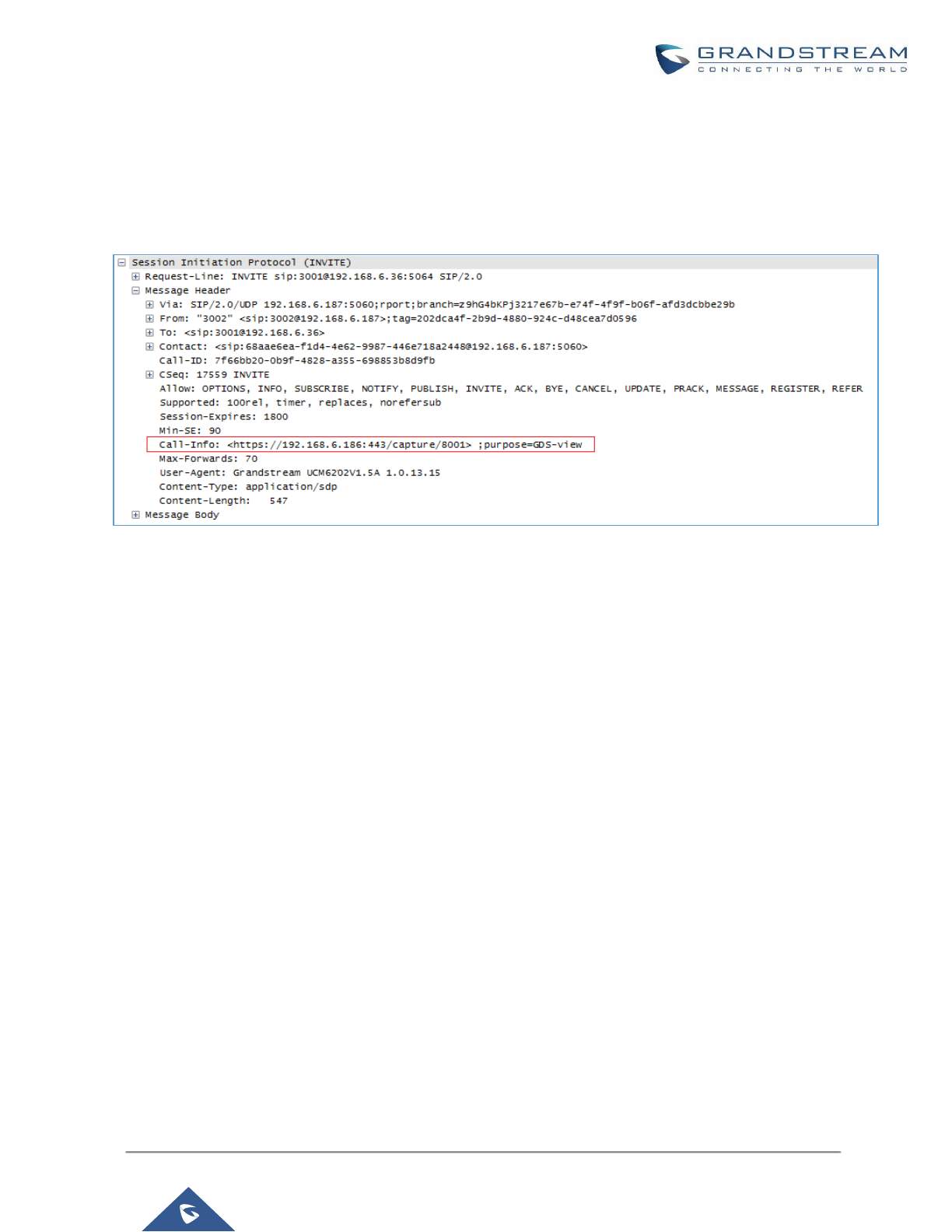
P a g e | 333
UCM6200 Series User Manual
Version 1.0.19.21
Transparent Call-Info header
UCM supports transparent call info header in order to integrate GDS door system with GXP21XX Color phones,
the UCM will forward the call-info header to the phone in order to request the live view from GDS door system
and give the option to open the door via softkey.
Figure 226: Transparent Call-Info

P a g e | 334
UCM6200 Series User Manual
Version 1.0.19.21
IAX SETTINGS
The UCM6200 IAX global settings can be accessed via Web GUI→PBX Settings→IAX Settings.
IAX Settings/General
Table 106: IAX Settings/General
Bind Port
Configure the port number that the IAX2 will be allowed to listen to. The default
setting is 4569.
Bind Address
Configure the address that the IAX2 will be forced to bind to. The default setting
is 0.0.0.0, which means all addresses.
IAX1 Compatibility
Select to configure IAX1 compatibility. The default setting is "No".
No Checksums
If selected, UDP checksums will be disabled and no checksums will be
calculated/checked on systems supporting this feature. The default setting is
"No".
Delay Reject
If enabled, the IAX2 will delay the rejection of calls to avoid DOS. The default
setting is "No".
ADSI
Select to enable ADSI phone compatibility. The default setting is "No".
Music On Hold
Interpret
Specify which Music On Hold class this channel would like to listen to when being
put on hold. This music class is only effective if this channel has no music class
configured and the bridged channel putting the call on hold has no "Music On
Hold Suggest" setting.
Music On Hold
Suggest
Specify which Music On Hold class to suggest to the bridged channel when
putting the call on hold.
Bandwidth
Configure the bandwidth for IAX settings. The default setting is "Low".
IAX Settings/Registration
Table 107: IAX Settings/Registration
IAX Registration Options
Min Reg Expire
Configure the minimum period (in seconds) of registration. The default setting is
60.
Max Reg Expire
Configure the maximum period (in seconds) of registration. The default setting is
3600.
IAX Thread Count
Configure the number of IAX helper threads. The default setting is 10.
IAX Max Thread Count
Configure the maximum number of IAX threads allowed. The default is 100.

P a g e | 335
UCM6200 Series User Manual
Version 1.0.19.21
Auto Kill
If set to "yes", the connection will be terminated if ACK for the NEW message is
not received within 2000ms. Users could also specify number (in milliseconds) in
addition to "yes" and "no". The default setting is "yes".
Authentication
Debugging
If enabled, authentication traffic in debugging will not show. The default is "No".
Codec Priority
Configure codec negotiation priority. The default setting is "Reqonly".
• Caller
Consider the callers preferred order ahead of the host's.
• Host
Consider the host's preferred order ahead of the caller's.
• Disabled
Disable the consideration of codec preference all together.
• Reqonly
This is almost the same as "Disabled", except when the requested format is
not available. The call will only be accepted if the requested format is
available.
Type of Service
Configure ToS bit for preferred IP routing.
IAX Trunk Options
Trunk Frequency
Configure the frequency of trunk frames (in milliseconds). The default is 20.
Trunk Time Stamps
If enabled, time stamps will be attached to trunk frames. The default is "No".
IAX Settings/Security
Table 108: IAX Settings/Static Defense
Call Token Optional
Enter a single IP address (e.g., 11.11.11.11) or a range of IP addresses
(11.11.11.11/22.22.22.22) for which call token validation is not required.
Max Call Numbers
Configure the maximum number of calls allowed for a single IP address.
Max Unvalidated Call
Numbers
Configure the maximum number of Unvalidated calls for all IP addresses.
Call Number Limits
Configure to limit the number of calls for a give IP address of IP range.
IP or IP Range
Enter the IP address (11.11.11.11) or a range of IP addresses
(11.11.11.11/22.22.22.22) to be considered for call number limits.
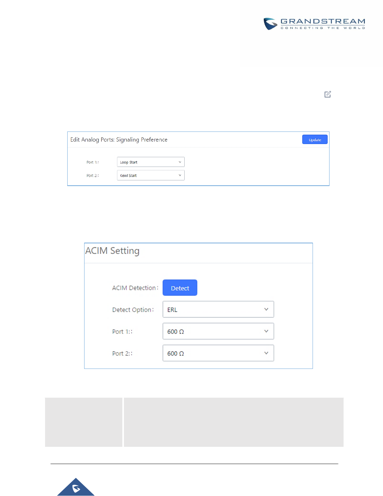
P a g e | 336
UCM6200 Series User Manual
Version 1.0.19.21
INTERFACE SETTINGS
Analog Hardware
The analog hardware (FXS port and FXO port) on the UCM6200 will be listed in this page. Click on to edit
signaling preference for FXS port or configure ACIM settings for FXO port.
Select "Loop Start" or "Kewl Start" for each FXS port. And then click on "Update" to save the change.
Figure 227: FXS Ports Signaling Preference
For FXO port, users could manually enter the ACIM settings by selecting the value from dropdown list for each
port. Or users could click on "Detect" and choose the detection algorithm, two algorithms exists (ERL, Pr) for the
UCM6200 to automatically detect the ACIM value. The detecting value will be automatically filled into the settings.
Figure 228: FXO Ports ACIM Settings
Table 109: PBX Interface Settings
Tone Region
Select country to set the default tones for dial tone, busy tone, ring tone and
etc to be sent from the FXS port. The default setting is "United States of
America (USA)".

P a g e | 337
UCM6200 Series User Manual
Version 1.0.19.21
Advanced Settings
FXO Opermode
Select country to set the On-Hook Speed, Ringer Impedance, Ringer
Threshold, Current Limiting, TIP/RING voltage adjustment, Minimum
Operational Loop Current, and AC Impedance as predefined for your country's
analog line characteristics. The default setting is "United States of America
(USA)".
FXS Opermode
Select country to set the On-Hook Speed, Ringer Impedance, Ringer
Threshold, Current Limiting, TIP/RING voltage adjustment, Minimum
Operational Loop Current, and AC Impedance as predefined for your country's
analog line characteristics. The default setting is "United States of America
(USA)".
FXS TISS Override
Configure to enable or disable override Two-Wire Impedance Synthesis
(TISS). The default setting is No.
If enabled, users can select the impedance value for Two-Wire Impedance
Synthesis (TISS) override. The default setting is 600Ω.
PCMA Override
Select the codec to be used for analog lines. North American users should
choose PCMU. All other countries, unless already known, should be assumed
to be PCMA. The default setting is PCMU.
Note:
This option requires system reboot to take effect.
Boost Ringer
Configure whether normal ringing voltage (40V) or maximum ringing voltage
(89V) for analog phones attached to the FXS port is required. The default
setting is "Normal".
Fast Ringer
Configure to increase the ringing speed to 25HZ. This option can be used with
"Low Power" option. The default setting is "Normal".
Low Power
Configure the peak voltage up to 50V during "Fast Ringer" operation. This
option is used with "Fast Ringer". The default setting is "Normal".
Ring Detect
If set to "Full Wave", false ring detection will be prevented for lines where Caller
ID is sent before the first ring and proceeded by a polarity reversal, as in UK.
The default setting is "Standard".
FXS MWI Mode
Configure the type of Message Waiting Indicator on FXS lines. The default
setting is "FSK".
• FSK: Frequency Shift Key Indicator
• NEON: Light Neon Bulb Indicator.
FXO Frequency
Tolerance
Allows users to adjust the tolerance of the FXO ringing frequency. 63Hz is
considered the standard value and is selected by default.
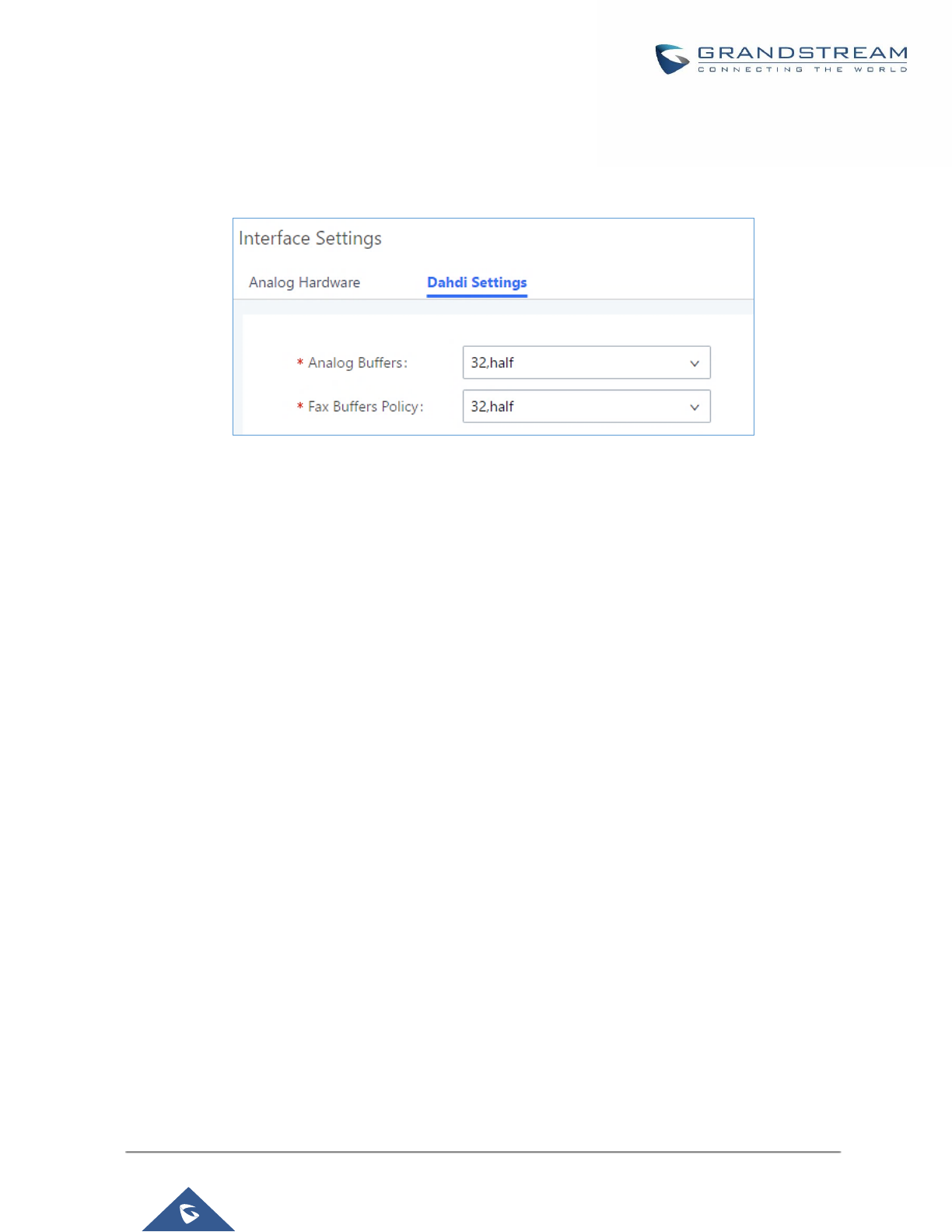
P a g e | 338
UCM6200 Series User Manual
Version 1.0.19.21
DAHDI Settings
When users encounter issues such as audio delay in outbound calls using the analog trunk, they can adjust
DAHDI settings on the UCM to attempt to lessen or resolve the issues.
Figure 229: DAHDI Settings
For the value of the option such as “32, half”:
The number in the option indicates the number of read/write buffers for TDM (DAHDI).
The “Half”, “Immediate” or “Full” option indicates the strategy when reading/writing data from buffer.
- “Half”: Data will be read/written from buffer when half of the buffer is occupied with data.
- “Immediate”: Read/write from buffer whenever there is data occupying the buffer.
- “Full”: Data will be read/written from buffer when buffer is fully occupied with data.
Normally, DAHDI settings should be kept default and should be adjusted only when users encounter analog
trunk/Fax-related issues.

P a g e | 339
UCM6200 Series User Manual
Version 1.0.19.21
API Configuration
The UCM6200 supports third party billing interface API for external billing software to access CDR and call
recordings on the PBX. The API uses HTTPS to request the CDR data and call recording data matching given
parameters as configured on the third-party application.
API Configuration Parameters
Before accessing the API, the administrators need enable API and configure the access/authentication
information on the UCM6200 first under Value-added Features→API Configuration. The API configuration
parameters are listed in the table below.
Table 110: API Configuration Parameters
CDR HTTP API Settings
Basic Settings
Enable
Enable/Disable API. The default setting is disabled.
TLS Bind Address
Configure the IP address for TLS server to bind to. "0.0.0.0" means binding to all
interfaces. The port number is optional, and the default port number is 8443. The IP
address must match the common name (host name) in the certificate so that the
TLS socket won't bind to multiple IP addresses. The default setting is 0.0.0.0:8443.
User Name
Configure the user name for TLS authentication. If not configured, authentication will
be skipped.
Password
Configure the password for TLS authentication. This is optional.
Permitted IP(s)
Specify a list of IP addresses permitted by CDR and REC API. This creates an API-
specific access control list. Multiple entries are allowed.
For example, "192.168.40.3/255.255.255.255" denies access from all IP addresses
except 192.168.40.3.
The default setting is blank, meaning all IP addresses will be denied.
Other Settings
TLS Private Key
Upload TLS private key. The size of the key file must be under 2MB. This file will be
renamed as 'private.pem' automatically.

P a g e | 340
UCM6200 Series User Manual
Version 1.0.19.21
TLS Cert
Upload TLS cert. The size of the certificate must be under 2MB. This is the certificate
file (*.pem format only) for TLS connection. This file will be renamed as
"certificate.pem" automatically. It contains private key for the client and signed
certificate for the server.
CDR Real-time Output Settings
Enable
Enables real-time CDR output module. This module connects to selected IP
addresses and ports and posts CDR strings as soon as it is available.
Server Address
CDR server IP address
Port
CDR server IP port
Upload Prompts User Configuration
User Name
User name used to upload prompts.
Password
Password used to upload prompts.
Upload Voice Prompt via API
Customers now can use the “Upload Prompts User Configuration” to upload/replace voice prompt files as an
alternative method to the manual upload method on UCM PBX Settings> Voice Prompt> Custom Prompt.
The workflow of the prompt file upload goes as:
An HTTP/HTTPS request is sent to the UCM to upload/replace a voice prompt file, the request should include
authentication details to the UCM and the name of the file to be uploaded. Then the UCM will contact an FTP
server that should be hosted on the same IP address of the HTTP/HTTPS requester and download the prompt
file from the FTP server.
The steps and conditions to upload the voice prompt via API are listed below:
1. Configure the prompt User under value-added Features -> API Configuration -> Upload Prompts
User Configuration. By default, the username and password for voice prompt user are “User Name:
uploader; Password: uploader123”.
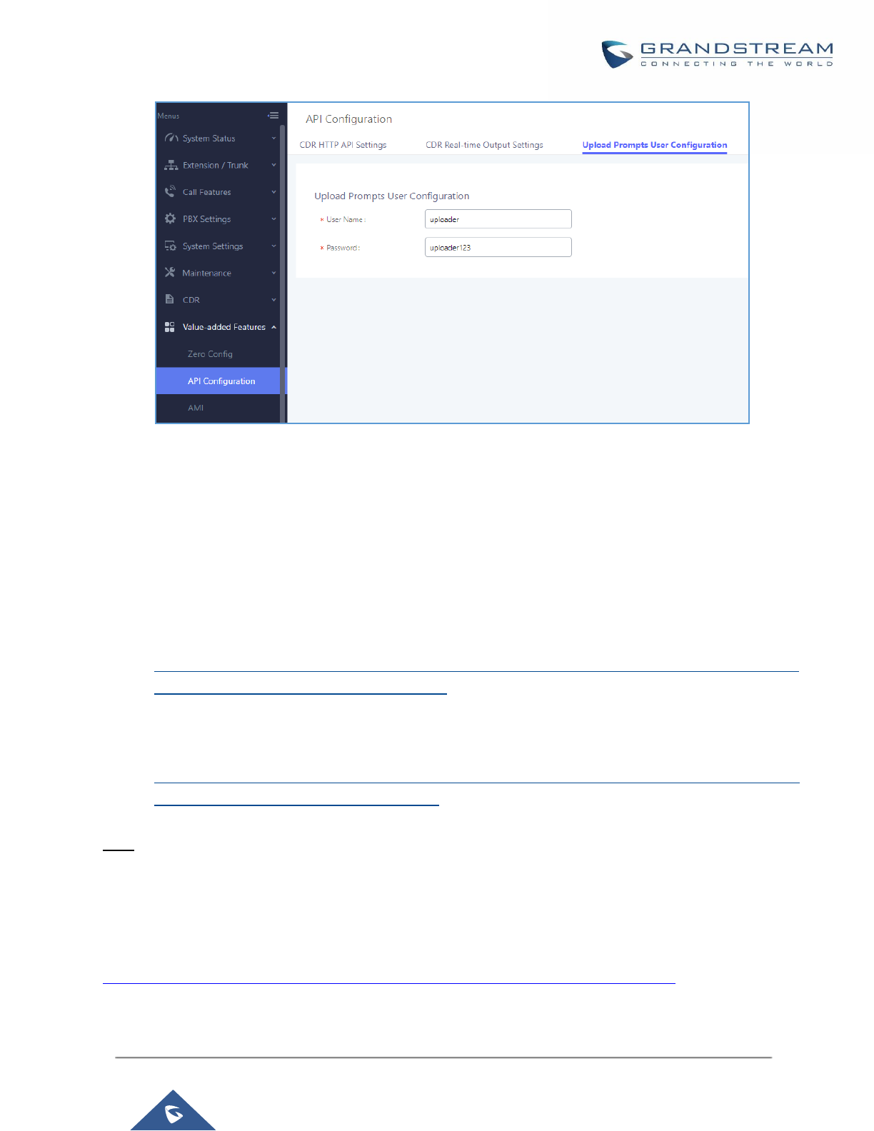
P a g e | 341
UCM6200 Series User Manual
Version 1.0.19.21
Figure 230: Upload Prompt User Configuration
1. Hash the password of the user configured to an MD5 Encryption format.
2. Set the permission on the FTP server to Anonymous on the local computer hosting the FTP server and
make sure that the default FTP port 21 is used.
3. Send an HTTP/HTTPS command to trigger the Prompt file upload on the UCM. If UCM's HTTP server
is set to HTTPS, the example of the request sent to the UCM is:
https://192.168.124.89:8089/cgi?action=uploadprompt&username=uploader&password=9191a6394c2
1b3aabd779213c7179462&filename=test.mp3
If UCM's HTTP server is set to HTTP, the example of the request sent to the UCM is:
http://192.168.124.89:8089/cgi?action=uploadprompt&username=uploader&password=9191a6394c21
b3aabd779213c7179462&filename=test.mp3
Note: If the File name on the HTTP/HTTPS request exists already on the UCM’s Custom voice prompts list the
existing file will be overwritten by the new file downloaded from the FTP server.
For more details on CDR API (Access to Call Detail Records) and REC API (Access to Call Recording Files),
please refer the document in the link here:
http://www.grandstream.com/sites/default/files/Resources/ucm6xxx_cdr_rec_api_guide.pdf
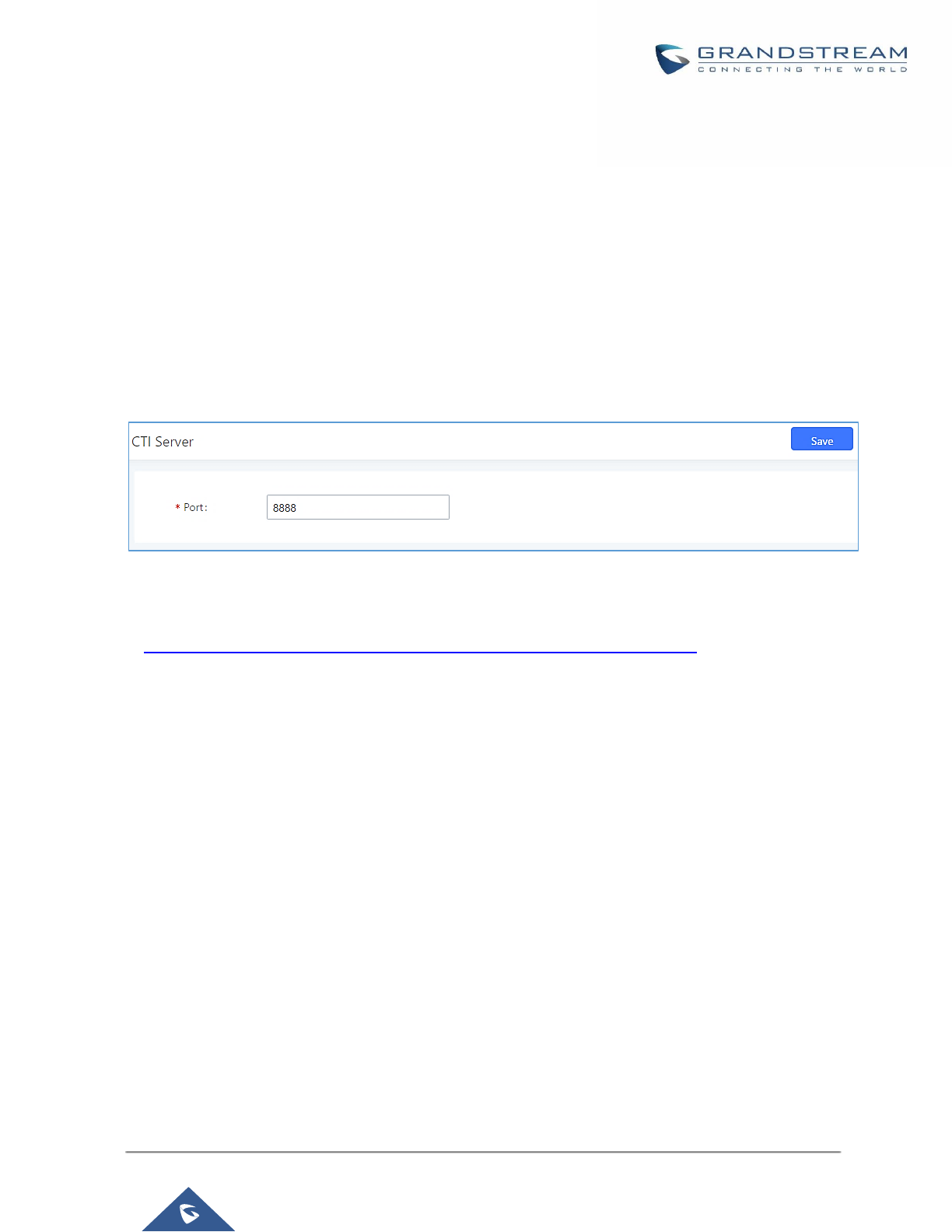
P a g e | 342
UCM6200 Series User Manual
Version 1.0.19.21
CTI SERVER
UCM does support CTI server capabilities which are designed to be a part of the CTI solution suite provided by
Grandstream, including GXP21XX and GXP17XX enterprise IP phones along with GS Affinity app.
Mainly the UCM will by default listening on port TCP 8888 for the connections from GS affinity application in
order to interact, modify and serve data requests by the application which includes setting call features for the
connected extension as call forward and DND.
Users can change the listening port under the menu page, Web GUI→Value-added Features→CTI Server as
shown on below screenshot:
Figure 231: CTI Server Listening port
More information about GS affinity and CTI Support on Grandstream products series please refer to the following
link: http://www.grandstream.com/sites/default/files/Resources/GS_Affinity_Guide.pdf

P a g e | 343
UCM6200 Series User Manual
Version 1.0.19.21
ASTERISK MANAGER INTERFACE (RESTRICTED ACCESS)
The UCM6200 supports Asterisk Manager Interface (AMI) with restricted access. AMI allows a client program to
connect to an Asterisk instance commands or read events over a TCP/IP stream. It’s particularly useful when
the system admin tries to track the state of a telephony client inside Asterisk.
User could configure AMI parameters on UCM6200 Web GUI→Value-added Features→AMI. For details on
how to use AMI on UCM6200, please refer to the following AMI guide:
http://www.grandstream.com/sites/default/files/Resources/UCM_series_AMI_guide.pdf
---------------------------------------------------------------------------------------------------------------------------------------------------
Warning:
Please do not enable AMI on the UCM6200 if it is placed on a public or untrusted network unless you have taken
steps to protect the device from unauthorized access. It is crucial to understand that AMI access can allow AMI
user to originate calls and the data exchanged via AMI is often very sensitive and private for your UCM6200
system. Please be cautious when enabling AMI access on the UCM6200 and restrict the permission granted to
the AMI user. By using AMI on UCM6200 you agree you understand and acknowledge the risks associated with
this.
----------------------------------------------------------------------------------------------------------------------------- ----------------------
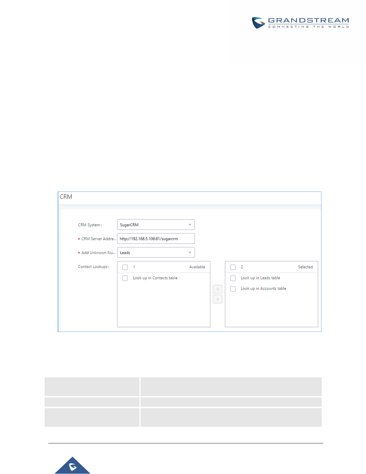
P a g e | 344
UCM6200 Series User Manual
Version 1.0.19.21
CRM INTEGRATION
Customer relationship management (CRM) is a term that refers to practices, strategies and technologies that
companies use to manage and analyze customer interactions and data throughout the customer lifecycle, with
the goal of improving business relationships with customers.
The UCM6200 support the following CRM API: SugarCRM, vTigerCRM, ZohoCRM and Salesforce CRM, which
allows users to look for contact information in the Contacts, Leads and / or Accounts tables, shows the contact
record in CRM page, and saves the call information in the contact’s history.
Note: Starting firmware 1.0.17.16, emergency calls will not be logged into CRM servers.
SugarCRM
Configuration page of the SugarCRM can be accessed via admin login, on the UCM webGUI→Value-added
Features→CRM.
Figure 232: SugarCRM Basic Settings
1. Select “SugarCRM” from the CRM System Dropdown in order to use SugarCRM.
Table 111: SugarCRM Settings
CRM System
Select a CRM system from the dropdown menu, four CRM systems
are available: SugarCRM, vTigerCRM, ZohoCRM and Salesforce.
CRM Server Address
Enter the IP address of the CRM server.
Add Unknown Number
Add the new number to this module if it can’t be found in the
selected module.
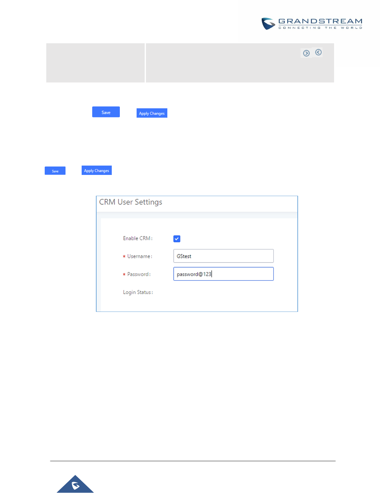
P a g e | 345
UCM6200 Series User Manual
Version 1.0.19.21
Contact Lookups
Select from the “Available” list of lookups and press to
select where the UCM can perform the lookups on the CRM tables,
Leads, Accounts, and Contacts.
Once settings on admin access are configured:
2. Click on and .
3. Logout from admin access.
4. Login to the UCM as user and navigate under “User Portal→Value-added Feature→CRM User Settings”.
Click on “Enable CRM” and enter the username/password associated with the CRM account then click on
and . The status will change from “Logged Out” to “Logged In”. User can start then using
SugarCRM features.
Figure 233: CRM User Settings
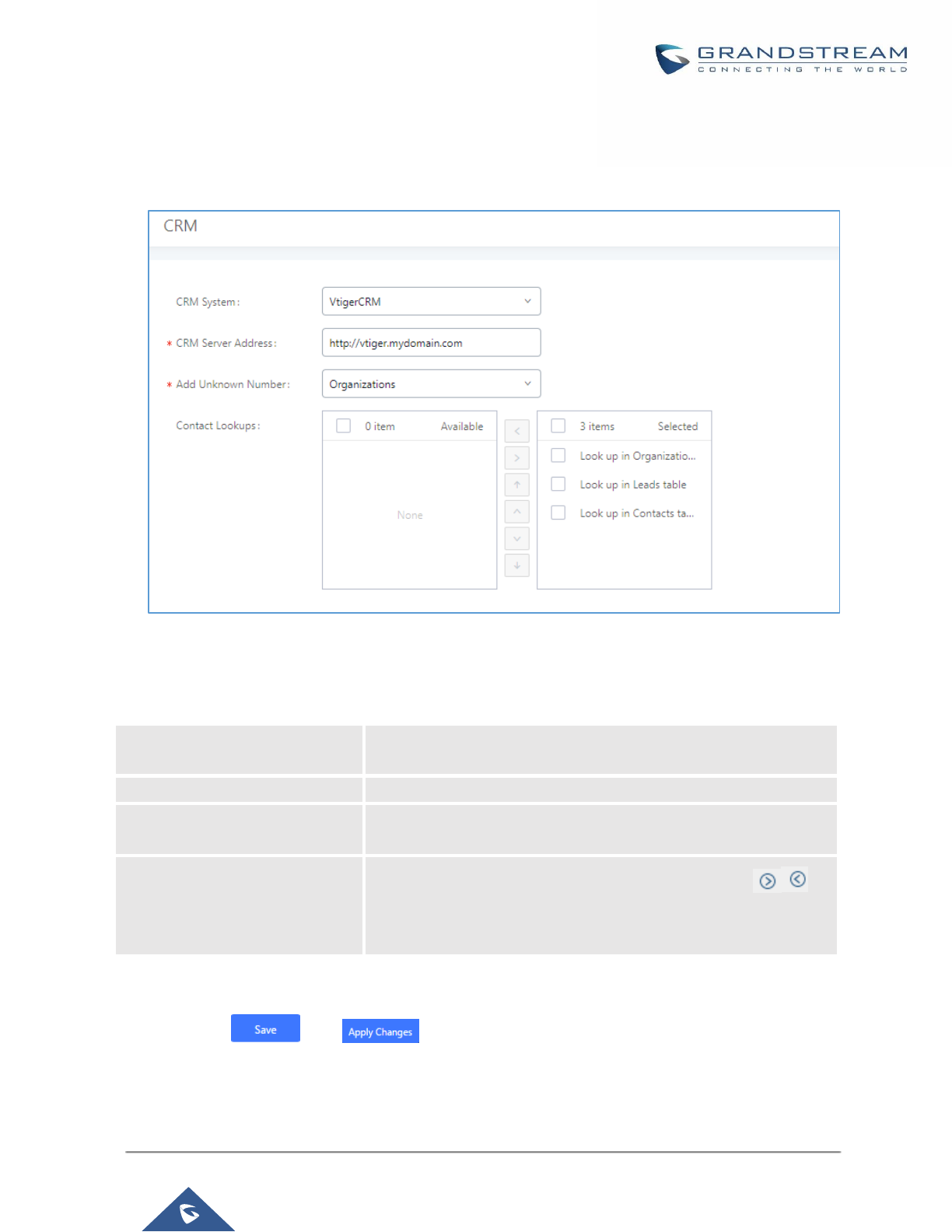
P a g e | 346
UCM6200 Series User Manual
Version 1.0.19.21
vTigerCRM
Configuration page of the vTigerCRM can be accessed via admin login, on the UCM webGUI→Value-added
Features→CRM.
Figure 234: vTigerCRM Basic Settings
1. Select “vTigerCRM” from the CRM System Dropdown in order to use vTigerCRM.
Table 112: vTigerCRM Settings
CRM System
Select a CRM system from the dropdown menu, four CRM systems
are available: SugarCRM, vTigerCRM, ZohoCRM and Salesforce.
CRM Server Address
Enter the IP address of the CRM server.
Add Unknown Number
Add the new number to this module if it can’t be found in the
selected module.
Contact Lookups
Select from the “Available” list of lookups and press to
select where the UCM can perform the lookups on the CRM tables,
Leads, Organizations, and Contacts.
Once settings on admin access are configured:
2. Click on and .
3. Logout from admin access.
4. Login to the UCM as user and navigate under “User Portal→Value-added Feature→CRM User Settings”.

P a g e | 347
UCM6200 Series User Manual
Version 1.0.19.21
Click on “Enable CRM” and enter the username/password associated with the CRM account then click on
and . The status will change from “Logged Out” to “Logged In”. User can start then using
SugarCRM features.
Figure 235: CRM User Settings

P a g e | 348
UCM6200 Series User Manual
Version 1.0.19.21
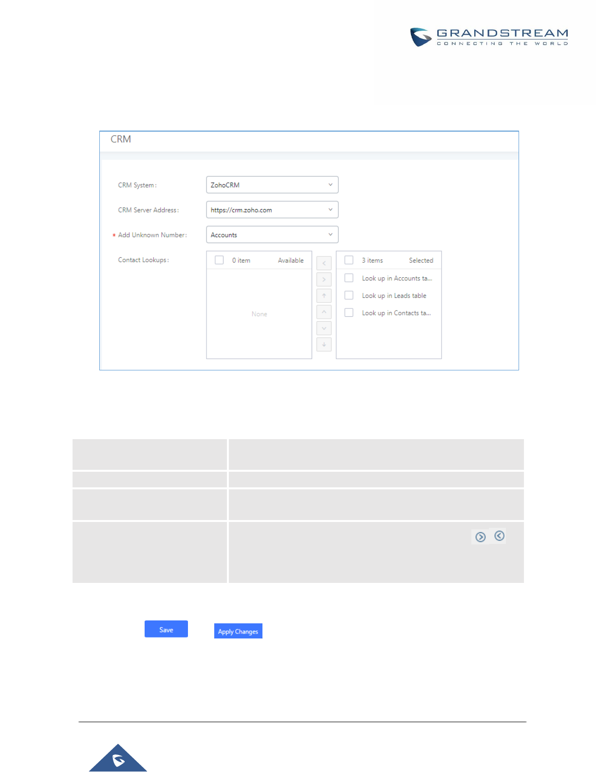
P a g e | 349
UCM6200 Series User Manual
Version 1.0.19.21
ZohoCRM
Configuration page of the ZohoCRM can be accessed via admin login, on the UCM webGUI→Value-added
Features→CRM.
Figure 236: ZohoCRM Basic Settings
1. Select “ZohoCRM” from the CRM System Dropdown in order to use ZohoCRM.
Table 113: ZohoCRM Settings
CRM System
Select a CRM system from the dropdown menu, four CRM systems
are available: SugarCRM, vTigerCRM, ZohoCRM and Salesforce.
CRM Server Address
Enter the IP address of the CRM server.
Add Unknown Number
Add the new number to this module if it can’t be found in the
selected module.
Contact Lookups
Select from the “Available” list of lookups and press to
select where the UCM can perform the lookups on the CRM tables,
Leads, Accounts, and Contacts.
Once settings on admin access are configured:
2. Click on and .
3. Logout from admin access.
4. Login to the UCM as user and navigate under “User Portal→Value-added Feature→CRM User Settings”.
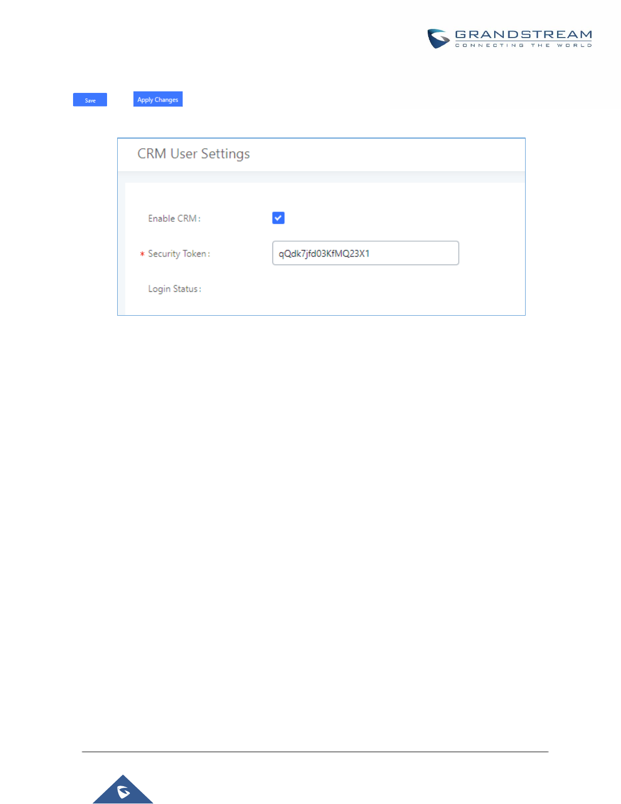
P a g e | 350
UCM6200 Series User Manual
Version 1.0.19.21
Click on “Enable CRM” and enter the username/password associated with the CRM account then click on
and . The status will change from “Logged Out” to “Logged In”. User can start then using
SugarCRM features.
Figure 237: CRM User Settings
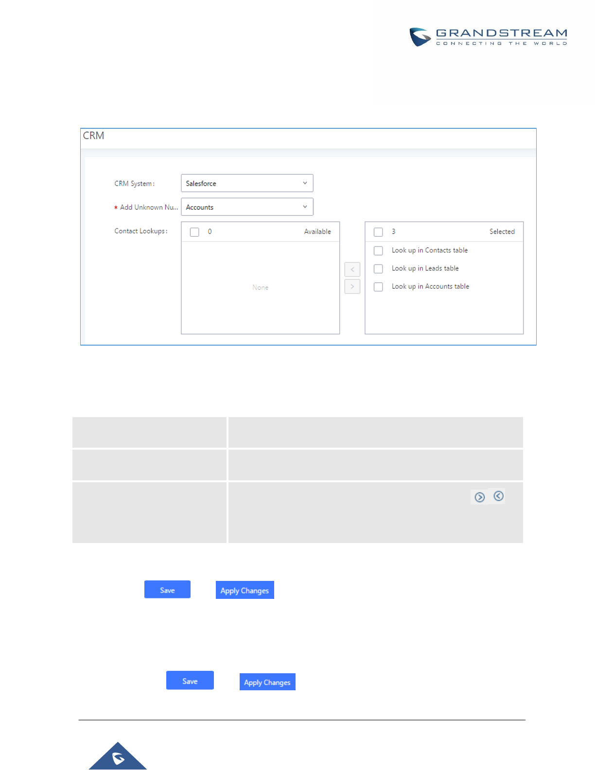
P a g e | 351
UCM6200 Series User Manual
Version 1.0.19.21
Salesforce CRM
Configuration page of the Salesforce CRM can be accessed via admin login, on the UCM Web GUI→Value-
added Features→CRM”.
Figure 238: Salesforce Basic Settings
1. Select “Salesforce” from the CRM System Dropdown in order to use Salesforce CRM.
Table 114: Salesforce Settings
CRM System
Select a CRM system from the dropdown menu, four CRM systems
are available: SugarCRM, vTigerCRM, ZohoCRM and Salesforce.
Add Unknown Number
Add the new number to this module if it can’t be found in the
selected module.
Contact Lookups
Select from the “Available” list of lookups and press to
select where the UCM can perform the lookups on the CRM tables,
Leads, Accounts, and Contacts.
Once settings on admin access are configured:
2. Click on and .
3. Logout from admin access.
4. Login to the UCM as user and navigate under “User Portal→Value-added Feature→CRM User Settings”.
Click on “Enable CRM” and enter the username, password and Security Token associated with the CRM
account then click on and . The status will change from “Logged Out” to “Logged In”.
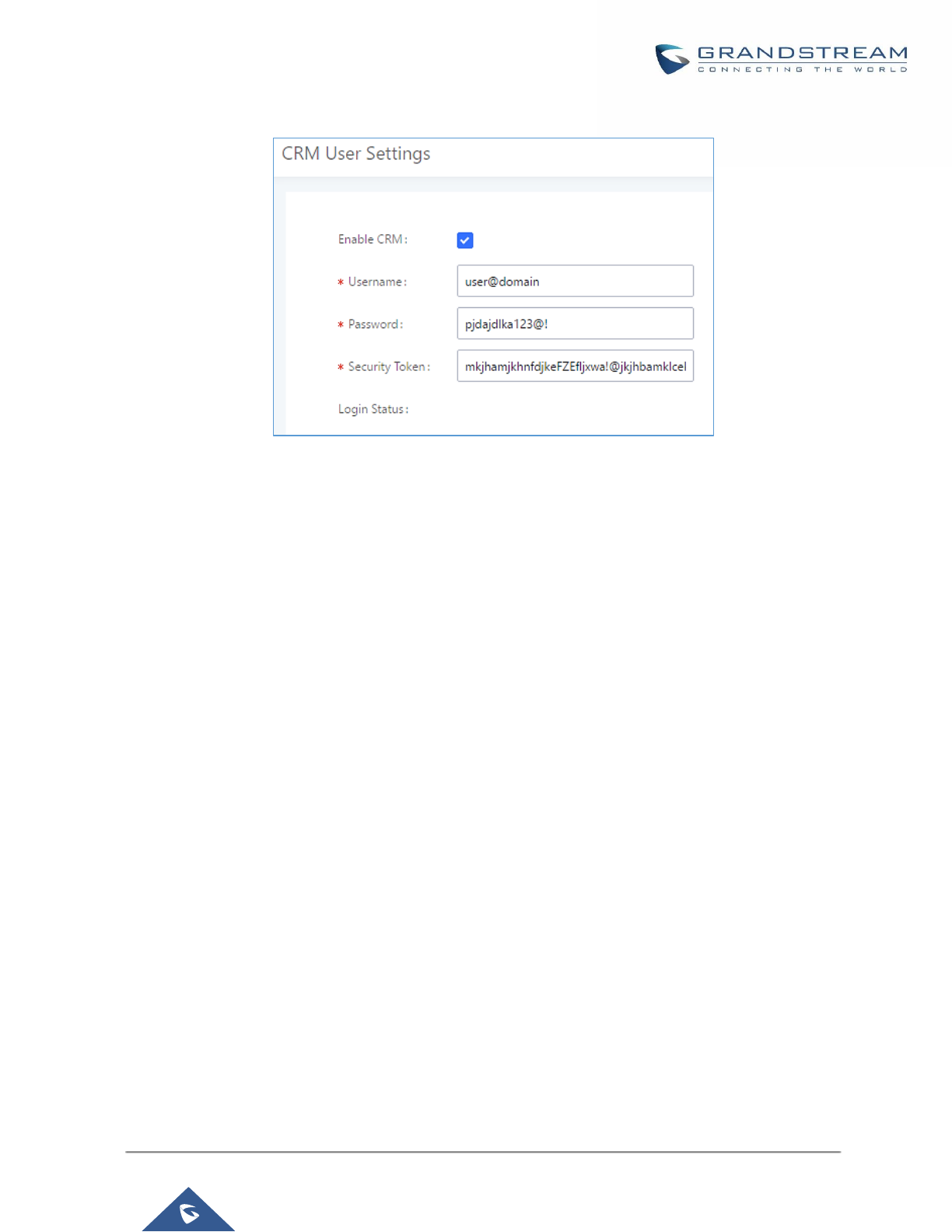
P a g e | 352
UCM6200 Series User Manual
Version 1.0.19.21
User can start then using Salesforce CRM features.
Figure 239: Salesforce User Settings
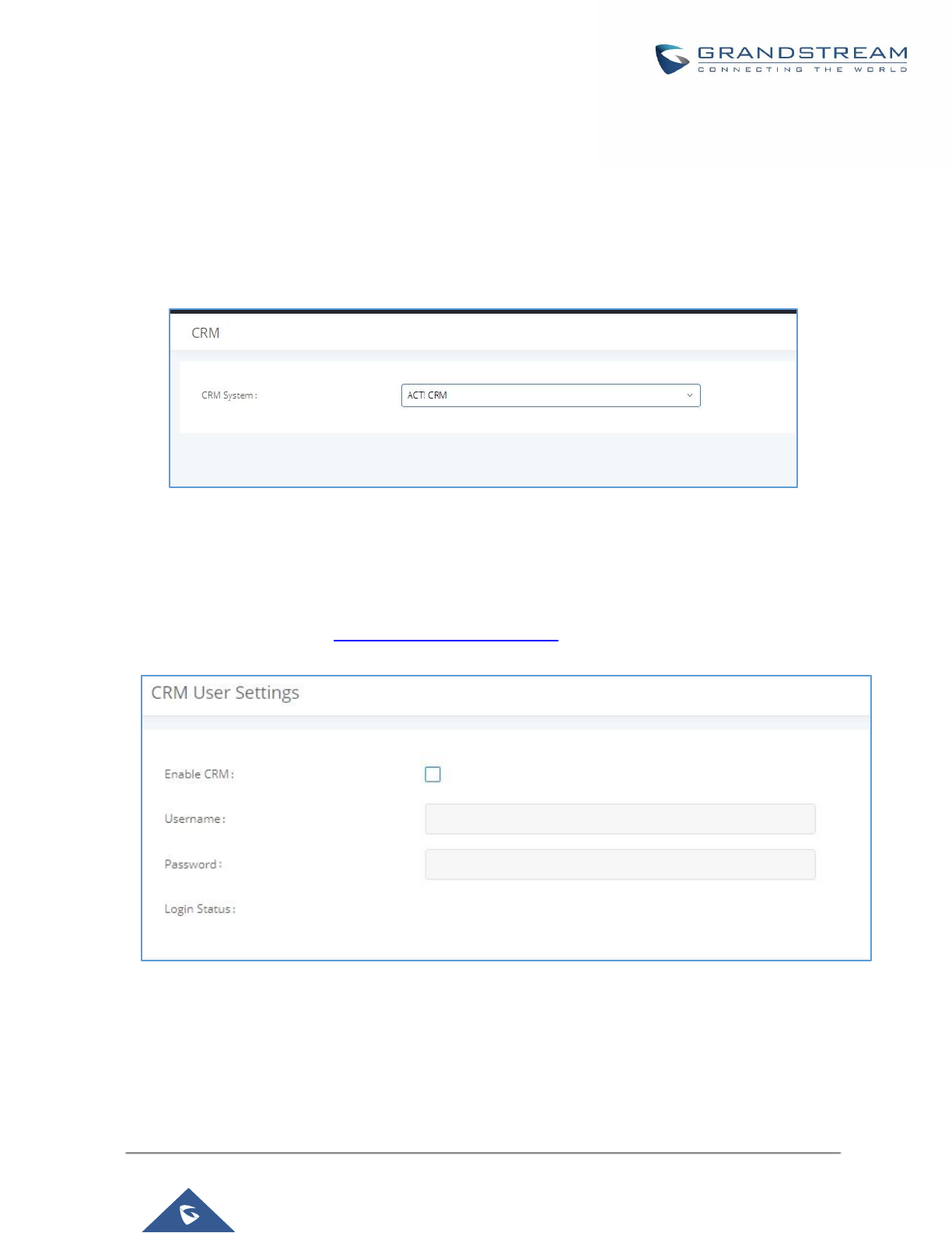
P a g e | 353
UCM6200 Series User Manual
Version 1.0.19.21
ACT! CRM
Configuration page of the ACT! CRM can be accessed via admin login, on the UCM Web GUI→Value-added
Features→CRM”.
The configuration steps of the ACT! CRM are as follows:
1. Navigate to Value-Added Features->CRM and select the “ACT! CRM” option.
Figure 240: Enabling ACT! CRM
2. Log into the UCM as a regular user and navigate to Value-Added Features->CRM User Settings and
check “Enable CRM” option and enter the username and password, which will be the ACT! CRM
account’s API Key and Developer Key respectively. To obtain these, please refer to the ACT! CRM API
developer’s guide here: https://mycloud.act.com/act/Help
Figure 241: Enabling CRM on the User Portal
Note: For more information on the ACT! CRM integration, please refer to the ACT! CRM documentation on our
website.
P a g e | 354
UCM6200 Series User Manual
Version 1.0.19.21
PMS INTEGRATION
UCM6200 supports Hotel Property Management System PMS, including check-in/check-out services, wakeup
calls, room status, Do Not Disturb which provide an ease of management for hotel applications. This feature can
be found on Web GUI→Value-added Features→PMS.
Note: The PMS integration on UCM is currently supported only with one of the three following solutions.
The PMS module built-in the UCM supports the following features based on each solution:
Table 115: PMS Supported Features
Feature
Mitel
HMobile
HSC
Check-In
✓
✓
✗
Check-out
✓
✓
✗
Wake-up Call
✓
✓
✗
Name Change
✓
✗
✓
Update
✗
✓
✗
Set Credit
✓
✗
✗
Set Station Restriction
✓
✗
✓
Room Status
✗
✓
✗
Room Move
✗
✓
✗
Do Not Disturb
✗
✓
✓
Mini Bar
✗
✓
✗
MSG
✗
✓
✗
MWI
✗
✗
✓
Unconditional Call Forward
✗
✗
✓
HMobile PMS Connector
In this mode, the system can be divided into three parts:
• PMS (Property Management System)
• PMSI (Property Management System Interface)
• PBX
Grandstream UCM6XXX series have integrated HMobile Connect PMSI which supports a large variety of PMS
software providing following hospitality features: Check-in, Check-out, set Room Status, Wake-up call and more.
The following figure illustrates the communication flow between the PBX (Grandstream UCM6xxx Series) and
PMS software, which is done through a middleware system (HMobile Connect) acting as interface between both
parties.

P a g e | 355
UCM6200 Series User Manual
Version 1.0.19.21
Figure 242: UCM & PMS interaction
HSC PMS
In this mode, the system can be divided into two parts:
• PMS (Property Management System)
• PBX
Grandstream UCM6XXX series have integrated HSC PMS providing following features:
• Changing Display Name
• Set Station Restriction
• Call forwarding
• DND
• Name Change
• MWI
The following figure illustrates the communication flow between the PBX (Grandstream UCM6xxx Series) and
PMS software (HSC). The communication between both parties is direct with no middleware.
PMS Software
PMSI Middleware
(HMobile Connect)
Grandstream UCM
P a g e | 356
UCM6200 Series User Manual
Version 1.0.19.21
Figure 243: UCM & HSC PMS interaction
Mitel PMS
In this mode, the system can be divided into two parts:
• PMS (Property Management System)
• PBX
Grandstream UCM6XXX series have integrated Mitel PMS providing following hospitality features: Check-in,
Check-out, set Room Status, Wake-up call and more.
The following figure illustrates the communication flow between the PBX (Grandstream UCM6xxx Series) and
PMS software (Mitel). The communication between both parties is direct with no middleware.
Figure 244: UCM & Mitel PMS interaction
HSC PMS Software
Grandstream UCM
Mitel PMS Software
Grandstream UCM

P a g e | 357
UCM6200 Series User Manual
Version 1.0.19.21
PMS API
The PMS API allows users to use their own middleware to work with PMS systems instead of currently supported
integrations.
Additionally, this API allows access to read and modify certain UCM parameters that current supported PMS
integrations cannot. To use this, users must first enable and configure the HTTPS API settings.
On the HTTPS API settings, permitted IP addresses must be configured. Otherwise, the API will be inaccessible.
On the HTTPS API settings, permitted IP addresses must be configured. Otherwise, the API will be inaccessible.
Make sure to check “Enable PMSAPI”.
Figure 245: Enable PMSAPI
For more details, please refer to online PMS API Guide.

P a g e | 358
UCM6200 Series User Manual
Version 1.0.19.21
Connecting to PMS
On the UCM WebGUI→Value-added Features→PMS→Basic Settings” set the connection information for the
PMS platform.
Table 116: PMS Basic Settings
Field
Description
PMS Module
Users can select the desired PMS module from the drop-down list.
Hmobile.
Mitel.
HSC.
PMS API.
Wake Up Prompt
Prompt used when answering the wakeup calls it can be customized
from “PBX Settings→Voice Prompt→Custom Prompt.
PMS URL
Enter the PMS system URL
UCM Port
Enter the Port used by the PMS system
Username
Enter the Username to connect to the PMS system
Password
Enter the password to connect to the PMS system
Back Up Voicemail
Recordings
If enabled, this option allows backing up voicemail recordings to external
storage after check-out.
Note: This option is available only when the PMS Module is set to PMS
API
In order to use some PMS features please activate the feature code associated under “Call Features→Feature
Codes”
• Update PMS Room Status
• PMS Wake Up Service
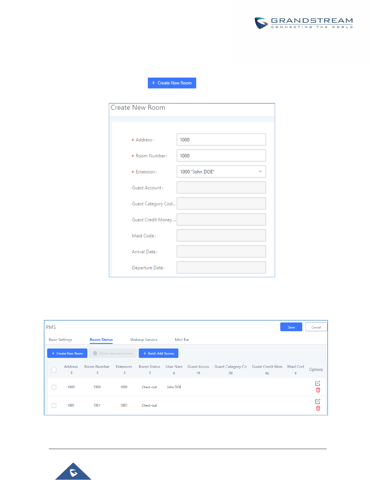
P a g e | 359
UCM6200 Series User Manual
Version 1.0.19.21
PMS Features
Room Status
User can create Rooms by clicking on , the following Figure will be displayed then.
Figure 246: Create New Room
Click “Save” to create the new room, the fields above can be configured from the PMS platform, once set the
following screen will be shown:
Figure 247: Room Status
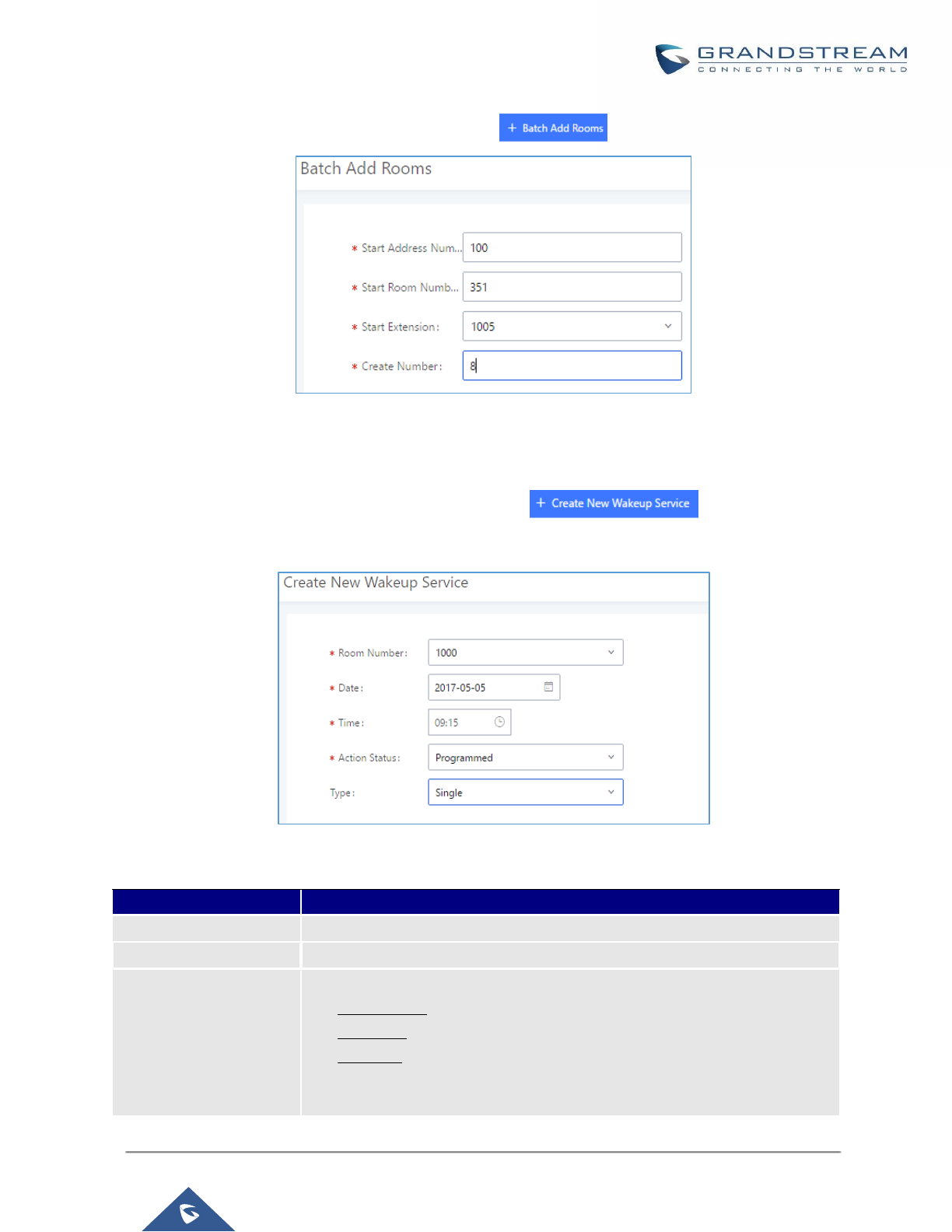
P a g e | 360
UCM6200 Series User Manual
Version 1.0.19.21
User can create a batch of rooms as well by clicking on , the following window will pop up:
Figure 248: Add batch rooms
Wake Up Service
In order to create a New Wake up service, user can click on , the following window will
pop up:
Figure 249: Create New Wake Up Service
Table 117: PMS Wake up Service
Field
Description
Room Number
Select the room number where to call with a limitation of 63 characters.
Time
Set the time of the wakeup call
Action Status
Show the status of the call:
• Programmed: the call is scheduled for the time set
• Cancelled: the call is canceled
• Executed: the wakeup call is made
Note: Editing an already executed wakeup service will automatically change
the service’s status to “Programmed”.
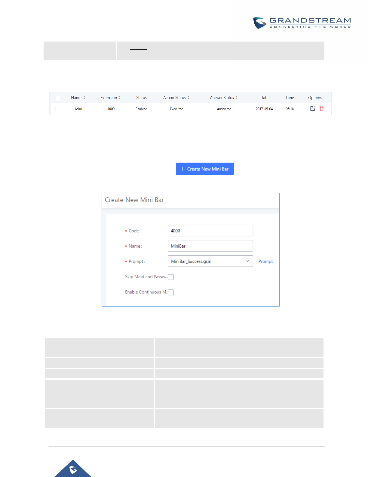
P a g e | 361
UCM6200 Series User Manual
Version 1.0.19.21
Type
• Single: The call will be made once on the specific time.
• Daily: The call will be repeated every day on the specific time
Once the call is made on the time specified, the following figure show the status of the wakeup call.
Figure 250: Wakeup Call executed
This call has been executed but has been rejected, that why we can see the “Busy” status.
Mini Bar
In order to create a new mini bar, click on under UCM webGUI→Value-added
Features→PMS→Mini Bar, the following window will pop up:
Figure 251: Create New Mini Bar
Table 118: Create New Mini Bar
Code
Enter a non-existing extension number to be dialed when
using the mini bar feature.
Name
Enter a name for the mini bar.
Prompt
Select the Prompt to play once connected to the mini bar.
Skip Maid and Password
Authentication
If enabled, the default maid code will be 0000, no
authentication is required. (Enter 0000 followed by # to access
the consumer goods)
Enable Continuous Multi Goods
Billing
If enabled, please separate the goods’ codes by*.
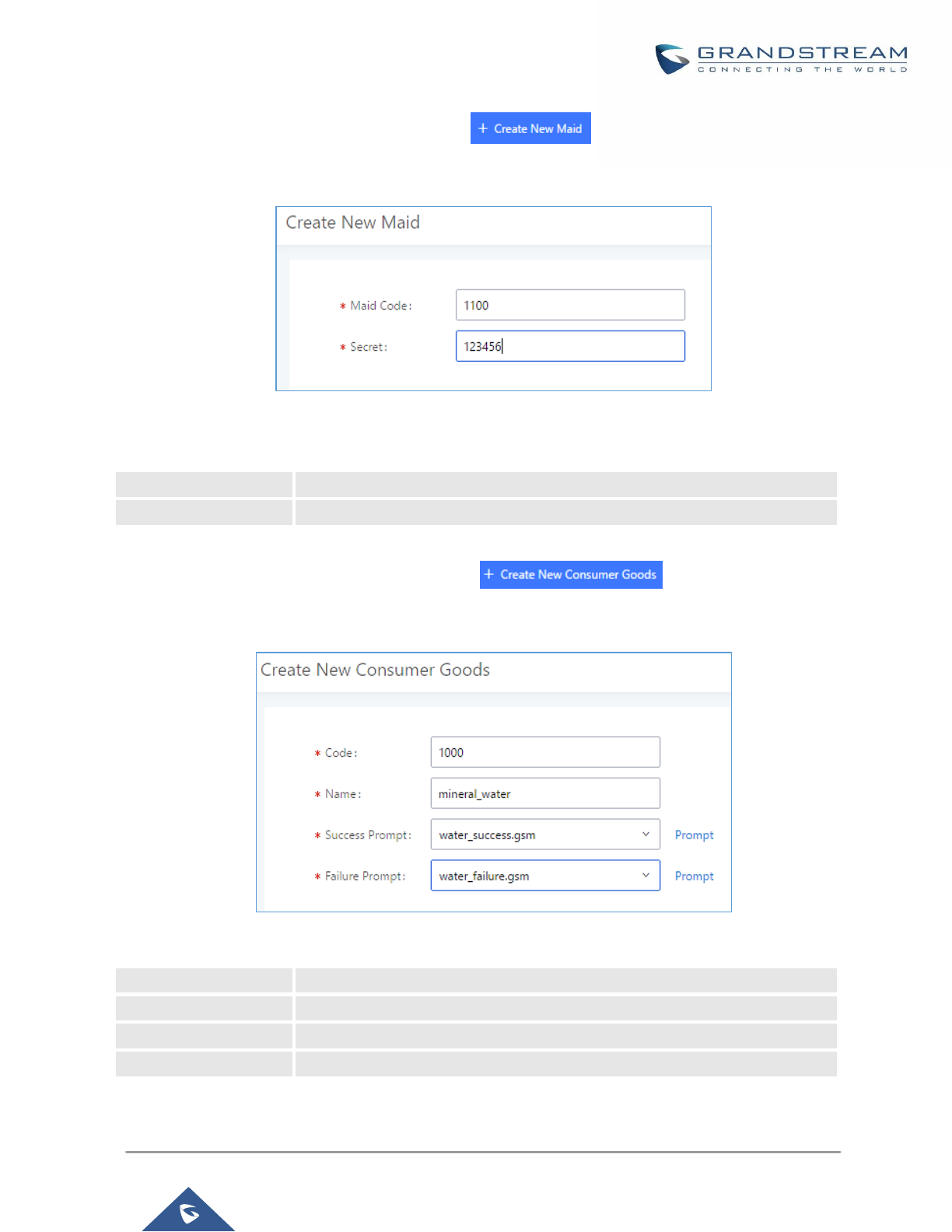
P a g e | 362
UCM6200 Series User Manual
Version 1.0.19.21
In order to create a new maid, click on under UCM webGUI→Value-added
Features→PMS→Mini Bar, the following window will popup.
Figure 252: Create New Maid
Table 119: Create New Maid
Maid Code
Enter the Code to use when the maid wants to use the Mini Bar.
Secret
Enter the password associated with the maid.
In order to create a new consumer goods, click on under UCM webGUI→Value-
added Features→PMS→Mini Bar, the following window will popup.
Figure 253: Create New Consumer Goods
Code
Enter the Goods Code.
Name
Enter the Name of the Goods
Success Prompt
Select the success prompt when typing the code of the goods by the maid.
Failure Prompt
Select the failure prompt.
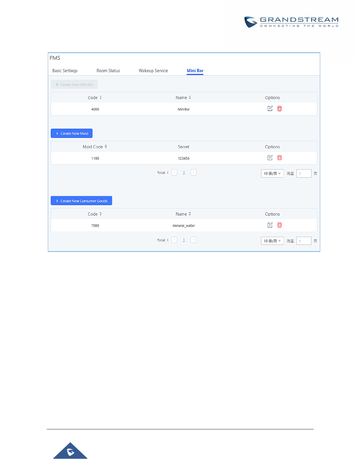
P a g e | 363
UCM6200 Series User Manual
Version 1.0.19.21
The Minibar page displays as:
Figure 254: Mini Bar
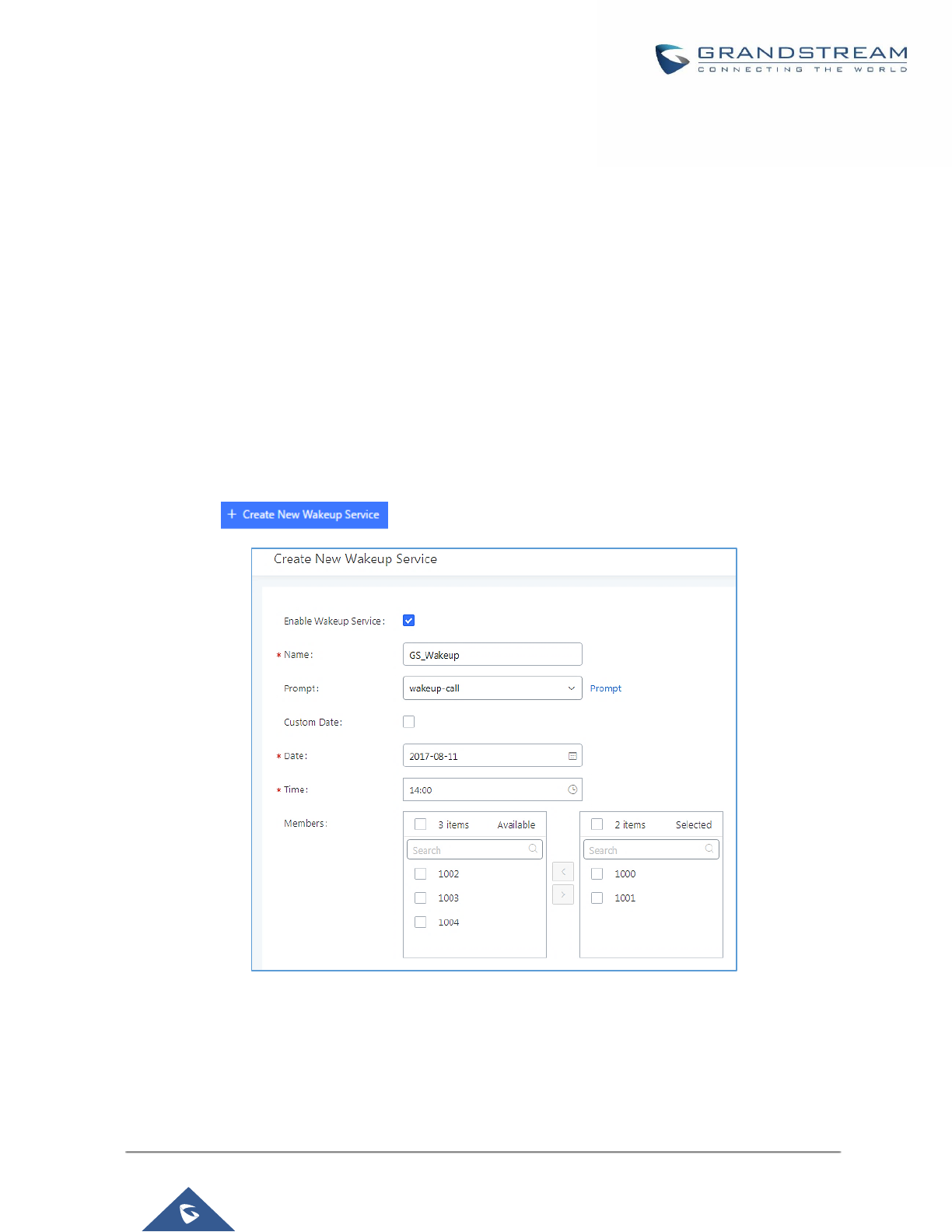
P a g e | 364
UCM6200 Series User Manual
Version 1.0.19.21
WAKEUP SERVICE
The WakeUp service can be used to schedule a reminder or wake up calls to any valid destination. This service
is available on the UCM6200 as a separated module.
There are three ways to set up Wakeup Service:
• Using admin login
• Using user portal
• Using feature code
WakeUp Service using Admin Login
1. Login to the UCM as admin.
2. WakeUp service can be found under Web GUI→Value-added Features→Wakeup Service, click
on to create a new wakeup service. The following window will pop up.
Figure 255: Create New Wakeup Service
3. Fill out the required fields and select the members to add to the wakeup group.
P a g e | 365
UCM6200 Series User Manual
Version 1.0.19.21
Table 120: Wakeup Service
Enable Wakeup Service
Enable Wakeup service.
Name
Enter a name (up to 64 characters) to identify the wakeup service.
Prompt
Select the prompt to play for that extension.
Custom Date
If disabled, users can select a specific date and time.
If enabled users can select multiple days of the week to perform the
wakeup.
Date
Select the date or dates when to performs the wakeup call.
Time
Select the time when to play the wakeup call.
Members
Select the members involved within the wakeup service group.
4. Click and to apply the changes.
A wakeup service entry is created. The UCM will send a wakeup call to every extension in the member list at
the scheduled date and time.
Note: the wakeup service has the following limitation on how many members can be added depending on UCM
model.
Table 121: Max Wakeup Members
UCM Model
Max members in a Wakeup Service
UCM6202
50
UCM6204
50
UCM6208
100
UCM6510
100
WakeUp Service from User Portal
1. Login to the user portal on the UCM6200.
2. WakeUp service can be found under “Value-added Features→Wakeup Service”, click on
to create a new wakeup service.
3. Configures the Name, Prompt, Date and Time for the user to make the wakeup to.
4. Click and to apply the changes.
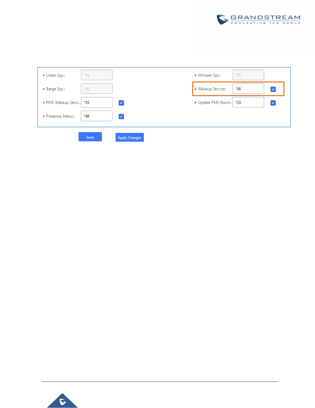
P a g e | 366
UCM6200 Series User Manual
Version 1.0.19.21
WakeUp Service using Feature Code
1. Login to the UCM as admin.
2. Enable “Wakeup Service” from the WebGUI under “Call Features→Feature Codes”.
3. Click and to apply the changes.
4. Dial “*36” which is the feature code by default to access to the UCM wakeup service to add, update,
activate or deactivate UCM wakeup service.
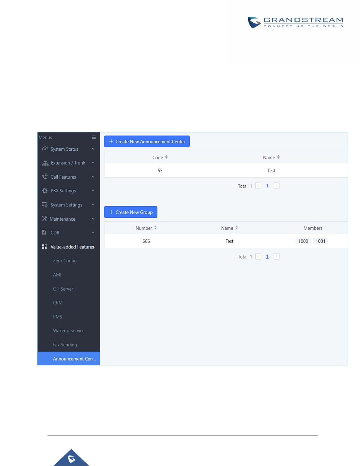
P a g e | 367
UCM6200 Series User Manual
Version 1.0.19.21
ANNOUNCEMENTS CENTER
The UCM6200 supports Announcements Center feature which allows users to pre-record and store voice
message into UCM6200 with a specified code. The users can also create group with specified extensions. When
the code and the group number are dialed together in the combination of code + group number, the specified
voice message is sent to all group members and only extensions in the group will hear the voice message.
Figure 256: Announcements Center

P a g e | 368
UCM6200 Series User Manual
Version 1.0.19.21
Announcements Center Settings
Table 122: Announcements Center Settings
Name
Configure a name for the newly created Announcements Center to identify this
announcement center.
Code
Enter a code number for the custom prompt. This code will be used in
combination with the group number. For example, if the code is 55, and group
number is 666. The user can dial 55666 to send prompt 55 to all members in
group 666.
Note:
The combination number must not conflict with any number in the system such
as extension number or conference number.
Custom Prompt
This option is to set a custom prompt as an announcement to notify group
members. The file can be uploaded from page ‘Custom Prompt’. Click ‘Prompt’
to add additional record.
Ring Timeout
Configure the ring timeout for the group members. The default value is 30
seconds.
Group Settings
Table 123: Group Settings
Name
Configure a name for the newly created group to identify the group.
Number
Configure the group number. The group number is used in combination with the
code. For example, if group number is 666, and code is 55. The user can dial
55666 to send prompt 55 to all members in group 666.
Note:
The combination number must not conflict with any number in the system such
as extension number or conference number.
Announcements Center feature can be found under Web GUI→Value-added Features→Announcements
Center. The following example demonstrates the usage of this feature.
1. Click to create new group.
2. Give a name to the newly created group.
3. Create a group number which is used with code to send voice message.
4. Select the extensions to be included in the group, who will receive the voice message.
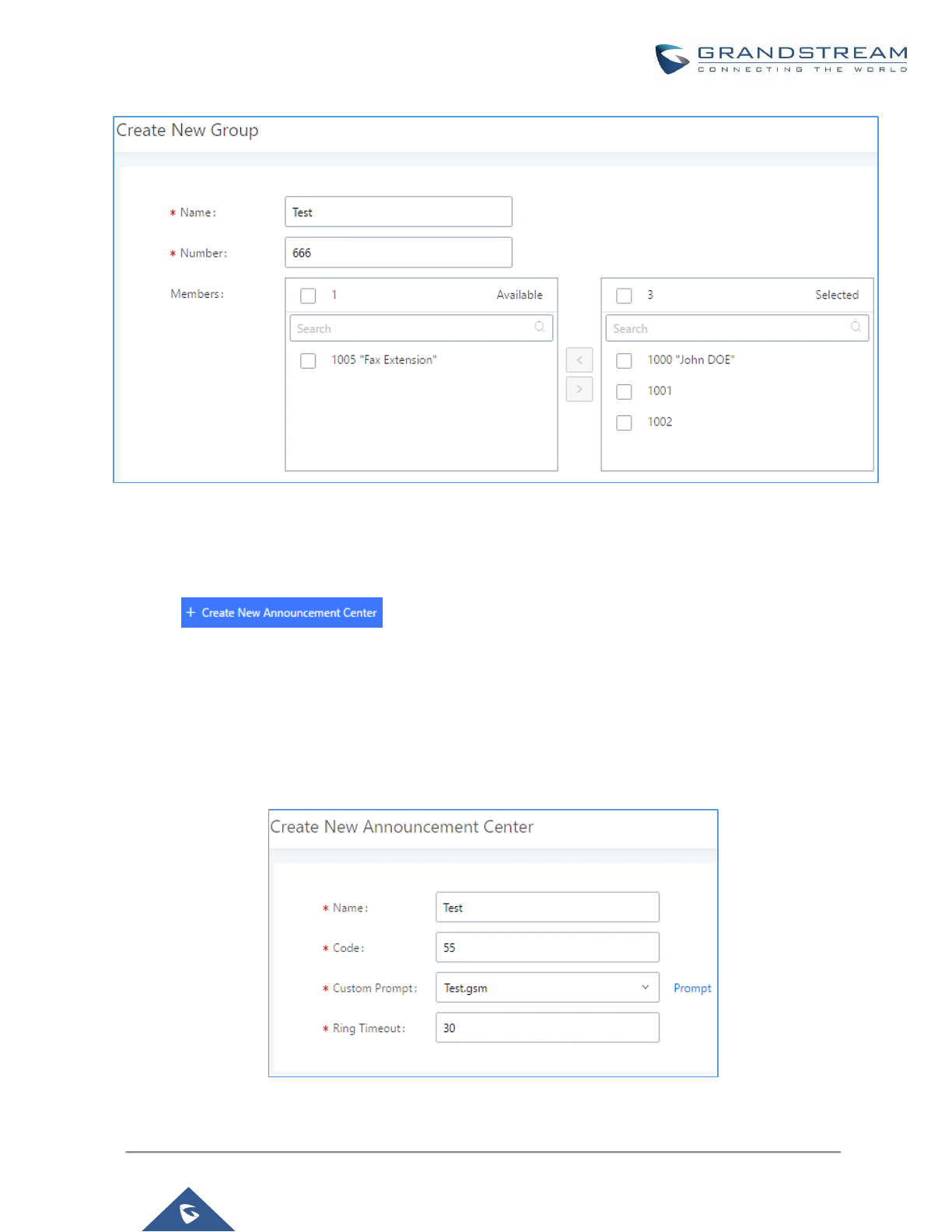
P a g e | 369
UCM6200 Series User Manual
Version 1.0.19.21
Figure 257: Announcements Center Group Configuration
In this example, group “Test” has number 666. Extension 1000, 1001 and 1002 are in this group.
1. Click to create a new Announcement Center.
2. Give a name to the newly created Announcement Center.
3. Specify the code which will be used with group number to send the voice message to.
4. Select the message that will be used by the code from the Custom Prompt drop down menu. To create a
new Prompt, please click “Prompt” link and follow the instructions in that page.
Figure 258: Announcements Center Code Configuration
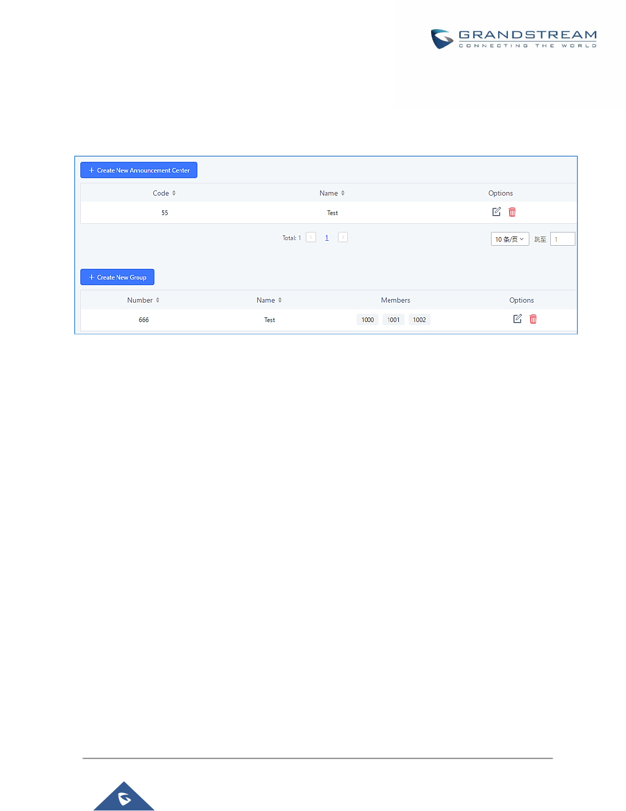
P a g e | 370
UCM6200 Series User Manual
Version 1.0.19.21
Code and Group number are used together to direct specified message to the target group. All extensions in
the group will receive the message. For example, we can send code 55 to group 666 by dialing 55666 from
any extension registered to the UCM6200. All the members in group 666 which are extension 1000, 1001 and
1002 will receive this voice message after they pick up the call.
Figure 259: Announcements Center Example
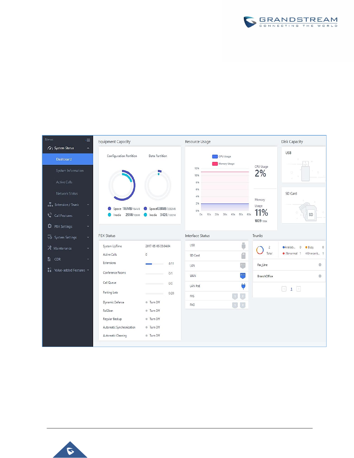
P a g e | 371
UCM6200 Series User Manual
Version 1.0.19.21
STATUS AND REPORTING
PBX Status
The UCM6200 monitors the status for Trunks, Extensions, Queues, Conference Rooms, Interfaces and Parking
lot. It presents administrators the real-time status in different sections under Web GUI→System
Status→Dashboard.
Figure 260: Status→PBX Status
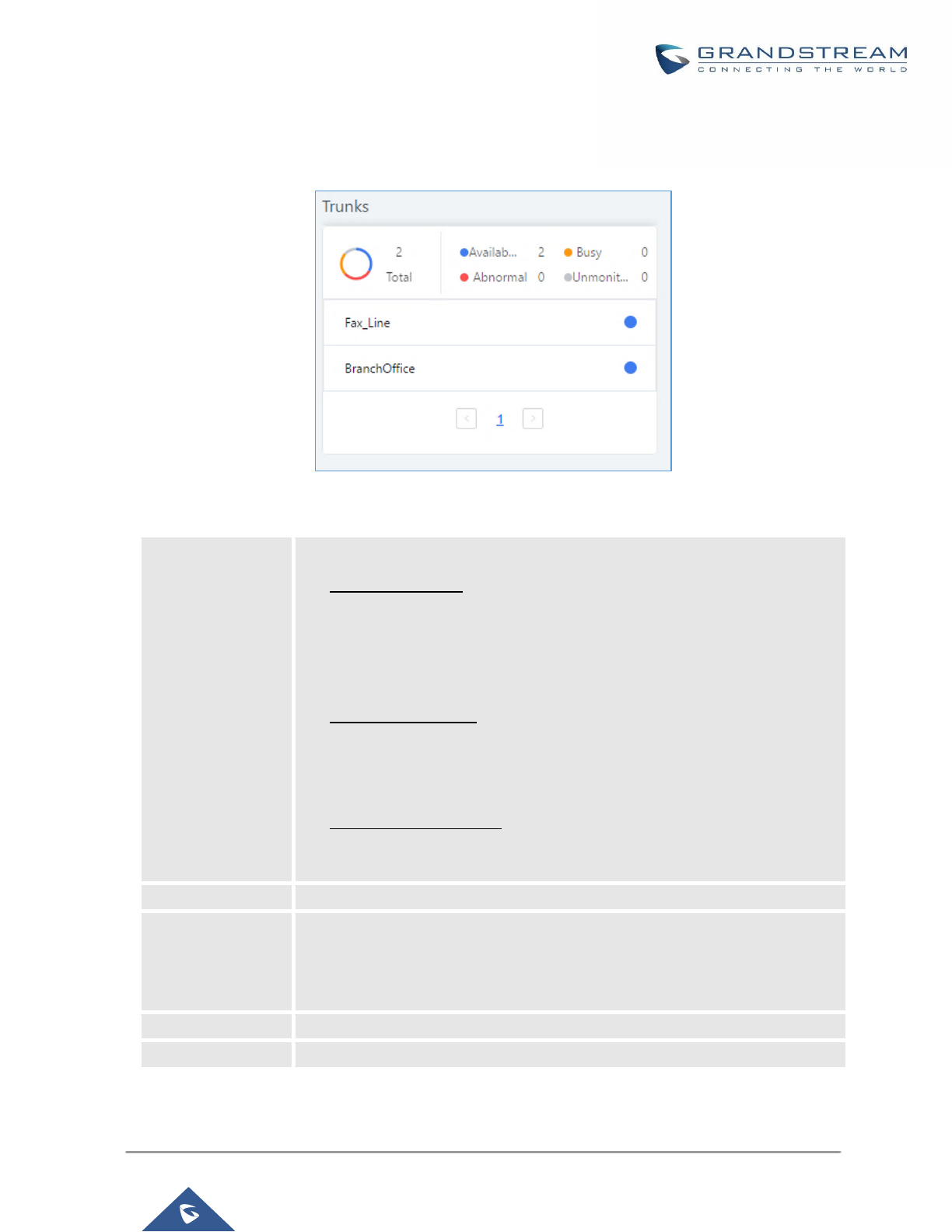
P a g e | 372
UCM6200 Series User Manual
Version 1.0.19.21
Trunks
Users could see all the configured trunk status in this section.
Figure 261: Trunk Status
Table 124: Trunk Status
Status
Display trunk status.
• Analog trunk status:
Available
Busy
Unavailable
Unknown Error
• SIP Peer trunk status:
Unreachable: The hostname cannot be reached.
Unmonitored: Heartbeat feature is not turned on to be monitored.
Reachable: The hostname can be reached.
• SIP Register trunk status:
Registered
Unrecognized Trunk
Trunks
Display trunk name
Type
Display trunk Type:
• Analog
• SIP
• IAX
Username
Display username for this trunk.
Port/Hostname/IP
Display Port for analog trunk, or Hostname/IP for VoIP (SIP/IAX) trunk.
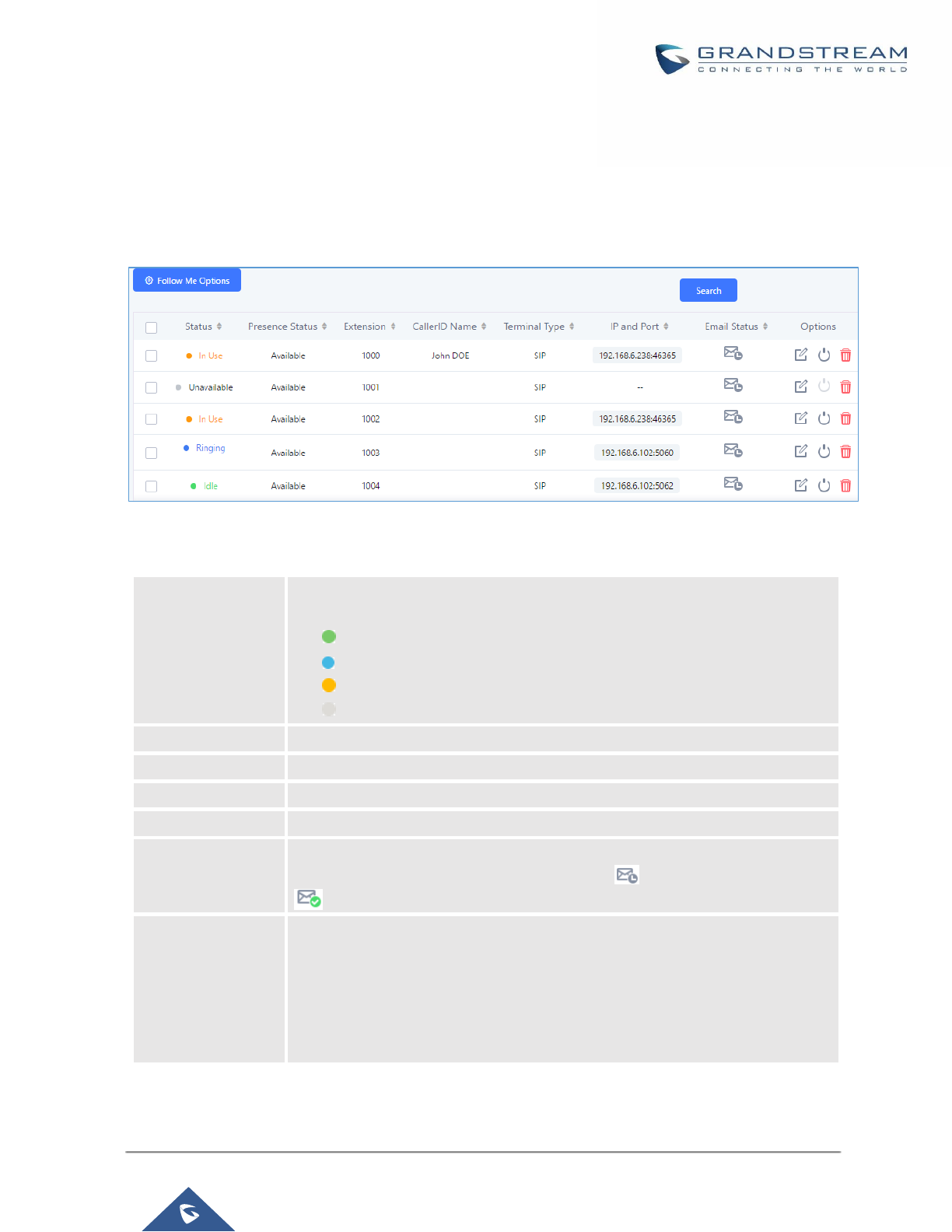
P a g e | 373
UCM6200 Series User Manual
Version 1.0.19.21
Extensions
Extensions Status can be seen from the same configuration page, users can go under Web
GUI→Extension/Trunk→Extensions and following page will be displayed listing the extensions and their status
information.
Figure 262: Extension Status
Table 125: Extension Status
Status
Display extension number (including feature code). The color indicator has the
following definitions.
• Green: Free
• Blue: Ringing
• Yellow: In Use
• Grey: Unavailable
Presence Status
Display the presence status of the extension.
Extension
Display the extension number.
CallerID Name
First name and last name of the extension.
IP and Port
Display the IP and port number of the registered device.
Email
Display Email Notification status for the extension.
When notification is waiting for be sent, shows and once sent it will display
Terminal Type
Displays extension type.
• SIP User
• IAX User
• Analog User
• Ring Groups
• Voicemail Groups
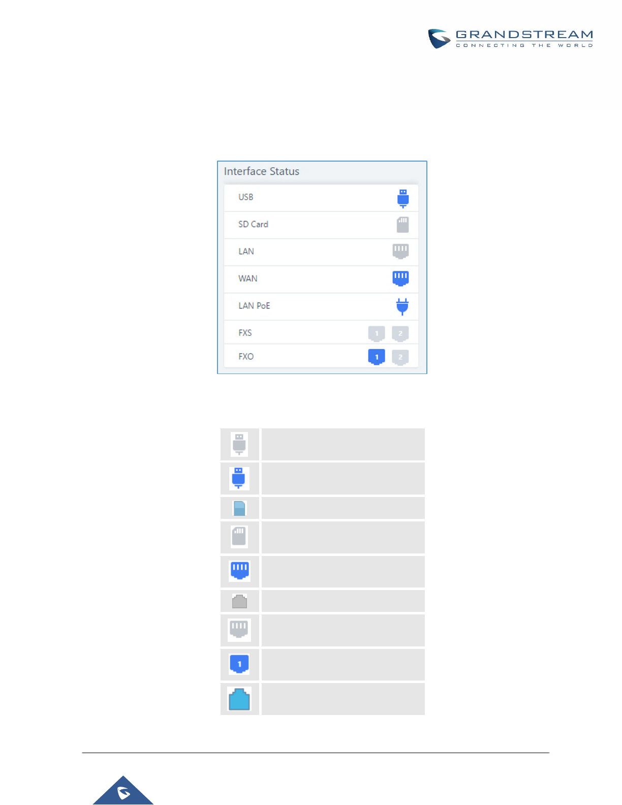
P a g e | 374
UCM6200 Series User Manual
Version 1.0.19.21
Interfaces Status
This section displays interface/port connection status on the UCM6200. The following example shows the
interface status for UCM6204 with USB, WAN port, FXS1, FXS2 and FXO1 connected.
Figure 263: UCM6204 Interfaces Status
Table 126: Interface Status Indicators
USB connected.
USB disconnected.
SD Card connected.
SD Card disconnected.
LAN/WAN connected.
LAN/WAN not configured.
LAN/WAN disconnected.
FXS/FXO connected.
FXS/FXO waiting.

P a g e | 375
UCM6200 Series User Manual
Version 1.0.19.21
FXS/FXO busy.
FXS/FXO not configured.
FXS/FXO disconnected.
System Status
The UCM6200 system status can be accessed via Web GUI→Status→System Status, which displays the
following system information.
General
Under Web GUI→System Status→System Information→General, users could check the hardware and
software information for the UCM6200. Please see details in the following table.
Table 127: System Status→General
System Status →System Information→General
Model
Product model.
Part Number
Product part number.
System Time
Current system time. The current system time is also available on the upper right of
each web page.
Up Time
System up time since the last reboot.
Boot
Boot version.
Core
Core version.
Base
Base version.
Program
Program version. This is the main software release version.
Recovery
Recovery version.
Network
Under Web GUI→System Status→System Information→Network, users could check the network information
for the UCM6200. Please see details in the following table.

P a g e | 376
UCM6200 Series User Manual
Version 1.0.19.21
Table 128: System Status→Network
System Status→System Status→Network
MAC Address
Global unique ID of device, in HEX format. The MAC address can be found on the
label coming with original box and on the label located on the bottom of the device.
IP Address
IP address.
Gateway
Default gateway address.
Subnet Mask
Subnet mask address.
DNS Server
DNS Server address.
Storage Usage
Users could access the storage usage information from Web GUI→System Status→Dashboard→Storage
Usage. It shows the available and used space for Space Usage and Inode Usage.
Space Usage includes:
• Configuration partition
This partition contains PBX system configuration files and service configuration files.
• Data partition
Voicemail, recording files, IVR file, Music on Hold files etc.
• USB disk
USB disk will display if connected.
• SD Card
SD Card will display if connected.
Inode Usage includes:
• Configuration partition
• Data partition
Note:
Inode is the pointer used for file reference in the system. The system usually has limited resources of pointers

P a g e | 377
UCM6200 Series User Manual
Version 1.0.19.21
Figure 264: System Status→Storage Usage
Resource Usage
When configuring and managing the UCM6200, users could access resource usage information to estimate the
current usage and allocate the resources accordingly. Under Web GUI→System
Status→Dashboard→Resource Usage, the current CPU usage and Memory usage are shown in the pie chart.
Figure 265: System Status→Resource Usage
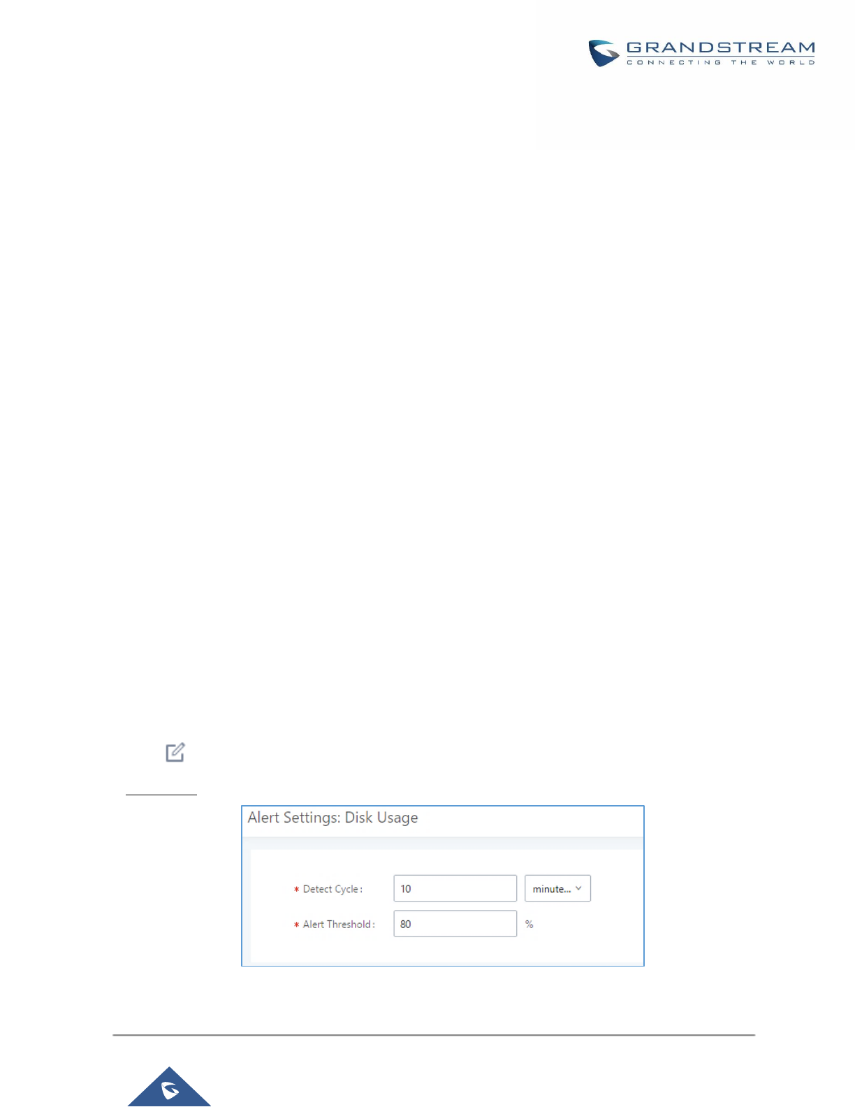
P a g e | 378
UCM6200 Series User Manual
Version 1.0.19.21
System Events
The UCM6200 can monitor important system events, log the alerts and send Email notifications to the system
administrator.
Alert Events List
The system alert events list can be found under Web GUI→Maintenance→System Events. The following event
are currently supported on the UCM6200 which will have alert and/or Email generated if occurred:
Disk Usage
External Disk Usage
Modify Admin Password
Memory Usage
System Reboot
System Update
System Crash
Register SIP Failed
Register SIP Trunk Failed
Restore Config
User Login Success
User Login Failed
SIP Internal Call Failure
SIP Outgoing Call through Trunk Failure
Fail2ban Blocking
SIP Lost Registration
SIP Peer Trunk Status
Emergency Calls
CDR database disk is malformed
Click on to configure the parameters for each event. See examples below.
1. Disk Usage
Figure 266: System Events→Alert Events Lists: Disk Usage
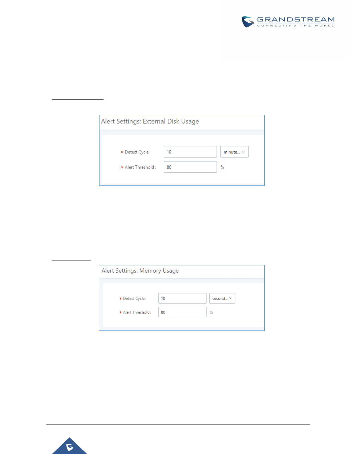
P a g e | 379
UCM6200 Series User Manual
Version 1.0.19.21
• Detect Cycle: The UCM6200 will perform the internal disk usage detection based on this cycle. Users
can enter the number and then select second(s)/minute(s)/hour(s)/day(s) to configure the cycle.
• Alert Threshold: If the detected value exceeds the threshold (in percentage), the UCM6200 system will
send the alert.
2. External Disk Usage
Figure 267: System Events→Alert Events Lists: External Disk Usage
• Detect Cycle: The UCM6200 will perform the External disk usage detection based on this cycle. Users
can enter the number and then select second(s)/minute(s)/hour(s)/day(s) to configure the cycle.
• Alert Threshold: If the detected value exceeds the threshold (in percentage), the UCM6200 system will
send the alert.
3. Memory Usage
Figure 268: System Events→Alert Events Lists: Memory Usage
• Detect Cycle: The UCM6200 will perform the memory usage detection based on this cycle. Users can
enter the number and then select second(s)/minute(s)/hour(s)/day(s) to configure the cycle.
• Alert Threshold: If the detected value exceeds the threshold (in percentage), the UCM6200 system will
send the alert.
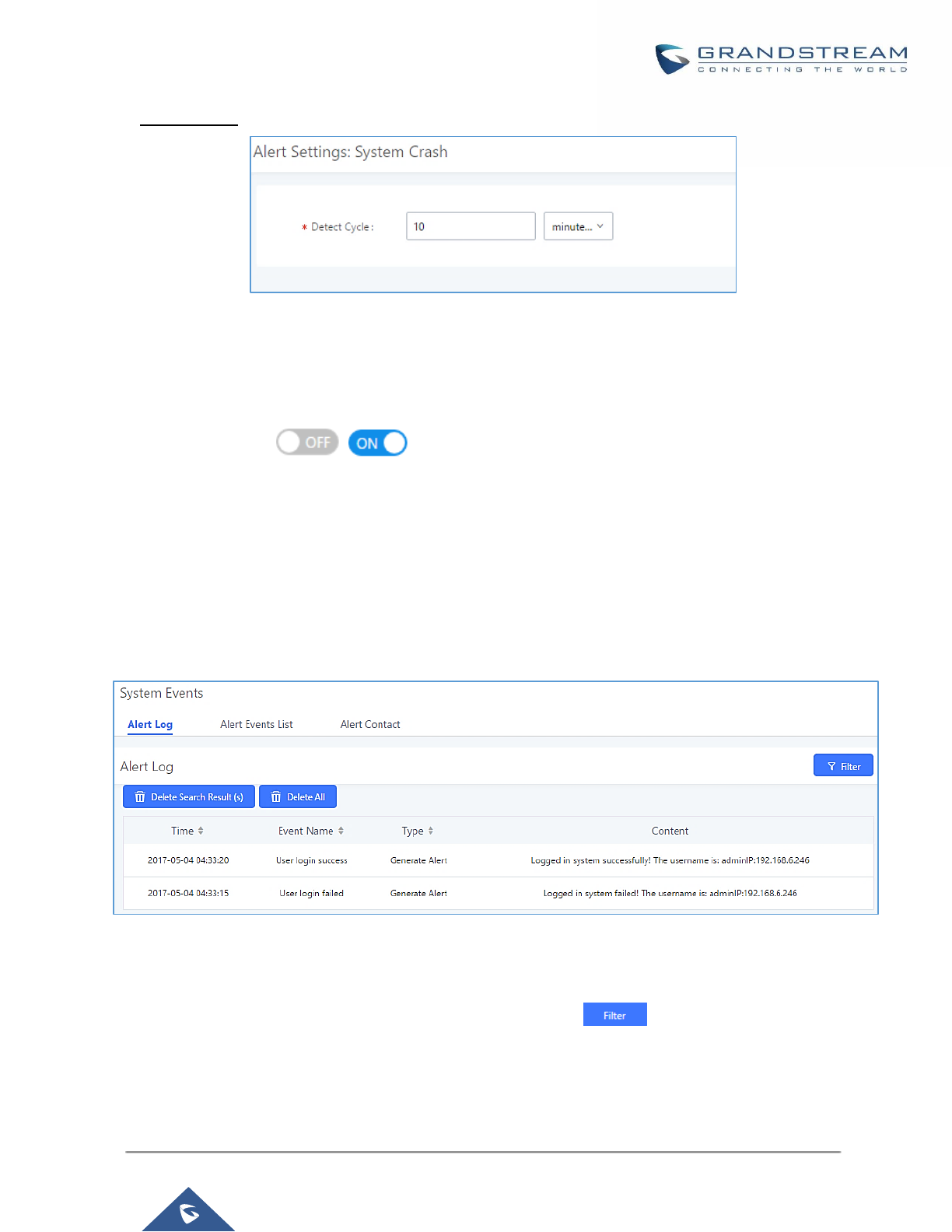
P a g e | 380
UCM6200 Series User Manual
Version 1.0.19.21
4. System Crash
Figure 269: System Events→Alert Events Lists: System Crash
• Detect Cycle: The UCM will detect the event at each cycle based on the specified time. Users can
enter the number and then select second(s)/minute(s)/hour(s)/day(s) to configure the cycle.
Click on the switch to turn on/off the alert and Email notification for the event. Users
could also select the checkbox for each event and then click on button "Alert On", "Alert Off", "Email
Notification On", "Email Notification Off" to control the alert and Email notification configuration.
Alert Log
Under Web GUI→Maintenance→System Events→Alert Log, system messages from triggered system events
are listed as alert logs. The following screenshot shows system crash alert logs.
Figure 270: System Events→Alert Log
User could also filter alert logs by selecting a certain event category, type of alert log, and/or specifying a certain
time period. The matching results will be displayed after clicking on . Alert logs are classified into two
types by the system:
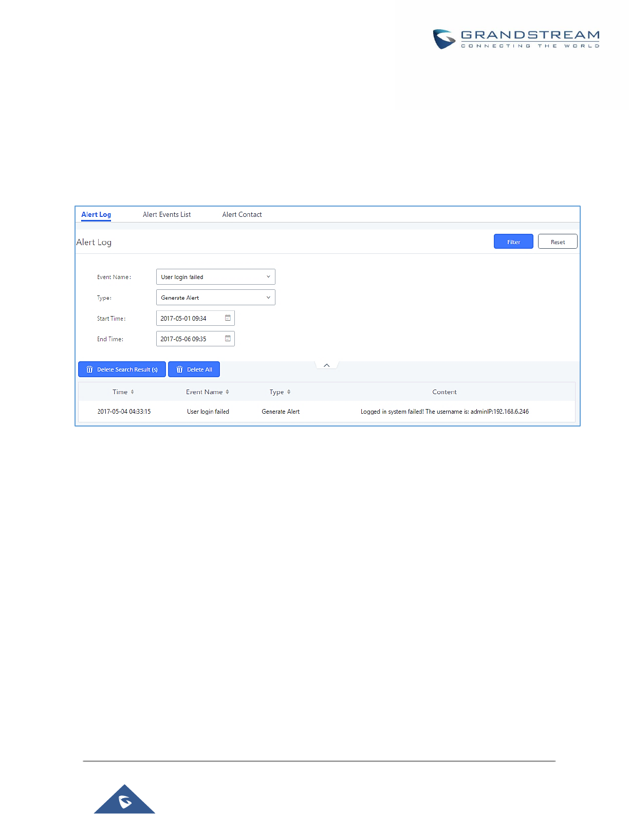
P a g e | 381
UCM6200 Series User Manual
Version 1.0.19.21
1. Generate Alert: Generated when alert events happen, for example, alert logs for disk usage exceeding the
alert threshold.
2. Restore to Normal: Generated when alert events being cleared, for example, logs for disk usage dropping
back below the alert threshold.
User could filter out alert logs of “Generate Alert” or “Restore to Normal” by specifying the type according to
need. The following figure shows an example of filtering out alert logs of type of “Restore to Normal”.
Figure 271: Filter for Alert Log
Alert Contact
Users could add administrator's Email address under Web GUI→Maintenance→System Events→Alert
Contact to send the alert notification to. Up to 10 Email addresses can be added.
CDR
CDR (Call Detail Record) is a data record generated by the PBX that contains attributes specific to a single
instance of phone call handled by the PBX. It has several data fields to provide detailed description for the call,
such as phone number of the calling party, phone number of the receiving party, start time, call duration, etc.
On the UCM6200, the CDR can be accessed under Web GUI→CDR→CDR. Users could filter the call report by
specifying the date range and criteria, depending on how the users would like to include the logs to the report.
Click on "Search" button to display the generated report.
Important Note: Starting from fw 1.0.15.16, the UCM has CDR separation and it will display only CDR for the
current month. And in order to get older data, users need to apply filter by specifying the date range.
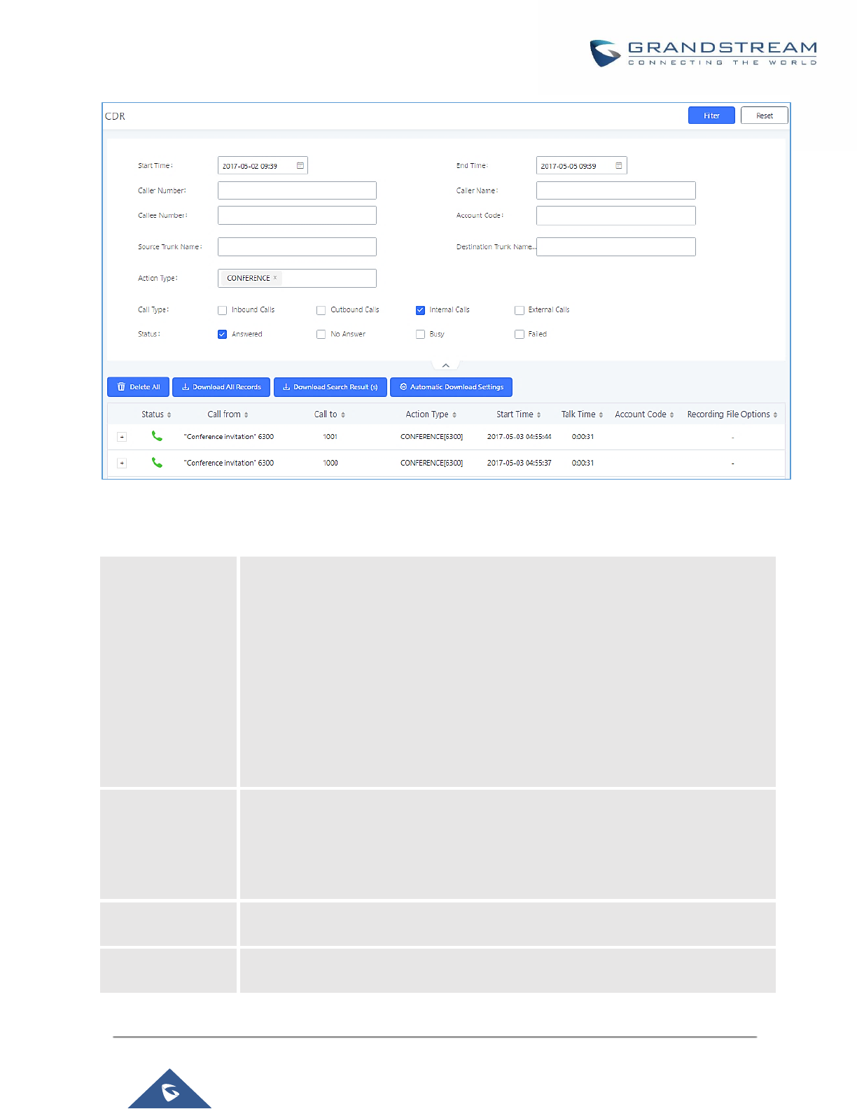
P a g e | 382
UCM6200 Series User Manual
Version 1.0.19.21
Figure 272: CDR Filter
Table 129: CDR Filter Criteria
Call Type
Groups the following:
• Inbound calls: Inbound calls are calls originated from a non-internal source
(like a VoIP trunk) and sent to an internal extension.
• Outbound calls: Outbound calls are calls sent to a non-internal source (like
a VoIP trunk) from an internal extension.
• Internal calls: Internal calls are calls from one internal extension to another
extension, which are not sent over a trunk.
• External calls: External calls are calls sent from one trunk to another trunk,
which are not sent to any internal extension.
Status
Filter with the call status, the available statuses are the following:
• Answered
• No Answer
• Busy
• Failed
Source Trunk
Name
Select source trunk(s) and the CDR of calls going through inbound the trunk(s) will be
filtered out.
Destination Trunk
Name
Select destination trunk(s) and the CDR of calls going outbound through the trunk(s)
will be filtered out.

P a g e | 383
UCM6200 Series User Manual
Version 1.0.19.21
Action Type
Filter calls using the Action Type, the following actions are available:
• Dial
• Announcements
• Callback
• Call Forward
• Conference
• Disa
• Fax
• Follow Me
• IVR
• Page
• Parked Call
• Queue
• Ring Group
• Transfer
• VFax
• VM
• VMG
• Wakeup
• Emergency Call
• Emergency Notify
• SCA
Account Code
Select the account Code to filter with. If pin group CDR is enabled, the call with pin
group information will be displayed as part of the CDR under Account Code Field.
Start Time
Specify the start time to filter the CDR report. Click on the calendar icon on the right
and the calendar will show for users to select the exact date and time.
End Time
Specify the end time to filter the CDR report. Click on the calendar icon on the right
and the calendar will show for users to select the exact date and time.
Caller Number
Enter the caller number to filter the CDR report. CDR with the matching caller number
will be filtered out.
User could specify a particular caller number or enter a pattern. ‘.’ matches zero or
more characters, only appears in the end. ‘X’ matches any digit from 0 to 9, case-
insensitive, repeatable, only appears in the end.
For example:
3XXX: It will filter out CDR that having caller number with leading digit 3 and of 4 digits’
length.
3.: It will filter out CDR that having caller number with leading digit 3 and of any length.
Caller Name
Enter the caller name to filter the CDR report. CDR with the matching caller name will
be filtered out.
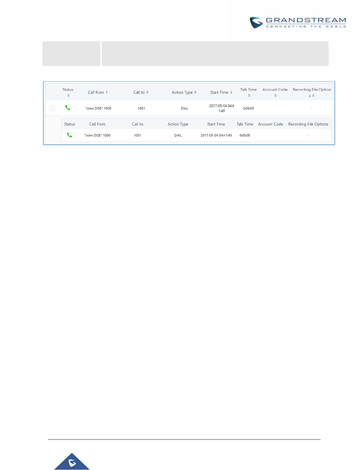
P a g e | 384
UCM6200 Series User Manual
Version 1.0.19.21
Callee Number
Enter the callee number to filter the CDR report. CDR with the matching callee number
will be filtered out.
The call report will display as the following figure shows.
Figure 273: Call Report
The CDR report has the following data fields:
• Start Time
Format: 2016-09-03 00:06:16
• Call Type
Example:
IVR
DIAL
WAKEUP
• Call From
Example format:
"John Doe" 2000
• Call To
Example format:
2002
• Call Time
Format: 0:00:02
• Talk Time
Format: 0:00:00
• Account Code
Example format:
Grandstream/Test
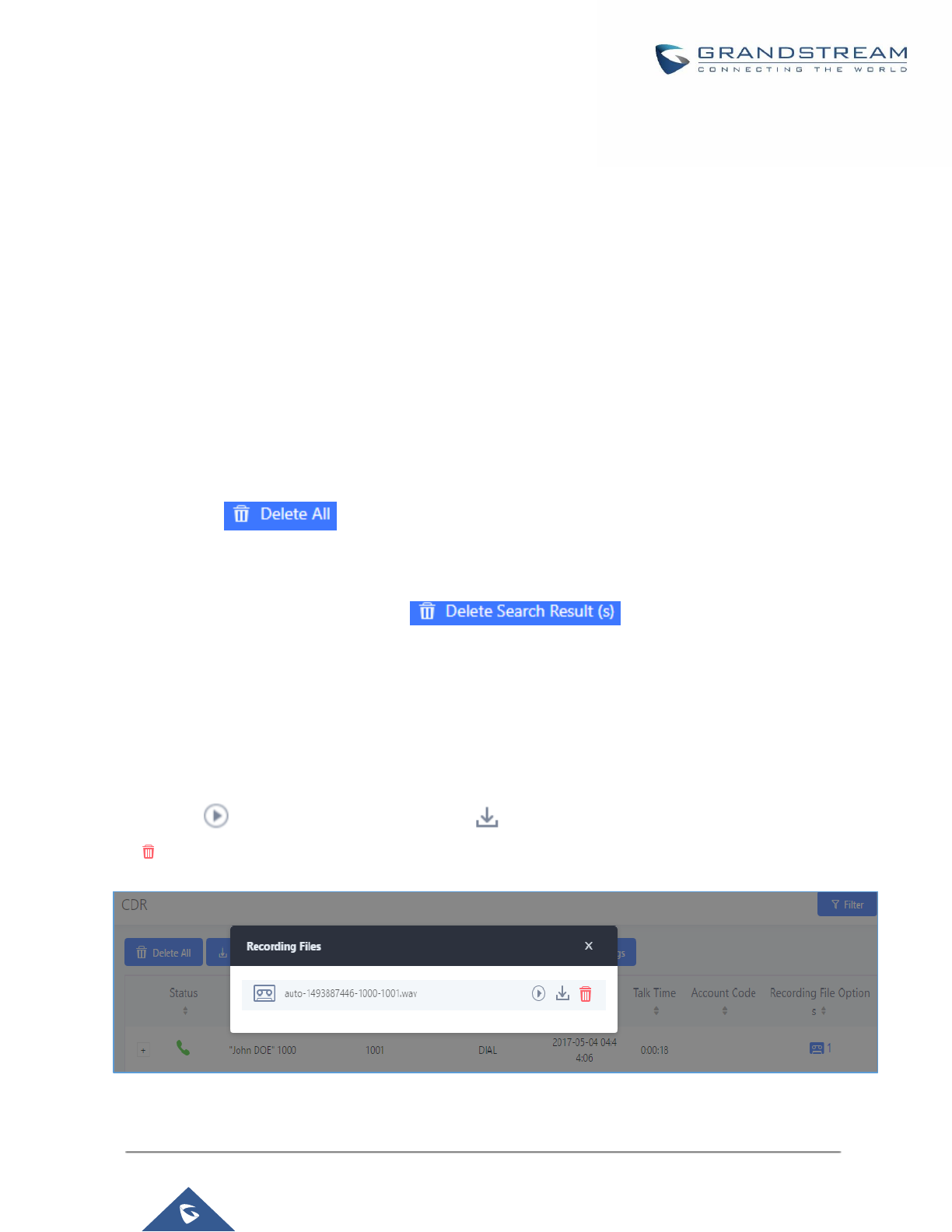
P a g e | 385
UCM6200 Series User Manual
Version 1.0.19.21
• Status
Answered, Busy, No answer or Failed.
Users could perform the following operations on the call report.
• Sort by “Start Time”
Click on the header of the column to sort the report by "Start Time". Clicking on "Start Time" again will
reverse the order.
• Download Searched Results
Click on “Download Search Result(s)” to export the records filtered out to a .csv file.
• Download All Records
Click on “Download All Records” to export all the records to a .csv file.
• Delete All
Click on button to remove all the call report information.
• Delete Search Result
On the bottom of the page, click on button to remove CDR records that
appear on search results.
Note: When deleting CDR, a prompt will now appear asking whether to delete all recording files or not.
• Play/Download/Delete Recording File (per entry)
If the entry has audio recording file for the call, the three icons on the most right column will be activated
for users to select. In the following picture, the second entry has audio recording file for the call.
Click on to play the recording file; click on to download the recording file in .wav format; click on
to delete the recording file (the call record entry will not be deleted).
Figure 274: Call Report Entry with Audio Recording File
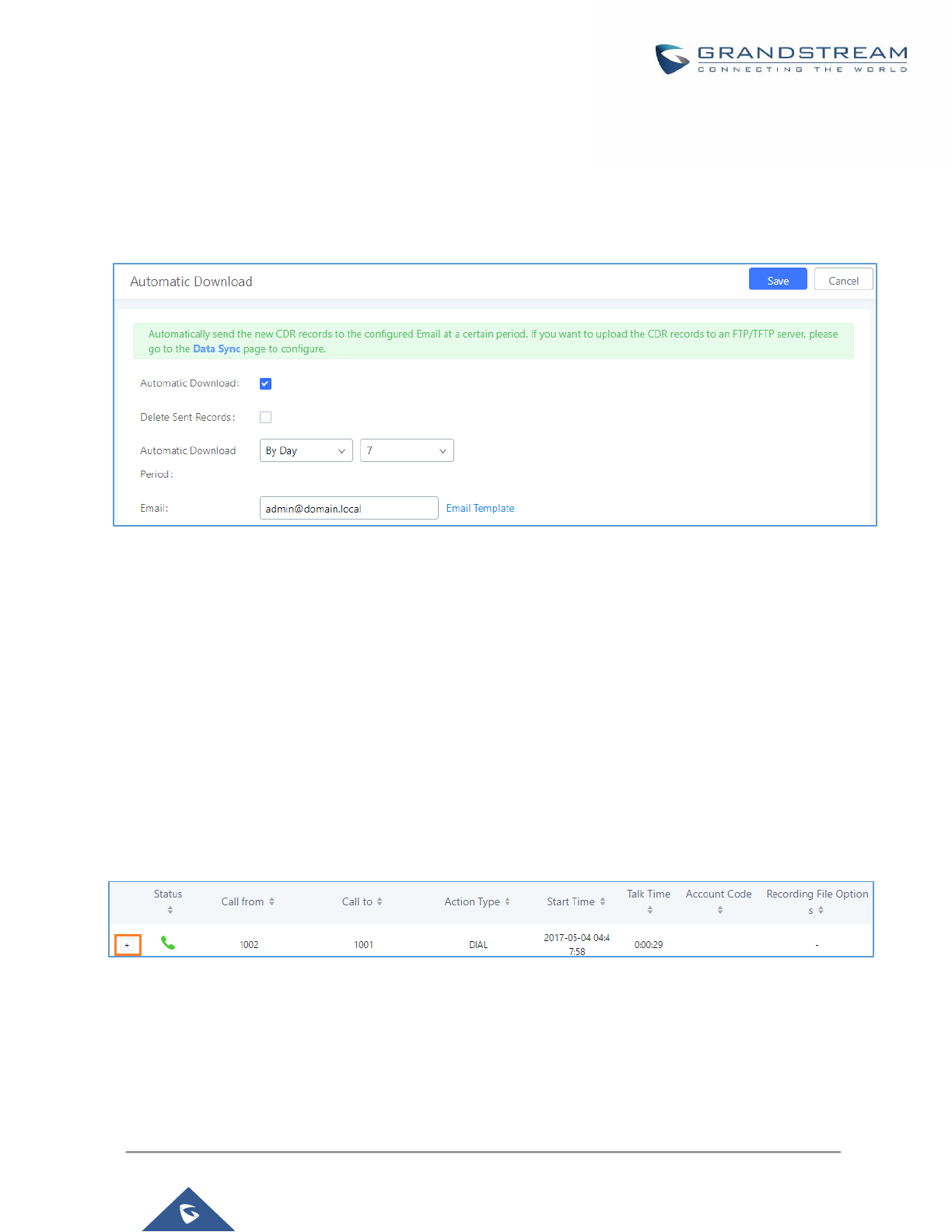
P a g e | 386
UCM6200 Series User Manual
Version 1.0.19.21
• Automatic Download CDR Records
User could configure the UCM6200 to automatically download the CDR records and send the records to
multiple Email recipients in a specific hour. Click on “Automatic Download Settings”, and configure the
parameters in the dialog below.
Figure 275: Automatic Download Settings
To receive CDR record automatically from Email, check “Enable” and select a time period “By Day” “By Week”
or “By Month”, select Hour of the day as well for the automatic download period. Make sure you have entered
an Email or multiple email addresses where to receive the CDR records.
Note: users have the option to delete the sent records “Delete Sent Records”
CDR Improvement
Starting from UCM6200 firmware 1.0.10.x, transferred call will no longer be displayed as a separate call entry in
CDR. It will display within call record in the same entry. CDR new features can be found under Web
GUI→CDR→CDR. The user can click on the option icon for a specific call log entry to view details about this
entry, such as premier caller and transferred call information.
Figure 276: CDR Report
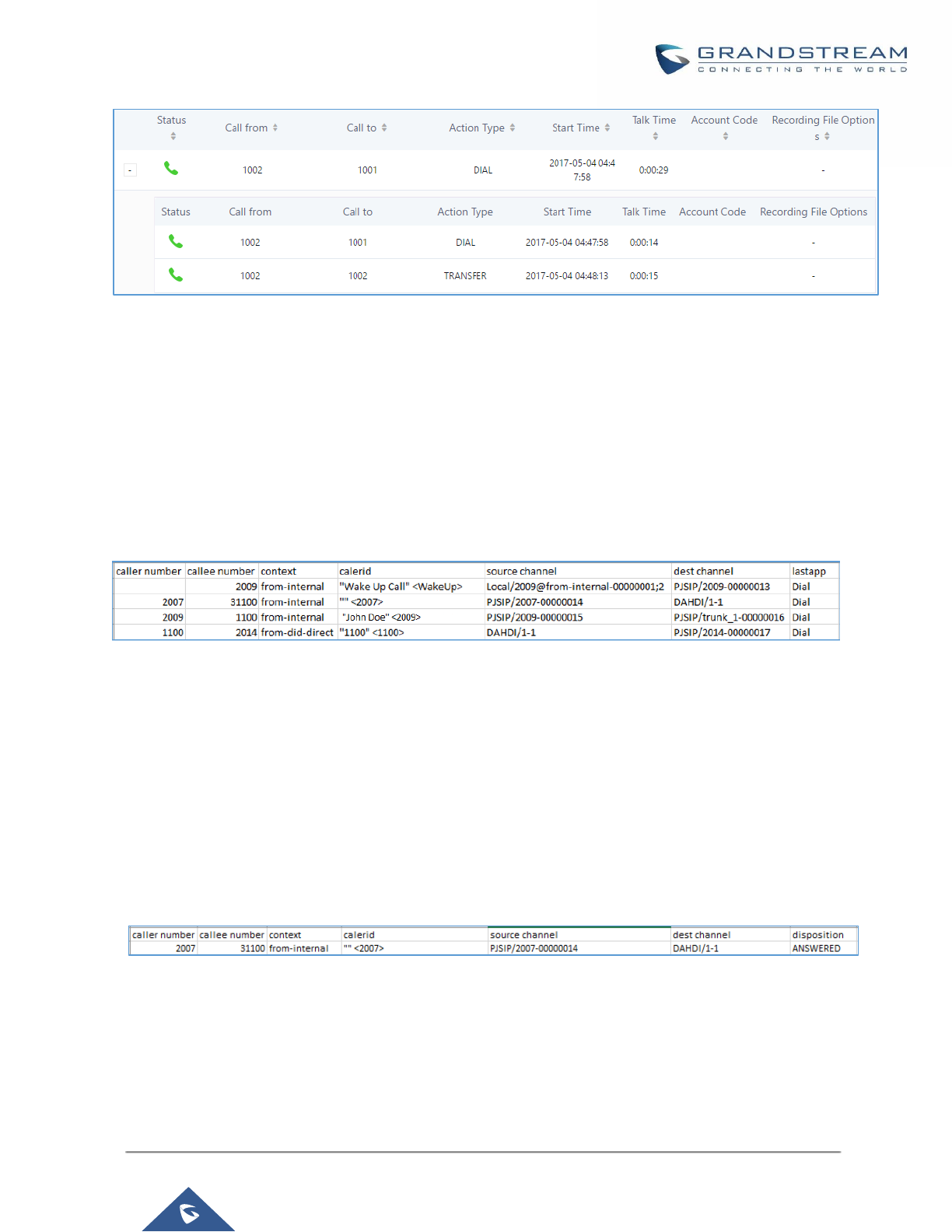
P a g e | 387
UCM6200 Series User Manual
Version 1.0.19.21
Figure 277: Detailed CDR Information
Downloaded CDR File
The downloaded CDR (.csv file) has different format from the Web GUI CDR. Here are some descriptions.
• Caller number, Callee number
"Caller number": the caller ID.
"Callee number": the callee ID.
If the "Source Channel" contains "DAHDI", this means the call is from FXO/PSTN line.
Figure 278: Downloaded CDR File Sample
• Context
There are different context values that might show up in the downloaded CDR file. The actual value can vary
case by case. Here are some sample values and their descriptions.
from-internal: internal extension makes outbound calls.
ext-did-XXXXX: inbound calls. It starts with "ext-did", and "XXXXX" content varies case by case, which also
relate to the order when the trunk is created.
ext-local: internal calls between local extensions.
• Source Channel, Dest Channel
Sample 1:
Figure 279: Downloaded CDR File Sample - Source Channel and Dest Channel 1
DAHDI means it is an analog call, FXO or FXS.
For UCM6202, DAHDI/(1-2) are FXO ports, and DAHDI(3-4) are FXS ports.
For UCM6204, DAHDI/(1-4) are FXO ports, and DAHDI(5-6) are FXS ports.
For UCM6208, DAHDI/(1-8) are FXO ports, and DAHDI(9-10) are FXS ports.
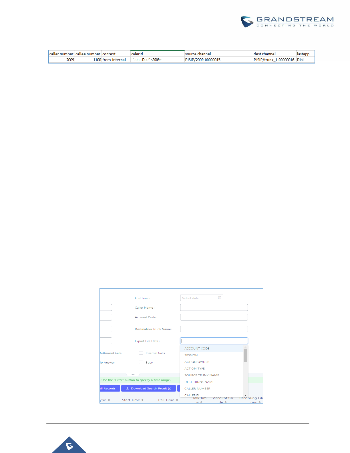
P a g e | 388
UCM6200 Series User Manual
Version 1.0.19.21
Sample 2:
Figure 280: Downloaded CDR File Sample - Source Channel and Dest Channel 2
"SIP" means it's a SIP call. There are three possible format:
(a) PJSIP/NUM-XXXXXX, where NUM is the local SIP extension number. The last XXXXX is a random string
and can be ignored.
(c) PJSIP/trunk_X/NUM, where trunk_X is the internal trunk name, and NUM is the number to dial out through
the trunk.
(c) PJSIP/trunk_X-XXXXXX, where trunk_X is the internal trunk name and it is an inbound call from this trunk.
The last XXXXX is a random string and can be ignored.
There are some other possible values, but these values are almost the application name which are used by the
dialplan.
IAX2/NUM-XXXXXXX: it means this is an IAX call.
Local/@from-internal-XXXXX: it is used internally to do some special feature procedure. We can simply ignore
it.
Hangup: the call is hung up from the dialplan. This indicates there are some errors or it has run into abnormal
cases.
Playback: play some prompts to you, such as 183 response or run into an IVR.
ReadExten: collect numbers from user. It may occur when you input PIN codes or run into DISA
CDR Export Customization
Users can select the data they want to see in exported CDR reports by first clicking on the Filter button on the
CDR page under CDR→CDR and selecting the desired information in the Export File Data field.
Figure 281: CDR Export File data
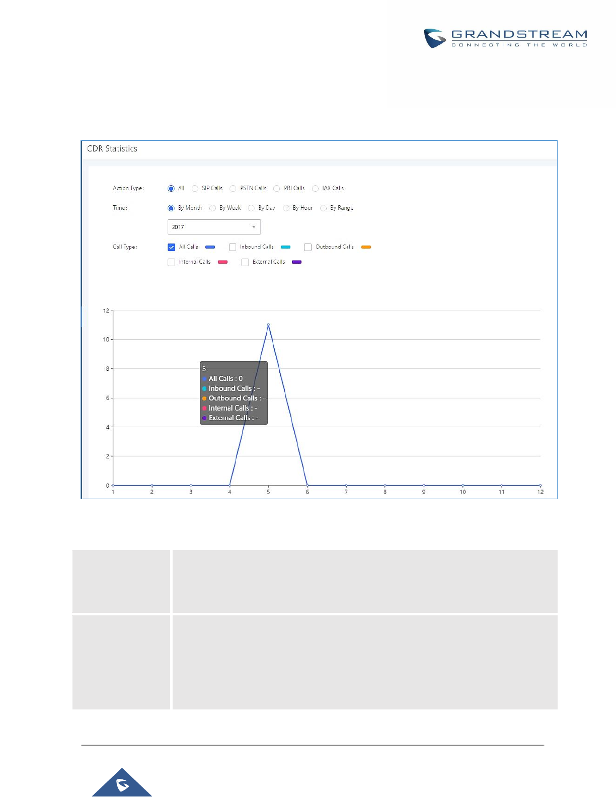
P a g e | 389
UCM6200 Series User Manual
Version 1.0.19.21
Statistics
CDR Statistics is an additional feature on the UCM6200 which provides users a visual overview of the call report
across the time frame. Users can filter with different criteria to generate the statistics chart.
Figure 282: CDR Statistics
Table 130: CDR Statistics Filter Criteria
Trunk Type
Select one of the following trunk type.
• All
• SIP Calls
• PSTN Calls
Call Type
Select one or more in the following checkboxes.
• Inbound calls
• Outbound calls
• Internal calls
• External calls
• All calls
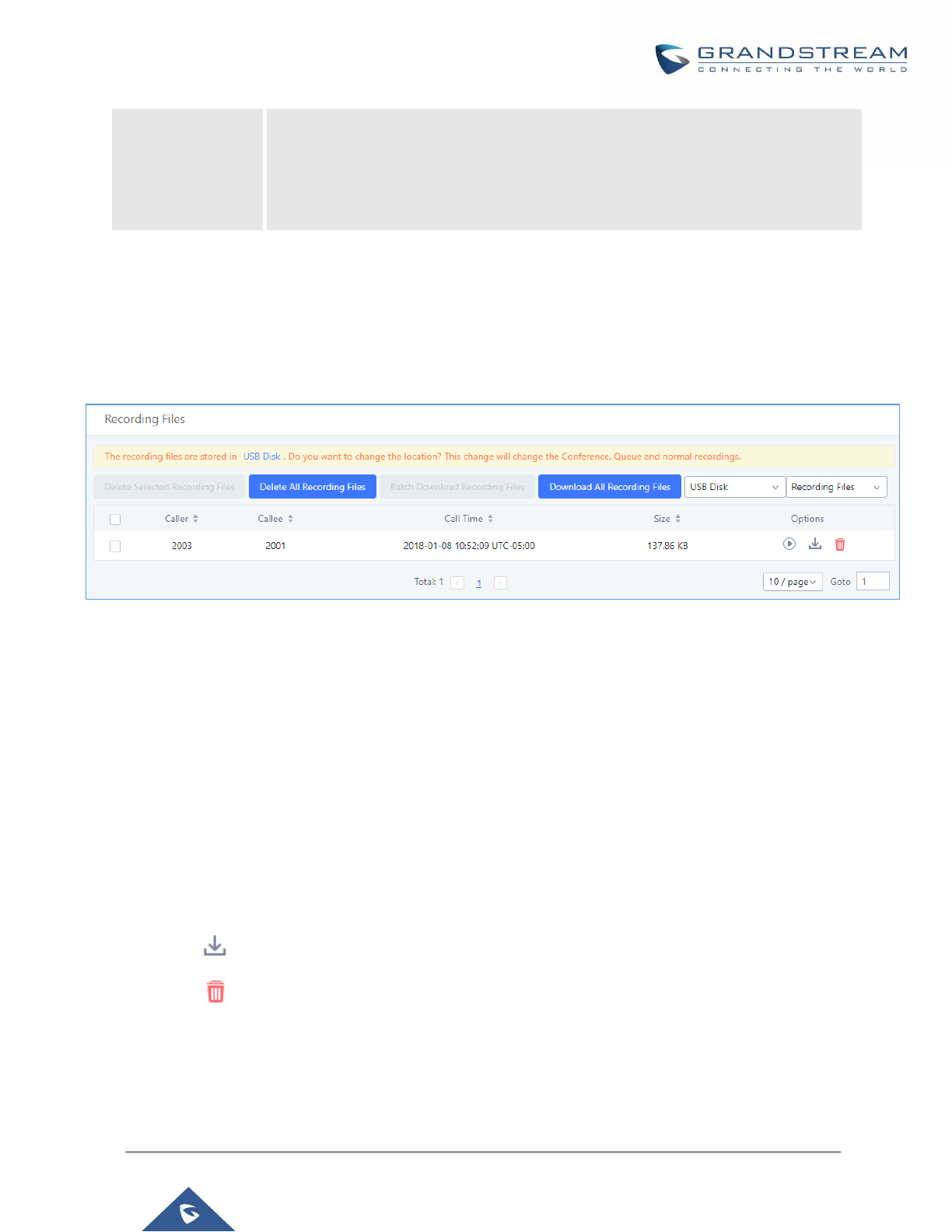
P a g e | 390
UCM6200 Series User Manual
Version 1.0.19.21
Time Range
• By month (of the selected year).
• By week (of the selected year).
• By day (of the specified month for the year).
• By hour (of the specified date).
• By range. For example, 2016-01 To 2016-03.
Recording Files
This page lists all the recording files recorded by "Auto Record" per extension/ring group/call queue/trunk, or via
feature code "Audio Mix Record". If external storage device is plugged in, for example, SD card or USB drive,
the files are stored on the external storage. Otherwise, internal storage will be used on the UCM6200.
Figure 283: CDR→Recording Files
• Click on “Delete Selected Recording Files” to delete the recording files.
• Click on “Delete All Recording Files” to delete all recording files.
• Click on “Batch Download Recording Files” in order to download the selected recording files.
• Click on “Download All Recording Files” to download all recordings files.
• Select Either “USB Disk” or “Local” to show recording files stored on external or internal storage, depending
on selected storage space.
• Select whether to show call recordings, queue recordings or conference recordings.
• Click on to download the recording file in .wav format.
• Click on to delete the recording file.
• To sort the recording file, click on the title "Caller", "Callee" or "Call Time" for the corresponding column. Click
on the title again can switch the sorting mode between ascending order or descending order.

P a g e | 391
UCM6200 Series User Manual
Version 1.0.19.21
API Configuration
The UCM6200 supports third party billing interface API for external billing software to access CDR and call
recordings on the PBX. The API uses HTTPS to request the CDR data and call recording data matching given
parameters as configured on the third-party application.
Before accessing the API, the administrators need enable API and configure the access/authentication
information on the UCM6200 first. The API configuration parameters are listed in the table below.
Table 131: API Configuration Files
Enable
Enable/Disable API. The default setting is disabled.
TLS Bind Address
Configure the IP address for TLS server to bind to. "0.0.0.0" means binding to all
interfaces. The port number is optional and the default port number is 8443. The IP
address must match the common name (host name) in the certificate so that the TLS
socket won't bind to multiple IP addresses. The default setting is 0.0.0.0:8443.
Username
Configure the Username for API Authentication.
Password
Configure the Password for API Authentication.
TLS Private Key
Upload TLS private key. The size of the key file must be under 2MB. This file will be
renamed as 'private.pem' automatically.
TLS Cert
Upload TLS cert. The size of the certificate must be under 2MB. This is the certificate
file (*.pem format only) for TLS connection. This file will be renamed as
"certificate.pem" automatically. It contains private key for the client and signed
certificate for the server.
Permitted IPs
Specify a list of IP addresses permitted by API. This creates an AIP-specific access
control list. Multiple entries are allowed.
For example, "192.168.5.20/255.255.255.255" denies access from all IP addresses
except 192.168.5.20.
The default setting is blank, meaning all IPs will be denied. Users must set permitted
IP address before connecting to the API.
Reset Certificates
Press button to restore UCM’s default certificates.
For more details on CDR API (Access to Call Detail Records) and REC API (Access to Call Recording Files),
please refer the document in the link here:
http://www.grandstream.com/sites/default/files/Resources/ucm6xxx_cdr_rec_api_guide.pdf
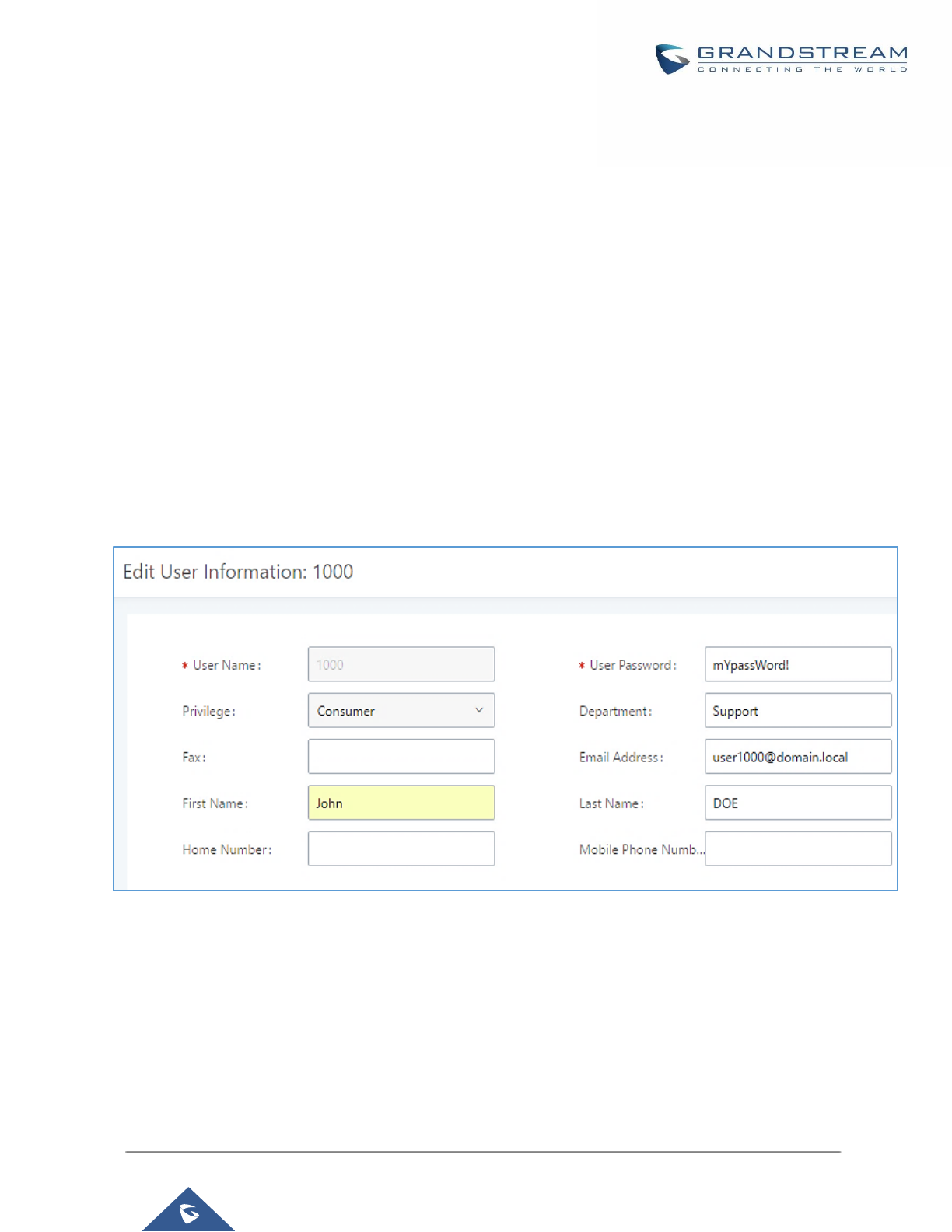
P a g e | 392
UCM6200 Series User Manual
Version 1.0.19.21
USER PORTAL
Users could log into their web GUI portal using the extension number and user password. When an extension is
created in the UCM62XX, the corresponding user account for the extension is automatically created. The user
portal allows access to a variety of features which include user information, extension configuration and CDR as
well as settings and managing value-added features like WebRTC, Fax Sending, Call Queue, Wakeup Service
and CRM.
Users also can access their personal data files (call recordings, Fax files, Voicemail Prompts …).
The login credentials are configured by Super Admin. The following figure shows the dialog of editing the account
information by Super Admin. The User Name must be the extension number and it’s not configurable, and the
password is set on “User Password” field and it should not be confused with the SIP extension password.
Figure 284: Edit User Information by Super Admin
The following screenshot shows an example of login page using extension number 1000 as the username.
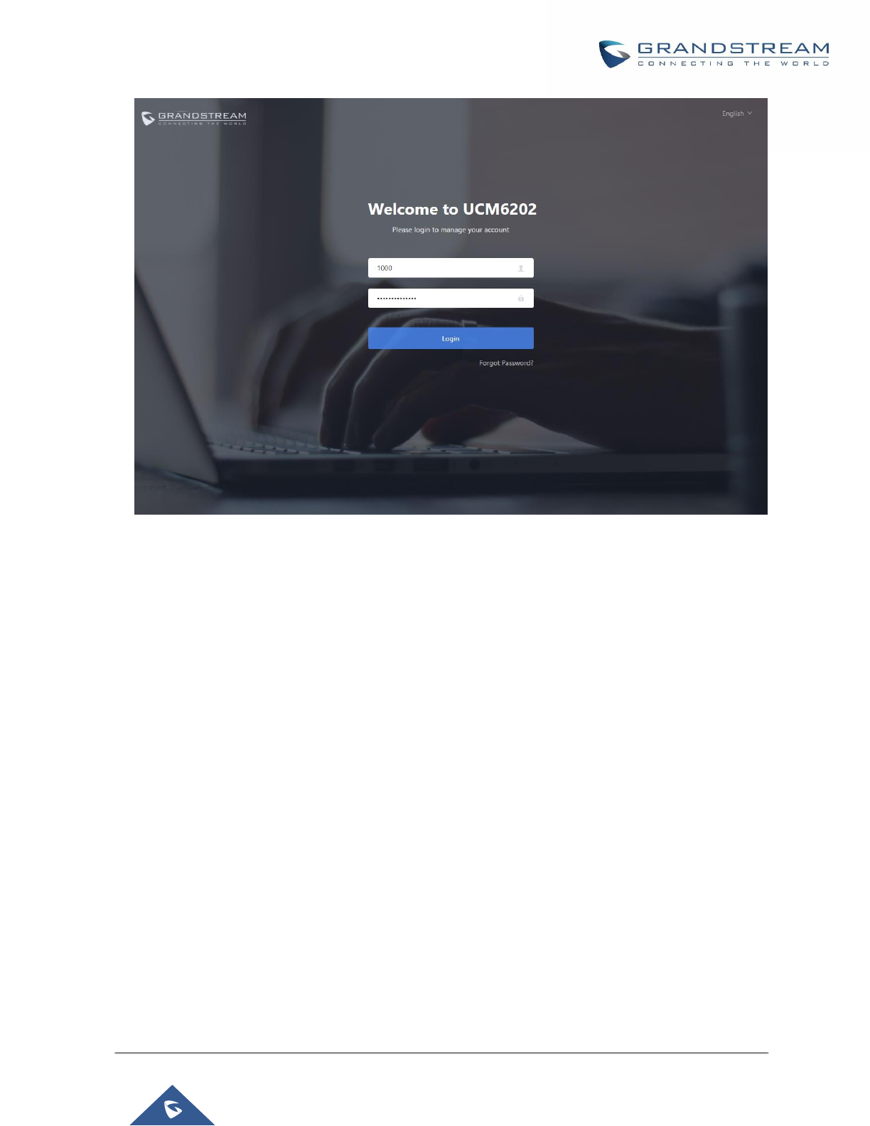
P a g e | 393
UCM6200 Series User Manual
Version 1.0.19.21
Figure 285: User Portal Login
After login, the Web GUI display is shown as below.
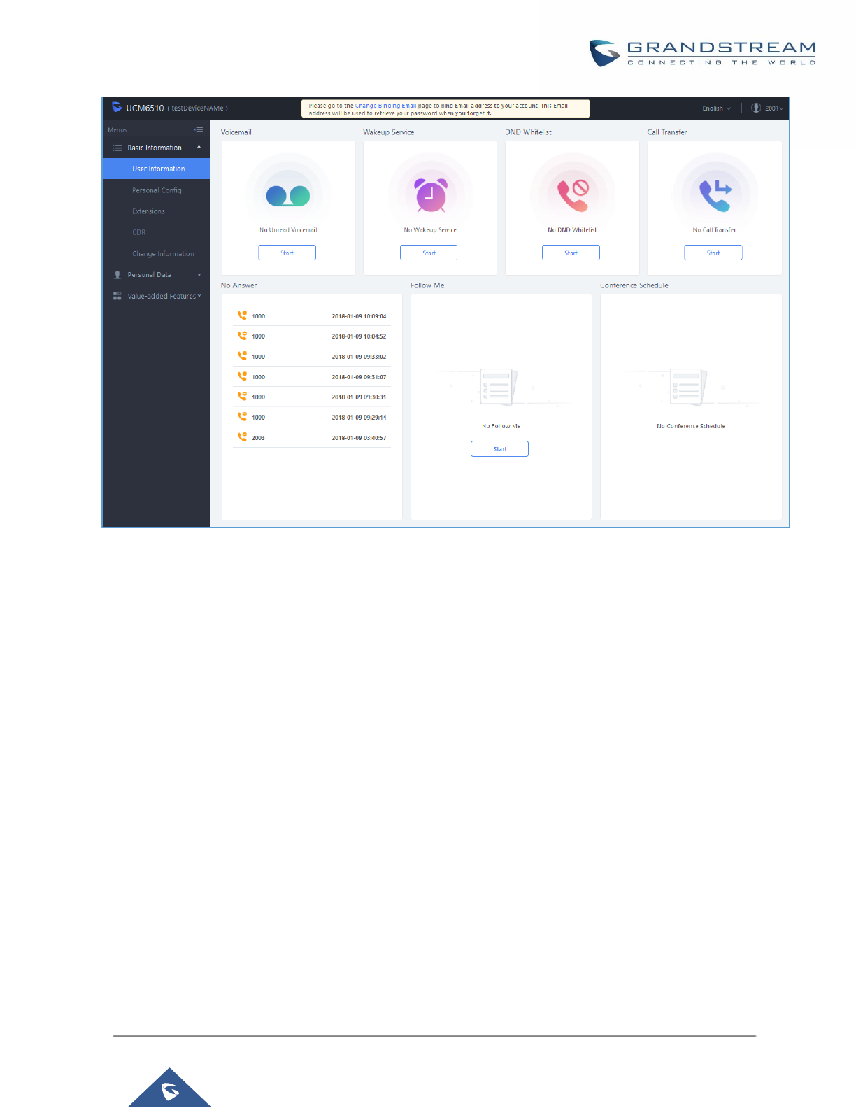
P a g e | 394
UCM6200 Series User Manual
Version 1.0.19.21
Figure 286: User Portal Layout
After successful login, the user has the following three configuration tabs:
Basic Information
Under this menu, the user can configure and change his/her personal information including (first name, last
name, password, email address, department…). And they can also set and activate their extension features
(presence status, call forward, DND ….) to be reflected on the UCM.
Also, the user can see from this menu the Call Details Records and search for specific ones along with the
possibility to download the records on CSV format for later usage.
Personal Data
Under this section, the user can access and manage their personal data files which includes (voicemail files, call
recordings, and fax files) along with the possibility to set Follow me feature to without requesting the Super admin
to set the feature from admin account.
Value-added Features
On this section, the user has access to manage and use all rich value-added features which includes.
+ WebRTC connection and making calls from the browser.

P a g e | 395
UCM6200 Series User Manual
Version 1.0.19.21
+ Sending Fax files using PDF or TIF/TIFF format.
+ If user is a member of call queue, they can check the queue’s activity from the “Call Queue” section.
+ Create and enable WakeUp service.
+ Enable and configure CRM connection to either SugarCRM or Salesforce.
For the configuration parameter information in each page, please refer to [Table 132: User Management
→
Create
New User] for options in User Portal→Basic Information→User Information page; please refer to
[EXTENSIONS] for options in User Portal→Basic Information→Extension page; please refer to [CDR] for User
Portal→Basic Information→CDR page.
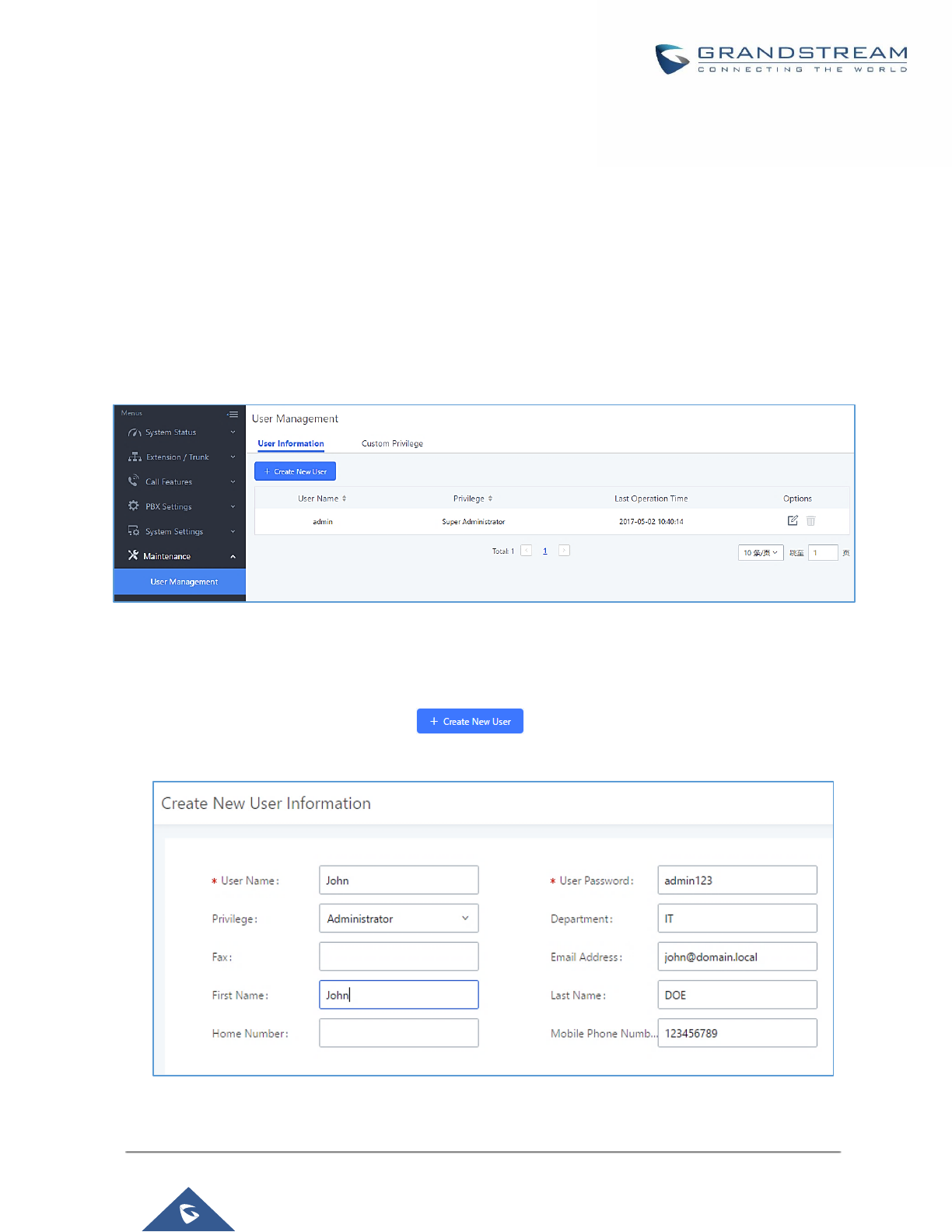
P a g e | 396
UCM6200 Series User Manual
Version 1.0.19.21
MAINTENANCE
User Management
User management is on Web GUI→Maintenance→User Management page. User could create multiple
accounts for different administrators to log in the UCM6200 Web GUI. Additionally, the system will automatically
create user accounts along with creating new extensions for extension users to login to the Web GUI using their
extension number and password. All existing user accounts for Web GUI login will be displayed on User
Management page as shown in the following figure.
Figure 287: User Management Page Display
User Information
When logged in as Super Admin, click on to create a new account for Web GUI user. The
following dialog will prompt. Configure the parameters as shown in below table.
Figure 288: Create New User
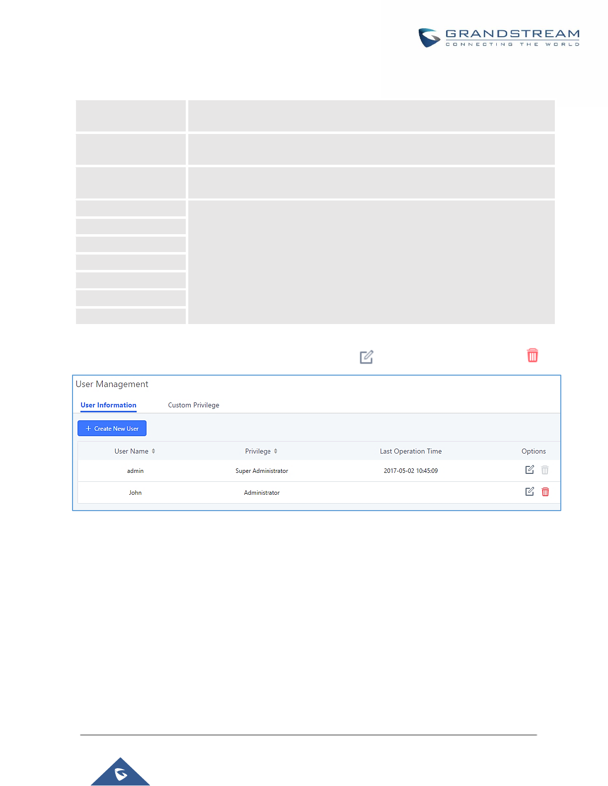
P a g e | 397
UCM6200 Series User Manual
Version 1.0.19.21
Table 132: User Management→Create New User
User Name
Configure a username to identify the user which will be required in Web GUI login.
Letters, digits and underscore are allowed in the user name.
User Password
Configure a password for this user which will be required in Web GUI login. Letters,
digits and underscore are allowed.
Privilege
This is the role of the Web GUI user. Currently only “Admin” is supported when
Super Admin creates a new user.
Department
Enter the necessary information to keep a record for this user.
Fax
Email Address
First Name
Last Name
Home Number
Phone Number
Once created, the Super Admin can edit the users by clicking on or delete the user by clicking on .
Figure 289: User Management – New Users
Custom Privilege
Four privilege levels are supported:
• Super Administrator
- This is the highest privilege. Super Admin can access all pages on UCM6200 Web GUI, change
configuration for all options and execute all the operations.
- Super Admin can create, edit and delete one or more users with “Admin” privilege
- Super Admin can edit and delete one or more users with “Consumer” privilege
- Super Admin can view operation logs generated by all users.
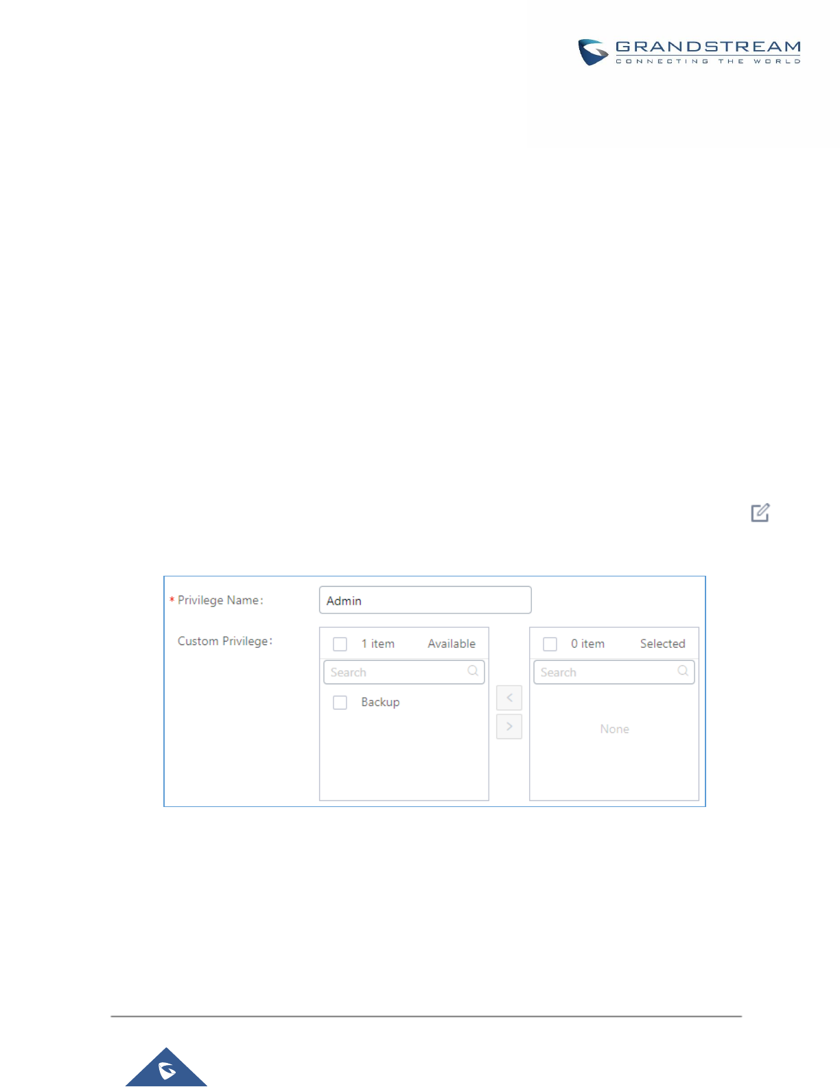
P a g e | 398
UCM6200 Series User Manual
Version 1.0.19.21
- By default, the user account “admin” is configured with “Super Admin” privilege and it’s the only user
with “Super Admin” privilege. The User Name and Privilege level cannot be changed or deleted.
- Super Admin could change its own login password on Web GUI→Maintenance→Change Information
page.
- Super Admin could view operations done by all the users in Web GUI→Maintenance→User
Management→Operation Log
• Administrator
- Users with “Admin” privilege can only be created by “Super Admin” user.
- “Admin” privilege users are not allowed to access the following pages:
Maintenance→Upgrade
Maintenance→Cleaner
Maintenance→Reset/Reboot
Settings→User Management→Operation Log
- “Admin” privilege users cannot create new users for login.
Note: By default, administrator accounts are not allowed to access backup menu, but this can be assigned
to them by editing the option “Maintenance → User Management → Custom Privilege” then press
to edit the “Admin” account and include backup operation permission for these types of users.
Figure 290: Assign Backup permission to "Admin" users
• Consumer
- A user account for Web GUI login is created automatically by the system when a new extension is
created.
- The user could log in the Web GUI with the extension number and password to access user information,
extension configuration and CDR of that extension.
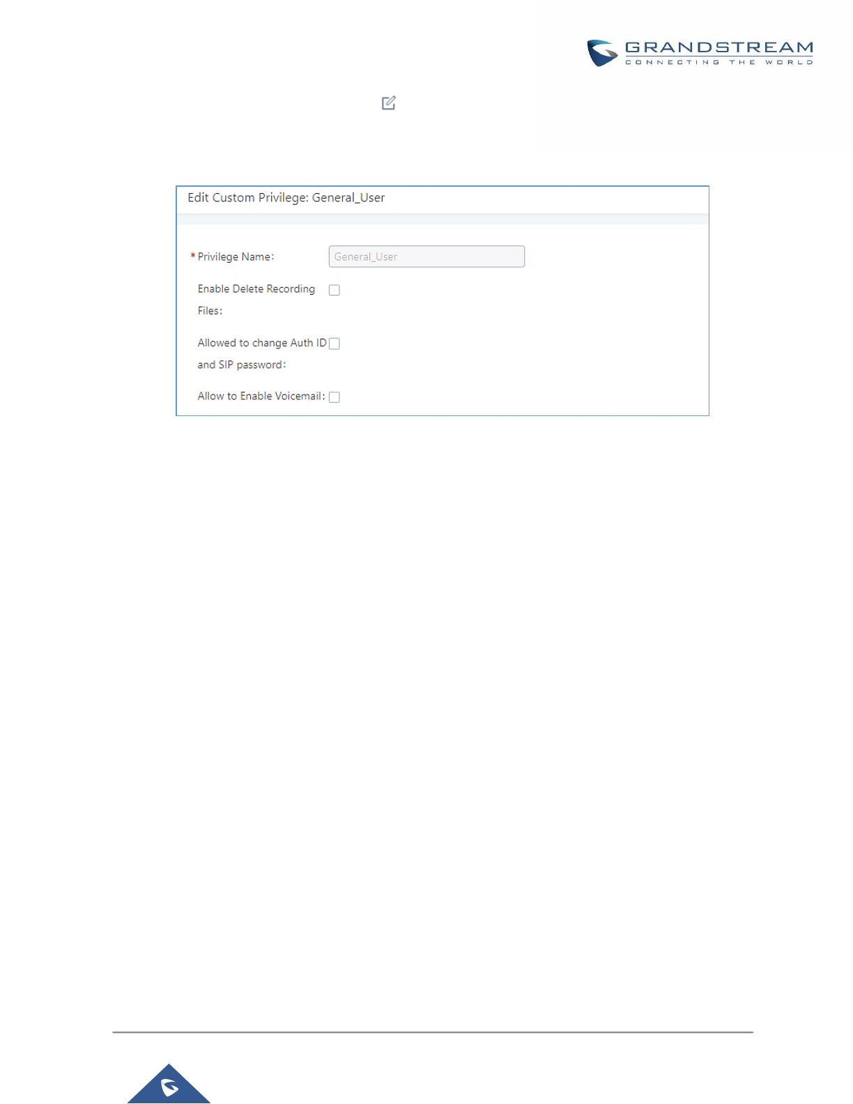
P a g e | 399
UCM6200 Series User Manual
Version 1.0.19.21
- The SuperAdmin user can click on on the “General_User” in order to enable/disable the custom
privilege from deleting their own recording files, changing SIP credentials and disabling voicemail
service in their user portal account.
Figure 291: General User
• Custom Privilege
The Super Admin user can create users with different privileges. 6 modules are available for privilege
customization.
- System Status
- Conference
- System Events
- CDR Records
- CDR API
- Wakeup Service
- Extensions
- IVR
- Voicemail
- Ring Groups
- Paging/Intercom
- Call Queue
- Pickup Groups
- Speed Dial
- DISA
- Event List
- Call back
- Feature Codes
- Fax/T.38
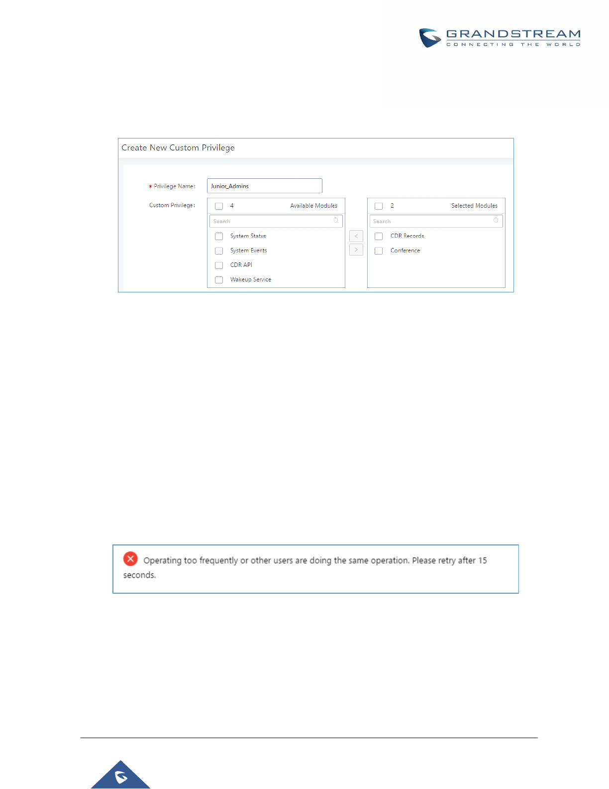
P a g e | 400
UCM6200 Series User Manual
Version 1.0.19.21
- Parking Lot
- Backup
- Dial by Name
- Emergency Calls
Figure 292: Create New Custom Privilege
Log in UCM6200 as super admin and go to Maintenance→User Management→Custom Privilege, create
privilege with customized available modules.
To assign custom privilege to a sub-admin, navigate to UCM Web GUI→Maintenance→User
Management→User Information→Create New User/Edit Users, select the custom privilege from “Privilege”
option.
Concurrent Multi-User Login
When there are multiple Web GUI users created, concurrent multi-user login is supported on the UCM6200.
Multiple users could edit options and have configurations take effect simultaneously. However, if different users
are editing the same option or making the same operation (by clicking on “Apply Changes”), a prompt will pop
up as shown in the following figure.
Figure 293: Multiple User Operation Error Prompt
Change Password
After logging in the UCM6200 Web GUI for the first time, it is highly recommended for users to change the default
password "admin" to a more complicated password for security purpose. Follow the steps below to change the
Web GUI access password.
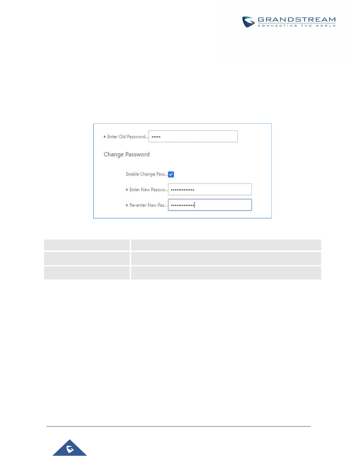
P a g e | 401
UCM6200 Series User Manual
Version 1.0.19.21
1. Go to Web GUI→Maintenance→Change Information page.
2. Enter the old password first.
3. Enter the new password and re-type the new password to confirm. The new password has to be at least 4
characters. The maximum length of the password is 30 characters.
4. Configure the Email Address that is used when login credential is lost.
5. Click on "Save" and the user will be automatically logged out.
6. Once the web page comes back to the login page again, enter the username "admin" and the new password
to login.
Figure 294: Change Password
Enter Old Password
Enter the Old Password for UCM6200
Enter New Password
Enter the New Password for UCM6200
Retype New Password
Retype the New Password for UCM6200
Change binding Email
UCM6200 allows user to configure binding email in case login password is lost. UCM6200 login credential will
be sent to the designated email address. The feature can be found under Web GUI→System Settings→User
Management→Change Binding Email.

P a g e | 402
UCM6200 Series User Manual
Version 1.0.19.21
Figure 295: Change Binding Email
Table 133: Change Binding Email option
Enter the password
of the account
Enter the current login user credential for UCM6200
Email Address
Email Address is used to retrieve password when password is lost
Login Settings
After the user logs in the UCM6200 Web GUI, the user will be automatically logged out after certain timeout, or
he/she can be banned for a specific period if the login timeout is exceeded. Those values can be specified under
UCM6200 web GUI→Maintenance→Change Information→Login Settings page.
The “User Login Timeout” value is in minute and the default setting is 10 minutes. If the user doesn’t make any
operation on Web GUI within the timeout, the user will be logged out automatically. After that, the Web GUI will
be redirected to the login page and the user will need to enter username and password to log in.
If set to 0, there is no timeout for the Web GUI login session and the user will not be automatically logged out.
“Maximum number of login attempts” can prevent the UCM6200 from brutal force decryption, if this number
is exceeded user IP address will be banned from accessing the UCM for a period of time based on user
configuration, the default value is 5.
“User ban period” specify the period of time in minutes an IP will be banned from accessing the UCM if the User
max number of try login is exceeded, the default value is 5.
“Login Banned User List” show the list of IPs’ banned from the UCM.
“Login White List” User can add a list of IPs’ to avoid the above restriction, thus, they can exceed the User max
number of try login.
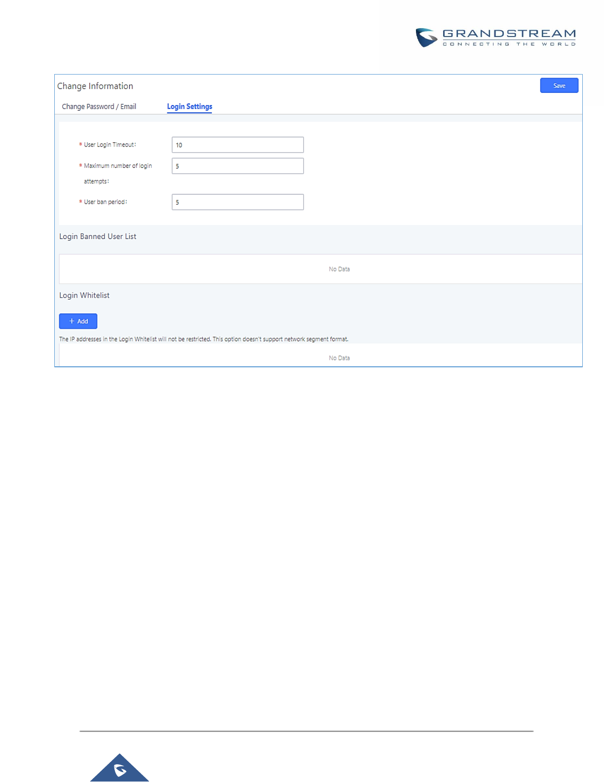
P a g e | 403
UCM6200 Series User Manual
Version 1.0.19.21
Figure 296: Login Timeout Settings
Operation Log
Super Admin has the authority to view operation logs on UCM6200 Web GUI→Settings→User
Management→Operation Log page. Operation logs list operations done by all the Web GUI users, for example,
Web GUI login, creating trunk, creating outbound rule and etc. There are 7 columns to record the operation
details “Date”, “User Name”, “IP Address”, “Results”, “Page Operation”, “Specific Operation” and “Remark”.
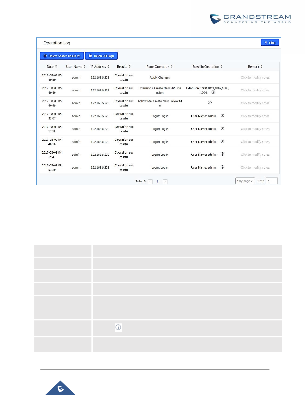
P a g e | 404
UCM6200 Series User Manual
Version 1.0.19.21
Figure 297: Operation Logs
The operation log can be sorted and filtered for easy access. Click on the header of each column to sort. For
example, clicking on "Date" will sort the logs according to operation date and time. Clicking on "Date" again will
reverse the order.
Table 134: Operation Log Column Header
Date
The date and time when the operation is executed.
User Name
The username of the user who performed the operation.
IP Address
The IP address from which the operation is made.
Results
The result of the operation.
Page Operation
The page where the operation is made. For example, login, logout, delete user, create
trunk and etc.
Specific Operation
Click on to view the options and values configured by this operation.
Remark
Allows users to add notes and remarks to each operation
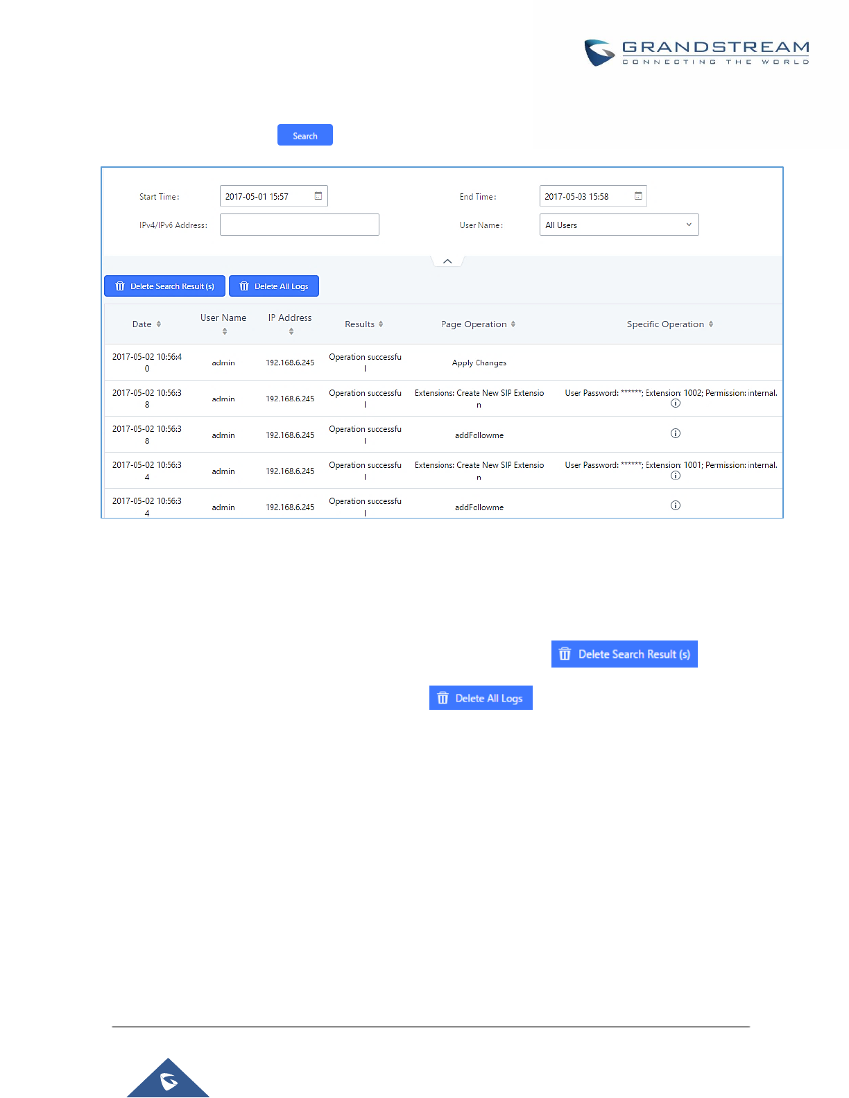
P a g e | 405
UCM6200 Series User Manual
Version 1.0.19.21
User could also filter the operation logs by time condition, IP address and/or username. Configure these
conditions and then click on .
Figure 298: Operation Logs Filter
The above figure shows an example that operations made by user “support” on device with IP 192.168.40.173
from 2014-11-01 00:00 to 2014-11-06 15:38 are filtered out and displayed.
To delete operation logs, users can perform filtering first and then click on to delete the
filtered result of operation logs. Or users can click on to delete all operation logs at once.
Upgrading
The UCM6200 can be upgraded to a new firmware version remotely or locally. This section describes how to
upgrade your UCM6200 via network or local upload.
Upgrading Via Network
The UCM6200 can be upgraded via TFTP/HTTP/HTTPS by configuring the URL/IP Address for the
TFTP/HTTP/HTTPS server and selecting a download method. Configure a valid URL for TFTP, HTTP or HTTPS;
the server name can be FQDN or IP address.
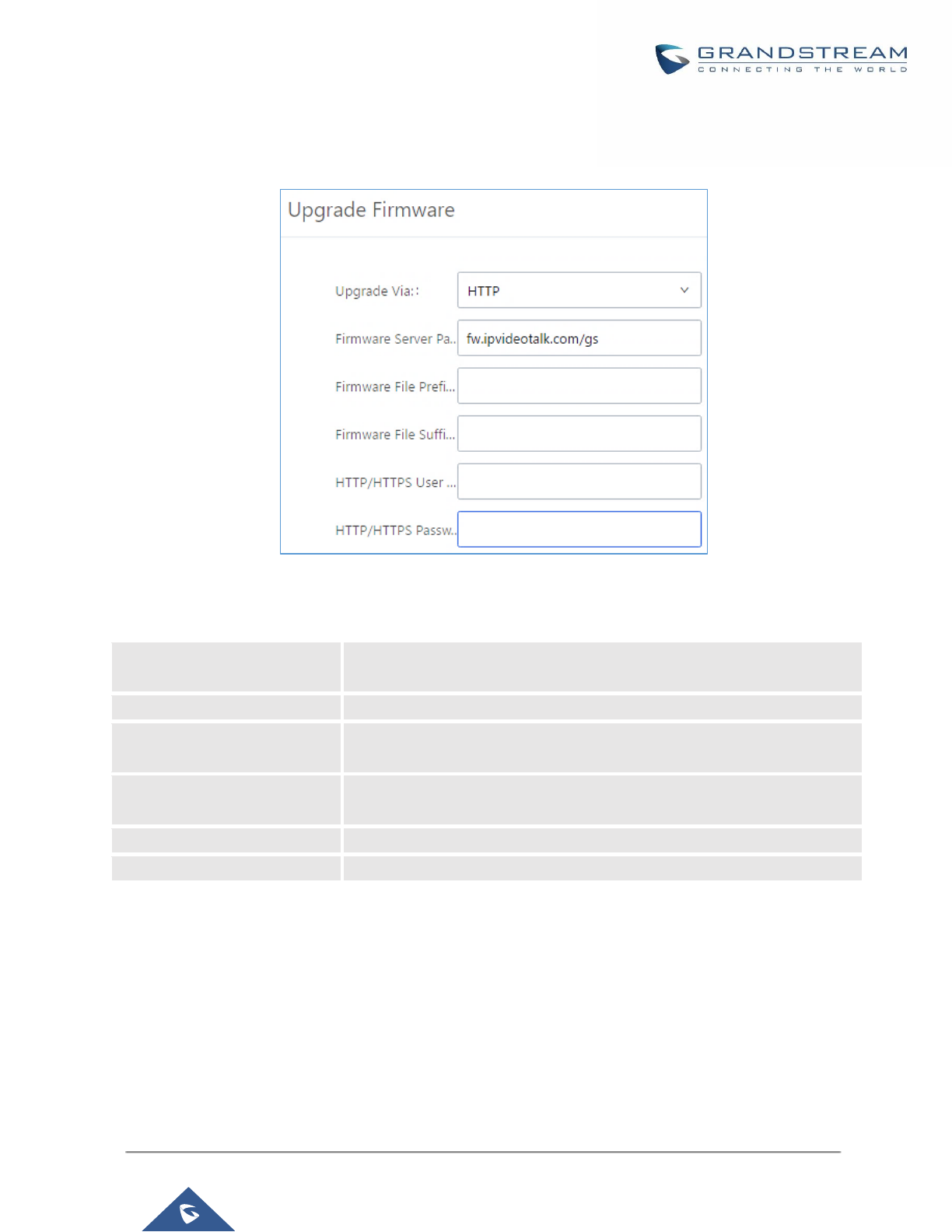
P a g e | 406
UCM6200 Series User Manual
Version 1.0.19.21
Examples of valid URLs:
firmware.grandstream.com/BETA
The upgrading configuration can be accessed via Web GUI→Maintenance→Upgrade.
Figure 299: Network Upgrade
Table 135: Network Upgrade Configuration
Upgrade Via
Allow users to choose the firmware upgrade method: TFTP, HTTP or
HTTPS.
Firmware Server Path
Define the server path for the firmware server.
Firmware File Prefix
If configured, only the firmware with the matching encrypted prefix will be
downloaded and flashed into the UCM6200.
Firmware File Suffix
If configured, only the firmware with the matching encrypted postfix will be
downloaded and flashed into the UCM6200.
HTTP/HTTPS User Name
The user name for the HTTP/HTTPS server.
HTTP/HTTPS Password
The password for the HTTP/HTTPS server.
Please follow the steps below to upgrade the firmware remotely.
1. Enter the firmware server path under Web GUI→Maintenance→Upgrade.
2. Click on "Save". Then reboot the device to start the upgrading process.
3. Please be patient during upgrading process. Once done, a reboot message will be displayed in the LCD.
4. Manually reboot the UCM6200 when it's appropriate to avoid immediate service interruption. After it
boots up, log in the Web GUI to check the firmware version.
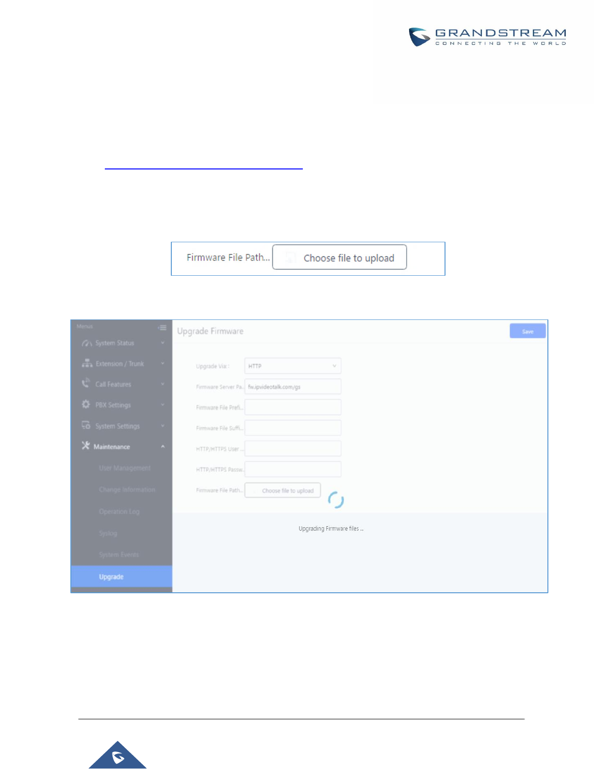
P a g e | 407
UCM6200 Series User Manual
Version 1.0.19.21
Upgrading Via Local Upload
If there is no HTTP/TFTP server, users could also upload the firmware to the UCM6200 directly via Web GUI.
Please follow the steps below to upload firmware locally.
1. Download the latest UCM6200 firmware file from the following link and save it in your PC.
http://www.grandstream.com/support/firmware
2. Log in the Web GUI as administrator in the PC.
3. Go to Web GUI→Maintenance→Upgrade, upload the firmware file by clicking on “choose file to upload”
and select the firmware file from your PC. The default firmware file name is ucm6200fw.bin
Figure 300: Local Upgrade
Figure 301: Upgrading Firmware Files
4. Wait until the upgrading process is successful and a window will be popped up in the Web GUI.
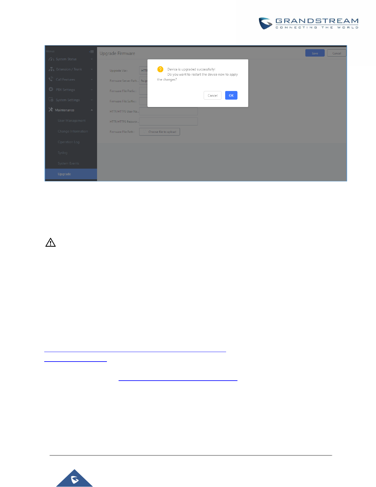
P a g e | 408
UCM6200 Series User Manual
Version 1.0.19.21
Figure 302: Reboot UCM6200
5. Click on "OK" to reboot the UCM6200 and check the firmware version after it boots up.
----------------------------------------------------------------------------------------------------------------------------- ----------------------
Notes:
- Please do not interrupt or power cycle the UCM6200 during upgrading process.
- The firmware file name allows the use of the special characters besides the following restricted
characters: # $ ^ & * + ( ) [ ] / ; ‘ | , < > ?
---------------------------------------------------------------------------------------------------------------------------------------------------
No Local Firmware Servers
Service providers should maintain their own firmware upgrade servers. For users who do not have
TFTP/HTTP/HTTPS server, some free windows version TFTP servers are available for download from
http://www.solarwinds.com/products/freetools/free_tftp_server.aspx
http://tftpd32.jounin.net
Please check our website at http://www.grandstream.com/support/firmware for latest firmware.
Instructions for local firmware upgrade via TFTP:
1. Unzip the firmware files and put all of them in the root directory of the TFTP server;
2. Connect the PC running the TFTP server and the UCM6200 to the same LAN segment;
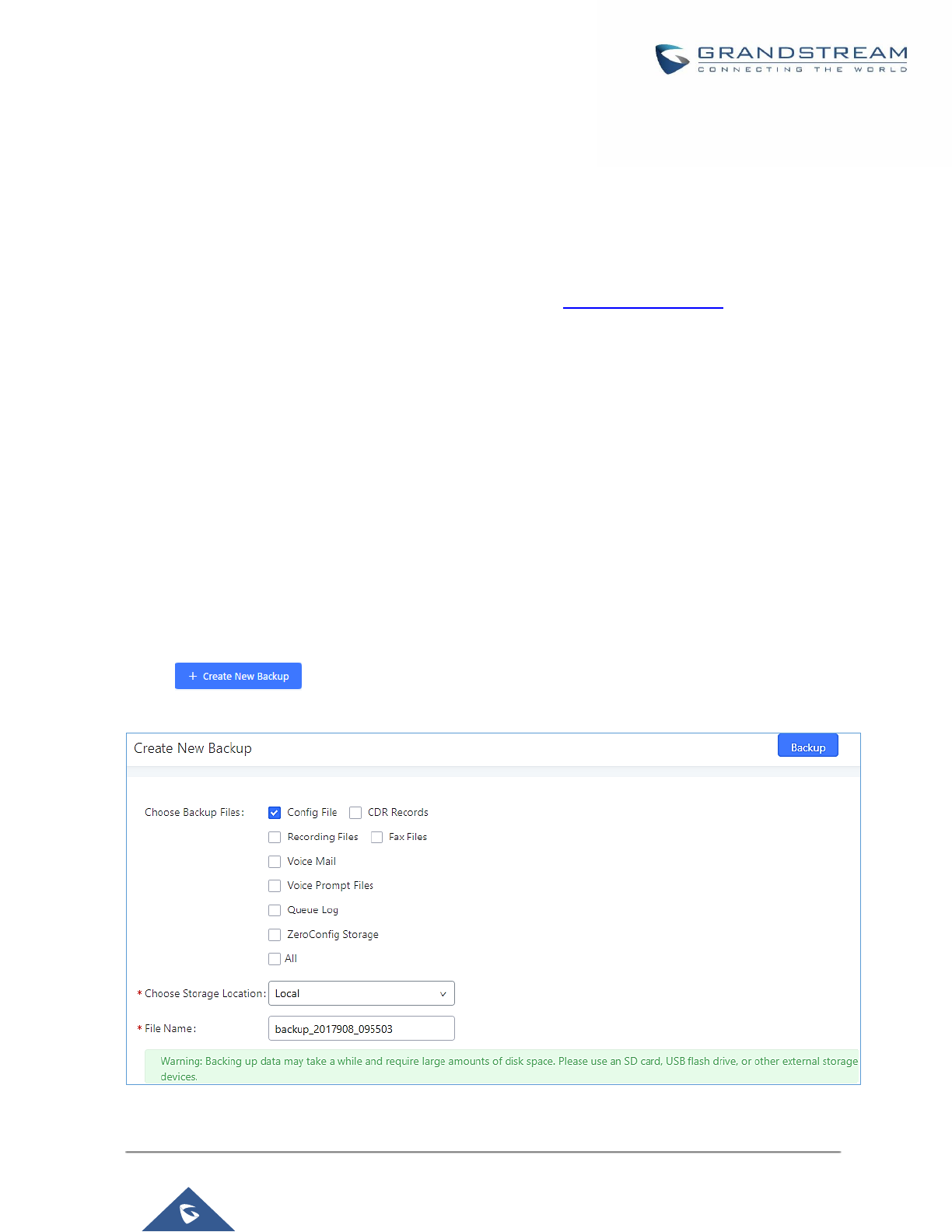
P a g e | 409
UCM6200 Series User Manual
Version 1.0.19.21
3. Launch the TFTP server and go to the File menu→Configure→Security to change the TFTP server's default
setting from "Receive Only" to "Transmit Only" for the firmware upgrade;
4. Start the TFTP server and configure the TFTP server in the UCM6200 web configuration interface;
5. Configure the Firmware Server Path to the IP address of the PC;
6. Update the changes and reboot the UCM6200.
End users can also choose to download a free HTTP server from http://httpd.apache.org/ or use
Microsoft IIS web server.
Backup
The UCM6200 configuration can be backed up locally or via network. The backup file will be used to restore the
configuration on UCM6200 when necessary.
Backup/Restore
Users could backup the UCM6200 configurations for restore purpose under Web
GUI→Maintenance→Backup→Backup/Restore.
Click on to create a new backup file. Then the following dialog will show.
Figure 303: Create New Backup
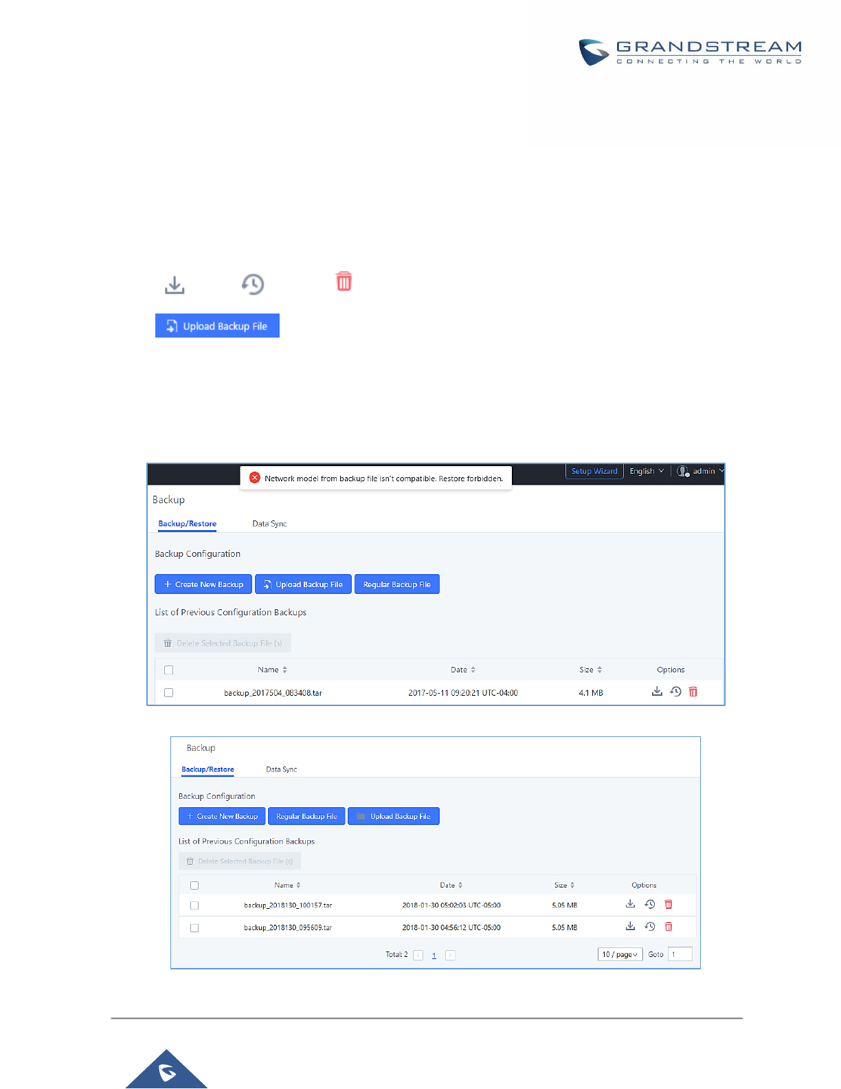
P a g e | 410
UCM6200 Series User Manual
Version 1.0.19.21
1. Choose the type(s) of files to be included in the backup.
2. Choose where to store the backup file: USB Disk, SD Card or Local.
3. Name the backup file.
4. Click on "Backup" to start backup.
Once the backup is done, the list of the backups will be displayed with date and time in the web page. Users can
download , restore , or delete it from the UCM6200 internal storage or the external device.
Click on to upload backup file from the local device to UCM6200. The uploaded backup
file will also be displayed in the web page and can be used to restore the UCM6200.
It is also possible to load backup files from UCM6100 to UCM6200 and vice versa.
Please make sure the FXO port settings, total number of extensions and total number of conference rooms are
compactable before restoring to another UCM model. Otherwise it will prompt a warning and stop the restore
process as shown below:
Figure 304: Restore Warning
Figure 305: Backup / Restore
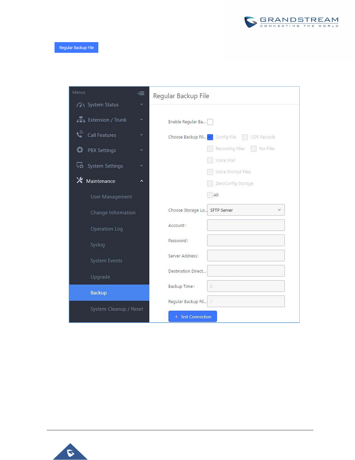
P a g e | 411
UCM6200 Series User Manual
Version 1.0.19.21
The option allows UCM to perform automatically backup on the user specified time. Regular
backup file can only be stored in USB / SD card / SFTP server. User is allowed to set backup time from 0-23 and
how frequent the backup will be performed.
Figure 306: Local Backup
Data Sync
Besides local backup, users could backup the voice records/voice mails/CDR/FAX in a daily basis to a remote
server via SFTP protocol automatically under Web GUI→Maintenance→Backup→Data Sync.
The client account supports special characters such as @ or “.” Allowing the use email address as SFTP
accounts. It allows users as well to specify the destination directory on SFTP server for backup file. If the directory
doesn’t exist on the destination, UCM6200 will create the directory automatically

P a g e | 412
UCM6200 Series User Manual
Version 1.0.19.21
Figure 307: Data Sync
Table 136: Data Sync Configuration
Enable Data Sync
Enable the auto data sync function. The default setting is "No".
Account
Enter the Account name on the SFTP backup server.
Password
Enter the Password associate with the Account on the SFTP backup server.
Server Address
Enter the SFTP server address.
Destination Directory
Specify the directory in SFTP server to keep the backup file. Format:
‘xxx/xxx/xxx’, If this directory does not exist, UCM will create this directory
automatically.
Sync Time
Enter 0-23 to specify the backup hour of the day.
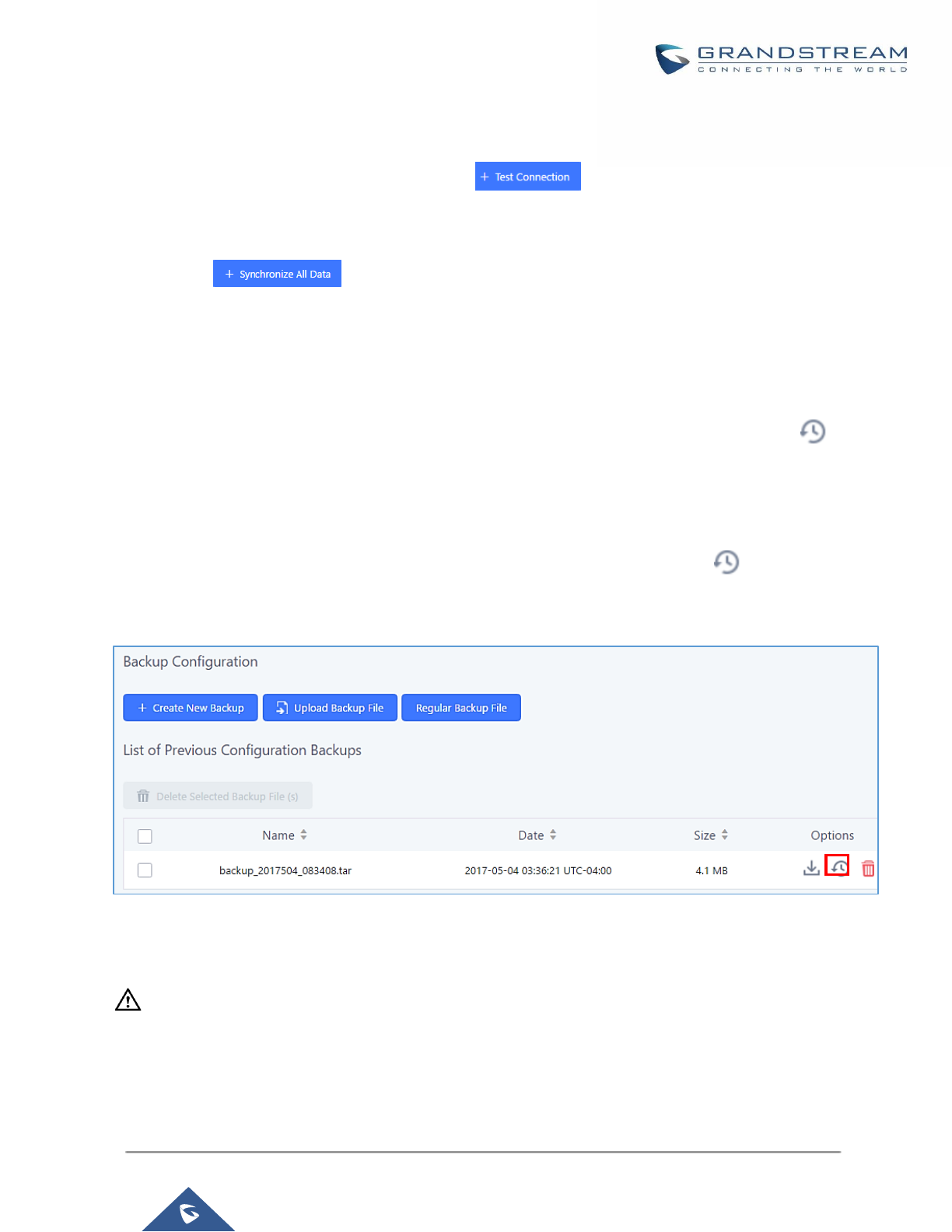
P a g e | 413
UCM6200 Series User Manual
Version 1.0.19.21
Before saving the configuration, users could click on . The UCM6200 will then try connecting the
server to make sure the server is up and accessible for the UCM6200. Save the changes and all the backup
logs will be listed on the web page. After data sync is configured, users could also manually synchronize all data
by clicking on instead of waiting for the backup time interval to come.
Restore Configuration from Backup File
To restore the configuration on the UCM6200 from a backup file, users could go to Web
GUI→Maintenance→Backup→Backup/Restore.
• A list of previous configuration backups is displayed on the web page. Users could click on of the
desired backup file and it will be restored to the UCM6200.
• If users have other backup files on PC to restore on the UCM6200, click on "Upload Backup File" first and
select it from local PC to upload on the UCM6200. Once the uploading is done, this backup file will be
displayed in the list of previous configuration backups for restore purpose. Click on to restore from the
backup file.
Figure 308: Restore UCM6200 from Backup File
----------------------------------------------------------------------------------------------------------------------------- ----------------------
Note:
• The uploaded backup file must be a tar file with no special characters like *,!,#,@,&,$,%,^,(,),/,\,space in
the file name.
• The uploaded back file size must be under 10MB.
----------------------------------------------------------------------------------------------------------------------------- ----------------------
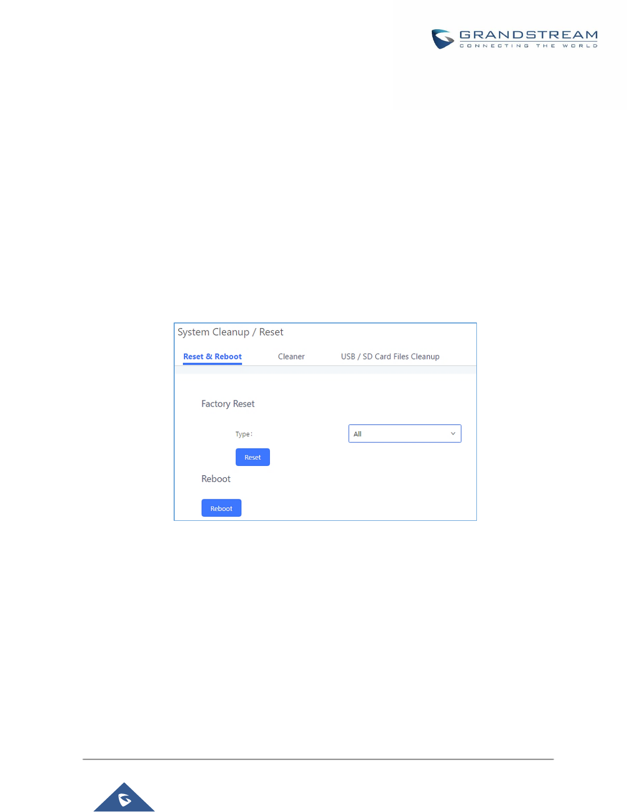
P a g e | 414
UCM6200 Series User Manual
Version 1.0.19.21
System Cleanup/Reset
Reset and Reboot
Users could perform reset and reboot under Web GUI→Maintenance→System Cleanup/Reset→Reset and
Reboot.
To factory reset the device, select the mode type first. There are two different types for reset.
• User Data
All the data including voicemail, recordings, IVR Prompt, Music on Hold, CDR and backup files will be
cleared.
• All
All the configurations and data will be reset to factory default.
Figure 309: Reset and Reboot
Cleaner
Users could configure to clean the Call Detail Report/Voice Records/Voice Mails/FAX automatically under Web
GUI→Maintenance→System Cleanup/Reset→Cleaner.
The following screenshot show the settings and parameters to configure the cleaner feature on UCM6200.
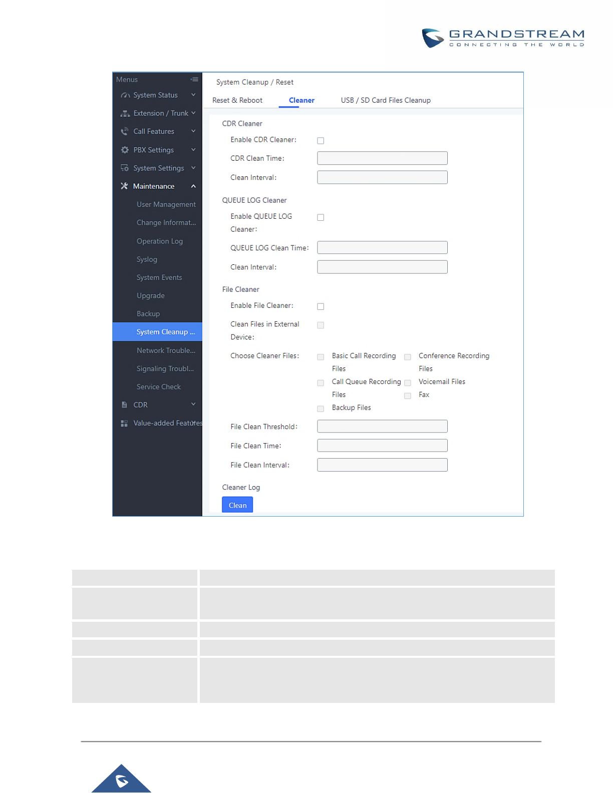
P a g e | 415
UCM6200 Series User Manual
Version 1.0.19.21
Figure 310: Cleaner
Table 137: Cleaner Configuration
Enable CDR Cleaner
Enable the CDR Cleaner function.
Clean Files in External
Device
If enabled the files in external device (USB/SD card) will be atomically cleaned
up as configured.
CDR Clean Time
Enter 0-23 to specify the hour of the day to clean up CDR.
Clean Interval
Enter 1-30 to specify the day of the month to clean up CDR.
Enable Queue Statistics
Report Cleaner
Enable scheduled queue log cleaning. By default, is disabled.

P a g e | 416
UCM6200 Series User Manual
Version 1.0.19.21
Queue Statistics Report
Cleaner Clean Time
Enter the hour of the day to start the cleaning. The valid range is 0-23.
Clean Interval
Enter how often (in days) to clean queue logs. The valid range is 1-30.
Enable File Cleaner
Enter the Voice Records Cleaner function.
Choose Cleaner File
Select the files for system automatic clean.
• Basic Call Recording Files.
• Conference Recording Files.
• Call Queue Recording Files.
• Voicemail Files.
• Fax
• Backup Files.
File Clean Threshold
Specify the threshold of local storage usage from 0 to 99 (in percentage).
File Clean Time
Enter 0-23 to specify the hour of the day to clean up the files.
File Clean Interval
Enter 1-30 to specify the day of the month to clean up the files.
All the cleaner logs will be listed on the bottom of the page.
USB/SD Card Files Cleanup
Users could configure to clean the Call Detail Report/Voice Records/Voice Mails/FAX automatically under Web
GUI→Maintenance→System Cleanup/Reset→USB / SD Card Files Cleanup.
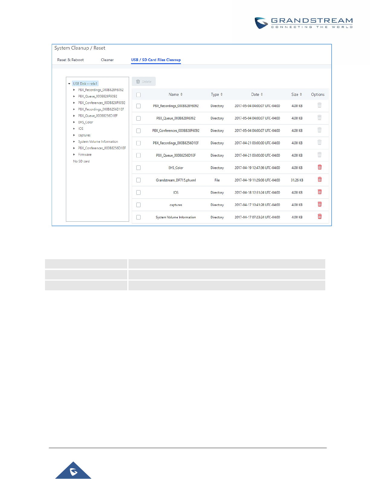
P a g e | 417
UCM6200 Series User Manual
Version 1.0.19.21
Figure 311: USB/SD Card Files Cleanup
Table 138: USB/SD Card Files Cleanup
Current Path
Displays the current path.
Directory
Select the directory user want to clean.
Delete Selected File
Select multiple entries to delete from USB or SD card.
System Recovery
In some cases (for example after wrong upgrading procedure where the user doesn’t follow the correct steps to
perform an upgrade) the system may go into some hardware/software issues where the web UI access is lost
as well as SSH, in this case the only solution would be to perform a full system recovery in order to reset or
update the software version of the device in order to use it again.
1. To access recovery mode on UCM, please follow below steps:
2. Remove the power from the unit and keep the network cable connected.
3. Press using a PIN the reset button and keep holding.
4. Plug back the power supply while maintaining the reset button pressed.
5. Wait for couple of seconds until you hear a click sound.
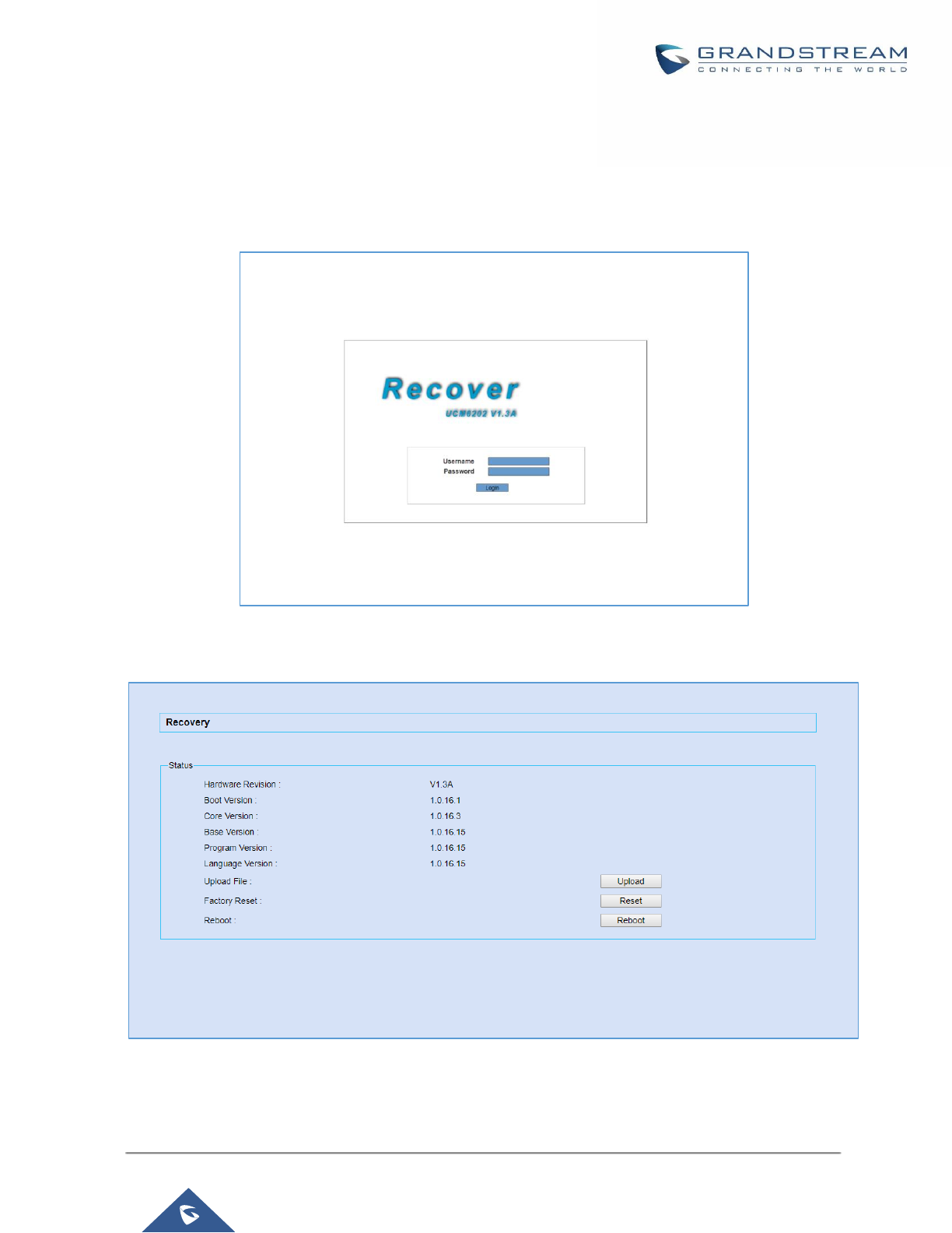
P a g e | 418
UCM6200 Series User Manual
Version 1.0.19.21
6. Release the reset button, and the system should display on the LCD a message “Recovery Mode” along
with an IP address.
Once at this stage, the administrator can access the recovery mode web portal by typing in either the IP0 address
(typically WAN) or IP1 address (typically LAN) into a browser address bar. The following page should appear:
Figure 312: UCM6202 Recovery Web Page
Make sure to enter the correct admin password, and press login to access the recovery mode page :
Figure 313: Recovery Mode
From here, the user can either upload a firmware file, factory reset or just reboot the device.

P a g e | 419
UCM6200 Series User Manual
Version 1.0.19.21
Syslog
On the UCM6200, users could dump the syslog information to a remote server under Web
GUI→Maintenance→Syslog. Enter the syslog server hostname or IP address and select the module/level for
the syslog information.
The default syslog level for all modules is "error", which is recommended in your UCM6200 settings because it
can be helpful to locate the issues when errors happen.
Some typical modules for UCM6200 functions are as follows and users can turn on "notice" and "verb" levels
besides "error" level.
• pbx: This module is related to general PBX functions.
• chan_sip: This module is related to SIP calls.
• chan_dahdi: This module is related to analog calls (FXO/FXS).
• app_meetme: This module is related to conference room.
----------------------------------------------------------------------------------------------------------------------------- ----------------------
Note:
Syslog is usually for debugging and troubleshooting purpose. Turning on all levels for all syslog modules is not
recommended for daily usage. Too many syslog prints might cause traffic and affect system performance.
The reserved size for Syslog entries on the cache memory of the UCM is 50M, once this sized is reached the
UCM will clean up 2M of the oldest Syslog entries to allow to save new logs.
---------------------------------------------------------------------------------------------------------------------------------------------------
Network Troubleshooting
On the UCM6200, users could capture traces, ping remote host and traceroute remote host for troubleshooting
purpose under Web GUI→Maintenance→Network Troubleshooting.
The following sections shows the steps to capture different types of traffic traces for analysis purposes.
Ethernet Capture
The captured trace can be downloaded for analysis. The instructions or result will be displayed in the Web GUI
output result.
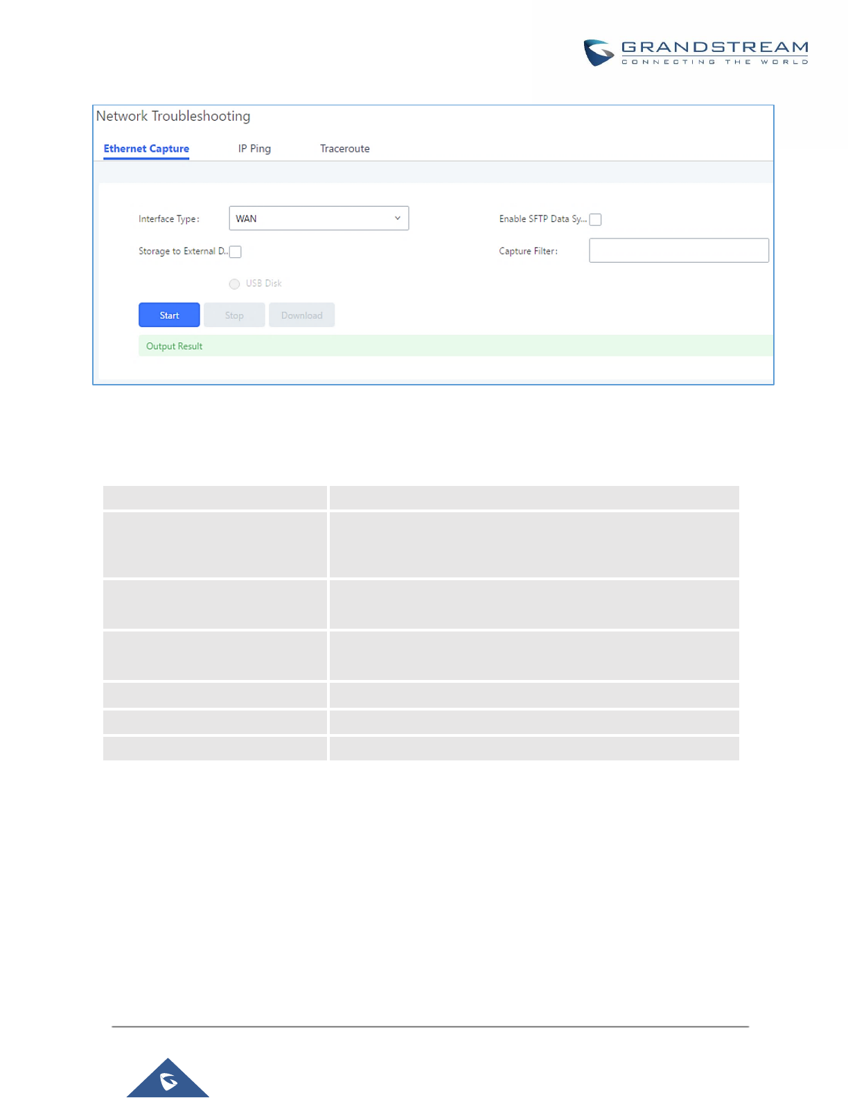
P a g e | 420
UCM6200 Series User Manual
Version 1.0.19.21
Figure 314: Ethernet Capture
Table 139: Ethernet Capture
Interface Type
Select the network interface to monitor.
Enable SFTP Data Sync
Check this box to save the capture files in the SFTP server.
Please make sure the configuration of data synchronization works
before.
Storage to External Device
Check this box to activate storage of the capture either on the
USB or SD Card.
Capture Filter
Enter the filter to obtain the specific types of traffic, such as (host,
src, dst, net, proto…).
Start
Click to start the trace.
Stop
Click to stop the trace.
Download
Click to download the trace if trace is stored locally.
The output result is in .pcap format. Therefore, users could specify the capture filter as used in general network
traffic capture tool (host, src, dst, net, protocol, port, port range) before starting capturing the trace.
Note: Capture files saved on external devices will now have “capture” prepended to file names.
IP Ping
Enter the target host in host name or IP address. Then press "Start" button. The output result will dynamically
display in the window below.
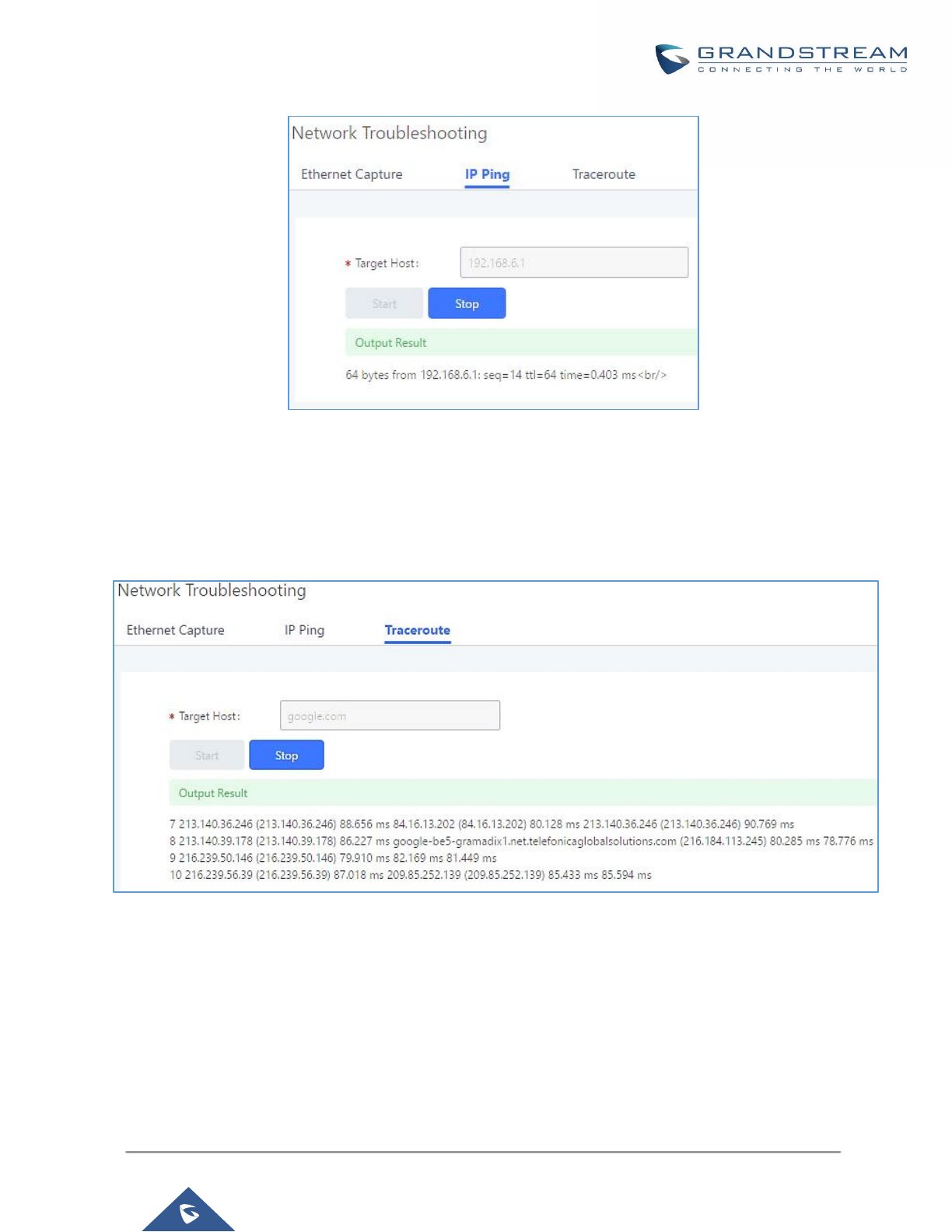
P a g e | 421
UCM6200 Series User Manual
Version 1.0.19.21
Figure 315: Ping
Traceroute
Enter the target host in host name or IP address. Then press "Start" button. The output result will dynamically
display in the window below.
Figure 316: Traceroute
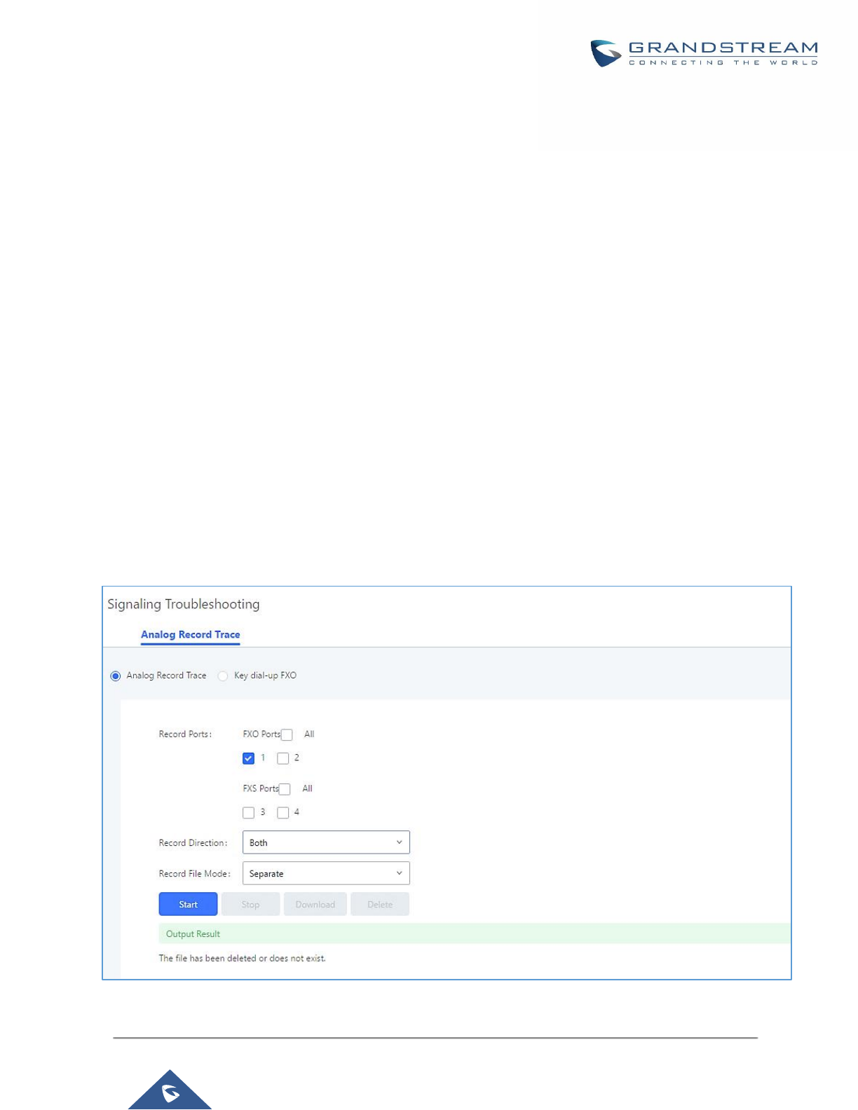
P a g e | 422
UCM6200 Series User Manual
Version 1.0.19.21
Signaling Troubleshooting
Analog Record Trace
• Analog Record Trace
Analog record trace can be used to troubleshoot analog trunk issue, for example, the UCM6200 user has caller
ID issue for incoming call from Analog trunk. Users can access analog record trance under Web
GUI→Maintenance→Signal Troubleshooting→Analog Record Trace.
Here is the step to capture trace:
1. Select FXO or FXS for "Record Ports". If the issue happens on FXO 1, select FXO port 1 to record the
trace.
2. Select "Record Direction".
3. Select "Record File Mode" to separate the record per direction or mix.
4. Click on "Start".
5. Make a call via the analog port that has the issue.
6. Once done, click on "Stop".
7. Click on "Download" to download the analog record trace.
Figure 317: Troubleshooting Analog Trunks
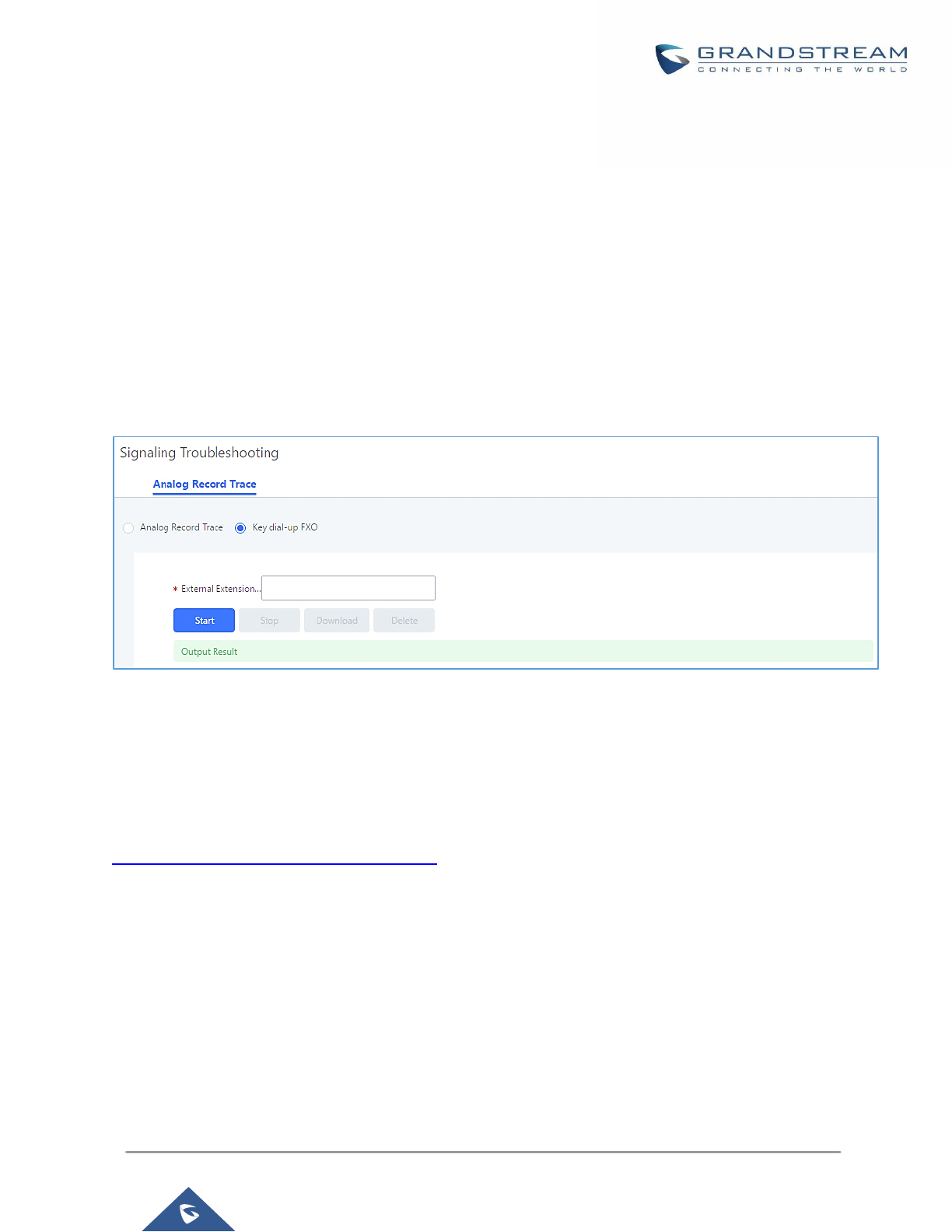
P a g e | 423
UCM6200 Series User Manual
Version 1.0.19.21
• A key Dial-up FXO
Users can directly set a PSTN number on the “External Extension” text box to troubleshoot issues related to
the analog trunk easily, the following steps shows how to use this feature:
1. Configure analog trunk on UCM, including outbound route.
2. Enter a reachable external number in “External Extension”.
3. Press “Start” button. The call will be initiated to the external number.
4. Answer and finish the call before pressing “Stop” button.
The trace will be available for analysis to download after output result shows “Done! Click on Download to
download the captured packets”.
Figure 318: A Key Dial-up FXO
Note: When using a Key Dial-up FXO feature the outbound trunk for the analog trunk need to have internal
permission. As well as it should be the trunk with the highest outbound route priority.
After capturing the trace, users can download it for basic analysis. Or you can contact Grandstream
Technical support in the following link for further assistance if the issue is not resolved.
http://www.grandstream.com/index.php/support
Service Check
Enable Service Check to periodically check UCM6200. Check Cycle is configurable in seconds and the default
setting is 60 sec. Check Times is the maximum number of failed checks before restart the UCM6200. The default
setting is 3. If there is no response from UCM6200 after 3 attempts (default) to check, current status will be
stored and the internal service in UCM6200 will be restarted.
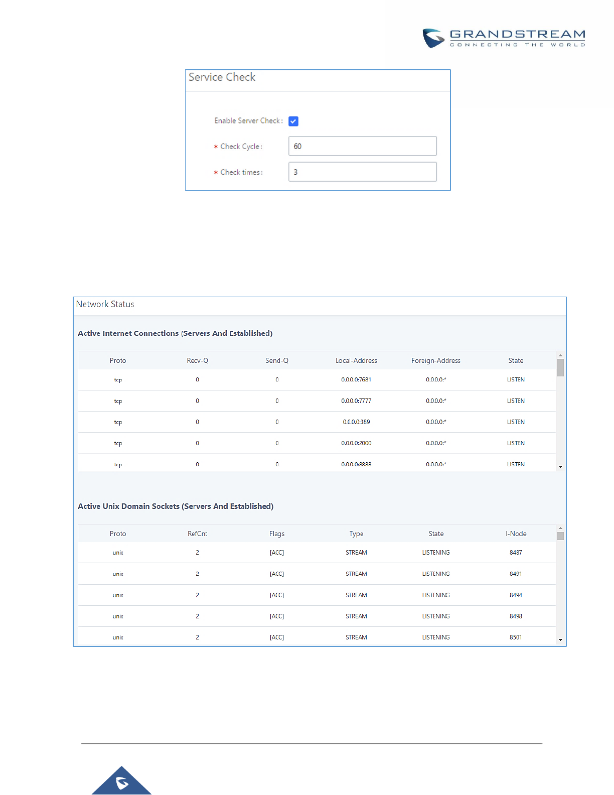
P a g e | 424
UCM6200 Series User Manual
Version 1.0.19.21
Figure 319: Service Check
Network Status
In UCM6200 Web GUI→System Status→Network Status, the users can view active Internet connections. This
information can be used to troubleshoot connection issue between UCM6200 and other services.
Figure 320: Network Status

P a g e | 425
UCM6200 Series User Manual
Version 1.0.19.21
EXPERIENCING THE UCM6200 SERIES IP PBX
Please visit our website: http://www.grandstream.com to receive the most up- to-date updates on firmware
releases, additional features, FAQs, documentation and news on new products.
We encourage you to browse our product related documentation, FAQs and User and Developer Forum for
answers to your general questions. If you have purchased our products through a Grandstream Certified
Partner or Reseller, please contact them directly for immediate support.
Our technical support staff is trained and ready to answer all of your questions. Contact a technical support
member or submit a trouble ticket online to receive in-depth support.
Thank you again for purchasing Grandstream UCM6200 series IP PBX appliance, it will be sure to bring
convenience and color to both your business and personal life.
* Asterisk is a Registered Trademark of Digium, Inc
