HD7999 Unimotor Hd Product Data
User Manual: HD7999
Open the PDF directly: View PDF  .
.
Page Count: 16
Unimotor
Product Data
High dynamic AC brushless servo motor
for Control Techniques drives
055 to 190 Frames
0.72 Nm to 85.0 Nm
(255.0 Nm peak)
www.controltechniques.com www.controltechniques.com 32
Compact servo motor for demanding applications
Unimotor is Control Techniques’ high dynamic brushless
AC servo motor range, designed for operation with Digitax ST,
Unidrive SP, Unidrive M and Epsilon EP drives. Unimotor
provides an exceptionally compact, low inertia solution for
applications where very high torque is required during rapid
acceleration and deceleration profiles. The Unimotor torque
profile is matched to Digitax ST servo drives, providing up to
300% peak overload for maximum dynamic performance.
Engineering excellence, innovation and reliability
Unimotor has been developed by a dedicated team using our
design process that prioritises product innovation, performance
and reliability. This enables new ideas to be quickly evaluated,
prototyped and tested using a suite of in-house development and
modelling software tools. As a result Unimotor incorporates
a number of unique performance enhancing design features with
several patents pending. Unimotor “raises the bar” in terms of
both performance and quality.
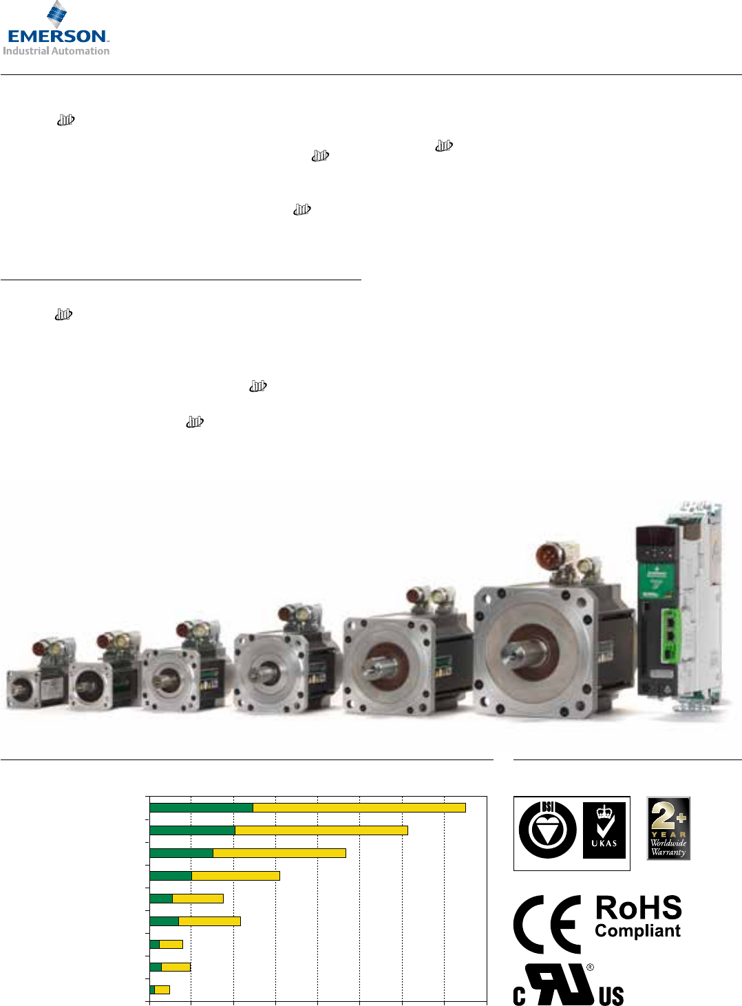
Torque performance ■ Stall torque ■ Peak torque (3000 rpm)
0 205 2510 3015 35 40
055UDA300 + DST1401
055UDC300 + DST1401
067UDA300 + DST1401
067UDC300 + DST1402
089UDA300 + DST1402
089UDB300 + DST1403
089UDC300 + DST1404
115UDB300 + DST1405
115UDC300 + DST1405
Key features
Unimotor is suitable for a wide range of industrial applications,
due to its extensive features.
➜ Torque range: 0.72Nm to 85.0Nm
➜ High torque to inertia ratio for high dynamic performance
➜ Compact but powerful
➜ High energy dissipation brakes
➜ IP65 conformance: sealed against water spray and dust when
mounted and connected
➜ Segmented stator design
➜ World class performance
➜ Supported by rigorous testing for performance and reliability
➜ Winding to suit 400V and 220V
➜ Rated speeds include 2000rpm, 3000rpm, 4000rpm and 6000rpm
➜ Larger shafts to increase torsional rigidity
QUALITY
MANAGEMENT
003
FM 30610
Conformance and standards
www.controltechniques.com www.controltechniques.com 32
The ultimate motor and drive combinations
Control Techniques drive and motor combinations provide an
optimised system in terms of ratings, performance, cost and ease
of use. Unimotor motors tted with high resolution SinCos
or Absolute encoders are pre-loaded with the motor “electronic
nameplate” data during the manufacturing process. This data can be
read by Control Techniques’ servo drives and used to automatically
optimise the drive settings. This feature simplies commissioning
and maintenance, ensures consistent performance and saves time.
For further information on Control Techniques
servo drives, please refer to the Digitax ST,
Unidrive SP and Unidrive M brochures.
Accuracy and resolution to suit your application requirements
Choosing the right feedback device for your application is critical
in getting optimum performance. Unimotor has a range
of feedback options that offer different levels of accuracy and
resolution to suit most applications:
➜ Resolver: robust for extreme applications and conditions
- low accuracy, medium resolution
➜ Incremental encoder: high accuracy, medium resolution
➜ Inductive Absolute: medium accuracy, medium resolution,
single turn and multi-turn
➜ Optical SinCos/Absolute: high accuracy, high resolution,
single turn and multi-turn
➜ Hiperface (SICK) and EnDAT (Heidenhain) protocols supported
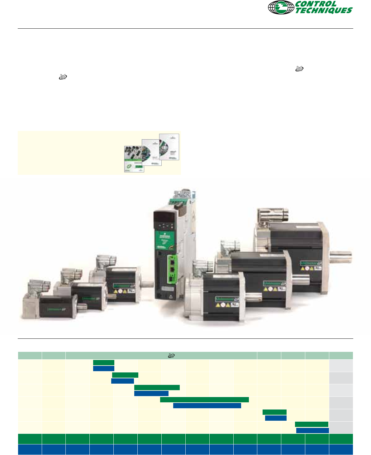
Quick reference table
Frame size PCD (mm) Unimotor Page No.
055 63 5
067 75 6
089 100 7
115 130 8
142 165 9
190 230 10
Stall 0 0.5 1.0 3.0 5.0 8.0 10.0 15.0 20.0 30 60 85.0 (Nm)
Inertia 0 0.1 0.2 0.7 1.5 2.5 6.5 8.0 9.0 20.0 60.0 103.5 (kgcm2)
0.72
0.14
1.65
0.36
3.20
5.80
25.0
52.0
0.87
2.42
17.0
54.6
8.00
18.80
38.0
85.0
2.34
8.38
27.2
103.5
1.45
0.30
3.70
0.75

www.controltechniques.com www.controltechniques.com 54
Unimotor ordering code Information
Use the information below in the illustration to create an order code for a Unimotor .
The details in the band are an example of an order reference.
089 UD B 30 5 B A CA A
Frame
size
Motor
voltage
Stator
length Rated speed* Brake Connection
type
Output
shaft Feedback device Inertia
055 - 089
Frame 055 Frame 055 Frame 055 - 067 Frame
055 ED = 220V A 30 = 3000 rpm 0 = Not tted
B = Power and
Signal 90°
rotatable
A = Round
with
key
AR = Resolver A = Standard
067 UD = 480V B 60 = 6000 rpm 1 = Parking
brake
CR = Incremental Encoder (Renco) 4096 ppr (R35i) E = Standard
+ Lifting
Brackets
089 C 089 Frame
B = Round
Plain
shaft
EM = Inductive Absolute Multi turn EQI 1130
115 115 Frame 30 = 3000 rpm X = Special
J = Power size
1.5 and
Signal 90°
rotatable
on 142
FM = Inductive Absolute Single turn ECI 1118
142 D 40 = 4000 rpm 067 - 190
Frame
LM = Inductive Absolute Multi turn
(Serial comms only) EQI 1130
190 142 Frame 60 = 6000 rpm 0 = Not tted F = Full key
and
half
key
supplied
separately
NM = Inductive Absolute Single turn
(Serial comms only) ECI 1118
C 115 Frame 5 = High
energy
dissipation
Parking
brake
TL = Optical Sincos Multi turn SKM 36
D 20 = 2000 rpm UL = Optical Sincos Single turn SKS 36
E 30 = 3000 rpm XX = Special
190 Frame 142 Frame X = Special X = Special 089 Frame
C 10 = 1000 rpm AE = Resolver
D 15 = 1500 rpm CA = Incremental Encoder (SICK) 4096 ppr
(CFS50)
F 20 = 2000 rpm EB = Optical Absolute Multi turn EQN 1325
30 = 3000 rpm FB = Optical Absolute Single turn ECN 1313
190 Frame EC = Inductive Absolute Multi turn EQI 1331
10 = 1000 rpm FC = Inductive Absolute Single turn ECI 1319
15 = 1500 rpm LC = Inductive Absolute Multi turn
(Serial comms only) EQI 1331
20 = 2000 rpm NC = Inductive Absolute Single turn
(Serial comms only) ECI 1319
* Not all rated
speeds are
available on
all frame
lengths
RA = Optical Sincos Multi turn SRM 50 (GEN 2)
SA = Optical Sincos Single turn SRS 50 (GEN 2)
XX = Special
115 - 190 Frame
AE = Resolver
CA = Incremental Encoder (SICK) 4096 ppr
(CFS50)
EB = Optical Absolute Multi turn EQN 1325
FB = Optical Absolute Single turn ECN 1313
EC = Inductive Absolute Multi turn EQI 1331
FC = Inductive Absolute Single turn ECI 1319
LC = Inductive Absolute Multi turn
(Serial comms only) EQI 1331
NC = Inductive Absolute Single turn
(Serial comms only) ECI 1319
RA = Optical Sincos Multi turn SRM 50 (GEN 2)
SA = Optical Sincos Single turn SRM 50 (GEN 2)
XX = Special
www.controltechniques.com www.controltechniques.com 54
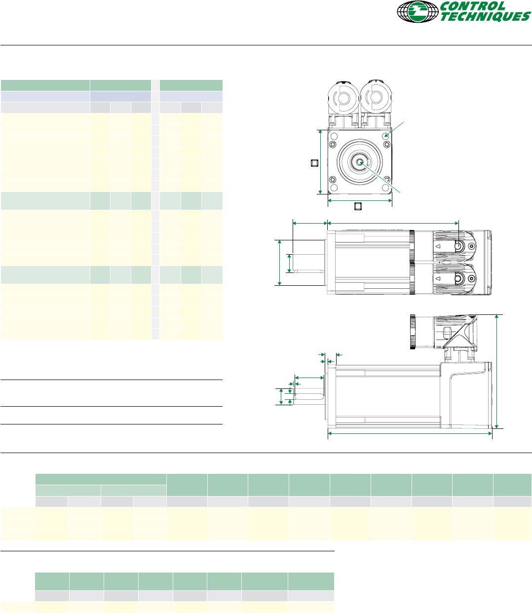
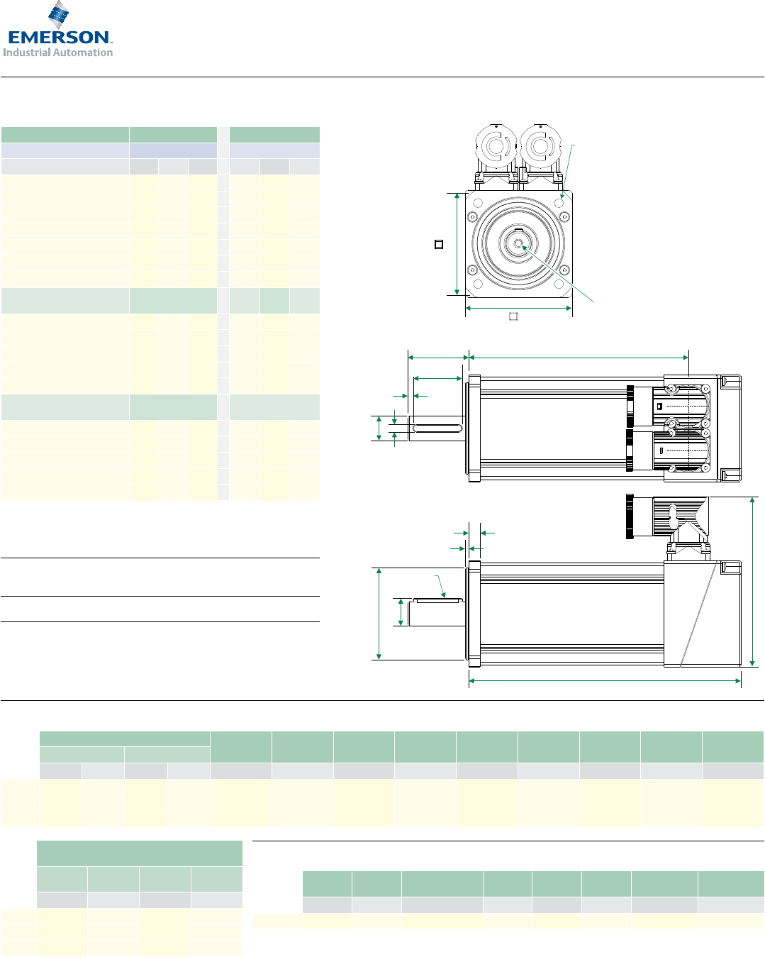
Motor dimension (mm) Drawing number: GM496400
Feedback AR, CR, EM/FM Flange
thickness
Register
length
Register
diameter
Overall
height
Flange
square
Fixing hole
diameter
Fixing hole
PCD
Motor
housing
Mounting
bolts
Unbraked length Braked length
A B A B K L M (j6) N P R (H14) S T
055A 118.0 90.0 158.0 130.0
7.0 2.5 40.0 99.0 55.0 5.8 63.0 55.0 M5
055B 142.0 114.0 182.0 154.0
055C 166.0 138.0 206.0 178.0
Shaft dimensions (mm)
Shaft
diameter
Shaft
length
Key
height
Key
length
Key to
shaft end
Key
width
Tapped hole
thread size
Tapped hole
depth
C (j6) D E F G H (h9) I J
14.0 Std 14 30.0 16.0 25.0 1.5 5.0 M5 12.5
Frame size 055 For 3 Phase VPWM drives
Motor frame size (mm) 055ED 055UD
Voltage (Vrms) 200-240 380-480
Frame length A B C A B C
Continuous Stall Torque (Nm) 0.72 1.18 1.65 0.72 1.18 1.65
Peak Torque (Nm) 2.88 4.72 6.60 2.88 4.72 6.60
Inertia (kgcm2)0.14 0.25 0.36 0.14 0.25 0.36
Winding thermal time constant (s) 34.0 38.0 42.0 34.0 38.0 42.0
Motor weight unbraked (kg) 1.20 1.50 1.80 1.20 1.50 1.80
Motor weight braked (kg) 1.60 1.90 2.20 1.6 1.90 2.20
Number of poles 8 8 8 8 8 8
Speed 3000 (rpm) Kt (Nm/A) =
Ke (V/krpm) =
0.74
45.00
0.87
52.50
0.91
55.00
0.74
45.00
1.49
90.00
1.65
100.00
Rated torque (Nm) 0.70 1.05 1.48 0.70 1.05 1.48
Stall current (A) 0.97 1.36 1.81 0.97 0.79 1.00
Rated power (kW) 0.22 0.33 0.46 0.22 0.33 0.46
R (ph-ph) (Ω) 28.00 14.12 9.53 28.00 45.00 31.00
L (ph-ph) (mH) 50.00 32.00 23.00 50.00 100.00 75.00
Speed 6000 (rpm) Kt (Nm/A) =
Ke (V/krpm) =
0.45
27.00
0.43
26.00
0.48
29.00
0.74
45.00
0.79
47.50
0.83
50.00
Rated torque (Nm) 0.68 0.90 1.20 0.68 0.90 1.20
Stall current (A) 1.61 2.74 3.44 0.97 1.49 1.99
Rated power (kW) 0.43 0.57 0.75 0.43 0.57 0.75
R (ph-ph) (Ω) 8.50 3.55 2.38 28.00 10.70 7.80
L (ph-ph) (mH) 16.00 8.20 6.30 50.00 25.00 20.00
F
G
E
Optional
key
K
L
A
N
H
C
∅M
BD
4 holes ∅R (H14)
equispaced on a
mounting PCD ∅S
P
T
Tapped hole
thread size
I to depth J
∆t= 100°C winding 40°C maximum ambient
All data subject to +/-10% tolerance
Stall torque, rated torque and power relate to maximum continuous
operation tested in a 20°C ambient at 12kHz drive switching frequency
All other gures relate to a 20°C motor temperature.
Maximum intermittent winding temperature is 140°C
www.controltechniques.com www.controltechniques.com 76
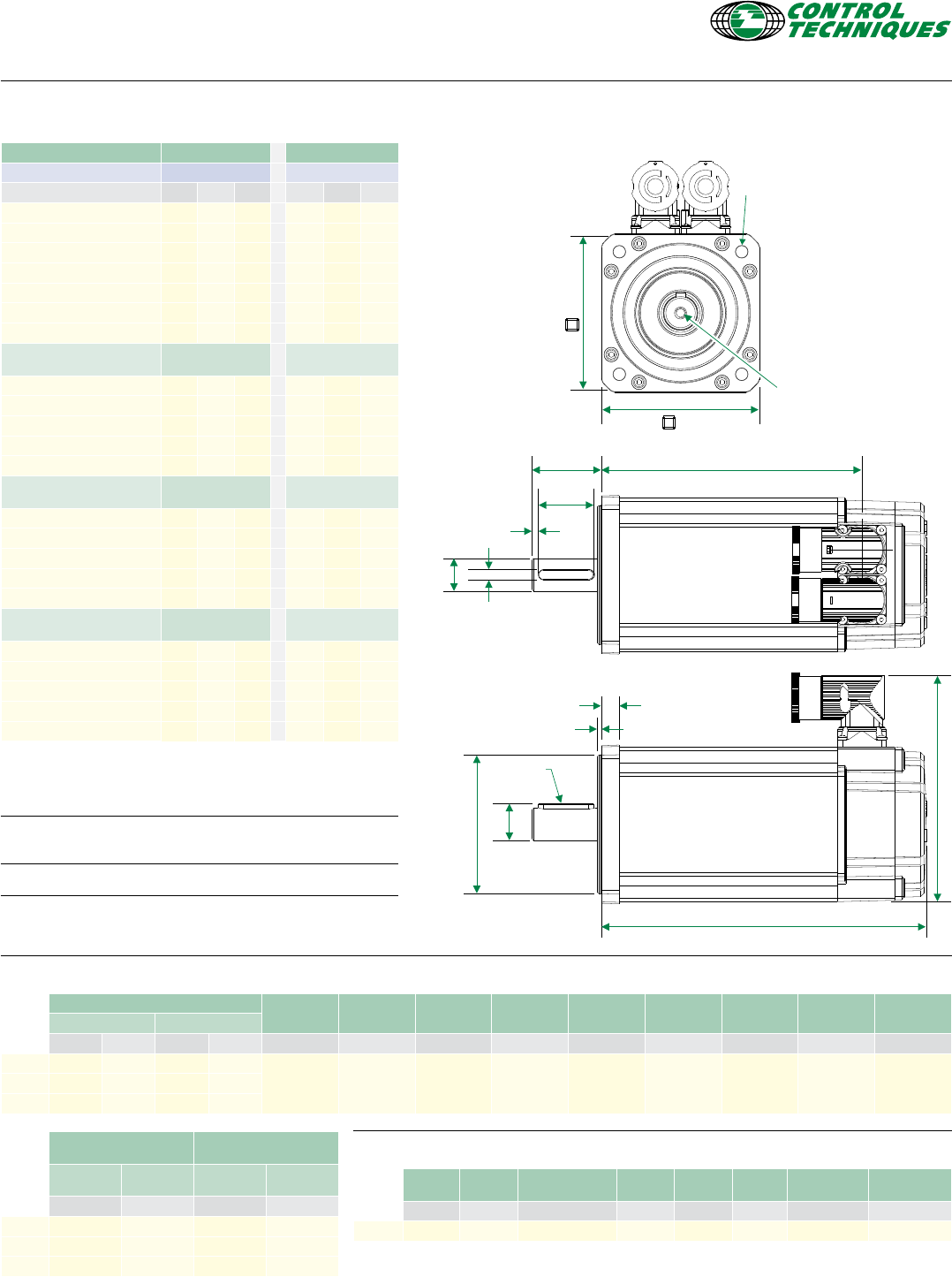
Shaft dimensions (mm)
Shaft
diameter
Shaft
length
Key
height
Key
length
Key to
shaft end
Key
width
Tapped hole
thread size
Tapped hole
depth
C (j6) D (± 0.45) E (IEC 72-1) F (± 0.25) G (± 1.1) H (h9) I J (± 0.1)
14.0 Std 14.0 30.0 16.0 22.0 3.6 5.0 M5 x 0.8 13.5
Frame size 067 For 3 Phase VPWM drives
Motor frame size (mm) 067ED 067UD
Voltage (Vrms) 200-240 380-480
Frame length A B C A B C
Continuous Stall Torque (Nm) 1.45 2.55 3.70 1.45 2.55 3.70
Peak Torque (Nm) 4.35 7.65 11.10 4.35 7.65 11.10
Inertia (kgcm2)0.30 0.53 0.75 0.30 0.53 0.75
Winding thermal time constant (s) 54 61 65 54 61 65
Motor weight unbraked (kg) 2.00 2.60 3.20 2.00 2.60 3.20
Motor weight braked (kg) 2.70 3.3 3.90 2.70 3.3 3.90
Number of poles 10 10 10 10 10 10
Speed 3000 (rpm) Kt (Nm/A) =
Ke (V/krpm) =
0.93
57.00
0.80
49.00
1.60
98.00
1.60
98.00
Rated torque (Nm) 1.40 2.45 3.50 1.40 2.45 3.50
Stall current (A) 1.56 2.74 3.98 1.81 1.59 2.31
Rated power (kW) 0.44 0.77 1.10 0.44 0.77 1.10
R (ph-ph) (Ω) 14.92 4.88 3.33 11.69 15.20 13.04
L (ph-ph) (mH) 45.43 17.40 12.70 35.18 54.20 48.65
Speed 6000 (rpm) Kt (Nm/A) =
Ke (V/krpm) =
0.47
28.50
0.8
49.00
Rated torque (Nm) 1.30 2.20 1.30 2.20 3.10
Stall current (A) 3.12 5.48 1.81 3.19 4.63
Rated power (kW) 0.82 1.38 0.82 1.38 1.95
R (ph-ph) (Ω) 3.86 1.22 11.69 3.79 2.68
L (ph-ph) (mH) 11.06 4.35 35.18 13.60 10.20
Optional
key
4 holes ∅R (H14)
equispaced on a
mounting PCD ∅S
T
P
K
L
A
N
E
∅M
F
G
H
∅C
B
D
Tapped hole
thread size
I to depth J
Motor dimension (mm) Drawing number: IM/0694/GA
Feedback AR, CR, EM/FM, LM/NM Flange
thickness
Register
length
Register
diameter
Overall
height
Flange
square
Fixing hole
diameter
Fixing hole
PCD
Motor
housing
Mounting
bolts
Unbraked length Braked length
A (± 0.9) B (± 1.0) A (± 0.9) B (± 1.0) K (± 0.5) L (± 0.1) M (j6) N (± 0.3) P (± 0.3) R (H14) S (± 0.4) T (± 0.4)
067A 142.9 109.0 177.9 144.0
7.5 2.50 60.0 111.5 70.0 5.8 75.0 67.00 M5
067B 172.9 139.0 207.9 174.0
067C 202.9 169.0 237.9 204.0
∆t= 100°C winding 40°C maximum ambient
All data subject to +/-10% tolerance
Stall torque, rated torque and power relate to maximum continuous
operation tested in a 20°C ambient at 12kHz drive switching frequency
All other gures relate to a 20°C motor temperature.
Maximum intermittent winding temperature is 140°C
Feedback
TL/UL
Unbraked
length
Braked
length
Unbraked
length
Braked
length
A (± 0.9) A (± 1.0) A (± 0.9) A (± 1.0)
067A 157.7 123.5 192.7 158.5
067B 187.7 153.5 222.7 188.5
067C 217.7 183.5 252.7 218.5
www.controltechniques.com www.controltechniques.com 76
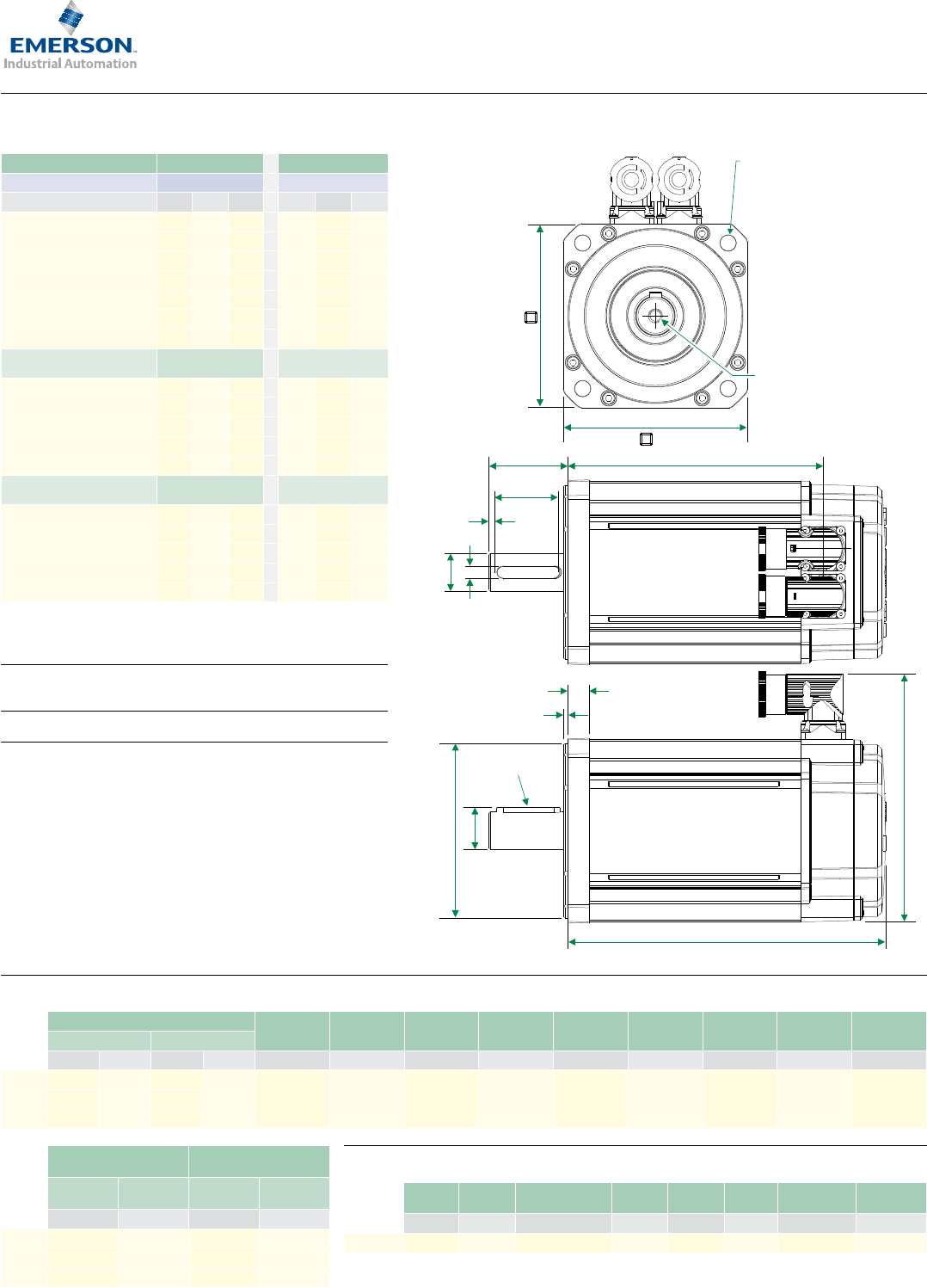
Frame size 089 For 3 Phase VPWM drives
Motor frame size (mm) 089ED 089UD
Voltage (Vrms) 200-240 380-480
Frame length A B C A B C
Continuous Stall Torque (Nm) 3.20 5.50 8.00 3.20 5.50 8.00
Peak Torque (Nm) 9.60 16.50 24.00 9.60 16.50 24.00
Inertia (kgcm2)0.87 1.61 2.34 0.87 1.61 2.34
Winding thermal time constant (s) 85 93 98 85 93 98
Motor weight unbraked (kg) 3.30 4.40 5.50 3.30 4.40 5.50
Motor weight braked (kg) 4.30 5.40 6.50 4.30 5.40 6.50
Number of poles 10 10 10 10 10 10
Speed 3000 (rpm) Kt (Nm/A) =
Ke (V/krpm) =
0.93
57.00
1.60
98.00
Rated torque (Nm) 3.00 4.85 6.90 3.00 4.85 6.90
Stall current (A) 3.44 5.91 8.60 2.00 3.44 5.00
Rated power (kW) 0.94 1.52 2.17 0.94 1.52 2.17
R (ph-ph) (Ω) 3.28 1.57 0.89 12.85 5.05 2.68
L (ph-ph) (mH) 21.55 11.84 7.09 80.66 38.36 21.72
Speed 4000 (rpm) Kt (Nm/A) =
Ke (V/krpm) =
0.70
42.75
1.2
73.50
Rated torque (Nm) 2.90 4.55 6.35 2.90 4.55 6.35
Stall current (A) 4.57 7.86 11.43 2.67 4.58 6.67
Rated power (kW) 1.21 1.91 2.66 1.21 1.91 2.66
R (ph-ph) (Ω) 2.04 0.79 0.54 6.16 2.47 1.75
L (ph-ph) (mH) 13.20 5.97 4.38 39.78 18.80 14.03
Speed 6000 (rpm) Kt (Nm/A) =
Ke (V/krpm) =
0.47
28.50
0.8
49.00
Rated torque (Nm) 2.65 3.80 5.00 2.65 3.80 5.00
Stall current (A) 6.88 11.83 17.20 4.00 6.88 10.00
Rated power (kW) 1.67 2.39 3.14 1.67 2.39 3.14
R (ph-ph) (Ω) 0.98 0.39 0.23 3.21 1.27 0.83
L (ph-ph) (mH) 6.24 2.96 1.89 20.16 9.59 6.66
F
G
E
Optional
key
K
L
A
N
H
∅C
∅M
B
D
4 holes ∅R (H14)
equispaced on a
mounting PCD ∅S
P
T
Tapped hole
thread size
I to depth J
Motor dimension (mm) Drawing number: IM/0688/GA
Feedback EC/FC, LC/NC Flange
thickness
Register
length
Register
diameter
Overall
height
Flange
square
Fixing hole
diameter
Fixing hole
PCD
Motor
housing
Mounting
bolts
Unbraked length Braked length
A (± 0.9) B (± 1.0) A (± 0.9) B (± 1.0) K (± 0.5) L (± 0.1) M (j6) N (± 1.0) P (± 0.28) R (H14) S (± 0.4) T (± 0.7)
089A 147.8 110.5 187.9 150.6
10.3 2.20 80.0 130.5 91.0 7.00 100.0 89.0 M6
089B 177.8 140.5 217.9 180.6
089C 207.8 170.5 247.9 210.6
Shaft dimensions (mm)
Shaft
diameter
Shaft
length
Key
height
Key
length
Key to
shaft end
Key
width
Tapped hole
thread size
Tapped hole
depth
C (j6) D (± 0.45) E (IEC 72-1) F (± 0.25) G (± 1.1) H (h9) I J (± 0.1)
19.0 Std 19.0 40.0 21.5 32.0 3.7 6.0 M6 x 1.0 17.0
Feedback
FB, EB/CA/SA, RA
Feedback
AE
Unbraked
length
Braked
length
Unbraked
length
Braked
length
A (± 0.9) A (± 0.9) A (± 0.9) A (± 0.9)
089A 160.8 200.9 137.8 177.9
089B 190.8 230.9 167.8 207.9
089C 220.8 260.9 197.8 237.9
∆t= 100°C winding 40°C maximum ambient
All data subject to +/-10% tolerance
Stall torque, rated torque and power relate to maximum continuous
operation tested in a 20°C ambient at 12kHz drive switching frequency
All other gures relate to a 20°C motor temperature.
Maximum intermittent winding temperature is 140°C
www.controltechniques.com www.controltechniques.com 98
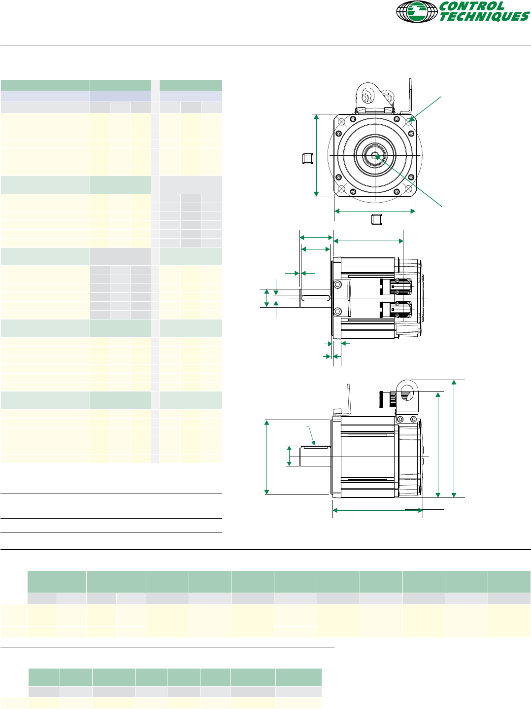
Frame size 115 For 3 Phase VPWM drives
Motor frame size (mm) 115ED 115UD
Voltage (Vrms) 200-240 380-480
Frame length B C D B C D
Continuous Stall Torque (Nm) 10.20 14.60 18.80 10.20 14.60 18.80
Peak Torque (Nm) 30.60 43.80 56.40 30.60 43.80 56.40
Inertia (kgcm2)4.41 6.39 8.38 4.41 6.39 8.38
Winding thermal time constant (s) 164 168 175 164 168 175
Motor weight unbraked (kg) 7.20 8.90 10.70 7.20 8.90 10.70
Motor weight braked (kg) 8.70 10.40 12.20 8.70 10.40 12.20
Number of poles 10 10 10 10 10 10
Speed 2000 (rpm) Kt (Nm/A) =
Ke (V/krpm) =
1.40
85.50
2.4
147.00
Rated torque (Nm) 8.60 11.90 15.60 8.60 11.90 15.60
Stall current (A) 7.29 10.43 13.43 4.25 6.08 7.83
Rated power (kW) 1.80 2.49 3.27 1.80 2.49 3.27
R (ph-ph) (Ω) 1.40 0.77 0.61 4.41 2.41 1.80
L (ph-ph) (mH) 12.84 7.87 6.62 40.59 24.69 19.45
Speed 3000 (rpm) Kt (Nm/A) =
Ke (V/krpm) =
0.93
57.00
1.60
98.00
Rated torque (Nm) 7.70 10.50 7.70 10.50 13.60
Stall current (A) 10.97 15.70 6.38 9.13 11.75
Rated power (kW) 2.42 3.30 2.42 3.30 4.27
R (ph-ph) (Ω) 0.58 0.39 1.83 1.21 0.78
L (ph-ph) (mH) 5.40 4.01 16.93 12.72 8.65
D
F
G
E
Optional key
4 holes ∅R (H14)
equispaced on a
mounting PCD ∅S
P
T
Tapped hole
thread size
I to depth J
K
L
A
N
H
∅C
∅M
B
Motor dimension (mm) Drawing number: IM/0689/GA
Feedback EC/FC, LC/NC Flange
thickness
Register
length
Register
diameter
Overall
height
Flange
square
Fixing hole
diameter
Fixing hole
PCD
Motor
housing
Mounting
bolts
Unbraked length Braked length
A (± 0.9) B (± 1.0) A (± 0.9) B (± 1.0) K (± 0.5) L (± 0.1) M (j6) N (± 1.0) P (± 0.31) R (H14) S (± 0.4) T (± 0.7)
115B 193.8 154.0 230.9 191.1
13.2 2.70 110.0 156.5 116.0 10.00 130.0 115.0 M8
115C 223.8 184.0 260.9 221.1
115D 253.8 214.0 290.9 251.1
Shaft dimensions (mm)
Shaft
diameter
Shaft
length
Key
height
Key
length
Key to
shaft end
Key
width
Tapped hole
thread size
Tapped hole
depth
C (j6) D (± 0.45) E (IEC 72-1) F (± 0.25) G (± 1.1) H (h9) I J (± 0.1)
24.0 Std 24.0 50.0 27.0 40.0 5.3 8.0 M8 x 1.25 20.0
Feedback
FB, EB/CA/SA, RA
Feedback
AE
Unbraked
length
Braked
length
Unbraked
length
Braked
length
A (± 0.9) A (± 0.9) A (± 0.9) A (± 0.9)
115B 206.8 243.9 183.8 220.9
115C 236.8 273.9 213.8 250.9
115D 266.8 303.9 243.8 280.9
∆t= 100°C winding 40°C maximum ambient
All data subject to +/-10% tolerance
Stall torque, rated torque and power relate to maximum continuous
operation tested in a 20°C ambient at 12kHz drive switching frequency
All other gures relate to a 20°C motor temperature.
Maximum intermittent winding temperature is 140°C
www.controltechniques.com www.controltechniques.com 98
Frame size 142 For 3 Phase VPWM drives
Motor frame size (mm) 142ED 142UD
Voltage (Vrms) 200-240 380-480
Frame length C D E C D E
Continuous Stall Torque (Nm) 25.0 31.5 38.0 25.0 31.5 38.0
Peak Torque (Nm) 74.9 94.5 114.0 74.9 94.5 114.0
Inertia (kgcm2)17.0 22.1 27.2 17.0 22.1 27.2
Winding thermal time constant (s) 245.0 251.0 256.0 245.0 251.0 256.0
Motor weight unbraked (kg) 11.5 15.0 18.5 11.5 15.0 18.5
Motor weight braked (kg) 14.3 17.8 21.3 14.3 17.8 21.3
Number of poles 10 10 10 10 10 10
Speed 1000 (rpm) Kt (Nm/A) =
Ke (V/krpm) =
2.8
171.0
Rated torque (Nm) 23.3 29.0 34.5
Stall current (A) 8.9 11.2 13.6
Rated power (kW) 2.44 3.04 3.61
R (ph-ph) (Ω) 1.36 0.94 0.72
L (ph-ph) (mH) 21.34 15.17 12.30
Connection type BBB
Speed 1500 (rpm) Kt (Nm/A) =
Ke (V/krpm) =
3.2
196.0
Rated torque (Nm) 22.3 27.0 31.7
Stall current (A) 7.8 9.8 11.9
Rated power (kW) 3.5 4.2 5.0
R (ph-ph) (Ω) 1.36 0.94 0.72
L (ph-ph) (mH) 21.34 15.17 12.30
Connection type BBB
Speed 2000 (rpm) Kt (Nm/A) =
Ke (V/krpm) =
1.4
85.5
2.4
147.0
Rated torque (Nm) 21.4 25.7 29.6 21.4 25.7 29.6
Stall current (A) 17.8 22.5 27.1 10.4 13.1 15.8
Rated power (kW) 4.48 5.38 6.20 4.48 5.38 6.20
R (ph-ph) (Ω) 0.34 0.24 0.18 0.79 0.62 0.49
L (ph-ph) (mH) 5.33 3.79 3.07 12.15 9.66 8.34
Connection type J J J B B B
Speed 3000 (rpm) Kt (Nm/A) =
Ke (V/krpm) =
0.93
57.0
1.6
98.0
Rated torque (Nm) 18.4 20.9 C/D 18.4 20.9 23.0
Stall current (A) 26.9 33.9 15.6 19.7 23.8
Rated power (kW) 5.78 6.57 5.78 6.57 7.23
R (ph-ph) (Ω) 0.12 0.10 0.34 0.24 0.18
L (ph-ph) (mH) 1.90 1.57 5.33 3.79 3.07
Connection type J J J B J J
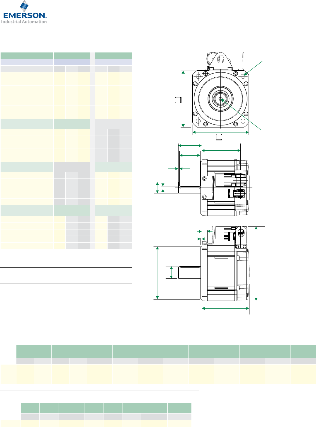
H
K
L
N
A
Optional
lifting
aid 205.0 mm
(± 1)
E
∅C
∅M
B
F
G
D
4 holes ∅R (H14)
equispaced on a
mounting PCD ∅S
P
T
Tapped hole
thread size
I to depth J
Optional
key
Motor dimension (mm) Drawing number: IM/0709/GA
Unbraked length Braked length Flange
thickness
Register
length
Register
diameter
Overall
height
Flange
square
Fixing hole
diameter
Fixing hole
PCD
Motor
housing
Mounting
bolts
A (± 0.9) B (± 1.0) A (± 0.9) B (± 1.0) K (± 0.2) L (± 0.1) M (j6) N (± 1.0) P (± 0.31) R (H14) S (± 0.4) T (± 0.7)
142C 217.0 182.5 282.5 248.0
14.0 3.4 130.0
183.5
142.0 12.0 165.0 142.0 M10
142D 247.0 212.5 312.5 278.0 183.5-204.5
142E 277.0 242.5 342.5 308.0 183.5-204.5
Shaft dimensions (mm)
Shaft
diameter
Shaft
length
Key
height
Key
length
Key to
shaft end
Key
width
Tapped hole
thread size
Tapped hole
depth
C (k6) D (± 0.45) E (IEC 72-1) F (± 0.25) G (± 1.5) H (h9) I J (± 1.0)
32.0 Std 32.0 58.0 35.0 50.0 3.0 10.0 M12 x 1.75 29.0
∆t= 100°C winding 40°C maximum ambient
All data subject to +/-10% tolerance
Stall torque, rated torque and power relate to maximum continuous
operation tested in a 20°C ambient at 12kHz drive switching frequency
All other gures relate to a 20°C motor temperature.
Maximum intermittent winding temperature is 140°C
www.controltechniques.com www.controltechniques.com 1110
Frame size 190 For 3 Phase VPWM drives
Motor frame size (mm) 190ED 190UD
Voltage (Vrms) 200-240 380-480
Frame length C D F C D F
Continuous Stall Torque (Nm) 52.0 62.0 85.0 52.0 62.0 85.0
Peak Torque (Nm) 156.0 186.0 255.0 156.0 186.0 255.0
Inertia (kgcm2)54.6 70.9 103.5 54.6 70.9 103.5
Winding thermal time constant (s) 311.0 316.0 324.0 311.0 316.0 324.0
Motor weight unbraked (kg) 23.5 28.6 38.8 23.5 28.6 38.8
Motor weight braked (kg) 28.8 33.9 44.1 28.8 33.9 44.1
Number of poles 10 10 10 10 10 10
Speed 1000 (rpm) Kt (Nm/A) =
Ke (V/krpm) =
2.8
171.0
Rated torque (Nm) 49.0 56.5 77.5
Stall current (A) 18.6 22.1 30.4
Rated power (kW) 5.13 5.92 8.12
R (ph-ph) (Ω) 0.47 0.40 0.23
L (ph-ph) (mH) 12.30 10.40 6.79
Speed 1500 (rpm) Kt (Nm/A) =
Ke (V/krpm) =
3.2
196.0
Rated torque (Nm) 46.2 52.2 68.5
Stall current (A) 16.3 19.4 26.6
Rated power (kW) 7.26 8.20 10.76
R (ph-ph) (Ω) 0.55 0.38 0.23
L (ph-ph) (mH) 14.15 10.40 6.79
Speed 2000 (rpm) Kt (Nm/A) =
Ke (V/krpm) =
1.4
85.5
2.4
147.0
Rated torque (Nm) 42.5 42.5
Stall current (A) 37.1 21.7
Rated power (kW) 8.90 8.90
R (ph-ph) (Ω) 0.12 0.32
L (ph-ph) (mH) 3.07 8.20
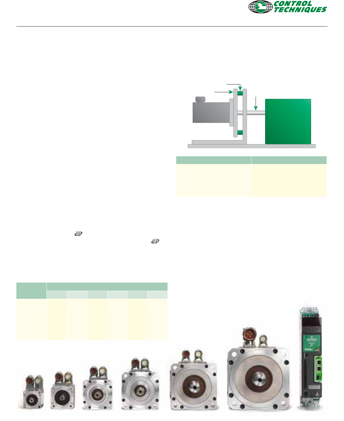
H
K
L
A
N
E
∅C
∅M
B
F
G
D
4 holes ∅R (H14)
equispaced on a
mounting PCD ∅S
P
T
Tapped hole
thread size
I to depth J
Motor dimension (mm) Drawing number: IM/00710/GA
Unbraked length Braked length Flange
thickness
Register
length
Register
diameter
Overall
height
Flange
square
Fixing hole
diameter
Fixing hole
PCD
Motor
housing
Mounting
bolts
A (± 0.9) B (± 1.0) A (± 0.9) B (± 1.0) K (± 0.2) L (± 0.1) M (j6) N (± 1.0) P (± 0.31) R (H14) S (± 0.4) T (± 0.7)
190C 220.6 191.1 319.1 289.6
18.5 3.9 180.0 252.5 190.3 14.5 215.0 190.0 M12
190D 250.6 221.1 349.1 319.6
190F 310.6 251.1 409.1 379.6
Shaft dimensions (mm)
Shaft
diameter
Shaft
length
Key
height
Key
length
Key to
shaft end
Key
width
Tapped hole
thread size
Tapped hole
depth
C (k6) D (± 0.45) E (IEC 72-1) F (± 0.25) G (± 1.5) H (h9) I J (± 1.0)
38.0 Std 38.0 80.0 41.0 70.0 4.6 10.0 M12 x 1.75 29.0
∆t= 100°C winding 40°C maximum ambient
All data subject to +/-10% tolerance
Stall torque, rated torque and power relate to maximum continuous
operation tested in a 20°C ambient at 6kHz drive switching frequency
All other gures relate to a 20°C motor temperature.
Maximum intermittent winding temperature is 140°C
www.controltechniques.com www.controltechniques.com 1110
Motor derating
Any adverse operating conditions require that the motor performance be
derated. These conditions include; ambient temperature above 40°C,
motor mounting position, drive switching frequency or the drive
being oversized for the motor.
Ambient temperatures
The ambient temperature around the motor must be taken into
account. For ambient temperatures above 40°C the torque must
be derated using the following formula as a guideline. (Note: Only
applies to 2000/3000rpm motors and assumes copper losses
dominate)
New derated torque = Specied torque x √ [1-((Ambient temperature - 40°C) / 100)]
For example with an ambient temperature of 76°C the new derated
torque will be 0.8 x specied torque.
Mounting arrangements
The motor torque must be derated if the motor mounting surface
is heated from an external source, such as a gearbox. The motor is
connected to a poor thermal conductor. The motor is mounted with
the connectors on the side or vertical. The motor is in a conned
space with restricted air ow.
Drive switching frequency
Most Digitax ST / Unidrive nominal current ratings are reduced
for the higher switching frequencies see Digitax ST or Unidrive
manual for details.
See the table below for the motor de rate factors. These gures are
for guidance only.
(Note: Only applies to motors up to 3000rpm and assumes copper losses dominate)
Switching
frequency
Motor type/frame
055 067 089 115 142 190
3kHz 0.92 0.93 0.89 0.89 0.83 0.90
4kHz 0.93 0.94 0.91 0.92 0.85 0.95
6kHz 0.95 0.95 0.95 0.96 0.88 1
8kHz 0.96 0.98 0.97 0.98 0.91 1
12/16kHz 111111
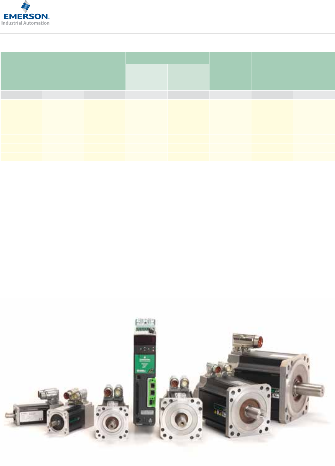
Thermal test conditions
The performance data shown has been recorded under the following
conditions. Ambient temperature 20°C, with the motor mounted on
a thermally isolated aluminum plate as shown below.
Motor type/frame Aluminium heatsink plate
055mm 110 x 110 x 27mm
067-089mm 250 x 250 x 15mm
115-142mm 350 x 350 x 20mm
190mm 500 x 500 x 20mm
Thermal protection
Thermistor protection (145°C) is built into the motor windings and
gives an indication of serious overheating problems. The installer
must connect the thermistor to the drive, failure to do so will
invalidate the motor warranty in respect of a burnt out winding.
Environmental conditions
Any liquids or gases that may come into contact with the motor
must be conrmed to ensure compliance with the correct
international standards.
Motor selection
Plate Shaft
Motor
Dynamometer
Thermal Isolator
www.controltechniques.com www.controltechniques.com 1312
Motor
frame
Supply
volts
Input
power
Static torque
Release
time
Moment
of inertia Backlash
Standard
parking
brake (01)
High energy
parking
brake (05)
Size Vdc Watts Nm Nm ms nom kgcm² * Degrees**
055 24 6.3 1.8 N/A 22 0.03 0.73
067 24 10.2 N/A 4 <50 0.073 0.75
089 24 23.35 N/A 10 <50 0.115 0.75
115 24 19.5 N/A 25 120 0.327 0.75
142 24 25 N/A 42 95 2.54 0.77
190 C-D 24 25 N/A 67 120 4.57 0.77
190 F 24 54.5 N/A 100 TBD 7.72 0.75
*Note 1 kgcm² = 1x10⁻⁴kgm² **Backlash figure will increase with time
➜ The brakes are intended for parking duty and are not for dynamic
or safety use
➜ The brake will engage when power is removed.
➜ Refer to your Drive Centre or Distributor if your application
requires dynamic braking in emergency conditions.
➜ To provide protection to the brake control circuit it is
recommended that a diode is connected across the output
terminals of the solid state or relay contacts devices.
➜ Figures are shown at 20°C ambient. Apply a de rate factor of 0.7
to the standard brake torque gures if motor temperature is
above 100°C
Brake Specification

www.controltechniques.com www.controltechniques.com 1312
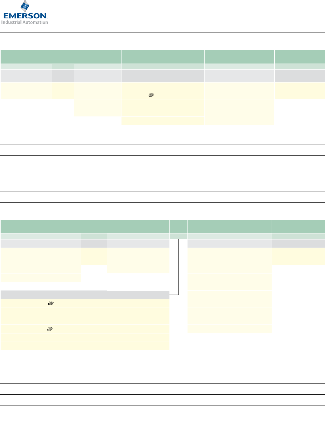
Feedback
Feedback device
part number code Feedback type Encoder
supply voltage¹
Sincos cycles or
incremental
pulses per
revolution
Resolution
available to
position loop²&³
Feedback Accuracy1
055 - 067 motors
AR Resolver 7Vdc rms 1Medium Low
Excitation 5kHz 16384 (14 bit) +/- 600”
Medium Medium
CR Incremental Encoder 5Vdc 4096 16384 (14 bit) +/- 150”
EM (Multi-turn) Inductive Absolute Encoder EnDat 2.1 5Vdc 16 High Medium
FM (Single turn) 2.62x10^5 (18 bits) +/- 480”
LM (Multi-turn)
NM (Single turn)
Inductive Absolute Encoder EnDat 2.2
(Serial comms only) 5Vdc 16 Medium
2.62x10^5 (18 bits)
Medium
+/- 480”
TL (Multi-turn)
UL (Single turn) SinCos Optical Encoder Hiperface 8Vdc 128 Medium
1.31x10^5 (17 bit)
Medium
+/- 150”
089 - 190 motors
AE Resolver 6Vdc rms 1"Medium Medium
Excitation 6kHz 16384 (14 bit) +/- 720”
CA Medium High
Incremental Encoder 5Vdc 4096 16384 (14 bit) +/- 60”
Inductive Absolute Encoder EnDat 2.1 7 - 10Vdc 32
Medium Medium
EC (Multi-turn) Absolute position
524288 +/- 280”
FC (Single turn) (19 bits)
LC (Multi-turn)
NC (Single turn)
Inductive Absolute Encoder EnDat 2.2
(Serial comms only) 7-10Vdc 32
Medium
Absolute position
524288
(19 bits)
Medium
+/- 280”
SinCos Optical Encoder
Hiperface 7 - 12Vdc 1024
Very high High
RA (Multi-turn) 1.04x10^6 For SinCos Integral non-
linearity +/- 45”
For SinCos Differential
non-linearity +/- 7”
(Total accuracy+/-52”)
SA (Single turn) (20 bits)
Optical Absolute Encoder EnDat 2.2 3.6 - 14Vdc 2048
Very High Very High
EB (Multi-turn) 2.08x10^6 +/-20”
(Differential non
linearity +/- 1%
signal period)
FB (Single turn) (21 bits)
Resolver
A passive wound device consisting of a stator and rotor elements excited from
an external source, such as an SM-Resolver, the resolver produces two output
signals that correspond to the sine and cosine angle of the motor shaft. This
is a robust absolute device of low accuracy, capable of withstanding high
temperature and high levels of vibration. Positional information is absolute
within one turn - i.e. position is not lost when the drive is powered down.
Incremental Encoder
An electronic device using an optical disc. The position is determined by
counting steps or pulses. Two sequences of pulses in quadrature are used so the
direction sensing may be determined and 4 x (pulses per rev) may be used for
resolution in the drive. A marker pulse occurs once per revolution and is used to
zero the position count. The encoder also provides commutation signals, which
are required to determine the absolute position during the motor phasing test.
This device is available in 4096 ppr version. Positional information is non absolute
- i.e. position is lost when the drive is powered down.
SinCos/Absolute Encoders
Types available are: Optical or Inductive - which can be single or multi-turn.
1) Optical: An electronic device using an optical disc. An absolute encoder with
high resolution that employs a combination of absolute information, transmitted
via a serial link, and sine/cosine signals with incremental techniques.
2) Inductive: An electronic device using inductively coupled PCB’s. An
absolute encoder with medium resolution that employs a combination of
absolute information, transmitted via a serial link, and sine/cosine signals
with incremental techniques. This encoder can be operated with the
drive using either sine/consine or absolute (serial) values only. Positional
information is absolute within 4096 turns - i.e. position is not lost when the
drive is powered down.
Multi-turn: As previous but with extra gear wheels included so that the
output is unique for each shaft position and the encoder has the additional
ability to count complete turns of the motor shaft up to 4096 revolutions.
Electronic nameplating
Available on both these types of encoders, and allows quick set-up times as the
motor information is stored on board the encoder (067-190 motors only).
Notes:
1) The output from the resolver
is an analogue output. The
resolution is determined
by the analogue to digital
converter used. The value
shown is when the resolver is
used in conjunction with the
SM-Resolver.
2) The sin and cosine outputs
from the SinCos optical
encoders are analogue outputs.
With Unidrive and Digitax
ST the resolutions quoted
above are when the encoder
type is set to either SC Endat
or SC Hiper depending on the
encoder.
3) The information is supplied
by the feedback device
manufacturer and relates
to it as a standalone device.
The values may change when
mounted into the motor and
connected to a drive.
These values have not been
veried by CT Dynamics.
www.controltechniques.com www.controltechniques.com 1514
SI B A A A 015
Cable type Jacket Special options Connection details motor end Cable length*
SI = Incremental Encoder Hyerboloid pins B = PUR A = Standard cable A = Encoder 17 pin connector Min = 001 (1m)
SR = Resolver C**= OFS E = Twisted screened SS cable B = Resolver 12 pin connector Max = 100 (100m)
SS = Sin/Cos Encoder L = 8.5mm dia SI cable C = Sin/Cos 12 pin connector (Hiperface)
SE = Incremental Encoder Split pins E = 17 pin extension connector
F = 90° Encoder 17 pin connector
Connection details drive end G = 90° Resolver 12 pin connector
A = Digitax ST/Unidrive /Epsilon EP Encoder 15 pin connector H = 90° Sin/Cos 12 pin connector (Hiperface)
B = Resolver / Sin/Cos Ferrules N = Sin/Cos 17 pin connector (EnDat)
F = Epsilon Encoder 26 pin connector O = 90° Sin/Cos 17 pin connector (EnDat)
H = Digitax ST/Unidrive Sin/Cos 15 pin connector X = Cut end
I = Extension connector male pins
X = Cut end
* Max cable length - 50m with the SIBA/SICA as standard, 100m only if +5V tolerance can be maintained.
* Max cable length - 10m with the SIBL.
* Max cable length - Heidenhain EC/FC 20m EB/FB 30m with the SSBA cable,EC/FC 20m EB/FB 100m with the SSBE cable.
** OFS only available on SI encoder cable.
Cable information
PS B A H A 015
Cable type Jacket Phase & ground:
conductor size Connection details drive end Connection details motor end Cable length
PS = Power (Standard) B = PUR H* = 1.0mm² 10A C = Extension power connector 6 way A = 055 - 142 Unimotor hd
size 1 power connector
Min = 001 (1m)
PB = Power (with brake) C = OFS G = 1.5mm² 16A F = Unidrive (1-2) Ferrules Max = 100 (100m)
A = 2.5mm² 22A H = Digitax ST and Unidrive SP0 Ferrules B = 142 - 190 Unimotor hd
size 1.5 power connector
* Only available in OFS B = 4.0mm² 30A K = Epsilon EP Ferrules
X = Cut end X = Cut end
Cable type Choose the cable type to match the feedback device.
Jacket B is for the PUR sheath and is the Dynamic cable selection. C is for the OFS sheath and is the Static cable selection.
Special options A is for standard cable. L is for the low cost 8.5mm incremental cable.
Connection detail drive end Select the correct drive end connection for the drive in use.
Connection detail motor end Select the correct motor end connection for the motor feedback device in use.
Length Numbers represent the required cable length in metres.
Cable type PS for motor without brakes, PB for motors with brake.
Jacket B is for the PUR sheath and is the Dynamic cable selection. C is for the OFS sheath and is the Static cable selection.
Conductor size Select the conductor size according to the motors STALL CURRENT. Cables of 6mm² and above will be
tted with ring terminals only. Ratings are for individual cables (not lashed together) in free air temperature
up to 40°C - make allowances as appropriate.
Connection detail drive end Select the correct drive end connection for the drive in use.
Connection detail motor end Select the correct motor end connection for the motor in use.
Length Numbers represent the required cable length in metres.
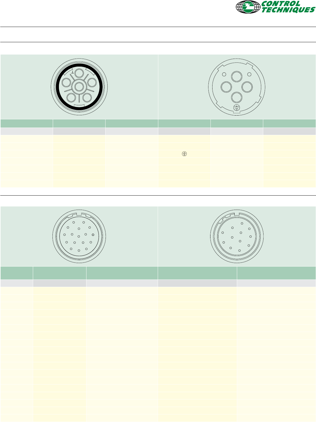
www.controltechniques.com www.controltechniques.com 1514
1 5
642
3
u
v
-+
w
Size 1 With brake Without brake Size 1.5 With brake Without brake
Pin Function Function Pin Function Function
1Phase U (R) Phase U (R) U Phase U (R) Phase U (R)
2Phase V (S) Phase V (S) V Phase V (S) Phase V (S)
3Ground Ground Ground Ground
4Phase W (T) Phase W (T) W Phase W (T) Phase W (T)
5Brake - + Brake
6Brake - - Brake
Shell Screen Screen Shell Screen Screen
1
10
9
8
12
13
1415
16 17
76
5
11
4
3
21
10
9
8
12
7
6
5
11
4
3
2
Incremental encoder
(CR,CA)
Heidenhain Absolute Encoders
(EM, FM, EC, FC, EB, FB, LC, NC, LM, NM)
Resolver
(AR, AE)
Sick|Stegmann Sin/Cos
encoders (RA, SA, TL, UL)
Pin Function Function Function Function
1 Thermistor Thermistor Excitation high REF Cos
2 Thermistor Thermistor Excitation low +Data
3 - Screen (Optical encoder only) Cos high -Data
4 S1 - Cos low +Cos
5 S1 Inverse - Sin high +Sin
6 S2 - Sin low REF Sin
7 S2 Inverse - Thermistor Thermistor
8 S3 + Clock Thermistor Thermistor
9 S3 Inverse - Clock - Screen
10 Channel A + Cos - 0 Volts
11 Index + Data - -
12 Index Inverse - Data - + Volts
13 Channel A Inverse - Cos - -
14 Channel B + Sin - -
15 Channel B Inverse - Sin - -
16 + Volts + V - -
17 0 Volts 0 Volts - -
Body Screen Screen Screen Screen
Motor connector details
Power plug
Signal plug
© Control Techniques 2013. The information contained in this brochure is for guidance only and does not
form part of any contract. The accuracy cannot be guaranteed as Control Techniques have an ongoing process
of development and reserve the right to change the specication of their products without notice.
* Operated by sister company
DRIVING THE WORLD...
Control Techniques Drive & Application Centres
Control Techniques Distributors
ARGENTINA
Euro Techniques SA
T: +54 11 4331 7820
eurotech@eurotechsa.com.ar
BAHRAIN
Emerson FZE
T: +971 4 8118100
ct.bahrain@emerson.com
BULGARIA
BLS - Automation Ltd
T: +359 32 968 007
info@blsautomation.com
CHILE
Ingeniería Y Desarrollo
Tecnológico S.A
T: +56 2 719 2200
rdunner@idt.cl
COLOMBIA
Sistronic LTDA
T: +57 2 555 60 00
luis.alvarez@sistronic.com.co
Redes Electricas S.A.
T: +57 1 364 7000
alvaro.rodriguez@redeselectricas.com
CROATIA
Zigg-Pro d.o.o
T: +385 1 3463 000
zigg-pro@zg.htnet.hr
CYPRUS
Acme Industrial Electronic
Services Ltd
T: +3572 5 332181
acme@cytanet.com.cy
EGYPT
Samiram
T: +202 29703868/+202 29703869
samiramz@samiram.com
EL SALVADOR
Servielectric Industrial S.A. de C.V.
T: +503 2278 1280
aeorellana@gruposervielectric.com
FINLAND
SKS Control
T: +358 207 6461
control@sks.
GUATEMALA
MICE, S.A.
T: +502 5510 2093
mice@itelgua.com
HONDURAS
Temtronics Honduras
T: +504 550 1801
temtronics@amnethn.com
HUNGARY
Control-VH Kft
T: +361 431 1160
info@controlvh.hu
ICELAND
Samey ehf
T: +354 510 5200
samey@samey.is
INDONESIA
Pt Apikon Indonesia
T: +65 6556 1100
info.my@controltechniques.com
Pt Yua Esa Sempurna Sejahtera
T: +65 6556 1100
info.my@controltechniques.com
ISRAEL
Dor Drives Systems Ltd
T: +972 3900 7595
info@dor1.co.il
KENYA
Kassam & Bros Co. Ltd
T: +254 2 556 418
kassambros@africaonline.co.ke
KUWAIT
Emerson FZE
T: +971 4 8118100
ct.kuwait@emerson.com
LATVIA
EMT
T: +371 760 2026
janis@emt.lv
LEBANON
Black Box Automation & Control
T: +961 1 443773
info@blackboxcontrol.com
LITHUANIA
Elinta UAB
T: +370 37 351 987
sales@elinta.lt
MALTA
Mekanika Limited
T: +35621 442 039
mfrancica@gasan.com
MEXICO
MELCSA S.A. de CV
T: +52 55 5561 1312
jcervera@melcsa.com
MOROCCO
Cietec
T: +212 22 354948
cietec@cietec.ma
NEW ZEALAND
Advanced Motor Control. Ph.
T: +64 (0) 274 363 067
info.au@controltechniques.com
PERU
Intech S.A.
T: +51 1 224 9493
artur.mujamed@intech-sa.com
PHILIPPINES
Control Techniques
Singapore Ltd
T: +65 6468 8979
info.my@controltechniques.com
POLAND
APATOR CONTROL Sp. z o.o
T: +48 56 6191 207
info@acontrol.com.pl
PORTUGAL
Harker Sumner S.A
T: +351 22 947 8090
drives.automation@harker.pt
PUERTO RICO
Motion Industries Inc.
T: +1 787 251 1550
roberto.diaz@motion-ind.com
QATAR
Emerson FZE
T: +971 4 8118100
ct.qatar@emerson.com
ROMANIA
C.I.T. Automatizari
T: +40212550543
ofce@citautomatizari.ro
SAUDI ARABIA
A. Abunayyan Electric Corp.
T: +9661 477 9111
aec-salesmarketing@
abunayyangroup.com
SERBIA & MONTENEGRO
Master Inzenjering d.o.o
T: +381 24 525 235
ofce@masterinzenjering.rs
SLOVENIA
PS Logatec
T: +386 1 750 8510
ps-log@ps-log.si
TUNISIA
SIA Ben Djemaa & CIE
T: +216 1 332 923
bendjemaa@planet.tn
URUGUAY
SECOIN S.A.
T: +5982 2093815
jose.barron@secoin.com.uy
VENEZUELA
Digimex Sistemas C.A.
T: +58 243 551 1634
digimex@digimex.com.ve
VIETNAM
N.Duc Thinh
T: +84 8 9490633
infotech@nducthinh.com.vn
P.N. 0702-0016-06 03/13
AUSTRALIA
Melbourne Application Center
T: +613 973 81777
controltechniques.au@emerson.com
Sydney Drive Center
T: +61 2 9838 7222
controltechniques.au@emerson.com
AUSTRIA
Linz Drive Center
T: +43 7229 789480
controltechniques.at@emerson.com
BELGIUM
Brussels Drive Center
T: +32 1574 0700
controltechniques.be@emerson.com
BRAZIL
Sorocaba Drive Center
T: +55 15 3413 8169
vendasbrasil.cta@emerson.com
CANADA
Toronto Application Center
T: +1 905 948 3402
controltechniques.ca@emerson.com
Calgary Drive Center
T: +1 403 253 8738
controltechniques.ca@emerson.com
CHILE
Santiago Application Center
T: +56 9 7708 9470
saleschile.cta@emerson.com
CHINA
Shanghai Drive Center
T: +86 21 3418 3888
controltechniques.cn@emerson.com
Shenzhen Application Center
T: +86 755 8618 7287
controltechniques.cn@emerson.com
CZECH REPUBLIC
Brno Drive Center
T: +420 511 180111
controltechniques.cz@emerson.com
DENMARK
Copenhagen Drive Center
T: +45 4369 6100
controltechniques.dk@emerson.com
FRANCE*
Angoulême Drive Center
T: +33 5 4564 5454
controltechniques.fr@emerson.com
GERMANY
Bonn Drive Center
T: +49 2242 8770
controltechniques.de@emerson.com
Chemnitz Drive Center
T: +49 3722 52030
controltechniques.de@emerson.com
Darmstadt Drive Center
T: +49 6251 17700
controltechniques.de@emerson.com
GREECE*
Athens Application Center
T: +0030 210 57 86086/088
controltechniques.gr@emerson.com
HOLLAND
Rotterdam Drive Center
T: +31 184 420555
controltechniques.nl@emerson.com
INDIA
Chennai Drive Center
T: +91 44 2496 1123/1130/1083
T: +91 44 6691 8400
controltechniques.in@emerson.com
IRELAND
Newbridge Drive Center
T: +353 45 448200
controltechniques.ie@emerson.com
ITALY
Milan Drive Center
T: +39 02575 751
controltechniques.it@emerson.com
Vicenza Drive Center
T: +39 0444 933400
controltechniques.it@emerson.com
MALAYSIA
Selangor Drive Center
T: +603 5891 6099
controltechniques.my@emerson.com
MEXICO
Mexico City Application Center
T: +52 155 3333 6666
salesmexico.cta@emerson.com
POLAND
Warsaw Application Center
T +48 22 45 89 200
controltechniques.pl@emerson.com
REPUBLIC OF SOUTH AFRICA
Johannesburg Drive Center
T: +27 11 462 1740
controltechniques.za@emerson.com
Cape Town Application Center
T: +27 21 556 0245
controltechniques.za@emerson.com
RUSSIA
Moscow Application Center
T: +7 495 981 9811
controltechniques.ru@emerson.com
SINGAPORE
Singapore Drive Center
T: +65 6556 1100
controltechniques.sg@emerson.com
SLOVAKIA EMERSON A.S
T: +421 32 7700 369
controltechniques.sk@emerson.com
SOUTH KOREA
Seoul Application Center
T: +82 2 3483 1605
controltechniques.kr@emerson.com
SPAIN
Barcelona Drive Center
T: +34 93 680 1661
controltechniques.es@emerson.com
Bilbao Drive Center
T: +34 94 620 3646
controltechniques.es@emerson.com
Valencia Drive Center
T: +34 96 154 2900
controltechniques.es@emerson.com
SWEDEN*
Stockholm Application Center
T: +468 554 241 00
controltechniques.se@emerson.com
SWITZERLAND
Zurich Drive Center
T: +41 56 201 4242
controltechniques.fr.ch@emerson.com
Lausanne Application Center
T: +41 21 637 7070
controltechniques.fr.ch@emerson.com
TAIWAN
Taipei Application Center
T: +886 2 8161 7695
controltechniques.tw@emerson.com
THAILAND
Bangkok Drive Center
T: +66 2 962 2099
controltechniques.th@emerson.com
TURKEY
Istanbul Drive Center
T: +90 216 4182420
controltechniques.tr@emerson.com
UAE*
Emerson FZE
T: +971 4 8118100
ct.dubai@emerson.com
UNITED KINGDOM
Telford Drive Center
T: +44 1952 213700
controltechniques.uk@emerson.com
USA
Charlotte Application Center
T: +1 800 893 2321
controltechniques.us@emerson.com
Cleveland Drive Center
T: +1 216 901 2400
controltechniques.us@emerson.com
Detroit Application Center
T: +1 248 882 2652
controltechniques.us@emerson.com
Minneapolis Drive Center
Americas Headquarters
T: +1 952 995 8000
controltechniques.us@emerson.com
Portland Drive Center
T: +1 503 266 2094
controltechniques.us@emerson.com
Providence Application Center
T: +1 401 392 4256
controltechniques.us@emerson.com
LATIN AMERICA
Miami Application Center
T: +1 954 846 5082
saleslatinam.cta@emerson.com
