PDF United States Army Tm 5 315 20 April 1971
united_states_army_tm_5-315 - 20_april_1971 united_states_army_tm_5-315 - 20_april_1971
User Manual: PDF T E X T F I L E S
Open the PDF directly: View PDF ![]() .
.
Page Count: 260 [warning: Documents this large are best viewed by clicking the View PDF Link!]
TM
5-315
TECHNICAL MANUAL
FIREFIGHTING
AND RESCUE PROCEDURES
IN THEATERS OF OPERATIONS
HEADQUARTERS, DEPARTMENT OF THE ARMY
APRIL 1971

ACKNOWLEDGMENTS
Acknowledgment is gratefully made to the organizations listed below for
permitting us to use their copyrighted material in this manual,
American National Red
Cross
Figures 4-81, 4-84, and 4-87.
Fire Service Exten&m Department, University of Maryland
Data on breathing apparatus, including figures 2-3, 2-4, 2-5, 2-6, 2-7,
2-8,2-9,2-10,2-11,2-12,
and 2-13
;
data
on carbon dioxide and combustible
metal agents, including figures 2-60 and 2-6’7
;
data on couplings, including
figures 2-19, 2-20, 2-21, 2-23, 2-24, 2-25, 2-26, 2-27, 2-28, 2-29, 2-30,
2-31, 2-32, 2-33, 2-34, 2-35, 2-36, 2-37, 2-38, 2-39, 2-40, 2-41, 2-42,
2-43, 2-44, 2-45, 2-46, 2-47, 2-48, and 2-49
;
data on hose loads, including
figures 4-2, 4-3; 4-4, 4-5, 4-6, 4-7, 4-9, 4-10, 4-11, 4-12, 4-13,
4-i4,
4-16, 4-17, and 4-18; the following figures on rope: 2-53, 2-54, 2-55,
and 4-26.
National Fire Protection Association
Reproduced by permission from the Fire Protective Handbook, 13th
Edition, Copyright National Fire Protective Association, Boston, Massa-
chusetts. Data from the following:
Basic
De&it&u
and
P!roperties
-ignition and combustion, flammable or
explosive limits, flammable (explosive range, flash point, and fire point).
PrincipZes
of Fire-ignition and combustion.
Heat
Energ
Sources-chemical heat energy, heat of combustion, sponta-
neous heating, heat of decomposition, heat of solution, electrical heat
energy, resistance heating, induction heating, dielectric heating, heating
from arcing, static electricity heating, heat generated by lightning,
mechanical heat energy, friction heat, heat of compression, nuclear heat
energy.
Reuben E.
Donnelley
Corporation
Reproduced by permission from The Fire Chief’s Handbook, Third Edition,
1967, New York, The Reuben H. Donnelley Corporation. Data on the
chemistry and physics of combustion, simple fire triangle, tetrahedron
of fire, modernizing the fire triangle, and figure 3-2.
.
This
tinual
contains
copyright
wzaterial
-
TECHNICAL MANUAL
No.
5-315
*TM
5-315
HEADQUARTERS
DEPARTMENT OF THE ARMY
WASHINGTON, D.C.,
20
Apd
1971
FIREFIGHTING AND RESCUE PROCEDURES
IN THEATERS OF OPERATIONS
CHAPTER
1.
INTRODUCTION
Section
I. General
___---_-----___--_-----__--------__---___---____----------
II. Organization
__-__-__-___---___---__-__-_----_-_---_---_-__-__-____
III. Facilities
--_-----_----__---___---_----_----__-------_-_--_______--
IV. DA forms, reports, and records
_--___---__---__-_-___--___-------__
V. Communications
--__-----_---___--____--__-_-___-_-__---_--------__
CHAPTER 2.
Section I.
II.
III.
IV.
CHAPTER 3. CHARACTERISTICS,
CHEMISTR,Y,
AND PHYSICS OF FIRE ---- 3-1-3-6
3-1-3-5
4.
Section I.
II.
III.
IV.
V.
VI.
VII.
VIII.
IX.
TACTICS AND TECHNIQUES OF FIREFIGHTING
Fire control
_________________-_--_______--_---------______--------
4-14-3 4-14-2
Fire department hydraulics
-------__--_------__-__-____--_---------
4-44-17
4-248
Hose, ladder, and pumper drills
__--_____-_--_-----_____--__---------
4-18-4-36
4-f!-4-39
Action on arrival,
sizeup,
and forcible entry
---___-__-___--_----------
4-374-39 4-39447
Ventilation and salvage
____--_--_______--_--_--_------____-__-----
4-46-446 4-474-65
Rescue operations
_______________-_____--------____-_----__-_______
4-47-4-53
4-554-60
First aid
-_____------------------__-__--_--_------_--------_____--
4-544-68 4-66-4-74
Control, extinguishment, and overhaul
______-____--____-------_______
4-69-4-72 4-744-76
Investigation and return to service
___________-__-____--__----_--___-
4-73479 4-77-4-81
CHAPTER 5. AIRCRAFT FIREFIGHTING AND CRASH RESCUE
Section I. Introduction
___----_----_--------__-_________________-_--_--------
II.
Aircraft fire hazards
____----__--__-____________________-__--------
III.
Emergency procedures
------_----------------__------__---__.---__.-_
CHAPTER 6. NUCLEAR WEAPON FIREFIGHTING PROCEDURE
Section I. Introduction
______-__-___--------_________________________________
II.
Responsibilities and safety factors
-_________________________________
III.
General
firefighting
guidelines
_____-_--_--____________-______------_
IV.
Fires involving nuclear weapons
---_________________________________
CHAPTER 7.
MDXELLANEOUS
FIRES
-__-_-_________________________________
7-1-7-11 7-1-7-11
8.
A~~xr~mx
A. REFERENCES
-_-___-__--____-__-_-_________-_____-__________---_____--_______----_____-
A-l
B.
CLOTHING AND EQUIPMENT
Clothing
______________________--_____-_----_-______--------------
Fire
apparatus
_________________-______-_------__-___-------------
Tools, appliances, and knots
__-__-_____-_--_--___---_-___-----------
Fire extinguishers
__________-----_--_------___-_-____-_----------
FIRE PREVENTION ______-__---_________________________
l-l-l-4 l-l-l-2
1-5-1-7
1-2-14
1-8-1-14 141-6
1-15-1-17
1-6-1-7
1-18-1-24 1-7-1-12
%l-2-3
2-1-2-3
2-4, 2-5 2-3, 2-4
2-6-2-16 2-8-2-27
2-17-2-28
%28-2-34
5-1-54
5-1-5-2
5-5-5-17
5-2-5-14
5-18-5-26 5-14-5-78
6-1-6-1
6-1
6-3-6-13 6-1-6-3
6-14-6-16 646-5
6-17-6-23 6-5-6-8
8-1-8-19
8-1-8-8
ARMY AIRCRAFT DESIGNATIONS AND FUELS
_--_-____--------_____-___-______-----__
B-l
INDEX
_______________---_____-_------
_____----_-----______-_________--_________________-_______----__
Index-l
u
l
This
manual
supersados
TM
5-315,
18
August
1965.
i
CHAPTER 1
INTRODUCTION
Section
I,
GENERAL
l-l. Purpose and Scope
a. This manual is a guide and basic reference
for firefighting teams and other personnel en-
gaged in fire prevention, firefighting, and rescue
procedures at military establishments in theaters
of operations. It covers the policies and proce-
dures, equipment, characteristics and chemistry
of fire, tactics and techniques of firefighting, first
aid, rescue, and fire prevention. It is concerned
primarily with structural, aircraft, petroleum and
unclear weapon fires, but also discusses explosive,
motor-vehicle, and natural cover fires.
b.
The material contained herein is applicable
to both
nuclear
and nonnuclear
warfare
1-2. Changes
Users of this manual are encouraged to submit
recommended changes or
commets
to improve the
manual. Comments should be keyed to the specific
page, paragraph, and line of the text in which the
change is recommended. Reasons should be pro-
vided for each comment to insure understanding
and complete evaluation. Comments should be for-
warded directly to Office Chief of Engineers,
ATTN
:
ENlGMC-FF,
Washington,
D.C.,
20314.
1-3. What the Fire Protection Specialist
Must Know
Progress in fire protection within the Army has
increased greatly in the last few years. This prog-
ress was brought about by the development of
new techniques and more efficient equipment. But
offsetting this progress, to some extent at least, is
th turnover of military personnel. This turnover
is a serious drawback to
efficiency,
but broad
training programs, which
include
the study of
chemistry, physics, mathematics, and building
construction, now make the firefighter’s training a
continuing process.
a.
Chem&t?+y.
The creation and spread of fire is
a chemical reaction involving flammable vapors.
Since
this
reaction can occur under many condi-
tions and circumstances, the fireflghter must know
the characteristics of fuels and other materials.
He gains knowledge through an understanding of
the chemistry of fire.
b.
Physics. Physics involves the principles of
mechanics, electricity, heat, light, and sound. The
firefighter needs mechanical knowledge to enable
him to operate the fire trucks and associated
equipment, and to maintain them so they will al-
ways be ready for use. Electricity is a common
source of fire. In addition, there is a danger of
electrocution, especially in the presence of water,
and water
is
the common extinguishing agent.
Heat is a major consideration in the spread of fire
and in the physical limitations of personnel. Light
is
necessary to combat fires at night or in
inclosed
or
smoke-filled
compartments. Sound (the basis of
alarm systems) is the foundation of fast and
efficient response to emergencies.
c.
Mathemutics.
The firefighter must know the
mathematical
formulas used to determine the
proper volume and force of
extinguishing agents
needed. His knowledge of fire department hy-
draulics enables the engineer, or pump operator,
to arrive at the correct nozzle pressure. An error
here may
cause
injuries, extensive water damage,
or unnecessary fire losses. Too much water pres-
sure at the nozzle has been known to throw fire-
men from ladders or out of windows. Wild hose
lines can seriously injure or kill people who are
struck by the heavy nozzle or hose couplings.
d.
Construction.
A basic knowledge of building
construction is essential for proper
forcible
entry,
rescue, ventilation, or extinguishment, Buildings
that look identical on the outside may collapse or
burn with great variations of time because of dif-
ferences in internal design and type of construc-
tion. Men who make fire inspections should
become familiar with the construction of each
building so
that
in case of fire they will know the
approximate length of time the building is safe to
l-l
TM
5-315
enter and the time at
which
it must be evacuated
before it collapses.
1-4.
Policies and
Procedwes
and procedures of the fire protection organization
of the Army, and the forms used. The policies and
forms are described in detail in many Army
publi-
cations. It is the purpose of this chapter to
acuuaint
the firefighter with those general
princi-
It is important that a member of a fire protection
unit be familiar with
t,he
most common policies
pies
which are
imiortant
in the proper
perform-
ante
of his duties.
Section Il.
ORGANtZATlON
1-5
Fire Protection
Firefighting science is divided into three phases:
fire prevention, rescue, and fire fighting.
a. Fire Prevention. This phase establishes
standards and
practice,s
for the prevention of
aaccidental
fires. These standards and practices are
controlled by frequent surveys and inspections.
Responsibi,lity
for inspections and
f,or
recom-
mending corrective action is placed in the fire pro-
tection organization.
b.
Rescue and Firefighting. On arriving at a
fire,
firefighters
must determine the
exa’ct
location
of the fire and then act to
racue
people, protect
exposures, confine the
fire,
and then extinguish it.
While rescue is not needed at most fires, it must
be the first concern. The firefighters must stop the
spreading of the fire (protect exposures or con-
fine) to other buildings or parts of the building on
fire before they can apply themselves to the
extin-
guishment of the fire.
Ventitution
(removal of
smoke, heat, and gases) is a part of the
3aZvage
effort which may be required at any time during
the
firefighting
operation. After the fire has been
extinguished, a final search is made for glowing
,spark
and embers. This search and the
extin-
gui,shment
of the rekindling potential are known
as overhaul.
1-6.
Firefighting Units
,The
firefighting
units provide fire prevention serv-
ice and protective measures in addition to extin-
guishing fires. They also train auxiliary firefight-
ers, maintain firefighting equipment, and advise
higher commanders of fire defense plans. The
fire-
fighting units consist of four types of
team,s.
They
may be attached or assigned as required to fixed
strength units or may be organized into service
units (TOE
54lOG).
These service units are de-
signed to provide different-size organizations with
firefighting
team’s, depending on the
tactiScal
and
logistical considerations involved. Command and
administrative control are normally provided by
tine
firefighting headquarters team.
1-2
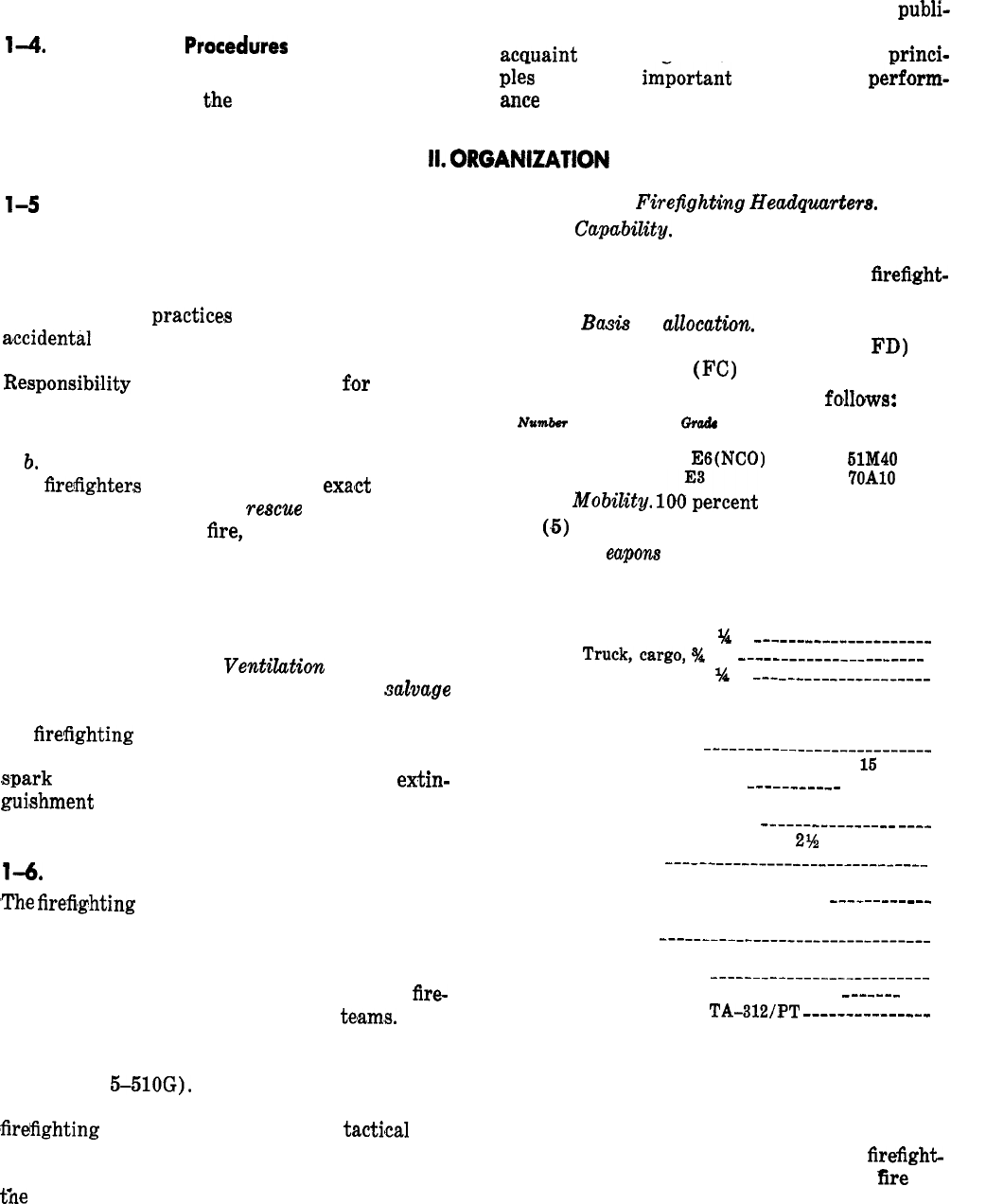
a. Team FA,
Firepghting
Headquurter8.
(1)
Capabdity.
Capable of planning for over-
all area fire prevention and firefighting program
and for controlling assigned or attached
fireflght-
ing teams.
(2)
Bad3
of
auocation.
Normally one per
three to five firefighting teams (FB and
FD)
and
one water truck team
(FC)
.
(3) Strength. Aggregate-4, as
fo,llows
:
NlbWbb&W
Grade
MOS
1
LT
9414
2
E6(NCO)
6lM40
1
(4)
Mobdity.
lOO*;ercent
mobile.
‘7OAlO
(,5)
Major items of equipment.
W
capons
Individual weapons only.
Vehicles
Trailer, cargo,
$4
T
-________-_---_-_-_-_
1
Truck,cargo,
%
T
____________-_-_______
1
Truck, utility,
%
T
__-_____________-____
1
Other equipment
Blanket, fire, wool, w/grommets and
rope handle
____-__-_-_____-_______---_
2
Extinguisher, fire, carbon dioxide,
16
lb
(6.76 kilograms)
____-____-_
------- ----
2
Extinguisher, fire, dry chemical, 20 lb
(9.072 kilograms)
___---___-__--__
--__
2
Extinguisher, fire, foam,
2%
gal (9.46
liters)
___-__-____--__---_-_______-__-
2
Firefighting equipment set, repair of
extinguishers and fire hose
-___--__-_-_
1
Light, warning, vehicular, red, w/blinker
device
-__-----_-_---__--_--_______-___
2
Repair and refill kit, carbon dioxide fire
extinguisher
--____-_-______-__-_------
1
Siren, electric motor operated
_--_--_
---- 2
Telephone set,
TA-312/PT
----_______-_-_
1
(6) Method of operation. Team leader serves
as the fire marshal of the installation or area of
responsibility. Team members conduct fire. pre-
vention inspections and train volunteer personnel
in firefighting operations. In addition to planning
for overall fire defense and commanding
firefight-
ing teams, this team maintains and refills
Ere
ex-
tinguishers and makes minor repairs to fire hose.

b. Team FB, Fire Truck.
(1)
CapabiZity.
Capable of providing fire pro-
tection, administering timely and adequate first
aid, and implementing a fire prevention program
for areas housing 5,000 to 10,000 troops, or a
warehouse and open storage area of 100,900
square feet (9290 square meters).
(2) Basis of
allocation.
One per installation
housing 5,000 to 10,000 troops, or containing
100,000 square feet (9,290 square meters) of
warehouse and open storage.
(3)
Strength.
Aggr,egate-6,
as follows
:
Number
1
E-5TCC)
MOS
5lM40
1
E4 (NCO)
5lM40
3
E-4
5lM20
1
E-3
5lM20
(4)
Mobility.
100 percent mobile.
(5)
Major items of equipment.
Weapons
Individual weapons only.
Vehicles
Firefighting
equipment
set,
truck
mounted,
structural type, overseas,
class 530B or 530C
---_-----___-___--__
1
Othe?*
equipment
Blanket, fire, wool, w/grommets and
rope handle
_--_--_--__---------_--_--
2
(6) Method of operation. Team members pro-
vide fire protection for the team’s assigned instal-
lation or area by
cond&ing
fire prevention
inspections and by fighting fires. See TM 5-225
for radiological decontamination.
c.
Team FC, Water Truck.
(1)
CapabiZity.
{Capable
of transporting
water for firefighting
purpose,s
when not enough
water is available near the fire.
(2) Basis of
aZZocation.
One or more per
fire-
fighting headquarters (Team FA) as required.
(31
Nwubm
1
1
(4)
(51
(61
Strength. Aggregate-2, as follows
:
c+nl&
mos
E-4
6lM20
E-3
6lM20
Mobility. 100 percent mobile.
Major items of equipment.
Weapons
Individual weapons only.
Vehicles
Truck, tank, water,
2%T
-__-___-__
------
1
Other equipment
No
other major items.
Method of operation. Team
trarrsports
water for firefighting when sufficient water is not
available. Team members may be used as fire-
fighters.
d.
tion
TM
5-315
Team FD, Brush
Fire
Truck.
(1)
CapabiZity.
Capable of furnishing
protec-
against
gras#s
or brush fires within its
as-
signed area of responsibility when augmented
with personnel and additional handtools. Can also
be used to a limited degree to combat structural
fires.
(2) Basis of
aZZocation.
One per installation
housing 5,000 to 10,000 troops, or
contiining
100,000 square feet (9290
!square
meters) of
warehouse and open storage.
(3) Strength. Aggregate-2, as follows
:
Number
MOS
1
E-57?&0)
‘51M40
1
E-3
6lM20
(
4)a
MobiZity.
100 percent mobile.
(‘5)
Major items of equipment.
Weapon8
Individual weapons only.
Vehicles
Firefighting
equipment
set,
truck
mounted, brush type, overseas, class
530 B or 530
C_-------__________------
1
Other equipment
No
other major items.
(6) Method of operation. Team members
train personnel of the supported unit in brush
firefighting and supervise them when so engaged.
Additional handtools (axes, mattocks, brush
,hooks)
must be provided by the supported unit.
1-7. Responsibilities
AR
611-201
lists the duties, skills, and
knowl-
edges of the firefighter. Listed below are the pri-
mary responsibilities of the fire protection person-
nel.
a. Fire Chief. The fire chief, under the direction
of the fire marshal, supervises the fire protection
organization, including management of fire sup-
pression and rescue operations, training and
pre-
fire planning programs, and maintenance of fire
equipment, systems, and devices
;
he also monitors
the fire prevention program. He insures
that:
(1) Fire vehicles and personnel are in a state
of immediate readiness and availability.
(‘2)
Training and fire prevention programs
are
carriced
out.
(3) Resources are efficiently utilized.
(4) Duty assignments, equipment
mainte-
nan,ce,
and operational procedures are accom-
plished.
b. Assistant or Deputy Fire Chief. He assists

TM
5-515
the fire chief in carrying out his duties and as-
sumes them in his absence.
c. Station Chief. Under the direction of the fire
chief, a designated person acts as the station
chief.
Since no position is
au.thorized
for his duty,
the person assigned will also perform duty as
crew chief. He supervises all chiefs assigned to
his station. He
will-
(1) Implement the policies and regulations of
the base fire protection organization and higher
headquarters.
(2) Respond with the assigned unit to
all
alarms and emergency calls.
(3) Extinguish fires and take necessary
pre-
cautions to prevent their being rekindled.
(4) Be careful to avoid unnecessary damage
to or
10,s~
of department property, or injury to
himself or other personnel.
(5) Watch for and protect at the scene of a
fire all clues or evidence indicating the fire’s
cause.
(82)
Respond with his crews to alarms and
emergency calls and insure
ad,equacy
of fire sup-
pression and rescue operations.
(3) When first to arrive at the scene of an
emergency,
as.sume
command until the arrival of
a senior fire authority.
(6) Participate in the fire prevention pro-
gram.
f.
Training
of Fire Truck Operators. Drivers of
emergency type vehicles must attain the following
minimum test scores
:
(1) Emergency judgment test-108.
(2) Road
test-go.
(4) Supervise and assist in training and in-
structing the crew members and conducting regu-
lar drills to maintain efficiency of flrefighting and
rescue operations.
d. Crew Chief. He
will-
(,I)
Supervise operator
in,spection
and main-
tenance of fire vehicles and insure the upkeep and
protection of all fire organization property.
(,2)
Insure the safe arrival of his vehicles,
with its full
compl,ement
of equipment and person-
nel, at the scene of an emergency.
(3) Respond with his crew and equipment to
alarms, fires, common emergencies, vehicle
res,cue
emergencies, and routine calls, including recipro-
cal movements as directed.
(3)
Individuals not achieving the above mini-
mum
qualifications
will have their SF Form 46
and Driver Qualification Record DA Form 348
stamped “Limited License.”
(4) Refresher training will be provided an-
nually to assure familiarity with emergency oper-
ational requirements for the type of vehicle
being operated. Specific attention will be given to
the understanding of
1,egal
limitations required by
the installation and by local laws.
(6) Any operator of an emergency vehicle
who
i,s
involved in an accident will have
hi,s
per-
mit suspended, pending completion of remedial
driver training.
(4)
Wlhen
first
to arrive, assume command
until relieved by senior fire authority.
(5) Perform the station chief’s
duti,es,
dele-
gated to him or dictated by emergency conditions.
(6) Any operator of an emergency vehicle
who
i,s
involved in an accident and is convicted of
any moving violation will have his permit re-
voked.
e. Firefighters. Each
firefighter
normally is as-
signed a specific duty related to equipment opera-
tion or firefighting and rescue. All personnel,
ho:w-
ever, will be cross-trained and capable of flexible
action in a fire situation and rescue emergency.
Firefighter,s
will-
(7) Should a requirement exist for the driver
to be retrained and tested for driving other than
emergency vehicles, the driver’s permit will be
stamped “Army Limited-Not Valid for
Emer-
gency
Vehicle.”
(1) Keep apparatus, equipment, tools, and
uniforms clean and serviceable,
(8)
.A
proper entry’ will be made on the
Driver Qualification Record (DA Form 348) to
assure that the above information and qualifica-
tions or limitations are known and available to the
motor officer in case of reassignment of the driver
or
loss of a permit.
Section Ill.
FACILITIES
1-8. Introduction
Firefighters often spend 24 hours or more on duty
at an assigned locality in order to assure rapid
response to fire alarms. They should be housed in
suitable living facilities, when available, including
_
those necessary for comfortable working,
sleep-
_
1-4

TM
54315
ing,
eating, recreation, training, and study. Inade-
quate facilities can greatly lessen the efficiency of
-
a
,fire
protection organization. When not on duty,
firefighters are on call (in case of grave emergen-
ties).
1-9.
Structural Stations
A structural fire station must be strategically lo-
cated in the area it is expected to protect.
a. Usually it is centrally located so
tha,t
each
portion of the area will have as much protection
as possible without
,slighting
any other portion.
However, when one portion
1
“high risk” in com-
parison with the rest of the area, the station’s
location will naturally favor the
,high
risk portion.
b.
Reasons for considering an area as a
“high-
risk” include the speed of ignition of the flamma-
ble materials located there, the propagation possi-
bilities, and the potential amount of loss if fire
occurs. Those portions of an area containing hos-
pitals\ technical buildings, barracks, headquarters
buildings, or other buildings in which life and
property loss potential is ‘greatest are necessarily
classified as critical from the standpoint of fire
hazard.
-
l-l 0. Crash Stations
The location of the aircraft fire rescue station is
limited to the vicinity of the airfield, but its loca-
tion even within that limitation is of utmost im-
portance. An aircraft
,fire
rescue station must be
centrally located. At the same time it must be so
positioned that there will be an open view of all
aircraft activity-including the flying field, run-
ways, ramp, parking areas, taxi strips, and
dis-
persal
areas-from the crash station.
l-l 1. Sleeping Quarters
Sleeping or bunking facilities should enable crew-
men of both aircraft
&fire
rescue and structural
organizations to reach the apparatus floor quickly
and safely. When the alarm sounds during sleep-
ing hours, a firefighter is expected to awaken,
throw back his blanket, spin around and insert
both feet into his
tboots,
stoop and pull up his
pants, run toward the apparatus floor while plac-
ing his suspenders over his shoulders, and finally
mount the truck, ready for action-all in about
15
seconds. He can do this only if the quarters are so
designed that the distance from the sleeping
-
quarters to the apparatus is as short as possible,
passageways are wide and clear, and the area is
completely free from obstructions which might
cause delay or injury.
l-l 2. Dining Facilities
Dining facilities included in the quarters must be
looked upon as a necessity rather than as a com-
fort or a luxury, because those periods of absence
from the fire station for eating greatly reduce the
strength of the organization,
,even
if only a few
persons are absent for a short time.
1-13. Heating and Sanitation
Each structural and crash
#station
should be prop-
erly ‘heated and ventilated.
a. The comfort of personnel will insure that the
men willingly and efficiently
,perform
their inside
duties, which include keeping the equipment in
excellent condition. Training and study periods
are even required of seasoned firefighters to ad-
vance or refresh their technical
knowl,edge.
Per-
sonal comfort
i,s
a necessity to the man who is
trying to absorb such knowledge, and proper
building temperature is necessary for personal
comfort.
b. Shower and latrine facilities are essential to
the health, comfort, and cleanliness of all fire pro-
tection personnel. These facilities should be placed
reasonably
clase
to the apparatus floor. After re-
turning from a fire, the men are frequently wet,
cold, and dirty, and a shower helps to prepare
them rapidly for another possible emergency.
While showering, the men should keep boots and
pants close by so that in case of alarm they can
put them on immediately.
l-l 4. Training Facilities
For the important purpose of practical training,
which serves as a proving medium for theories
presented in classrooms, a training ground or
area should be provided for fire protection crews.
a. The training ground should be located, if pos-
sible, in a position from which response to any
part of the area may be made in a minimum of
time. Training areas must have a supply of water
ample to replenish the supply on the vehicles.
Trainers and simulated structures
,should
be pro-
vided to enable actual fire ignition, control, and
extinguishment according to the standing opera-
ting procedures.
b. Neither the entire aircraft fire rescue crew
nor the entire structural crew will be out of serv-
ice at any one time while attending
t,he
training
1-5

TM
5-315
ground. Reasonably ample protection must be
im-
helpful publications. The study room must be well
mediately available at all times.
li,ghted,
comfortable, and inviting, so as to
encour-
c. A reading or study room is a great asset
toward maintaining a progressive study or
train-
ing ‘schedule. A
16-millimeter
projector should be
available from the signal library for showing
training films. A set of technical manuals and
or-
ders should be furnished along with any other
age individual study.
d. A storeroom and repair
‘shop,
or a
combina-
tion of the two, should adjoin the fire station so
that crew members studying apparatus there, or
working there, will not be far from their duty
stations.
Section IV. DA FORMS, REPORTS AND RECORDS
l-l
5.
Introduction
Fire protection and firefighting operations require
reports and records, These are used for determin-
ing the effectiveness of firefighting and rescue op-
erations; for appraising fire prevention regula-
tions, programs, and training; and for evaluating
fire protection engineering, equipment, and de-
vices. The statistical data enable the organization
to analyze and evaluate its own conditions and
affect it changes to improve its
efhciency.
Reports
are required for any fire incident
,which
involves
death or disabling injury to personnel or damage
to or destruction of any building, structure,
grounds, utility plant or ‘system, installed or
moveable
equipment, aircraft, missile, vehicle,
material, supplies, and personal property. Also,
technical investigations are necessary for fire in-
cidents to analyze
cause.s,
contributing factors,
and Sects; and to determine the effectiveness of
the measures taken or required to be taken to
meet other
such
emergencies. Records are re-
quired for fire protection equipment systems or
devices that may be peculiar to an installation.
Routine should be made of inspection and haz-
ards.
l-l 6. Forms
Listed below are forms to be used for inspection’s
and test of firefighting equipment.
a. DA Form
253,
Fire Extinguisher Record
Tag?
DA Form 253 is attached to each installed
extinguisher for recording the monthly inspection
and recharging.
b.
DA Form 5-1 (Fire Department
Individual
Run Report). This form is designated to give in-
formation on responses made by individual fire
units. The form
listxs
information on
suclh
matters
as time of alarm reception and response, type of
apparatus dispatched, location and nature of the
emergency (or other type response), equipment
used, and hose line operation.
1-6
c. DA Form 5-2 (Fire Report). This form is
designed to furnish information about fire inci-
dents which affect life or real property. It is used
to-(1) Identify the incident and related opera-
tions.
(2) Provide close estimates of monetary loss
and the damage or destruction of property, mate-
rial, and equipment.
(3) Indicate the loss of life and the extent
and nature of physical injury owing to fire.
(4) Indicate the extent and nature of contin-
gent loss and its effect on the installation mission.
(5) Determine the cause and contributing
factors.
(6) Evaluate and improve fire protection or-
ganization,
per,sonnel,
equipment, training, and
procedures.
(7) Determine action to be taken to prevent
similar occurrences.
d. DA Form 5-78 (Fire Hose Record). This
form records the inspection, test, and mainte-
nance of all fire hoses, the type of coupling, and
provides a remarks section.
e. DA Form
5-118
(Annuul
Dry Pipe Valve
Inspection and Tripping Test). This form is pro-
vided to record tripping, cleaning, and resetting
of dry-pipe and deluge valves with their accesso-
ries.
f. DA Form 5-119 (Automatic Sprinkler and
Bandpipe
Equipment, Inspection and Test). This
form is used for inspection and tests by mainte-
nance personnel. It is completed as the inspection
or test is made for operation of sprinklers, valves,
and fire pumps.
g.
DA Form
240.4
(Equipment, Inspection and
Maintenance Worksheet). The equipment inspec-
tion and maintenance worksheet is used by all
personnel performing inspections, preventive
maintenance services, diagnostic
checkouts,
and

equipment serviceability criteria
vides a standard procedure for
-
cording equipment deficiencies.
l-l 7. Records and Reports
checks. It
pro-
temporarily
re-
Records at the installation level will be prepared
by qualified fire prevention personnel and will be
approved by the operating agency commander or
authorized representative. The forms are to be
prepared as authorized in AR 310-1, as applica-
ble, and used to record technical details of opera-
tions and tests for the following reports (For ad-
ditional information, see TM
38-760).
a. Automatic Sprinkler Water-Flow and Low
Air Pressure, Automatic and Manual Fire Alarm
System Report. Complete and permanent records
will be kept of the operation of fire alarm systems
and of inspections, tests, and services performed.
In addition to inspection and test record forms,
impairment tags will be provided for use when
devices are found inoperable and not immediately
repairable.
b. Fire Hazard Inspection Report. This is used
for either the fire inspection notice or fire hazard
inspection report.
T’he
procedure to be used can be
determined locally. The main reason for using the
fire
in.spection
notice is to streamline action and
reduce the time required to complete fire inspec-
tion requirements. The establishment of good will
and cooperation between the fire organization and
the activities occupying the structures will reveal
that the majority of fire hazard’s can be resolved
with this procedure. For situations where
tlhe
fire
inspection notice does not prove
,satisfactory,
or is
not adequate, the fire hazard inspection report
will be used. Regardless of the procedure followed
all fire hazards or deficiencies discovered during
any inspection which cannot be or are
n,ot
cor-
rected during the inspection will be recorded. To
insure that all hazards recorded on this form are
corrected quickly,
followup
by the fire inspector is
necessary. The time allowed to correct the
ha+
TM
5-315
ards, which can vary from 1 to
72
hours,
dlepend-
ing on the potential dangers involved, will be
listed on the form.
c. The Training Timetable. ‘The training timeta-
ble is a simple chart to assist the supervisor in
identifying, planning, and scheduling the training
needed by his employees. It is a means of record-
ing the operations each employee can perform, the
operations in which each employee needs to be
trained, and the date when this training should be
started. The chart may vary in form and size,
depending on the purpose, the size of the work
force, and even the complexity of the work itself.
It may also be called a training
,schedule
or work
chart and its essential features may be incorpo-
rated in an operations guide, work distribution
chart, or control chart. However, when once pre-
pared, it gives an overall picture of the specific
training to be done in that unit. If the
training
timetable is
corr,ectly
u,sed,
it serves the following
purposes
:
(1)
Aids in identifying, planning, and sched-
uling training.
(2) Checks on the extent to which training is
carried out as planned.
(3) Aids in determining
whether
there
will
be a trained staff as needed to accomplish the
mission.
(4) Aids in assigning workers,
d. Log. Each fire protection organization will
maintain a daily log containing information on
duty personnel assignments, vehicle movements
and mechanical status, response to fire
inciJ.ients,
emergencies, false alarms,
alarmas
received, alarm
transmis,sions
over automatic manual, sprinkler
systems, special exercises, names of visitors, inju-
ries to personnel, etc. This log may be typed or
prepared by hand on
8
x
lOl,&inch
(20.3 by
26.7-
centimeter) bond paper and maintained in a
bound notebook. It will be reviewed and approved
by the senior
ofIlcer
in charge at the close of each
work shift.
Section V. COMMUNICATIONS
l-l 8. Introduction
l-l 9. Telephone Systems
The fire protection facilities of an installation ‘Facilities for reporting fires on posts,
canxps,
and
must include an adequate communications system.
stations have, at most locations, been
standard-
This system consists of telephone systems,
auto-
ized.
-
matic,
manual, and waterflow alarm systems, a. Fires may be reported through the
installa-
two-way radios, and visual and aerial signals.
tion telephone system or through a special system
1-7

of outside fire reporting telephones installed in
boxes, and connected directly to the alarm board
at the main fire station.
b.
External fire-reporting telephones are housed
in metal boxes mounted on poles or external walls
of buildings, and are placed so that one of them
can be reached rapidly and easily from any possi-
ble post location. These boxes are painted’red and
usually have a red target light mounted over them
so they will be visible at night.
c. To report a fire over the fire reporting tele-
phone, a person must open the box, lift the tele-
phone receiver, and give the information to the
alarm
,board
operator.
d.
In outdoor storage areas where post tele-
phones or fire reporting telephones are widely
scattered, signs should be posted throughout the
area to show where these
,fire
reporting
fa,cilities
are
locat,ed.
1-20. Automatic, Manual, and
Waterflow
Alarm Systems
In the following systems, alarms are transmitted
by electrical impulses and recorded on a tape in
the central fire station alarm room.
a.
Automiatic
Fire, Detection and
Aktrm
SV-
terns. These systems are installed
wher’e
it is not
feasible to install automatic sprinkler systems.
Dormitory type combustible buildings with indi-
vidual sleeping rooms should have
automati,c
fire
detection systems.
(1) These automatic fire detection and alarm
systems incorporate some device
sen,sitive
to heat,
fire, and smoke. These devices cause an electri-
cally operated transmitter to send a coded signal
to the fire station alarm system.
(2) Heat-sensitive
devi,ces
used in fire detec-
tion systems may be either fixed-temperature or
rate-of-rise thermostats. Fixed-temperature ther-
mostats will actuate the transmitter when a pre-
determined degree of
temperatur#e
is created by
unusual circumstances. Rate-of-rise thermostats
will actuate the transmitter when a fire or other
source of heat causes the temperature to rise at a
rate faster than normal. The rate-of-rise devices
must be used with fixed-temperature devices.
b. Manual
Alamo
Systems.
Manual alarm sys-
tems are usually installed in areas not provided
with sprinkler or automatic fire detection systems.
Watchman service is often provided in these
areas.
Manual alarm boxes are located strategi-
cally throughout an area and are usually operated
by opening the box and pulling a lever. (Due to
the different types of boxes, the operation will
vary.) Only a local alarm is normally provided.
Under certain conditions a coded signal may be
sent to the fire station alarm system.
-
c.
Waterjlow
Alarm Systems. Waterflow alarm
systems are those that transmit a coded signal to
the
fire
station alarm system when a ruptured
sprinkler head causes water
ato
flow through the
pipes of a sprinkler system. Loss of air pressure
in a dry-pipe system will cause a local alarm and
may also transmit coded signals to the
,fire
station
alarm system.
1-21. Fire Department Radios
The provision of two-way radios for structural
fire apparatus is not a substitute for a fire alarm
system because such radios usually are not
avail-
ble
to post personnel for reporting fires.
a. Radios installed on structural apparatus are
used successfully for issuing detailed and specific
orders to fire crews while they are
enroute
to the
scen’e
of an emergency and at any other time
when the apparatus is away from the station.
b. Radios are
u,sually
installed in the smaller,
faster vehicles, since these trucks are normally
the first to arrive. Upon arrival, auxiliary
equip-
ment or additional emergency assistance can be
ordered by radio without delay.
c.
The frequency of radio equipment on the
crash rescue apparatus should be the same fre-
quency as the airfield radio tower.
d.
Portable radios for firefighters are advanta-
geous. They permit firefighters
(to
engage in var-
ious activities and be available for fire call.
1-22. Radio Terms and Procedures
Several standardized radio terms and procedures
must
b,e
understood and used by fire crews.
a.
Tern.
(1) “Roger” means “received your message.”
(,2)
“Wilco”
means “received your message
and (where applicable) will comply.”
(3)
‘Say
again,” “I say again,” and “That is
correct” are selfexplanatory. To correct some-
thing said, the work “Wrong” is used, followed by
the correction.
(4) “Wait,” if used by itself, means “I must
pause for a few
selconds”
and requests the other
,station
to stand by (refrain from transmitting)
-
for a period not to exceed 30 seconds.
1-8
(5) If the pause is to be longer (up to 1
minute), the expression “Wait out” is used.
-
(6) To request an even longer standby pe-
riod, the expression “Wait
-
Out,” is sued in
which the blank is replaced
#by
a numeral indicat-
ing the number of minutes the other station is
requested to stand by.
NOTE
Standby periods usually are requested by
an operator who
,has
to perform a duty
that takes his attention away from the
transmitter/receiver-or who has to
handle communications of higher prior-
ity or greater urgency. When requested
to stand by, a station normally is ex-
pected to remain in this status until ad-
vised or invited to resume transmission.
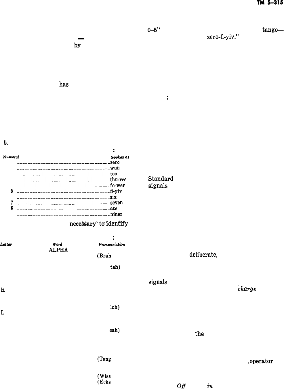
b.
Numbers. To transmit numbers, the follow-
ing standard pronunciation should be used
:
NUWWd
stmken
aa
0
-__-_____--_-____--____-_-__________zero
1
---___-__-_____-______________------wun
2
--_---___-----_-__--___----_---_____too
3
-----__.__----____---___----_---____-thu-ree
4
-__-____--____--_---__-_-___--___-__fo-wer
6
___---___----___-_____----_-----___-fi-yiv
6
--_____--__-__------____--__-__._-.---six
1
_________-______----__-_________--_-seven
3
---___-_-----____-_____--___--_-___-ate
9
----__-------_------_----___________niner
c. Letters. When it is necessary’to identify a
letter of the alphabet or to spell a word, the new
standard phonetic alphabet should be used
:
Lett6Y
A
B
C
D
E
F
G
H
I
J
K
I
M
N
0
P
Q
R
S
T
U
V
W
‘-
X
Y
Z
A%A
BRAVO
CHARLIE
DELTA
ECHO
FOXTROT
GOLF
HOTEL
INDIA
JULIET
KILO
LIMA
MIKE
NOVEMBER
OSCAR
PAPA
QUEBEC
ROMEO
SIERRA
TANGO
UNIFORM
VICTOR
WHISKY
XRAY
YANKEE
ZULU
Pmnu7u&don
(Al fah)
(Brah
voh)
(Char lee)
(Dell
tab)
(Eck oh)
(Foks trot)
(Golf)
(Ho tell)
(In dee ah)
(Jew lee ett)
(Key loh)
(Lee mah)
(Mike)
(No vem ber)
(Oss cab)
(Pah pah)
(Kwi beck)
(Row me oh)
(See air ah)
(Tang
go )
(You nee form)
(Vik tah)
(Wiss
key)
(Ecks
ray)
(Yang kee)
(Zoo loo)
TM
5-315
Words not understood will be spelled phonetically.
For example, phonetic transmission of “Type
0-5”
would be made as follows: “I spell:
tango-
Yankee-papa-echo,
zero-fi-yiv.”
d.
Calling Procedure.
To establish communica-
tion with other units make the initial call-
(1) Once communication is established, begin
each message with the truck’s identification and
conclude with the proper closing remark. All mes-
sages will end in “over” or “out,” whichever is
appropriate. “Over” means “my transmission is
ended
;
I expect a response.” “Out” means “this
conversation is ended, and no response is ex-
pected.”
“Over” and “out” are never used to-
gether
to end a transmission.
(2) Crews should keep radio equipment clean
and protected from the weather. Particular care
must be given to the condition of the battery,
which must be tested frequently and charged
when necessary.
1-23. Hand Signals
Randard
throughout the services are the visual
signal,s
between the senior man in charge and the
pump operator at structural fires. These signals
may be given by hand during the day or by flash-
light or lantern during the night. They cover most
of the orders usually transmitted from the senior
man to the pump operator. The pump operator
must be constantly on the alert for signals and
must acknowledge all signals by repeating them.
Standard signals are easily understood since, in
most cases, they suggest the action desired. Sig-
nals should be
deli,berate,
for careless signals may
be misunderstood. If necessary, additional signals
may be developed to fill special needs. However,
they should be distinctly different from standard
signal,s
and should be understood by all concerned.
The standard hand signals are
kharge
line, shut
off water in line, cease operations, increase pres-
sure, and decrease pressure.
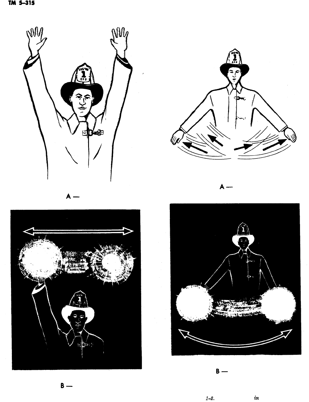
a. Charge Line. During the day this signal is
given by raising both arms vertically from the
shoulders, palms to the front, and holding them
stationary until
,the
signal is acknowledged, as
shown in A, figure l-l. At night it is given by
holding a flashlight or lantern in one hand and
raising the arm vertically above the head. The
beam is directed toward the pump
)operator
and
the light swung horizontally above the head, as
shown in B, figure l-l.
b. Shut
08
Water
in
Line. This signal is for a
temporary shutdown to allow for line repairs or
1-9
A-
DAY
A-
DAY
I
B-
NIGHT
Figure l-l. Charge line.
B-
NIGHT
Figure
1-2.
Shut off water in line.
1-10
changes. On receiving it, the operator closes the
discharge valve, but continues to pump and holds
himself ready to open the valve at the proper
sig-
A-
DAY
B-
NIGHT
B-
NIGHT
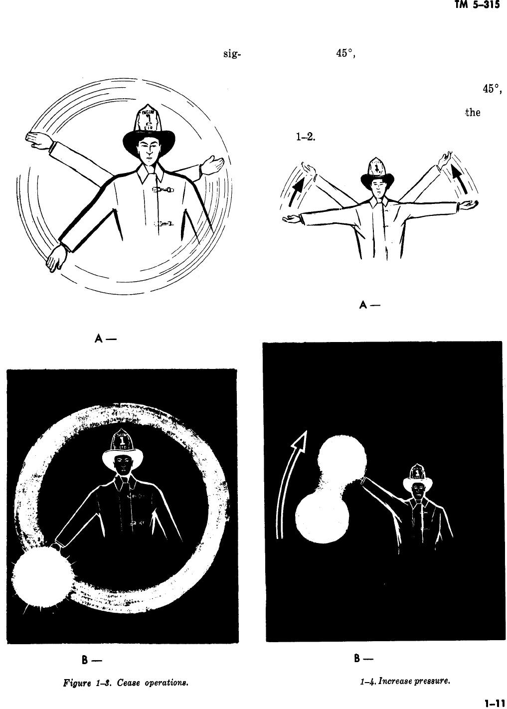
Figwe
1-8.
Cease
operation&
Figure
1-4.
Znweaee
presewe.
TM
5-31s
nal. During the day the signal to shut off the
water is given by extending both arms downward
at an angle of
45’,
crossing them in front of the
body, and swinging them back and forth, as
shown in A, figure 1-2. At night, it is given by
extending one arm downward at an angle of
45’,
directing the beam of the flashlight or lantern
toward the pump operator, and swinging
<the
arm
back and forth in front of the body as shown in B,
figure
1-2.
A-
DAY
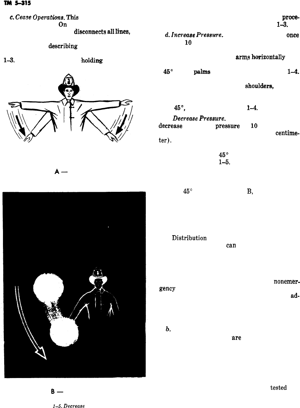
c.
Cease
Operatims.
Thti
signal means that the
operation is over.
Qn
receiving it, the operator
disengages the pump,
diseonneets
ah
&es,
and
picks up his equipment. During the day, this sig-
nal is given by
describing
a circle in front of the
body with an extended arm, as shown in A, figure
1-3.
At night, it is given by
,hokling
a flashlight or
A-
DAY
B-
NIGHT
Figure
1-5.
Decrease
pressure.
lantern in the hand and following the same
proce-
dure as for daytime, as shown in B, figure
1-3.
d.
Increme
Premme.
This signal is given
once
for each
I@
pounds (4.5 kilograms) increase of
pressure required. During the day this signal is
given by extending the
arms
horizuntally
and
sideways from the shoulders and raising them to
a
45’
angle,
palms
up, as shown in A, figure
1-4.
At night it is given by extending one arm horizon-
tally and sideways from the
shouh?ersY
holding
a light in the hand with the beam directed toward
the pump operator, and then raising the arm up-
ward
45O,
as shown in B, figure
1-4.
e.
Deere-e
Freaaure.
Each signal indicates a
deerease
in pump pressure of
10
pounds per
square inch (0.7 kilograms per square
centime-
t,er).
During the day the signal is given by extend-
ing the arms horizontally from the shoulders and
lowering them to a
45’
angle, palms down, as
shown in A, figure
1-5.
At night it is given by
extending one arm horizontally from the shoulder,
holding a light in
one
hand with the beam directed
toward the pump operator, and then lowering the
arm to a
45’
angle, as shown in
B,
figure 1-5.
1-24. Other Characteristics of Alarm Systems
-
A functional fire alarm system must have the fol-
lowing characteristics.
a.
Distri,bution
and quantity of the alarm boxes
must be such that they
.can
be easily and quickly
reached from any possible fire emergency location.
The operation must be so simple that persons
under the strain of excitement are able to report
the location of the fire accurately. Alarms must be
transmitted without interference by
nonemer-
gency
communications. The system must be able
to operate properly under stress of time and
ad-
verse climatic conditions. Alarm systems must
survive fires and other conditions which may tend
to cause a circuit break.
!J.
The most frequent causes of alarm failures
and inaccurate impulses
‘are
the. result of falling
poles and trees, faulty wiring involving commer-
cial utilities, impact of motor vehicles, wind, sleet,
snow, electrical storms, sewer explosions, and ex-
cavations which cut or disturb underground
wires. To assure the dependability of the alarm
systems they must be inspected and
te.sted
fre-
quently and kept in the optimum operating condi-
tion.
1-12
TM
5-315
CHAPTER 2
CLOTHING AND EQUIPMENT
Section
I.
CLOTHING
2-1.
Introduction
Protective clothing provides firefighters with
maximum personal safety which enables them to
approach and attack fires and perform rescue op-
erations effectively.
a. For normal fires in buildings or in the open,
involving basic, ordinary
combusti,ble
material,s
(wood, paper, stored materials, etc.), the protec-
tive clothing issued consists of special fireman’s
bunker coat and trousers with
,suspenders,
plastic
helmet, rubber boots, and gloves (fig. 2-1). This
clothing, when properly worn, gives reasonable
prot,ection
to the wearer against normal exposures
to heat, flames, water, cold, and physical injury
without too much sacrifice of body freedom.
b. For more extreme fire-intensity exposure,
such as to flammable liquids, liquid or solid fuels
and propellants, chemicals, or explosives encoun-
tered in typcial aircraft or missile fires, special
protective clothing must be worn in varying com-
binations with the normal clothing. Such addi-
tional clothing consists of special heat reflective
coat and trouser covers and protective head, face,
and shoulder hoods.
c.
All types of protective clothing are intended
to be worn, in various combinations, over and in
conjunction with normal personal work clothing,
depending upon the climatic, work, and fire condi-
tions.
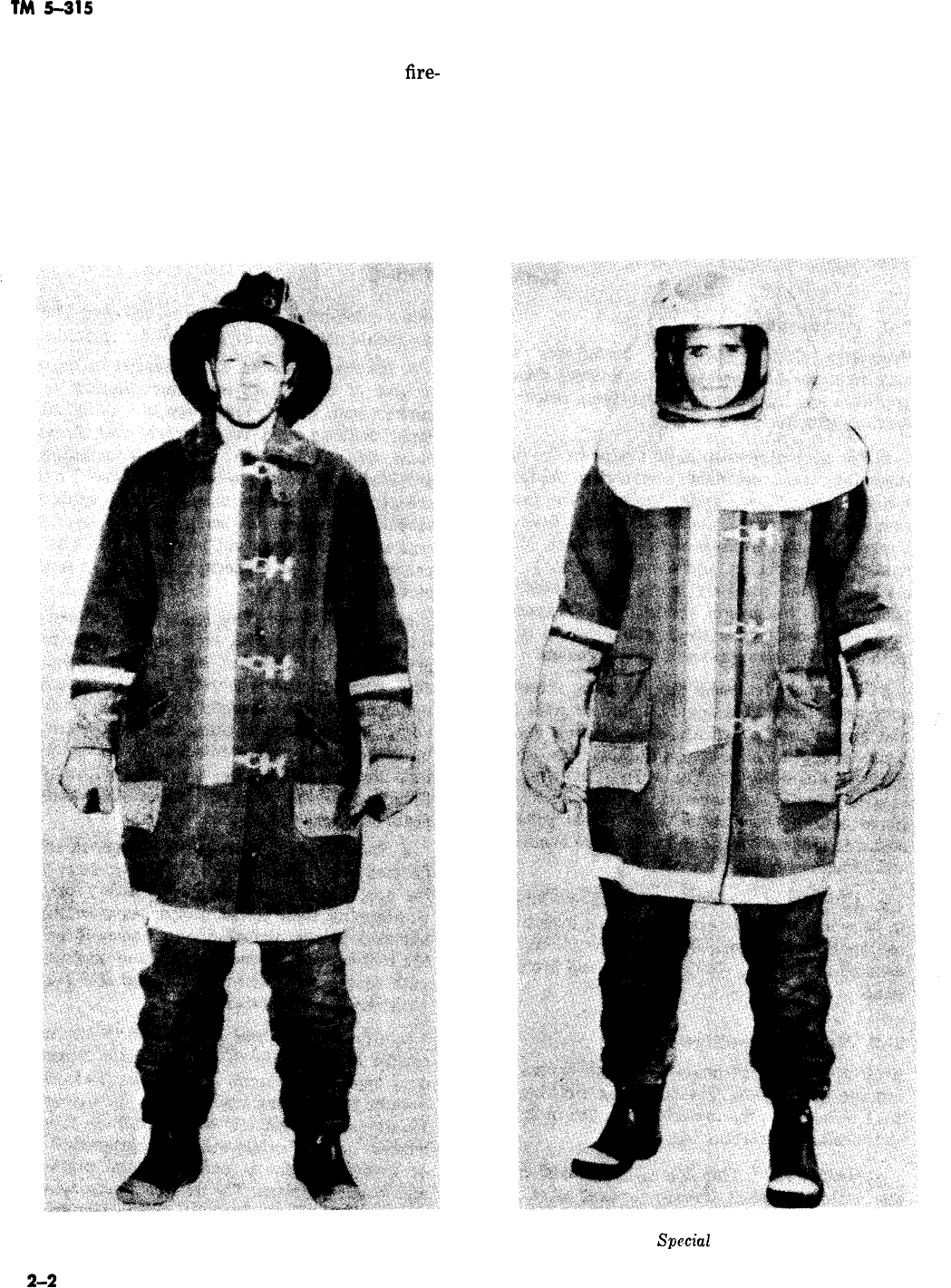
2-2. Normal Protective Clothing
Protective clothing should be put on before leav-
ing the fire station. The following clothing (fig.
2-1) is issued to the firefighter for use in fighting
the normal installation fire
:
a.
Bmker
Co&.
This is a a/a-length coat of spe-
cial water
repellment
flame-retardant duck outer
cloth, with water repellent liner and a rem;ovable
blanket inner lining. Special snap fasteners
pro-
vide a quick-hitch for putting on the coat. The lin-
ing should not be removed except for cleaning.
b. Bunker Trousers. These consist of an
over-
trouser of duck cloth and liner, similar to the
bunker coat. The trouser legs are designed for
rapid donning, and to be worn over fireman’s
boots. Special waist flap and snap fastening are
provided to facilitate securing in place. Trousers
are generally worn with heavy duty, quick-hitch
suspenders. When not being worn, bunker trou-
sers are normally assembled over boots with sus-
penders arranged to permit donning in a single
movement.
c. Plastic Helmet. This is a special-molded plas-
tic safety helmet with cushioned heat strap to
provide fit and prevent impact head injury. A
chin strap further secures the helmet in place
under arduous work conditions. In some
case.s,
an
additional removable inner liner with ear and
back-of-neck flaps is provided. This helmet pro-
tects against falling debris, contact with obstruc-
tions and, to some
degr,ee,
against water and mod-
erate heat reflection.
d. Boots. Rubber boots designed particularly for
firemen’s use are
hi,p
length with a steel safety
toe cap, flexible punctureproof safety insole of
overlapping steel plates, and a heavy corrugated
non-slip, grease resistant outer sole. It protects
the foot against physical injury and may
b,e
worn
with equal comfort in both hot and cold
clim,ates,
with variations in socks.
e. Gloves. Standard gloves issued for firemen
consist of conventional leather shells of
medium-
duty type, with thumb and fingers. These gloves
may be worn either separately or in various com-
binations with cotton, wool, or other fabric or
rubber- or synthetic coated or impregnated liners
or covers, depending upon personal preferences
and local conditions. The leather gloves, while not
as water-repellent or heat insulative as some
types and combinations, are generally preferred,
2-1
TM
5-315
since they give reasonable protection and are plia- f. Protective Clothing Maintenance. After use,
ble enough not to hinder the performance of
fire-
all types of protective clothing should be checked
fighting tasks, It is good practice to carry an for damage from cuts, abrasions, burns, or wear,
extra pair in the pocket of the turnout coat. As- Reflective fabrics of coat and trousers are some-
bestos gloves, unless treated or worn with some what more likely to be cut and torn, especially
combination of water-repellants, are not recom-
when working
close to jagged metal such as dam-
mended because they tend to soak up moisture aged aircraft. All items of clothing should be
and crate severe internal steaming when exposed flushed off after use to remove any residues of
to heat. fuels, extinguishing agents, oils, chemicals, dirt.
-
Figure 2-1. Normal protective clothing. Figure 2-2.
special
protective clothing.

TM
5-315
etc. Persistent dirt or other contamination should
be removed by washing with soap or mild deter-
gents, water, and a brush. In come cases, mild
solvents may be used for cleaning. Tumbling,
scrubbing, or abrasive action would be kept to a
minimum, particularly for aluminized reflective
fabrics. Clothing should be thoroughly dried after
cleaning to prevent molding or rotting. Some pro-
tective hood models have a special facepiece glass
which may be removed for cleaning or replace-
ment. The glass is removed by unfastening one
side of the frame and sliding out the glass.
2-3.
Special Protective Clothing
Special protective clothing is used to fight fires of
extreme heat, such as oil, missile, and aircraft
fires.
a.
Aluminized
Covers. These consist
,of
separate
long coat and trouser covers made of special
heat-reflective aluminized cloth, the same material
of which the hood and gloves in figure 2-2 are
made. This material reflects about 90 percent of
all radiant heat when clean. The basic fabric is
primarily of noncombustible yarns (minimum 84
percent glass fiber and asbestos), and is not read-
ily ignitable if subjected to flashbacks or contact
with splashed burning fuel. When worn over nor-
mal bunker coats and trousers, with inner liners
removed, they absorb and pass on to the body only
about
l/lOth
as much heat as the normal duck
bunker clothing. This combined assembly’s weight
is about 30 percent less than that of the standard
bunker clothing with inner liners, and provides
greater
freedom of movement, more effective op-
erations, and personal safety. Covers may be
worn over normal arctic type clothing when on
standby in extremely cold climates. Combinations
of the coat and trouser covers with other clothing
allow the wearer to approach closer to a hot fire
and stay longer safely without becoming uncom-
fortable. By proper prearrangement of the reflec-
tive covers over bunker coats and trousers, they
can be put on in essentially the same time as
bunker clothing alone.
5.
Hood. This is a protective plastic skull case-
ment with a sweatband and braces positioned in
the upper portion. To this is fastened a swiveled
headpiece of thin, hard, lightweight fire-resistant
composition material holding a thick safety,
fire-
re.sistant,
and heat-reflective glass facepiece (fig.
2-2). The hood assembly-from the skull base in
the rear and chin level in the front-is draped
with a special asbestos and glass fiber
heat-
and
fire-resistive cloth which drops to the shoulders
when
wcrn,
to protect the otherwise exposed por-
tion of the head, neck, and face. The entire
face-
piece-body assembly to the hood, including draped
fabric, may be swung away
fr0.m
the face to the
top of the hood without moving the skull casement
from the hood. Before entering the fire or fuel
spill area, wearers should check that the fabric
drape is completely down and overlapping the
coat at the shoulders. Wearers should also vacate
the area and remove the hood or lift the facepiece
when they notice vapor inside the hood.
c.
GoggZes.
If a mask is not worn which will
protect the eyes, shatter resistant goggles should
be worn when working with power tools or hand
tools in pulling, cutting, or striking operations.
Goggles must be of good quality to avoid distorted
vision.
Section Il. FIRE APPARATUS
2-4. Breathing Apparatus
The body can survive a great deal of external
damage, but if breathing stops death will result in
a short time. By using the proper breathing appa-
ratus the firefighter will be able to enter and work
in many fire atmospheres and carry out rescue
operations or attack a fire at its seat. A person
working with a breathing apparatus must rely to
a great extent on his sense of touch. His vision
will probably be restricted by smoke and dark-
ness, and to a certain extent by the mask
face-
piece itself. It is absolutely necessary that a fire-
fighter is thoroughly trained before he attempts to
-
use breathing apparatus on the fire ground. In
addition, the apparatus used must be of a suitable
type and properly maintained.
a. Rules for Using a
Breuthing
Apparatus.
When working with breathing apparatus, the fol-
lowing rules must be observed.
(1) Use breathing apparatus only when in
good health and physical condition.
(2) Do not use breathing apparatus when ov-
erexerted. Do not use if you have already suffered
from exposure to the unbreathable atmosphere.
(3) Check the operation of the apparatus be-
fore entering the fire area.
(4) Always work in pairs. It is important to
2-3
, FACEPIECE
TM
5-315
have another trained individual present in case of
a malfunction in the apparatus.
(5) When possible, stay in contact with a
hose line, or use a life line, so escape can be made
quickly if necessary. If you should lose contact
with a hose line, find a wall and follow it to a
window or doorway. To avoid crawling in circles,
feel the flooring. Usually floor boards, seams in
carpeting, or cracks in tile flooring can be located.
Following these will lead you in a
.straight
line to
a wall.
(6) Conserve air
;
work efficiently and
m,ake
every movement count.
(7) Thorough training and
practi.ce
with the
type of breathing apparatus to be used is abso-
lutely necessary.
(8) Recognize the limitations of the equip-
ment. Under fire conditions you will have to move
slowly as vision is limited. You cannot work as
efficiently with breathing apparatus, but you
might not work at all without it.
(9) Allow sufficient time to get out of the
area in which you are working when the air sup-
ply or the oxygen generating capability of the
apparatus is used up.
b.
Breathing Apparatus for General Fire Fight-
ing Use. The compressed air, self-contained de-
mand type breathing apparatus is the only type
apparatus acceptable for use by Army firefighters.
This demand type compressed air apparatus (fig.
2-3) has a tank of compressed air which is car-
ried by the firefighter and supplies air as he needs
it.
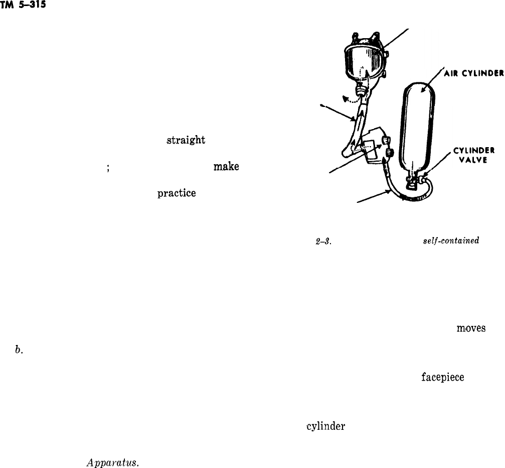
c. The Compressed Air, Self-Contained, De-
mand Breathing
Apparatus.
This breathing appa-
ratus (fig. 2-3) supplies oxygen in the form of
compressed air from a cylinder which is carried
by the firefighter. Its name reflects the fact that
the air from the cylinder is supplied to the wearer
through a demand valve as the wearer inhales.
This valve regulates the flow of air proportionate
to the supply required and reduces the pressure so
that it is supplied to the facepiece at or slightly
above normal atmospheric pressure. A variety of
this apparatus is designed which maintains a
slight positive pressure at all times to insure
against leakage. This apparatus is called a pres-
sure demand breathing apparatus and is similar
in operation to the demand apparatus. Operation
of the demand valve or regulator is fairly simple.
It consists of a large diaphragm which moves in
and out with the wearer’s inhalation and exhala-
tion. As he inhales, pressure on the diaphragm
LOW PRESSURE
AIR HOSE ~
COMPRESSED
REGULATOR
’
HIGH PRESSURE
AIR HOSE
Figure
2-3.
The compressed air,
self-contaked
demand type breathing apparatus.
decreases and permits air to flow from the cylin-
der. The diaphragm permits enough air to flow
from the cylinder to provide air in the facepiece
at or slightly above normal atmospheric pressure.
When inhalation stops, the diaphragm
mloves
in-
ward and stops the flow of air from the cylinder.
An exhalation valve on the facepiece releases ex-
haled air to the outside atmosphere. A speaking
diaphragm is also located on the
facepiece
of most
apparatus now being manufactured to permit
communication without removing the facepiece.
The air cylinder is normally carried on the user’s
back. A ,cylinder containing about 40 cubic feet (1
cubic meter) of air at a pressure of about 2000
pounds per square inch (140 kilograms per square
centimeter), when full, has become standard in
the fire service. It will provide 30 minutes of pro-
tection under test conditions. When used on the
fire ground, conditions will not be exactly the
same as during the tests. The air supply may last
less than 30 minutes, possibly as little as 15 mi-
nutes. Many makes and models of demand breath-
ing apparatus are in use. In all cases, the detailed
instructions provided by the manufacturer should
be followed carefully when using, maintaining,
and repairing the apparatus. The following are
general procedures for using this apparatus.
(1) Inspect the apparatus visually to make
sure that all parts appear to be in good operating
condition.
(2) Check the cylinder pressure gage to be
sure the cylinder is fully charged.
(3) Quickly check all straps to make sure
they are fully extended.
2-4
(4;)
Check the demand regulator to be sure
the main line valve is fully open and the bypass
(red) valve is completely closed. The bypass (red)
valve permits air to
flow
directly to the facepiece
without being governed by the operation of a reg-
ulator. It is used for escape if the regulator fails
to function properly. If it is necessary to use the
bypass valve, first open it slightly and close the
mainline valve. Next, adjust the bypass valve
slowly until just enough air is being
supphed
to
the facepiece to permit breathing while escape is
made. If the bypass is opened suddenly excessive
air
pre,ssure
reaching the facepiece may cause it
to lift and destroy the seal, leaving you exposed to
the contaminated atmosphere until the facepiece
can be seated to obtain a proper seal again. If
both hands are not needed to escape, as they
would ‘be in climbing a ladder, it is possible to
gain additional escape time by opening and clos-
ing the bypass valve
,as
air is needed while you are
escaping.
(5:)
Turn the cylinder valve to the full open
position. If the mask is so equipped, set the re-
serve lever to start.
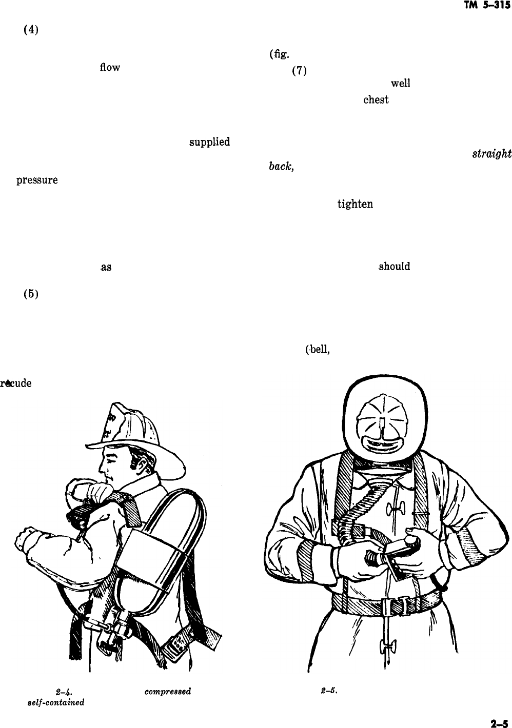
(6) Insert the left arm through the harness,
swing the cylinder assenbly on to the back, and
insert the right arm through the harness. It is
important to insert the left arm through first, to
r&ude
the chance of damaging the regulator by
striking it on something as the harness swings
around while placing the cylinder on your back
(.fig.
2-4).
(7)
Take up on the shoulder straps so that
the cylinder is positioned
wel.1
up on the back.
(8) Fasten the
che.st
and waist straps.
(9) Grasp the facepiece between the thumbs
and forefinger. Place the chin in the lower part of
the facepiece and pull the strap harness back over
the head. Tighten the straps by pulling
&r&&t
back,
not out to the side, first the lower two
straps, next the two side straps. Place the hands
on the strap harness and push it back toward the
neck. Again
tight,en
the lower straps, then the
side straps. They should be snug and not too tight.
It should not be necessary to tighten the top
strap. Check the fit of the facepiece by placing one
hand over the end of the breathing tube and in-
haling. The facepiece
,should
collapse against the
face.
(10) When ready to enter the structure or
the contaminated area, connect the breathing tube
to the regulator outlet (fig. 2-5).
(11) When the low air pressure warning
device
(,bell,
whistle, or resistance to breathing)
Figure
2-4.
Putting on the
camp-eased
air, Figure
2-5.
Connecting the breathing tube to
aelf-contained
demand breathing apparatus. the regulator outlet.
2-5
TM 5-315
operates, if the apparatus is so equipped, place the
reserve lever in the reserve position, and retreat
to a safe and breathable atmosphere at once. Some
air pressure will remain in the
,cylinder
even after
low pressure warning devices have operated and
escape has been made. This should be allowed to
remain, as a positive pressure in the cylinder will
prevent outside air from being forced into the
cylinder as the air pressure of the atmosphere
changes. This “breathing” would let moisture
into the cylinder and could cause rust.
Rus,ting
of
the cylinder might result in cylinder failure under
pressure, or the accumulation of carbon
mjon,oxide
within the cylinder.
d. Breathing Apparatus for
Specid
Situ&ions.
Rescue work in an extremely confined space, work
in a remote area of a large building which cannot
be reached or withdrawn from in a short time, or
prolonged operations on an elevated platform pre-
sent situations in which special types of breathing
apparatus are useful. One of these special types is
the
air
line apparatus. It is similar to the demand
breathing apparatus, except that air is supplied
through a long small
diamieter
hose from large
compressed air cylinders which are usually
mounted on the fire truck. Another special type is
the
air
hose apparatus. It supplies air through a
large diameter hose from a blower or pump lo-
cated
,outside
the unbreathable atmosphere.
Should the blower fail some air can still be ob-
tained through the large diameter hose.
e. Limitations of All Breathing Apparatus
Breathing apparatuses are a means of supplying
air to the firefighter, but other dangers still exist.
In addition to the time limits in which breathing
apparatus functions adequately, the firefighter
may become exposed to intense heat or toxic gas.
Some of the latter can be absorbed through the
skin and produce serious health effects.
2-5.
Fire Trucks
Because of the various firefighting problems
common to all Army installations, several types of
fire apparatus (trucks) are provided. These
trucks have pumping capacities ranging from 300
to
750
gallons per minute (gpm) (1135 to 2650
liters per minute). Factors to be considered in
determining apparatus requirements are
:
loca-
tion, construction, occupancy, property value, ex-
isting safeguards, and availability of outside fire
protection assistance. Current models of struc-
tural firefighting apparatus used by the Army in-
clude class
75OA,
class 500, and classes 530B and
53oc.
a. Class 750A Fire Truck. These trucks are the
largest pumping units authorized.
(1) They are, in general, the same type used
by municipal fire departments. They are mounted
on a 4 x 2 chassis. (The expression “4 x 2” means
that the
tru,ck
has four axle endings and that two
of them are power driven.)
(2) Water pressure is provided by a mid-
ship-mounted centrifugal type pump, driven by a
special gear train or
transfer
unit from the vehi-
cle engine. The pump on a class 750A pumper can
supply four
2l/&inch
(6,35-centimeter) hose lines
at the same time under normal operating condi-
tions. The total pump capacity varies with pres-
sure
requirem:ents,
as follows
:
750 gpm (2839 li-
ters per minute) at 150 pounds (68 kilograms)
n&
pump
pre~ssure,
525 gpm
(19,87
liters per mi-
nute) at 200 pounds (91 kilograms) net pump
pressure, and 375 gpm
(14’24
liters per minute) at
250 pounds (113
ki1,ogram.s)
net pump pressure.
The booster water tank is mounted in the front
end of the hose body and is permanently con-
neoted
to the intake side of the pump. Its capacity
is 150 gallons (568 liters).
(3) The hose body can hold from 1,000 to
2,000 feet (305 to 610 meters) of
2$&inch
(6.35-
centimeter) double jacketed hose. In addition, the
class
75OA
fire truck carriers 150 feet (46 me-
ters) of l-inch
(2.54-centimeter)
booster hose
permanently attached to the discharge side of the
pump. The purpose of the booster tank and the
attached l-inch
(2.54-centimeter)
hose is to ena-
ble the firefighting crew to extinguish a small fire
in the fastest way possible before it spreads so
,much
as to require a lengthy major layout and
loss of considerable time and property. The
booster hose may be carried either on a reel or in
a compartment basket.
(4) On the class
‘75OA
fire truck the linemen
and the
plugman
can ride in the cab behind the
driver.
Ladders
and hard suction
ho,ses
are in
compartments on top of the side compartments,
all tools and
accessorie,s
are in closed compart-
ments, all pump controls are in closed compart-
ments, and there is a
40-gallon
(152-liter)
foam
tank located forward of the water booster tank.
b.
Class 500 Fire Truck. The
clas:s
500 fire truck
is commonly used at most
installati,ons.
(1) It is similar to the class
75QA
fire truck
except that it is smaller, has less pump capacity,
and all tools and equipment are externally
mounted. The class 500 fire truck has a 4 x 2
_
cha#ssis
and 90 to
lOO-h,orsepower
engine. It car-
2-4
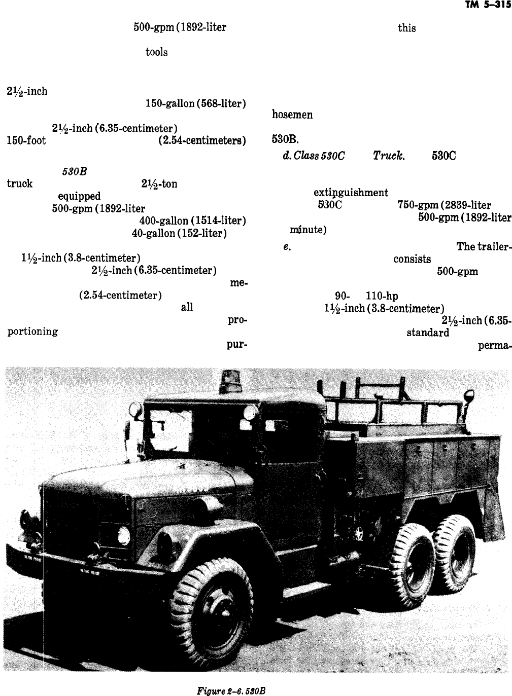
ries a midship-mounted
500-gpm
(1892-liter
per
minute) pump, a booster water tank, hose body,
and all standard firefighting
tool,s
and equipment.
(2) The centrifugal pump, driven by a trans-
fer unit from the main engine, can supply two
2$&inch
(6.35centimeter) hose lines within its
limits of capacity. It uses a
150-ga’llon
(568-liter)
booster tank, 750 to 1,000 feet (229 to 305 me-
ters) of
2?&inch
(6.35-centimeter)
hose, and a
150-foot
(46-meter) l-inch
(2.54-centimeters)
booster line hose.
c. Class DOB Fire Truck The 530B pumper
truok
(fig. 2-6) is a 6 x 6,
2l/&ton
(2.2%metric
ton) truck
equippe.d
to combat all classes of fires.
It has a
500~gpm
(1892-liter
per minute) mid-
ship-mounted pump, a
400-gallon
(1514liter)
booster water tank, and
40-gallon
(152-liter)
liq-
uid foam tank. It can carry 800 feet (244 meters)
of
ii/a-inch
(3.8-centimeter)
hose and 1,200 feet
(366 meters) of
2$$-inch
(6.35-centimeter)
hose.
Two hose reels each containing 150 feet (46
me&
ters) of l-inch
(2.54-centimeter)
hose are located
behind the cab. This truck, like
al,1
other fire
trucks discussed in this section, has a foam
pro-
portion:ing
system for introducing foam into the
water discharge. As a self-contained general
pur-
TM
5-215
pose firefighting vehicle,
thi,s
truck is completely
equipped with portable extinguishers, ladders,
floodlights, flashlights, tools, and other accessories
commonly knows as “removable firefighting equip-
ment,”
The equipment on this truck, like the
equipment on the class 500, is in the open and
visible. The pump controls are external and the
h,osemen
ride on the tailboard. See paragraph 1-6
for the different units that may be used with the
53OB.
dY
CZuss
HOC
Fire
Truclc.
The
53CG
(fig. 2-7)
is the same as the 530B fire truck, except that the
530C has a turret extinguisher (pump) which
permits
ext$guishment
while the truck is mov-
ing. The
5GOC
also has a
750~gpm
(2839-liter
per
minute) pump instead of the
500~gpm
(1892-liter
per
mlinute)
pump on the 530B.
e.
Trailer-Mounted Pumping Unit. The
trailer-
mounted pumping unit
consi,sts
of a two-wheel
trailer carrying a self-contained
500-gpm
(1892
liter per minute) centrifugal pump directly con-
nected to a
90-
to
llO-hp
engine, 300 feet (92
meters) of
ll/e-inch
(3.8-centimeter)
hose and 500
to 700 feet (152 to 214 meters) of
2va-inch
(6.35-
centimeter) hose, and the
stan,dard
firefighting
equipment. The pump does not have a
perma-
Figwe
.%6.
MOB
fire truck.
2-7
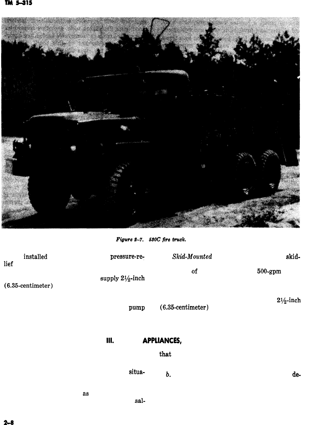
nently
instahed
pressure regulator or
pressure-re:
f.
Sk&&Mounted
Pumping Unit. The
skid-
lief
valve. The pump operator must meet changing
mounted pumping unit is a self-contained unit
firefighting requirements by manually adjusting consisting
#of
a powerplant and a
500-gpm
(1892
the controls. The pump can
,supply
2l&inch
liter per (minute) pump mounted on a single-skid
(6.35~centimeter)
hose lines at 500 gpm (1892 li- base. Fire departments may augment the water
ters per minute) at 120 pounds (54 kilograms)
supply and pressure on such systems by pumping
net pump pressure, 250 gpm (946 liters per mi- from the hydrant through one or two
2r&inch
nute) at 200 pounds (91 kilograms) net
pu.mp
(6.35-centimeter)
hose lines connected to the fire
pressure, and 167 gpm (632 liters per minute) at
department (Siamese) connection of the sprinkler
250 pounds (113 kilograms) net pump pressure.
system.
Section
Ill.
TOOLS,
APPUANCES,
AND KNOTS
2-6. Introduction
a. The tools, appliances, and eqnipmcnt needed
in firefighting vary greatly according to the
situa-
tion. The firefighting tools and appliances dis-
cussed in this section include hoses and hose tools,
ladders, special tools such
a:s
axes and pry-bars,
ropes, wrenches, couplings and connections,
sal-
vage equipment, and lights. It is most important
that
the firefighter be familiar with all the tools
and appliances he may use.
b.
In addition to itemizing, identifying, and
de-
scribing the types of equipment used, this section
also explains operation, safety procedures, and
preventive maintenance as they apply to each type
of tool and appliance.
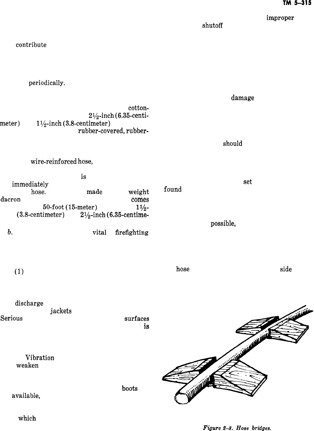
TM
5-31s
-
2-7. Hoses
Hose layouts subjected to any degree of high pres-
sure are always a potential source of danger and
may
contri,bute
to the failure of an operation.
Accidents and failures caused by discharge lines
can be prevented if firefighters are well trained in
the proper use of hose lines and if complete tests
and inspections of hoses and related equipment
are made perio,dically.
a. Types. Five types of hose are currently being
used by the Army, some much more widely than
others. The most widely used type is the
cotton-
jacket, rubber-lined hose in
2l&inch
(6.35-centi-
m,eter) and
lQ$-inch
(3.8-centimeter)
sizes. An-
other type used is the
rublber-covered,
rubber-
lined hose, usually in comparatively smaller di-
mensions, used for finishing lines, booster lines,
and high-pressure hoses. A third type is the rub-
ber-lined,
wire-reinf,orced
hose,
used in operations
where rigidity is essential. A fourth type is the
unlined linen hose, which
i,s
light and pliable but
not
imme.diately
watertight. The ‘fifth type is the
polyester
Ihose.
This hose is
ma.de
of light
weight
dacron
with pin or rocker plug couplings. It
co,mes
in standard
50-foot
(15-meter)
lengths in
l$$-
inch
(3.8~centim,eter)
and
21/2-inch
(6.35-centime-
ter) diameters.
b.
Care of Hose. Hose is so
vi,t,al
to
fire;fighting
operations: that its care must be the responsibility
of every firefighter. The following are some of the
causes of lhose damage and general precautions in
handling hose.
(1)
Dragging the hose along the ground fre-
quently results in cuts, abrasions, punctures, and
damaged couplings, threads, or lugs.
(2) Pulsations in the pump cause the suction
and disch.arge hose sections to vibrate which
chafes the hose
j,ackets
where the hose touches.
Seriou,s
hose injury results when these
,surfaces
are rough or have sharp edges. Hose damage
i,s
most pronounced near the engine. Farther away,
the vibration is absorbed by the elasticity of the
hose.
(3)
V’ibration
may be almost unnoticed, yet it
may
weak:en
the hose so much that it fails in a
relatively short time. To prevent this, chafing
boots must be inserted between the hose and the
ground at the affected points. If chafing
b’oots
are
not
availa’ble,
burlap, rope cushions, or any suita-
ble substitute may be used. The chafing boot con-
sists of a pad, usually a portion of salvaged
hose,
whic:h
is strapped or clamped to the hard or
soft suction hose during pumping operations.
(4) Hose may be damaged by
iqproper
oper-
ation at the
,shutoff
nozzle. Closing the nozzle
quickly causes a sudden increase in pressure
which may rupture the hose. If the nozzle is
opened quickly, back pressure will increase 50
percent, and the operator may lose control of the
hose, which may injure personnel in addition to
damaging the hose.
(5) One of the most common causes of hose
injury is the result of vehicles being driven over
hose layouts. Serious
dam,age
is less likely when
the hose is charged with pressure. When the hose
is empty or under insufficient pressure, the jacket
may be separated from the lining or the hose may
be ruptured or torn from the coupling. This type
of damage can be prevented by hose bridges (fig.
2-8). Two of them
,should
be built and carried on
the truck at all times. After the hose lines are
laid, the bridges are placed over them at the de-
sired spacing, generally about 4 feet (1.2 meters)
apart. If standard bridges are not available, a
suitable bridge may be
:set
up with materials
foun.d
at the scene of the fire. A simple bridge
consists of planks, laid on each side of the hose,
thick enough to keep the wheels from striking the
hose.
(6) When
possi:ble,
the hose lines should be
stretched on the same side of the road as the fire.
The lines should be laid parallel to the curb, but
not so close to the curb that acid or oil floating
down the gutter may come in contact with the
hose. When a street or areaway must be crossed,
the
ho,se
should be laid on the same
si,de
of the
street as the hydrant, parallel to the curb and up
to a point opposite the fire, then across the street.
Thus, fire equipment that follows need not travel
Figure
2-8.
Hose
bridges.
2-9

TM
5-315
over the hose unless it is necessary to pass to the one end of the hose. This causes considerable loss
far side of the fire. or complete stoppage
,of
waterflow.
(7) Where freezing temperatures are
common, hose is frequently damaged by rough
handling during the winter. When the
ho.se
is
frozen, the fibers are weakened and the threads
which run lengthwise in the hose are warped. A
break in the hose will be caused if it is not han-
dled carefully. If the hose is frozen to the ground
or street, remove it by carefully chopping away
the ice beneath it. Do
not
remove the ice which
remains stuck to the hose. Place the hose in the
truck with the least possible bending and forcing
and take it back to the station. After the frozen
hose thaws out, it should be stretched out, washed,
and left to dry.
(12) Paint and paint thinner are
equs,ily
harmful to firehose. Consequently, paint should
not be used to mark the hose. A thin application
of indelible ink with the aid of a stencil should be
used. Hose should be cleaned with mild soap and
water solution, followed by a thorough rinse in
clean water and a complete drying process to pre-
vent mildew. Damp or dirty hose
shou1.d
never be
stored. Hose such as the
dacron
type will not mil-
dew and may be stored wet in warm weather.
(8)
Firehose
should not be dropped because
this may damage the couplings. When possible,
the hose should be carried at the
coup1ing.s.
When
hose is carelessly handled, the exposed threads of
the male coupling may be damaged so much that
efficient connection to the female coupling is im-
possible. The female coupling is easily knocked
out of round, thus making the entire
50-foot
(15-
meter) length of hose useless in a layout.
(9)
Firehose
is frequently and unavoidably
burned at fires, All hose which has been exposed
to fire should be turned in to salvage if extensive
damage is found at a considerable distance from
either of the couplings. When the damage is close
to the coupling, the damaged portion may be cut
off and the coupling replaced.
c.
Mctinten~ance.
Improper or incomplete mainte-
nance shortens the life of the hose and may result
in hose failure at a critical time. Hose mainte-
nance is somewhat complicated because hose com-
ponents present entirely dissimilar problems. The
jacket and rubber lining deteriorate with age re-
gardless of whether or not the hose is used. Rub-
ber deterioration can be delayed if the lining is
not allowed to dry rot. If the jacket is kept wet, it
is subject to mildew and fungus which destroys
the fiber. Keeping the rubber moist and the cotton
clean and dry requires frequent handling of the
hose, which makes the couplings more liable to
damage.
d.
Inspectiohs
and Tests. Fabric-jacket, rub-
ber-lined hose must be inspected daily and after
each use.
(10) If hot liquids penetrate the cover of the
hose, the lining is loosened seriously which weak-
ens the hose. Chemical injury cannot always be
prevented, especially at fires at chemical depots
and warehouses. In addition, it is almost
impo.ssi-
ble to detect the presence of injurious chemicals
in water that may be flowing from a burning
structure. Many acids, even when diluted, can
stain and destroy the hose jackets. When acid
damage is suspected, each length should be care-
fully examined for brown or powdery spots. The
exposed portions should be washed immediately
and thoroughly with baking soda solution and
then given a pressure test.
(11) Petroleum products such as gasoline,
oils, and greases, upon coming in contact with
hose, cause rapid deterioration of the rubber lin-
ing by dissolving the cement and loosening the
lining from the jacket. When a single hose length
is used after having been exposed to lubrication
products, the lining tears apart and piles up in
(1) The after-use inspection includes the re-
moval and inspection of all hose which is wet.
After the fabric jacket is cleaned and visually
inspected, the couplings should be examined
f,or
proper operation and the hose placed on the
drying rack. If there is dirt or dampness in the
hose bed, the remaining
ho.se
should be removed
from the truck and replaced with clean, dry hose.
(2) All discharge and suction hoses should be
hydrostatically tested seminannually to determine
whether each section can withstand operating
pressures. Up to six lengths (300 feet (92 me-
ters)) of discharge hose
may
be tested at one
time. One-inch
(2.54-centimeter)
rubber-covered
hose and
l$$
(3.8) and
2i,+inch
(6.35centimeter)
double, cotton-jacket, rubber-lined hose should be
tested at 150 pounds (68 kilograms) of pressure,
Fabric-jacket, rubber-lined
lr,&
(3.8)
an.d
2i&
inch
(6.35-centimeter)
ho.se
should be hydrostati-
cally tested at 250 pounds
(113
kilograms) pres-
sure for 5 minutes. The hard and soft suction hoses
should be tested at 100 pounds (45 kilograms) of
pre,ssure. The hard suction hose should be vacuum
2-10

TM
5-315
tested to an ll-pound
(5-kilogram)
vacuum on the h. Hose Records. Complete
recorda
of perform-
pump and the lining examined for detects. All ance, maintenance, and testing are a basic part of
previously mentioned hose inspection procedures any maintenance program. The minimum records
are repeated together with the hydrostatic tests required for
firehose
are kept by fire-department
on the semiannual inspection. administrative personnel.
e. Drying. All hose must be dried before being
stored. The interior of each length must be
drained of all water. Water that
remairrs
in the
hose for any length of time tends to remove the
sulfur from the rubber, as shown by a sulfuric
acid solution which can be drained from carelessly
stored hose. Hose-drying racks may be of any size
or general
arrangem:ent
a.s
long as they have a
reasonable slope to encourage
,drainage.
(1) As each length of hose is received, an
identifying number is stamped on its coupling. At
the same time, a record (DA Form
5-748)
is set up
indicating the hose number, type of hose, date
received, and manufacturer (fig. 2-19). There-
after, operating and maintenance data are entered
regularly on this form.
f. Storage. Proper storage of unused hose is a
vital part of hose maintenance. To prevent rapid
deterioration, hose should be stored in a clean,
dry, well-ventilated location out of direct sunlight
and away from heating pipes and radiators. Heat
and sunlight cause rubber covers and linings to
become hard and brittle.
(2) Entries include the date the hose was
tested, test pressures, and remarks on the test;
explanation of any hose failure, the cause and the
date
;
date of any recoupling; and details of other
unusual maintenance.
Firehose
records are kept
in the fire station where they are available for
immediate reference. In addition, copies of test
reports
may
be kept in the daily department
rec-
ords.
2-8. Hose Couplings
a. Use. Hoses are issued in
female-thre,aded
coupling at
threaded coupling at the
g. Replacing Damaged Couplings and
Wvaging
Hose. Fire-department personnel are responsible
for replacing damaged hose couplings and for sal-
vaging damaged hose.
Damlaged
hose may be sal-
vaged by cutting out defective portions and recou-
pling the
re’maining
portions. Not less than
two-
thirds of a section should be recoupled, although
short lengths may be used occasionally for pur-
poses other than layouts to fires. Couplings should
be removed and replaced as follows
:
(1) Place the coupling in
through the expansion ring with
other tool.
(2) Remove the expansion
rubber gasket.
a vise and cut
a chisel
,or
some
ring, hose, and
(3) Cut off the damaged portion of the hose
with a sharp knife and make sure that the end of
the hose is square and smooth.
(4) Place the expansion ring in the coupling.
(5) Fit the expansion ring inside the hose
flush with the hose end.
(6) Insert the hose in the coupling tailpiece.
(7) Make sure the hose is flush with the gas-
ket and the shoulder of the coupling.
(8) Using an expansion tool, expand the ring
unti:
it locks firmly inside the coupling. Several
types of expansion tools are manufactured. The
directions for use and specifications for pressure
are published by each manufacturer. Follow these
directions and specifications exactly.
sections fitted with a
one end
an.d
a
male-
other. Hard-suction
hoses are usually in 10 to
14-foot
(3 to
3.8-meter)
lengths. Hose lines may
bse
made any desired
iength by coupling individual sections together.
For fire service use, hose couplings must-
(1) Be easily and quickly made up and bro-
ken (connected and disconnected).
(2) Form a watertight connection when
handtight.
(3)
Hold_
securely when hose is dragged or
hoisted.
(4)
With’stand
damage
fr,om
dragging and
dropping when coupled.
(5) Be reusable so that damaged portions of
hose, if close enough to an end, can be cut off and
the remaining portion recoupled.
b. Types. Several types are available, the screw
type having a male coupling with external threads
and a swiveling female coupling with internal
threads being most widely used. Couplings should
ccnform
to the National Standard Fire Hose
Thread
(NST)
for the particular size
ho’se.
This
enables hose to be used interchangeably when
different departments work together on the fire
ground. The following are some of the couplings
and connections.
(1) Double male couplings or connections
2-11
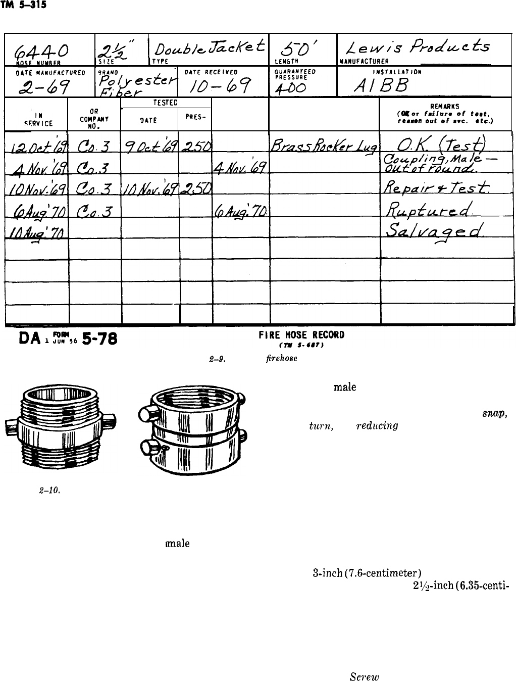
LENGTH
MAWFACTURER
OATE
MhtlUFbCTUREO
NAME OF
IMSTALLATJDN
LOCATION
_
TESTEO
OATE
OATE
REMdRKS
OATE
PRES-
OUT OF TYPE COUPLING
fff
or
failurm
of
teet,
re.“”
e”t
of
..e.
at=.)
NO.
SURE SERVICE
r
Figure
2-9.
Sample
firehoee
record.
Figure
2-10.
Double male and double female couplings.
consist of a single piece of metal hose coupling
containing two sets of exposed male threads (fig.
2-10). The purpose of the double
male
connection
is to enable the joining of two female connections
which could not otherwise be united.
(2) Double female couplings consist of two or
three pieces of metal hose coupling containing two
sets of female threads (fig. 2-10). When double
female couplings have only one swivel, the connec-
tion frequently contains only two pieces of metal,
and the solid portion should be connected first.
Double female couplings which have two swivels
consist of three metal parts, and it is optional as
to which female should be connected first. The
purpose of the double female connection is to
2-12
connect two
malle
couplings to complete a hose
layout.
(3) Other types of coupling include
snup,
quarter
turn,
and
red&ng
couplings (fig. 2-11).
The snap coupling has spring loaded clips or lugs
on the female coupling which clamp over a ring
on the male coupling. Couplings are broken by
disengaging the clips. The quarter turn coupling
has beveled lugs on the couplings at each end of
the hose. They are made up by twisting a quarter
turn, which causes the beveled lugs to interlock.
While both types can be made up and broken
quickly, the advantage of being able to couple
with a neighboring fire department’s hose may be
lost. Reducing or five part couplings are often
used on
3-inch
(7.6~centimeter)
hose so it can be
used interchangeably with
2+inch
(6.35-centi-
meter) hose. The smaller waterway caused by the
reduction does not affect performance much be-
cause the length of small waterway is very short
and a jet or venturi effect is created. Except for
the reducing feature and construction, they are
the same as the NST screw type.
c. Features of
Screw
Type Couplings. The NST
standards specify the number of threads per inch
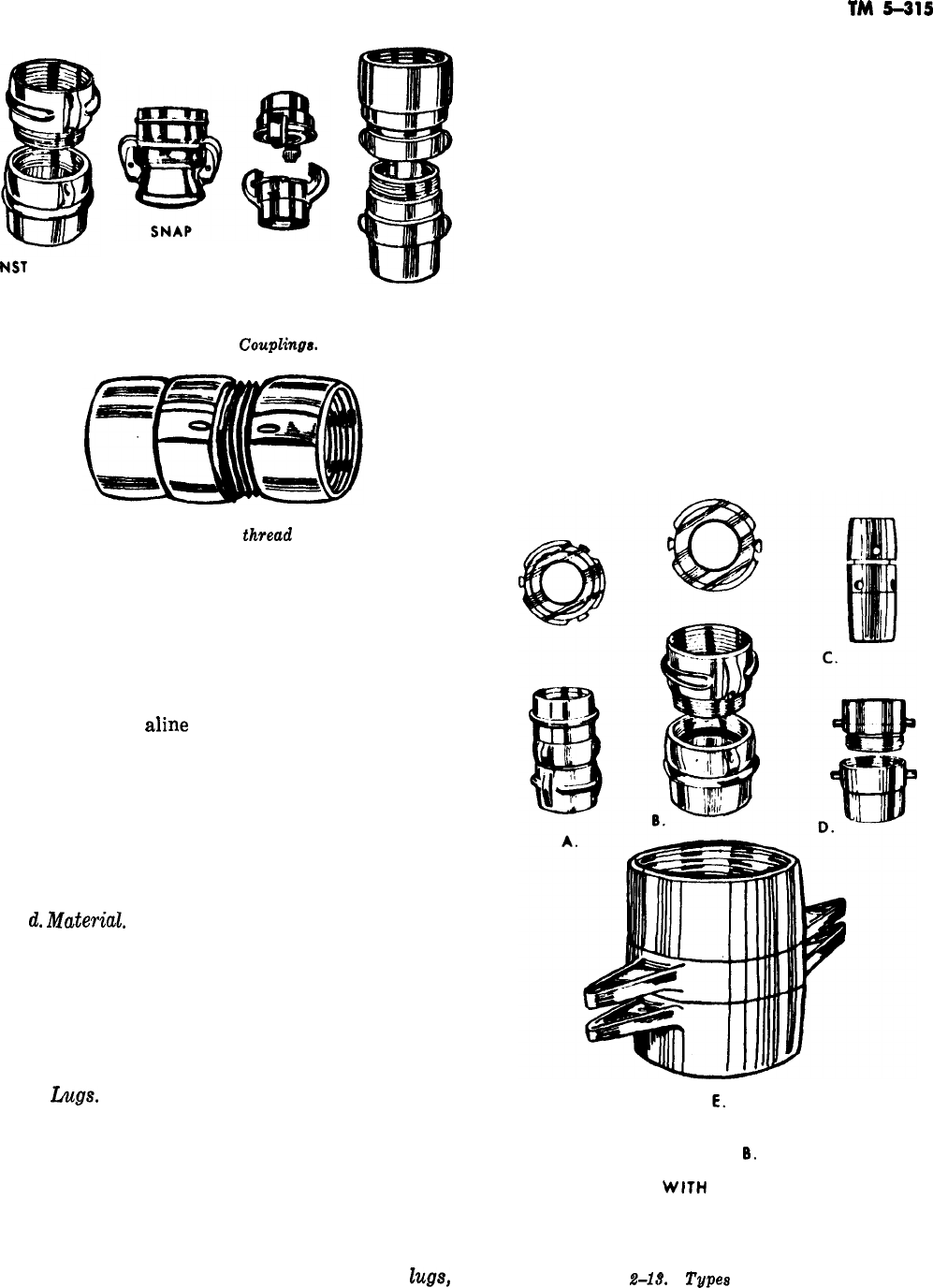
NST
SCREW
QUARTER TURN
REDUCING
Figure 2-11.
Coupling&
Figure 2-12. Higbee
thread
indicator.
(or centimeters), the shape and dimensions of
threads, and use of the Higbee cut. The latter
consists of cutting a blunt end on the first thread
so that a positive start is made in engaging
threads and prevent the crossing of threads. It
also results in a short blank end on each coupling
that helps to
aline
the threads and reduces
chances of damaging threads if the coupling is
dropped. The Higbee thread indicator (fig. 2-12)
is a notch cut in one lug to show the position of
the Higbee cut. By lining up the thread indicators
on both couplings, and they are deep enough to be
felt with gloves on, threads will engage on the
first turn.
d.
Materid.
Brass alloys are commonly used for
couplings. They are also made of aluminum alloys,
aluminum, and malleable iron. Iron rusts and
pure aluminum, while light, is easily damaged.
Various aluminum alloys are lighter than brass
and hold up well in service, but are more expen-
sive.
e.
hgs.
Lugs (fig. 2-13) are provided on cou-
plings so that a grip can be obtained with
wrenches, called spanner wrenches or spanners,
(fig. 2-14) to assist in breaking couplings. On
rubber lined fabric hose the rocker lug (either
two or three lugs) is normally used. This consists
of rounded ears which provide a good gripping
surface for wrenches, but tend to slide over ob-
structions as hose is laid. Couplings with pin
Z~ge,
TM
5415
dot or Navy type lugs, and nut or forestry type
shape are also used. Pin type lugs catch on ob-
structions and on each other in the hose bed. Slot
and nut type couplings are satisfactory but the
rocker lug is better suited for use witth different
types of spanners and provides a better grip when
making handtight connections. Making and break-
ing couplings is normally unnecessary when using
booster hose; therefore, couplings with holes for
use with special booster hose spanners are usually
used. These have no projections to catch on ob-
jects. Hard and soft sleeves, on the other hand,
are carried, rather than dragged, and must be
made up each time the sleeve is used. They are
usually equipped with long handled lugs to facili-
tate making and breaking of the couplings.
f. Means of Attaching to Hose. The most
common means of attaching couplings to hose
A. THREE ROCKER LUG
B.
TWO ROCKER LUG
C. BOOSTER TYPE
WtTH
HOLES INSTEAD OF LUGS
. .
D. PIN LUG E. LONG HANDLED TYPE FOR USE
WITH SLEEVES
Figure
2-l&
Types
of coupling lugs.
2-13
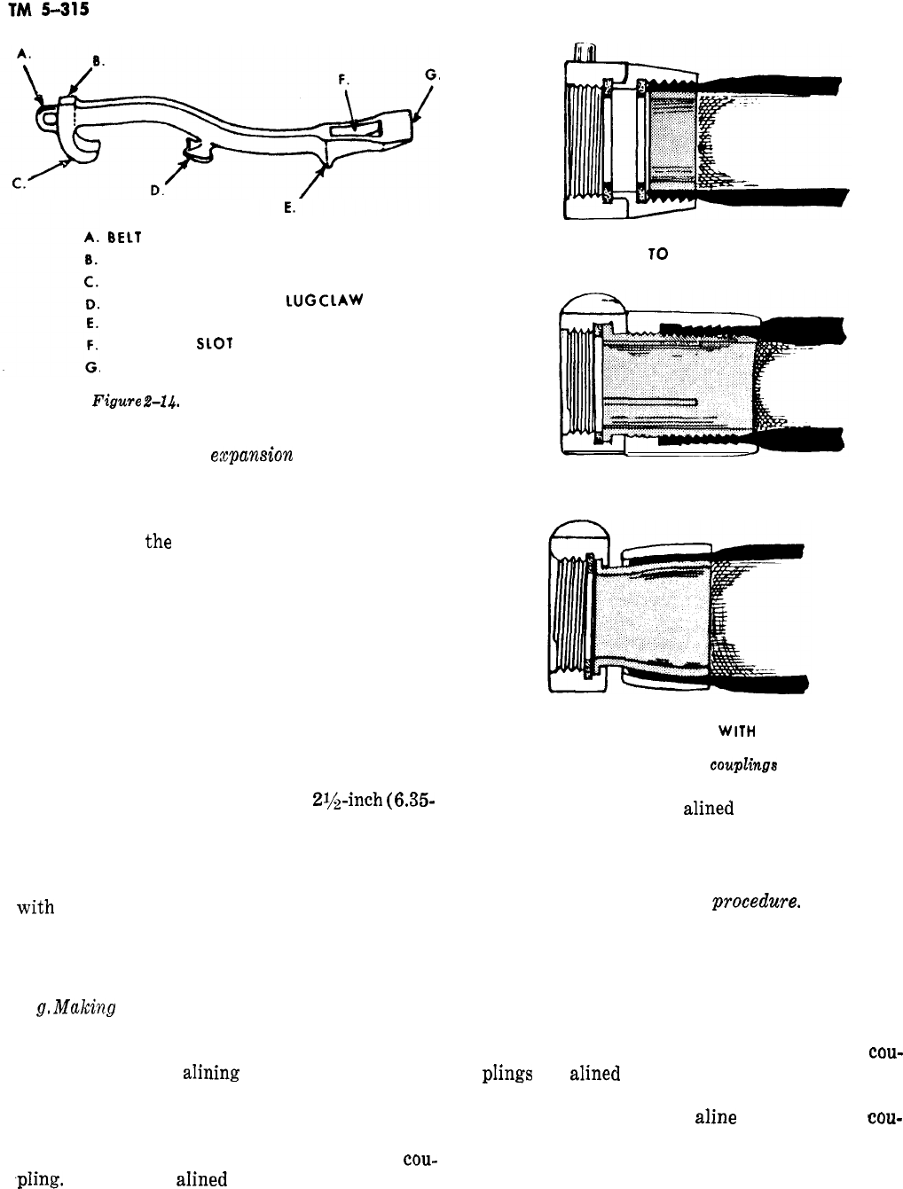
BELT
HOOK EYELET
HAMMER HEAD
SPANNER CENTER LUG CLAW
UNCOUPLING CENTER
LUG
CLAW
PRY HEEL OR FULCRUM
GAS COCK
SLOT
WINDOW JIMMY
Figure
2-14.
The spanner wrench.
(fig. 2-15) is with an
expansion
ring. A ductile
brass ring or collar is placed inside the hose. The
coupling is placed over the hose and the ring ex-
panded under great pressure to force the hose
jacket against
t,he
corrugated inner face of the
coupling. Couplings can be reused by extracting
the expansion ring and using a new one. A means
of attaching couplings with a screw sleeve is also
used. With this method, the coupling shell slips
over the hose jacket. A sleeve containing the male
threads or female swivel and threads on one end,
and a double threaded section on the other end, is
screwed into the hose and forced against the shell.
Such couplings withstand greater water pressure
and pull on the hose than expansion ring types.
They are used most often with booster hose,
though available for hose up to
2$$-inch
(6.35-
centimeter) diameter. A special key and wrench
are used to attach the couplings, which can be
removed for reuse by unscrewing the sleeve. A
third means involves slipping a coupling shell,
with
threads or swivel and threads, over the hose
jacket, inserting a tapered sleeve and pulling up
on the shell. To reuse, the shell is driven back off
the tapered sleeve.
g.
Making
up Couplings. Couplings, particularly
on rubber lined fabric hose, must be made up
quickly. Making up or connecting couplings in-
volves two actions:
aIining
the hose and couplings
and connecting the threads. If hose is being
loaded in a hose bed, the additional step of check-
ing for the presence of a gasket in the female
coupling bowl is taken before making up the
cou-
.pIing.
The hose is
alined
so that the flat sides of
each length are in approximately the same plane.
COUPLING
ATTACHED
TO
HOSE WITH EXPANSION
RING.
COUPLING ATTACHED TO HOSE WITH SCREW SLEEVE.
-
COUPLING ATTACHED TO HOSE
WITH
TAPERED SLEEVE.
Figure 2-15. Attaching
couplkge
to hose.
Next, the couplings are
alined
so that threads will
engage. Then the couplings are held steady and
the threads engaged by operating the swivel on
the female coupling.
(1) One-mm coupling procedwe. Making up
couplings is normally a one man operation (fig.
2-16). The female coupling is picked up with one
hand on the swivel. The hose is brought across the
right (or left) hip with the feet spread comforta-
bly apart. The hose is held against the hip with
the forearm. The male coupling is held with one
hand, the female coupling with the other. The
cou-
pIings
are
alined
by manipulating the swivel on
the female coupling to engage the threads. An
alternate method is to
aline
the hose and
cou-
plings on the ground. The firefighter faces the
couplings, feet spread comfortably, with one foot
on the hose directly behind the male coupling (fig.
2-16). This will tilt up the coupling and at the
.-
2-14
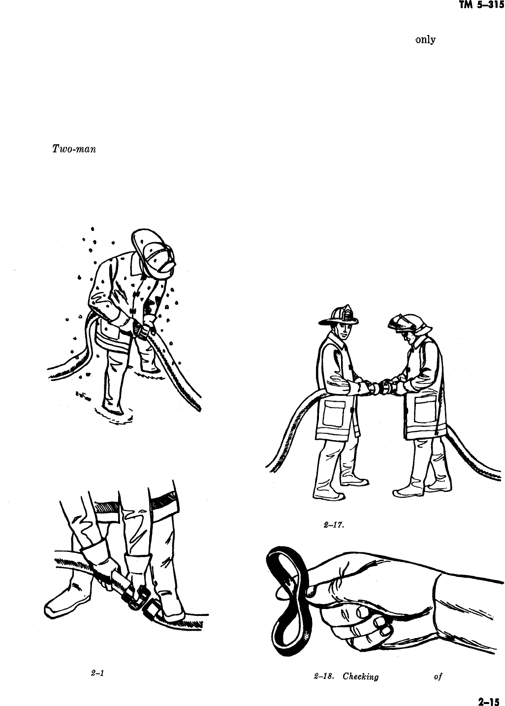
TM
5-315
same
time
hold it in position. The hose with the
female coupling is brought up to the male cou-
pling and the threads are engaged by operating
the swivel. This method is not practical in deep
snow, mud, or similar conditions. The swivel is
rotated counterclockwise until a click is heard,
then the threads are engaged by rotating the
swivel in the opposite direction. If the couplings
contain Higbee thread indicators, line up the
notched lugs and rotate in a clockwise direction.
(2)
Two-rnan
coupling procedure. Two men
make up couplings (fig. 2-17) by each grasping a
coupling and holding the hose against the hip
*
with one forearm. The man with the male cou-
pling holds the coupling so that the other man
can
aline
the female coupling with one hand and
oper-
MAKING UP COUPLINGS.
ALTERNATE
METHOD
OF MAKING UP COUPLINGS.
Figure
Z-l
6.
Coupling hoses.
ate the swivel with the other, thus engaging the
threads. Couplings are made
,only
handtight be-
cause the hose is constructed so that when it is
charged with water it twists and
tightens
the cou-
plings. If couplings are tightened with wrenches
the
gaskets
may be flattened until they protrude
into the waterway which partially restricts the
flow of the water. It also damages the gasket. The
last step in making up couplings is to give a sharp
twist or snap as the threads seat home. With a
good gasket this results in a watertight connec-
tion. Gaskets are checked by removing them from
the female swivel and flexing them between the
thumb and forefinger (fig. 2-18). If they spring
back to a flat position they are usable. If not they
should be replaced. Do not leave couplings without
a gasket. If the gasket must be replaced, do so as
soon as possible. If the female swivel on a hose
coupling continues to swivel after the
couplings
are tightened, the threads have not seated com-
pletely and require further adjustment.
h. Breaking Couplings. Couplings usually are
Figure
2-17.
Two men making up couplings.
Figure
2-18.
Ghecking
the condition
of
a gasket.
2-1s
.
,
--
/-
Figure
?&lo.
U8ing
spanner8 to break
couplinge.
Figwe
#-g0,
Udng
a rubber mallet to tighten
ooupling8
for
dra
fting
broken
(relea,sed)
in the
same
way they were
made-by hand, In the process, the arm and
shoulder muscles are used, not the fingers. Span-
ner wrenches (fig, 2-14) are used as shown in
figure 2-19 on couplings that cannot be broken by
hand. The fingers are extended as
shown
in figure
2-19 to prevent injury when the coupling breaks
loose or the spanner slips.
i.
Coupling Sleeves for Drafting, Hand-tight-
ened connections usually suffice for coupling hose,
but connecting sleeves for drafting and booster
hose require tightening with a tool, In drafting
operations, hard sleeves must be airtight. This is
done by using a wooden or rubber mallet as shown
on figure
2-20.
j.
Avoiding Damage to Couplings. Damage
couplings is usually the result of the following
:
(1) Dropping of uncoupled couplings.
(2) Dragging of uncoupled couplings.
to
(3) Excessive strain or pull, or pressure, on a
hose line.
(4) Grit or dirt in the
swivel
This binds the
swivel on female couplings. Dirty couplings must
be washed with water that is mildly detergent. Oil
or grease only increases the possibility of picking
up more dirt.
(6) Crossing of couplings by heavy vehicles.
2-9. Nozzles
Nozzles are devices which regulate the
amount
velocity, and form of water released from a hose.
The following are the different types of nozzles
used by firefighters.
a*
Fog Node. A fog or spray nozzle (fig. 2-21)
normally consists of a fog tip, a controlling shut-
off, and, in the larger sizes, a
playpipe
with han-
dles to make controlling of the nozzle easier, The
fog or spray nozzle breaks up the water stream
into
particles
of water which cover a larger area
and increase the heat absorbing capability of the
A.
A. STREAM DEFLECTED FROM BAFFLE
B.
IMPINGING STREAM
C.
CENTRIFUGAL
TYPE
Figure
2-21,
Types
of high velocity fog
nozzles.
2-16
TM
5-315
Figure
24%
Measuring the angle of a fog stream.
water. Fog nozzles may produce a fixed fog pat-
tern, or the pattern may be adjustable
frotm
a
straight stream (which is not a solid stream) to a
wide angle fog of nearly 180 degrees. The angle of
a fog stream is the approximate angle formed
from one edge of the stream to the other (fig.
2-22). Nozzles are
availab’le
that discharge an al-
most constant volume of water as fog patterns are
changed. Others will discharge varying volumes
of water depending on the pattern. Still others
have selectors to change the volume of discharge,
with the discharge remaining almost constant as
patterns change at a given setting.
b.
Solid Stream Nozzle. The solid stream nozzle
(fig. 2-23) normally consists of an
olpen
tip, a
controlling shutoff, and a
playpipe
with handles to
make controlling the nozzle easier. The volume of
water discharged at a given pressure depends on
the size of the tip. Tips are usually interchangea-
ble to obtain different
vo,lume
discharges. This is
an aid if the water supply will not provide an
effective stream with the larger size tips. The pur-
pose of a solid stream nozzle is to project water so
that it will travel a distance or
will1
penetrate
through loose or porous material.
Effectivness
of
t,he
nozzle depends on a smooth surface in the tip,
so care must be taken not to drop or otherwise
dent or damage the tip. Design of the solid stream
nozzle produces a thrust backward on the nozzle
and hose when it is used. It is important to be
prepared for this reaction when using this type of
nozzle.
c. Combination Nozzle. The combination nozzle
(fig. 2-24) has both a fog tip and a solid stream
tifp.
The controlling shutoff has pcisitions for
both
fog stream and solid stream operation, as well as
an off position. It
shou’ld
not be used on electrical
or flammable liquids fire because the control han-
dle might accidentally be shifted to the solid
stream position.
Figure
2-23.
Solid stream nozzle.
Figure 2-2.4. Combination
nozzle.
d. Applicators. An applicator (fig. 2-25) con-
sists of a controlling shutoff, a pipe 2 to
10
feet
(0.6 to 3 meters) long, often bent
ait
a 45 or 90
degree angle at the tip end, and a tip which may
be of the solid stream, high velocity fog, or low
velocity fog type.
(1) Low
veZocitp
fog tip. This is an imping-
ing stream nozzle or head (fig. 2-25) in which the
streams join (impinge) outside the head, produc-
ing a cloud of fog in the vicinity of the tip, as
ccmpared
to a fog stream which projects out from
the tip.
(2) Puncture nozzle. This is a pointed, hard-
ened
steel
nozzle (fig. 2-26). This nozzle can be
2-17
LOW VELOCITY FOG APPLICATOR.
LOW VELOCITY FOG TIP.
Figure 2-25. Low velocity fog tip and applicator.
Figure 2-27. Partition nozzle.
ROTATING
DlSlRlDUlORS
Figure 2-26. Puncture nozzle.
ROTATING
DISTRIBUTOR
IN OPERATION
driven through walls and siding, or into loose
ma-
terial
such as baled fibers. A place is provided
near the base of some puncture nozzles so they
can be driven in with a
flathead
axe or similar
tool.
(3) Partition nozzle. The partition nozzle
(fig. 2-27) discharges a solid stream at a
90’
angle to the
pi’pe,
with the direction of the stream
controlled by a handle. The partition nozzle often
has a pointed projection near the tip to aid in
pushing it into a wall, though materials through
which it can be driven are more limited than with
the puncture nozzle.
e.
Distributor and
Cellctr
Pipe.
(1) Distributor. A distributor (fig. 2-28)
Figure
2-26.
Distributors.
consists of a swivel with an arrangement of
straight or fog tips. The reaction of
t.he
tips
causes the swivelled head to rotate rapidly. This
throws a spray in a spherical pattern around the
distributor. It is useful for attacking fires that
cannot be reached by other means. Before the
device is put in operation a controlling shutoff
must be placed in the line so that the
disltributor
can be shut down before removing it.
(,2)
CeUur
pipe.
The cellar pipe (fig. 2-29)
consists of a short pipe with one or two straight
tips and levers to
control
the direction of the
stream or streams. Cellar
pipes
are used in the
2-18
TM
5-315
CELLAR PIPE
CELLAR PIPE IN OPERATION
Figure
2-29.
Cellar pipe.
same manner as distributors but have greater
reach. They also require a controlling shutoff like
the
dilstributors.
f. Master Stream Devices. Basically, a master
stream device (fig.
2-30)
consists of a
siamese
or
manifold arrangement for collecting water from
more than one line of hose and for mechanically
directing the stream and the nozzle tip. Tips are
*
removable
so that the proper type and size can be
used for a particular situation. A length of pipe
called a stream straightener is used with solid
stream tips. It contains thin baffles or vanes to
keep the large volume of water from swirling and
breaking up the stream. A monitor
nozzle
is used
from the ground and can be mounted for use on
an engine. A deluge set is an older version of the
monitor nozzle. It consists of
separate
parts
joined by a large diameter pipe or hose. It nor-
mally is not mounted on an engine because its
rotation would be limited. The deck pipe is
mounted on an engine, connected directly to the
pump by piping.
It
may also be connected to
sia-
mese inlets mounted permanently on the engine or
truck. A
Zadder
pipe is attached to an aerial lad-
der, It is supplies by a large diameter hose with
the Siamese on the ground. Some ladder pipes are
mounted permanently on the bed section of an
aerial ladder. All master stream devices have con-
trols to govern the vertical
direction
of the
stream. The monitor nozzle and deck pipe have
horizontal direction controls as well. Some ladder
pipes and deluge sets have controls to permit lim-
ited horizontal movement of the stream. A ladder
pipe should be moved horizontally by rotating the
ladder. This avoids placing dangerous stress on
the ladder.
g. Sprinkler Heads. Heads on sprinkler systems
(fig.
2-31)
in structures act as metering devices.
They give the advantage of applying water in the
fire area without sending men into it. Fire depart-
ments must supply such systems with hose lines
from engines to assure adequate volume and
pres-
sure of water.
2-10.
Devices Which Control Flow
The
following
are in-line valves which control the
flow of water through hose lines
:
a.
BaZZ
VaZves.
The ball valve (fig. 2-32) con-
sists of a housing with couplings, a ball with a
waterway through the middle, and a handle to
A. MONITOR
NOZZLB
B.
DELUGE
SET
C.
DECK PIPE
D.
LADDER
PIPE
Figwe
2-30.
Ma&eT
stream devices.
2-19
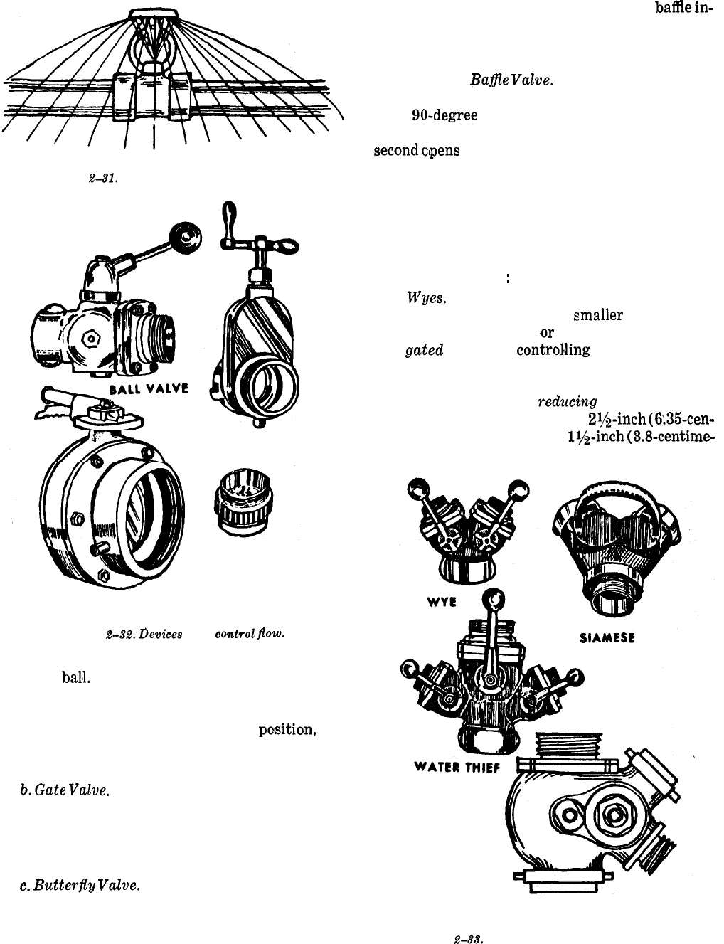
TM 5-315
Figure
2-81.
Sprinkler head discharging.
GATE VALVE
ROTATING BAFFLE
VALVE
BUTTERFLY VALVE
Figure
242.
Devices
that
controZ
fZow.
turn the
balll.
In most models, when the handle is
turned in line with the hose line the valve is open.
Turning the handle to a right angle to the hose
line, or to a right angle to the open
pclsition,
ro-
tates the ball and shuts the valve, Earlier versions
have a cylinder in place of the ball.
b.
G&e
VuZve.
The gate valve (4ig. 2-32) has a
housing with couplings and a baffle, or solid
plate
which is operated by a handle and screw arrange-
ment. Turning the handle moves the baffle down
into (or up out of) the waterway.
c.
Butterfly
V&e.
A butterfly valve (fig. 2-32)
or keystone type valve consists of a housing with
couplings, and a baffle or plate connected to a
quarter turn handle. It operates in the same way
2-20
as the ball valve, except that the flat
batYe
in-
stand of a ball with a waterway forms the shutoff.
The chief advantage of the butterfly valve is ease
of maintenance and repair.
d. Rotating
Bafle
V&e.
Rotating baffle valve
(fig. 2-32) consist of two baffles, each with two
open
go-degree
segments. Turning one of the baf-
fles to line up its open segments with those in the
second
clpens
the valve. Turning it to line up its
open segments with the closed segments in the
second baffle closes it. This type valve is also
known as the “gizmo”.
2-11. Devices That Combine or Divide Flow
The following are combining or dividing devices
used by firefighters
:
a.
Wyes.
A wye (fig. 2-33) divides a hose line
into two lines of the same or
s,maller
size. If it has
controlling valves (gate
,or
ball valve), it is known
as a
gctted
wye. Most
control,ling
valve wyes today
are manufactured with ball type valves, If the
wye divides the line into smaller lines it is called a
reducing wye or gated
reduckg
wye. The gated
reducing wye which divides a
2rbz-inch
(6’.35-cen-
timeter) hose line into two
ls-inch
(3.8-centime-
ter) lines is very common.
FOUR WAY SWITCH VALVE
Figure
2-33.
Combining and dividing devices.
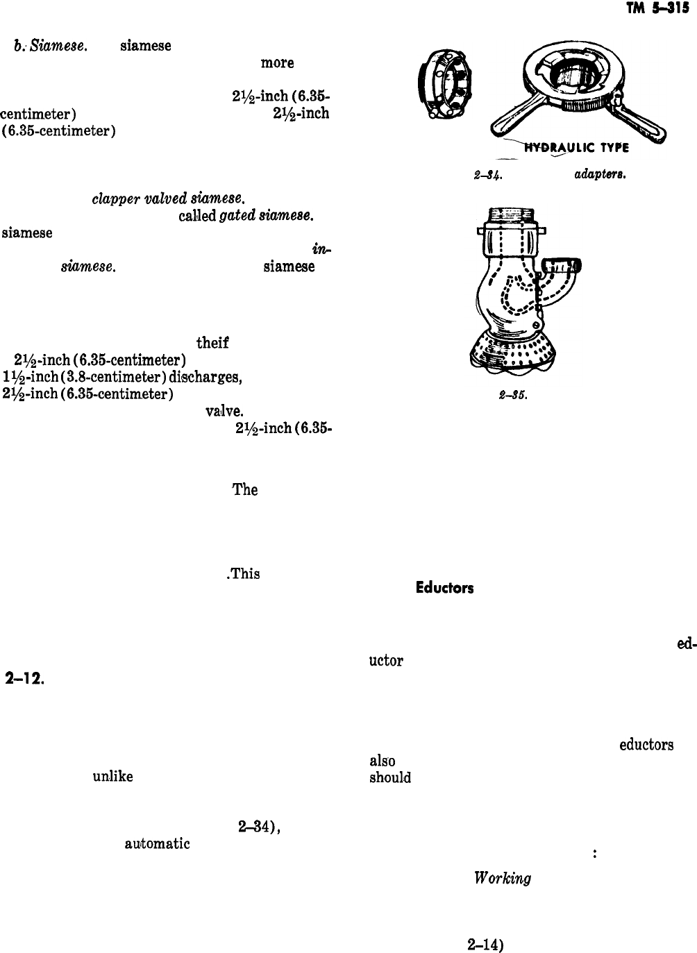
6:
Siamese.
The
Siamese
is a Y-shaped connec-
tion (fig. 2-33) which combines two or
m,ore
hose
lines into a single line of the same or larger size.
It is used primarily to join two
2?&inch
(6.36-
centim,eter)
intake lines into a single
2i/z-inch
(6.35~centimeter)
outlet line or into other heavy
stream appliances. Siamese may have swing check
valves (clapper valves) to assure that water will
not flow back through any of the inlets, and are
then called
cZapper
vaZved
siumeee.
They may
have gate or ball valves
callled
gates!
Siamese.
A
Siamese
that combines from two to four small
lines into a single larger line is known as an
&z-
creasing
&ameee.
The gated increasing
Siamese
is
often carried on the large steamer inlet of a
pumping engine and is also known as a suction
siamese.
c. Water Thief. The water
theif
(fig. 2-33) has
a
2lh-inch
(6.35-centimeter)
inlet and two gated
l$&inch
(3.8-centimeter)
diNscharges,
as well as a
2$$-inch
(6.36-centim,eter)
discharge which may
or may not have a controlling
vallve.
It is used for
taking short attack lines from a
2ye-inch
(6.36-
centimeter) or B-inch (6.6%centimeter) supply
line.
d. Four-Way Switch Valve.
,The
four-way
switch valve (fig. 2-33) is used to hook up a sup-
ply line to a hydrant. It permits hooking. up a
pumping engine to the hydrant later, without
shutting down the supply, and then increasing
water pressure in the supply line
.This
is done by
moving a single rotor or two baffles, depending
on the design of the valve, so the path of the
water is changed from the supply line to the en-
gine and back through the supply line.
2-12.
Adapters for Coupling
Adapters are used for coupling hose which cannot
be joined because of a difference in coupling size,
threads, or the fact that both are male or female.
a, Adapter. True adapters permit joining cou-
plings with
umike
threads. The rigid adapters
consist of a short tube with one type of thread on
the female end and the other type on the male
end, The adjustable adapter (fig.
2-34),
such as
the universal and
aujtomatic
types, normally have
a male coupling thread which matches the depart-
ment’s standard thread on one side and teeth on
the other side. The teeth adjust over the male hose
coupling, either by spring action or manual lever
operation, engaging the male threads. A twist of
the hose coupling tightens the connection.
AUTOMATIC
Figure
2-84.
Adjustable
adaptem
Figure
g-85.
An eductor.
b. Reducers and Increasers. Reducers and in-
creasers are used to join different size hose cou-
plings. The reducer is a rigid adapter with a large
female thread on one end and a smaller size male
thread on the other. The increaser is a rigid
adapter with a small female and larger male
thread. Double female reducers equipped with a
swivel on the smaller end are used with sleeves.
2-13.
Eductors
An eductor (fig. 2-35) is a device that introduces
liquid or powder into a water stream by a jet or
venturi effect. The waterway coming into the
ed-
uctor
reduces in size to form a nozzle which is
directed into a larger opening on the discharge
side. The action of this jet creates a siphon effect
which is used to pick up foam liquid, chemical
foam powder, or other chemicals to be added to
the stream. Specially designed siphon
eductors
are
a1s.o
used to pick up water when a pump cannot or
shou1.d
not be used to draft the water directly.
2-14. Tools
The following are the major tools used to aid in
working with hose and appliances
:
a. Tools for
Worlcing
with Hose and Appli-
ances. Tools which aid in working with hose and
appliances include spanner wrenches, hydrant
wrenches, and drafting sleeve mallets. Spanner
wrenches (fig.
Z-14)
are used to break couplings,
2-21
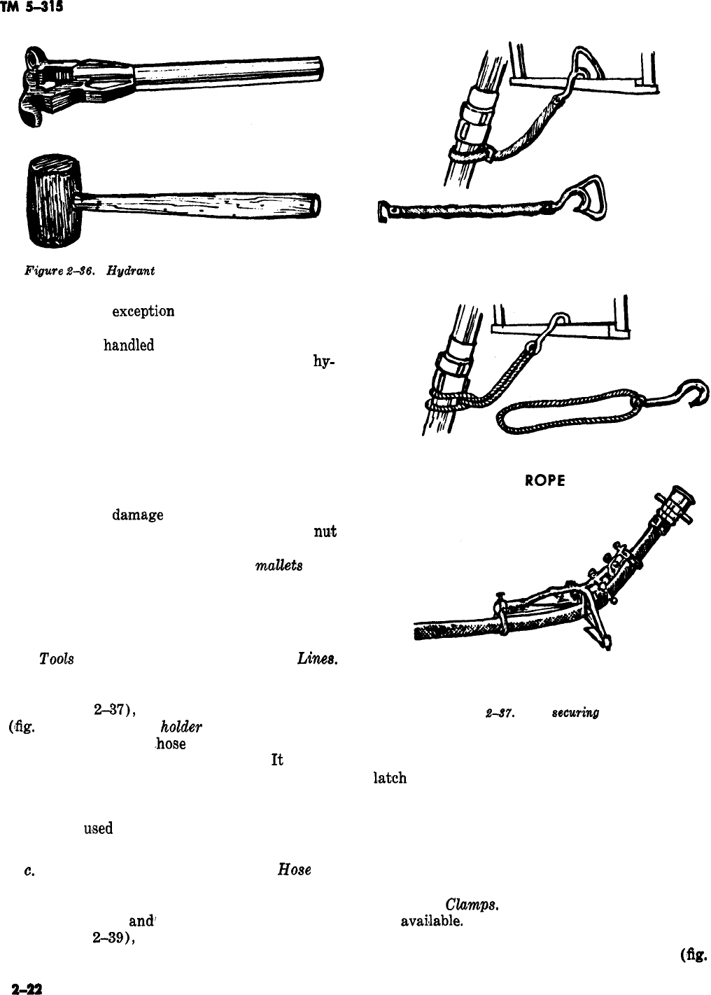
TM
s-as
STRAP
Figure
2-66.
Hydrant
wrench and rubber mallet.
which, with the
excepti,on
of drafting sleeves, are
made up handtight. Hydrant wrenches (fig. 2-36)
consist of long
hand’led
box wrenches. Some types
have an adjustable box to permit its use on
hy-
drant operating nuts of different size. Some have
ears to permit use as a spanner. The hydrant
wrench is used to remove hydrant caps and to
operate the hydrant operating nut which controls
the flow of water from the hydrant. It is also used
to operate the valves on some models of four-way
switch valves. The adjustable pipe wrench is not
normally used to turn a hydrant operating nut
because it will
da,mage
the nut. It is used, how-
ever, if a hydrant with a damaged or missing
nut
must be used at a fire, as the hydrant must be
repaired anyway. Drafting sleeve
mallets
(fig.
2-36) have a hard rubber or wooden head. They
are used to tap the couplings on drafting sleeves
to secure an air tight seal. Mallets must be used
with restraint to avoid damaging couplings.
b.
Tools
For Moving or Securing Hose
Linea.
Tools which aid moving or securing hose lines
include hose straps and rope hose tools, the hose
holder (fig.
2-37),
and the hose hoist or roller
(:fig.
2-38). The hose
hoZder
is a device which
clamps around the
-hose
line, or has the line
threaded through it, behind the nozzle.
It
enables
one man to control a hose line discharging a large
volume of water by directing the back thrust or
nozzle reaction against the ground. The hose hoist
or roller is
u,sed
as a bearing for hoisting hose or
tools to a roof or upper floor.
c.
Tools For Protecting or Repairing
Hose
and
Couplings. Tools to protect or provide emergency
repairs for hose and couplings include hose jack-
ets, hose ramps,
and’
chafing blocks. The hose
jacket (fig.
2-39),
not to be confused with the
fabric jacket of hose, is a metal device consisting
-
HOLDER
Figure
g-N.
Hose
eecuring
took.
of two half cylinders hinged on one edge, with a
l.atch
on the other. While it does not permanently
repair faulty hose, it repairs leaks and tends to
prevent additional damage to hose from the effect
of water pressure on a hole or tear. The hose
jacket can also be used to join lengths of hose
with defective, mismated or different couplings,
by placing the couplings in the jacket.
d. Hose
CZmnp.s.
Several kinds of hose clamps
are
avai!lable.
Those in general use are the lever
operated devices with latches, screw-down or gate
types, and hydraulically operated types
(fig.
2-22
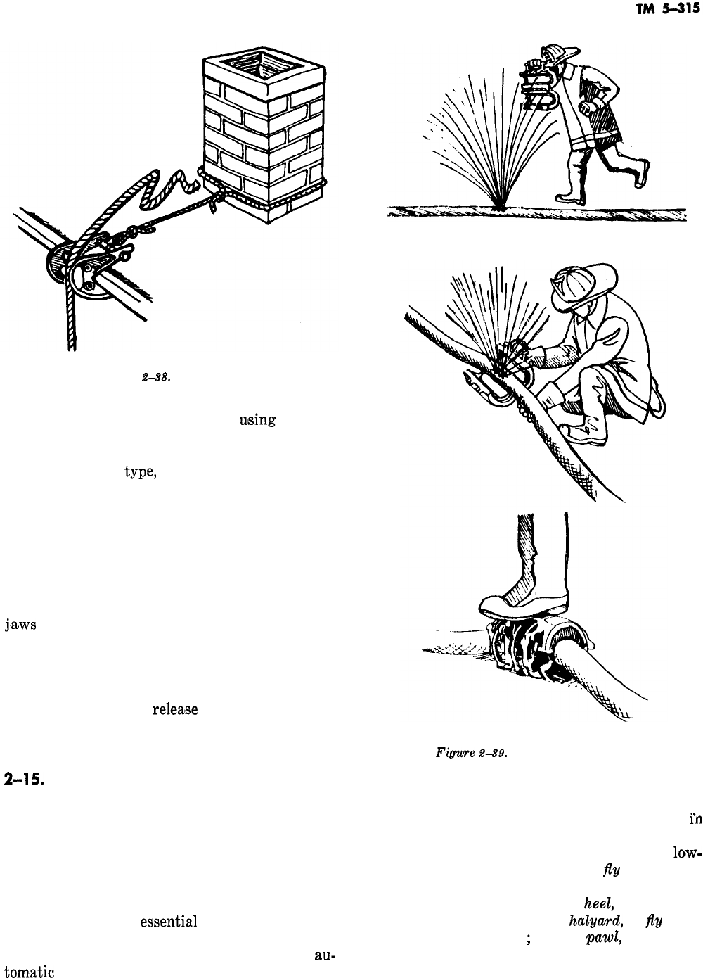
-
Figure
248.
Hose hoist.
2-40). All work on the principle of
ulsing
mechan-
ical force to compress the jacket of the hose to-
gether, and stop the flow of water in a line. To
operate the lever
ty!pe,
open the clamp, place the
hose line between the jaws, and either lift up or
press down on the lever. A ratchet type latch will
hold the jaws in the closed position. To release,
stand clear of the lever, hold it, down, or up, se-
curely, and release the latch. Release the lever
slowly. The lever may tend to kick out with some
force when the latch is released. The screwdown
or gate type is operated by placing the hose in the
j,aws
and operating as with a gate valve. Hy-
draulic hose clamps are operated by placing the
hose in the jaws, setting the selector to “close”
with the wrench end of the operating handle, in-
serting the handle in the pump lug, and pumping
the jaws closed. To
relea’se
the clamp turn the
selector to “open”. Push the jaws to the full open
position,
2-15.
ladders
Ladders are vital during an emergency, when a. The standard ladders used by the Army con-
every second is a factor toward the success or sist of solid beams with cylindrical rungs set
in
failure of an operation. Firefighters must know the center of the beam. The following terms are
the proper procedures for carrying, raising, and commonly applied to ladders: bed ladder, the
lomw-
climbing ladders so thoroughly that they can do est section of an extension ladder;
fly
ladder, the
them almost by habit. Even after the procedures top sections of an extension ladder; the butt, the
are well
established
in the minds of the trainees, ground end of the ladder; the
heeZ,
the extreme
constant practice is
essential1
to maintain this de- ground end of the ladder; the
haZyard,
or
j$q
rope,
gree of
efficiency.
Continuous training should be used for raising the fly
;
and the
paw&
or dog, the
carried on to make these operations as nearly
au-
mechanism on the lower end of the fly which locks
tom,atic
as possible. it to the bed ladder. The heel portion of portable
Figwre
2-89.
Using a hose jacket.
2-23
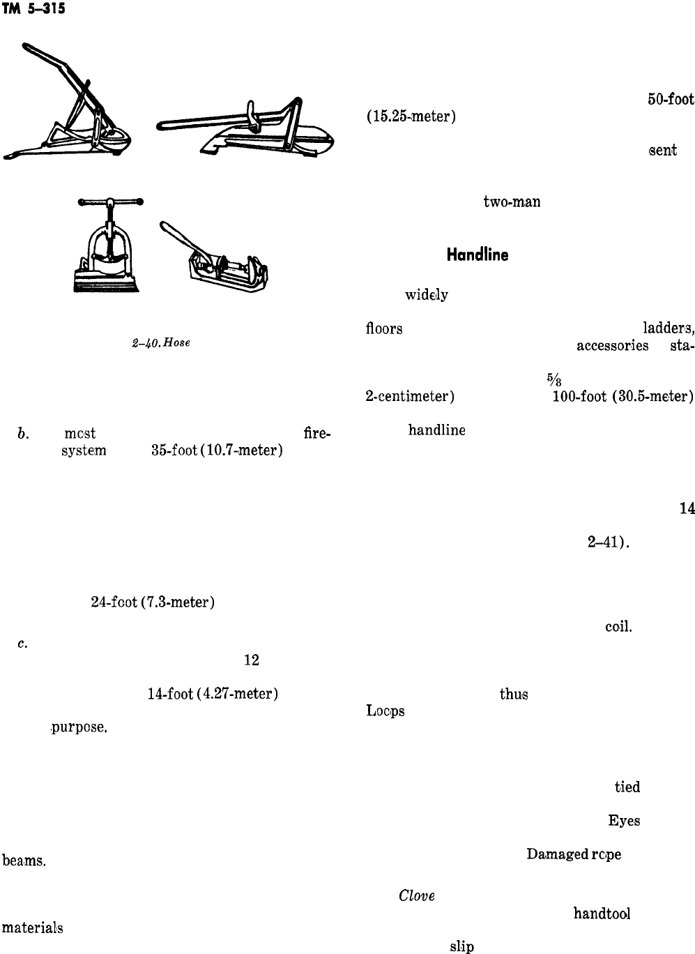
LEVER OPERATED
GATE TYPE
HYDRAULIC TYPE
Figure
2-40.
Hose clamps.
ladders should be equipped with cleats or nonskid
footers.
b.
The
mclst
common ladder in the Army
fire-
fighting
syste,m
is the
35foot
(10.7-,meter)
exten-
sion ladder. An extension ladder consists of a bed
ladder and one or more fly ladders. The fly ladder,
sliding through guides on the upper end of the bed
ladder, contains locks which hook over the rungs
of the bed ladder. This secures it in position at the
desired length of the ladder. The fly is usually
raised by a halyard fastened to the lower rung
and operating over a pulley on the upper end of
the bed. The
24-foot
(7.3-meter)
extension ladder
is commonly found on pumpers.
c.
Straight ladders or wall ladders contain only
one section, and usually are from
12
to 16 feet
(3.66 to 4.88 meters) long. The most common size
straight ladder is the 14-foot
(4.2’7-meter)
length.
The roof ladder is a wall ladder adapted for a
special
,purpose.
Roof ladders have hooks mounted
on a movable socket that permits the books to fold
inward when not in use. Placing the hooks over
roof peaks, sills, walls, or the coping of any open-
ing makes the ladder safe and
reliable
even if the
butt does not rest on a foundation. The roof lad-
der may be used as a wall ladder when the hooks
are set so they do not extend beyond the ladder
bealms.
The roof ladder is used when the pitch or
the material of the roof or bad weather endangers
the men moving over it. It is valuable in climbing
to the peaks of gabled roofs to remove roofing
materialIs
or to cut holes for ventilation and extin-
guishment. It
may
also be used to enter scuttle
holes or holes cut through flooring, and sidewalk
openings.
d. On installations where there are buildings
more than three stories high, special
50-foot
(15.25~meter)
Bangor ladders may be necessary.
These ladders may be either strategically located
in the area where they are to be used, or
(sent
to
the scene of the fire, mounted on special equip-
ment. These larger ladders require more team-
work than do the
two-m,an
ladders to place, raise,
and lower them quickly and efficiently.
2-16. The
Handline
Rope is indispensable in combating fires. The
most
widelly
used type of rope is the handline.
Handlines are used for hoisting tools to various
tloors
of a structure and for anchoring
ladderIs,
charged hose lines, and other
accessor,ies
to
sta-
tionary objects. Handlines for hoisting and an-
choring should be either
5/a
or ah-inch (1.6 or
2-centi.meter)
rope of
lOO-foot
(30.5-meter)
lengths, with an eye spliced in one end. For quick
use, a
handline
should be coiled in such a manner
that it pays out without tangling, even when
dropped from the top of a building.
a.
Coiling
a
Handline.
For coiling a handline, a
frame containing two vertical posts about
14
inches (36 centimeters) high and 25 inches (64
centimeters) apart is set up (fig.
2-41).
The rope
is first
wrapped
several
times horizontally around
the upright posts and then wrapped around the
horizontal wrappings to secure the rope around
the posts. When the opposite end is reached, the
horizontal pipe is pulled from the
coil
The free
end of the rope should be folded and slipped
through the end of the coil. The free end will then
be slipped through the opposite end of the coil and
through the loop,
thuis
pulling the loop tight.
Locps
should be made large enough for the coil to
be loaded over the shoulder.
b. Knots and Hitches. Knots and hitches should
be capable of quickly and securely serving their
intended purpose and of being easily
t,ied
and un-
tied in darkness. The rope ends should be whipped
(tightly bound) to prevent fraying.
Eye,s
may be
spliced in both ends of the rope to speed up tying
operations (fig. 2-42).
Daamaged
rcjpe
should be
replaced rather than spliced.
c.
CZoue
Hitch. The clove hitch (fig, 2-43)
should be used to tie a line to a
handtool
such as a
pike pole. The clove hitch holds the object securely
and will not
sl,ip
when properly tied. It should be
2-24
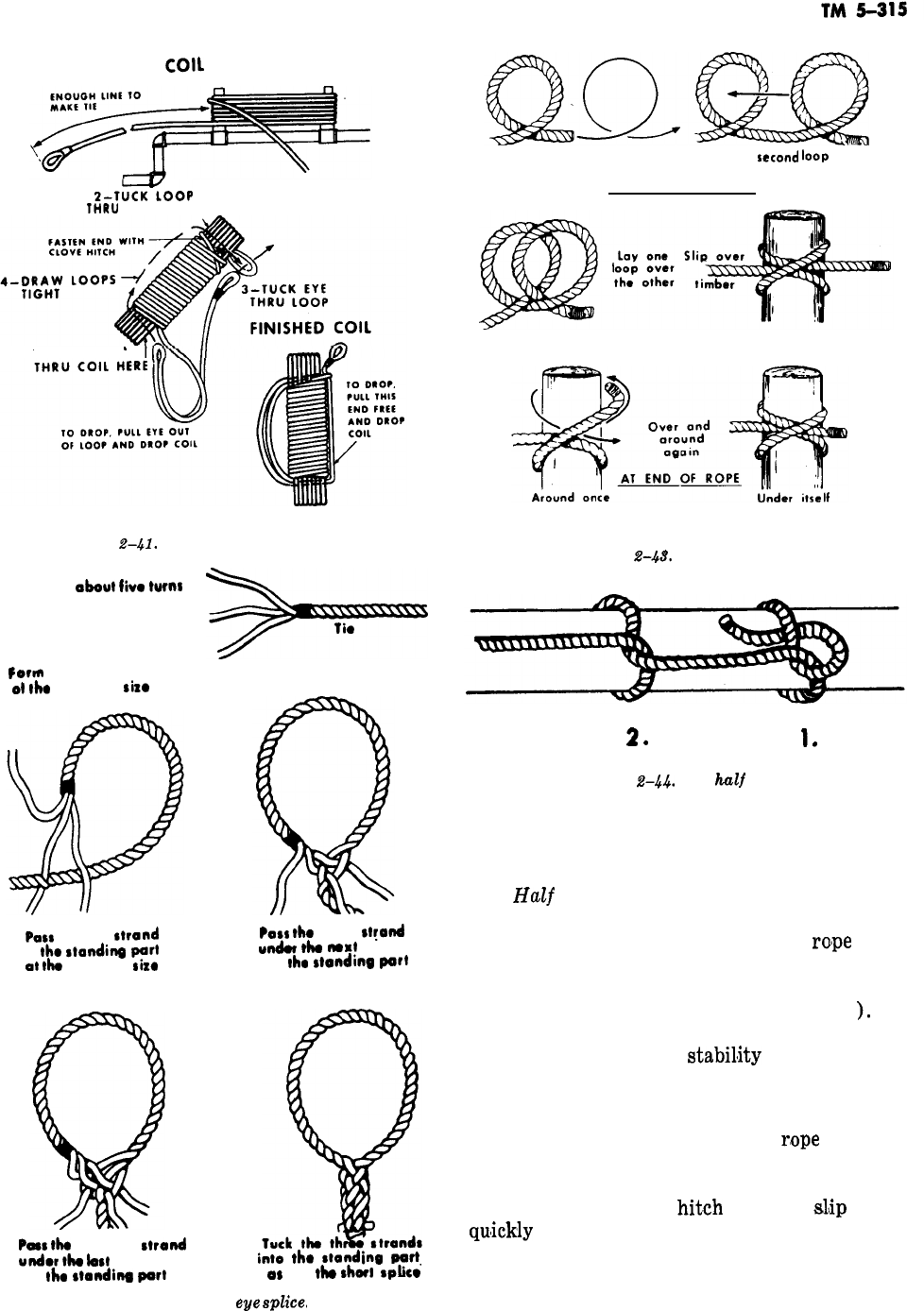
START OF
COIL
L-TKOOP
THRU
COIL HERE
l-TUCK LOOP
Figure
2-41.
Coiling in handline.
Unlay
about
Iivo
wfns
Pofm
loop
01
the
dosirod
size
POSS
middb
strand
in
the
stondina
art
ot
who
dosirod
sixo
Pass
the bottom
strand
under
ho
bst strand
in
the
stomdiw
POH
POSS
the
top
s~yond
W&V
tlu
nomt
strand
in
the
standing
prt
into
the
standing
pati
OS
in
the
shwt
splice’
Figure 2-42. The eye
splice,
Underhand loop
Add
second
loop
AT CENTER OF ROPE
Figure
2-48.
The clove hitch.
2.
Figure 2-44. The
half
hitch.
1.
tied near one end of the pole with a single half
hitch around the other end.
d.
HuZf
Hitch. The half hitch (fig. 2-44) is a
loop in a rope which is placed over or around an
object so that the standing end of the
ro’pe
exerts
a constant strain on the loop. The running end
can be secured under the loop (fig. 2-44) (1)) or
may run on to another knot (fig. 2-44 (2) ). The
half hitch is used with other knots as a safety
hitch and to give added
stabil$ity
to objects being
hoisted.
e. Chimney Hitch. The chimney hitch is used
when it is necessary to anchor a
r,ope
to a solid
object to strengthen the position of another
object, such as a charged hose or a ladder (fig.
2-45). The chimney
hit.ch
will not
s&p
and is
qu’ickly
and easily untied. This knot is used when
the strain on the rope is to be constant. The rope
may be shortened or lengthened by slipping the
knot.
2-25
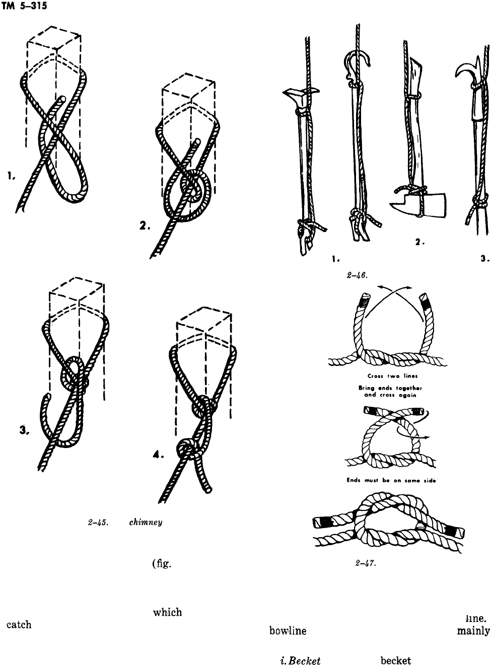
Figure %-45. The
chimmq
hitch.
f. Tool Hoisting Hitch. Tools are usually se-
cured by at least two knots
(fig.
2-46) to hold
them in a relatively stable position. Long heavy
tools are generally hoisted with the heavy end up.
Tools with hooks or sharp ‘projections, such as an
ax, are hoisted in a position in
wh,ich
they will not
,catch
on projecting ledges.
g. Square Knot. The square knot (fig. 2-47) is
used to tie the ends of equal sized ropes together.
Figure
2-46.
Tool hoisting hitch.
Figure
2-47.
The square knot.
h. Bowline. The bowline (fig. 2-48) is
that will not slip and is easily and quickly
. .
a knot
untied.
It is used to form a loop on the end of a
nne.
The
bo,wline
on a bight (fig. 2-49) is used
m.ainly
for
rescue purposes.
-
i.
Becket
Bend. The
becket
bend (fig. 2-50) is
used to connect ropes of unequal ‘diameter.
_.
2-26
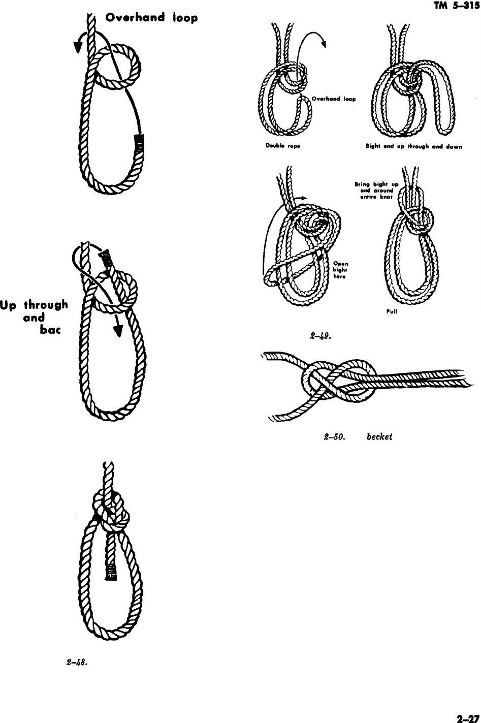
up
tatYgh
around
bat
k
loop
Figure
g-.&L
The bowline on a bight.
Figure
f&W.
The
becket
bend.
Back down
through loop
Figure
2-48.
The bowline.
2-27
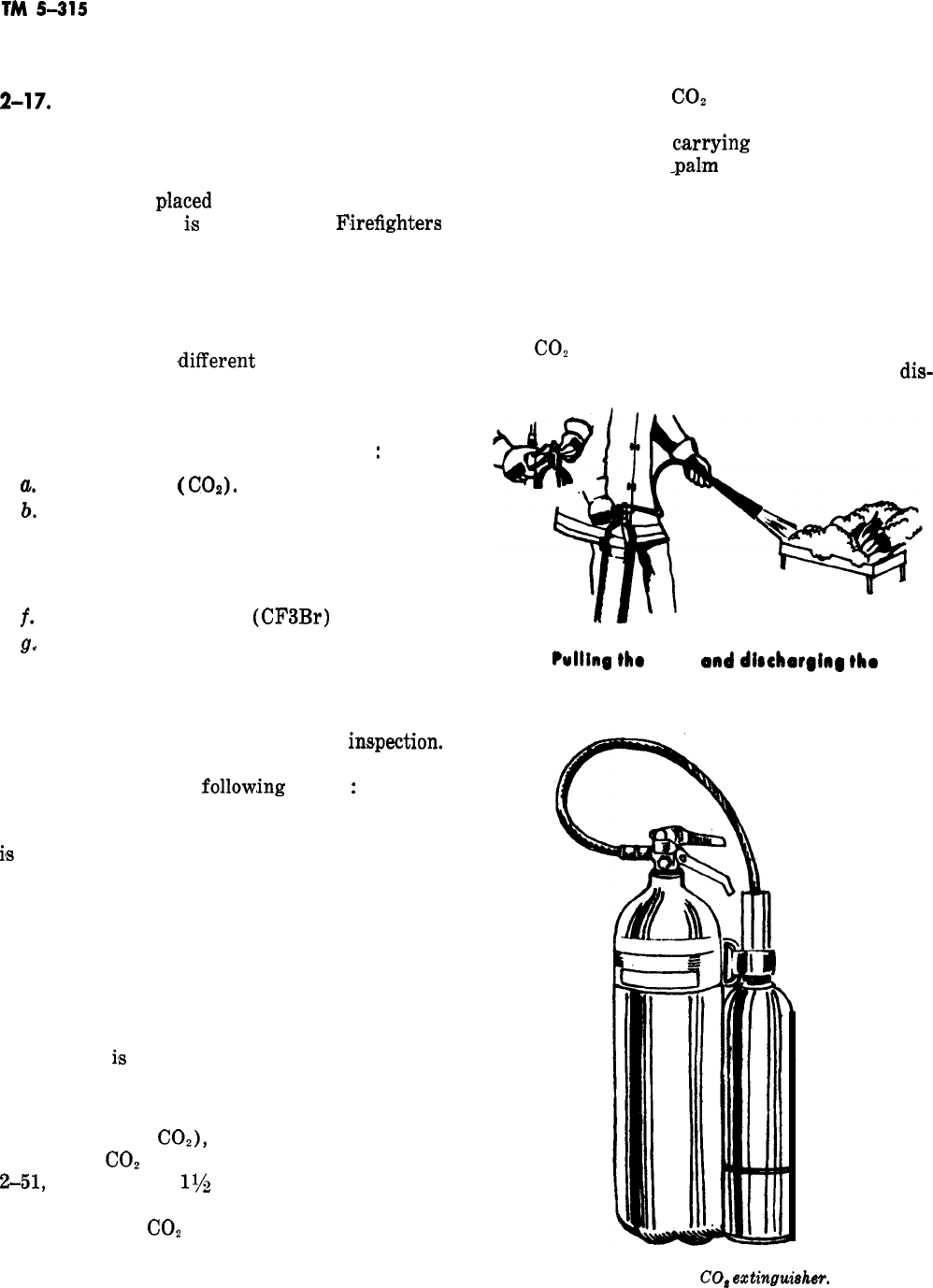
TM
5-215
Section IV. FIRE EXTINGUISHERS
2-17.
Introduction
Portable fire extinguishers are normally used as
first aid firefighting devices for fighting small
fires. They often prevent catastrophes. These ex-
tinguishers are
pla,ced
in buildings and other
places where there
i,s
a fire hazard.
F,irefighters
also carry them on fire apparatus because their
extinguishing agents are more effective and better
suited under some conditions and for certain ma-
terials such as combustible metals. These extin-
guishers are available in a number of shapes and
sizes and contain
,different
agents for various
types of fires. The different extinguishers require
different individual procedures for inspection, op-
eration, and application. The following are the
type of extinguishers most commonly used
:
a.
Carbon dioxide
(
COs).
b.
Pump type water.
c. Pressurized water.
d. Soda-acid.
e. Foam.
f. Bromotrifluoromethane
(CF3Br)
g..
Dry chemical.
2-18. Inspection
Fire extinguishers must be kept in good operating
condition and thus require periodic ins,pection.
When making an inspection of any type of fire
extinguisher, take the
follow,ing
action
:
Examine
the surroundings to check that the extinguisher is
accessible under actual fire conditions, and that it
i,s
not subject to possible mechanical injury. Have
all obstructions removed which may hide the ex-
tinguisher from view or delay its use. If neces-
sary, change the type of extinguisher or add new
units. See that the extinguisher is located in the
right place to meet the existing fire regulations.
Check the hanging bracket or support for secu-
rity. Replace, tighten, or strengthen the hanging
bracket or support, if necessary, and see that the
extinguisher
its
easily removable.
2-19. Carbon Dioxide Extinguishers
Carbon dioxide
COZ),
the extinguishing agent
used in the
CO*
extinguisher illustrated in figure
2-51,
is a gas about
l$$
times heavier than air. It
is nonpoisonous, and will not support combustion
or sustain life.
CO*
converts to a liquid when
under pressure in an individual extinguisher or
when refrigerated, as in the bulk storage tank.
2-28
a. In operating a
CO*
extinguisher, break the
wire seal and remove the safety pin. Hold the
extinguisher by the
c.arrying
handle in one hand
with the thumb or -palm resting on the shutoff
valve lever. Direct the discharge horn with the
other hand, holding the horn by the rubber or
wooden handle. Squeeze the shutoff valve lever to
operate. Direct the discharge at the base of the
fire. On flammable liquids fires, sweep the dis-
charge across the burning surface, starting at the
front and working from side to side and front to
rear.
CO2
extinguisher discharge valves should be
opened fully and the entire contents should be
dis-
Pulling
the
pin,
and
dimhargina
the
carbon
dioxide
Extinguisher
.
Figure 2-51.
CO#
extinguish@.
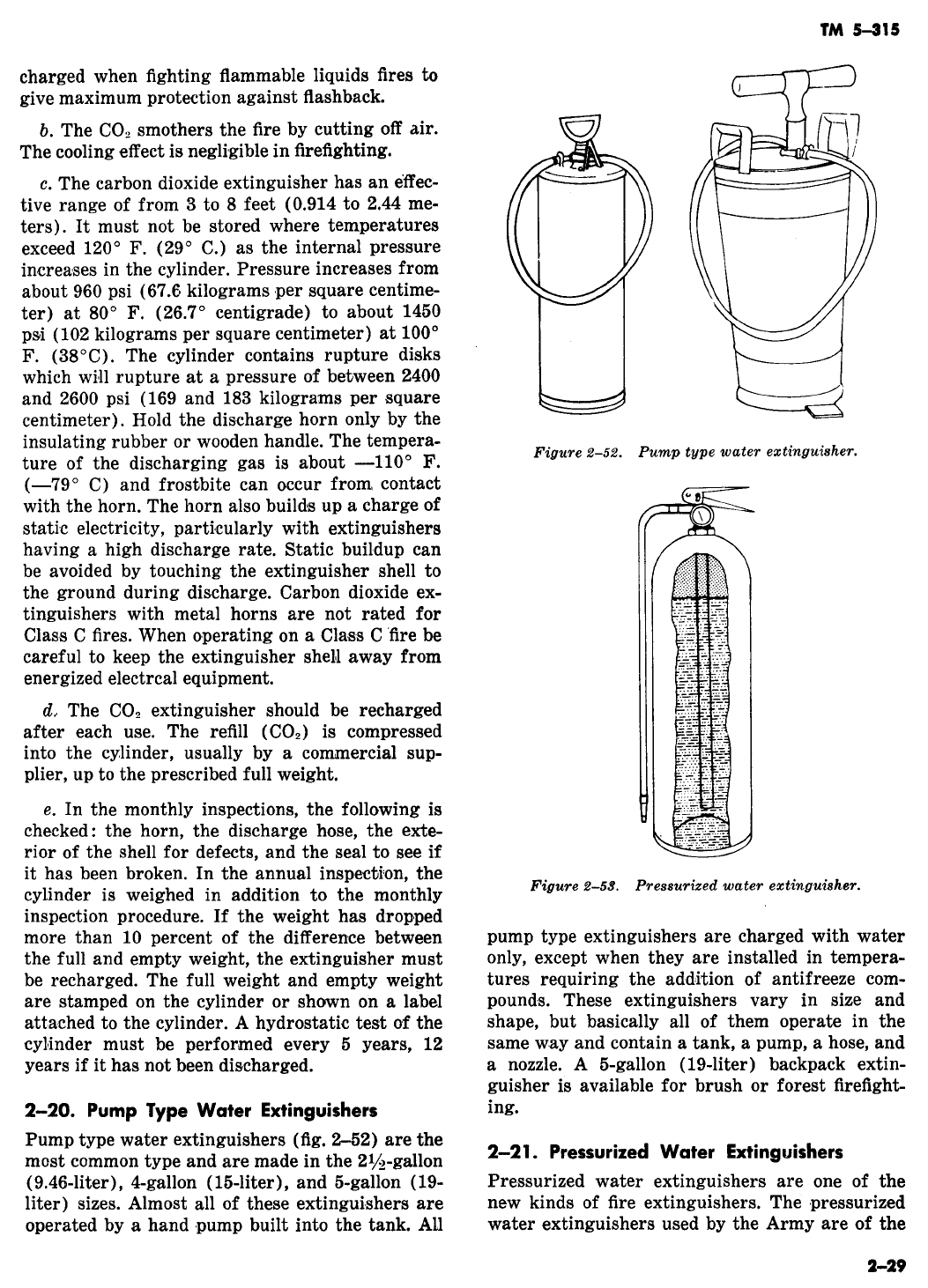
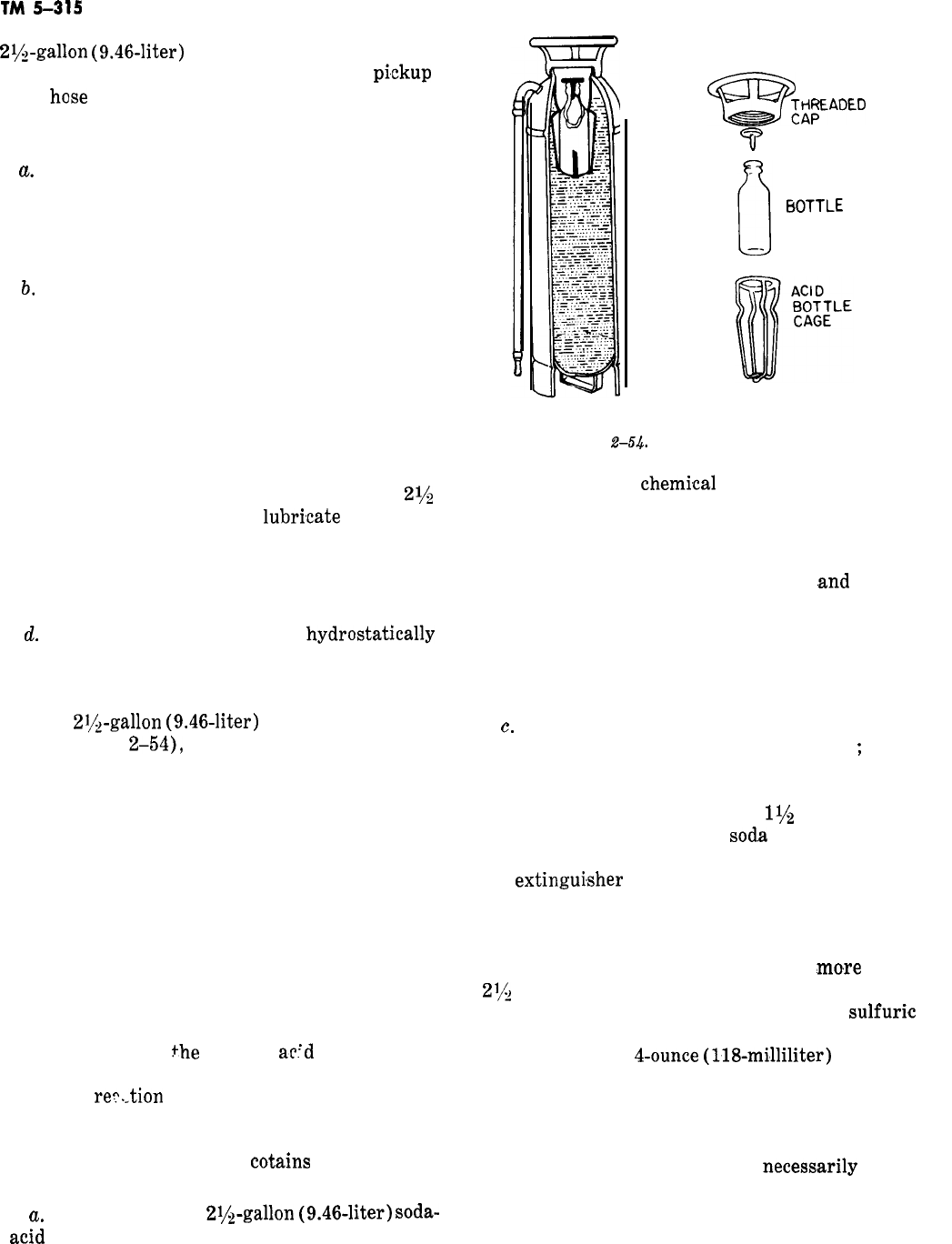
TM
5-315
2$!&gallon
(9.46~liter)
size (fig. 2-53). The extin-
guisher consists of a tank, discharge valve,
pi,ckup
tube,
base
and nozzle, and pressure gage. Nitro-
gen or air pressure of 100 psi (7 kilograms per
square centimeter) is used to discharge the water.
CL
To operate the pressurized water extin-
guisher, pull the safety locking pin out, depress
the operating handle, and direct the stream at the
base of the fire, moving often enough so that as
much of the fuel as possible is covered with water.
b,
To perform a monthly inspection, check the
wire and lead seal for damage, the air pressure
gage for deviation from the correct pressure read-
ing of 100 psi (7 kilograms per square centime-
ter), and the hose and nozzle for foreign objects.
The semiannual and annual inspections are simi-
lar in scope to the monthly inspection.
c. To recharge the pressurized water extin-
guisher, first remove the discharge valve and
attach the pickup tube. Then fill the tank with
2$
gallons (9.46 liters) of water,
lubri,cate
the gasket
in the neck of the discharge valve, replace the
discharge valve and pickup tube, and apply the
proper air pressure (100 psi, 7 kilograms per
square centimeter).
d.
The extinguisher must be
hydrostat,ically
tested every 5 years.
2-22. Soda-Acid Extinguishers
In the
2i&gallon
(9.46-liter)
soda-acid extin-
guisher (fig.
2-54),
water is the extinguishing
agent, and a chemical combination generates
enough pressure to discharge the water. The tank
contains a solution of sodium bicarbonate and,
supported in the top of the reservoir, a glass bot-
tle containing 4 ounces (118 milliliters) of sul-
furic acid. When brought together, these two
chemicals produce carbon dioxide gas, which ex-
pels the water. A loose stopper in the mouth of
the acid bottle retards the absorption of moisture
by the acid. When the extinguisher is turned up-
side down, the loose stopper falls partially clear of
the acid bottle and allows the contents of the bot-
tle to mix with the soda solution. The taper of the
stopper regulates
the
flow of
ac!d
and prevents
sudden nigh pressures. The rate of flow insures
chemical
re?._tion
of all the acid before the solu-
tion is discharged from the extinguisher. The
soda-acid extinguisher also has a hose and nozzle
and a tnreaded cap which
cotains
the necessary
gasket.
a,
To operate the
2$‘&gallon
(9.46-liter)
sob-
acid
extinguisher, grasp the nozzle and invert the
2-30
Tz3
EFADED
T
LEAD STOPPER
ACID
6OTTLE
Figure
2-54.
Soda-acid extinguisher.
extinguisher. The
chemi,cal
reaction and pressure
occur almost immediately after tilting, causing
discharge of the agent.
b. The monthly inspection of the soda-acid ex-
tinguisher includes checking the hose
,and
nozzle
for obstruction, removing the cap to assure the
presence of the proper agent, and recording the
entry on the extinguisher tag. The annual inspec-
tion requires discharging, cleaning, and recharg-
ing the tank.
c.
To recharge the soda-acid extinguisher re-
move the cap, acid bottle, and bottle cage
;
wash
all parts thoroughly; and check to see that all of
the liquid is removed from the acid bottle before
water or acid is added. Dissolve
l$‘z
pounds (0.68
kilogram) of bicarbonate of
sod,a
in ‘7 quarts (6.5
liters) of lukewarm water. Pour the solution into
the
extingui,sher
and add fresh water to the level
of the special marker on the inner wall of the
extinguisher. The extinguisher when filled to the
top of the collar holds 3 gallons (11.4 liters), but
it must never be charged with
mo,re
than
2112
gallons (9.46 liters) of liquid. Pour 4 fluid
ounces (118 milliliters) of concentrated
sulfuri,c
acid into the bottle. A plainly etched line in the
bottle shows the
4-ounce
(118-mi’lliliter)
level. In-
sert the lead stopper in the acid bottle and place it
in the cage; then insert the cage and bottle in the
extinguisher. Be certain that the cage, bottle, and
stopper are those made for that particular extin-
guisher. Manufacturers are not
necess,arily
stand-
ard in the shaping of their
extinguishers,
and
many of the parts are not interchangeable. Next
examine the gasket in the cap. Replace the gasket
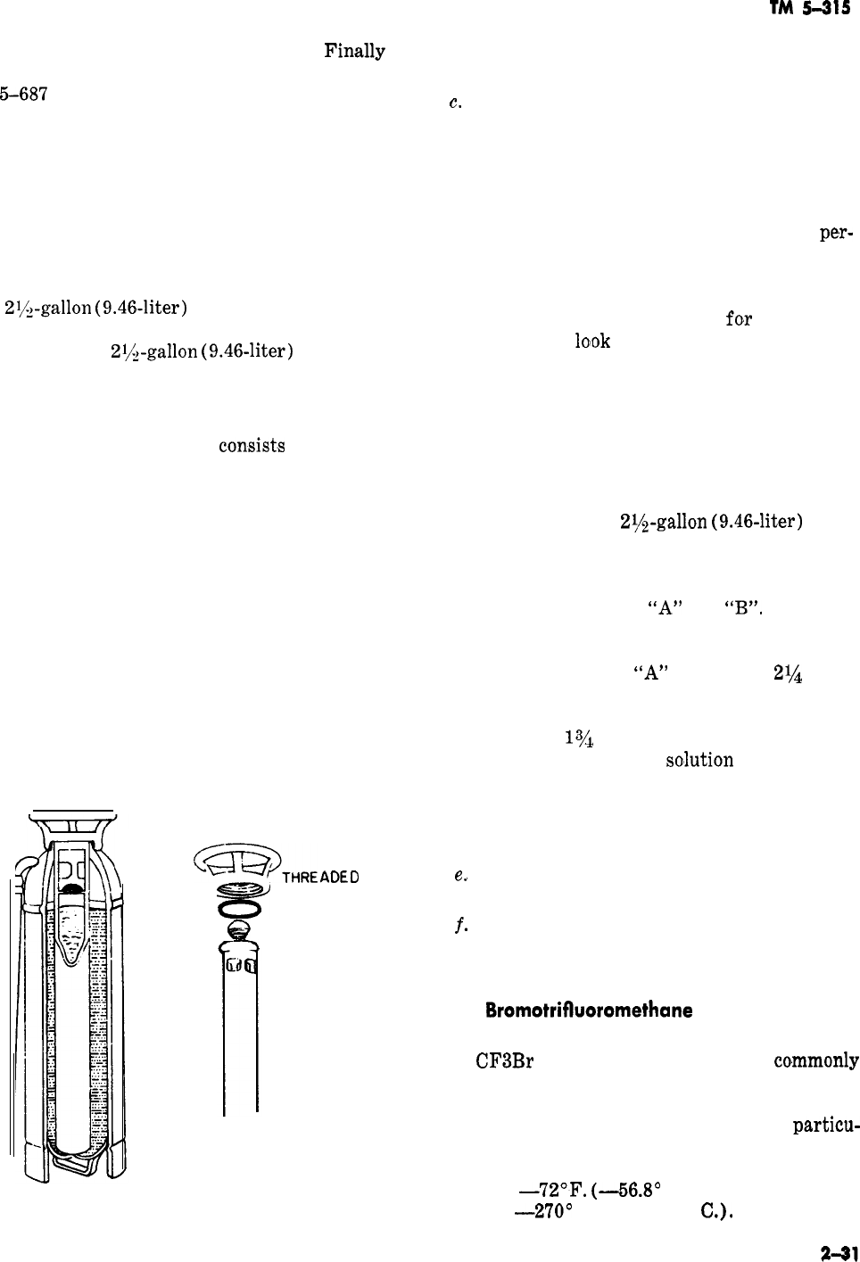
with a new one if it is rigid or
screw the cap down hand-tight
-
TM
5-687
for further details.
defective.
Fin.ally
the foam to flow over the surface of the fire area
on the collar. See as a smothering blanket.
d. The soda-acid extinguisher must be hydro-
statically tested every 5 years.
e. The soda-acid extinguisher has been taken
out of TB 5-4200-200-10, and therefore, thas been
discontinued as Army issue equipment. The pump
type water extinguisher is taking its place.
2-23. Foam Extinguishers
The
2l/L-gallon
(9.46-liter)
foam extinguisher il-
lustrated in figure 2-55 is similar in size and ap-
pearance to the
2$gallon
(9.46-liter)
soda-acid
extinguisher, but it differs in internal construc-
tion, extinguishing agent, and charging proce-
dure.
CL. This type extinguisher
consist.s
of an inner
chamber and an outer chamber. The outer cham-
ber contains a solution of sodium bicarbonate,
and the inner chamber contains a solution of alu-
minum sulfate, Ingredients added to the soda sol-
ution assist in forming and stabilizing the foam.
The extinguisher is operated by inverting it, al-
lowing the contents of the two chambers to mix.
This reaction produces bubbles containing carbon
dioxide gas, with the stabilizing ingredients
strengthening the bubble structure and producing
foam. This foam is expelled from the extinguisher
by the carbon dioxide gas pressure.
b. To operate the extinguisher, simply grasp the
hose, invert the extinguisher, and direct the foam
at the base or forward part of the flame. Allow
\
<_>THRE
ADE
D
.-
zz!!i!?
CAP
CASKET
3
LEAD STOPPER
7
INNER
CHAMBER
Figure 2-55. Foam extinguisher.
TM
5-315
c.
The monthly inspection of the foam extin-
guisher includes carefully examining the nozzle
for stoppage, since the contents of the extin-
guisher frequently plug the nozzle; inspecting the
hose and tank for deterioration; and checking for
the proper amount of fluid by weight or internal
observation. On the semiannual inspection,
pe,r-
form the monthly services and also check the
inner chamber for corrosion by removing the cap.
Replace the inner or outer chamber, if required.
Check the inner chamber stopper
fo,r
freedom of
movement and
lo’ok
for gasket breaks or deep
grooves worn by the filler collar. Replace the gas-
ket in the cap, if necessary. Examine the filler
collar for dents and for the presence of foreign
matter. The annual inspection includes all of the
preceding services plus the discharging and re-
charging of all foam extinguishers. See TM 5-687
for further details.
d. To recharge the
2lh-gallon
(9.46~liter)
foam
extinguisher make sure that the two solutions are
in accordance with the instructions printed on the
chemical containers. Usually the chemicals are in
two containers marked
“A”
and
“B”.
The solu-
tions should be prepared in separate containers.
In the absence of such instructions, dissolve the
contents of package
“A”
in exactly
2%
pints
(1.064 liters) of hot water and pour it into the
inner chamber. Dissolve the contents of package
“B” in exactly
lye
gallons (6.624 liters) of luke-
warm water and pour this
so’lution
into the outer
chamber. Do not use hot water with the contents
of package “B” because it deteriorates with heat.
Place the stopper in the inner chamber and as-
semble the extinguisher.
e.,
The foam extinguisher should be hydrostati-
cally tested every 5 years.
f. The foam extinguisher has been discontinued
as Army issue equipment. The ones in use will be
phased out in time.
2-24.
Bromotrifboromethane
Extinguisher
(Vaporizing liquids)
The
CF3Br
extinguisher, figure 2-56,
co,mmonly
known as FREON 1301, contains a liquefied com-
pressed gas which offers unusual advantages as a
safe and efficient fire extinguishing agent
particu-
larly against Class B (flammable liquid) and
Class C (electrical) fires. The liquid has a boiling
point of
-72’F.
(-56.8’
C.), and a freezing
point of
-2’70’
F. (-167.78’
CL).
Figure 2-56. CF3Br extinguisher.
a.
CF3Br
is not toxic in its natural state.
De-
com,position
occurs at fire temperatures and the
products of decomposition are toxic. These prod-
ucts are injurious if they exceed
10
percent of the
air volume. Normally, extinguishment can be
accomplished with less than 5 percent per volume
of air. It should be used with caution in confined
spaces.
CF3Br
decomposes partly when subjected
to heat and flame, which causes a decrease in its
toxicity limits.
CF3Br
is noncorrosive on metals
and alloys, and is considered a clean agent.
13.
The only
CF3Br
extinguisher in the Army
inventory is of the
2ah-pound
(1.25-kilogram)
size, which has the same extinguishing ability as
the
£
(2.27-kilogram)
CO2
unit.
c.
Because of the low vapor pressure of
CF3Br
at ambient temperatures, the extinguisher is pres-
surized to 400 psi (28 kilograms per square centi-
meter) with nitrogen. This pressure is sufficient
to permit use of the extinguisher at
-65’
F.
(-54’
C.)
without further modification.
d. The
CF3Br
extinguisher must be kept fully
charged at all times. Reweighing is the only
method of determining whether or not the extin-
guisher is fully charged. The extinguisher should
be weighed
semi.annually
on an accurate scale to
determine leakage. The cylinder assembly must be
replaced if it has lost more weight than
ils
permit-
ted by the instructions on the extinguisher name-
plate. Recharging is necessary if the weight is
found to be 10 percent deficient. The date of re-
charging should be stenciled on the cylinder.
e. Where extinguishers of this type are used,
charged cylinder assemblies should be kept on
hand so the extinguisher may be promptly re-
charged after use.
f. These extinguishers should not be located
where the ambient temperature will exceed
160’
F.
(66’
C.).
2-25. Dry Chemical Extinguishers
Dry chemical portable fire extinguishers vary
from
2$$
pounds to 150 pounds
(1.1’34
kilograms
to 68 kilograms). The dry chemical compound
used consists principally of bicarbonate of soda or
potassium bicarbonate or ammonia phosphate
which
has
been treated to make it waterproof and
free flowing. The extinguishing action of this
agent is to smother the fire.
a. Dry chemical extinguishers are of two basic
types. One type is pressurized with 150 psi (10.5
kilograms per square centimeter) of dry nitrogen
or dry air, and the other has a cartridge with
CO2
under pressure. When the cartridge of the second
type is punctured,
CO2
pressure expels the agent
(fig. 2-57).
b. To operate the pressurized dry chemical ex-
tinguisher, break the
seahng
wire, remove the
locking pin, depress the operating handle, and
direct the agent at or close to the base of the fire.
To operate the cartridge dry chemical
extin-
Figure 2-57.
Dry
chewzicd extinguisher.
2-32
TM
5-215
guisher,
break the sealing wire, remove the lock-
ing pin, depress the cartridge-puncturing handle,
and direct the agent at or close to the base of the
fire.
c. When performing a monthly inspection,
check the sealing wire and seal, the dry nitrogen
pressure gage for the correct pressure of 160 psi
(10.6 kilograms per square centimeter) (pressur-
ized type), and the hose and nozzle for foreign
objects. The semiannual and annual inspections
compare with the monthly inspections, with the
one exception that the cartridge of
t,he
nonpres-
surized extinguisher must be weighed during the
annual inspection. If the weight of the cartridge
contents (as stamped on the cylinder) is 10 per-
cent or more below the prescribed weight, the
car-
trdige should be replaced. See TM
6-637
for fur-
ther details.
d.
The dry chemical extinguisher should be hy-
drostatically tested every
5
years.
2-26. Combustible Metal Agents
Two extinguishing agents are listed for use on
Class D (combustible metal) fires. They are avail-
able in drums or barrels and put on the fire with a
scoop or shovel. A cover of at least
l/z
inch (1.27
centimeters) of extinguishing agent is applied to
the burning agents. The two agents are
:
a. G-l Powder. This is screened graphitized
foundry coke with various phosphates added. It
includes particles of various sizes to aid in pack-
ing. The material acts as a heat conductor to
lower temperature of the burning metal and
forms a coating to smother the fire by excluding
air. It also produces a gas to aid in smothering. It
may be used on magnesium and magnesium alloy
fires.
b.
Met-L-X Powder. This has a sodium chloride
base with additives to give water
repellancy
and
good flow characteristics. An additive fuses at
high temperatures to aid in forming an airtight
coating. This material forms a coating to exclude
air, which smothers the fire. It also conducts some
heat away from the burning metal. It may be used
on magnesium, sodium, potassium, and sodium-po-
tassium alloy
(NaK)
fires.
2-27. Dry Power Extinguishers for
Combustible Metal Fires
a. Dry powder extinguishers also use the
Met-
L-X sodium chloride dry powder described in the
preceding paragraph. It is dispensed with a
30-
pound
(13.6-kilogram)
capacity extinguisher (fig.
248). This amount of rated D agent is effective
on about 6 pounds (2.7 kilograms) of burning
metal, depending on the type and form of the
metal. Only cartridge-operated units are available.
The dry powder extingGsher is operated by re-
moving the hose which is around the puncturing
mechanism, then depressing the plunger which
punctures the cartridge. The compressed gas in
the cartridge is released into the shell, thus pres-
surizing it. The gas pressure expels the dry pow-
der from the shell when a nozzle shutoff is opened.
This pressurizes the shell. The extinguisher is car-
ried by its handle with one hand and the nozzle
and shutoff valves are operated with the other
hand. The shutoff valve is squeezed to open it and
released to stop the flow of the agent. The normal
operation is to open the nozzle partially to obtain
a soft flow of the agent. The burning metal is
covered with at least one
r/z
(1.27 centimeters) of
the Met-L-X sodium chloride. If glowng spots ap-
pear, they should be
recoated.
The application of
this agent forms a crust over the burning metal
which excludes the air and thus smothers the fire.
The effective range of the extinguisher is from 3
to
5
feet (0.9 to 1.5 meters).
b. The dry powder extinguisher should be re-
charged after each use. First, the gas pressure is
released by turning the extinguisher upside down
and opening the shutoff valve. This will not re-
lease the agent remaining in the extinguisher.
Next, the extinguisher is disassembled according
to the manufacturer’s instructions and cleaned
Figure
2-58.
Exterior and cutaway
viewa
of a
&y
powder
ext+lguiaher.
2-33

TM
5-315
with a brush or
compresised
air. Then the shell is extinguisher to operate in temperatures higher
filled with the proper amount of dry powder. In than in those permitted by
CO*
gas, as well as in
reassembling, check the gasket, insert a new car- temperatures lower than in those permitted by
tridge, seal the extinguisher, and tag it.
CO*
gas.
c. The monthly inspection includes checking the
nozzle, the hose, the shell for defects, and the seal
to assure that it has not been broken. The annual
inspection requires a thorough check of all compo-
nent parts and the weighing of the cartridge on
an accurate scale calibrated in fractions of an
ounce (or grams). The cartridge is replaced if it
has lost
$$
ounce (14 grams) or
m,ore.
A hydro-
static test must be performed on the extinguisher
shell and the hose every 5 years.
d. Do not confuse tthe dry powder extinguisher
with the dry chemical type extinguisher.
b.
The prescribed chemical for lowering the
freezing point of water in water-type extinguish-
ers is calcium chloride. The quantity of calcium
chloride required to prevent freezing will vary
from 3 pounds per gallon (0.362 kilogram per
liter) of water to protect against a temperature of
2’
F. (-16.9’ C.), to a
max,imum
of
6
pounds per
gallon (0.6 kilogram per liter) of water to protect
against a temperature of
-53’
F.
(-47’
C.)
(TM 5-687). Local directives should be consulted
fo,r
specific
amounts at each temperature level.
l3efore
winterization, extinguishers which require
the use of calcium chloride solutions should have
the interior of the water tank painted
w,ith
two
coats of asphaltum base paint to retard corrosive
action. Dry calcium chloride should not be placed
directly into the appliance to be winterized. The
chemical should be mixed with water in a sepa-
rate container to prevent caking at the bottom of
the tank. A
s
ounce of
so&urn
bichromate added
to each gallon (1.87 grains per liter) of water will
act as a rust inhibitor. Do not antifreeze pressur-
ized water extinguishers with calcium chloride.
Use specially prepared solution.
2-28. Winterization of Extinguishers
The protection of fire extinguishers krom freezing
is extremely
i,mportant
and should be thoroughly
understood by all fire protection personnel.
a. Carbon dioxide extinguishers which must be
operated in temperatures below
0”
F. (17.8’ C.)
must be winterized. This winterization is essential
because when the temperature falls below
0’
F.
(17.8’
C.), the pressure of the extinguisher also
falls below
285
pounds per square inch (20 kilo-
grams per
(square
centimeter), which is the mini-
mum amount of pressure needed for proper oper-
ation. The winterization of
CO*
extinguishers re-
quires the addition of 200 pounds (90.7 kilo-
grams) of pressure per square inch (14 kilograms
per square centimeter), which is done by adding
dry nitrogen to the
COZ.
Local directives should
be consulted as to the amount of dry nitrogen to be
added. The addition of dry nitrogen requires a
decrease in the amount of
CO2
in the cylinder.
The dry nitrogen provides additional pressure for
expelling
CO2
at low temperature. Since the de-
crease of the
CO*
will not allow the addition of
dry nitrogen pressure to rupture the cylinder
gravity disk until the temperature reaches
160’
F.
(71’
C.),
the injection of dry nitrogen allows the
c. Since soda-acid and foam extinguishers de-
pend on a chemical reaction to expel the extin-
guishing agent, winterizing chemicals are not
used. Therefore, soda-acid and foam extinguishers
are normally located only in heated structures.
d
Pressurized dry chemical extinguishers do not
require winterization. Cartridge type dry chemi-
cal extinguishers are winterized by replacing the
CO2
filled cartridge with one filled with dry nitro-
gen.
NOTE
,See
TB 5
+200-200-10
for hand portable
fire extinguishers approved for Army
users.
TM
5-315
‘-
-
CHAPTER 3
CHARACTERISTICS, CHEMISTRY, AND PHYSICS OF FIRE
3-1.
Introduction
The number of fires caused by uncontrollable nat-
ural reactions is minimal in relation to those
caused by the carelessness of man and his apathy
in acquiring and using the information available
on the characteristics, chemistry, and physics of
fire. The knowledge of the principles of fire also
helps the firefighter in extinguishing those fires
that he
fail,s
to prevent.
3-2.
The Nature of Fire
Previously, the process of chemical oxidation and
combustion and that of halting combustion was
shown with the familiar fire triangle (fig.
3-1).
This two-dimenional triangle aided in explaining
the combustion process. Thus, when all the sides
of the fire triangle were intact and in proper state
and proportion, burning took place. When any one
of the sides (factors) was removed, burning was
stopped. Before the introduction of the modern
knowledge on chemical fire extinguishment, there
were only three methods of extinguishing a fire,
alined
closely with each leg of the fire triangle.
Cooling the fire removed the “heat leg”; excluding
the oxygen from the fire removed the “oxygen
leg”
;
and separating the fuel from the fire re-
moved the “fuel leg”. When chemical extinguish-
ing agents were introduced and successfully used
for fire extinguishment, additional information
was required to explain the action of the chemi-
cal. This new information added another dimen-
sion to the diagram. The new diagram is known
as the
tetru/zedron
of
fire
(fig.
3-2).
It has four
triangular surfaces that make up a solid pyrami-
dal form which has depth. Each of the triangular
surfaces shows an element necessary to continue
combustion. It shows that combustion
(,fire)
is a
continuous chemical reaction which changes con-
stantly because of external conditions. Chemical
extinguishment agents
(pota,ssium
and sodium bi-
carbonate type dry chemicals or vaporizing liquid
agents) inhibit the chain reaction of a fire by
interfering with or cutting off the conditions
nec-
Figure
3-1.
The fire triangle.
FUEL
-
meDllclI40
AogIdr,
TEMPERATURE
UNINHIBITED CHAIN
REACTIONS
(Courtesy Walter M.
Haesaler,
The
Figure 3-2. The
te?ahedron
of fire.
essary,for
combustion. Thus, all the three parts of
the fire triangle may be present, but the chain
reactions are prevented (inhibited) by a chemical
extinguishment agent (or agents) which puts out
the flame.
3-3. Basic Definitions and Properties of Fire
a. Ignition
Temperature.
The ignition tempera-
ture of a substance (solid, liquid, or gaseous) is
the minimum temperature to which the substance
exposed to air must be heated in order to
ini.tiate
or cause self-sustained combustion. Ignition tem-
peratures of the same substance vary according to
the percentage composition of the vapor or
gas-
3-1
TM
5-315
ai,r
mixture, shape, and size, of space where the
ignition occurs, rate and duration of heat, kind
and temperature of the ignition source, oxygen
concentration, and
o’ther
effects of materials that
may be present. Therefore, given ignition temper-
atures should be looked upon as approximations.
b. Vapors. Vapors in the process of combustion
are the gaseous substance given off by the mate-
rial that is burning. In burning wood, heat causes
the resinous substance in the wood to vaporize.
The vapors combine with the oxygen of the air,
and the flame from the kindling ignites the com-
bustible vapor-oxygen gas. The
he,at
from the fire
heats the wood, which in turn liberates more va-
pors and thus sustains the fire until the wood is
consumed.
c.
Vapor Density. Vapor density is the term
used to explain the weight of vapors. When speak-
ing of the weight of
the,se
vapors, they are usually
compared to air, which has a vapor density of
1,
Therefore, if a substance has a vapor density of
1.5, it is
lr$
times as heavy as air. If it has a
vapor density of
.5,
it weighs only
r/z
as
m,uch
as
air. Figure 3-3 shows how the density of gasoline
vapors can be demonstrated with a small trough,
a candle, and a gasoline-soaked rag. A lighted
candle (the ignition source) is placed at the lower
end of the trough, and the gasoline-soaked rag
placed at the upper end. Gasoline vapors are heav-
ier than air and will flow down through the
trough to the lighted candle, where they will ig-
nite, and flash back to the rag at the top of the
trough, This illustration shows the need for the
“No smoking within 100 feet” signs
displ,ayed
around gasoline storage areas.
d. Flammable or Explosive Limits. In the case
Figure
8-8
Vapor
den&y.
of gases or vapors which form
flammmable
mix-
tures with air (or oxygen), there is a minimum
concentration of vapor in air below which flame
doe,s
not occur when the vapor-air mixture comes
in contact with a source of ignition; thus, it is too
“lean” to ignite. Most flammable vapors and gases
also have a maximum proportion of vapor or gas
in air above which flame does not occur (too
“rich” to ignite). A few materials, like ethylene
oxide, decompose and burn with no oxygen pres-
ent.
e. Flammable (Explosive) Range. The range of
combustible vapor or gas-air mixtures between
the upper and lower flammable limits
i,s
known as
the “flammable range” (or “explosive range”).
For example, the lower limit of flammability of
acrylonitrile at ordinary ambient temperatures is
approximately 3 percent vapor in air by volume.
The upper limit of flammability is about
1’7
per-
cent. Thus, all concentrations of acrylonitrile
vapor in air falling between 3 and 1’7 percent are
in the flammable or explosive range.
f. Flash Point and Fire Point. The flash point of
a liquid is the lowest temperature of the liquid at
which it gives
o’ff
vapor sufficient to cause a
flammable mixture with the air near the surface
of the liquid or within the vessel
used.
Some sol-
ids, such as camphor and naphthalene, change
from solid to a vapor at ordinary room tempera-
ture and therefore have flash points while still in
the solid state. The fire point (the lowest tempera-
ture at which a substance continues to burn in
air) is usually a few degrees above the flash point.
34. Principles of Fire
a. Ignition and Combustion. Fire or combustion
may be described as rapid oxidation with the
action (evolution) of heat and light. Oxidation of
a material takes place continuously as long as it is
exposed to an oxidizing agent, which may be air.
At ambient temperatures, oxidation is usually so
slow that the
proce,ss
is not noticeable to human
senses. Examples of such slow oxidation are the
rusting of iron and the yellowing of paper. As
temperatures rise above the ambient, the rate of
oxidation becomes more
rapi,d
and generates heat.
When the ignition temperature is reached, flame
appears, thus ignition has taken place. Combus-
tion is the continuous burning that follows after
ignition.
b.
Fire. Actual burning (fire) is a much more
complicated chemical reaction than is commonly
explained by the “fire triangle” (fig.
3-1)
or the

TM
5-315
more recent “tetrahedron of fire” fig. (3-2). AS
the temperatures rise above the ambient, pyro-
lysis takes place. Pyrolysis is the chemical decom-
position of matter through the action of heat. It
proceeds through the following stages
:
(1) Decomposition of combustible material
slowly gives off gases, including water vapor. The
combustible gases are not ignitible during the
early stages of pyrolysis.
(2) Gas evolution continues with some of the
gas becoming ignitible. As the temperature in-
creases the gas
evolution,also
increases.
(3) At the ignition temperature the evolved
gases are too rich, at first, in carbon dioxide and
water vapor to sustain flame very long. However,
the heat of the flame starts a secondary pryolysis
reaction process and flaming combustion occurs
entirely in the gaseous distillate vapor phase. Gas
evolution may be so fast that it blankets the fuel
surface and excludes air. This prevents the char
from burning, retards the penetration of heat,
and delays the
igniti,on
temperatures in penetrat-
ing deeper into the
combu,stible
material. As tem-
peratures increase, the char begins to glow, air
flows in to support combustion, and the fuel itself
burns as well as its decomposition gases. If the
released heat is concentrated and sufficient to sus-
tain oxidation, and more heat is generated than
lost through conduction, convection, or radiation,
a positive heat balance exists. If, however, most
or all of the heat generated is lost, there is a
negative heat balance and the fire goes out as a
match flame in a wind. At the same time, a condi-
tion known as feedback may exist. Feedback is
generated heat that prepares adjacent combusti-
ble material for burning by raising it to ignition
temperatures. If the feedback is not adequate, the
fire goes out. In addition to heat generation dur-
ing pyrolysis, the concentration of the oxidizing
agent is another factor that determines whether
or not ignition and combustion can occur. There
appears to be a minimal oxidizing agent concen-
tration for almost all materials below which com-
bustion will not take place. Exceptions to the lat-
ter are some combustible solids, such as cellulose
nitrate, that contain oxygen in the constituent
molecules. This oxygen can be released by heat
even if there is no air supply. Thus,
pyroly,sis
reaction may take place without the presence of
air. An example is charcoal in coking ovens which
continues to oxidize and produce heat with a mini-
mal amount of air.
c.
Summary of the Principles of Fire. The prin-
ciples of fire may be summarized as follows
:
(1) There must be an oxidizing agent, com-
bustible material, and a source of ignition for
combustion to take place.
(2) Combustible material must be heated to
its
ignition
temperature before it will burn.
(3) Combustion will continue until-
(a) The combustible material is removed
or consumed.
(b)
The oxidation agent concentration is
lowered below that essential.
(c) The combustible material is cooled
below its ignition temperature.
3-5.
Heat Energy Sources
Since fire prevention and extinguishment are de-
pendent on the control of heat energy, it is essen-
tial that firefighters know the common ways in
which heat can be produced. The following dis-
cusses briefly the heat energy sources.
a.
Chemical Heat Energy.
This source of heat is
the result of oxidation, and is of primary concern
to fire protection engineers. The following are the
different ways heat is produced thorugh the chem-
ical process
:
(1)
Combustion. Heat of
combusti,on
is the
quantity of heat released during the oxidation of
a substance (fuel). This is the heat normally uti-
lized by industry and for domestic use, and is
measured in terms of British thermal units
(BTU). The heat intensity of oxidation (complete
or partial) of almost all compounds of carbon,
hydrogen, and oxygen depends on the oxygen
wn-
sumed.
Thus, the heat produced by combustion is
limited by the air supply.
(2)
Spontaneous heat.
Practically all organic
substances which are capable of combining with
oxygen will oxidize at some critical temperature
with evolution of heat if exposed to the atmos-
phere. The rate of oxidation at normal tempera-
tures is usually slow and the heat which is re-
leased is transferred to its surroundings. This
keeps the temperature down and prevents igni-
tion. This is not true of all combustible materials.
The oxidation of some material generates heat
more rapidly than it can dissipate, which results
in spontaneous combustion. Enough air must be
available to permit oxidation, yet not so much
that the heat is carried away by convection as
rapidly as it is formed. Oily rags might heat spon-
taneously in a wastebasket, but would not do so if
these rags were hung on a line where air move-
ment is sufficient to remove the heat. Again, a
tightly packed bale of rags is not as likely to

cause spontaneous combustion as a loose bale. Be-
cause of the many possible combinations of air
supply and insulation, no positive
predicti,on
can
be made as to when material will heat sponta-
neously. Fire safety engineers should not only be
aware of the possibility of spontaneous combus-
tion and fires caused by oily rags, paper, coal
piles, and foam rubber, but also be aware that
oxidation of agricultural products can produce
fires by spontaneous combustion. Grains in large
piles or bins and piles of grass (hay) will oxidize
to a point of ignition when saturated with a cer-
tain amount of moisture. Fires from this source
may not be as prevalent on farms as in urban
areas where the agricultural products are stored.
(3) Decomposition. Heat of decomposition is
the heat released by the decomposition of com-
pounds such as cellulose nitrate and many com-
mercial and military explosives.
(4) Solution. Heat of solution
i,s
the heat pro-
duced when a substance is dissolved in a liquid.
Most materials release heat when dissolved.
Chem,icals,
such as concentrated sulfuric acid,
produce enough heat when dissolved to be danger-
ous. The chemicals that react in water and release
heat are not combustible, but liberate sufficient
heat to ignite combustible material nearby.
b. Electrical Heat Energy. Electrical heat en-
ergy produces heat when an electric current flows
through a conductor or when a spark jumps an
airgap.
(1) Resistance. An electric wire or other con-
ductor of
electricity
offers resistance and thus
produces heat. The heat from these causes the
oxidation and ignition of nearby combustibles and
fire results. Fires of this type are quite common
in all areas using electricity as a source of heat
and energy.
(2) Induction. When an
altern,ating
current
is passed through a wire and induces a current in
another wire parallel to it, a form of heat called
induction heating is produced if the current-car-
rying capacity of the second wire is inadequate.
Inducted heat is produced by the resistance to the
flow
of electricity and by molecular friction. An
example of the latter is the heat produced in a
mi,crowave
oven.
(3)
DieZectric.
Dielectric heating is that pro-
duced when the insulating materials are imperfect
and, therefore, allow a leakage of current. This
heats the insulating material which may eventu-
ally ignite the nearby combustible material.
(4)
Arcing.
Heat from arcing occurs when
an electric circuit which carries a current is
in-
terrupted and the current leaps the gap. The
tern-
peratures of arcs are very high and may ignite
combustible and flammable material in the area.
(5)
Stc&.
Static electricity (friction
elee-
tricity)
is an electrical charge that accumulates
on the surfaces of two materials that have been
brought together and then separated. One surface
becomes charged positively and the other
nega-
tively. If the two objects are not bonded or
grounded, they may accumulate sufficient electric-
ity to discharge a spark. ‘The spark produces little
heat, but it will ignite flammable vapors, gas, and
clouds of combustible dust.
(6) Lightning. Lightning is the discharge of
electrical charge on one cloud to an opposite
charge on another cloud or on the ground. Light-
ning develops very high temperatures in any ma-
terial of high resistance which may be in its path.
c.
Mechanical Heat Energy. Mechanical heat en-
ergy, especially friction heat, is responsible for a
significant number of fires annually. A few are
caused by heat energy released by compression.
(‘1)
Friction heat. Friction heat is the result
of resistance to motion when two solids are
rubbed together. The intensity of heat depends
upon the amount of mechanical energy trana-
formed to heat and on the rate at which the heat
is generated.
(2) Heat of
compress&%
This is the heat
released when a gas is compressed. A useful pur-
pose of ignition by compression is the diesel en-
gine which needs no spark plugs for ignition. A
fire may be caused by directing a jet of com-
pressed air into a pipe. The air is converted to
heat which ignites an oil film on the inside surface
of the pipe fittings.
d. Nuclear Heat Energy. Nuclear heat energy is
released from the
nuc1eu.s
of the atom. The nu-
cleus is held together by a great force which can
be released by bombardment of the nucleus with
particles of energy. The bombardment (fission
and fusion) releases the energy in the form of
tremendous heat and pressure, and also nuclear
radiations. In nuclear fission, energy is released
by splitting the nucleus. In nuclear
fusion,
energy
is released by the fusion of two nuclei. Nuclear
weapons firefighting procedures are discussed in
chapter 6.
3-6. Classes of Fire
Fires are divided into four main classes: class A,
class B, class C, and class D fires. These classes
TM
5-315
are based on the combustion characteristics of the
ignited material. In most cases, installation fires
are combinations of at least two and sometimes all
of these classes.
a.
Clam
A Fires. Class A fires are fires in ordi-
nary combustible materials such as bedding, mat-
tresses,
dunnage,
books, cloth, canvas, wood, and
paper. Class A fires must be dealt with by cooling
the fire below its ignition temperature. All class A
fires leave embers which are likely to rekindle if
air comes in contact with them. Therefore, a class
A fire must not be considered extinguished until
the entire mass has been cooled thoroughly.
Smothering is not effective for class A fires be-
cause it does not lower the temperature of the
burning embers below the surface of the fire.
b.
Cl,ass
B Fires. Class B fires are those which
occur in flammable substances such as gasoline,
jet fuels, kerosene, oils, paint, turpentine, grease,
tar, and other combustible substances which do
not leave embers or ashes. Class B fires can be
extingusihed by providing a barrier between the
burning substance and the air or oxygen neces-
sary for its
comb,ustion.
Chemical foam and me-
chanical foam produce such barriers, and are
known as “permanent” smothering agents.
Carbon dioxide is also a smothering agent, but its
effect is only temporary and the application must
be renewed if there is any danger of reignition.
c.
CZass
C Fires. Class C fires are fires in live
electrical materials. They present an extra hazard
to the firefighter, because of the danger of electri-
cal shock. A nonconducting extinguishing agent is
essential for fighting class C fires. An additional
consideration in fighting class C fires is the fact
that it may be quite important to avoid damaging
the electrical equipment in the process of extin-
guishing the fire. Electrical instruments and con-
tacts will be contaminated by any extinguishing
agents except gases, The first step in extinguish-
ing a class C fire is to secure the source of power
to the circuit or equipment on fire. The preferred
agent in fighting class C fires is carbon dioxide or
monobromotrifluoromethane, since they give pro-
tection against electrical shock and are not likely
to injure the equipment. Water fog, although not
preferred, may be used; under ordinary condi-
tions it does not
transm,it
electricity to the fire-
fighter (as would a solid stream of water), but it
may damage the energized electrical equipment.
d.
Cluss
L
Fires. Class D fires are those in
combustible metals, such as titanium, zirconium,
sadium,
potassium, etc. The greatest hazard exists
when these metals are in the molten state or in
finely divided forms of dust, trimmings, or shav-
ings. Ordinary extinguishing agents are ineffec-
tive on these metal fires, and they are best con-
trolled by covering with special dry powdered or
granular materials which
excl’ude
oxygen and
which will not react or combine adversely with
metal.
3-5

TM
5-315
CHAPTER 4
TACTICS AND TECHNIQUES OF FIREFIGHTING
Section
I.
FIRE CONTROL
4-1. Introduction
Fire control is
detlned
as “retarding or reducing
the rate of burning.” Extinguishment, on the
other hand, is the complete elimination of the fire.
Retarding or reducing the rate of burning would
seem to be just a step in the process of extin-
guishment. But it can be an immediate objective
in itself, for a successfully controlled fire makes it
possible to
resuce
personnel before completely ex-
tinguishing the fire. When a building is com-
pletely engulfed in flames, the heat makes rescue
impossible until it has been reduced by control. In
structural firefighting, control is very important
especially when rescue of personnel may be neces-
sary or when there is a danger of the fire spread-
ing. Because water is the principal extinguishing
agent, the supply limitation is not usually a prob-
lem. Instead, water pressure and the volume in
gallons per minute are generally the
m,ost
impor-
tant factors in this phase of fire protection. An-
other method of control frequently used in struc-
tural firefighting is called covering exposures.
This means that when one
structure
is burning,
other structures, especially those downwind, are
protected to keep radiation and convection heat
from causing these buildings to start burning. To
prevent this kind of spreading, streams of water
are applied to these exposed buildings. In this
sense, then, control means the prevention of
spreading rather than the reduction of fire in a
particular area.
4-2. Fire Control Methods
Three methods are used in the control of fire
:
a.
Cooling or reducing the temperature below
the ignition point.
b. Smothering or reducing the oxygen content
within the fire area below the burnable limits. The
atmosphere must contain at least 15 percent oxy-
gen in order for a fire to burn.
c.
Removing fuel from the vicinity of the fire,
by valve or switch action, by the application of
heavy streams of water, by firebreaks in the case
of natural-cover fires, or by manual removal.
4-3. Extinguishment of the Different
Classes of Fire
a. Class A fires require primarily water or an
agent containing water so that the deep-seated
embers in wood, cloth, and other class A materials
may be reached by the cooling agent.
b.
Class B fires may be extinguished with
carbon dioxide
(CO?),
monobromotrifluo-
romethane
(CF3Br),
foam (mechanical and chem-
ical),
dry chemical (bicarbonate of soda),
PO-
tassium
bicarbonate (Purple
K),
and ammonium
phosphate), methyl bromide, mineral soil,
water-
fog, aqueous film forming foam (AFFF) (trade
name “light water”) or any other system of cov-
ering that excludes oxygen. AFFF extinguishes
the fire and prevents flashback. Dry chemical ex-
tingui!shes
the fire immediately by conditioning
the atmosphere, but does not cool the combusti-
bles.
c.
Class C fires are extinguished by (in order of
preference) monobromotrifluoromethane, carbon
dioxide, and dry chemical. When selecting an ex-
tinguishing agent for class C fires, consideration
msut be given to the electrical conductivity of the
extinguishing agents. None of the substances
listed above is a conductor of electricity. It is ad-
visable to use
,monobromotrifluor,omethane
(CF3Br)
or carbon dixoide
(
C02)
on class C fires
whenever possible.
CF3Br
and
C02)
leave no resi-
due and will not damage electrical equipment.
NOTE
One more type of fire to be aware of is
the compressed gas fire. ‘Technically this
type of fire is rated as class B, and
4-1
TM
!L315
agents listed for class B fires are used to
extinguish it. The safest and best way of
controlling this fire is to remove the
f,uel
supply. This prevents the accumulation
were allowed to continue to flow. Fires
involving pressurized flammable gases,
especially those heavier than air, such as
liquefied (petroleum gases, should not be
of explosive vapors that would
the fire were extinguished and
Section
occur if
co-mpletely
extinguished unless the flow
the fuel
of gas can be immediately stopped.
Il.
FIRE DEPARTMENT HYDRAULICS
4-4. Introduction
Hydraulics is that branch of science which deals
with the mechanical properties of water or other
liquids and with the application of these proper-
ties in engineering.
Firelfighters,
especially pump
operators,
m,ust
understand and be able to apply
those principles of hydraulics which are essential
to firefighting. Inadequate training or lack of ex-
perience in fire
hydraulicts
can be extremely costly
in lives and materiel.
4-5. Properties of Water
Water, the most common liquid, is also the most
effective, in its various
form,s,
for firefighting. To
use it most effectively, however, one should
kn0.w
about its physical properties.
a. For all
practic,al
purposes, water is not com-
pressible. It requires 30,000 pounds (13,608 kilo-
grams) of pressure per square inch (6.45 square
centimeters) to reduce its volume 1 percent. If
water has a mineral content (such as salt) or is
subjected to different temperatures, its character-
istics will differ.
b.
Water consists of two parts of hydrogen and
one part of oxygen-a fact represented by the
common chemical formula
HZO.
One cubic foot
(0.6283 cubic meter) of water weighs 62.6 pounds
(28!%
kilograms). There are 231 cubic inches
(3786.09 cubic centimeters) in 1 gallon (3.785 li-
ters) of water and 1,728 cubic inches (28,312
cubic centimeters) in 1 cubic foot (0.0283 cubic
meter) of water. One cubic foot (0.0283 cubic cen-
timeter) of water contains 7.481 gallons (28.3156
liters). One gallon (3.785
1iter.s)
of water weighs
8.35 pounds (3.7876 kilograms). Thse figures are
important and should be remembered.
4-6. Volume
It is often necessary to determine the volume of
cylindrical and rectangular containers in order to
know the weights and capacities of installed or
reserve tanks and consequently how long they
will1
4-2
be of use. To compute volume, first find the area
of a surface. For a square or rectangle, this is
done by multiplying the length by the width
(A
=
1~).
For a circle, the area is found by
multiplying the diameter squared by 0.7864 (i.e.,
A
=
Dzx 0.7854) or by multiplying the radius
squared by 3.1416 (i.e., A
=
R2
X
3.1416, com-
monly written A
=
nR2,
where the Greek letter
7r
(pi) means 3.1416). In hydraulics, the pre-
ferred formula is the first one: A
=
D2
)(
0.7854.
When going on from problems dealing with the
areas of rectangles and circles to those involving
the volumes of cylindrical and rectangular tanks,
consider a third dimension, that of height, repre-
sented by the
,symbol
h.
The formula for the
vol-
ume of a rectangular tank is V
=
lwh,
meaning
that the volume is found by multiplying the length
by the width by the height. For example:
‘How
many cubic feet are there in a tank 5 feet
(1.52~6
meters) by 4 feet (1.22 meters) by 10 feet (3.06
meters)
Substituting in the
formula-
V
=
lwh
=5X4XlO
=
200 cubic feet
NOTE
When computing volume, all dimensions
must be in the same unit of measure-
ment. For example, if the diameter of a
cylindrical container is given in inches
and the height is given in feet, the
height must be converted to inches.
Tile
tank contains 200 cubic feet (5.67 cubic me-
ters), and it then becomes a simple
pr.oblem.
to
find its contents in gallons (or liters). There are
7.481 gallons in 1 cubic foot (1000 liters in 1 cubic
meter), so 7.481 multiplied by 200 equals
L496.2
gallons (1000 multiplied by 5.67 equals 5670 li-
ters), the number of gallons in a
200-cubic-foot
tank. For problems involving volumes of cylindri-
cal ‘tanks, use the formula V
=
D2
x
0.7864
X
h.
For example: How many cubic feet-are contained
in a tank 12 feet (3.66 ‘meters) high and 5 feet
(L&J5
meters) in diameter?
v=
E
-
Z
D.2
x
0.7864
x
h
5
x
5
x
0.7864
x
12
235.62
cubic feet
To find the number of gallons, multiply 235.62 by
7.481 to get approximately 1,763 gallons (6673
liters).
4-7. Weight
a. Firefighters must know how to find the
weight of a given quantity of water. For example,
vehicles with a capacity of 1,000 gallons (3785
liters) actually have 8350 pounds (3785 kilo-
grams) of extinguishing agent aboard (8.35 mul-
tiplied by l,OOO), or more than 4 tons (3.628
metric tons) of water. Such knowledge would be
necessary in making a decision about detouring or
crc,ssing a bridge of limited capacity.
b. It is also necessary to be able to determine
the weight of a charged hose line, especially when
only a limited number of personnel are available
to move such a line. The futility of filling a
21&
inch (6.35centimeter) hose with water before
trying to move it to the point of operation is re-
vealed after figuring the weight of water in a
50-foot
(600 inches
;
1524 centimeters) section.
-
This is done by means of the
formula-
V=
D*
x
0.7854 X
h
231
x
8.35
(Metric System
:
V
=
Dz
x
0.7854
x
h
x
I)
1000
in which h is the length of the hose in inches, D
i,s
the diameter of the hose in inches, 231 is the
number of cubic inches in a gallon (1000 is the
number of cubic centimeters in 1 liter), and 8.35
is the weight in pounds of a gallon (1 kilogram is
the weight of 1 liter).
The V
=
6.25
x
.7854
x
600
x
8.35
equals
231
approximately 106 pounds (42.8 kilograms) plus
the weight of the hose, which is 65 pounds (29.5
kilograms) per section, a total of approximately
171 pounds (78 kilograms).
c.
To pull four
50-foot
(l&meter) sections of
2$&inch
(6.35-centimeter)
hose, totaling some-
thing over one-quarter of a ton of hose and water
combined, up a ladder, becomes a formidable task.
These calculations also show that 1,000 feet (305
meters) of
2l,&inch
(6.35-centimeter)
hose, which
-
is the length often carried on structural pumpers,
weighs almost 2 tons (1.8 metric tons) when
filled.
TM
5-315
4-0. Pressure
Water pressure is proportional to the depth of the
water, which, in hydraulics, is stated in pounds
(or kilograms) per square inch (6.45 square
cen-
timeter,s)
. A column of water 1 foot
(0.30)5
meter)
high exerts a pressure of 0.434 pound (0.197
kilo-
.
gram) per square inch (6.45 square centimeters).
Two columns of water, each 1 foot
(.305
meter)
high, one on top of the other, would exert 0.868
pound (0.3937 kilogram) per square inch (6.45
square centimeters) of pressure at the base. In
other words, if a column of water 1 square inch in
base area and 1 foot high weighs 0.434 pound, the
effective pressure in pounds per square inch at
any point in a column of water is equal to 0.434
multiplied by the height of the column above that
point in terms of feet
;
this is expressed
as-
P
=
0.434H
in which H is the head in feet. Static pressure is
the pressure exerted by water at rest. The static
pressure may be determined readily, if the head is
known by the formula SP
=
0.434H.
Back pres-
sure or gravity pressure indicates the pressure in
pounds per square inch (psi) exerted by a head of
water against a pump lifting it to an elevated
point, The solution is found by the same
method-
BP
=
0.434H
4-9. Rate of Discharge
The rate of discharge is the quantity of water
coming from an opening during a given period of
time. It is calculated in gallons per minute (gpm).
a. When the rate of discharge is computed, two
items must be considered: the diameter of the
opening (nozzle) and the pressure of the flow.
The rate of discharge is found by multiplying the
diameter squared by the square root of the pres-
sure times the constant 29.7
;
this is expressed
as-
gpm discharge
=
29.7
x
D2
X
fl
For example, using this formula and table 4-1, if
the diameter is 2 inches (5.08 centimeter) and the
pressure is 36 psi, then
:
Discharge
=
29.7
X
Dz
X
d??
=
29.7
x
22
x
@6
=
29.7
x
4
x
6
=
712.8 gpm (2697.7 liters per minute)
b.
An open hose butt (no nozzle) or an average
hydrant outlet is only about 90 percent as efficient
as a nozzle tip in terms of water volume dis-
4-3
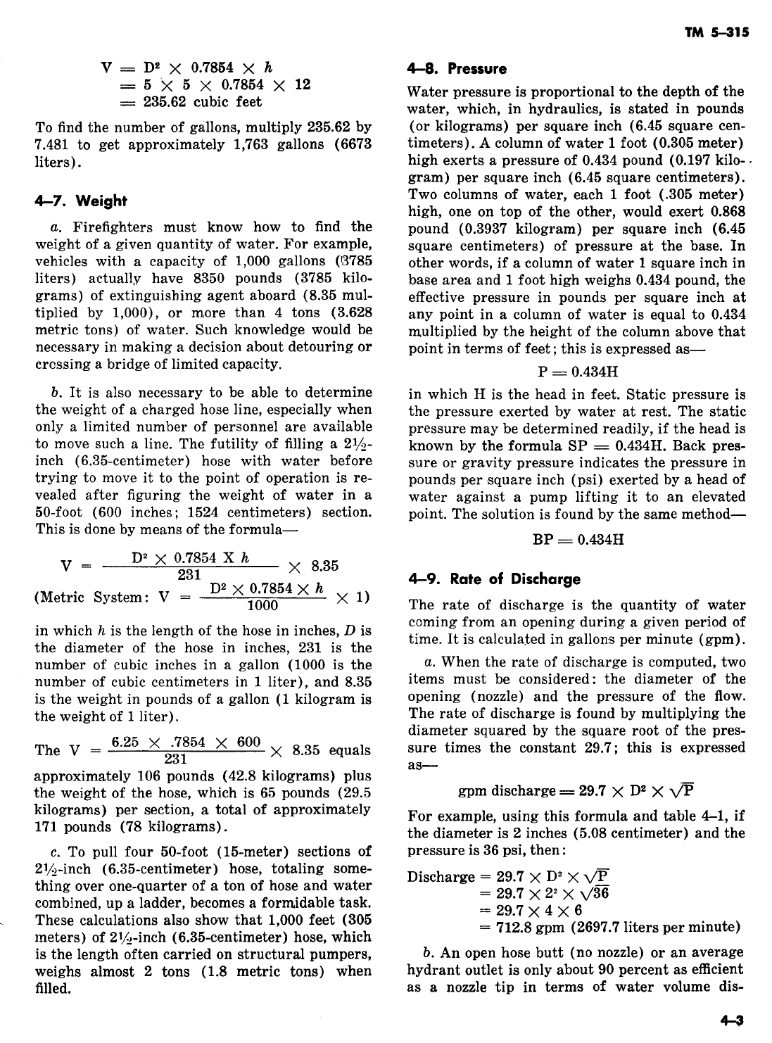
TM
5-315
Table
h-l.
Square
Roots of
Ahmbers
1 to 100
nn n
I
n
1
1.
21
4.582
41
6.403
61
7.810
81
9.
2
1.414
22
4.690 42
6.480
62
7.874
82
9.056
3
1.732
23
4.795
43
6.567
63
7.937
83
9.110
4
2.
24
4.899
44
6.633
64
8.
84
9.165
5
2.236
25
5.
45
6.708
65
8.062
86
2.219
6
2.449
26
6.099
46
6.782
66
8.124
86
9.273
7
2.646
27
6.196
47
6.855
67
8.185
87
9.327
8
2.828
28
5.291
48
6.928
68
8.246
88
9.380
9
3.
29
5.385
49
7.
69
8.306
89
9.434
10
3.162
30 5.417
60
7.071
70
8.366
90
9.486
11
3.316
31 5.667
51
7.141
71
8.426
91
9.639
12
3.464
32
5.656
52
7.211
72
8.485
92
9.691
13
3.605
33
5.744
53
7.280
73
8.544
93
9.643
14
3.741
34
5.831
64
7.348
74
8.602
94
9.696
15
3.873
35
5.916
55
7.416
75
8.660
95
9.746
16
4.
36
6.
66
7.483
76
8.717
96
9.798
17
4.123
37
6.082
57
7.549
77
8.775
97
9.848
18
4.242
38
6.164
58
7.615
78
8.831
98
9.899
19
4.368
39
6.245
59
7.681
79
8.888
99
9.949
20
4.472
40
6.324
60
7.746
80
8.944
100
10.
charge. So, for calculating open-butt or hydrant
discharges in gallons per minute, the formula just
applied to nozzle discharge must be multiplied by
0.9. This gives
:
Discharge
=
$%j??
x
02
+??
x
0.9
Applying this to a hydrant in the above example
gives ‘713 gpm
x
.9,
or 64.52 gpm (1428.16 liters
per minute). For all practical
purpo:ses,
712.8 and
641.52 would be rounded off to 713 (2698 liters)
and 642 (1423 liters).
4-10. Drafting
When fire hydrants are not available to supply
water for firefighting
purpojses,
it may be possible
to obtain water by drafting from a static or
semi-
static source, such as a pond, lake, or river.
CL
This is done by dropping one end of a hard
suction hose into the body of water and connect-
ing the other end to the intake side of the pump.
The pump is started and a partial vacuum is cre-
ated within the hard suction hose by a primer,
When positive displacement pumps are used, no
primer is needed. Atmospheric pressure exerted
on the body of water forces the water up through
the hard suction hose into the pump. The pump
discharges the water, under pressure, through the
discharge outlet.
IL
Atmospheric pressure at sea level is 14.7
pounds
(6.668
kilograms) per square inch (6.45
square centimeters). Water creates a gravity or
head pressure of 0.434 pound (0.1969 kilogram)
per square inch (6.45 square centimeters). One
pound per square inch has a head of 1
+
0.434 or
2.304 feet (0.703 meter). Therefore, atmospheric
pressure of 14.7 psi can raise water to a height of
14.7
x
2.304 or 33.9 feet (10.34 meters) at sea
.level.
However, it must be understood that this
figure is theoretical and can be true only where a
perfect vacuum can be created. Fire pumps, re-
gardless of condition, cannot create a perfect
vacuum. A fire pump in good condition should be
able to raise water about 75 percent of the theo-
retical height, or about 25 feet (7.6 meters) at sea
level. Atmospheric pressure decreases as altitude
increa.ses at the rate of about 0.5 psi per 1,000
feet (305 meters). At 5,000 feet (1525 meters)
altitude, the atmospheric pressure is about 12.2
psi; therefore, water can be raised about 21 feet
(6.04 meters) at this altitude.
c.
When pumping from draft, be careful to as-
sure that all gaskets are in good condition and
seated properly in place. All connections must be
tight. An adequate screen should be connected to
the hard suction hose to prevent debris in the
water from being pulled into the pump.
4-11.
Application of Water
Water is the most practical extinguishing agent
for ordinary structural fires.
a. It absorbs heat rapidly and with greater
capacity than most other agents used for fire ex-
4-4

TM
5-315
tinguishment. A great amount of heat is required
-
to raise cold water to the boiling point; much
more heat is required to change the water to
steam. However, only a small fraction of the theo-
retical maximum cooling effect is used if the
water is applied in a solid stream.
b.
To be effective, water must reach the base of
a fire. A stream or spray directed into the smoke
does little
,more
than cool the atmosphere, unless
it eventually falls upon the burning material. For
large Class A fires, a
sub,stantial
stream is neces-
sary to penetrate the smoke, flame, and fuel. The
most efficient fire stream is one which is forceful
and large enough to do the job efficiently without
excessive water damage. Solid fire streams project
water over a considerable area and extinguish
other,wise
inaccessible fires. The production of
this fire stream is the primary concern of the
senior man, but is also the responsibility of other
crewmen from the nozzle-men to the pump opera-
tor.
-,
c. Some fires, even structural ones, can be extin-
guished more efficiently with a spray or fog
stream, which requires greater pressure to be
effective. Fog streams do not have the range of a
straight ‘stream, but the heat absorption is
greater. Water damage is usually less when fog is
used because much of the liquid is dissipated as
steam. In a hot, smoky, interior fire, firefighters
are usually more efficient and comfortable with a
fog
,stream
in front of them.
d.
An efficient firefighter must be able to deter-
mine the extinguishment requirements of a fire
and know the means available for meeting those
requirements.
e. Extinguishment is
u,sually
simple if the fire is
reached in the early stage, when it can be
extin-
*
guished with a booster line or portable extin-
guisher.
f.
If a fire is not discovered in the early
.&age
of
burning, extinguishment is usually difficult be-
cause the fire stream must not only produce the
amount of water required for extinguishment but
must also carry through space to the point of use.
Valume
can often be supplied with small streams,
but even these streams must have shape and ve-
locity to carry them efficiently to the base of the
fire.
g. If a fire is not discovered or controlled until
the entire building is burning, it can be extin-
guished only by the use of large quantities of
water. Even then, the fire stream must be
con-
trolled so as to supply the greatest amount of
water from a safe distance and yet reach the fire
at the point of burning. This stage of the fire
required heavy master streams.
h.
The fast-burning temporary frame struc-
tures, which have large areas unbroken by parti-
tions, found on many military installations allow
fire to spread rapidly. The use of
1%~inch
(3.81
centimeters) hose streams on most installations
depends upon sound judgment resulting from the
experience of the senior firefighter. The
l$&inch
(3.81-centimeter)
hoses should not be used from
pumpers unless ample
2iJe-inch
(6.36-centimeter)
hose is available for support. If in doubt that a
lqz-inch
(3.81-centimeter)
line is capable of ex-
tinguishment, use a
2$+inch
(6.36-centimeter)
line. Large streams from monitor nozzles and del-
uge sets may be used when equipment and ade-
quate water supply are available and when the
magnitude of the fire demands it.
4-12. Friction loss
Friction is the resistance to motion between two
surfaces in contact.
a. The term “friction loss” in fire department
hydraulics means the loss of energy or pressure
caused by friction. The friction conditions with
whi,ch
fire protection personnel are most con-
cerned consist of water
r,ubbing
against the inside
lining of the hose. This causes a turbulence of the
water, which in turn sets up another friction, that
of water rubbing against water.
‘5.
The rubber linings of the hose appear per-
fectly smooth to the naked eye. But
m,icroscopic
observation of hose linings shows a series of ir-
regularities
whi,ch
increase in size as water pres-
sure is exerted on the interior of the hose. These
irregularities impede the speed of the water as it
travels through the hose under pressure, causing
friction loss, which, in turn, decreases the amount
of flow pressure at the nozzle. The friction loss is
always less than the amount of pressure available
at the source, whether a
pu’mper
or a hydrant,
c.
When dealing with friction loss in hydraulics,
the law of pressure may be expressed as follows
-the water pressure at the source
min,us
the
pressure lost on the way equals the pressure at
the nozzle. The pressure acquired in the beginning
is the engine pressure. The pressure lost on the
way is the friction loss. The pressure which is left
is the nozzle pressure. The conclusion is that en-
gine pressure minus friction loss equals nozzle

pressure (NP
=
EP
-
FL), or, to put it another
way, nozzle pressure plus friction loss equals en-
gine pressure (EP
=
NP
+
FL). These formulas
are strictly
rule
of thumb
;
they are not the techni-
cal formulas.
4-13. ideal Requirements
NOW the nozzle pressure necessary to make a good
fire-extinguishing stream can be determined.
a. A good stream for structural firefighting is
one which has enough pressure to reach the fire in
a solid mass. This means that it must have ample
range and must not break into large fog particles
or water drops before reaching its desired range.
This ideal structural
fire-exting,uishing
stream
must be capable of discharging
9/10
of its volume
in a
l&inch
(3%centimeter) circle at a distance of
60
to 100 feet (16 to
30~5
meters), depending
upon the size and extent of the fire. Experiments
have revealed that 40 to 60 pounds (18 to 27 kilo-
grams) of nozzle pressure will do this. The mean
or average nozzle pressure would then be
60
pounds per square inch (22.7 kilograms per 6.46
square
centismeters)
;
this is the accepted pressure.
b.
Since the desired nozzle pressure is known,
the amount of friction loss in any given hose lay-
out must be computed and added to the 50 pounds
of nozzle pressure; the sum of these two figures
would be equal to the desired engine pressure.
Friction loss varies in proportion to the square of
the degree of increase in the
flow
of water. Thus,
when the flow of water through a hose is doubled,
the friction loss increases four times. For exam-
ple, if 200 gallons (757 liters) of water per mi-
nute are flowing through a hose with a friction
loss of 20 pounds (9 kilograms), an increase to
400 gallons (1514 liters) per minute
wo,uld
bring
the friction loss to
80
pounds (36 kilograms).
4-14. Factors Affecting Friction loss
Friction loss also varies directly with the length
of the line.
a.
,This
means that the total friction loss will
vary with each hose layout. For example, if there
are 10 pounds (4.5 kilograms) of friction loss in
100 feet (30.6 meters) of
2$&inch
(6.35 centime-
ter) hose using a l-inch
(254-centimeter)
nozzle,
then there would be 20 pounds (9 kilograms)
,of
friction loss in 200 feet (61 meters) of the same
hose using the same nozzle.
b.
Friction loss increases very rapidly with de-
crease in the size of the hose. If the diameter of
the hose is doubled, the friction loss is only
1/32
as
smuch
as that in the smaller line. If the diameter
ia
halved, the loss is 32 times greater than the larger
line. Thus, friction loss in
ll$inch
(3.8-centime-
ter) hose is
13%
times as great as in
2$‘&inch
(6.35-centimeter)
hose, other conditions remain-
ing the same.
4-15. Siamesing
When two hoses
r.un
parallel into a single hose to
whi,ch
one nozzle is attached, they are said to be
siamesed.
a. This frequently done to prevent excessive
loss and thereby increase nozzle pressure. Fric-
tion loss in two
2vz-inch
(6.36-centimeter)
sia-
mesed lines of the same length is only 28 percent
as great as in a single line of
2l/s-inch
(6.3,5-centi-
meter)
;
26 percent may be used for rapid calcula-
tion.
b.
For
example,
if there are 10 pounds (4.6 kilo-
grams) of friction loss in 100 feet (30.5 meters)
of
2l/s-inch
(6.35~centimeter)
hose, there would be
13%
times
10
(4.5 kilograms) or 135 pounds (61
kilograms) loss in the same length of
lyz-inch
(3.81-centimeter)
hose, other conditions remain-
ing the same. In two lengths of
2J,,z-inch
(6.36-
centimeter) hose siamesed in parallel lines, there
would be
l/h
of 10 (4.5 kilograms), or
2l/s
pounds
(,1.134
kilograms) loss in discharging the same
amount of water. This shows the value of a
sia-
mese connection, especially in the use of heavy
streams where a large quantity of water is needed
with greater pressure.
4-16. Effect of Nozzle Size and Pressure
CL
For all ordinary structural fires that have not
advanced to the point of becoming an exterior
conflagration, a l-inch
(2:54-centimeter)
nozzle
tip is used to keep water damage at a minimum
while still having ample volume and pressure to
extinguish the fire quickly and efficiently. A
llh-
inch
(3.2-
centimeter) tip will discharge ll/z times
as much water as a l-inch
(2.64-centimeter)
tip,
and a
2-inch
(¢imeter) tip will discharge 4
times as much water as a l-inch
(254-centimeter)
tip at the same nzozle pressure. The larger tips
are used for large, advanced fires which require
greater range and volume.
b.
A l-inch
(2.54-centimeter)
tip with
60
pounds (22.7 kilograms) of nozzle pressure will
discharge slightly more than 200 gallons (767
liters) per minute with about 10 pounds (4.6
kilo-
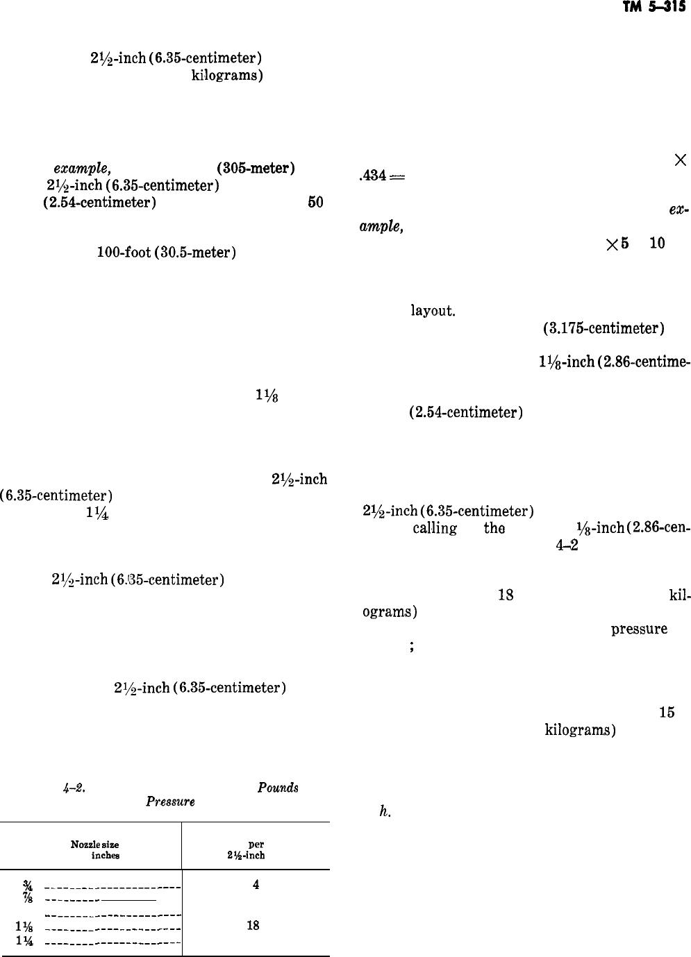
TM
!i-315
grams) of friction loss for every 100 feet (30.5
kilometers) of
2r/&inch
(6.35-centimeter)
hose. So
there will be a lo-pound (4.5
ki’lograms)
pressure
loss for each 100 feet (30.5 meters) of hose in use.
Adding this friction loss to the desired nozzle
pressure gives the engine pressure necessary to
supply the nozzle pressure.
c. For
emmvpZe,
in a l,OOO-foot
(305meter)
lay-
out of
2$$-inch
(6.35-centimeter)
hose, using a
l-inch
(2.54-centimeter)
nozzle and desiring
50
pounds (22.7 kilograms) of nozzle pressure, the
needed engine pressure is easily determined. Since
there are ten
lOO-foot
(30.5-meter)
sections in
1,000 feet (305 meters), with 10 pounds (4.5 kilo-
grams) of pressure loss per 100 feet (30.5 me-
ters) of hose, multiply the 10 sections by 10
pounds (4.5 kilograms) to get the pounds of fric-
tion (100) and add to it the 50 pounds (22.7 kilo-
grams) of nozzle pressure required. This equals
150 pounds (68 kilograms) of engine pressure.
d. If the nozzle size is increased to
llh
inches
(2.858 centimeters), maintaining 50 pounds (22.7
kilograms) of nozzle pressure, the flow of water
increases to 265 gallons (1003 liters) per minute,
with 18 pounds (8.165 kilograms) of friction loss
for every 100 feet (30.5 meters) of
2vz-inch
(6.35-centimeter)
hose. If the nozzle diameter is
increased to
lib
inches (3.175 centimeters), the
flow increases to 325 gallons (1230 liters) per mi-
nute, and the friction loss increases to 25 pounds
(11.34 kilograms) for every 100 feet (30.5 me-
ters) of
2$!&inch
(6.‘35-centimeter)
hose.
e. Friction loss for the five common nozzle sizes
at 50 pounds (22.7 kilograms) of pressure is cal-
culated in table 4-2. Every pump operator should
memorize this table so that he can tell at once how
much engine pressure is required for any type of
layout that uses
2ih-inch
(6.35-centimeter)
hose.
f. When hose is laid or advanced to a level
above the discharge outlet of the pump, the water
in the hose exerts a pressure against the pump,
Table
&.%
Friction Loss of Nozzles at 50
Pow&
of
Pr.essure
Nozzle
size
in
inch8
Approximate friction loss
in pounds
per
100 feet
of
2?44nch
hose
q!&
----_____-------------
4
78
---------
8
1
--_______--------_-___
10
1%
----____--------------
18
1%
----____--------------
25
known as back pressure. This back pressure is
determined by multiplying the height above the
pump discharge outlet, in feet (0.305 meter), by
0.434, which is the pressure in pounds per square
inch (6.45 square centimeters) created by 1 foot
(0.305 meter) of water. In the army, each story of
a building is considered as 12 feet (3.66 meters),
so the back pressure for each story would be 12
)(
434
=
5.208 pounds (2.36 kilograms per 6.45
square centimeters), or approximately 5 psi
(0.366 kilogram per square centimeter). For
en
cmpZe,
if the hose is advanced to the third story,
which is two stories above the first, 2
x
5
or
10
psi
must be added to the pump pressure to compen-
sate for the back pressure. The nozzle size that
should be used is determined by the total length of
a hose
layo,ut.
In a short layout (up to 600 feet
(183 meters) a lx-inch
(3.175-centimeter)
tip
may be used. In a medium layout, 600 to 900 feet
(183 to 274.5 meters), a
lys-inch
(2.86-centime-
ter) tip is used. A long layout, 900 feet or over
(274.5 meters), ordinarily requires the use of the
l-inch
(2.54-centimeter)
tip. The tip size, how-
ever, may be changed at the discretion of the sen-
ior firefighter.
g. To illustrate all the preceding points, set up a
situation involving 700 feet (273.5 meters) of
2i/z-inch
(6.35-centimeter)
hose. This is a medium
layout,
cahing
for
tha
use of a 1 ?/‘-inch
(2.86-cen-
timeter) nozzle. From table
L2
it is known that
the friction loss factor of hose and nozzle is 18
pounds (8.2 kilograms) per 100 feet (30.5 meters).
Seven multiplied by
13
equals 126 pounds (57
kil-
ogram,s)
of friction loss; to this add the 50
pounds (22.7 kilograms) of nozzle
pre,ssure
re-
quired
;
the result is a required engine pressure of
176 pounds (80 kilograms). If the hose is taken
up to the fourth floor, three floors above the first,
multiply 3 by 5 (pounds) to get 15 pounds (6.8
kilograms) of back pressure. Then add this
15
to
176 to get 191 pounds (87
kilogram,s)
as the total
engine pressure required. For all practical pur-
poses the answer 191 would be rounded off to 190,
or the nearest figure divisible by 5.
h.
One of the most important factors that deter-
mine success or failure in combating structural
fires is the effectiveness of the fire stream. A weak
stream generally will not reach the objective. Too
much pressure will cause a stream to break up
and lose its effectiveness. It has been determined
that 50 psi (22.7 kilograms per 6.45 square centi-
meters) nozzle pressure will, in most cases, result
in a good effective stream. If the chief or crew
4-7

TM
ii-315
chief in charge decides that less or more pressure
is needed, he will order or signal the pump opera-
tor to decrease or increase the pressure. The
pump operator should, however, set the initial
nozzle pressure at
50
psi.
Z.
The pump operator of a structural
pumper
must be thoroughly familiar with all the equip-
ment on the truck. He must know how many
lengths of hose there are in each layer in the hose
bed. When hose has been laid from the truck, the
operator should be able to determine
blow
much
hose was used in the lay by glancing at the hose
remaining in the hose bed. (Only an approximate
estimate is necessary.) The pump operator can, by
glancing at the nozzle tips remaining on the truck,
determine what size nozzle tip is to be used.
Knowing the amount of hose laid and the size of
the nozzle tip, the pump operator determines what
pressure must be maintained at the pump to pro-
duce 50 psi at the nozzle by referring to the pump
operator’.s
guide plate (fig.
4-1).
4-17. Pump Operator’s Guide Plate
Most structural pumpers employed by the army
are equipped with a pump operator’s guide plate
installed on the left side of the pumper directly
over or near the pump operator’s controls.
a. This plate (fig. 4-1) lists the pump pressures
required to maintain a desired
nlozzle
pressure for
different size nozzle tips and hose lengths and is
used merely as a guide by pump operators.
b.
To read the guide plate, a pump operator
must understand what is meant by “changeover
valve” and what occurs within the pump when the
valve is placed in either of two positions.
c.
He must understand that the only pumps
equipped with a changeover valve are
multiple-
stage pumps. The Class 530B or
63OC
pumper,
-
Figure
4-1.
Pump operator’s guide
plute.
used by the army, have a single stage pump, how-
ever a two-stage pump is planned for the future.
The two stage pump has two sets of impellers
which operate from a single shaft. When the valve
is placed in the “parallel” or “volume” position,
the water entering the pump on the intake side is
divided and delivered to both sets of impellers
simultaneously. Then, as the impellers force the
water out of each impeller housing, the two mass-
es of water joins together before emerging from
the discharge outlet. When the valve is placed in
the “series” or “pressure” position, the water en-
tering the intake side is delivered to one impeller,
which forces the water through an outlet (orifice)
to the other impeller which in turn forces it out at
increased pressure through the discharge outlet,
d. The heavy zigzag line running down across
the guide plate shows pressures required. This
line divides the chart in half and is not to be
considered when operating a single-stage pump.
However, when operating a two-stage pump with
a changeover valve and when pumping at a pres-
sure listed to the left of the heavy line, be sure
that the changeover valve
i,s
in the volume or par-
allel position. If pumping at a pressure listed to
the right to the heavy line, see that the change-
over valve is in the pressure or series position.
Note that the pressures given in the chart are
actual pressures, and that
.the
pressure gages on
various pumpers will vary in calibration. They
may be calibrated in 2, 5, 10, or 50 psi. The policy
is to set the pump pressure to the nearest calibra-
tion of the gage on that specific truck.
-
Section
Ill.
HOSE,
iADDER,
AND PUMPER DRILLS
4-18. Introduction
b.
In the firefighting drills, each crewman has a
Hose,, ladder, and pumper drills performed under series of assignments which must be quickly
car-
simulated fire conditions train firefighting
person-
ried out in a precise manner and at the proper
nel for an actual emergency. time. These assignments involve laying out the
a. The drills must be varied so that all the
fire-
hose, putting the pump into
operatilon,
and
erect-
protection equipment on the firefighting vehicle is ing ladders on buildings. Since hesitancy on the
used. These drills must be constantly practiced part of a crewman could
cau.se
serious delay, and,
until the proficiency of both individual and crew in turn, serious fire damage and loss of life, these
in all the duties to be performed reaches a high hose, ladder, and pumper operations must be
un-
level. After a high degree of skill is achieved, derstood and practiced until each man can execute
refresher drills must be carried out to retain it. them
wfihout
a moment’s hesitation.
-

TM
5-315
c..
It is difficult to specify a fixed procedure for
drills, because of such variables as the aptitude of
1
the crewmen, the frequency and intensity of
training periods, and the conditions peculiar to
each fire emergency and to each individual instal-
lation. Some general standards can be set up,
however, although assignments will vary with
each emergency.
4-19.
Special Purpose Rolls and Folds
When hose is used in a very
lar,ge
or high build-
ing, it is normally operated from a building
stand-
pipe system. This is a system of piping with out-
lets on each floor. A pumping engine should pump
into this system to assure enough pressure for
effective streams. As mentioned under the section
on unlined fabric hose, the fire department ad-
vances its own hose from building standpipes.
Where standpipe systems exist, hose should be
carried that can be taken through
door,s,
on eleva-
tors, and up stairways quickly. This hose
sh’ould
be compactly rolled or folded in such a way that it
can be placed in service very quickly. Certain
methods of rolling and folding hose are well
suited for this use. Hose carried in these rolls and
folds is also useful for extending lines or replac-
ing burst lengths of hose. Often a carrying pack is
employed which also contains wrenches, adapters
to non-fire service threads on standpipes, and
other tools.
a. The Donut Roll. The donut roll forms a
compact roll with both couplings accessible. The
hose will pay out quickly and easily, even with
both couplings coupled, and does not kink. To
form a donut roll lay the hose out flat (fig.
4-2),
and pull the male coupling back so the hose is
doubled back on itself, with the male coupling
about 3 to 4 feet (approximately a meter) from
the female. Stand at the folded end, and face the
fol’ded
end with one foot on each side of the hose.
Leave enough space in the fold to place one hand
through the roll for carrying. Roll the doubled
hose (fig.
4-2),
keeping the top and bottom por-
tions
alined
with your feet as you back up. When
the roll is completed the male coupling should be a
foot
(0!,3
meter) or so behind the female coupling,
protected by the hose behind the female coupling.
This protects threads from damage, or the nozzle
if one is carried
preconnected.
If the roll is not
exactly
alined
it can be flattened by laying it on
the floor and stepping on it. If a second man is
available to help in forming the donut roll, he can
keep the hose
alined
and take up slack in the top
portion by pulling on the hose behind the male
coupling. The first man would then face the cou-
pling end to make the roll.
b.
The Double Donut Roll. The double donut roll
can be made up with two lengths of hose, and can
also be used for a
sin,gle
length where carrying
space makes a smaller but wider roll desirable.
Tlo
roll a double donut with two lengths of hose (fig.
4-3),
couple them together and lay the lengths
flat, next to each other. Fold the loop that results
at the coupled
,couplings
back onto the
hjose.
Lea.v-
ing enough room for a hand hold, roll the hose
toward the uncoupled couplings.
c.
Self Locking Start for Donut or Double
Donut Roll. The self locking start for donut rolls
(fig. 4-3) will hold the roll in place when it is
handled, and provides a
han,dle
for carrying. To
form this feature the end fold or loop is brought
out about
18
inches
(r/s
meter) on each side of the
flat hose before the roll is started, folding it in
once toward the couplings and laying it flat on the
hose. When the roll is completed the loop left ex-
posed on one
si,de
is passed through the other loop
(fig. 4-4). By pulling
Ion
the hose that passes
through the roll the second or locking loop is
tightened. The roll can be carried by the first loop.
To put the roll in service the loops are first disen-
gaged.
d. The Flat Single Length Fold. A single length
of hose can be folded
clompactly
by laying the
length flat (fig.
4-5),
then bringing the couplings
together on top of the hose and engaging them a
few turns to insure they remain coupled. Fold the
hose in from each end to within about a foot (0.3
meter) of the couplings, then fold one side over
the other. Couplings are protected from damage.
The hose can be carried easily and put in service
quickly.
e. The
Stcmdpipe
Pack.
If a canvas, plastic, or
leather bag is available, the hose can be accordion
folded into it with couplings accessible. When the
hose is coupled to the standpipe or the line to be
extended, the line pays out from the bag
(‘fig.
4-6). This bag can also serve to carry a spanner
wrench and adapters for use if
stan,dpipes
have
non-fire service threads. A nozzle is usually carried
connected to the line and often a gated wye is
connected to the standpipe end of the hose. Hose
appliances made of lightweight materials and
hose of lightweight
constructijon
should be used
for this purpose if available.
4-9
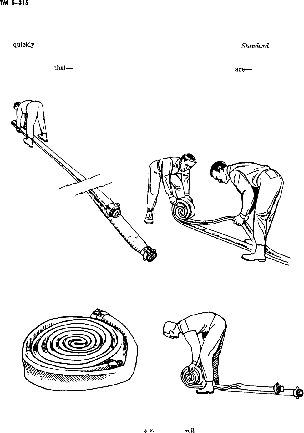
TM
5-315
4-20. Hose loads layers beneath, and become tangled.
a. Use of Standard Methods. Hose carried on (3) Hose will not be subjected
fire apparatus is loaded so that it can be put to sharp bending than is necessary. to any more
-
use
quiokly
and easily at the scene of a fire. It
must pay out from the hose bed smoothly, without
kinking. Standard methods of loading hose beds
are used to assure
that-
(1) Hose will pay out easily, without binding.
(2) Layers of hose will not settle into the
b. Determining Which
Stano!urd
Load to Use.
Several factors determine which of the standard
loads should be used in a particular situation. The
most important of these
are-
(1) The size and shape of the hose bed.
(2) The amount of hose to be loaded.
FORMING THE DONUT ROLL. FORMING THE DONUT ROLL WITH TWO MEN,
COMPLETED DONUT ROLL. DONUT ROLL PARTLY COMPLETED.
Figure
@A
The donut
~011.
4-10
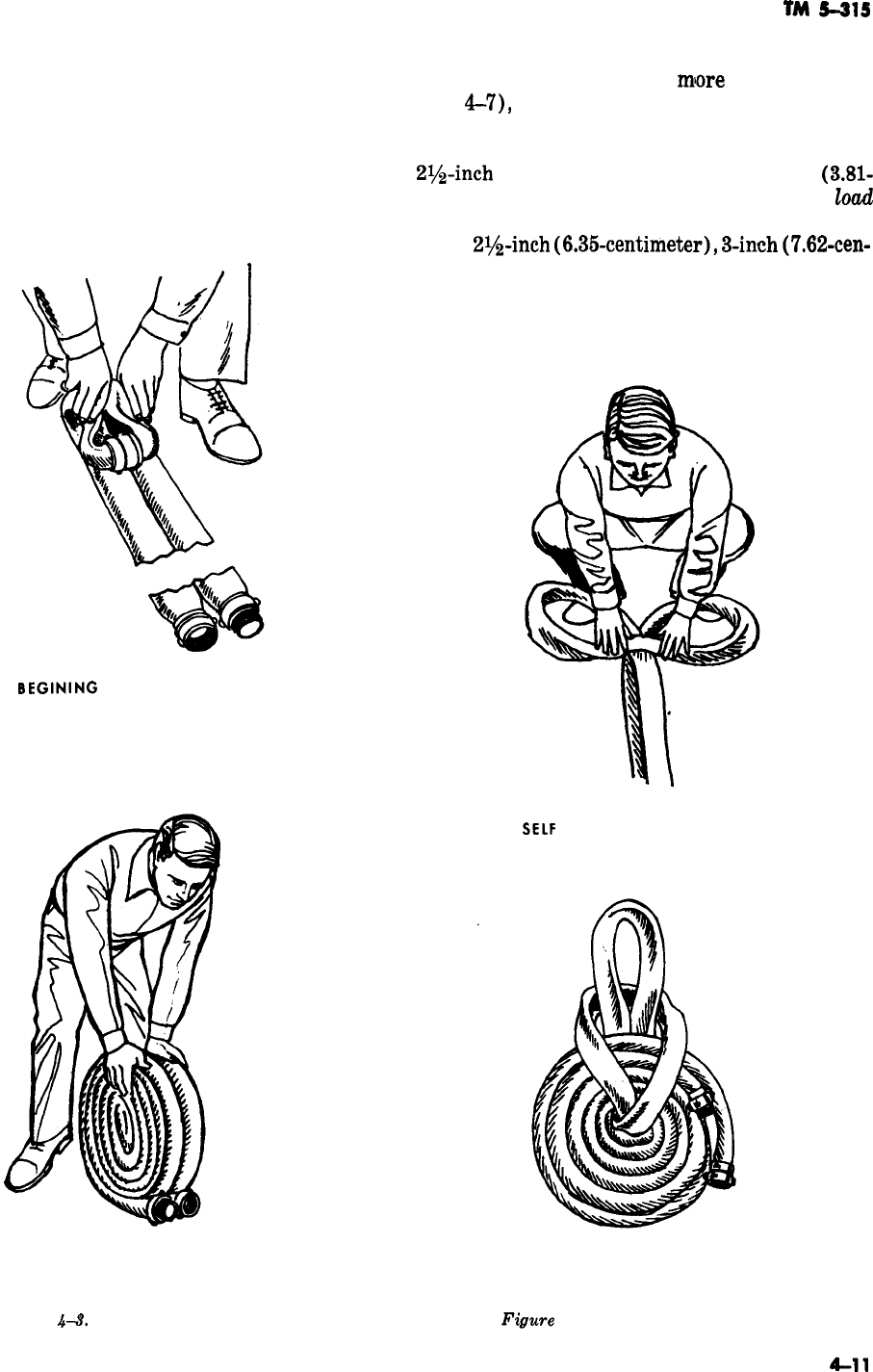
(3) The purpose for which the hose will nor-
mally be used.
-
(4) The water system or location of drafting
sources in the area.
4-21. Apparatus Hose Beds
a. Divided Bed. Most hose carried on apparatus
is loaded in a bed which is open to the rear of the
TM
s-al5
apparatus. To increase efficiency, beds are nor-
mally divided into two or
miore
compartments
(fig.
4-7),
either by built-in partitions or by plac-
ing boards (baffle boards) in the bed as hose is
loaded. Separate compartments are provided for
2%-inch
(6.35centimeter) and lx-inch
(3.81-
centimeter) hose (fig. 4-8). The term divided
Zoad
is used to describe a load in which the larger size
hose,
Z?Jz-inch
(6.36-centimeter),
3-inch
(7.62-cen-
timeter) or larger, is divided so that two or more
lines can be laid with a single movement of the
apparatus. This is an advantage when the quan-
tity of water to be moved is too great for a single
line.
BEGINING
THE DOUBLE DONUT ROLL.
FORMING THE
SELF
LOCKING START FOR A DONUT ROLL.
COMPLETED DOUBLE DONUT ROLL. COMPLETED DONUT ROLL WITH SELF LOCKING
Figure
4-3.
The double donut roll.
Figwe
4-4. Self locking donut roll.
LOOPS.
4-11
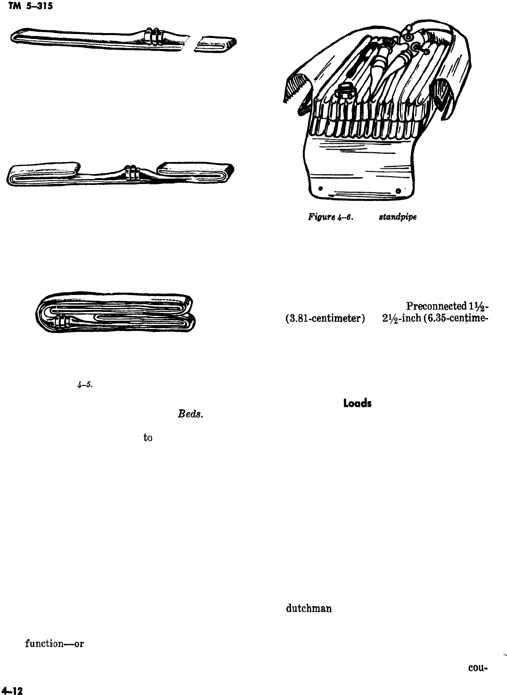
BEGINNING THE SINGLE LENGTH FOLD.
SECOND STEP IN FORMING A SINGLE LENGTH FOLD.
Figwe
4-6.
The
standpipe
pack.
COMPLETED SINGLE LENGTH FOLD.
Figure
.&5.
The single length fold.
b. Cross Body or Transverse Hose
Beok.
These
beds are provided on some apparatus for attack
lines, which can be taken off
to
either side. They
are usually located behind the cab and can be
reached quickly by men riding in or behind the
cab. The lines are usually connected to a swivel
fitting in the middle of the bed, which connects to
piping from the pump. This allows the line to be
taken from the side of the apparatus directly to-
ward the fire, if there is room for both the engine
and a ladder truck in front of the building on fire.
Disadvantages of cross body hose beds include in-
terference with the pump operator’s use of the
pump panel, and the short length of the bed,
which is less than the width of the apparatus.
Hose loaded in such beds has more sharp bends
than where a longer bed is used.
4-22. Functions of Hose lines
The
functilon-or
purpose for which normally
used-of a hose line determines how it is loaded
and what type of hose is used. Lines that are
-
normally used for supplying water to pumping
engines, building sprinkler systems, or nozzles
and master stream devices at major fires must be
large enough to move large volumes of water
efficiently. They should be capable of being laid by
movement of the apparatus.
Preconnected
1$4-
inch
(3.81-centimeter)
or
2r/z-inch
(6.3%centime-
ter) attack lines, with nozzles attached and con-
nected to piping from the pump, are designed to
be put in operation quickly with the apparatus
placed near the involved building. They are
stretched by hand.
_
4-23. Standard
laads
The methods used by fire departments for loading
hose on main hose beds of a fire truck are the
accordion load, the flat load, and the horseshoe
load. These loads can be packed tight enough by
hand to keep the layers from settling into each
other as apparatus travels over the road. Tools
such as bars and spanners should never be used to
pack hose. This could result in damaging the hose,
and in loads too tight to pay out easily. When
loading hose it is important to locate couplings so
they will pay out without turning in the bed.
Turning couplings can wedge in the bed and may
also fly up and injure men on the back step. To
locate couplings properly, it is sometimes neces-
sary to use a short fold when loading the bed.
This is called a dutchman. The method for form-
ing a
dutchman
is described under each of the
standard loads. In beginning a load the coupling
that is loaded first-and will be the last off-is
placed at the rear corner of the bed so it can be
seen when the load is completed. When a divided
-
bed is used it is possible to connect the top
cou-
4-12
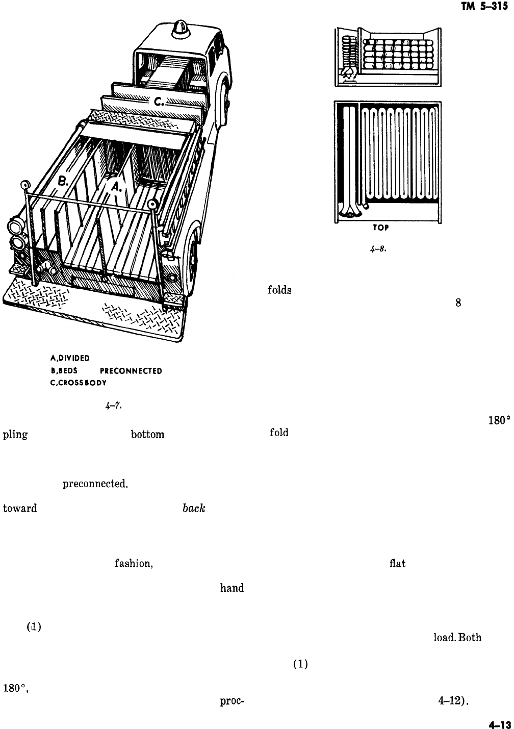
END VIEW
A,DlVlDED
MAIN BED
B,BEDS
FOR
PRECONNECTED
HOSE
C,CROSS
6ODY
OR TRANSVERSE REDS
Figure
4-7.
Hose beds.
pling
in one bed with the
bott,om
coupling in the
next, so that a single long line can be laid without
stopping. If the hose is not crossconnected, the
visible coupling will show at a glance that the
hose is not
preconnected.
In describing the var-
ious loads, the front of the hose bed is the end
towar#d
the apparatus cab, and the
back
or rear
the end at the back step.
a. The Accordion Load. The accordion load con-
sists of folding the hose back and forth lengthwise
in the bed accordion
fashi,on,
with the hose on
edge. The main advantage of this load is the ease
with which shoulder loads can be formed for
han,d
stretching lines. Its principal disadvantage is that
it places many sharp bends in the hose.
(11)
To form an accordion load, place the first
coupling in the rear of the bed, next to the parti-
tion or baffle board that will separate the two
parts of the main hose load (fig. 4-9). Take the
-
hose to the front of the bed, standing on edge, fold
MO’,
and bring it to the rear alongside the first
fold. Again fold 180 degrees and repeat the
proc-
YOP
VIEW
Figure
.&8.
Divided bed.
ess. As each end fold is formed, stagger alternate
fol,ds
with the first all the way to the end of the
bed, and the next 2 or 3 inches (5 to
8
centime-
ters) short of the end. This keeps folds from
coming directly opposite each other, which would
make the ends fill up faster than the middle of the
bed and would also make the folds sharper.
(2) To change the position of a coupling with
a dutchman, take a short fold in the hose (fig.
4-10). This assures that the coupling will not turn
in the truck bed when paying out.
(3) When a layer is complete, the last 180’
fol,d
at the rear of the hose bed is made in the
opposite direction of the other folds (fig. 4-11).
This prevents kinking when the hose is laid. The
hose is then tucked between the two previous
folds and taken to the front of the bed, rising
gradually to the top of the first layer at the front
of the bed. It is then either brought straight back,
beginning the next layer, or carried across the
front of the bed to begin the second layer on the
same side as the first.
b. The Flat Load. The
flat
load consists of fold-
ing the hose back and forth lengthwise in the bed,
with the hose flattened (fig. 4-12). It pays out
very easily and produces a straighter lay than the
accordion load. However, it is more difficult to
form shoulder loads for hand stretching from the
flat load than from the accordion
loa,d.
l3oth loads
have many sharp bends in the hose.
(1)
To form a flat load, place the first cou-
pling in the rear corner of the bed next to the
partition or baffle board that separates the two
parts of the main hose load (fig.
&12).
Lay the
4-13
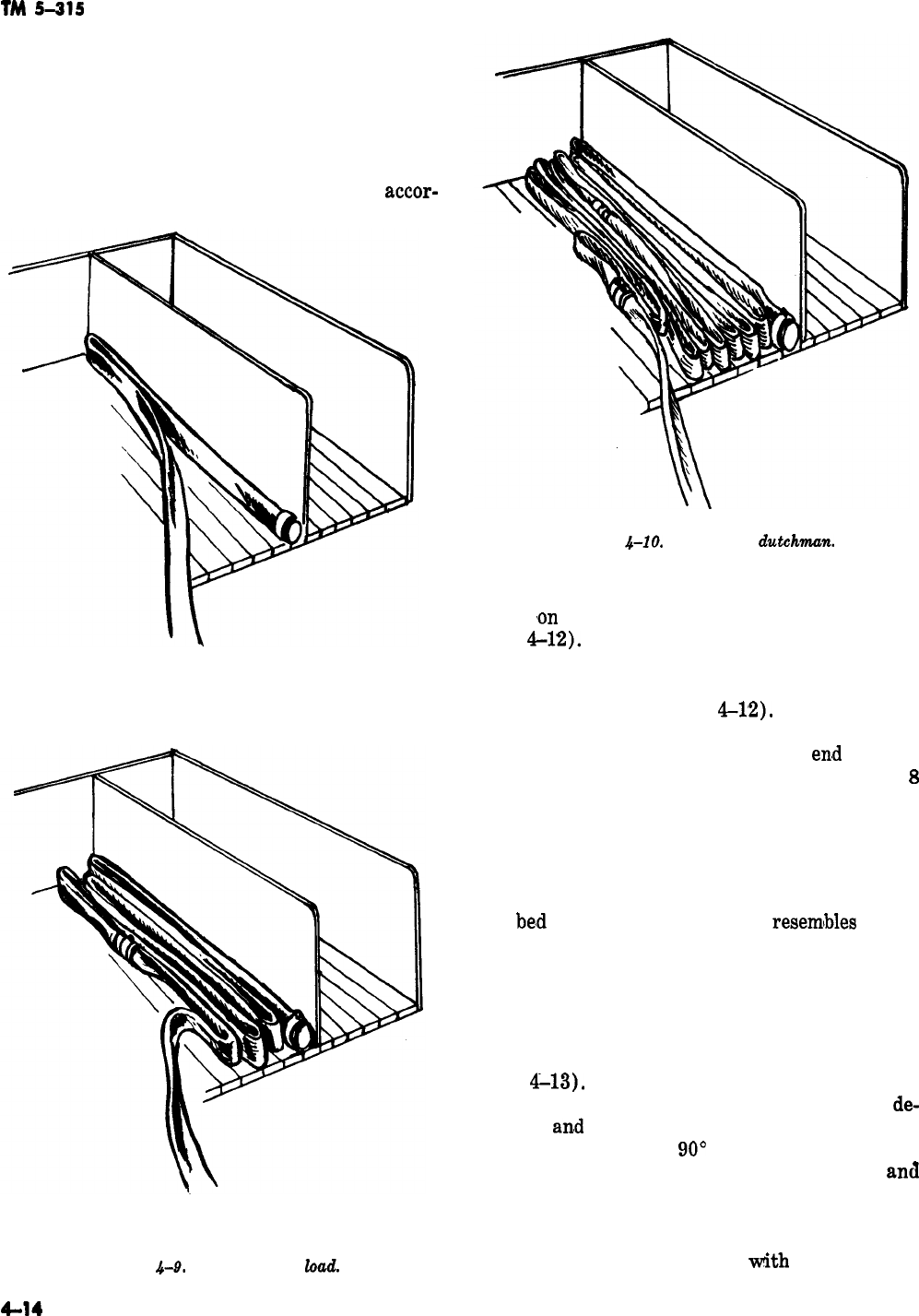
TM
5-315
hose to the front of the bed, fold it 180 degrees,
and bring it to the rear at a slight diagonal to
place the second fold next to the first coupling.
Fold 180 degrees and repeat the process. Keep the
end folds even.
(2) To change the position of a coupling,
make a short fold (dutchman) as with the
accor-
Figure
4-10.
Forming a
clutchmun.
BEGINNING THE ACCORDION LOAD
FORMING THE ACCORDION LOAD NOTE STAGGERED FOLDS.
Figure 4-9. The accordion
&ad.
dion load, except that the fold will be doubled
back
,on
itself rather than placed next to itself
(fig.
4-12).
(3) When the first layer is complete, begin
the second by laying the hose diagonally in the
opposite direction (fig.
4-1’2).
The layers are
formed in the same manner as the first layer,
except that in alternate layers the
en,d
folds at
each end are staggered by 2 or 3 inches (5 to
8
centimeters) so that the bends will be less sharp
and the ends will not fill up faster than the middle
of the bed.
-
c. The Horseshoe Loud. The horseshoe load con-
sists of hose loaded around the sides and front of
the
be,d
so that its shape roughly
resemlbles
that of
a horseshoe. It has the advantage of less sharp
bends in the hose, but does not lend itself readily
to forming shoulder loads for hand stretching.
(1) To form the horseshoe load, place the
first coupling next to the partition or baffle board
that separates the two parts of the main hose load
(fig.
4-13).
Lay the hose to the front of the bed
with the hose lying on edge, fold the hose 90
de-
Agrees,
an,d
lay it across the front of the bed to the
opposite side. Make a
90’
fold and lay the hose to
the rear of the bed. Then fold it 180 degrees
amI
repeat the process. Stagger the 180 degree folds
at the rear of the bed as shown in figure 4-13.
(2) Coupling positions can be changed by use
of a short fold (dutchman) as
tith
the accordion
-
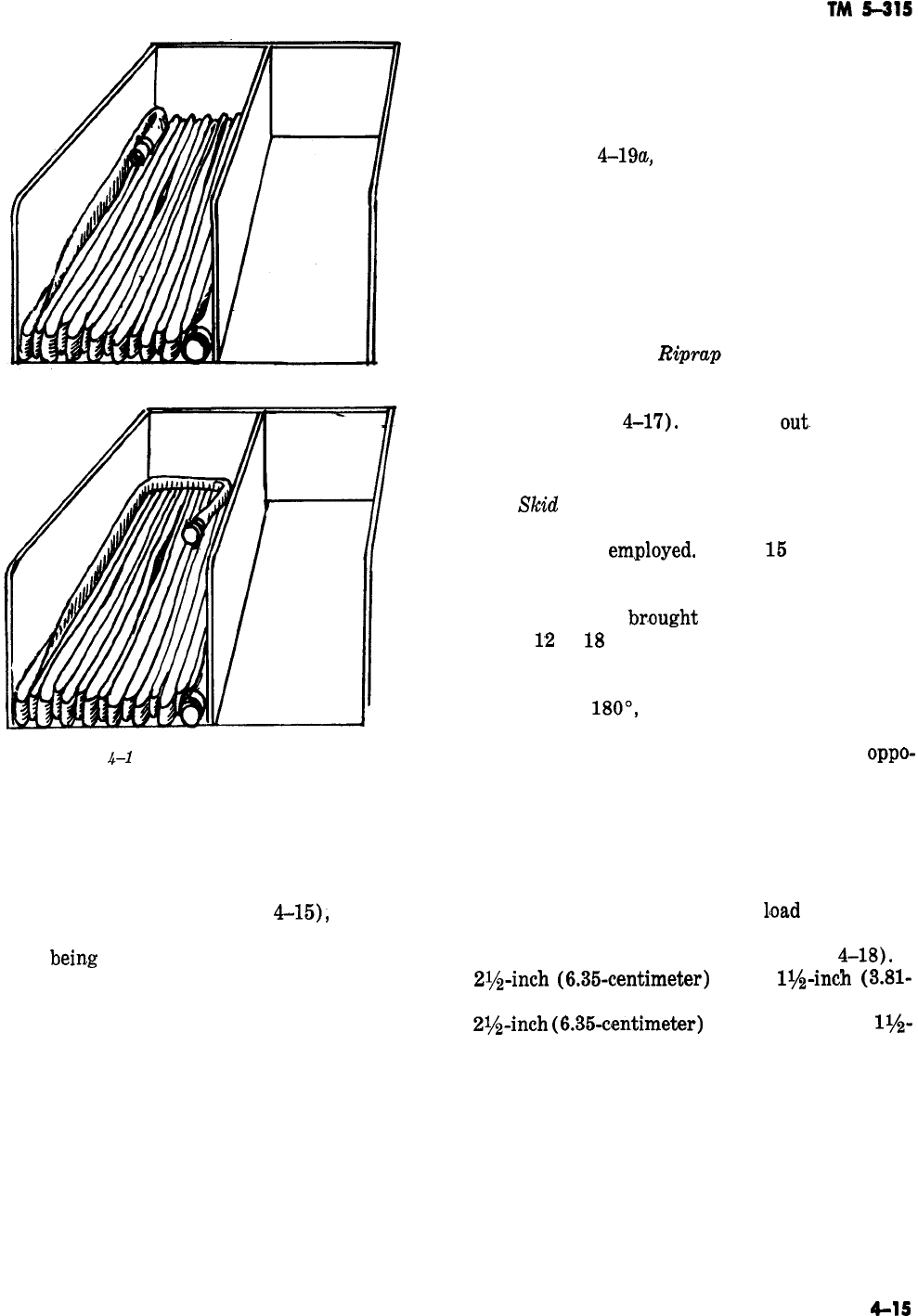
-
Figure
A-1
1. Two methods of starting
second layer of accordion load.
load or by taking an extra fold across the front of
the bed (fig. 4-14).
(3) A new layer is started by bringing the
hose to the rear of the bed (fig. 4-15), across the
end of half of the layer, and then gradually rising
as it is
bein.g
brought to the front of the bed. An
alternate method (fig. 4-15) may be used in which
the last fold of the layer toward the front of the
bed is brought up, laid flat, and placed diagonally
to a front corner. Then the hose is folded to bring
it up on edge and laid in the same way as the
layer laid previously.
4-24. Hose load Finishes
Hose load finishes have two primary purposes-to
provide hose line at the fire area with a minimum
amount of effort ‘and for convenience in hooking
up to a hydrant. The finishes must provide a
loosely loaded hose that will pull off the truck and
pay out easily. The method adopted is governed by
the local conditions and the preferences of the fire
chief.
a. The Donut Finish. The donut roll, described
in paragraph
4-19a,
can be used to finish a hose
load (fig. 4-16). It provides 50 feet (15 meters) of
hose to facilitate hoooking up to a hydrant or
advancing attack lines. When a load is finished
with a donut roll a second length of hose is
usually placed (flaked) loosely back and forth
across the top of the load so the donut can be
carried off easily.
b. Cross Fold or
Riprap
Finish. This finish
consists of loading the last length or two in a
loose accordion fashion across the hose bed on top
of the load (fig.
4-1’7).
It will pay
out-
freely, and
a bundle can be grasped under the arm when step-
ping off to catch a hydrant.
c.
ShSd
Load Finish. The skid load is used to
finish a load for working attack lines when the
reverse lay is
em,ployed.
About
16
feet (4.5 me-
ters) of hose is loaded starting at the front of the
bed with a cross fold (fig. 4-18). The hose is then
turned flat and
br,ought
to the rear of the bed
about
1’2
to
18
inches (30.6 to 46 centimeters)
from the side of the bed. It is allowed to hang
over the rear edge of the load about a foot (30.6
centimeters)
MO’,
and taken back on itself to the
front of the bed. Here it is folded to run at a right
angle to a point the same distance from the
oppo-
site end of the load, folded again, and brought to
the rear and back to form a second skid (fig.
4-18). At the front of the bed the hose is brought
up on edge and loaded in a cross fold on the two
skids (fig. 4-18). The ends of the cross fold are
kept 3 to 6 inches (7.6 to 15 centimeters) from
the sides of the hose bed so the
l’oad
will not dis-
lodge when laying out. A nozzle can be attached
and placed on top of the cross folds (fig.
4-18).
A
2$$-inch
(6.35-centimeter)
by
ll,&nch
(3.81-
centimeter) reducing wye can be coupled to the
2$$-inch
(6.35-centimeter)
hose and a line of
ls-
inch (3.81 centimeter) hose, or two lines folded to-
gether, used to complete the skid load. Care must
be taken that all couplings and appliances used in
the skid load rest on the skids or on top of the
cross fold position.
4-25. Inspection and Maintenance
All hose and fittings should be inspected monthly,
and after each use they should be washed and
inspected again.
4-15
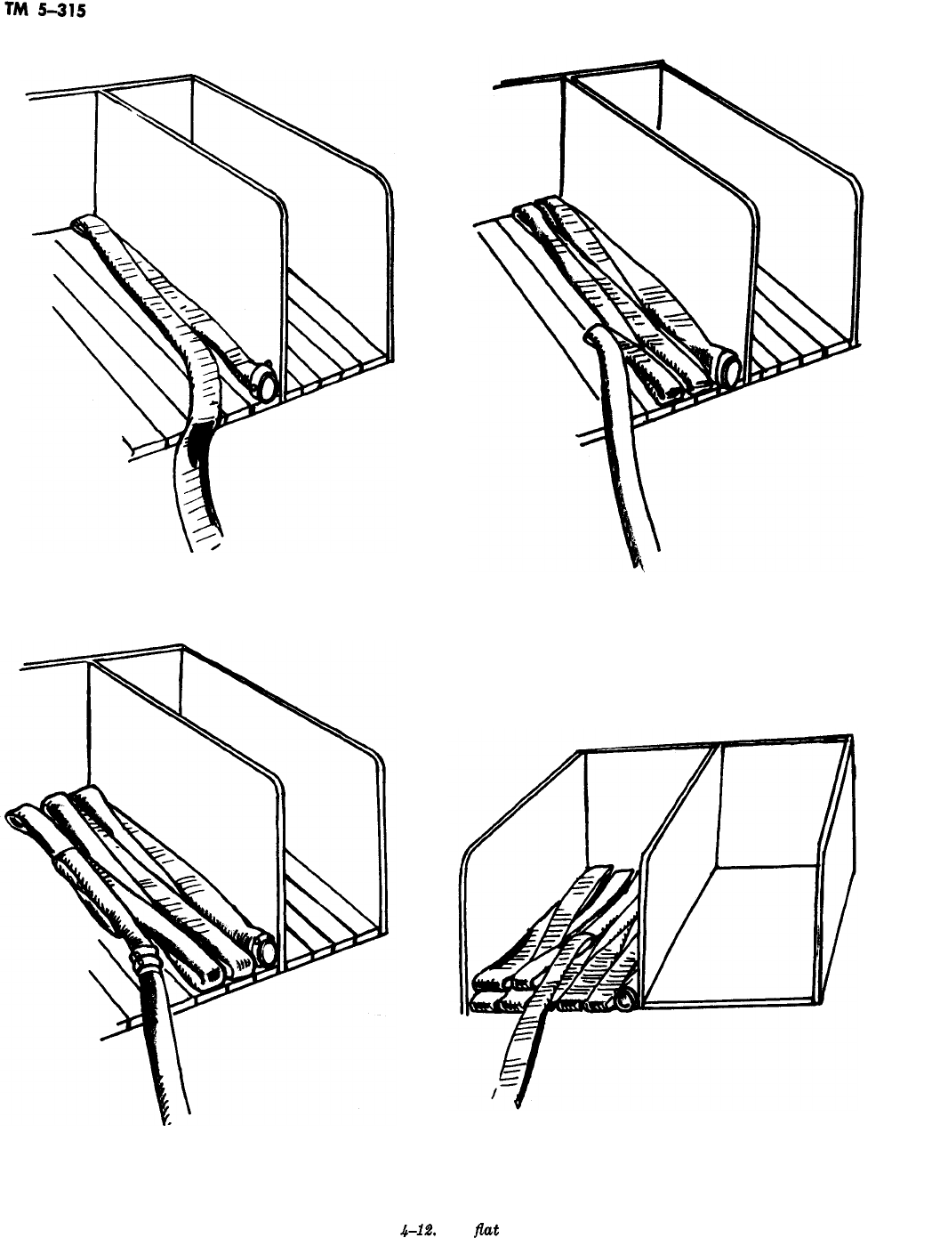
BEGINNING THE FLAT LOAD FORMING THE FLAT LOAD
BY FOLDING THE HOSE BACK ON ITSELF
THE SECOND LAYER NOTE THAT FOLDS ARE STAGGERED
FROM THOSE IN FIRST LAYER
Figure
4-12.
The
flat
load.
4-16
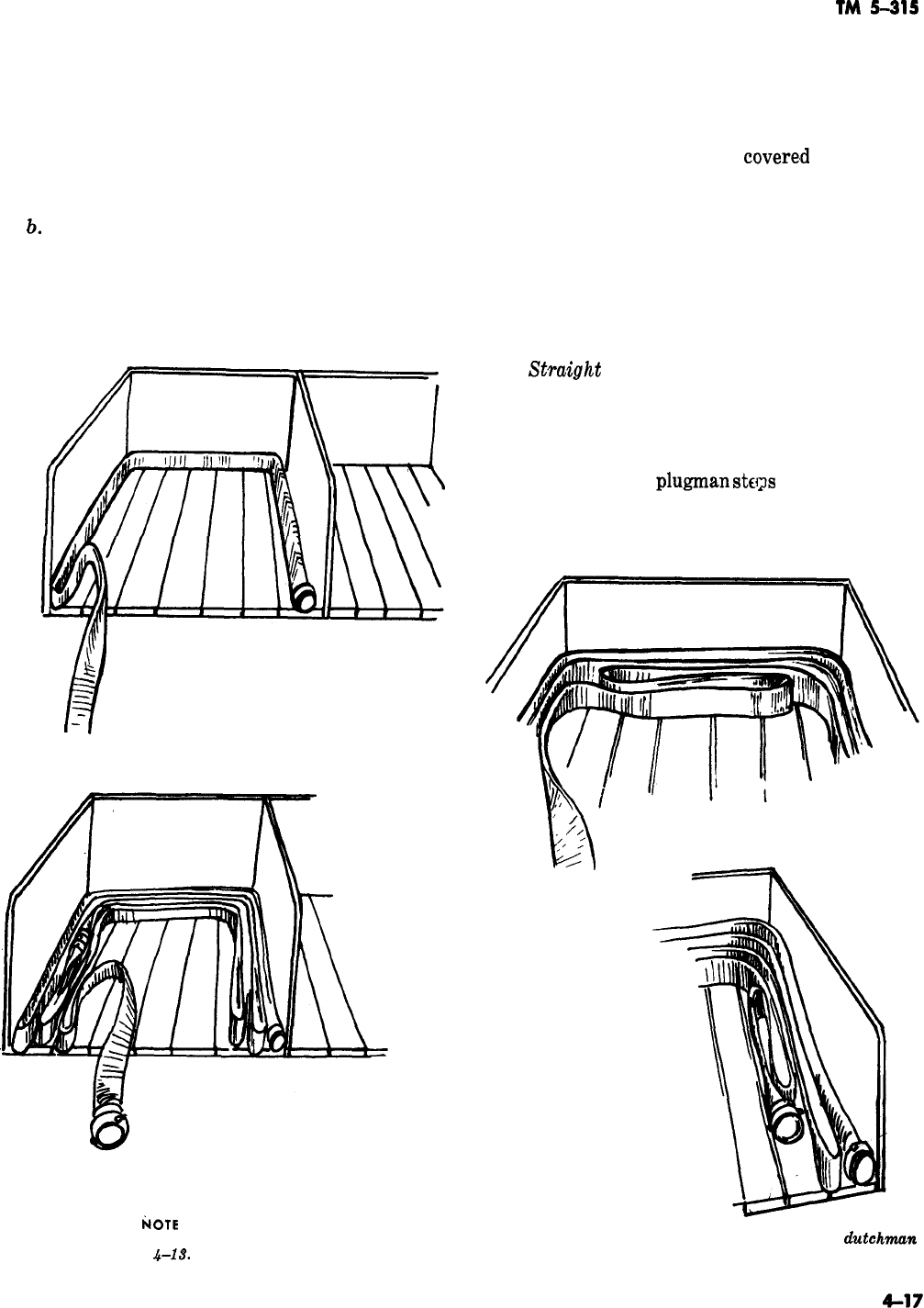
TM
5-315
a. When inspecting hose, go over the jacket
thoroughly for breaks or worn spots. Look closely
-
where the hose enters the coupling to see if there
is any sign of the coupling coming loose. Look
inside the coupling for damaged or slipping ex-
pansion rings. Inspect the swivel of the female
couplings for damage.
b.
Any damage to hose should be reported im-
mediately to the crew chief in charge and re-
corded on the hose record card. The threads of
couplings should be cleaned thoroughly with a
wire brush and a small amount of powdered
I-
I
BEGINNING THE HORSESHOE LOAD.
FORMING THE HORSESHOE LOAD.
IkOTE
STAGGERED FOLDS.
Figure
4-13.
The horseshoe load.
graphite or mild soap solution should be applied
to them.
4-26. Hose layouts and Carries
The preceding paragraphs
covere,d
the various
methods of loading hose on a firetruck. Additional
preparation is that of hose layouts and advance-
ment to fires. Time is not so important when load-
ing hose, but the process requires the utmost skill
and cooperation because it is an important factor
in hose layouts. There are only two hose layouts
used in the Army: the straight lay and the re-
verse lay (which is the standard Army hose lay),
a.
Stmight
Lay. The straight lay (fig. 4-19) is
made as follows: On the approach to a fire the
truck stops at a hydrant chosen by the crew chief.
The hydrant should be as near the fire as possible
without endangering the truck or driver, should
the fire spread. The
plugman
stags
off with enough
line, and while he takes a turn around the hydrant
with the hose, the truck proceeds to the fire. The
Figure 4-14. Two methods of forming a
dutchman
with the horseshoe load.
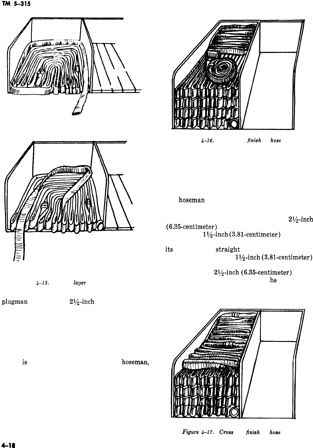
STARTING A SECOND LAYER OF THE HORSESHOE LOAD.
ALTERNATE METHOD OF STARTING A SECOND LAYER.
Figure
&15.
Second
1ayeT
of horseshoe load.
plugman
removes the
2rjs-inch
(6.35centimeter)
cap nearest the fire, connects the hose, removes
the loop that is around the hydrant, opens the
hydrant with his hydrant wrench, and proceeds to
the fire, straightening out kinks or bends in the
hose on the way. When the truck arrives at the
fire, a hose clamp is applied to the hose, and
enough working line (determined by the crew
chief)
i’s
removed from the truck by a
hoseman,
who grasps one or more folds and walks backward
till the loop or loops are clear of the truck. Then
he goes back to the truck and repeats the proce-
dure. He lays each loop nearer the fire. When
enough hose has been removed, he disconnects the
nearest coupling, puts the loose end back in the
truck bed, and connects the nozzle to the hose. He
then removes the hose clamp from the hose. He
can then advance to the fire.
Figure
4-16.
Donut roll
fir&h
for
hose
load.
NOTE
It is a good practice for the driver, if
possible, to stop the truck about 75 to 100
feet (23 to 30.5 meters) beyond the near-
est point to the fire. This will give the
hoseman
that much additional working
line.
The straight lay, particularly if a long
2$&inch
(6.35~centimeter)
supply hose line is used, car
supply only
lr/s-inch
(3.81-centimeter)
hose line:
and the pumper can be used only to a fraction of
itls
capacity. The
str.aight
lay should be used with
caution and only for a
lr/s-inch
(3.81-centimeter)
hose stream fire without possibility of develop-
ment into a
2r/&inch
(6.35~centimeter)
hose
stream fire. The straight lay may
b’e
used under
certain circumstances if a second pumper is posi-
tioned at the hydrant.
Figure
4-17.
Cross
fold
finish
for
hose
load.
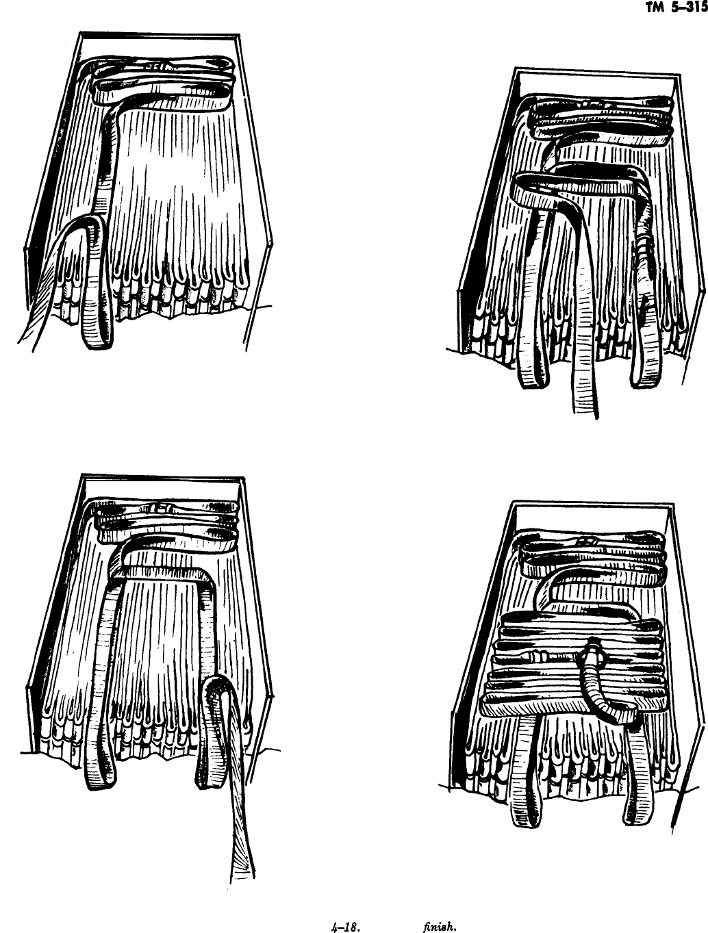
TM
5-315
-
BEGINNING THE SKID LOAD FINISH.
FORMING THE SECOND SKID.
FORMING THE CROSS FOLD PORTION
OF THE SKID LOAD FINISH.
COMPLETED SKID LOAD FINISH FOR HOSE LOAD.
Figure
.b-18.
Skid load
fintih,
4-19
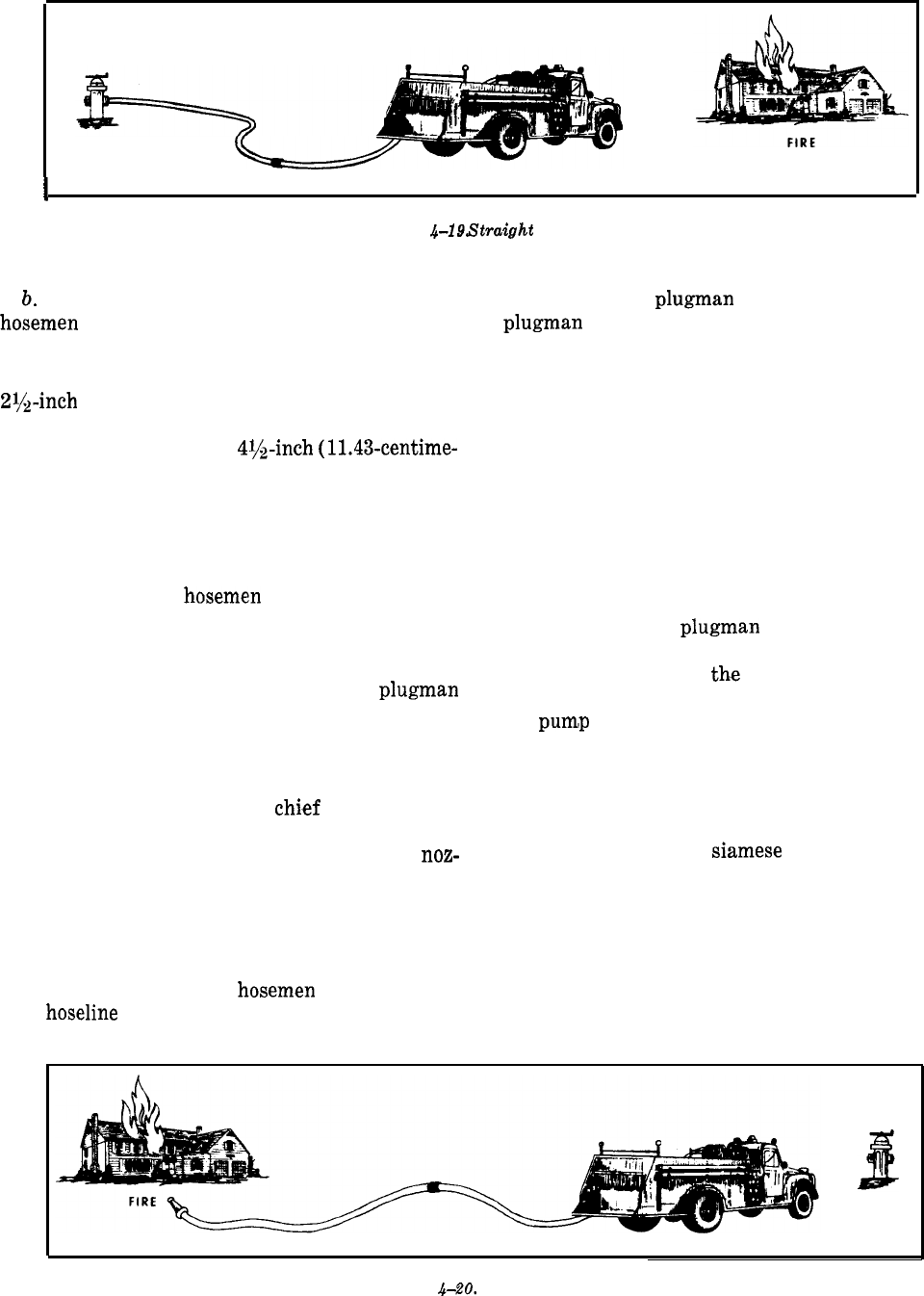
TM 5-315
SUPPLY
SOURCE
Figure 4-19.
5’traight
lay.
b. Reverse Lay. When using the reverse lay, the
hosemen
lay hose from the fire to the hydrant (fig.
4-20).
(1) The pumper can be used to capacity and
2$&inch
(6.35centimeter) hand lines used only
hhen the pumper is positioned at the hydrant and
taking suction through a
4y&inch
(11.43-centime-
ter) hose.
(2) To make the reverse lay, the following
procedures should be used. The truck should stop
75 to 100 feet (23 to 30.5 meters) short of the
nearest point to the fire. (This will give additional
working line.) The
hosemen
remove the working
line by pulling a “skid” or other hose load. When
the working line is removed, the nozzlemen start
advancing the line to the fire. While the nozzlemen
are occupied, the crew chief, driver, and
plugman
remove other equipment that may be needed, such
as ladders (extension and roof), forcible-entry
tools, portable lights, and pike pole. This equip-
ment should be placed off the road and on the fire
side of the truck. The crew
chi,ef
kneels on the
hose line to anchor it as it pays out, and then
proceeds to the fire to aid and supervise the
noz-
zlemen.
The driver and
plugman
remount the truck, the
plugman
riding on the side to avoid injury from
hose and couplings as the load is paying out. Mak-
ing sure that a crew member is anchoring the
hose, the driver drives the truck to the hydrant.
He then puts the pump in gear, dismounts, discon-
nects the hose at a coupling (making sure there is
enough hose to reach the pump), returns the loose
end of the hose to the hose bed, carries the end of
the hose that leads to the fire around to the pump
on the side opposite the hydrant, and connects the
hose to the discharge outlet of the pump. He may,
if necessary, assist the driver in connecting the
suction hose to the hydrant. The hydrant valve is
then opened. The
plugman
proceeds to the fire,
checking the hose line for leaking couplings and
kinks, and reports to
th.e
crew chief. The driver
remains at the pump controls at all times while
the
pum,p
is being used.
NOTE
This procedure is flexible. The crew chief
may have one of the
hosemen
anchor the
hoseline
while he proceeds to the fire.
c. General Principles of Layout. Any crew mak-
ing a layout during drill or actual emergency
must understand the principles of fire hydraulics
in order to compute such things as friction loss.
Hose layouts, such as Siamese operations, may be
carried out during drill periods, depending upon
the potential firefighting demands of the individ-
ual base. In areas where the possibility of exten-
sive fires exists, it may be well to concentrate on
drills containing layouts where large water vol-
umes and pressures may be required. It may be
advisable under these conditions to establish a
I
.-
SUPPLY
SOURCE
Figure 4-20. Reverse lay.
4-20
-
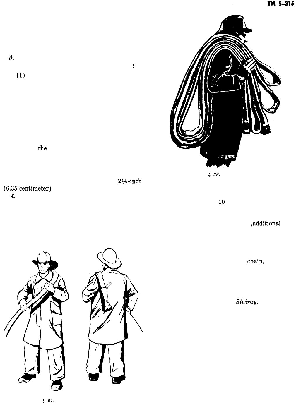
preassigned procedure for each piece of apparatus
where the fire hazard exists. The pieces of appara-
tus which would normally be first in, or first to
arrive at the scene of a potential fire, should be
given priority.
d.
Advancing the Lines. The most commonly
used method of advancing the line is as follows
:
(1)
The nozzleman faces away from the fire,
puts the hose over his left shoulder with the noz-
zle hanging downward at his back, and turns to
the left facing the fire; the hose will extend across
his chest and in under his right arm (fig. 4-21).
He then advances to the fire.
(2) Personnel to the rear of the nozzleman
carry the hose by means of the shoulder carry and
the underarm carry (figs. 4-22 and 4-23). When
using the shoulder carry, the carriers must place
the hose on
the
same shoulder as the nozzleman
uses. The underarm carry is particularly good for
advancing lines at street level. Underarm loads
may be picked up easily and quickly.
e. Advancing Hose up a Ladder. A
2r/z-inch
(6.35-centimeter)
hose should always be advanced
up
(a
ladder with a dry line if possible.
(1) A hose full of water is difficult to move or
maneuver. If the line is already charged, time and
effort are saved if the line is first broken and
drained before any extensive advancement is at-
tempted.
Figure
4-21.
Carrying a hose forward.
Figure
4-22.
Shoulder carry.
(2) In advancing an empty line up a ladder,
the men climb about
10
to 12 feet (3 to 3.7 me-
ters), with the hose on their shoulders and 20 to’
25 feet (6 to 7.6 meters) between them (fig.
4-24). As the operation progresses
,additional
hose
must be fed or passed to the men on the ladder to
prevent the line from becoming fouled. When
enough hose for adequate maneuvering has
reached the desired height, the hose line should be
anchored with a rope hose tool,
ch!ain,
or strap to
a fire well, a window sill or the ladder itself. The
anchor should be made directly below the coupling
to remove the strain of the hose and water weight
from the lineman.
f. Advancing Hose Up A
Stairay.
Hose is diffi-
cult to drag even in an open, unobstructed area,
and it is very difficult to maneuver around ob-
structions, such as those offered by a stairway.
Time and energy may be saved if the hose is car-
ried. The underarm carry is superior for stairway
work under most conditions (fig. 4-25). If the
hose has been properly removed from the appara-
tus, a man can quickly grasp an armful, since it
lies in an orderly position. Again, advancing the
hose is much faster and easier if the line is kept
dry until the fire is approached; this can be done
by keeping the hose clamp in place until the
proper time for its release.
4-21
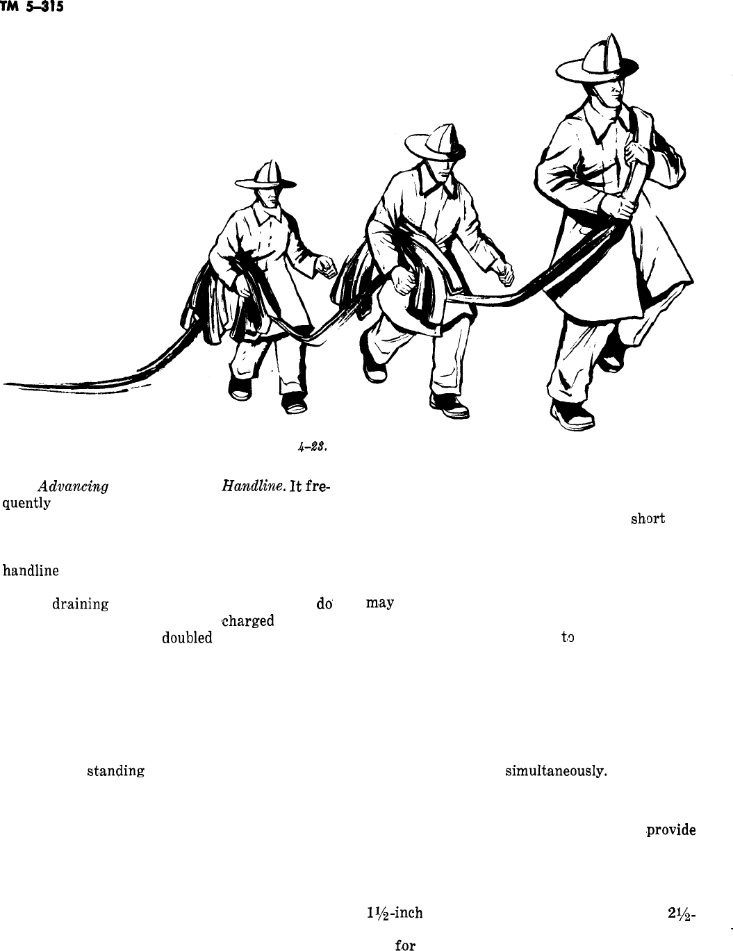
TM
5-215
g.
Advanczhg
Hose With a
Handline.
It
fre-
quently
becomes necessary to take a hose line to
Figure
&28.
Underarm. carry.
an upper window or over a roof parapet with a
handline. The line should be dropped from above
by someone who has already carried the coiled
handline
to the desired level. Hose lines should be
hoisted dry whenever possible, even if this re-
quires
dr,aining
a line. It is usually faster to
a0
this than to attempt to hoist a
tcharged
line. In
hoisting the line, it is
aoublea
back so that the
nozzle is about 4 feet (1.22 meters) from the end
(‘fig. 4-26). A clove hitch is tied around the nozzle
and hose, securing the nozzle a few inches be-
hind the tip, with the standing end of the rope
on the opposite side of the doubled hose from the
nozzle (1). Next a half hitch is taken around the
hose about a foot from the end (2). As the hose is
hoisted, the
st’anding
end of the rope is kept be-
tween the building and the hose if possible, to
prevent unnecessary damage to the hose. A man
on the ground guiding the hose can assist in main-
taining this position.
4-27. Replacing a Section of Hose
A hose line does not normally burst when equip-
ment is properly handled, maintained, and in-
spected. Nevertheless, it happens, and any fire or-
ganization will suffer serious consequences if
4-22
drills and precautions against burst lines are not
undertaken. If a hose bursts, either the ruptured
section of hose must be replaced, or a
sh,ort
line
must be extended; either procedure requires shut-
ting down the line by kinking it (fig. 4-27) or by
using a hose clamp. The hose clamp is normally
used if it is immediately available; if not, the line
m,ay
be kinked behind the coupling to save the
time required to go back to the hydrant. The re-
placement section is brought
t,o
the point where it
is to be inserted, care being taken that the cou-
plings are not dragged, dropped, or damaged in
moving and that the male and female coupling are
placed to make proper connection. Manpower per-
mitting, the ruptured section should be removed
while the replacement section is being carried
from the apparatus. To save time, both connec-
tions should be made
simuItaneously.
----
4-28. lengthening a Hose
Every precaution must be taken to
,provide
enough hose for whatever maneuvering may be
required to reach any portion of the structure
involved in fire or any nearby structures which
may be ignited by the original fire. Frequently,
l$$-inch
(3.81 centimeter) lines are fed by a
2l,,&
inch
(6.35-centimeter
line for confined spaces
and
f’or
overhaul purposes. This requires that the
-
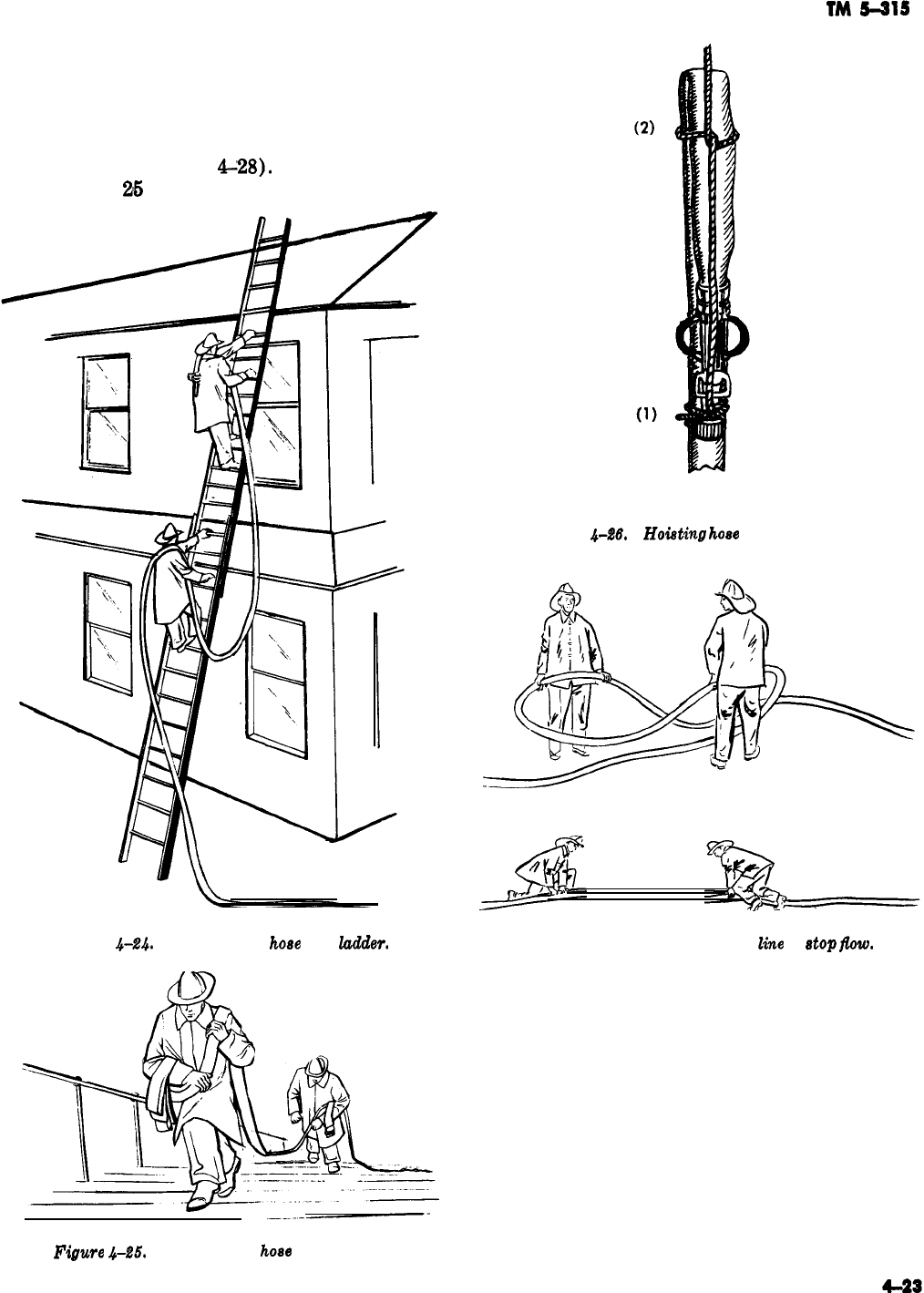
TM
5-215
-
larger line be advanced when necessary and de-
mands surplus or additional lines. When a line
must be lengthened, two men remove two lengths
(or 100 feet (30.6 meters) of hose) from the
truck, and, using the shoulder carry, proceed to
the end of the line (fig.
G28).
When the second
man is about
26
feet (7.6 meters) beyond the end
Figure
4-24.
Advancing a
houe
up a ludder. Figure 4-27. Kinking a hose
line
to atop
fiw.
Figure
4-25.
Advancing a
ho8e
up a stairway.
DRY LINE
Figure
4-26.
Hoisting
hose
with a handline.
of the line to be lengthened, he drops the hose,
lays the coupling on the ground, and goes back to
make the connection. The line is coupled while the
first man continues on, paying off hose from his
shoulder. After completion of the connection,
water is readmitted into the hose when the signal
is given.
4-29. Controlling a Charged line
Working on a ladder sets up unstable conditiona
especially when a charged hose line is being han-
dled. To prevent accidents and conserve efforts,
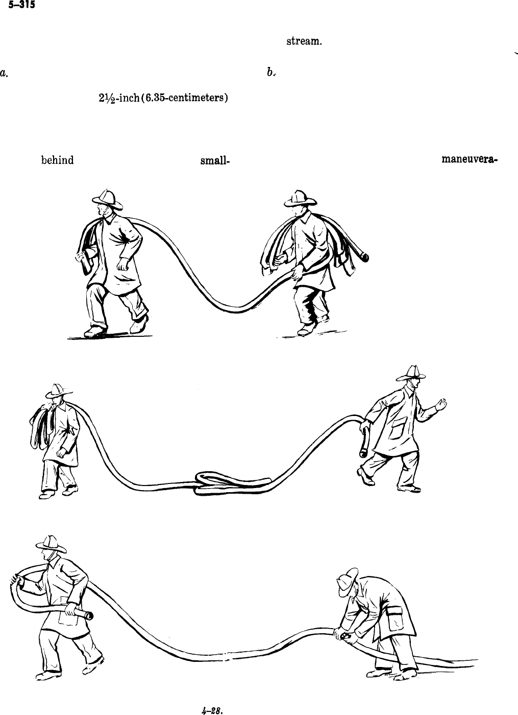
TM
5-315
the hose may be anchored to the ladder with ei-
ther a hose rope, a hose strap, or a hose chain
(fig. 4-29).
a.
As previously stated, it is difficult for one
man to hold a nozzle of normal size which is dis-
charging water from a
2$inch
(6.35-centimeters)
line. This feat becomes even more difficult on a
ladder. Therefore, when water is being discharged
from a nozzle while the nozzleman is standing on
a ladder, the hose should be secured to the ladder
a few feet
b’ehind
the nozzle, or within the
small-
est distance necessary to permit proper movement
of the
strea,m.
Securing the hose in this way stops
the nozzle reaction or kickback.
-
b..
Frequently, when a nozzle is operated from
ground level, not enough manpower is available,
or too much nozzle pressure causes the nozzle to
set up too much reaction to allow its safe holding.
This situation may be remedied to a reasonable
extent by shutting off the nozzle, looping the hose,
and tying it to the forward end of the loop just
far enough behind the nozzle to allow
maneuvera-
Figure
&Z8.
Lengthening a hose.
4-24
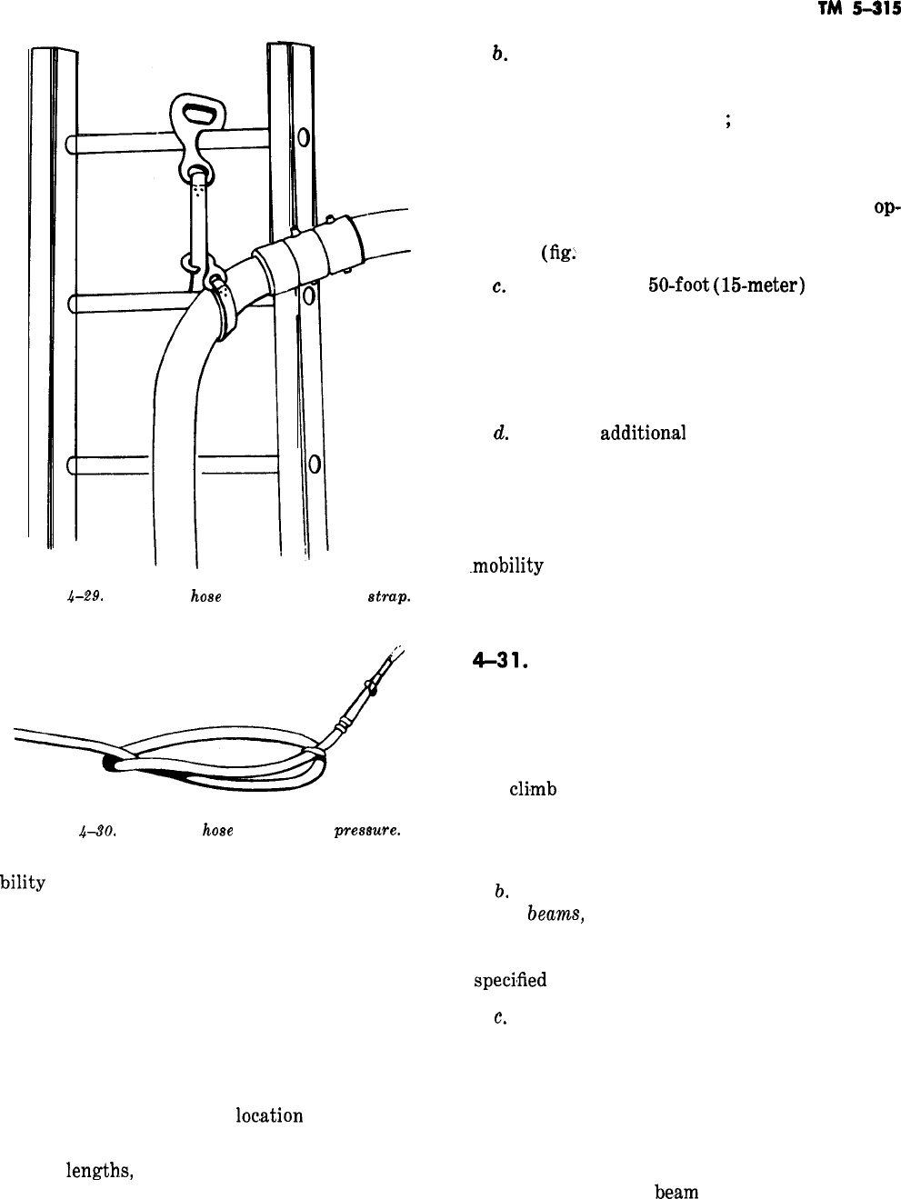
Figure
k.29.
Securing
hose
to ladder with hose
etmp.
Figure 4-30. Securing
hose
against back
preeewe.
bility
of the nozzle (fig. 4-30). Tying the hose in
this manner increases friction loss somewhat and
gives the hose a greater tendency to straighten
itself. After securing it, however, one man should
be capable of directing the stream. When move-
ment of the hose is necessary, tying the hose in
this manner is not recommended.
4-30. Moving Hose lines
Hose lines when dry or uncharged must fre-
quently be moved from one
loc,ation
to another.
a. When any great quantity of hose, such as
several
length.s,
must be carried from one location
to another, it normally requires the coordinated
-
effort of several men to move the hose with any
degree of speed and order.
TM
5-215
b.
Shoulder loads are formed by the first man,
who starts with the nozzle or free end of the hose
and places several layers or loops of hose over his
shoulder in front and back
;
but they must not
extend so far as to interfere with his mobility.
The next man will leave about 10 feet (3 meters)
between the man in front of him and the point
where he starts forming shoulder loads. This
op-
eration continues until all available manpower is
utilized
(fig>
4-31).
c.
When a single
50-foot
(15-meter)
section of
hose is to be carried, a man places the main body
of the hose on his shoulder and holds it with one
hand (fig. 4-32). He uses his other to hold both
couplings to prevent them from being dragged on
the ground or damaged in some other way.
d.
If a small
addition.al
length of hose is needed
to reach the fire or to allow the hose to move to
another area, a loop may be formed in the line
and rolled toward the nozzle. This operation re-
moves much of the zigzag slack from the line and
lengthens it somewhat, thus increasing nozzle
-mobility
and stream range efficiency-both from
the standpoint of decreasing friction loss and in-
creasing the range.
4-3
1.
ladders
A ladder is made of wood, rope, or metal, and is
as definitely a part of fire service equipment as
the hose, nozzles, or tools.
a. A firefighter must know how to carry, raise,
and
chmb
the different types of ladders issued by
the Army. He should practice these procedures
until the operations become as nearly automatic
as is humanly possible.
?j.
The principal parts of a ladder are the sides,
called
beawzs,
and the crossbars, called rungs. Lad-
der rungs are of the same design, regardless of
the type of ladder. They consist of a round bar of
specimfied
size and strength.
c.
Trussed ladders are designed as they are to
make them stronger and lighter (fig. 4-33). A
solid-beam ladder made of good material may
meet the strength specifications, but it is much
heavier than an equally strong trussed ladder, so
the truss type is perferable. Trussed ladders are
constructed with two beams on each side of the
ladder. Some are made with one of the beams
larger than the other
be.am
on the same side of the
ladder; others are made with all beams of equal
size. With the former, the rungs are set in the
4-25
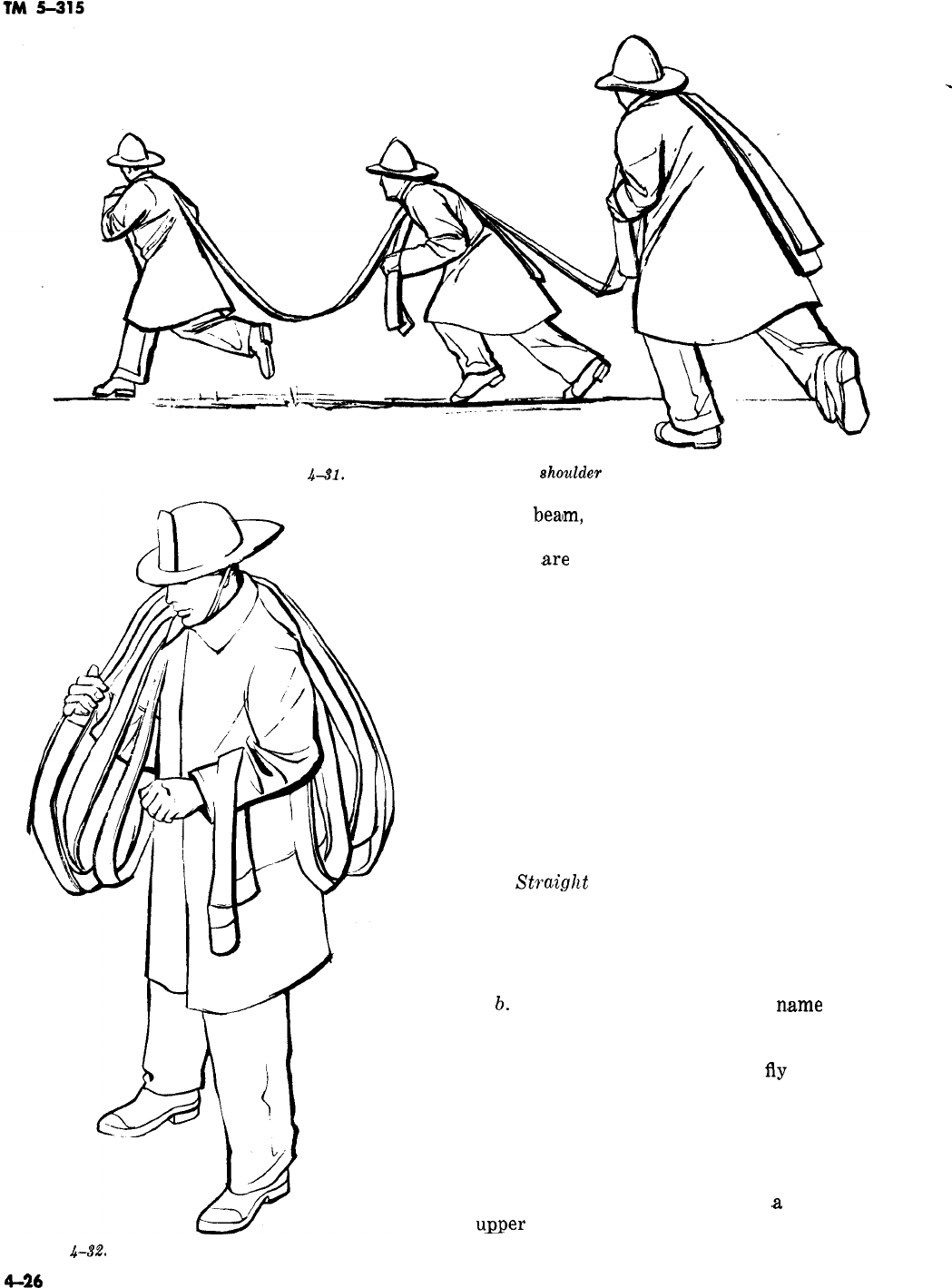
-
Figure
.&.91.
Hoving a hose line using
shoulder
loads.
Figure &%‘. Carrying a single folded section of hose.
4-26
larger
beaIm,
which is called the rung beam; the
other beam is called the truss beam. Where the
beams
,are
of equal size, the rungs are set into
blocks which are, in turn, set between the two
beams.
d. The beams of wooden ladders are made of
either Douglas fir or airplane spruce. The rungs
of a wooden ladder are made of second growth
hickory or ash. Many ladders are now being made
of aluminum and are much lighter in weight.
_
4-32. Kinds of ladders
Ladders currently being used by the Army are
straight ladders, extension ladders, folding lad-
ders, roof ladders, and Bangor ladders.
a.
Straight
Laddem. Straight ladders are some-
times called wall ladders and range in length from
10 to 40 feet (3 to 12 meters). In the Army these
ladders are constructed on the exterior walls of
buildings. They are used as auxiliary ladders only.
b.
Extension Laddem. As the
n,ame
implies,
these ladders consist of two or more sections. The
base section is called the bed ladder, and the other
sections are the fly ladders. The
fly
ladder slides
through guides on the upper end of the bed ladder
and is equipped on the lower end with pawls, or
dogs, that hook over the rungs of the bed ladder
when extended to the desired height. The fly lad-
ders are raised by a halyard that is fastened to the
lower rung and operates through
,a
pulley on the
user
end of the bed ladder. Extension ladders
are made in lengths from 14 feet (4 meters),
.-
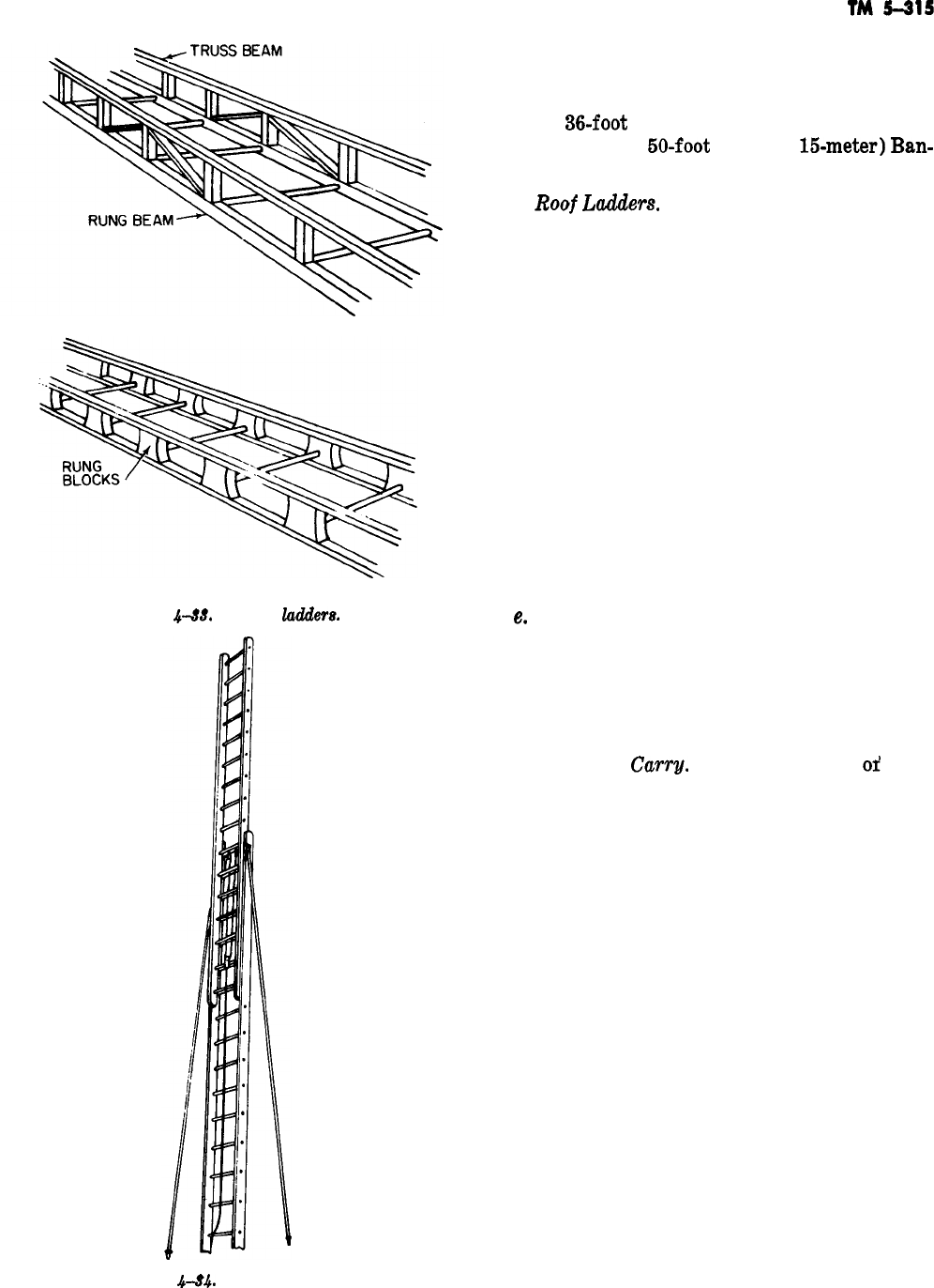
called the “baby” extension, to aerial ladders of
160 feet (48 meters). However, extension ladders
used most commonly by the Army are the 20,
24, and
36-foot
(6, ‘7, and U-meter) extensions,
and the 40 and
60-foot
(12 and
15-meter)
Ban-
gors.
c.
Booi
LadAlert?.
Roof ladders issued by the
Army have hooks mounted on a movable socket,
which permits them to fold inward when not in
use. Roof ladders range in length from 10 to 20
feet (3 to 6 meters), They may be of either the
solid-beam or truss type. By placing the hooks of
the ladders over roof peaks, sills, walls, or the
coping of any opening, a fireman can climb the
ladder with safety even though its butt may not
rest on a foundation.
d. Bangor Ladders. A Bangor ladder is an ex-
tension ladder 40 feet (12 meters) tall or taller
(fig. ‘4-34). Each side has a pole attached to it
with a swivel. These poles are called tormentors.
They have a spike in each free end, and aid in
lifting and steadying the ladder while it is being
raised.
Figure
&SS.
Trussed
hiders.
e.
Folding Ladders. A folding ladder is made up
of two or more sections which are hinged for fold-
ing. A mechanism locks the hinges when the lad-
der is extended for use.
4-33. ladder Carrying
a. One-Man
Carry.
Often a shortage
or’
man-
power makes it necessary for one man to carry
and operate ladders. One well-trained man can do
this, leaving the other men to perform the many
other tasks necessary during an emergency. The
roof ladder can be carried by removing it from
the apparatus and passing either arm through the
ladder at the middle of its length. The hooks
should be carried forward and lowered (fig.
4-36). Extension ladders under 25 feet (7.6 me-
ters) in length can be carried by positioning the
shoulder at the center of the ladder with the heel
forward, as shown in figure 4-36. This method
allows the ladder to be set and raised in one con-
tinuous operation.
Figure
4-84.
Bangor h&&r.
to 36 feet long (8 to 11 meters) require a mini-
mum of two men, one near each end. After they
have removed the ladder from the apparatus, each
man passes one arm through the ladder and
grasps the second rung forward (fi. 4-37). Both
men must be on the same side of the ladder. The
heel should be carried forward. When carrying a
ladder in a crowded area, the lead man will use
4-27
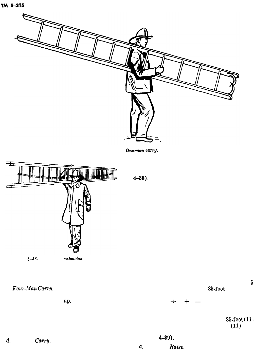
-
Figure 4-86.
Onemum
can-g.
Figure
&St?.
One-man
esteneion
ladder carry.
his outside hand to prevent injury to persons in
the line of travel.
c.
Four-Mm
Cuwy.
Four men remove the lad-
der from the apparatus and place it on the ground
with the fly of the ladder
up,
The men take posi-
tions, two near each end on opposite sides of the
ladder. They face the top of the ladder, reach
down, and grasp a rung with the hand nearer to
it. They raise the ladder on their shoulders and
carry it, as shown in figure
4-38.
d.
Six-man
Carry.
This carry is used for the
Bangor ladders and is the same as the four-man
carry, except that two additional men are placed
in the middle on opposite sides of the ladder (fig.
4738).
-
NOTE
Ladder drills tie in very closely with
hose operations, because ladders are fre-
quently needed for maneuvering the hose
to an effective fire-extinguishment posi-
tion. In addition, ladders are needed for
rescue, ventilation, and salvage work,
and for other fire fighting duties.
4-34. Ladder Raising
As in ladder carrying, ladder raising is an opera-
tion requiring practice and cooperation. Before a
ladder can be raised, it must be determined how
far the heel of the ladder should be placed from
the building. There are two methods to determine
this. One is to divide the length of the ladder by
6
and add 2. For example, if a
35-foot
(U-meter)
ladder, fully extended, is to be used, the distance
would be (35
+
5)
+
2
=
9 feet (2.7 meters).
The other method is simpler and more commonly
used. The distance is determined by dividing the
length of the ladder by 4. Thus, if a
35-foot
(ll-
meter) ladder is to be used, divide 36
(11)
by 4
and the result is approximately 9 feet (2.7 me-
ters) (fig.
M9).
-
a.
One-Man
Raise.
There are two methods by
4-28
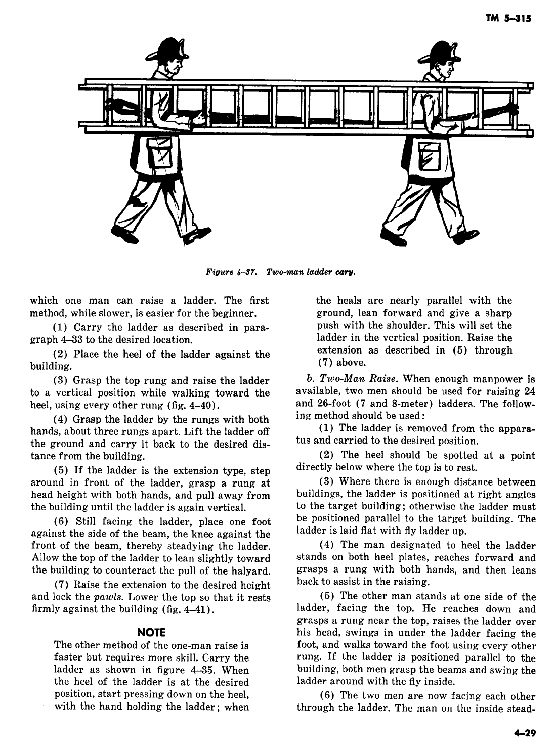
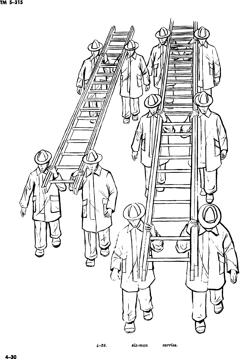
Figure
.&38.
Four and six-man ladder
carriea.
4-30
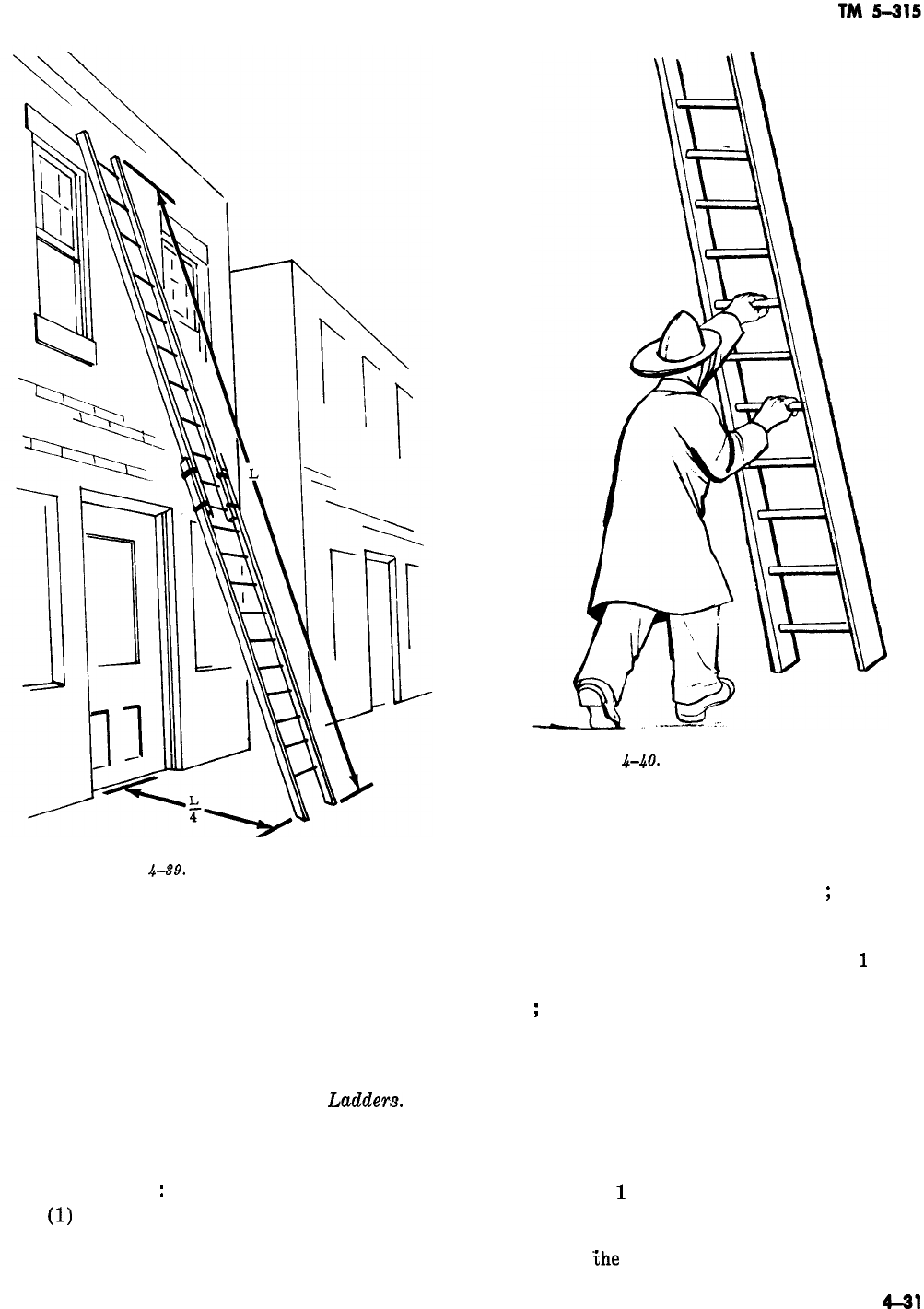
-
Figure
4-89.
Proper ladder angle.
ies the ladder while the man on the outside raises
the fly to the desired height and locks the pawls
(fig. 4-42).
(7) The ladder is then lowered to the build-
ing by both men.
(8) To lower the ladder, reverse the opera-
tions.
c. Four-Man Raise for Bangor
Ladders.
Al-
though six men should be used to raise Bangor
ladders, shortage of manpower frequently makes
it necessary to use the four-man raise. The proce-
dure is as follows
:
(1)
The four men remove the ladder from the
apparatus and carry it to the desired point. Then
ground it at right angles to the building with the
Figure
4-40.
One-man ladder raise.
heels close to the building. The four men then take
their positions as shown in figure 4-43.
(2) Nos. 1 and 2 release the tormentors and
pass them overhead to Nos. 3 and 4
;
then they
return to a position just below the tormentor
swivels.
(3) Facing the top of the ladder, Nos.
1
and 2
grasp a common rung and raise the ladder over-
head
;
then they swing around in under the ladder
and raise it to the vertical position by walking
toward the foot. The pole men assist as soon as
the ladder is raised above the beam men’s heads.
(4) Nos. 1 and 2 grasp a convenient rung,
and with their other hands on the beam, lift and
carry the heel to the proper distance from the
building.
(5) Nos.
1
and 2 each place a foot on the
rung, and Nos. 3 and 4 pull the ladder to the
vertical position with the tormentors. Nos. 1 and
2 then raise
the
ladders and lock the pawls.
4431
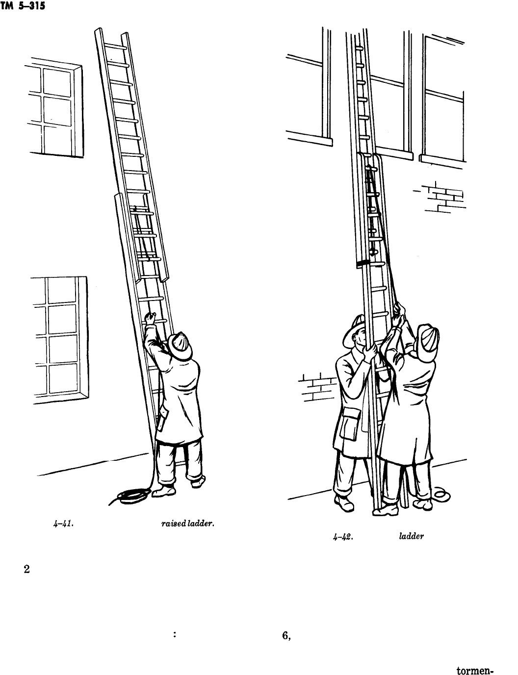
IU
3
IEJ
JCJ
-
Figure
.441.
Placing of one-man
raised
lao!der.
Figure
4-42.
Two-man
hdder
rake.
(6) The ladder is then held in place by Nos. 1
and
2
while Nos. 3 and 4 lower the ladder to the
building with the tormentors. The tormentors are
then locked in place.
d. Six-Man Raise for Bangor Ladders. Six men
should be used to raise Bangor ladders whenever
possible. The procedure is as follows
:
(1) The men remove the ladder from the ap-
paratus and carry it to the desired location.
(2) The men ground the ladder with the fly
-
ladders on top, then they take their positions as in
figure 4-44.
(3) Nos. 1 and 2 release the tormentors by
pulling the keys, raise the ends, and pass them to
Nos. 3 and 4, who, in turn, pass them to Nos. 5
and
6,
the tormentor men. With the spur of the
tormentors between the first and second fingers of
the hand nearest the spur when standing outside
the tormentors, the other hand grasps the
tormen-
-
4-32
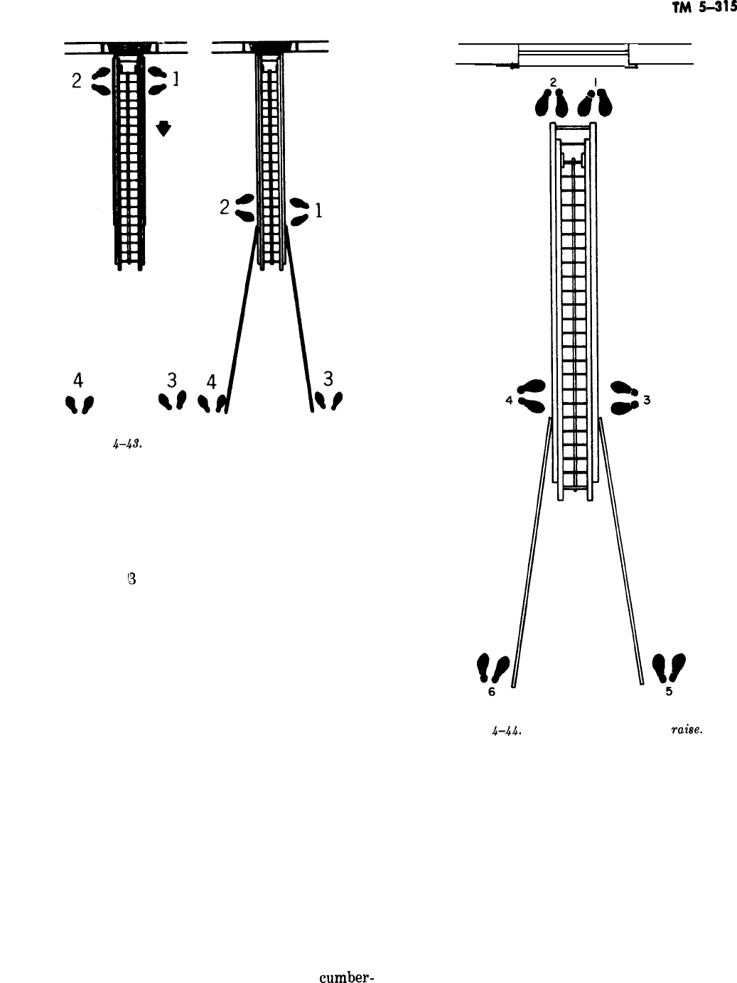
TM
5-315
WINDOW
i.
Figure
&&I’.
Four-man Bangor ladder rake.
tor at arms’ length. These men should be about 5
feet (1.5 meters) apart.
(4) Nos. 1 and 2 stand on the heel plates and
reach over and grasp a convenient rung as the
ladder is raised.
(5) Nos.
13
and 4, facing the top of the ladder,
reach down and grasp a common rung, raise the
ladder overhead, swing under the ladder, and
raise it using every other rung. Nos. 5 and 6 take
the weight from Nos. 3 and 4 with their tormen-
tors as soon as possible, pushing the ladder to the
vertical position.
(6) When the ladder is vertical, No. 5 will
swing to the inside of his tormentor pole and
carry it around to a position at right angles to the
other tormentor (fig. 4-45). This steadies the lad-
der and allows it to be set plumb.
(7) Nos. 3 and 4 heel the ladder while Nos. 5
and 6 lower the ladder to the building with the
tormentor poles. The tormentors are then set
under the ladder to prevent sidesway.
(8) To lower the Bangor ladder, reverse the
operations.
4-35. ladder Climbing
-
a. Ladder climbing is involved in the duties of
rescue, ventilation, and extinguishment, including
the moving of hose, ladders, and other
cumber-
Figure
,$-.44.
Six-man Bangor ladder
rahe.
some but necessary equipment. Since all these du-
ties must be carried out swiftly under the strain
of a fire emergency, ladder climbing becomes a
highly important skill. To acquire ease in ladder
climbing and its related uses, the average man
needs much practice.
b. In climbing a ladder, one hand is always on
one of the rungs, unless an article of equipment is
being carried up or down the ladder. If something
is carried in one hand, it should be slid along the
beam, if possible, to give the climber at least a
limited hold at all times.
4-33
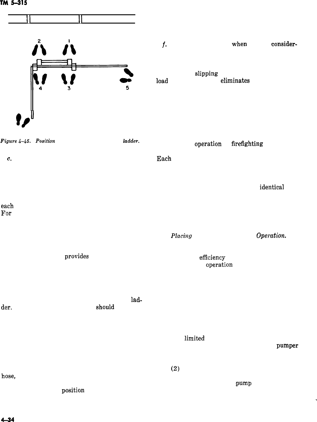
TM
5-315
II
WINDOW
II
6
Figure
&&T.
PO&ion
of tormentor men-Bangor
ludder.
c.
An unnatural coordination exists in proper
ladder climbing, for while one foot or the other
must be placed on every rung, one hand or the
other moves only once for each two rungs as-
cended by the feet.
d. The feet should be placed in the center of
eamh
rung to prevent the ladder from wobbling.
Flor
speed and smoothness, the body should be
carried in a nearly upright position with the arms
moving outward almost in an arch as the hands
are changed from rung to rung. The ball of the
foot should be placed on each rung to get complete
advantage of the leverage afforded by the angle.
When poor weather
provi,des
little traction be-
tween the boot and rung, the arch in the center of
the boot should be placed on the rung as a safety
measure. Using the ball of the foot for climbing
permits more speed and smoothness and takes less
effort. Climbing should be steady and smooth, and
no attempt made to run either up or down a
lad-
dler.
The upper part of the body
shoul,d
move so
evenly that it appears to be standing on an escala-
tor.
e. Locking in on a ladder means simply placing
the leg between two rungs and bringing the foot
back out between the next lower rungs and lock-
ing the foot either around the rung or around the
beam (fig. 4-46). This leg lock enables the man on
tlhe ladder to work with both hands free to handle
h.ose,
ladders, and tools. Men should anchor them-
selves to a ladder with a rope hose tool or a safety
belt only when one
positio,n
must be kept for a
long time. Short men are more comfortable when
they lock one foot around the rung above the one
on which the other foot is placed, while tall men
usually are more at ease when they lock one foot
around the beam.
-
t.
For safety, especially
whe,n
there is
oonsider-
able weight and activity on a ladder, it should be
anchored to the building with a rope hose tool,
hose chain, or strap. This anchor prevents the
ladder from slip.ping or turning over when the
lolad
is shifted; it also
eli,minates
much of the vi-
bration caused by activity on the ladder. When
necessary, the slack must be taken from the rope
by twisting it or taking an extra turn around the
ladder rung.
4-36. Pumping Operations
It is difficult to establish a definite, rigid proce-
dure for the
operati,on
of
firefrghting
pumps be-
cause fire services employ many types of pumps.
Eiach
type of pump normally is manufactured by
many corporations, and each corporation, in turn,
locates the pump valves and levers in various
places on the apparatus. Although comparable
valves and levers may serve almost
identi,cal
pur-
poses, they often differ considerably in appear-
ance. Consequently, it is practical to give here
only the operational sequence, eliminating details
of description and location of the valves, levers,
-
and gages.
a.
Pking
the Booster Line in
Operation.
All
Army pumpers have booster tanks which contain
a minimum of 150 gallons (568 liters) of water.
The speed and
eflieiency
with which a booster line
can be placed in
o:peration
largely determines the
amount of damage by smoke, fire, and water that
can be prevented. The proper use of the booster
line is frequently responsible for the extinguish-
ment of fires at an early stage.
(1) To place the booster line into operation,
first remove the line from the pumper and assign
one crewman to man the nozzle. Since the hose
usually is 1 inch (2.54 centimeters) or less in di-
ameter, one man can operate the nozzle efficiently
with the
limi,ted
amount of pressure generated
and volume discharged. Next, start the
pum:per
engine, if not already running, and allow it to
idle. Then place the pump in gear.
(,2)
Open the pump intake valve leading from
the tank to the pump and allow the pump to fill
with water. Then open the
:pump
discharge valve
leading from the booster line. With the engine
still idling, allow the booster line to fill with water
to the nozzle. Accelerate the engine until the gage
_
4l-34
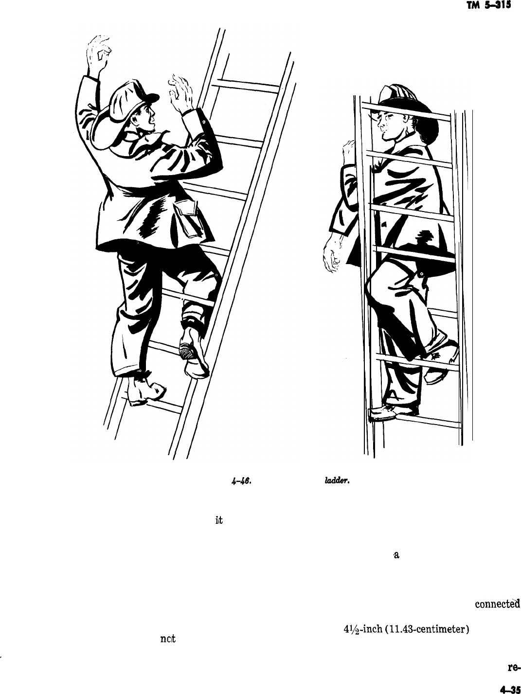
-
-
TM
5415
Figure
.Ht?.
Looking in on a
lad&v.
on the control panel shows the pump pressure to
be 100 psi, then open the nozzle. When
it
becomes
desirable to shut down the pump, retard the throt-
tle, close the pump discharge valve and the inlet
valve, take the pump out of pump gear, and place
it back in road gear. If it becomes necessary to
close all discharge valves during pumping opera-
tions, the pump should be taken out of “pump”
position and placed in “road” position. This will
prevent the water in the pump from “boiling.”
The relief valve will take care of the pressure and
heat for a short time, but
net
for extended peri-
ods.
-
b. Taking Water from the Hydrant. The pri-
mary rule to follow when taking water from a
hydrant is as follows: A fire hydrant should be
opened slowly to prevent pressure surges, and
completely to prevent undue wear. To take water
from a hydrant with
,a
pumper (which may be
necessary because of the great size of the fire or
insufficient hydrant pressure), the pumper must
be located strategically in relation to the hydrant.
This will permit the suction hose to be
connect&l
conveniently and without kinking (fig. 4-47). The
cap on the
4l/z-inch
(11.43-centimeter)
“steamer”
connection of the hydrant should be removed and
also the suction hose connected to the plug and the
intake on the pump (which also requires the
re-
4-3s
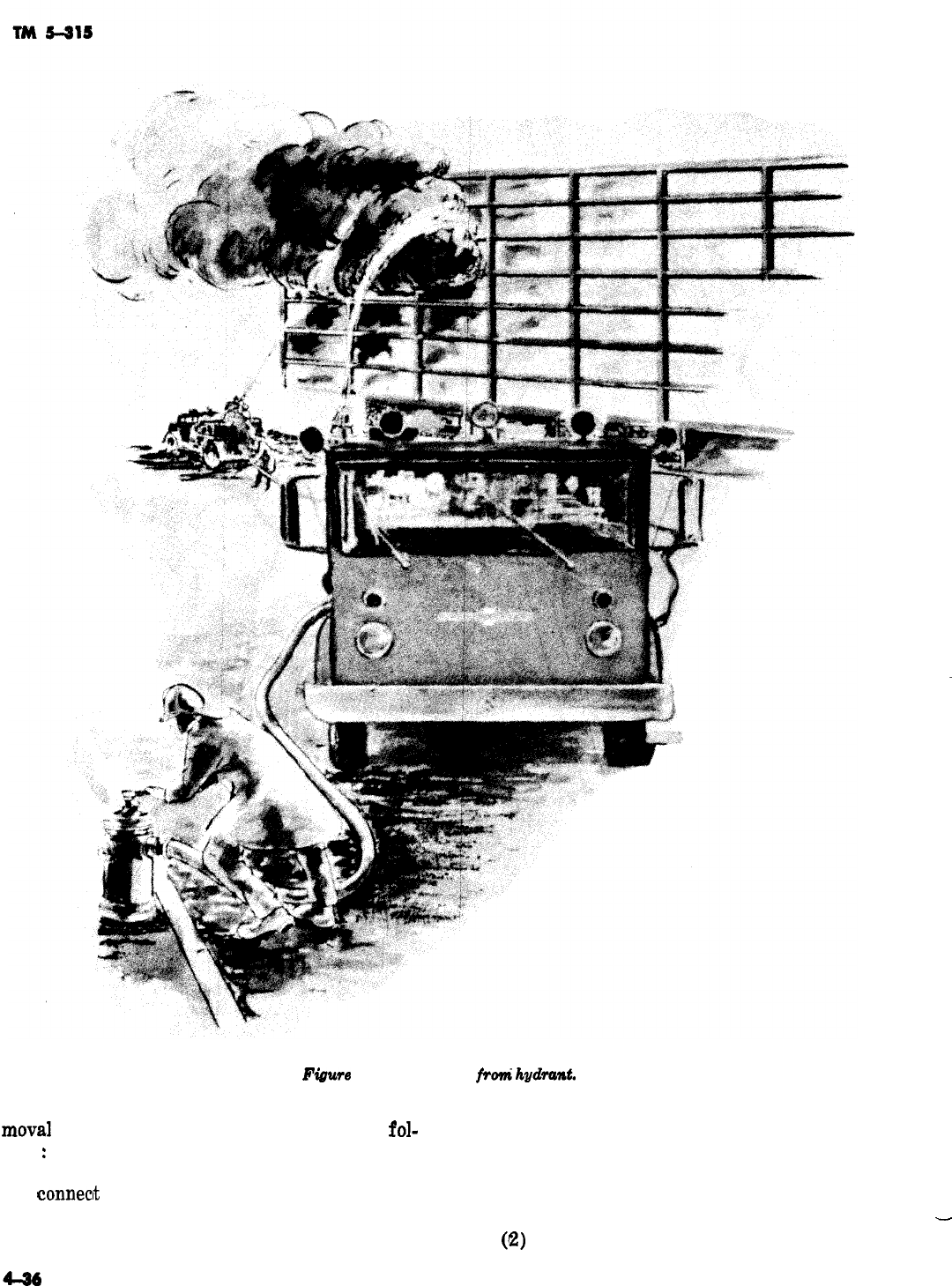
-
-
Figwe
4-47. Pumping
f+ok
hydra&.
moval
of a cap). The process is continued as
fol-
the hydrant valve. Start the pump engine, if not
lows
:
already running, and let it idle while the pump is
(1) Break the hose at the proper coupling put into gear. Open the discharge valve on the
and
conneclt
it to one of the discharge outlets from
pump and accelerate the engine until the gage
the pump. After the pumper discharge valves and
indicates the desired pressure.
-
churn valves are checked and found closed, open
(2)
The desired pressure is determined by
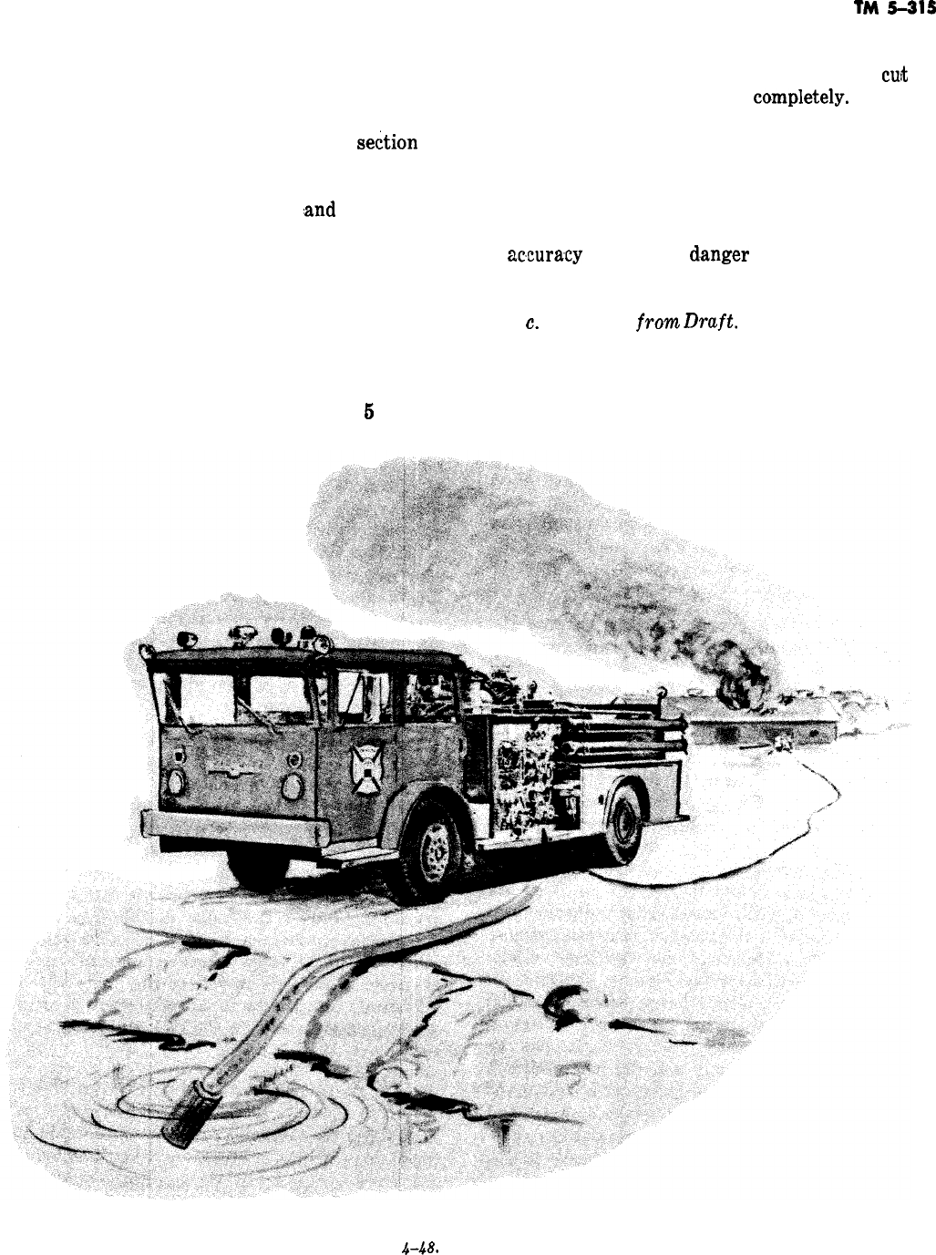
taking into consideration the size, type, and
length of the hose, the nozzle size, and the vertical
distance from the pumper level to the point at
which the nozzle is elevated, according to the
principles of hydraulics presented in
se&ion
II of
chapter 4. The pump operator should be capable
of arriving at the desired pump pressure within
seconds after the layout is made
,and
observed.
(3) When pumping from a substandard
water system, pumpers of comparatively large
capacity may collapse their intake lines if the flow
into the system is less than the discharge capacity
of the pump. In this event, the pump operator
must watch the intake gage as well as the pres-
sure gage, and regardless of the pressure main-
tained, should regulate the throttle so that the
intake pressure does not fall below
6
psi. This
TM
5-315
precaution is taken to prevent a collapse of the
soft suction hose (intake line) which would
cuti
off
the pumper’s water supply
campletely.
If the hy-
drants are of such limited capacity, small nozzle
tips and fewer hose lines should enable continued
operations. If the hydrant suction is weak the
hard suction hose should be used. The suction
pressure should not be permitted to drop below 10
psi. This will permit a 5 psi error in the gage
ac,curacy
without the
d.anger
of collapsing a water
main.
c.
Pumping
frowz
Druft.
When pumping from
draft, whether the source is a tank, a pond, a lake,
or a moving stream, the intake side of the pumper
should be located as close to the water body as is
feasible (fig. 4-48).
Figure
448.
Pumping from draft.
4-37

(1) The location should have a solid founda-
tion and be capable of bearing the weight of the
truck and withstanding the vibration created by
the engine and the pump. The pump lift, or the
height from the water surface to the pumper,
should not exceed
12
feet (3.66 meters) unless
absolutely necessary. Shorter lifts
,are
capable of
producing greater overall volume and pressure ef-
ficiency. The emergency brake of the pumper
must be set, the gearhift lever placed in neutral
position, and the throttle opened only slightly to
maintain a good idling speed. Check blocks are
placed at the wheels if the vehicle is on an incline.
(2) Regarding the suction connections, the
gaskets of the
hc&
suction connections must be in
place before connections are made. The suction
strainer is attached to the end of the suction
,hose.
A rope is secured to the suction strainer to
facil-
itte handling, and tied into position. The strainer
beneath the water surface is submerged to a
depth of
18
inches to 4 feet (0.46 to 1.22 meters),
depending upon the depth of the water source and
the capacity of the pumps. Where the depth of the
water permits, the strainer should be at least 12
inches (0.305 meter) above the bottom.
(3) If the water is too shallow to allow the
suction line and strainer to be suspended in it and
if the bottom of the water source contains sand
and debris, the strainer must be protected to pre-
vent debris from entering the pump. Lumber sheet-
ing, sheet metal, boxes, the blade of a shovel, or
any other flat container or object may be placed
underneath and around the suction strainer to
keep it clear. The strainer should be tied into posi-
{tion
with a rope to prevent it from drawing air. If
it is impractical to use rope, a large board or some
other heavy material is placed over the suction
strainer to keep it submerged. All openings are
closed including drains and booster connections on
the suction side of the pump. The necessary hose
couplings are attached to the discharge outlets.
When priming a centrifugal pump, the first re-
quirement is that all discharge valves be closed
and intakes, except the one being used, be tightly
capped. The primer should then be started and the
valve between the primer and the pump opened.
When the pump is primed (filled with water) the
pump should be engaged, the primer stopped, and
the disch,arge valve(s) opened very slowly to pre-
vent loss of the prime. Once the pumper is dis-
charging water, the pressure desired as well as
the number of lines needed can be maintained by
coordinating the inake and discharge pressures
with slow and deliberate adjustments of the throt-
tle.
(4) Centrifugal pumps may be equipped
wit3
either a relief valve or a pressure-regulator valve.
A relief valve is set at the predetermined pres-
sure
;
then when a line is shut off at the nozzle, the
backpressure at the pump opens a bypass valve
which reroutes the water from the discharge to
the intake side of the pump, thus preventing a
water hammer. A
pressureYregul!ator
valve is set
at a pressure determined by existing conditions.
These conditions are governed by the number of
lines being used, their lengths, and the size of the
nozzle tips. When a line is shut off at the nozzle,
the backpressure thus
,created
at the pump
actuates
a.governor
that reduces the engine speed
and the pump pressure.
--
(5) When the pump is in operation the en-
gine temperature must be watched constantly so
as to maintain an efficient engine temperature of
160’
to 180” F.
(71’
to
82’
C). The temperature
can be controlled by the cooling-water-supply
valve. This valve is manipulated as often as neces-
sary to maintain the desired engine temperature.
However, the
vaive
should never be suddenly
opened or closed, for this practice heats or chills
the engine too rapidly. The excess pressure
taming
from the fire pump is likely to damage the
radiator or cooling system if the cooling valve is
opened too far or too fast.
(6) Water is pumped from the boaster tank
on the fire truck or trailer in much the same man-
ner as it is from a
hydr:ant.
Since the water in the
tank is above the level of the pump opening, the
valve in the connection between the tank and the
pump will permit water to flow from the tank to
the pump by gravity, eliminating the necessity of
priming. Because af this connection, care must be
exercised to have the valve in this line
clased
when pumping from a hydrant or other gravity
source of supply under pressure, since the excess
pressure on the suction side of the pump will be
introduced into the tank and will result in over-
flowing, causing leaks in the tank and other dam-
age.
(7) As previously stated, it is not possible to
set forth specific operating procedures for all
pumps, but the foregoing will serve as a guide for
the basic principles of operation. Almost all valves
and levers on the pump are descriptively labeled.
When they are not or when the nomenclature is
not completely understandable, the pump operator
4-38

TM
5-315
may, if he understands the purpose and principles line leiading away from the valve to its source and
of the operation, follow out each lever and each thus determine its specific purpose.
-
Section IV.
4-37. Introduction
After responding to as few
gencies
the firefighter will
ACTION ON ARRIVAL,
SIZEUP,
AND
FORCl8lE
ENTRY
as a dozen fire
emer-
be convinced of the
great variation in fire conditions and the varia-
tion in procedure required to put out each fire.
The first action of the firefighting crew immedi-
ately upon arrival at the fire is probably the
greatest single factor in determining the success
or failure of the operation.
Enroute
to the fire and
upon arrival, crewmen must quickly analyze the
part that each will play in the rescue and extin-
guishment procedures. The crew chief or senior
man will make the basic assignments. Even after
the assignments are made there is a great necess-
ity for individual initiative in the details of execu-
tion. This initiative increases with
exsperience
and
study.
4-38.
Sizeup
The first duty of the crew chief and the crew is to
“size up” or make a quick appraisal of the situa-
-
tion and determine what the conditions demand
and the order of their procedures.
a. The following six conditions must always be
talken
into consideration
:
(1)
Life hazard involved or the rescue work
required, if any.
(2) Exposure hazards from both the interior
and exterior viewpoint.
(3) Type of building construction (consider
the possibilities of collapse).
(4) Content hazards to both the occupants
and the firemen.
(5) The accessibility of the fire.
(6) The type and amount of fire equipment
required.
b.
Whether persons occupy a burning building
should be known before firefighting operations
begin. Also, how many sleep there at night (if the
fire occurs at night), and the facilities for exit
and their condition, capacity, and usability. For
example, open stair wells and fire escapes may be
blocked by heat and flame, and elevators may be
inoperative; if the roof over the elevator or its
shaft is involved in fire, the elevator should not be
used. On the other hand, stairways cut off at each
landing,
inclosed
smoke towers, or horizontal exits
into adjacent wings or buildings are likely to pro-
vide safe exits. Fires in buildings used for public
assembly, such as theaters, dancehalls, clubs,
schools, and hospitals, and for sleeping quarters
offer the greatest life hazard.
c. The roofs and walls of adjacent buildings
may be endangered by heat radiation or by an
infiltration of heated smoke and
gase,s
from the
iniltial fire, which may suddenly ignite or explode.
Frequently the building or buildings exposed are
more important to save than the burning building
from the standpoint of life hazard, content value,
or current need. Where the fire is well advanced,
the first streams of water should be used to pro-
tect such exposed buildings. The direction of the
wind, slope of the ground, distance between the
buildings, extent to which the fire has spread and
other considerations must be carefully appraised
before action is taken.
d.
Internal exposures from floor to floor via ele-
vator shafts, open stairways, light walls, etc.,
must also be considered. When the fire is located
in the basement or lower floor, prompt action in
getting hose streams into operation at points
where fire is apt to spread is an important means
of making an effective fire stop.
e. The type of building
consltruction
is a factor
which determines the time that fire will require to
cause the collapse of a structure. This is impor-
tant in determining whether a building can be
safely laddered, and it will also determine
whether men should be sent inside the building.
Heavy timber construction will hold up under
higher temperatures and
f,or
a longer time than
unprotected steel. Reinforced concrete will with-
stand more weight of water than ordinary
brick-
joisted
buildings.
f. Content hazards to the occupants and fire-
fighters consist of explosive stock, toxic fumes,
chemicals, acid
carboys,
compressed;gas
cylinders,
high-voltage wires, etc., which, when subjected to
heat
or
hose streams, may jeopardize the safety of
personnel. All of these hazards must be considered
before ordering specific
guishment. Knowledge
building inspections is
time.
procedures for fire
extin-
gained during previous
of real value at such a
4-39

TM
5-315
g. The characteristics of explosives should be
studied, and, with the advice and assistance of the
ordnance officer, advance conclusions should be
reached regarding the time and heat necessary for
detonation.
h.
Toxic fumes require the use of compressed
air, self-contained demand breathing apparatus.
Z.
Compressed-gas cylinders should have been
previously inspected to learn the amount of pres-
sure required to rupture them. Also, whether a
cylinder is shatterproof should have been deter-
mined. The flammability, rate of expansion, and
other pertinent properties of the cylinder contents
should have been obtained so that the chemical
reactions in the event of fire can be anticipated.
liquid and powdered
chemi,cal
reacti,ons
in the
event of fire can be anticipated. Liquid and pow-
dered chemicals must be respected from the
standpoint of their gas-liberating qualities, the
toxicity of the gas, the type of container (which
may hasten or retard its release), and the general
characteristics of the chemical when exposed to
heat and water.
i.
High-voltage wires can electrocute personnel
over a widespread fire area where water is gener-
ally present. If the circuits are not cut off by the
time water is used, extreme caution must be ob-
served in stationing personnel durin,g extinguish-
ment. Personnel must be kept free of water which
is in contact with sources of electrical currents.
k.
Frequently mud, excavations, traffic jams,
ditches across roads, blocked alleys, and a multi-
tude of other obstacles prevent an approach to the
fire
fr.om
the most favorable direction. Previous
knowledge of such conditions, which allows the
crew chief to take alternate action, will prevent
considerable delay.
Z.
In some fire emergencies it is possible, even
before the firefighters reach the fire location, to
determine that additional men and equipment will
be needed. This can be judged by the nature and
extent of the headway which the fire has already
gained. When a large fire is observed in an area
where no
,open
fires should be found, a second
alarm
shouId
be turned in as quickly as possible.
This may be done from the alarm box, if one is
available, or over a two-way radio. On small
bases, where there are no firefighters available to
respond to a second alarm, a thorough knowledge
of available outside aid is invaluable.
m. In most responses or runs, it will be found
upon arrival that there is no large fire, but rather
a small fire consisting of something such as burn-
ing rubbish, automobile or furniture upholster-
ing
;
or oil overflow around the base of heaters. In
such cases the crew chief should order one or two
of his men to use the appropriate extinguisher or
the booster line. The remainder of the crew should
remain on the apparatus to await further orders.
n.
In some instances firefighters arriving at the
scene of a fire may find only an odor of smoke
instead of an actual fire. If the source of smoke
cannot be traced immediately and the odor con-
tinues, a thorough investigation should be made
from the lowest level to the rooftop. Smoke fre-
quently is blown into a building from the outside
or may result merely from the temporary abnor-
mal operation of a heating appliance, If there is
any doubt regarding the source of the smoke, the
firefighters will remain until the source has been
discovered and corrective action taken.
o. When the
sizeup
discloses the need for imme-
diate action, the following steps should be taken:
Call for additional help (if required), initiate
rescue work (if required), ventilate, locate the
fire, close in, extinguish, salvage, overhaul, and
investigate. Although listed in sequence, these
steps are carried out almost simultaneously if
enough personnel are available.
4-39. Forcible Entry
Forcible entry means gaining entry to closed
spaces by opening locked doors and windows,
roof, floors, skylights, partitions, and walls by me-
chanical means. Even the breaching of masonry
walls with a battering ram and other extreme op-
erations may be necessary. However, unnecessary
destruction of buildings must be discouraged. Re-
sponsibility for careful, methodical
forcijble
entry
rests directly with the fire department. Forcible
entry may be required for rescue, ventilation, con-
trol, or extinguishment and must be carried out
with fast, methodical judgment, and tactics.
a. Cutting with the Ax. In cutting with a fire
ax, short, quick, forceful strokes are used for bet-
ter aim. Such strokes also prevent the ax from
striking personnel and from catching in overhead
obstructions, either of which is easily possible in
dark or smoke-filled areas.
(1) Cuts are made diagonally rather than
with the grain of the board (fig. 4-49) and as
close to a
joi.st
or stud as possible. A proficient
firefighter should be able to use the ax either right
or left handed. Cutting in difficult corners
,and
under obstructions can be efficiently done only by
men who have
b’een
properly trained.
-
-
4-40
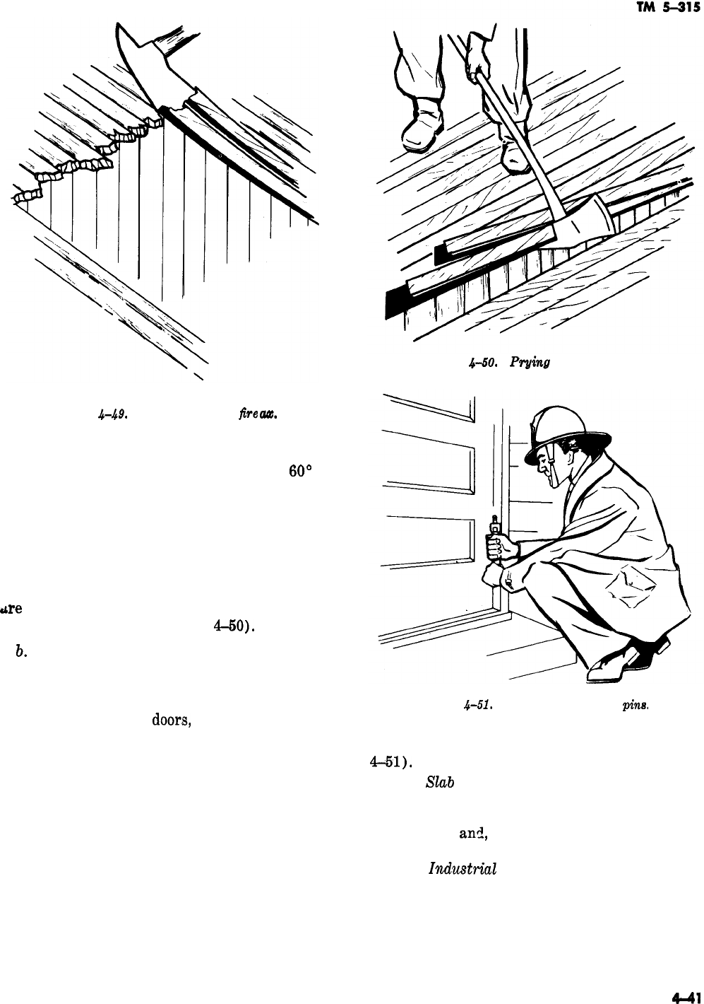
Figure
&SO.
Prying
with the fire ax.
Figure
&.@.
Cutting with the
five
aa.
(2) Ax-made cuts in flooring, roofing, or
sheathing are made at an angle of about
60’
in-
stead of straight down. Diagonal sheathing is cut
-
in the direction the sheathing runs so that chips
will tend to split out. If cuts are made against the
sheathing, the ax may bind and require extra ef-
fort and time. Cuts through a lath-and-plaster
wall are made in a direction diagonal to the grain
rather than perpendicular to it. After the boards
tire
cut, the pick end of the ax may be used for
prying and removing them (fig.
GO).
b.
Types of Doors. The various types of doors
must be understood by firemen before successful
forcible entry can be made with the proper tools.
The doors normally found on Army installations
are ledge doors, panel
door,s,
and industrial doors.
(1) Ledge doors. Ledge doors, sometimes
called batten doors, are made of built-up material.
These doors must be locked with surface locks
consisting of hasps and padlocks, bolts, or bars.
Hinges on ledge doors generally are of the surface
type, fastened with screws or bolts.
(‘2) Panel doors. Panel doors may be either
cross or vertically paneled. The panels are com-
posed of thin material and dadoes are not glued
into the stiles and rails. Either surface or mor-
tised locks may be used, and hinges may have full
-
surfaces, half surfaces, or hidden butts. The
hinges usually contain loose pins, which are easily
removed by a tap with an ax or a spanner wrench.
Figure
4-51.
Removing the hinge
pina
This avoids damaging the door or its casing (fig.
4-51).
(3)
SZab
doors. These are generally made of
veneered hardwood with a white-pine core. They
usually employ the same general hardware as
panel doors,
am!,
because they are solid, are not
easily sprung.
(4)
Zndustrial
doors. Industrial doors are
used in garages, warehouses, and storehouses, are
double- and single-sliding, overhead-lift, or over-
head-rolling.
c. Opening Doors. The method for opening
doors is determined first by the manner in which
441
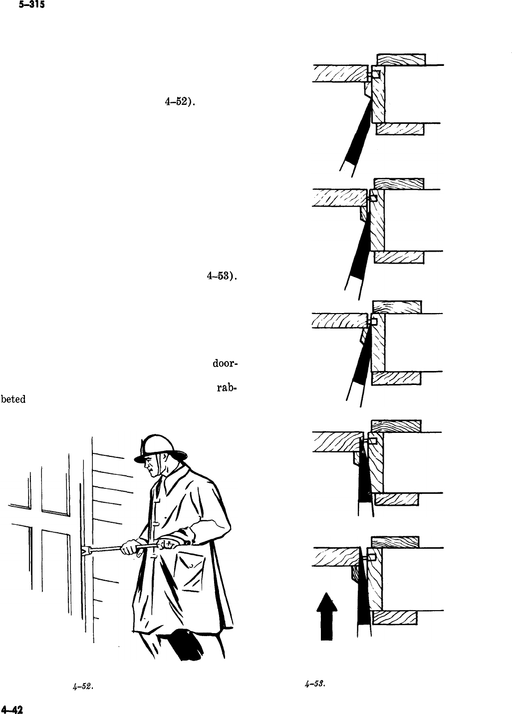
TM
5-315
the door is hung on the frame and then the way it
is locked. Outside doors in barracks, store build-
ings, and recreation halls, and smaller doors of
other buildings are set either against stops in the
frame or against a rabbeted shoulder in the door-
jamb. When using a door opener, insert the wedge
just above or below the lock (fig.
4-52).
A span-
ner wrench with a wedge end may also be used
where a great amount of leverage is not required.
(1) Overhead-rolling doors are made of steel
and offer the greatest resistance to forcible-entry
tools. Normally, such a door cannot be raised
except by operating its gear and chain. Prying on
such a door may spring it so that the gear will not
function. Sometimes a cast iron plate is installed
in the wall near the chain. This plate can be bro-
ken to permit reaching the chain and raising the
door in an emergency.
(2) If doors are only stopped in frame, the
stop can be raised with a sharp wedge and the
door swung clear of its fastening (fig.
4~53).
When springing a door in a stopped frame with a
door opener, use the tool to separate the lock and
the jamb just enough for the lock to pass the
keeper.
(3) When the door is set in a rabbeted frame,
entry is not easily made. However, splitting the
jamb or breaking the lock bolt with the
door-
opening tool will allow entry (fig. 4-54). To spring
a door from either the stopped frame or the
rab-
beted
frame, push the door open inward after the
opener is completely inserted.
PUSH
-
-
Figure
44%‘.
Using the door opener. Figure
&CL%
Springing a door in a stopped frame.
-
PUSH
’
Figure
4-54. Springing a door in a
rabbeted
frame.
(4) The same door may
,be
opened with the
wedge of an ax by inserting the blade above or
-
below the lock and prying it to allow the bolt to
pass the keeper (fig. 4-55). If this system is used,
both the door and the jamb will be
alightly
dam-
TM
5-315
aged, but the door will close properly after the
entry has been made.
(5) Double doors may be opened by prying
between the doors until the bolt of the door clears
the keeper. If an astragal, or the wooden molding,
covers the opening, it must be set away before
inserting the wedge.
(6) Night latches will normally yield to the
same prying tactics as mortised locks. However, if
Figure
4-55.
Opening a door with a fire aa.
Figure
.kW.
Battering ram.
they are fastened to the door with screws, they
can be bumped off with a heavy
obejct,
such as a
battering ram
(fig.
656).
When a battering ram
is available, pushing a shoulder against the side of
the door opposite the hinges will often spring the
lock.
(7) Overhead-lift doors can be forced by
prying upward at the bottom of the door with a
crowbar or claw tool. After the lock bar is broken,
the doors open readily.
(8) When single-hinged doors, such as those
on houses and stables, are locked with a hasp and
padlock, the staple of the hasp can be pried or
twisted off with a door opener without damage to
the lock (fig. 4-57).
(9) Many double warehouse doors are
ae-
cured with a bar dropped into stirrups on the
inside of the wall. In these cases, forcible entry is
made by battering the door down or by making a
breach in the wall with a battering ram. The
breach is made at a point which permits slipping
the bar from the stirrups. For ordinary brick
walls, battering a hole large enough for a
man,
to
enter and unlock the doors from the inside is
fr+
quently the quickest and
lea&
destructive method
of entry.
d.
V%dowa.
Prying with a wedge is the princi-
pal operation in forcing
windo-.
The
firefighter's
ax, a claw tool, or any other wedge-shaped instru-
ment may be used. If the wedge
ie
wide and thin,
entry can be forced with minimum damage.
Figure
4-57.
U&g
a door
opmer
ou
a hasp.
(1)
Factory type windows
con&t
of steel
sashes, which are often set solidly in the frame so
that only a portion of the window may be opened.
The movable portion is generally either pivoted at
the center or hinged at the top and latched on the
inside. Since factory type windows have small
panes, breaking a glass near the latch becomes a
fact,
simple operation which causes negligible
damage. Jagged pieces of glass left on the sash
are cleared out before the hand is inserted. Wired
glass must be completely removed from the sash.
--
(2) The check-rail window has two frames,
or sashes, which are in contact at the top and
bottom horizontals. If the window has no weights,
the sash is locked with bolts in the window stiles
or by a friction lock pressing against the window
jamb (fig. 4-58).
(B)
Check-rail windows can be opened by
prying upward on the lower sash rail (fig.
4&9).
If the window is locked on the check-rail, the
screws of the lock give way, and the sashes sepa-
rate. When the window is locked with spring-acti-
vated bolts, they must be broken or bent before
the sash can be raised. Prying should be done at
the center of the glass. However, if the check-rail
-
I
Figure
4-68.
Locking
devices
for
cheakqail
winha.
TM
5-315
-
latch is on the side, the pry should be made di-
rectly beneath it.
(4) Basement windows may be opened in the
same manner as a door in a rabbeted frame. If the
prying is done at the center of the lower rail, the
lock may be pulled or sprung.
(5) To open windows on upper floors, pri-
marily to provide ventilation, the firefighter lies
face down on the roof or leans from a window on
the floor above and
applie,s
the point or hook of a
pike pole to the window below (fig. 4-60). The
pike pole can also be used to break the glass if the
windown
cannot be raised or lowered and ventila-
tion is essential.
(6) Casement sashes are hinged to the win-
dow jambs and meet vertically
;
they are locked
either together or to the window frame. Casement
windows can be opened in much the same manner
as double doors. Generally, they are securely
locked, and breaking the glass is necessary. Case-
ment sashes of wood are generally hinged at the
top and locked at the bottom; metal sashes may be
hinged either at the bottom or at the top.
e.
Roofs. Roofs may be classified, according to
the construction of the covering, as shingle roofs,
composition roofs, or metal roofs.
(1) Shingle roofs include all those made of
small sections of material, such as wood, metal, or
asbestos, fastened to the sheathing. Shingles are
nailed to sheathing and can be removed easily.
Shingle roofs can be opened by stripping
o’ff
the
shingles and cutting away the sheathing.
(2) Composition roofs contain from one to
six sheets of roofing material, generally consisting
of tarred felt nailed to the sheathing and
cemented together with asphalt. Hot asphalt that
hardens when it cools is spread over the entire
cavering.
Gravel may be spread into and over the
hot asphalt to become a part of the covering when
the asphalt cools. The sheathing consists of l-inch
(2.54-centimeter)
shiplap
laid tightly on wood
joints or on solid concrete. Composition roofs re-
quire more care to open because they are more
difllcult
to repair. The covering is cut and rolled
back before the sheathing is cut away to make an
opening. To locate joists, the roof should be
sounded before it is cut. The cuts should be close
to the joists to make both cutting and repair eas-
ier.
(3) Metal roofs, generally tinplate, consist of
sheets of metal crimped or soldered together as
one sheet. The sheets are fastened to the shea-
thing just as in wood construction under composi-
tion roofs. Successful ventilation frequently must
be obtained by forcible entry tactics, When mak-
ing an entry for ventilation,
tmhe
firefighter should
always work with the wind at his back so that
gases and flames coming from the opening do not
hinder or endanger him. After a roof is opened,
the ceiling below is opened by forcing it down
with a pike pole or other suitable tool. A ceiling is
not usually difficult to push down from above.
Figure
4-59.
Opening check-rail windows. Figure
4-60.
Using pike pole to open a window
from above.
4-4s
TM
5-315
f. Floors. Permanent-construction wood floors
are
laicl
double on joints generally set on
16-inch
(40.6-centimeter)
centers. The subfloor
i,s
usually
laid on a
45O
angle to the joints, and the fop or
finish
floor at right angles to the joists. In mobili-
zation type builclings, a single floor is
laicl
directly
on the joists, the joists set on
16-inch
(40.6-centi-
meter) centers. In theather-of-operations type
construction, a single floor
i,s
laid on joists on
24-inch
(41-centimeter)
centers. Floors may be
openecl in much the same way as flat roofs, except
that two
clistinct
ctting
jobs are required for
double floors because the subfloor
ancl
finish floor
run in
clifferent
clirections. Joists are
locatecl
by
sounding, and both cuts follow the
sicle
of the
joi,sts
toward the
insicle
of the required opening.
For efficient cutting, the
had
which applies the
force is held halfway up the ax hanclle. The feet
are spreacl for proper balance
ancl
to
avoicl
cutting
the foot by a misplacecl or glancing stroke. The
man
cloing
the cutting must be careful to stand
outside the area to be opened
g.
Ceilings.
Plasterecl
ceilings are opened by
breaking the plaster
ancl
pulling off the laths. A
pike pole of proper length is the most effective
tool for this job (fig. 4-61). Metal and composi-
tion ceilings can be
pullea
from
joist,s
in the same
manner. Board ceilings are somewhat difficult to
remove because the lumber offers considerable re-
sistance when an attempt is
macle
to jam the pole
through or between the
boar&
to get a
solid
grip
on the hook.
NOTE
Certain precautions must be observed
when opening ceilings
ancl
walls. Do not
stand under the areas to be openecl, pull
clownwarcl
ancl
away to avoid being hit
by falling material,
ancl
keep the upper
hancl
on top of the pole to
aicl
in pulling
away. Always wear a helmet when pull-
ing
down
a ceiling, since it is
clifficult
to
precletermine
the amount of the ceiling
which may fall after one thrust.
h. Glass.
(1)
The glass panes of a skylight are gener-
ally
installecl
in a metal frame which slips over a
flangecl
roof opening (fig. 4-62). By prying uncler
the
eclge,
the entire skylight can usually be
pullecl
loose
ancl
remove&
if necessary. If
.skylight
cannot be liftecl, the glass panes may be taken out
by releasing the metal strips that cover the joists
ancl
removing the putty.
(2) Glass in
r3oors
ancl
widows
is broken
-
Figure
4-61.
Removing lath and plaster ceiling.
Figure
4-62. Section of a typical skylight.
Figure
4-68.
Breaking window glass with an
ax,
easily with the flat side of an ax. When breaking
the glass, stand to one side and strike
th&
upper
portion of the pane first, being careful that bro-
ken
gla,ss
does not
slide
down the ax hanclle (fig.
4-63). After the glass is broken out, remove all
jaggecl
pieces from the sash to
safeguarcl
person-
nel, hose, and ropes from injury
ancl
clamage
--

-
when they pass through the opening. The jagged
glass may be removed with the pick of the
ax:
i.
Took.
The proper way to carry tools is almost
as important as knowing how to use them. Tools
with sharp hooks or sharp edges should never be
carried on the shoulder. If the carrier
stimbles,
he may release his grip on the tool, which may fall
against him or strike another person. In the con-
fusion, haste, and limited vision which normally
accompany a fire, body contact is common,
makin.g
an exposed tool a definite hazard. Sharp edges and
points can be guarded best if tools are held in the
hands. An ax, for example, is carried at about the
level of the waist and held high in a horizontal
position, with one hand
groping
the handle near
TM
5-315
the head and the other hand covering the pick,
Another effective method of carrying an ax is to
hold it in a vertical position, parallel to the body,
with the
axhead
upward, the blade almost beneath
the armpit, and the hand covering the pick. In
these positions, an ax can be easily thrown away
from the body in the event of a fall. Tools with
hooks, such as claw tools, are carried at the side
with the hook forward. All tools with pointed and
sharpened edges are carried in a like manner. A
sense of
safety
is important in this respect.
j. Other
Types
of
Con&-u&m.
Local
construe-
tion should be studied and preplanning done when
construction varies from that described in
this
paragraph.
Section V. VENTILATION AND SALVAGE
-
--.
4-40.
Introduction
The problem of ventilation in burning buildings
frequently presents great difficulties even to the
experienced man. Salvage, including the preven-
tion of excessive water damage, is another impor-
tant factor in firefighting.
a.
Unlem
firefighters have a technical knowl-
edge of combustion processes, fuel characteristics,
oxygen requirements, draft, effect of heat on air
currents and building ventilation, and the princi-
ples involved in forcible entry, they cannot attack
fires in buildings effectively and with reasonable
freedom from danger. Principles of the chemistry
of fires include many of the necessary facts, but
ventilation
introduce
special variations. Ventila-
tion includes removing smoke,
gases,
and heat
from a building and controlling the fresh air sup-
ply to aid in rescues, protect the
iirellghters,
and
prevent the spread of fire.
b.
The importance of salvage work done by fire-
fighters cannot be stressed too strongly. Buildings
and other combustibles are salvaged proportion-
ately to the speed and efficiency of the firefighters
and their ability to prevent water damage.
4-41.
The Combustion Process
In’the
combustion process, fuels liberate carbon
and hydrogen, the most common
elementa
in burn-
ing materials.
CL
A fuel exposed to flame or spark burns if it is
heated to its ignition temperature if a sufficient
amount of oxygen is present.
Tohe
approximate
ignition temperatures of the most common
struc-
tural
materials are as follows
:
dry wood,
60°F.
(26OOC.)
;
paper,
460°F.
(232%)
;
pyroxylin
plas-
tica,
276’F.
(135%)
;
and cotton cloth,
440°F.
(227OC.).
ZL
When fuels reach their ignition tempera-
tures, they react with oxygen to form new com-
pounds called the products of combustion. Moat of
this oxygen comes from the
atmosphere,
which
normally contain8 21 percent of oxygen. Some ox-
ygen may be supplied by the oxygen content in
cellulose materials
such
a8
wood, paper, and cloth.
Free burning occurs when enough oxygen is
prea-
ent to consume the available fuel. For example, 1
atom of carbon (C) at its ignition temperature
reacts with 2 atoms of oxygen (0) to form carbon
dioxide
(
COs).
c.
In a closed structure, enough oxygen is pres-
ent when the
6re
starts to support free burning.
Hot gases rise to the ceiling; this starts a
con&&
ent current and forces the cooler air downward to
feed the fire from the floor. If fresh air is unable
to enter the room from the outside, the amount of
oxygen is gradually reduced until the fuel smol-
ders and smokes. Theoretically, it should
fmally
smother out completely
;
actually, however, the
smoldering stage is sustained
because
in
mogt
cases the oxygen supply is never completely ex-
hausted.
d. When the oxygen content of air is lowered,
the rate and
nature,of
combustion change: More
and more of the carbon fraction reacts with sim-
ple atoms of oxygen to form carbon monoxide
(CO), which, unlike carbon dioxide, is toxic and
flammable. Sometimes fuels will
di&ill,
because of
4-47

TM
5-315
the extreme high temperatures, and join the at-
mosphere as hot, flammable gases.
e. Carbon dioxide, the common product of the
complete burning of carbon materials, is neither
flammable nor poisonous. The fire begins to smol-
der as carbon dioxide replaces oxygen in at-
mosphere of a closed room. In air having a high
carbon dioxide content, the danger to personnel is
the suffocating effect caused by lack of oxygen.
f.
Carbon monoxide is a product of incomplete
combustion. Carbon monoxide gas is more preva-
lent in
unventil,ated
buildings because of the lack
of oxygen. It is an extremely poisonous gas, and
air that has a content of 0.5 percent carbon mon-
oxide causes unconsciousness
guickly.
Air contain-
ing 12.5 to 74 percent carbon monoxide may be
explosive. The ignition temperature of carbon
monoxide is
1128’F.
(609’C.).
The combined
toxic quality and flammability of this gas make it
very dangerous.
g. Burning hydrogen combines with oxygen to
form water vapor. Burning sulfur produces sul-
fur dioxide, an irritating suffocating gas which is
not flammable
;
it irritates the eyes and respira-
tory passages and is dangerous to breathe in
,high
concentration. Nitrous fumes include several ox-
ides produced by cellulose nitrates.
/z.
Although the gases of combustion are mixed
with the air, they are more highly concentrated at
specific levels, depending upon their densities.
Taking’air as 1.000, the following list of compara-
tive densities will indicate the level at which these
gases may be found
:
carbon
dioxide, 1.608
;
carbon monoxide, 0.978; sulfur dioxide, 2.437;
and nitrous fumes, 1.036 to 1.530.
L
Smoke is always produced when combustion
is incomplete. Its density, color, and content vary
with the oxygen supply, the intensity of heat, and
the type of fuel being burned. Water vapor and
particles of free carbon are generally found in the
smoke; such fuels as pine may distill and give off
dense black smoke. Oils, tar, paint, varnish, mo-
lasses, sugar, rubber, and sulfur may burn with
such dense smoke that ordinary ventilation prac-
tices fail to clear the room.
j.
If combustible materials are heated to ex-
tremely high temperatures in the absence of oxy-
gen, the lighter fuel elements and compounds
from the materials are distilled into fuel gases,
These hot gases need ‘only oxygen and a spark to
burn with explosive violence. This explosive
reac-
tion is known as a back draft. Actually a back
draft may be defined as an explosion that occurs
when a large quantity of oxygen is suddenly ad-
mitted to an interior fire. This condition is gener-
ally met when ventilation is made initially on the
windward wide of a burning building, especially
when the wind is of high velocity and of sudden
and large
volume-
4-42.
Evaluation
Careful evaluation of the situation is necessary
before an opening is made to ventilate closed
buildings. The fire chief estimates the situation by
considering the rescue requirements, type of
building and contents, smoke and heat conditions,
and explosive hazards. He also takes into account
the weather conditions, manpower and equipment
available, safety precautions, and exposed build-
ings nearby.
a. One-story buildings with several rooms or
compartments present more hazards than a single
compartment structure of the same size. When
hot gases rise to the ceiling, the cooler fresh air
from adjoining rooms is drawn under doors or
through other openings, permitting the fire to
burn longer before it begins to smolder. As the
hot gases and smoke fill the entire structure, it
becomes difficult to find the exact location of the
fire, and proper ventilation procedures become in-
creasingly uncertain.
b. In buildings of more than one story, hot
gases and smoke rise to upper floors through ele-
vator shafts, stairways, air-conditioning shafts,
and similar conduits. Reaching the highest possi-
ble level, the gases and smoke spread over the
entire floor, eventually filling the building from
the top down. This condition is commonly known
as mushrooming, and can create great smoke
damage even from a small smoldering fire. At the
same time, oxygen is supplied to the fire from
incoming currents of cool air. Smoke is generally
seen coming from openings in the upper floors
regardless of the location of the fire.
c. Figure 4-64 shows how the
progress
of a fire
in a closed room occurs in four stages
:
(1) In the first stage (A) the fire burns
freely. Adequate oxygen is still available in the
air, and water vapor and carbon dioxide are pro-
duced, along with small quantities of carbon mon-
oxide and sulfur dioxide. The room temperature is
about
lOOoF.
(38’C.).
(2) In the second stage
(B)
the original
pro-
-
4-48
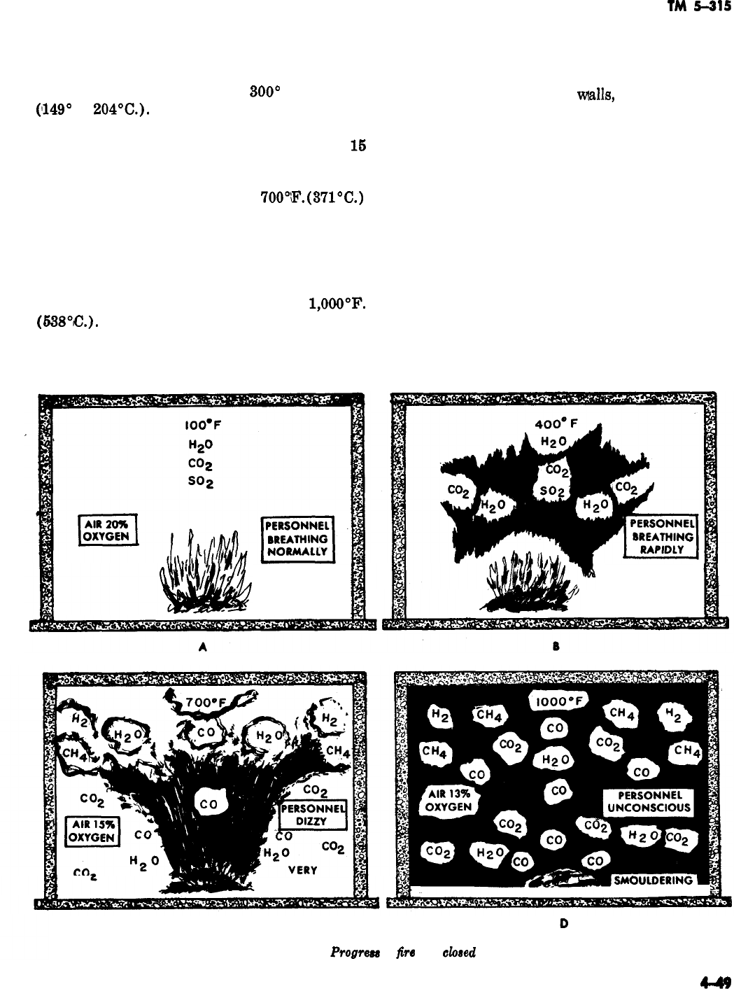
portion of 21 percent oxygen in the air is reduced
-
to about 17 percent. Burning has slowed, and
carbon monoxide production has increased. The
room temperature is between
300”
and 400°F.
(149”
to
204’C.).
(3) In the third stage (C) fire is barely visi-
ble because the oxygen has been reduced to
16
percent. Carbon monoxide is produced in increas-
ing amounts, and free carbon and unburned fuel
form dense smoke. Heat of about
7OO’iF.
(37l’C.)
and gases imperil personnel and produce an explo-
sion hazard.
(4) In the fourth stage (D) the fire is smol-
dering, with the oxygen content at 13 percent or
less. The room is completely filled with smoke and
gases at a temperature of about
1,OOOOF.
(638’C.).
This intense heat distills a portion of
the fuels from the combustible materials; the fuel
gases mix with other gases present, adding to the
FREE BURNING
TM
5-315
fire hazard. The danger to personnel and the prob-
ability of explosion (back draft) are extreme.
d. An idea of the intensity of the fire can be
obtained from feeling the
walls,
doors, windows,
and roof. Hot spots on walls and ceilings indicate
the location of the fire or the path of the hot
gases, A hot spot on the roof on a one-story build-
ing indicates the fire to be directly beneath it. A
hot spot on the floor of a multistoried structure
shows the line of travel of hot gases on the floor
below.
e. When the method of attacking a fire is
planned, the danger of an explosion from the ad-
mission of fresh air must be considered. Explo-
sions which occur when fresh air is admitted to a
smoldering fire are caused by rapid ignition of
combustible material, gases, or both. Improper
ventilation procedures generally lead to explosion
hazards, and in some cases explosion hazards are
SLOW BURNING
SLOW BURNING
CD
Figure 4-64.
Progmm of
fire
in a
closed
room.
TM
5-315
not completely absent regardless of procedures. If
the opening made for ventilation permits a sudden
amount of fresh air to enter before the outward
draft of fuel gases begins, an explosion will result
i’f
the mixture forms in proper proportions. When
possible, openings should be made
above
the seat
of the fire to avoid forcing a draft of fresh air
directly into the fuel gases still
tra,pped
inside the
building. Openings made near the fire, which per-
mit large quantities of fresh air to become mixed
with fuel gases before complete ignition occurs,
are dangerous.
f.
Since fire can be expected to spread rapidly
as soon as an opening is made, adequate protec-
tion in the form of extinguishing agents must be
provided, in advance, at points of intended en-
trance and at points of exposure to other struc-
tures. Enough charged hose lines must be ad-
vanced to extinguish the fire and provide an ade-
quate standby reserve.
443. Safety Measures
Fire protection involves so many procedures
which must be executed almost simultaneously
that it is difficult to present one phase without
mentioning a related duty. Consequently, advanc-
ing charged hose lines to the points of entrance
becomes a
significant
part of the ventilation se-
quence.
u.
A combination nozzle providing either a fog
or a straight stream should be
.used.
The fog
stream is invaluable in clearing remaining gases
and laying a curtain to protect
firellghters
from
the intense heat. Since carbon dioxide, carbon
monoxide, and nitrous fumes are soluble, this
water vapor curtain
,dissolves
and carries down
much of the gas ahead of the firefighters. The
standby hose should be brought into use only if
the fire spreads as a result of an increased oxygen
suPPlY*
?L
Before the burning building is opened, pro-
tective standby lines are advanced to other build-
ings that may be endangered if the fire spreads.
These lines are charged and ready but are not
used until they are actually needed. It may be
necessary to advance some of these lines over
roofs and perhaps inside adjoining buildings. Oth-
ers may be laid to support floors of the burning
building if the
fire
has not yet reached them.
c. Precautions for the safety of the
fighters
are
of primary importance during ventilating
.proce-
dures. Firefighters who take unnecessary
riska
not only endanger their own lives but also may
handicap the department by becoming injured be-
fore the fire is extinguished. These risks, in turn,
endanger the lives of others,
d.
Air containing less than
16
percent oxygen
will not sustain life, and atmosphere containing
less than 1’7 percent
oxy.gen
prevents firefighters
from working efficiently. Carbon monoxide and
nitrous fumes in the smallest amounts may prove
fatal. Compressed air, self-contained demand
breathing apparatus are used where lack of oxy-
gen is suspected.
e. Rope strung from the entrance to the
smoke-
filled area permits the firefighter to retrace his
steps when the smoke is so thick that it permits
only limited vision. After a hose is laid to the fire
area, a rope becomes unnecessary, because the
hose may be readily traced back to the entrance.
Of sufficient importance to repeat is the necessity
of using fog streams to absorb and settle
combua-
tion gases and disperse smoke.
4-44. Ventilating the Building
After the situation at the fire has been evaluated,
and the necessary preparations made, the building
is opened to permit hot gases and smoke to escape
and to extinguish the fire in the shortest possible
time. Proper ventilation should clear the building
of smoke and gases and minimize smoke damage,
allow crewmen to prevent further spread of the
fire, and permit the extinguishing of the fire with
a minimum amount of water.
a. Vertical
Ventilution.
If the internal ventila-
tion, or the
ventilzation
of an inside compartment,
of a closed building permits smoke and gas to
move to the uppermost level, an opening there
permits gas and smoke to escape quickly into the
atmosphere. This procedure is termed vertical
ventilation. The exit opening is generally made in
the roof. The following procedures are important
in vertical ventilation.
(1) Check the condition of the roof supports
to insure that they have not been burned away or
weakened to a point where they may collapse
under the weight of the
firefighters.
(2) Plan a means of escape from the roof for
firefighters who may be confronted with a
possibIe
emergency.
(8)
Use any available natural openings, such
-
-

TM 5-315
as scuttle holes, penthouses, and skylights, if they
are
pro’perly
located.
(4) Do not permit hot combustible gases to
pass
flammable materials which are already
heated. Fresh air may enter the opening before
the outward current is established, thus starting a
new fire on the roof.
(5) Be certain that roof openings are ex-
tended down through the ceiling of the room.
(6)
Make the openings large enough to pro-
vide quick exit for smoke and gases.
(7) Work on the windward side of the open-
ings, keeping in mind the heat, explosive charac-
teristics, and toxic effects of escaping gas.
b.
Cross
VentiZation.
If smoke
,and
gases have
not reached the uppermost level, cross ventilation
may be used to clear the building, one floor at a
time. This method requires more care than verti-
cal ventilation because large vertical shafts, such
as open stairwells, may allow downward drafts of
cross-ventilated fresh air to reach an area not yet
opened, causing an explosion. Natural outside
openings must be available on each floor level. The
procedures for cross ventilation are as follows
:
(1) Open the windows on the leeward side
first; then open the windows on the windward
side.
(2) If the windows are check-rail types, open
the upper half on the leeward side and the lower
half on the windward side.
(3) After one floor is clear, ventilate the next
floor in the same way, or ventilate into the room
already cleared if the room is not occupied by
people.
(4) Do not make openings below the level of
the fire.
(5) If the opening is made at the same level
as the fire, the hose lines should be available for
immediate use.
4-45. Entering
Before
hosemen
are directed to proceed with ex-
tinguishment, checks must be made to insure that
enough heat, smoke, and gases have been removed
to permit entering the building without
casuali-
ties. When the intense draft set up at the exit
openings cools or ceases altogether, the building
probably is ready for entry.
d. A complete knowledge of such matters as the
structural characteristics, arrangement, and con-
tents of the building, acquired by previous inspec-
tions, is almost essential to successful ventilation.
Basement fires are sometimes extremely difficult
to ventilate because under some conditions the
smoke is not hot enough to rise, which increases
the possibility of explosion.
Low-tem,perature
smok+produced
by such materials as rubber,
fats, and wax-is very persistent in resisting ven-
tilation. Such smoke is also capable of dropping to
lower levels. This condition usually requires me-
chanical aid, such as blowers, in addition to the
normal procedures.
4-46. Salvage
a. After precautions have been taken against Salvage work in firefighting consists of <prevent-
the spread of fire and the opening has been made ing excessive damage by fire, smoke, and water.
for ventilation, the next step involves reaching
and extinguishing the fire. Other openings are
made as near the fire as possible, with charged
hose lines held in readiness. These openings
should never be below the base of the fire.
6.
When firefighters proceed through smoke-
filled rooms to locate the base of the fire, they
advance behind a
waterfog
curtain if the smoke
causes enough discomfort to warrant its use and
if water damage will not be unnecessarily great.
‘This curtain tends to drive the smoke ahead of the
personnel. Following the heat and smoke toward
their point of greatest density is the best guide;
feeling walls and fixtures and observing air cur-
rents are also helpful. The same safety and
pro-
t’ective
measures
.must
be taken during extinguish-
ment as are taken for ventilation.
c. It
m,ay
not always be necessary to ventilate a
building to locate a fire, nor is it always advisable
to postpone ventilation until rescue work is com-
pleted. Actually, they go hand in hand, and when
the number of available personnel is such that
different
o*perations
can be carried on simultane-
ously, teamwork then takes the initiative, and
hose lines are ready for use by the time the crew
is
r.eady
to ventilate. Ventilation normally should
be started at the top of the building and worked
downward. Coordination in
ventil,ation
is an ex-
tremely important factor. When possible, it is ad-
visable for the fire chief in charge to give the
commands to ventilate. This minimizes the possi-
bility of back draft or accelerated fire propaga-
tion, which may easily occur with several groups
working without concern for each other.
4-51
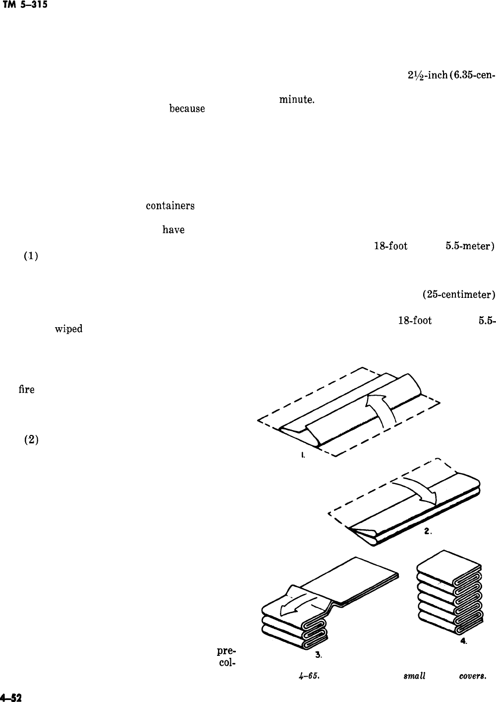
TM
5-31s
Water often causes as much damage as the fire
itself.
a. Water Protection. Improper arrangement of
contents in a structure can cause large water
losses. For example, shelves built up to the ceiling
directly against a wall make salvage impossible,
unless the contents are removed,
b,ecause
water
flows down the wall, soaking the shelf surfaces
and their contents. One common obstacle to
efficient salvage involves material piled on the
floor without skids. The lower portion of such
piles is difficult to salvage when a large volume of
water has been used for extinguishment. Materi-
als stored in paper boxes or cartons frequently
spill when the bottoms of the
cont,ainers
are wet,
thus ruining the entire contents even if the boxes
are covered efficiently and if dikes
hav’e
been made
with sawdust.
(‘1)
Material stored on lower floors may be
covered with large waterproof tarpaulins. If the
quantity of material and weight is not excessive,
it may be moved outside or to another part of the
building. Heavy crates, packing cases, machinery,
and similar articles should be covered. Metal
should be
wi,ped
dry and oiled to prevent rust.
Much water damage can be prevented by proper
application of water at the base of a fire. Fire-
fighters should watch for leaky hose connections
and for the spray of water on dry material. When
the
fir,e
has been extinguished, all floors should be
cleared of water by sweeping it toward a door or
opening. If holes must be chopped for drainage,
the rate of damage is greatly increased.
(,2)
Foodstuffs must be protected against be-
coming tainted by exposure to smoke and water.
Meat, solid fats, and cheese may have little or no
salvage value if they are subjected to smoke or
heat.
(3) When a roof has been damaged, the hole
may be covered with a tarpaulin or roofing paper.
Care should be taken to remove all nails and
sharp objects to prevent damage to the covers.
When the entire roof is destroyed, temporary
roofs of canvas truck covers may be installed. The
covers must be securely fastened.
(4) Further damage by water can be pre-
vented by using sawdust to absorb water and to
form dikes that direct the water outside through
doorways or other openings. Wooden floors can be
drained by drilling holes in them. When absorbent
materials are involved, care is necessary to
pre-
vent the excess weight added by water from
col-
lapsing the floor. Firefighters should be trained to
make a speedy estimate of the weight of water
being used by calculating from the known nozzle
size, the water pressure, and the length of time
during which water has been discharged. A pum-
per discharging from a single
2rh-inch
(6.35cen-
timeter) hose line can deliver about 1 ton of water
per
minut,e.
(5) Articles of special value should be re-
moved from the debris as soon as the fire has been
extinguished. Debris should be removed from the
building, floors swept, and excess water removed
with broom and squeegees. Office records of ad-
ministration buildings, headquarters, and similar
buildings should be fully protected with canvas
covers.
b. Salvage Covers.
(1) To permit convenient handling and easy
manipulation, the 12 by
l&foot
(3.7 by
5.5-meter)
salvage covers are folded into an accordion fold
(fig. 4-65). In this fold, the two ends are brought
together in the center of the cover, which is then
foided over double. Then lo-inch
(25-centimeter)
folds are made until the operation is completed.
(2) The large 14 by
18-foot
(4.3 by
5.5-
meter) salvage cover is folded somewhat diff-
erently from the small one because of its greater
Figure
.$-65.
Accordion fold for
emu11
salvage
covera.
-
-
4-52
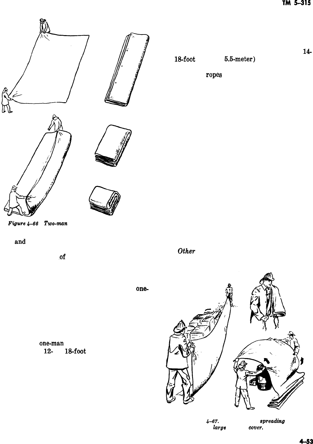
TM
5-315
-
-
Figwe
4-66
Two-mun
fold for large salvage cover.
size
an,d
weight. The fold for the larger cover
requires two men, who position themselves at the
two corners of one
.of
the long sides of the cover
(fig. 4-66). They fold the cover to the center, then
fold it to the center again, bring the ends to-
gether, and fold the cover again lengthwise.
(3) The large salvage cover requires a
one-
man carry in which the cover is placed over the
shoulder. This is done to keep the tops, which are
secured in the grommets on the corners of the
cover, to the front of the body. This enables the
carrier to grasp them when the cover is to be put
into use (fig. 4-67).
-,
(4) ‘The
one-ma.n
throw is a quick method for
spreading a
12-
by
18-foot
(3.7 by M-meter)
cover. It may be used effectively to cover desks,
office records, shop machinery, and similar items.
First he places the center of the folded cover over
his forearm, and grasps the bottom of the fold
with the fingers. Then he reaches in next to his
body with the other hand and grasps the three
folds between the thumb and fingers, with the
thumb down. He swings his arm up and over his
shoulder and flips the three folds over the back of
his hand to give weight to the throw. He brings
the hand forward, with the arm still, and throws
the cover over the object to be covered with a
straight-arm throw. Finally he opens the cover
completely and tucks the edges in at the bottom.
(6) Two men should be used to unload the
14-
by
18-foot
(4.3 by
6.Lmeter)
cover from the
shoulder and place it in use. The carrier grasps
the grommet
rope
at the cover corners nearest
his body, and the second man grasps the remain-
ing ropes and moves away from the carrier. The
cover is dropped to the ground and stretched out
near the material to be covered. Both men drop
the inside edge of the cover, holding firmly to the
outside edges. They then raise one edge of the
cover quickly, carrying it over the material and
allowing the air to balloon the cover, thus en-
abling the proper placement of the thrown edge.
All corners and edges of the cover should be
tucked in at the bottom.
(6) The counter payoff is used when material
must be covered to prevent its damage, destruc-
tion, or disarrangement. The counter payoff is
begun by placing the cover over the forearm,
holding the bottom fold with the fingers. A second
man grasps the top fold and walks backward, both
men raising the cover as it unfolds. They place
the cover gently over the material. When the
cover has been draped, they tuck in the edges at
the bottom.
c.
Other
Protective Devices. The contents and
interiors of buildings may be severely damaged by
Figure
4-67.
Carrying and
spreading
the
lurge salvage
wver.
4-53
TM
5-315
water dripping through a floor or ceiling in which
a drain cannot be made.
(1) To prevent this, improvised basins are
frequently needed to catch water which can be
removed later by bailing, dumping, or pumping. A
catch basin (fig. 4-68) is constructed by placing
furniture, boxes, or other equipment in a circle or
square beneath the leak. A basin is formed by
placing a salvage cover over the furniture and
boxes. The cover is fastened to the boxes and fur-
niture or to the door, with the bottom of the basin
resting on the floor. Where the quantity of water
is not great, shallow catch basins may be made by
rolling all four edges toward the cneter. The rolls
then form the sides of the basin.
(2) S-hooks, cord, salvage covers, and pike
poles can be used to build a chute which directs
water through windows, thus protecting contents
and interiors of buildings from water damage
(fig. 4-69). Light rope or heavy cord can be
tied
through the grommets to support the covers.
Figure
4-68. Salvage cover
bah.
Figure
4-69.
Window
drain
chute.
Figure
4-7’11.
Stairway
drain.
(3) S-hooks can be improvised from heavy
wire, welding rods, or
3/16-inch
(0.476-centime-
ter) cold-rolled steel rods. Rods can be cut to
lengths of approximately
8
inches (20 centime-
ters), sharpened at the ends on a grinding wheel,
and bent to an S-shape.
-
(4) To protect material stored on shelves, the
shelf should be covered with the canvas salvage
covers. This is down by using S-hooks, nails, and
cord to suspend the covers from the walls and the
ceiling or by securing the cover with weights.
When more than one cover is used, lapovers of
about 1 foot (0.305 meter) should be used to
lpre-
vent leakage.
(5) To protect the interior structures and
contents from water damage, stairway drains of
canvas covers are frequently needed to direct
water
frbm
upper floors to a lower level and out-
side. The two methods of forming stairway drains
shown in figure 4-70 are commonly used. Two
men and two canvas covers are required to per-
form the operations efficiently. The first cover is
spread by the one-man throw at the bottom of the
stairs and fitted to the steps. The second cover is
placed at the top of the steps in the same way and
is allowed to overlap the lower cover about 1 foot
(0.305 meter).
(6) In addition to the tarpaulin or salvage
cover, the things most commonly used in salvage
work
are squeegees, brooms, mops, buckets, pike
poles, shovels, and sawdust. Shovels and buckets
are used to remove
debri,s.
Water is removed from
floors with squeegees, mops, buckets, and brooms.
d. Salvage Training. When properly executed,
salvage work can often prevent great property
-
-
TM
5-315
loss, and invalidate the old theory that firefighters
tation. For practice by two men in a coordinated
do more damage in putting out a fire than the fire
handling of salvage covers, the fire apparatus
iL
-
itself does. The folding, throwing, and general self is an ideal object over which the covers may
handling of salvage covers should be
conscien-
be thrown. The erection of catch basins, plus any
tiously
practiced under varied conditions until the
related operations required of the crew, may be
firefighters can do the job efficiently without
hesi-
set up as part of the salvage and pumper drills.
Section
VI,
RESCUE OPERATIONS
-
-
447. Introduction
The primary function of rescue operations is to
perform all emergency procedures that are neces-
sary to recover personnel from situations that
prohibit their escape. The first consideration of
the firefighter is always that of saving lives. This
function may be performed by-(l) recovering
victims from hazardous situations, (2) moving
victims to a safe place, and (3) giving essential
first
aid to victims. Whenever possible, the
re-
moval of victims to a safe place must be made
without further injury. Extreme care must be
taken in removing personnel who appear to be
injured. Simple fractures, for example, may
become compound fractures or may develop into
more serious or even fatal injuries unless the
victim is moved properly. The different ways of
removing
casuaIties
are by supporting or carry-
ing, by using a stretcher, and by lowering and
raising victims.
4-48.
Carries
Helping a victim walk is probably the simplest
and easiest of the rescue methods, provided the
victim is able to walk at all. This method should
not be used unless the rescuer is sure there are no
severe injuries that would be aggravated by so
doing.
‘I?vo
methods are used, the one-man method
and the two-man method.
a. One-Man Supporting Carry. To perform the
one-man method, an uninjured arm of the victim
is placed over the rescuer’s shoulder and behind
his neck. The rescuer grasps the victim’s hand
and passes his other arm around the victim’s
waist (fig.
4-71).
In this way the one man may
support and help a slightly injured person to
walk.
b.
Two-Man Supporting Carry. The two-man
method is similar to the one-man method except
that the victim puts an arm over the shoulder and
behind the neck of each rescuer. Each grasps his
hand and puts the other arm around his waist,
thus giving him added support (fig. 4-72). This
way practically the entire weight of the victim
can be borne by the rescuers.
449. Fireman’s Carry
The fireman’s carry (fig.
4-73)
is the easiest
method for one man to carry another. It is
accom-
plished in the following seven steps.
Figure
.b-71.
fhppovting
camy.
Figwe
&??2.
Two-man
mpporting
cam-g.
a. Step 1. Turn the casualty face down and
kneel on one knee at his head. Place both hands
under the casualty’s armpits and gradually work
them down the side and across the back.
b.
Step
2.
Raise the casualty to the knees.
c. Step
3.
Take a firm hold across the casualty’s
back.
d
Step
4.
While holding the casualty around the
waist with your right arm, grasp the casualty’s
right wrist with your left hand and draw his arm
over your head. (If the casualty is wounded in
such a way that the procedure must be performed
from the opposite side, simply change the hand
and continue as described, substituting right for
left and vice versa.)
e. Step 5. Bend at the waist and knees and pull
the casualty’s right arm down over your left
shoulder so that his body comes across your shoul-
ders. At the same time, pass your right arm be-
tween his legs and grasp his right knee with your
right hand.
f.
Step 6. The casualty is lifted as you
straighten up.
4-56
I
Figure
&73.
Firtmun’8
carry.
g.
Step 7’. Then grasp the casualty’s right wrist
with your right hand, leaving your left hand free.
This is the position of carry. A man can carry
another some distance in this manner.
4-50. Pack-Strap Carry
Place the pack-strap over the back and under the
arms of the victim. Lift the casualty, then turn
around while retaining a hold around his body
with one arm. Grasp his wrists with your hands
and hoist him so that his armpits are over your
shoulders (fig. 4-47). This is a good way to carry
an unconscious casualty. Do not use it if the
cas-
ualty
has any broken bones. Since both hands are
-
TM
5-31s
free, the rescuer may proceed down a ladder or
through difficult passages. Although the dangling
-
legs of the victim are awkward, he cannot slip
from the load. Too, the rescuer can shift the load
from his back to his leg muscles by bending for-
v.lard.
4-5
1. Two-Man Carriers
CL
The seat carry is a two-man means of carry-
ing a person. It consists of making a seat rest of
one pair of arms and a back rest of the other pair.
Figure 4-75 shows how the arms are arranged
when completed. The rescuers kneel, one on either
side of the victim, near the hips, and raise him to
a sitting position steadying him with the arm
near,est
his head around his back. Each then slips
the other arm under the victim’s thighs, clasping
the wrist of the other. Both arise slowly but in
unison, lifting the victim from the ground. When
erect, they adjust their upper arms to form a
Gomfortable
back rest and to make the victim
-
Figure
4-74.
Paek-atrap
cam.
Figwe
4-76. Amn
mat
rd.
secure. If conscious, the victim assists the
rea-
cuers
by grasping each man around the neck.
b.
Carrying by the extremities is a good method
for carrying a person, hut not usable in case of
leg or back injuries. The victim is laid straight on
his back, feet apart. One rescuer takes his place
between the victim’s legs and the other at his
head, facing each other. Both men kneel and raise
the victim’s head and shoulders to a sitting posi-
tion. The man at the victim’s head grasps him
from behind, around the
.body
under the armpits.
The one between the victim’s legs turns around
and passes his hands from the outside under the
victim’s knees, then both rise together and move
forward in step (fig.
&76).
c. A two-man chair-litter carry may be used if a
common chair is available. The two men place the
victim on the chair, then with one in front and
one behind, they grasp the chair conveniently, tip
it back, and walk forward in unison, as shown in
figure
677.
The chair serves as a litter.
4-52. Severe
lniuries
Carv
In cases of severe injuries the number of rescuers
should be increased to at least three. This makes
it
possilble
to transport the victim with the least
possible bending or twisting of his body.
a. To make the carry more effective, all efforts
should be coordinated, and to do so, one of the
group must be in command.
,The
common practice
is to make the one at the victim’s head com-
mander or leader of the crew. This applies espe-
cially to a three-man crew.
F@uT~
4-76.
Extvemitie8
cam-g.
b.
The three-man carry is accomplished as
fol-
lows: The three men line up on one side of the
victim and the leader gives the word to “prepare
to lift.” Each man kneels on the knee nearest the
victim’s feet, with one man at his shoulders, one
at his hips, and one at his knees. Without further
orders, they pass their hands and forearms under
the victim (A, fig. 4-78). The one at the head
places his hands under the victim’s neck and
shouilders,
the next places his hands under the
pelvis and hips and small of the back, and the
third under the knees and ankles. At the command
“Lift,” they raise the victim and place him on
their knees, but without releasing their hands
(B,
fig. 4-78).
-
c. At the command “Prepare to raise,” they
slowly turn the victim on his side toward them
until he rests in the bend of the elbows. At the
command “Rise,” all rise slowly to standing posi-
tion, holding the patient closely against their
chests (C, fig. 4-78). If space permits, the res-
cuers may move forward at the command
‘OMarch,”
starting off with the left foot. If space
will not permit moving forward, they must move
sidewise, in which case the command, “Side step
left (or right)” is given. The rescuers step off
with the foot according to the command, bring the
other foot up to it in even, short steps. The victim
is lowered and placed by reversing the operations,
always at the command of the leader.
4-53.
lowering and Raising a Victim
In situations where the victim is not at ground
level and the natural exits are blocked, he must be
rescued by some other means of escape. In flre
rescues, this usually involves lowering the victim,
although in rare cases it might involve raising
him.
Figure
4-77.
Chair-littm
cam.
a.
The escape method commonly used by the
rescue squad of the fire service is by a ladder
__
Figure
4-78.
Severe
injuriea
cam.
from the outside. If the victim is conscious and
uninjured, he may be guided down a ladder at a
window or other opening as shown in figure
4-79.
Generally a victim
is.unaccustomed
to going down
a ladder, especially under emergency circum-
stances, so great care must be taken to make sure
that he does not fall. The rescuer goes down below
the victim, keeping his arms around him and one
-
knee between the victim’s legs to assure a support
in case he becomes unconscious.
Figure 4-78. Lowering
vi&m
m
ladder.
Figure
4-80.
Lowe&g
victim with rope and ladder.
4-59
TM
5-315
b.
Should the victim become unconscious, the
rescuer lets him slip down astride his knee and
proceeds carefully to the ground. If the victim is
unconscious or not too seriously injured, he may
be carried down the ladder by the pack-strap
method.
c. An unconscious victim may be lowered from
an upper floor by the use of a ladder and lifeline.
(A small
handline
is not safe for this practice).
Although it may appear slow compared to carry-
ing him down a ladder, the method
ma3
be a safer
one in certain conditions.
d.
The procedure is as follows. A ladder is
raised to a point just
ab,ove
the window where the
rescue is to be made. The first man takes the end
of the lifeline at the bottom of the ladder and
passes it underneath the bottom rung. The end is
then held in either hand so that the rope will
fee3
to the under side of the ladder as he ascends.
When the bottom of the window sill is reached,
’
-.
the rope is then threaded back through the rungs,
up
and’over
three consecutive rungs. This allows
the rope to hang freely but not too close to the
building. Enough rope is then fed through, aided
by the men on the ground, to allow a
sufficient
length to be taken through the window where the
tie is made. Usually about 20 feet (6 meters) is
enough for this operation. The rescuer then steps
from his ladder through the window into the room
and makes the tie on the victim. After the tie has
been made, the victim is swung from the window
and lowered by the men on the ground holding the
rope tight (fig. 4-80).
Section VII. FIRST AID
4-54. Definition and Requirements
First aid is the immediate and temporary care
given to casualties before they can be treated by
professional medical personnel. The firefighter is
confronted mainly with cases of bleeding, respira-
tory deficiencies, shock, fractures, burns, and
wounds. In all oases, the
unjured
must
%e
assured
of the competency of those
administeting
first aid.
The victim must be kept lying down and warm
with a blanket under him (if possible without
danger of injury), and as comfortable as possible.
4-55.
Short Distance Transfer
If the victim must be moved to safety, he should
be pulled in the direction of the long axis of his
body, not sideways. The danger is less if a blanket
or similar object can be placed beneath him
BO
that he can be dragged with the blanket. If a
person must be lifted to safety before a check for
injuries can be made, the carriers
@muld
try
b
protect all parts of the body from the tensions of
lifting, as discussed in paragraphs
4-47,
and
4-62,
vessel which supplies the blood to the part of the
body that is injured.
a. Direct
Presmre.
Place an opened first-aid
dressing over the wound and press dbwn
(fig.
4-81).
The pressure compresses the blood vessels.
This reduces the blood flow and it also helps to
hold blood in the wound until it clots. An addi-
tional measure which aids in controlling bleeding
from an arm or leg is to elevate the injured limb
higher than the rest of the body.
-
CAUTION
If there is a suspected fracture of an arm
or leg do not raise the injured limb until
it has been properly splinted.
b.
Digital Pressure. It may be necessary at
times to apply pressure to the supplying blood
vessel to reduce bleeding. If blood is spurting
4-56.
External
Bleding
Severe bleeding (hemorrhage) may cause
death
within minutes; therefore, it requires
immedi&e
attenti,on.
It
causes shock, the degree of which
depends on the severity of the injury and
on.&
temperament of the injured. Most bleeding can be
stopped by applying direct pressure over the
wound. Some wounds may require pressure on the
Figure
4-81.
Stopping bleeding by direct
premure
a
th.9
~OU?ld.
Figure 4-82.
Pressure
points from temporary control of arterial bleeding.
from a wound (arterial bleeding), digital pres-
sure can be used to control the bleeding until a
pressure dressing can be unwrapped and applied.
Digital pressure is applied with the fingers, the
thumbs, or the hands to a pressure point (fig.
4-82). A pressure point is the site at which a
-
main artery supplying the wounded area lies near
the skin and over a bone. By pressing on this
point the flow of blood from the heart to the
wound is shut off or at least slowed down. The
two most essential pressure points to know are
e and h on figure
U2.
These are the main
points by which bleeding from the extremities can
be controlled.
c.
Tourniqud.
A tourniquet is a band placed
around an arm or leg so tightly that the compres-
sion Hocks the arteries. It should be used
onZy
if
pressure over the wound and elevation or pressure
4-61
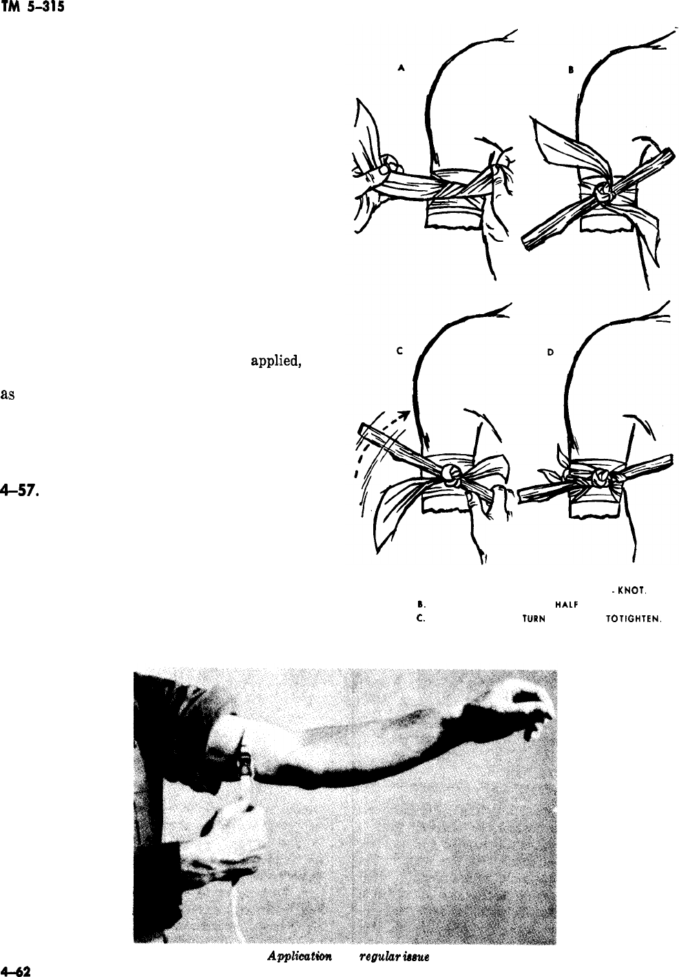
TM
5-315
on the supplying blood vessels fail to control the
bleeding. A tourniquet does not stop all bleeding
immediately. When a tourniquet is needed it must
be applied promptly and properly.
(1) If a regular issue tourniquet is used, the
buckle should be adjusted as shown in figure 4-83,
and the strap pulled downward while the injured
part is steadied. If an issue tourniquet is not
available, a belt, tie, rope, or handkerchief is used
instead of the strap. These improvised bands are
tied around the arm or leg and twisted with a
stick as shown in figure 4-84. A tourniquet must
be drawn up tightly.
(2) For bleeding from the arm or leg, never
apply a tourniquet over a bony part such as wrist,
elbow, ankle, or knee. It is more efficient when
applied over fleshy parts such as the thigh or
upper arm. The tourniquet should be applied as
close as possible to the edge of the wound,
(3) Once the tourniquet has been
apphed,
the
wounded man should be seen by a doctor as soon
ass
possible. The tourniquet should not be loosened
by anyone except medical personnel. When a tour-
niquet has been applied to a casualty, the time of
application should be written on or near the tour-
niquet.
4-57.
Internal Bleeding
If the victim is bleeding from the mouth or nose,
the blood is probably coming from the lungs,
stomach, or within the skull, or passages related
thereto. If the victim has trouble breathing, raise
the head and shoulders, using pillows or substi-
tutes. Try to control his vomiting. Give no stimu-
lants or water. If unconscious, turn the victim on
his side with head and chest lower than the hips.
This prevents the victim from drawing blood into
A. WRAP TWICE AROUND ARM, TIE HALF
-KNOT.
B.
PLACE ‘WINDLASS’ OVER
HALF
KNOT.
C.
FINISH KNOT AND
TURN
WINDLASS TO
TIGHTEN.
D. SECURE WINDLASS WITH TAILS OF TOURNIQUET.
Figure 4-84. Application of an improvised tourniquet.
Figure 4-88.
Applieutim
of a
regulur
&me
tourniquet.
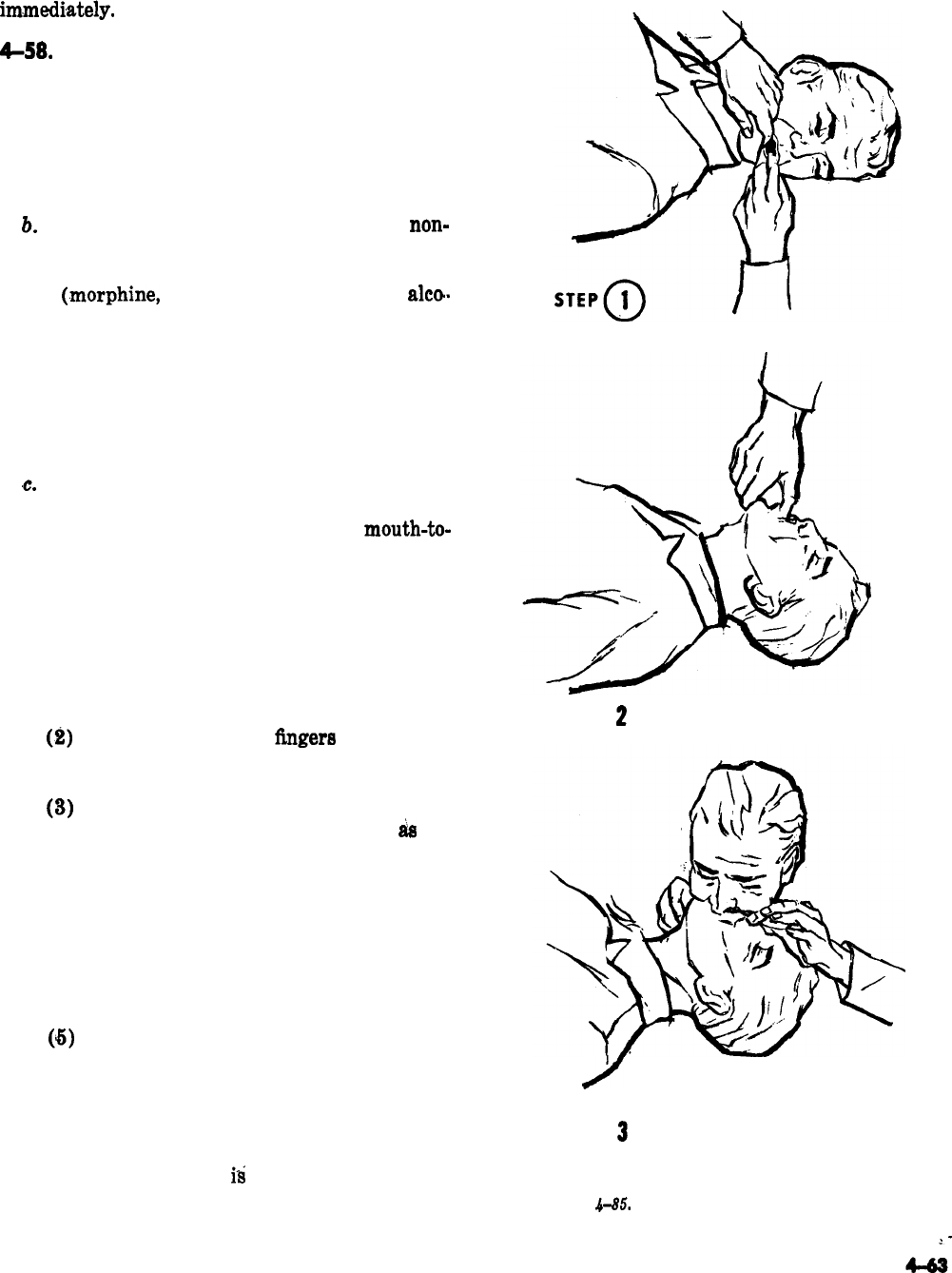
TM 5-315
the lungs while breathing. Obtain medical care
im,mediately.
&58.
Artificial Respiration
a. Knowledge of artificial respiration is essen-
tial to firefighters. Large fires sometimes trap peo-
ple in smokefilled buildings. Then, too, firefighters
are themselves likely victims of smoke inhalation.
Thus, it becomes the duty of firefighters to know
and apply artificial respiration.
b.
Artificial respiration is administered to
non-
breathing victims of electric shock, drowning, gas
poisoning, poisoning by respiration-depressing
drugs
(.morphine,
opium, barbiturates, and
alto.
hol), compression of the chest caused by building
collapse or cave-ins, choking and strangling, and
partial obstruction of the breathing passages. Ar-
tificial respiration must be started promptly after
normal respiration ceases. Most persons die in ap-
proximately six minutes after breathing stops un-
less artificial respiration is administered.
,c.
Artificial respiration may be administered by
manual or mechanical methods. When the manual
method is necessary, it may be the
mouth-to-
mouth method, back-pressure arm lift method, or
the back-pressure hip-lift method. In performing
any method of artificial respiration, always keep
the following general principles in mind.
(1) Time is of prime importance. Do not
delay artificial respiration to loosen clothing, to
warm the casualty, or to give stimulants. Most
important is to get air into the casualty’s lungs.
(2)
Quickly sweep your
fingers
through the
casualty’s mouth to clear out froth and debris,
and draw his tongue forward.
STEP
2
0
(3)
Position the casualty properly in order to
maintain an open airway. Tilt his head
as
far
back as possible so that the front of the neck is
stretched with the chin in a “jutting-out” posi-
tion. Do not allow the chin to sag.
(4) Begin artificial respiration and continue
it, without interruption, until the casualty starts
natural breathing or is pronounced dead. A
smooth rhythm is desirable, but split second tim-
ing is not essential.
(5)
If the casualty begins to breathe on his
own, adjust your timing to assist him. Do not
fight his attempts to breathe. Synchronize your
efforts with his.
(6) As soon as the casualty is breathing for
himself, or when additional help becomes availa-
ble, see that his clothing
is
loosened (or removed
if wet) and that he is kept warm, and is being
treated for shock.
I
/
STEP
3
0
Figure
4-85.
Mouth-to-mouth (thumb-jaw-lift)
resuscitation method.
2-

TM
5-315
4-59. Mouth-to-Mouth (Thumb-Jaw-lift)
Method
a. Place the casualty on his back (face up).
D.o
not put anything under his head because it may
flex the neck and
cau,se
the air passages to be
blocked.
into the stomach instead of the lungs. Although
an inflation of the
sto,mach
is not dangerous, it
makes inflation of the lungs more difficult. There-
fore, when you see the stomach bulging to a
marke,d
degree, apply gentle pressure to the stom-
ach with your hand between inflations.
b.
Quickly clear his mouth of any foreign mat-
ter by running your fingers behind his lower teeth
a.nd
over the back of his tongue (fig. 4-85). Wipe
out any fluid,
vomitus,
or mucus.
c.
If available, place a rolled blanket or some
other similar material under the shoulders so that
the head will drop backward. Tilt his head back so
that the neck is stretched and the head is in the
“chin-up” position (fig. 4-85). This
alines
the air
passages so that they do not become blocked by
kinking or pressure.
d.
Place your thumb into the corner of his
mouth and grasp the lower jaw firmly. Lift the
lower jaw forward and pull the tongue forward
out of the air passage. Do not attempt to hold the
tongue. Close his nostrils with the thumb and
index finger (step
@,
fig. 4-85). Put a cloth over
the victim’s mouth or nose and breathe through it
if you do not wish to come in contact with the
person.
i. Remember: keep the air passages as clear of
fluid and other obstructions as possible. Several
sharp slaps between the shoulder blades usually
dislodge foreign matter. Keep the head back, the
neck stretched, and the chin pulled forward
;
read-
just
po,sition
if air does not flow freely in and out
of casualty, Do not breathe too forcibly or too
large a
v,olume
if casualty is an infant or small
chil,d
;
in infants seal both the mouth and the nose
with your mouth and blow with small puffs of air
from the cheeks, rather than blowing from the
lungs. If
yo,u
become distressed as a result of the
shallow breaths, interrupt the blowing long
enough to take a deep breath, then resume blow-
ing.
4-60.
Mouth-to-Mouth (Two-Hands-Jaw-lift)
Method
e.
Take a deep breath. Open your mouth wide.
Then seal your mouth around the casualty’s
mouth and your thumb, and blow forcefully
(except for infants and small children) into his
mouth until you see his chest rise. If the chest
does not rise, hold the jaw up more forcefully and
blow harder while making sure there is no block-
age of the air passage and no air leakage around
the mouth or nose.
This is an alternate method for use in a clean
atmosphere when the casualty’s jaws are so
tightly closed that the thumb cannot be inserted.
a. Place the casualty on his back, clear his
mouth if possible, and position his head in the
“chin-up” position.
f.
When his chest rises, stop blowing and
quickly remove your mouth from his. Take an-
other deep breath while listening for his exhala-
tion. (If his exhalation is noisy, elevate the jaw
f,urther.)
b. Grasp the angles of his lower jaw with both
hands just
belo,w
the ear lobes and lift the jaw
forcibly forward to pull the tongue forward out of
the air passage. If the lips are closed, push the
lower lip toward the chin with
yuur
thumbs (fig.
4-S6).
g. When exhalation is
finitshed,
blow in the next
deep breath. The first
6
to 10 breaths must be
keep (except for infants and small
childre,n)
and
given at a rapid rate in order to provide rapid
reoxygenation. Thereafter, continue breathing at
a rate of 12 to 20 times a minute until the cas-
ualty begins to breathe normally. Excessively
deep and rapid breathing
‘may
cause you to
become faint and even lose consciousness.
c. Take a deep breath and open your mouth
wide. Seal your mouth around the casualty’s
mouth, press
yo,ur
cheek against his nose to pre-
vent air leakage and blow forcibly into his mouth
until you see his chest rise.
4-61.
Mouth-to-Nose Method
This is an alternate method for use in a clean
atmosphere when neither of the methods above
can be used
;
for example, on casualties with se-
vere jaw spasm or with wounds of the jaw and
mouth?
h. After performing rescue breathing for a
a.
Place the casualty on his back, clear his
time, you may notice that the casualty’s stomach mouth if possible, and position his head in the
is bulging. The bulging is due to air being blown “chin-up” position. Grasp the angle of his lower
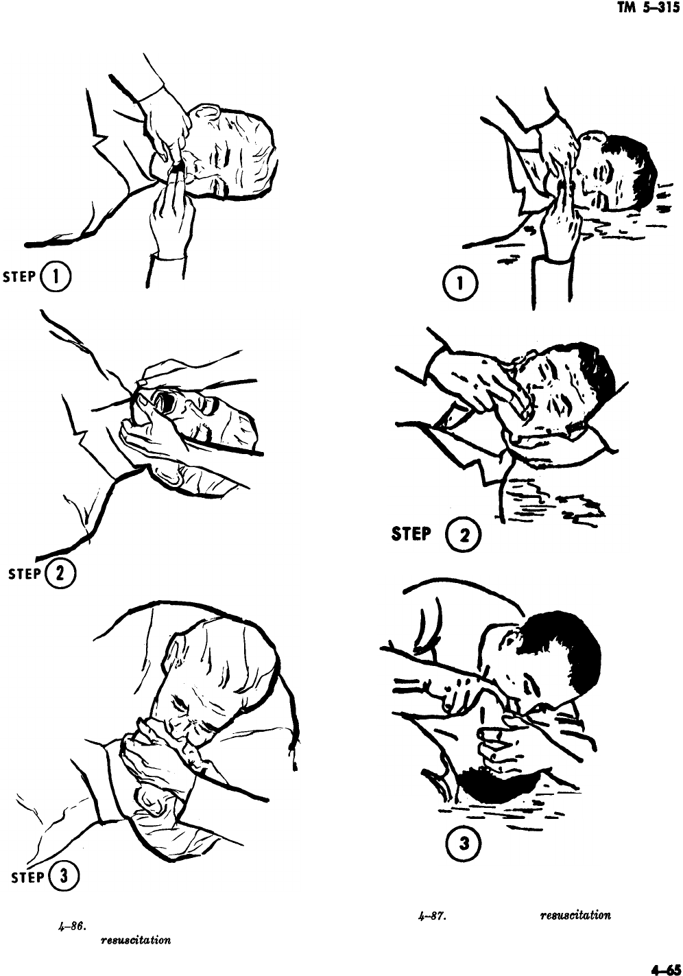
Figure
.&86.
Mouth-to-mouth (two-hands-jaw-lift)
~e~citution
method.
STEP
STEP
Figure
4-87.
Mouth-to-nose
resuacitution
method.
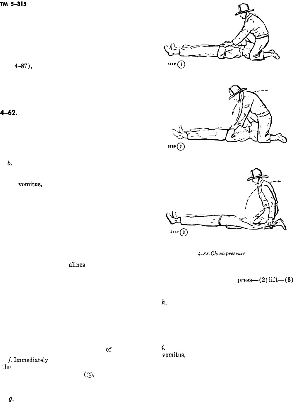
TM
5-315
jaw with one hand just below the ear lobe and lift
the jaw forcibly forward (fig. 4-87).
b. Seal your other hand over the casualty’s
mouth to prevent air leakage (fig. 4-87).
c. Take a deep breath and open your mouth
wide. Seal your mouth around the casualty’s nose
(fig.
4-87),
and blow forcefully until you see his
chest rise.
d. When his chest rises, stop blowing and
quickly remove your mouth from his nose. Take
another breath while listening for his exhalation.
6-62.
Chest-Pressure Arm-lift Method
(Modified Silvester)
This is the preferred method for use in a contami-
nated atmosphere.
a. Place the casualty on his back (face up) with
his arms folded on his chest (fig. 4-88).
!L
Quickly clear his mouth of any foreign mat-
ter by running your fingers behind his lower teeth
and over the back of his tongue. Wipe out any
fluid,
vomitus,
or mucus. If you are in a contami-
nated area and the casualty is not already
masked, put his mask on. If he is already masked,
quickly remove the mask, wipe away any fluids
that may have collected in his mouth or in his
mask, and replace the mask.
c. If available, place a rolled blanket or some
other similar material under the shoulders so that
the head will drop backward. Tilt his head back so
that the neck is stretched and the head is in the
“chin-up” position. If possible, keep the head in
this position, since this
alines
the air passages so
that they do not become blocked by kinking or
pressure.
d. Kneel on either knee at the casualty’s head,
placing your knee at one side of his head, and
placing your opposite foot on the other side of his
head.
e. Take the casualty’s arms just above his
wrists and place them over the lower ribs. Rock
forward and exert steady, uniform pressure al-
most directly downward until you meet firm re-
sistance. This pressure forces air out
o.f
the lungs.
f.
I’mmediately
release this pressure and pull
thfl
arms outward and upward over his head and
backward as far as possible
(,@,
fig. 4-88). Lift-
ing and stretching of the arms increases the chest
size and draws air into the lungs.
g.
Slowly replace his arms on his chest and
Figure
4-88.
Chest-presswe
arm-lift
resuscitation method
repeat the complete cycle about 12 times per mi-
nute at’ a rhythm of (1)
press-(2)
lift-(3)
stretch-(4) release. The “release” should be ab-
rupt.
h.
If you become tired or uncomfortable on one
knee, you may quickly switch to the other knee. If
it is more comfortable, you may knee on both
knees, although the forward and backward motion
is easier to obtain while kneeling on one knee
only.
i.
Check the mouth frequently for obstructions.
If
vomitus,
mucus, or blood obstruct the air pas-
sage, keep the victim’s head extended and turned
to one side.
j. When a second man is available, he may take,
over the chest-pressure arm-lift with practically
no break in the rhythm. This is done by the first
man moving off to one side while the replacement
4-66

TM
5-315
--
comes in from the other side. When the second
man is ready, the casualty’s arms are released
during the “stretch” and the new operator takes
them and continues in the same rhythm.
4-63.
Followup
Care in Artificial Respiration
When the casualty is breathing normally, wrap
him in a blanket. He should remain lying down
until he is seen by a physician or his recovery
seems assured. When he is conscious, give him a
warm drink, such as coffee or tea.
4-44.
Shock
Although there are several types of shock, the one
with which the firefighter is chiefly concerned is
traumatic shock. This is a depressed condition of
many of the body fun&ions. It is caused by failure
of enough blood to circulate through the body fol-
lowing a serious injury. Traumatic shock may re-
sult from injury to body tissues from burns,
wounds, or fractures. In most instances it is the
result of the loss of large
quantihies
of blood ei-
ther externally or into the tissues of body cavities.
In general, the greater the damage to flesh and
bone and the more loss of blood, the greater the
danger that shock will occur. Victims of shock
must be handled with great care
;
rough handling
may have fatal results. Any seriously injured
victim is susceptible to shock and must be handled
accordingly.
a.
Symptoms
of Shock. The most important evi-
dence of shock is the victim’s weakness coupled
with pale skin which is moist and cooler than
normal.
(1) Beads of perspiration may be noted
about the victim’s lips, forehead, palms, and arm-
pits. He may vomit or complain of nausea. His
mental reactions may appear normal at first, but
he will later lose his alertness and interest in his
surroundings. He will most likely be thirsty.
(2) The pulse of a shock victim is rapid but
may be weak and difficult to detect. Breathing is
faster than usual with occasional deep breaths. In
case of severe hemorrhage, these signs may not be
evident at first but may develop after an hour or
more. Where there is doubt, give first-aid treat-
ment for shock.
b. Treatment. The same first-aid treatment
should be used for both prevention and care of
shock.
(1) Keep the victim lying down. This permits
a greater amount of blood to flow to the head and
chest. It is also the most favorable position if
there is injury to the internal organs or the head,
or when there is evidence of fracture. If the
victim has difficulty in breathing, his head and
shoulders should be elevated. If there is no diffi-
culty in breathing and there are no head injuries,
the lower part of his body should be elevated to
aid the t-low of blood to the head and chest.
(2) Place a blanket beneath the victim and if
necessary cover him with another. Keep him
warm but just warm
en,ough
to be comfortable.
Never use hot-water bottles or heating pads
except in very cold weather, and then with care.
(3) The overall principle of applying heat to
a shock victim is
:
do not add heat
;
simply prevent
the loss of body heat.
(4) If the victim is conscious and there is no
sign of nausea or
,stomach
hemorrhage, a few sips
of water may be given to him. If there is a delay
in obtaining medical service,
l/z
glass of water
(with
s
teaspoon of table salt and
$$
teaspoon of
baking soda per quart (0.946 liter) of water),
given at X-minute interval, is recommended
when fluids
may
be given. Stimulants, such as
amm,onia
or coffee, have no value in treating
trau-
matic
shock.
(5) Do not forget to
injuries of a shock victim.
courage him.
4-65. Electric Shock
give attention to the
Also comfort and
en-
a. Electric shock accidents frequently result
from contact with a
“live”
wire and occasionally
occur when a person is struck by lightning.
b. If a person has come in contact with an elec-
tric current, turn
tiff
the
swiich
if it is nearby, but
do not waste time looking for it. Use a dry
wooden pole, dry clothing, dry rope, or some other
material which will not conduct electricity to re-
move the person from a live wire (fig. 4-89). Do
nat
touch the wire or the casualty with your bare
hands.
C.
Electric shock causes breathing to stop, so
start artificial respiration immediately after
freeing the person from the wire.
4-66. Fractures
Fractures (broken bones) are either simple or
compound fractures (fig. 4-90). A simple fracture
is also called a closed fracture because the broken
bone has not pierced the skin and is causing no
4-67
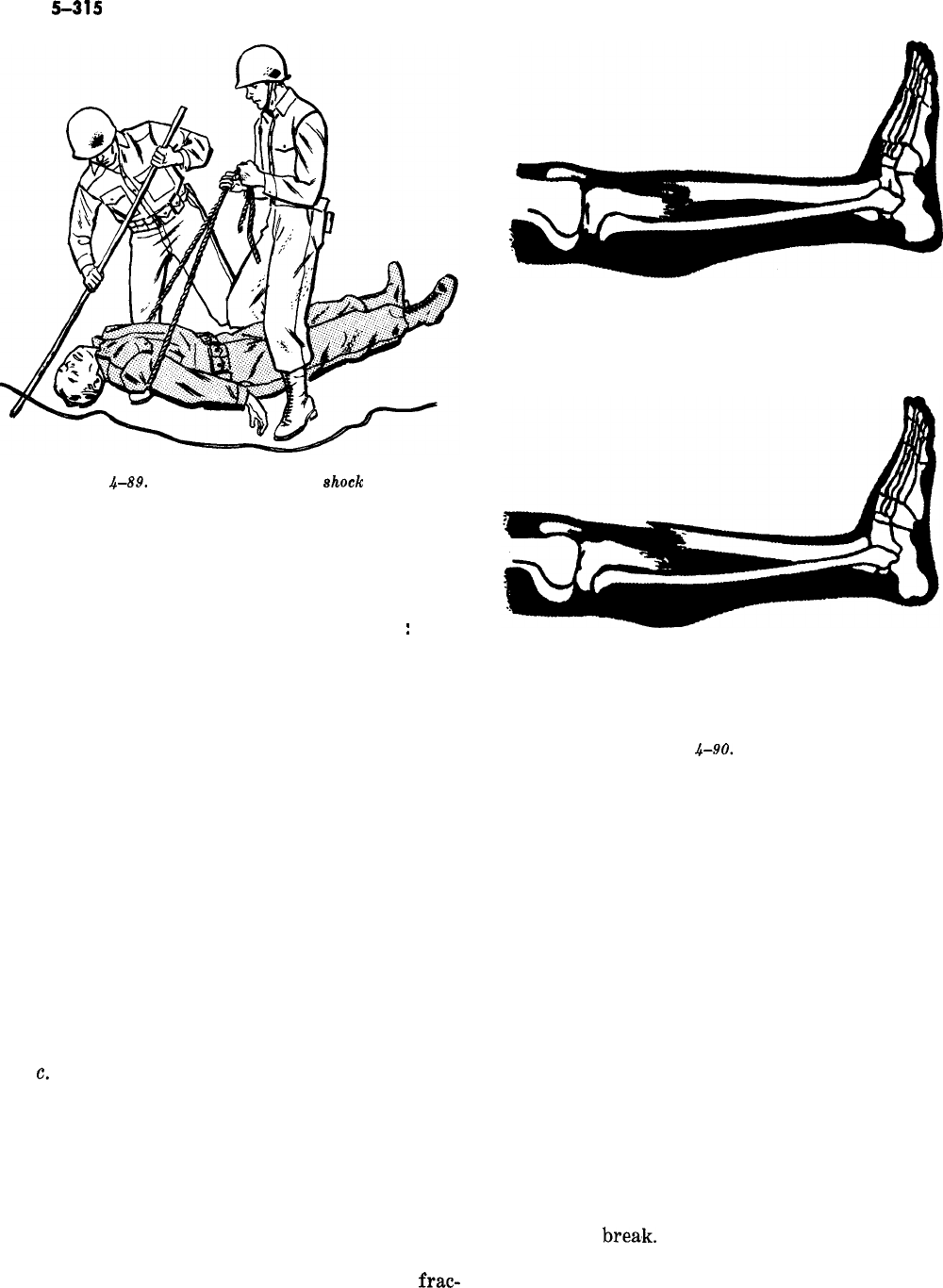
TM
5-315
Figure
4-89.
Rescuing an electric
shock
victim.
external bleeding. A compound fracture, some-
times referred to as an open fracture, is a broken
bone that has pierced the skin.
a. Signs and Symptoms of a Fracture. The fol-
lowing are indications that a bone is broken
:
(1) Tenderness over the injury with pain on
movement.
(2) Inability to move the injured part.
(3) Unnatural shape (deformity).
(4) Swelling and discoloration.
b. Treatment. If you think a person has a bro-
ken bone, handle him with great care. Rough or
careless handling causes pain and increases the
chances of shock. Furthermore, the broken ends
of the bone are razor-sharp and can cut through
muscle, blood vessels, nerves, and skin. Remember
-do not move a casualty with a fracture unless it
is necessary. If you do, be gentle and keep the
fractured part from moving. If there is a wound
with a fracture, apply a dressing as you would for
any other wound. If there is bleeding, use the first
aid methods for stopping bleeding.
c.
Splinting. All fractures require splinting.
Persons with fractures of long bones or of the
bones of the pelvis, back, and neck, should be
splinted “where they lie” before any movement or
transportation is attempted. Proper splinting
greatly relieves the pain of a fracture and often
prevents or lessens shock. Fixing the fragments
of a broken bone by use of splints prevents the
jagged edges of the bone from tearing blood ves-
sels and nerves. Proper splinting of a closed
frac-
SIMPLE FRACTURE
COMPOUND FRACTURE
Figure
4-90.
Fractures.
ture will prevent the bone from piercing the skin
and causing the fracture to be an open one.
Proper splinting of an open fracture will prevent
further injury to the wound. First aid in the field
may require that you improvise splints from
whatever material you may have handy-tree
limbs, poles, rifles, cardboard, rolled newspapers
or magazines, etc. You should remember that
splints should always be padded, especially where
they come into contact with bony parts, such as
the elbow, wrist, knee, and ankle joints. Leafy
vegetation can be used to supplement pieces of
clothing used for splint padding.
(1) Splints for fractured bones of the leg,
thigh, and hip. To splint a fractured leg, roll
sticks or other support into a folded blanket, or
other padding material, to form a padded trough
in which to rest the injured leg (fig. 4-91). Bind
the splints firmly at several places above and
below the
brea’k.
Splints for a leg fracture should
extend from a point above the knee to a little
below the foot (fig. 4-91). In case of a fractured
4-68
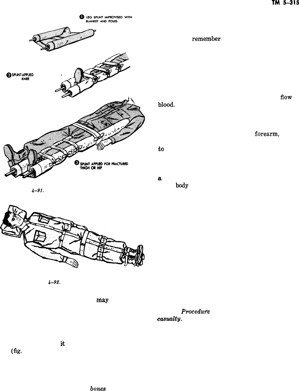
TM
ii-315
-
@
SPtM
APPtlED FOR FRACTURED
LEG,
KNEF.
OR ANKLE
SPLINT
APPLE0
FOR
FRAcruRED
mloli
OR
tllP
Figure
4-91.
Improvised leg, thigh, hip splints.
Figure
.$-9.2.
Expedient leg splint.
thigh or hip, poles and blankets
,may
be used for
splints as for the leg, except that the inside splint
is extended from the crotch to a little below the
foot. The outside splint is extended from the arm-
pit to a little below the foot. The armpits and the
crotch must be well padded. A quick way to splint
a broken leg is to tie
it
to the casualty’s uninjured
leg
(‘fig.
4-92). Padding is placed between the per-
son’s legs, then the legs are tied together at sev-
eral points above and below the fracture. The cas-
ualty’s feet with shoes on should be tied across the
arches and toes.
(2) Splints for fractured
bone.s
of the arm.
Keep a fractured bone of the arm from moving by
supporting it with splints. This reduces pain and
prevents damage to the tissues. Temporary splints
can be made from boards, branches, folded card-
board, magazines, newspapers, etc. A good gen-
eral rule to
rememlber
in splinting any long bone
(bones of the leg, thigh, forearm, or upper arm)
is to have the splint long enough to extend from
above the joint above the fracture to below the
joint below the fracture. Splints should always be
padded with some soft material to protect the limb
from pressure and rubbing. Bind splints securely
at several points above and below the fracture,
but not tight enough to interfere with the
tlow
of
bl,ood.
It is well to apply two splints-one on ei-
ther side of the arm. If an injured elbow is bent,
do not try to straighten it; if it is straight, do not
try to bend it. Figure 4-93 shows examples of
splints correctly applied to the
f,orearm,
upper
arm, and elbow to support the fractured bone and
to
prevent its moving. In figure 4-93, padding of
splints has been omitted for clarity. A sling is the
quickest way to support a fractured bone of the
arm or shoulder, a sprained arm, or an arm with
a
painful injury. The arm should be bound snugly
to the
bady
to prevent movement. You can make a
sling by using any material that will support all
or a portion of the lower arm and hold it close to
the body (fig. 4-94).
d. Broken Back. It is often impossible to deter-
mine whether a casualty has a broken back. Be
suspicious of any back injury, especially if the
back has been sharply struck or bent, or if the
casualty has fallen. If a casualty has received such
an injury and he lacks feeling in his legs or lacks
the ability to move them, you can be reasonably
sure that he has a severe back injury which
should be treated as a fracture. You must remem-
ber that if there is a fracture, the sharp bone
fragments can cut or damage the spinal cord and
cause permanent paralysis (fig. 4-95).
(1)
Procedum
for handling a spine-fracture
cmtity.
(a) Place a low roll, such as a bath towel
or clothing, under the middle of the back to sup-
port it.
(b) Lift the casualty, if he must be moved,
onto a litter or board without bending his spine
forward. It is best to have at least four men for
this job (fig. 4-96).
(c) If the casualty is in a face-down posi-
tion, he may be carried face down on a litter.
(d) Keep the casualty’s body alinement
straight and natural at all times and keep the air
4-69
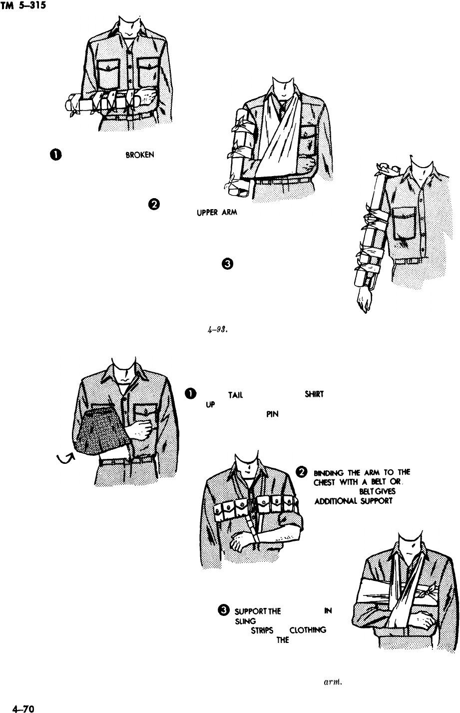
0
SPLINTS FOR A
8ROKEN
WRIST OR FOREARM
Q
SPLINTS
BROKEN
FOR A
@
SINGLE STRAIGHT SPLINT
FOR A FRACTURE NEAR
THE ELBOW WHEN THE
ELBOW CANNOT BE EASILY
BENT
Figure
4-9$.
Splints for a broken arm.
TURN
TAIL
OF JACKET OR SliiRT
w
OVER INJURED ARM AND FASTEN
IN PLACE WITH
PlN
OR TWIG.
@
mNDlNGTHEARMTOTHE
CHESTWlTHAE’ELTOR~
CARTRIDGE
B&T
GlVES
ADDlTlONAl
SUF’PORT
Q
Figure 4-94.
~FQIU
TM
FOREARM
lN
A
SLlNG
MADE FROM A BELT
OR
STRtPS
OF
CLOTMNG
AND BIND
WE
ARM TO THE
,
CHEST
,:.:,~:~::~:~::.:~::‘::,::::~~:.:.~~.~
,.:::::::::.;
Slings for an injured
awl.
-
4-70
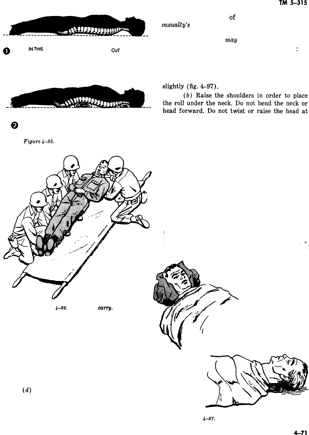
-
TM
5-315
cord just as in the case
,of
a broken back. Keep the
emu&y’s
head straight and still with the neck
slightly arched. If he is conscious, caution him not
to move. Moving him.
nmy
cause his death.
0
IN
TtiS
POSITION, BONE FRAGMENTS
CUT
(1) A broken neck is protected as follows
:
THE SPINAL CORD
(a) Place a rolled bath towel, or a roll of
clothing about the same bulk as a bath towel,
under the neck for support and padding. The roll
should be thick enough only to arch the neck
all.
Q
IN THIS POSITION, BONE FRAGMENTS ARE IN
PROPER PLACE AND WON’T CUT THE SPINAL CORD
(c) Place the roll so that when the casualty
is lying flat, the back of his head touches the
Figure
4-95. Positioning a broken back. ground.(d) To keep the head motionless after the
roll is in place, put a large padded rock or pack at
each side of the head (fig. 4-97).
(2) If the man must be moved, get help. One
person should support the man’s head and keep it
straight while others lift him. Transport him on a
hard stretcher or board.
(3) Never turn over a casualty who has a
broken neck.
f. Fractured Ribs. Fractured ribs cannot be
splinted, but the pain can be relieved by restrict-
ing the movement of injured ribs. This
is
done by
binding a tight swathe of muslin bandage around
Figure
4-96.
Four-man
carry.
passages free. If he is conscious, caution him not
to move.
(2) Cautions. Do not-
(a) Move the casualty with a broken spine
unless absolutely necessary.
(b) Raise his head even for a drink of
water. (c) Twist his neck or back.
(d)
Carry him in a blanket face up (fig.
4-96).
e. Broken Neck. A broken neck is extremely
dangerous. Bone fragements may cut the spinal Figure
4-97.
Protecting a broken neck.
TM
5-315
Figure
4-98.
Immobilization of fractured
rib8
with cravats,
Figure
4-99.
Method of immobilizing clavicle.
the chest or by applying three triangular band-
ages, folded as cravats,
aroun,d
the chest (fig.
4-98). These are applied when the patient has
forcefully exhaled the air from his lungs. Band-
ages are applied tightly enough to give support
but not so tightly that the rib may pierce the lung.
g. Fractures of the
Ckvicle.
When the clavicle
(collarbone) is fractured, the break is easy to
detect. The shoulder on the injured side droops,
bending the broken ends of bone upward and
causing a noticeable deformity. The arm on the
injured side cannot be raised and the patient
usually supports it at the elbow with the opposite
hand. The injured part is immobilized temporar-
ily by one of the following methods
:
(1)
Supporting the arm in a triangular band
4-72
TM
ii-315
~~
Figure
4-100.
xzg&g
a fractured jaw.
age sling, holding the arm slightly higher than the
elIbow.
(2) Binding the arm to the chest wall with
triangular bandages.
(3) Supporting the arm with a
figure-of-
eight improvised with
twobelts
(fig. 4-99).
h. Fractured Jaw. Support the jaw with a
cravat bandage (fig.
4-lOO),
but do not obstruct
the breathing. Place a wad
af
gauze between the
teeth in back of the jaw to keep the jaws apart to
maintain an air passage and to permit free drain-
age from the mouth.
4-67. Burns
There are three kinds of burns: thermal, sunburn,
-
and chemical burns. Burns are also classified
according to the degree (depth) of the burn. A.
first degree burn reddens the skin. A second de-
gree burn blisters the skin. A third degree burn is
a deep burn where the underlying
,skin
growth
cells are destroyed.
a. First Aid for Thermal Burns. Victims of
burns require treatment for shock, relief from
pain, and prevention from contamination. Shock
is the major hazard. It is usually serious when the
burn involves 10 percent or more of the body sur-
face, and sometimes less in especially deep third
degree
.burns.
The exclusion of air from the burn
by the application of a thick dressing relieves
pain and, if the dressing is sterile, prevents fur-
ther contamination. At least four layers of dress-
ing should be applied, then covered with clean,
tightly woven material to exclude air. Hands must
be thoroughly cleaned for this procedure. If the
burn is extensive, involving the trunk or a large
part of an extremity, wrap a clean sheet or large
4-73
TM
5-315
towel around the part. Then cover the victim 4-68. Heat Stroke
according to the weather and transport him to
where he can obtain medical aid.
b. Sunburn and Chemical Burns. An intensive
sunburn requires a sterile dressing, especially if
blistered. Chemical burns must be washed with a
large quantity of water, then dressed with sterile
dressing according to the seriousness of the in-
jury. Severe chemical burns and sunburns require
medical attention in proprotion to the seriousness
of the burn.
Occasionally hot weather causes heat stroke
where the victim experiences a dry
Bkin,
rapid
pulse, and a headache. This may develop into diz-
ziness, nausea, and ultimately unconsciousness.
The victim’s temperature may rise
to
106’
F.
(41’
C.)
and sometimes as high as
109“
F.
(41.7’ C.). The afflicted person must be brought
under cover, then unclothed and cooled by spong-
ing the body with alcohol or lukewarm water. The
patient requires immediate medical care.
-
Section VIII. CONTROL, EXTINGUISHMENT, AND OVERHAUL
4-69. Introduction
Hose, ladder, and pumper operations; alarm re-
ception and response
;
sizeup,
ventilation, salvage,
rescue, and first aid have been discussed so far.
I,t
has been stated that an ideal situation would in-
volve nearly all of these procedures being carried
out almost instantly and simultaneously. Person-
nel rescue is the primary concern of any fire-pro-
tection organization. When rescue is accom-
plished, the secondary concern
i,s
fire control, ex-
tinguishment, and the related procedures essential
to the preservation of property.
4-70.
loeating
the Fire
Structural fires generally fall into two categories,
the interior fire and the exterior fire. Both the
interior and the exterior fires involve the same
basic materials but under greatly variable condi-
tions, quantities, and proportions.
a. Structural Interior Fire. The source of the
structural interior fire lies inside the building.
This fire may still be in an early stage of incip-
iency after burning for several hours, and be-
cause of its confinement and lack of oxygen, or
even lack of time, it has not yet burned through
the exterior walls or roof of the building. This
situation normally involves great quantities of
smoke, ventilation problems, and backdraft possi-
bilities along with the difficulty of finding the
actual fire. Cases of suffocation involving both fire-
protection personnel and occupants of the build-
ing must be anticipated. This type of fire normally
does not involve exposure to other buildings un-
less the roof or walls suddenly collapse. Building
collapse admits oxygen to the fire and expands it
thus endangering nearby buildings by heat radia-
tion. This condition is normally caused by delay in
4-74
gaining control of the fire after arrival, extensive
enkindling before arrival, or widespread smolder-
ing before sudden ventilation. The structural inte-
rior fire must be located, controlled, and extin-
guished from inside the building.
(1) Usually, before a fire can be controlled or
extinguished, it must be located within the struc-
ture with some degree of certainty, A fire in the
basement may appear to be in the attic or top
floor, from which smoke is coming. Frequently,
smoke from one building may entirely envelop an
adjacent building, owing to wind conditions. The
practice of standing in the middle of the street
and directing hose streams through windows, re-
gardless of where the fire may be inside the build-
ing, is now largely confined to the movie version
of fire suppression.
_,
(2) A hose line should not normally be
opened inside a building until the fire is seen,
unless a fog curtain is necessary to enable firemen
to reach the seat of the fire. It is common for an
incandescent lamp to appear as a tire in a smoky
room. This deceptive condition also may be en-
countered when approaching an outside window
or some other transparency which reflects sun-
light or artificial light.
b. Structural Exterior Fire. A structural exte-
rior fire may ignite within the building and burn
through the roof or outside walls so that the fire
in the building is ventilated by the burnt-out
opening, and the flames are
visibl,e
before arrival.
The exterior fire may also be started first on the
outside of the building by carelessly discarded cig-
arettek,
flying embers falling on rooftops or on
dry vegetation near the building, or by other
causes. Exterior fires demand procedures to pre-
vent the fire from spreading to nearby exposed
buildings.
._
TM 5-315
4-71. Closing in on the Fire
After a fire is located, the next step is to confine it
to its point of origin.
a. Its spread may be controlled by covering in-
ternal exposures with hose streams and shutting
communicating doors and windows. External ex-
posures will be covered by other firefighting units,
if required. The greatest exposure is usually to
the leeward of the fire. Although this may be the
most difficult approach to make, owing to the
wind’s carrying the heat and smoke in the direc-
tion of the firefighters, it offers the greatest possi-
bility for making a fire stop and preventing the
fire from intentifying and spreading.
b.
Fires cannot be
suwessfully
combated by
paying undue attention to comfort. However, if it
is obvious that the fire is not likely to spread
beyond a certain point, such as an unpierced brick
firewall
or exterior wail, or that it is entirely
within one room or building, needless physical
punishment can be avoided by making the ap-
proach from the windward side.
c.
The fire should be attacked from as many
sides as possible. Good ladder work and proper
ventilation are of invaluable assistance when lo-
cating, confining, and closing in on the fire. One
precaution is worth repeating: where there is
danger of back draft (superheated gases which
have not ignited owing to lack of oxygen), be
certain that the hose lines are in position and
charged before “opening up”. This condition is
usually present in a tightly closed room or build-
ing. It is recognized by heavy smoke oozing out of
cracks around doors or from beneath eaves.
d. Closing in consists merely of moving in on
the fire as rapidly as conditions permit. Hose lines
should not be advanced so rapidly, however, that
the fire will be allowed to rekindle and gain head-
way in those areas where only initial extinguish-
ment has taken place.
e. This is especially true when class B (flamma-
ble liquids) materials are involved and extinguish-
ing agents such as
CO?
or dry chemical are being
used. It is most important to remember that when
these agents are used, they should be backed-up
with a water fog line or possibly even a foam line.
This precaution safeguards against a sudden
reig-
nition
(flashback), which is so typical of class B
materials, unless light water is used. Firefighters
have been seriously burned because they failed to
observe this precaution when combating a fire. In
one case, for example, fire had involved a paint
room, and
laquer
thinner was blazing on the floor.
Firefighters using carbon dioxide extinguishers to
clear a path to the leaking supply tank had to
make a dash for safety, in which two were burned
quite badly, when the thinner suddenly reignited
behind them.
f. Moreover, firefighters should be cautious
against stepping into open shafts in the dark or
advancing too far on weakened floor supports.
Where caution may be necessary, the firefighter
should “feel his way with his feet” or even crawl
on his hands and knees. If large cracks appear in
masonry walls, which may happen when a stream
played upon them causes contraction on one side
while leaving the other side expanded, collapse
may be imminent, and preparation for withdraw-
ing personnel and equipment must be made
quickly.
g. When advancing against radiated heat, the
helmet should be turned around so that the broad
part shields the face. This part provides consider-
able protection although it will not provide safety
in the actual presence of flame. Rotating men at
the nozzle, with the men backing up the line from
rear to front, will enable each man to rest or cool
off when the exposure to heat causes discomfort.
The nozzleman is normally the only person sub-
jected to any great degree of heat because, the
men behind him get considerable protection from
even a single person between them and the fire. If
it becomes necessary to retreat from an advanced
position rapidly, as, for example, when the water
sup,ply
fails, causing hose lines to go limp, and the
smoke is so dense that a means of escape is not
readily visible, remember that following the hose
line backward is certain to lead to the outside and
safety.
h.
The most suitable extinguishing agent for
the type of fire encountered should be used in an
amount that will most quickly put out the fire and
a minimum of damage from its use.
i.
Basic factors which must be considered in the
extinguishment of a fire are the type of material
involved, the quantity
of’
the material, and the
details of its arrangement. The ideal situation
consists of opening a door of the building and
extinguishing the fire from the outside, where the
air is cool and plentiful and there is little danger
of physical abuse. Usually it is not that easy.
Often the firefighters must go inside and move
with impeded speed, in increased temperature,
4-75

TM
5-315
with limited vision, and perhaps with an almost
depleted supply of oxygen.
j.
Standpipe systems within the building should
be used whenever practical to save time and pre-
vent damage. They are practical when the fire is
too large to be held in check with a first aid extin-
guisher but has not spread so much as to require
the volume of water supplied by a large line.
4-72. Overhaul
The overhaul operation involves a complete and
detailed check of the structure or structures in-
volved and of all material therein. This check is to
insure the complete absence of abnormal heat and
the extinguishment of every spark, so there is
definite assurance against re-ignition.
a. Perhaps the most embarrassing occurrence in
the career of the fire chief and his crew is to
receive an alarm directing the return of men and
equipment to the scene of a fire which was re-
cently “extinguished.” A second fire is frequently
more difficult to control than the original fire.
5.
Before overhauling is started, the first step is
to survey the building for structural damage to
determine that collapse is not imminent.
(Inciden-
tally, water-soaked stock, such as cotton materi-
als, increases the floor load tremendously.) When
necessary, the gas and electricity should be shut
off as a further precaution. However, the most
important aspect of the work is to make certain
that the fire is fully extinguished.
c. The building should be checked for concealed
spaces where the fire may continue to burn unnot-
iced. These spaces are between floor joints, ceiling
beams, false or hanging ceilings, walls and parti-
tions, inside cornices, inside window door casings,
light and air shafts, pipe or wire recesses, chutes,
and dumbwaiter shafts. They may be checked by
sliding a hand over the surfaces. If they feel
warm or appear blackened or if there is any doubt
of the situation, the suspected area must be
opened up and investigated. The inspection holes
should be square openings and near the studs in
order to avoid unnecessary damage and to sim-
plify the repair job. Then the adjacent areas
should be checked thoroughly, including attics,
basements, walls, and adjoining occupancies for
possible spread.
d. To make sure the fire will not rekindle, glow-
ing textiles, such as mattresses and clothing,
should be submerged in water. Smoldering bales
of paper, rags, kapok, and similar material should
be removed to the outside and broken open in
order to extinguish the deep-seated fire in the
center. Recent developments in the use of wetting
agents or surface-active agents added to water in
about a
2-percent
concentration indicate the fu-
ture possibility of more quickly and effectively ex-
tinguishing fires in those materials not penetrable
by plain water. Such agents would make it unnec-
essary to tear the objects apart and submerge
each fragment in water. Surface fires involving
lumber are extinguished quickly, but because of
the normal resistance of charcoal to water, it is
possible that heat and sparks may remain active
for some time beneath the surface. Under such
conditions, a water solution containing a wetting
agent may be effectively used to save time, dam-
age, and energy.
e. Oil-soaked metal filings, lampblack, or other
fmely
divided substances should be examined with
care because they are possible sources of
re-igni-
tion. Cylinders,
carboys,
and other vessels con-
taining gases and chemicals should be segregated
to avoid their mingling and a resultant explosion.
f. Burned materials should be handled care-
fully. Clothing or other objects which may contain
articles of value should not be thrown out of
win-
dews. If it is necessary to dump debris from
upper floors, a firefighter should be posted below
to warn others of the danger. Particular caution
should be taken when handling poisonous or cor-
rosive substances. Rubbish carriers, consisting of
old salvage covers cut into 5 by
5-foot
(162 by
152-centimeter)
sections with handles on the cor-
ners, provide a convenient means of removing
fallen plaster and debris. Burned materials should
be segregated from the unburned objects, and un-
damaged goods placed where they will not be sub-
ject to damage during overhaul.
g. Precautions should be taken to guard against
subsequent injuries. Holes which may have been
burned or cut in the floor should be covered or
blocked off and approaches to damaged stairways
or elevator shafts should be obstructed. Walls or
chimneys which have been weakened seriously
and which endanger pedestrians should be pulled
down.
-
h. If it becomes necessary to respond to another
alarm or return to quarters, and there is a possi-
bility that the fire might rekindle, a firefighter
should be left on watch at the scene with a line
-
charged for instant use,
4-76

TM 5-315
Section IX. INVESTIGATION AND RETURN TO SERVICE
.-
-
-
4-73. Introduction d. If the fire has involved a building in which
The investigation of a fire, which is the last thing
concluded before return to quarters, primarily
in-
eludes
the preservation of evidence, especially of
arson. The preservation of evidence in many cases
overlaps into the overhaul operations and even
into control and extinguishment.
are stored classified documents or equipment such
as reels of film, models, drawings, files, or similar
items, the officer in charge of the fire should
re-
quest that an adequate guard be posted over the
area where the items have been gathered until they
can be removed to a more secure location. Since
firtightens
are not authorized to
exami’ne
classi-
4-74. Initial Investigation fied materials, the men should be cautioned to be
extremely conscientious and attentive when
han-
If the circumstances upon arrival give rise to a dling such items or when sorting them from the
suspicion of arson, fire investigators should be debris and to set them aside in the designated
called. location promptly. This point is stressed because
a. Photographs should be taken before any
dis-
turbance of the environment beyond that which
was caused by extinguishment. When
circum-
stances point to arson, suspicious
devicesduch
as gasoline cans, cotton trails, film trails, candles,
oil-soaked rags, cleaning fluid containers,
matches, and cigarettes-should be labeled. The
label’s should indicate the finder and where and
when the suspicious items were found. Notes
should be taken immediately on the following:
recollections as to persons present on arrival;
existence of two or more separate fires simultane-
ously
;
color and aroma of smoke
;
color of flame
and from where it was issuing. A record should
also be made as to whether doors were locked
from the inside or outside; condition of contents
and whether disarranged or removed
;
nature of
the burning material; direction of wind; humid-
ity, temperature, and general weather conditions
;
direction of spread; obstruction extent of win-
dows in the room where the fire was believed to
have been started; whether a passerby may have
seen the
arsoni,st
making arrangements inside
;
and any other relevant facts.
there have been examples of carelessness and of
unnecessary loss or destruction. Instances are also
known in which firefighters have taken time out
after the fire was extinguished to unroll reels of
confidential film to see if they contained anything
interesting. These firefighters were of course cen-
sured and even investigated according to the
de-
gree of importance of the material involved.
e. Before returning to the station, the chief in
charge should obtain all the facts necessary to
write up the required fire report. This report in-
cludes type of alarm
;
location of fire
;
building
number; description, origin, cause, and confine-
ment of the fire
;
damage
;
agents used
;
time re-
quired
;
number of personnel
;
mileage traveled.;
weather
;
remarks
;
and other necessary data.
4-75. Determining the Origin of the Fire
When the fire has been serious, that is, when
there has been loss of life or extensive property
damage, assistance in investigation may be ob-
tained from the fire marshal or other authorized
representatives of higher headquarters so that an
impartial viewpoint may be expressed at any later
board of inquiry or board of investigation pro-
ceedings.
IL
Notes and sketches made at the scene while
the facts are fresh may be used to reconstruct
minute details which may be come significant as
the entire picture takes form. The facts may be
requested during a board of inquiry or
investiga-
tion proceedings, or even in court, if an arsonist is
caught and later brought to trial.
c. If the investigating officers have not arrived
before the firefighters must return to the station,
military policy should be posted to preserve the
evidence. They should be instructed to disclose no
opinion about the fire, its origin, or any facts
which may have been
di.scovered
as to its cause,
except to proper authorities.
a. In such cases, the investigating authority will
attempt to collect much more detailed information
than would be required ordinarily. This investiga-
tion might include such matters as reasons for
possible delay in alarm, for extensive spread of
fire, for heavy lose, and for the inability of
occu-
pants to escape. It might also consider the
fire-
fighting methods employed, the adequacy of the
watter supply, and whether recommendation had
been previously made to correct deficiencies which
may have caused the fire, delayed the alarm, or
impeded extinguishing operations. For the
aver-
4-77

TM
5-315
age response, however, the regular fire report
form is enough to record the necessary informa-
tion, The questions on this form that may be diffi-
cult to answer accurately are origin of fire, cause,
and estimate of damage.
b. When there are no eyewitnesses, the exact-
ness with which the point of origin of a fire may
be determined will depend, in most cases, on the
extent of the fire. When several buildings have
been destroyed, it may be possible only to desig-
nate one of them as the place of origin. The same
may be true when a number of rooms have been
gutted by fire. On the other hand, if the fire has
been confined largely to one room, it may be rela-
tively easy to determine the point of origin
;
this
may be indicated by defective wiring, a wastebas-
ket, a stove, or any one of the many other sources.
c.
In a great many cases however, the
exa,ct
point of origin is often difficult to determine. The
tendency is to pronounce the first plausible spot as
the probable location at which the fire staIrted.
d. For example, after a fire which involved a
large one-story frame woodworking shop, the fol-
lowing facts were disclosed by the debris. Paint
cans had been burned out with no trace of rag
ashes. Nearby, behind a door, was a partially
burned pile of shavings, sweepings, and remains
of a
bream.
Nonmetallic sheath wiring was badly
burned and holes were burned through the metal
conduit, but the fuse box and fuses were intact.
There was heavy charring around air vents
through the roof. One outside wall was burned
completely through. Outside this opening and
aginst the building were the partially burned re-
mains of a pile of heavy lumber which had been
involved in fire, and near the edge of the pile were
the burned remains of what might have been a
broom handle.
e. Where did the fire start? Judging from this
information,
i,t
would be impossible to say. While
deep charring of the wood beams around the ceil-
ing vents might indicate that the heat was very
imense
at that point, it is only
wha,t
should be
expected, since these vents provided a natural flue
to draw off the heat and fire. The presence of
paint cans does not necessarily indicate the loca-
tion of the origin. Even if these cans were empty
at the outbreak of the fire, the residue would have
burned out during the course of the fire. The ab-
sence of rag ash does not rule out the possibility
of spontaneous ignition, for linseed oil may have
been present on newspaper or other materials, or
4-78
all of the ashes may have
hose streams. been washed away by
f. In regard to electrical difficulties, the intense
heat of the fire could have burned off the insula-
-
tion of the nonmetallic sheath cable along the ceil-
ing. The arcing of wires, which had become bare
as a result of the heat, would account for the
burned hole in the metal
condui,t.
The absence of
bridged fuses or overcapacity fuses would not rule
out the possibility of electrical difficulties, for fire
can start from frayed wires or overheated motors
without blowing fuses. In addition, the electric
glue pots, along with other heating devices, were
checked for possible overheating, but these had
apparently been shut off before the fire started.
g. Investigation disclosed that no one had been
in the building since noon the day before. Thus,
the possibility of a carelessly disposed of cigarette
being thrown into the rubbish pile or elsewhere
was rejected. Close inspection of the burned sur-
faces of the outer wall disclosed that the fire had
started outside the building under the woodpile.
The remain’s of the wooden handle found in the
pile showed it to be of a type similar to those on
mops found on a nearby outside rack, all bearing
evidence of having been used for mopping a vege-
table oil. It was apparent that an oil soaked mop
had been left on the ground the previous day,
with the wood piled on top of
i$
against the frame
building. A statement by workmen eventually ver-
ified this conclusion. There had been enough time
for spontaneous heating and the resultant out-
break by the next day. Therefore, it
w!as
not
difi-
cult to guess the cause of the fire, after the possi-
ble sources were found, considered, and elimi-
nated with proper
reasoninsg
and due considera-
tion.
-
h.
Thus, it can be seen that determining the
point of origin may be very helpful in determin-
ing the cause, if not directly, then indirectly, by
eliminating other possible causes. Although cer-
tain indications point to the greatest concentra-
tion of heat, which may be useful in
llocating
the
point of
o’rigin,
these indications are not always
infallible. The prevailing drafts during a fire have
a great deal to do with the way the fire spreads
and the manner in which heat is concentrated. In
addition, some materials are more highly resistant
than others and slow less evidence of heat condi-
tions than lighter and more flammable substances.
An example of differing resistance is glass and
iron. Glass that has become molten and fused indi-
cates that the temperature had reached the
vicin-
_

TM 5-315
-
ity of
1,‘7OO’F.
(927’C.)
;
ordinarily unprotected
iron supports will warp at slightly over half that
temperature.
i.
Moreover, it must be kept in mind that the
cause of the fire and the point of outbreak may
not always be in the same location. This may
occur
f,or
example when gasoline vapors are car-
ried by drafts to an open flame or to the arc of a
knife switch a considerable distance away. It
could also happen where
cam,bustible
materials at
one end of a duct are ignited as a result of an
overheated furnace at the other end.
j. The recurrence of several fires in the same
location or the presence of two or more simultane-
ous fires in different areas of the same building
should be viewed with suspicion. There
i,s
a possi-
bility of deliberate planning, and a more careful
investigation is warranted.
4-76.
Determining the Cause of the Fire
After having determined as far as practicable the
point of the fire’s origin, the next
step
is to deter-
mine its cause.
a. It is well, in ascertaining its cause, to con-
sider first the most common causes of fire, such as
carelessly discarded cigarettes, overheated or
defective stoves or flues, faulty electrical appli-
ances, and slag or sparks from welding and cut-
ting operations. If these are eliminated beyond a
reasonable doubt as a possible source of the fire, a
thorough interrogation of all persons potentially
connected with the fire may
.throw
additional light
on the subject. Such personnel would include
those who ordinarily occupy the building, those
who were present at the time of or immediately
before the discovery of the fire, and those who last
left the building at quitting time or who later
went through or near it. Such extensive
inveatiga-
tions are only required for large fires or those
involving a
l,oss
of life. They will usually be con-
ducted by specially appointed
ofhcers
or boards,
with the assistance of the fire marshal and ap-
pointed aides.
13.
Although it is true that approximately
70
percent of the total fire damage results from only
about 10 percent of all fires, it does not follow
that smalier fires should not receive careful study.
Small fires can teach about fire protection mea-
sures. If any gain is to be made in preventing
similar occurrences, it is of the utmost importance
to determine the source of the fire and the partic-
ular manner in which it started. Hence, when fill-
ing out a fire report, it is not enough merely to list
“rubbish,” “grass,”
or “flammable liquids” as the
cause of fire. These items are
sim’ply
examples of
combustible
muterids
which are not uncommon in
the vicinity of many buildings. The
cume,
in a
strict sense, is the agency which brings the com-
bustible materials up to their ignition points. For
example, the
“poin$
of origin” might be “rubbish
can in northeast corner of hanger No. 301,”
“dry
grass on west side of building No. 731,” or
“bucket of gasoline near the center of the floor in
garage building No. 43.” The
cuuse
of the above
fires may have been a cigarette carelessly dis-
carded into the rubbish, sparks from an unpro-
tected incinerator landing in the grass, or the
spark from a broken light bulb in an unguarded
extension cord socket in the vicinity of the gaso-
line vapors from the bucket. This type of fire
analysis lakes possible a decision about whether
new fires can best be prevented by regulating the
sources of ignition, the handling of combustibles,
or both. If it is impractical to eliminate the for-
mer, stricter controls can be placed upon the han-
dling and disposal of highly combustible materi-
als. In the foregoing illustrations, it so happens
that both the causes and the points of origin are
the proper subjects of regulation or prohibition.
4-77. Estimate of loss
Accurate appraisals of monetary losses resulting
from fires are often difficult to make.
a. When the loss is negligible, it will be found
advisable to obtain the assistance of the post engi-
neer, who is qualified to estimate the cost of any
necessary repairs. Note that the typical fire report
calls not only for an estimate of loss in dollars but
also for a brief description of the extent of physi-
cal damage. The fire chief should make such a
description, but the decision regarding replace-
ment or bracing of weakened construction such as
joists and walls should be made by the post engi-
neer. Photographs are of great help in establish-
ing the extent of structural damage and in pre-
serving evidence.
5.
Partial losses of Army structures are esti-
mated by the installation personnel charged with
construction responsibility. Total structural loss
of an Army building is the value of the structure
as reported on the most recent inventory of the
real property report (AR 405-45) prior to the fire
(AR 385-12).
4-79

TM
5-315
been built when construction costs were either
higher or lower than at the time of estimate. It is
best to make an estimate on the basis of the pres-
ent cost of restoration to the original conditions.
Loss estimates should
,be
made by personnel
charged with construction responsibility. Total
structural loss is the value of the structure when
built plus improvements.
c.
Before an estimate can be made of the loss
to
contents, an inventory of everything remaining
after the fire is extinguished must be taken and
com,pared
with a previous inventory of the con-
tents. Since the loss includes damage from smoke,
heat, and water, as well as that sustained by
actual contact with the flames, it can be accu-
rately appraised only after the salvage value, if
any, has been determined. This is a task for the
supplying
servi.ce.
d.
Vehicle and aircraft losses will be
deter.mined
by replacement in kind for partial losses and re-
corded inventory value less salvage for total
losses.
e.
When preparing his preliminary report, the
fire chief is not expected to go into great detail in
his loss estimate. He should be guided by
,the
fig-
ures given him by proper authorities, if these fig-
ures are available. These figures may be chal-
lenged only if a considerable discrepancy is noted.
For example the itemized loss sheet may indicate
that much more property was destroyed in the
building than it was known to have contained, or
it may indicate the destruction of important ob-
jects which fire personnel know the building did
not contain
(.by
reason of their having made an
inspection just before the fire and an investiga-
tion of the debris afterward). These facts should
be called to the attention of the proper authorities
so that the mistake can be corrected or other ap-
propriate action taken.
4-78. Final Action at Scene of the Fire
In the case of large fires, it is well that the ranking
fire protection officer in charge should obtain all
the information possible before leaving the scene
in order to prepare a coherent story of the fire
and the way it was extinguished.
a. Considerable time may be involved in taking
the names of witnesses, jotting down significant
statements, directing the taking of photographs,
and drawing sketches of the building, location of
apparatus, hose lines, and other pertinent facts.
Those companies not needed for salvage and over-
haul work should be directed to “pick up” and
return to the station.
i3.
Before leaving the scene of the fire, fire pro-
tection supervisors should make a
dou’ble
check to
assure that no tools or equipment are missing
from the fire apparatus. When equipment, such as
salvage covers placed over holes in the roof, has
been temporarily lent to the occupant, a receipt
should
,be
obtained and instructions given for its
return.
c. Even though the fire station is relatively close
by, some precautions should be taken in case an-
other fire occurs before the apparatus gets com-
pletely back into service. When almost the entire
hose supply has been use& it is frequently advisa-
ble to reload the hose in the bed of the firetruck so
as to be in readiness for instant use in case an-
other fire occurs before the hose can be changed.
All wet or dirty hose must be replaced. Where
only a few sections of hose have been used, they
may be rolled up and stacked on the rear running
board, since there would most probably still be
enough hose in the bed to
com,bat
another fire
successfully.
d.
When a crew is returning from a fire, the
necessity for getting back into service quickly
does not constitute an emergency. Therefore, si-
rens should not be used and all traffic rules should
be observed.
4-79. Return to Quarters
ct. Upon return to quarters, the crew chief in
charge should report to alarm headquarters, ei-
ther that his company is back in service, or that it
will be out of service temporarily while the hose is
being changed. If the latter is the case, he should
again notify headquarters when the company is
back in service.
b. While the fire chief or crew chief is complet-
ing the required fire reports and making entries
of the run in the daily log or journal, the mem-
bers of the company should make an immediate
check of the fire apparatus. Tires should be
washed to facilitate an inspection for cuts, nails,
and other damage. Fuel, oil, and water in the ra-
diator and booster tank should be replenished if
required. All equipment and appliances should be
checked for presence and condition.
c.
After clean dry hose is replaced in the appa-
ratus bed, wet or dirty hose should be thoroughly
washed and placed on the rack to dry. Hose should
_
4-80
TM 5-315
be rolled as soon as it is dry in order to avoid
deterioration from the heat of the sun.
-
d. Wet salvage covers should be washed, in-
spected for cuts or
tear,s,
and hung to dry. Lad-
ders should be inspected for damage, and all tools
and
a,ppliances
which have become dirty or wet
should be cleaned and dried. Metal surfaces which
might rust should be lightly wiped with oil. The
entire apparatus should be washed, if necessary,
to remove caked mud, dirt, and carbon.
e. When all necessary work which follows a fire
has been carried out, it is advisable to congregate
all the men in the study room and review the
method of attack from start to finish. Each com-
pany crew chief can explain the operation in
which his crew was engaged, illustrating the
placement of men and equipment on a blackboard.
The purpose of such a verbal postmortem is not to
criticize or embarrass anyone but to take full ad-
vantage of any lessons learned while fighting the
!-b-e, and to determine whether operations might
be
im,proved
at any future fire of a similar nature.
f. If obvious mistakes were made at the fire, the
persons in error should readily admit making
them. If the chief in charge is assured that a
repetition of the same error will not occur, no
particular issue need be made of it, especially if
the error is a minor one. Serious mistakes, how-
ever, should not be passed over lightly merely be-
cause the department as a whole was praised.
Most of the time, the general public believes that
the fire department has done an excellent job, and
perhaps that is usually true, but firefighters nor-
mally are aware of their own mistakes even when
the uninitiated layman is not.
g. When a private reprimand is necessary to
cover individual cases, it should be carried out
promptly after return from the fire and before the
general discussion is held. When improvement is a
matter of general performance of duty, the post-
mortem session should be followed by drills and
more drills until every man is functioning as an
efficient
,part
of the team. On the other hand, if
lpraise
is due a man or a company for a good job
or an exceptional piece of work at the fire, appro-
priate words of recommendation should be given
during the discussion in the presence of the entire
group.
4-81
TM
5-315
CHAPTER
5
AIRCRAFT FIREFIGHTING AND RESCUE
Section
I.
INTRODUCTION
5-1.
Purpose
5-4.
Fire Hazards of Aviation Gasoline,
Turbine Engine lubricating Oil,
and Jet Fuel
This chapter provides Army
firefighters
with the
correct procedures for rescuing personnel from
burning aircraft and for fighting aircraft fires.
Preservation of
life and
prevention of injury
should be the first objective of all
firefighters;
the
saving of aircraft is secondary.
A knowledge of the characteristics of gasoline,
turbine engine lubricating oil, and jet fuel is es-
sential to the aircraft firefighter. See paragraph
4-3b
for extinguishing class B fires.
5-2. scope a.
Gasoline
and Turbine Engine Lubricating
Oil.
Various phases of aircraft firefighting and rescue
are covered herein. Section I includes general in-
formation on the characteristics of fire as they
pertain to aircraft and aircraft materials. Section
II
familiarizes firefighters with the specific
com-
-
ponents of aircraft and the fire hazards associated
with them. Section
111
describes emergency proce-
dures, and gives illustrations of the general ar-
rangement and the emergency procedures for typ-
ical Army aircraft.
(1) Aviation gasoline versus automotive
gm-
oline.
Aviation grades of high-octane gasoline,
with octane ratings of about
U5
to
145,
are not
greater fire hazards than automotive grades with
a rating of approximately 90. Actually, automo-
tive grades have a slightly higher volatility. How-
ever, for practical considerations, gasoline of any
octane rating within the automotive or aviation
range (approximately 70 to 145) presents identi-
cal fire extinguishing problems.
5-3.
Flammable Materials in Aircraft
a. Flammable materials and fire-accelerating
materials carried in each aircraft are of major
concern to the firefighter. The materials may in-
clude a combination of the following
:
(1) Gasoline, turbine engine lubricating oil,
and jet fuel.
(2) Oxygen.
(3) Oils.
(4) Hydraulic fluid.
(2) Turbine engine lubricating oil and
au&
tion
gasoline
grades
and uses.
(u)
Whole, unheated turbine engine lubri-
cating oil, Military Specification ML-L-7808, is
relatively nontoxic and does not present a serious
health problem. Some dermatitis can be expected
in unprotected personnel continuously exposed to
whole unheated oil. However, the decomposition
products resulting from temperatures above
500’
F.
(260’
C.) are toxic. Adequate ventilation
should be maintained where these oils are heated
above the critical temperature.
(5) Anti-icing fluid.
(6) Grease.
(7) Pyrotechnics, ammunition, and other
ordnance.
b.
Of the above materials, gasoline and jet fuel
are the greatest problem in firefighting. The crash
firefighter must remember that danger of fire or
-
explosion is always present in the aircraft fuel
system.
(b) Aviation gasoline consists of
hydrocar-
.bons
except for the addition of chemical agents,
such as tetraethyl lead, inhibitors, and dye. The
various grades are dyed distinguishing colors of
red, blue, green, and purple for identification pur-
poses. Aviation gasoline is provided in four
grades and colors, in accordance with Military
Specification MIL-F-5572, as
follow,s
:
1. Grade
80/87,
for use in light aircraft
and helicopter engines, red if it contains
tetra-
ethyl lead, otherwise dye free.
5-1

ml
5-315
2 Grade
91/96,
for use in light aircraft
and helicopter engines, blue.
3 Grade
100/130,
for use in high output
b.
Jet
Fuel. Jet fuel is designated JP-4
(Mili-
tary Specification
MIL-F-5524)
and is used in
the gas turbine series engines installed in some
aircraft engines, green.
4
Grade
115/145,
purple in color,
staLndard
grade of aviation gasoline used
Army aircraft gasoline engines (app. II).
is the
in all
Army aircraft. This type of fuel must be handled
with as much caution as gasoline. Jet fuel mist in
air ignites readily regardless of the theoretical
advantages of a kerosene grade fuel.
Section
Il.
AIRCRAFT FIRE HAZARDS
5-5.
What Firefighters and Operation
5-6.
Aircraft Design
Personnel Should Know About Aircraft
tz.
Firefighters and operation personnel must be
familiar with the fire hazards of every aircraft
that uses the nearby airfields. After an aircraft is
on fire, it is too late to make a study of it to
det,ermine
the best methods of lifesaving and
fire-
fighting. An aircraft fire requires immediate, in-
telligent, and carefully planned action. Every
situ-
atifon
is different, but often the rescue squad has
only a minute to rescue occupants from a burning
aircraft.
1).
A knowledge of the location, function, and
operation of all parts of an aircraft is necessary,
whether they appear to be fire hazards or not.
Nearly any part of an aircraft may become im-
portant to firefighting, often under unanticipated
circumstances. For example, a landing gear strut
would not ordinarily be considered worthy of
study from a firefighting point of view, but when
it is known that on a certain type of aircraft the
strut has been driven upward and has ruptured a
fuel tank, it is evident that a knowledge of its
pos,ition
and action is important. A crucial deci-
sion on firefighting or rescue operations must
often be made within seconds.
C.
Features of aircraft which are directly
con-
nec:ted
with fire hazards and rescue are outlined in
generalized form in the following paragraphs.
These may be applied to the study and investiga-
tion of any specific type or individual aircraft.
Such studies must be supplemented by personal
inspection of the aircraft, contact with flight and
maintenance personnel, and review of current
avi,ation
magazines and manufacturer’s data. The
best way to learn about aircraft is by inspecting
and asking questions about them. Few aircraft,
even of the same type, are identical in every re-
spect. Some aircraft of the same type are altered
for performance of different tasks. Others are as-
sembled in different ways, or changed for special
reasons after being in service.
5-2
a. Modern
Ar.my
utility aircraft are of all-metal
construction. Figure 5-1 illustrates the general
arrangement of transport aircraft.
b.
Helicopters differ from fixed wing aircraft in
that lift comes from rotor blades mechanically ro-
tated about an approximately vertical axis. Fig-
ure 5-2 illustrates the principal structural units
of a helicopter.
c.
Helico,pters
may be broken down into two
main types: the single rotor type and the tandem
rotor type. The single rotor type uses a small
an-
titorque tail rotor to overcome the effects of
torque, while the tandem rotor type rotates the
blades in opposite directions, thus reducing torque
to an acceptable limit. The flight controls of a
helicopter have primarily the same function as
those of fixed-wing aircraft. The only additional
control is the collective pitch stick, to the left of
the pilot. A motorcycle-type throttle is attached to
the end of the pitch stick.
5-7.
Powerplants and Components
The engines are divided into two groups, the re-
ciprocating engine and the gas turbine engine.
a. Reciprocating Engines.
(1) The reciprocating engines are air-cooled
and constructed on a radial or opposed design.
Radial types are used in larger engines and pre-
sent the greater fire hazards. On a radial type
engine, the cylinders are installed in one or more
separate rows around the crankshaft. The crank-
shaft of a helicopter extends into the clutch or
transmission assembly and forward to the propel-
ler installation, and far enough to the rear to
drive auxiliary equipment such as generators, oil
pumps and hydraulic pumps. A radial engine and
accessory section are shown in figure 5-3. Figure
5-4 shows an opposed engine and accessory sec-
tion.
(2)
The fire hazard in the cylinder section of
the engine is very small unless the cylinders
frac-
, AILERON
i
VERTICAL STABILIZER
fi
RUODER
-TRIM
TAB
HORIZONTAL STABILIZER.
FM ANTENNA
FLAP
PI LOTS
RAMP
7
EXTENSIONS STOWED
ENTRANCE DOOR
ERNAL POWER
#lENJNE
\
-------- , ,,
,,
,
,rr
_,.,b
. .
.._.
IM
TAB
_
PROPELLER
r’CoWLING
\
NACELLE
LANDINGGEAR
UHF ANTENNA
CABIN EMERGENCY DOOR\\\&
x
Figure
5-1.
General
arrarwement
of transport aircraft.
ROTOR
BLADB
mw
TRANSMISS&QN
TAIL
SECTtON
CENTRAL
TRANSMSStON
POWER
PIANT
NO!%
ENCLOSURE
bfAMu
LANDING GEAR
NOSE LANDING GEAR
Figure
5-2.
Principat
etructurat
units of a
heticopter.
ture. The greatest fire hazard in the cylinder sec-
5-4). Broken fuel and oil lines generally occur in
tion are the electrical wiring, oil lines, and a small
the accessory section and are the source of fires
amount of tubing. An engine cylinder section sel-
both in the air and on the ground, either under
dom presents a fire problem.
normal conditions or in the event of a crash.
(3) The accessory section is located immedi-
ately to the rear of the cylinder. The accessory
section contains the carburetor, internal super-
charger, main fuel lines, fuel pump, oil lines, oil
pump, generator, magnetos, electrical connections,
and other engine equipment. In some aircraft, the
accessory section contains the oil tanks and stor-
age batteries. The most serious engine fires
accur
in the accessory section.
(4) The accessory section is filled with
equipment containing moving parts (figs. 5-3 and
(5) Access to the accessory section is gained
by removing the engine cowling. The cowling is
fastened with
dzus
and other special rapid fasten-
ers and can be quickly removed. The fasteners can
be opened with a screwdriver which is part of the
crash rescue tool kit (fig.
5-5}
or a coin, since the
exposed top is slotted for turning. Many instances
occur where the intensity of the fire will
aprevent
the removal of the
cowling.
It is then necessary to
gain access to the accessory section by quick use
of forcible entry equipment. ‘The cowling is
gener-
5-4
TM
5-315
ENGINE
44%
COWLSTOP
-
CARBURETOR AIR
JNDUCTION
SYSTEM
Figure 5-3. Radial engine and accessory section.
ally constructed of metal a little thicker than the
aircraft skin, but can quickly be entered with
crash kit tools. Effectiveness of the extinguishing
agent within
the,confined
space may be increased
by keeping the cowling in place and by using bay-
onet nozzles or applicator.
NOTE
or
accessory section and the pilot’s compartment. In
multiengine aircraft, the main
firewall
is between
the engine and the rear of the nacelle with its
adjoining wing structure.
(7) Aircraft
irewalls
consist of a metal plate
thicker than the aircraft skin. The firewalls are
not thick enough to prevent the passage of heat
for a long time or the actual transmission of
fire
from one section of the engine to another section
or to the rear structures.
,Firewalls
are
bpierced
with necessary openings for cables, linkage,
tub-
ing, etc (fig. 5-4). In some instances, there is
clear space between the device passing through
the
firewall
and the
o.pening.
The objective of the
firewall
is to localize, for a brief time, a fire in the
engine cylinders or accessory sections.
(8) It is important that firefighters know the
If it is a severe engine fire, check
acces-
sory section first.
(6) There may be a forward
firewall
shroud between the forward section of the engine
containing the cylinders and the accessory section.
On most aircraft, a main
firewall
is located
be-
tween
the accessory section of the engine and the
adjoining portions of the aircraft. In
single-en-
gine aircraft, the main
firewall
is ‘between the
5-5
FIRE
Figure5-4.
Opposed engine and
accessory
section.
location of firewalls and accessory section compo-
nents. With the engine cowling removed, each
type of engine should be studied from a
firefight-
ing point of view.
(9) On radial engines having only a single
row of cylinders, baffler plates or shields are
placed
between
the cylinders and the cowling. The
shields are close-fitting and regulate the flow of
air to the rear of the cylinders. The shields should
not be confused with a
firewall
as they will do
very little to localize a fire. Their purpose is to
reduce the volume of air which can
#pass
over the
rear of the cylinder cooling fins. There is some fire
hazard from the coil connections and ignition har-
ness forward of these shields.
(10) On multiengine aircraft, the main
fire-
wall at the rear of the engine isolates engine fires
‘to some extent from the remainder of the nacelle
and from the wing structure. The rear of the en-
gine nacelle may contain oil or hydraulic fluid
tanks, a housing for retractable landing gear, or
other equipment.
(l,l)
Cowl flaps are installed near the
firewall
between the engine and accessory section. The
5-6
cowl flaps are important to a firefighter because
they provide immediate access to the engine with-
out removal of sections of the cowl surface. A
CO2
horn applicator nozzle may be placed at, or
thrust through, the opening at the cowl flaps to
quickly combat engine fires.
(12) When an engine is started or warmed
up, a firefighter will stand to the rear of the pro-
peller and be prepared to combat an engine fire
through the cowl flaps. On emergency landings,
the cowl flaps may be in the closed position. It
may be faster to pry a flap loose with a small bar
than a hole could be penetrated or a section of
cowling removed.
(13) The most likely time for a fire to start is
during engine starting because of the excessively
rich fuel mixture settings. The fire can best be
extinguished by the pilot turning off the fuel tank
valves, moving the engine mixture controls to
“idle
cutofY,
and allowing the engine to run itself
out of fuel.
--Y
(14)
Some reciprocating engine-driven air-
craft have spring-loaded fire extinguisher access
doors on the lower outside portion of the engine
-
FEDERAL STOCK NO. 42 10-293-7666
ITEM NO. QUANTITY DESCRIPTION FEDERAL STOCK NO.
2
3
4
5
6
7
8
9
10
11
12
13
14
15
16
1
METAL CUTTING SAW
2SCREW DRIVER, COMMON,
4-INCH
2SCREW DRIVER, COMMON,
8-INCH
2SCREW
ORIVER,
PHILLIPS,
4-INCH
2
SCREW DRIVER, PHILLIPS,
&INCH
1
PLIERS, LINESMAN
1
CABLE CUTTER
6HACK SAW BLADES
1
HACK SAW FRAME
1
‘V”
BLADE RESCUE KNIFE
1
AXE
1
DZUS
WRENCH
3
woo0
PEGS
(SOFT)
3
RU6BER
PEGS
1
GRAPNEL HOOK AND STEEL CABLE
1
CHAIN SAW
G5110-221-0235
G512@227-9491
G512@277-9494
G51%%236-2133
G5120-236-212B7
G5120-239-825
R5110-224-7053-5231
G51
lo-142-492B
G51
lo-2234971
RN51
10-524-6924
Figure
5-5.
Crash
Tescue
tool kit,
chuin
saw, and grapnel hook.
5-7
TURBINE SECTION
TAIL PIPE
PROPEI
ROTOR
Figure
S-G.
Gas
turbine
engine.
na,celles.
These doors permit a fire extinguisher
nozzle to be thrust directly into the accessory sec-
tion of the engine. The doors are usually well la-
beled.
b.
Gas
Twbine
En.qines.
(1) A typical gas turbine engine (fig. 5-6)
consists of an air intake, compressor, combustion
section, turbine section, exhaust tailpipe, acces-
sory section, and propeller or rotor drive.
(2) Short circuits in the electrical system or
broken fuel and oil lines are major sources of fire.
A firefighter will be prepared to immediately
combat any electrical, oil, or fuel fire that occurs
during ground operation of the aircraft or in the
event of a crash.
(3) The firefighter will be on the alert for the
possibility of an engine fire during starting and
stolping
of the gas turbine engine. If the engine is
not started correctly, there is a tendency for fuel
to drain or be pumped through the engine into the
tailpipe or out the manifold drain onto the
ground. A fire may start in the burned or turbine
section after the throttle is closed. Should a fire
occur, it can be extinguished by shooting
CO2
or
CF3Br
through the air intake duct or between the
exhaust tailpipe and cowling.
NOTE
DO NOT DISCHARGE
CO?
DI-
RECTLY INTO THE ENGINE
EX-
HAUST
BECAUSE IT MAY DAMAGE
THE ENGINE.
(4) The gas turbine engine is separated into
four sections which are potential fire zones: the
inlet compressor, combustor (including the tail-
pipe), and the accessory section. When combating
gas turbine engine fires, the firefighter should at-
tempt to separate hot engine parts or other
sources of ignition from fuel sources and the pri-
mary structure of the aircraft.
(5) Although very improbable, explosive
mixtures may form in the accessory section from
fuel leakage. Sparks
from.the
generator or starter
motor will supply the remaining element needed
for an explosion or fire within the accessory sec-
tion.
(6) The engine is separated from the aircraft
by a shroud which is similar to a firewall. The
shroud is pierced by necessary openings for
cables, linkage, tubing, etc. The shroud is installed
so that it seals at the forward bulkhead, at the
forward end, and is vapor-tight throughout its
length. It, is highly improbable that the shroud
will remain completely
vapor-
and liquid-tight
after several removals and
reinstallations
during
engine changes. The area surrounding an improp-
erly sealed shroud becomes a hazardous area, in
that there are generally many small pockets cre-
ated by the stringers, ribs, and bulkheads of the
nacelle in which fuels may collect and fill the zone
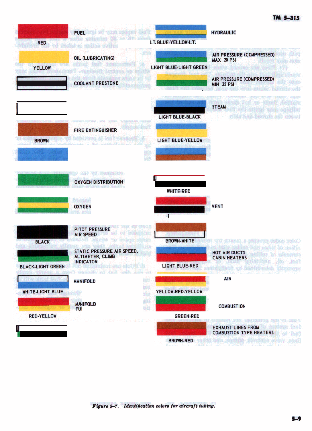
COLOR COOES
HYORAULIC
PRESSURE OIL
LT.BLlJE-YELLOW-LT.
BLUE
WHITE-BLACK-WHITE YELLOW-LIGHT GREEN
11
COOLANT WATER
WHITE
-1
FLOTATION EQUIPMENT
LIGHT BLUE
LIGHT GREEN
~YGEN
FILLER
GREEN-YELLOW-GREEN
PURGING
EXHAUSTANALYZER
LIGHT BLUE-BROWN
’
’ ANTI-ICING
WH,TE-RED
“ENT
(CLOSED COMPARTMENTS)
RED-BLACK
SMOKE SCREEN EQUIPMENT
MANIFDLD
PRESSURE
W.R
-YEL
NIFOLD
PRESSURE LINE TO
EL TANK PRESSURE UNIT
a
COLD
A,R
DUCTS
CABIN HEATERS
LIGHT
GREEN.RED
FUEL-AIR VAPOR SUPPLY LINES
TO
COMBUSTIDN
TYPE CABIN
HEATERS
1
b VACUUM
WHITE-LIGHT GREEN
5-9

TM
5-315
wit,h
flammable vapor. The zone generally has no
ignition sources of its own. Ignition occurs from
heat or flame entering the zone through the same
path used by fuel or vapors, and a violent explo-
sion may result.
(7) Fires are caused when improper engine
starts spill fuel into the tailpipe. The fuel dropped
onto the shroud runs forward, leading through
the shroud joints into the area between the fuse-
lage skin and the shroud. When the engine is
started, flame or hot gases from the end of the
tailpipe may ignite the fuel which has leaked be-
tween the shroud and skin.
MB.
Color Codes
a.
Zdentijication
of Tubing. To simplify identifi-
cation and tracing of cables, conduits, and tubing
of approximately the same size, a standard mark-
ing system has been devised. It consists of color
bands in various
comSbinations,
each color combi-
nation indicating a specific type of equipment.
The color code system used for tubing on all air-
craft is shown in figure 6-7. Colored bands are
applied to the tubing and cables on
.both
sides of
all points of connection and passage through bulk-
heads or sheaths. Where long runs of unjoined
tubing occur, there may be color bands at inter-
mediate points for identification.
bl.
Significance of Color Codes in F&refighting.
Color codes provide a means for immediate
recog-
niti.on
of tubes and cables vital to firefighting. The
contents of tubing carrying such fire hazards as
fuel, oil, anti-icing fluid, or oxygen can be
promptly determined by firefighters familiar with
color code designations. Color codes aid in tracing
sources of leaks or ruptures in the tubing so that
either a cutoff valve may be closed or the flow
may
,be
stopped by other means.
5-9.
Fuel System
Fuel is the principal fire hazard in aircraft. The
fuel system of an aircraft stores and transfers
fuel to the engine or engines. Fuel tanks, fuel
lines, valve controls, pumps, and other component
parts of the fuel system are widely dispersed
throughout the structure of an aircraft. An outlet
for escape of vapor or fuel may be produced by
impact, twist, or movement of the aircraft or by
improper assembly or maintenance. Ruptures in
the fuel system are hazardous because of the exis-
tence of possible sources of ignition, such
ae
over-
heated metal surfaces, exhaust gases, electrical
connections, discharge of static electricity, etc.
Fuel vapors may be ignited by engine heat sources
from
15
to 30 minutes after a fuel spill unless
proper preventive action is taken by the firefight-
ers.
a. Permanent fuel tanks are located in the
wings or central fuselage. Permanent tanks may
be in units separate from the aircraft framework,
permanently built into the aircraft framework, or
structurally part of the aircraft framework. As
part of the permanent tank installations, a re-
serve supply of fuel is usually provided for emer-
gency use. The reserve supply is separate from,
and should not be confused with, the auxiliary
fuel supply.
b. Reserve fuel is provided by separate tanks or
by the installation of a standpipe or small
open-
topped tank within the main tank. The outlet
from the reserve section of the tank is separate
from the main tank outlet. Fuel from the reserve
section is obtained by the operation of a selector
valve. The importance of the reserve tank in
fire-
fighting is that the main tank may indicate empty,
yet within the same tank the reserve section may
be full, creating a fire hazard.
c. Auxiliary fuel tanks are frequently installed
so that they can be dropped from an aircraft as
soon as the fuel is exhausted. Auxiliary tanks not
intended to be dropped in flight are installed in
cargo space or wings. Because of the location of
auxiliary tanks, they are usually vulnerable and
highly hazardous in crash landings.
d. Pilots are instructed not to permit fuel tanks
to run dry, but to change from a nearly empty
tank to a full tank. Normally, no fuel tank will be
completely drained. A mixture of fuel vapor and
air, drawn into the tank through the vent open-
ing, will be present and may be in such propor-
tions as to create a flammable or explosive mix-
ture.
e. Connections between fuel tanks of a
multi-
tank system are by direct openings in the tank
walls or by tubing connecting the separate outlets.
Fuel supply lines do not go directly from tank to
engine, but pass through the wing or fuselage, or
both, to control or selector valves at or near the
pilots position. From the control or
selector
valves, the fuel lines go to the engine or engines.
Tubing for venting and overflow extends from the
tank interior to an outboard discharge point. The
location of these outlets may be detected by
open-
end tubing extending just
#beyond
the exterior
5-10
surface and by adjacent stenciled description. A
manually operated drain valve is frequently
mounted below the tank to permit daily with-
drawal of water and sediment from the tank bot-
tom. During tank filling, draining, or overflow due
to expansion of fuel within a filled tank, liquid
fuel or vapor may discharge from these outlets
and remain on the ground surface. These dis-
charges are a constant fire hazard.
f. A selector valve permits the selection of the
fuel tank desired for engine fuel supply or com-
pletely cuts off the fuel supply from the engine or
engines. The selector valve may have an indicat-
ing dial showing two OFF positions. Either posi-
tion cuts off the fuel supply from engine or en-
gines.
g.
In firefighting operations, it may become nec-
essary to isolate the fuel supply to each engine in
an effort to determine the source of fuel flow. This
can be done by placing the cross feed valve, lo-
cated adjacent to the pilots position, in OFF posi-
tion. When switched to ON position, the discharge
lines of the two main fuel pumps are intercon-
nected and the pump remaining in operation sup-
plies fuel to both engines.
h.
The main fuel pump is engine driven and is
located in the accessory section. A booster pump
is an auxiliary fuel pump in the fuel line at some
point between the fuel tank and the main fuel
pump. Booster pumps may be manually or electri-
cally operated. Switching the master or the
booster pump switch to
O,FF
will shut off the
booster pump. The priming pumps are used to
supply fuel to the cylinder head or manifold for
engine starting. Excessive priming is a cause of
fires during engine starting. Liquid fuel or rich
vapor may be discharged into the exhaust system
and ignited, or ignite in the cylinder and return
through the intake, spreading flame through the
induction system to the carburetor and air scoop.
i.
Carburetor, throttle, and mixture controls are
usually mounted on the control quadrant. If the
engine is still running after a crash, the fuel sup-
ply can be cut off on float type carburetors by
moving the mixture control to the
IDLEOFF
posi-
tion. On injection fuel systems the fuel may be cut
off by moving the mixture control to the MAXI-
MUM LEAN position, or by placing the idle
cutoff switch in the OFF position, depending on
the type of fuel injection
system-
5-10.
Oil
System
a. Lubricating Oil. Lubricating oil commonly
used for aircraft engines has viscosity ratings
corresponding to SAE No. 40, 50, and 60. These
oils do not vaporize at ordinary temperatures and
their ignition temperature is higher than that of
fuel; therefore, the fire hazard is relatively less
than that of fuel. When lubricating oil is com-
bined with fuel, as frequently happens in aircraft
crashes, the fuel is readily ignited. The heat from
the ignited fuel vaporizes and ignites the oil, pro-
ducing an intense flame. The high viscosity of oil
makes it more difficult to r, nove from a surface
or from saturated debris. W le oil is most readily
ignited when combined with fuel, oil alone may be
ignited by contact with hot engine parts, arcing
electrical connections, or other sources of high
temperature.
b.
Oil
Tanks. Tanks are of metal construction,
ranging in capacity from 1 gallon (3.785 liters) to
45 gallons (170.3 liters). The oil tank may be
located at various points in the wings or fuselage,
but most commonly is immediately to the rear of
the engine accessory section, just forward of the
rear firewall. Filler necks and level cocks are in-
stalled on the tank for filling and determining oil
level within the tank. The location of the filler
neck is indicated by stenciling on a nearby sur-
face.
c.
0i.I
Cooler. Many aircraft engines have oil
coolers to lower the temperature of the oil in high
temperature operation. The most common type, of
cooler is a system of tubes or a cellular radiator
through which the oil is circulated. This cooler is
usually located within the engine nacelle.
d. Oil Pump. The oil pump is in the accessory
section of the engine and is engine driven. Normal
operating pressures do not usually exceed 100 psi
(7 kilograms per square centimeter) and may be
much less. Pressure is indicated by a gage on the
pilot’s instrument panel.
S-l 1.
Oxygen
System
All aircraft intended for operation at high alti-
tudes are equipped with breathing oxygen for
each crew member and passenger. Oxygen lines
run from a permanently mounted storage tank, or
tanks, to crew and passenger positions.
a. Tanks, Tubing, and Controls.
(1) The actual quantity of oxygen carried on
an aircraft is of only secondary interest to the
firefightrrs.
They must be as cautious with a small
quantity as with a large quantity.
(2) Oxygen storage tanks usually are painted
5-11
green. Tubing from main oxygen storage tanks to
outlet stations generally contains oxygen at all
times. Master control valves normally are kept in
the open position.
(3) Oxygen is stored up to 1,800 psi (126
kilograms per square centimeter). This pressure
exists throughout the distribution tubing system
down to the outlet stations. Rupture of tubing
anywhere between these points will free oxygen
under high pressure.
b.
Fire Hazard.
(1) Two hazards might occur from oxygen
equipment
:
explosion, and released oxygen feed-
ing the fire.
(a) Explosion may occur from rapid heat-
ing and expansion of the cylinders or from any
traces of grease or oil that may come in contact
with oxygen. The explosion may disrupt other
equipment and cause a fire by breaking fuel lines,
electrical cables, etc.
(b)
Release of oxygen during a fire results
in acceleration of burning and great intensity of
heat. Escape of oxygen during crash fires results
in rapid spread of fires and resistance to extin-
guishing agents.
(2) Every precaution must be taken to pro-
tect oxygen equipment from damage during forci-
ble-entry operations, and if possible, to protect
oxygen from exposure to heat or fire. Firefighters
should be familiar with the location and operation
of oxygen master control valves, and
iI
possible,
should close these valves during fire.
WARNING
DO NOT HANDLE
OXY,GEN
EQUIP-
MENT OF ANY KIND WITH
GREASY OR OILY RAGS OR HANDS.
OXYGEN UNDER PRESSURE, IN
CONTACT WITH GREASE OR OIL,
WILL CAUSE AN EXPLOSION OR
FIRE.
5-12.
Electrical System
The electrical system on an aircraft supplies cur-
rent for lights, booster pumps, hydraulic pumps,
propeller or rotor pitch gears, electronic equip-
ment, etc.
a. Electrical Wiring.
(1) All aircraft have an extensive wiring
system. The principal fire hazard is the danger of
a short circuit or arcing.
(2) In a crash, it is probable that a large
number of electric wires will be torn apart or
damaged. Movement of an aircraft after a crash
may produce a spark large enough to ignite fuel
vapors. A crashed aircraft should be moved only
when necessary for rescue operations, or when a
fire is of such proportions that the additional dan-
ger from a short circuit is immaterial.
b.
Batteries.
(1) The location of batteries varies with the
type of aircraft. The batteries may be in the fuse-
lage, wings, or engine nacelles. Special equipment,
such as certain types of radar, is provided with
separate batteries. These auxiliary batteries are
not usually located in the same compartment as
the main batteries.
(2) Before an aircraft is moved after a crash
or after a fuel spill, disconnect the batteries and
tape the leads, if possible, as a precautionary
measure against arcing or short circuits. The
proper way to disconnect a battery is to discon-
nect the ground wire first in order to eliminate
the danger of arcing. Improper disconnection may
produce an arc that will ignite fuel vapors.
c. Ignition.
(1) On reciprocating engine aircraft, the ig-
nition switch usually means the magneto switch.
In almost all reciprocal engines the ignition
siwtch
is operated by magnetos. Most aircraft are
equipped with dual magnetos.
(2) If the aircraft engines are not running
after a crash or fuel spill, the position of the
ignition switch is of no importance to firefighters
since the magnetos are driven by the engine and
stop when the engine stops. If the engine is run-
ning after an accident, it is usually safe from a
fire hazard viewpoint to stop the engine by first
cutting off the fuel at the mixture control or fuel
valve before cutting off the ignition switch. The
ignition switch usually is separate from the mas-
ter switch. Aircraft fire rescue personnel should
always check the position of the master switch
and beware of a hot magneto. A “hot mag” can
cause the engine to fire even if the master switch
is in off position.
(3) The battery switch usually is referred to
as the master switch. The master switch is the
principal electrical swtich on an aircraft. All elec-
trically operated units are connected to the power
source through the master switch. The master
switch is independent of separate equipment
switches and may be used to cut off electric cur-
rent simultaneously from all cables and equip-
5-12

TM
5-315
ment. In a crashed aircraft and in case of fuel
spill, it is important that the master switch is
immediately placed in OFF position.
d. Auxiliary
Powerplants.
(1) Some aircraft have auxiliary
power-
plants which are used to start the aircraft engine
or engines. The axuiliary powerplants may be op-
erated after takeoff to furnish an additional
source of electrical power. The unit consists of an
engine and an engine-driven generator.
(2) There is little fire hazard from the auxil-
iary powerplant electrical
equipmem
but a fire
hazard exists because of the engine. The auxiliary
powerplant generator is mounted on the engine.
5-13. Anti-Icing System
a. The anti-icing system prevents the formation
of ice on the propellers, carburetor, and wind-
shield. For propellers and windshield, nonflamma-
ble fluids are used in combat zones, but in non-
combat zones, alcohol (85 percent) and glycerine
(15 percent) are used. For the carburetor, alcohol
alone is used.
6.
Locations and sizes of tanks containing
anti-
icing fluids vary with the type of aircraft. Sepa-
rate tanks are provided for alcohol and
alcohol-
glycerine mixtures. Tubing extends from the tank
‘JO
the forward part of the aircraft.
c.
To prevent icing of propellers, anti-icing fluid
is pumped from the tank to a slinger ring at the
base of the propeller. The liquid then runs down
the blades by centrifugal force. A similar ar-
rangement is used to prevent icing of windshields.
Icing of a carburetor occurs inside the carbu-
retor; therefore, alcohol is routed directly to the
carburetor and mixed with the fuel.
d. The fire hazard of anti-icing fluids is less
than the fire hazard of aircraft fuel, but they
should be treated with caution in the event of an
aircraft crash. The most important points for the
firefighter to know are the location of tanks, and
the fact that the tank and tubing carry flammable
liquids.
5-14. Heater System
In the combustion type heater, a fuel vapor-air
mixture is burned in a hermetically sealed cham-
ber. Fuel for the heater is routed from the main
fuel system to the heater. The heater is usually
located in the center fuselage section. The fuel
vapor-air mixture is ignited by an electric igniter,
and is controlled by the heater control panel. The
fire hazard from the combustion type heater re-
sults from the small quantity of fuel vapor-air
mixture present in the heater.
5-15. Crew Entrapment
The controls for ailerons,
ruddel,
elevators, trim
tabs, rotors, and rotor blades are usually in the
form of cables, mechanical levers, or rod linkages
which pass from the pilot’s position through the
wings or fuselage to the control surfaces. These
controls are actuated by a pilot’s control stick or a
wheel and drum type control. A crash will some-
times jam the cables or mechanical linkages in a
fixed position, so that the control stick or wheel
pins the pilots within the pilot’s compartment. In
such cases it may be necessary to cut the cables or
mechanical linkages in order to release entrapped
personnel.
5-16. Rockets
Rockets still on their launchers are extremely
dangerous. Every precaution should be taken to
stand clear both fore and aft of rocket installa-
tions. Rocket flash which occurs upon ignition is
usually fatal at short ranges behind the rocket.
The auto-ignition temperature of solid rocket pro-
pellants is about
392O
to
575’
F.
(200’
-300’
C.
)
.
a. The effects of a propellant explosion are
minor. The usual result is a split motor tube and
an ejection of flame and gas from the motor
through the nozzles and the split. The exhaust
gases from the burning propellant are about
4,OOO’F.
(2,204W.)
and will add to the intensity
of the existing fire. If the high temperature gas is
directed against the aircraft surface, penetration
may occur. This adds to the fire hazard due to the
fact that fuel tanks may be ruptured or fire
spread to other sections of the aircraft.
b.
Ignition of the propellant could cause the
rocket to fire. The rocket will probably follow a
normal path and be armed when it stops. Extreme
care must be taken in handling rockets fired in
this manner.
5-17. Pyrotechnics
a. Pyrotechnics are used for signals, warnings,
lighting for photography, bombing or landing, or
other special purposes. They consist of various
types of flares, signal lights, smoke grenades, and
similar devices.
5-13
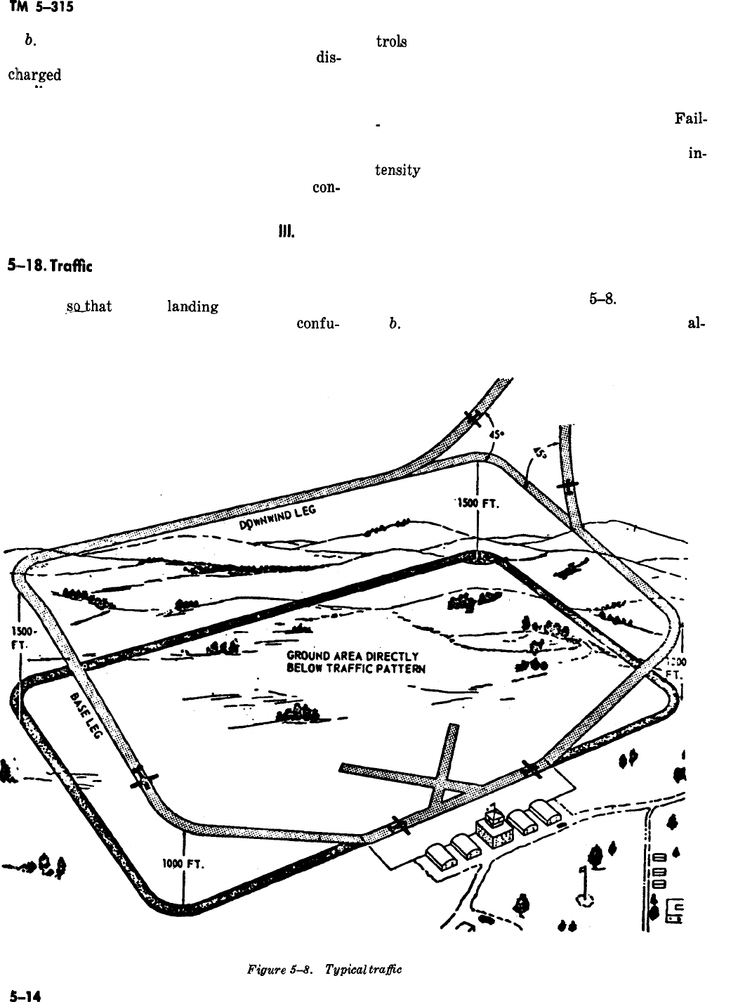
b.
Pyrotechnics contain rapid-burning powder,
magnesium, or flammables which are readily
dis-
clharged or ignited. Pyrotechnics may contain
_.
small explosive charges that will spread fire
quickly throughout the aircraft.
trols
located in the
normally carried in
side of the fuselage.
pilot’s compartment and are
special compartments in the
c. Pyrotechnics may be located anywhere on the
aircraft. In single-seated aircraft, hand-launched
pyrotechnics are located conveniently for the
pilot. Parachute flares are released by remote
con-
d. Whenever possible, pyrotechnics should be
promptly removed from a crashed aircraft.
Fail-
-
ure to do so may result in the discharge of these
flares and signals with great increase in the
in-
tensity
of an existing fire, or in the ignition of a
fire which otherwise might not have occurred.
Section
Ill.
EMERGENCY PROCEDURES
5-18.
Traffk
Pattern
a. The traffic pattern prescribes direction and
altitude,
@hat
aircraft
lanlding
or taking off will
follow prescribed courses, thereby avoiding
confu-
according to the direction of the wind. A typical
sion and collisions. The traffic pattern is shifted
traffic pattern is shown in figure
5-8.
IL
Movement within the traffic pattern is
al-
Figure
54.
Typical
trafic
pattern.
5-14

TM
5-31s
-
ways in the same direction regardless of arrival
or departure from the airfield, because landings
and takeoffs are both made into the wind. A typi-
cal traffic pattern has dimensions of 3 miles (4.8
kilometers) at
1,500-foot
(457.5meter) altitude,
but other dimensions and altitudes may be used,
established according to local conditions.
c. The typical traffic pattern consists of a coun-
terclockwise rectangular flow of aircraft about
the airfield. One side consists of the runway, take-
off leg, and approach leg along the line of the
runway nearest the prevailing wind direction.
The takeoff leg continues with a
90°
turn, which
is crosswind. On the crosswind leg an aircraft
departing the traffic pattern would turn
45’
away
from the flow of traffic. To continue in the traffic
pattern, another
90’
turn is then made and this
places the aircraft parallel to the runway and
forms the downwind leg. An aircraft arriving at
the airfield would enter the pattern at a
‘45’
angle
to the downward flow of traffic. The landing air-
craft continues with a
90’
turn, forming the base
leg. At this point the aircraft normally begins to
descend. The final 90’ turn is then made to place
the aircraft in a position to land on the runway.
The traffic pattern will occasionally be clockwise
or as published by the airfield.
5-19.
Coordination Between
Militury,
Civil,
and Municipal Organizations
Coordination and cooperation between local mili-
tary, civil airfield, and municipal firefighting or-
ganizations is most desirable. Mutual assistance
agreements between responsible activities are en-
couraged.
,Local
commanders
Ishould
cooperate
fully with Forest Service, state, and local fire
officials in developing plans to furnish assistance
in firefighting and rescue to an extent which
would not impair the safety of the military instal-
lation involved.
5-20. Emergency Communications System
a. An emergency aircraft rescue communica-
tions
sy,stem
must be provided to permit rapid
and reliable notification of impending and actual
aircraft accidents to firefighting and rescue crews,
ambulance crews, and other personnel requiring
such notification. The system must be capable of
conveying full initial information on the emer-
gency so that crash trucks and ambulances can be
dispatched quickly and efficiently. They system
must also provide continuing intercommunication
between mobile units and the fixed control sta-
tions throughout the emergency.
b. A complete emergency communications sys-
tem should consist of the following:
(1) Principal fire truck and ambulance fixed
control stations.
(2) Provisions for monitoring communica-
tions between aircraft and control tower.
(3) Direct emergency wire intercommuni-
cation between control tower and principal crash
truck and crash ambulance fixed control stations.
(4) Secondary emergency telephone or simi-
lar wired system for notifying essential support-
ing personnel.
c. Operation of the two-way radio sets is simpli-
fied to the extent that the driver of the fire truck
can operate them. A qualified radio operator is not
necessary.
5-21. Training
Maintenance, refuleing, and servicing personnel
on the flight line, supporting aircraft operation,
will be
in,structed
in the types of extinguishers
and their operation, care, and proper
app!lication
ofr extinguishment of fires. Firefighters assigned
to aircraft fire rescue work must become thor-
oughly familiar with and have a working knowl-
edge of the requirements contained in AR 95-26
and AR 95-1.
5-22. On-The-Airfield Emergency
Normally the control tower operator will obtain
the first information of impending emergencies or
accidents. He immediately notifies the fire rescue
crew of the situation, giving exact information on
the location and status of the event together with
any pertinent details. Upon receipt of this notifi-
cation, all crash crews and ambulances on alert
will respond immediately.
If
the situation is an
impending emergency, they assume standby posi-
tions at predetermined locations alongside, but
clear of, the runway.
NOTE
Notification by the control tower opera-
tor does not relieve fire rescue crews on
alert of the responsibility of maintain-
ing constant observation since, particu-
larly during active flying periods, many
instances may escape the initial notice of
the tower operator.
5-23. Off-The-Airfield Emergency
a. Maps of the installation and surrounding
area of about 15-mile
(24-kilometer)
radius
5-15
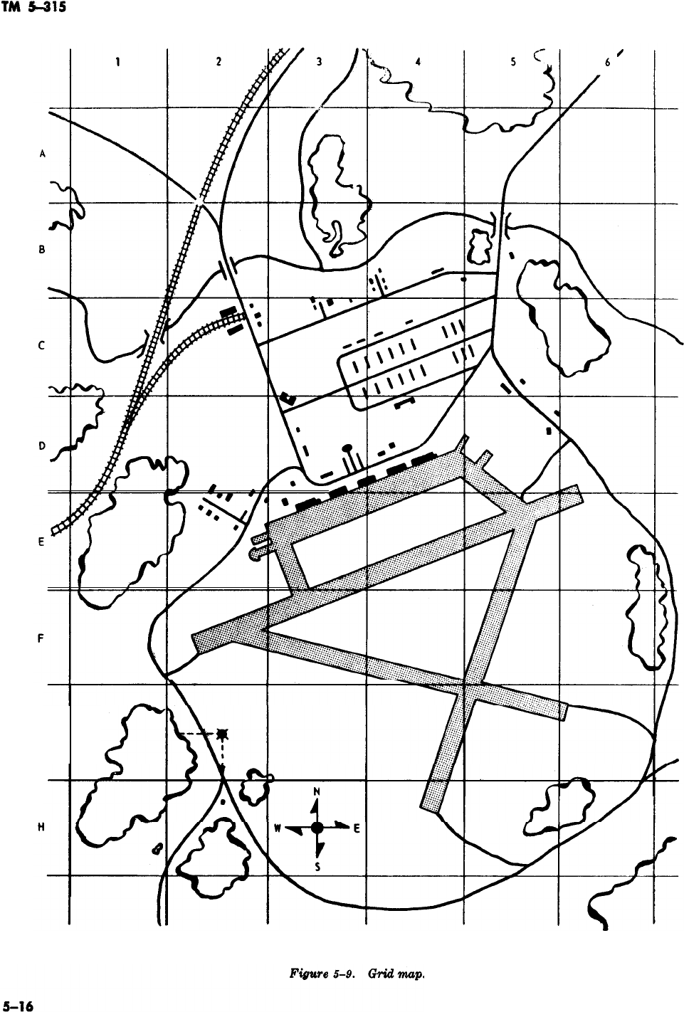
-
G
-

should be available. These maps should be ruled
off in numbered grids, and compass headings
marked on them generally as shown in figure 5-9.
This will make it easier to locate any point within
the map area.
b. When necessary, an aircraft will be used to
locate and guide firefighting and rescue trucks to
the scene.
c. Aircraft are guided by radio contact and vis-
ual and audible
signal,s.
d.
When not directing
craft will circle crashed
fuel supply permitting.
fire rescue trucks,
air-
aircraft until relieved,
5-24. Emergency Rescue Procedures
a. Aircraft Entrances.
(1) Depending on the aircraft model, en-
trance doors may be found on
eifther
side or both
sides of the fuselage. They usually open outward
and are hinged on the forward side so the
air-
stream tends to close the door. The opposite side
is fastened by a latch which usually is operated by
pulling the door handle. On most aircraft, an
emergency release mechanism is installed
ait
the
hinge side of the door, and is operated by pulling
the jettison handle.
(,2)
E,scape
hatches or escape panels, pro-
vided on some aircraft, are made either of
plexi-
glas or metal. The hatches usually have an exter-
nal release handle with the location and operating
procedures marked on the adjacent surface of the
fuselage.
(3) Emergency cut-in areas, indicated by a
broken yellow line, are provided on some aircraft.
This marking is a safety guide which designates a
comparatively obstacle-free area where tools used
for cutting fuselage skin will not meet heavy
structural members or rupture fuel, electrical, or
oxygen lines that can cause additional fire or an
explosion. Extreme care should be used when cut-
ting fuselage skin to prevent sparks which might
ignite fuel vapors.
(4) The aircraft may have other openings
intended primarily for other specific purposes, but
which may be used under certain circumstances
for emergency entrance.
b. Rescue of Personnel.
(1) After entrance is gained, the firefighters
should first locate and determine the condition of
injured personnel. If immediate hazards are be-
yond control, personnel should
*be
evacuated im-
mediately. If immediate evacuation is not possible
TM
5-315
due to wreckage or twisted controls, the firefight-
ers should attempt to keep the fire away from the
area where personnel are trapped. Extreme care
should be used when removing personnel pinned
in wreckage to prevent aggravating existing or
causing additional injuries. If possible, medical
advice should be obtained before moving injured
personnel.
(2) All Army aircraft have seat safety belts
and many have shoulder harnesses. The safety
belts and shoulder harness are constructed of very
strong, webbed material and are difficult to cut;
therefore, the rescueman should be familiar with
the release procedures. The safety belt and shoul-
der harness (fig. 5-10) are released by unlocking
the inertia reel and pulling up on the’release han-
dle. The inertia reel is unlocked by placing the in-
ertia reel lock lever at the locked and then the un-
locked position. If necessary, the safety belt and
shoulder harness may be cut as shown in figure
5-1~1.
Some aircraft, such as the
UH-l!C
and
UH-1D
model helicopters, are equipped with
tilt-
back pilot and copilot seats to aid in extracting
injured personnel from a crowded cockpit. These
seats are identifiable by two red handles located at
the back of each side of the seat. Both handles
must be pulled down to tilt back the seat.
(3) After releasing the safety belt and shoul-
der harness, it may be necessary to remove the
parachute from injured personnel. Three basic
types of parachutes are used: the seat type, the
-back
type, and the attachable chest type. These
parachutes are strapped to the personnel by
means of a parachute harness which may have
either three clip-type fasteners or one quick-re-
lease box. The parachute harness with clip-type
fasteners (fig. 5-12) is the most commonly used.
The parachute harness may also have one or two
parachute canopy release mechanisms in addition
to the clip-type fasteners. The purpose of the re-
lease mechanism is to release the parachute
canopy and not the entire harness. The release
mechanism may be located either on the left-hand
parachute canopy strap or on both straps. Typical
parachute release mechanisms with operating pro-
cedures are shown in figure
&13.
The parachute
harness equipped with the quick-release box pro-
vides a fast and efficient method of releasing the
personnel, as shown in figure 5-14.
5-25.
Portable and Fixed Fire Protection
on Aircraft
Fire protection equipment installed on aircraft
may consist of one or more portable fire
extin-
5-17
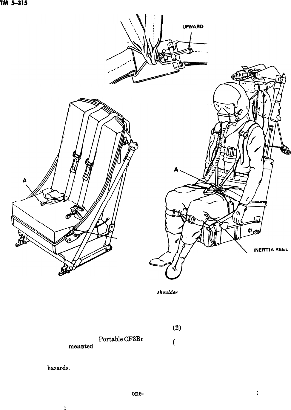
PULL HANDLE
DETAIL A
RELEASE HANDLE
INERTIA REEL
LOCK LEVER
Figure 5-10. Safety belt and
shoulder
harness-typical.
w
LOCK LEVER
\
\
guishers. On larger aircraft this protection may
be supplemented by a fixed fire extinguisher sys-
tem.
a. Portable Fire Extinguishers.
P,ortable
CF3Br
fire extinguishers are
mo&uated
for quick access.
They usually are located within the fuselage at or
near crew member positions or adjacent to spe-
cific equipment
hazar,ds.
b. Fixed Fire Extinguisher System. The major-
ity of fixed fire extinguisher systems are installed
in multiengine aircraft and are usually the
one-
shot type. The system consists essentially of the
following components
:
5-18
(1) One or more cylinders for storing extin-
guishing agent.
(2)
Distribution lines leading to protected
areas.
‘(
3) Controls for releasing extinguishing
agent.
5-26. Aircraft Familiarization
a. The different types of aircraft make the job
of firefighting and rescue more complex. To carry
it out successfully, the firefighter should be thor-
oughly familiar with the following
:
(1) Visual identification of various types of
--+
aircraft.
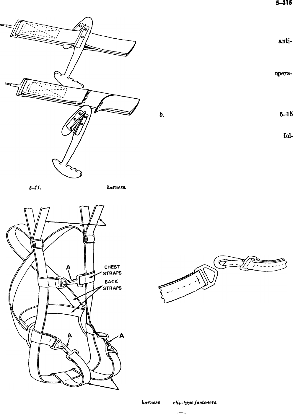
Figure
5-11.
Method of cutting double harnees.
PARACHUTE CANOPY
u
STRAPS
TM
5-315
(2) Location of personnel and aircraft en-
trance points.
(3) Fuel tank locations and capacities.
(4) Oil tanks, hydraulic reservoirs, and anti-
icing reservoir locations and capacities.
(6) Battery location.
(6) Oxygen cylinder location.
(7) Basic features of ejection seat, its
apera-
tion, and precautions necessary to prevent acci-
dental ejection.
(8) Preservation of evidence that could possi-
ble aid in determining cause of accident.
b.
To aid in this familiarization, figures
6-16
through 6-49 illustrate the general arrangement
of standard Army aircraft and several Air Force
aircraft, and the emergency procedures to be
fol-
lowed for each.
DETAIL A
CLIP-TYPE FASTENER
LEG STRAPS
Figure 5-12. Parachute
hameea
with
clip-type
fasteners.
5-19
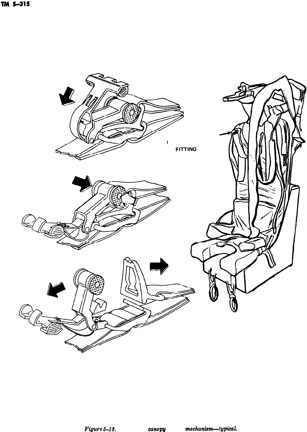
-
HARNESS
/
QUICK-DISCONNECT
1. UNSNAP SAFETY CLIP
2. PRESS RELEASE BUTTONS
-
3. REMOVE PARACHUTE CANOPY STRAP
Figwe
5-13.
Parachute
canopy
release
mechankm--twiGal.
5-20
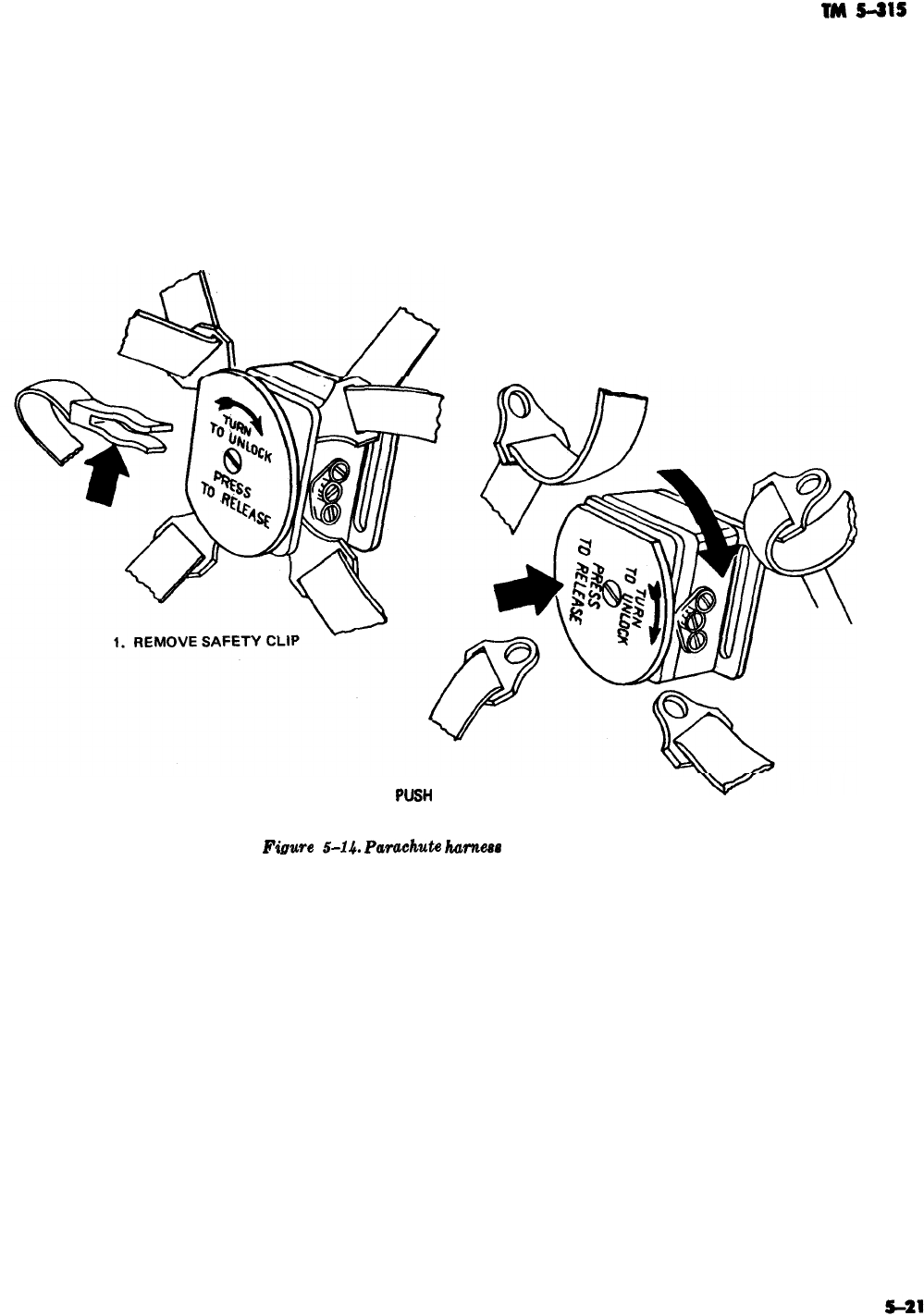
.-
-
2. ROTATE PLATE TO UNLOCK POSITION
3.
PUSI-I
PLATE TO RELEASE HARNESS
Finwe
5-14.
Parachuti
harness
quick-release box.
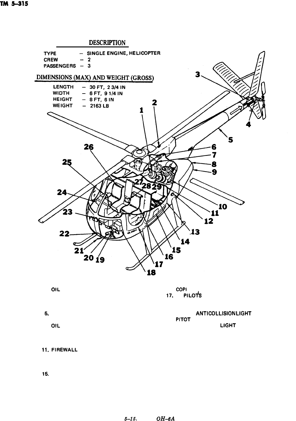
GENERAL
DESCRIF’TION
1.
OtL
COOLER 6LOWER
16.
2.
UPPER ANTICOLLISION LIGHT
17.
3.
TAIL ROTOR DRIVE SHAFT
16.
4.
TAIL ROTOR TRANSMISSION
19.
6.
TAIL BOOM
20.
6.
ENGINE OIL TANK
21.
7.
OtL
COOLER
22.
6.
ENGINE EXHAUST PIPE
23.
9.
ENGINE ACCESS DOOR
24.
10.
ENGINE
25.
Il.
FIREWALL
26.
12. LH NAVIGATION LIGHT 27.
13. LH CARGO COMPARTMENT DOOR
2B.
14. TROOP SEAT 29.
15.
ARMAMENT ACCESS DOOR
COPI
LOTS SEAT
LH
PlLOfS
COMPARTMENT DOOR
RADIO AND NAVIGATION EQUIPMENT
BATTERY
LOWER
ANTlCOLLlStON
LtGHT
PITOT
TUBE
LANDING/HOVER
LtGHl
EXTERNAL AIR INLET
INSTRUMENT PANEL AND CONSOLE
EXTERNAL POWER RECEPTACLE
PI LO& SEAT
MAIN ROTOR TRANSMISSION
MAP CASE (CHECKLIST)
MAIN DRIVE SHAFT
Figure
5-15.
Model
OH-6A
aircraft.
5-22
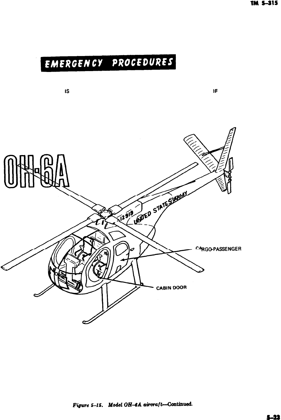
1
EMERGENCY ENTRANCE
IS
GAINED THROUGH CABIN DOORS AND PASSENGER DOORS. lF
DOOR FAILS TO OPEN, BREAK WINDOWS OR CANOPY TO GAIN ACCESS TO DOOR
JETTISON HANDLE,
RGC3PASSENGER
DOOR
-
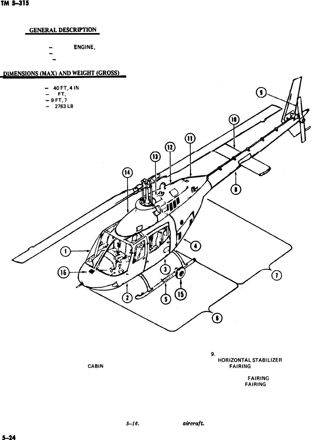
TM
5-215
GENERALDESCRH'TIDN
TYPE
-
SINGLE
ENGiNE,
HELICOPTER
CR&W
-
2
PASSENGERS
-
2
LENGTH
-
4OFT,4lN
WIDTH
-
6 FT. 5.5 IN
HEIGHT
-
9FT.7
IN
WEIGHT
-
2763L8
1.
WINDSHIELD
9.
2.
CREW DOORS
10.
3. AFT
CABIN
DOORS
11.
4. AFT AVIONICS COMPARTMENT
12.
5.
LANDING GEAR
13.
6.
FORWARD SECTION
14.
7.
INTERMEDIATE SECTION
15.
8.
TAIL 800M
16.
TAIL ROTOR
HORIZONTALSTABILIZER
AFT
FAIRING
ENGINE COWL
INDUCTION
FAIRING
FORWARD
FAIRING
GROUND HANDLING WHEELS
RAM AIR
Figure
5-16,
Model OH-58A
aimraft.
5-24
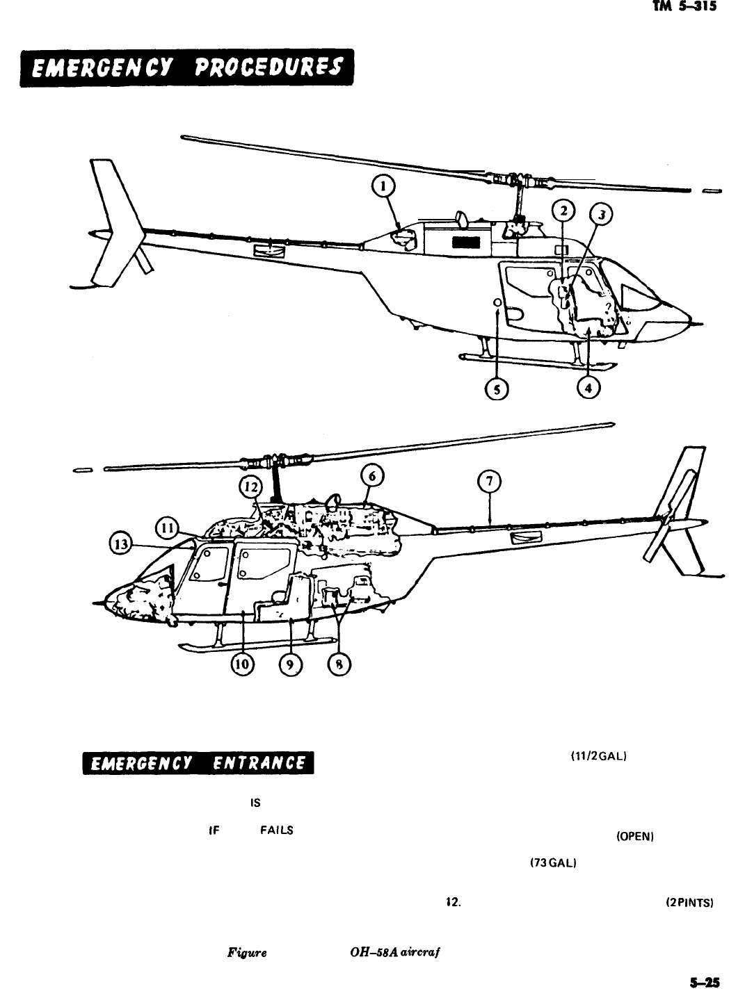
TM
5-315
-
EMERGENCY ENTRANCE
IS
GAINED
THROUGH CABIN DOORS AND
PASSENGER DOOR.
lF
DOOR
FAlLS
TO
OPEN, BREAK WINDOWS OR CANOPY TO
GAIN ACCESS TO DOOR JETTISON
HANDLE.
1. OIL TANK FILLER
(1
1/2
GAL)
2. FIRST AID KIT
3. FIRE EXTINGUISHER
4. PILOT’S STATION
5. FUEL TANK FILLER
6. ENGINE
7. TAIL ROTOR DRIVE SHAFT
(OPEN)
B. BATTERY
9. FUEL CELL
(73
GAL)
10. PASSENGER STATION
11. FUEL VALVE SHUT-OFF
82,
HYDRAULIC PUMP AND RESERVOIR
(2
PINTS)
13. MASTER SWITCH (CONSOLE)
Figwe
5-16. Model
OH-58A
aircvaf
t-continued.
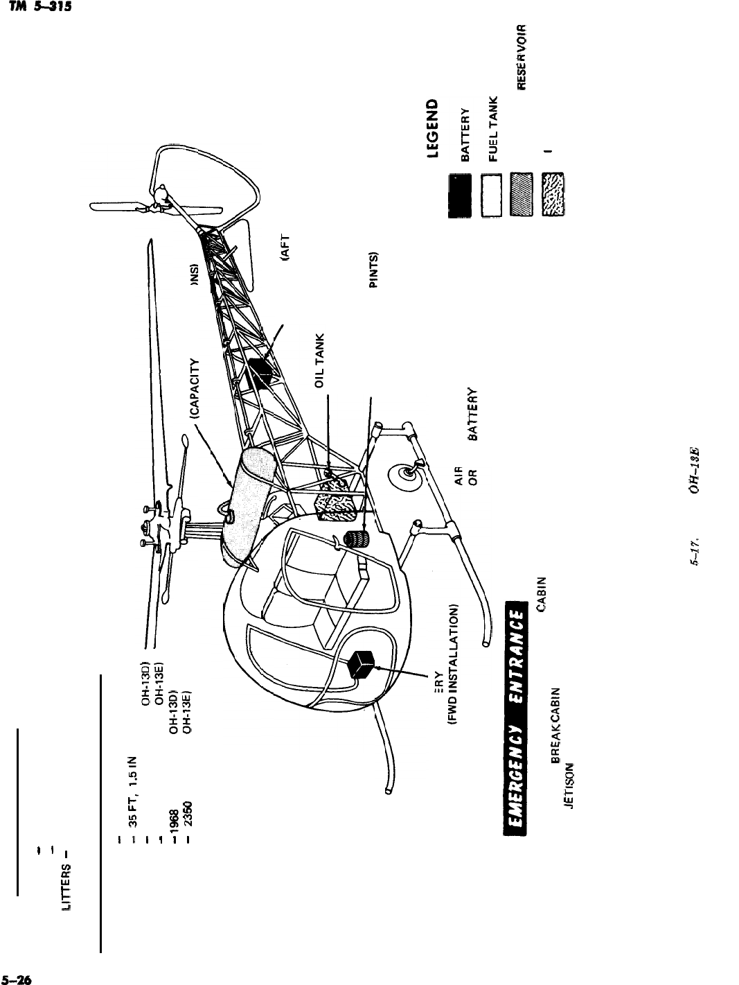
GENERAL DESCRIPTION
TYPE
-
SINGLE ENGINE, HELICOPTER
CREW
-
2
LllTERS
-
2
DIMENSIONS (MAX) AND WEIGHT (GROSS)
LENGTH
WIDTH
HEIGHT
WEIGHT
-
41 FT, 4.75 IN
-
35FT,
1.5lN
-
8 FT, 8.15 IN (MODEL OH-13DI
-
Q FT, 4.31 IN (MODEL
OH-13E)
-
lQB8
LB (MODEL OH-13DI FUEL TANK
-
235Q
LB (MODEL
OH-13E)
@ZAPAClTY
29 US GALL0
BATTERY
(AFT
INSTALLATION)
(CAPACITY 2 us GALLONS)
HYDRAULIC RESERVOIR
(CAPACITY 1.5 US
PINTS)
BATTERY
(FWD
INSTALLAA
AIRCRAFT MAY BE EQUIPPED WITH FWD
OR AFT
BA-lTERY
INSTALLATIONS OR BOTH.
F
B::i:RL
HYDRAULIC
EMERGENCY ENTRANCE MAY 8E GAINED THROUGH
CA8lN
DOORS.
IF DOORS FAIL TO OPEN,
8REAK
CA8lN
DOOR OR THE BUBBLE TO 0
I
L TANK
GAIN ACCESS TO
JETISON
DOORS.
RESE
R
‘VOIR
Figure
5-17.
Model
OH-13E
aircraft.
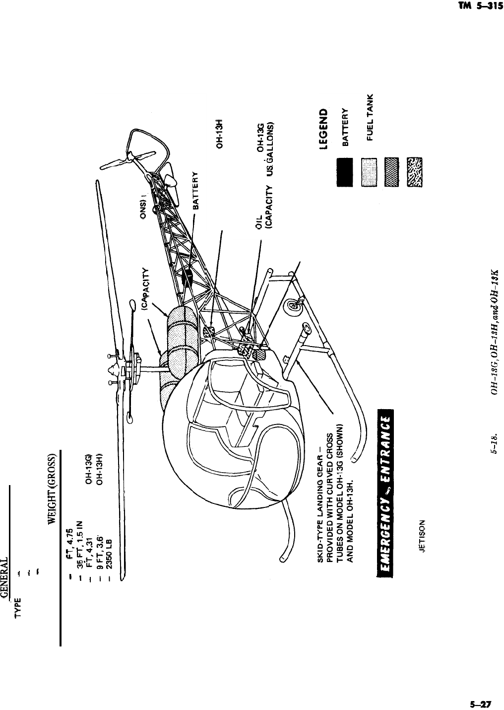
i
GENERALs
DESCRIPTION
TYPb
-
SINGLE ENGINE, HELICOPTER
CREW
-
2
LITTERS
-
2
DIMENSIONS (MAX) AND
WE1GI-R
(CXW9
LENGTH
-
41
FT,4.75
IN
WIDTH
-
35FT,l.5lN
HEIGHT
-
9
F?,4.31
IN (MODEL
OH-13G)
1 IN (MODEL
OH-13H)
WEIGHT
FUEL TANKS
PACITY 57 US GALL
OIL TANK-MODEL OH-13H
(CAPACITY 2 US GALLONS)
OlL
TANK-MODEL
OH-13G
(CAPACITY 2
USbALLONS)
HYDRAULIC RESERVOIR
(CAPACITY 1.5 US PINTS)
HYDRAULIC RESERVOIR
EMERGENCY ENTRANCE MAY BE GAINED THROUGH CABIN DOORS.
IF DOORS FAIL TO OPEN, BREAK CABIN DOOR OR THE BUBBLE TO
GAIN ACCESS TO
.lETlSON
DOORS.
OIL TANK
Figure
5-18.
Models
OH-lSG,
OH-13H,
and
OH-1SK
aircraft.
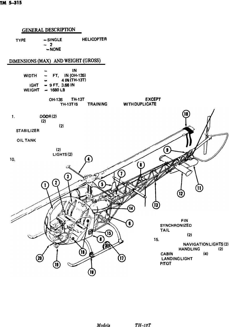
GENERALDESCmaN
I-YPIZ
-
StNGLE
ENGINE,
IiELlCOPlER
CREW
-2
PASSENGERS
-
NOhE
DIMENSIONS(h4fi.X)
ANDWEIGHT(GROSS)
LENGTH
-
43 FT, 2.56
tN
WtDTH
-
9
Fl,
7
tN
[OH-13Si
-
9 FT, 4
tN
(TH-13TI
HE
tGtiT
-
9FT,
3.66tN
WEtGHl
-
16BOLB
NOTE:
OH-13S
and
TH-13T
ARE THE SAME HELICOPTERS,
EXCEF’T
THAT
THE
TH-13T
tS
THE
TRAtNtNG
MODEL
WtTH
DlJPLtCATE
CONTROLS.
1.
ENTRANCE
DCiOFi
12)
2. SEAT BELTS
(21
3. SHOULDER HARNESS
(21
4.
STABtLtZER
BAR
5. UHF ANTENNA
6.
OtLTANK
7. BATTERY
8. ROTATING BEACON
(2)
9. AFT NAVtGATtON
LtGHTS
(21
10:
BLADE MOORING BLOCK
11. VENTRAL FtN
12.
SYNCHRONtZED
ELEVATOR
13.
TAtL
BOOM
14. FUEL TANKS
(21
15.
EXTERNAL POWER RECEPTACLE
16. FORWARD
NAVtGATtON
LtGHTS
(21
17. GROUND
HANDLtNG
WHEELS
(21
18.
CABtN
VENTILATORS
141
19.
LANDtNG
LtGHT
20.
PtTOT
TUBE
Figure 5-19.
Models
OH-US and
TH43T
aircraft.
5-28
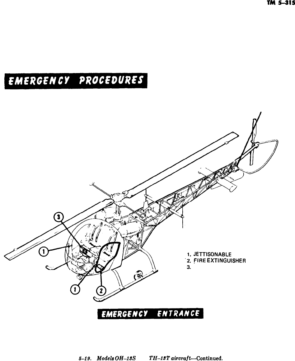
TM
s-ms
JETTISONABLE
DOOR RELEASE
FIRE
EXTlNGUlSHER
FIRST AID KIT
EMERGENCY ENTRANCE MAY BE GAINED THROUGH CABIN DDORS. IF DOORS FAIL TO
OPEN, BREAK CABIN DOOR OR THE BUBBLE TO GAIN ACCESS TO JETTISON DOORS.
Figure
5-19.
Modela
OH-18s
and
TH-13T
ahraft-Continued.
5-29
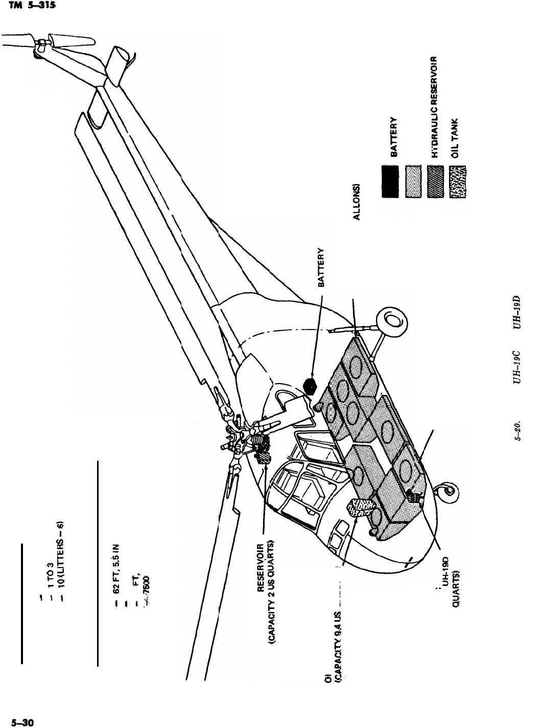
GENERAL DESCRIPTION
TYPE
-
SINGLE ENGINE, HELICOPTER
CREW
-
lTO3
PASSENGERS
-
10
(LllTERS
-
6)
DIMENSIONS (MAX) AND WEIGHT (GROSS)
LENGTH
-
62FT,5.tilN
WIDTH
-
63FT
HEIGHT
-
14
FT,
6.6 IN
WEIGHT
‘+~?600
LB
01
L TANK
WAPA~?ITYQ_~US
GALLONS)
HYDRAULIC
RESERyOlR
h?APACtl-V2USQUART!i)
AFT FUEL TANKS
(CAPACITY B2 US G
CLUTCH HYDRAULIC
RESERVOIR-MODEL
FWD FUEL TANKS
(CAPACITY 101 US GALLONS)
ALLONS)
LEGEND
BATTERY
FUEL TANK
HMMAULIC
RESERVOtR
(CAPACITY 5 US
QUARTS)
O’L
TANK
Figure
&fM.
Models
UH-19C
and
UH-19D
aircraft.
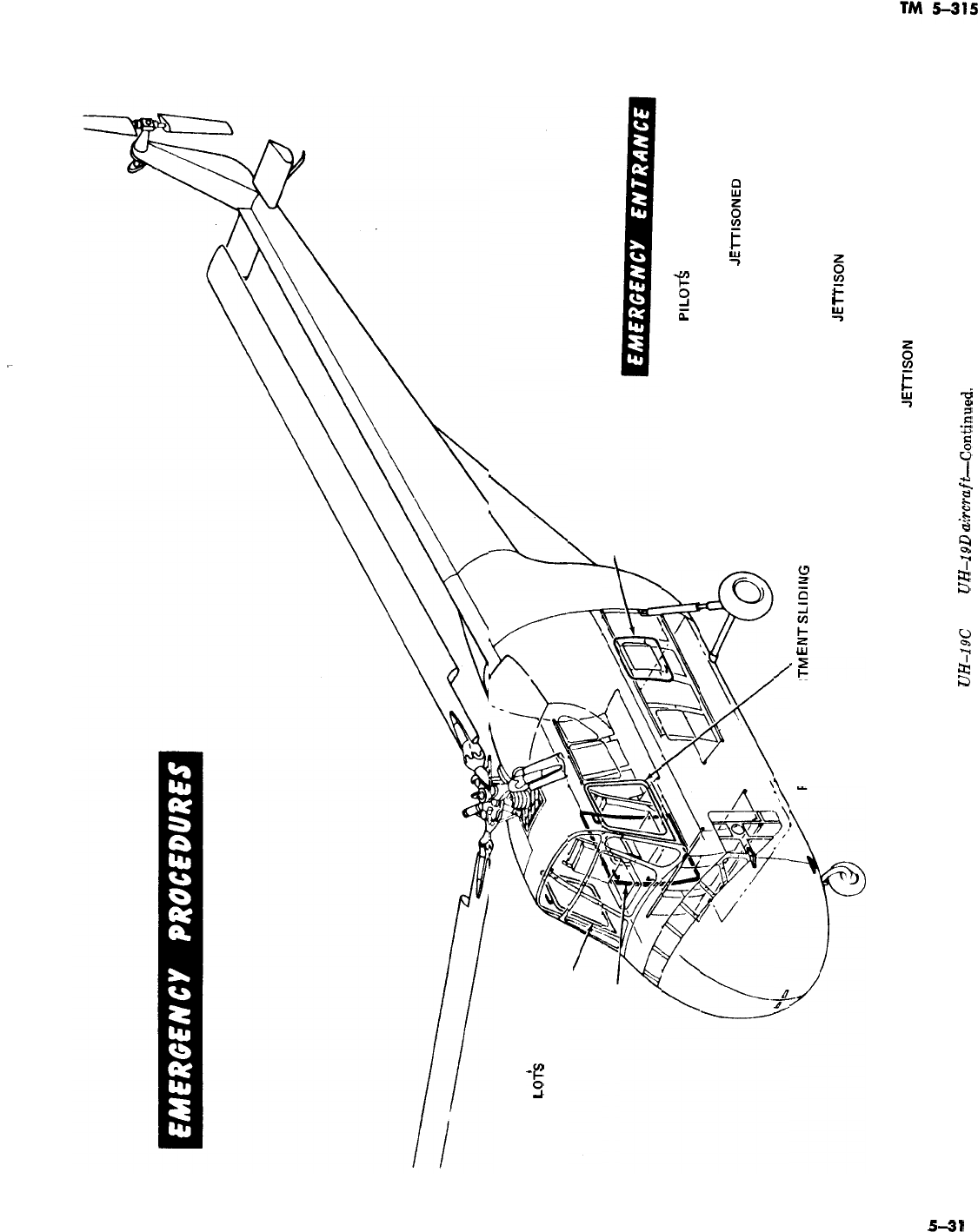
1
PI
LO+3
COMPARTMENT
SLIDING WINDOW
CABIN DOOR
CABIN ESCAPE PANEL
EMERGENCY ENTRANCE MAY BE GAINED
THROUGH
PILOT6
COMPARTMENT SLIDING
WINDOWS, CABIN DOOR, AND CABIN ESCAPE
PANEL. PILOT!! COMPARTMENT SLIDING
WINDOWS MAY BE
JEl-rlSONED
BY ROTATING
JETTISON HANDLES LOCATED ON UPPER
FORWARD FRAME OF EACH WINDOW. SLIDING
WINDOWS MUST BE FULLY CLOSED BEFORE
PI LOTS COMPAR
ENTSLIDING
WINDOW JETTISONING MECHANISM WILL RELEASE.
CABIN DOOR MAY BE JETTISONED BY
ROTATING
JE-ITISON
HANDLE, LOCATED ON
UPPER FORWARD CORNER OF DOOR, AND
PULLING OUTWARD ON DOOR. CABIN ESCAPE
PANEL MAY BE JETTISONED BY ROTATING
JEl-rlSON
HANDLE AND PULLING OUTWARD.
Figure 5-20. Models
UH-19C
and
UH-19D
akcraf&-Continued.
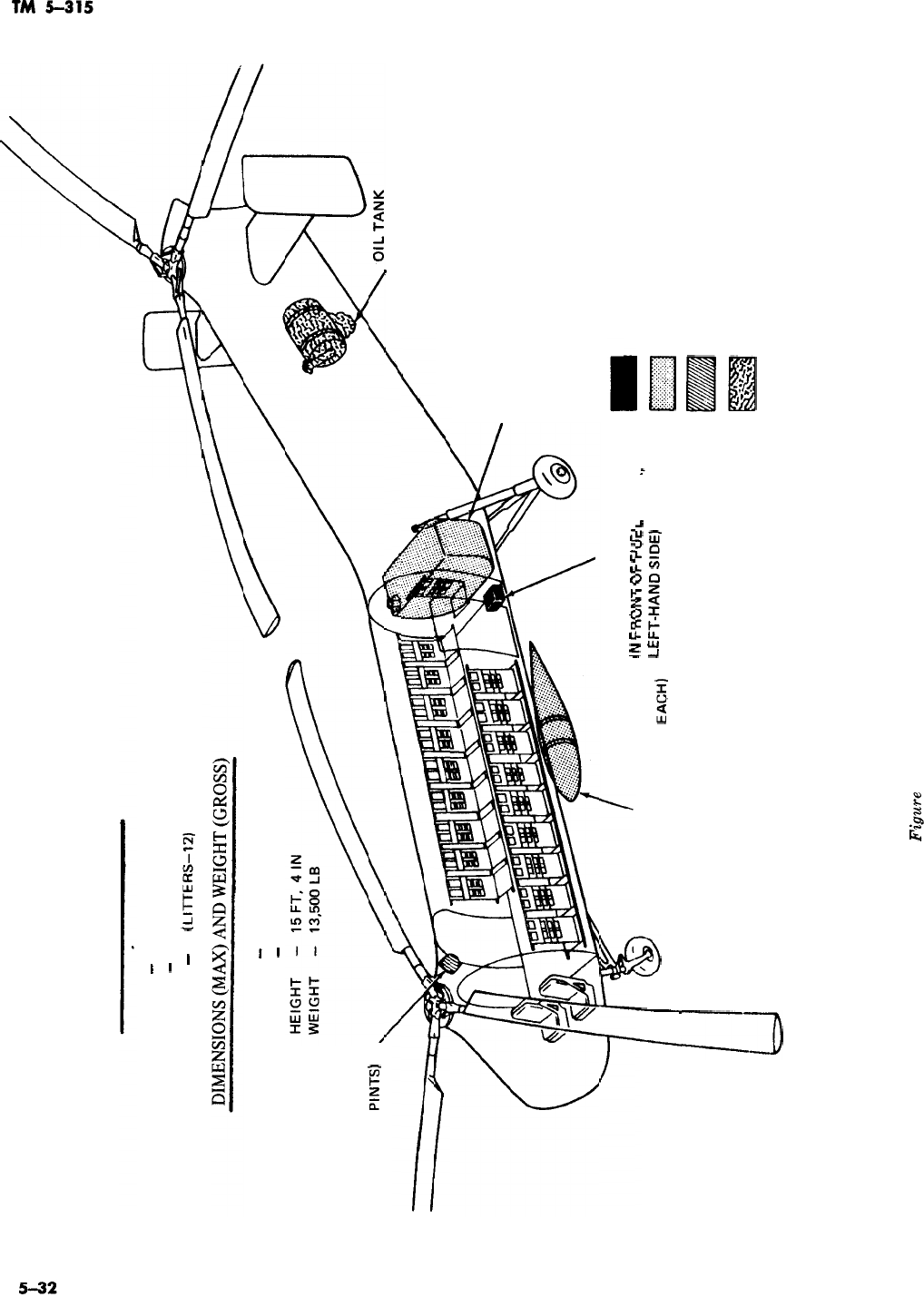
GENERAL DESCRIPTION
TYPE
-
SINGLE ENGINE, HELICOPTER
CREW
-
lT05
PASSENGERS
-
20
(LITTERS-12)
LENGTH
-
86 FT, 4 IN
WIDTH
-
44FT
HYDRAULIC RESERVOIR
(CAPACITY 6.5 US
PINTS)
/
-
(CAPACITY 21.5 US GALLONS)
FUEL TANK
(CAPACITY 304 US GALLONS)
LEGEND
BATTERY (LOCATED ON FLOOR
IhI
cmfim-r
nc
=*
#c-m
TANK
I
I
FUEL DROP TANK-TWO PLACES
at”
,_““I”
1
“I-
I-“=!_
(CAPACITY 165 US GALLONS
EACH)
LEFT-HAND
““’
BATTERY
.,
m
FUEL TANK
HYDRAULIC RESERVOIR
OIL TANK
Fipre
5-21. Models CH-21 B and CH-21C aircraft.
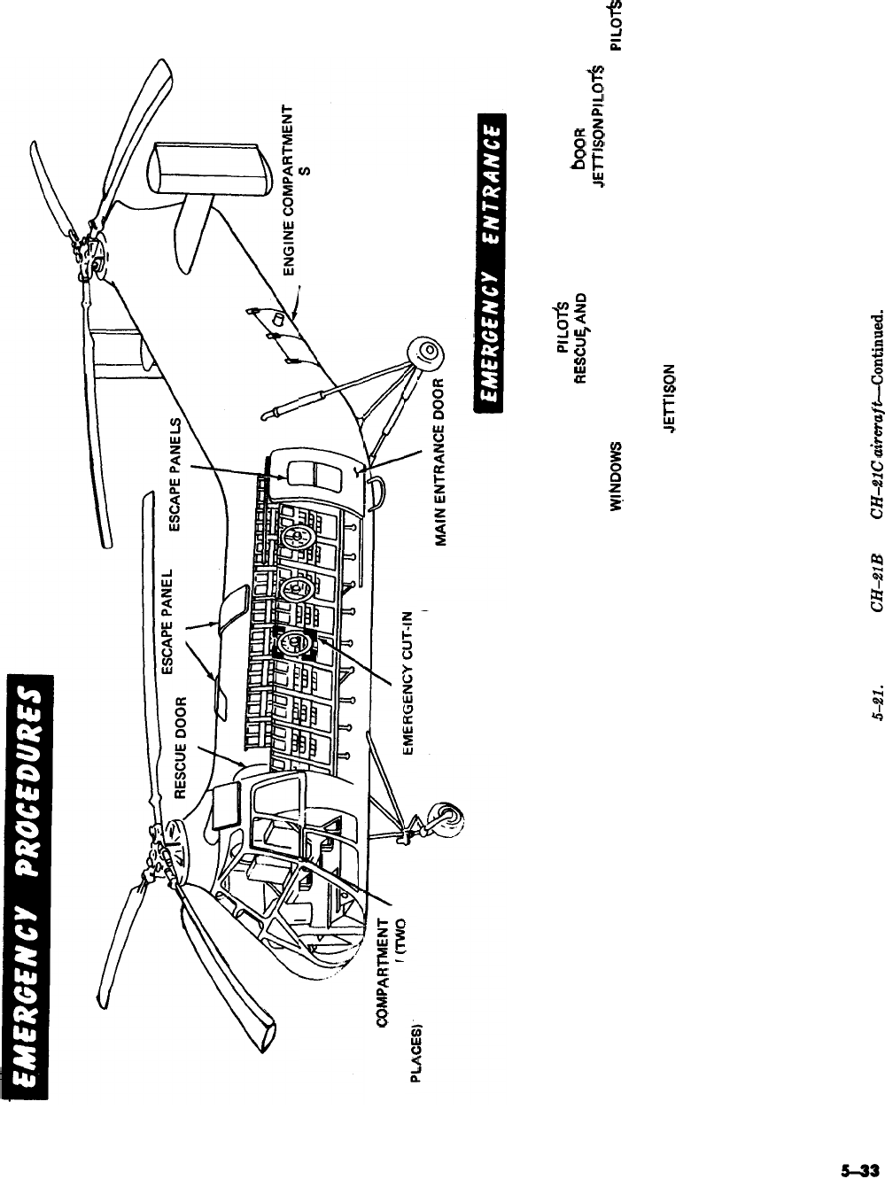
ACCESS DOOR
PILOTS
COMPART
SLIDING WINDOW
AREA (TWO PLACES)
EMERGENCY ENTRANCE MAY BE MADE THROUGH OVERHEAD ESCAPE
PANELS, MAIN ENTRANCE DOOR ESCAPE PANEL, RESCUE DOOR
ESCAPE PANEL, AND
PlLOfS
SLIDING WINDOWS. TO OPEN OVERHEAD
ESCAPE PANELS, RESCUCAND MAIN ENTRANCE
booR
ESCAPE PANELS,
PULL RED PROTRUDING TAB FROM PANEL.
JElTlSON
PILOT!?
SLIDING
WINDOWS
BY PULLING OUT ON EXTERNAL JETTISON HANDLE.
PILOT!3
SLIDING WINDOWS, RESCUE DOOR (LOCATED ON RIGHT-HAND SIDE OF
FUSELAGE), AND MAIN ENTRANCE DOOR ARE PROVIDED WITH
INTERNAL
JElTlSON
HANDLES,
Figure
5-21.
Models
CH-2lB
and
CH-2lC
a&rafUontinued.
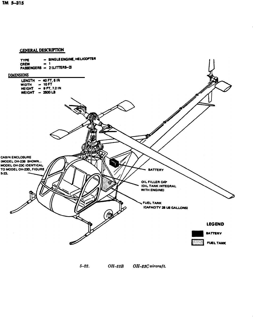
-
TYF6
-
SINGLE
ENGINE,
MELlm~
CREW
-
1
FA6SlENGER6
-
ZlLlmn6-a
DIMFNSIONS
(MAX) AND WEIGHT (GROSS)
L6NGTM
-
4OFT,6lN
WIDK’4
-
1OFT
H6lGHT
-
6R.7.2lN
WIEIGHT
-26OOL6
Figure
5-22.
Models
OH-2.W
and
OH-MC
aimraft.
5-34
-
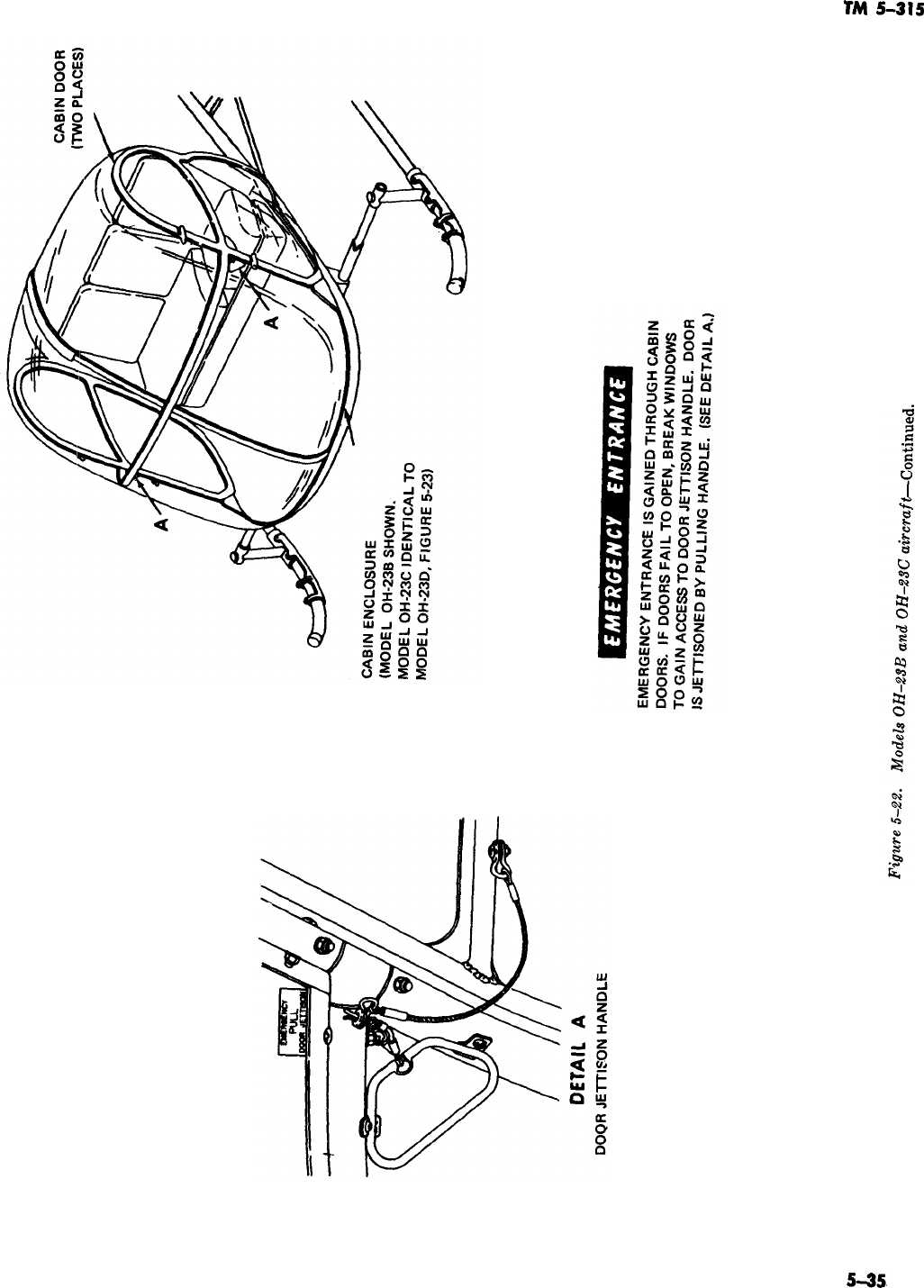
TM
5-315
5-35,
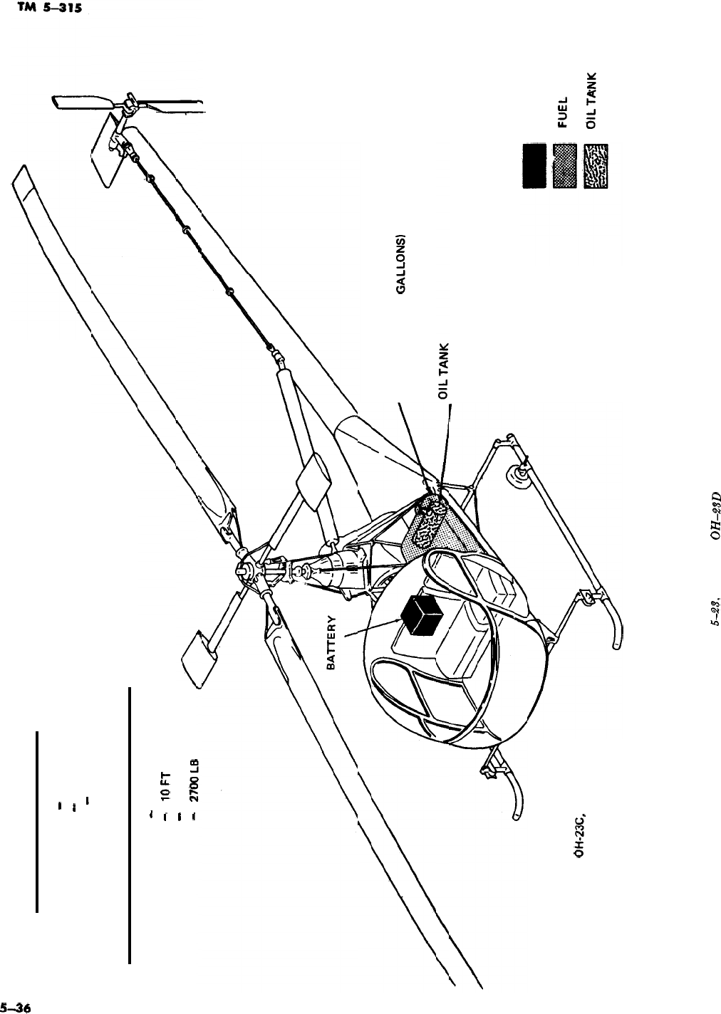
E
GENERAL DESCRIPTION
--
TYPE
-
SINGLE ENGINE, HELICOPTER
CREW
-
1
PASSENGERS
-
2 (LITTERS-21
DIMENSIONS (MAX) AND WEIGHT (GROSS)
LENGTH
-
40 FT, 8.5 IN
WIDTH
-
1OFT
HEIGHT
-
10 FT, 1.5 IN
WEIGHT
-
2790 L8
FUEL TANK
(CAPACITY 48 US GALLONS)
(CAPACITY 9.3 QUARTS)
EMERGENCY PROCEDURES: SAME AS FOR
MODELS OH-238 AND
Ol+23C,
FIGURE 5-22.
LEGEND
8ATTERY
FUEL
TANK
OILTANK
Figure
5-23.
Models
OH-23D
and OH-28G aircraft.
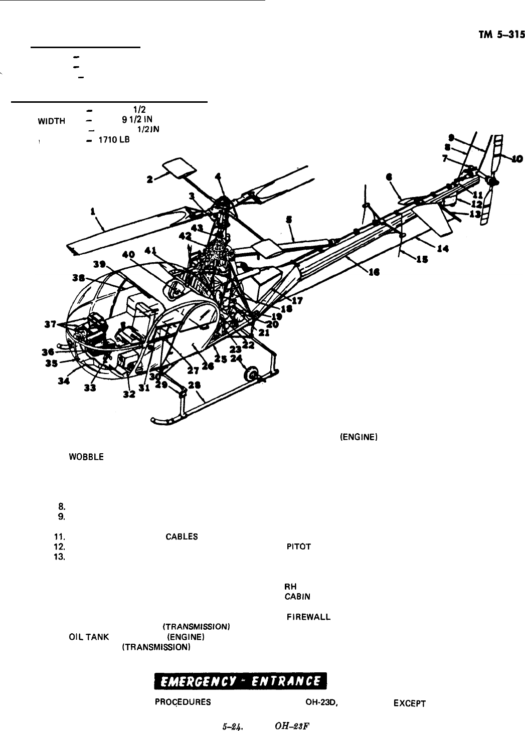
GENERAL DESCRIPTION
TM
5-315
TYPE
-
SINGLE ENGINE, HELICOPTER
CREW
-
1
PASSENGERS
-
2
DIMENSIONS (MAX) AND WEIGHT (GROSS)
LENGTH
-
40 FT, 8
I/2
IN
WIDTH
-
7 FT,
91/2lN
HEIGHT
-
10 FT, 1
I/2
IN
l -
WEIGHT
-
17lOL8
1.
MAIN ROTOR
2.
CONTROL ROTOR
3.
WO88LE
PLATE
4. COLLECTIVE BALLAST
5. TAIL ROTOR DRIVE
6.
STABILIZER
7. TAIL ROTOR SPEED DECREASER GEAR ASSY
8.
ANTENNA
9.
ANTENNA
IO.
TAIL ROTOR
II.
TAIL ROTOR CDNTROL
CA8LES
12.
BATTERY
13.
TAIL SKID STRUT
14.
ANTENNA
15.
ANTENNA
16.
TAIL 800M
17.
CARGO COMPARTMENT
18.
ENGINE
19.
FUEL TANK FILLER
20.
OIL TANK FILLER CAP
tTRANSMlSSlONI
21.
OILTANK
FILLER CAP
(ENGINE)
22.
OIL COOLER
iTRANSMISSION)
23. OIL COOLER
(ENGINE)
24. GROUND HANDLING WHEELS
25. 8ASlC BODY SECTION
26. LH CABIN DOOR
27. UTILITY POWER RECEPTACLE
28. SKID LANDING GEAR
29. NAVIGATION LIGHT
30. WINDOW PANEL
31. VENTILATOR WING
32. RADIO EQUIPMENT
33. PEDESTAL TUNNEL
34. PITOT
TUBE
35. LANDING LIGHT
36. INSTRUMENT PEDESTAL
37. RADIO EQUIPMENT
38.
RH
CABIN DOOR
39.
CA8lN
HEAT DIFFUSER
40. EXTERNAL POWER RECEPTACLE
41.
FIREWALL
42. TRANSMISSION
43. ANTICOLLISION LIGHT
EMERGENCY
PROGEDURES
SAME AS FOR MODEL OH-23D, FIGURE 5-23,
EXCEPT
THAT BATTERY IS IN TAIL.
Figure
5-24.
Model
OH-28F
aircraft.
5-37
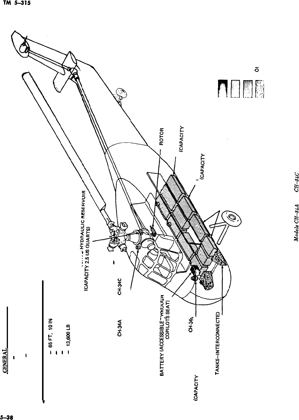
TYPE
GENElUL
DESCRIPTION
-
SINGLE ENGINE, HELICOPTER
CREW
-2
PASSENGERS
-
12 TO 18 (LITTERS-8)
DIMENSIONS (MAX) AND WEIGHT (GROSS)
*
LENGTH
-
65FT,
1OiN
WIDTH
-
56FT
HEIGHT
-
15 FT, 11 IN
WEIGHT
-
13,6OOL8
PRIMARY SERVO
AUXILIARY SERVO HYDRAULIC RESERVOIR
-
LATE MODEL
CH-34A
AND ALL
CH-34C
(CAPACITY 2.5 US QUARTS).
l3AmEKY
(ACCESSltsu
I
i-iriUUbtI
FLOOR UNDER
COPlLOfSSEAT)
AUXILIARY SERVO HYDRAULIC
RESERVOIR-EARLY MODEL
CH-34
(CAPACITY 2.5 US QUARTS)
R(3Km
8RAKE HYDRAULIC CYLINDER
AFT FUEL TANKS
(CAbIclTY
92 US GALLONS!
CENTER FUEL TANKS
(CAPACITY 70 US GALLONS)
ENGINE OIL
TANKS-INTERCONNECTE
(CAPACITY 10.5 US GALLONS) FWD FUEL TANKS
(CAPACITY 101 US GALLONS)
LEGEND
8ATTERY
FUEL TANK
HYDRAULIC RESERVOIR
01
L TANK
Figure 5-25. Modek
CH4hA
and
CH-34C
aircraft.
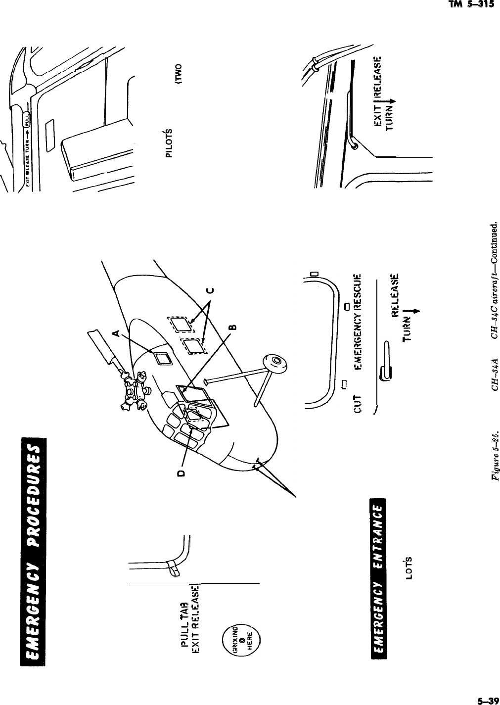
1
l’lJl_l_
T/W
L
DETAIL A
OUTSIDE CABIN EMERGENCY
ESCAPE WINDOW TAB
ENGINE ACCESS DOOR HANDLES
c&y
0
ClJT
FOR
EMl33GENO’;ESCtJE
.
EMERGENCY ENTRANCE IS GAINED THROUGH
CABIN DOOR, PI
LOTk
COMPARTMENT
WINDOWS, ESCAPE HATCHES, AND ESCAPE
WINDOW. BROKEN YELLOW LINES
EXIT
lW_EASE
TLJIW
1
DETAIL C
SURROUNDING CABIN DOOR WINDOW, AND
OUTSIDE CABIN EMERGENCY ESCAPE
ESCAPE HATCHES INDICATE WHERE FUSELAGE
HATCH RELEASE HANDLES
MAY BE CUT IF DOOR OR ESCAPE HATCHES
FAIL TO OPEN.
Figum
5-25.
Models
CH-&$A
and
CHiQC
abw+afCcontinued.
DETAIL B
OUTSIDE
PILOT6
COMPARTMENT
WINDOW RELEASE HANDLE
(TWO
PLACES)
DETAIL D
OUTSIDE CABIN DOOR EMERGENCY
RELEASE HANDLE
2
r9
z
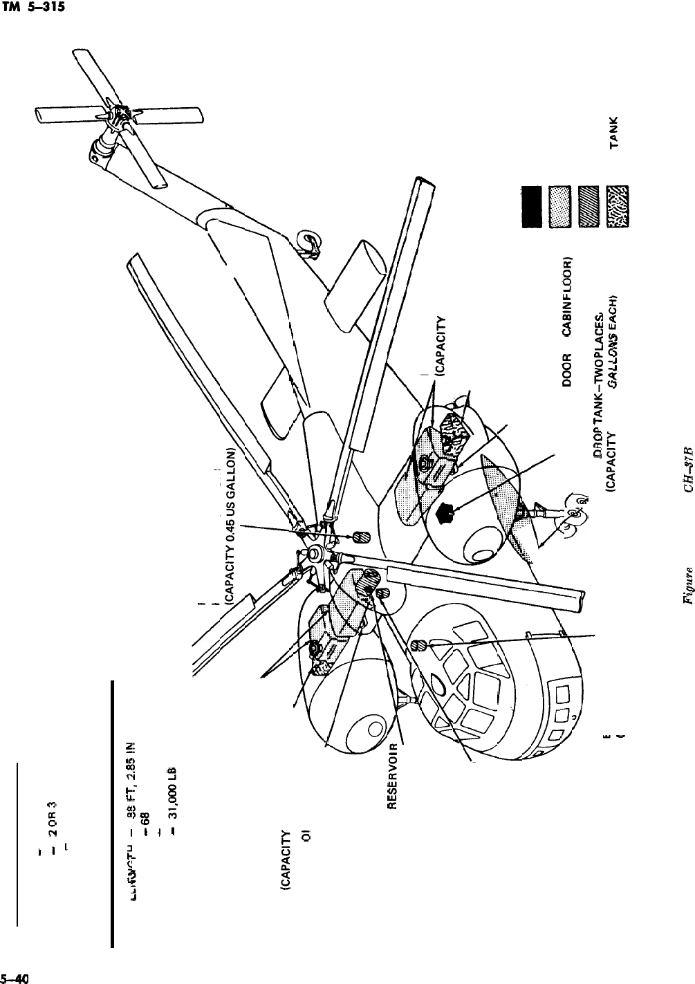
WI
A
GENERAL DESCRIPTION
TYPE
-
TWIN ENGINE, HELICOPTER
CREW
-
2OFl3
PASSENGERS
-
23 (LITTERS-241
DIMENSIONS (MAX) AND WEIGHT (GROSS)
,
lzk,c-ru
_
&.L,.”
,
,
a
38
FT,
2.85
!!d
WIDTH
-
B8
FT, 5.75 IN
HEIGHT
-
21 FT, 9 IN
WEIGHT
-
31,oooLB
FIRST STAGE SERVO
HYDRAULIC RESERVOIR
FUEL TANKS
(CAPACITY 203 US GALLONS)
OIL TANK
(CAPACITY 13.3 us GALLONS) ,
ROTOR CLUTCH
01
L RESERVOIR
(CAPACITY 1.5 US GALLONS)
UTILITY HYDRAULIC
RESERVOI
(CAPACITY 2.78 US GALLONS)
SECOND STAGE SERVO
HYDRAULIC RESERVOIR
(CAPACITY 0.74 US GALLON)
FUEL TANKS
0ZAPAClTY
203 US GALLONS)
OIL TANK
(CAPACITY 13.3 US GALLONS)
ROTOR CLUTCH OIL RESERVOIR
(CAPACITY 1.5 US GALLONS)
8ATTERY (ACCESSIBLE THROUGH
BATTERY
DWR
IN
CA8lN
FLOOR)
T%
71
---
-..-.
.,
. .
. .
.
EMERGENCY HYDRAULIC RESERVOIR
(CAPACITY 0.8 US GALLON) (CAPACITY 150 us
~,_~,.~
FUEL
DRflP
TANK-l-W0
PuCEs
LEGEND
BATTERY
FUEL TANK
~
HYDRAULIC
OIL
TbNK
RESERVOIR
Figure
5-26. Model
CH-37B
aircraft.
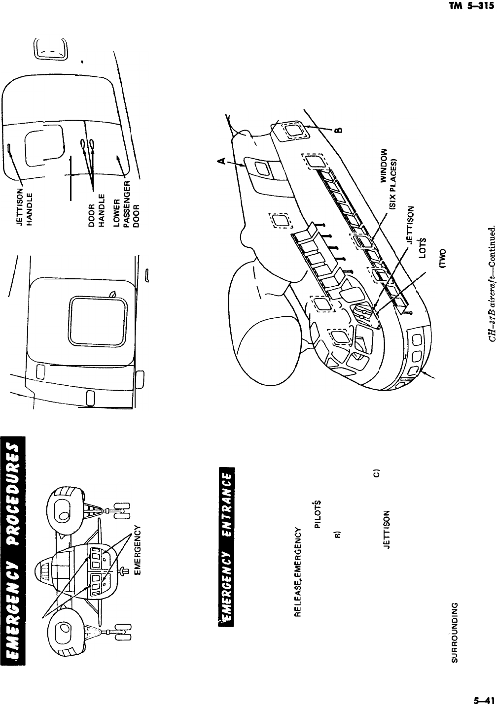
JETTISON HANDLES,
a
EMEFlGENbY
PANELS
DETAIL C
NOSE DOORS
DETAIL B
CABIN EMERGENCY HATCH
UPPER
PASSENGER\
L-J
1
DOOR
I
_
I
I
I
DETAIL A
PASSENGER DOORS
EMERGENCY ENTRANCE IS NORMALLY GAINED THROUGH
UPPER AND LOWER PASSENGER DOORS (DETAIL A),
LOCATED ON RIGHT-HAND SIDE OF CABIN, BY TURNING
DOOR HANDLES. UPPER PASSENGER DOOR MAY BE
JETTISONED BY TURNING JETTISON HANDLE, MARKED
TURN EXIT
RELEASE,EMERGENCY
ENTRANCES MAY ALSO
BE GAINED THROUGH CABIN EMERGENCY HATCH, NOSE
DOOR EMERGENCY PANELS,
PILOT!3
COMPARTMENT
WINDOWS, AND FOUR FORWARD CABIN WINDOWS. CABIN
EMERGENCY HATCH (DETAIL
B)
MAY BE JETTISONED BY
TURNING JETTISON HANDLE MARKED TURN EXIT
RELEASE. HATCH WINDOW PANE MAY BE REMOVED BY
PULLING TAB, MARKED PULL TAB EXIT RELEASE. NOSE
DOOR EMERGENCY PANELS (DETAIL Cl MAY BE
JETTISONED BY PULLING
JElTlSON
HANDLE, MARKED
RELEASE PULL TO JETTISON. PILOT: COMPARTMENT
EMERGENCY PANELS MAY BE JETTISONED BY PULLING
DOWN ON JETTISON HANDLE, MARKED PULL DOWN EXIT
CABIN
WINDOW
J--nSON
HANDLE
RELEASE. EACH OF FOUR FORWARD CABIN WINDOW pl
LOT&
COMPARTMENT
PANES ARE PROVIDED WITH A PULL TAB, MARKED PULL EMERGENCY PANEL
TAB EXIT RELEASE. BROKEN YELLOW LINES
C
(TWO
PLACES)
SURROiJNDlNG
CABIN WINDOWS INDICATE EMERGENCY
CUT-IN AREAS.
E
Figure 5-26. Model
CH-37B
a&raft-Continued.
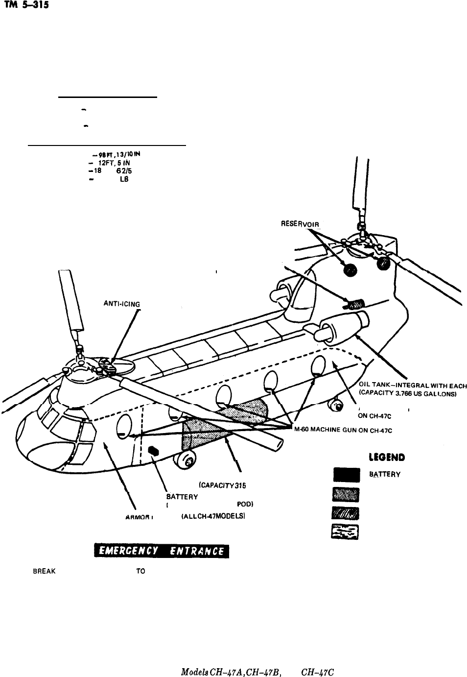
TM
5-315
GENERAL DESCRIPTION
TYPE
-
TWIN ENGINE, HELICOPTER
CREW -2
PASSENGERS
-
33 (LITTERS-241
DIMENSIONS (MAX) AND WEIGHT (GROSS)
LENGTH
-
98
Fl,l3/~0
IN
WIDTH
-
lZFT,5lN
HEIGHT
-
1s FT,
5
2/5
IN
WEIGHT
-
24,500
Ls
ANT~-IC~NG
RESERVOIR
-
FLIGHT CONTROL
HYDRAULIC
RESER
UTILITY HYDRAULIC
RESERVOIR
ARMOR PLATED
\
FUEL TANK-TWO PLACES
fcAPAclTY
315
US GALLONS)
SAlTERY
(ACCESSIBLE THROUGH
DOOR IN EXTERNAL
POD)
sA.lTE
RY
FUEL TANK
PLATED
{ALL
CH47
MODELS)
HYDRAULIC RESERVOIR,
ANTI-ICING RESERVOIR
EMERGENCY ENTRANCE IS GAINED THROUGH DOORS. IF DOOR FAILS TO OPEN.
BREAK
GLASS TO GAIN ACCESS
TD
DOOR JETTISON HANDLE.
ENGINE
Figure 5-27.
Modela
CH-h7A,
CH-h?B,
and CH-hYC aircraft.
5-42
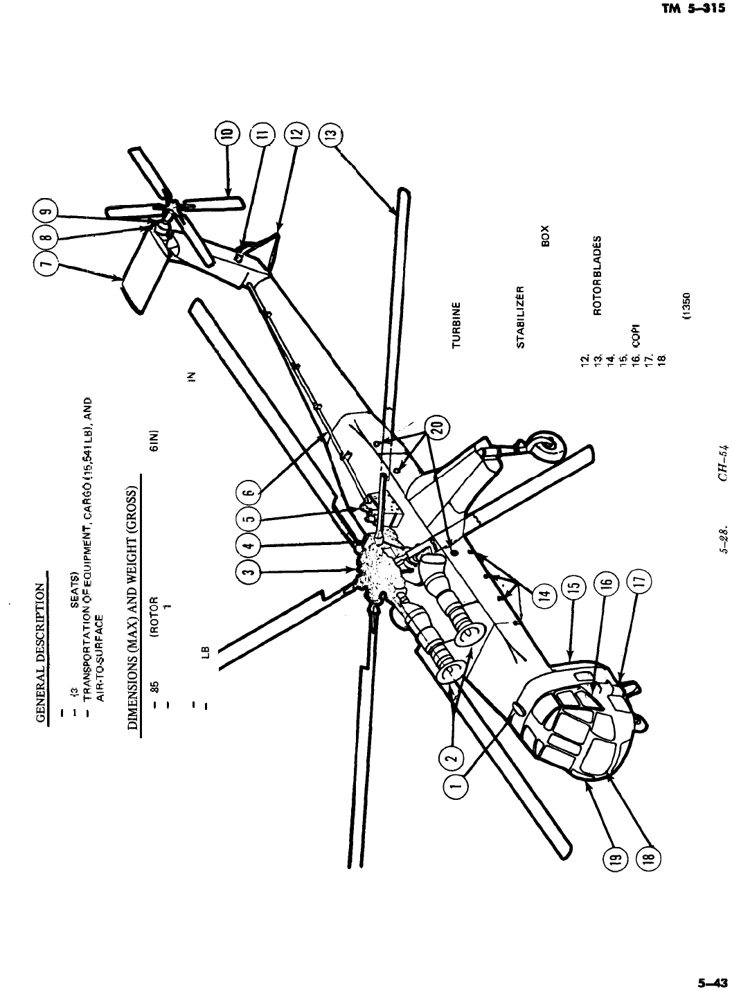
TYPE
-
FREE TURBINE ENGINE, HELICOPTER
CREW
-
2
(3
ADDITIONAL SEATS)
USE
-
TRANSPDRTAT!DN
DF
EQU!PMENT,
C.ARGD
(15,541
LB!,
.AND
AIR-TO6URFACE
TOWING
-I
\h
LENGTH
-
WIDTH
-
HEIGHT
-
WEIGHT
-
DlMENSIONS(MAX)ANDWEIGHT(GROSS)
85 FT, 5 IN
(ROTOR
BLADES ROTATING-88 FT,
6
IN)
COCKPIT-7 FT,
1
IN; FUSELAGE-6 FT, 8 IN; MAIN
ROTOR BLADES-72 FT
TOP OF TAIL ROTOR-25 FT, 7.4 IN; TOP OF ROTOR-18 FT, 7 lN
38,000 L8
Figure
5-28.
Model
CH-5.4
aircraft.
1.
2.
3.
4.
5.
6.
7.
8.
9.
10.
11.
12#
13.
14.
15
16,
17.
18,
DIRECTION FINDER SET ANTENNA HOUSING
TUR8lNE
ENGINES
ROTOR HEAD
AUXILIARY POWERPLANT
HYDRAULIC RESERVOIRS
TAIL ROTOR DRIVE SHAFT
STA8lLlZER
ANTI-COLLISION LIGHT
TAIL ROTOR GEAR
8DX
TAIL ROTOR BLADES
INTERMEDIATE GEAR BOX COOLING AIR SCREEN
TAIL SKID
MAIN
RDTOR
6LADES
HARD POINTS (TYPICAL)
AFT PI LOT’S ENCLOSURE
COPI
LOT’S DOOR
COCKPIT ACCESS STEPS
ELECTRONIC EQUIPMENT COMPARTMENT
19. PI LOT’S COMPARTMENT
20. FUEL
(1350
GALLONS)
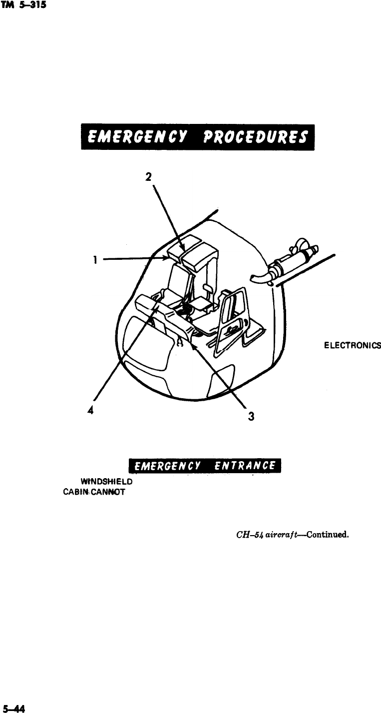
4
3
1. CIRCUIT BREAKER PANEL
2. OVERHEAD CONTROL PANEL
3. INSTRUMENT PANEL
4.
ELECTRONJCS
COMPARTMENT
THE WfNDBHiELD OR WINDOWS MAY BE BROKEN IF ENTRANCE TO THE
CABtNCANm
BE GAINED THROUGH ANY OF THE ACCESS DOORS.
Figure 5-28. Model
CH-!ih
akraft-Continued.
--
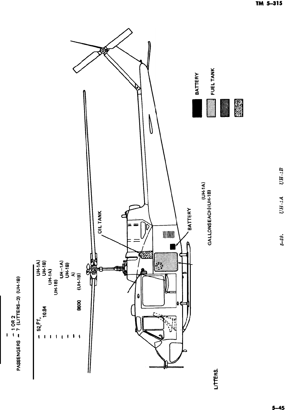
GENERAL DESCRIPTION
TYPE
-
SINGLE ENGINE, HELICOPTER
CREW
-
lOR2
FASSENGERS
-
?
(L!I-rERS-2)
(UH-!B!
DIMENSIONS (MAX) AND WEIGHT (GROSS)
LENGTH
-
52_FT,
10.24 IN (MODEL
UH-1Ab
-
52 FT,
lO.B4
IN (MODEL
UH-lB1
WIDTH
-
43 FT, 9 IN (MODEL UH-lA1
-
44 FT, (MODEL
UH-lB1
HEIGHT
-
11 FT, 4.57 IN (MODEL
UHrlAI
-
13 FT, 2.02 IN (MODEL
UH-lB1
WEIGHT
-
5600 TO 7200 LB
(UH-1
AI
-
6600 TO
B600
LB
(UH-lB1
(CAPACITY 1.6 US GALLONS)
HYDRAULIC OIL RESERVOIR
(CAPACITY
0.5 US GALLONS)
LEGEND
BAlTERY
I
AUXILIARY FUEL TANK (CAPACITY
165 US GALLONS) MAY BE INSTALLED
IN PLACE OF PASSENGER SEATS OR
LllTERS.
FUEL TANK-TWO PLACES
(CAPACITY 62.5 US GALLONS EACH)
(UH-IAl
(CAPACITY 62.5
GALLEONS
EACH)
(UH-1Bb
HYDRAULIC RESERVOIR
OIL TANK
E
ul
Figure
S.29.
Models
UH-1A
and
UH-1B
aircraft.
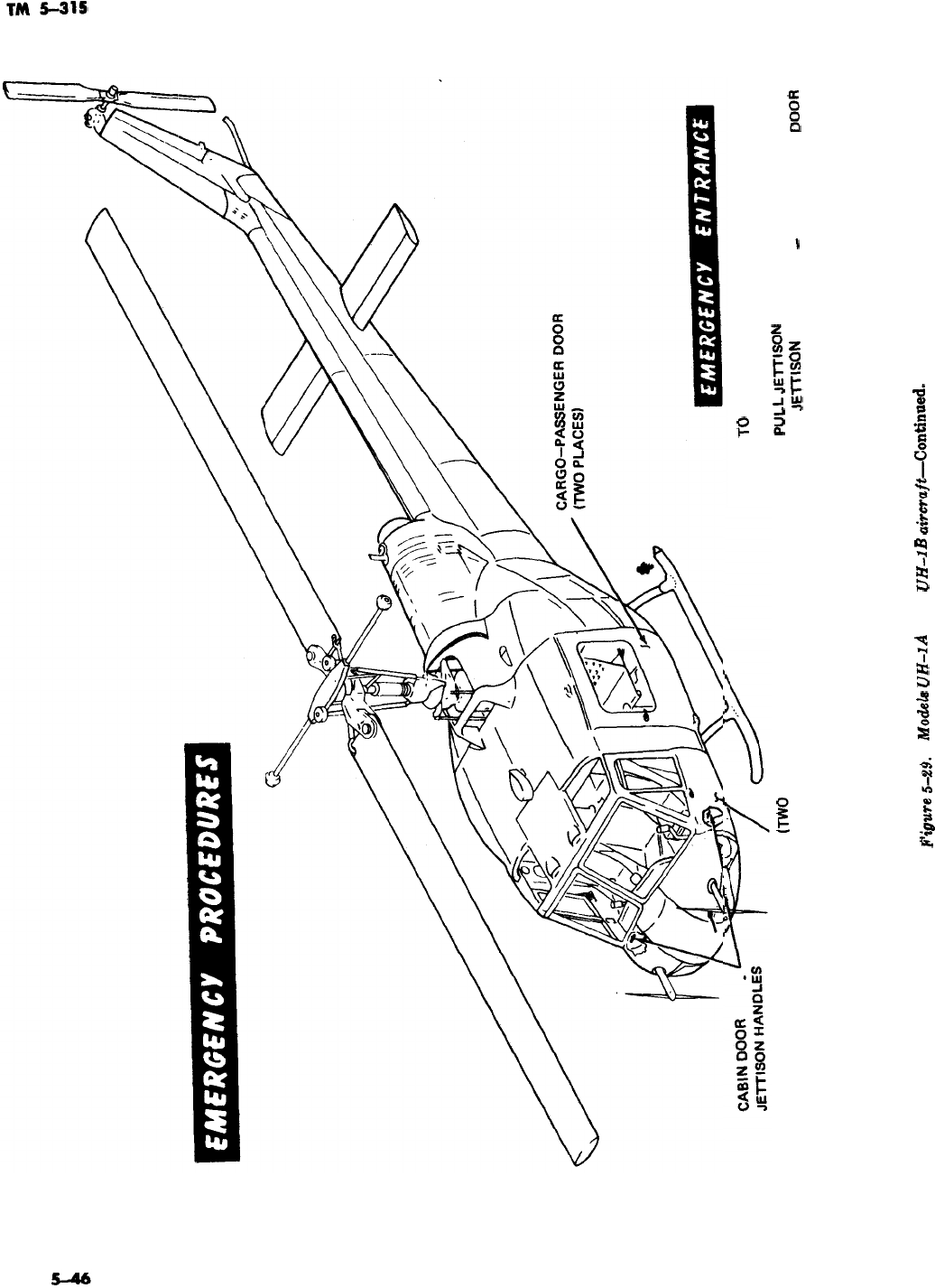
CABIN DOOR
(TWO
PLACES)
TO
GAIN ENTRANCE TO CABIN, SLIDE OR
BREAK EITHER CABIN DOOR WINDOW AND
PULL
JElTlSON
HANDLE. IF CABIN DOOR FAILS
TO
JETMON
OR CARGO
-
PABBENGER
DOOR
FAILS TO OPEN, BREAK WINDOWS OR
WINDSHIELD.
Fipure
&H.
Mod&
UH-1A
and
UH-1B
aircraft-continwd.
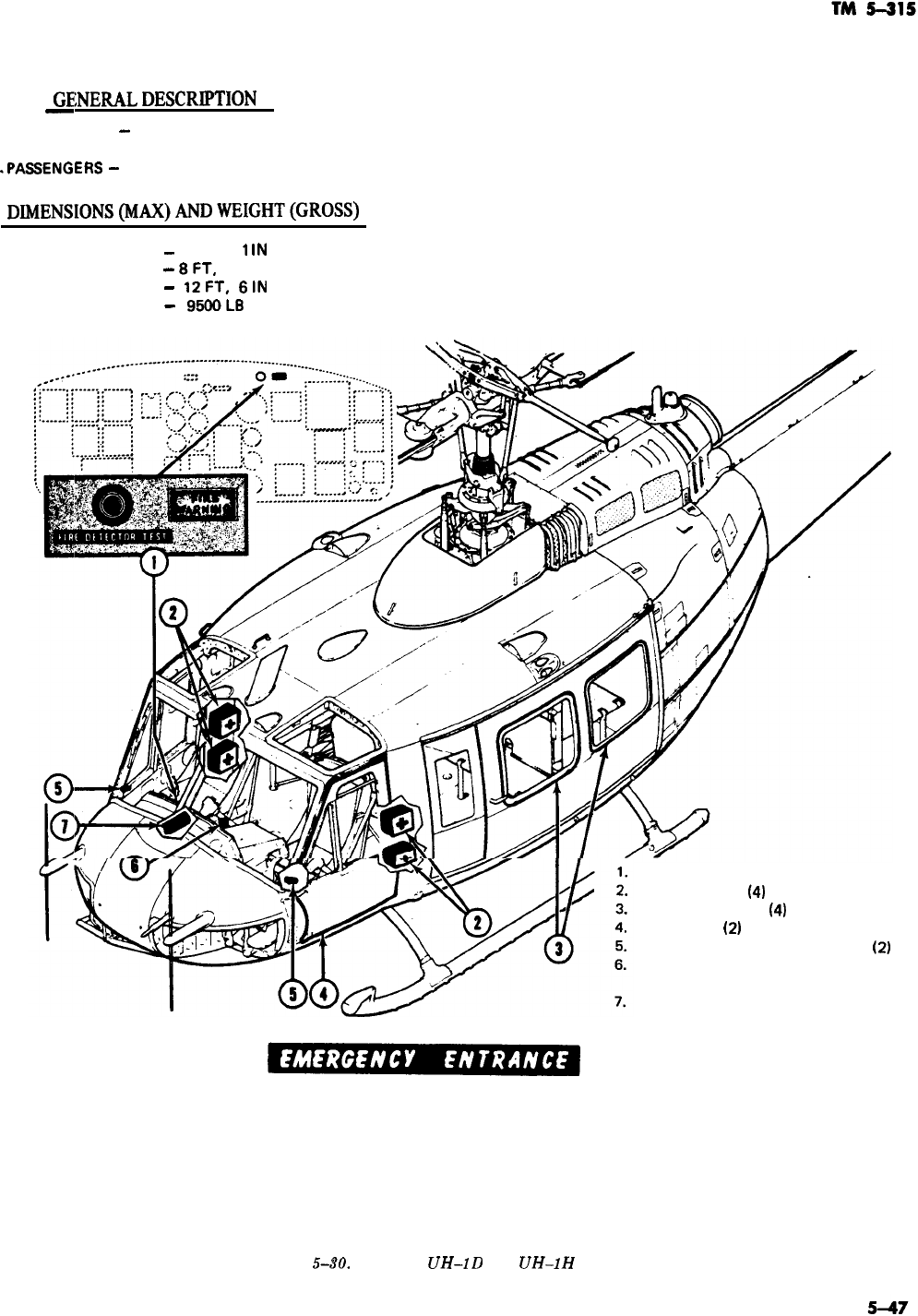
GEiNER4LDESCRIPTION
-
TYPE
-
SINGLE TURBINE ENGINE, HELICOPTER
CREW
-3
.PASSENGERS
-
10
DIMENSIONS(MAX)ANDWEIGHT(GROSS)
LENGTH
-
57 FT,
1
lN
‘WIDTH
-
8FT,
4 IN
HEIGHT
-
12FT,
6lN
‘WEIGHT
-
95OOL8
-
FIRE DETECTION SYSTEM
FIRST AID KIT
(41
PASSENGER EXIT
(4)
CREW EXIT
(21
JETTISONABLE DOOR RELEASE
(2)
EXTERNAL STORES JETTISON
RELEASE LEVER
FIRE EXTINGUISHER
TO GAIN ENTRANCE TO THE CABIN IN THE EVENT OF AN EMERGENCY, SLIDE OPEN OR
BREAK THE PILOT’S OR CO-PILOT’S SLIDE WINDOW AND REACH FORWARD AND PULL
THE JETTISONABLE DOOR RELEASE. IF DOOR WILL NOT JETTISON OR CARGO DOOR
WILL NOT OPEN, BREAK DOOR WINDOWS OR WINDSHIELD TO GAIN ENTRANCE.
-
Figure
.&SO.
Models
UH-1D
and
UH-1H
aircraft.
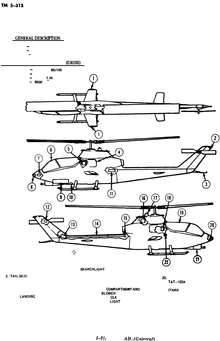
GENER4L
DESCWION.
TYPE
-
SINGLE ENGINE, HELICOPTER
CREW
-
2
PASSENGERS
-
0
DIMENSIONS (MAX) AND WEIGHT
@ROSS)
LENGTH
-
52 FT, 11
65/109
IN
WIDTH
-
10 FT, 4 IN
HEIGHT
-
11
FT,
WEIGHT
-
7,lN
9!j@3 LB
1. WING TIP POSITION LIGHTS
2. AFT POSITION LIGHT
3.‘TAlLSKlD
4. ENGINE AIR INLET
5. HYDRAULIC RESERVOIR
6. GUNNER’S CANOPY HATCH
7. BATTERY
a LEFT
LANDING
LIGHT
9. AMMUNITION COMPARTMENT
10.
SEA.RCHLlGHT
18.
11. ENGINE AND TRANSMISSION OIL COOLER 19.
12. 90 DEGREES GEAR BOX
20.
13. 42 DEGREES GEAR BOX 21.
14. TAIL ROTOR DRIVE SHAFT 22.
15. TRANSMISSION
COMPARTMWTAND
OIL COOLER
8LDWER
16. ENGINE OIL TANK 13.4 GALLONS)
17. ANTI-COLLISION
LIGHT
HYDRAULIC RESERVOIR-2 (3.2 PINTS EACH)
PILOT’S CANOPY HATCH
RIGHT LANDING LIGHT
TAT-102A
OR XM-28 TURRET
FUEL FILLER CAP
(TANK
CAPACITY-265 GALLONS)
Figure
s-s1
.
Model
AH-1G
airwaft
5-48
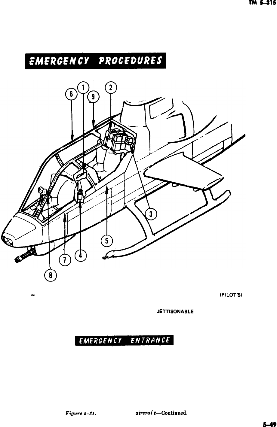
TM
5-315
1.
KNIFE
-
CANOPY BREAKOUT
2.
SURVIVAL KITS STOWAGE (PROVISIONS)
3.
FIRST AID KIT
4. FIRE EXTINGUISHER
5.
PI LOT’S CANOPY DOOR
0
8
6. CANOPY JETTISONABLE RELEASE
tPlLOT’S1
7. GUNNER’S CANOPY DOOR
8. CANOPY
JElTlSONABLE
RELEASE (GUNNER’S)
9. CANOPY AREA
WINDOWS AND WINDSHIELDS MAY BE BROKEN IF ENTRANCE TO THE
CABIN THROUGH THE DOORS IS NOT POSSIBLE.
Figure
6.91.
Model AH-1 G
airoraf
t-Continued
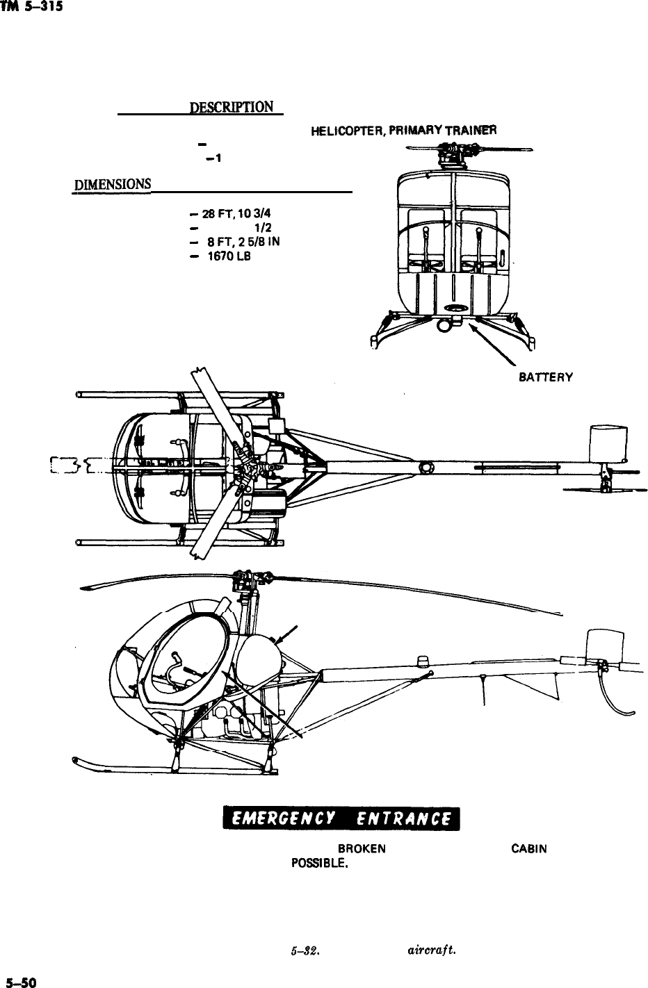
TM
5-315
GENERAL
DE!XR.IPTION
TYPE
-- SINGLE ENGINE,
HELtCOPTEFt,FRlt@ARY
TRAiP=R
-
I-
L
CREW
-
1
PASSENGERS
-
1
jXh4ENSIONS
(MAX) AND WEIGHT (GROSS)
LENGTH
-
28FT,
lQ3/4
IN
WIDTH
-
25 FT, 3
1/2
IN
HEIGHT
-
SFT,25/8lN
WEIGHT
-
187OL8
EXTERIOR
SATTERY
-SECURED
TO RIGHT AFT FUSELAGE STRUT
FUEL TANK 30 U.S. GAL.
DOORS SECURED WITH SPRING LATCH.
OPENS READILY FROM EITHER SIDE.
WINDOWS AND WINDSHIELD MAY SE
SROKEN
IF ENTRANCE TO THE
CASIN
THROUGH THE DOOR IS NOT
POSSlSLE.
Figure
5-32.
Model TH-55
uircruft.
S-SO
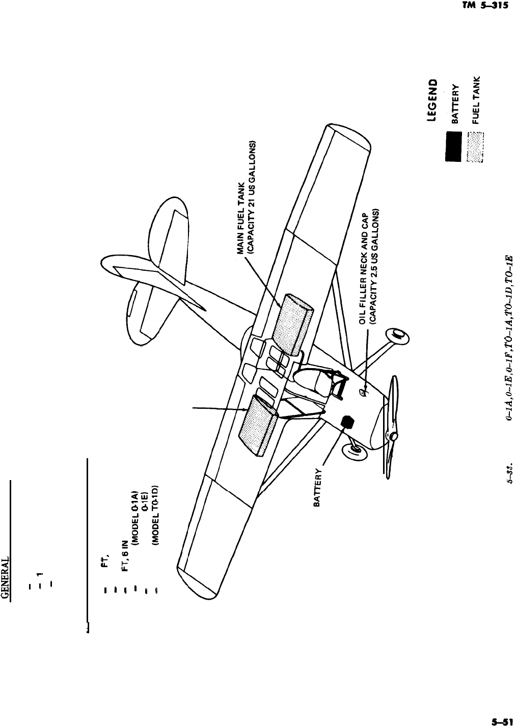
GENERiL
DESCRIPTION
TYPE
-
SINGLE ENGINE, LIAISON
CREW
-
1
PASSENGERS
-
1
DIMENSIONS AND WEIGHT (GROSS)
LENGTH
WING SPAN
HEIGHT
WEIGHT
-
25
Fl,
9.5 IN
-
36FT
-
7
FT,6lN
-
2100 LB
(MODEL
@lAI
-
2166 LB (MODEL
@lEI
-
2400 LB
0vlODEL
Tt%lD)
AUXILIARY FUEL TANK
(CAPACITY 21 US GALLONS)
Figure
543.
Models
0-lA,
0-lE,
0-lF,
TO-lA,
TO-lD,
TO-1E
aircraft.
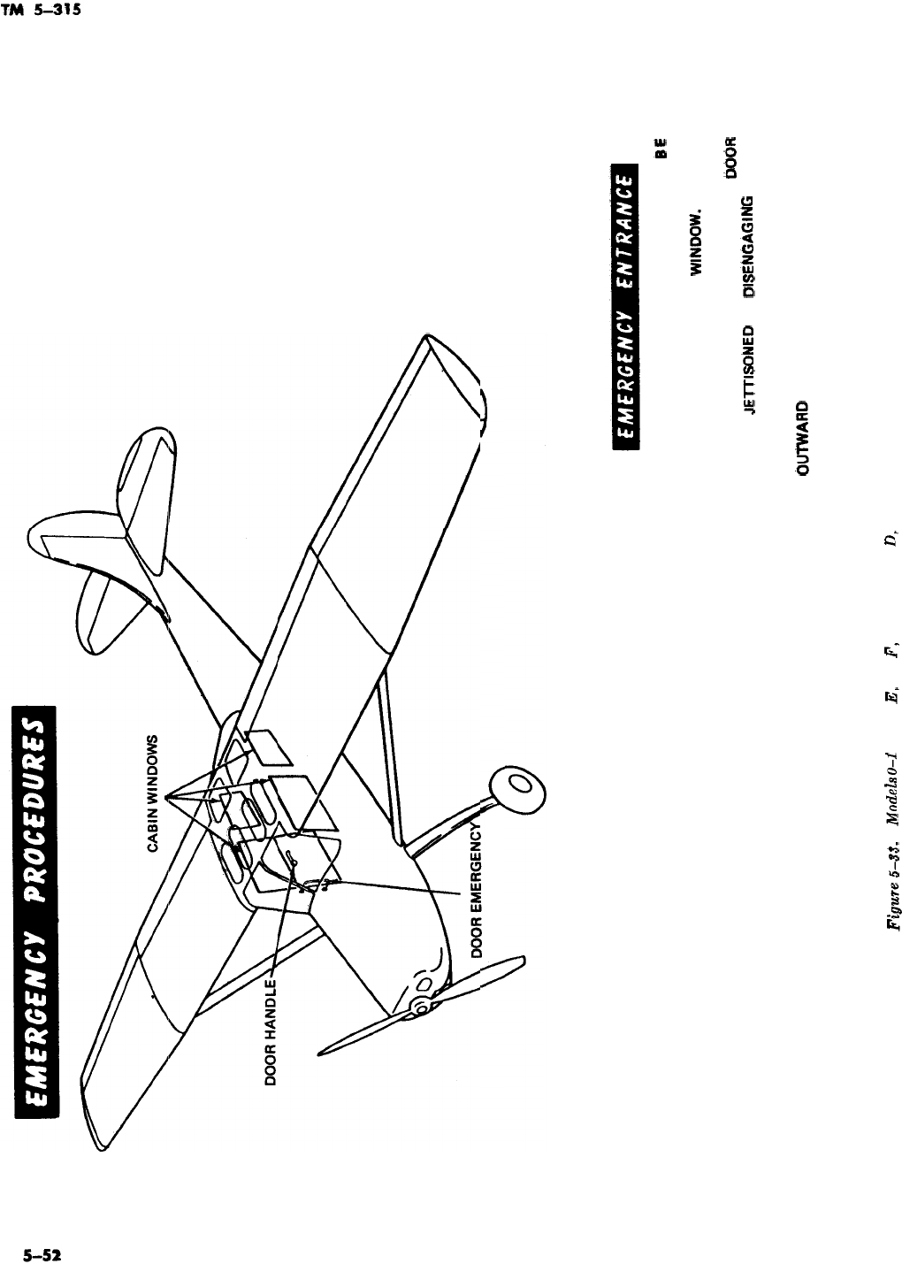
RELEASE HANDLE
EMERGENCY ENTRANCE. MAY
EE
ACCOMPLISHED BY TURNING DOOR HANDLE
TO RELEASE DOOR AND
WINOOW.
IF DOOR
CANNOT BE OPENED, BREAK CABIN WINDOWS,
AFTER ENTRANCE IS ACCOMPLISHED,
DOOR
MAY BE
JEl-i-ISONED
BY
DlSEtUGAGlNG
LOWER
END OF DOOR EMERGENCY RELEASE HANDLE,
TURNING IT CLOCKWISE, AND PUSHING
OWARD
ON DOOR.
Figwe
5-33.
Models
0-1
A, O-l
E,
O-l
F,
TO-l A, TO-l D, TO-l E aircraft--Continued.
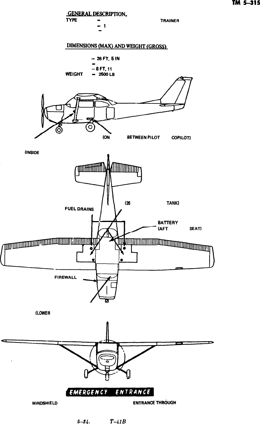
TM
5-315
GENEIULDESCRIPTiON
TYF+E
-
SINGLE ENGINE, PRIMARY
TRAINER
CREW
-
1
PASSENGERS
-
3
LENGTH
-
28FT,
SIN
WING SPAN
-
36 FT, 2 IN
HEIGHT
-
8FT.11
IN
WElt%T
-
25fXbL8
FIRE EXTINGUISHER
A
-
(ON
FLOOR
8ETWEEN
PILOT
AND
COPILOTJ
DOOR JETTISON HANDLE
0NSlDE
BOTH DOORS)
FUEL TANK
QS
GALLONS EACH
TANK)
(AFT
OF REAR
SEAT)
MASTER SWITCH
(LOWER
CENTER OF INSTRUMENT PANEL)
WlN.DSHlELO
OR WINDOWS MAY BE BROKEN IF
ENTRANCE’THRbJGH
THE DOOR IS NOT POSSIBLE.
Figure
544.
Model
T-4lB
aircraft.
5-53
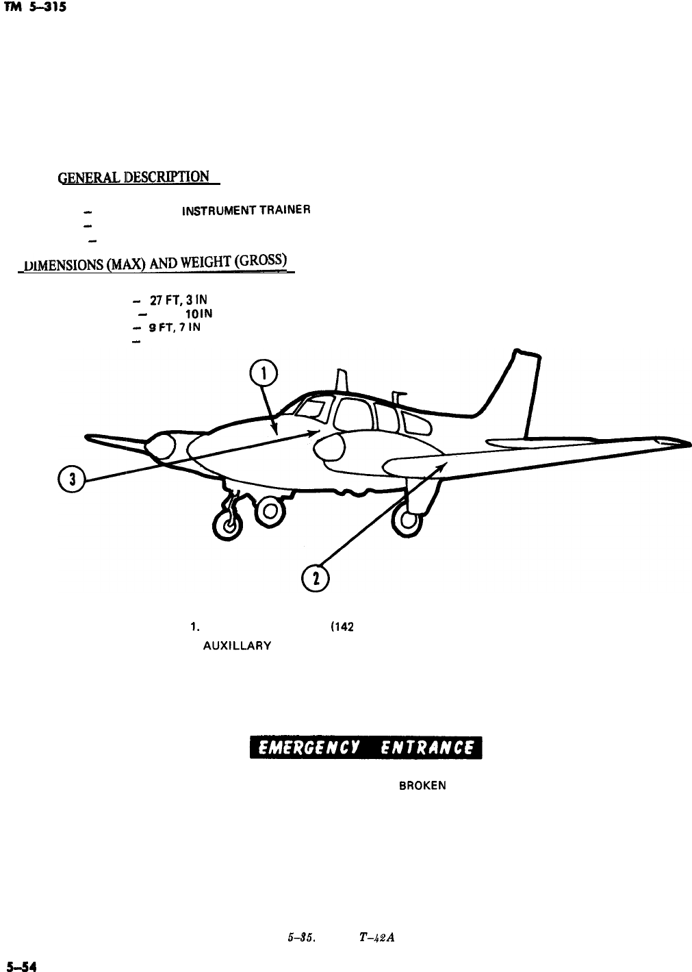
GENERALlDESCmON
-
TYPE
-
TWIN ENGINE,
INSTRUMENTTRAINER
CREW
-
1
PASSENGERS
-
3
DlMENSIONS(MAX)ANDWEIGHT(GROSS)
LENGTH
-
27FT,3iN
WING SPAN
-
37 FT,
IO
IN
HEIGHT
-
SFT,7lN
WEIGHT
-
3480 L8
1.
MAIN FUEL TANK
1142
GALLONS)
2.
AUXILLARY
FUEL TANK
3. IGNITION SWITCH (EXTREME LEFT OF INSTRUMENT PANEL)
THE WINDSHIELD OR WINDOWS MAY 8E 8ROKEN IF ENTRANCE TO THE
CABIN CANNOT 8E GAINED THROUGH THE DOOR.
Figure
5-35.
Model
T-&?A
aircraft.
5-54
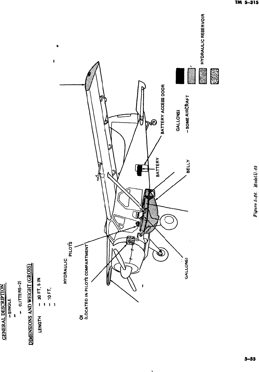
GENERALDESCmnON
TYPE
-
SINGLE ENGINE, LIAISON
CREW
-
1
PASSENGERS
-
5
(L!TTERS-2)
DIMENSIONSANDWEIGHT(GROSS~
.LENGlH
-
WINGSPAN
-
HEIGHT
-
WEIGHT
-
m
FT,
5
IN
4BFT
lOFT,
51N
5100 LB
HYORAULIC
RESERVOIR
(LOCATED IN
PlLOTk
COMPARTMENT)
01
L TANK
\
WING TIP FUEL TANK
-
SOME AIRCRAFT
(CAPACITY 21.5 US
GALLONS)
WING TIP FUEL TANK
-
SOME AIRCRAFT
(CAPACITY 21.5 US GALLONS)
-
FWD FUEL TANK
(CAPACITY 35.7 US
AFT FUEL TANK
(CAPACITY 25.5 US
GANWW
CENTER FUEL TANK BELLY FUEL TANK
-SOME
AIRCRAFT
(CAPACITY 35.6 US GALLONS) (CAPACITY 43 US GALLONS)
LEGEND
BATTERY
’ FUEL TANK
OIL TANK
Figure
5-66.
Model
&69
aircraft.
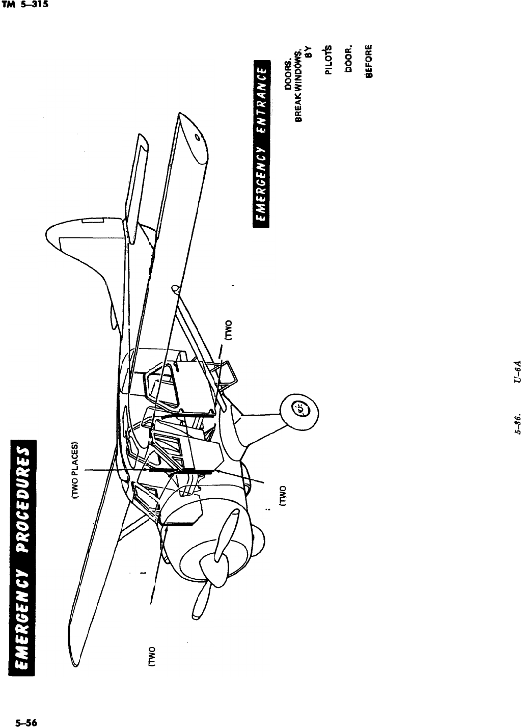
CABIN DOOR
JETTISON LEVER
(TWO
PLACES)
PILOTS COMPARTMENT
DOOR JETTISON LEVER
mvo
PLACES)
-
CABIN DOOR
(TWO
PLACES)
PI LOTS COMPARTMENT
DOOR
(WO
PLACES)
EMERGENCY ENTRANCE MAY BE GAINED
THROUGH ANY ONE OF FOUR
t3OORS.
IF
DOORS CANNOT BE OPENED, FREAK
WINDOWS.
EACH DOOR MAY BE JETTISONED
EY
OPERATING A JETTISON LEVER, LOCATED AT
HINGE SIDE OF DOOR. TO OPERATE
PILO+
COMPARTMENT DOOR JETTISON LEVER, PULL
AFT ON LEVER AND PUSH OUTWARD ON
bOOR.
TO OPERATE CABIN DOOR JETTISON LEVER,
PULL LEVER AFT OR PUSH FORWARD,
#EFORE
PUSHING DOOR OUTWARD.
Figure
5-66.
Model
U-6A
aircraft-Continued.
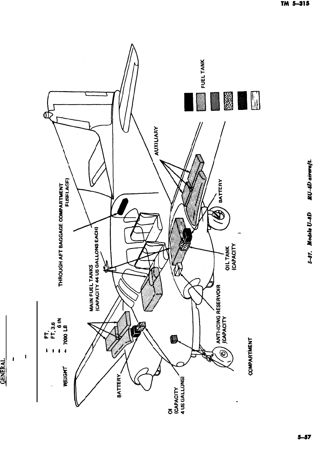
SENERAL DESCRIPTION
TYPE
-
TWIN ENGINE, LIAISON
CREW
-1
PASSENGERS
-
5
DIMENSIONS AND WEIGHT (GROSS)
LENGTH
-
31
Fl,
6 IN
WING SPAN
-
45
Fl,
Zj.6
IN OXYGEN CYLINDER (ACCESSIBLE
HEIGHT
-
11 FT,
6lN
W_ElGllT
THROUGHAFTBAGGAGECOMPARTMENT
-
7OfXLB
DOOR ON RIGHT-HAND SIDE OF
AUXILIARY FUEL TANKS
(CAPACITY 71 US GALLONS)
UXlL1AR.Y
FUEL TANKS
(CAPACITY 71 US GALLONS)
01
L TANK
LEGEND
BATTERY
&APAClTY
3 US GALLONS)
ol
L
T
HYDRAULIC RESERVOIR 4 US GALLONS)
(ACCESSIBLE THROUGH NOSE
BAGGAGE
COMPARTklENT
DOOR ON RIGHT-HAND SIDE
OF FUSELAGE)
HYDRAULIC RESERVOIR
OIL TANK
OXYGEN CYLINDER
ANTI-ICING RESERVOIR
Figure
5-87.
Mod&
U-8D
ad
BU-8D
ainmaft.
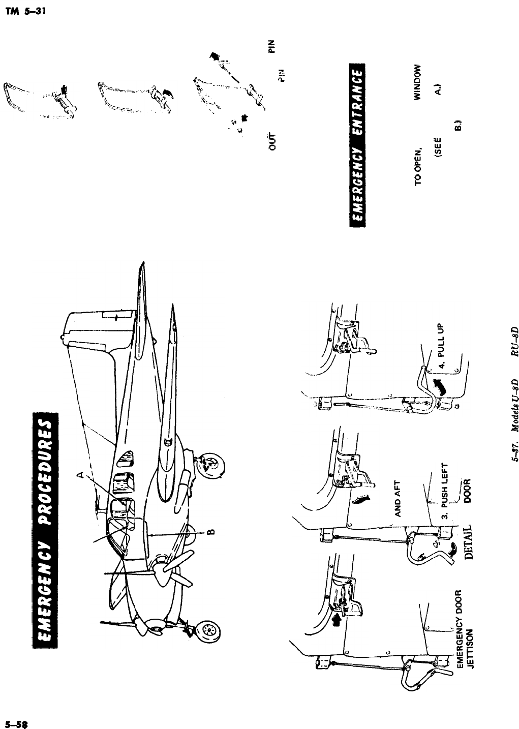
DOOR HANDLE
f
1. PUSH LOCK UP
f
DOOR HANDLE
II
IG
II
!,
2. PULL HANDLE OUT
i-.
JETTlSON
HANDLE
DETAIL
B
DODF?
JETTISON
1. PUSH LATCH IN
2. LIFT HANDLE
,
.L.
.+G
m
4. PUSH
WINDOW
aUT
,?
.:q
,,/;
,!
,!’
:
.,a
.;
‘/FL!
,;
/
,I$>
_/K..s
3. PULL
RELEASE
PIN
?lti
DETAIL A
WINDOW RELEASE
EMERGENCY ENTRANCE IS GAINED THROUGH
DOOR DN RIGHT-HAND SIDE OF CABIN. DOOR
IS OPENED BY TURNING DOOR HANDLE. IF
DOOR FAILS
~0
OPEN,
CENTER
WINDOW
MAY
BE BROKEN TO GAIN ACCESS TO WINDOW
RELEASE PINS. (SEE DETAIL
A.1
AFTER
ENTRANCE IS ACCOMPLISHED, DOOR MAY BE
JETTISONED. (SEE DETAIL
B.1
BROKEN YELLOW
LINES SURROUNDING RIGHT-HAND AFT
WINDOW INDICATE WHERE FUSELAGE MAY BE
CUT IF DOOR OR WINDOWS FAIL TO OPEN.
Figure
tj-87.
Modela
lJ-8D
and
RU-8D
aircraft-continued.
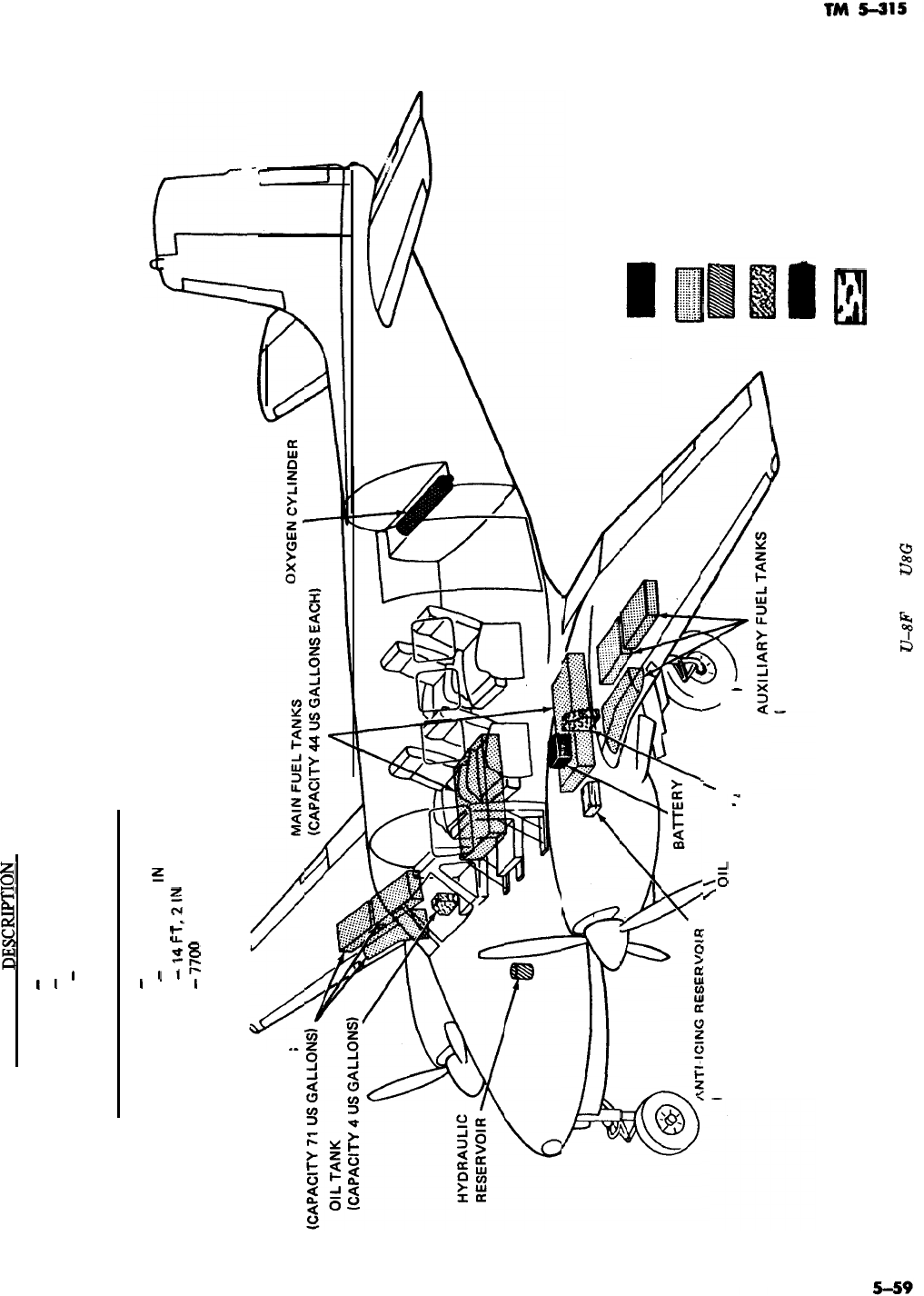
GENERAL
DESCRPTION
TYPE
-
TWIN ENGINE, LIAISON
CREW
-
2
PASSENGERS
-
4
DIMENSIONS AND WEIGHT (GROSS)
LENGTH
-
33 FT, 2 IN
WING SPAN
-
45 FT, 10.5
IN
HEIGHT
-
l4FT,
2lN
WEIGHT
-
77oO
LB
AUXILIARY FUEL TANKS
(CAPACITY 3 Us GALLONS)
‘;lL
TANK
ICAPACITY
I
4 US GALLONS)
(CAPACITY 71 US GALLONS)
Figure 5-38. Models
U-8F
and
U8G
aircraft.
LEGEND
BATTERY
:::::::::::::::::
lIzzl
z::::::::::::::::
FUEL TANK
:::::::::x::::::
HYDRAULIC RESERVOIR
OIL TANK
OXYGEN CYLINDER
Ly
ANTI-ICING RESERVOIR
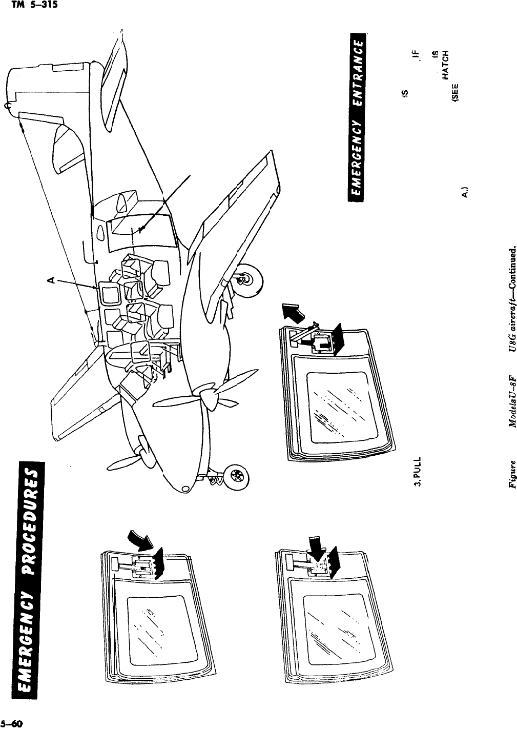
1. PULL DOWN RED COVER OVER HANDLE
2. PUSH RED BUTTON TO RELEASE HANDLE
3.
PULL
Up ON HANDLE AND PUSH OUTWARD ON HATCH
DETAIL A
DOOR HANDLE
EMERGENCY ENTRANCE IS GAINED
THROUGH DOOR ON LEFT-HAND
SIDE OF CABIN. DOOR
IS
OPENED
BY TURNING DOOR HANDLE.
,lF
DOOR FAILS TO OPEN, BREAK
WINDOWS. AFTER ENTRANCE
IS
ESCAPE HATCH
ACCOMPLISHED, ESCAPE
HAT&i
MAY BE JETTISONED.
(SEE
DETAIL
A.) DOOR IS ALSO PROVIDED WITH
INTERNAL RELEASE.
Figure
548.
Mod.&
U-8F
and
iY8G
airmaftiontinued.
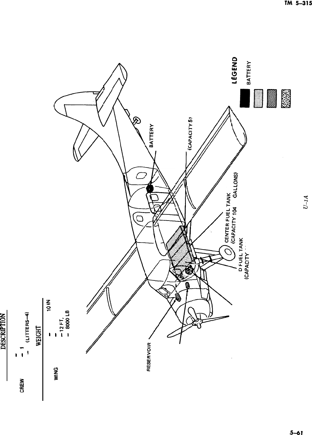
GENERAL
DESCRtE’TION
TYPE
-
SINGLE ENGINE, UTILITY
-
1
PASSENGERS
-
10
0slTERS-4)
DIMENSIONS AND
mIGHT
(GROSS)
LENGTH
-
41 FT,
10
lN
WING
SPAN
-
58FT
HEIGHT
-
IzFT,
51N
WEIGHT
-
8oooL8
HYDRAULIC
(LOCATED IN 8AGGAGE
COMPARTMENT)
SKI HYDRAULIC
RESERVOIR
AFT FUEL TANK
k%PAClTY
51
Us GALLONS)
OIL TANK (CAPACITY
(CAPACITY 10.8 US GALLONS)
104
US
GALLONS)
FW
tCAPAClTY
61
US GALLONS)
lEGEN
8AlTERY
FUEL TANK
HYDRAULIC RESERVOIR
E
OIL TANK
Figure 5-39. Model
U-1A
aircraft.
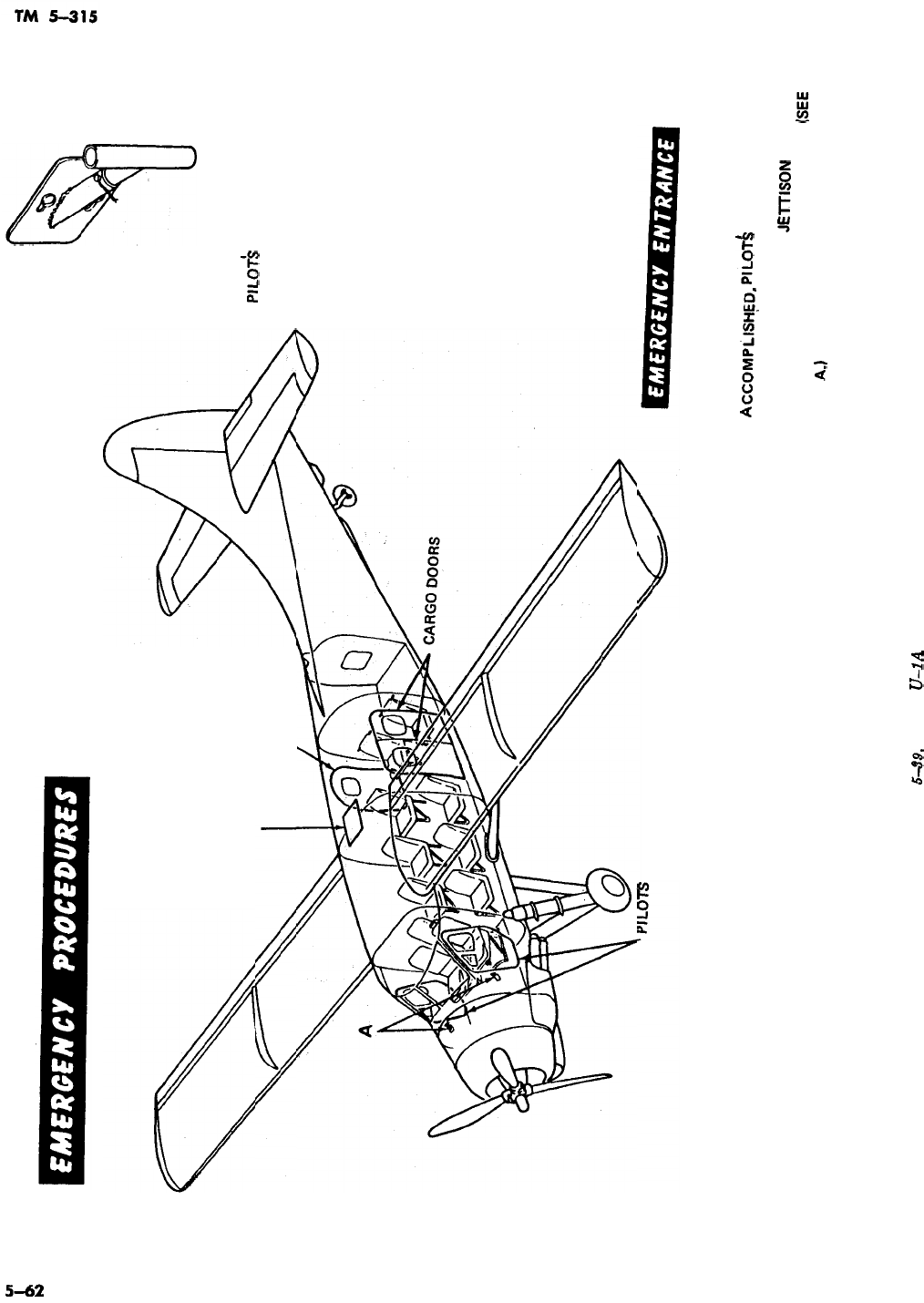
ESCAPE HATCH
CAB-IN DOOR
I
COMPARTMENT DOORS
DETAIL A
PlLOTk
COMPARTMENT
DOOR JETTISON HANDLE
EMERGENCY ENTRANCE MAY BE GAINED
THROUGH ANY ONE OF FIVE FUSELAGE
DOORS AND ESCAPE HATCH. AFTER ENTRANCE
IS
ACCOMPLISHFD,
PILOT&
COMPARTMENT
DOORS MAY BE JETTISONED BY PULLING
SHARPLY ON RESPECTIVE
JElTlSON
HANDLE
AND PUSHING OUTWARD ON DOOR.
(SEE
DETAIL
A.1
Figure
5-39.
Model
U-1A
a&raft-Continued.
.
.
.
,’
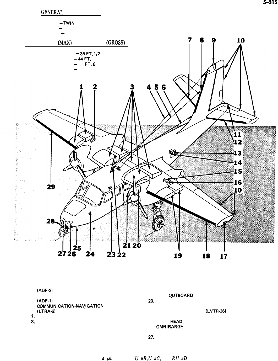
TM
5-315
GENEIUL
DESCRIPTION
TYPE
-
TWIN ENGINE, LIAISON AND LIGHT CARGO
CREW
-
2
PASSENGERS
-
4
DIMENSIONS
(h4AXj
AND WEIGHT
(GROSS)
LENGTH
-
35FT,
I/2
IN
WIDTH
-
44FT,
7 IN
HEIGHT
-
14
FT,6
IN
WEIGHT
-
7000 LB
3
456
1.
2.
3.
4.
5.
6.
7.
B.
9.
10.
11.
12.
13.
2726
24
23
22
RIGHT OUTBOARD FUEL TANK
14.
EXTERNAL POWER RECEPTACLE
RIGHT OIL TANK
15.
HYDRAULIC RESERVOIR
CENTER FUEL TANK
16.
LEFT OIL TANK
AUTOMATIC DIRECTION FINDING RECEIVER
17.
LEFT POSITION LIGHT
(ADF-2)
ANTENNA
18.
LEFT WING DE-ICER BOOT
AUTOMATIC DIRECTION FINDING RECEIVER
19.
LEFT QUTBOARD FUEL TANK
(ADF-II
ANTENNA
20.
8AGGAGE COMPARTMENT DOOR
COMMUNICATION-NAYIGATION
RADIO
21.
CABIN DOOR
(LTRA-61
ANTENNA
22.
VHF COMMAND RADIO
(LVTR-36)
ANTENNA
RIGHT HORIZONTAL STABILIZER DE-ICER BOOT 23. STATIC VENT
VERTICAL STABILIZER DE-ICER BOOT
24.
PI LOT
HEADS
ROTATING BEACON
25.
OMNIRANGE
RECEIVER ANTENNA
STATIC DISCHARGE WICK
26.
LEFT LANDING LIGHT
AFT POSITION LIGHT
27.
HEATER AND VENT INTAKE DUCT
LEFT HORIZONTAL STABILIZER DE-ICER BOOT
28.
GLIDE SLOPE RECEIVER ANTENNA
BATTERY
29.
RIGHT WING DE-ICER BOOT
Figure
5-.4&
Models
U-9B,
U-9C,
and
RU-9D
aircraft.
5-63
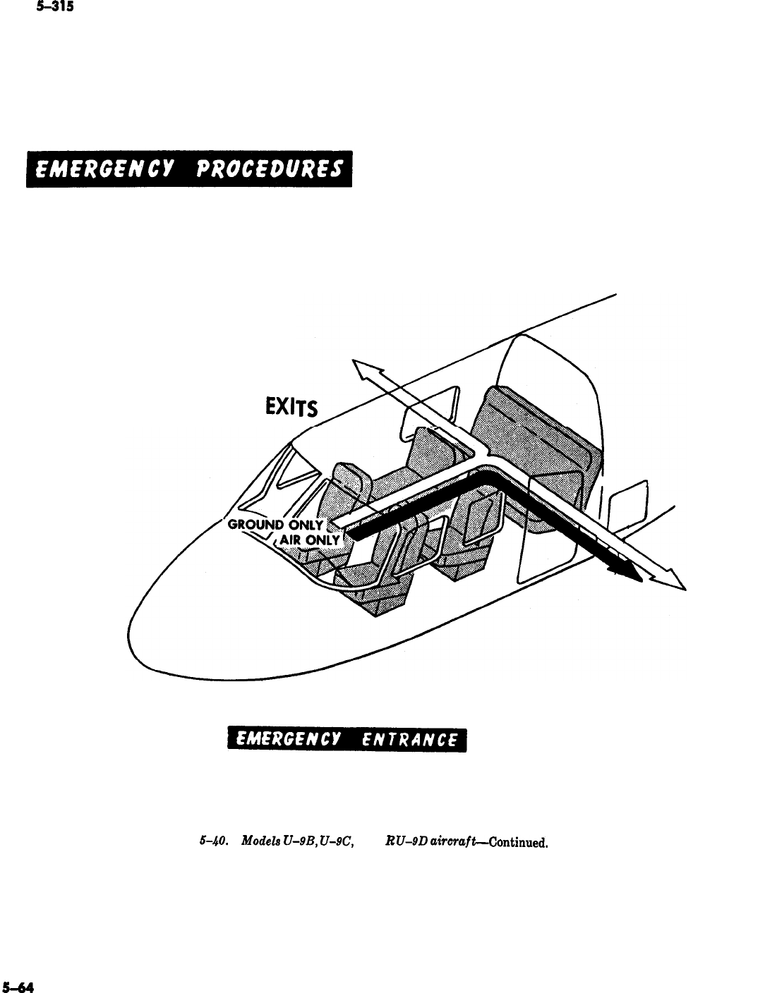
TM
5-315
GROUND AND AIR
ESCAPE ROUTES AND
EXI
WINDSHIELDS OR WINDOWS MAY BE BROKEN IF ENTRANCE TO THE CABIN
IS NOT POSSIBLE THROUGH THE DOORS.
Figure
5-40.
Modela
U-9B,
U-N?,
and
RU-9D
a&rafLContinued.
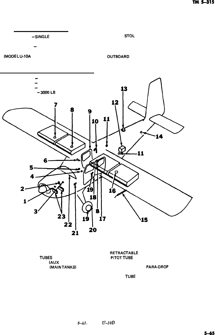
TM
5-315
1.
2.
3.
4.
5.
6.
7.
8.
9.
10.
11.
12.
GENERAL DESCRIPTION
TYPE
-
SINGLE ENGINE, LIAISON AND LIGHT CARGO,
STOL
CREW
-2
PASSENGERS
-
3
(MODEL
U-1OA
DOES NOT HAVE THE RIGHT AND LEFT
OUT8OARD
AUXILIARY FUEL TANKS)
DIMENSIONS (MAX) AND WEIGHT (GROSS)
LENGTH
-
30 FT, 8.4 IN
WIDTH
-
39FT
HEIGHT
-
8 FT, 9.6 IN
WEIGHT
-
3OOOL8
OIL DRAIN
OIL FILLER CAP
FUEL DRAIN
TUBES
STRAINER DRAIN
(AUX
TANKS)
STRAINER DRAIN tM.4lN TANKS)
TRIM TA8 AND FLAP CONTROL PANEL
RIGHT AUXILIARY FUEL FILLER CAP
MAIN TANK FUEL FILLER CAPS
PASSENGER COMPARTMENT DOOR
FUEL VENT
STATIC PORTS
8ATTERY
13. ANTI-COLLISION LIGHT
14.
RETRACTA8LE
LIFT HANDLE
15.
PITOT
TU8E
16. LEFT AUXILIARY FUEL FILLER CAP
17. LITTER DOOR
PARA-DROP
DOOR
18. PILOT COMPARTMENT DOOR
19. RELIEF
TU8E
DRAIN
20. TIRE FILLER VALVE
21. EXTERNAL POWER RECEPTACLE
22. INSTRUMENT PANEL
23. INDUCTION AIR FILTERS
Figure
5-41.
Model
U-1OD
aircraft.
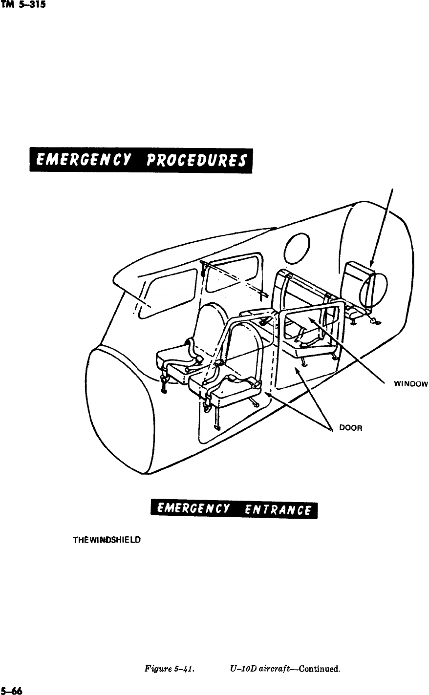
TM
5415
AUXILIARY GASOLINE
THE
WtkDSHlELD
OR WINDOWS MAY BE BROKEN IF ENTRANCE TO THE CABIN
CANNOT BE GAINED THROUGH ANY OF THE ACCESS DOORS.
Figure
5-41.
Model
U-1OD
ahraft-Continued.
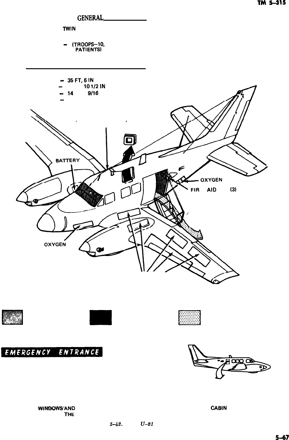
TM
5-315
GENE=
DESCRIPTION
TYPE
lWlN
ENGINE, LIAISON AND CARGO
CREW
-2
PASSENGERS
-
6
(TROOPS-10,
or 3 LITTER CASES AND3 AMBULATORY
PATI
ENTSI
DIMENSIONS (MAX) AND WEIGHT (GROSS)
LENGTH
-
35Fl,6lN
WING SPAN
-
45 FT,
10
1/2
1h1
HEIGHT
-
14
FT, 2
9/16
IN
WEIGHT
-
9650LB
FIRE EXTINGUISHER
ST
Al0
KITS
(31
FUEL TANKS
EMERGENCY EXITS AND
EMERGENCY ENTRANCE
DITCHING AND GROUND BAIL-OUT, DITCHING
EXIT ONLY AND GROUND EXIT
WtNf3OWYAND
WINDSHIELDS MAY BE BROKEN IF ENTRANCE TO THE CAEIN
THROUGH
THii
DOORS IS NOT POSSIBLE.
Figure
&4.%
Model
V-21
aircraft.
5-67
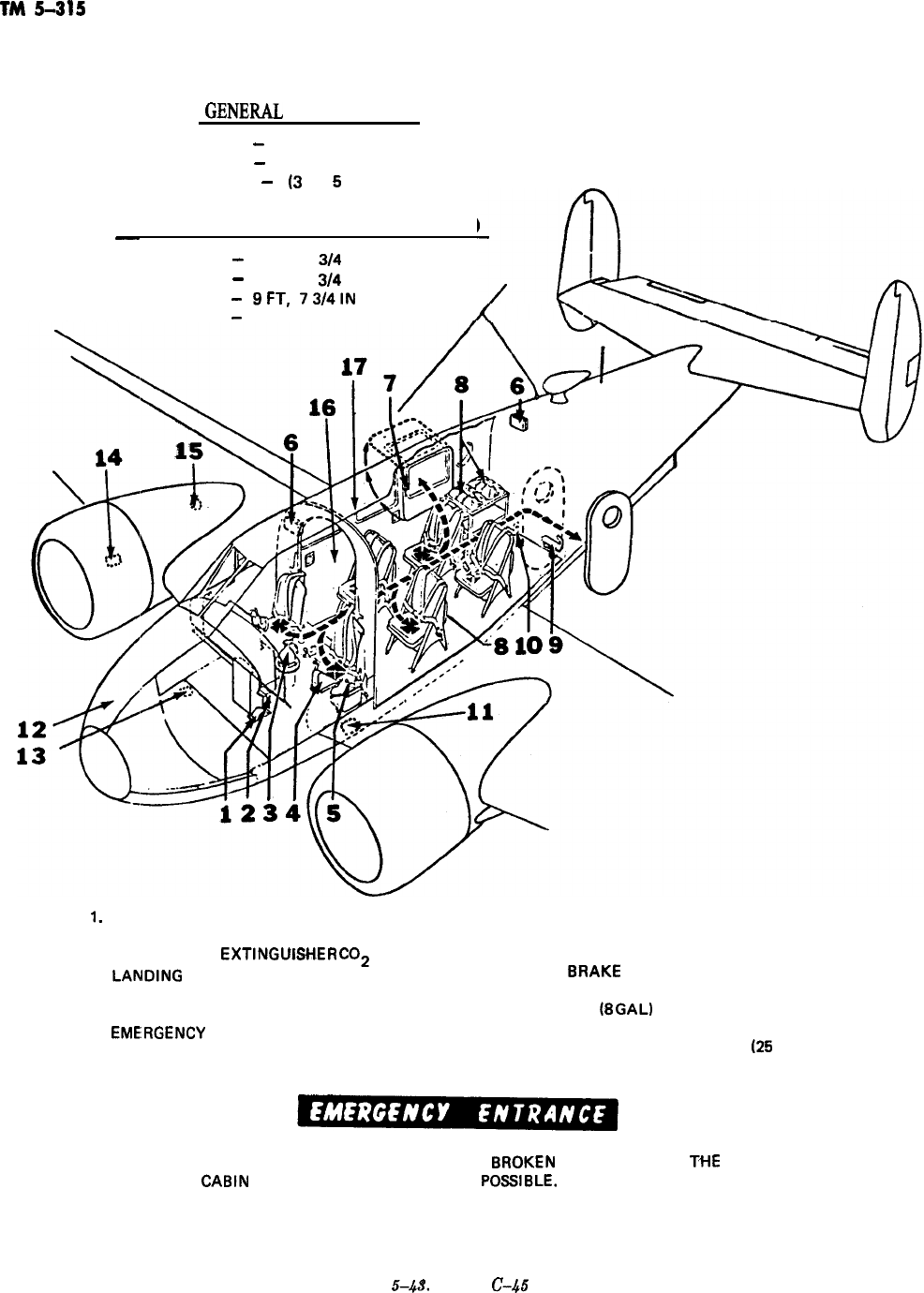
TM
5-815
GENERU
DESCRIPTION
TYPE
-
TWIN ENGINE, LIAISON, PASSENGER, AND CARGO
CREW
-
2
PASSENGERS
-
5
(3
OR
5
SEATS)
DIMENSIONS (MAX) AND WEIGHT (GROSS)
-
LENGTH
-
34 FT, 2
3/4
IN
SPAN
-
47 FT, 6
314
IN
HEIGHT
-
9FT,
73/4lN
WEIGHT
-
6730 L6
1.
2.
3.
4.
5.
6.
7.
8.
9.
LANDING GEAR CLUTCH
ENGINE FIRE EXTINGUISHER CONTROLS
ENGINE FIRE
EXTlNGUlS4iER
CO2
80TTLE
LANOING
GEAR AND WING FLAP HAND CRANK
SHOULDER-HARNESS LOCKS
FIRST AID KITS
EMELRGENCY
ESCAPE PANEL RELEASE
PARACHUTES
CO2 HAND FIRE EXTINGUISHER
10. EMERGENCY DOOR RELEASE LEVER
11.
8ATTERY
12. NOSE FUEL TANK (47 GAL)
13.
8RAKE
FLUID
14.
AUTO-PILOT RESERVOIR
15.
OIL
18
GAL)
16. MAIN FUEL TANK (78 GAL)
17. AUXILIARY FUEL TANK
(26
GAL)
WINDOWS AND WINDSHIELDS MAY 8E 8ROKEN IF ENTRANCE TO
TtIE
CA8lN
THROUGH THE DOORS IS NOT
POSSl8LE.
-
Figure
5-43.
Model
C-.&S
aircraft.
5-68
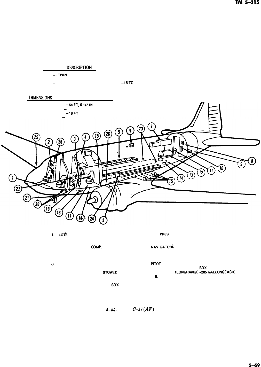
TM
5-315
GENERAL
DESCIUF’TION
TYPE
-..lWlN
ENGINE, PASSENGER, CARGO, AND AMBULANCE
CREW -6
PASSENGERS
-
27 (FOLDING BENCHES1 AMBULANCE
-
15TO
24 LITTERS
DIhtENSIONS
(MAX) AND WEIGHT (GROSS)
LENGTH
-
64FT,51/2lN
SPAN
-
95FT
HEIGHT
-
16FT
WEIGHT
-
26,OOOLB
-
I.
PI
LOT&
COMPARTMENT
2. HYDRAULIC PRESSURE ACCUMULATOR
3. PORTABLE OXYGEN CYLINDER
4. RADIO OPERATOR’S
COMP.
5. FOLDING TROOP SEATS
6. LITTER HANGER
7. SPACE HEATER
B.
MISC. STOWAGE
9. ENG. COVER STOWAGE
10. SURFACE CONTROL LOCKS
6TDWED
11. TOILET
12. A.P.P.
13. PARAPACK CONTROL JUNCTION
9OX
14. LOW PRES. SYS. OXY. FILLER VALVE
15. LOW PRES. SYS. OXY. TANKS
16. ALTERNATE STATICSOURCE
17.
NAVlGATOdS
COMPARTMENT
16. EXTERNAL POWER RECEPTACLE
19. MAIN ELECTRICAL JUNCTION BOX
20. BATTERIES
21.
PITOT
STATIC TUBE
22. POWER SYSTEMS JUNCTION
BDX
23. FUEL TANKS
(LONG
RANGEdS6GALLONS
EACH)
24. C. B. CONTAINERS
25. MAIN FUEL TANK-m2 GALLONS EACH
26. AUXILIARY FUEL TANK-299 GALLONS EACH
Figure
54.4.
Model
C-.V(AF)
aircraft.
5-69
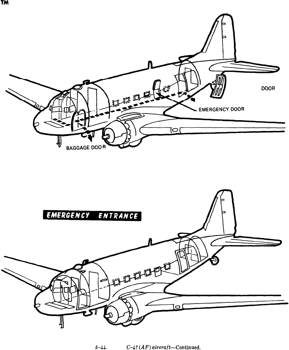
TM
5-315
ROUTES OF ESCAPE AND EMERGENCY EXITS
MAIN CARGO
OOOR
EMERGENCYDOOR
BAGGAGEDOO
(CUTTHROUGHAREASMARKEDINYELLOWONAIRCRAFT)
Figure
.G-.&$.
Model
C-hY(AF)
aircraft-Continued.
5-70
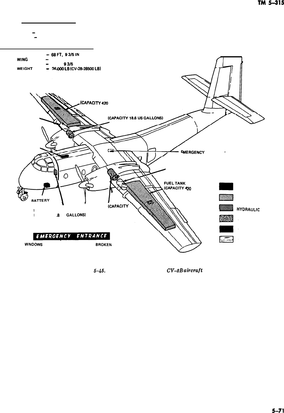
TM
5-315
GENERAL DESCRIPTION
TYPE
-
TWIN ENGINE, CARGO
CREW
-
2
DIMENSIONS (MAX) AND WEIGHT (GROSS)
LENGTH
-
6SFT,
93/5lN
WING
SPAN
-
96FT
HEIGHT
-
31 FT,
93/5
IN
WFIGHT
-
!x3
ooo
LS
tcv-2B26500
LSI
.
h
FUEL TANK
I
@ZAPAclTY
4m
US G ALLONS)
OIL TANK
ANTI-ICING RESERVOIR
OXYGEN CYLINDER
MERGENCY
BATTERY
ANTI-ICING RESERVOIR
20
US GALLONS)
\
,
OIL TANK
ICAPACITY
HYDRAULIC RESERVOIR lS.6 US GALLONS)
(CAPACITY 1
.S
US
GALLONSJ
INDOWS
AND WINDSHIELDS MAY 6E
BROKEN
IF
ENTRANCE THROUGH DOORS IS NOT POSSIBLE.
LEGEND
BATTERY
FUEL TANK
HYDRAULIC
RESERVOIR
OIL TANK
OXYGEN CYLINDER
ANTI-ICING RESERVOIR
Figure
5-45.
Models C-?‘A (AF) and
CV-ZB
aim-aft
5-71
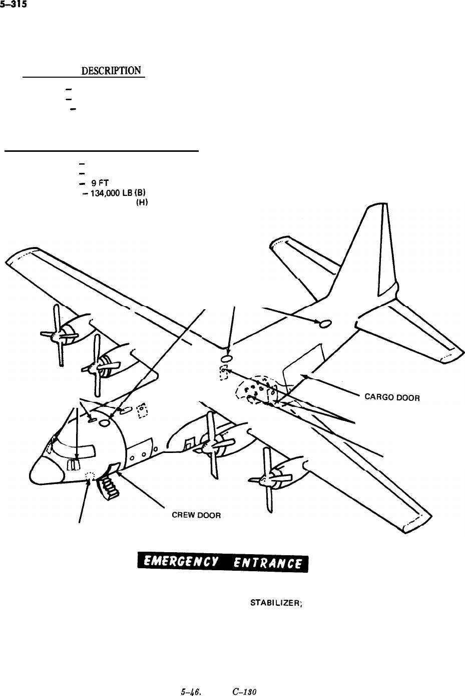
TM
5-315
GENERAL
DESCR~TION
TYPE
-
4 ENGINE, PASSENGER AND CARGO
CREW
-
4
PASSENGERS
-
78
DIMENSIONS (MAX) AND WEIGHT (GROSS)
LENGTH
-
95FT
WIDTH
-
132 FT, 7 IN
HEIGHT
-
9FT
WEIGHT
-
134,OOOL8
(81
175,000 L8
(HI
ESCAPE HATCHES
OXYGEN CYLINDERS
PARATROOPER DOOR
EMERGENCY EXIT
8ATTERY
THERE ARE FOUR ESCAPE HATCH RELEASES, INTERIOR AND EXTERIOR, ON TOP OF THE
AIRCRAFT. ONE IS FORWARD OF THE VERTICAL
STA8lLlZER;
ONE AT THE TRAILING
EDGE OF WING, AND THE OTHER TWO ARE FORWARD OF THE WING. THERE IS A
PARATROOP DOOR HANDLE ON 80TH SIDES OF THE AIRCRAFT NEAR THE TRAILING
EDGE OF THE WING. THERE ARE CHOPPING AREAS DESIGNED ON 80TH SIDES OF THE
AIRCRAFT, THERE IS A CREW DOOR ON THE LEFT SIDE AT THE COCKPIT AREA.
-
Figure
5-46.
Model
C-l80
aircraft.
5-72
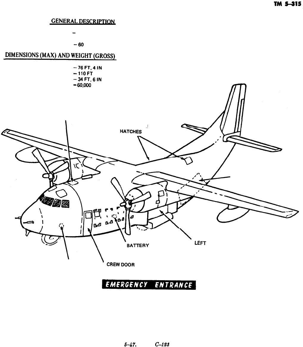
TYPE
-
TWIN ENGINE, PASSENGER AND CARGO
CREW
-4
PASSENGERS
-66
DlMENSIONS(MAX)ANDWElGHT(GROSS)_
LENGTH
-76FT,4lN
WIDTH
-
1lOFT
HEIGHT
-34FT,6lN
WEIGHT
-
60,ooo
LB
FORWARD
ESCAPE HATCH
AFT ESCAPE
CARGO DOOR
LEFT
REAR TROOP DOOR
OXYGEN
’
CREWDOOR
EMERGENCY ENTRANCE MAY BE MADE THROUGH THE FORWARD ENTRANCE DOOR AND
THROUGH THE TWO REAR TROOP DOORS. ALL THREE DOORS HAVE EXTERNAL
CONTROL HANDLES AND ACCESS PANELS FOR REACHING EMERGENCY RELEASE
HANDLES. EMERGENCY CUT-IN AREAS ARE MARKED AROUND ALL CARGO
COMPARTMENT WINDOWS AND AROUND THE THREE DITCHING HATCHES IN THE CARGO
COMPARTMENT CEILING. THE DITCHING HATCHES ALSO HAVE EXTERNAL RELEASE
HANDLES FOR EMERGENCY ENTRANCE.
Figure
5-47,
Model
C-l28
aircraft.
5-73
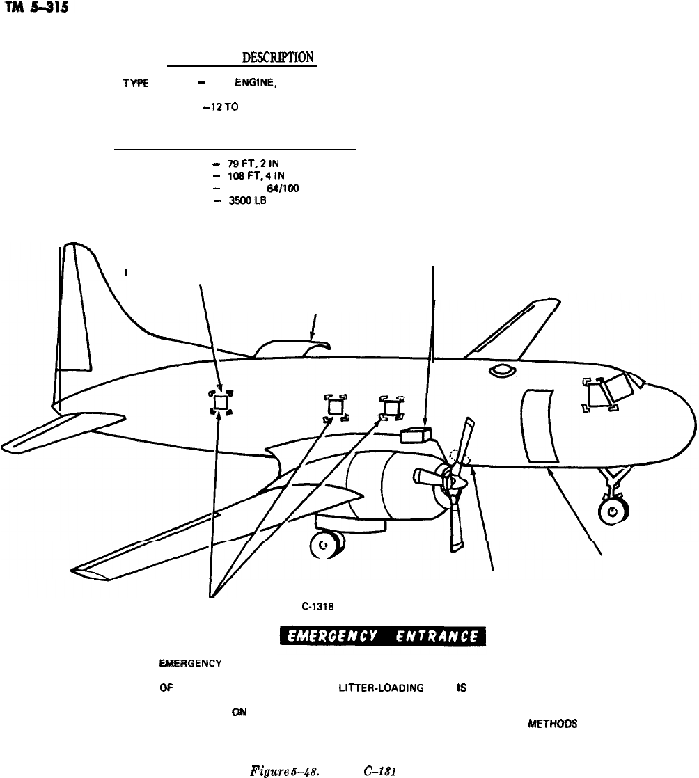
GENERAL
DESCRPTiON
w#%
-
TWIN
ENGlNE,
PASSENGER
CREW
-3
PASSENGERS
-
12TO
44
DIMENSIONS (MAX) AND WEIGHT (GROSS)
LENGTH
-
7SFT,2lN
WIDTH
-
lOBFT,4lN
HEIGHT
-
28 FT, 1
S4il00
IN
WEIGHT
-
35DoLB
BATTERIES ARE LOCATED
ON UNDERSIDE OF LEFT
INBOARD WING
EMERGENCY CUT-IN AREAS
\
LITTER DOOR
DOOR AND STAIRS
OXYGEN CYLINDER
EMERGENCY ESCAPE HATCHES ASTRODOME C-13lB ONLY
WRGENCY
ENTRANCE MAY BE MADE THROUGH THE MAIN ENTRANCE DOOR AND
EMERGENCY ESCAPE HATCHES. THE MAIN ENTRANCE DOOR IS ON THE RIGHT SIDE, AFT
GF
THE CREW COMPARTMENT. THE
LllTER-LOADING
DOOR
IB
HINGED AT THE TOP AND
MAY BE OPENED BY ROTATING TWO LATCH HANDLES AND LIFTING THE DOOR. THIS
ENTRANCE IS DN THE LEFT SIDE OF THE AIRCRAFT, AFT OF THE WING. EMERGENCY
CUT-IN AREAS ARE MARKED ON THE AIRCRAFT FOR USE IF THE ABOVE
METHOOS
OF
ENTRY FAIL.
Ft$ure
5-48.
Model
C-1.U
aircraft.
5-74
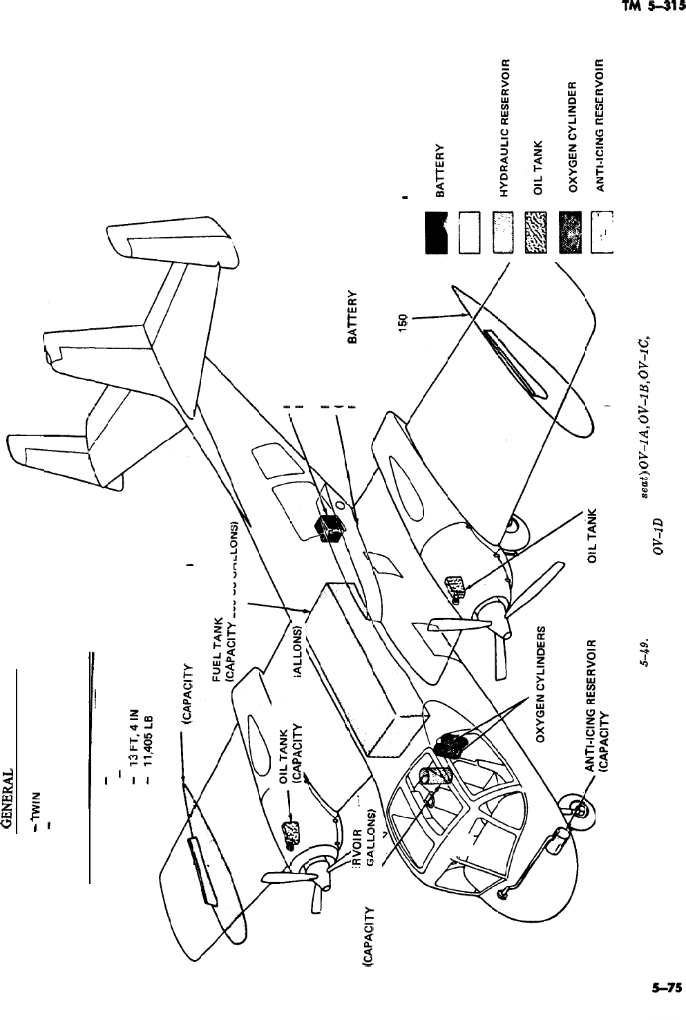
,
GENES
DESCRIPTION
TYPE
-
TWlN ENGINE, OBSERVATION
CREW
-
2
DIMENSIONS AND WEIGHT (GROSS)
LENGTH
-
40 FT, 7.25 IN
WINGSPAN
-
42FT
HEIGHT
-
13FT,4lN
WEIGHT
-
11,405LB
FUEL DROP TANK
(CAPACITY 150 US GALLONS)
ApAClTY
256
US GAL
HYDRAULIC RESE
(CAPACITY 2.6 US
PACITY
2.5 US G
BATTERY (ACCESS GAINED THROUGH
EMERGENCY PUNCH-IN PANEL)
FLARE POD-OPTIONAL
(PROVIDED WITH PUNCH-IN
PANEL FOR
BAlTERY
ACCESS)
FUEL DROP TANK
(CAPACITY
150
US GALLONS)
m
LEGEND
FUEL TANK
olL
TANK
~CAPAC~TY
1.5 us GALLONS)(CAPACITY 2.5 US GALLONS)
Figure
5-49.
Models (with ejection
seut)
OV-lA,
OV-lB,
OV-lC,
and
2
OV-1D
aircraft.
E
z
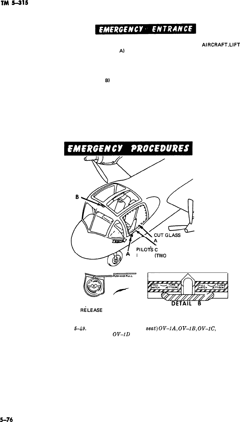
TM
5-315
EMERGENCY ENTRANCE MAY BE GAINED FROM EITHER SIDE OF
AlRCRAFT.LlFT
EXIT
RELEASE LOCK RING (DETAIL Al AND TURN TO UNLOCK POSITION. OPEN PILOT’S
COMPARTMENT HATCH WITH LEVER BY PUSHING AT FORWARD END AND PICKING UP. IF
EITHER HATCH FAILS TO OPEN, ENTRANCE MAY BE GAINED BY CUTTING THROUGH
EITHER HATCH GLASS. IF ENGINES ARE STILL OPERATING, FLOOD AIR INTAKE WITH
FOAM OR WATER. TO JETTISON EMERGENCY CANOPY, ROTATE EMERGENCY CANOPY
JETTISON HANDLE (DETAIL
BI
CLOCKWISE 90 DEGREES AND PULL.
CAUTION
MAKE SURE ALL PERSONNEL ARE CLEAR OF CANOPY AREA. CANOPY
TRAJECTORY IS TOWARD AFT SECTION OF AIRCRAFT.
TIME PERMITTING, POSITION ENGINE MASTER SWITCHES, BATTERY SWITCH, AND
OXYGEN REGULATOR SHUT-OFF LEVER TO OFF POSITION. ALSO PULL FIRE EMERGENCY
CONTROL HANDLES.
ROUND EDGE
OMPARTMENT
HATCH
(TWO
PLACES)
EXIT RELEASE
DETAIL A
EXIT
RiLEASE
LOCK RING EMERGENCY CANOPY JETTISON HANDLE
AND LEVER
Figure
5-49.
Models (with ejection
se&)
OV-lA,
OV-lB,
OV-lC,
and
OV-1D
aircraft-Continued.
-
5-74
-m
_~

1.
2.
3.
1.
2.
3.
4.
SECURING THE EJECTION SEAT
Lift red tab of face blind (Detail C, fig.
6-49-cont’d
Lift lower firing handle safety guard (fig.
549-cont’d
(2)).
Insert safety pins (2 of 5). First, ‘the drogue gun pin (fig.
5-49-
cont’d (2)
),
then the main ejection gun sear safety pin (Detail C).
Emergency pins are in the map compartment of the aircraft, but must
be carried in every crash vehicle for emergency use. A metal pin the
diameter of a ten-penny nail can also be used.
REMOVAL OF PILOT AND/OR OBSERVER
Unlock the harness quick-disconnect fitting by squeezing the release
bar tabs and at the same time move the release bar upward. Then
release the safety belt and remove the survival kit vertical restraint
straps. Release the leg garters from the leg restraint cords at the
quick-disconnects by squeezing the serrated lock release tabs to free
the
lmk
ring. Remove the pilot or observer through the pilot’s
compartment hatch or the emergency canopy opening.
If the harness quick-disconnect fittings and the lap belt cannot be
unlocked, or if survival kit vertical restraint straps cannot be removed,
the pilot and observer can be removed with parachute and survival
kit attached by activating the manual override release lever. Raise
up on the ring rearward until the handle locks. Next, unlock the
harness quick-disconnect fittings by squeezing the release bar tabs and
moving the release bar upward. Then unlock the lap belt and remove
the survival kit vertical restraint straps. Remove the leg garters by
squeezing the serrated lock release tabs which frees the lock ring.
Tilt pilot or observer forward from the waist and turn his shoulders
toward the entrance hatch. Grasp the pilot or observer under his
armpits, lift and pull him through the entrance hatch or escape hatch.
If there appears to be little chance of fire, it is advisable to leave the
injured in their seats until qualified medical personnel arrive.
5-77
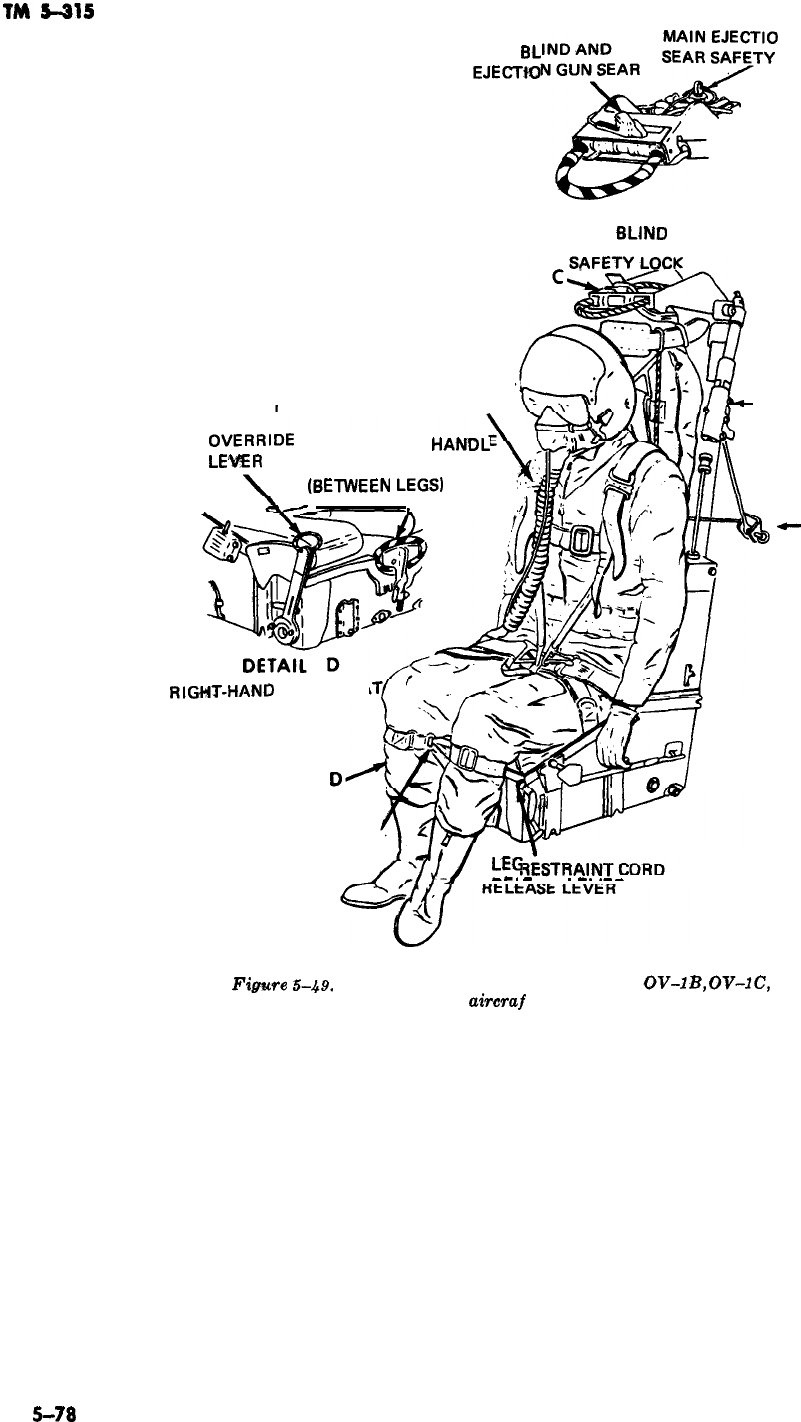
FACE
BL
EJECTW
N GUN
PIN
DETAIL C
FACE
6LJNfJ
HARNESS QUICK-DISCONNECT
FITTING
MANUAL
OVERRIDE
LOWER FIRING
HANDL
RELEASE
LEVER
SAFETY GUARD
(6ETWEEN
LEGS)
,.._
1
,,
DROGUE GUN PIN
e
PIP
PIN
RIGHT-HAND
SIDE OF
SEA
LEG GARTER
QUICK-DISCONNECT
FITTING
LEb
-a.
-
---
.
-.
.--
Fig~e
5-49.
Models (with ejection seat) OV-1 A,
QV-lB,
OV-lC,
and
OV-1 D
aircraf
h-Continued.
5-78
TM
5-315
CHAPTER 6
NUCLEAR WEAPONS FIREFIGHTING PROCEDURES
Section
I.
GENERAL
6-1. Purpose and
Obiective
62.
Policy
This chapter provides guidance to all individuals It is Department of the Army policy that fires in
concerned with fires involving nuclear weapons an area containing nuclear weapons will be fought
and associated high explosives. until an explosion is imminent.
Section
Il.
RESPONSlBlllTlES
6-3.
Introduction
The prevention of accidents, including fires, is a
responsibility of command. Commanders at every
echelon are responsible for prevention of acci-
dents involving personnel, operations, and activi-
ties under their jurisdiction. General areas of re-
sponsibilities, and policies and procedures to be
followed for prompt, effective, and coordinated re-
sponse to accidents and/or incidents involving nu-
clear weapons, are set forth in AR 50-2.
6-4.
Commanders
Commanders responsible for the storage, han-
dling, or transportation of
nuclear
weapons or nu-
clear materials will insure that
a. Personnel involved in the transportation,
storage, or handling of nuclear weapons are fa-
miliar with the provisions of applicable nuclear
accident information plans prepared in compli-
ance with Department of the Army, USCONARC,
and major
oversea
basic
,policies,
with particular
reference to guidance governing the release of
in-
formaton
to the public regarding the presence of
nuclear weapons or material at an accident scene.
b.
Personnel working
inthe
vicinity of nuclear
weapons are informed of and trained in proper
fire-protection procedures.
c. Standing operating procedures are published
and enforced, as required, concerning such mat-
ters as control and mvoement of nuclear weapons,
positioning of firefighting equipment, exposure
control and evacuation of personnel in case of fire,
reporting procedures required, and the like.
d.
Civilian fire departments (municipal) which
may be called upon to assist in extinguishing fires
involving nuclear weapons are informed of the
hazards involved and the procedures to be used,
6-5.
Couriers
Nuclear weapons are classified items of material
and as such must be safeguarded at all times.
a. Couriers are military personnel physically
accompanying shipments of nuclear weapons ma-
terial for security purposes. In effect, the courier
“owns” the material;
i.e.,
he is the direct cus-
todian of it. While he is physically able, it is the
courier’s responsibility to protect the material
from loss or security compromise.
b. At the time of departure each courier is fur-
nished information as to organizations which are
to be contacted in event of an accident or incident.
Couriers are capable of rendering technical advice
pending the arrival of specially trained personnel.
6-6. Decontamination and Disposal
*earns
a. Specially trained teams of personnel
&spon-
sible for and equipped to detect radiation, to neu-
tralize a weapon if necessary, and to decontami-
nate the area of explosives or nuclear materials,
are maintained by the military services and by the
Atomic Energy Commission.
b. Immediately upon notice to the military and
6-1

TM
5-315
Atomic Energy Commission of an accident involv-
ing nuclear weapons, one or more of these teams,
known as “Nuclear Emergency Teams,”
“‘Explo-
sive Ordnance Disposal (EOD)
Detach3ments,”
“Radiological ‘Contamination
(‘RADCON)
Teams,” “Alpha Teams” and “Radiological
Emergency Medical Teams
(REMT)“,
will be dis-
patched to the
<a&dent
area.
6-7. The
Nucilear
Weapon-
General Safety Factors
The extreme care devoted to the design of nuclear
weapons and
t,he
equipment and procedures for
handling them has been repaid with a record of no
inadvertent or unintentional nuclear detonations.
Because of the
voIume
of weapons handled daily,
accidents cannot be ruled out entirely. Because of
the safety factors designed into the weapons,
acci-
dental1
detonation of the nuclear material is vir-
tually impossible.
&8.
Explosion
In a typical nuclear weapon, high explosives
sur-
round the mass of nuclear material. The simulta-
neous explosion of the high explosives, timed in
millionths of seconds, exerts even pressure inward
on the subcritical mass of nuclear material and
compresses it until it becomes
supercritical,
fis-
sions, and
sustains
a chain reaction.
a. To become critical, the mass of nuclear mate-
rial requires even compression by the surrounding
high explosive. There can be no chain reaction
until enough pressure is applied uniformly to sus-
tain chain reaction.
b. To insure that the high
explvosive
sends its
pressure uniformly to all areas of the nuclear
mass, a typical weapon has detonators arranged
at many points, to be set off simultaneously by an
electric charge, If the high explosive becomes
accidentally ignited by fire at one point, it will
burn or perhaps explode, but it will neither burn
nor explode with sufficiently uniform pressure to
make the mass critical. If the weapon should be
inadvertently dropped, struck, or should acciden-
tally
f,all
from
a,n
aircraft, the blow may cause the
ignition or
expllo,sion
of the high explosive. Again,
while any explosion would be at the one point
w,hich
receives the blow or shock, this will not
cause the nuclear material to become critical and
sustain chain reaction.
6-9. Hazards
a. General. Even though nuclear weapons are so
designed as to prevent a nuclear yield in the event
of accidental detonation, there is still a potential
hazard commensurate with
conventiona
weapons
and materials. ‘The two components of a nuclear
weapon which constitute the most
probable
haz-
ard in case of an accident
are-(‘1)
the high ex-
plosive
;
and (2) the nuclear material. Other com-
ponents may produce hazards, but they are of
such nature that precautions taken against high
explosive and nuclear materials are more than
enough for their control. It should
,be
kept in mind
that accidents involving nuclear weapons or com-
ponents usually will involve other materials in
more widespread use,
,such
as gasoline or other
vol,atile
and explosive fuels.
-.
b. High Explosives. Most nuclear weapons con-
tain high explosive. This high explosive
com-
preises
the major hazard associated with acci-
dents involving nuclear weapons.
(1)
Zdentificution.
Burning high explosives
have certain characteristics which
will
enable
the
firdghters
to recognize them. The high tempera-
ture at which
they
oxi.dize
causes hot flame, or
“torching,”
which is easily distinguishable from
the flame of, for instance, burning petroleum
fuels, or other materials. The smoke of burning
explosive from nuclear weapons is noticeably light
in color as it mingles with that from most other
burning fuels.
(2) Characteristic
hazarok
As they burn,
high explosives melt, flow, drip, spread, and mix
with surrounding ground or wreckage. After the
fire is extinguished these explosives are safe only
if they are completely burned. High explosives
which have not completely burned remain an ex-
treme explosive hazard. After these explosives
have cooled below ignition temperature they will,
like metal, take on curious shapes. They may have
picked up impurities, while molten or burning,
which will make them actually more dangerous
than they were before melting.
c. Detonation. In any accident involving a high
explosive there is the possibility of a detonation
occurring. The detonation may range from a very
small one to one of considerable magnitude; or it
may be a series of small explosions. The breakup
of the weapon from impact or a small explosion
will probably result in the local scattering of
small pieces of high explosive. Rough
handfling,
as
well as accidents, may produce powdered explo-
sives. Most high explosives are more sensitive in
these conditions and are more apt to detonate
when subjected to heat or impact or friction.
-
6-2

TM
5-315
6-110.
Nuclear Yield
The possibility of the accidental nuclear detona-
tion of a nuclear weapon is so remote as to be
negligible.
6-1
‘I.
Nuclear Materials
a.
Gene&.
As the result of impact or detona-
tion of the high explosive, nuclear materials
beco:me
dispersed as finely divided particles or, if
a fire occurs, become dispersed as oxides. These
particles, or oxides, are alpha emitters. Unlike the
beta and gamma radiation in the fallout of a nu-
clear explosion, alpha radiation has a very short
range and lacks the ability to pierce the skin.
b.
Body
Effects. Because of the inability of the
alpha radiation to
penetrati
the skin, nuclear ma-
terials are not a hazard if they remain outside the
body,,
(1) To avoid possible radiation effects and
also the possibility
,of
heavy-metals <poisoning
(sim.i,lar
to lead poisoning), effort should be made
to prevent nuclear material from entering the
body.,
102)
When finely divided particles of nuclear
materials, or their oxides, are suspended in the
air, it is possible to swallow them or inhale them.
Cuts in the skin provide another and more dan-
gerous source of entry into the bloodstream.
c. Intake. Field experiments indicate that the
principal
source8
of intake of nuclear materials
into the body is inhalation during the passage of
the cloud resulting from the detonation or the
burning of the nuclear material. Once the fine
particles have been deposited on the ground, the
hazard is markedly reduced. However, care should
be taken that dust, which may have been contami-
nated, is not stirred up.
(1) It is always desirable to reduce to a mini-
mum the intake of nuclear materials but, when
necessary, one may enter or remain in a highly
conta:minated
open area for short periods (up to
several hours) after passage of the smoke cloud.
(2) Respirators, or preferably self-contained
breathing <apparatus, and protective clothing
should be worn.
(3) Persons with cuts should remain outside
the contaminated area(s).
(4) Under extreme emergency conditions,
and in the absence of respirators or self-contained
breathing apparatus, a wet handkerchief over the
nose and mouth may be utilized to reduce the in-
take of nuclear material into the body.
6-12. Fire
If a nuclear weapon is enveloped in flame the high
explosive may ignite, burn, and in many cases
detonate. Whenever heated or burning high
expb-
sives are confined,
az~
in an intact
wmpon,
detona-
tion may occur at
an3
time. High explosives
which have not completely burned may actually be
more sensitive and dangerous than before being
subjected to fire
(para
6-9).
6-13. Fire Symbols: Explosive Symbols
a.
GeneraZ.
To provide guidance to firefighting
forces it is an accepted practice to divide explo-
sives into four groups in accordance with the gen-
eral burning and explosive characteristics of the
materials and the relative danger in fighting fires
in which they are present. The four groups are
i,dentified
by symbol numbers 1 through 4.
Tahe
hazard to firefighters increases progressively with
the numbers. Nuclear weapons containing high ex-
plosives are included in the symbol 4 group
(b
below). However, it must be understood that the
fire symbols were developed for conventional am-
munition long before nuclear weapons came into
being. Where nuclear weapons are concerned,
categorizing the weapons on the same basis with
conventional ammunition without due considera-
tion of all the aspects of design, packaging sensi-
tivity, and without regard for weapon vulnerabil-
ity, would result in an unacceptable abandonment
of the weapon to a fate where, in most instances,
timely and intelligent application of firefighting
techniques would and could prevent disaster. With
conventional ammunition, a fire may involve
various types of ammunition and explosives, each
type varying in sensitivity and vulnerability to
heat and flame. Packaging in most cases is highly
flammable, thereby increasing the danger and
rendering the firefighting effort more difficult.
b.
Symbol
.4.
This includes materials which may
detonate when involved in a fire. The safety of
personnel in fighting a symbol 4 fire depends on
the accuracy of the informatoin made available to
the firefighting forces. In case of rail or vehicle
fires outside of the military installation, the trans-
port vehicle will be labeled with
“explosive”
plac-
ards. All such vehicles with “explosive” placards
will be regarded as symbol 4. For nuclear weap-
ons involved in a fire, the minimum area to be
cleared is 2000 feet (610 meters)
(para
646b)
in
all directions of the fire.
6-3

TM
5-315
Section
Ill.
GENERAL FIREFIGHTING GUIDELINES
6-14. Planning Prior to a Fire
The
potentia’l
hazards surrounding a fire involv-
ing a nuclear weapon, and the protective mea-
sures which can be taken, vary widely. The time,
during which a fire can be fought before detona-
tion of the high explosive component becomes a
possibility, will be critical in some cases. There-
fore, it is important that situations in
wlhich
a
weapon may become involved in a fire be antici-
pated to the maximum extent feasible. Written
plasn of action or standing operating procedures
should be prepared and should be familiar to all
personnel who may become involved.
6-15.
Emeqgency
Procedures
The first observer of the fire
should-
a. Assist. Give immediate assistance to person-
nel where possible. However, except for the sav-
ing of lives, keep away from the fire. There is
always the danger of a detonation of the high
explosive component. Remain upwind and uphill
from the fire. In saving lives, use any available
method to prevent smoke from entering your eyes,
nose, and throat.
b. Report. Report the fire immediately to the
nearest fire department, whether military or mu-
nicipal. Upon arrival at the scene, the police or
fire department (military or municipal) should be
asked to notify the nearest military
inst,allation
or
Atomic Energy Commission office
(para
6-6).
6-16. General Procedures
T’he
techniques for fighting fires in which nuclear
weapons are involved are basically the same as
those used in fighting fires involving high explo-
sives. The critical factor is the brief time availa-
ble to extinguish or control the fire before the
nuclear
weaplon
is enveloped in flame. Therefore,
teamwork and the quick application of current
firefighting and operational procedures are vital
to the successful fighting of such fires.
a. Determination. The primary consideration in
determining whether to fight the fire is “How
soon will an explosion occur
?”
b. Clearing the Area. One of the first actions in
any fire involving nuclear weapons is to clear the
area of all personnel not actually needed or en-
gaged in the
firefighting
operation. Where nuclear
weapons are involved, the minimum clearance dis-
6-4
-
tance is 2000 feet (610 meters). Even at this dis-
tance injury
fr.om
flying objects is possible.
c.
Time Factor. If the fire or impact does not
immediately detonate the high explosive, the pe-
riod of time available to fight the fire before such
detonation might occur varies from a few minutes
to an indefinite period, depending on the physical
characteristics of the weapon casing and the in-
tensity and proximity of the fire.
(1) When the weapon is enveloped in flame,
or is subjected to high heat from conduction,
convection, or radiant heat energy, the time
factor is critical.
(2) When burning high
exiplosives
are con-
fined, as in an intact weapon, detonation of the
high explosives may occur at
an.y
time.
(3) When an intact weapon has become so
heated that it cannot be touched with the bare
hand it
i,s
vulnerable to detonation of the high
explosive component.
(4) When an explosion is imminent all per-
sonnel will be cleared to at least 2000 feet (610
meters) from the fire. Personnel will not attempt
to fight the fire.
-
(5) If the weapon is in an area adjacent
to a fire but is not enveloped in flames, personnel
should
attem.pt
to cool the weapon while extin-
guishing the fire.
d. Safety Measures. The standard firemen’s
bunking clothing,
boot.s,
and helmet provide ade-
quate shielding against the alpha
radiati.on
which
may be present. Self-contained breathing appara-
tus
#and
tight-fitting goggles should be worn if at
all possible. The fact that some or all of these
items are not available should not hold up opera-
tions necessary for rescue of personnel.
e. Attacking The Fire. If the decision is made to
attack the fire, the senior fire department officer
must make decisions rapidly. (If the available
supply of water and other extinguishing agents is
adequate, it may be possible to cool the weapon
with a water fog and extinguish the main fire at
the same time. If the water supply is such that
both cooling and extinguishing operations cannot
be accomplished, and it appears that this fire can
be extinguished or controlled to a point at which
heat absorbed by the weapon will not exceed safe
limitations, it may be advantageous to use all
available water on the fire
itsel’f.)
(1) Approach the fire from upwind and at a

maximum angle to any armament that might be
invlolved.
(For instance, since the heat of flames
might fire them, do not approach directly into the
line of guns, rockets, or missiles in the nose, tail
or wings of a wrecked aircraft.) The approach
should afford maximum effective application of
extinguishing agents on the critical area and per-
mit rapid withdrawal of men and equipment.
(2) The most important thing is to cool the
high explosive and to secure control of fuel or
other exposing fires quickly. If a weapon is lo-
cated, cool its entire surface with the available
extinguishing agent.
(3) Water is the most effective agent for
cooling a weapon, or for extinguishing a fire
in-
.volving
high explosives. Application as a fog or
spray is desirable. High pressure
applicatiun
can
be dangerous; it can scatter exposed explosives,
such as may be encountered with a damaged
wealpon.
(4) Foam in a wet mix may effectively be
used to extinguish fires in explosives. Its disad-
vantage for this use is that it is not as good a
cooling agent as water and it conceals the extin-
guished but still dangerous residue. This conceal-
ment increases the probability that the sensitive
explosive will be stepped upon, and increases the
difficulty of cleanup after the fire. The insulating
quality of foam may be used effectively to shield a
cool weapon from flame or heat. Because of its
insulating quality, and reduced cooling effect,
foam., especially the protean type, will not be ap-
plied to a hot weapon if other agents are
ava&?.a-
Me.
(85)
High explosive materials have all the
ox-
TM
5-315
ygen necessary for combustion included in their
chemical composition. Therefore, dry powder,
canbon dioxide
(
COZ),
or other agents which ex-
tinguish fires by smothering or displacement of
oxygen, are not effective in extinguishing fires in
explosives. These extinguishing agents can, how-
ever, be used to gain control of fuel fires which, if
permitted to continue burning, would involve the
weapon.
(6) After initiation of
fireflghting,
if evacua-
tion of firefighting personnel is required, they will
be withdrawn immediately upon order of the sen-
ior fire department officer. If
possMe,
equipment
will also be withdrawn. The minimum evacuation
distance will be 1200 feet (366 meters) for fire-
fighters and related support personnel.
f. Action After Fire Extinguishment.
(1) Immediately upon extinguishment of the
fire all personnel will be withdrawn a minimum
distance of 2000 feet (610 meters). The area in
which the weapon is located will be kept clear of
all personnel, other than the
s,pecially
trained dis-
posal and decontamination teams, until it is desig-
nated safe by the agency having such responsibil-
ity. (2) When the fire
i,s
extinguished, personnel
and all equipment that may have become contami-
nated from the smoke of a burning atomic
weapon, will be congregated and isolated in an
area at least 2000 feet (610 meters) from the
weapon. This isolation is necessary to ,prevent
possi,ble
contamination of others and will be main-
tained until release is authorized by specially
trained and equipped monitoring and decontami-
nation
,personnel.
Section IV. FIRES INVOLVING NUCLEAR WEAPONS
6-1:7.
Storage Fires
a. General. Weapon storage facilities will vary
with geographical areas. Normally, storage of
weapons will be in one of the following:
(1)
Underground magazine.
(2) Earth-covered igloo magazine.
(3) Outdoor storage.
(4) Rudimentary storage.
cilities.
However, certain fire potentials may be
present and should be considered, eliminated, or
controlled. These potentials include building elec-
trical systems
;
fork lift trucks (electrical system,
hydraulic system, or brake drums (overheated)
)
;
storage hydraulic system (elevators)
;
grass or
woodland.
c. Procedures. When a fire occurs in a weapon
storage location-
b.
Fire Potentials. Weapon storage locations are (1) Send someone to notify the
fire
depart-
restricted in the use of flammable materials and ment and other personnel as soon as possible.
flame-producing devices. Because of these restric- (2) Apply portable firefighting equipment
tions and the high order of supervision and care immediately, while the fire is in the incipient
requ:ired, fires seldom occur in weapon storage
fa-
state, to extinguish the fire or control its
spread.
6-5

TM
5-315
(3) Remove power from electric circuits
;
if will be considered in developing a plan of action
and
w’hen
indicated, remove fork lift trucks, and for transport vehicle
fires-
the like, to a
s,afe
area.
(1)
Every effort must be made to prevent the
(4) Remove all weapons from the storage lo-
cation to a safe distance from the fire when possi-
ble.
detonation of the high explosive component of the
weapon.
(5)
Tech.niques
and procedures used by the
fire department upon its arrival will be in conso-
nance with paragraphs 6-15 and
6-1’6.
6-18. Rail Fiires
Rail
,shipmeni;
fires may occur at any point in the
routing of the shipment: along the railroad, at
railheads, at interchanges, or on a spur of the
shipping or receiving installation. Procedures for
dealing with rail fires require a rapid analysis of
the situation. The following procedure will be
taken
:
(2)
Procedures and techniques
(para
6-15
and 6-16) may involve separation of a burning
tractor from the van containing the weapon, the
use of portable fire-extinguishing equipment pend-
ing arrival of the motorized fire department, and
the unloading of the weapon from the vehicle.
a. Send someone to secure aid from motorized
fire departments, if possible.
b.
Immediately apply
protable
firefighting
equipment.
c.
Isolate the affected car from other cars.
(3) In some instances, such as a fire involv-
ing substantial spillage of flammable liquids or
one involving liquefied petroleum fuels, and under
other circumstances, it may be
,evident
that there
is no way of keeping the weapon cool enough to
avo’id
detonation of the high explosive component.
In
such
cases, the utmost effort must be directed
toward the evacuation
.of
all personnel from the
area. On the open highway, immediate action will
be taken to establish roadblocks at a safe distance.
Minimum distance is 2000 feet (610 meters)
;
preferably no less than three-fourths of a mile
(1.2 kilometers).
d. Immediately inspect the interior of the car
to see if the fire
h’as
penetrated inside and possi-
bly ignited areas within the car.
6-20.
Tactical Vehicle Fires
e. If the fire or sparks
shave
,penetrated
the floor
or side of the car and the weapon is not enveloped
in flame, fight the fire with any available
fireflght-
ing equipment (water
ins
preferable except for
flammable liquid fires where foam is indicated).
a.
GeneraZ.
Tactical vehicles tranpsorting weap-
ons will vary as to type, capacity, degree of pro-
tection provided by truck body, and facilities with
whiclh
a weapon may be removed.
f. Where size of the items, and conditions per-
mit, remove the lading.
g. When an explosion is imminent, evacuate all
personnel as provided in paragraph
6-16e
(6) and
6-16f.
6-19. Transport Vehicle Fires
a.
GeneraZ.
Fires in
tr,ansport
vehicles may re-
sult from various causes. The most common
causes of vehicle fires are electrical short circuits;
collisions
;
overheated brakes
;
overheated tires
;
improper fueling techniques
;
broken fuel lines
;
careless smoking habits; and the like.
b. Procedures and Techniques. Fires involving
tactical vehicles will vary in origin. Therefore,
depending on the degree of seriousness of the fire,
the location of the fire in relation to the weapon,
and the potential for involvement of the weapon
itself, varying techniques will need to be employed
in combating the fire-or the situation may dic-
tate evacuation of the area. Under some tactical
circumstances extreme measures may be needed
which ignore the
#safety
of personnel required to
fight the fire. The local commander will determine
the action to take under emergency conditions.
I(
1) In general, the principles and procedures
prescribed in paragraphs 6-16 and
6dl9
apply to
fighting fires involving nuclear weapons in tacti-
cal vehicles.
b. Plan of Action. Because of the varied situa-
tions or locations in which a transport vehicle
may be involved in a fire, it
i,s
essential that the
courier and transport driver have a mutually un-
derstood plan of action.
c.
Procedwes
and Techniques. The following
(2) In some cases, the weapon in a tactical
vehicle will be attached to a complete missile, with
rocket in propulsive or
nonpropuLsive
sta,te.
When
fire involves the carrying vehicle or launcher,
maximum effort will be directed to unloading the
vehicle and isolating the complete weapon from
_.
6-6

TM
5-315
the fire. If this is not possible, the vehicle or
launcher will be directed in such a manner that if
the motor ignites the rocket will impinge on a solid
earth mass such as a mound,
h.ill,
or other terrain
so
,as
to produce the least possible damage to life
and property.
c.
Missile
Fires. Guidance for handling fires in
complete missiles, carried on tactical vehicles or
elsewhere, is given in paragraph
6-22.
6-21.
Weapon Operation Fires
Fires near
weap0n.s
being processed will vary in
magnitude, source, and type.
a.
GeneruZ.
Electrical fires are most likely to
occur during electrical testing or electrical moni-
toring of the weapon. The fire may occur in a
warhead section, in cables leading to the weapon,
or in the test equipment. In any situation a sense
of urgency and responsibility must prevail and
tendency to panic must be overcome by imparting
knowledge and skill through training and supervi-
sion.
b,
Procedures and
Techniques.
The following
will apply to all weapons not in shipping contain-
ers
:
(1)
E:mergency
firefighting equipment must
be immediately used while the fire is in the incipi-
ent state. In every case effort
wi.11
be made to
bring motorized fire department equipment into
play before the fire endangers the weapon.
(,2)
Weapon electrical fires must be dealt
with1
rapidly and with a sense of urgency by
knowledgeable and responsible personnel. Electri-
cal
nres
in a weapons system
,present
a serious
condition which, if not imediately brought under
cont:rol,
may gravely affect the safety of person-
nel, the operation, and the facility or emplace-
ment.
(3) One of the first steps in combating elec-
trical fires will be the removal of power from the
weapon or tester, whichever is applicable.
(4) If smoke or flames are emanating from
the wiring within the weapon, use
CO2
(carbon
dioxide) to extinguish any flames which may be
present. The possibility of
flames
developing is
extrefmely remote
;
smoke will be expected from
overheated components and/or cables usually re-
sulting from a short circuit. Since the smoke from
some electrical apparatus may be toxic, necessary
measures must be taken to prevent breathing
toxic fumes.
6-22. Missile Fires (With or Without Warheads)
When flammable and explosive components for
guided missiles and heavy rockets are properly
stored by themselves, fire prevention precautions
and fire-extinguishing procedures are not
coml&
cated.
The proper type of extinguishing agent
(e.g., water, foam, carbon dioxide,
dry,chemical)
for each combustible component is indicated in
missile training manuals or standard texts. How-
ever, when a missile is being placed in a “ready”
condition, each phase of the assembly, fueling,
and warheading places these flammable and
explo-
sive components close to each other. This com-
pletely changes the method and duration of the
fire-extinguishing action, which is further compli-
cated by the possibility that the recommended ex-
tinguishing agent for one component may not be
correct for all other components involved.
a. General. The following firefighting guidance
is general. The type, size, and design of the mis-
siles in use preclude any attempt to establish firm
policy and standards for fire-extinguishing meth-
ods and procedures which will be suitable for all
types of missiles. Each commander of a missile
unit must have a detailed fire plan, and every
member of the unit must know what he must do
in any given circumstance.
b.
Ewxuation.
When a fire occurs, all personnel
not essential for extinguishing operations or relo-
cation of other missiles will evacuate the area at
once.
c.
Znert
MissiZe.
When an inert missile (i.e., un-
fueled without warhead, boosters, solid propellant
motors, and other dangerous components) is in-
volved in a fire, all types of extinguishing agents
and appliances may be used in the area.
(Ex-
ception.
Straight water streams should not be di-
rected against burning magnesium, if present, be-
cause a violent reaction and splattering of the
molten metal will occur. Chemical extinguishers
or water, while not effective on burning magne-
sium itself, may be used to extinguish adjacent
fires and assist in reducing the temperature of
the magnesium below its ignition point.)
d. Partially Complete Missile. When a partially
or completely fueled liquid propellant missile,
without warhead or boosters, is involved in a fire,
the largest possible volume of water should be
directed at the base of the fire
;
or foam should be
used if flammable liquids are the burning fuel. If
the
tie
is on the ground, every effort will be made
6-7

TM
5-315
to prevent involvement of the missile by flushing cool it; water should not be used for this purpose
the burning fuel away or relocating the missile. when the quantity of water available
w’oul’d
pre-
All personnel will evacuate the area as soon as
elude
both cooling and extinguishing at the same
any of the following conditions
exi.st
:
time.
‘(~1)
The surface of the missile starts to melt.
~$2)
The brilliant white glow of burning mag-
nesium can be seen.
6-23. Aircraft Fires
(3) It is readily apparent that complete
de-
stru.ction
of the missile cannot be (prevented.
(4) The condition of the missile cannot be
determined because of
sm#oke
and flames.
The general procedure for fighting fire in an air-
craft is the same whether nuclear weapons are
carried or not. Rescue of personnel is primary and
will proceed simultaneously with fire control mea-
sures as
,determined
by the situation.
IL
Complete:
Missile. Although a risk is assumed
in fighting fire involving a fueled and warheaded
‘missile, aggres.sive action should be taken if it
appears that the fire may be extinguished or con-
trolled to the extent that the missile will not be
enveloped in flames. If the fire is on the ground,
large volumes of water or foam
slhould
be used to
flush any burning liquid away from the missile. If
sufficient
water-flow
is available, a hose stream
should be directed on the surface of the missile to
a. A
ra,pid
survey must be
m,ade
of the aircraft
to determine if the weapon is intact. If at all
po,ssible,
a visual survey of the weapon within the
aircraft will be made.
b. Knowledge of the weapon condition will aid
in determining
the-
(1) Method of firefighting.
(,2)
Time allowed to accomplish rescue opera-
tions
a.s
well as the firefighting.
(3) Cooling techniques to be employed.

TM
5-315
CHAPTER 7
MISCELLANEOUS FIRES
7-1.
Introduction
There are many types of fires which, though re-
lated to structural or aircraft fires, may fall into a
classification different enough to warrant the use
of varied specialized agents and tactics. Broadly,
these fires include ammunition and explosives,
motor vehicles, and
natural-caver
fires. To combat
these successfully, the
firtighter
will need a
wealth of knowledge about each of these catego-
ries. This chapter discusses each type of fire to
only a limited extent, but the
in,formation
given
will
iprovide
the firefighter enough background to
become more efficient as he gains experience.
7-2. Ammunition Hazards
Ammunition fires are among the most feared be-
cause of their potential destructive possibilities by
detonation. Where ammunition is involved, fire
prevention is doubly important, since many of the
fires involving explosives and ammunition are
preventable. It is the duty of fire-protection per-
sonnel and personnel handling ammunition to
study the causes of fire so they will know the
safety precautions which must be taken to pre-
vent fires,
a. Heat. A great hazard in an around
eqlosives
is heat.
(1) Some explosives ignite at temperatures
substantially lower than those required to ignite
wood, paper, or fabrics. The ignition of
exfiosives
frequently results in violent reactions. Every ef-
fort must be made to maintain normal tempera-
tures around ammunition and
explosi,ves.
(2) Fires in ammunition dump areas may be
due to a number of causes. The following are moat
comlmon:
dry grass, leaves, and underbrush ig-
nited by sparks from locomotives, carelessly dis-
carded cigarettes, campfires, or unprotected
smokestacks.
b.
Detetioration.
Deterioration of explosives
and ammunition normally occurs at such a slow
rate that most of them remain serviceable
for
many years. Under unfavorable conditions, explo-
sives and ammuniton which are deterioriating
pick up heat so fast that it cannot be dissipated,
and the explosives and ammunition may burst
into flames as a result. An explosion or detonation
may also result when deteriorating explosive or
ammunition is confined too closely. A definite
safety hazard results when repacking, renovation,
and salvage operations are not
properIy
super-
vised and conducted in accordance with recog-
nized standards.
c. Common Safety
Viohtions.
Among the more
common sources of fire hazards are excessive
quantities of powder and loose explosives, accu-
mulation of wastepaper, broken boxes, unauthor-
ized use of spark-producing tools, defective ma-
chinery, faulty electrical equipment, and failure to
pxovide the proper barricades and firebreaks nec-
essary to prevent the spread of fire from one oper-
ation to another.
(1) Lack of training and violations of in-
structions or written regulations are frequently
responsible for serious consequences. The most
common violations include smoking, carrying
matches in forbidden areas or buildings, and
tampering with explosives or ammunition,
partic-
ular,ly
grenades or fuzes.
(.2)
Failure to understand and carefully ob-
serve the safety precautions prescribed for de-
stroying ammunition and explosives might cause
grass fires or explode nearby ammunition piles
which are awaiting destruction. The most fre-
quent
sauce
of these troubles is flying fragments
released upon detonation.
d.
Sparks. Sparks may be created by striking
iron or steel nails or metal containers against iron
or steel tools, or by nails in shoes striking flint,
pebbles, sand grains, or nails in the floor. Such
sparks, small as they are, have caused disastrous
explosions of
,black
powder and have exploded the
dust from other easily ignited
!powders.
This haz-
ard is the
prilme
reason for requiring tools of
brass, copper, or other non-sparking materials. It
7-1

TM 5-315
is recommended that mud or dirt be cleaned from
shoes before entering magazines that contain ex-
posed explosives. Also sparks from a faulty car or
truck muffler may cause an explosion.
e.
St&c
Electricity. Charges of static electric-
ity can be accumulated on a person and on explo-
sive material such as smokeless powder. The dis-
charge of static electricity is a serious hazard in
the presence of certain exposed explosives, dust
and air mixtures, and flammable vapor-air mix-
tures. Processing equipment for such materials
subject to static discharge should be electrically
grounded, benches and flooring should be covered
with electrically grounded conductive material,
and personnel should be provided with safety
shoes
af
an authorized type. Cushioned metal
chairs should not be used in
locations
where ex-
plosives or highly flammable materials are pres-
ent. The failure to control safely the use of heat
and flame-producing equipment offers a constant
hazard.
f. Lightning. Lightning may strike buildings,
trees, or other objects in or near explosive areas.
Buildings and structures in storage areas should
have complete lighting protection where condi-
tions permit.
g. Transmission Lines. Electric transmission
lines are often blown down on or come in contact
with combustible material. These lines should be
periodically checked for condition and security of
installation. When it is
neceseary
to install power
transmission
and service lines in the vicinity of
the buildings containing explosives, the distance
from the lines to the buildings must be greater
than the distance between the poles which support
the lines. This precaution is necessary to prevent
falling wires from coming in contact with the
building. Overhead
transmission
lines must not
pass within 50 feet (15 meters) of the building.
In future installations power lines and services
which enter buildings containing explosives must
be placed underground within 50 feet (15 meters)
of the building.
h. Vegetation. Vegetation (such as grass, under-
growth, weeds, etc.), which is or may become a
fire hazard, should be controlled by using a chemi-
cal weed killer, by mowing, plowing, cutting, live-
stock grazing, or, in calm weather and with the
proper control, by burning.
(1) Chemical weed killers should not contain
chlorates or other substances which may ignite
spontaneously under hot, dry conditions or by
friction.
(2) Burning should not be permitted within
50
feet (15 meters) of any earth’ covered maga-
zine containing explosives or ammunition, or
within 200 feet (61 meters) of any above ground
type magazine or outdoor storage
,pad.
Brush,
grass, wood, etc., gathered in piles, will not be
burned within 200 feet (61 meters) of a maga-
zine. Reserve supplies of
dunnage,
consisting of
wood or other materials packed between explo-
sives to prevent vibration or
chafing,
should not
be stored hapazardly inside the magazine area. In
no case may it be
sotred
within the
60-foot
(16-
meter) firebreak around the magazine.
(3) A firebreak at
lea&
50 feet (15 meters)
wide and as free as practicable from flammable
material will be constantly maintained around
each aboveground magazine. The earth adjacent
to and extending over igloo magazines should be
cleared of dry debris. Firebreaks around the en-
tire magazine area and at other locations within
the magazine area, such as along railroad tracks,
must be maintained whenever necessary.
i.
Trains. Locomotives, trains, and other rail
vehicles used in the magazine
,area
must be
equipped so that the communication of fire will be
prevented as far as [practicable. Inspections
should
,be
made regularly to insure that safe con-
ditions are maintained.
.-
--
j. Cleaning
Fit&k
Gasoline or other highly
flammable liquids should never be used for clean-
ing. Solvent, dry-cleaning (Federal Specification),
must be used when cleaning solvents are required.
k.
Smoking. Fire prevention regulations state
that matches or other flame-or spark-producing
devices are not permitted in any magazine or ex-
plosive area except by written authority of the
commanding officer. Smoking is prohibited in any
magazine or magazine area, or in the vicinity of
cars, wagons, motor trucks, or boats in which
there are explosives or ammunition. Buildings or
locations for smoking may be
desi,gnated
outside
restricted areas subject to certain limitations
;
smoking will not be allowed in locations closer
than 60 feet (18 meters) to buildings containing
explosives, ammunition, or other hazardous mate-
rials.
1.
MisceUuneous
Hazards.
(1) When buildings close to explosive or am-
munition areas are approved for smoking, win-
dows and doors must be fitted with wire screens.
(2) Suitable receptacles must be provided for
cigarette and cigar butts and pipe ashes.
._
7-2

TM
5-315
(3) Only permanently installed electric light-
ers of approved types may be used in the building.
(4) Portable fire extinguishers, sandboxes,
and water barrels with buckets must be furnished
as required for each room or building in which
smoking is permitted.
(6) Persons wearing clothing contaminated
with explosives or other hazardous materials will
not be permitted in such areas.
(6) Automobile parking should be regulated
so that vehicles will not be
iparked
within
25
feet
(7.7 meters) of fire hydrants and should use des-
ignated areas only.
(7) All flashlights or storage-battery lamps
used in buildings containing explosives or flamma-
ble vapors must be safety-approved types for that
specific type of exposure.
(8) Ordnance safety requirements must be
complied with if
gasoline-
or electric-powered lift
trucks are used for transporting ammunition or
explosives.
7-3. Preventive Measures
Occasional fires may reasonably be expected, no
matter how careful personnel are with flammable
materials. But, by following the principle that “an
ounce of prevention is worht a pound of cure,” the
numfber
of fires can be greatly reduced. Below is a
brief discussion of some of the measures that can
be taken.
a. Stacking. Ammunition boxes, containers,
dunnage,
and lumber must be stacked in an or-
derly manner when in the vicinity of
explosivee-
handling or storage operations. Stacks of such
combustible materials must be limited to small
areas between firebreaks. Additional factors to
consider in limiting the spread of
fire
are the
available space for combustibles, the availability
of fire-extinguishing facilities, and the probability
of fire. Under average conditions, areas under
solid stacks of such materials should be limited to
1,500 square feet (139 square meters), separated
from other similar
area,s
by
50-foot
(15-meter)
firebreaks in which vegetation has been cut and
controlled. Bulk stacks of such materials should
not be located within 500 feet (152 meters) of
magazines or other buildings containing high ex-
plosives. Working quantities, within feasible lim-
its, may be stacked in the vicinity of explosive
magazines but not closer than
60
feet
(16
me-
ters). Water barrels and pails should be liberally
provilded
in such areas for extinguishing begin-
ning fires. Additional rules may be issued as the
commanding officer deems necessary to secure the
fire protection local conditions demand.
b.
Port&e
Extinguishers. A
fire
involving ex-
plosives or ammunition produces a conflagration
(major fire) or explosion very quickly; therefore,
means for attacking the first small blaze detected
are vitally important.
(,I)
Immediate use must be made of portable
extinguishers and other hand equipment. In addi-
tion to organized permanent facilities, barrels and
buckets filled with water should be placed at each
magazine. This type of fire protection, when prop-
erly maintained and utilized, may ‘be extremely
valuable in explosive storage areas having open
storage pads or combustible storage magazines.
During hot weather the barrel must be refilled
frequently
;
in freezing weather calcium chloride
or salt must be added. Buckets deteriorate rapidly
unless they are frequently painted or protected
from the weather. They may be blown about by
windstorms if they are not securely fastened in
place. Fastening devices must be easily releasable.
(2) Boxes and buckets filled with sand (with
shovels located nearby) are useful in isolating,
checking, or extinguishing beginning fires. To
combat grass or forest fires in or near the maga-
zine areas, an adequute supply of gunnysacks,
brooms, rakes, hoes, or other similar equipment
must be maintained at suitable locations. This
equipment should be regularly inspected
anfd
pro-
tected against theft or unauthorized use.
(3) When explosives and ammunition are
being handled, or work is being done in the imme-
diate vicinity of such stores, two portable fire ex-
tinguishers of adequate size and rating must be
ready for immediate use. It is not necessary that
these extinguishers be located permanently in a
magazine. Portable extinguishers must be placed
in the most accessible location. Serious fires may
be prevented by the prompt use of hand fire ex-
tinguishers. They are required primarily for use
on beginning fires of inert combustibles, such as
grass, grease, oil,
dunnage,
etc., which, if not
extinguished, may reach explosives. Personnel
other than the individual using the extinguisher
should seek safety immediately and report the
fire.
c. Water Distribution System. The water distri-
bution system should be
.protected
by sectional
control valves so that damaged sections of the
main can be cut off without impairing the opera-
tion of the remainder of the system. Water
maine
should not be located under railroads or roads
used for transporting large quantities of
explo-
7-3

TM 5-315
sives
or ammunition, because a detonation may
break the main. When it is necessary to have
water mains pass under railroads or roads, cars
or trucks loaded with ammunition must not re-
main over these water mains longer than neces-
sary for continuous travel. Suitable signs must be
posted to indicate such a location. Water mains
should be protected with cutoff valves on both
sides of the railroad or road. Fire hydrants should
be connected to a looped grid system to provide a
supply from more than one direction.
d. Fire-Protection Personnel. The duties
o,f
fire-
fighters, guards, military personnel, and others
should be arranged so that an adequate
tirefight-
ing force is available at all times.
(1) Fire drills and
firedprevention
inspections
should be carefully conducted to insure that
fire-
fighting forces understand their specific
d,uties
and that firefighting equipment functions depend-
ably under actual working conditions.
(2) Fires that occur in buildings or maga-
zines containing explosives vary in intensity and
effect, depending on the material involved in the
fire. Certain explosives may detonate or explode
immediately on contact with a spark or flame or
when
subjected to frictional heat or concussion.
Fire may or may not result from the detonation.
Some explosive substances burn freely while oth-
ers may explode while burning. Some substances
develop such intense heat, as in the case of smoke-
less powder, that firefighting efforts are impossi-
ble. Firefighting forces should be well acquainted
with the hazards and best methods of combating
fires in all such materials under their protection.
(3) With certain rare exceptions, water is
used as the firefighting medium. Generally speak-
ing, for extinguishing explosive fires, large vol-
umes of water spray or fog, produced by special
nozzles with large range and volume capacities,
prove more efficient than solid streams of water.
Solid streams of water at higher pressures and
great range should be used when consideration
for the safety of firefighting personnel makes it
impossible to approach the seat of the fire. Train-
ing programs should
emphalsize
the importance of
laying as many hose lines as practical in order to
surround the fire completely and to extinguish it
rapidly. When an explosion is imminent, firefight-
ers must seek shelter or lie close to the ground
when directing long-range water streams to the
fire.
(4) Guards and watchmen should be in-
structed that when smoke
i,s
discovered coming
from a closed magazine or when there is other
evidence that the magazine is afire, the alarm
must be given as quickly as possible. A single
guard on duty will not enter the building, since he
may become trapped and unable to give the alarm.
If
the.
fire is discovered in the grass or other com-
bustible material
surroun.ding
the magazine, the
alarm should be given immediately. The guard
should then do all that is possible, using extin-
guishers, water from nearby water barrels, or
grass firefighting tools, to extinguish or control
the fire until firefighting forces arrive.
(5) When a workman or some other person
discovers a fire where personnel are working and
explosives are present, the personnel should be
evacuated by a signal in accordance with prear-
ranged plans. At least one responsible messenger
should be
di,spatched
in the direction from which
the fire department is expected in order to
i.nform
them of the nature and extent of the fire. The
officer in charge of firefighters must not permit
the advance of his men to such a fire unless he has
what he believes to be accurate information as to
the existing conditions and
concluldes
therefrom
that he is justified in so doing.
(6) Firefighting forces should attack a grass
fire vigorously and try to extinguish it even when
it is burning in the vicinity of a magazine. If a
fire has actually gained headway in a magazine,
firefighting forces should either combat the fire or
seek the nearest suitable protection, depending on
the type of ammunition or explosives within the
magazine.
NOTE
When a fire occurs in a locked magazine,
no attempt will be made to enter the
magazine or fight the fire. All personnel
will evacuate the area to a safe distance.
74. Kinds of Explosive Fires
To guide firefighting organizations, explosives are
divided into four groups in
accor,dance
with the
general burning or explosive characteristics of the
materials and the relative danger in fighting fires
in which they are present. The four groups are
identified by the symbol numbers 1 through 4 (fig.
‘7-1)
;
as
the hazards to firefighters increase, a
progressively larger number is used. Regulations
7-4
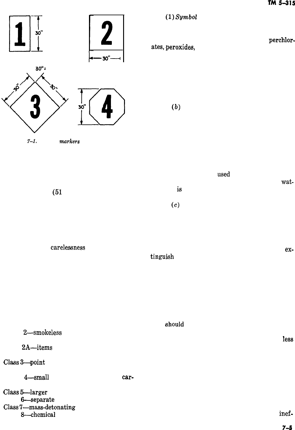
b
30”:
76.2 CENTIMETERS
AA
2
-
&‘--I
Figure
7-1.
Hazard
murkers
(fire symbols),
require that buildings containing hazardous or ex-
plosive materials, except igloo magazines, be
plainly marked with the symbol number of the
most hazardous material contained therein. These
numbers must be at least 24 inches (61 centime-
ters) high, 20 inches
(51
centimeters) wide, black
lettering on yellow background.
a. Ammunition Storage Chart. In the early days
of explosive manufacture, black powder was the
only explosive used. Later, more sensitive explo-
sives were manufactured. Still later, chemical am-
munition came into use, and serious explosions
occurred because of
careleseness
in handling. The
ammunition storage chart was devised to stand-
ardize the handling of ammunition and to prevent
accidents. This chart separates ammunition into
the ammunition hazard classes shown below.
These explosives and ammunitions must not be
stored together in any random combination. They
are mixed only under certain specific conditions
which permit a maximum degree of safety.
Class l-small-arms ammunition and similar
items
Class
2-smokeless
powder and other fire
hazard items
Class
2A-items
similar to Class 2, but pre-
senting a detonation hazard
‘Class
3-+point
detonating fuzes and similar
items
Class
4-small
high-explosive (HE)
car-
tirdges and mines
~Class
5-larger
caliber HE cartridges
Class
6-separate
loading HE projectiles
,Class
7-mass-detonating
high explosives
Class
3-chemical
hazard without explosives
TM
5-315
(1)
SumboZ
1. The symbol 1 group of explo-
sives consists of class 1 ammunition.
(a) These are metallic powders in ap-
proved shipping containers-chlorates,
perchlor-
ates,
,peroxides,
nitrates, and other inorganic oxi-
dizing agents in sealed containers. While these
materials are principally fire hazards, and fires in
which they are involved may be combated, minor
explosions may also be expected. Described below
are some of the characteristics of fires in this
group and the safety measures prescribed for
them,
(b)
Shipping containers of small-arms am-
munition, especially when incendiary and tracer
rounds are included, will continue to burn in-
tensely even after the magazine has been con-
sumed. Personnel attempting to fight the fire after
it has reached the ammunition must be shielded
from missiles, which may be expected to travel up
to ZOO yards (183 meters) at a velocity of 200 feet
(61 meters) per second. Sheet-metal-covered
wooden shields can be
u,sed
and moved to various
vantage points. When it is practicable to use
wat-
erfog, it
ifs
found to be very effective for extin-
guishing such fires.
(c)
Oxidizing agents are not flammable in
themselves, but when heated in a fire involving
combustibles they liberate oxygen, which greatly
facilitates the burning. Suitable masks should be
provided to guard against the poisonous fumes
resulting from such fires. Cooling or “drowning”
with large quantities of water may control or
ex-
tinguieh
these fires. After the fire has gained con-
siderable headway, firefighters must direct their
efforts to protecting adjacent property.
(d) For fires involving chemical ammuni-
tion containing blister agents, firefighters must be
protected by masks and complete protective cloth-
ing. If possible, such fires should be fought from
the windward side. All unprotected personnel
downwind must be evacuated and civilian inhabit-
ants
ehoul,d
be warned. Fires involving toxic
chemicals should be fought with similar precau-
tions except that the downwind area will be
Iess
hazardous. In fires involving hazardous chemical
(H) smoke mixture, attempts should be made to
remove and segregate the burning containers.
When a relatively small amount of HC smoke
mixture is involved in a fire, it may be saturated
with water. Water will also serve to cool adjacent
containers to prevent further propagation. Unless
water can be applied in large amounts in relation
to the actual HC smoke mixture exposed and
burning, the efforts to light the fire will be
inef-
7-5

fective,
and the material may explode. Firefight-
ers should not enter magazines containing a high
concentration of HC smoke unless adequately pro-
tected by oxygen masks and supplied with life-
lines.
(2) Symbol 2. The symbol 2 group consists of
Class 3 ammunition and explosives. Personnel dis-
covering such a fire
shauld
first give the alarm
and then attempt to put the fire out with the
equipment on hand, provided the fire is in the
beginning stage. The firefighting organization
should fight the fire if there is a possibility of
extingui,shing
it. If extinguishment does not ap-
pear possible, the building should be abandoned
and the firefighting efforts concentrated on pre-
venting spreading. Limited explosions may be ex-
pected from fire in these materials. Personnel
should be careful to prevent
inj,ury
to themselves
and damage to their equipment.
(3) Symbol
3.
The symbol
B
group consists of
Class 2 and
Clas’s
2A material.
(u)
Unless the fire is minor and does not
involve the explosive itself, and there is a chance
of controlling it, firefighting should be confined to
preventing the spread of the fire to other build-
ings. These materials burn with intense heat, and
personnel and firefighting equipment should be ad-
equately protected.
(b) When fires involve
phosphoru@,
person-
nel entering magazines with portable extinguish-
ers must have lifelines attached to themselves to
enable them to find their way out through the
heavy smoke. It should be remembered
t,hat
phos-
phorus will stop burning only so long as it is
under water; when exposed again to the air, it
ignites
spontaneously.
(c) Fires involving pyrotechnics and large
quantities of magnesium type incendiaries make it
necessary for firefighters to confine their efforts to
protecting adjacent buildings and magazines.
Water may accelerate burning and cause
expl,o-
sions which will scatter burning material. The use
of carbon dioxide may cause a suffocating atmos-
phere. Small fires involving 50 pounds (22.7 kilo-
grams) or less of magnesium can be smothered
with dry inert material, powdered or granular,
such as hard coal, tar, pitch, graphite (preferably
coated to eliminate dust),
rustfree
cast-iron bor-
ings, soft coal, talc, salt, or sand.
Asbestw,
sand,
salt, and talc are not inert in magnesium fires, but
may be used dry if the fire is small. The powder
from these
age&s
should be placed over the burn-
ing material to cover it at least
1
inch (2.54
centi-
meters) deep. It should not be disturbed until the
magnesium has cooled, excpet when the fire is on
a floor of flammable material. In this case, after
the fire is covered, a
2-inch
(5-centimeter)
layer
of extinguishing powder should be placed on the
floor beside the fire and the burning material
raked onto the insulating layer and resmothered.
(4)
SymboZ
4. The symbol 4 group includes
Classes 4, 5, 6, and 7 ammunition and explosives.
(u)
Every effort should be made to prevent
fire from reaching these classes of material, which
are especially hazardous. If a fire occurs in a mag-
azine containing these materials, personnel pres-
ent should attempt to extinguish the fire with the
equipment at hand, providing the fire has not
actually reached the material and there is a favor-
able chance of extinguishment. If the fire appears
,beyond
control, personnel must evacuate the mag-
azine and take cover. If fire breaks out in a maga-
zine containing high explosives, firefighting forces
will not immediately approach the fire.
(b) Unless specific information is av,ailable
(either from one who was present when the fire
was discovered or from intimate knowledge of the
construction of the building and location of the
explosives) indicating that it is safe to approach
the fire, firefighting forces will remain in a posi-
tion 1,000 feet (305 meters) away from a fire
involving up to 50,000 pounds
@2,680
kilograms)
of high explosives until the explosions have
occurred. A proportionally greater distance is re-
quired for larger amounts of high explosives (up
to 2,000 feet (‘710 meters) for 100,000 pounds
(45,360 kilograms) of high explosives).
Fire-
fighting forces and their equipment must not be
exposed to unnecessary risk when these materials
are involved. Demolition or general-purpose
‘bombs and antitank mines can detonate en masse,
and propelling charges may explode, producing
heat capable of blistering the paint on buildings
500 feet (152.5 meters) away. Bulk high explo-
sives packed in boxes will usually burn quietly but
may also detonate. Black powder, photoflash
bombs, smokeless powder in bulk, and unpacked
propelling charges explode or flash so quickly that
little time is left to do anything to save the maga-
zine involved. In almost every instance, the efforts
of firefighters will be confined to preventing fire
from spreading to adjacent buildings or maga-
zines.
b. Summary of Explosive Fires. Fire is, without
question, the principal hazard in the storage of
ammunition in the field.
7-6
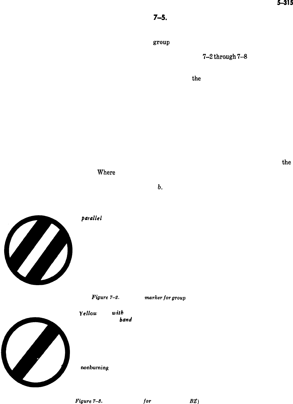
(1) The fact that ammunition and explosives
are capable of such violent destructive force when
exposed to heat makes it extremely important for
fire-protection personnel to become as completely
familiar as possible with the characteristics of
various explosives and ammunition when they are
exposed to heat. The men in charge of firefighting
crews should be well aware of the importance of
the counsel of ordnance specialists before and
during an emergency.
(2) The ammunition officer must be com-
pletely familiar with the local environment of the
areas in which ammunition and explosives are
stored. He should also know the characteristic re-
actions of materiel to fire. The opinion of the am-
munition officer, therefore, before and during the
combating of the fire, should be respected. If the
order is given to remain at a safe distance in
readiness to prevent further fire spread after det-
onations or to withdraw men during the combat-
ing of a fire in expectation of an explosion, the
action should be taken immediately.
W,here
ammu-
nition and explosives are present and where these’
conditions exist, an ounce of prevention is worth a
ton of extinguishment.
Yellow disk witb 2
paralIe1
black bands
INDICATES
TM
5-315
7-5.
Chemical Munitions Markers
Hazard markers provide a guide for firefighters
and other personnel by indicating the chemical
grou.p
of stored chemicals. The markers are yel-
low disks with a diameter of 24 inches (61 centi-
meters). Figures
‘7-2
through
‘7-8
show the sym-
bol for each of group A, B, C, D, and nerve
agents. Each figure also states what the symbol
indicates and
t,he
hazard of the chemical agent or
the precaution to be taken.
7-6. Motor Vehicle Fires
Another type of firefighting is fire resulting from
motor-vehicle accidents.
a. These accidents are responsible for many
thousands of deaths annually. Many of these
deaths and many serious injuries are caused by
victims being trapped in wreckage that has
caught fire. This danger is always present in
t,he
Army because of the large volume of motor-vehi-
cle transportation required.
b.
Of course, motor-vehicle accidents are often
attributable only to negligence or recklessness,
PRECAUTION
Group A (except nerve agents).
Wear complete protective clothing
and protective mask, Work upwind.
Fhre
7-2.
Hazard
murker
jar
group A.
yellow
disk
with
diagonal black
band
INDICATES
PRECAUTION
Group B toxic chemical agents,
nonburning
screening smokes,
and nonburning mixtures of riot
control agents.
Use protective mask. Wak upwind.
Enter with care.
F’igure
74.
Hazard marker
jar
group B (except
BL?)
.
7-7
TM
5-315
Yellow disk witb
Q
black letter Z
INDICATES
Special chemical hazard.
Incapacitating agent
BZ.
PRECAUTION
Use protective mask.
Work upwind. Enter
with care.
Figure 7-4. Hazard
murker
for agent
B.Z.
yellow
disk witb
black letter
C
INDICATES
HAZARD
Group C spontaneously flammable
chemical agents. Dangerous to enter
line and protective mask.
Figure 7-5. Hazard marked for group C.
without
life-
Yellow disk witb
black letter D
INDICATES
Group D incendiary and readily
flammable chemical agents.
HAZARD
Intense radiarx
,heat.
Danger of
explosion if water is used to
attempt to extinguish fire.
PRECAUTION
Wear
compIete
protective clothing
and protective mask. Do not enter
unti1
clearance is granted.
Figure 7-6. Hazard marker for group D.
yellow
disk witb
black letter G
INDICATES
Special
chemicaI
hazard.
G-type nerve agents.
-
-
Figure 7-7. Hazard
murker
for G-type nerve agents.
7-8
TM
5-315
0Yellow dish witb
black letter V
V
INDICATES PRECAUTION
SPecial
chemical
hazard.
Wear
complete
praective
V-type
acme
l @OtS.
--
clothing and protective
nmsk
Do
not
enter until
clearance is
granted
Figure 7-8. Hazard
murker
for
V-type
nerve agents.
but when large numbers of personnel and quanti-
ties of materiel are transported under even the
most favorable conditions, some mishaps are una-
voidable. It is the duty and responsibility of fire-
protection personnel to prevent loss of lives and
property as a result of motor-vehicle accidents
and, resulting fires.
c,
When a motor vehicle overturns, or when it
crashes into another vehicle or object,
tra,pping
the occupants inside it, assistance by experienced
rescue personnel becomes an immediate necessity
to prevent death by injury or fire.
d.
Basically, motor-vehicle fire safety depends
on
.four
conditions: design and construction fea-
tures
;
use of the vehicle, including its garaging
;
.proper repair and maintenance
;
and operational
safety procedures.
e,,
‘The use of all-steel bodies has resulted in
increased safety, both from the accident and the
fire-hazard standpoint. Interior finishes, however,
particularly upholstery and linings, still remain a
definite fire hazard unless these
‘fabrics
are
treated with a fire retardant.
f.
The fuel-tank’s construction, location, and se-
curity, and its vulnerability to damage in a colli-
sion or upset, are the most important
featu.res
of
design for fire safety. The use of seat tanks and
cowl tanks has largely disappeared. Fuel tanks
are safely located at the rear of, or beneath, the
vehicle, in a position where they are not
inclosed
in the body. This positioning of the tanks gives
passengers a better chance to escape if the
auto catches fire. Trucks normally have tanks of
12-gage
steel, having high resistance to rupture.
These tanks are of double thickness at the edges,
will not spill fuel in an upset, contain an auto-
matic pressure relief in the event of exposure to
fire, will not seep gasoline, and cannot be over-
filled. Vibration, corrosion, and improper mainte-
nance are some of the chief factors responsible for
fuel-system failures, particularly at fuel-pump
fittings, tubing, filters, and carburetors.
g. The fire safety factor in the electrical system
of automobiles lies primarily in proper installa-
tion, fusing, and maintenance. Fires of an electri-
cal origin are normally propagated by petroleum
deposits in the engine area or by combustible ma-
terials, such as fabric lining. In a collision or
upset, electrical short circuits are likely to occur
unless an automatic overturn switch cuts the elec-
trical power at the battery. Proper installation of
exhaust systems is important, as incandescent
carbon particles and hot exhaust gases may ignite
flammable liquids, grease, and other combustible
materials. Brakes are a possible fire hazard be-
cause their overheating may cause the ignition of
oil, grease, or brake fluid. Friction heat frequently
may
ca,use
underinflated tires to ignite. Anti-
freeze-alcohol vapors are an added fire hazard, as
are certain types of heaters.
h.
In motor-vehicle fires, the first task is to
evacuate all persons from the vehicle. If the fire is
well advanced, fire-control operations may be nec-
essary before they can be rescued. As soon as entry
is made and personnel are removed from the vehi-
cle, the ignition switch should be turned off, if
this has not already been done. The battery should
be disconnected (remove ground cable first) as
soon as possible to prevent reignition of the al-
ready heated fuel vapors.
i.
The average motor-vehicle fire can be quickly
extinguished with portable
COZ,
CF3Br,
or dry
chemical extinguishers. When the engine area is
involved in fire, the extinguishing agent can be
applied through the louvers on grill. This permits
extinguishing the fire without opening the hood.
7-9

TM 5-315
Leaving the hood closed
lim_its
the oxygen and
allows the extinguishing agent to
w,ork
in a more
confined area.
j. When the fire originates from a fuel tank
leak, the fire closest to the tank should be extin-
guished first. The outlet in the tank then should be
plugged to stop the flow of fuel. If the fire is in
the upholstery, the area should be saturated thor-
oughly with water until every spark is eliminated.
When a tire catches fire because of underinflation,
large quantities of water are needed to extinguish
the fire and prevent it from spreading.
k.
The procedures in attacking a motor-vehicle
fire will be described in proper sequence and de-
tail in this and the following subparagraphs. The
approach and general estimate of the fire must be
considered first. Even as they approach the
ve&
cle, the firefighters must be alert to protect or
rescue personnel in or near the accident. Firefight-
ers must be aware of the fact that victims with
clothing on fire may
r,un
some distance from the
scene of the fire. It is also possible that persons
may be thrown from the wreckage and left uncon-
scious near the scene where they are in danger of
being run over by fire-department vehicles.
1.
The primary consideration of the fire crew is
to place the fire apparatus in a location which will
enable the crew to give oclcupants the most com-
plete protection and to control the fire so that
personnel may be rescued with a minimum of
delay.
m.
The fire should be controlled first in the im-
mediate area of the
v’ehicle
to relieve the occu-
pants of excessive heat. No attempt should be
made to extinguish the fire completely at the onset
unless it is certain that no persons are still within
the burning wreckage. Personnel rescue should
be given priority because a
dizerence
of
se’eonds
may determine the life or death of a victim. Also,
the extent of the fire may be too great for the
quantity of extinguishing agents available in the
firefighting apparatus to extinguish the fire com-
pletely.
n. When necessary,
for,cible
entry must be made
where it offers the most expedient access to the
interior and is at the same time consistent with
the location of trapped personnel within the vehi-
cle. The person or persons closest to the point of
entry should be rescued first. During rescue, the
victims must be
exa,mined
as thoroughly as time
permits; the extent of injuries will be considered,
and first aid will be administered at once. A visual
check of the
vict,im
should be made before or
d,ur-
ing rescue. If bleeding is profuse, direct pressure
should be applied to the wound even before the
res.cue
is completed. Rescued personnel should be
moved to a safe spot quickly and carefully.
-
o.
Firefighters must extinguish the flames in
the area where the source of gasoline flow can be
stopped. While cutting off the flow of gasoline, or
while in the presence of gasoline vapors, the crew-
men must always be alert for the signal which
warns of the near depletion of extinguishing
agents. This is a signal given by the pump opera-
tor for withdrawal of personnel. It consists of
intermittent blasts from the fire vehicle. The
pump operator is responsible for observing the
consumpticn
of the extinguishing agent.
q. During overhaul, each crewman should be
alert for any evidence which will aid in the
inves-
tigation
to determine the cause of the fire. These
“after-extinguishment” procedures require that a
charged hose line be immediately available in the
event of a sudden reflash.
p.
After the gasoline supply has been shut off,
the fire is immediately extinguished and the entire
area is cooled
to
prevent
reignition.
The overhaul
operation consists of entering the vehicle and
thoroughly extinguishing every existent spark. If
the fire was extinguished with
C?FSBr,
the motor
vehicle should be thoroughly ventilated before
anybody enters it. The immediate area in which
fire occurred also requires close observation, com-
plete extinguishment, and reinspection.
-
7-7. Special Nozzles and Equipment
The majority of emergencies that the structural
firefighter will have to face can be dealt
wtih
suc-
cessfully by using the tools and
equi,pment
that
have been explained in
previ,ous
chapters of this
manual. ‘The fighting of special types of fires, such
as those covered in this chapter, requires the use
of specialized equipment, particularly nozzles.
a. Fog
Nozzle.
The ideal fog nozzle
(para
2-9u)
can discharge either fog or a straight blasting
stream. After the high-velocity fog tip has been
removed, it is possible to insert any one of several
variable-length applicators containing a nozzle
which discharges a low-velocity fog. This nozzle
change will not require a change in nozzle pres-
sure. Either the
high-
or low-velocity fog may be
used for personnel protection or for extinguishing
the fire, depending upon wind conditions and
accessibility. Generally, the low-velocity fog is
preferable when extinguishing a fire from the
windward side and where large open surface
_
7-10

TM
5-315
areas are involved. A leeward-side fire requires
the use of high-velocity fog for personnel protec-
tion and penetration. Fog nozzles are made for
use with both the
ll/z-inch
(3%centimeter)
and
2r&inch
(6.35centimeter) hose. The high-velocity
fog tip and the low-velocity applicator may be
inserted or detached in seconds.
b.
Foum
Nozzle. The mechanical foam nozzle
tor consists of a metal base through which the
consists of a venturi (cap v) system installed in
an aspirator cage near the rear of the nozzle. A
pickup tube is installed near the aspirator cage.
The venturi system creates a partial vacuum,
which enables the foam to pass through the tube
from a foam can. The aspirator cage is responsi-
ble for injecting the proper amount of air into the
proportionately mixed foam solution.
c.
Foum
Generutor.
The chemical foam genera-
tor consists of a metal base through which the
water passes. The base includes a male and female
coupling, normally
S,,s-inch
(6.35centimeter)
size
;
a venturi
;
a gage
;
and a valve. Mounted on
top of the base center is the tapered metal hopper
into which the powder is poured. The water pass-
ing
.through
the venturi system “pulls” the pow-
der into the water stream in the proper propor-
tions, after which the powder and water are
tur-
bulated through 50 to 150 feet
(PIE
to 46 meters)
of Y&inch
(6.35-centimeter)
hose to the nozzle.
When the water makes contact with the powder, a
chemical reaction takes place which results in
ex-
pansiun,
causing additional pressure and afford-
ing considerable range from the nozzle.
7-8.
Natural Cover Fires
Natural-cover fires involve grass, weeds, grain,
brush, forest, or any other plant life.
a. Forest fires are no doubt the most serious of
all natural-cover fires from the standpoint of a
national fire problem. Forest fires involve more
than the immediate monetary loss. The cost is in-
significant compared with the
effect
on the future
water supply and timber supply, and with the loss
of hunting, fishing, and recreational
facilit,ies,
to
say nothing of the loss of life which may occur.
(A single forest fire in Minnesota is known to
have taken 559 lives, a fact which emphasizes the
importance of organized fire safety before such
catastrophes occur.)
t!~
1Forest
fires frequently involve farms, vil-
lages, and towns. For this reason, fire-protection
organizations are called upon to handle both
structural and natural-cover fires. During recent
years, the nation has become increasingly con-
scious of the importance of the prevention and
control of fires in camps and buildings, for these
may expand to become forest fires.
c. The majority of natural-cover
fires
are
caused by man and are the result of carelessness,
The natural elements, such as lightning, the sun,
and the wind, are responsible for the remainder.
Careless hunter, campers, and fishermen, and fre-
quently local residents, account for more fires
than any other causes. Other causes of forest fires
include locomotives, burning of rubbish, lumber
operations, and arson. The most
eflective
means
of combating these fires should be started before
the fire actually occurs-through the medium of
law enforcement, restrictions, education, and the
complete elimination of hazards in critical areas.
d. Prompt discovery of forest fires is essential
in achieving quick control and limiting damage.
In areas where efficient detection, control, and
fire-extinguishing organizations are present, fires
rarely get out of control and damage is kept to a
minimum.
The methods of detection include
ground and air patrols and forest observation
towers.
e.
An adequate system of trails and roads,
properly distributed, built, and maintained
throughout the area, is of utmost importance in
making the fire area reasonably accessible to
fire-
fighting forces and their equipment. Roads of
proper width are also invaluable as firebreaks,
which prevent the spread of fire beyond a limited
area. In many instances, it is necessary to
clear-
strips for permanent firebreaks,
f. Aircraft of various types are now being suc-
cessfully used to transport men and supplies to
the scene of forest fires, especially such areas as
may lack trails and roads. Parachute-jumping fire-
fighters started extensive training before World
War II, and have expanded and improved their
effectiveness consistently during each succeeding
year. In the years following the war, considerable
ex.perimentation
and test flying was performed by
the Air Force. The use of helicopters has been
very effective. For forest-fire
extinguishin,g
by
aircraft, the “water bomb” and other airborne de-
vices are now being tested for effectiveness.
g.
Training and organization are essential to
suppress forest fires successfully. Under extensive
emergency conditions, it is frequently necessary
to use all able-bodied personnel within an area. At
7-11

TM
5-315
such times, it is highly important to have
well-
trained men available to organize and supervise
the untrained force. The complete and extensive
training of fireguards and lookout men is of ut-
most
imlportance.
h.
‘The equipment used must be adequate and
suited to the immediate environment. This im-
plies, for example, that large vehicles will not be
employed where roads are narrow and where
there are small bridges with limited capacity.
Areas where the water supply from ponds, lakes,
and small streams is plentiful might advanta-
geously
emplo,y
several portable pumping units,
but these units would be almost useless where
water is scarce. In some areas, water cans
equipped with a hand pump are carried on the
backs of personnel. For fires in logging woods,
water tanks mounted on pump-equipped trucks
are commonly used, as are railroad tank cars.
7-9. Tools
a. The common portable pump weights about 75
pounds (35 kilograms). It is gasoline driven and
can deliver 60 gallons of water per minute
through a
lQ$-inch
(3%centimeter)
hose at 100
pounds of pressure per square inch (7 kilograms
per
squ,are
centilmeter).
To attain this output, a
s/s-inch
(1.6~centimeter)
nozzle tip should be used.
The hose may be rubber lined, canvas
cbvered,
or
it may be linen for lightness. Frequently, these
portable pumps are hooked up in series to enable
propul.sion
of .water over great distances or up
mountainsides.
b. Power-driven tools and equipment are availa-
ble for natural-cover firefighting in a wide vari-
ety of designs and sizes. Power-driven equipment
is used primarily for constructing barriers or
fire-
breaks. Such equipment varies from
loo-pound
(45-kilogram)
trenchers to
lo-ton
(g-metric ton)
tractors with front-mounted, power-controlled
angle blades.
Tlhese
large tractors are better than
all other equipment for
fireline
construction
through heavy forests but costly equipment
i,s
re-
quired to move them to the desired location.
Lightweight tractors are now being developed for
fast initial attack.
7-10. The Nature of Natural-Cover Fires
Natural-cover fires can move very rapidly, espe-
cially when the wind velocity is high. The perime-
ter, or fireline, is the hottest part of the fire. The
interior of the fire is a
smolldering
mass with com-
paratively fewer flames and with many glowing
embers or sparks. Natural-cover fires are best con-
trolled along the fireline.
I
ct. Parts of the Fire.
(11)
The point where the
fireline
is .progress-
ing fastest is called the head. A natural-cover fire
may have any number of heads, depending on the
type, abundance, and location of the fuel. Fire
heads generally travel with the wind; the
stronger the wind, the greater the speed of the
fire.
B,ecause
of frequent directional changes of
the wind, varying types and
quanti,ties
of fuel,
and topographic
condsitions,
natural-cover fires
have irregular perimeters, making control difficult
and often dangerous. The upwind or windward
,portion
of the fire is called the
&&!.
Usually the
tail is in or near the general vicinity of the origin
of the fire.
(:2)
All portions of the
fireline
between the
tail and the various heads and those slower burn-
ing areas between the heads are called
flunks.
(3) The rate of burning of natural-cover fires
depends primarily on the velocity of the wind,
type and abundance of fuel, and general topo-
graphic conditions. The head of the fire travels at
a rate proportional to the wind velocity. Wind
carries additional oxygen to the fire and increases
the rate of burning. The hot air rising from the
fire causes a partial vacuum. Cold air with a fresh
supply of oxygen rushes in at the base. The larger
and hotter the fire, the stronger is this draft cre-
ated by the fire.
(4) Fire heads move faster uphill and
through
dr’aws
or canyons than on level ground or
downhill, other condition,s remaining equal. Heads
burning uphill dry out and
varporize
fuel faster
than those burning on level ground or downhill.
The upward rush of cold air acts like the draft in
a chimney and speeds burning accordingly. Heads
running up draws, valleys, or canyons cause the
inrush of cold air with a new oxygen supply to be
concentrated in a small area and, as a result, the
fire propagation rate is greatly increased. This
condition is similar to a forced draft in a black-
smith% forge, fanning the fire to a greater speed
and intensity. Men or equipment should never ap-
proach the head of a fire from upwind when the
approach necessitates travel in a draw,
v$ley,
or
canyon.
‘.
(5) A running fire
shou’ld
never be
co@,rolled
from the uphill direction. This entails a high risk
to men and equipment. The correct point to begin
control is at the tail on the upwind side of the fire
line or at the head of the fire when it tops a crest
7-12

TM
!3-315
CHAPTER 8
FIRE
PRNENTION
8-1,.
Introduction
The purpose of fire prevention is to eliminate fire
hazards, or elements which cause fire to occur, or
conditions which will contribute to the spread of
fire. The firefighter’s utmost concern is the pre-
vention of destructive fires. Prevention saves the
effont
and expense of extinguishing them. It is DA
policy that arrangements be made to have fire-
fighters perform fire prevention duties away from
the fire station and at the same time be available
for
Gre
call.
a. To prevent a situation from being hazardous,
one of the three elements of the fire triangle must
be removed. Of the three, heat is the undeter-
mined condition, the one which is most generally
considered from the standpoint of fire prevention.
b. Effective fire prevention requires the estab-
lishment of a well-planned program and the or-
ganization, publicity, support, cooperation, inspec-
tion, and supervision to implement and maintain
it. It also requires the instilling of personal re-
sponsibility and interest in individuals so that
they
,will
help
prevent the loss of property and life
by fire due to carelessness. The personal interest
and concentrated effort of all concerned, from
commanders to supervisors to individuals, is es-
sential if the fire prevention program is to be
successful.
8-2. Cigarettes and Matches
Smoking is the greatest single cause of fires. The
careless discarding of matches, the dropping of
hot ashes, and the careless leaving of lit cigarettes
are the principal infractions of smokers that
cause fires.
a. Smoking does not appear to be a serious
cause of fire to most individuals because the great
majority have never started a fire by smoking,
that they know of. Actually,
unyone
who has care-
lessly discarded a lighted cigarette may be guilty
of having started a fire, even though the cigarette
may have been originally dropped upon concrete,
metal, or barren earth. Paper, having a low flash
point, is very easy to burn by a lighted cigarette.
Thus, emptying of ashtrays into a wastepaper
container is foolish even though the cigarette
butts apparently are not smoldering.
b. Any type of match may start a fire, but the
possibility of its doing so varies greatly according
.to
the type of match. The proper safety match has
a head that will not fly off when struck and a stick
that is treated to eliminate afterglow. The use of
good safety matches should be required, especially
in areas near flammable gases, vapors, and mate-
rials.
8-3. Waste
Waste
materials and rubbish are great contribu-
tors to the start and spread of fire independent of
flammable liquids.
a. Waste materials containing oil have sponta-
neous ignition characteristics and are very likely
to cause fires. A high standard of cleanliness and
the complete elimination of loose rubbish from
building interiors are unquestionably among the
greatest factors in fire prevention. It is the duty
not only of fire-inspection personnel but also of all
personnel occupying the building to see that poor
housekeeping habits are eliminated. When it is
impossible or very inconvenient to remove flamma-
ble rubbish from the
.building
immediately, such
material should be kept in fireproof or fire-resis-
tant containers or inclosures.
b.
Clean waste, although not as hazardous as
used or reclaimed waste, has occasionally been re-
ported as a source of spontaneous ignition.
Conse:
quently all waste, excelsior, straw, sawdust, and
burlap should be kept in metal tins with self-clos-
ing covers to prevent the admission of oxygen and
thus the ignition of the heated combustible sub-
stance.
c. Spontaneous ignition occurs under extremely
variable conditions. It is difficult to state that a
8-1
TM
5-315
specific quantity of flammable materials will or
will not ignite independent of external heat, since
the naked eye cannot see all of the contents of the
material
;
furthermore, the time factor required
for ignition rnay range from minutes to months.
frequent cleaning
which will isolate
prevention fails.
and compartment dampers
the fire to a single section if
8-6. Effect of the Sun
8-4. Sparks
Live sparks from chimneys and stacks, refuse
burners, and other similar sources must be given
priority consideration. Spark-arresting screens
can be
insta,lled
over the openings, but their
efficiency is limited. A large mesh screen will let
many sparks escape. A small mesh screen will
soon become carbon congested and impede the
passage of smoke. The best procedure is to use
medium mesh screens of heat-resisting alloy
metal. These screens will require periodic clean-
ing. Medium mesh will allow only those sparks
having a limited “glow life” to escape, retaining
those large and more dangerous embers in the
stack. During periods of low humidity and high
wind velocity, special precautions must be taken
depending upon the fire risk in the immediate
area.
The sun frequently is responsible for fires, though
it is usually assisted by some manmade imple-
ment.
8-5.
Mechanical Devices
Engines of any type, or other machines in which
friction is created, are possible sources of fire.
a. A common example of this is a fire caused by
overheated bearings. Wherever there are engines,
there should be frequent elimination of lint and
dust from the immediate surroundings of the
moving mechanical device. Also all excessive
flammable
lublricants
should be removed promptly.
a. A fire inspector must be
especiahy
observant
of these implements, because under most condi-
tions they are
extremly
difhcult
to detect as fire
hazards. For example, forest fires have been
known to start from discarded bottles or other
fragments of glass left by careless campers. The
sun’s rays, shining through a piece of glass which
may be so ideally curved and placed as to act as a
magnifying glass, are concentrated so as to ignite
a piece of paper. Similarly, curtains can be ig-
nited by a window pane containing a bubble or
some other irregularity. Fire may also occur from
such
sour,ces
as laboratory flasks, fish bowls,
water bottles, concave mirrors (which reflect
heat), and other common sources. The sun also
contributes to spontaneous heating, thus aiding
ignition.
D,uring
warm seasons when buildings
are closed for the weekend, sprinkler heads lo-
cated beneath skylights and in attic spaces may be
discharged, often resulting in considerable water
damage.
b.
Grinding wheels
and
other spark-producing
equipment are a
frequenk
cause of fires and should
not be permitted
i,n
areas which might contain
highly flammable gas or vapors. Neither should
flammable
ma,terials
of any type be left in an area
where sparks may fall upon them.
b.
The possibility of fire being started by the
sun is somewhat remote. However, since numer-
ous conditions may create these
soxalled
freak
fires and any one fire may completely destroy a
building or many buildings, these possibilities de-
serve careful consideration.
8-7.
6uildings
Under Construction
Buildings in their various stages of construction
usually have more fire hazards than they do after
they are completed.
c. Blower systems including all duct installa- a. Probably the primary reason for this is the
tions, whether used for ventilation, air condition- fact that
m’ost
people cannot visualize a building
ing, or dust and vapor elimination, are fire haz- burning down completely before it is put up com-
ards. Most dust, including that of some metals, is pletely. Therefore, there is usually no fire-extin-
an explosion hazard where a spark is possible. guishing equipment immediately available. On an
These sparks may be struck by fan motors, over- Army base, construction operations are common.
heated fan bearings, or the movement of the fan The loss of any of these projects by fire, regard-
against surrounding metal. Blower fans or their less of their stage of completion, may
ca’use
severe
metal
housmgs
should consist of nonferrous hardships and serious delays. For this reason, it is
metal. The
du,cts
must be of metal and free from recommended that fire extinguishers be made
contact with wood and other flammable material. available in proper quantity and be adequately
They must also contain parts
whi~ch
will permit distributed throughout the
,project.
All excess
8-2
.-
-
TM
5-315
wood and other combustible materials should be
removed promptly. Heaters and heating equip-
ment should be strong and safe. They should be
located where they will not ignite other material,
and must be constantly attended.
IL
Combustible materials should not be stored in
or near buildings under construction. Gasoline
and other volatile liquids should be segregated
and stored in standard safety containers, prefera-
bly underground if the liquid is kept in any large
quantity. Windbreakers and tarpaulins should be
properly secured, and their location should be
checked for possible fire sources. Welding should
be supervised and all adjacent combustible mate-
rial either removed or adquately protected from
the flame and flying embers. Stairways and exits
must be clear and properly maintained in order to
enable quick evacuation of the structure and for
extinguishing the fire in any location.
8-8. Heating Systems
Heating systems are a common source of fire dur-
ing winter seasons in most latitudes. Heating
units and their conditions of installation are so
variant that it is impossible to deal with each
specific hazard in detail here. ‘The best procedure
is to inspect each heating system while it is out of
operation and also while it is in various phases of
operation, and then take the necessary action to
eliminate hazards. Any source of heat is a poten-
tial fire hazard unless it is so constructed and
installed that it will not heat nearby combustible
materials to a point where they may ignite. Heat-
ing devices, for a
$roper
margin of safety, should
be so installed that exposed
woodw,ork
will not be
heated in excess of
160’
F. (71” C.). Normally,
building codes require that heating units and
their conveying ducts be installed a given mini-
mum distance from combustible materials. This
condition seems somewhat unimportant if we do
n’ot
take the ventilation and circulation aspects
into consideration.
a.
In.sulatim.
Insulation alone is not a solution
to safe heating. Heat from a stove base, for exam-
ple, has been known to penetrate metal, brick, and
asbestos and to char the wood beneath when these
materials had no air space below them. Long peri-
ods of high temperatures have been known to
cause fires under apparently safe conditions. In
large rooms, a reasonable clearance between the
heating device and the combustible material is the
primary requisite. In small rooms the lack of
space may restrict the proper clearance and some-
times even adequate insulation to supply the
proper safeguard against the ignition of combus-
tibles. This requires a closer watch on the quan-
tity and consistency of heat and more careful
inspections.
b.
Fuses.
Stationary heating devices are
rated in three grades: low, medium and high.
Low-grade furnaces develop temperatures up to
6OO’F.
(316’C.).
Medium-grade
f,urnaces
develop
temperatures from
600’
F.
(316’
C.) to 1,500’ F.
(815’C.).
High-grade furnaces create tempera-
tures in excess of 1,500’ F.
(315’
C.) and require
30 feet (9.15 meters) of frontal clearance, 10 feet
(3 meters) on the rear and sides, and 15 feet (4.6
meters) of overhead clearance.
c.
Steampipes.
Steampipes of any type may, in
the course of time, make charcoal out of wood
with which they are in contact. This charcoal is
subject to spontaneous ignition because it absorbs
great quantities of oxygen from the atmosphere.
Steampipes should be wrapped in asbestos or
magnesia insulation which has a minimum of 1
inch (2.54 centimeters) of clearance from all
woodwork.
d. Ranges and
VerMating
Systems. Massive
ranges and ventilating systems present great haz-
ards in dining halls and &her locations where
food is prepared for large groups. Hot grease boil-
ing over containers, the residue in the hoods, the
area over the range, and the space within the
ducts leading away from the hoods are the chief
sources of fire danger. Ducts should be made of
not less than No.
18
US.
gage steel,
tiglrtly
riv-
eted at the joints, so that if the grease residue
ignites and burns there will be a minimum of
damage to the building itself. Access ports should
be prwided in exhaust ducts to enable periodic
cleaning.
e.
Stows.
Coal and wood stoves should be
mounted on a fire-resistant floor and should follow
the clearance and ventilating requirements of a
low-grade furnace. ‘The stovepipes must be prop-
erly installed and must not pass through
comlned
spaces in which an ignition temperature could
build up. Stovepipes should be properly supported,
kept in good repair, and cleaned regularly.
8-9. Electricity
,Electricity,
if improperly used, may easily become
a major fire hazard and a serious source of danger
to personnel.
8-3

TM
5-315
a. When the simple and proper rules of installa-
tion and use are followed, electricity is a superior
source of power,
illumirmtion,
and heat. It may
become a fire hazard by overheating, arcing or
sparking.
Ove?,heating
is a condition where an ov-
erload of
elect,rical
current is
passe’d
through a
wire and the internal heat created by the overload
burns through to ignite the insulation covering
the wire. This insulation then ignites adjacent
combustibles. When an electric motor is over-
worked or defective, it overheats, and fire
res,ults.
A single electrical outlet or wire used as a power
supply for too many electrical implements will
cause
ovjerheating.
Awing
is a sustained luminous
glow which is formed under certain conditions
when a break is made in an electric circuit. An
arc light and the breaker points in an automotive
distributor system are
exampl,es
of arcing. Spark-
ing is an electrical condition in which light is
created, accom:panied by a sudden disruptive dis-
charge, between two conductors separated by air
or some similar medium. The
acti,on
of spark
plugs in an internal combustion engine is an ex-
ample of sparking.
b.
To minimize these hazards from electrical
sources, the equipment and installation should be
standar’dized
and properly maintained. It is the
job of tire-inspection personnel to see that these
hazards are
co:mpletely
eliminated. Being certain
that no fires will
&art
from an electrical source
today gives no assurance of fire safety next week.
Inspectors unable to visit each building daily must
help educate the occupants on what constitutes a
fire hazard.
c.
Electrical installations are made in accord-
ance with national electrical codes, state laws, and
municipal ordinances. If these provisions are fol-
lowed, fire hazards are decreased but certainly not
eliminated.
Deterioriation
by use, abuse, and age
often requires the replacement of electrical wires
and their associated implements. Frequently,
crude installations and use of electrical fixtures
make
f’or
flagrant violations of fire safety rules.
d.
Electrical circuits carry currents of varied
intensity. When current is suddenly cut off,
whether by accident-such as by a loosened
contact at a terminal-or by intention, an arc is
produced. The magnitude of this arc depends
upon the current and amount of voltage involved.
At all times the temperature of this arc is very
high, and it can ignite combustible materials. In
addition, the metal of the conductor usually fuses.
This hot, flying metal, along with the
flying
sparks,
amy
also ignite combustibles and fre-
quently causes ignition of the wire insulation.
e. ‘The electric wire, or conductor, as it is tech-
nically termed, is normally a negligible considera-
tion from the standpoint of ‘overheating tenden-
cies. However, there is a possibility of overload-
ing, for each conductor is rated with a certain
maximum capacity. Fire hazards occur in two
ways when this capacity limitation is exceeded:
through the deterioration of the insulation (which
exposes the wire) and through the creation of
excessive heat.
8-10. Fuses and Other Safety Devices
Many devices have been designed to give
overcur-
rent protection. These devices open the circuit and
cut off the current when the electrical flow
reaches a given maximum.
a. The most common of these devices is the
fuse, which contains a strip of metal that over-
heats and melts when the current exceeds the fuse
capacity, thus breaking the circuit. Fuses consist
normally of two common types, the plug type and
the cartridge type.
b. Another protection against overcurrent is
provided by the circuit breaker. This device auto-
matically cuts off the flow of electricity when the
currem
becomes excessive.
c. All overcurrent protective devices must be so
designed as to confine the arc harmlessly within
themselves when they go into operation. Clean
contacts at the fuse terminals or boxes are impor-
tant because dirt can cause overheating and the
blowing of fuses.
d.
The hazards most likely to be found in
over-
current protective devices are as follows
:
(1) Plug fuses which have blown out and
have had pennies inserted behind them or wires
inserted between the broken contacts.
(2) Fuses of a capacity higher than desira-
ble, or circuit breakers with too high a setting.
(3) Fuses or circuit breakers in poor me-
chanical condition.
(4) Unconfined fuses in an area containing
combustible material.
(5) Fuse cabinets with open or missing
doors.
(6) Corroded fuses, inclosures, or circuit
breakers.
(7) Refillable fuses containing additional
metal strips.
84

TM
s-al5
(8)
ICartridge
f,uses
which have been blown
and replaced with nails, wires, or other metal.
(9)
Cricuit
breakers made useless by the
tying or blocking of the tripping element.
8-11. Wiring and Switches
There are several recognized methods of installing
electrical wiring. Only rigid conduits should be
used where gasoline vapors may be
<present.
No
conductor should be installed, even temporarily,
that does not conform to all safety requirements.
a. The hazards most frequently found in electri-
cal wiring are as follows
:
(1) Overloaded conductors.
(2)
Corrosion of the conductor coverings.
(8)
Corrosion and loosening of supports.
(4)
*Covers
of outlet boxes or junction boxes
removed.
(5) Wiring installed for temporary use.
(6) joints not properly put together.
(7) Flexible conductors hung over nails or
other makeshift contrivances which may cause
wear and create arcing or sparking.
b.
In electrical switches the chief hazard is
caused by arcing when the switch is operated.
Switches should contain an inclosure that will
confine any arc that might occur. The most promi-
nent
hazard,s
in switches are corrosion, faulty me-
chanical condition resulting from use or abuse,
overheating due to poor contact or an overload of
current, inclosures absent or ineffective, and con-
tacts burned or pitted where the circuit is opened
or closed.
are fragile sockets, the use of defective or unap-
proved cord, the use of frail lamp guards or the
absence of any guard, and the failure to provide a
disconnection release in the event of strain on the
cord. Lamp sockets are not great fire hazards if
an approved type of socket containing the correct
load limit is used and if the component socket
parts are properly assembled.
c.
There are many lamps in use that are of
substandard construction. When making a fire
safety inspection, inspect these lamps carefully. A
substandard lamp is a definite fire
,hazard.
8-13. Flexible Cords
Flexible cords should be used only when abso-
lutely necessary, for their use constitutes a dis-
tinct fire hazard unless careful attention is given
to their treatment and condition. Flexible, porta-
ble cords are subject to much
abuse.
They contain
a conductor of fine strands of wire with an insu-
lating covering of small dimensions, which fre-
quently consists of combustible materials. In-
stances have occurred where metal-wheeled vehi-
cles have passed over portable, flexible cords and
caused critical losses by creating an arc in the
presence of gasoline vapors. A cord should be
lifted over any heavy moving object instead of the
object passing over the cord. The better portable
cords are covered with a heavy rubber outer
jacket. Constant observation and maintenance of
these cords is a paramount safety precaution.
Complete replacement of a cord is necessary when
appreciable wear becomes evident.
8-14. Motors and Generators
8-12.
lamps
The principal types of electric lamps are vapor,
incandescent, and arc.
Electric motors and generators present a definite
fire hazard, since they can produce arcs or sparks
and frequently overheat and burn out because of
overload.
u.
In locations where flammable gases, vapors,
or dust are present, the improperly equipped lamp
becomes an explosion and
{fire
hazard. Mercury
arc lamps are a spark hazard
i,fl
not confined. The
ga&illed
lamps now in common use generate
enough heat to ignite combustibles in contact
with, or close to, the globe. Neon
llamps
require a
high-voltage supply and offer a hazard from the
arcing which this high voltage may create. Porta-
ble lamps are frequently used in damp or wet
locations. This practice presents both a fire haz-
ard and a personal safety hazard.
b.
The hazards most common in portable lamps
u.
The motor frame should
,be
suitably inclosed.
Combustible material should be kept away from
the vicinity of motors and generators to prevent
hazardous conditions resulting from arcing and
sparking.
,Overcurrent
protection will safeguard
against overloading.
b.
The
,following
are the common precautions
required in the use of electric motors to safeguard
against fires. They must be kept away from com-
bustible material and out of damp places which
subject the motor to corrosive vapors. The
over-
current must not exceed
1:25
percent of its rated
capacity. Lint and dust must be kept off the top of
a-s

TM
5-315
the motor. Special precautions must be taken
when starting an electric motor near combustible
material because of the arcs and heat produced by
the motor. Low voltage at the terminal must be
corrected because it will cause the motor to burn
out and start a fire. Overloading also produces
heat and becomes a
fire
hazard.
8-15. Static Electricity
Static electricity is generated to an appreciable
extent in many industrial and
m’anufacturing
op-
erations. It is a factor which requires major con-
sideration where aircraft are used.
a. Previously it was believed that static electric-
ity was generated only by friction between two
unllike
substances. It is now known that static
electricity is created by contact between two un-
like substances even though no friction is present.
Static electricity is
*known
to be a serious fire and
explosion hazard in the presence of volatile flam-
mable liquid, flammable gases, highly ignitible
fibers, and combustible dusts.
b.
In areas where the hazard is great, it is ad-
visable to replace belts with chains and gear
drives to eliminate the generation of static elec-
tricity. When the construction features cannot be
changed to prevent the generation of static elec-
tricity, it is also advisable to ground all metal
parts which may
accumul,ate
an
electri,cal
charge.
The atmosphere normally is a nonconductor of
electricity, but ionized air will normally draw
static electricity from charged metal implements.
Static neutralizers may be installed to do this.
c.
Humidity is an important factor in the abil-
ity of static electricity to drain from highly
charged metal objects. Where high humidity is
present, surface resistance is reduced, and electri-
cal charges are drained off almost as they form. A
humidity of 40 to 50 percent generally prevents
any quantitative buildup of static electricity.
d. Static electricity is created when gasoline or
similar flammable liquids are passed through a
hose, poured from one container to another, fil-
tered, or subjected to velocity in almost any man-
ner, These dangerous static charges
frequentIy
cause serious fires and explosions unless preven-
tive measures are taken.
e. When gasoline is
d&charged
through a hose,
a copper wire should be installed from the pump
through the hose to the nozzle, and the nozzle
should be kept in contact with the metal recepta-
cle at
al’1
times. In many cases, such as in aircraft
tanks, a separate wire with a male connection is
plugged into a static electricity drain installed
near the tank opening. This device should be
plugged in before the gasoline is allowed to flow
through the hose.
-
8-16. General Storage Precautions
In theaters of operations, where materials are
stored outside or where they are protected in
warehouses, large quantities should be divided and
dispersed to discourage fire propagation. At the
same time, ample space should be allowed for ex-
tinguishment activity and the firefighting equip-
ment. Fire losses are greatly
d’ecreased
if the
var-
iouts
classes of supplies are stored systematically.
a. Fire Extinguishers. Fire extinguishers
should be strategically placed in storerooms and
other locations where flammables are present for
controlling fire at its outbreak.
gnstructions
should be provided which inform the occupants of
the buildings to call the fire department immedi-
ately if fire occurs, then attempt to put out the
blaze with first-aid extinguishers. If more than
one person is present, one should turn in the
alarm while the rest fight the
‘fire.
5.
Sign. Signs should be conspicuously placed
where special precautions are necessary which
order “no smoking” and other essential precau-
tions. A recommended procedure in the event of
fire should also be given. Metal containers, plainly
marked for the intended contents, should be
placed where needed and a safe
distanlce
from
structures and flammables. Both civilian and mili-
tary personnel should report any violations of fire
regulations without delay to the responsible per-
son in charge.
-
c. Fuels. Engine fuels, lubricants, gasoline, and
coal should be stored separately on bases that are
without previously installed permanent facilities.
Gasoline and oil drums should be
stacked*horizon-
tally in double rows, butt to butt. Flammable liq-
uids should be placed on a slope away from dan-
ger so that the free liquid will drain off in a safe
direction. When storage
involves’&eat
quantities
of liquid fuel, it should be segregated into group
volumes as small as practicable, with earthen
dikes erected around each group to confine the
burning limits to single areas or groups.
d. Ammunition.
All
types of ammunition should
be stored in isolated areas, in individual piles, sep-
arated by enough space to allow passage of
vehi-
cles
for fire extinguishment and for removal of
-
8-6

TM
5-315
exposed ammunition to a safe area during the
course of a fire. If possible, ammunition piles
should be segregated to prevent an individual pile
from exploding another or a series of others,
causing the complete loss of materials in the area.
The distance between piles can be determined by
the type of ammunition and its characteristic re-
action upon detonation.
8-17. lightning
Lightning is a frequent
cau:!
of fires. At -certain
periods in past years it has led the field from the
standpoint of monetary losses. ‘On bases where
there are wooden structures, flammable
Squids,
and ammunition powder, precautions against
lightning must be taken. This is especially true in
some sections of the United States where the
lightning hazard is present for almost 100 days
out of every year.
a. Lightning rods prevent damage from light-
ning if they are properly installed. The rods must
extend from 24 inches (0.6 meter) to 60 inches
(1;5
meters) above the highest projection of a
structure with grounding connections distributed
symmetrically around the base of
the
structure.
At least two down conductors and ground connec-
tions should be made at the opposite horizontal
ends of the structure, The lightning rods, conduc-
tors, and grounding connections should be made
of copper. Where several lightning rods are in-
stalled on a structure, they should be bonded to-
gether by horizontal conductors following the
rgof
edges, roof ridges, and parapets of the structure.
Likewise, all down or vertical conductors should
be connected to bonded grounding connections. All
conductor cables should be not less than 1’7 Ameri-
can wire gage (AWG) .
b.
All oil tanks, whether of steel or some other
material, should be grounded. Direct lightning
strikes on the tank may be averted by a network
of wires, properly grounded, at least 6 feet (1.8
meters) above the tank. A series of steel masts
may be erected around the entire tank farm at
such a height that they will not impede ground
activity. The masts are then joined with a series
of wires which form a horizontal pattern.
c. Structures containing stored explosives need
protection not only against direct lightning hits
but also against induced sparks caused by a light-
ning strike in the immediate area. The best loca-
tion for powder storage is underground or in
small
individual’ly
segregated rooms. These rooms
should be covered with earth and equipped with
copper cables running across the roof and
grounded on each side.
8-18. Painting and Spraying
ln
any location where paint and lacquer spraying
is performed, whether it involves vehicles, air-
craft, or simply structural interior decorating, it
is always fairly certain that flammable solvents,
ignitable at low temperatures, are present in the
atmosphere. Ventilation is the best insurance
against vapor ignition. Each compartment or
spray booth should be equipped with an individual
exhau@
duct, including a sparkproof fan. The
,use
of heat for drying purposes increases the
tie
haz-
ard in paint spray areas and increases the necess-
ity for caution. Electrical
hazards,are
the greatest
source of fire danger in a paint spray area. Spon-
taneous ignition and careless operation and main-
tenance habits are also high on the list of fire
hazards.
8-19. Miscellaneous
Common deficiencies and conditions, not other-
wise covered in this chapter, which require atten-
tion during inspections are as follows:
a.
Sprinklered
Buildings. Arrangements should
be made to keep at least
H
inches
(~45.72
centime-
ters) clearance below sprinkler defectors to
reduce possible obstruction to distribution of
water. ‘For high-piled combustible stock, increased
clearance of 36 inches (91.44 centimeters) or
more should be provided. Sprinkler heads
sheuld
not be painted, and painted hea& must be re-
placed. Alterations, extensions, additions, or other
modXcations
to existing
buildin,gs
should not be
made without providing for necessary alteration
of the sprinkler system. When new suspended ceil-
ings and similar additions to the building are
made, the necessary extension of the sprinkler
system may tend to be ovenlooked. New parti-
tions, unless positioned midway between sprinkler
heads or lines, require additional sprinkler heads.
A change of occupancy may also
c.reate
conditions
that require sprinklers.
b.
Automatic Fire
Alum
SyHwms.
The same
conditions as described in
u
above may occur in
buildings in which automatic fire alarm systems
are installed. All combustible dormitory type
buildings with individual sleeping rooms should
have automatic fire alarm systems. This is partic-
ularly true of former open bay barracks of
com-
8-7

TM
5-315
bustible construction which have been modified
for individual or
two-
to four-man sleeping rooms.
c. Interior Finish and
In&m%m.
Interior finish
and insulation in Army buildings is required to be
noncombustible (flame spread rating of not
higher than 25 as tested in accordance with
ASTM E 84). Combustible material such as ply-
wood, low density
fiberboard,
or
si,milar
material,
often installed by troop labor or self-help, should
be removed.
d.
Exit
FuciZities.
Inspection should determine
the condition of panic hardware, exit lights, and
door swing of exit doors. Exit doors should not
have blocks or locks or chains installed unless
they are unlocked or removed when the building is
occupied. Structures must have two exits; exces-
sive dead-end corridors may require additional
exits or outside stairs.
e. Fire Doom. Fire door closing devices should
be in good operating condition. The doors should
not be blocked. Doors such as stairway enclosure
doors should be kept closed.
-
f. Cleaning with Gasoline. Cleaning with gaso-
line or similar flammable liquids is prohibited.
g. Close-of-Business Inspections. This inspec-
tion, conducted by the building fire marshal, is an
important fire prevention practice, particularly in
clubs, theaters, and other places of assembly.
Trash and smoking material should be removed
from the building and upholstered cushions on
furniture turned up. Early morning inspections
by the fire department are recommended to deter-
mine if this has been done.
h. Hoods. Hoods over kitchen equipment should
be equipped with a washable type filter. ‘This filter
should be cleaned weekly, usually in the
dishwash-
mg
machine. The hood and connecting ducts
snould
also be cleaned regularly.
-
84

APPENDIX A
REFERENCES
1.
Army Regulations
AR 50-2
AR
95-1
AR
95-26
AR 310-1
AR
320-50
AR
385-12
AR
385-1’7
AR
385-30
AR
405-45
AR
420-70
AR
420-90
AR
500-60
AR 611-201
AR
‘700-68
2. Field Manuals
FM 5-1
FM 21-11
FM 21-26
3. Technical Manuals
TM 5-225
TM 5-687
TM 5-725
TM 8-230
TM 9-1300-206
TM 38-750
4. DA Pamphlets
DA Pam 310-2
DA Pam 310-4
DA Pam 310-6
DA Pam 420-2
5.
Other References
SB 700-20
TB 5-4200-200-10
TB 385-2
Nuclear Weapons Accident and Incident Control (NAIC)
Army Aviation-General Provisions
Aircraft Firefighting and Rescue
General Policies
Authorized Abbreviations and Brevity Codes
Fire Report (Reports Control Symbol ENG-7
(R3)
Fire Extinguishers For Rail, Marine, Amphibious, and Off-the-Road
Equipment
Safety Color Code Markings and Signs
Inventory of Military Real Property
Buildings and Structures
Fire Prevention and Protection
Disaster Relief
Enlisted Military Occupational Specialists
Safe Handling, Storing, Shipping, Use, and Disposal of Compressed Gas
Cylinders
Engineer Troop Organizations and Operations
First Aid For Soldiers
Map Reading
Radiological and Disaster Recovery at Fixed Military Installations
Repairs and Utilities
;
Fire Protection Equipment and Appliances
;
Inspections, Operations, and Preventive Maintenance
Rigging
Medical Corpsman and Medical Specialist
Care, Handling, Preservation and Destruction of Ammunition
Army Equipment Record Procedures
Index of Blank Forms
Index of Technical Manuals, Technical Bulletins, Supply Manuals (Types
7,8,
and
9) ,
Supply Bulletins, and Lubrication Orders
Index of Supply Catalogs and Supply Manuals
Management of Fire Prevention and Protection Program
American Society For Testing and Material Designation E 84
Army Adopted Items of Materiel and List of Reportable Items
Hand Portable Fire Extinguishers Approved For Army Users
Nuclear Weapons Fire-Fighting Procedures
A-l
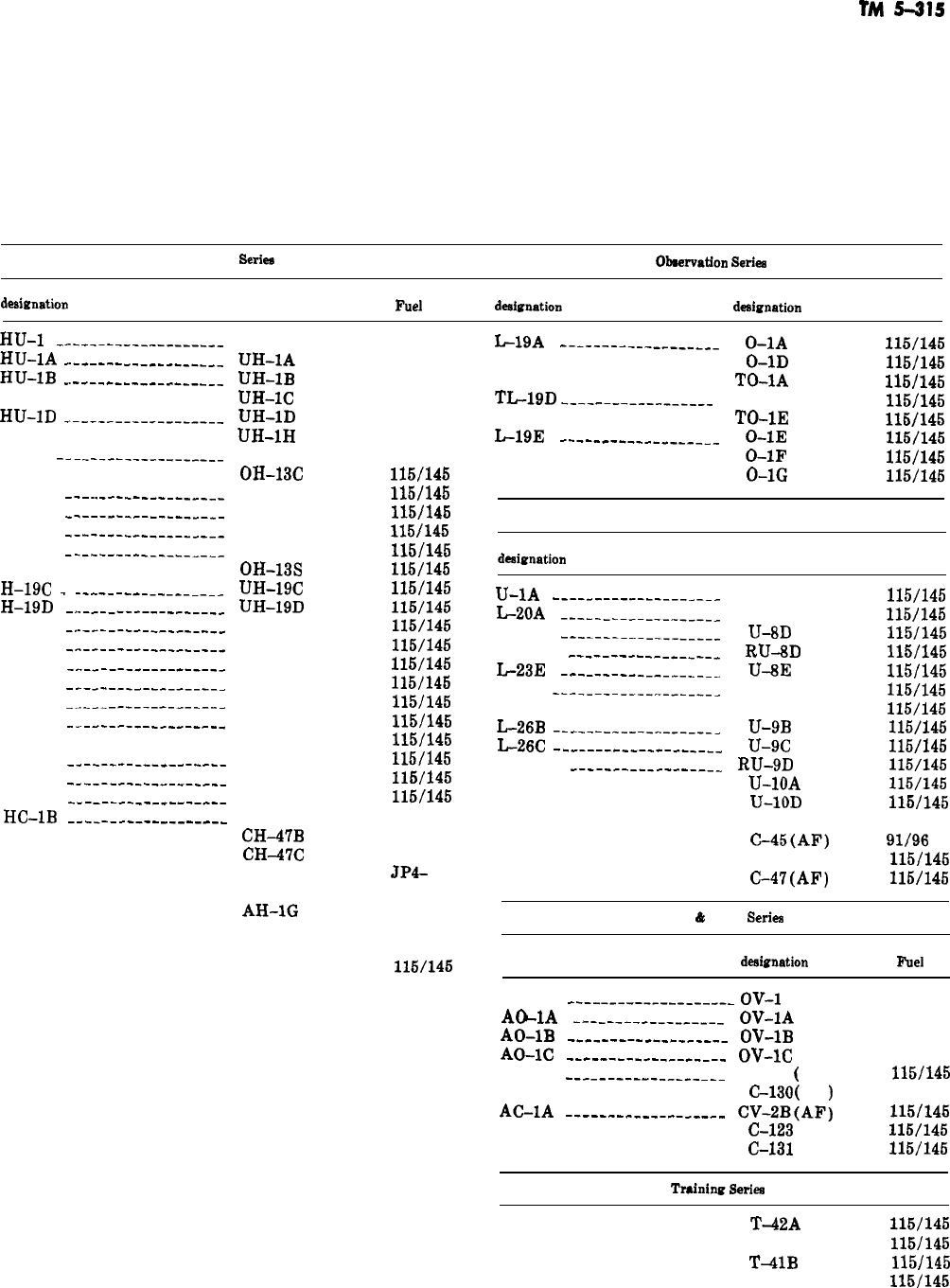
TM
5-315
.-
APPENDIX B
ARMY AIRCRAFT DESIGNATIONS AND FUELS
Helicopter
Seriee
Obeeavation
Serb
Former
de&nation
current
designation
Fllel
Former
deeignetion
Current
de&nation
Fuel
HU-1
-_.__-_____-___---___
HU-1A
_.-_---_--__-_______
HU-1B
_.___-____-____--___
HU-1D
__----_____-_-----_
HO-6
_--_-___-----_-_____
H-13E
---.._-_-_-----_____
H-13G
__---__--_----__-__
H-13H
_----__---_-_-_____
H-13K
------___------_-__
H-19C
-
_-----___---_-_-__
H-19D
-.--_-_____-_-----__
H-21B
-..--_--___-------__
H-21C
_._----____--------_
H-23B
-..-__--____-___-_-_
_-
H-23C
-_.-_-----_--------_
H-23D
_..___-_______-_-_--
H-23F
------__-_----_---_
H-34A
__-_-___---_--_----
H-34C
-_--_-__-_--_-_----
H-37B
__-_----_-__----_--
HC-1B
---__-__-__---_-_-_
UH-1
UH-1A
UH-1B
UH-1c
UH-1D
UH-1H
OH-6A
OH-13C
OH-13E
OH-13G
OH-13H
OH-13K
OH-13s
UH-19C
UH-19D
CH-21B
CH-21C
OH-23B
OH-23C
OH-23D
OH-23F
OH-23G
CH-34A
CH-34C
CH-37B
CH-47A
CH-47B
CH47C
CH-54A
AH-1G
AH-56A
TH-55A
TH-13T
JP-4
JP-4
JP4
JP4
JP-4
JP4
JP4
115/145
115/145
115/145
115/145
115/145
115/145
115/145
llWl45
115/145
115/145
115/145
115/145
115/145
115/145
115/145
115/145
115/145
115/145
JP4
JP-4
JP4
JP4-
or
JP-5
JP4
JP4
JP4
115/145
L-19A
_-____--___-__-_-_-
0-1A
0-1D
TO-1A
TLl9D
_--__-___---_--___
TO-ID
TO-1E
L-19E
--_-__-_________---
0-1E
0-1F
0-1G
115/145
115/145
115/145
115/145
115/145
115/145
115/145
115/145
Utility Series
Former
designation
Current
designation Fuel
U-1A
-__---__---__-_--_--
L-20A
_____-__-_____----_
L-23D
___--_-_____-_----_
RL-23D
__-___________-___
L-23E
______-__-_____----
L-23F
--_--_-_----__-_---_
L-26B
-__--_-____-_------_
IL-26C
__-___-___-__-__-_-_
RK-26D
-_-_-____-_____--_
Same
u-6A
U-8D
RU-8D
U-8E
u-8F
u-8G
U-9B
u-9c
RU-9D
U-1OA
U-1OD
u-21
C-45(AF)
C-47(AF)
115/145
115/145
115/145
115/145
115/145
115/145
115/145
115/145
llWl45
115/145
115/145
llWl45
JP4
91/96
or
115/146
llWl45
VTOL
&
STOL
Se&a
Former
designation Current
de&nation
AO-1
____-___-_____-___-_
OV-1
JP4
A&lA
____-_-___-_-_-_--
OV-1A
JP4
AO-1B
-______-___-_---___
OV-1B
JP4
AO-1C
--_-_______--____-_
ov-1C
JP4
CV-2A
_----______---_----
C-?A
(
AF)
115/145
C-l30
(
AF
)
JP4
AC-1A
_-______---__-_____
CV-2B(AF)
115/145
C-l23
(AF)
115/145
C-l31
(AF)
115/145
Fuel
T42A
115/146
T-41B
115/145
T-4lB
115/145
T-41D
115/145
B-1
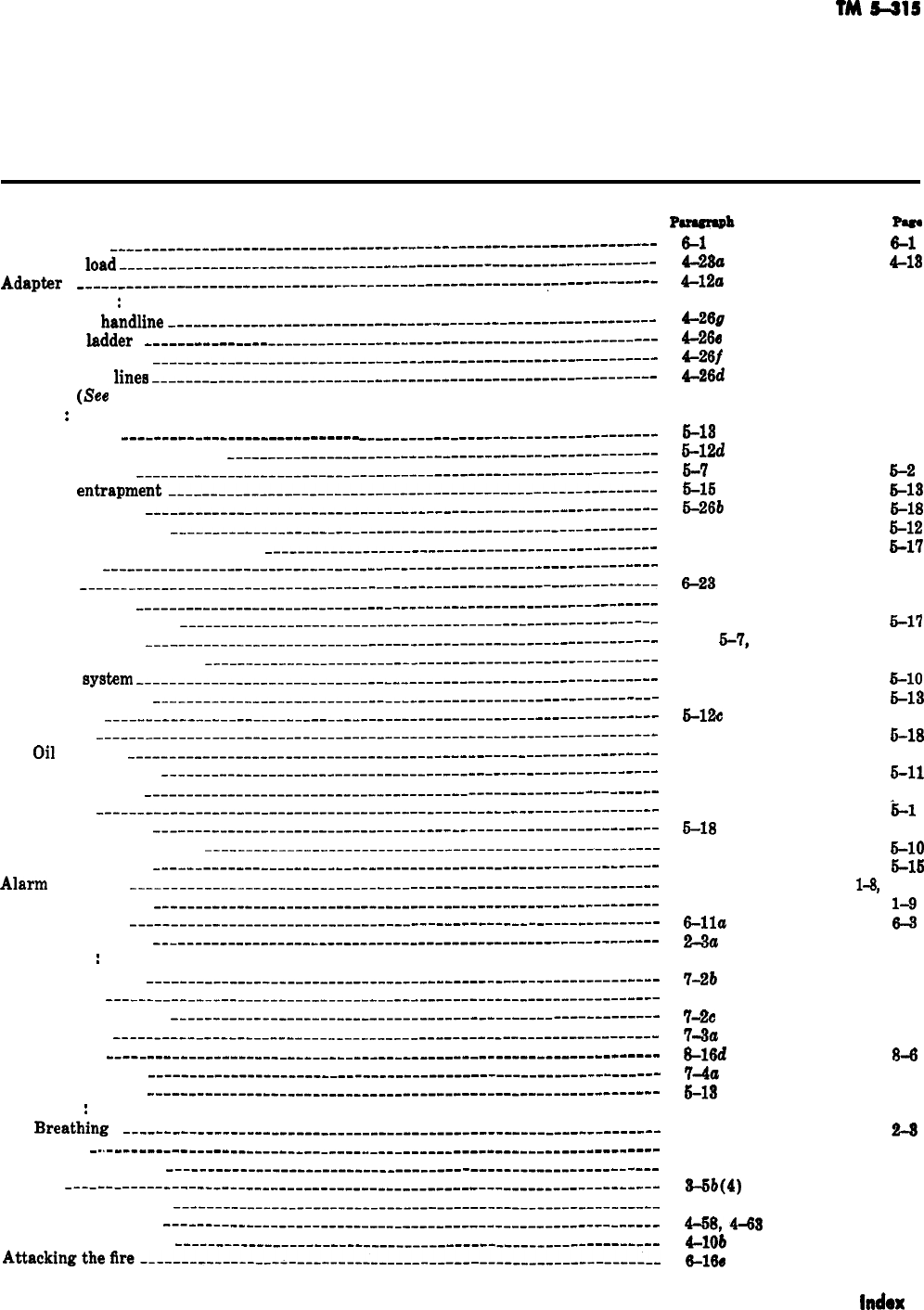
TM
5-315
INDEX
Accidenta ___
_____________________________________~_~~-~~-~~~_~~~~~~~----------
Accordion
load
____________________--______________------------__---------------
Adapter
___________________________--_______--___-______--______~_------------
Advancing hoee
:
With a
handline
____________________-________--__-______________-----------
Up a
Iadder
___---_________
_____________________~~__-__-__--~~~~~---------
Up a stairway
--_-__________________-____-______-__-__~--__~~~~------------
Advancing the
iines
-________________________________--______________------------
Aid, first. (see First aid.)
Aircraft
:
Anti-icing
_-_____________________--__--
__________-_-_--~-_____~~~----------
Auxiiiary power plants
__-______-----_____-___-________~____~_~------------
Components
_-----____________________________----_-____-____-__--~--------
Crew
entrapment-______________--_--______---_--________-___---------------
Ejection seat
-__-_________--__-_________--_-_____-_____--______------------
Electrical system
_____________________________-_--___-__--__--_-___---------
Emergency rescue procedures
_--_------___-_---_________--_______------------
Engines
__-_-----_________________-________-_--__--______________----------
Fires
____--____________________-_______-__--__________--__-__-__~----------
Firefighting
_-----__________________-__________---____-_-___-_-__----------
Fire extinguishers
-______________-_-_-_________----_____________------------
Fire hazards
______________________________________-________--_-__---------
Flammable materials
__-____________--_______-_---___-___---______----------
Fuel
system
_-----____________________________________________-__--___-----
Heater system
____-------________-__-__________---_--____-__-__-_----------
Ignition
_---__-___________________________________--_-_-_-----_____--------
Models
-_-_--_----___________________________________-______-_____---------
OiI
system
_--_---____________________________________-________--______----
Oxygen system
---________________________________-__--___-__-_______------
Power plants _----______________________________________-_________-_-_____-
Rescue
-__---__-_-_--_--_--__-_--__-__________-_-----_______-_---_____---__
Traffic pattern
---__--________________________________-_-______---_________-
Tubing identification
---__-___---____-_____________-----________------______
Airfield emergency
-_--__---__--_________________________-_________-_---________
Alarm
systems
____-----____-____________________-_---___-_______--_-__--______
Alphabet, phonetic
___-_--_____---_-__-_____________--____-_______-_____________
Alpha radiation
---______________________________________-________________--____
Aluminized covers
-__________________________________________________________-_
Ammunition
:
Deterioration
___-_--_______________________________________________--______
Hazards
______--_____________________________________________________-__-__
Safety violations
___-__--_-__-_-__---_______________--__-_______-___________
Stacking
__________-______--____---_________________--____________-__-__-__
Storage
-___________-________-___--_______________-________________________
Storage chart _____-_-_______-__-____________________----___________________
Anti-icing system
________________-_-___________________----_______________-____
Apparatus
:
Breathing
-___--_-__________________________________-________________-_____
Appliances
-~-------___________________-_______________-_-____________-_________
Application of water
________________---_______________--_--_____________________
Arcing
---_--_-----_______________--_____________________-___________________-_
Arm-lift resuscitation
________-_-_____-__________________________________________
Artificial respiration
_--_________________________________________________________
Atmospheric pressure
_________________________________-__-______________________
A~ackingthe~re---_______________________________-__-___-_____________________
&l
4-22a
4-12a
Pus
6-1
413
46
4-20g
422
4-260
421
4-26f
421
4-26d
421
6-13
6-12d
6-7
5-16
6-26b
6-12
6-24
6-7
6-23
6-1
6-26
6-6,
6-‘7,
6-23
6-3
6-9
6-14
6-12c
6-26
6-10
6-11
6-7
6-1
6-18
6-3
6-22
1-20, 1-24
1-22-c
6-lla
2-3a
6-13
6-13
6-2
6-13
6-18
Ex2
Ei-17
6-2
6-8
6-1
S-l?
6-2, 6-8
6-1
5-10
6-13
6-12
5-18
6-11
E+ll
6-2
-b-l
6-14
6-10
6-16
1-8,
1-12
z
2-3
‘7-2b
7-1
7-2
7-1
7-2~
7-1
7-3a 7-3
8-16d
3-6
7-4a
7-4
6-13
6-13
2-4
2-3
2-14 2-21
411
4-4
3-W4)
3-4
462 466
468,443
462,467
4lOb
44
6-16@
6-4
lndox
1
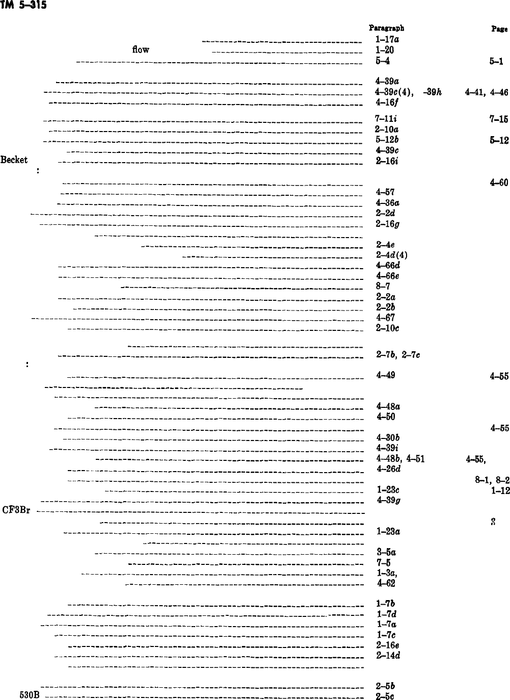
TM
5415
Automatic and manual fire alarm system report __________-____-___-_______-_______-
Automatic, manual, and water
tlow
alarm system
--______-____-___-_-________-_-_-
Aviation gasoline
---__--___-__-_--______-___--_______---__--__-_-----____-___-__
Ax: Cutting
-__._-____-_______
_______________--_--________-_-_--_--_---_-_--_--_
Fire
_________________________-_________---_--___---________-_-____________
Hitch
_--____________________-_________-_-_--___-____-___-____-_________-__
Backfires
_____-_-____________---_______-___----__-___--_--_____-------_-_-__--_
Ball valve
______--__________----______--__-_---__-__-_-_---__--------__----_---
Batteries
-_--__----__-_________-_______-______-__-____---_--_-_---__-_____--_--
Battering ram
_----__________-_-_-____---_---_-__-_-_--__-_____---__-__---__-__
Becket
bend
____-_____________________________-___________-__--__-__-___--_-__-
Bleeding
:
External
-----_------_-______-__-______--__--_____-____-____--__---_---_---
Internal
------------_---__-_-__________-----_-_-------___----_---_-__-__-_
Booster line
--_-----_-_________--_______-___--_______----_-___----___------_---
Boots
-------__--_-__-_________-_______--__---________--__--__-_--___--_----__-
Bowline
------------_--___-_____-__-__---_---___-----______________--__-_____-_
Breathing apparatus
_________--___--_---___--_-__---______--______----_________
Breathing apparatus limitations
_-___________---_________-_---__-_-____--___--_--
Breathing apparatus for special situations
_____--_________-__---_-__-___--___--__-
Broken back
_--_-_-__-____-_-_---______________-___-___--_---_----_--___-____-_
Broken neck
-_---------___--___---__-___-___---___-__---_---__-_------_-_______
Building under construction
_-____---___-______--_-______--____-__---____-__------
Bunker coat
-__-----_---__--___---__--______--_______--__---____---_--__-_-__--
Bunker trousers
_--__________---____-_---_---____-----_--_______-___-____--_---_
Burns
----_--__----__-_______---___-___--_--___--_-___--__---__---_-----_--__-_
Butterfly valve
_---___-__-__---____--_----_--____------_________-_-----__--__-__
Carbon dioxide extinguishers
_---_-___-__________-____-_-_______-_______-________
Care of hose
___----______-__---________--__---____-___---_--__-______---___-___
Carry
:
Fireman’s
-_______-_-_-___-__-_____---___-----________--__--_-_________-___
Hose
__----._--_-_---__-___-___
__-__
_-__----_-______-_-_-___-_-_
____ ________
Ladder
____-__-______-_-------_________-_-_____________--___--___--__---_--
One-man method
-----_--_________________-________-_____-_--___________-___
Pack-strap
_~-_____-______--_--______-_-_--_-_-__--______-__-_______________
Rescue
----__-_-__-______--_--_-___--_--___--_-__---______-_--____-____-___
Shoulder
_-__-_----__--__--__-_-____------_---__----__-___--____---_----_--
Tools
------.---------_-______-___-_______-_________-_---__--____-_-__---__-
Two-man method
__-___-__--__-___-_-____-----_-__-_-____-_-_--____-___-___-
Underarm
-__-_~~._-______-----_____--__---_--_-__-------__--_--__--____-__-
Causes of fires
_~--_.__-__---_--__-_------_--____----_-___-_____---_----_--___--
Cease operations signal
_____________________----___-__-_-__---_--__-__--_-----_-
Ceilings
-_____-~____-___-_-_---_-__--___--__----_______-____-_______-_-________
CF3Br
___-_---~____-___--__---___--__-------____--__--------_-_---_---_--_____
Characteristics of fire
___--__---____-___-------___------__---____-____--____--__
Charged line
__~----__-__-___--_-_______--_---___--___-_____----___--__________
Chemical extinguishment agents
___-_------_--_____---_---_---__-_---__--__----_-
Chemicalheatenergy
__--______-________---__---_______---__--_-__----___---____
Chemical munitions markers
----___---__---___-_--___-_______-__---_------------
Chemistry of fire
____-___--_---___--____--_-----________-_----_---_--_-_--_____
Cbest-pressure resuscitation
_--_-__-----_------_______-_________-______________-_
Chief:
Assistance
________--_-___-----_-__----_--_--___-_______--_-_-_-____-___--__
Crew
--_______----__--__------_______-_-_-__--__--_______---__-_-~
_____-__
Fire
--__--_-_-____--_-____-______-__--___--_______---_---__-_______-_______
Station
____--____-___-__----_-_--__---_--__--_--_--___---______-_---__---_-
Chimney hitch
_--__------___---_--__-___--____-_____-_______--_--___--________-
Clamp,hose
____-__-_-_---_-__--_-__--_----_----_-______--__--_________--_----_-
Classes of fire
-_-_----_--------____------------_______--------_________-___--__
Classes of fire trucks:
600
____---__-----__-____-----_-------_----_______-____-_______~~~_________
63OB
--____--_____--___-__________________-__-_____-_____-_____~____-______
PU4mZ.h
l-17a
l-2cl
64
4-39a
4-39c(4),
4
4-10f
440
-39th
4-41,4-46
4-6
7-lli
7-15
2-1Oa
2-19
5-12b
6-12
4-39c 4-41
2-16i
2-26
4-56
4-80
4-57 4-62
4-36a
4-34
2-2a
2-1
2-16g
2-26
2-4 2-3
2-48
2-6
2-4d(4)
2-6
4-66d
4-69
4-666
4-71
8-7
3-2
2-2a
2-1
2-2b
2-1
4-67
4-73
2-1oc
2-20
2-19
2-28
2-7b,
2-7~
2-11
4-49
4-26
4-33
4-48a
4-60
4-48
4-3Ob
4-39i
4-48b,
4-51
4-26d
8-2-8-6
1-230
4-39g
4-3
3-1
l-23a
3-2
3-6a
7-6
1-3a,
3-1
&62
l-7b
1-3
l-7d
1-4
l-7a
1-3
l-7c
1-4
2-166
2-25
2-14d
2-22
3-6
3-4
2-6b
2-6
-
2-5c
2-7
P4e
1-7
1-8
6-1
-
4-65
4-17
4-27
4-55
4-66
4-55
4-25
4-47
4-65,
4-57
4-21
8-1,8-2
1-12
4-46
4-1
3
-1
1-9
3-1
3-3
7-7
l-l, 3-1
4-66
Index 2
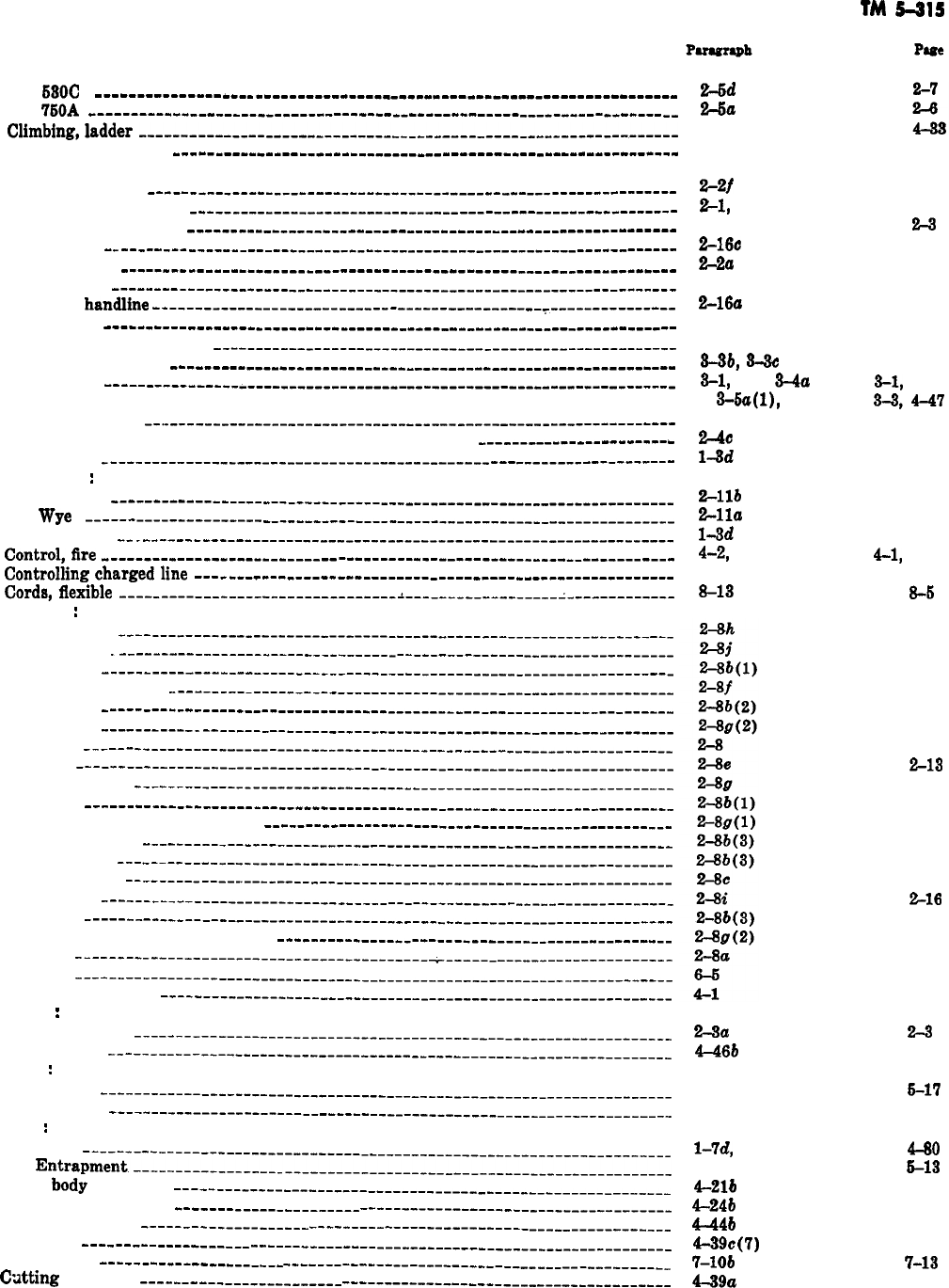
TM
5-31s
Classes of fire trucks-Continued
63OC
_________________________---_______-_________________________________
76OA
~~~~~~~~~~~~_-~--_______-__~_~~~~~~~__~~~--~~~-_-_~_________~__~~-____
C~mbing,ladder__________________-__________-______---__--_____________________
Closingin on theflre
_________________________________----_-________-_______-____
Clothing:
Maintenance
_________________________________-_______-__-__________________
Normal protective
____________________-___________--__________-____________-
Special protective
_____________________-_________-_--_--____________--------
Clove hitch
________________--_-____________________________________-____-______
Coat, bunker
________________________________________-_-_-______________-______
Codes, color _______________________-__--_--________________________-___-__-____
Coiling a
handline
_____-_______---_____________________--___-___~_______--____-_
Color codes
______________________-_______-_______-_____-__-______-________-____
Combustible metal agent
-_____________________________________________---______
Combustible vapors
______________________________________________-_____-__-____
Combustion
_________________-__________-______-______-____-___________-__-_____
Communications
-_.____-_______-_____________________________-__----------------
Compressed air, self-contained, demand breathing apparatus
_.-----------------------
Conduction
__-________________-________________---_----__----------------------
Connection
:
Siamese
__________-__________-_-__-_-________-__-_-__-___-_________-_______
Wye
--__--_______---__-___-_-_--_-______________-__-__-___-_-_____________
Construction
_____________-__--________________________________-_--_-----------
Control,fire
_---________________________---_------------------__----------------
Controlhngchargedline
---_________---_____-----___-_______________-----_-------
Cords,flexible
--__-____---_----________________~---______________-~-------------
Coupling
:
Breaking
__--_____-__________________-_--______-_______-________________--_
Damage ._-_____________________--__-_____--____________-__________________
Double
--________----_____________--_-_______-_______--___________--------_
Expansion ring
-__--__________-_-__--__________-_-----_-_-_________________
Female
_-___-___--______--__-----_-_-____--------_--____-------__-__-______
Gasket
--________-_-______-___----_-___-_-__---_________--_----_-----___---
Hose
---_--_______---______-___________________-___----___--_______--____--
Lug
-__-_~__~_____-_~_-__-__--_-__--___-__-----_--________-___-------_-_---
Making up
_______-_---_____________-________------_-----__-____-__________
Male
----_______-____________-____---______----_--______----_--___________-
One-man coupling procedure
--_--______----_--____-___----_--_----________--_
Quarter turn
-_____---_--__-_____________-_____-_------____-________________
Reducing
---_---__---_-___________-_-____-----_------_-____-----____-------
Screw type
-------------~--_________-_______-__-___----_____-__-____________
Sleeves
_-----_-___----________---____----__-__-_--____________-----___-____
Snap
____-__-_____-_-____________-_________________--____-_--______________
Two-man coupling procedure
_______________-_________---__-________________
Use
-------------_-----_-____-__-_--___-_-_--______________-______________
Couriers
-----_----------______-____---_--______-----______-_____-______________
Covering exposures
-_-__________________-__-----__-__--_------__________________
Covers
:
Aluminized
---------------_____-_----_____-_-----__________________________
Salvage
__---_____-__-___________-_______________-_--___-__________________
Crash
:
Rescue
------------------_-________________--_____-_____-____---_--_-__----
Stations
_______________________--_________-________________________________
Crew
:
Chief
--------------------________________-_____-_-___________-_-___________
Entrapment----------_--_______________________-_--_-___--_________________
Cross
body
hose beds
---________________--__-_--____---_________________________
Cross fold hose finish
_______-----__________
-----~~_~-~~~~____~________-__-_-----
Cross ventilation
_-___-__-___________
~~~~~____~_---~__-_______-_________________
Crowbar
---_-_-__----_______
------~~-------__-~~~~__-----____-_____--_-------_
Crown fires
___--______--_________
~~~~___-~~~_-~_-___---__-_-________-__________
Cdtting
with ax
__________---___________
---------~--~-~~~~_~___~__-_____---__--
24a
2-6a
4-26
4-71
2-2f
2-2
%l,
2-2
2-1
2-2
w
2-16~
2-24
2-2a
2-1
6-8
6-10
2-16a
2-24
6-g
6-10
2-26
2-38
2-6b,
6-6~
2-2
9-1,
2-2, 2-4a
9-1,
2-2,
9-6a(lI,
4-41
9-9,4-47
1-19-1-24 1-7-1-12
2-4C
2-4
1-3d
l-l
2-llb
2-21
2-lla
2-20
l-9d
l-l
4-2,
4-69
4-1,
4-74
4-29
4-29
9-13
9-6
2-3a
2-3
4-46b
4-62
6-24
6-17
1-10
1-6
l-7d,
4-79 1-4,
4-go
6-16
6-13
4-216
4-12
4-24b
4-16
4-44b
4-61
4-69c(7)
4-41
‘Glob
7-13
4-39a
440
4-76
2-16
2-16
2-11
2-13
2-12
2-12
2-11
2-12
2-14
2-11
2-14
2-12
2-12
2-12
216
2-12
2-16
2-11
6-1
4-1
Index 3
TM
5-315
DA Forms
_--_____------__---_--_~_----__--__--___---__---_-__---_--------____
Deck pipe
-_------__-__--__---_-------_--_---_-_--_--_----__-___-___--___---_--
Decontamination
---___-_-__------------_____--_------_---_-_-____-____-_--____-
Decrease pressure signal
~__---_----__--_____-___--___------_-___--_---_--______
Deluge set
__---__--_______________-____________--__-_-__---_-____-_-_-__-_-_--_
Demand breathing apparatus
-------_-----__------__-__-______-_--_--------__-__
Department radios
---____-____-____-___-______-_--__-_-__-___-___--__-_-_---_---
Design, aircraft
---_____-___--__-_-___-_____--_--__--_______-___---________.-__-
Determining the cause of fire
--_---__---_____--__-----__________--_-_-_____--___
Devices
:
Combine flow
____________-__-__--_---___-___--__-____-_--____--_-___--___-_
Control flow
_________________-------_______----_---_--__-____-___-----__-__
Divide flow
___________________--__--_________-_______-_______-__-------_-__
Master stream
-_-______--_--------____--__------_______-----_--___-_______
Mechanical
__________________---__-_____-______--------_____--__-__--______
Protective
_____-_________-___--__---___--__-___--___--_____------_________-
Safety
_-________-__________--_------__--__-_-__---__--_____---_--__-___-__
Dining facilities
___-__________-__-----_--___---_---_--_-_--_-___--_---__--______
Discharge,rate
-~----____-___---------__-___---_-------_____-___-----___--_____-
Disposal teams
-----_____-__-------__--_--__--_---__-_______-___--_--______-__--
Divided load
__~_---________-----_-_.._______------___---_-__-______--_-_--_-_-__
Donut roll
----_----___---__-------_--__-___--_---__---__-_--__-_-----__--______
Door opener
___-_---______________--_-_-_____-____-__-_-___-_____-_--_________--
Doors
---_________-_______________-________--___--__---____-______-__-___--_--_
Double
donutroll----________--___--__--_____-___--__-_-__--_________--__--__-__
Drafting sleeve mallet
__--__---_---_---_-__-------_----__--_-____-_----_-______-
Drafting water
_-__-___---_------___-----__--__--_----__-__-__--------___--_---
Drain, water
__-__-____-------_---_---_-___--------_-___----____-_-------______
Drills, pumper
------___--__---__---____-__--__--___--____--_________--___--____
Driver qualification record
___--------_-_-___--___-__---__----____--_--------_-_-
Dutchman
--------_-_---____--__---_----___--__-------__-_--____-_---_--_______
Eductors
~---_--.-_-__--__------------_-__---__---_-------__---_______-___-___-
Electricalheatenergy
---_-----_----_--__-__---_--_----_-------_--------_--__----
Arcing
----_---___--_---__-__-_--_____-------_---___-_-----__--____________
Dielectric
_____--_---___---_---______-----_--___---_---_____----___----_----
Induction
----__---___--------__---____-----_-__---_---_-----__--__--______-
Lightning
-___---__--___--___---------__--___-___-_-_----__------_-----_-___
Resistance
__--__------------~-_---__-_---___-__---_----_----______--___-__-
Static
___----------__---__-____--___----_---_----__-__-_----_____-___---_--
Electricity
--------____________--__---_--__--___--___---___--________-----_____-
Electric shock
--___-___-___-----------_-____-_______--__-_-____---_-_----__-__-
Electric system
-----___-____-___-------___---__--_---____---____-_----_-_--_--_
Emergency judgment test
_-__-__~______--___--_-_--_--______-___--_----_--__-___
Emergency, off the airfield
________-___--____--_---__-_-_____-____-___-__-_--__--
Emergency, on the airfield
-__-____-______________-----____________________-__---
Engines
:
Opposed design
~.-_--_--_-__--------_-----_---_----__---_--___-______------~
Radial design
___-______-___--___---________-_--------__----_--______--____
Reciprocating
-----____--__--------_-__--__-----------------_---__--______-
Turbine
_-___--______________-____-_____-__--_-_-__-____----_--__--________
Entering
---_-___--_---_--_--__---___--__-------__--_-__-_-------_-------_---__
Entrapment, crew
_-_~---_________-_----____--__--__-_-____--__----_-----------_
Entry, forcible
________--________________________-__--_____--____-__--__------__
Equipment, firefighting units
___~_---___--________----__-___-------_---__--______-
Estimate of loss
----_-___-----__--__---___--__------_-__-------__---__-______--
Estimating the fire
____--_.._--__.._-______________-_----____-__---_----_--___~___
Evaluation of situation
-_---_-_--_-___--____-____-__---___----_--_--__--______--
Explosion, nuclear
-_---__-----_________..____-___--__-___________-___--__--____-_
Explosive
:
Kinds of fire
-----_-____------__---________________________________________
Limits
-___-_--_----_____------_____----____-______________________________
Symbols
_-__--------_____-----_---_--______________________________________
2-13
3-5lJ
3-5b
(4)
3-Lib
(3)
34b
(2)
3-5b(6)
3-5b
(1)
Mb(s)
8-9
4-65
5-‘7u(2),
54b(2),
5-12
l-7f
5-23
5-22
5-7
5-7u(l)
5-7a
5-7b
4-45
5-15
4-39
1-6
4-77
7-lib
4-42,
7-llb
6-8
7-4
3-3d
6-13
ParaeraDh
Pm
l-7f,
1-16
1-4,1-6
S6f
2-19
6-16f
6-6
l-23e 1-12
-
2-9f
2-19
!2-4b
2-4
1-21
1-3
6-6 6-2
4-76
4-79
2-11
2-20
2-10
2-19
2-11
2-20
-f
2-19
8-6
8-2
4-46~
4-s3
8-10
8-4
1-12
1-6
4-9,
4-13u
4-3, 4-6
6-6 6-1
4-2la
4-11
4-19a
4-9
4-39c
4-41
4-39b,
4-39c
4-41
4-19b
4-9
2-14a
2-21
4-10
4-4
4-46~
4-63
4-18
4-8
l-7f
1-4
4-23u(2)
4-13
2-21
3-4 --
34
3-4
3-4
3-4
3-4
3-4
8-3
4-67
5-2, 5-8,
5-12
1-4
6-15
6-15
6-2
6-2
6-2
5-8
4-51
6-13
4-40
1-2
4-79
7-13
4-48, 7-13
6-2
7-4
3-2
6-3
-.
Index 4
TM
5-315
PU-Dh
Exposures, covering
--__---_-____-_-__-_-___-____-__.____-__-_______________---_-
4-1
External bleeding
______-_--_____________-
__-___~______-_-~~~_-__-___~~~~~~-----
4-56
Extinguishers:
Aircraft
-___-_---_____________--_-_-___-_-___-___-__-_______--_____-_______
5-25
Bromotrifluoromethane
(CF3Br)
--____-____-________--_-__________-_________
2-24
Carbon dioxide
--___--____-_-_____--___--________-_________________-_____-_
2-19
Dry chemical
----_-__-___--_--____________________--_____________-_--______
2-24
Dry powder
-__---____-____-_.______-_--_-_______-__---______________-__-____
2-26
Familiarization
--___-_______---____-___-____-__-____________________-__-___
5-26
Fire
__-____-_______________---___--_________-______________________-_-____
2-17
Fixed
_--___-________-______--_________-_________--____________________-_-_
5-25
Foam
_--___-__-__________-_--___________-__________________________--_____
2-23
Inspection
______-_______-____________________-__
_~-_-_~~-_-~_____~_~_~~----
2-18
Portable
-----________________--___-____-____-____--_-_________-____________
5-25
Pressurized water
________--_-______-_________-______-________________-_____
2-21
Pump type, water
___________--_________-_____________---___________-_______
2-20
Soda-acid
_____---__-_-__--________________________________________-_-______
2-22
Winterization
_______________-_-___-___________-____-______________---~_____
2-28
Extinguishment, classes of fire
_-___-____-_-_--_-_-~-_-_-_________________-__-___
4-3
Eye splice
_.-__...____________-_______________________
__~____~~________~~___~~~~~~
2-16b
Facilities for firefighters
:
Crash stations
---___-____---________-_-_____________________~--_~----------
Dining
--_--_-----___-_-_---_-_--__________-__________-________-_---~_---.--
Heat
_-_----__---_________--__-_-____-_______________---____-__-~----------
Sanitation
_-_---___-_-__-----___-_-__--_-___________________-__-_----------
Sleeping quarters
_----_---__-_____--_---_-_______--______-________-___-----
Structural stations
-----_----_-__-__--____-_____-_____-__---__-___----------
Training
-___-_--_---__-__________-____________-_-__--___-____________---_-
Factor, time
__--___-___------_--_----____-___-___________--_-________----------
Factors affecting friction loss
-__-___--____-_____-_____________________---_------
Female couplings
-_----__-------_----___--________--______-_-__________-_------_
Final action
___-____-_____-__-_-__---____-_--______-_-_-_-__-____-__-~---------
Finish
:
Doughnut-roll
_____-___-__-_-__---__---__-_-___-________--____--_-___-______
Hose-load
_-___________-___-___--___-________--____-___________-__----______
Rip-rap load
_-____---__-__--___--___-_-___--____-__--__--______--__-_______
Skid load
____-___---_______-___--___-_----________-__-_-_____________-_-___
Fire
:
Army aircraft
___--_______-_______-___-__-_________-_--_-___-___-__________
Ax
__-____________-____________--_,-_----_-________---__-___--____-___~----
Backfires
---_____-____-__--____--__-____-___-_--______________--_____-___--
Breaks
_----__---___--__----_--___--_____________-_---_--_______-_____-____
Characteristics
__--____-___--_--____--________-______________---____---_____
Chemistry
________--________-____-___-__-_____-_--_-_---____-_________~--__
Chief
________-___________-_-_----__---_--____--___--_-_______-_____-----___
Classes
_____-___-________---__-_____-________________________________-___-_
Closing in on
_____--_______----_______--______-_-____---___________---____-
Clothing maintenance
_____--__--__-_-__-_______-____________________---__--.
Control methods
-_--____-______---__---__--___--________________-_______-__
Crown
______-____-___--____-__-__-_____--____-____________________________
Department radios
________--_----___--__--______________________________-__
Determining the cause
_____--_-_--_-__-_-__-__--________________________--__
Determining the origin
_____-__-_-_--__-_________-______-__________-___-___-
Estimating
______________________-_-__-_-_--___--_-__--_-_____-____---__-__
Estimating loss
_-__--__________-_-__-________-_-__________________----____-
Extinguishers
-__________________-__-_-__--____________________________--_-
Extinguishment
____-_______-__-___--_-____-____-__-________________________
Extinguishment, classes
_______________-__-________-____________________--__
Grass
_________________________---__--__--___-_____________________________
Ground
_______--_________________-_____--______-__________________----_-__-
Hazards
--___--___________--_-_-_-_----__._________-________________________
Hazard inspection
report_--_______________-____--__-_______________________-
1-10
1-5
1-12
1-5
1-13
1-5
1-13
1-5
1-11
1-5
1-9 1-5
1-14
1-5
6-16~
6-5
4-12, 4-14
4-5p4-6
2-8b(2)
2-12
4-78 4-80
4-19a
4-9
4-20 4-10
4-24b
4-15
4-24~
4-15
6-23
6-8
4-39a
4-40
7-lli
7-1s
7-llh
7-15
3-1
3-1
Ma,
3-1 l-l, 3-1
l-7a
1-3
3-6 3-4
4-71 4-75
2-2f
2-2
4-2, 4-69 4-1, 4-74
7-lob
7-13
1-21
1-8
4-76 4-79
4-75 4-77
7-lib
7-13
4-77 4-79
2-17,
7-2b
2-28, 7-3
4-69, 4-71, 4-74,
4-75,
8-16a
8-6
4-3
4-1
%lOb,
7-lid
7-13,
7-14
7-lob
7-13
7-2,
8-2-8-19
7-1,
8-1-8-7
l-17b
1-7
PW8
4-1
4-60
5-17
5-17
2-28
2-31
2-32
2-33
2-28
5-17
2-31
2-28
5-17
2-29
2-29
2-30
2-34
4-1
2-24
Index
5
TM
5-315
Fire-Continued
Hazards,fire
aircraft
_-----___--_-______-_____-____-___--____-_____-_______-
Investigation
-___-_----__------_____-__________-_-__-_-----__--____________
Locating
_________-_______-__-________-----------______---____------____-__
MisceIlaneous
_______-__--___---__-_-_____________-_---_-__----_-_--_-___--_
Missile
______-___------__-_______-____~__-____--__-_-_--------_--_-______-_
Motor vehicle
______-___---------__--_-___________-_-_-------------_-____--
Natural cover
___-__---------------_-________-_____----_--_______-___------
Nature
-_----_____-----__----____----_____-__-__________-__-_-_--__-------_
Nuclear
__-__-________-___--_____--______________--_____---_-__-__---______
Origin
____-_-_---______-____-____--_--____-_____-__-__---__-______________
Overhaul
___------___________-__-----____-_____--____-__-__-_------------_-
Parts of
-------__-------_----_----___-______________-__---_-__---__-----___
Point
------___-__-------____-__-__--_-----------_-_--___-------______-___-
Prevention
-__-_---_-----_______----------_---_-___----------------------._-
Properties
--_____________-_______________-__--_---_--_--_----------_--_----
Protection
--__-----------_____-__-__------__-______-___-_-___-----_-----_--
Protection personnel
-__-__--__--____________-_--_--_____-_--_---__----------
Protection specialist
______------____________-__-_--__-_____--------__-------
RaiI
___________-___----__--_----______-__-_-__-__-_____---_-______---------
Records
____--_--____-____________---__----__---__------------__--_----_---
Shortage
---___------__--_______-_______-_____-_-----__-_____-_______-----_
spot
____________-__--__-_--------_--_____-_____-___----__---------------__
S&face
-------_---__-_----_--______-_____-_-_-_____________----__---------
Symbols
-------__-----_-_-___-____________-___----_-__-_______--------___--
Tactical vehicle fires
-__-----_--______________-____
____
____--_
---------_-----
TaiI
-__-------_------------_______---_-_-____-____________-_---------------
Tetrahedron
-------------_----________-_---_-______-_______-___-__---------
Timber
_--_--__---_-_-_---____--_------------_--__________--______________-
Transport vehicle
___-______--_-______________---___-__-_____---------------
Triangle
-----___-____---_----________-__---__________-_-_--_________-_____
Truck operator training
-____--_______-____---_______-__-_-_-----__---_____-
Trucks
-------___-----_--_-___---_-_-----_________--___---_-___-__-________
Firebreaks
----_----___________-_____________--______________--_---_____-------
Firefighter
facihties
______--___-__---_------__-__--_------_--__-_-______________
Firefighter
responsibilities
__-__________________--______________------__________
Firefighters
_---_-_-__---___---____________--_-_______-_-_-_--___-___________--
Firetlghting
:
Aircraft
_______----__________---___________--_________-----_.______-------_
Color codes
-_--_________-----___._-_____-__---________________-__-------____
Communications
_--__________-______________---________--_______-----_-____
Coordination
__-------________------_--_-______-_______-_----_--____-------_
Equipment
_____--_-_________--_____--_____-_-___---__----_----_--_-_------_
Evaluation
---_------_________---_--_____~-_--___-_--_-_____--__-_---_-----
Forcible entry
_----__________-______--_----_-_-_______---____----___-______
HydrauIics
____-----__--_____-________-_-----_--_--__________-__-__________
Natural cover
----------_-____--_______--_________-__-_-_____--__----______
‘Nuclear weapons
-----_____-_-_____-___----___----__________________________
Organization
--------__-____________________-_____-_----____--------_--____
Salvage
-----------------__-__----_____--____-_-___--__-____-__-___________
Situation
(sizeup)
--__________________---_--___----__________--____________
Tactics
---------------___~______________-__-___-__--_______---_------__-__
Teams
------_----_-______________________-_-_---_---______________________
Techniques
--__--_____________________-__---__-__--________________________
Tools
--------------_--______________-_-----__--_--_________________________
Units
---------------____---_-___-_______-_--__--_____________-____________
Ventilation
--__-_____________-_____-_---_--__-_____________________________
Fireman’s carry
-----__--_-____-____---------__----___--_____--_--__---__-_-_-_
First aid:
Artificial respiration
______________-_________-___---_--__--_____----_--___--
Artificial respiration
followup
__-______--______-___-__----__-___--_--________
Broken back
____--_-_----___
_---__-_______-__------__----__---_-_-----__-_-
Broken neck
_-_----__________--___-----
~___-~~__-~~___-_-_-_------__-__----
6-lib
6-12
4-73, 4-74 4-77
.-
4-70 4-74
7-1
7-1
6-22
8-7
7-6 7-7
7-8
7-11
3-2
3-1
6-12
6-3
4-76 4-77
4-72
4-76
7-1Oa
7-12
3-3f
3-2
l&Z,
7-3, 8-1 l--2, 7-3, 8-1
,3-3,
4-6 3-2, 4-2
1-6
1-2
7-3a 7-4
1-3, 7-3d l-l, 7-4
8-18
6-3
4-78
4-79
4-80
6-17
3-6
7-lob
7-13
7-lob
7-13
613
8-3
3-20
8-3
7-1Oa
7-12
3-2
3-1
7-lld
7-14
619
9-6
3-2
3-1
l-7f
1-4
2-6 2-6 --
1-8-1-14
1-4, 1-6
1-7
1-3
1-76
1-4
6-1,
6-2,
6-6 6-1, 6-2
6-8iJ
6-10
6-20
6-16
6-19 6-16
1-6
1-2
4-42 4-48
4-39, 4-46 4-40, 4-61
4-4 4-2
7-11 7-13
6-1-6-23
6-1-3-8
1-6-1-7 1-2, 1-3
4-4Oa
4-47
4-38
4-39
4-1 4-1
1-6
1-2
4-1 4-1
7-lla
7-13
1-6
1-2
4-4Ob,
4-44, 4-47,
4-60,
4-48
4-66
4-49
4-66
4-68 4-62
4-63 4-67
4-66d
4-69 ---
4-666
471
Index 6
TM
5-315
PIUWWlRh
Firat
aid-Continued
Burns
----_-__--_---_--_----_-_____-______-__--_-_________-_-___-__-_______
4-67
Chemical burns
-----__--__-----_-______________-___---_--___-__--_________-
4-675
Chest-pressure arm-lift resuscitation
-__--_--_--___-__----_--__-_____--.----.---
4-62
Digital
pressure
-_______-_-_-__--_--___-__-__--______--_---________--__-----
4-565
Direct pressure
_-_______-__--_--__-___-__-____--_____-____-_-_-________---~-
4-56a
Electric shock
-_-__--__--__-__----_-___-_--_----____-----_-__--____-------_-
4-65
External bleeding
-----------_--_-___-_____________________-__-__-____-_____
4-56
Fracture
__________________-_-___-___________________-__--_-__-________-_~-
4-66
Fractured clavicle
--___--__--___-__-__--_--__--_--___---_--__-_____-___-----
4-66g
Fractured jaw
--_--__------__-_-_--_____---_----_-______..-_-__--_----------
&66h
Fractured ribs
___------_---_--------------_--___-__---_---____-_-_---_-----
4-66f
Heat stroke
__-___-__________-______----_--_-_--_-_-_--_--__---________---__
4-68
Internal bleeding
_-_-_------_--__-___-----__--__--__---_--_--_-____-___-----
4-57
Mouth-to-mouth resuscitation
---___-__--__--_--__-___--__---_-____.__.____.-----
4-59,
4-60
Mouth-to-nose resuscitation
-_---__-___--_---_---__--_--_-_-___-____---------
4-61
Requirements
__-___-___-_---_--__-_____-______-___-_--__-____-_-__---------
4-54
Shock
___-_________-__--_-_______________--__--_-___--__-_____--__---__-__-
4-64
Short distance transfer
--____-____-__-___________________-_-_-__-_-__--____-
4-55
Siivester resuscitation method
_--_--__--__-__-___--__--__-__----___-____-_-_-
4-62
Splinting
______-__--_--_____-____________-__--_---_______________-__--_--__
4-66~
Sunburn
-______________-__-___-_--_--__--__----___---_---_---___-_____-__-
4-67b
Thermal burns
_____-_---_--_-_-_______________________________--_----______
4-67o
Thumb-jaw-lift resuscitation
-_--_-___-___-___________-__-______----________-
4-59
Tourniquet
________-__--_--_--__-__________________-___-____-_--____-______
4-56~
Flammable
iimits
-_--------___------_-___-___-____-_--___-_-----__-________---_-
3-3d
Flammable (explosive) range
___-__--_--_---------------_--___-__--________-____
3-3e
Flammable material in aircraft
--_----_-----__-___-__--__---_--_----_-______---_-
5-3
Flank
_____--__--_--_---_-_-_--_---_-___________________-----____-_---______---
7-lOu(2)
Flash point
________-___-___-__------_--_--__-___-_-__-__--_------_----_---__-__
3-3j
Flatioad
_________________--__--_--_--__-___-_____________--__--_--_-----_____
4-23b
Flatsinglelength hose fold
_____-___-_---_--______--_-__-____-_______-__-------_-
5-19d
Flexible cords
-------_-_-___-___-__--_--_---_-___-__-__~___-___-_-___-__-______
8-13
Floors
-_______________________________-___-_-_-_--__-__---__-___-___--_---_____ 4-39j
Foam extinguishers
____________-__--_--__--_--__-___-__-_______-____--_---_____
2-23
Fog nozzles
____________-___-__--_------_--_______-_________________________--_-
2-9a
Forcible entry
--_---_______-_--------___-_____________________________--_-__---
4-39
Forms
-----_----_---_------_---_--_-___~__________________--__-__----_---_____
1-16
Forward, carrying hose
-__------_--___---------_--_--___------__--__--____--__-
4-26d
Four-way switch
valve
---_---------_---_--__-___--_____-___-___--__---__-______
2-lld
Fractured clavicle
___-_-__-___--__--_--_--__-____-_____------__---__--____-___-
4-66g
Fractured jaw
_____________-_---_-_-__-__-----__-____-_--__-___-__----______-__
4-66h
Fractured ribs
-__-_____________-_--__-__-___-__________-___--__---__--________-
4-66f
Fractures
-______-_________-----_-_________________________________---___-____-
4-66
Friction heat
_------_--__-_-___-_--_-___-___--__---______--_--__--__--_________
3-5c(l)
Friction loss
_--__--__-_____--_--_---_--_--__-___--__--_--__--__---___-________-
4-12.
4-14
Fuel, jet (app
II)
_____--__--_--__--__-__-______________--__--___--__--____-----
5-45
Fuel leg
-__--------_----_-_-_--__-______-______________________---___-____-__--
3-2
Fuel storage
-__--___----__--_--~_-______-_______-_______-__-___-_______--_---__
8-16c
Fuel system
--------__--__--_--__-____________-__-__--__----___-_____-____-____
5-9
Furnaces
______--__-_______-_____---_--_--__-___-___-__--__--__--___-_____-___-
8-8b
Fuses
______-___-__________-_---_---_--_--__--__--__--_____-____--__-__________
8-10
G-l powder
_-______-_______-__--__--_--__________--__--_---_-__---___-__--_____
2-25a
2-32
Gasoiine, aviation
______________-___-_______________-____-----__---__--_________
5-4
5-1
Gas turbine
-----_--__---_-___--_----______-__-____-___-____-_______--_____-___-
5-7b
5-8
Gated wye
-__-______-____________--_-__________-_---_______________-__---__--_
2-lla
2-20
Gate valve
______-_-__________--_--____----_--__-____________________________-_
2-lob
2-20
Generators
-----_--__-___-_-__--_--___-_____--___--__-__--_--___-__-___----_--_
8-14
8-5
Glass, skyiight
__-_-___--___-_--__-_______--___-__-__________-__---__--____--__-
4-39h
4-46
Gloves
_____-__--_--_--__--___-_________---_--__-__________________---_---_____
2-2e
2-1
Goggles
___________--______-__-__-__________--___--______-_______-____~__-----_
2-3c
2-3’
Grass fires
---_--__--______-_-_________-_-___-_________________-_-_---____-___-
7-lle
7-14
Ground fires
_____--__-__-_____-__-________-__-__-_______--_--__--__-_-________-
7-lob
(1)
7-13
Guide plate, pump operator’s
_____-_--___________-_____-_-________--__---____-____
4-17
4-8
4-73
4-74
4-66
4-60
4-60
4-67
4&60
4-67
4-72
4-73
4-71
4-74
4-62
4-63, 4-64
4-64
4-60
4-67
4-60
4-66
4-68
4-74
4-73
4-63
4-61
3-2
3-2
5-1
7-12
3-2
4-13
5-15
8-5
4-46
2-31
2-16
4-40
1-6
4-21
2-21
4-72
4-73
4-71
4-67
3-4
4-5, 4-6
5-2
3-1
8-6
5-10
8-3
8-4
Index 7
ml
54315
Handline
:
Advancing hose
----_------__-__--_--____------_--_-_-__-_----____-----_-__
Coiiing
----_~______-__--___________________________________-________------
Use
_---__-_-._--_--_-----____________________________________-_____-----___
Hand signals
____~___________________--______----_--_-___--______-___--__------
Fa;i;;s,
parachute
____-_____________---_____-----_____--__________-______------
Aircraft fire
_______-__________________________-_--___________-__---_--_____
Ammunition
_______-___-____________-_______--_-_-____-__-----__-__________
Fire
--____________________~_______--_--_--_--______--_--________-------_--
426g
4-22
2-16a
2-24
-
2-16
2-24
1-23
1-9
6-24b
(3)
6-1’7
6-6,
6-23
6-2, 6-8
8-16d
8-3
7-2, 8-2, 8-19
7-1,
8-1, 8-7
Nuclear
-----__--__--------_________----_____--_------__-_-__-___-_-___----
8-9
Head, natural cover fire
_-_------__------------_-__-------______---________-----
7-1Oa
Heat
:
Compression
_______________-___________--______-------____---____________--
iz(2)
Energy sources
____________________________-------_--___---_---________----
Faciiities
____________________-__________-----_____-_-------_-_----______--_
1-13
Log
--___________________--____--_-----_----_--_--_---_---_--_--_----_--_-_
3-2
Nuclear
---_-_________-----______--------___--_------____----_______---____
3-6d
Spontaneous
--______-__-__--_______-__----________-----_-__----_______-____
p6;(2)
Stroke
-___--__-___________---____---__--_------------__----_--------___---_
Systems
__---___________--_-_____________--_____________-______-_---____-_-
8-8,
6-14
Helicopter
_----_.._______--_---____-----------_____-----_---_-___-__------------
&ic,
6-26
Helmet, plastic
_-..___________---_________-_-----_______-_------------_--____--_-
Highbee
cut
--_-_._____------_____-___------_--___--___--_______----------_-----
2-8~
Higbee thread indicator
_--_----_______.___--_---__________-----_-------______---
2-80
High explosives
_~___________________________________________-__------__________
69b,
6-9c
Hitch
:
Chimney
__--~--________-______________-_-----__-__---------_----_______----
2-16e
Clove
-_____~_____________________-------_-__-__---_---__-__-------_-_-----
2-16ti
Half
_-_____.___________________________--_________-----___--------_________
2-16d
Tool-_______~______________--____--__-_---_--_____---______----__--__-____-
2-16f
Hood
-_--------.____-----------_____--_----_--_-_____-__________________--___-
2-3b
Horseshoe load
__________________________--____________---____----------_-__--_
4-23~
Hose
:
Accordion load
__----_------__-____-------_____-------_-______--------------
4-23a
Advancing by hand
_____-_________--___---__-__--_------______-__----_______
4-26d
Beds
__--------_-------_------___--_------_--_---------------------________
4-21
Care
_-------____________--_______-----_-_-__--_------________-__---_______
2-7b
Carries
--------_-----_----_________--__-________________________--________
4-26
Clamp
_______-----__------__-_-----------__------_----____----------------
2-14d
Couplings
_______________________-____---___-__--------_______------_------_
2-8
DriIls
________________--_-_---____---_-----_-_--------_---__-----__-_____--
4-18
Drying
_~__._______________--__________------____-----_-----_-----________-
2-7e
Folds
____--___________--_-__-_--_---____---_--__-__-_----------____-------
4-19
Functions
_---___---__--------__------_---_-_--------------------_-_______-
422
Hoist
_____---___________________-----____--__-_----____-__---___-____---__-
2-146
Holder
__-_~-______________________-___--____--_----_--______------------__
2-14b
Inspection
_~_--_____________--___------___---___--_---__---___-------------
2-7d,
4-26
Jacket
__-~~~_--________--_----_______-_----_-_______-_------_____.
,.-_-----
2-14~
Layouts
___~__-_______________________-___---______--_--_---___----__---_-_
4-26,
426~
Lengthening
---________----_--______---------______-_-------_____--_---____
4-28
Lines
-_-_------_______---_--___---_----___-__----_-----_----------_______--
4-26d
Load finish
-_---_--------_-----__--__------_--____-----------__--------_____
4-24
Loads
-----_-_______-------___________---___________--_________-__--__-----
4-20
Maintenance
__-_________--_-_-_________------_-__--___--__--____--_____----
2-‘7c,
4-26
Moving
--------________-------_____________--___-_-_-_____--_____----______
4-30
Record
__--_---____--_-_--_~--____________--_________________________------
2-7h
Replacing damaged couplings
----__--------_---_--------_--__-----___----____
2-7g
Replacing section
__--___----___________--____--__-__---_____________________
4-27
Reverse lay
______--____-__-__-___________----_-_____---___________-----____
4-26b
Rolls
__-----__-__--___--_----_____________--____-__---_____________--___-_-
6-19
Rope
~-________---------------___________-_--_______---____-________--_____
2-6b,
2-14b,
4-26e, 426g
Salvaging
-_---___-_--_____-_______----__-_____--_________,_______--_-_~__--_
2-7g
Index 8
6-2
7-12
3-4
3-3
1-6
3-1
3-6
3-3
4-74
8-3, 6-13
6-2, 6-18
2-1
2-12
2-12
6-2, 6-10
2-26
2-24
2-26
2-26
2-3
4-14
-
413
4-21
4-11
2-11
4-17
2-22
2-11
4-8
2-11
49
412
2-22
2-22
2-11, 4-16
2-22
4-17, 4-20
4-22
4-21
4-16
4-10
2-11, 4-16
4-26
2-11
2-11
4-22
4-20
6-16
2-9, 2-22,
2-33, 4-22
.-
2-11
Hose-Continued
Securing
__-__________-_____________-_____________________--____-____-------
Standard loads
____---_-_--_-_-__--____-____________________________________
Storage
_-___________________________________________________--------------
Straight lay
___________-___---___-_-____-______-_____-_-_____--------------
Strap
____-____________-___-_-_______-_______________-______-__----_-----_-
Tests
__________-___________-______-____-_____-_____---___-_-_--------------
Types
_-_--__________-____-_______-____-___-_--_____-____-_-___--__~---~---
Hydrant
__--__--_-____---____-_____-_______-___________-___--______------------
Hydrant wrench
_____--____._-___---____--_-_-____________-______________~---~~--
Hydraulics
-__-______--_______________--_____-_______
_______--_____~~~~~~-------
Ideal stream
______________--_____________________--_____-_________-------------
Ignition
__----_-__-_-_--_____--____--_____________-___-_-___-________--~----_--
Ignition temperature
______________-__-________-___________________--------------
Increase pressure
si~al________-__-__-_________-____-_______~-____~-~-----------
Inspection, hose
_--_________--____-_________-________-_____________-------------
Insulation
__-_--___-_-_________---_-_-____--___-________~---~_-_____~____-------
Internal bleeding
___-_-_______--____-____________-__-_--_---_-_____~-~___-------
Investigation, fire
___-______-_-__--__________-___-______-_-__-_-___~__--~-----~-
2-14b
2-22
4-23
4-12
2-7f
2-9
4-26a
4-17
4-266
(2) 4-21
2-7a
2-11
2-Ta
2-11
4-26b
4-36
2-14a
2-21
-17
4-2-4-8
4-13 4-6
3-4a,
6-12o
3-2,
8-12
3-3a
3-1
l-23d
1-12
2-7d
2-11
8-8a 8-3
4-67
4762
4-72,
4-74
4-77
Jacket, hose
_____-_________-__-_--_---_-________--__-_--__-__--_-_--__---------
2-14c
2-22
Jet fuel
___-_________-_______-_____-_____________________-__-__---_____---~--_-
6-4b
6-2
Knot
:
Becketbend
-____-___---__---___-_______-----___-_____________~-------------
Bowline
-_--__---__-_____--_____-_-_-_______-___-_-__-____-____----~-------
Bow~neonabight-___---_--_--___--______-_____-______________-------------
Square
----_____--___--_-__---_----_-_______________-_-_-_______--__-------
2-16h
2-26
2-16g
2-26
2-16g
2-26
2-16f
2-26
Ladder
:
Advancing hose
_______---_-_---___---__----____--__-_--______________-____-
Baby extension
----_--_-_--___--___--__-----_---___---___________---________
Bangor
______-________--_-----__---_____---___---___---____-_________----_-
Bed
---_______-_-_______-_____________-----_-_---___--__--____________-____
Carrying
________--___---__--____-_____---___--____--___---__________------
Climbing
__-_-___________________________--_---_-___-____--_______________~
Drills
_______-________---__---_-----____--____-_-____--_-----________---__~
Fly
--__----_____-____-_-__---__________________________________---________
Kinds
____--_____-___-_-___--__---____-______-__________________________--_
Lowering victim
_-_____.__-_---__--__-___--__----____--__--____-_-_--_____-_
Parts of
____________________--__________-___--______---_-_-_--_____________
Pipe
-___-_-____--___-_-_----__--______-____-______________________________
Raising__-___--_______---_----______-___________-_--____-___________~-_--_-
Standard
_______________-____--___--____--____-_________---_________~-----~
Straight
-____-________--__-_____-_____-___________________-__________---___
Trussed
______________-_-__-_--_-_______--__--______-____-_______________-_
Lamps
_______________-___--________-_____-__________
~~~~---~~~---~~~~-~~------
Lay:Reverse
-__________________--____-_-__-_-___--______-___________--_________
Straight
-_-__-_-______________-__________-__-_____--___-______________-____
Layout:
Hose
__-________________-_-___-________-_--_--_____-_____-_________________
Principles
______________-____-__-______-___--___-__-_--_______--_____--____
Lengthening a hose
________________--___--_____-_--______-____---_______________
Lightning
-~~____--_______________-_-_______---__--______-_____________-_______
Lights
_____-____-__________--___---_____________--____-_________________-___--_
Light water
__--___---_______________-_____-______--_______--_________-__-__-___
Limits, explosive
______-_____-____-____-_________-_--__---____-___________~-~__~
Line
:
Advancing
-__~-______________--_____--_____-__-_-_____-_____-______________
Booster
----__---___--_________-_-__-______----__________________-_______-__
Charged
__________-____-__--________________
-
~~__~~---_~~~~~~~-~----------
_
Load
:
Accordion
_____-_______________-_____-_____-------__________________-_-_--__
Divided
--____________________---___-____-____________________________--____
426e 4-21
4-32b
4-26
4-32d,
4-34~
4-27, 4-31
2-16a
2-23
4-33 4-27
4-36
4-33
4-18
4-8
2-16a,
4-32
2-23, 4-26
2-16, 4-32
2-23, 4-26
4-63
4-68
2-16a,
4-31
2-23
2-9f
2-19
4-34 4-28
2-16a
2-23
2-16c,
4-32a
2-23, 4-26
4-3lc
626
8-12
8-8
4-26b
4-26a
4-20
4-17
4-26,
4-26~
4-l?,
4-20
4-26~
&20
4-28 4-22
8-17
8-7
2-6a
2-9
4-3 41
6-16a,
616b
6-4
4-26d
421
4-36a
4-34
l-2Sa
1-9
423a
4-21a
413
411
ltKkx9
Load-Continued
Finish
__---___________-___-_--___-_--______-__-__--____---_---___________--
Horseshoe
_-__________---___------____________---_--__-_----_-_____________
Hose
_-__-__--_-_____________-___-__----____-___--____-----_--__-_-__-_---_
Shoulder
---________-_---___--_---_-___________---_-----_-_---_____________
Skid
_-__---__-_______-_-____--_---_-________-___---__--_--__-___--___-___-
Locating the fire
______--_-_--___-___________--__________-______________________
Log
_--____
____
_-_____--
----
-___--
-----
-_--~-~~~-__~-___~~---_______----__-_-__
Loss:
Estimate
___--------_____---_____________________________--_-______-___-__-
Friction
____--________---____-_------_-___------_____---_______-____-__-_-_
Lowering and raising a victim
_-__--________-____-_______-__-_-__----___-_-_----_
Lowering victim on ladder
--______-________-____-_-_--__-__--_-_-_-_-_-_-___---_
Lubricating oil
_-_-__________------____-_-_-_-_____-_--_________________________
Lugs
______ ---- _______
-
------
___--
_-__
-_--__--_-__-___-_~--__________--____---_
Maintenance
:
Clothing
_-__-_________-______________-__~-_____-_-______-_--_-_____________
Hose
--_____--_____-_____
---- ___
-____
-
-___--__
_-_-
__--_
___----_______------
Male coupling
___-_---__________---________--___________-______---____________--
Mallet
--_____--__-__-___________________-____-_______---____---___--_______-_--
Mathematics
__-_______--_________-_______-_-_________-_______--___--________---
Measures, safety
__-___---________--_----_--__---__-____-_____---_____-_____----
M~hanicaldevices---__--____-____-____________________--_____-________________-
Mechanical heat energy
-_--________--_____-___--__--___________---_-____-____--_
Miscellaneous fires
___--_____-------___--------__-__--_____-__----_-__-__-___-_--
Missile fires
----_-_____---_____-_________-_________-_____-_____-_-_--_______-__-
Met-L-X
__-_-_____---___-----_____---------__-_--_--____------__----___________
Motors and generators
-___-____----______-----_____-----____-___-----_______-__-
Motor vehicle fires
_____________-__-____-_----_______-----___-_-------___________
Mouth-to-mouth resuscitation
-_______________________--_--____---____-___________
Mouth-to-nose resuscitation
______-______--___________-__-________--_______-_____-
National standard fire hose thread (NST)
----___-____-_--___--_---_--______-_-___
NST
-----------
---__
_
-----__
-____
_____
___-__
_____
_________-_--__--___-__---___
Natural-cover fires
:
Attackingmethods
____----______-___________----__-______---__-___-____-----
Burning rate
____---__-_________-_-__-____-______--______--_---___-____-__-_
Control
_____--_-______-_____________-___________-_____--_--__-________--___
Fire
--______--__-________---_________-___________-____-____--_______-______
Fire flank
--___---_--_---_________---_____--___-_-____-_____--__________-__
Fire head
___---____-___-_---_-_______-_-_____________-__---____-____-______
Fire tail
____________--_____-_____---_-_--__--_______-_______________-____-
Kinds
______--________________-____-____----------_-______--___-_---_-_---_
Movement
__---_______-__________-_--_______--__--_______-__--_____________
Self protection
__--_-_---_----________-_______-___-____--------_____________
Nature of fire
-----____-_______________--_-___________-__-__---___-____________
Navy lug
_---_________-_______________--____-______--____-________---_____--_-_
Normal protective clothing
---_-
___-
________
_-_________-_-_____--___-_
-__________
Nozzle
:
Applicator
____________---___-___-_-_-_____------__-_--________-_---------_-
Cellar pipe
----___--_____--____-__--_-__-_-_____---____________------------_
Combination
-------_______________---________---_-______--__-_____________-
Distributor
_--------______----________--_____-____-__-_--___--____--_------
Fog
-_--------------_____-________-______________-__-----___--_____________
Fog tip
__--_----_____-___-______--_---_____---_-__-__--_______-_-____-__--_
Friction
-___---________________--___-_____--_------__---_____________-__---
High velocity
---________________-__--__--__--_-____----_______-------------
Low velocity
----_-_---___-_-_-_________-______----_-___-______----_----____
Master stream devices
-___----________--_______________-------____--__--____
Monitor
__-_-----_---_-__--_____-_________-_-_-_---___---_____-----_-_-____
Partition
-_---------_____-_________--_______-_---________________--_-------
Pressure
__-------_----___----_--___--_____-____-_________-_____----___-____
Puncture
___--_____________________-______-__-_--_-----_-________-_--__----
4-24
4-16
4-23~
4-14
4-20
4-10
4-3Ob
4-2s
4-24c
4-16
4-70 4-74
l-l’fd
1-7
4-77
4-79
4-12, 4-14 4-6, 4-6
4-53
4-38
4-63
4-68
6-4a
8-1
2-8c, 2-86 2-12, 2-13
2-2f
2-2
2-70,
4-26
2-11,
4-1s
2-8b(l)
2-12
2-14a
2-21
1-3c l-l
4-43
4-60
8-6 a2
3-6o
3-4
7-1
7-1
6-22
6-7
2-26b
2-33
8-14
8-6
7-6 7-7
4-09,
4-60
4-63, 4-64
4-61
4-64
2-8b
2-11
2-8b,
2-8~
2-11, 2-12
?-llc,
Vllf
7-13,
7-14
GlOd(3)
7-13
7-lli
7-16
7-10 7-12
7-10a(2)
7-12
7-lOa(
7-10a(4)
7-12
7-10a( 1) 7-12
7-lob
7-13
7-1Oa
(4)
7-12
7-llk
7-16
3-2
3-1
1-86
1-4
2-2 2-1
2-9d
2-17
2-9e(2)
2-18
2-9c
2-17
2-9e(l)
2-18
2-9a
2-16
2-9a,
2-9c, 2-9d 2-16, 2-17
4-16e
4-6
2-9a
2-16
2-9d(l)
2-17
2-9f
2-19
2-9f
2-19
2-9d(3)
2-18
4-16
4-6
2-9d(2)
2-17
Index
10
Nossb+-Continued
Size
___-______________-____-____-__--___-_______-________________--__---__-
Solid stream
__________-__-__-___-_____-______---_____________________-_-___
Special
_____--__--___-___---__-_-_-___---_--___--__________________________
Types
_-----__________-_--__-----__--__--__--___-________________-_-_______
Nuclear
:
Body effects
_-___-__--____--__-_______________________________________--__-
Decontamination
_-____________--______-___---____________________-_-__--_-_
Disposal teams
_-_____________--__-___-____________________________________
Emergency firefighting procedures
__--__--__--___-_______________-_________.--
Explosion
__--_---___-____--__--__--__--__-__________________________-__~-_
General firefighting procedures
_---_---__----____---_______________--__---.---
Grouping of explosives __-_-___________________________________-________----
Fire
--__-__-__--______-________________________________________-__--___---
Firefighting plans
______--_________________________________-_______-__--_---
Fire symbols
--___-___-__-_____--__--__-_____________________-____---_------
Hazards
_______---_-___-_________________________________________-___------
Material intake
__-_--_________________________-_____________-____--__------
Missile fires
-___-__---____________________________________-__________------
Rail fires
____-___-___-________________-___---__________--__--__-_~---------
Responsibility
__--_---____________-___--___-____--______-___-____~---------
Safety design
-__-__--___-_________________-______________-__-____~-__------
Storage fires
-___-_---__-_________-___-___-___________-_____-____~---------
Tactical vehicle fires
--__-_____________-_-_______--____-_____-____~---------
Time factor
---_--_---_--_____________________---______-____-____~___------
Transport vehicle fires
_--_____________-___-___--______---_--_________~-----
Weapon firefighting
------_________-___-_______---_____--__________~-_------
Weapon operation fires
_____-___-__-___--__----__--______-_________---------
Weapons couriers
-_----________-______---_---_-____.___-____--_____---_-----
Weapons decontamination and disposal teams
-____-________-___________.-.----.--
Yield
--___-_-_-_-___-__--_________-___-___-__________________________~-----
Office buildings
_---_--__--_________________________________________-__________-
Off-the-airfield emergency
--_____-___--__--_----___-_-____-_--__-_-_____---------
Oil, lubricating
_-__---_--____________________________________________-____-___-
Oil pump
___---__--__--__-_--__--___-_____----_-_-_-_______________---_____----
Oil system
__---__-____-__-_-___-___-_______-__________-____--______________--~-
Oil tank
_____---_--__-----_-____-______-___-__---__-________-_---____________~-
On-the-airfield emergency
-_-___________________________________-__________-___-
Opener,door
_----------_--_-__________________________________________---______
Operations, pumping
__-____-_-___-_--__---__--_---_-__________-___-_-_____-----
Organization, firefighting
___---_-___-_______-_______-___________-_____________--
Origin of fire
_-__--__--__-_-___--__-___--__-___-____________-__-__---_____-----
Overall view of fire protection
__-__________________________________-_-_________-
Overhaul operation -_--_---_________-___._______________________________-_______-
Overheating
_______________---_-___-___-___---_-____________________-__________
Oxidation
____--_---_-__---____________________________________________---______
Oxygen leg
_-_____-________--__--__--__-___--__-________________-__-_-____-___-
Oxygen system
-___-___-_________________________--__________________________---
Pack-strap carry
_________________-________--___________-______-__________-___-
Paint
--_--___-_______-__--___----_---_________________________-___---____--__-
Parachute harness
____________-___-__-_-_______---_____-____--___-________--__-
Pattern, traffic ___________________--__-_-___________-__~_--__-_________-_______--
Phonetic alphabet
_-___-___-______----______-___________________--_____________-
Physics
__--_---_-____-__--___-_--_-________________________________--_________
Pike pole
---_---_-__---_~--__-_---_--______-____________-_______-___-______-__-
Pin lug
_______________-_________-_________________________-___---___-________-
Plaster, removing
_____________---__-_-____________________.___________-_--______
Plastic helmet
__-___-___--__________--_-___-___-___________---__--__-__________
Plate, guide
_______-____-_____-__-______________________________________--_____
Point
:
Fire
_________-_-___-_________-----_____________-__________-_-____________-
3-3f
3-2
Flash
--___-____-___________-___-_-__--__-_________-_______--_______--_____
3-3f
3-2
Policies of fire protection
_-____----__---__________-________-_____--_____________
1-4
1-2
4-16,
‘7-9a
4-6,
7-12
2-9b
2-17
7-7
7-10
2-9
2-16
6lib
6-3
6-6 61
6-6
6-1
6-16
6-4
6-3, 6-13
6-2,63
6-16
6-4
6-13a
6-3
6-13b
63
6-14
6-4
613b
6-3
6-9
62
6-llc
63
622
6-7
6-18 6-6
6-3, 6-4
61
6-7
62
617
6-6
620 66
6-16~
6-4
619
6-6
61
6-1
6-21
6-7
6-6
61
66 61
610 63
8-19
8-8
6-23
6-16
6-4a
6-1
6-1Od
6-11
6-10 6-11
6-lob
6-11
6-22 6-16
4-39c
4-41
4-36 4-34
1-6-1-7
1-2,
1-3
4-76 4-77
1-6 .
1-2
l-6b,
4-72
1-2,
4-76
8-8, 8-9
8-3
3-4a,
3-4c,
3-6a
3-2, 3-3
3-2 3-1
6-11
6-11
4-60 4-66
8-18 8-7
6-24b
(3)
6-17
6-18 6-14
l-22c
’
1-9
l-3b,
3-1
l-l, 3-1
4-39d
(6)
4-44
1-8e
1-4
4-39#
4-46
2-2c 2-1
4-17
4-8
Index
11
TM
5-31s
Portable fire extinguishers
-_--__________--_________-______________--__----------
Precautions, storage
__--______--____--_____-______-_______________--_~______-~_
Pressure, nozzle
----_---____-----___-_--_____--__---________-______-___---_-_-__
Pressure of water
___----_____---_----____________--__________--_-_---~-----_---
Pressurized
water
extinguishers
_-_____--
--__
__-______
--___
_____
____----
---------
Prevention of fire
___---_______--_------_________________________-_-------------
Principles of hose
layout
---__________-_-
_____
_____--__
--__________-
--_--
----- ---
Procedures
:
Emergency
_-____--_______--_________-________________________-------------
Radio
______--__--_____--_--__-----_____-_____________________---_-----_--.
Properties of fire
-_-__---______-__--_-_______-___----______________---_----__--_
Properties of water
-----______--___--_________-----_______________-------------
Protection,water
__--___---_-__________--_____-_______---__---___---------------
Protective clothing
--___---_____-_--____--____-_______-__________-_--__---------
Protective devices
--__----____---------______-____--_______________---_----__---
Pump
__________-____-____-__----_---_________-_--__-___-____--_______---______
Pumper drills
___________--___________--___________-_______-_____-_-------------
Pumping operations
--_--_____-_.-___--_______-_____.__-_________________---------
Pumper, skid-mounted
-----_-___--____________________-____-_____-_-------___---
Pumpers, trailer
----_----_-____--_-__--_________---__________--______-_--___-~_
Pump operator guide plate
_-___---_-----____-_-___--_-_________-____________-___
Pump type water extinguishers
---___---__________--_______________-___-____----
Purple K
----______-_----_______-_-_---_______________________-_______-____-_--
Pyrotechnics
-__-________-__-___-___-_-__________--_____-______________-_-__--__
Quarters
:
Return to
__-____________--__-_______-________-___--__-_-__-_____________--
Sleeping
-__-_________-_________---__________---_-_________________________
Radial engines
-_________-______-___---_____-__--_________-____________________
Radio
:
Call
procedures
__________________----___-_----__-__-__-_____-_-____________
Fire department
_-_______________--_________--___-___---_-__-__---_-_-___-_
Letters
--___---_________________---_-___-__--_________-_______---__--_-__-_
Numbers
__----__________________--_____-___--_____-__-_-_____-____--______
Procedures
-----__-_
_____-___-___---_--
____~~~_______-_~~__-__-_-_-_________
Terms
_--__-___-_-___--__-________
_~_____~--~___--~__-___-___-________--_--
Rail fires
---_----________-__________--______-___-_____-___________-____________
Raising a victim
----_---___--_______________-__----_-__-__-_______--___-_______
Raising, ladder
-----_-__---_-__--_-_____-___
~~~~___-_~~__-__-_~_~____-_--____--
Ram, battering
---_-_---____-____________________--___--________-_-____-_____--
Ranges
------------__-_______________--___---__--_____--__________-__________.__
Rate of water discharge
____----__________________--__--__-__-___--_---_--____-_
Reciprocating engines
_________________-___________--_____-___---_____-___---___
Records
:
Fire_-------------_______-_________-________--_____-__--___________________
Hose
_____-_-_______--__-_--__--__
_
--
~___~-~__--~~~__-___--_-_---__--____--
Technical details of operation and teats
_________--____--__--__-______________
Use
_-----_---------_____--___-___--____-___-_-_______________-____________
Reducing couplings
----____--___________________---_____-_---___-_---__--______
Reducing wye
----------______________-_____-___-_____-____-______---__-__-__-_
Removing plaster
---_--_______________-_____-__---____--__--______-____________
Replacing a section of hose
_____________-___-__________--____-___________-_______
Reports
------------_--____-____________________---____________________-_______
Rescue
:
Aircraft
--_-_____-__-___________
-~~~~~~--~-~~~--~~~~______-______-_---___-_
Carries
-______-______________
----~_~----~_-~--~_~__~-__--____--_____-______
Crash
_-_____________--_--___
---~~~~~-~~__~~--__~~~~___________-___-_______
Function
-_-----_---_____-________-______-_________________________________
Operations
__--------_____-_______----__---__--____-____-___________________
Removing pilot
-------------_______-___________-_______---_____-_-_---_--_-
Respiration, artificial
_-___------__-__--_-__________-_____-_--____-_-___--____--
Responsibilities
:
Assistant or deputy fire chief
____---__________--_______________--__----__-_
Crew chief
_---__----____--______--________-_______________________----__--
hmmwh
PW
5-25,
7-3b
5-17,
7-3
8-16
8-6
4-16
4-6
4-8 4-3
2-20 2-29
3-4, 7-3, 8-1 3-2, ‘7-3,
8-1
4-26~
4-20
5-18-5-26 5-14-5-18
1-21, 1-22 1-8
4-5 4-2
4-5 4-2
4-46a
4-52
2-2, 2-3 2-1, 2-3
4-460
4-53
7-9a
7-12
4-18
4-8
4-36
4-34
2-5f
2-8
2-5e
!&7
4-17
4-8
2-20 2-29
4-3 4-1
5-17 5-13
479
480
1-11
1-5
5-7 5-2
l-22d
1-9
1-21
1-8
l-22c
1-9
l-22b
1-9
1-22
1-8
l-22a
1-8
6-18
66
4-53
4-58
4-34 4-28
4-39c
4-41
8-8d a3
4-9
4-3
S-7a
5-2
4-78,
4-79
480
2-7b
2-11
1-17
1-7
1-15
1-6
2-8b
(3),
2-12b
2-12,
2-21
2-lla
2-20
4-39g
4-46
4-27 4-22
1-17
1-7
5-24 5-17
4-48
455
5-24 5-17
l-5b
1-2
4-47
4-55
S-26b
5-18
4-58,
4-63
4-62,
4-67
l-7b
1-3
l-7d
1-4
Index
12
TM
3-313
Responsibilities-Continued
Fire chief
_______--_-___________________________________________----_-_---_
Firefighters
-_____-_--_______----____________-__--_______________-_~_~~_____
Station chief
____________-__---____~-___--____-_-___~~~~_______----~-~~-~_
Return to quarters
____----________--_________-________--____________--_--_----_
Return to service
____-_~_____-----_----_---____~-___--__-_~________-___-__----
Reverse lay
~~__-_~~~~~~~~~~~~~--_~~~~~~~~~~~~~~~~~~~-~_-~~~~~~~~~~~-~~~~~~~~~~
Rip-rap-load
tlnish
_
~~~~~~~~~~~~~~~~~~~~~~~~~~~~~~~~~~~_~~~~~~~~~~~~~-~~~~----~
Rocker lug
_-____-_______________-_____________________-______-_______-------
Rockets __
~~~~~~---~~~--~~~~~~~~~~~~~~~~~~~~~~~~~~~~~~~~~~~~~~~~~~~-----~~~---~
Roofs
__________-___
~~~~~_~~~~-_~~~~~~~~~~~~~~~~~~~~__~~~~~~~~~~~-~~~~~~~~~--~
Rope and knots
______-_________-_-_____________________-____________---_____---
Rotating
bagie
valves
_-________
___ _________ __ ____ ____________
_______-----------
Safety devices ____
~~~~~~~~~~~~~~~~~~~~~~~~~~~~~~~~~~~~~~~~~~~~~~~~~~~~---------
Safe storage
:
Ammunition
__----____
_-___-
~~~~~~~~~~~~~~~~~~~~~~~~~~~~~~~~~~~~~~~~~~~--~-
Fire extinguishers
-
~~~___~~_-_~~~~~~~~~_~~~~~~~-~~-_-~~~~~~~~~~~~~~-~~~---~~
Fuels
_____________________--______-_-_______--__----~~_________-~-----_~~~
Hose
____-______-_--____--___-_____-_-__-__---______~-___---___---~~-_~~_
Measures ___
~~~~-~~~~~~~~~~~---_-~~___-_~-_-~~~~~~---~~~~~~~~~~~~----------
Precautions
__~____-________--_________---_____---__________-___-----------
Signs
___________--____--_--______--____________________________~~~~~~--~~-
Safety measures, nuclear
_________________--_________--_____________-----------
Salvage
:
Effort
-----------_-__--________~____________________________-_____--_-----_
Salvage covers
____________________________-_____-__--______________________
Salvage hose
--_______-______________-__-__~~__---_-______--_--_____-___---
Training
_----_____-_________-_-_____--__-___-----_--______-_-_____________
Sanitation
--------______~-____-_--____-_____-___--_---__-___-___----___________
Securing ejection seat
__________-______--__-______-_-__-_-____--_-_-______--____
Self locking donut
roII
_---________-______-_____-_-________--__---__________-____
SF Form 46
-_________________--______--__-_____---_____--____--_______________
Shock
--------------__--_________-~__-___-______-------_-----___-______________
Shoulder carry
__________________--____-____-______-__-____-____--_-________--__
Shoulder harness
---___--_________-____-__-_______---_____---___-______________~
Shoulder loads
--______--_______-______--_-____-__--_--__-----_--_-____________._
Shutoff water
si~al___________--_____---__-_-_____--____-___________-__________
Siamese
:
Clapper valve
-______---~~_______________________________--_____-_-__-_-__
Connection
----~_____--~_______-_____--_-___---_________________-_-__--__
Gated
----__----_______-_________-_-
~~~~~~_~~~~~_~~~~~_____________________
Increasing
--------___-~________________-___--__-________-________---___-___
Suction
--_-------____-_________--_-
~~~~~__~~~~~~~~~~~~~~~_____~~~~~________
Siamesing
-----------_---__________________________-----_-____-__--________-_-_
Signals, hand
____________________-_______---____--_--___-_-__________-___-_____
Signs, safety
-----_____~__________-_______-__-_____-_-_-____-__-___-__--________
Size, nozzle _______
__--_---_-_____
~~~~~~~~~~~~---~~~~~~~~~~~~~~~-~--~~~~~___~~__
Size-up
---__-_-___
----~~---~~~--~~~-~~--~~~-~~--~~----~~~-__--_____~__~~_-~~_~_
Skid-load finish
-______--___________________-_______----____--_----_-______-____
Skid-mounted pumping unit
__________________-_______-____---_---_---________-_-
Skylight glass
----____-__________-______--_-____-_--______-___--__-__-_--_____-
Sleeping quarters
--___--__________________________-_-__-_--__--_--_______--____
Slot
lug
---------------------~~~~~~~~~~~~~-~_~~~~-___--__~~_________-~~--~~__-~
Smoking, cause of fires
___________________---~_--_-_-__--____-____________-____-
Soda-acid extinguisher
----________________--____---_----____-___-_--_________--
Sodium chloride dry powder
_____________--____-___-__________________-__--_____
Spanner wrench
---___-_________________--_-__-_----_____--_-_-_--_-_-__---_-__
Sparks
--------------------____________________________-_______________________
Special
:
Nozzles
-----------___-___________________-__-___________________________-__
Protective clothing
____________-______-_____________________________________
Splice, eye
-__---______---_____-_________
-~~~~~~~~~-~-~~~~-_~~_-____-__-~~-___~-
Spiinting
------------_---_______________--_-____-______________________________
l-7b 1-3
1-76
1-4
l-7c 1-4
4-79 4-80
4-73, 4-79
4-77, 4-80
4-26b
4-20
4-24b
4-16
2-38
2-18
6-16
5-18
4-396
4-46
2-16
2-24
2-1Od
2-20
8-10
8-4
8-16d
8-16a
8-16c
2-7f
4-48
8-16
6-13,
8-16b
6-16d
l-bb,
4-46 1-2,
4-61
4-46b
4-62
2-n7
2-11
4-46d
4-64
1-13
l-b
6-26b
6-18
4-190
4-9
l-7f
1-4
4-64,4-66
4-67
4-3Ob
426
6-24b
6-17
4-3Ob
4-26
l-23b
l-Q
2-llb
2-21
2-llb
2-21
2-llb
2-21
2-llb
2-21
2-llb
2-21
4-16
4-6
1-23
l-Q
6-13,
8-16b
M,
8-6~
4-16,
7-9a 4-6, 7-12
4-38
4-39
4-24~
4-16
-f
2-8
4-39h
4-46
1-11
1-6
2-86 2-18
8-2
8-1
2-22
2-30
2-27
2-33
2-8e,
2-14a
2-13, 2-21
8-4
8-2
7-7
7-10
2-3
2-3
2-16b
2-24
4-660
4-68
8-6
8-6
8-6
2-11
4-60
8-6
6-398-6
6-4
Index
13
ml
5-315
Spontaneous heating
_-__--____-______----_--_-_--___-___-_-----___-_________--
Spot fires
-____-_--_--___--_______________--_____----__________-____---_______--
Sprays
_____------__-__--___---___-__--__-_---_-_________-_--_--_--_-____--___-
Sprinkler head
_-___--__________________-_-___---_--________--_-_-_--_________-
Square knot
-__---__--__--____-_-_-_-__---__----_______--__--__-_-_______--___-
Stacking ammunition
_________________________---_---________--__----__________
Stairway drain
__------_________-______---___---_____--____--_--__--____--------
Stairway, hose advancing
_____----____-----__-__________-___--____-____---------
Standard ladders
___--______________________________-________---__---_____--__-
Standpipe pack
__-----__--____---_____-_---__-_--___--____--__________---------
Static electricity
_-----___________________--____---__-____-_---_________--------
Station chief
-_--_----___--____-_-______-_______-----_-__-_-___-__-________--__-
Stations
:
Crash
______-----___-_---__--______---_______--__-_______________----_-___-
Fire
__-----_-__---___--____________________-_---_-___________________-_____
Structural
_______________---_____-_----__---_--___________--______-________
Steampipes
Storage
:
Ammunition
_-_____---_____-________________-___-________________-__-__-__-
Chart, ammunition
__---__--_-__-_-_--_-__-__-___________-________--_-__-_-_
Fuels
--_-_-------__-__-----___--__--___---________--_______-_-______---__-_
Hose
___---__--____------___-_-_-------_----__-___-____-_________----------
Precautions
__--_--_____--__-_____--_--__-----________-_-----_--__-___-_____
Stoves
______----------_____------____---____------__-_-----_-________-_--------
Straight lay
_--_--____----_--__-__----___-__--_-___-____---_______-___-____--__-
Strap, hose
-_________----------____--------__--_______--____________-----------
S~eam,ideal__--------__--_--_-_-_--__---__---_-___--_--______-_-_-__--__-_____
Stream straightener
------_------____-_-----_-_---___---_-__--____-____---------
Structural stations
---------_--__-------_____------__-_________-____-__--_----__-
Sun, effects
-----------____________________-____------____----------______-__---
Surface fires
__-------___--_----____-__---_-__-__---_-__-_---------_--__-_-___--
Switches
_____--_----_-_____-_---________--________---_____---------____---__---
Symhols,explosive
--_-___--_--____---_--__-_---_---_-_________-____-___-_--~-___
Systems
:
Alarm
_-----------_---------___---_---______-----______-_-___----__________
Anti-icing
--__---_-__---______-----_____--___-_____--_---------_-__________
Electrical
--------____-------________---_____---______--____-__--_______-___
Fuel
---___-------_____-___-____--_--___----_--___--_-__-_____-_--_____-___
Heater
--------_--_____________________------_____-__------__--____---___--
Heating
__--_----__---_----___--__---__-___--___-_--_------_--_-___________
Ignition
_________-----------_______--_-------_--__--------__---______-____-
Oil
----_--___-____-_--_-----_____----__---_---_---_-__-__--__-_--__-____--_
Oxygen
--_________----------___________--_________---____--_---_____--_----
Powerplant
__--__------______-_----_-___---_____-_-_____---__--__-___-_____
Telephone
________-----_----_______-___--------____-___----_----_________-_
Ventilation
_----_____--___---______---___----________--___--___--_--__-__-__
Tactical vehicle fires
___----------_______---_________--__________________---__---
Tactics and techniques of firefighting
_____--_-_---_-__-___---_--_____--_--__-__---
Tail fire
---------_---_____-_--_-_-_________-__---_____--___-______---___-__----
Team
:
Brush fire truck
___---_----_-___--_---__--_-_---_-__--____-___________-___-_
Decontamination
__----------_________---~---__-_-______-________----___----
Disposal
-------___----__-__-_____-___-_---__-_______---_______-__________-_
FA team
_________-_________----_----__-------_--____---____-----------___-
FBteam
_-__--_______________---_--_______-________-_--___-_-----______-_--
FCteam
_--___--____--_______-------_-______________----_____-____________-
FDteam-_--___--_----_______-__-__-_________---___-----__-_--_--_---__-___
Firefighting headquarters
-_--__--_--____-----__---___-------____________-_--
Firefighting units
____---__--_-_----____-----_-______-_-_______--__-_____--_
Fire truck
--------___________-_______________-__-___-___-________-----_-___
Water truck
__---__________________-_______________-__-___-__-____-____-__-
l-6d
6-6
6-6
l-6a
l-6b
150
15d
15a
1-6
l-6b
150
Param-aph
Psse
S-6u(2)
3-3
7-106
7-13
3-18
8-7
2-9g
2-19
-
2-16f
2-26
7-3a
7-3
4-46c(6)
4-63
4-26f
4-21
2-16a
2-23
4-196
&9
8-16
85
l-7c
14
1-10
1-9
1-9
8-16l.l
85
7-4a
7-5
6-17
6-6
8-160
85
2-Tf
2-11
8-16
85
85e
8-3
4-26a
4-17
4-26e(2) 4-21
4-13
45
2-9f
2-19
1-9
1-6
8-6
a2
7-lOb(2)
7-13
8-11 8-6
6-13
6-3
.-
1-20, 1-24
1-8,
1-12
6-13
6-13
6-7a(2),
6-76(2)
EL2,
65,
6-12
6-12
6-9
6-10
6-14
6-13
3-3
8-3
6-120
6-12
6-10
6-11
6-11
6-11
6-7,
6-12d
6-2,
6-13
1-19
1-7
3-M
8-3
3-20
4-1
7-1Oa
1-6
1-6
1-6
65
4-1
7-12
1-3
6-1
6-1
1-2
1-3
1-3
1-3
1-2
1-2
1-3
1-3
-
Index 14
TM
54315
Techniques of
firelIghting
_______-________-___-_________________-_____--__-------
Telephone systems
___-_________---___
____-___-~~~--~___~~-_~~~__---_~~~~~~~~~-~~
Temperature ignition
___-__-__-_-___-__-____-__-_-______-___-______--____~~~~--~
Terms, radio
--____________-____--____-_-____-_-________-____-___________~---~__
Tests, hose
-_______________-___-___-__--___-_______-___--__--___-______~-~~~---
Timber fires
_____-__-______-____________-_____-_--_-_-______-_____-____~--~~---
Time factor
_--__---_~________--_____--__---____-__--_-_---___-______--~--------
Time
table,
training
-___-_____-____-___---_____-_
__~~___---~~-_____~~~~~~-~~~--~
Tools
:
Aircraft rescue,
_______-___--_-_-__--___________-________________-_____--___
Carrying
-______~-______________-___-__________-___-___-__________-__-_____
Coupling
__________________-__-____--___--_-___-___-___-__________-________
Firefighting
--___-________--____-__-__-_____-__-___________________________
Hose
-_~--_---__-__________-_---__-_______---_---_--------_-_-_________~~_
Pioneer
________________~__-___--__--___-__--______-___-_________-___---___
Pump
_____-__--_--__---_-________-__-__---____-_______-______-_________~~_
Rope ______-__-___-__-_-_---__--__---____-__-______-__--__________--~--____
Strap, hose
________________-__________--_____________________-__-----------
Wrench, hydrant
_-_______-__-_---___-_~~___~________----_____~___-~--------
Wrench, spanner
_____--_____________-_---__-__________________-------------
Tourniquet
-___-____~-___~____-_-~____--__-____~____--_--__~__-_____-~__-~~~~--
Traffic pattern
_______-___-_____________-__________________-_________-----------
Trailer-mounted pumping unit
--___________-_-_-_-__
~~~--~~--~-_-~~~~~-----------
Trailer pumper
--__-__-_-__-_-_________-____-_-__-_-____-____-_____-_~___--__~-~
Training
---_--__-_-----_-____________________________-_____________-----------
Training time table
_---_----___--_______--_____________________________-_-----_-
Transport vehicle fires
-------___________-_____________-__---_________---_-------
Transverse hose beds
---__-__________-_______-_______--_-_--_--__-_______~_~_~-~
Triangle,fire________~--__-__-_-_--______--___-_-_-_--_______-_-_-_-____-_______
Trousers, bunker
_---_----_--___________--__---______-_-_--_______--______-____-
Truckdriver
roadtest---__-_______-_--_______-____-_____----___--__-__-__~~__~-~
Trucks, fire
_--__-__---___-___________-____________-__-__-___-__________________
Turbine, engine
-~------__~-______---_____-__--_-___________________-________~~_
Turbine engine lubricant
________________________-______
__-_____-_-______________
Types of hose
----------_____________________________-___-______________________
6-7a(6)
6-2
4-89<
4-47
2-14o
2-22
7-11 7-18
2-14o
2-22
7-lla
7-13
7-9a
7-12
2-14b
2-22
&26e
(2)
421
2-14a
2-21
2-86,
2-14a
2-13,
2-il
4-66e
4-61
6-18 6-14
2-66
2-7
2-60
2-7
l-7f,
4--46d,
1-4,
4-54,
6-21
6-16
l-17e
1-7
6-19
6-6
4-20
412
3-2
8-1
2-2a
2-1
l-7f
1-4
2-6
2-6
6-7b
5-8
6-4
6-2
2-7a
2-11
Underarm carry
__-___---____________________________________-____-___-_-_____-_
4-26d
421
Valveifour-way switch
_________---__---_____-_________________________-_____-___
Vapor density
-___-_----__________-__-_______-_________________-______-_________
Vapors
_____
_--_
____--___
-~~~~-~~_--~~~~~-~--~~~~~-~~_~~~--__~__~_~_~~~~~~~~~~~
Ventilation
:
Burning building
__-__~______--___-___-___-_-_________________-___-_-_______
Cross
-_-------~-_--~~~---____________________--_-___-____-_______-____-____
Systems
_-___--___~______________-___________-__________-________---__--__-
Vertical
_---_._--__----____-
______________________________________________-_
Victim, lowering
--------~~-_________________________-_________________-_-_--__-
View,overall
-__________-__-_-_-_____
-----~~--~---~~~~~~~--~~~~-_~~~~~~~~~~~~-~-
Volume of water
__
---------~----~~~~~~~-~~~~~~~~-__~~~_____-~-__~-__~-~-~~~__~~
Waste-cause
of
f&s
---------_-__________________-______--___--________________
Water
:
Application
_______-__________________________-_______-_____________________
Distribution system
-_--_-___________________________________________________
Drafting
--------~--~~-~~~--~~~~~~~~~~~~~~~~~~~~~~~~~~__--_~~~~~~~~~~~~~~~~
Extinguisher
_---__---_-------__________-___________________-___-____-_-___
Pressure
-_~__~~___--__--____-__-_-____-__________________________-____-___-
Properties
___--__--------_--______________________-_______-____-_-__-______
Protection
--_~--_~-----~__~________-__-__--__-__________-_________--____-__
Rate of discharge
__--__--___________--___________--___________-_______-_-___
Thief
________________-_______-_-_-__-_____
--
~-~~~~~~~~_--~~~~~~~--~~------
_
Volume
__--~----_~-~-~------__~___________________-_--___-___-_____----____
Weight
__ --__--___--__-______
________~-___-_____-___-_____________--____-__
Weapon,nuclear
-__-___--__--_-___-___-______
~~~~~__~~~~~~~~~~_~~~~~~~~~~~~~~~~~
2-lld
%3e
8%
2-21
8-2
a-2
Mb,
444
1-2,
4-60
4-44b
461
6-8d
8-8
444a
4-60
4-6s
4-68
1-6
1-2
4-6
42
8-8
8-1
4-11
4-4
7-80
7-3
4-10
4-4
2-20, 2-21
2-29
4-8 4-8
4-6
42
4-46~
462
4-9
4-!I
2-lle
2-21
4-6
42
4-7
4-3
6-1
6-1
Pwph
PW
4-1
41
1-19
1-7
S-Sa
8-1
l-22a
1-8
2-7a
2-11
7-lld
7-14
6-16~
6-4
1-170
1-7
Index
15
TM
5-315
Weightofwater
----____--_---_--_---_-__--__-_-________-__------__-________-___
Window drain chute
__--_--_-_--__-_________-_________-___-____-_--___--__-____-
Windows
-------_--_-_--_-_----__________.___________________-__________________
Winterization of extinguishers
__--_--_--__________-___-_____--___-____--_________
Wiring
----_-------_---_-_-------______________________________________--------
Wrench
:
Hydrant
____----_-__-_----____-_--_--_-___----_-__-_--________--_-_----____
Spanner
---_____________-------_---__-_-----_-------__-____-_---__-________
Wye connections
--_-_--_-_--___--__-___________-____-___--_________-_________-_-
--mwh
4-7
4-460
4-39d
2-28
8-11
2-14a
2-8e,
2-14a
2-lla
Yield,nuclear
--------_-__-__-__--___-_-_-_-_--__-_--__--__-___-____-__-________
6-10
2-21
2-13, 2-21
2-20
6-3
By Order of the Secretary of the Army
:
Official
:
VERNE L. BOWERS,
Major
Germ-al,
United States Army,
The Adjutant
Gtmwal.
W.
C.
WESTMORELAND,
General, United States
Army,
Chief of Staff.
Distribution
:
To be distributed in accordance with DA Form
12-25,
Set
I (qty rqr Block
#122),
Organizational maintenance
requirements for Fire
Rghting.
*US
GOVERNMEW
PRINTING
OFFEEt
19S
- 28842lNOSV7
_
Index 16
