USB 485M Quick Start Guide Instruction Sheet
User Manual: USB-485M instruction sheet USB-485M Insert/Instruction Sheets
Open the PDF directly: View PDF ![]() .
.
Page Count: 2
Data Sheet: USB-485M_QSP 2nd Ed 09/06/2017 Sheet 1 of 2
USB–485M
USB to RS-485 CoMMUniCation adapteR
inStRUCtion Sheet
• Please read this instruction sheet thoroughly before installing and using the USB-485M.
• The contents of this instruction sheet may be changed without prior notice. Please check the
AutomationDirect website for the latest version: www.automationdirect.com/pn/usb485m.
• The driver file for this communication adapter may be updated without prior notice. Please
check the AutomationDirect website for the latest version: http://support.automationdirect.
com/products/usb485m.html.
Preface
The USB-485M is a convenient USB-to-RS-485 converter, which does not require an external power
supply or a complex configuration process. It supports baud rates from 75 to 115.2 kbps, and auto
switching direction of data transmission. In addition, it accomplishes RS-485 data transmission
using RJ-45 connectors for convenient wiring. Its small size, handy use of plug-and-play, and hot-
swap capability also provide more convenience for users.
USB–485M includes:
• USB-to-RS–485 serial communication adapternext line.
• Cable, RJ12 to RJ12, 6-wire crossover, 2m [79 in], gray (Comparable to part # ZL-RJ12-CBL-2)
• Cable, RJ12 to flying leads, 2-wire straight-through, 2m [79 in], black
• Mini-CD containing Windows driver
• This instruction sheet
aPPlicable Uses and Pc reqUirement
• GS and DURApulse™ series AC drives – Modbus polling, and GSOFT configuration software
• SOLO™ temperature controllers – Modbus polling, and SL-SOFT configuration software
• SureServo™ servo drives – Modbus polling, and SV-PRO configuration software
• PLC – CLICK & P3-550 – Modbus polling
• Requires 32-bit PC with Windows 98, 2000, NT, XP, Vista, 7, 8, or 10 operating system;
or 64-bit PC with Windows XP, Vista, 7, 8, or 10 operating system (for bridge and driver installation).
• NOTE: Not compatible with DirectSOFT PLC software.
sPecifications
USB–485M Specifications
Power Supply no external power suppy needed
Power Consumption 0.4W
Voltage Isolation 3000 VDC
Baud Rates Supported 75, 150, 300, 600, 1200, 2400, 4800, 9600, 19200, 38400, 57600, 115200 (bps)
Transmission Type RS-485 half-duplex (2-wire)
USB Connector Type A (plug)
RS-485 Connector RJ-45
Compatibility USB v2.0 specification
PC Compatibility
Windows Operating System required for bridge & driver installation:
32-bit driver: Windows 98, 2000, NT, XP, Vista, 7, 8, 10
64-bit driver: XP, Vista, 7, 8, 10
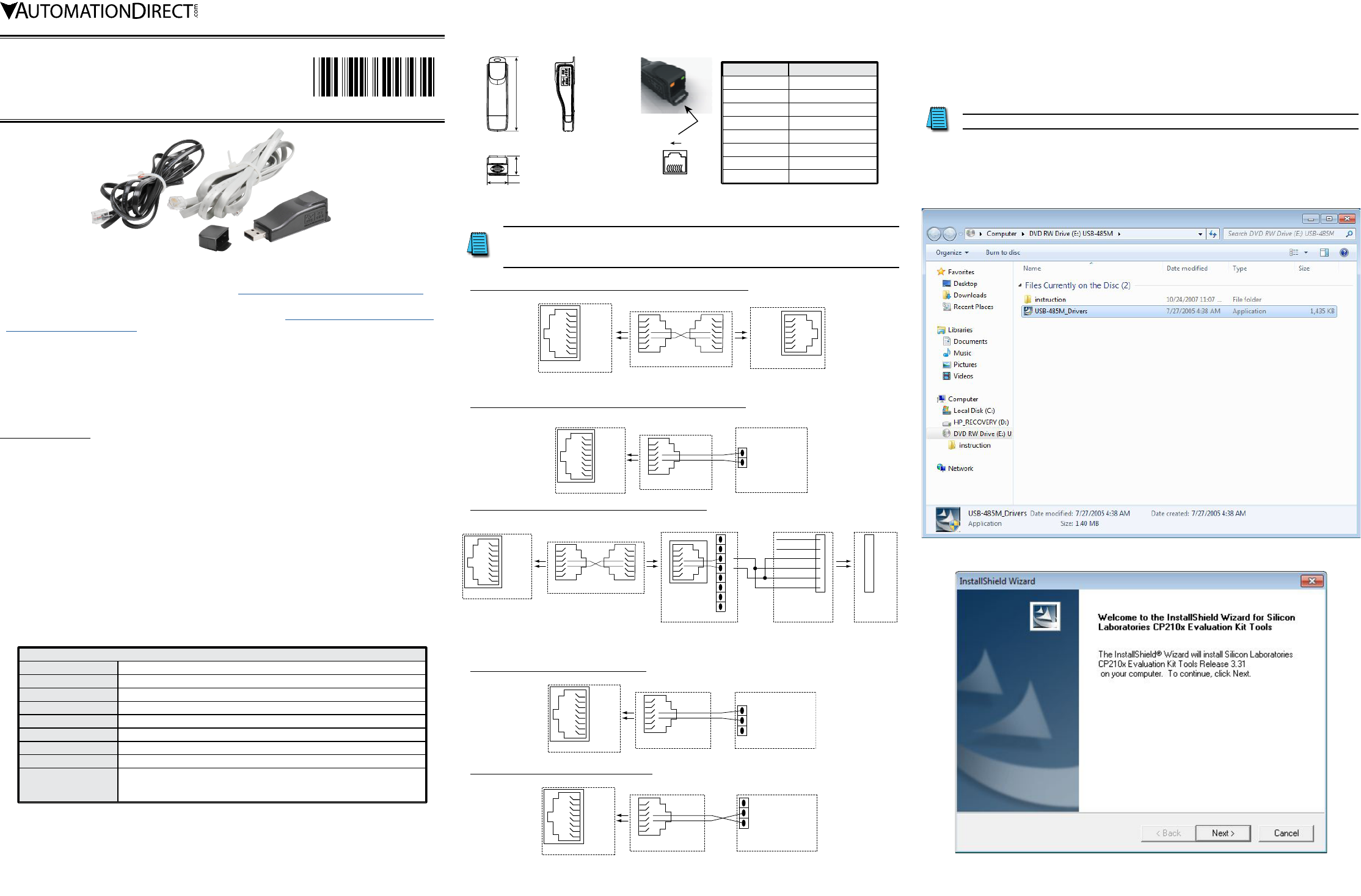
led disPlay
• Steady Green LED ON: power is ON.
• Blinking orange LED: data is transmitting.
80.0
[3.15]
UNITS:
mm [in]
22.5 [0.89]
21.2 [0.83]
dimensions
Pin Description
1 reserved
2 reserved
3 reserved
4 SG+
5 SG–
6 reserved
7 reserved
8 reserved
81
RJ-45
rJ-45 Pin-oUt
Wiring connections
The wiring connector on the USB-485M is a standard 8-pin RJ45 receptacle.
A standard 6-pin RJ12 connection plug fits into the RJ45 receptacle,
but it connects only the middle six pins. RJ12 pins 1–6 connect to RJ45 pins 2–7.
Wiring Connections for GS/DURApulse Series AC Drives
4 (SG+)
5 (SG–)
1
8
USB-485M Converter
RJ45 Receptacle
USB-485M
gray 6-wire crossover cable
1
6
3
4
RJ12 Plug
1
6
RJ12 Plug
3
4
GS Series AC Drive
1
6
(SG–) 3
(SG+) 4
RJ12 Receptacle
This cable cross-connects
pins 1 to 6, 2 to 5, etc.
Wiring Connections for SOLO Temperature Controllers
4 (SG+)
5 (SG–)
1
8
USB-485M Converter
RJ45 Receptacle
green
1
6
3
4
USB-485M
black 2-wire cable
RJ12 Plug
red
Flying
Leads
SOLO
Temperature Controller
Data – (RS-485)
Data + (RS-485)
Terminals
Wiring Connections for SureServo Servo Drives
4 (SG+)
5 (SG–)
1
8
USB-485M converter
RJ45 Receptacle
ZL-RTB-RJ12
feed-thru module
4
5
6
SH
SH
2
3
1
Terminal Blocks
RJ12
Receptacle
USB-485M
gray 6-wire crossover cable
1
6
3
4
RJ12 Plug
1
6
RJ12 Plug
3
4
This cable cross-connects
pins 1 to 6, 2 to 5, etc.
NOTE: Do not terminate any other
wires from this cable. Cut and tape them off.
(The other wires are used by the SureServo drive.)
1
6
3
44
5
6
2
3
1
RD / BK
YL
YL / BK
BN / WH
RD
BN
IEEE
1394
Plug
Flying
Leads
SVC-MDCOM-CBL
communication cable
SureServo drive
(CN3 terminal)
4
5
6
2
3
1
IEEE
1394
Receptacle
Wiring Connections for CLICK PLCs
4 (SG+)
5 (SG–)
1
8
USB-485M Converter
RJ45 Receptacle
green
1
6
3
4
USB-485M
black 2-wire cable
RJ12 Plug
red
Flying
Leads
CLICK PLC (Port 3)
– Signal B (RS-485)
LG Logic Ground (0V)
+ Signal A (RS-485)
Terminals
Wiring Connections for P3-550 PLCs
USB-485M Converter
4 (SG+)
5 (SG–)
1
8
RJ45 Receptacle
USB-485M
black 2-wire cable
green
1
6
3
4
RJ12 Plug
red
Flying
Leads
P3-550 PLC (RS-485 port)
– TXD-/RXD-
+ TXD+/RXD+
G GND
RS-485
Terminals
PreParations before installing driver (extract the driver file)
Install the driver file onto your PC BEFORE installing the USB-485M communication adapter. The
driver file (USB-485M_Drivers.exe) is located on the mini-CD supplied with the USB-485M.
Do NOT connect the USB-485M to your PC before extracting the driver file.
Insert the mini-CD into your PC, follow the file installation prompts, and accept the default
selections except as shown below. (The following screen captures are from 32-bit Windows 7. The
installation windows from other operating systems may vary somewhat.)
• Select the file “USB-485M_Drivers” for installation:
• “Silicon Laboratories CP210x Evaluation Kit Tools” will be installed on your PC:
2017-09-06
5011670101-UM01
Data Sheet: USB-485M_QSP 2nd Ed 09/06/2017 Sheet 2 of 2
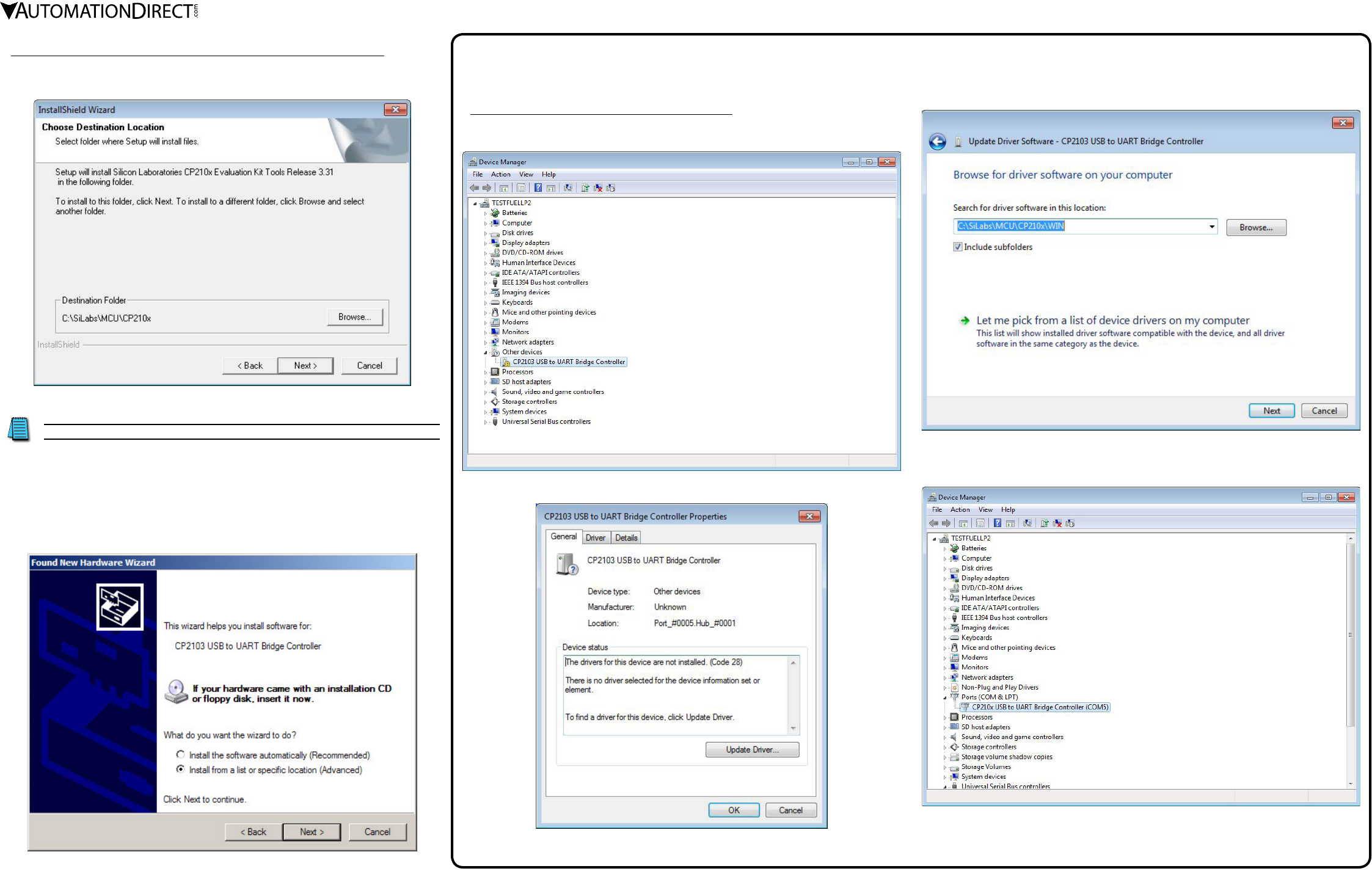
Preparations BEFORE Installing Driver (Extract the Driver File) (continued)
• Use the “Browse...” button only if you want to install the driver file in PC folder other than the default
folder (not recommended):
driver installation
Do NOT connect the USB-485M to your PC before extracting the driver file.
AFTER installing the driver file onto your PC, connect the USB-485M communication adapter to the
USB port of the PC and install the driver onto the USB-485M.
Follow the file installation prompts and accept the default selections except as shown below.
(The following screen captures are from Windows XP Service Pack 3. The installation windows from
other operating systems may vary somewhat.)
• We recommend “Install from a list...”, especially if you installed the driver file on your PC in a file
location other than the default location.
troUbleshooting
(Required Only if Driver Installation is Unsuccessful)
• With the USB-485M connected to the PC, go to:
Control Panel --> System --> System Properties --> Hardware --> Device Manager --> Other devices,
and select the “CP2103 USB to UART Bridge Controller”:
• From the “General” tab, select “Update Driver...”
• Browse to the file location where the driver is stored:
• After the driver is successfully updated, the applicable comm port will show in Device Manager.
(The comm port number may vary depending upon your PC.)
Double click the comm port to set the baud rate, stop bits, etc.
