PDF Walther P38
Walther P38 Walther P38
User Manual: PDF T E X T F I L E S
Open the PDF directly: View PDF ![]() .
.
Page Count: 24
CF~
p-38
9MM
Au+o
R’b+oR
OWEIt’S
MANUAL
1
1
CARL WALTHER. WORKS FOR SPORTS-AND HUNTING WEAPONS. ULM DONAU . GERMANY

The
WALTHER
Police Pistol Models PP and PPK hove, by virtue of their unique construc-
tion, proved themselves to be the World’s safest and most dependable handguns.
The absolute faith in these two products induced specialists both at home and abroad to
demand
a pistol of a similarly recognized and approved construction which would retain
the
principle of a
veq
light
weight
and at
the
same
time
flro
the
more
powerful
cartridge
Cal. 9 mm
?ambellum.
lho
outcome
of
the
appropriate considerations was
the
new
WALTHER
Model P
38
Cal.
9 mm
Parbollum,
which combines a phantastically low
weight
of only a
liilo
over
27
ounces with all
the
drimblo
advantages of a modern handgun
-
absolute safety, in-
stantaneous readiness, and easy handling
-
and which allows the
use
of a considerably
more potent cartridge. This pistol stands without rival.
All
the
component parts are
interchangeable.
They are
mado
by means of
the
most
up-to-
date production methods involving the use of modern machinery under strictest
ruper-
vision. As in the
manufacture
of any other of the
sevoral
WALTHER
products, only
the
very best materials are used in the production of
the
Model P
38.
The pages of this little brochure will give
a
most detailed and therefore very useful
description of the various
data
relating to the pistol Model P 38.
@@@
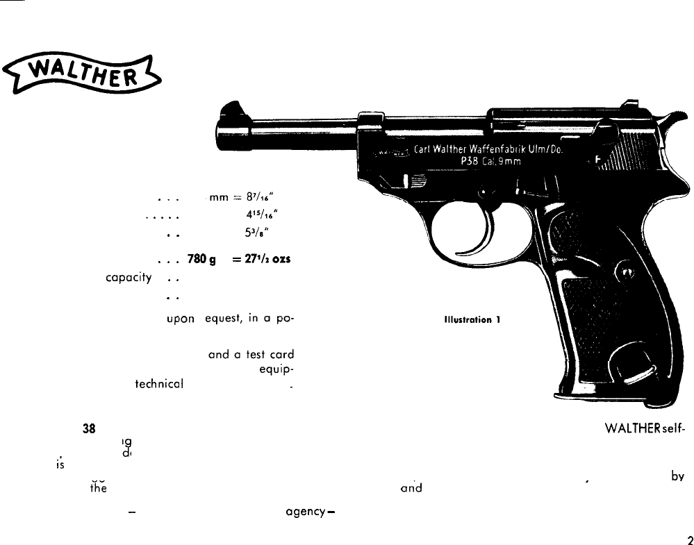
Auto Pistol Model P 38 Cal. 9 mm Parabellum
General Data:
Overall Length
.
.
.
Length of Barrel
.
.
.
.
.
Height of Pistol
.
.
Total Weight
.
.
.
Magazine capacity .
.
.
Standard Finish
.
.
The pistol can be supplied, Up
lished and blued finish.
A spare magazine, a cleaning
are supplied with every pistol.
ment also includes a
technica
delivered in a stout carton.
214
125 mm =
415/16*
136 mm =
S/S”
7809
=
27%
01s
8 Cartridges
set block (matted).
Ion
r
rod,
The complete equip-
II
description and is
The pistol P
38
has an external hammer. The combination of o perfect action design, mode evident in the
WALTHER
self-
loading pistols havin an external hammer, and the constant readiness of a revolver makes the enormous odvantages of
these weaoons obun
3
antlv manifest.
The P 38
ii
o double-actidn, locked-breech, semi-automatic pistol. It is fitted with on external hammer which is connected
to a tension triaaer and which has a distinctive pressure point. The P 38, like the models PP and PPK, may be fired by
merely pulling
yhi
trigger. It may, moreover, readily be co’rried loaded
on’d
uncocked.
I
Cartridges with faulty primer cops can be fired by pulling the trigger repeatedly.
A bulge in the borrel
-
caused by some irregular agency
-
will not impede the functioning of the P 38, since the barrel is
mounted in on open and unencumbered manner. The pistol is thus alwoys ready for instant use.
n
L
An entirely new method has been adopted in the con-
struction of the safety device’of the P 38.
As may be well known, there is always a certain amount
of danger inherent in any loaded and cocked firearm,
even though the latter may be rendered ‘safe’ by means
of the safety lever. Any sudden mechonicol
shod
or a
fracture of on
action
component con cause on accidental
discharge.
In the P 38, this basic evil has been remedied: the rotary
safely
catch
does not make the action mechanism safe in
the cocked stage.
Instead,
-
application of the safety catch
causes the hammer to become uncocked,
-
and that with-
out any danger to the user. When the safety catch is mov-
ed to the ‘Safe’ position, the firing pin becomes
lodted
first. Immediately following this, the action mechanism is
automatically
blodted
and the hammer drops harmlessly
-
and the pistol is completely uncocked.
Un-cocking of the hammer by means of applying the
so-
fety catch, preceded by the locking of the firing pin and
the connection with the tension trigger, make the P
38
a
truly ideal service pistol.
Since the pistol is thus always uncocked but nevertheless
always ready for immediate use, the hammer spring is
therefore not subject to fatigue and weakening.
The P 38 can be dismantled within a few seconds and
without using any tools. Component parts
connot
drop out.
Any unnecessary operating of the trigger mechanism
should be duly avoided, and the hammer should not be
allowed to drop while the
chamber
is empty. In any in-
stance of ‘dry’ shooting practice, a dummy cartridge
should be introduced into the chamber first.
It is an essential rule for every shooter that despite the
fully guaranteed safety of the weapon, the pistol should
always be held so that the muzzle points downwards while
the
weapon
is not being actually used.
3
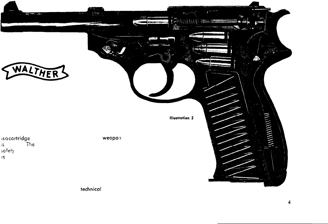
P 38 Auto Pistol
Cal. 9mm Parabellum
in
longitudinal section
In this Illustration, the signal pin immediately above
the hammer is clearly visible. It indicates that there
is
CI
ccrtridge in the chamber. i. e., that the
weapo;l
is
loaded. The signal pin remains visible when the
;cfety catch is applied. The pistol is uncocked, but
IS
nevertheless ready for action. Illustration 4 shows
how the pistol is fired by merely pulling the trigger
(in ‘Double-action’ shooting).
A list of the individuol component parts moy be
found on pages 17 and 18 of this
technical
descrip-
tion.
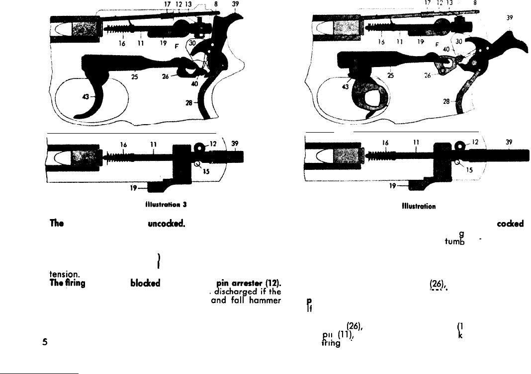
Graphic Description
Illus1mli0n 3
The
pistol is loaded and
uncocked.
The safety lever is ‘off.
The pistol is thus ready for instont use (‘Double-Action’).
Automatic Safety
The pistol, though uncocked and loaded, moy thus be
fired. The safety lever (19
1
is in the ‘Fire’ position. The
weopon is, OS shown in II ustration 3, entirely free from
tensron.
The
firing
pin (11) is
blodced
by the firing
The live round in the chamber cannot be
pistol should occidentally be dropped
first on the floor. The signal pin (8) can both be felt and
seen, and indicates that there is a cartridge in the
&amber (Illustration 3).
5
Illustration
4
The pistol is loaded, safety lever ‘off’, and
codted
by
‘pulling through’ (Double-Action trig er motion, shown
here in the moment in which the
turn
%
.
released by the sear). ler IS about to be
Operating the Trigger
The trig er (43) has been pulled back until the tumbler
edge (40 of the hammer (39) barely rests on the sear
3
edge of the tensioning piece
(26),.
as shown in Illustra-
tion 4.
Until then, the firing pin (11)
IS
blocked by the firing
Pin
arrester 92).
f the trigger (43) is now pulled back a little further, the
sear (40) of the hammer slides off the edge of the cock-
ing piece
(26),
the firing pin arrester 12) releases the fir-
ing
P.
in
(ll!,
and the hammer (39) striI,es the rear end of
the
rrmg
pm (11).
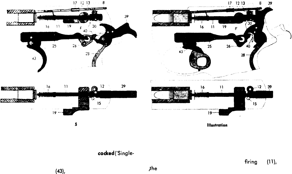
Illustration
5
Illustrtiion
6
Pistol loaded and cocked, safety lever ‘Off Pistol at the moment of firing
Operating the trigger when the hammer is
coded
(‘Single-
Action’).
Upon pulling the trigger
(43),
the cocked hammer (39) is
releosed from its rearward position by the lifting motion
of the cocking piece (26) and strikes the unlocked firing
pin (11).
Process of firing
The hammer (39) strikes the unlocked
firing
pin
(ll),
ond
jhe tip of the latter detonates the primer by hitting and
indenting the primer cap, thus igniting the powder charge
and thereby causing the resultant pressure gases to drive
the bullet out of the cartridge case.
6
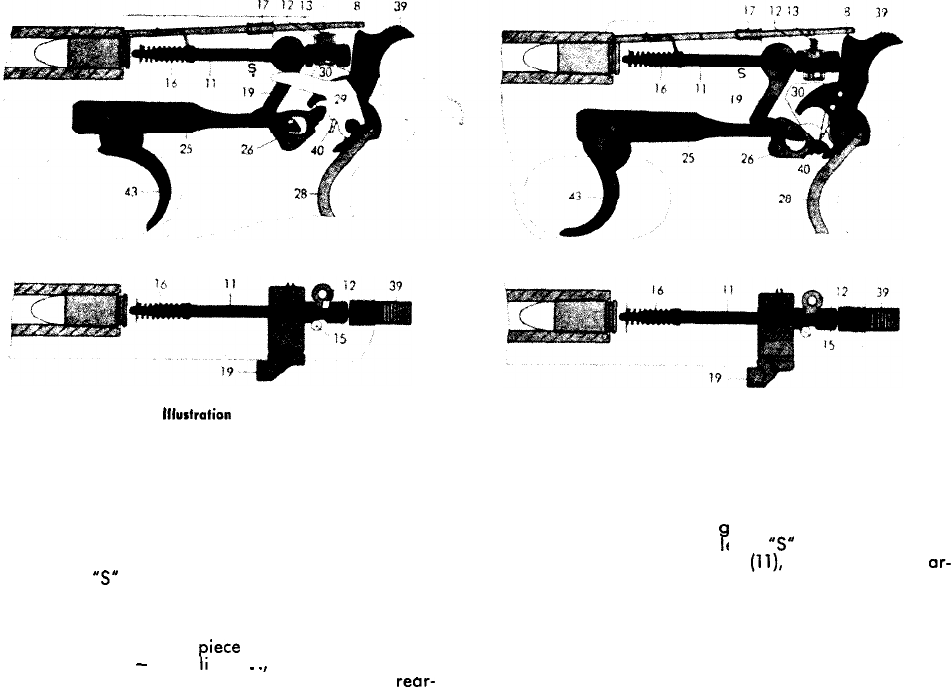
lllusfrafion
7
illustration 8
Pistol loaded, safety lever ‘Off
Operating the safety lever when the hammer is cocked.
The hammer (39) has been drawn back, and the arm is
thus ready. The protruding signal pin (8) indicates that
there is a cartridge in the chamber.
If for some reason it is not intended to fire the round, the
safety lever (19) should in such case be moved downwards
until the letter
5”
becomes clearly exposed. This appli-
cation of the safety lever (19) causes the firing pin (11) to
be blocked (see arrows). Moreover, during the last third
of the lever travel the hammer (39) becomes disengaged
by the lifting of the cocking
iece
(26) and drops forward.
(See also: page 10,
-
‘Hand ing’ .
.
.,
and Illustration 14.)
P
The trigger moves backwards and remains in the rear-
most limit of its travel.
Pistol loaded, safety lever ‘Off
Operating the safety lever when the hammer is uncodced.
The firing pin (11) remains blocked by the automatic safety
effect of the firing pin arrester (12) when the hammer is in
an uncocked state. By movin
wards, thereby exposing the etter
‘5”
fully, an additional
P
the safety lever (19) down-
lock is applied to the firing pin
(ll),
as shown by the or-
rows in Illustration 8. The trigger remains in its normal
forward position.
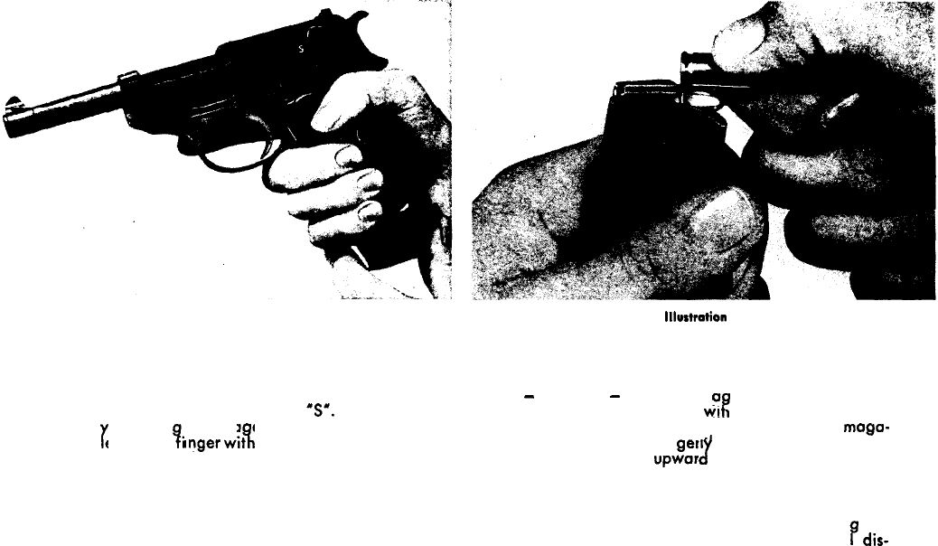
Directions for the Use and Handling of the Pistol P 38
Illustration 9
loading
Hold the pistol with the right hand and render it safe by
turning the safety lever downwords to the fullest extent
of its travel, thus fully exposing the letter
5’.
Remove
the mogozine
b
releasin the ma azine catch with the
left thumb. The eft index
anger
wtt
r
7.
4
draws the magazine
from the grip, as shown in the above Illustration 9.
lllurtration
10
Filling the magazine
Hold the magazine with the left hand and push the cart-
ridges
-
base first
-
under the ma
3
ozine lips by carefully
depressing the feeder platform wtt the cartridge rim. The
magazine holds 8 cartridges. When emptying the mogo-
zine, push the cartridges
gent1
forward until they are
finally expelled by the upwor
J
thrust of the magazine
spring. The 7 holes in the side of the magazine serve to
facilitate chedcing the contents of the magazine.
Any forceful jamming-in or tearing-out during either of
these two respective operations would cause damo
B
e to
the magazine and consequently lead to functiona
dis-
orders of the pistol.
8
IllurWation
11
Illustrdion
12
Introducing the first cartridge into the chamber
After inserting the full
ma
azine into the pistol grip, hold
the pistol with the right 3,and. The pistol must still be
‘safe’. Next, grip the slide by the ribbed rear end with the
left hand and pull fully backwards
-
then let go. This
operation causes the first cartridge to slip into the cham-
ber. The hammer, however, does not become cocked by
this process, as the safety lever is still ap
mer of the P
3
therefore cannot be co
cl?
lied and the ham-
ed either by hand
or else be pulling the trigger through. To make the pistol
ready for immediate use, push the safety lever upwards to
cover the letter
“‘5”
completely and the letter
‘F”
(‘Fire’)
becomes visible. The weapon will still remain uncocked,
since the firing pin is still blocked. The pistol is neverthe-
less ready for firing.
9
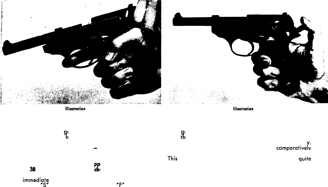
‘Single-Action’ shooting
In tar
with
t9,
et shooting, it is recommended to cock the hammer
e right thumb as shown in Illustration 12. With a
little practice, this operation should become fairly
eas
It offers the advantage of having only a comparafive y
Y’
slight amount of resistance (trigger pressure) to overcome.
This
in its turn increases the accuracy in shooting quite
considerably.
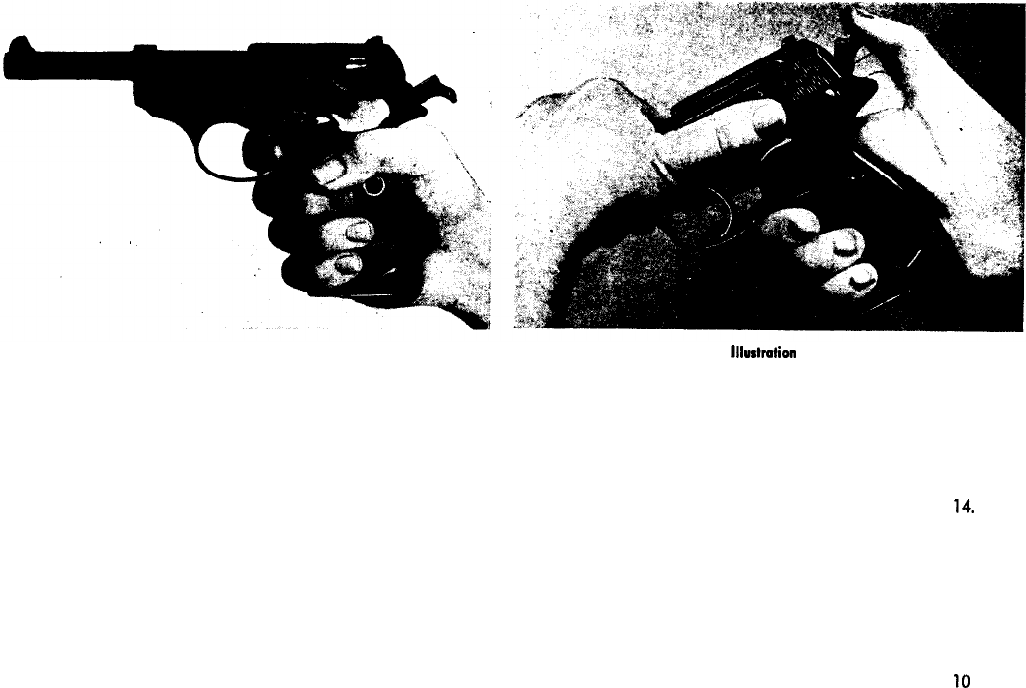
Illustration 13
‘Double-Action’ shooting
Firing fhe first shot by means of the ‘single-action’ method
is, of course, chiefly enacted in practice and competition
shooting at targets, while ‘double-action’ shooting occurs
mainly under active service conditions. In the latter event,
the hammer is cocked by simply pulling the trigger through
its entire length of travel for the first shot.
Should for reasons of faulty ammunition the pistol fail to
fire in such exceptional cases, the trigger should be pulled
again. A second impact of the firing pin on the primer cap
will as a rule cause even a defective round to detonate.
lllurtmtion
14
Operating the safety lever
Hold the weapon with the right hand, and place the right
index finger along the side of the trigger guard. The right
thumb grips the hammer, while the left thumb pushes the
safety lever downwards. The hammer can now slowly
return to its resting position, as shown in illustration
14.
Care should be taken that the muzzle of the pistol paints
downwards.
10
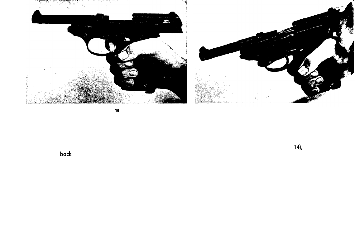
Illustration
15
The emptied magazine
When the last round in the magazine has been fired, the
slide stays open. If shooting is to be continued, remove
the empty magazine and insert the next full magazine.
Pull the slide
bade
lightly and then let it glide forwards.
This process will cause the first round to be introduced
into the chamber.
This cartridge may also be fed into the chamber without
using the left hand: by simply depressing the catch lever
with the right thumb. If it is not intended to continue
shooting, apply the safety lever (see page 10, Illustra-
tion 14).
Illustration 16
Unlooding
If the pistol P 38 is to be unloaded after a live round has
been lodged in the chamber, put the safety lever into the
Safe’ position (see page 10, Illustration
14),
withdraw the
magazine, and remove the cartridges from the latter. Now
pull the slide fully back (as shown in Illustration 16). The
cartridge will be extracted from the chamber by this ope-
ration and drop out.
11
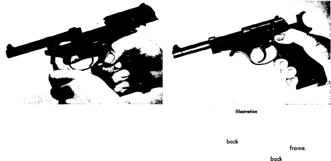
Illustration 17 lllustmtion
18
Dismantling
insert an empty magazine. Hold the pistol with the right
hand and move the safety lever to ‘Safe’ (see page 10,
Illustration 14). Next, pull the slide back until it stays open,
and remove the magozine. Then turn the barrel catch lever
downwards with the left thumb until it engages with an
audible ‘click’.
Dismantling
The barrel catch lever having been pushed down, the slide
should now be pulled
bade
slightly and then be allowed
to move forward so as to be separated from the
frame.
Alternatively, the slide may be drawn
back
with the left
hand while the right thumb depresses the breech catch
lever. Following this, the slide may be allowed to glide
If an empty magazine is not available, the retracted slide
may be made to stay open by pushing the catch lever up-
wards.
forward and off the frame unit.
12
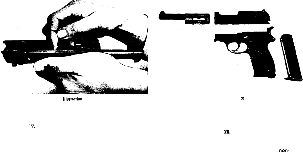
lllurtration
19
Separating the barrel from the slide
Hold the slide upside-down in the left hand as shown in
lilustration
;9.
Press the small internal locking bolt to-
wards the muzzle end with your right index finger. The
barrel can then be readily taken out of the slide unit.
Illustration
20
Cleaning the component parts
The pistol has now been partly stripped and split up into
its four main units: barrel, slide, frame (grip), and maga-
zine, as shown in Illustration
M.
These components can
now be cleaned and oiled.
The barrel, the grooves of the slide, and the grip unit
should be lubricated with a good, acid-free, and
non-
resinous oil, and the barrel should then be wiped dry
again.
Any further dismantling should be carried out only if there
is an uncommonly great amount of dirt present in these
parts. Any such work, however, should be entrusted to
skilled craftsmen.
13
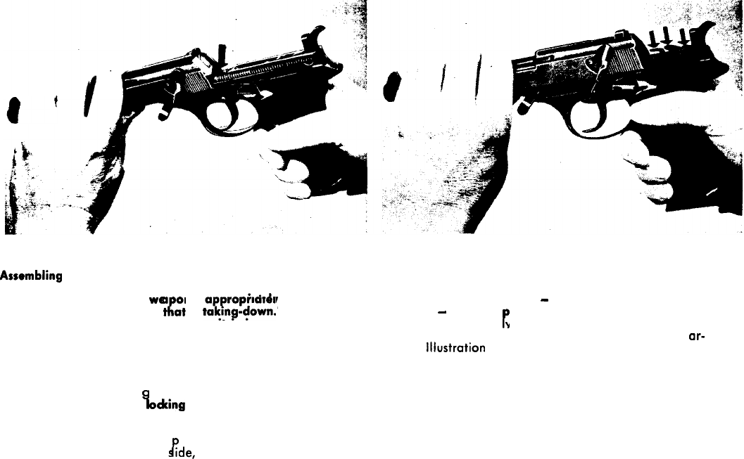
Illustration 21
Illustration 22
Assembling
The re-assembling of the
wea
on is a propriately carried
out in the opposite order to
tl?at
of
to&down.
In order
to avoid damage during this process, it IS important that
the following explanations and Illustrations be observed:
It is particularly important to realize that re-assembling
can be carried out only while the pistol is in a ‘safe’ state,
i. e., the hammer must be ‘down’. First, re-fit the barrel to
the slide. When attochin this re-assembled unit to the
grip unit, ensure that the
I
oclcing
bolt below the chamber
IS pressed upwards with the left thumb in the manner
shown in Illustration 21. The slide unit can now be freely
pushed back over the frame to without any fear of dam-
age to the recoil springs, the
s
rde,
or the frame.
1!
The three protruding parts
-
ejector, release lever, and
trip lever’
-
must be
P
ushed downwards so as to permit
the slide to run freey back over the top of the frame
(the three components in question are indicated by ar-
rows in lliustration 22).
14
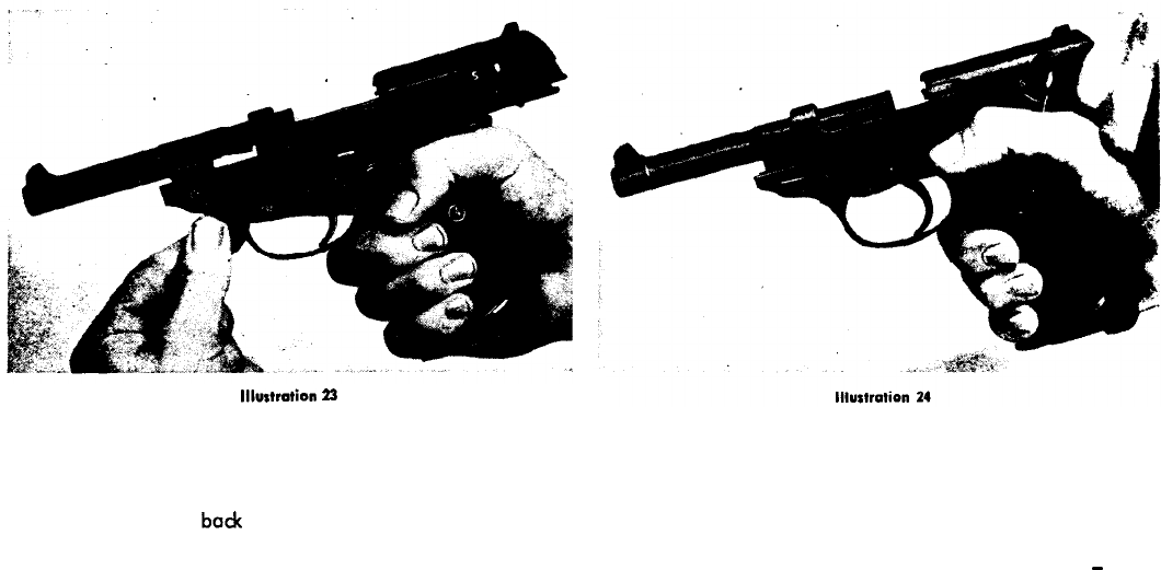
lllurtrotion
23
Assembling
Insert the empty magazine into the grip, then pull the slide
bock until the latter engages and stays open. Now push
the barrel catch lever bath into its normal locking position
with the left thumb, as shown in Illustration 23.
Finally, push the breech locking lever downwards with the
right thumb and at the same time pull the slide back with
the left hand, then let the slide move forward.
The P 38 is now once again in its complete original state,
-
safe, and ready for further service.
15
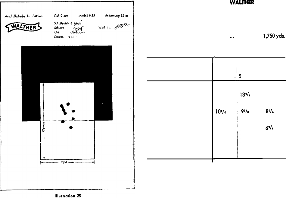
Test Target with test group of the WALTHER Self-loading
Pistol P 38, Cal. 9 mm Parabellum.
Ranges and Performance:
Sighting range . . . . . . . . 50 m = 54.681 yds.
Range of shot, approximately
.
.
1,600 m = 1,750yds.
Depth of penetration:
r
Material
25 m
17.34 yds
Range
50 m
i4.68 yds.
5
v
-
200m
18.72 yds.
Loose soil
Sand
Pine wood
Sheet iron, 2 mm (0.0787”)
thick, hit at an angle
of 90 degrees
36 cm
14 ins.
26 cm
101/h
ins.
23 cm
9 ins.
cut
clean
through
35 cm
13V4
ins.
25 cm
9’/1
ins.
23 cm
9 ins.
cut
clean
through
31 cm
12 ins.
21 cm
8’14
ins.
17cm
6%
ins.
cut
clean
through
Ammunition
The ammunition for the P 38 is the pistol cartridge
Calibre 9 mm Parabellum.
16
10
14
18
17
6
6
54
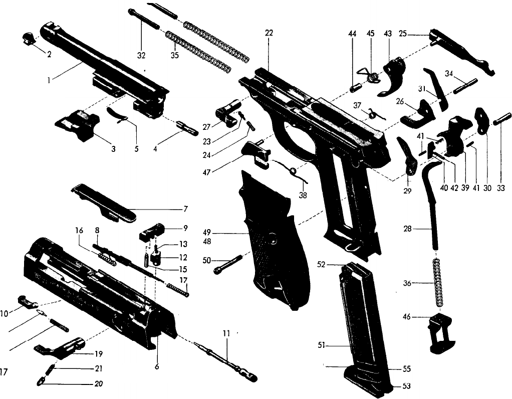
Illustration 26
UNIT I: Barrel
Barrel
Front sight
Locking-piece
Locking pin
V-spring
UNIT II: Slide
Slide body
6
Cover 7
Signal-pin
8
Rear sight
9
Extractor
10
Firing pin
11
Firing pin
lode
12
Spring to No. 12
13
Extractor pin
14
Limit stop pin
15
Firing pin spring
16
Signal pin spring
17
Extractor spring
18
The Components of the
Walther
Pistol P 38
Sofety lever unit
19
Rest pin
20
Rest pin spring
21
UNIT Ill: Grip
Frame
Rest pin
Rest pin spring
Trigger connector
Cocking-piece
Barrel catch lever
Striker rod
Relief piece
Release lever
Ejector
Recoil spring guide pins
Hammer pin
Cocking piece pin
Recoil springs
Striker rod spring
Trigger rod spring
22
23
24
25
26
27
28
29
30
31
32
33
34
35
36
37
Cocking piece spring
Hammer
Hammer trap
Pins to Nos.39 & 40
Hammer trap spring
Trigger
Sleeve
Trigger spring
Magazine holder
Catch lever
Grip plate, right
Grip plate, left
,
Grip plate screw
UNIT IV: Magazine
Magazine casing
51
Feeder platform 52
Magazine bottom lock
53
Magazine bottom
54
Feeder spring
55
38
39
40
41
42
43
44
45
46
47
48
49
50
18
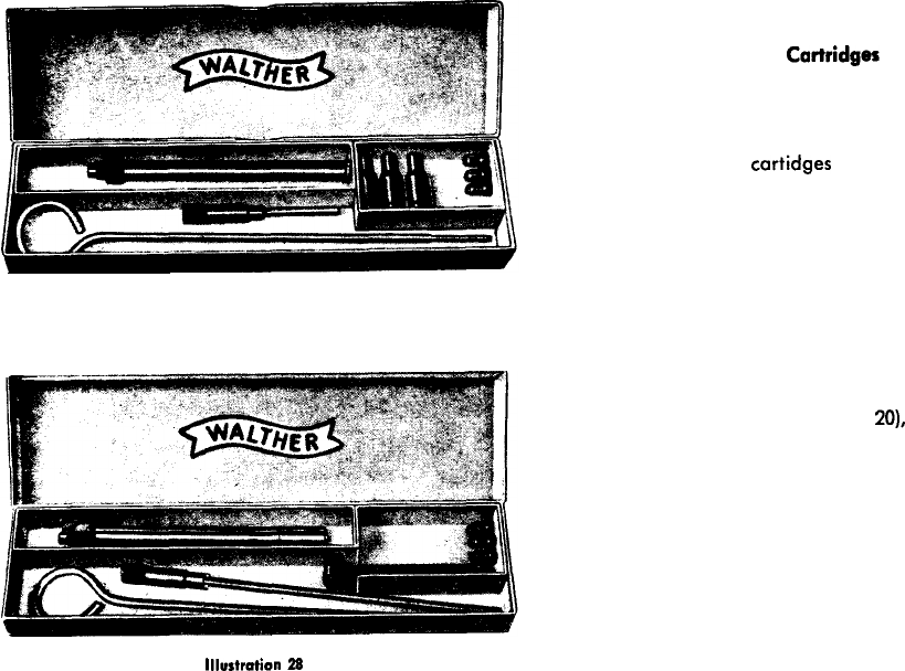
Illustration 27
Conversion Unit Cal. 4 mm (M 20)
for the Pistol P 38
with Steel Adaptor
Cortridger
comprising:
Insertion barrel (liner) with spring washer and
locking nut
3 steel adaptor
cartidges
Ejector tool
Cleaning rod
Additional steel adaptor cart-
ridges supplied upon request
and against payment of extra
cost.
Conversion Unit Cal. 4 mm (M
20),
with loading tool, for the Pistol P 38
comprising:
Insertion barrel (liner) with spring washer and
lock nut
Loading Tool
Ejector Tool
Cleaning Rod
lllustrotion
28
19

Instructions for the use of the Conversion Units
(as shown in Illustrations 27 and 28)
Conversion units, developed for the world-renowned
Walther
pistol models PP and PPK
and having proved a great success, are now also available for the pistol model P 38.
These conversion units make it possible to use the small Cal. 4 mm (M 20) cartridges for all
indoor practice shooting.
Fitting
Remove the slide in the usual manner (see page 12). Insert the conversion barrel (liner)
into the barrel of the P 38, apply the spring washer and the lock nut, and tighten up with
the aid of the ejector tool by applying the latter to the groove.
Shooting practice by using the steel cartridge adaptors
Insert a Cal. 4 mm cartridge into each steel adaptor, then feed the latter into the maga-
zine in the normal manner, and insert the magazine into the grip of the P 38. Next, feed
a round into the chamber as demonstrated in illustrations 10 and 11. The pistol is now
ready for use. After firing the shot, pull the slide back with the left hand, thereby eject-
ing the steel adaptor containing the empty case from the chamber. The next ‘live’ adaptor
may now be brought into the chamber by letting the slide move forward, thus closing the
breech.
Shooting practice with the aid of the loading tool
Remove the magazine from the P 38, pull the slide fully back, and push the barrel catch
lever (breech lock) upwards. The slide will now stay open. Now insert a 4 mm
cartridge
into the chamber by using the loading tool, and release the slide by pulling the latter
slightly back. Let the slide move forward and close the breech. The shot may now be fired.
After discharging the round, open the breech and push the empty case out of the chamber
by means of the ejector tool. The empty case will readily drop out through the magazine
shaft.
20
er.-
_.,._._..
_:
,, -_,-“~‘-e_“->.
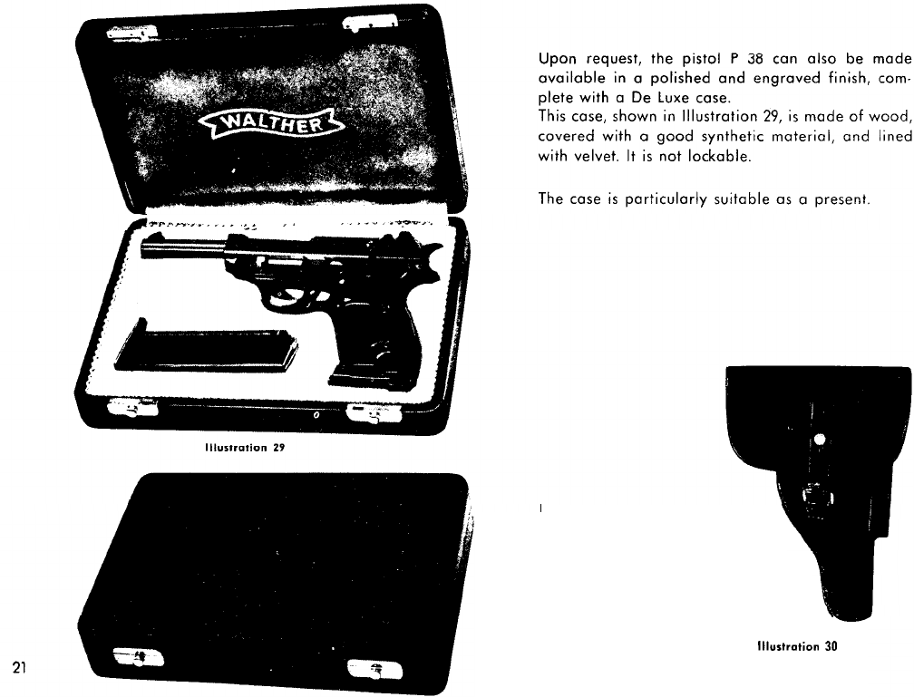
Holster for the Pistol P 38
Cal. 9 mm Parabellum
Made of harness leather,
dull black finish outside and
smooth inside. External
magazine pocket. Two loops
for attachment to a belt.
-
Illurtration
30

General reference:
Description of pistol
Sectional view of pistol
Graphic Descriptions:
Automatic
Safety
mechanism
‘Double Action’ shooting
‘Single Action’ shooting
Process of firing
Operating the safety lever:
a) when the hammer is
codred
b) when the hammer is not
codced
Poge
Illustration
1
1
2&3
1
42
5
3
54
6
5
6
6
7
7
7
8
Directions for the use and handling:
Loading
8
Filling the magazine
8
9
10
Introducing the first cartridge 9
11
‘Single Action’ shooting
9
12
‘Double Action’ shooting
10 13
Rendering the P 38 safe
10 14
The emptied magazine
11
15
Un-loading
11
16
Dismantling
12
17h18
Detaching the barrel
13 19
Cleaning
13
2tl
Assembling
14b15 21-24
Test target and performance
16
25
Description of components
17618
26
Conversion Units Cal. 4 mm 19&20
P&28
De Luxe case
21
29
Holster
21
30
Page
IllurtmtkA

A tradition of over
250
years
of
practtcal
experience
in the manufacture of precision-built
is
intktety
askiated
hunRng
,
sports
and
defence
weapons
with
this
name.
