Waspmote Lora 868mhz 915mhz Sx1272 Networking Guide
waspmote_lora_868mhz_915mhz_sx1272_networking_guide
User Manual:
Open the PDF directly: View PDF ![]() .
.
Page Count: 47
- 1. LoRa and LoRaWAN
- 2. Hardware
- 3. Dual radio with Expansion Board
- 4. General considerations
- 5. Transmission modes
- 6. Initialization
- 7. Node parameters
- 8. Packet parameters
- 9. Power gain and sensitivity
- 10. Long range tests
- 11. Connectivity
- 12. Starting a network
- 13. Joining an existing network
- 14. Security and data encryption
- 15. Understanding LoRa
- 16. Code examples and extended information
- 17. API changelog
- 18. Certifications
Waspmote-LoRa-868MHz_915MHz-SX1272
Networking Guide

-2- v7.0
Index
Document Version: v7.0 - 02/2017
© Libelium Comunicaciones Distribuidas S.L.
INDEX
1. LoRa and LoRaWAN ............................................................................................................................. 4
2. Hardware .............................................................................................................................................. 5
3. Dual radio with Expansion Board ..................................................................................................... 10
3.1. Expansion Radio Board ........................................................................................................................................................... 10
4. General considerations ..................................................................................................................... 12
4.1. Waspmote libraries ...................................................................................................................................................................12
4.1.1. Waspmote SX1272 les ............................................................................................................................................12
4.1.2. Constructor ...................................................................................................................................................................12
4.2. API functions ...............................................................................................................................................................................12
4.3. Additional functions ................................................................................................................................................................14
4.3.1. Getting temperature .................................................................................................................................................14
4.3.2. Getting maximum allowed current supply .......................................................................................................15
4.4. Waspmote reboot .....................................................................................................................................................................15
5. Transmission modes .......................................................................................................................... 16
5.1. LoRaTM mode ............................................................................................................................................................................... 16
5.1.1. Bandwidth ....................................................................................................................................................................17
5.1.2. Coding Rate ..................................................................................................................................................................17
5.1.3. Spreading Factor ........................................................................................................................................................17
6. Initialization ....................................................................................................................................... 18
6.1. Setting on ....................................................................................................................................................................................18
6.2. Setting o ....................................................................................................................................................................................18
7. Node parameters ............................................................................................................................... 19
7.1. Node address .............................................................................................................................................................................19
7.2. Frequency band .........................................................................................................................................................................19
7.3. Channel.........................................................................................................................................................................................20
8. Packet parameters ............................................................................................................................. 22
8.1. Structure used in packets ......................................................................................................................................................22
8.2. Maximum payload ....................................................................................................................................................................22
9. Power gain and sensitivity ................................................................................................................ 23
9.1. Power level ..................................................................................................................................................................................23
9.2. RSSI of one packet and RSSI of the channel .................................................................................................................... 24
9.3. SNR ................................................................................................................................................................................................. 24

-3- v7.0
Index
10. Long range tests .............................................................................................................................. 25
10.1. Line of Sight test .....................................................................................................................................................................25
10.2. Non Line of Sight tests ..........................................................................................................................................................26
10.2.1. Tests in Zaragoza ......................................................................................................................................................26
10.2.2. Test in Paris .................................................................................................................................................................28
11. Connectivity ..................................................................................................................................... 29
11.1. Topologies ................................................................................................................................................................................. 29
11.2. Connections .............................................................................................................................................................................30
11.2.1. Unicast .........................................................................................................................................................................30
11.2.2. Broadcast ....................................................................................................................................................................31
11.3. Connection parameters .......................................................................................................................................................32
11.3.1. Setting retries ............................................................................................................................................................32
11.4. Sending process ......................................................................................................................................................................32
11.4.1. SX1272 API packet structure ..............................................................................................................................32
11.4.2. Using Frame class to create SX1272 packets .................................................................................................33
11.4.3. Sending data .............................................................................................................................................................33
11.5. Receiving data .........................................................................................................................................................................34
11.5.1. How to receive packets in Waspmote ..............................................................................................................35
11.5.2. How to show received Frames ............................................................................................................................35
11.5.3. Receiving all packets ..............................................................................................................................................36
12. Starting a network ........................................................................................................................... 37
12.1. Choosing a channel ............................................................................................................................................................... 37
12.2. Choosing a mode ..................................................................................................................................................................37
13. Joining an existing network ........................................................................................................... 38
13.1. Channel ...................................................................................................................................................................................... 38
13.2. Mode ........................................................................................................................................................................................... 38
14. Security and data encryption ......................................................................................................... 39
14.1. Security in transmissions ..................................................................................................................................................... 39
15. Understanding LoRa ....................................................................................................................... 40
15.1. Introduction .............................................................................................................................................................................40
15.2. Long Range VS Transmission time / consumption ..................................................................................................... 41
15.3. LoRa VS XBee 868/900 MHz ................................................................................................................................................ 42
15.4. For what applications is LoRa a good option? ............................................................................................................ 42
15.5. For what applications is NOT LoRa a good option? .................................................................................................43
16. Code examples and extended information ................................................................................... 44
17. API changelog .................................................................................................................................. 46
18. Certications .................................................................................................................................... 47

-4- v7.0
LoRa and LoRaWAN
1. LoRa and LoRaWAN
This guide explains the LoRa features and functions. There are no great variations in this library for our new product lines
Waspmote v15 and Plug & Sense! v15, released on October 2016.
Anyway, if you are using previous versions of our products, please use the corresponding guides, available on our Development
website.
You can get more information about the generation change on the document “New generation of Libelium product lines”.
Libelium currently oers two options of this type of radio technology: LoRa and LoRaWAN
•LoRa contains only the link layer protocol and is perfect to be used in P2P communications between nodes. LoRa modules
are a little cheaper that the LoRaWAN ones.
•LoRaWAN includes the network layer too so it is possible to send the information to any Base Station already connected to
a Cloud platform. LoRaWAN modules may work in dierent frequencies by just connecting the right antenna to its socket.
These modules are based on the same modulation technology (the same PHY layer): LoRa™, developed by Semtech. The LoRa
module implements a simple link protocol, created by Libelium. However, the LoRaWAN module runs the LoRaWAN protocol, a
much richer and more advanced protocol, created by the LoRa Alliance.
The LoRa module and the LoRaWAN module are not compatible because the protocols are dierent.
This guide talks about the LoRa module, not about LoRaWAN. If you are interested in the LoRaWAN module, please read the
LoRaWAN Networking Guide:
http://www.libelium.com/development/waspmote/documentation/waspmote-lorawan-networking-guide/
-5- v7.0
Hardware
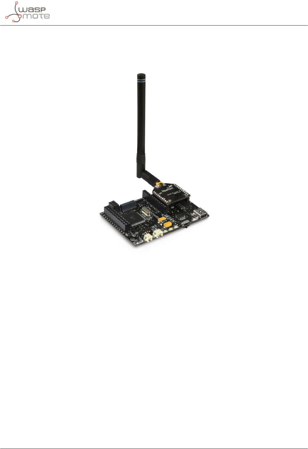
2. Hardware
The SX1272 chipset has been developed by the company Semtech. Based on this chipset, Libelium created the Waspmote-
compliant LoRa module (or SX1272 module).
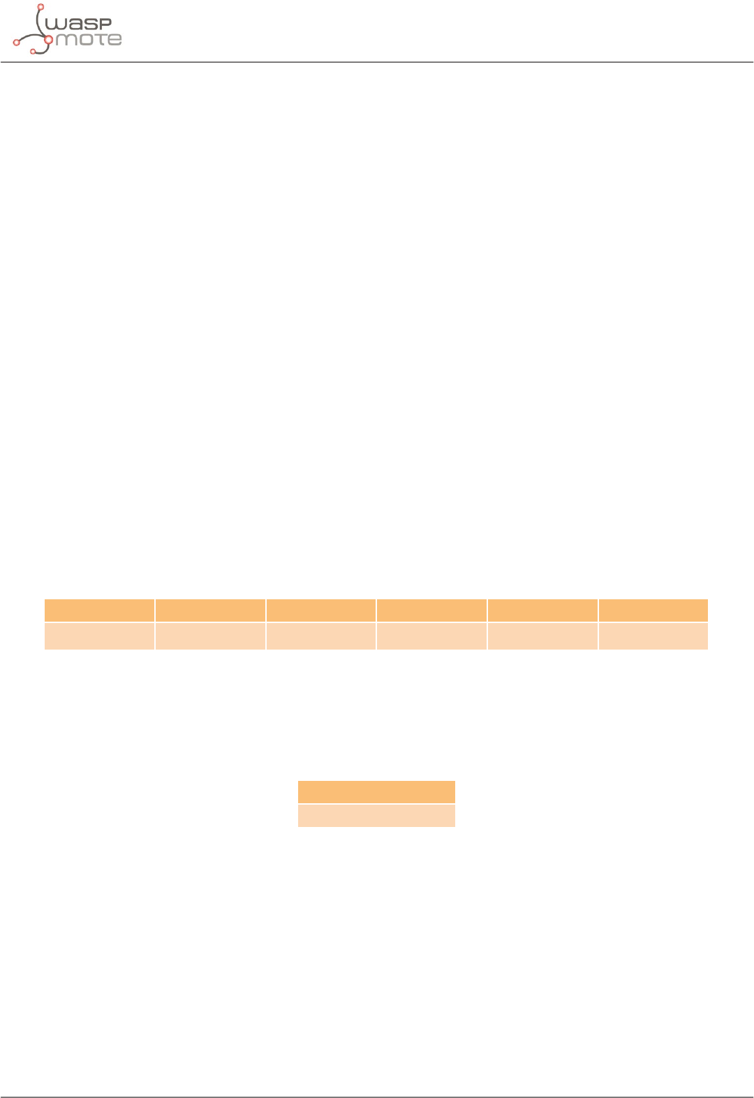
Module Dual frequency
band
Transmission
power Sensitivity Channels Distance
SX1272
863-870 MHz
(Europe) 14 dBm -134 dBm
822+ km
(13.4+ miles)
902-928 MHz (US) 13
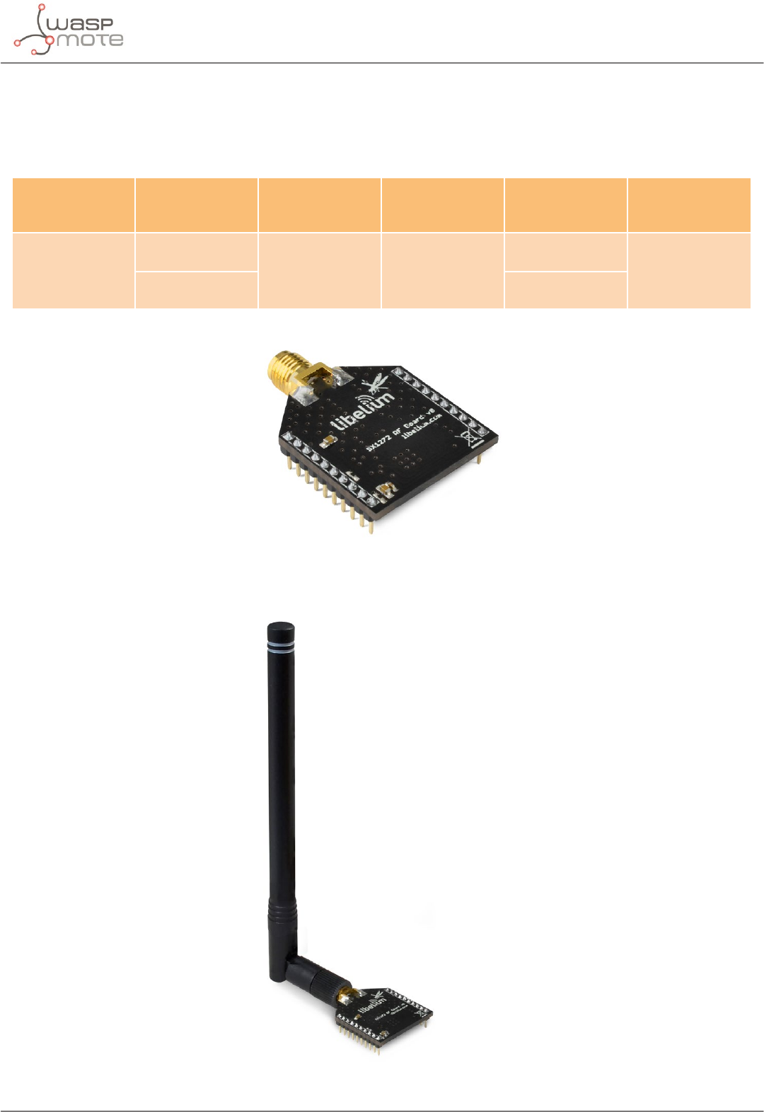
Figure: LoRa module
Figure: LoRa module with 4.5 dBi antenna
-6- v7.0
Hardware
The user must keep in mind that there are two dierent antennas for LoRa modules regarding the frequency band: 868 or 900
MHz. Although the appearance of these antennas is the same, the user must choose which one needs to be purchased.
Note: It is not recommended to work without an antenna screwed to the module. The module could be damaged due to RF reections.
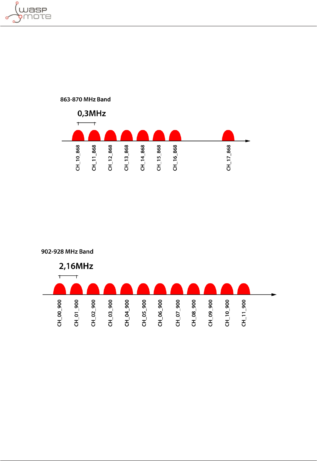
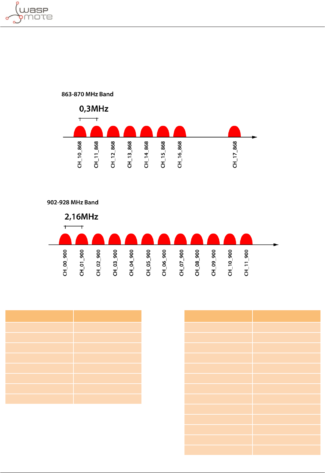
The frequency used in Europe is the free ISM band of 868 MHz, using 8 channels with a bandwidth of 0.3 MHz per channel. That
is shown in the following gure.
Figure: Frequency channels in the 868 MHz band
Note: These channels were chosen arbitrarily, according to the UN-111 appeared in the Spanish BOE-A-2013-4845. If necessary, users
can select the appropriate channels according to their country regulations.
The frequency used in USA, Canada, Australia, Singapore or Israel is the free ISM band of 900 MHz, using 13 channels with a
bandwidth of 2.16 MHz per channel. It is shown in the following gure.
Figure: Frequency channels in the 900 MHz band
Note: These channels were chosen arbitrarily; they t the channels used by the equivalent XBee 900 MHz. If necessary, users can select
the appropriate channels according to their country regulations.
-7- v7.0
Hardware
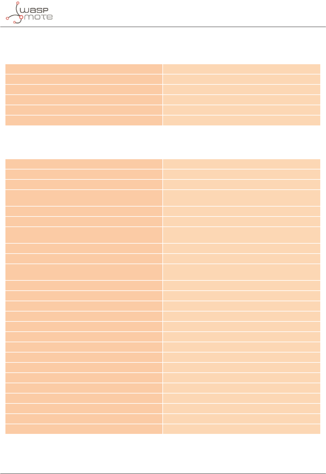
Channel Number Central frequency Channel Number Central frequency
CH_10_868 865.20 MHz CH_00_900 903.08 MHz
CH_11_868 865.50 MHz CH_01_900 905.24 MHz
CH_12_868 865.80 MHz CH_02_900 907.40 MHz
CH_13_868 866.10 MHz CH_03_900 909.56 MHz
CH_14_868 866.40 MHz CH_04_900 911.72 MHz
CH_15_868 866.70 MHz CH_05_900 913.88 MHz
CH_16_868 867 MHz CH_06_900 916.04 MHz
CH_17_868 868 MHz CH_07_900 918.20 MHz
CH_08_900 920.36 MHz
CH_09_900 922.52 MHz
CH_10_900 924.68 MHz
CH_11_900 926.84 MHz
CH_12_900 915 MHz
Figure: Channels used by the LoRa modules in 868 MHz and 900 MHz
Note: Due to the propagation characteristics of the 868/900 MHz bands, the near eld eect could make that 2 modules cannot
communicate if they are placed very close (< 1 m). We suggest to keep a minimum distance of 3 or 4 meters between modules.
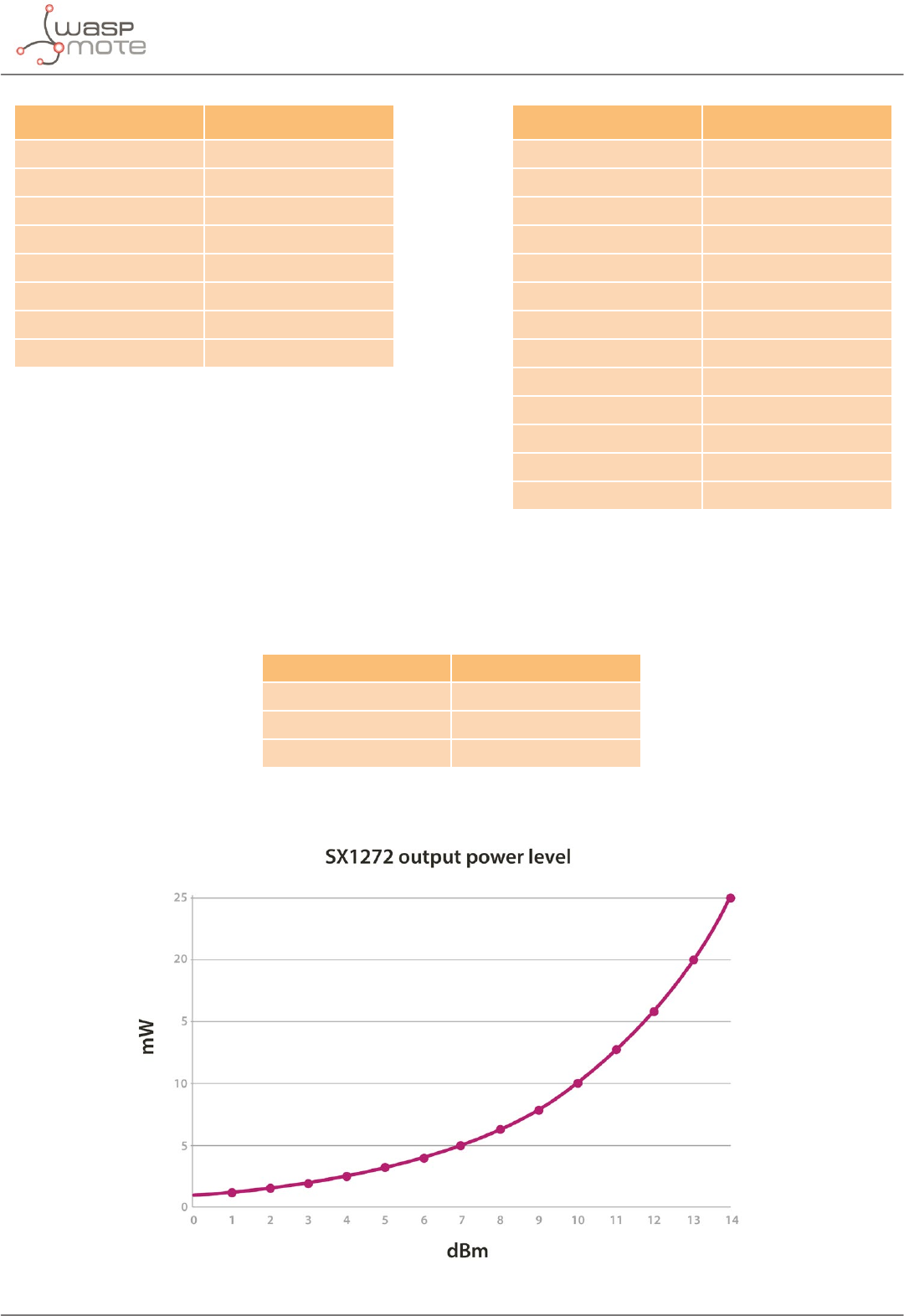
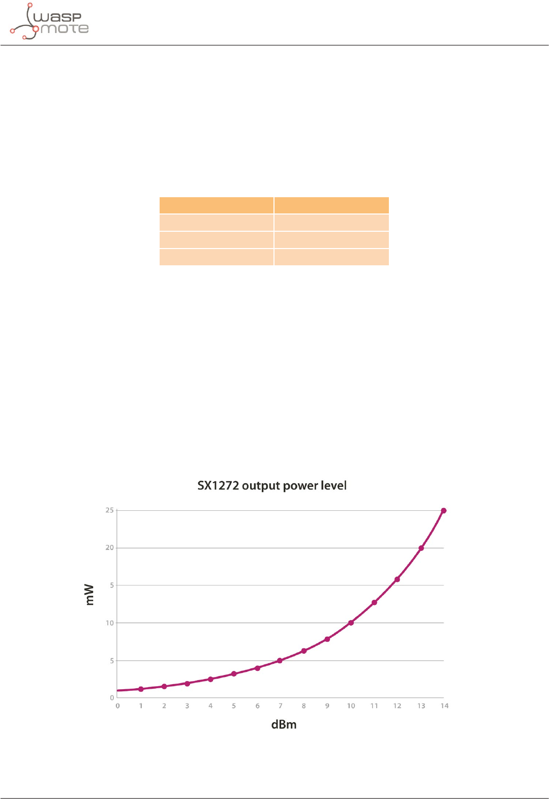
Regarding the energy section, the transmission power can be adjusted to several values:
Parameter SX1272 power level
'L' 0 dBm
'H' 7 dBm
'M' 14 dBm
Figure: Transmission power value
Figure: SX1272 output power level
-8- v7.0
Hardware
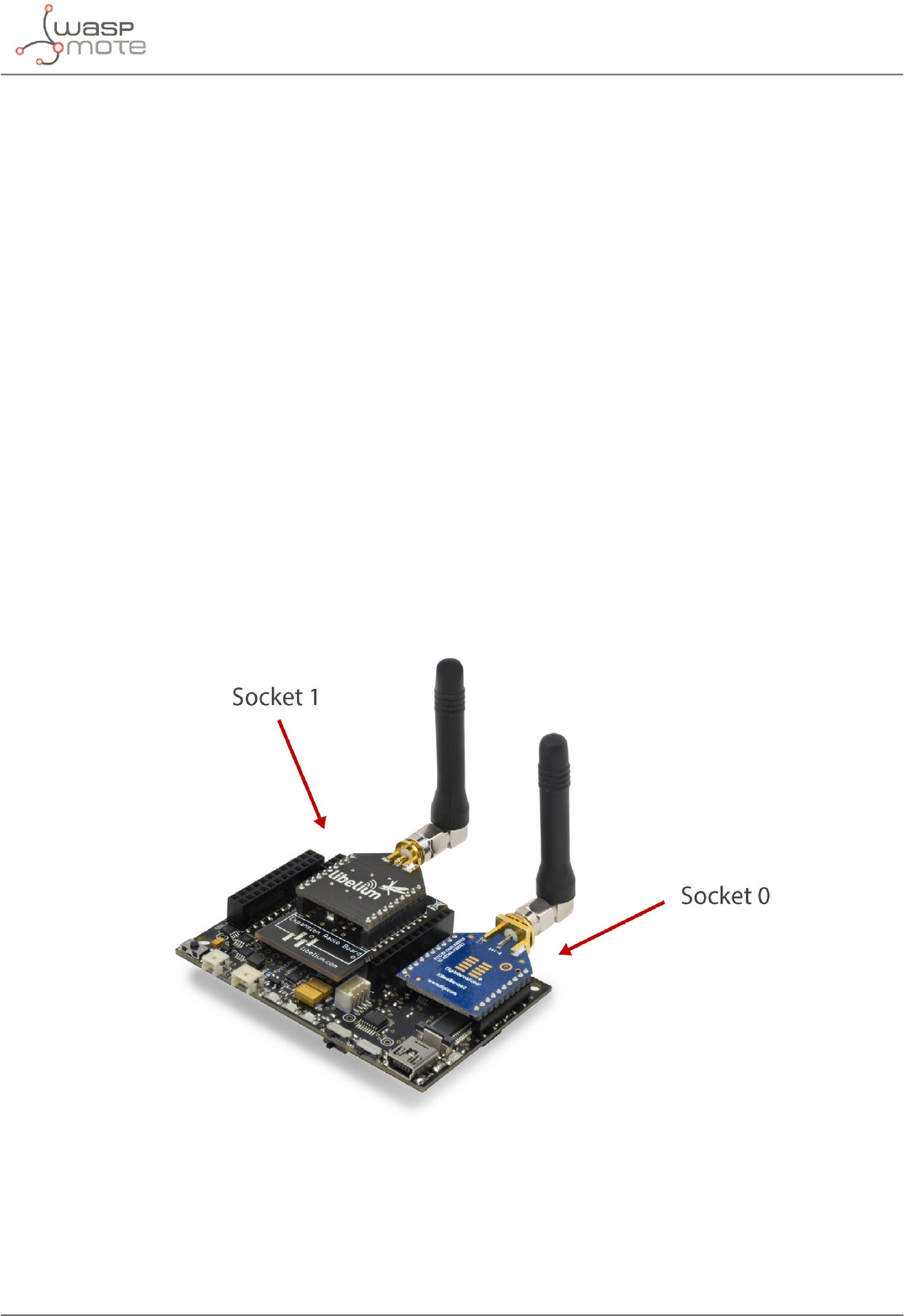
The LoRa module uses the SPI pins for communication. The SPI port allows more speed communication and frees up the
Waspmote’s UART for other purposes. The Expansion Board allows to connect two communication modules at the same time
in the Waspmote sensor platform. This means a lot of dierent combinations are possible using any of the radios available for
Waspmote and the LoRa module.
Figure: LoRa module in Socket 0
Note: The SX1272 module can only be used in special Waspmote v12 units which have been modied to drive the SPI pins to socket 0.
The SX1272 module does not implement any security method. Encryption is provided through the Waspmote Encryption
library. Specically, through the AES algorithm with symmetric key, with a length of 128, 192 or 256 bits.
The classic layout of this type of network is Star topology (shown in the gure), as the nodes establish point to point connections
with brother nodes through the use of parameters such as the Node Address.
-9- v7.0
Hardware
Figure: Star topology
Note: OTA programming is not implemented for the LoRa module. Due to its low datarate, it would take much time to send one
program.
-10- v7.0
Dual radio with Expansion Board
3. Dual radio with Expansion Board
3.1. Expansion Radio Board
The Expansion Board allows to connect two communication modules at the same time in the Waspmote sensor platform. This
means a lot of dierent combinations are possible using any of the wireless radios available for Waspmote: 802.15.4, ZigBee,
DigiMesh, 868 MHz, 900 MHz, LoRa, WiFi, GPRS, GPRS+GPS, 3G, 4G, Sigfox, LoRaWAN, Bluetooth Pro, Bluetooth Low Energy and
RFID/NFC. Besides, the following Industrial Protocols modules are available: RS-485/Modbus, RS-232 Serial/Modbus and CAN Bus.
Some of the possible combinations are:
• LoRaWAN - GPRS
• 802.15.4 - Sigfox
• 868 MHz - RS-485
• RS-232 - WiFi
• DigiMesh - 4G
• RS-232 - RFID/NFC
• WiFi - 3G
• CAN bus – Bluetooth
• etc.
Remark: GPRS, GPRS+GPS, 3G and 4G modules do not need the Expansion Board to be connected to Waspmote. They can be plugged
directly in the socket1.
Figure: Waspmote with XBee radio on socket0 and Bluetooth Pro module on socket 1

-11- v7.0
Dual radio with Expansion Board
The LoRa module can be used only in the socket 0. If the user wants to use a wireless radio, they must use the socket 1.
WARNING:
• Avoid to use DIGITAL7 pin when working with Expansion Board. This pin is used for setting the XBee into sleep.
• Avoid to use DIGITAL6 pin when working with Expansion Board. This pin is used as power supply for the Expansion Board.
• Incompatibility with Sensor Boards:
- Agriculture v30 and Agriculture PRO v30: Incompatible with Watermark and solar radiation sensors
- Events v30: Incompatible with interruption shift register
- Gases v30: DIGITAL6 is incompatible with CO2 (SOCKET_2) and DIGITAL7 is incompatible with NO2 (SOCKET_3)
- Smart Water v30: DIGITAL7 incompatible with conductivity sensor
- Smart Water Ions v30: incompatible with ADC conversion
- Gases PRO v30: Incompatible with SOCKET_2 y SOCKET_3
- Cities PRO v30: Incompatible with SOCKET_3. I2C bus can be used. No gas sensor can be used.

-12- v7.0
General considerations
4. General considerations
4.1. Waspmote libraries
4.1.1. Waspmote SX1272 les
WaspSX1272.h, WaspSX1272.cpp
It is mandatory to include the SX1272 library when using this module. The following line must be introduced at the beginning
of the code:
#include <WaspSX1272.h>
4.1.2. Constructor
To start using the Waspmote SX1272 library, an object from class WaspSX1272 must be created. This object, called sx1272,
is created inside the Waspmote SX1272 library and it is public to all libraries. It is used through the guide to show how the
Waspmote SX1272 library works.
When creating this object, some variables are dened with a value by default.
4.2. API functions
Through the guide there are many examples of using parameters. In these examples, API functions are called to execute the
commands, storing in their related variables the parameter value in each case.
Example of use:
{
sx1272.getPreambleLength(); // Gets the preamble length that is going to be send
}
Related variables:
sx1272._preamblelength → stores the preamble length
When returning from sx1272.getPreambleLength() the variable sx1272._preamblelength will be lled with the
appropriate values.
Before calling the function, the related variable is created but it is empty.
All the functions return a ag to know if the function called was successful or not. Available values for this ag:
• 0 : Success. The function was executed without errors and the variable was lled.
• 1 : Error. The function was executed but an error occurred while executing.
• 2 : Not executed. An error occurred before executing the function.
• -1 : Function not allowed in this mode.
-13- v7.0
General considerations
The main functions are listed here:
Basic functions
WaspSX1272(); Class constructor.
ON(); Opens the SPI and switches the SX1272 module on.
OFF(); Closes the SPI and switches the SX1272 module o.
readRegister(); Reads the indicated internal register.
writeRegister(); Writes the indicated internal register.
clearFlags(); Clears the interruption ags.
Conguration functions
setLORA(); Sets the module in LoRaTM transmission mode.
getMode(); Gets the BW, CR and SF of the LoRaTM modulation.
setMode(); Sets the BW, CR and SF of the LoRaTM modulation.
getHeader(); Indicates if module is congured in implicit or explicit header
mode.
setHeaderON(); Sets the module in explicit header mode (header is sent).
setHeaderOFF(); Sets the module in implicit header mode (header is not sent).
getCRC(); Indicates if module is congured with or without checking
CRC.
setCRC_ON(); Sets the module with CRC on.
setCRC_OFF(); Sets the module with CRC o.
getChannel(); Indicates the frequency channel within the module is
congured.
setChannel(); Sets the indicated frequency channel in the module.
getPower(); Gets the signal power within the module is congured.
setPower(); Sets the signal power indicated in the module.
setPowerNum(); Sets the signal power indicated in the module.
getPreambleLength(); Gets the preamble length from the module.
setPreambleLength(); Sets the preamble length in the module.
getPayloadLength(); Gets the payload length from the module.
setPacketLength(); Sets the packet length in the module.
getNodeAddress(); Gets the node address in the module.
setNodeAddress(); Sets the node address in the module.
setRetries(); Sets the maximum number of retries.
getMaxCurrent(); Gets the current supply limit of the internal power amplier.
setMaxCurrent(); Limits the current supply of the internal power amplier.
getTemp(); Gets the temperature from the measurement block module.
getRegs(); Gets the content of dierent registers.
-14- v7.0
General considerations
Link information functions
getSNR(); Gets the SNR value in LoRaTM mode.
getRSSI(); Gets the current value of RSSI from the channel.
getRSSIpacket(); Gets the RSSI of the last packet received in LoRaTM mode.
Sending functions
sendPacketTimeout(); Sends a packet to the specied destination before a timeout
expires.
sendPacketMaxTimeout(); Same as previous function with maximum timeout.
sendPacketTimeoutACK(); Sends a packet to a destination before a timeout and wait for
an ACK response.
sendPacketMaxTimeoutACK(); Same as previous function with maximum timeout.
sendPacketTimeoutACKRetries(); Sends a packet to a destination before a timeout, wait for an
ACK response and retry to send the packet if ACK is lost.
sendPacketMaxTimeoutACKRetries(); Same as previous function with maximum timeout.
Receiving functions
receivePacketTimeout(); Receives information before a timeout expires.
receivePacketMAXTimeout(); Same as previous function with maximum timeout.
receivePacketTimeoutACK(); Receives information before a timeout expires and responds
with ACK.
receivePacketMAXTimeoutACK(); Same as previous function with maximum timeout.
receiveAll(); Receives all the information on air with maximum timeout.
showFramefromPacket(); Prints a frame received in a packet.
4.3. Additional functions
4.3.1. Getting temperature
It reads the module temperature in Celsius. Negative temperatures can be expected. It stores the information in the global
_temp variable in Celsius.
Note: this feature has not a good accuracy because it requires internal calibration. Libelium recommends to use dedicated temperature
sensor.
Example of use:
{
sx1272.getTemp(); // Gets the temperature of the module
}
Related variables:
sx1272._temp → stores the temperature of the module
SX1272 getting temperature example:
www.libelium.com/development/waspmote/examples/sx-13-get-temp

-15- v7.0
General considerations
4.3.2. Getting maximum allowed current supply
It reads the current supply limit of the power amplier. This value is set to 240 mA at the beginning of the conguration when
the module is switched on. Parameter range: from 0x00 to 0x1B corresponding to a range from 45 to 240 mA.
Example of use:
{
sx1272.getMaxCurrent(); // Gets the maximum current supply
}
Related variables:
sx1272._maxCurrent → stores the maximum current supply of the module
SX1272 getting current supply example:
www.libelium.com/development/waspmote/examples/sx-14-currentsupply
4.4. Waspmote reboot
When Waspmote is rebooted, the application code will start again, creating all the variables and objects from the beginning.
-16- v7.0
Transmission modes
5. Transmission modes
The module has two dierent modulations, LoRa™ modulation, owned by Semtech, and standard FSK modulation. Libelium has
decided to only use the LoRa™ modulation due to the range improvement it provides.
When setting the SX1272 module on, the module is prepared to use LoRa mode.
About the operation states, it is not necessary to control them manually. It is done automatically by the API functions.
5.1. LoRaTM mode
The innovative LoRa™ mode is the most interesting included in this module. It is an advanced and private modulation that
increases the range comparing to classic modulations. The LoRa™ long range mode provides ultra-long range spread spectrum
communication and high interference immunity whilst minimizing current consumption. It combines digital spread spectrum,
digital signal processing, and forward error correction coding to achieve unprecedented performance. LoRa™ also provides
signicant advantages in both blocking and selectivity over conventional modulation techniques.
LoRa has three congurable parameters:
• Bandwidth (BW)
• Coding Rate (CR)
• Spreading Factor (SF)
The combination of these values denes the transmission mode. It is possible to set a predened mode or to set these three
parameters manually.
There are ten predened modes in the API, including the largest distance mode, the fastest mode, and eight other intermediate
modes that Libelium has found interesting. All of them can be modied or deleted, and also it is possible to attach new modes
in the appropriate function. The predened modes and its properties are shown in the next table.
Mode BW CR SF Sensitivity
(dB)
Transmission time
(ms) for a 100-byte
packet sent
Transmission time
(ms) for a 100-byte
packet sent and
ACK received
Comments
1 125 4/5 12 -134 4245 5781 max range, slow
data rate
2 250 4/5 12 -131 2193 3287 -
3 125 4/5 10 -129 1208 2120 -
4 500 4/5 12 -128 1167 2040 -
5 250 4/5 10 -126 674 1457 -
6 500 4/5 11 -125,5 715 1499 -
7 250 4/5 9 -123 428 1145 -
8 500 4/5 9 -120 284 970 -
9 500 4/5 8 -117 220 890 -
10 500 4/5 7 -114 186 848
min range, fast
data rate, minimum
battery impact
Figure: LoRa conguration modes
The transmission times have been measured for a whole transmission process: power the module on, congure the module,
send a 100-byte packet and power the module o.
The user will be able to choose the most suitable mode for that application after the appropriate test phase because there is not
a perfect mode for any situation. In fact, it exists a compromise between distance range and speed of transmission.

-17- v7.0
Transmission modes
Note: When transmitting in ISM frequency bands, the user must ensure that the communication is not exceeding the permitted time
using the chosen frequency channel (for example, 1% of time). It is the responsibility of the user to know the allowed time of use in the
occupied frequency band and respect it. Ignoring this, could lead to considerable penalties.
Example of use:
{
sx1272.setMode(3); // Sets the LoRa mode in transmission mode 3
}
SX1272 conguration example:
www.libelium.com/development/waspmote/examples/sx-01-congure-lora-parameters
If the user is going to select a mode with this function, it is not necessary to set also the bandwidth, coding rate and spreading
factor later.
5.1.1. Bandwidth
The value of the bandwidth shows how wide is going to be the transmission signal. It only can be chosen among 3 options:
125 kHz, 250 kHz or 500 kHz. If a fast transmission is required, a 500 kHz value is better. But if a great reach is needed, a 125 kHz
value must be congured. The smaller the bandwidth is, the higher the time-on-air is in a transmission but also the better the
sensitivity is, so the communication has better link budget. The user should also note that the increasing in time-on-air involves
an increasing in battery consumption.
Example of use:
{
sx1272.setBW(BW_250); // Sets the 250 kHz bandwidth in LoRa mode
}
5.1.2. Coding Rate
The coding rate value must be chosen among 4 options: 4/5, 4/6, 4/7 and 4/8. It denotes that every 4 useful bits are going to be
encoded by 5, 6, 7 or 8 transmission bits depending on its value. The smaller the coding rate is (the smallest is 4/8), the higher
the time-on-air is in a transmission, so it takes more time to transmit a packet. This will ease the task of receiving, because each
symbol is wider in time, so the receiver can demodulate packets with lower reception power. This means the receiver has better
sensitivity, so the user has better link budget. But slow data transmissions have an impact in the battery consumption: spending
more time in transmission mode involves more battery consumption.
Example of use:
{
sx1272.setCR(CR_7); // Sets the 4/7 coding rate in LoRa mode
}
5.1.3. Spreading Factor
The spreading factor is the number of chips per symbol used in the data treatment before the transmission signal. Its value is
an integer number between 6 and 12. This parameter is relevant in the spread spectrum technique. In the spread spectrum
techniques, the greater value of this parameter, the more capability the receiver has to move away the noise from the signal.
So the greater value taken, the more time it takes to send a packet, but also the better range is reached because the receiver
sensitivity is better.
Example of use:
{
sx1272.setSF(SF_9); // Sets the 9 spreading factor in LoRa mode
}
-18- v7.0
Initialization
6. Initialization
Before starting to use a module, it needs to be initialized. During this process, Waspmote’s SPI bus has to be opened to
communicate with the module, and the LoRa module’s switch has to be set on.
Note: This module does not save the conguration. So, the network settings as the mode or the channel MUST be congured
every time it is switched on.
6.1. Setting on
It initializes all the global variables, opens the SPI bus and switches the LoRa module on.
When setting on, the module always has the conguration by default shown in the next table:
Global variable Description Initial value
modem activated mode LORA
bandwidth bandwidth to use in LoRaTM mode BW_125
codingRate coding rate to use in LoRaTM mode CR_5
spreadingFactor spreading factor to use in LoRaTM mode SF_7
channel transmission frequency channel CH_12_900
header species if header is enabled HEADER_ON
CRC species if CRC is enabled CRC_OFF
power power transmission level 15
Figure: Conguration by default
Also, there are other global variables initialized when this function is called, shown in the following table:
Global variable Description Initial value
packetNumber packet number to send 0
reception species if packet is correctly received CORRECT_PACKET
retries number of the current retrying that is
being executed in the protocol 0
maxRetries maximum number of retries permitted
in each case 3
Figure: Global variables initialized by software
Example of use:
{
sx1272.ON(); // Opens the SPI and switches the SX1272 module ON
}
6.2. Setting o
It closes the SPI and switches the SX1272 module o.
Example of use:
{
sx1272.OFF(); // Closes the SPI and switches the SX1272 module off
}

-19- v7.0
Node parameters
7. Node parameters
When conguring a node, it is necessary to set some parameters which will be used lately in the network, and some parameters
needed for using the API functions.
7.1. Node address
Each module must have a unique address of 8 bits.
It identies uniquely a node inside a network. It is necessary to assign the address value each time the module is set on.
The node address 0 and the node address 1 are reserved to broadcast communication and to the network central node
respectively. In order to respect this, users must assign the node address 1 to the module in the central node and node addresses
from 2 to 255 to all the other nodes in their network. That means a network will consist of:
• 1 central node. Address value equal to 1
• Up to 254 nodes. Address values from 2 to 255
The user must not assign the node address 0 to any node since it is reserved to indicate the module we want to perform a
broadcast transmission.
Example of use:
{
sx1272.setNodeAddress(2); // Set the Node address into REG_NODE_ADDRESS register
sx1272.getNodeAddress(); // Get the assigned Node address
}
Related variables:
sx1272._nodeAddress → stores the Node address
The module rejects packets destined to other nodes, although it is actually receiving all the packets in the network while it is in
receiving state.
7.2. Frequency band
There are two frequency bands available to work with this module, 868 MHz and 900 MHz ISM bands. Depending on the country
the user is located, one or the other will be chosen. Inside each frequency band there are several channels, so the user can
choose among them.
Note: To know what band is legal in your country, please check the ITU region map. Region 1 ISM free band is 868 MHz and Region
2 ISM free band is 900 MHz. You must also check the legal restrictions by region to use the proper conguration and channel. It is the
responsibility of the users to know the allowed frequency band and channels in their country, and use them. Ignoring this, could lead
to considerable penalties.
-20- v7.0
Node parameters
7.3. Channel
This parameter denes the frequency channel used by the module to transmit and receive.
There are 8 channels dened to be used in the 868 MHz band and 13 channels to be used in the 900 MHz band. They can be
observed in the following gures.
Figure: Frequency channels in the 868 MHz band
Figure: Frequency channels in the 900 MHz band
Channel Number Central Frequency Channel Number Central Frequency
CH_10_868 865.20 MHz CH_00_900 903.08 MHz
CH_11_868 865.50 MHz CH_01_900 905.24 MHz
CH_12_868 865.80 MHz CH_02_900 907.40 MHz
CH_13_868 866.10 MHz CH_03_900 909.56 MHz
CH_14_868 866.40 MHz CH_04_900 911.72 MHz
CH_15_868 866.70 MHz CH_05_900 913.88 MHz
CH_16_868 867 MHz CH_06_900 916.04 MHz
CH_17_868 868 MHz CH_07_900 918.20 MHz
CH_08_900 920.36 MHz
CH_09_900 922.52 MHz
CH_10_900 924.68 MHz
CH_11_900 926.84 MHz
CH_12_900 915 MHz
Figure: Channels used by the LoRa modules in 868 MHz and 900 MHz

-22- v7.0
Packet parameters
8. Packet parameters
8.1. Structure used in packets
Packets are structured in WaspSX1272.h using a dened structure called pack. This structure has many elds to be lled by the
user or the application:
• dst
Destination node address: this parameter is indicated as an input in the function used by the user.
• src
Source node address: this parameter is lled by the application with the module’s address (previously set by the user).
• packnum
Packet number: this parameter indicates the packet number and is lled by the application. It is a byte eld, so it starts in 0 and
reaches 255 before restarting. If the packet is trying to be retransmitted, the packet number is not incremented.
• length
Packet length: this parameter indicates the total packet length and is lled by the application.
• data[MAX_PAYLOAD]
Data to send in the packet: It is used to store the data to send to other nodes. All the data to send must be stored in this eld. Its
maximum size is dened by MAX_PAYLOAD, a constant dened in the library.
• retry
Retry counter: this parameter is lled by the application. It is usually equal to 0. Only when we use the retries feature, this value
is incremented from 0 to the maximum number of retries stored in the global variable _maxRetries which value is 3 by default.
If the packet is sent successfully, or if the maximum number of retries is reached without success, the retry counter is set to 0.
dst src packnum length data retry
(1 Byte) (1 Byte) (1 Byte) (1 Byte) (Variable Bytes) (1 Byte)
Figure: Packet structure
8.2. Maximum payload
The maximum data payload is dened as:
LoRaTM
250 Bytes
Figure: Maximum payload size
Due to the limit on maximum payloads it could happen that the packet has to be truncated to the maximum possible length.
The current available payload when operating in LoRaTM mode can be retrieved in real time.
Example of use:
{
sx1272.getPayloadLength(); // Get Maximum Payload Bytes
}
Related variables:
sx1272._payloadlength → stores the maximum payload is available at the moment
-23- v7.0
Power gain and sensitivity
9. Power gain and sensitivity
When conguring a node and a network, one important parameter is related with power gain and sensitivity.
9.1. Power level
Power level (dBm) at which the module transmits conducted power.
The possible values are Low (‘L’), High (‘H’) and Max (‘M’):
Parameter SX1272 power level
'L' 0 dBm
'H' 7 dBm
'M' 14 dBm
Figure: Transmission power values
It is also possible to set the conducted power indicating the quantity as a parameter in the function setPower.
Note: dBm is a standard unit to measure power level taking as reference a 1 mW signal.
Values expressed in dBm can be easily converted to mW using the next formula:
mW = 10^(value dBm/10)
Graphic about transmission power is exposed next:
Figure: SX1272 output power level

-24- v7.0
Power gain and sensitivity
Example of use:
{
sx1272.setPower(0); // Set Power Output Level to the minimum value
sx1272.getPower(); // Get Power Output Level
}
Related variables:
sx1272._power → stores the selected power output level
Note: It is the responsibility of the users to know the maximum allowed power level in their country (if any), and use levels below it.
Ignoring this could lead to considerable penalties.
9.2. RSSI of one packet and RSSI of the channel
It reports the Received Signal Strength of the last received packet and the current value of the Received Signal Strength in the
selected channel. The RSSI of the packet is the meaningful one: if its value is greater than the sensitivity the packet sent is going
to be successfully detected, otherwise the packet will be lost. The RSSI of the channel reports the signal level detected in every
moment, even if it is not signal being transmitted, so it provides also noise level information. In the case the user develops a
multi-hop network, this parameters only indicate the signal strength of the last hop, so it does not provide an accurate quality
measurement of a multihop link.
Example of use:
{
sx1272.getRSSIpacket(); // Get the Receive Signal Strength Indicator
sx1272.getRSSI(); // Get the current Receive Signal Strength Indicator
}
Related variables:
sx1272._RSSIpacket → stores the RSSI of the last received packet
sx1272._RSSI → stores the current RSSI value
SX1272 RSSI example:
www.libelium.com/development/waspmote/examples/sx-12-rssilora
The ideal working mode is at getting maximum coverage with the minimum power level. Thereby, a compromise between power
level and coverage appears. Each application scenario will need some tests to nd the best combination of both parameters.
9.3. SNR
It reports the Signal-to-Noise Ratio of the last received packet. The LoRa module is capable to demodulate received signals
with SNR values as low as -20 dB. Getting the SNR, it is possible to have an idea about the link’s quality or health, and thus the
additional distance we could get in a communication link.
Example of use:
{
sx1272.getSNR(); // Get the Signal Noise Ratio
}
Related Variables:
sx1272._SNR → stores the SNR of the last received packet
SX1272 RSSI example:
www.libelium.com/development/waspmote/examples/sx-12-rssilora
-25- v7.0
Long range tests
10. Long range tests
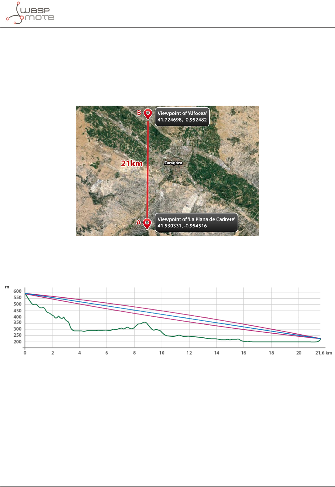
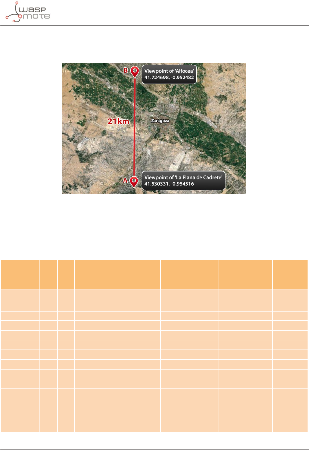
10.1. Line of Sight test
The Line of Sight (LOS) tests were taken between two dierent points next to the surrounding area of Zaragoza (Spain). The
emitter was set in the point A : viewpoint of ‘La Plana de Cadrete’. The receiver was set in the point B: viewpoint of the village of
Alfocea. These points are 21.6 km (13.4 miles) apart.
Figure: Map of the LOS long range tests in Zaragoza
The following picture represents the prole of the link. The blue line indicates the line of sight conditions taken in the test.
Besides, the purple ellipse indicates the Fresnel zone clearance achieved in this path.
Figure: Prole of the LOS path
Test features:
• Several LoRa modes, frequency channels and output-power modes were tested in order to know the performance of the
LoRa module depending on great distances
• All packets were set to a xed 90-byte payload
• More than one hundred attempts were performed in every trial
-26- v7.0
Long range tests
Results:
LoRa
Mode Range Power Channel Success
(%)
Mean SNR
(dB)
Mean RSSI
(dBm)
Mean RSSI
packet( dBm)
Sensitivity
(dB)
Margin
(dB)
Mode 1 21.6 km
(13.4 miles)
High CH_12_868 100 -9.79 -113.72 -126.79 -134 7.21
Max 100 -4.33 -113.76 -121.76 -134 12.24
High CH_16_868 100 -10.06 -114.28 -127.06 -134 6.94
Max 100 -3.20 -113.97 -120.21 -134 13.79
Mode 3 21.6 km
(13.4 miles)
High CH_12_868 95 -10.29 -114.16 -127.29 -129 1.71
Max 95 -3.73 -114.08 -120.73 -129 8.27
Mode 6 21.6 km
(13.4 miles)
High CH_12_868 99 -14.77 -107.22 -125.77 -125.5 -0.27
Max 100 -8.42 -106.60 -119.43 -125.5 6.07
Mode 9 21.6 km
(13.4 miles)
High CH_12_868 0 - - - -117 -
Max 49 -9.95 -107.68 -120.95 -117 -3.95
10.2. Non Line of Sight tests
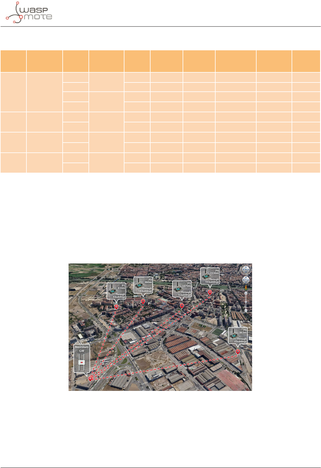
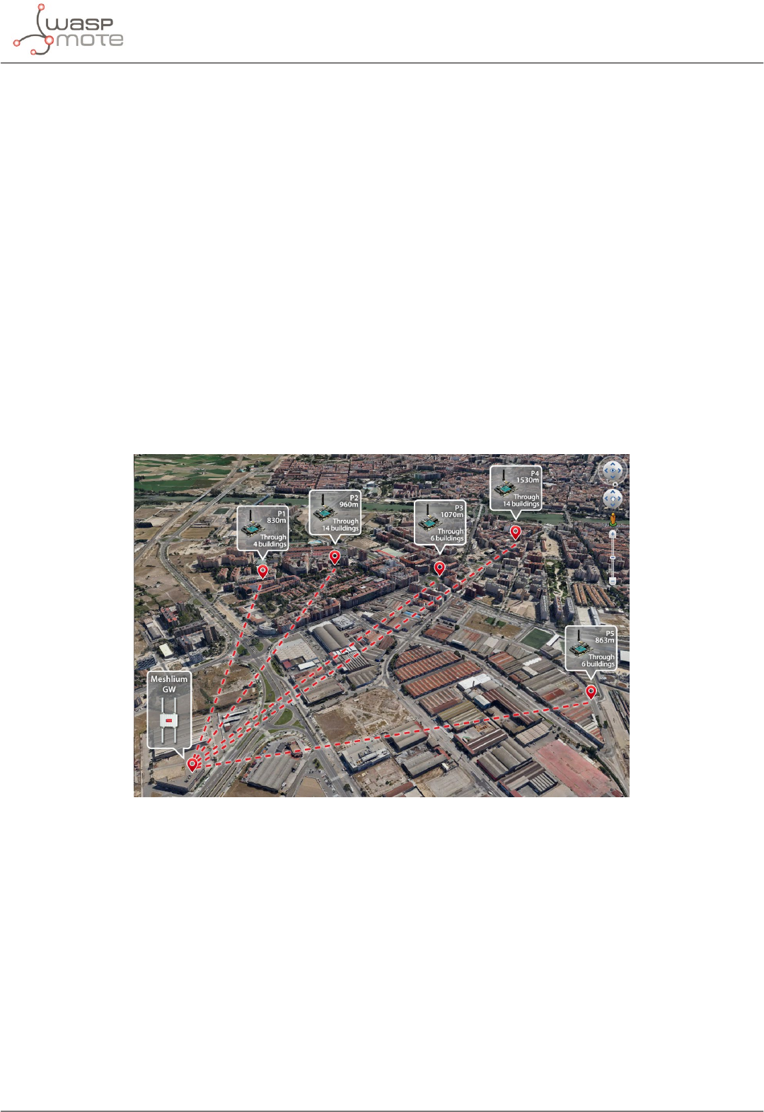
10.2.1. Tests in Zaragoza
The Non Line of Sight (NLOS) tests were taken between several points in the surrounding areas of the Libelium’s headquarters
in Zaragoza (Spain).
The receiver was a Meshlium device, installed on the roof of the Libelium’s headquarters. The emitter was set in several points in
order to know the performance of this module in NLOS conditions within a city area.
Figure: Map of the NLOS long range tests in Zaragoza
Test features:
• Lora Mode 1: maximum range
• Maximum output power: 14 dBm
• Frequency channel: CH_12_868 in the 868 MHz band
• Packets were set to a Waspmote Frame reaching around a 80-byte payload
• Fifty attempts were performed for every point

-27- v7.0
Long range tests
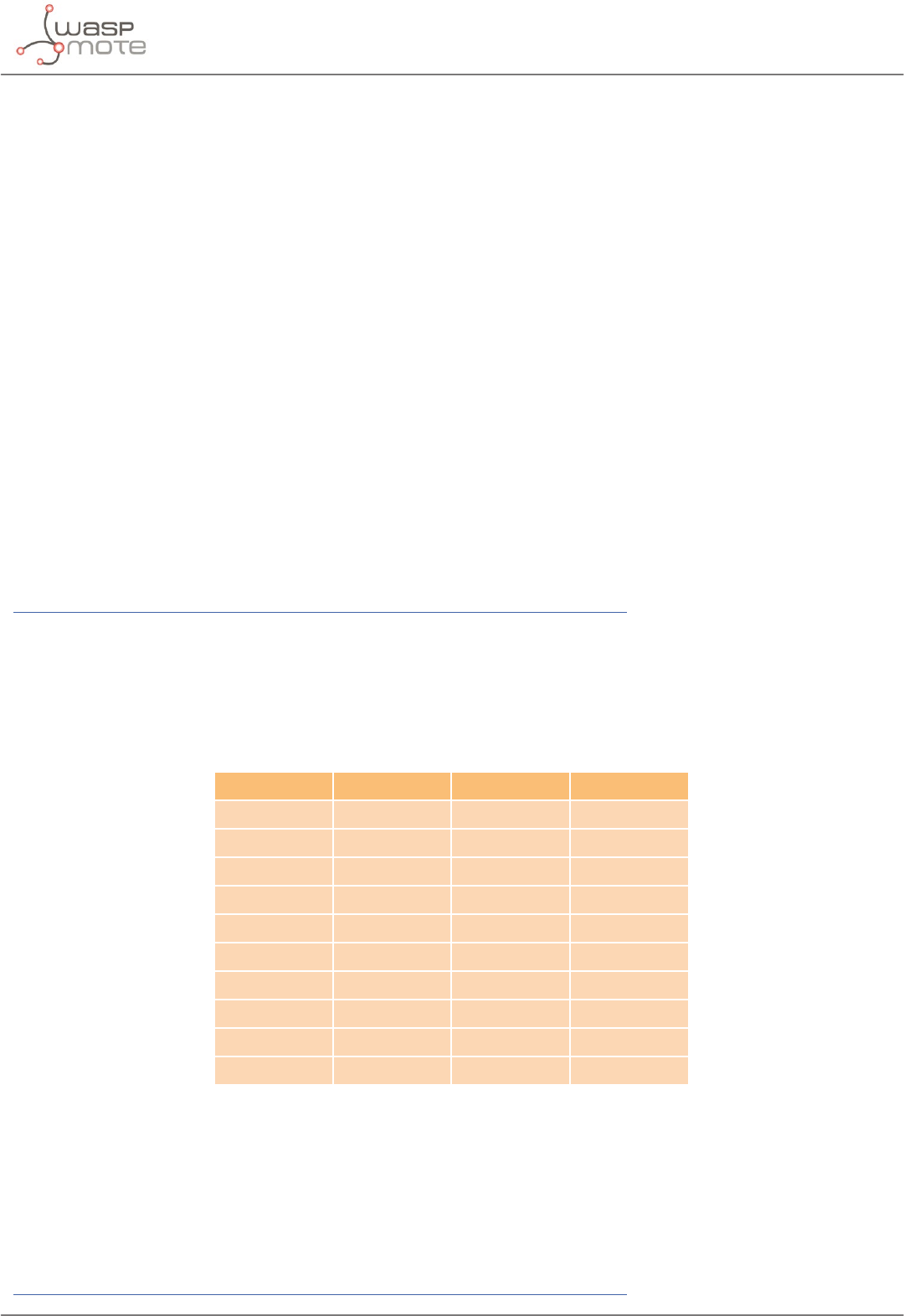
Results:
Point Range (m) Number of Buildings
(signal going through) Success (%) Mean SNR
(dB)
Mean RSSI
(dBm)
Mean RSSI
packet (dBm) Margin (dB)
Point 1 830 4 96 -7.89 -112.95 -124.89 9,11
Point 2 960 14 92 -14.26 -111.26 -131.26 2,74
Point 3 1070 6 98 -3.22 -114.14 -120.24 13,76
Point 4 1530 14 98 -13.16 -112.24 -130.16 3,84
Point 5 863 6 100 -3.42 -113.48 -120.42 13,58
Paths description:
•Point 1: The signal goes through four buildings. Three high-rise housing buildings and a low building do not permit to have
line of sight in this path. Then, an open space is found in the way to the receiver.
•Point 2: The signal goes through fourteen buildings. In this case, a large group of low residential houses are close to the
point 2. Also, a residential block is found in the way to the receiver.
•Point 3: The signal goes through six buildings. This point is placed at the side of a big square of the neighborhood. The path
nds out a big residential building and after this, some industrial buildings too.
•Point 4: The signal goes through fourteen buildings. This is the largest path. This point comes across four high residential
buildings. Then there is an open space with no obstacles before reaching another group of high housing buildings again.
Finally, several industrial buildings are found before ending the path to the receiver.
•Point 5: The signal goes through six buildings. This point is separated from the receiver by several industrial buildings with
no open spaces between them.
-28- v7.0
Long range tests
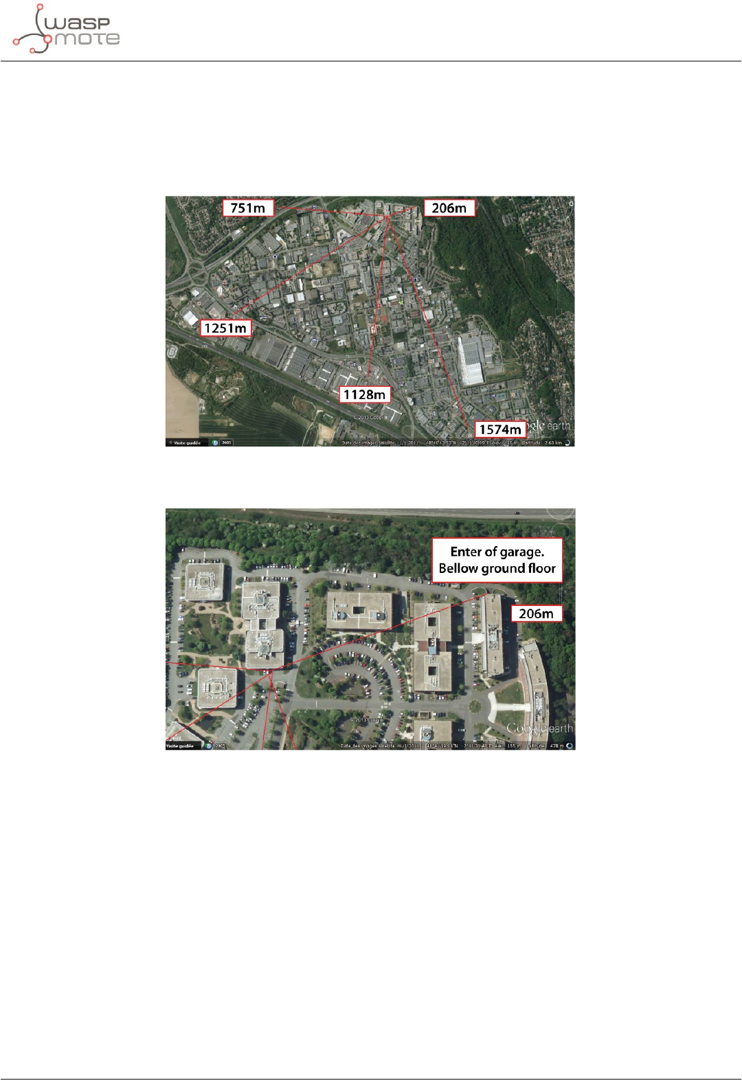
10.2.2. Test in Paris
This tests were developed in an oce area in Paris city. The transmitter is outside the rst oor of an oce building, at a height
of about 3 meters. The receiver is at street except in one of them that is situated bellow ground oor, in a garage. There is no line
of sight between the points.
Figure: Test distance on the map
Figure: Detail of the garage test point
-29- v7.0
Connectivity
11. Connectivity
11.1. Topologies
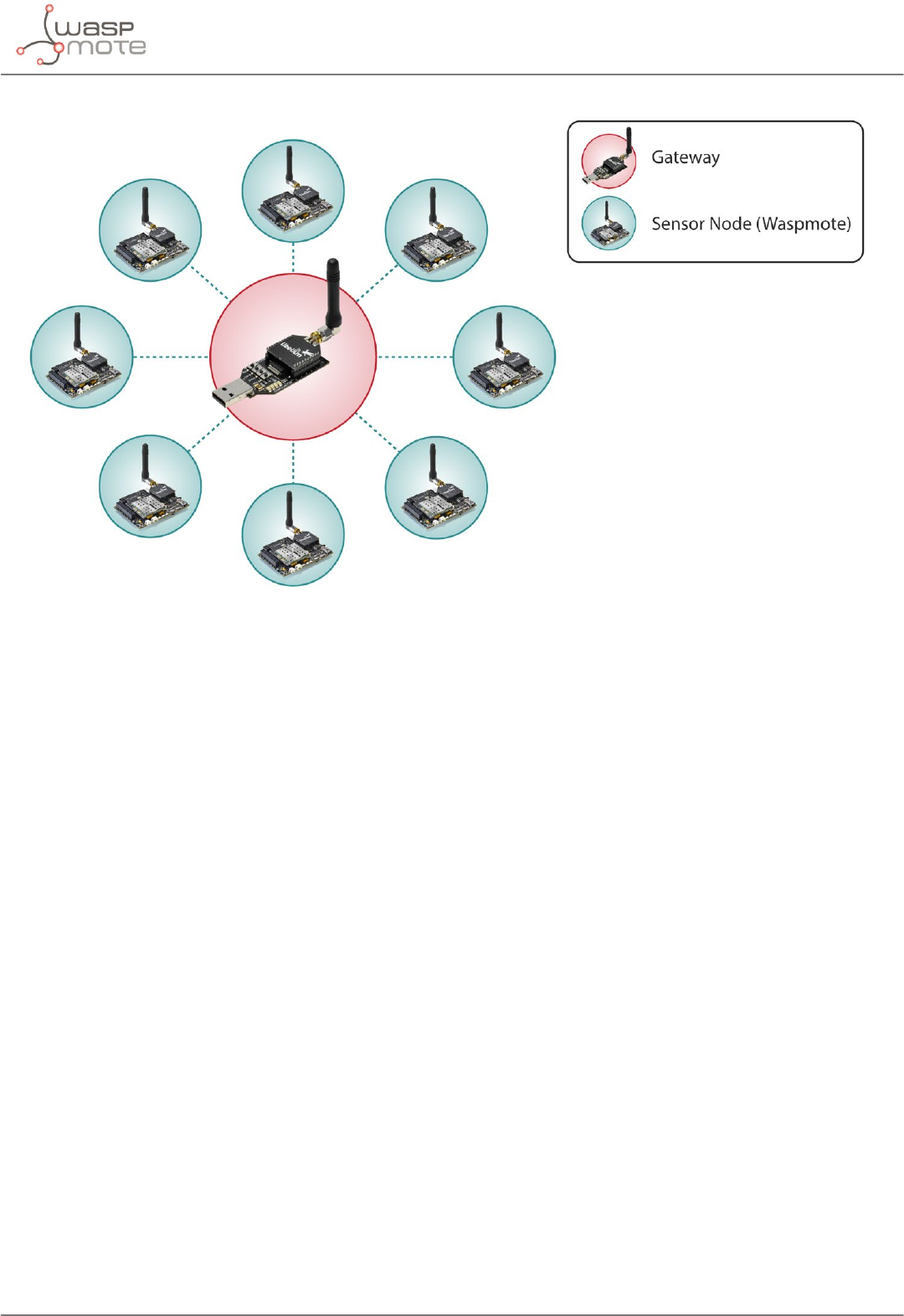
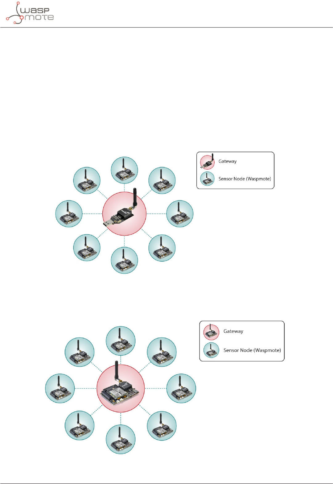
Several LoRa modules can be set in a star topology to create a network. A star network has a central node, which is linked to all
other nodes in the network. The central node gathers all data coming from the network nodes.
It is not possible to set mesh networks with the LoRa module.
Libelium oers the following options for the central node:
•Gateway LoRaTM: This special Gateway enables the user to receive data directly in a standard PC. It is interesting for the rst
development phase, and can be used to test a real project or to do less advanced tasks.
Figure: Star topology with Gateway as central node
•Waspmote: It is the less interactive option. In order to send the data to Cloud or via wireless, it is necessary to have another
radio module available. Since Plug & Sense! can only have one radio, the user can just receive packets and output them via
USB port.
Figure: Star topology with Waspmote as central node
-30- v7.0
Connectivity
11.2. Connections
Every packet sent contains a Source Address byte and Destination Address byte in its payload eld. The module supports only
8-bit addresses. For every node, a unique 8-bit Source Address (Node Address) must be chosen by the user and assigned each
time the module is powered on. This address can be set and read with the functions explained in chapter “Node Parameters”.
The LoRa module supports Unicast and Broadcast transmissions.
11.2.1. Unicast
Unicast is used to send a packet to one specic node in a network through its Node Address. Unicast always performs control
time mechanisms (time-out) to prevent perpetual waiting for a packet. Unicast mode is the only one that supports additional
services for more robust communication like:
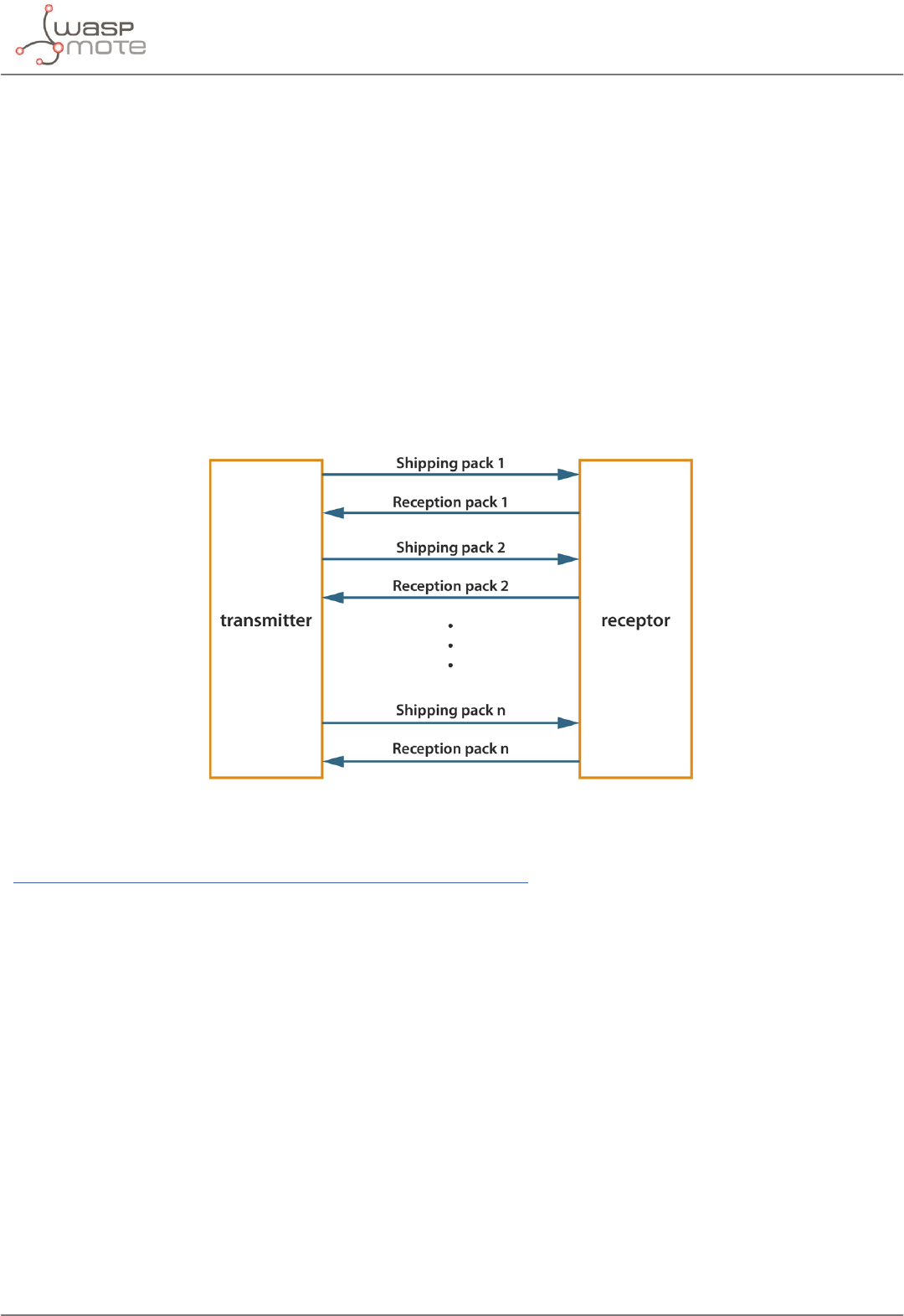
1 - ACK conrmation: if the developer uses functions like sendPacketTimeoutACK() and receivePacketWithTimeoutACK(),
receiving modules will send an ACK (packet which aim is to conrm the packet was correctly received) to the transmitter.
Figure: ACK conrmation diagram
Unicast mode with ACK example:
www.libelium.com/development/waspmote/examples/sx-03a-tx-lora-ack
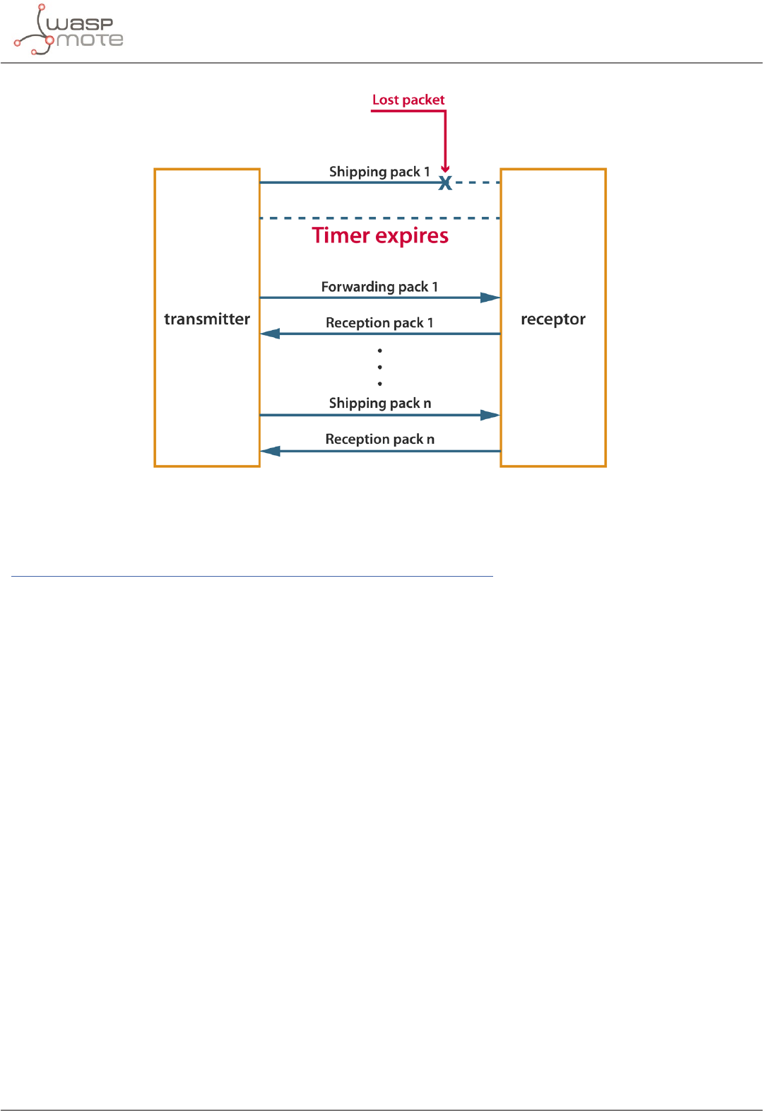
2 - Retries: this option is only available with ACK conrmation. If the transmitting module does not receive the ACK, it will re-
send the packet up to the congured number of times or until the ACK is received.
-31- v7.0
Connectivity
Figure: ACK and retries diagram
Unicast mode with ACK and retries example:
www.libelium.com/development/waspmote/examples/sx-04a-tx-lora-ackwretries
11.2.2. Broadcast
Broadcast is used to send a packet to all nodes in a network. Any module within range will accept a packet that contains the
broadcast address (0). To send a broadcast message, the Destination Address should be set to BROADCAST_0. While in this mode,
there is no possibility to use ACK conrmations or retries.
-32- v7.0
Connectivity
11.3. Connection parameters
There are some parameters related to connections and their congurations.
11.3.1. Setting retries
It species the number of retries than can be sent for a given Unicast packet and stores it in the global variable _maxRetries.
Parameter range: from 0x00 to 0x05. Default value: 0x03.
Example of use:
{
sx1272.setRetries(2); // Sets the number of retries that can be sent
}
Related variables:
sx1272._maxRetries → stores the maximum number of retries that can be sent
11.4. Sending process
Sending data is a complex process which needs some special structures and functions.
11.4.1. SX1272 API packet structure
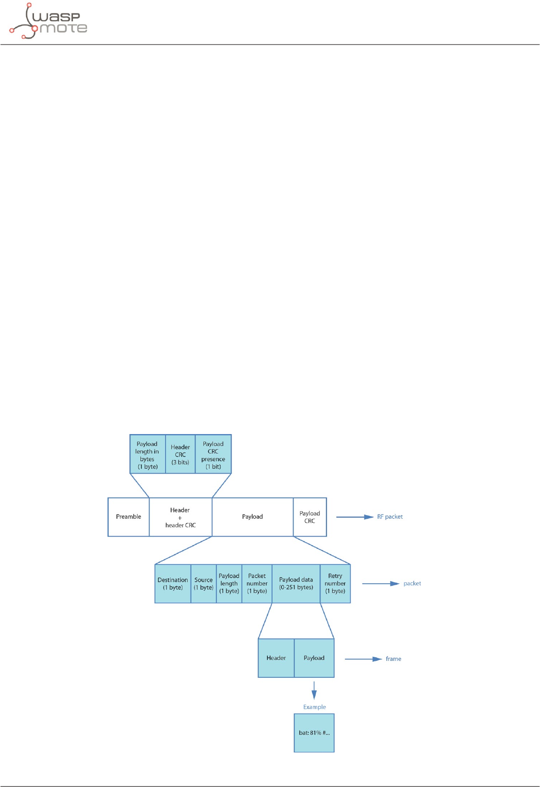
The API packet structure used to transmit packets with LoRa modules is specied in the following gure. It shows how the
payload is included inside the RF Data eld:
Figure: Frame structure inside a packet structure

-33- v7.0
Connectivity
Generally, the user will add the information to be sent with the Frame library (frame.addSensor()). The Frame library
encapsulates it in a frame instance. Then, the user will pass this frame instance to the send function, which will encapsulate it
inside a packet. Finally, the LoRa module will encapsulate that in a RF packet and send it.
11.4.2. Using Frame class to create SX1272 packets
Frame is a class that allows the user to create data frames with a specied format. It is a very useful tool to set the payload of
the packet to be sent. It is recommended to read the Waspmote Data Frame Guide in order to understand the LoRa module
examples:
www.libelium.com/development/waspmote/documentation/data-frame-guide/
SX1272 sending Frame examples:
www.libelium.com/development/waspmote/examples/sx-05a-tx-lora-waspframe
www.libelium.com/development/waspmote/examples/sx-06a-tx-lora-ack-waspframe
www.libelium.com/development/waspmote/examples/sx-07a-tx-lora-ackwretries-waspframe
11.4.3. Sending data
This is the process to send a packet between SX1272 devices.
Send data
The API function responsible for sending data is called indicating the Destination Node Address and the payload data to send:
sx1272.sendPacketTimeout(destination, payload);
Related variables:
sx1272.packet_sent → stores the structure of the packet to send
SX1272 sending example:
www.libelium.com/development/waspmote/examples/sx-02a-tx-lora
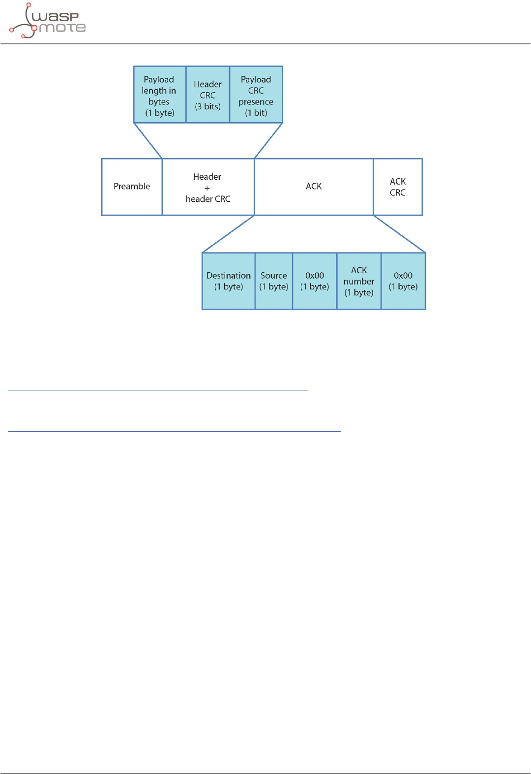
The user may want to add services for more robust communication, like ACK conrmation or retries. In order to send ACK
conrmation, there are some special functions and a specic packet format, shown in the following gure. We also show
examples for these services next:
-34- v7.0
Connectivity
Figure: ACK structure inside a packet structure
Send packets in unicast mode and wait for a response:
www.libelium.com/development/waspmote/examples/sx-03a-tx-lora-ack
Send packets in unicast mode, wait for a response and retry to send the packet if there is no response:
www.libelium.com/development/waspmote/examples/sx-04a-tx-lora-ackwretries
11.5. Receiving data
Normally, the only receiver node in a network is the central node.
Receiving data in Waspmote is a complex process which needs some special structures to carry out. These operations are
transparent to the API user, so it is going to be explained the necessary information to be able to read properly a received packet.
Before any packet has been received, an structure of pack is created. This pack is called packet_received.
The size of this array is dened by a eld in the structure.

-35- v7.0
Connectivity
11.5.1. How to receive packets in Waspmote
To receive any packet, rst it is necessary to know what kind of communication is being used. The used function will be dierent
if we want to receive packets or if we want to receive packets and answer with an ACK conrmation too. All receiving functions
are protected with a time-out method to avoid perpetual waiting.
In the case of ACK receiving functions, the SX1272 library automatically sets the destination address of the ACK packet to the
sender node.
Example of use:
{
sx1272.receivePacketTimeout(); // Receive packets
sx1272.receivePacketTimeoutACK(); // Receive packets and response to the sender with ACK
}
Related variables:
sx1272.packet_received → stores the structure of the last packet received
sx1272.ACK → stores the structure of the ACK
Receiving packets example:
www.libelium.com/development/waspmote/examples/sx-02b-rx-lora
Receiving packets and answering with ACK example:
www.libelium.com/development/waspmote/examples/sx-03b-rx-lora-ack
Receiving packets, sending a response and retrying to receive the packet example:
www.libelium.com/development/waspmote/examples/sx-04b-rx-lora-ackwretries
11.5.2. How to show received Frames
If the received packet has the structure of a Waspmote Frame inside the payload, there is a specic function to show it correctly,
after being received.
Example of use:
{
sx1272.showFramefromPacket(); // Show a Waspmote frame properly
}
If the received packet is just a plain-text message or the user prefers to know the packet contents: destination, source, packet
number and retry elds, there is other function for that purpose.
Example of use:
{
sx1272.showReceivedPacket(); // Show received packet contents
}

-36- v7.0
Connectivity
Receiving frames insides packets examples:
www.libelium.com/development/waspmote/examples/sx-05b-rx-lora-waspframe
www.libelium.com/development/waspmote/examples/sx-06b-rx-lora-ack-waspframe
www.libelium.com/development/waspmote/examples/sx-07b-rx-lora-ackwretries-waspframe
11.5.3. Receiving all packets
Due to the architecture of the LoRa module, all nodes in a channel with the same conguration mode listen any packet.
Depending on the destination address, each node will hold packets addressed to it, and discard others.
The user can decide to receive all packets, no matter the destination address. This is called promiscuous mode. The user should
know that the only way to protect transmissions is using Encryption libraries.
Receive all the packets sent to any destination:
www.libelium.com/development/waspmote/examples/sx-10-receiveall-lora
Receive all the packets sent to any destination and send a response back to the sender:
www.libelium.com/development/waspmote/examples/sx-11-receiveall-ack-lora
-37- v7.0
Starting a network
12. Starting a network
To create a network it is only necessary to set 2 parameters in LoRa: channel and mode. These parameters are the base of a
network and we need to be careful choosing them.
Encryption is optional. There are more parameters used to create a network like security parameters, which are not necessary
but recommended (see chapter “Security and Data Encryption”).
Two nodes are in the same LoRa network if they are using the same channel and mode.
12.1. Choosing a channel
As explained in chapter “Node Parameters”, there are dierent channels to choose. Depends on the frequency band used, a
random value between CH_10_868 – CH_17_868 or CH_00_900 – CH_12_900 should be chosen. This value will be used as the
input parameter in the API function responsible for setting the channel.
Example of use:
{
sx1272.setChannel(CH_04_900); // Set channel
}
SX1272 conguration example:
www.libelium.com/development/waspmote/examples/sx-01-congure-lora-parameters
12.2. Choosing a mode
This parameter is only intended for LoRa. Mode is dierent depending on the BW, CR and SF parameters chosen. There are 10
dierent modes in the Waspmote API, shown in the gure, but it is possible to add any other combination of BW, CR and SF
values.
Mode BW CR SF
1 125 4/5 12
2 250 4/5 12
3 125 4/5 10
4 500 4/5 12
5 250 4/5 10
6 500 4/5 11
7 250 4/5 9
8 500 4/5 9
9 500 4/5 8
10 500 4/5 7
Figure: LoRa conguration modes
Example of use:
{
sx1272.setMode(3); // Set LoRa mode
}
SX1272 conguration example:
www.libelium.com/development/waspmote/examples/sx-01-congure-lora-parameters

-38- v7.0
Joining an existing network
13. Joining an existing network
Joining an existing network process requires some information about the network to join. In LoRa mode, two parameters are
needed: channel and mode.
Encryption is optional.
13.1. Channel
To set channel, use the API function responsible for that matter.
Example of use:
{
sx1272.setChannel(CH_04_900); // Set channel number 4 in 900 band
}
SX1272 conguration example:
www.libelium.com/development/waspmote/examples/sx-01-congure-lora-parameters
13.2. Mode
To set mode, use the API function responsible for that matter.
Example of use:
{
sx1272.setMode(3); // Set LoRa mode number 3
}
• SX1272 conguration example:
www.libelium.com/development/waspmote/examples/sx-01-congure-lora-parameters

-39- v7.0
Security and data encryption
14. Security and data encryption
The SX1272 does not implement any security method. Data encryption is an optional feature provided by the Waspmote’s API,
and it is highly recommended to take advantage of it using in real projects. That means we can make the LoRa module send
packets previously encrypted by Waspmote micro-controller. This way we will ensure nobody can read our packets, and the
authenticity of the senders is veried.
Advanced Encryption Standard (AES) is a symmetric key encryption algorithm that supports key lengths of 128, 192, and 256 bits
and encrypts a block of elements (set of bits) at the same time, unlike stream ciphers that encode each single item individually.
This feature allows the algorithm to be very fast. It has the advantage of occupying very little memory and consequently makes
it very suitable for low memory capacity devices.
AES is able to encrypt and decrypt a block of data using a key. The key and the block of data have a xed length. The input is
always 128-bit (16 bytes), while the key can be 128-bit, 192-bit or 256-bit (16, 24 and 32 bytes respectively). The information is
encrypted with AES using a private key shared exclusively between the origin and the destination.
AES is classied as a block cipher algorithm. This means it has dierent modes of operation, like ECB or CBC mode. In this case it
has been used ECB (electronic codebook) mode, which is the simplest of the encryption modes, with a ZEROS padding scheme.
For further information, please check the Waspmote encryption Programming Guide:
www.libelium.com/development/waspmote/documentation/encryption-programming-guide/
And also the encryption examples:
www.libelium.com/development/waspmote/examples/
14.1. Security in transmissions
When creating or joining a network, using security is highly recommended to prevent the network from attacks or intruder
nodes. It is necessary to enable security and set the same encryption key in all nodes in order to set security in a network. If not,
it will not be possible to communicate between dierent LoRa modules.
When creating a link between 2 nodes, it is possible to use the Waspmote encryption libraries to make the communication
secure.
SX1272 encryption example:
www.libelium.com/development/waspmote/examples/sx-08a-encrypted
www.libelium.com/development/waspmote/examples/sx-08b-decrypted
It is also possible to make the communication secure using the Waspmote Frame.
SX1272 encryption example transmitting a frame:
www.libelium.com/development/waspmote/examples/sx-09a-encrypted-waspframe
www.libelium.com/development/waspmote/examples/sx-09b-decrypted-waspframe
-40- v7.0
Understanding LoRa
15. Understanding LoRa
15.1. Introduction
LoRa is a new, private and spread-spectrum modulation technique which allows sending data at extremely low data-rates
to extremely long ranges. The low data-rate (down to few bytes per second) and LoRa modulation lead to very low receiver
sensitivity (down to -134 dBm), which combined to an output power of +14 dBm means extremely large link budgets: up to
148 dB, what means more than 22 km (13.6 miles) in LOS links and up to 2 km (1.2 miles) in NLOS links in urban environment.
Libelium’s LoRa module works in both 868 and 900 MHz ISM bands, which makes it suitable for virtually any country. Those
frequency bands are lower than the popular 2.4 GHz band, so path loss attenuation is better in LoRa. In addition, 868 and 900
MHz are bands with much fewer interference than the highly populated 2.4 GHz band. Besides, these low frequencies provide
great penetration in possible materials (brick walls, trees, concrete), so these bands get less loss in the presence of obstacles
than higher bands.
The great performance of LoRa in all these 3 features (good sensitivity, low path loss, good obstacle penetration) makes LoRa
a disruptive technology enabling really long range links. This is specially important in urban scenarios, with very dicult
transmission conditions. To sum up, LoRa can get long ranges in Smart Cities deployments, so it reduces dramatically the size of
the backbone network (repeaters, gateways or concentrators).
Figure: Map of the NLOS long range tests in Zaragoza
-41- v7.0
Understanding LoRa
As shown in the chapter “Long Range Tests”, Libelium performed long range tests, getting the awesome distance of 22 km (13.6
miles) in LOS congurations and 2 km (1.2 miles) in urban scenarios (going through buildings). The margin in those conditions
would allow even more distance (x2, x3), the only problem was to keep the line-of-sight condition.
Figure: Map of the LOS long range tests in Zaragoza
15.2. Long Range VS Transmission time / consumption
It is really important to study the table in the chapter “Transmission Modes”. There are 10 predened transmission modes.
Mode 1 gives the best range performance because the sensitivity is minimum; however, we must take into account that the
transmission time of a typical packet is high.
Mode BW CR SF Sensitivity
(dB)
Transmission time
(ms) for a 100-byte
packet sent
Power consumption
(mA·ms/1000)
(reference = 35 mA
in TX mode)
Transmission time
(ms) for a 100-byte
packet sent and
ACK received
Comments
1 125 4/5 12 -134 4245 149 5781
max range,
slow data
rate
2 250 4/5 12 -131 2193 77 3287 -
3 125 4/5 10 -129 1208 42 2120 -
4 500 4/5 12 -128 1167 41 2040 -
5 250 4/5 10 -126 674 24 1457 -
6 500 4/5 11 -125,5 715 25 1499 -
7 250 4/5 9 -123 428 15 1145 -
8 500 4/5 9 -120 284 10 970 -
9 500 4/5 8 -117 220 8 890 -
10 500 4/5 7 -114 186 7 848
min range,
fast data
rate,
minimum
battery
impact
Figure: LoRa conguration modes and power consumption
-42- v7.0
Understanding LoRa
The transmission mode is set to 1 by default. The user should explore other transmission modes, with a better range-time
balance. For example, if we go from mode 1 to mode 5, sensitivity is reduced in 8 dB, thus range will be 40-50%. But on the other
hand, packets will be sent in just 20% of time. This makes a great dierence in terms of energy consumption, because in general
terms, more time transmitting means more battery consumption.
Figure: Example of simple transmissions in LoRa (no ACK)
Besides, we should consider that the transmission channel is shared by all the nodes in the network. This is important since only
one packet can be transmitted at the same time. So the slower the packet transmission is, the worse is the channel availability.
This fact has a dramatic impact in the number of nodes that a LoRa network can have. The developer must consider the number
of nodes to install and run careful availability tests before deploying the network.
Libelium tests have checked that there is possible to set up a network with 8 dierent nodes sending frames every minute. This
has been done using mode 1 which implies the worst time restrictions but best range. For the time synchronization, the RTC of
Waspmote has been used to open temporal windows so as to perform the sending process.
15.3. LoRa VS XBee 868/900 MHz
Tests demonstrate that the LoRa module has much better long-range performance than other communication modules,
including XBee 868 or 900. Dozens of km are easily achievable in good conditions thanks to the extremely low sensitivity that
the disruptive LoRa technology oers. Even in urban environment, LoRa can reach some km in range. Both things are impossible
for XBee.
However, XBee 868 or 900 win in terms of time of transmission. Basically, they complete a transmission cycle, including ACK
reception, in less than 200 ms. The LoRa module takes more time as seen in the previous table (even in mode 10, which is the
fastest mode).
Time of transmission is directly related to battery consumption, so XBees 868 and 900 need less energy to work (60-80% less
than LoRa). In other words, a battery will last longer with XBee.
15.4. For what applications is LoRa a good option?
LoRa is a very good choice for solar or mains-powered nodes transmitting every 10 or 15 minutes in networks with low or
medium number of nodes.
LoRa is also the best option for very wide networks, with long-range links. Other communication modules just cannot get more
than few km.
Figure: Example of transmissions with ACK reception in LoRa

-43- v7.0
Understanding LoRa
15.5. For what applications is NOT LoRa a good option?
Denitely, LoRa is not suitable for projects which require high data-rate and/or very frequent transmissions (e.g., each 10
seconds).
Also, LoRa is probably not suitable for highly populated networks. Anyway, it depends on the number of nodes, and on the
number of packets per hour that each node sends.
Power consumption is a major challenge, so probably any LoRa node should be powered by a solar panel, or even better,
connected to mains electricity.
Last, we must note that due to the low bandwidth, LoRa by itself does not support Over the Air Programming (OTA), however
many of our clients use as a second radio the 3G, GPRS or WiFi modules that allow to perform OTA easily retrieving the binary
image from a FTP server in just a couple of seconds.

-44- v7.0
Code examples and extended information
16. Code examples and extended information
In the Waspmote Development section you can nd complete examples:
www.libelium.com/development/waspmote/examples
Example:
#include <WaspSX1272.h>
#include <WaspFrame.h>
// variable to show the ag from some functions
int e;
void setup()
{
// Init USB port
USB.ON();
USB.println(F(“SX1272 module TX in LoRa, complete example”));
// Init SX1272 module
sx1272.ON();
// Select frequency channel
e = sx1272.setChannel(CH_11_868);
USB.print(“Setting Channel: state “);
USB.println(e);
// Select implicit (off) or explicit (on) header mode
e = sx1272.setHeaderON();
USB.print(“Setting Header ON: state “);
USB.println(e);
// Select mode (mode 1 is the better reach one)
e = sx1272.setMode(1);
USB.print(“Setting Mode 1: state “);
USB.println(e);
// select CRC on or off
e = sx1272.setCRC_ON();
USB.print(“Setting CRC on: state “);
USB.println(e);
// Select output power (Max, High or Low)
e = sx1272.setPower(‘H’);
USB.print(“Setting Power: state “);
USB.println(e);
// Select the node address value
e = sx1272.setNodeAddress(6);
USB.print(“Setting Node Address: state “);
USB.println(e);
delay(1000);
USB.println(F(“Conguration nished”));
}
void loop()
{
// Creating frame to send

-45- v7.0
Code examples and extended information
frame.createFrame(ASCII,”WASP_PRO”);
// Adding sensor battery
frame.addSensor(SENSOR_BAT, (uint8_t) PWR.getBatteryLevel());
// Printing frame via USB
frame.showFrame();
// Sending packet with timeout protection
sx1272.sendPacketTimeout(5, frame.buffer, frame.length);
delay(1000);
}

-47- v7.0
Certications
18. Certications
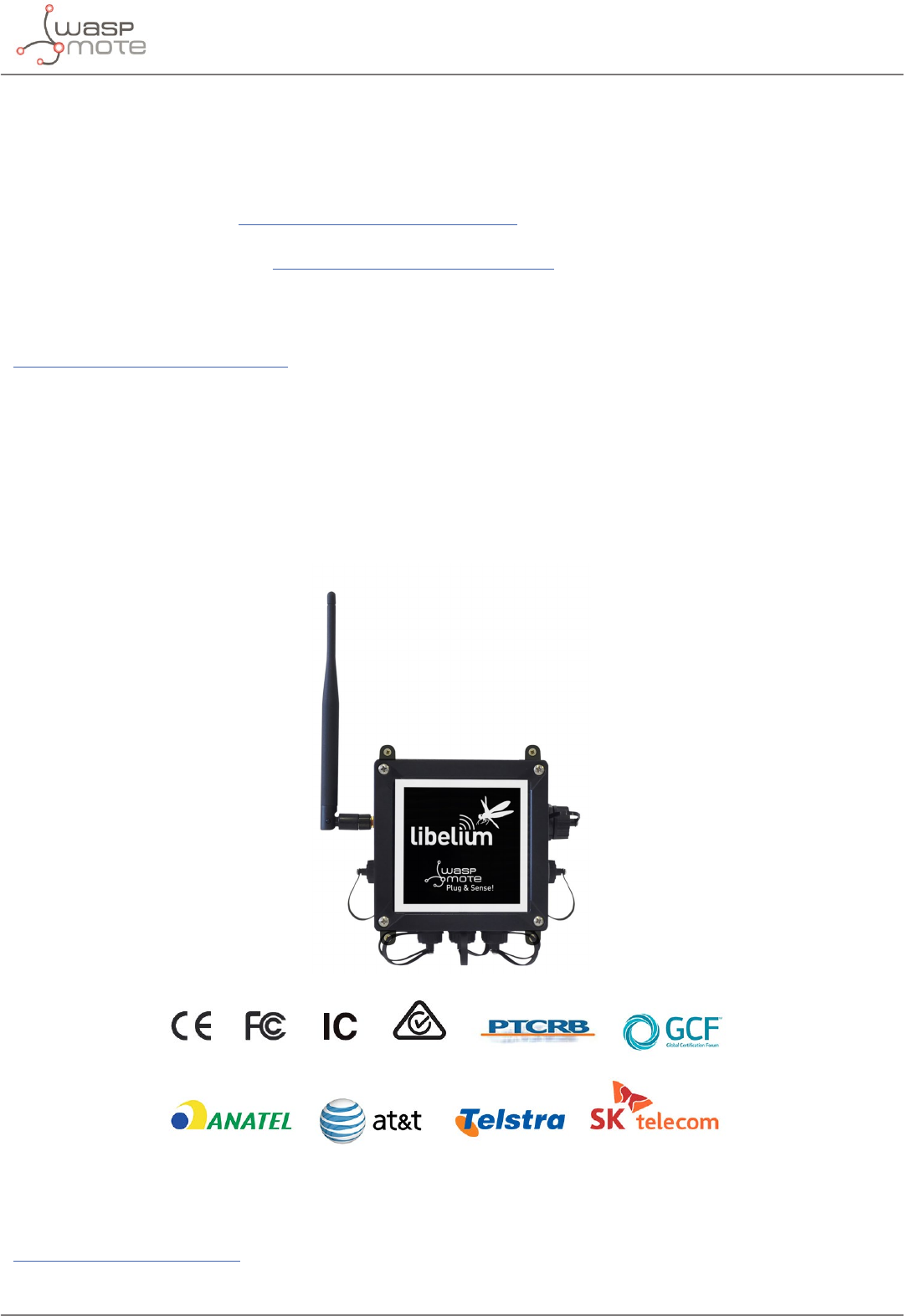
Libelium oers 2 types of IoT sensor platforms, Waspmote OEM and Plug & Sense!:
•Waspmote OEM is intended to be used for research purposes or as part of a major product so it needs nal certication on
the client side. More info at: www.libelium.com/products/waspmote
•Plug & Sense! is the line ready to be used out-of-the-box. It includes market certications. See below the specic list of
regulations passed. More info at: www.libelium.com/products/plug-sense
Besides, Meshlium, our multiprotocol router for the IoT, is also certied with the certications below. Get more info at:
www.libelium.com/products/meshlium
List of certications for Plug & Sense! and Meshlium:
• CE (Europe)
• FCC (US)
• IC (Canada)
• ANATEL (Brazil)
• RCM (Australia)
• PTCRB (cellular certication for the US)
• AT&T (cellular certication for the US)
Figure: Certications of the Plug & Sense! product line
You can nd all the certication documents at:
www.libelium.com/certications
