(WEB)IOM WKM GATE SAF T SEAL API 6D Valves IOM
User Manual: WKM Saf-T-Seal API 6D Gate Valves IOM Resource Library
Open the PDF directly: View PDF ![]() .
.
Page Count: 20
P R O C E S S V A L V E S
®
WKM
API 6D GATE VALVES
®
SAF-T-SEAL
®
WKM
Installation, Operation and Maintenance Manual
Installation, Operation and Maintenance Manual IOM-WKM-GATE-SAF-T-SEAL

P R O C E S S V A L V E S
TABLE OF CONTENTS
WKM SAF-T-SEAL
API 6D GATE VALVES
Bill of Materials
2 inch - 4 inch Model M .................................................. 1
6 inch - 12 inch Model C3/C6 ......................................... 2
6 inch - 12 inch Class 300 - 900 Model C6B .................. 3
6 inch - 12 inch Class 1500 - 2500 and
14 inch - 36 inch Class 300 - 900 Model C2B/C2C......... 4
Scope ............................................................................. 5
Nameplate Information ................................................... 5
Storage ........................................................................... 6
Installation ...................................................................... 6
Hydrostatic Testing ......................................................... 7
Operation ....................................................................... 8
Routine Maintenance ..................................................... 9
Draining Valve ................................................................ 9
Low Temperature Precautions ...................................... 10
Lubricating Handwheel and Operator Assembly............13
Lubricating Seats .......................................................... 13
Recommended Lubricants and Sealants ......................14
Maintaining Vee-Packing .............................................. 16
Trouble Shooting Chart .................................................17
© Cameron’s Valves & Measurement Group Printed in Canada 07/09-ION-2M IOM-WKM-GATE-SAF-T-SEAL
Installation, Operation and Maintenance Manual IOM-WKM-GATE-SAF-T-SEAL
Rev. 1 07/09
P R O C E S S V A L V E S
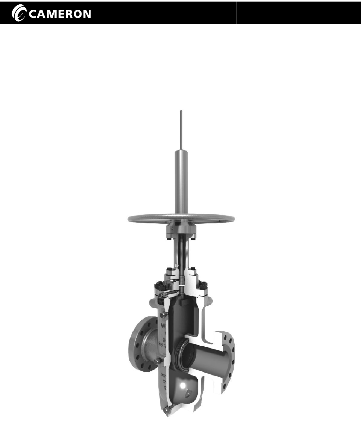
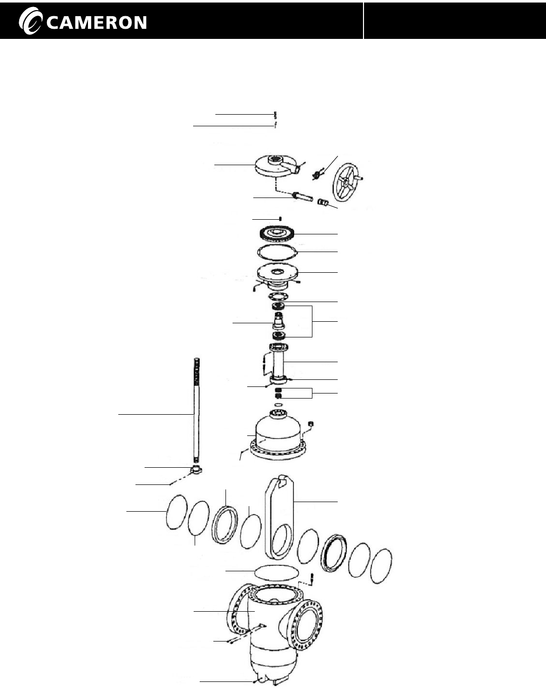
Valve Details - 2 inch - 4 inch Model M
1
Figure 1 - WKM Saf-T-Seal Gate Valve 2 - 4 Class 300-1500 (Model M)
Details may vary by size
" "
Installation, Operation and Maintenance Manual IOM-WKM-GATE-SAF-T-SEAL
PLUG
INDICATOR ROD
STEM PROTECTOR
DOWNSTOP
THRUST BEARINGS
BEARING HOUSING
STEM NUT
PACKING RETAINER NUT
PACKING RETAINER LOCK NUT
PACKING SET
BONNET
PACKING FITTING
STEM
LOCK PIN
DRIVE NUT
SEAT O-RING
SEAT
SEAT SKIRT
BONNET GASKET
BODY
GATE
3
P R O C E S S V A L V E S
Installation, Operation and Maintenance Manual IOM-WKM-GATE-SAF-T-SEAL
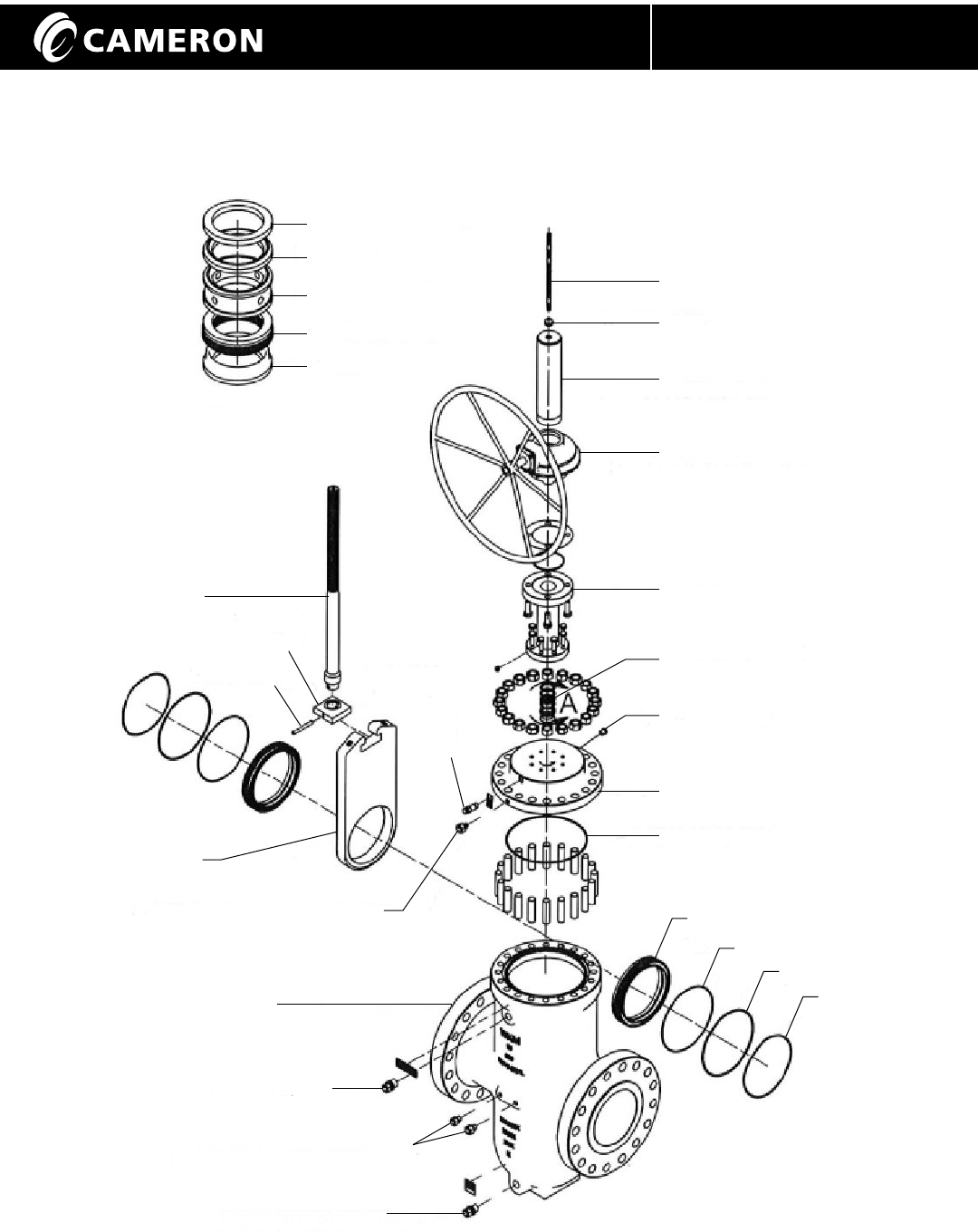
Figure 3 - WKM Saf-T-Seal Gate Valve 6 - 12 Class 600 - 900 (Model C6B)
Details may vary by size
" "
Valve Details - 6 inch - 12 inch Class 300-900 Model C6B
INDICATOR ROD
ROD WIPER
STEM PROTECTOR
BEVEL GEAR OPERATOR
YOKE TUBE
PACKING ARRANGEMENT
PACKING PLUG
BONNET
BODY SEAL RING
SEAT
SEAT O-RING
SEAT O-RING
SEAT SPRING
PACKING ADAPTER
PACKING RING
LANTERN RING
SLS SEAL RING
PEDESTAL
PACKING ARRANGEMENT
STEM BACKSEAT TEST FITTING
GATE
STEM
STEM HEAD
STEM PIN
PACKING
FITTING
BODY
VENT FITTING
SEAT SEALANT FITTINGS
BODY DRAIN FITTING
YOKE TUBE
2
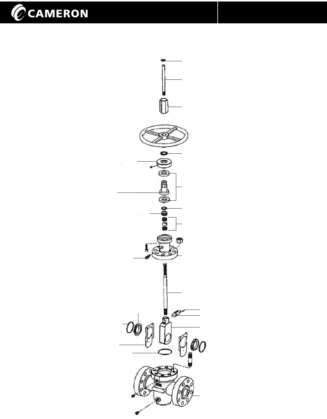
Valve Details - 6 inch - 12 inch Model C3/C6
P R O C E S S V A L V E S
Installation, Operation and Maintenance Manual IOM-WKM-GATE-SAF-T-SEAL
Figure 2 - WKM Saf-T-Seal Gate Valve 6 - 12 Class 150-900 (Model C3/C6)
Details may vary by size
" "
INDICATOR ROD
STEM PROTECTOR
THRUST BEARINGS
BEARING HOUSING
STEM NUT
PACKING SET
BONNET
STEM NUT O-RING
STEM
GATE
BODY
BEARING HOUSING GASKET
PACKING PLUG
YOKE TUBE DRAIN PLUG
PACKING
FITTING
STEM PIN
SEAT
REAR SEAL
O-RING
SEAT O-RING
BODY O-RING
BODY DRAIN FITTING
SEAT SEALANT FITTING
STEM HEAD
BODY VENT FITTING
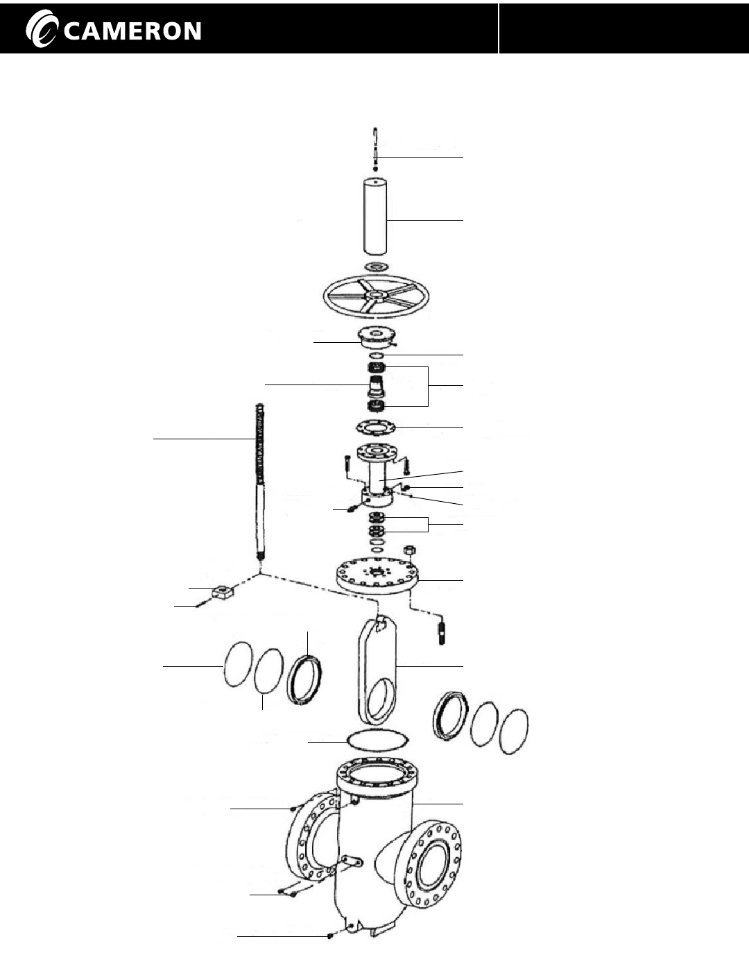
Valve Details - 6 inch - 12 inch Class 1500 - 2500
14 inch - 36 inch Class 300 - 900 Model C2B/C2C
P R O C E S S V A L V E S
4Installation, Operation and Maintenance Manual IOM-WKM-GATE-SAF-T-SEAL
Figure 4 - WKM Saf-T-Seal Gate Valve 6 - 12 Class 1500 - 2500, 14" - 36" (Model C2B/C2C)
Details may vary by size
" "
GEAR HOUSING GASKET
PINION BUSHING
THRUST BEARINGS
STEM NUT O-RING
YOKE TUBE
BEARING HOUSING
INDICATOR ROD
GROMMET
GEAR HOUSING
STEM PROTECTOR
PINION
STEM NUT KEY
GEAR
PACKING PLUG
PACKING SET
STEM NUT
PACKING
FITTING
BONNET
STEM
STEM HEAD
STEM PIN
REAR SEAL
O-RING
SEAT
GATE
SEAT O-RING
BODY O-RING
SEAT SEALANT FITTINGS
BODY DRAIN FITTING
SEAT
INSERT
BODY
SPLIT COLLAR ASSEMBLY
VENT FITTING
P R O C E S S V A L V E S
5Installation, Operation and Maintenance Manual IOM-WKM-GATE-SAF-T-SEAL
Scope
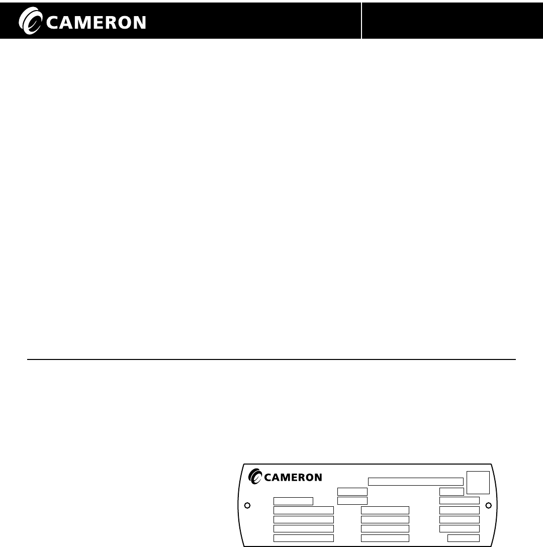
Nameplate Information
ITEM STAMP
1 Nominal Valve Size
2 Maximum Cold Working Pressure (psig)
3 *Serial Number
4 API Class Designation
5 Maximum Temperature in °F
6 *Bill of Material Number
7 Body Material Designation
8 Stem Material Designation
9 Gate Material Designation
10 Seat Material Designation
11 (Maximum Operating Pressure at 250°F - if Applicable)
12 (API Monogram - if Applicable)
13 Model Designation
14 (Marking for Non-Standard End-to-End - if Applicable)
15 (Licence Number - if Applicable
16 Date of Manufacture
17 (Impact Test Temperature - if Applicable)
This manual covers all bolted bonnet Saf-T-Seal
gate valves. Drawings, shown are typical.
The design of specific valves may vary slightly
from the drawings.
The Saf-T-Seal gate valve is a simple, yet rugged
and reliable, through conduit gate valve. It utilizes
two floating seats to provide a complete seal
with the gate. The full bore design has the same
pressure drop as an equivalent length of pipe
and allows passage of all types of scrapers (pigs).
The valve stroke is established by manufacturing
tolerances and cannot get out of adjustment.
The valve can be repaired while in line (pressure
removed and valve drained).
The stem is sealed either by Chevron packing or
spring-loaded lip seals. In an emergency, plastic
packing can be injected into the packing box to
affect a temporary seal while the valve is under
pressure.
( ) Description in parenthesis may be left blank in some cases.
* Most important data for obtaining replacement parts.
Nameplate may vary.
Saf-T-Seal valves do not depend on lubricant
for a seal in normal operation. However,
lubricants/sealants can be injected to promote
smooth operation (most 6" and larger sizes).
Seat sealant can also be injected to affect a
seal in an emergency should the seats become
damaged by foreign matter. Seats with all
metal seats are available in special trims.
Excess body pressure is automatically vented
to the upstream conduit by the seat. External
body cavity relief systems are not required.
Saf-T-Seal gate valves are available in sizes,
pressure classes, materials, and coatings to
meet industry requirements. Valves are
available with Lubrication1 Packing/Drain
extensions and Stem/Yoke tube extensions.
1
3
4
5
8
9
10
7
15
17
14
13
16
12
6
11
2
®
WKM ®
Saf-T-Seal
SIZE
B/M
SN
CLASS API
TEMP.
MOP
MOP
BODY
STEM
GATE
SEAT
@ MIN TEMP
@ MAX TEMP
DoM
MODEL
ETE
LIC. #
ISO
°F
IMPACT TEST
TEMP.
2086951 --04 --XX
°F
Valves & Measurement

6
P R O C E S S V A L V E S
Installation, Operation and Maintenance Manual IOM-WKM-GATE-SAF-T-SEAL
Storage
After WKM Saf-T-Seal Gate Valves are
assembled and tested, the valves are left in
the full open position, seats and bores are
greased and end protectors are installed.
These measures will provide protection for
approximately six months. The following
care should be taken when storing valves:
1. Make sure the valve end connection
covers remain in place during storage.
2. If the valve does not have an operator and the
valve will be stored outside, the exposed stem
or the stem adapter should be covered to avoid
accumulation of water and debris.
If long-term storage is required, the valve should be
conditioned by the following Cameron procedure
X-150771-01. Ensure adequate end connection
covers are in place. Request a copy of X-150771-01
from Cameron Valves & Measurement group.
Installation
WKM Saf-T-Seal Gate Valves are bi-directional
and have no preferred pressure end.
Overhaul and repair is easier with valve in
the "stem vertical" position. When handling or
installing the valve, keep the valve in the full
open position whenever possible to prevent
foreign matter damage to the gate and seat
sealing surfaces. The valve should be lifted
in such a way that the body supports the load
or use lifting lugs, if provided.
CAUTION: Do not use handwheels or other
protruding parts of the valve, gearbox, or
actuator to lift the valve. During handling,
use care to avoid damaging the end
connection faces, fittings and bypass
relief systems. The end connection necks
are suitable places to attach lifting slings,
if lifting lugs are not provided on the valve.
Flange End Valves may be bolted into line
using two open boxed end wrenches.
Power wrenches may be required for larger
valves. Make sure the line flanges are properly
aligned and will not distort or bind the valve.
Use new flange gaskets.
1. Bolt and nut threads should be lubricated
to obtain proper loading of bolts.
2. Finger-tighten all nuts first.
3. Tighten bolts, using the crisscross method
and torque each bolt to ASME or gasket
manufacturer’s specification.
Butt Weld End Valves should be welded into
the line by qualified welders, using qualified
procedures. Cameron's Valves & Measurement
group recommends that all welding procedures
and welders be qualified per ASME Section IX.
CAUTION: Keep weld end valves open while
installing/welding into the line. Weld slag
created during the welding process could
damage gate sealing surfaces.
7
P R O C E S S V A L V E S
Installation, Operation and Maintenance Manual IOM-WKM-GATE-SAF-T-SEAL
Installation Continued
1. Use solvent to clean grease or rust
inhibitor from the gate and/or bore of
the valve.
2. Make sure the line and valve weld
bevels are properly aligned and will
not bind the valve.
3. Electric welding equipment is preferred
for all installations. However, if only
oxygen-acetylene welding equipment
is available, extreme caution should
be taken regarding excess welding
temperature to prevent damage to
sealing components of the valve.
4. Weld with the gate in "Full Open" position.
5. Make sure temperature of the body/seat
area does not exceed 250°F. (Check with
Tempil stick or equivalent).
6. Avoid rapid application of excess welding
material. Weld each end of the valve with
a continuous bead using a 1/8" maximum
diameter electric welding rod.
7. Keep the valve in the "Full Open" position
until the line has been thoroughly cleaned
of weld slag in the valve bore and line (by
pigging and/or flushing) before changing
the position of the gate.
Hydrostatic Testing
When WKM Saf-T-Seal Gate Valves are
installed in a piping system that requires
hydrostatic testing of the adjoining pipe,
follow these procedures to minimize any
damage that could occur to the sealing
surface and seat seals inside the valve.
CAUTION: Ensure that all test fluids
contains corrosion inhibitors and
these are compatible with the valve
seat and seal materials.
1. The valve should be in the fully open
position when the injection of test fluids
begins. This will allow any pipeline
debris to be flushed through the valve
bore and out of the piping.
2. Once the piping system has been purged
of debris and the system has been filled
completely with the test fluid, the gate
should be placed in the partially open
position to allow test fluid into the body
cavity of the valve.
3. The valve is now ready to be
hydrostatically pressure tested.
CAUTION: Do not exceed pressures listed
on the following page. The maximum
Allowable Working Pressure (MAOP) is
marked on the nameplate.

8
P R O C E S S V A L V E S
Installation, Operation and Maintenance Manual IOM-WKM-GATE-SAF-T-SEAL
Hydrostatic Testing Continued
Pressure Class Hydrostatic Shell Hydrostatic Seat
psig (barg) psig (barg)
150 425 (31) 325 (22)
300 1125 (78) 825 (57)
600 2250 (155) 1650 (114)
900 3375 (233) 2475 (171)
1500 5625 (389) 4125 (284)
2500 9375 (646) 6875 (474)
4. Upon completion of hydrostatic testing, the
valve should be returned to the fully open
position before removing the test fluid from
the piping system. The test fluid in the body
cavity can be drained through the body drain
port located in the lower portion of the valve.
(See Draining Valve Page 9).
5. Close the valve body bleed fitting and return
the valve to required operating position,
either fully open or fully closed.
6. If the valve is equipped with seat injection
fittings, the valve seat pockets should be
filled with an approved valve lubricant to
displace any test fluid from behind the seats.
7. WKM T-11 or T-102 trim valves having Vee-
Packing shall be repacked after hydrostatic
testing with water. Follow the procedure in
the Troubleshooting section of this manual
for repacking the stem seal. Use WKM #113
or Jim Ray Tiger Pak FF plastic packing.
Operation
The WKM Saf-T-Seal Gate Valve may be
operated with a handwheel or may be power
actuated. With either mode of actuation,
open and close valve completely. DO NOT
THROTTLE FLOW.
The valve, in good condition, will seal pressure
up to the maximum allowable working pressures
as a block valve, single-block-and-bleed valve or
a double-block-and-bleed valve.
Valves equipped with handwheels are CLOSED
by turning the handwheel CLOCKWISE until a
stop is felt. The indicator rod at the top of the
valve will move down (towards the valve bore),
as the handwheel is turned CLOCKWISE.
The valve is OPENED by turning the handwheel
COUNTER-CLOCKWISE until it contacts the
stop. The indicator rod at the top of the valve will
move up (away from the valve bore), as the
handwheel is turned COUNTER-CLOCKWISE.
When valves are equipped with power actuators,
the movement of the indicator rod will indicate
if the valve is being opened or closed. Make sure
all accessories recommended by the actuator
manufacturer are installed before valve actuator
installation. Should any maintenance be
necessary, obtain the part number from the unit's
nameplate and contact Cameron's Valves &
Measurement group or the nearest
representative.
9
P R O C E S S V A L V E S
Installation, Operation and Maintenance Manual IOM-WKM-GATE-SAF-T-SEAL
Routine Maintenance
The following outlines the minimum scheduled
maintenance required for WKM Saf-T-Seal
Gate Valves to promote trouble-free service
and long life. Some applications may require
more maintenance. Visually inspect every
six (6) months.
See trouble shooting section (Page 17) for
temporary solutions to problems.
Operate the valve once a month, if practical.
A full open-closed cycle is preferable.
Operate a partial cycle as a minimum.
CAUTION: Verify compatibility of any
sealant, lubricant, or anti-freeze with the
trim of the valve and product in the line.
Draining Valve
After lengthy service, there is a possibility of
water, line scale, sediment or other foreign
matter collecting in the lower body cavity.
It is advisable to periodically drain the valve
to discourage development of conditions that
can possibly lead to valve damage or impair
the operation of the valve. If draining is not
regularly scheduled, it is strongly
recommended to drain the valve at these
times:
1. After hydrostatic testing.
2. After cleaning the line.
3. When valve cannot be fully opened or
closed. (Foreign matter in the bottom of
valve can not only prevent placing valve
in a fully closed position, it can also cause
permanent damage to the internal sealing
surfaces).
A safety pressure releasing tool is required to
simplify the procedure of releasing body
pressure or draining the valve. To release body
pressure or to drain valve, first place the valve
in the closed position.
WARNING: To avoid possibly being struck
by liquid or foreign solid matter, position
yourself so the outlet port of the grease
fitting is pointing safely away from you.
(If the ball check is not holding pressure,
pressure will blow through the safety holes
in the cap.) Back-up the seat grease fitting
using a wrench so only the safety cap will
be removed from the fitting. Carefully
remove the safety cap from the seat grease
fitting. NEVER remove the grease fitting
with the valve under pressure!
10
P R O C E S S V A L V E S
Installation, Operation and Maintenance Manual IOM-WKM-GATE-SAF-T-SEAL
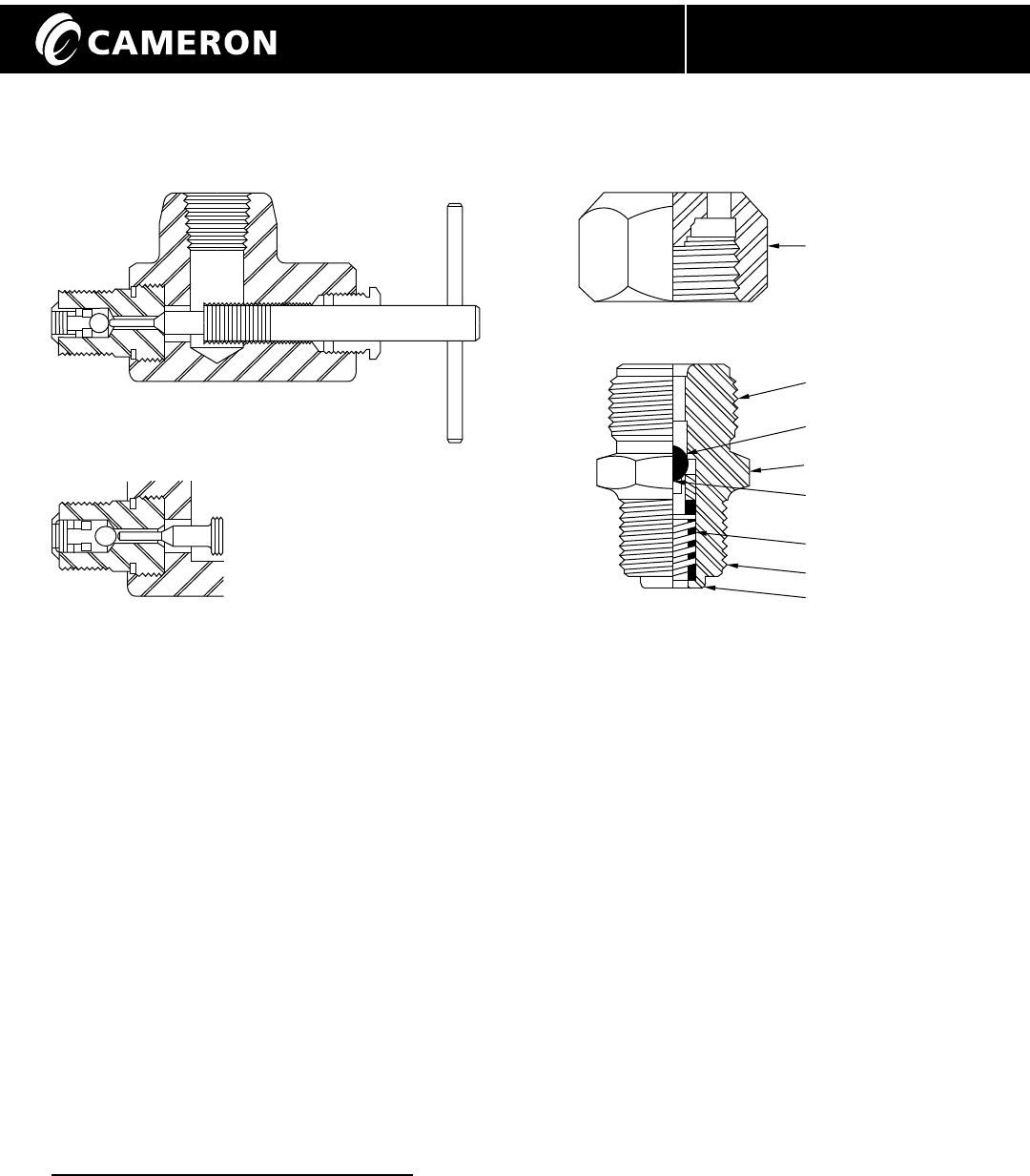
Draining Valve Continued
VENTED CAP
1 1/4" HEX
PRESSURE RELEASING TOOL WITH STINGER
SCREWED IN - BALL CHECK OPEN AND VENTING
PRESSURE RELEASING TOOL
AS INSTALLED - BALL CHECK CLOSED
Pressure releasing Tool Grease Fitting
Carefully remove the safety cap of the lower
drain grease fitting. Contact your local
Cameron's Valves & Measurement group
representative for further assistance, if
needed. Back out the stinger of the
pressure releasing tool until it stops.
Install the pressure releasing tool onto the
uncapped grease fitting. Carefully screw
the stinger of the releasing tool- (until the
ball check in the grease fitting is pushed
off its seat). This will allow the valve to
drain or to release body pressure.
After completion, back out the stinger of
the pressure releasing tool to allow the
ball check in the grease fitting to reseat
and permit easy removal of the pressure
releasing tool. Replace safety cap on the
lower drain grease fitting.
Low Temperature Precautions
Prior to exposure to freezing temperatures it
is highly recommended the valve be drained.
Water that may be trapped in the body cavity
could freeze and impair the operation of the
valve or damage the valve. If the valve has
a grease fitting in the lower drain, a sufficient
amount of anti-freeze injected into the body
cavity via the lower drain grease fitting will
prevent accumulated water from freezing.
It is also advisable to inject a sufficient
amount of valve lubricant into the grease
fittings of valve and operator (if present)
prior to extended cold temperature exposure.
Trapped water should be drained from stem
extensions. Some stem extensions in the
field are equipped with plastic plugs that can
be removed to drain trapped water from the
piped extension.
1" - 14" UNS
BALL
1" TO 1 5/16"
WRENCH HEX
POSITIVE FLOW
BALL SUPPORT
SPRING
1/4" to 1" NPT THREAD
HEAVEY-DUTY
RADIAL RIVET CRIMP

11
P R O C E S S V A L V E S
Installation, Operation and Maintenance Manual IOM-WKM-GATE-SAF-T-SEAL
Low Temperature Precautions Continued
Minimum Expected
Temperature Valve 18°F (-8°C) 13°F (-11°C) 7°F (-14°C) -8°F (-22°C) -28°F (-33°C)
(Percent Anti-freeze) (18%) (23%) (28%) (37%) (48%)
2" 0.1 gallons 0.2 gallons 0.2 gallons 0.3 gallons 0.4 gallons
150-300 (0.5 Liters) (0.7 Liters) (0.8 Liters) (1.1 Liters) (1.5 Liters)
2" 0.3 gallons 0.3 gallons 0.4 gallons 0.6 gallons 0.7 gallons
600-2500 (1 Liters) (1.3 Liters) (1.6 Liters) (2.1 Liters) (2.7 Liters)
2-1/2" 0.2 gallons 0.2 gallons 0.3 gallons 0.3 gallons 0.4 gallons
150-300 (0.6 Liters) (0.8 Liters) (1 Liters) (1.3 Liters) (1.6 Liters)
2-1/2" 0.3 gallons 0.3 gallons 0.4 gallons 0.6 gallons 0.7 gallons
400-2500 (1 Liters) (1.3 Liters) (1.6 Liters) (2.1 Liters) (2.7 Liters)
3" 0.2 gallons 0.2 gallons 0.3 gallons 0.4 gallons 0.5 gallons
150-300 (0.7 Liters) (0.9 Liters) (1.1 Liters) (1.4 Liters) (1.8 Liters)
3" 0.4 gallons 0.5 gallons 0.6 gallons 0.7 gallons 1 gallons
600-2500 (1.4 Liters) (1.7 Liters) (2.1 Liters) (2.8 Liters) (3.6 Liters)
4" 0.5 gallons 0.6 gallons 0.7 gallons 0.9 gallons 1.2 gallons
150-300 (1.7 Liters) (2.2 Liters) (2.6 Liters) (3.5 Liters) (4.5 Liters)
4" 0.5 gallons 0.7 gallons 0.8 gallons 1.1 gallons 1.4 gallons
600-2500 (2 Liters) (2.6 Liters) (3.2 Liters) (4.2 Liters) (5.5 Liters)
6" 1 gallons 1 gallons 1.2 gallons 1.6 gallons 2 gallons
150-300 (3.8 Liters) (3.7 Liters) (4.5 Liters) (5.9 Liters) (7.6 Liters)
6" 1 gallons 1.2 gallons 1.4 gallons 1.9 gallons 2.4 gallons
600-2500 (3.8 Liters) (4.4 Liters) (5.3 Liters) (7 Liters) (9.1 Liters)
8" 1.7 gallons 2.2 gallons 2.7 gallons 3.6 gallons 4.6 gallons
150-300 (6.5 Liters) (8.4 Liters) (10.2 Liters) (13.4 Liters) (17.4 Liters)
8" 1.8 gallons 2.3 gallons 2.8 gallons 3.7 gallons 4.8 gallons
600-2500 (6.8 Liters) (8.7 Liters) (10.6 Liters) (14 Liters) (18.2 Liters)
10" 2.7 gallons 3.5 gallons 4.2 gallons 5.6 gallons 7.2 gallons
150-300 (10.2 Liters) (13.1 Liters) (15.9 Liters) (21 Liters) (27.3 Liters)
10" 2.7 gallons 3.5 gallons 4.2 gallons 5.6 gallons 7.2 gallons
600-2500 (10.2 Liters) (13.1 Liters) (15.9 Liters) (21 Liters) (27.3 Liters)
12" 4.5 gallons 5.8 gallons 7 gallons 9.3 gallons 12 gallons
150-300 (17.0 Liters) (21.8 Liters) (26.5 Liters) (35 Liters) (45.4 Liters)
12" 4 gallons 5.1 gallons 6.2 gallons 8.1 gallons 10.6 gallons
600-2500 (15 Liters) (19.2 Liters) (23.3 Liters) (30.8 Liters) (40 Liters)
14" 3.6 gallons 4.6 gallons 5.6 gallons 7.4 gallons 9.6 gallons
150 (13.6 Liters) (17.4 Liters) (21.2 Liters) (28 Liters) (36.3 Liters)
14" 5.4 gallons 6.9 gallons 8.4 gallons 11.1 gallons 14.4 gallons
300-1500 (20.4 Liters) (26.1 Liters) (31.8 Liters) (42 Liters) (54.5 Liters)
16" 5 gallons 6.4 gallons 7.8 gallons 10.4 gallons 13.4 gallons
150 (19.1 Liters) (24.4 Liters) (29.7 Liters) (39.2 Liters) (50.9 Liters)
16" 7.4 gallons 9.4 gallons 11.5 gallons 15.2 gallons 19.7 gallons
300-2500 (27.9 Liters) (35.7 Liters) (43.5 Liters) (57.4 Liters) (74.5 Liters)
Volume of Anti-freeze (Ethylene Glycol) to Prevent Freezing

12
P R O C E S S V A L V E S
Installation, Operation and Maintenance Manual IOM-WKM-GATE-SAF-T-SEAL
Low Temperature Precautions Continued
Minimum Expected
Temperature Valve 18°F (-8°C) 13°F (-11°C) 7°F (-14°C) -8°F (-22°C) -28°F (-33°C)
(Percent Anti-freeze) (18%) (23%) (28%) (37%) (48%)
18" 6.5 gallons 8.3 gallons 10.1 gallons 13.3 gallons 17.3 gallons
150 (24.5 Liters) (31.3 Liters) (38.2 Liters) (50.4 Liters) (65.4 Liters)
18" 9.9 gallons 12.7 gallons 15.4 gallons 20.4 gallons 26.4 gallons
300-1500 (37.5 Liters) (47.9 Liters) (58.3 Liters) (77 Liters) (99.9 Liters)
20" 8.3 gallons 10.6 gallons 12.9 gallons 17 gallons 22.1 gallons
150 (31.3 Liters) (40 Liters) (48.8 Liters) (64.4 Liters) (84 Liters)
20" 12.4 gallons 15.9 gallons 19.3 gallons 25.5 gallons 33.1 gallons
300-900 (47 Liters) (60.1 Liters) (73.1 Liters) (96.6 Liters) (125 Liters)
22" 13.1 gallons 16.8 gallons 20.4 gallons 27 gallons 35 gallons
150 (49.7 Liters) (63.6 Liters) (77.4 Liters) (102 Liters) (133 Liters)
22" 14.8 gallons 18.9 gallons 23 gallons 30.3 gallons 39.4 gallons
300-600 (55.9 Liters) (71.4 Liters) (86.9 Liters) (115 Liters) (149 Liters)
24" 13 gallons 16.6 gallons 20.2 gallons 26.6 gallons 34.6 gallons
150 (49.1 Liters) (62.7 Liters) (76 Liters) (101 Liters) (131 Liters)
24" 18 gallons 23 gallons 28 gallons 37 gallons 48 gallons
300-900 (68.1 Liters) (87.1 Liters) (106 Liters) (140 Liters) (182 Liters)
26" 16.7 gallons 21.4 gallons 26 gallons 34.4 gallons 44.6 gallons
150 (63.4 Liters) (81 Liters) (99 Liters) (130 Liters) (169 Liters)
26" 22.5 gallons 28.8 gallons 35 gallons 46.3 gallons 60 gallons
300-600 (85.2 Liters) (109 Liters) (132 Liters) (175 Liters) (227 Liters)
28" 21.2 gallons 27.1 gallons 33 gallons 43.7 gallons 56.6 gallons
150 (80 Liters) (103 Liters) (125 Liters) (165 Liters) (214 Liters)
28" 27.7 gallons 35.4 gallons 43.1 gallons 57 gallons 73.9 gallons
300-600 (105 Liters) (134 Liters) (163 Liters) (216 Liters) (280 Liters)
30" 25.9 gallons 33.1 gallons 40.3 gallons 53.3 gallons 69.1 gallons
150 (98 Liters) (125 Liters) (153 Liters) (202 Liters) (262 Liters)
30" 34.6 gallons 44.2 gallons 53.8 gallons 71 gallons 92.2 gallons
300-600 (131 Liters) (167 Liters) (204 Liters) (269 Liters) (349 Liters)
32" 26.4 gallons 34 gallons 41 gallons 54 gallons 70 gallons
150 (100 Liters) (128 Liters) (155 Liters) (205 Liters) (267 Liters)
32" 49.7 gallons 63 gallons 77 gallons 102 gallons 132 gallons
300-600 (188 Liters) (240 Liters) (293 Liters) (387 Liters) (502 Liters)
34" 30.4 gallons 39 gallons 47 gallons 62 gallons 81 gallons
150 (115 Liters) (147 Liters) (179 Liters) (237 Liters) (307 Liters)
34" 63.2 gallons 81 gallons 98 gallons 130 gallons 169 gallons
300-600 (239 Liters) (306 Liters) (372 Liters) (492 Liters) (638 Liters)
36" 28.4 gallons 36 gallons 44 gallons 58 gallons 76 gallons
150 (108 Liters) (138 Liters) (167 Liters) (221 Liters) (287 Liters)
36" 96.3 gallons 123 gallons 150 gallons 198 gallons 257 gallons
300-600 (365 Liters) (466 Liters) (567 Liters) (749 Liters) (972 Liters)
40" 44.3 gallons 57 gallons 69 gallons 91 gallons 188 gallons
150 (168 Liters) (214 Liters) (261 Liters) (345 Liters) (448 Liters)
40" 130 gallons 167 gallons 203 gallons 268 gallons 348 gallons
300-600 (494 Liters) (631 Liters) (768 Liters) (1015 Liters) (1317 Liters)
Volume of Anti-freeze (Ethylene Glycol) to Prevent Freezing

13
P R O C E S S V A L V E S
Installation, Operation and Maintenance Manual IOM-WKM-GATE-SAF-T-SEAL
Low Temperature Precautions Continued
Minimum Expected
Temperature Valve 18°F (-8°C) 13°F (-11°C) 7°F (-14°C) -8°F (-22°C) -28°F (-33°C)
(Percent Anti-freeze) (18%) (23%) (28%) (37%) (48%)
42" 49.7 gallons 63 gallons 77 gallons 102 gallons 132 gallons
150 (188 Liters) (240 Liters) (292 Liters) (386 Liters) (501 Liters)
42" 166 gallons 212 gallons 258 gallons 341 gallons 443 gallons
300-600 (629 Liters) (803 Liters) (978 Liters) (1292 Liters) (1677 Liters)
48" 67.7 gallons 87 gallons 105 gallons 139 gallons 181 gallons
150 (256 Liters) (328 Liters) (399 Liters) (527 Liters) (684 Liters)
48" 343 gallons 438 gallons 533 gallons 704 gallons 914 gallons
300-600 (1297 Liters) (1658 Liters) (2018 Liters) (2667 Liters) (3459 Liters)
Volume of Anti-freeze (Ethylene Glycol) to Prevent Freezing
Lubricating Handwheel and Operator Assembly
Handwheel Operated Valves-
Connect a grease gun containing
NLGI grade 2 petroleum base grease
to the 1/8" Alemite type grease fitting
on the bearing housing. Pump in a
small amount of grease. DO NOT
OVERFILL.
Bevel Gear Operators-
Bevel gear operators are supplied by
other manufacturers. Consult particular
manufacturer's instructions. If these
are not available, lubricate the same
as Handwheel Operated Valves above.
Motor Operated Valves-
Motor operators are supplied by other
manufacturers. Consult particular
manufacturer's instructions.
Lubricating Seats
(6" and larger valves equipped with seat sealant
ports). Lubricate once a year.
1. Only use grease guns that are equipped with
a pressure gage.
2. Some seat sealants become very stiff or
viscous in cold weather. It may be difficult to
pump some sealants under these conditions.
It is recommended that the grease gun be
kept in a heated area until it is ready to be
used. If this is not possible, contact your local
Cameron Valves & Measurement group
representative for low temperature sealant
recommendations.
3. Move the valve to the closed position.
4. Carefully, remove the safety caps on the seat
lubrication fitting using a wrench.

14Installation, Operation and Maintenance Manual IOM-WKM-GATE-SAF-T-SEAL
P R O C E S S V A L V E S
Lubricating Handwheel and Operator Assembly Continued
WARNING: Back up the seat grease fitting
using a wrench so only the safety cap will
be removed from the fitting. Carefully
remove the safety cap from the seat
grease fitting. NEVER remove the grease
fitting with the valve under pressure!
5. Connect the grease gun to the seat
lubrication fitting(s). (Both sets may
be lubricated at the same time).
6. Pump the sealant into the seat.
Once the pressure rises above the
valve rated pressure, hold for
three (3) minutes to promote filling
of the grease grooves.
Note: Grease guns can develop pressures far
in excess of the valve working pressure.
Use only grease guns, which are equipped
with pressure gages. Do not exceed the valve
maximum allowable working pressure.
7. Stroke the valve to spread the sealant on the
seat surfaces. (Indicator rod should move
approximated 1" or 25 mm).
8. Release the pressure in the grease gun and
remove it from the grease fitting. The fitting
ball check should prevent the release of the
valve grease pressure.
9. Install the fitting safety cap and tighten securely.
10. Repeat for the other seat. Both seats may be
lubricated at the same time, if desired.
Recommended Lubricants and Sealants
TRIM NORMAL SEAT EMERGENCY BEARING STEM
LUBRICANT SEAT SEALANT LUBRICANT PACKING
T-11, T-102 WKM #58G WKM #58G NLGI Grade 2 WKM #113
(Aromatic Hydrocarbons or Val-Tex 700 Bearing grease or Jim Ray
and refined products) Tiger Pak "FF"
T-10, T-24 Val-Tex700 WKM #102 NLGI Grade 2 WKM #109
(Sour Oil and Gas, Bearing grease
Waterflood
T-50, T-51 NONE NONE NLGI Grade 2 WKM #115
(Geothermal water and Bearing Grease
steam)
Trim T-36, T-37, T-38, T-39 Val-Tex 50 WKM #103 WKM #1 WKM #109
(Low temperature produced
hydrocarbons)
T-88 NLGI Grade 2 NLGI Grade 2 NLGI Grade 2 Jim Ray
(Anhydrous Ammonia Bearing grease Bearing grease Bearing grease Tiger Pak "A"
Products) or or
Chemola TF-41 Chemola TF-41
or Val-Tex 80H or Val-Tex 80H
15Installation, Operation and Maintenance Manual IOM-WKM-GATE-SAF-T-SEAL
P R O C E S S V A L V E S
Lubricating Handwheel and Operator Assembly Continued
PRODUCT MANUFACTURER
WKM 1 Cameron Valves & Measurement
WKM 58G CAMSERV™ Aftermarket Services
WKM 102 8820 Meldrum Ln
WKM 103 Houston, TX 77075
WKM 109 713-946-2122
WKM 113 Fax: 713-331-5813
WKM 115
Val-Tex 700 Val-Tex
Val-Tex 50 10600 Fallstone Road
Houston, TX 77009
800-627-9771
281-530-4848
Fax: 281-530-5225
Jim Ray Tiger Pak FF Jim Ray
Jim Ray Tiger Pak A 10645 Richmond Ave. #130
Houston TX 77042
713-785-5055
Fax: 713-785-5534
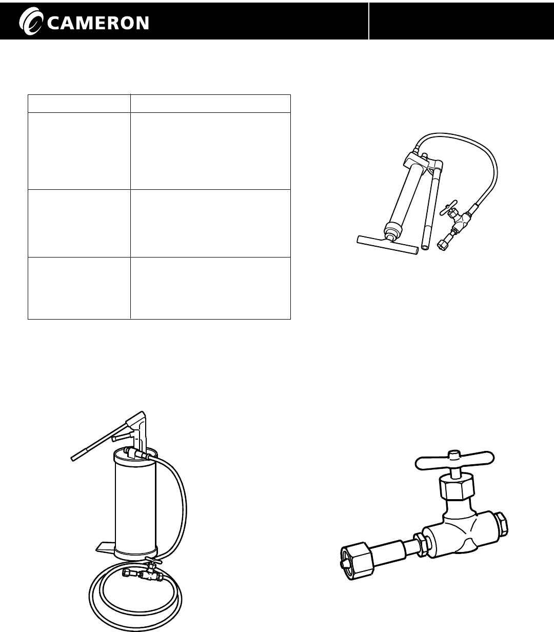
Figure 10 - Screw/Prime Hand Gun,
Part Number 2122495-01.
Exact configuration may
vary from illustration.
Figure 12 - Adapter Fitting,
Part Number K296434
Figure 11 - Bucket-Type Gun,
Cameron Part Number K065189.
Exact configuration may vary
from illustration.
16Installation, Operation and Maintenance Manual IOM-WKM-GATE-SAF-T-SEAL
P R O C E S S V A L V E S
Maintaining Vee-Packing
(If so equipped) - Once a year or more often as required.
1. Valves equipped with Vee Packing may require periodic
inspection and maintenance to preclude stem leakage.
This is particularly important if the valves are in service
at temperatures above 250°F (121°C).
2. Other designs use a self-adjusting stem seal
identified by the following tag on the packing
fitting. These require only periodic inspection.
3. Inspect the valve for evidence of
stem leakage.
This might be determined by paint
discoloration around the bonnet-yoke tube
joint. If there is no evidence of leakage, no
maintenance is required. It is often
beneficial to add one stick of packing once
a year to help keep the packing pliable and
prevent future problems. (Couple of "sticks"
for larger valves).
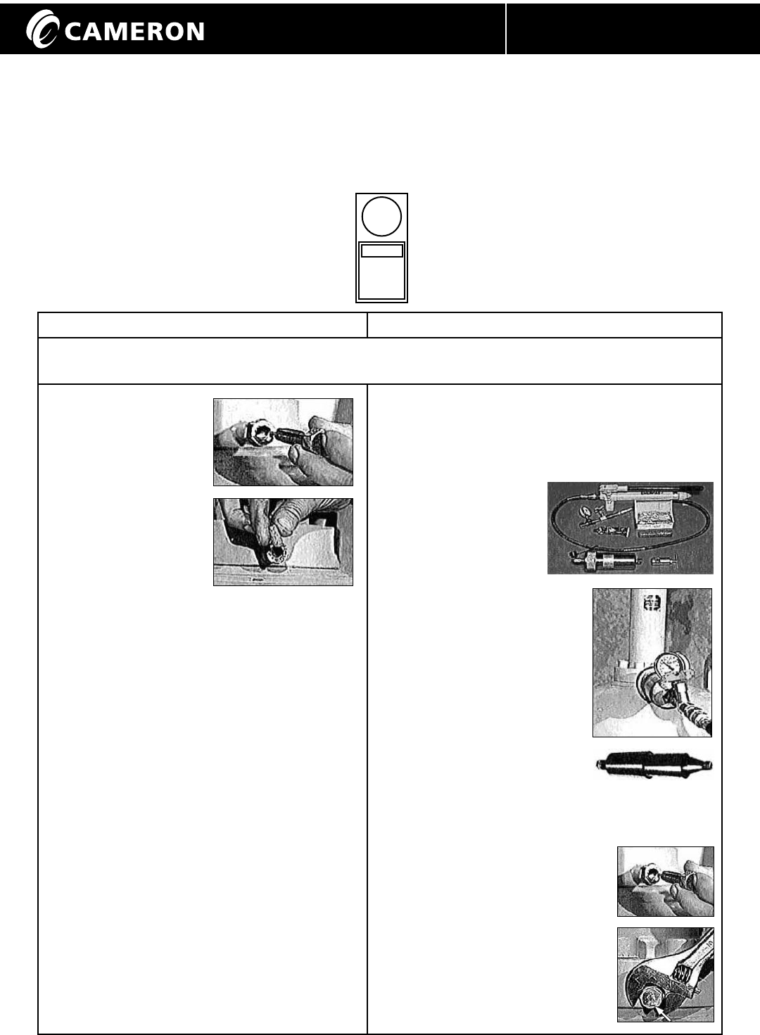
4. If leakage is evident, inject plastic packing
as follows:
Stick Method Gun Method
Note: Packing is not damaged by cold. However, keep plastic packing in a warm place (like a heated
room or vehicle cab) until ready for use to keep pliable
• Remove the injection
stinger from the
packing fitting.
CAUTION:
pressure may be
trapped in the
packing box
• Apply a good grade
of earing grease to
the threads
• Place a stick of
packing Into the fitting and screw in the
stinger until it seats
• Repeat as necessary. Use screw torques
as follows:
• 3-4 ft-lb (40-50 in-lb, 4-5.5 N-m) for
WKM packings
• 4-5 ft-lb (50-60 in-lb, 5.5-7 N-m) for
thick packings
• Do not exceed 7 ft-lb (60 in-lb, 9.5 N-m)
as this may exceed the 10,000 psig
(689 barg) rating of the fitting
• Back out the screw until the threads show.
This allows the bail check to seat
CAUTION: Apply only enough packing
to stop the leak
• Remove the injection stinger from the packing
fitting. CAUTION: pressure may be trapped in the
packing box
• Assemble the packing gun with the appropriate
plastic packing
• Connect the gun to
the packing fitting
• Apply 5500-7500 psi
(379-517 bar) to the
packing gun. Thick
packings may require
8000-9000 psi (551-620 bar)
CAUTION:
The WKM style packing gun
applies twice the hand
pump pressure
• Hold for several minutes
• Add more plastic if the
pressure drops
• Repeat until the packing pressure holds steady
• Do not exceed 10,000 psi (689 bar)
• Remove the packing gun
• Dig out any excess packing
from the packing fitting
• Apply a small amount of bearing
grease to the packing fitting screw
• Install the packing fitting screw
and tighten
NOTICE
T HI S V ALV E I S
ASSEMBLED USING
A SELF ENERGIZED
STEM SEA L. INJECT
PL AS TI C PAC KI NG
ONLY IN THE EVENT
O F A S TEM SEAL
L E A K.

17Installation, Operation and Maintenance Manual IOM-WKM-GATE-SAF-T-SEAL
P R O C E S S V A L V E S
The Grease fitting or
bleed plug is leaking.
The valve is leaking
around bonnet to
body joint.
The safety cap or bleed plug
screw is loose.
The bonnet seal is leaking. Ensure that the bonnet nuts are tightened properly.
Call CAMERON VALVES & MEASUREMENT group
representative if leakage persists.
HANDWHEEL OR BEVEL GEAR OPERATED
VALVES:
Open the valve fully by turning the handwheel
counter-clockwise. Tighten securely. DO NOT
BACK OFF THE HANDWHEEL.
MOTOR OPERATED VALVES:
Make sure the operator limit switches are set correctly.
The gate is not properly aligned
with the seats.
A restriction is present
in the valve bore.
Lubricate the bearings, operator, and/or seats
per the Routine Maintenance Section. Lubricate
the operator per the manufacturer’s instructions.
The lubrication is not sufficient.
The valve is hard
to operate.
Ice is present in the yoke tube,
handwheel unit, or operator.
(Pipeline bending moments
distorting the valve body).
Apply heat to melt ice.
Line bind is present.
(Pipeline bending moments
distorting the valve body).
Relieve the bind or moment on the valve.
Motor operator will
not actuate the valve.
Improperly sized motor operator. Replace with properly sized motor operator.
Improperly wired electric operator. Verify wiring following instructions and schematics
provided by the operator manufacturer.
Valve operation
is erratic.
The bearings need lubrication. Lubricate bearings per the Routine Maintenance
Section.
The bearing or gear unit is broken
or damaged.
Replace broken or damaged parts.
The valve seats
will not seal.
Valve is not fully closed. Fully close the valve. Turn the handwheel
CLOCKWISE.
Seat or seat seals are damaged. Lubricate seats per Routine Maintenance
Section. Replace parts.
Trouble Probable Cause Remedy
Tighten the safety cap or bleed plug screw.
Troubleshooting

P R O C E S S V A L V E S
®
WKM
© Cameron’s Valves & Measurement Group Printed in Canada 07/09-ION-2M IOM-WKM-GATE-SAF-T-SEAL
3250 Briarpark Drive, Suite 300
Houston, Texas 77042
USA Toll Free 800 323 9160
For the most current contact and location information go to: www.c-a-m.com/valvesandmeasurement
Contact your Cameron’s Valves & Measurement group representative for a Repair Manual
Rev. 1 07/09
Installation, Operation and Maintenance Manual IOM-WKM-GATE-SAF-T-SEAL
