Wkm Saf T Seal Gate Valves
User Manual: Resource Library
Open the PDF directly: View PDF ![]() .
.
Page Count: 36

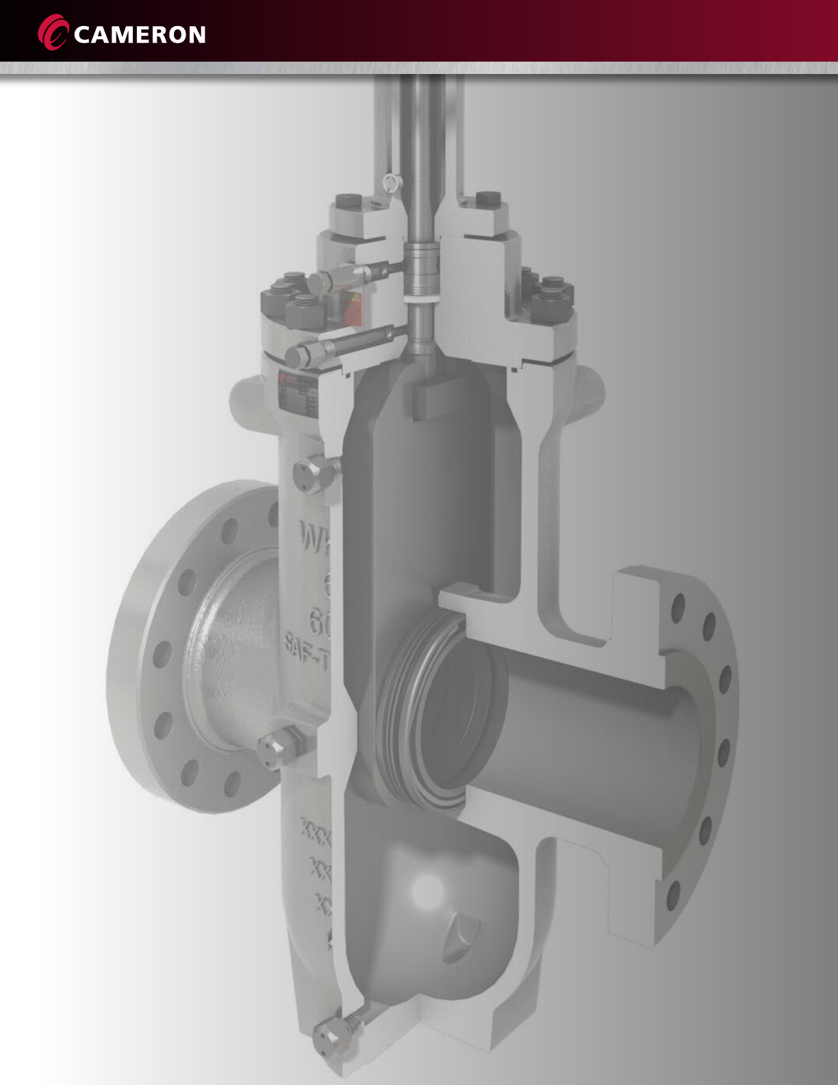
WKM Saf-T-Seal Gate Valves
Through-conduit, double block-and-bleed slab gate valves with fully protected
seat faces for long-lasting, drop-tight shutoff in liquid pipelines

1
WKM SAF-T-SEAL GATE VALVES
Introduction .......................................................................................... 3
Design .................................................................................................. 4
Features ................................................................................................ 5
Options ................................................................................................. 6
C6, C2B and C2C Models
Automatic Relief of Excess Body Pressure .............................................. 7
C6B Model
Automatic Relief of Excess Body Pressure .............................................. 8
Single Spring-Loaded (SLS) Seal ............................................................. 9
2” to 4” (50 mm to 100 mm) Classes 600, 900 and 1500
Model M (Handwheel Operated) ........................................................... 10
6” to 12” (150 mm to 300 mm) Classes 150, 300, 600, and 900
Models C6 and C6B (Handwheel and Bevel Gear Operated) .................. 11
14” to 36” (350 mm to 900 mm) Classes 150 and 300
Models C6B and C2B (Bevel Gear Operated) ......................................... 12
14” to 36” (350 mm to 900 mm) Classes 600 and 900
Models C68 and C6B (Handwheel and Bevel Gear Operated) ................ 13
WKM Saf-T-Gard Actuators ................................................................... 14
Pneumatic Diaphragm Actuator ............................................................ 15
Pneumatic Piston Actuator .................................................................... 19
Table of Contents

2
Operating Size Requirements ................................................................ 20
Topworks Model M ............................................................................... 22
Topworks Model C6 .............................................................................. 23
Topworks Model C6B ............................................................................ 24
Flow Coefficients (Cv) ............................................................................ 26
Flow Coefficients (Kv) ............................................................................ 27
Trim Chart ............................................................................................ 28
Common Trims ..................................................................................... 29
Partial Open Flow Characteristics .......................................................... 30
CAMSERV Aftermarket Services for Valves and Actuation ...................... 31
Trademark Information ......................................................................... 32
Table of Contents

3
WKM Saf-T-Seal Gate Valves
Cameron is a leading provider of valves and measurement systems to the oil and gas industry.
Our products are primarily used to control, direct and measure the flow of oil and gas as it is
moved from individual wellheads through flowlines, gathering lines and transmission systems
to refineries, petrochemical plants and industrial centers for processing.
Cameron provides a wide range of valves for use in natural gas, LNG, crude oil and refined
products transmission lines. The traditional CAMERON® fully welded ball valve product line
has been combined with the GROVE®, RING-O®, TOM WHEATLEY®, ENTECH™ and TK®
product lines. This broad offering has strengthened Cameron’s ability to serve as a single
source for customer requirements. Cameron also provides critical service valves for refinery,
chemical and petrochemical processing businesses, and for associated storage terminal
applications, particularly through the ORBIT® and GENERAL VALVE® lines. These brands are
complemented by WKM®, TBV™ and TEXSTEAM™ valve products and considerably expand
the scope of our product offerings.
Cameron’s WKM Saf-T-Seal™ gate valve’s smooth continuous bore reduces turbulence.
Additionally, the seat faces are outside the flow stream and are protected from contact with
the lading whether the valve is in the open or closed position. The WKM Saf-T-Seal gate
valve’s full bore makes it possible to run pigs, scrapers or hot tap cutters through the valves
without danger of damaging the valve, lodging the scraper, or jamming it with metal cuttings.
Ville Platte, La.,
USA
4
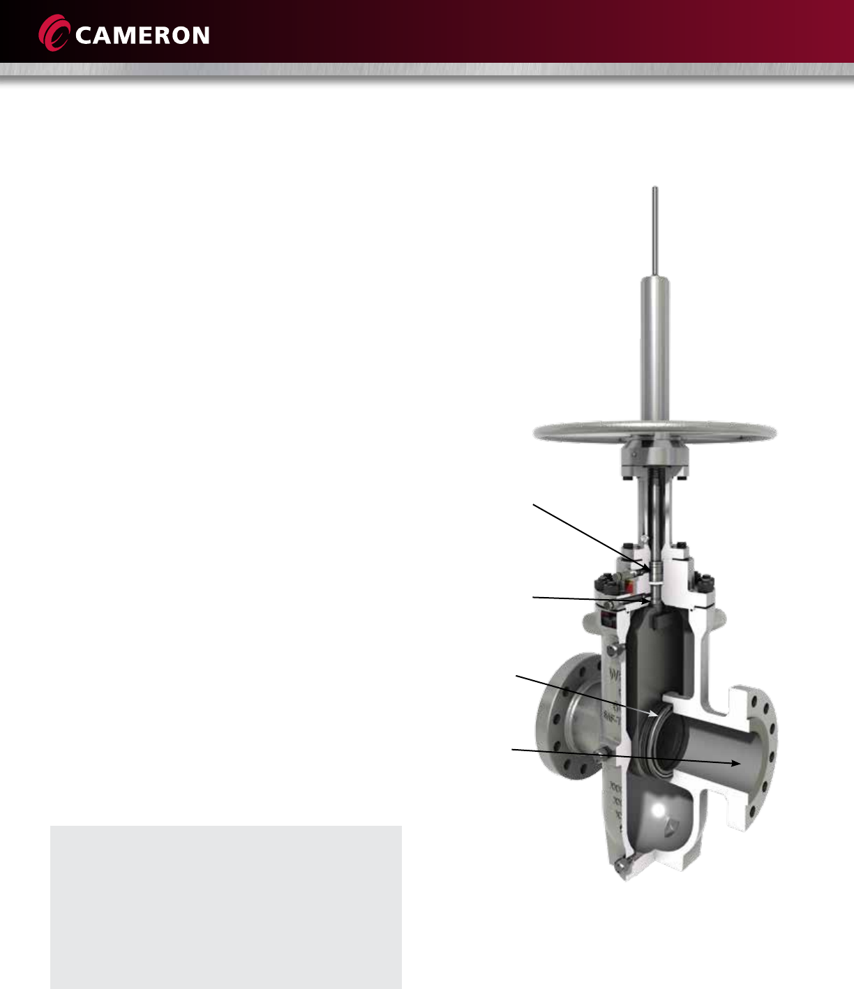
DESIGN
Cameron’s WKM Saf-T-Seal valve’s through-conduit design provides the following
specific advantages that result in reliable performance and long life:
Protection of Seat Faces
• Seat faces are outside the flow
stream and in full contact with
the gate, in both open and closed
positions, greatly extending the
seat life.
Smooth, Continuous
Conduit for Flow
• Destructive turbulence is reduced.
In a full-bore valve, pressure drop
through the valve is no greater
than that through an equal
length of equal diameter pipe.
Block-and-Bleed Capability
• In the closed position, the valve
forms a tight seal on both seats
simultaneously. This allows the
body cavity to be bled.
The single spring-loaded (SLS) lip seal
is self-adjusting and does not depend
on plastic packing
Blowout-proof stem with backseat
Metal wave spring to ensure
a bubble-tight seal
Full-bore, through-conduit
design reduces turbulence
Commonly Used Applications
• Mainline and manifold valves in liquids pipelines
• Storage wells (salt domes, etc.)
• Water flood
• Safety valves (emergency shutdown valves (ESDVs)
pipelines, wellheads and salt domes

5
FEATURES
1. Through-Conduit Slab Gate Valve
• Provides a tight pressure-activated seal
• Full-bore design reduces pressure drop and allows passage of all types of scrapers (pigs)
• Nickel-plated internals
2. Cameron’s SLS Stem Seal System or Vee Packing with Injectable Plastic Packing
3. Double-Sealing, Replaceable, Floating Seats
• Block-and-bleed per API 6D
• Simple one-piece design is resistant to dirty service
• Insert initiates the seal and helps clean the gate
• Excess body pressure is automatically vented upstream
• Seats may be lubricated to promote long life, reduce operating torques, or effect a seal in an
emergency situation
• Easily removed and replaced while the valve is in-line
• Double seal established by initial plastic-to-metal seal in addition to metal-to-metal seal, both
upstream and downstream
4. Bolted Bonnet Valve is In-Line Repairable
• Seal is made by an O-ring or flat metal gasket for standard applications (spiral-wound metal gasket
with a non-asbestos filler for high-temperature applications)
5. Singe-Piece Cast Body Center Section
• Provides the necessary strength to resist pipeline bending moments
• Smooth shape reduces stress concentrations
• Made from pressure vessel quality steel
6. Valve Stroke is Established by Manufacturing Tolerances
• Cannot get out of adjustment
7. Upgrades
• Stem backseat with test port
• SLS stem seal contained entirely in the bonnet, reducing a potential leak path
• Seat with wave spring to seal on low-pressure air
• Complies to API 6D and B16.34
6
• Position indicator rods standard on handwheel- and bevel gear-operated valves
• Handwheel operators, bevel gear operators, or less gearing (bare stem)
• Saf-T-Gard hydraulic actuators or piston or diaphragm pneumatic actuators for surface safety applications
• Lubrication/packing/drain extensions
• Stem/yoke tube extensions
• Variety of coatings (coal tar epoxy for buried service, two- to three-part coating systems for marine environments,
inorganic zinc-rich epoxy, etc.)
• Retrofits available for stem and body fitting extensions on buried service or difficult-to-reach valves,
6” (150 mm) increments
• HF-6 overlay available for gate and seal sealing surfaces
OPTIONS
WKM Saf-T-Seal valves have a legacy of solid, innovative solutions around the globe.
7
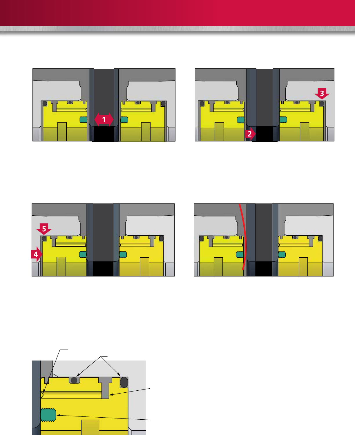
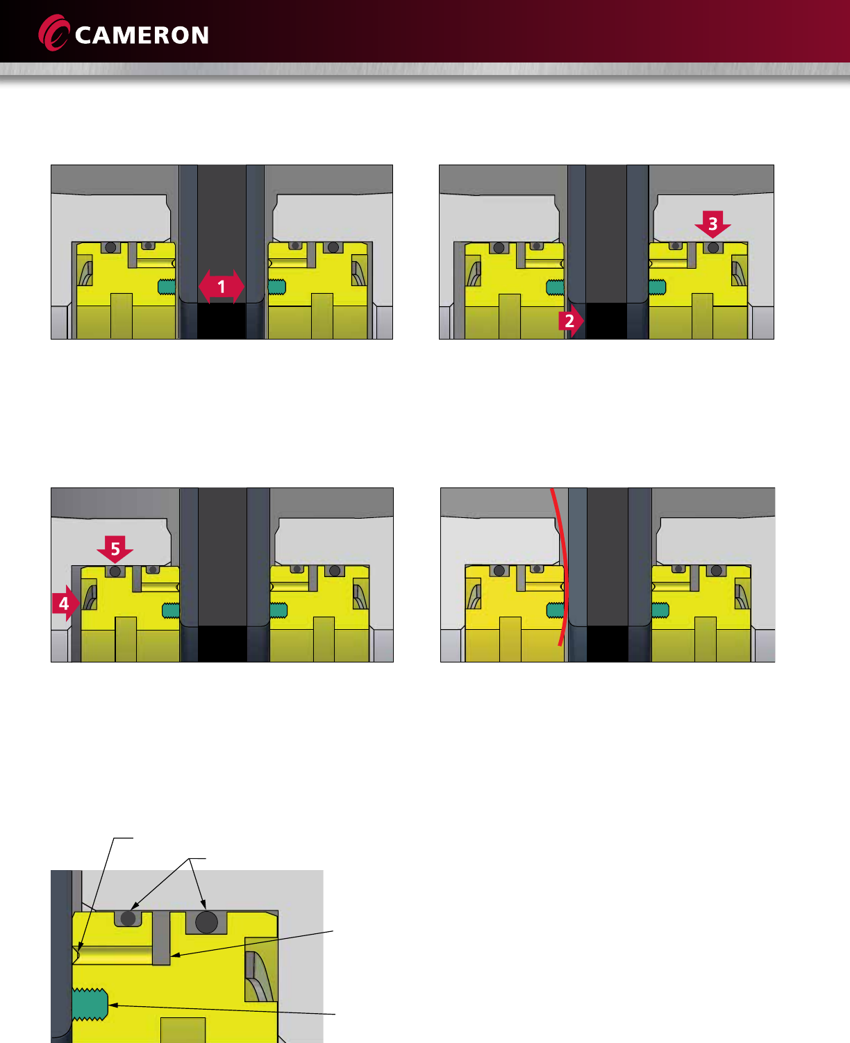
AUTOMATIC RELIEF OF EXCESS BODY PRESSURE
1. When the gate is in the closed position and there is an
equal pressure through the valve, an initial seal (1) is
formed by the raised plastic ring on the faces of the
seats. The seat inserts clean both sides of the gate
each time the valve is opened or closed.
2. As line pressure (2) is applied to the valve, it acts on
the gate, forcing it against the plastic ring on the
downstream seat and compressing it until the gate
rests against the steel seat. Thus, a double seal is
formed; first, a plastic-to-metal seal then metal-to-metal.
The seal also is forced firmly into its recess. The O-ring
(3) prevents any downstream flow around the seat.
3. An upstream seal is provided by the force of line
pressure acting against the upstream seat (4),
moving the seat against the gate and providing
a tight plastic-to-metal seal. At the same time,
the O-ring (5) forms a tight seal with the seat recess.
4. The valve automatically relieves itself of excessive body
pressure. When body pressure exceeds line pressure,
from causes such as thermal expansion, the upstream
seat is forced back into its recess and the excess
pressure in the body is bled between the seat and the
gate into the line.
Emergency Sealant Injection
In valves 6” (150 mm) and larger, the sealant can be
pumped through body fittings directly into a groove
on the face of the seat. In smaller valves, the sealant
is injected through fittings into the valve body.
Repacking Under Pressure
The WKM Saf-T-Seal gate valve is equipped with Cameron‘s
SLS stem packing in an enclosed packing box. Plastic packing
is not required. Plastic stem packing can be added while
the valve is under pressure in case of an emergency.
Seat face groove
O-ring
Peripheral
groove and
sealant
injection
port
Plastic
insert
C6, C2B and C2C Models
8
AUTOMATIC RELIEF OF EXCESS BODY PRESSURE
1. When the gate is in the closed position and there is an
equal pressure through the valve, an initial seal (1) is
formed by the raised plastic ring on the faces of the
seats. The seat inserts clean both sides of the gate
each time the valve is opened or closed.
2. As line pressure (2) is applied to the valve, it acts on
the gate, forcing it against the plastic ring on the
downstream seat and compressing it until the gate
rests against the steel seat. Thus, a double seal is
formed; first, a plastic-to-metal seal then metal-to-metal.
The seal is also forced firmly into its recess. The O-ring
(3) prevents any downstream flow around the seat.
3. An upstream seal is provided by the force of line
pressure acting against the upstream seat (4),
moving the seat against the gate and providing a
tight plastic-to-metal seal. At the same time, the
O-ring (5) forms a tight seal with the seat recess.
4. The valve automatically relieves itself of excessive body
pressure. When body pressure exceeds line pressure
from causes such as thermal expansion, the upstream
seat is forced back into its recess and the excess
pressure in the body is bled between the seat and the
gate into the line.
Seat face groove
O-ring
Peripheral
groove and
sealant
injection
port
Plastic
insert
C6B Model
Emergency Sealant Injection
In valves 6” (150 mm) and larger, the sealant can be
pumped through body fittings directly into a groove
on the face of the seat. In smaller valves, the sealant
is injected through fittings into the valve body.
Repacking Under Pressure
The WKM Saf-T-Seal gate valve is equipped with Cameron‘s
SLS stem packing in an enclosed packing box. Plastic packing
is not required. Plastic stem packing can be added while
the valve is under pressure in case of an emergency.

9
FEATURES AND BENEFITS
Single Spring-Loaded (SLS) Seal
The SLS stem seal system is designed to provide
optimum performance while requiring reduced
maintenance. This seal is hydrocarbon fugitive
emissions-tested and has demonstrated seal ability
up to 500 ppm leakage.
Testing and Certifications
• Fire tests per API 6FA, BS 6755 Part 11
• ISO 10497
Design
• Single spring-loaded lip seal
• Lantern ring
• Chevron ring(s)
• Lower pedestal
• Upper adapter
Features
• Self-adjusting seal designed to reduce maintenance
• No plastic packing required to establish an effective seal*
• Four separate sealing bands to promote reliability
• Filled PTFE shell backed with a corrosion-resistant alloy
spring (making it suitable for virtually all line media)
• Metal spring provides an initial seal and uniform loading
over a wide temperature range
• Lantern ring acts as a spacer in conjunction with the upper
adapter as a bearing to center the stem
• Lower pedestal support seal acts as a stem scraper to keep
contaminants away from sealing members
• Chevron ring(s) act as an emergency seal, should it be
necessary to inject plastic packing, and keeps foreign
matter away from the seal
Model C6B Details
Stem backseat
Seat wave spring
Stem backseat port
Packing injection port
Standard on C6B model. Can be retrofitted or requested for C6, C2B and C2C models.
* Plastic packing can be injected into packing box to affect a temporary seal while the valve is under pressure.
Pedestal supports
the SLS stem seal
and acts as a wiper
to keep contaminants
away from the seals
SLS seal is
hydrocarbon fugitive
emissions-tested,
compatible with
most media and
ladings, and is
fire-tested to API 6FA
Chevron vee ring(s)
act as a wiper and
provide a seal, should
it be necessary to
inject plastic packing
Metal upper adapter
centers the stem
Metal lantern ring
centers the stem
and acts as a spacer
10
Size in.
(mm)
* Weight lb (kg)
A B F G H N FE WE F x W
2
(50)
11-1/2
(292)
2-1/16
(52)
4-13/16
(122)
17-3/4
(451)
12
(305) 15-3/4 90
(41)
72
(33)
84
(38)
3
(80)
14
(356)
3-3/16
(81)
6-15/16
(176)
24-3/8
(619)
12
(305) 20-1/4 180
(82)
144
(65)
155
(70)
4
(100)
17
(432)
4-1/8
(105)
8-5/8
(219)
29
(737)
14
(356) 19-1/2 345
(156)
259
(117)
245
(111)
H
G
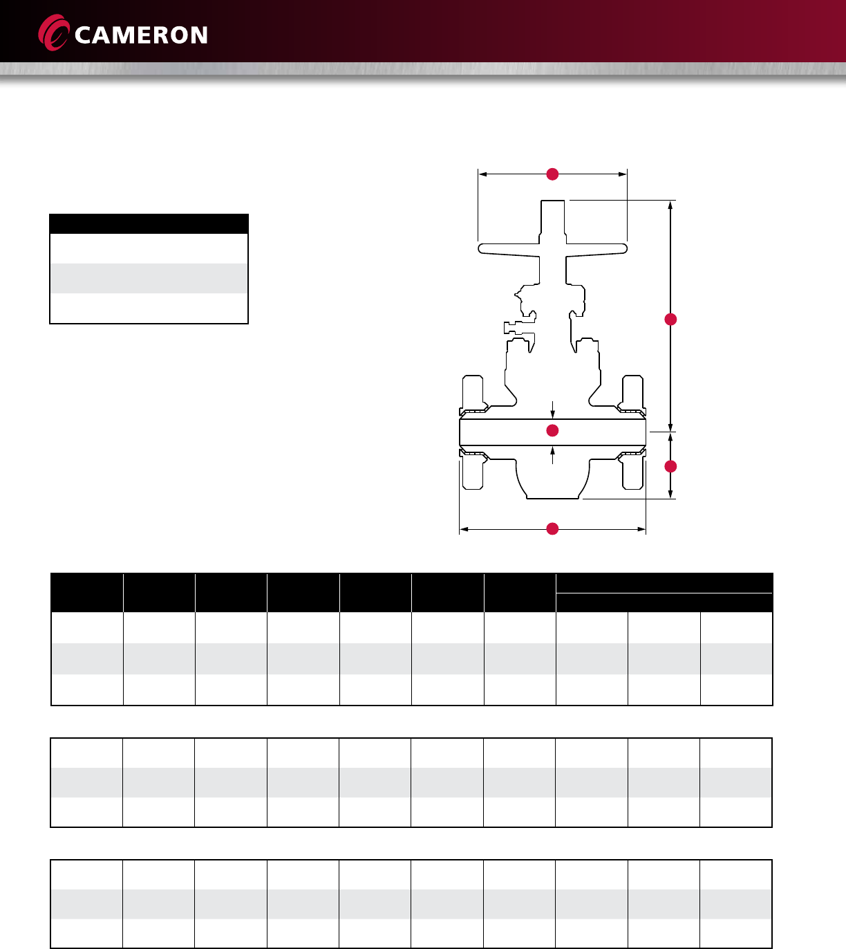
MODEL M (HANDWHEEL OPERATED)
B
F
A
* Some valves may require a gear operator to meet API 6D.
Max. WP at 100˚ F (38˚ C)
Class 600: 1500 psi CWP
2250 psi Test
Class 900: 2250 psi CWP
3375 psi Test
Class 1500: 3750 psi CWP
5625 psi Test
2 14-1/2 2-1/16 5-1/16 17-3/4 12 15-3/4 150 72 105
(50) (368) (52) (129) (451) (305) (68) (33) (48)
3 15 3-3/16 7-5/16 24-3/8 12 20-1/4 265 193 247
(80) (381) (81) (186) (619) (305) (120) (88) (112)
4 18 4-1/8 9-1/16 29 18 19-1/2 515 390 417
(100) (457) (105) (230) (737) (457) (234) (177) (189)
2 14-1/2 2-1/16 5-1/16 17-3/4 12 15-3/4 220 150 154
(50) (368) (52) (129) (451) (305) (100) (68) (70)
3 18-1/2 3-3/16 7-5/16 24-3/8 12 20-1/4 450 328 370
(80) (470) 3(81) (186) (619) (305) (204) (149) (168)
4 21-1/2 4-1/8 9-1/16 29 18 19-1/2 720 547 583
(100) (546) (105) (230) (737) (457) (327) (248) (264)
Class 600
Class 900
Class 1500
PRINCIPAL DIMENSIONS
N = Number of turns to fully open or close valve
SN = Stem nut
BGO = Bevel gear operator
2” to 4” (50 mm to 100 mm) Classes 600, 900 and 1500
11
6 15-7/8 6 13-1/2 45-3/8 46-3/8 24 30-3/4 29 116 316 271 294
(150) (403) (152) (343) (1153) (1178) (610) (781) (143) (123) (133)
8 16-1/2 8 16-1/2 54-3/8 55-3/8 24 35-7/8 37 148 520 459 489
(200) (419) (203) (419) (1381) (1407) (610) (911) (236) (208) (222)
10 18 10 19-1/2 59-1/2 60-1/2 24 40-7/8 45 180 773 695 731
(250) (457) (254) (495) (1511) (1537) (610) (1038) (351) (315) (332)
12 19-3/4 12 22-5/8 68-5/8 69-5/8 24 46-1/8 53 212 1035 930 983
(300) (502) (305) (578) (1743) (1768) (610) (1172) (469) (422) (446)
Max. WP at 100˚ F (38˚ C)
Class 150: 290 psi CWP
450 psi Test
Class 300: 750 psi CWP
1125 psi Test
Class 600: 1500 psi CWP
2250 psi Test
Class 900: 2250 psi CWP
3375 psi Test
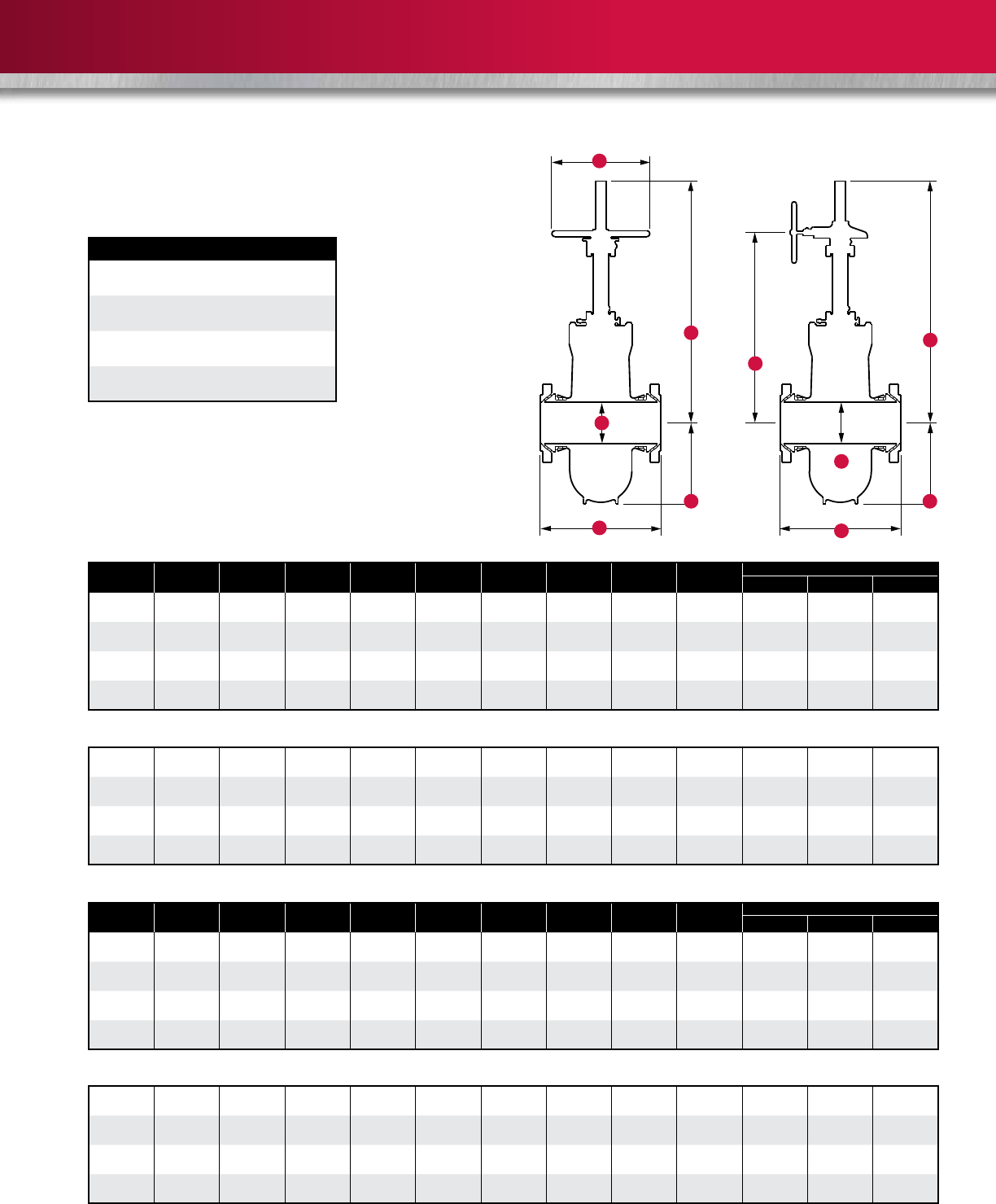
G
Flange dimensions conform to ASME B16.5, 1981. Information on power-actuated and other types of valves available on application.
* Some valves may require a gear operator to meet API 6D.
K
Handwheel Operated Bevel Gear Operated
PRINCIPAL DIMENSIONS
N = Number of turns to fully open or close valve
SN = Stem nut
BGO = Bevel gear operator
MODELS C6 AND C6B
(HANDWHEEL AND BEVEL GEAR OPERATED)
H
G
B
A
F
B
A
F
6 24 6 13-7/8 45-1/8 46-1/8 24 30-3/4 29 116 650 500 575
(150) (610) (152) (352) (1146) (1222) (610) (781) (295) (227) (261)
8 29 8 17-1/8 56-1/8 57-1/8 24 37-13/16 37 148 1200 950 1050
(200) (737) (203) (435) (1426) (1451) (610) (960) (544) (431) (476)
10 33 10 20-1/2 59-1/2 60-3/4 30 42-1/16 45 180 2150 1830 1980
(250) (838) (254) (521) (1511) (1543) (762) (1068) (975) (830) (898)
12 38 12 23-3/4 71-3/4 73-1/8 30 48-1/2 53 318 3250 2500 2650
(300) (965) (305) (603) (1822) (1857) (762) (1232) (1474) (1134) (1202)
Class 900 (Model C6B)
Class 600 (Model C6B)
Class 150 (Model C6)
Class 300 (Model C6)
Size in. G G * N N Weight lb (kg)
(mm) A B F (HWO) (BGO) H K (SN) (BGO) FE WE WXF
6 22 6 13-5/8 45-3/8 46-3/8 24 30-3/4 29 116 600 439 650
(150) (559) (152) (346) (1153) (1178) (610) (781) (272) (199) (295)
8 26 8 16-3/4 56-3/8 57-3/8 24 37-13/16 37 148 970 737 853
(200) (660) (203) (425) (1432) (1457) (610) (960) (440) (334) (387)
10 31 10 20 59-1/2 61-1/2 24 40-7/8 45 180 1736 1584 1656
(250) (787) (254) (508) (1511) (1562) (610) (1038) (787) (718) (751)
12 33 12 23-1/4 68-7/8 70-1/2 30 47-1/4 53 318 2374 2010 2156
(300) (838) (305) (591) (1743) (1791) (762) (1200) (1077) (912) (9143)
Size in. G G * N N Weight lb (kg)
(mm) A B F (HWO) (BGO) H K (SN) (BGO) FE WE WXF
6 10-1/2 6 13-1/2 45-3/8 46-3/8 24 30-3/4 29 116 245 215 230
(150) (267) (152) (343) (1153) (1178) (610) (781) (111) (98) (104)
8 11-1/2 8 16-1/2 52-3/8 55-3/8 24 35-7/8 37 148 365 320 342
(200) (292) (203) (419) (1330) (1407) (610) (911) (166) (145) (155)
10 13 10 19-1/2 59-1/2 60-1/2 24 40-7/8 45 180 515 459 488
(250) (330) (254) (495) (1511) (1537) (610) (1038) (234) (208) (221)
12 14 12 22-3/4 68-5/8 69-5/8 24 46-1/8 53 212 677 594 635
(300) (356) (305) (578) (1743) (1768) (610) (1172) (307) (269) (288)
6” to 12” (150 mm to 300 mm) Classes 150, 300, 600 and 900
12
Max. WP at 100˚ F (38˚ C)
Class 150: 290 psi CWP
450 psi Test
Class 300: 750 psi CWP
1125 psi Test
G
Flange dimensions conform to ASME B16.5, 1981.
Information on power-actuated and other types of valves available on application.
* Some valves may require a gear operator to meet API 6D.
K
PRINCIPAL DIMENSIONS
N = Number of turns to fully open or close valve
SN = Stem nut
BGO = Bevel gear operator
MODELS C6B AND C2B
(BEVEL GEAR OPERATED)
H
G
B
A
F
B
A
F
Class 150 (Model C6B)
Class 300 (Model C2B)
Size in. * N N Weight lb (kg)
(mm) A B F G H K (SN) (BGO) FE WE WXF
14 15 13-1/4 25-1/4 76 24 51-3/4 36-3/4 146-7/8 872 760 817
(350) (381) (337) (641) (1930) (610) (1314) (396) (345) (371)
16 16 15-1/4 28-3/8 82-7/8 24 56-7/8 41-3/4 166-7/8 1309 1163 1235
(400) (406) (387) (721) (2105) (610) (1445) (594) (528) (560)
18 17 17-1/4 31-3/8 90 24 62 46-1/16 184-3/8 1781 1603 1690
(450) (432) (438) (797) (2286) (610) (1575) (808) (727) (767)
20 18 19-1/4 34-1/2 98-1/4 24 67-1/4 41-1/2 166 2351 2119 2235
(500) (457) (489) (876) (2496) (610) (1708) (1066) (961) (1014)
24 20 23-1/4 41-1/8 113 24 78 50-1/4 301-1/2 2892 2514 2703
(600) (508) (591) (1045) (2870) (610) (1981) (1312) (1140) (1226)
26 22 25 43-13/16 120-1/4 24 84-5/8 - - 3521 3172 3327
(650) (559) (635) (1113) (3054) (610) (2149) (1597) (1439) (1509)
28 24 27 46-7/8 127-1/4 24 90-1/8 57-7/8 347-1/4 4098 3506 3802
(700) (610) (686) (1191) (3232) (610) (2289) (1859) (1590) (1725)
30 26 29 50 136-1/4 24 95-1/2 62-1/2 500 4916 4231 4573
(750) (660) (737) (1270) (3461) (610) (2426) (2230) (1919) (2074)
36 32 34-1/2 59 157 36 113-3/8 46-1/8 368-3/4 5842 5264 5521
(900) (813) (876) (1499) (3988) (914) (2880) (2650) (2388) (2504)
Flange dimensions on valves through 24” (600 mm) conform to American National Standards Institute Standard 816.5, 1974.
Larger sizes conform to MSS-SP-44.
150 Class 300 Class
K
H
14 30 13-1/4 25-1/2 75-5/8 24 49-1/2 29-3/8 117-1/2 1454 1266 1361
(350) (762) (337) (648) (1921) (610) (1257) (660) (574) (617)
16 33 15-1/4 28-1/8 80-5/8 24 54-1/2 41-3/4 166-7/8 2182 1939 2058
(400) (838) (387) (714) (2048) (610) (1384) (990) (880) (933)
18 36 17-1/4 31 88 24 60-3/4 37-3/8 224-1/4 2969 2672 2816
(450) (914) (438) (787) (2235) (610) (1543) (1347) (1212) (1277)
20 39 19-1/4 34-1/2 97-3/4 24 67 41-1/2 249 3919 3532 3725
(500) (991) (489) (876) (2483) (610) (1702) (1778) (1602) (1690)
24 45 23-1/4 41-1/8 114-1/8 24 78-3/4 50-1/4 402 5868 5287 5545
(600) (1143) (591) (1045) (2899) (610) (2000) (2662) (2398) (2515)
26 49 25 43-3/4 120-1/4 24 83-1/4 - - 6830 5844 6337
(650) (1245) (635) (1111) (3054) (610) (2115) (3098) (2651) (2874)
28 53 27 47 129-3/4 24 90-1/4 - - 8194 7051 7623
(700) (1346) (686) (1194) (3296) (610) (2292) (3717) (3198) (3458)
30 55 29 50-5/8 139-1/8 36 96-3/4 39-1/16 312-1/2 9736 8773 9201
(750) (1397) (737) (1286) (3534) (914) (2457) (4416) (3979) (4174)
36 68 34-1/2 59-1/4 161 36 112-3/4 46-1/8 368-3/4 15,441 13,607 14,524
(900) (1727) (876) (1505) (4089) (914) (2864) (7004) (6172) (6588)
14” to 36” (350 mm to 900 mm) Classes 150 and 300
13
Size in. * N N Weight lb (kg)
(mm) A B F G H K (SN) (BGO) FE WE WXF
14 35 13-1/4 26 75-3/8 24 51-1/2 29-3/8 176-1/4 3232 2828 3030
(350) (889) (337) (660) (1915) (610) (1308) (1466) (1283) (1374)
16 39 15-1/4 29-1/8 83-1/2 24 56-3/4 33-3/8 200-1/4 4023 3515 3767
(400) (991) (387) (740) (2121) (610) (1441) (1825) (1594) (1709)
18 43 17-1/4 32-3/8 91-1/2 24 62-1/2 37-3/8 224-1/4 5617 4110 5252
(450) (1092) (438) (822) (2324) (610) (1588) (2548) (1864) (2382)
20 47 19-1/4 35-7/8 100-1/2 24 69-3/8 26 208 6984 6070 6449
(500) (1194) (489) (911) (2553) (610) (1762) (3168) (2753) (2925)
24 55 23-1/4 42-1/4 118 36 83 31-3/8 251-1/4 11,447 10,014 10,730
(600) (1397) (591) (1073) (2997) (914) (2108) (5192) (4542) (4867)
26 57 25 46 124-5/8 36 87-1/2 33-9/16 268-3/4 13,124 11,494 10,024
(650) (1448) (635) (1168) (3165) (914) (2223) (5953) (5214) (4547)
28 61 27 49-1/4 134 36 93-1/2 36-3/16 434 14,293 12,232 12,624
(700) (1549) (686) (1251) (3404) (914) (2375) (6483) (5548) (5726)
30 65 29 52-3/4 142-3/4 36 100-1/2 39-1/16 468-3/4 14,457 12,724 13,591
(750) (1651) (737) (1340) (3626) (914) (2553) (6558) (5772) (6165)
36 82 34-1/2 61-3/4 171-1/4 36 117-1/2 46-1/8 553-1/8 26,377 23,967 25,172
(900) (2083) (876) (1568) (4350) (914) (2985) (11964) (10871) (11418)
Flange dimensions conform to ASME B16.5, 1981.
Information on power-actuated and other types of valves available on application.
Max. WP at 100˚ F (38˚ C)
Class 600: 1500 psi CWP
2250 psi Test
Class 900: 2250 psi CWP
3375 psi Test
PRINCIPAL DIMENSIONS
N = Number of turns to fully open or close valve
SN = Stem nut
BGO = Bevel gear operator
MODELS C6 AND C6B
(HANDWHEEL AND BEVEL GEAR OPERATED)
H
G
B
A
K
F
Class 600 (Model C6B)
Class 900 (Model C2C)
14 40-1/2 12-3/4 25-9/16 79-5/8 24 55-13/16 20-7/8 166-7/8 ---
(350) (1029) (324) (649) (2022) (610) (1418) - - -
16 44-1/2 15-1/4 30-7/16 87-3/8 24 60-3/16 20-7/8 166-7/8 ---
(400) (1130) (387) (773) (2219) (610) (1529) - - -
18 48 17-1/4 33-7/8 56-15/16 24 64-11/16 23-3/8 187 ---
(450) (1219) (438) (860) (1446) (610) (1643) - - -
20 52 19-1/4 37-1/4 103-3/8 36 71-1/8 26 208 ---
(500) (1321) (489) (946) (2626) (914) (1807) - - -
24 61 23-1/4 46-1/4 123-1/8 36 86-3/8 -----
(600) (1549) (591) (1175) (3127) (914) (2194) - - -
14” to 36” (350 mm to 900 mm) Classes 600 and 900

14
WKM Saf-T-Gard Actuators
Electric and Pneumatic
Cameron’s WKM Saf-T-SealTM gate valves can be equipped with two principal types of actuators: electric actuators and
pneumatic or gas-powered motor drives.
Information Required for Sizing
Electric Actuators
• Valve type: Saf-T-Seal
• Size: pipe size x bore size
• Pressure class
• Top-mounted or side-mounted
• Closing time in seconds
• Maximum differential pressure (psi)
• Type and make of actuator required
• Voltage:
Three-phase, 60-cycle 220 V/440 V
Three-phase, 50-cycle 220 V/440 V
Control voltage
Motor connection voltage
Any special requirements
• Enclosure:
Weather-proof
Explosion-proof, Class 1, Group D, Div. 2
ATEX
Certification required
• Accessories:
Reversing starter
Control transformer
Push-button station:
- Three push buttons
Two lights
Limit switches:
- Two train-geared limit switches
(eight contacts)
-
Four train-geared limit switches
(16 contacts)
• Special requirements
Information Required for Sizing
Pneumatic Actuators
• Valve type: Saf-T-Seal
• Size: pipe size x bore size
• Pressure class
• Actual working pressure at which valve will be
operated (psi)
• Available gas pressure to power motor drive: psi
• Top-mounted or side-mounted
• Closing time in seconds
• Maximum differential pressure (psi)
• Type and make of actuator required
• Accessories
• Special requirements
15
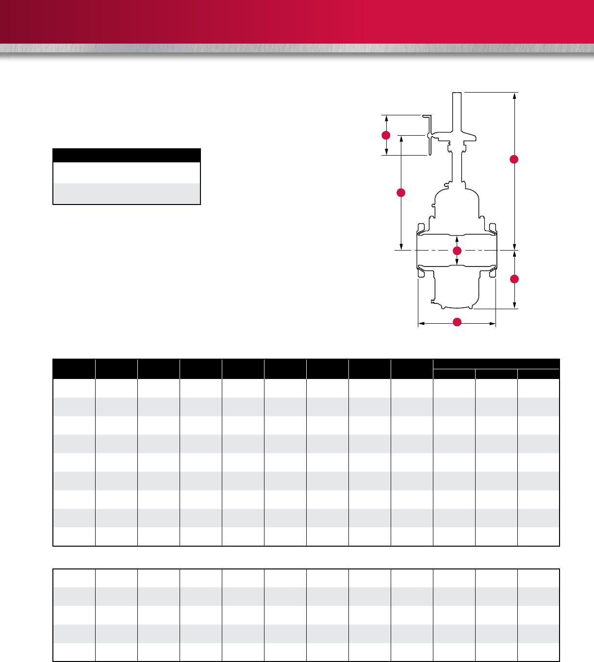
PNEUMATIC DIAPHRAGM ACTUATOR
MA 12 Series
For use with 2”, 3” and 4”
(50 mm, 80 mm and 100 mm)
nominal gate valves
(Family Group Code Y55012).
Description
Cameron’s Saf-T-Gard diaphragm actuator was developed by using the quality
features of field proven products and then combining them with innovative
technology. Particular attention has been given to safety, ease of maintenance
and cost of manufacturing.
Designed for use with all manufacturers’ gate valves in nominal sizes of 2” to
6” (50 mm to 150 mm), its simple design and operating principle helps to avoid
most of the problems commonly associated with piston type actuators such as
galling, misalignment, distortion and O-ring failures.
The Saf-T-Gard diaphragm actuators are interchangeable with other models
in the product line, which reduces the amount of spare parts necessary
for maintenance.
Design Advantages
Stronger Actuator
Mounting Arrangement
Unlike other designs, the mounting
bolts on Cameron’s actuators are
positioned parallel to the centerline
of the actuator, which loads the
mounting bolts in tension. This design
is not subject to bending or shear
forces. This means it can withstand
greater separation forces than other
actuators on the market.
Corrosion-Resistant Materials
Cameron’s Saf-T-Gard diaphragm
actuators are manufactured to NACE
MR0175. In addition, all non-stainless
components are coated with Xylan to
increase corrosion resistance.
Superior Diaphragm Design
Cameron’s diaphragm material is
stronger than most designs currently
on the market, resulting in extended
service life and higher operating
pressures. Unique sealing grooves
provide additional grip and improve
the outer seal of the diaphragm housing.
Flexible Actuator Orientation
Connecting misaligned components
with rigid tubing can be time-
consuming and can induce high stress
into the tubing connections. The MA
lower ring is threaded to the bonnet,
thus allowing rotation of the actuator
to accommodate precise alignment.
Top shaft
Seal retainer
Rod wiper
Snap ring
Polypak seal
Wear bearing
Diaphragm nut
Diaphragm retainer plate
Pressure inlet
Diaphragm
Downstop
Spring
Spacer
Breather plug
Packing retainer
Lower ring
Stem packing
Stem
Metal-to-metal backseat
Bonnet
Pressure
relief
device
16
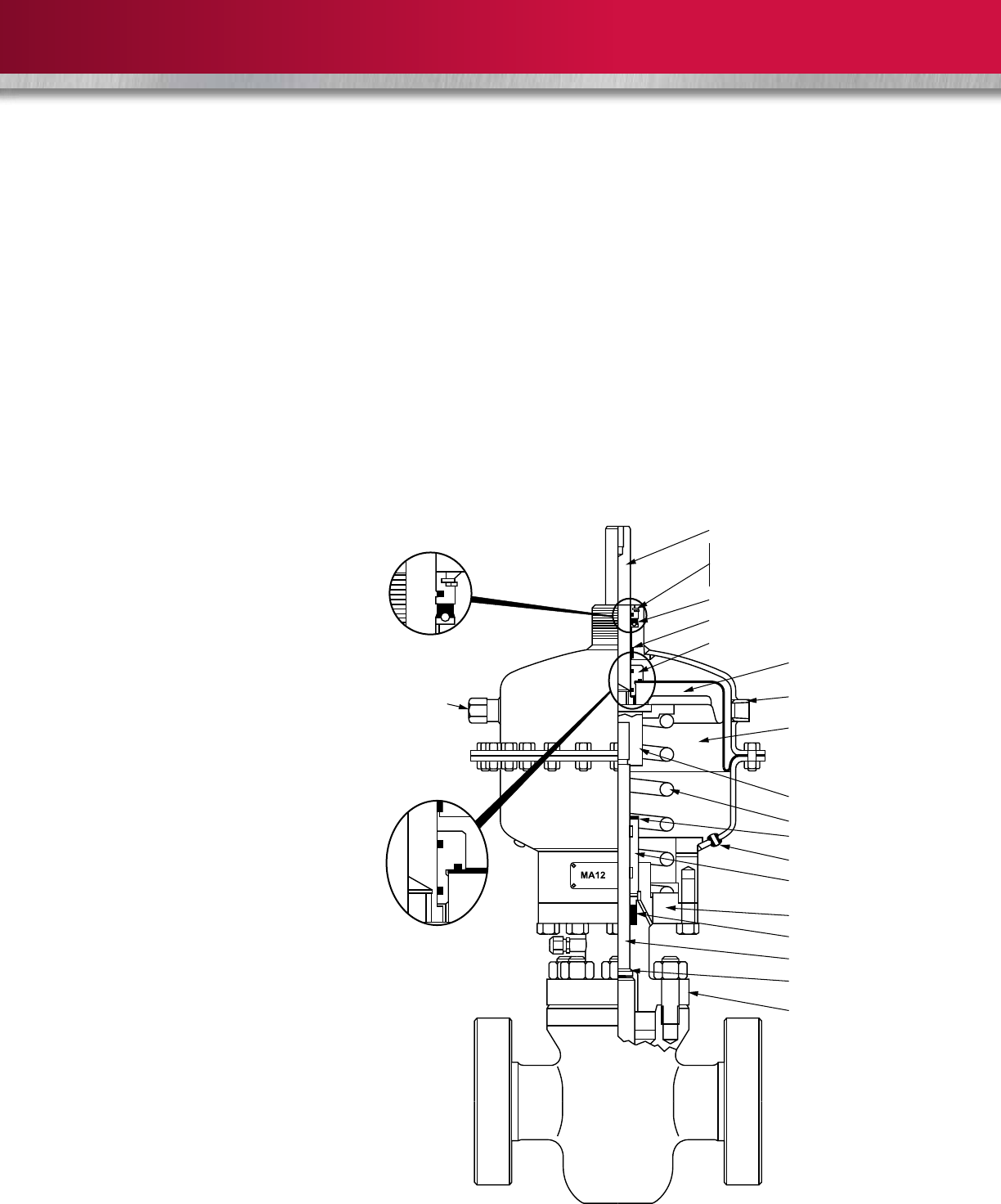
MA 16 Series
For use with 2“, 3“, 4“ and 5“
(50 mm, 80 mm, 100 mm and
125 mm) nominal gate valves
(Family Group Code Y55016).
MA 20 Series
For use with 2“, 3“, 4“, 5“ and 6“
(50 mm, 80 mm, 100 mm, 125 mm
and 150 mm) nominal gate valves
(Family Group Code Y55020).
Top shaft
Seal retainer
Rod wiper
Snap ring
Polypak seal
Wear bearing
Diaphragm nut
Diaphragm retainer plate
Pressure inlet
Diaphragm
Downstop
Spring
Spacer
Breather plug
Packing retainer
Lower ring
Stem packing
Stem
Metal-to-metal backseat
Bonnet
Pressure
relief
device
Pressure
relief
device
Top shaft
Wear bearing
Diaphragm nut
Diaphragm retainer plate
Pressure inlet
Diaphragm
Downstop
Spring
Spacer
Breather plug
Packing retainer
Lower ring
Stem packing
Stem
Bonnet
Seal retainer
Rod wiper
Snap ring
Polypak seal
17
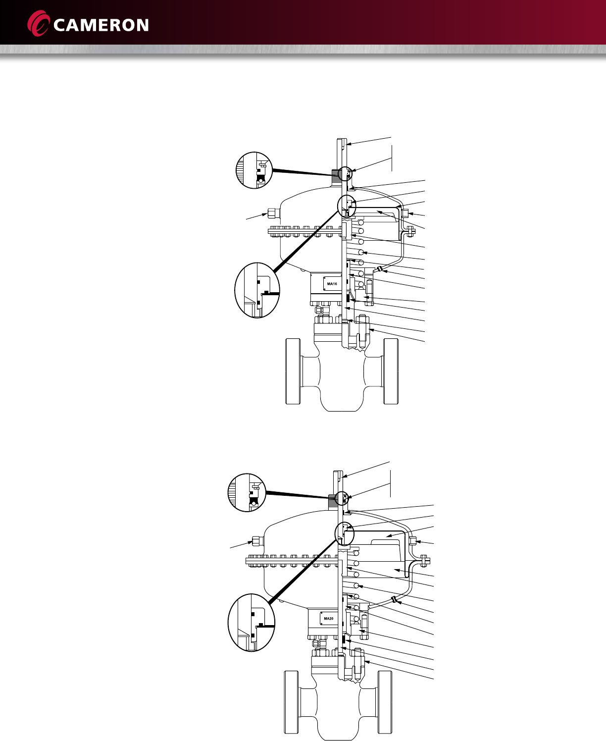
MA 1212 Series
For use with 2”, 3” and 4”
(50 mm, 80 mm and 100 mm)
nominal gate valves
(Family Group Code Y55012).
The MA 1212 series doubles
the area affected by applied
control pressure.
MA 2012 Series
For use with 2”, 3” and 4”
(50 mm, 80 mm and 100 mm)
nominal gate valves
(Family Group Code Y55020).
The MA 2012 series increases
the area affected by applied
control pressure.
Top shaft
Seal retainer
Rod wiper
Snap ring
Polypak seal
Wear bearing
Diaphragm nut
Diaphragm retainer plate
Pressure inlet
Diaphragm
Downstop
Spring
Spacer
Breather plug
Packing retainer
Lower ring
Stem packing
Stem
Metal-to-metal backseat
Bonnet
Pressure
relief
device
Pressure
relief
device
Top shaft
Wear bearing
Diaphragm nut
Pressure inlet
Diaphragm retainer plate
Downstop
Spring
Breather plug
Packing retainer
Lower ring
Stem
Bonnet
Seal retainer
Rod wiper
Snap ring
Polypak seal
Stem extension
Pressure inlet
Diaphragm
Stem extension
Pressure inlet
18
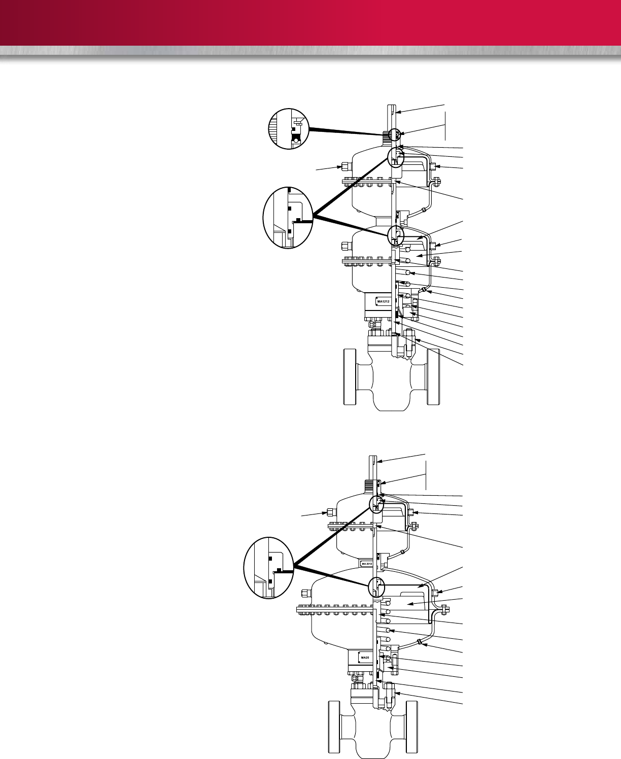
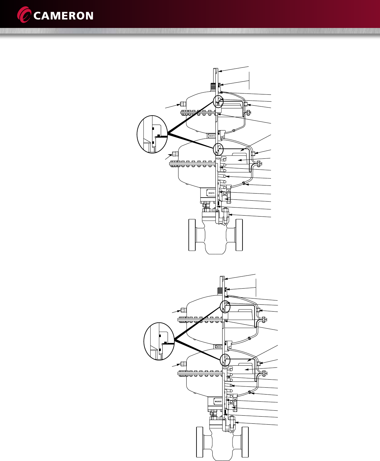
MA 2016 Series
For use with 2”, 3”, 4” and 6”
(50 mm, 80 mm, 100 mm and
150 mm) nominal gate valves
(Family Group Code Y55020).
The MA 2016 series increases
the area affected by applied
control pressure.
MA 2020 Series
For use with 2”, 3”, 4”, 5”, 6”
and 8” (50 mm, 80 mm, 100 mm,
125 mm, 150 mm and 200 mm)
nominal gate valves
(Family Group Code Y55020).
The MA 2020 series increases
the area affected by applied
control pressure.
Top shaft
Seal retainer
Rod wiper
Snap ring
Polypak seal
Wear bearing
Diaphragm nut
Diaphragm retainer plate
Pressure inlet
Diaphragm
Downstop
Spring
Breather plug
Packing retainer
Lower ring
Stem
Bonnet
Pressure
relief device
Stem extensions
Pressure inlet
Top shaft
Seal retainer
Rod wiper
Snap ring
Polypak seal
Wear bearing
Diaphragm nut
Diaphragm retainer plate
Pressure inlet
Diaphragm
Downstop
Spring
Breather plug
Packing retainer
Lower ring
Stem
Bonnet
Pressure
relief device
Stem extensions
Pressure inlet
19
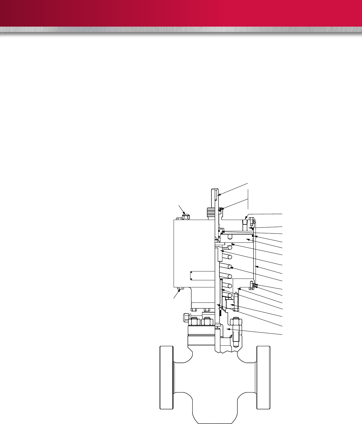
PNEUMATIC PISTON ACTUATOR
MP 13 Series
For use with 2”, 3” and 4”
(50 mm, 80 mm and 100 mm)
nominal gate valves
(Family Group Code Y55013).
Description
Cameron’s pneumatic piston actuator series is designed for use with all
manufacturers’ gate valves in nominal sizes of 2” to 4” (50 mm to 100 mm).
Its remarkably simple design and operating principle make this piston
actuator suitable for a variety of applications. Cameron’s piston actuators
are interchangeable and very versatile because they operate with many
types of supply gas, compressed air, nitrogen or well gas.
Design Advantages
Stronger Actuator
Mounting Arrangement
Unlike other designs, the mounting
bolts on Cameron’s actuators are
positioned parallel to the centerline
of the actuator, which loads the
mounting bolts in tension. This design
is not subject to bending and shear
forces. This means it can withstand
greater separation forces than other
actuators on the market.
Corrosion-Resistant Materials
Cameron’s piston actuators are
manufactured to NACE MR0175.
In addition, all non-stainless
components are coated with Xylan
to increase corrosion resistance.
Superior Diaphragm Design
Cameron’s piston actuators utilize a
single-piece stainless steel snap ring
to facilitate easy cylinder removal.
The dynamic piston has a large wear
bearing that reduces any internal
metal-to-metal contact.
Flexible Actuator Orientation
Connecting misaligned components
with rigid tubing can be time-consuming
and can induce high stress into the
tubing connections. The MA lower
ring is threaded to the bonnet, thus
allowing rotation of the actuator to
accommodate precise alignment.
Top shaft
Seal retainer
Rod wiper
Snap ring
Polypak seal
Top cap
Diaphragm nut
Piston
Upper spring retainer
Downstop
Spring
Snap ring
Packing retainer
Lower ring
Stem
Bonnet
Pressure
relief device
Lower housing
Lock ring
Housing
Piston seal
Pressure inlet
Breather plug
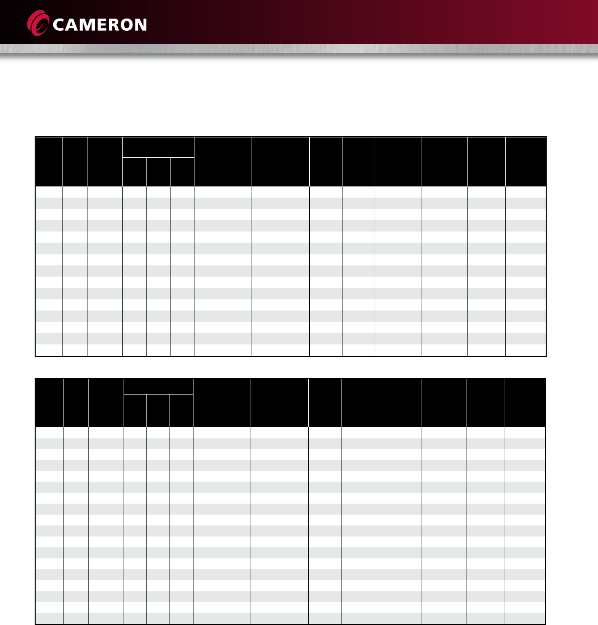
20
OPERATING SIZE REQUIREMENTS
Valve
Size
in.
(mm)
ASME
Class
ASME
Working
Pressure
(psig)
Stem Thread Recommended
Operating
Thrust
(lbf)
Recommended
Operating
Torque
(ft-lbf)
Block-
and-
Bleed
Thrust
(lbf)
Block-
and-
Bleed
Torque
(ft-lbf)
Maximum
Allowable
Thrust
(lbf)
Maximum
Allowable
Torque
(ft-lbf)
Total
Stem
Travel
in. (mm)
Stem Nut
Turns-to-
Open
Valve
Size
in.
Pitch
in.
Lead
in.
2 (50) 150 290 0.875 0.167 0.167 457 3 535 4 12,597 93 2.63 (67) 15.8
2 (50) 300 750 0.875 0.167 0.167 1183 9 1383 10 12,597 93 2.63 (67) 15.8
2 (50) 600 1500 0.875 0.167 0.167 2366 17 2766 20 12,597 93 2.63 (67) 15.8
2 (50) 900 2250 0.875 0.167 0.167 3549 26 4149 30 12,597 93 2.63 (67) 15.8
2 (50) 1500 3750 0.875 0.167 0.167 5914 43 6915 51 12,597 93 2.63 (67) 15.8
3 (80) 150 290 1.000 0.200 0.200 803 7 1115 9 16,027 136 4.03 (102) 20.2
3 (80) 300 750 1.000 0.200 0.200 2078 18 2884 25 16,027 136 4.03 (102) 20.2
3 (80) 600 1500 1.000 0.200 0.200 4155 35 5769 49 16,027 136 4.03 (102) 20.2
3 (80) 900 2250 1.000 0.200 0.200 6233 53 8653 74 16,027 136 4.03 (102) 20.2
3 (80) 1500 3750 1.000 0.200 0.200 10,388 88 14,422 123 16,027 136 4.03 (102) 20.2
4 (100) 150 290 1.250 0.250 0.250 1327 14 1783 19 25,442 271 4.88 (124) 19.5
4 (100) 300 750 1.250 0.250 0.250 3432 37 4610 49 25,442 271 4.88 (124) 19.5
4 (100) 600 1500 1.250 0.250 0.250 6864 73 9221 98 25,442 271 4.88 (124) 19.5
4 (100) 900 2250 1.250 0.250 0.250 10,297 110 13,831 147 25,442 271 4.88 (124) 19.5
4 (100) 1500 3750 1.250 0.250 0.250 17,161 183 23,052 245 25,442 271 4.88 (124) 19.5
Valve
Size
in.
(mm)
ASME
Class
ASME
Working
Pressure
(psig)
Stem Thread Recommended
Operating
Thrust
(lbf)
Recommended
Operating
Torque
(ft-lbf)
Block-
and-
Bleed
Thrust
(lbf)
Block-
and-
Bleed
Torque
(ft-lbf)
Maximum
Allowable
Thrust
(lbf)
Maximum
Allowable
Torque
(ft-lbf)
Total
Stem
Travel
in. (mm)
Stem Nut
Turns-to-
Open
Valve
Size
in.
Pitch
in.
Lead
in.
6 (150) 600 1500 1.250 0.250 0.250 9839 105 14,307 152 26,783 283 7.25 (184) 29
6 (150) 900 2250 1.250 0.250 0.250 14,758 157 21,460 228 27,685 335 7.25 (184) 29
8 (200) 600 1500 1.750 0.250 0.250 17,099 237 21,507 298 45,807 557 9.25 (235) 37
8 (200) 900 2250 1.750 0.250 0.250 25,649 355 32,261 447 49,637 604 9.25 (235) 37
10 (250) 600 1500 1.750 0.250 0.250 23,859 330 29,078 403 46,726 569 11.25 (286) 45
10 (250) 900 2250 1.750 0.250 0.250 35,789 495 43,617 604 57,297 697 11.25 (286) 45
12 (300) 600 1500 1.750 0.250 0.250 32,032 443 41,381 573 69,033 840 13.31 (338) 53
12 (300) 900 2250 2.000 0.250 0.250 49,816 770 62,072 959 80,522 1109 13.31 (338) 53
14 (350) 150 290 1.500 1.390 0.400 7149 104 16,674 242 9053 131 14.75 (375) 36.875
14 (350) 600 1500 2.000 1.864 0.500 39,183 741 64,831 1226 46,824 886 14.75 (375) 29.50
16 (400) 150 290 1.500 1.390 0.400 9177 133 27,543 399 11,448 166 16.75 (425) 41.875
16 (400) 600 1500 2.000 1.864 0.500 49,676 940 69,091 1307 59,215 1120 16.75 (425) 33.50
18 (450) 150 290 1.500 1.390 0.400 11,594 168 22,596 327 13,960 202 18.50 (470) 46.25
18 (450) 600 1500 2.250 2.113 0.500 63,501 1303 98,175 2014 72,208 1481 18.75 (470) 37.50
20 (500) 150 290 1.750 1.614 0.500 14,380 249 31,621 548 17,230 298 20.75 (527) 41.50
20 (500) 600 1500 2.750 2.536 0.500 79,986 1858 145,272 3375 89,122 2070 20.75 (527) 41.50
24 (600) 150 290 2.000 1.864 0.500 20,606 390 21,390 405 26,347 498 25.125 (638) 50.25
24 (600) 600 1500 3.250 3.036 0.800 114,674 3510 219,495 6718 136, 279 4171 25.00 (635) 31.25
Note: 1. Recommended operating thrust and torque are the loads required to open or close the valve with full differential pressure
across the gate. The operator should be sized for these values.
2. Maximum allowable thrust and torque values are maximum allowable loads of the valve.
3. When block-and-bleed or double block-and-bleed service is specified, operators should be sized for these values.
4. Unless otherwise stated, handwheel rim pull for manual and motor operators shall not exceed 120 lb (54 kg).
5. All torque and thrust values are based on maximum working pressure at ambient temperature.
Model M – 2” to 4” (50 mm to 100 mm) ASME Classes 150 to 1500
Model C6B – 6” to 12” (150 mm to 300 mm) ASME Classes 600 to 900
21
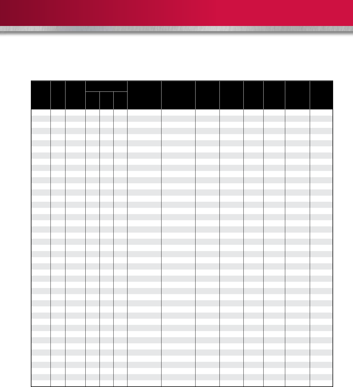
Models C6, C2B, C2C – 6” to 36” (150 mm to 900 mm) ASME Classes 150 to 900
Valve
Size
in.
(mm)
ASME
Class
ASME
Working
Pressure
(psig)
Stem Thread Recommended
Operating
Thrust
(lbf)
Recommended
Operating
Torque
(ft-lbf)
Maximum
Allowable
Thrust
(lbf)
Maximum
Allowable
Torque
(ft-lbf)
Block-
and-
Bleed
Thrust
(lbf)
Block-
and-
Bleed
Torque
(ft-lbf)
Total
Stem
Travel
in. (mm)
Stem Nut
Turns-to-
Open
Valve
Size
in.
Pitch
in.
Lead
in.
6 (150) 150 290 1.250 0.250 0.250 1902 18 31,785 307 2762 27 7.25 (184) 29
6 (150) 300 750 1.250 0.250 0.250 4919 47 31,785 307 7143 69 7.25 (184) 29
6 (150) 600 1500 1.250 0.250 0.250 9836 95 31,785 307 14,285 138 7.25 (184) 29
6 (150) 900 2250 1.250 0.250 0.250 14,757 142 31,785 307 21,428 207 7.25 (184) 29
8 (200) 150 290 1.500 0.250 0.250 3106 34 52,036 574 4153 46 9.25 (235) 37
8 (200) 300 750 1.500 0.250 0.250 8033 89 52,036 574 10,740 119 9.25 (235) 37
8 (200) 600 1500 1.500 0.250 0.250 16,067 177 52,036 574 21,481 237 9.25 (235) 37
8 (200) 900 2250 1.500 0.250 0.250 24,100 266 52,036 574 32,221 356 9.25 (235) 37
10 (250) 150 290 1.500 0.250 0.250 4413 49 52,036 574 5817 64 11.25 (286) 45
10 (250) 300 750 1.500 0.250 0.250 11,413 126 52,036 574 15,045 168 11.25 (286) 45
10 (250) 600 1500 1.500 0.250 0.250 22,828 252 52,036 574 30,090 332 11.25 (286) 45
10 (250) 900 2250 1.500 0.250 0.250 34,239 378 52,036 574 45,135 498 11.25 (286) 45
12 (300) 150 290 1.500 0.250 0.250 5993 66 52,036 574 7755 86 13.25 (337) 53
12 (300) 300 750 1.500 0.250 0.250 15,500 171 52,036 574 20,056 221 13.25 (337) 53
12 (300) 600 1500 1.500 0.250 0.250 30,999 342 52,036 574 40,113 443 13.25 (337) 53
12 (300) 900 2250 1.750 0.250 0.250 48,045 597 77,223 960 60,169 748 13.25 (337) 53
14 (350) 150 290 1.500 0.200 0.400 7149 95 54,521 722 9063 120 14.69 (373) 36.73
14 (350) 300 750 2.000 0.250 0.500 19,594 338 101,611 1754 23,439 405 14.69 (373) 29.38
14 (350) 600 1500 2.000 0.250 0.500 39,187 676 101,611 1754 46,878 809 14.69 (373) 29.38
14 (350) 900 2250 2.250 0.250 0.500 60,540 1129 135,875 2533 70,547 1315 14.69 (373) 29.38
16 (400) 150 290 1.500 0.200 0.400 9178 122 54,521 722 11,439 152 16.69 (424) 41.73
16 (400) 300 750 1.500 0.200 0.400 23,735 314 54,521 722 29,584 392 16.69 (424) 41.73
16 (400) 600 1500 2.000 0.250 0.500 49,680 857 101,611 1754 59,168 1021 16.69 (424) 33.38
16 (400) 900 2250 2.750 0.400 0.800 81,146 2040 180,794 4546 88,752 2232 16.69 (424) 20.86
18 (450) 150 290 1.500 0.200 0.400 11,594 154 54,521 722 13,974 185 18.44 (468) 46.10
18 (450) 300 750 1.750 0.250 0.500 30,500 484 72,304 1148 36,139 574 18.69 (475) 37.38
18 (450) 600 1500 2.250 0.250 0.500 63,504 1184 135,875 2533 72,278 1347 18.69 (475) 37.38
18 (450) 900 2250 2.750 0.400 0.800 99,884 2512 180,794 4546 108,418 2726 18.69 (475) 23.36
20 (500) 150 290 1.750 0.250 0.500 14,381 228 72,304 1148 17,245 274 20.75 (527) 41.50
20 (500) 300 750 2.000 0.250 0.500 37,782 652 101,611 1754 44,600 770 20.75 (527) 41.50
20 (500) 600 1500 2.750 0.400 0.800 79,982 2011 180,794 4546 89,200 2243 20.75 (527) 25.94
20 (500) 900 2250 3.000 0.400 0.800 122,624 3252 225,696 5986 133,801 3549 20.75 (527) 25.94
22 (550) 150 290 1.750 0.250 0.500 17,243 274 72,304 1148 21,470 341 22.94 (583) 45.88
22 (550) 300 750 2.250 0.250 0.500 45,845 855 135,875 2533 55,526 1035 22.94 (583) 45.88
22 (550) 600 1500 3.000 0.400 0.800 96,549 2561 225,696 5986 111,051 2945 22.94 (583) 28.68
24 (600) 150 290 2.000 0.250 0.500 20,605 356 101,611 1754 26,366 455 25.13 (638) 50.26
24 (600) 300 750 2.250 0.250 0.500 53,952 1006 135,875 2533 68,188 1271 25.13 (638) 50.26
24 (600) 600 1500 3.250 0.400 0.800 114,677 3200 275,560 7689 138,375 3806 25.13 (638) 31.41
24 (600) 900 2250 3.750 0.400 0.800 178,422 5474 390,393 11,977 204,563 6276 25.13 (638) 31.41
30 (750) 150 290 2.250 0.250 0.500 31,396 585 135,875 2533 42,018 783 31.25 (794) 62.50
30 (750) 300 750 3.000 0.400 0.800 83,626 2218 225,698 5986 108,866 2882 31.25 (794) 39.06
30 (750) 600 1500 3.750 0.400 0.800 173,437 5321 390,393 11,877 217,333 6668 31.25 (794) 39.06
36 (900) 150 290 2.750 0.400 0.800 44,184 1111 180,794 4546 57,303 1441 36.88 (937) 46.10
36 (900) 300 750 3.250 0.400 0.800 116,110 3240 275,560 7889 148,199 4135 36.88 (937) 46.10
36 (900) 600 1500 4.250 0.400 0.800 241,350 8075 525,088 17,568 296,397 9317 36.88 (937) 46.10
Note: 1. Use recommended operating thrust and torque for sizing bevel gear operators.
2. Use block-and-bleed thrust and torque for sizing power operators (electric, gas, hydraulic and more).
3. Maximum operating thrust and torque are the maximum allowable for the valve.
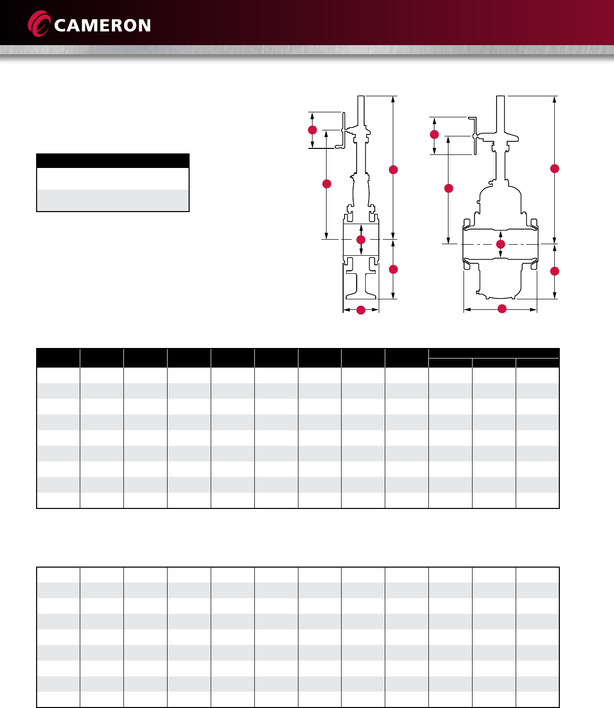
22
C
B
A
E
F
TOPWORKS
Size in.
(mm)
ASME
Class
Open Closed
A B C D E F G H J
2 (50) 600 and
1500
9.25
(234.95)
6.56
(166.62)
6.44
(163.58)
2.808
(71.32)
0.63
(16.00)
0.12
(3.05)
5.00
(127.00)
4.00
(101.60)
4
(101.60)
3 (80) 150 and
1500
12.00
(304.80)
7.97
(202.44)
7.75
(196.85)
2.808
(71.32)
0.63
(16.00)
0.12
(3.05)
5.00
(127.00)
4.00
(101.60)
4
(101.60)
4 (100) 150 and
600
15.00
(381.00)
10.12
(257.05)
9.95
(252.73)
3.308
(84.02)
0.625
(15.88)
0.12
(3.05)
5.25
(133.35)
4.25
(107.95)
4
(101.60)
4 (100) 900 and
1500
13.63
(346.20)
8.75
(222.25)
9.95
(252.73)
3.308
(84.02)
1.00
(25.40)
0.12
(3.05)
6.00
(152.40)
5.00
(127.00)
4
(101.60)
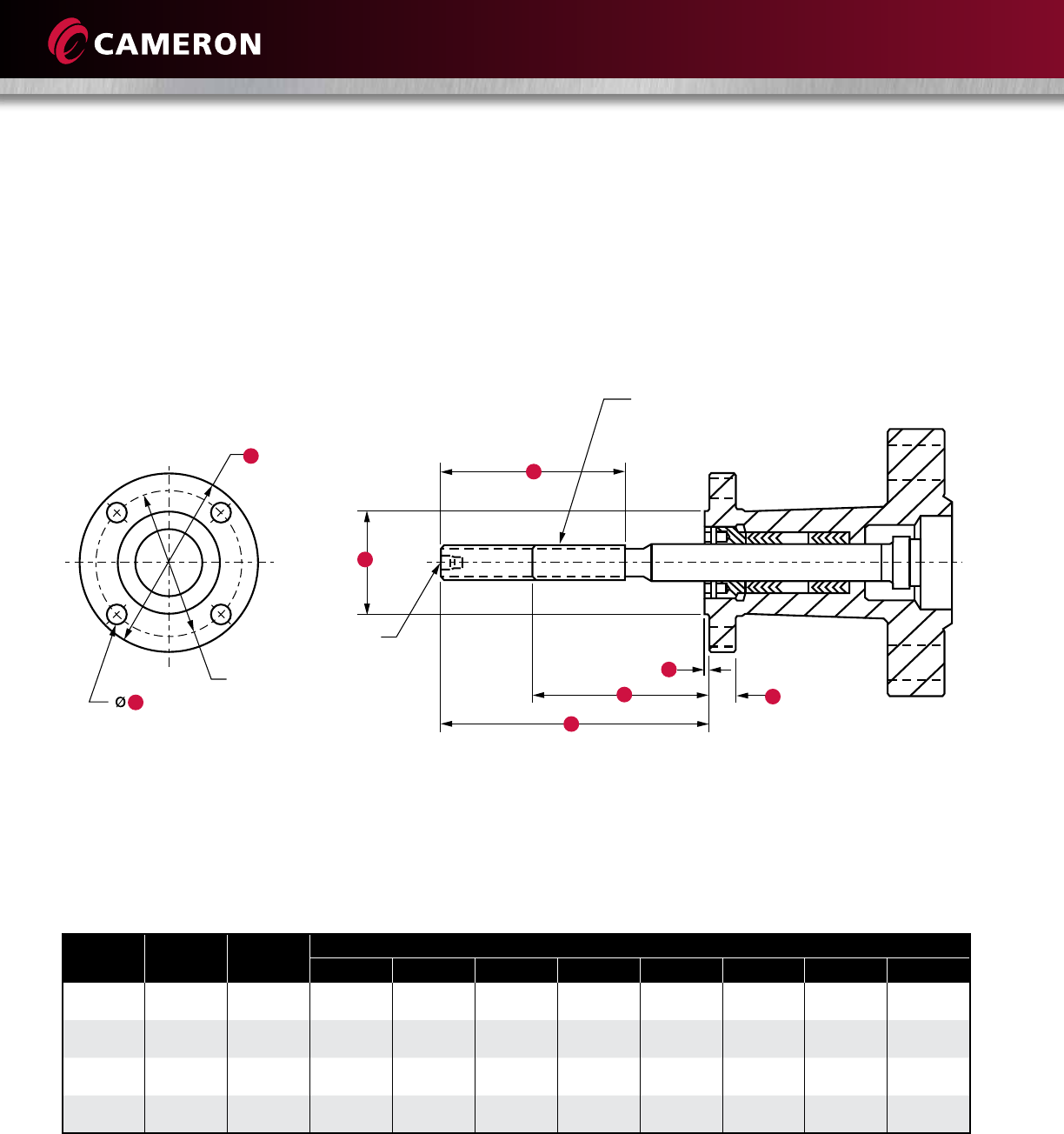
4 Holes
G
D
G
2” – 0.875” -6NA-2G LH
3” – 1.000” -5NA-2G LH
4” – 1.25” -4NA-2G LH
1/4”– 18 NPT
Ø4.25
Ø
Ø ± 0.005
Model M
Model M
Sizes 2” to 4” (50 mm to 100 mm)
Classes 150, 600, 900 and 1500
23
C
B
M
L
K
D
H
N
P
E
F
G
J
TOPWORKS
Total
stem travel
Ø
Size in.
(mm) Series ISO
FLG
A -NA-2G-L.H.
Single Lead
Thd.
Closed Open
B C D E F G H J K L M N P
6
(150) 150/3C F14 1-1/2 - 0.250P
- 0.250L
8.50
(215.90)
15.75
(400.05)
7.25
(184.15)
16.83
(427.48)
16.31
(414.27)
27.38
(695.45)
6.88
(174.75)
5.50
(139.70)
4 - 0.658
(4 - 16.71)
3.942
(100.127)
3.952
(100.381)
2.62
(66.55)
1.00
(25.40)
0.169
(4.29)
0.183
(4.65)
8
(200) 150/3C F14 1-1/2 - 0.250P
- 0.250L
10.19
(258.83)
19.44
(493.78)
9.25
(234.95)
20.58
(522.73)
20.06
(509.52)
35.44
(900.18)
6.88
(174.75)
5.50
(139.70)
4 - 0.688
(4 - 17.48)
3.942
(100.127)
3.952
(100.381)
2.62
(66.55)
1.00
(25.40)
0.169
(4.29)
0.183
(4.65)
10
(350) 150/3C F14 1-1/2 - 0.250P
- 0.250L
8.19
(208.03)
19.44
(493.78)
11.25
(285.75)
20.58
(522.73)
20.06
(509.52)
38.50
(977.90)
6.88
(174.75)
5.50
(139.70)
4 - 0.688
(4 - 17.48)
3.942
(100.127)
3.952
(100.381)
2.62
(66.55)
1.00
(25.40)
0.169
(4.29)
0.183
(4.65)
12
(300) 150/3C F14 1-1/2 - 0.250P
- 0.250L
9.69
(246.13)
23.00
(584.20)
13.31
(338.07)
24.20
(614.68)
23.69
(601.73)
44.00
(1117.60)
6.88
(174.75)
5.50
(139.70)
4 - 0.688
(4 - 17.48)
3.942
(100.127)
3.952
(100.381)
2.62
(66.55)
1.00
(25.40)
0.169
(4.29)
0.183
(4.65)
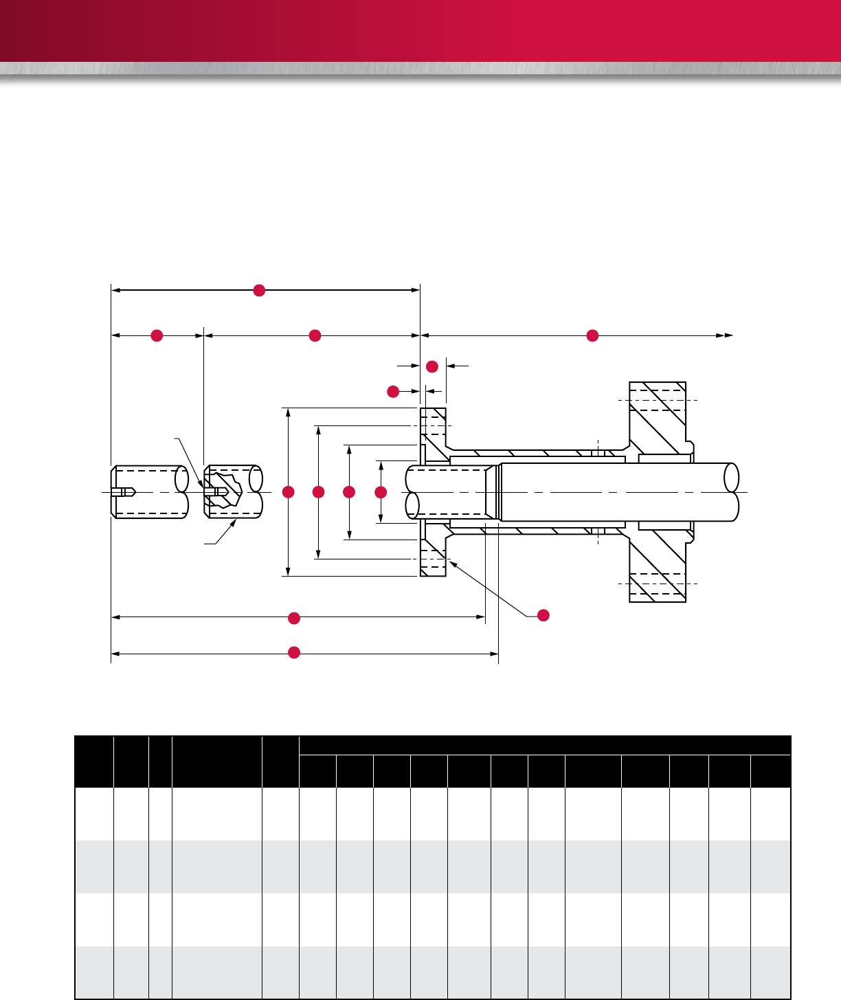
ØØ Ø
Top of stem open
Top of stem closed
To centerline of valve nore
= Number and
size of holes
End of stem thd. diameter
Minimum full thd.
Model C6
Model C6
Sizes 6” to 12” (150 mm to 300 mm)
Class 150
24
TOPWORKS
Total
stem travel
G
K
P
F
B
C
D
N
Ø
H J L M
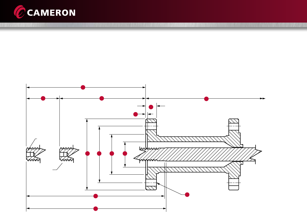
ØØ Ø
Top of stem open
Top of stem closed
To centerline of valve nore
= Number and
size of holes
EEnd of stem thd. diameter
Minimum Full thd.
Model C6B
Sizes 6” to 12” (150 mm to 600 mm)
Classes 150, 600 and 900

25
Model C6B
Size
in.
(mm)
Class ISO
FLG
ACME Stem Closed Open
A B C D E F G H J K L M N P
6
(150)
600
and 900 F14 1-1/4 - 0.250P
- 0.250L
7.83
(198.88)
10.02
(254.51)
7.19
(182.63)
16.69
(423.93)
16.25
(412.75)
28.06
(712.72)
6.89
(175.01)
5.512
(140.00)
4 - 0.688
(4 - 17.48)
3.945
(100.203)
3.955
(100.457)
2.50
(63.50)
1.03
(26.16)
0.168
(4.267)
0.188
(4.775)
8
(200)
600
and 900 F14 1-3/4 - 0.250P
- 0.250L
10.17
(258.32)
19.37
(492.00)
9.20
(233.68)
20.44
(519.18)
20.00
(508.00)
35.41
(899.41)
6.89
(175.01)
5.512
(140.00)
4 - 0.688
(4 - 17.48)
3.945
(100.203)
3.955
(100.457)
2.50
(63.50)
1.03
(26.16)
0.168
(4.267)
0.188
(4.775)
10
(250) 600 F14 1-3/4 - 0.250P
- 0.250L
8.17
(207.52)
19.37
(492.00)
11.20
(284.48)
20.44
(519.18)
20.00
(508.00)
38.47
(977.14)
6.89
(175.01)
5.512
(140.00)
4 - 0.688
(4 - 17.48)
3.945
(100.203)
3.955
(100.457)
2.50
(63.50)
1.03
(26.16)
0.168
(4.267)
0.188
(4.775)
10
(250) 900 F16 1-3/4 - 0.250P
- 0.250L
8.17
(207.52)
19.37
(492.00)
11.20
(284.48)
20.44
(519.18)
20.00
(508.00)
38.47
(977.14)
8.27
(210.06)
6.496
(165.00)
4 - 0.812
(4 - 20.62)
5.240
(133.096)
5.260
(133.604)
2.50
(63.50)
1.50
(38.10)
0.220
(5.588)
0.240
(6.096)
12
(300) 600 F16 1-3/4 - 0.250P
- 0.250L
9.61
(244.09)
22.83
(579.88)
13.22
(335.79)
24.06
(611.12)
23.62
(599.95)
43.91
(1115.31)
8.27
(210.06)
6.496
(165.00)
4 - 0.812
(4 - 20.62)
5.240
(133.096)
5.260
(133.604)
2.50
(63.50)
1.50
(38.10)
0.220
(5.588)
0.240
(6.096)
12
(300) 900 F16 2 - 0.250P
- 0.250L
9.55
(242.57)
22.67
(575.82)
13.12
(333.25)
24.06
(611.12)
23.62
(599.95)
44.47
(1129.54)
8.27
(210.06)
6.496
(165.00)
4 - 0.812
(4 - 20.62)
5.240
(133.096)
5.260
(133.604)
3.25
(82.55)
1.50
(38.10)
0.220
(5.588)
0.240
(6.096)
14
(350) 150 FA14 1-1/2 - 0.200P
- 0.400L
10.68
(271.27)
25.34
(643.64)
14.66
(372.36)
26.39
(670.31)
25.69
(652.53)
46.50
(1181.10)
6.89
(175.01)
5.512
(140.00)
4 - 0.688
(4 - 17.48)
3.945
(100.203)
3.955
(100.457)
2.50
(63.50)
1.03
(26.16)
0.168
(4.267)
0.188
(4.775)
14
(350) 600 FA16 2 - 0.250P
- 0.500L
10.68
(271.27)
25.34
(643.64)
14.66
(372.36)
27.27
(692.66)
26.69
(677.93)
49.75
(1263.65)
8.25
(209.55)
6.500
(165.10)
4 - 0.812
(4 - 20.62)
5.010
(127.254)
5.020
(127.508)
2.88
(73.15)
1.50
(38.10)
0.220
(5.588)
0.240
(6.096)
16
(400) 150 FA14 1-1/2 - 0.200P
- 0.400L
10.38
(263.65)
27.07
(687.58)
16.69
(423.93)
28.14
(714.76)
27.56
(700.02)
51.37
(1304.80)
6.89
(175.01)
5.512
(140.00)
4 - 0.688
(4 - 17.48)
3.945
(100.203)
3.955
(100.457)
2.50
(63.50)
1.03
(26.16)
0.168
(4.267)
0.188
(4.775)
16
(400) 600 FA25 2 - 0.250P
- 0.500L
10.19
(258.83)
28.86
(733.04)
16.67
(423.42)
28.20
(716.28)
27.59
(700.79)
53.56
(1360.42)
11.50
(292.10)
10.000
(254.00)
8 - 0.688
(8 - 17.48)
6.010
(152.654)
6.020
(152.908)
3.12
(79.25)
2.00
(50.80)
0.220
(5.588)
0.240
(6.096)
18
(450) 150 FA14 1-1/2 - 0.200P
- 0.400L
11.68
(296.67)
30.09
(764.29)
18.41
(467.61)
31.14
(790.96)
27.56
(700.02)
57.00
(1447.80)
6.89
(175.01)
5.512
(140.00)
4 - 0.688
(4 - 17.48)
3.945
(100.203)
3.955
(100.457)
2.50
(63.50)
1.03
(26.16)
0.168
(4.267)
0.188
(4.775)
18
(450) 600 FA25 2-1/4 - 0.250P
- 0.500L
11.93
(303.02)
30.62
(777.75)
18.69
(474.73)
32.39
(822.71)
31.81
(807.97)
60.19
(1528.83)
11.50
(292.10)
10.000
(254.00)
8 - 0.688
(8 - 17.48)
6.010
(152.654)
6.020
(152.908)
3.00
(76.20)
2.36
(59.94)
0.220
(5.588)
0.240
(6.096)
20
(500) 150 FA14 1-3/4 - 0.250P
- 0.500L
10.97
(278.64)
31.69
(804.93)
20.72
(526.29)
32.83
(833.88)
32.25
(819.15)
62.28
(1581.91)
6.89
(175.01)
5.512
(140.00)
4 - 0.688
(4 - 17.48)
3.945
(100.203)
3.955
(100.457)
2.50
(63.50)
1.03
(26.16)
0.168
(4.267)
0.188
(4.775)
20
(500) 600 FA30 2-3/4 - 0.400P
- 0.800L
12.57
(319.28)
33.30
(845.82)
20.73
(526.54)
34.88
(885.95)
34.31
(872.24)
65.67
(1668.02)
13.62
(345.95)
11.750
(298.45)
8 - 0.875
(8 - 22.23)
7.010
(178.054)
7.020
(178.308)
3.50
(89.90)
2.75
(69.85)
0.220
(5.588)
0.240
(6.096)
24
(600) 150 FA14 2 - 0.250P
- 0.500L
11.03
(280.16)
36.14
(917.96)
25.11
(637.79)
37.02
(940.31)
36.44
(925.58)
75.61
(1920.49)
6.89
(175.01)
5.512
(140.00)
4 - 0.688
(4 - 17.48)
3.945
(100.203)
3.955
(100.457)
2.50
(63.50)
1.03
(26.16)
0.168
(4.267)
0.188
(4.775)
24
(600) 600 FA35 3-1/4 - 0.400P
- 0.800L
13.12
(333.25)
38.26
(971.80)
25.14
(638.56)
39.95
(1014.73)
39.38
(1000.25)
80.00
(2032.00)
16.12
(409.45)
14.000
(355.60)
8 - 1.120
(8 - 28.45)
8.510
(216.154)
8.520
(216.408)
4.50
(114.30)
3.00
(76.20)
0.223
(5.664)
0.237
(6.020)
26
FLOW COEFFICIENTS (CV)
The following chart outlines the CV for through-conduit gate valves having end-to-end dimensions and bore diameters
in compliance with API 6D standards.
CV is the flow of water through the valve at 1 psi pressure drop in gal/min. Since CV is a calculated number, the actual
value may vary.
Valve Size in.
(mm) 150 300 400 600 900 1500 2500
2 (50) 476 432 378 378 337 337 218
3 x 2 (80 x 50) - - 165 165 203 239 -
2-1/2 (65) - - 682 682 558 558 305
3 (80) 1358 1155 1053 1109 1072 966 474
4 x 3 (100 x 80) - - 534 529 597 677 624
4 (100) 2508 2176 1925 1944 1890 1730 725
6 x 4 (150 x 100) - - 886 944 943 1231 -
6 (150) 5402 5300 4860 4577 4383 3622 2510
8 x 6 (200 x 150) 2583 2499 - 3240 3588 2137 -
8 (200) 11,261 11,054 9345 8886 8416 6879 5227
10 x 8 (250 x 200) - 5218 - 5036 7975 4859 -
12 x 8 (300 x 200) - 3302 - 3892 - - -
10 (250) 19,181 18,856 15,771 14,533 14,087 11,283 8313
12 (300) 29,435 28,980 23,834 22,729 21,025 16,843 12,282
12 x 10 (300 x 250) 7875 - - 12,799 7299 - -
14 (350) 35,605 30,883 29,921 28,837 23,846 20,336 -
16 x 14 (400 x 350) - - - 21,096 - - -
16 (400) 49,979 42,224 41,022 39,144 33,358 27,548 21,396
20 x 16 (500 x 400) 13,060 - 15,761 - - - -
18 (450) 66,156 55,740 54,277 51,368 45,004 - -
20 (500) 83,865 70,386 68,680 64,559 56,871 - -
22 (550) - 86,869 85,422 80,279 - - -
24 (600) 127,916 106,835 103,504 97,240 84,836 - -
26 (650) 149,428 123,222 120,829 114,905 - - -
28 (700) 176,798 144,355 142,391 135,267 - - -
30 (750) 212,313 170,229 163,776 157,401 133,706 - -
36 (900) 322,548 245,362 236,147 224,424 - - -

27
FLOW COEFFICIENTS (KV)
The following chart outlines the KV for through-conduit gate valves having end-to-end dimensions and bore diameters
in compliance with API 6D.
KV is the flow of water through the valve at 1 bar pressure drop in cu m/hr. Since KV is a calculated number, the actual
value may vary.
Valve Size in.
(mm) 150 300 400 600 900 1500 2500
2 (50) 412 373 327 327 291 291 188
3 x 2 (80 x 50) - - 142 142 175 207 -
2-1/2 (65) - - 590 590 483 483 264
3 (80) 1175 999 911 959 927 835 410
4 x 3 (100 x 80) - - 462 458 516 585 540
4 (100) 2170 1882 1665 1682 1635 1496 627
6 x 4 (150 x 100) - - 766 817 816 1065 -
6 (150) 4673 4585 4204 3959 3792 3133 2172
8 x 6 (200 x 150) 2234 2162 - 2803 3103 1849 -
8 (200) 9742 9562 8084 7687 7280 5951 4522
10 x 8 (250 x 200) - 4514 - 4356 6898 4204 -
12 x 8 (300 x 200) - 2857 - 3367 - - -
10 (250) 16,592 16,312 13,643 12,572 12,186 9761 7191
12 (300) 25,463 25,070 20,617 19,662 18,188 14,570 10,624
12 x 10 (300 x 250) 6812 - - 11,072 6314 - -
14 (350) 30,800 26,715 25,883 24,945 20,628 17,591 -
16 x 14 (400 x 350) - - - 18,249 - - -
16 (400) 43,234 36,526 35,486 33,862 28,856 23,831 18,509
20 x 16 (500 x 400) 11,298 - 13,634 - - - -
18 (450) 57,228 48,218 46,953 44,436 38,930 - -
20 (500) 72,547 60,888 59,412 55,847 49,196 - -
22 (550) - 75,147 73,894 69,445 - - -
24 (600) 110,654 92,417 89,536 84,117 73,388 - -
26 (650) 129,263 106,593 104,523 99,399 - - -
28 (700) 152,939 124,874 123,175 117,013 - - -
30 (750) 183,661 147,257 141,674 136,160 115,662 - -
36 (900) 279,021 212,251 204,279 194,138 - - -

28
TRIM CHART
Service Trim
Code
Body and
Bonnet Gate Seat Stem
Seal Stem Bolting Fittings Temperature
Range
Waterflood,
Corrosive T-10
WCC
Carbon Steel,
Internally
Coated
Carbon Steel, ASME
Classes 300-600,
Low-Alloy Steel 900
Class, Nickel-Plated
Carbon Steel,
Nickel-Plated
PTFE Insert
PTFE
Low-Alloy
Steel, Nickel-
Plated
Alloy
Steel,
NACE
Stainless
Steel
-20° F to 250° F
(-29° C to 121° C)
Standard T-11
2” to 4”
only
WCC
Carbon
Steel
Carbon Steel,
Low-Alloy Steel,
Nickel-Plated
Carbon Steel,
Nickel-Plated
PTFE Insert
FKM
Viton
Low-Alloy
Steel, Nickel-
Plated
Alloy
Steel
Carbon
Steel
-20° F to 250° F
(-29° C to 121° C)
Corrosive
Service T-22
WCC
Carbon
Steel
410
Stainless
Steel
410
Stainless
Steel
PTFE
17-4 PH
Stainless
Steel
Alloy
Steel
Stainless
Steel
-20° F to 250° F
(-29° C to 121° C)
Sour, Mildly
Corrosive
T-24
2” and
larger
WCC
Carbon
Steel
Carbon Steel, ASME
Classes 300-600,
Low-Alloy Steel 900
Class, Nickel-Plated
Carbon Steel,
Nickel-Plated
PTFE Insert
PTFE
Low-Alloy
Steel, Nickel-
Plated
Alloy
Steel,
NACE
Stainless
Steel
-20° F to 250° F
(-29° C to 121° C)
Low-
Temperature,
Non-Sour T-36
LCC
Carbon
Steel,
Impact-
Tested
Carbon Steel, ASME
Classes 300-600,
Low-Alloy Steel 900
Class, Nickel-Plated
Carbon Steel,
Nickel-Plated
PTFE Insert
PTFE
Low-Alloy
Steel,
Impact-Tested,
Nickel-
Plated
Alloy
Steel,
Impact-
Tested
Stainless
Steel
-50° F to 250° F
(-46° C to 121° C)
Low-
Temperature,
Sour T-37
LCC
Carbon
Steel,
Impact-
Tested
Carbon Steel, ASME
Classes 300-600,
Low-Alloy Steel 900
Class, Nickel-Plated
Carbon Steel,
Nickel-Plated
PTFE Insert
PTFE
Low-Alloy
Steel,
Impact-Tested,
Nickel-
Plated
Alloy
Steel,
NACE,
Impact-
Tested
Stainless
Steel
-50° F to 250° F
(-46° C to 121° C)
Anhydrous
Ammonia T-88
WCC/A36
Carbon
Steel
Carbon Steel,
Low-Alloy Steel,
Nickel-Plated
Carbon Steel,
Nickel-Plated
PTFE Insert
PTFE
Low-Alloy
Steel, Nickel-
Plated
Alloy
Steel,
NACE
Stainless
Steel
-20° F to 250° F
(-29° C to 121° C)
Standard T-94
WCC
Carbon
Steel
Carbon Steel, ASME
Classes 300-600,
Low-Alloy Steel 900
Class, Nickel-Plated
Carbon Steel,
Nickel-Plated
PTFE Insert
Special
Low-Alloy
Steel, Nickel-
Plated
Alloy
Steel
Carbon
Steel
-20° F to 350° F
(-29° C to 177° C)
MTBE T-102
6” and
larger
WCC
Carbon
Steel
Carbon Steel, ASME
Classes 300-600,
Low-Alloy Steel 900
Class, Nickel-Plated
Carbon Steel,
Nickel-Plated
PTFE Insert
PTFE
Low-Alloy
Steel, Nickel-
Plated
Alloy
Steel
Carbon
Steel
-20° F to 250° F
(-29° C to 121° C)
Standard T-101
6” and
larger
WCC
Carbon
Steel
Carbon Steel, ASME
Classes 300-600,
Low-Alloy Steel 900
Class, Nickel-Plated
Carbon Steel,
Nickel-Plated
PTFE Insert
PTFE
Low-Alloy
Steel, Nickel-
Plated
Alloy
Steel
Carbon
Steel
-20° F to 250° F
(-29° C to 121° C)

29
COMMON TRIMS
Waterflood (T-10) – Carbon steel body/bonnet with wetted surface, ENP-plated, internal parts of corrosion-resistant
materials.
Model M (Sizes 2” to 4”, (50 mm to 100 mm), Classes 600 through 1500) Standard (T-11) – For non-corrosive
aromatic service with concentration of MTBE to 100%.
Corrosive Service – Internal Parts (T-22) – For substantially the same service as T-21, but where the corrosion resistance
of internal parts is desirable. The valve internal sealing members are stainless steel to gain this corrosion resistance. This
trim also is usable for mildly corrosive fluids and gases when limited corrosion of the internal body surfaces can be tolerated.
Sour Gas and Oil (NACE MR0175) (T-24) – Primarily for sour gas and oil (NACE MR0175) where resistance to H2S
embrittlement is required. Also suitable for other chemicals, products or hydrocarbons when H2S is present. May be used
when CO2 is present in smaller amounts than H2S.
Low-Temperature - 50° F (-46° C) NACE (T-36) – For essentially non-corrosive ladings, either liquid or gaseous. The
pressure-retaining components (body, bonnet and bolting) are of impact-tested materials.
Low-Temperature Sour -50° F (-46° C) NACE (T-37) – Primarily for sour gas and oil (NACE MR0175) where resistance to
H2S embrittlement is required at -50° F (-46° C) service. The pressure-retaining components (body, bonnet and bolting) are
of impact-tested materials. Also suitable for other chemicals, products or hydrocarbons when H2S is present. Can be used
when CO2 is present in smaller amounts than H2S.
Anhydrous Ammonia (T-88) – Special elastomers and stem nut for ammonia service
Fire-Tested to API 6FA (T-94) – These valves have been qualified as fire-tested and contain a special stem packing
arrangement for essentially non-corrosive ladings. The elastomer O-rings used for seal and bonnet seals are of a material
that will not swell and affect the operation of the valve. Typical examples of ladings are: gasoline, benzene, toluene,
carbon-tetrachloride, 1,1, 1 trichloroethane, richloroethylene perchloroethylene and phosphate ester hydraulic fluids.
Aromatic (to 40% MTBE, Fire-Tested API 6FA or ISO 10497) (T-101) – For essentially non-corrosive, non-sour aromatic
or non-aromatic service with methanol or ethanol based corrosion inhibitors where up to 40% MTBE may be present.
30
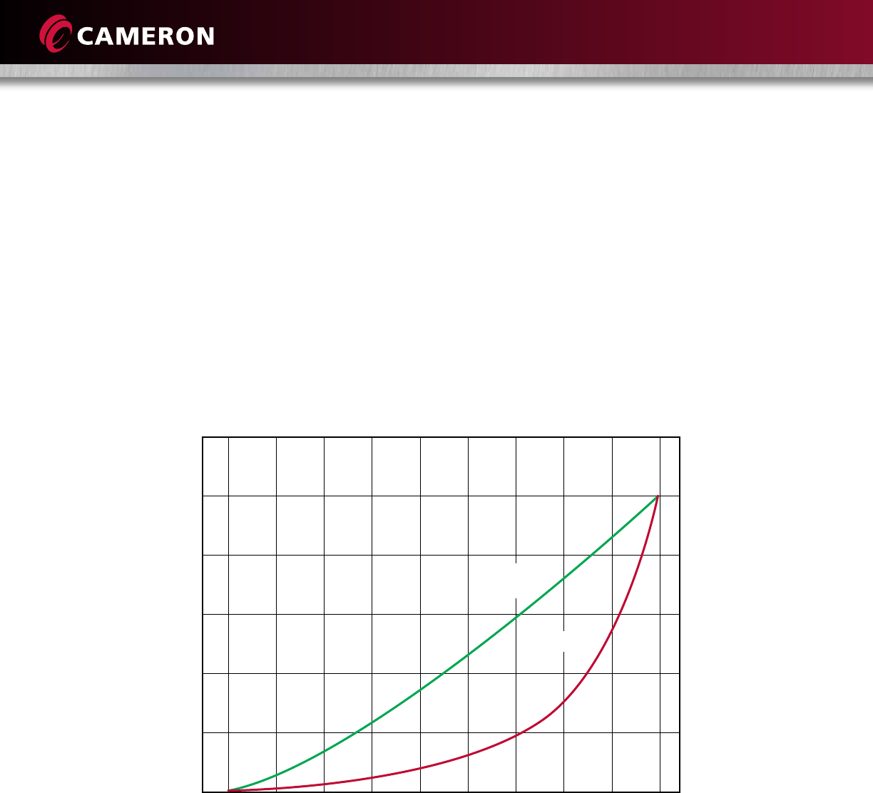
PARTIAL OPEN FLOW CHARACTERISTICS
The following graph approximates the flow coefficient, CV or KV, of gate valves as a function of the valve stroke going
from closed to open. Note that this is an estimation only because of assumptions made in the valve stroke, as well as
unpredictable flow characteristics around the gate-seat bore in the partially open position.
Gate valves are intended for on-off service. Intermittent throttling such as pressure equalization service is acceptable.
Continuous throttling is not recommended. This information is provided only to facilitate the engineering of systems in the
transition between open and closed positions of the valves. One example might be to evaluate the possibility of water
hammer in liquid pipelines.
Partial Open Flow Characteristics (Through Conduit Gate Valves)
Percent of Valve Stroke
120%
100%
80%
60%
40%
20%
0%
10% 20% 30% 40% 50% 60% 70% 80% 90% 100%
% of Total
Flow Area
% of CV
31
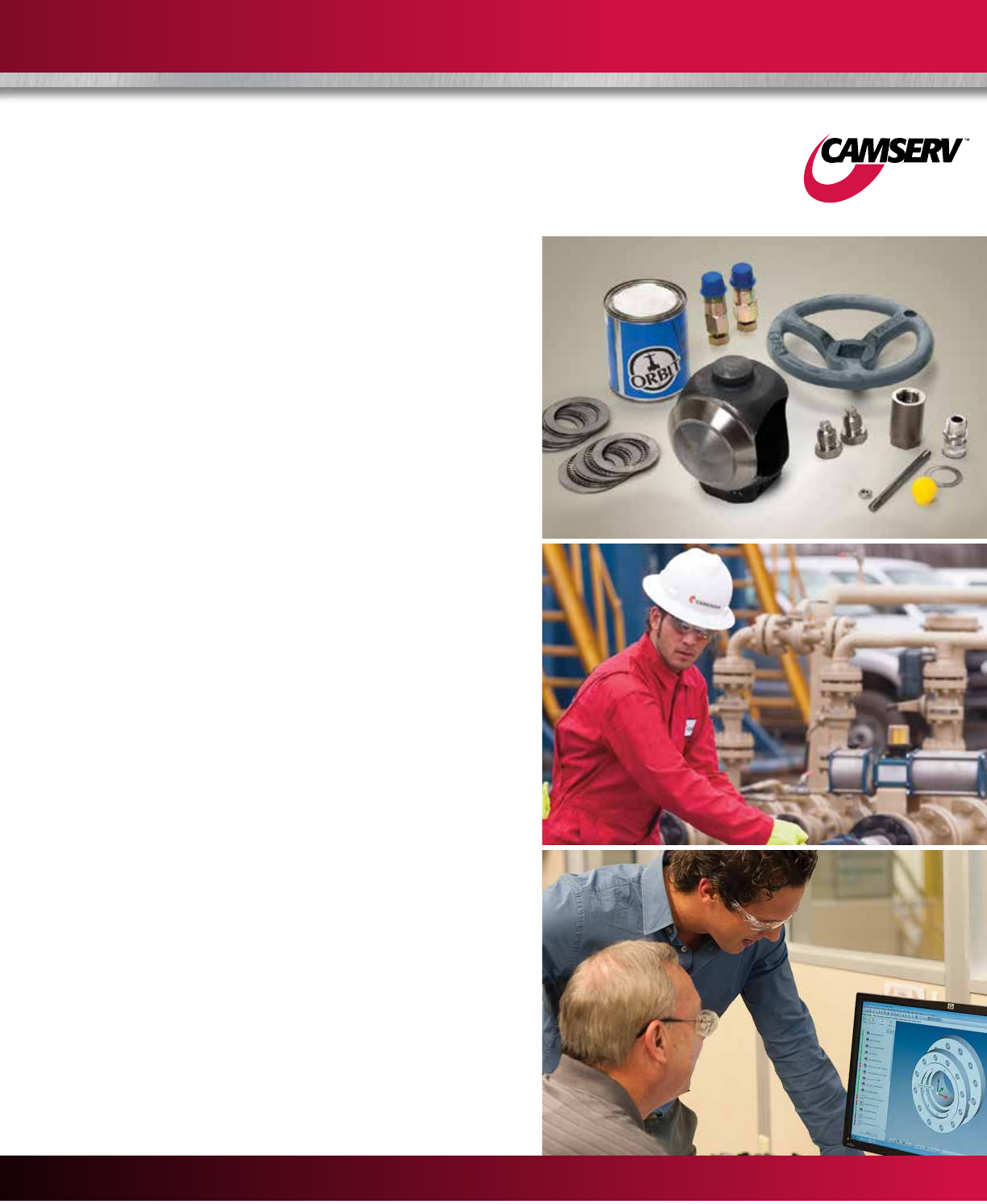
CAMSERV™ Aftermarket Services for Valves and Actuation
WE BUILD IT. WE BACK IT.
Global Network and Local Support
Cameron is well-positioned to deliver total aftermarket
support, quickly and efficiently, with unmatched OEM
expertise. Our highly skilled engineers and technicians are
available around the clock, seven days a week, to respond
to customer queries, troubleshoot problems and offer
reliable solutions.
Easily Accessible Parts and Spare Valves
• OEM spare valves, actuators and parts
(including non-Cameron brands)
• Handling, storage, packaging and delivery
• Dedicated stocking program
Comprehensive Aftermarket Services Portfolio
• Parts and spare valves
• Repair
• Field services
• Preventative maintenance
• Equipment testing and diagnostics
• Remanufacturing
• Asset preservation
• Customer property management
• Training and recertification services
• Warranty
Customized Total Valve CareSM (TVC) Programs
Customized asset management plans that optimize uptime,
availability and dedicated services.
• Engineering consultancy
• Site management
• Flange management
• Startup and commissioning
• Spare parts and asset management
• Operational support
USA • CANADA • LATIN AMERICA • EUROPE • RUSSIA • AFRICA • MIDDLE EAST • ASIA PACIFIC

32
Trademark Information
WKM is a registered trademark of Cameron. CAMSERV is a trademark of Cameron.
This document contains references to registered trademarks or product designations,
which are not owned by Cameron.
Trademark Owner
Inconel INCO Nickel Sales, Inc.
Monel INCO Alloys International, Inc
Stellite Stoody Deloro Stellite, Inc.
Teflon E.I. Dupont De Nemours & Company
Viton Dupont Dow Elastomers L.L.C.

33

HSE Policy Statement
At Cameron, we are committed ethically, financially and personally to a
working environment where no one gets hurt and nothing gets harmed.
H
E
A
L
T
H
S
A
F
E
T
Y
A
N
D
E
N
V
I
R
O
N
M
E
N
T
A
L
E
X
C
E
L
L
E
N
C
E
C
A
M
E
R
O
N
3250 Briarpark Drive, Suite 300
Houston, TX 77042
USA
Toll Free 1 800 323 9160
Learn more about WKM gate valves at:
www.c-a-m.com/WKM
WKM@c-a-m.com
© 2013 Cameron | GROVE, CAMERON, RING-O, TOM WHEATLEY, TK and WKM are registered brands of Cameron. CAMSERV, TBV, TEXSTEAM, Saf-T-Seal and Saf-T-Gard are trademarks of Cameron.
Total Valve Care is a service mark of Cameron. Viton and all other brands listed are trademarks of their respective companies. | SWP 1.5M 12/13 AD00912V
