GA 03.108/14.02 Ws Wsu
User Manual: ws-wsu
Open the PDF directly: View PDF ![]() .
.
Page Count: 26
RUVAC WS/WSU
251/501/1001/2001
Roots pump with mineral oil,
synthetic oil or PFPE filling
Cat.-No.
101 83
117 22/32/42/52
117 23/33/43/53
117 27/37/47/57
117 28/38
118 33/43/53
150 44/95/96
167 007
917 48
155 000
Operating Instructions
GA 03.108/14.02
Vacuum Solutions Application Support Service LEYBOLD VACUUM
View our inventory

Contents
Contents Page
IMPORTANT SAFETY CONSIDERATIONS . .4
1 Description . . . . . . . . . . . . . . . . . . . . . . . . . .6
1.1 Design and function . . . . . . . . . . . . . . . . . . . .6
1.2 Standard specification . . . . . . . . . . . . . . . . . .9
1.3 Technical data . . . . . . . . . . . . . . . . . . . . . . .10
1.4 Accessories . . . . . . . . . . . . . . . . . . . . . . . . .11
2 Transportation and storage . . . . . . . . . . . .12
3 Installation and connection . . . . . . . . . . . .13
3.1 Installation . . . . . . . . . . . . . . . . . . . . . . . . . .13
3.2 Filling in of the lubricants . . . . . . . . . . . . . . .13
3.3 Electrical connections . . . . . . . . . . . . . . . . . .14
3.4 Connection of the flanges . . . . . . . . . . . . . . .16
4 Operation . . . . . . . . . . . . . . . . . . . . . . . . . .17
4.1 Start-up . . . . . . . . . . . . . . . . . . . . . . . . . . . .17
4.2 Operation . . . . . . . . . . . . . . . . . . . . . . . . . . .17
4.3 Shutdown and storage . . . . . . . . . . . . . . . . .18
4.4 Changing from vertical to horizontal flow . . . .18
5 Maintenance . . . . . . . . . . . . . . . . . . . . . . . .19
5.1 Safety information . . . . . . . . . . . . . . . . . . . . .19
5.2 Exchanging the lubricants . . . . . . . . . . . . . . .19
5.3 Cleaning the fan cowl and the cooling fins . .20
5.4 Cleaning the dirt trap . . . . . . . . . . . . . . . . . .20
5.5 Cleaning the pumping chamber . . . . . . . . . .21
5.6 Cleaning the valve of the pressure
balance line . . . . . . . . . . . . . . . . . . . . . . . . .21
5.7 Leybold service . . . . . . . . . . . . . . . . . . . . . .22
6 Troubleshooting . . . . . . . . . . . . . . . . . . . . .23
EEC Declaration of Conformity . . . . . . . . .24
Indicates procedures that must be strictly
observed to prevent hazards to persons.
Indicates procedures that must strictly be
observed to prevent damage to, or destruc-
tion of the equipment.
Figures
The references to figures, e.g. (1/2) consist of the Fig.
No. and the Item No. in that order.
2GA 03.108/14.02 - 01/03
Warning
Caution

Contents
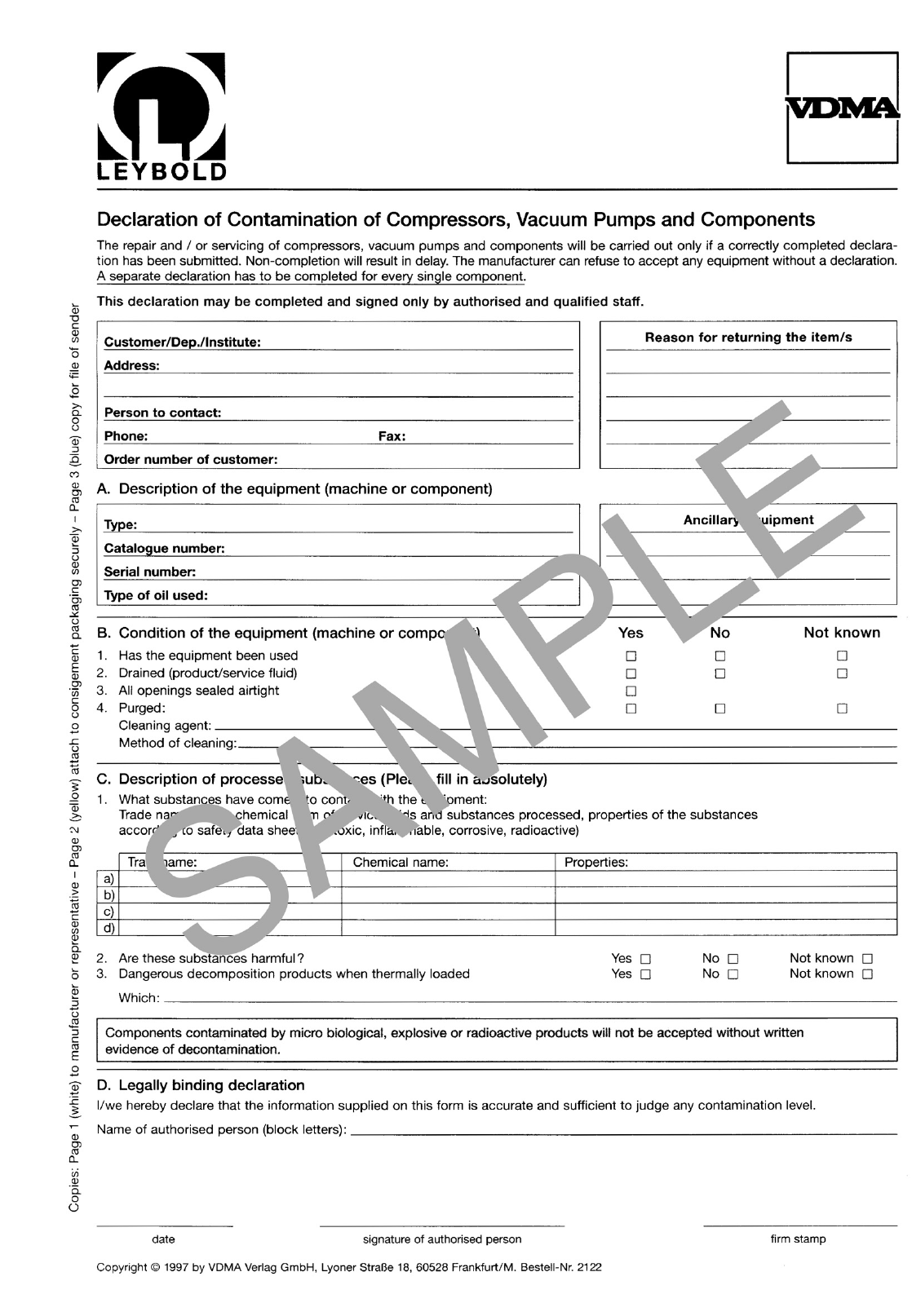
Leybold-Service
If a pump is returned to Leybold, indicate whether the
pump free of substances damaging to health or whether
it is contaminated.
If it is contaminated also indicate the nature of the
hazard. Leybold must return any pumps without a
„Declaration of Contamination“ to the sender’s address.
Disposal of waste oil
Under the amended law relating to waste disposal dated
November 1, 1986 (valid in the Federal Republic of Ger-
many) the disposal of used oil is subject to new provi-
sions. According to legislation relating to waste disposal
the so-called principle of causality is applied. Hence,
anyone in possession of used oil is responsible for its
proper disposal.
Used oils coming from vacuum pumps must not be
mixed with other substances.
Used oils from vacuum pumps (LH-oils on the basis of
mineral oils) having been affected by normal contamina-
tion due to oxygen from the ambient air, increases in
temperature and mechanical wear, must be disposed of
as used oil in accordance with the regulations.
Used oils from vacuum pumps that have been contami-
nated by other substances must be labelled, stored and
disposed of as special waste with reference to the kind
of contamination.
If you send a pump to LEYBOLD for repair please indi-
cate any harmful substances existing in the pump oil or
around the pump.
When disposing of used oil please observe the safety
regulations that are valid in your country.
We reserve the right to modify the design and the speci-
fied data. The illustrations are not binding.
3
GA 03.108/14.02 - 01/03

4GA 03.108/14.02 - 01/03
Safety considerations
IMPORTANT SAFETY CONSIDERATIONS
The Leybold RUVAC vacuum pump is designed for safe and efficient operation when used properly and
in accordance with this manual. It is the responsibility of the user to carefully read and strictly observe
all safety precautions described in this section and throughout the manual. This product must be ope-
rated and maintained by trained personnel only. Consult local, state, and national agencies regarding
specific requirements and regulations. Address any further safety, operation and/or maintenance que-
stions to your nearest Leybold Vacuum office.
Warning Failure to observe the following precautions could result in serious personal injury.
• Before beginning with any maintenance or service work on the RUVAC, disconnect
the pump from all power supplies.
• Do not operate the pump with any of the covers removed. Serious injury may result.
• If exhaust gases must be collected or contained, do not allow the exhaust line to
become pressurized.
• Make sure that the gas flow from the exhaust port is not blocked or restricted in
any way.
• The standard version of the RUVAC is not suited for operation in explosion hazard
areas. Contact us before planning to use the pump under such circumstances.
• Before starting up for the first time, the motor circuit must be equipped with a suitable
protective motor switch. Please take note of the information in these Operating
Instructions or on the electric motor (wiring diagram).
• The RUVAC is not suited for pumping of
- combustible and explosive gases or vapours
- radioactive and toxic substances
- pyrophorous substances.
• The RUVAC must be integrated in the system control arrangement so that the pump
can not run-up automatically after it has been shut down by the temperature switches
in the motor. This applies equally to emergency shut-down arrangements. After having
determined the fault cause, the pump should be switched on manually again.
• Avoid exposing any part of the human body to the vacuum.
• Never operate the RUVAC without a connected intake line or blank flange.
• The location at which the RUVAC (including its accessories) is operated should be
such that angles over 10° from the vertical are avoided.
• The location of the RUVAC should be such that all controls are easily accessible.
• Under certain ambient conditions the RUVAC may attain a temperature of over 80 °C
(176 °F). There then exists the danger of receiving burns.
Note the symbols on the pump pointing to the hazards, and in the case of a hot pump
wear the required protective clothing.
5
GA 03.108/14.02 - 01/03
Safety considerations
Warning • The noise level produced by the RUVAC is about 63 to 72 dB(A).
Make sure that suitable protection measures are taken to protect the hearing.
• Before pumping oxygen (or other highly reactive gases) at concentrations exceeding the
concentration in the atmosphere (> 21 % for oxygen) it will be necessary to use a special pump.
Such a pump will have to be modified and de-greased, and an inert special lubricant (like PFPE)
must be used.
• Before commissioning the RUVAC, make sure that the media which are to be pumped are
compatible with each other so as to avoid hazardous situations.
All relevant safety standards and regulations must be observed.
• It is recommended to always operate the RUVAC with a suitable exhaust line which is properly
connected.
• When moving the RUVAC always use the allowed means.
A lifting eye is provided as standard on the pump.
Caution Failure to observe the following precautions could result in damage to the pump:
• Do not allow the ingestion of small objects (screws, nuts, washers, pieces of wire, etc.)
through the inlet port. Always use the screen which is supplied with every pump.
• Do not use the pump for applications that produce abrasive or adhesive powders or
condensable vapors that can leave adhesive or high viscosity deposits. Please contact Leybold Sales
for selecting the right separator.
• Before pumping vapors, the RUVAC should have attained its operating temperature.
The pump will have attained its operating temperature about 30 minutes after starting the pump.
During this time the pump should be separated from the process, by a valve in the intake line,
for example.
• In the case of wet processes we recommend the installation of liquid separators upstream and
downstream of the pump so as to avoid a massive influx of liquid into the pump.
• The exhaust line should be laid so that it slopes down and away from the pump so as to prevent
condensate from backstreaming into the pump.
• In order to prevent the transfer of vibrations from the RUVAC to other parts of the system we
recommend the use of corrugated hoses or compensators on both the intake and the exhaust sides.
• The entry of particles and fluids must be avoided under all circumstances.
• Corrosion, deposits and cracking of oil within the pump are not allowed.
Description
6GA 03.108/14.02 - 01/03
1 Description
1.1 Design and Function
The RUVAC WS and RUVAC WSU are Roots pumps dri-
ven by a canned motor.
The WSU types have a pressure balance line between
the discharge and intake flanges.
The RUVAC WS and WSU are lubricated with mineral oil
or perfluorized polyether (PFPE) in the case of the PFPE
models. Apart from the lubricant the mineral oil and
PFPE models are identical in type.
Only the RUVAC WS/WSU PFPE can be used for pum-
ping greater than atmospheric concentrations of oxygen
or very aggressive or hazardous gases.
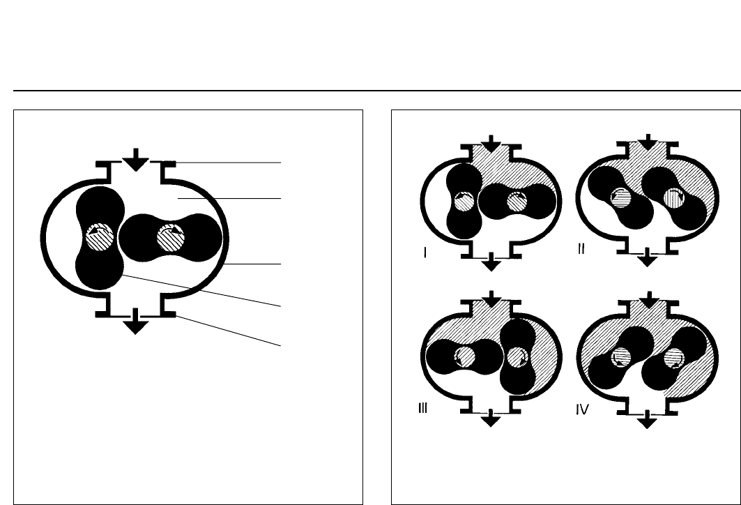
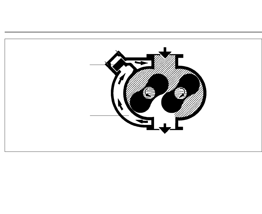
1.1.1 Principle of Operation
Roots pumps - also known as Roots blowers - contain in
their pump casing (1/3) two symmetrical impellers (1/4)
rotating in opposite directions. The impellers have roug-
hly the cross section of a figure „8“ and are synchronised
by a toothed gearing so that they move past each other
and the casing without contact but with a small clearan-
ce.
The principle of operation is explained in Fig. 2.
In impeller positions I and II, the volume in the intake
flange is increased. When the impellers rotate further to
position III, part of the volume is sealed off from the inta-
ke side.
In position IV, this volume is opened to the discharge
side, and gas at backing pressure (higher than the inta-
ke pressure) flows in. The inflowing gas compresses the
gas volume pumped from the intake side. As the impel-
lers rotate further, the compressed gas is ejected via the
discharge flange.
This process occurs twice per complete revolution of
each of the two impellers.
Due to the non-contacting rotation in the pumping cham-
ber, Roots pumps can be operated at high speeds (stan-
dard n = 3,000 rpm at a mains frequency of 50 Hz). Thus
a relatively high pumping speed is attained with small
pumps.
The pressure differential and compression ratio between
the intake and discharge sides are limited on Roots
pumps. If the allowable pressure differential is exceeded,
the pump overheats.
In practice, the maximum attainable pressure differential
is significant only in the rough vacuum range (p > 10
mbar), whereas for pressures in the fine vacuum range
(p < 1 mbar) the attainable compression ratio is decisive.
Fig. 2 Functional diagram of a Roots pump (vertical flow)
1
2
3
4
5
Key to Fig. 1
1 Intake flange
2 Pumping chamber
3 Casing
4 Impeller
5 Discharge flange
Fig. 1 Schematic cross-section of a Roots pump (vertical flow)
Description
7
GA 03.108/14.02 - 01/03
RUVAC pumps from the WS/WSU range have been spe-
cifically designed for operation in the rough and fine
vacuum ranges. They are thus either used in connection
with backing pumps or in closed gas cycles. The pump’s
power consumption depends not only on the pumping
chamber volume and the rotational speed of the pump,
but also on the pressure differential between the dischar-
ge and intake flanges (see Fig. 7).
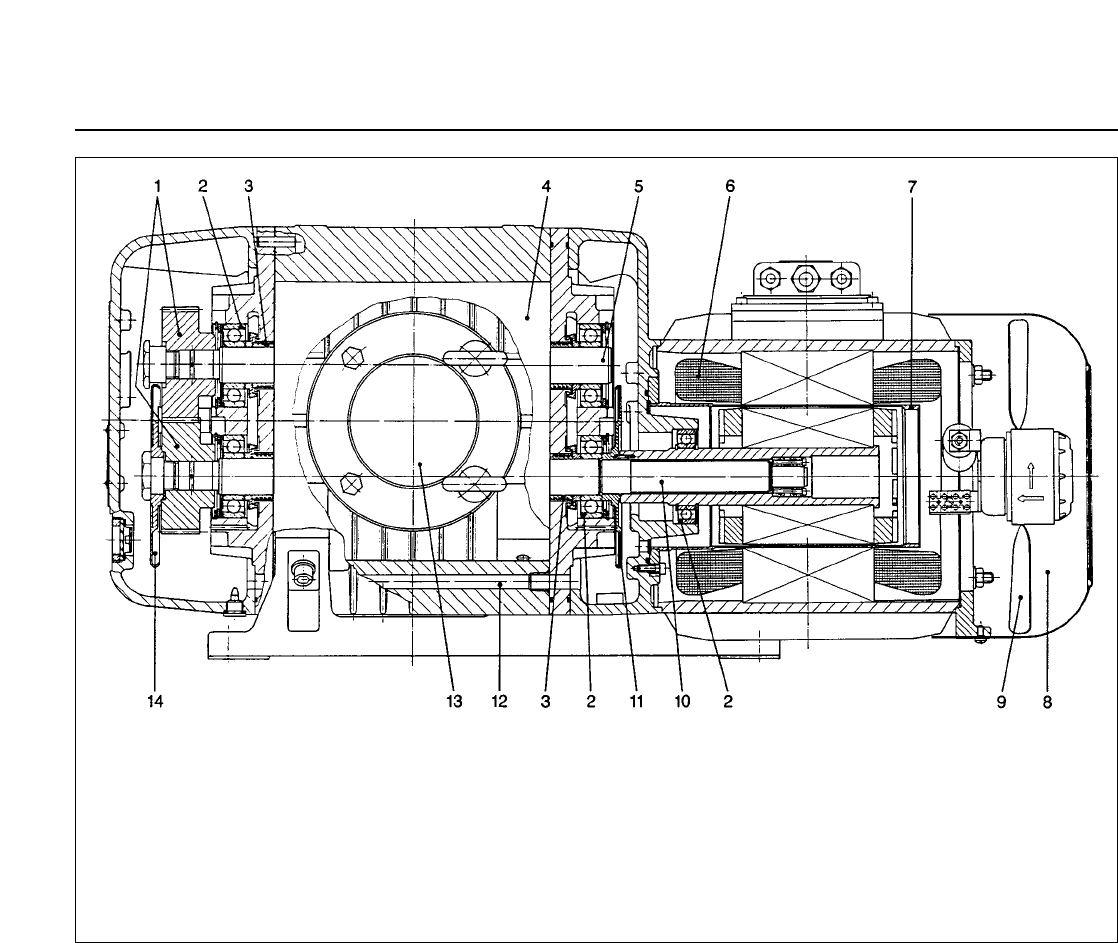
1.1.2 Design
RUVAC Roots pumps can pump gas in the vertical or
horizontal direction.
Although the pumping chamber of Roots pumps is free
of sealing agents and lubricants, the two gearwheels of
the synchromesh gearing (3/1) and the bearings (3/2)
are lubricated with mineral oil or with PFPE. The gear-
wheels and bearings of the RUVAC are located in two
side chambers which also contain the oil supply.
These two side chambers are separated from the pum-
ping chamber by the impeller seals (3/3). During operati-
on of the pump, the side chambers are evacuated via the
impeller seals.
The side chambers are linked to each other by two pas-
sages (3/12). These passages are arranged so that for
either horizontal or vertical flow the pressure will be
equalised between the oil supplies.
In both side chambers there are integrated oil pumps to
ensure that the bearings and gearwheels receive suffi-
cient lubricant at all recommended speeds.
RUVAC WS/WSUs are driven by a canned motor. In such
a motor, the rotor and stator coils (3/6) are separated by
a vacuum-tight can (3/7) made of non-magnetic materi-
al. The rotor runs in the vacuum on the pump’s drive
shaft (3/10); thus a shaft feedthrough to the atmosphere
is not needed.
With the standard motors, the RUVAC WS/WSUs can
run on either 50 Hz or 60 Hz power supplies.
For the permissible electrical connection data with res-
pect to these frequencies, see Section 1.3.
Fig. 3 Longitudinal section of a RUVAC WS 1001 (horizontal flow)
Key to Fig. 3
1 Gearwheels 8 Fan cowl
2 Bearings 9 Fan
3 Impeller seals 10 Drive shaft
4 Impellers 11 Centrifugal disc lubricator
5 Driven impeller shaft 12 Equalisation passage
6 Stator 13 Intake port
7 Can 14 Centrifugal disc lubricator
Description
8GA 03.108/14.02 - 01/03
Incorporated in the motor’s stator winding is a thermal
switch which turns off the pump when the motor tempe-
rature is too high.
RUVAC WS/WSUs are air-cooled. The airflow for cooling
the motor and pump is produced by a fan (3/9) with its
own drive motor under the motor’s fan cowl (3/8).
When operating the pump via a frequency
converter you must ensure that the drive
motor for the fan is connected to the mains.
1.1.3 Pressure Balance Line
The RUVAC WSU has an integrated pressure balance
line (4/1). It links the discharge and intake flanges via a
pressure balance valve.
If the pressure differential between the flanges is too
large, the valve opens (4/2). Some of the gas which has
already been pumped then flows back through the line to
the intake flange.
The valve is weight- and spring-loaded so that it works
with both vertical and horizontal flow of the pump.
As a result of this pressure balance line, no additional
devices are needed to protect the pump against exces-
sive pressure differentials.The RUVAC WSU can be swit-
ched on at atmospheric pressure at the same time as a
backing pump. As a result, the pumping speed of the
pump combination is increased even at high intake pres-
sures.
1.1.4 Lubricants
RUVAC WS/WSU pumps are, as standard, prepared eit-
her for operation with mineral oil, synthetic oil or the spe-
cial lubricant perfluoropolyether PFPE).
Other types of oil (white oil, for example) upon request.
If mineral oil and PFPE come into contact
they will emulsify. That’s why the pumps
must only be run with the type of lubricant
specified for the pump. If you want to chan-
ge the type of lubricant LEYBOLD should
do the change.
In case of operation with mineral oil we recommend our
vacuum pump oil N 62 (HE-200 in the USA). In case of
operation with PFPE we recommend our NC 1/14
(HE1600 in the USA).
PFPE pumps are marked by an additional red label at
the oil-fill screw.
The Operating Instructions GA 07.009 „PFPE for Vacu-
um Pumps“ will be enclosed with any RUVAC PFPE.
Observe the handling notes for PFPE collected in these
Operating Instructions.
1.1.5 Flange Connections
The cast flanges on the pump’s body comply with DIN
2501, nominal pressure 6.
The pumps are supplied with different collar flanges:
Pumps with Cat. Nos. beginning with 117... are equipped
with ISO-K collar flanges. This standard can be applied
in all other parts of the world.
Fig. 4 Schematic diagram of a Roots pump with pressure balance line
Caution
Key to Fig. 4
1 Pressure balance line
2 Pressure balance valve
2
1
Caution
Description
9
GA 03.108/14.02 - 01/03
1.2 Standard Specification
RUVAC WS/WSUs are supplied for vertical flow as stan-
dard unless you specifically request horizontal flow.
Before delivery the oil has been drained out. The
quantity of mineral oil, synthetic oil or PFPE oil required
for operation has been included separately.
Pumps with Cat. Nos. beginning with 117... are supplied
with a sealing disc, a blank flange and an ISO-K collar
flange fitted with the required number of screws.
The intake flanges of all pumps contain a wire mesh dirt
trap and have been vented with nitrogen for protection
against corrosion.
Fig. 5 Dimensional drawing for the RUVAC WS/WSU
h3
b5
DN 1
h4
h51)
DN
DN
DN1
h2
h
b6
b4
b3
1)
b6
DN1
b2
DN1
DN
h1
b1b
b7
a3
a5a2a1a
a4
DN
h6
b8
50
DN
DIN 2501 DN
1
WS/WSU 251 65 63 ISO-K
WS/WSU 501 65 63 ISO-K
WS/WSU 501H 65 63 ISO-K
WS/WSU 1001 100 100 ISO-K
WS/WSU 1001H 100 100 ISO-K
WS/WSU 2001 150 160 ISO-K
WS/WSU 2001H 150 160 ISO-K
1)
RUVAC WSU only DN
1
= ND 6 pump flange in accordance with DIN 2501
DN
1
= Collar flange with gasket for connecting ISO-K standard components
aa
1
a
2
a
3
a
4
a
5
bb
1
b
2
b
3
b
4
b
5
697 405 365 14 212 120 250 270 210 280 230 170
745 486 450 14 239 155 307 299 229 320 271 201
745 486 450 14 239 155 307 299 229 320 271 201
887 560 520 16,5 300 180 372 352 278 370 320 246
887 560 520 16,5 300 180 372 352 278 370 320 246
1065 800 740 18 370 220 457 518 388 460 422 292
1065 800 740 18 370 220 457 518 388 460 422 292
b
6
b
71)
b
8
hh
1
h
2
h
3
h
4
h
51)
h
6
24 305 285 300 160 280 180 306 360 307
24 390 313 340 180 320 194 348 430 332
24 414 330 340 180 320 194 348 450 350
24 490 366 396 211 370 227 414 532 392
24 524 398 396 211 370 227 414 564 424
24 635 456 530 300 460 351 578 753 523
24 642 460 530 300 460 351 578 760 530
Fig. 6 Pumping speed characteristics for operation at 50 Hz
The ultimate pressure (Pult.) depends on the backing
pump used. Fig. 7 Power consumption of the RUVAC WS/WSU
Saugvermögen
Druck

Description
10 GA 03.108/14.02 - 01/03
1.3 Technical Data
(SI units)
RUVAC WS / WSU 251 501 1001 2001
Nominal pumping speed 1) m3· h-1 253 505 1000 2050
Maximum pumping speed (at a pumping
speed for the backing pump of) m3· h-1
m3· h-1 210
65 450
160 890
250 1850
630
Possible cut-in pressure (RUVAC WS at a
pumping speed for the backing pump of) mbar
m3· h-1
31
65 37
160 27
250 22
630
Leak tightness mbar · l ·s-1 1 · 10-4
Permissible ambient temperatures
(Mineral oil and PFPE) °C12 - 40 °C
Permissible voltages at the motor’s fan AC 230 V / 50/60 Hz and 265 V / 60 Hz
Maximum allowable pressure differential in
continuous operation mbar 80 80 80 50
Mains voltage at the motor, 50 Hz V200 V (-5 %) - 230 V (+10 %) / 400 V (±10 %)4)
Motor power, 50 Hz kW 1,1 2,2 4,0 7,5
Nominal speed, 50 Hz min-1 3000 3000 3000 3000
Max. permissible speed min-1 6000 6000 6000 42003)
Motor protection category IP 20 20 20 20
Lubricant filling6)
• PFPE - vertical flow
- horizontal flow
• other types of oil
- vertical flow
- horizontal flow
l
l
l
l
1.Filling5) / 2.Filling
0,6 0,55
0,5 0,45
0,65 0,6
0,5 0,45
1.Filling5) / 2.Filling
0,85 0,75
0,75 0,7
0,9 0,8
0,75 0,7
1.Filling5) / 2.Filling
1,95 1,75
1,2 1,1
2,0 1,8
1,2 1,1
1.Filling5) / 2.Filling
3,8 3,5
2,6 2,4
3,85 3,6
2,6 2,4
Weight WS / WSU kg 90 / 95 130 / 135 228 / 233 458 / 465
Collar flanges DN 63 ISO - K 63 ISO - K 100 ISO - K 160 ISO - K
Noise level 2) dB (A) < 63 < 63 < 68 < 72
Cat. Nos.
RUVAC WS 117 22 117 32 117 42 117 52
RUVAC WSU 117 23 117 33 117 43 117 53
RUVAC WS PFPE 117 27 117 37 117 47 117 57
RUVAC WSU PFPE 117 28 117 38 - -
1) as per DIN 28400 ff
2) at an operating pressure < 10-1 mbar at 1 meter distance
3) upon request also available with a speed of 6,000 rpm
4) at Kat.-Nr. 150 44 - 230/400 V ±10 %, 50/60 Hz
5) after a complete disassembly
6) authoritative, however, is the oil level at the oil-level glass, see Fig. 8 and 9
7) horizontal flow
8) Impeller, balanced
Mains voltage at the motor, 60 Hz V200 V (-5 %) - 265 V (+10 %) / 460 V (±10 %)4)
RUVAC WS ANDEROL 555 101 83 7) 150 44
155 0003)
RUVAC WSU (H)
with ACE vibration absorber -118 33 118 43 118 53
RUVAC WS 100 Hz 8) - - - 167 007
RUVAC WSU 100 Hz 8) - - - 150 96
RUVAC WS - PFPE 100 Hz 8) - - - 150 95

Description
11
GA 03.108/14.02 - 01/03
The motor overload protection switch must be set to the nominal current stated in the table in each case.
The separate fan current may only be operated within the permissible voltage range (230 V, 50 Hz and
265 V, 60 Hz) as otherwise the fan will be damaged, especially so when using a frequency converter.
In the case of deviating voltages you must use a transformer.
Caution
Pump model
WS 251
WSU 251
WS/WSU PFPE 251
WS 501
WSU 501
WS/WSU PFPE 501
WS 1001
WSU 1001
WS PFPE 1001
WS 2001
WSU 2001
WS PFPE 2001
200 V
KW A
0,9 4,8
1,6 7,8
313
521
230 V
KW A
1,1 5,5
2,2 9
4 15,7
7,5 26
400 V
KW A
1,1 3,2
2,2 5,4
4 9,1
7,5 15
200-208 V
KW A
0,9 4,8
1,6 7,8
313
521
265 V
KW A
1,4 5,5
2,4 10
4,4 14,7
8,5 26
460 V
KW A
1,4 3,2
2,4 5,8
4,4 8,5
8,5 15
Nominal power / Nominal current at
50 Hz
Nominal power / Nominal current at
60 Hz
Voltage ranges for the canned motors of the RUVAC WS/WSU pumps
1.4 Accessories
. . . . . . . . . . . . . . . . . . . . . . . . . . . . . .Cat.-No.
Set of gaskets
WS/WSU 251 . . . . . . . . . . . . . . . . . . . . . . . . . .194 62
WS/WSU 501 . . . . . . . . . . . . . . . . . . . . . . . . . .194 66
WS/WSU 1001 . . . . . . . . . . . . . . . . . . . . . . . . .194 70
WS/WSU 2001 . . . . . . . . . . . . . . . . . . . . . . . . .194 74
Oil pressure switches . . . . . . . . . . . . . . . . . . .194 82
(for WS-PFPE models only)
Oil drain facility (M 16 x 1.5)
- with right-angled drain coupling . . . . . . . .200 14 271
ACE vibration absorber
WAU/WSU 501 . . . . . . . . . . . . . . . . . . . . .200 03 251
WAU/WSU 1001 . . . . . . . . . . . . . . . . . . . .200 03 252
WAU/WSU 2001 . . . . . . . . . . . . . . . . . . . . . . . .100 22
. . . . . . . . . . . . . . . . . . . . . . . . . . . . . .Cat.-No.
Pressure switch PS 115 (stainless steel) . . . .160 04
Accessories for mounting PS 115
Adapter . . . . . . . . . . . . . . . . . . . . . . . . . . . . . .168 40
Right-angle bend DN 16 KF . . . . . . . . . . . . . . .184 36
Centering ring DN 16 KF, 2 x . . . . . . . . . . . . . .183 26
Clamping ring DN 16 KF, 2x . . . . . . . . . . . . . . .183 41
Contact amplifier SV 110
- 220 V . . . . . . . . . . . . . . . . . . . . . . . . . . . . . .160 78
Oil N 62*,5l . . . . . . . . . . . . . . . . . . . . . . . . . . . .177 02
Oil HE-200*,1 gal . . . . . . . . . . . . . . . . . . .98-198-007
PFPE NC 1/14,1l . . . . . . . . . . . . . . . . . . . . . . .177 38
PFPE HE-1600,2 lb . . . . . . . . . . . . . . . . . . .898 564-1
Oil ANDEROL 555,1l . . . . . . . . . . . . . . . . .200 10 272
* N 62 is an oil grade of LH Cologne, and HE-200 is an oil grade of LHVP Export. They are interchangeable. For other
quantities, see catalogue. This applies similarly also to NC 1/14 and HE-1600.
Only fill in the oil
after
having installed the
pump.
In the case of the RUVAC WS PFPE also observe the
additional information provided in Operating Instructions
GA 07.009.
3.1 Installation
Install RUVAC WS/WSU pumps on a flat, horizontal sur-
face (5° max. tilt).
If the pump is not level, lubricant may enter the pumping
chamber from the gear chambers.
Keep the air intake and exhaust ducts for cooling the
motor unobstructed (for minimum clearance with respect
to the fan cowl, see Fig. 5).
The pump’s ambient temperature should be between
12 °C and 40 °C . Lower temperatures hamper run-up;
higher ones shorten the lubricant change intervals and
may lead to greater wear.
Special oil for operation at temperatures below 12 °C is
available upon request.
Install the WS/WSU pumps only in rooms
with a roof. Motor and fan cowl are rated as
IP 20 and are thus not protected against
drip water and condensing water.
Secure the pump. Four bores in the feet are provided for
this purpose.
3 Installation and Connection
Caution
Caution
Transportation and storage
12 GA 03.108/14.02 - 01/03
Roots pumps are heavy machines (> 70 kg) made of
cast iron and thus should only be lifted using suitable lif-
ting equipment tied to the eye (8/3) provided for this pur-
pose.
Before transporting the pump always drain
out the oil (see Section 5.2). Screw the oil-
drain plug with its gasket back in and wipe
any oil droplets off from the casing.
The pump should be transported and sto-
red in a horizontal position (5° max. tilt with
respect to its longitudinal axis). Otherwise
there is the danger that oil from the side
chambers may enter the pump chamber,
even before the pump is filled with oil for the
first time.
When shelving the pump for a longer period
of time you should seal off the flanges of the
pump with a piece of foil or the cardboard
discs initially supplied with the pump using
the collars. Place a bag with desiccant in
the pump chamber, if required. Before ope-
rating the pump once more do not forget to
remove this bag first.
Pumps having a filling of PFPE should be
sealed off in a gas-tight manner and vented
with nitrogen.
The area of the motor (fan and slits at the
flange of the motor) must be protected
against dust and dripping water.
2 Transportation and Storage
Caution
Caution
When bolting the feet down, make certain
that there is no stress or twist on the pump
casing. Stress on the pump can change the
close tolerances between the impellers and
the pump casing and may result in damage
to the pump (use washers to equalise).
Since compensation elements must be
attached to the flanges on the suction and
pressure sides, the screws for attachment
of the feet must always be fitted and tighte-
ned.
Use the following screws:
RUVAC 251/501: 4 x M 12
RUVAC 1001/2001: 4 x M 16
Caution
Warning
Installation and connection
13
GA 03.108/14.02 - 01/03
When operating the pump with PFPE, the
correct oil level must be as shown in Fig. 8.
If the oil level is too low, the bearings and
gearwheels are not lubricated adequately; if
it is too high oil may enter the pumping
chamber.
Clean the oil-fill port and screw the plug
back in using a gasket which is in perfect
condition.
The oil-fill port must be sealed air-tight.
Entry of air from the outside may cause oil-
containing gas to enter the pumping cham-
ber via the impellers seals.
Caution
Fig. 9 Oil level in the oil glass
Pumping action of the vacuum pump
vertical horizontal
Approximate
oil level during
operation min.
max. min.
max.
Oil level with
the pump at
standstill
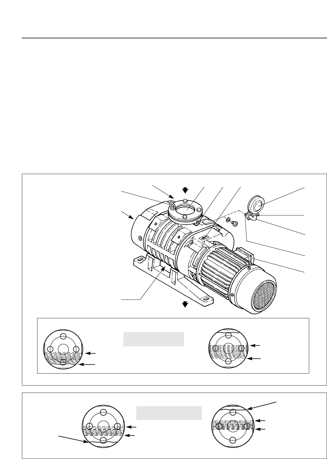
Fig. 8 Connections and controls; arrows = direction of flow
1
2
4 5 6 7 8
9
10
11
12
3
min.
max.
Oil level in the oil glass
- with PFPE
min.
max.
Pumping action of the vacuum pump
vertical horizontal
Oil level in the oil glass
- with N 62 and Anderol
Oil level with
the pump at
standstill
Oil level with
the pump at
standstill
3.2 Filling in of the Lubricants
The lubricant needed for running the pump is supplied in
a separate container.
Unscrew the oil-fill plug (11/3) and add lubricant.
An oil without additives and of viscosity class ISO VG
100 (formerly SAE 30) must be used for the pump. We
recommend the use of our special oils N 62, ANDEROL
555 or HE-200. As PFPE we recommend our NC 1/14 or
HE-1600. Please consult us if you intend to run the pump
with other oils or special lubricants.
With the pump at standstill, the correct oil level for a
pump with vertical pumping action is in the middle, in the
case of horizontal pumping action, 4 mm over the
middle of the oil level glass (8/2), see also Fig. 9.
Key to Fig. 8
1 Discharge flange
2 Oil-level glass
3Eye
4 Oil-fill port
5 Intake flange
6 Connection for pressure switch
7 Direction-of-rotation arrow
8 Pressure switch
9 Centering and clamping ring
10 Right-angle bend
11 Adapter
12 Junction box
Approximate
oil level during
operation
Oil level with
the pump at
standstill
Installation and connection
14 GA 03.108/14.02 - 01/03
3.3 Electrical Connections
Disconnect the mains before doing work on
the wiring.
The electrical connections must only be
provided by a trained electrician in accor-
dance with the regulations of the IEC 64
international series of standards.
For proper connection, a suitable motor pro-
tection switch must be used. Set the switch
in accordance with the rating on the motor
nameplate.
The pumps of the RUVAC WS/WSU series
may also be operated by a frequency con-
verter. For maximum speeds, refer to Sec-
tion 1.3.
Please note, that at increased speeds and
at the available maximum power, the max.
permissible pressure difference (see Sec-
tion 1.3) is no longer obtained.
Especially when operating the pump using
a frequency converter you must ensure by
means of a separate mains connection for
the fan’s motor that is connected to the right
supply voltage and frequency. Otherwise
the fan will be damaged.
Always provide an uninterrupted connection
for the protective ground conductor
connecting it in a professional manner.
Never leave the protective ground conduc-
tor for the pump unconnected.
Connect the pump to the correct mains vol-
tage through the terminals provided in the
junction box (see Fig. 10).
Do not link control circuits to the power cir-
cuit of the motor. Observe the wiring dia-
grams of Fig. 10.
When connecting the motor you must also
connect the thermal switch of the pump
motor and the fan motor (for recommenda-
tions, see Fig. 10).
Only the PG fittings provided on the junction
box may be used.
After connecting the motor and every time
you alter the wiring, check the direction of
rotation.
Never allow the pump to run in the wrong
direction or with open flanges for a longer
period of time.
An arrow (8/7) on the motor flange shows the correct
direction of rotation for the impeller connected to the
motor shaft. To check rotation, switch on the motor brief-
ly and observe the direction of impeller rotation through
the pump’s intake and then immediately switch off again.
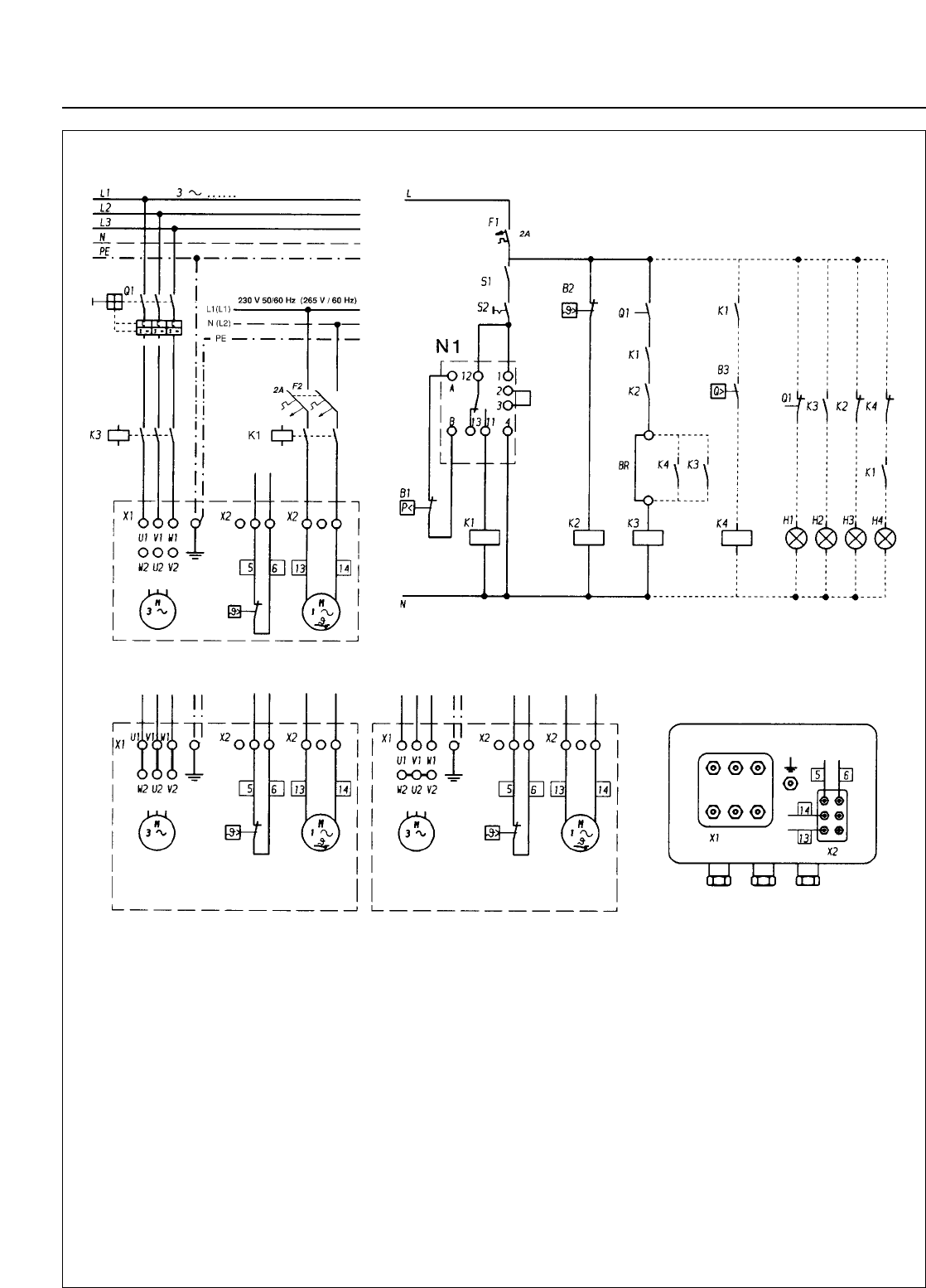
Wear protective goggles for protection
against particles which may be forced out of
the flange opening. Keep your hands away
from the flange opening.
The impellers should move up from the center and drop
down to the side.
If this is not the case, disconnect the pump from the
mains and interchange two mains phases.
Even if the pump has been already firmly connected to
the piping, you may determine the direction of rotation.
For this, evacuate the vacuum system down to a pressu-
re below 20 mbar with the aid of the backing pump.Then
switch on the RUVAC briefly; now the pressure must
drop. If the pressure increases or remains constant, the
RUVAC is turning in the wrong direction.
Then rewire as described above.
The built-in fan is driven by a separate
single-phase motor and may thus not be
used to determine the direction of rotation
of the pump.
Its direction of rotation is independent of the
pump and doesn’t change when you inter-
change the phases.
Connecting the fan to the terminals for the
motor is not allowed.
The fan should be connected via a separa-
te cable to 230 V, 50/60 Hz or 265 V/60 Hz.
A voltage of 265 V/60 Hz must not be
exceeded. In a case of deviating voltages
an appropriate transformer must be used.
In no single phase 230 V/50 Hz or 265 V/60 Hz mains
power is available, the motor of the fan may be connec-
ted between two live conductors. A wiring diagram is pro-
vided in the junction box of the motor.
The RUVAC can be automatically switched on and off via
a contactor using a pressure switch and the contact
amplifier SV 110 (see Section 1.4).
Warning
Caution
Warning
Caution
Warning
Caution
Installation and connection
15
GA 03.108/14.02 - 01/03
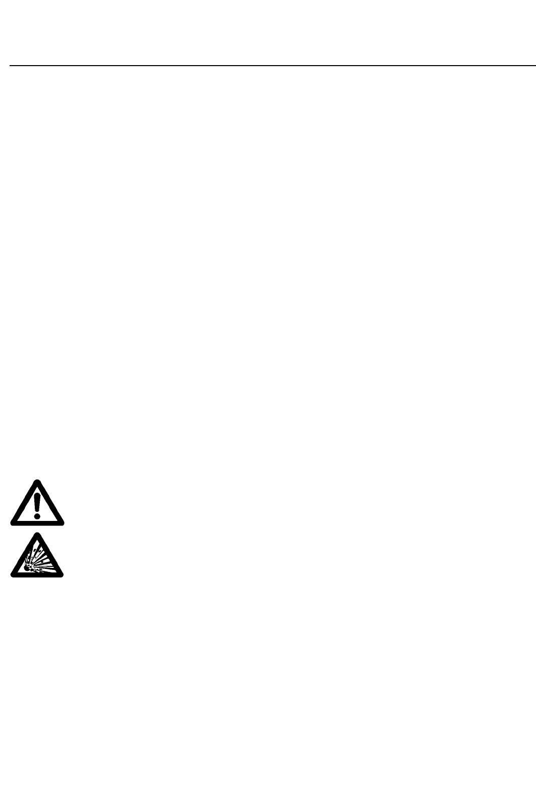
Fig. 10 Electrical connection
Key to Fig. 10
B1 Pressure switch PS 115
B2 Limit switch, coil temperature
B3 Flow monitor (fan)
K1 Relay for fan motor
K2 Relay for temperature monitor, pump’s motor
K3 Relay for Roots pump motor
K4 Relay for fan monitor
N1 Contact amplifier SV 110 (220 V - 240 V,
50/60 Hz, 110 - 130 V, 50/60 Hz)
S1 External switch contact
S2 Switch contact
F1 Fuse, control circuit
Q1 Motor protection switch
Signal lamps
H1 Motor protection switch: OFF
H2 Roots pump: ON
H3 Coil temperature: TOO HIGH
H4 Cooling air: BELOW MINIMUM
Links
BR on extension : - - remove link
Note
The above control circuit is designed so that the
Roots pump cuts in only if the pressure drops below
the set pressure level (B1).
Various connection options for different mains power supplies.
Motor junction box
3 x 230 V 50 Hz
3 x 265 V 60 Hz 3 x 400 V 50 Hz
3 x 460 V 60 Hz
Caution: for Cat.-No. 150 44 - 230V/50/60 Hz Caution: for Cat.-No. 150 44 - 400V/50/60 Hz
Installation and connection
16 GA 03.108/14.02 - 01/03
The threshold of pressure switch PS 115 is freely
adjustable.
The contact amplifier is identical for all pressure
switches.
Pressure switches and contact amplifiers with explosion
hazard protection are available upon request.
After removing a screw plug, the pressure switch (8/8)
together with an adapter (8/11) and a right-angle bend
(8/10) can be mounted on the bore (8/6).
When doing so, ensure proper sealing and air-tight
installation.
It is advisable to mount the switch vertically to reduce the
entry of contaminants.
3.4 Connection of the
Flanges
Already small quantities of liquids (from the
vacuum chamber or the piping) can lead to
liquid damages within the pump. These may
lead to a deformation of the impellers and
may entirely destroy the pump. Suitable pro-
tective measures should be provided as
required in the piping on the suction side
(separator, T-piece).
The RUVAC WS/WSU pumps have not
been designed to pump ignitable or explosi-
ve mixtures without additional protection.
If the pumps are none-the-less to be used
under such conditions, the customer hims-
elf must ensure that proper measures for
the purpose of protection against explosi-
ons (pressure monitor, flame arresters etc.)
are introduced in line with the requirements
of the applicable laws.
Explosion protected canned motors (tem-
perature class T 3 or T 4) are not available.
Consult us for advice.
The RUVAC WS pumps is vented with nitro-
gen. Only remove the packing flanges befo-
re immediate connection.
If not already done, remove the protective shipping
covers, cardboard pieces, foil or packing flanges from the
flanges (8/5) and (8/1).
We recommend that you retain the transport flanges of
the WS PFPE in case you want to store the pump at a
later date.
Clean the flanges and check that the sealing surfaces
are in perfect condition.
Flange the pump to the vacuum system.
Don’t place any stress on the pump casing
when installing the intake and exhaust lines.
Fit compensation elements in order to avoid
such stresses.
When attaching the pump directly (without
bolting down the feet) to the forevacuum
pump, you must always use on the pressu-
re side the full number of screws defined by
the flange standard (ISO-K, DIN or ASME)
whereby these must comply with the
demanded property class rating.
You must also check whether the backing
pump is rigid and stable enough to support
the load of the RUVAC pump in each case.
The dirt-trap which is supplied with the pump should
always be fitted into the intake flange when there is the
possibility of contaminants entering the pump coming
from the vacuum chamber or the piping. Even with clean
vacuum processes, contaminants from the system may
enter upon initial start-up. Depending on the operating
conditions, the dirt trap may reduce the pumping speed
of the pump.
Observe the maintenance information provided in Sec-
tion 5.1.
Caution
Warning
Caution
Caution
Operation
17
GA 03.108/14.02 - 01/03
4.1 Start-up
Check the pump motor’s direction of rotation (see Sec-
tion 3.3).
RUVAC WSU
The RUVAC WSU can be started together with the
backing pump at atmospheric pressure.
It is protected against excessively high pressure diffe-
rentials by a bypass line.
RUVAC WS
Do not switch on the RUVAC WS until the backing pump
has evacuated the vacuum vessel to the cut-in pressure.
For processes in which condensable vapours are pum-
ped, it is advisable to evacuate the vacuum vessel via a
roughing line to the cut-in pressure. Electrically switch on
the Roots pump together with the backing pump and cut
it in upon reaching the cut-in pressure. The initial bypas-
sing of the Roots pump serves to prevent condensation
of vapours in the cold pump.
The permissible cut-in pressure depends on the ratio
between the Roots pump and the backing pump. It can
be calculated according to the following formula:
pmax
pE= ———
kth - 1
pE= Cut-in pressure
pmax = Maximum permissible pressure differential
(see technical data)
kth = Theoretical compression ratio
= nominal pumping speed of Roots pump /
pumping speed of backing pump.
Example:
Pump combination:
RUVAC WS 501 / SOGEVAC SV 100
505 m3· h-1
kth = ————— ~5
100 m3· h-1
80 mbar
pE= ———— = 20 mbar
5 - 1
With small vacuum vessels, the maximum permissible
pressure differential can be briefly exceeded (max. 3
min) upon start-up. If a pressure switch has been instal-
led, do not set it to this higher pressure because it will fail
to protect the pump against overload in the event of a
greater gas quantity.
It is advisable to switch the RUVAC WS on and off via a
pressure switch to ensure that it runs only in the permis-
sible pressure range.
4.2 Operation
Do not operate the pump without having
connected the flanges to a vacuum system.
The screws of the flanges on the suction
and the pressure side must not be loosened
in the presence of a vacuum or while the
pump is still running.
During operation of the RUVAC, check the lubricant level
from time to time and also the condition of the lubricant.
Correct as required (see Section 5/2). Normally, the oil N
62 or HE-200 is light-brown. If it turns dark, this is a sign
of early ageing due to excessively high temperatures.
When using PFPE as intended, PFPE will not be subject
to ageing.
Run the Roots pump exclusively under the
operating conditions for which it has been
designed. Any modification of the operating
parameters (e. g. intake pressure, intake
temperature, ratio between Roots pump
and backing pump) for a longer period may
place an inadmissible thermal load on the
pump. Increases in temperature which are
not compensated by taking suitable measu-
res may damage the Roots pump and/or
the backing pump.
During normal operation temperatures
exceeding 80 °C may occur at the oil cham-
bers and at the line on the pressure side.
When touching these there is the danger of
receiving burns.
Note the labels on the pump.
Never open the oil-fill or oil-drain screw (Fig.
11) in the presence of a vacuum or while
the pump is running. There is the
danger that oil may squirt out.
4 Operation
Warning
Caution
Warning
Operation
18 GA 03.108/14.02 - 01/03
4.3 Shutdown and Storage
We recommend to keep the RUVAC WS
with a PFPE filling running even during pro-
longed intervals (e. g. over night) with the
intake line closed. This can help to avoid
corrosion during standstill.
Close the valve between the Roots pump and the vacu-
um system. First switch off the Roots
pump, then the backing pump.
After working with corrosive gases, the system should be
vented with dry protective gas (e.g. N2) to prevent corro-
sion during standstill.
When shutting down the pump and removing it from the
system, it is advisable to seal the connecting flanges
tightly.
Before removing pump from the vacuum
system, disconnect it from the mains supp-
ly.
Before removing the RUVAC WS PFPE from the system
it must be purged with nitrogen and sealed in a gas-tight
manner.
For transportation and storing of the pump, observe the
information provided in Section 2.
4.4 Changing from Vertical
to Horizontal Flow
The RUVAC WS/WSUs are supplied as standard for ver-
tical flow unless you specifically request horizontal flow.
Moreover, the pump may be converted from one flow
direction to the other.
For this proceed as follows:
Drain the lubricant (11/2) or (11/4) and tightly screw the
oil-drain plug back in. Remove the feet, turn the pump by
90° as shown in Fig. 5 (dimensional drawing) and mount
the feet for the new direction of flow.
The longitudinal axis of the pump must
remain horizontal so that no residual lubri-
cant can flow from the side chambers into
the pumping chamber.
Fill in lubricant (11/3); (see Section 3.2).
If a pressure switch has been installed, turn it so that it
again points vertically upwards.
The valve in the pressure balance line of the RUVAC
WSU is designed to work with both vertical and horizon-
tal flow of the pump.
Caution
Warning
Caution
Fig. 11 Changing the lubricant
Key to Fig. 11
1 Oil-level glass
2 Oil-drain plug for vertical flow
3 Oil-fill plug
4 Magnetic oil-drain plug for horizontal flow
1
23
4
Maintenance
19
GA 03.108/14.02 - 01/03
5 Maintenance
5.1 Safety Information
The safety information given in the following applies to all
maintenance work.
Disconnect the electrical power before
disassembling the pump. Make absolutely
sure that the pump cannot be accidentally
started.
If the pump has been pumping harmful sub-
stances, determine the nature of hazard
and introduce suitable safety measures.
Observe all safety regulations !
If you send a pump to LEYBOLD for repair
please indicate any harmful substances exi-
sting in or around the pump. For this use the
„Declaration of Contamination“ form which
has been prepared by us and which we will
provide upon request.
Any pump received by us without, or an
incompletely filled in declaration will delay
the repair.
When shipping contaminated pumps which
require approval by the authorities, you
must observe the applicable packaging and
shipping regulations.
All maintenance and cleaning work descri-
bed in this section must be carried out only
by suitably trained personnel.
When disposing of used lubricants please
observe the relevant environmental regula-
tions.
Improper maintenance or repairs may affect
the service life and performance of the
pump, and cause problems when filing war-
ranty claims.
Advanced repair work not described here
should be left to the LEYBOLD service.
We would like to point out that LEYBOLD offers training
courses on the maintenance, repair, and troubleshooting
of RUVAC pumps. Further details are available on
request.
5.2 Exchanging the
Lubricant
Before pumping oxygen (or other highly
reactive gases) at concentrations excee-
ding the concentration in the atmosphere
(> 21 % for oxygen) it will be necessary to
use a special pump. Such a pump will have
to be modified and de-greased, and an inert
special lubricant (like PFPE) must be used.
Observe all safety information provided in
Section 5.1.
Very little lubricant is consumed by wear in the bearings
and the gear under clean operating conditions. We
recommend changing the oil or PFPE after the first 500
hours of operation to remove any wearing residue.
Then, under normal operating conditions, change the oil
after every 3,000 hours of operation.
Change the oil more frequently when pumping corrosive
vapours or large amounts of dust or when cycling fre-
quently from atmospheric to working pressure.
Under such operating conditions it is recommended to
regularly check the neutralisation value (to DIN 51 558)
based on a sample of oil. If the neutralisation value
exceeds 2, an oil exchange will be required.
Before removing the oil-drain or oil-fill plug
always switch off the pump first and vent to
atmospheric pressure.
When the pump has become warm during
operation the casing and the oil temperatu-
re may exceed 80 °C.
Leave the pump to cool down. Always wear
protective gloves also to protect yourself
against aggressive residues in the oil.
To simplify the process and also for safety
reasons we recommend the use of our oil-
drain facility (see Section 1.4).
Unscrew the oil-drain plugs (11/2) or (11/4) and the oil-
fill plug (11/3) and drain the oil.
Clean the sealing surface and firmly reinstall the oil-drain
plug (11/2) or (11/4) using a gasket which is in perfect
condition. Wipe off any oil residues from the casing.
Fill in new oil.
For oil quantities and ordering data see Sections 1.3 and
1.4.
Make sure to use the right kind of oil. PFPE pumps are
marked with a red label.
Only use Leybold oil.
Warning
Caution
Warning
Warning
Maintenance
20 GA 03.108/14.02 - 01/03
Mineral oils, synthetic oils and PFPE do not
mix.
Please consult us if you intend to run the pump with
other oils or special lubricants.
At vertical flow the correct oil level is in the center of the
oil-level glass when the pump is not running.
In the case of horizontal pumping action, the correct oil
level is 4 mm over the middle of the oil level glass (11/1),
see also Fig. 9.
If the oil level is too low, the bearings and
gearwheels are not lubricated adequately; if
it is too high, oil may enter the pumping
chamber.
Clean the oil-fill port and reinstall the plug (11/3) using a
gasket which is in perfect condition. Wipe off any oil resi-
dues from the casing.
The oil-fill port must be sealed air-tight. In
the presence of a vacuum, the entry of air
may cause oil-containing gas to enter the
pumping chamber via the impeller seals.
When using PFPE as intended, PFPE is not subject to
ageing. It must only be changed if it is contaminated by
the process gas. It can only be determined for each indi-
vidual case when the PFPE is so contaminated that it
must be changed. To be sure, we recommend changing
the PFPE once a year.
Please also take note of the Operating Instructions
„PFPE for Vacuum Pumps“ included with the pump.
For recycling contaminated PFPE we ask you to consult
us. As PFPE we recommend our NC 1/14 or the
HE-1600.
5.3 Cleaning the Fan Cowl
and the Cooling Fins
Observe all safety information provided in
Section 5.1.
The slits in the fan cowl as well as the fins on the motor
and on the pump may be contaminated depending on
humidity conditions and the degree of contamination in
the ambient air.
In order to ensure a sufficient air flow for the motor and
the pump’s casing, the grid of the fan cowl must be clea-
ned with a clean brush when contaminated.
Any coarse dirt must be removed from the fins on the
motor and the pump.
5.4 Cleaning the Dirt Trap
Observe all safety information provided in
Section 5.1.
A wire-mesh sieve is located in the intake port to collect
foreign objects. It should be kept clean in order to avoid
a reduction of the pumping speed.
To do so, take off the intake line. Remove the dirt trap
from the intake flange and rinse it using a suitable sol-
vent. Then thoroughly dry it with compressed air. If the
dirt trap is damaged, replace it.
Caution
Caution
Caution
Warning
Warning
Maintenance
21
GA 03.108/14.02 - 01/03
5.5 Cleaning the Pumping
Chamber
Observe all safety information provided in
Section 5.1.
Under dirty operating conditions, contaminants may be
deposited in the pumping chamber or on the impellers.
After removing the two connecting lines, the contami-
nants can be blown out with dry compressed air or flus-
hed out with a suitable solvent.
Contaminants that cannot be blown or flushed out, can
be removed completely from the pumping chamber with
a wire brush, metallic sponge or scraper.
Then change the lubricant.
During cleaning, the blower must be turned
only by hand.
The loosened deposits must not remain in
the pump. After cleaning, check the pump
by slowly turning the impellers by hand.
They should move freely and without any
resistance.
Generally, the Roots pump does not need to
be disassembled. If necessary, this should
only be done by our after-sales service.
5.6 Cleaning the Valve of the
Pressure Balance Line
Observe all safety information provided in
Section 5.1.
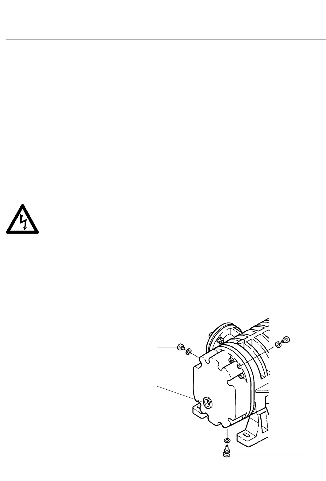
Remove the screws and take off the cover (12/1) with
O-ring (12/2).
Take out the spring (12/4).
Remove the valve disk (12/6) with O-rings (12/5) and
(12/7).
If the bushing (12/3) is damaged, pull it out of the valve
disk and replace it.
Clean all parts or replace them if necessary. Reassem-
ble in the reverse sequence. When doing so, check the
O-rings for leak-tightness and replace if found faulty.
Warning
Caution
Warning
Warning
1
2
3
4
5
6
7
Fig. 12 Valve of the pressure balance line
Key to Fig. 12
1Cover
2 O-ring
3 Bushing
4 Spring
5 O-ring
6 Valve disc
7 O-ring

Maintenance
22 GA 03.108/14.02 - 01/03
5.7 Leybold Service
If a pump is returned to LEYBOLD, indicate whether the
pump free of substances damaging to health or whether
it is contaminated.
If it is contaminated also indicate the nature of the
hazard. For this you must use a form which has been
prepared by us which we will provide upon request.
A copy of this form is reproduced at the end of these
Operating Instructions: „Declaration of Contamination of
Vacuum Instruments and Components“.
Please attach this form to the pump or enclose it with the
pump.
This „Declaration of Contamination“ is required to meet
German Law and to protect our personnel.
LEYBOLD must return any pumps without a „Declaration
of Contamination“ to the sender’s address.
The pump must be packed in such a way,
that it will not be damaged during shipping
and so that any contaminants are not relea-
sed from the package.
Warning

Troubleshooting
23
GA 03.108/14.02 - 01/03
6 Troubleshooting
Fault Possible cause Remedy Repair*
Pump does not
start.
Pump gets too hot.
Motor is connected incorrectly.
Thermal switch or motor stator is malfunctioning.
Pressure switch is malfunctioning.
Lubricant is too viscous.
Motor rotor is malfunctioning.
Pump has seized up: damaged impellers, bearings
or gearwheels.
Connect the motor correctly.
Leybold service.
Replace the pressure switch.
Change the lubricant or
warm the lubricant and the pump.
Leybold Service
Leybold Service
3.3
-
3.3
5.2
-
-
Ambient temperature is too high or cooling air
supply is restricted.
Pump is working in the wrong pressure range.
Pressure differential is too great.
Gas temperature is too high.
Clearance between casing and impellers is too
small due to:
- contamination
- distortion of pump.
Excessive frictional resistance due to contaminated
bearings and/or lubricant.
Lubricant level is too high.
Lubricant level is too low.
Wrong lubricant has been used.
Bearings are malfunctioning.
Fan incorrectly or not connected
Fan faulty
Valve of pressure balance line does not open.
Install the pump at a suitable site or ensure
enough cooling air.
Check pressure values of vacuum system.
Check pressure values of vacuum system.
Check the vacuum system.
Clean the pumping chamber.
Ensure that the feet and connecting lines
aren’t placing a strain on the pump.
Drain some lubricant to reach the correct level.
Add lubricant to reach the correct level.
Drain lubricant and fill in correct lubricant.
Leybold service
Connect the fan correctly
Leybold service
Clean or repair the valve.
3.1/5.3
-
-
-
5.5
3.1/3.4
5.2
5.2
5.2
-
3.3
-
5.6
Power consumption
of the motor is too
high.
See fault „Pump gets too hot“.
Wrong mains voltage supply for the motor.
Motor stator is malfunctioning.
Motor rotor is malfunctioning.
See fault „Pump gets too hot“.
Connect the motor to the correct voltage supply.
Leybold service
Leybold service
-
1.3/3.3
-
-
Pump loses lubri-
cant. Lubricant leak is visible:
Oil-drain plug is not tight.
Oil-level glass is not tight.
Gearbox is not tight.
Oil puddle under the motor, leaky can
No lubricant leak is visible:
See fault „Lubricant in the pumping chamber“.
Drain lubricant, firmly screw in the oil-drain plug
with a new gasket, fill in the correct quantity.
Leybold service
Replace the O-ring of the gearbox cover.
Leybold service, switch off the pump immediately.
See fault „Lubricant in the pumping chamber“.
Lubricant in the
pumping chamber. Lubricant level is too high.
Lubricant leaks out of the system.
Pump is not installed on a flat horizontal surface.
Pump has an external leak.
Pump has an internal leak.
Impeller rings are malfunctioning.
Drain lubricant to reach the correct oil level.
Check system.
Install pump correctly.
Check proper fit of oil-fill and oil-drain plugs,
replace gaskets if necessary.
Replace O-ring of the gearbox cover.
Leybold service
Leybold service
5.2
-
3.1
5.2
-
-
-
5.2
-
-
-
-
Pumping speed of
the pump is too low. Dirt trap in the intake flange is clogged.
Motor is connected incorrectly.
Motor stator is malfunctioning.
Motor rotor is malfunctioning.
Pump or pump system has a leak.
Clearance of impellers is too large.
Bearing is malfunctioning.
Valve of the pressure balance line does not close.
Clean the dirt trap.
Connect the motor correctly.
Leybold service
Leybold service
Find and seal the leak.
Leybold service
Leybold service
Clean or repair the valve.
5.4
3.3
-
-
-
-
-
5.6
Pump is too noise. Clearance between casing and impellers is too
small due to :
- contamination
- distortion of the pump.
Bearing or gearing is damaged.
Impellers strike the casing.
Motor rotor runs out of true.
Centrifugal disc lubricator strikes gear lid
or oil tube.
Oil pump obstructed or malfunctioning.
Clean the pumping chamber.
Ensure that the feet and connecting lines aren’t placing a strain
on the pump.
Leybold service, switch off the pump immediately.
Leybold service, switch off the pump immediately.
Leybold service, switch off the pump immediately.
Leybold service
Leybold service, switch off the pump immediately.
5.5
3.1/3.4
-
-
-
-
-
-
Oil turns dark. Oil has broken down.
Pump gets too hot. Change the oil.
See fault „Pump gets too hot“; after solving the
problem, change the oil.
5.2
-
* for repair information, refer to the stated section in the Operating Instructions

GA 03.108/14.02 - 01/03
We - LEYBOLD Vacuum GmbH - herewith declare that
the products defined below meet the basic requirements
regarding safety and health of the relevant EEC direc-
tives by design, type and the versions which are brought
in to circulation by us.
In case of any products changes made without our
approval, this declaration will be void.
Designation of the products: Roots pump
Types: RUVAC WS 251 - 2001
RUVAC WSU 251 - 2001 (H)
Catalogue numbers: 101 83
117 22; 117 23; 117 27; 117 28;
117 32; 117 33; 117 37; 117 38;
117 42; 117 43; 117 47;
117 52; 117 53; 117 57;
118 33; 118 43; 118 53;
150 44; 150 95; 150 96
167 007
917 48
155 000
EEC Declaration of Conformity
The products conform to the following directives:
• EC Directive on Machinery (98/37/EG)
• EC Directive on Low-Voltages (73/23)+(93/68/EWG)
• EC EMC Directive (89/336/EWG)
(91/263/EWG) + (92/31/EWG) + (93/68/EWG)
Applied harmonised standards:
• DIN EN 292 Part 1 11.91
• DIN EN 292 Part 2 06.95
• DIN EN 1012 Part 2 07.96
• DIN EN 60 204 Part 1 11.98
Applied national standards and technical
specifications:
• DIN 31 001 April 1983
• DIN ISO 1940 Dec. 1993
24
Cologne, October 30, 2002
—————————————————————
Hauck, BU Head SPS
Division Industrial
Cologne, October 30, 2002
—————————————————————
Dr. Beyer, Development Head SPS
Division Industrial
GA 03.108/14.02 - 01/03 25

GA 03.108/14.02 - 01/03
LEYBOLD VAKUUM GmbH
Bonner Strasse 498 (Bayenthal)
D-50968 Köln
Tel.: (0221) 347-0
Fax: (0221) 347-1250
http://www.leyboldvac.de
e-mail:documentation@leyboldvac.de
LV_xxxxx_2003 BICOM/OF 01.03
Printed in Germany on chlorine-free bleached paper
USA:
LEYBOLD VACUUM USA
5700 Mellon Road
Export, PA 15632
Phone: +1-724-327 57 00
Fax: +1-724-733 12 17
Internet: http://www.
leyboldvacuum.com
Canada:
LEYBOLD Canada Inc.
7050 Telford Way, Unit 5
Mississauga, Ontario
Canada L5S 1V7
Phone: +1-905-672 77 04
Fax: +1-905-672 22 49
e-mail:
reachus@leybold.on.ca
AMERICA EUROPE ASIA
Deutschland:
LEYBOLD VAKUUM
GmbH
Bonner Straße 498
D-50968 Köln
Phone: +49-221-347-1234
Fax: +49-221-347-12 45
Internet: www.leybold
va
c.
de
e-mail:
sales
@
leybold
vakuum.com
Belgien/Niederlande/
Luxemburg:
LEYBOLD N.V.
Leuvensesteenweg 542, 9A
B-1930
Zaventem
Phone: +32-2-71 10 083
Fax: +32-2-72 08 338
LEYBOLD B.V.
Computerweg 7
NL-3606 AV Maarssen
Phone: +31-346-583 999
Fax: +31-346-583 990
Frankreich:
LEYBOLD S.A.
7, Avenue du Quebec
Z.A. de Courtaboeuf, B.P. 42
F-91942
Courtaboeuf
Cedex
Phone: +33-1-69 82 48 00
Fax: +33-1-69 07 57 38
e-mail: leybold-vacuum@
leybold.fr
Groß-Britannien/Irland:
LEYBOLD LTD.
Waterside Way,
Plough Lane
GB-London SW 17 OHB
Phone: +44-208-97170 00
Fax: +44-208-97170 01
Italien:
LEYBOLD S.P.A.
Via Trasimeno 8
I-20128 Milano
Phone: +39-02-27 22 31
Fax: +39-02-27 20 96 41
Spanien:
LEYBOLD S.A.
C/. Mataró, 27
Polígono Industrial Les
Grases
E-08980 Sant Feliu de
Llobregat (Barcelona)
Phone: +34-93-666 46 16
Fax: +34-93-666 43 70
Schweden:
LEYBOLD AB
Box 9084
40092 Göteborg
Phone: +46-31-68 84 70
Fax: +46-31-68 39 39
Schweiz/
Liechtenstein:
LEYBOLD AG
Leutschenbachstraße 55
CH-8050 Zürich
Phone: +41-1-308 40 50
Fax: +41-1-302 43 73
Volksrepublik China:
LEYBOLD (Tianjin)
VACUUM EQUIPMENT
MANUFACTURING Co.,
Ltd.
Beichen Economic Develop-
ment Area (BEDA)
Tianjin 300400, China
Phone: +86-22 26 972 016
Fax: +86-22 26 972 017
e-mail:
leybold@public.tpt.tj.cn
Japan:
LEYBOLD Co., Ltd.
Head Office
Tobu A.K. Bldg. 4th Floor
23-3, Shin-Yokohama 3-
chome
Kohoku-ku,Yokohama-shi
Kanagawa ken 222-0033
Phone: +81-45-471 33 30
Fax: +81-45-471 33 23
Korea:
LEYBOLD Korea Ltd.
4th Fl. Shinan Bldg., 173-1
Jangchoog-dong 2ga,
Choong-ku
Seoul 100-392, Korea
C.P.O. Box 709
Phone: +82-2-227 11 567
Fax: +82-2-227 11 568
Singapore:
BALZERS and LEYBOLD
Singapore Pte. Ltd.
1 Tuas South Street 3
Singapore 638043
Phone: +65-865 18 65
Fax: +65-862 22 95
Taiwan:
LEYBOLD Taiwan, Ltd.
2 F, No 416-1, Sec. 3
Chung-Hsin Rd.
Chu Tung, Hsinchu.
Taiwan R.O.C: 310
Phone: +886-3-583 39 88
Fax: +886-3-583 39 99
Sales Net worldwide
