Dogtra E-FENCE3500 Electronic fence for dog using 10 kHz User Manual
Dogtra Co., Ltd. Electronic fence for dog using 10 kHz
UserManual.wiki
>
Dogtra
>
E FENCE3500 User Manual
User Manual
Navigation menu
Upload a User Manual
Namespaces
Wiki Guide
HTML
PDF
Info
Views
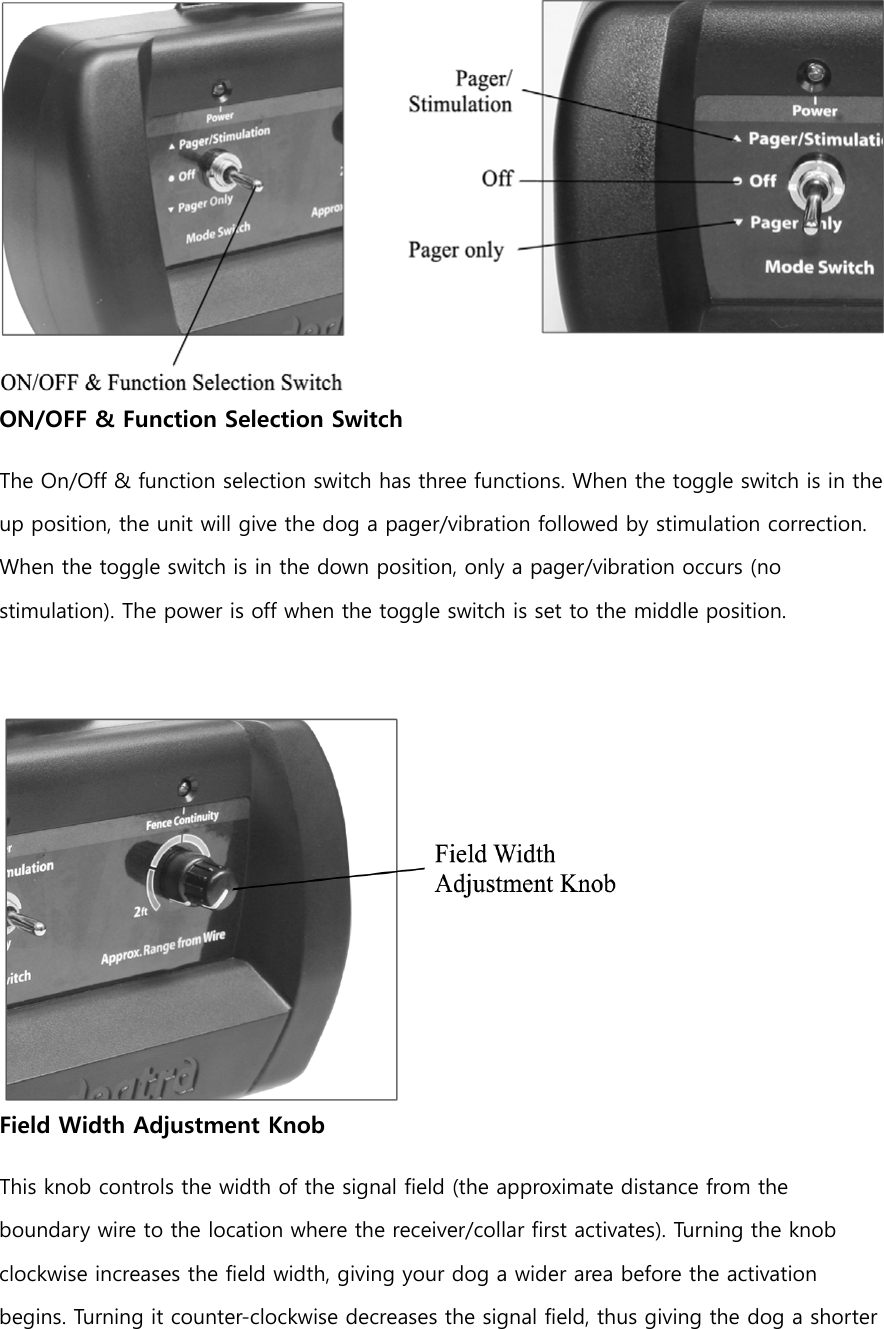
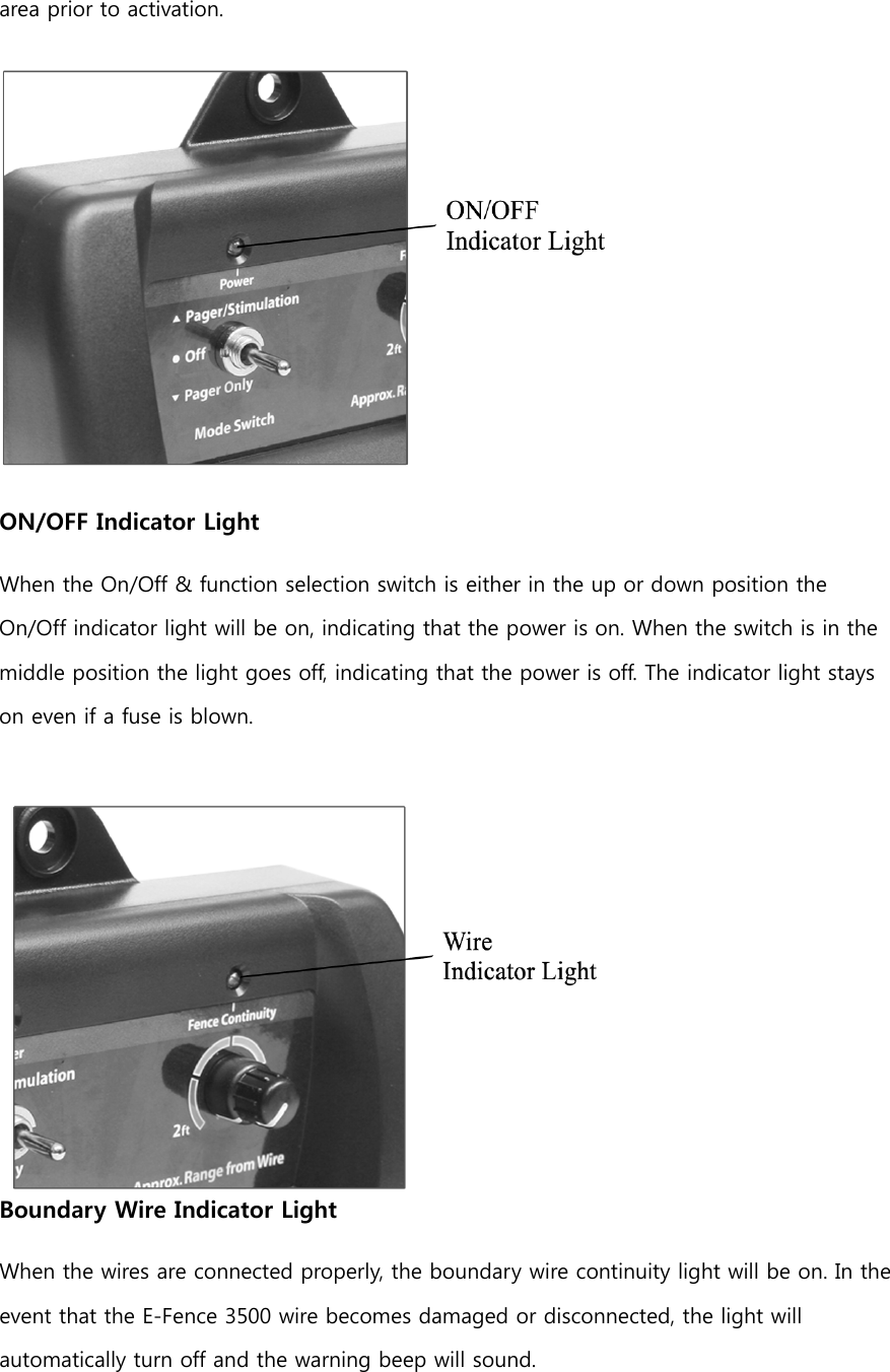
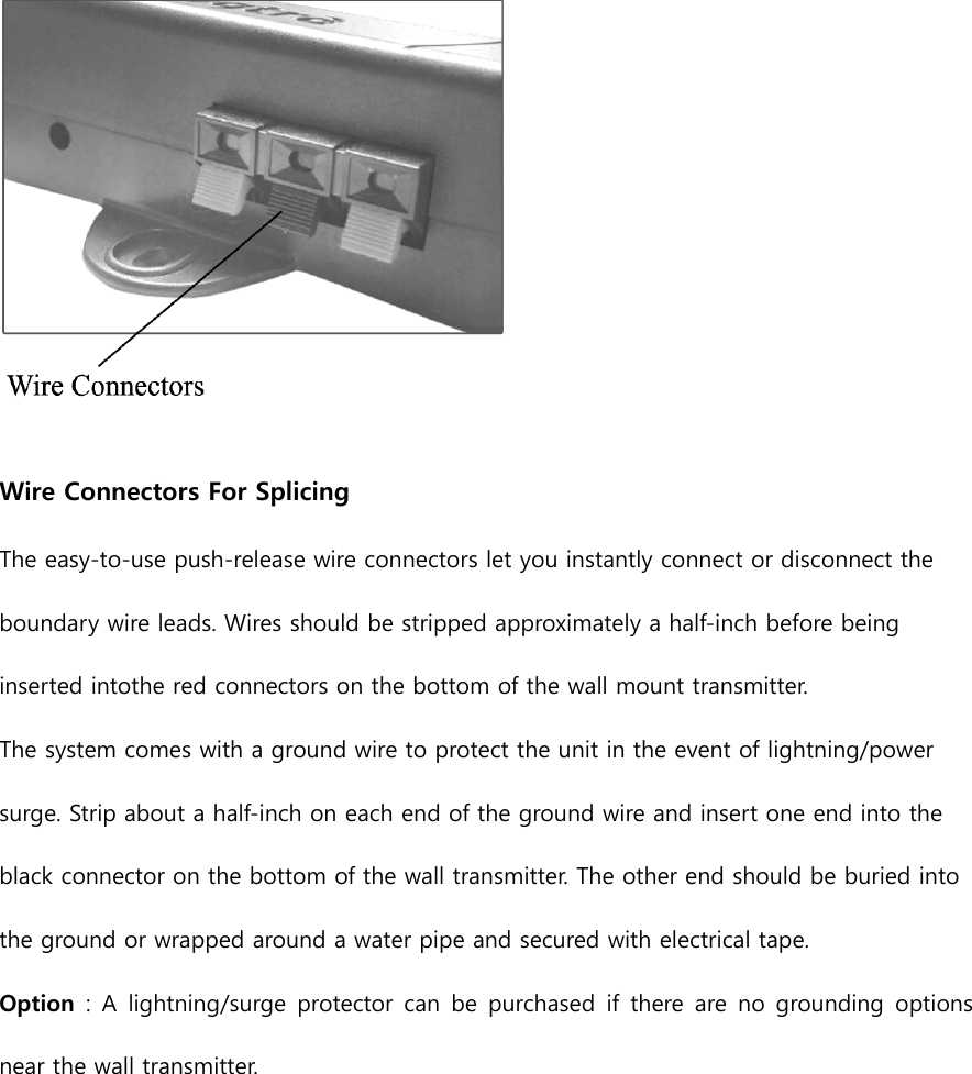
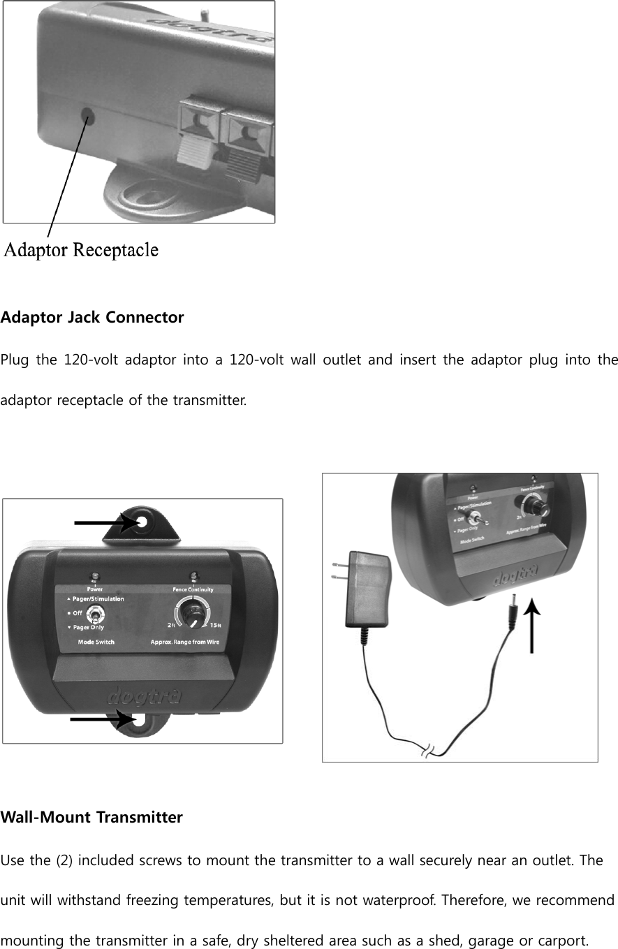
User Manual
Discussion / Help
Navigation