Dogtra E-FENCE3500 Electronic fence for dog using 10 kHz User Manual
Dogtra Co., Ltd. Electronic fence for dog using 10 kHz
Dogtra >
User Manual
E-Fence 3500
By Dogtra
Remote Controlled Dog Training Collars
CONTENTS
OVERVIEW
MAIN FEATURES
SAFETY FEATURES
PACKAGE CONTENTS
DESCRIPTION OF TRANSMITTER PARTS
DESCRIPTION OF COLLAR PARTS
CHARGING THE RECEIVER/COLLAR
How th Change the Length of the Contact Points
INSTALLATION
ADDITIONAL PARTS
WIRE SPLICING
OPTIONAL ACCESSORIES
TROUBLESHOOTING
GENERAL MAINTENANCE TIPS
WARRANTY AND REPAIR INFORMATION
OVERVIEW
The Dogtra E-Fence 3500 system gives you the ability to allow your dog the freedom he
wants within your specified boundaries. Dogtra’s containment system contains your dog without
the use of conventional fencing that can be chewed through, jumped over or dug under.
The width of the signal field can easily be adjusted at the wall-mount transmitter. The strength of the
electrical stimulation can be adjusted on each separate receiver with the intensity selection dial. In the
“Stimulation Only”mode, your dog will receive stimulation only. In the “Pager +
Stimulation”mode, your dog will receive a silent pager/vibration, followed by stimulation
when he approaches the boundary area. In the “Pager Only”mode, you dog will receive and
non-stimulating pager/vibration only.
Once your dog consistently avoids the signal boundary, the stainless steel contact points
can be replaced with the plastic training probes. With the plastic training probes, your dog
will be able to respond to the vibration warning without receiving any electrical stimulation.
Accessories for the system such as additional wire, flags, lightning/surge protector, and the
European 220-volt battery charger, are available by calling Dogtra Company at 1-888-811-
9111.
MAIN FEATURES
· Wide range of stimulation for all breeds and temperaments
· Fully waterproof receiver/collar
· 8 intensity levels on the receiver/collar to control individual dog stimulation needs
· Non-stimulating High Performance Pager vibration warning before stimulation
· High Performance Pager vibration only mode
· Wire breakage light with audible warning tone
· Long range signal with 40 acres maximum area coverage
· Advanced filtering system to prevent interference from outside sources
· Expandable to multiple dogs
· 2-hour rapid charge Lithium Polymer batteriesork up to 40 acres).
SAFETY FEATURES
· Dogtra’s E-Fence 3500 system collars use state-of-the-art
microcomputer technology. The receiver/collar has an automatic control that limits the
stimulation to eight seconds.
· Dogtra’s filtering system prevents accidental activation from outside sources other than
your transmitter.
PACKAGE CONTENTS
·Wall-Mount Transmitter
·Receiver/collar
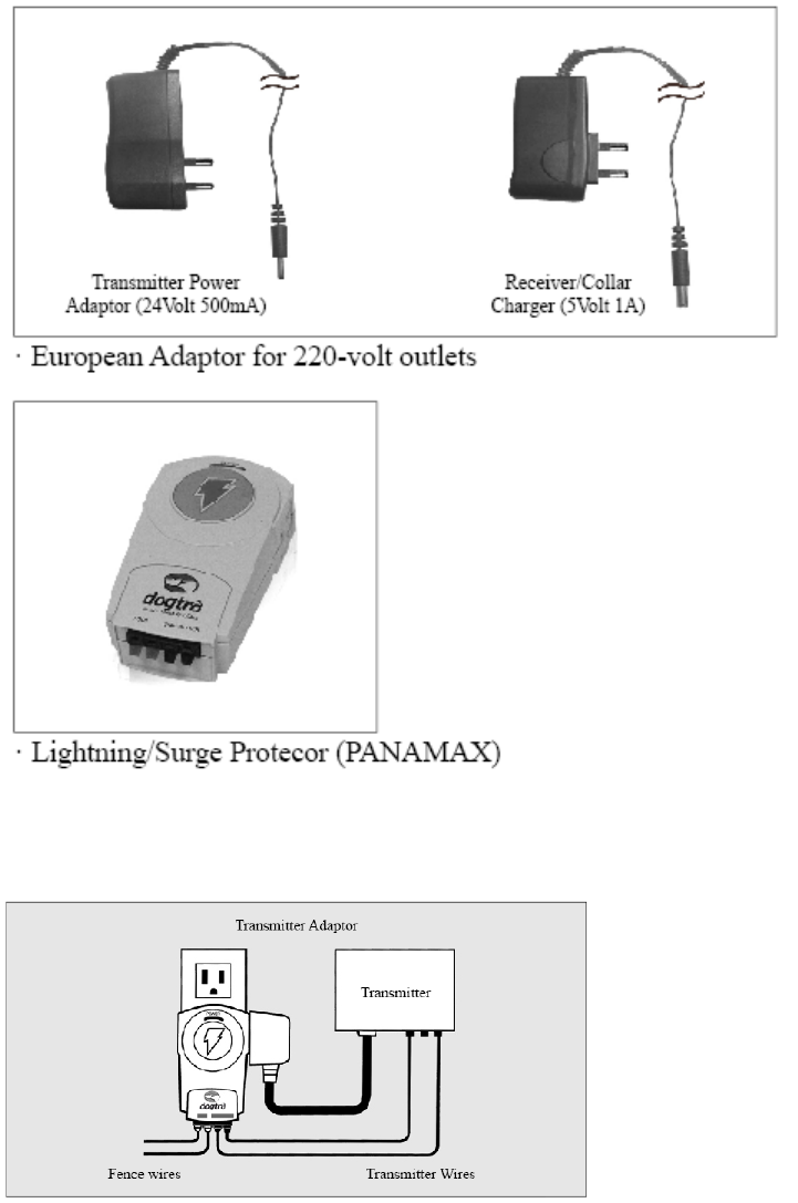
·Transmitter Power Adaptor (25-volt 500mA)
·Receiver/Collar Charger (5-volt 1A)
·Test Lamp
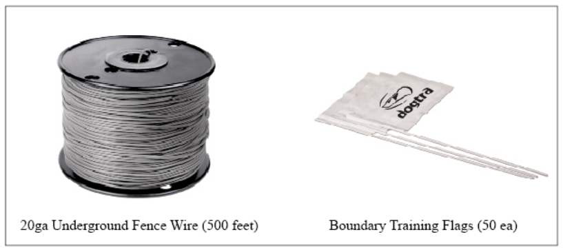
·Boundary Training Flags (50 ea.)
·20ga Underground Fence Wire (500 feet)
·Wire Splices (4 ea.)
·Ground Wire (green)
·Transmitter Mount Screws (2 ea.)
·Plastic Anchor (2 ea.)
·Enhanced Contact Points Male (2 ea.)
·Non-Stimulation Contact Points (2 ea.)

·Contact Point Extension Washer/Adjustment Tool(2 ea.)
·Owner’'s Manual
·Training Book
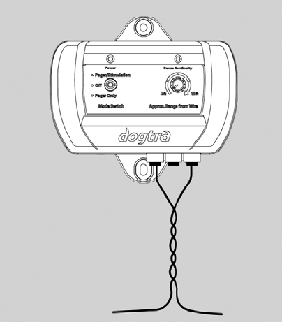
Description Of Transmitter Parts
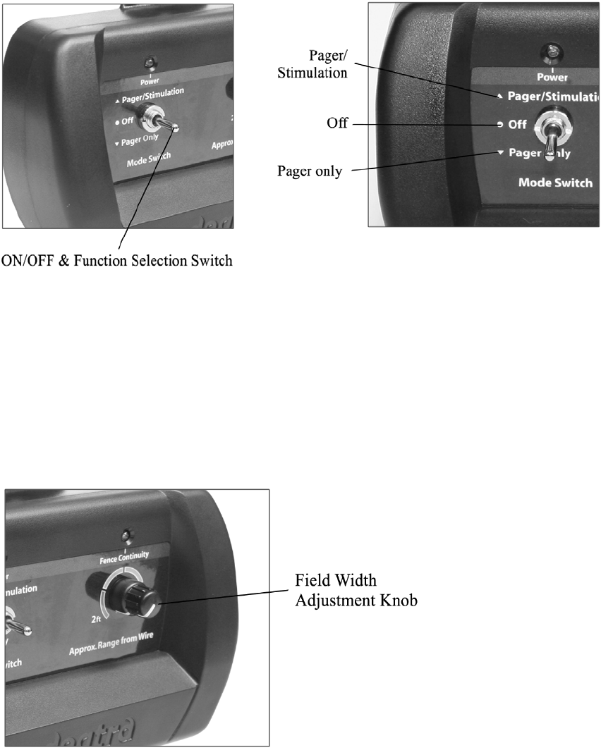
ON/OFF & Function Selection Switch
The On/Off & function selection switch has three functions. When the toggle switch is in the
up position, the unit will give the dog a pager/vibration followed by stimulation correction.
When the toggle switch is in the down position, only a pager/vibration occurs (no
stimulation). The power is off when the toggle switch is set to the middle position.
Field Width Adjustment Knob
This knob controls the width of the signal field (the approximate distance from the
boundary wire to the location where the receiver/collar first activates). Turning the knob
clockwise increases the field width, giving your dog a wider area before the activation
begins. Turning it counter-clockwise decreases the signal field, thus giving the dog a shorter
area prior to activation.
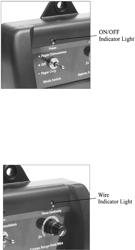
ON/OFF Indicator Light
When the On/Off & function selection switch is either in the up or down position the
On/Off indicator light will be on, indicating that the power is on. When the switch is in the
middle position the light goes off, indicating that the power is off. The indicator light stays
on even if a fuse is blown.
Boundary Wire Indicator Light
When the wires are connected properly, the boundary wire continuity light will be on. In the
event that the E-Fence 3500 wire becomes damaged or disconnected, the light will
automatically turn off and the warning beep will sound.
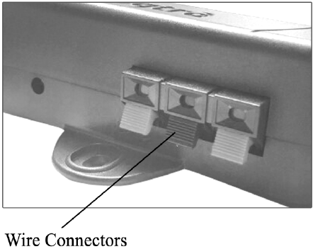
Wire Connectors For Splicing
The easy-to-use push-release wire connectors let you instantly connect or disconnect the
boundary wire leads. Wires should be stripped approximately a half-inch before being
inserted intothe red connectors on the bottom of the wall mount transmitter.
The system comes with a ground wire to protect the unit in the event of lightning/power
surge. Strip about a half-inch on each end of the ground wire and insert one end into the
black connector on the bottom of the wall transmitter. The other end should be buried into
the ground or wrapped around a water pipe and secured with electrical tape.
Option : A lightning/surge protector can be purchased if there are no grounding options
near the wall transmitter.
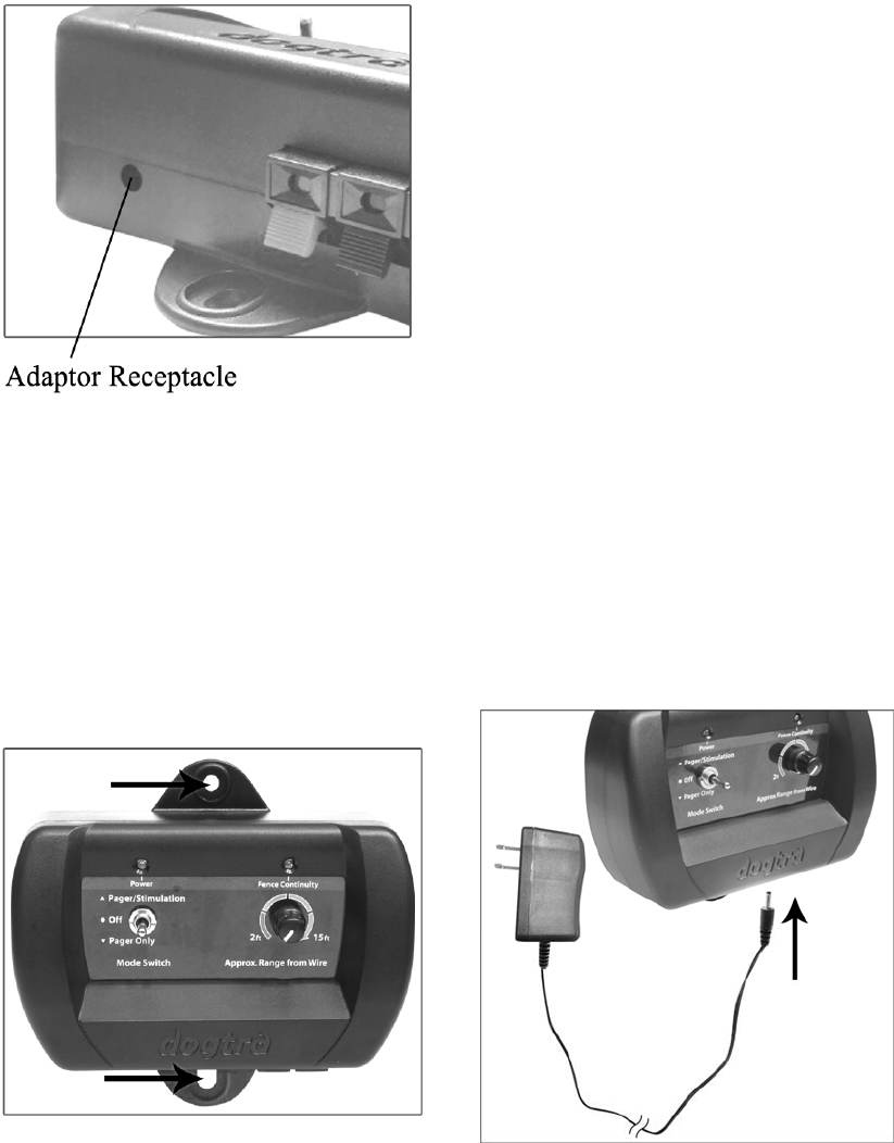
Adaptor Jack Connector
Plug the 120-volt adaptor into a 120-volt wall outlet and insert the adaptor plug into the
adaptor receptacle of the transmitter.
Wall-Mount Transmitter
Use the (2) included screws to mount the transmitter to a wall securely near an outlet. The
unit will withstand freezing temperatures, but it is not waterproof. Therefore, we recommend
mounting the transmitter in a safe, dry sheltered area such as a shed, garage or carport.
Plastic anchors have been provided to secure mounting onto drywall. Use a 1/4“drill bit to
make holes into the drywall. Insert the anchors into the holes so that the open end faces
out and mount the transmitter by inserting the screws into
the open end of the anchors.
To power the wall transmitter, plug the AC daptor into the standard 120-volt outlet and
connect it to the adaptor receptacle of the transmitter.
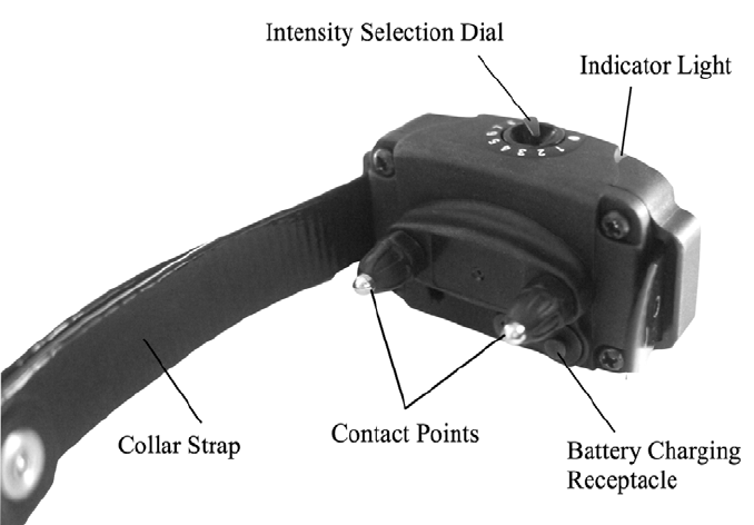
Description Of Reciver/Collar Parts

Intensity Selection Dial
The stimulation level is adjustable from each individual dog’s receiver/collar so that it is easy
accommodate each dog’s different personality and temperament.
The stimulation levels range from level 1 to level 8, level 1 being the lowest.
In order to select the proper intensity level for each dog, we recommend that you begin at
level 1 and continue to increase the level slowly until you are able to notice a reaction from
your dog. This ensures that you select a level that is appropriate for your dog.
When you place the knob at the OFF position, the collar is completely shut off. In order to
maintain full use of the batteries in the collar, please turn off the receiver/collar when your
E-Fence 3500 system is not being utilized.
Receiver Indicator Light (LED)
When first activating the E-Fence 3500, the LED light on the receiver/collar will illuminate for
approximately 1 second to indicate that the power is on. 2 seconds after the initial light, a
blink will occur every 2 seconds to indicate that the receiver/collar is functioning properly.
The color of the LED indicates the battery life of the receiver. When the collar does not
receive a signal from the transmitter for 10 seconds or more, the receiver/collar will go into
sleep mode, and the LED light will stop blinking.
(Green = full charge, Amber = medium charge, Red = needs charge)
When your dog gets close to the wire boundary, the indicator light will blink steadily to
indicate that the receiver/collar is being activated.
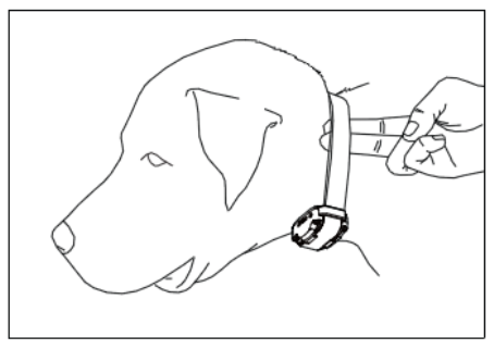
PROPER FIT
The collar should be fitted so that the surgical stainless steel contact points press firmly
against the dog’s skin. You should be able to fit a finger in between the contact point and
your dog’s skin. The best location is either side of the dog’s windpipe.
IMPROPER FIT
A loose fit can allow the collar to move around on the dog’s neck. When this happens, the
contact points may rub the skin and cause irritation. If the collar is too loose, electrical
contact will be inconsistent and your corrections will be inconsistent also.
Dogtra uses surgical stainless steel contact points and Anti-microbial plastic to protect the
dog’s skin.
ATTENTION!
Leaving the receiver/collar in the same location on the dog’s neck, for an extended period
of time can cause skin irritation. If the dog is to wear the e-collar for long periods,
occasionally reposition the collar so that the contact points are moved to a different
location on the dog’s neck. Make sure you check for skin irritation, each time you use the
unit.
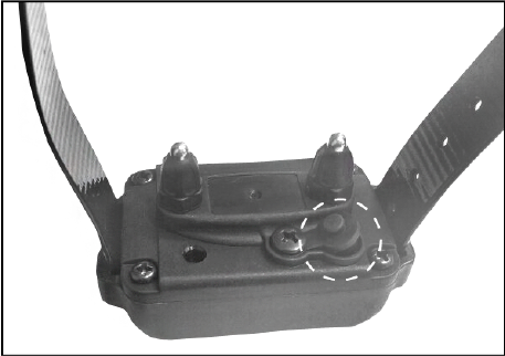
Receiver/collar Battery Charging Receptacle
On the inside of the receiver/collar, next to the collar strap, is a battery charging receptacle
with a rubber plug.
The unit will be fully waterproof with or without the rubber plug. If the dog was in salt-water,
be sure to rinse the receiver and charging port with clean water, and let air dry.
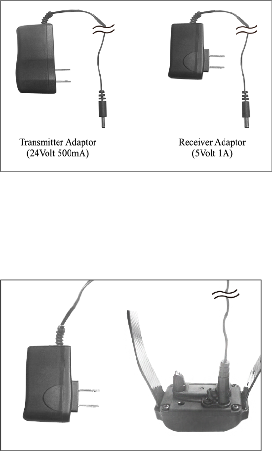
Adaptor
The battery charger is designed for a 120-volt wall outlet (An European 220-volt AC charger
is also available.).
CHARGING THE RECEIVER/COLLAR
Dogtra uses Lithium-Polymer batteries.
1. Charge the unit before using the unit for the first time.
2. Do not charge the batteries near any flammable substances.
3. Fully charge the batteries if the unit is to be stored without use for a period of 3
months or more.
Recharge the unit if :
- The LED indicator light on the receiver/collar is emitting a red color.
- The indicator light on the receiver will not come on.
- The indicator light on the receiver comes on momentarily, but will not stay on near
the wire.
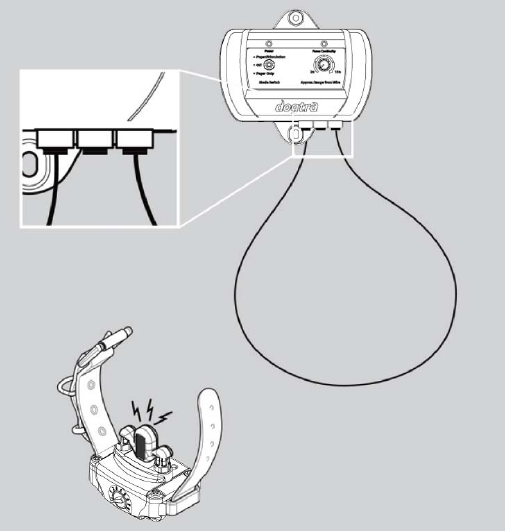
Battery Charging Procedure
1. Attach the charging cables to the receiver as shown.
2. Plug the charger into a 120-volt wall outlet.
When properly plugged in, all indicator lights should glow red.
During the charging process, the unit will shut off.
3. The Lithium-Polymer battery is fully charged within 2 hours. The lights will stay red during
the charging process. The red light will change into a steady green light when the battery is
fully charged. (When you disconnect the charger after finishing the charge, you will need to
restart the units).
4. After charging, cover the battery charging receptacle with the
rubber plug on the receiver/collar.
Note: Only use Dogtra-approved batteries, chargers, and
accessories for the E-Fence 3500. Unauthorized chargers
may cause the unit to malfunction and the indicator light to
blink in an amber color.
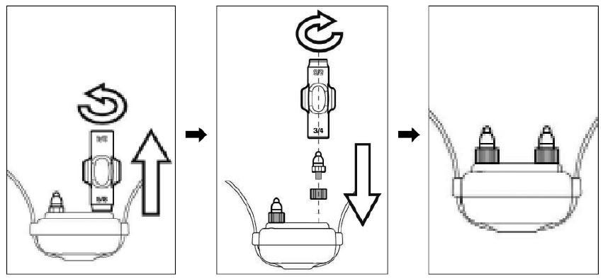
How th Change the Length of the Contact Points
The Dogtra E-Fence 3500 comes equipped with standard 5/8” contact points that can be
extended to 3/4” contact points, for use with dogs with longer coats.
To increase the contact point length from 5/8” to 3/4”, follow the steps below.
1. Using the included adjustment tool with the side marked 5/8”,
unscrew the contact points counter-clockwise.
2. Place the contact point extension over the exposed threads, flat side
down.
3. Place the contact points over the extensions and tighten the contact
points and extensions clockwise using the adjustment tool with the
side marked 3/4”.
* Caution : Tighten until firmly in place. Be careful not to over
tighten.
To shorten the contact points back to the standard 5/8”, start with the adjustment tool with the
side marked 3/4”, remove the contact point extensions, and tighten the contact points with the
adjustment tool with the side marked 5/8”.
TESTING YOUR DOGTRA E-Fence 3500 PRIOR TO
INSTALLATION
1. To ensure that your E-Fence 3500 system is working properly, connect the transmitter
adaptor into the adaptor of the transmitter and then plug the adaptor into a household
outlet. Switch the stimulation knob to Pager+Stimulation, or Stimulation Only. The ON/OFF
indicator light should turn on.
2. Unwind the length of ground wire that was provided and strip about 1/2 inch off each
end. Insert both ends of the ground wire into the outer, red wire connector jacks, leaving
the center jack free. If the wires are connected properly, the wire indicator light will be on.
3. Next, activate the receiver/collar by turning the intensity level dial on the receiver to the
desired level. The LED light will blink once every two seconds showing that it is on.
* If not activated for 10 seconds or more, the system will go into sleep mode.
4. Hold the receiver in your hand with the contact points facing up. Place the test lamp over
the contact points and approach the test loop.
5. Watch for the test lamp to come on and/or the unit will emit the warning vibration if the
unit is in this mode at the wall mount transmitter. Be careful not to touch the contact points
as the unit will emit stimulation when activated.
INSTALLATION
Fence Wire
The e-fence boundary wire must make a continuous loop around your property for the
system to operate. The signal is delivered from the terminal of the transmitter, through the
fence wire, back to the other terminal on the transmitter. When this is accomplished, the
wire continuity light will emit a constant red indicator.
Wire Placement
CAUTION - Before you install your E-Fence 3500 wire, contact the utility company to mark
the utility lines on your property before you begin digging. Be sure to test your wire
layout above ground before permanent installation begins.
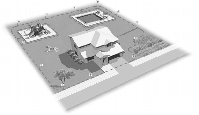
Carefully choose the areas in which you want to contain your dog. A diagram may be
helpful in predicting unforeseen obstacles. (Please refer to the Common Boundary Designs)
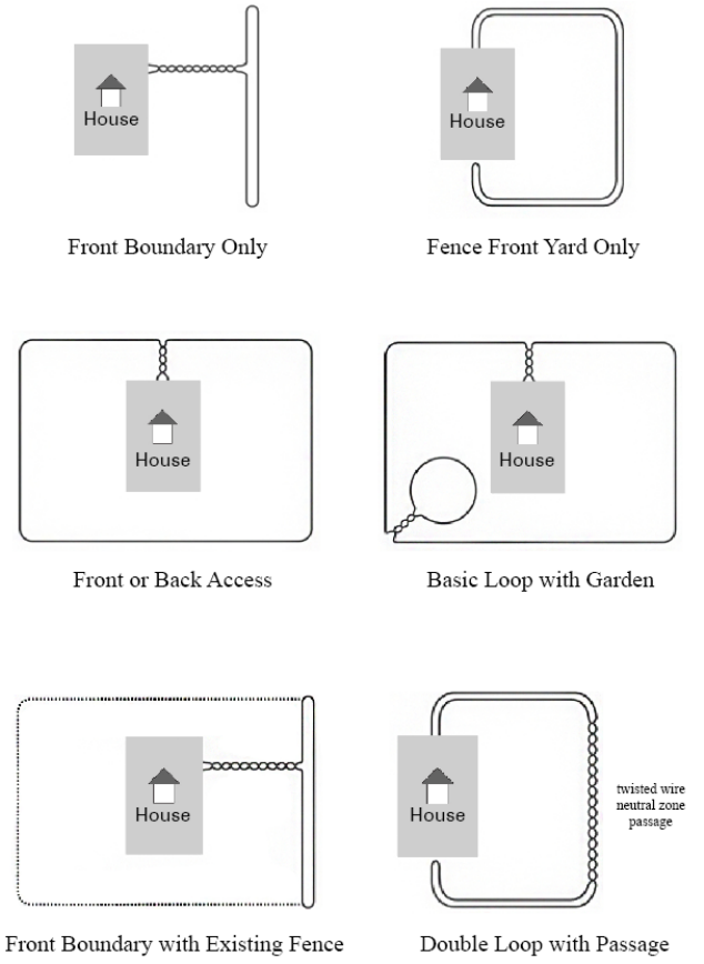
IMPORTANT!
When creating a Front Boundary Only, Fence Front Yard Only, or Front Boundary with
Existing Fence type of containment system a double loop layout is required. THE TWO
PARALLEL WIRES OF THE DOUBLE LOOP MUST BE 6-10 FEET APART to avoid any signal
interference. Single loop systems must also be kept 6-10 feet of distance between the wires
as well.
* Please note, the diagrams are not drawn to scale.
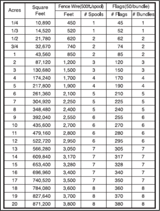
The E-Fence-3500 system includes 500 feet of boundary wire and 50 training flags.
Additional flags and wiring can be purchased through the Dogtra Company. The estimated
requirements are as follows:
ADDITIONAL PARTS
The diagrams on p.18 are indicated for a rectangular layout.
Actual flag/wire requirements may vary depending on the layout you’ve chosen. You will
want to keep a signal field (area where the dog will receive stimulation) at least 6-8 feet on
each side of the wire.
In addition, your dog will keep 2-4 feet away from the signal field, so an overall signal field
of 8-12 feet is preferred. Avoid making passageways that are too narrow (i.e. along the sides
on a house) or your dog may hesitate from using them.
Tools
To install your , E-Fence 3500 you will need a flat-edge spade, Phillips screwdriver and a wire
cutter/stripper. If your layout calls for the wires to be connected across concrete, you will
also need a caulking gun, exterior silicon caulk and a circular saw with a masonry blade for
cutting the pavement.
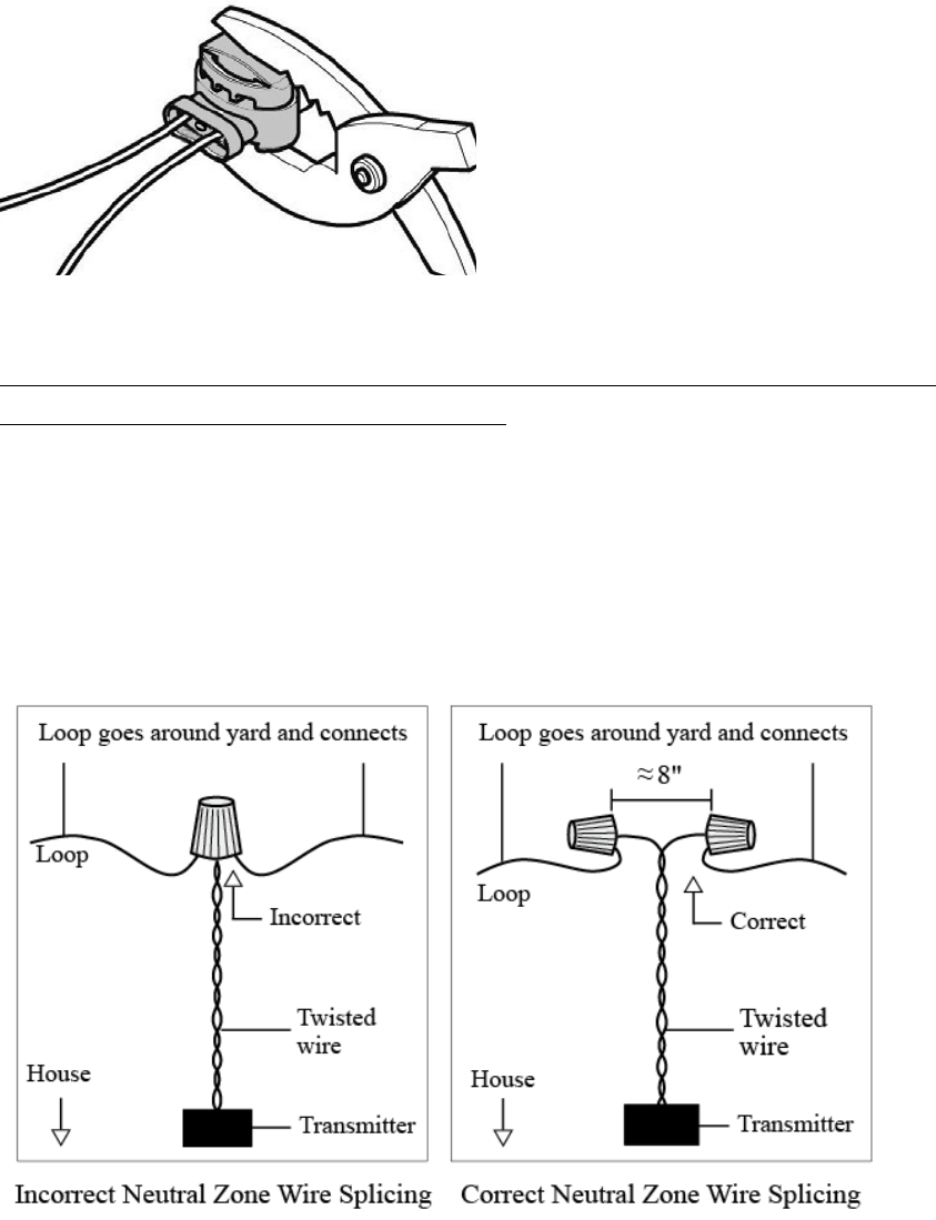
Creating a Neutral Zone in the Boundary
You must create a neutral zone from the fence transmitter to the beginning of the fence so
the signals do not cross over to any existing utility wires. Start by twisting the two pieces of
fence wire so they are braided from the beginning of the neutral zone area to the end.
Braiding the two wires will interrupt the signal of the buried fence, thus creating an area for
your dog to cross
without getting stimulation. To braid the fence wire, hold the two wires side by side, and
twist them around each other. This can also be done by securing the two wire ends in the
opening of a drill and letting the drill twist the wires for you. The tighter the wires are
twisted, the better the signal cancellation. Braiding the two wires will interrupt the signal of
the boundary wire, thus creating a neutral zone.
Burying The Fence Wire
IMPORTANT : Before starting any digging, contact your local phone, gas and
power companies to locate any other buried services.
The E-Fence 3500 boundary wire does not have to be buried to
operate. For protective measures we highly recommend the wire be buried about 3-4 inches
underground. Begin by digging a 4-inch deep cut where the wire first enters the ground
near the transmitter and continue around the path of the loop wire. A 30- to 45-degree
angle cut made with a flat-edge spade will be easiest to close.
Note : When covering a large area, a trenching machine may be used to cut into the
ground. However, it is recommended that the wire be placed in the trench by hand. A
commercial wire-placing machine may damage the wire.
IMPORTANT!
Bury the fence wire after you have tested the system and are sure it is working properly.
Do not nick or scrape the fence wire during installation as it may result in an intermittent
signal or no signal.
Make gradual turns at the corners with a radius of at least 3 feet. This will provide a more
consistent signal field that will avoid confusing the dog in these areas.
DO NOT run the e-fence boundary wire within 6 feet parallel to electrical, telephone, cable
TV or other buried wires.
DO NOT run the e-fence boundary wire of one section within
10 feet of another section of e-fence wire or the signal may cancel.
DO NOT run the e-fence boundary wire within 10 feet of a
neighboring pet containment system boundary wire.
Driveways/Sidewalks
When crossing an asphalt driveway, make a 1/2-inch deep cut across the driveway using a
circular saw and masonry blade. Close the crack with asphalt sealant after the fence wire is
placed in it. If an expansion joint is available on driveway and sidewalks, place e-fence wire
in the joint and close it with outdoor caulk. When crossing gravel, bury fence wire at least 3
inches deep. PVC pipes or a garden hose can be used to protect the wire. In water, anchor
the wire with large rocks. Use PVC piping or garden hose to protect the wire.
WIRE SPLICING
The wire connection must be waterproof
Do not use electrical tape, or soldered/twisted wire nuts in this type of connection as it will
cause an intermittent signal or disarm the system.
The waterproof splices included in the E-Fence 3500 system are designed to provide a
sealed connection between the wires. The insulation on the boundary wire should not be
stripped before placing wire into the holes. To use the waterproof splices, boundary wire is
placed into the outer holes of the splices. This should leave the center hole empty. A pair of
pliers should be used to gently press down and snap together the top of the blue part of
the splice.

Connecting the Fence Wire to the Transmitter
Splice the two ends of the twisted wire to each of the two ends of the fence wire.
Drill a hole through the exterior wall or window/door sill or run the fence wire through an
existing utility line hole. Connect the twisted fence wire to the transmitter, either wire to
either terminal (wire ends must be stripped 1/2 -inch). A red indicator light should appear
indicating a continuous fence wire field. If no light appears, check to make sure that all
fence wires are properly connected and that the wire is not damaged.
The Signal Field
The Field Width Adjustment Knob on the transmitter controls the signal field width.
Increasing or decreasing the signal field width does not affect the stimulation intensity.To
test the signal field, walk slowly toward the boundary wire holding the collar/receiver at
approximately the height of the dog’s neck. Contact points must be upward with the test
light attached. Watch for the test lamp to illuminate, this will give you an idea of the width
of the signal field. The wider the signal field is, the less chance that the dog will run through
the field and out of your yard.The signal field should extend at least 6 feet on both sides of
the wire (creating a field that is 12-feet wide total). An 8-12 foot field is preferred.
This will maximize the effectiveness of the containment system and minimize the chances
that the dog will run through the signal field.
Note : If you alter the field adjustment knob by turning it clockwise or counterclockwise, or
by removing it, you must check the signal field for
the desired setting.
When you are satisfied with the field width setting, bury the fence wire below the grass and
place the flags at the distance where the test light comes on.
Optional Accessories
The following items may be purchased separately. To purchase
accessories, please visit Dogtra's online store at or call customer service at 1-888-811-9111.
Connecting a Lightning Surge Protector
Plug the lightning protector into a grounded (3-wire) 120V AC outlet within five feet of
where you want to locate the transmitter. Cut the e-fence wires near the protector and strip
all four ends back ¼ inch. Push the connector tab firmly away from yourself and the
connector jaws will open. Push the stripped end of the wire into the connector.
TROUBLESHOOTING
1. Dog Doesn t Respond to Stimulus
- Adjust the collar fit.
- Trim the dog’s hair or use longer contact points to make better skin contact.
- Recharge the battery in the receiver/collar .
- Adjust the stimulation intensity level.
2. System Test Procedures:
Whenever you experience a malfunction, you will need to do a test loop to determine which
component - collar, wall transmitter or yard wire – is not working. Follow these steps to
perform the test loop procedure.
1. Make a test e-fence using at least 10 ft. to 20 ft. of fencing wire(or use the ground wire).
2. Remove the existing boundary wire from your wall transmitter.
3. Insert the two ends of the test e-fence wire into the wall transmitter.
4. Turn the field width adjustment knob to the 9 o'clock position or a low setting.
5. Place the test light on the receiver/collar. With the receiver/collar, approach the test loop
and note the distance between you and the wire when the collar activates the test lamp.
6. Turn the field width adjustment knob to the 12 o'clock position or a medium setting.
7. Back away from the wire and approach it again. Determine the distance between you and
the wire when the collar activates. The distance should be greater on the medium range
setting.
If more than one collar receiver is used, repeat the above test on each collar. If there is no
red light on the wire indicator light of the wall transmitter with the test loop wire in place,
the wall transmitter is malfunctioning. If the red light is solid on the wall transmitter, but the
collar does not activate on the test loop wire, the receiver/collar is not working. Recharge
the battery in the receiver/collar and repeat the test. If the collars are activating normally,
there may be a wire break in the fence wire.
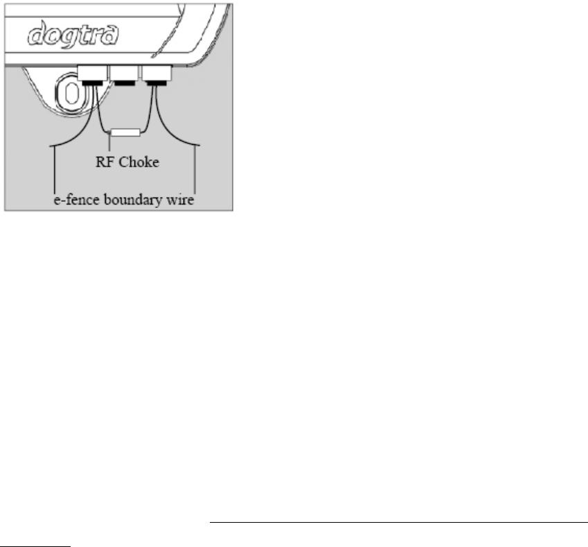
3. Finding a wire break using an RF Choke
You will need a 100 μμH RF Choke and an AM radio tuned to AM530.
Go to the wall mount transmitter box and disconnect the two underground wire leads from
the RED terminals, where they connect to the transmitter. In place of each wire lead, connect
one end of the RF Choke. Next, take the two underground wire leads and reconnect them
into the RED terminals. You should now have a wire from the RF choke and an underground
fence wire in each RED terminal. Turn up the transmitter signal strength to full. (RED area on
the dial) Take the radio (tuned to approx. AM530 on the dial) and the volume turned up.
Walk slowly along the path of the wire, holding the radio as close to the ground as possible
and directly over the wire. You should hear a whirling/static noise where the wire is intact
and no whirling noise where the break is located.
Fixing the Break
Once you have found the break, cut out the damaged area and usea weatherproof gel style
wire splicerto reconnect the two wires. If the break is large, or if you cannot identify the
break location, you may need to splice in some extra wire to bypass the area that is
damaged.
GENERAL MAINTENANCE TIPS
Your system requires very little maintenance. The receiver/collar for the E-Fence 3500 system
is fully waterproof. To remove dirt, simply wipe with soap and water.
The wall transmitter is not waterproof and must be protected from the elements in a shed,
garage or carport.
Do not attempt to dismantle or repair the wall mount transmitter or receiver/collar :
this will void the manufacturer’s warranty. These components contain computerized
circuitry that should be serviced only by an authorized expert.
*Caution
Any changes or modifications of this device which are not specifically approved by the party
responsible for compliance could void the user’s authority to operate the equipment.
FCC Warning
This device complies with part 15 of the FCC Rules. Operation is subject to
the following two conditions: (1) This device may not cause harmful
interference, and (2) this device must accept any interference received,
including interference that may cause undesired operation.
This is a sensitive radio device. Any unauthorized changes or modifications
to this device that are not expressly approved by Dogtra Co.,Ltd will void the
devices warranty, and might void user’s authority to operate the equipment.
So don’t do it please.

22912 Lockness Ave.
Torrance, CA. 90501
USA
TEL : 310-534-0101
FAX : 310-534-9111
Website :www.dogtra.com
Copyright©2015 Dogtra Company All rights reserved. (1)