Dongguan longxin barcode equipment LM800 2.4G Wireless Barcode Scanner User Manual
Dongguan longxin barcode equipment co.,LTD 2.4G Wireless Barcode Scanner User Manual
User_Manual
1
NADAMOO2.4GWireless&USBwiredBarcodeScanner
QuickStartGuide
Respected customer,thank you for choose our scanner. Please read carefully the
following user manual before using your device.
Package Include:
1 x Barcode scanner
1 x USB cable
1 x USB Wireless receiver
1 x User manual
Technical Parameters
Interface: USB Wires + 2.4 G Wireless
Transmission diatancce: 30m/98ft
Light source:Red LED (Aiming)
Storage:30000 barcode
Decoding capability: UPC-A,UPC-E,EAN-13,EAN-8,ISBN/ISSN code,code 39,code 39 Full
ASCII,code93,code 128, code128 Full ASCII, Codabar, Interleaved 2 of 5,industral 2 of
5,Chinese Postal code,MSI, Code11
Decoding speed:260 scan /s
Error rate:1/500million
Trigger mode: Manual trigger, Continuous scanning
Scanning area: 5*5 cm2 ~ 30-30cm2
Indicator mode:Buzzer indicator light
Charging time:4 hours
Shock resistance: design to fall from 1.5meters from concrete surface
Charging
Please ensure that the scanner has enough power before start using it. If the scanner is
run out of battery,the buzzer will ring for a second.And the scanner will shut down
automatically. At this time,please stop scanning and charge the scanner.
Correctly insert one end of USB cable into the scanner, and insert another end to
computer USB interface or 5V DC USB interface power (NOTE: please use computer USB
interface or special 5V DC power supply to charge, the informal power will cause
permanent damage to scanning gun and battery),
Yellow LED light will light when is at charge state, the charging will complete after about
four hours and the yellow LED light will go out.
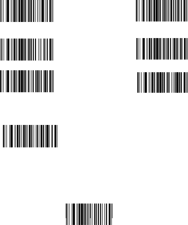
Power on
Press the butt
o
Power of
f
The system d
e
a long beepin
g
**Scan one of
time interval
y
30s auto pow
e
5min auto po
w
20min auto p
o
Reset th
e
To reset the f
a
Connecti
o
Wired Mode:
1. Connect th
e
2. Press the s
c
3. Scan the fo
l
4.Run Microso
f
barcode into t
h
o
n,the scanner will
f
e
fault shut down tim
e
g
. And the system
w
the following barco
d
y
ou set,the scanner
e
r off (default)
w
er off
o
wer off
e
factory defa
a
ctory default seting
reset
t
o
n Setting
e
scanner to your c
o
c
anner's yellow butt
l
lowing code to con
v
PS2 keyboar
d
f
t Word on comput
e
h
e location of the c
u
2
beep two times. Po
w
e
is 30s. If non-ope
r
w
ill shut down auto
m
d
e to set the time i
n
will power off.
6
1
ult setting
,scan the following
t
he factory defalut
o
mputer Via USB ca
b
on to wake up the
s
v
ert the scanner to
d
wired mode
e
r,when barcode is
s
u
rso
r
.
w
er is on successful
r
ation in 30s, the sc
a
m
atically.
n
terval,when it's idl
e
6
0s auto power off
0min power off
power offf
code
b
le
s
canner.
wired mode
s
caned, the scanner
l
y
.
a
nner will issue
e
exceeding the
inputs the

Wireless Mo
d
1.Plug the US
B
2.Press the sc
a
3.Scan the foll
scanner to wir
Wireless mod
e
4.Run Microso
f
barcode into t
h
Under wireles
s
A.Real-time
u
barcode is upl
o
buzzer will giv
discontinuous.
**To set the s
c
Real
B.Collection
m
it’s own mem
o
data to comp
u
**To set the s
c
Collection mo
d
** Scan the f
o
d
e:
B
wireless receiver i
a
nner's yellow butt
o
owing codes to ma
t
eless mode
e
f
t Word on comput
e
h
e location of the c
u
s
mode,there are t
w
u
pload mode: Sca
n
o
ad successfully, th
e
e one continuous s
o
c
anner to
R
eal-tim
e
-time upload mode
m
ode:Under this
m
o
r
y
. Internal storage
u
ter when you need
c
anner to Collectio
n
d
e
o
llowing barcode to
Upload data
3
nto a PC’s USB por
t
o
n to wake up the s
c
t
ch the receiver wit
h
Match the
e
r,when barcode is
s
u
rsor.
w
o 2 upload mode:
n
ning barcode and r
e
blue LED light will
o
unds;if the scan fa
i
e
upload mode,plea
s
m
ode, the scanner
w
supports up to 30,
0
it.
n
mode ,please scan
upload the stored d
t
c
anner.
h
the scanner and c
o
r
s
caned, the scanner
eal-time upload the
flicker once, at the
i
led,the buzzer bee
p
s
e scan the followin
g
w
ill automatically st
o
0
00barcodes .You c
o
the following barc
o
ata
o
nvert the
r
eceiver
inputs the
barcode.If the
same time
p
twice
g
barcode
o
re the data in
o
uld upload the
o
de
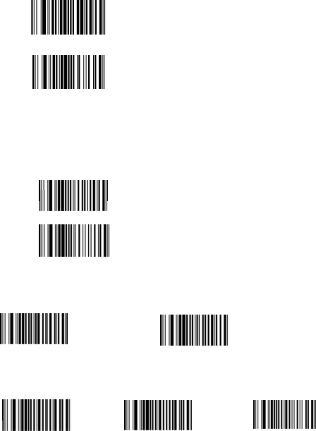
**Scan the fol
Sho
w
**Scan the fol
Cl
e
Scanning
Key trigger
m
Continuous
s
The scanner r
e
** Scan one o
K
C
o
Buzzer s
e
Scan one of t
h
Open vo
Upload s
p
Scan one of t
h
lowing barcode to
s
w
total storage
lowing barcode to
c
e
ar data
Mode Settin
g
m
ode: Red laser lig
h
s
canning mode: R
e
e
ads barcode witho
u
f the following barc
o
K
eys Trigger mode (
d
o
ntinuous Mode
e
ttings:
h
e following barcod
e
ice
p
eed
h
e following barcod
e
4
s
how total number
o
c
lear all the stored
b
g
h
t is on when pres
s
e
d laser light always
u
t pressing any but
t
o
de to select scann
i
d
efault)
e
to ON / OFF the b
u
Close voi
c
e
to select the dat
a
o
f stored barcode
b
arcode
s
ing the button
on when the scann
e
t
ons.
i
ng mode
u
zzer
c
e
a
upload speed
e
r is electrified.

Upload speed
Data Edtt
I
D setting
s
Add Code ID
a
Case sensi
t
All in lower-ca
All in capital l
e
Chage lower-c
Change capita
Turn off letter
-fast Uplo
a
ing
s
a
s prefix Add
C
t
ivity settings
se letters
e
tters
ase to capital
l to lowe
r
-case
conversion
5
a
d speed-modest (
d
C
ode ID as suffix
d
efault) Uploa
d
Turn off ID
(
d
speed-slow
(
default)
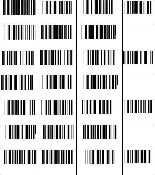
Barcode s
e
code39-On
code39
UPCA-ON
UPCA to EAN 1
3
UPCE-On
UPCE tO UPCA-
O
EAN13-On
e
tting
Code39-
O
f
f
code39 Fu
l
ASCII-Off
UPCA-Off
3
-On
UPCA TO E
A
UPCE-Off
O
n
UPCE to U
P
EAN13-Off
6
f
C
ode39
l
l
C
ode39
UPCA-
c
A
N13-Off
U
PCA I
UPCE-
c
P
CA - Off
U
PCE I
EAN13
-
check digit-ON
ID Character “m”
c
heck digit - ON
D Character “e”
c
heck digit - ON
D character “f”
check digit -On
Code39 check
digit-Off
UPCA-check
digit-Off
UPCE-check
digit - off
EAN13-check
digit-Off
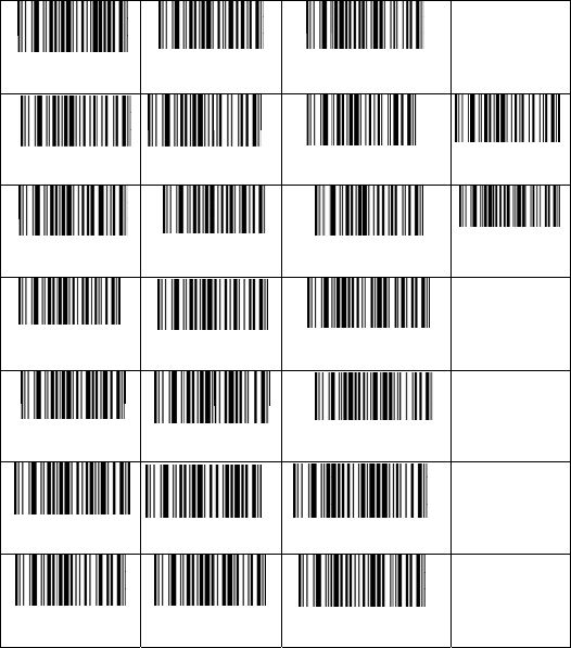
EAN13 to IBS
N
EAN8 -On
EAN8-2digit
extracode-On
Code93-On
Code128-On
Codabar-On
Interleaved 2
5-On
N
- On EAN13 to
I
EAN8-Off
EAN8-
5
di
g
extracode
-
Code93-
O
f
f
Code128-
Of
Codabar-
Of
of Interleav
e
5-Off
7
I
BSN- Off
E
AN13
EAN8-
c
g
it
-
On
EAN8-
f
C
ode93
f
f
C
ode12
f
f
C
odab
a
e
d 2 of
I
nterl
c
hara
c
ID charater “d”
c
heck digit- On
extracode-Off
id charater “i”
8 ID Character “a”
a
r ID Charater “v”
eaved 2 of 5 ID
c
ter “n”
EAN8-chec
digit-Off
EAN8 ID
character “c”
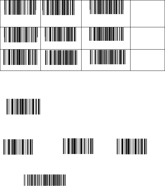
Industrial 2
-On
Prefix & s
u
Insert chara
t
(1) . The first
s
Enter into pre
f
(2) .The seco
n
E.g. To add pr
e
1082 R
Now the “RST
”
Scan the abov
of 5 Industria
l
5-Off
MSI-Off
u
ffix setting
t
er as prefix
s
tep: scan the set
u
f
ix setting
n
d step: scan the n
e
e
fix ”RST”,scan the
”
will be added then
X001E52257
e X001E52257 bar
c
8
l
2 of
I
ndust
C
hara
c
M
SI I
D
C
ode11
u
p code below:
e
eded character cod
character R , S ,T i
n
1083 S
scan the normal b
a
c
ode, ”RSTX001E52
2
rial 2 of 5 ID
c
ter “o”
D
character “s”
ID Character “u”
e (char-table is o
n
n
order.
1
a
r code
2
57” will show.
n
page 10)
084 T

Insert chara
t
(1) . The first
s
Enter into
(2) .The seco
n
E.g. To add pr
e
1082 R
Now the “RST
”
X001E52257
Scan the abov
Example:
To add TAB
a
To add CR aft
e
To add CR&L
F
Scan the follo
w
Clear all chara
prefix
t
er as suffix
s
tep: scan the set
u
suffix setting
n
d step: scan the n
e
e
fix ”RST”,scan the
”
will be added then
e X001E52257 bar
c
a
fter barcode , Plea
s
e
r barcode , Please
s
F
after barcode , Ple
w
in
g
to clear chara
c
cter suffix
9
u
p code below:
e
eded character cod
character R , S ,T i
n
1083 S
scan the normal b
a
c
ode, ”X001E5225
7
s
e scan the “enter i
n
s
can the “enter int
o
ase scan the “enter
c
ter
e (char-table is o
n
n
order.
1
0
a
r code
7
RST” will show.
n
to suffix setting”“
T
o
suffix setting”“CR
”
into suffix setting”
“
Clear all
n
page 10)
0
84 T
T
AB”
”
“
CR ””LF”
character

char-t
a
1001
S
1004
E
1007
B
1010 LF
1013
1016
D
1019
D
a
ble
S
OH
1
0
0
E
OT
B
EL
CR
D
LE
D
C3
10
0
2STX
1005ENQ
1008Backspace
1011VT
1014SO
1017DC1
1020DC4
10
10
10
1
1
1
0
10
0
03ETX
0
06ACK
0
09TAB
012FF
015SI
18DC2
0
21NAK

1022
S
102
5
102
8
1031US
1034“
103
7
104
0
104
3
S
YN
5
EM
8
FS
1
0
3
7
%
0
(
3
+
11
1023ETB
1026SUB
1029GS
3
2SPACE
1035#
1038&
1041)
1044,
10
10
1
1
1
1
1
1
0
24CAN
0
27ESC
030RS
1
033!
1
036$
1
039‘
1
042*
1
045-

104
6
104
9
105
2
105
5
105
8
106
1
106
4
106
7
6
.
9
1
2
4
5
7
8
:
1
=
4
@
7
C
12
1047/
10502
10535
10568
1059;
1062>
1065A
1068D
1
1
1
1
1
1
1
1
1
0480
1
0513
1
0546
1
0579
1
060<
1
063?
1
066B
1
069E

107
0
107
3
107
6
107
9
108
2
108
5
108
8
109
1
0
F
3
I
6
L
9
O
2
R
5
U
8
X
1
[
13
1071G
1074J
1077M
1080P
1083S
1086V
1089Y
1092\
1
1
1
1
1
1
1
1
1
072H
1
075K
1
078N
1
081Q
1
084T
1
087W
1
090Z
1
093]

109
4
109
7
1100
110
3
110
6
110
9
111
2
111
5
4
^
7
a
0d
3
g
6
j
9
m
2
p
5
s
14
1095_
1098b
1101e
1104h
1107k
1110n
1113q
1116t
1
1
1
1
1
1
1
1
1
096`
1
099c
1
102f
1
105i
1
108l
1
111o
1
114r
1
117u

111
8
112
1
112
4
1127D
e
113
0
113
3
113
6
1139
F
8
v
1
y
4
|
e
lete
0
F3
3
F6
6
F9
F
12
15
1119w
1122z
1125}
1128F1
1131F4
1134F7
1137F10
1140INSERT
1
1
1
1
1
1
11
1
1
1
120x
1
123{
1
126~
129F2
132F5
135F8
1
38F11
41HOME

1142Pa
g
1145Pag
e
1148Dow
n
For any spe
natamo@1
2
g
e up
e
down
n
arrow
cific requests, pl
2
6.com , burnfre
e
16
1143Delete
1146Right arrow
1149Up arrow
ease contact us
:
e
@126.com
11
1147
L
:
1
44END
L
eft arrow
17
FCC Caution.
This device complies with part 15 of the FCC Rules. Operation is subject
to the following two conditions: (1) This device may not cause harmful
interference, and (2) this device must accept any interference received,
including interference that may cause undesired operation.
Any Changes or modifications not expressly approved by the party
responsible for compliance could void the user's authority to operate the
equipment.
Note: This equipment has been tested and found to comply with the limits
for a Class B digital device, pursuant to part 15 of the FCC Rules. These
limits are designed to provide reasonable protection against harmful
interference in a residential installation. This equipment generates uses
and can radiate radio frequency energy and, if not installed and used in
accordance with the instructions, may cause harmful interference to radio
communications. However, there is no guarantee that interference will
not occur in a particular installation. If this equipment does cause harmful
interference to radio or television reception, which can be determined by
turning the equipment off and on, the user is encouraged to try to correct
the interference by one or more of the following measures:
-Reorient or relocate the receiving antenna.
-Increase the separation between the equipment and receiver.
18
-Connect the equipment into an outlet on a circuit different from that to
which the receiver is connected.
-Consult the dealer or an experienced radio/TV technician for help.
* RF warning for Portable device:
The device has been evaluated to meet general RF exposure requireme
nt. The device can be used in portableexposure condition without restrict
ion.