Donnelly Electronics 200226 Model 100392 User Manual INSTALLATION AND QUICK START INSTRUCTIONS
Donnelly Electronics Model 100392 INSTALLATION AND QUICK START INSTRUCTIONS
UserManual.wiki
>
Donnelly Electronics
>
200226 User Manual
>
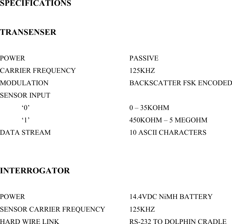
manual part 3
Contents
1.
manual part 1
2.
manual part 2
3.
manual part 3
manual part 3
Navigation menu
Upload a User Manual
Namespaces
Wiki Guide
HTML
PDF
Info
Views
User Manual
Discussion / Help
Navigation