Donnelly Electronics 200226 Model 100392 User Manual INSTALLATION AND QUICK START INSTRUCTIONS
Donnelly Electronics Model 100392 INSTALLATION AND QUICK START INSTRUCTIONS
Contents
- 1. manual part 1
- 2. manual part 2
- 3. manual part 3
manual part 3

SENTRICON* SYSTEM
INSTRUCTION
MANUAL
*Trademark of Dow AgroSciences LLC

TABLE OF CONTENTS
I. QUICK START INSTRUCTIONS
II. SYSTEM DESCRIPTION
III. SPECIFICATIONS

FCC STATEMENT
The interrogator generates low-level radio frequency energy. The unit has been
tested and found to comply with the limits and specifications as set forth in Part 15 of the
FCC rules. If this unit is suspected of interfering with radio or television reception,
verify that the unit is indeed the source of the interference. First, remove power form the
devices. If the interference continues, then the unit is not the source of the interference.
If the interference stops upon power-down of the unit, then reapply power to the
interrogator. If the interference begins again, proceed as follows:
• Reorient the receiving antenna on the unit experiencing interference.
• Move the interrogator farther from the unit experiencing interference.
• Change the orientation of the interrogator antenna.
If necessary, contact the manufacturer for additional suggestions.
Any changes or modifications not expressly approved by Donnelly Electronics
Inc. may void the users authority to operate the equipment.
This device complies with Part 15 of the FCC Rules. Operation is subject to the
following two conditions: (1) This device may not cause harmful interference, and (2)
this device must accept any interference received, including interference that may cause
undesired operation.

QUICK START INSTRUCTIONS
Immediately upon unpacking the interrogator, verify that you have received the
following items:
BATTERY CHARGER
For units to be used in the US and Canada, this unit is Elpac model
WP1224. The input voltage is 100 to 120 volt 47-63hz. If your electrical service differs
from these specifications, do not attempt to charge the batteries and contact the supplier
of this interrogator immediately for an exchange.
INTERROGATOR HANDLE
This unit consists of two pieces: The armrest, and bottom leg.
ANTENNA
This unit is a white circular disk, eleven inches in diameter. It will be
connected to the bottom leg of the interrogator handle.
INTERROGATOR ELECTRONICS BOX
This unit is a rectangular box attached to the armrest section of the
interrogator handle.
Depress the POWER switch on the rear panel of the INTERROGATOR
ELECTRONICS BOX. The unit should emit a single ‘beep’ and the green POWER
LED should be illuminated steadily. If the LED is flashing, you should immediately
charge the batteries.

To charge the batteries, plug the power supply that was shipped with the
interrogator into a 120 vac wall outlet. Insert the plug from the charger into the jack on
the rear panel of the INTERROGATOR ELECTRONICS BOX. This jack is labeled
‘CHARGER’. The yellow LED labeled ‘CHARGE’ on the front panel will now be
illuminated. If the batteries are severely discharged, the Yellow LED may blink for
several hours while the charging circuitry is conditioning the batteries. Once the
conditioning has terminated, the Yellow LED will emit a steady glow. When the
charging cycle has been completed, the LED will extinguish.
To verify interrogator operation as a stand-alone unit, it is not necessary to have
the transceiver in operation. No meaningful data will be obtained from this operation, but
it is instructive to test out the operation of the transensors and interrogator. The
following paragraphs will explain how to operate the interrogator:
Depress the ‘POWER’ switch located on the rear of the electronics box to enable
interrogator operation. You will hear a single “beep” tone from the interrogator when the
switch is depressed and the self –test operation has been successfully completed. The
GREEN LED labeled ‘POWER’ will illuminate. The interrogator is now operating
normally, and is continually scanning for a transensor.
Since the interrogator is only a portion of a system, it is necessary to have all the
other parts of the system operational in order to get meaningful data from the
interrogator. One can test the interrogator’s operation without the other components of
the system by placing a transensor near to the antenna. When the interrogator powers up
the transensor, the identification code of the transensor is sent to the interrogator, and
BOTH the ‘ACTIVE’ and ‘INACTIVE’ LEDs will turn on. The interrogator will emit a
single “beep” to indicate that the transensor has been read. Both LED’s will remain on
for about 2 seconds and then go off. This operation is the same regardless of whether a
sensor is connected to the transensor or not.
After approximately two 1/2 minutes of inactivity, the interrogator will
automatically shut down to conserve battery power.
Although the above operation does not do anything useful and is not very
spectacular, it does give a feel of the operation of the interrogator.
The interrogator will operate for about 8 hours on a full battery charge, but it is
good practice to charge the batteries at least at the end of each day. As a minimum, the
interrogator should be charged on a weekly basis since some of the internal circuitry
continuously draws battery power and will ultimately completely discharge the batteries.
This will result in diminished lifetime of the battery pack. The battery chemistry is
NiMH and thus will not exhibit the notorious “memory effect” common to NiCd
batteries. Therefore, it is not necessary or desirable to wait for the batteries to discharge
before recharging them.
To complete the system, the Dolphin 7200 must be inserted into the Dolphin
cradle slot. To insert the Dolphin into the cradle slot, grasp the top end of the Dolphin
with the IR port pointing into the cradle push the unit into the cradle. Ensure that the
Dolphin is fully inserted.
Turn on the Dolphin 7200 and the PROLINX software will start automatically.
Operation of the PROLINX software is beyond the scope of these instructions; however,
proper starting of the software will allow for the Sentricon System to begin working.
Now, depress the Power switch on the rear of the interrogator. You should hear a
single “beep” and the GREEN LED labeled ‘POWER’ should now be lighted. You are
now ready to read transensors. To try this out, place a transensor near the antenna (White
Disk) of the interrogator. The interrogator will read the transensors ID code and sensor
status and will emit a single ‘BEEP’. Both the ‘ACTIVE’ and ‘INACTIVE’ LED’s will
illuminate. The IR cradle will receive this information and send this information to the
PROLINX software. If the transensor code has been properly registered and is valid, a
command will be transmitted back to the Interrogator and the interrogator will then turn
off either the ‘ACTIVE’ or ‘INACTIVE’ LED, depending on the state of the sensor. The
interrogator will also emit a series of “Beeps” which varies depending upon the state of
the sensor.
If the transensor has not been registered properly within PROLINX, a command
will be sent to the Interrogator that will cause both LED’s to turn-off without giving any
audible response.
SYSTEM DESCRIPTION
The Sentricon System consists of a transensor, sensor, interrogator and Dolphin
7200. The following sections will give a brief description of each of these units.
SENSOR
The sensor is an electronic device that is sandwiched between the wooden
monitoring devices of the Sentricon unit. The sensor is a passive device that can be
consumed by termites. When this event occurs, the electronic state of the sensor is
altered. This change of state of the sensor is the event that indicates the presence of
termites within the Sentricon unit.
The sensor is electrically connected to the transensor by insertion into the slot on
the bottom of the transensor housing.
The sensor is shown in figure 1. The dark pattern printed on the white substrate is
the electronic portion of the sensor that, when broken, causes the transensor to detect a
changed state within the sensor and transmit this information to the interrogator.
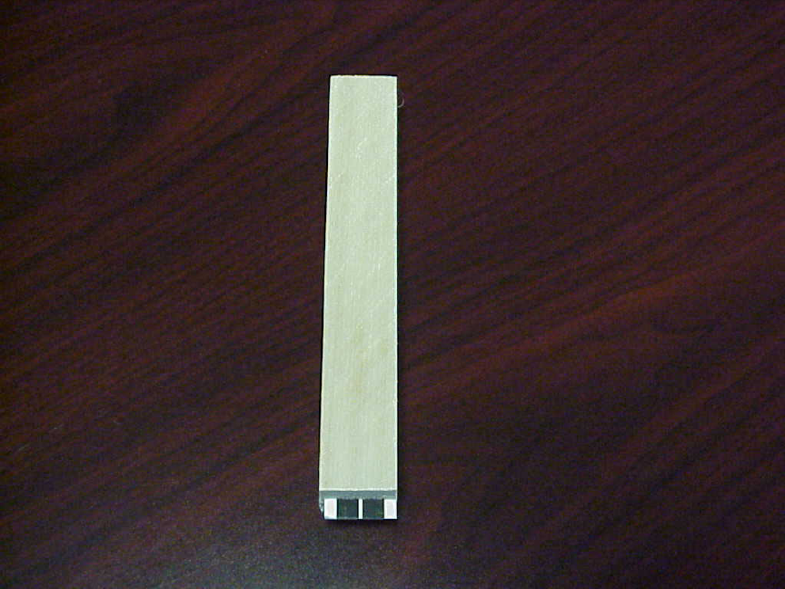
FIGURE 1: SENSOR UNIT FOR SENTRICON
TRANSENSER
The transensor is a device that contains all the electronics necessary to derive its
power from the interrogator, detect the state of the sensor, and provide a unique
identification code to allow PROLINX software to determine specific information about
the Sentricon station.
Some of the unique features of the transensor are that it does not require a battery
or other self-contained source of power, thus giving it an unlimited lifetime; The
frequency of operation is such that objects such as dirt, water and other non-ferrous
materials do not affect the operation, allowing the transensor to be completely buried
underground; finally, the transensor has a very large environmental operating range,
allowing for operation in hostile environments.
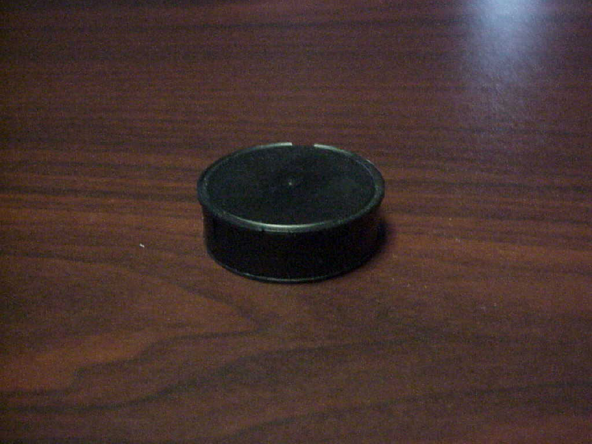
The transensor is shown in figure 2.
FIGURE 2: TRANSENSER
Figure 3 shows a transensor with a sensor inserted. Please note that the black traces on
the sensor are oriented so as to connect to the black plugs on the transensor. Also note
that the ‘white’ transensor is to allow easier viewing of the connections, and in actual
practice, the transensors will be colored ‘black’.
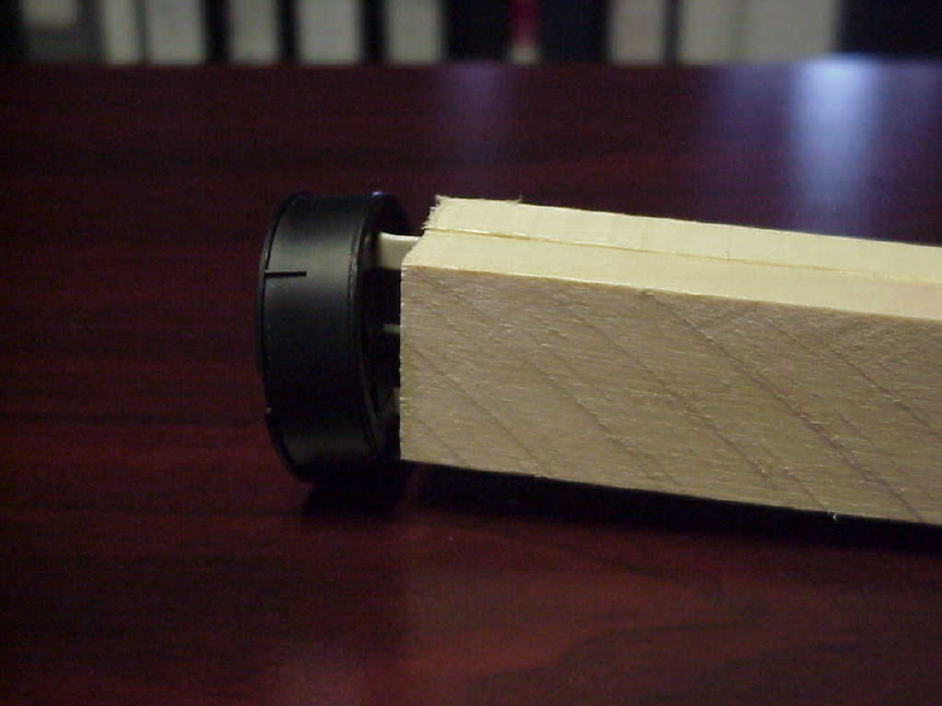
FIGURE 3: SENSOR INSTALLED INTO TRANSENSER
INTERROGATOR
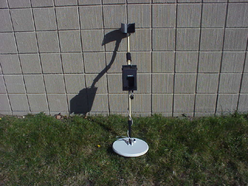
The interrogator is shown in figures 4, 5, and 6. The complete unit consists of a
carrying handle, electronics, battery charger and antenna.
The carrying handle is ergonomically designed to fit users of varying heights and
arm lengths. The handle length can be adjusted from 42.5 inches to 52 inches. The
curved handle and forearm rest provide a well-balanced unit that reduces fatigue.
The complete unit weighs approximately 75 ounces.
.
The power switch, battery charger and antenna connector are located on the rear
of the interrogator electronics box.
FIGURE 4: INTERROGATOR
Referring to figure 4, the interrogator electronics is contained within the black
colored electronics box mounted midway on the handle. The antenna is the white
circular disk attached to the end on the handle.
The handle is adjustable in height from about 30 inches to 50 inches to
accommodate individual preferences. To adjust the height, loosen the black locking nut
between the interrogator and the antenna and move the rod forward or backward to
lengthen or shorten the handle.
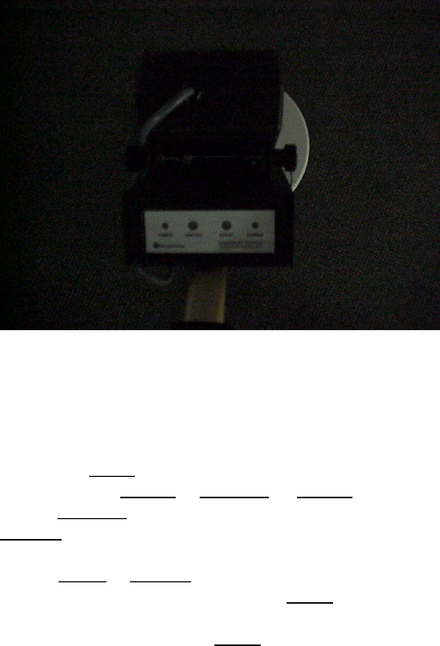
FIGURE 5: INTERROGATOR FRONT PANEL
The electronics housing contains visual displays and an audio alarm to give the
user feedback regarding the status of the interrogator as well as the status of a Sentricon
transensor. The LED’s are mounted on the front panel of the electronics box as seen in
figure 5. The panel contains four LED’s. A green LED on the left of the display
window indicates POWER, Sensor status displays are placed in the center of the display.
These LEDs are labeled ‘ACTIVE’ and ‘INACTIVE’. The ‘ACTIVE’ LED is colored
red and the ‘INACTIVE’ LED is colored green. On the right side of the display is the
‘CHARGE’ LED, which is colored yellow.
The ACTIVE and INACTIVE LED’s indicate the status of the sensor attached to
the transensor that was identified by the interrogator. The POWER LED indicates that
power is applied to the electronics. If the batteries within the interrogator are sufficient
for proper operation of the interrogator, the POWER LED will be illuminated
continuously. If battery power is getting low, the POWER LED will flash at
approximately 1-second intervals.
The CHARGE LED will illuminate when the battery charger is plugged into the
rear of the interrogator. The CHARGE LED will remain illuminated until the batteries
have reached sufficient charge. At this time, the CHARGE led will turn-off.
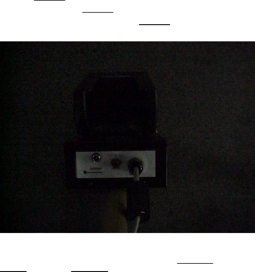
FIGURE 6: INTERROGATOR REAR PANEL
Looking at the rear of the interrogator, one can see the CHARGER jack, the
POWER switch and the ANTENNA . These devices are used for charging the batteries
contained within the interrogator, applying power to the interrogator and attaching the
antenna to the interrogator electronics box.
SPECIFICATIONS
TRANSENSER
POWER PASSIVE
CARRIER FREQUENCY 125KHZ
MODULATION BACKSCATTER FSK ENCODED
SENSOR INPUT
‘0’ 0 – 35KOHM
‘1’ 450KOHM – 5 MEGOHM
DATA STREAM 10 ASCII CHARACTERS
INTERROGATOR
POWER 14.4VDC NiMH BATTERY
SENSOR CARRIER FREQUENCY 125KHZ
HARD WIRE LINK RS-232 TO DOLPHIN CRADLE