Dorma 9700/F9700 Series Rim Exit Device Installation Instructions I 9700 1 Rev04 10
User Manual: Dorma 9700/F9700 Series Rim Exit Device Installation Instructions Installation Instructions
Open the PDF directly: View PDF ![]() .
.
Page Count: 14
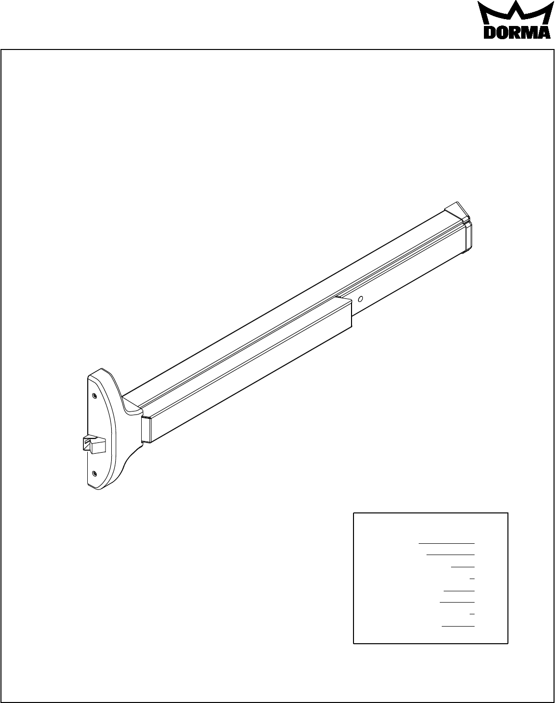
I 9700-1 4/2010
RIM EXIT DEVICE
9700/F9700 SERIES
INSTALLATION INSTRUCTIONS
1135-232 95057471 www.dorma-usa.com 1-800-523-8483
Index:
Screw chart
Tools required
Outside trim options
"03" Additional door prep
Device installation
Options available
5300 retro-fit preparation
Spotting template
1
2
3
4
5-8
9-11
12
13
Note: One set of instructions should be left
with building owner after device has been
installed.
1
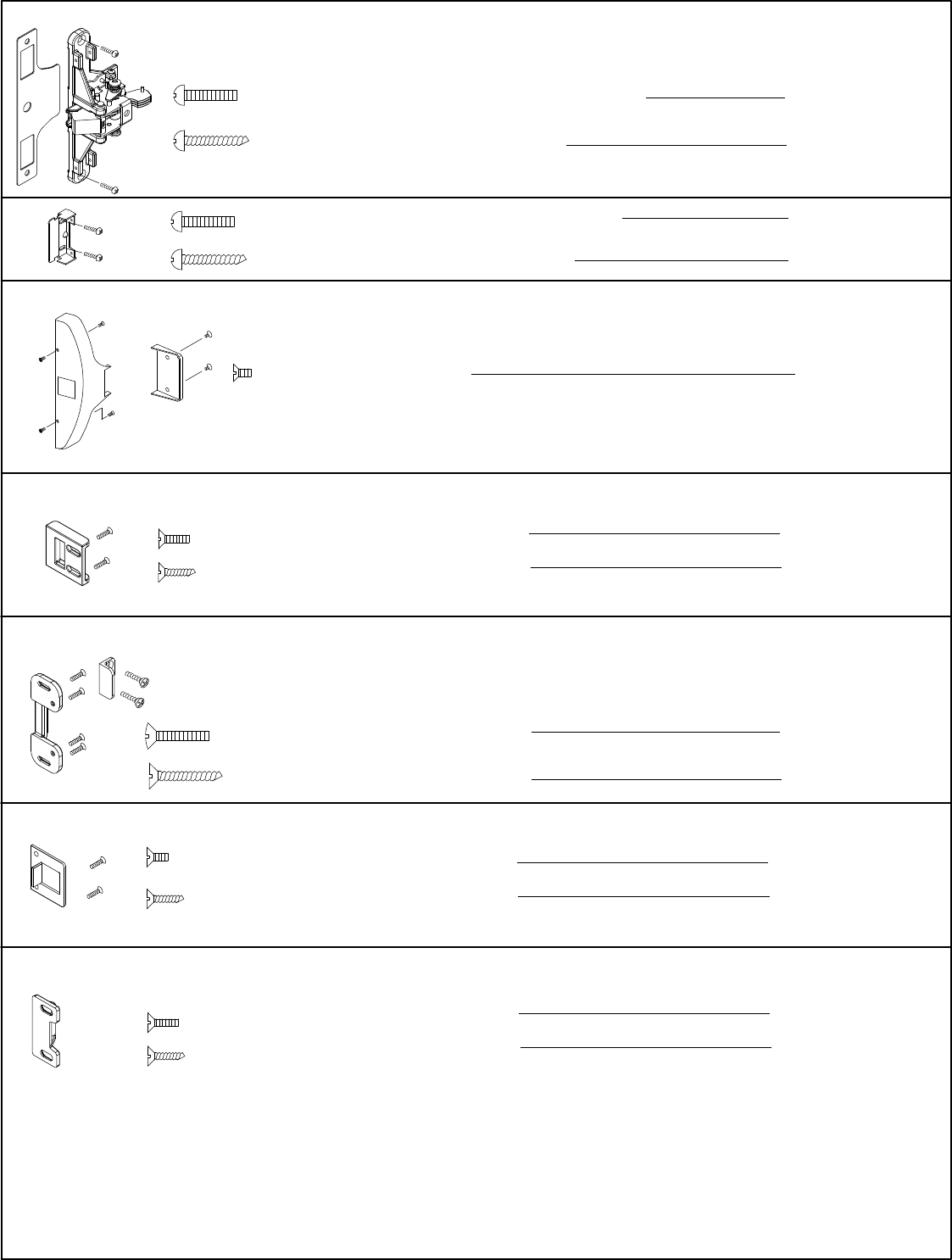
SCREW CHART
(2) #12 x 1 1/4" R.H.P.T.S. (Wood Door)
(2) 12-24 x 1" R.H.P.M.S. (Metal or Thru Bolts)
(2) #12 x 1 1/4" R.H.P.T.S. (Wood Door)
(2) 12-24 x 1" R.H.P.M.S. (Metal or Thru Bolts)
(6) 8-32 x 3/8" F.H.P.M.S.
Chassis Mounting
End Cap Bracket
Chassis Cover
& End Cap
Chassis Mounting
End Cap Bracket
(2) #10 x 1" F.H.P.T.S. (Wood Door)
(2) 10-32 x 5/8" F.H.P.M.S. (Metal) Strike Mounting
Strike Mounting
(6) #12 x 1" F.H.P.T.S. (Wood Door)
(6) 12-24 x 3/4" O.H.P.M.S. (Metal) Strike Mounting
Strike Mounting
(2) #10 x 1" F.H.P.T.S. (Wood Door)
(2) 10-32 x 3/8" F.H.P.M.S. (Metal) Strike Mounting
Strike Mounting
(2) #10 x 1" F.H.P.T.S. (Wood Door)
(2) 10-32 x 5/8" F.H.P.M.S. (Metal) Strike Mounting
Strike Mounting

2
RHR LHR
9600
Series
Device
9700
Series
Device
9800
Series
Device
9700
Series
Device
9700
Series
Device
9700
Series
Device
9700
Series
Device
Read the entire instruction sheet prior to installation.
Before Installing Hardware:
1. Door should be fitted and hung.
2. Verify door width, handing and product with carton label for correct exit device & length. (See Step 9)
3. For hand reversal of outside lever trim see page 3.
If device is to be installed over glass lite panels, glass lite shim kit may be required order GK9200.
NOTE:
12-24 Tap, 10-32 Tap
Drill bits: 1/8", 3/8", #25, #16, #21
Hole saw 1 1/4" diameter for trim (if required) or jig saw.
5/32" Allen wrench for lever trim.
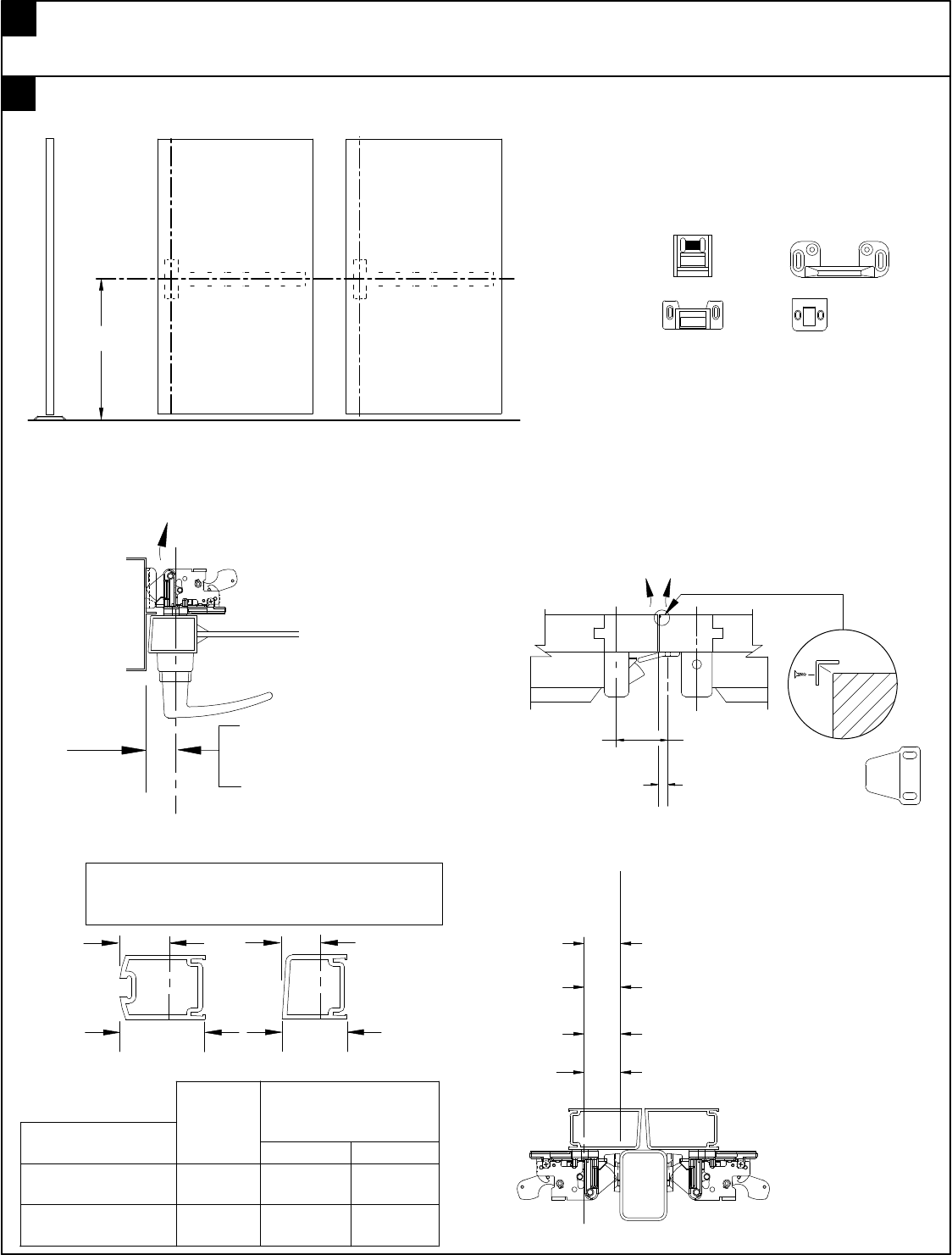
HANDING OF DOOR
TYPICAL APPLICATIONS
SPECIAL TOOLS FOR INSTALLATION
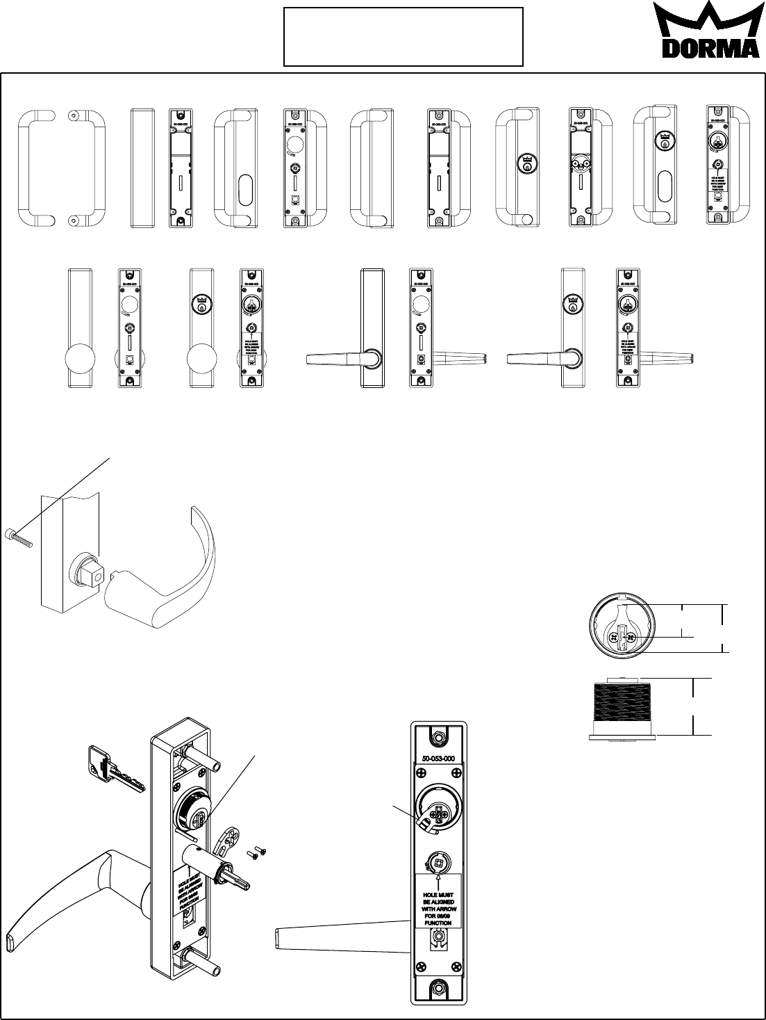
LHRB TRIM SHOWN RHRB OPPOSITE
All trims are free wheeling.
(Handle will rotate when locked.)
Note: When used with narrow
stiles, consult door manufacturer
for compatibilty.
TRIM INSTRUCTIONS
TYPICAL OUTSIDE
OP02 ZODT ZP25 ZP02 ZP03/04 ZP11/ZP12
ZR23
ZK23 ZK08/09 ZC23 ZT23
ZG23 ZR08/09
ZC08/09 ZT08/09
ZG08/09
1 1/8"
21/32" 61/64"
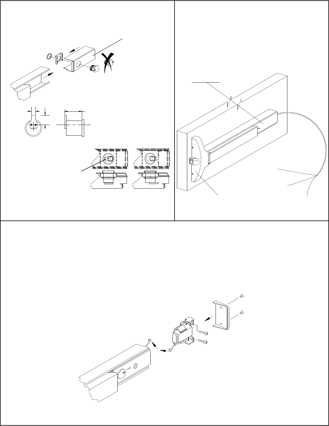
"09" Cam
For functions "09" & "12"
operation a DORMA #09
cam is required. Remove
key, install cylinder as
shown then cam as shown,
legs of cam stradle actuator.
Key removed.
3
Locked
position
IMPORTANT
Note: All lever handles except for
"clutch" are shipped unattached. To
install; Place handle in desired
position and attach with allen screw
located in bcak of trim plate. 5/32"
Allen wrench required.
To change hand on "clutch" trim
rotate and "break" lever around to
desired hand.
Tighten
Securely
Conventional 1 1/8" rim cylinder
#80R20SC with tail piece, keyed
differently to a random combina-
tion supplied with functions "03"
& "04" trim unless otherwise
noted.
Conventional 1 1/8" mortise
cylinder #90X13SC118 supplied
with DORMA #13 cam, keyed
differently to a random combina-
tion supplied with functions "08"
& "11" trim unless otherwise
noted.
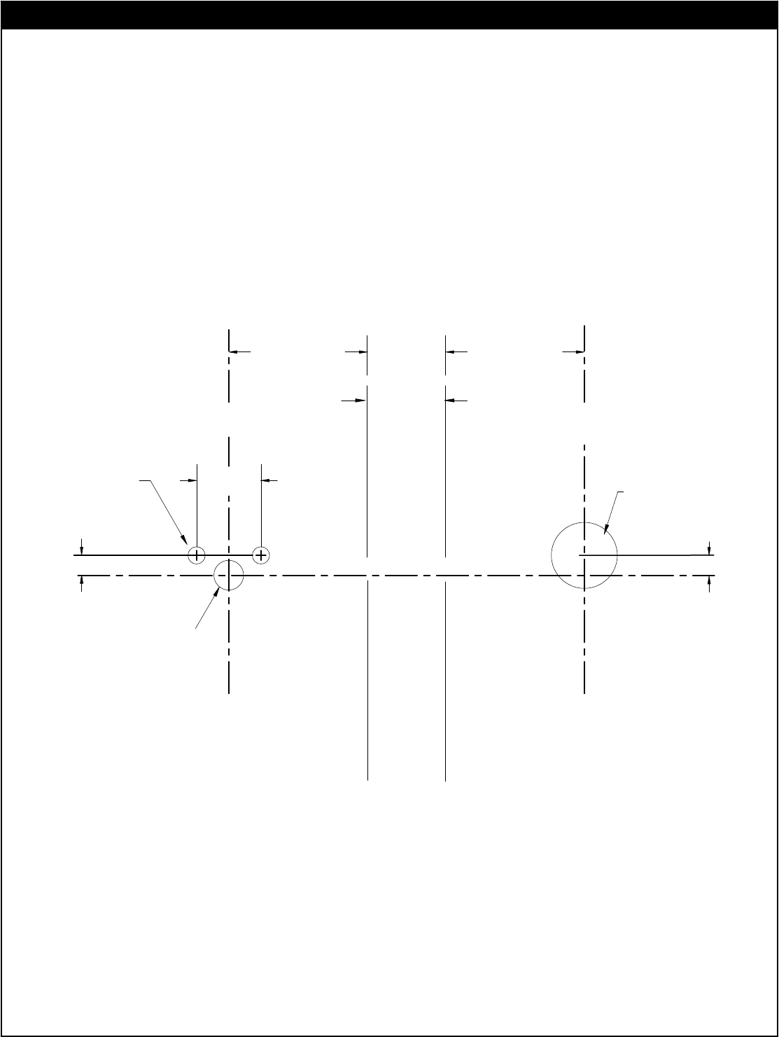
(DEVICE SIDE ONLY)
3/8" DIA. HOLE
INSIDE FACE
OF DOOR
HORIZONTAL REF. LINE
DIA. (2) PLACES
1/4"
7/32" DIA. HOLE 13/16"
VERTICAL REF. LINE
(CENTERLINE OF CHASSIS)
1 3/16" DIA. HOLE
(TRIM SIDE ONLY)
OF DOOR
OUTSIDE FACE
OF
STOP
EDGE
(SEE STEP 2)
OR
MULLION
(DEVICE SIDE) (TRIM SIDE)
1/4"
NOTE: If using 80CK
cyinder adapter kit with
trim; hole diameter re-
quired is 1 3/8".
VERTICAL REF. LINE
(CENTERLINE OF CHASSIS)
(SEE STEP 2)
4
9700/F9700
Rim Exit Device
RHR Shown
LHR Opposite
Required for "03" & "04" function on device
with cylinder only and no trim.
(NOT TO SCALE)
ADDITIONAL DOOR PREP REQUIREMENTS
IMPORTANT NOTE:
NOTE: "04" function not
available on fire rate device.
"Fire rated devices can not
be dogged."
Hole dimensions may
vary, when using cylinder
by other manufacturer's
use backplate supplied
with cylinder as drilling
template.
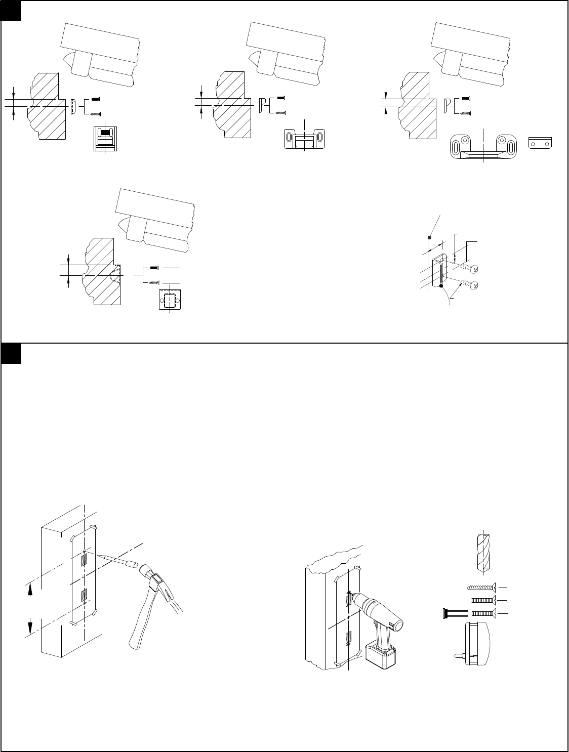
Strikes
Mullions
Strike
5
Edge of Stop
or Mullion
Standard
Vertical reference line
C
L
430 463
320
486
1 3/8" Standard #430 strike
LHR
LHRRHR
1/2"
Outside edge
2 3/8"
1310
1330
F1300
1 1/2" For #463 or #486 strike
7/8" For #443 strike
1 3/8" Standard #430 strike
1 1/2" For standard #463 & 486 strike
7/8" Standard #443 recessed strike
443
9700 Rim 9800 Vertical rod
Edge
guard
Vertical ref.
Door preperation
1340KR
F1340KR
1 1/2" For standard #463 & 486 strike
1
Open box, layout all parts and verify prior to starting installation. See page (1) one for parts.
Note: If this is a retro-fit from current 5300 series see page 12 prior to proceeding.
2
40 5/16"
Based on 1/2"
threshold and 3/16"
clearance between
threshold and door
after door is hung.
Finished floor
Chassis
horizontal
ref. line
Chassis
vertical
ref. line
Edge of stop
or mullion
Based on 1/2" blade
stop "cut out"; If using
trim dimensions may
vary. See proper device
and trim templates.
Pull only
Type of
installation
Single door 1/2"
blade stop
Pairs and
double egress
1 3/8"
1 5/8"
"Z" trim
2 1/8""
2 " 2 3/16"
Minimum Stile
1 1/4"
Minimum
vertical
ref. of
chassis
Min. Stile Min. Stile
Beveled edge door
Rounded edge door
Vert. ref.
Vert. ref.
Backset or vertical reference is measured from
outer edge of door as shown. Minimum stile is
less glass stop.
6
486
1 1/16"
430
1 3/4"
10-32 x 5/8" F.H.P.M.S.
425/443
#10 x 1" F.H.P.T.S.
10-32 x 3/8" F.H.P.M.S.
#10 x 1" F.H.P.T.S.
5/8" 13/16"
463
#12 x 1" O.H.P.T.S.
12-24 x 3/4" O.H.P.M.S.
#10 x 1" F.H.P.T.S.
10-32 x 5/8" F.H.P.M.S.
For metal frame: No. 21 drill x 10-32 tap
For wood frame: 1/8" drill for pilot hole For metal frame: No. 16 drill x 12-24 tap
For wood frame: 1/8" drill for pilot hole
For metal frame: No. 21 drill x 10-32 tap
For wood frame: 1/8" drill for pilot hole
Strike angle
(Fire rated device only)
must be installed on
rated openings.
Prepare frame for strike
3
12-24
Strike angle (Pt. no. 6300-324-500)
R.H.P.M.S.
15/16"
15/32"
1/2"
Edge of door
stop or mullion
4
If not done layout device on door using drilling template T9700 located at rear of booklet.
For additional templates contact DORMA at 1-800-523-8483 or www.dorma-usa.com
7 1/2"
HORIZONTAL REF. LINE
VERTICAL REF. LINE
Refer to carton label for model and trim number prior to drilling.
Prepare mounting holes and cut-outs per template.
Verify all holes
prior to drilling.
(See Backsets on page 5.)
3/8"
No. 16
No. 25
7
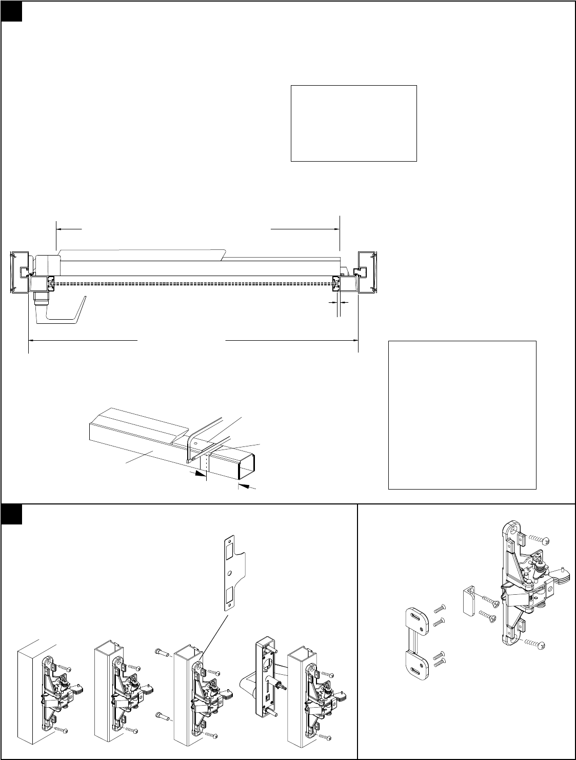
2"
36" Door opening
NOTE: All dimensions are based on 1/2" stop height; Verify strikes, stile width, any trim and stop
height prior to making any cuts. If cutting is required follow instructions below.
Size AA:
Fits 48" door opening without cutting.
Can be cut to fit a 32 1/2" minimum door opening.
Size BB:
Fits 36" door opening without cutting.
Can be cut to fit a 26 1/2" minimum door opening.
Size CC:
Fits 36" door opening with out cutting.
Using a shorter touch pad then the standard "B"
size allows it to be cut to 23 1/2" door opening.
Verify device length with box label; "AA", "BB" or "CC", ie. 9700BB
Note: If door opening width is less then standard touch bar will have
to be cut down. ie: door opening width 34" subtract 2" from rear of
touch bar and rail, tape and cut to length as shown.
Edge of stop
Edge of stop
Example:
Standard "BB" touch bar and rail 31 1/2"
Touch bar
and rail assembly
Filler
Tape
IMPORTANT
Use caution when cutting
touchbar and rail to size on
models with "ES", "MS", "LM"
or "DWA" prefix options.
These units contain internal
wiring.
For models with prefix options
"BPA", BPAR" or "DE" remove
filler containing electronics be-
fore cutting.
Note: Models with prefix
options such as "ES", "DE"
etc. may not be cut down
to minimums shown to left.
Consult factory or catalog
for details.
9
Prepare to install touch bar and rail on door.
Apx. 1/4"-3/16"
Strike
#463
Strike angle
(2) 12-24 R.H.P.M.S.
F9700 Series chassis assembly
(2) 12-24 F.H.P.M.S.
(4) 12-24 O.H.P.M.S.
10
Secure chassis to door as shown.
Optional mounting
Metal - (2) 12-24 x 1 1/2" R.H.P.M.S.
Wood - (2) #12 x 1 1/4" R.H.P.T.S.
(For other options; trim, thru bolts, etc.
see below.)
(Must be installed)
For 3 1/2" stiles or
less on aluminum
doors, place shim
under chassis prior
to mounting on door.
(Finished side to
outside face.)
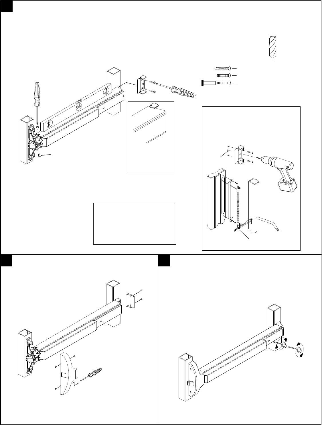
8
Bracket should be
flush against door
and tight against
rear of rail. 1/2" DIA.
No. 16 Drill - 12-24 Tap (Metal)
1/8" Drill 1" Deep (Wood)
3/8" Dia. (Thru bolts)
ES105
(2) 8-32 x 3/8" P.H.P.M.S.
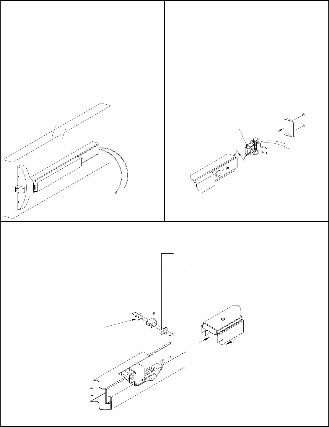
11
Install touch bar and rail assembly and end cap to door.
Metal/thru-bolts - (2) 12-24 x 1" F.H.P.M.S.
Wood - (2) #12 x 1 1/4" F.H.P.T.S.
Remove two 8-32 screws from chassis,
slide touch bar and rail assembly under
rear of chassis. Note: If device has pre-
fix "ES" ensure that pins in lever bolt
align with slots in actuator located in-
side nose of touch bar. See instruction
sheet IES-7 packed with device. Install
(2) two 8-32 x 3/8" P.H.P.M.S. to
secure touchbar to chassis.
Hold rear mounting bracket tightly
against door and rear of rail. Mark
(2) two holes and drill per chart.
Secure with proper fasteners.
For the following models prefixes:
"ES", "MS", "LM" or "DWA" drill an
additional 1/2" diameter hole as
shown. See options pages at rear
for addtional information.
(Required for above
options.)
"Remove protective
covering from the
touchbar and rail
assembly prior to
installing on door."
NOTE: If carton label list pre-
fix; "ES", "MS", "LM", "BPA",
"BPAR", "DWA", "LM/MS/BP"
or "CD" prefix see Options
pages at rear.
12
Install center case cover and end cap.
(6) 8-32 x 3/8" P.H.F.H.M.S.
Start all (4) screws
prior to tightening.
13
Check dogging operation (if equipped).
Standard hex key dogging, depress
touch bar, insert supplied hex key and
rotate clock wise to dog and counter
clock wise to undog.
*
a2
a1
c1 c2
b
12-24 x 3/4" R.H.P.M.S.
8-32 x 1/4" P.H.F.H.U.C.M.S.
9
"LM" (LATCH MONITOR) OPTION:
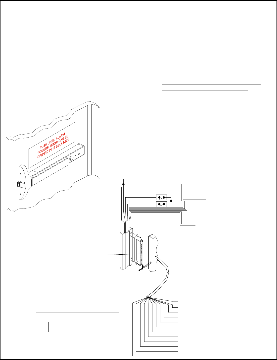
"BPA" & "BPAR" (ALARM) OPTION:
FOR DIRECT WIRED SEE NEXT PAGE
Refer to additional alarm
instructions packed with
device for operation of
alarmed exit device.
SIZE A:
Will fit 48" door opening without cutting.
Can be cut to fit a 371/2" minimum door opening.
SIZE B:
Will fit 36" door opening without cutting.
Can be cut to fit a 31 1/2" minimum door opening.
SIZE C:
Will fit 36" door opening without cutting.
Can be cut to fit a 28 1/2" minimum door opening.
OPTIONS
To replace battery
remove endcap.
NOTE: Touch bar must
be in dogged down po-
sition, to remove the
rear filler panel.
(DORMA mortise
cylinder supplied.)
To install customer
supplied cylinder, see
cylinder dogging option
at top of page.
*NOTE: Use caution when
cutting touch bar and rail to
length.
BPA: Battery powered alarm, sounds continuous
or until disarmed.
BPAR: Battery powered alarm, sounds
for 4 minutes, automatically resets.
"Alarm mode set at factory."
Red
Normally
Closed
Green
Normally
Open
Black
Common
SPDT, .5 amp
@ 28VDC max.
*NOTE: Use caution when
cutting touch bar and rail to
length. Additional hole re-
quired see step 11.
Latch monitor: Monitors movement of
bellcrank, with or without depressing
of touch bar.
Can be wired normally open or normally
closed.
a
b3
b1
b2 c
11/16" Min
Note: DORMA mortise
cylinder supplied. To use
other manufacture cylinders,
"L" less cylinder is available.
5/16" 1" Min.
1 1/8" Max.
to
"CD" (CYLINDER DOGGING) OPTION:
Correct In-correct
NOTE: Touch bar must
be in dogged down po-
sition, to remove the
rear filler panel.
Useable Cams
Cylinder dogging installation
instructions & cylinder speci-
fications.
001
Std. (Yale)
C136
A02
12667-3
SC1
SC1 4200-82-2002 Std.
13-0664 or 13-0660
001
2160
Arrow
Assa
Best
Corbin
Falcon
Ilco/Unican
Lori
Sargent
Schlage
Yale
10
DORMA
Note: When using IC core
cylinders, ensure that cam
is in proper position prior
to installing the new core.
Witness
Marks
c2
d
b2 e
c1
b1
af
*
12-24 x 3/4" R.H.P.M.S.
8-32 x 1/4" T.H.P.U.C.M.S.
c
b
a
de
10
"MS" (MICRO SWITCH) OPTION:
"DWA" (DIRECT WIRED ALARM) OPTION:
"ES" (ELECTRIC LATCH RETRACTION) OPTION:
OPTIONS
(Non-polarized)
Green
White
(Polarized)
-+
Positive
Negative Red
Black
Electrically retracts latchbolt(s)
when energized by power supply.
REQUIRES DORMA PS501 POWER SUPPLY
AND ES105 POWER TRANSFER.
PS501 Will operate (2) "ES" 9600 exit devices,
but is capable of powering (2) additional devices
by installing the optional "ES-2" card.
*NOTE: Use caution when
cutting touch bar and rail to
length. Requires additional
hole see step 11.
NOTE: Touch bar must
be in dogged down po-
sition, to remove the
rear filler panel.
DWA
Battery Eliminator
(Standard mortise
cylinder supplied.)
Connected to outside power source.
12-24 Volt AC/DC Power Supply.
i.e. DORMA ES100 etc.,
Contact DORMA for other power
supplies available.
Refer to additional sheet
IAL9000 packed with device
for operation of alarmed
exit device.
SPDT, .5 amp
@ 28VDC max.
Green
Normally
Open
Black
Common
Red
Normally
Closed
*NOTE: Use caution when
cutting touch bar and rail to
length. Requries additional
hole see step 11.
"MS" option allows monitoring of touch
bar during normal operation, or can be
used as a signal switch for horn, light etc.
Comes standard with (2) two micro
switches. Both can be wired either
Normally Open or Normally Closed. Can
be added to device after installation.
Requires additional
hole see step 11.
Note: Normal switch position
shown, once installed normally
open and closed positions are
reversed.
11
Minimum 18 AWG
wire recommended for
24VDC inputs (red &
black) leads.
DORMA ES105
(Power Transfer
"Required")
* For 24VDC inputs only (red & black wires).
Note: Wire run is from supply to device
and back to the supply.
WIRE 18AWG 16AWG 14AWG 12AWG
FEET 25 50 75 100
Maximum Wire Length From Power Supply To
Device & Back To Supply In Feet x Wire Gage/Size
Monitoring
Outputs
Control Inputs
(12) Wire Connection
Bundle 22" in length.
DPS
BLACK: (-) 24VDC IN
RED: (+) 24VDC IN
WHITE: AUTHORIZED EGRESS/AUTO RESET
ORANGE: BYPASS/RE-ARM
GREY: DPS N/C
VIOLET: ALARM RELAY COMMON
GREEN: RED OUTPUT EMITTER
BROWN: RED OUTPUT COLLECTOR
BLUE: GREEN OUTPUT EMITTER
YELLOW: GREEN OUTPUT COLLECTOR
PINK: ALARM RELAY N/C
TAN: ALARM RELAY N/O
Grey
Black
OPTIONS
"DE" (DELAYED EGRESS) OPTION:
DE9700
SIZE AA:
Will fit 48" door opening without cutting.
Can be cut to fit a 39 1/2" minimum door opening.
SIZE BB:
Will fit 36" door opening without cutting.
Can be cut to fit a 32" minimum door opening.
REQUIRES DORMA
ES-100 24 VDC POWER SUPPLY.
One supply per device unless the
optional ES101 Time Delay is used
to sequence the arming of the two
devices.
Easily accessible slide in and out electronics.
Meets UL & ANSI/BHMA requirements.
Note: Refer to DE9000 Series Installation Instructions for addtional instructions for installation and operation
of the "Delayed Egress" exit device.
NOTE: Some CA Codes may require
different verbiage; check local code re-
quirements prior to installing decal.
85 Decibel Alarm - Standard
LED Status Indicator - Standard
Nuisance Alarm - Standard
Key Switch Control - Standard
Remote Authorized Egress - Standard
Remote Re-Arm - Standard
Remote Bypass - Standard
Door Position Input - Standard, DIP Switch Setting
Auto Reset or Manual Reset, DIP Switch Setting
Auto - Standard (Manual - in CA)
Additional Form "C" Relays For Optional Horn etc.
(Rated 1 amp @ 30 vdc)
RETROFIT FROM EXISTING 5300 TO NEW 9700 MODEL
DO NOT SCALE
Outside face
Existing
Holes
Existing horizontal ref. line
LHR
Existing vertical ref. line
(Center line of chassis)
When using trim
with outside cylinder.
Outside face only.
1 1/2"
max.
1 3/4"
11/16" 1" Dia. max. thru
door for spindle
12
Additional installation instructions:
New "Z" trim required if using trim.
Existing strike may or may not have to be adjusted or relocated and replaced.
Install chassis assembly to door, install end cap bracket to door, hold touch bar and rail
assembly in position aligning screw holes in rail with mounting screw location of chassis,
mark a line on rear of rail where front edge of end cap bracket is then cut touch bar and
rail assembly to length.
Install touch bar and rail to door then install all covers.
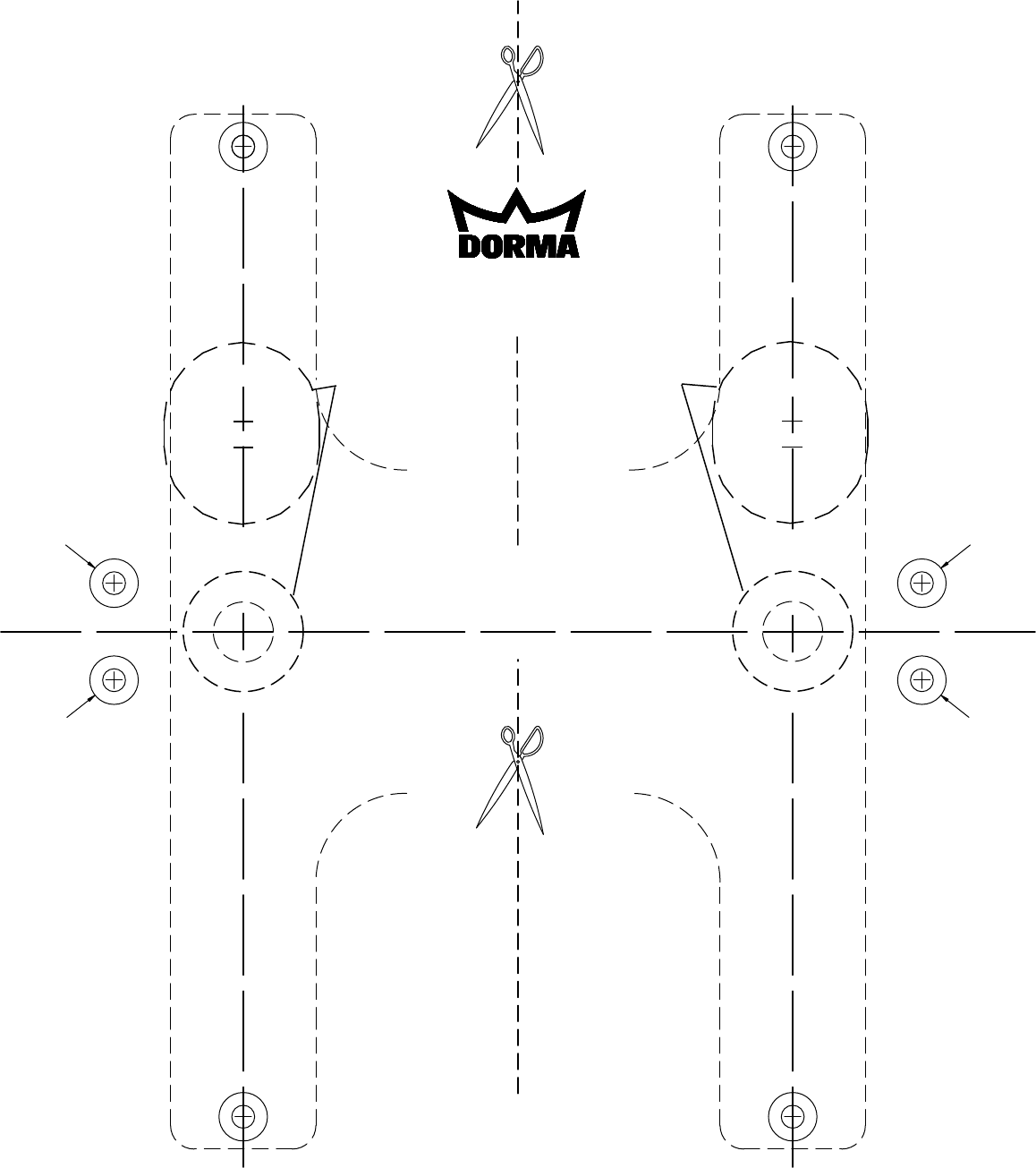
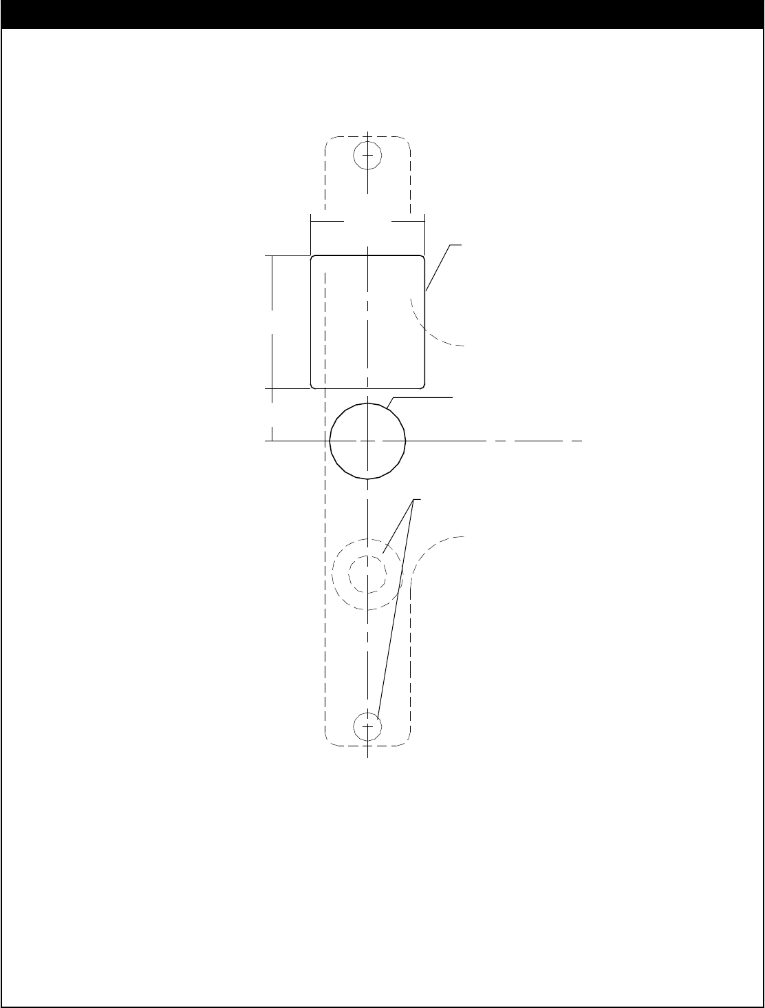
HORIZONTAL REFERENCE LINE
(CENTERLINE OF CHASSIS)
VERTICAL REF. LINE
RHRB
(CENTERLINE OF CHASSIS)
VERTICAL REF. LINE
LHRB
G FOR KNOB/LEVER/THUMBTURN 1" DIA. OUTSIDE FACE
D FOR USE WITH TRIM 3/8" DIA. HOLE THRU DOOR
C FOR SEX BOLT 3/8" DIA. HOLE THRU DOOR
B FOR METAL DOOR No. 16 DRILL 12-24 TAP
A FOR WOOD DOOR No. 25 DRILL 1" DEEP
EXIT DEVICE
9700/F9700 SERIES
NOTE: FOR CYLINDER ONLY
FUNCTION SEE PAGE 4
1/2" DIA. INSIDE FACE
H FOR KNOB/LEVER/THUMBTURN 1" DIA. OUTSIDE FACE
1 1/2" DIA. x 1 3/4" HIGH FOR CYLINDER CLEARANCE
D
B
C
A
D
B
C
A
C
B
C
B
A B
DC
BC
C
B
BA
DC
F9700
ONLY
T9700 4/2010
G
G
H
H
F9700
ONLY
F9700
ONLY
F9700
ONLY
OUTSIDE
FACE ONLY
OUTSIDE
FACE ONLY
Drawing Not To Scale
Use for Reference Only
