Dorma IMLR 1 9000 Series MLR Retraction Installation Instructions 7 14
User Manual: Dorma 9000 Series MLR Retraction Installation Instructions Installation Instructions
Open the PDF directly: View PDF ![]() .
.
Page Count: 5
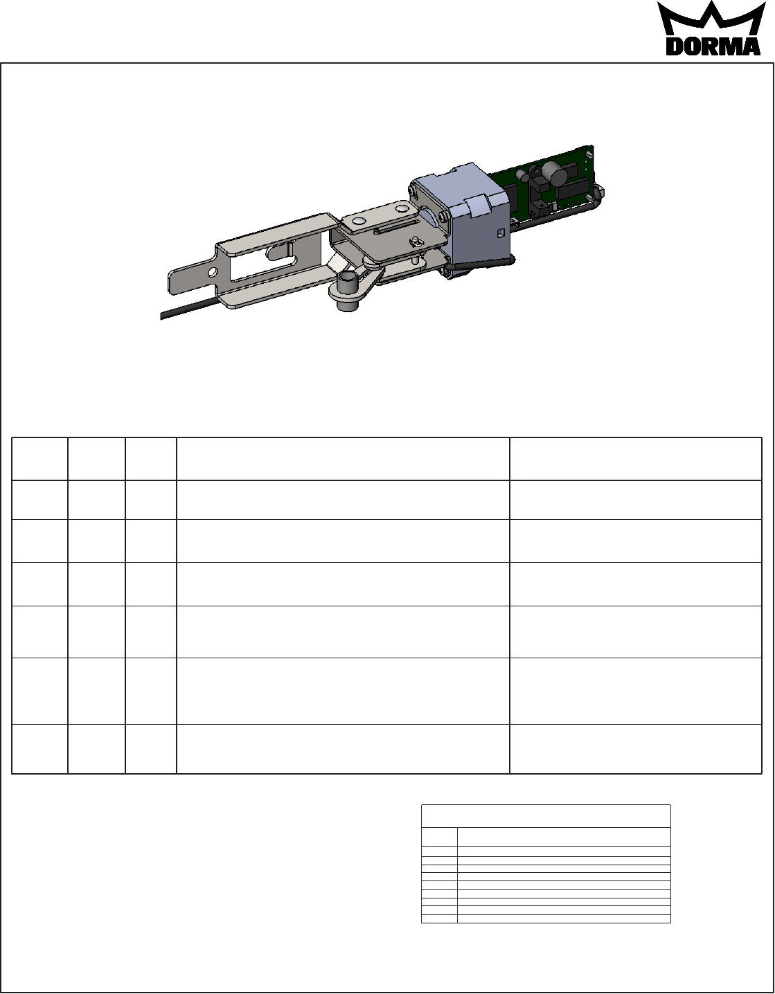
INSTALLATION INSTRUCTIONS
9000 Series MLR motorized latch retraction device
Specifications:
Electrical input requirements:
24Vdc +10% Filtered and regulated power supply; ie: DORMA PS610RF or PS532RF.
The unit may also be powered by the DORMA ED900 operator.
Current: .88A max. inrush, 400mA max. hold
Non polarized leads
-
Provides simultaneous electric latch retraction and dogging (depressed touch bar).
IMLR-1F 1/2014
1135-252 95071186 www.dorma-usa.com 1-800-523-8483
Onboard indicator light assignments: (Touch pad must be removed to view)
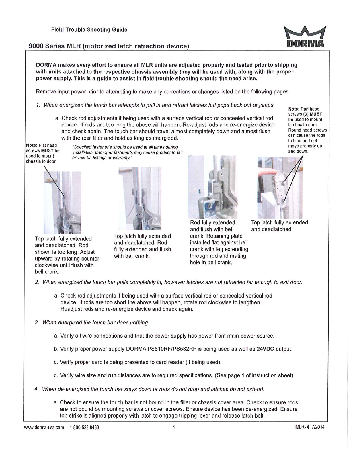
Maintain input power to exit device and check the onboard indicator light status.
Remove input power prior to attempting to make any corrections or changes.
Green
(Power)
Off
On
On
On
On
On
Yellow
(Sensor)
Off
On
Off
On
On
Blink
Red
(Error)
Off
Off
On
Blink
On
On
Indication
No power.
Normal operation. The touch bar is retracted to the dogged
position and dogged; the latch is retracted by default. The
device is allowed 2 attempts.
Error in operation. The touch bar did not retract to the dogged
position within the 2 attempts.
Error in operation. The touch bar is retracted to the dogged
position but not able to remain dogged. The device is allowed
5 attempts.
Error in operation. Without power being removed, the touch bar
went from being dogged to unintentionally being extended, and
the touch bar did not retract to the dogged position within 2
attempts.
Error in operation. The touch bar did not extend from the
dogged position when the power was last removed. The
device will not attempt a retraction.
Possible solution
Connect the wiring between the power supply
and the exit device.
Rotate the adjustment screw counterclockwise
to decrease the latch retraction.
Rotate the adjustment screw counterclockwise
to decrease the latch retraction.
Cycle the input power.
Clear the jam condition manually and cycle
the input power.
Size A:
Fits 48" door opening without cutting.
Can be cut to fit a 34" minimum door opening.
Size B:
Fits 36" door opening without cutting.
Can be cut to fit a 28" minimum door opening.
Size C:
Fits 36" door opening with out cutting.
Using a shorter touch pad than the standard "B"
size allows it to be cut to 25" door opening.
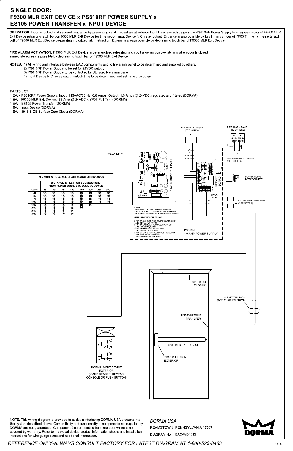
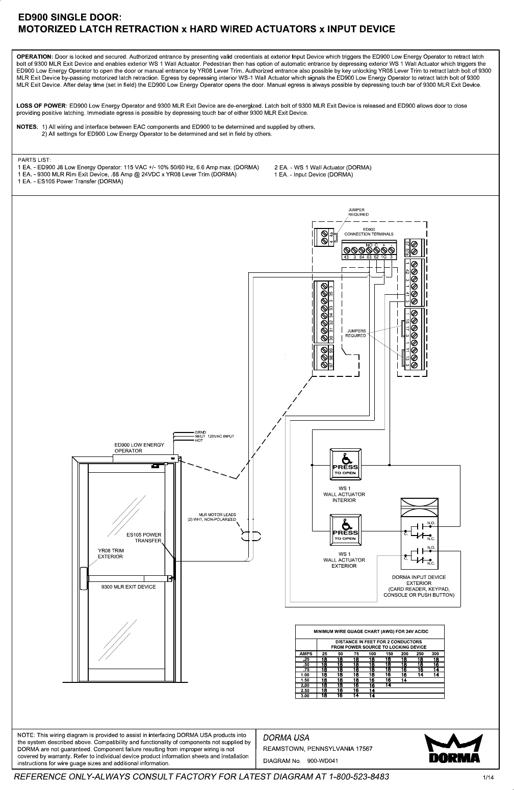
See addtional pages for typical wiring diagrams. For additional diagrams or a custom project specific diagram please contact DORMA at number below.
Addtional options available such as MS,CD,LM, BPA etc.; However minimum cut lengths may different than shown.
AMPS 25 50 75 100 150 200 250 300
MINIMUM WIRE GUAGE CHART (AWG) FOR 24V AC/DC
DISTANCE IN FEET FOR 2 CONDUCTORS
FROM POWER SOURCE TO LOCKING DEVICE
.25
.50
.75
1.00
1.50
2.00
2.50
3.00
18 18 18 18 18 18 18 18
18 18 18 18 18 18 18 16
18 18 18 18 18 16 16 14
18 18 18 18 16 16 14 14
18 18 18 16 16 14
18 18 16 16 14
18 18 16 14
18 16 14 14