Dowtelecom DTT-1900 CDMA PCS WLL TERMINAL User Manual dtt800 1900 user manual
Dowtelecom Inc. CDMA PCS WLL TERMINAL dtt800 1900 user manual
UserManual.wiki
>
Dowtelecom
>
DTT 1900 User Manual
USER MANUAL
Navigation menu
Upload a User Manual
Namespaces
Wiki Guide
HTML
PDF
Info
Views
User Manual
Discussion / Help
Navigation
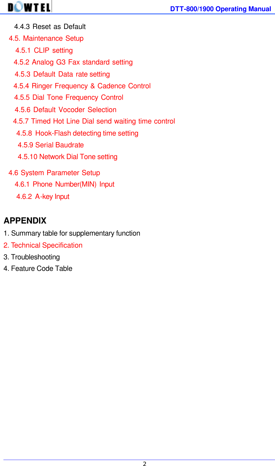
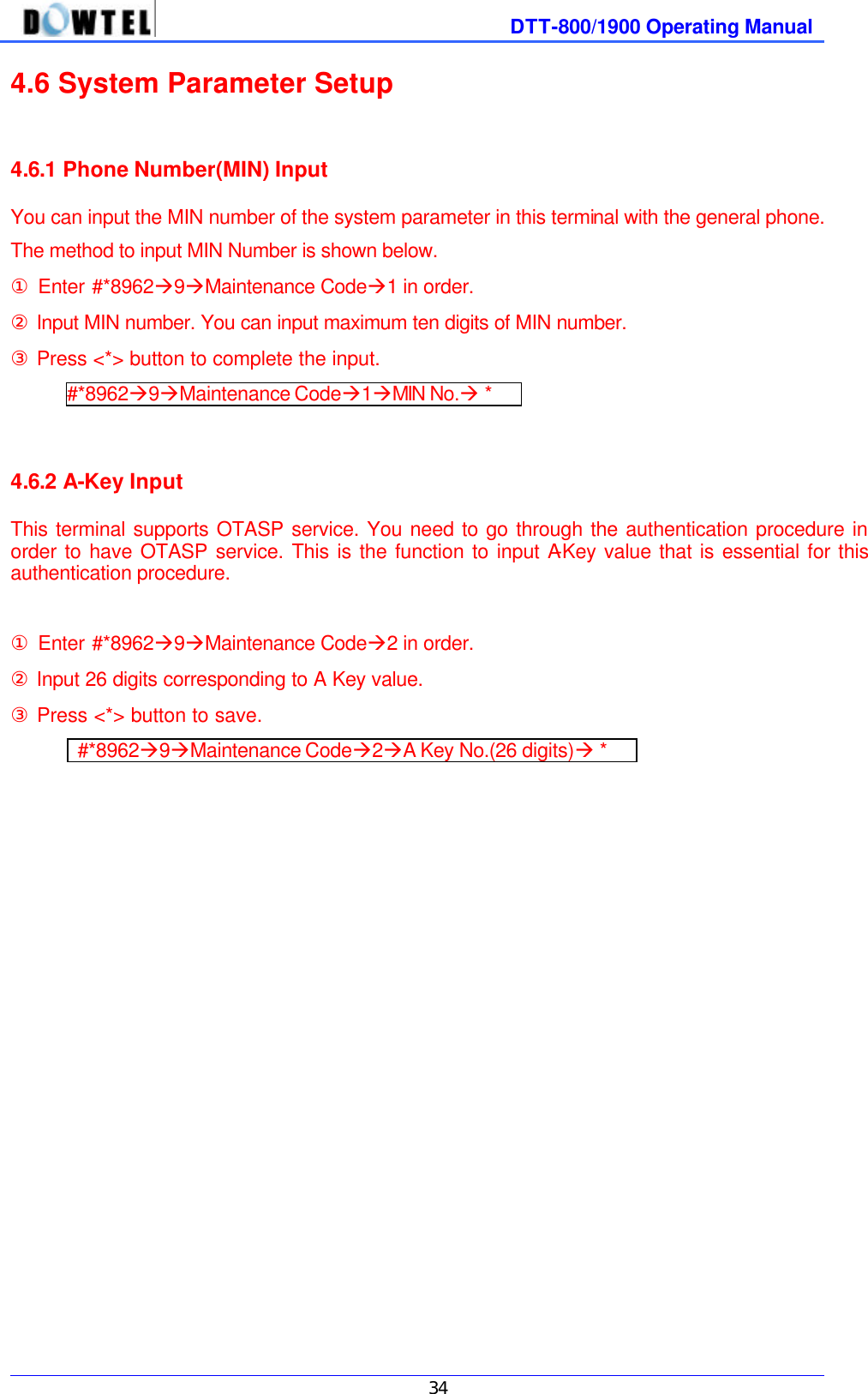
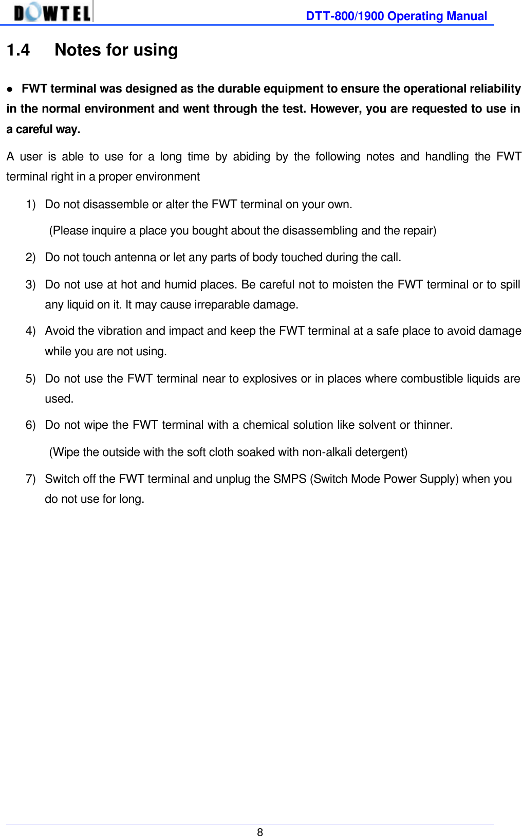
![DTT-800/1900 Operating Manual 4 1. Before Using This manual consists of the terminal introduction, the installation method, the basic directions, feature code and the technical standard, describing ways to resolve some possible problems in using. Please carefully read through contents of this manual before using this product. [Note] When you have any questions or think that you got any product defect in using FWT terminal, please contact a place you bought. 1.1 Accessories check FWT terminal provides following accessories. After purchasing, you are required to open up the box and check out if accessories inside consist of all as below. - - FWT terminal Antenna TEL LINE SMPS User’s Manual Screws](https://usermanual.wiki/Dowtelecom/DTT-1900/User-Guide-167574-Page-4.png)
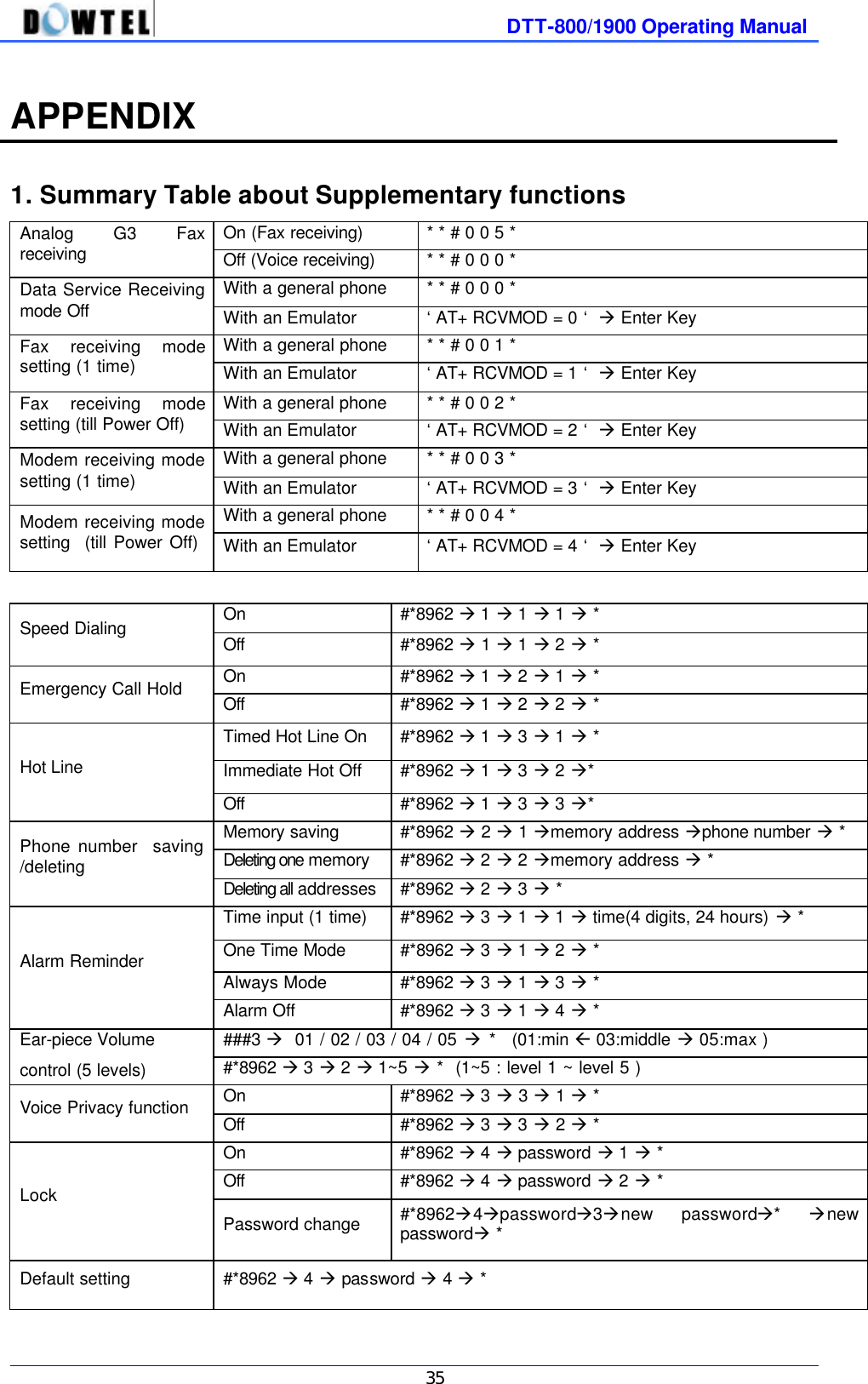
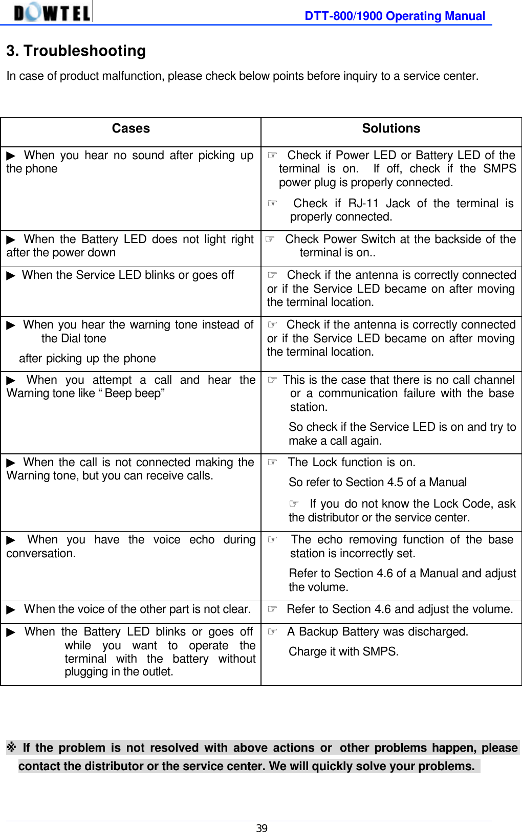
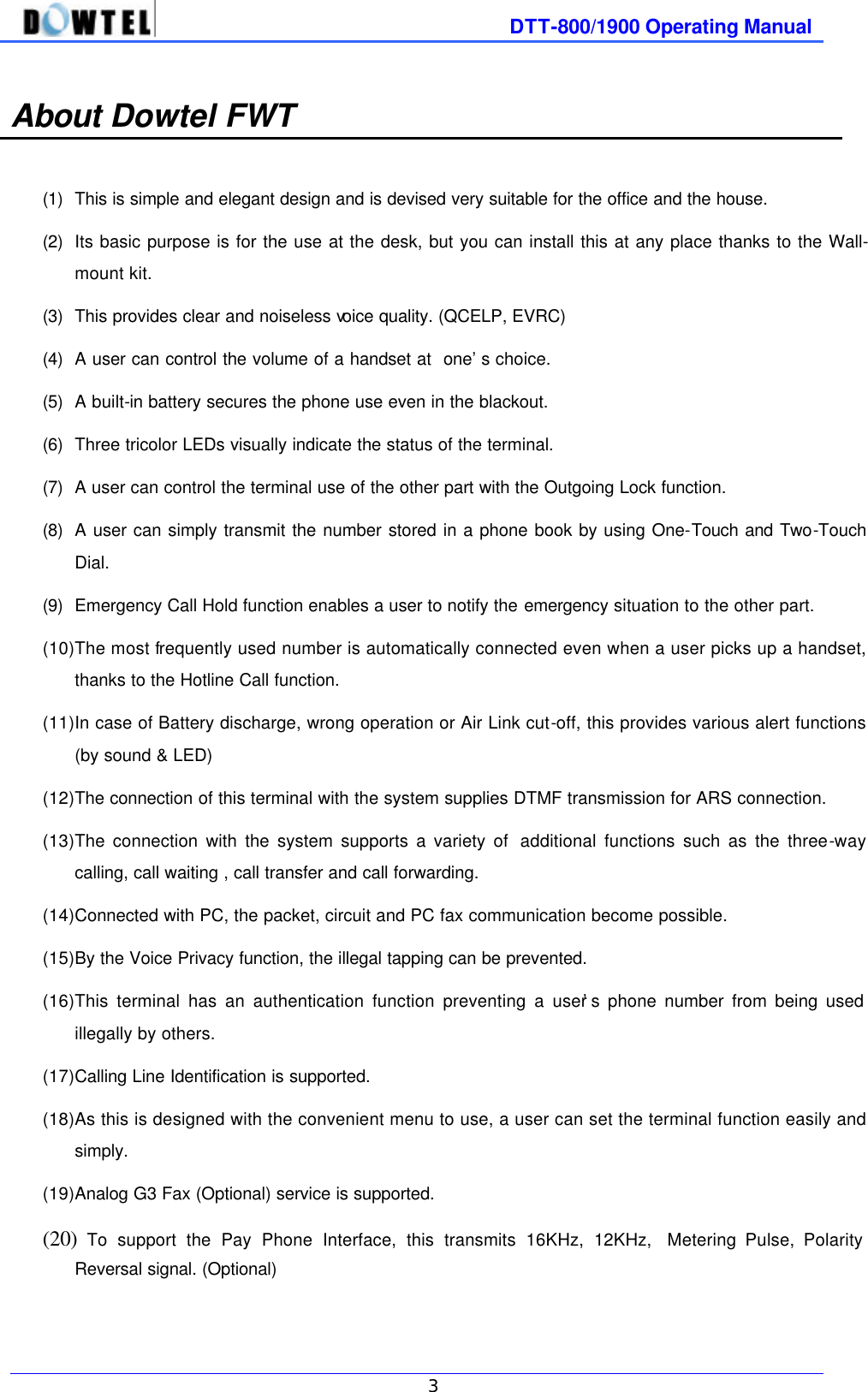
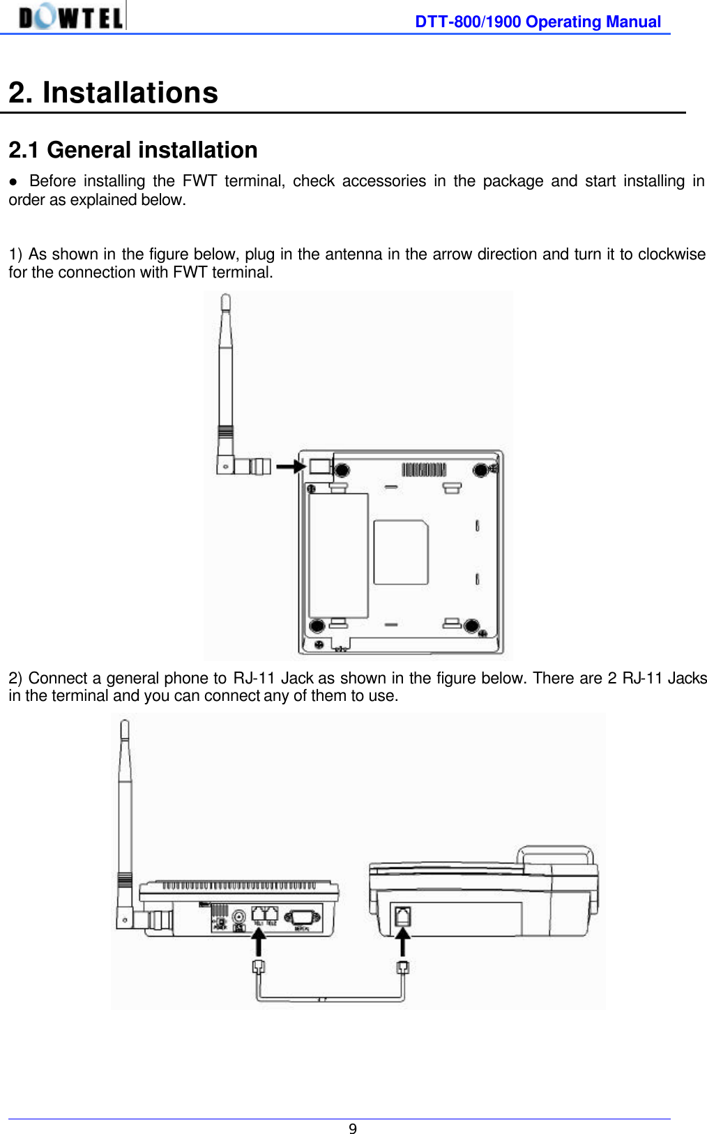
![DTT-800/1900 Operating Manual 6 l SERVICE LED Indicates call service availability. Power intensity (dBm) RSSI Level LED status Terminal status ~ -85 5 Green Service available -86 ~ -91 4 “ “ -92 ~ -97 3 “ “ -98 ~ -103 2 “ “ -104 ~ -110 1 Green & Blink “ -111 ~ 0 Red No Service During a call Orange Indicates during a call LED Red : Indicates the call service is not available as the receiving power intensity is weak. LED Green & Blink : Indicates the call service is available although the receiving power intensity is weak. LED Green : Indicates the receiving power intensity is strong and the call service is available. LED Orange : Indicates the call service is now on, regardless of the receiving power intensity. [Notice] Malfunction Indicator In case of the terminal malfunction, Service LED and Battery LED light in red and blink at the same time. Please contact the service provider for this matter. l DC JACK Through This part, the SMPS supplies the FWT terminal with the power. - AC Input voltage of SMPS ranges 100 ~ 240 V. l POWER SWITCH The power of FWT terminal consists of the external and the internal power. Although DC Jack at the terminal backside gets unplugged, the terminal does operate until the built-in battery discharges. If a user does not use the terminal for long or wants to turn off the power, please switch off the power. l SERIAL PORT A port used to connect to the PC for the maintenance/repair and the data communication. l RJ-11 JACK Connects the general phone or a fax. - This terminal is basically provided with 2 jacks. - You can connect 2 phones at the same time but there is no mutual security function. - You can connect up to 5 phones to RJ-11 jack. (A user must buy additional parts to extend the connection)](https://usermanual.wiki/Dowtelecom/DTT-1900/User-Guide-167574-Page-6.png)
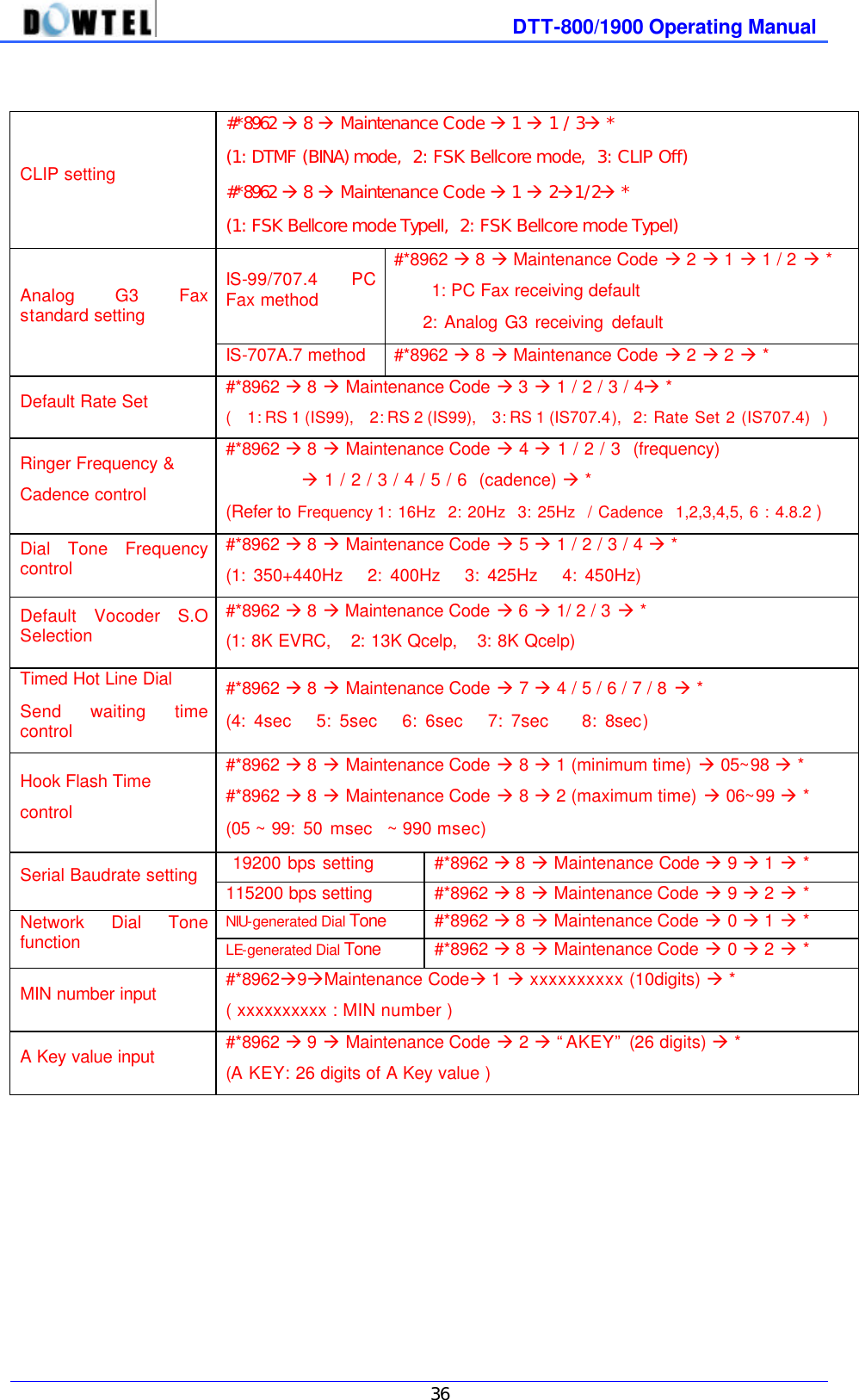
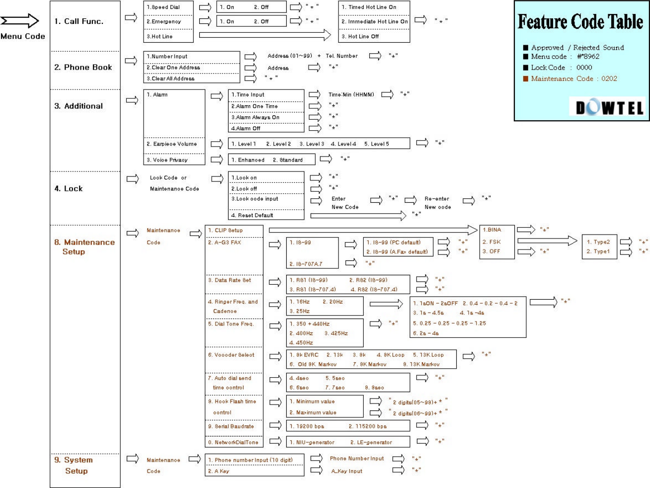
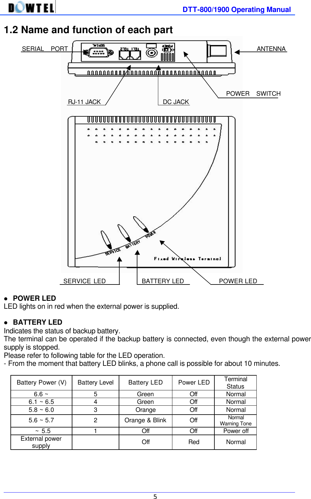
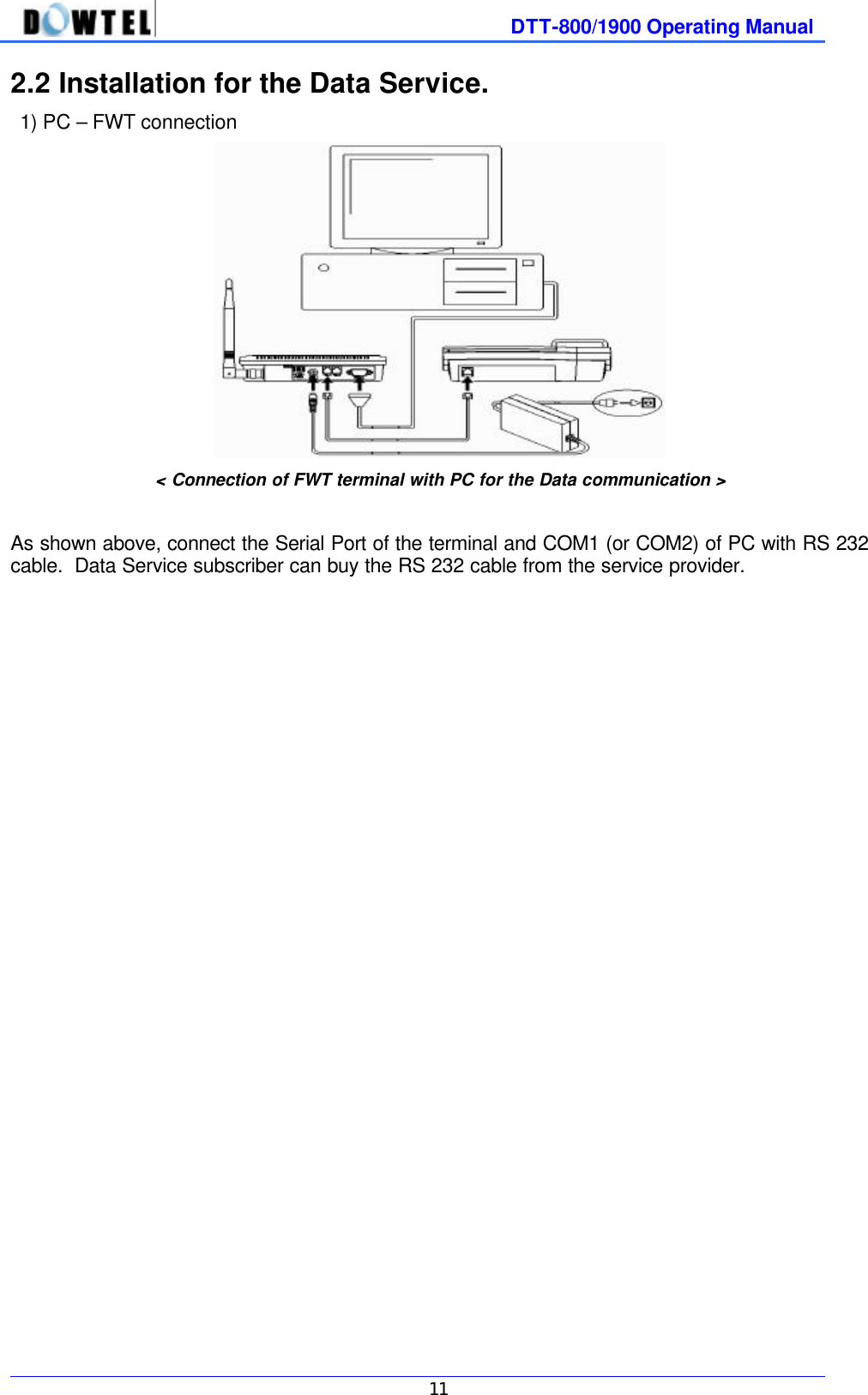
![DTT-800/1900 Operating Manual 10 3) Connect SMPS exclusively used for the FWT terminal to DJ-JACK positioned at the left of terminal. At this time, properly insert the power jack until it is not inserted any further. 4) Connect the power plug of SMPS to the outlet. 5) Switch on the power and the next operation is done as follows. l After all 3 lamps(LED) light on, only a power lamp that is now on the use lights. l After a power-up beep sound through the terminal, a service lamp lights on to indicate the call available. [Notes] Malfunction Indicator In case of a malfunction, a service LED and a battery LED light in red and blink at the same time. Inquire a service provider for this.](https://usermanual.wiki/Dowtelecom/DTT-1900/User-Guide-167574-Page-10.png)
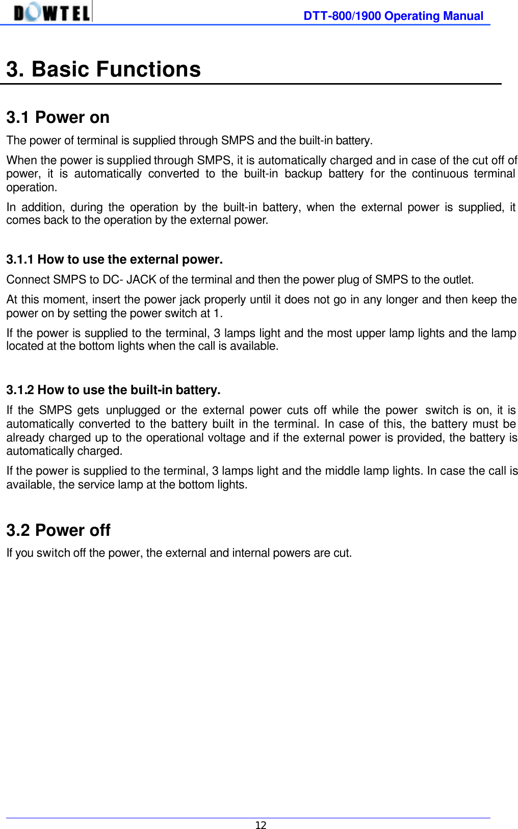
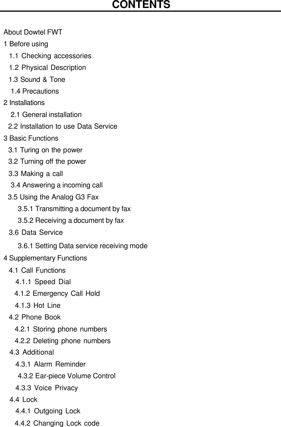
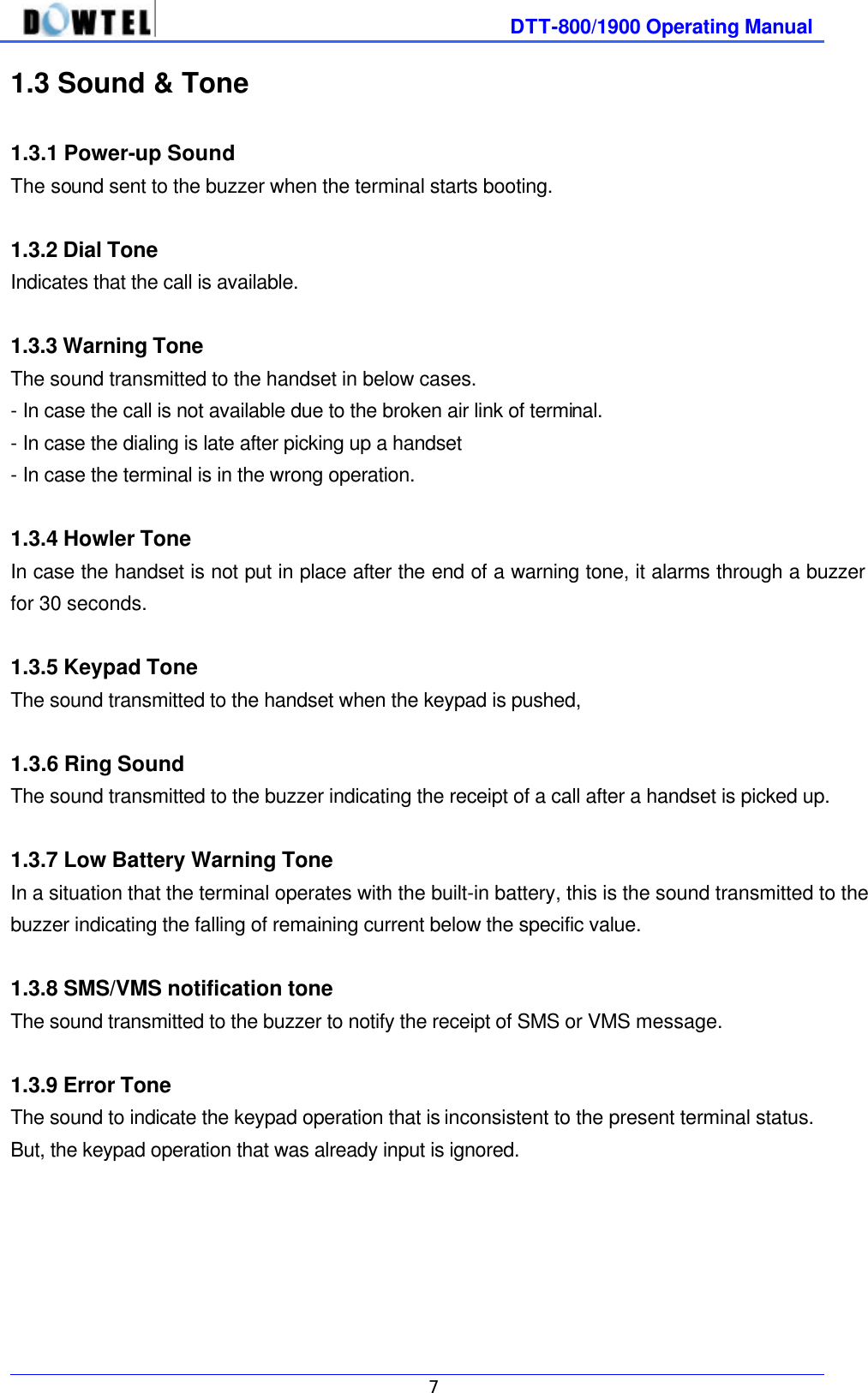
![DTT-800/1900 Operating Manual 13 3.3 Making a call 3.3.1 General method 1) Pick up the handset and you will hear the dial tone (off-hook state). 2) The Dial Tone transmits the even sound in succession and it indicates making a call is possible. 3) If the tone is heard at the interval of 0.5 second (warning tone), it indicates making a call is not possible. 4) In the situation of point 2), dial the telephone number and click the hook switch (hook-flash). 5) Talk with the other part when connected (Service LED is orange). 6) If you put down the handset (on-hook), the call is ended. [Notice] Malfunction Indicator In case of a malfunction, a service LED and a battery LED light in red and blink at the same time. Inquire a service provider for this. 3.3.2 Making a call by using the speed dial In order to use this function, you need to set the speed dial function previously. About its setting method, refer to 4.1. 1) In case numbers that you want to dial are stored under addresses 01~09, pick up the handset and after pressing the speed dial (1~9), do the hook-flash or press the dial for long. You can talk when connected to the other part (Service LED is orange). If you want to end the call, put down the handset. 2) In case numbers that you want to dial are stored under addresses 10~99, Pick up the handset and after pressing the speed dial (10~99), do the hook-flash or press the first number for short and the second number for long. You may talk when connected to the other part (Service LED is orange). If you put down the handset, the call ends. 3.3.3 Making a call by using the redial function The redial function is used when you want to make a call to the last dialed telephone number and the additional setting is not necessary. 1) If you pick up the handset and do the hook-flash, it is connected to the last dialed number. But, if the number was never dialed once after the power on, this function does not work. 2) Pick up the handset and do the hook-flash. 3) Talk when connected to the other part (Service LED is orange). 4) The call is terminated if you put down the handset.](https://usermanual.wiki/Dowtelecom/DTT-1900/User-Guide-167574-Page-13.png)
![DTT-800/1900 Operating Manual 15 3.5 How to use Analog G3 Fax Only the terminal equipped with the Analog G3 board in option can send and receive the document in following ways. 3.5.1 Transmitting a document by fax * Press 00 and then a number of a destination. For the next procedure, refer to the instructions of a fax connected to the terminal. 3.5.2 Receiving a document by fax You need to set the terminal receiving mode to receive the document through the Analog G3 fax by using this terminal. Pick up a fax handset and press **#005* to complete setting the receiving mode of Analog G3 fax. An incoming fax message is automatically connected to the general fax connected to the terminal. [Note] The Analog G3 receiving mode of terminal remains operating until the terminal turns off and in this state, it is impossible to receive the voice call. After the completion of a document receipt by fax, press **#000* and be sure to reset the receiving mode of Analog G3 fax.](https://usermanual.wiki/Dowtelecom/DTT-1900/User-Guide-167574-Page-15.png)
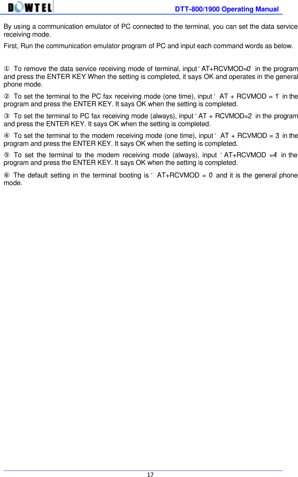
![DTT-800/1900 Operating Manual 16 3.6 Data Service If you use a DATA communication cable of WLL that is provided in option, you can connect to PC and utilize the service like Internet, PC communication and PC fax sending/receiving. In case you intend to use the data service, check following points. • A service provider should supply the wireless data communication function. • When you purchase the data communication cable, you are needed to set up the computer conditions by referring to the provided manual. 3.6.1 Setting Data service receiving mode Some functions are provided with the receipt mode used in regard to the data service for the user’s convenience. • MODEM receive (1 time) : If you received one time by MODEM or 10 minutes pass after setting, the setting is automatically off and it is converted to the general phone mode. • MODEM receive (always) : This mode is maintained until the terminal power turns off. • PC Fax receive (1 time) : If you received a PC Fax one time or 10 minutes pass after setting, it is automatically off and converted to the general phone mode. • PC Fax receive (always) : This mode is maintained until the terminal power turns off. • MODEM/ PC Fax removal (a general phone mode) [Note] PC Fax receive (always) mode and MODEM receive ( always ) mode are maintained until the terminal power is off and a user needs to be careful because a call receiving through the general phone is not possible. Therefore, after using, you are required to convert to the general phone mode. 1) How to set using the general phone You can set the data service receiving mode by using a general phone connected to the terminal. ① Pick up the phone handset and press **#001*. It will be set as the PC Fax receiving mode (one time). ② Pick up the phone handset and press **#002*. It will be set as the PC Fax receiving mode (always). ③ Pick up the phone handset and press **#003*. It will be set as the MODEM receiving mode (one time). ④ Pick up the phone handset and press **#004*. It will be set as the MODEM receiving mode (always). ⑤ The default setting is **#000* and it’s the general phone mode. After the data-related service use is completed, pick up the phone handset and press **#000* at any cost to convert to the general phone mode. 2) Hot to set using AT Command.](https://usermanual.wiki/Dowtelecom/DTT-1900/User-Guide-167574-Page-16.png)
![4. Feature Code 4.1 Call Functions 4.1.1 Speed Dial This is the function to store the phone number in 99 addresses that this terminal allocates and to quickly, conveniently dial by using stored addresses. In case you want to dial using this function, a phone number should be input and the Speed Dial function should be set in advance. 4.1.1.1 Speed Dial Function On / Off You can use or stop the Speed Dial function by setting as follows. 1) Speed Dial On #*8962 à 1 à 1 à 1 à * : Speed Dial function on 2) Speed Dial Off #*8962 à 1 à 1 à 2 à * : Speed Dial function off 4.1.1.2 Making a call by using a Speed Dialing function 1) If phone numbers were saved in the address and the Speed Dial function was already set after using above <the phone number saving in 4.2.1>, you can make a call by entering just the address to quickly dial to a desired number. 2) Entering the saved address is separated into 1-touch and 2-touch. If the saved address is one digit, press <1> ~ <9> button long or do the Hook-flash after pressing for short. Then, you can make a call. 3) If the saved address is two digits, press the first digit short and the second digit long. Or after pressing two digits short , do the Hook-flash. Then, you can make a call. [Notice] If you attempt a Speed Dialing while the Speed Dial function is off, the terminal rings with the Error tone to notify for the wrong operation and making a call is not available.](https://usermanual.wiki/Dowtelecom/DTT-1900/User-Guide-167574-Page-18.png)
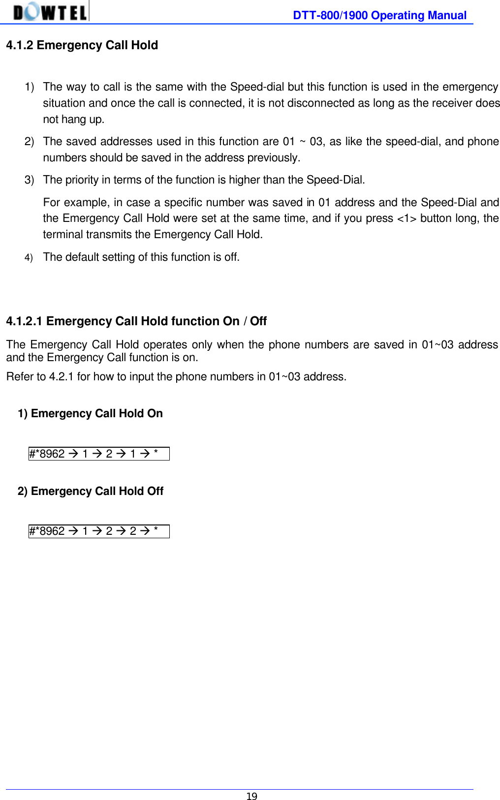
![DTT-800/1900 Operating Manual 20 4.1.3 Hot Line function 1) Making a call is possible by just picking up the handset of the phone connected to the terminal and this is the most convenient, quickest method among dialing methods. 2) The saved address used in this function is only [99] address and the phone number should be saved in advance. 3) The Hot Line function contains the specific setting related to the Dial automatic transmission time. In addition, it has <Timed> and <Immediate>. The first mode means picking up the handset and making a call after a certain time passes. The latter mode means the call is made immediately the moment you pick up the handset. 4) In this function, the priority is higher than the Speed-Dial. 4.1.3.1 Hot Line function On / Off 1) Timed Hot Line On #*8962 à 1 à 3 à 1 → * 2) Immediate Hot Line On #*8962 à 1 à 3 à 2 → * 3) Hot Line Off #*8962 à 1 à 3 à 3 → * 4.1.3.2 Making a call using a Hot Line In the state that the phone number is saved in [99] address and the Hot Line function is set to the Timed Hot Line mode and if the send waiting time (4 ~ 8 seconds) passes in the state of picking up the handset, the call is automatically made. In case the Hot Line function is set to the Immediate Hot Line mode, if you pick up the handset, the call is immediately made to the number saved in the [99] address. [Note] If the Hot Line function is in the Immediate Hot Line mode, you can not make a call to other number. In this case, if you want to make a call to other number, by using the setup mode, pick up the handset and press <#> within 1 second. Then you can go into the setup mode and change the Hot Line mode to use.](https://usermanual.wiki/Dowtelecom/DTT-1900/User-Guide-167574-Page-20.png)
![DTT-800/1900 Operating Manual 21 4.2 Phone Book 4.2.1 Storing phone numbers #*8962 à 2 à 1 à address (2 digits) à phone number à * ① Pick up the phone handset connected and enter the code as shown below. < #*8962 à 2 à 1 > ② Press 2 digits of the address to save. If it is pretended that the address to save is <4>, press [04]. ③ Input the phone numbers to save in succession. ④ If you press <*> button (saving), you can hear the <confirmation sound> and the saving becomes completed. 4.2.2 Deleting phone numbers 4.2.2.1 Deleting a number #*8962 à 2 à 2 à address (2 digits) à * ① Pick up the phone handset connected and enter the code as shown below. < #*8962 à 2 → 2 > ② Press 2 digits of the address to delete. ③ If you press <*> button (saving), you can hear the <confirmation sound> and the deleting becomes completed. 4.2.2.2 Deleting all numbers #*8962 à 2 à 3 à * ① Pick up the phone handset connected and enter the code as shown below. < #*8962 à 2 → 3 > ② If you press <*> button (saving), you can hear the <confirmation sound> and the deleting becomes completed.](https://usermanual.wiki/Dowtelecom/DTT-1900/User-Guide-167574-Page-21.png)
![DTT-800/1900 Operating Manual 25 4.4 LOCK 4.4.1 Outgoing Lock The Outgoing Lock function is used to block other people from using this terminal. If you make a call while this function is on, the terminal generates the Error Sound and making a call becomes not possible. One thing, as this function locks only the outgoing call, receiving a call is possible in spite of the Outgoing Lock function. To use the phone, you need to remove this function and enter the password for the function removal and setting. [Reference] If Emergency Call and Outgoing Lock function are set at the same time, only the emergency call (01~03 address) sending is allowed. Default setting is <Outgoing Lock off>. 4.4.1.1 Outgoing Lock On / Off ① Enter #*8962 à 4 ② Enter four digits of a password. [Note] If you enter the incorrect password, the Reject Tone rings and you need to enter the password again. There will be no sound if you enter the correct password. ③ Press <1> button to set this function and <2> to reset this function. ④ Press <*> button to terminate this function. #*8962 à 4 à password à 1 à * : Lock function On #*8962 à 4 à password à 2 à * : Lock function Off 4.4.2 Changing Lock Code (User’s password) ① Enter #*8962 à 4 to change your password. ② Press <3> after entering a password in use. ③ Enter the new password and press * button. ④ Enter the new password again and press * button. Then, it will be changed to a new password. #*8962à4àpasswordà 3ànew passwordà * ànew passwordà * : password change [ Note ] Default password is 0000](https://usermanual.wiki/Dowtelecom/DTT-1900/User-Guide-167574-Page-25.png)
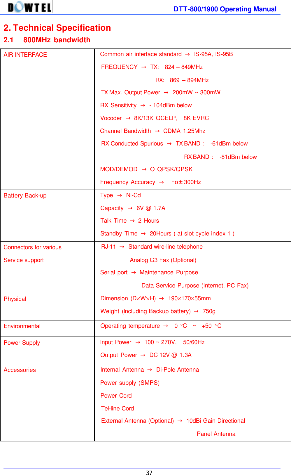
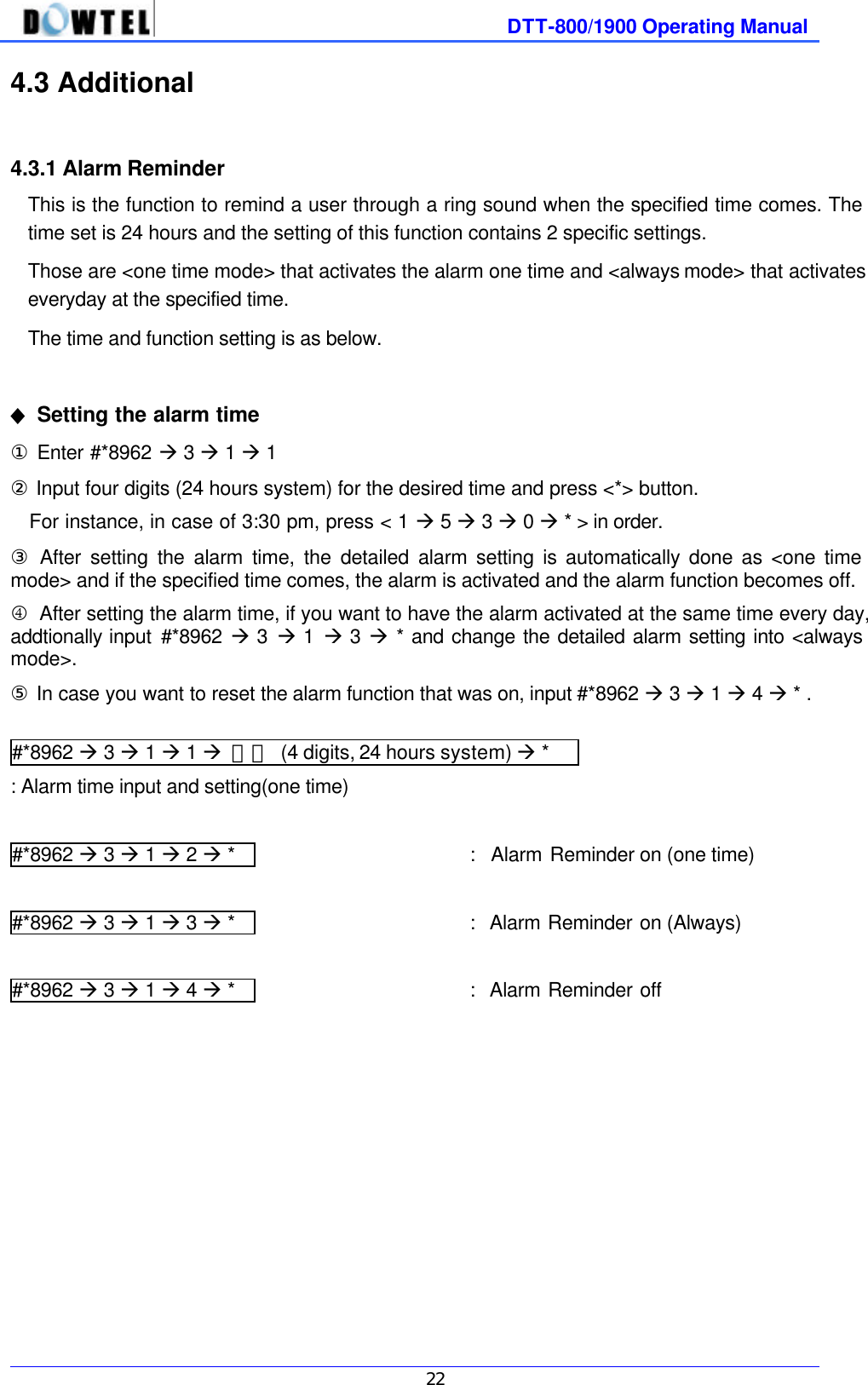
![DTT-800/1900 Operating Manual 26 4.4.3 Reset as Default This is used to transfer the main settings of the terminal to the default setting when the terminal is released. ◆ How to do the default setting. ① Press #*8962à4 ② Enter a password and press <4>. ③ If you press <*> button, terminal functions listed below become the default. #*8962 à4àpasswordà 4 à * : How to do the default setting [Note] Reset items and their status are as below. Items Status Speed Dial Off Emergency call hold Off Hot line call Off Alarm Off Outgoing Lock Off Handset Level 3](https://usermanual.wiki/Dowtelecom/DTT-1900/User-Guide-167574-Page-26.png)
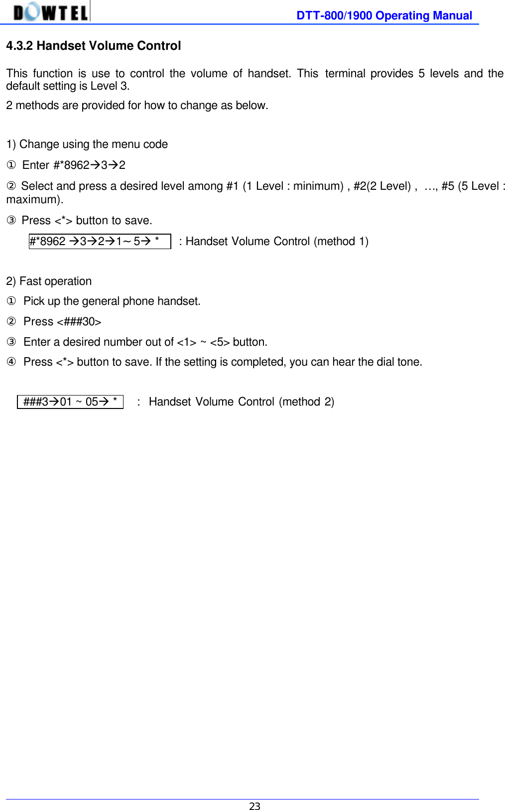
![DTT-800/1900 Operating Manual 27 4.5 Maintenance Setup 4.5.1 CLIP setting Since this terminal has no display like LCD, the calling party’s number of an incoming call can be indicated when it is connected to the general phone with display and the specific module. In this case, you need to set the communication method between the terminal and the module. Communication methods of the terminal include DTMF mode and FSK mode. ① Enter #*8962 à 8 ② Press Maintenance Code à 1 ③ Press <1> for [DTMF mode] <2> for [FSK mode] <3> for [OFF] ④ Press <*> button to complete the setting. #*8962à8àMaintenance Codeà1à1à * : CLIP method setting (DTMF mode) #*8962à8àMaintenance Codeà1à2à 1* : CLIP method setting (FSK Type2 mode) #*8962à8àMaintenance Codeà1à2à 2* : CLIP method setting (FSK Type1 mode) #*8962à8àMaintenance Codeà1à3à * : CLIP method setting (OFF) ☞ Reference : Maintenance Code is “0202” This number is allowed for the maintenance & repair only.](https://usermanual.wiki/Dowtelecom/DTT-1900/User-Guide-167574-Page-27.png)
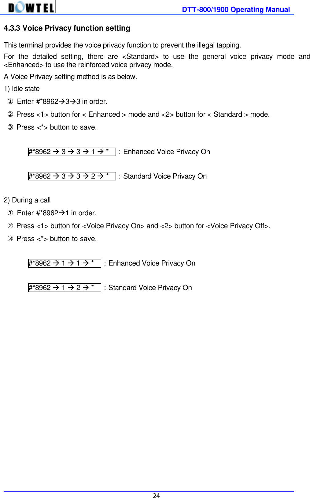
![DTT-800/1900 Operating Manual 28 4.5.2 Analog G3 Fax Setting 1) A user can get the Analog G3 Fax Service from this terminal using below standards. - IS-99/IS-707.4 based PC Fax standard - IS-707A.7 Analog G3 Fax standard [Note] In case of IS-99/IS-707.4 based PC Fax standard, a service provider must inquire a user to decide the fax receiving method in advance whether it should be done by a fax program of PC connected to the terminal or by the Analog G3 fax connected to the terminal. (A fax program or the Analog G3 Fax becomes a Default Fax Receiver) 2) In case of IS-99/IS-707.4 based PC Fax standard, ① Enter #*8962à8àMaintenance Codeà2à1 in order ② Set the Default Fax Receiver Press <1> button to receive an incoming fax through a fax program connected to the terminal. Or press <2> button to receive an incoming fax through the Analog G3 Fax connected to the terminal. ③ Press <*> button to complete the setting. [Note] Default Fax Receiver is system-dependent. ▶ In case a system is composed of Single Dial Number : In other words, if a user tries to use a fax and the voice call with a sing dial number, according to one’s decision on <3.6.1 data service receiving mode setting>, the voice call or a fax receive will be selected. In this regard, Default Fax Receiver setting does not mean much. ▶ In case a system is composed of Two Dial Number. : In other words, in case each number is given to the voice call and a fax despite using in the same terminal, when a fax is received, a fax service option is already decided and the signal is taken. Accordingly, depending on the Default Fax Receive setting, the terminal receives a fax by a fax program of PC or by the Analog G3 fax connected to a terminal. 3) In case of IS-707A.7 Analog G3 Fax standard ① Enter #*8962à8àMaintenance Codeà2 in order ② Press <2> button ③ Press <*> button to complete.](https://usermanual.wiki/Dowtelecom/DTT-1900/User-Guide-167574-Page-28.png)
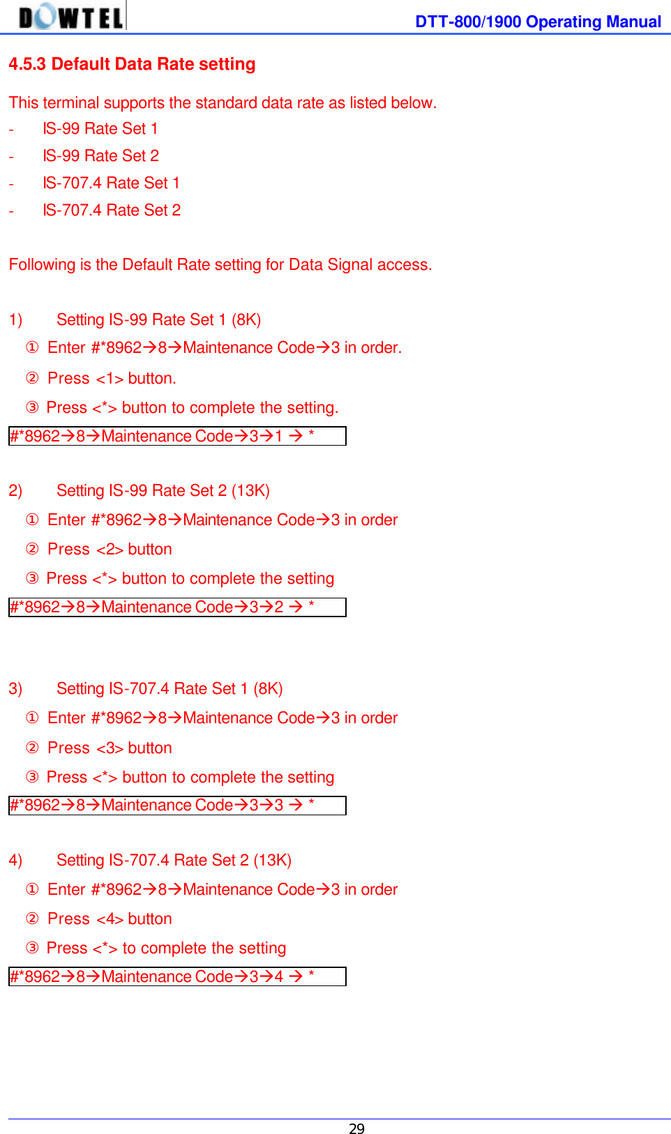
![DTT-800/1900 Operating Manual 32 4.5.7 Timed Hot Line Dial Send Waiting Time Control In < 4.1.3 Hot Line function on and off > when it is set to Timed Hot Line, this function is used to control the time taken from picking up the handset to the automatic dial sending. Hot Line number send time is adjustable from 4 sec to 8 sec and default setting is 6 sec. The 2 setting methods are provided to Timed Hot Line Dial Send Waiting Time. ◆ Timed Hot Line Dial Send Waiting Time setting 1) A menu code use ① Enter #*8962 à 8 à Maintenance Codeà7 ② Press one number out of 4 , 5 , 6 , 7 , 8 button. For example, if you press <5> button, the send waiting time becomes 5 sec. ③ Press <*> button in succession. #*8962 à 8 à Maintenance Codeà 7 à 4~8 à * 2) Fast menu ① Pick up the handset of general phone and press <***1> ② Input the number of desired time between 4 sec~8 sec. For example, press <07> and the send waiting time becomes 7 sec and the setting is completed. ***1 à 04~08 4.5.8 Hook-Flash Detect Time Setting In case of the Redial, Speed Dial, the normal Dialing, you can control the minimum and the maximum time needed to recognize the Hook-Flash which is used to send the dial. Default setting is 100 ~ 700ms and the setting method is as below. 1) The minimum time setting method ① Enter #*8962à8àMaintenance Codeà8à1 ② Enter two digits (05~98) for the minimum time by the 10m sec. For example, if you want to set 150msec, enter <15>. [Note] The minimum time is set to 50 ~ 90msec, a phone used for the Dial Pulse does not work. ③ Press <*> button to save. #*8962à8àMaintenance Codeà8à1à05~98à* 2) The maximum time setting method ① Enter #*8962à8àMaintenance Codeà8à2 ② Enter two digits (06~99) for the maximum time by the 10msec. [Note] If the maximum time is set in lower value than the minimum time, the Error Tone rings. In this case, enter 2 digits of time value again and carry out the following course. ③ Press <*> button to save. #*8962à8àMaintenance Codeà8à2à06~99à*](https://usermanual.wiki/Dowtelecom/DTT-1900/User-Guide-167574-Page-32.png)
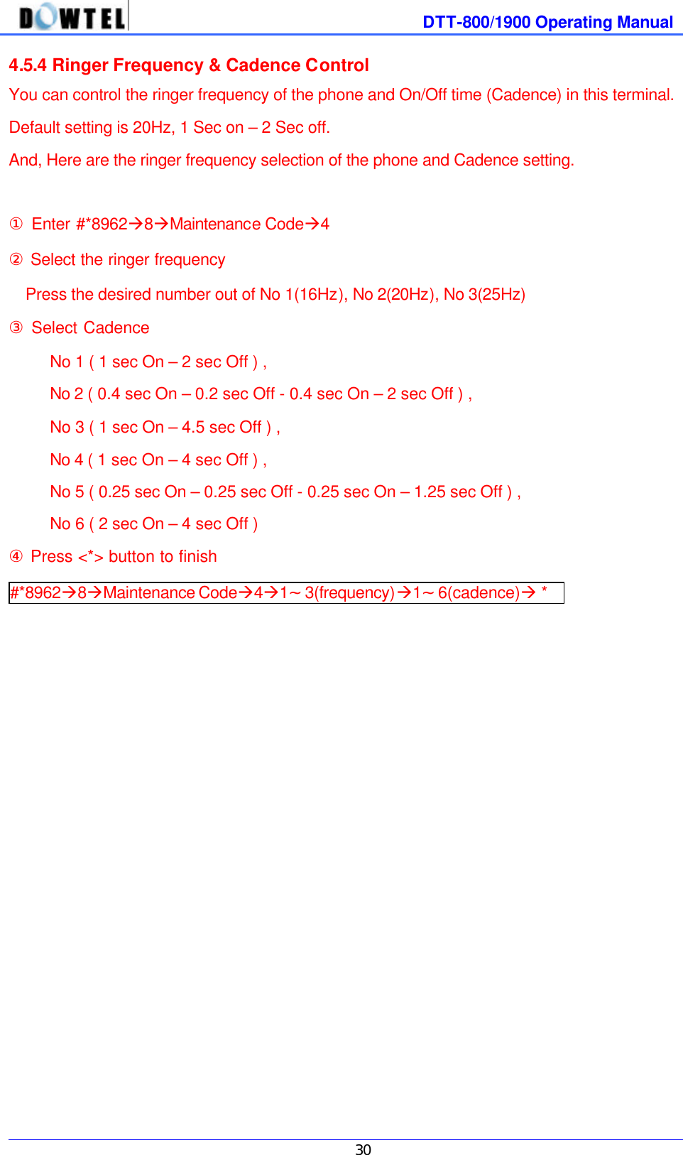
![DTT-800/1900 Operating Manual 33 4.5.9 Serial Baudrate This terminal supports the Data Service function, connected to a PC through a Serial Interface that complies with RS-232 standard. It provides two communication speeds for the PC interface. Those are 115200 bps for the high speed packet data service and 19200 bps for a modem, PC fax and the low speed packet data service. 1) How to set Serial Baudrate to 19200 bps #*8962à8àMaintenance Codeà9à1 à * 2) How to set Serial Baudrate to 115200 bps #*8962à8àMaintenance Codeà9à2 à * 4.5.10 Network Dial Tone setting This terminal provides following 2 kinds of the generated Dial tone. ◆ NIU generate ~ This is a mode that is used by generating the Dial tone inside the terminal itself. ◆ LE generate (Network Dial tone) ~ This is a mode that actually takes a Dial tone from the system. The detailed setting method is as below. ① Enter #*8962à8àMaintenance Codeà0 in order. ② For [NIU generate] mode setting, press <1> button, For [LE generate] mode setting, press <2> button. ③ Press <*> button to complete the setting. #*8962à8àMaintenance Codeà0à1 or 2à *](https://usermanual.wiki/Dowtelecom/DTT-1900/User-Guide-167574-Page-33.png)