Dowtelecom DTT-1900 CDMA PCS WLL TERMINAL User Manual dtt800 1900 user manual
Dowtelecom Inc. CDMA PCS WLL TERMINAL dtt800 1900 user manual
USER MANUAL

CONTENTS
About Dowtel FWT
1 Before using
1.1 Checking accessories
1.2 Physical Description
1.3 Sound & Tone
1.4 Precautions
2 Installations
2.1 General installation
2.2 Installation to use Data Service
3 Basic Functions
3.1 Turing on the power
3.2 Turning off the power
3.3 Making a call
3.4 Answering a incoming call
3.5 Using the Analog G3 Fax
3.5.1 Transmitting a document by fax
3.5.2 Receiving a document by fax
3.6 Data Service
3.6.1 Setting Data service receiving mode
4 Supplementary Functions
4.1 Call Functions
4.1.1 Speed Dial
4.1.2 Emergency Call Hold
4.1.3 Hot Line
4.2 Phone Book
4.2.1 Storing phone numbers
4.2.2 Deleting phone numbers
4.3 Additional
4.3.1 Alarm Reminder
4.3.2 Ear-piece Volume Control
4.3.3 Voice Privacy
4.4 Lock
4.4.1 Outgoing Lock
4.4.2 Changing Lock code

DTT-800/1900 Operating Manual
2
4.4.3 Reset as Default
4.5. Maintenance Setup
4.5.1 CLIP setting
4.5.2 Analog G3 Fax standard setting
4.5.3 Default Data rate setting
4.5.4 Ringer Frequency & Cadence Control
4.5.5 Dial Tone Frequency Control
4.5.6 Default Vocoder Selection
4.5.7 Timed Hot Line Dial send waiting time control
4.5.8 Hook-Flash detecting time setting
4.5.9 Serial Baudrate
4.5.10 Network Dial Tone setting
4.6 System Parameter Setup
4.6.1 Phone Number(MIN) Input
4.6.2 A-key Input
APPENDIX
1. Summary table for supplementary function
2. Technical Specification
3. Troubleshooting
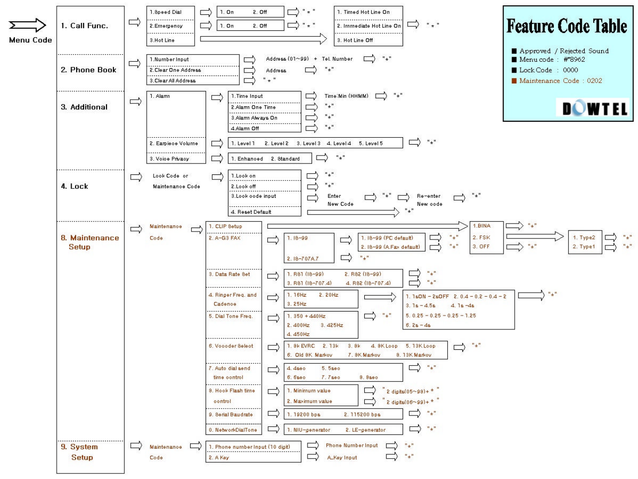
4. Feature Code Table

DTT-800/1900 Operating Manual
3
About Dowtel FWT
(1) This is simple and elegant design and is devised very suitable for the office and the house.
(2) Its basic purpose is for the use at the desk, but you can install this at any place thanks to the Wall-
mount kit.
(3) This provides clear and noiseless voice quality. (QCELP, EVRC)
(4) A user can control the volume of a handset at one’s choice.
(5) A built-in battery secures the phone use even in the blackout.
(6) Three tricolor LEDs visually indicate the status of the terminal.
(7) A user can control the terminal use of the other part with the Outgoing Lock function.
(8) A user can simply transmit the number stored in a phone book by using One-Touch and Two-Touch
Dial.
(9) Emergency Call Hold function enables a user to notify the emergency situation to the other part.
(10)The most frequently used number is automatically connected even when a user picks up a handset,
thanks to the Hotline Call function.
(11)In case of Battery discharge, wrong operation or Air Link cut-off, this provides various alert functions
(by sound & LED)
(12)The connection of this terminal with the system supplies DTMF transmission for ARS connection.
(13)The connection with the system supports a variety of additional functions such as the three-way
calling, call waiting , call transfer and call forwarding.
(14)Connected with PC, the packet, circuit and PC fax communication become possible.
(15)By the Voice Privacy function, the illegal tapping can be prevented.
(16)This terminal has an authentication function preventing a user’s phone number from being used
illegally by others.
(17)Calling Line Identification is supported.
(18)As this is designed with the convenient menu to use, a user can set the terminal function easily and
simply.
(19)Analog G3 Fax (Optional) service is supported.
(20) To support the Pay Phone Interface, this transmits 16KHz, 12KHz, Metering Pulse, Polarity
Reversal signal. (Optional)
DTT-800/1900 Operating Manual
4
1. Before Using
This manual consists of the terminal introduction, the installation method, the basic directions,
feature code and the technical standard, describing ways to resolve some possible problems in
using. Please carefully read through contents of this manual before using this product.
[Note]
When you have any questions or think that you got any product defect in using FWT terminal,
please contact a place you bought.
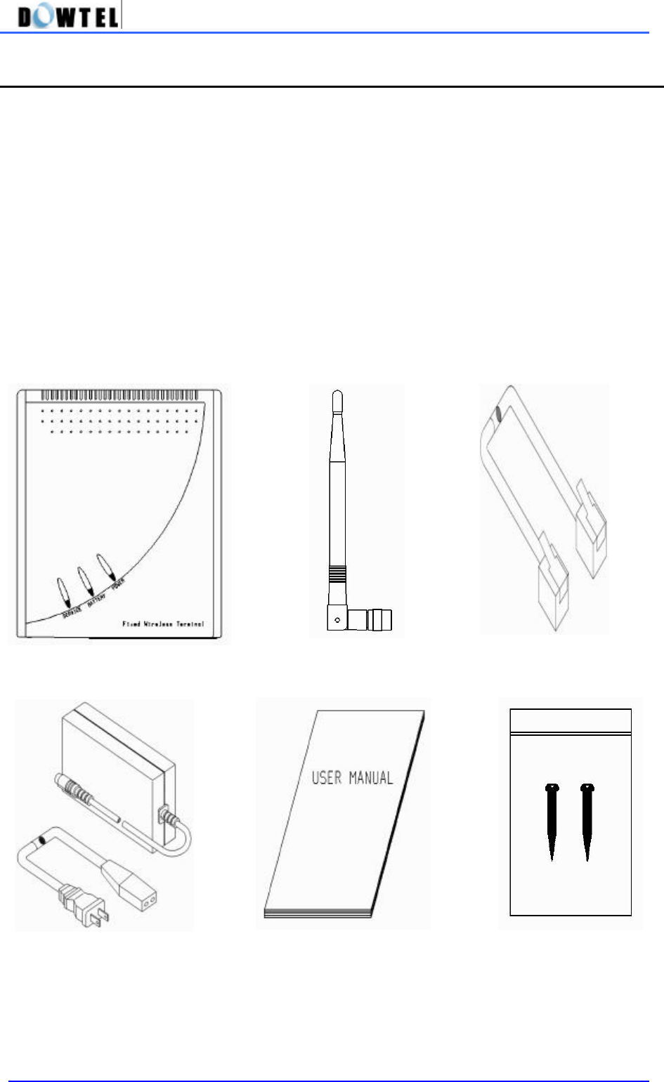
1.1 Accessories check
FWT terminal provides following accessories. After purchasing, you are required to open up the
box and check out if accessories inside consist of all as below.
-
-
FWT terminal Antenna TEL LINE
SMPS User’s Manual Screws
DTT-800/1900 Operating Manual
5
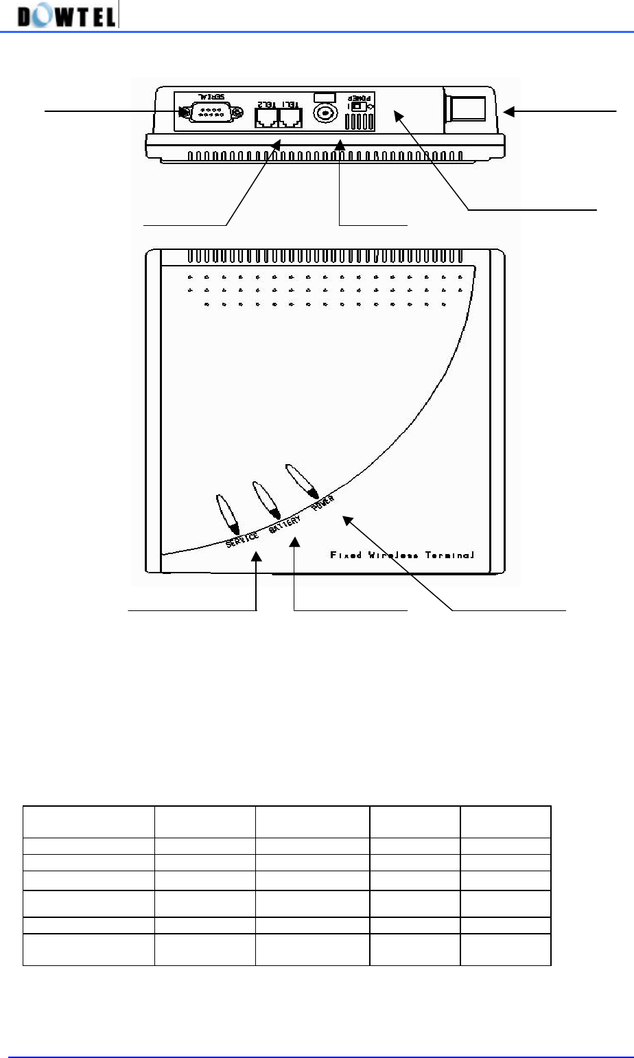
1.2 Name and function of each part
l POWER LED
LED lights on in red when the external power is supplied.
l BATTERY LED
Indicates the status of backup battery.
The terminal can be operated if the backup battery is connected, even though the external power
supply is stopped.
Please refer to following table for the LED operation.
- From the moment that battery LED blinks, a phone call is possible for about 10 minutes.
Battery Power (V) Battery Level Battery LED Power LED Terminal
Status
6.6 ~ 5 Green Off Normal
6.1 ~ 6.5 4 Green Off Normal
5.8 ~ 6.0 3 Orange Off Normal
5.6 ~ 5.7 2 Orange & Blink Off Normal
Warning Tone
~ 5.5 1 Off Off Power off
External power
supply Off Red Normal
SERIAL PORT ANTENNA
RJ-11 JACK DC JACK
POWER SWITCH
SERVICE LED BATTERY LED POWER LED

DTT-800/1900 Operating Manual
6
l SERVICE LED
Indicates call service availability.
Power intensity (dBm)
RSSI Level LED status Terminal status
~ -85 5 Green Service available
-86 ~ -91 4 “ “
-92 ~ -97 3 “ “
-98 ~ -103 2 “ “
-104 ~ -110 1 Green & Blink “
-111 ~ 0 Red No Service
During a call Orange Indicates during a
call
LED Red : Indicates the call service is not available as the receiving power intensity is weak.
LED Green & Blink : Indicates the call service is available although the receiving power intensity is weak.
LED Green : Indicates the receiving power intensity is strong and the call service is available.
LED Orange : Indicates the call service is now on, regardless of the receiving power intensity.
[Notice] Malfunction Indicator
In case of the terminal malfunction, Service LED and Battery LED light in red and blink at the same
time.
Please contact the service provider for this matter.
l DC JACK
Through This part, the SMPS supplies the FWT terminal with the power.
- AC Input voltage of SMPS ranges 100 ~ 240 V.
l POWER SWITCH
The power of FWT terminal consists of the external and the internal power.
Although DC Jack at the terminal backside gets unplugged, the terminal does operate until the
built-in battery discharges. If a user does not use the terminal for long or wants to turn off the
power, please switch off the power.
l SERIAL PORT
A port used to connect to the PC for the maintenance/repair and the data communication.
l RJ-11 JACK
Connects the general phone or a fax.
- This terminal is basically provided with 2 jacks.
- You can connect 2 phones at the same time but there is no mutual security function.
- You can connect up to 5 phones to RJ-11 jack.
(A user must buy additional parts to extend the connection)

DTT-800/1900 Operating Manual
7
1.3 Sound & Tone
1.3.1 Power-up Sound
The sound sent to the buzzer when the terminal starts booting.
1.3.2 Dial Tone
Indicates that the call is available.
1.3.3 Warning Tone
The sound transmitted to the handset in below cases.
- In case the call is not available due to the broken air link of terminal.
- In case the dialing is late after picking up a handset
- In case the terminal is in the wrong operation.
1.3.4 Howler Tone
In case the handset is not put in place after the end of a warning tone, it alarms through a buzzer
for 30 seconds.
1.3.5 Keypad Tone
The sound transmitted to the handset when the keypad is pushed,
1.3.6 Ring Sound
The sound transmitted to the buzzer indicating the receipt of a call after a handset is picked up.
1.3.7 Low Battery Warning Tone
In a situation that the terminal operates with the built-in battery, this is the sound transmitted to the
buzzer indicating the falling of remaining current below the specific value.
1.3.8 SMS/VMS notification tone
The sound transmitted to the buzzer to notify the receipt of SMS or VMS message.
1.3.9 Error Tone
The sound to indicate the keypad operation that is inconsistent to the present terminal status.
But, the keypad operation that was already input is ignored.

DTT-800/1900 Operating Manual
8
1.4 Notes for using
l FWT terminal was designed as the durable equipment to ensure the operational reliability
in the normal environment and went through the test. However, you are requested to use in
a careful way.
A user is able to use for a long time by abiding by the following notes and handling the FWT
terminal right in a proper environment
1) Do not disassemble or alter the FWT terminal on your own.
(Please inquire a place you bought about the disassembling and the repair)
2) Do not touch antenna or let any parts of body touched during the call.
3) Do not use at hot and humid places. Be careful not to moisten the FWT terminal or to spill
any liquid on it. It may cause irreparable damage.
4) Avoid the vibration and impact and keep the FWT terminal at a safe place to avoid damage
while you are not using.
5) Do not use the FWT terminal near to explosives or in places where combustible liquids are
used.
6) Do not wipe the FWT terminal with a chemical solution like solvent or thinner.
(Wipe the outside with the soft cloth soaked with non-alkali detergent)
7) Switch off the FWT terminal and unplug the SMPS (Switch Mode Power Supply) when you
do not use for long.
DTT-800/1900 Operating Manual
9
2. Installations
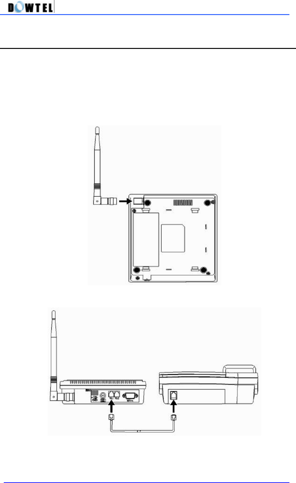
2.1 General installation
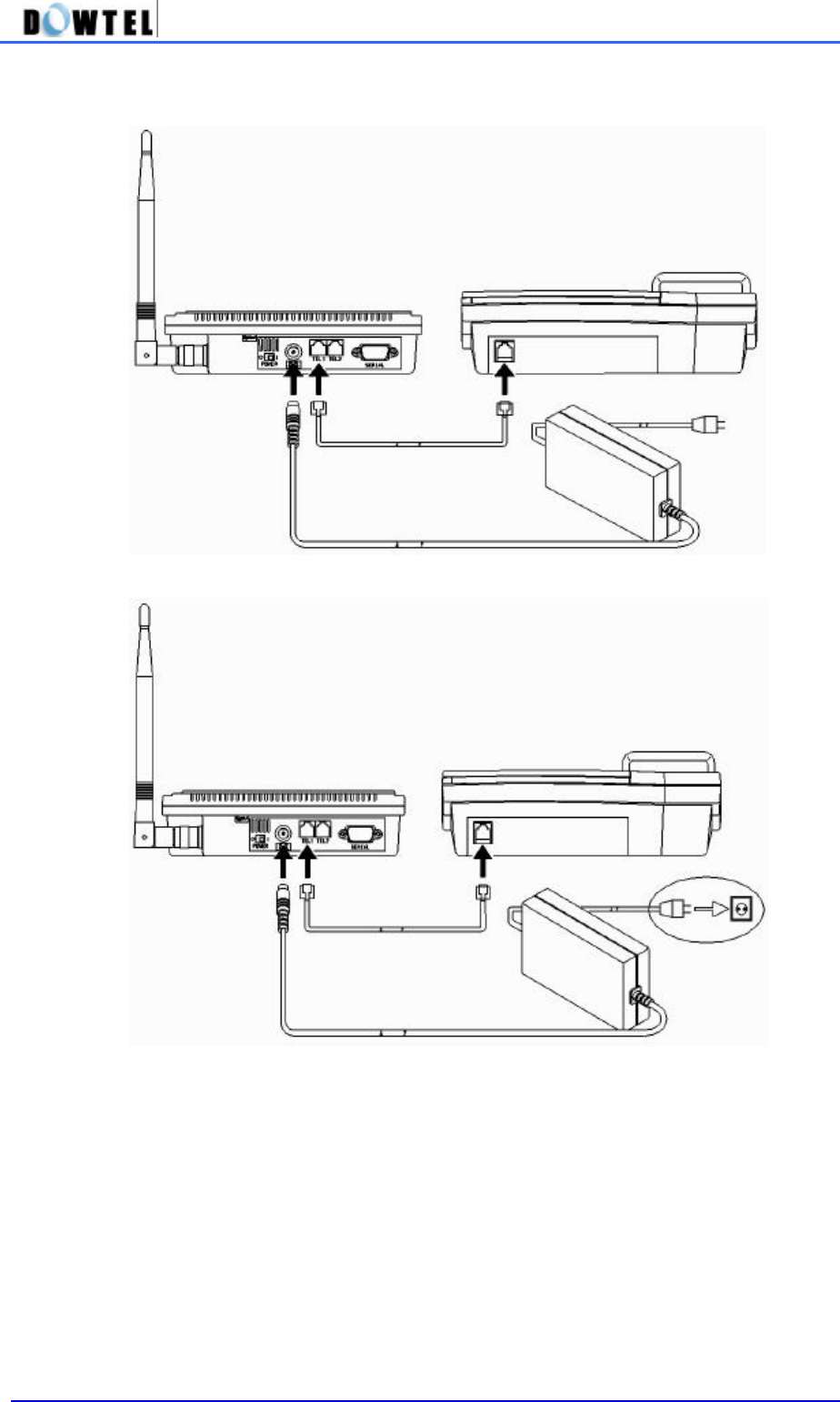
l Before installing the FWT terminal, check accessories in the package and start installing in
order as explained below.
1) As shown in the figure below, plug in the antenna in the arrow direction and turn it to clockwise
for the connection with FWT terminal.
2) Connect a general phone to RJ-11 Jack as shown in the figure below. There are 2 RJ-11 Jacks
in the terminal and you can connect any of them to use.
DTT-800/1900 Operating Manual
10
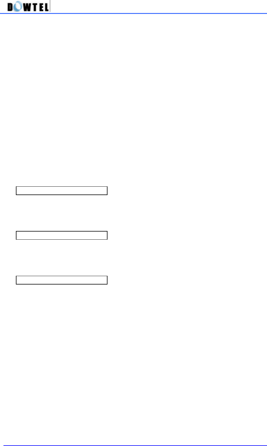
3) Connect SMPS exclusively used for the FWT terminal to DJ-JACK positioned at the left of
terminal. At this time, properly insert the power jack until it is not inserted any further.
4) Connect the power plug of SMPS to the outlet.
5) Switch on the power and the next operation is done as follows.
l After all 3 lamps(LED) light on, only a power lamp that is now on the use lights.
l After a power-up beep sound through the terminal, a service lamp lights on to indicate the call
available.
[Notes] Malfunction Indicator
In case of a malfunction, a service LED and a battery LED light in red and blink at the same time.
Inquire a service provider for this.

DTT-800/1900 Operating Manual
11
2.2 Installation for the Data Service.
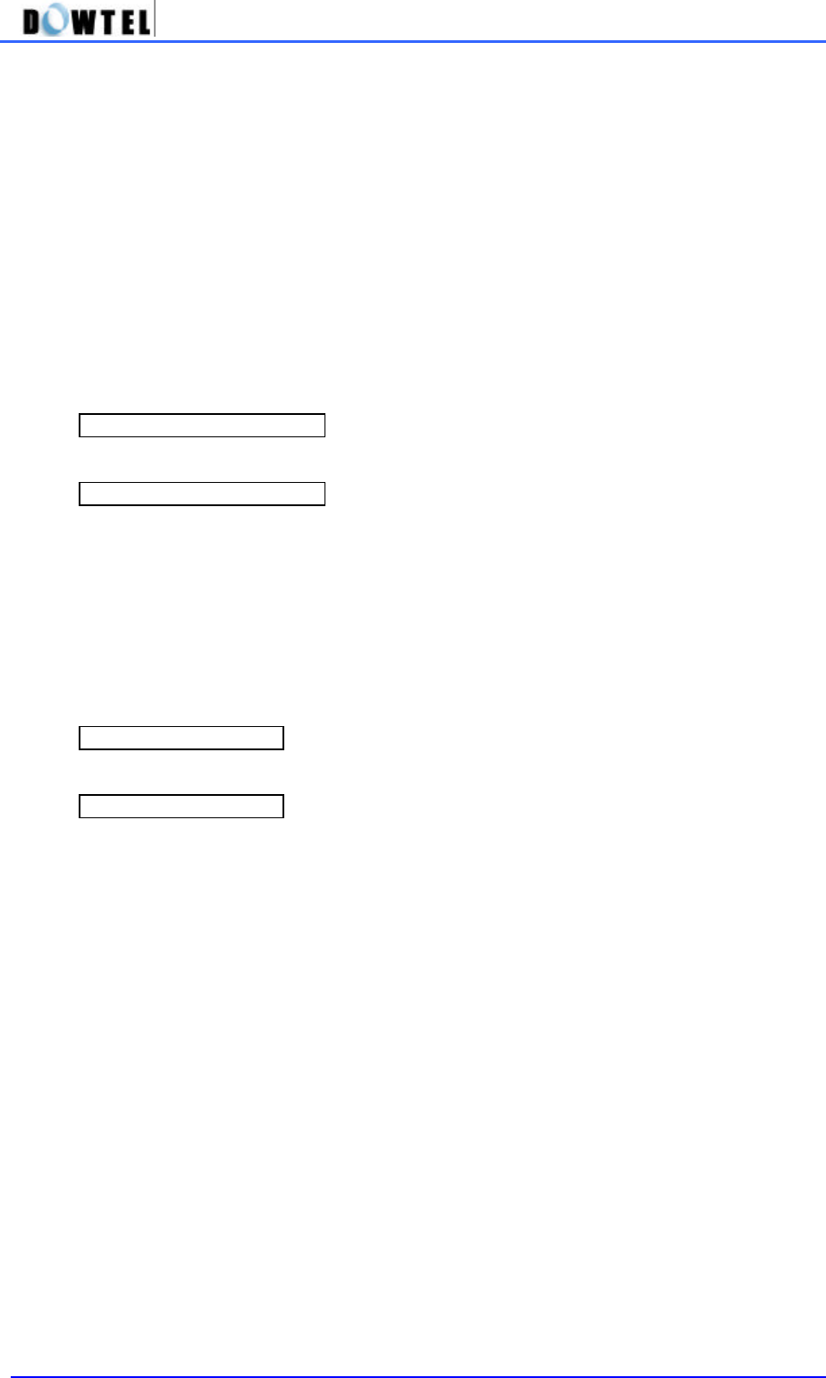
1) PC – FWT connection
< Connection of FWT terminal with PC for the Data communication >
As shown above, connect the Serial Port of the terminal and COM1 (or COM2) of PC with RS 232
cable. Data Service subscriber can buy the RS 232 cable from the service provider.

DTT-800/1900 Operating Manual
12
3. Basic Functions
3.1 Power on
The power of terminal is supplied through SMPS and the built-in battery.
When the power is supplied through SMPS, it is automatically charged and in case of the cut off of
power, it is automatically converted to the built-in backup battery for the continuous terminal
operation.
In addition, during the operation by the built-in battery, when the external power is supplied, it
comes back to the operation by the external power.
3.1.1 How to use the external power.
Connect SMPS to DC- JACK of the terminal and then the power plug of SMPS to the outlet.
At this moment, insert the power jack properly until it does not go in any longer and then keep the
power on by setting the power switch at 1.
If the power is supplied to the terminal, 3 lamps light and the most upper lamp lights and the lamp
located at the bottom lights when the call is available.
3.1.2 How to use the built-in battery.
If the SMPS gets unplugged or the external power cuts off while the power switch is on, it is
automatically converted to the battery built in the terminal. In case of this, the battery must be
already charged up to the operational voltage and if the external power is provided, the battery is
automatically charged.
If the power is supplied to the terminal, 3 lamps light and the middle lamp lights. In case the call is
available, the service lamp at the bottom lights.
3.2 Power off
If you switch off the power, the external and internal powers are cut.

DTT-800/1900 Operating Manual
13
3.3 Making a call
3.3.1 General method
1) Pick up the handset and you will hear the dial tone (off-hook state).
2) The Dial Tone transmits the even sound in succession and it indicates making a call is possible.
3) If the tone is heard at the interval of 0.5 second (warning tone), it indicates making a call is not
possible.
4) In the situation of point 2), dial the telephone number and click the hook switch (hook-flash).
5) Talk with the other part when connected (Service LED is orange).
6) If you put down the handset (on-hook), the call is ended.
[Notice] Malfunction Indicator
In case of a malfunction, a service LED and a battery LED light in red and blink at the same time.
Inquire a service provider for this.
3.3.2 Making a call by using the speed dial
In order to use this function, you need to set the speed dial function previously.
About its setting method, refer to 4.1.
1) In case numbers that you want to dial are stored under addresses 01~09, pick up the
handset and after pressing the speed dial (1~9), do the hook-flash or press the dial for long.
You can talk when connected to the other part (Service LED is orange). If you want to end
the call, put down the handset.
2) In case numbers that you want to dial are stored under addresses 10~99, Pick up the
handset and after pressing the speed dial (10~99), do the hook-flash or press the first
number for short and the second number for long.
You may talk when connected to the other part (Service LED is orange). If you put down the
handset, the call ends.
3.3.3 Making a call by using the redial function
The redial function is used when you want to make a call to the last dialed telephone number and
the additional setting is not necessary.
1) If you pick up the handset and do the hook-flash, it is connected to the last dialed number.
But, if the number was never dialed once after the power on, this function does not work.
2) Pick up the handset and do the hook-flash.
3) Talk when connected to the other part (Service LED is orange).
4) The call is terminated if you put down the handset.

DTT-800/1900 Operating Manual
14
3.4 Receiving an incoming call
3.4.1 On-hook State
1) A phone rings when you have an incoming call.
2) If you pick up the handset, talk when connected to the other part (Service LED is orange).
3) A call is terminated if you put down the handset.
3.4.2 Off-hook State
1) If you have an incoming call, you can hear the ring signal of the general phone. At this time,
do the hook-flash and answer the phone. But, the receiving a call in Off-Hook state is
possible only when the dial tone or the warning tone is heard. It rings through the buzzer.
2) Talk when connected to the other part (Service LED is orange).
3) If you want to end the call, put down the handset.

DTT-800/1900 Operating Manual
15
3.5 How to use Analog G3 Fax
Only the terminal equipped with the Analog G3 board in option can send and receive the document
in following ways.
3.5.1 Transmitting a document by fax
* Press 00 and then a number of a destination. For the next procedure, refer to the instructions of a
fax connected to the terminal.
3.5.2 Receiving a document by fax
You need to set the terminal receiving mode to receive the document through the Analog G3 fax by
using this terminal. Pick up a fax handset and press **#005* to complete setting the receiving
mode of Analog G3 fax. An incoming fax message is automatically connected to the general fax
connected to the terminal.
[Note] The Analog G3 receiving mode of terminal remains operating until the terminal turns off and
in this state, it is impossible to receive the voice call. After the completion of a document receipt by
fax, press **#000* and be sure to reset the receiving mode of Analog G3 fax.

DTT-800/1900 Operating Manual
16
3.6 Data Service
If you use a DATA communication cable of WLL that is provided in option, you can connect to PC
and utilize the service like Internet, PC communication and PC fax sending/receiving.
In case you intend to use the data service, check following points.
• A service provider should supply the wireless data communication function.
• When you purchase the data communication cable, you are needed to set up the computer
conditions by referring to the provided manual.
3.6.1 Setting Data service receiving mode
Some functions are provided with the receipt mode used in regard to the data service for the user’s
convenience.
• MODEM receive (1 time) : If you received one time by MODEM or 10 minutes pass after
setting, the setting is automatically off and it is converted to the general phone mode.
• MODEM receive (always) : This mode is maintained until the terminal power turns off.
• PC Fax receive (1 time) : If you received a PC Fax one time or 10 minutes pass after
setting, it is automatically off and converted to the general phone mode.
• PC Fax receive (always) : This mode is maintained until the terminal power turns off.
• MODEM/ PC Fax removal (a general phone mode)
[Note]
PC Fax receive (always) mode and MODEM receive ( always ) mode are maintained until the
terminal power is off and a user needs to be careful because a call receiving through the general
phone is not possible. Therefore, after using, you are required to convert to the general phone
mode.
1) How to set using the general phone
You can set the data service receiving mode by using a general phone connected to the terminal.
① Pick up the phone handset and press **#001*.
It will be set as the PC Fax receiving mode (one time).
② Pick up the phone handset and press **#002*.
It will be set as the PC Fax receiving mode (always).
③ Pick up the phone handset and press **#003*.
It will be set as the MODEM receiving mode (one time).
④ Pick up the phone handset and press **#004*.
It will be set as the MODEM receiving mode (always).
⑤ The default setting is **#000* and it’s the general phone mode.
After the data-related service use is completed, pick up the phone handset and press **#000* at
any cost to convert to the general phone mode.
2) Hot to set using AT Command.

DTT-800/1900 Operating Manual
17
By using a communication emulator of PC connected to the terminal, you can set the data service
receiving mode.
First, Run the communication emulator program of PC and input each command words as below.
① To remove the data service receiving mode of terminal, input ‘AT+RCVMOD=0’ in the program
and press the ENTER KEY. When the setting is completed, it says OK and operates in the general
phone mode.
② To set the terminal to the PC fax receiving mode (one time), input ‘ AT + RCVMOD = 1’ in the
program and press the ENTER KEY. It says OK when the setting is completed.
③ To set the terminal to PC fax receiving mode (always), input ‘AT + RCVMOD=2’ in the program
and press the ENTER KEY. It says OK when the setting is completed.
④ To set the terminal to the modem receiving mode (one time), input ‘ AT + RCVMOD = 3’ in the
program and press the ENTER KEY. It says OK when the setting is completed.
⑤ To set the terminal to the modem receiving mode (always), input ‘AT+RCVMOD =4’ in the
program and press the ENTER KEY. It says OK when the setting is completed.
⑥ The default setting in the terminal booting is ‘ AT+RCVMOD = 0’ and it is the general phone
mode.

4. Feature Code
4.1 Call Functions
4.1.1 Speed Dial
This is the function to store the phone number in 99 addresses that this terminal allocates and to
quickly, conveniently dial by using stored addresses.
In case you want to dial using this function, a phone number should be input and the Speed Dial
function should be set in advance.
4.1.1.1 Speed Dial Function On / Off
You can use or stop the Speed Dial function by setting as follows.
1) Speed Dial On
#*8962 à 1 à 1 à 1 à * : Speed Dial function on
2) Speed Dial Off
#*8962 à 1 à 1 à 2 à * : Speed Dial function off
4.1.1.2 Making a call by using a Speed Dialing function
1) If phone numbers were saved in the address and the Speed Dial function was already set after
using above <the phone number saving in 4.2.1>, you can make a call by entering just the address
to quickly dial to a desired number.
2) Entering the saved address is separated into 1-touch and 2-touch.
If the saved address is one digit, press <1> ~ <9> button long or do the Hook-flash after pressing
for short. Then, you can make a call.
3) If the saved address is two digits, press the first digit short and the second digit long. Or after
pressing two digits short , do the Hook-flash. Then, you can make a call.
[Notice] If you attempt a Speed Dialing while the Speed Dial function is off, the terminal rings with
the Error tone to notify for the wrong operation and making a call is not available.

DTT-800/1900 Operating Manual
19
4.1.2 Emergency Call Hold
1) The way to call is the same with the Speed-dial but this function is used in the emergency
situation and once the call is connected, it is not disconnected as long as the receiver does
not hang up.
2) The saved addresses used in this function are 01 ~ 03, as like the speed-dial, and phone
numbers should be saved in the address previously.
3) The priority in terms of the function is higher than the Speed-Dial.
For example, in case a specific number was saved in 01 address and the Speed-Dial and
the Emergency Call Hold were set at the same time, and if you press <1> button long, the
terminal transmits the Emergency Call Hold.
4) The default setting of this function is off.
4.1.2.1 Emergency Call Hold function On / Off
The Emergency Call Hold operates only when the phone numbers are saved in 01~03 address
and the Emergency Call function is on.
Refer to 4.2.1 for how to input the phone numbers in 01~03 address.
1) Emergency Call Hold On
#*8962 à 1 à 2 à 1 à *
2) Emergency Call Hold Off
#*8962 à 1 à 2 à 2 à *
DTT-800/1900 Operating Manual
20
4.1.3 Hot Line function
1) Making a call is possible by just picking up the handset of the phone connected to the
terminal and this is the most convenient, quickest method among dialing methods.
2) The saved address used in this function is only [99] address and the phone number should
be saved in advance.
3) The Hot Line function contains the specific setting related to the Dial automatic
transmission time. In addition, it has <Timed> and <Immediate>. The first mode means
picking up the handset and making a call after a certain time passes. The latter mode
means the call is made immediately the moment you pick up the handset.
4) In this function, the priority is higher than the Speed-Dial.
4.1.3.1 Hot Line function On / Off
1) Timed Hot Line On
#*8962 à 1 à 3 à 1 → *
2) Immediate Hot Line On
#*8962 à 1 à 3 à 2 → *
3) Hot Line Off
#*8962 à 1 à 3 à 3 → *
4.1.3.2 Making a call using a Hot Line
In the state that the phone number is saved in [99] address and the Hot Line function is set to the
Timed Hot Line mode and if the send waiting time (4 ~ 8 seconds) passes in the state of picking up
the handset, the call is automatically made.
In case the Hot Line function is set to the Immediate Hot Line mode, if you pick up the handset, the
call is immediately made to the number saved in the [99] address.
[Note]
If the Hot Line function is in the Immediate Hot Line mode, you can not make a call to other number.
In this case, if you want to make a call to other number, by using the setup mode, pick up the
handset and press <#> within 1 second. Then you can go into the setup mode and change the Hot
Line mode to use.

DTT-800/1900 Operating Manual
21
4.2 Phone Book
4.2.1 Storing phone numbers
#*8962 à 2 à 1 à address (2 digits) à phone number à *
① Pick up the phone handset connected and enter the code as shown below.
< #*8962 à 2 à 1 >
② Press 2 digits of the address to save. If it is pretended that the address to save is <4>,
press [04].
③ Input the phone numbers to save in succession.
④ If you press <*> button (saving), you can hear the <confirmation sound> and the saving
becomes completed.
4.2.2 Deleting phone numbers
4.2.2.1 Deleting a number
#*8962 à 2 à 2 à address (2 digits) à *
① Pick up the phone handset connected and enter the code as shown below.
< #*8962 à 2 → 2 >
② Press 2 digits of the address to delete.
③ If you press <*> button (saving), you can hear the <confirmation sound> and the deleting
becomes completed.
4.2.2.2 Deleting all numbers
#*8962 à 2 à 3 à *
① Pick up the phone handset connected and enter the code as shown below.
< #*8962 à 2 → 3 >
② If you press <*> button (saving), you can hear the <confirmation sound> and the deleting
becomes completed.

DTT-800/1900 Operating Manual
22
4.3 Additional
4.3.1 Alarm Reminder
This is the function to remind a user through a ring sound when the specified time comes. The
time set is 24 hours and the setting of this function contains 2 specific settings.
Those are <one time mode> that activates the alarm one time and <always mode> that activates
everyday at the specified time.
The time and function setting is as below.
◆
Setting the alarm time
① Enter #*8962 à 3 à 1 à 1
② Input four digits (24 hours system) for the desired time and press <*> button.
For instance, in case of 3:30 pm, press < 1 à 5 à 3 à 0 à * > in order.
③ After setting the alarm time, the detailed alarm setting is automatically done as <one time
mode> and if the specified time comes, the alarm is activated and the alarm function becomes off.
m After setting the alarm time, if you want to have the alarm activated at the same time every day,
addtionally input #*8962 à 3 à 1 à 3 à * and change the detailed alarm setting into <always
mode>.
⑤ In case you want to reset the alarm function that was on, input #*8962 à 3 à 1 à 4 à * .
#*8962 à 3 à 1 à 1 à 시간 (4 digits, 24 hours system) à *
: Alarm time input and setting(one time)
#*8962 à 3 à 1 à 2 à * : Alarm Reminder on (one time)
#*8962 à 3 à 1 à 3 à * : Alarm Reminder on (Always)
#*8962 à 3 à 1 à 4 à * : Alarm Reminder off

DTT-800/1900 Operating Manual
23
4.3.2 Handset Volume Control
This function is use to control the volume of handset. This terminal provides 5 levels and the
default setting is Level 3.
2 methods are provided for how to change as below.
1) Change using the menu code
① Enter #*8962à3à2
② Select and press a desired level among #1 (1 Level : minimum) , #2(2 Level) , … , #5 (5 Level :
maximum).
③ Press <*> button to save.
#*8962 à3à2à1~5à * : Handset Volume Control (method 1)
2) Fast operation
① Pick up the general phone handset.
② Press <###30>
③ Enter a desired number out of <1> ~ <5> button.
④ Press <*> button to save. If the setting is completed, you can hear the dial tone.
###3à01 ~ 05à * : Handset Volume Control (method 2)
DTT-800/1900 Operating Manual
24
4.3.3 Voice Privacy function setting
This terminal provides the voice privacy function to prevent the illegal tapping.
For the detailed setting, there are <Standard> to use the general voice privacy mode and
<Enhanced> to use the reinforced voice privacy mode.
A Voice Privacy setting method is as below.
1) Idle state
① Enter #*8962à3à3 in order.
② Press <1> button for < Enhanced > mode and <2> button for < Standard > mode.
③ Press <*> button to save.
#*8962 à 3 à 3 à 1 à * : Enhanced Voice Privacy On
#*8962 à 3 à 3 à 2 à * : Standard Voice Privacy On
2) During a call
① Enter #*8962à1 in order.
② Press <1> button for <Voice Privacy On> and <2> button for <Voice Privacy Off>.
③ Press <*> button to save.
#*8962 à 1 à 1 à * : Enhanced Voice Privacy On
#*8962 à 1 à 2 à * : Standard Voice Privacy On

DTT-800/1900 Operating Manual
25
4.4 LOCK
4.4.1 Outgoing Lock
The Outgoing Lock function is used to block other people from using this terminal.
If you make a call while this function is on, the terminal generates the Error Sound and making a
call becomes not possible. One thing, as this function locks only the outgoing call, receiving a call
is possible in spite of the Outgoing Lock function.
To use the phone, you need to remove this function and enter the password for the function
removal and setting.
[Reference] If Emergency Call and Outgoing Lock function are set at the same time, only the
emergency call (01~03 address) sending is allowed.
Default setting is <Outgoing Lock off>.
4.4.1.1 Outgoing Lock On / Off
① Enter #*8962 à 4
② Enter four digits of a password.
[Note] If you enter the incorrect password, the Reject Tone rings and you need to enter the
password again. There will be no sound if you enter the correct password.
③ Press <1> button to set this function and <2> to reset this function.
④ Press <*> button to terminate this function.
#*8962 à 4 à password à 1 à * : Lock function On
#*8962 à 4 à password à 2 à * : Lock function Off
4.4.2 Changing Lock Code (User’s password)
① Enter #*8962 à 4 to change your password.
② Press <3> after entering a password in use.
③ Enter the new password and press * button.
④ Enter the new password again and press * button. Then, it will be changed to a new password.
#*8962à4àpasswordà 3ànew passwordà * ànew passwordà * : password change
[ Note ]
Default password is 0000
DTT-800/1900 Operating Manual
26
4.4.3 Reset as Default
This is used to transfer the main settings of the terminal to the default setting when the terminal is
released.
◆
How to do the default setting.
① Press #*8962à4
② Enter a password and press <4>.
③ If you press <*> button, terminal functions listed below become the default.
#*8962 à4àpasswordà 4 à * : How to do the default setting
[Note]
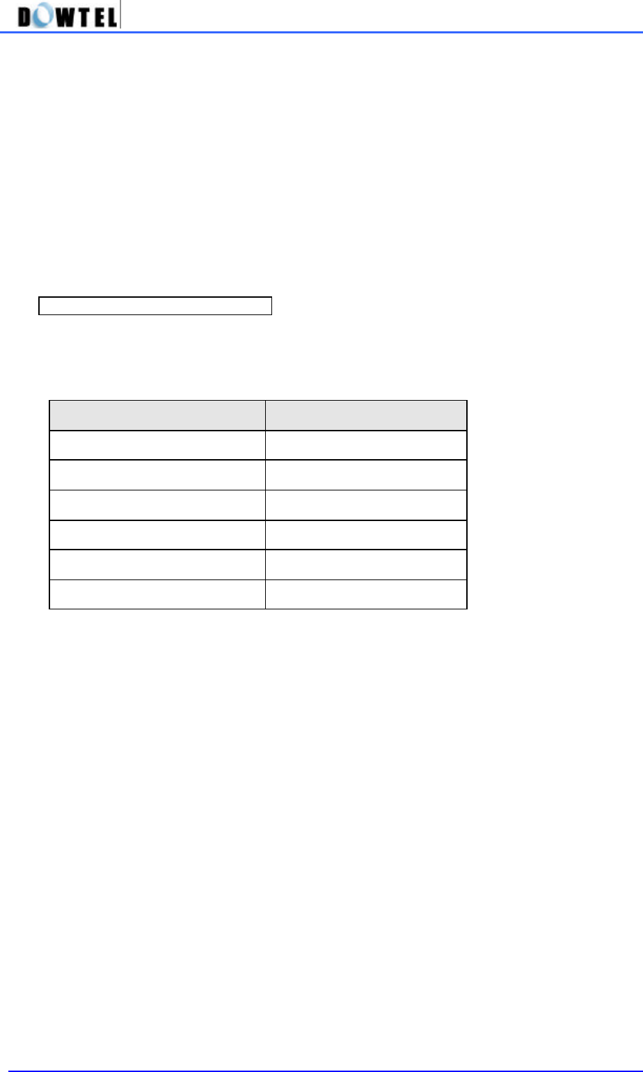
Reset items and their status are as below.
Items Status
Speed Dial Off
Emergency call hold Off
Hot line call Off
Alarm Off
Outgoing Lock Off
Handset Level 3
DTT-800/1900 Operating Manual
27
4.5 Maintenance Setup
4.5.1 CLIP setting
Since this terminal has no display like LCD, the calling party’s number of an incoming call can be
indicated when it is connected to the general phone with display and the specific module.
In this case, you need to set the communication method between the terminal and the module.
Communication methods of the terminal include DTMF mode and FSK mode.
① Enter #*8962 à 8
② Press Maintenance Code à 1
③ Press <1> for [DTMF mode]
<2> for [FSK mode]
<3> for [OFF]
④ Press <*> button to complete the setting.
#*8962à8àMaintenance Codeà1à1à * : CLIP method setting (DTMF mode)
#*8962à8àMaintenance Codeà1à2à 1* : CLIP method setting (FSK Type2 mode)
#*8962à8àMaintenance Codeà1à2à 2* : CLIP method setting (FSK Type1 mode)
#*8962à8àMaintenance Codeà1à3à * : CLIP method setting (OFF)
☞
Reference : Maintenance Code is “0202”
This number is allowed for the maintenance & repair only.

DTT-800/1900 Operating Manual
28
4.5.2 Analog G3 Fax Setting
1) A user can get the Analog G3 Fax Service from this terminal using below standards.
- IS-99/IS-707.4 based PC Fax standard
- IS-707A.7 Analog G3 Fax standard
[Note] In case of IS-99/IS-707.4 based PC Fax standard, a service provider must inquire a user to
decide the fax receiving method in advance whether it should be done by a fax program of PC
connected to the terminal or by the Analog G3 fax connected to the terminal.
(A fax program or the Analog G3 Fax becomes a Default Fax Receiver)
2) In case of IS-99/IS-707.4 based PC Fax standard,
① Enter #*8962à8àMaintenance Codeà2à1 in order
② Set the Default Fax Receiver
Press <1> button to receive an incoming fax through a fax program connected to the terminal.
Or press <2> button to receive an incoming fax through the Analog G3 Fax connected to the
terminal.
③ Press <*> button to complete the setting.
[Note]
Default Fax Receiver is system-dependent.
▶ In case a system is composed of Single Dial Number
: In other words, if a user tries to use a fax and the voice call with a sing dial number, according to
one’s decision on <3.6.1 data service receiving mode setting>, the voice call or a fax receive will
be selected. In this regard, Default Fax Receiver setting does not mean much.
▶ In case a system is composed of Two Dial Number.
: In other words, in case each number is given to the voice call and a fax despite using in the same
terminal, when a fax is received, a fax service option is already decided and the signal is taken.
Accordingly, depending on the Default Fax Receive setting, the terminal receives a fax by a fax
program of PC or by the Analog G3 fax connected to a terminal.
3) In case of IS-707A.7 Analog G3 Fax standard
① Enter #*8962à8àMaintenance Codeà2 in order
② Press <2> button
③ Press <*> button to complete.

DTT-800/1900 Operating Manual
29
4.5.3 Default Data Rate setting
This terminal supports the standard data rate as listed below.
- IS-99 Rate Set 1
- IS-99 Rate Set 2
- IS-707.4 Rate Set 1
- IS-707.4 Rate Set 2
Following is the Default Rate setting for Data Signal access.
1) Setting IS-99 Rate Set 1 (8K)
① Enter #*8962à8àMaintenance Codeà3 in order.
② Press <1> button.
③ Press <*> button to complete the setting.
#*8962à8àMaintenance Codeà3à1 à *
2) Setting IS-99 Rate Set 2 (13K)
① Enter #*8962à8àMaintenance Codeà3 in order
② Press <2> button
③ Press <*> button to complete the setting
#*8962à8àMaintenance Codeà3à2 à *
3) Setting IS-707.4 Rate Set 1 (8K)
① Enter #*8962à8àMaintenance Codeà3 in order
② Press <3> button
③ Press <*> button to complete the setting
#*8962à8àMaintenance Codeà3à3 à *
4) Setting IS-707.4 Rate Set 2 (13K)
① Enter #*8962à8àMaintenance Codeà3 in order
② Press <4> button
③ Press <*> to complete the setting
#*8962à8àMaintenance Codeà3à4 à *

DTT-800/1900 Operating Manual
30
4.5.4 Ringer Frequency & Cadence Control
You can control the ringer frequency of the phone and On/Off time (Cadence) in this terminal.
Default setting is 20Hz, 1 Sec on – 2 Sec off.
And, Here are the ringer frequency selection of the phone and Cadence setting.
① Enter #*8962à8àMaintenance Codeà4
② Select the ringer frequency
Press the desired number out of No 1(16Hz), No 2(20Hz), No 3(25Hz)
③ Select Cadence
No 1 ( 1 sec On – 2 sec Off ) ,
No 2 ( 0.4 sec On – 0.2 sec Off - 0.4 sec On – 2 sec Off ) ,
No 3 ( 1 sec On – 4.5 sec Off ) ,
No 4 ( 1 sec On – 4 sec Off ) ,
No 5 ( 0.25 sec On – 0.25 sec Off - 0.25 sec On – 1.25 sec Off ) ,
No 6 ( 2 sec On – 4 sec Off )
④ Press <*> button to finish
#*8962à8àMaintenance Codeà4à1~3(frequency)à1~6(cadence)à *

DTT-800/1900 Operating Manual
31
4.5.5 Dial Tone Frequency Control
This is the function to select the frequency of Dial Tone transmitted through a handset.
Default setting is 350 + 440Hz and there are 2 setting methods.
1) A method to use a menu code
① Enter #*8962à8àMaintenance Codeà5
② Press a button of desired number out of No 1(350+440Hz), No 2(400Hz), No 3(425Hz),
No4(450Hz)
③ Press <*> button
#*8962 à8àMaintenance Codeà5à1~4à *
2) Fast menu
① Pick up the handset of a general phone and press ‘###1’
② Press <01> to select 350+440Hz,
<02> to select 400Hz,
<03> to select 425Hz,
<04> to select 450Hz and the setting is completed.
###1 à 01~04 : Dial Tone Frequency Control (method 2)
4.5.6 Default Vocoder Selection
This terminal can be used to select Vocoder that decides the sound quality during a voice call.
A provided Vocoder option is 8K EVRC, 13K Qcelp, 8K Qcelp .
Change of Vocoder option is as below.
① Enter #*8962à8àMaintenance Codeà6
② If you press <1> for 8K EVRC,
<2> for 13K Qcelp,
<3> for 8K Qcelp
③ Press <*> button to complete the setting.
#*8962à8àMaintenance Codeà6à1~3à *

DTT-800/1900 Operating Manual
32
4.5.7 Timed Hot Line Dial Send Waiting Time Control
In < 4.1.3 Hot Line function on and off > when it is set to Timed Hot Line, this function is used to
control the time taken from picking up the handset to the automatic dial sending.
Hot Line number send time is adjustable from 4 sec to 8 sec and default setting is 6 sec.
The 2 setting methods are provided to Timed Hot Line Dial Send Waiting Time.
◆ Timed Hot Line Dial Send Waiting Time setting
1) A menu code use
① Enter #*8962 à 8 à Maintenance Codeà7
② Press one number out of 4 , 5 , 6 , 7 , 8 button. For example, if you press <5> button, the send
waiting time becomes 5 sec.
③ Press <*> button in succession.
#*8962 à 8 à Maintenance Codeà 7 à 4~8 à *
2) Fast menu
① Pick up the handset of general phone and press <***1>
② Input the number of desired time between 4 sec~8 sec. For example, press <07> and the send
waiting time becomes 7 sec and the setting is completed.
***1 à 04~08
4.5.8 Hook-Flash Detect Time Setting
In case of the Redial, Speed Dial, the normal Dialing, you can control the minimum and the
maximum time needed to recognize the Hook-Flash which is used to send the dial.
Default setting is 100 ~ 700ms and the setting method is as below.
1) The minimum time setting method
① Enter #*8962à8àMaintenance Codeà8à1
② Enter two digits (05~98) for the minimum time by the 10m sec.
For example, if you want to set 150msec, enter <15>.
[Note] The minimum time is set to 50 ~ 90msec, a phone used for the Dial Pulse does not work.
③ Press <*> button to save.
#*8962à8àMaintenance Codeà8à1à05~98à*
2) The maximum time setting method
① Enter #*8962à8àMaintenance Codeà8à2
② Enter two digits (06~99) for the maximum time by the 10msec.
[Note] If the maximum time is set in lower value than the minimum time, the Error Tone rings.
In this case, enter 2 digits of time value again and carry out the following course.
③ Press <*> button to save.
#*8962à8àMaintenance Codeà8à2à06~99à*

DTT-800/1900 Operating Manual
33
4.5.9 Serial Baudrate
This terminal supports the Data Service function, connected to a PC through a Serial Interface that
complies with RS-232 standard. It provides two communication speeds for the PC interface.
Those are 115200 bps for the high speed packet data service and 19200 bps for a modem, PC fax
and the low speed packet data service.
1) How to set Serial Baudrate to 19200 bps
#*8962à8àMaintenance Codeà9à1 à *
2) How to set Serial Baudrate to 115200 bps
#*8962à8àMaintenance Codeà9à2 à *
4.5.10 Network Dial Tone setting
This terminal provides following 2 kinds of the generated Dial tone.
◆ NIU generate
~ This is a mode that is used by generating the Dial tone inside the terminal itself.
◆ LE generate (Network Dial tone)
~ This is a mode that actually takes a Dial tone from the system.
The detailed setting method is as below.
① Enter #*8962à8àMaintenance Codeà0 in order.
② For [NIU generate] mode setting, press <1> button,
For [LE generate] mode setting, press <2> button.
③ Press <*> button to complete the setting.
#*8962à8àMaintenance Codeà0à1 or 2à *

DTT-800/1900 Operating Manual
34
4.6 System Parameter Setup
4.6.1 Phone Number(MIN) Input
You can input the MIN number of the system parameter in this terminal with the general phone.
The method to input MIN Number is shown below.
① Enter #*8962à9àMaintenance Codeà1 in order.
② Input MIN number. You can input maximum ten digits of MIN number.
③ Press <*> button to complete the input.
#*8962à9àMaintenance Codeà1àMIN No.à *
4.6.2 A-Key Input
This terminal supports OTASP service. You need to go through the authentication procedure in
order to have OTASP service. This is the function to input A-Key value that is essential for this
authentication procedure.
① Enter #*8962à9àMaintenance Codeà2 in order.
② Input 26 digits corresponding to A Key value.
③ Press <*> button to save.
#*8962à9àMaintenance Codeà2àA Key No.(26 digits)à *
DTT-800/1900 Operating Manual
35
APPENDIX
1. Summary Table about Supplementary functions
On (Fax receiving) * * # 0 0 5 *
Analog G3 Fax
receiving Off (Voice receiving) * * # 0 0 0 *
With a general phone * * # 0 0 0 *
Data Service Receiving
mode Off With an Emulator ‘AT+ RCVMOD = 0 ‘ à Enter Key
With a general phone * * # 0 0 1 *
Fax receiving mode
setting (1 time) With an Emulator ‘AT+ RCVMOD = 1 ‘ à Enter Key
With a general phone * * # 0 0 2 *
Fax receiving mode
setting (till Power Off) With an Emulator ‘AT+ RCVMOD = 2 ‘ à Enter Key
With a general phone * * # 0 0 3 *
Modem receiving mode
setting (1 time) With an Emulator ‘AT+ RCVMOD = 3 ‘ à Enter Key
With a general phone * * # 0 0 4 *
Modem receiving mode
setting (till Power Off) With an Emulator ‘AT+ RCVMOD = 4 ‘ à Enter Key
On #*8962 à 1 à 1 à 1 à *
Speed Dialing Off #*8962 à 1 à 1 à 2 à *
On #*8962 à 1 à 2 à 1 à *
Emergency Call Hold Off #*8962 à 1 à 2 à 2 à *
Timed Hot Line On #*8962 à 1 à 3 à 1 à *
Immediate Hot Off #*8962 à 1 à 3 à 2 à*
Hot Line
Off #*8962 à 1 à 3 à 3 à*
Memory saving #*8962 à 2 à 1 àmemory address àphone number à *
Deleting one memory #*8962 à 2 à 2 àmemory address à *
Phone number saving
/deleting
Deleting all addresses #*8962 à 2 à 3 à *
Time input (1 time) #*8962 à 3 à 1 à 1 à time(4 digits, 24 hours) à *
One Time Mode #*8962 à 3 à 1 à 2 à *
Always Mode #*8962 à 3 à 1 à 3 à *
Alarm Reminder
Alarm Off #*8962 à 3 à 1 à 4 à *
###3 à 01 / 02 / 03 / 04 / 05 à * (01:min ß 03:middle à 05:max ) Ear-piece Volume
control (5 levels) #*8962 à 3 à 2 à 1~5 à * (1~5 : level 1 ~ level 5 )
On #*8962 à 3 à 3 à 1 à *
Voice Privacy function Off #*8962 à 3 à 3 à 2 à *
On #*8962 à 4 à password à 1 à *
Off #*8962 à 4 à password à 2 à *
Lock
Password change #*8962à4àpasswordà3ànew passwordà* ànew
passwordà *
Default setting #*8962 à 4 à password à 4 à *

DTT-800/1900 Operating Manual
36
CLIP setting
#*8962 à 8 à Maintenance Code à 1 à 1 / 3à *
(1: DTMF (BINA) mode, 2: FSK Bellcore mode, 3: CLIP Off)
#*8962 à 8 à Maintenance Code à 1 à 2à1/2à *
(1: FSK Bellcore mode TypeII, 2: FSK Bellcore mode TypeI)
IS-99/707.4 PC
Fax method
#*8962 à 8 à Maintenance Code à 2 à 1 à 1 / 2 à *
1: PC Fax receiving default
2: Analog G3 receiving default
Analog G3 Fax
standard setting
IS-707A.7 method #*8962 à 8 à Maintenance Code à 2 à 2 à *
Default Rate Set #*8962 à 8 à Maintenance Code à 3 à 1 / 2 / 3 / 4à *
( 1: RS 1 (IS99), 2: RS 2 (IS99), 3: RS 1 (IS707.4), 2: Rate Set 2 (IS707.4) )
Ringer Frequency &
Cadence control
#*8962 à 8 à Maintenance Code à 4 à 1 / 2 / 3 (frequency)
à 1 / 2 / 3 / 4 / 5 / 6 (cadence) à *
(Refer to Frequency 1: 16Hz 2: 20Hz 3: 25Hz / Cadence 1,2,3,4,5, 6 : 4.8.2 )
Dial Tone Frequency
control
#*8962 à 8 à Maintenance Code à 5 à 1 / 2 / 3 / 4 à *
(1: 350+440Hz 2: 400Hz 3: 425Hz 4: 450Hz)
Default Vocoder S.O
Selection
#*8962 à 8 à Maintenance Code à 6 à 1/ 2 / 3 à *
(1: 8K EVRC, 2: 13K Qcelp, 3: 8K Qcelp)
Timed Hot Line Dial
Send waiting time
control
#*8962 à 8 à Maintenance Code à 7 à 4 / 5 / 6 / 7 / 8 à *
(4: 4sec 5: 5sec 6: 6sec 7: 7sec 8: 8sec)
Hook Flash Time
control
#*8962 à 8 à Maintenance Code à 8 à 1 (minimum time) à 05~98 à *
#*8962 à 8 à Maintenance Code à 8 à 2 (maximum time) à 06~99 à *
(05 ~ 99: 50 msec ~ 990 msec)
19200 bps setting #*8962 à 8 à Maintenance Code à 9 à 1 à *
Serial Baudrate setting 115200 bps setting #*8962 à 8 à Maintenance Code à 9 à 2 à *
NIU-generated Dial Tone #*8962 à 8 à Maintenance Code à 0 à 1 à *
Network Dial Tone
function LE-generated Dial Tone #*8962 à 8 à Maintenance Code à 0 à 2 à *
MIN number input #*8962à9àMaintenance Codeà 1 à xxxxxxxxxx (10digits) à *
( xxxxxxxxxx : MIN number )
A Key value input #*8962 à 9 à Maintenance Code à 2 à “AKEY” (26 digits) à *
(A KEY: 26 digits of A Key value )

DTT-800/1900 Operating Manual
37
2. Technical Specification
2.1 800MHz bandwidth
AIR INTERFACE
Common air interface standard → IS-95A, IS-95B
FREQUENCY → TX: 824 – 849MHz
RX: 869 – 894MHz
TX Max. Output Power → 200mW ~ 300mW
RX Sensitivity → - 104dBm below
Vocoder → 8K/13K QCELP, 8K EVRC
Channel Bandwidth → CDMA 1.25Mhz
RX Conducted Spurious → TX BAND : -61dBm below
RX BAND : -81dBm below
MOD/DEMOD → O QPSK/QPSK
Frequency Accuracy → Fo±300Hz
Battery Back-up Type → Ni-Cd
Capacity → 6V @ 1.7A
Talk Time → 2 Hours
Standby Time → 20Hours ( at slot cycle index 1 )
Connectors for various
Service support
RJ-11 → Standard wire-line telephone
Analog G3 Fax (Optional)
Serial port → Maintenance Purpose
Data Service Purpose (Internet, PC Fax)
Physical Dimension (D×W×H) → 190×170×55mm
Weight (Including Backup battery) → 750g
Environmental Operating temperature → 0 °C ~ +50 °C
Power Supply Input Power → 100 ~ 270V, 50/60Hz
Output Power → DC 12V @ 1.3A
Accessories Internal Antenna → Di-Pole Antenna
Power supply (SMPS)
Power Cord
Tel-line Cord
External Antenna (Optional) → 10dBi Gain Directional
Panel Antenna

DTT-800/1900 Operating Manual
38
2.2 1.9GHz bandwidth
Air Interface
Common air interface standard →J-STD-008, IS-95B
FREQUENCY → TX: 1850-1910MHz
RX: 1930-1990MHz
TX Max. Output Power → 200mW ~ 300mW
RX Sensitivity → - 104dBm below
Vocoder → 8K/13K QCELP, 8K EVRC
Channel Bandwidth → CDMA 1.25Mhz
RX Conducted Spurious → TX BAND : -61dBm below
RX BAND : -81dBm below
MOD/DEMOD → O QPSK/QPSK
Frequency Accuracy → Fo±150Hz
Battery Back-up Type → Ni-Cd
Capacity → 6V @ 1.7A
Talk Time → 2 Hours
Standby Time → 20Hours ( at slot cycle index 1 )
Connectors for various
Service support
RJ-11 → Standard wire-line telephone
Analog G3 Fax (Optional)
Serial port → Maintenance Purpose
Data Service Purpose (Internet, PC Fax)
Physical Dimension (D×W×H) → 190×170×55mm
Weight (Including Backup battery) → 750g
Environmental Operating temperature → 0 °C ~ +50 °C
Power Supply Input Power → 100 ~ 270V, 50/60Hz
Output Power → DC 12V @ 1.3A
Accessories Internal Antenna → Di-Pole Antenna
Power supply (SMPS)
Power Cord
Tel-line Cord
External Antenna (Optional) → 10dBi Gain Directional
Panel Antenna

DTT-800/1900 Operating Manual
39
3. Troubleshooting
In case of product malfunction, please check below points before inquiry to a service center.
Cases Solutions
▶ When you hear no sound after picking up
the phone ☞ Check if Power LED or Battery LED of the
terminal is on. If off, check if the SMPS
power plug is properly connected.
☞ Check if RJ-11 Jack of the terminal is
properly connected.
▶ When the Battery LED does not light right
after the power down ☞ Check Power Switch at the backside of the
terminal is on..
▶ When the Service LED blinks or goes off ☞ Check if the antenna is correctly connected
or if the Service LED became on after moving
the terminal location.
▶ When you hear the warning tone instead of
the Dial tone
after picking up the phone
☞ Check if the antenna is correctly connected
or if the Service LED became on after moving
the terminal location.
▶ When you attempt a call and hear the
Warning tone like “Beep beep” ☞ This is the case that there is no call channel
or a communication failure with the base
station.
So check if the Service LED is on and try to
make a call again.
▶ When the call is not connected making the
Warning tone, but you can receive calls. ☞ The Lock function is on.
So refer to Section 4.5 of a Manual
☞ If you do not know the Lock Code, ask
the distributor or the service center.
▶ When you have the voice echo during
conversation. ☞ The echo removing function of the base
station is incorrectly set.
Refer to Section 4.6 of a Manual and adjust
the volume.
▶ When the voice of the other part is not clear. ☞ Refer to Section 4.6 and adjust the volume.
▶ When the Battery LED blinks or goes off
while you want to operate the
terminal with the battery without
plugging in the outlet.
☞ A Backup Battery was discharged.
Charge it with SMPS.
※
If the problem is not resolved with above actions or other problems happen, please
contact the distributor or the service center. We will quickly solve your problems.