Draeger Medical Systems MS24895 802.11b/g WIRELESS ADAPTER User Manual ICS F83 EN R01
Draeger Medical Systems, Inc. 802.11b/g WIRELESS ADAPTER ICS F83 EN R01
UserManual.wiki
>
Draeger Medical Systems
>
MS24895 User Manual
>
Users Manual 2
Contents
1.
Users Manual 1
2.
Users Manual 2
Users Manual 2
Navigation menu
Upload a User Manual
Namespaces
Wiki Guide
HTML
PDF
Info
Views
User Manual
Discussion / Help
Navigation

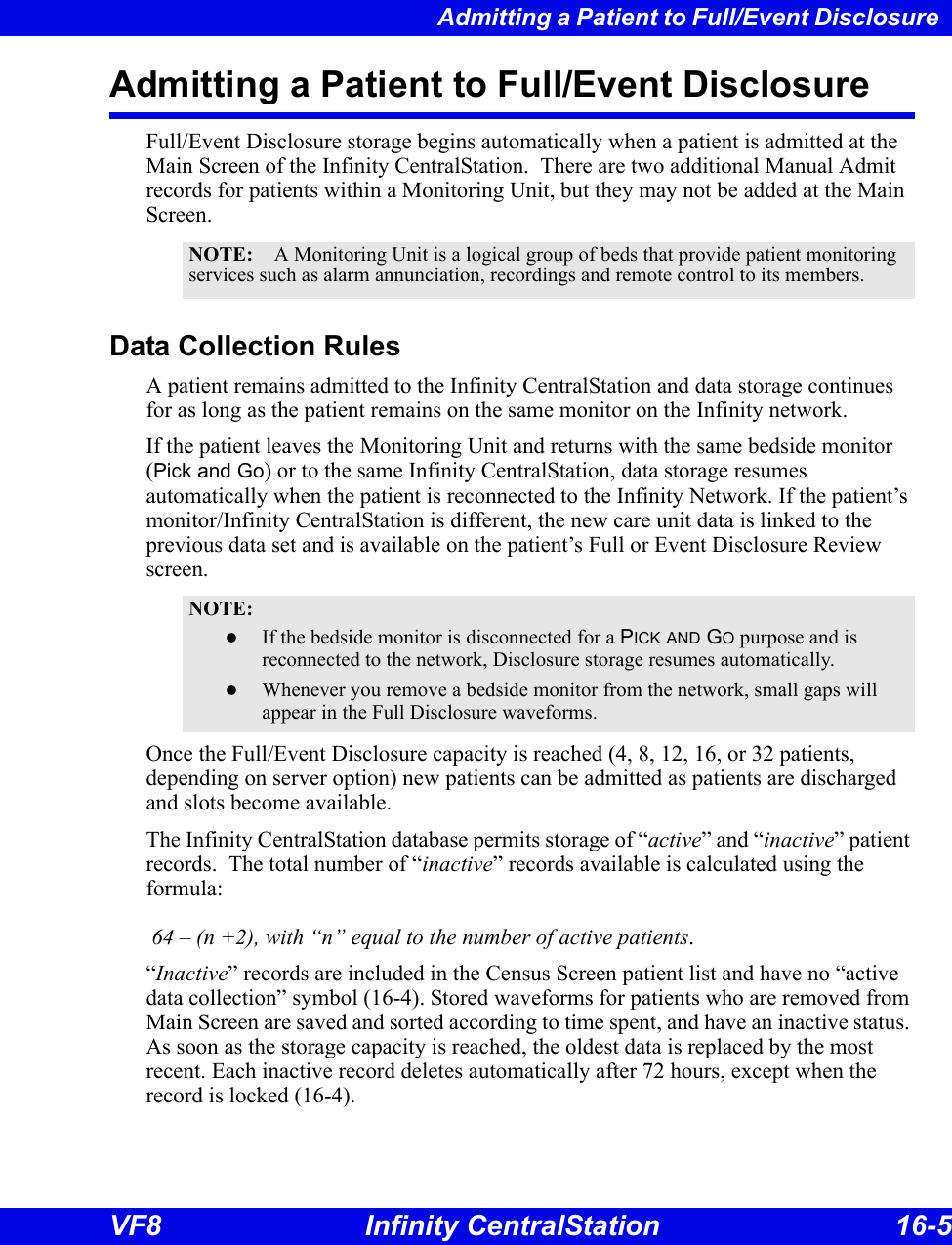
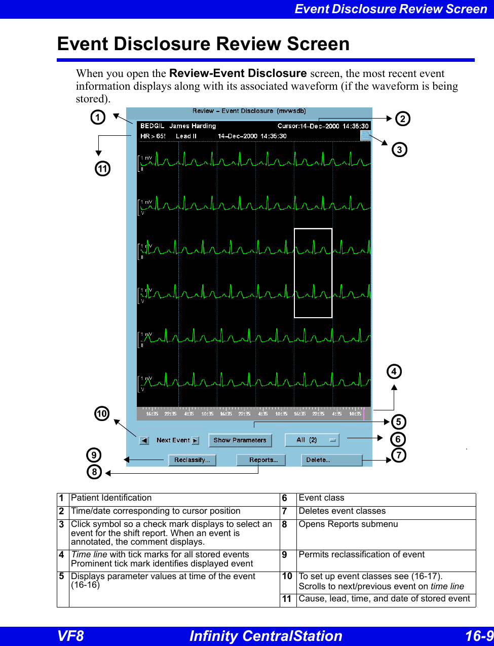
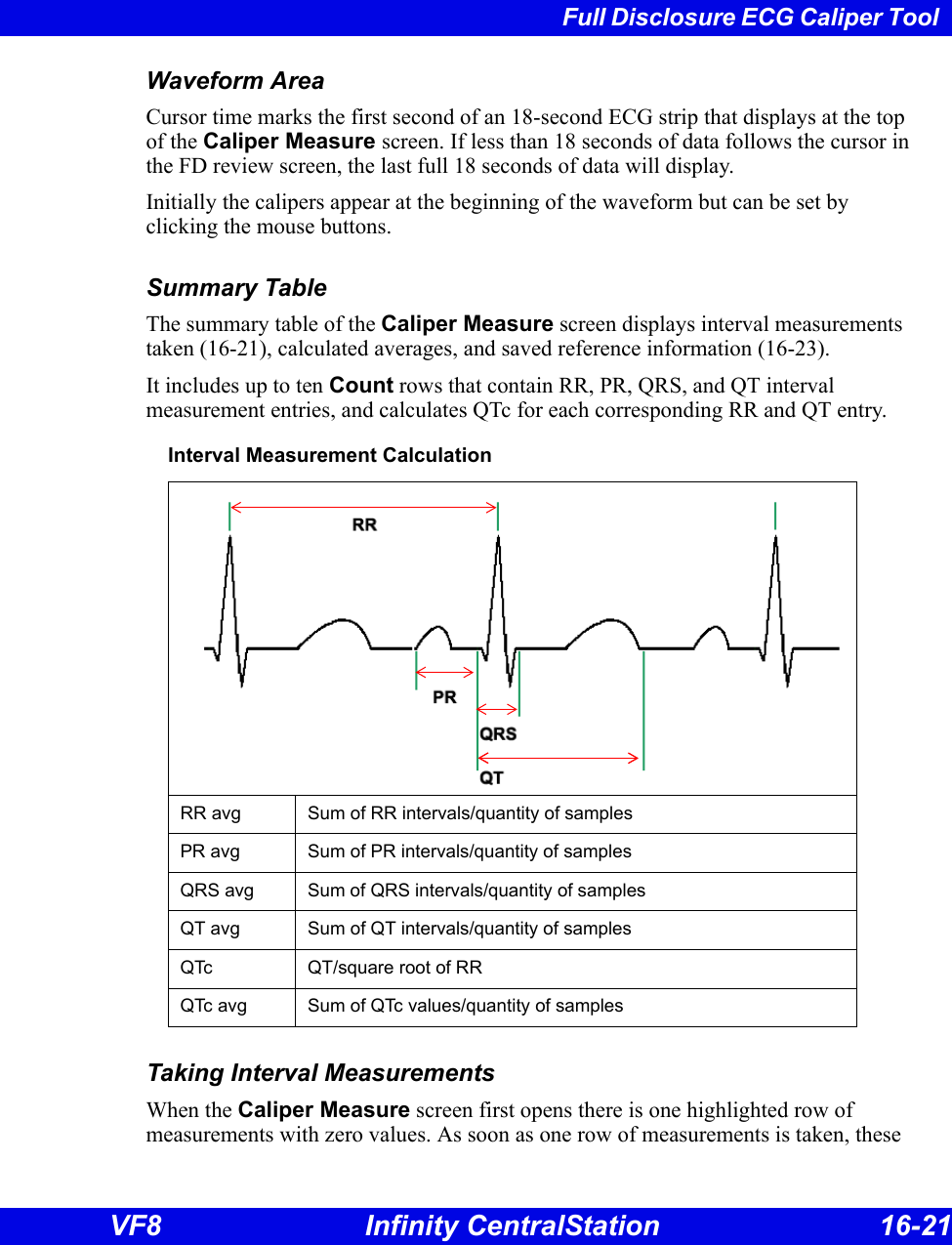
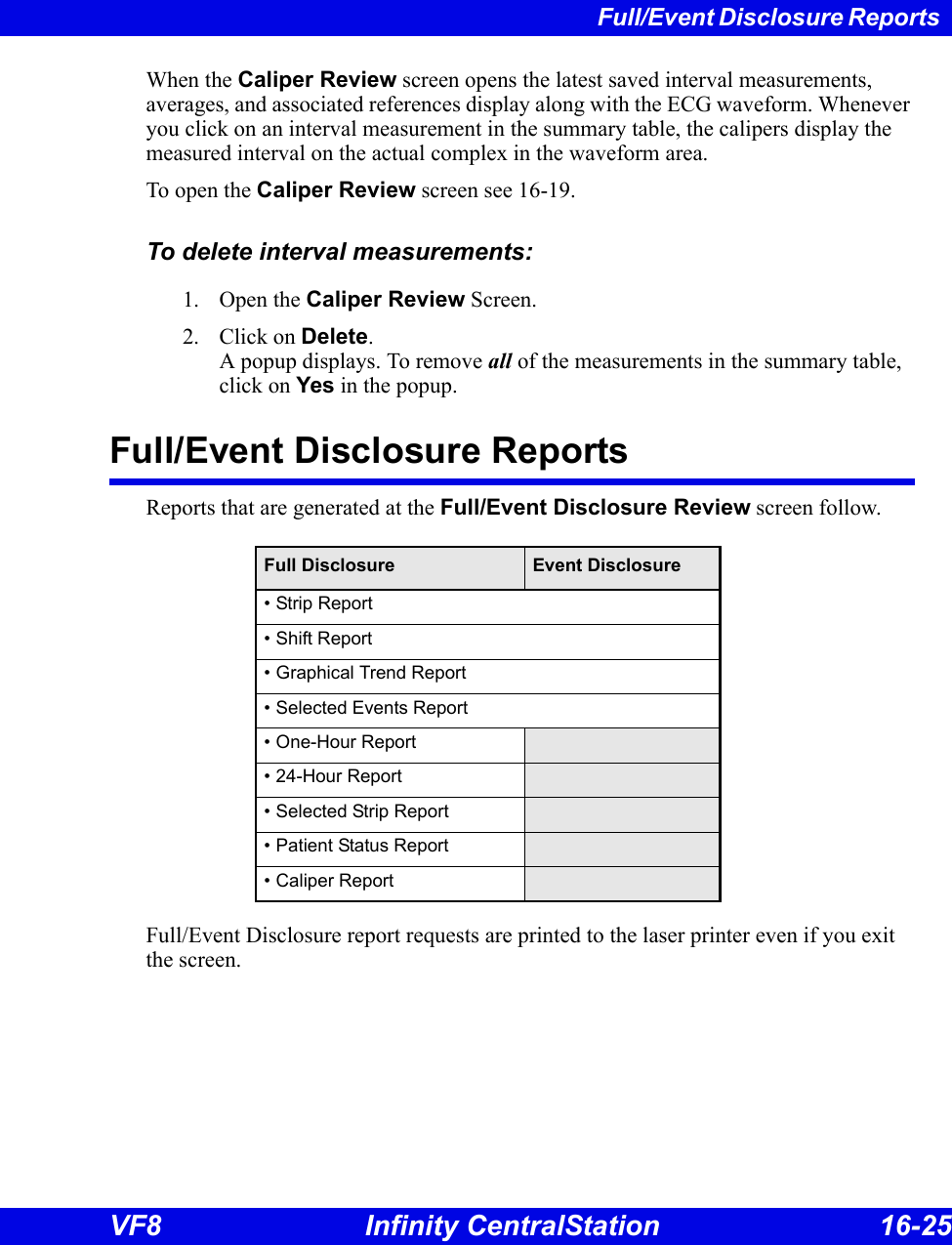
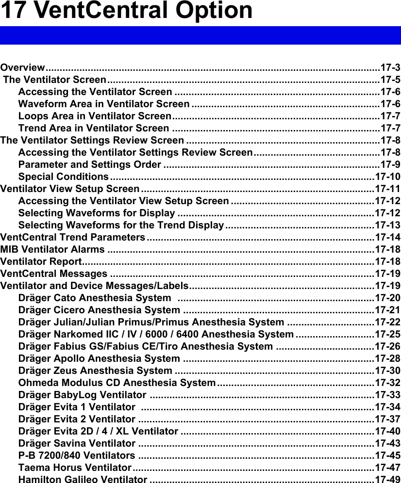
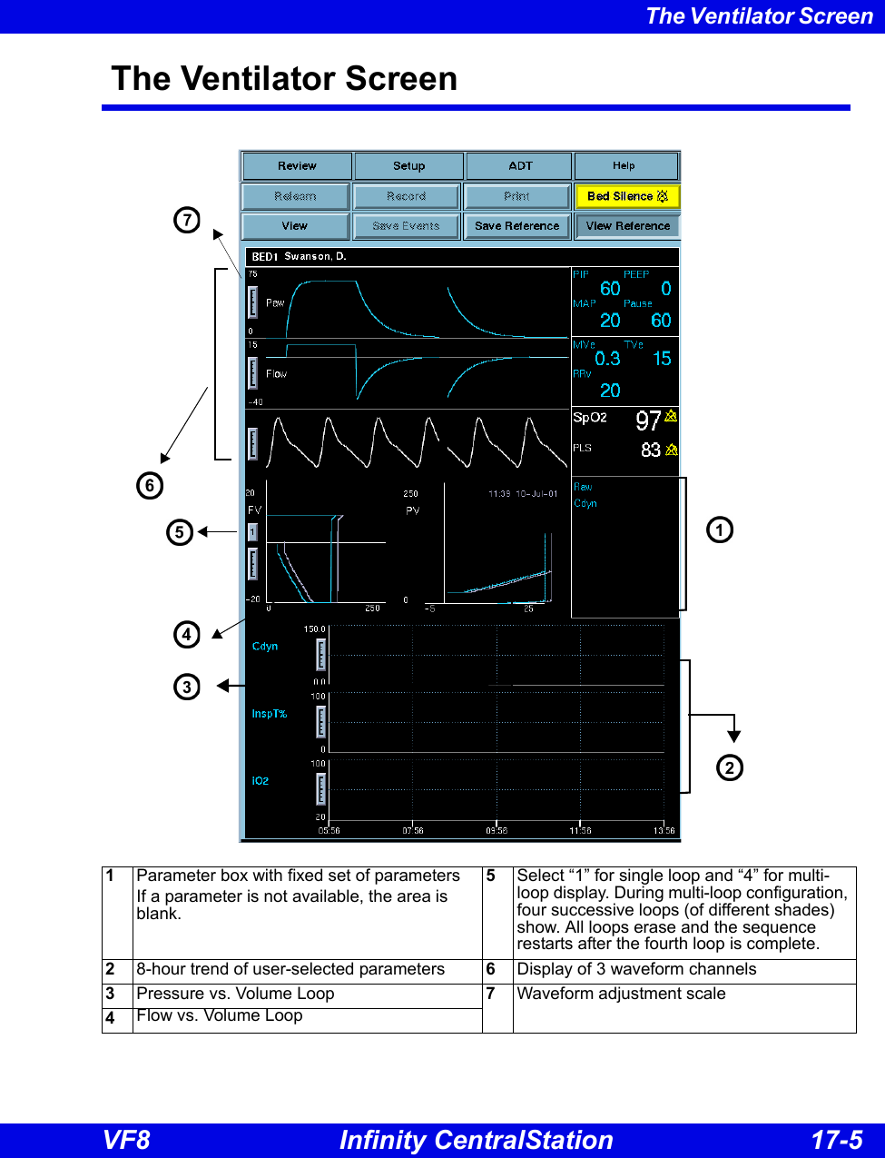
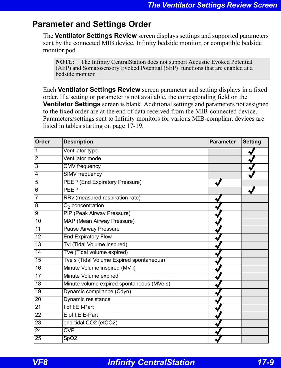
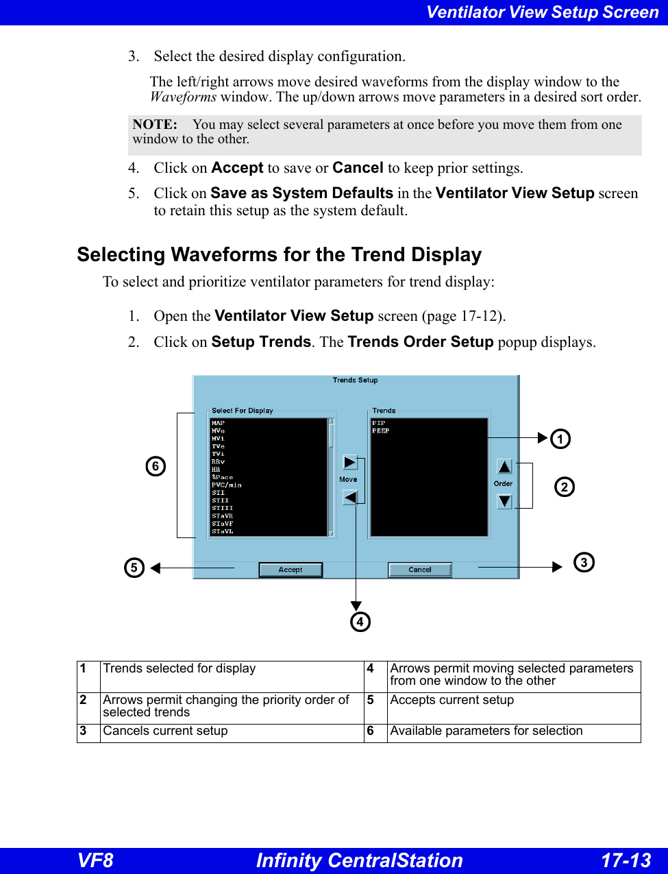
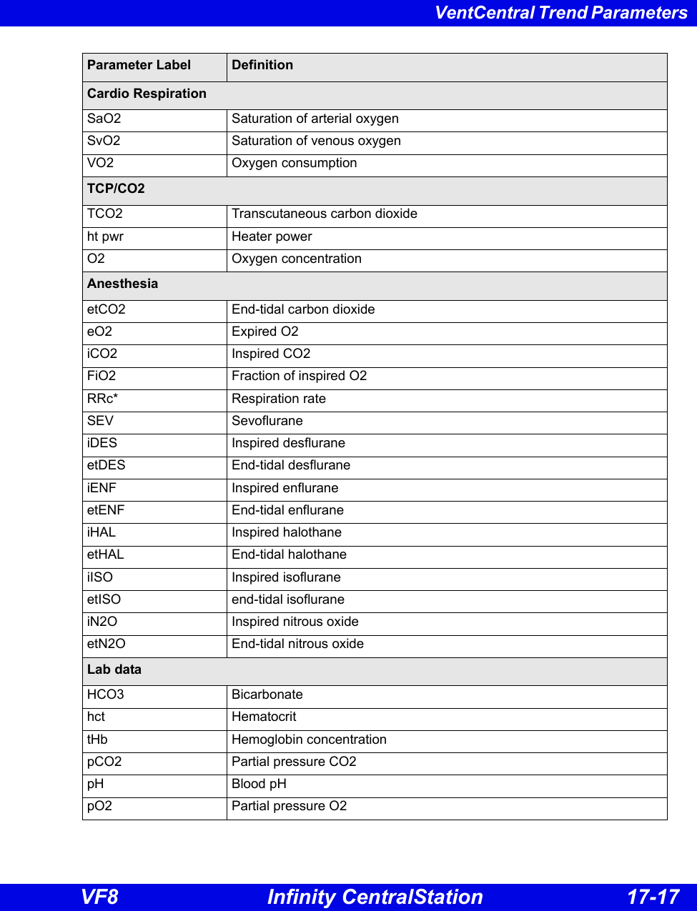
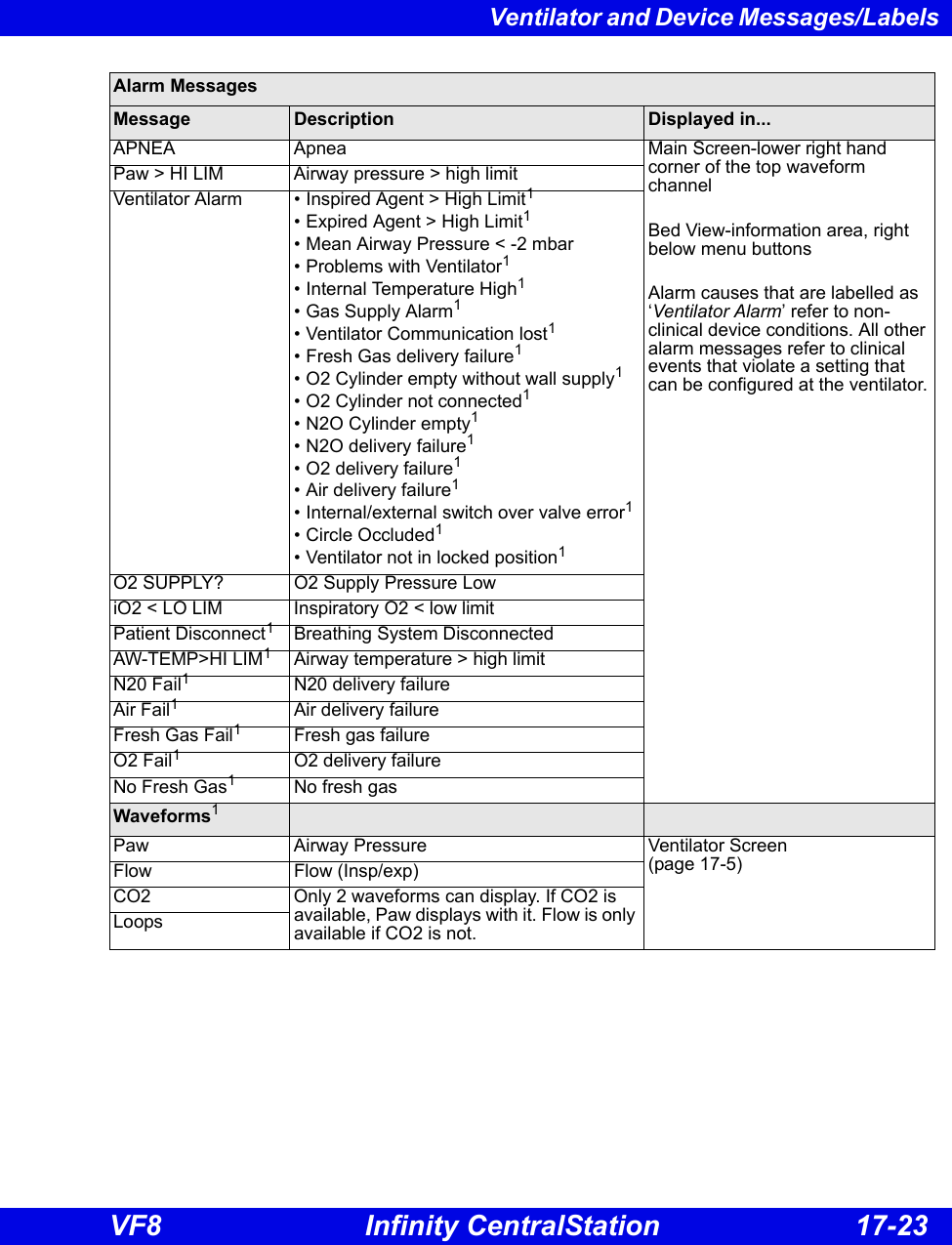
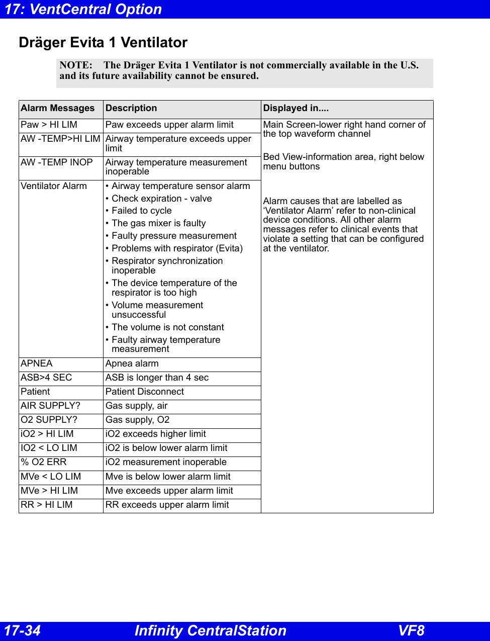
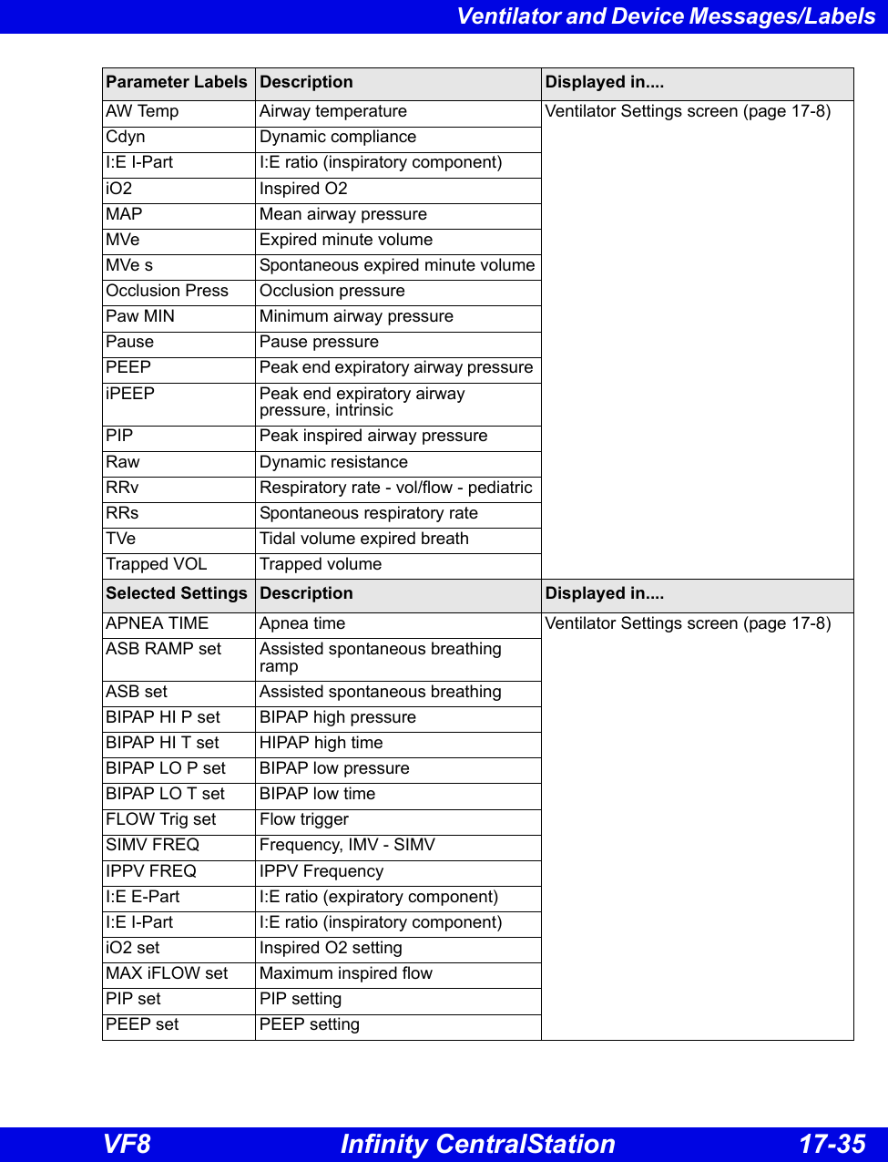
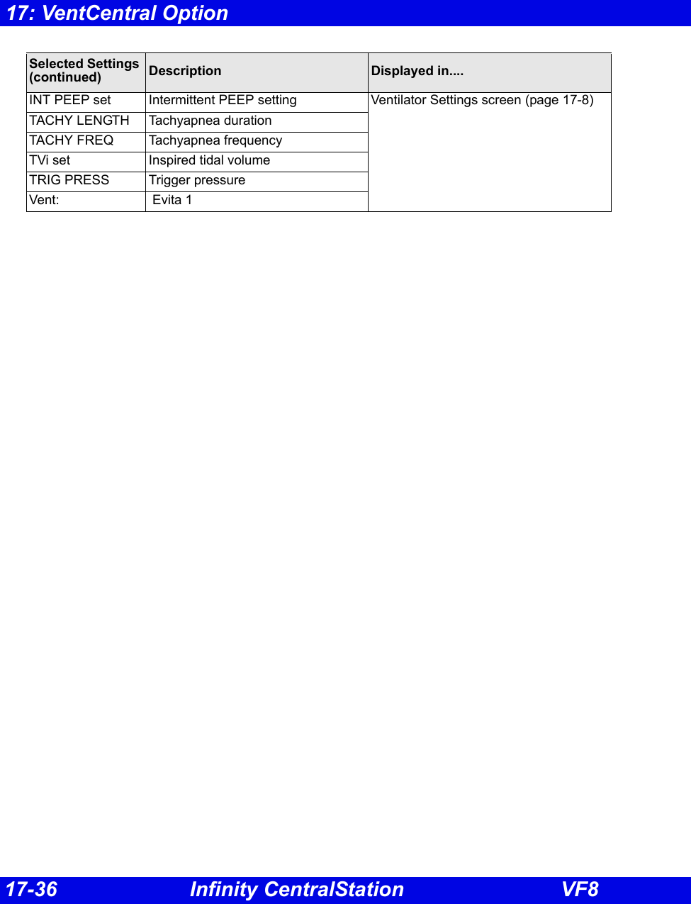
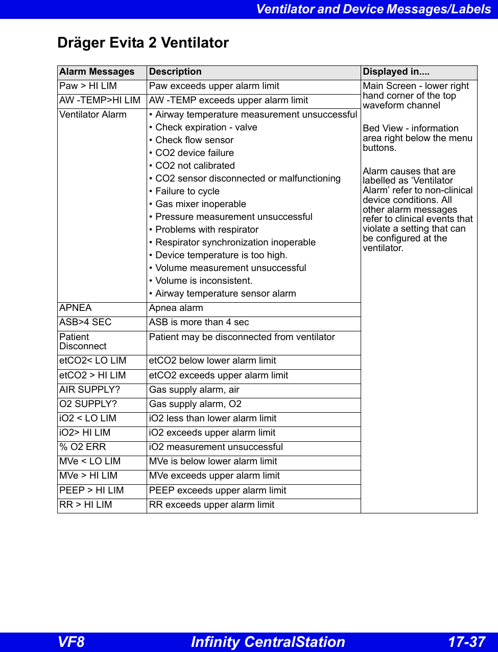
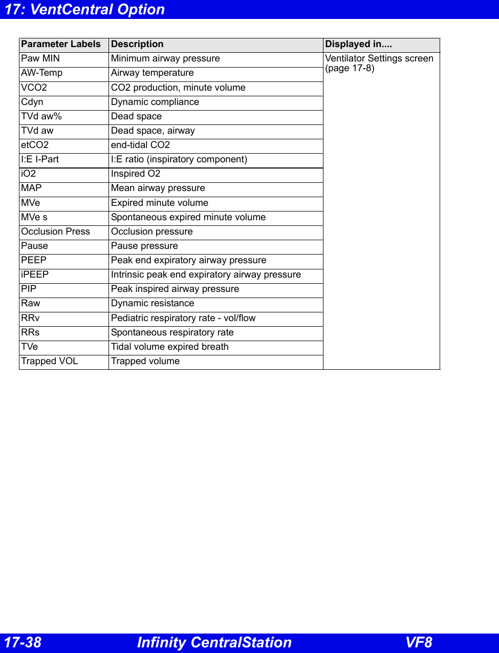
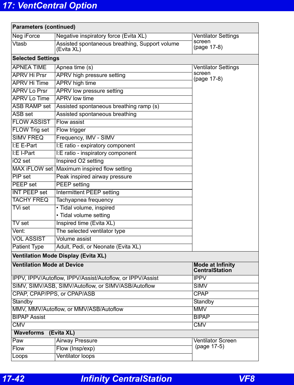
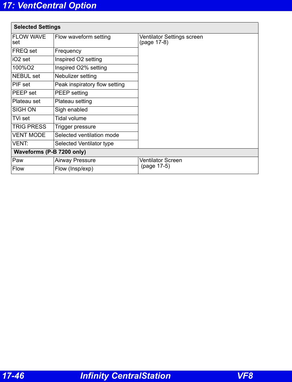
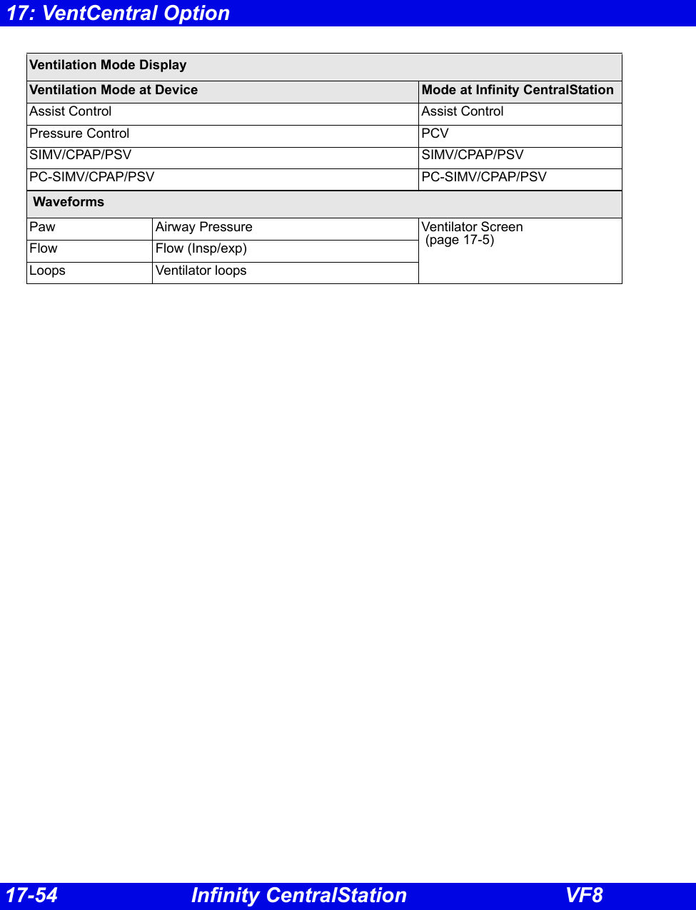
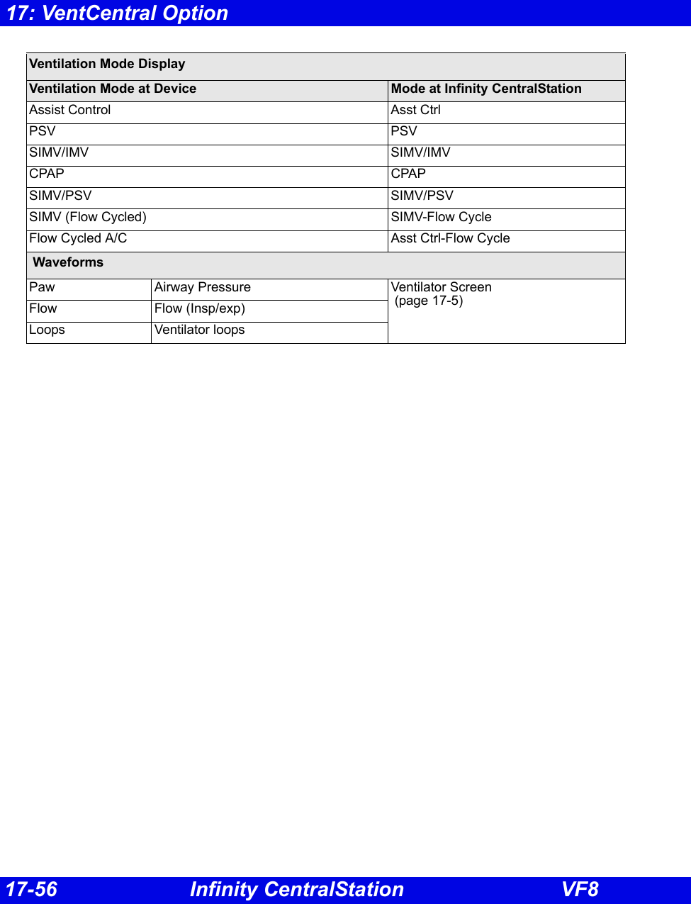
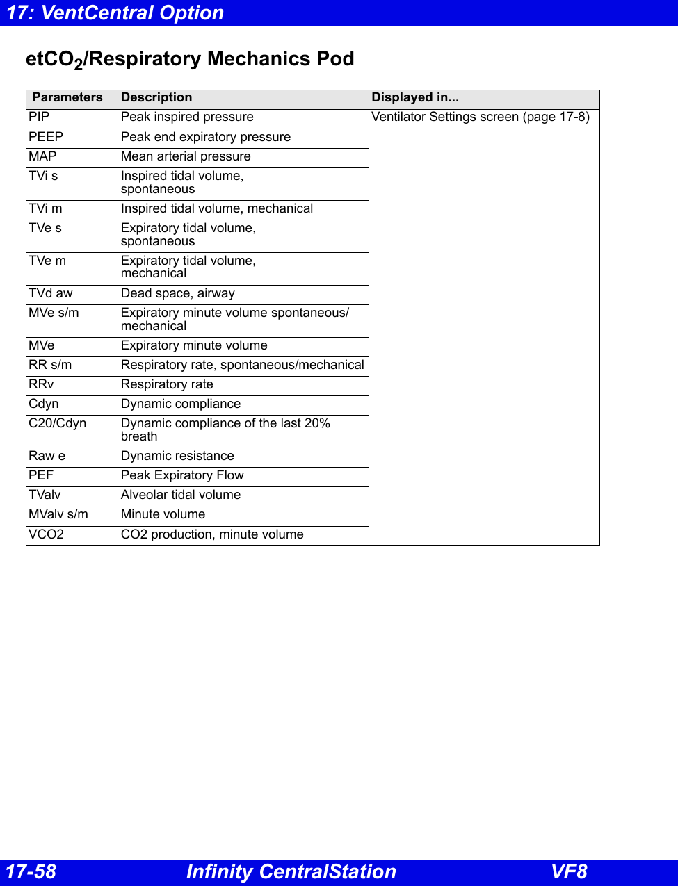
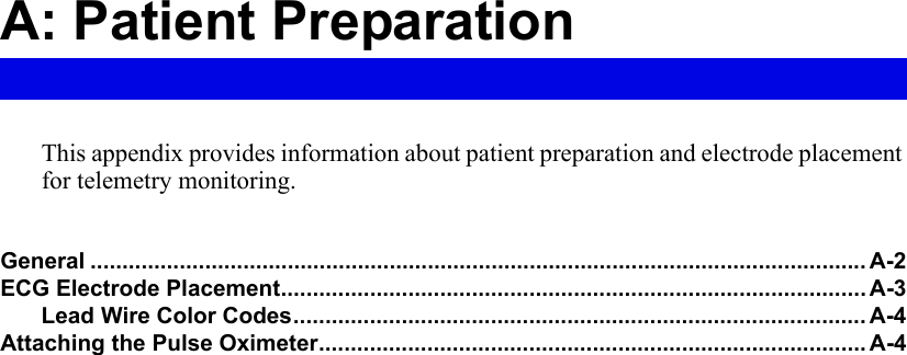
![17-20 Infinity CentralStation VF817: VentCentral OptionDräger Cato Anesthesia System NOTE: The Dräger Cato Anesthesia System is not commercially available in the U.S. and its future availability cannot be ensured.Parameter Label Description Displayed in...e[HAL, ISO, ENF, SEV, DES]Expired agent Ventilator screen (page 17-6)i[HAL, ISO, ENF, SEV, DES]Inspired agent eCO2 Expired CO2 iCO2 Inspired CO2 eO2 Expired O2 iN2O Inspired N2OiO2 Inspired O2 MAP Mean Airway PressureMVe Expired Minute Volume Pause Pause PressurePIP Peak Inspired Airway PressurePEEP Peak End Expiratory Airway Pressure RRc Respiratory rate RRv Respiratory rate TVe Tidal volume, expired breath](https://usermanual.wiki/Draeger-Medical-Systems/MS24895.Users-Manual-2/User-Guide-1093179-Page-71.png)
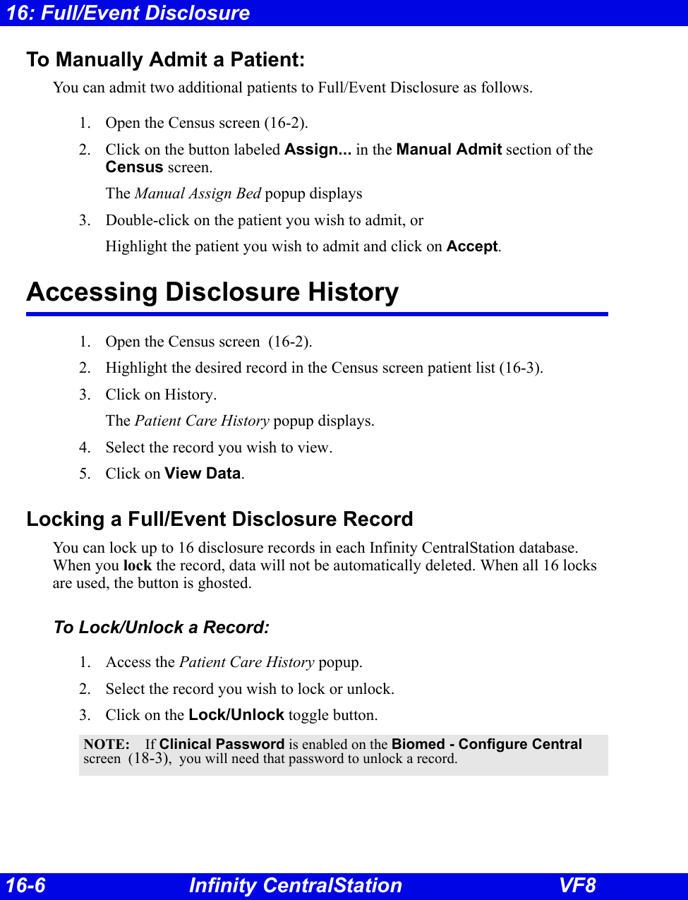
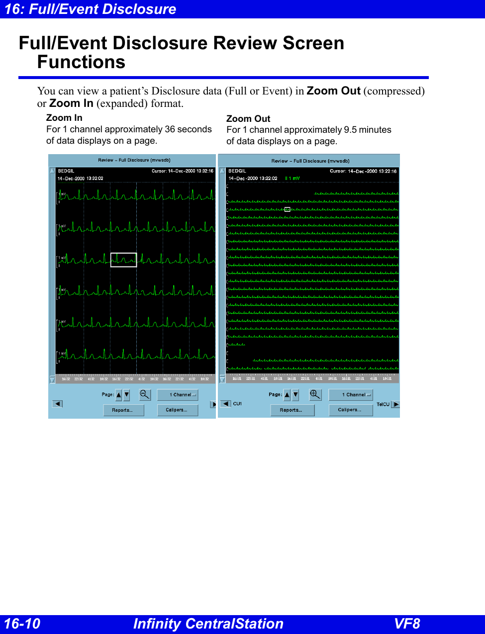
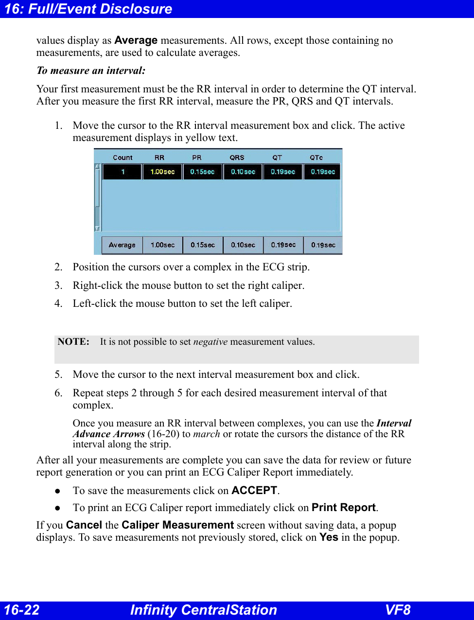
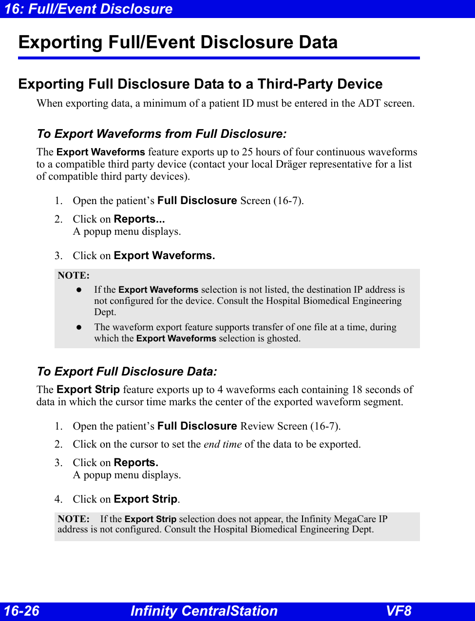
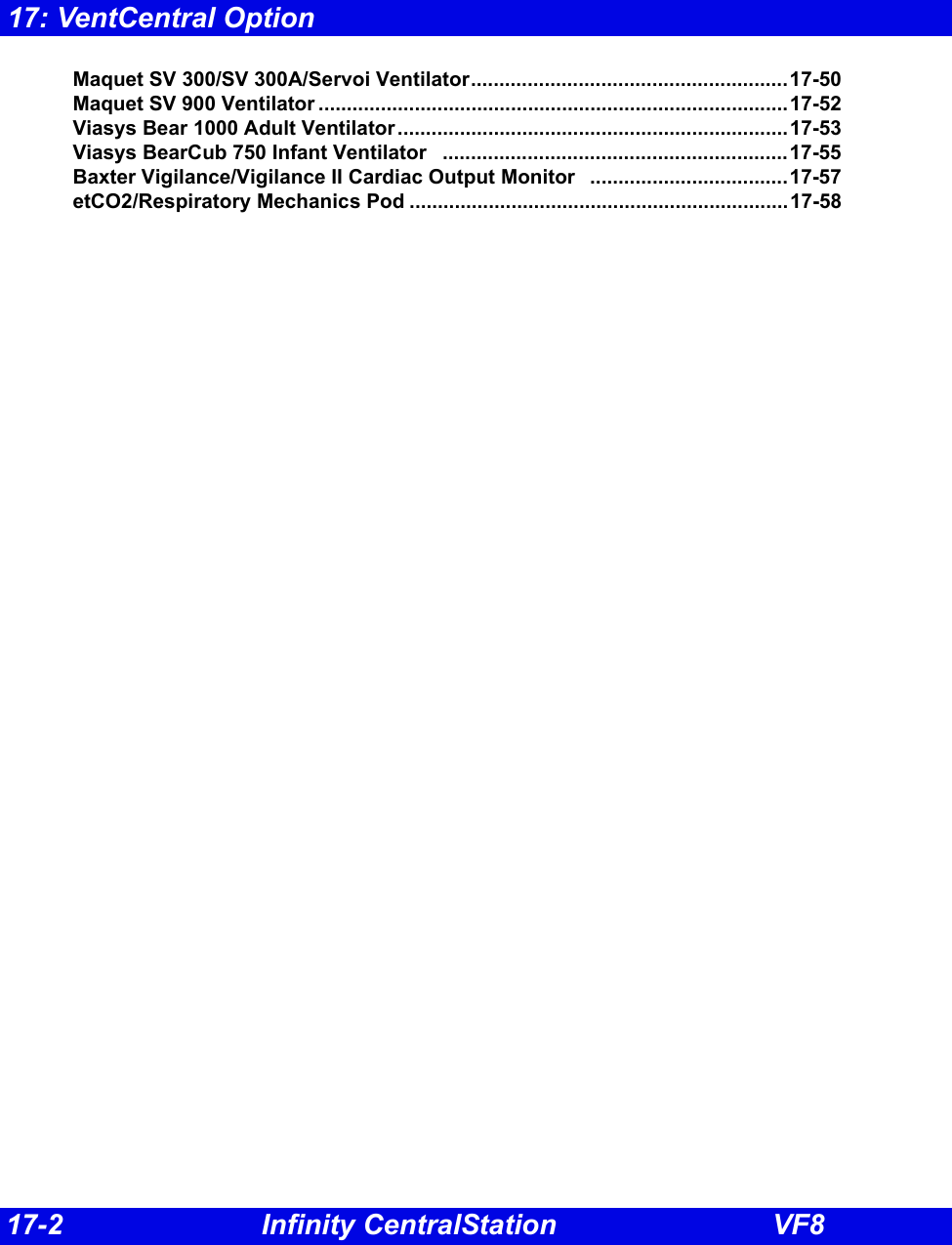
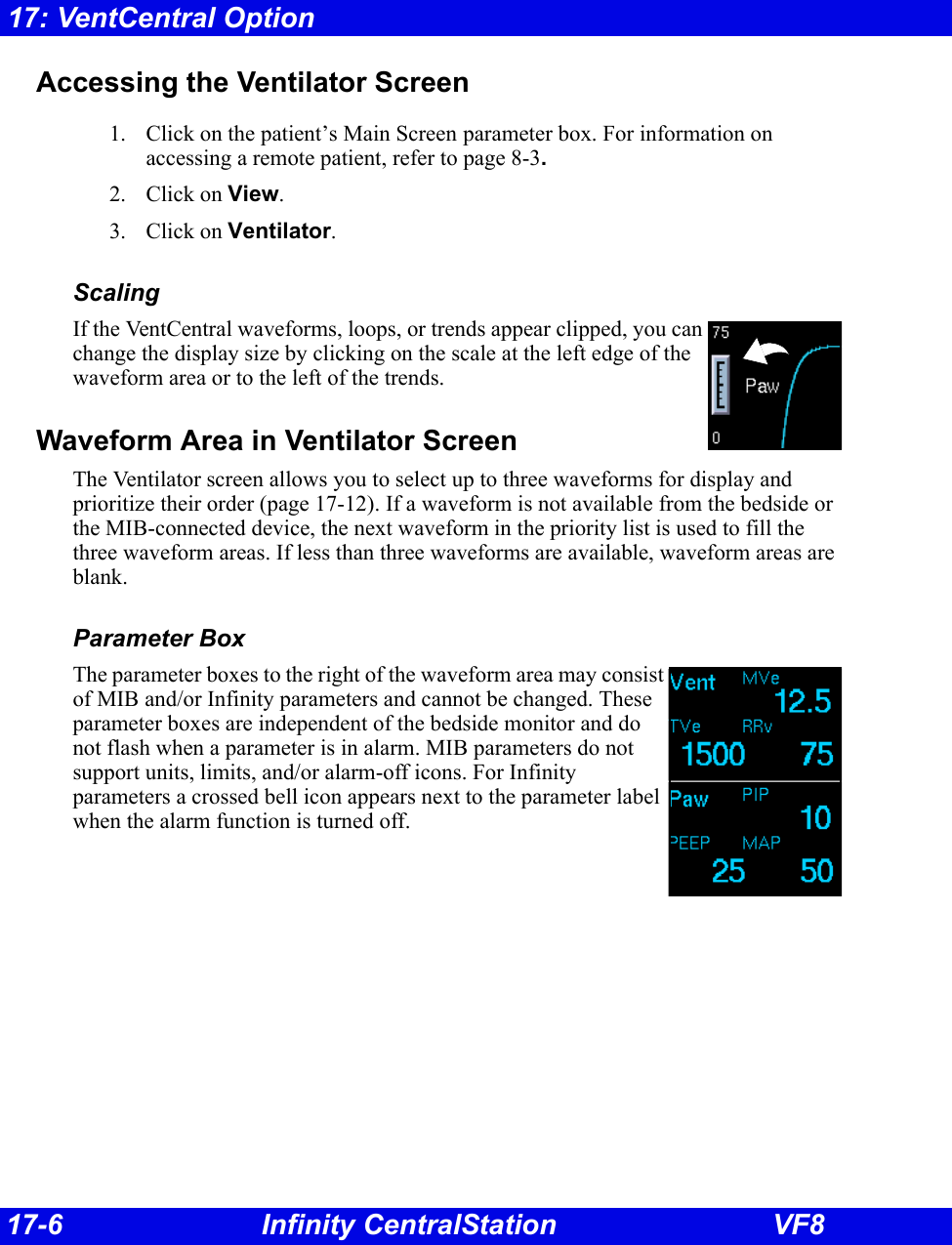
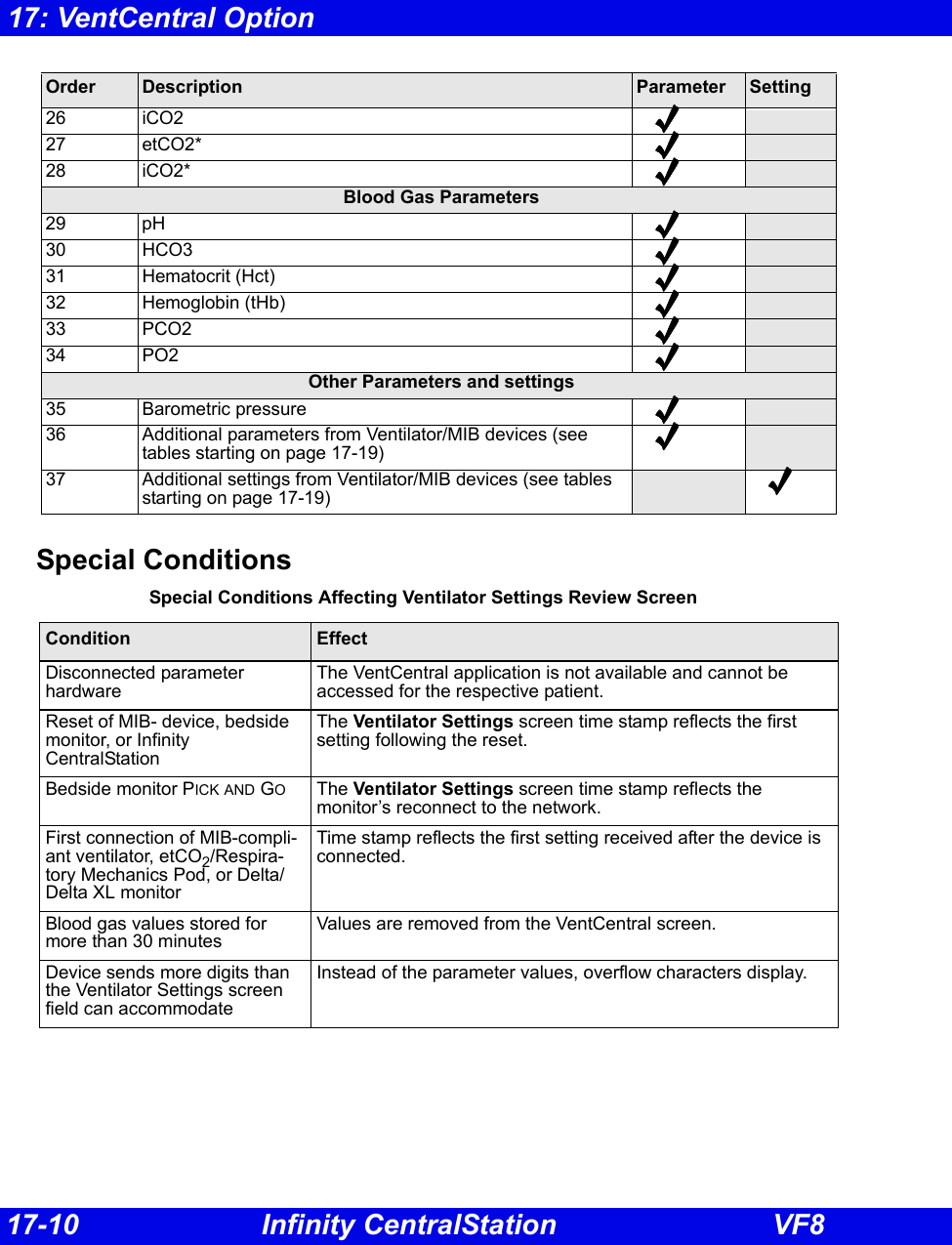
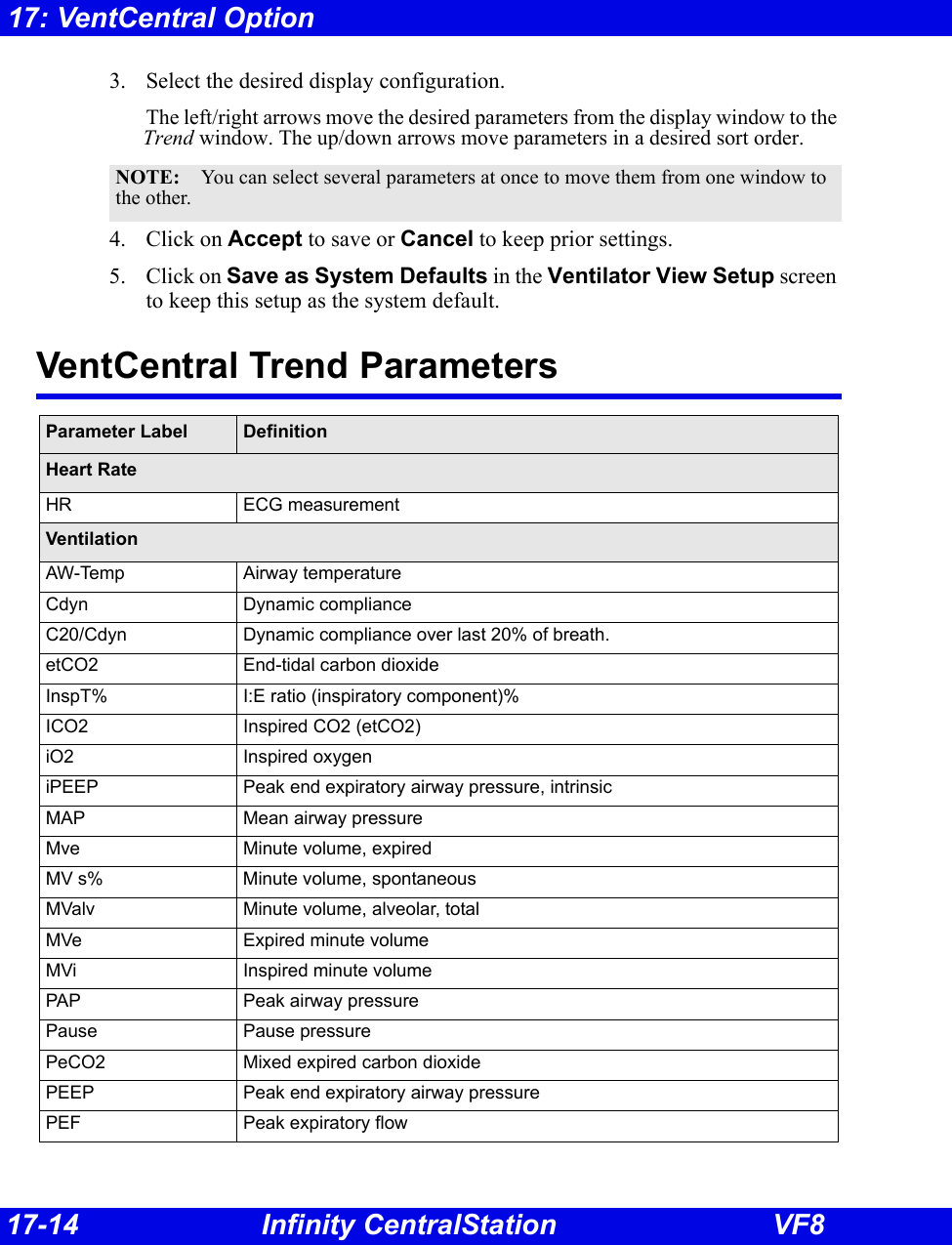
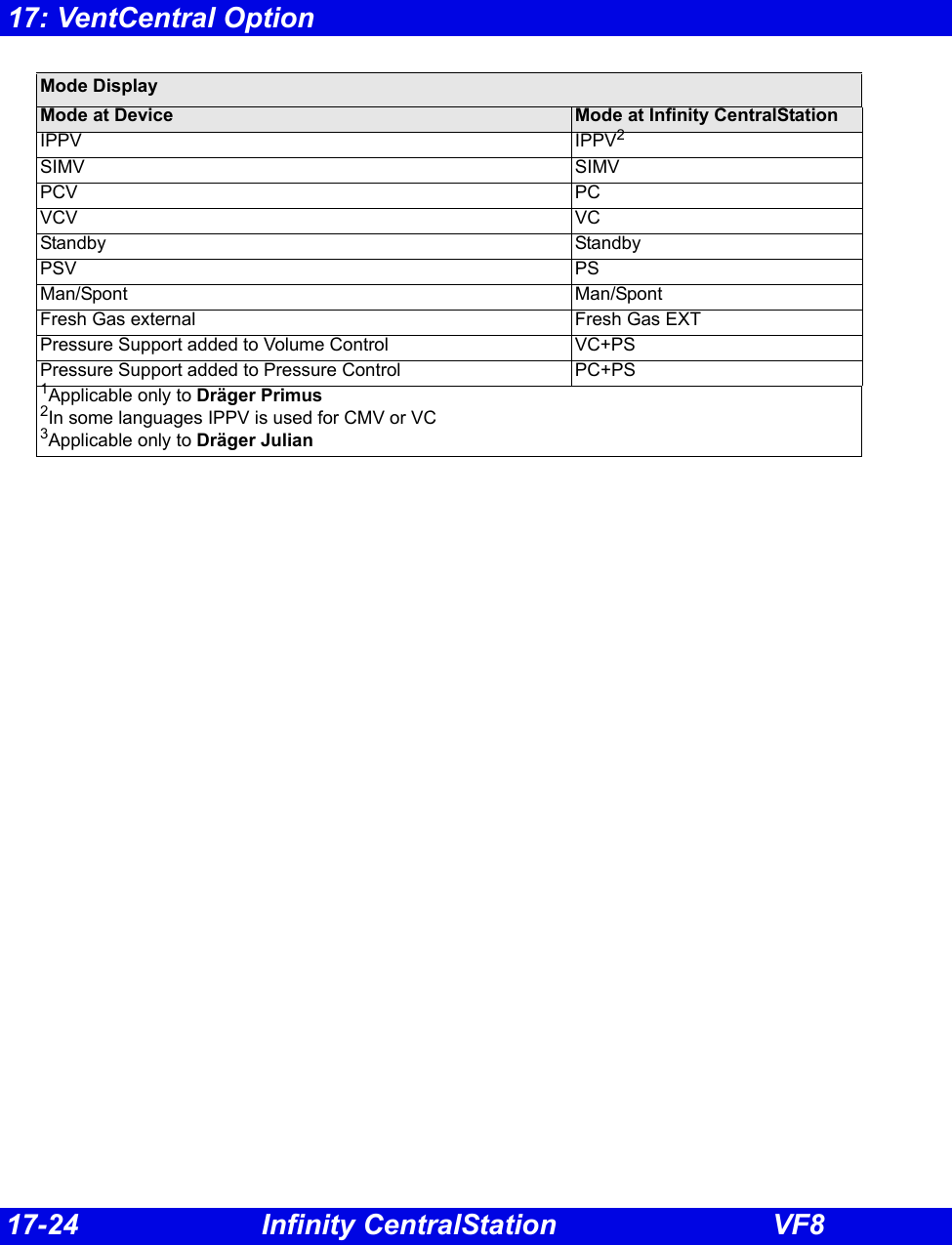
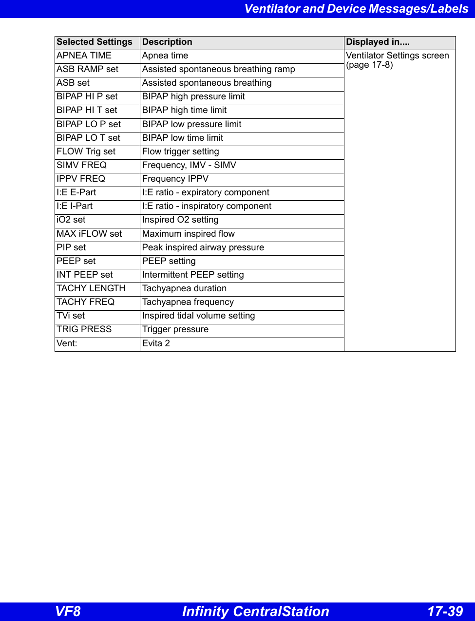
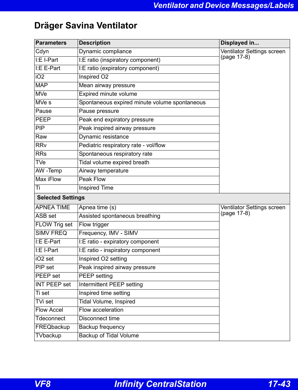
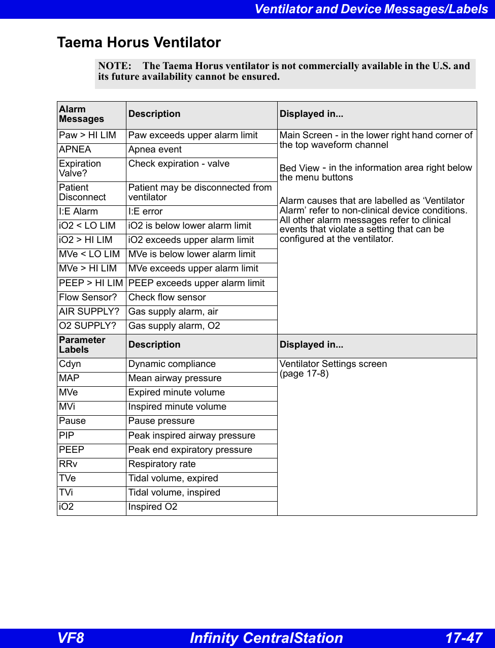
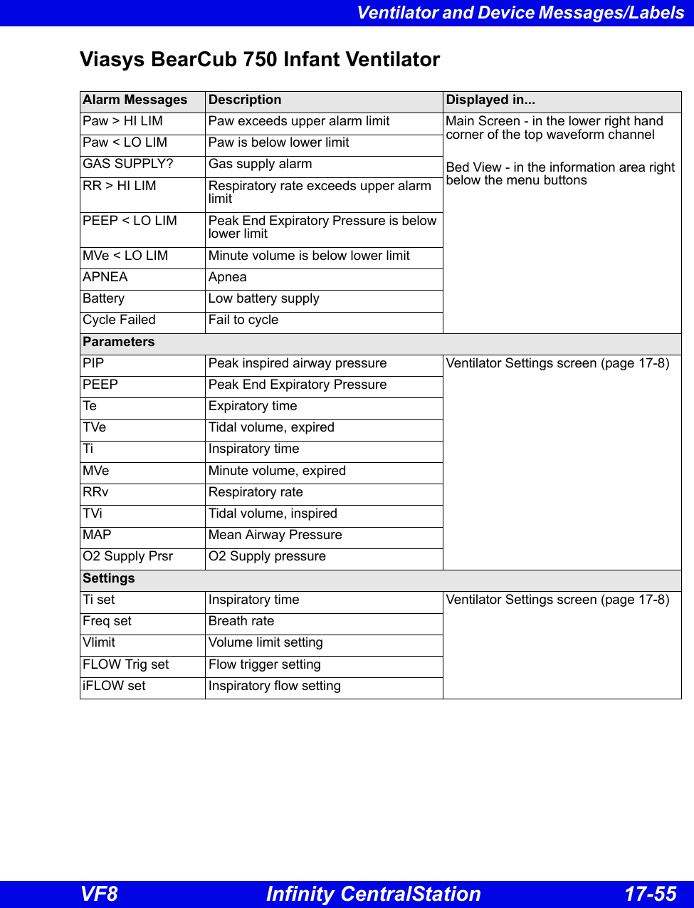
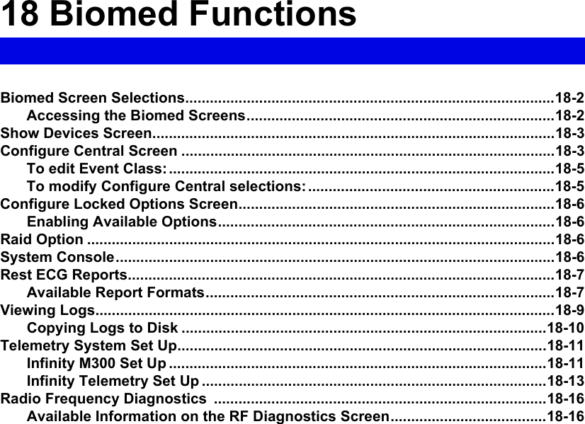
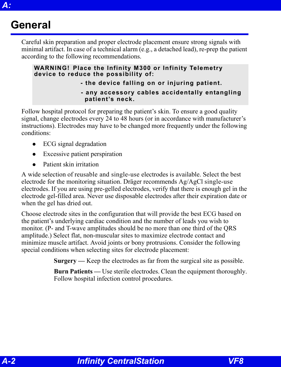
![17-22 Infinity CentralStation VF817: VentCentral OptionDräger Julian/Julian Primus/Primus Anesthesia SystemNOTE: The Dräger Julian Primus and Dräger Primus Anesthesia Systems are not commercially available in the U.S. and their future availability cannot be ensured.Parameter Label Description Displayed in...[HAL, ISO, ENF, SEV, DES]Expired and inspired agent Ventilator Settings screen (page 17-8)ECO23 or etCO2 Expired CO2etCO2 End Tidal CO2eN2O Expired N2OeO2 or etO2 Expired O2 iN2O Inspired N2OiCO21Inspired CO2iO2 Inspired O2 MAP Mean Airway PressureMVe Minute Volume, expired Pause Pause Pressure PIP Peak inspired airway pressurePEEP Peak end expiratory airway pressure RRc Respiratory rate (CO2)RRv Respiratory rate (Volume/flow/pressure/derived)TVe Tidal volume, expired breathCdyn1ComplianceBaro Prsr1Barometric PressureLeakage1LeakageiMAC1Inspired MAC (minimum alveolar concentration)eMAC1Expired MACAPNEAt1Apnea DurationDelta O21(iO2 - eO2)Selected Settings iO2 set iO2 setting Ventilator Settings screen (page 17-8)TVi set1Tidal volume, inspired breath Ti set1Inspiratory TimeIPPV FREQ1frequencyINT PEEP set1Intermittent PEEPP Support1Support PressurePIP set1Maximum Inspired Airway PressureFLOW trig set1Flow TriggerF Gas Flow Fresh Gas Flow](https://usermanual.wiki/Draeger-Medical-Systems/MS24895.Users-Manual-2/User-Guide-1093179-Page-73.png)
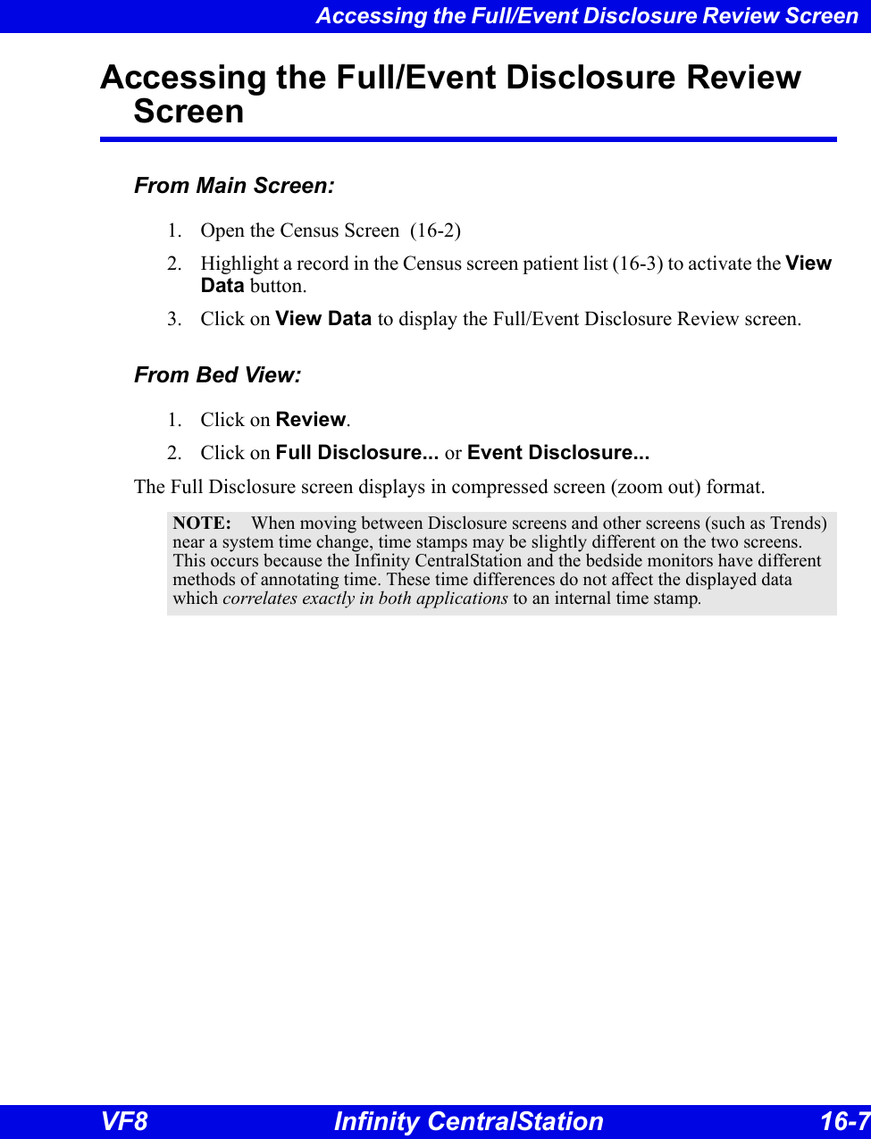
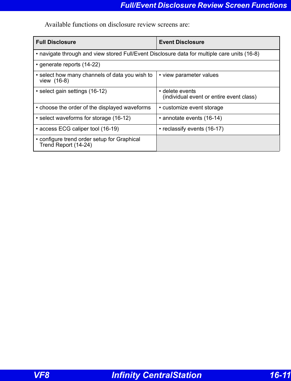
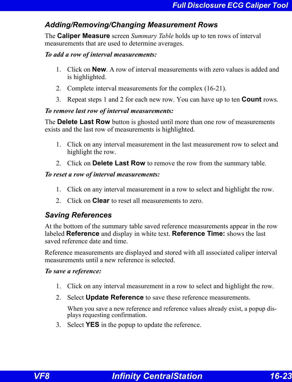
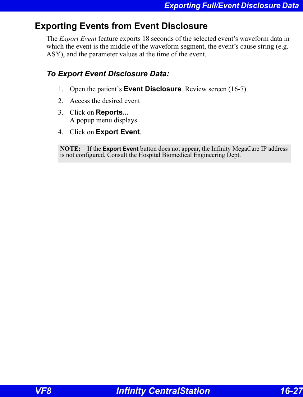
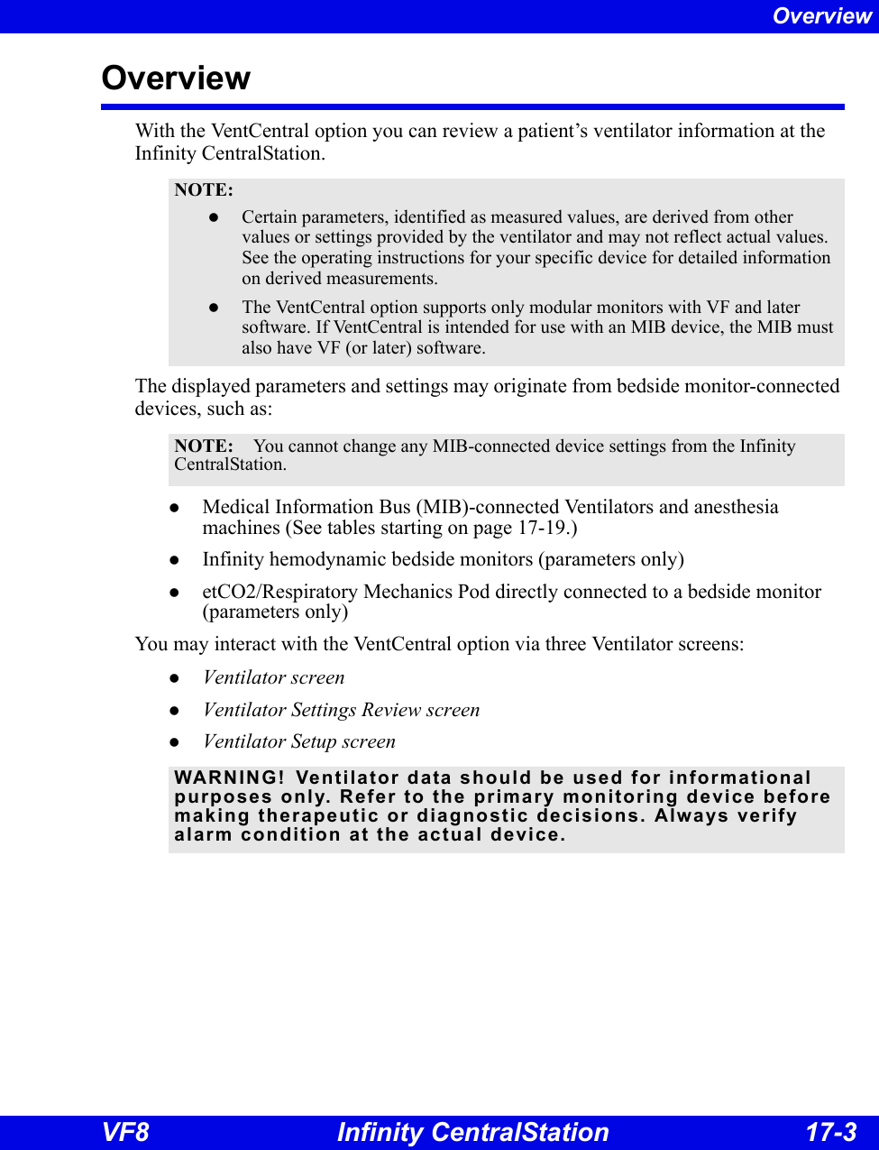
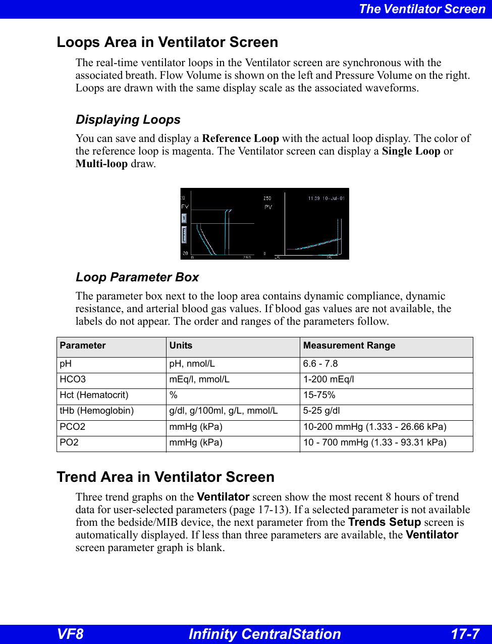
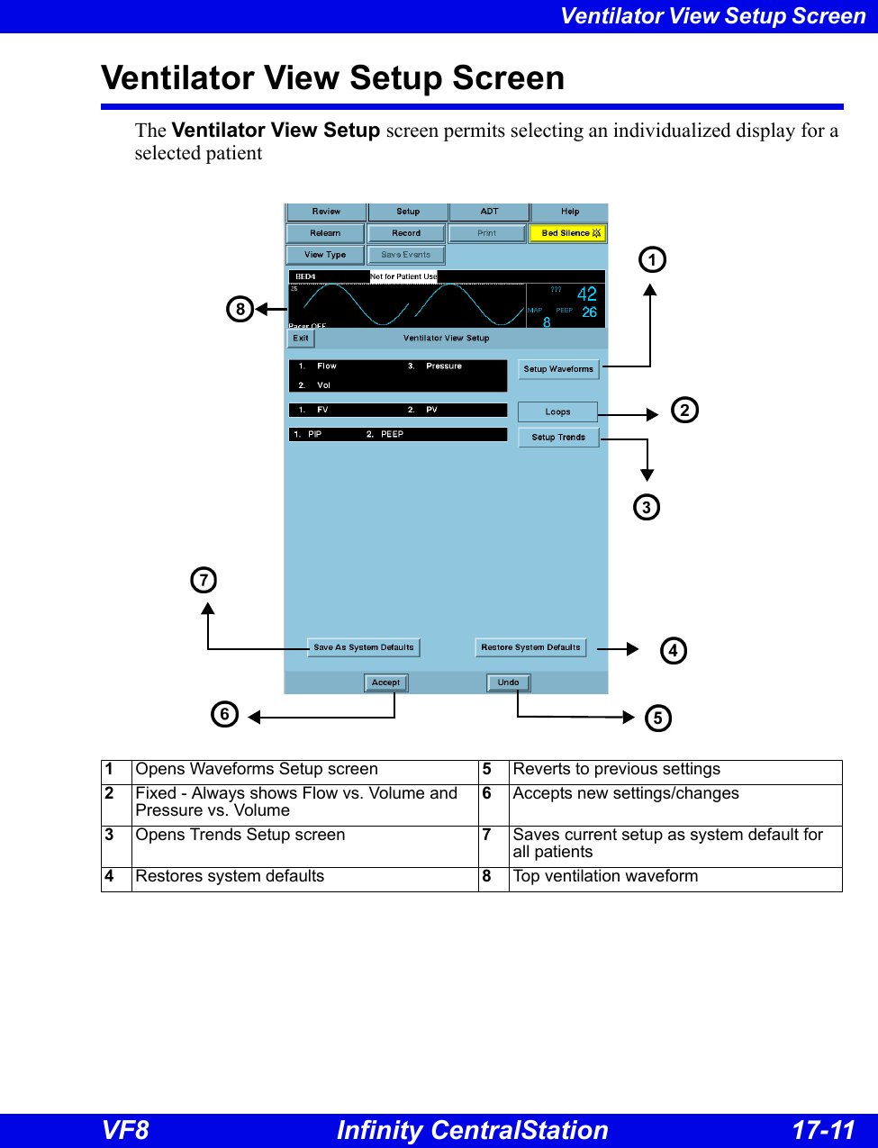
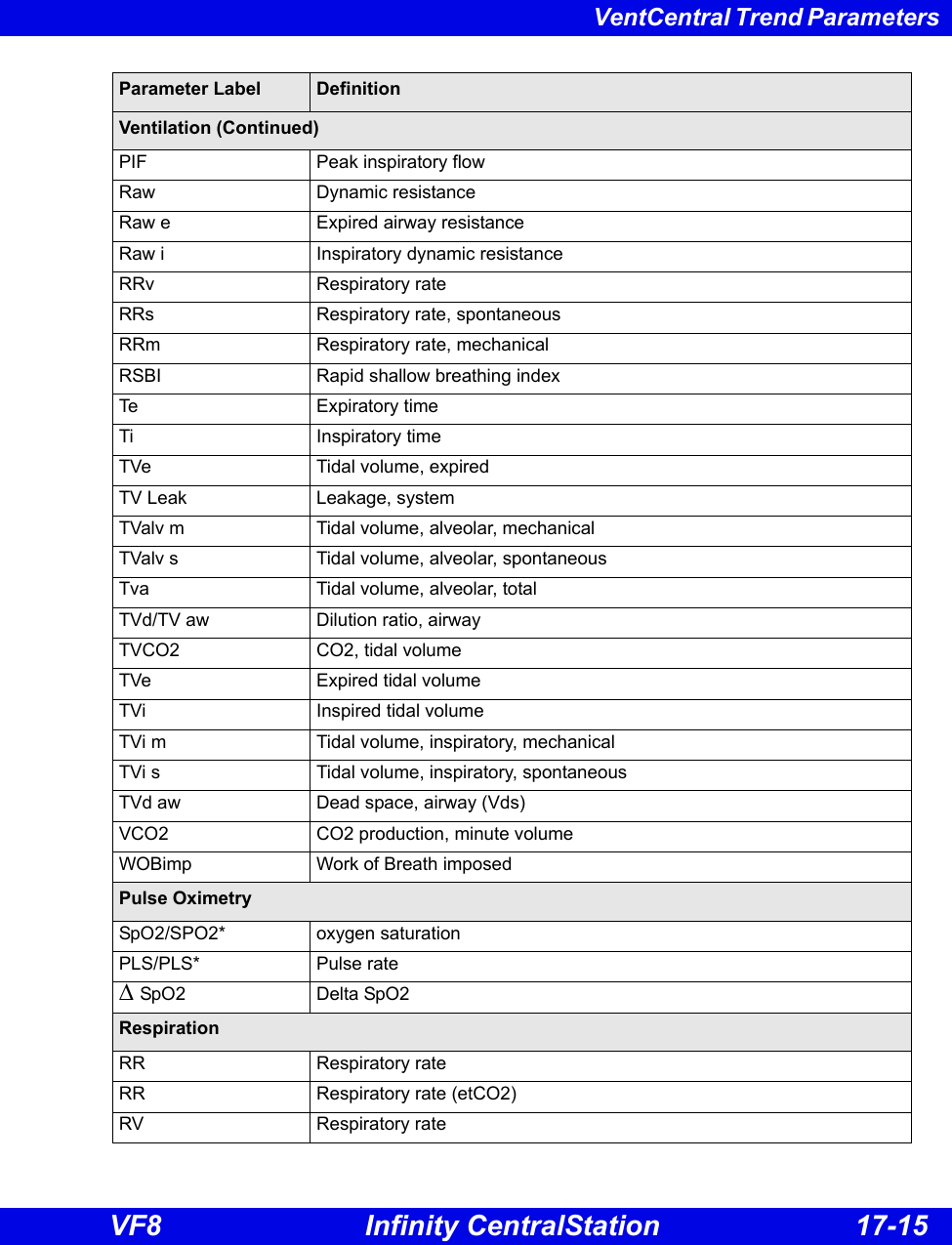
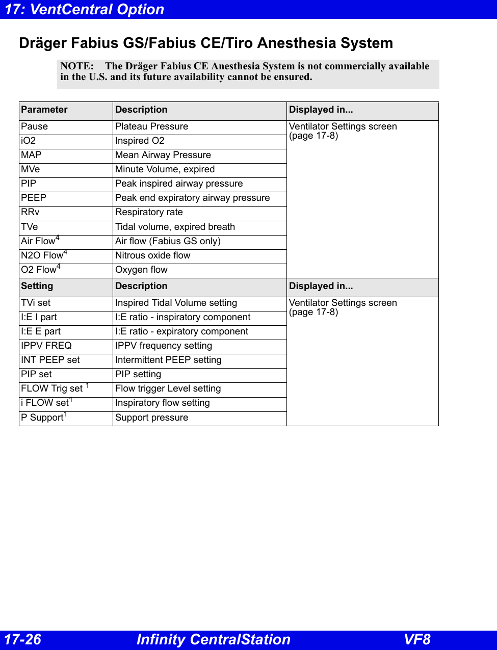
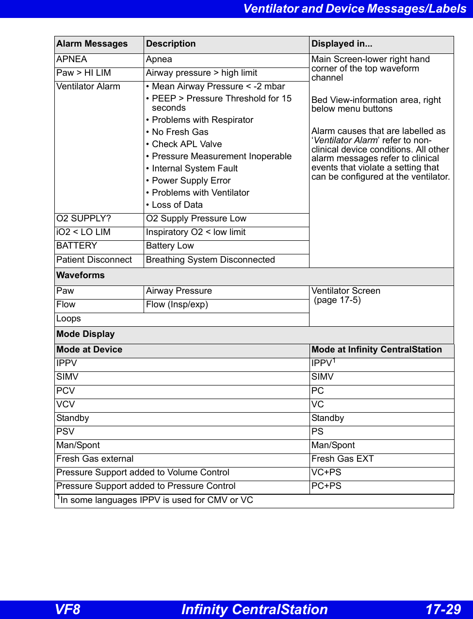
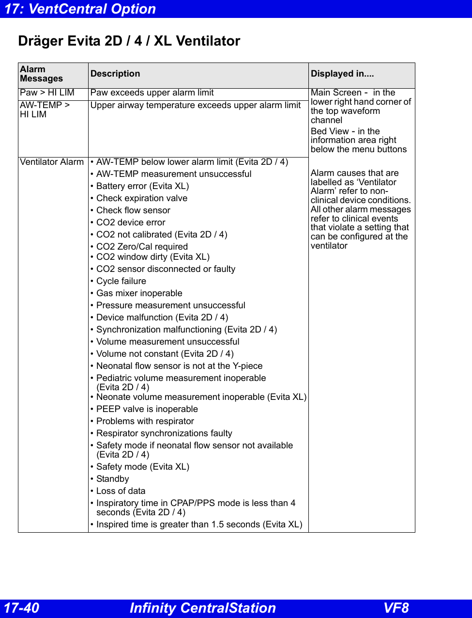
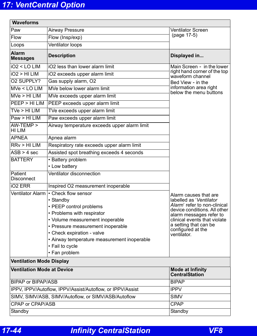
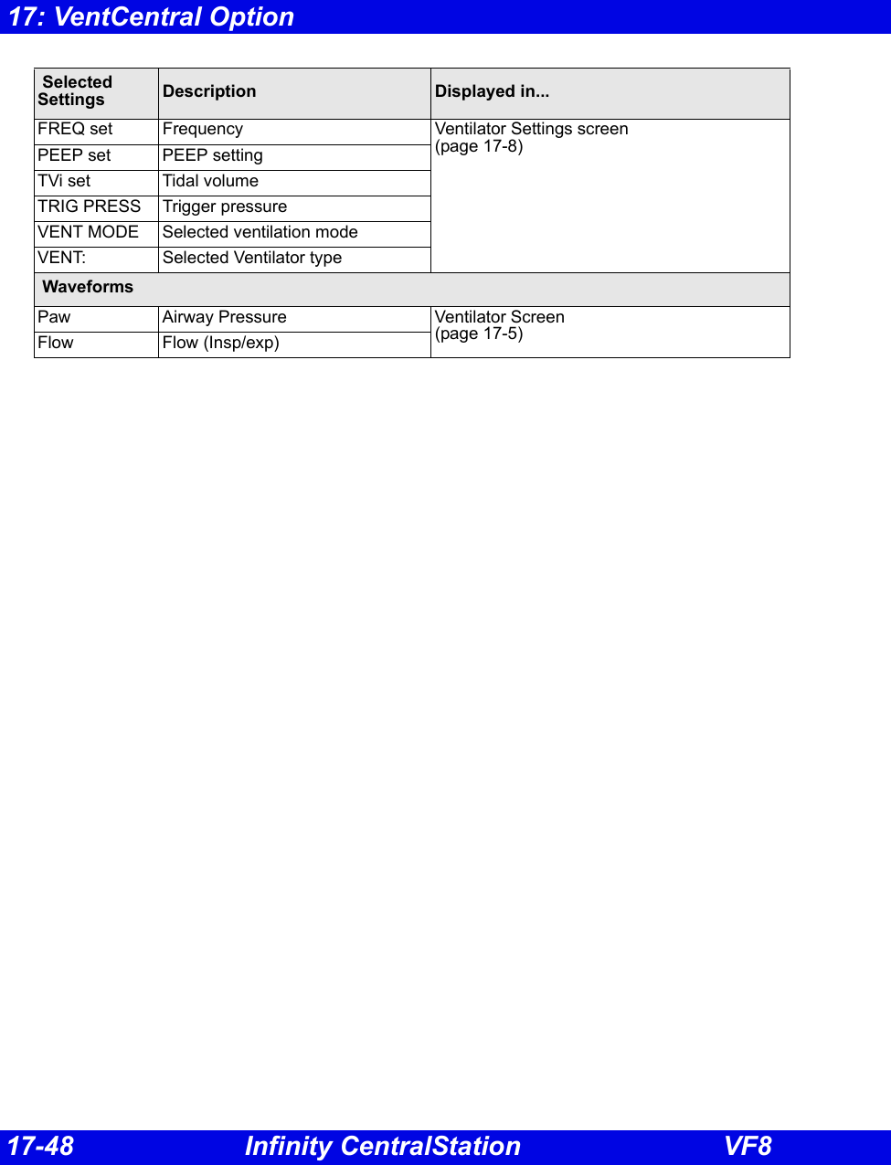
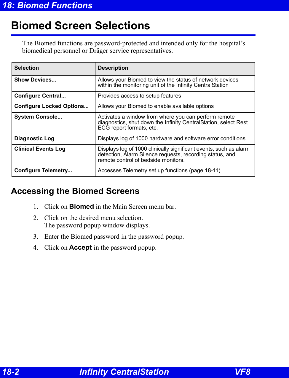
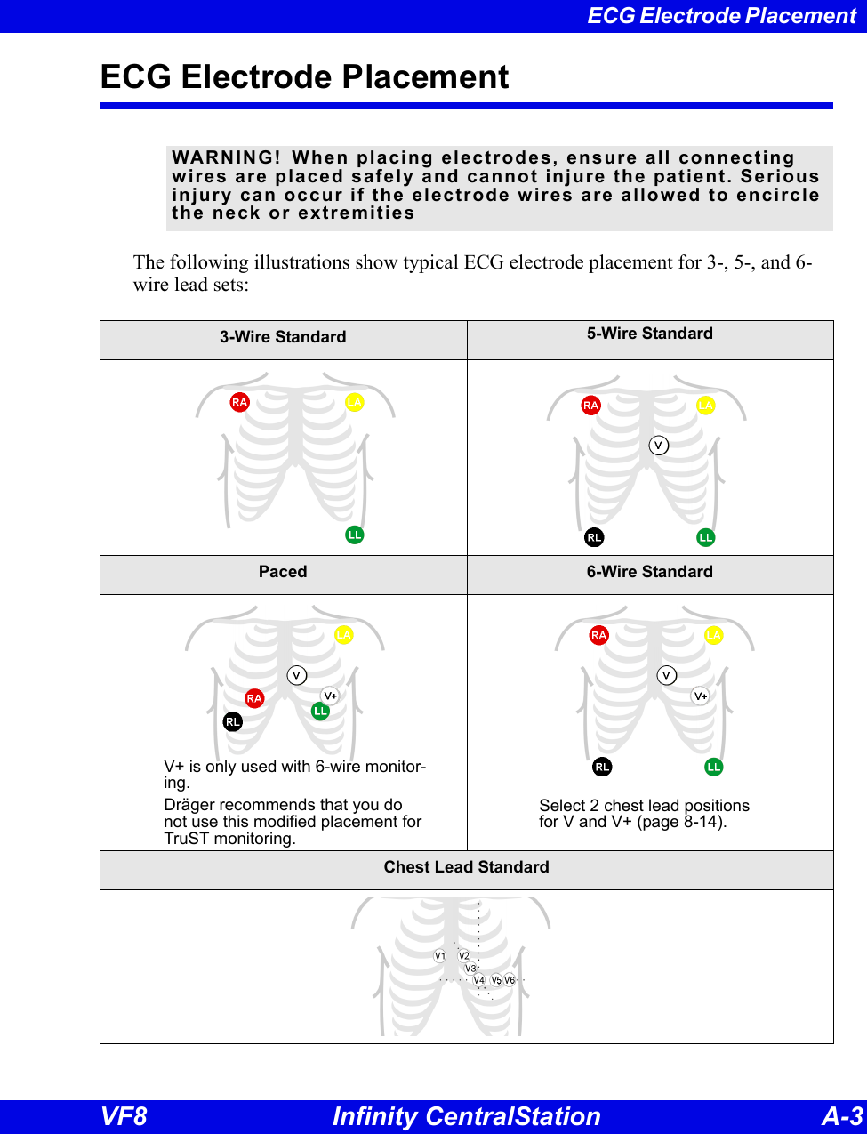
![Ventilator and Device Messages/Labels Infinity CentralStation 17-25 VF8Dräger Narkomed IIC / IV / 6000 / 6400 Anesthesia SystemParameter Label Description Displayed in...i[HAL, ISO, ENF, SEV, DES]Inspired agent Ventilator Settings screen (page 17-8)e[HAL, ISO, ENF, SEV, DES]Expired agent etCO2 Expired CO2iCO2 Inspired CO2eO2 or etO2 Expired O2 iO2 Inspired O2iN2O Inspired N2OetN2O Expired N2O (6000 and 6400 only)MAP Mean Airway PressureMVe Minute Volume, expiredPIP Peak inspired airway pressurePEEP Peak end expiratory airway pressure RRc Respiratory rate RRv Respiratory rate TVe Tidal volume, expired breathSelected Settings (IIC and IV only)iO2 set iO2 setting Ventilator Settings screen (page 17-8) Waveforms Paw Airway Pressure Ventilator Screen (page 17-5)Flow Flow (Insp/exp)Alarms APNEA Apnea Main Screen-lower right hand corner of the top waveform channel Bed View-information area, right below menu buttonsAlarm causes that are labelled as ‘Ventilator Alarm’ refer to non-clinical device conditions. All other alarm messages refer to clinical events that violate a setting that can be configured at the ventilator.Paw > HI LIM Airway pressure > high limitiO2 > HI LIM Inspired O2 > high limitVentilator Alarm • Agent > High Limit• Ventilator failure• Ventilator Communication lost• Mean Airway Pressure < -2 mbar• CO2 device error• Check expiration valveO2 SUPPLY? O2 Supply Pressure LowNo Fresh Gas No fresh gasLow Battery Low batteryPEEP > HI LIM PEEP exceeds high limitMVe < LO LIM MVe below lower alarm limitetCO2< LO LIM etCO2 below lower limitetCO2>HI LIM etCO2 exceeds upper limit](https://usermanual.wiki/Draeger-Medical-Systems/MS24895.Users-Manual-2/User-Guide-1093179-Page-76.png)
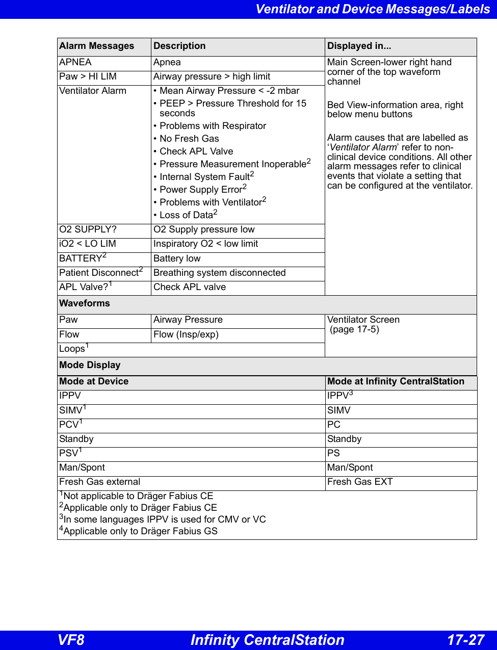
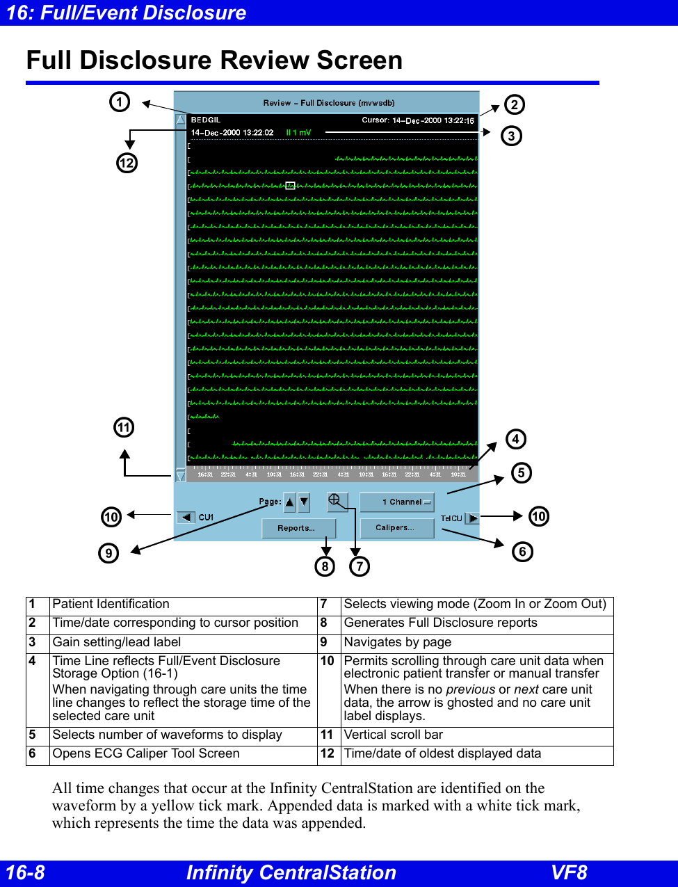
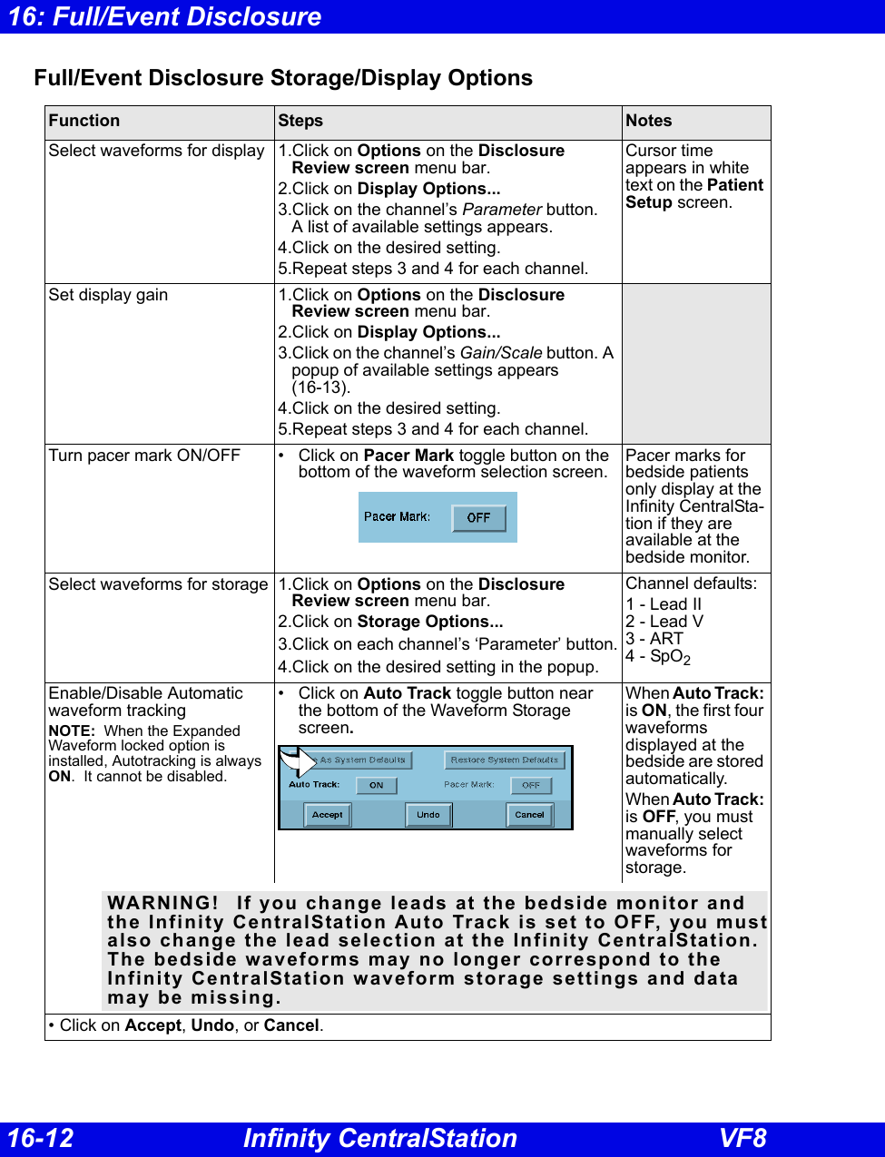
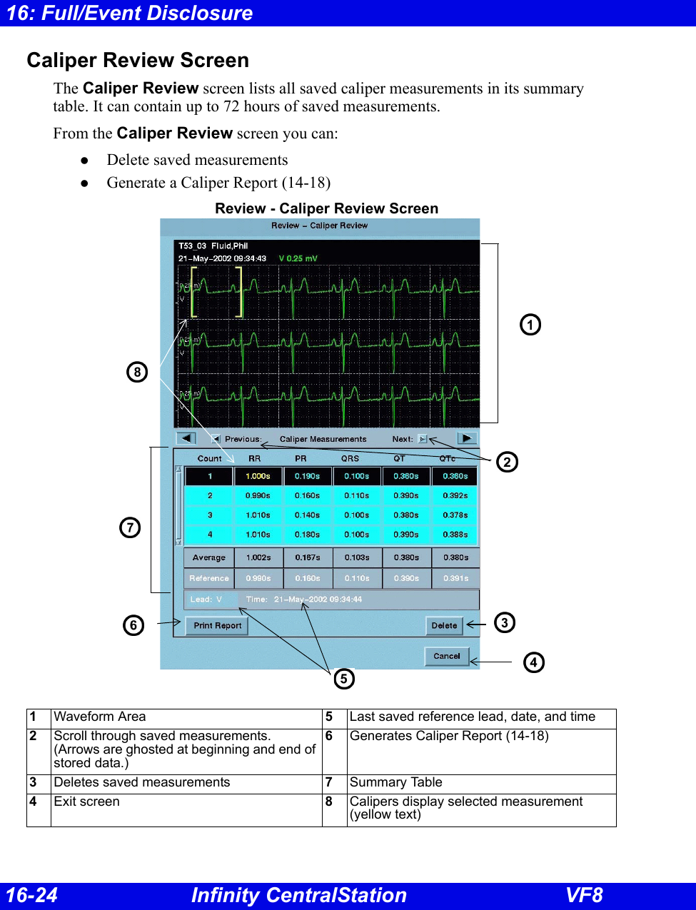
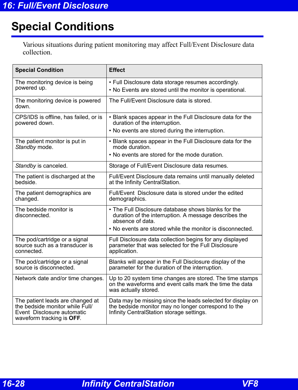
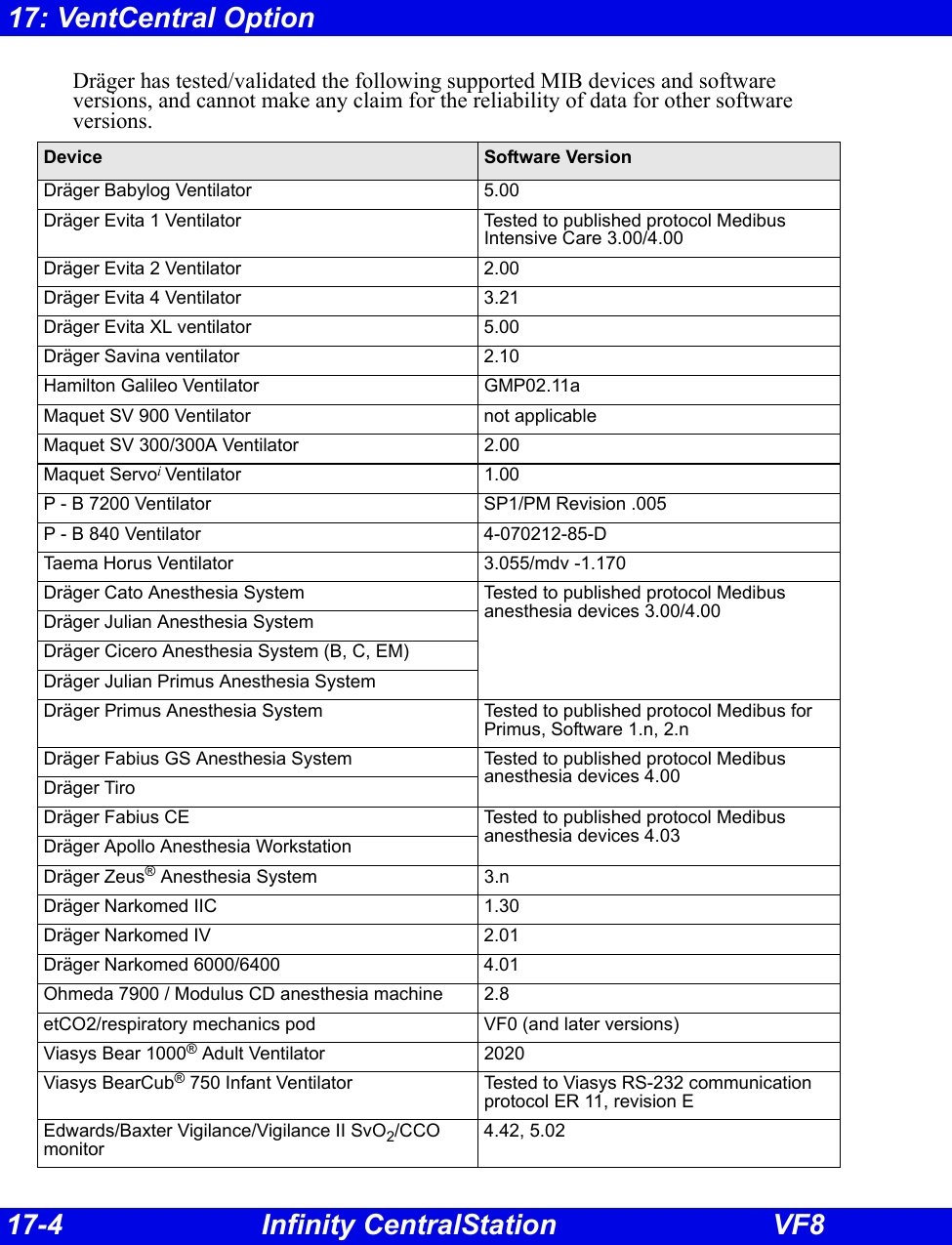
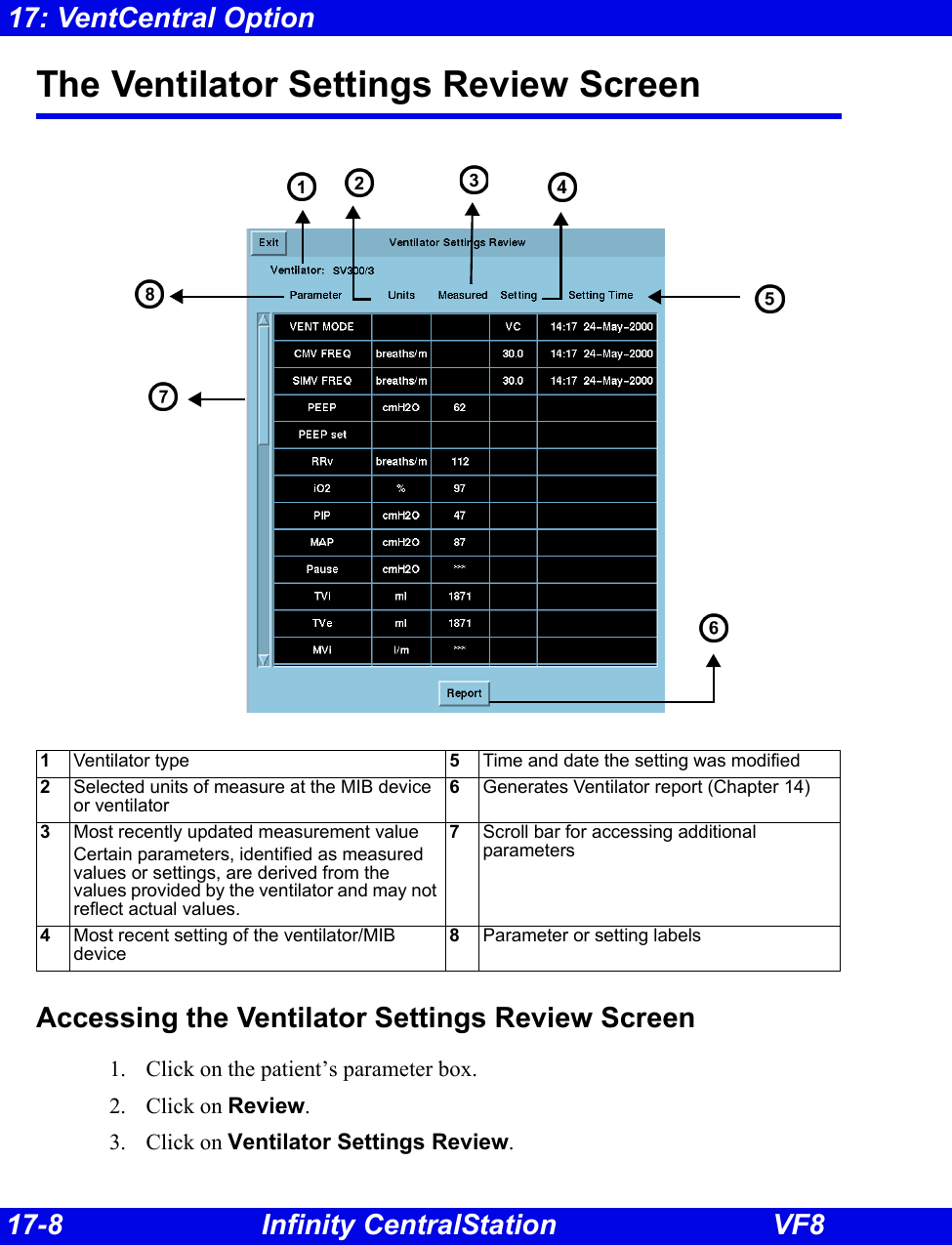
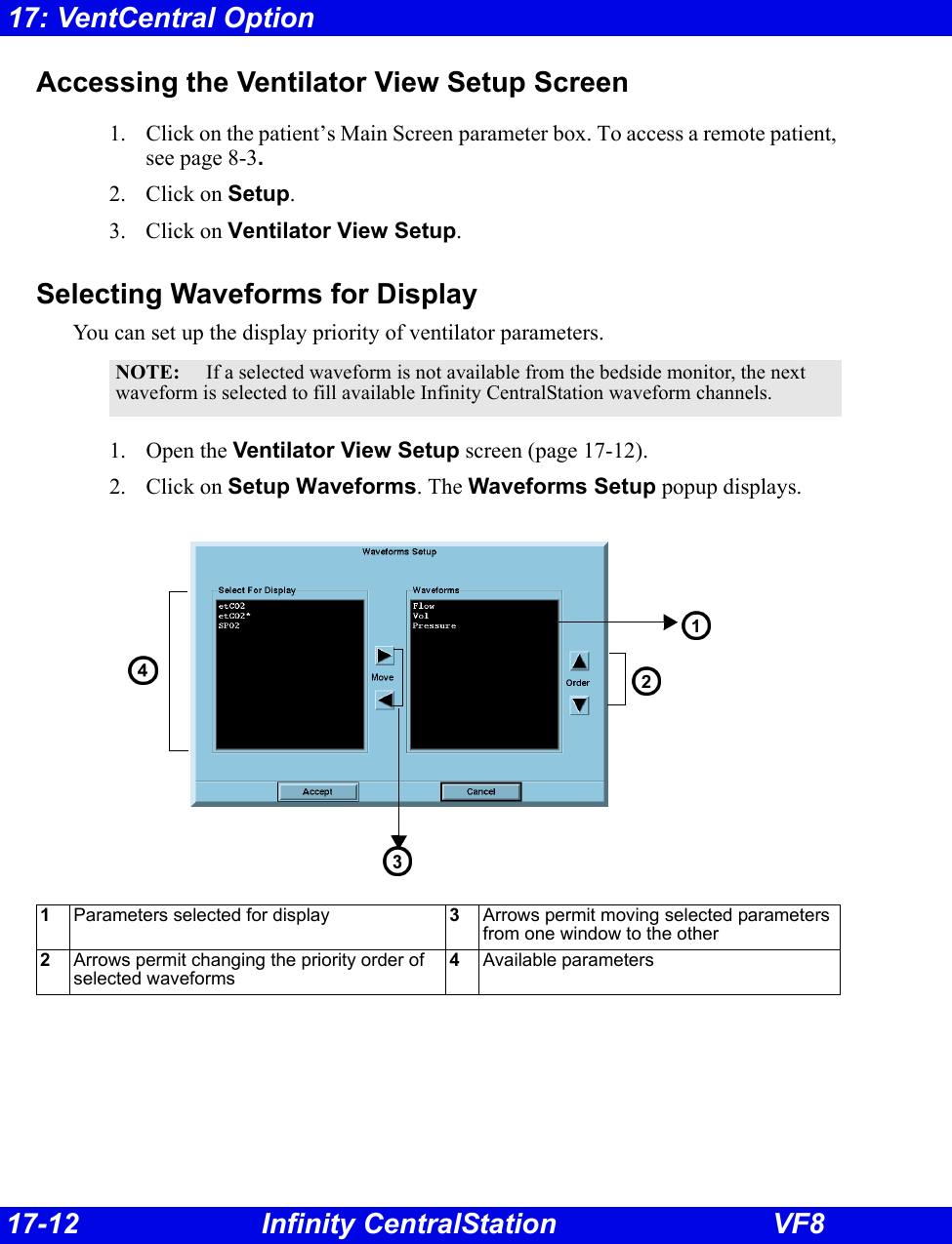
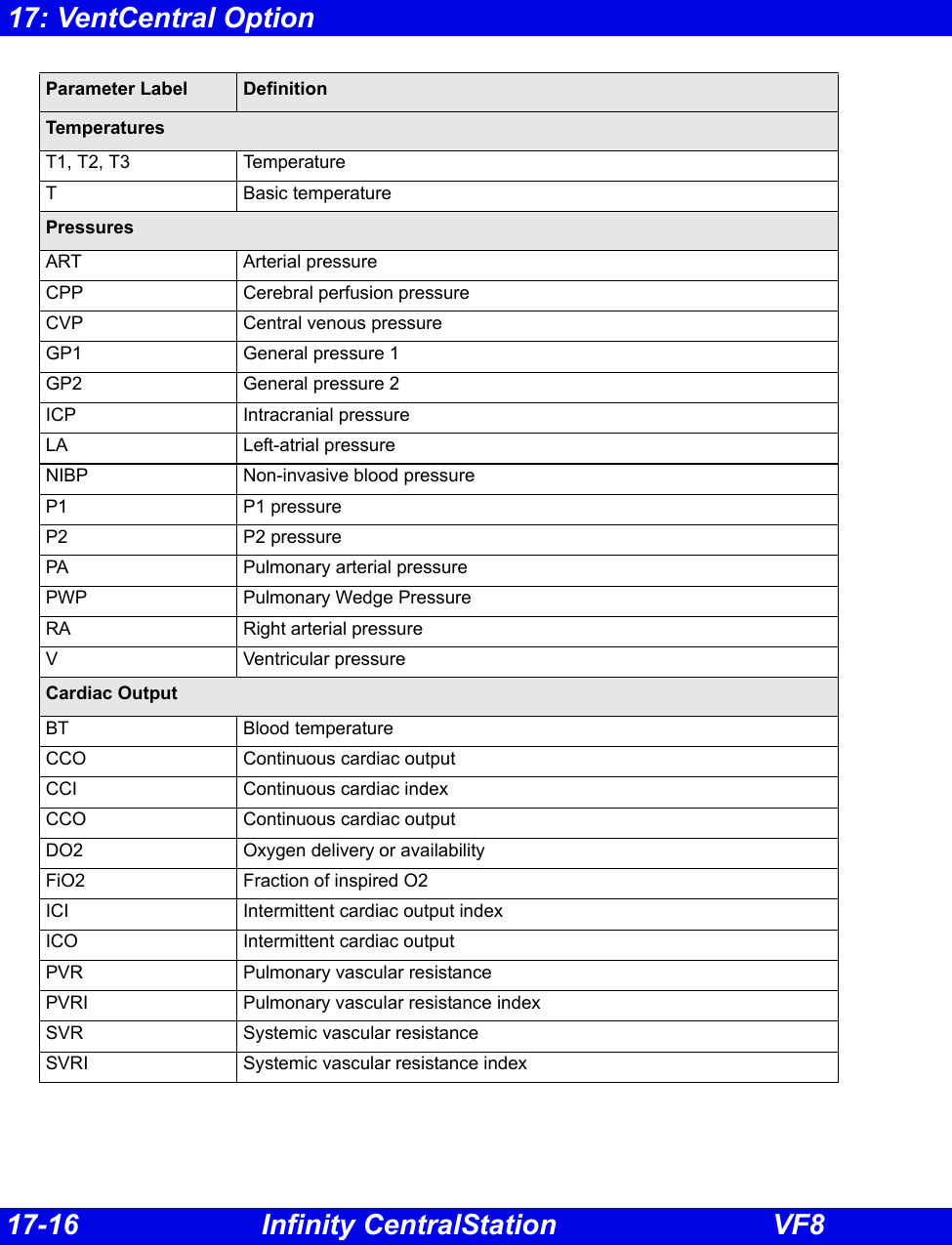
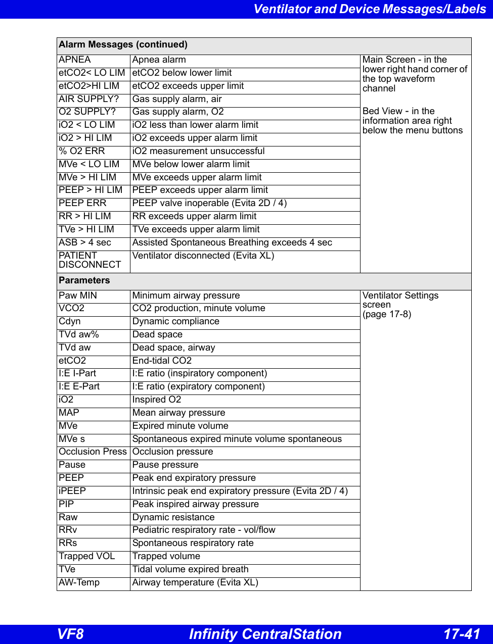
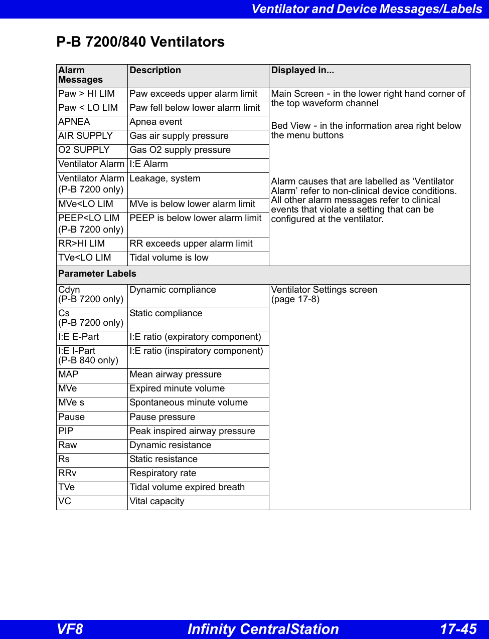
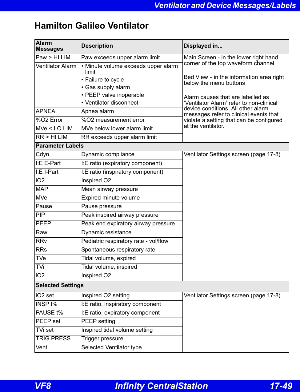
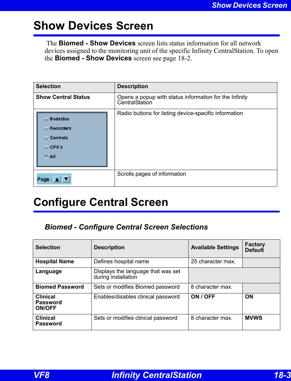
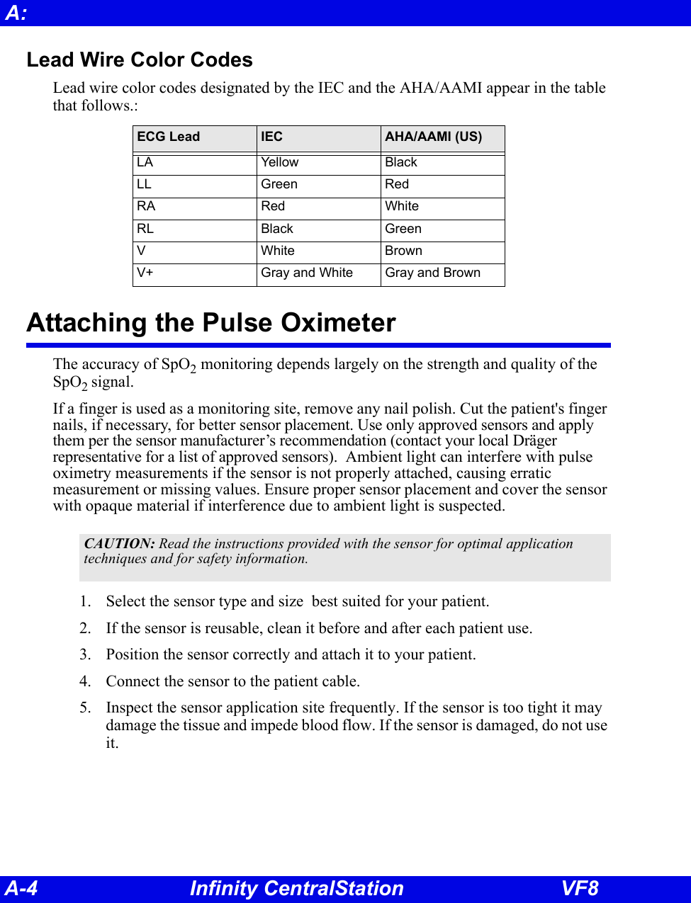
![17-28 Infinity CentralStation VF817: VentCentral OptionDräger Apollo Anesthesia SystemNOTE: The Dräger Apollo Anesthesia System is not commercially available in Canada and its future availability cannot be ensured.Parameter Description Displayed in...[HAL, ISO, ENF, SEV, DES]Expired and inspired agent Ventilator Settings screen (page 17-8)ECO2 Expired CO2eO2 Expired O2 iN2O Inspired N2OiO2 Inspired O2 MAP Mean Airway PressureMVe Minute Volume, expired Pause Pause Pressure PIP Peak inspired airway pressurePEEP Peak end expiratory airway pressure RRc Respiratory rate RRv Respiratory rateTVe Tidal volume, expired breathBaro Prsr Barometric PressureLeakage LeakageiMAC Inspired MACeMAC Expired MACAPNEA t Apnea DurationDelta O2 (iO2 - eO2)Setting Description Displayed in...TVi set Inspired Tidal Volume setting Ventilator Settings screen (page 17-8)I:E I part I:E ratio - inspiratory componentI:E E part I:E ratio - expiratory componentIPPV FREQ IPPV frequency settingINT PEEP set Intermittent PEEP settingPIP set PIP setting](https://usermanual.wiki/Draeger-Medical-Systems/MS24895.Users-Manual-2/User-Guide-1093179-Page-79.png)
![17-30 Infinity CentralStation VF817: VentCentral OptionDräger Zeus Anesthesia SystemNOTE: The Zeus Anesthesia System is not commercially available in the U.S. and its future availability cannot be ensured.Parameter Description Displayed in...Air Flow Air flow Ventilator Settings screen (page 17-8)Baro Prsr Barometric Pressure Cdyn Complianceet[HAL, ISO, ENF, SEV, DES]Expired agent etCO2 Expired CO2etN2O Expired N2OetO2 Expired O2 i[HAL, ISO, ENF, SEV, DES]Inspired agent iCO2 Inspired CO2iN2O Inspired N2OiO2 Inspired O2 Leakage LeakageMAP Mean Airway PressureMVe Minute Volume, expired MVe s Minute Volume, spontaneous MVm Mandatory MVN2O Flow Nitrous oxide flowO2 Flow Oxygen flowO2 Supply Prsr O2 supply pressurePause Pause Pressure PIP Peak inspired airway pressureRaw ResistanceRRc Respiratory rate (CO2) RRm Respiratory rate (mandatory)RRv Respiratory rate (volume/flow)TVe Tidal volume, expired breathTVm Mandatory Tidal volumeTVs Spontaneous Tidal volume](https://usermanual.wiki/Draeger-Medical-Systems/MS24895.Users-Manual-2/User-Guide-1093179-Page-81.png)

![B-20 Infinity CentralStation VF8B: Power frequency magnetic field 50/60 Hz (IEC 61000-4-8)3 A/m 3 A/m Equipment which emits high levels of power line magnetic fields (in excess of 3A/m) should be kept at a distance to reduce the likelihood of interference.Voltage dips and short interruptions on AC mains input lines(IEC 61000-4-11)Dip >95%, 0.5 periods >95%, 0.5 periods Mains power should be that of a typical commercial or hospital environment. If user requires continued operation during power mains interruptions insure that batteries are installed and charged. Insure that battery life exceeds longest anticipated power outages or provide and additional uninterruptible power source.Dip 60%, 5 periods 60%, 5 periodsDip 30%, 25 periods 30%, 25 periodsDip >95%, 5 seconds >95%, 5 secondsConducted RFRF coupled into lines(IEC 61000-4-6)150 kHz – 80 MHz: 3 V/m Portable and mobile RF communications equipment should be used no closer to any part of the, including cables, than the recommended separation distance calculated from the equation applicable to the frequency of the transmitter as below.Recommended separation distance:d=1.2/V1]√Pd=1.2/√P 80 MHz to 800MHzd=2.3√P 800 MHz to 2.5 GHzwhere ‘P’ is the maximum output power rating of the transmitter in watts according to the transmitter manufacturer and ‘d’ is the recommended separation distance in metres.Field strengths from fixed RF transmitters, as determined by an electromagnetic site survey1, should be less than the compliance level in each frequency range2. Interference may occur in the vicinity of equipment marked with the wireless symbol:Radiated RF(IEC 61000-4-3)80 MHz – 2.5 GHz 3 V/mElectromagnetic ImmunityImmunity against... IEC 60601-1-2 test level Compliance level (of this device) Electromagnetic environment](https://usermanual.wiki/Draeger-Medical-Systems/MS24895.Users-Manual-2/User-Guide-1093179-Page-149.png)
![Electromagnetic Compatibility VF8 Infinity CentralStation B-21 1Field strengths from fixed transmitters, such as base stations for radio (cellular/cordless) telephones and land mobile radios, amateur radio, AM and FM radio broadcast, and TV broadcast cannot be predicted theoretically with accuracy. To assess the electromagnetic environment due to fixed RF transmitters, an electromagnetic site survey should be considered. If the measured field strength in the location in which the equipment is used exceeds the applicable RF compliance level above, the equipment should be observed to verify normal operation. If abnormal performance is observed, additional measures may be necessary, such as re-orienting or relocating the equipment.2If the frequency range is 150 kHz to 80 MHz, field strengths should be less than 3 V/m.Recommended separation distances between portable and mobile RF communications equipment and the equipmentRated maximum output power of Transmitter (watts)Separation distance according to frequency of transmitter (meters)150 kHz to 80 MHzd=1.2/V1]√P80 MHz to 800MHzd=1.2/V1]√P800 MHz to 2.5 GHzd=2.3√P0.01 0.12 0.12 0.230.1 0.38 0.38 0.7311.2 1.2 2.310 3.8 3.8 7.3100 12 12 23For transmitters rated at a maximum output power not listed, the recommended separation distance ‘d’ (in meters) can be estimated using the equation applicable to the frequency of the transmitter, where ‘P’ is the maximum output power rating of the transmitter (in watts) according to the transmitter manufacturer.Electromagnetic ImmunityImmunity against... IEC 60601-1-2 test level Compliance level (of this device) Electromagnetic environmentNOTE:zAt 80 MHz and 800 MHz, the separation distance for the higher frequency range applies.zThese guidelines may not apply in all situations. Electromagnetic propagation is affected by absorption and reflection from structures, objects, and people.](https://usermanual.wiki/Draeger-Medical-Systems/MS24895.Users-Manual-2/User-Guide-1093179-Page-150.png)