Draeger Medical Systems MS24895 802.11b/g WIRELESS ADAPTER User Manual ICS F83 EN R01
Draeger Medical Systems, Inc. 802.11b/g WIRELESS ADAPTER ICS F83 EN R01
Contents
- 1. Users Manual 1
- 2. Users Manual 2
Users Manual 2
14-14 Infinity CentralStation VF8
14: Recordings / Reports
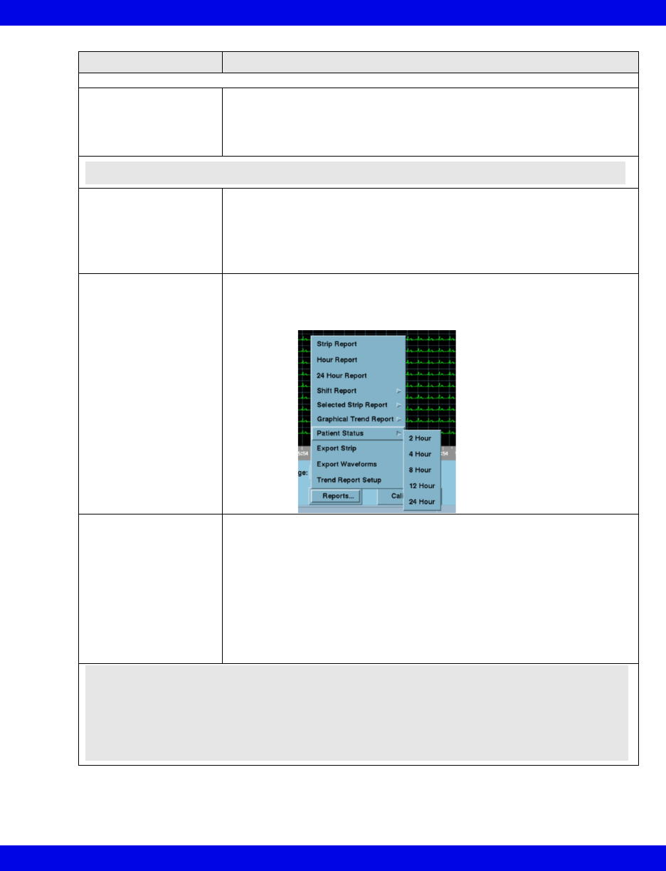
Patient Status
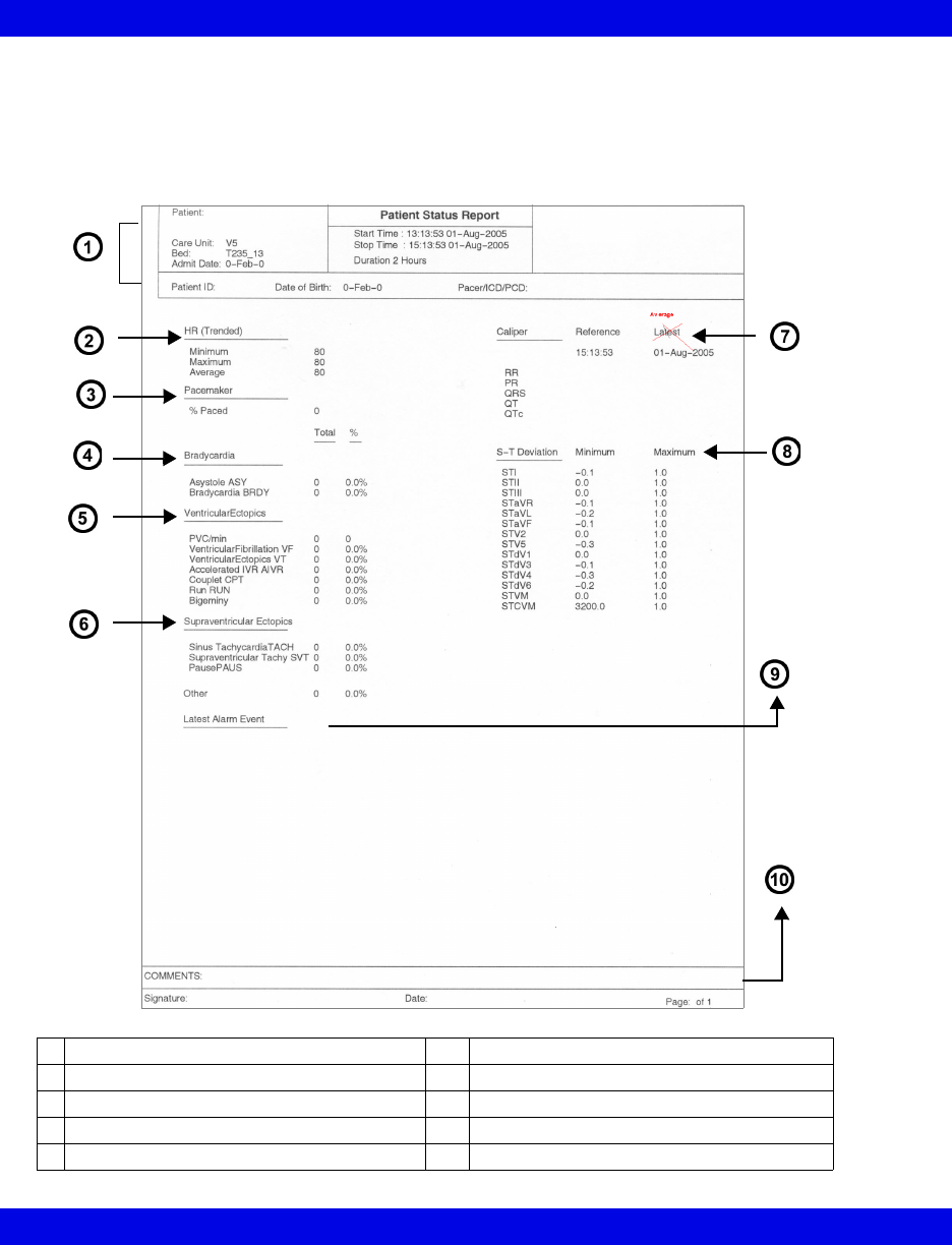
The Patient Status section of the Shift Report is a summary report focusing on a
patient's arrhythmia status. A Patient Status Report is also available as an
independent report and can be configured to print 2, 4, 8, 12, or 24 hours of data
(page 14-23).
1Header Information 6Supraventricular Ectopics
2Heart Rate, calculated from trend data 7Caliper Results
3Pacemaker 8S-T Deviation (from ST trends)
4Bradycardia 9Latest Alarm Event (in alarm categories)
5Ventricular Ectopics 10 Comment area
Reports
VF8 Infinity CentralStation 14-15
Graphical Trends
In the Graphical Trends section of the Shift Report each parameter trend is plotted
according to type.
This section resembles the full version Graphical Trend Report in appearance and
content (page 14-17) but is numbered and labeled as part of the Shift Report.
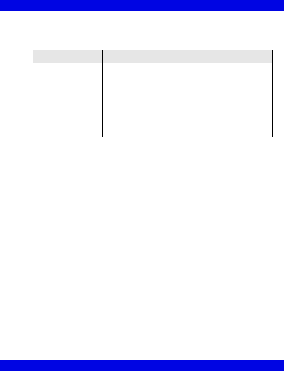
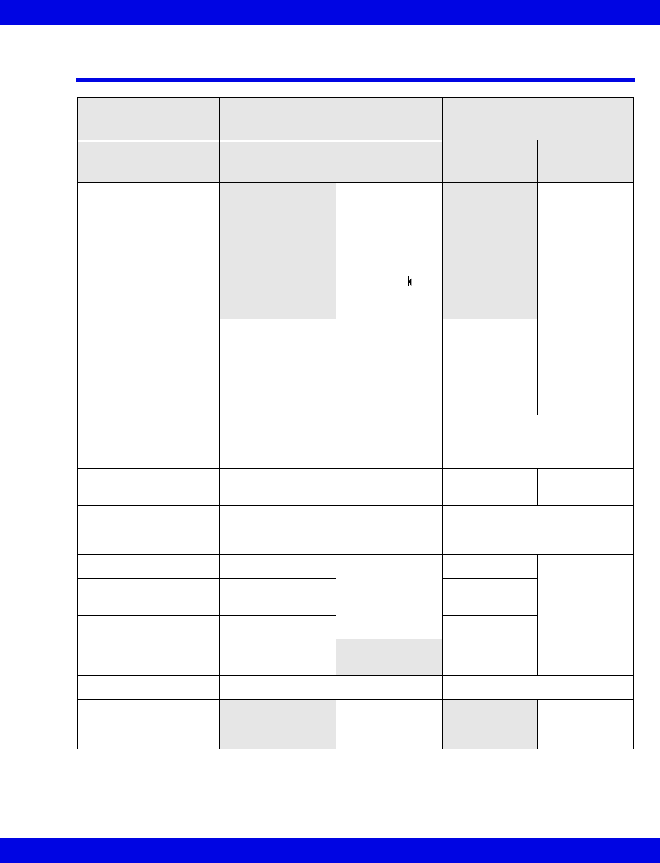
Parameter Type Appearance on Trend Graph
Single-value,
continuous such as HR
Single, continuous line
Single-value,
intermittent such as C.O.
Cross-hairs representing each value
Multi-value,
continuous such as ART
Lines with a dotted line in the center indicating the mean value
e.g., The top and bottom line can represent systolic and diastolic
values.
Multi-value,
intermittent such as NIBP
Vertical line with a blank space in the center indicating the mean
value
14-16 Infinity CentralStation VF8
14: Recordings / Reports
Selected Events
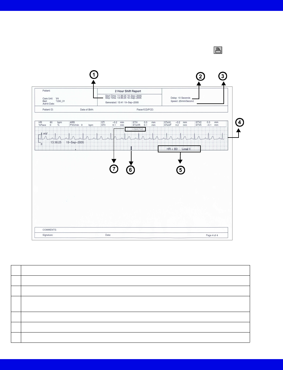
Depending on how many events you select (page 16-14) the selected events section
may consist of up to three pages (4 waveform strips each). You must select each event
that will appear in this section of the shift report by clicking on the icon so that a
check mark displays on the icon.
1Cursor time minus selected report length (2, 4, 8, 12, 24 hrs)
2Delay
3Recording speed
4The waveform contains 5 seconds of pre-event data and 5 seconds of real-time data. The
event marks the middle of the waveform.
5Event Label
6Event Marker
7Example of an annotated event
Reports
VF8 Infinity CentralStation 14-17
Graphical Trend Report
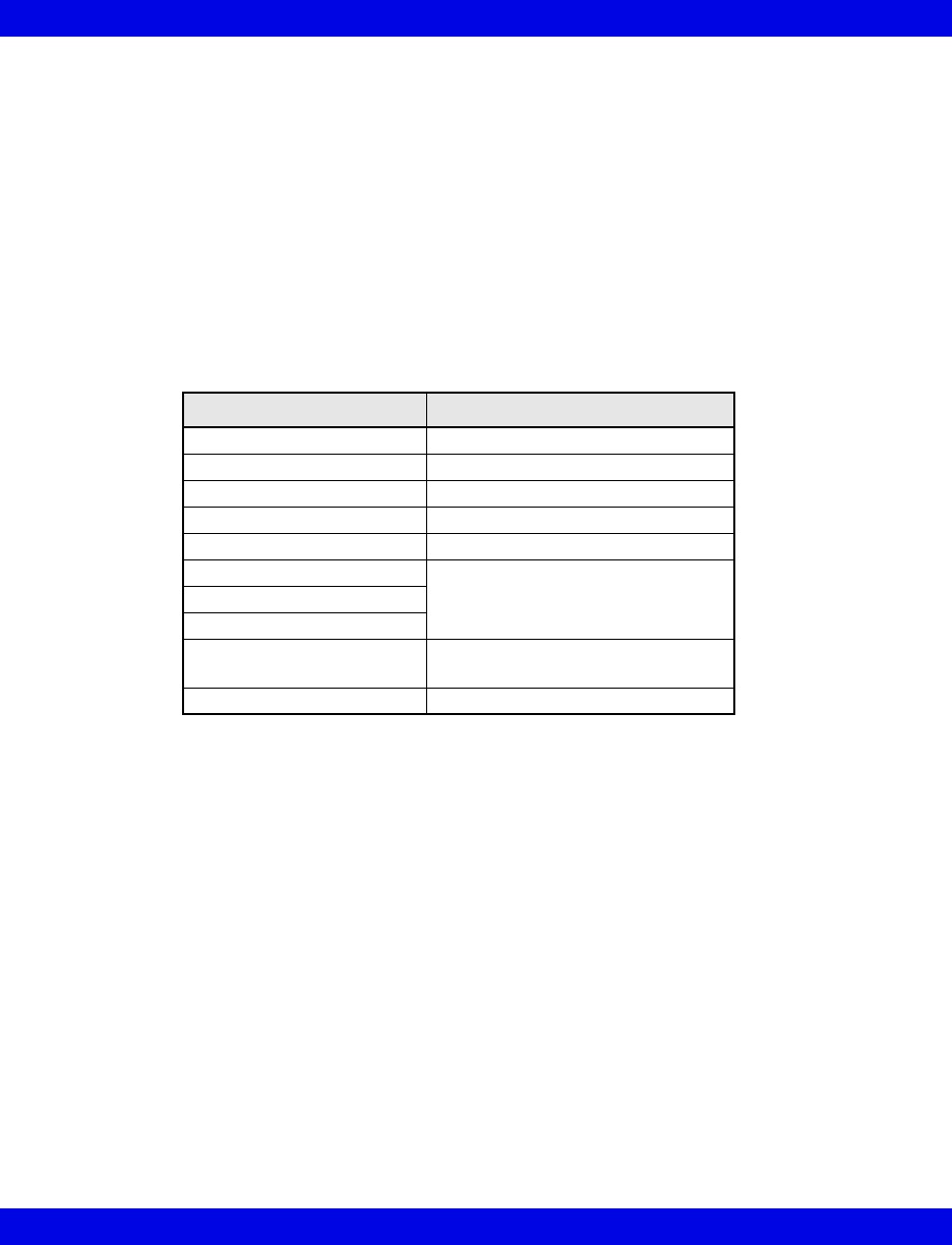
The Graphical Trend Report is a multi-parameter report containing up to 15 trended
parameters from bedside or telemetry patients. The report can be configured to print 2,
4, 8, 12, or 24 hours of Full or Event Disclosure data. The cursor time represents the
report ‘stop time’; the report ‘start time’ equals ‘stop time’ minus the report length.
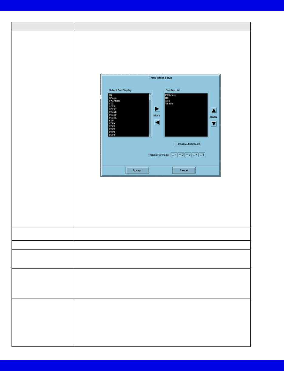
You can customize the trend selection per patient (page 14-24) or at system setup
(page 4-4). The trend scale can be a fixed scale or have autoscale values. When you
select Enable Autoscale (page 14-24) in the Trend Order Setup screen, the low and
high scale values are determined by an autoscale factor to the highest and lowest
parameter value over the currently selected trend time. To request a Graphical Trend
Report, see page 14-22.
Selected Strip Report
The Selected Strip Report allows the user to select a waveform of interest within
Full Disclosure and define beginning and ending cursor times (not to exceed one
hour). The report can contain 8 seconds to 1 hour of information (8 second default)
with 8 seconds of waveform data per row. To request this report, see page 14-23.
Selected Events Report
The Selected Events Report may consist of up to six pages (4 event strips per page).
You can select and print up to 24 events. Each waveform contains 10 seconds of data,
and is annotated with Lead Printed, Lead Processed, Event Cause, 12 of the most
recent parameter values, Event End Time, and Event Date. If the lead processed is
stored in the Infinity CentralStation database, it will be printed on the report. If not,
the top lead of the displayed Full Disclosure data will appear.To request this report,
see page 14-23.
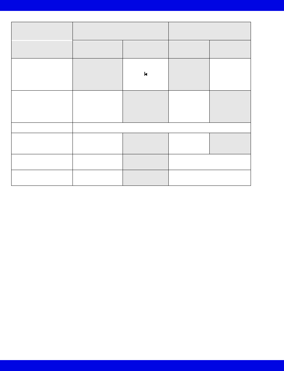
Parameter Autoscale Factor (approximate)
HR 10 bpm
PVC/min 10
% Paced 10%
SpO2 10%
PLS 10
ST 1.0 mm
0.10 mV
STVM
STCVM
Pressures (including NIBP) 10 mmHg
1 kPa
All others 10
14-18 Infinity CentralStation VF8
14: Recordings / Reports
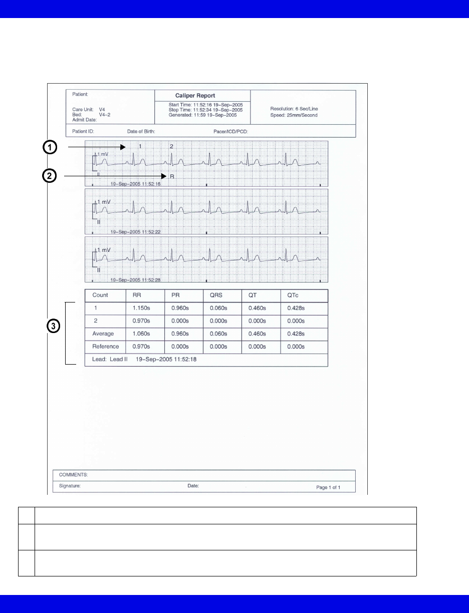
ECG Caliper Report
The ECG Caliper Report includes an 18-second ECG waveform strip and up to ten
rows of interval measurements. To request this report, see page 14-24.
1Count row number displays above measured complex.
2“R” displays under complex from which reference measurements were taken when it is in the
18-second ECG strip.
3Summary table from Caliper Review screen can include up to 10 rows of interval
measurements.

Reports
VF8 Infinity CentralStation 14-19
Ventilator Report
With the VentCentral option you can request a ventilator report for a bedside patient
who is connected to a ventilator.
A ventilator report is divided into two sections:
zParameters And Settings
zWaveforms and Loops
To request a ventilator report, see page 14-22.
Parameters and settings
This portion contains the parameter values, units of measure, the settings, and the time
the settings were last changed. The order of the parameters is fixed. Depending on the
number of available parameters originating from the bedside monitor, this portion of
the report may consist of several pages.
Waveforms and loops
The waveforms and loops page contains the ventilator waveforms and loops displayed
in the VentCentral Review screen and may contain up to three waveforms and up to
two loops.
Each waveform consists of 7 seconds of data and begins at the time the report is
generated. Each loop represents the first detected breath within the 7 seconds of data.
All waveforms are printed at 25mm/sec.
The labels and the scale of the printed waveforms and loops are identical to the
displayed waveforms and loops in the VentCentral Review screen.
NOTE: Certain parameters, identified as measured values, are derived from other
values provided by the ventilator and may not reflect the true measured values. See the
operating instructions for your specific monitor for detailed information on derived
measurements.
14-20 Infinity CentralStation VF8
14: Recordings / Reports
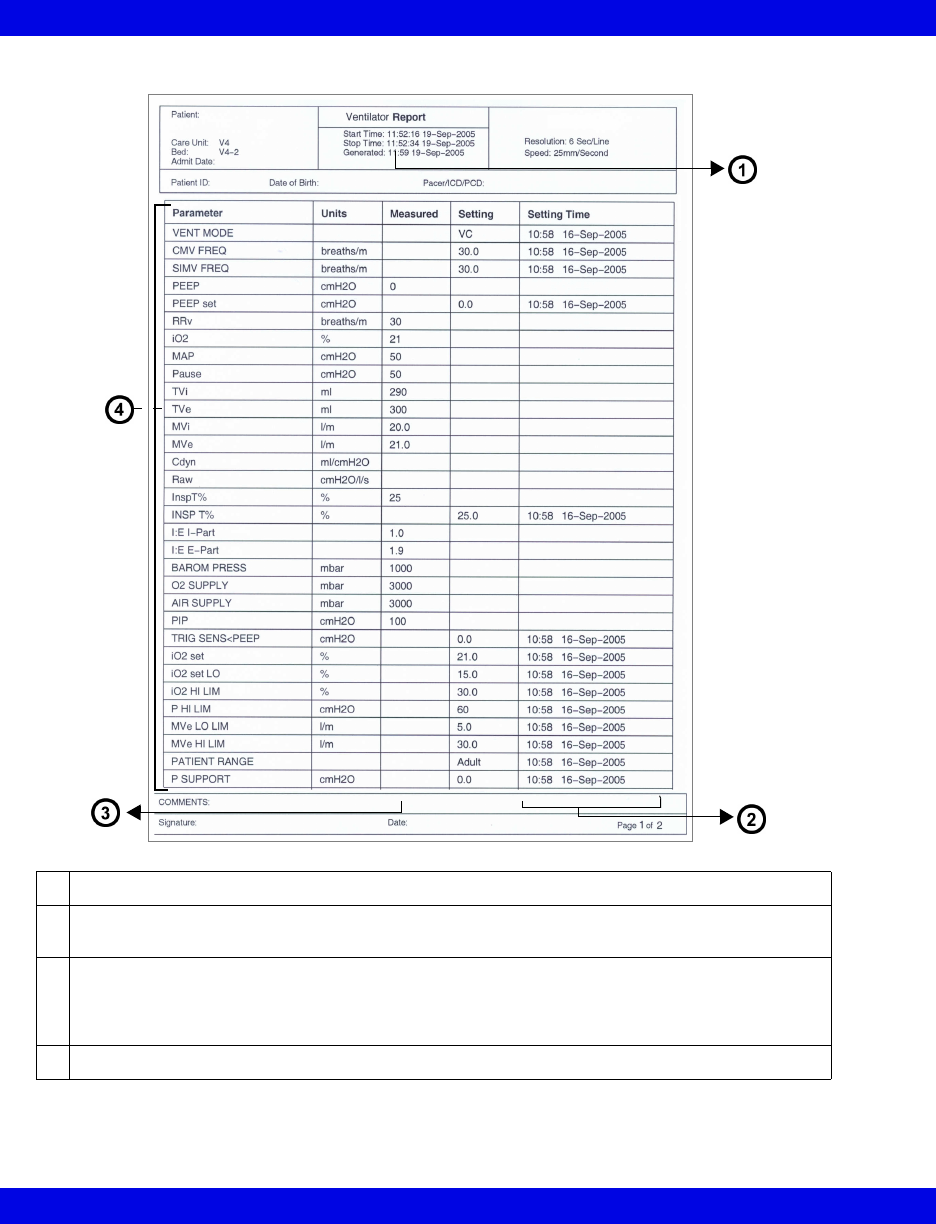
Parameters and Settings
1Time that the report request was processed
2Time the setting was updated or data collection resumed after the monitor was disconnected
from the patient
3Measured parameter values
Certain parameters, identified as measured values, are derived from other values or settings
provided by the ventilator and may not reflect actual values. See the operating instructions for
your specific monitor for detailed information on derived measurements.
4Parameters measured at the time the report request was processed
Reports
VF8 Infinity CentralStation 14-21
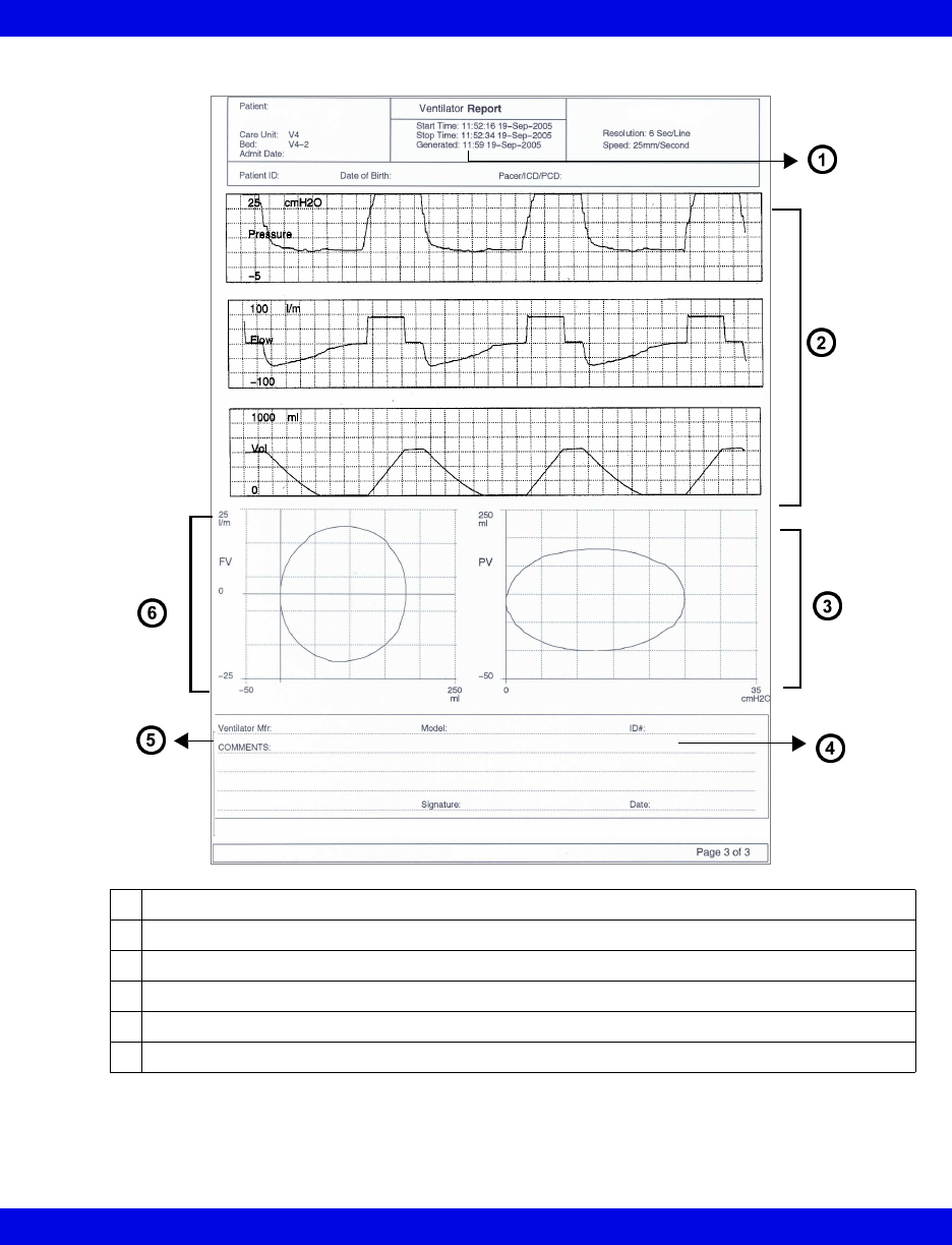
Waveforms and loops
1Time that the report request was processed
2Top 3 waveforms selected in VentCentral screen
3Pressure Loop (represents the first breath)
4Area to record Ventilator Identification Number
5Area to record Ventilator manufacturer
6Flow Loop (represents the first breath)
14-22 Infinity CentralStation VF8
14: Recordings / Reports
Requesting Recordings and Reports
NOTE: The print queue can handle multiple report requests. You are notified when
the print queue is full, and must wait until some reports print before requesting more.
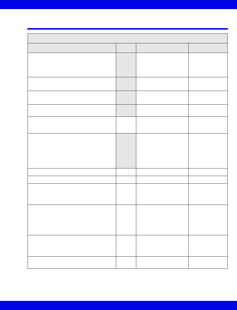
Recording/Report Required Steps
Timed recording
(from Main Screen)
For an individual patient:
• Click on the REC button in the patient’s parameter.
If the patient is discharged, in Standby, or waveforms are stopped, the
REC button is ghosted and you cannot request a timed recording.
For all patients admitted to Main Screen:
• Press the keyboard F11 key.
Timed recording
(from Bed View)
• Click on Record on the menu bar.
Timed manual recording
(from transmitter)
• Press transmitter recording button for less than 3 seconds.
Automatic alarm
recording
Automatically generated timed recordings are described in Chapter 13
and Chapter 10.
Continuous recording • Click on the CONT button.
If the patient is discharged, in Standby, or waveforms are stopped, the
CONT button is ghosted and you cannot request a timed recording.
Continuous recording
(from transmitter)
• Press transmitter recording button for more than 3 seconds.
Print Screen Main Screen
• Press the keyboard Print Screen key.
Bed View
1.Click on View in the menu bar.
2.Click on the desired menu selection.
3.Click on Print in the Bed View menu bar.
4.Click on Bed.
Simultaneous ECG
Report
1.Open patient’s Bed View Screen.
2.Click on Print in the Bed View menu bar.
3.Click on ECG Report.
Ventilator report 1.Open the Ventilator Settings Review Screen (page 17-8).
2.Click on Report.
NOTE:
zIf a recording was previously requested for a patient from Main Screen or the
patient’s waveforms are stopped, no recording is printed for that patient.
zIf the Infinity CentralStation is operating in Dual Display mode, recordings are only
printed for patients of the screen in which the mouse pointer is located at the time of
the request.
NOTE: If the Print button is ghosted, the Printer Connected setting is Off in the
Configure Central menu (page 18-3).
Requesting Recordings and Reports
VF8 Infinity CentralStation 14-23
Recording/Report Required Steps
Full Disclosure Reports
• Strip Report
• Hour Report
• 24 Hour Report
1.From the Full Disclosure screen (page 16-7) click on Reports...
2.Click on and select desired report.
If you request a 24 Hour Report a popup displays to alert you that this
report will keep the printer busy. You must confirm your request by
clicking on OK in the popup.
• Batch Shift Reports 1.Open the Setup Central screen (page 4-2).
2.Click on Batch Shift Reports.
The report length selections display.
3.Select a report length (2, 4, 8, 12, or 24 Hour).
4.Click on Accept to save the setting.
5.Press F9 on your keyboard.
• Shift Report
• Patient Status Report
1.From the Full Disclosure screen (page 16-7) click on Reports.... The
Reports menu displays.
2.Click on and select the desired report.
3.Select a report length from the menu (2, 4, 8, 12, or 24 Hour).
• Selected Strip Report 1.From the Full Disclosure screen (page 16-7) click on Reports....
2.Select a report length from an entry on the menu (1, 5 10, or 60 min-
utes, and Selected).
The menu item ‘Selected” is ghosted until a second cursor is defined.
For a Selected report length
3.Right-click on the waveform to set a second cursor. The second cursor
displays with dotted lines and can represent either the Stop or Start
Time depending on its location relative to the first cursor.
A confirmation popup appears that shows Start Time, Stop Time, and
Total Pages.
4.Click on Continue or Cancel in the popup.
NOTE: You can change the cursor time by clicking on it.
NOTE:
zYou cannot set the cursors so that the report is longer than 60 minutes or less than 2
seconds. A popup will display that cancels the selected period.
zThe minimum report length is 8 seconds. Also, the report length will automatically
adjust so that each row will contain a full 8 seconds of ECG data.
14-24 Infinity CentralStation VF8
14: Recordings / Reports
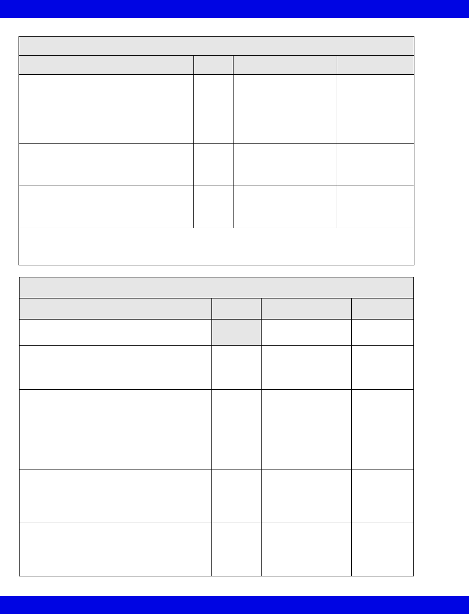
Recording/Report Required Steps
• Graphical Trend
Report
On a Graphical Trend Report, which is also included in a Shift Report,
you can print a report with the system-assigned trend settings (page 4-4)
or you can configure the report to display particular trends for the
individual patient as follows:
1.From the Full Disclosure screen (page 16-7) click on Reports....
From the Reports menu click on Trend Report Setup.
The Trend Order Setup screen displays.
2.Select the trends you want to display and move them to the Display
List window.
The trends typically display on a fixed scale, but you can change the
display by enabling autoscale.
3.If you want to change the display scale to autoscale, click on the selec-
tion box next to Enable AutoScale.
4.Select a number of Trends Per Page for the report.
5.Click on Accept to keep the trend order setup or on Cancel.
• Caliper Report 1.Open the Caliper Review screen (page 16-24).
2.Click on Print Report.
Event Disclosure Reports
• Event Disclosure Strip
Report
1.From the Event Disclosure screen (page 16-7) click on the button,
Reports...
2.Click on Strip Report.
• Event Disclosure Shift
Report
• Event Disclosure
Graphical Trend
Report
1.From the Event Disclosure screen (page 16-7) click on the button,
Reports....
2.Click on and select desired report.
3.Select a report length from the menu (2, 4, 8, 12, or 24 hr).
• Selected Events
Report
1.From the Event Disclosure screen (page 16-7) click on the button,
Reports....
2.Click on Selected Events Report.
3.Select the events for the report.
A popup displays the number of events selected.
4.Click on Accept to continue or on Cancel.

Canceling a Recording
VF8 Infinity CentralStation 14-25
Canceling a Recording
Recording Type Cancel in
Main Screen
Cancel in
Bed View
Cancel at the
Recorder
Manual timed
recording
Click on patient(s) REC
key to ‘deselect’.
Click on the RECORD
key to ‘deselect’.
Press STOP key.
Alarm recording Not possible Not possible Press STOP key.
ARR event recording Not possible Not possible Press STOP key.
Continuous recording Click on patient’s CONT
REC key to ‘deselect’ it.
Not possible Press STOP key.

14-26 Infinity CentralStation VF8
14: Recordings / Reports
Actions that Affect Recordings
Action Effect on Pending
Recordings
Effect on Recordings in
Progress
Patient Discharge Pending recordings
discarded
Recording is canceled.
Edit patient’s demographic data No effect No effect
Patient monitoring put in standby
mode
No effect Recording is canceled.
Restore factory defaults Pending recordings
discarded
Recording is canceled.
Configuration change of Main
Screen resulting in removal of a
patient
Patient’s pending recordings
canceled
Recording is canceled.
Change in scale settings or
parameter order (parameters
might become available/
unavailable due to restored/
missing signals)
No effect Recordings will continue
but waveform and
parameter data for any
removed parameter appear
as blanks. Added
parameters are not
included on an in-progress
recording.
Recorder assignment change No effect. Additional
recordings are printed on
the new recorder.
No effect on recordings
Network time/date change No effect on active or
pending recordings. All new
and continuous recordings
in progress reflect the new
date/time.
Continuous recordings
reflect the change
immediately (as will all
future timed recordings).
R 50 recorder becomes
unavailable, runs out of paper, or
jams
No effect Recording is not lost, but
routed to another assigned
recorder, or stored for later
printing when the recorder
becomes available.
Remote device requesting a
recording of a local patient goes
offline
Deletes all recordings
associated with this device
Recording is canceled.
Patient disconnect for transport Cancels all pending
recordings for that bed
Recording is canceled.
Recording Status Messages
VF8 Infinity CentralStation 14-27
Recording Status Messages
Recorder Status Messages
Status Message Tone Description Action
• <xxxx> Recording Request Accepted1
• Cont. Recording Now Timed (for
Gamma/Gamma XL/Vista monitors only)
• <xxxx> Report Request Accepted2
Request is accepted, but
stored until a printing
device is available.
None
• <xxxx> Recording Started1
• <xxxx> Report Request Started2
Request is being printed. None
• <xxxx> Recording Finished1
• <xxxx> Report Request Finished2
Printout is finished or is
stored.
None
•<xxxx> Report Request Canceled -
Queue full2Report is canceled due
to a full print queue.
None
<xxx> Disconnected3Advisory Recorder(s) not
connected to the
network.
Connect the
recorder.
• <xxxx> Recording Interrupted1Recording stalled
because recorder is
disconnected or out of
paper, its door is open,
or an error occurred
during data
transmission.
Contact the
Hospital
Biomedical
Engineering Dept.
<xxx> Door Open3Advisory Recorder door open Close door.
<xxx> Out Of Paper3Advisory Recorder needs paper. Replace paper.
<xxx> Failure3Serious Recorder failed. Take recorder out
of service and
contact service
personnel.
<xxx> Offline3Serious Recorder is offline.
Recorder
communication with the
network failed.
Contact the
Hospital
Biomedical
Engineering Dept.
to check network
connection.
<xxx> Duplicate Address3Serious Recorder detected
duplicate address.
Contact the
Hospital
Biomedical
Engineering Dept.
Recorder Not Assigned Attention No recorder assigned. Assign a recorder
(page 4-5)
14-28 Infinity CentralStation VF8
14: Recordings / Reports
Recording Request Not Accepted Attention Bedside monitor’s print
queue is full, or
telemetry patient’s
recording is requested
within 5 seconds of
request for a higher-
priority recording.
Wait until some of
the pending
recordings are
printed before
requesting
another recording.
Recording Status Unknown - Connection
Failed
Attention Recording status
unknown due to failed
bed connection
(telemetry or bedside).
Contact the
Hospital
Biomedical
Engineering Dept.
Cursor out of Range Attention More than 60 minutes of
data is defined by
Selected Strip Report
cursors.
Set cursors for 8
seconds to 60
minutes of FD
data.
1 <xxxx> represents recording title.
2 <xxxx> represents report title.
3 <xxx> represents device/host label.
Printer Status Messages
Status Message Tone Description Action
Print Request Finished Request is
complete.
None
Printer Not Configured Attention No printer is
configured at the
Infinity
CentralStation.
Configure the
printer
(page 18-4).
Print Request Not Accepted - Queue Full Attention Print screen request
was rejected
because the print
queue handles one
request at a time.
Wait until
previous
screens
complete
printing
before
requesting
another.
Printer/Communication Error Attention Communication to
network is faulty.
Consult the
Hospital
Biomedical
Engineering
Dept.
Printer Selection Failed Attention Selected printer is
not set up properly.
Consult the
Hospital
Biomedical
Engineering
Dept.
Recorder Status Messages
Status Message Tone Description Action

15 Trends
Overview.......................................................................................................................15-2
Accessing a Patient’s Trends.....................................................................................15-2
Trend Graphs ...............................................................................................................15-3
Parameter Display Order and Trend Scales for Telemetry Patients ................15-4
Trend Table ..................................................................................................................15-5
Trend Cursor ................................................................................................................15-6
Representation of Special Conditions.......................................................................15-7

15-2 Infinity CentralStation VF8
15: Trends
Overview
Trend information is available at the Infinity CentralStation for remote viewing of
bedside and telemetry devices.
Accessing a Patient’s Trends
1. Open the patient’s Bed View screen.
2. Click on Review.
3. Click on Trend Graphs... or Trend Table....
When you open the Trend Graphs screen, data is centered around the cursor time.
Trend Graphs
VF8 Infinity CentralStation 15-3
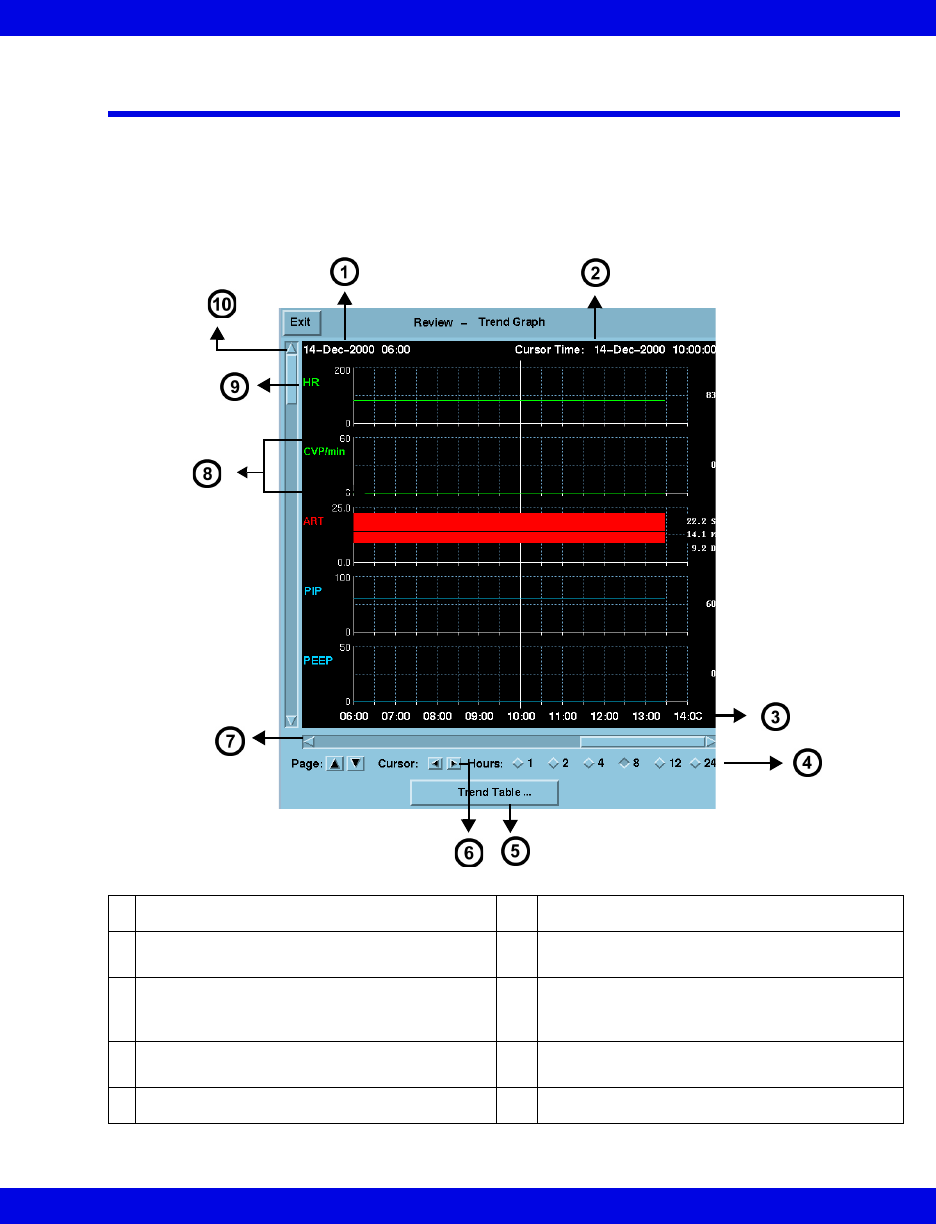
Trend Graphs
Trend graphs show stored trend data for each parameter. Each trend page can
accommodate up to five parameter graphs that may be blank if the parameter is not
selected for trending. Trends are updated automatically, with the most recent data
entering continuously on the right. When you click on the trended parameter label, the
scale toggles between fixed and autoscale values (page 14-17).
1Start date/time of Trend data 6Cursor scrolling keys
2Time and date corresponding to current
cursor position 7Horizontal arrows scroll time periods
3
Time labels
8
Interactive scale permits selection of:
-autoscale or fixed scale (telemetry patients)
-autoscale or bed scale (bedside patients)
4Radio buttons to select graph time period 9Parameter label (click on Parameter Label
to autoscale)
5Opens Trend Table 10 Vertical arrows scroll one graph at a time
15-4 Infinity CentralStation VF8
15: Trends
Parameter Display Order and Trend Scales for Telemetry
Patients
Parameter Display Order Upper/Lower Scale
HR 1 0 to 200 beats/min
PVC/min 2 0 to 60
% paced 3 0 to 100%
SPO2 (SPO2*) 4 50 to 100%
PLS (PLS*) 5 0 to 200 beats/min
NPB 6 0 to 250 mmHG
STI 7 - 26 -5 to 5mm or -0.5 to 0.5mV
STII
STIII
ST aVR
ST aVL
ST aVF
ST V
ST V+
ST V1
ST V2
ST V3
ST V4
ST V5
ST V6
ST dV1
ST dV2
ST dV3
ST dV4
ST dV5,
ST dV6
ST VM 27 -10.0 to10.0 mm or -0.10 to 0.10mV
ST CVM 28
Trend Table
VF8 Infinity CentralStation 15-5
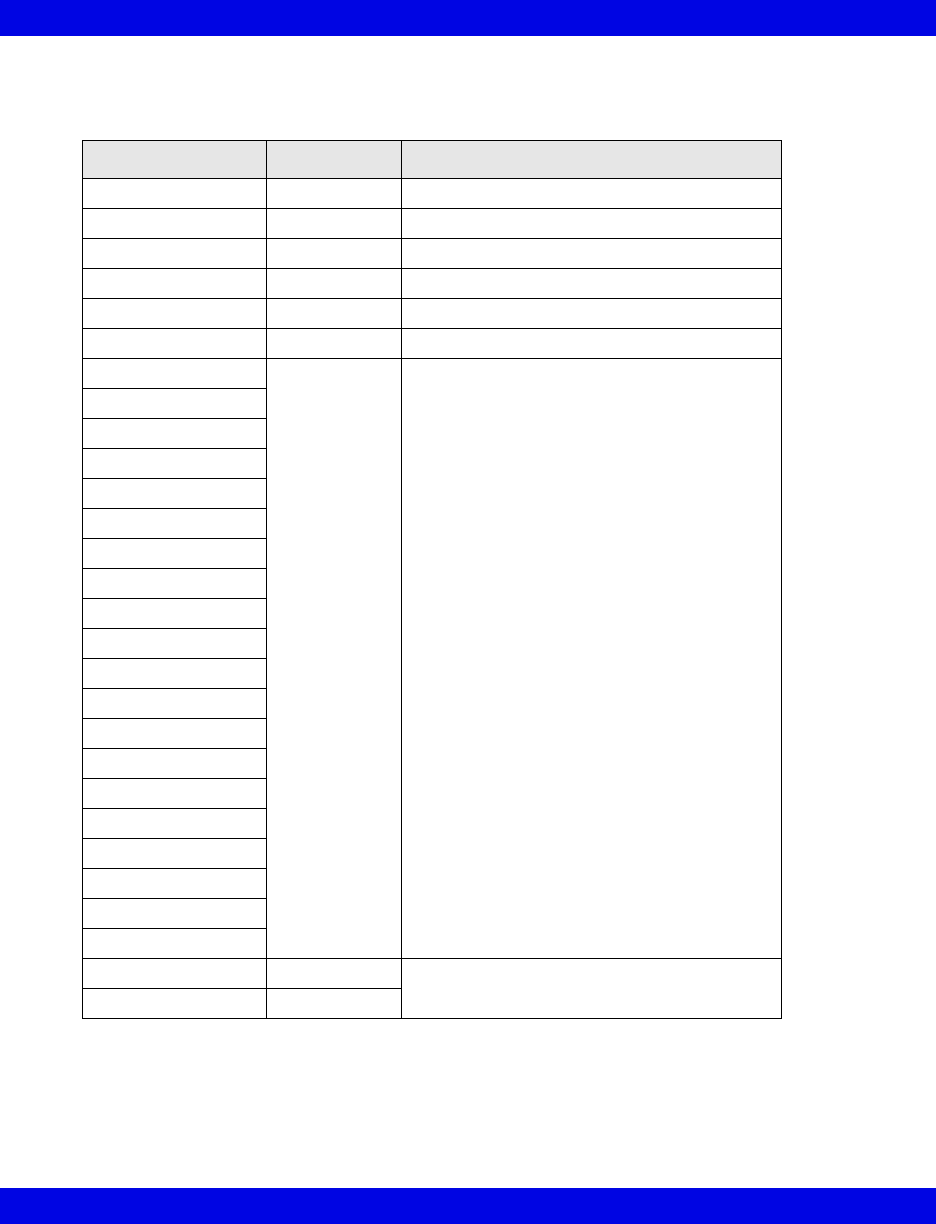
Trend Table
Each trend table row shows a parameters values; each column shows a trend data set
for all parameters at that time. If a parameter is assigned to trending but cannot be
trended, the row lists the parameter label but values are blank. Regardless of the
selected interval, a trend table displays up to 8 data columns. A trend table may also
represent special events (page 15-7).
zTrend values appear in groups of associated parameter rows.
zDiscrete events such as NPB or CO measurements cause a set of trend data to
be stored for all parameters. Such data appears as a separate trend column a
with a green time stamp heading. This is also true when a mini-calc
computation is initiated on an Delta/Delta XL/Kappa/GammaX XL monitor.
zThe trend table updates automatically whenever an interval elapses. The most
recent column is at the right of the screen.
1Date/time of cursor position 5Permits page scrolling
2Time stamps 6Parameter labels
3Horizontal arrows scroll time columns 7Start date/time of trend data
4Radio buttons for selecting time period 8Vertical arrows scroll rows of data
15-6 Infinity CentralStation VF8
15: Trends
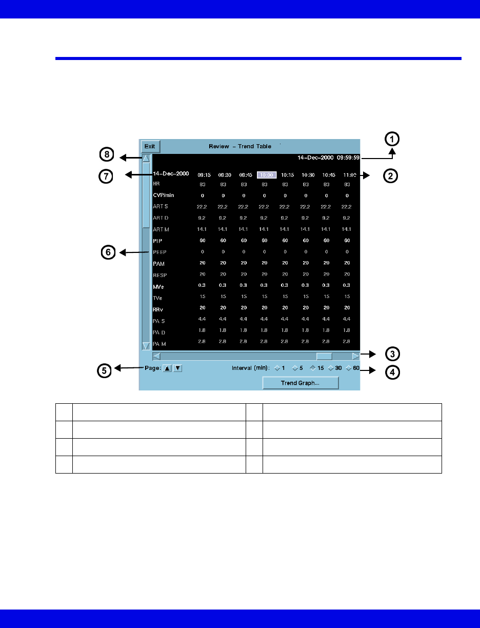
Trend Cursor
On a trend graph, the cursor appears as a full-screen white vertical line; on a trend
table the cursor is the highlighted column time. Cursor time displays in the upper right
part of the screen.
zWhen using the time anchor function between Full Disclosure, Event
Disclosure and trends, the cursor time will match one of the trend table
column time stamps. The column time is highlighted and appears in the center
of the trend table screen.
zIf the cursor time does not exactly match one of the columns in the trend table,
cursor time is displayed but no column is highlighted. Click on any column
time to highlight it.
zIf the cursor time is not within the time span of the current trend page, the
cursor time displays but the cursor does not. Scroll to the desired data to
display the cursor on the current trend.
zIf the cursor time is older than any of the available trend data, the oldest trend
data is displayed without the cursor.
z24 hours of trend graph data is displayed. One hour of tabular trend data is
displayed.
Representation of Special Conditions
VF8 Infinity CentralStation 15-7
Representation of Special Conditions
Condition Representation in Trend Table Representation in Trend
Graphs
Telemetry
Patients
Bedside
Patients
Telemetry
Patients
Bedside
Patients
Discrete trend sam-
ples such as those
associated with NPB
and CO
Column desig-
nated with a
green time
stamp
Vertical line
with a gap in
the center indi-
cating the
mean value
A trend event stored at
Delta/Delta XL/Kappa
bedside monitor
Column desig-
nated with
and a green time
stamp
Not shown in
graphs
Physiological condi-
tions such as an asys-
tole or an apnea
• ASY = Asystole
•VF = ventricular
Fibrillation
• ASY = Asystole
•FIB =
Ventricular
Fibrillation
• APN = Apnea
• Parameter
value = 0
• Parameter
value = 0
• Parameter
value = 0
• Parameter
value = 0
No parameter could be
derived * * *
Blanks in the graphs
Lead-Off
condition
*L* *** *L* ***
Out-of-range
values
+ + + (high) or - - - (low) Blanks (Move the cursor over
the blanks to display actual val-
ues.)
Artifact *A* *** *A* ***
Lead wires, electrodes
are unplugged
*U* *U*
Hardware failure *F* *F*
Interference *I* Blanks in the
graphs
shaded
No signal *N* Blank spaces Blanks in the graphs
Time change at bed-
side monitor
Yellow line
between trend
columns
Blank spaces
in the graph
15-8 Infinity CentralStation VF8
15: Trends
Telemetry
Patients
Bedside
Patients
Telemetry
Patients
Bedside
Patients
A trend event has been
stored by initiating a
mini-calc computation
at the bedside.
Column desig-
nated with this
symbol and a
green time
stamp
not shown in
graphs
Change in units of
measure
New units take
effect during the
next patient
admission.
New units take
effect during
the next
patient admis-
sion.
Power loss in server Blank spaces are stored in place of trend values
Telemetry receiver
goes offline.
Blank spaces
instead of trend
values
Blank spaces
instead of
trend values
Relearning of ST
complexes
RVertical dotted line that extends
through the entire graph
Changing of ST
measuring points
CHG Vertical solid line that extends
through the entire graph
Condition Representation in Trend Table Representation in Trend
Graphs

16 Full/Event Disclosure
Overview.......................................................................................................................16-2
Full/Event Disclosure Census Operations ................................................................16-2
Accessing the Census Screen.............................................................................16-2
Admitting a Patient to Full/Event Disclosure ............................................................16-5
Data Collection Rules ...........................................................................................16-5
To Manually Admit a Patient: ...............................................................................16-6
Accessing Disclosure History ....................................................................................16-6
Locking a Full/Event Disclosure Record ............................................................16-6
Accessing the Full/Event Disclosure Review Screen ..............................................16-7
Full Disclosure Review Screen...................................................................................16-8
Event Disclosure Review Screen ...............................................................................16-9
Full/Event Disclosure Review Screen Functions....................................................16-10
Full/Event Disclosure Storage/Display Options ...............................................16-12
Annotating Events ..............................................................................................16-14
Viewing Events....................................................................................................16-15
Deleting Events ...................................................................................................16-16
Viewing Parameter Values .................................................................................16-16
Renaming/Reclassifying Events........................................................................16-17
Disclosure Review Screen Cursor.....................................................................16-18
Full Disclosure ECG Caliper Tool ............................................................................16-19
Caliper Measure Screen ....................................................................................16-20
Caliper Review Screen........................................................................................16-24
Full/Event Disclosure Reports..................................................................................16-25
Exporting Full/Event Disclosure Data......................................................................16-26
Exporting Full Disclosure Data to a Third-Party Device..................................16-26
Exporting Events from Event Disclosure .........................................................16-27
Special Conditions ....................................................................................................16-28

16-2 Infinity CentralStation VF8
16: Full/Event Disclosure
Overview
The Infinity CentralStation has the ability to store Full Disclosure waveforms
continuously for a minimum of two hours to a maximum of 72 hours, depending on
the configuration. The number of waveforms stored in Full Disclosure depends upon
the configuration also. Event Disclosure is storage of arrhythmia, alarm events, or
manually triggered events. Depending upon the license option, storage capacity for
Event Disclosure is two to 72 hours and up to 1000 events per patient.
Full/Event Disclosure Census Operations
Accessing the Census Screen
From Bed View:
1. Click on Review.
2. Click on Full Disclosure... or Event Disclosure....
3. Click on Census in the menu bar.
From Main Screen:
1. Click on View.
2. Click on Full Disclosure... or Event Disclosure....
Full/Event Disclosure Census Operations
VF8 Infinity CentralStation 16-3
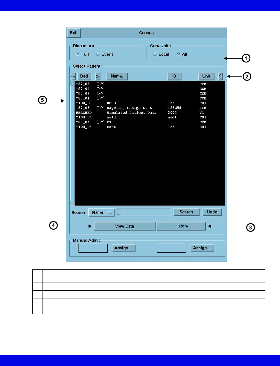
Census Screen Illustration
1Local - all patients with Full/Event Disclosure records on local Infinity CentralStation
All - all patients with Full/Event Disclosure records on the Infinity Network
2Click on heading to sort columns
3Opens selected patient’s History window
4Opens Disclosure Review Screen
5Census Screen patient list
16-4 Infinity CentralStation VF8
16: Full/Event Disclosure
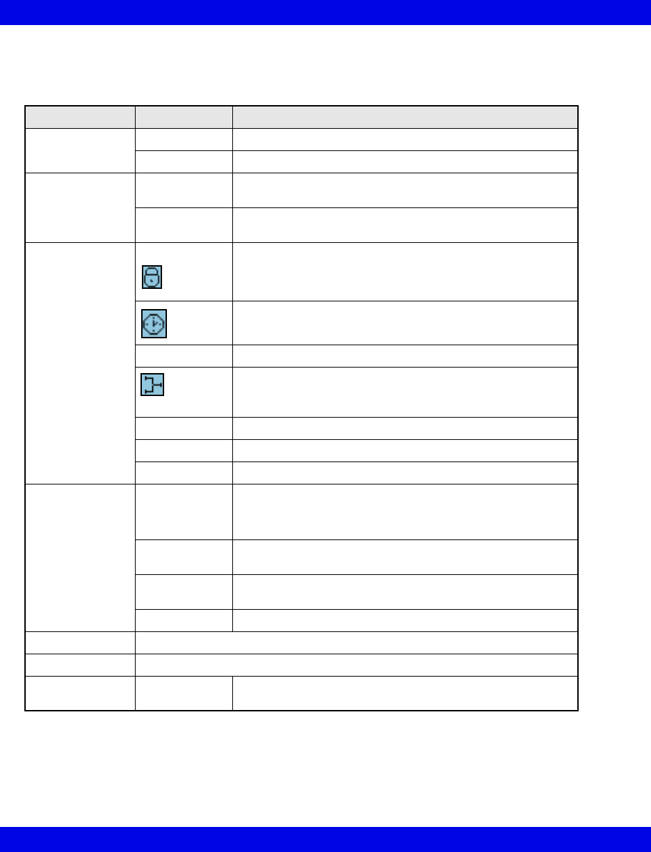
Census Screen Selection Description
Selection Description
Disclosure Full Full Disclosure data
Event Event Disclosure data
Care Units Local Patients with disclosure records being stored in the database
of the Infinity CentralStation currently being used
All Patients with disclosure records accessible on the Infinity
Network
S e l e c t P a t i e n t :
Available patient
records are listed
and can be
sorted by clicking
on one of the
headings.
Record Lock Denotes a “locked” record. Up to 16 records may be locked
at one time.
Time Disclosure record was acquired
Sort order places most recent record first.
Bed Infinity Network bed label
Denotes Active/Inactive status
When the symbol displays, disclosure data collection is
active.
Name Patient Name
ID Patient ID Number
Care Unit Care Unit Label
Search • Name
•ID
•Bed
Selects field that will be searched for keyword entered in the
text entry box
text box Text entry box for keyword search criteria (20-character
maximum)
Search Activates search function for information entered in to text
box
Undo Returns Census Screen
View Data Opens selected patient’s disclosure review screen (Full or Event)
History Opens selected patient’s disclosure history screen
Manual Admit Assign... Manually admit up to 2 additional patients to Disclosure data
collection (See page 16-6)

Admitting a Patient to Full/Event Disclosure
VF8 Infinity CentralStation 16-5
Admitting a Patient to Full/Event Disclosure
Full/Event Disclosure storage begins automatically when a patient is admitted at the
Main Screen of the Infinity CentralStation. There are two additional Manual Admit
records for patients within a Monitoring Unit, but they may not be added at the Main
Screen.
Data Collection Rules
A patient remains admitted to the Infinity CentralStation and data storage continues
for as long as the patient remains on the same monitor on the Infinity network.
If the patient leaves the Monitoring Unit and returns with the same bedside monitor
(Pick and Go) or to the same Infinity CentralStation, data storage resumes
automatically when the patient is reconnected to the Infinity Network. If the patient’s
monitor/Infinity CentralStation is different, the new care unit data is linked to the
previous data set and is available on the patient’s Full or Event Disclosure Review
screen.
Once the Full/Event Disclosure capacity is reached (4, 8, 12, 16, or 32 patients,
depending on server option) new patients can be admitted as patients are discharged
and slots become available.
The Infinity CentralStation database permits storage of “active” and “inactive” patient
records. The total number of “inactive” records available is calculated using the
formula:
64 – (n +2), with “n” equal to the number of active patients.
“Inactive” records are included in the Census Screen patient list and have no “active
data collection” symbol (16-4). Stored waveforms for patients who are removed from
Main Screen are saved and sorted according to time spent, and have an inactive status.
As soon as the storage capacity is reached, the oldest data is replaced by the most
recent. Each inactive record deletes automatically after 72 hours, except when the
record is locked (16-4).
NOTE: A Monitoring Unit is a logical group of beds that provide patient monitoring
services such as alarm annunciation, recordings and remote control to its members.
NOTE:
zIf the bedside monitor is disconnected for a PICK AND GO purpose and is
reconnected to the network, Disclosure storage resumes automatically.
zWhenever you remove a bedside monitor from the network, small gaps will
appear in the Full Disclosure waveforms.

16-6 Infinity CentralStation VF8
16: Full/Event Disclosure
To Manually Admit a Patient:
You can admit two additional patients to Full/Event Disclosure as follows.
1. Open the Census screen (16-2).
2. Click on the button labeled Assign... in the Manual Admit section of the
Census screen.
The Manual Assign Bed popup displays
3. Double-click on the patient you wish to admit, or
Highlight the patient you wish to admit and click on Accept.
Accessing Disclosure History
1. Open the Census screen (16-2).
2. Highlight the desired record in the Census screen patient list (16-3).
3. Click on History.
The Patient Care History popup displays.
4. Select the record you wish to view.
5. Click on View Data.
Locking a Full/Event Disclosure Record
You can lock up to 16 disclosure records in each Infinity CentralStation database.
When you lock the record, data will not be automatically deleted. When all 16 locks
are used, the button is ghosted.
To Lock/Unlock a Record:
1. Access the Patient Care History popup.
2. Select the record you wish to lock or unlock.
3. Click on the Lock/Unlock toggle button.
NOTE: If Clinical Password is enabled on the Biomed - Configure Central
screen (18-3), you will need that password to unlock a record.

Accessing the Full/Event Disclosure Review Screen
VF8 Infinity CentralStation 16-7
Accessing the Full/Event Disclosure Review
Screen
From Main Screen:
1. Open the Census Screen (16-2)
2. Highlight a record in the Census screen patient list (16-3) to activate the View
Data button.
3. Click on View Data to display the Full/Event Disclosure Review screen.
From Bed View:
1. Click on Review.
2. Click on Full Disclosure... or Event Disclosure...
The Full Disclosure screen displays in compressed screen (zoom out) format.
NOTE: When moving between Disclosure screens and other screens (such as Trends)
near a system time change, time stamps may be slightly different on the two screens.
This occurs because the Infinity CentralStation and the bedside monitors have different
methods of annotating time. These time differences do not affect the displayed data
which correlates exactly in both applications to an internal time stamp.
16-8 Infinity CentralStation VF8
16: Full/Event Disclosure
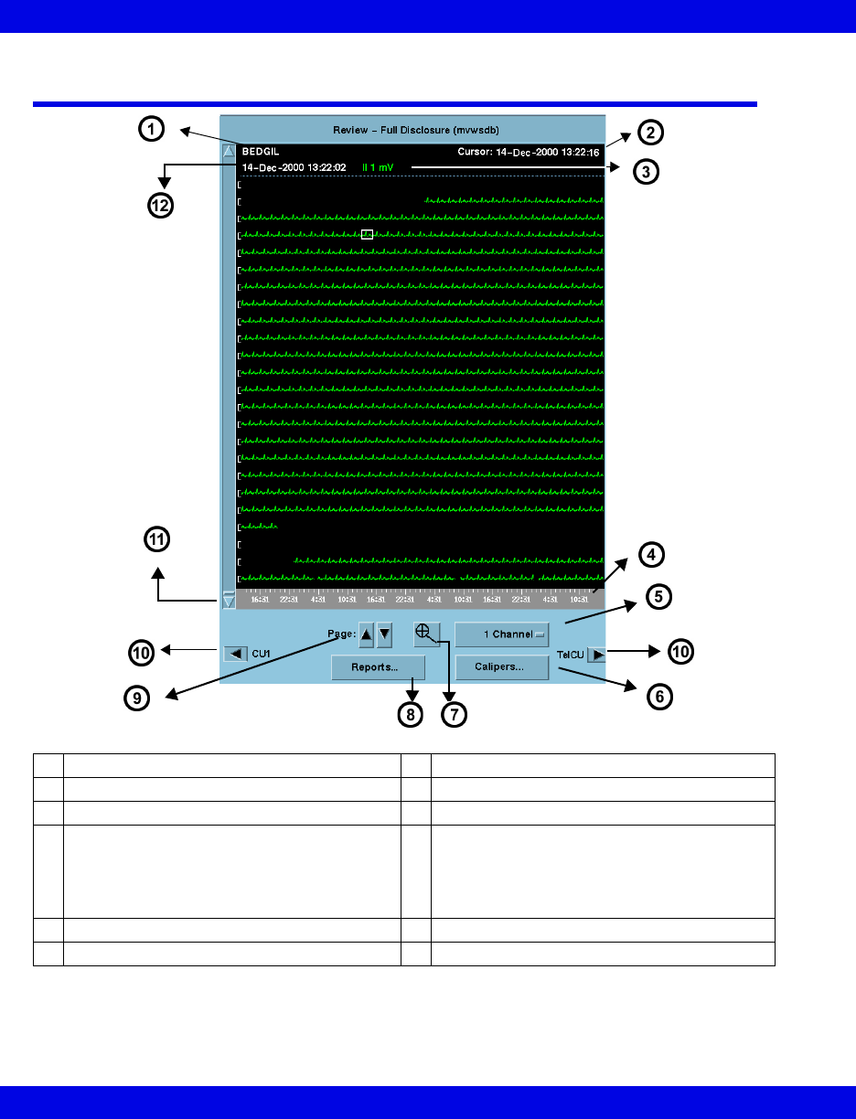
Full Disclosure Review Screen
All time changes that occur at the Infinity CentralStation are identified on the
waveform by a yellow tick mark. Appended data is marked with a white tick mark,
which represents the time the data was appended.
1Patient Identification 7Selects viewing mode (Zoom In or Zoom Out)
2Time/date corresponding to cursor position 8Generates Full Disclosure reports
3Gain setting/lead label 9Navigates by page
4Time Line reflects Full/Event Disclosure
Storage Option (16-1)
When navigating through care units the time
line changes to reflect the storage time of the
selected care unit
10 Permits scrolling through care unit data when
electronic patient transfer or manual transfer
When there is no previous or next care unit
data, the arrow is ghosted and no care unit
label displays.
5Selects number of waveforms to display 11 Vertical scroll bar
6Opens ECG Caliper Tool Screen 12 Time/date of oldest displayed data
Event Disclosure Review Screen
VF8 Infinity CentralStation 16-9
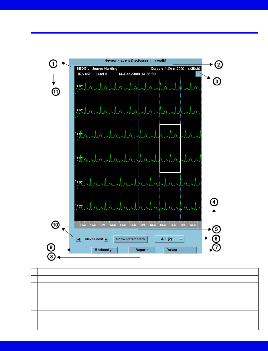
Event Disclosure Review Screen
When you open the Review-Event Disclosure screen, the most recent event
information displays along with its associated waveform (if the waveform is being
stored).
1Patient Identification 6Event class
2Time/date corresponding to cursor position 7Deletes event classes
3Click symbol so a check mark displays to select an
event for the shift report. When an event is
annotated, the comment displays.
8Opens Reports submenu
4Time line with tick marks for all stored events
Prominent tick mark identifies displayed event
9Permits reclassification of event
5Displays parameter values at time of the event
(16-16)
10 To set up event classes see (16-17).
Scrolls to next/previous event on time line
11 Cause, lead, time, and date of stored event
.
16-10 Infinity CentralStation VF8
16: Full/Event Disclosure
Full/Event Disclosure Review Screen
Functions
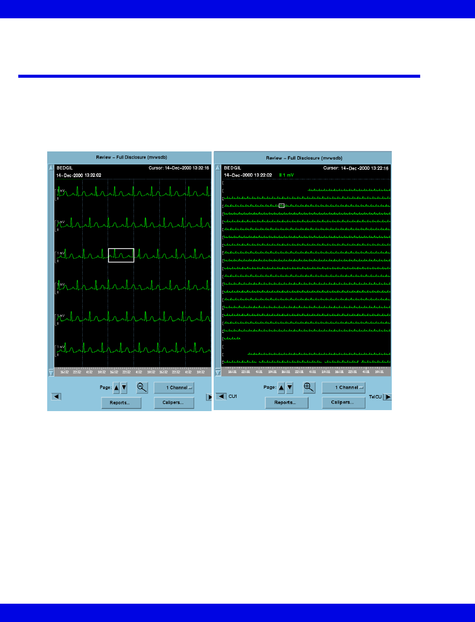
You can view a patient’s Disclosure data (Full or Event) in Zoom Out (compressed)
or Zoom In (expanded) format.
Zoom Out
For 1 channel approximately 9.5 minutes
of data displays on a page.
Zoom In
For 1 channel approximately 36 seconds
of data displays on a page.
Full/Event Disclosure Review Screen Functions
VF8 Infinity CentralStation 16-11
Available functions on disclosure review screens are:
Full Disclosure Event Disclosure
• navigate through and view stored Full/Event Disclosure data for multiple care units (16-8)
• generate reports (14-22)
• select how many channels of data you wish to
view (16-8)
• view parameter values
• select gain settings (16-12) • delete events
(individual event or entire event class)
• choose the order of the displayed waveforms • customize event storage
• select waveforms for storage (16-12) • annotate events (16-14)
• access ECG caliper tool (16-19) • reclassify events (16-17)
• configure trend order setup for Graphical
Trend Report (14-24)
16-12 Infinity CentralStation VF8
16: Full/Event Disclosure
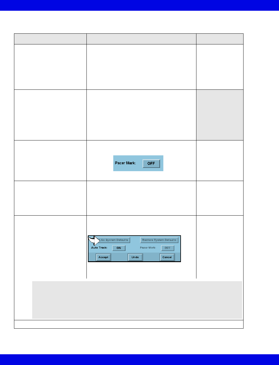
Full/Event Disclosure Storage/Display Options
Function Steps Notes
Select waveforms for display 1.Click on Options on the Disclosure
Review screen menu bar.
2.Click on Display Options...
3.Click on the channel’s Parameter button.
A list of available settings appears.
4.Click on the desired setting.
5.Repeat steps 3 and 4 for each channel.
Cursor time
appears in white
text on the Patient
Setup screen.
Set display gain 1.Click on Options on the Disclosure
Review screen menu bar.
2.Click on Display Options...
3.Click on the channel’s Gain/Scale button. A
popup of available settings appears
(16-13).
4.Click on the desired setting.
5.Repeat steps 3 and 4 for each channel.
Turn pacer mark ON/OFF • Click on Pacer Mark toggle button on the
bottom of the waveform selection screen.
Pacer marks for
bedside patients
only display at the
Infinity CentralSta-
tion if they are
available at the
bedside monitor.
Select waveforms for storage 1.Click on Options on the Disclosure
Review screen menu bar.
2.Click on Storage Options...
3.Click on each channel’s ‘Parameter’ button.
4.Click on the desired setting in the popup.
Channel defaults:
1 - Lead II
2 - Lead V
3 - ART
4 - SpO2
Enable/Disable Automatic
waveform tracking
NOTE: When the Expanded
Waveform locked option is
installed, Autotracking is always
ON. It cannot be disabled.
• Click on Auto Track toggle button near
the bottom of the Waveform Storage
screen.
When Auto Track:
is ON, the first four
waveforms
displayed at the
bedside are stored
automatically.
When Auto Track:
is OFF, you must
manually select
waveforms for
storage.
• Click on Accept, Undo, or Cancel.
WARNING! If you change leads at the bedside monitor and
the Infinity CentralStation Auto Track is set to OFF, you must
also change the lead selection at the Infinity CentralStation.
The bedside waveforms may no longer correspond to the
Infinity CentralStation waveform storage settings and data
may be missing.

Full/Event Disclosure Review Screen Functions
VF8 Infinity CentralStation 16-13
Available Gain Settings
Parameter Available settings Default size
ECG 0.25, 0.5, 1, 2, 4, and 8 mV 1 mV
ART/IBP, LV, GP1,
GP2, P1a-P3d
0 to: 20, 40, 50, 100, 125, 150, 175,
200, 225, 250, 300 mm Hg
0 to: 8, 12, 16, 20, 24, 32, 40 kPa
Adult
0 to 200 mm Hg/0 to 24 kPa
Neonatal
0 to 100 mm Hg/0 - 16 kPa
Pediatric
0 to 150 mm Hg/0 to 20 kPa)
PA, RV 0 to: 20, 40, 50 100, 125, 150 mm Hg
0 to: 4, 6, 8, 12, 16, 20 kPa
0 to 50 mm Hg/0 to 8 kPa
LA, RA, CVP -5 to: 5, 15, 20, 25, 40, 50, 100, 150,
200, 250, 300 mm Hg
-1 to: 2, 4, 5, 6, 8 kPa
-5 to 20 mm Hg/ -1 to 5 kPa
ICP -30 to 30,
0 to: 20, 40, 50, 100, 150, 200, 250,
300 mm Hg
-4 to 4,
0 to: 1, 2, 3, 4, 8, 16 kPa
0 to 20 mm Hg/0 - 4 kPa
SpO210, 20, 30, 40, 50, 60, 70, 80, 90, 100% 40%
etCO2 0 to: 40, 60, 80 mm Hg
0 to: 5, 8, 12 kPa
0 to: 5, 8, 12%
0 to 40 mm Hg/0 to 5 kPa
0 to 5%
0 to 12%/0 to 12 kPa
(MIB acquired)
Ventilator flow (MIB) -5 to 5 L/min
-10 to 10 L/min
-20 to 20 L/min
-50 to 50 L/min
-100 to 100 L/min
-200 to 200 L/min
Adult
-100 to 100 L/min
Neonatal
-20 to 20 L/min
Pediatric
-50 to 50 L/min
Ventilator pressure
(MIB)
-5 to 25 cmH2O
-10 to 50 cmH2O
-20 to 120 cmH2O
-5 to 25 cmH2O
Agent (MGM):
Halothane,
Isoflurane, Enflurane,
Seflurane,
Desflurane
0 - 1%, 0 - 2%, 0 - 3%, 0 - 5%,
0 - 10%, 0 - 20%
0 - 3%
O2 (MGM) 20 - 50%, 20-100% 20 - 100%
Resp 5 - 100% 40%
16-14 Infinity CentralStation VF8
16: Full/Event Disclosure
Annotating Events
On the Event Disclosure Review Screen you can annotate clinically significant
events. For example, you can add a remark to an event such as Chest Pain Decrease
after administering medications. A maximum of 100 annotations can be stored per
patient. If you attempt to store a comment once the maximum capacity has been
reached, a popup appears alerting you that the storage capacity is full. If this happens,
you must delete unnecessary comments to make room for new ones.
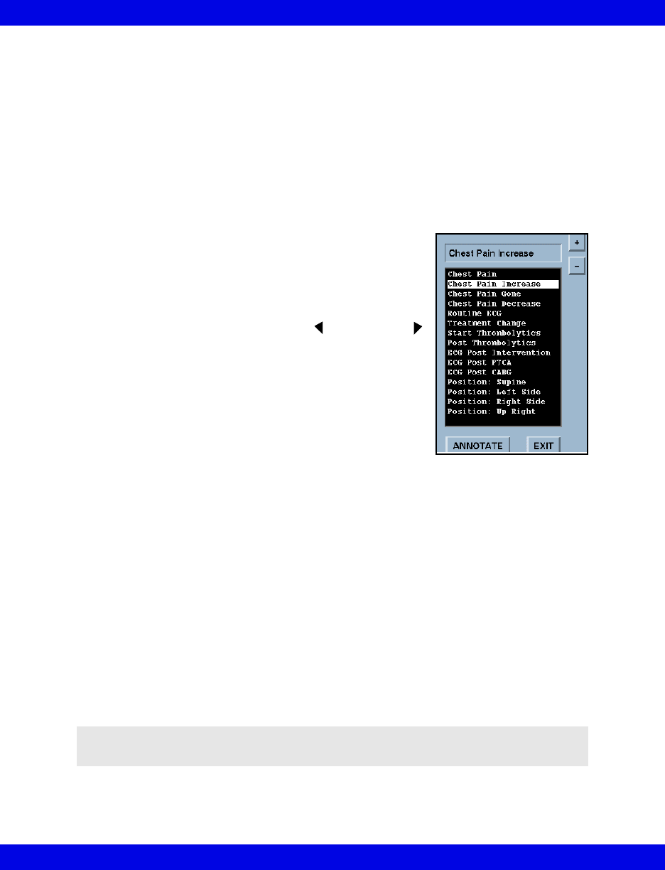
A list of frequently used terms is available to select from to annotate an event.
Annotating an event
1. Access the patient’s Event Disclosure Review
screen (16-7).
2. Scroll to the desired event either by clicking within
the Event window or by using the Next Event
button.
3. Click the right mouse button to activate the annotate
popup list.
4. Either click on a term within the popup or type in a
new comment (maximum of 25 characters).
5. Click on Annotate to add the comment to the
event database or on Exit to leave the popup without storing an annotation.
After an annotation is assigned to an event, it appears at the top of the waveform of the
Even Disclosure Review Screen.
Creating Your Own Annotations List
The annotations list contains a predefined set of terms that you cannot alter. However,
you can add your own terms to the list (maximum capacity = 100 terms).
1. Open the patient’s Event Disclosure Review screen (16-7).
2. Click on the right mouse button to activate the Notes popup.
3. Type in the note and click on the + button to add the entry to the top of the
list; or highlight the list item to delete and press the – button.
NOTE: You cannot delete a predefined entry from the annotation list; you can only
delete terms you have added manually.
Full/Event Disclosure Review Screen Functions
VF8 Infinity CentralStation 16-15
Viewing Events
To view and navigate through stored events:
zClick on the time line of the Event Review screen and click on the
Next Event arrows.
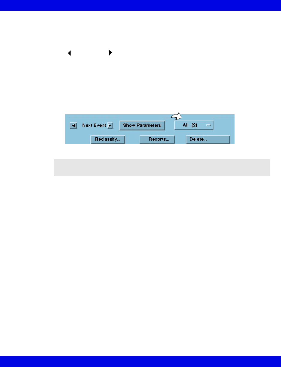
Viewing a class of events
1. Click on the event class option button (see arrow) to display an event class list
with the number of events for each.
All is the default event class that displays when the screen opens and includes
all stored events.
2. Click on the desired event class.
NOTE: Only event classes that have had an event in the last 28, 48 or 72 hours
(depending on the configured option) are listed unless the disclosure record was locked.
16-16 Infinity CentralStation VF8
16: Full/Event Disclosure
Deleting Events
You can either delete individual events or entire event categories.
To delete an individual event
1. Open the Event Review screen (16-7).
2. Select the event you wish to delete.
3. Click on Delete...
4. Click on Event to delete the currently displayed event (the previous event is
displayed; if no previous events exist, the next event is displayed instead).
To delete an entire event class
1. Click on the Event Class button to display a list.
2. Click on the Event Class you wish to delete.
3. Click on Delete... to delete the entire Event Class. This activates a
confirmation popup.
4. Click on Yes in the popup to delete all of the events for the selected class or
on No to exit the popup without deleting any events.
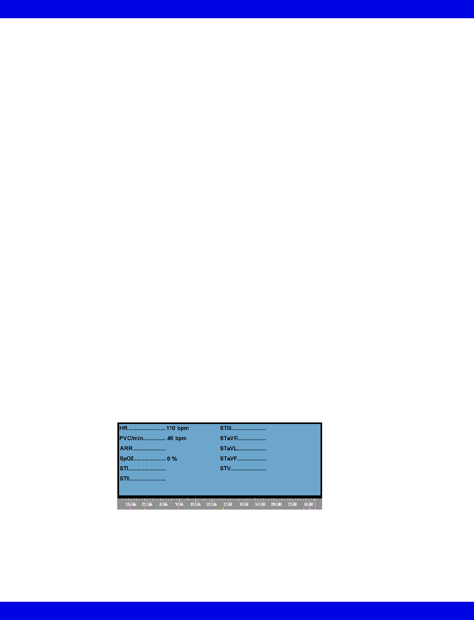
Viewing Parameter Values
To see parameter values stored at the time of an event:
1. Open the Event Review screen (16-7).
2. Click on Show Parameters.
Arrow buttons may appear on either side of the parameter screen popup depending on
the number of stored parameters for the events. Use these arrows to scroll through the
list.
Full/Event Disclosure Review Screen Functions
VF8 Infinity CentralStation 16-17
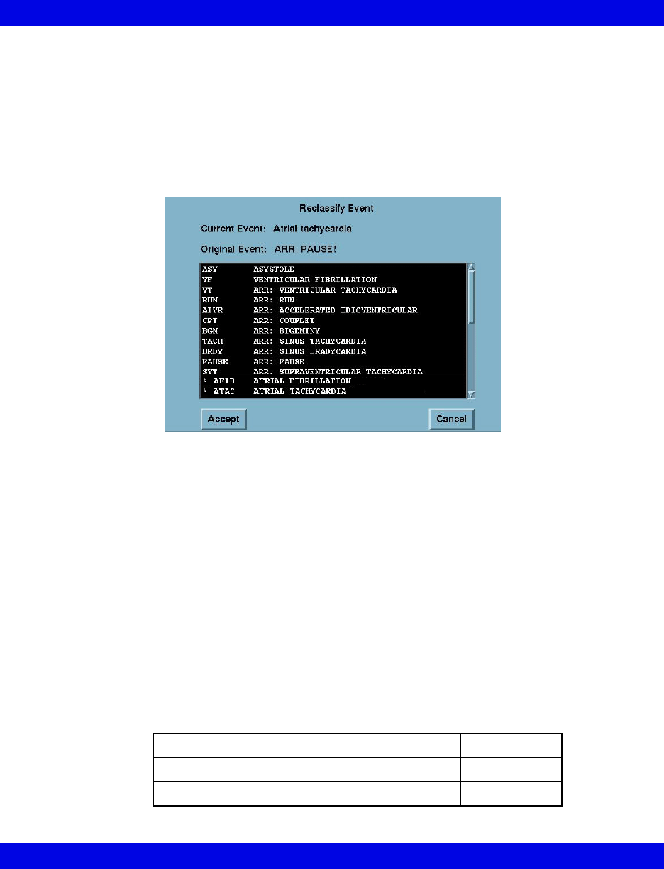
Renaming/Reclassifying Events
You can rename any stored arrhythmia event using labels from a pre configured
selection menu as follows:
1. Open the Event Review screen (16-7) and select the event you wish to
rename.
2. Click on Reclassify. The Reclassify Event popup displays.
The popup list includes all current Infinity arrhythmia class labels and ten
additional labels with a preceding asterisk. These additional labels can either
be the defaults or user-configured event names (18-5).
3. Select the desired event label and click on Accept.
A confirmation popup displays which asks you to confirm that you want to
reclassify the Current Event with your selection.
4. Click on Continue in the confirmation popup to accept the change or
Cancel to keep the current label.
The new label for the event displays on the Event Disclosure Review screen.
If an event has a label that is user-configured, it is grouped in the event class,
“other” (16-15).
You can only reclassify events if they are in one of the following arrhythmia
categories. Otherwise, the Reclassify button is ghosted on the Event Review
Screen.
ASYVFVTRUN
AIVR CPT BGM TACH
BRDY PAUSE SVT OTHER
16-18 Infinity CentralStation VF8
16: Full/Event Disclosure
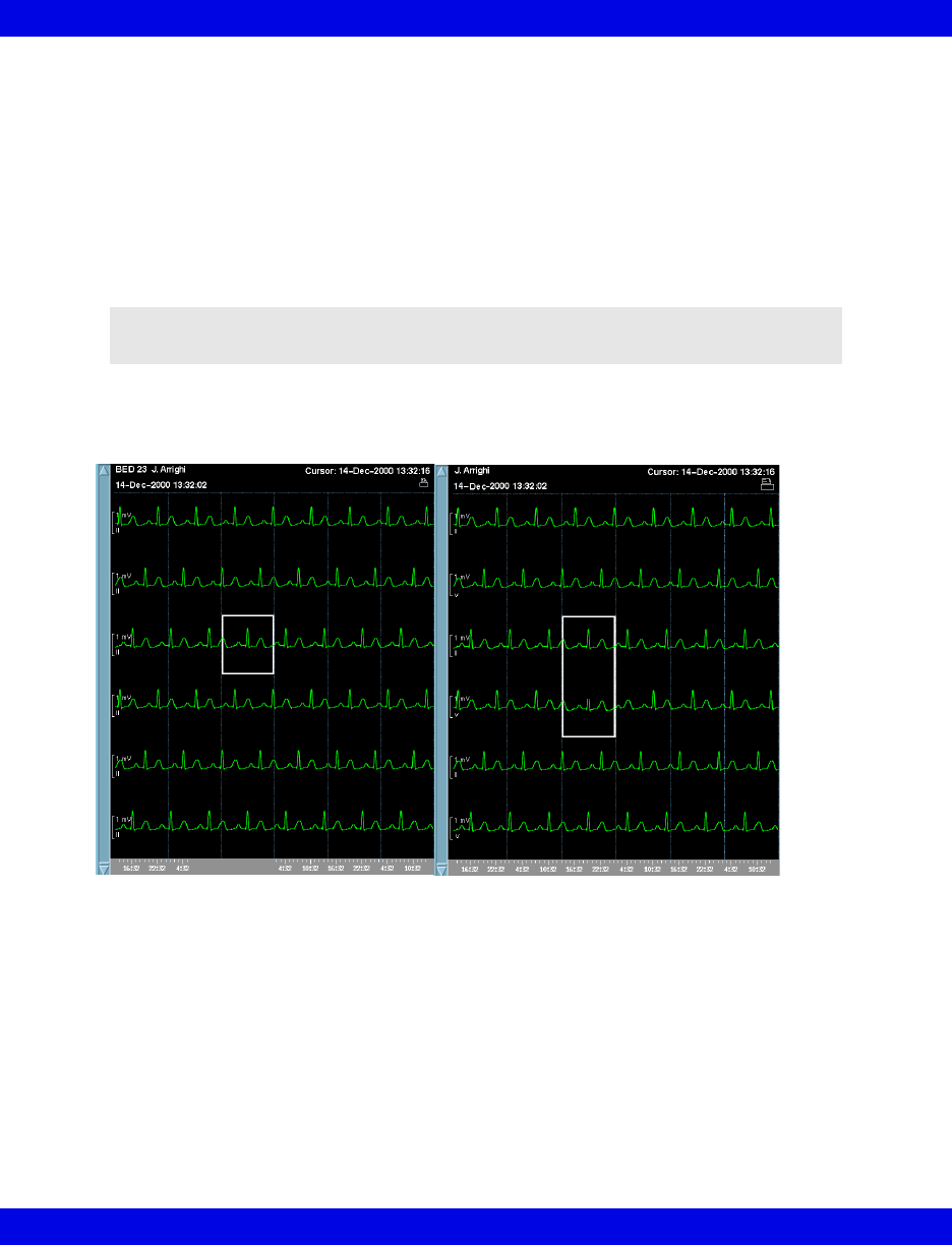
Disclosure Review Screen Cursor
When you open a Disclosure Review screen data is centered around the cursor time,
which appears at the top right of the screen.
Changing the Cursor Time
Left-click the mouse anywhere on the displayed waveforms to change cursor time.
The cursor height varies with the number of channels selected.
NOTE: Cursor time does not change when you scroll through the data or select a time
on the time line.
1 Channel cursor 2 Channel cursor
Full Disclosure ECG Caliper Tool
VF8 Infinity CentralStation 16-19
Full Disclosure ECG Caliper Tool
An on-screen ECG caliper tool allows you to obtain, calculate, store, and review time-
based interval measurements and averages using Full Disclosure.
Before you can use the ECG caliper tool the Full Disclosure Channel 1 setting must
be set to display ECG data (16-12).
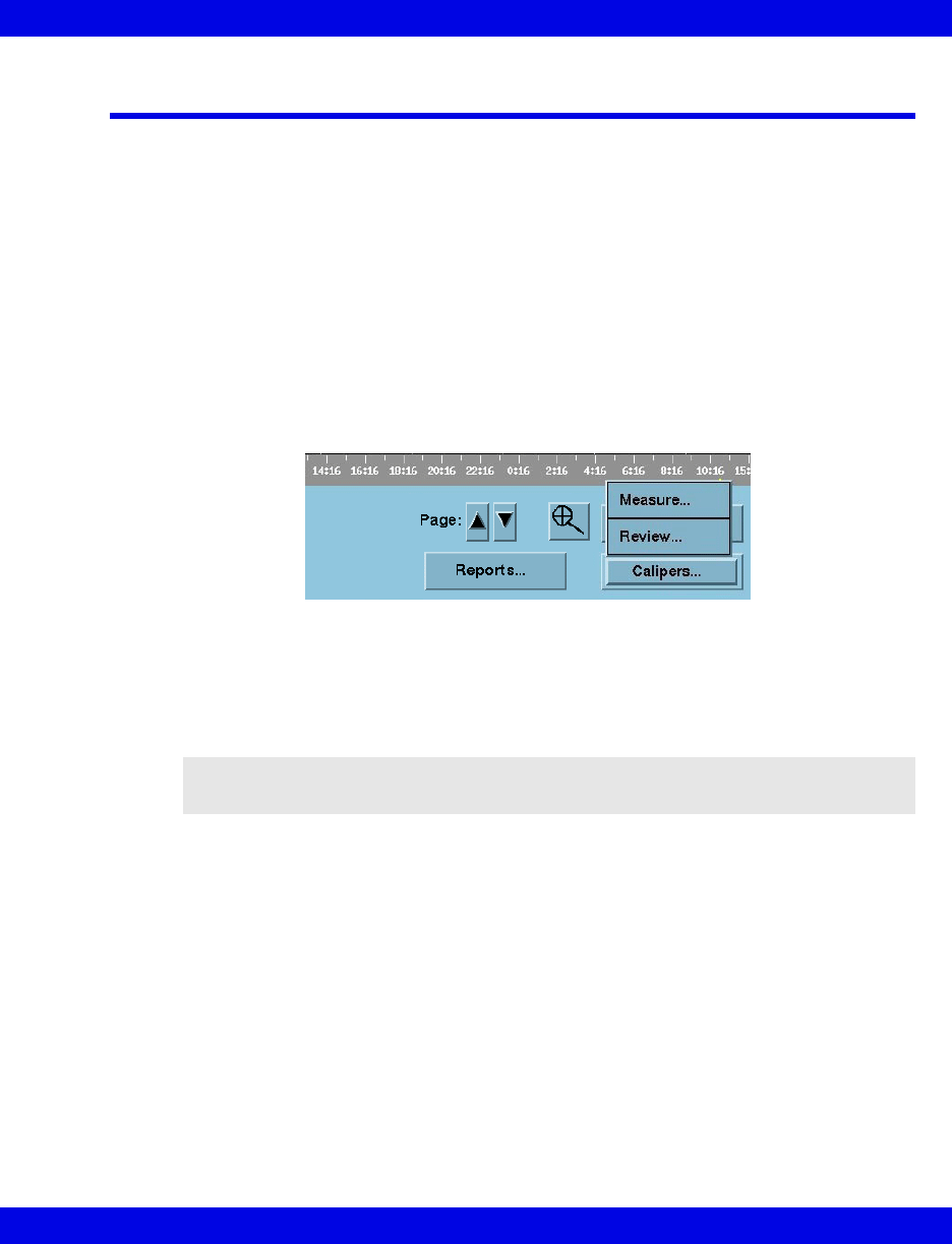
Accessing The ECG Caliper Screens
1. Open the Full Disclosure Review screen (16-7).
2. Position cursor over the ECG area you wish to measure.
3. Click on Calipers...
A submenu displays.
4. Click on the desired function.
Measure Executes Caliper Measure screen which uses 18 seconds of
complete Full Disclosure ECG data following cursor time.
Review Executes Caliper Review screen.
NOTE: The Review button is ghosted when no measurements are stored for the
patient.
16-20 Infinity CentralStation VF8
16: Full/Event Disclosure
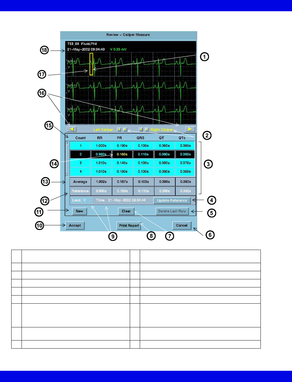
Caliper Measure Screen
1Waveform area - Right click mouse to move
right caliper to any position on Waveform.
10 Accepts/Saves measurements, calculations, and
averages
2Caliper positioning adjustment controls 11 Generates new row of caliper measurements
3Summary Table 12 Reference values (white text)
4Updates reference 13 Interval averages
5Deletes last row of measurements 14 Current measurement (yellow text)
6Cancels measurements 15 Interval measurements and QTc
7Resets selected row’s measurements to zero 16 Interval Advance Arrows rotate or “march”
calipers to the next common interval in the strip. In
order for the calipers to march, you must measure
the first RR interval in the strip.
8Generates an immediate printed report of
current measurements (14-18)
17 Left click mouse to move left caliper to any position
on waveform.
9Last saved reference lead, date, and time 18 Cursor date and time
Full Disclosure ECG Caliper Tool
VF8 Infinity CentralStation 16-21
Waveform Area
Cursor time marks the first second of an 18-second ECG strip that displays at the top
of the Caliper Measure screen. If less than 18 seconds of data follows the cursor in
the FD review screen, the last full 18 seconds of data will display.
Initially the calipers appear at the beginning of the waveform but can be set by
clicking the mouse buttons.
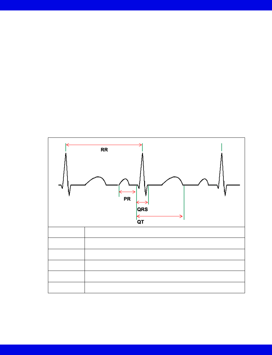
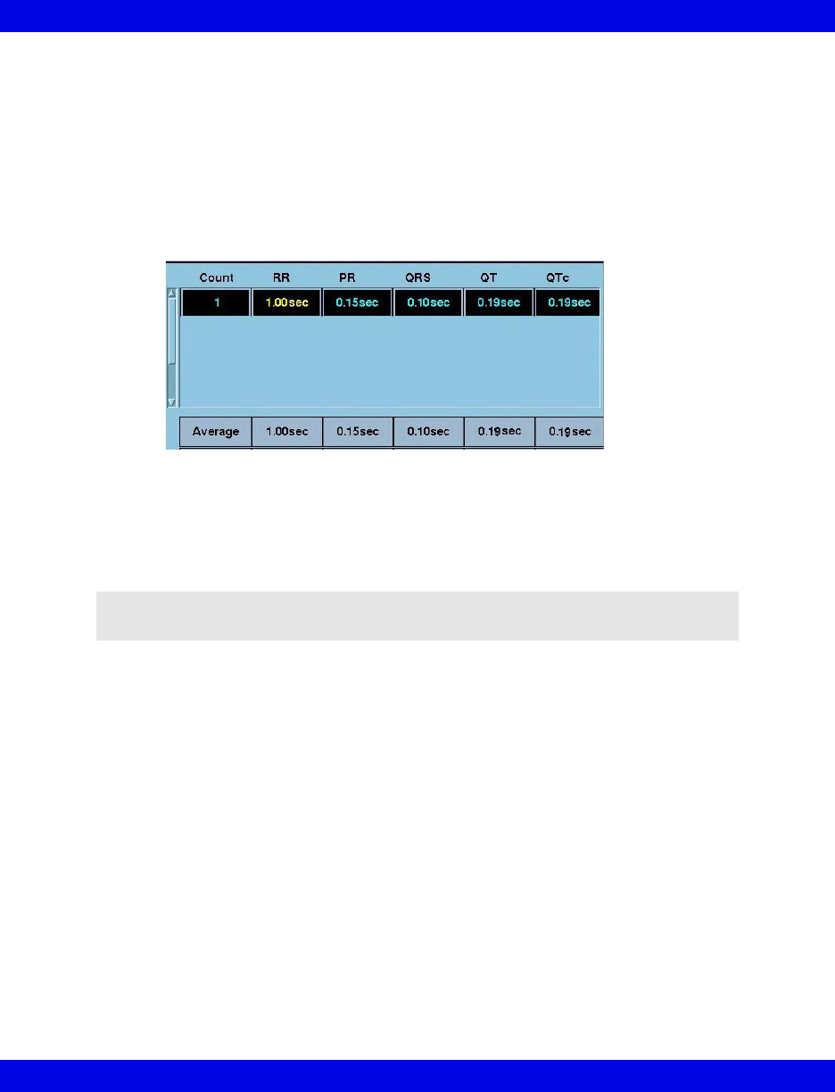
Summary Table
The summary table of the Caliper Measure screen displays interval measurements
taken (16-21), calculated averages, and saved reference information (16-23).
It includes up to ten Count rows that contain RR, PR, QRS, and QT interval
measurement entries, and calculates QTc for each corresponding RR and QT entry.
Taking Interval Measurements
When the Caliper Measure screen first opens there is one highlighted row of
measurements with zero values. As soon as one row of measurements is taken, these
Interval Measurement Calculation
RR avg Sum of RR intervals/quantity of samples
PR avg Sum of PR intervals/quantity of samples
QRS avg Sum of QRS intervals/quantity of samples
QT avg Sum of QT intervals/quantity of samples
QTc QT/square root of RR
QTc avg Sum of QTc values/quantity of samples
16-22 Infinity CentralStation VF8
16: Full/Event Disclosure
values display as Average measurements. All rows, except those containing no
measurements, are used to calculate averages.
To measure an interval:
Your first measurement must be the RR interval in order to determine the QT interval.
After you measure the first RR interval, measure the PR, QRS and QT intervals.
1. Move the cursor to the RR interval measurement box and click. The active
measurement displays in yellow text.
2. Position the cursors over a complex in the ECG strip.
3. Right-click the mouse button to set the right caliper.
4. Left-click the mouse button to set the left caliper.
5. Move the cursor to the next interval measurement box and click.
6. Repeat steps 2 through 5 for each desired measurement interval of that
complex.
Once you measure an RR interval between complexes, you can use the Interval
Advance Arrows (16-20) to march or rotate the cursors the distance of the RR
interval along the strip.
After all your measurements are complete you can save the data for review or future
report generation or you can print an ECG Caliper Report immediately.
zTo save the measurements click on ACCEPT.
zTo print an ECG Caliper report immediately click on Print Report.
If you Cancel the Caliper Measurement screen without saving data, a popup
displays. To save measurements not previously stored, click on Yes in the popup.
NOTE: It is not possible to set negative measurement values.

Full Disclosure ECG Caliper Tool
VF8 Infinity CentralStation 16-23
Adding/Removing/Changing Measurement Rows
The Caliper Measure screen Summary Table holds up to ten rows of interval
measurements that are used to determine averages.
To add a row of interval measurements:
1. Click on New. A row of interval measurements with zero values is added and
is highlighted.
2. Complete interval measurements for the complex (16-21).
3. Repeat steps 1 and 2 for each new row. You can have up to ten Count rows.
To remove last row of interval measurements:
The Delete Last Row button is ghosted until more than one row of measurements
exists and the last row of measurements is highlighted.
1. Click on any interval measurement in the last measurement row to select and
highlight the row.
2. Click on Delete Last Row to remove the row from the summary table.
To reset a row of interval measurements:
1. Click on any interval measurement in a row to select and highlight the row.
2. Click on Clear to reset all measurements to zero.
Saving References
At the bottom of the summary table saved reference measurements appear in the row
labeled Reference and display in white text. Reference Time: shows the last
saved reference date and time.
Reference measurements are displayed and stored with all associated caliper interval
measurements until a new reference is selected.
To save a reference:
1. Click on any interval measurement in a row to select and highlight the row.
2. Select Update Reference to save these reference measurements.
When you save a new reference and reference values already exist, a popup dis-
plays requesting confirmation.
3. Select YES in the popup to update the reference.
16-24 Infinity CentralStation VF8
16: Full/Event Disclosure
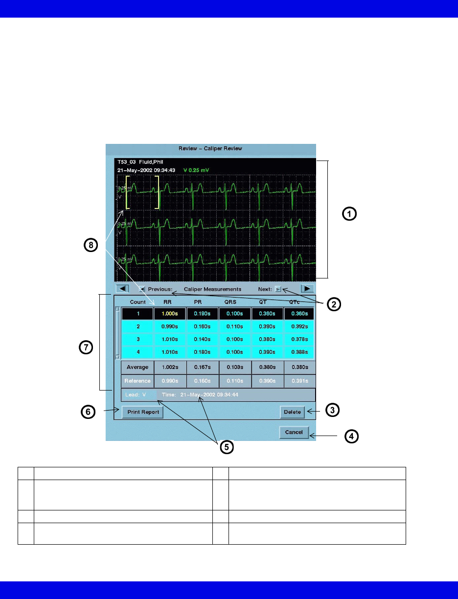
Caliper Review Screen
The Caliper Review screen lists all saved caliper measurements in its summary
table. It can contain up to 72 hours of saved measurements.
From the Caliper Review screen you can:
zDelete saved measurements
zGenerate a Caliper Report (14-18)
Review - Caliper Review Screen
1Waveform Area 5Last saved reference lead, date, and time
2Scroll through saved measurements.
(Arrows are ghosted at beginning and end of
stored data.)
6Generates Caliper Report (14-18)
3Deletes saved measurements 7Summary Table
4Exit screen 8Calipers display selected measurement
(yellow text)
Full/Event Disclosure Reports
VF8 Infinity CentralStation 16-25
When the Caliper Review screen opens the latest saved interval measurements,
averages, and associated references display along with the ECG waveform. Whenever
you click on an interval measurement in the summary table, the calipers display the
measured interval on the actual complex in the waveform area.
To open the Caliper Review screen see 16-19.
To delete interval measurements:
1. Open the Caliper Review Screen.
2. Click on Delete.
A popup displays. To remove all of the measurements in the summary table,
click on Yes in the popup.
Full/Event Disclosure Reports
Reports that are generated at the Full/Event Disclosure Review screen follow.
Full/Event Disclosure report requests are printed to the laser printer even if you exit
the screen.
Full Disclosure Event Disclosure
• Strip Report
• Shift Report
• Graphical Trend Report
• Selected Events Report
• One-Hour Report
• 24-Hour Report
• Selected Strip Report
• Patient Status Report
• Caliper Report

16-26 Infinity CentralStation VF8
16: Full/Event Disclosure
Exporting Full/Event Disclosure Data
Exporting Full Disclosure Data to a Third-Party Device
When exporting data, a minimum of a patient ID must be entered in the ADT screen.
To Export Waveforms from Full Disclosure:
The Export Waveforms feature exports up to 25 hours of four continuous waveforms
to a compatible third party device (contact your local Dräger representative for a list
of compatible third party devices).
1. Open the patient’s Full Disclosure Screen (16-7).
2. Click on Reports...
A popup menu displays.
3. Click on Export Waveforms.
To Export Full Disclosure Data:
The Export Strip feature exports up to 4 waveforms each containing 18 seconds of
data in which the cursor time marks the center of the exported waveform segment.
1. Open the patient’s Full Disclosure Review Screen (16-7).
2. Click on the cursor to set the end time of the data to be exported.
3. Click on Reports.
A popup menu displays.
4. Click on Export Strip.
NOTE:
zIf the Export Waveforms selection is not listed, the destination IP address is
not configured for the device. Consult the Hospital Biomedical Engineering
Dept.
zThe waveform export feature supports transfer of one file at a time, during
which the Export Waveforms selection is ghosted.
NOTE: If the Export Strip selection does not appear, the Infinity MegaCare IP
address is not configured. Consult the Hospital Biomedical Engineering Dept.

Exporting Full/Event Disclosure Data
VF8 Infinity CentralStation 16-27
Exporting Events from Event Disclosure
The Export Event feature exports 18 seconds of the selected event’s waveform data in
which the event is the middle of the waveform segment, the event’s cause string (e.g.
ASY), and the parameter values at the time of the event.
To Export Event Disclosure Data:
1. Open the patient’s Event Disclosure. Review screen (16-7).
2. Access the desired event
3. Click on Reports...
A popup menu displays.
4. Click on Export Event.
NOTE: If the Export Event button does not appear, the Infinity MegaCare IP address
is not configured. Consult the Hospital Biomedical Engineering Dept.

16-28 Infinity CentralStation VF8
16: Full/Event Disclosure
Special Conditions
Various situations during patient monitoring may affect Full/Event Disclosure data
collection.
Special Condition Effect
The monitoring device is being
powered up.
• Full Disclosure data storage resumes accordingly.
• No Events are stored until the monitor is operational.
The monitoring device is powered
down.
The Full/Event Disclosure data is stored.
CPS/IDS is offline, has failed, or is
powered down.
• Blank spaces appear in the Full Disclosure data for the
duration of the interruption.
• No events are stored during the interruption.
The patient monitor is put in
Standby mode.
• Blank spaces appear in the Full Disclosure data for the
mode duration.
• No events are stored for the mode duration.
Standby is canceled. Storage of Full/Event Disclosure data resumes.
The patient is discharged at the
bedside.
Full/Event Disclosure data remains until manually deleted
at the Infinity CentralStation.
The patient demographics are
changed.
Full/Event Disclosure data is stored under the edited
demographics.
The bedside monitor is
disconnected.
• The Full Disclosure database shows blanks for the
duration of the interruption. A message describes the
absence of data.
• No events are stored while the monitor is disconnected.
The pod/cartridge or a signal
source such as a transducer is
connected.
Full Disclosure data collection begins for any displayed
parameter that was selected for the Full Disclosure
application.
The pod/cartridge or a signal
source is disconnected.
Blanks will appear in the Full Disclosure display of the
parameter for the duration of the interruption.
Network date and/or time changes. Up to 20 system time changes are stored. The time stamps
on the waveforms and event calls mark the time the data
was actually stored.
The patient leads are changed at
the bedside monitor while Full/
Event Disclosure automatic
waveform tracking is OFF.
Data may be missing since the leads selected for display on
the bedside monitor may no longer correspond to the
Infinity CentralStation storage settings.

17 VentCentral Option
Overview.......................................................................................................................17-3
The Ventilator Screen.................................................................................................17-5
Accessing the Ventilator Screen .........................................................................17-6
Waveform Area in Ventilator Screen ...................................................................17-6
Loops Area in Ventilator Screen..........................................................................17-7
Trend Area in Ventilator Screen ..........................................................................17-7
The Ventilator Settings Review Screen .....................................................................17-8
Accessing the Ventilator Settings Review Screen.............................................17-8
Parameter and Settings Order .............................................................................17-9
Special Conditions..............................................................................................17-10
Ventilator View Setup Screen ...................................................................................17-11
Accessing the Ventilator View Setup Screen ...................................................17-12
Selecting Waveforms for Display ......................................................................17-12
Selecting Waveforms for the Trend Display.....................................................17-13
VentCentral Trend Parameters .................................................................................17-14
MIB Ventilator Alarms ...............................................................................................17-18
Ventilator Report........................................................................................................17-18
VentCentral Messages ..............................................................................................17-19
Ventilator and Device Messages/Labels..................................................................17-19
Dräger Cato Anesthesia System ......................................................................17-20
Dräger Cicero Anesthesia System ....................................................................17-21
Dräger Julian/Julian Primus/Primus Anesthesia System ...............................17-22
Dräger Narkomed IIC / IV / 6000 / 6400 Anesthesia System ............................17-25
Dräger Fabius GS/Fabius CE/Tiro Anesthesia System ...................................17-26
Dräger Apollo Anesthesia System ....................................................................17-28
Dräger Zeus Anesthesia System .......................................................................17-30
Ohmeda Modulus CD Anesthesia System ........................................................17-32
Dräger BabyLog Ventilator ................................................................................17-33
Dräger Evita 1 Ventilator ...................................................................................17-34
Dräger Evita 2 Ventilator ....................................................................................17-37
Dräger Evita 2D / 4 / XL Ventilator .....................................................................17-40
Dräger Savina Ventilator ....................................................................................17-43
P-B 7200/840 Ventilators ....................................................................................17-45
Taema Horus Ventilator......................................................................................17-47
Hamilton Galileo Ventilator ................................................................................17-49

17-2 Infinity CentralStation VF8
17: VentCentral Option
Maquet SV 300/SV 300A/Servoi Ventilator........................................................17-50
Maquet SV 900 Ventilator ...................................................................................17-52
Viasys Bear 1000 Adult Ventilator .....................................................................17-53
Viasys BearCub 750 Infant Ventilator .............................................................17-55
Baxter Vigilance/Vigilance II Cardiac Output Monitor ...................................17-57
etCO2/Respiratory Mechanics Pod ...................................................................17-58

Overview
Infinity CentralStation 17-3 VF8
Overview
With the VentCentral option you can review a patient’s ventilator information at the
Infinity CentralStation.
The displayed parameters and settings may originate from bedside monitor-connected
devices, such as:
zMedical Information Bus (MIB)-connected Ventilators and anesthesia
machines (See tables starting on page 17-19.)
zInfinity hemodynamic bedside monitors (parameters only)
zetCO2/Respiratory Mechanics Pod directly connected to a bedside monitor
(parameters only)
You may interact with the VentCentral option via three Ventilator screens:
zVentilator screen
zVentilator Settings Review screen
zVentilator Setup screen
NOTE:
zCertain parameters, identified as measured values, are derived from other
values or settings provided by the ventilator and may not reflect actual values.
See the operating instructions for your specific device for detailed information
on derived measurements.
zThe VentCentral option supports only modular monitors with VF and later
software. If VentCentral is intended for use with an MIB device, the MIB must
also have VF (or later) software.
NOTE: You cannot change any MIB-connected device settings from the Infinity
CentralStation.
WARNING! Ventilator data should be used for informational
purposes only. Refer to the primary monitoring device before
making therapeutic or diagnostic decisions. Always verify
alarm condition at the actual device.

17-4 Infinity CentralStation VF8
17: VentCentral Option
Dräger has tested/validated the following supported MIB devices and software
versions, and cannot make any claim for the reliability of data for other software
versions.
Device Software Version
Dräger Babylog Ventilator 5.00
Dräger Evita 1 Ventilator Tested to published protocol Medibus
Intensive Care 3.00/4.00
Dräger Evita 2 Ventilator 2.00
Dräger Evita 4 Ventilator 3.21
Dräger Evita XL ventilator 5.00
Dräger Savina ventilator 2.10
Hamilton Galileo Ventilator GMP02.11a
Maquet SV 900 Ventilator not applicable
Maquet SV 300/300A Ventilator 2.00
Maquet Servoi Ventilator 1.00
P - B 7200 Ventilator SP1/PM Revision .005
P - B 840 Ventilator 4-070212-85-D
Taema Horus Ventilator 3.055/mdv -1.170
Dräger Cato Anesthesia System Tested to published protocol Medibus
anesthesia devices 3.00/4.00
Dräger Julian Anesthesia System
Dräger Cicero Anesthesia System (B, C, EM)
Dräger Julian Primus Anesthesia System
Dräger Primus Anesthesia System Tested to published protocol Medibus for
Primus, Software 1.n, 2.n
Dräger Fabius GS Anesthesia System Tested to published protocol Medibus
anesthesia devices 4.00
Dräger Tiro
Dräger Fabius CE Tested to published protocol Medibus
anesthesia devices 4.03
Dräger Apollo Anesthesia Workstation
Dräger Zeus® Anesthesia System 3.n
Dräger Narkomed IIC 1.30
Dräger Narkomed IV 2.01
Dräger Narkomed 6000/6400 4.01
Ohmeda 7900 / Modulus CD anesthesia machine 2.8
etCO2/respiratory mechanics pod VF0 (and later versions)
Viasys Bear 1000® Adult Ventilator 2020
Viasys BearCub® 750 Infant Ventilator Tested to Viasys RS-232 communication
protocol ER 11, revision E
Edwards/Baxter Vigilance/Vigilance II SvO2/CCO
monitor
4.42, 5.02
The Ventilator Screen
Infinity CentralStation 17-5 VF8
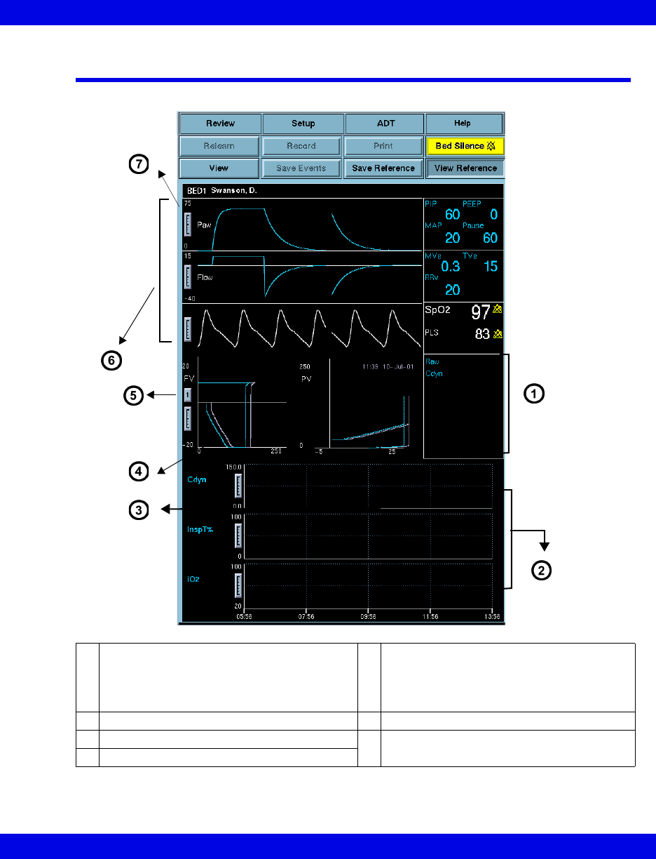
The Ventilator Screen
1Parameter box with fixed set of parameters
If a parameter is not available, the area is
blank.
5Select “1” for single loop and “4” for multi-
loop display. During multi-loop configuration,
four successive loops (of different shades)
show. All loops erase and the sequence
restarts after the fourth loop is complete.
28-hour trend of user-selected parameters 6Display of 3 waveform channels
3Pressure vs. Volume Loop 7Waveform adjustment scale
4Flow vs. Volume Loop
17-6 Infinity CentralStation VF8
17: VentCentral Option
Accessing the Ventilator Screen
1. Click on the patient’s Main Screen parameter box. For information on
accessing a remote patient, refer to page 8-3.
2. Click on View.
3. Click on Ventilator.
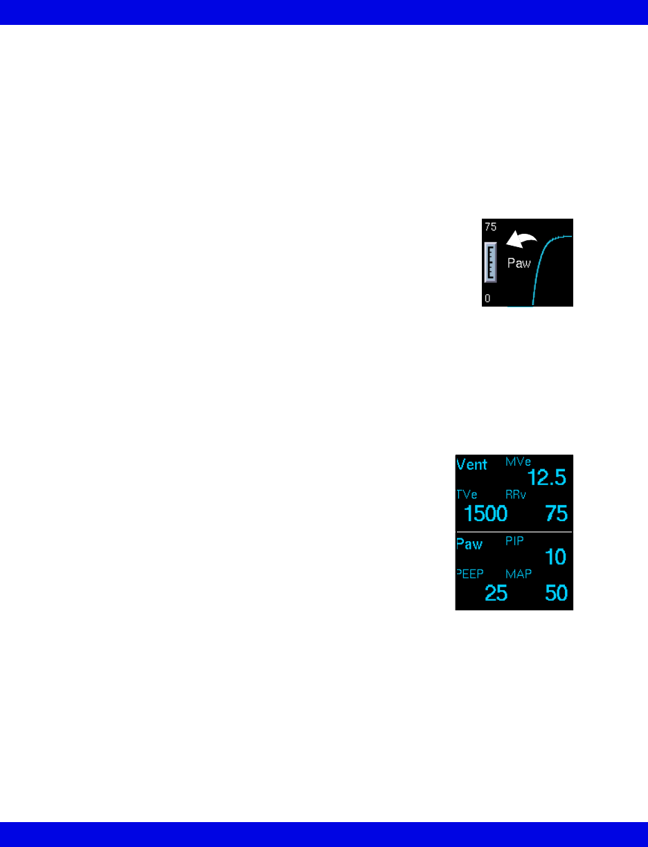
Scaling
If the VentCentral waveforms, loops, or trends appear clipped, you can
change the display size by clicking on the scale at the left edge of the
waveform area or to the left of the trends.
Waveform Area in Ventilator Screen
The Ventilator screen allows you to select up to three waveforms for display and
prioritize their order (page 17-12). If a waveform is not available from the bedside or
the MIB-connected device, the next waveform in the priority list is used to fill the
three waveform areas. If less than three waveforms are available, waveform areas are
blank.
Parameter Box
The parameter boxes to the right of the waveform area may consist
of MIB and/or Infinity parameters and cannot be changed. These
parameter boxes are independent of the bedside monitor and do
not flash when a parameter is in alarm. MIB parameters do not
support units, limits, and/or alarm-off icons. For Infinity
parameters a crossed bell icon appears next to the parameter label
when the alarm function is turned off.
The Ventilator Screen
Infinity CentralStation 17-7 VF8
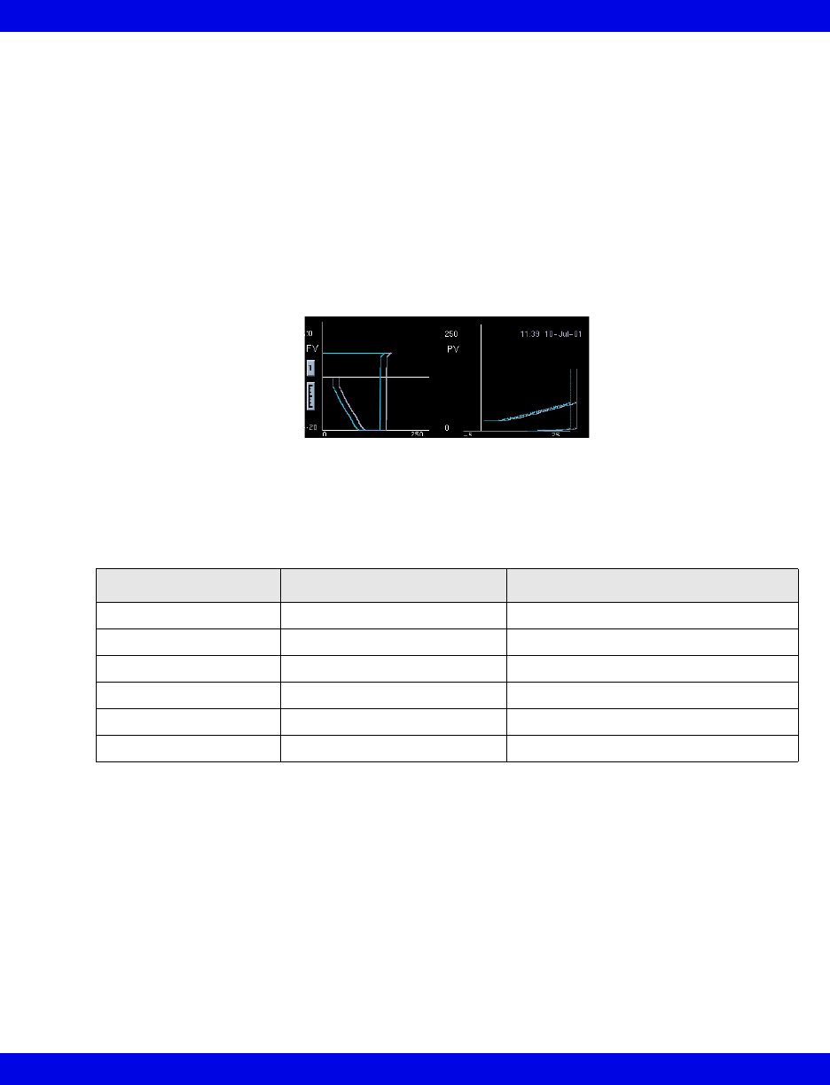
Loops Area in Ventilator Screen
The real-time ventilator loops in the Ventilator screen are synchronous with the
associated breath. Flow Volume is shown on the left and Pressure Volume on the right.
Loops are drawn with the same display scale as the associated waveforms.
Displaying Loops
You can save and display a Reference Loop with the actual loop display. The color of
the reference loop is magenta. The Ventilator screen can display a Single Loop or
Multi-loop draw.
Loop Parameter Box
The parameter box next to the loop area contains dynamic compliance, dynamic
resistance, and arterial blood gas values. If blood gas values are not available, the
labels do not appear. The order and ranges of the parameters follow.
Trend Area in Ventilator Screen
Three trend graphs on the Ventilator screen show the most recent 8 hours of trend
data for user-selected parameters (page 17-13). If a selected parameter is not available
from the bedside/MIB device, the next parameter from the Trends Setup screen is
automatically displayed. If less than three parameters are available, the Ventilator
screen parameter graph is blank.
Parameter Units Measurement Range
pH pH, nmol/L 6.6 - 7.8
HCO3 mEq/l, mmol/L 1-200 mEq/l
Hct (Hematocrit) % 15-75%
tHb (Hemoglobin) g/dl, g/100ml, g/L, mmol/L 5-25 g/dl
PCO2 mmHg (kPa) 10-200 mmHg (1.333 - 26.66 kPa)
PO2 mmHg (kPa) 10 - 700 mmHg (1.33 - 93.31 kPa)
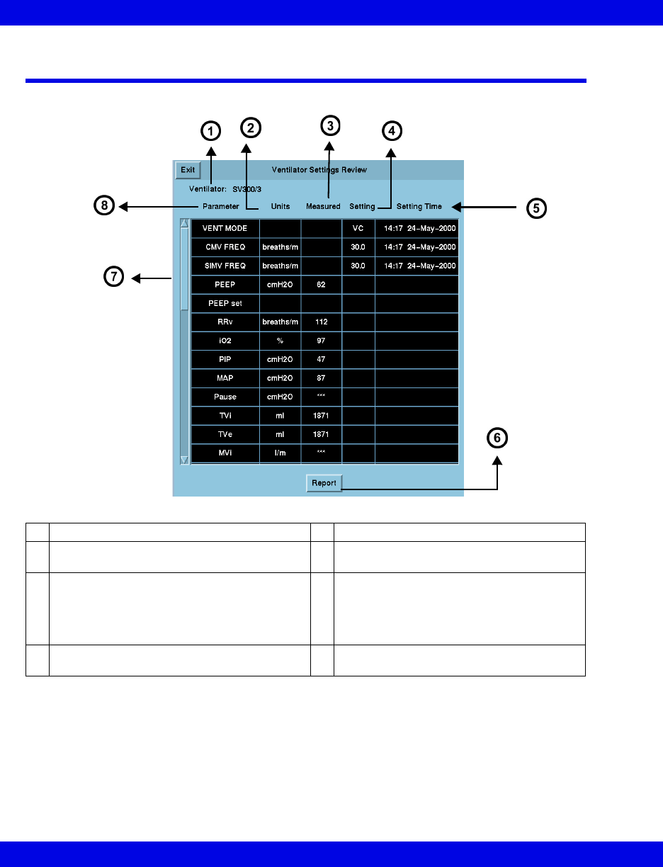
17-8 Infinity CentralStation VF8
17: VentCentral Option
The Ventilator Settings Review Screen
Accessing the Ventilator Settings Review Screen
1. Click on the patient’s parameter box.
2. Click on Review.
3. Click on Ventilator Settings Review.
1Ventilator type 5Time and date the setting was modified
2Selected units of measure at the MIB device
or ventilator
6Generates Ventilator report (Chapter 14)
3Most recently updated measurement value
Certain parameters, identified as measured
values or settings, are derived from the
values provided by the ventilator and may not
reflect actual values.
7Scroll bar for accessing additional
parameters
4Most recent setting of the ventilator/MIB
device
8Parameter or setting labels
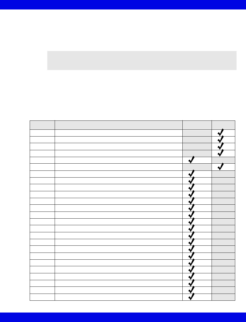
The Ventilator Settings Review Screen
Infinity CentralStation 17-9 VF8
Parameter and Settings Order
The Ventilator Settings Review screen displays settings and supported parameters
sent by the connected MIB device, Infinity bedside monitor, or compatible bedside
monitor pod.
Each Ventilator Settings Review screen parameter and setting displays in a fixed
order. If a setting or parameter is not available, the corresponding field on the
Ventilator Settings screen is blank. Additional settings and parameters not assigned
to the fixed order are at the end of data received from the MIB-connected device.
Parameters/settings sent to Infinity monitors for various MIB-compliant devices are
listed in tables starting on page 17-19.
NOTE: The Infinity CentralStation does not support Acoustic Evoked Potential
(AEP) and Somatosensory Evoked Potential (SEP) functions that are enabled at a
bedside monitor.
Order Description Parameter Setting
1 Ventilator type
2 Ventilator mode
3 CMV frequency
4 SIMV frequency
5 PEEP (End Expiratory Pressure)
6 PEEP
7 RRv (measured respiration rate)
8O
2 concentration
9 PIP (Peak Airway Pressure)
10 MAP (Mean Airway Pressure)
11 Pause Airway Pressure
12 End Expiratory Flow
13 Tvi (Tidal Volume inspired)
14 TVe (Tidal volume expired)
15 Tve s (Tidal Volume Expired spontaneous)
16 Minute Volume inspired (MV i)
17 Minute Volume expired
18 Minute volume expired spontaneous (MVe s)
19 Dynamic compliance (Cdyn)
20 Dynamic resistance
21 I of I:E I-Part
22 E of I:E E-Part
23 end-tidal CO2 (etCO2)
24 CVP
25 SpO2
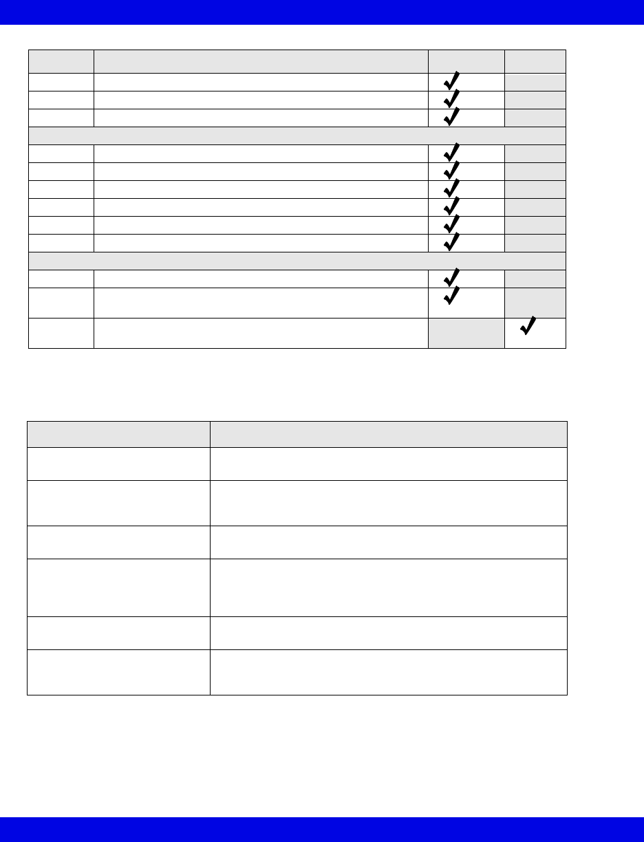
17-10 Infinity CentralStation VF8
17: VentCentral Option
Special Conditions
26 iCO2
27 etCO2*
28 iCO2*
Blood Gas Parameters
29 pH
30 HCO3
31 Hematocrit (Hct)
32 Hemoglobin (tHb)
33 PCO2
34 PO2
Other Parameters and settings
35 Barometric pressure
36 Additional parameters from Ventilator/MIB devices (see
tables starting on page 17-19)
37 Additional settings from Ventilator/MIB devices (see tables
starting on page 17-19)
Special Conditions Affecting Ventilator Settings Review Screen
Condition Effect
Disconnected parameter
hardware
The VentCentral application is not available and cannot be
accessed for the respective patient.
Reset of MIB- device, bedside
monitor, or Infinity
CentralStation
The Ventilator Settings screen time stamp reflects the first
setting following the reset.
Bedside monitor PICK AND GO The Ventilator Settings screen time stamp reflects the
monitor’s reconnect to the network.
First connection of MIB-compli-
ant ventilator, etCO2/Respira-
tory Mechanics Pod, or Delta/
Delta XL monitor
Time stamp reflects the first setting received after the device is
connected.
Blood gas values stored for
more than 30 minutes
Values are removed from the VentCentral screen.
Device sends more digits than
the Ventilator Settings screen
field can accommodate
Instead of the parameter values, overflow characters display.
Order Description Parameter Setting
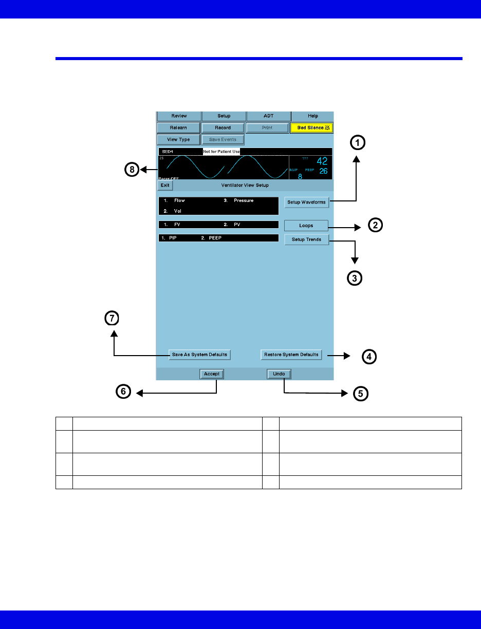
Ventilator View Setup Screen
Infinity CentralStation 17-11 VF8
Ventilator View Setup Screen
The Ventilator View Setup screen permits selecting an individualized display for a
selected patient
1Opens Waveforms Setup screen 5Reverts to previous settings
2Fixed - Always shows Flow vs. Volume and
Pressure vs. Volume
6Accepts new settings/changes
3Opens Trends Setup screen 7Saves current setup as system default for
all patients
4Restores system defaults 8Top ventilation waveform
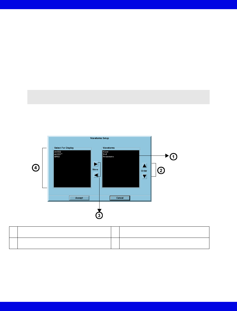
17-12 Infinity CentralStation VF8
17: VentCentral Option
Accessing the Ventilator View Setup Screen
1. Click on the patient’s Main Screen parameter box. To access a remote patient,
see page 8-3.
2. Click on Setup.
3. Click on Ventilator View Setup.
Selecting Waveforms for Display
You can set up the display priority of ventilator parameters.
1. Open the Ventilator View Setup screen (page 17-12).
2. Click on Setup Waveforms. The Waveforms Setup popup displays.
NOTE: If a selected waveform is not available from the bedside monitor, the next
waveform is selected to fill available Infinity CentralStation waveform channels.
1Parameters selected for display 3Arrows permit moving selected parameters
from one window to the other
2Arrows permit changing the priority order of
selected waveforms
4Available parameters
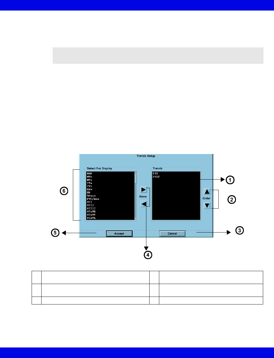
Ventilator View Setup Screen
Infinity CentralStation 17-13 VF8
3. Select the desired display configuration.
The left/right arrows move desired waveforms from the display window to the
Waveforms window. The up/down arrows move parameters in a desired sort order.
4. Click on Accept to save or Cancel to keep prior settings.
5. Click on Save as System Defaults in the Ventilator View Setup screen
to retain this setup as the system default.
Selecting Waveforms for the Trend Display
To select and prioritize ventilator parameters for trend display:
1. Open the Ventilator View Setup screen (page 17-12).
2. Click on Setup Trends. The Trends Order Setup popup displays.
NOTE: You may select several parameters at once before you move them from one
window to the other.
1Trends selected for display 4Arrows permit moving selected parameters
from one window to the other
2Arrows permit changing the priority order of
selected trends
5Accepts current setup
3Cancels current setup 6Available parameters for selection
17-14 Infinity CentralStation VF8
17: VentCentral Option
3. Select the desired display configuration.
The left/right arrows move the desired parameters from the display window to the
Trend window. The up/down arrows move parameters in a desired sort order.
4. Click on Accept to save or Cancel to keep prior settings.
5. Click on Save as System Defaults in the Ventilator View Setup screen
to keep this setup as the system default.
VentCentral Trend Parameters
NOTE: You can select several parameters at once to move them from one window to
the other.
Parameter Label Definition
Heart Rate
HR ECG measurement
Ventilation
AW-Temp Airway temperature
Cdyn Dynamic compliance
C20/Cdyn Dynamic compliance over last 20% of breath.
etCO2 End-tidal carbon dioxide
InspT% I:E ratio (inspiratory component)%
ICO2 Inspired CO2 (etCO2)
iO2 Inspired oxygen
iPEEP Peak end expiratory airway pressure, intrinsic
MAP Mean airway pressure
Mve Minute volume, expired
MV s% Minute volume, spontaneous
MValv Minute volume, alveolar, total
MVe Expired minute volume
MVi Inspired minute volume
PAP Peak airway pressure
Pause Pause pressure
PeCO2 Mixed expired carbon dioxide
PEEP Peak end expiratory airway pressure
PEF Peak expiratory flow
VentCentral Trend Parameters
Infinity CentralStation 17-15 VF8
Parameter Label Definition
Ventilation (Continued)
PIF Peak inspiratory flow
Raw Dynamic resistance
Raw e Expired airway resistance
Raw i Inspiratory dynamic resistance
RRv Respiratory rate
RRs Respiratory rate, spontaneous
RRm Respiratory rate, mechanical
RSBI Rapid shallow breathing index
Te Expiratory time
Ti Inspiratory time
TVe Tidal volume, expired
TV Leak Leakage, system
TValv m Tidal volume, alveolar, mechanical
TValv s Tidal volume, alveolar, spontaneous
Tva Tidal volume, alveolar, total
TVd/TV aw Dilution ratio, airway
TVCO2 CO2, tidal volume
TVe Expired tidal volume
TVi Inspired tidal volume
TVi m Tidal volume, inspiratory, mechanical
TVi s Tidal volume, inspiratory, spontaneous
TVd aw Dead space, airway (Vds)
VCO2 CO2 production, minute volume
WOBimp Work of Breath imposed
Pulse Oximetry
SpO2/SPO2* oxygen saturation
PLS/PLS* Pulse rate
Δ SpO2 Delta SpO2
Respiration
RR Respiratory rate
RR Respiratory rate (etCO2)
RV Respiratory rate
17-16 Infinity CentralStation VF8
17: VentCentral Option
Parameter Label Definition
Temperatures
T1, T2, T3 Temperature
T Basic temperature
Pressures
ART Arterial pressure
CPP Cerebral perfusion pressure
CVP Central venous pressure
GP1 General pressure 1
GP2 General pressure 2
ICP Intracranial pressure
LA Left-atrial pressure
NIBP Non-invasive blood pressure
P1 P1 pressure
P2 P2 pressure
PA Pulmonary arterial pressure
PWP Pulmonary Wedge Pressure
RA Right arterial pressure
V Ventricular pressure
Cardiac Output
BT Blood temperature
CCO Continuous cardiac output
CCI Continuous cardiac index
CCO Continuous cardiac output
DO2 Oxygen delivery or availability
FiO2 Fraction of inspired O2
ICI Intermittent cardiac output index
ICO Intermittent cardiac output
PVR Pulmonary vascular resistance
PVRI Pulmonary vascular resistance index
SVR Systemic vascular resistance
SVRI Systemic vascular resistance index
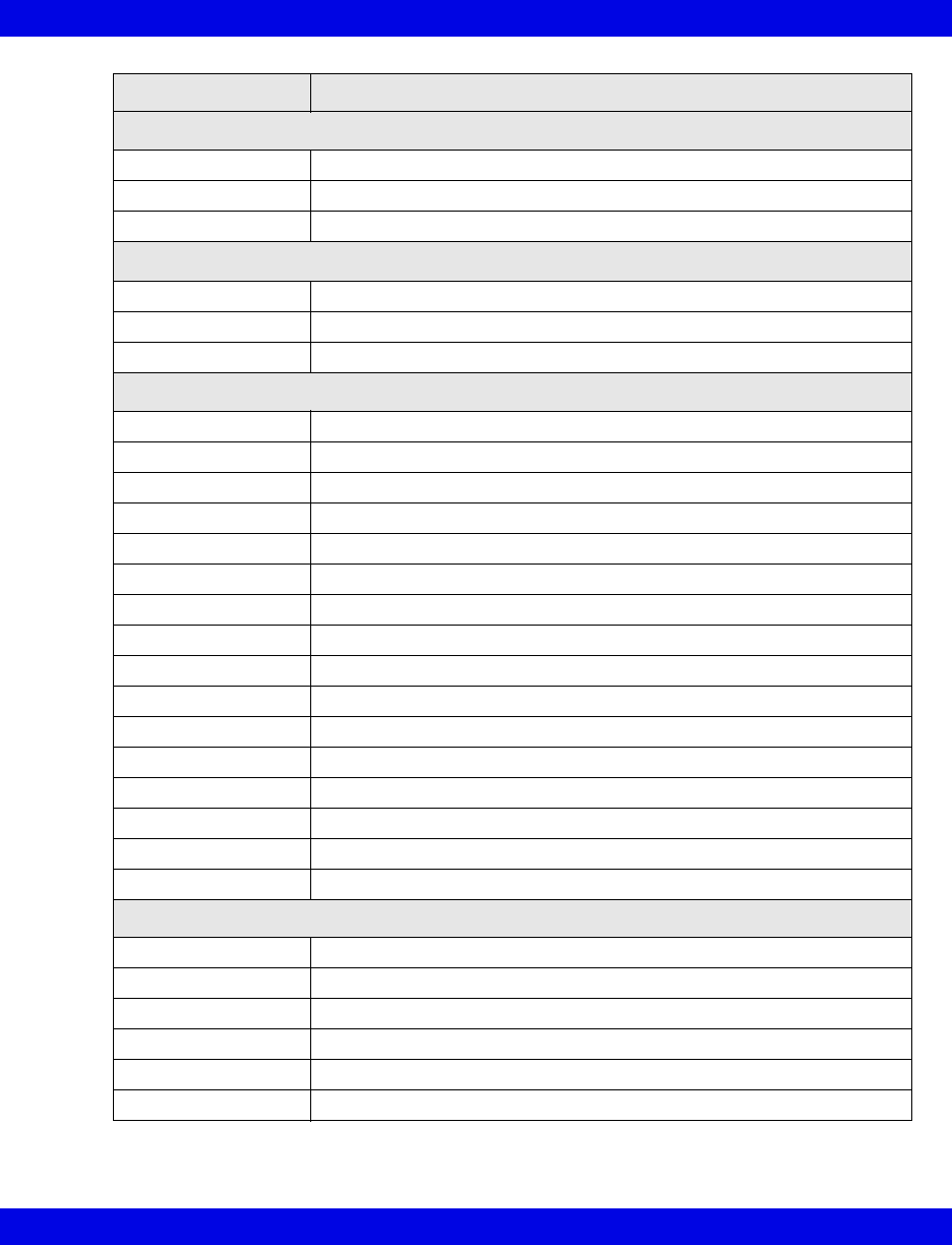
VentCentral Trend Parameters
Infinity CentralStation 17-17 VF8
Parameter Label Definition
Cardio Respiration
SaO2 Saturation of arterial oxygen
SvO2 Saturation of venous oxygen
VO2 Oxygen consumption
TCP/CO2
TCO2 Transcutaneous carbon dioxide
ht pwr Heater power
O2 Oxygen concentration
Anesthesia
etCO2 End-tidal carbon dioxide
eO2 Expired O2
iCO2 Inspired CO2
FiO2 Fraction of inspired O2
RRc* Respiration rate
SEV Sevoflurane
iDES Inspired desflurane
etDES End-tidal desflurane
iENF Inspired enflurane
etENF End-tidal enflurane
iHAL Inspired halothane
etHAL End-tidal halothane
iISO Inspired isoflurane
etISO end-tidal isoflurane
iN2O Inspired nitrous oxide
etN2O End-tidal nitrous oxide
Lab data
HCO3 Bicarbonate
hct Hematocrit
tHb Hemoglobin concentration
pCO2 Partial pressure CO2
pH Blood pH
pO2 Partial pressure O2
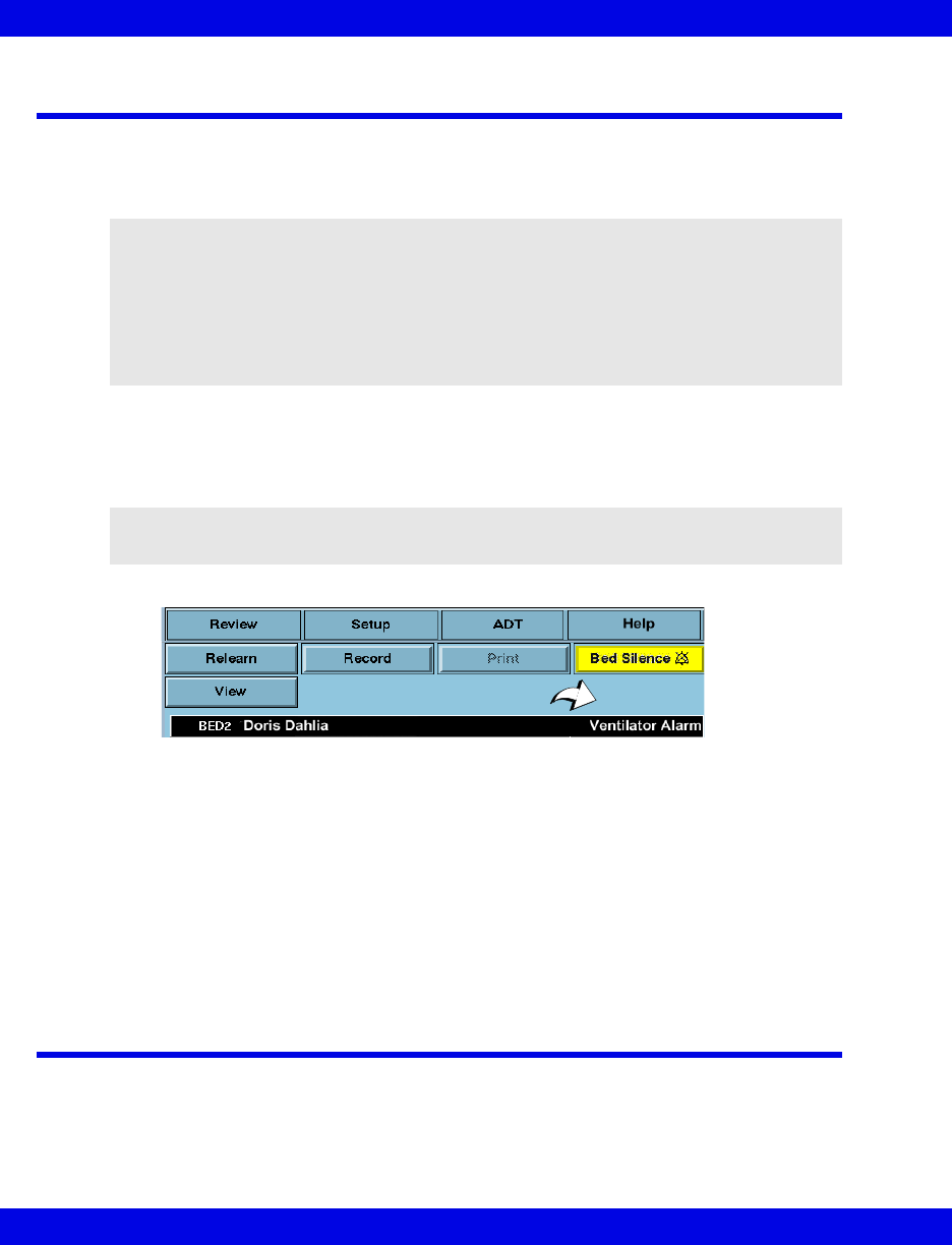
17-18 Infinity CentralStation VF8
17: VentCentral Option
MIB Ventilator Alarms
MIB-connected ventilators: Orange alarm messages appear in the lower right corner
of the topmost Main Screen waveform channel and are available without the
VentCentral option enabled.
In the VentCentral screens alarm messages appear on the right side of the information
area (see arrow).When an MIB-connected ventilator is active at the Infinity
CentralStation and the signal is lost, the Infinity CentralStation sounds a one-shot
alarm and displays the message, MIB Disconnected
Parameter boxes in the VentCentral screens that originate at MIB-connected
ventilators do not flash when they are in alarm.
Alarm messages that originate at MIB-connected ventilators are displayed for as long
as the ventilator sends them. If multiple alarm conditions occur simultaneously, the
messages rotate.
Alarms that originate from the etCO2/Respiratory Mechanics Pod can be silenced
remotely when the corresponding remote silence function is enabled.
Ventilator Report
For detailed information on ventilator reports and how to request them, see
page 14-19.
WARNING!
zVentilation alarms function independently from the
bedside monitor.
zThe bedside monitor does not annunciate ventilation
alarms.
zThe connected ventilator allows no remote control.
NOTE: MIB alarm messages will be sent to and displayed at the Infinity
CentralStation when you put a patient’s bedside monitor in standby mode.
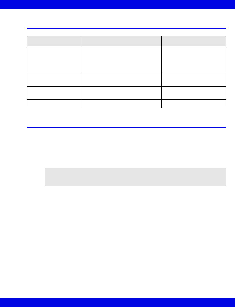
VentCentral Messages
Infinity CentralStation 17-19 VF8
VentCentral Messages
Ventilator and Device Messages/Labels
Tables on the following pages list messages, labels, and settings sent by various MIB-
connected devices to the Infinity bedside monitors for display at the Infinity
CentralStation.
Please refer to the table on page 17-9 for information about display of these data on
the Ventilator Settings Review screen and the Ventilator report.
Message Description Action
Trend data not available When you admit a new patient to Main
Screen, it takes a moment for the
trend data to be compiled. Within 1
minute the database will contain trend
data.
Exit and re-enter the trend
application.
No trend parameters
selected
Trend parameters have not been
selected.
Select trend parameters
(page 17-13).
Serious Alarm at <%s> There is an MIB alarm at the
corresponding bed.
Check the patient.
MIB Disconnected MIB cable is disconnected Re-connect MIB cable
CAUTION! The following tables list possible labels and messages for identification
purposes. For complete information about message interpretation and device operation,
please refer to the equipment documentation.
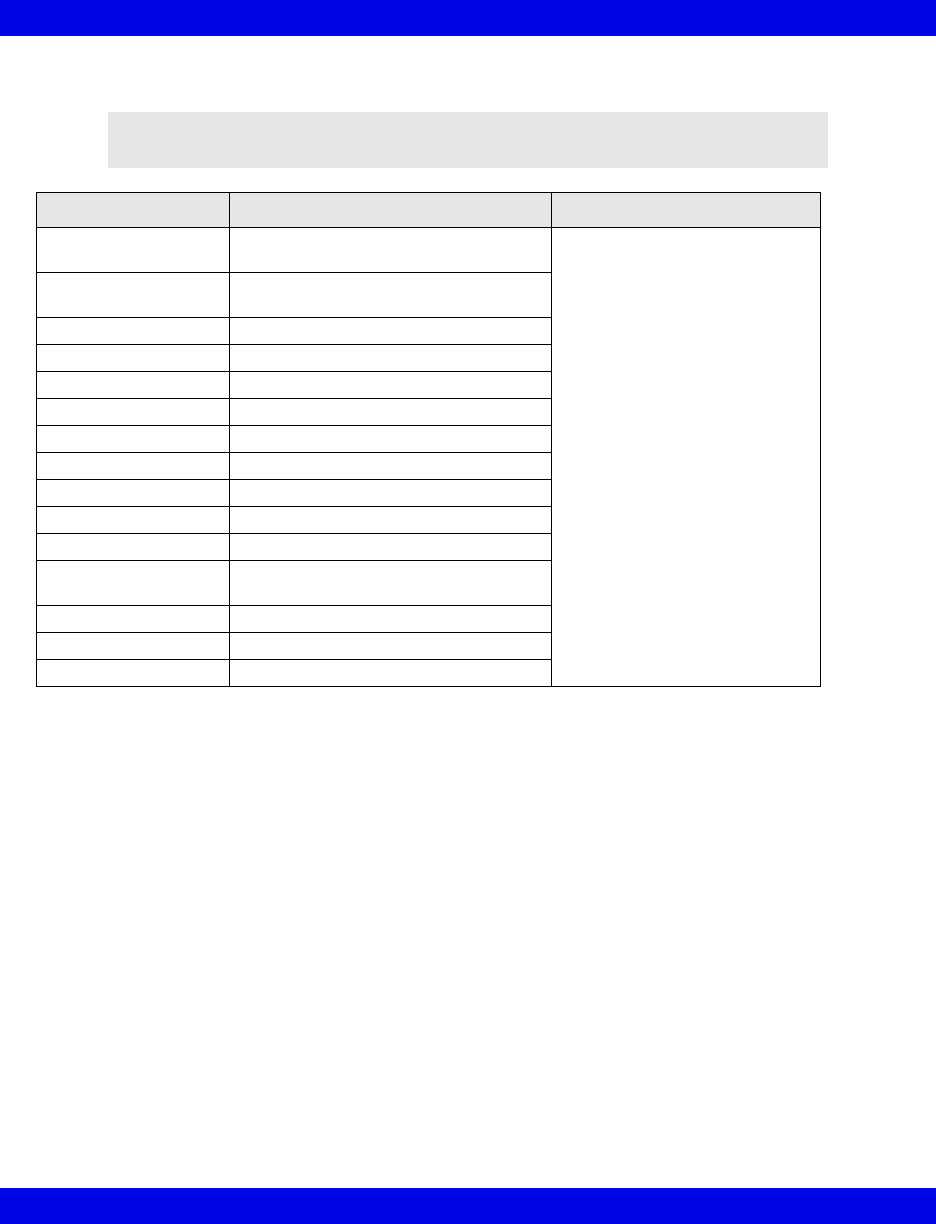
17-20 Infinity CentralStation VF8
17: VentCentral Option
Dräger Cato Anesthesia System
NOTE: The Dräger Cato Anesthesia System is not commercially available in the
U.S. and its future availability cannot be ensured.
Parameter Label Description Displayed in...
e[HAL, ISO, ENF, SEV,
DES]
Expired agent Ventilator screen (page 17-6)
i[HAL, ISO, ENF, SEV,
DES]
Inspired agent
eCO2 Expired CO2
iCO2 Inspired CO2
eO2 Expired O2
iN2O Inspired N2O
iO2 Inspired O2
MAP Mean Airway Pressure
MVe Expired Minute Volume
Pause Pause Pressure
PIP Peak Inspired Airway Pressure
PEEP Peak End Expiratory Airway
Pressure
RRc Respiratory rate
RRv Respiratory rate
TVe Tidal volume, expired breath
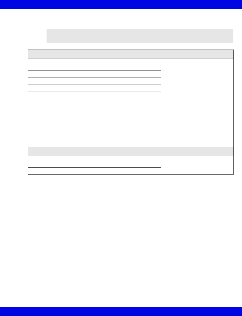
Ventilator and Device Messages/Labels
Infinity CentralStation 17-21 VF8
Dräger Cicero Anesthesia System
NOTE: The Dräger Cicero Anesthesia System is not commercially available in
the U.S. and its future availability cannot be ensured.
Parameter Label Description Displayed in...
HAL, ISO, ENF, SEV,
DES
Expired and inspired agent Ventilator screen (page 17-6)
eO2 Expired O2
iN2O Inspired N2O
iO2 Inspired O2
MAP Mean Airway Pressure
MVe Minute Volume, expired
Pause Pause Pressure
PIP Peak inspired airway pressure
PEEP Peak end expiratory airway pressure
RRc Respiratory rate
RRv Respiratory rate
TVe Tidal volume, expired breath
Selected Settings
HAL, ISO, ENF, SEV,
DES
Tidal volume, expired breath Ventilator Settings screen
(page 17-8)
eO2 Tidal volume, inspired breath
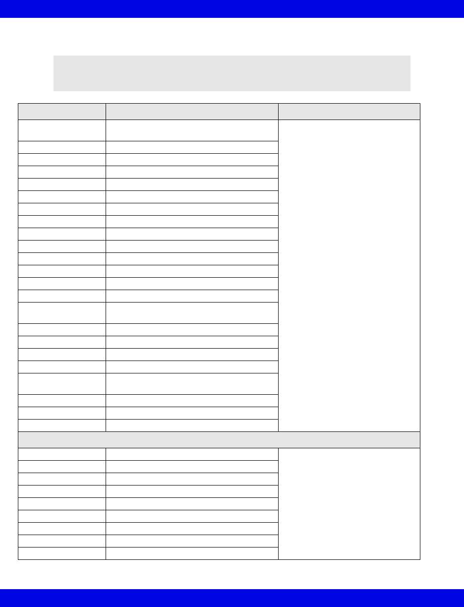
17-22 Infinity CentralStation VF8
17: VentCentral Option
Dräger Julian/Julian Primus/Primus Anesthesia System
NOTE: The Dräger Julian Primus and Dräger Primus Anesthesia Systems are
not commercially available in the U.S. and their future availability cannot be
ensured.
Parameter Label Description Displayed in...
[HAL, ISO, ENF,
SEV, DES]
Expired and inspired agent Ventilator Settings screen
(page 17-8)
ECO23 or etCO2 Expired CO2
etCO2 End Tidal CO2
eN2O Expired N2O
eO2 or etO2 Expired O2
iN2O Inspired N2O
iCO21Inspired CO2
iO2 Inspired O2
MAP Mean Airway Pressure
MVe Minute Volume, expired
Pause Pause Pressure
PIP Peak inspired airway pressure
PEEP Peak end expiratory airway pressure
RRc Respiratory rate (CO2)
RRv Respiratory rate (Volume/flow/pressure/
derived)
TVe Tidal volume, expired breath
Cdyn1Compliance
Baro Prsr1Barometric Pressure
Leakage1Leakage
iMAC1Inspired MAC (minimum alveolar
concentration)
eMAC1Expired MAC
APNEAt1Apnea Duration
Delta O21(iO2 - eO2)
Selected Settings
iO2 set iO2 setting Ventilator Settings screen
(page 17-8)
TVi set1Tidal volume, inspired breath
Ti set1Inspiratory Time
IPPV FREQ1frequency
INT PEEP set1Intermittent PEEP
P Support1Support Pressure
PIP set1Maximum Inspired Airway Pressure
FLOW trig set1Flow Trigger
F Gas Flow Fresh Gas Flow
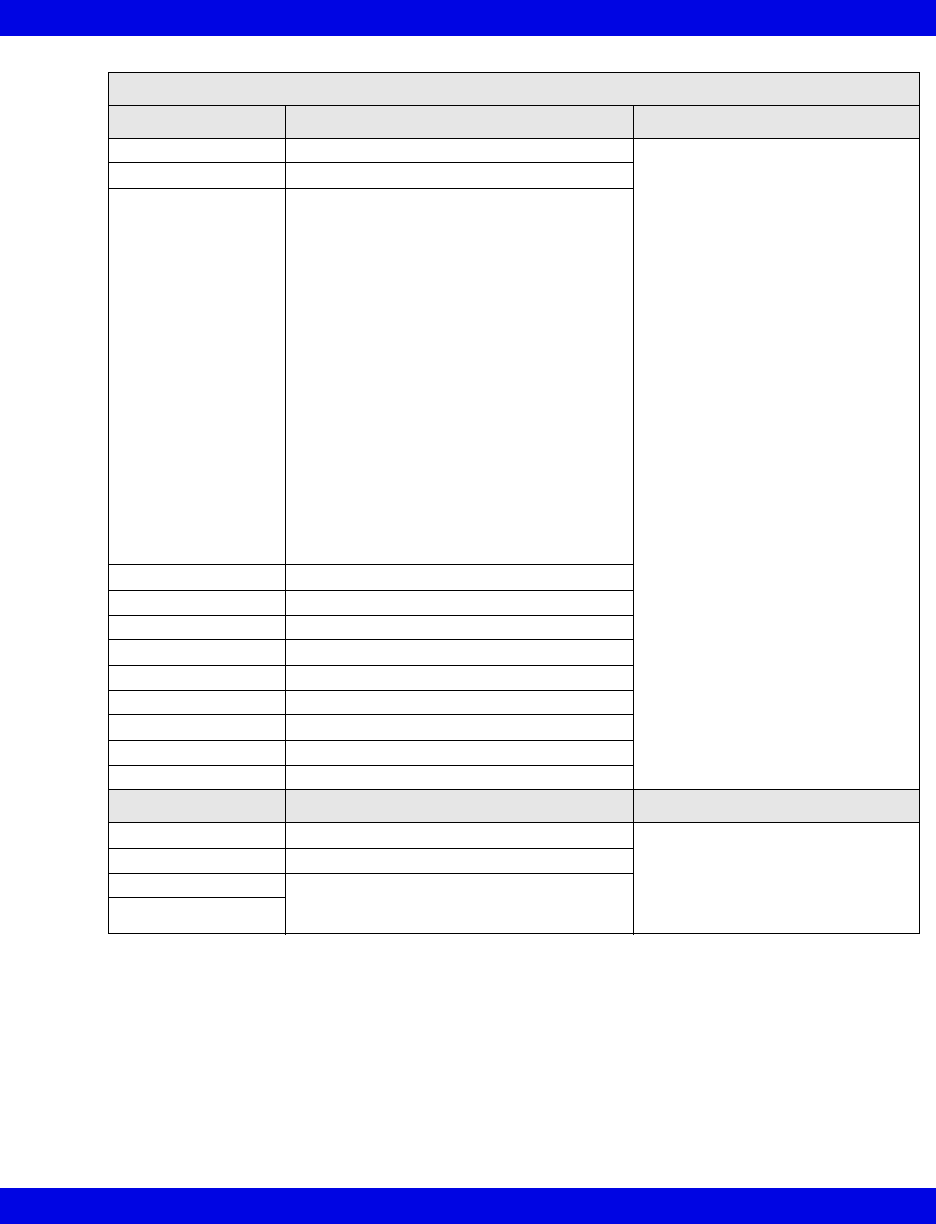
Ventilator and Device Messages/Labels
Infinity CentralStation 17-23 VF8
Alarm Messages
Message Description Displayed in...
APNEA Apnea Main Screen-lower right hand
corner of the top waveform
channel
Bed View-information area, right
below menu buttons
Alarm causes that are labelled as
‘Ventilator Alarm’ refer to non-
clinical device conditions. All other
alarm messages refer to clinical
events that violate a setting that
can be configured at the ventilator.
Paw > HI LIM Airway pressure > high limit
Ventilator Alarm • Inspired Agent > High Limit1
• Expired Agent > High Limit1
• Mean Airway Pressure < -2 mbar
• Problems with Ventilator1
• Internal Temperature High1
• Gas Supply Alarm1
• Ventilator Communication lost1
• Fresh Gas delivery failure1
• O2 Cylinder empty without wall supply1
• O2 Cylinder not connected1
• N2O Cylinder empty1
• N2O delivery failure1
• O2 delivery failure1
• Air delivery failure1
• Internal/external switch over valve error1
• Circle Occluded1
• Ventilator not in locked position1
O2 SUPPLY? O2 Supply Pressure Low
iO2 < LO LIM Inspiratory O2 < low limit
Patient Disconnect1Breathing System Disconnected
AW-TEMP>HI LIM1Airway temperature > high limit
N20 Fail1N20 delivery failure
Air Fail1Air delivery failure
Fresh Gas Fail1Fresh gas failure
O2 Fail1O2 delivery failure
No Fresh Gas1No fresh gas
Waveforms1
Paw Airway Pressure Ventilator Screen
(page 17-5)
Flow Flow (Insp/exp)
CO2 Only 2 waveforms can display. If CO2 is
available, Paw displays with it. Flow is only
available if CO2 is not.
Loops
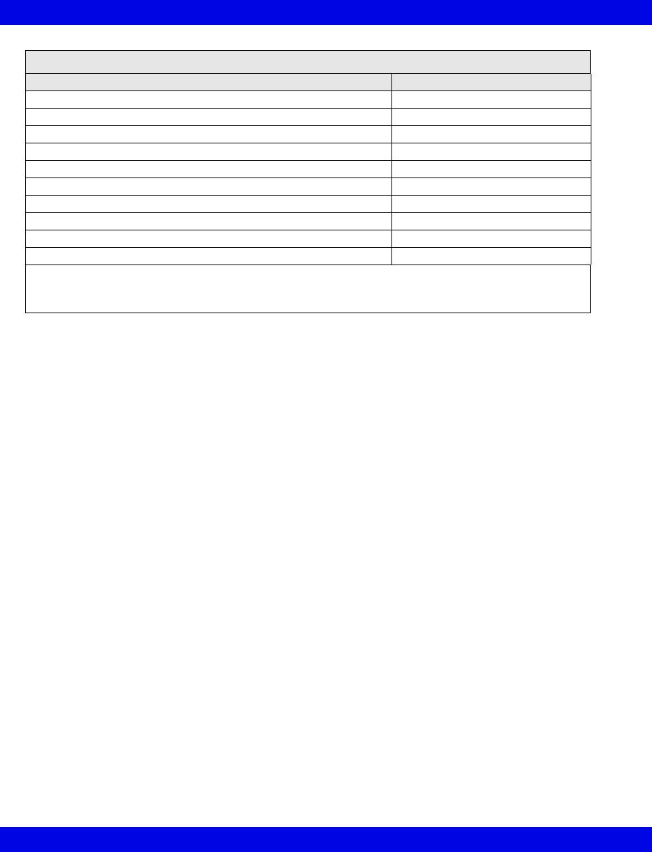
17-24 Infinity CentralStation VF8
17: VentCentral Option
Mode Display
Mode at Device Mode at Infinity CentralStation
IPPV IPPV2
SIMV SIMV
PCV PC
VCV VC
Standby Standby
PSV PS
Man/Spont Man/Spont
Fresh Gas external Fresh Gas EXT
Pressure Support added to Volume Control VC+PS
Pressure Support added to Pressure Control PC+PS
1Applicable only to Dräger Primus
2In some languages IPPV is used for CMV or VC
3Applicable only to Dräger Julian
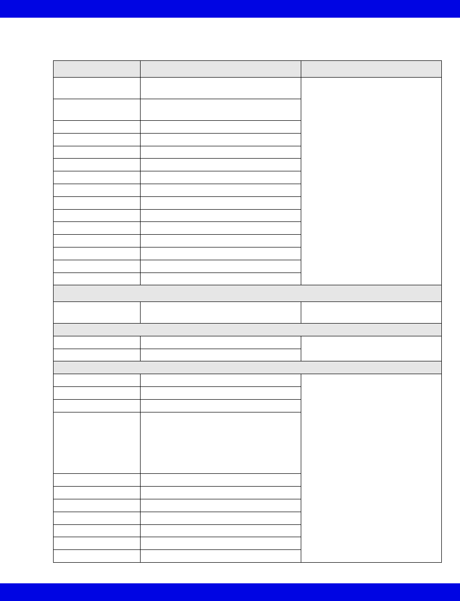
Ventilator and Device Messages/Labels
Infinity CentralStation 17-25 VF8
Dräger Narkomed IIC / IV / 6000 / 6400 Anesthesia System
Parameter Label Description Displayed in...
i[HAL, ISO, ENF,
SEV, DES]
Inspired agent Ventilator Settings screen
(page 17-8)
e[HAL, ISO, ENF,
SEV, DES]
Expired agent
etCO2 Expired CO2
iCO2 Inspired CO2
eO2 or etO2 Expired O2
iO2 Inspired O2
iN2O Inspired N2O
etN2O Expired N2O (6000 and 6400 only)
MAP Mean Airway Pressure
MVe Minute Volume, expired
PIP Peak inspired airway pressure
PEEP Peak end expiratory airway pressure
RRc Respiratory rate
RRv Respiratory rate
TVe Tidal volume, expired breath
Selected Settings (IIC and IV only)
iO2 set iO2 setting Ventilator Settings screen
(page 17-8)
Waveforms
Paw Airway Pressure Ventilator Screen
(page 17-5)
Flow Flow (Insp/exp)
Alarms
APNEA Apnea Main Screen-lower right hand
corner of the top waveform
channel
Bed View-information area, right
below menu buttons
Alarm causes that are labelled as
‘Ventilator Alarm’ refer to non-
clinical device conditions. All other
alarm messages refer to clinical
events that violate a setting that
can be configured at the ventilator.
Paw > HI LIM Airway pressure > high limit
iO2 > HI LIM Inspired O2 > high limit
Ventilator Alarm • Agent > High Limit
• Ventilator failure
• Ventilator Communication lost
• Mean Airway Pressure < -2 mbar
• CO2 device error
• Check expiration valve
O2 SUPPLY? O2 Supply Pressure Low
No Fresh Gas No fresh gas
Low Battery Low battery
PEEP > HI LIM PEEP exceeds high limit
MVe < LO LIM MVe below lower alarm limit
etCO2< LO LIM etCO2 below lower limit
etCO2>HI LIM etCO2 exceeds upper limit
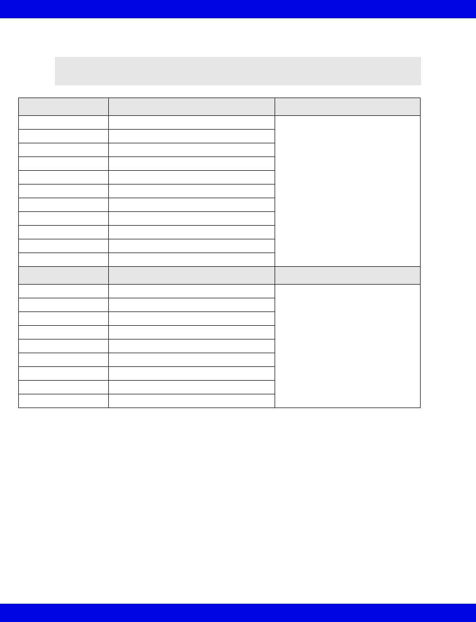
17-26 Infinity CentralStation VF8
17: VentCentral Option
Dräger Fabius GS/Fabius CE/Tiro Anesthesia System
NOTE: The Dräger Fabius CE Anesthesia System is not commercially available
in the U.S. and its future availability cannot be ensured.
Parameter Description Displayed in...
Pause Plateau Pressure Ventilator Settings screen
(page 17-8)
iO2 Inspired O2
MAP Mean Airway Pressure
MVe Minute Volume, expired
PIP Peak inspired airway pressure
PEEP Peak end expiratory airway pressure
RRv Respiratory rate
TVe Tidal volume, expired breath
Air Flow4Air flow (Fabius GS only)
N2O Flow4Nitrous oxide flow
O2 Flow4Oxygen flow
Setting Description Displayed in...
TVi set Inspired Tidal Volume setting Ventilator Settings screen
(page 17-8)
I:E I part I:E ratio - inspiratory component
I:E E part I:E ratio - expiratory component
IPPV FREQ IPPV frequency setting
INT PEEP set Intermittent PEEP setting
PIP set PIP setting
FLOW Trig set 1Flow trigger Level setting
i FLOW set1Inspiratory flow setting
P Support1Support pressure
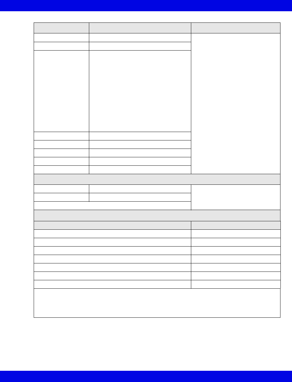
Ventilator and Device Messages/Labels
Infinity CentralStation 17-27 VF8
Alarm Messages Description Displayed in...
APNEA Apnea Main Screen-lower right hand
corner of the top waveform
channel
Bed View-information area, right
below menu buttons
Alarm causes that are labelled as
‘Ventilator Alarm’ refer to non-
clinical device conditions. All other
alarm messages refer to clinical
events that violate a setting that
can be configured at the ventilator.
Paw > HI LIM Airway pressure > high limit
Ventilator Alarm • Mean Airway Pressure < -2 mbar
• PEEP > Pressure Threshold for 15
seconds
• Problems with Respirator
• No Fresh Gas
• Check APL Valve
• Pressure Measurement Inoperable2
• Internal System Fault2
• Power Supply Error2
• Problems with Ventilator2
• Loss of Data2
O2 SUPPLY? O2 Supply pressure low
iO2 < LO LIM Inspiratory O2 < low limit
BATTERY2Battery low
Patient Disconnect2Breathing system disconnected
APL Valve?1Check APL valve
Waveforms
Paw Airway Pressure Ventilator Screen
(page 17-5)
Flow Flow (Insp/exp)
Loops1
Mode Display
Mode at Device Mode at Infinity CentralStation
IPPV IPPV3
SIMV1SIMV
PCV1PC
Standby Standby
PSV1PS
Man/Spont Man/Spont
Fresh Gas external Fresh Gas EXT
1Not applicable to Dräger Fabius CE
2Applicable only to Dräger Fabius CE
3In some languages IPPV is used for CMV or VC
4Applicable only to Dräger Fabius GS
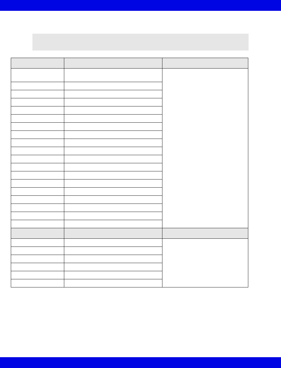
17-28 Infinity CentralStation VF8
17: VentCentral Option
Dräger Apollo Anesthesia System
NOTE: The Dräger Apollo Anesthesia System is not commercially available in
Canada and its future availability cannot be ensured.
Parameter Description Displayed in...
[HAL, ISO, ENF,
SEV, DES]
Expired and inspired agent Ventilator Settings screen
(page 17-8)
ECO2 Expired CO2
eO2 Expired O2
iN2O Inspired N2O
iO2 Inspired O2
MAP Mean Airway Pressure
MVe Minute Volume, expired
Pause Pause Pressure
PIP Peak inspired airway pressure
PEEP Peak end expiratory airway pressure
RRc Respiratory rate
RRv Respiratory rate
TVe Tidal volume, expired breath
Baro Prsr Barometric Pressure
Leakage Leakage
iMAC Inspired MAC
eMAC Expired MAC
APNEA t Apnea Duration
Delta O2 (iO2 - eO2)
Setting Description Displayed in...
TVi set Inspired Tidal Volume setting Ventilator Settings screen
(page 17-8)
I:E I part I:E ratio - inspiratory component
I:E E part I:E ratio - expiratory component
IPPV FREQ IPPV frequency setting
INT PEEP set Intermittent PEEP setting
PIP set PIP setting
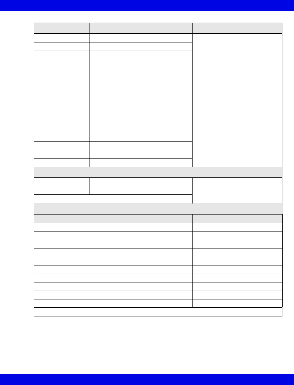
Ventilator and Device Messages/Labels
Infinity CentralStation 17-29 VF8
Alarm Messages Description Displayed in...
APNEA Apnea Main Screen-lower right hand
corner of the top waveform
channel
Bed View-information area, right
below menu buttons
Alarm causes that are labelled as
‘Ventilator Alarm’ refer to non-
clinical device conditions. All other
alarm messages refer to clinical
events that violate a setting that
can be configured at the ventilator.
Paw > HI LIM Airway pressure > high limit
Ventilator Alarm • Mean Airway Pressure < -2 mbar
• PEEP > Pressure Threshold for 15
seconds
• Problems with Respirator
• No Fresh Gas
• Check APL Valve
• Pressure Measurement Inoperable
• Internal System Fault
• Power Supply Error
• Problems with Ventilator
• Loss of Data
O2 SUPPLY? O2 Supply Pressure Low
iO2 < LO LIM Inspiratory O2 < low limit
BATTERY Battery Low
Patient Disconnect Breathing System Disconnected
Waveforms
Paw Airway Pressure Ventilator Screen
(page 17-5)
Flow Flow (Insp/exp)
Loops
Mode Display
Mode at Device Mode at Infinity CentralStation
IPPV IPPV1
SIMV SIMV
PCV PC
VCV VC
Standby Standby
PSV PS
Man/Spont Man/Spont
Fresh Gas external Fresh Gas EXT
Pressure Support added to Volume Control VC+PS
Pressure Support added to Pressure Control PC+PS
1In some languages IPPV is used for CMV or VC
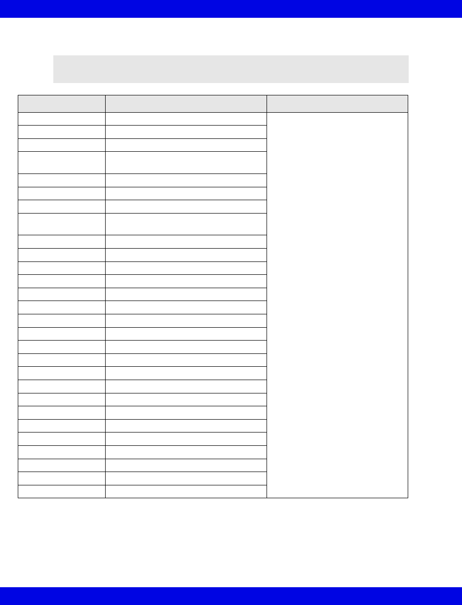
17-30 Infinity CentralStation VF8
17: VentCentral Option
Dräger Zeus Anesthesia System
NOTE: The Zeus Anesthesia System is not commercially available in the U.S. and
its future availability cannot be ensured.
Parameter Description Displayed in...
Air Flow Air flow Ventilator Settings screen
(page 17-8)
Baro Prsr Barometric Pressure
Cdyn Compliance
et[HAL, ISO, ENF,
SEV, DES]
Expired agent
etCO2 Expired CO2
etN2O Expired N2O
etO2 Expired O2
i[HAL, ISO, ENF,
SEV, DES]
Inspired agent
iCO2 Inspired CO2
iN2O Inspired N2O
iO2 Inspired O2
Leakage Leakage
MAP Mean Airway Pressure
MVe Minute Volume, expired
MVe s Minute Volume, spontaneous
MVm Mandatory MV
N2O Flow Nitrous oxide flow
O2 Flow Oxygen flow
O2 Supply Prsr O2 supply pressure
Pause Pause Pressure
PIP Peak inspired airway pressure
Raw Resistance
RRc Respiratory rate (CO2)
RRm Respiratory rate (mandatory)
RRv Respiratory rate (volume/flow)
TVe Tidal volume, expired breath
TVm Mandatory Tidal volume
TVs Spontaneous Tidal volume
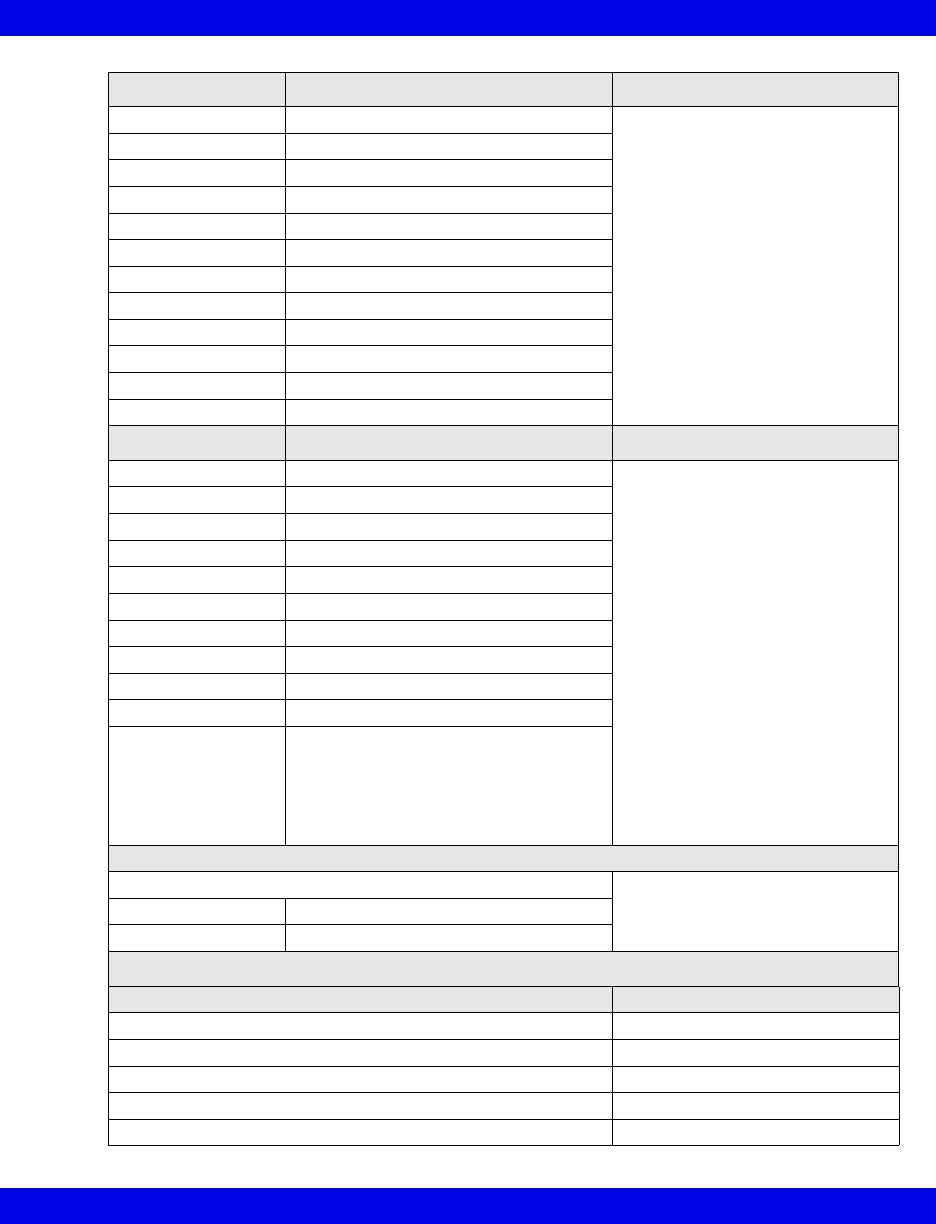
Ventilator and Device Messages/Labels
Infinity CentralStation 17-31 VF8
Setting Description Displayed in...
ASB RAMP set Assisted spontaneous breathing ramp Ventilator Settings screen
(page 17-8)
F Gas Flow Fresh gas flow
FLOW Trig set Flow trigger Level setting
I:E E part I:E ratio - expiratory component
I:E I part I:E ratio - inspiratory component
INT PEEP set Intermittent PEEP setting
IPPV FREQ IPPV frequency setting
PEEP set PEEP setting
PIP set PIP setting
Te set Expiratory time setting
Ti set Inspiratory time setting
TVi set Inspired Tidal Volume setting
Alarm Messages Description Displayed in...
AIR SUPPLY? Air supply low Main Screen-lower right hand
corner of the top waveform
channel
Bed View-information area, right
below menu buttons
Alarm causes that are labelled as
‘Ventilator Alarm’ refer to non-
clinical device conditions. All other
alarm messages refer to clinical
events that violate a setting that
can be configured at the ventilator.
AW-TEMP>HI LIM Airway temperature exceeds high limit
etCO2< LO LIM etCO2 below lower limit
etCO2>HI LIM etCO2 exceeds upper limit
iO2 > HI LIM Inspiratory O2 exceeds high limit
iO2 < LO LIM Inspiratory O2 below low limit
MVe < LO LIM MVe below lower alarm limit
MVe > HI LIM MVe exceeds upper alarm limit
O2 SUPPLY? O2 Supply Pressure Low
Paw > HI LIM Airway pressure > high limit
Ventilator Alarm • Check Flow Sensor
• Battery error
• CO2 device error
• Problems with respirator
• Check expiration valve
Waveforms
CO2 Ventilator Screen
(page 17-5)
Flow Flow (Insp/exp)
Paw Airway Pressure
Mode Display
Mode at Device Mode at Infinity CentralStation
IPPV IPPV
IPPV/AutoFlow IPPV
PCV PC
SIMV/AutoFlow SIMV
Standby Standby
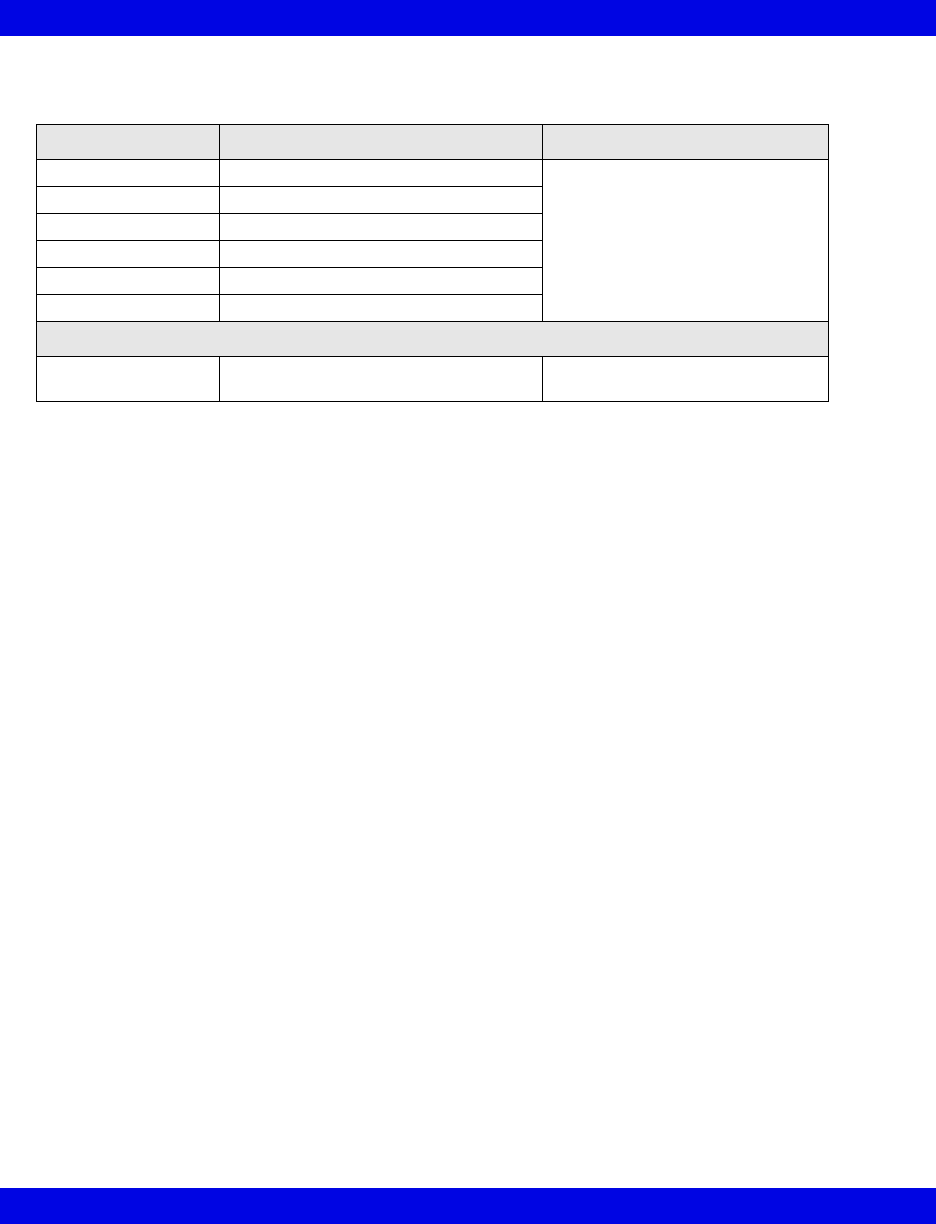
17-32 Infinity CentralStation VF8
17: VentCentral Option
Ohmeda Modulus CD Anesthesia System
Parameter Description Displayed in...
MAP Mean Airway Pressure Ventilator Settings screen
(page 17-8)
MVe Minute Volume, expired
Pause Pause Pressure
PIP Peak inspired airway pressure
RRv Respiratory rate (volume/flow)
TVe Tidal volume, expired breath
Selected Settings
iO2 set iO2 setting Ventilator Settings screen
(page 17-8)
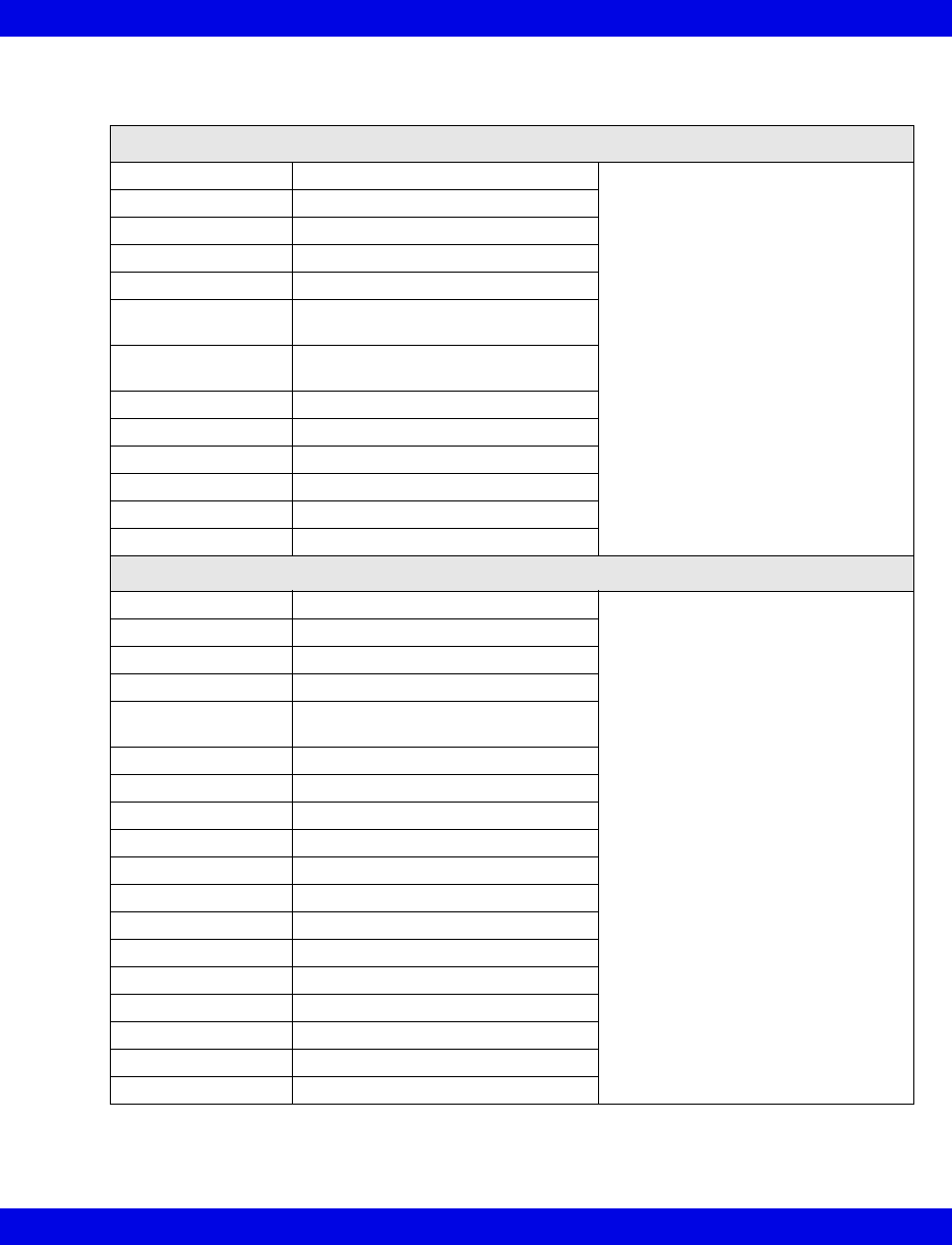
Ventilator and Device Messages/Labels
Infinity CentralStation 17-33 VF8
Dräger BabyLog Ventilator
Parameters
Gas Trans Coeff Gas transport coefficient Ventilator Settings screen (page 17-8)
I:E l-Part I:E ratio (Inspiratory component)
iO2 Inspired O2
TV Leak Leakage in system
MAP Mean airway pressure
MVe Expired minute volume - high
resistance
MVe / l Expired minute volume - low
resistance
MV s% Minute volume, spontaneous fraction
PEEP Peak end expiratory pressure
PIP Peak inspired airway pressure
RRv Respiratory rate - vol/flow
TVeml Tidal volume, expiratory
TVhfml Tidal volume, high frequency
Settings
APNEA TIME Apnea time limit Ventilator Settings screen (page 17-8)
FLOW Expiratory flow setting
i FLOW Inspiratory flow setting
SIMV FREQ Frequency, IMV
HFV AMPL High frequency ventilation (HFV)
mode amplitude
HFV FREQHz HFV mode frequency
I:E E-Part I:E ratio - expiratory component
Te set I:E ratio (expiratory time)
I:E I-Part I:E - inspiratory component
Ti set Inspiratory time
iO2 set Inspired O2 setting
MV ALM DLY Minute volume alarm delay
MV HI LIM Upper minute volume alarm limit
MV LO LIM Lower minute volume alarm limit
PIP set PIP setting
PEEP set PEEP setting
TRIG VOL Trigger volume
Vent: Babylog
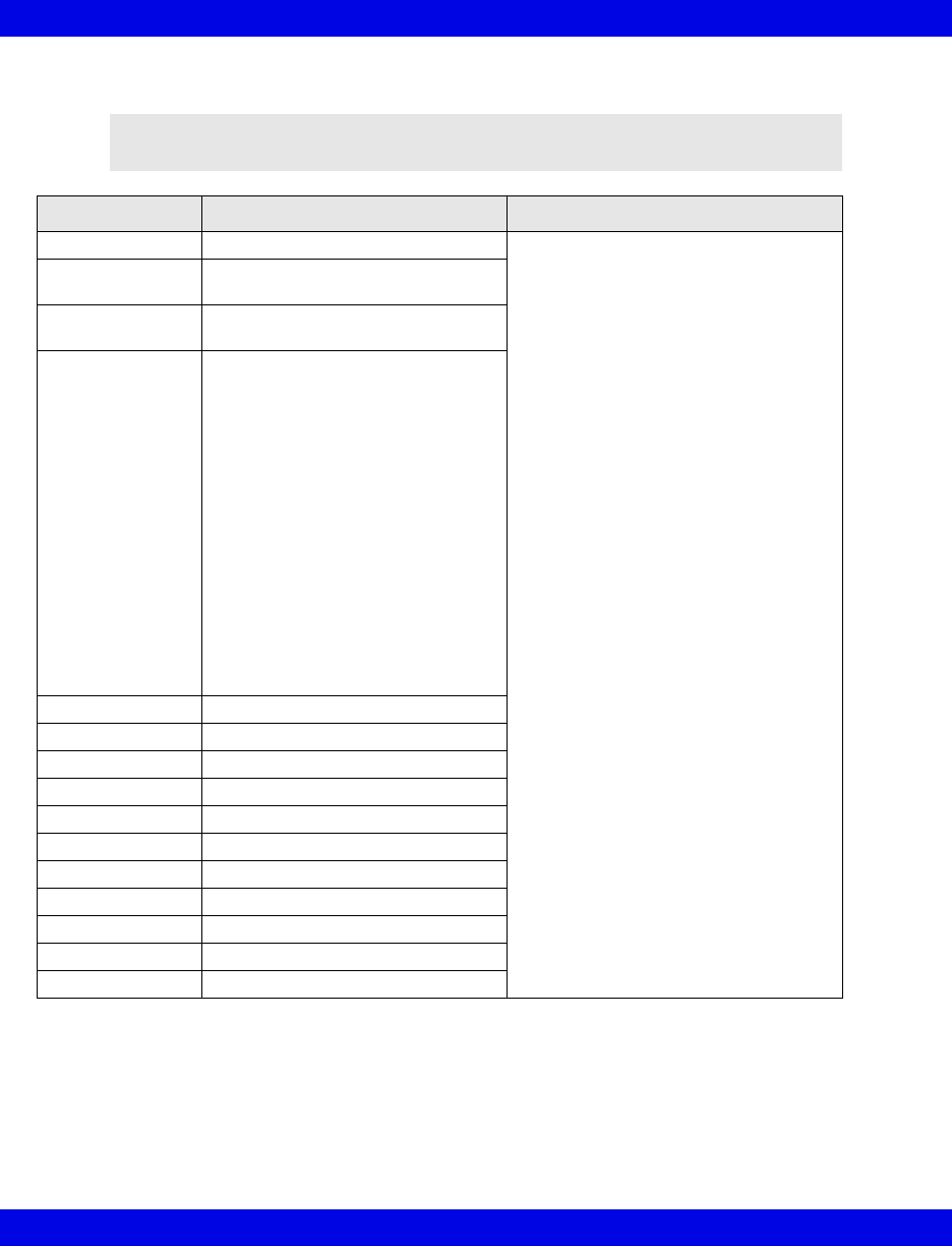
17-34 Infinity CentralStation VF8
17: VentCentral Option
Dräger Evita 1 Ventilator
NOTE: The Dräger Evita 1 Ventilator is not commercially available in the U.S.
and its future availability cannot be ensured.
Alarm Messages Description Displayed in....
Paw > HI LIM Paw exceeds upper alarm limit Main Screen-lower right hand corner of
the top waveform channel
Bed View-information area, right below
menu buttons
Alarm causes that are labelled as
‘Ventilator Alarm’ refer to non-clinical
device conditions. All other alarm
messages refer to clinical events that
violate a setting that can be configured
at the ventilator.
AW -TEMP>HI LIM Airway temperature exceeds upper
limit
AW -TEMP INOP Airway temperature measurement
inoperable
Ventilator Alarm • Airway temperature sensor alarm
• Check expiration - valve
• Failed to cycle
• The gas mixer is faulty
• Faulty pressure measurement
• Problems with respirator (Evita)
• Respirator synchronization
inoperable
• The device temperature of the
respirator is too high
• Volume measurement
unsuccessful
• The volume is not constant
• Faulty airway temperature
measurement
APNEA Apnea alarm
ASB>4 SEC ASB is longer than 4 sec
Patient Patient Disconnect
AIR SUPPLY? Gas supply, air
O2 SUPPLY? Gas supply, O2
iO2 > HI LIM iO2 exceeds higher limit
IO2 < LO LIM iO2 is below lower alarm limit
% O2 ERR iO2 measurement inoperable
MVe < LO LIM Mve is below lower alarm limit
MVe > HI LIM Mve exceeds upper alarm limit
RR > HI LIM RR exceeds upper alarm limit
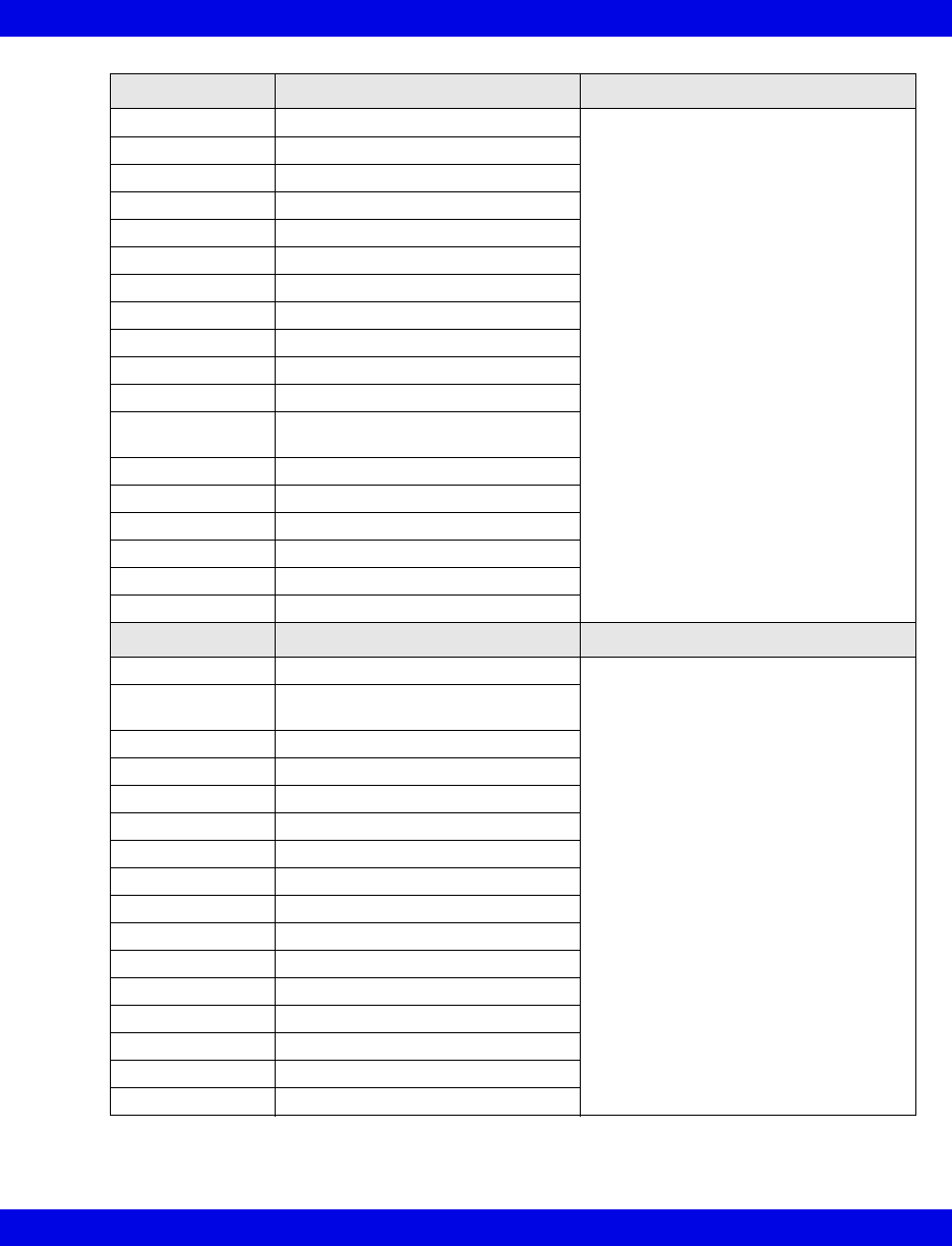
Ventilator and Device Messages/Labels
Infinity CentralStation 17-35 VF8
Parameter Labels Description Displayed in....
AW Temp Airway temperature Ventilator Settings screen (page 17-8)
Cdyn Dynamic compliance
I:E I-Part I:E ratio (inspiratory component)
iO2 Inspired O2
MAP Mean airway pressure
MVe Expired minute volume
MVe s Spontaneous expired minute volume
Occlusion Press Occlusion pressure
Paw MIN Minimum airway pressure
Pause Pause pressure
PEEP Peak end expiratory airway pressure
iPEEP Peak end expiratory airway
pressure, intrinsic
PIP Peak inspired airway pressure
Raw Dynamic resistance
RRv Respiratory rate - vol/flow - pediatric
RRs Spontaneous respiratory rate
TVe Tidal volume expired breath
Trapped VOL Trapped volume
Selected Settings Description Displayed in....
APNEA TIME Apnea time Ventilator Settings screen (page 17-8)
ASB RAMP set Assisted spontaneous breathing
ramp
ASB set Assisted spontaneous breathing
BIPAP HI P set BIPAP high pressure
BIPAP HI T set HIPAP high time
BIPAP LO P set BIPAP low pressure
BIPAP LO T set BIPAP low time
FLOW Trig set Flow trigger
SIMV FREQ Frequency, IMV - SIMV
IPPV FREQ IPPV Frequency
I:E E-Part I:E ratio (expiratory component)
I:E I-Part I:E ratio (inspiratory component)
iO2 set Inspired O2 setting
MAX iFLOW set Maximum inspired flow
PIP set PIP setting
PEEP set PEEP setting

17-36 Infinity CentralStation VF8
17: VentCentral Option
Selected Settings
(continued) Description Displayed in....
INT PEEP set Intermittent PEEP setting Ventilator Settings screen (page 17-8)
TACHY LENGTH Tachyapnea duration
TACHY FREQ Tachyapnea frequency
TVi set Inspired tidal volume
TRIG PRESS Trigger pressure
Vent: Evita 1
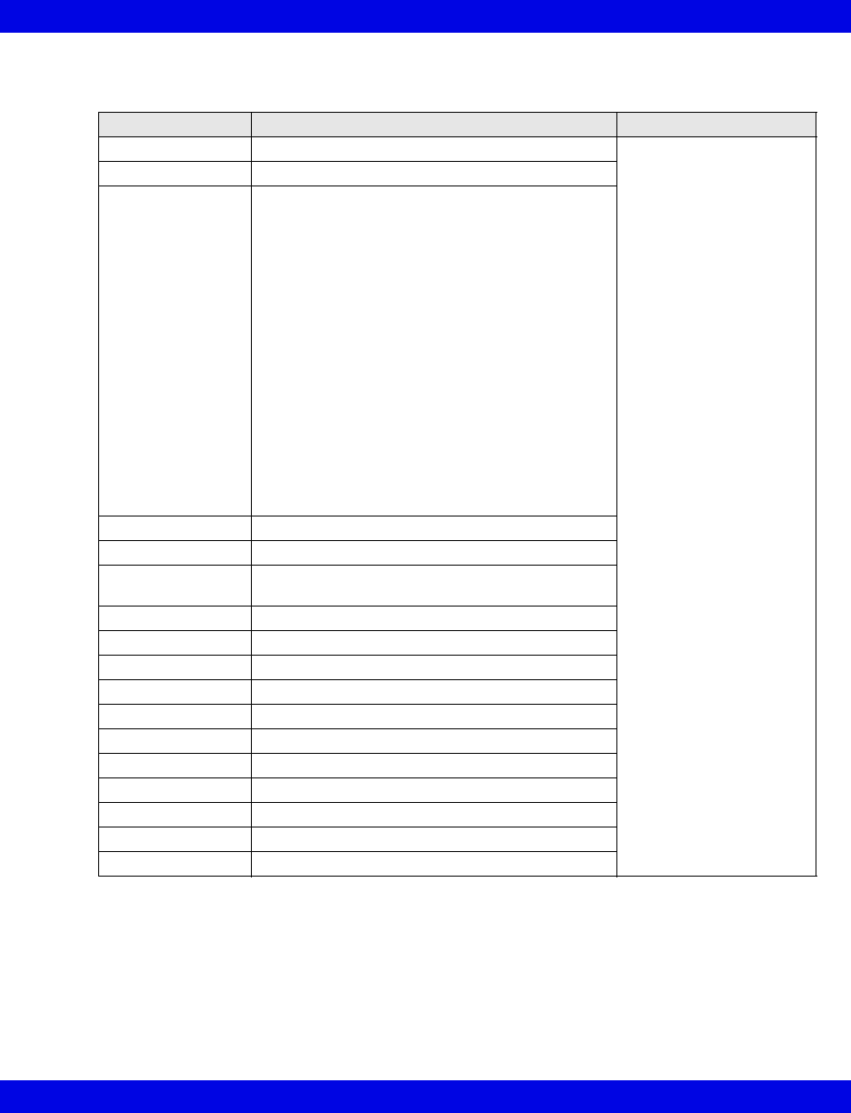
Ventilator and Device Messages/Labels
Infinity CentralStation 17-37 VF8
Dräger Evita 2 Ventilator
Alarm Messages Description Displayed in....
Paw > HI LIM Paw exceeds upper alarm limit Main Screen - lower right
hand corner of the top
waveform channel
Bed View - information
area right below the menu
buttons.
Alarm causes that are
labelled as ‘Ventilator
Alarm’ refer to non-clinical
device conditions. All
other alarm messages
refer to clinical events that
violate a setting that can
be configured at the
ventilator.
AW -TEMP>HI LIM AW -TEMP exceeds upper alarm limit
Ventilator Alarm • Airway temperature measurement unsuccessful
• Check expiration - valve
• Check flow sensor
• CO2 device failure
• CO2 not calibrated
• CO2 sensor disconnected or malfunctioning
• Failure to cycle
• Gas mixer inoperable
• Pressure measurement unsuccessful
• Problems with respirator
• Respirator synchronization inoperable
• Device temperature is too high.
• Volume measurement unsuccessful
• Volume is inconsistent.
• Airway temperature sensor alarm
APNEA Apnea alarm
ASB>4 SEC ASB is more than 4 sec
Patient
Disconnect
Patient may be disconnected from ventilator
etCO2< LO LIM etCO2 below lower alarm limit
etCO2 > HI LIM etCO2 exceeds upper alarm limit
AIR SUPPLY? Gas supply alarm, air
O2 SUPPLY? Gas supply alarm, O2
iO2 < LO LIM iO2 less than lower alarm limit
iO2> HI LIM iO2 exceeds upper alarm limit
% O2 ERR iO2 measurement unsuccessful
MVe < LO LIM MVe is below lower alarm limit
MVe > HI LIM MVe exceeds upper alarm limit
PEEP > HI LIM PEEP exceeds upper alarm limit
RR > HI LIM RR exceeds upper alarm limit
17-38 Infinity CentralStation VF8
17: VentCentral Option
Parameter Labels Description Displayed in....
Paw MIN Minimum airway pressure Ventilator Settings screen
(page 17-8)
AW-Temp Airway temperature
VCO2 CO2 production, minute volume
Cdyn Dynamic compliance
TVd aw% Dead space
TVd aw Dead space, airway
etCO2 end-tidal CO2
I:E I-Part I:E ratio (inspiratory component)
iO2 Inspired O2
MAP Mean airway pressure
MVe Expired minute volume
MVe s Spontaneous expired minute volume
Occlusion Press Occlusion pressure
Pause Pause pressure
PEEP Peak end expiratory airway pressure
iPEEP Intrinsic peak end expiratory airway pressure
PIP Peak inspired airway pressure
Raw Dynamic resistance
RRv Pediatric respiratory rate - vol/flow
RRs Spontaneous respiratory rate
TVe Tidal volume expired breath
Trapped VOL Trapped volume
Ventilator and Device Messages/Labels
Infinity CentralStation 17-39 VF8
Selected Settings Description Displayed in....
APNEA TIME Apnea time Ventilator Settings screen
(page 17-8)
ASB RAMP set Assisted spontaneous breathing ramp
ASB set Assisted spontaneous breathing
BIPAP HI P set BIPAP high pressure limit
BIPAP HI T set BIPAP high time limit
BIPAP LO P set BIPAP low pressure limit
BIPAP LO T set BIPAP low time limit
FLOW Trig set Flow trigger setting
SIMV FREQ Frequency, IMV - SIMV
IPPV FREQ Frequency IPPV
I:E E-Part I:E ratio - expiratory component
I:E I-Part I:E ratio - inspiratory component
iO2 set Inspired O2 setting
MAX iFLOW set Maximum inspired flow
PIP set Peak inspired airway pressure
PEEP set PEEP setting
INT PEEP set Intermittent PEEP setting
TACHY LENGTH Tachyapnea duration
TACHY FREQ Tachyapnea frequency
TVi set Inspired tidal volume setting
TRIG PRESS Trigger pressure
Vent: Evita 2

17-40 Infinity CentralStation VF8
17: VentCentral Option
Dräger Evita 2D / 4 / XL Ventilator
Alarm
Messages Description Displayed in....
Paw > HI LIM Paw exceeds upper alarm limit Main Screen - in the
lower right hand corner of
the top waveform
channel
Bed View -in the
information area right
below the menu buttons
AW-TEMP >
HI LIM
Upper airway temperature exceeds upper alarm limit
Ventilator Alarm • AW-TEMP below lower alarm limit (Evita 2D / 4)
• AW-TEMP measurement unsuccessful
• Battery error (Evita XL)
• Check expiration valve
• Check flow sensor
• CO2 device error
• CO2 not calibrated (Evita 2D / 4)
• CO2 Zero/Cal required
• CO2 window dirty (Evita XL)
• CO2 sensor disconnected or faulty
• Cycle failure
• Gas mixer inoperable
• Pressure measurement unsuccessful
• Device malfunction (Evita 2D / 4)
• Synchronization malfunctioning (Evita 2D / 4)
• Volume measurement unsuccessful
• Volume not constant (Evita 2D / 4)
• Neonatal flow sensor is not at the Y-piece
• Pediatric volume measurement inoperable
(Evita 2D / 4)
• Neonate volume measurement inoperable (Evita XL)
• PEEP valve is inoperable
• Problems with respirator
• Respirator synchronizations faulty
• Safety mode if neonatal flow sensor not available
(Evita 2D / 4)
• Safety mode (Evita XL)
• Standby
• Loss of data
• Inspiratory time in CPAP/PPS mode is less than 4
seconds (Evita 2D / 4)
• Inspired time is greater than 1.5 seconds (Evita XL)
Alarm causes that are
labelled as ‘Ventilator
Alarm’ refer to non-
clinical device conditions.
All other alarm messages
refer to clinical events
that violate a setting that
can be configured at the
ventilator
Ventilator and Device Messages/Labels
Infinity CentralStation 17-41 VF8
Alarm Messages (continued)
APNEA Apnea alarm Main Screen - in the
lower right hand corner of
the top waveform
channel
Bed View -in the
information area right
below the menu buttons
etCO2< LO LIM etCO2 below lower limit
etCO2>HI LIM etCO2 exceeds upper limit
AIR SUPPLY? Gas supply alarm, air
O2 SUPPLY? Gas supply alarm, O2
iO2 < LO LIM iO2 less than lower alarm limit
iO2 > HI LIM iO2 exceeds upper alarm limit
% O2 ERR iO2 measurement unsuccessful
MVe < LO LIM MVe below lower alarm limit
MVe > HI LIM MVe exceeds upper alarm limit
PEEP > HI LIM PEEP exceeds upper alarm limit
PEEP ERR PEEP valve inoperable (Evita 2D / 4)
RR > HI LIM RR exceeds upper alarm limit
TVe > HI LIM TVe exceeds upper alarm limit
ASB > 4 sec Assisted Spontaneous Breathing exceeds 4 sec
PATIENT
DISCONNECT
Ventilator disconnected (Evita XL)
Parameters
Paw MIN Minimum airway pressure Ventilator Settings
screen
(page 17-8)
VCO2 CO2 production, minute volume
Cdyn Dynamic compliance
TVd aw% Dead space
TVd aw Dead space, airway
etCO2 End-tidal CO2
I:E I-Part I:E ratio (inspiratory component)
I:E E-Part I:E ratio (expiratory component)
iO2 Inspired O2
MAP Mean airway pressure
MVe Expired minute volume
MVe s Spontaneous expired minute volume spontaneous
Occlusion Press Occlusion pressure
Pause Pause pressure
PEEP Peak end expiratory pressure
iPEEP Intrinsic peak end expiratory pressure (Evita 2D / 4)
PIP Peak inspired airway pressure
Raw Dynamic resistance
RRv Pediatric respiratory rate - vol/flow
RRs Spontaneous respiratory rate
Trapped VOL Trapped volume
TVe Tidal volume expired breath
AW-Temp Airway temperature (Evita XL)
17-42 Infinity CentralStation VF8
17: VentCentral Option
Parameters (continued)
Neg iForce Negative inspiratory force (Evita XL) Ventilator Settings
screen
(page 17-8)
Vtasb Assisted spontaneous breathing, Support volume
(Evita XL)
Selected Settings
APNEA TIME Apnea time (s) Ventilator Settings
screen
(page 17-8)
APRV Hi Prsr APRV high pressure setting
APRV Hi Time APRV high time
APRV Lo Prsr APRV low pressure setting
APRV Lo Time APRV low time
ASB RAMP set Assisted spontaneous breathing ramp (s)
ASB set Assisted spontaneous breathing
FLOW ASSIST Flow assist
FLOW Trig set Flow trigger
SIMV FREQ Frequency, IMV - SIMV
I:E E-Part I:E ratio - expiratory component
I:E I-Part I:E ratio - inspiratory component
iO2 set Inspired O2 setting
MAX iFLOW set Maximum inspired flow setting
PIP set Peak inspired airway pressure
PEEP set PEEP setting
INT PEEP set Intermittent PEEP setting
TACHY FREQ Tachyapnea frequency
TVi set • Tidal volume, inspired
• Tidal volume setting
TV set Inspired time (Evita XL)
Vent: The selected ventilator type
VOL ASSIST Volume assist
Patient Type Adult, Pedi, or Neonate (Evita XL)
Ventilation Mode Display (Evita XL)
Ventilation Mode at Device Mode at Infinity
CentralStation
IPPV, IPPV/Autoflow, IPPV/Assist/Autoflow, or IPPV/Assist IPPV
SIMV, SIMV/ASB, SIMV/Autoflow, or SIMV/ASB/Autoflow SIMV
CPAP, CPAP/PPS, or CPAP/ASB CPAP
Standby Standby
MMV, MMV/Autoflow, or MMV/ASB/Autoflow MMV
BIPAP Assist BIPAP
CMV CMV
Waveforms (Evita XL)
Paw Airway Pressure Ventilator Screen
(page 17-5)
Flow Flow (Insp/exp)
Loops Ventilator loops
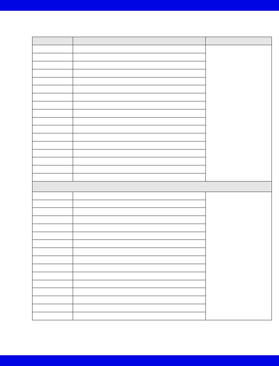
Ventilator and Device Messages/Labels
Infinity CentralStation 17-43 VF8
Dräger Savina Ventilator
Parameters Description Displayed in...
Cdyn Dynamic compliance Ventilator Settings screen
(page 17-8)
I:E I-Part I:E ratio (inspiratory component)
I:E E-Part I:E ratio (expiratory component)
iO2 Inspired O2
MAP Mean airway pressure
MVe Expired minute volume
MVe s Spontaneous expired minute volume spontaneous
Pause Pause pressure
PEEP Peak end expiratory pressure
PIP Peak inspired airway pressure
Raw Dynamic resistance
RRv Pediatric respiratory rate - vol/flow
RRs Spontaneous respiratory rate
TVe Tidal volume expired breath
AW -Temp Airway temperature
Max iFlow Peak Flow
Ti Inspired Time
Selected Settings
APNEA TIME Apnea time (s) Ventilator Settings screen
(page 17-8)
ASB set Assisted spontaneous breathing
FLOW Trig set Flow trigger
SIMV FREQ Frequency, IMV - SIMV
I:E E-Part I:E ratio - expiratory component
I:E I-Part I:E ratio - inspiratory component
iO2 set Inspired O2 setting
PIP set Peak inspired airway pressure
PEEP set PEEP setting
INT PEEP set Intermittent PEEP setting
Ti set Inspired time setting
TVi set Tidal Volume, Inspired
Flow Accel Flow acceleration
Tdeconnect Disconnect time
FREQbackup Backup frequency
TVbackup Backup of Tidal Volume

17-44 Infinity CentralStation VF8
17: VentCentral Option
Waveforms
Paw Airway Pressure Ventilator Screen
(page 17-5)
Flow Flow (Insp/exp)
Loops Ventilator loops
Alarm
Messages Description Displayed in...
iO2 < LO LIM iO2 less than lower alarm limit Main Screen - in the lower
right hand corner of the top
waveform channel
Bed View -in the
information area right
below the menu buttons
Alarm causes that are
labelled as ‘Ventilator
Alarm’ refer to non-clinical
device conditions. All other
alarm messages refer to
clinical events that violate
a setting that can be
configured at the
ventilator.
iO2 > HI LIM iO2 exceeds upper alarm limit
O2 SUPPLY? Gas supply alarm, O2
MVe < LO LIM MVe below lower alarm limit
MVe > HI LIM MVe exceeds upper alarm limit
PEEP > HI LIM PEEP exceeds upper alarm limit
TVe > HI LIM TVe exceeds upper alarm limit
Paw > HI LIM Paw exceeds upper alarm limit
AW-TEMP >
HI LIM
Airway temperature exceeds upper alarm limit
APNEA Apnea alarm
RRv > HI LIM Respiratory rate exceeds upper alarm limit
ASB > 4 sec Assisted spot breathing exceeds 4 seconds
BATTERY • Battery problem
• Low battery
Patient
Disconnect
Ventilator disconnection
iO2 ERR Inspired O2 measurement inoperable
Ventilator Alarm • Check flow sensor
• Standby
• PEEP control problems
• Problems with respirator
• Volume measurement inoperable
• Pressure measurement inoperable
• Check expiration - valve
• Airway temperature measurement inoperable
• Fail to cycle
• Fan problem
Ventilation Mode Display
Ventilation Mode at Device Mode at Infinity
CentralStation
BIPAP or BIPAP/ASB BIPAP
IPPV, IPPV/Autoflow, IPPV/Assist/Autoflow, or IPPV/Assist IPPV
SIMV, SIMV/ASB, SIMV/Autoflow, or SIMV/ASB/Autoflow SIMV
CPAP or CPAP/ASB CPAP
Standby Standby
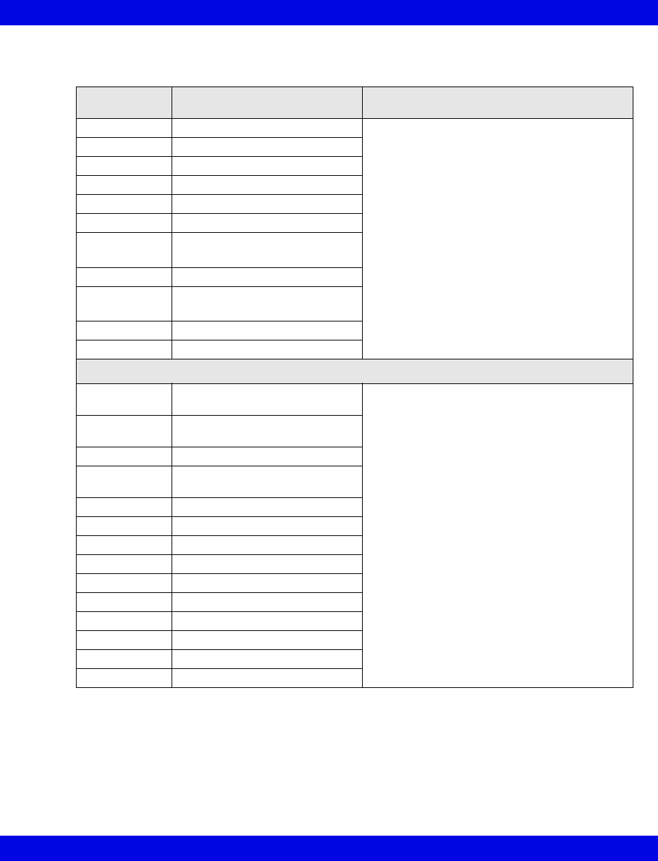
Ventilator and Device Messages/Labels
Infinity CentralStation 17-45 VF8
P-B 7200/840 Ventilators
Alarm
Messages
Description Displayed in...
Paw > HI LIM Paw exceeds upper alarm limit Main Screen -in the lower right hand corner of
the top waveform channel
Bed View -in the information area right below
the menu buttons
Alarm causes that are labelled as ‘Ventilator
Alarm’ refer to non-clinical device conditions.
All other alarm messages refer to clinical
events that violate a setting that can be
configured at the ventilator.
Paw < LO LIM Paw fell below lower alarm limit
APNEA Apnea event
AIR SUPPLY Gas air supply pressure
O2 SUPPLY Gas O2 supply pressure
Ventilator Alarm I:E Alarm
Ventilator Alarm
(P-B 7200 only)
Leakage, system
MVe<LO LIM MVe is below lower alarm limit
PEEP<LO LIM
(P-B 7200 only)
PEEP is below lower alarm limit
RR>HI LIM RR exceeds upper alarm limit
TVe<LO LIM Tidal volume is low
Parameter Labels
Cdyn
(P-B 7200 only)
Dynamic compliance Ventilator Settings screen
(page 17-8)
Cs
(P-B 7200 only)
Static compliance
I:E E-Part I:E ratio (expiratory component)
I:E I-Part
(P-B 840 only)
I:E ratio (inspiratory component)
MAP Mean airway pressure
MVe Expired minute volume
MVe s Spontaneous minute volume
Pause Pause pressure
PIP Peak inspired airway pressure
Raw Dynamic resistance
Rs Static resistance
RRv Respiratory rate
TVe Tidal volume expired breath
VC Vital capacity
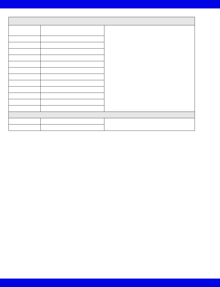
17-46 Infinity CentralStation VF8
17: VentCentral Option
Selected Settings
FLOW WAVE
set
Flow waveform setting Ventilator Settings screen
(page 17-8)
FREQ set Frequency
iO2 set Inspired O2 setting
100%O2 Inspired O2% setting
NEBUL set Nebulizer setting
PIF set Peak inspiratory flow setting
PEEP set PEEP setting
Plateau set Plateau setting
SIGH ON Sigh enabled
TVi set Tidal volume
TRIG PRESS Trigger pressure
VENT MODE Selected ventilation mode
VENT: Selected Ventilator type
Waveforms (P-B 7200 only)
Paw Airway Pressure Ventilator Screen
(page 17-5)
Flow Flow (Insp/exp)
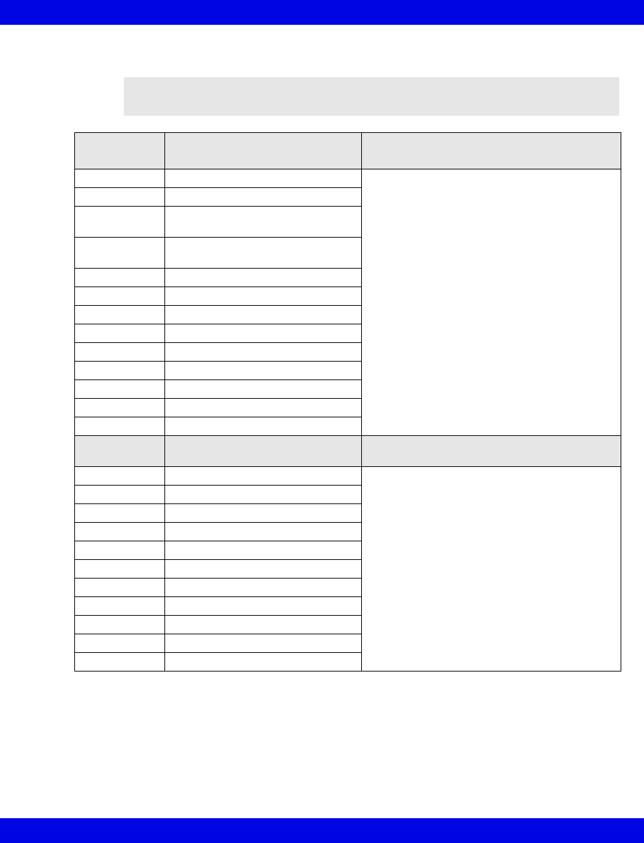
Ventilator and Device Messages/Labels
Infinity CentralStation 17-47 VF8
Taema Horus Ventilator
NOTE: The Taema Horus ventilator is not commercially available in the U.S. and
its future availability cannot be ensured.
Alarm
Messages Description Displayed in...
Paw > HI LIM Paw exceeds upper alarm limit Main Screen - in the lower right hand corner of
the top waveform channel
Bed View -in the information area right below
the menu buttons
Alarm causes that are labelled as ‘Ventilator
Alarm’ refer to non-clinical device conditions.
All other alarm messages refer to clinical
events that violate a setting that can be
configured at the ventilator.
APNEA Apnea event
Expiration
Valve?
Check expiration - valve
Patient
Disconnect
Patient may be disconnected from
ventilator
I:E Alarm I:E error
iO2 < LO LIM iO2 is below lower alarm limit
iO2 > HI LIM iO2 exceeds upper alarm limit
MVe < LO LIM MVe is below lower alarm limit
MVe > HI LIM MVe exceeds upper alarm limit
PEEP > HI LIM PEEP exceeds upper alarm limit
Flow Sensor? Check flow sensor
AIR SUPPLY? Gas supply alarm, air
O2 SUPPLY? Gas supply alarm, O2
Parameter
Labels Description Displayed in...
Cdyn Dynamic compliance Ventilator Settings screen
(page 17-8)
MAP Mean airway pressure
MVe Expired minute volume
MVi Inspired minute volume
Pause Pause pressure
PIP Peak inspired airway pressure
PEEP Peak end expiratory pressure
RRv Respiratory rate
TVe Tidal volume, expired
TVi Tidal volume, inspired
iO2 Inspired O2
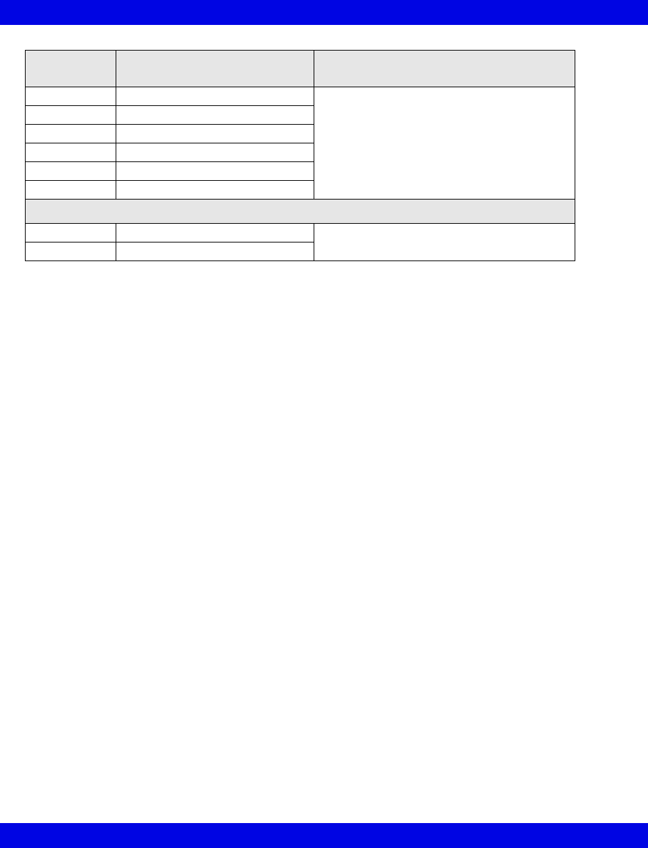
17-48 Infinity CentralStation VF8
17: VentCentral Option
Selected
Settings Description Displayed in...
FREQ set Frequency Ventilator Settings screen
(page 17-8)
PEEP set PEEP setting
TVi set Tidal volume
TRIG PRESS Trigger pressure
VENT MODE Selected ventilation mode
VENT: Selected Ventilator type
Waveforms
Paw Airway Pressure Ventilator Screen
(page 17-5)
Flow Flow (Insp/exp)
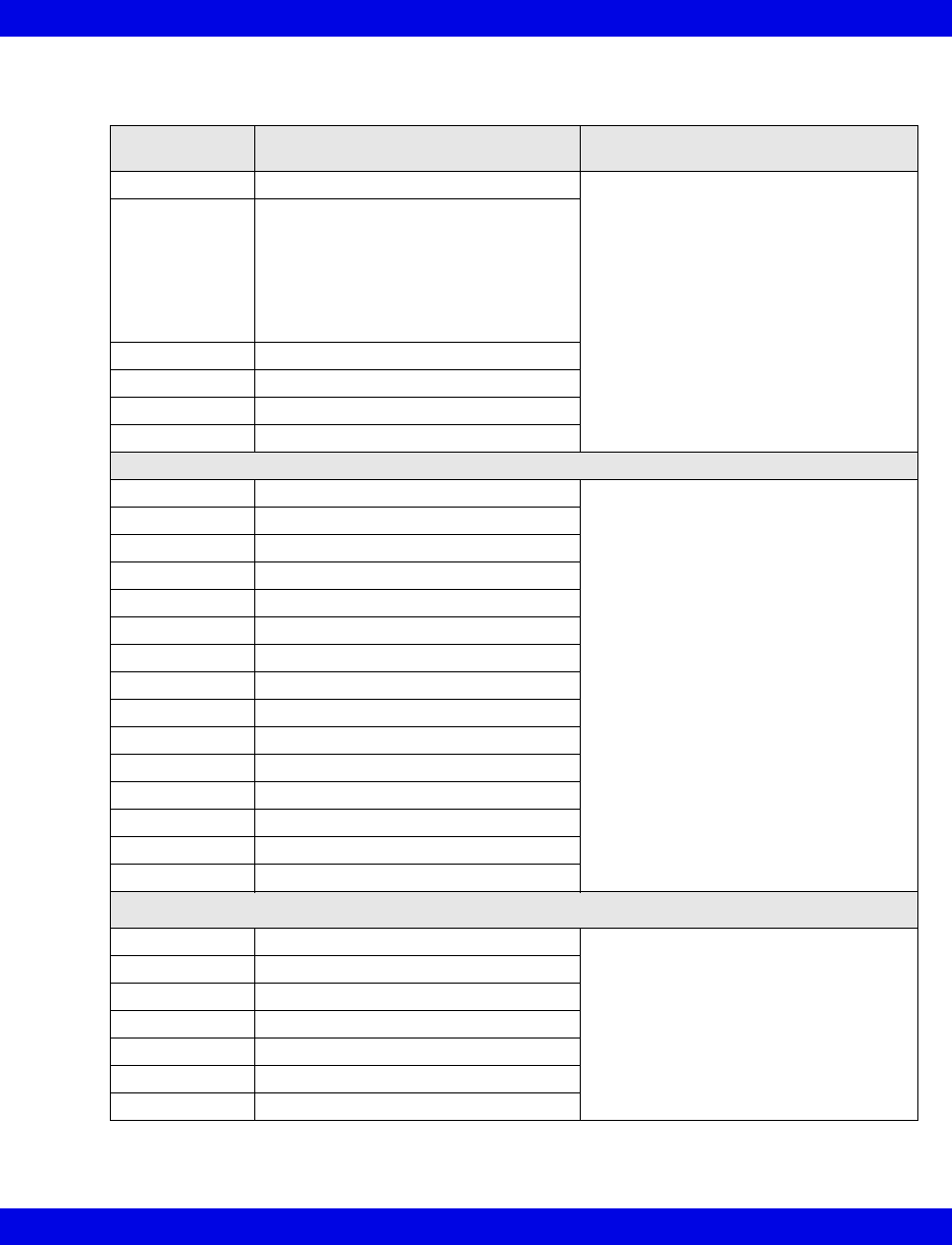
Ventilator and Device Messages/Labels
Infinity CentralStation 17-49 VF8
Hamilton Galileo Ventilator
Alarm
Messages Description Displayed in...
Paw > HI LIM Paw exceeds upper alarm limit Main Screen - in the lower right hand
corner of the top waveform channel
Bed View -in the information area right
below the menu buttons
Alarm causes that are labelled as
‘Ventilator Alarm’ refer to non-clinical
device conditions. All other alarm
messages refer to clinical events that
violate a setting that can be configured
at the ventilator.
Ventilator Alarm • Minute volume exceeds upper alarm
limit
• Failure to cycle
• Gas supply alarm
• PEEP valve inoperable
• Ventilator disconnect
APNEA Apnea alarm
%O2 Error %O2 measurement error
MVe < LO LIM MVe below lower alarm limit
RR > HI LIM RR exceeds upper alarm limit
Parameter Labels
Cdyn Dynamic compliance Ventilator Settings screen (page 17-8)
I:E E-Part I:E ratio (expiratory component)
I:E I-Part I:E ratio (inspiratory component)
iO2 Inspired O2
MAP Mean airway pressure
MVe Expired minute volume
Pause Pause pressure
PIP Peak inspired airway pressure
PEEP Peak end expiratory airway pressure
Raw Dynamic resistance
RRv Pediatric respiratory rate - vol/flow
RRs Spontaneous respiratory rate
TVe Tidal volume, expired
TVi Tidal volume, inspired
iO2 Inspired O2
Selected Settings
iO2 set Inspired O2 setting Ventilator Settings screen (page 17-8)
INSP t% I:E ratio, inspiratory component
PAUSE t% I:E ratio, expiratory component
PEEP set PEEP setting
TVi set Inspired tidal volume setting
TRIG PRESS Trigger pressure
Vent: Selected Ventilator type
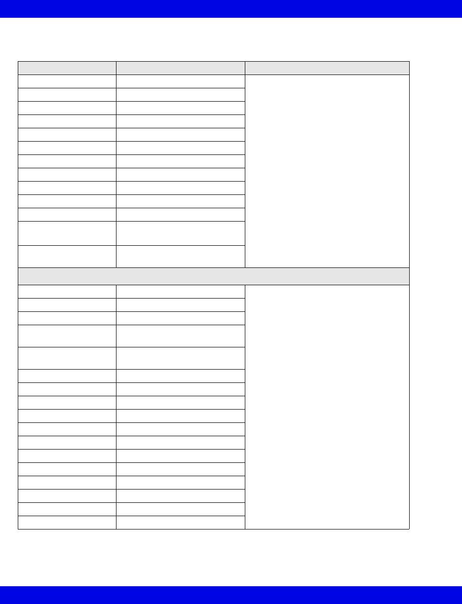
17-50 Infinity CentralStation VF8
17: VentCentral Option
Maquet SV 300/SV 300A/Servoi Ventilator
Alarm Messages Description Displayed in...
Paw > HI LIM Paw exceeds upper alarm limit Main Screen - in the lower right hand
corner of the top waveform channel
Bed View - in the information area right
below the menu buttons
APNEA An apnea detected
BATTERY Battery alarm
CMV potentiometer CMV potentiometer error
GAS SUPPLY? Gas supply alarm
HI CONT PRESS High continuous pressure
iO2 < LO LIM iO2 is below lower limit
iO2 > HI LIM iO2 exceeds upper limit
MAINS FAIL Mains failure
MVe > HI / LO LIM MVe is too high/too low
VENT ERR Mode switch error
% O2 ERR O2 cell disconnect, or
O2 potentiometer error
DEVICE ERR Over range or
Range switch error
Labels/Settings
BAROM PRESS Barometric pressure Ventilator Settings screen
(page 17-8)
AIR SUPPLY Gas air supply pressure
O2 SUPPLY Gas O2 supply pressure
1I:E I-Part I:E ratio (inspiratory
component)
1,2INSP t% I:E ratio (inspiratory
component)%
iO2 Inspired O2
MAP cmH20 Mean airway pressure
MVe I Expired minute volume
MVi I Inspired minute volume
Pause Pause pressure
PEEP Peak end expiratory pressure
PIP Peak inspired pressure
RRv Respiratory rate
TVe Tidal volume expired breath
TVi Tidal volume inspired breath
CMV FREQ Frequency of CMV setting
SIMV FREQ Frequency of SIMV setting
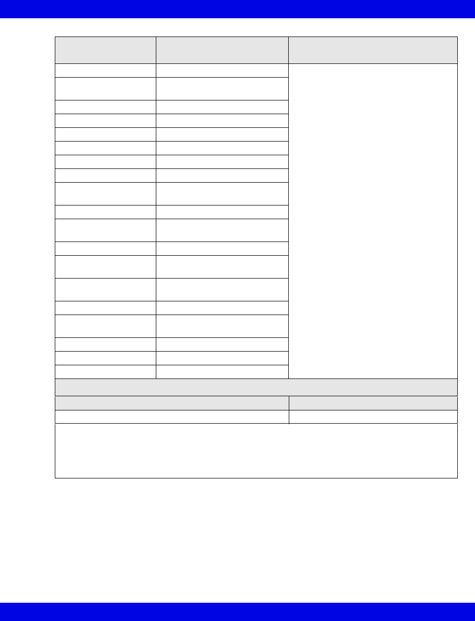
Ventilator and Device Messages/Labels
Infinity CentralStation 17-51 VF8
Labels/Settings
(continued) Description Displayed in...
INSP t% I:E ratio - inspiratory component Ventilator Settings screen
(page 17-8)
I RISE% I:E ratio - inspiratory rise time
component
PAUSE t% I:E ratio - pause component
iO2 set iO2 setting
iO2 set LO Lower alarm limit of iO2
iO2 HI LIM Upper alarm limit of iO2
MVe LO LIM Lower alarm limit of MVe
MVe HI LIM Upper alarm limit of MVe
PATIENT RANGE Patient type (Adult= 4;
Pediatric=15; Neonate=16)
PEEP set PEEP setting
P CTL > PEEP Pressure control level above
PEEP
P HI LIM Upper pressure alarm limit
P SUPPORT Pressure support level above
PEEP.
TRIG SENS > PEEP Trigger sensitivity level below
PEEP
VENT MODE3Ventilation mode setting
SV 300, SV 300A,
Servoi
Selected Ventilator type
VOL set Volume setting
Paw Airway pressure
Flow Flow (insp/exp)
Ventilation Mode Display (Servoi)
Ventilation Mode at Device Mode at Infinity CentralStation
SIMV (PRVC) SIMV (PRVC)
1Certain parameters, identified as measured values, are derived from other values or settings
provided by the ventilator and may not reflect actual values. See the operating instructions for your
specific monitor or ventilator for detailed information on derived measurements.
2Display of I:E value may be affected by mode of ventilation.
3Mode value may be blanked during certain conditions and modes of ventilation.
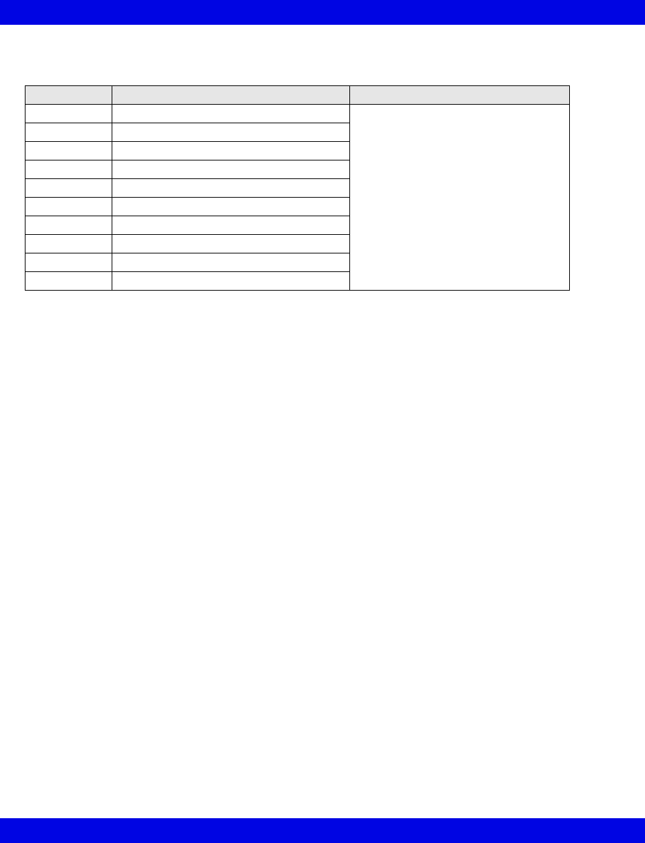
17-52 Infinity CentralStation VF8
17: VentCentral Option
Maquet SV 900 Ventilator
Parameters Description Displayed in...
RRv Respiratory rate Ventilator Settings screen (page 17-8)
TVe Tidal volume, expired
Tvi Tidal volume, inspired
MVi Minute volume, inspired
MVe Minute volume, expired
PIP Peak inspired airway pressure
MAP Mean airway pressure
Pause Pause pressure
PEEP Peak End Expiratory Pressure
iO2 Inspired O2
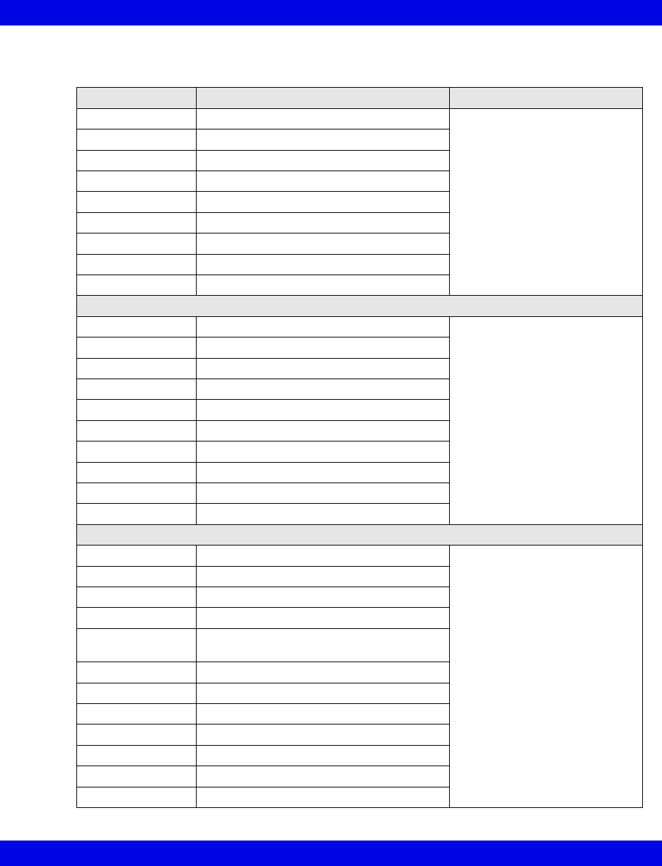
Ventilator and Device Messages/Labels
Infinity CentralStation 17-53 VF8
Viasys Bear 1000 Adult Ventilator
Alarm Messages Description Displayed in...
Paw > HI LIM Paw exceeds upper alarm limit Main Screen - in the lower right
hand corner of the top waveform
channel
Bed View - in the information
area right below the menu
buttons
Paw < LO LIM Paw is below lower limit
GAS SUPPLY? Gas supply alarm
RR > HI LIM Respiratory rate exceeds upper alarm limit
RR < LO LIM Respiratory rate is below lower limit
MVe < LO LIM Minute volume is below lower limit
MVe > HI LIM Minute volume exceeds upper alarm limit
I:E Alarm I:E Limit (I:E Error)
Cycle Failed Fail to cycle
Parameters
PIP Peak inspired airway pressure Ventilator Settings screen
(page 17-8)
MAP Mean airway pressure
%MMV % Mandatory minute ventilation
TVe Tidal volume, expired
Ti Inspiratory time
MVe Minute volume, expired
MVe s Spontaneous minute volume
RRv Respiratory rate
Pause Pause (plateau) pressure
RRs Respiratory rate, spontaneous
Settings
Ti set Inspiratory time Ventilator Settings screen
(page 17-8)
iO2 set Inspired O2 setting
MAX iFLOW set Maximum inspiratory flow
TVi set Tidal volume, inspired
Pause t I:E ratio (Pause component)
Inspiratory pause
Pslope Pressure slope
TRIG PRESS Pressure trigger sensitivity
FLOW Trig set Flow trigger
Paw set Inspiratory pressure
MMV Mandatory minute ventilation
Freq set Breath rate
PSupport Pressure support
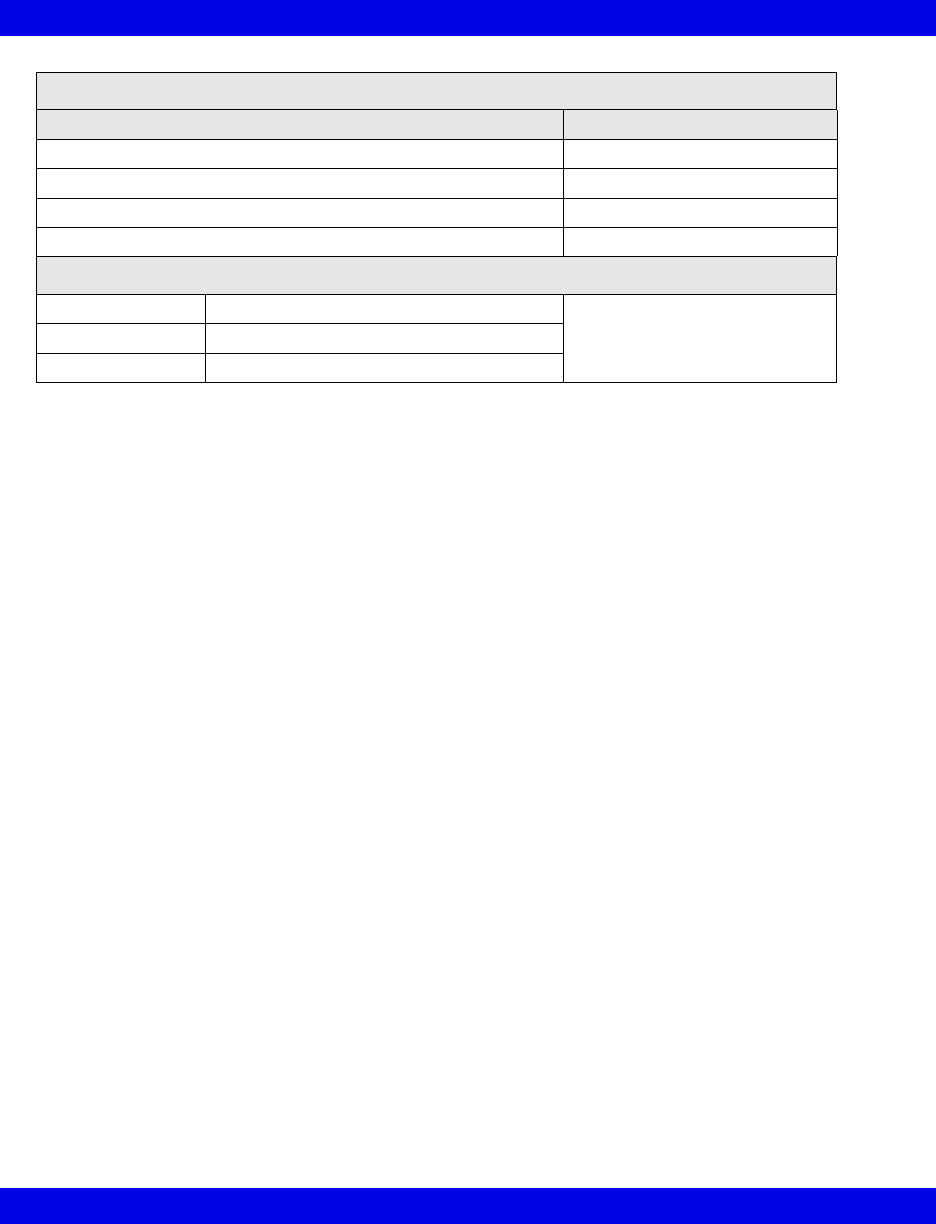
17-54 Infinity CentralStation VF8
17: VentCentral Option
Ventilation Mode Display
Ventilation Mode at Device Mode at Infinity CentralStation
Assist Control Assist Control
Pressure Control PCV
SIMV/CPAP/PSV SIMV/CPAP/PSV
PC-SIMV/CPAP/PSV PC-SIMV/CPAP/PSV
Waveforms
Paw Airway Pressure Ventilator Screen
(page 17-5)
Flow Flow (Insp/exp)
Loops Ventilator loops
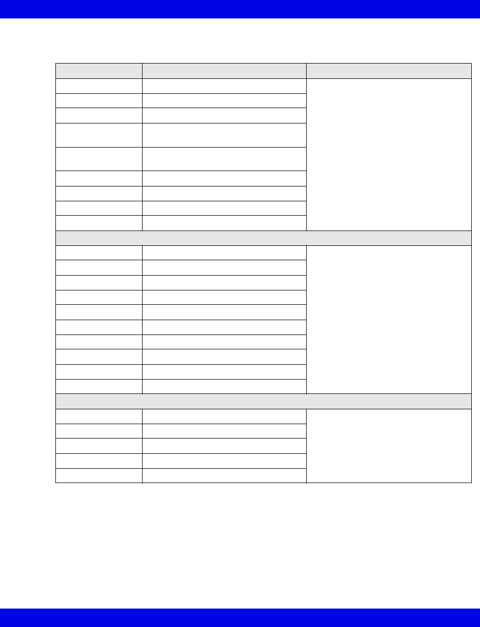
Ventilator and Device Messages/Labels
Infinity CentralStation 17-55 VF8
Viasys BearCub 750 Infant Ventilator
Alarm Messages Description Displayed in...
Paw > HI LIM Paw exceeds upper alarm limit Main Screen - in the lower right hand
corner of the top waveform channel
Bed View - in the information area right
below the menu buttons
Paw < LO LIM Paw is below lower limit
GAS SUPPLY? Gas supply alarm
RR > HI LIM Respiratory rate exceeds upper alarm
limit
PEEP < LO LIM Peak End Expiratory Pressure is below
lower limit
MVe < LO LIM Minute volume is below lower limit
APNEA Apnea
Battery Low battery supply
Cycle Failed Fail to cycle
Parameters
PIP Peak inspired airway pressure Ventilator Settings screen (page 17-8)
PEEP Peak End Expiratory Pressure
Te Expiratory time
TVe Tidal volume, expired
Ti Inspiratory time
MVe Minute volume, expired
RRv Respiratory rate
TVi Tidal volume, inspired
MAP Mean Airway Pressure
O2 Supply Prsr O2 Supply pressure
Settings
Ti set Inspiratory time Ventilator Settings screen (page 17-8)
Freq set Breath rate
Vlimit Volume limit setting
FLOW Trig set Flow trigger setting
iFLOW set Inspiratory flow setting
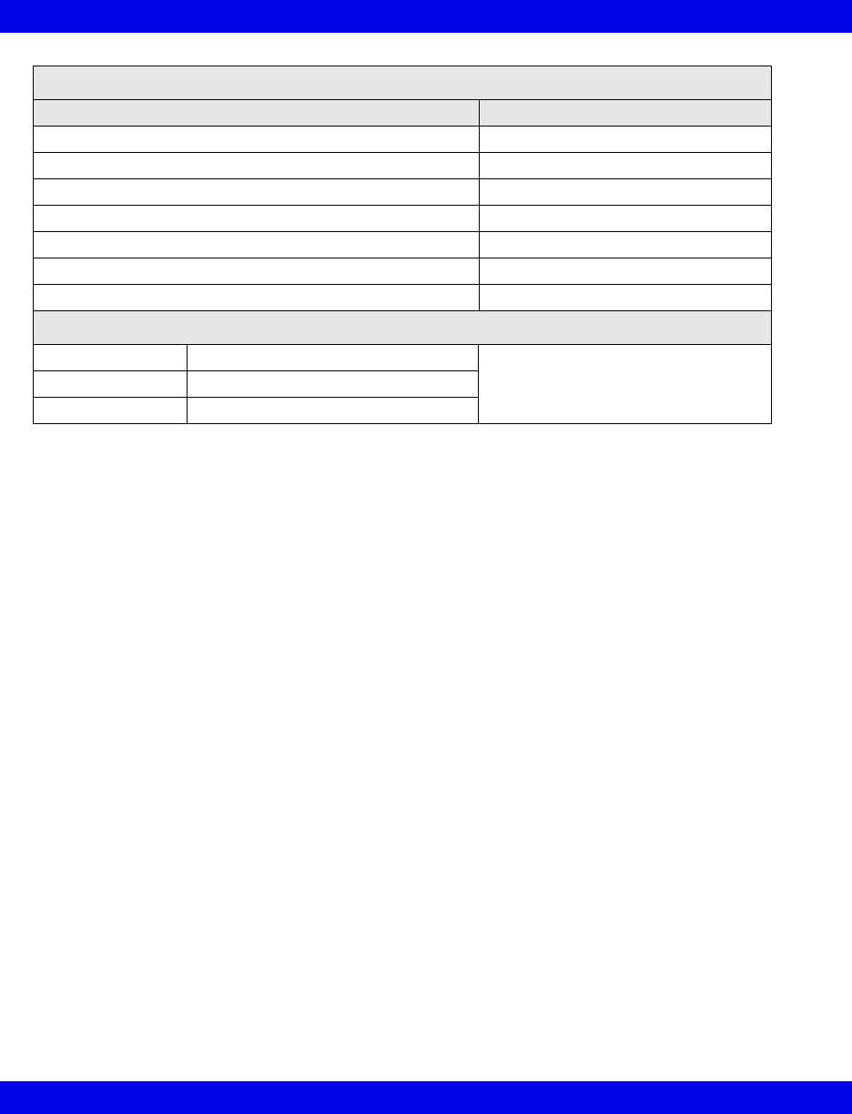
17-56 Infinity CentralStation VF8
17: VentCentral Option
Ventilation Mode Display
Ventilation Mode at Device Mode at Infinity CentralStation
Assist Control Asst Ctrl
PSV PSV
SIMV/IMV SIMV/IMV
CPAP CPAP
SIMV/PSV SIMV/PSV
SIMV (Flow Cycled) SIMV-Flow Cycle
Flow Cycled A/C Asst Ctrl-Flow Cycle
Waveforms
Paw Airway Pressure Ventilator Screen
(page 17-5)
Flow Flow (Insp/exp)
Loops Ventilator loops
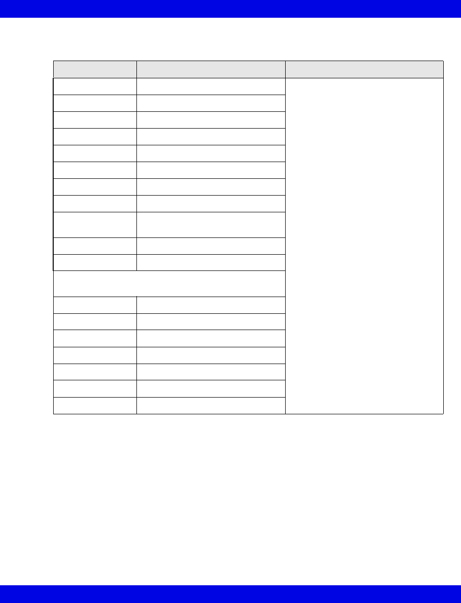
Ventilator and Device Messages/Labels
Infinity CentralStation 17-57 VF8
Baxter Vigilance/Vigilance II Cardiac Output Monitor
Parameters Description Displayed in...
BT Blood Temperature Ventilator Settings screen (page 17-8)
CCO Continuous Cardiac Output
CCI Continuous Cardiac Output Index
ICO Intermittent Cardiac Output
ICI Intermittent Cardiac Output Index
SaO2 Arterial Oxygen Saturation
SvO2 Venous Oxygen Saturation
SVR Systemic Vascular Resistance
SVRI Systemic Vascular Resistance
Index
VO2 O2 Consumption
DO2 O2 Delivery
The following parameters are available from the Baxter
Vigilance II only.
SV Stroke Volume
SVI Stroke Volume Index
EDV End Diastolic Volume
EDVI End Diastolic Volume Index
ESV End Systolic Volume
ESVI End Systolic Volume Index
EF Ejection Fraction
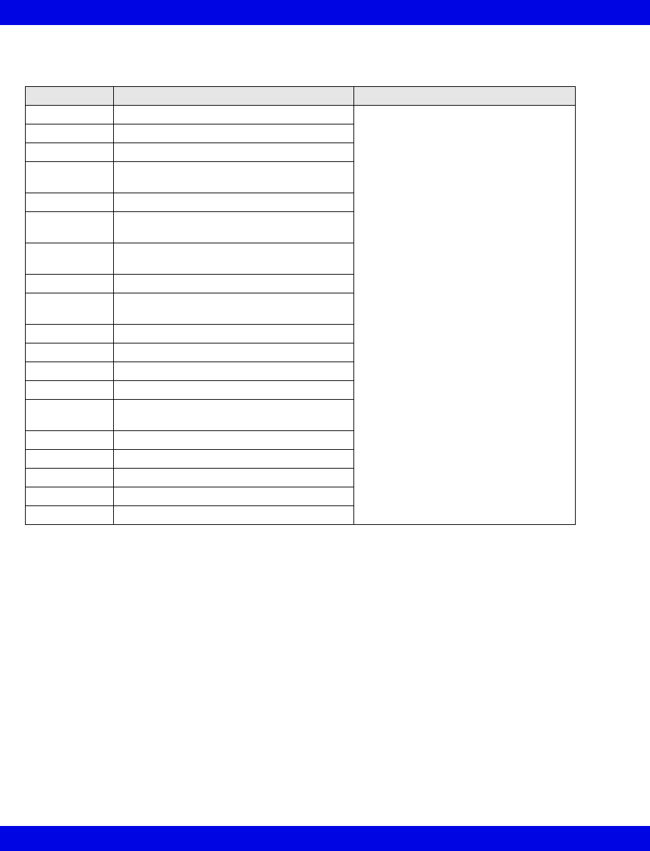
17-58 Infinity CentralStation VF8
17: VentCentral Option
etCO2/Respiratory Mechanics Pod
Parameters Description Displayed in...
PIP Peak inspired pressure Ventilator Settings screen (page 17-8)
PEEP Peak end expiratory pressure
MAP Mean arterial pressure
TVi s Inspired tidal volume,
spontaneous
TVi m Inspired tidal volume, mechanical
TVe s Expiratory tidal volume,
spontaneous
TVe m Expiratory tidal volume,
mechanical
TVd aw Dead space, airway
MVe s/m Expiratory minute volume spontaneous/
mechanical
MVe Expiratory minute volume
RR s/m Respiratory rate, spontaneous/mechanical
RRv Respiratory rate
Cdyn Dynamic compliance
C20/Cdyn Dynamic compliance of the last 20%
breath
Raw e Dynamic resistance
PEF Peak Expiratory Flow
TValv Alveolar tidal volume
MValv s/m Minute volume
VCO2 CO2 production, minute volume

18 Biomed Functions
Biomed Screen Selections..........................................................................................18-2
Accessing the Biomed Screens...........................................................................18-2
Show Devices Screen..................................................................................................18-3
Configure Central Screen ...........................................................................................18-3
To edit Event Class:..............................................................................................18-5
To modify Configure Central selections:............................................................18-5
Configure Locked Options Screen.............................................................................18-6
Enabling Available Options..................................................................................18-6
Raid Option ..................................................................................................................18-6
System Console...........................................................................................................18-6
Rest ECG Reports........................................................................................................18-7
Available Report Formats.....................................................................................18-7
Viewing Logs................................................................................................................18-9
Copying Logs to Disk .........................................................................................18-10
Telemetry System Set Up..........................................................................................18-11
Infinity M300 Set Up ............................................................................................18-11
Infinity Telemetry Set Up ....................................................................................18-13
Radio Frequency Diagnostics .................................................................................18-16
Available Information on the RF Diagnostics Screen......................................18-16
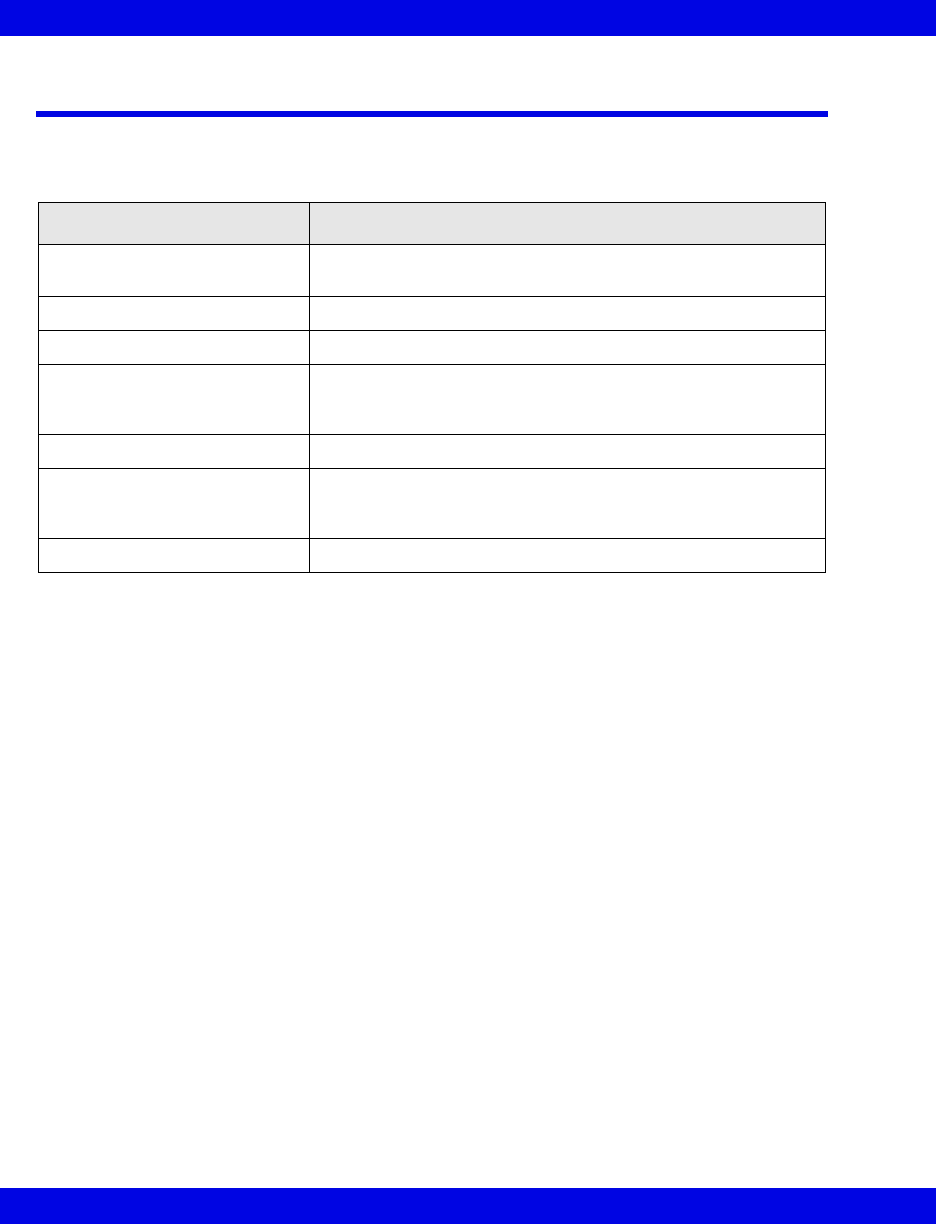
18-2 Infinity CentralStation VF8
18: Biomed Functions
Biomed Screen Selections
The Biomed functions are password-protected and intended only for the hospital’s
biomedical personnel or Dräger service representatives.
Accessing the Biomed Screens
1. Click on Biomed in the Main Screen menu bar.
2. Click on the desired menu selection.
The password popup window displays.
3. Enter the Biomed password in the password popup.
4. Click on Accept in the password popup.
Selection Description
Show Devices... Allows your Biomed to view the status of network devices
within the monitoring unit of the Infinity CentralStation
Configure Central... Provides access to setup features
Configure Locked Options... Allows your Biomed to enable available options
System Console... Activates a window from where you can perform remote
diagnostics, shut down the Infinity CentralStation, select Rest
ECG report formats, etc.
Diagnostic Log Displays log of 1000 hardware and software error conditions
Clinical Events Log Displays log of 1000 clinically significant events, such as alarm
detection, Alarm Silence requests, recording status, and
remote control of bedside monitors.
Configure Telemetry... Accesses Telemetry set up functions (page 18-11)
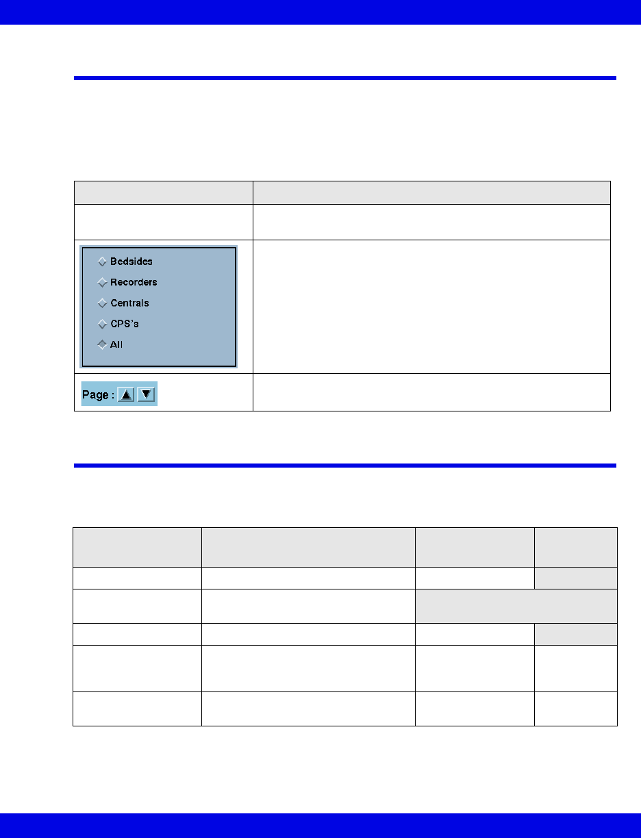
Show Devices Screen
VF8 Infinity CentralStation 18-3
Show Devices Screen
The Biomed - Show Devices screen lists status information for all network
devices assigned to the monitoring unit of the specific Infinity CentralStation. To open
the Biomed - Show Devices screen see page 18-2.
Configure Central Screen
Biomed - Configure Central Screen Selections
Selection Description
Show Central Status Opens a popup with status information for the Infinity
CentralStation
Radio buttons for listing device-specific information
Scrolls pages of information
Selection Description Available Settings Factory
Default
Hospital Name Defines hospital name 25 character max.
Language Displays the language that was set
during installation
Biomed Password Sets or modifies Biomed password 8 character max.
Clinical
Password
ON/OFF
Enables/disables clinical password ON / OFF ON
Clinical
Password
Sets or modifies clinical password 8 character max. MVWS
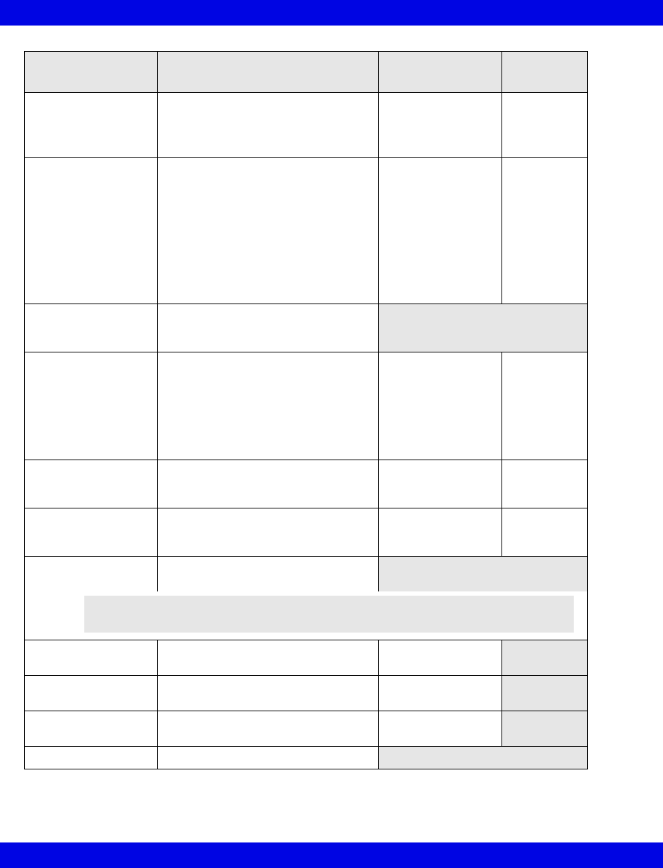
18-4 Infinity CentralStation VF8
18: Biomed Functions
Central Layouts
Password
Enables/disables password protec-
tion
If enabled, screen is password pro-
tected.
ON / OFF OFF
Printer Connected Sets printer connection •OFF
•Network
(Central station is
connected to a
network printer.)
•Local
(Printer is
connected directly
to the Infinity
CentralStation.)
OFF
Network Printer
Address
Displays network printer IP address
configured during installation (for
viewing only)
Cabrera Permits activation/deactivation of the
hex axial lead configuration
When you turn Cabrera on, the leads
are displayed in the hex axial display
format.
If you turn Cabrera off, the leads
appear in standard mode.
ON/OFF OFF
Event Class Editor Permits editing of user-selectable
event classification labels
(page 18-5)
Edit / Hide Hide
Patient
Confidentiality
Determines whether a patient’s name
appears on Infinity CentralStation
displayed screens
ON / OFF OFF
Restore Default
Settings
Restores system default settings
Hospital Label Identifies the hospital label for the
network
7 character max
Monitoring Unit
Label
Identifies the monitoring unit to which
the Infinity CentralStation is assigned
7 character max
Care Unit Label Identifies the care unit to which the
Infinity CentralStation is assigned
7 character max
Host Label View only
Selection Description Available Settings Factory
Default
NOTE: Whenever you restore defaults the Infinity CentralStation must be
restarted. An entry is made to the clinical events log.
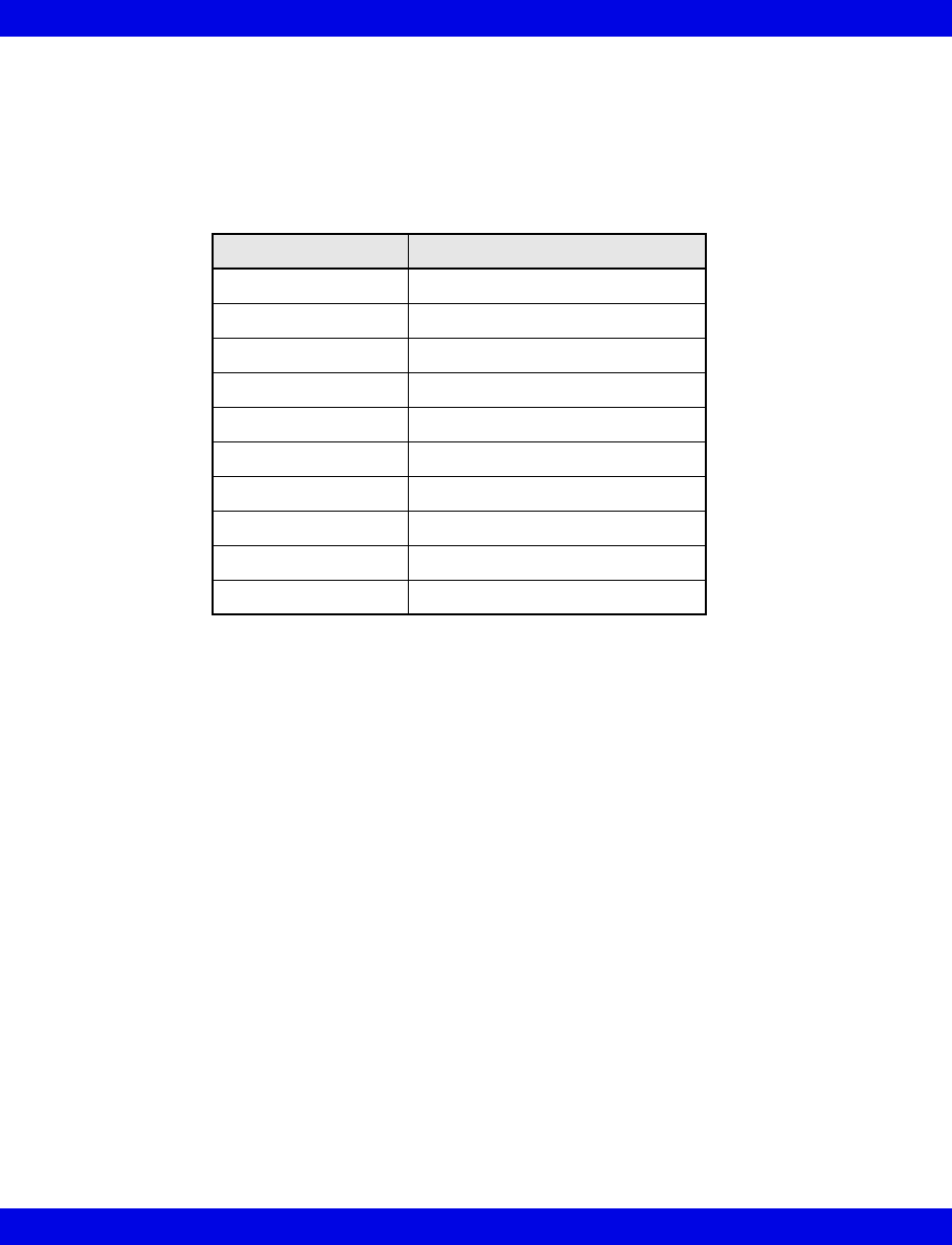
Configure Central Screen
VF8 Infinity CentralStation 18-5
To edit Event Class:
1. Open the Biomed - Configure Central screen (page 18-2).
2. Click on the toggle button next to Event Class Editor so that it displays Edit.
A popup displays with ten default labels.
3. After you make the desired changes, click on Accept to save changes or
Undo.
To modify Configure Central selections:
1. Open the Biomed - Configure Central screen (page 18-2).
2. Select a button or text entry box to set and click.
3. After entering information and modifying settings click on Accept to save
changes or Undo.
Class Name Class Description
AFIB Atrial Fibrillation
ATAC Atrial Tachycardia
BBB Bundle branch block
PNC Pacer not captured
PNP Pacer not pacing
TRIG Trigeminy
MTI Multifocal PVC
RONT R-on-T
IRR Irregular HR
NVTA Non-sustained VTAC

18-6 Infinity CentralStation VF8
18: Biomed Functions
Configure Locked Options Screen
This screen lists software that must be purchased separately and can only be enabled
with a unique password for each Infinity CentralStation. For a list of available
software options, contact your local Dräger representative.
Enabling Available Options
1. Open the Configure Locked Options screen (page 18-2).
2. Click on one of the available menu choices.
3. Enter the password for the option you wish to enable.
4. Click on Accept.
After an option is enabled, a popup displays the message:
The Infinity CentralStation must be restarted to allow the locked options to
take effect.
5. Restart the Infinity CentralStation.
Whenever you lock or enable an option, a message is stored in the clinical events log.
Raid Option
With the Infinity CentralStation RAID Option, RAID 1 mirroring provides disclosure
disk redundancy by writing all full/event disclosure data to two identical hard drives.
With this option configured, all disclosure disk data is written to a second, identical
hard drive in the background.
System Console
This Biomed menu selection activates a console window with a prompt from which
you can:
zRun remote diagnostics for all network devices,
zShut down or restart the Infinity CentralStation,
zReview an alarm history log for telemetry patient channels consisting of the
last 5000 events (with time and date of the alarm occurrences), and
zSelect Rest ECG report formats
To open the System Console see page 18-2.
CAUTION: In the event of a RAID (Redundant Array of Independent Disks) failure, no
tone sounds, and no message appears. However, an LED on the hard drive that failed
will light.
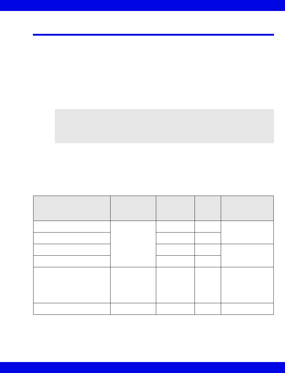
Rest ECG Reports
VF8 Infinity CentralStation 18-7
Rest ECG Reports
Rest ECG reports are available in several formats which you can customize. As soon
as the data arrives from the bedside monitor, the Infinity CentralStation analyzes it and
generates a printed report.
Whenever the Infinity CentralStation issues a report successfully, an entry is made in
the clinical events log. If a report cannot be processed successfully, an entry is made in
the diagnostic log (page 18-9). If multiple printing requests exist, the Rest ECG report
is queued until the assigned printer becomes available.
Available Report Formats
The format of a Rest ECG report determines the layout and the type of information
included in the report. For more detailed information on generating ECG reports,
please refer to the bedside monitor documentation.
WARNING: Diagnosis based on interpretation of 12-lead
monitoring results should only be done by qualified
personnel. Prior to final interpretation and diagnosis,
qualified physicians should review suggested diagnostic
statements and all other available information
Report Type Resolution
Diagnostic
Statements
Y/N
# of
Pages Orientation
6x2 waves, 2.5 s 50 mm/s Y 1 Landscape
6x2 waves, 2.5 s N 1
6x2 waves, 2.5 s Y 2 Landscape,
cabrera
6x2 waves, 2.5 s N 1
Complexes and 3 waves
(V1, II, V5) 7 s
Complexes:
50mm/s
Waveforms:
25mm/s
Y 1 Portrait, standard
12 waveforms, each 5 s 50 mm/s N 2 Cabrera
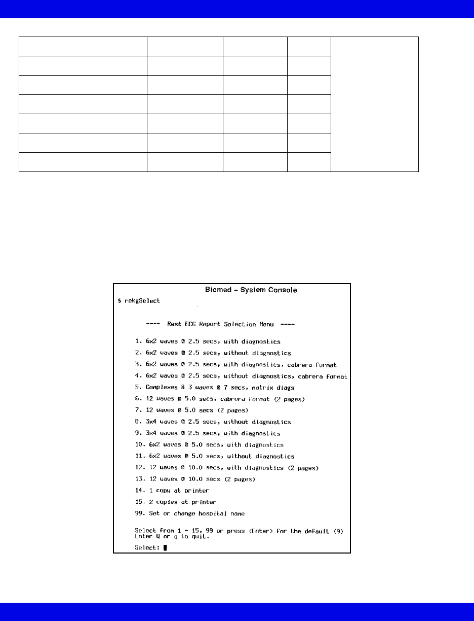
18-8 Infinity CentralStation VF8
18: Biomed Functions
Accessing the Rest ECG Report Selection Menu
1. Open the System Console (page 18-2).
2. At the system prompt type the following:
rekgSelect
A selection list appears.
12 waveforms, each 5 s 50 mm/s N 2 Landscape
12 waveforms, each 10s 50 mm/s Y 1
12 waveforms, each 10s 50 mm/s N 2
3x4 waveforms, each 2.5 s 25 mm/s N 1
3x4 waveforms, each 2.5 s 25 mm/s Y 2
6x2 waveforms, each 5 s 25 mm/s Y 1
6x2 waveforms, each 5 s 25 mm/s N 1

Viewing Logs
VF8 Infinity CentralStation 18-9
3. Enter the number before the format or function you wish to select (1 - 15, 99)
or press <Enter> for the default (9).
If you want to change hospital name you must type the new information after
making your selection, then press <Enter> on the keyboard.
Viewing Logs
The password-protected diagnostic and clinical events logs support recording
hardware and software conditions and clinical events. The Diagnostic log contains a
record of up to 1000 hardware and software events and are helpful in determining
system status. The Clinical Events log contains information on up to 1000 events of
clinical significance.
Typical clinical events log entries may include:
zTransitions in/out of local alarm silence
zInfinity CentralStation Alarm State Change (e.g., Audible Alarm
Annunciation Change from active to silenced or vice versa)
zAlarm Limit Change from the Infinity CentralStation
zArrhythmia Setup Change from the Infinity CentralStation
zBedside State Change (e.g., on-line, off-line)
zCPS/IDS State Change (e.g., on-line, off-line, duplicate IP address detected)
zMain Screen Layout Change
zEdits of Patient Demographics
zAlarm Volume Change
zClinical Password Modification
zLanguage Change
zRestoration of Factory Default Settings
zRecording Status (other than cancellation of continuous or timed recordings)
zRecorder State Change (e.g., Recorder off-line, Recorder Failure, CPS/IDS
Off-line)
zTime and Date Change
zLocked Options Change
zA request for SPO2 with no additional SPO2 licenses available
zInfinity CentralStation detection of incompatible Infinity M300 software

18-10 Infinity CentralStation VF8
18: Biomed Functions
Log entries appear as separate lines and are displayed in chronological order with the
most recent entry at the top. Each entry includes date, time, event class, event code,
and event description.
To open the Diagnostic or Clinical Events logs, see page 18-2.
Copying Logs to Disk
1. Insert a 3.5” high-density disk into the disk drive of the Infinity
CentralStation.
2. Access the log you wish to copy (page 18-9).
3. Click on Copy Logs To Disk. The Infinity CentralStation formats the disk
automatically.
Logs are copied as individual files. During the copying process, the Infinity
CentralStation is fully operational. However, the Copy Logs To Disk button
remains ghosted until the process completes. If the operation fails, a status message
displays and an advisory tone sounds.
NOTE:
zYou do not need to format the disk before copying logs.
zBoth the Diagnostic and Clinical Events logs are copied during a copy request.

Telemetry System Set Up
VF8 Infinity CentralStation 18-11
Telemetry System Set Up
The following Biomed setup functions pertain exclusively to the Infinity M300.
Before you can access these functions, the Infinity M300 option must be enabled
(page 18-6).
Infinity M300 Set Up
Accessing the Infinity M300 Telemetry Setup Screens
1. Click on Biomed in the Main Screen menu bar.
2. Click on Configure Telemetry....
3. Click on Telemetry Devices or M300 Setup.
4. Enter the Biomed password in the password popup.
5. Click on Accept in the popup.
The selected screen displays.
You must use the Biomed password to access these screens (See Installation
Instructions, included with this Instructions for Use in product packaging).
Infinity M300 Devices Screen
The Telemetry Devices screen permits the Biomed to configure up to 300 devices
to use with the Infinity CentralStation.
1. Open the Telemetry Devices screen.
2. Click on the New Device button.
3. For each available device, enter the IP address in a row of the table.
4. Assign a unique Telemetry ID (4 character maximum).
5. Repeat steps 2 and 3 for each device.
6. When you have added all the devices, click on the Accept.
Once you assign the Telemetry IDs, those devices are available for selection from the
Telemetry ID section of the Admit screen (page 9-3).

18-12 Infinity CentralStation VF8
18: Biomed Functions
Biomed - Infinity M300 Setup Screen
NOTE: You can only configure the Infinity M300 Alarm Paused key, STAFF ALERT
key, Record key, and speaker for an individual patient (page 18-15) if Per Patient is
selected during setup.
Selection Description Settings Default
Alarm Paused Determines how the Infinity M300 Alarm
Paused key can be used
If you want to be able to individually set this
function for each patient, you must select Per
Patient (page 18-15).
If you select All Off Alarm Paused key will
be disabled for all Infinity M300 devices in the
system.
• All On
• All Off
•Per Patient
All Off
Record Determines how the Infinity M300 Record
key can be used
If you want to be able to individually set this
function for each patient, you must select Per
Patient (page 18-15).
If you want to generate manual timed
recordings when you press the Infinity M300
Record key, you must select All Record or All
Record/Store.
• All Record
• All Off
• All Record/Store
•All Store
•Per Patient
All
Record
Staff Alert Determines how the Infinity M300 STAFF
ALERT key can be used
If you want to be able to individually set this
function for each patient, you must select Per
Patient (page 18-15).
If you want to generate a STAFF ALERT
alarm at the Infinity Central Station when you
press the Infinity M300 STAFF ALERT key,
you must select All On.
• All On
• All Off
•Per Patient
All On
Speaker
WARNING: The
Infinity M300
speaker is intended
for use only in the
patient vicinity. It is
not intended for
primary alarm
annunciation. Use
the Infinity
CentralStation
speaker for primary
alarm annunciation.
Determines if the Infinity M300 speaker can
be enabled
NOTE:
• If set to ALL OFF, Infinity M300 will not present
the Volume screen and Volume will be forced to
OFF.
• Unless you select Per Patient, you cannot
individually set this function for each patient
(page 18-15).
• All On
• All Off
•Per Patient
All Off
M300 Volume Determines volume of Infinity M300 audible
alarm
•OFF
• 10 - 100 %
OFF
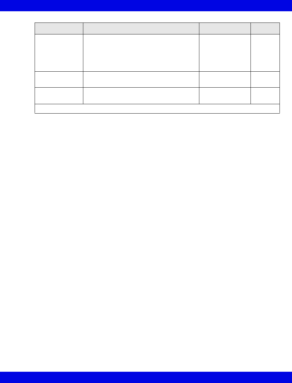
Telemetry System Set Up
VF8 Infinity CentralStation 18-13
Infinity Telemetry Set Up
Accessing the Infinity Telemetry Setup Screens
1. Click on Biomed in the Main Screen menu bar.
2. Click on Configure Telemetry...
3. Click on one of the following:
Receiver Setup...
Transmitter Setup...
RF Diagnostics...
4. Enter the Biomed password in the password popup.
5. Click on Accept in the popup.
Once you access a Telemetry Setup screen with the Biomed password, you can open
all other Telemetry Setup screens without having to re-enter the Biomed password.
Display Shut Off
Timer
Determines how long the Infinity M300
display remains on with no user activity
•1 min
•2 min
•3 min
•4 min
•5 min
1 min
ECG Notch
Filter
Assigns Infinity M300 ECG Notch filter setting • 50 Hz
• 60 Hz
60 Hz
Régulation Sets French Homologation mode • Par défaut
•France
Par
défaut
• Click on Accept or on Undo to return to previous settings.
Selection Description Settings Default
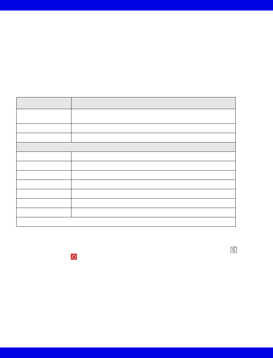
18-14 Infinity CentralStation VF8
18: Biomed Functions
Infinity Telemetry Receiver Setup
The Receiver Setup screen is further protected by a special password, which is only
accessible to authorized service personnel. For detailed information on the various
setup functions of this screen, please consult the accompanying service
documentation.
To open the Receiver Setup screen see page 18-11.
Configuring the Transmitter Buttons
In the Transmitter Setup screen, you can configure the transmitter Recording
and the Staff Alert buttons. These settings determine whether or not a recording or
a staff alert can be initiated from the transmitter.
1. Open the Transmitter Setup screen (page 18-12).
The top of the screen contains the Transmitter Record and Transmitter
Staff Alert buttons.
Receiver Setup Screen Selections
Selection Description
Country Permits selection of country from option list (Password protected.
Contact Dräger Service)
ECG Notch Filter Displays list of possible ECG Notch Filter selections
Regulation Permits selection of possible Regulation configurations
Receiver Details
S/W Version Displays Infinity CentralStation software version
ID Label Displays receiver identification name assigned at installation
Ethernet Address Displays telemetry receiver IP address configured during installation
Antenna System Displays Antenna System type
Channel Spacing Permits channel selections for selected country
Receiver Type Permits selection of UHF or VHF
Frequency Range Graphic display of Channel Spacing range
• Click on Accept to save changes or Undo to keep original settings.
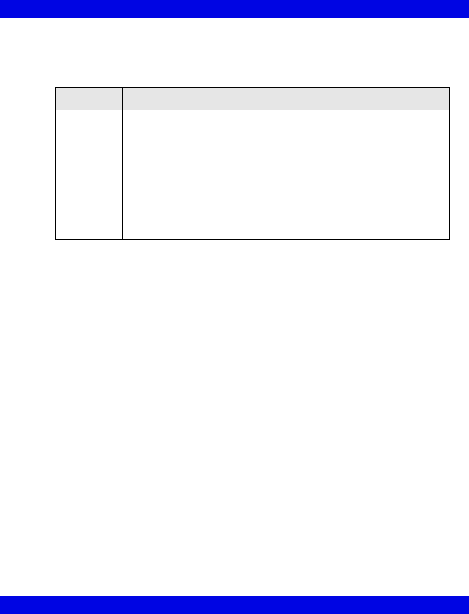
Telemetry System Set Up
VF8 Infinity CentralStation 18-15
2. Click on the Transmitter Record or Transmitter Staff Alert button and
scroll to a setting:
3. Click on Accept to save the setting or Undo button to keep the previous
setting.
Transmitter Record and Staff Alert Button Selections
Setting Description
All On This selection activates the transmitter Staff Alert and Recording buttons for
all telemetry channels. A timed recording is initiated if you press the recording
button, and if you press the staff alert button, a serious alarm is generated at
the Infinity CentralStation. Also, an alarm message appears in the patient’s
corresponding Main Screen and Bed View waveform areas.
All Off The transmitter staff alert button and recording button are deactivated for all
telemetry channels. You cannot generate any recordings or staff alert calls from
any transmitter.
Per Patient This setting allows you the greatest flexibility because the transmitter buttons
can be enabled or disabled for each patient individually in the Transmitter
Setup menu (page 3-5)
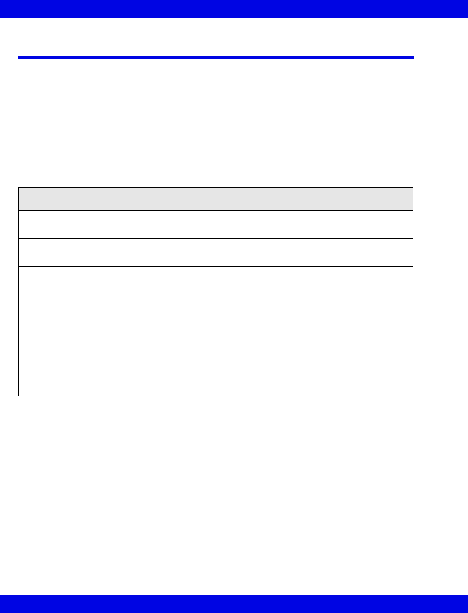
18-16 Infinity CentralStation VF8
18: Biomed Functions
Radio Frequency Diagnostics
To open the RF Diagnostics screen see “Infinity Telemetry Set Up” on page 18-13.
Available Information on the RF Diagnostics Screen
The RF Diagnostics screen displays the frequency and I.D. for active Infinity
Telemetry patients that currently have a transmitter assigned to the receiver channel.
The screen also provides the information outlined in the following table. This
information is updated every minute even as you are viewing it. Please consult the
Service documentation for further information.
Information Description Possible Values
Channel Lists the channels of the receiver reported by the
receiver subsystem
1 to 4; 1 to 8; 1 to
12; 1 to 16; blank
Frequency Lists the center operating frequencies (MgHz) of
the receiver’s channels.
abc.defg; blank
I.D. Lists the transmitter ID number for each channel
as reported by the receiver subsystem. A blank
means that no ID is reported (the transmitter
signal is not being received).
1 to 255; blank
RSSI-dBm Receiver’s signal strength indicator for each
channel (averaged over 1 minute)
0 to -125 dBm; blank
1 min,
5 min,
10 min,
1 Hour,
24 Hours
Percentage of good ECG signal samples received
over the specified interval
0 to 100%

A: Patient Preparation
This appendix provides information about patient preparation and electrode placement
for telemetry monitoring.
General .......................................................................................................................... A-2
ECG Electrode Placement............................................................................................ A-3
Lead Wire Color Codes.......................................................................................... A-4
Attaching the Pulse Oximeter...................................................................................... A-4

A-2 Infinity CentralStation VF8
A:
General
Careful skin preparation and proper electrode placement ensure strong signals with
minimal artifact. In case of a technical alarm (e.g., a detached lead), re-prep the patient
according to the following recommendations.
Follow hospital protocol for preparing the patient’s skin. To ensure a good quality
signal, change electrodes every 24 to 48 hours (or in accordance with manufacturer’s
instructions). Electrodes may have to be changed more frequently under the following
conditions:
zECG signal degradation
zExcessive patient perspiration
zPatient skin irritation
A wide selection of reusable and single-use electrodes is available. Select the best
electrode for the monitoring situation. Dräger recommends Ag/AgCl single-use
electrodes. If you are using pre-gelled electrodes, verify that there is enough gel in the
electrode gel-filled area. Never use disposable electrodes after their expiration date or
when the gel has dried out.
Choose electrode sites in the configuration that will provide the best ECG based on
the patient’s underlying cardiac condition and the number of leads you wish to
monitor. (P- and T-wave amplitudes should be no more than one third of the QRS
amplitude.) Select flat, non-muscular sites to maximize electrode contact and
minimize muscle artifact. Avoid joints or bony protrusions. Consider the following
special conditions when selecting sites for electrode placement:
Surgery — Keep the electrodes as far from the surgical site as possible.
Burn Patients — Use sterile electrodes. Clean the equipment thoroughly.
Follow hospital infection control procedures.
WARNING! Place the Infinity M300 or Infinity Telemetry
device to reduce the possibility of:
- the device falling on or injuring patient.
- any accessory cables accidentally entangling
patient’s neck.
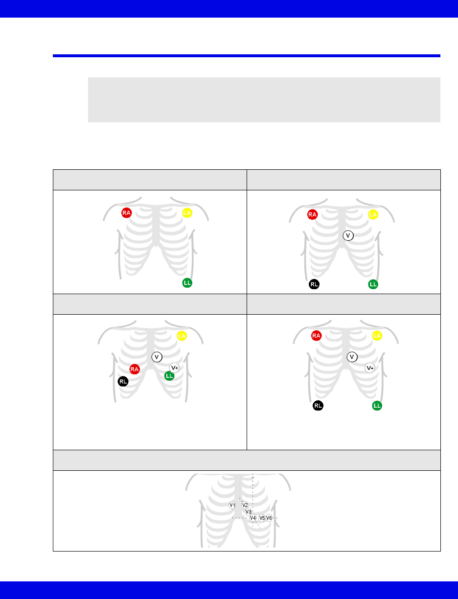
ECG Electrode Placement
VF8 Infinity CentralStation A-3
ECG Electrode Placement
The following illustrations show typical ECG electrode placement for 3-, 5-, and 6-
wire lead sets:
WARNING! When placing electrodes, ensure all connecting
wires are placed safely and cannot injure the patient. Serious
injury can occur if the electrode wires are allowed to encircle
the neck or extremities
3-Wire Standard 5-Wire Standard
Paced 6-Wire Standard
Chest Lead Standard
Select 2 chest lead positions
for V and V+ (page 8-14).
V+ is only used with 6-wire monitor-
ing.
Dräger recommends that you do
not use this modified placement for
TruST monitoring.
A-4 Infinity CentralStation VF8
A:
Lead Wire Color Codes
Lead wire color codes designated by the IEC and the AHA/AAMI appear in the table
that follows.:
Attaching the Pulse Oximeter
The accuracy of SpO2 monitoring depends largely on the strength and quality of the
SpO2 signal.
If a finger is used as a monitoring site, remove any nail polish. Cut the patient's finger
nails, if necessary, for better sensor placement. Use only approved sensors and apply
them per the sensor manufacturer’s recommendation (contact your local Dräger
representative for a list of approved sensors). Ambient light can interfere with pulse
oximetry measurements if the sensor is not properly attached, causing erratic
measurement or missing values. Ensure proper sensor placement and cover the sensor
with opaque material if interference due to ambient light is suspected.
1. Select the sensor type and size best suited for your patient.
2. If the sensor is reusable, clean it before and after each patient use.
3. Position the sensor correctly and attach it to your patient.
4. Connect the sensor to the patient cable.
5. Inspect the sensor application site frequently. If the sensor is too tight it may
damage the tissue and impede blood flow. If the sensor is damaged, do not use
it.
ECG Lead IEC AHA/AAMI (US)
LA Yellow Black
LL Green Red
RA Red White
RL Black Green
VWhiteBrown
V+ Gray and White Gray and Brown
CAUTION: Read the instructions provided with the sensor for optimal application
techniques and for safety information.

B: Technical Specifications
Technical Data .............................................................................................................. B-2
Infinity Telemetry Systems.................................................................................... B-7
Electromagnetic Compatibility .................................................................................. B-20
NOTE:
zSpecifications are subject to change.
zThe telemetry system complies with the Radio Equipment and
Telecommunications Terminal Equipment Directive (1999/5/EC).
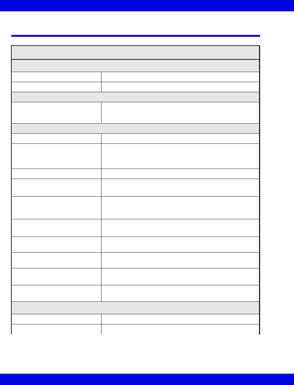
B-2 Infinity CentralStation VF8
B:
Technical Data
Infinity CentralStation
Display Specifications
Display Size 432 mm (17 in.), 533 mm (21 in.) diagonal, CRT or TFT
Resolution 1280 x 1024 pixels (native resolution)
User Controls
Input Device Controls PS/2-compatible keyboard and PS/2-compatible optical
mouse included in country-specific kit. Optional Dräger
Medical supplied touch screen is also supported.
Central Processing Unit (CPU)
Processor Intel® XeonTM Processor minimum 3.20 GHz
Storage • (1) minimum GB RAM, 1.44 Mb 3.5 in. floppy drive
• (1) DVD/CDRW
• (2) minimum 73 GB hard drives
Disk Array SCSI Raid 1 in locked drive bay (available with locked option)
Software Updates • 1.44 MB 3.5 inch floppy disk drive
• CD-ROM
Connections • 2 Asynchronous RS-232 serial ports
• 2 GB LAN connections
•4 USB ports
Network Connectivity • Infinity Network
• Infinity TruST Telemetry Network
Video Output Dual Head PCI 32M graphics board,
1280 x 1024 @ 75 Hz
Audio Output Internal speaker standard. Dräger Medical supplied external
speakers also required
Alarm Grades Life-threatening, Serious, Advisory
(Audible and visual indicators)
Number of patients supported
per CPU
• 16 patients with single display
• 32 patients with two displays
Electrical Specifications
Power consumption 115V / 230V 4.0A/2.0A
Power Output Up to 460W
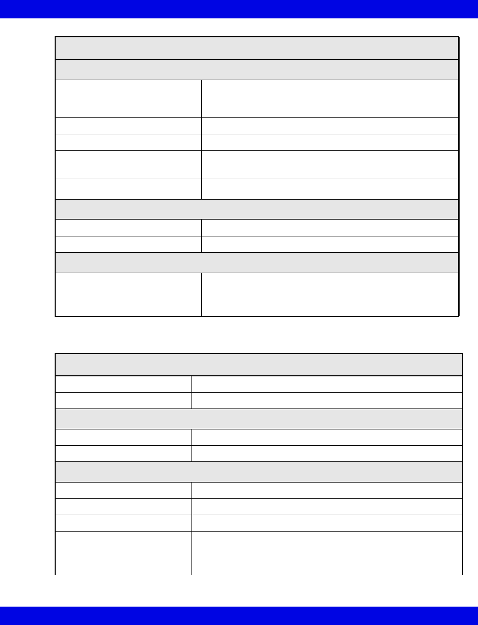
Technical Data
VF8 Infinity CentralStation B-3
Environmental Requirements
Cooling Passive heatsink moved across 1 - 120 mm fan
SCA drive array and power supply cooled by dedicated
80 mm fans
Operation Temperature 0 to 45oC (32 to 113oF)
Non-Operating Conditions -20 to 50oC (-4 to 122oF)
Altitude Operating: 3500 m (11000 feet)
Storage: 10600 m (35000 feet)
Acoustic Noise < 53 dBA
Physical Attributes
Size (H x W x D) 426.7 x 218.4 x 508.0 mm (16.8 x 8.6 x 20.0 in.)
Weight 22.5 kg (50 lbs.)
Regulatory Standards
Compliances UL/CSA/CE Certification as required per Original Equipment
Manufacturers (OEM). Infinity CentralStation is CE marked in
accordance with the requirements of the 93/42/EEC Medical
Device Directive.
Uninterruptible Power Supply (350VA, 120V, 220V)
Connections Infinity CentralStation, Infinity TruST Telemetry Receiver
Audio output < 45 dB at 1 m (3 ft.)
Physical Specifications
Size (H x W x D) 165 x 114 x 368 cm (6.5 x 4.5 x 14.5 in.)
Weight 11.3 kg (25 lbs.)
Electrical Specifications
Inverter Waveform Low distortion sine wave
Input voltage 115, 220, 230, 240 VAC ± 20% (nominal, user-selectable)
Input frequency 50/60 Hz ± 5%
Noise Rejection Isolation With unit under power and an ANSI/IEEE C62.41 Cat. A pulse
applied either normal or common mode at the input, the noise
output voltage will be <10 normal mode and < 0.5V common
mode in all 4 quadrants (CM-NM, NM-NM, CM-CM, NM-CM).
Infinity CentralStation(continued)
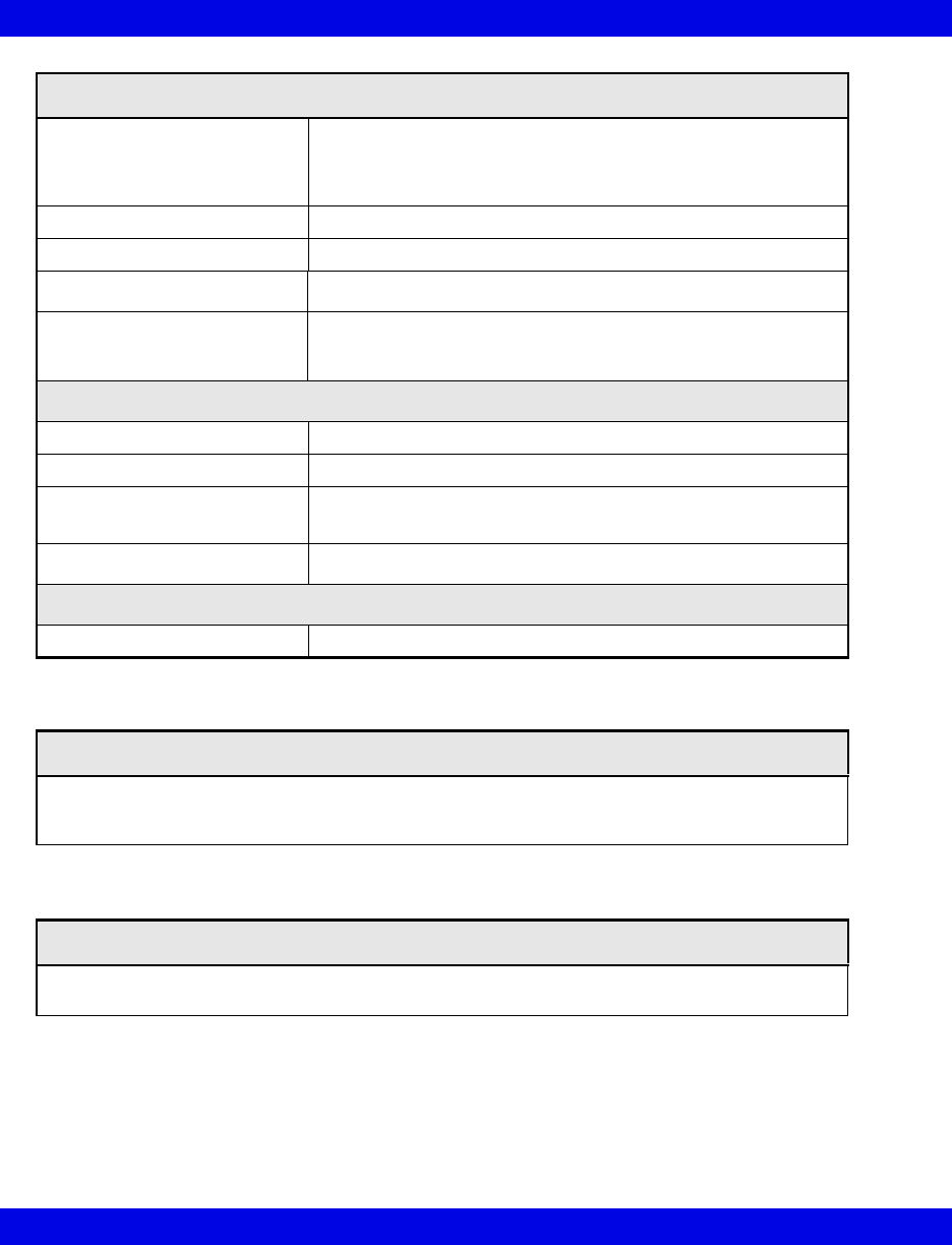
B-4 Infinity CentralStation VF8
B:
Surge Voltage Withstand
Capability
Tested under power to ANSI/IEEE C62.41 Cat. A & B (formerly
IEEE 587-1980). Cat. A 6000V @ 200 amps, 0.5 usec risetime,
100 kHz decay, Cat. B 6000V @ 500 amps, 0.5 usec risetime,
100 kHz decay.
Battery charging time 3 to 8 hours
Backup time 6 to 20 minutes (half/full loaded)
Internal batteries 2 -12 volt user hot-swap batteries, recharge time 4 hours
Indicators
LEDs for Load level, voltage manager boost, voltage manager
nominal, voltage manager buck, on battery, replace battery,
overload
Environmental Requirements
Operation Temperature 0 to 40oC (32 to 104oF)
Non-Operating Conditions -20 to 60oC (-4 to 140oF)
Altitude Operating: 3000 m (10000 feet)
Storage: 3000 m (10000 feet)
Wall Mountable Yes
Regulatory Standards
Compliances UL 1778, cUL 1778
Laser Printer
Black and white 1200x1200 dpi laser printers, 115V/220V sold separately. Contact Dräger Medical
to obtain list of supported laser printers.
Strip Recorder
Infinity R50N Network Strip Recorder provides two-channel strip recordings of automatically cap-
tured arrhythmia or alarm events or manually initiated recordings.
Uninterruptible Power Supply (350VA, 120V, 220V)(continued)
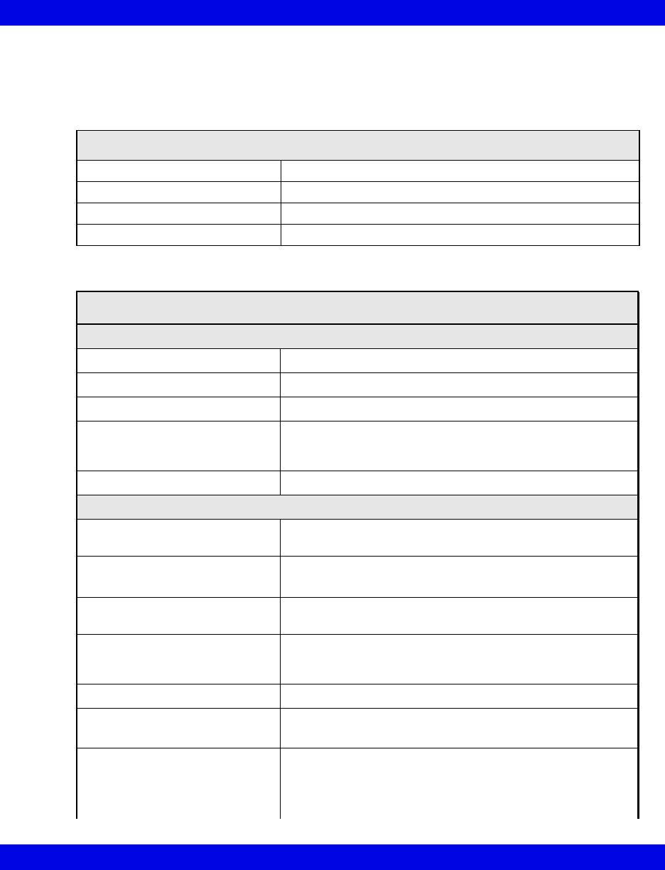
Technical Data
VF8 Infinity CentralStation B-5
Infinity Telemetry Systems
Infinity M300 System
Infinity M300 Programming Cable
Connections PC via 3m or optional 20m Serial cable
H x W X D 44.0 x 96.5 x 96.4 mm (1.7 x 3.8 x 3.8 in.)
Weight 450 g (1 lb.)
Method Directly to PC and to SpO2 connector of Infinity M300
Infinity M300
Physical Specifications
Size, H x W x D 139.7 x 76.2 x 30.4 mm (5.6 x 3 x 1.2 in)
Weight 276.4 g (9.75 oz) with battery
Cooling Convection
Disposal All materials must be disposed of or recycled properly and in
accordance with local regulations. There are no known
special disposal requirements for any accessories.
Connections ECG, SpO2, Programming Cable
Environmental Specifications
Atmospheric Pressure Operating: 647 to 1060 hPa
Storage: 500 to 1060 hPa
Temperature Operating: 0 to 40° C (32 to 104 °F)
Storage: -20 to 60° C (-4 to 140 °F)
Humidity (non condensing) Operating: 10% to 85%
Storage: 10% to 85%
Shock
IEC 60068-2-27
50 g half-sine waveform, 11 mS duration,
3 shocks in each +/- directions/axis, 18 total shocks,
3 mutually perpendicular axes
Frequency Response 0.5 - 40 Hz: ± 3 dB
Sinusoidal Vibration
IEC 68-2-6
5-10 Hz @ 0.098 DA, 100-500 Hz @ 2 G
10 sweep cycles/axis, 3 axes, 1 octave / minute
Random Vibration
IEC 60068-2-36
Reproducibility Medium
ASD 10 to 20 Hz: 0.05 g2 /Hz, -3dB/Octave
ASD 20 to 150 Hz: 0.05 g2 /Hz, -3dB/Octave
Duration: 30 min
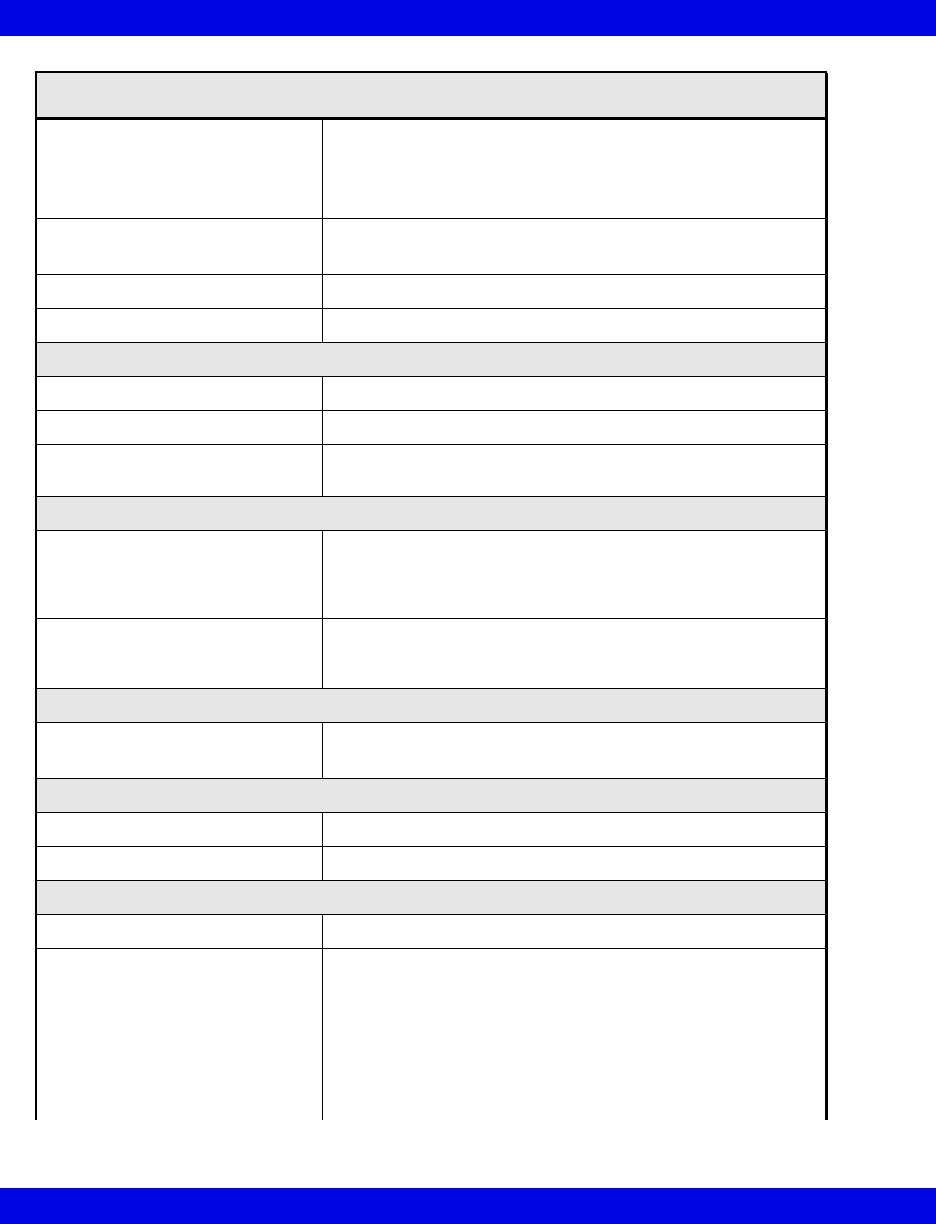
B-6 Infinity CentralStation VF8
B:
Bump
IEC60068-2-29
Peak acceleration: 15 g
Pulse duration: 6 ms
Number of bumps: 1000
Direction: Vertical (normal operating position)
Free Fall
IEC 60068-2-32, Procedure 1
Height of fall: 1 m
Number of falls: 1 on each of six surfaces
Drop Per IEC68-2-31, Packaged drop- 30"
Water Resistance Per EN 60529 rating IPX7
Electrical Characteristics
Power Source Rechargeable lithium ion battery
Mode of operation Continuous
Typical Battery Run Time
ECG only
18 hours
User Interface
User Interface 6 fixed keys: alarm pause, view screen, staff alert, record/
mark event, up/down screen scroll,
Audio annunciator,
LCD Display
Alarm Indicator LED Battery Charging Indicator,
Visual Alarm Banners on LCD,
Audible alarms via speaker
Display
Type Color Liquid Crystal Display (LCD)
Communications
Network Direct Sequence Spread Spectrum (802.11b)
Operating Frequencies ISM-2.4: 2400MHz to 2483.5MHz
Arrhythmia
Leads Analyzed Any user-selected, non-derived single lead or Lead II and V
Detected Events/Rhythms Asystole, Ventricular Fibrillation, Ventricular Tachycardia,
Sinus Bradycardia, Ventricular Run, Accelerated
Idioventricular Rhythm, Supraventricular Tachycardia,
Ventricular Couplet, Ventricular Bigeminy, Sinus Tachycardia,
Pause, Artifact, PVC/min
Infinity M300(continued)
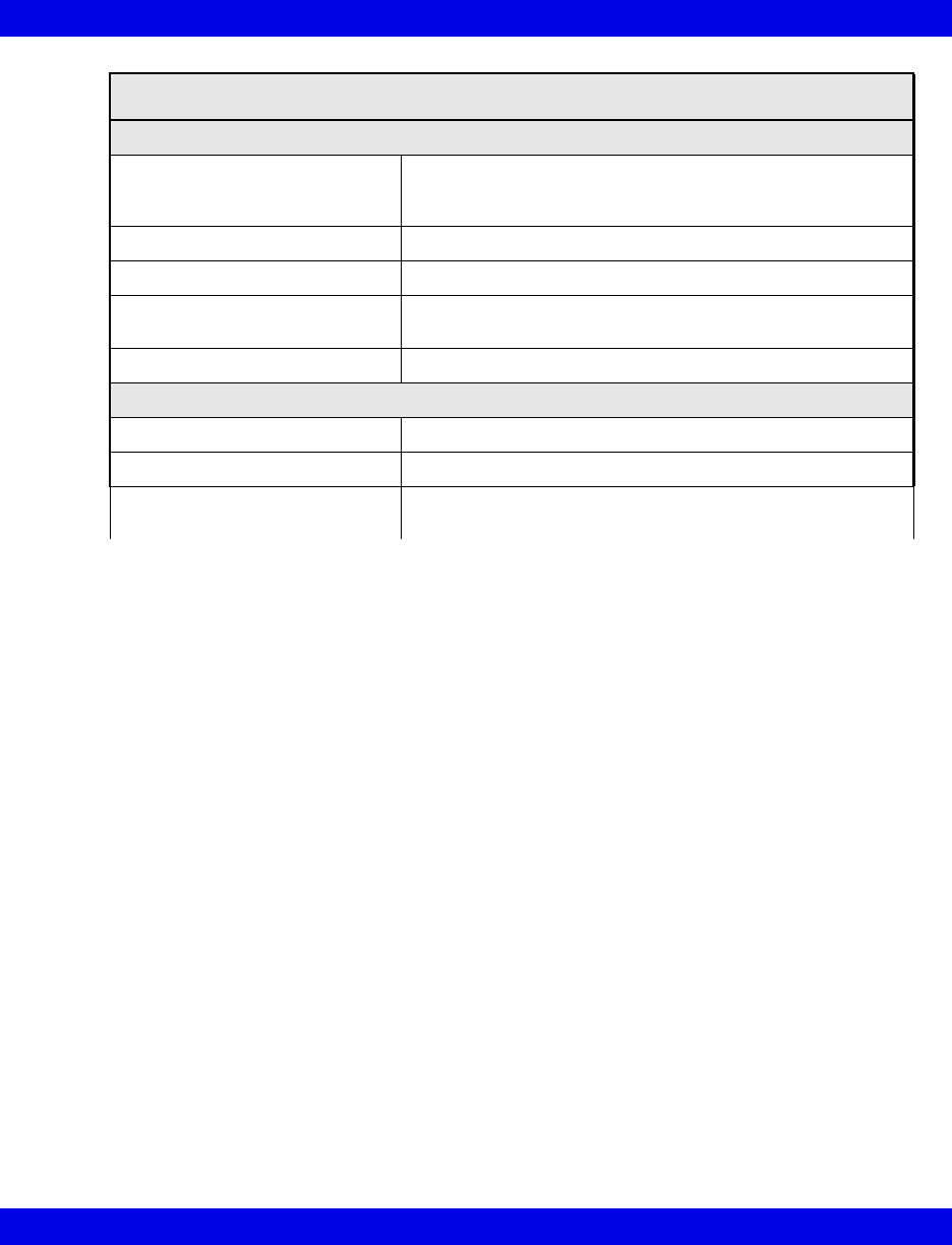
Technical Data
VF8 Infinity CentralStation B-7
ECG
Available leads-
Adult/Pediatric
I, II, III, aVL, aVR, aVF, V, V+V1, V2, V3, V4, V5, V6, dV1,
dV2, dV3, dV4, dV5, dV6 (dVx leads using TruST 12-lead
algorithm K030738)
Measurement Range 15 to 300 bpm
Accuracy ± 2 beats/minute or ± 1%, whichever is greater
Degree of protection against
electrical shock
Type CF
Defibrillation Protection </= 360 Joules
Event Storage
Automatic Alarm violation or arrhythmia trigger
Manual "Recording" key activation
Central Monitor WorkStation and
Input Controls
Draeger Medical Systems Infinity CentralStation
Keyboard, mouse, touchscreen
Infinity M300(continued)
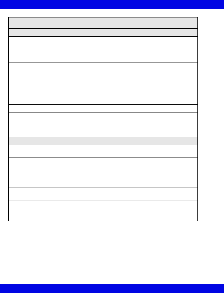
B-8 Infinity CentralStation VF8
B:
ST Segment Analysis (Adult/Pediatric)
Available Leads for display on
patient worn device
Choice of any ECG lead being monitored
Isoelectric Point Adjustment range: Start of QRS complex to fiducial point
Default: QRS onset - 28msec
ST Measurement Point Adjustment range: Fiducial point to end of QRS complex
Default: QRS offset + 80msec
ST Complex Length 900 msec (-300 to +600 msec from fiducial point)
Update Interval 15 secs ±1, 1 normal beat required
ST Level Alarm Adjustment
Range
-15.0 to 15.0 mm, -1.5 to 1.5 mV
ST Accuracy ±0.1 mm (±0.01 mV)
ST Measurement Range -15.0 to 15.0 mm, -1.5 to 1.5 mV
ST Measurement Resolution ±0.1 mm (±0.01 mV)
Sampling Rate for Averaged ECG 250 samples/s
Pulse Oximetry (optional)
Parameter Display Percentage of functional (oxygen-saturated) hemoglobin
Saturation (%SpO2), pulse rate
Measurement method Absorption-spectrophotometry
Measurement range SpO2: 1 - 100%
Pulse rate: 30-250 bpm
Calibration range 70-100%
Display range 1-100% (SpO2)
30-250 bpm (Pulse)
Display update period 2 seconds nominal
Maximum hold from previous
update
30 seconds (in the event of artifact or other error)
Infinity M300(continued)
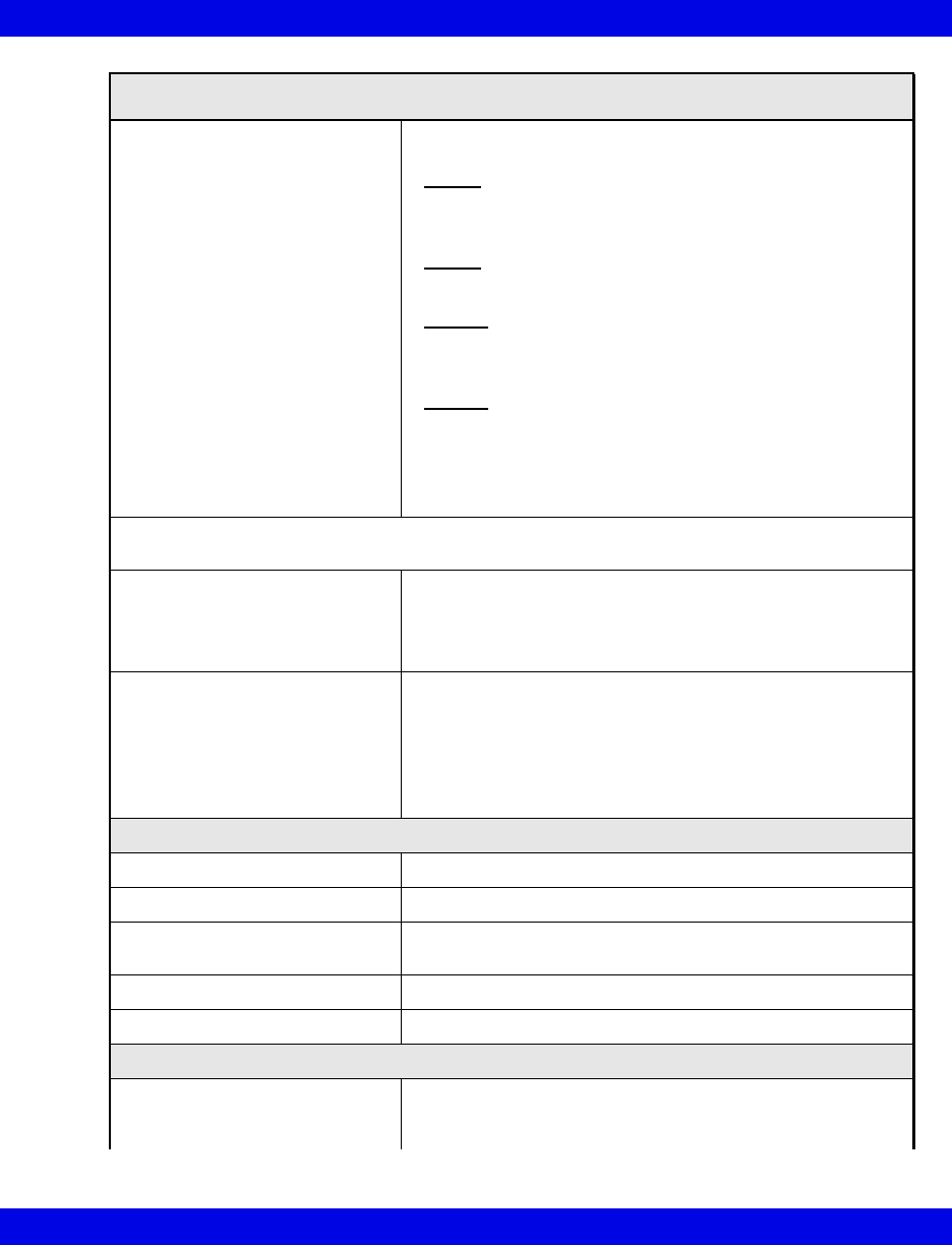
Technical Data
VF8 Infinity CentralStation B-9
Measurement accuracy, Adult and
pediatric Mode1:
SpO2: 0 to 69% not specified
70 to 100% sensor-specific as follows:
Nellcor:
D-25, D-20, I-20, N-25, MAX-A, MAX-AL, MAX-P, MAX-N,
MAX-I, MAX-R ±2
Nellcor:
DS100A ±3
Masimo:
LNOP ADLT, LNOP-YI ±2
Masimo:
LNOP-DCI, LNOP-DCIP, NR125 ±2
LNOP-EAR ±3.5
Pulse Rate: ±3 beats/min or ±3%
(whichever is greater)
1 SpO2 accuracies are expressed as ± "X" digits between indicated saturation levels. Accuracy of
the SpO2measurement is specified 1 SD (standard deviation).
Nominal wavelength: Nellcor: Red: 660 nm
IR: 910 nm
Masimo: Red: 660 nm
IR: 905 nm
Power: Nellcor: Red: 3 mW(max.)
IR: 4 mW(max.)
Masimo: Red: 0.9 mW(max.)
IR: 0.9 mW(max.)
LED drive is current limited by hardware mechanisms
QRS Detection
Amplitude 0.5 to 5 mV
Duration - Adult/Pediatric 70 to 120 msec
Pacer Detection Leads
(Adult/Pediatric)
I, II or III
Pacer Detection Amplitude ±2 to ±900 mV
Pacer Detection Width 0.1 to 2.0 msec
Trends
Trended Telemetry Parameters HR, ST, PVC/min, % paced, SpO2, PLS, STI, STII, STIII,
STaVR, STaVL, STaVF, STV1 to STV6, STdV1 to STdV6,
STVM, and STCVM
Infinity M300(continued)
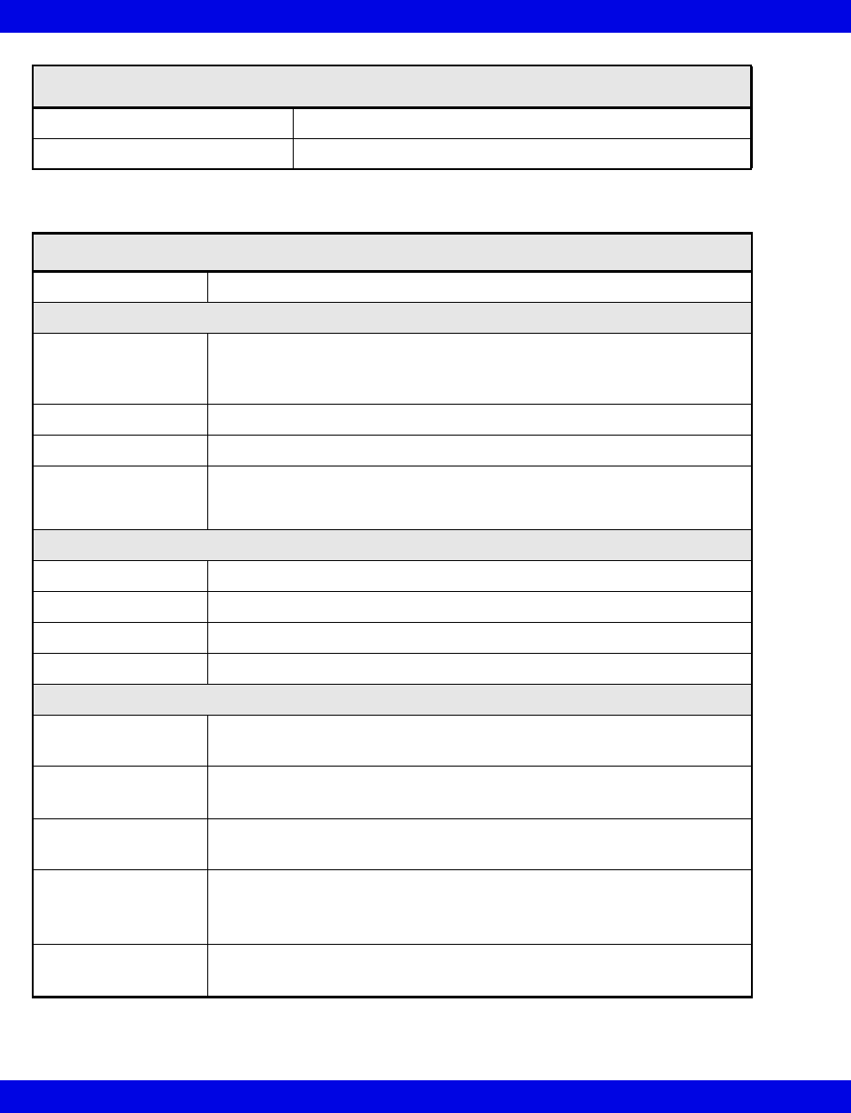
B-10 Infinity CentralStation VF8
B:
Storage Time 72 Hours
Resolution 1 minute interval
Infinity M300 Bedside Charger
Connections Infinity M300
Physical Attributes
Dimensions Length: 99.06 mm (3.9 in)
Height: 162.56 mm (6.4 in)
Depth: 45.72 mm (1.8in)
Weight 224.0 g (7.9 oz)
Cooling Convection
Disposal All materials must be disposed of or recycled properly and in accordance
with local regulations. There are no known special disposal requirements
for any accessories.
Electrical Specifications
Input Voltage 115, 220, 230, 240 VAC ± 20% (nominal, user selectable)
Input frequency (Hz) 50/60 Hz ±5%
Protection Class From specified Class 1 power supply
Mode of Operation Continuous
Environmental Requirements
Atmospheric
Pressure
Operating: 647 hPa to 1060 hPa
Storage: 500 hPa to 1060 hPa
Temperature Operating: 0 to 40° C (32 to 104 °F)
Storage: -20 to 60° C (-04 to 140 °F)
Humidity (non
condensing)
Operating: 10% to 85%
Storage: 10% to 85%
Shock
IEC 68-2-27
• 50 g half-sine waveform, 11 mS duration,
• 3 shocks in each +/- directions/axis, 18 total shocks,
• 3 mutually perpendicular axes
Sinusoidal Vibration
IEC 68-2-6
• 5-10 Hz @ 0.098 DA, 100-500 Hz @ 2 G
• 10 sweep cycles/axis, 3 axes, 1 octave / minute
Infinity M300(continued)
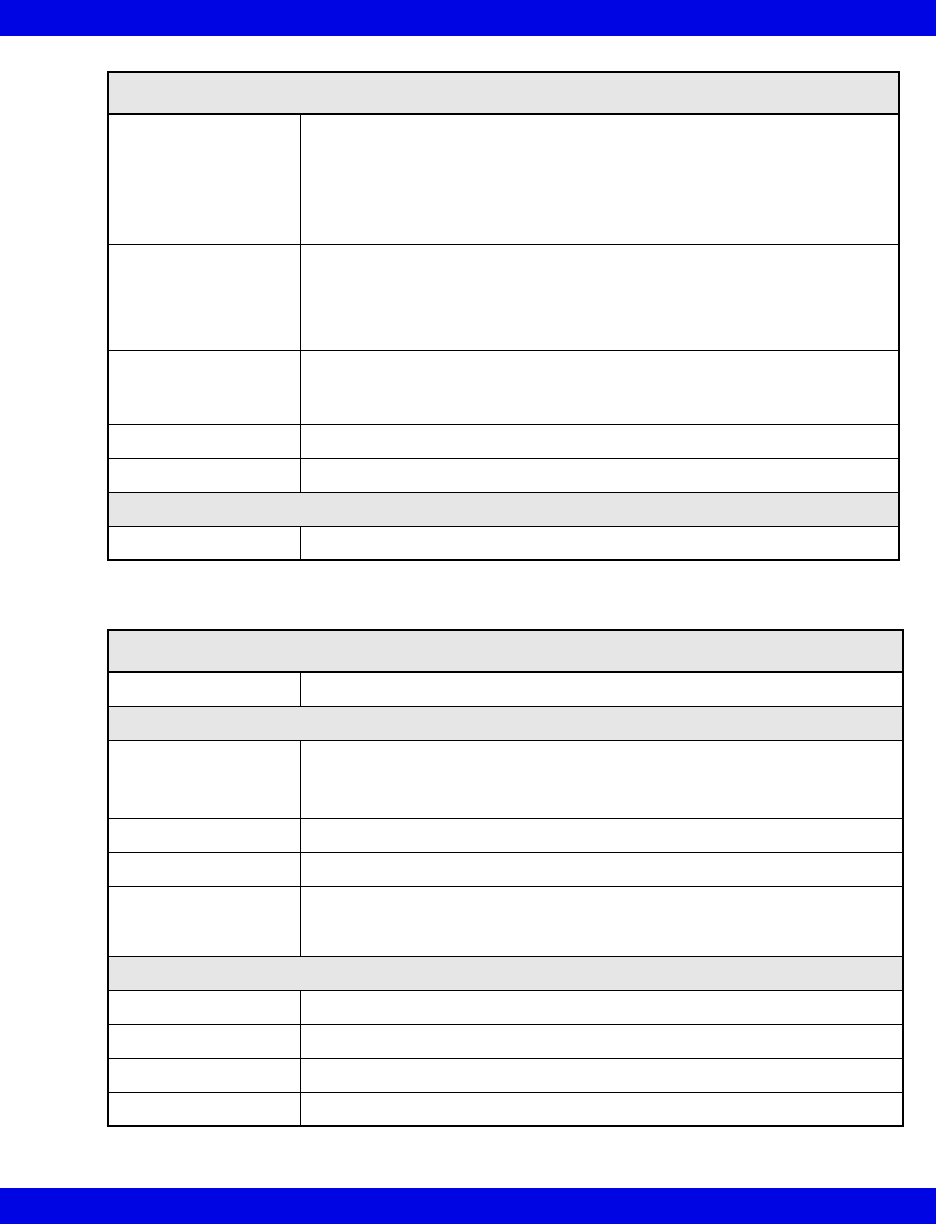
Technical Data
VF8 Infinity CentralStation B-11
Random Vibration
IEC 60068-2-36
• Reproducibility Medium
• ASD 10 to 20 Hz: 0.05 g2 /Hz, -3dB/Octave
• ASD 20 to 150 Hz: 0.05 g2 /Hz, -3dB/Octave
• Total acceleration: 1.6g (rms)
• Duration/axis/mounting: 30 min
Bump
IEC60068-2-29
• Peak acceleration: 15 g
• Pulse duration: 6 ms
• Number of bumps: 1000
• Direction: Vertical (normal operating position)
Free Fall
IEC 60068-2-32,
Procedure 1
• Height of fall: 1 m
• Number of falls: 1 on each of six surfaces
Drop Per IEC68-2-31, Packaged drop- 30"
Water Resistance IPX4 (cradle side that connects to patient)
Standards
Compliances IEC 60601-1 and IEC 60601-1-2
Infinity M300 Central Charger
Connections Infinity M300 (supports 10 devices concurrently)
Physical Attributes
Dimensions Length: 520.7 mm (20.5 in)
Height: 215.9 mm (8.5 in)
Depth: 190.5 mm (7.5 in)
Weight 6.5 kg (14.4 lbs)
Cooling Heat sink and fan
Disposal All materials must be disposed of or recycled properly and in accordance
with local regulations. There are no known special disposal requirements
for any accessories.
Electrical Specifications
Input Voltage 115, 220, 230, 240 VAC ± 20% (nominal, user selectable)
Input frequency (Hz) 50/60 Hz ±5%
Protection Class From specified Class 1 power supply
Mode of Operation Continuous
Infinity M300 Bedside Charger(continued)
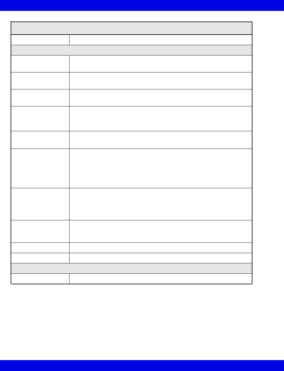
B-12 Infinity CentralStation VF8
B:
Power Output Provides power to Infinity M300 via magnetic coupling
Environmental Requirements
Atmospheric
Pressure
Operating: 647 to 1060 hPa
Storage: 500 to 1060 hPa
Temperature Operating: 0 to +40 ° C (32 to 104 °F)
Storage: -30 to +70° C (-22 to 158 °F)
Humidity (non
condensing)
Operating: 10 to 85%
Storage: 10% to 85%
Shock
IEC 68-2-27
• 50 g half-sine waveform, 11 mS duration,
• 3 shocks in each +/- directions/axis, 18 total shocks,
• 3 mutually perpendicular axes
Sinusoidal Vibration
IEC 68-2-6
• 5-10 Hz @ 0.098 DA, 100-500 Hz @ 2 G
• 10 sweep cycles/axis, 3 axes, 1 octave / minute
Random Vibration
IEC 60068-2-36
• Reproducibility Medium
• ASD 10 to 20 Hz: 0.05 g2 /Hz, -3dB/Octave
• ASD 20 to 150 Hz: 0.05 g2 /Hz, -3dB/Octave
• Total acceleration: 1.6g (rms)
• Duration/axis/mounting: 30 min
Bump
IEC60068-2-29
• Peak acceleration: 15 g
• Pulse duration: 6 ms
• Number of bumps: 1000
• Direction: Vertical (normal operating position)
Free Fall
IEC 60068-2-32,
Procedure 1
• Height of fall: 1 m
• Number of falls: 1 on each of six surfaces
Drop Per IEC68-2-31, Packaged drop- 30"
Water Resistance IPX1 - Protected against harmful effects of dripping water.
Standards
Compliances IEC 60601-1 and IEC 60601-1-2
Infinity M300 Central Charger(continued)
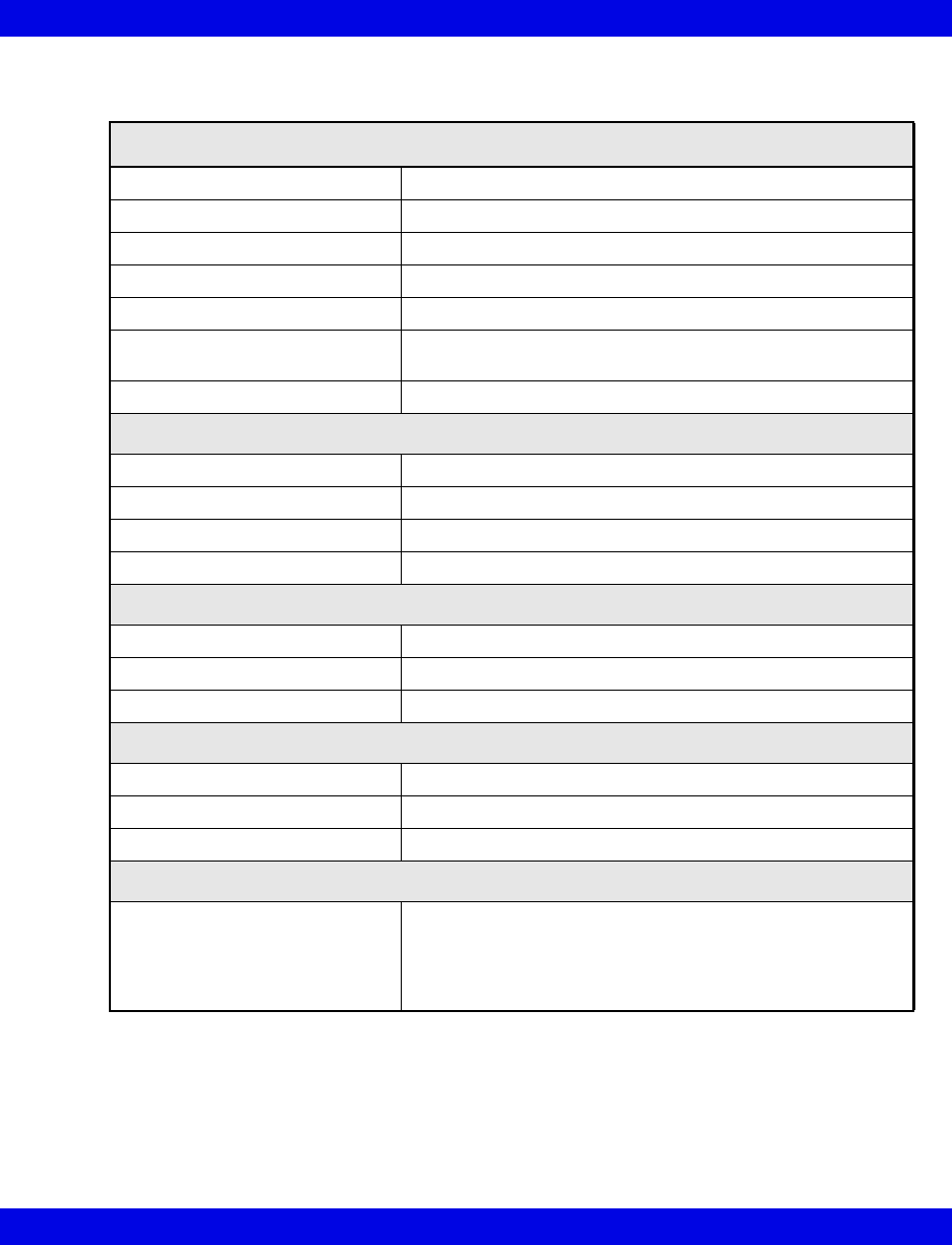
Technical Data
VF8 Infinity CentralStation B-13
Infinity TruST Telemetry System
TruST Telemetry Receiver
Network Connectivity Infinity Network; Infinity TruST Telemetry Network
Antenna Type Dual conversion super heterodyne
Modulation Gaussian Minimum Shift Keying (GMSK)
Software Update 1.44 MB 3.5 inch floppy disk drive
Channels 4 channels per card, maximum 16 channels
Frequencies UHF 400 - 460 MHz., UHF 608 - 614 MHz.,
VHF 174-216 MHz
Channel Spacing Varies by country, 25, 40 or 50 kHz
Electrical Specifications
Power Consumption 2A@ 100 VAC, 1A @ 240 VAC
Input Voltage 100/120/220/230-240 VAC selectable +/- 10%
Mains Frequency 50/60 Hz. (nominal)
Indicators LED indicator for power
Environmental Conditions
Cooling Fan circulation
Operation Temperature 10 to 40° C (50 to 104 °F)
Non-Operating Conditions -20 to 60° C (-4 to 140 °F)
Physical Attributes
Chassis Color White
Weight 16 kg (35 lbs)
H x W x D 191 x 432 x 508 mm (7.5 x 17.0 x 20.0 in.)
Regulatory/Standards Compliance
Compliances • EN 60601-1 Medical electrical equipment Part 1: General
requirements for safety.
• EN 60601-1-2: Medical electrical equipment, collateral
standard: electromagnetic compatibility
• UL 544 second addition (1991)
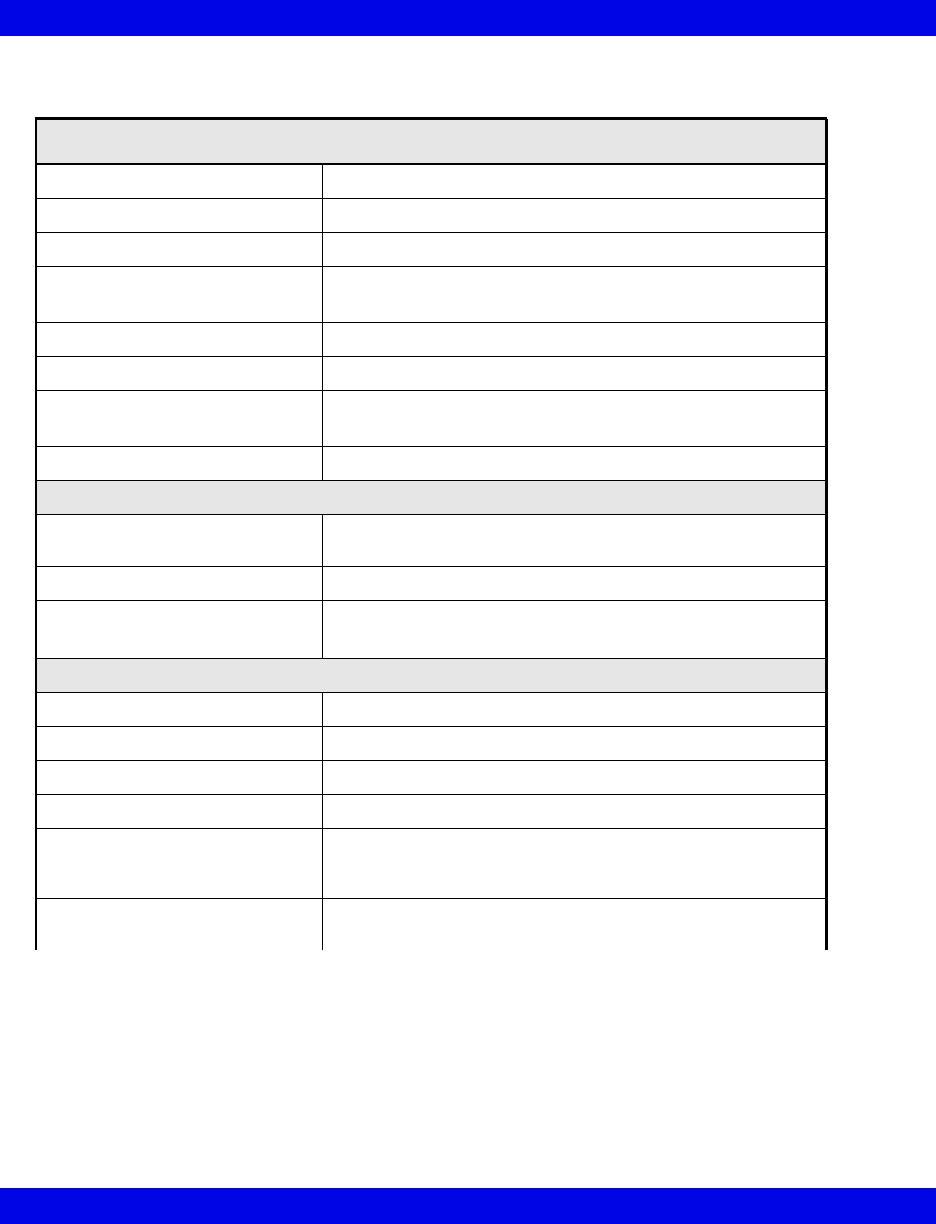
B-14 Infinity CentralStation VF8
B:
TruST Telemetry Transmitter
Lead Type 3-wire, 5-wire, 6-wire
Indicators LEDs indicating lead off and low battery
Leads-off Sensors One for each lead: RA, LA, LL, V, V+
Lead-off Threshold 12 MΩ, ± 25% for RA, LA, LL, V, V+
2.7 MΩ, ± 25% for RL
Common Mode Rejection Meets CMRR test specification in AAMI EC 13-2002 4.2.9.10
Controls Staff alert, timed and continuous recording start, self-test
Pacemaker Detection 0.1 to 2 ms, 2.5 to 700 mV (positive or negative)
Independent detectors for Lead I and II
Defibrillation Protection Will withstand 360 joules
Electrical Specifications
Protection against electrical
shock
Type B
Electrosurgery and Cautery Not intended for use during ESU
Battery • 9 V alkaline: 2 days
• 9 V lithium: 4 days
Environmental Specifications
Operation Temperature 10 to 40° C (50 to 104 °F)
Non-Operating Conditions -25 to 60° C (-13 to 140 °F)
RF Power Output 1 MW, -3 to + 4 dBm
Frequency Response 0.5 - 40 Hz: ± 3 dB
Water Resistance Electronics protected from damage due to accidental
immersion in up to 1 m of water for 30 minutes. Meets EN
60529 rating IPX7.
Drop and Free fall Withstands 20 drops from 1.5 m onto a tiled concrete surface
with no degradation of performance
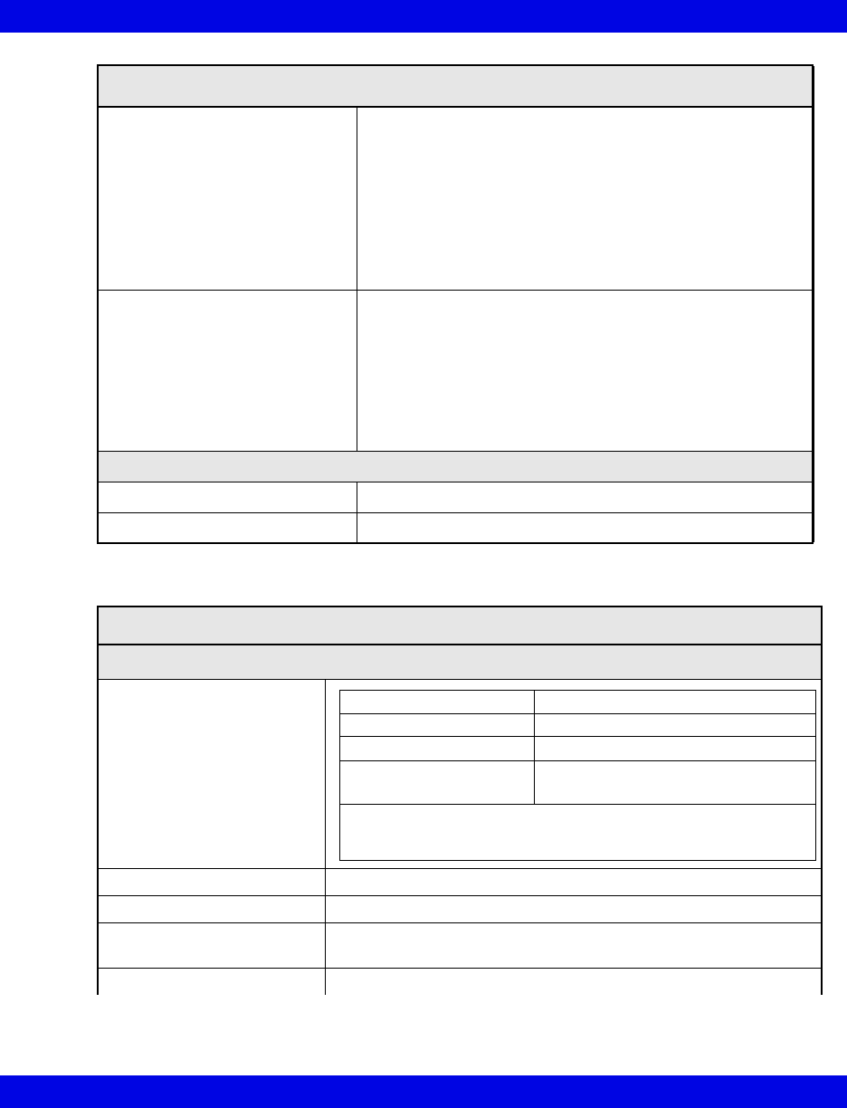
Technical Data
VF8 Infinity CentralStation B-15
Chemical Resistance Resistance tested for isopropyl alcohol 70%, sodium
hypochlorite (bleach) 2.5% and the following commercial
disinfectants:
Buraton 10F 1%, Cetylcide-G® Concentrate, Diluent
Concentrate Cidex Plus™ 28 Day Solution, Cidex OPA
Solution, Cidex OPA Solution High Level Disinfectant,
Cidex™ Activated Dialdehyde Solution, Compliance, Enzol
(Cidezyme), Incidin® Plus 1%, Incidin® Plus 2%, Lysoformin
3000 1%, Metricide® 28 Long-Life Activated, Dialdehyde
Solution, Sporicidin Sterilizing and Disinfecting Solution
Connections • ECG Analog cable for bedside display of Lead II scaled to 1
mV ± 15% to transmitter's ECG input leads
• Vital Connection cable between Infinity CentralStation and
Infinity monitor X8 port for data acquisition of SpO2 and/or
NIBP
• Infinity Telemetry Transmitter Programming Port for tuning
each transmitter electronically over its frequency range;
• MicrO2+ pulse oximeter.
Physical Specifications
Size, H x W x D 116 x 65 x 25 mm (4.56 x 2.56 x 1 in.)
Weight 160 grams (5.7 oz.) with lithium battery
Telemetry Vital Signs Measuring Capabilities
ECG
Available leads
Measuring range 15 - 300 bpm
Accuracy ± 5 bpm or ± 5% of rate (whichever is greater)
QRS detection range
amplitude
Amplitude: 0.5 to 5.0 mV
Duration: 40 to 120 ms
1 mV calibration pulse 1 mV ± 5%, all leads
TruST Telemetry Transmitter(continued)
3-wire I, II, III
5-wire I, II, III, aVR, aVF, aVL, V
6-wire I, II, III, aVR, aVF, aVL, V, V+
6-wire
(Infinity TruST 12-lead)
V2, V5, dV1, dV3, dV4, dV6 (Default)
For TruST 12-lead, any other combination of V1-V6 can be
selected; the chest lead selection determines the constructed
leads (dV1 - dV6).
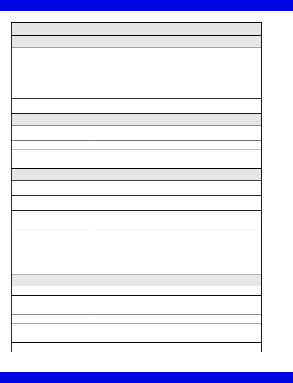
B-16 Infinity CentralStation VF8
B:
Arrhythmia Processing
Algorithm ACE (Arrhythmia Classification Expert)
Leads analyzed Any two user-selected ECG leads (simultaneously), or
any one user-selected ECG lead
Detected events/rhythms Asystole, ventricular fibrillation, ventricular tachycardia, sinus
bradycardia, pause, ventricular run, sinus tachycardia, accelerated
idioventricular rhythm, couplet, bigeminy, paced artifact, PVC/
min,% paced, SVT
Functions User-selectable functions: alarm on/off, record on/off, store on/off,
assignment of alarm grade for each event category.
Trends
Parameters HR,% paced, PVC/min ST (I, II, III, aVL, aVR, V, V+, V1-V6, dV1-
dV6), STCM, STVCM, SpO2, pulse rate (PLS)
Storage time 72 hours
Trend Graphs 1, 2, 4, 8, 12, 24 hours (72 hours max)
Trend Tables 1, 5, 15, 30, 60 minutes
ST Segment Analysis
Leads analyzed Simultaneous analysis of leads I, II, III, aVL, aVF, aVR, V, V+, V1-
V6, dV1-dV6
Sampling rate for averaged
ECG
250 samples
Resolution ± 10 µV
Alarm handling Positive and negative S-T deviations
Isoelectric point Default is set at 28 ms before QRS onset; user-selectable in 4 ms
increments between QRS peak to beginning of averaged ECG seg-
ment.
ST measurements The value is updated every 15 seconds from an average of all nor-
mal, non-paced beats.
Trends Both graphical and tabular format for each ECG lead
General Display Capabilities
Telemetry channels Up to 16
Display screens 1 or 2
Screen formats Refer to Infinity CentralStation Instructions for Use.
Sweep Speeds 25 or 50 mm/s
Channel amplitudes 0.25; 0.5; 1; 2; 4; 8 mV/cm
Display mode Fixed Waveform (erase bar) mode
X-Y resolution 1024 x 1280 pixels with ECG waveform enhancements
Telemetry Vital Signs Measuring Capabilities(continued)
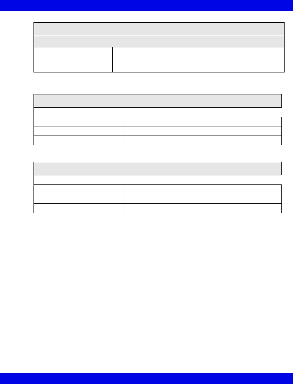
Technical Data
VF8 Infinity CentralStation B-17
Recordings
Types R50 producing 50 mm wide strips with thermal array print head
Laser Printer
Number 2
Transmitter Programming Port
Used to tune transmitters to selected frequency and to select ECG wire mode
Connections Infinity CentralStation
H x W X D 44.0 x 96.5 x 96.4 mm (1.7 x 3.8 x 3.8 in.)
Weight 450 g (1 lb.)
Infinity Telemetry ECG Analog Output Cable
Used to tune transmitters to selected frequency and to select ECG wire mode
Connections Infinity MultiMed Pod
H x W X D 44.0 x 96.5 x 96.4 mm (1.7 x 3.8 x 3.8 in.)
Weight 450 g (1 lb.)
Telemetry Vital Signs Measuring Capabilities(continued)

B-18 Infinity CentralStation VF8
B:
Electromagnetic Compatibility
The separation distances are written with regard to the Infinity CentralStation with
Infinity Telemetry, TruST Transmitters and Infinity M300. The numbers provided will
not guarantee faultless operation but should provide reasonable assurance of such.
This information may not be applicable to other medical electrical equipment, and
older equipment may be particularly susceptible to interference.
General Notes
Medical electrical equipment needs special precautions regarding electromagnetic
compatibility (EMC) and needs to be installed and put into service according to the
EMC information provided in this manual.
Portable and mobile radio frequency (RF) communications equipment can affect
medical electrical equipment. The TruST telemetry receiver may be sensitive to RF
interference and could possibly be interfered with by other equipment even if the
equipment complies with CISPR11.
Cables and accessories not specified within the instructions for use are not authorized.
Using other cables and/or accessories may adversely impact safety, performance and
electromagnetic compatibility (increased emission and decreased immunity).
The equipment should not be used adjacent to or stacked with other equipment; if
adjacent or stacked use is inevitable, the equipment should be observed to verify
normal operation in the configuration in which it will be used.
When using wireless networking, be aware that the system operates at 2.4 GHz range.
Other equipment, even if compliant with CISPR emission requirements, could
interfere with reception of wireless data. When selecting new wireless systems (e.g.
cell phones, pager systems, cordless phones etc.) for use in installations where
wireless networking is used, care should always be used to insure that operating
frequencies are compatible. For example, selecting cordless phones that operate at 2.4
GHz will likely cause difficulty with the phones and networking components.
Low level signals such as ECG are potentially susceptible to interference from
electromagnetic energy. While the equipment meets the testing described below, it is
not a guarantee of perfect operation, the ‘quieter’ the electrical environment the better.
In general, increasing the distance between electrical devices decreases the likelihood
of interference.
NOTE: Detailed radio frequency characteristics: 2412-2472 MHZ, Direct-sequence
spread spectrum (DSSS) IEEE 802.11b compatible, limited to 100 mW. Applicable to
both access points and client adaptors. When used with 802.15.1 wireless, the device
will transmit with the following characteristics: 2400-2485 MHz, Frequency Hopping
Spread Spectrum (FHSS), limited to 2.5 mW. See the documentation that accompanies
the wireless products for further details.
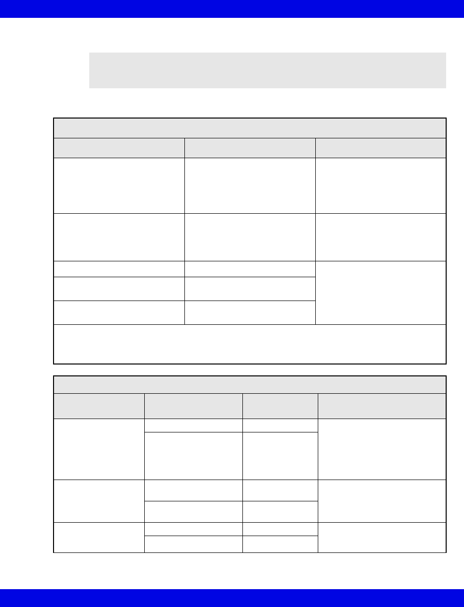
Electromagnetic Compatibility
VF8 Infinity CentralStation B-19
NOTE: The Infinity CentralStation with Infinity Telemetry, TruST transmitters and
Infinity M300 are intended for use in the electromagnetic environments specified below.
The user of this equipment should assure that is used in such an environment.
Electromagnetic Emissions
Emissions Compliance according to... Electromagnetic environment
RF emissions (CISPR 11)
Infinity CentralStation
Telemetry Receiver
and Infinity M300
Group 1 The Infinity CentralStation and
receiver use RF energy only for
internal function. Therefore, their
RF emissions are very low and are
not likely to cause any interference
in nearby electronic equipment.*
RF emissions (CISPR 11)
Transmitter
Group 2 The TruST Telemetry Transmitter
must emit electromagnetic energy
in order to perform its intended
function. Nearby electronic
equipment may be affected.
CISPR Emissions Classification Class B The equipment is suitable for use
in all establishments including
domestic establishments and those
directly connected to the public
low-voltage power supply network
that supplies buildings used for
domestic purposes.
Harmonic emissions
(IEC 61000-3-2)
Class A
Voltage fluctuations / flicker (IEC
61000-3-3)
Complies
*Note that when used with the wireless options, the Infinity M300 emits electromagnetic energy in order to
communicate with the Infinity Network. Nearby electronic equipment may be affected. Radio frequency
characteristics are specified above. See the documentation that accompanies the wireless products for further
details.
Electromagnetic Immunity
Immunity against... IEC 60601-1-2 test level Compliance level
(of this device) Electromagnetic environment
Electrostatic discharge,
ESD
(IEC 61000-4-2)
Contact discharge: ± 6 kV ± 6 kV Floors should be wood, concrete
or ceramic tile. If floors are
covered with synthetic material,
the relative humidity should be
kept at levels to reduce
electrostatic charge to suitable
levels.
Air discharge: ± 8 kV ± 8 kV
Electrical fast
transients / bursts
(IEC 61000-4-4)
Power supply lines:
± 2kV
± 2 kV Mains power quality should be
that of a typical commercial or
hospital environment.
Longer input / output
lines: ± 1 kV
± 1 kV
Surges on AC mains
lines
(IEC 61000-4-5)
Common mode: ± 2 kV ± 2 kV Mains power quality should be
that of a typical commercial or
hospital environment.
Differential mode: ± 1 kV ± 1 kV
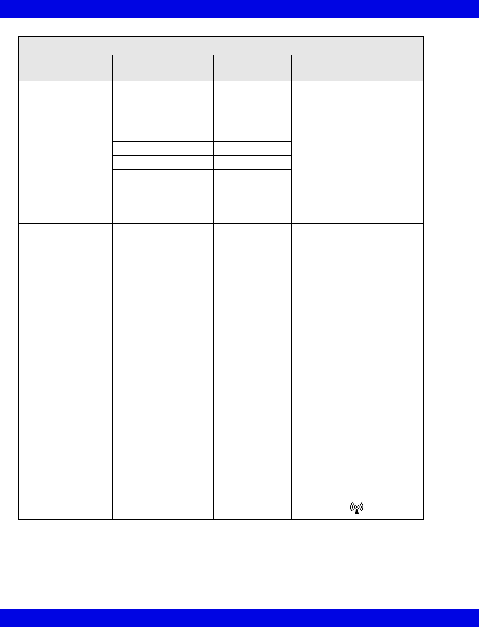
B-20 Infinity CentralStation VF8
B:
Power frequency
magnetic field 50/60 Hz
(IEC 61000-4-8)
3 A/m 3 A/m Equipment which emits high levels
of power line magnetic fields (in
excess of 3A/m) should be kept at
a distance to reduce the likelihood
of interference.
Voltage dips and short
interruptions on AC
mains input lines
(IEC 61000-4-11)
Dip >95%, 0.5 periods >95%, 0.5 periods Mains power should be that of a
typical commercial or hospital
environment. If user requires
continued operation during power
mains interruptions insure that
batteries are installed and
charged. Insure that battery life
exceeds longest anticipated
power outages or provide and
additional uninterruptible power
source.
Dip 60%, 5 periods 60%, 5 periods
Dip 30%, 25 periods 30%, 25 periods
Dip >95%, 5 seconds >95%, 5 seconds
Conducted RF
RF coupled into lines
(IEC 61000-4-6)
150 kHz – 80 MHz: 3 V/m Portable and mobile RF
communications equipment
should be used no closer to any
part of the, including cables, than
the recommended separation
distance calculated from the
equation applicable to the
frequency of the transmitter as
below.
Recommended separation
distance:
d=1.2/V1]√P
d=1.2/√P 80 MHz to 800MHz
d=2.3√P 800 MHz to 2.5 GHz
where ‘P’ is the maximum
output power rating of the
transmitter in watts according to
the transmitter manufacturer
and ‘d’ is the recommended
separation distance in metres.
Field strengths from fixed RF
transmitters, as determined by an
electromagnetic site survey1,
should be less than the
compliance level in each
frequency range2.
Interference may occur in the
vicinity of equipment marked with
the wireless symbol:
Radiated RF
(IEC 61000-4-3)
80 MHz – 2.5 GHz 3 V/m
Electromagnetic Immunity
Immunity against... IEC 60601-1-2 test level Compliance level
(of this device) Electromagnetic environment
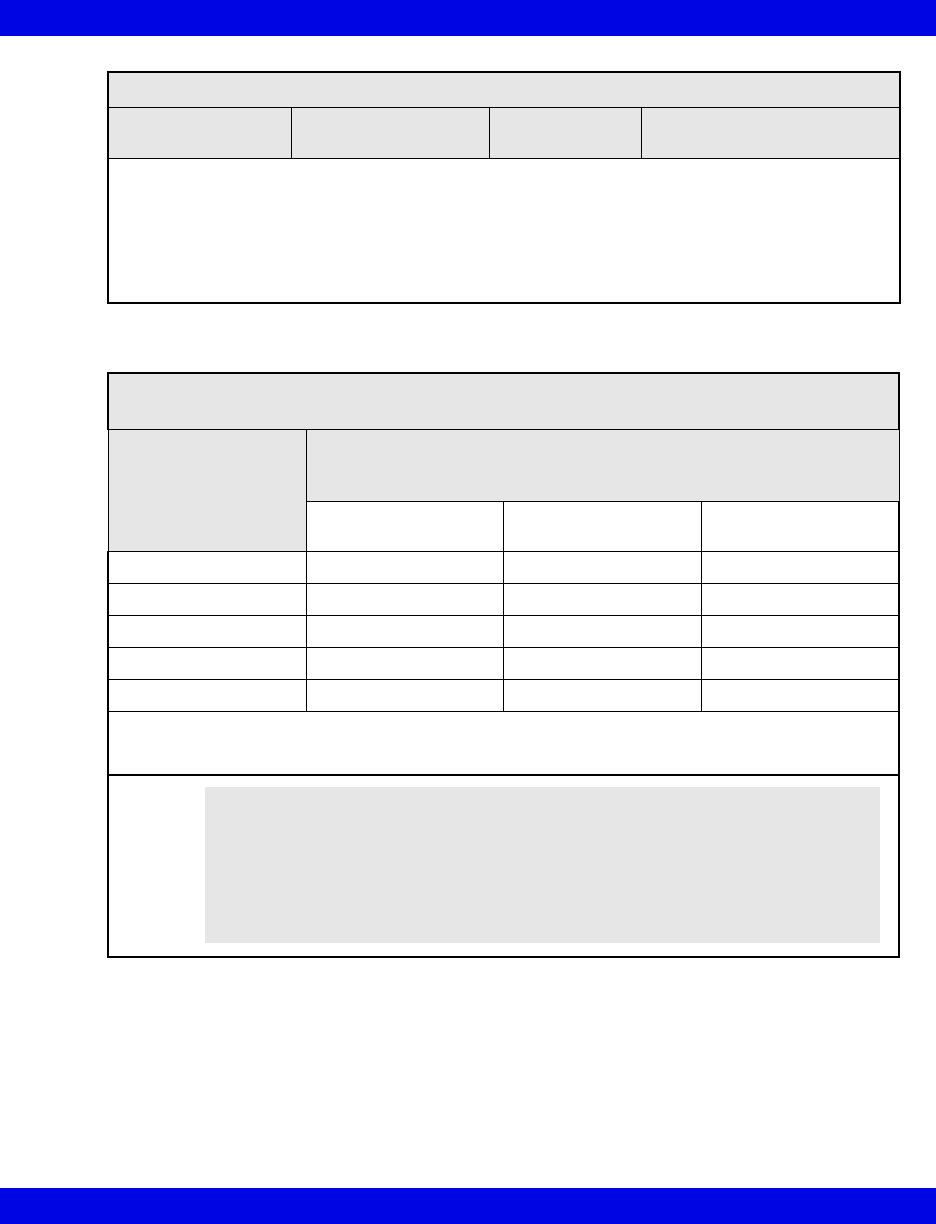
Electromagnetic Compatibility
VF8 Infinity CentralStation B-21
1Field strengths from fixed transmitters, such as base stations for radio (cellular/cordless) telephones and land
mobile radios, amateur radio, AM and FM radio broadcast, and TV broadcast cannot be predicted theoretically
with accuracy. To assess the electromagnetic environment due to fixed RF transmitters, an electromagnetic
site survey should be considered. If the measured field strength in the location in which the equipment is used
exceeds the applicable RF compliance level above, the equipment should be observed to verify normal
operation. If abnormal performance is observed, additional measures may be necessary, such as re-orienting
or relocating the equipment.
2If the frequency range is 150 kHz to 80 MHz, field strengths should be less than 3 V/m.
Recommended separation distances between portable and mobile RF communications equipment and
the equipment
Rated maximum output
power of Transmitter
(watts)
Separation distance according to frequency of transmitter (meters)
150 kHz to 80 MHz
d=1.2/V1]√P
80 MHz to 800MHz
d=1.2/V1]√P
800 MHz to 2.5 GHz
d=2.3√P
0.01 0.12 0.12 0.23
0.1 0.38 0.38 0.73
11.2 1.2 2.3
10 3.8 3.8 7.3
100 12 12 23
For transmitters rated at a maximum output power not listed, the recommended separation distance ‘d’ (in
meters) can be estimated using the equation applicable to the frequency of the transmitter, where ‘P’ is the
maximum output power rating of the transmitter (in watts) according to the transmitter manufacturer.
Electromagnetic Immunity
Immunity against... IEC 60601-1-2 test level Compliance level
(of this device) Electromagnetic environment
NOTE:
zAt 80 MHz and 800 MHz, the separation distance for the higher frequency
range applies.
zThese guidelines may not apply in all situations. Electromagnetic
propagation is affected by absorption and reflection from structures,
objects, and people.

B-22 Infinity CentralStation VF8
B:
- This page left blank intentionally -

C: Cleaning
Cleaning the Infinity CentralStation............................................................................ C-2
Cleaning and Disinfecting Infinity Telemetry and Infinity M300.............................. C-2
Recommended Cleaning Agents .......................................................................... C-3
Patient Cables ........................................................................................................ C-3
Reusable ECG Electrodes ..................................................................................... C-3
Reusable SpO2 Sensor.......................................................................................... C-3
Cleaning the MicrO2/MicrO2+® Oximeter................................................................... C-4
Oximeter.................................................................................................................. C-4
Reusable Sensor .................................................................................................... C-4
CAUTION! Do not sterilize any components.

C-2 Infinity CentralStation VF8
C:
Cleaning the Infinity CentralStation
During normal use the display, CPU, accessories, and peripherals may become soiled.
Clean these components according to the original manufacturer's Instructions For Use
or hospital protocol for computer equipment and peripherals.
Cleaning and Disinfecting Infinity Telemetry
and Infinity M300
1. Clean the device with gauze moistened in soapy water.
2. Thoroughly dry with a lint-free cloth.
3. Disinfect the device with gauze moistened in a cleaning agent.
4. Thoroughly dry with a lint-free cloth.
CAUTION!
z Do not immerse the CPU or its peripherals.
zDo not pour or spray cleaning solution directly on equipment surfaces.
zDo not allow fluids to contact electrical connectors or drip into ventilation
openings.
CAUTION!
zDo not use disinfectants other than those recommended by Dräger. The use of
non-approved disinfectants can damage the device.
zDo not use disinfectants containing phenol. Do not use strong aromatic ketone,
ether, or ester solvents, or sharp tools and abrasives. These will damage the
device.
zDo not gas sterilize, steam autoclave, immerse, or rinse the device in fluids. If
you accidentally spill liquid on the device, remove the battery and contact the
Hospital Biomedical Engineering Dept. regarding the continued safety of the
unit before placing it back in operation.

Cleaning and Disinfecting Infinity Telemetry and Infinity M300
VF8 Infinity CentralStation C-3
Recommended Cleaning Agents
Dräger recommends the following cleaning agents for Infinity Telemetry and Infinity
M300.
zDiluted isopropyl alcohol
zSodium hypochlorite 2.5%
zGreen tinctured soap
Patient Cables
zClean the patient cables with a gauze pad moistened with a soap solution.
zDry thoroughly with a lint-free cloth.
zTo disinfect patient cables, wipe the cables with a gauze moistened with
diluted alcohol.
zDry thoroughly with a lint-free cloth.
Reusable ECG Electrodes
zClean grabber-wire clips regularly with a toothbrush.
zRemove any gel residue from the electrode by brushing it off under running
water.
zClean the electrodes with a gauze moistened with a soap solution.
zDry thoroughly with a lint-free cloth.
zDisinfect the electrodes with a gauze moistened with diluted alcohol.
zDry thoroughly with a lint-free cloth.
Reusable SpO2 Sensor
See the cleaning instructions and recommendations provided with the sensor.

C-4 Infinity CentralStation VF8
C:
Cleaning the MicrO2/MicrO2+® Oximeter
Oximeter
1. Turn the oximeter off.
2. Clean the oximeter with gauze moistened in soapy water.
3. Thoroughly dry with a lint-free cloth.
4. Disinfect the oximeter with gauze moistened in diluted isopropyl alcohol
(70%), or sodium hypochlorite (2.5%).
5. Thoroughly dry with a lint-free cloth.
Reusable Sensor
1. Unplug the sensor from the oximeter.
2. Clean reusable sensors according to the instructions supplied with the sensor
NOTE: Disposable sensors are intended for single-use only and should not be
reprocessed.
CAUTION!
zDo not use disinfectants containing phenol. Do not use strong aromatic ketone,
ether, or ester solvents, or sharp tools and abrasives. These will damage the
oximeter.
zDo not use disinfectants other than those recommended. The use of non-
approved disinfectants can damage the oximeter.
zDo not gas sterilize, steam autoclave, immerse, or rinse the oximeter and its
reusable sensor in fluids. If you accidentally spill liquid on the device, remove
the battery and contact the Hospital Biomedical Engineering Dept. regarding
the continued safety of the unit before placing it back in operation.
- This page left blank intentionally -
These Instructions for Use only apply to
Infinity CentralStation
with Infinity Telemetry System
and with Infinity M300
VF8
with the Serial No.:
If no Serial No. has been filled in by Dräger,
these Instructions for Use are provided for
general information only and are not intended
for use with any specific machine or device.
This document is provided for customer infor-
mation only, and will not be updated or
exchanged without customer request.
Directive 93/42/EEC
for medical devices
In Europe, Middle East, Africa, Latin
America, Asia Pacific distributed by
Dräger Medical AG & Co.
KG
Moislinger Allee 53 – 55
D-23542 Lübeck
Deutschland
+49 451 8 82-0
FAX +49 451 8 82-20 80
http://www.draeger.com
MS23349 RI 01
© Dräger Medical Systems, Inc.
05/2008
Dräger reserves the right to make modifi-
cations to the equipment without prior
notice.
Manufactured by
Draeger Medical Systems, Inc.
3135 Quarry Road
Telford, PA 18969
U.S.A.
(215) 721-5400
(800) 4DRAGER
(800) 437-2437
FAX (215) 723-5935
http://www.draeger.com
I