Draytek AP903 Dual Band Security Firewall User Manual QS VigorAP 900

Draytek Corporation Dual Band Security Firewall QS VigorAP 900

Contents

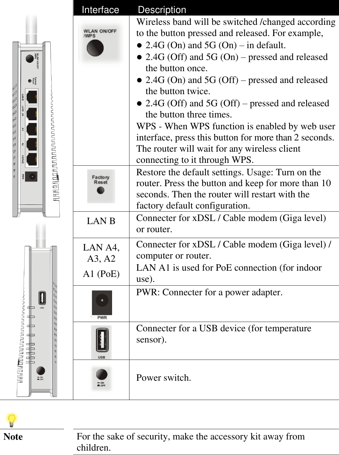
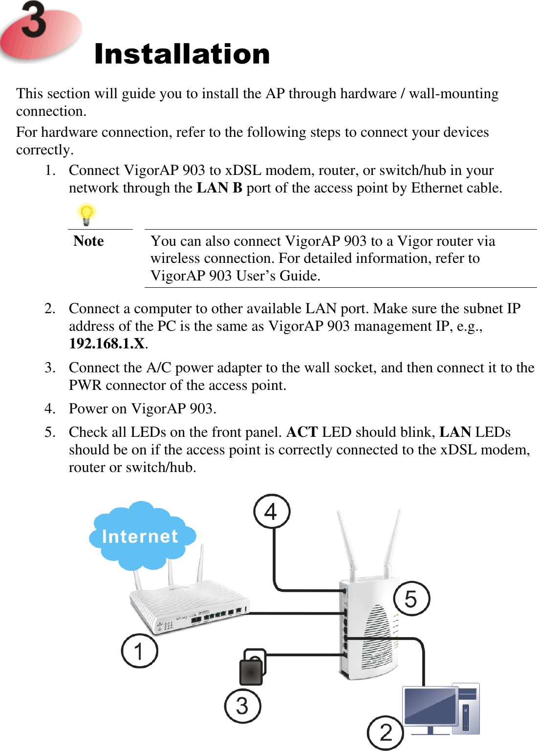
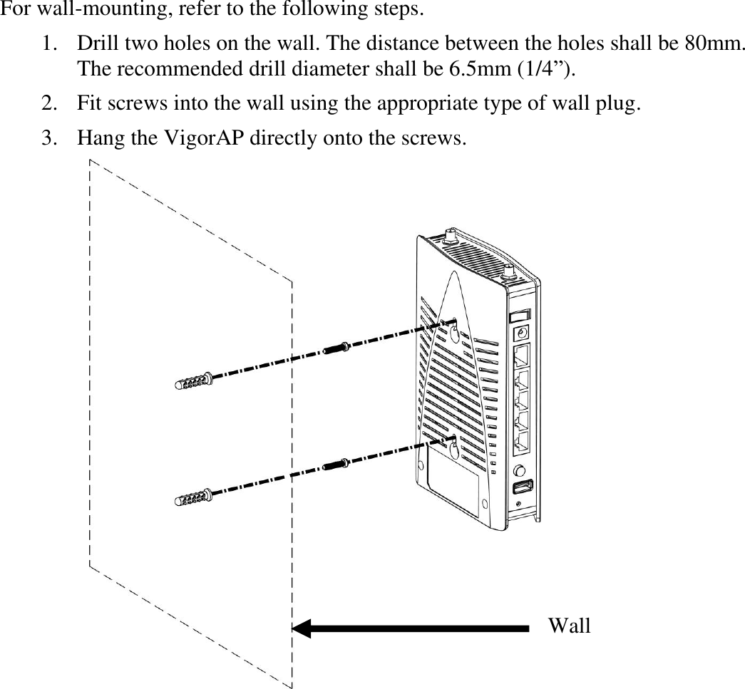
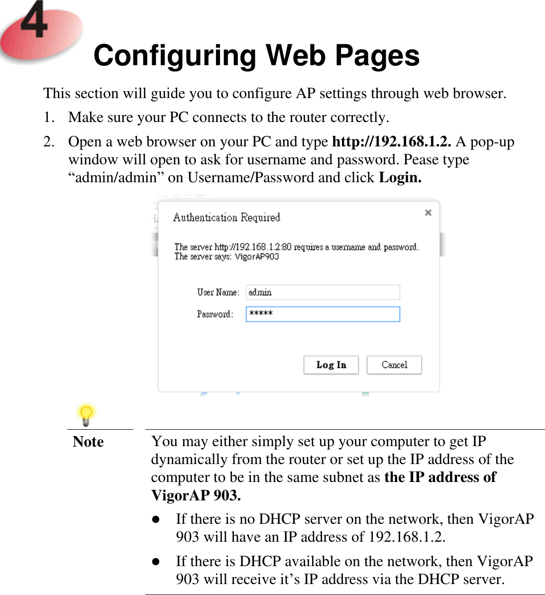
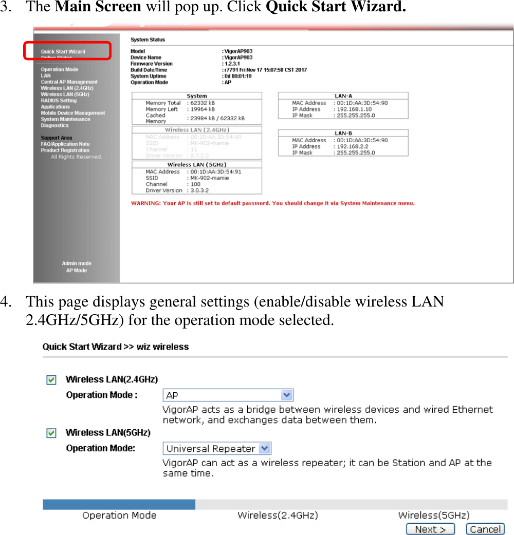
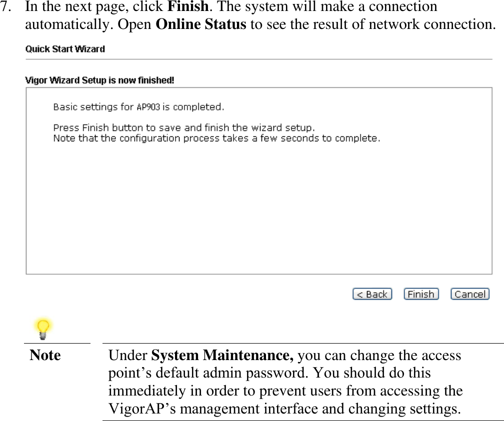
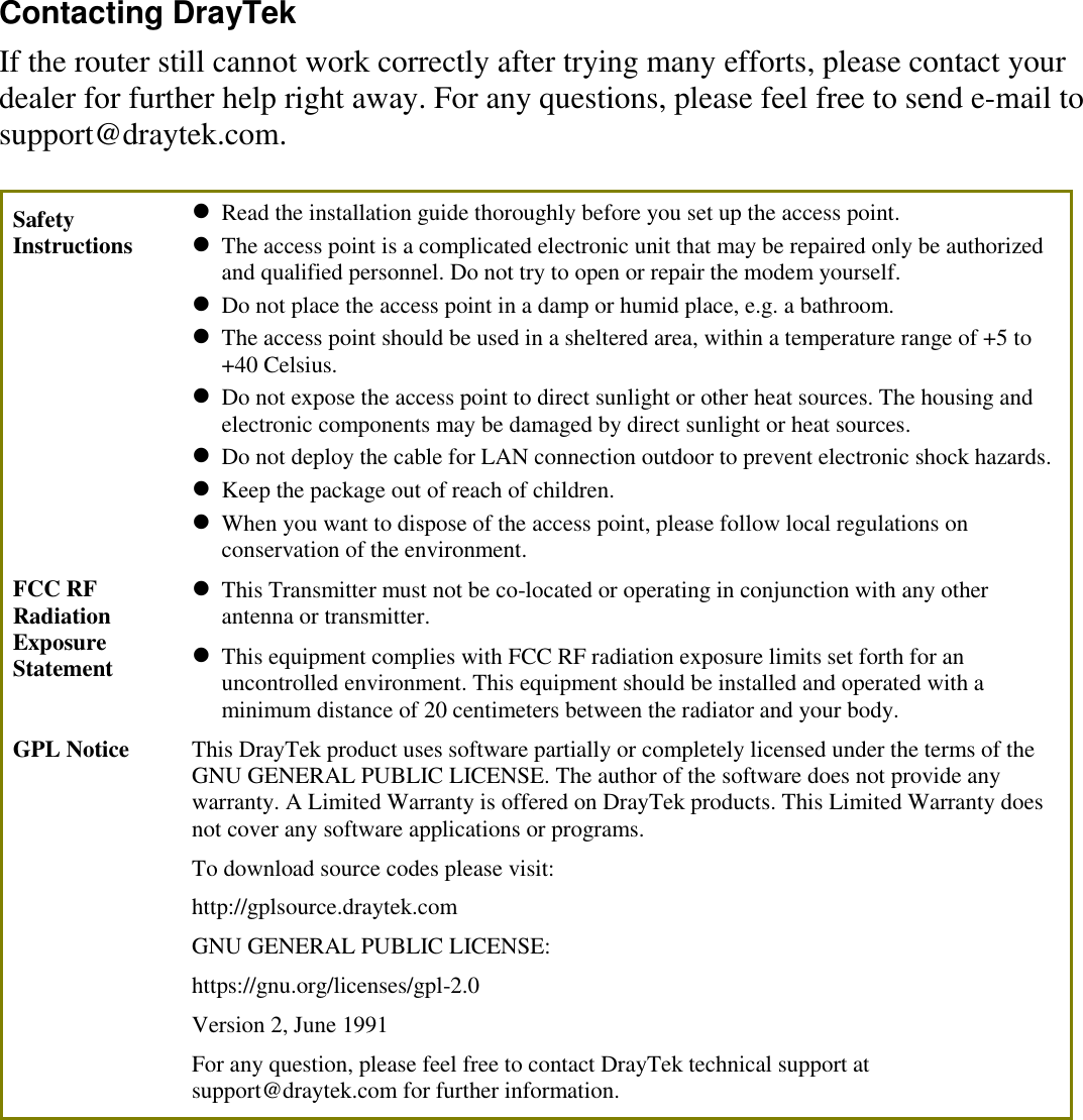
VigorAP-903 User Manual

  VViiggoorrAAPP  990033  DDuuaall  BBaanndd  SSeeccuurriittyy  FFiirreewwaallll  Quick Start Guide Version: 1.0 F/W: V1.3.0 Date: March 27, 2018   Warranty We warrant to the original end user (purchaser) that the access point will be free from any defects in workmanship or materials for a period of one (1) year from the date of purchase from the dealer. Please keep your purchase receipt in a safe place as it serves as proof of date of purchase. During the warranty period, and upon proof of purchase, should the product have indications of failure due to faulty workmanship and/or materials, we will, at our discretion, repair or replace the defective products or components, without charge for either parts or labor, to whatever extent we deem necessary tore-store the product to proper operating condition. Any replacement will consist of a new or re-manufactured functionally equivalent product of equal value, and will be offered solely at our discretion. This warranty will not apply if the product is modified, misused, tampered with, damaged by an act of God, or subjected to abnormal working conditions. The warranty does not cover the bundled or licensed software of other vendors. Defects which do not significantly affect the usability of the product will not be covered by the warranty. We reserve the right to revise the manual and online documentation and to make changes from time to time in the contents hereof without obligation to notify any person of such revision or changes.    Declaration of Conformity Hereby, DrayTek Corporation declares that the radio equipment type VigorAP 903 is in compliance with Directive 2014/53/EU. The full text of the EU Declaration of Conformity is available at the following internet address: http://www.draytek.com.tw/ftp/VigorAP 903/Document/CE/ Manufacturer:    DrayTek Corp. Address:     No. 26, Fu Shing Road, HuKou Township, HsinChu Industrial Park, Hsin-Chu, Taiwan 303 Product:      VigorAP 903     Frequency Information for Europe area: 2.4G WLAN 2412MHz - 2472 MHz, max. TX power: 19.86dBm 5G WLAN 5180MHz - 5700 MHz, max. TX power: 29.86dBm  Requirements in AT/BE/BG/CZ/DZ/DK/EE/FR/DE/IS/IE/IT/EL/ES/ CY/LV/LI/LT/ LU/HU/MT/ NL/NO/PL/PT/RO/SI/SK/TR/FI/SE/CH/ UK/HR. 5150MHz~5350MHz is for indoor use only.       This product is designed for 2.4GHz/5GHz WLAN network throughout the EC region.
    Regulatory Information Federal Communication Commission Interference Statement This equipment has been tested and found to comply with the limits for a Class B digital device, pursuant to Part 15 of the FCC Rules. These limits are designed to provide reasonable protection against harmful interference in a residential installation. This equipment generates, uses and can radiate radio frequency energy and, if not installed and used in accordance with the instructions, may cause harmful interference to radio communications. However, there is no guarantee that interference will not occur in a particular installation. If this equipment does cause harmful interference to radio or television reception, which can be determined by turning the equipment off and on, the user is encouraged to try to correct the interference by one of the following measures:   Reorient or relocate the receiving antenna.   Increase the separation between the equipment and receiver.   Connect the equipment into an outlet on a circuit different from that to which the receiver is connected.   Consult the dealer or an experienced radio/TV technician for help. This device complies with Part 15 of the FCC Rules. Operation is subject to the following two conditions: (1) This device may not cause harmful interference, and (2) This device may accept any interference received, including interference that may cause undesired operation.  USA Local Representative Company name ABP International Inc. Address 13988 Diplomat Drive Suite 180 Dallas TX 75234 ZIP Code 75234 E-mail rmesser@abptech.com Contact Person Mr. Robert Messer Tel. 19728311600 Caution: Any changes or modifications not expressly approved by the party responsible for compliance could void the user's authority to operate the equipment. The antenna/transmitter should be kept at least 20 cm away from human body.  More update, please visit www.draytek.com.
    Package Content Take a look at the package content. If there is anything missed or damaged, please contact DrayTek or dealer immediately.      Access Point  Antenna    RJ-45 Cable (Ethernet)  Quick Start Guide The type of the power adapter depends on the country that the AP will be installed:      UK-type power adapter  EU-type power adapter    USA/Taiwan-type power adapter  AU/NZ-type Power Adapter     Note The antenna/transmitter should be kept at least 20 cm away from human body.
   Descriptions of Components              LED Status Explanation ACT Off The system is not ready or is failed. Blinking The system is ready and can work normally. USB On A USB device is connected and active. Blinking The data is transmitting. 2.4G On Wireless function is ready. Off Wireless function is not ready. Blinking   Data is transmitting (sending/receiving). 5G On Wireless function is ready. Off Wireless function is not ready. Blinking   Data is transmitting (sending/receiving). LAN A1 - A4 On A normal connection (rate with 100M/1000M) is through its corresponding port. Off LAN is disconnected. Blinking Data is transmitting (sending/receiving). LAN B On A normal connection (rate with 100M/1000M) is through its corresponding port. Off LAN is disconnected. Blinking Data is transmitting (sending/receiving).
      Interface Description  Wireless band will be switched /changed according to the button pressed and released. For example,    2.4G (On) and 5G (On) – in default.  2.4G (Off) and 5G (On) – pressed and released the button once.  2.4G (On) and 5G (Off) – pressed and released the button twice.  2.4G (Off) and 5G (Off) – pressed and released the button three times. WPS - When WPS function is enabled by web user interface, press this button for more than 2 seconds. The router will wait for any wireless client connecting to it through WPS.  Restore the default settings. Usage: Turn on the router. Press the button and keep for more than 10 seconds. Then the router will restart with the factory default configuration. LAN B   Connecter for xDSL / Cable modem (Giga level) or router. LAN A4, A3, A2 A1 (PoE) Connecter for xDSL / Cable modem (Giga level) / computer or router.   LAN A1 is used for PoE connection (for indoor use).  PWR: Connecter for a power adapter.  Connecter for a USB device (for temperature sensor).   Power switch.     Note For the sake of security, make the accessory kit away from children.
    Installation  This section will guide you to install the AP through hardware / wall-mounting connection.   For hardware connection, refer to the following steps to connect your devices correctly. 1. Connect VigorAP 903 to xDSL modem, router, or switch/hub in your network through the LAN B port of the access point by Ethernet cable.    Note You can also connect VigorAP 903 to a Vigor router via wireless connection. For detailed information, refer to VigorAP 903 User’s Guide. 2. Connect a computer to other available LAN port. Make sure the subnet IP address of the PC is the same as VigorAP 903 management IP, e.g., 192.168.1.X.   3. Connect the A/C power adapter to the wall socket, and then connect it to the PWR connector of the access point.   4. Power on VigorAP 903.   5. Check all LEDs on the front panel. ACT LED should blink, LAN LEDs should be on if the access point is correctly connected to the xDSL modem, router or switch/hub.
  For wall-mounting, refer to the following steps.   1. Drill two holes on the wall. The distance between the holes shall be 80mm. The recommended drill diameter shall be 6.5mm (1/4”).   2. Fit screws into the wall using the appropriate type of wall plug.   3. Hang the VigorAP directly onto the screws.  Wall
    Configuring Web Pages  This section will guide you to configure AP settings through web browser. 1. Make sure your PC connects to the router correctly. 2. Open a web browser on your PC and type http://192.168.1.2. A pop-up window will open to ask for username and password. Pease type “admin/admin” on Username/Password and click Login.     Note You may either simply set up your computer to get IP dynamically from the router or set up the IP address of the computer to be in the same subnet as the IP address of VigorAP 903.  If there is no DHCP server on the network, then VigorAP 903 will have an IP address of 192.168.1.2.  If there is DHCP available on the network, then VigorAP 903 will receive it’s IP address via the DHCP server.
  3. The Main Screen will pop up. Click Quick Start Wizard.    4. This page displays general settings (enable/disable wireless LAN 2.4GHz/5GHz) for the operation mode selected.
  5. The first page is set for 2.4G wireless connection. There are five operation modes for you to choose. Simply click any one of modes. In this example, choose AP and click Next to configure the following page.  6. After finished the configuration for wireless LAN (2.4GHz) and click Next, you need to configure the following page for wireless LAN (5GHz).
  7. In the next page, click Finish. The system will make a connection automatically. Open Online Status to see the result of network connection.     Note Under System Maintenance, you can change the access point’s default admin password. You should do this immediately in order to prevent users from accessing the VigorAP’s management interface and changing settings.
  Contacting DrayTek If the router still cannot work correctly after trying many efforts, please contact your dealer for further help right away. For any questions, please feel free to send e-mail to support@draytek.com. Safety Instructions   Read the installation guide thoroughly before you set up the access point.  The access point is a complicated electronic unit that may be repaired only be authorized and qualified personnel. Do not try to open or repair the modem yourself.  Do not place the access point in a damp or humid place, e.g. a bathroom.  The access point should be used in a sheltered area, within a temperature range of +5 to +40 Celsius.  Do not expose the access point to direct sunlight or other heat sources. The housing and electronic components may be damaged by direct sunlight or heat sources.  Do not deploy the cable for LAN connection outdoor to prevent electronic shock hazards.  Keep the package out of reach of children.  When you want to dispose of the access point, please follow local regulations on conservation of the environment. FCC RF Radiation Exposure Statement  This Transmitter must not be co-located or operating in conjunction with any other antenna or transmitter.  This equipment complies with FCC RF radiation exposure limits set forth for an uncontrolled environment. This equipment should be installed and operated with a minimum distance of 20 centimeters between the radiator and your body. GPL Notice This DrayTek product uses software partially or completely licensed under the terms of the GNU GENERAL PUBLIC LICENSE. The author of the software does not provide any warranty. A Limited Warranty is offered on DrayTek products. This Limited Warranty does not cover any software applications or programs. To download source codes please visit: http://gplsource.draytek.com GNU GENERAL PUBLIC LICENSE: https://gnu.org/licenses/gpl-2.0 Version 2, June 1991   For any question, please feel free to contact DrayTek technical support at support@draytek.com for further information.

Navigation menu