Durst MG600 OM 98065.GB Multigraph Ilford600 Manual
User Manual: Durst
Open the PDF directly: View PDF ![]() .
.
Page Count: 42
POWER
0
I
MULTIGRADE 600S ILFORD
8888888
MULTIGRADE 600C
ILFORD
CONTRAST ADJ.
CONTRAST
GRADE TABLE
MEMORY GRADE % TIME
CLEAR BURN FOCUS
EXPOSE
GRADE TABLE
CALIBRATION
PRINT COUNT
YELLOW
MAGENTA
DENSITY
CAL ADJ.
NEW ADJ.
CALIBRATION
PAPER
_+
PAPER/MEMORY GRADE TIME/PRINTS
MULTIGRADE 600H
VARIABLE CONTRAST
ENLARGER HEAD AND CONTROL SYSTEM
5th draft - 14th December 1998
4th draft - 8th December 1998
3rd draft - 24th November 1998
2nd draft - 4th November 1998
1st draft - 12th October 1998
50/60Hz OPERATING MANUAL
ILFORD
ILFORD
MULTIGRADE
600

1
2
3
4
5
6
7
8
9
10
11
SAFETY PRECAUTIONS
Your photographic equipment is powered by mains electricity,
and is designed to comply with international electrical safety
standards. However, basic safety precautions must always be
followed when operating electrical equipment, including the
following, where applicable:
Read and understand all instructions.
Observe labels on the equipment, particularly those advising of
possible hazards.
Close supervision is necessary when the equipment is being used
by inexperienced personnel.
Take care to avoid burns. Some internal parts of the equipment
can become very hot with continuous use.
Do not operate equipment that has been dropped or damaged,
or has damaged electrical leads. Have the equipment examined
by qualified personnel.
Do not allow any electrical lead to touch hot surfaces.
To comply with safety and EMC requirements, ensure that the
mains socket provides a proper connection to earth.
Ensure the leads are arranged such that they cannot be pulled or
tripped over.
Ensure the air flow through the vents is not obstructed when
operating the equipment. An obstructed air vent can lead to
overheating.
Do not dismantle the equipment unless you are qualified to do
so. Incorrect assembly can cause hazards both to yourself and to
the equipment.
Always obey local codes of practice, particularly for installation
requirements.
Do not destroy these instructions

CONTENTS
1
1.1
2
2.1
2.1a
2.1b
2.2
2.3
2.4
2.5
2.6
2.7
2.7a
2.7b
3
3.1
3.2
3.3
3.4
3.5
3.6
3.7
3.8
3.9
3.10
3.11
4
4.1
4.1a
4.2
4.2a
4.2b
4.2c
4.3
4.4
4.5
4.6
5
6
1
INTRODUCTION 5
Optional extras 5
DESCRIPTION 6
MULTIGRADE 600H enlarger head 6
Light source 6
Light mixing boxes 7
MULTIGRADE 600C control unit 7
MULTIGRADE 600S power supply 8
MULTIGRADE 600P exposure probe 9
MULTIGRADE 600F footswitch 9
Automatic roll easel 10
Photographic papers 10
MULTIGRADE paper 10
Other papers 10
CONTROLS 11
Contrast selection 11
Electronic timer 11
Expose 12
Focus 12
Prints counter 12
Paper channel selection 13
Manual burning-in 13
Burning-in operations using the memory 13
Calibration 14
Grade table 14
Clear button 14
INSTALLATION 15
Enlarger head 15
Changing light mixing boxes 15
Power supply 17
Supply voltage 17
Working environment 18
Connection to mains supply 18
Enlarger head 18
Control unit 18
Footswitch 18
Exposure probe 18
PRINT MAKING STANDARD METHOD 19
PROGRAMMING THE MEMORY 20

7
7.1
8
8.2
8.2a
8.2b
8.3
9
9.1
9.2
9.3
9.4
10
11
12
2
PRINT MAKING USING THE PROBE 22
Using the exposure - contrast probe some notes and guidelines 23
PROGRAM STRUCTURE 24
Calibration of the exposure - contrast probe 24
Density calibration - ‘New Cal’ and ‘Cal Adj’ 24
Grade calibration - ‘Contrast Adj’ 26
Checking or setting up a grade table 26
CLEANING AND MAINTENANCE 28
Cleaning 28
Replacing the lamp 28
Projection lamp - preventative maintenance 29
Replacing mains input or lamp fuse 29
FAULT FINDING 30
SPECIFICATION 33
PAPER CHANNEL DATA 36

3
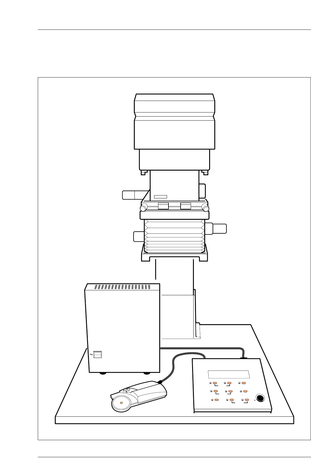
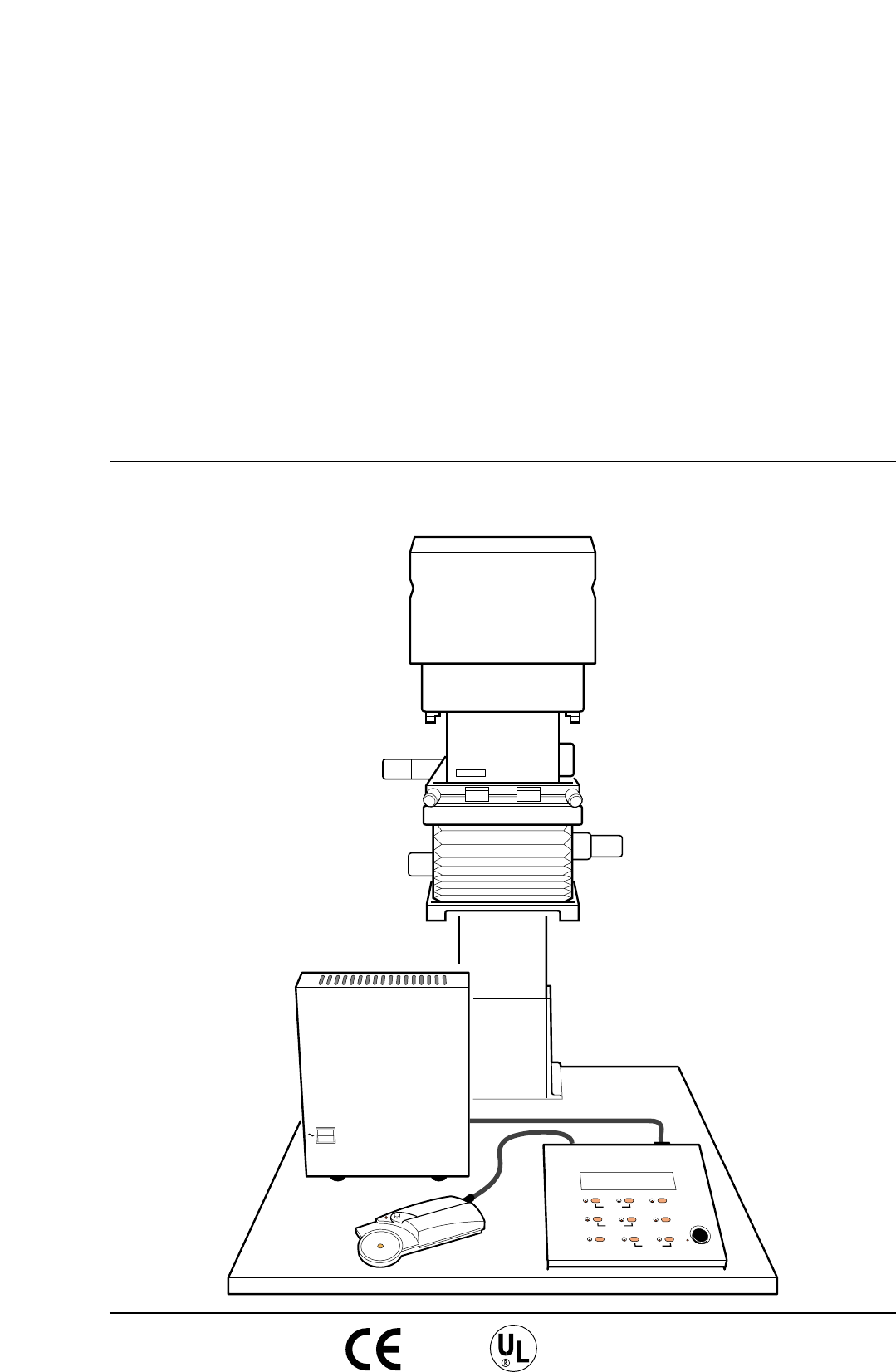
Figure 1.1 MULTIGRADE 600 System
POWER
0
I
MULTIGRADE 600S ILFORD
8888888
MULTIGRADE 600C
ILFORD
CONTRAST ADJ.
CONTRAST
GRADE TABLE
MEMORY GRADE % TIME
CLEAR BURN FOCUS
EXPOSE
GRADE TABLE
CALIBRATION
PRINT COUNT
YELLOW
MAGENTA
DENSITY
CAL ADJ.
NEW ADJ.
CALIBRATION
PAPER
_+
PAPER/MEMORY GRADE TIME/PRINTS
MULTIGRADE 600H
4

1
INTRODUCTION
a
b
c
d
1.1
a
b
5
See figure 1.1.
The MULTIGRADE 600 enlarger head and control system is for
use on professional enlargers where negative coverage is
required up to 12.7x10.2cm (5x4 inches). The system
incorporates advanced electronics, and offers the black and
white printer finger tip control of a wide range of contrasts.
The MULTIGRADE 600 system comprises the following elements:
MULTIGRADE 600H enlarger head
MULTIGRADE 600C control unit
MULTIGRADE 600S power supply
MULTIGRADE 600P contrast and exposure probe
OPTIONAL EXTRAS
Available as optional extras are:
A range of light mixing boxes from 35mm up to 5x4inches.
MULTIGRADE 600F footswitch
2
DESCRIPTION
2.1
2.1a
6
The MULTIGRADE 600 system is easy to install and straightforward
to use. By following the instructions in this manual, quality prints,
together with continuous and reliable operation, are assured.
MULTIGRADE 600H ENLARGER HEAD
See figure 2.1.
The MULTIGRADE 600H diffuser enlarger head replaces the
original condenser, diffuser or cold cathode lamphouse used with
a range of professional enlargers. It is fitted to the enlarger
chassis using an adaptor kit, designed to make installation quick
and relatively simple.
Light source
The enlarger head is fitted with a fan cooled high output halogen
lamp, heat filter and motorized yellow and magenta dichroic
colour filters.
The lamp is kept running at low power (pre-warmed) whenever the
system is switched on, to provide quick start-up and consistent results.
The cooling fan runs only while an exposure is being made.
Extremely stable and repeatable exposures are provided by a
proven closed loop light monitoring system and motorised light
shutter mounted in the base of the head, just above the light
mixing box. Light from the filters is reflected and diffused in the
mixing box to provide even illumination of the negative. The
colour variation obtainable enables the wide contrast range,
available with ILFORD variable contrast papers, to be used to its
full advantage.
MULTIGRADE 600H
Figure 2.1 MULTIGRADE 600H enlarger head
2.1b
2.2
7
Note
A single servo motor drives both filter carriers. At one extreme,
the magenta filter is fully in the light beam (Grade 5). At mid-
travel, both filters are clear of the light beam and white light is
transmitted (at Grade 2.5) giving maximum printing speed. At
the other extreme, the yellow filter is fully in the light beam
(Grade 00). The yellow and magenta filters can never both be in
the light beam at the same time.
Light mixing boxes
A range of light mixing boxes is available, including sizes
35mm, 6x6cm, 6x7cm, 6x9cm and 5x4inches.
The box or boxes required are not included with the MG600
system and must be ordered separately. Additional boxes may
be ordered at any time to suit user requirements.
To fit the light mixing box, see section 4.1a.
MULTIGRADE 600C CONTROL UNIT
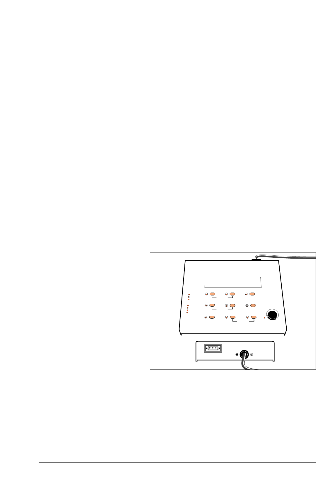
See figure 2.2.
The MULTIGRADE 600C control unit is quick and simple to
operate. Once the exposure time and contrast are established,
the permanent microprocessor controlled closed loop system
checks light intensity and colour before each exposure. A
correction is made automatically to the exposure time and
filtration (if required) to ensure consistent print results time after
time.
8888888
MULTIGRADE 600C
ILFORD
CONTRAST ADJ.
CONTRAST
GRADE TABLE
MEMORY GRADE % TIME
CLEAR BURN FOCUS
EXPOSE
GRADE TABLE
CALIBRATION
PRINT COUNT
YELLOW
MAGENTA
DENSITY
CAL ADJ.
NEW ADJ.
CALIBRATION
PAPER _+
PAPER/MEMORY GRADE TIME/PRINTS
Figure 2.2 MULTIGRADE 600C control unit
2.3
8
The control unit provides five paper channels. Four are pre-
programmed for ILFORD papers (see section 2.7) and one is left
free for programming by the user, if required.
Note
All channels can be checked and/or re-programmed (see section 8).
The control unit also incorporates calibration facilities to ensure
that the desired print density and grade are obtained when
scanning an image with the probe (see section 8 ).
All controls are described in section 3.
For maximum operator safety, the control unit is powered entirely
by low voltages supplied from a remote power supply (see
section 2.3).
The brightness of the display and button indicator lights
optimised to be seen under normal darkroom lighting. During
normal use, the displays will not fog ILFORD variable contrast
papers or other black and white paper of similar sensitivity.
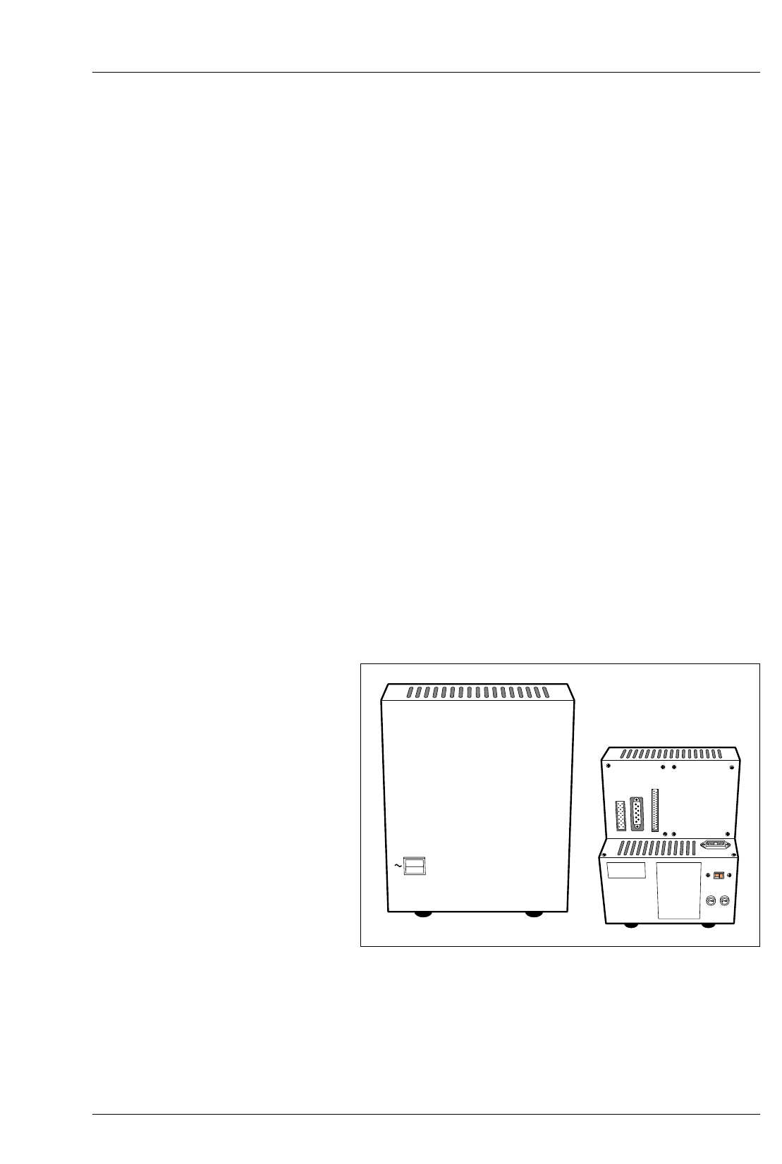
MULTIGRADE 600S POWER SUPPLY
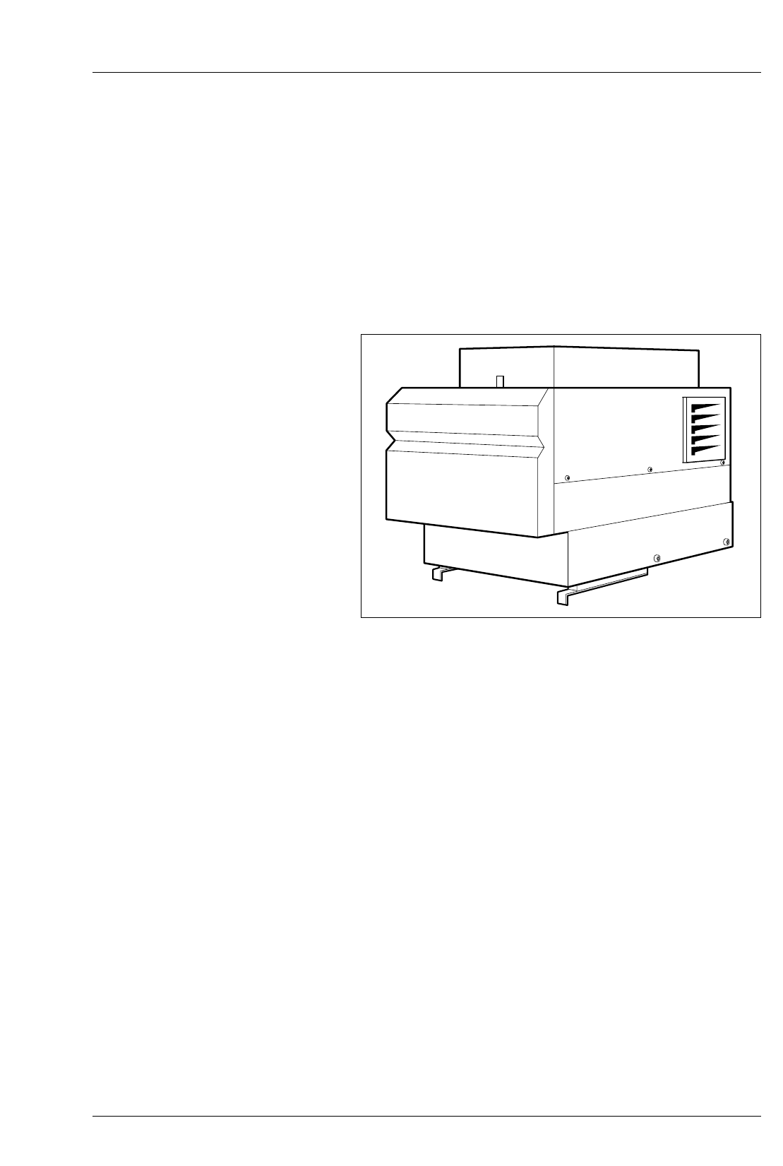
See figure 2.3.
The MULTIGRADE 600S stabilised power supply is connected
directly to the electrical mains supply. It has sockets for
connecting the enlarger head, control unit and footswitch or roll
easel, positioned on the rear of the unit. The on/off switch,
showing ‘O’ in the off position, controls power to the system.
POWER
0
I
ROLL-PAPER
FOOTSITCH
KEYBOARD
HEAD
F1 F1
MULTIGRADE 600S ILFORD
Figure 2.3 MULTIGRADE 600S power supply unit
2.4
2.5
9
CAUTION
The unit is factory set to mains voltage of 230V. Before switching
on the unit please check the correct mains voltage is selected and
the correct fuse is fitted, see section 4.2a.
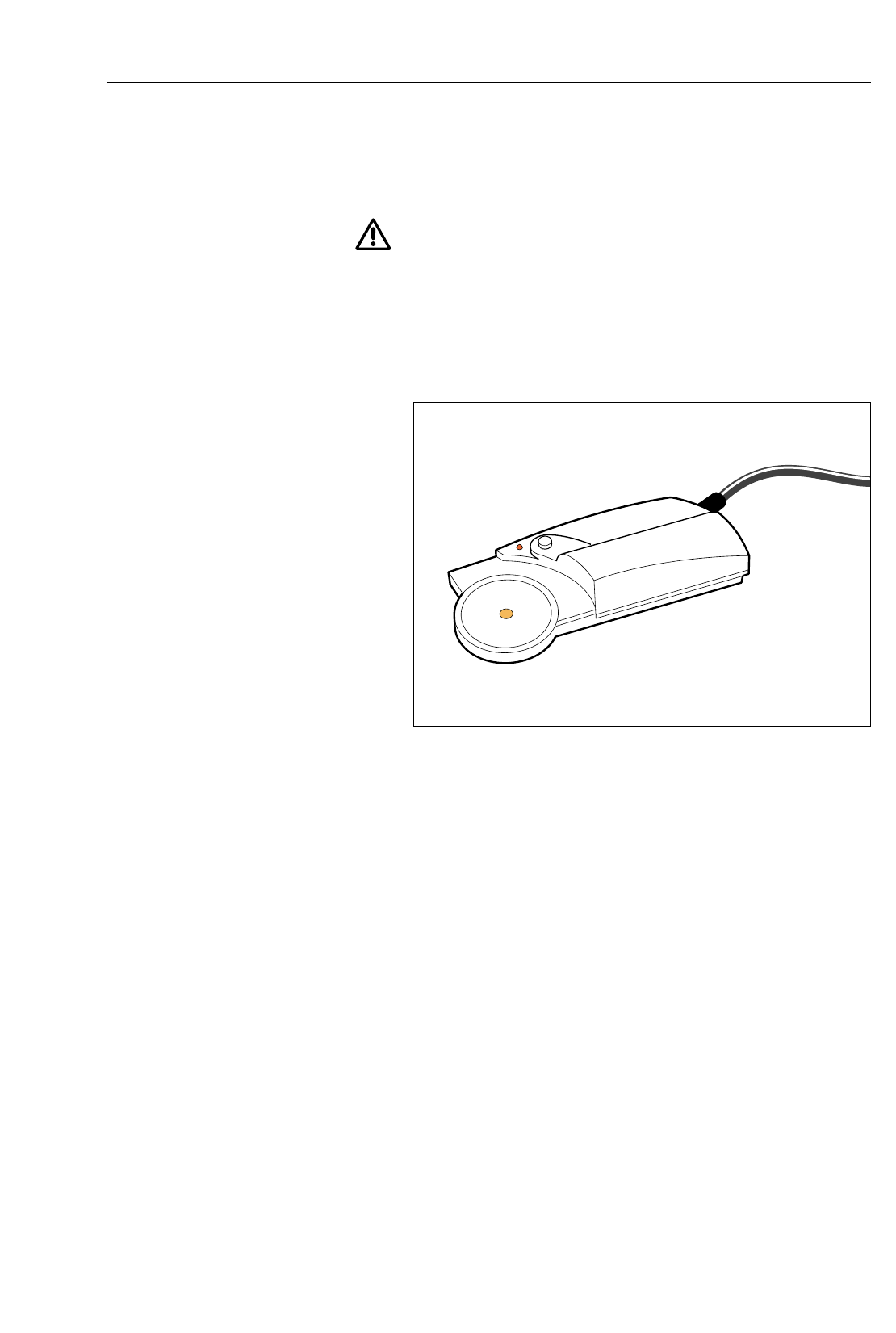
MULTIGRADE 600P EXPOSURE PROBE
See figure 2.4.
The MULTIGRADE 600P probe saves paper and time by
eliminating the need to make test strips or sheets.
The brightest and darkest parts of the image are scanned and the
readings obtained enable exposure time and grade to be
automatically calculated and displayed.
For a detailed description of how to use the probe, see section 7.
MULTIGRADE 600F FOOTSWITCH
The MULTIGRADE 600F footswitch is available as an optional
extra, and enables the printer to keep both hands free. The
function of the footswitch is to start an exposure only. If an
exposure in progress is required to be cancelled, this must be
done on the control unit.
Figure 2.4 MULTIGRADE 600P exposure probe

2.6
2.7
2.7a
2.7b
10
AUTOMATIC ROLL EASEL
The MULTIGRADE 600 system can be connected to most
automatic roll easels. Connection is made via an 8-pin Siemens
plug (as typically used on Durst roll easels). Please contact
ILFORD for inter-connection details.
PHOTOGRAPHIC PAPERS
The MULTIGRADE 600 system is designed for use with ILFORD
MULTIGRADE variable contrast papers.
MULTIGRADE paper
The control unit is pre-programmed for the following papers:
P1 ILFORD MULTIGRADE IV RC Deluxe
P2 ILFORD MULTIGRADE RC Warmtone
P3 ILFORD MULTIGRADE IV FB Fiber
P4 ILFORD MULTIGRADE FB Warmtone
P5 Spare channel
Other papers
Colour prints or prints from graded papers such as ILFORD
ILFOSPEED can be made using an appropriate setting from one
of the paper channels (grade 2.5) where both yellow and
magenta filtration values are set to zero, ie the enlarger head is
projecting white light. See section 12.
Alternatively, if it has not been reprogrammed, any grade setting
in paper channel 5 (P5) may be used.
During use, the control unit will display the grade set but this will
have no relevance to the prints being made.
3
CONTROLS
3.1
3.2
11
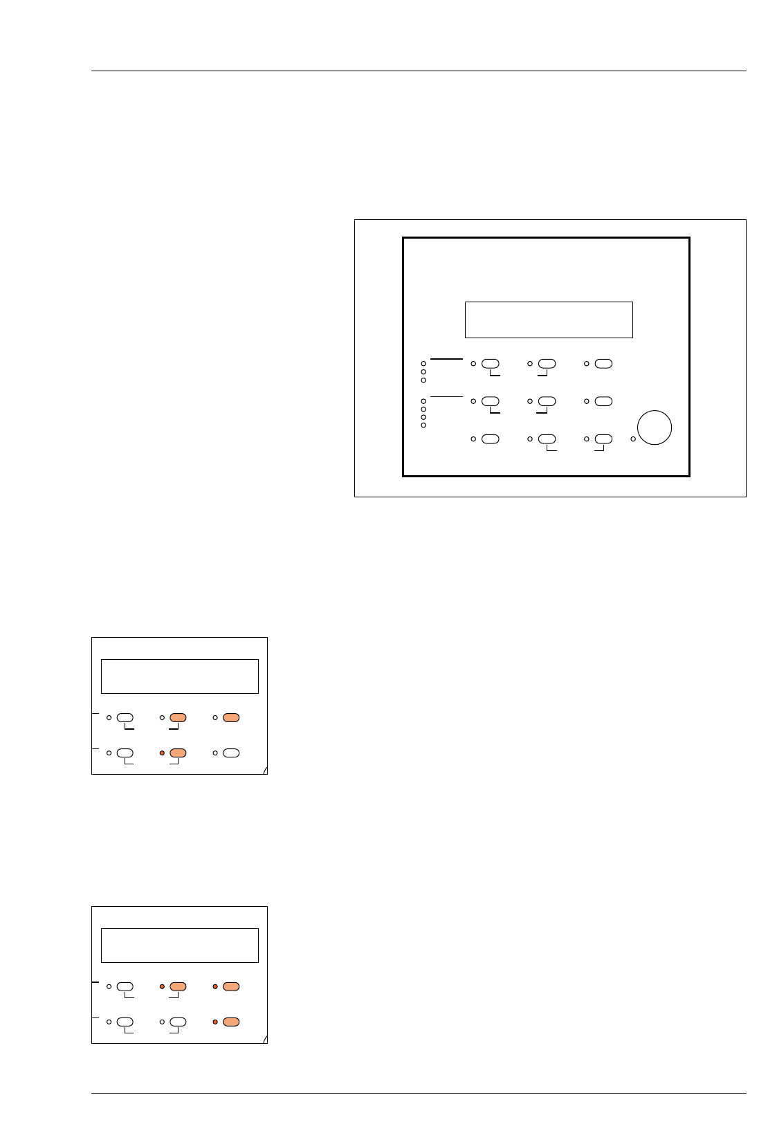
See figure 3.1.
All controls necessary to operate the MULTIGRADE 600 system
are located on the control unit, except for the power control
switch which is located on the power supply.
CONTRAST SELECTION
Grade is displayed in the centre display and is set by holding
down the ‘Grade’ button and depressing the +/– buttons to
increase or decrease the set value. The buttons control grade
selection from 5 (highest grade) to 0.0 (low grade) in 1/10
grade steps. At setting 0.0, a further press of the – button selects
the lowest grade 00. Holding the +/– buttons down causes the
display to roll sequentially in increments of 1/10 grade.
Note
When making changes to the grade setting, any necessary
changes to the exposure time to maintain a constant print density
will be automatically set by the control unit.
ELECTRONIC TIMER
Exposure time is displayed in the right hand display. Time is
displayed in hundredths of a second for 1.00 to 9.99 seconds,
tenths of seconds for 10.0 to 99.9 seconds and in whole
seconds from 100 to 999 seconds. The display counts down to
zero during main exposures, then resets to the set value.
The required exposure time is set using the +/– buttons. A short
press will increment the set value. Keeping a button depressed
will cause the time to roll up or down. The roll rate increases if
the button is held depressed for more than two seconds.
P2 3.5 14.5
CALIBRATION PAPER
EXPOSE
PRINT COUNT
GRADE TABLE
CALIBRATION
PAPER/MEMORY GRADE TIME/PRINTS
MULTIGRADE 600C ILFORD
NEW CAL.
CAL ADJ.
CONTRAST ADJ.
CONTRAST
YELLOW
MAGENTA
DENSITY
–+
MEMORYGRADE TABLE GRADE %TIME
CLEAR BURN FOCUS
IL1035
Figure 3.1 Controls
3.5
ON PAPER
GRADE TABLE
CALIBRATION
PAPER/MEMORY GRADE TIME/PRINTS
L.
ST ADJ.
ST
A
–+
MEMORYABLE GRADE %TIME
14.5
ON PAPER
GRADE TABLE
CALIBRATION
PAPER/MEMORY GRADE TIME/PRINTS
L.
ST ADJ.
ST
A
–+
MEMORYABLE GRADE %TIME
3.3
3.4
3.5
12
Note
The exposure time cannot be incremented in less than 2% steps.
Exposure time may also be adjusted using the ‘% Time’ button.
When the ‘% Time’ button is depressed, the time display shows
zero. Whilst holding this button depressed, the required
percentage time adjustment can be set using the +/– buttons. On
release of the ‘% Time’ button, the corrected time is displayed.
The operating range of % Time is –99% to +999%.
Note
When an exposure is initiated, the closed loop control system
assesses colour and brightness of the exposing light before the
shutter is opened to begin the exposure. Any necessary
corrections to maintain a constant exposure are made
automatically and this could result in the set exposure time
changing to a different value, from which the countdown then
begins.
This is normal operation for the system. The effect will become
more pronounced (an increase in exposure time) as the lamp
ages and its light output reduces, or the colour filters become
dirty, etc.
EXPOSE
With the time and grade selected, start the main exposure by
pressing the ‘expose’ button. The time will count down to zero.
Exposure can be stopped at any time by pressing the ‘expose’
button. Pressing the expose button again will re-start and
complete the remaining exposure. If the remaining exposure is
not required, pressing the ‘clear’ button resets the timer to the
original exposure time.
FOCUS
To obtain a continuous light suitable for focusing and
composition, press the ‘Focus’ button. To cancel the ‘Focus’
mode, press the ‘Focus’ button again (or the ‘Clear’ or ‘Expose’
buttons).
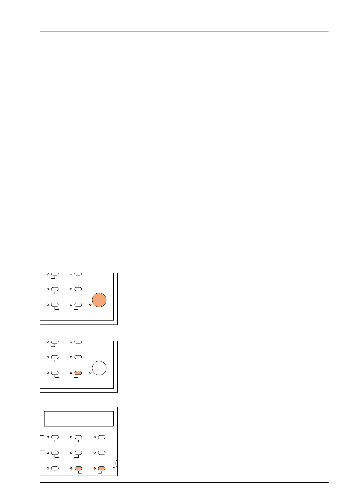
PRINTS COUNTER
The control unit automatically counts the number of main
exposures (additional burn-in exposures are not counted). This is
particularly useful if a run of identical prints is made from one
negative. To obtain the display, simultaneously press the ‘Focus’
and ‘Burn’ buttons. For example, 99 exposure cycles is displayed
C 099
EXPOSE
PRINT COUNT
A
DE TABLE
L
IBRATION
GRADE %TIME
BURN FOCUS
EXPOSE
PRINT COUNT
A
DE TABLE
L
IBRATION
GRADE %TIME
BURN FOCUS
PI C 099
O
N PAPER
PRINT COUNT
GRADE TABLE
CALIBRATION
PAPER/MEMORY GRADE TIME/PRINTS
L
.
S
T ADJ.
S
T
A
–+
MEMORY
A
BLE GRADE %TIME
CLEAR BURN FOCUS
a
b
3.6
3.7
3.8
13
Note
The maximum number of exposure cycles that can be counted is
999.
To reset the prints counter to zero, press and hold the ‘Focus’
and ‘Burn’ buttons and press the ‘Clear’ button also.
Notes
The prints counter will also record a cancelled exposure cycle.
The print counter retains the count value when power to the unit
is switched off. Ensure that the counter is zeroed before starting a
new print run.
PAPER CHANNEL SELECTION
The ‘Paper’ button is used to select paper channels P1 to P5 (see
section 2.7). The selection is indicated in the left-hand display.
MANUAL BURNING-IN
The ‘Burn’ button selects a continuous exposure at the grade
shown on the display for manual burning in. If required, the
grade can be changed during the exposure.
To cancel the ‘Burn’ mode, press the ‘Burn’ button again (or the
‘Clear’ or ‘Expose’ buttons).
BURNING-IN OPERATIONS USING THE MEMORY
FACILITY
The control unit incorporates a memory store, capable of storing
a maximum of three exposures in addition to the main exposure
and is selected using the ‘Memory’ button. The memory store is
particularly useful for programming a sequence of additional
exposures to follow the main exposure. Each additional exposure
can be made at a different grade. Once the memory has been
programmed, the control unit steps through the sequence of
exposures each time the ‘Expose’ button is pressed.
See section 6.
Note
The stored memories are retained when the equipment is
switched off.
P2 3.5 14.5
O
N PAPER
PRINT COUNT
GRADE TABLE
CALIBRATION
PAPER/MEMORY GRADE TIME/PRINTS
.
T
ADJ.
T
A
–+
MEMORYBLE GRADE %TIME
CLEAR BURN FOCUS
1E
O
N PAPER
PRINT COUNT
GRADE TABLE
CALIBRATION
PAPER/MEMORY GRADE TIME/PRINTS
.
S
T ADJ.
S
T
A
–+
MEMORY
A
BLE GRADE %TIME
CLEAR BURN FOCUS
PI C 000
O
N PAPER
PRINT COUNT
GRADE TABLE
CALIBRATION
PAPER/MEMORY GRADE TIME/PRINTS
L
.
S
T ADJ.
S
T
A
–+
MEMORY
A
BLE GRADE %TIME
CLEAR BURN FOCUS
P2
I
ON PAPER
GRADE TABLE
CALIBRATION
PAPER/MEMORY GRADE TIME/PRINTS
L
.
S
T ADJ.
S
T
–+
MEMORY
A
BLE GRADE %TIME
3.9
3.10
3.11
a
b
c
d
14
CALIBRATION
The three functions which may be calibrated or re-calibrated are
selected by holding down the ‘Paper’ button and pressing the ‘–’
button to select the feature required. An LED on the panel
illuminates to indicate the feature selected. A fourth press of the
‘–’ button returns the control unit to normal operation. See section
8 for details.
GRADE TABLE
The four elements of the grade tables may be accessed if the
stored data needs to be changed or if Paper channel 5 is
required to be set up. For each Paper channel, the data to be
checked or changed is selected by holding down the ‘memory’
button and then pressing the ‘Grade’ button. An LED on the panel
illuminates to indicate the data selected. A fifth press of the
‘Grade’ button returns the control units to normal operation. See
section 8 for details.
CLEAR BUTTON
The ‘Clear’ button is used to:
Reset a cancelled exposure to its original setting
Reset the Burn-in memory times (for memories 3E and 4E) to zero.
Reset the paper grade table data to the factory programmed
values values
Reset the print counter to zero
CALIBRATION PAPER
PRINT COUN
T
GRADE TABLE
CALIBRATION
NEW CAL.
CAL ADJ.
CONTRAST ADJ.
CONTRAST
YELLOW
MAGENTA
DENSITY
–
MEMORYGRADE TABLE GRADE
CLEAR BURN
CALIBRATION PAPER
PRINT COUN
T
GRADE TABLE
CALIBRATION
NEW CAL.
CAL ADJ.
CONTRAST ADJ.
CONTRAST
YELLOW
MAGENTA
DENSITY
–
MEMORYGRADE TABLE GRADE
CLEAR BURN
CALIBRATION PAPER
PRINT COUN
T
GRADE TABLE
CALIBRATION
NEW CAL.
CAL ADJ.
CONTRAST ADJ.
CONTRAST
YELLOW
MAGENTA
DENSITY
–
MEMORYGRADE TABLE GRADE
CLEAR BURN
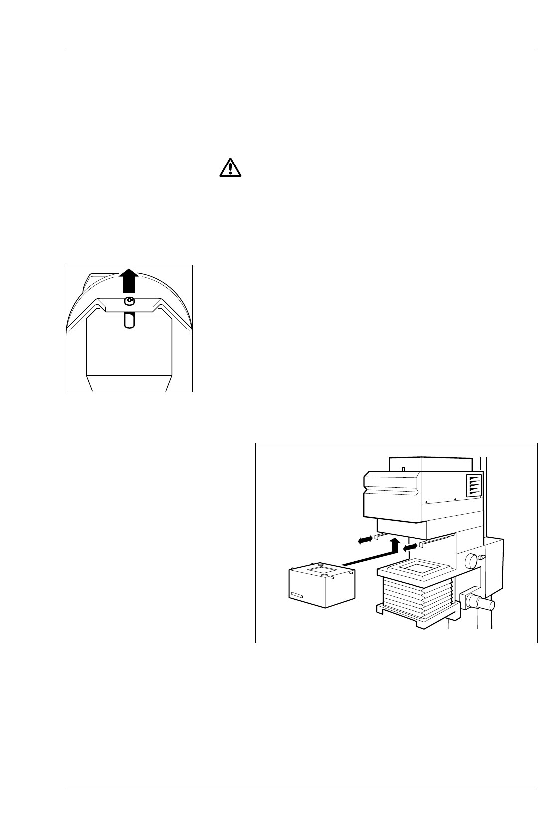
4
INSTALLATION
4.1
4.1a
1
15
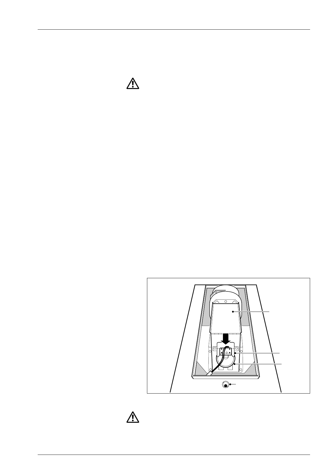
See figure 4.2.
CAUTION
Installation of the MULTIGRADE 600 system is very
straightforward. However, if you are in any doubt about making
any of the electrical connections, consult a competent electrician.
Ensure the mains electrical supply is switched off before
connecting or disconnecting any plug.
ENLARGER HEAD
For information on fitting the enlarger head to your particular
enlarger, refer to the separate leaflet supplied with the adaptor
kit.
During installation, remove the top access cover (see section 9)
and remove the transport securing device (screw and bush).
Replace the top cover.
Connect the head to the appropriate socket on the power supply.
Changing light mixing boxes
See figure 4.1.
To minimise exposure times, a light mixing box should be fitted
which suits the negative format being printed.
To fit a light mixing box:
With the negative carrier removed, move the two slide catches,
which retain the mixing box, to the forward position.
MULTIGRADE 600H
MULTIGRADE 600H
Figure 4.1 Changing light mixing boxes
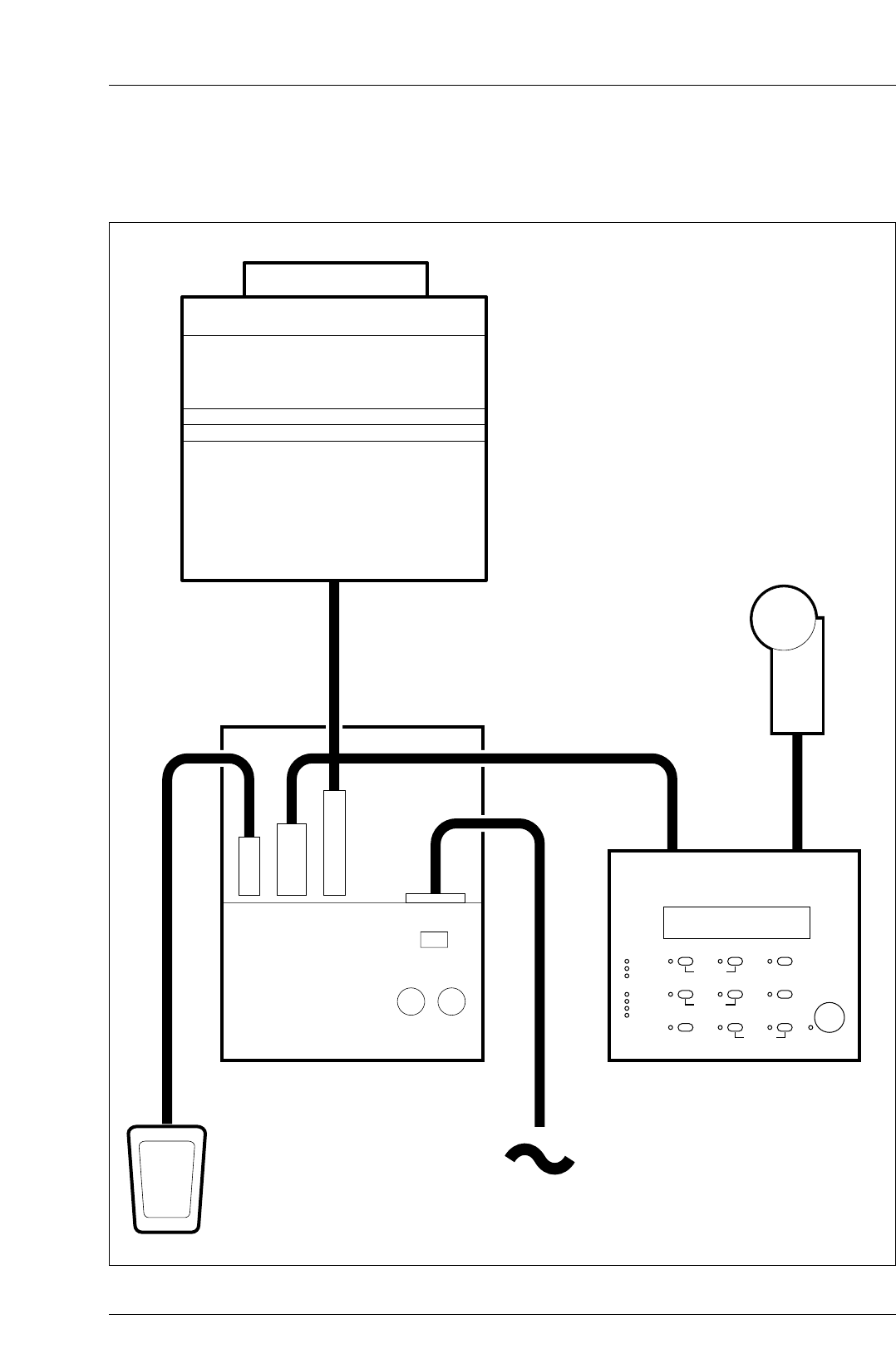
Figure 4.2 Installation
MULTIGRADE 600P
MULTIGRADE 600F
MULTIGRADE 600S
MULTIGRADE 600H
MULTIGRADE 600C
16
2
3
4
5
4.2
4.2a
1
2
a
b
3
a
b
17
Ensure the mixing box format/size label is facing the front (eg
24x36mm).
Locate the mixing box in position and lift upward to locate the
retaining pins into their slots.
Move both slide catches backward to lock the mixing box in
position.
Refit the negative carrier.
Removal of the mixing box is the reverse of the above procedure.
Support the mixing box to prevent it from dropping downwards
as the slide catches are released.
POWER SUPPLY
Supply voltage
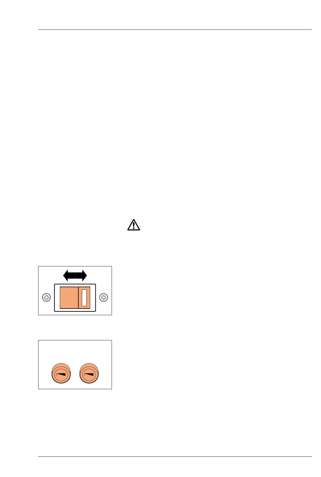
WARNING
The power supply is supplied with the voltage selector set to
230V and a 2.5A fuse fitted. Before switching on, check that this
is correct for your electrical mains supply. If it is not, carry out the
following procedure.
Remove the bayonet fitting fuseholder cap, complete with fuse (F1).
A two position supply voltage selector is located on the rear
panel enabling the appropriate input voltage to be selected in
accordance with the electrical mains supply.
Position the 2-position voltage selector to the correct setting.
For supplies 110-120V, 50/60Hz, set to the 115V position.
For supplies 220-240V, 50/60Hz, set to the 230V position.
Fit the correct fuse, supplied with the unit (see section 11).
For 115V insert T-5.0A fuse.
For 230V insert T-2.5A fuse.
F1
230V T2.5A
115V T5A
F2
T 12.5A
230V
4.2b
4.2c
a
b
c
4.3
4.4
4.5
4.6
18
Working environment
The power supply is totally enclosed and becomes warm with
extended use. It is advisable to position the unit so that adequate
all round ventilation is provided at all times.
CAUTION
For safety reasons, do not position the power supply on the floor.
When the power supply had been positioned, ensure there is
enough slack in the lead to the enlarger head, to allow full travel
of the head on the enlarger column.
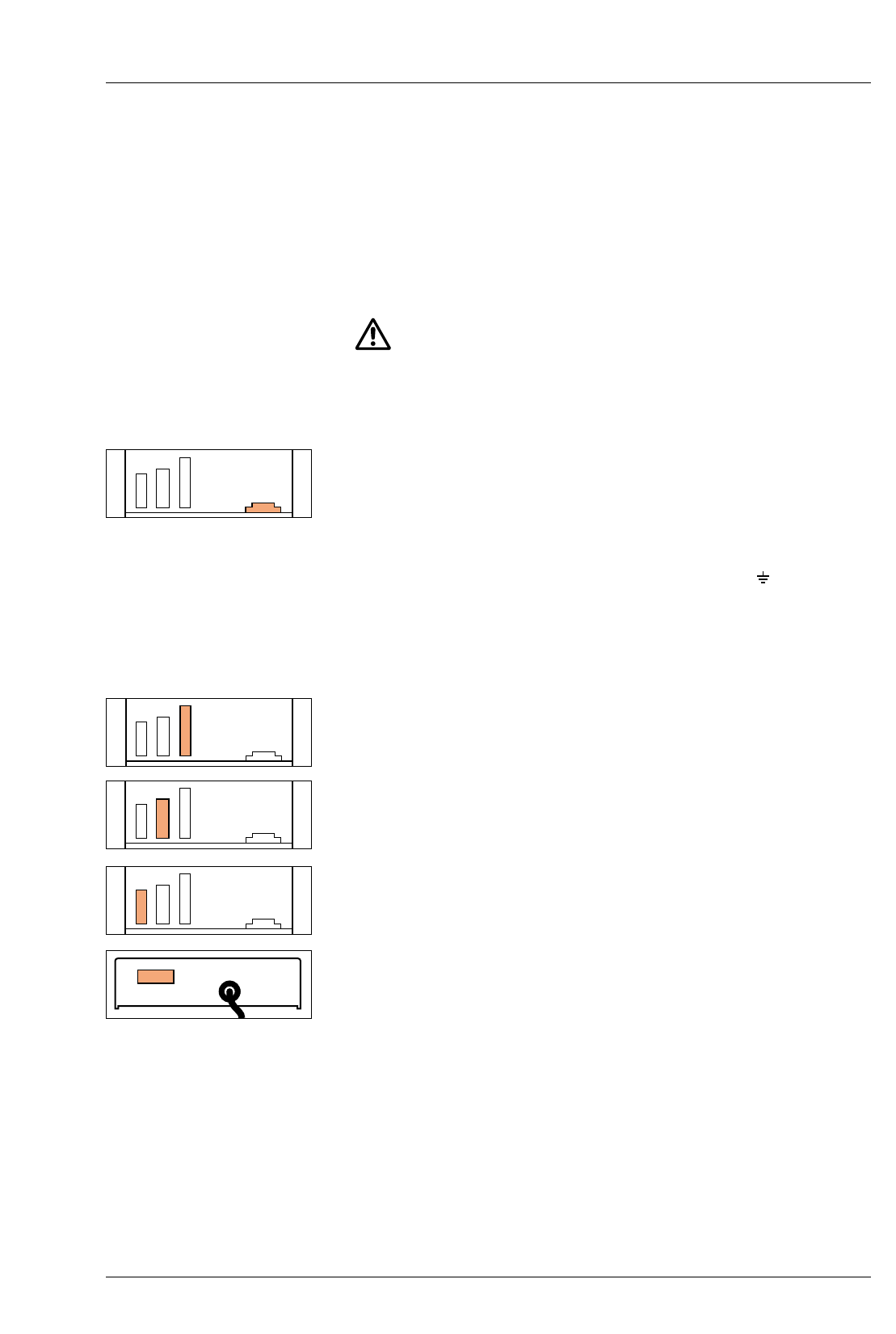
Connection to mains supply
If a moulded plug is not fitted to the mains cable provided,
connect a plug of at least 10A rating as follows:
Brown wire to the live pin (marked L ).
Blue wire to the neutral pin (marked N ).
Green/yellow wire to the earth pin (marked E or ).
Connect the other end of the mains cable to the ‘power input’
socket on the power supply. Ensure the plug is pushed fully into
the socket.
ENLARGER HEAD
Connect the enlarger head to the appropriate socket on the
power supply.
CONTROL UNIT
Connect the control unit lead to the appropriate socket on the
power supply, and tighten the two retaining screws.
FOOTSWITCH
Connect the footswitch to the appropriate socket on the power
supply.
EXPOSURE PROBE
Connect the probe to the appropriate socket on the control unit,
and tighten the two retaining screws.

5
PRINT MAKING
STANDARD METHOD
1
2
3
4
5
6
7
19
Switch the system on.
Note
The control unit will display the values set when it was last
switched off. Select the required paper channel for the paper
type you are using.
Locate your negative in the enlarger. Select ‘Focus’ to project
white light for focusing, composition and assessment of the
image. When satisfied press ‘Focus’ again to cancel.
Select the contrast required. See section 3.1.
Select the estimated exposure time. See section 3.2.
Position a sheet of ILFORD MULTIGRADE paper on the enlarger
base board. Expose the sheet by pressing ‘expose’.
Process the exposed paper. Check the print for density. If
necessary, correct the exposure and make another print.
Check the print for contrast. If necessary, make another print at a
different grade.
It is not necessary to alter the exposure time when changing
grades. This is done automatically by the control unit to ensure
that a constant mid-tone density is maintained.
In this example, exposure time had automatically changed from
13.0 to 16.3.
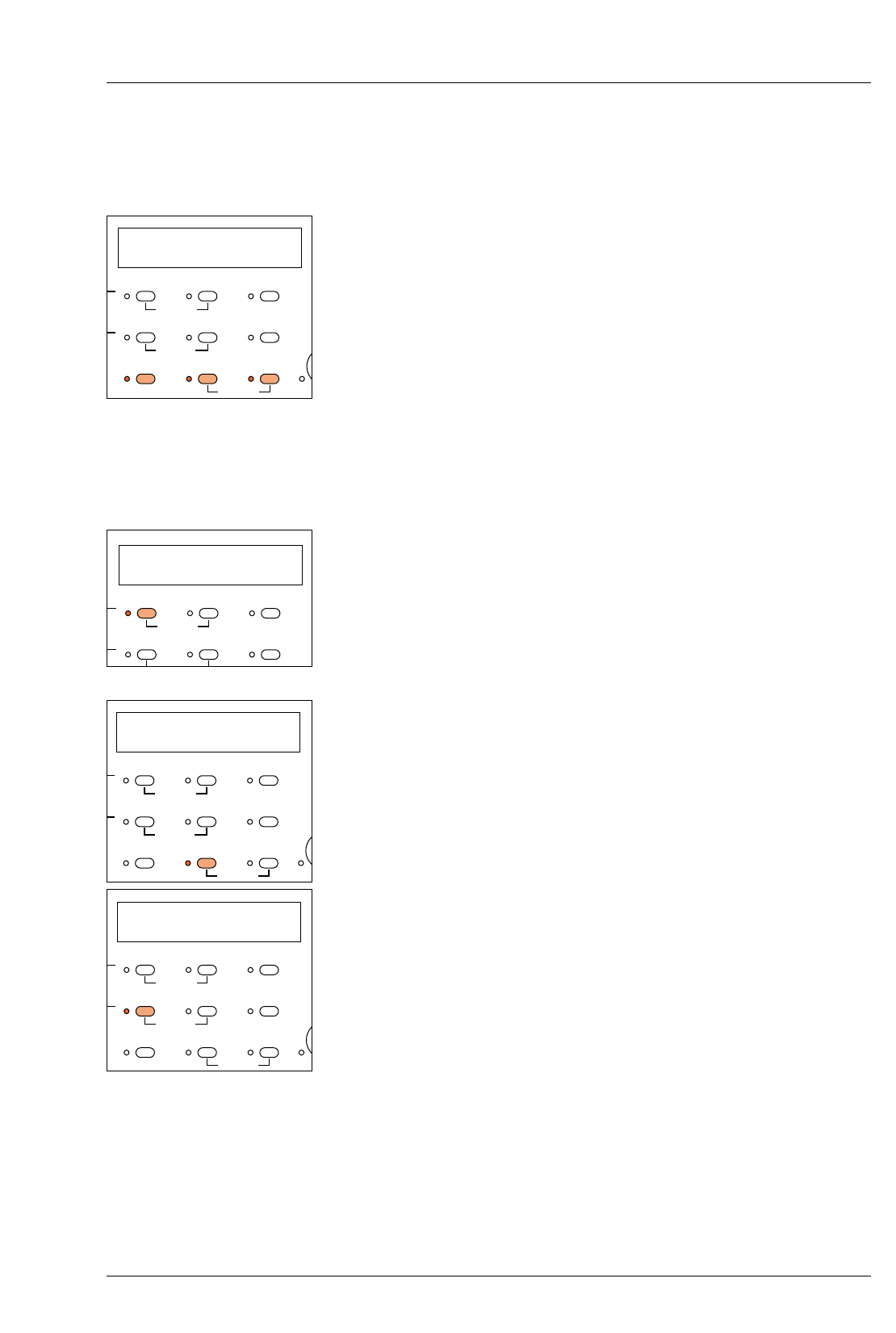
6
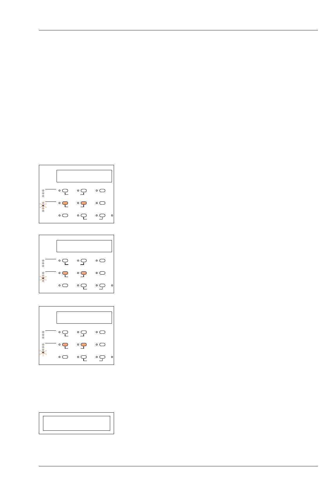
PROGRAMMING
THE MEMORY
1
2
3
4
5
6
7
8
9
20
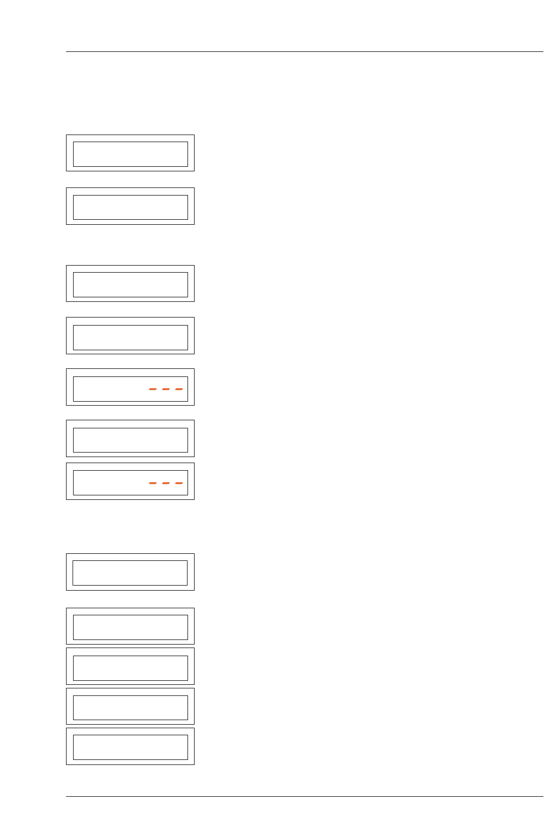
The values shown in the following diagrams are given for
example only. Set the paper channel main exposure time and
grade required in the normal way.
Press ‘memory’. ‘1E’ will appear in the memory display
indicating that the control unit is now in memory mode. The
exposure time and grade set above have now become the main
exposure 1E, to be followed by burn-in exposures 2E, 3E and
4E.
Press ‘memory’ again and ‘2E’ will appear in the memory
display. As a start point, this second exposure always sets to
50% of the main exposure (at the grade setting previously left in
the memory).
Reset the exposure time and grade to the settings required for the
second exposure (first burn-in memory).
Press ‘memory’ again to select the third exposure. The last grade
value used will appear in the display. An exposure time may
appear if it was not previously cleared.
Set the exposure time and grade to the settings required for the
third exposure.
Repeat 5 and 6 to set the fourth exposure if required. If not
required, cancel the exposure time by pressing ‘Clear’.
Note
The control unit will ignore exposures 3E and 4E when the
exposure time is set to ‘– – –’.
A further press of the ‘memory’ button will return the control unit
to normal mode, where only this exposure will be activated on
pressing ‘Expose’.
To use the burn-in memories set as above, again press ‘memory’
so that 1E is shown in the display.
Pressing ‘Expose’ now will cause the control unit to step
sequentially through the exposures.
P2 2.5 6.00
PAPER/MEMORY GRADE TIME/PRINTS
1E 2.5 6.00
PAPER/MEMORY GRADE TIME/PRINTS
2E 2.0 3.36
PAPER/MEMORY GRADE TIME/PRINTS
2E 2.8 5.60
PAPER/MEMORY GRADE TIME/PRINTS
3E 1.5
PAPER/MEMORY GRADE TIME/PRINTS
3E 4.0 9.00
PAPER/MEMORY GRADE TIME/PRINTS
4E 2.4
PAPER/MEMORY GRADE TIME/PRINTS
P2 2.5 6.00
PAPER/MEMORY GRADE TIME/PRINTS
1E 2.5 6.00
PAPER/MEMORY GRADE TIME/PRINTS
2E 2.8 5.60
PAPER/MEMORY GRADE TIME/PRINTS
3E 4.0 9.00
PAPER/MEMORY GRADE TIME/PRINTS
1E 2.5 6.00
PAPER/MEMORY GRADE TIME/PRINTS

a
b
c
d
21
Notes
The burn-in memories are retained in the memory unless
cancelled or reset.
The exposure time of memory 2E cannot be set to ‘– – –’. If only
the main exposure is required, set the control unit back to normal
mode with a paper channel showing in the display.
If the main exposure time is reset (when either set to a paper
channel or to ‘1E’) then the times set in all memories will be reset
in the same ratio. The grade settings are unaffected.
If any recalculated exposure time is less than 1.0 seconds, the
value will be displayed but will flash indicating that this exposure
cannot be made.
Pressing ‘% Time’ when the display is showing memories 2E, 3E
or 4E indicates the burn-in exposure as a percentage of the main
exposure 1E.
7
PRINT MAKING
USING THE PROBE
1
2
3
4
5
6
22
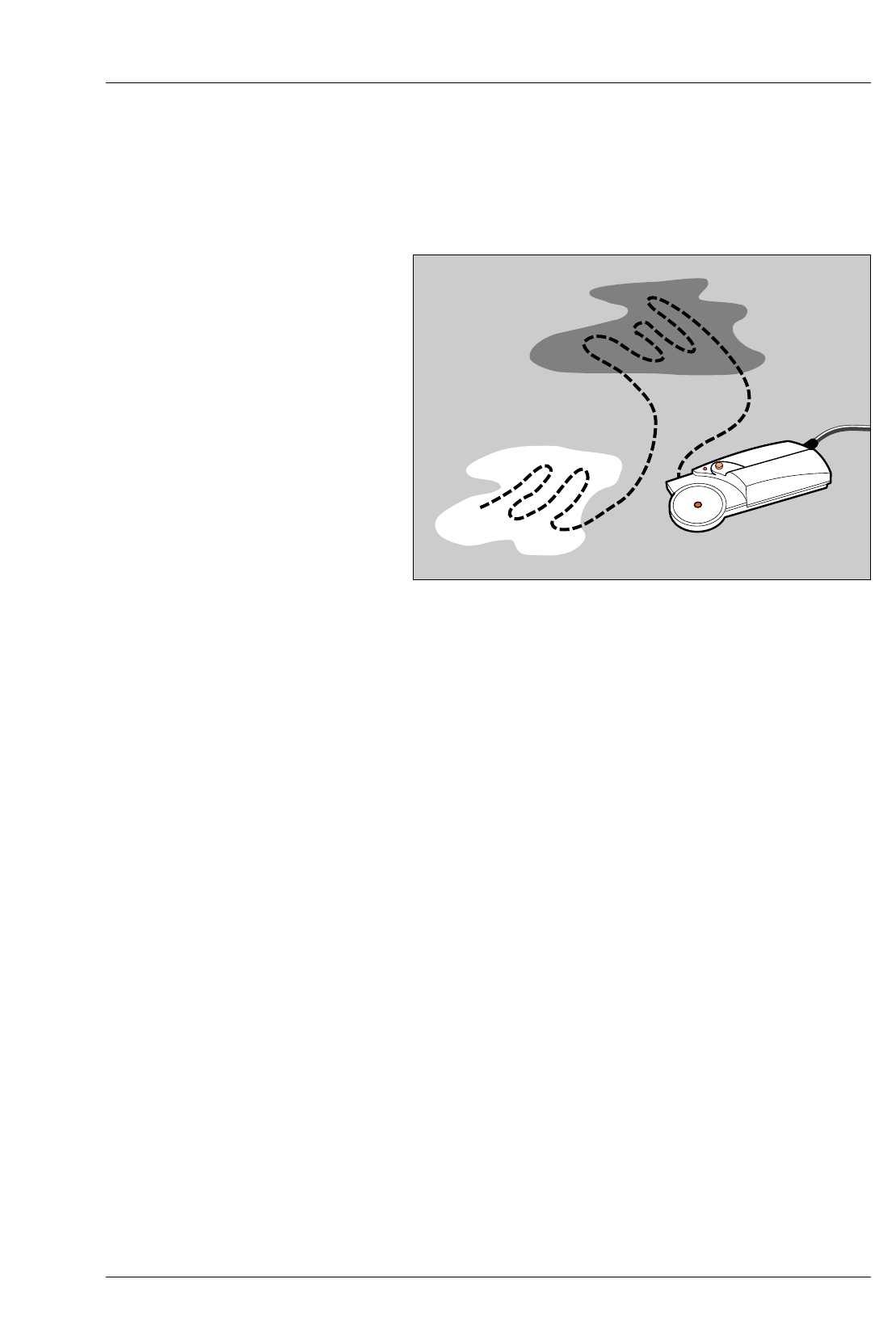
See figure 7.1.
Insert the negative to be printed into the enlarger. Select ‘Focus’. Focus
and compose the required image and set the working aperture (f-stop)
of the lens.
Select the appropriate paper channel on the control unit.
Check the probe LED is switched on. Position the probe photocell in the
brightest area of the projected image and press and hold the probe
button.
Note
The probe button must be held down during the complete measurement
cycle.
When the probe LED extinguishes move the probe measuring cell over the
brightest and darkest areas of the image. Release the probe button.
The calculated exposure time and grade is then displayed. Unless you
wish to make a further measurement, cancel the focus light and prepare
to make a print.
Position a sheet of paper on the enlarger baseboard. Press ‘expose’. The
sheet is given the calculated exposure. Process and assess the final print.
The exposure probe can be used if the control unit has stored memories.
Note
The exposure times set in the burn-in memories will be modified in the
same ratio as the new and previous main exposure times. The grades
set in the memories are unaffected (see section 6 Note c).
Figure 7.1 Using the MG600 exposure probe
7.1
1
2
3
4
5
6
7
8
23
USING THE EXPOSURE-CONTRAST PROBE
SOME NOTES AND GUIDELINES
If used correctly, the MULTIGRADE 600P exposure probe can be of
great benefit to the black and white printer. Listed below are some
simple rules to observe in order to maximise the probe accuracy.
Pressing the probe button opens a shutter covering the measuring
cell and begins the measuring cycle.
During scanning, the probe takes ten readings per second. The
highest and lowest readings are stored and enable the grade and
exposure time to be calculated.
Also during scanning, the display shows the previously set grade
and a number which represents the density being measured by the
probe. This enables the lightest and darkest areas of the image to
be found (if necessary). The difference between the highest and
lowest numbers represents the contrast of the negative.
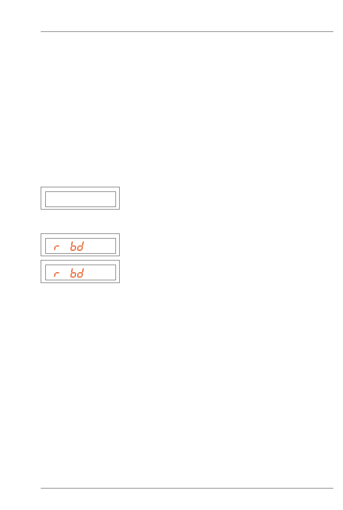
If the light level measured is too low, the display will show Pr bd HI
(Probe density high). The lens aperture should be increased and a
new probe measurement taken.
If the light level is too high, the display will show Pr bd LO (Probe
density low). The lens aperture should be reduced and a new probe
measurement taken.
The probe is not affected by normal levels of darkroom safelighting.
However a very bright safelight situated close to and above the
enlarger baseboard could have an effect. This can easily be checked.
Operate the probe button to initiate a probe measurement. View
the density value being displayed on the control unit (see 7.1 para
3 above) and switch the local safelight on and off. If the number
displayed is affected, then for accurate results, this safelight should
be re-sited or switched off when using the probe.
If the paper channel is changed, the image must be measured
again for accurate results.
Obtaining good results with the probe requires some familiarisation with
its use. It is not necessarily the absolute brightest and darkest parts of the
image which should be scanned, but rather the areas in which detail still
needs to be seen in the resulting print. Extreme dark areas or highlights
should therefore be avoided when scanning.
The MULTIGRADE 600 system is programmed to calculate the correct
exposure time for a wide range of negatives. Inevitably, there will be some
negatives (showing extremes of exposure or development or not having a
suitable area from which to take readings) that may produce inaccurate
results. If continued difficulty is found in obtaining a high percentage of
correctly exposed prints, the probe may be re-calibrated (see section 8).
P1 2.5 195
PAPER/MEMORY GRADE TIME/PRINTS
PHI
PAPER/MEMORY GRADE TIME/PRINTS
PLO
PAPER/MEMORY GRADE TIME/PRINTS
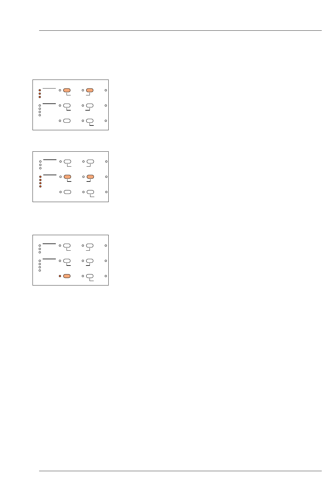
8
PROGRAM STRUCTURE
8.1
8.2
8.2a
24
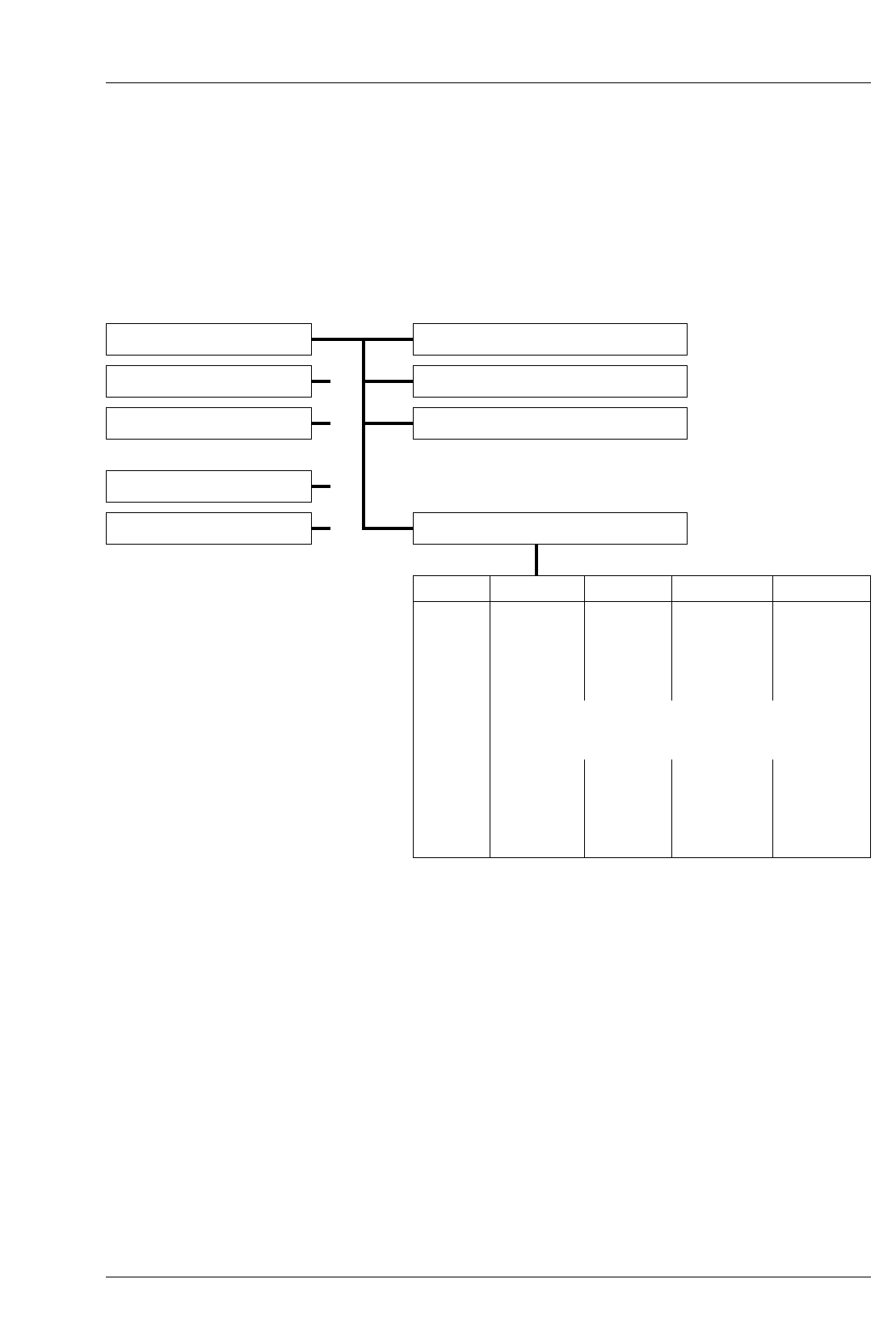
BASIC CALIBRATION AND DATA ENTRY
The program consists of five paper channels, each with the
following structure:
CALIBRATION OF THE EXPOSURE-CONTRAST
PROBE
The ‘Calibration’ function allows the basic setting up of the
system to obtain the correct exposure times (density) and grade,
when using the probe.
Density calibration - ‘New Cal’ and ‘Cal Adj’
The density calibration factor ‘Cal’ is displayed on the control
unit in ‘Cal Adj’ mode. the value of ‘Cal’ is determined by
making test prints and is directly linked to exposure time
determined by the probe (it represents paper speed).
‘New Cal’ should be used to calibrate the probe for new batches of
paper. ‘Cal Adj’ is best used to reset the calibration to predetermined
values. For example, to reset to values determined under ’New Cal’
and then written on the paper box for reference.
Fine tuning can also be carried out by small adjustments of the ‘New Cal’
value to compensate for a drift in processing chemistry activity, for example.
Paper Channels Probe Calibration
Channel 1 Density calibration - ‘New Cal’
Channel 2 Calibration adjustment - ‘Cal Adj’
Channel 3 Contrast adjustment - ‘Contrast Adj’
Channel 4
Channel 5 Paper grade table - ‘Grade Table’
Grade Contrast Yellow Magenta D-Comp
00
0.0
0.5
1.0
1.5
2.0
2.5
3.0
3.5
4.0
4.5
5.0
Grade Table
See tables in section 12
1
2
3
4
5
6
7
8
9
10
11
25
Density calibration is only possible by using the following
procedure, during which a probe measurement must be made
when the control unit displays ‘Measure’.
To calibrate proceed as follows:
Select an average production negative of good tonal range which
you would expect to be printed at grade 2.5 and place in the
enlarger. Press ‘Focus’, adjust and focus an image of
approximately 20x25cm (8x10in) onto the baseboard. Set the
working aperture on the lens.
Select the paper channel.
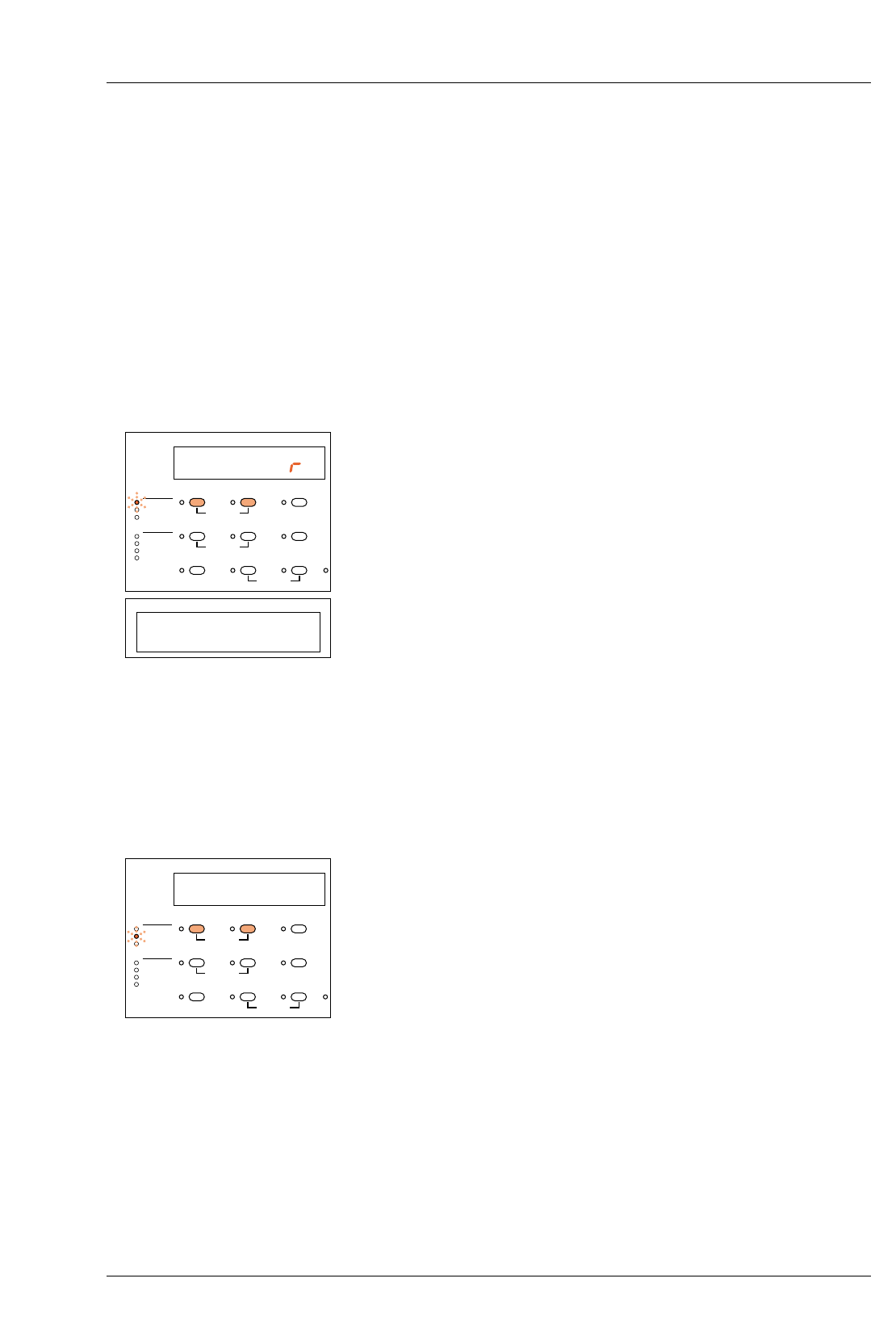
Select ‘New Cal’ mode by keeping the ‘Paper’ button depressed
and by pressing the ‘–’ button once.
The ‘New Cal’ LED will light up and the display will show ‘Measure’.
With the room lights off, make a normal probe measurement (see section 7).
After releasing the probe key, the display will show the grade (2.5) and the
exposure time (which corresponds to the calibration value).
Make an exposure with the settings obtained and process the print.
Correct the test print by adjusting the exposure time using the ‘+/–’
buttons as required.
Note
When the exposure time is corrected, the calibration value will be
automatically adjusted (they are directly linked together).
Repeat steps 5 and 6 until the density of the test print is correct.
Select ‘Cal Adj’ by keeping the ‘Paper’ button depressed and
pressing the ‘–’ button once.
The ‘Cal Adj’ LED will light and the display will show the
calibration value derived during the previous procedure. This
calibration value represents the paper speed and for reference
should be noted down or written on the box of paper being used.
Return to the normal printing mode by keeping the ‘Paper’ button
depressed and by pressing the ‘+/–’ button twice.
If required, the density calibration value may be adjusted in ‘Cal
Adj’ mode by using the ‘+/–’ buttons. 30 units corresponds to 1 f-
stop (eg. reducing the calibration value by 30 will halve the
exposure time set).
Note
Changing the value in ‘Cal Adj’ only changes the exposure times
determined by the probe.
ME AS U E
CALIBRATION PAPER
PRINT COUNT
GRADE TABLE
CALIBRATION
PAPER/MEMORY GRADE TIME/PRINTS
NEW CAL.
CAL ADJ.
CONTRAST ADJ.
CONTRAST
YELLOW
MAGENTA
DENSITY
–+
MEMORYGRADE TABLE GRADE %TIME
CLEAR BURN FOCUS
P1 2.5 3.11
PAPER/MEMORY GRADE TIME/PRINTS
P1 212
CALIBRATION PAPER
PRINT COUNT
GRADE TABLE
CALIBRATION
PAPER/MEMORY GRADE TIME/PRINTS
NEW CAL.
CAL ADJ.
CONTRAST ADJ.
CONTRAST
YELLOW
MAGENTA
DENSITY
–+
MEMORYGRADE TABLE GRADE %TIME
CLEAR BURN FOCUS
8.2b
1
2
3
4
5
8.3
1
2
3
3a
26
Grade calibration - ‘Contrast Adj’
This function allows the grade (contrast) value determined by the probe to
be offset by ± 30% (an adjustment of approximately ±1.5 grades).
It also enables personal taste to be taken into account and can provide
matching between two batches of paper.
A change to ‘Contrast Adj’ results in a print contrast being
obtained which is either higher or lower than the value
determined by the grade table. The grade correction function
only fully affects the grade values (as determined by the probe)
in the range 1.0 to 4.0.
The available offset from 1.0 towards 00 and from 4.0 towards
5.0, reduces as the extremes of the range are approached.
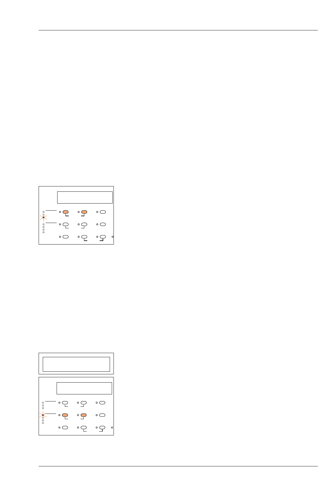
Select ‘Contrast Adj’ mode by keeping the ‘Paper’ button
depressed and by pressing the ‘–’ button twice.
The ‘Contrast Adj’ LED will light and the display will show the
contrast correction value in %. This will be 0 if no previous
correction has been made.
The correction value can be set from –30 to +30 using the +/–
buttons. + increases the contrast – lowers the contrast
Return to normal printing mode by keeping the ‘Paper’ button
depressed and pressing the ‘–’ button.
After switching to the normal printing mode, the system
automatically re-calculates the grade and exposure time
determined by the probe during calibration mode.
Whenever required, the contrast calibration value may be
adjusted in ‘Contrast Adj’ mode by using the ‘+/–’ buttons.
CHECKING OR SETTING UP A GRADE TABLE
The following example shows the procedure for setting or
checking data in a grade table. Values shown in this example
are from the table for channel 1 (see section 12).
Select the paper channel.
Call up the grade table by keeping the ‘Memory’ button
depressed and by pressing the ‘Grade’ button once.
The ‘Contrast’ LED will light and the display will show the paper
grade and the corresponding set value for the contrast (1st and
2nd columns in the grade table)
Adjust the contrast value by pressing the ‘+/–’ buttons.
Notes
The actual grade achieved on the print is determined by the
settings of the yellow and magenta filters. The contrast value
P1 0
CALIBRATION PAPER
PRINT COUNT
GRADE TABLE
CALIBRATION
PAPER/MEMORY GRADE TIME/PRINTS
NEW CAL.
CAL ADJ.
CONTRAST ADJ.
CONTRAST
YELLOW
MAGENTA
DENSITY
–+
MEMORYGRADE TABLE GRADE %TIME
CLEAR BURN FOCUS
P1 00 3.12
PAPER/MEMORY GRADE TIME/PRINTS
P1 00 1.70
CALIBRATION PAPER
PRINT COUNT
GRADE TABLE
CALIBRATION
PAPER/MEMORY GRADE TIME/PRINTS
NEW CAL.
CAL ADJ.
CONTRAST ADJ.
CONTRAST
YELLOW
MAGENTA
DENSITY
–+
MEMORYGRADE TABLE GRADE %TIME
CLEAR BURN FOCUS
3b
3c
4
4a
4b
5
5a
5b
6
6a
6b
7
27
shown in the table enables the probe to calculate the correct grade
following measurements taken during a scanning cycle.
The contrast value can only be adjusted over a limited range, pre-
determined by the control unit, otherwise ‘Cont Err’ will be
displayed when the unit is returned to normal operating mode.
Change to the next paper grade step by pressing the ‘Grade’ button.
Repeat the above steps until you have adjusted or checked the
values for all paper grade steps (00 - 5.0)
Now change to the entering mode for the Yellow-filtration by keeping
the ‘Memory’ button depressed and by pressing the ‘Grade’ button. The
‘Yellow’ LED will light and the display will show the paper grade and
the corresponding set value for the Yellow-filtration.
(1st and 3rd columns in the grade table)
Adjust the Yellow-filtration by pressing the ‘+/–’ buttons.
Step through the paper grades by pressing the ‘Grade’ button as before.
Now change to the entering mode for the Magenta-filtration by keeping
the ‘Memory’ button depressed and by pressing the ‘Grade’ button. The
‘Magenta’ LED will light and the display will show the paper grade and
the corresponding set value for the Magenta filtration.
(1st and 4th columns in the grade table)
Adjust the Magenta-filtration by pressing the ‘+/–’ buttons.
Again, step through the grades using the ‘Grade’ button.
Now change to the entering mode for the density compensation by
keeping the ‘Memory’ button depressed and by pressing the ‘Grade’
button. The ‘Density’ LED will light and the display will show the paper
grade and the corresponding set value for the density compensation,
‘D-Comp’. ‘D-Comp’ enables automatic re-calculation of the exposure
time when changing grades to ensure a constant print density.
(1st and 5th columns in the grade table)
Adjust the value for the ‘D-Comp’ by pressing the ‘+/–’ buttons. For
example, +30 ‘D-Comp’ would double the exposure time from say 2.5
to 5.0 seconds. Note that the value of 0.00 corresponding to grade 2.5
cannot be amended. Step through each grade as before.
The checking or entering cycle for the grade table is now complete.
To return to the normal printing mode keep the ‘Memory’ button
depressed and press the ‘Grade’ button.
Note
When contrast, yellow, magenta or D-Comp mode has been
selected on the control unit (for checking or changing the set
values), pressing the ‘Clear’ button will return ALL values in that
column of the table to the factory settings.
P1 00 110
CALIBRATION PAPER
PRINT COUNT
GRADE TABLE
CALIBRATION
PAPER/MEMORY GRADE TIME/PRINTS
NEW CAL.
CAL ADJ.
CONTRAST ADJ.
CONTRAST
YELLOW
MAGENTA
DENSITY
–+
MEMORYGRADE TABLE GRADE %TIME
CLEAR BURN FOCUS
P1 00 0
CALIBRATION PAPER
PRINT COUNT
GRADE TABLE
CALIBRATION
PAPER/MEMORY GRADE TIME/PRINTS
NEW CAL.
CAL ADJ.
CONTRAST ADJ.
CONTRAST
YELLOW
MAGENTA
DENSITY
–+
MEMORYGRADE TABLE GRADE %TIME
CLEAR BURN FOCUS
P1 00 31.0
CALIBRATION PAPER
PRINT COUNT
GRADE TABLE
CALIBRATION
PAPER/MEMORY GRADE TIME/PRINTS
NEW CAL.
CAL ADJ.
CONTRAST ADJ.
CONTRAST
YELLOW
MAGENTA
DENSITY
–+
MEMORYGRADE TABLE GRADE %TIME
CLEAR BURN FOCUS
P1 00 3.12
PAPER/MEMORY GRADE TIME/PRINTS
9
CLEANING AND
MAINTENANCE
9.1
1
2
3
9.2
28
WARNING
Switch off and disconnect the MG600 system from the mains
supply before carrying out any cleaning or maintenance
procedures.
Never allow liquids to enter the equipment and do not use
corrosive cleaning agents.
CLEANING
Cleaning is the only routine maintenance required on the
MULTIGRADE 600 equipment. Carry out the following
operations at regular intervals:
Remove dust and debris from the light mixing box (es) with a soft
brush. Take care not to leave fingerprints on the diffuser and
internal mirrors.
The control unit switch panel should be cleaned periodically
using a damp, lint free cloth.
It is recommended that the dust filter on the rear of the MG600H
enlarger head is cleaned once per month. Remove and clean in
warm water. Dry thoroughly before re-fitting.
REPLACING THE LAMP
See figure 9.1.
WARNING
Switch the system off and allow the lamp to cool before
handling.
3
2
1
4
Figure 9.1 Lamp removal and replacement
Figure 9.1
Hinged lamphouse cover
Lamp clip
Lamp
Top cover catch housing
1
2
3
4

1
2
3
4
5
6
7
8
9
9.3
1
2
3
4
5
9.4
29
To replace the lamp, proceed as follows:
Lower the enlarger head for ease of access.
Press in the sprung catch on the front of the top cover to release.
Lift the cover up and back and remove from the enlarger head.
Lift up the hinged cover above the lamp.
Pull off the lamp socket from the lamp pins.
Pull the lamp upwards and forwards to disengage it from its
locating recess and the springs which retain it in place.
Fit the new lamp, ensuring that it is properly located.
Re-connect the lamp socket and close the hinged cover.
Refit the top cover and press the sprung catch to re-engage.
PROJECTION LAMP - PREVENTIVE MAINTENANCE
To ensure maximum lamp life and to obtain the best results from
the lamp, always keep the following points in mind.
Do not touch the inner reflective surface of the lamp, and
especially the bulb.
Ensure the correct type lamp is used (see section 11
MULTIGRADE 600H enlarger head).
Avoid excessive vibration and mechanical shock, particularly
when the unit is switched on.
Ensure the power supply is always operated at the correct
voltage. Unusually high voltages will reduce lamp performance
leading to premature lamp failure.
Ensure the cooling fan operates correctly, and that the air flow is
not obstructed.
REPLACING MAINS INPUT OR LAMP FUSES
See section 4.2a.

10
FAULT FINDING
30
This section provides a list of checks to make should there be any
problems with the equipment; any competent person can make
these checks. If the checks prove to be ineffective, contact your
nearest ILFORD Selling Company, the address can be found on
the back of this manual.
CAUTION
If in doubt about making any of the following checks, consult a
competent engineer. Any further repair work carried out by
unqualified personnel will invalidate any guarantees applicable
to the equipment.
Symptom Possible cause Remedy
MULTIGRADE 600H
1 Display shows LA MP Err Lamp defective or blown or Check lamp (see section 9.2).
contact poor. and lampholder.
Lamp fuse blown Check/replace.
Enlarger head plug not Check connection.
properly located into socket
on power supply.
2 Uneven illumination on the Light mixing box damaged or dirty. Examine for damage.
enlarger baseboard Clean the light mixing box
(see section 9.1).
3 Change in print density with Incorrect paper program Select alternative program
change in contrast selection. selected on control unit. (see section 6)
4 Lamp contacts black or pitted Defective lampholder. Replace lamp and lampholder.
Contact your nearest ILFORD
Selling Company.

31
Symptom Possible cause Remedy
MULTIGRADE 600C
1 Display and keypad fail to illuminate Failure of power supply. Check control unit is plugged
Poor connection between power correctly into the power
supply and control unit. supply.
2 Flashing ‘Time/Prints’ display Calculated exposure times which Repeat probe reading or
are less than 1.0 second are re-enter data.
shown but with a flashing display
(Exposures of less than 1.0 second
cannot be made).
Calculated exposure times Repeat probe reading or
which are greater than 999 re-enter data.
seconds are shown as 999,
but with a flashing display.
3 Cont Err An unrealistic contrast value has Check the paper/grade table
been set in the grade table for and re-enter revised values
the paper grade required. as necessary or select
‘Contrast’ and press ‘Clear’
to reset the factory settings.
Note
Pressing ‘Clear’ will set all contrast values in the table for that
paper channel back to the factory settings.
MULTIGRADE 600S
1 No power to output sockets Poor connection between Ensure plug at each end of
electrical mains and power supply. mains cable is pushed fully
into socket.
Fuse blown in power supply. Replace fuse (see section 2.3)
2 Fuse blown Incorrect fuse fitted. Check and replace fuse
(see section 2.3).
If the fault persists, contact
your nearest ILFORD Selling
Company.
Incorrect voltage selection. Check setting on voltage
selector and alter if necessary
(see section 2.3a).
Faulty power supply. Contact your nearest ILFORD
Selling Company.

32
Symptom Possible cause Remedy
MULTIGRADE 600P
1 Display shows Pr bd HI Light intensity too low for Open enlarger lens aperture
probe to measure. and repeat measurement.
2 Display shows Pr bd LO Light intensity too high for Close enlarger lens aperture
probe to measure. and repeat measurement.
3 Incorrect or erratic results Incorrect paper channel selected. Select correct channel.
Unsuitable areas on projected Select areas towards
image chosen to take the centre of the
measurements. projected image if
possible and re-measure
(see section 7.1).
Unsuitable negative. Negatives should be
correctly exposed and
processed with a good
tonal range
(see section 7.1).
Some negatives, for
example, those used in
electron microscopy,
may be unsuitable for
taking probe
measurements.
Very bright safelight close Move or switch off the
to and above the enlarger. safelight.
(see section 7.1).

11
SPECIFICATION
33
MULTIGRADE 600H ENLARGER HEAD
Dimensions Height 300mm
Width 225mm
Depth 390mm
Weight 7.45kg excluding light mixing box and adaptor kit
Electrical cable (integral) Screened Multicore, Length 1.7m
connects to MULTIGRADE 600S power supply
Lamp 24V 250W
ANSI code ELC
Quartz halogen projection lamp with dichroic reflector
Heat filter 35x35x2mm heat absorbing glass
Colour filters Motorised yellow and magenta dichroic interference filter
coatings on glass substrate, each providing maximum
obtainable filter density of 170 densitometric units. Cut-off
wavelengths selected to give optimum grade range on ILFORD
variable contrast papers.Proven automatic closed loop control
system providing extremely consistent exposures.
Cooling fan Dynamically balanced centrifugal type on isolated mountings.
Light mixing boxes Up to three sizes are available to cover the following negative
sizes: up to 35mm, from 35mm to 6x7cm or 6x9cm and from
6x7cm to 4x5 inches.
Evenness of illumination (at f8) Maximum fall off middle-corners 20%
Maximum difference corner-corner 5%
MULTIGRADE 600C CONTROL UNIT
Dimensions Height 65mm
Width 200mm
Depth 215mm
Weight 1.84Kg
Electrical cable Screened Multicore, Length 1.9m
connects to the MULTIGRADE 600S power supply unit
Other connections Socket for exposure-contrast probe.

34
Features Operation of each feature is by a push button, with adjacent
illuminated indicator.
Exposure time 1.0 - 999 sec
% exposure time correction -99% to +999%
Grade range 00-5 in 1/10 grade steps
Paper channels 5. All channels are user programmable
Factory settings are provided as follows:
P1 ILFORD MULTIGRADE IV RC Deluxe
P2 ILFORD MULTIGRADE RC Warmtone
P3 ILFORD MULTIGRADE IV FB Fiber
P4 ILFORD MULTIGRADE FB Warmtone
P5 Spare channel
Probe calibration for density and contrast
Memory - for storage of 1 main exposure and up to
3 additional exposures.
Burn
Print counter
Focus (white light)
Clear
Expose - pause
Display Digital, 7 segment LED’s
Electronics Microprocessor incorporating memory with battery back-up
MULTIGRADE 600S POWER SUPPLY
Dimensions Height 280mm
Width 220mm
Depth 150mm
Weight 11.13Kg
Mains electrical cable (separate) 3 core, live, neutral and earth. Length - 2m
Mains input Nominal voltage 115/230Vac
Frequency 50 or 60Hz
Power consumption 400W maximum
Mains Voltage tolerance -10% to +10%
Replacement fuses - Mains input (F1) 115V T-5.0A (5.0A SB)
230V T-2.5A (2.5A SB)
Above fuses are time delay type.
Replacement fuse - Lamp (F2) 250V T-12.5A (12.5A SB)

35
Outputs Control unit
Enlarger head
Footswitch/Roll Easel
MULTIGRADE 600P EXPOSURE PROBE
Dimensions Height 35mm
Width 78mm
Depth 154mm
Weight 0.19Kg
Electrical cable Screened Multicore, length 1.35m
connects to MULTIGRADE 600C control unit
Controls Measurement period defined by push and release of button
Density (exposure time) and contrast (grade) calibration via the
MULTIGRADE 600C control unit
Reading point 7.5mm diameter, photocell with built-in shutter
GENERAL
Ambient temperature range 15-30°C
Relative Humidity 5-95%
Noise Level 56db(A)
System Weight Approximately 20Kg

12
PAPER CHANNEL DATA
36
P1 MULTIGRADE IV RC Deluxe
Gradation Contrast Yellow Magenta D-Comp
00 1.70 110 0 31.0
0.0 1.50 80 0 26.0
0.5 1.40 65 0 23.0
1.0 1.30 50 0 19.0
1.5 1.20 35 0 13.5
2.0 1.10 20 0 7.00
2.5 1.00 0 15 0.00
3.0 0.90 0 30 5.00
3.5 0.80 0 50 11.0
4.0 0.70 0 70 15.5
4.5 0.60 0 95 19.0
5.0 0.50 0 170 22.5
P2 MULTIGRADE RC Warmtone
Gradation Contrast Yellow Magenta D-Comp
00 1.70 110 0 29.5
0.0 1.50 80 0 26.0
0.5 1.40 64 0 24.5
1.0 1.30 51 0 21.5
1.5 1.20 36 0 17.0
2.0 1.10 19 0 11.0
2.5 1.00 0 0 0.00
3.0 0.90 0 22 13.0
3.5 0.80 0 43 22.5
4.0 0.70 0 62 28.5
4.5 0.60 0 87 34.0
5.0 0.50 0 170 39.0
P3 MULTIGRADE IV FB Fiber
Gradation Contrast Yellow Magenta D-Comp
00 1.60 110 0 35.0
0.0 1.50 93 0 34.0
0.5 1.40 73 0 30.0
1.0 1.30 54 0 25.0
1.5 1.20 35 0 16.0
2.0 1.10 16 0 9.00
2.5 1.00 0 0 0.00
3.0 0.90 0 24 7.00
3.5 0.80 0 39 10.0
4.0 0.70 0 54 13.0
4.5 0.60 0 74 17.0
5.0 0.50 0 170 26.0

37
P4 MULTIGRADE FB Warmtone
Gradation Contrast Yellow Magenta D-Comp
00 1.60 92 0 15.0
0.0 1.50 70 0 13.0
0.5 1.40 50 0 12.0
1.0 1.30 36 0 8.00
1.5 1.20 25 0 4.00
2.0 1.10 12 0 0.00
2.5 1.00 0 12 0.00
3.0 0.90 0 36 10.0
3.5 0.80 0 52 15.0
4.0 0.70 0 66 17.0
4.5 0.60 0 90 24.0
5.0 0.50 0 170 28.0
P5 Spare channel (for user programming)
Gradation Contrast Yellow Magenta D-Comp
00 1.60 0 0 0.00
0.0 1.50 0 0 0.00
0.5 1.40 0 0 0.00
1.0 1.30 0 0 0.00
1.5 1.20 0 0 0.00
2.0 1.10 0 0 0.00
2.5 1.00 0 0 0.00
3.0 0.90 0 0 0.00
3.5 0.80 0 0 0.00
4.0 0.70 0 0 0.00
4.5 0.60 0 0 0.00
5.0 0.50 0 0 0.00
See section 8 ‘Checking or setting up a grade table’ for
information on data entry for this channel.
Table for recording user data
Gradation Contrast Yellow Magenta D-Comp
00
0.0
0.5
1.0
1.5
2.0
2.5
3.0
3.5
4.0
4.5
5.0

38
SPECIFICATION NUMBER EC DIRECTIVE
Electromagnetic compatibility - emissions EN55022 89/336/EEC
Electromagnetic compatibility - immunity EN50082-1 89/336/EEC
EN55024-2 89/336/EEC
EN55024-3 89/336/EEC
EN55024-4 89/336/EEC
Low voltage EN60950 73/23/EEC
DECLARATION
OF CONFORMITY
ILFORD
ILFORD DECLARE UNDER OUR SOLE RESPONSIBILITY THAT PRODUCT
MULTIGRADE600 printing system
NAME . TYPE OR MODEL
TO WHICH THIS DECLARATION RELATES
IS IN CONFORMITY WITH THE FOLLOWING SPECIFICATIONS
NAME OF AUTHORISED OFFICER POSITION OF AUTHORISED OFFICER
Mr M.G.Hammond Manager - Central Equipment Group
DATE
1st October 1998
SIGNATURE OF AUTHORISED OFFICER
ILFORD IMAGING UK LIMITED .MOBBERLEY .KNUTSFORD .CHESHIRE WA16 7JL

Australia
ILFORD Imaging Asia Pacific Pty Limited
Monash Corporate Centre
Unit 1, 10 Duerdin Street
Clayton North 3168 Victoria
Benelux
ILFORD Imaging Benelux
Fotografielaan, 18
2610 WILRIJK
ANTWERP
Belgium
Canada
ILFORD Imaging Canada Limited
361 Steelcase Road West
Unit No.4
Markham
Ontario L3R 3V8
France
ILFORD Imaging France SA
14 rue Galilée Cité Descartes
77420 Champs-sur-Marne
Germany/Austria
ILFORD Imaging GmbH
Heinrich-Hertz-Str 1
POB 10 11 68
D-63265 Dreieich
Italy
ILFORD Imaging Italia SpA
Corso Italia 13
21047 Saronno (VA)
Switzerland
ILFORD Imaging Switzerland GmbH
Rue de l’Ancienne Papeterie
CH-1723 Marly 1
United Kingdom
ILFORD Imaging UK Limited
Town Lane
Mobberley
Cheshire WA16 7JL
USA
ILFORD Imaging USA Inc
West 70 Century Road
Paramus
New Jersey 07653
If your country is not shown here, please
contact:
Export EAMER Group
ILFORD Imaging UK Limited
Mobberley
Cheshire WA16 7JL
England
Web
www.ilford.com
Constant improvements in ILFORD
products mean that changes in design
or specification may occur from time to
time. Any improvements will, however,
maintain conformance of the product
with all relevant legislation. The right to
alter the design and specification of the
equipment without prior notice is
accordingly reserved.
Product names printed in capitals are
ILFORD trade marks.
ILFORD Imaging UK Limited
Mobberley Cheshire
21 June 1998
Printed in England 98065.GB
February 2002
