Dust Networks M2140 Smart Mesh Wireless Mote User Manual
Dust Networks, Inc. Smart Mesh Wireless Mote Users Manual
Users Manual
PRELIMINARY Confidential
M2x40 Mote Datasheet Dust Networks™ 1
SmartMesh-XDTM M2140/M2040
2.4 GHz Wireless Mote
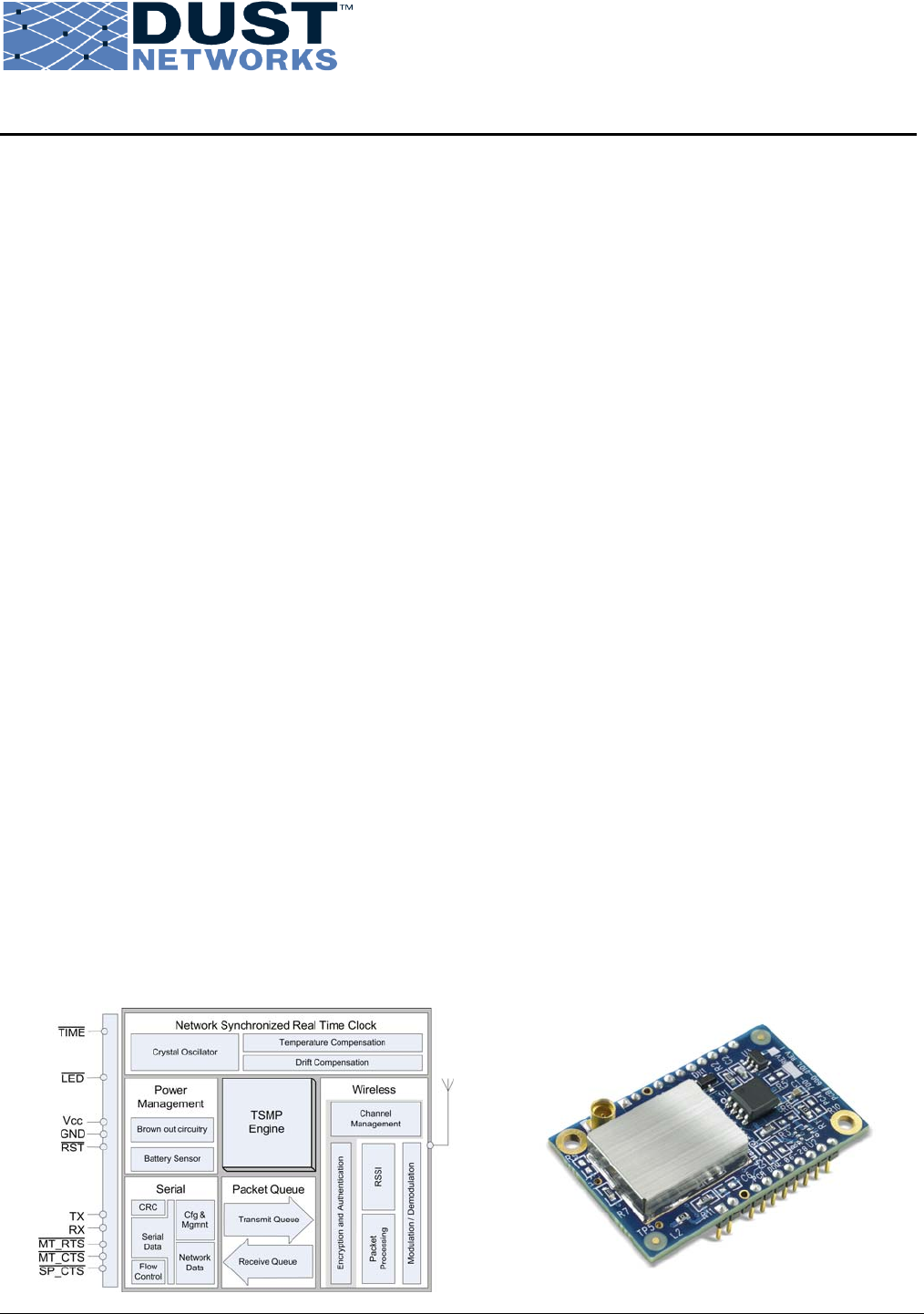
Product Description
Dust Network’s network-ready SmartMesh-XD™ M2x40 allows OEMs to build solutions for the global market using ultra low-power,
highly reliable system-on-chip (SoC) mesh networking solutions. The M2x40 combines a microprocessor and a standards-based 802.15.4
radio with robust networking capabilities built on top of the industry-leading Time Synchronized Mesh Protocol (TSMP) pioneered by Dust
Networks.
The M2x40 is tailored for use in battery- and line-powered wireless devices for applications that demand proven performance and
scalability. The innovative radio design in the M2x40 operates in the global license-free 2.4 GHz band, with 80% less receiver current than
comparable radios in the market. The combination of extremely high reliability and low power consumption enables applications that
require very low installation cost for low-maintenance, long-term deployments. The M2x40 provides all the functionalities of a mote in an
easy-to-integrate Mote-on-Chip™ (MoC). The multi-functional interface of the M2x40 gives it the flexibility to be used in a wide variety
of applications, from industrial process monitoring to building control to machine health monitoring. The M2x40 requires no embedded
programming, enabling OEMs to reduce the development time and cost for wireless sensor networking solutions.
About SmartMesh®
Dust Networks SmartMesh® products combine robust networking capabilities with TSMP, pioneered by Dust Networks, and standards-
based motes to provide proven wireless sensor networking systems. SmartMesh® systems achieve high network reliability in the face of
unpredictable or harsh RF environments, utilize frequency hopping for interference rejection and have a typical battery life of 5-10 years.
Each node in a SmartMesh-based network is a router, offering mesh-to-the-edge™ advantage for easy network integration, installation and
maintenance. With a flexible platform and predictable network performance, OEMs can wirelessly enable a whole host of solutions for
their industrial automation, building automation and defense markets.
Key Features
Ultra Low Power Consumption
• Innovative radio design that consumes 80% less
power in receive mode than competing solutions
• Delivers additional 5X increase in battery life
• Automatic network-wide coordination for efficient
power usage
Reliable Networking
• Uses the Time-Synchronized Mesh Protocol
(TSMP) for high reliability (> 99.9% typical
network reliability)
• Frequency hopping for interference rejection
• Mesh networking for built-in redundancy
• Every M2x40 acts as both an endpoint and a router,
increasing network reliability: mesh-to-the-edge™
• Automatic self-organizing mesh networking
capability built-in
Easy Integration
• M2x40 provides all the functionality of a mote with zero
embedded programming, or complex configuration
• Complete RF stage—balun, antenna matching circuitry,
Power Amplifier, and antenna connector included
• High-level Data Link Control (HDLC) serial interface
with bidirectional flow control
• Industrial temperature range –40 °C to +85 °C
• FCC, IC and CE modular RF certifications (pending)
802.15.4 Standard Radio
• Global 2.4 GHz license-free band: suitable for use in
North America, Europe and most of Asia
• +8 dBm (6.3 mW) conducted RF output power
• –90 dBm receiver sensitivity
• 300 m outdoor range (typical)
• Direct-sequence spread spectrum (DSSS) for additional
interference rejection

PRELIMINARY Confidential
M2x40 Mote Datasheet Dust Networks™ 2
Table of Contents
1.0 Absolute Maximum Ratings................................................................................4
2.0 Normal Operating Conditions .............................................................................4
3.0 Electrical Specifications .....................................................................................5
4.0 Timing Values.....................................................................................................6
5.0 Radio..................................................................................................................6
5.1 Detailed Radio Specifications ................................................................................ 6
5.2 Antenna Specifications......................................................................................... 7
6.0 Pinout ................................................................................................................8
6.1 M2x40 Pinout ..................................................................................................... 8
7.0 Mote Boot Up......................................................................................................9
7.1 Power-on Sequence............................................................................................. 9
7.2 Inrush Current.................................................................................................... 9
7.3 Serial Interface Boot Up......................................................................................10
7.3.1 M2x40 Serial Interface Boot Up......................................................................10
8.0 Interfaces ........................................................................................................10
8.1 Timestamps ......................................................................................................10
8.2 Status LED
¯¯¯ Signal ..............................................................................................11
8.3 Serial Interface..................................................................................................11
8.3.1 Serial Interface Overview..............................................................................11
8.3.2 Serial Interface Timing Requirements .............................................................13
8.3.2.1 CTS Byte-level Handshake .....................................................................13
8.3.2.2 Data Flow Out of the Mote Serial Port ......................................................14
8.3.2.3 Data Flow Into the Mote Serial Port .........................................................14
9.0 Packaging Description......................................................................................15
9.1 Mechanical Drawing............................................................................................15
9.2 Soldering Information.........................................................................................16
10.0 Regulatory and Standards Compliance.............................................................16
10.1 FCC Compliance...........................................................................................16
10.1.1 FCC Testing ................................................................................................16
10.1.2 FCC-approved Antennae ...............................................................................17
10.1.3 OEM Labeling Requirements ..........................................................................17
10.2 Industry Canada (IC) Compliance...................................................................17
10.2.1 IC Testing...................................................................................................17
10.2.2 IC-approved Antennae..................................................................................17
10.2.3 OEM Labeling Requirements ..........................................................................17
10.3 CE Compliance ............................................................................................17
10.3.1 Declaration of Conformity .............................................................................17
10.3.2 European Compliance...................................................................................18
10.3.3 OEM Labeling Requirements ..........................................................................18
10.3.4 Restrictions.................................................................................................18

PRELIMINARY Confidential
M2x40 Mote Datasheet Dust Networks™ 3
10.4 Industrial Environment Operation...................................................................18
11.0 Ordering Information.......................................................................................18
PRELIMINARY Confidential
M2x40 Mote Datasheet Dust Networks™ 4
1.0 Absolute Maximum Ratings
The absolute maximum ratings shown below should under no circumstances be violated. Permanent damage to the device
may be caused by exceeding one or more of these parameters.
Table 1 Absolute Maximum Ratings
Parameter Min Typ Max Units Comments
Supply voltage (Vcc to GND) –0.3 3.6 V
Voltage on any digital I/O pin –0.3 VCC + 0.3
up to 3.6
V
Input RF level 10 dBm Input power at antenna
connector
Storage temperature range –45 +85 °C
Lead temperature +230 °C For 10 seconds
VSWR of antenna 3:1
* All voltages are referenced to GND
Caution! The M2x40 can withstand an electrostatic discharge of up to 2 kV Human Body Model (HBM) or
200 V Machine Model (MM) applied to any header pin, except the antenna connector. The antenna input can
withstand a discharge of up to 50 V.
2.0 Normal Operating Conditions
Table 2 Normal Operating Conditions
Parameter Min Typ Max Units Comments
Operational supply voltage
range (between Vcc and GND) 2.75 3.3 V
Including noise and load
regulation
Voltage on analog input pins 0 1.8 V
Voltage supply noise 200 mVp-p 50 Hz–15 MHz
Peak current
Power amplifier enabled
TBD
mA
TX during OTAP*. (TBD)
ms max
TBD mA TX, 5 ms maximum
TBD mA
Searching for network, 60
minutes maximum
TBD mA
Radio turn on, (TBD) μs
max
TBD mA boot_delay (see Table 7)
Peak current
Power amplifier disabled
TBD
mA
TX during OTAP*. (TBD)
ms max
TBD mA TX, 5 ms maximum
TBD mA
Searching for network, 60
minutes maximum
TBD mA
Radio turn on, (TBD) μs
max
TBD mA boot_delay (see Table 7)
Average current

PRELIMINARY Confidential
M2x40 Mote Datasheet Dust Networks™ 5
Power amplifier enabled TBD µA
Power amplifier disabled TBD µA
Assuming 80 byte
packets, 1 per 2 minutes,
data-only mote, 3V, 25 °C
Storage and operating
temperatures -40 +85 °C
Maximum allowed temperature
ramp during operation 8 °C/min –40 °C to +85 °C
Operating relative humidity 10 90 % RH Non-condensing
*OTAP = over-the-air programming of motes
Unless otherwise noted, Table 3 assumes Vcc is 3.0 V.
Table 3 Current Consumption
Parameter Min Typ Max Units Comments
Transmit
Power amplifier enabled 18 mA
Power amplifier disabled 7 mA
Receive 6 mA
Sleep 5 µA
3.0 Electrical Specifications
Table 4 Device Load
Parameter Min Typ Max Units Comments
Total capacitance 15.5 µF Vcc to GND
Unless otherwise noted, Vcc is 3.0 V and temperature is –40 °C to +85 °C
Table 5 Digital I/O Type 1
Digital Signal Min Typ Max Units Comments
VIL (low-level input voltage) –0.3 0.6 V
VIH (high-level input voltage) 0.8 x VCC V
cc + 0.3 V
VOL (low-level output voltage) 0.4 V
VOH (high-level output voltage) 2.4 V
Digital current*
Output source (single pin)
3.7 mA 25 °C
Output sink (single pin) 2.0 mA 25 °C
Input leakage current 50 nA 25 °C
* This current level guarantees that the output voltage meets VOH and VOL specifications above.
Table 6 Digital I/O Type 2
Digital Signal Min Typ Max Units Comments
VIL (low-level input voltage) –0.3 0.6 V
VIH (high-level input voltage) 0.8 x VCC V
CC + 0.3 V
VOL (low-level output voltage,
multi-function I/O configured
as output)
0.6 V IOL < 0.6 mA, 85 °C
VOH low-level output voltage,
multi-function I/O configured
as output)
VCC – 0.6 VCC V IOH > –0.6 mA, 85 °C

PRELIMINARY Confidential
M2x40 Mote Datasheet Dust Networks™ 6
Digital Signal Min Typ Max Units Comments
Digital current*
Output source (single pin,
multifunction I/O configured
as output)
0.6 mA 25 °C
Output sink (single pin,
multifunction I/O configured
as output)
0.6 mA 25 °C
Input leakage current 50 nA 25 °C
* This current level guarantees that the output voltage meets VOH and VOL specifications above.
4.0 Timing Values
Table 7 Timing Values
Variable Meaning Min Max Units
RST
¯¯¯ pulse width Reset timing 125 µs
interbyte_timeout The time between consecutive data bytes on the serial
port cannot exceed this time. 7 ms
interpacket_delay The sender of an HDLC packet must wait at least this
amount of time before sending another packet. 20 ms
ack_delay The max time delay between the MT_RTS
¯¯¯¯¯¯¯ and the
receiver’s acknowledge, SP_CTS
¯¯¯¯¯¯¯.
1 500 ms
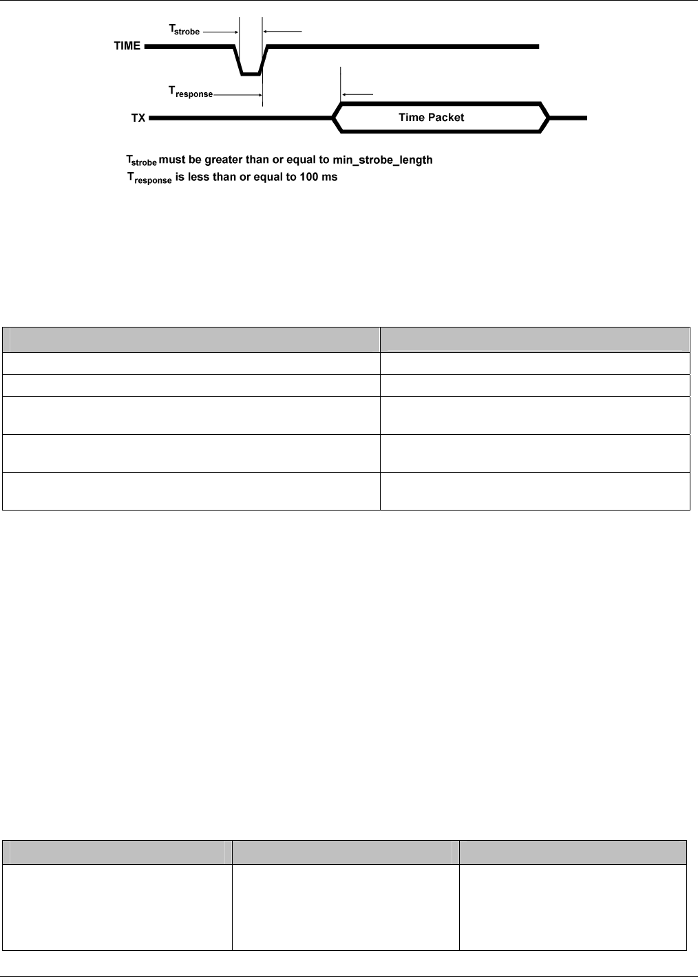
time_ack_timeout The mote responds to all TIME
¯¯¯¯ pin activation requests
within this time.
100
ms
diag_ack_timeout The mote responds to all requests within this time. 125 ms
min_strobe_length The length of the strobe signal. 500 ns
boot_delay The time between mote power up and serial interface
availability. 6250 ms
5.0 Radio
5.1 Detailed Radio Specifications
Parameter Min Typ Max Units Comments
Operating frequency 2.4000 2.4835 GHz
Number of channels 15
Channel separation 5 MHz
Occupied channel bandwidth 2.7 MHz At –20 dBc
Frequency Accuracy -50 +50 kHz
Modulation IEEE 802.15.4 DSSS
Raw data rate 250 Kbps
Receiver operating input level 0 -10 dBm
Receiver sensitivity –93 dBm At 50% PER, VDD = 3 V,
25 °C
–90 dBm
At 1% PER, VDD = 3 V,
25 °C, (inferred by 50%
PER measurement)

PRELIMINARY Confidential
M2x40 Mote Datasheet Dust Networks™ 7
Parameter Min Typ Max Units Comments
Output power, conducted
Power amplifier enabled +8 dBm VDD = 3 V, 25 °C
Power amplifier disabled –3 dBm VDD = 3 V, 25 °C
Range*
Power amplifier enabled:
Indoor 100 m
Outdoor 300 m
25 °C, 50% RH, 1 meter
above ground, +2 dBi
omni-directional antenna
Power amplifier disabled:
Indoor 25 m
Outdoor 200 m
* Actual RF range performance is subject to a number of installation-specific variables including, but not
restricted to ambient temperature, relative humidity, presence of active interference sources, line-of-sight
obstacles, near-presence of objects (for example, trees, walls, signage, and so on) that may induce
multipath fading. As a result, actual performance varies for each instance.
5.2 Antenna Specifications
A MMCX-compatible male connector is provided on board for the antenna connection. The antenna must meet specifications
in Table 8. For a list of FCC-approved antennae see section 10.1.2.
Table 8 Antenna Specifications
Parameter Value
Frequency range 2.4 – 2.4835 GHz
Impedance 50 Ω
Gain +2 dBi maximum
Pattern Omni-directional
Maximum VSWR 3:1
Connector MMCX*
* The M2x40 can accommodate the following RF mating connectors:
• MMCX straight connector such as Johnson 135-3402-001, or equivalent
• MMCX right angle connector such as Tyco 1408149-1, or equivalent
When the mote is placed inside an enclosure, the antenna should be mounted such that the radiating portion of the antenna
protrudes from the enclosure. The antenna should be connected using a MMCX connector on a coaxial cable. For optimum
performance, allow the antenna to be positioned vertically when installed.

PRELIMINARY Confidential
M2x40 Mote Datasheet Dust Networks™ 8
6.0 Pinout
The M2x40 has two 11-pin Samtec MTMM-111-04-S-S-175-3 (or equivalent) connectors on the bottom side for handling all
of the I/O. The third pin in each of the connectors is not populated, and serves as a key for alignment. The connectors are
mounted on opposite edges of the long axis of the M2x40.
6.1 M2x40 Pinout
The M2x40 provides a bidirectional flow-controlled serial interface (serial protocol is specified in section Error! Reference
source not found.).
Table 9 M2x40 Pin Functions
Pin
Number Pin Name Description Type Direction
1 GND Ground Power –
2 VCC Power Power –
3 KEY (no pin) – – –
4 RX UART Rx Type 2 In
5 TX UART Tx Type 2 Out
6 LED
¯¯¯¯ Active low led turn on Type 1 Out
7 MT_RTS
¯¯¯¯¯¯¯ UART active low mote ready
to send Type 2 Out
8 MT_CTS
¯¯¯¯¯¯¯ UART active low mote clear to
send Type 1 Out
9 SP_CTS
¯¯¯¯¯¯¯ UART active low serial
peripheral clear to send Type 2 In
10 TIME
¯¯¯¯ Falling edge time request Type 2 In
11 Mode_pin_B
Selects between Mode 1 &
Mode 3 operation (9600bps &
115.2 kbps)
Type 2 In
12 FLASH_P_EN
¯¯¯¯¯¯¯¯¯¯¯¯ Active low flash power enable – –
13 No connection – – –
14 No connection – – –
15 No connection – – –
16 No connection – – –
17 SCK SPI clock – –
18 MOSI
SPI master out slave in serial
data – –
19 MISO
SPI master in slave out serial
data – –
20 KEY (no pin) – – –
21 SPI_CS
¯¯¯¯¯¯ Active low flash chip select – –
22 RST
¯¯¯ Active low reset Type 1 In
The RST
¯¯¯ input pin is internally pulled up, and connecting it is optional. When driven active low, the mote is hardware reset
until the signal is deasserted. Refer to section 7.1 for timing requirements on the RST
¯¯¯ pin. Note that the mote may also be
reset using the mote serial command (see Mote Serial API guide).
The TIME
¯¯¯¯ input pin is optional, and must either be driven or pulled up with a 5.1 MΩ resistor. Unless noted otherwise, all
signals are active low.
PRELIMINARY Confidential
M2x40 Mote Datasheet Dust Networks™ 9
7.0 Mote Boot Up
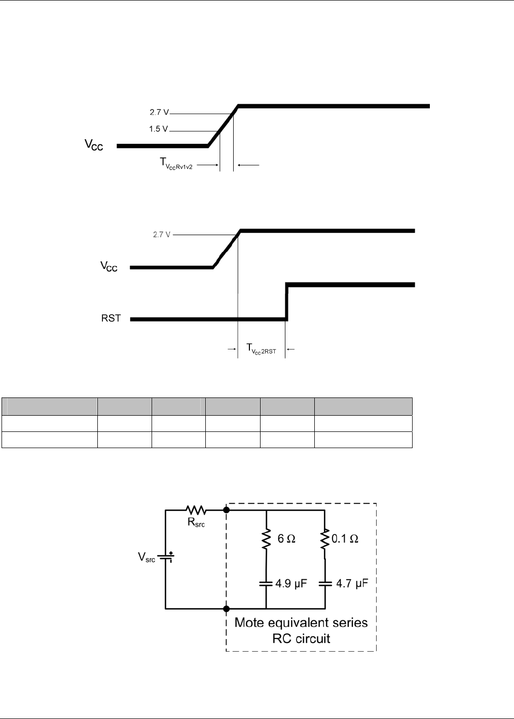
7.1 Power-on Sequence
The M2x40 mote has internal power-on-reset circuits that ensure that the mote will properly boot. However, for the power-
on-reset circuitry to function properly, the external power supply must meet the timing shown in Figure 1 and specified in
Table 10.
Figure 1 External Power Supply Timing Requirement
The following reset sequence (shown in Figure 2 and specified in Table 10) is required for external power supplies that fail to
meet the requirement above.
Figure 2 Power-on Sequence
Table 10 Power-on Sequence
Parameter Min Typ Max Units Comments
TVcc2RST 0 ms
TVccRv1v2 10 µs
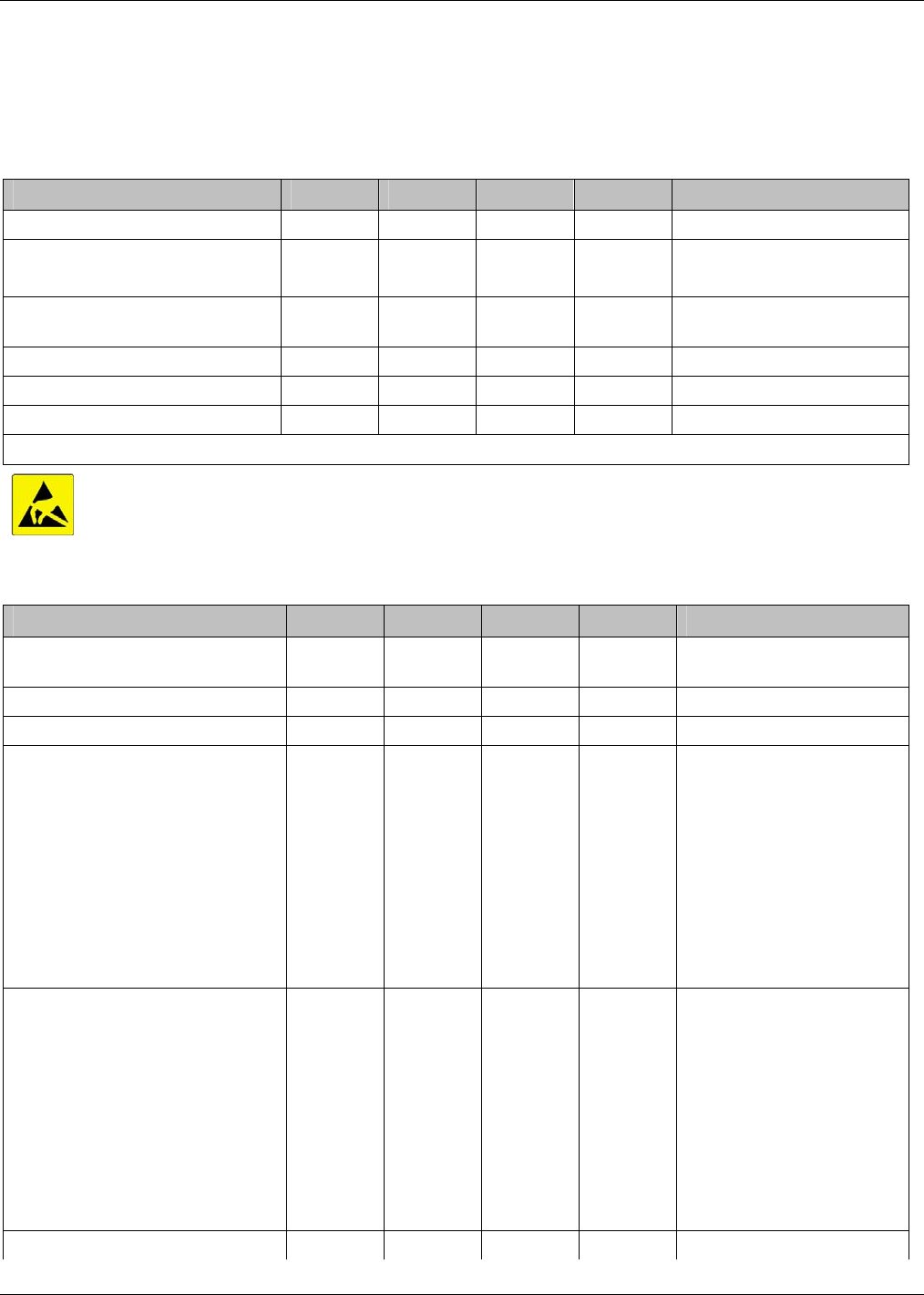
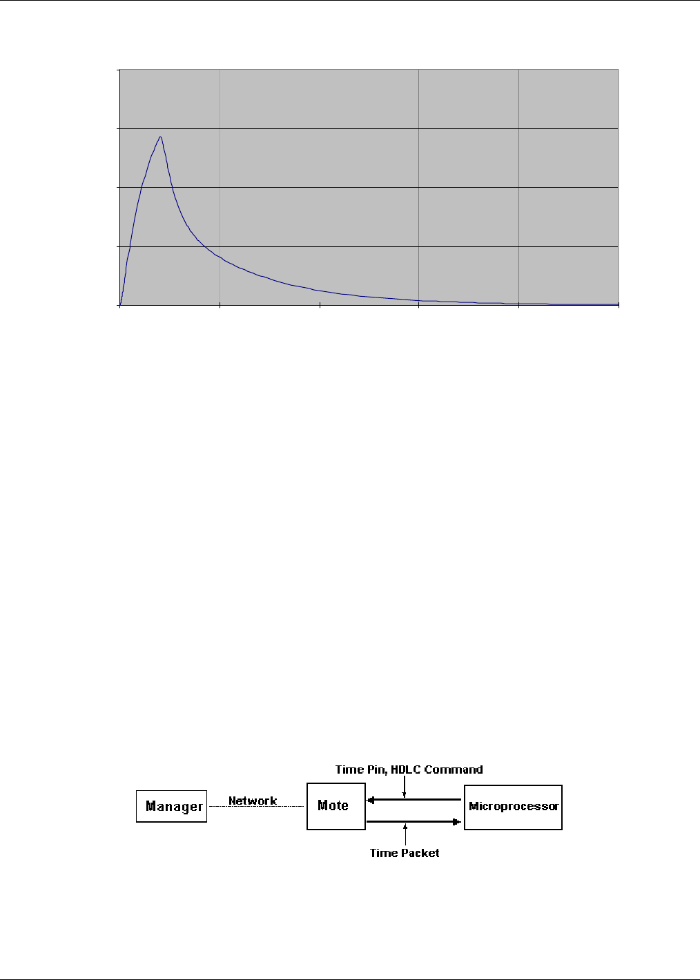
7.2 Inrush Current
During power on, the mote can be modeled as a lumped impedance, as shown in Figure 3 . With a source impedance (Rsrc) of
1 Ω, the inrush current on the mote appears as shown in Figure 4.
Figure 3 M2x40 Equivalent Series RC Circuit
PRELIMINARY Confidential
M2x40 Mote Datasheet Dust Networks™ 10
Vcc Inrush Current (Power On with Supply Impedance of 1 Ohm)
0
250
500
750
1000
0 50 100 150 200 250
Time (us)
Current (mA)
Figure 4 VCC Inrush Current
7.3 Serial Interface Boot Up
7.3.1 M2x40 Serial Interface Boot Up
Upon M2x40 power up, the MT_CTS
¯¯¯¯¯¯¯ line is high (inactive). The M2x40 serial interface boots within boot_delay (see Error!
Reference source not found.) of the mote powering up, at which time the M2x40 will transmit an HDLC Mote Information
packet. Note that full handshake (see section 8.3.2) is in effect and is required to receive this packet.
8.0 Interfaces
8.1 Timestamps
The M2x40 has the ability to deliver network-wide synchronized timestamps. The M2x40 sends a time packet (as described
in Error! Reference source not found.) through its serial interface when one of the following occurs:
• Mote receives an HDLC Get Parameter request for time/state (see Error! Reference source not found.)
• On the M2x40, mote TIME
¯¯¯¯ signal is activated
The TIME
¯¯¯¯ pin is optional and has the advantage of being more accurate. The value of the timestamp is taken within
approximately 1 ms of receiving a TIME
¯¯¯¯ signal activation. If the HDLC request is used, because of packet processing, the
value of the timestamp may be captured several milliseconds after receipt of the packet. The real time delivered to the sensor
processor is relative to the real time clock on the Manager, which serves as the Network Real Time Clock (NRTC). The time
stamp skew across the network is guaranteed to be within ±250 ms of the NRTC.
Figure 5 Network Real Time Clock
When the time pin is activated for at least min_strobe_length (see Error! Reference source not found.), the mote responds
by sending the time packet within 100 ms delay.
PRELIMINARY Confidential
M2x40 Mote Datasheet Dust Networks™ 11
Figure 6 Operation of Time Pin
8.2 Status LED
¯¯¯ Signal
The M2x40 provides an output that can be used to drive a status LED
¯¯¯ . This signal indicates network connectivity information
which is most useful during mote installation. Alternatively, the mote’s network status may be polled via serial using the Get
Parameter request with the mote state parameter (see section Mote Serial API Guide).
Table 11 Status LED
¯¯¯ Signal
LED
¯¯¯ Signal Behavior Mote State
High Off, or in sleep mode
Single blink (750 ms low, 3 s high) On, and searching for potential network
Double blink (750 ms low, 750 ms high, 750 ms low, 3 s
high) On, and attempting to join the network
Triple blink (750 ms low, 750 ms high, 750 ms low, 750 ms
high, 750 ms low, 3 s high) On, and attempting to establish redundant links
Low On, fully configured into network with redundant
parents
8.3 Serial Interface
8.3.1 Serial Interface Overview
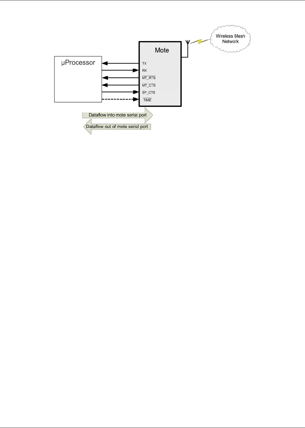
The M2x40 offers a well-defined five-signal serial interface that is optimized for low-powered embedded applications. This
serial interface offers a serial port comprised of the data pins (TX, RX) as well as handshake pins (MT_RTS
¯¯¯¯¯¯¯ , MT_CTS
¯¯¯¯¯¯¯ ,
SP_CTS
¯¯¯¯¯¯¯) used for bidirectional flow control. Through this port, the M2x40 provides a means of transmitting and receiving
serial data through the wireless network, as well as a command interface that provides synchronized time stamping, local
configuration, and diagnostics.
The serial handshake provides for flow control of packets transmitted via the M2x40 serial interface. Packet delineation and
error control are handled separately. The handshake supports the following:
• Full-duplex communication
• Bidirectional byte-level flow control
The five-signal serial port is comprised of the data pins (TX, RX) as well as the handshake pins (MT_RTS
¯¯¯¯¯¯¯ ,MT_CTS
¯¯¯¯¯¯¯ ,
SP_CTS
¯¯¯¯¯¯¯) used for bidirectional flow control. This port supports 9600 bps operation in full-duplex mode. The handshake
signals are active low.
Table 12 Mode 1 and Mode 3 Serial Parameters
Parameter Mode 1 Mode 3
Serial
Control signals 5-signal 5-signal
Flow control Bidirectional Bidirectional
Bit rate 9600 bps 115.2 kbps
PRELIMINARY Confidential
M2x40 Mote Datasheet Dust Networks™ 12
The following diagram illustrates the pins used in the handshaking protocol.
Figure 7 Diagram of Pins Used in Handshaking Protocol
PRELIMINARY Confidential
M2x40 Mote Datasheet Dust Networks™ 13
Table 13 Pin Usage
Pin Usage
RX, TX Used for serial data flow into and out of the mote.
MT_RTS
¯¯¯¯¯¯¯ This signal goes active low when the mote is ready to send a serial packet. The signal
stays low until the SP_CTS
¯¯¯¯¯¯¯ signal from the microprocessor goes active low (indicating
readiness to receive a packet) or the ack_delay timeout (see Error! Reference source
not found.) expires.
SP_CTS SP_CTS
¯¯¯¯¯¯¯ should transition from high to active low in response to the MT_RTS
¯¯¯¯¯¯¯ signal from
the mote. This indicates that the microprocessor is ready to receive serial packets.
Following this, the microprocessor should strobe SP_CTS
¯¯¯¯¯¯¯ after receiving each byte. After
all packets are received, the microprocessor should de-assert the SP_CTS
¯¯¯¯¯¯¯ signal.
MT_CTS
¯¯¯¯¯¯¯ MT_CTS
¯¯¯¯¯¯¯ indicates the state of the network connection and availability of data buffers to
receive packets destined for the network. Once the mote has established wireless network
connection, it will use the MT_CTS
¯¯¯¯¯¯¯ pin to signify availability to accept serial packets for
wireless transmission. At certain critical times during communication, the mote may bring
MT_CTS
¯¯¯¯¯¯¯ high. MT_CTS
¯¯¯¯¯¯¯ will remain high if the mote does not have enough buffer space to
accept another packet. It will also remain high if the mote is not part of the network. OEM
designs must check that the MT_CTS
¯¯¯¯¯¯¯ pin is low before initiating each serial packet for
wireless transmission. Note that the mote may receive local serial packets at any time
regardless of the MT_CTS
¯¯¯¯¯¯¯ state.
Upon receipt of the first byte of the HDLC packet, the mote strobes MT_CTS
¯¯¯¯¯¯¯ in
acknowledgement of each subsequent byte. After the last byte of the packet is received,
MT_CTS
¯¯¯¯¯¯¯ switches back to signaling the availability of the network connection and data
buffers. The microprocessor should wait a minimum of interpacket_delay (see Error!
Reference source not found.) before initiating another packet transmission.
The mote can accept local commands (packets that are not sent through the network) at
any time, and the status of the MT_CTS
¯¯¯¯¯¯¯ pin may be ignored when initiating these packets.
(MT_CTS
¯¯¯¯¯¯¯ acknowledges each byte, as specified in section 8.3.2.1. For a list of local
commands,
see Mote Serial API guide.)
TIME
¯¯¯¯ The TIME
¯¯¯¯ pin is optional and can be used for triggering a timestamp packet. For details,
refer to 8.1.
8.3.2 Serial Interface Timing Requirements
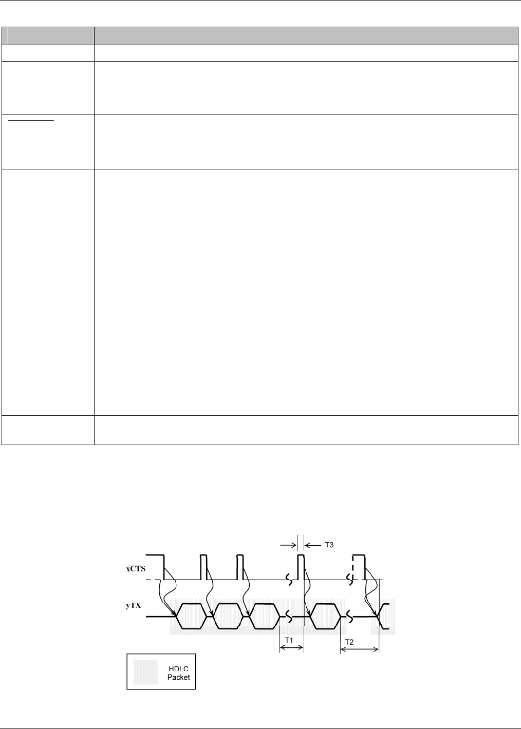
8.3.2.1 CTS Byte-level Handshake
The following diagram shows generic CTS byte-level flow control timing. The following details are applicable to both
MT_CTS
¯¯¯¯¯¯¯ and SP_CTS
¯¯¯¯¯¯¯.
Figure 8 CTS Byte-level Flow Control Timing
PRELIMINARY Confidential
M2x40 Mote Datasheet Dust Networks™ 14
Timeouts T1, T2, and T3 are defined as follows (refer to Error! Reference source not found. for values):
T1: interbyte_timeout—Maximum time between the transmit module sending a byte and the receiving module
acknowledging the byte using CTS (requests the next byte).
T2: interpacket_delay—For communications into the mote, the minimum time after the mote receives the last byte of a
packet before it can start receiving the next packet. For communications out of the mote, the minimum time between the
mote receiving acknowledgement of the last byte reception (or timeout) and the mote driving MT_RTS
¯¯¯¯¯¯¯ to request to send
another packet.
T3: min_strobe_length—The minimum length of time that CTS must be held active to be recognized by the receiver.
In idle mode or upon expiration of the interbyte_timeout, the transmit side treats CTS as level triggered (MT_RTS
¯¯¯¯¯¯¯ is
disregarded in case of local serial packets). After transfer of the first byte of a packet, the meaning of CTS signal is changed
to a byte acknowledgement strobe, active on a falling edge. In other words, CTS becomes a request signal for the next byte of
a packet. This acknowledgement strobe will occur for all packets (both local and network packets). Whenever timeouts T1 or
T2 occur, the packet is discarded and both sides switch to idle mode and start hunting for the next HDLC packet, assuming
CTS active low. If a packet is transferred completely, the interbyte_timeout after the last byte naturally takes care of
switching to idle mode.
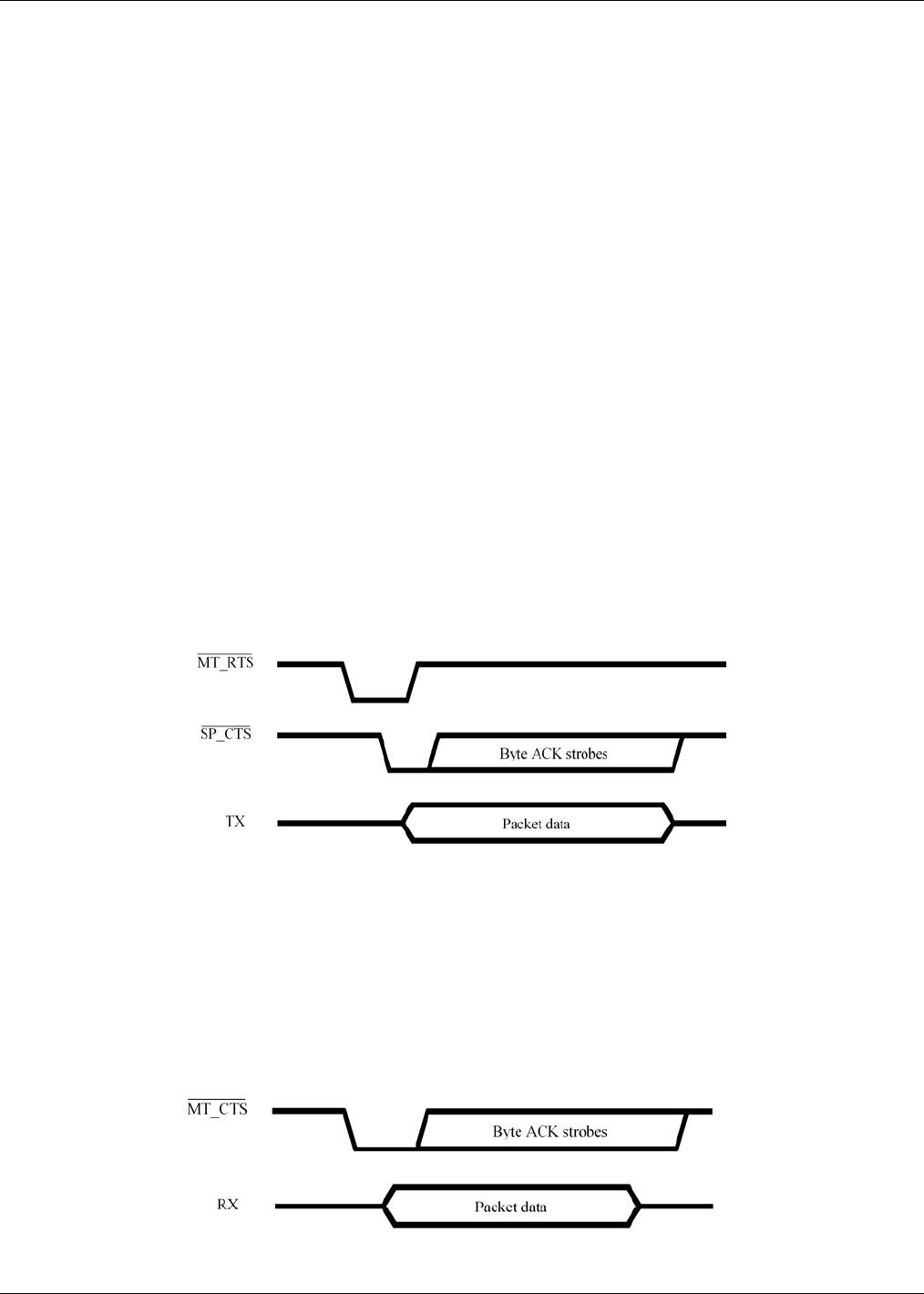
8.3.2.2 Data Flow Out of the Mote Serial Port
Figure 9 illustrates the process that the mote uses to transmit serial data:
1. The mote ensures the interpacket_delay time has passed since the last transmission.
2. The mote drives MT_RTS
¯¯¯¯¯¯¯ to active, waits for a falling edge on SP_CTS
¯¯¯¯¯¯¯. Timeout is defined as ack_delay (see Error!
Reference source not found.), and is long enough to handle the worst-case response.
3. If the mote times out before the SP_CTS
¯¯¯¯¯¯¯ becomes active, the mote restores MT_RTS
¯¯¯¯¯¯¯ to inactive and drops the packet.
4. If SP_CTS
¯¯¯¯¯¯¯ is active, then the mote transmits the first byte and follows the CTS byte-level handshaking rules for
subsequent bytes.
5. MT_RTS
¯¯¯¯¯¯¯ is restored to inactive after the ack_delay timeout has expired.
Figure 9 Packet Transmission from Mote
8.3.2.3 Data Flow Into the Mote Serial Port
Figure 10 illustrates the process the mote uses to receive serial data.
The mote may receive serial packets for local commands (not intended for wireless transmission) at any time regardless of
the MT_CTS
¯¯¯¯¯¯¯ status.
The mote signals its readiness to receive serial packets for wireless transmission (serial payload command 0x80) by driving
MT_CTS
¯¯¯¯¯¯¯ active low. The mote will drive MT_CTS
¯¯¯¯¯¯¯ low within interpacket_delay time (see Error! Reference source not
found.) after the transmission of the last packet.
PRELIMINARY Confidential
M2x40 Mote Datasheet Dust Networks™ 15
Figure 10 Packet Transmission to Mote
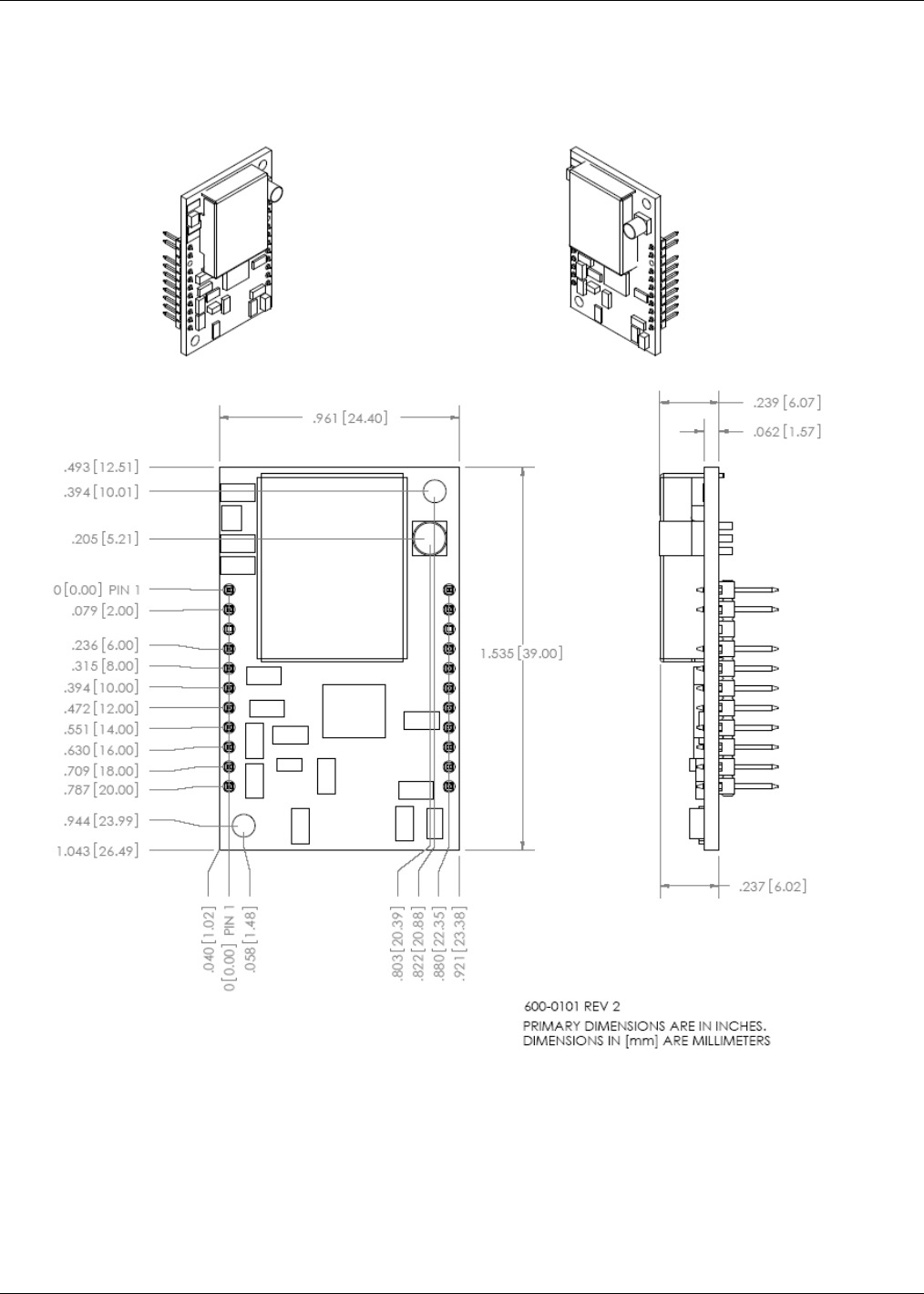
9.0 Packaging Description
9.1 Mechanical Drawing
Figure 11 M2x40 Mote Mechanical Drawing
PRELIMINARY Confidential
M2x40 Mote Datasheet Dust Networks™ 16
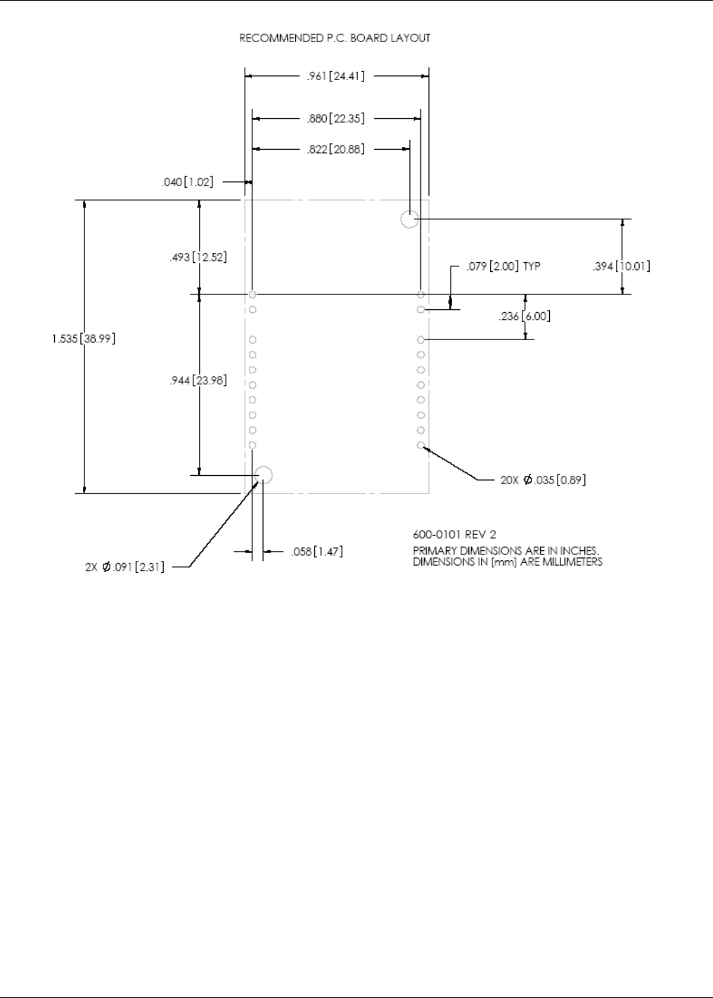
Figure 12 M2x40 Mote Footprint
9.2 Soldering Information
The M2x40 can be hand soldered with a soldering iron at 230 °C. The soldering iron should be in contact with the pin for 10
seconds or less. The M2x40 is also suitable for eutectic PbSn reflow.
10.0 Regulatory and Standards Compliance
10.1 FCC Compliance
The M2x40 mote complies with Part 15.247 modular (Intentional Radiator) of the FCC rules and regulations. Changes or
modifications not expressly approved by Dust Networks could void the user's authority to operate the equipment.
10.1.1 FCC Testing
In order to fulfill FCC certification requirements, products incorporating the M2x40 mote must comply with the following:
1. An external label must be provided on the outside of the final product enclosure specifying the FCC identifier as
described in 10.1.3 below.
2. The antenna must be electrically identical to the FCC-approved antenna specifications for the M2x40 as described in
10.1.2 with the exception that the gain may be lower than specified in Table 14.
3. The device integrating the M2x40 mote may not cause harmful interference, and must accept any interference received,
including interference that may cause undesired operation.

PRELIMINARY Confidential
M2x40 Mote Datasheet Dust Networks™ 17
4. An unintentional radiator scan must be performed on the device integrating the M2x40 mote, per FCC rules and
regulations, CFR Title 47, Part 15, Subpart B. See FCC rules for specifics on requirements for declaration of conformity.
10.1.2 FCC-approved Antennae
The following are FCC-approved antenna specifications for the M2x40
Table 14 FCC-approved Antenna Specifications for the M2x40
Gain Pattern Polarization Frequency Connector
+2 dBi maximum Omni-directional Vertical 2.4-2.4835 GHz MMCX
10.1.3 OEM Labeling Requirements
The Original Equipment Manufacturer (OEM) must ensure that FCC labeling requirements are met. The outside of the final
product enclosure must have a label with the following (or similar) text specifying the FCC identifier. The FCC ID and
certification code must be in Latin letters and Arabic numbers and visible without magnification.
Contains transmitter module FCC ID: SJC-M2140
Or
Contains FCC ID: SJC-M2140
10.2 Industry Canada (IC) Compliance
10.2.1 IC Testing
The M2x40 is certified for modular Industry Canada (IC) RSS-210 approval. The OEM is responsible for its product to
comply with IC ICES-003 and FCC Part 15, Sub. B - Unintentional Radiators. The requirements of ICES-003 are equivalent
to FCC Part 15 Sub. B and Industry Canada accepts FCC test reports or CISPR 22 test reports for compliance with ICES-003.
10.2.2 IC-approved Antennae
The following are IC-approved antenna specifications for the M2x40.
Table 15 IC-approved Antenna Specifications for the M2x40
Gain Pattern Polarization Frequency Connector
+2 dBi maximum Omni-directional Vertical 2.4-2.4835 GHz MMCX
10.2.3 OEM Labeling Requirements
The Original Equipment Manufacturer (OEM) must ensure that IC labeling requirements are met. The outside of the final
product enclosure must have a label with the following (or similar) text specifying the IC identifier. The IC ID and
certification code must be in Latin letters and Arabic numbers and visible without magnification
Contains IC: 5853A-M2140
10.3 CE Compliance
10.3.1 Declaration of Conformity
We, Dust Networks, of
30695 Huntwood Ave
Hayward, CA 94544 USA
declare under our sole responsibility that our product,
SmartMesh-XD M2140 and M2040, and in combination with our accessories, to which this declaration relates is in
conformity with the appropriate standards ETSI EN 300 328, ETSI EN 301 489-17 and EN 60950, following the provisions
PRELIMINARY Confidential
M2x40 Mote Datasheet Dust Networks™ 18
of Radio Equipment and Telecommunication Terminal Equipment directive 99/5/EC with requirements covering EMC
directive 89/336/EEC, and Low voltage directive 73/23/EEC.
10.3.2 European Compliance
If the M2140 and M2040 motes are incorporated into a product, the manufacturer must ensure compliance of the final
product to the European harmonized EMC and low-voltage/safety standards. A Declaration of Conformity must be issued for
each of these standards and kept on file as described in Annex II of the R&TTE Directive. Furthermore, the manufacturer
must maintain a copy of this M2140/M2040 user documentation and ensure the final product does not exceed the specified
power ratings, antenna specifications, and/or installation requirements as specified in the user manual. If any of these
specifications are exceeded in the final product, a submission must be made to a notified body for compliance testing to all
required standards.
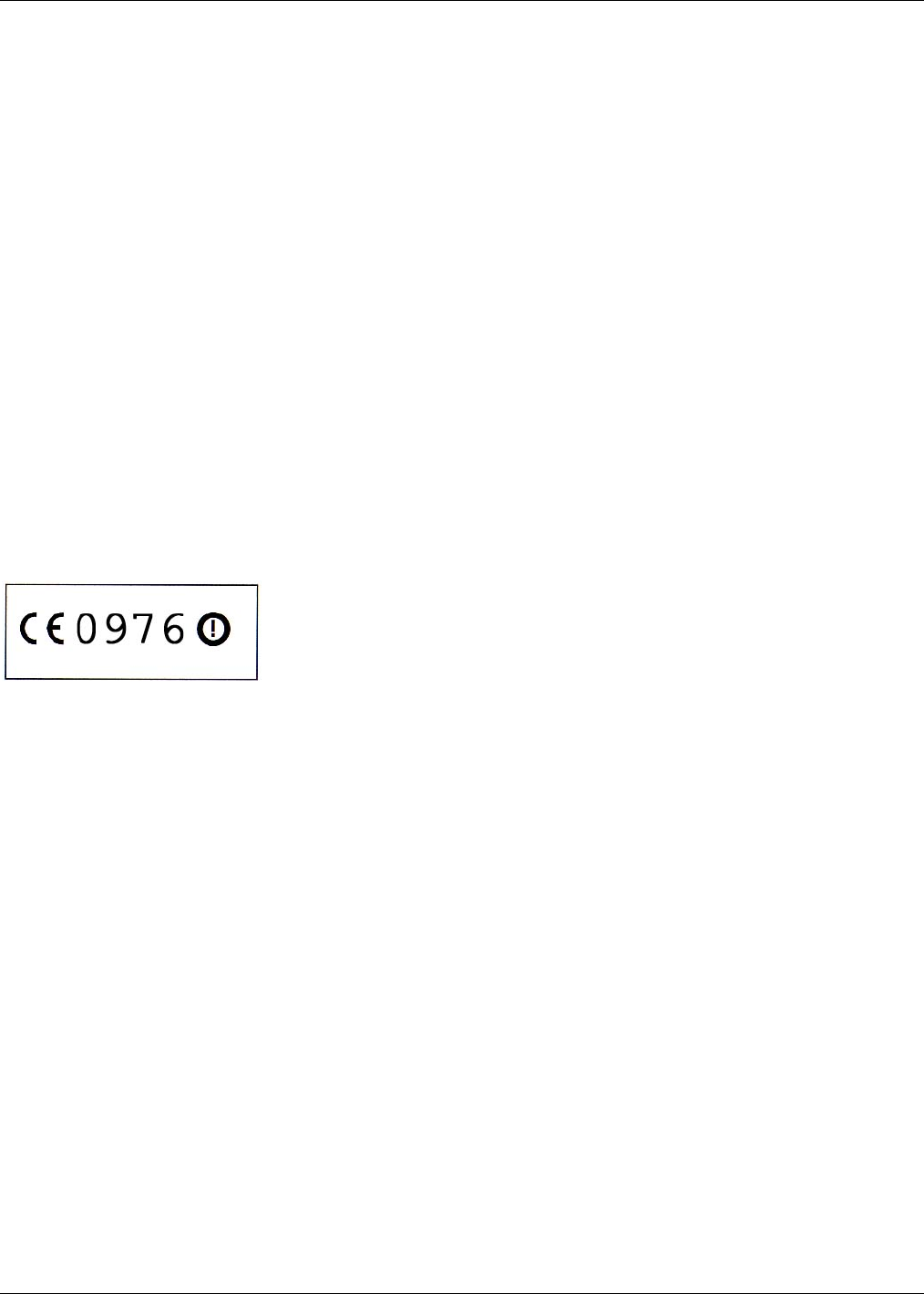
10.3.3 OEM Labeling Requirements
The ‘CE’ marking must be affixed to a visible location on the OEM product. The CE mark shall consist of the initials “CE”
taking the following form:
If the CE marking is reduced or enlarged, the proportions given in the drawing below must be respected.
The CE marking must have a height of at least 5mm except where this is not possible on account of the nature of the
apparatus.
The CE marking must be affixed visibly, legibly, and indelibly.
Furthermore, since the usage of the 2400 – 2483.5 MHz band is not harmonized throughout Europe, the Restriction sign must
be placed to the right of the ‘CE’ marking as shown below. See the R&TTE Directive, Article 12 and Annex VII for more
information.
Figure 13 CE Label Requirements
10.3.4 Restrictions
France—France imposes restrictions on the 2.4 GHz band. Go to www.art-telecom.Fr or contact Dust Networks for more
information.
Norway—Norway prohibits operation near Ny-Alesund in Svalbard. More information can be found at the Norway Posts and
Telecommunications site (www.npt.no).
10.4 Industrial Environment Operation
The M2x40 is designed to meet the specifications of a harsh industrial environments which includes:
• Shock and Vibration—The M2x40 complies with high vibration pipeline testing, as specified in IEC 60770-1.
• Hazardous Locations—The M2x40 design is consistent with operation in UL Class 1 Division 1 and Division 2
hazardous locations.
• Temperature Extremes—The M2x40 is designed for industrial storage and operational temperature range of –40 °C to
+85 °C.
11.0 Ordering Information
Product List:
M2x40: Marconi / 2.4 GHz MHz Mote
Contact Information:
Dust Networks
30695 Huntwood Ave.

PRELIMINARY Confidential
M2x40 Mote Datasheet Dust Networks™ 19
Hayward, CA 94544
Toll-Free Phone: 1 (866) 289-3878
Website: www.dustnetworks.com
Email: sales@dustnetworks.com

PRELIMINARY Confidential
M2x40 Mote Datasheet Dust Networks™ 20
Trademarks
Dust Networks™, the Dust Networks logo, SmartMesh-XT™, SmartMesh-XD™, Marconi™, mesh-to-the-edge™, and Mote-on-Chip™ are trademarks
of Dust Networks, Inc. Dust® and SmartMesh® are registered trademarks of Dust Networks, Inc. All third-party brand and product names are the
trademarks of their respective owners and are used solely for informational purposes.
Copyright
This documentation is protected by United States and international copyright and other intellectual and industrial property laws. It is solely owned by Dust
Networks, Inc. and its licensors and is distributed under a restrictive license. This product, or any portion thereof, may not be used, copied, modified,
reverse assembled, reverse compiled, reverse engineered, distributed, or redistributed in any form by any means without the prior written authorization of
Dust Networks, Inc.
RESTRICTED RIGHTS: Use, duplication, or disclosure by the U.S. Government is subject to restrictions of FAR 52.227-14(g) (2)(6/87) and FAR
52.227-19(6/87), or DFAR 252.227-7015 (b)(6/95) and DFAR 227.7202-3(a), and any and all similar and successor legislation and regulation.
Disclaimer
This documentation is provided “as is” without warranty of any kind, either expressed or implied, including but not limited to, the implied warranties of
merchantability or fitness for a particular purpose.
This documentation might include technical inaccuracies or other errors. Corrections and improvements might be incorporated in new versions of the
documentation.
Dust Networks does not assume any liability arising out of the application or use of any products or services and specifically disclaims any and all
liability, including without limitation consequential or incidental damages.
Dust Networks products are not designed for use in life support appliances, devices, or other systems where malfunction can reasonably be expected to
result in significant personal injury to the user, or as a critical component in any life support device or system whose failure to perform can be reasonably
expected to cause the failure of the life support device or system, or to affect its safety or effectiveness. Dust Networks customers using or selling these
products for use in such applications do so at their own risk and agree to fully indemnify and hold Dust Networks and its officers, employees, subsidiaries,
affiliates, and distributors harmless against all claims, costs, damages, and expenses, and reasonable attorney fees arising out of, directly or indirectly, any
claim of personal injury or death associated with such unintended or unauthorized use, even if such claim alleges that Dust Networks was negligent
regarding the design or manufacture of its products.
Dust Networks reserves the right to make corrections, modifications, enhancements, improvements, and other changes to its products or services at any
time and to discontinue any product or service without notice. Customers should obtain the latest relevant information before placing orders and should
verify that such information is current and complete. All products are sold subject to Dust Network's terms and conditions of sale supplied at the time of
order acknowledgment or sale.
Dust Networks does not warrant or represent that any license, either express or implied, is granted under any Dust Networks patent right, copyright, mask
work right, or other Dust Networks intellectual property right relating to any combination, machine, or process in which Dust Networks products or
services are used. Information published by Dust Networks regarding third-party products or services does not constitute a license from Dust Networks to
use such products or services or a warranty or endorsement thereof. Use of such information may require a license from a third party under the patents or
other intellectual property of the third party, or a license from Dust Networks under the patents or other intellectual property of Dust Networks.
© Dust Networks, Inc. 2006, 2007. All Rights Reserved.
Document Number: 020-0026 rev 1 M2140 / M2040 Datasheet
Last Revised: December 7, 2007
Document Status Product Status Definition
Advanced
Information Planned or under
development
This datasheet contains the design specifications for
product development. Dust Networks reserves the right to
change specifications in any manner without notice.
Preliminary
Engineering samples and
pre-production prototypes
This datasheet contains preliminary data; supplementary
data will be published at a later time. Dust Networks
reserves the right to make changes at any time without
notice in order to improve design and supply the best
possible product. The product is not fully qualified at this
point.
No Identification
Noted
Full production
This datasheet contains the final specifications. Dust
Networks reserves the right to make changes at any time
without notice in order to improve design and supply the
best possible product.
Obsolete
Not in production
This datasheet contains specifications for a product that
has been discontinued by Dust Networks. The datasheet is
printed for reference information only.