DynaLock E Binder 5500 Series Installation Instructions 5500IN
User Manual: DynaLock 5500 Series Installation Instructions Installation Instructions
Open the PDF directly: View PDF ![]() .
.
Page Count: 4
Page #4
No Output Power @ No Output @
4
3
2
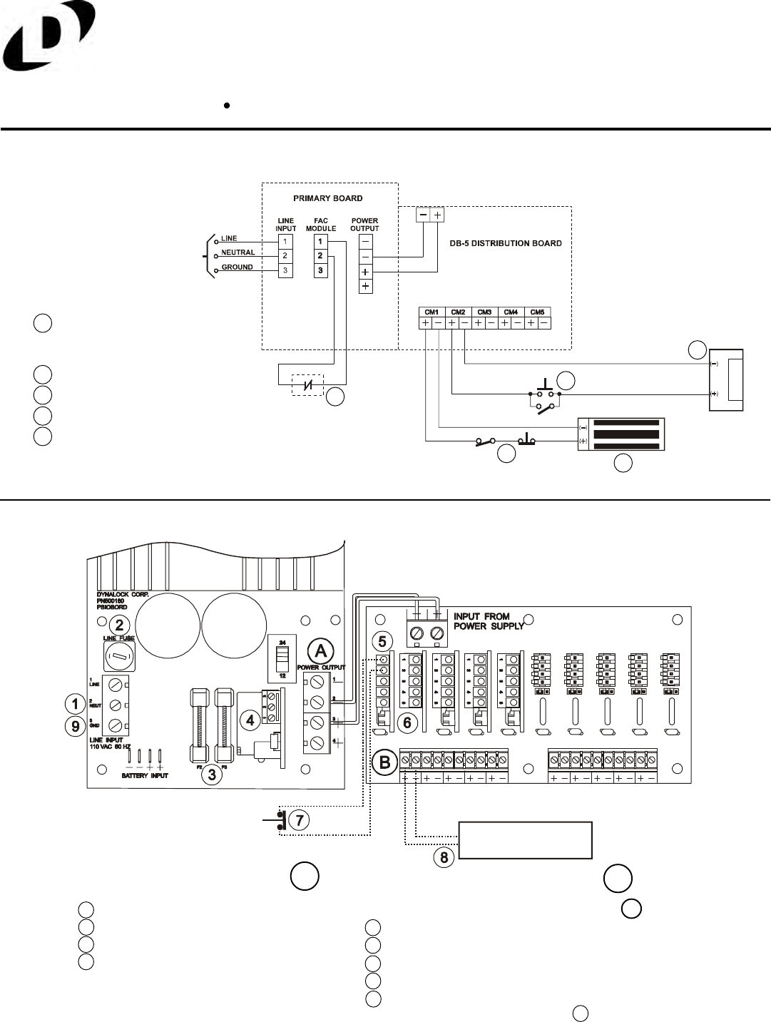
1Check input line power.
Check line fuse.
Check F2 & F3 output fuses.
Check FAC (If applicable) terminals
1 & 2 must be wired to N/C contact.
Check jumper settings on CM/CMTD module(If applicable).
Check jumper setting on DB-5/DB-10 card.
Check for proper access switch contact status.
Check load & external wiring for short condition.
Reset Power Supply (With no load) by
disconnecting input power at for 2 minutes.
B
A
ELECTROMAGNETIC LOCK
Access control
legal release
TYPICAL APPLICATION
Normally-closed dry
contact from Fire Alarm
Control panel (By others).
Fail Secure locking
Fail Safe locking device.
TROUBLESHOOTING
120 VAC
50/60 HZ
INPUT
A
B
A
Normally open access/egress controls.
Normally closed access/egress controls.
D
DB
E
E
C
C
1
Note: Start at ‘No Output Power @ A
6
7
5
8
9
FAC Option
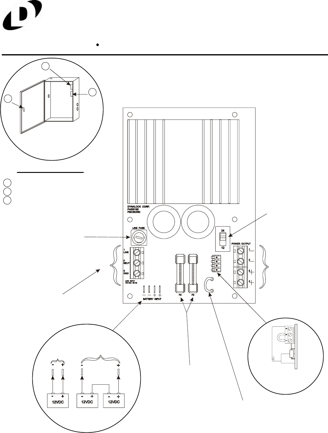
BBU (Battery Back-Up)
Option
12V BBU1-4
or BBU1-7 24V BBU2-7 or BBU2-7
5500 Enclosure
B
A
C
Enclosure Options:
C
B
A-KLC, (Key Lock Cover)
-FACMR, (FAC Manual Reset)
-ATS, (Anti-Tamper Switch)
Note: ATS Wiring on Page 3.
Primary Fuse
1 Amp Slow Blow
PC (Power Cord) Option
Prewired 6’ long
Output Fuses
5 Amp slow blow
FAC Jumper
Cut if FAC Module
is installed in field
12/24V Selection
Switch
Output Power
Switchable from
12VDC @ 3 amps.
24VDC @ 2 amps.
DB-5 & DB- 10
(Distribution Board)
Option connection.
5500 POWER SUPPLY BOARD
115 VAC Input
5500 Manual 03/03
MODEL #5500
POWER SUPPLY
INSTALLATION INSTRUCTIONS
Dyna
Lock
705 Emmett Street Bristol, CT 06011-2728
Phone:(860) 582-4761 Fax:(860) 585-0338
5500 Manual 03/03
MODEL #5500
POWER SUPPLY
INSTALLATION INSTRUCTIONS
Dyna
Lock
705 Emmett Street Bristol, CT 06011-2728
Phone:(860) 582-4761 Fax:(860) 585-0338
Page #3
A
B
CMTD Option (Control Module with Time Delay)
Same as CM Option with Relock Time Delay
Adjustable for 1-80
Second delay on
relock time.
B
AAccess Control Input, Dry Contacts Only.
SPDT Dry Contacts Rated 2A @ 24V.
ILB Option (Interlock Logic Board)
Provides Four DPDT Relay Outputs Common Negative Terminal
Positive Inputs to Energize
Relay Coils
Note: Separate
ILB user manual
shows typical
wiring diagrams.
Installation Information LOCK CAPACITY CHART
*This chart indicatess minimum recommended wire size, but local codes prevail
Single Full
Size Double Full
Size Single Double Single Delay
Egress Deadbolt
12VDC
24VDC
6
Voltage
24VDC
20 AWG 18 AWG 16 AWG 14 AWG 12 AWG 10 AWG
8
100Ft. 200Ft. 300Ft. 500Ft. 750Ft. 1500Ft.
36333
48
434
CURRENT DRAW UP TO 1/2 AMP
12VDC 50Ft. 100Ft. 150Ft. 250Ft. 400Ft. 750Ft.
NOTE: ATS switch contacts
rated .25A @ 24V.
ATS Option
(Anti-Tamper Switch)
Contact held open with
Enclosure cover closed.
Contact closed with
Enclosure cover open.
White
White
White
White
Page #2
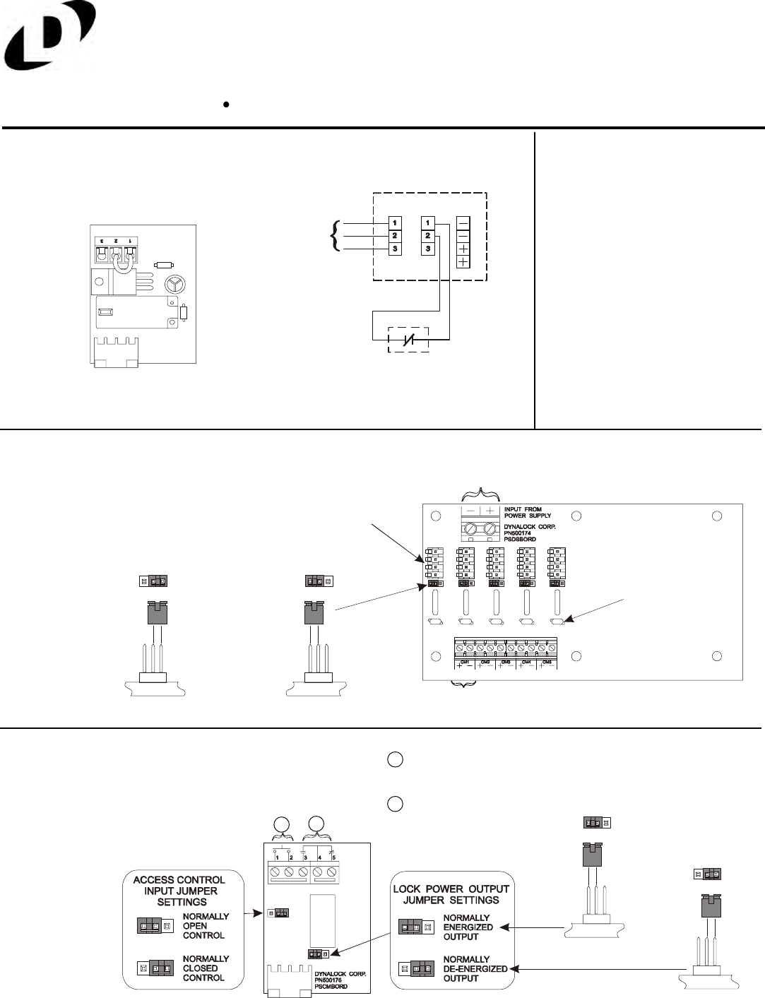
FAC Option (Fire Alarm Control)
Kills all voltage outputs when interfaced
with emergency system dry contact.
Module supplied with jumper
on terminals 1 & 2 as shown.
Typical Application
Normally-Closed Dry Contact from
Fire Alarm Control Panel (By others).
Cut Main Board Jumper when field installed.
Refer to Page #1 (FAC Jumper).
FACMR Option
(FAC Manual Reset)
Opening normally closed contact removes
all output power until the normally open reset
button is momentarily pressed.
120 VAC
50/60 HZ
INPUT
*Resettable Fuse
DC Input from Power
Supply Main Board
With Control Module OptionWithout Control Module Option
OUTPUT JUMPERS
Connector for
CM/CMTD Modules
DB-5 & DB-10 Option (Distribution Board)
Two size distribution boards (5 or 10 position)
are available to provide individually fused
output terminals for each lock zone.
*Resetting is done by first correcting the overload then disconnecting
the load or turning off the line voltage for two minutes.
CM Option (Control Module)
Accepts access/egress control
dry contact input. Provides
SPDT relay output.
Access Control Input,
Dry Contacts Only.
SPDT Dry Contacts
Rated 2A @ 24V.
AB
B
A
LINE
INPUT POWER
OUTPUT
FAC
MODULE
LINE
NEUT
GND
(Factory Setting)
123
eReset Button
5500 Manual 03/03
MODEL #5500
POWER SUPPLY
INSTALLATION INSTRUCTIONS
Dyna
Lock
705 Emmett Street Bristol, CT 06011-2728
Phone:(860) 582-4761 Fax:(860) 585-0338
5500 Manual 03/03
MODEL #5500
POWER SUPPLY
INSTALLATION INSTRUCTIONS
Dyna
Lock
705 Emmett Street Bristol, CT 06011-2728
Phone:(860) 582-4761 Fax:(860) 585-0338
Page #3
A
B
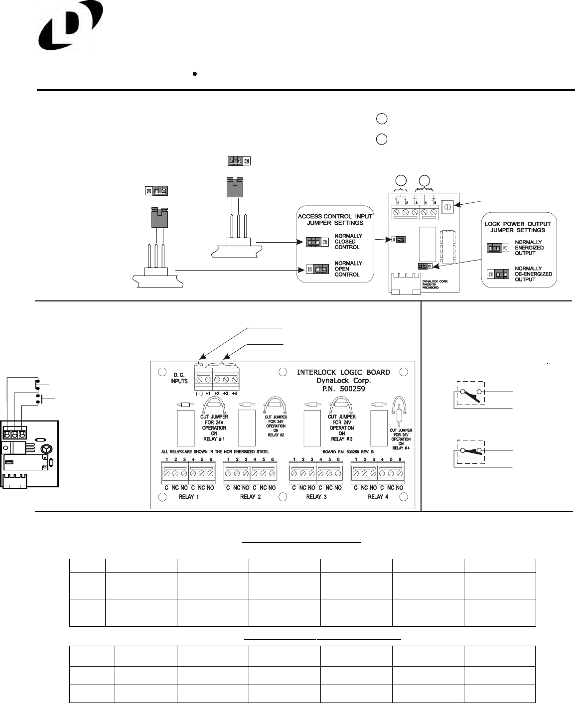
CMTD Option (Control Module with Time Delay)
Same as CM Option with Relock Time Delay
Adjustable for 1-80
Second delay on
relock time.
B
AAccess Control Input, Dry Contacts Only.
SPDT Dry Contacts Rated 2A @ 24V.
ILB Option (Interlock Logic Board)
Provides Four DPDT Relay Outputs Common Negative Terminal
Positive Inputs to Energize
Relay Coils
Note: Separate
ILB user manual
shows typical
wiring diagrams.
Installation Information LOCK CAPACITY CHART
*This chart indicatess minimum recommended wire size, but local codes prevail
Single Full
Size Double Full
Size Single Double Single Delay
Egress Deadbolt
12VDC
24VDC
6
Voltage
24VDC
20 AWG 18 AWG 16 AWG 14 AWG 12 AWG 10 AWG
8
100Ft. 200Ft. 300Ft. 500Ft. 750Ft. 1500Ft.
36333
48
434
CURRENT DRAW UP TO 1/2 AMP
12VDC 50Ft. 100Ft. 150Ft. 250Ft. 400Ft. 750Ft.
NOTE: ATS switch contacts
rated .25A @ 24V.
ATS Option
(Anti-Tamper Switch)
Contact held open with
Enclosure cover closed.
Contact closed with
Enclosure cover open.
White
White
White
White
Page #2
FAC Option (Fire Alarm Control)
Kills all voltage outputs when interfaced
with emergency system dry contact.
Module supplied with jumper
on terminals 1 & 2 as shown.
Typical Application
Normally-Closed Dry Contact from
Fire Alarm Control Panel (By others).
Cut Main Board Jumper when field installed.
Refer to Page #1 (FAC Jumper).
FACMR Option
(FAC Manual Reset)
Opening normally closed contact removes
all output power until the normally open reset
button is momentarily pressed.
120 VAC
50/60 HZ
INPUT
*Resettable Fuse
DC Input from Power
Supply Main Board
With Control Module OptionWithout Control Module Option
OUTPUT JUMPERS
Connector for
CM/CMTD Modules
DB-5 & DB-10 Option (Distribution Board)
Two size distribution boards (5 or 10 position)
are available to provide individually fused
output terminals for each lock zone.
*Resetting is done by first correcting the overload then disconnecting
the load or turning off the line voltage for two minutes.
CM Option (Control Module)
Accepts access/egress control
dry contact input. Provides
SPDT relay output.
Access Control Input,
Dry Contacts Only.
SPDT Dry Contacts
Rated 2A @ 24V.
AB
B
A
LINE
INPUT POWER
OUTPUT
FAC
MODULE
LINE
NEUT
GND
(Factory Setting)
123
eReset Button
5500 Manual 03/03
MODEL #5500
POWER SUPPLY
INSTALLATION INSTRUCTIONS
Dyna
Lock
705 Emmett Street Bristol, CT 06011-2728
Phone:(860) 582-4761 Fax:(860) 585-0338
5500 Manual 03/03
MODEL #5500
POWER SUPPLY
INSTALLATION INSTRUCTIONS
Dyna
Lock
705 Emmett Street Bristol, CT 06011-2728
Phone:(860) 582-4761 Fax:(860) 585-0338
Page #4
No Output Power @ No Output @
4
3
2
1Check input line power.
Check line fuse.
Check F2 & F3 output fuses.
Check FAC (If applicable) terminals
1 & 2 must be wired to N/C contact.
Check jumper settings on CM/CMTD module(If applicable).
Check jumper setting on DB-5/DB-10 card.
Check for proper access switch contact status.
Check load & external wiring for short condition.
Reset Power Supply (With no load) by
disconnecting input power at for 2 minutes.
B
A
ELECTROMAGNETIC LOCK
Access control
legal release
TYPICAL APPLICATION
Normally-closed dry
contact from Fire Alarm
Control panel (By others).
Fail Secure locking
Fail Safe locking device.
TROUBLESHOOTING
120 VAC
50/60 HZ
INPUT
A
B
A
Normally open access/egress controls.
Normally closed access/egress controls.
D
DB
E
E
C
C
1
Note: Start at ‘No Output Power @ A
6
7
5
8
9
FAC Option
BBU (Battery Back-Up)
Option
12V BBU1-4
or BBU1-7 24V BBU2-7 or BBU2-7
5500 Enclosure
B
A
C
Enclosure Options:
C
B
A-KLC, (Key Lock Cover)
-FACMR, (FAC Manual Reset)
-ATS, (Anti-Tamper Switch)
Note: ATS Wiring on Page 3.
Primary Fuse
1 Amp Slow Blow
PC (Power Cord) Option
Prewired 6’ long
Output Fuses
5 Amp slow blow
FAC Jumper
Cut if FAC Module
is installed in field
12/24V Selection
Switch
Output Power
Switchable from
12VDC @ 3 amps.
24VDC @ 2 amps.
DB-5 & DB- 10
(Distribution Board)
Option connection.
5500 POWER SUPPLY BOARD
115 VAC Input
5500 Manual 03/03
MODEL #5500
POWER SUPPLY
INSTALLATION INSTRUCTIONS
Dyna
Lock
705 Emmett Street Bristol, CT 06011-2728
Phone:(860) 582-4761 Fax:(860) 585-0338
5500 Manual 03/03
MODEL #5500
POWER SUPPLY
INSTALLATION INSTRUCTIONS
Dyna
Lock
705 Emmett Street Bristol, CT 06011-2728
Phone:(860) 582-4761 Fax:(860) 585-0338
