Dynabook UPA3373WL 802.11 b/g Mini PCI Card User Manual Palao WLAG 1106 03
Toshiba Corporation 802.11 b/g Mini PCI Card Palao WLAG 1106 03
Dynabook >
Contents
- 1. Instalation Guide
- 2. addendum
- 3. PotegeM200 User Manual
Instalation Guide

1
TOSHIBA Wireless LAN Card
Installation
This sheet provides information on installing the Wireless LAN card in the PORTÉGÉ
M200.
CAUTION: This sheet is for information only. The Wireless LAN card must
be installed by dealers of TOSHIBA or TOSHIBA OEM products.
NOTE: The Wireless LAN card is a wireless network card that complies
with the IEEE 802.11 standard for Wireless LANs (Revision B.)
Installing the Wireless LAN card
1. Discharge static electricity from your body by touching a metal object, before
you handle the card.
2. Turn off the power and disconnect the AC adaptor.
3. Lay the computer upside down.
4. Remove the battery pack from the computer. For instructions on removing the
battery pack, refer to Chapter 6 in the online manual.
2
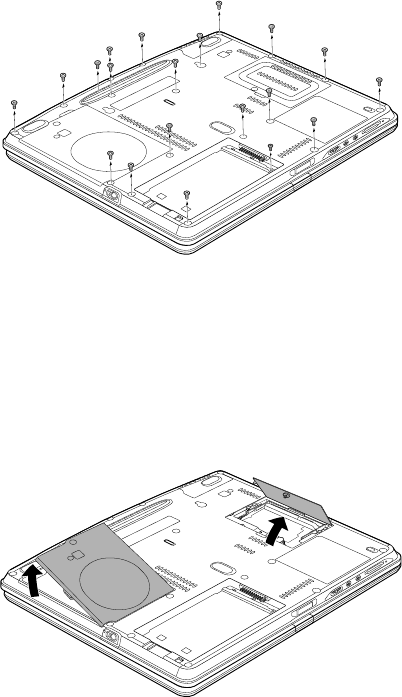
5. Remove twenty screws securing computer’s under cover. (One screw is situated
under the battery pack.)
NOTE: Use a point size 0 Phillips screwdriver.
Figure 1 Removing twenty screws
6. Loosen one screw securing the memory module cover and lift off the cover.
Remove the memory module. Refer to Chapter 8 in the online manual for details.
7. Loosen one screw securing the HDD cover and lift off the cover.
Figure 2 Removing the memory module cover and HDD cover
3
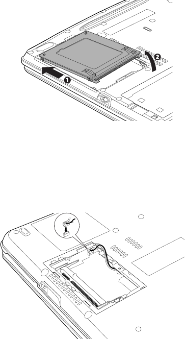
8. Slide the HDD and remove it.
Figure 3 Removing the HDD
9. Disconnect the VGA fan cable under the memory module.
Figure 4 Removing the VGA fan cable
4
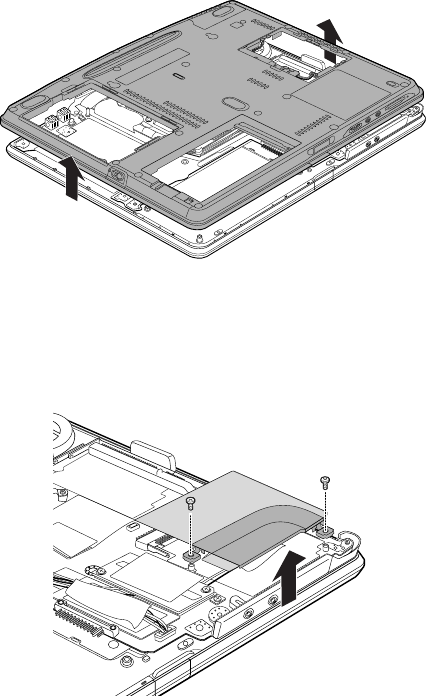
10. Remove the computer’s under cover.
Figure 5 Removing the computer’s under cover
11. Remove flat-head two screws and the metal cover.
Figure 6 Removing two screws and the metal cover
5
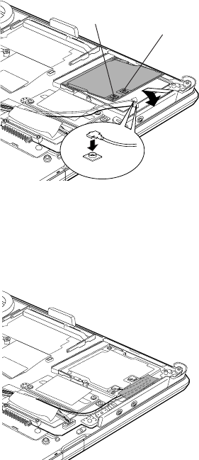
12. Connect the antenna cables to the proper connectors on the Wireless LAN card.
The cables are color coded white and black. Refer to figure 7 to see for which
color to goes to which connector.
CAUTION: Be careful not to apply pressure to the ICs on the Wireless LAN
card.
13. Hold the card at about a 45 degree angle, fit it into the computer’s connector and
press carefully to ensure firm contact.
14. Gently, push the card down until latches on either side engage the card to hold it
in place.
Figure 7 Installing the Wireless LAN card
15. Route the cable as shown below and secure it with tape.
Figure 8 Routing the Wireless LAN cable
BLACK WHITE
6
16. Seat the metal cover on the Wireless LAN card and secure it with flat-head two
screws.
17. Seat the computer’s under cover.
18. Connect the VGA fan cable under the memory module.
19. Seat the memory module. Refer to Chapter 8 in the online manual for details.
20. Seat the memory module cover and secure it with one screw.
21. Install the HDD.
22. Seat the HDD cover and secure it with one screw.
23. Secure twenty screws.
24. Turn the computer upside down.
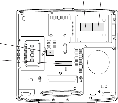
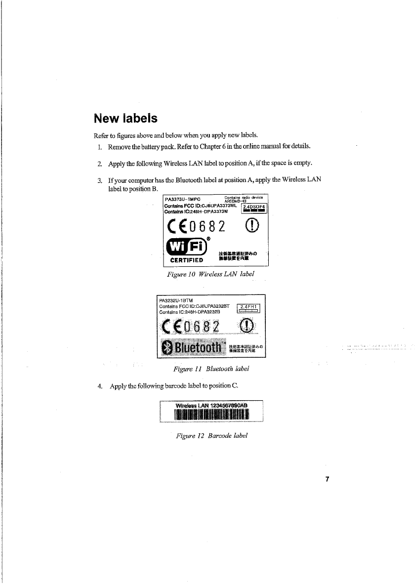
Applying labels
The figure below shows the locations of labels . The letters A, B, C and D correspond
to labels identified in later illustrations. The applied labels will vary according to your
computer’s configuration.
Figure 9 Label positions
B
C
D
A

8
5. Apply the following Singapore Regulatory label to position D. If your computer
already has the Singapore Regulatory label, you do not need to apply a new label.
Figure 13 Singapore Regulatory label