Dynabook UPA3547G3 CDMA Cell-PCS Module User Manual Manual
Toshiba Corporation CDMA Cell-PCS Module Manual
Dynabook >
Contents
Manual 1

User’s Manual
PORTÉGÉ M700/M710

User’s Manual ii
Table of Contents
Copyright. . . . . . . . . . . . . . . . . . . . . . . . . . . . . . . . . . . . . . . . . . . . . . . . . vi
Disclaimer . . . . . . . . . . . . . . . . . . . . . . . . . . . . . . . . . . . . . . . . . . . . . . . . vi
Trademarks . . . . . . . . . . . . . . . . . . . . . . . . . . . . . . . . . . . . . . . . . . . . . . . vi
FCC information . . . . . . . . . . . . . . . . . . . . . . . . . . . . . . . . . . . . . . . . . . . vii
EU Conformity Statement . . . . . . . . . . . . . . . . . . . . . . . . . . . . . . . . . . viii
VCCI Class B Information . . . . . . . . . . . . . . . . . . . . . . . . . . . . . . . . . . viii
Modem warning notice. . . . . . . . . . . . . . . . . . . . . . . . . . . . . . . . . . . . . viii
Japan regulations. . . . . . . . . . . . . . . . . . . . . . . . . . . . . . . . . . . . . . . . . . ix
Instructions for IC CS-03 certified equipment . . . . . . . . . . . . . . . . . . . xii
Notes for Users in Australia and New Zealand . . . . . . . . . . . . . . . . . xiii
Following information is only for EU-member states: . . . . . . . . . . . xvi
Description on Laser specification. . . . . . . . . . . . . . . . . . . . . . . . . . . xvi
Preface
Conventions . . . . . . . . . . . . . . . . . . . . . . . . . . . . . . . . . . . . . . . . . . . . . xvii
General Precautions
Creating a computer-friendly environment . . . . . . . . . . . . . . . . . . . . . xx
Stress injury . . . . . . . . . . . . . . . . . . . . . . . . . . . . . . . . . . . . . . . . . . . . . . xx
Heat injury. . . . . . . . . . . . . . . . . . . . . . . . . . . . . . . . . . . . . . . . . . . . . . . xxi
Pressure or impact damage. . . . . . . . . . . . . . . . . . . . . . . . . . . . . . . . . xxi
PC Card overheating . . . . . . . . . . . . . . . . . . . . . . . . . . . . . . . . . . . . . . xxi
Mobile phones . . . . . . . . . . . . . . . . . . . . . . . . . . . . . . . . . . . . . . . . . . . xxi
Instruction Manual for Safety and Comfort . . . . . . . . . . . . . . . . . . . . xxi
Chapter 1 Getting Started
Equipment checklist. . . . . . . . . . . . . . . . . . . . . . . . . . . . . . . . . . . . . . . 1-1
Getting Started . . . . . . . . . . . . . . . . . . . . . . . . . . . . . . . . . . . . . . . . . . . 1-3
System Recovery Options. . . . . . . . . . . . . . . . . . . . . . . . . . . . . . . . . 1-12
System Recovery . . . . . . . . . . . . . . . . . . . . . . . . . . . . . . . . . . . . . . . . 1-13
Chapter 2 The Grand Tour
Front with the display closed . . . . . . . . . . . . . . . . . . . . . . . . . . . . . . . 2-1
Left side. . . . . . . . . . . . . . . . . . . . . . . . . . . . . . . . . . . . . . . . . . . . . . . . . 2-3

User’s Manual iii
PORTÉGÉ M700/M710
Right side . . . . . . . . . . . . . . . . . . . . . . . . . . . . . . . . . . . . . . . . . . . . . . . 2-4
Back . . . . . . . . . . . . . . . . . . . . . . . . . . . . . . . . . . . . . . . . . . . . . . . . . . . . 2-5
Underside . . . . . . . . . . . . . . . . . . . . . . . . . . . . . . . . . . . . . . . . . . . . . . . 2-7
Front with the display open. . . . . . . . . . . . . . . . . . . . . . . . . . . . . . . . . 2-9
Indicators . . . . . . . . . . . . . . . . . . . . . . . . . . . . . . . . . . . . . . . . . . . . . . 2-13
Optical disc drives . . . . . . . . . . . . . . . . . . . . . . . . . . . . . . . . . . . . . . . 2-15
AC adaptor . . . . . . . . . . . . . . . . . . . . . . . . . . . . . . . . . . . . . . . . . . . . . 2-17
Chapter 3 Hardware, Utilities and Options
Hardware . . . . . . . . . . . . . . . . . . . . . . . . . . . . . . . . . . . . . . . . . . . . . . . . 3-1
Special features . . . . . . . . . . . . . . . . . . . . . . . . . . . . . . . . . . . . . . . . . . 3-6
TOSHIBA Value Added Package . . . . . . . . . . . . . . . . . . . . . . . . . . . . . 3-9
TOSHIBA Tablet PC Extension . . . . . . . . . . . . . . . . . . . . . . . . . . . . . 3-10
Utilities and Applications. . . . . . . . . . . . . . . . . . . . . . . . . . . . . . . . . . 3-10
Optional devices. . . . . . . . . . . . . . . . . . . . . . . . . . . . . . . . . . . . . . . . . 3-14
Bridge media slot . . . . . . . . . . . . . . . . . . . . . . . . . . . . . . . . . . . . . . . . 3-18
Optional accessories . . . . . . . . . . . . . . . . . . . . . . . . . . . . . . . . . . . . . 3-45
Chapter 4 Operating Basics
Pointing Devices. . . . . . . . . . . . . . . . . . . . . . . . . . . . . . . . . . . . . . . . . . 4-1
Using the Tablet mode . . . . . . . . . . . . . . . . . . . . . . . . . . . . . . . . . . . . . 4-9
Using the Fingerprint Sensor . . . . . . . . . . . . . . . . . . . . . . . . . . . . . . 4-17
Web Camera . . . . . . . . . . . . . . . . . . . . . . . . . . . . . . . . . . . . . . . . . . . . 4-25
Changing Ultra Slim Bay modules . . . . . . . . . . . . . . . . . . . . . . . . . . 4-26
Using optical disc drives . . . . . . . . . . . . . . . . . . . . . . . . . . . . . . . . . . 4-29
Writing CD/DVDs on DVD Super Multi drives . . . . . . . . . . . . . . . . . 4-33
Media care . . . . . . . . . . . . . . . . . . . . . . . . . . . . . . . . . . . . . . . . . . . . . . 4-40
Sound System. . . . . . . . . . . . . . . . . . . . . . . . . . . . . . . . . . . . . . . . . . . 4-41
Modem . . . . . . . . . . . . . . . . . . . . . . . . . . . . . . . . . . . . . . . . . . . . . . . . . 4-43
Wireless communications . . . . . . . . . . . . . . . . . . . . . . . . . . . . . . . . . 4-47
LAN . . . . . . . . . . . . . . . . . . . . . . . . . . . . . . . . . . . . . . . . . . . . . . . . . . . 4-50
Computer Handling . . . . . . . . . . . . . . . . . . . . . . . . . . . . . . . . . . . . . . 4-52
Using the Hard Disk Drive (HDD) Protection . . . . . . . . . . . . . . . . . . 4-53
Heat dispersal. . . . . . . . . . . . . . . . . . . . . . . . . . . . . . . . . . . . . . . . . . . 4-55
Chapter 5 The Keyboard
Typewriter keys. . . . . . . . . . . . . . . . . . . . . . . . . . . . . . . . . . . . . . . . . . . 5-1
Function keys: F1 … F12 . . . . . . . . . . . . . . . . . . . . . . . . . . . . . . . . . . . 5-2
Soft keys: FN key combinations . . . . . . . . . . . . . . . . . . . . . . . . . . . . . 5-2
Hot keys. . . . . . . . . . . . . . . . . . . . . . . . . . . . . . . . . . . . . . . . . . . . . . . . . 5-3
Windows special keys . . . . . . . . . . . . . . . . . . . . . . . . . . . . . . . . . . . . . 5-5
Keypad overlay . . . . . . . . . . . . . . . . . . . . . . . . . . . . . . . . . . . . . . . . . . . 5-6
Generating ASCII characters. . . . . . . . . . . . . . . . . . . . . . . . . . . . . . . . 5-7
Chapter 6 Power and Power-Up Modes
Power conditions . . . . . . . . . . . . . . . . . . . . . . . . . . . . . . . . . . . . . . . . . 6-1
Monitoring of power condition . . . . . . . . . . . . . . . . . . . . . . . . . . . . . . 6-4

User’s Manual iv
PORTÉGÉ M700/M710
Battery . . . . . . . . . . . . . . . . . . . . . . . . . . . . . . . . . . . . . . . . . . . . . . . . . . 6-5
TOSHIBA Password Utility. . . . . . . . . . . . . . . . . . . . . . . . . . . . . . . . . 6-14
Tablet mode. . . . . . . . . . . . . . . . . . . . . . . . . . . . . . . . . . . . . . . . . . . . . 6-18
Power-up modes. . . . . . . . . . . . . . . . . . . . . . . . . . . . . . . . . . . . . . . . . 6-18
Panel power on/off . . . . . . . . . . . . . . . . . . . . . . . . . . . . . . . . . . . . . . . 6-19
System Auto Off . . . . . . . . . . . . . . . . . . . . . . . . . . . . . . . . . . . . . . . . . 6-19
Chapter 7 HW Setup & BIOS Setup
Accessing HW Setup . . . . . . . . . . . . . . . . . . . . . . . . . . . . . . . . . . . . . . 7-1
HW Setup window . . . . . . . . . . . . . . . . . . . . . . . . . . . . . . . . . . . . . . . . 7-1
BIOS Setup Program . . . . . . . . . . . . . . . . . . . . . . . . . . . . . . . . . . . . . . 7-8
Chapter 8 Troubleshooting
Problem solving process. . . . . . . . . . . . . . . . . . . . . . . . . . . . . . . . . . . 8-1
Hardware and system checklist . . . . . . . . . . . . . . . . . . . . . . . . . . . . . 8-3
TOSHIBA support . . . . . . . . . . . . . . . . . . . . . . . . . . . . . . . . . . . . . . . . 8-26
Appendix A Specifications
Physical Dimensions . . . . . . . . . . . . . . . . . . . . . . . . . . . . . . . . . . . . . . A-1
Environmental Requirements . . . . . . . . . . . . . . . . . . . . . . . . . . . . . . . A-1
Appendix B Display Controller and Video mode
Display controller . . . . . . . . . . . . . . . . . . . . . . . . . . . . . . . . . . . . . . . . . B-1
Video mode . . . . . . . . . . . . . . . . . . . . . . . . . . . . . . . . . . . . . . . . . . . . . . B-1
Appendix C AT Commands
Appendix D S-registers
S-register values. . . . . . . . . . . . . . . . . . . . . . . . . . . . . . . . . . . . . . . . . . D-1
AT command set result codes. . . . . . . . . . . . . . . . . . . . . . . . . . . . . . . D-5
Appendix E V.90
V.90 mode . . . . . . . . . . . . . . . . . . . . . . . . . . . . . . . . . . . . . . . . . . . . . . . E-1
AT Command. . . . . . . . . . . . . . . . . . . . . . . . . . . . . . . . . . . . . . . . . . . . . E-3
Appendix F Wireless LAN
Card Specifications . . . . . . . . . . . . . . . . . . . . . . . . . . . . . . . . . . . . . . . F-1
Radio Characteristics. . . . . . . . . . . . . . . . . . . . . . . . . . . . . . . . . . . . . . F-2
Supported Frequency Sub-bands. . . . . . . . . . . . . . . . . . . . . . . . . . . . F-3
Appendix G Intel® Matrix Storage Manager
Manually Setting up Windows (Windows Vista®) . . . . . . . . . . . . . . . G-1
Manually Setting up Windows Manually (Windows XP) . . . . . . . . . . G-2
How to install Intel® Matrix Storage Manager on Windows XP or
Windows Vista®: . . . . . . . . . . . . . . . . . . . . . . . . . . . . . . . . . . . . . . . . . . G-3
Appendix H Bluetooth wireless technology Interoperability
Bluetooth wireless technology and your Health . . . . . . . . . . . . . . . . H-3
Regulatory statements . . . . . . . . . . . . . . . . . . . . . . . . . . . . . . . . . . . . . H-3
Using Bluetooth™ Adaptor from TOSHIBA equipment in Japan. . . H-6

User’s Manual v
PORTÉGÉ M700/M710
Appendix I AC Power Cord and Connectors
Certification agencies . . . . . . . . . . . . . . . . . . . . . . . . . . . . . . . . . . . . . . I-1
Appendix J TOSHIBA Anti-theft Protection Timer
Appendix K Legal Footnotes
Non-applicable Icons*1 . . . . . . . . . . . . . . . . . . . . . . . . . . . . . . . . . . . . K-1
CPU*2. . . . . . . . . . . . . . . . . . . . . . . . . . . . . . . . . . . . . . . . . . . . . . . . . . . K-1
Memory (Main System)*3 . . . . . . . . . . . . . . . . . . . . . . . . . . . . . . . . . . . K-2
Battery Life*4 . . . . . . . . . . . . . . . . . . . . . . . . . . . . . . . . . . . . . . . . . . . . K-3
Hard Disk Drive (HDD) Capacity*5 . . . . . . . . . . . . . . . . . . . . . . . . . . . K-3
LCD*6. . . . . . . . . . . . . . . . . . . . . . . . . . . . . . . . . . . . . . . . . . . . . . . . . . . K-3
Graphics Processor Unit ("GPU")*7 . . . . . . . . . . . . . . . . . . . . . . . . . . K-3
Wireless LAN*8 . . . . . . . . . . . . . . . . . . . . . . . . . . . . . . . . . . . . . . . . . . . K-4
Copy Protection*9 . . . . . . . . . . . . . . . . . . . . . . . . . . . . . . . . . . . . . . . . K-4
Images*10 . . . . . . . . . . . . . . . . . . . . . . . . . . . . . . . . . . . . . . . . . . . . . . . K-4
Glossary
Index

User’s Manual vi
PORTÉGÉ M700/M710
Copyright
© 2007 by TOSHIBA Corporation. All rights reserved. Under the copyright
laws, this manual cannot be reproduced in any form without the prior
written permission of TOSHIBA. No patent liability is assumed, with respect
to the use of the information contained herein.
TOSHIBA PORTÉGÉ M700/M710 Portable Personal Computer User’s
Manual
First edition November 2007
Copyright authority for music, movies, computer programs, databases and
other intellectual property covered by copyright laws belongs to the author
or to the copyright owner. Copyrighted material can be reproduced only for
personal use or use within the home. Any other use beyond that stipulated
above (including conversion to digital format, alteration, transfer of copied
material and distribution on a network) without the permission of the
copyright owner is a violation of copyright or author's rights and is subject
to civil damages or criminal action. Please comply with copyright laws in
making any reproduction from this manual.
Disclaimer
This manual has been validated and reviewed for accuracy. The
instructions and descriptions it contains are accurate for the TOSHIBA
PORTÉGÉ M700/M710 Portable Personal Computer at the time of this
manual’s production. However, succeeding computers and manuals are
subject to change without notice. TOSHIBA assumes no liability for
damages incurred directly or indirectly from errors, omissions or
discrepancies between the computer and the manual.
Trademarks
IBM is a registered trademark and IBM PC is a trademark of International
Business Machines Corporation.
Intel, Intel SpeedStep, Intel Core and Centrino are trademarks or registered
trademarks of Intel Corporation.
Windows, Microsoft and Windows Vista are registered trademarks of
Microsoft Corporation.
Bluetooth is a trademark owned by its proprietor and used by TOSHIBA
under license.
InterVideo and WinDVD are registered trademarks of InterVideo Inc.
Photo CD is a trademark of Eastman Kodak.
Memory Stick and i.LINK are trademark and registered trademark of Sony
Corporation.
Other trademarks and registered trademarks not listed above may be used
in this manual.

User’s Manual vii
PORTÉGÉ M700/M710
FCC information
FCC notice "Declaration of Conformity Information"
This equipment has been tested and found to comply with the limits for a
Class B digital device, pursuant to part 15 of the FCC rules. These limits
are designed to provide reasonable protection against harmful interference
in a residential installation. This equipment generates, uses and can
radiate radio frequency energy and, if not installed and used in accordance
with the instructions, may cause harmful interference to radio
communications. However, there is no guarantee that interference will not
occur in a particular installation. If this equipment does cause harmful
interference to radio or television reception, which can be determined by
turning the equipment off and on, the user is encouraged to try to correct
the interference by one or more of the following measures:
■Reorient or relocate the receiving antenna.
■Increase the separation between the equipment and receiver.
■Connect the equipment into an outlet on a circuit different from that to
which the receiver is connected.
■Consult the dealer or an experienced radio/TV technician for help.
FCC conditions
This device complies with part 15 of the FCC Rules. Operation is subject to
the following two conditions:
1. This device may not cause harmful interference.
2. This device must accept any interference received, including
interference that may cause undesired operation.
Contact
Address: TOSHIBA America Information Systems, Inc.
9740 Irvine Boulevard
Irvine, California 92618-1697
Telephone: (949) 583-3000
Only peripherals complying with the FCC class B limits may be attached to
this equipment. Operation with non-compliant peripherals or peripherals
not recommended by TOSHIBA is likely to result in interference to radio
and TV reception. Shielded cables must be used between the external
devices and the computer’s external monitor port, Universal Serial Bus
(USB 2.0) ports, i.LINK (IEEE1394) port and microphone jack. Changes or
modifications made to this equipment, not expressly approved by
TOSHIBA or parties authorized by TOSHIBA could void the user’s
authority to operate the equipment.
User’s Manual viii
PORTÉGÉ M700/M710
EU Conformity Statement
This product and - if applicable - the supplied accessories too are marked
with "CE" and comply therefore with the applicable harmonized European
standards listed under the Low Voltage Directive 2006/95/EC, the EMC
Directive 2004/108/EC and/or R&TTE Directive 1999/5/EC.
The complete official EU CE Declaration can be obtained on following
internet page:
http://epps.toshiba-teg.com/
VCCI Class B Information
Modem warning notice
Conformity Statement
The equipment has been approved to [Commission Decision "CTR21"] for
pan-European single terminal connection to the Public Switched Telephone
Network (PSTN).
However, due to differences between the individual PSTNs provided in
different countries/regions the approval does not, of itself, give an
unconditional assurance of successful operation on every PSTN network
termination point.
Responsible for CE-
marking: TOSHIBA EUROPE GMBH, Hammfelddamm 8,
41460 Neuss, Germany.
Manufacturer: Toshiba Corporation, 1-1 Shibaura 1-chome,
Minato-ku, Tokyo, 105-8001, Japan
This information is applicable to the models equipped with a built-in
modem.

User’s Manual ix
PORTÉGÉ M700/M710
In the event of problems, you should contact your equipment supplier in the
first instance.
Network Compatibility Statement
This product is designed to work with, and is compatible with the following
networks. It has been tested to and found to conform with the additional
requirements conditional in EG 201 121.
Specific switch settings or software setup are required for each network,
please refer to the relevant sections of the user guide for more details.
The hookflash (timed break register recall) function is subject to separate
national type approvals. It has not been tested for conformity to national
type regulations, and no guarantee of successful operation of that specific
function on specific national networks can be given.
Japan regulations
Region selection
If you are using the computer in Japan, technical regulations described in
the Telecommunications Business Law require that you select the Japan
region mode. It is illegal to use the modem in Japan with any other
selection.
Redial
Up to two redial attempts can be made. If more than two redial attempts are
made, the modem will return Black Listed. If you are experiencing
problems with the Black Listed code, set the interval between redials at one
minute or longer.
Japan’s Telecommunications Business Law permits up to two redials on
analogue telephones, but the redials must be made within a total of three
minutes.
The internal modem is approved by Japan Approvals Institute for
Telecommunications Equipment.
Germany ATAAB AN005,AN006,AN007,AN009,AN010
and DE03,04,05,08,09,12,14,17
Greece ATAAB AN005,AN006 and GR01,02,03,04
Portugal ATAAB AN001,005,006,007,011 and
P03,04,08,10
Spain ATAAB AN005,007,012, and ES01
Switzerland ATAAB AN002
All other countries/regions ATAAB AN003,004
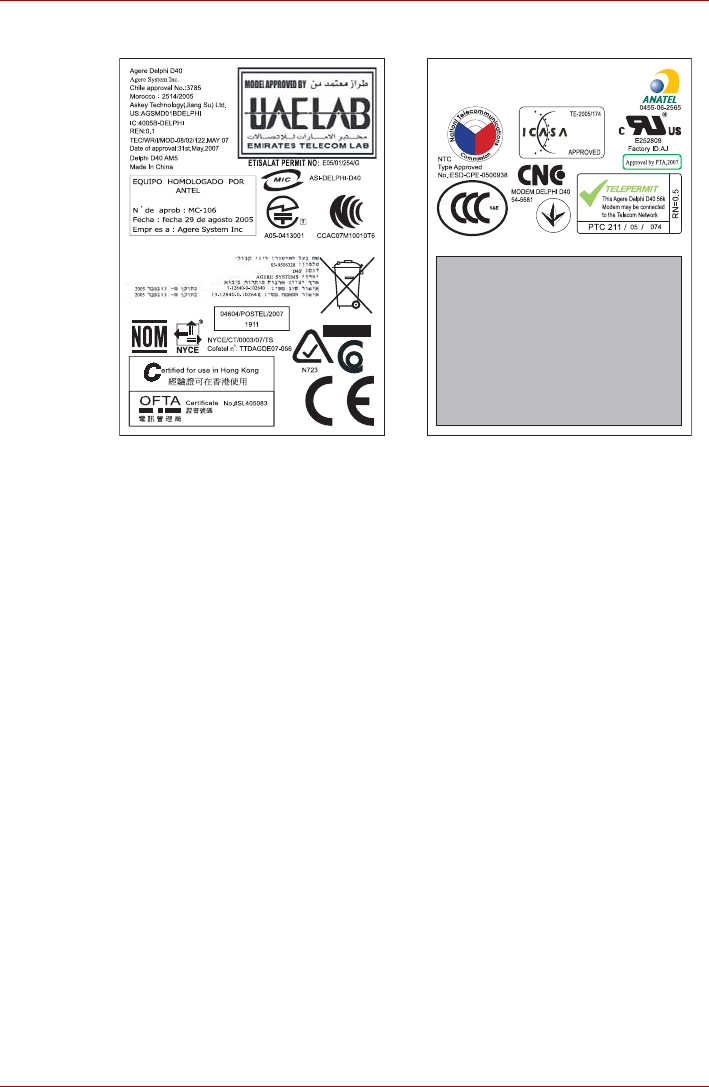
A05-0413001
User’s Manual x
PORTÉGÉ M700/M710
This label is located on the module.
Pursuant to FCC CFR 47, Part 68:
When you are ready to install or use the modem, call your local telephone
company and give them the following information:
■The telephone number of the line to which you will connect the modem
■The registration number that is located on the device
The FCC registration number of the modem will be found on either the
device which is to be installed, or, if already installed, on the bottom of
the computer outside of the main system label.
■The Ringer Equivalence Number (REN) of the modem, which can vary.
For the REN of your modem, refer to your modem’s label.
The modem connects to the telephone line by means of a standard jack
called the USOC RJ11C.
Type of service
Your modem is designed to be used on standard-device telephone lines.
Connection to telephone company-provided coin service (central office
implemented systems) is prohibited. Connection to party lines service is
subject to state tariffs. If you have any questions about your telephone line,
such as how many pieces of equipment you can connect to it, the
telephone company will provide this information upon request.

User’s Manual xi
PORTÉGÉ M700/M710
Telephone company procedures
The goal of the telephone company is to provide you with the best service it
can. In order to do this, it may occasionally be necessary for them to make
changes in their equipment, operations, or procedures. If these changes
might affect your service or the operation of your equipment, the telephone
company will give you notice in writing to allow you to make any changes
necessary to maintain uninterrupted service.
If problems arise
If any of your telephone equipment is not operating properly, you should
immediately remove it from your telephone line, as it may cause harm to
the telephone network. If the telephone company notes a problem, they
may temporarily discontinue service. When practical, they will notify you in
advance of this disconnection. If advance notice is not feasible, you will be
notified as soon as possible. When you are notified, you will be given the
opportunity to correct the problem and informed of your right to file a
complaint with the FCC. In the event repairs are ever needed on your
modem, they should be performed by TOSHIBA Corporation or an
authorized representative of TOSHIBA Corporation.
Disconnection
If you should ever decide to permanently disconnect your modem from its
present line, please call the telephone company and let them know of this
change.
Fax branding
The Telephone Consumer Protection Act of 1991 makes it unlawful for any
person to use a computer or other electronic device to send any message
via a telephone fax machine unless such message clearly contains in a
margin at the top or bottom of each transmitted page or on the first page of
the transmission, the date and time it is sent and an identification of the
business, other entity or individual sending the message and the telephone
number of the sending machine or such business, other entity or individual.
In order to program this information into your fax modem, you should
complete the setup of your fax software before sending messages.

User’s Manual xii
PORTÉGÉ M700/M710
Instructions for IC CS-03 certified equipment
1. The Industry Canada label identifies certified equipment. This
certification means that the equipment meets certain
telecommunications network protective, operational and safety
requirements as prescribed in the appropriate Terminal Equipment
Technical Requirements document(s). The Department does not
guarantee the equipment will operate to the user’s satisfaction.
Before installing this equipment, users should ensure that it is
permissible to be connected to the facilities of the local
telecommunications company. The equipment must also be installed
using an acceptable method of connection.
The customer should be aware that compliance with the above
conditions may not prevent degradation of service in some situations.
Repairs to certified equipment should be coordinated by a
representative designated by the supplier. Any repairs or alterations
made by the user to this equipment, or equipment malfunctions, may
give the telecommunications company cause to request the user to
disconnect the equipment.
Users should ensure for their own protection that the electrical ground
connections of the power utility, telephone lines and internal metallic
water pipe systems, if present, are connected together. This precaution
may be particularly important in rural areas.
2. The user manual of analog equipment must contain the equipment’s
Ringer Equivalence Number (REN) and an explanation notice similar to
the following:
The Ringer Equivalence Number (REN) of the modem, which can vary.
For the REN of your modem, refer to your modem’s label.
3. The standard connecting arrangement (telephone jack type) for this
equipment is jack type(s): USOC RJ11C.
The IC registration number of the modem is shown below.
Canada: 4005B-DELPHI
Users should not attempt to make such connections themselves, but
should contact the appropriate electric inspection authority, or electrician,
as appropriate.
The Ringer Equivalence Number (REN) assigned to each terminal device
provides an indication of the maximum number of terminals allowed to be
connected to a telephone interface. The termination on an interface may
consist of any combination of devices subject only to the requirement that
the sum of the Ringer Equivalence Numbers of all the devices does not
exceed 5.

User’s Manual xiii
PORTÉGÉ M700/M710
Notes for Users in Australia and New Zealand
Modem warning notice for Australia
Modems connected to the Australian telecoms network must have a valid
Austel permit. This modem has been designed to specifically configure to
ensure compliance with Austel standards when the country/region
selection is set to Australia. The use of other country/region setting while
the modem is attached to the Australian PSTN would result in you modem
being operated in a non-compliant manner. To verify that the
country/region is correctly set, enter the command ATI which displays the
currently active setting.
To set the country/region permanently to Australia, enter the following
command sequence:
AT%TE=1
ATS133=1
AT&F
AT&W
AT%TE=0
ATZ
Failure to set the modem to the Australia country/region setting as shown
above will result in the modem being operated in a non-compliant manner.
Consequently, there would be no permit in force for this equipment and the
Telecoms Act 1991 prescribes a penalty of $12,000 for the connection of
non-permitted equipment.
Notes for use of this device in New Zealand
■The grant of a Telepermit for a device in no way indicates Telecom
acceptance of responsibility for the correct operation of that device
under all operating conditions. In particular the higher speeds at which
this modem is capable of operating depend on a specific network
implementation which is only one of many ways of delivering high
quality voice telephony to customers. Failure to operate should not be
reported as a fault to Telecom.
■In addition to satisfactory line conditions a modem can only work
properly if:
a/ it is compatible with the modem at the other end of the call and.
b/ the application using the modem is compatible with the application
at the other end of the call - e.g., accessing the Internet requires
suitable software in addition to a modem.
■This equipment shall not be used in any manner which could constitute
a nuisance to other Telecom customers.

User’s Manual xiv
PORTÉGÉ M700/M710
■Some parameters required for compliance with Telecom’s PTC
Specifications are dependent on the equipment (PC) associated with
this modem. The associated equipment shall be set to operate within
the following limits for compliance with Telecom Specifications:
a/ There shall be no more than 10 call attempts to the same number
within any 30 minute period for any single manual call initiation, and
b/ The equipment shall go on-hook for a period of not less than 30
seconds between the end of one attempt and the beginning of the
next.
c/ Automatic calls to different numbers shall be not less than 5
seconds apart.
■Immediately disconnect this equipment should it become physically
damaged, and arrange for its disposal or repair.
■The correct settings for use with this modem in New Zealand are as
follows:
ATB0 (CCITT operation)
AT&G2 (1800 Hz guard tone)
AT&P1 (Decadic dialing make-break ratio =33%/67%)
ATS0=0 (not auto answer)
ATS6=4 (Blind dial delay)
ATS7=less than 90 (Time to wait to carrier after dialing)
ATS10=less than 150 (loss of carrier to hangup delay, factory
default of 15 recommended)
ATS11=90 (DTMF dialing on/off duration=90 ms)
ATX2 (Dial tone detect, but not (U.S.A.) call progress detect)
■When used in the Auto Answer mode, the S0 register must be set with a
value of 3 or 4. This ensures:
■a person calling your modem will hear a short burst of ringing before
the modem answers. This confirms that the call has been
successfully switched through the network.
■caller identification information (which occurs between the first and
second ring cadences) is not destroyed.
■The preferred method of dialing is to use DTMF tones (ATDT...) as this
is faster and more reliable than pulse (decadic) dialing. If for some
reason you must use decadic dialing, your communications program
must be set up to record numbers using the following translation table
as this modem does not implement the New Zealand “Reverse Dialing”
standard.
Number to be dialed: 0 1 2 3 4 5 6 7 8 9
Number to program into computer: 0 9 8 7 6 5 4 3 2 1
Note that where DTMF dialing is used, the numbers should be
entered normally.

User’s Manual xv
PORTÉGÉ M700/M710
■The transmit level from this device is set at a fixed level and because of
this there may be circumstances where the performance is less than
optimal. Before reporting such occurrences as faults, please check the
line with a standard Telepermitted telephone, and only report a fault if
the phone performance is impaired.
■It is recommended that this equipment be disconnected from the
Telecom line during electrical storms.
■When relocating the equipment, always disconnect the Telecom line
connection before the power connection, and reconnect the power first.
■This equipment may not be compatible with Telecom Distinctive Alert
cadences and services such as FaxAbility.
NOTE THAT FAULT CALLOUTS CAUSED BY ANY OF THE ABOVE
CAUSES MAY INCUR A CHARGE FROM TELECOM
General conditions
As required by PTC 100, please ensure that this office is advised of any
changes to the specifications of these products which might affect
compliance with the relevant PTC Specifications.
The grant of this Telepermit is specific to the above products with the
marketing description as stated on the Telepermit label artwork. The
Telepermit may not be assigned to other parties or other products without
Telecom approval.
A Telepermit artwork for each device is included from which you may
prepare any number of Telepermit labels subject to the general instructions
on format, size and color on the attached sheet.
The Telepermit label must be displayed on the product at all times as proof
to purchasers and service personnel that the product is able to be
legitimately connected to the Telecom network.
The Telepermit label may also be shown on the packaging of the product
and in the sales literature, as required in PTC 100.
The charge for a Telepermit assessment is $337.50. An additional charge
of $337.50 is payable where an assessment is based on reports against
non-Telecom New Zealand Specifications. $112.50 is charged for each
variation when submitted at the same time as the original.
An invoice for $NZ1237.50 will be sent under separate cover.

User’s Manual xvi
PORTÉGÉ M700/M710
Following information is only for EU-member states:
Description on Laser specification
The optical disc drive such as DVD Super Multi drive that is used in this
computer is equipped with laser. The classification label with the following
sentence is affixed to the surface of the drive.
CLASS 1 LASER PRODUCT
LASER KLASSE 1
LUOKAN 1 LASERLAITE
APPAREIL A LASER DE CLASSE 1
KLASS 1 LASER APPARAT
The drive with the above label is certified by the manufacturer that the drive
complies with the requirement for laser product on the date of
manufacturing pursuant to article 21 of Code of Federal Regulations by the
United States of America, Department of Health & Human Services, Food
and Drug Administration.
In other countries, the drive is certified to comply with the requirement
pursuant to IEC 60825-1 and EN 60825-1 on class 1 laser product.
This computer is equipped with the optical disc drive in the following list
according to the model.
The use of the symbol indicates that this product may not be treated as
household waste. By ensuring this product is disposed of correctly, you will
help prevent potential negative consequences for the environment and
human health, which could otherwise be caused by inappropriate waste
handling of this product. For more detailed information about recycling of
this product, please contact your local city office, your household waste
disposal service or the shop where you purchased the product.
This symbol may not stick depending on the country and region where you
purchased.
Manufacturer Type
Panasonic UJ-852
Panasonic UJ-862

User’s Manual xvii
Preface
Congratulations on your purchase of the PORTÉGÉ M700/M710 series
computer. This powerful notebook computer provides excellent expansion
capability, includes multimedia functionality, and is designed to provide
years of reliable, high-performance computing.
This manual tells how to set up and begin using your PORTÉGÉ
M700/M710 computer. It also provides detailed information on configuring
your computer, basic operations and care, using optional devices and
troubleshooting.
If you are a new user of computers or if you’re new to portable computing,
first read over the Chapter 1, Getting Started and Chapter 3, Hardware,
Utilities and Options chapters to familiarize yourself with the computer’s
features, components and accessory devices. Then read Chapter 1,
Getting Started for step-by-step instructions on setting up your computer.
If you are an experienced computer user, please continue reading the
preface to learn how this manual is organized, then become acquainted
with this manual by browsing through its pages. Be sure to read the Special
features section in Chapter 3, Hardware, Utilities and Options to learn
about features that are uncommon or unique to this computer, as well as
the section on Chapter 7, HW Setup & BIOS Setup, to understand how to
setup and configure these features.
Read Chapter 3, Hardware, Utilities and Options if connecting optional
products or external devices.
Conventions
This manual uses the following formats to describe, identify, and highlight
terms and operating procedures.
Abbreviations
On first appearance, and whenever necessary for clarity, abbreviations are
enclosed in parentheses following their definition. For example: Read Only
Memory (ROM). Acronyms are also defined in the Glossary.

User’s Manual xviii
PORTÉGÉ M700/M710
Icons
Icons identify ports, dials, and other parts of your computer. The indicator
panel also uses icons to identify the components it is providing information
on.
Keys
The keyboard keys are used in the text to describe many computer
operations. A distinctive typeface identifies the key top symbols as they
appear on the keyboard. For example, ENTER identifies the ENTER key.
Key operation
Some operations require you to simultaneously use two or more keys. We
identify such operations by the key top symbols separated by a plus sign
(+). For example, CTRL + C means you must hold down CRTL and at the
same time press C. If three keys are used, hold down the first two and at
the same time press the third.
Display
Messages
Messages are used in this manual to bring important information to your
attention. Each type of message is identified as shown below.
ABC When procedures require an action such as
clicking an icon or entering text, the icon's name
or the text you are to type in is represented in the
typeface you see to the left.
SABC Names of windows or icons or text generated by
the computer that appear on its display screen
are presented in the type face you see to the left.
Pay attention! A caution informs you that improper use of equipment or
failure to follow instructions may cause data loss or damage your
equipment.
Please read. A note is a hint or advice that helps you make best use of
your equipment.
Indicates a potentially hazardous situation, which could result in death or
serious injury, if you do not follow instructions.

User’s Manual xix
PORTÉGÉ M700/M710
Terminology
This term is defined in this document as follows:
Start The word "Start" refers to the " " button in
Microsoft® Windows Vista®.

User’s Manual xx
General Precautions
TOSHIBA computers are designed to optimize safety, minimize strain and
withstand the rigors of portability. However, certain precautions should be
observed to further reduce the risk of personal injury or damage to the
computer.
Be certain to read the general precautions below and to note the cautions
included in the text of the manual.
Creating a computer-friendly environment
Place the computer on a flat surface that is large enough for the computer
and any other items you are using, such as a printer.
Leave enough space around the computer and other equipment to provide
adequate ventilation. Otherwise, they may overheat.
To keep your computer in prime operating condition, protect your work area
from:
■Dust, moisture, and direct sunlight.
■Equipment that generates a strong electromagnetic field, such as
stereo speakers (other than speakers that are connected to the
computer) or speakerphones.
■Rapid changes in temperature or humidity and sources of temperature
change such as air conditioner vents or heaters.
■Extreme heat, cold, or humidity.
■Liquids and corrosive chemicals.
Stress injury
Carefully read the Instruction Manual for Safety and Comfort. It contains
information on the prevention of stress injuries to your hands and wrists
that can be caused by extensive keyboard use. Instruction Manual for
Safety and Comfort also includes information on work space design,
posture and lighting that can help reduce physical stress.

User’s Manual xxi
PORTÉGÉ M700/M710
Heat injury
■Avoid prolonged physical contact with the computer. If the computer is
used for long periods, its surface can become very warm. While the
temperature will not feel hot to the touch, if you maintain physical
contact with the computer for a long time, for example if you rest the
computer on your lap or if you keep your hands on the palm rest, your
skin might suffer a low-heat injury.
■If the computer has been used for a long time, avoid direct contact with
the metal plate supporting the various interface ports as this can
become hot.
■The surface of the AC adaptor can become hot when in use but this
condition does not indicate a malfunction. If you need to transport the
AC adaptor, you should disconnect it and let it cool before moving it.
■Do not lay the AC adaptor on a material that is sensitive to heat as the
material could become damaged.
Pressure or impact damage
Do not apply heavy pressure to the computer or subject it to any form of
strong impact as this can damage the computer's components or otherwise
cause it to malfunction.
PC Card overheating
Some PC Cards can become hot during prolonged use which may result in
errors or instability in the operation of the device in question. In addition,
you should also be careful when you remove a PC Card that has been
used for a long time.
Mobile phones
Please be aware that the use of mobile phones can interfere with the audio
system. The operation of the computer will not be impaired in any way, but
it is recommended that a minimum distance of 30cm is maintained between
the computer and a mobile phone that is in use.
Instruction Manual for Safety and Comfort
All important information on the safe and proper use of this computer is
described in the enclosed Instruction Manual for Safety and Comfort. Be
sure to read it before using the computer.

User’s Manual 1-1
Chapter 1
Getting Started
This chapter provides an equipment checklist, and basic information to
start using your computer.
Equipment checklist
Carefully unpack your computer, taking care to save the box and packaging
materials for future use.
Hardware
Check to make sure you have all the following items:
■PORTÉGÉ M700/M710 Portable Personal Computer
■AC adaptor and power cord (2-pin plug or 3-pin plug)
■Battery pack (Is pre-installed in some computers)
■Slice Expansion Battery (Is included with some models)
■Tablet PC Pen (Is included with some models)
■Reserve Pen (Is included with some models)
■Ultra Slim Bay Weight Saver (Is included with some models)
■Ultra Slim Bay Case (Is provided with some models)
Some of the features described in this manual may not function properly if
you use an operating system that was not pre-installed by TOSHIBA.
■For some models, Tablet PC Pen is included together with spare pen
tips and a tip removal tool in the small case coming with the product.
■For some models, Reserve Pen is included in the small case coming
with the product.

User’s Manual 1-2
Getting Started
Documentation
■PORTÉGÉ M700/M710 Series User Information Guide
■Instruction Manual for Safety and Comfort
■End User License Agreement
If any of the items are missing or damaged, contact your dealer
immediately.
Software
The following Windows® operating system and utility software are pre-
installed.
■Microsoft® Windows Vista®
■TOSHIBA Value Added Package
■Recovery Disc Creator
■DVD Video Player
■TOSHIBA SD Memory Utilities
■TOSHIBA SD Memory Boot Utility
■CD/DVD Drive Acoustic Silencer
■TOSHIBA Assist
■TOSHIBA ConfigFree
■TOSHIBA HDD Protection
■TOSHIBA Disc Creator
■TOSHIBA Tablet PC Extension
■TOSHIBA Tablet Access Code Logon Utility
■Fingerprint Utility
■Windows Mobility Center
■Online Manual
■PORTÉGÉ M700/M710 User's Manual (This manual)

User’s Manual 1-3
Getting Started
Getting Started
This section provides basic information to start using your computer. It
covers the following topics:
■About the Tablet mode
■Connecting the AC adaptor
■Opening the display
■Turning on the power
■Starting up for the first time
■Turning off the power
■Restarting the computer
■Creating Optical Recovery Discs
■Restoring the pre-installed software from the Recovery hard disk drive
■Restoring the pre-installed software from your created Recovery Discs
About the Tablet mode
Change to "The TOSHIBA PORTÉGÉ M700/M710" computer can be used
in two ways, as an ordinary laptop PC and as a Tablet PC. You can use the
computer as Tablet PC, operated with the supplied Tablet PC Pen, by
turning the display panel through 180 degrees and closing it. This manual
calls the use as an ordinary laptop PC "Laptop mode", and the use as a
Tablet PC "Tablet mode". Refer to Changing to the Tablet mode section in
Chapter 4, Operating Basics for details on changing the mode.
■All users should be sure to read the section Starting up for the first
time.
■Be sure to read the enclosed Instruction Manual for Safety and Comfort
for information on the safe and proper use of this computer. It is
intended to help you be more comfortable and productive while using a
notebook computer. By following the recommendations in it you may
reduce your chance of developing a painful or disabling injury to your
hand, arms, shoulders or neck.
■Use a virus-check program and make sure it is updated regularly.
■Never format storage media without checking its content - formatting
destroys all stored data.
■It is a good idea to periodically back up the internal hard disk drive or
other main storage device to external media. General storage media is
not durable or stable over long periods of time and under certain
conditions may result in data loss.
■Before you install a device or application, save any data in memory to
the hard disk drive or other storage media. Failure to do so may result
in the loss of data.

User’s Manual 1-4
Getting Started
Connecting the AC adaptor
Attach the AC adaptor when you need to charge the battery or you want to
operate from AC power. It is also the fastest way to get started, because
the battery pack will need to be charged before you can operate from
battery power.
The AC adaptor can be connected to any power source supplying from 100
to 240 volts and 50 or 60 hertz. For details on using the AC adaptor to
charge the battery pack, refer to Chapter 6, Power and Power-Up Modes.
■Always use the TOSHIBA AC adaptor that was included with your
computer, or use AC adaptors specified by TOSHIBA to avoid any risk
of fire or other damage to the computer. Use of an incompatible AC
adaptor could cause fire or damage to the computer possibly resulting
in serious injury. TOSHIBA assumes no liability for any damage caused
by use of an incompatible adaptor.
■Never plug the AC adaptor into a power source that does not
correspond to both the voltage and the frequency specified on the
regulatory label of the unit. Failure to do so could result in a fire or
electric shock, possibly resulting in serious injury.
■Always use or purchase power cables that comply with the legal
voltage and frequency specifications and requirements in the country
of use. Failure to do so could result in a fire or electric shock, possibly
resulting in serious injury.
■The supplied power cord conforms to safety rules and regulations in
the region the product is bought and should not be used outside this
region. For use in other regions, please buy power cords that conform
to safety rules and regulations in the particular region.
■Do not use a 3-pin to 2-pin conversion plug.
■When you connect the AC adaptor to the computer, always follow the
steps in the exact order as described in the User’s Manual. Connecting
the power cable to a live electrical outlet should be the last step
otherwise the adaptor DC output plug could hold an electrical charge
and cause an electrical shock or minor bodily injury when touched. As
a general safety precaution, avoid touching any metal parts.
■Never place your computer or AC adaptor on a wooden surface,
furniture, or any other surface that could be marred by exposure to heat
since the computer base and AC adaptor's surface increase in
temperature during normal use.
■Always place your computer or AC adaptor on a flat and hard surface
that is resistant to heat damage.
Refer to the enclosed Instruction Manual for Safety and Comfort for
detailed precautions and handling instructions.
User’s Manual 1-5
Getting Started
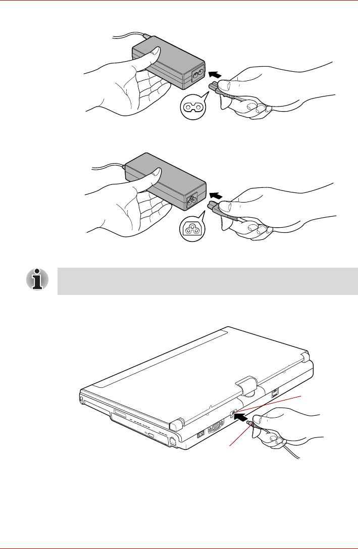
1. Connect the power cord to the AC adaptor.
Figure 1-1 Connecting the power cord to the AC adaptor (2-pin plug)
Figure 1-2 Connecting the power cord to the AC adaptor (3-pin plug)
2. Connect the AC adaptor’s DC output plug to the DC IN 15V jack on the
back of the computer.
Figure 1-3 Connecting the DC output plug to the computer
3. Plug the power cord into a live wall outlet - the Battery and DC IN
indicators on the front of the computer should glow.
Either a 2-pin or 3-pin adaptor/cord will be included with the computer
depending on the model.
DC IN 15V jack
DC output plug
User’s Manual 1-6
Getting Started
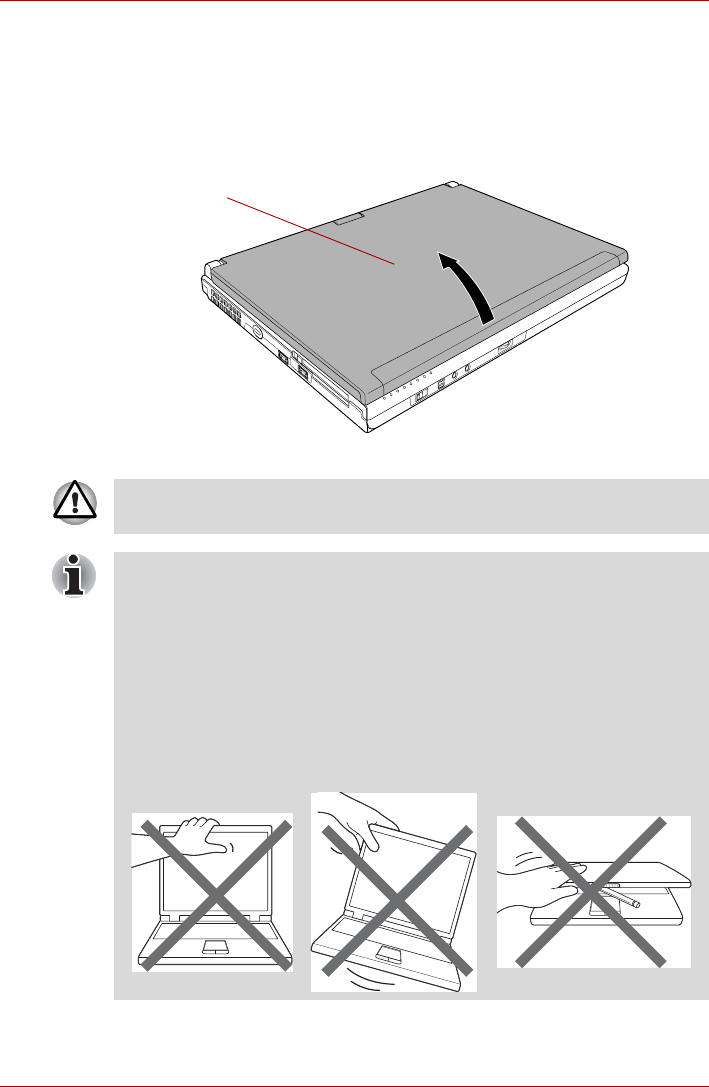
Opening the display
The display panel can be opened to a wide range of angles for optimal
viewing.
While holding down the palm rest with one hand so that the main body of
the computer is not raised, slowly lift the display panel - this will allow the
angle of the display panel to be adjusted to provide optimum clarity.
Figure 1-4 Opening the display panel
Display panel
Use reasonable care when opening and closing the display panel.
Opening it vigorously or slamming it shut could damage the computer.
■Be careful not to open the display panel too far as this could put stress
on the display panel’s hinges and cause damage.
■Do not press or push on the display panel.
■Do not lift the computer by the display panel.
■Do not close the display panel with pens or any other objects left in
between the display panel and the keyboard.
■When opening or closing the display panel, place one hand on the
palm rest to hold the computer in place and use the other hand to
slowly open or close the display panel (Do not use excessive force
when opening or closing the display panel).
User’s Manual 1-7
Getting Started
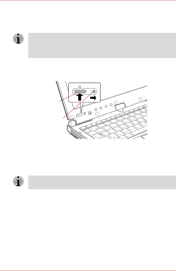
Turning on the power
This section describes how to turn on the power - the Power indicator will
then indicate the status. Please refer to the Monitoring of power condition
section in Chapter 6, Power and Power-Up Modes for more information.
1. Open the display panel.
2. Slide the Power Button Lock Switch to the right.
3. Press and hold the computer's power button for two or three seconds.
Figure 1-5 Turning on the power
Starting up for the first time
The Microsoft Windows Vista® Startup Screen will be the first screen
displayed when you turn on the power. Follow the on-screen instructions on
each screen in order to properly install the operating system.
Turning off the power
The power can be turned off in one of three modes, either Shut Down
(Boot) Mode, Hibernation Mode or Sleep Mode.
Shut Down mode (Boot Mode)
When you turn off the power in Shut Down Mode no data will be saved and
the computer will boot to the operating system's main screen the next time
it is turned on.
1. If you have entered data, either save it to the hard disk drive or to other
storage media.
2. Make sure all disk/disc activity has stopped before removing the
CD/DVD or floppy diskette.
■After you turn on the power for the first time, do not turn it off until you
have set up the operating system. Please refer to the section Starting
up for the first time for more information.
■Volume cannot be adjusted during Windows Setup.
Power button
Power Button
Lock Switch
When it is displayed, be sure to read the Software License Terms
carefully.
User’s Manual 1-8
Getting Started
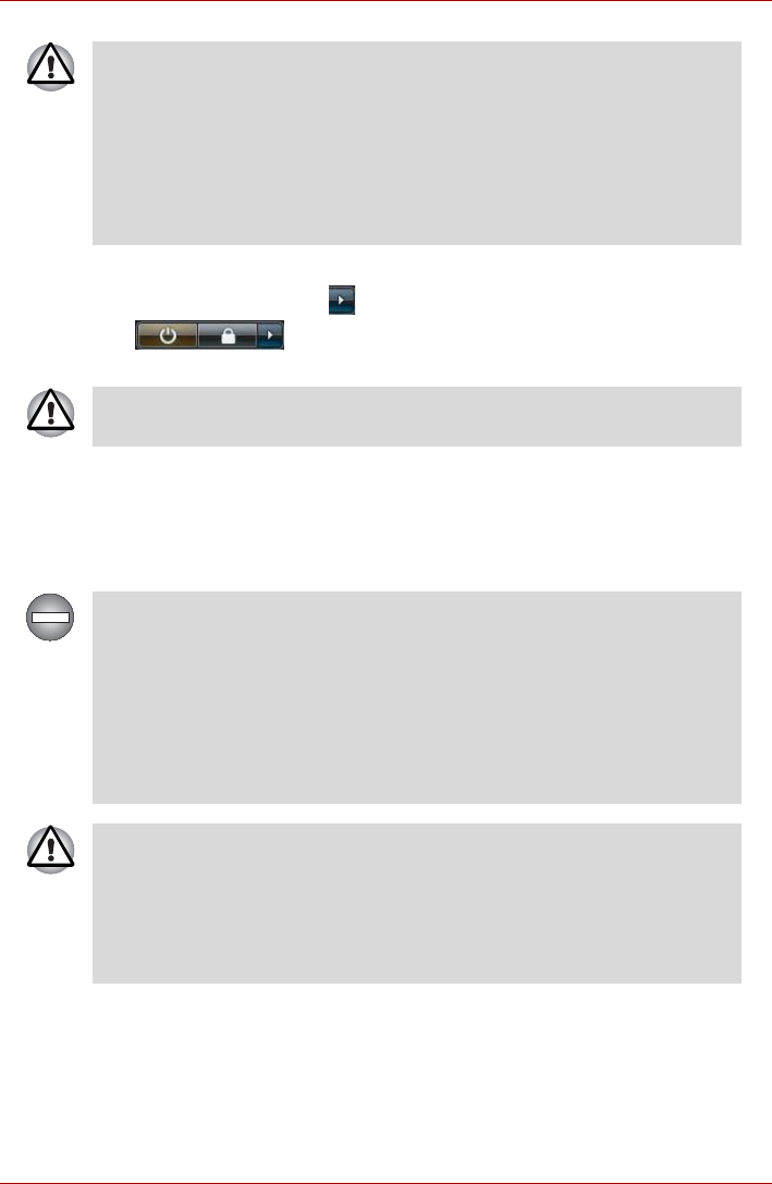
3. Click Start.
4. Click the arrow button ( ) located in the power management buttons
( ) and select Shut Down from the menu.
5. Turn off any peripheral devices connected to your computer.
Sleep Mode
If you have to interrupt your work, you are able to turn off the power without
exiting from your software by placing the computer into Sleep Mode. In this
mode data is maintained in the computer's main memory so that when you
turn on the power again, you can continue working right where you left off.
■Make sure the Hard Disk Drive and Ultra Slim Bay's module
indicator is off. If you turn off the power while a disk (disc) is being
accessed, you may lose data or damage the disk.
■Never turn off the power while an application is running. Doing so could
cause loss of data.
■Never turn off the power, disconnect an external storage device or
remove storage media during data read/write. Doing so can cause data
loss.
Do not turn the computer or peripheral devices back on immediately - wait
a short period to avoid any potential damage.
When you have to turn off your computer aboard an aircraft or in places
where electronic devices are regulated or controlled, always completely
shut down the computer. This includes turning off any wireless
communication switches or devices, and canceling settings that reactivate
the computer automatically, such as a timer recording function. Failure to
completely shut down the computer in this way could allow the operating
system to reactivate and run pre-programmed tasks or preserve unsaved
data, which could interfere with aviation or other systems, possibly causing
serious injury.
■Before entering Sleep Mode, be sure to save your data.
■Do not install or remove a memory module while the computer is in
Sleep Mode. The computer or the memory module could be damaged.
■Do not remove the battery pack while the computer is in Sleep Mode
(unless the computer is connected to an AC power source). Data in
memory could be lost.

User’s Manual 1-9
Getting Started
Benefits of Sleep Mode
The Sleep Mode feature provides the following benefits:
■Restores the previous working environment more rapidly than does the
Hibernation Mode feature.
■Saves power by shutting down the system when the computer receives
no input or hardware access for the time period set by the System
Sleep Mode feature.
■Allows the use of the panel power off feature.
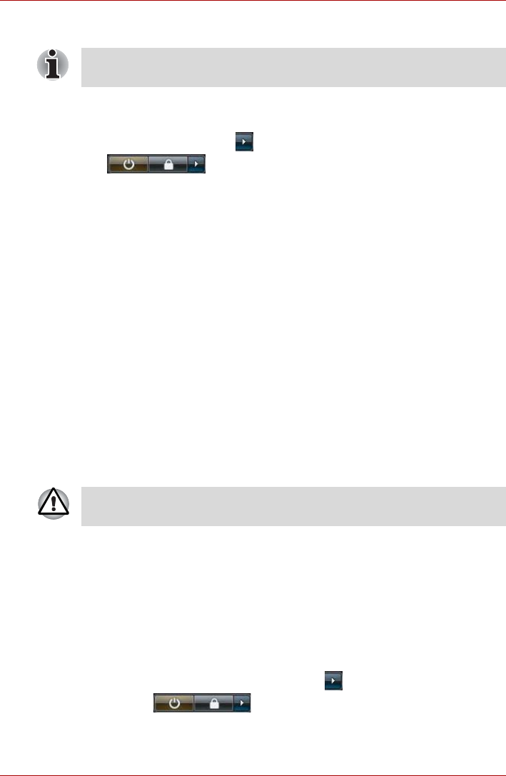
Executing Sleep Mode
You can enter Sleep Mode in one of four ways:
■Click Start then click the power button ( ) located in the power
management buttons ( ).
Please note that this feature must be enabled within the Power Options
(to access it, click Start -> Control Panel -> System and Maintenance
-> Power Options).
■Click Start then click the arrow button ( ) and select Sleep from the
menu.
■Close the display panel. Please note that this feature must be enabled
within the Power Options (to access it, click Start -> Control Panel ->
System and Maintenance -> Power Options).
■Press the power button. Please note that this feature must be enabled
within the Power Options (to access it, click Start -> Control Panel ->
System and Maintenance -> Power Options).
■When the AC adaptor is connected, the computer will go into Sleep
Mode according to the settings in the Power Options (to access it, Start
-> Control Panel -> System and Maintenance -> Power Options).
■To restore the operation of the computer from Sleep Mode, press and
hold the power button or any key on the keyboard for a short amount of
time. Please note that keyboard keys can only be used if the Wake-up
on Keyboard option is enabled within the HW Setup utility.
■If the computer enters Sleep Mode while a network application is
active, the application might not be restored when the computer is next
turned on and the system returns from Sleep Mode.
■To prevent the computer from automatically entering Sleep Mode,
disable Sleep Mode within the Power Options (to access it, Start ->
Control Panel -> System and Maintenance -> Power Options).
However, please be aware that this configuration will nullify the
computer's Energy Star compliance.
■To use the Hybrid Sleep function, configure it in the Power Options.
You can also enable Sleep Mode by pressing FN + F3 - please refer to
Chapter 5, The Keyboard, for further details.

User’s Manual 1-10
Getting Started
When you turn the power back on, you can continue where you left when
you shut down the computer.
Sleep Mode limitations
Sleep Mode will not function under the following conditions:
■Power is turned back on immediately after shutting down.
■Memory circuits are exposed to static electricity or electrical noise.
Hibernation Mode
The Hibernation Mode feature saves the contents of memory to the hard
disk drive when the computer is turned off so that, the next time it is turned
on, the previous state is restored. Please note that the Hibernation Mode
feature does not save the status of any peripheral devices connected to the
computer.
Benefits of Hibernation Mode
The Hibernation Mode feature provides the following benefits:
■Saves data to the hard disk drive when the computer automatically
shuts down because of a low battery condition.
■You can return to your previous working environment immediately when
you turn on the computer.
■Saves power by shutting down the system when the computer receives
no input or hardware access for the time period set by the System
Hibernate feature.
■Allows the use of the panel power off feature.
■When the computer is in Sleep Mode, the Power indicator will blink
orange.
■If you are operating the computer on battery power, you can lengthen
the overall operating time by turning it off into Hibernation Mode - Sleep
Mode will consume more power while the computer is off.
■Save your data. While entering Hibernation Mode, the computer saves
the contents of memory to the hard disk drive. However, for safety
sake, it is best to save your data manually.
■Data will be lost if you remove the battery or disconnect the AC adaptor
before the save is completed. Wait for the Hard Disk Drive indicator to
go out.
■Do not install or remove a memory module while the computer is in
Hibernation Mode. Data will be lost.
User’s Manual 1-11
Getting Started
Starting Hibernation Mode
To enter Hibernation Mode, follow the steps below.
1. Click Start.
2. Click the arrow button ( ) in the power management buttons
( ) and select Hibernate from the menu.
Automatic Hibernation Mode
The computer can be configured to enter Hibernation Mode automatically
when you press the power button or close the lid. In order to define these
settings, you can follow the steps as described below:
1. Click Start and click the Control Panel.
2. Click System and Maintenance and click Power Options.
3. Click Choose what the power button does or Choose what closing
the lid does.
4. Enable the desired Hibernation Mode settings for When I press the
power button and When I close the lid.
5. Click the Save changes button.
Data save in Hibernation Mode
When you turn off the power in Hibernation Mode, the computer will take a
moment to save the current data in memory to the hard disk drive. During
this time, the Hard Disk Drive indicator will glow.
After you turn off the computer, and the content of memory has been saved
to the hard disk drive, turn off the power to any peripheral devices.
Restarting the computer
Certain conditions require that you reset the computer, for example if:
■You change certain computer settings.
■An error occurs and the computer does not respond to your keyboard
commands.
If you need to restart the computer, there are three ways this can be
achieved:
■Click Start then click the arrow button ( ) in the power management
buttons ( ) and select Restart from the menu.
■Press CTRL,ALT and DEL simultaneously (once) to display the menu
window, then select Restart from the Shut down options.
You can also enable Hibernation Mode by pressing FN + F4 - please refer
to Chapter 5, The Keyboard, for further details.
Do not turn the computer or devices back on immediately. Wait a moment
to let all capacitors fully discharge.

User’s Manual 1-12
Getting Started
■Press the power button and hold it down for five seconds. Once the
computer has turned itself off, wait between ten and fifteen seconds
before turning the power on again by pressing the power button.
System Recovery Options
About 1.5GB hidden partition is allocated on the hard disk drive for the
System Recovery Options.
This partition stores files which can be used to repair the system in the
event of a problem.
System Recovery Options
The System Recovery Options feature is installed on the hard disk when
shipped from the factory. The System Recovery Options menu includes
tools to repair startup problems, run diagnostics or restore the system.
See the Windows Help and Support content for more information about
Startup Repair.
The System Recovery Options can also be run manually to repair
problems.
The procedure is as follows. Follow the instructions shown on the on-
screen menu.
1. Turn off the computer.
2. While holding the F8 key, turn on the computer.
3. The Advanced Boot Options menu will be displayed.
Use the arrow keys to select Repair Your Computer and press
ENTER.
4. Follow the on-screen instructions.
The Windows Vista® CompletePC Backup feature can be used on
Windows Vista® Business Edition and Ultimate Edition.
The System Recovery Options feature will be unusable if this partition is
deleted.

User’s Manual 1-13
Getting Started
System Recovery
This section describes the creation of Recovery Discs and their use.
Creating Optical Recovery Discs
This section describes how to create Recovery Discs.
A recovery image of the software on your computer is stored on the hard
disk drive, and can be copied to either CD or DVD media by using the
following steps:
1. Select either blank CD or DVD media.
2. The application will allow you to choose from a variety of different media
onto which the recovery image can be copied including CD-R, CD-RW,
DVD-R, DVD-R DL, DVD-RW, DVD+R, DVD+R DL and DVD+RW.
3. Turn on your computer and allow it to load the Windows Vista®
operating system from the hard disk drive as normal.
4. Insert the first blank media into the optical disc drive tray.
5. Double click the Recovery Disc Creator icon on the Windows Vista®
desktop, or select the application from Start Menu.
6. After Recovery Disc Creator starts, select the type of media and the title
you wish to copy, and then click the Create button.
■Be sure to connect the AC adaptor when you create Recovery Discs.
■Be sure to close all other software programs except the Recovery Disc
Creator.
■Do not run software such as screen savers which can put a heavy load
on the CPU.
■Operate the computer at full power.
■Do not use power-saving features.
■Do not write to the disc when the virus check software is running. Wait
for it to finish, then disable virus detection programs including any
software that checks files automatically in the background.
■Do not use utilities, including those intended to enhance hard disk drive
access speed. They may cause unstable operation and damage data.
■Do not shut down/log off or Sleep/Hibernate while writing or rewriting
the disc.
■Set the computer on a level surface and avoid places subjected to
vibrations such as airplanes, trains, or cars.
■Do not use on unstable tables or other any other unstable surfaces.
Please note that some of the above media may not be compatible with the
optical disc drive installed into your computer. You should therefore verify
the optical disc drive supports the blank media you have chosen before
proceeding.

User’s Manual 1-14
Getting Started
Restoring the pre-installed software from the Recovery hard disk
drive
A portion of the total hard disk drive space is configured as a hidden
recovery partition. This partition stores files which can be used to restore
pre-installed software in the event of a problem.
If you subsequently set up your hard disk drive again, do not change,
delete or add partitions in a manner other than specified in the manual,
otherwise you may find that space for the required software is not available.
In addition, if you use a third-party partitioning program to reconfigure the
partitions on your hard disk drive, you may find that it becomes impossible
to setup your computer.
1. Turn off your computer.
2. While holding down 0(zero) key on the keyboard, turn on your
computer.
3. A menu will be displayed from which you should follow the on-screen
instructions.
If your optical disc drive can only write to CDs, select 'CD' as the 'Disc Set'
within the Recovery Disc Creator application.
Otherwise, if your optical disc drive can write both CDs and DVDs, select
the type of media you want to create.
When the sound mute feature has been activated by pressing the FN +
ESC key, be sure to disable this to allow sounds to be heard before
starting the restore process. Please refer to Chapter 5, The Keyboard, for
further details.
You can not use System Recovery Options if restoring the pre-installed
software without System Recovery Options.
When you reinstall the Windows operating system, the hard disk will be
reformatted and all data will be lost.

User’s Manual 1-15
Getting Started
Restoring the pre-installed software from your created Recovery
Discs
If the pre-installed files are damaged, you are able to either use the
Recovery Discs you have created or the hard disk drive recovery process
to restore the computer to the state it was in when you originally received it.
To perform this restoration, follow the steps below:
1. Load the Recovery Discs into the optical disc drive and turn off the
computer's power.
2. While holding down F12 key on the keyboard, turn on your computer -
when the TOSHIBA logo screen appears, release the F12 key.
3. Use the left and right cursors key to select the CD-ROM icon from the
menu. Please refer to the Boot Priority section in Chapter 7, HW Setup
& BIOS Setup for further information.
4. A menu will be displayed from which you should follow the on-screen
instructions.
When the sound mute feature has been activated by pressing the FN +
ESC key, be sure to disable this to allow sounds to be heard before
starting the restore process. Please refer to Chapter 5, The Keyboard, for
further details.
You can not use System Recovery Options if restoring the pre-installed
software without System Recovery Options.
When you reinstall the Windows operating system, the hard disk will be
reformatted and all data will be lost.
When removing pre-installed drivers / utilities or when installing, you can
setup the respective drivers / utilities from the following folder.
C:\TOSAPINS\***
User’s Manual 2-1
Chapter 2
The Grand Tour
This chapter identifies the various components of the computer - it is
recommended that you become familiar with each before you operate the
computer.
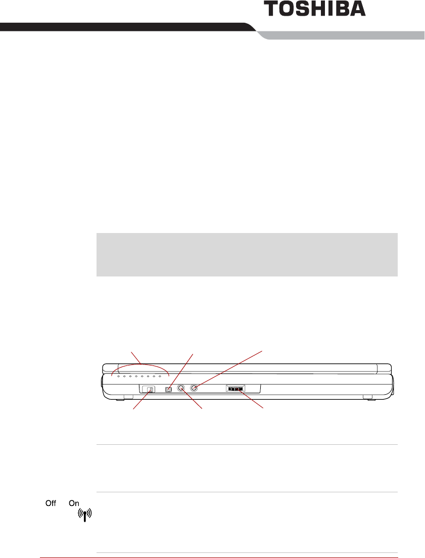
Front with the display closed
The following figure shows the computer’s front with its display panel in the
closed position.
Figure 2-1 Front of the computer with display panel closed
Legal Footnote (Non-applicable Icons)*1
For more information regarding Non-applicable Icons, please refer to the
Legal Footnotes section in Appendix K or click the *1 above.
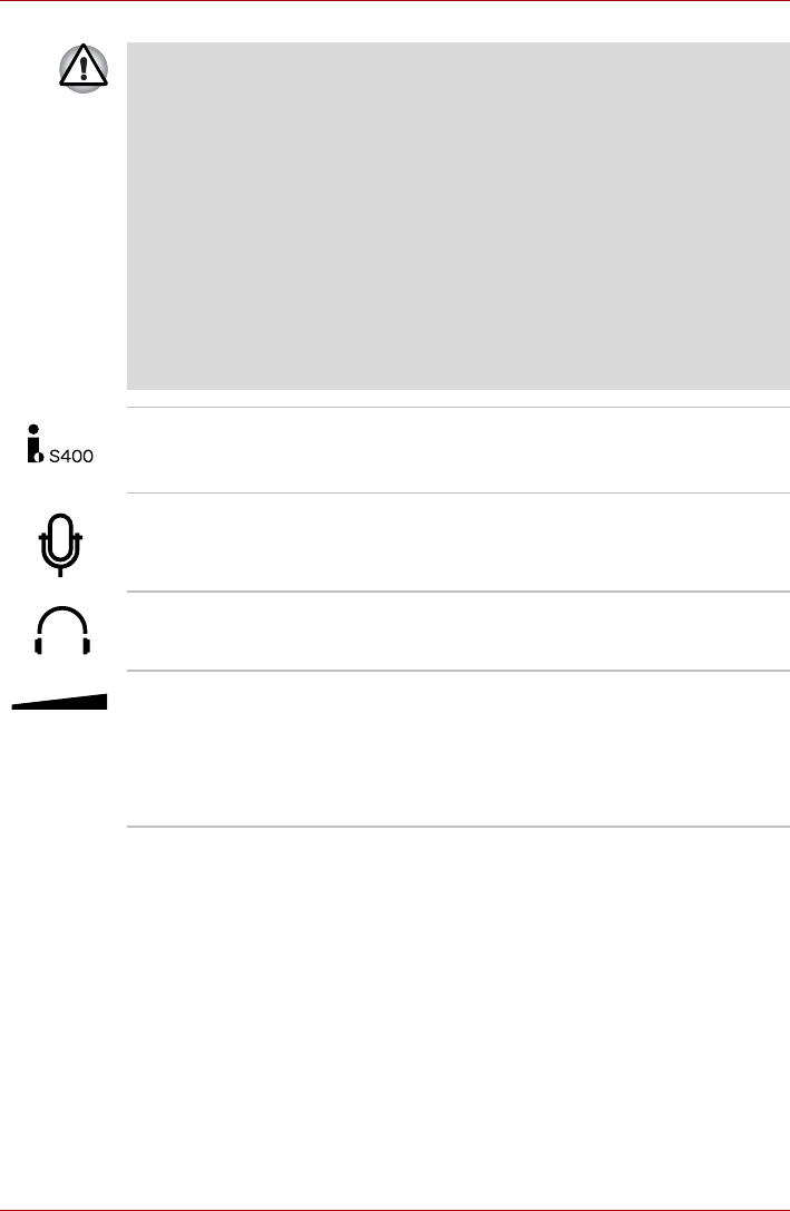
System indicators
Wireless
communication switch
Headphone jack
i.LINK (IEEE1394) port
Microphone jack Volume control dial
System indicators These LED indicators allow you to monitor the
status of various computer functions and are
described in more detail within the System
indicators section.
Wireless
communication
switch
Slide this switch to the left to turn off Wireless
LAN, Bluetooth and Wireless WAN functions.
Slide it to the right to turn on the functions.
Only some models are equipped with Bluetooth,
Wireless LAN and Wireless WAN functions.
User’s Manual 2-2
The Grand Tour
■Turn Wi-Fi®, Bluetooth and Wireless WAN functionalities off when near
a person who may have a cardiac pacemaker implant or other medical
electric device. Radio waves may affect pacemaker or medical device
operation, possibly resulting in serious injury. Follow the instruction of
your medical device when using any Wi-Fi or Bluetooth or Wireless
WAN functionality.
■Always turn off Wi-Fi or Bluetooth or Wireless WAN functionality if the
computer is near automatic control equipment or appliances such as
automatic doors or fire detectors. Radio waves can cause malfunction
of such equipment, possibly resulting in serious injury.
■Do not use the Wi-Fi or Bluetooth functionalities near a microwave
oven or in areas subject to radio interference or magnetic fields.
Interference from a microwave oven or other source can disrupt Wi-Fi
or Bluetooth operation.
i.LINK (IEEE1394)
port This port allows you to connect an external
device, such as a digital video camera for high-
speed data transfer.
Microphone jack A 3.5 mm mini microphone jack enables
connection of a three-conductor mini jack for
monaural microphone input.
Headphone jack A 3.5 mm mini headphone jack enables
connection of stereo headphones.
Volume control dial Use this dial to adjust the volume of the internal
stereo speakers and optional external stereo
headphones (if connected).
Move the Volume control dial to the right to
increase the volume and to the left to decrease
the volume.
User’s Manual 2-3
The Grand Tour
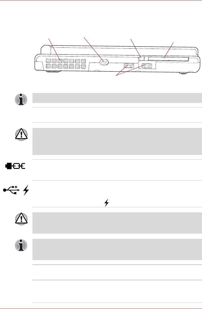
Left side
The following figure shows the computer’s left side.
Figure 2-2 The left side of the computer
Cooling vents
Universal Serial Bus (USB 2.0) ports
PC Card slot
(or Smart Card slot)
PC Card eject button
Security lock slot
The computer is equipped with either a PC Card slot or a Smart Card slot.
Cooling vents The cooling vents help keep the processor from
overheating.
Do not block the cooling vents. Keep foreign metal objects, such as
screws, staples and paper clips, out of the cooling vents. Foreign metal
objects can create a short circuit, which can cause damage and fire,
possibly resulting in serious injury.
Security lock slot A security cable can be attached to this slot and
then connected to a desk or other large object in
order to deter theft of the computer.
Universal Serial Bus
(USB 2.0) ports Two Universal Serial Bus ports, which comply to
the USB 2.0 standard, are provided on the left
hand side of the computer. The ports with the
icon ( ) has USB Sleep and Charge function.
Keep foreign metal objects, such as screws, staples and paper clips, out of
the USB connectors. Foreign metal objects can create a short circuit,
which can cause damage and fire, possibly resulting in serious injury.
Please note that it is not possible to confirm the operation of all functions of
all USB devices that are available. In view of this it may be noted that some
functions associated with a specific device might not operate properly.
PC Card eject button This button is used in order to remove a PC Card
from within the computer.
PC Card slot This slot can accommodate a single Type II, 16-
bit or 32-bit (CardBus) PC Card device.
Some models are equipped with a PC Card slot.
User’s Manual 2-4
The Grand Tour
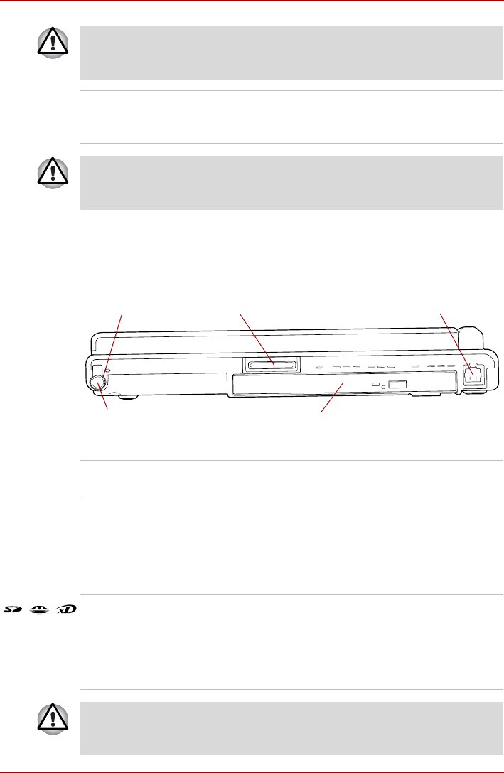
Right side
The following figure shows the computer’s right side.
Figure 2-3 The right side of the computer
Keep foreign metal objects, such as screws, staples and paper clips, out of
the PC Card slot. Foreign metal objects can create a short circuit, which
can cause damage and fire, possibly resulting in serious injury.
Smart Card slot This slot can accommodate a single Smart Card
device. Some models are equipped with a Smart
Card slot.
Keep foreign metal objects, such as screws, staples and paper clips, out of
the Smart Card slot. Foreign metal objects can create a short circuit, which
can cause damage and fire, possibly resulting in serious injury.
Ultra Slim Bay
Tablet PC Pen slot
Tablet PC Pen
Bridge media slot Modem jack
Tablet PC Pen slot The Tablet PC Pen slot provides storage for the
Tablet PC Pen.
Tablet PC Pen The Tablet PC Pen is stored within the right side
of the computer and enables direct data entry
through the display screen. Some models are
equipped with a Tablet PC Pen. Refer to the
Using the Tablet PC Pen and Reserve Pen
section in Chapter 4, Operating Basics.
Bridge media slot This slot lets you insert an SD/SDHC memory
card, miniSD/microSD Card, Memory Stick
(PRO/PRO Duo), xD picture card and
MultiMediaCard. Refer to the Optional devices
section in Chapter 3, Hardware, Utilities and
Options.
Keep foreign metal objects, such as screws, staples and paper clips, out of
the Bridge media slot. Foreign metal objects can create a short circuit,
which can cause damage and fire, possibly resulting in serious injury.
User’s Manual 2-5
The Grand Tour
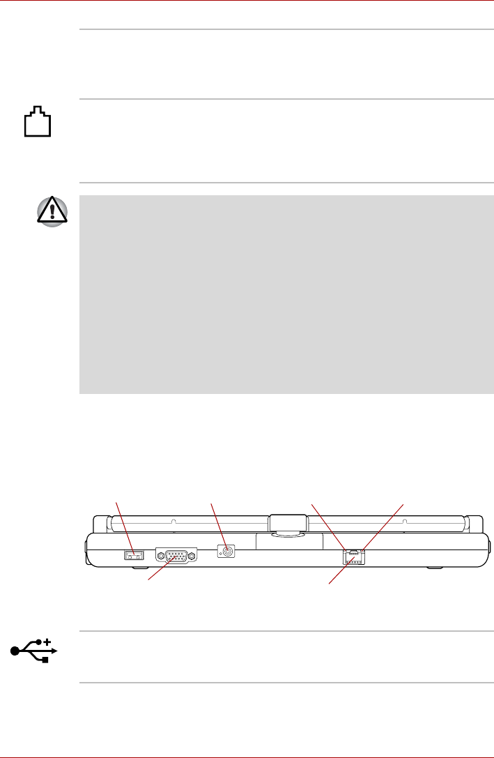
Back
The following figure shows the computer’s back.
Figure 2-4 The back of the computer
Ultra Slim Bay A DVD Super Multi drive or Ultra Slim Bay HDD
Adaptor can be installed in the Ultra Slim Bay.
Some models are equipped with a DVD Super
Multi drive or Ultra Slim Bay HDD Adaptor.
Modem jack The modem jack allows you use to attach a
modular cable in order to connect the internal
modem directly to a telephone line.
Some models are equipped with a built-in
modem.
■Connection to any communication line other than an analog phone line
could cause a computer system failure.
■Connect the built-in modem only to ordinary analog phone lines.
■Never connect the built-in modem to a digital line (ISDN).
■Never connect the built-in modem to the digital connector on a
public telephone or to a digital private branch exchange (PBX).
■Never connect the built-in modem to a key telephone system for
residences or offices.
■Never operate your computer on AC power during a thunderstorm. If
you see lightning or hear thunder, immediately turn off the computer.
An electric surge caused by the storm, may result in a system failure,
loss of data or hardware damage.
DC IN 15V jack
External monitor port
Universal Serial Bus
(USB 2.0) port
LAN jack
LAN active indicator
(orange) Link indicator
(green)
Universal Serial Bus
(USB 2.0) port One Universal Serial Bus port, which complies to
the USB 2.0 standard, is provided on the back of
the computer.
User’s Manual 2-6
The Grand Tour
Keep foreign metal objects, such as screws, staples and paper clips, out of
the USB connectors. Foreign metal objects can create a short circuit,
which can cause damage and fire, possibly resulting in serious injury.
Please note that it is not possible to confirm the operation of all functions of
all USB devices that are available. In view of this it may be noted that some
functions associated with a specific device might not operate properly.
External monitor
port This port allows you to connect an external
monitor to the computer.
DC IN 15V jack The AC adaptor connects to this jack in order to
power the computer and charge its internal
batteries. Please note that you should only use
the model of AC adaptor supplied with the
computer at the time of purchase - using the
wrong AC adaptor can cause damage to the
computer.
LAN jack This jack lets you connect to a LAN. The adaptor
has built-in support for Ethernet LAN (10
megabits per second, 10BASE-T), Fast Ethernet
LAN (100 megabits per second, 100BASE-TX)
and Gigabit Ethernet LAN (1000 megabits per
second, 1000BASE-T). Refer to Chapter 4,
Operating Basics, for details.
■Do not connect any cable other than a LAN cable to the LAN jack. It
could cause damage or malfunction.
■Do not connect the LAN cable to a power supply. It could cause
damage or malfunction.
Link indicator
(green) This indicator glows green when the computer is
connected to a LAN and the LAN is functioning
properly.
LAN active indicator
(orange) This indicator glows orange when data is being
exchanged between the computer and the LAN.
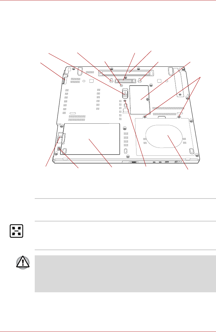
User’s Manual 2-7
The Grand Tour
Underside
The following figure shows the underside of the computer. You should
ensure that the display is closed before the computer is turned over to
avoid causing any damage.
Figure 2-5 The underside of the computer
Memory module slot
Battery
release latch Battery lock
Notch Docking port
Battery pack
HDD pack
cover screws
Hard disk drive
Ultra Slim Bay
Ultra Slim Bay
lock screw
(lock position)
Ultra Slim Bay latch
Notch
Reserve Pen
Ultra Slim Bay
lock screw
(unlock position)
Notches Notches on the computer engage hooks on the
TOSHIBA Express Port Replicator to ensure a
secure connection.
Docking port This port enables connection of an optional
TOSHIBA Express Port Replicator or a Slice
Expansion Battery described in Chapter 3,
Hardware, Utilities and Options.
■Only the TOSHIBA Express Port Replicator can be used with this
computer. Do not attempt to use any other Port Replicator.
■Keep foreign objects out of the docking port. A pin or similar object can
damage the computer's circuitry. A plastic shutter protects the
connector.
User’s Manual 2-8
The Grand Tour
Memory module slot The slot B memory module is located here. The
memory module slot allows for the installation,
replacement and removal of additional memory
module.
Refer to the Additional memory module section in
Chapter 3, Hardware, Utilities and Options.
HDD pack cover
screws The HDD pack cover screws are the screws that
hold the hard disk drive cover in place.
Hard disk drive This contains a Hard disk drive pack, which can
be removed and reinstalled. For more
information on how to remove or reinstall, please
refer to the HDD Kit (Serial-ATA) section in
Chapter 3, Hardware, Utilities and Options.
Battery release latch Slide and hold this latch into its 'Unlock' position
in order to release the battery pack ready for
removal. For more detailed information on
removing the battery pack please refer to
Chapter 6, Power and Power-Up Modes.
Battery lock Slide the battery lock to release the battery pack
for removal.
Battery pack The battery pack provides power to the computer
when the AC adaptor is not connected. For more
detailed information on the use and operation of
the battery pack please refer to Chapter 6, Power
and Power-Up Modes.
Ultra Slim Bay Refer to the Right side section in this chapter for
details.
Ultra Slim Bay latch Slide the latch to release or secure the Ultra Slim
Bay latch.
Be sure to lock the Ultra Slim Bay latch before you transport or carry the
computer.
Ultra Slim Bay lock
screw (lock position) Lock position is used to lock the Ultra Slim Bay
Latch.
The Ultra Slim Bay Latch is locked by securing
the Ultra Slim Bay Lock screw into the lock
position.
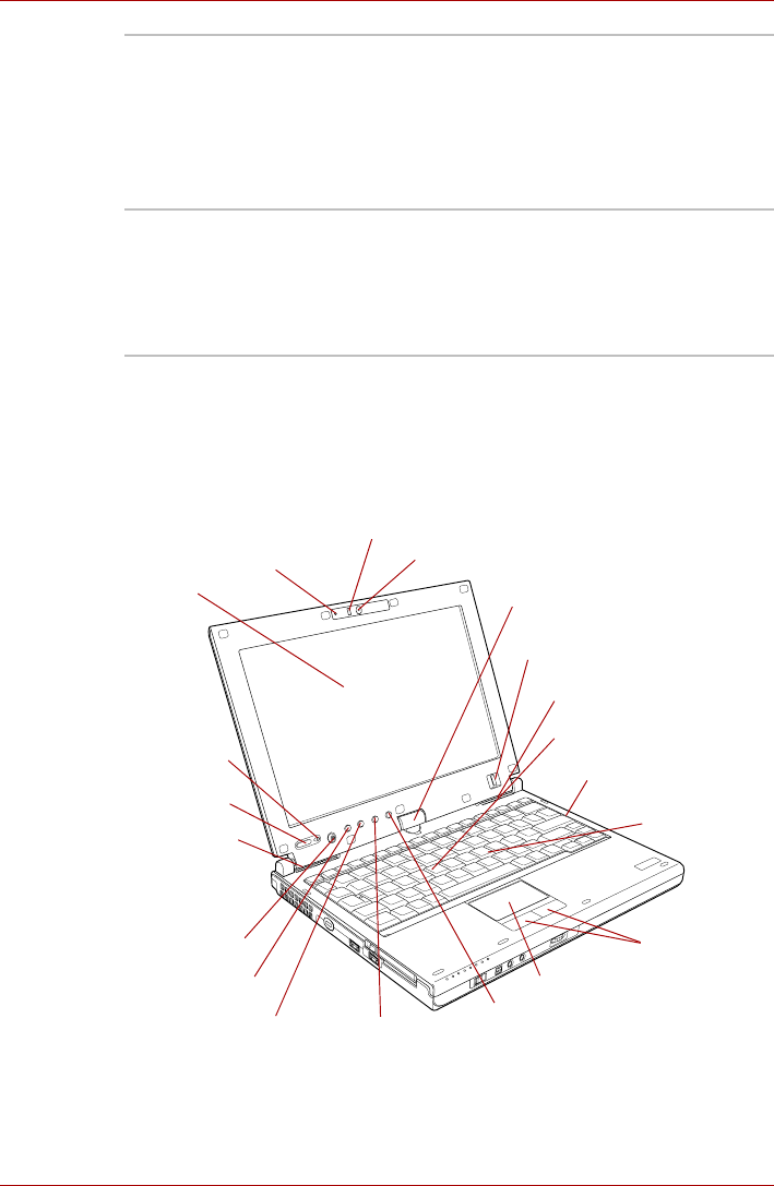
User’s Manual 2-9
The Grand Tour
Front with the display open
This section shows the computer with the display panel open. In order to
open the display, lift the display panel up and position it at a comfortable
viewing angle for you.
Figure 2-6 The front of the computer with the display panel open
Ultra Slim Bay lock
screw (unlock
position)
Unlock position is used for changing the Ultra
Slim Bay. To unlock the Ultra Slim Bay latch,
please move the Ultra Slim Bay Lock screw to
unlock position.
For more information on how to remove or insert,
please refer to the Changing Ultra Slim Bay
modules in Chapter 4.
Reserve Pen Reserve Pen is contained in the Reserve Pen
case of Underside. Reserve Pen enables data
entry directly through display screen. Some
models are equipped with a Reserve Pen. Refer
to the Using the Tablet PC Pen and Reserve
Pen section in Chapter 4, Operating Basics.
Display screen
Touch Pad
control buttons
Fingerprint Sensor
Display hinge
Touch Pad
Keyboard
Power button
TOSHIBA Assist
button
Microphone Web Camera
Web Camera LED
ESC/Rotation
button
Cross Function
button
TOSHIBA Presentation
button
Power button
Lock Switch
Stereo speaker
(Left)
Stereo speaker (Right)
Windows Security tablet
button
Memory module slot
(Not shown)
LCD Sensor switch
(Not shown)

User’s Manual 2-10
The Grand Tour
Web Camera Web Camera is a device that allows you to
record video or take photographs with your
computer. You can use it for video chatting or
video conferences using a communication tool
such as Windows Live Messenger.Camera
Assistant Software will help you to add various
video effects to your video or photograph.
Enables the transmission of video and use of
video chat via the internet using specialized
applications.
The effective pixel count for this web camera is
1.3 million.
Some models are equipped with a Web Camera.
Please refer to the Web Camera section in
Chapter 4, Operating Basics.
Web Camera LED
The Web Camera LED glows when the Web
Camera is operating.
Display screen Please be aware that, when the computer is
operating on the AC adaptor, the image
displayed on the internal screen will be
somewhat brighter than when it operates on
battery power. This difference in brightness
levels is intended to save power when operating
on batteries. For more information on the
computer's display, please refer to the Display
Controller and Video mode section in Appendix
B.
Power button Press this button to turn the computer's power on
and off.
Power Button Lock
Switch This switch locks the Power button in order to
prevent them from being accidentally pressed.
Slide the switch to the left to lock the Power
button.
Cross Function
button This button function will automatically open the
Windows Mobility Center window.
ESC/Rotation button This button functions the same as the ESC key
when tapped, or changes the orientation of the
screen when pressed for more than a second.
Windows Security
tablet button This button functions the same as the Ctrl + Alt +
Del keys to show Menu window.
User’s Manual 2-11
The Grand Tour
TOSHIBA Assist
button Press this button to launch the program
automatically. When power-off, Sleep Mode and
Hibernation Mode, press this button to start the
computer and launch the program.
TOSHIBA
Presentation button The TOSHIBA Presentation button has the same
functionality as the Connect display button in the
Mobility Center. Pressing this button when an
external display is connected will open the
Windows Vista® TMM (Transient Multimon
Manager) screen.
Display hinge The display hinge allows the display panel to be
position at a variety of easy-to-view angles.
Rotate the computer on this fulcrum point when
switching between Tablet and Laptop modes.
Fingerprint Sensor
This sensor enables you to enroll and recognize a
fingerprint.
Some models are equipped with a Fingerprint
Sensor.
For detailed information on Fingerprint Sensor,
refer to Chapter 4, Using the Fingerprint Sensor.
Stereo speakers The speakers emit sound generated by your
software as well as audio alarms, such as low
battery condition, generated by the system.
Keyboard The internal keyboard provides the embedded
numeric overlay keys, dedicated cursor control
overlay keys, and Keys. The keyboard
is compatible with the IBM® enhanced keyboard.
Refer to Chapter 5, The Keyboard, for details.
Touch Pad The Touch Pad mouse control device located in
the center of the palm rest is used to control the
movement of the on-screen pointer. For more
information, please refer to the Using the Touch
Pad section in Chapter 4, Operating Basics.
Touch Pad control
buttons The control buttons located below the Touch Pad
allow you to select menu items or manipulate text
and graphics as designated by the on-screen
pointer.

User’s Manual 2-12
The Grand Tour
Microphone A built-in microphone allows you to import and
record sounds for your application - please refer
to the Sound System section in Chapter 4,
Operating Basics for more information.
LCD Sensor switch This switch senses when the display panel is
either closed or opened and activates the Panel
Power Off/On feature as appropriate. For
example, when you close the display panel the
computer enters Hibernation Mode and shuts
itself down and then, when you next open the
display, the computer will automatically start up
and return you to the application you were
previously working on.
You can specify within the Power Options. To
access it, click Start -> Control Panel ->
System and Maintenance -> Power Options.
Do not put any magnetic objects close to this switch as they may cause the
computer to automatically enter Hibernation Mode and shut down even if
the Panel Power Off feature is disabled.
Memory module slot The slot A memory module is located here. The
memory module slot allows for the installation
and replacement of additional memory module.
Refer to the Additional memory module section in
Chapter 3, Hardware, Utilities and Options.
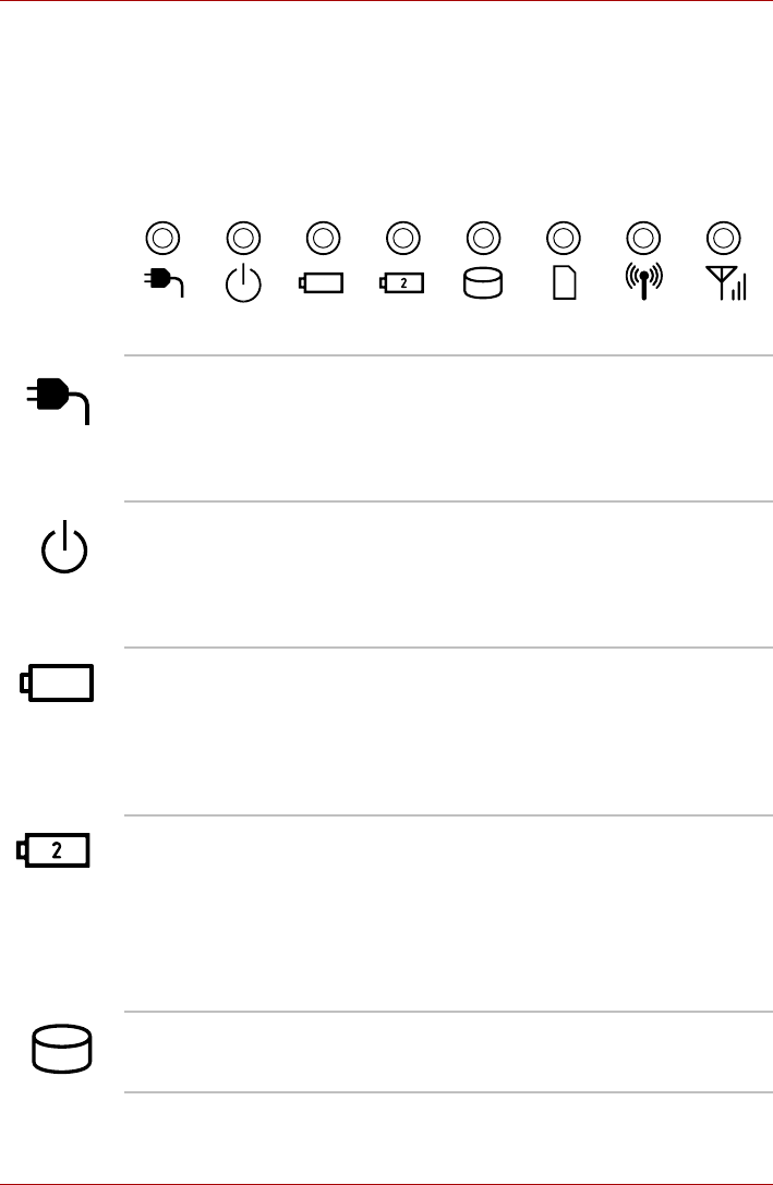
User’s Manual 2-13
The Grand Tour
Indicators
This section explains indicator functions.
System indicators
The LED system indicators for specific computer operations glow when
those operations are in progress.
Figure 2-7 System indicators
DC IN The DC IN indicator normally glows green when
power is being correctly supplied from the AC
power adaptor. However, If the output voltage
from the adaptor is abnormal, or if the computer's
power supply malfunctions, this indicator will
flash orange.
Power The Power indicator normally glows green when
the computer is turned on. However, if you turn
the computer off into Sleep Mode, this indicator
will flash orange - approximately one second on,
two seconds off - both while the system is
shutting down and while it remains turned off.
Battery The Battery indicator shows the condition of the
battery's charge - green indicates the battery is
fully charged, orange indicates the battery is
charging, and flashing orange indicates a low
battery condition. Please refer to Chapter 6,
Power and Power-Up Modes for more
information on this feature.
2nd battery The 2nd battery indicator shows the condition of
the Slice Expansion Battery's charge - green
indicates the Slice Expansion Battery is fully
charged, orange indicates the Slice Expansion
Battery is charging, and flashing orange indicates
a low battery condition.
Please refer to Chapter 6, Power and Power-Up
Modes for more information on this feature.
Hard Disk Drive The Hard Disk Drive indicator glows green
whenever the computer is accessing the built-in
hard disk drive or Ultra Slim Bay HDD.
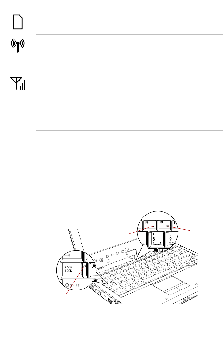
User’s Manual 2-14
The Grand Tour
Keyboard indicators
The following figures show the positions of the CAPS LOCK indicator and
the keypad overlay indicators which show the following conditions:
■When the CAPS LOCK indicator glows, the keyboard will produce
capitals when any letter is typed.
■When the Arrow Mode indicator glows, the keypad overlay allows you
to use cursor functions.
■When the Numeric Mode indicator glows, the keypad overlay allows
you to enter numbers.
Figure 2-8 Keyboard indicators
Bridge media slot The Bridge media slot indicator glows green
when the computer is accessing the Bridge
media slot.
Wireless
communication The Wireless communication indicator blinks
orange when the Bluetooth, Wireless LAN and
Wireless WAN functions are turned on.
Only some models are equipped with Bluetooth,
Wireless LAN and Wireless WAN functions.
Wireless WAN The Wireless WAN indicator glows or blinks blue
when the Wireless WAN function is on.
The indicator will glow or blink in order to indicate
the connection status of the Wireless WAN
function.
A Wireless WAN card must be installed to use
this function. Some models are equipped with a
Wireless WAN card.
CAPS LOCK indicator
Arrow Mode indicator Numeric Mode
indicator

User’s Manual 2-15
The Grand Tour
Optical disc drives
The computer is configured with a DVD Super Multi drive. Some models
are equipped with an optical disc drive. An ATAPI interface controller is
used for CD/DVD-ROM operation. When the computer is accessing a
CD/DVD, an indicator on the drive glows.
For information on loading and unloading discs refer to the Using optical
disc drives section in Chapter 4, Operating Basics.
Region codes for DVD drives and media
DVD Super Multi drives and their associated media are manufactured
according to the specifications of six marketing regions. When you
purchase DVD-Video, make sure it matches your drive, otherwise it will not
play properly.
CAPS LOCK This indicator glows green when letter keys are
locked into their uppercase format.
Arrow Mode When the Arrow Mode indicator lights green,
you can use the gray labeled keys on the keypad
overlay as cursor keys. Please refer to the
Keypad overlay section in Chapter 5, The
Keyboard for more information.
Numeric Mode When the Numeric Mode indicator lights green,
you can use the gray labeled keys on the keypad
overlay for number entry. Please refer to the
Keypad overlay section in Chapter 5, The
Keyboard for more information.
Code Region
1Canada, United States
2Japan, Europe, South Africa, Middle East
3Southeast Asia, East Asia
4Australia, New Zealand, Pacific Islands, Central
America, South America, Caribbean
5Russia, Indian Subcontinent, Africa, North Korea,
Mongolia
6China

User’s Manual 2-16
The Grand Tour
Writable discs
This section describes the types of writable CD/DVD discs. Check the
specifications of your drive to see the types of discs it can write. Use
TOSHIBA Disc Creator to write compact discs. Refer to Chapter 4,
Operating Basics.
CDs
■CD-R discs can be written only once. The recorded data cannot be
erased or changed.
■CD-RW discs including multi speed CD-RW discs, high-speed CD-RW
discs and ultra-speed CD-RW discs can be recorded more than once.
DVDs
■DVD-R, DVD+R, DVD-R (Dual Layer) and DVD+R (Double Layer) discs
can be written only once. The recorded data cannot be erased or
changed.
■DVD-RW, DVD+RW and DVD-RAM discs can be recorded more than
once.
Formats
The drive supports the following formats.
DVD Super Multi drive
The drive supports the formats CD-ROM, DVD-ROM, DVD-Video, CD-DA,
CD-Text, Photo CDTM (single/multi-session), CD-ROM Mode 1, Mode 2,
CD-ROM XA Mode 2 (Form1, Form2), Enhanced CD (CD-EXTRA),
Addressing Method 2, CD-R, CD-RW, DVD-R, DVD-R DL, DVD-RW,
DVD+R, DVD+R DL, DVD+RW and DVD-RAM.
Some types and formats of DVD-R DL and DVD+R DL discs may be
unreadable.
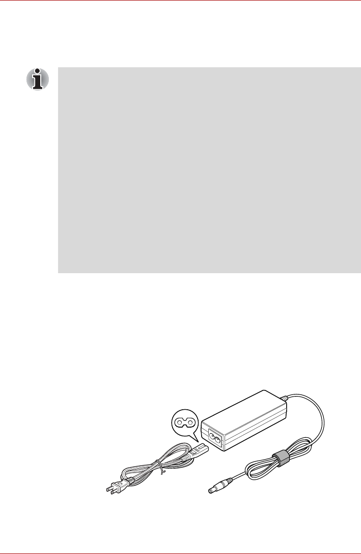
User’s Manual 2-17
The Grand Tour
DVD Super Multi drive
The full-size DVD Super Multi drive module lets you record data to
rewritable CD/DVDs as well as run either 12 cm (4.72") or 8cm (3.15")
CD/DVDs without using an adaptor.
AC adaptor
The AC adaptor can automatically adjust to any voltage ranging from 100
to 240 volts and to a frequency of either 50 or 60 hertz, enabling you to use
this computer in almost all country/region. The adaptor converts AC power
to DC power and reduces the voltage supplied to this computer.
To recharge the battery, simply connect the AC adaptor to a power source
and to the computer. Please refer to Chapter 6, Power and Power-Up
Modes for further information.
Figure 2-9 The AC adaptor (2-pin plug)
The read speed is slower at the center of a disc and faster at the outer
edge.
DVD read 8 speed (maximum)
DVD-R write 8 speed (maximum)
DVD-R DL (UJ-852) write 4 speed (maximum)
DVD-R DL (UJ-862) write 6 speed (maximum)
DVD-RW write 6 speed (maximum)
DVD+R write 8 speed (maximum)
DVD+R DL (UJ-852) write 4 speed (maximum)
DVD+R DL (UJ-862) write 6 speed (maximum)
DVD+RW write 8 speed (maximum)
DVD-RAM write 5 speed (maximum)
CD read 24 speed (maximum)
CD-R write 24 speed (maximum)
CD-RW write 16 speed (maximum, Ultra-speed
media)
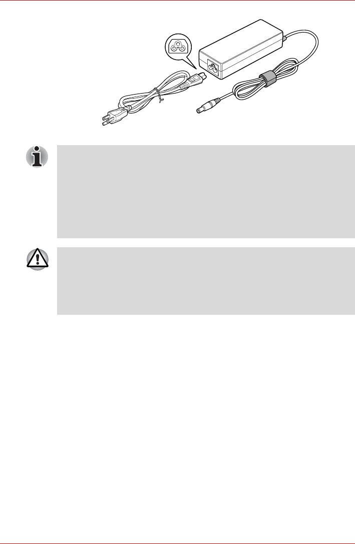
User’s Manual 2-18
The Grand Tour
Figure 2-10 The AC adaptor (3-pin plug)
■Depending on the model in question, either a 2-pin or 3-pin
adaptor/power lead will be bundled with the computer.
■Do not use a 3-pin to 2-pin conversion plug.
■The supplied power cord conforms to safety rules and regulations in
the region the product is bought and should not be used outside of this
region. In order to use the adaptor/computer in other regions, you
should please buy a power cord that conforms to the safety rules and
regulations in that particular region.
Always use the TOSHIBA AC adaptor that was included with your
computer, or use AC adaptors specified by TOSHIBA to avoid any risk of
fire or other damage to the computer. Use of an incompatible AC adaptor
could cause fire or damage to the computer possibly resulting in serious
injury. TOSHIBA assumes no liability for any damage caused by use of an
incompatible adaptor.

User’s Manual 3-1
Chapter 3
Hardware, Utilities and Options
Hardware
This section describes the hardware of your computer.
The actual specifications may vary depending on the model you
purchased.
Processor
CPU The computer is equipped with one of the
following Intel® processors.
■Intel® CoreTM 2 Duo Processor, which
incorporates a 2MB level2 cache memory. It
also supports Enhanced Intel® SpeedStep®
Technology.
■Intel® CoreTM 2 Duo Processor, which
incorporates a 4MB level2 cache memory. It
also supports Enhanced Intel® SpeedStep®
Technology.
Some models in this series carry Intel® Centrino® Duo processor
technology, which is based on three separate technologies of Intel® CoreTM
2 Duo processor, Intel® PRO/Wireless Network Connection, and Mobile
Intel® 965 Express Chipset Family.
Legal Footnote (CPU)*2
For more information on the CPU, please refer to the Legal Footnotes
section in Appendix K or Click the *2 above.

User’s Manual 3-2
Hardware, Utilities and Options
Memory
Power
Module slot 512, 1,024 or 2,048MB memory module can be
installed in the computer's memory module slot
for a maximum of 4,096MB system memory.
Video RAM The amount of Video RAM available is
dependent on the computer's system memory.
Start -> Control Panel -> Appearance and
Personalization -> Personalization -> Display
Settings.
The amount of Video RAM can be verified by
clicking the Advanced Settings... button in the
Display Settings window.
Legal Footnote (Memory (Main System))*3
For more information regarding Memory (Main System), please refer to the
Legal Footnotes section in Appendix K or click the *3 above.
Battery pack The computer is powered by one rechargeable
lithium-ion battery pack.
Slice Expansion
Battery This battery pack increases your computer's
operating time when main battery pack is also
installed.
Some models are equipped with a Slice
Expansion Battery.
Legal Footnote (Battery Life)*4
For more information regarding Battery Life, please refer to the Legal
Footnotes section in Appendix K or click the *4 above.

User’s Manual 3-3
Hardware, Utilities and Options
Disks
Optical disc drive
RTC battery The internal RTC battery backs up the Real Time
Clock (RTC) and calendar.
AC adaptor The AC adaptor provides power to the system
and recharges the batteries when they are low. It
comes with a detachable power cord which will
either have a 2-pin or 3-pin plug enclosure.
As the AC adaptor is universal, it can receive a
range of AC voltages from 100 to 240 volts,
however you should note that the output current
varies among different models. Using the wrong
adaptor can damage your computer. Refer to the
AC adaptor section in Chapter 2, The Grand
Tour.
Hard disk drive This computer is equipped with one of the
following hard disk drive types. The capacity of
each hard disk drive model is different.
■80GB
■120GB
■160GB
Please note that part of the hard disk drive's
overall capacity is reserved as administration
space.
Legal Footnote (Hard Disk Drive (HDD) Capacity)*5
For more information regarding Hard Disk Drive (HDD) Capacity, please
refer to the Legal Footnotes section in Appendix K or click the *5 above.
Drive The following optical disc drive is pre-installed in
this computer. Some models are equipped with
an optical disc drive.
■DVD Super Multi drive
2.6GB and 5.2GB DVD-RAM media cannot be read from or written to.

User’s Manual 3-4
Hardware, Utilities and Options
Display
The computer's internal display panel supports high-resolution video
graphics and can be set to a wide range of viewing angles for maximum
comfort and readability.
Sound
Display panel 12.1" TFT LCD screen, 16 million colors, with a
resolution of 1280 horizontal x 800 vertical pixels
WXGA.
The function of the display screen varies from
model to model.
■Digitizer screen model:
Operations on the display screen can be
done by using the Tablet PC Pen which
comes with the computer.
■Digitizer and touch screen model:
Operations on the display screen can be
done by a finger or using the Tablet PC Pen
which comes with the computer.
■Display screen model:
Operations on the display screen can not be
done by using Tablet PC Pen or a finger. In
order to prevent damages to the display
screen please refrain from touching it.
Legal Footnote (LCD)*6
For more information regarding the LCD, please refer to the Legal
Footnotes section in Appendix K or click the *6 above.
Graphics controller The graphics controller maximizes display
performance. Refer to Display Controller and
Video mode section in Appendix B for more
information.
Legal Footnote (Graphics Processor Unit ("GPU"))*7
For more information regarding the Graphics Processor Unit ("GPU"),
please refer to the Legal Footnotes section in Appendix K or click the *7
above.
Sound system The integrated sound system provides support
for the computer's internal speakers and
microphone, as allowing an external microphone
and headphones to be connected via the
appropriate jacks.

User’s Manual 3-5
Hardware, Utilities and Options
Multimedia
Communications
Web Camera Web Camera is a device that allows you to
record video or take photographs with your
computer. You can use it for video chatting or
video conferences using a communication tool
such as Windows Live Messenger.Camera
Assistant Software will help you to add various
video effects to your video or photograph.
Please refer to the Web Camera section in
Chapter 4, Operating Basics.
Modem Some models are equipped with the integrated
modem. The integrated modem provides
capability for data and fax communications that
support the V.90 (V.92) standards and includes a
modem jack for connection to the telephone line.
Please note that both the V.90 and V.92
standards are only supported in the USA,
Canada, United Kingdom, France, Germany and
Australia - only the V.90 standard is supported in
other regions. You should also be aware that the
speed of data and fax transfer will depend on the
analog telephone line conditions.
The integrated model is only installed as a
standard device in some markets. Please refer to
the V.90 section in Appendix E for more
information.
LAN The computer has built-in support for Ethernet
LAN (10 megabits per second, 10BASE-T), Fast
Ethernet LAN (100 megabits per second,
100BASE-TX) and Gigabit Ethernet LAN (1000
megabits per second, 1000BASE-T).
It is pre-installed as a standard device in some
markets.
Bluetooth Some computers in this series offer Bluetooth
wireless communication functionality which
eliminates the need for cables between
electronic devices such as computers, printers
and mobile phones. When implemented,
Bluetooth provides a fast, reliable and secure
means to achieve wireless communication in a
small space.

User’s Manual 3-6
Hardware, Utilities and Options
Ultra Slim Bay
Special features
The following features are either unique to TOSHIBA computers or are
advanced features which make the computer more convenient to use.
Access each function using the following procedures.
*1 To access the Power Options, click Start -> Control Panel -> System
and Maintenance -> Power Options.
Wireless LAN Some computers in this series are equipped with
a Wireless LAN card that is compatible with other
LAN systems based on Direct Sequence Spread
Spectrum/Orthogonal Frequency Division
Multiplexing radio technology that complies with
the IEEE 802.11 Standard (Revision A, B, G or n
Draft 2.0).
Legal Footnote (Wireless LAN)*8
For more information regarding Wireless LAN, please refer to the Legal
Footnotes section in Appendix K or click the *8 above.
Wireless WAN Some computers in this series are equipped with
a Wireless WAN card. This card supports
HSDPA and provides faster communications
than previous Wireless WAN cards.
Ultra Slim Bay
Modules Ultra Slim Bay is a single-drive bay that
accommodates an optical disc drive and
secondary hard disk drive.
Ultra Slim Bay
Weight Saver To reduce weight, the Ultra Slim Bay module can
be removed and a weight saver installed. It is
preinstalled in some models.
TOSHIBA Assist
button Press this button to launch the program
automatically. When power-off, Sleep Mode and
Hibernation Mode, press this button to start the
computer and launch the program.
TOSHIBA
Presentation button The TOSHIBA Presentation button has the same
functionality as the Connect display button in the
Mobility Center. Pressing this button when an
external display is connected will open the
Windows Vista® TMM (Transient Multimon
Manager) screen.

User’s Manual 3-7
Hardware, Utilities and Options
Hot keys Hot keys are specific key combinations that let
you quickly change the system configuration
directly from the keyboard without running a
system program.
Display automatic
power off *1
This feature automatically cuts off power to the
computer's display panel when there is no
keyboard input for a specified time, with power
being restored the next time a key is pressed.
This can be specified in the Power Options.
HDD automatic
power off *1
This feature automatically cuts off power to the
hard disk drive when it is not accessed for a
specified time, with power being restored when
the hard disk drive is next accessed. This can be
specified in the Power Options.
System automatic
Sleep/Hibernation
Mode *1
This feature automatically shuts down the system
into either Sleep Mode or Hibernation Mode when
there is no input or hardware access for a
specified time. This can be specified in the Power
Options.
Keypad overlay A ten-key numeric keypad is integrated into the
keyboard. Please refer to the Keypad overlay
section in Chapter 5, The Keyboard, for
information on using this feature.
Power on password Two levels of password security, supervisor and
user, are available to prevent unauthorized
access to your computer.
Instant security A specific hot key function automatically locks the
system providing data security.
Intelligent power
supply *1
A microprocessor in the computer's intelligent
power supply detects the battery's charge,
automatically calculates the remaining battery
capacity and protects electronic components
from abnormal conditions such as a voltage
overload from the AC adaptor. This can be
specified in the Power Options.
Battery save mode *1 This feature lets you configure the computer in
order to save battery power. This can be
specified in the Power Options.
Panel power on/off
*1
This feature automatically turns power to the
computer off when the display panel is closed,
and turns it back on when the display panel is
opened. This can be specified in the Power
Options.

User’s Manual 3-8
Hardware, Utilities and Options
Low battery
automatic
Hibernation Mode *1
When battery power is exhausted to the point that
computer operation cannot be continued, the
system automatically enters Hibernation Mode
and shuts itself down. This can be specified in the
Power Options.
Heat dispersal *1 To protect against overheating, the processor
has an internal temperature sensor so that, if the
computer's internal temperature rises to a certain
level, the cooling fan is turned on or the
processing speed is lowered. This can be
specified in the Power Options.
TOSHIBA HDD
Protection This feature uses the acceleration sensor built in
the computer to detect vibration and shocks, and
automatically moves the hard disk drive's
read/write head to a safe position in order to
reduce the risk of damage that could be caused
by head-to-disk contact. Refer to the Using the
Hard Disk Drive (HDD) Protection section in
Chapter 4, Operating Basics, for more details.
The TOSHIBA HDD Protection function does not guarantee that the hard
disk drive will not be damaged.
Optical Drive Auto
Lock This function automatically locks the optical disc
drive eject button if the computer detects any
vibration or other shocks while running on the
battery.
This function prevents the disc tray from opening
even if the eject button is pushed unexpectedly.
For information on using this feature, please refer
to the Optical Drive Auto Lock section in Chapter
4, Operating Basics.
Hibernation Mode This feature lets you turn off the power to the
computer without exiting from your software. The
contents of main memory are automatically
saved to the hard disk drive so that when you
next turn the power on again, you can continue
working right where you left off. Refer to the
Turning off the power section in Chapter 1,
Getting Started, for more details.
Sleep Mode If you have to interrupt your work, you can use
this feature to allow you to turn off power to the
computer without exiting from your software.
Data is maintained in the computer's main
memory so that when you next turn on the power,
you can continue working right where you left off.

User’s Manual 3-9
Hardware, Utilities and Options
TOSHIBA Value Added Package
This section describes the TOSHIBA Component features pre-installed on
the computer.
TOSHIBA Power
Saver TOSHIBA Power Saver provides you with the
features of more various power supply
managements.
TOSHIBA Button
Support This utility controls the following computer button
functions.
■TOSHIBA Assist
■TOSHIBA Presentation
The starting application from the button can be
changed.
TOSHIBA Zooming
Utility This utility allows you to enlarge or reduce the
icon size on the Windows Desktop, or the zoom
factor associated with specific supported
applications.
TOSHIBA PC
Diagnostic Tool The TOSHIBA PC Diagnostic Tool will display
basic system configuration information and allow
the functionality of some of the computer's built-
in hardware devices to be tested.
TOSHIBA Password
Utility The TOSHIBA Password utility allows you to set
a password in order to restrict access to the
computer.
TOSHIBA Flash
Cards The TOSHIBA Flash Cards provide a quick way
to modify selected system functions and to
launch applications.
■Hot key function
■TOSHIBA utility launcher function
HW Setup This utility allows you to customize your
hardware settings according to the way you work
with the computer and the peripherals you use.
TOSHIBA
Accessibility The TOSHIBA Accessibility utility provides
support to movement impaired users when they
need to use the TOSHIBA Hot-key functions. In
use, the utility allows you to make the FN key
'sticky', that is you can press it once, release it,
and they press one of the 'F' keys in order to
access its specific function. When set, the FN
key will remain active until another key is
pressed.

User’s Manual 3-10
Hardware, Utilities and Options
TOSHIBA Tablet PC Extension
This section describes the pre-installed TOSHIBA Component features that
come with the computer. To access these components, click Start -> All
Programs -> TOSHIBA.
Utilities and Applications
This section describes the pre-installed utilities that come with the
computer and details how to start them. For further information on their
operation, please refer to each utility's online manual, help files or
README.TXT file.
TOSHIBA Rotation
Utility This utility controls the screen orientation setting
for both Laptop mode and Tablet mode.
You can set four types of orientation setting:
■Primary landscape
■Primary portrait
■Secondary landscape
■Secondary portrait
The default setting of PC mode is Primary
Landscape while that for Tablet mode is Primary
Portrait.
TOSHIBA
Accelerometer
Utilities
When TOSHIBA Accelerometer Utilities is
enabled, you can invoke the Start menu, switch
active windows or launch predefined applications
by shaking the computer vertically or horizontally,
or by tilting it.
DVD Video Player The DVD Video Player is used to play DVD-
Video. It has an on-screen interface and
functions. Click Start -> All Programs ->
InterVideo WinDVD -> InterVideo WinDVD for
TOSHIBA.
■Frame dropping, audio skipping or out of synch audio and video may
occur during playback of some DVD Video titles.
Make sure to connect the computer's AC adaptor when playing a DVD
Video. Power-saving features may interfere with smooth playback.
■When using the WinDVD™ software, a horizontal white line may
appear during playback of a DVD media in VR-format. If this occurs,
set the Windows Color scheme to "Windows® Aero™".
Adding additional memory is also recommended.

User’s Manual 3-11
Hardware, Utilities and Options
Fingerprint Utility This product has a fingerprint utility installed for
the purpose of enrolling and recognizing
fingerprints which can then be linked to a
username and password in order to remove the
need to input these details from the keyboard.
Just by swiping an enrolled finger against the
fingerprint sensor, the following functions will be
enabled:
■Logon to Windows and access a security
enabled homepage through Internet Explorer.
■Files and folders can be encrypted/decrypted
and third party access to them is prevented.
■Disable the password-protected screen-saver
when returning from a power-saving mode
such as Sleep Mode.
■Authentication of the User Password (and, if
applicable, the HDD(Hard Disk Drive)
Password) when booting up the computer
(Pre-OS Authentication).
■Single-Swipe Sign On feature
Fingerprint security cannot be used in models that do not have a fingerprint
module installed.
Bluetooth Stack for
Windows by Toshiba This software enables communication between
the computer and external Bluetooth devices
such as printers and mobile phones.
Bluetooth functions cannot be used in models that do not have a Bluetooth
module installed.
TOSHIBA SD
Memory Boot Utility The TOSHIBA SD Memory Boot Utility allows
you to create a bootable SD memory card to start
the system. You can boot TOSHIBA SD Memory
Boot Utility from the menu bar as follows. Click
Start -> All Programs -> TOSHIBA -> Utilities
-> SD Memory Boot Utility.
SD Memory Card Format Utility and other SD functions are packaged into
TOSHIBA SD Memory Utilities.
TOSHIBA SD
Memory Card Format This utility allows you to format an SD/SDHC
memory card by the SD standard format.

User’s Manual 3-12
Hardware, Utilities and Options
TOSHIBA Assist TOSHIBA Assist is a graphical user interface that
provides access to specific tools, utilities and
applications that make the use and configuration
of the computer easier.
TOSHIBA ConfigFree TOSHIBA ConfigFree is a suite of utilities that
improve the ease and control of communication
devices and network connections, help in the
identification of communication problems and
allow the creation of profiles if you need to switch
between different locations and communication
networks. To access this utility, click Start -> All
Programs -> TOSHIBA -> Networking ->
ConfigFree.
TOSHIBA Disc
Creator You can create CD's and DVD's in a number of
formats including audio CD's that can be played
on a standard CD player, and data CD's/DVD's
which can store copies of the files and folders on
your computer's hard disk drive. This software
can be used on models with a DVD Super Multi
drive.
To start this utility, click Start -> All Programs ->
TOSHIBA -> CD&DVD Applications -> Disc
Creator.
TOSHIBA DVD-RAM
Utility This utility has the function of Physical Format
and Write-Protect to DVD-RAM. This utility is
contained the setup module of TOSHIBA Disc
Creator. To start this utility, click Start -> All
Programs -> TOSHIBA -> CD&DVD
Applications -> DVD-RAM Utility.
CD/DVD Drive
Acoustic Silencer This utility allows you to configure the read speed
of the optical disc drive. You can either configure
Normal Mode, which operates the drive at its
maximum speed for quick data access, or Quiet
Mode which runs audio CDs at single speed and
which can lessen operational noise.
It is ineffective with DVDs.

User’s Manual 3-13
Hardware, Utilities and Options
Windows Mobility
Center This section describes the Windows Mobility
Center. Mobility Center is a utility for accessing
several mobile PC settings quickly in one
window. A default maximum of eight tiles are
provided by the operating system, and the
additional three tiles are added to your Mobility
Center.
■Ext.Screen Orientation :
This can be used to switch the orientation of
an external display connected to your Tablet
PC between portrait and landscape modes.
■Lock Computer :
This can be used to lock your computer
without turning it off. This has the same
function as the Lock button at the bottom of
the right pane in the start menu.
■TOSHIBA Assist :
This can be used to open TOSHIBA Assist if
it is already installed in your computer.
TOSHIBA Tablet
Access Code Logon
Utility
If a Windows password has been set, you can
logon to the operating system by entering a
handwriting signature into the dialog box using
the Tablet PC Pen when prompted.

User’s Manual 3-14
Hardware, Utilities and Options
Optional devices
Optional devices can expand the computer's capabilities and its versatility.
This section describes the connection or installation of the following
devices:
Cards/memory
■PC Card
■Smart Card
■Bridge media slot
■Secure Digital (SD) Card (SD memory card, SDHC memory card,
miniSD Card, microSD Card)
■Memory Stick (Memory Stick, Memory Stick PRO, Memory Stick
PRO Duo)
■xD picture card
■MultiMediaCard
■Additional memory module
Peripheral devices
■HDD Kit (Serial-ATA)
■Ultra Slim Bay HDD Adaptor
■External monitor
■USB
■USB FDD Kit
■USB Sleep and Charge function
■USB WakeUp function
■i.LINK (IEEE1394)
■TOSHIBA Express Port Replicator
Other
■Security lock
To connect optional devices (such as USB device or External monitor) to
the computer, be sure to check the shape and orientation of the connector
before connecting.
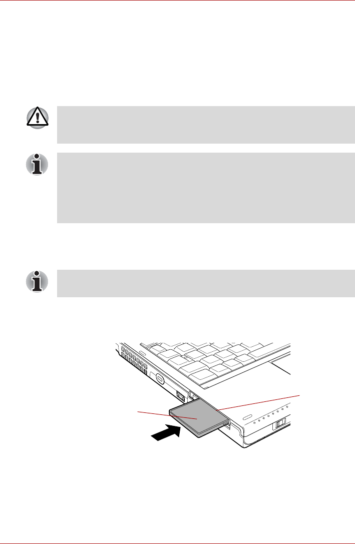
User’s Manual 3-15
Hardware, Utilities and Options
PC Card
Some models are equipped with a PC Card slot. The computer is equipped
with a single PC Card slot that can accommodate a Type II format card.
Any PC Card that meets industry standards, either manufactured by
TOSHIBA or another vendor, can be installed as the slot supports 16-bit
PC Cards and 32-bit CardBus cards. For reference, CardBus supports the
newer standard of 32-bit PC Cards and provides superior performance for
the greater demands of applications such as multimedia data transmission.
Inserting a PC Card
The Windows hot-install feature allows you to insert PC Cards while the
computer is turned on.
To insert a PC Card, follow the steps as detailed below:
1. Insert the PC Card into the PC Card slot on the side of the computer.
2. Press the PC Card gently to ensure a firm connection is made.
Figure 3-1 Inserting the PC Card
3. After inserting the PC Card, you should refer to its documentation and
also check the configuration in Windows in order to ensure that it is
correct.
PC Cards can sometimes become hot during computer operation. Before
you remove a PC Card always wait for it to cool. You could get burned
removing a hot PC Card.
■The computer is equipped with either a PC Card slot or a Smart Card
slot.
■When inserted in the PC Card slot, some PC Cards may block the
optical disc drive tray and prevent it from opening. If this occurs please
remove the PC Card each time you wish to open or close the optical
disc drive tray.
Do not insert a PC Card while the computer is in Sleep Mode or
Hibernation Mode as you may find that some cards do not work properly.
PC Card
PC Card slot
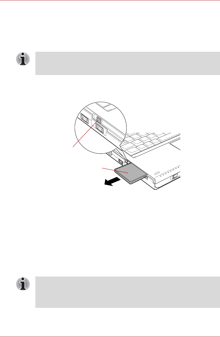
User’s Manual 3-16
Hardware, Utilities and Options
Removing a PC Card
To remove a PC Card, follow the steps as detailed below:
1. Open the Safely Remove Hardware icon on the Windows Taskbar.
2. Point to PC Card and click the left Touch Pad control button.
3. Press the PC card eject button to extend it.
4. Press the extended PC Card eject button in order to eject the PC Card
partially out of the computer.
5. Grasp the PC Card and remove it.
Figure 3-2 Removing the PC Card
Smart Card
Some models are equipped with a Smart Card slot.
A Smart Card is a credit card sized plastic card. An extremely thin
integrated circuit (IC chip) is embedded into the card on which information
can be recorded. These cards can be used for a wide variety of
applications including telephone related and electronic monetary
payments.
This section contains information on the proper use of the Smart Card slot,
and it is strongly recommended that you read it before operating the
computer.
If the PC card is not inserted all the way, the eject button may not cause it
to pop out sufficiently to allows it to be grasped. Be sure to push the PC
card firmly into the computer and slide the eject button again.
PC Card
PC Card eject
button
■Your computer supports ISO7816-3 asynchronous cards (support
protocols are T=0 and T=1) with a working voltage of 5V.
■The computer is equipped with either a PC Card slot or a Smart Card
slot.
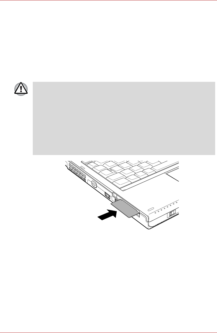
User’s Manual 3-17
Hardware, Utilities and Options
Inserting a Smart Card
The Smart Card slot is located on the left side of the computer. The
Windows hot-install feature allows you to insert a Smart Card while the
computer is turned on.
To install a Smart Card, follow the steps as detailed below:
1. Insert the Smart Card into the Smart Card slot with the metal
connectors facing up.
2. Press the Smart Card gently to ensure a firm connection is made. The
computer will identify the Smart Card and display an icon in the
Windows Taskbar.
Figure 3-3 Inserting a Smart Card
3. After inserting the Smart Card, you should refer to its documentation
and also check the configuration in Windows in order to ensure that it is
correct.
■When inserting a Smart Card into the Smart Card slot, make sure to
confirm that the card is oriented correctly before inserting.
■Insert the Smart Card until it reaches the end of the Smart Card slot.
There will be about 2cm of the Smart Card sticking out of the Smart
Card slot. Do not attempt to insert it further.
■Always remove the Smart Card from the Smart Card slot before moving
the computer.
■Remove the Smart Card after use.
Failure to follow these instructions may result in damage to the computer
and/or damage to the Smart Card.
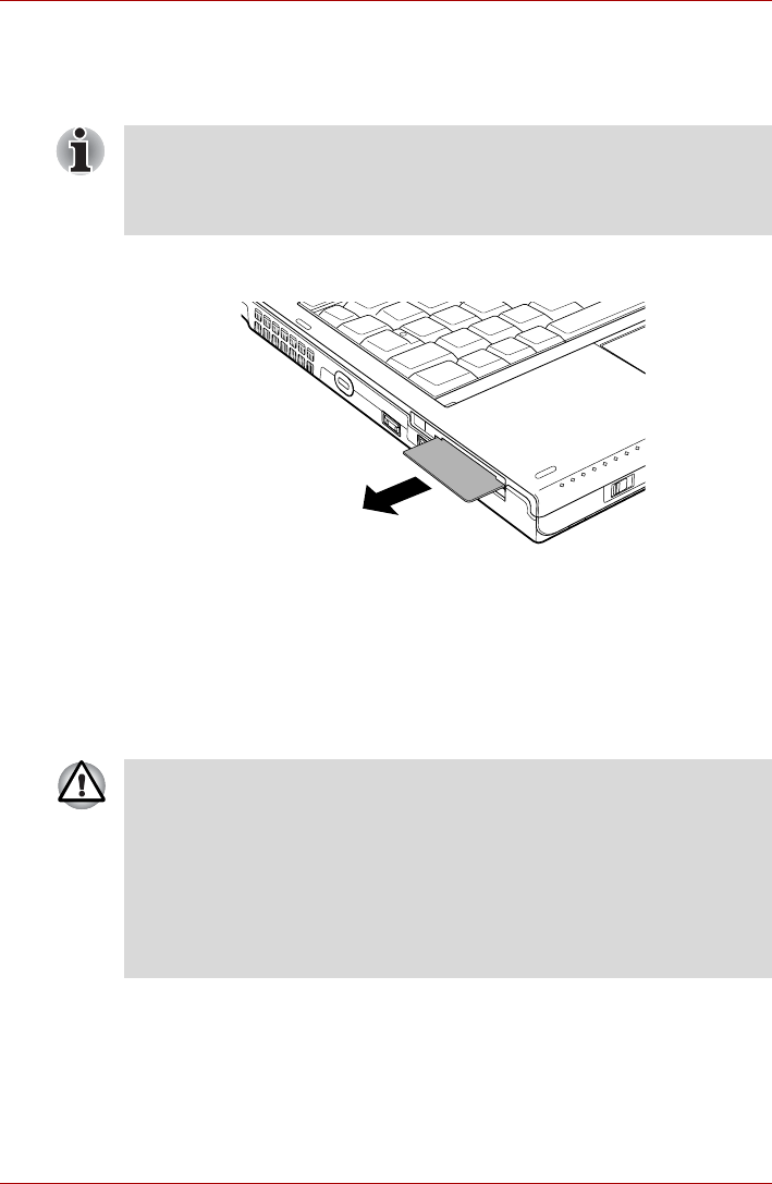
User’s Manual 3-18
Hardware, Utilities and Options
Removing a Smart Card
To remove a Smart Card, follow the steps as detailed below:
1. Open the Safely Remove Hardware icon on the Windows Taskbar.
2. Point to Smart Card and click the left Touch Pad control button.
3. Grasp the Smart Card and remove it.
Figure 3-4 Removing a Smart Card
Bridge media slot
The computer is equipped with a Bridge media slot that can accommodate
some kinds of memory media with various memory capacities so that you
can easily transfer data from devices, such as digital cameras and
Personal Digital Assistants.
■Before removing the Smart Card, confirm that the Smart Card is not
working with any program or system.
■Be careful not to bend the Smart Card while removing it from the
computer.
■Keep foreign objects out of the Bridge media slot. Never allow metal
objects, such as screws, staples and paper clips, to enter the computer
or Keyboard. Foreign metal objects can create a short circuit, which
can cause computer damage and fire, possibly resulting in serious
injury.
■Memory Stick Duo is not compatible with the Bridge media slot. Do not
insert Memory Stick Duo into the slot or you may not be able to remove
it. Data may be lost or damaged if you use any memory media other
than those supported.
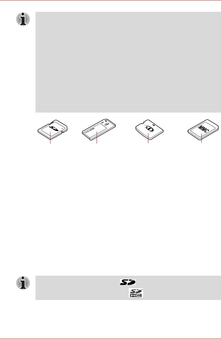
User’s Manual 3-19
Hardware, Utilities and Options
Figure 3-5 Examples of memory media
Memory media
This section provides the important safety precautions in order to handle
your memory media.
Points to note about the SD/SDHC memory card
SD/SDHC memory cards comply with SDMI (Secure Digital Music
Initiative), which is a technology adopted to prevent unlawful copy or
playback of digital music. For this reason, you cannot copy or playback
protected material on another computer or other device, and you may not
reproduce any copyrighted material except for your personal enjoyment.
Below is a simple explanation for distinguishing SD memory cards from
SDHC memory cards.
■SD and SDHC memory cards appear the same externally.
■The logo on SD and SDHC memory cards is different, so pay careful
attention to the logo when purchasing.
■This Bridge media slot supports the following memory media.
■Secure Digital (SD) Card (SD memory card, SDHC memory card,
miniSD Card, microSD Card)
■Memory Stick (Memory Stick, Memory Stick PRO, Memory Stick
PRO Duo)
■xD picture card
■MultiMediaCard (MMC)
■Please note that an adaptor is required to use miniSD/microSD Card.
■Please note that an adaptor is required to use Memory Stick PRO Duo.
■Please note that not all memory media have been tested and verified to
work correctly. Therefore, it is not possible to guarantee that all
memory media will operate properly.
■The slot does not support Magic Gate functions.
Secure Digital
(SD) Card Memory Stick xD picture card MultiMediaCard
(MMC)
■The SD memory card logo is ( ).
■The SDHC memory card logo is ( ).

User’s Manual 3-20
Hardware, Utilities and Options
■The maximum capacity of SD memory cards is 2GB. The maximum
capacity of SDHC memory cards is 8GB.
Memory media format
New media cards are formatted according to specific standards. If you wish
to reformat a media card, be sure to do so with a device that uses media
cards.
Formatting an SD/SDHC memory card
SD/SDHC memory cards are sold already formatted in conformity to
specific standards. If you format the SD/SDHC memory card again, be sure
to format it with the TOSHIBA SD Memory Card Format utility, not with the
format command provided within Windows.
In order to run the TOSHIBA SD Memory Card Format utility, click Start ->
All Programs -> TOSHIBA -> Utilities -> SD Memory Card Format.
Media care
Observe the following precautions when handling the card.
Card care
■Do not twist or bend cards.
■Do not expose cards to liquids or store in humid areas or lay media
close to containers of liquid.
■Do not touch the metal part of a card or expose it to liquids or let it get
dirty.
■After using card, return it to its case.
■The card is designed so that it can be inserted only one way. Do not try
to force the card into the slot.
■Do not leave a card partially inserted in the slot. Press the card until you
hear it click into place.
Card Type Capacities
SD 8MB, 16MB, 32MB, 64MB, 128MB, 256MB,
512MB, 1GB, 2GB
SDHC 4GB, 8GB
The TOSHIBA SD Memory Card Format utility does not format the
protected area of the SD/SDHC memory card - should you need to format
all areas of the memory card, including the protected area, you will need to
obtain an appropriate application that applies the copy protection system.
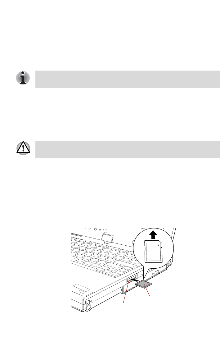
User’s Manual 3-21
Hardware, Utilities and Options
Memory card care
■Set the write-protect switch to the lock position, if you do not want to
record data.
■Memory cards have a limited lifespan, so it is important to backup
important data.
■Do not write to a card if the battery power is low. Low power could affect
writing accuracy.
■Do not remove a card while read/write is in progress.
About the write-protect
The following memory media have a function for protect.
■SD Card (SD memory card, SDHC memory card)
■Memory Stick (Memory Stick, Memory Stick PRO, Memory Stick PRO
Duo)
■MultiMediaCard (MMC)
Inserting a memory media
The following instructions apply to all types of supported media devices. To
insert a memory media, follow the steps as detailed below:
1. Turn the memory media so that the contacts (metal areas) are face
down.
2. Insert the memory media into the Bridge media slot on the side of the
computer.
3. Press the memory media gently to ensure a firm connection is made.
Figure 3-6 Inserting a memory media
For more details on using memory cards, see manuals accompanying the
cards.
Set the write-protect switch to the lock position, if you do not want to record
data.
Memory media
Bridge media slot
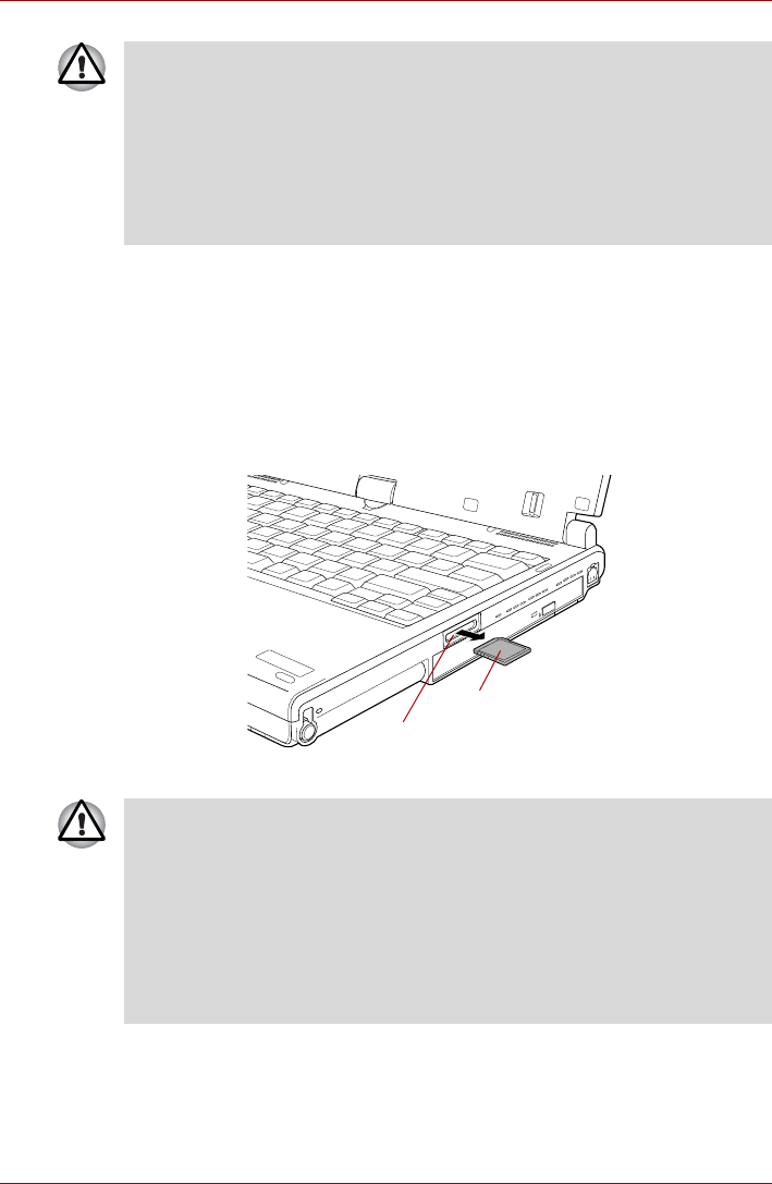
User’s Manual 3-22
Hardware, Utilities and Options
Removing a memory media
The following instructions apply to all types of supported media devices. To
remove a memory media, follow the steps as detailed below:
1. Open the Safely Remove Hardware icon on the Windows Taskbar.
2. Point to memory media and click the left Touch Pad control button.
3. Press the memory media to partially extend it out of the computer.
4. Grasp the media and remove it.
Figure 3-7 Removing memory media
■Make sure memory media is oriented properly before you insert it. If
you insert the media in wrong direction, you may not be able to remove
it.
■When inserting memory media, do not touch the metal contacts. You
could expose the storage area to static electricity, which can destroy
data.
■Do not turn the computer off or switch to Sleep Mode or Hibernation
Mode while files are being copied - doing so may cause data to be lost.
Memory media
Bridge media slot
■Make sure the Bridge Media slot indicator is out before you remove
the memory media or turn off the computer’s power. If you remove the
memory media or turn off the power while the computer is accessing
the memory media, you may lose data or damage the media.
■Do not remove the memory media while the computer is in Sleep or
Hibernation Mode. The computer could become unstable or data in the
memory media could be lost.
■Do not remove only the miniSD/microSD Card while leaving the
adaptor in the Bridge Media slot.

User’s Manual 3-23
Hardware, Utilities and Options
Additional memory module
This computer is equipped with two memory slots; Slot A is beneath the
keyboard and Slot B is in the underside of the computer.
You can install additional memory into the computer in order to increase
the amount of system memory that is available. This section describes how
to install and remove optional memory modules.
Point to note about memory module error
If you install a memory module that is not compatible with the computer, the
Power indicator will flashes (on for 0.5 seconds, off for 0.5 seconds) in the
following ways;
■If there is an error in only Slot A or no memory module is inserted in Slot
A: repeatedly flashes orange twice, then green.
■If there is an error in Slot B: repeatedly flashes orange, then green
twice.
■If there are errors in both Slot A and Slot B: repeatedly flashes orange
twice, then green twice.
In all instances you should shut down the computer and remove the
incompatible module(s).
■You should place a mat beneath the computer in order to prevent the
computer's lid from becoming scratched or damaged when you are
installing/replacing the memory module. In this instance you should
avoid mats that are made of materials that hold or generate static
electricity.
■When installing or removing a memory module, you must ensure that
you do not touch any other internal areas of the computer.
■Use only memory modules approved by TOSHIBA.
■Do not try to install or remove a memory module under the following
conditions.
a. The computer is turned on.
b. The computer was shut down in either Sleep or Hibernation Mode.
c. Wake-up on LAN is enabled.
d. Wake-up on Wireless LAN is enabled.
e. The wireless communication switch is turned on.
■Be careful not to let screws or other foreign matter fall into the
computer. It could cause malfunction or electric shock.
■Additional memory module is a precision electronic component that
may be fatally damaged by static electricity. Since the human body can
carry static electricity, it is important that you discharge yourself before
touching or installing any additional memory modules. To discharge
your body’s static electricity, simply touch any metal close to you with
bare hands.
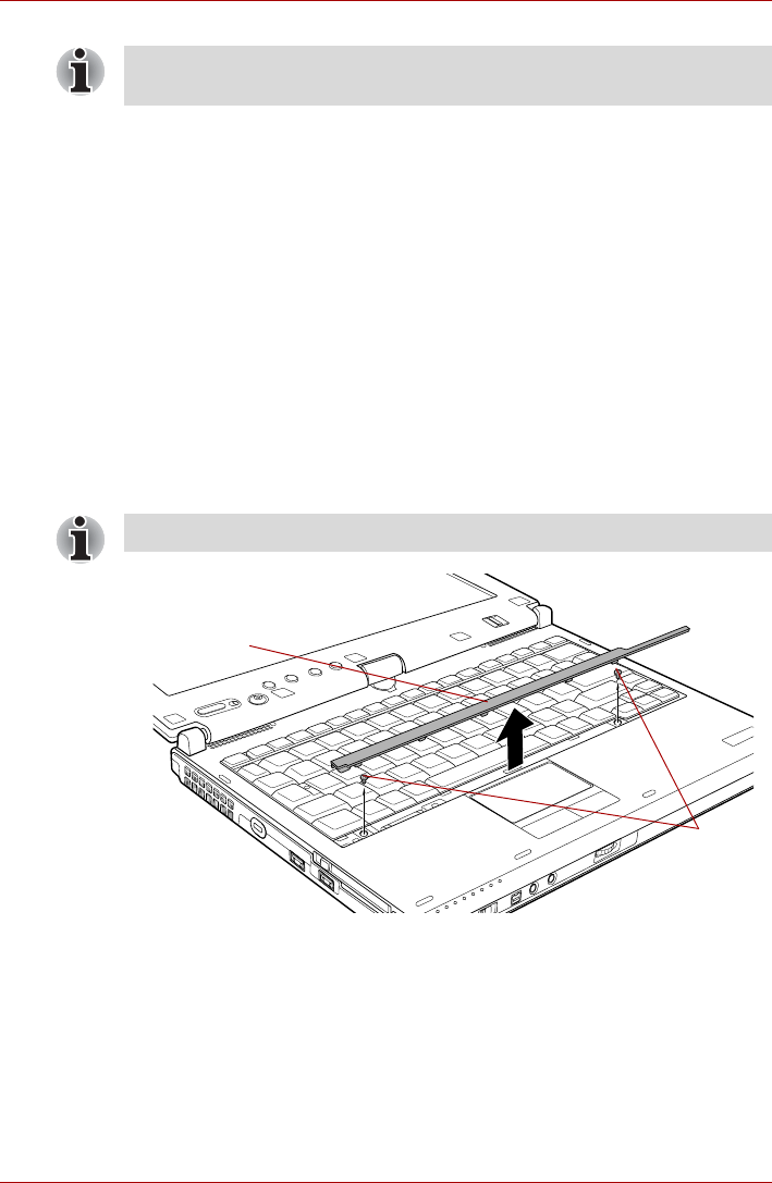
User’s Manual 3-24
Hardware, Utilities and Options
Installing a memory module (Slot A)
To install a memory module, follow the steps as detailed below:
1. Set the computer to Boot Mode and turn its power off - make sure the
Power indicator is off (refer to the Turning off the power section in
Chapter 1, Getting Started if required).
2. Remove the AC adaptor and all cables and peripherals connected to
the computer.
3. Turn the computer upside down and remove the battery pack (refer to
Replacing the battery pack section in Chapter 6, Power and Power-Up
Modes, if required).
4. Turn your computer over.
5. Open the display panel so that the screen faces directly upward.
6. Slip your finger under a notch at the end of the keyboard brace and lift
up to release latches and remove the keyboard brace.
7. Remove two screws securing the keyboard.
Figure 3-8 Removing the keyboard brace and two screws
Use a point size 0 Phillips screwdriver to remove and fasten the screws -
the use of an incorrect screwdriver can damage the screw heads.
Use a point size 0 Phillips screwdriver.
Keyboard brace
Screws
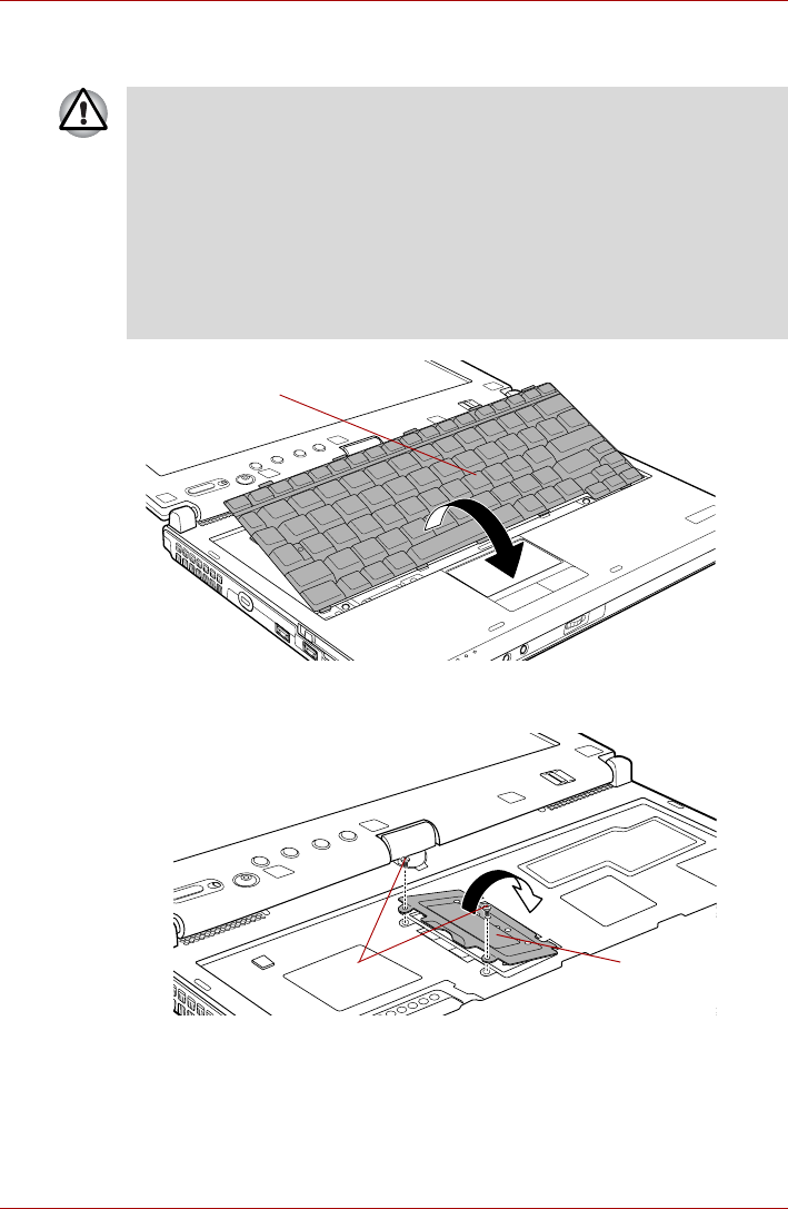
User’s Manual 3-25
Hardware, Utilities and Options
8. Lift up the back of the keyboard, rotate it toward you and lay in face
down on the palm rest.
Figure 3-9 Rotate the keyboard
9. Remove the two screws and take off the memory module cover.
Figure 3-10 Removing the memory module cover
■Never allow metal objects, such as screws, staples and paper clips, to
enter the computer or keyboard. Foreign metal objects can create a
short circuit, which can cause computer damage and fire, possibly
resulting in serious injury.
■When you move the keyboard forward, do not touch the keys. Doing so
could cause misalignment. Hold the keyboard by the sides and lay it
gently on the palm rest.
■The keyboard is connected to the computer by a keyboard ribbon
cable. Be careful not to apply tension to this cable when you lift up the
keyboard. Do not try to disconnect this cable.
Keyboard
Memory module cover
Screws
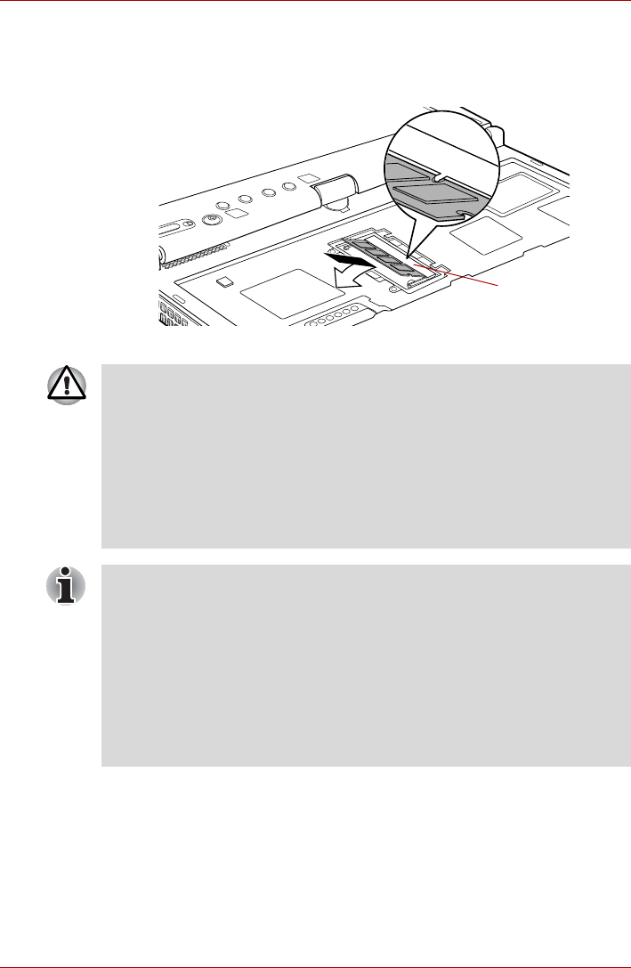
User’s Manual 3-26
Hardware, Utilities and Options
10. Align the notch of the memory module with that of the memory module
slot and gently insert the module into the slot at about a 45 degree
angle before holding it down until the latches on either side snap into
place.
Figure 3-11 Installing the memory module
Slot A
■Never allow metal objects, such as screws, staples and paper clips, to
enter the computer or keyboard. Foreign metal objects can create a
short circuit, which can cause computer damage and fire, possibly
resulting in serious injury.
■Do not touch the connectors on the memory module or on the
computer. Debris on the connectors may cause memory access
problems.
■The memory module cover will be hot after using the computer for long
periods of time. Exercise caution when removing.
■Slot A is reserved for the first memory module. Use slot B for expansion
memory modules. If only one module is installed, use slot A.
■When inserting or removing memory modules, make sure to use the
correct slot (A or B).
■Align the grooves along the edges of the memory module with the
locking tabs on the connector and insert the memory module into the
connector firmly - if you find it difficult to install the memory module,
gently prise the locking tabs outwards using the tip of your finger.
Please also ensure that you hold the memory module along its left and
right hand edges - the edges with the grooves in.
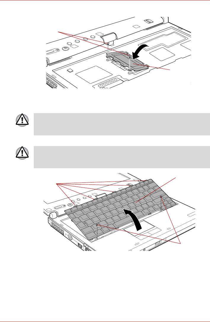
User’s Manual 3-27
Hardware, Utilities and Options
11. Screw in the two screws and replace the memory module cover.
Figure 3-12 Seating the memory module cover
12. Insert the tabs on the front of the keyboard into the corresponding
notches on the computer and place the keyboard down.
13. Replace the keyboard and secure it using the two screws.
Figure 3-13 Replace the keyboard
14. Set the keyboard brace into its groove and hold down to secure the
latches.
15. Install the battery pack. Refer to Replacing the battery pack section in
Chapter 6, Power and Power-Up Modes, for details.
16. Turn your computer over.
17. Turn the computer on and make sure the added memory is recognized
- to confirmed it, Start -> Control Panel -> System and Maintenance -
>System icon.
Memory module
cover
Screws
When seating the keyboard, be sure to connect the circuit board if the
keyboard ribbon cable was pulled out while you were removing the
keyboard.
Be sure to use all two screws removed in step 7. Make sure no screw was
dropped into the computer. Make sure no foreign matter can be found
inside the computer.
Keyboard
Screws
Tabs
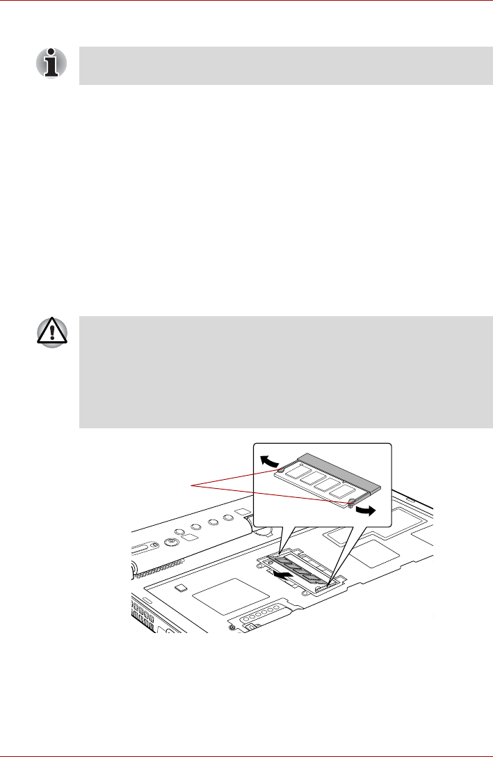
User’s Manual 3-28
Hardware, Utilities and Options
Removing a memory module (Slot A)
To remove the memory module, follow the steps as detailed below:
1. Set the computer to Boot Mode and turn its power off - make sure the
Power indicator is off (refer to the Turning off the power section in
Chapter 1, Getting Started if required).
2. Remove the AC adaptor and all cables and peripherals connected to
the computer.
3. Turn the computer upside down and remove the battery pack (refer to
Replacing the battery pack section in Chapter 6, Power and Power-Up
Modes, if required).
4. Follow steps 4 through 9 in Installing a memory module (Slot A) to
appear the memory module.
5. Push the latches to the outside to release the memory module. A spring
will force one end of the memory module up.
6. Grasp the sides of the memory module and pull it out.
Figure 3-14 Removing the memory module
7. Rotate the keyboard back into place and secure the keyboard brace as
described in the previous section.
8. Install the battery pack. Refer to Replacing the battery pack section in
Chapter 6, Power and Power-Up Modes, for details.
9. Turn your computer over.
The slot A is reserved for main memory. Use the slot B for expanded
memory. If only one card is installed, use the slot A.
■If you use the computer for a long time, the memory modules and the
circuits locating close to the memory modules will become hot. In this
case, let them cool to room temperature before you replace them. Or
you will get burnt if you touch any of them.
■Do not touch the connectors on the memory module or on the
computer. Debris on the connectors may cause memory access
problems.
Latches
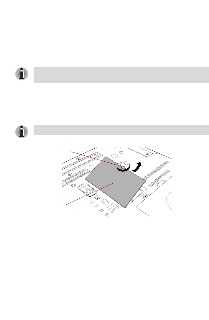
User’s Manual 3-29
Hardware, Utilities and Options
Installing a memory module (Slot B)
To install a memory module, follow the steps as detailed below:
1. Set the computer to Boot Mode and turn its power off - make sure the
Power indicator is off (refer to the Turning off the power section in
Chapter 1, Getting Started if required).
2. Remove the AC adaptor and all cables and peripherals connected to
the computer.
3. Close the display panel.
4. Turn the computer upside down and remove the battery pack (refer to
the Replacing the battery pack section in Chapter 6, Power and Power-
Up Modes, if required).
5. Loosen the screw securing the memory module cover in place - please
note that this screw is attached to the cover in order to prevent it from
being lost.
6. Slide your fingernail or a thin object under the cover and lift it off.
Figure 3-15 Removing the memory module cover
Always make sure the display panel is closed in Laptop mode before
turning the computer upside down.
Use a point size 0 Phillips screwdriver.
Screw
Memory
module cover
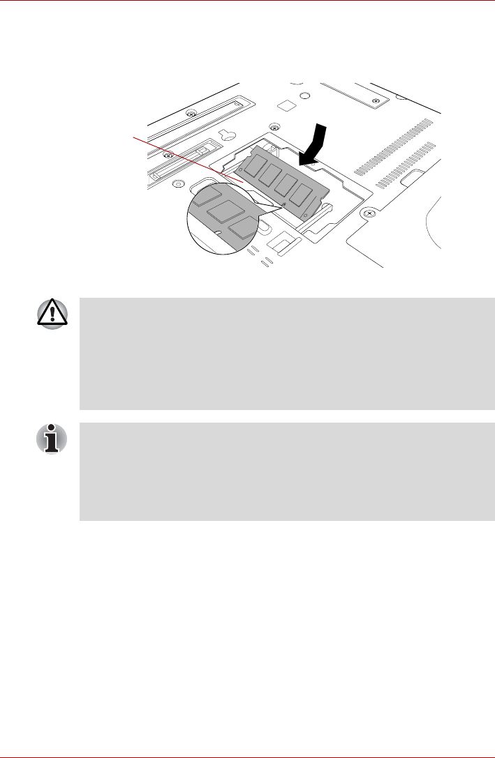
User’s Manual 3-30
Hardware, Utilities and Options
7. Align the notch of the memory module with that of the memory module
slot and gently insert the module into the slot at about a 45 degree
angle before holding it down until the latches on either side snap into
place.
Figure 3-16 Seating the memory module
Slot B
■Never allow metal objects, such as screws, staples and paper clips, to
enter the computer. Foreign metal objects can create a short circuit,
which can cause computer damage and fire, possibly resulting in
serious injury.
■Do not touch the connectors on the memory module or on the
computer. Debris on the connectors may cause memory access
problems.
Align the grooves along the edges of the memory module with the locking
tabs on the connector and insert the memory module into the connector
firmly - if you find it difficult to install the memory module, gently prise the
locking tabs outwards using the tip of your finger.
Please also ensure that you hold the memory module along its left and
right hand edges - the edges with the grooves in.
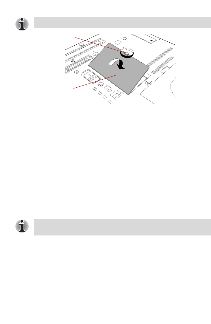
User’s Manual 3-31
Hardware, Utilities and Options
8. Seat the memory module cover in place and secure it with one screw.
Figure 3-17 Seating the memory module cover
9. Install the battery pack - refer to Replacing the battery pack section in
Chapter 6, Power and Power-Up Modes, if required.
10. Turn your computer over.
11. Turn the computer on and make sure the added memory is recognized
- to confirmed it, Start -> Control Panel -> System and Maintenance -
>System icon.
Removing a memory module (Slot B)
To remove the memory module, follow the steps as detailed below:
1. Set the computer to Boot Mode and turn its power off - make sure the
Power indicator is off (refer to the Turning off the power section in
Chapter 1, Getting Started if required).
2. Remove the AC adaptor and all cables and peripherals connected to
the computer.
3. Close the display panel.
4. Turn the computer upside down and remove the battery pack (refer to
Replacing the battery pack section in Chapter 6, Power and Power-Up
Modes, if required).
5. Loosen the screw securing the memory module cover in place - please
note that this screw is attached to the cover in order to prevent it from
being lost.
6. Slide your fingernail or a thin object under the cover and lift it off.
7. Push the latches away from the module in order to release it - a spring
will force one end of the module up at an angle.
Take care to ensure that the memory module cover is firmly closed.
Screw
Memory module
cover
Always make sure the display panel is closed in Laptop mode before
turning the computer upside down.
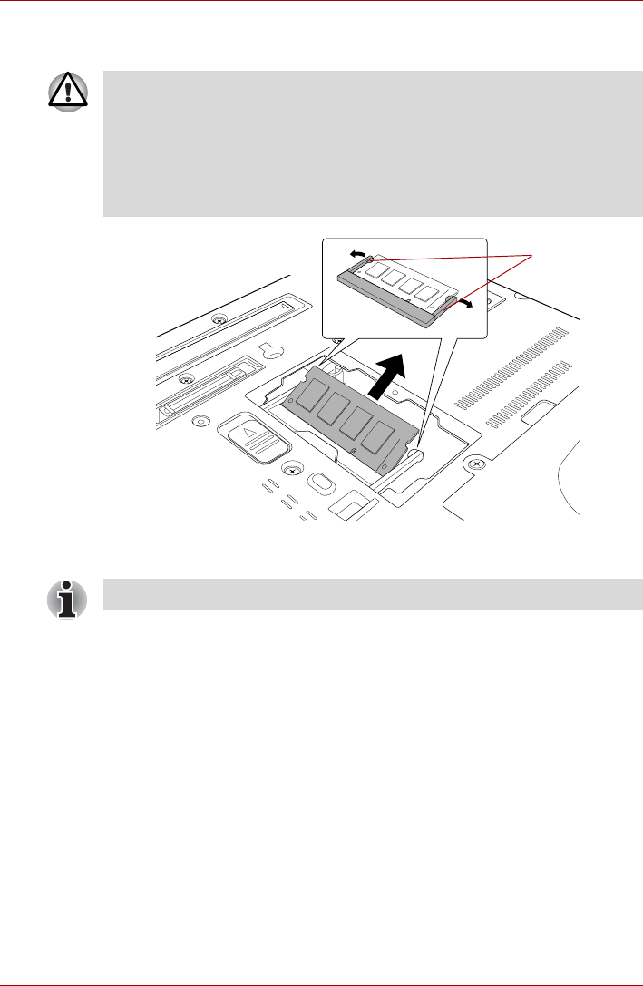
User’s Manual 3-32
Hardware, Utilities and Options
8. Grasp the memory module by its edges and remove it from the
computer.
Figure 3-18 Removing the memory module
9. Seat the memory module cover in place and secure it with one screw.
10. Install the battery pack - refer to Replacing the battery pack section in
Chapter 6, Power and Power-Up Modes, if required.
11. Turn your computer over.
■If you use the computer for a long time, the memory modules and the
circuits locating close to the memory modules will become hot. In this
case, let them cool to room temperature before you replace them. Or
you will get burnt if you touch any of them.
■Do not touch the connectors on the memory module or on the
computer. Debris on the connectors may cause memory access
problems.
Latches
Take care to ensure that the memory module cover is firmly closed.
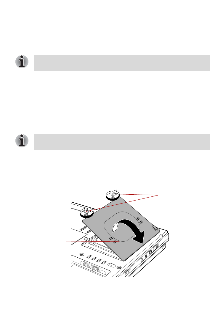
User’s Manual 3-33
Hardware, Utilities and Options
HDD Kit (Serial-ATA)
An extra hard disk drive expands the flexibility of your system and allows
you to carry your data separately without having to carry the computer.
The HDD Kit (Serial-ATA) can either replace the hard disk drive installed
inside the computer or be connected to the Ultra Slim Bay HDD Adaptor.
Some models are equipped with a Ultra Slim Bay HDD Adaptor.
Removing the hard disk drive pack
To remove the hard disk drive pack, follow the steps as detailed below:
1. Set the computer to Boot Mode and turn its power off - make sure the
Power indicator is off (refer to the Turning off the power section in
Chapter 1, Getting Started if required).
2. Remove the AC adaptor and all cables and peripherals connected to
the computer.
3. Close the display panel.
4. Turn the computer upside down and remove the battery pack (refer to
Replacing the battery pack section in Chapter 6, Power and Power-Up
Modes, if required).
5. Loosen two screws securing the hard disk drive cover in place.
6. Lift the cover up and out, and remove it from the computer.
Figure 3-19 Removing the hard disk drive cover
7. Pull the hard disk drive pack up to a vertical position by holding the
plastic tab.
Use a point size 0 Phillips screwdriver to remove and fasten the screws -
the use of an incorrect screwdriver can damage the screw heads.
Always make sure the display panel is closed in Laptop mode before
turning the computer upside down.
Screws
Hard disk drive
cover
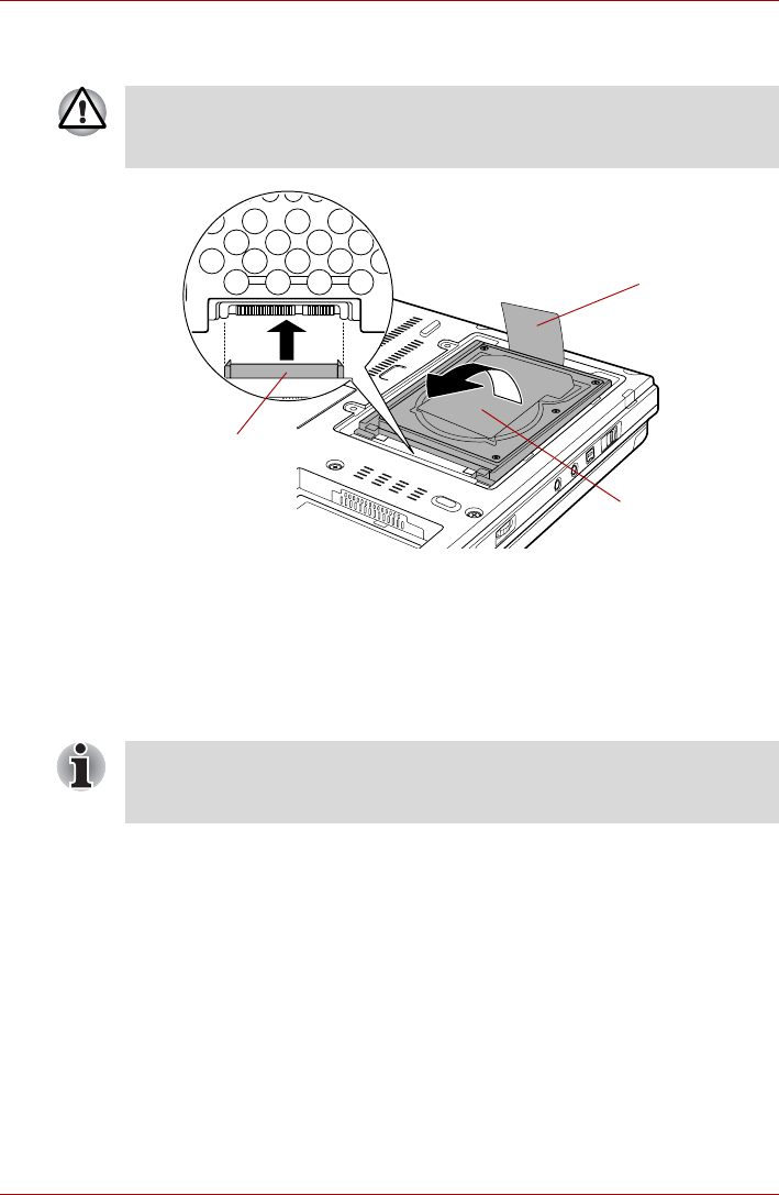
User’s Manual 3-34
Hardware, Utilities and Options
8. With the hard disk drive in a vertical position, lift it straight up and away
from the connector.
Figure 3-20 Removing the hard disk drive pack
Installing the hard disk drive pack
To install the hard disk drive pack, follow the steps as detailed below:
1. Move the connector until it is vertical.
2. Hold the hard disk drive vertically with its label on the left.
3. Connect the hard disk drive to the connector.
Never allow metal objects, such as screws, staples and paper clips, to
enter the computer. Foreign metal objects can create a short circuit, which
can cause computer damage and fire, possibly resulting in serious injury.
Plastic tab
Hard disk drive
pack
Connector
Ensure that the hard disk drive is connected to the connector in a vertical
position. If the hard disk drive is slanted and connected to the connector, it
might damage the connector.
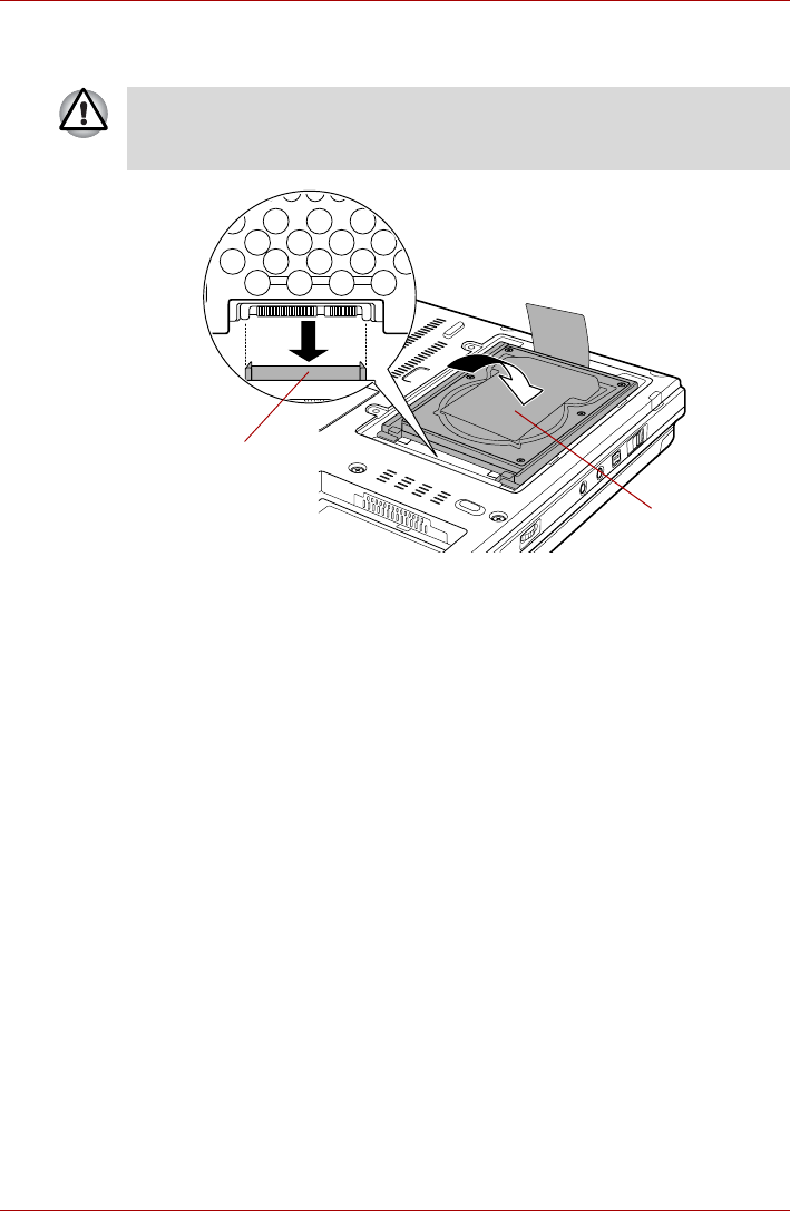
User’s Manual 3-35
Hardware, Utilities and Options
4. With the connector connected, lower the hard disk drive down to the
storage position.
Figure 3-21 Installing the hard disk drive pack
5. Seat the cover and press down until the latches click into place.
6. Secure the cover with two screws.
7. Turn your computer over.
Never allow metal objects, such as screws, staples and paper clips, to
enter the computer. Foreign metal objects can create a short circuit, which
can cause computer damage and fire, possibly resulting in serious injury.
Hard disk drive
pack
Connector
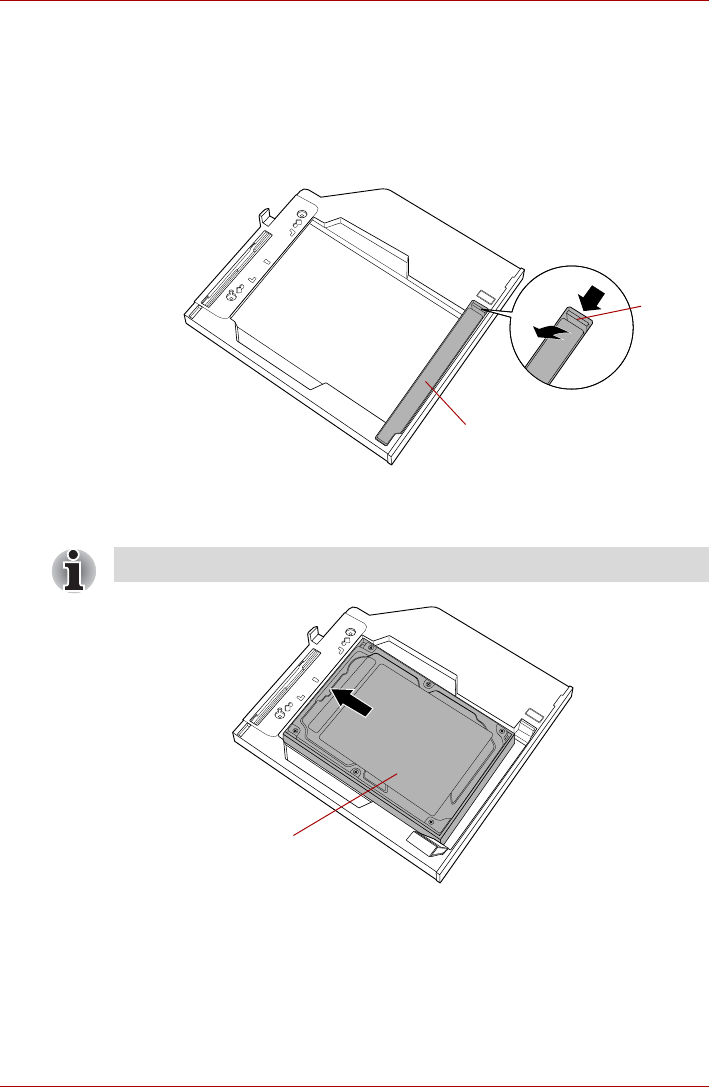
User’s Manual 3-36
Hardware, Utilities and Options
Ultra Slim Bay HDD Adaptor
You can increase your computer’s data storage capacity by installing an
additional 80GB hard disk drive in the Ultra Slim Bay.
To install a hard disk drive in the Ultra Slim Bay HDD Adaptor follow the
steps below.
1. Slide the lock to the unlock position and open the lid.
Figure 3-22 Opening the lid
2. Insert the hard disk drive in the Ultra Slim Bay HDD Adaptor and push
forward to ensure a firm connection.
Figure 3-23 Inserting the hard disk drive
Lid
Lock
Tuck the Plastic tab underneath the hard disk drive.
Hard disk drive
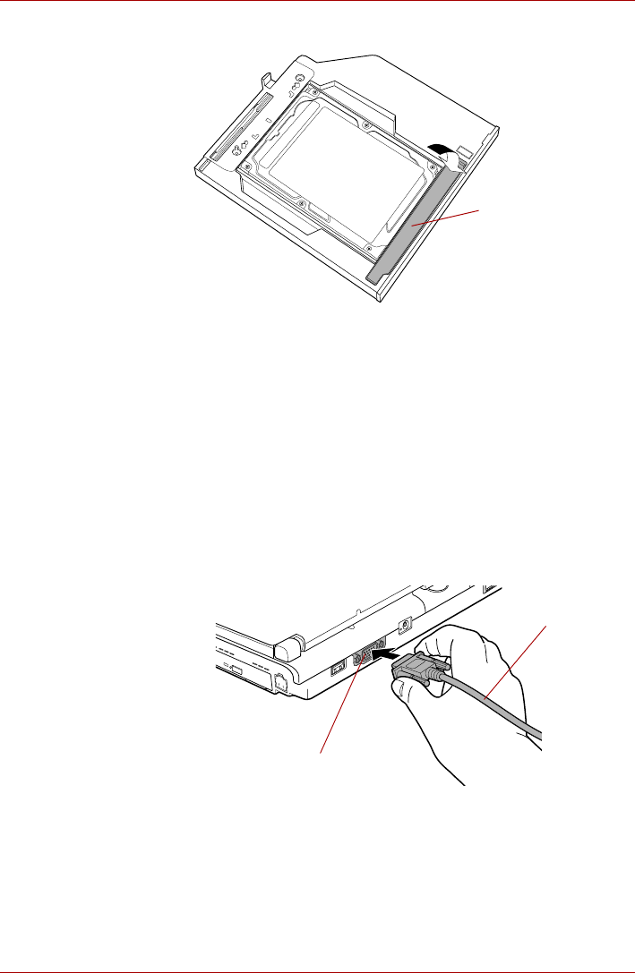
User’s Manual 3-37
Hardware, Utilities and Options
3. Close the lid and slide the lock to the lock position.
Figure 3-24 Closing the lid
For details on inserting the Ultra Slim Bay HDD Adaptor in the computer’s
Ultra Slim Bay slot, refer to Chapter 4, Operating Basics.
External monitor
An external analog monitor can be connected to the external monitor port
on the computer.
Connecting the monitor cable
To connect a monitor, follow the steps as detailed below:
1. Turn the computer's power off.
2. Connect the monitor cable to the external monitor port and tighten the
screws on the left and right hand side of the connector as required.
Figure 3-25 Connecting the monitor cable to the external monitor port
3. Turn the external monitor's power on.
Lid
External monitor port
Monitor cable
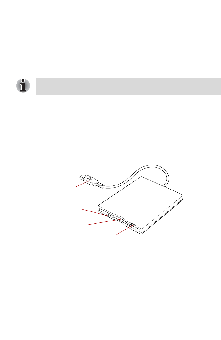
User’s Manual 3-38
Hardware, Utilities and Options
4. Turn the computer's power on.
When you turn on the power, the computer will automatically recognize the
monitor and determine whether it is a color or monochrome device. In the
event that you find that there are issues getting an image displayed on the
correct monitor, you should consider using the FN + F5 hot key to change
the display settings (if you then disconnect the external monitor before you
turn the computer's power off, be sure to press FN + F5 hot key again to
switch to the internal display).
Please refer to Chapter 5, The Keyboard, for further details on using hot
keys to change the display setting.
USB
The computer is equipped with the Universal Serial Bus ports that can
accommodate some kinds of devices.
These ports comply with the USB 2.0 standard.
USB FDD Kit
The USB floppy diskette drive accommodates either a 1.44MB or 720KB
floppy diskette and connects to one of the computer's USB ports.
Figure 3-26 The USB floppy diskette drive
Do not disconnect the external monitor while in Sleep or Hibernation Mode.
Turn off the computer before disconnecting the external monitor.
Eject button
Floppy
diskette slot
Disk-In-Use
Indicator
USB connector
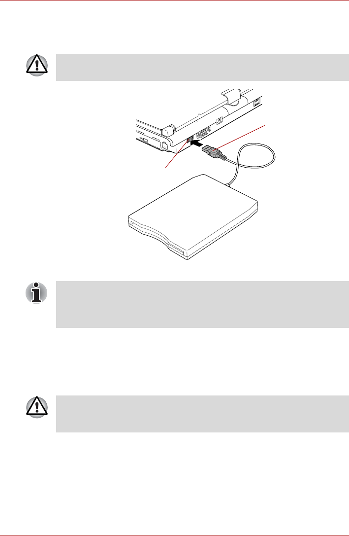
User’s Manual 3-39
Hardware, Utilities and Options
Connecting the USB floppy diskette drive
To connect the drive, plug the floppy diskette drive’s USB connector into a
computer’s USB port.
Figure 3-27 Connecting the USB floppy diskette drive
Disconnecting the USB floppy diskette drive
When you have finished using the USB floppy diskette drive, you can follow
the procedures below in order to disconnect it:
1. Wait for the Disk-In-Use Indicator light to go out to make sure all floppy
diskette activity has stopped.
2. Click the Safely Remove Hardware icon on the Windows Taskbar.
3. Click the USB floppy diskette drive device that you want to remove.
4. Carefully pull the floppy diskette drive's USB connector out from within
the computer's USB port.
Make sure the connector is properly aligned with the socket. Do not try to
force the connection, doing so can damage the connecting pins.
USB connector
USB port
If you connect the USB floppy diskette drive after the computer has already
been turned on, it will take about ten seconds for it to be recognized by the
computer. Do not attempt to disconnect and reconnect the drive before this
period has elapsed.
If you disconnect the USB floppy diskette drive or turn off the power while
the computer is accessing the drive you may lose data or damage the
floppy diskette or the drive.

User’s Manual 3-40
Hardware, Utilities and Options
USB Sleep and Charge function
Your computer can supply USB bus power (DC5V) to the USB port even
when the power of the computer is turned OFF. "Power OFF" includes
Sleep Mode, Hibernation Mode or shutdown state.
This function can only be used for ports that support the USB Sleep and
Charge function (hereinafter called "compatible ports").
Compatible ports are USB ports that have the ( ) symbol icon.
You can use the "USB Sleep and Charge function" to charge certain USB-
compatible external devices such as mobile phones or portable digital
music players.
However, the "USB Sleep and Charge function" may not work with certain
external devices even if they are compliant with the USB specification. In
those cases, turn the power of the computer ON to charge the device.
■The "USB Sleep and Charge function" only works for compatible ports.
This function is disabled in the default setting. To enable it, you must
change [Disabled] to [Enabled] in the BIOS Setup.
Refer to the USB Sleep and Charge function section in Chapter 7, HW
Setup & BIOS Setup.
■When "USB Sleep and Charge function" is set to [Enabled] in BIOS
Setup, USB bus power (DC5V) will be supplied to compatible ports
even when the power of the computer is turned OFF.
USB bus power (DC5V) is similarly supplied to the external devices
which are connected to the compatible ports. However, some external
devices cannot be charged solely by supplying USB bus power
(DC5V).
As for the specifications of the external devices, please contact the
device manufacturer or check the specifications of the external devices
thoroughly before use.
■Using the USB sleep and charge function to charge external devices
will take longer than charging the devices with their own chargers.
■If external devices are connected to compatible ports when the AC
adaptor is not connected to the computer, the battery of the computer
will be depleted even when the power of the computer is turned OFF.
As such, we recommend that you connect the AC adaptor to the
computer when using the USB sleep and charge function.
■External devices connected to the USB bus power (DC5V) function that
interfaces with the power ON/OFF of the computer may always be in
an operational state.
■When there is a current overflow of the external devices connected to
the compatible ports, USB bus power (DC5V) supply may be stopped
for safety reasons.
Metal paper clips or hair pins/clips will generate heat if they come into
contact with USB ports. Do not allow USB ports to come into contact with
metal products, for example when carrying the computer in your bag.

User’s Manual 3-41
Hardware, Utilities and Options
USB WakeUp function
This function restores the computer from Sleep Mode depending on the
external devices connected to the USB ports.
The "USB WakeUp function" operates under Windows Vista® OS and it
works for all USB ports.
i.LINK (IEEE1394)
i.LINK (IEEE1394) is used for high-speed data transfer for a range of
compatible devices such as:
■Digital video cameras
■Hard disk drives
■MO drives
■Writable optical disc drives
Precautions
■Make a back-up of your data before transferring it to the computer.
There is a possibility that the original data will be damaged. There is a
particular risk that some frames will be deleted in the case of digital
video transfer. TOSHIBA assumes no liability for such loss of data.
■Do not transfer data in areas where static electricity is easily generated
or in areas subjected to electronic noise. Data can be destroyed.
■If you are transferring data through an IEEE1394 hub, do not connect or
disconnect other devices from the hub during data transfer. There is a
likelihood that data will be damaged. Connect all devices to the hub
before you turn on the computer’s power.
■You may not use any copyrighted video or music data copied from a
video camera except for your personal enjoyment.
■"USB WakeUp function" will supply USB bus power (DC5V) to all USB
ports ,including compatible ports, even when the computer is in Sleep
Mode.
USB bus power (DC5V) will not be supplied if the computer is in
Hibernation Mode or shutdown state.
■When "USB Sleep and Charge function" is set to [Enabled] in BIOS
Setup, the "USB WakeUp function" does not work for compatible ports.
The WakeUp setting (function to allow the WakeUp) check box will be
displayed on the Device Manager. You can change the settings but the
USB WakeUp function will not work. For example, if a mouse or USB
keyboard is connected to a compatible port, moving the
mouse/keyboard will not "wakeup" the computer.
In that case, attach the mouse or keyboard to an USB port that does
not have the USB Sleep and Charge function-compatible icon ( ).
i.LINK uses a four-pin connector, which does not carry any electric current.
External devices will need their own power supply to operate.
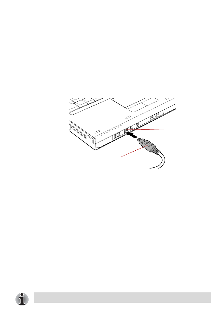
User’s Manual 3-42
Hardware, Utilities and Options
■If you connect/disconnect an i.LINK device to/from another i.LINK
device that is currently exchanging data with the computer, data frames
might be dropped.
■Make sure data transfer has ended or turn off the computer, before you:
■Connect/disconnect an i.LINK device to/from the computer.
■Connect/disconnect an i.LINK device to/from another i.LINK device
that is connected to the computer.
Connecting the i.LINK (IEEE1394) cable
To connect the i.LINK (IEEE1394) cable, follow the steps as detailed
below:
1. Make sure the connectors are properly aligned and plug the i.LINK
(IEEE1394) cable into the computer.
Figure 3-28 Connecting the i.LINK (IEEE1394) cable into the computer
2. Plug the other end of the cable into the device.
Note the following when you use i.LINK:
■You may need to install drivers for your i.LINK devices.
■Not all i.LINK devices have been tested. Therefore, compatibility with all
i.LINK devices cannot be guaranteed.
■Some devices might not support sleep or automatic off functions.
■Do not connect or disconnect an i.LINK device while it is using an
application or when the computer is automatically shutting it down to
save power. Data might be destroyed.
Disconnecting the i.LINK (IEEE1394) cable
To disconnect the i.LINK (IEEE1394) cable, follow the steps as detailed
below:
1. Open the Safely Remove Hardware icon on the Windows Taskbar.
2. Point to i.LINK (IEEE1394) device and click.
3. Disconnect the cable from the computer then from the i.LINK device.
i.LINK (IEEE1394)
connector
i.LINK (IEEE1394)
port
Refer also to the documentation that came with your i.LINK device.

User’s Manual 3-43
Hardware, Utilities and Options
TOSHIBA Express Port Replicator
In addition to the ports available on the computer, the TOSHIBA Express
Port Replicator. The TOSHIBA Express Port Replicator connects directly to
the docking interface on the underside of the computer. The AC adaptor
connects the TOSHIBA Express Port Replicator to a power source.
The following ports are available on the TOSHIBA Express Port Replicator.
■RJ45 LAN jack
■External monitor port
■DC IN 15V jack
■Security lock slot
■Universal Serial Bus 2.0 port (four)
■DVI port
The computer must be configured properly before connecting to a LAN.
Logging onto a LAN using the computer’s default settings could cause a
malfunction in LAN operation. Check with your LAN administrator
regarding set-up procedures.
■You must connect the AC adaptor before you connect to a TOSHIBA
Express Port Replicator.
■When a TOSHIBA Express Port Replicator is connected to the
computer, you can not use the following computer's ports: LAN jack,
DC IN 15V jack and External monitor port.
■When connecting an AC Adaptor to the TOSHIBA Express Port
Replicator, use only the AC Adaptor included with TOSHIBA Express
Port Replicator. Do not use the computer’s AC Adaptor.
■As the port operation of all DVI (Digital Visual Interface) monitors has
not been confirmed, some DVI monitors may not function properly.
■Set the TOSHIBA Express Port Replicator's Slide Adjuster to SLIDE
position #4 when connecting this computer to the TOSHIBA Express
Port Replicator. Refer to the TOSHIBA Express Port Replicator User's
Manual for more details on connection methods.
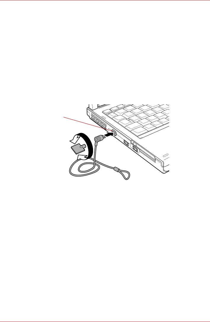
User’s Manual 3-44
Hardware, Utilities and Options
Security lock
A security locks enable you to anchor your computer a desk or other heavy
object in order to help prevent unauthorized removal or theft. The computer
has a security lock slot on its left side into which you can attach one end of
the security cable, while the other end attaches to a desk or similar object.
The methods used for attaching security cables differ from product to
product. Please refer to the instructions for the product you are using for
more information.
Connecting the security lock
In order to connect a security cable to the computer, follow the steps as
detailed below:
1. Turn the computer so its left hand side faces you.
2. Align the security cable with the 'lock hole' and secure it in place.
Figure 3-29 Security lock
Security lock slot

User’s Manual 3-45
Hardware, Utilities and Options
Optional accessories
You are able to add a number of options and accessories in order to make
your computer even more powerful and convenient to use. For reference,
the following list details some of the items that are available from your
reseller or TOSHIBA dealer:
DDR2-400/533
Memory Module A 512MB or 1,024MB memory module (DDR2-
533) can easily be installed in the computer.
DDR2-667 Memory
Module A 512MB, 1,024 or 2,048MB memory module
(DDR2-667) can easily be installed in the
computer.
Universal AC
Adaptor If you frequently use your computer at more than
one site, it may be convenient to purchase an
additional AC adaptor to be kept at each site in
order to remove the need to always carry the
adaptor with you.
Battery Pack An additional battery pack can be purchased for
use as either a spare or replacement. Please
refer to Chapter 6, Power and Power-Up Modes
for further information.
Slice Expansion
Battery This battery pack increases your computer's
operating time when a main battery pack is also
installed. It is connectable to the Docking port of
the computer.
Slice Expansion
Battery adaptor The Slice Expansion Battery adaptor is used to
connect with the Battery Charger in order to
charge a Slice Expansion Battery.
Battery Charger The optional battery charger allows you to
charge extra battery packs outside of having to
use the computer.
USB FDD Kit The USB floppy diskette drive accommodates
either a 1.44MB or 720KB floppy diskette through
connection to one of the computer's USB ports.
In use, please be aware that, while you cannot
format 720KB floppy diskettes under Windows
Vista®, you are able to read and write to diskettes
that have already been formatted.
HDD Kit (Serial-ATA) You can increase your computer's data storage
capacity with additional hard disk drive. It is
available in the following size:
■80GB

User’s Manual 3-46
Hardware, Utilities and Options
Ultra Slim Bay options
The following module can be installed in the Ultra Slim Bay. All other
module is option.
TOSHIBA Express
Port Replicator The TOSHIBA Express Port Replicator provides
the ports available on the computer in addition to
a digital visual interface (DVI) port, External
monitor port, Universal Serial Bus port (USB2.0)
x 4, LAN jack.
Tablet PC Pen Tablet PC Pens can be purchased from your
TOSHIBA dealer for use as spare items (spare
pen tips and a tip draw-out tool are included).
Reserve Pen Reserve Pen can be purchased from your
TOSHIBA dealer. Use the Reserve Pen in place
of the Tablet PC Pen if the Tablet PC Pen is lost
or broken.
Ultra Slim Bay HDD
Adaptor An adaptor lets you install an optional hard disk
drive described in Ultra Slim Bay HDD Adaptor.
Ultra Slim Bay DVD
Super Multi (Double
Layer) Drive Kit
Refer to the Hardware section for details.

User’s Manual 4-1
Chapter 4
Operating Basics
This chapter describes the basic operations of your computer, highlights
the precautions that should be taken when using it.
Pointing Devices
The pointing devices of this computer vary from model to model.
■Digitizer screen model: The Touch Pad and the Tablet PC Pen which
comes with the computer can be used as a pointing device.
■Digitizer and touch screen model: The Touch Pad and Tablet PC Pen
which comes with the computer or a finger can be used as pointing
devices.
■Display screen model: The Touch Pad can be used as a pointing
device.
■Digitizer and touch screen model: The Touch pointer is provided as a
supplementary tool for operations which are difficult to carry out only
using your finger.
■Display screen model: Operations on the display screen can not be
done either by using Tablet PC Pen or your finger. Please refrain from
touching the display screen to avoid damaging it.
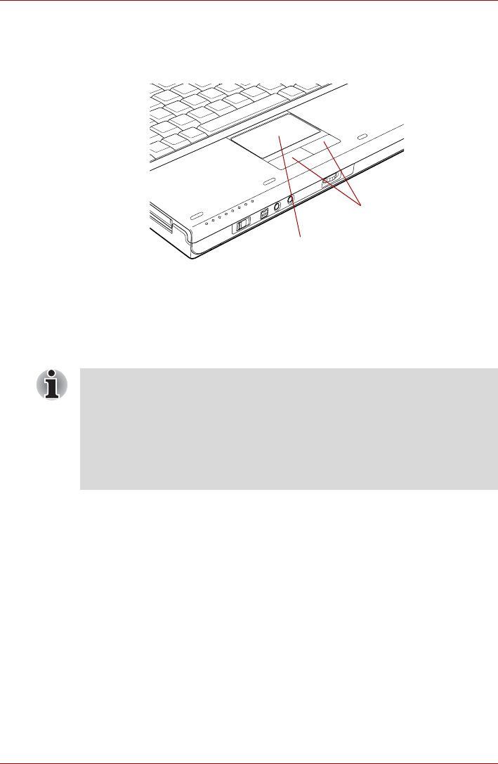
User’s Manual 4-2
Operating Basics
Using the Touch Pad
To use the Touch Pad, simply touch and move your fingertip across it in the
direction you want the on-screen pointer to go.
Figure 4-1 Touch Pad and Touch Pad control buttons
The two buttons below the Touch Pad are used like the buttons on a
standard mouse - press the left button to select a menu item or to
manipulate text or graphics designated by the pointer, and press the right
button to display a menu or other function depending on the software you
are using.
Touch Pad
Touch Pad
control buttons
You can also tap the Touch Pad to perform functions similar to those of the
left button on a standard mouse.
Click: Tap once
Double-click: Tap twice
Drag and drop: Tap to select the item(s) you want to move, leave your
finger on the Touch Pad after the second tap and then move the
item(s) to their new destination.

User’s Manual 4-3
Operating Basics
Using the Tablet PC Pen and Reserve Pen
You can use the Tablet PC Pen to execute actions and enter data. Hold the
Tablet PC Pen in a natural position and tap, press or trace on the screen
lightly.
Some computers in the series are equipped with a Tablet PC Pen and a
Reserve Pen.
Figure 4-2 The Tablet PC Pen (the left) and Reserve Pen (the right)
Eraser button You can use this button as an eraser when using
a graphics software application. Text based
software application enable you to select and
delete characters with a one-touch action.
Pen button Provides the same function as clicking the right
Touch Pad control button.
Pen point Provides the same function as clicking the left
Touch Pad control button.
Eraser button
Pen button
Pen point
Pen button
Pen point

User’s Manual 4-4
Operating Basics
Observe the following precautions on the handling of the Tablet PC Pen.
■In order to avoid damages to the display screen, please refrain from
doing anything other than the specified operation methods. Failure to
do so could cause a malfunction or characteristic deterioration.
■Do not tap or press the Tablet PC Pen forcefully against the display as
this could damage the Tablet PC Pen and the screen itself.
■Avoid using or keeping the Tablet PC Pen in areas where the
temperature can change rapidly or in places, such as a car, where the
Tablet PC Pen is exposed to direct sunlight. Store the Tablet PC Pen
without any pressure being applied to the buttons. Failure to do so
could cause a malfunction or characteristic deterioration.
■The Tablet PC Pen is composed of precision parts. Do not drop the
Tablet PC Pen. Strong impact causes a malfunction or characteristic
deterioration.
■Do not apply excessive force to the Tablet PC Pen point and the side
buttons. Excessive force applied to these parts causes short life or
characteristic deterioration (Allowable force to pen point, Eraser button,
Pen button: less than 1 kg, for less than 30 seconds).
■Avoid water entering the Tablet PC Pen or condensation forming within
it as either condition will cause a malfunction.
■Do not disassemble the Tablet PC Pen. It causes maladjustment or
short life.
■Do not stain the Tablet PC Pen with cosmetics or chemicals as this will
cause a deterioration in appearance. Use a glass wiping cloth or dry
cloth to clean the Tablet PC Pen. Do not use volatile liquids such as
alcohol, thinner or petroleum benzine to clean the Tablet PC Pen.
■Do not apply excessive force to the Tablet PC Pen point as a bent or
deformed pen point will cause a malfunction.
■Keep the small parts of the Tablet PC Pen, such as the pen point or the
knob of the side buttons, away from infants and small children to
prevent the accidental ingestion by them.
■Do not use a ball point pen instead of the Tablet PC Pen included with
the product.
■Do not use a broken pen tip.
■The pen tip cannot be replaced if it is worn (Reserve Pen only).
■You can change the Tablet PC Pen setting and the Touch pointer
setting, using the Pen and Input Device.
■TOSHIBA is not liable for any problems arising on the products due to
the use of the Tablet PC Pen in an environment where the above
conditions are not satisfied or because of its use by unspecified
number of users.
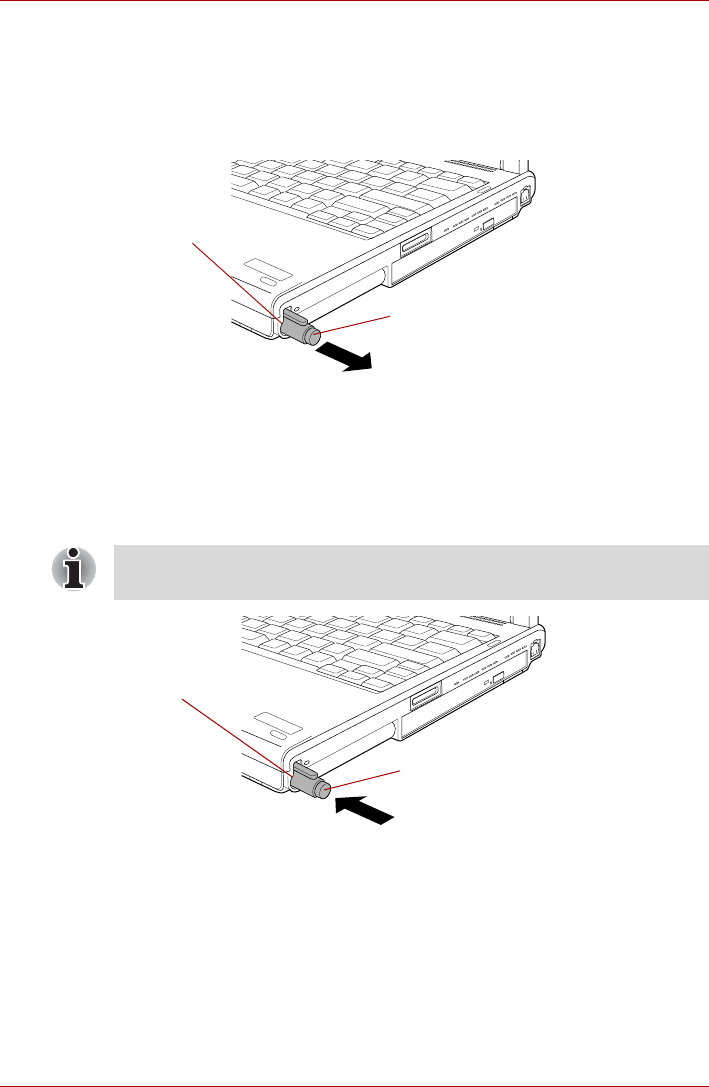
User’s Manual 4-5
Operating Basics
Removing the Tablet PC Pen
To remove the Tablet PC Pen, follow the steps as described below:
1. Slide the Tablet PC Pen from the Tablet PC Pen slot, so that it
protrudes slightly.
2. Pull the Tablet PC Pen to remove it from the Tablet PC Pen slot.
Figure 4-3 Removing the Tablet PC Pen
Inserting the Tablet PC Pen
The Tablet PC Pen is included in the small case coming with the product.
Remove the Tablet PC Pen from small case and install it to the computer
as follows:
1. Insert the Tablet PC Pen into the Tablet PC Pen slot until it clicks.
Figure 4-4 Inserting the Tablet PC Pen
Pen actions
You can use the Tablet PC Pen to enter data, start programs, move objects
and execute other actions.
Single tap
Lightly tap the tip of the Tablet PC Pen on an object and lift it immediately
to execute an action. A single tap is similar to clicking the left touch pad
control button.
Tablet PC Pen
Tablet PC Pen slot
The Tablet PC Pen and the Reserve Pen are different in shape. Do not
insert the Reserve Pen into the Tablet PC Pen slot.
Tablet PC Pen slot
Table t PC Pen
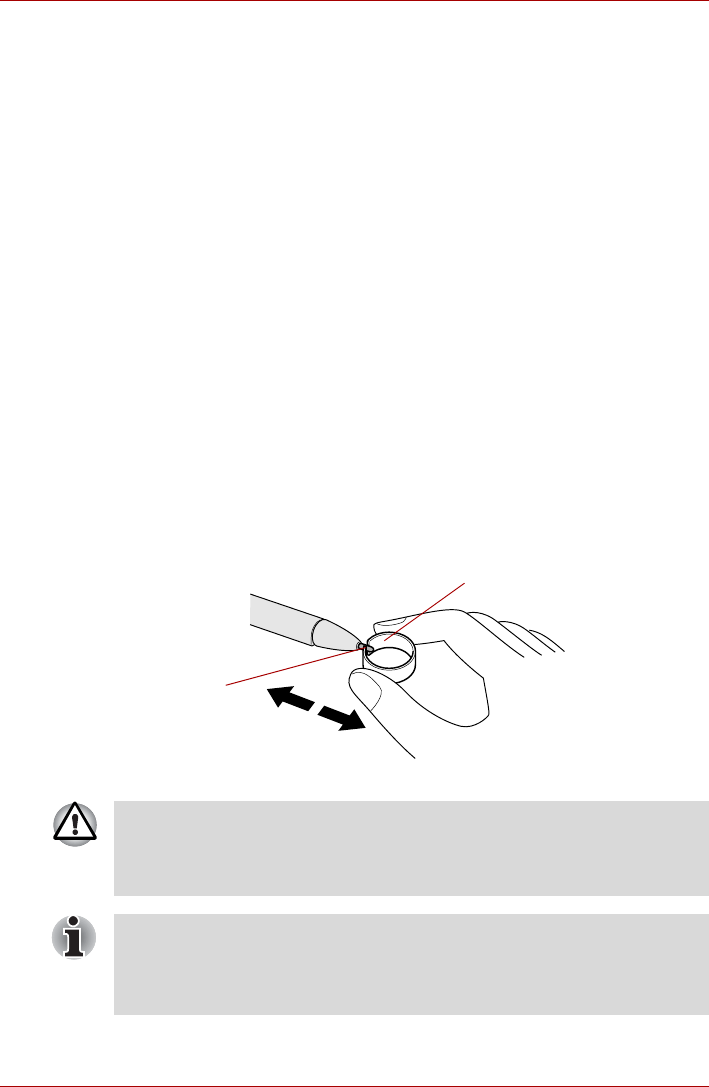
User’s Manual 4-6
Operating Basics
Double tap
Lightly tap the tip of the Tablet PC Pen twice on an object and lift it
immediately to execute an action. A double-tap is similar to double-clicking
the left touch pad control button.
Press and hold
Touch the tip of the Tablet PC Pen to the display screen and hold it there to
display a pop-up menu or other action. Press and hold is similar to clicking
the right touch pad control button.
Drag
Touch the Tablet PC Pen to the screen. Without lifting the Tablet PC Pen,
drag it across the screen to select text or objects.
Drag and drop
Touch the Tablet PC Pen to the screen to select an object. Without lifting
the Tablet PC Pen, drag it across the screen. Lift the Tablet PC Pen to drop
the object to a new location.
Replacing the pen tip
To replace the pen tip, follow the steps as described below:
1. Pinch the tip with a draw-out tool and pull it out.
2. Insert a new pen tip into the Tablet PC Pen carefully, and press it
securely.
Figure 4-5 Replacing the pen tip
Draw-out tool
Pen tip
Do not continue to use a broken pen tip as this may result in scratching of
the display panel. When the pen tip breaks replace it with one of the refills
delivered with the Tablet PC Pen. When these refills have run out, you can
purchase a new pen set from a TOSHIBA authorized dealer.
■A short and worn pen point is difficult to pull out. Replace the pen point
with a refill before it becomes too short to remove.
■It is recommended that you keep another pen set as a spare. You can
buy replacement pen sets from your TOSHIBA authorized dealer.
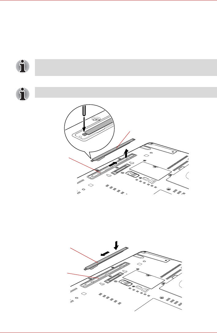
User’s Manual 4-7
Operating Basics
Removing the Reserve Pen case
To remove the Reserve Pen case, follow the steps as detailed below:
1. Save your work.
2. Turn the computer’s power off - ensure that the Power indicator is off.
3. Remove all cables and peripherals that are connected to the computer.
4. Close the display panel and turn the computer upside down.
5. Slide and then lift out the Reserve Pen case.
Figure 4-6 Removing the Reserve Pen case
Inserting the Reserve Pen case
To insert the Reserve Pen case, follow the steps as detailed below:
1. Insert the Reserve Pen case into the Reserve Pen case slot on the
computer and slide it until it locks.
Figure 4-7 Inserting the Reserve Pen case
Always make sure the display panel is closed in Laptop mode before
turning the computer upside down.
Push lightly the point shown by the arrow using an object with a thin tip.
Reserve Pen case
Reserve Pen
case slot
Reserve Pen case
Reserve Pen
case slot
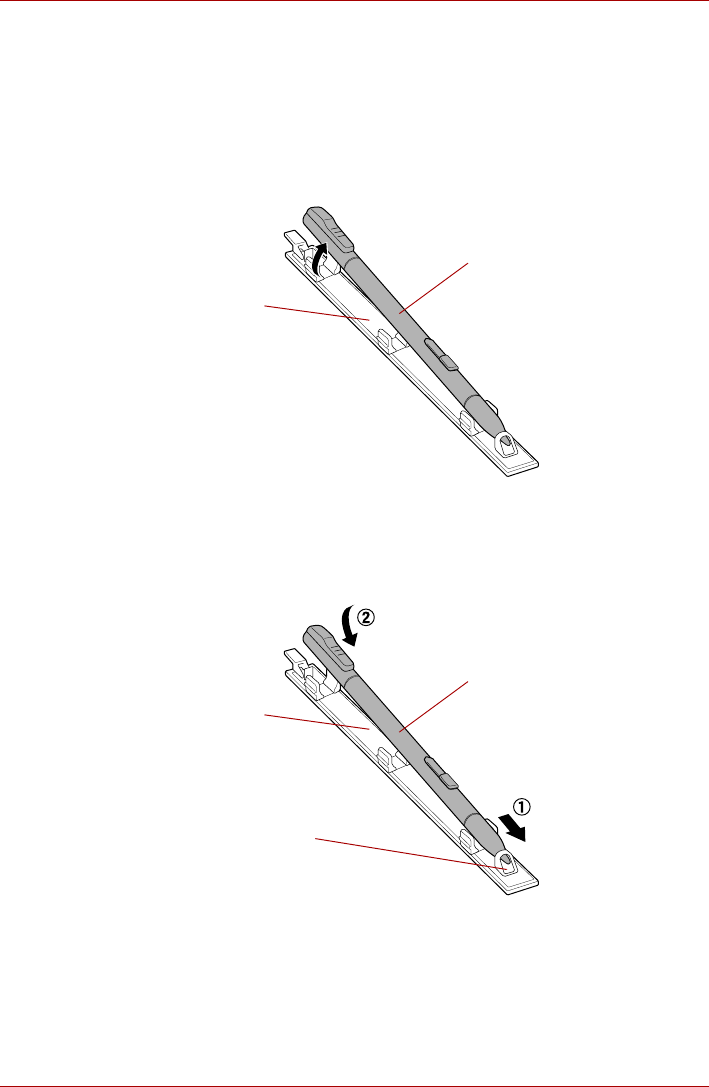
User’s Manual 4-8
Operating Basics
Storing and Removing the Reserve Pen from the Reserve
Pen case
Follow the procedures below to remove the Reserve Pen from the Reserve
Pen case.
Removing the Reserve Pen from the Reserve Pen case
1. Lift the Reserve Pen up from the Reserve Pen case by its end.
Figure 4-8 Removing the Reserve Pen from the Reserve Pen case
Storing the Reserve Pen in the Reserve Pen case
1. Insert the tip of the Reserve Pen into the Reserve Pen case holder and
press down.
Figure 4-9 Storing the Reserve Pen in the Reserve Pen case
Reserve Pen case
Reserve Pen
Reserve Pen case
Reserve Pen
Reserve Pen case
holder
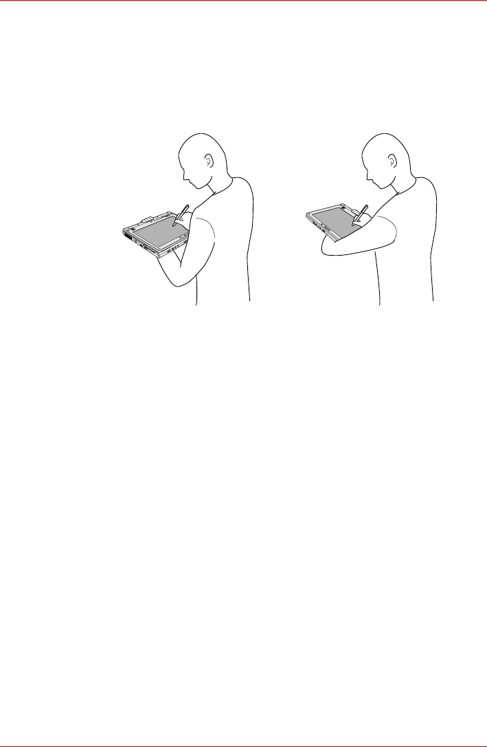
User’s Manual 4-9
Operating Basics
Using the Tablet mode
This section explains Tablet mode functions and use.
Operating the computer in Tablet mode
When operating the computer in Tablet mode, follow the instructions below.
Figure 4-10 Operating the computer in Tablet mode (using a Tablet PC Pen)
■Hold the computer firmly on your forearm. Do not block the vent.
■Remove the AC adaptor from the computer when using it in Tablet
mode held in your forearm.
■Do not use the computer while walking or driving a car.
■Change to Laptop mode and turn off the computer before carrying it. Do
not carry the computer with power on or in Sleep Mode. Do not carry
the computer while the Hard Disk Drive indicator is glowing.
■Do not expose the computer to rapid temperature changes (such as
would be the case if you brought the computer from a cold environment
into a warm room). When rapid temperature changes are unavoidable,
leave the computer for around two hours before turning it on to prevent
the formation of condensation.
■Remove all external peripheral devices and their connection cables
from the computer before carrying.
■Do not drop the computer or apply excessive impact to it. Do not leave
the computer in a car or similar environment where it is exposed to
direct sunlight.
■Do not put the computer in a bag when it is in Tablet mode.

User’s Manual 4-10
Operating Basics
■The function of the display screen varies from model to model.
■Digitizer screen model: Please use the Tablet PC Pen to operate,
which comes with the computer.
Please carefully observe the following items in order to avoid
damaging the display screen. Incorrect use could cause the screen
to be scratched.
■Do not press on the screen with anything other than the
included touch pen (especially with anything pointed)
■Prevent long fingernails and rings or other metal from touching
the screen
■Do not apply excessive pressure to the screen
■Digitizer and touch screen model: Please operate either using the
Tablet PC Pen which comes with the computer or your finger.
Please carefully observe the following items in order to avoid
damaging the display screen. Incorrect use could cause the screen
to be scratched.
■Do not press on the screen with anything other than the
included touch pen (especially with anything pointed)
■Prevent long fingernails and rings or other metal from touching
the screen
■Do not apply excessive pressure to the screen
■If you operate simultaneously by finger and Tablet PC Pen, then
the operation of Tablet PC Pen gets executed. Operations done
by the finger are not available.
■Only touch one location at a time when operating using your
finger. If you touch multiple locations simultaneously, the input
will not be correctly interpreted.
■Display screen model: Operations on the display screen can not be
done either by using Tablet PC Pen or your finger. Please refrain
from touching the display screen to avoid damaging it.
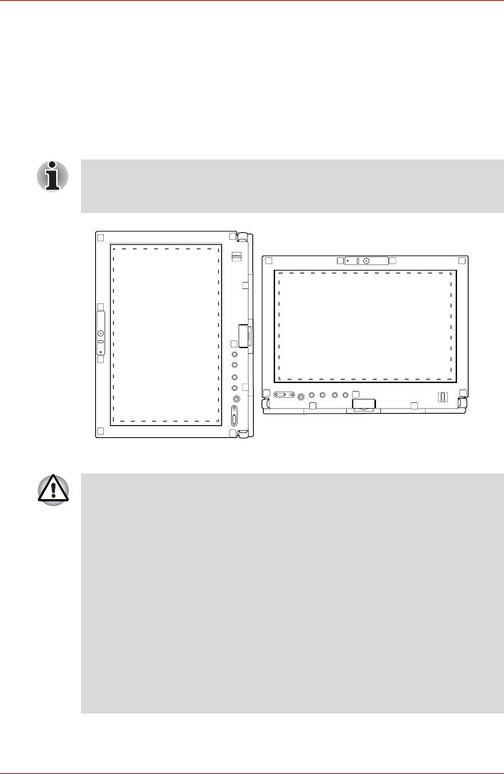
User’s Manual 4-11
Operating Basics
■The display panel works as a touch sensitive digitizer screen. However,
the outer edges of the screen may be less sensitive. Please keep the
Tablet PC Pen or your finger inside the display area when you use it
near the edges of the display panel. The position of the pen may not be
recognized if you move the Tablet PC Pen or your finger too fast
towards the outer edge. Please be sure to slide the Tablet PC Pen or
your finger slowly in areas near the edges of the screen.
Use the Tablet PC Pen or your finger in the areas enclosed by the
dotted line as shown in the following figure.
Figure 4-11 Use area of a Tablet PC Pen
Display screen model: Operations on the display screen can not be done
either by using Tablet PC Pen or your finger. Please refrain from touching
the display screen to avoid damaging it.
■When performing operations on the display screen using the Table PC
Pen or a finger, the on-screen cursor position may deviate from the
actual pen (or finger) position in the following situations:
■If the screen resolution is lower than 1280 x 800 (For example 800
x 600)
■When the Aspect Ratio Options in the Intel® GMA Driver for Mobile
(Intel® Graphics Media Accelerator Driver for mobile) Display
Settings are set to Maintain Aspect Ratio or Center Desktop
Adjust one of the following settings to correct cursor position deviation.
■Set the resolution to 1280 x 800
■Set the Aspect Ratio Options to Full Screen (No Border)
■Do not block the vent of the computer when holding it. If you continue
to expose your skin to the hot air expelled from the vent for a long time,
your skin might suffer low temperature injury.
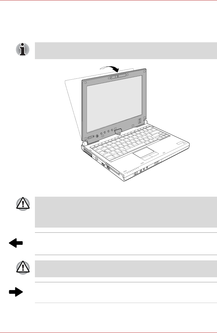
User’s Manual 4-12
Operating Basics
Changing to the Tablet mode
To change from Laptop mode to the Tablet mode, follow the instructions
below.
1. Open the display panel to the upright position.
Figure 4-12 Changing to the Tablet mode (1)
When rotating the display panel, be sure to keep the display panel at a
90-degree angle to the keyboard.
■Place the computer on a stable, flat surface such as a desktop and
rotate the display panel slowly, holding the panel at its lower part.
■To change from Laptop mode to Tablet mode you must rotate the
display panel 180 degrees clockwise.
Tablet mode icon Turn the display panel to the direction indicated
by the Tablet mode icon.
To change from Tablet mode to Laptop mode you must rotate the display
panel 180 degrees counter-clockwise.
Laptop mode icon Turn the display panel to the direction indicated
by the Laptop mode icon.
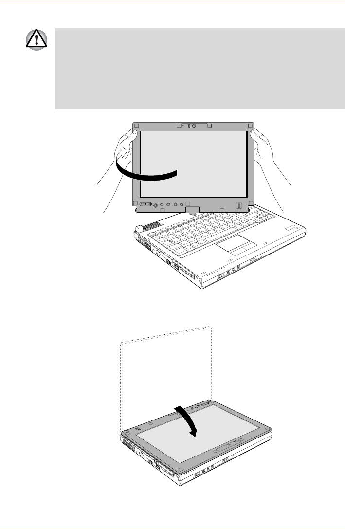
User’s Manual 4-13
Operating Basics
2. Rotate the display panel clockwise slowly.
Figure 4-13 Changing to the Tablet mode (2)
3. Close the display panel slowly with display surface facing upwards.
Figure 4-14 Changing to the Tablet mode (3)
■When rotating display panel of your computer, be sure to slowly turn it
in the proper direction, and not apply excessive force or speed.
■Do not attempt to rotate the display panel past the maximum rotation
point. Forcing the display panel past the maximum rotation point will
damage the display panel.
■Rotating the display panel counter-clockwise will break the hinge and
cause the computer to cease to function correctly.
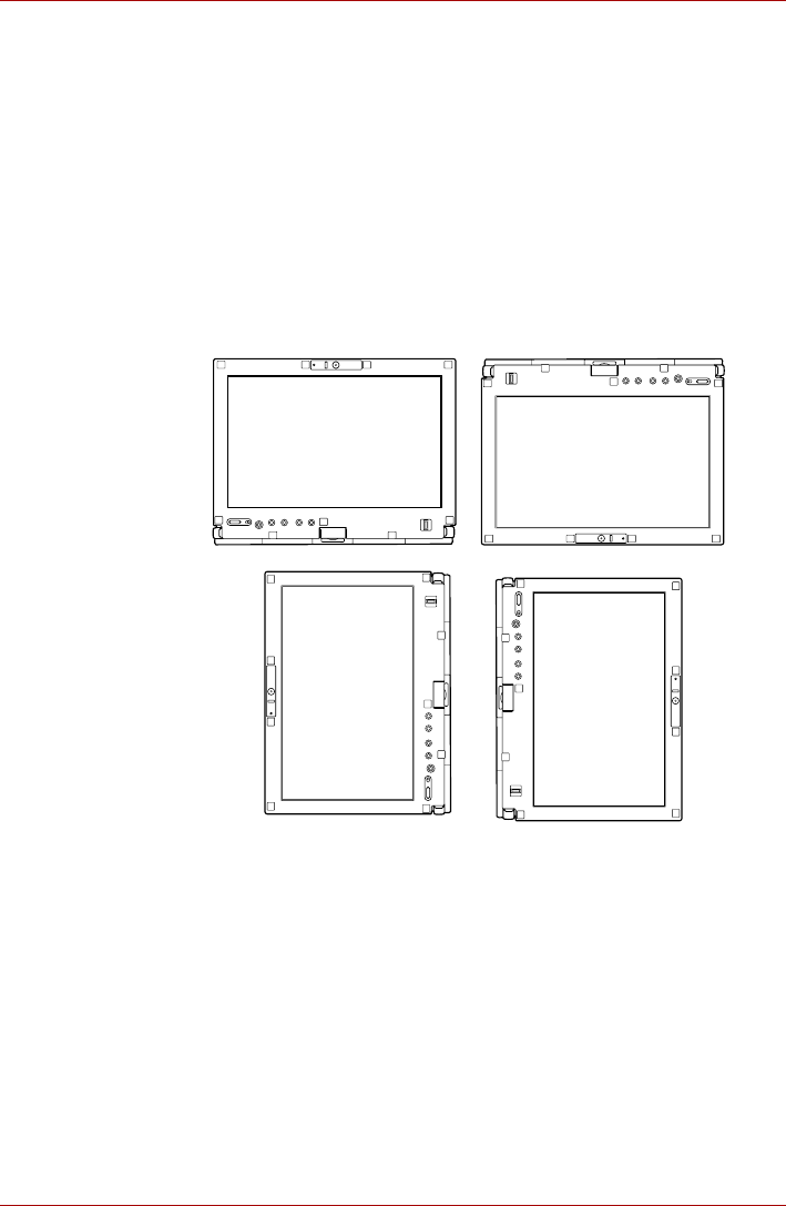
User’s Manual 4-14
Operating Basics
Changing to the Laptop mode
To change the operating mode to the Laptop mode, follow the steps as
detailed below:
1. Raise the display to the upright position carefully.
2. Rotate the display counter-clockwise slowly.
3. Close the display.
Changing the screen orientation
The orientation of the computer screen can be changed to one of the
following four display modes:
Figure 4-15 Four display modes
Secondary landscapePrimary landscape
Secondary portraitPrimary portrait

User’s Manual 4-15
Operating Basics
Method 1: Changing the screen orientation using TOSHIBA
Accelerometer Utilities and TOSHIBA Rotation Utility
When the TOSHIBA Accelerometer Utilities and TOSHIBA Rotation Utility
are running, changes in the orientation of the top and bottom of the screen
is automatically recognized by pressing ESC/Rotation button for more than
a second.
Method 2: Changing the screen orientation using Taskbar
1. Click Start and open Control Panel.
2. Select Mobile PC.
3. Open Tablet PC Settings.
4. Click Change button in Display tab.
■Execute the following applications on Primary landscape:
■3D game software
■3D screen saver
■Playback of a motion picture as would be the case using
DVD-Video playback on the computer connected to an external
DVD-ROM Drive.
■The screen cannot automatically rotate in the following cases.
You should first quit the running application and then rotate the screen:
■Running of an application that changes the screen resolution
dynamically, such as a game that is running in full-screen mode.
■DOS prompt in full-screen mode.
■Running of 3D screen saver.
■Do not play 3D game software or replay DVD-Video in a display mode
other than Primary landscape. An abnormality will appear on the
Windows screen display when you replay a DVD-Video in a mode other
than Primary landscape because DVD playback software can boot only
in the Primary landscape mode.
■An abnormality will appear on the Windows screen display when you
change from Tablet mode to Laptop mode while a 3D screen saver is
running. In this case, press any key while in Laptop mode to deactivate
the 3D screen saver.
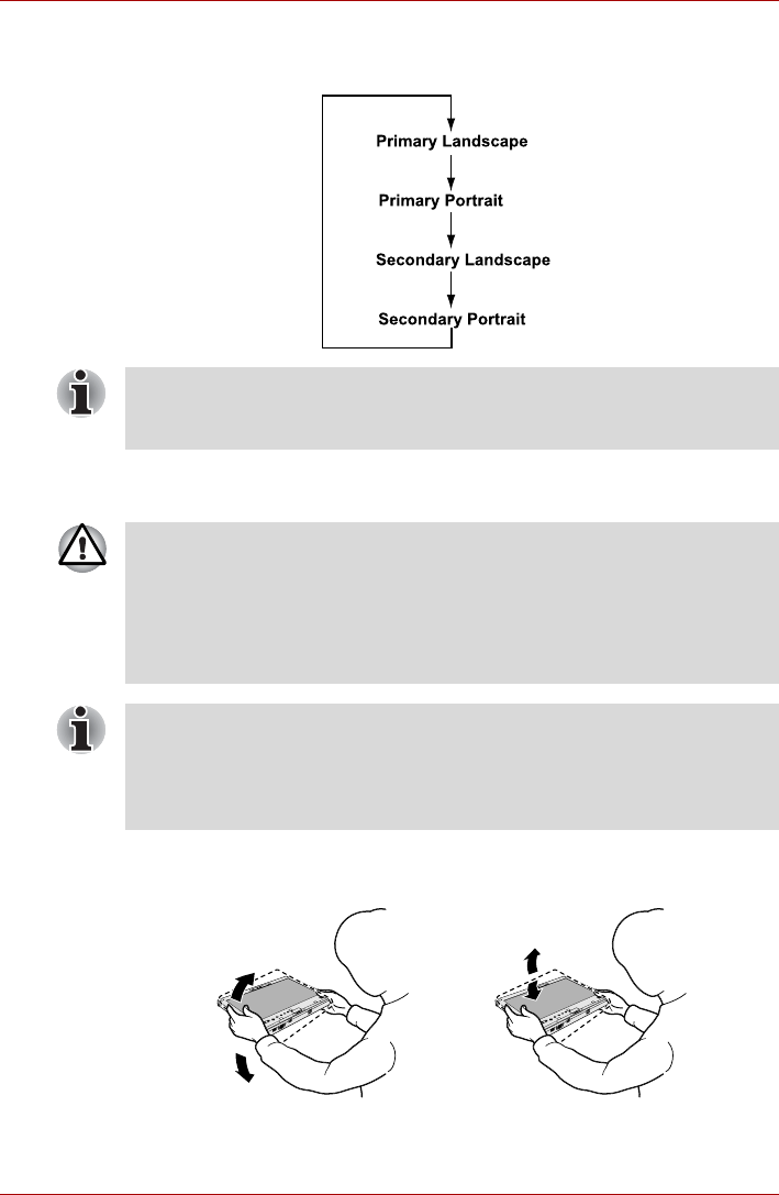
User’s Manual 4-16
Operating Basics
5. Select a screen orientation from the Orientation pull down menu and
change the screen.
Using Accelerometer Utilities
It is safer if you hold the computer with both hands horizontally as shown in
the below example.
Figure 4-16 Shake the computer
You can set the orientation of the desktop screen just after rotating the
display from Start -> All Programs -> TOSHIBA -> Tablet PC ->
Rotation Utility.
When you shake the computer:
■Do not shake the computer too strongly as this may cause the
computer to be dropped or hit those people or items around you.
■Avoid using the computer in crowded places (e.g. in commuter trains or
in busy streets).
This may cause injury to children or adults, or damage to the computer.
When the TOSHIBA HDD protection function is turned on and the Tilt
function (function to start applications, etc. by waving the computer
vertically or horizontally) is used, the TOSHIBA HDD protection message
may be displayed on the screen. Turn off the TOSHIBA HDD protection
function in order to stop such messages from displaying.
The computer is shaken perpendicularly.The computer is shaken horizontally.

User’s Manual 4-17
Operating Basics
Using the Fingerprint Sensor
This product has a fingerprint utility installed for the purpose of enrolling
and recognizing fingerprints. By enrolling the ID and password onto the
fingerprint authentication feature, it is no longer necessary to input the
password from the keyboard. Fingerprint feature enables you to:
■Logon to Windows and access a security enabled homepage through
Internet Explorer.
■Files and folders can be encrypted/decrypted and third party access to
them prevented.
■Disable the password-protected screen-saver when returning from a
power-saving mode such as Sleep Mode.
■Authentication of the User Password (and, if applicable, the HDD(Hard
Disk Drive) Password) when booting up the computer (Pre-OS
Authentication).
■Single-Swipe Sign On feature
How to Swipe your Finger
Using the following steps when swiping fingers for fingerprint registration or
authentication will help to minimize authentication failures:
Align the first joint of the finger to the center of the sensor. Lightly touch the
sensor and swipe finger levelly towards you when in portrait mode, and
sideways when in either landscape mode or Laptop mode.
While lightly touching the sensor, swipe the finger towards you when in
portrait mode, and sideways when in either landscape mode or Laptop
mode until the sensor surface becomes visible.
Fingerprint cannot be used in models that do not have a fingerprint module
installed.
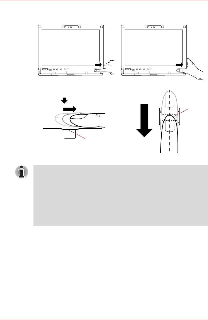
User’s Manual 4-18
Operating Basics
The following illustrations show the recommended way to swipe your finger
over the fingerprint sensor.
Figure 4-17 Swipe the finger
Sample. 2) When swiping the thumb
Sample. 1) When swiping the index finger
Sensor
Sensor
■Avoid swiping with your finger stiff or pressed too hard onto the sensor,
and take care to ensure that the center of the fingerprint is touching the
sensor before swiping. Either of these conditions may cause fingerprint
reading to fail.
■Check the center of the fingerprint whorl before swiping and then
ensure this is swiped along the center line of the sensor.
■There is a possibility of authentication failures if the finger is swiped too
quickly or too slowly - follow any on-screen instructions to adjust the
speed used during the swipe process.

User’s Manual 4-19
Operating Basics
Points to note about the Fingerprint Sensor
Please be aware of the following considerations when using the fingerprint
sensor. A failure to follow these guidelines might result in damage to the
sensor, sensor failure, fingerprint recognition problems or a lower
fingerprint recognition success rate.
■Do not scratch or poke the sensor with your nails or any hard or sharp
objects.
■Do not press the sensor strongly.
■Do not touch the sensor with a wet finger or any wet objects - keep the
sensor surface dry and free from water vapor.
■Do not touch the sensor with a soiled or dirty finger as minute foreign
particles of dust and dirt may scratch it.
■Do not paste stickers or write on the sensor.
■Do not touch the sensor with a finger or any other object which may
have a build-up of static electricity on it.
Observe the following before you place your finger on the sensor whether
for fingerprint enrollment/registration or recognition.
■Wash and dry your hands thoroughly.
■Remove static electricity from your fingers by touching any metal
surface. Static electricity is a common cause of sensor failures,
especially when the weather is dry.
■Clean the sensor with a lint-free cloth - do not use detergent or any
other chemicals to clean the sensor.
■Avoid the following finger conditions for enrollment or recognition as
they may result in fingerprint enrollment errors or a drop in the
fingerprint recognition success rate
■Soaked or swollen finger, for example as may occur after taking a
bath.
■Injured finger
■Wet finger
■Soiled or oily finger
■Extremely dry skin condition on finger
Observe the following to improve the fingerprint recognition success rate.
■Enroll two or more fingers.
■Enroll additional fingers if a recognition failure often occurs when using
already enrolled fingers.
■Check the condition of your finger - any conditions which have changed
since enrollment, such as injury, rough skin, and extremely dry, wet,
soiled, dirty, oily, soaked or swollen fingers, may lower the recognition
success rate. Also if the fingerprint is worn down or the finger becomes
thinner or fatter, the recognition success rate may be lowered.
■As the fingerprint for each finger is different and unique you should
ensure that only the registered or enrolled fingerprint or fingerprints are
used for identification.

User’s Manual 4-20
Operating Basics
■Check the position and speed at which you swipe your finger across the
sensor - please refer to the preceding drawing.
■The fingerprint sensor compares and analyzes the unique
characteristics in a fingerprint. However, there may be instances where
certain users are unable to register their fingerprints due to insufficient
unique characteristics in their fingerprints.
■The recognition success rate may differ from user to user.
Setup Procedure
Please use the following procedure when first using fingerprint
authentication.
Fingerprint Registration
You should initially enroll the required authentication data using the
Fingerprint Enrollment Wizard.
1. To run this program, click Start -> All Programs -> TrueSuite Access
Manager -> Fingerprint Application.
2. The Verify screen will be displayed, enter the Windows logon password
and click the Next button.
3. On the User's Fingers screen click the box above the finger you wish
to register.
If any of the previously enrolled fingerprints is selected again, the latest
information will be enrolled and any previous information over-written.
4. The Fingerprint Enrollment screen will be displayed and the tutorial
will begin. First click "Replay video" and confirm the proper movement
for the finger you wish to register. Then confirm the message displayed
on this screen and ensure that there is a check mark in the Run
Interactive Tutorial box. Once this has been done, click Next.
5. At the Scanning Practice screen, you are able to practice swiping
(three times) your finger to ensure you use the correct method. Click
"Try again" to if you wish to practice again. You have finished
practicing, click Next button.
■In use, the fingerprint authentication system will use the same
username and password as defined within the Windows operating
system. If no Windows password has been configured, you must do
this before starting the fingerprint registration process.
■This sensor has the memory space for at least twenty-one fingerprint
patterns. You might be able to register more fingerprint patterns
depending on the sensor memory usage.
You are also able to start the Fingerprint Enrollment Wizard by using the
following methods.
■Click the Fingerprint Application icon in the Taskbar.

User’s Manual 4-21
Operating Basics
6. Register your fingerprint on the Fingerprint Image Capture screen.
Let the computer read the finger to be registered 3 times. An image of
your fingerprint will be shown on the screen each time the fingerprint is
successfully read.
Once the fingerprint is successfully read for the third time, the message
Successfully combined will be displayed beneath the fingerprint
images. Click the Next button.
7. When the Store To Sensor screen is displayed, check Store
fingerprint to Sensor. Click Finish to complete fingerprint registration.
How to Delete the Fingerprint Data
Saved fingerprint data is stored in special non-volatile memory inside the
fingerprint sensor. Therefore, if you give the computer to someone else, or
dispose of it in any way, the following process is recommended to delete
your fingerprint information:
1. To run this program, click Start -> All Programs -> TrueSuite Access
Manager -> Fingerprint Application.
2. The Verify screen will be displayed, so either swipe your registered
finger or enter the Windows logon password and click the Next button.
3. The User's Fingers screen is displayed.
■To delete all registered fingerprints
■To delete individual fingerprints
It is strongly recommended that you register 2 or more fingerprints. Repeat
the procedure from step 3 to register another fingerprint.
1. Click Delete All Fingerprints.
2. Follow the on-screen instructions to deleted the registered
fingerprints.
1. Click the fingerprint mark above the registered finger.
2. Click Delete All Fingerprints.
3. "Are you sure you want to delete this fingerprint?" will be displayed
on the screen, click Yes button.
4. When Delete All Fingerprints is selected, the user selection
screen will be displayed, so select which user's fingerprint data to
delete.
■Selecting "Delete current user's fingerprints" will delete the
fingerprint data for the currently logged in user.
■Selecting "Delete all users' fingerprints" will delete the
fingerprint data for all users, however this item can only be
selected if the currently logged in user has administrator
privileges.
5. A message will be displayed asking for confirmation to delete the
fingerprint data, click the Yes button.

User’s Manual 4-22
Operating Basics
In use, please be aware of the following limitations of the fingerprint sensor:
■A warning message will be displayed when recognition is abnormal or
recognition is not successful within a fixed duration.
■The fingerprint sensor compares and analyzes the unique
characteristics in a fingerprint. However, there may be instances where
certain users are unable to register their fingerprints due to insufficient
unique characteristics in their fingerprints.
■The recognition success rate may differ from user to user.
■Toshiba does not guarantee that this fingerprint recognition technology
will be error-free.
■Toshiba does not guarantee that the fingerprint sensor will recognize
the enrolled user or accurately screen out unauthorized users at all
times. Toshiba is not liable for any failure or damage that might arise
out of the use of this fingerprint recognition software or utility.
Points to note about the Fingerprint Utility software
The Encrypting File System (EFS) is a Windows Vista® feature.
If a file is encrypted using EFS, it cannot be encrypted further using the
fingerprint authentication function.
Windows Logon via Fingerprint Authentication
If required, you are also able to use fingerprint authentication in place of the
usual Windows logon process using your username and password.
This method is especially useful where there are many users using the
same computer as it removes the need for actual user selection when the
system is started.
Fingerprint Authentication Procedure
1. Start up the computer.
2. At the Windows Welcome screen, choose any of the enrolled fingers
and swipe the fingerprint on the sensor - if the authentication process is
successful, the user will automatically be logged in to Windows.
You are able to backup saved fingerprint data and information within the by
using the Import or Export User Data facility under the fingerprint
management software. However, please be aware that any encrypted files
cannot be backup within File protection using this function - in these
instances it is recommended that you backup these files to external media
using standard file copy processes.
If the fingerprint authentication process fails you will need to log into
Windows using the appropriate username and password. In addition, you
should use this manual login process if fingerprint authentication fails for
three consecutive tries - a warning message will be displayed when
authentication is not normal or is not successful within a fixed duration.

User’s Manual 4-23
Operating Basics
Fingerprint Pre-OS Authentication
General
The fingerprint authentication system can be used to replace the keyboard
based password authentication system that is used when the computer is
turned on.
If you do not want to use the fingerprint authentication system for password
authentication while booting up the computer, instead you prefer using the
keyboard entry method, simply press the BACK SPACE key or the
ESC/Rotation button when the Fingerprint Pre-OS Authentication screen is
displayed.
Using this process will switch the password input screen across to the
keyboard based entry screen.
How to Enable Fingerprint Pre-OS Authentication Settings
It is necessary to first enroll your fingerprint with the Fingerprint Application
prior to enabling and configuring the Fingerprint Pre-OS Authentication
System. You should check that your fingerprint is enrolled before
configuring the settings (please refer to the Manual for Fingerprint
Registration/Enrollment for further instructions).
1. To run this program, click Start -> All Programs -> TrueSuite Access
Manager -> Fingerprint Application with Admin.
2. UserAccountControl screen is displayed, click the Allow button.
This setting can only be changed if the currently logged in user has
administrator privileges.
3. Swipe a registered finger on the fingerprint sensor.
4. Click the Setting menu at the TrueSuiteAccessManager screen.
5. Administrator Setting screen is displayed, check the "Enable Pre-OS
Fingerprint Authentication" check box and then click OK.
6. Click the Exit button at the TrueSuiteAccessManager screen.
■You must ensure that you use the TOSHIBA Password Utility to
register a User Password before using the Fingerprint Pre-OS
Authentication and its extended function to allow fingerprints to be used
to access the computer when it is turned on.
■If the fingerprint authentication process fails five times, a preset time
limit is exceeded, or you press the BACK SPACE key, [Password =]
will be displayed on the screen and you will have to enter either the
User Password or Supervisor Password manually in order to start the
computer.
■When swiping your finger, please ensure that you do it slowly and at a
constant speed. If you find that this does not improve the authentication
rate, you should try to adjust the speed at which the finger is swiped.
■If there are any changes in the environment or settings related to
authorization, you will be required to provide authorization information
such as a User Password (and, if applicable, the HDD(Hard Disk Drive)
password).

User’s Manual 4-24
Operating Basics
Fingerprint Single-Swipe Sign On Feature
General
This is a feature that allows the user to complete the authentication for both
the User/BIOS Password (and, if applicable, the HDD(Hard Disk Drive)
Password) and logging onto Windows using only one fingerprint
authentication when booting up.
It is necessary to register the User/BIOS Password and Windows Logon
Password before using the Fingerprint Pre-OS Authentication and this
Fingerprint Single-Swipe Sign On Feature. Please use the TOSHIBA
Password Utility to register your User/BIOS Password. If Windows Logon is
not the default for your system, see Manual to register your Windows
Logon Password.
Only one fingerprint authentication is required to replace the User/BIOS
Password (and, if applicable, the HDD(Hard Disk Drive) Password) and the
Windows Logon Password.
How to Enable Fingerprint Single-Swipe Sign On Feature
It is necessary to first enroll your fingerprint with the Fingerprint application
prior to enabling and configuring the Fingerprint Single-Swipe Sign On
feature. You should check that your fingerprint is enrolled before
configuring the settings (please refer to the Manual for Fingerprint
Registration/Enrollment for further instructions).
1. To run this program, click Start -> All Programs -> TrueSuite Access
Manager -> Fingerprint Application with Admin.
2. UserAccountControl screen is displayed, click the Allow button.
This setting can only be changed if the currently logged in user has
administrator privileges.
3. Swipe a registered finger on the fingerprint sensor.
4. Click the Setting menu at the TrueSuiteAccessManager screen.
5. Administrator Setting screen is displayed, check the "Enable Single-
Sign On Fingerprint Authentication" check box and then click OK.
6. Click the Exit button at the TrueSuiteAccessManager screen.
Fingerprint utility limitations
TOSHIBA does not guarantee that the fingerprint utility technology will be
completely secure or error-free, or that it will accurately screen out
unauthorized users at all times. TOSHIBA is not liable for any failure or
damage that might arise out of the use of the fingerprint software.
■The fingerprint sensor compares and analyzes the unique
characteristics in a fingerprint. However, there may be instances where
certain users are unable to register their fingerprints due to insufficient
unique characteristics in their fingerprints.
■The recognition success rate may differ from user to user.
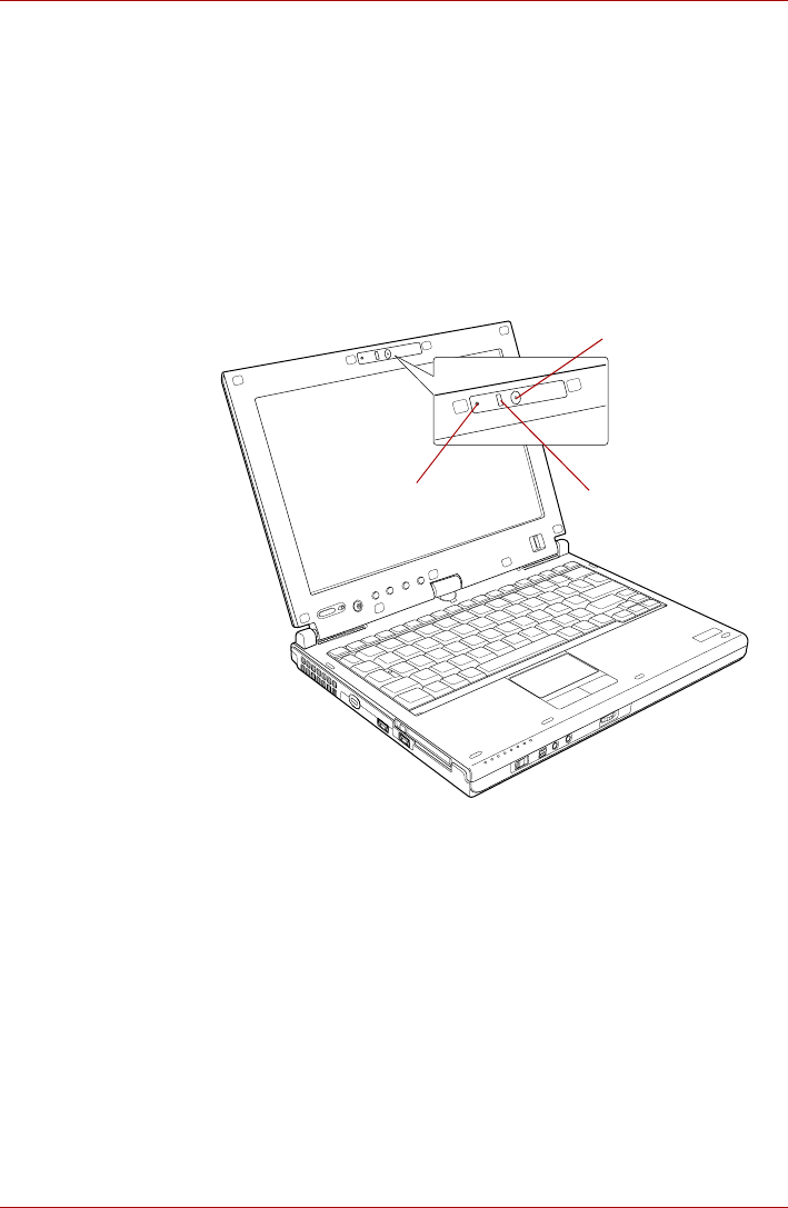
User’s Manual 4-25
Operating Basics
Web Camera
Web Camera is a device that allows you to record video or take
photographs with your computer. You can use it for video chatting or video
conferences using a communication tool such as Windows Live
Messenger.Camera Assistant Software will help you to add various
video effects to your video or photograph.
Enables the transmission of video and use of video chat via the internet
using specialized applications.
The effective pixel count for this web camera is 1.3 million.
Please refer to the Camera Assistant Software Online Help for details.
Figure 4-18 Web Camera
Web Camera
Web Camera LED
Microphone

User’s Manual 4-26
Operating Basics
Changing Ultra Slim Bay modules
This section explains how to change modules in the Ultra Slim Bay. The
illustrations show replacement of the optical disc drive with the Ultra Slim
Bay HDD Adaptor.
Removing a module
To remove the optical disc drive, follow the steps as described below:
1. Save your work.
2. Turn the computer's power off - ensure that the Power indicator is off.
3. Remove all cables and peripherals that are connected to the computer.
4. Close the display panel.
5. Turn the computer upside down and remove the battery pack (refer to
Replacing the battery pack section in Chapter 6, Power and Power-Up
Modes, if required).
6. Remove the Ultra Slim Bay lock screw from the Lock position.
7. Set the Ultra Slim Bay lock screw in the Unlock position.
■Do not point the web camera directly at the sun.
■Do not touch or press strongly on the web camera lens. Doing so may
reduce image quality. Use an eyeglass cleaner (cleaner cloth) or other
soft cloth to clean the lens if it becomes dirty.
■Setting the [Size] to more than "800x600" will cause a larger amount of
data to be written to the hard disk drive and may interfere with smooth
recording.
■When recording in dimly lit environments, the following procedure can
be used to select "Night Mode" which allows for brighter images with
less noise.
1. Click the Properties button on the [Web Camera] menu.
2. Check Night Mode on the [Options] tab.
3. Click the OK button.
The number of frames per second is lowered when "video recording" in
"Night Mode". This may result in the playback of the recorded video file
seeming unsmooth.
To avoid injury, do not put your hand into the Ultra Slim Bay slot.
Always make sure the display panel is closed in Laptop mode before
turning the computer upside down.
Wait for all disk indicators to go out before you turn over the computer and
do not lay the computer down gently. Shock can damage the HDD or other
components.
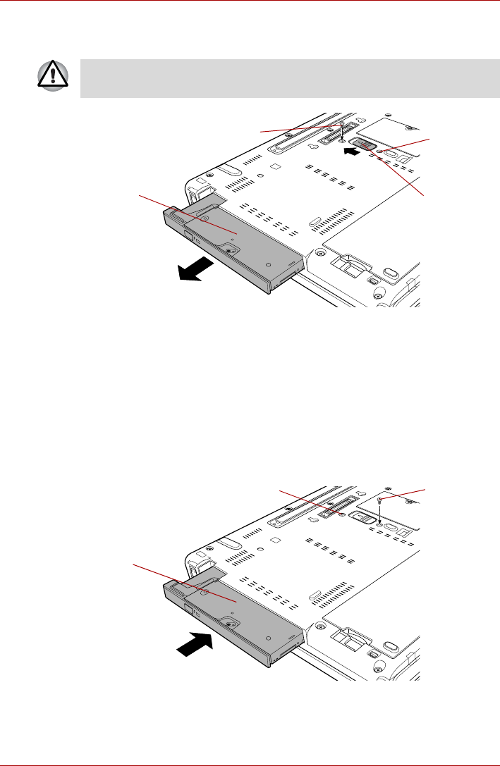
User’s Manual 4-27
Operating Basics
8. Slide the Ultra Slim Bay latch to the unlock position.
9. Grasp the optical disc drive and slide it out.
Figure 4-19 Removing the optical disc drive
Inserting a module
To insert the Ultra Slim Bay HDD Adaptor, follow the steps as described
below:
1. Insert the Ultra Slim Bay HDD Adaptor in the computer as shown below
and press until the Ultra Slim Bay latch clicks.
2. Remove the Ultra Slim Bay lock screw from the Unlock position.
3. If you want to lock the Ultra Slim Bay HDD Adaptor, set the Ultra Slim
Bay lock screw in the hole for the lock position.
Figure 4-20 Inserting the Ultra Slim Bay HDD Adaptor
The optical disc drive and other Ultra Slim Bay modules can become hot
with use. Be careful when removing the module.
Lock screw
(Unlock position)
Optical disc drive
Ultra Slim Bay
latch
Lock position
Ultra Slim Bay
HDD Adaptor
Lock screw
(Lock position)
Unlock position
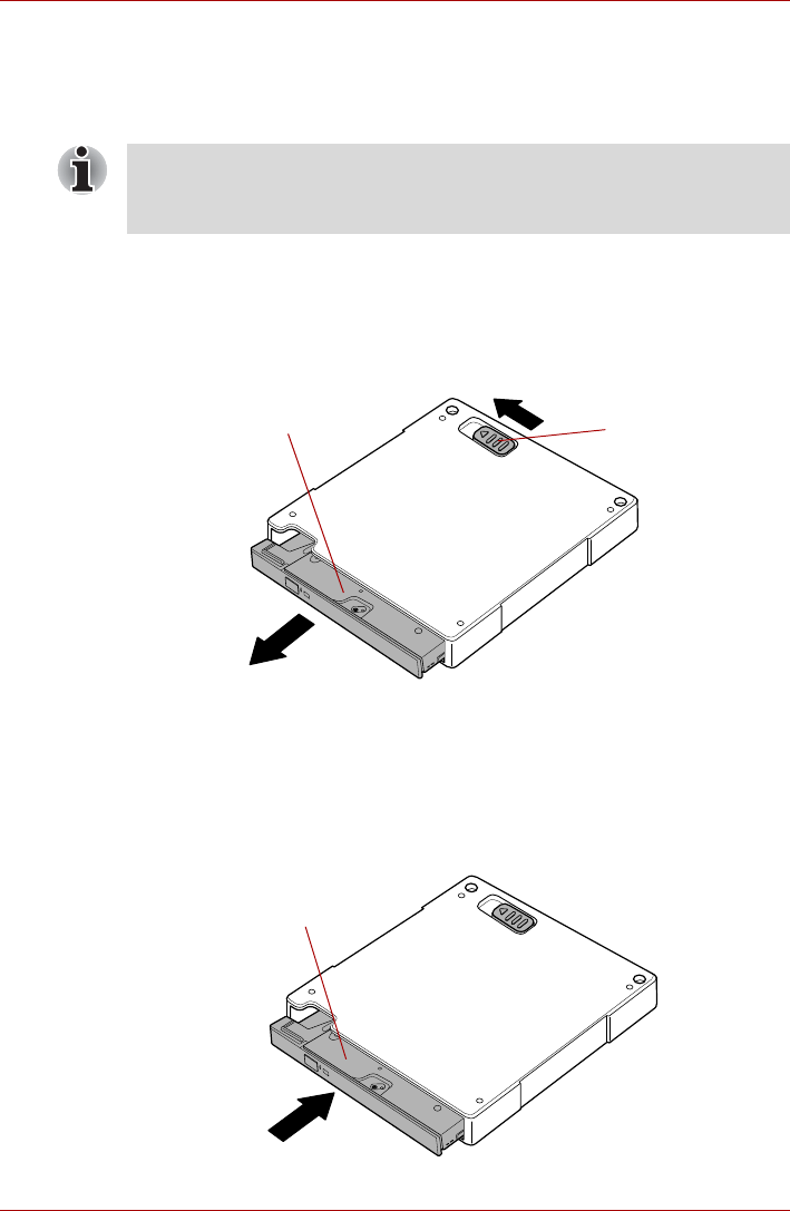
User’s Manual 4-28
Operating Basics
Ultra Slim Bay Case (UJ-862 model only)
The DVD Super Multi drive (UJ-862) is equipped with an Ultra Slim Bay
Case. This section explains how to remove and install the DVD Super Multi
drive unit (UJ-862).
Removing a unit
To remove the DVD Super Multi drive unit from the Ultra Slim Bay Case,
follow the steps as described below:
1. Slide the Ultra Slim Bay latch to the unlock position.
2. Grasp the DVD Super Multi drive unit and slide it out.
Figure 4-21 Removing the DVD Super Multi drive unit
Inserting a unit
To insert the DVD Super Multi drive unit into the Ultra Slim Bay Case,
follow the steps as described below:
1. Insert the DVD Super Multi drive unit in the Ultra Slim Bay Case as
shown below and press until the Ultra Slim Bay latch clicks.
Figure 4-22 Inserting the DVD Super Multi drive unit
Store the DVD Super Multi drive unit (UJ-862 model only) in the Ultra Slim
Bay Case when removing it from the computer or transporting it.
Refer to Ultra Slim Bay Case (UJ-862 model only) section in this chapter.
DVD Super Multi drive unit Ultra Slim Bay
latch
DVD Super Multi drive unit
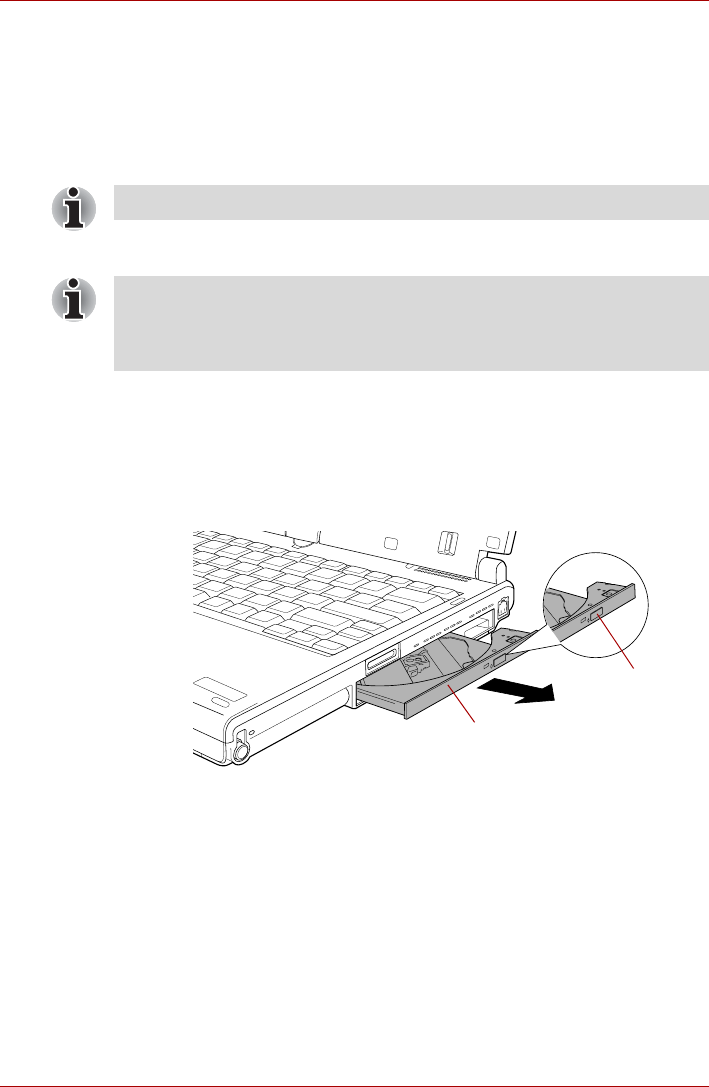
User’s Manual 4-29
Operating Basics
Using optical disc drives
The full-size drive provides high-performance execution of CD/DVD-ROM-
based programs. You can run either 12 cm (4.72") or 8 cm (3.15")
CD/DVDs without an adaptor. An ATAPI interface controller is used for
CD/DVD-ROM operation. When the computer is accessing a CD/DVD-
ROM, an indicator on the drive glows.
If you have a DVD Super Multi drive, refer also to the Writing CD/DVDs on
DVD Super Multi drives section for precautions on writing to CDs/DVDs.
Loading discs
To load CD/DVDs, follow the steps as detailed below:
1. When the computer’s power is on, press the eject button to open the
disc tray slightly.
2. Grasp the disc tray gently and pull until it is fully opened.
Figure 4-23 Pressing the eject button and pulling the disc tray open
Use the WinDVD application to view DVD-Video discs.
When the power of the optical disc drive is off, pressing the FN +Tab keys
will turn the power of the optical disc drive on. Furthermore, it is possible to
set it to turn the power of the optical disc drive on and eject the tray at the
same time.
Disc tray
Eject button
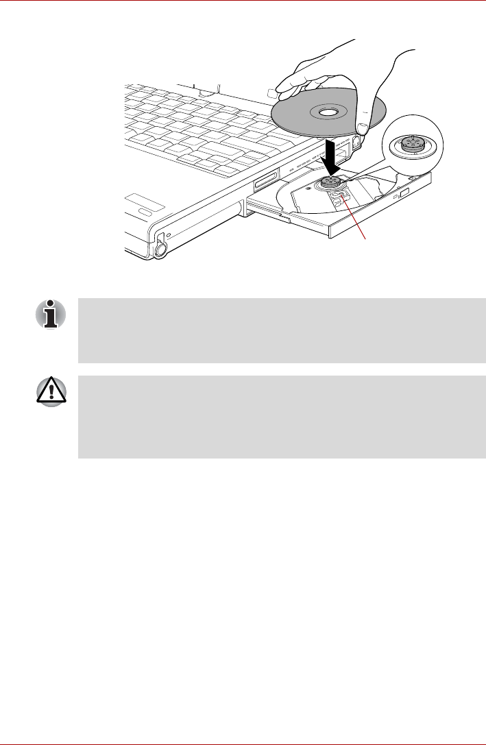
User’s Manual 4-30
Operating Basics
3. Lay the CD/DVD, label side up, in the disc tray.
Figure 4-24 Inserting a CD/DVD
4. Press gently at the center of the CD/DVD until you feel it click into
place. The CD/DVD should lie below the top of the spindle, flush with
the spindle base.
Laser lens
When the disc tray is fully opened, the edge of the computer will extend
slightly over the CD/DVD tray. Therefore, you will need to turn the CD/DVD
at an angle when you place it in the disc tray. After seating the CD/DVD,
however, make sure it lies flat.
■Do not touch the laser lens or any portion of its surrounding casing as
this could cause misalignment.
■Prevent foreign objects from entering the drive. Check the surface of
the disc tray, especially the area behind the front edge of the disc tray,
to make sure there are no such objects before closing the drive.
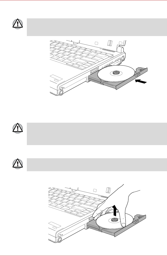
User’s Manual 4-31
Operating Basics
5. Push the center of the disc tray to close it. Press gently until it locks into
place.
Figure 4-25 Closing the CD/DVD disc tray
Removing discs
To remove the CD/DVD, follow the steps as detailed below:
1. To pop the disc tray partially open, press the eject button. Gently pull
the disc tray out until it is fully opened.
2. The CD/DVD extends slightly over the sides of the disc tray so you can
grasp it. Gently lift out the CD/DVD.
Figure 4-26 Removing a CD/DVD
If the CD/DVD is not seated properly when the disc tray is closed, the
CD/DVD might be damaged. Also, the disc tray might not open fully when
you press the eject button.
Do not press the eject button while the computer is accessing the media
drive. Wait for the optical disc drive indicator to go out before you open the
disc tray. Also, if the CD/DVD is spinning when you open the disc tray, wait
for it to stop before you remove it.
When the disc tray pops open slightly, wait a moment to make sure the
CD/DVD has stopped spinning before pulling the disc tray fully open.

User’s Manual 4-32
Operating Basics
3. Push the center of the disc tray to close it. Press gently until it locks into
place.
Optical Drive Auto Lock
This function automatically locks the optical disc drive eject button if the
computer detects any vibration or other shocks while running on the
battery.
This function prevents the disc tray from opening even if the eject button is
pushed unexpectedly.
When the Optical Drive Auto Lock is on, there will be key mark on the
bottom right of the Optical Drive Power icon in the Taskbar.
Setting the Optical Drive Auto Lock
Right click the Optical Drive Power icon in the Taskbar to change the
Optical Drive Auto Lock settings.
Enabling and Disabling Optical Drive Auto Lock
1. Right click on the Optical Drive Power icon on the Taskbar.
2. Click Optical Drive Auto Lock -> Enable or Disable.
Lock Time Settings for Optical Drive Auto Lock
This sets the amount of time required to pass before the optical disc drive
eject button unlocks when the Computer detects vibration or other shock.
1. Right click on the Optical Drive Power icon on the Taskbar.
2. Click Unlock time settings -> 1s or 3s or 5s.
To enable this function, turn the Optical Drive Power ON.
■When the Optical Drive Auto Lock is engaged, the FN+Tab key
combination and Eject Buttons on application screens are disabled.
■Optical Drive Auto Lock is not enabled immediately after the computer
is started, the Disc tray is closed, or the optical disc drive is switched
from OFF to ON using the FN+Tab keys.
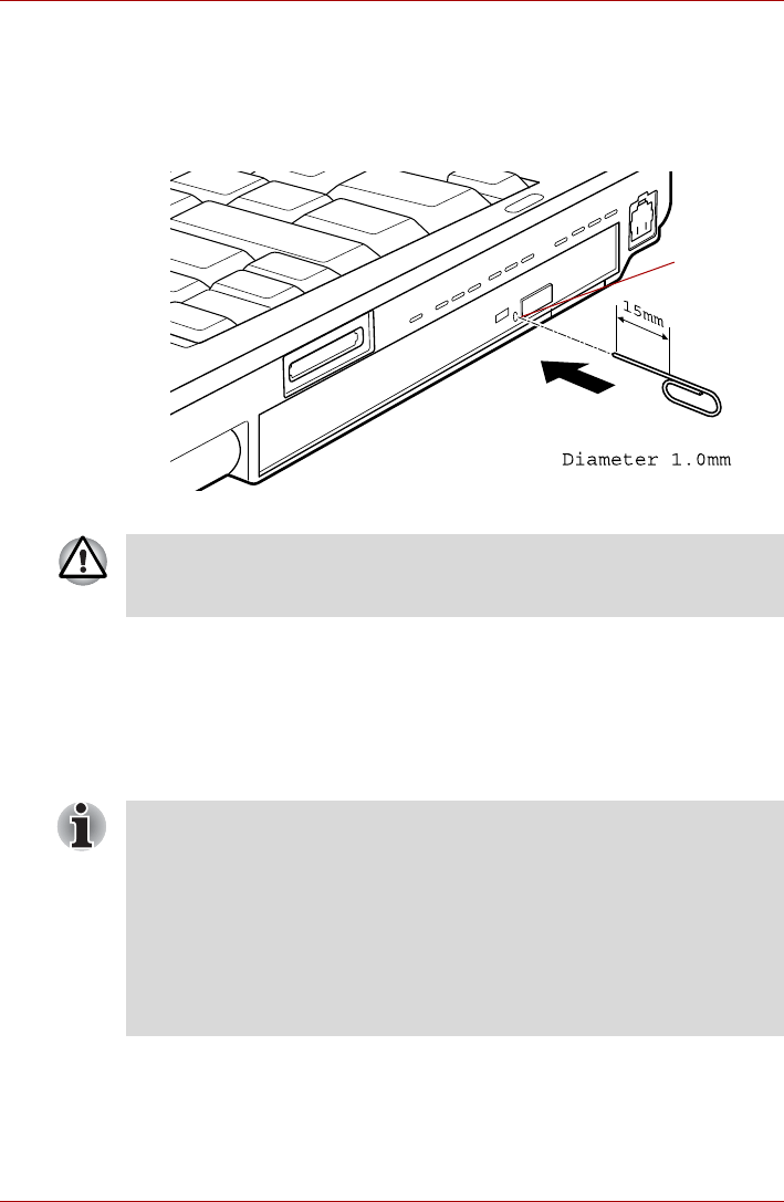
User’s Manual 4-33
Operating Basics
How to remove CD/DVD when the disc tray will not open
Pressing the eject button will not open the disc tray when the computer
power is off. If the power is off, you can open the disc tray by inserting a
slender object (about 15 mm) such as a straightened paper clip into the
eject hole near the eject button.
Figure 4-27 Manual release with the eject hole
Writing CD/DVDs on DVD Super Multi drives
You can use the DVD Super Multi drive to write data to either CD-R, CD-
RW, DVD-R, DVD-R (Dual Layer), DVD-RW, DVD+R, DVD+R (Double
Layer), DVD+RW or DVD-RAM discs. TOSHIBA Disc Creator is provided
as writing software with this computer.
Eject hole
Turn off the power before you use the eject hole. If the CD/DVD is spinning
when you open the disc tray, the CD/DVD could fly off the spindle and
cause injury.
■Please refer to the Writable discs, Chapter 2 for details about the types
of writable CD and DVD discs that can be supported by this computer.
■Do not turn off the power to the optical disc drive while the computer is
accessing it as this may cause you to lose data.
■To write data to CD-R/-RW media, use the TOSHIBA Disc Creator
feature that is installed on your computer.
■When the power of the optical disc drive is off, the disc tray will not
open even if the eject button is pushed. Use the ODD to turn the power
of the optical disc drive on. Please refer to Chapter 5, Hot keys.

User’s Manual 4-34
Operating Basics
Important message
Before you write or rewrite to any of the media supported by the DVD
Super Multi Drive, please read and follow all of the setup and operating
instructions in this section. If you fail to do so, you may find that the DVD
Super Multi drive may not function properly, and you may fail to write or
rewrite information successfully - this may cause you to either lose data or
incur other damage to the drive or media.
Disclaimer
TOSHIBA does not bear responsibility for the following:
■Damage to any CD-R, CD-RW, DVD-R, DVD-R (Dual Layer), DVD-RW,
DVD+R, DVD+R (Double Layer), DVD+RW or DVD-RAM disc that may
be caused by writing or rewriting with this product.
■Any change or loss of the recorded contents of CD-R, CD-RW, DVD-R,
DVD-R (Dual Layer), DVD-RW, DVD+R, DVD+R (Double Layer),
DVD+RW or DVD-RAM media that may be caused by writing or
rewriting with this product, or for any business profit loss or business
interruption that may be caused by the change or loss of the recorded
contents.
■Damage that may be caused by using third party equipment or
software.
Given the technological limitations of current optical disc writing drives, you
may experience unexpected writing or rewriting errors due to disc quality or
problems with hardware devices. In view of this, it is good practice to make
two or more copies of important data, in case of any undesired change or
loss of the recorded contents.
Before writing or rewriting
■Based on TOSHIBA's limited compatibility testing, we suggest the
following manufacturers of CD-R, CD-RW, DVD-R, DVD-R (Dual
Layer), DVD-RW, DVD+R, DVD+R (Double Layer), DVD+RW or DVD-
RAM media, however, it must be noted that disc quality can affect write
or rewrite success rates. Please also be aware that in no event does
TOSHIBA guarantee the operation, quality or performance of any disc.
When writing information to media using an optical drive, you should
always ensure that you connect the AC adaptor to a live power socket. It is
possible that, if data is written while powered by the battery pack, the write
process may sometimes fail due to low battery power - in these instances
data loss may occur.
CD-R:
TAIYO YUDEN CO., LTD.
MITSUBISHI CHEMICAL CORPORATION
RICOH Co., Ltd.

User’s Manual 4-35
Operating Basics
CD-RW: (Multi-Speed and High-Speed)
MITSUBISHI CHEMICAL CORPORATION
RICOH Co., Ltd.
CD-RW: (Ultra-Speed)
MITSUBISHI CHEMICAL CORPORATION
DVD-R:
DVD Specifications for Recordable Disc for General Version 2.0
TAIYO YUDEN CO., LTD.
Matsushita Electric Industrial Co., Ltd
DVD-R (Dual Layer):
MITSUBISHI CHEMICAL CORPORATION
DVD+R:
MITSUBISHI CHEMICAL CORPORATION
RICOH Co., Ltd.
DVD+R (Double Layer):
MITSUBISHI CHEMICAL CORPORATION
DVD-RW:
DVD Specifications for Recordable Disc for Version 1.1 or version
1.2
VICTOR COMPANY OF JAPAN.LIMITED
MITSUBISHI CHEMICAL CORPORATION
DVD+RW:
MITSUBISHI CHEMICAL CORPORATION
RICOH Co., Ltd.
DVD-RAM:
DVD Specifications for DVD-RAM Disc for Version 2.0, Version 2.1
or Version 2.2
Matsushita Electric Industrial Co., Ltd.
Hitachi Maxell Ltd.

User’s Manual 4-36
Operating Basics
■If the disc is poor in quality, or is dirty or damaged, writing or rewriting
errors may be noted - ensure that you check all discs for dirt or damage
before you use them.
■The actual number of rewrites to CD-RW, DVD-RW, DVD+RW or DVD-
RAM media will be affected by the quality of the disc itself and the way
in which it is used.
■There are two types of DVD-R media available, authoring discs and
general use discs. Do not attempt to use authoring discs as only
general use discs can be written to by a computer drive.
■You can use both DVD-RAM discs that can be removed from a
cartridge and DVD-RAM discs designed without a cartridge.
■You may find that other computer DVD-ROM drives or other DVD
players may not be able to read DVD-R, DVD-R (Dual Layer), DVD-
RW, DVD+R, DVD+R (Double Layer) or DVD+RW discs.
■Data written to a CD-R, DVD-R, DVD-R (Dual Layer), DVD+R or
DVD+R (Double Layer) discs cannot be deleted either in whole or in
part.
■Data deleted/erased from a CD-RW, DVD-RW, DVD+RW or DVD-RAM
disc cannot be recovered. You must check the content of the disc
carefully before you delete it, taking care that, if multiple drives that can
write data to discs are connected, you do not delete data from the
wrong one.
■In writing to DVD-R, DVD-R (Dual Layer), DVD-RW, DVD+R, DVD+R
(Double Layer), DVD+RW or DVD-RAM media, some space is required
for file management, so you may not be able to write to the full capacity
of the disc.
■Since the disc is based on the DVD standard, it might be filled with
dummy data if the written data is less than about 1GB. Therefore, in
these circumstance, even if you write only a small amount of data, it
might take additional time to fill in the dummy data.
■When multiple drives that can write data to discs are connected, be
sure that you do not write to or delete data from the wrong drive.
■Be sure to connect the AC adaptor to the computer before you write or
rewrite any information.
■DVD Super Multi drive cannot use discs that allow writing faster than
16x speed (DVD-R and DVD+R media), 8x speed (DVD-R (Dual
Layer), DVD+RW and DVD+R (Double Layer) media), 6x speed (DVD-
RW media), 5x speed (DVD-RAM media).
■Some types and formats of DVD-R (Dual Layer) and DVD+R (Double
Layer) discs may be unreadable.
■2.6GB and 5.2GB DVD-RAM media cannot be read from or written to.
■DISC created in DVD-R (Dual Layer) format4 (Layer Jump Recording)
cannot be read.

User’s Manual 4-37
Operating Basics
■Before you enter either Sleep Mode or Hibernation Mode, take care to
ensure that any DVD-RAM writing has been completed. In this instance,
writing is finished if you can eject the DVD-RAM media.
■Be sure to close all other software programs except for the writing
software itself.
■Do not run software such as a screen saver which can put a heavy load
on the processor.
■Operate the computer at its full power settings - do not use any power-
saving features.
■Do not write information while virus checking software is running,
instead wait for it to finish, then disable the virus protection applications,
including any software that checks files automatically in the
background.
■Do not use any hard disk utilities, including those that are intended to
enhance hard disk drive access speeds, as they may cause unstable
operation and damage data.
■CD-RW (Ultra Speed +) media should not be used as data may be lost
or damaged.
■You should always write from the computer's hard disk drive onto the
CD/DVD - do not try to write from shared devices such as a server or
any other network device.
■Writing with software other than TOSHIBA Disc Creator has not been
confirmed, therefore operation with other software applications cannot
be guaranteed.
When writing or rewriting
Please observe the following points while you write or rewrite data to CD-R,
CD-RW, DVD-R, DVD-R (Dual Layer), DVD-RW, DVD+R, DVD+R (Double
Layer), DVD+RW or DVD-RAM media:
■Always copy data from the hard disk drive to the optical media - do not
use the cut-and-paste function as the original data will be lost if there is
a write error.
■Do not perform any of the following actions:
■Change users in the Windows Vista® operating system.
■Operate the computer for any other function, including such tasks as
using a mouse or Touch Pad, or closing/opening the display panel.
■Start a communication application such as a modem.
■Apply impact or vibration to the computer.
■Install, remove or connect external devices, including such items as
a PC Card, Smart Card, SD/SDHC Card, USB device, external
monitor, i.LINK device, or an optical digital device.
■Use the audio/video control button to reproduce music or voice.
■Open the optical disc drive.
■Do not use shut down, log off, Sleep Mode or Hibernation Mode
functions while writing or rewriting.

User’s Manual 4-38
Operating Basics
■Make sure that the write/rewrite operation is completed before going
into either Sleep Mode or Hibernation Mode (writing is completed if you
can remove an optical media on the DVD Super Multi drive).
■If the media is of poor quality, or is dirty or damaged, writing or rewriting
errors may occur.
■Set the computer on a level surface and avoid places subject to
vibration such as airplanes, trains or cars. In addition, do not use the
computer on an unstable surface such as a stand.
■Keep mobile phones and other wireless communication devices away
from the computer.
TOSHIBA Disc Creator
Please be aware of the following limitations when you use the TOSHIBA
Disc Creator:
■DVD Video cannot be created using TOSHIBA Disc Creator.
■DVD Audio cannot be created using TOSHIBA Disc Creator.
■You cannot use TOSHIBA Disc Creator's 'Audio CD for Car or Home
CD Player' function to record music to DVD-R, DVD-R (Dual Layer),
DVD-RW, DVD+R, DVD+R (Double Layer) or DVD+RW media.
■Do not use the 'Disc Backup' function of TOSHIBA Disc Creator in order
to copy DVD Video or DVD-ROM material that has copyright protection.
■DVD-RAM discs cannot be backed up using the 'Disc Backup' function
of TOSHIBA Disc Creator.
■You cannot back up CD-ROM, CD-R or CD-RW media to DVD-R, DVD-
R (Dual Layer) or DVD-RW media using the 'Disc Backup' function of
TOSHIBA Disc Creator.
■You cannot back up CD-ROM, CD-R or CD-RW media to DVD+R,
DVD+R (Double Layer) or DVD+RW media using the 'Disc Backup'
function of TOSHIBA Disc Creator.
■You cannot back up DVD-ROM, DVD Video, DVD-R, DVD-R (Dual
Layer), DVD-RW, DVD+R, DVD+R (Double Layer) or DVD+RW to CD-
R or CD-RW media using the 'Disc Backup' function of TOSHIBA Disc
Creator.
■TOSHIBA Disc Creator cannot record in packet format.
■You might not be able to use the 'Disc Backup' function of TOSHIBA
Disc Creator to back up a DVD-R, DVD-R (Dual Layer), DVD-RW,
DVD+R, DVD+R (Double Layer) or DVD+RW disc that was made with
other software on a different optical media recorder.
■If you add data to a DVD-R, DVD-R (Dual Layer), DVD+R or DVD+R
(Double Layer) disc that you have already recorded to, you might not be
able to read the added data under some circumstances. For example, it
cannot be read under 16-bit operating systems, such as Windows 98SE
and Windows Me, while in Windows NT4 you will need Service Pack 6
or later, and in Windows 2000, you will need Service Pack 2. In addition
to this, some DVD-ROM and DVD-ROM / CD-R/RW drives cannot read
this added data regardless of the operating system.

User’s Manual 4-39
Operating Basics
■TOSHIBA Disc Creator does not support recording to DVD-RAM discs -
to achieve this you should use Windows Explorer or another similar
utility.
■When you back up a DVD disc, be sure that the source drive supports
recording to DVD-R, DVD-R (Dual Layer), DVD-RW, DVD+R, DVD+R
(Double Layer) or DVD+RW media - if this is not the case then the
source disc might not be backed up correctly.
■When you back up a DVD-R, DVD-R (Dual Layer), DVD-RW, DVD+R,
DVD+R (Double Layer) or DVD+RW disc, be sure to use the same type
of disc.
■You cannot partially delete any data written to a CD-RW, DVD-RW or
DVD+RW disc.
Data Verification
To verify that data has been written or rewritten correctly to a data CD/DVD
you should follow the steps below before you begin the write/rewrite
process:
1. Display the setting dialog box by one of the following two steps:
■Click the Recording settings button ( ) for writing on the main
toolbar in the Data Disc mode.
■Select Settings for Each Mode -> Data Disc in the Settings menu.
2. Mark the Verify written data check box.
3. Select File Open or Full Compare mode.
4. Click the OK button.
How to learn more about TOSHIBA Disc Creator
Please refer to the Help files for additional TOSHIBA Disc Creator
information.

User’s Manual 4-40
Operating Basics
Media care
This section provides tips on protecting data stored on your CD's, DVD's
and floppy diskettes. Handle your media with care. Following the simple
precautions listed below will increase the lifetime of your media and protect
the data stored on it.
CD/DVDs
1. Store your CD's and DVD's in the containers they originally came in to
protect them and keep them clean.
2. Do not bend the CD's or DVD's.
3. Do not write on, apply a sticker to, or otherwise mar the surface of the
CD or DVD that contains the data.
4. Hold the CD or DVD by its outside edge or the edge on the center hole
- any fingerprints on the surface of the disc can prevent the drive from
properly reading data.
5. Do not expose the CD or DVD to direct sunlight, extreme heat or cold.
6. Do not place heavy objects on your CD's or DVD's.
7. If your CD's or DVD's become dusty or dirty, wipe them with a clean dry
cloth from the center hole outwards - do not wipe in a circular direction.
If necessary, you can use a cloth that has been lightly dampened in
water or a neutral cleaner but you must not use benzine, thinner or any
similar cleaning solution.
Floppy diskettes
1. Store your floppy diskettes in the container they came in to protect them
and keep them clean. If a floppy diskette becomes dirty, clean it with a
soft, lightly dampened cloth - do not use cleaning fluid.
2. Never open the shutter or touch the magnetic surface of your floppy
diskette - doing this could permanently damage it and lose data.
3. Always handle floppy diskettes with care to prevent the loss of stored
data.
4. Always apply the floppy diskette label in the correct location and never
apply a new label on top of an existing one - in this instance the label
could come loose and damage the floppy diskette drive.
5. Never use a pencil for writing on a floppy diskette label as the dust from
the pencil lead could cause a system malfunction if it found its way onto
the computer's components. In this instance, always use a felt-tipped
pen and write the label first before applying it to the floppy diskette.
6. Never put a floppy diskette in a location where water or other liquid may
make contact with it, or where it is excessively damp - either of these
conditions could cause data loss.
7. Never use a wet or damp floppy diskette - this could damage the floppy
diskette drive or other devices within the computer.
The USB floppy diskette drive is available only as an option.

User’s Manual 4-41
Operating Basics
8. Data may be lost if the floppy diskette is twisted, bent, or exposed to
direct sunlight, extreme heat or cold.
9. Do not place heavy objects on your floppy diskettes.
10. Do not eat, smoke, or use items such as erasers near your floppy
diskettes as foreign particles inside the jacket of the floppy diskette can
damage the magnetic surface.
11. Magnetic energy can destroy the data on your floppy diskettes. In view
of this you should keep your floppy diskettes away from speakers,
radios, televisions and other sources of magnetic fields.
Sound System
This section describes some of the audio control functions.
Volume Mixer
The Volume Mixer utility lets you control the audio volume for playback of
devices and applications under Windows.
■To launch the Volume Mixer utility, right click on the speaker icon on the
Taskbar, and select Open Volume Mixer from the sub menu.
■To adjust the volume level of speakers or headphones, move the
Speakers slider.
■To adjust the volume level of an application that you are using, move
the slider for the corresponding application.
Microphone Level
Follow the steps below to change the microphone recording level.
1. Right click on the speaker icon on the Taskbar, and select Recording
Devices from the sub menu.
2. Select Microphone, and click Properties.
3. On the Levels tab move the Microphone slider to increase or decrease
the microphone volume level.
If you feel the microphone volume level is inadequate, move the
Microphone Boost slider to a higher level.
PC Beep Level
Follow the steps below to change the PC Beep playback level.
1. Right click on the speaker icon on the Taskbar, and select Playback
Devices in the sub menu.
2. Select Speakers, and click Properties.
3. On the Levels tab move the PC Beep slider to increase or decrease
the PC Beep volume level.

User’s Manual 4-42
Operating Basics
Audio Enhancements
In order to apply the sound effects for your current speaker, follow the steps
below.
1. Right click on the speaker icon on the Taskbar, and select Playback
Devices from the sub menu.
2. Select Speakers, and click Properties.
3. On the Enhancements tab select the sound effects you would like, and
click Apply.
Realtek HD Audio Manager
You can confirm and change the audio configuration using the Realtek
Audio Manager. To launch the Realtek Audio Manager, click Start ->
Control Panel -> Hardware and Sound -> Realtek HD Audio Manager.
When you first launch the Realtek Audio Manager, you will see two device
tabs. Speakers is the default output device. Microphone is the default
input device. To change the default device, click the Set Default Device
button under the chosen device tab.
Information
Click the information button to view hardware information, software
information, and language setting.
Power Management
The audio controller in your computer can be turned off when the audio
function is not used. To adjust the configuration of audio power
management, click the battery button .
■When audio power management is enabled, the circle button at the
upper left of the Power Management is blue and convex.
■When audio power management is disabled, the button is black and
concave.
Speaker Configuration
Click the playback button to confirm the internal speakers or the
headphone sound is coming from the right direction.
Default Format
You can change the sample rate and bit depth of sound.

User’s Manual 4-43
Operating Basics
TOSHIBA Mic Effect
TOSHIBA Mic Effect provides you with a hands-free environment for
holding mutual communication via the Internet Protocol or Local Area
Network. If you wish to communicate with someone on your computer, you
can use a messenger application. However, with such an application, you
would hear your own voice returning to you as echo during the
communication if you did not use a headset system or headphone.
TOSHIBA Mic Effect will reduce these echoes generated on your
computer.
To apply the echo cancellation, follow the steps below.
1. Click the right button of a mouse on the speaker icon on the Taskbar,
and select Playback Devices in the sub menu.
2. On the Playback tab, select Speakers, and click Properties.
3. On the Advanced tab, select “16 bit, 48000 Hz (DVD Quality)” in the
pull-down menu of Default Format, and then click OK.
4. On the Recording tab, select Microphone, and click Properties.
5. On the Advanced tab, select “2 channel, 16 bit, 48000 Hz (DVD
Quality)” in the pull-down menu of the Default Format pane.
6. On the TOSHIBA Mic Effect tab, select the Enable Echo Canceller
check box, and click Apply.
Modem
This section describes how to connect and disconnect the internal modem
to and from a telephone jack.
■Connection to any communication line other than an analog phone line
could cause a computer system failure.
■Connect the built-in modem only to ordinary analog phone lines.
■Never connect the built-in modem to a digital line (ISDN).
■Never connect the built-in modem to the digital connector on a
public telephone or to a digital private branch exchange (PBX).
■Never connect the built-in modem to a key telephone system for
residences or offices.
■Never operate your computer on AC power during a thunderstorm. If
you see lightning or hear thunder, immediately turn off the computer.
An electric surge caused by the storm, may result in a system failure,
loss of data or hardware damage.
■Modem functions cannot be used in models which are not equipped
with a modem.
This information is applicable to the models equipped with a built-in
modem.

User’s Manual 4-44
Operating Basics
Region selection
Telecommunication regulations vary from one region to another, so you will
need to make sure the internal modem’s settings are correct for the region
in which it will be used.
To select a region, follow the steps as detailed below:
1. Click Start -> All Programs -> TOSHIBA -> Networking -> Modem
Region Select.
2. The Region Selection icon will appear in the Windows Taskbar.
3. Click the icon with the primary (left) mouse button to display a list of
regions that the modem supports, together with a sub-menu which
details telephony location information - a check mark will appear next to
the currently selected region and telephony location.
4. Select either a region from the region menu or a telephony location from
the sub-menu.
■When you click a region it becomes the modem's default selection
for any new dialling locations that are created within the Windows
Control Panel (Phone and Modem Options).
■When you select a telephony location, the corresponding region is
automatically selected and becomes the modem's default setting.
Properties menu
Click the icon with the secondary (right) mouse button in order to display a
Properties menu on the screen.
Setting
Within the Properties menu you are able to either enable or disable the
following settings:
AutoRun Mode
Allows you to configure whether the Modem Region Select utility starts
automatically whenever you start up the operating system.
Open the Dialing Properties dialog box after selecting region.
Allows you to configure whether the dialing properties dialog box will be
displayed automatically after you have selected a region.
The built-in modem can be used only in specified countries and regions.
Using the modem in an area not specified for use may cause a system
failure. Check the specified areas carefully before using it.
If it is available, do not use the Country/Region Select function included as
part of the modem setup utility within the Control Panel - if you change the
country/region setting this way you may find that the change does not take
effect.

User’s Manual 4-45
Operating Basics
Location list for region selection.
Displays a sub-menu appears which details location information.
Open dialog box, if the modem and Telephony Current
Location region code do not match.
Displays a warning if the current settings for both region code and
telephony location are different.
Modem Selection
If the computer cannot recognize the internal modem, a dialog box is
displayed from which you should select the appropriate communications
port for your modem to use.
Dialing Properties
You should select this item in order to display the dialing properties.
Connecting the modular cable
To connect the modem's modular cable, follow the steps as detailed below:
1. Plug the end of the modular cable into the computer's modem jack.
If you are using the computer in Japan, the Telecommunications Business
Law requires that you select Japan region mode. It is illegal to use the
modem in Japan with any other selection.
■Connection to any communication line other than an analog phone line
could cause a computer system failure.
■Connect the built-in modem only to ordinary analog phone lines.
■Never connect the built-in modem to a digital line (ISDN).
■Never connect the built-in modem to the digital connector on a
public telephone or to a digital private branch exchange (PBX).
■Never connect the built-in modem to a key telephone system for
residences or offices.
■Never operate your computer on AC power during a thunderstorm. If
you see lightning or hear thunder, immediately turn off the computer.
An electric surge caused by the storm, may result in a system failure,
loss of data or hardware damage.
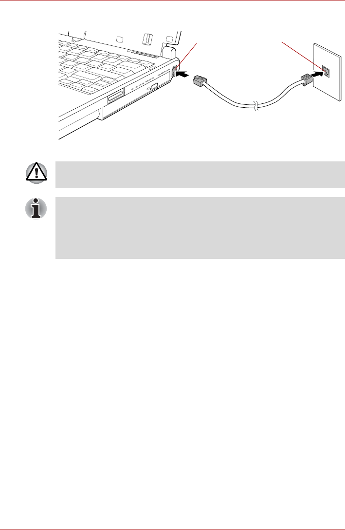
User’s Manual 4-46
Operating Basics
2. Plug the other end of the modular cable into a telephone jack.
Figure 4-28 Connecting the internal modem
Disconnecting the modular cable
To disconnect the modular cable, follow the steps as detailed below:
1. Pinch the lever on the plug in the telephone jack and pull it out from
within the connector.
2. Pinch the lever on the plug in the computer's modem jack and pull it out
from within the computer.
Modem jack Telephone jack
Do not pull on the cable or move the computer while the cable is
connected.
If you use a storage device such as an optical drive or hard disk drive
connected to a 16-bit PC Card, you might experience the following
problems with the operation of the modem:
■The modem speed is slow or communication is periodically interrupted.
■Skips or jumps may be noted in sound.

User’s Manual 4-47
Operating Basics
Wireless communications
The computer’s wireless communication function supports both Wireless
LAN and Bluetooth devices.
Only some models are equipped with both Wireless LAN and Bluetooth
functions.
Wireless LAN
The Wireless LAN is compatible with other LAN systems based on Direct
Sequence Spread Spectrum / Orthogonal Frequency Division Multiplexing
radio technology that complies with the IEEE802.11 Wireless LAN standard
(Revision A, B, G or n Draft 2.0).
■Frequency Channel Selection of 5GHz for IEEE 802.11a or 2.4GHz for
802.11b/g
■Roaming over multiple channels
■Card power management
■Do not use the Wireless LAN (Wi-Fi), Bluetooth or Wireless WAN
functionalities near a microwave oven or in areas subject to radio
interference or magnetic fields. Interference from a microwave oven or
other source can disrupt Wi-Fi, Bluetooth or Wireless WAN operation.
■Turn Wi-Fi, Bluetooth and Wireless WAN functionalities off when near
a person who may have a cardiac pacemaker implant or other medical
electric device. Radio waves may affect pacemaker or medical device
operation, possibly resulting in serious injury. Follow the instruction of
your medical device when using any Wi-Fi or Bluetooth or Wireless
WAN functionality.
■Always turn off Wi-Fi or Bluetooth or Wireless WAN functionality if the
computer is near automatic control equipment or appliances such as
automatic doors or fire detectors. Radio waves can cause malfunction
of such equipment, possibly resulting in serious injury.
■It may not be possible to make a network connection to a specified
network name using the ad hoc network function.
If this occurs, the new network(*) will have to be configured for all
computers connected to the same network in order to re-enable
network connections.
* Please be sure to use new network name.
Do not install or remove a memory module while Wake-up on Wireless
LAN is enabled.
■The Wake-up on Wireless LAN function consumes power even when
the system is off. Leave the AC adaptor connected while using this
feature.
■The Wake-up on Wireless LAN function is effective only when it is
connected with an Access Point. This function becomes invalid when
the connection is broken.

User’s Manual 4-48
Operating Basics
■Wired Equivalent Privacy (WEP) data encryption based on an 128-bit
encryption algorithm
■Wi-Fi Protected Access (WPA)
Setting
1. Please make sure that the Wireless Communication Switch is turned
on.
2. Click Start and then click Connect To to display Connect to a network
window.
3. Click Set up a connection or network.
4. Follow the wizard. You will need the name of the wireless network
together with security settings. Consult the documentation
accompanied with your router or ask your wireless network
administrator for the settings.
Security
■TOSHIBA strongly recommend that you enable encryption functionality,
otherwise your computer will be open to illegal access by an outsider
using a wireless connection. If this occurs, the outsider may illegally
access your system, eavesdrop, or cause the loss or destruction of
stored data.
■TOSHIBA is not liable for the loss of data due to eavesdropping or
illegal access through the wireless LAN and the damage thereof.
Bluetooth wireless technology
Bluetooth™ wireless technology eliminates the need for cables between
electronic devices such as desktop computers, printers and mobile phones.
You cannot use the computer's built-in Bluetooth functions and an optional
Bluetooth devices simultaneously. For reference, Bluetooth wireless
technology has the following features:
Worldwide operation
The Bluetooth radio transmitter and receiver operate in the 2.4GHz band,
which is license-free and compatible with radio systems in most countries
in the world.
The transmission speed over the wireless LAN, and the distance over
which the wireless LAN can reach, may vary depending on surrounding
electromagnetic environment, obstacles, access point design and
configuration, client design and software/hardware configurations. The
transmission rate described is the theoretical maximum speed as specified
under the appropriate standard - the actual transmission speed will be
lower than the theoretical maximum speed.

User’s Manual 4-49
Operating Basics
Radio links
You can easily establish links between two or more devices, with these
links being maintained even if the devices are not within a line-of-sight of
each other.
Security
Two advanced security mechanisms ensure a high level of security:
■Authentication prevents access to critical data and makes it impossible
to falsify the origin of a message.
■Encryption prevents eavesdropping and maintains link privacy.
Bluetooth™ Stack for Windows® by TOSHIBA
Please note that this software is specifically designed for the following
operating systems:
■Microsoft® Windows Vista®
Information regarding the use of this software with these operating systems
is listed below, with further details being contained with the electronic help
files supplied with the software.
Release Notes related to the Bluetooth™ Stack for
Windows® by TOSHIBA
1. Fax application software:
Please be aware that there is some fax application software that you
cannot use on this Bluetooth™ Stack.
2. Multi-user considerations:
On Windows Vista®, the use of Bluetooth is not supported in a multi-
user environment. This means that, when you use Bluetooth, other
users that are logged into the same computer will not be able to use this
type of functionality.
Product Support:
The latest information regarding operating system support, language
support or available upgrades can be found on our web site
http://www.toshiba-europe.com/computers/tnt/bluetooth.htm in Europe or
www.pcsupport.toshiba.com in the United States.
Wireless communication switch
You can enable or disable Wireless communication (Wireless LAN,
Bluetooth and Wireless WAN) functions, with the on/off switch. No
transmissions are sent or received when the switch is off. Slide the switch
to the right to turn it on and to the left to turn it off.
This Bluetooth™ Stack is based on the Bluetooth™ Version
1.1/1.2/2.0+EDR specification. However, TOSHIBA cannot confirm the
compatibility between any computing products and/or other electronic
devices that use Bluetooth™, other than TOSHIBA notebook computers.
User’s Manual 4-50
Operating Basics
Wireless communication Indicator
The wireless communication indicator shows the status of the computer's
wireless communication functions.
If you used the Taskbar to disable the wireless LAN, restart the computer or
perform the following procedure to re-enable it: Start -> Control Panel
-> System and Maintenance -> System -> Device Manager -> Network
adapters and right click the wireless device then choose enable.
LAN
The computer has built-in support for Ethernet LAN (10 megabits per
second, 10BASE-T), Fast Ethernet LAN (100 megabits per second,
100BASE-TX) and Gigabit Ethernet LAN (1000 megabits per second,
1000BASE-T).
This section describes how to connect/disconnect to a LAN.
LAN cable types
If you are using Gigabit Ethernet LAN (1000 megabits per second,
1000BASE-T), be sure to connect with a CAT5E cable or higher. You
cannot use a CAT3 or CAT5 cable.
If you are using Fast Ethernet LAN (100 megabits per second, 100BASE-
TX), be sure to connect with a CAT5 cable or higher. You cannot use a
CAT3 cable.
If you are using Ethernet LAN (10 megabits per second, 10BASE-T), you
can connect with a CAT3 or higher cable.
Indicator status Indication
Indicator off The wireless communication switch is off - no
wireless functionality is available.
Indicator glows Wireless communication switch is on. Wireless
LAN or Bluetooth is turned on by an application.
Do not install or remove a memory module while Wake-up on LAN is
enabled.
■The Wake-up on LAN function consumes power even when the system
is off. Leave the AC adaptor connected while using this feature.
■The Link speed (10/100/1000 megabits per second) changes
automatically depending on the network conditions (connected device,
cable or noise and so on).
The computer must be configured properly before connecting to a LAN.
Logging onto a LAN using the computer’s default settings could cause a
malfunction in LAN operation. Check with your LAN administrator
regarding set-up procedures.