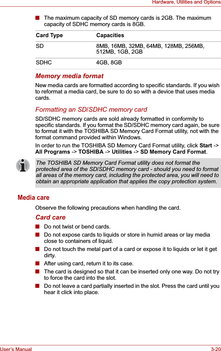
Dynabook UPA3547G3 CDMA Cell-PCS Module User Manual Manual
Toshiba Corporation CDMA Cell-PCS Module Manual
UserManual.wiki
>
Dynabook
>
UPA3547G3 User Manual
>
Manual 1
Contents
1.
3G Manual
2.
RF Exposure statement
3.
Manual
4.
Regulatory Manual Statements
5.
Manual 1
6.
Manual 2
Manual 1
Navigation menu
Upload a User Manual
Namespaces
Wiki Guide
HTML
PDF
Info
Views
User Manual
Discussion / Help
Navigation


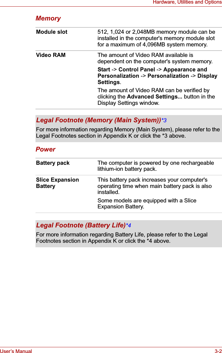
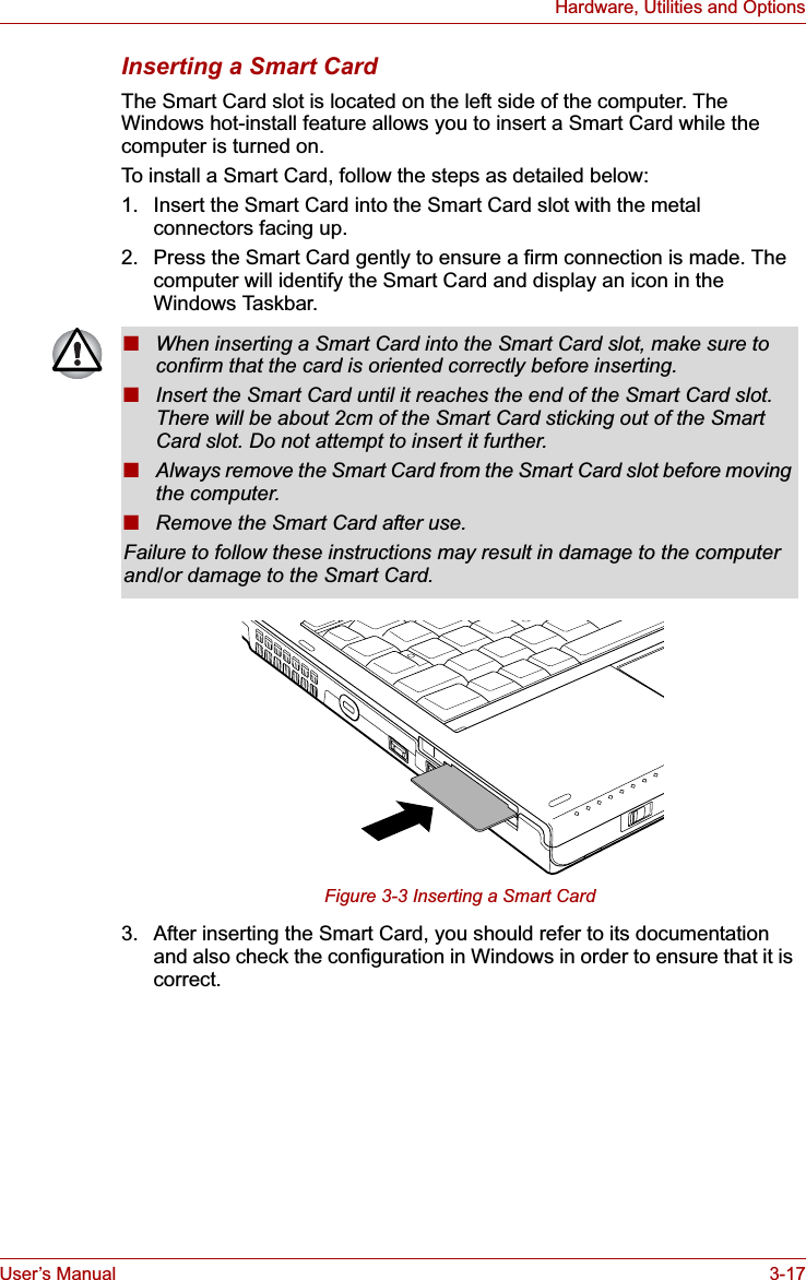
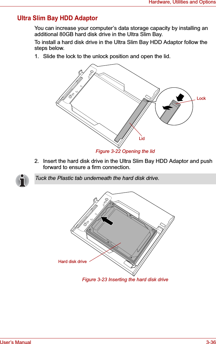
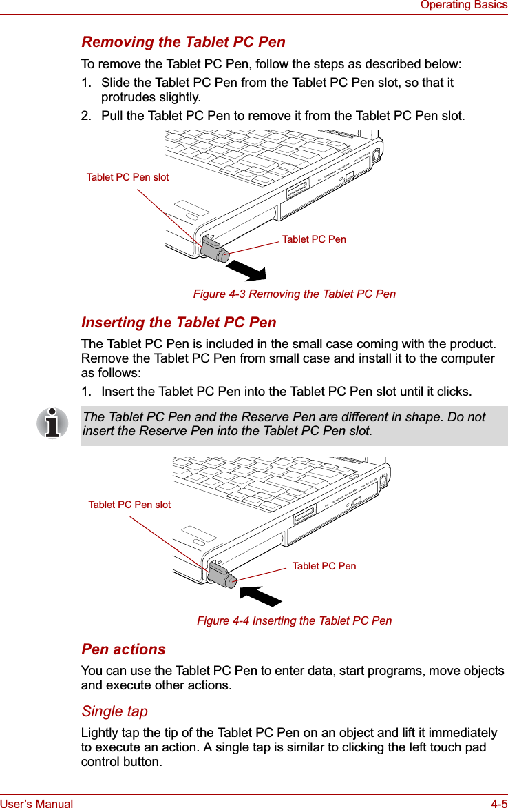
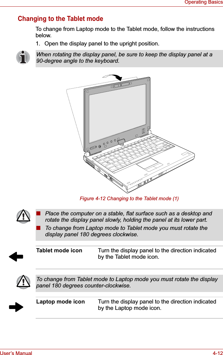
![User’s Manual viiiPORTÉGÉ M700/M710EU Conformity StatementThis product and - if applicable - the supplied accessories too are marked with "CE" and comply therefore with the applicable harmonized European standards listed under the Low Voltage Directive 2006/95/EC, the EMC Directive 2004/108/EC and/or R&TTE Directive 1999/5/EC.The complete official EU CE Declaration can be obtained on following internet page:http://epps.toshiba-teg.com/VCCI Class B InformationModem warning noticeConformity StatementThe equipment has been approved to [Commission Decision "CTR21"] for pan-European single terminal connection to the Public Switched Telephone Network (PSTN).However, due to differences between the individual PSTNs provided in different countries/regions the approval does not, of itself, give an unconditional assurance of successful operation on every PSTN network termination point.Responsible for CE-marking: TOSHIBA EUROPE GMBH, Hammfelddamm 8, 41460 Neuss, Germany.Manufacturer: Toshiba Corporation, 1-1 Shibaura 1-chome, Minato-ku, Tokyo, 105-8001, JapanThis information is applicable to the models equipped with a built-in modem.](https://usermanual.wiki/Dynabook/UPA3547G3.Manual-1/User-Guide-886039-Page-8.png)


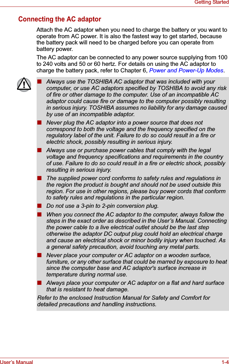


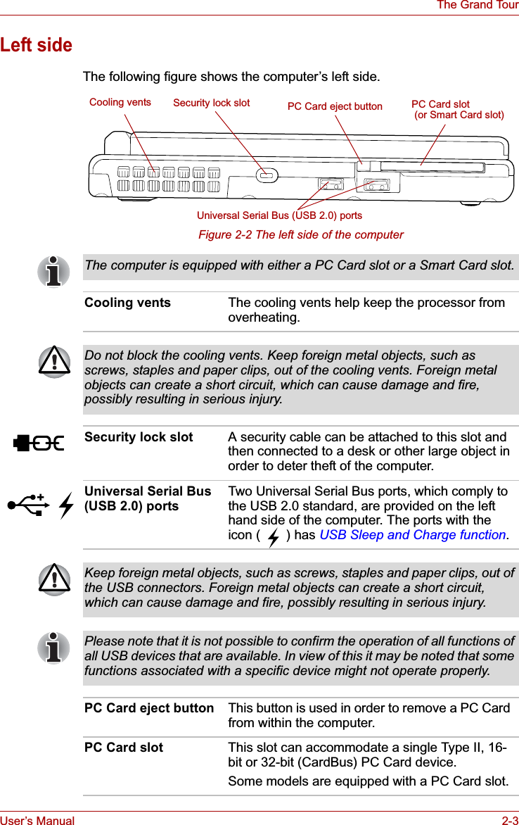


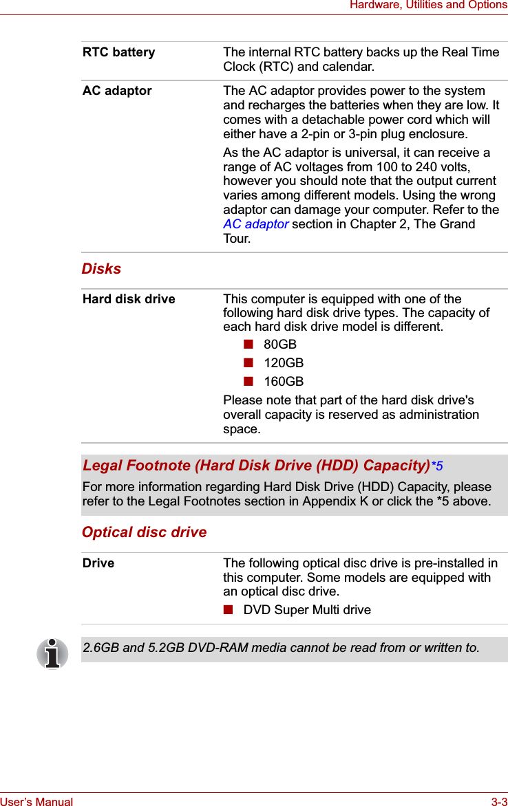

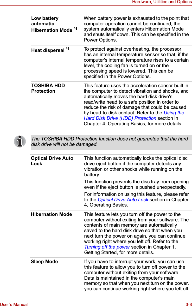


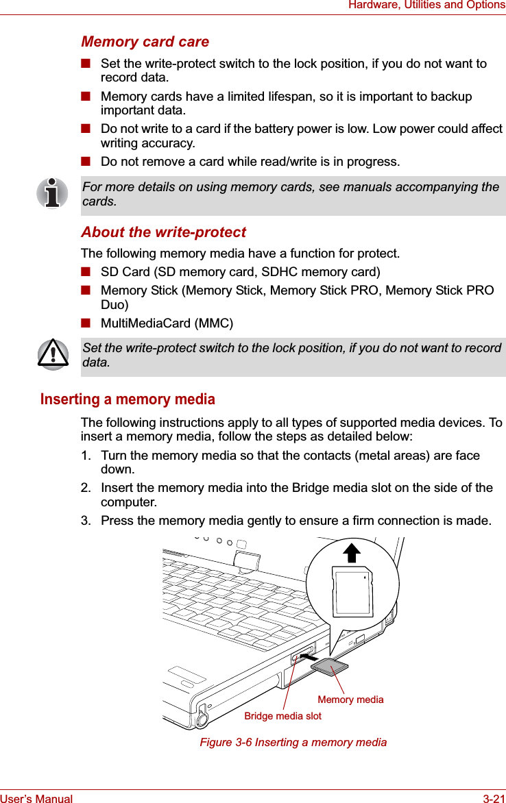


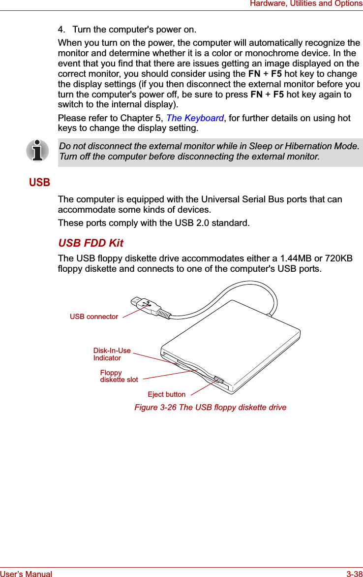
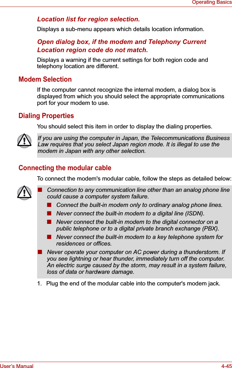
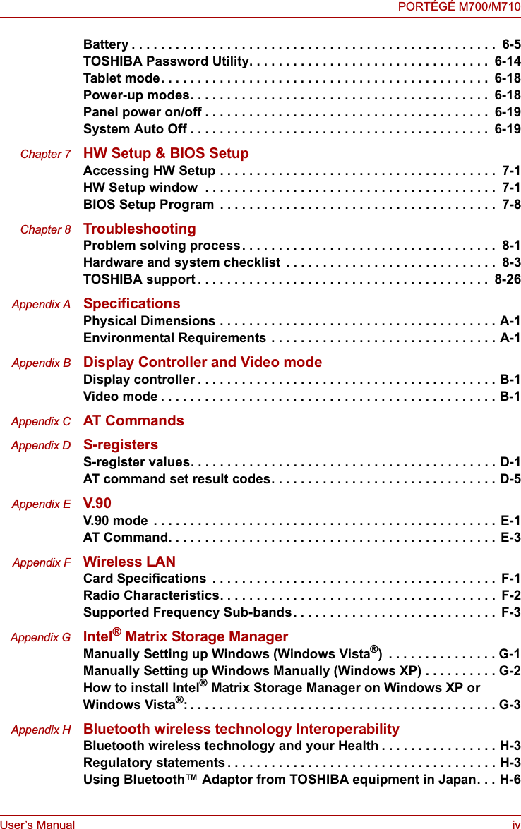
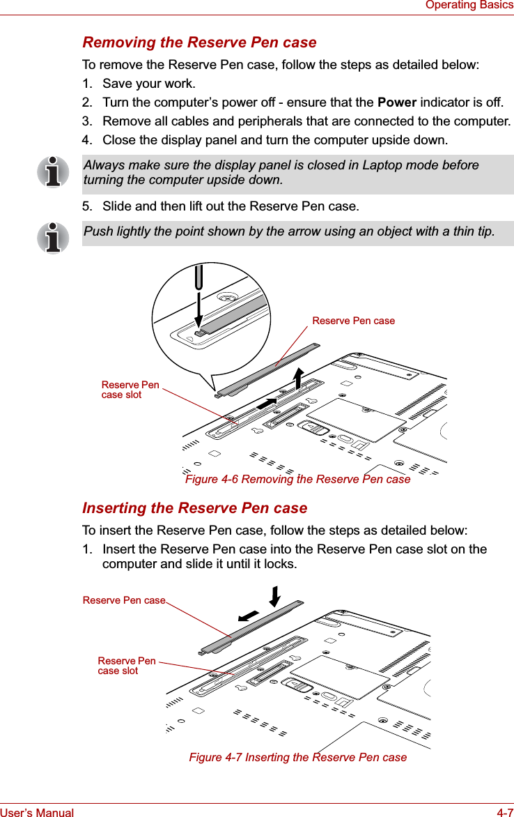
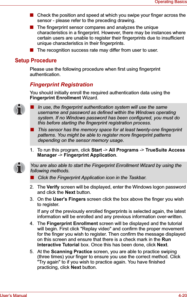
![User’s Manual 3-40Hardware, Utilities and OptionsUSB Sleep and Charge functionYour computer can supply USB bus power (DC5V) to the USB port even when the power of the computer is turned OFF. "Power OFF" includes Sleep Mode, Hibernation Mode or shutdown state.This function can only be used for ports that support the USB Sleep and Charge function (hereinafter called "compatible ports").Compatible ports are USB ports that have the ( ) symbol icon.You can use the "USB Sleep and Charge function" to charge certain USB-compatible external devices such as mobile phones or portable digital music players.However, the "USB Sleep and Charge function" may not work with certain external devices even if they are compliant with the USB specification. In those cases, turn the power of the computer ON to charge the device.■The "USB Sleep and Charge function" only works for compatible ports.This function is disabled in the default setting. To enable it, you must change [Disabled] to [Enabled] in the BIOS Setup.Refer to the USB Sleep and Charge function section in Chapter 7, HW Setup & BIOS Setup.■When "USB Sleep and Charge function" is set to [Enabled] in BIOS Setup, USB bus power (DC5V) will be supplied to compatible ports even when the power of the computer is turned OFF.USB bus power (DC5V) is similarly supplied to the external devices which are connected to the compatible ports. However, some external devices cannot be charged solely by supplying USB bus power (DC5V).As for the specifications of the external devices, please contact the device manufacturer or check the specifications of the external devices thoroughly before use.■Using the USB sleep and charge function to charge external devices will take longer than charging the devices with their own chargers.■If external devices are connected to compatible ports when the AC adaptor is not connected to the computer, the battery of the computer will be depleted even when the power of the computer is turned OFF.As such, we recommend that you connect the AC adaptor to the computer when using the USB sleep and charge function.■External devices connected to the USB bus power (DC5V) function that interfaces with the power ON/OFF of the computer may always be in an operational state.■When there is a current overflow of the external devices connected to the compatible ports, USB bus power (DC5V) supply may be stopped for safety reasons.Metal paper clips or hair pins/clips will generate heat if they come into contact with USB ports. Do not allow USB ports to come into contact with metal products, for example when carrying the computer in your bag.](https://usermanual.wiki/Dynabook/UPA3547G3.Manual-1/User-Guide-886039-Page-94.png)
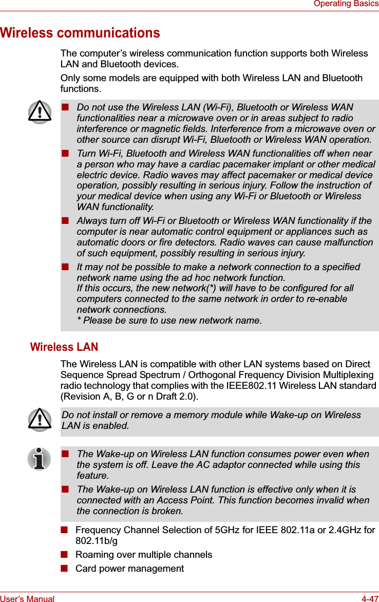
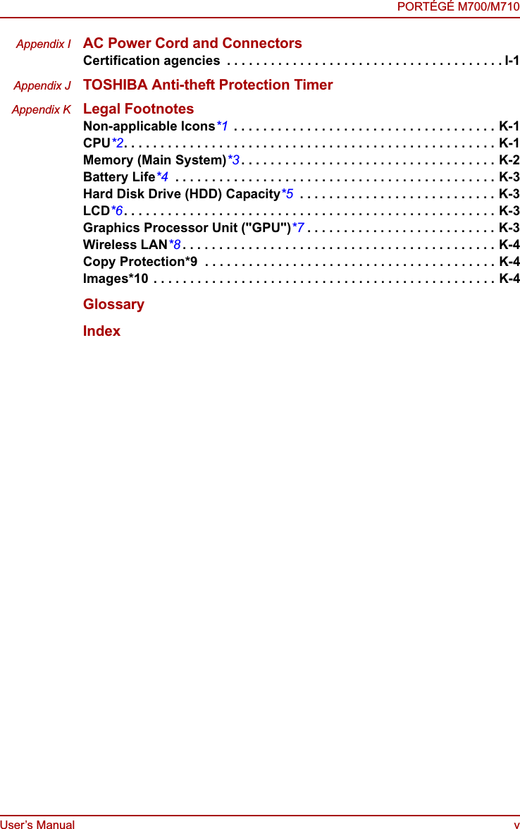
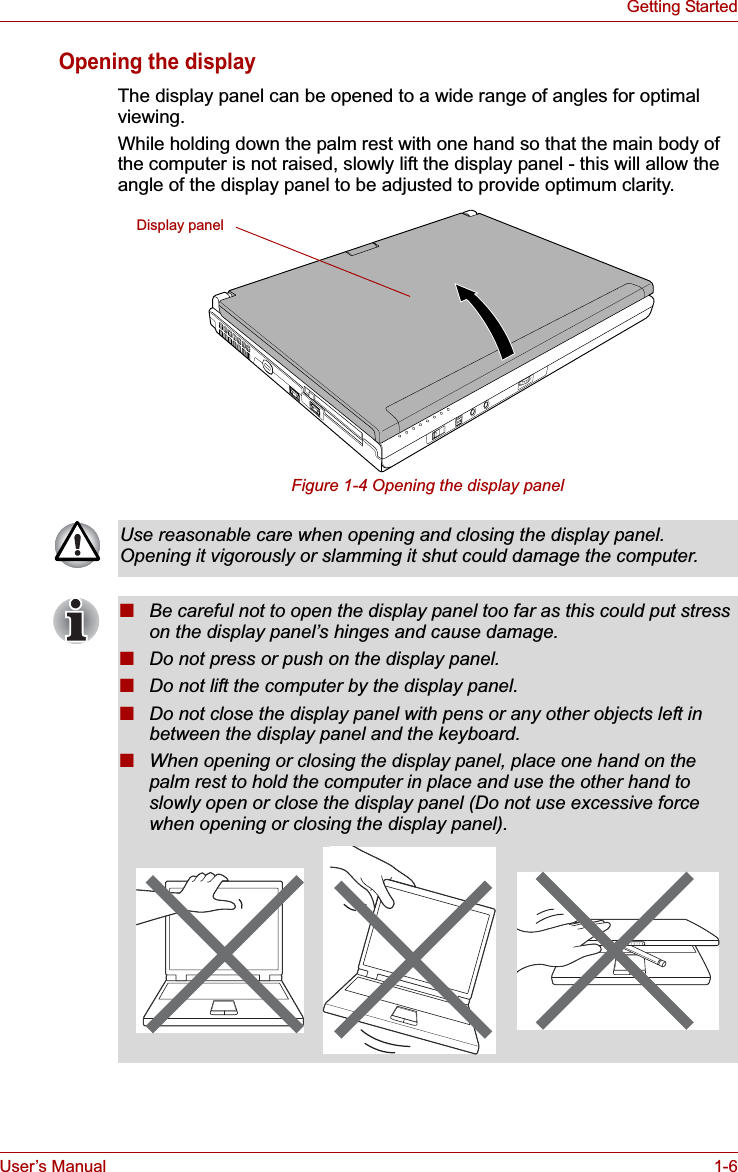
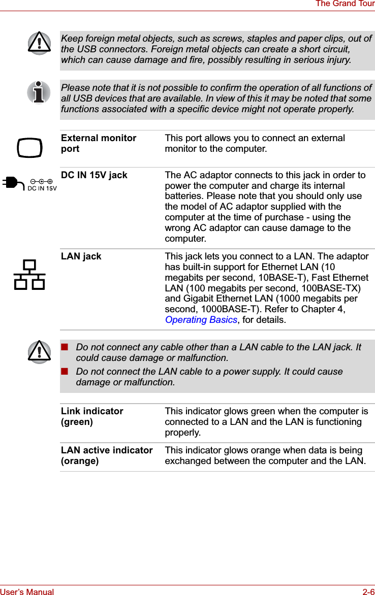
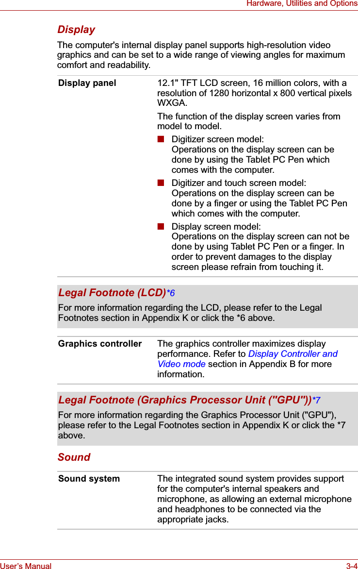
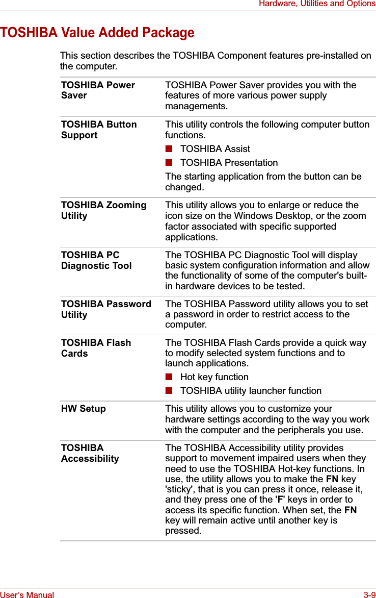
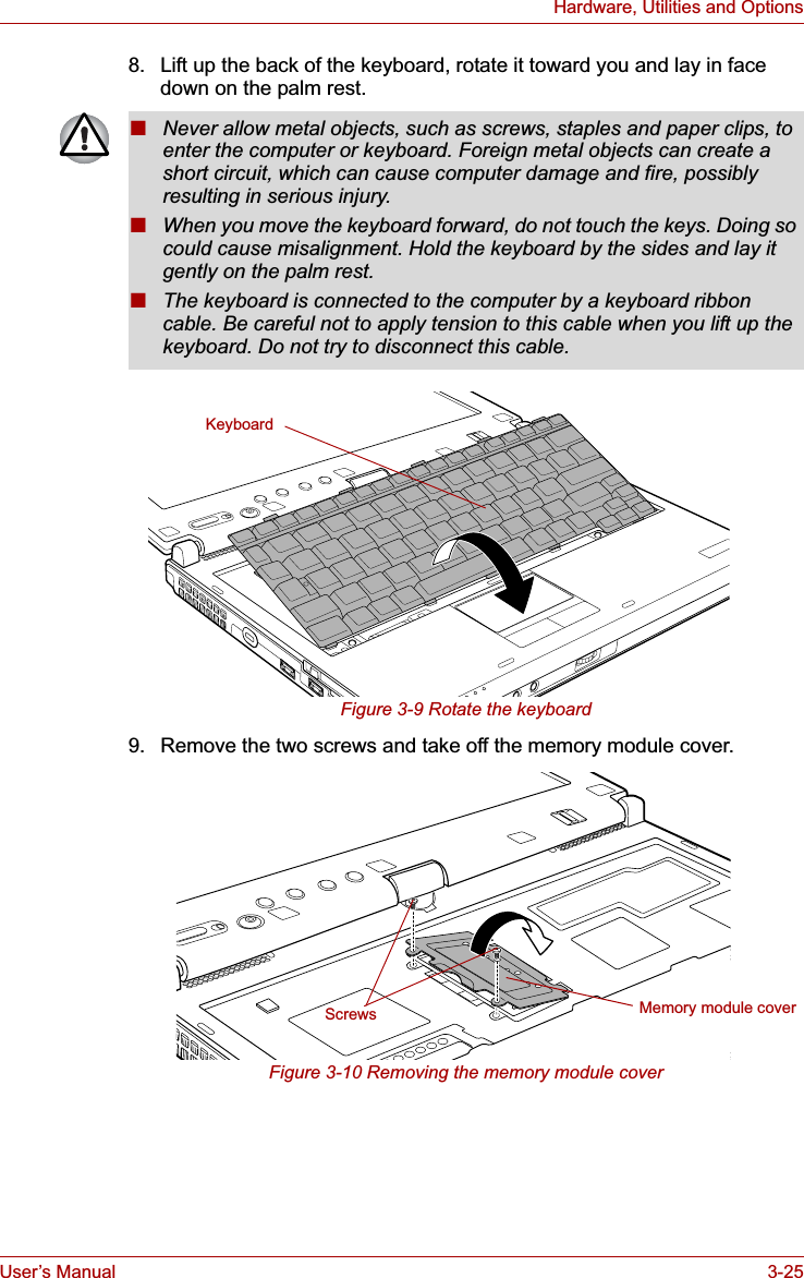
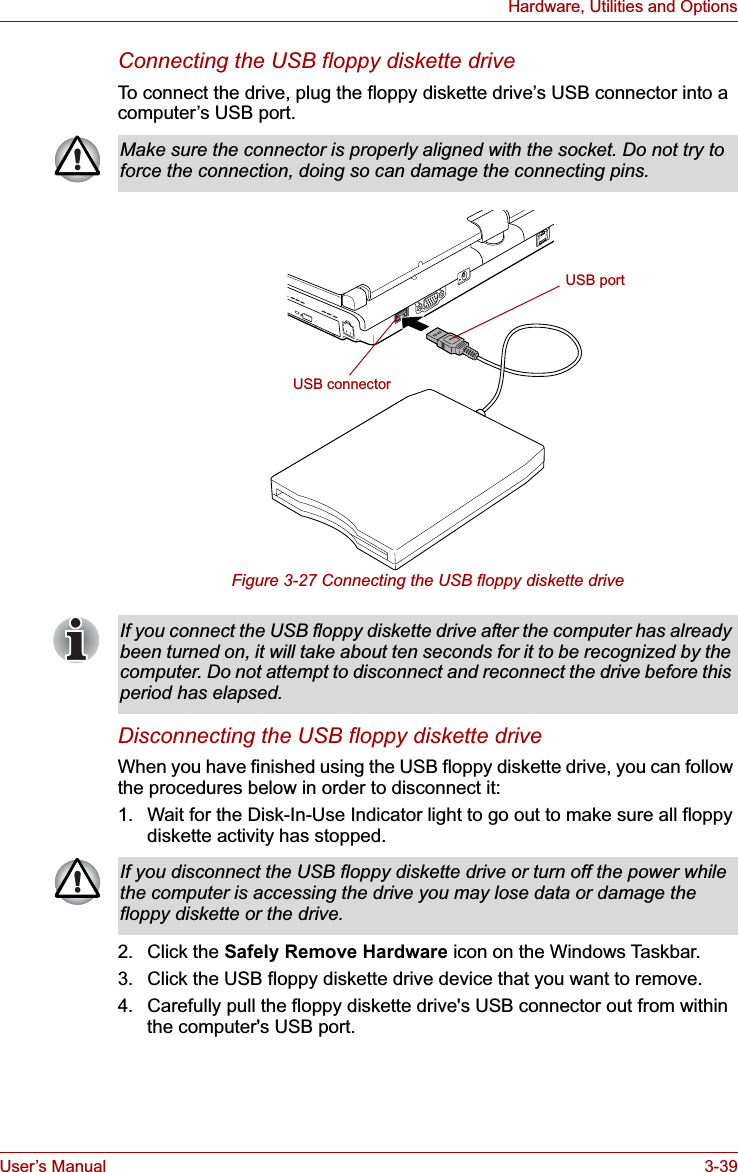
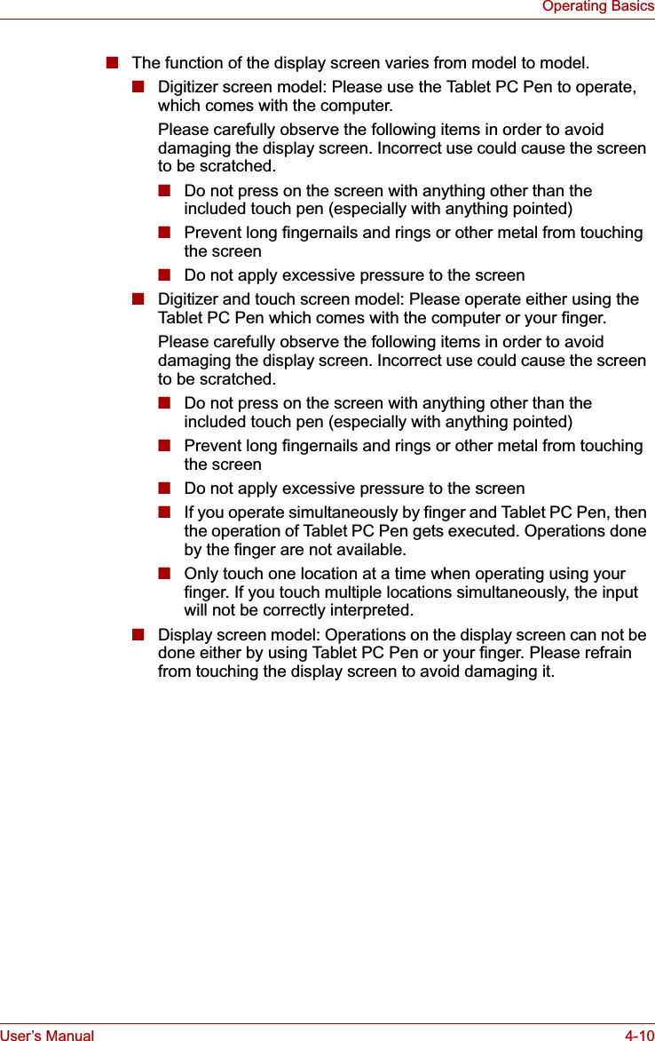
![User’s Manual 3-41Hardware, Utilities and OptionsUSB WakeUp functionThis function restores the computer from Sleep Mode depending on the external devices connected to the USB ports.The "USB WakeUp function" operates under Windows Vista® OS and it works for all USB ports.i.LINK (IEEE1394)i.LINK (IEEE1394) is used for high-speed data transfer for a range of compatible devices such as:■Digital video cameras■Hard disk drives■MO drives■Writable optical disc drivesPrecautions■Make a back-up of your data before transferring it to the computer. There is a possibility that the original data will be damaged. There is a particular risk that some frames will be deleted in the case of digital video transfer. TOSHIBA assumes no liability for such loss of data.■Do not transfer data in areas where static electricity is easily generated or in areas subjected to electronic noise. Data can be destroyed.■If you are transferring data through an IEEE1394 hub, do not connect or disconnect other devices from the hub during data transfer. There is a likelihood that data will be damaged. Connect all devices to the hub before you turn on the computer’s power.■You may not use any copyrighted video or music data copied from a video camera except for your personal enjoyment.■"USB WakeUp function" will supply USB bus power (DC5V) to all USB ports ,including compatible ports, even when the computer is in Sleep Mode.USB bus power (DC5V) will not be supplied if the computer is in Hibernation Mode or shutdown state.■When "USB Sleep and Charge function" is set to [Enabled] in BIOS Setup, the "USB WakeUp function" does not work for compatible ports. The WakeUp setting (function to allow the WakeUp) check box will be displayed on the Device Manager. You can change the settings but the USB WakeUp function will not work. For example, if a mouse or USB keyboard is connected to a compatible port, moving the mouse/keyboard will not "wakeup" the computer.In that case, attach the mouse or keyboard to an USB port that does not have the USB Sleep and Charge function-compatible icon ( ).i.LINK uses a four-pin connector, which does not carry any electric current. External devices will need their own power supply to operate.](https://usermanual.wiki/Dynabook/UPA3547G3.Manual-1/User-Guide-886039-Page-95.png)

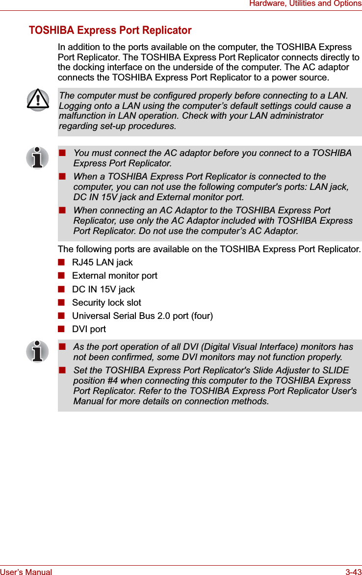


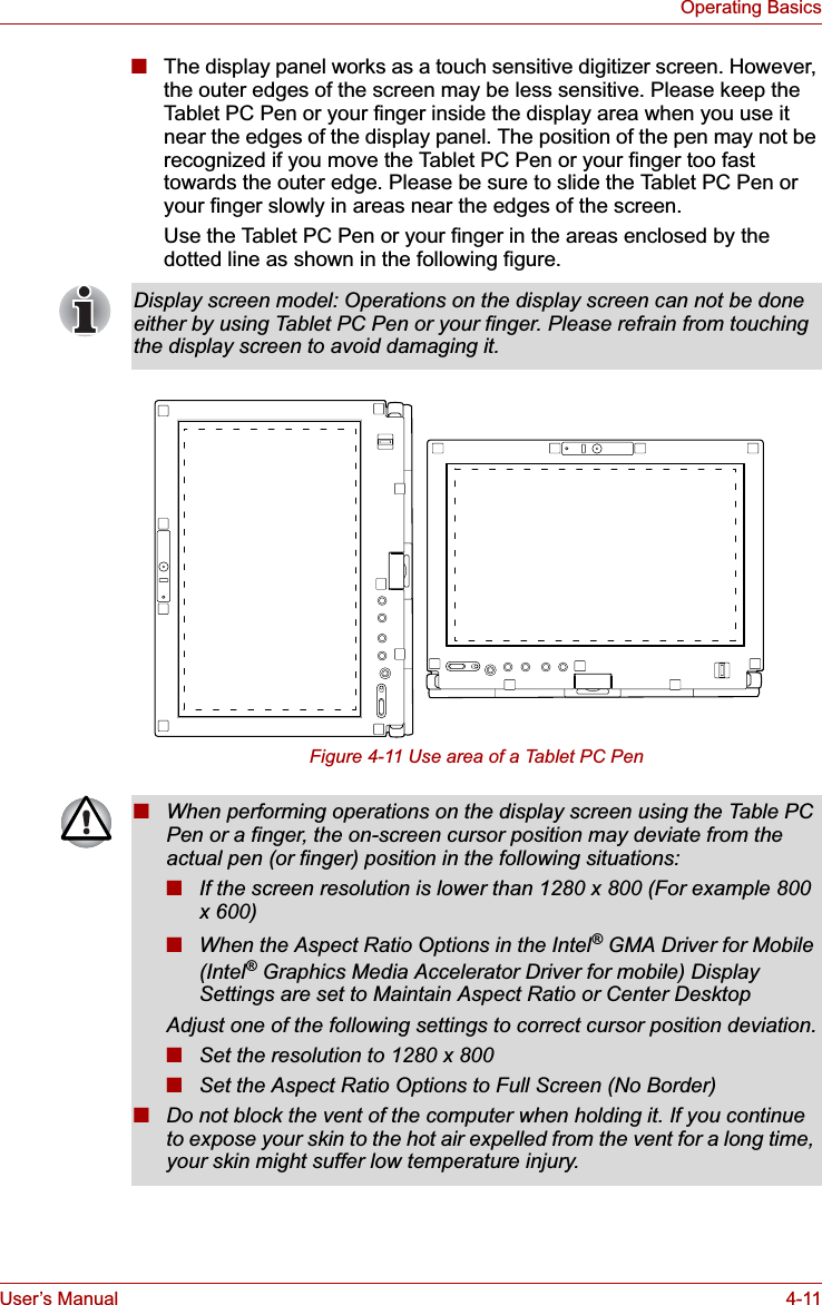


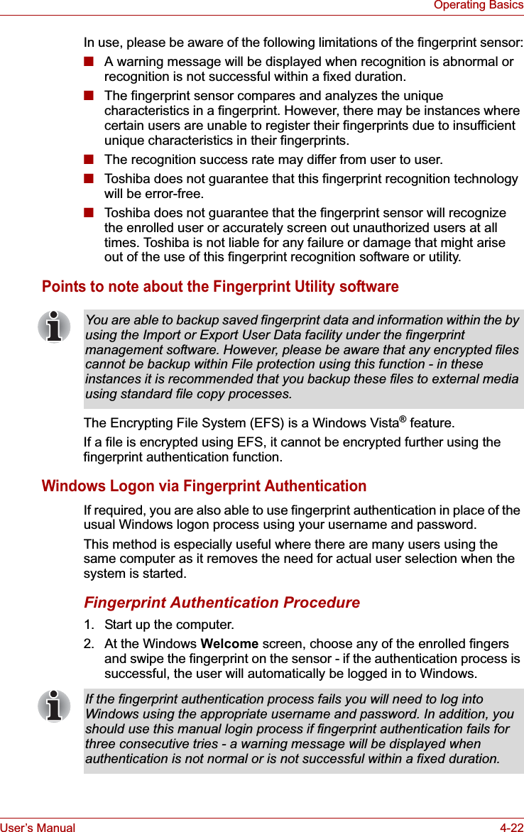
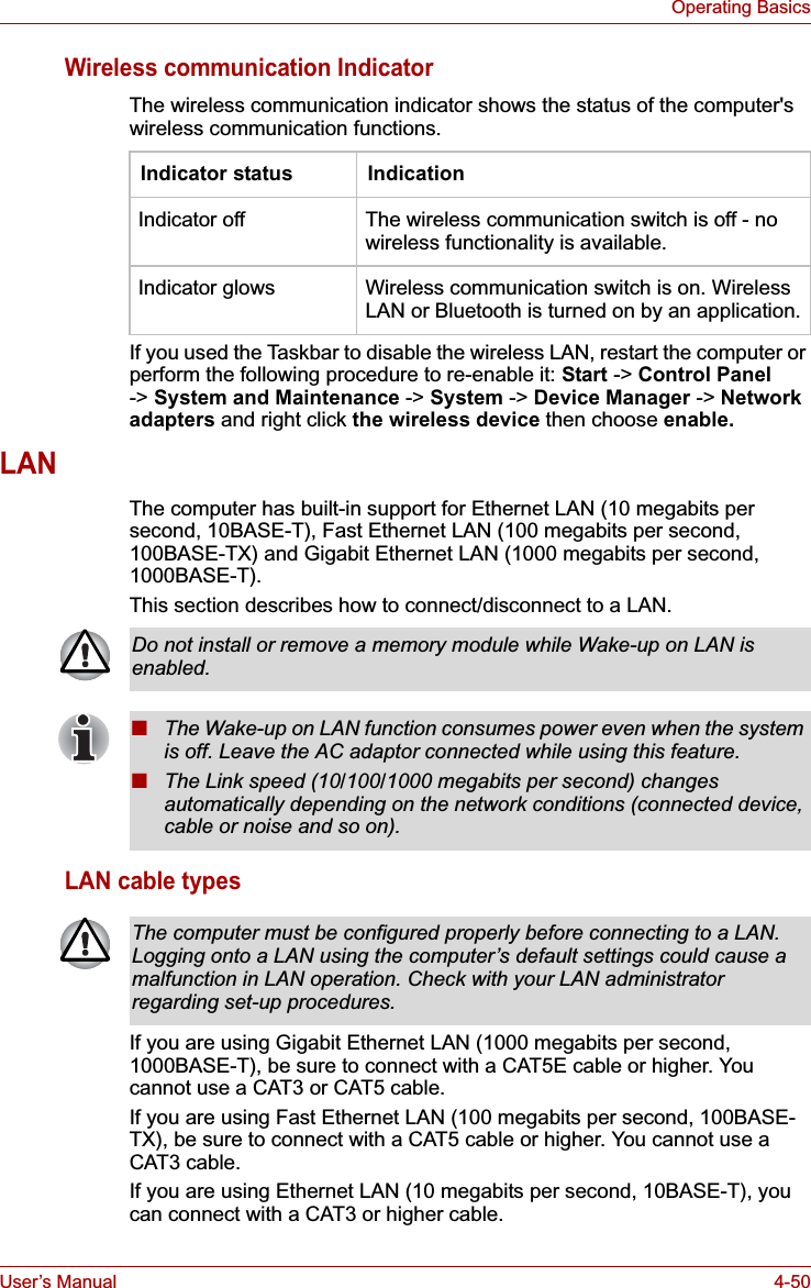
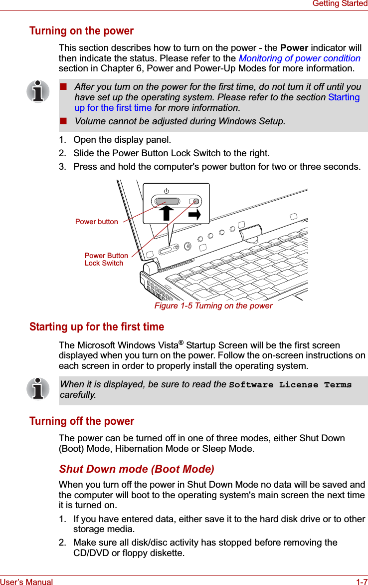
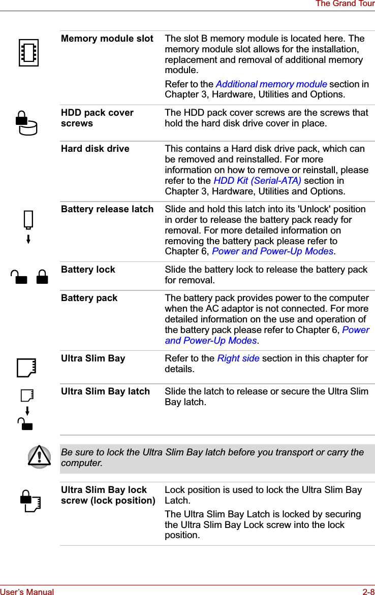
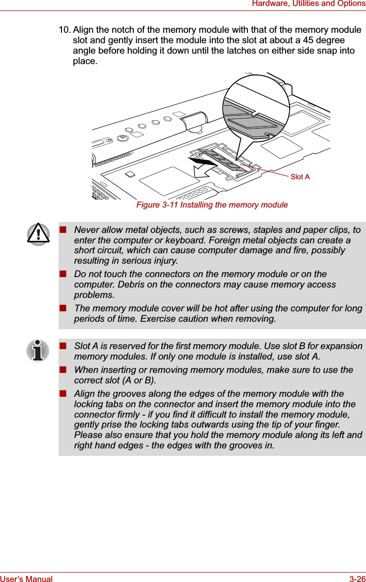
![User’s Manual 4-23Operating BasicsFingerprint Pre-OS AuthenticationGeneralThe fingerprint authentication system can be used to replace the keyboard based password authentication system that is used when the computer is turned on.If you do not want to use the fingerprint authentication system for password authentication while booting up the computer, instead you prefer using the keyboard entry method, simply press the BACK SPACE key or the ESC/Rotation button when the Fingerprint Pre-OS Authentication screen is displayed.Using this process will switch the password input screen across to the keyboard based entry screen.How to Enable Fingerprint Pre-OS Authentication SettingsIt is necessary to first enroll your fingerprint with the Fingerprint Application prior to enabling and configuring the Fingerprint Pre-OS Authentication System. You should check that your fingerprint is enrolled before configuring the settings (please refer to the Manual for Fingerprint Registration/Enrollment for further instructions).1. To run this program, click Start -> All Programs -> TrueSuite Access Manager -> Fingerprint Application with Admin.2. UserAccountControl screen is displayed, click the Allow button.This setting can only be changed if the currently logged in user has administrator privileges.3. Swipe a registered finger on the fingerprint sensor.4. Click the Setting menu at the TrueSuiteAccessManager screen.5. Administrator Setting screen is displayed, check the "Enable Pre-OS Fingerprint Authentication" check box and then click OK.6. Click the Exit button at the TrueSuiteAccessManager screen.■You must ensure that you use the TOSHIBA Password Utility to register a User Password before using the Fingerprint Pre-OS Authentication and its extended function to allow fingerprints to be used to access the computer when it is turned on.■If the fingerprint authentication process fails five times, a preset time limit is exceeded, or you press the BACK SPACE key, [Password =] will be displayed on the screen and you will have to enter either the User Password or Supervisor Password manually in order to start the computer.■When swiping your finger, please ensure that you do it slowly and at a constant speed. If you find that this does not improve the authentication rate, you should try to adjust the speed at which the finger is swiped.■If there are any changes in the environment or settings related to authorization, you will be required to provide authorization information such as a User Password (and, if applicable, the HDD(Hard Disk Drive) password).](https://usermanual.wiki/Dynabook/UPA3547G3.Manual-1/User-Guide-886039-Page-123.png)


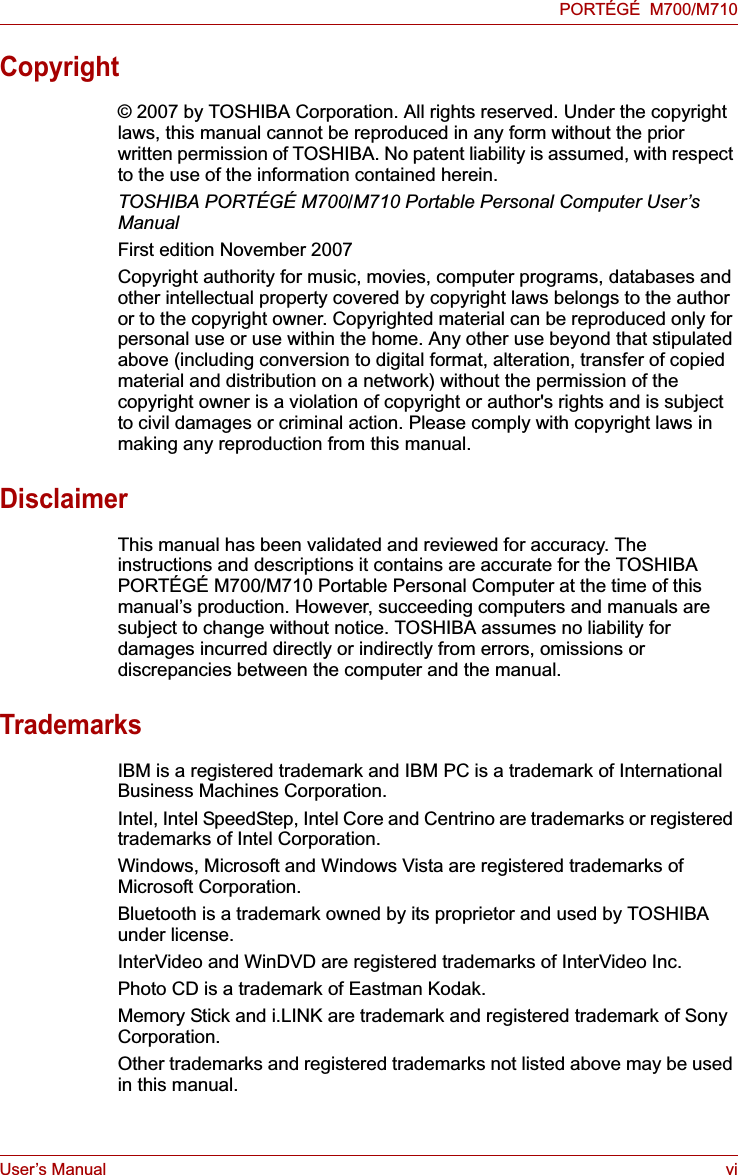
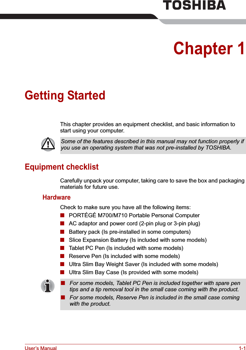
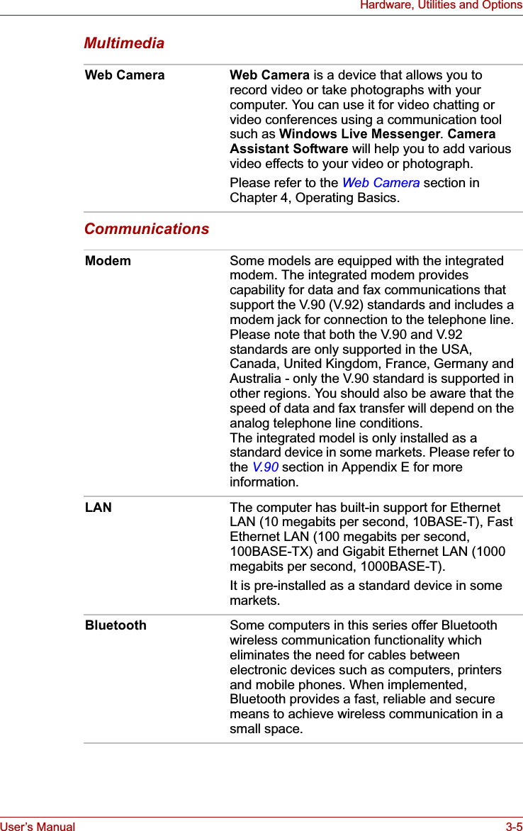
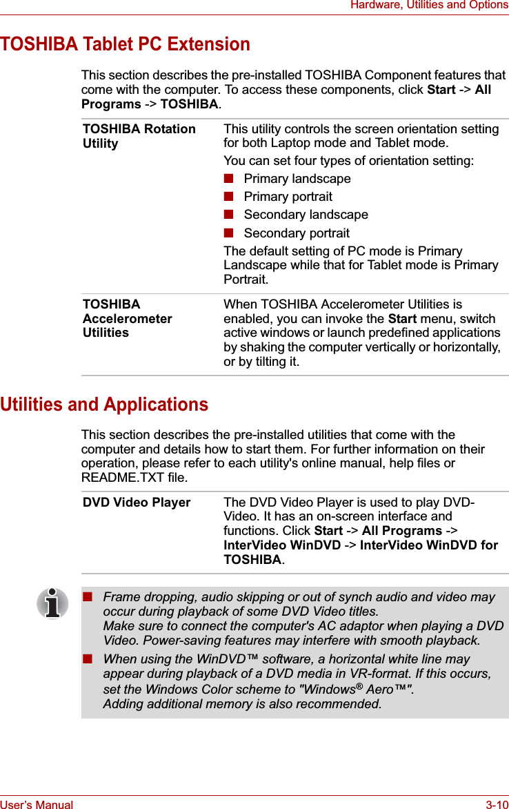
![User’s Manual 4-26Operating BasicsChanging Ultra Slim Bay modulesThis section explains how to change modules in the Ultra Slim Bay. The illustrations show replacement of the optical disc drive with the Ultra Slim Bay HDD Adaptor.Removing a moduleTo remove the optical disc drive, follow the steps as described below:1. Save your work.2. Turn the computer's power off - ensure that the Power indicator is off.3. Remove all cables and peripherals that are connected to the computer.4. Close the display panel.5. Turn the computer upside down and remove the battery pack (refer to Replacing the battery pack section in Chapter 6, Power and Power-Up Modes, if required).6. Remove the Ultra Slim Bay lock screw from the Lock position.7. Set the Ultra Slim Bay lock screw in the Unlock position.■Do not point the web camera directly at the sun.■Do not touch or press strongly on the web camera lens. Doing so may reduce image quality. Use an eyeglass cleaner (cleaner cloth) or other soft cloth to clean the lens if it becomes dirty.■Setting the [Size] to more than "800x600" will cause a larger amount of data to be written to the hard disk drive and may interfere with smooth recording.■When recording in dimly lit environments, the following procedure can be used to select "Night Mode" which allows for brighter images with less noise.1. Click the Properties button on the [Web Camera] menu.2. Check Night Mode on the [Options] tab.3. Click the OK button.The number of frames per second is lowered when "video recording" in "Night Mode". This may result in the playback of the recorded video file seeming unsmooth.To avoid injury, do not put your hand into the Ultra Slim Bay slot.Always make sure the display panel is closed in Laptop mode before turning the computer upside down.Wait for all disk indicators to go out before you turn over the computer and do not lay the computer down gently. Shock can damage the HDD or other components.](https://usermanual.wiki/Dynabook/UPA3547G3.Manual-1/User-Guide-886039-Page-126.png)