Dynabook UPA3547G3 CDMA Cell-PCS Module User Manual Manual
Toshiba Corporation CDMA Cell-PCS Module Manual
UserManual.wiki
>
Dynabook
>
UPA3547G3 User Manual
>
Manual 2
Contents
1.
3G Manual
2.
RF Exposure statement
3.
Manual
4.
Regulatory Manual Statements
5.
Manual 1
6.
Manual 2
Manual 2
Navigation menu
Upload a User Manual
Namespaces
Wiki Guide
HTML
PDF
Info
Views
User Manual
Discussion / Help
Navigation

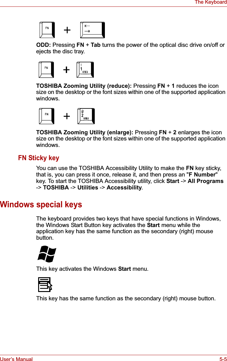
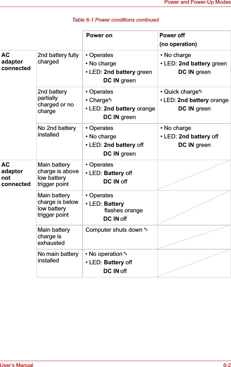


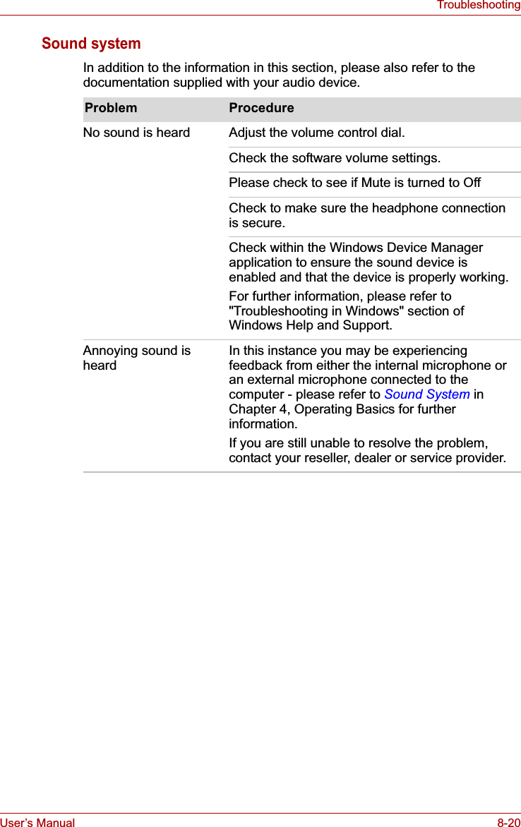
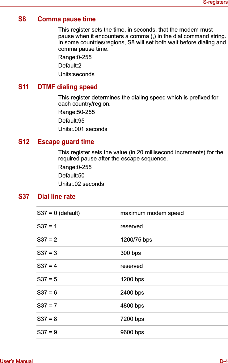
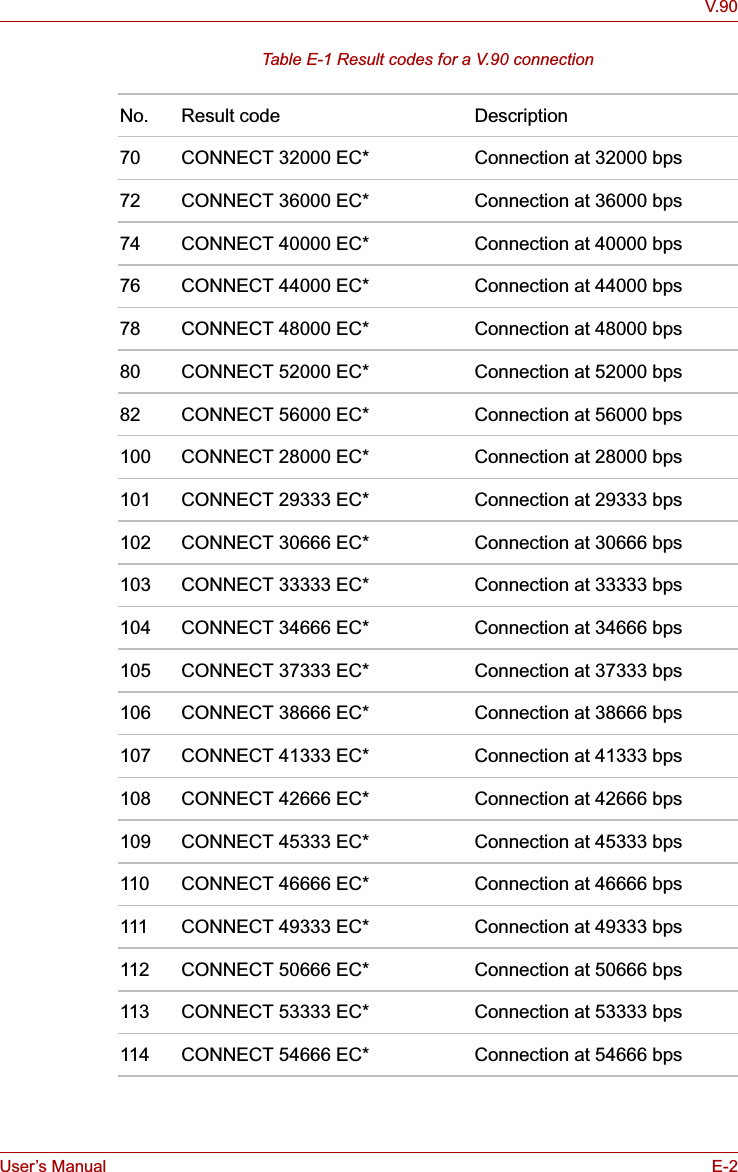
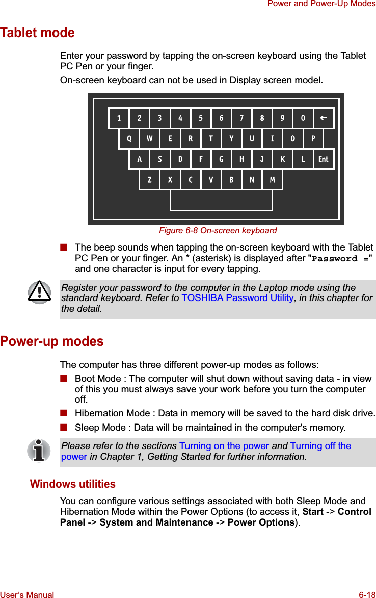
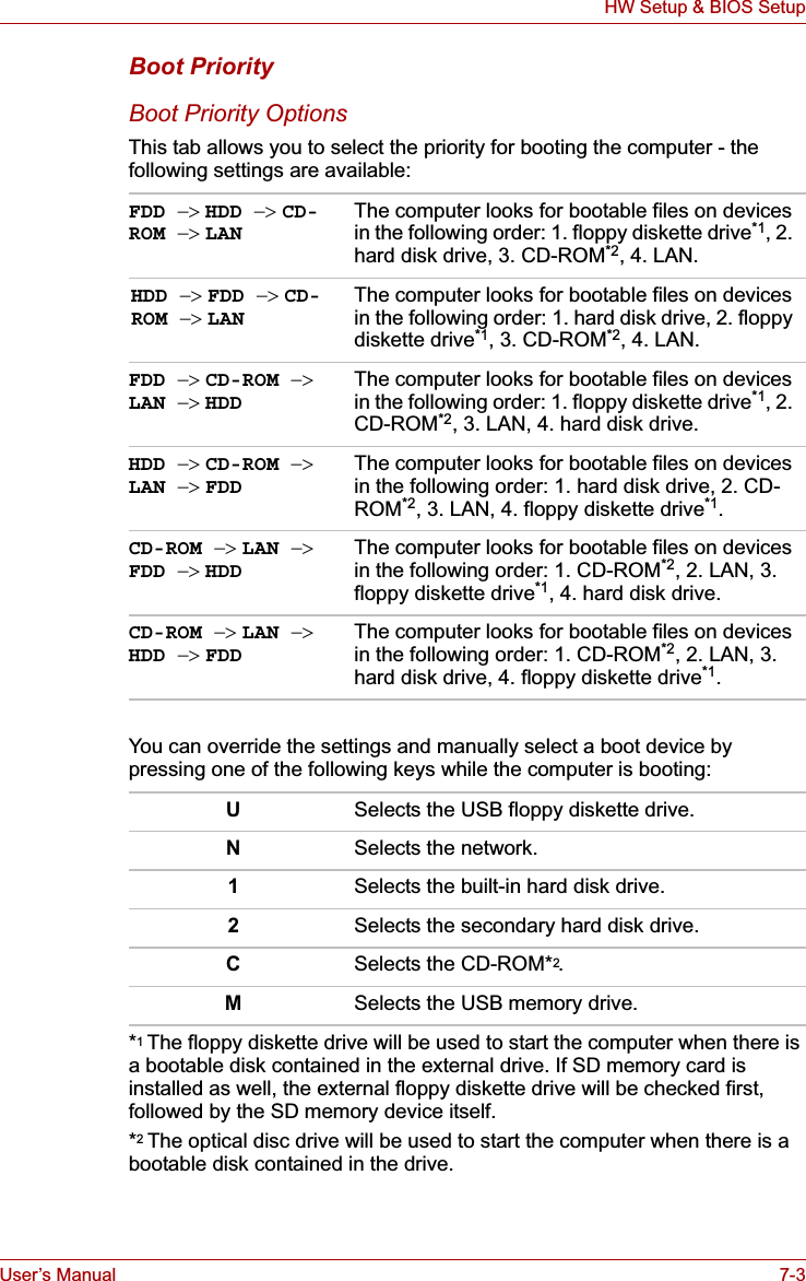
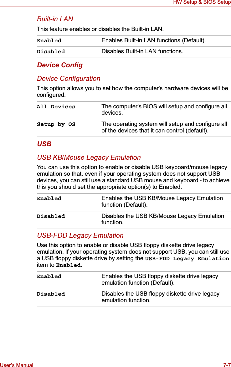
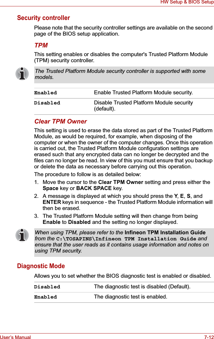
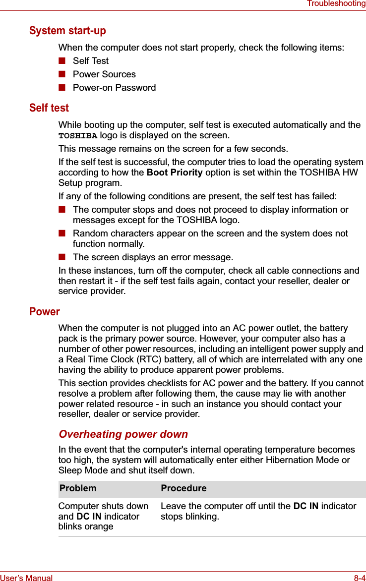
![User’s Manual 6-6Power and Power-Up ModesReal Time Clock (RTC) batteryThe Real Time Clock (RTC) battery provides power for the internal real time clock and calendar function and also maintains the system configuration while the computer is turned off. If the RTC battery becomes completely discharged, the system will lose this information and the real time clock and calendar will stop working - in this instance the following message will be displayed when you turn on the power:S**** RTC battery is low or CMOS checksum is inconsistent **** Press [F1] key to set Date/Time. You can change the Real Time Clock settings by turning the computer on while pressing the ESC key and then the F1 key when prompted. Please refer to Chapter 8 Troubleshooting for further information.Care and use of the battery packThis section provides the important safety precautions in order to handle your battery pack properly.Refer to the enclosed Instruction Manual for Safety and Comfort for detailed precautions and handling instructions.The RTC battery does not charge while the computer is turned off even if the AC adaptor is attached.■Make sure the battery is securely installed in the computer before attempting to charge the battery pack. Improper installation could generate smoke or fire, or cause the battery pack to rupture.■Keep the battery pack out of reach of infants and children. It can cause injury.■The battery pack and Slice Expansion Battery are lithium ion battery, which can explode if not replaced, used, handled or disposed of properly. Dispose of the battery as required by local ordinances or regulations. Use only batteries recommended by TOSHIBA as replacements.■The computer's RTC battery is a Ni-MH battery and should be replaced only by your dealer or by a TOSHIBA service representative. The battery can explode if not properly replaced, used, handled or disposed. Dispose of the battery as required by local ordinances or regulations. ■Charge the battery pack only in an ambient temperature between 5 and 35 degrees Celsius. Otherwise, the electrolyte solution might leak, battery pack performance might deteriorate and the battery life might be shortened.■Never install or remove the battery pack without first turning off the power and disconnecting the AC adaptor. Never remove the battery pack while the computer is in Sleep Mode. Data could be lost.](https://usermanual.wiki/Dynabook/UPA3547G3.Manual-2/User-Guide-886040-Page-18.png)

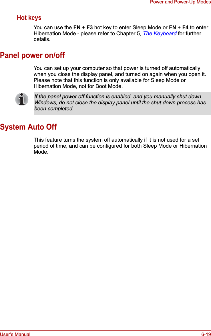
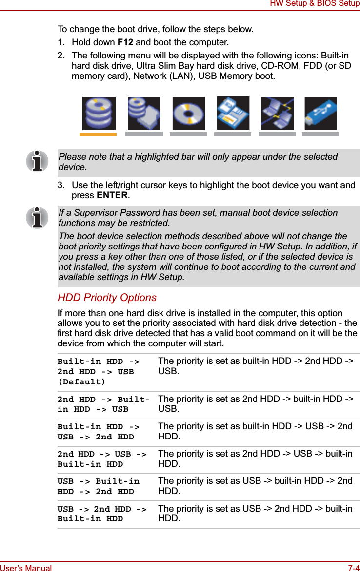
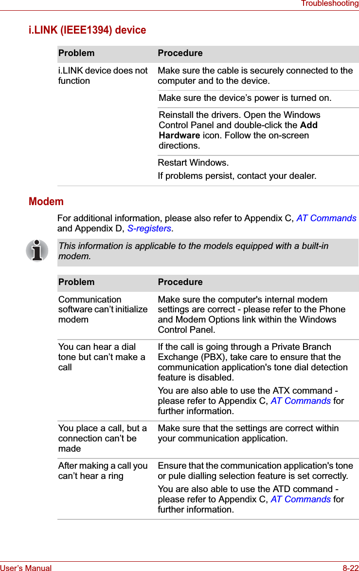
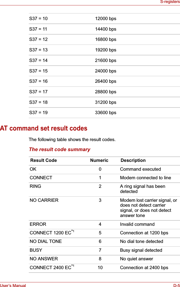
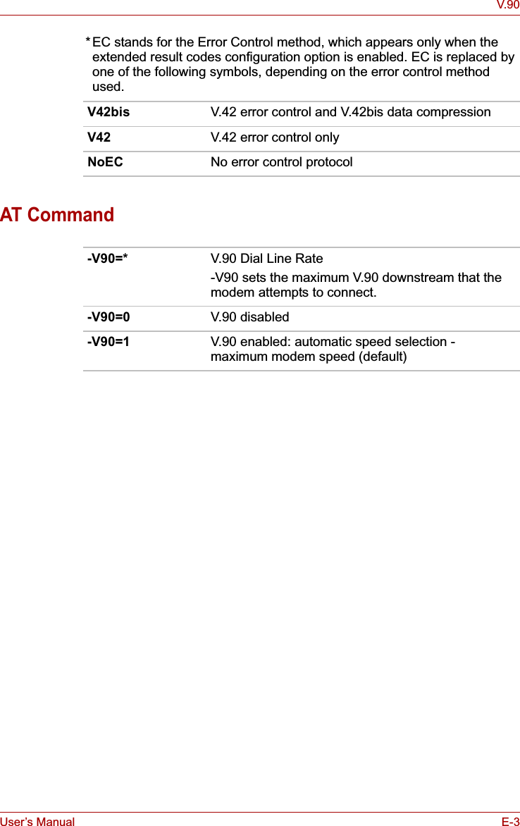
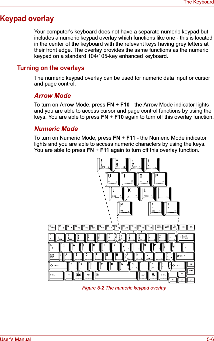
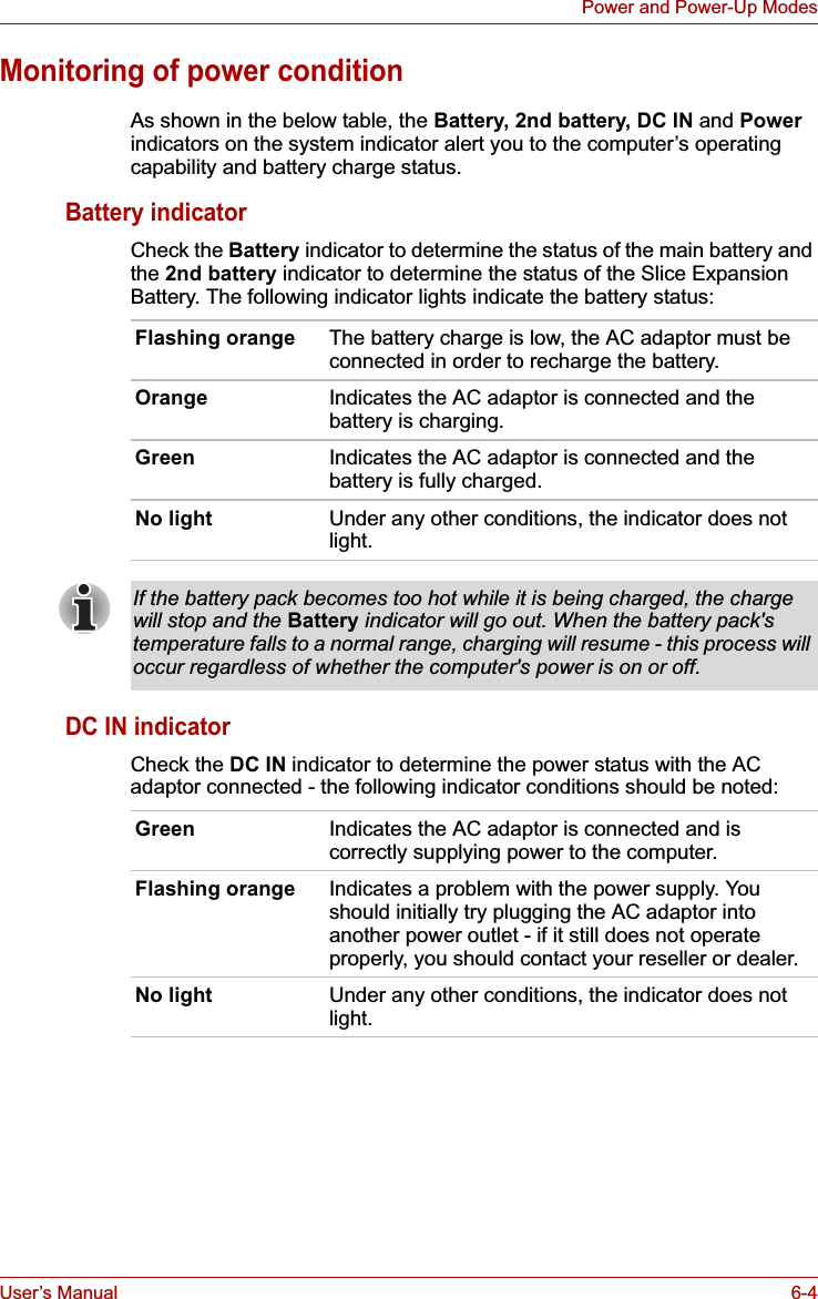
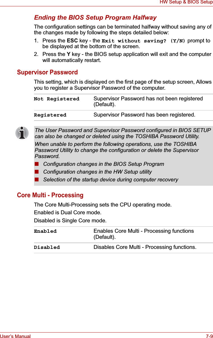
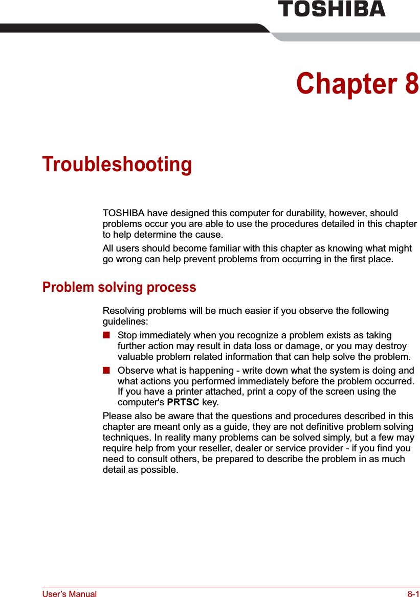
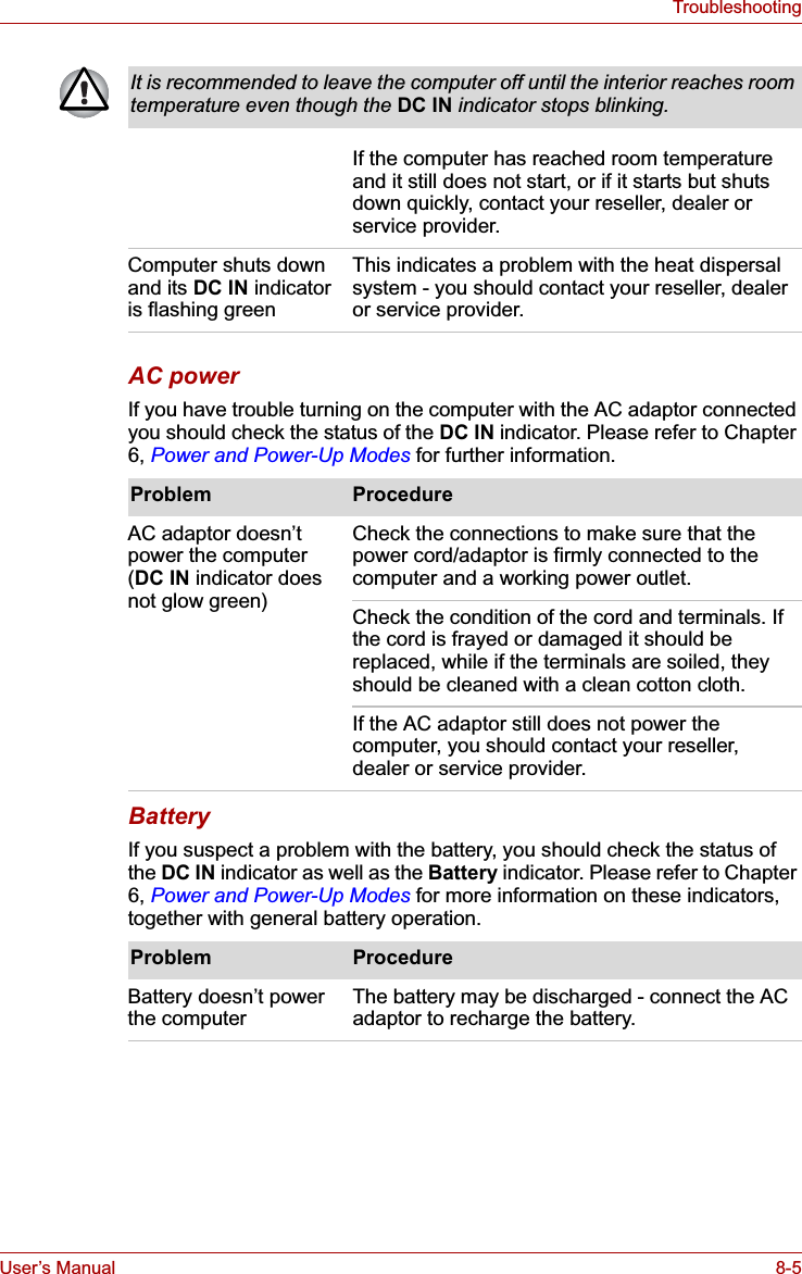
![User’s Manual 7-8HW Setup & BIOS SetupBIOS Setup ProgramSettings for some features are carried out in the BIOS setup program.Starting and Ending the BIOS Setup ProgramStarting the BIOS Setup Program1. Turn on the computer while pressing the ESC key - if the Password =prompt is displayed, enter either the Supervisor Password, if one is set, or the User Password and press the ENTER key. Please refer to Chapter 6, the TOSHIBA Password Utility for further details about the User Password.2. At the Check system. Then press [F1] key. prompt, press the F1 key - the BIOS setup application will start up.Ending the BIOS Setup ProgramIn order to save the changes you have made and end the BIOS setup application, follow the steps as detailed below:1. Press the END key - this will cause the Are you sure? (Y/N). The changes you made will cause the system to reboot.prompt to be displayed at the bottom of the screen.2. Press the Y key - this will save the configuration changes and end the BIOS setup application, automatically restarting the computer.Notes Before Using the BIOS Setup Application■In most cases, changes to the system's configuration should be made within Windows by using applications such as TOSHIBA HW Setup,TOSHIBA Password Utility,Windows Device Manager and so forth. If you make changes to the configuration through the BIOS setup program, please be aware that the configuration set through the Windows applications will take priority.■Changes to the settings within the BIOS setup program will not be erased even if the power supply is turned off and the main battery removed. However, if the built-in Real Time Clock (RTC) battery runs out of power, most of the settings will revert back to their default values. However, please note that the following items will not be affected in this instance:• Password• Hard Disk Drive Password• Security Controller• Fingerprint patternsPlease refer to the operating instructions displayed in the settings screen.](https://usermanual.wiki/Dynabook/UPA3547G3.Manual-2/User-Guide-886040-Page-39.png)
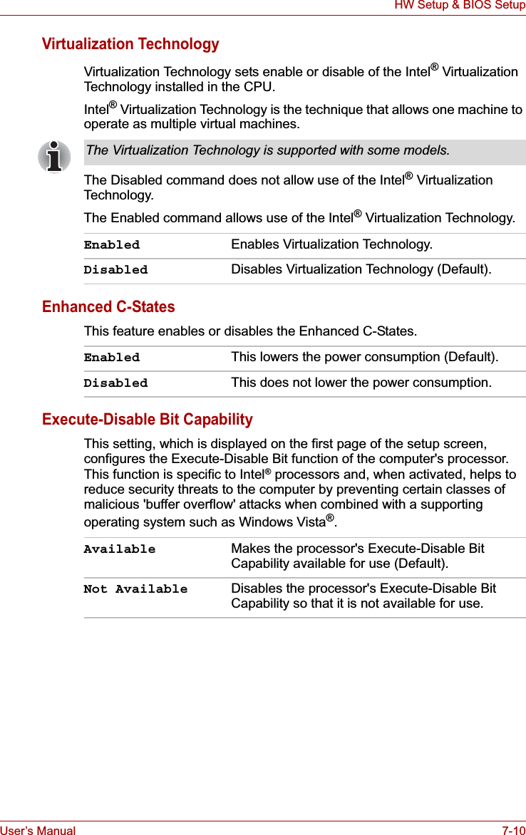
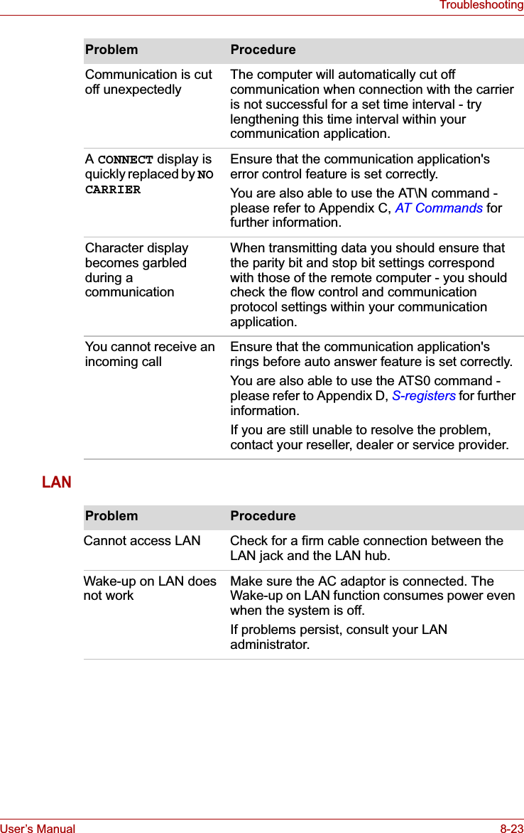
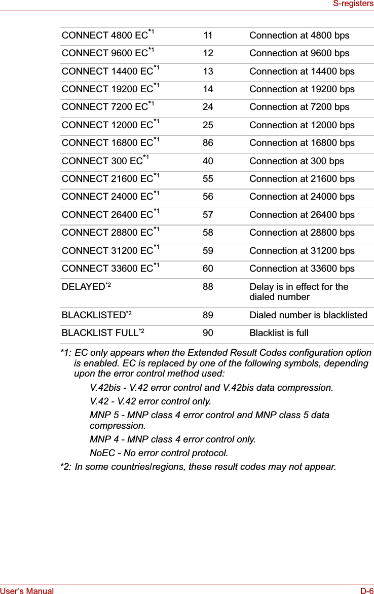
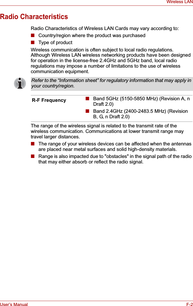
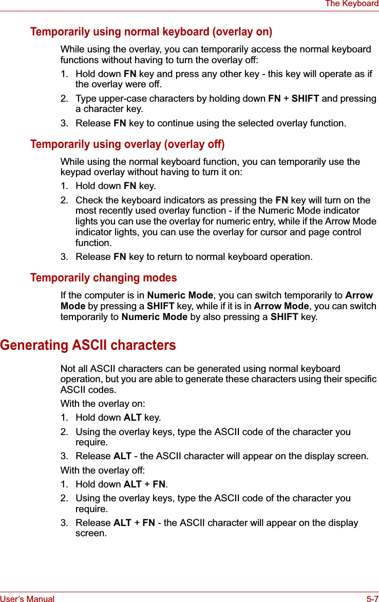
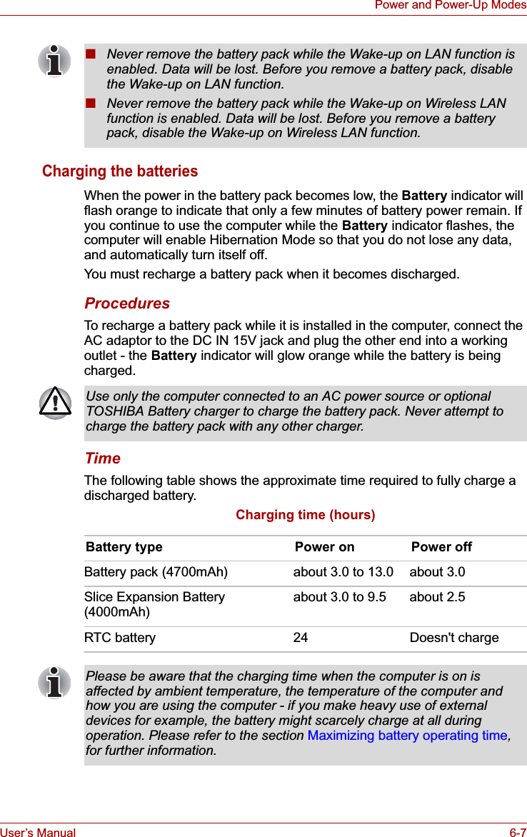
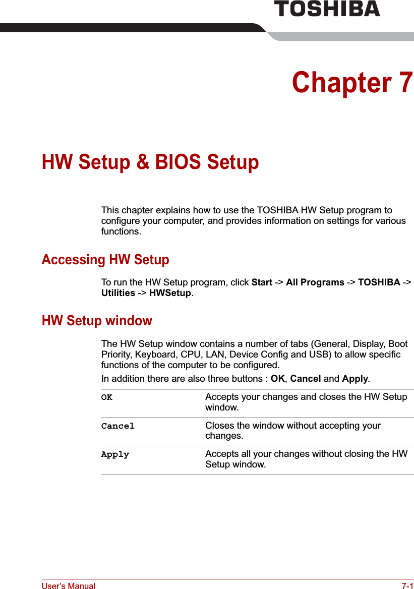
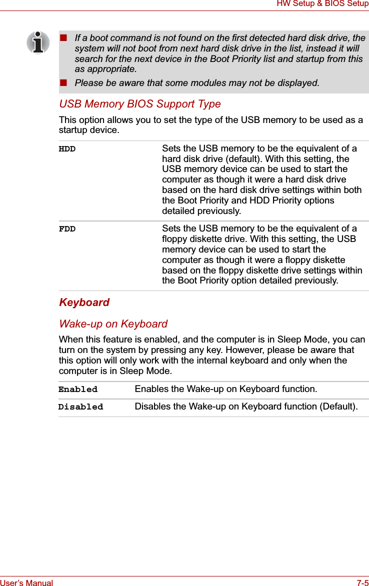
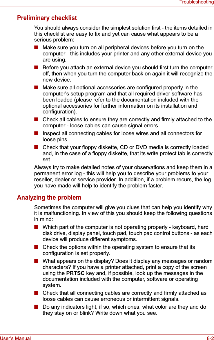
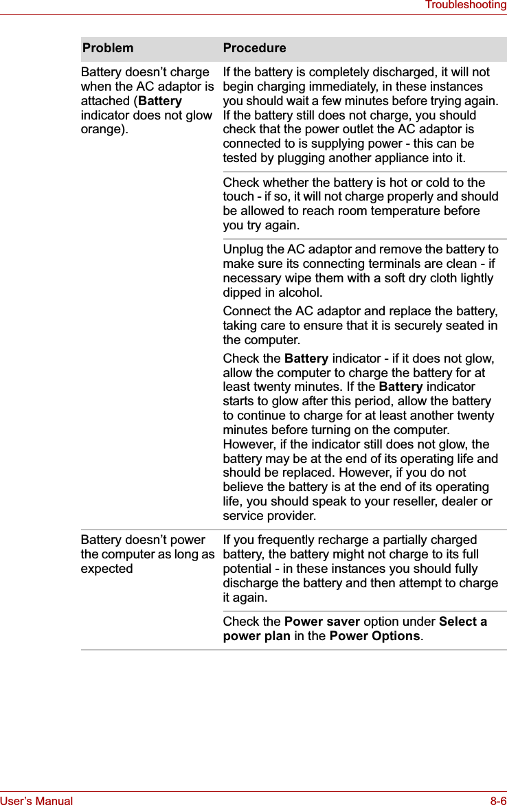
![User’s Manual 7-13HW Setup & BIOS SetupSATA Controller ModeThis feature sets the SATA Controller Mode.USB Sleep and Charge functionThis section describes the settings for "USB Sleep and Charge function". For more information, please refer to the USB Sleep and Charge functionsection in Chapter 3, Hardware, Utilities and Options.The default setting in BIOS Setup is [Disabled]. Changing the setting to [Enabled] enables the use of this function. There are two modes, Mode-1 and Mode-2 in [Enabled]. For normal use, set the setting to Mode-1. The SATA Controller Mode is supported with some models.AHCI Sets AHCI which is the mode for Windows Vista®(Default).Compatibility Sets the mode for legacy OS. Use this mode when the driver corresponding to AHCI is not used.If the function does not work with Mode-1 setting, change it to Mode-2. Some external devices may not be able to use this function in either mode. When this happens, change the setting to [Disabled]. Enabled (Mode-1) Enables USB Sleep and Charge function.Enabled (Mode-2) Enables USB Sleep and Charge function.Disabled Disables USB Sleep and Charge function (Default).](https://usermanual.wiki/Dynabook/UPA3547G3.Manual-2/User-Guide-886040-Page-44.png)
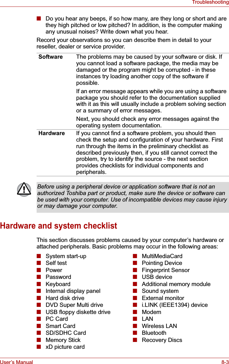
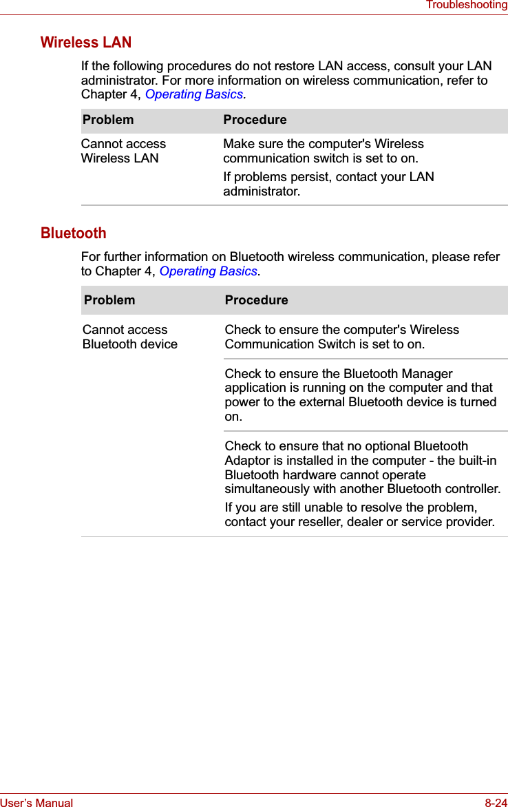
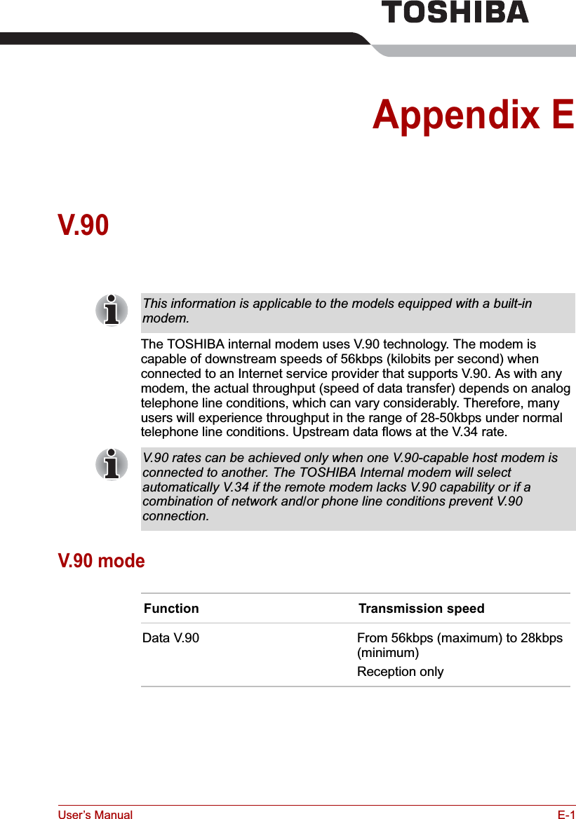
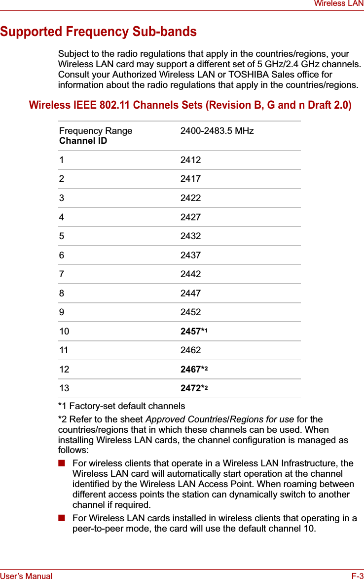
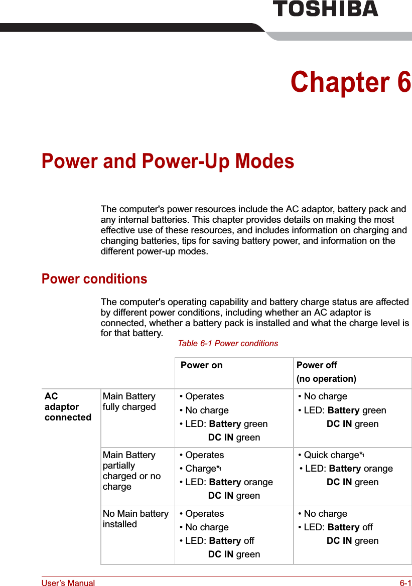
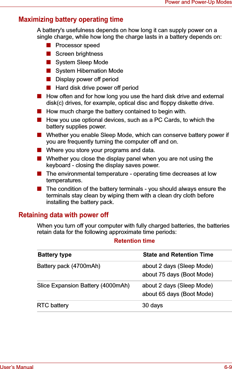
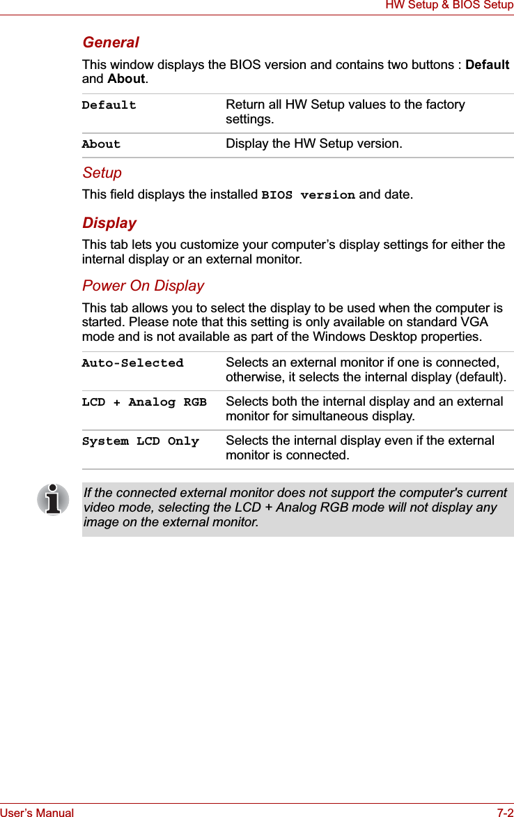
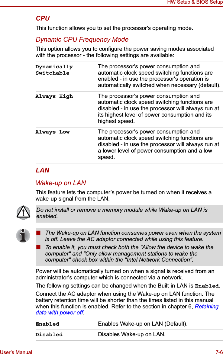
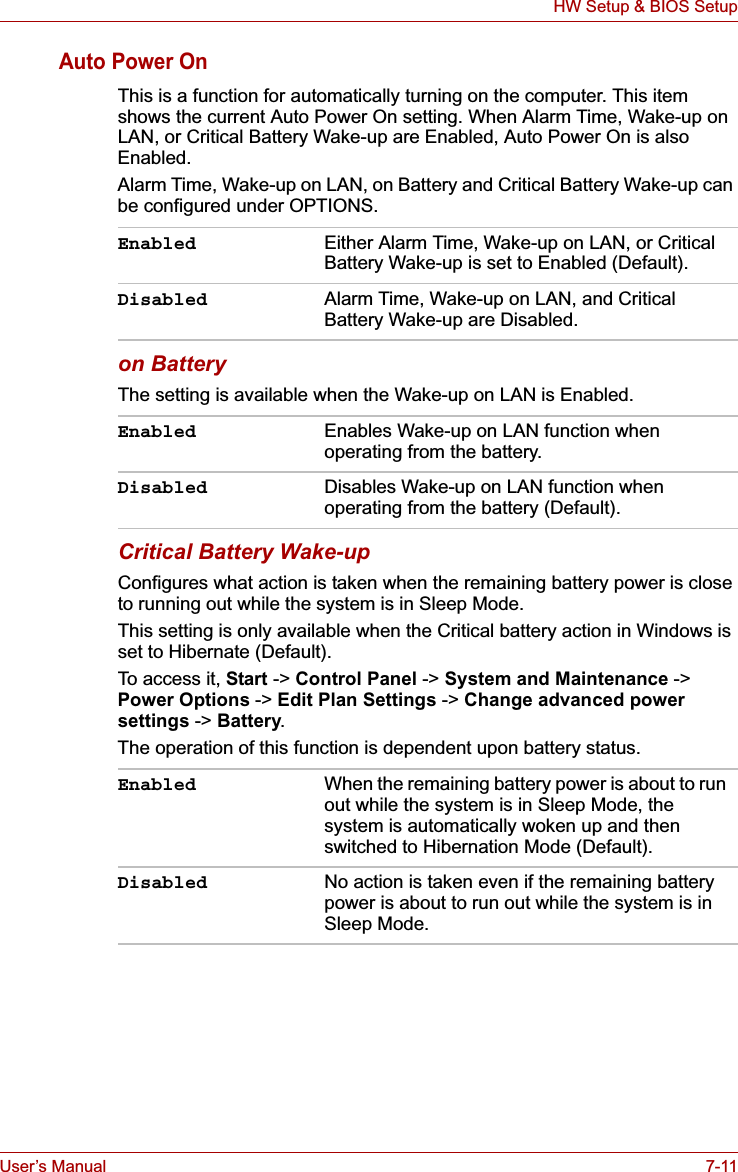
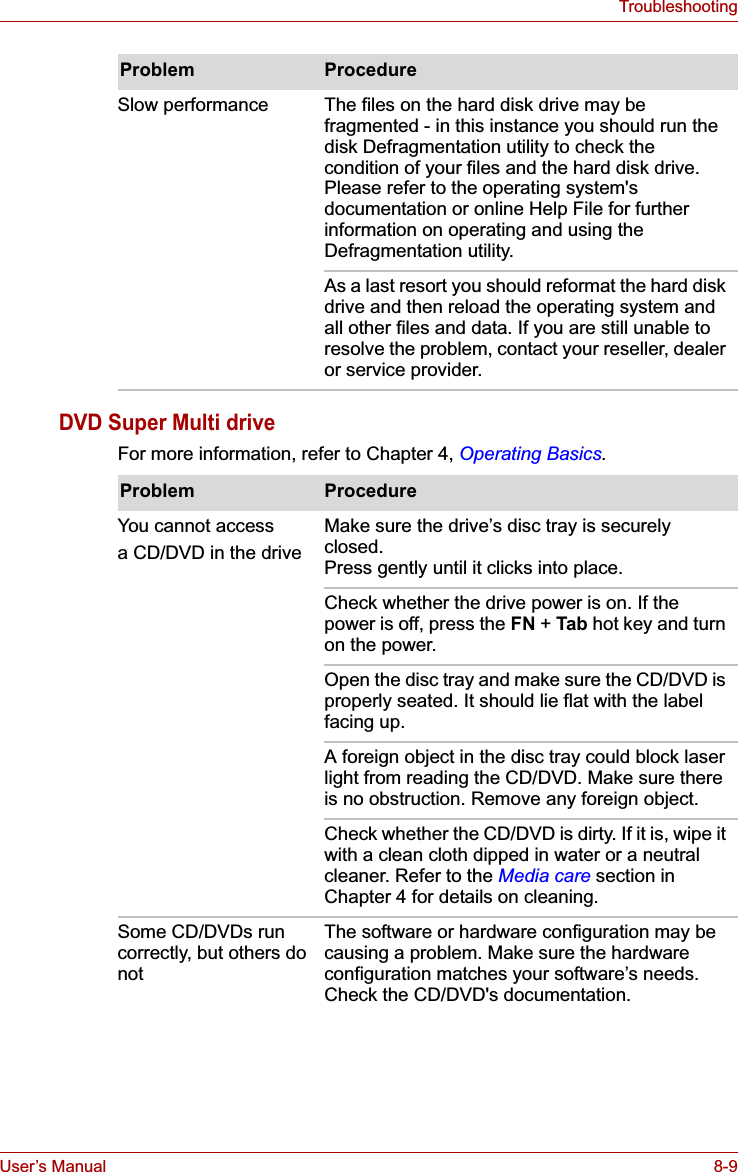
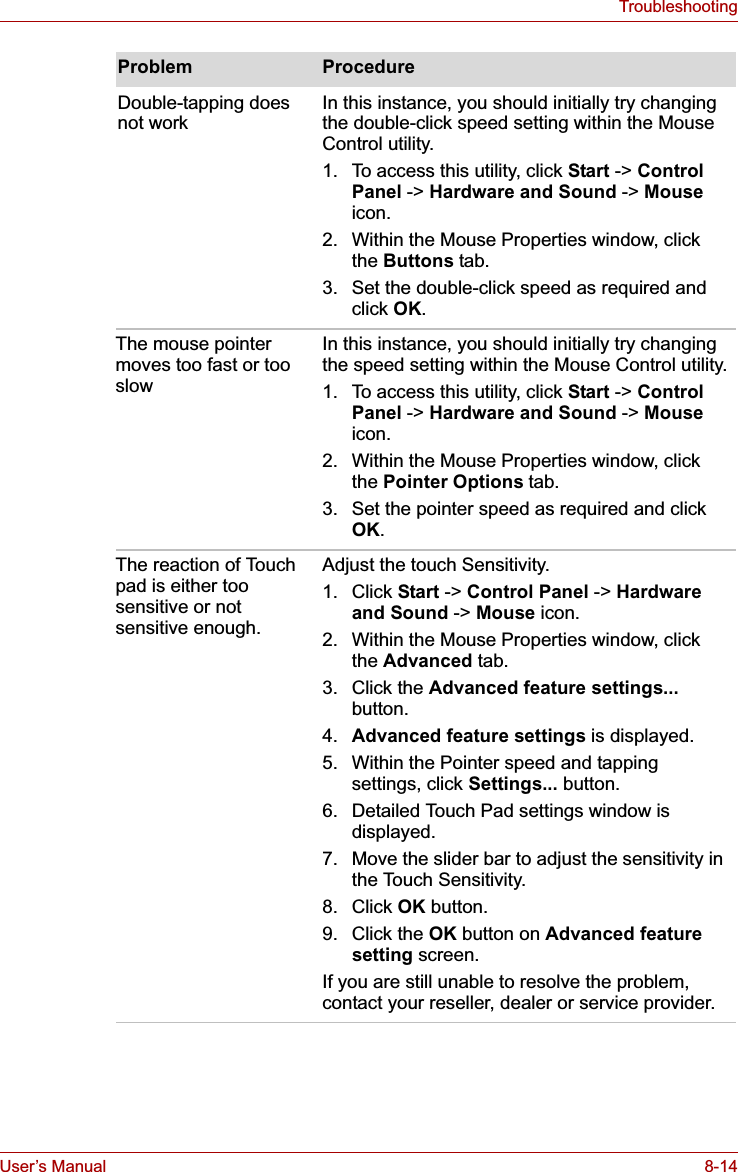
![User’s Manual 8-7TroubleshootingReal Time ClockPasswordKeyboardKeyboard problems can be caused by the setup and configuration of the computer - please refer to Chapter 5, The Keyboard for further information.Problem ProcedureThe following message is Displayed on the screen:RTC battery is low or CMOS checksum is inconsistent. Press [F1] key to set Date/Time.The charge in the Real Time Clock (RTC) battery has run out - you will need to set the date and time in the BIOS setup application by using the following steps:1. Press the F1 key - the BIOS setup application will load.2. Set the date in the System Date field.3. Set the time in the System Time field.4. Press the END key - a confirmation message will be displayed.5. Press the Y key - the BIOS setup application will end and the computer will restart.Problem ProcedureCannot enter password Please refer to the TOSHIBA Password Utilitysection in Chapter 6, Power and Power-Up Modes for further information.Problem ProcedureSome letter keys produce numbers Check that the numeric keypad overlay is not activated - press the FN + F11 hot key and try typing again.Output to screen is garbled Please refer to your software's documentation to ensure that its is not remapping the keyboard in any way (remapping involves changing or reassigning the function of each key).If you are still unable to use the keyboard, you should contact your reseller, dealer or service provider.](https://usermanual.wiki/Dynabook/UPA3547G3.Manual-2/User-Guide-886040-Page-51.png)

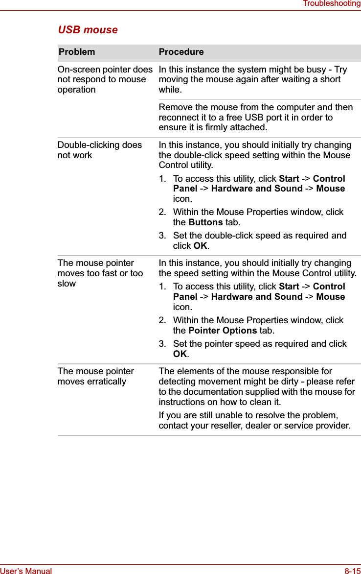
![User’s Manual 8-17TroubleshootingUSB deviceIn addition to the information in this section, please also refer to the documentation supplied with your USB device.USB Sleep and Charge functionProblem ProcedureUSB device does not workRemove the USB device from the computer and then reconnect it to a free port it in order to ensure it is firmly attached.Ensure that any required USB device drivers are properly installed - to achieve this you should refer to both the device documentation and the operating system documentation.If you are using an operating system that does not support USB, you are still able to use a USB mouse and/or USB keyboard by setting the USBKB/Mouse Emulation option within the TOSHIBA HW Setup utility to Enabled.If you are still unable to resolve the problem, contact your reseller, dealer or service provider.Problem ProcedureI cannot use the "USB Sleep and Charge function".The setting of "USB Sleep and Charge function" may be [Disabled]. Change the setting to [Enabled] in the BIOS Setup.When there is a current overflow of the external device connected to the compatible port, USB bus power (DC5V) supply may be stopped for safety reasons. When this happens, disconnect an external device if some external devices are connected. After that, turn the power of the computer ON/OFF to restore the function. If this function can not be still used even if only one external device is connected, stop using the external device because its current is over the acceptable value of this computer.](https://usermanual.wiki/Dynabook/UPA3547G3.Manual-2/User-Guide-886040-Page-61.png)
![User’s Manual 8-18TroubleshootingProblem ProcedureSome external devices may not be able to use the "USB Sleep and Charge function". In this case, please try one or more of the following methods. ■Change a mode setting of [Enabled] by the BIOS Setup.■Turn OFF the computer while external devices are connected.■Connect external devices after turning OFF of the computer.If this function can not be still used, change the setting to [Disabled] in the BIOS Setup and stop using this function.The battery depletes quickly even when I turned OFF the power of the computer. When "USB Sleep and Charge function" is set to [Enabled] in the BIOS Setup, USB bus power (DC5V) will be supplied to the external device connected to the compatible port. If external device is connected to the compatible port when the AC adaptor is not connected to the computer, the battery of the computer will be depleted even when the power of the computer is turned OFF.Connect the AC adaptor to the computer or change the "USB Sleep and Charge function" setting to [Disabled] in the BIOS Setup.Instead use an USB port that does not have the USB Sleep and Charge function-compatible icon ( ).External devices connected to the compatible ports do not work when connected to a compatible port. Some external devices may not work when connected to a compatible port when the "USB Sleep and Charge function" is [Enabled] in the BIOS Setup.Reconnect the external device after turning ON the computer.If the external device still does not work, connect device to an USB port that does not have the USB Sleep and Charge function-compatible icon ( ) or change the "USB Sleep and Charge function" setting to [Disabled] in the BIOS Setup.](https://usermanual.wiki/Dynabook/UPA3547G3.Manual-2/User-Guide-886040-Page-62.png)
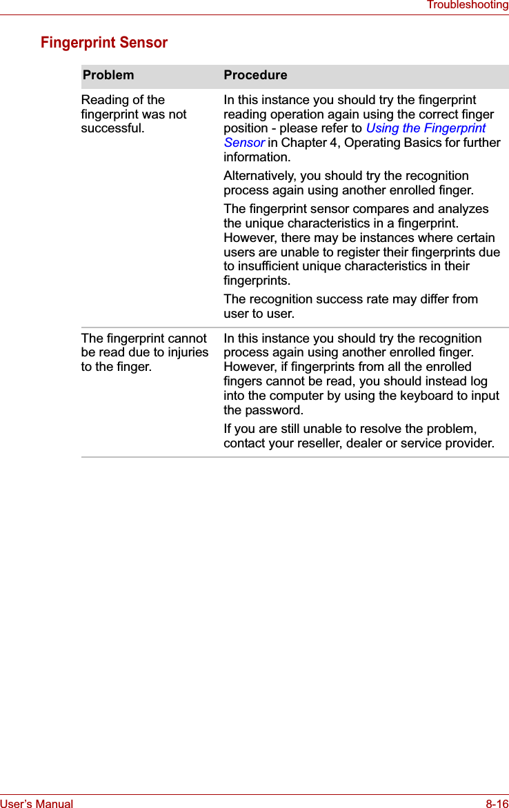
![User’s Manual 8-19TroubleshootingAdditional memory modulePlease also refer to Chapter 3, Hardware, Utilities and Options, for further information on installing and removing memory modules.Problem ProcedureThe "USB WakeUp function" does not work.When "USB Sleep and Charge function" is set to [Enabled] in the BIOS Setup, the "USB WakeUp function" does not work for ports that support the USB Sleep and Charge function.In that case, use an USB port that does not have the USB Sleep and Charge function-compatible icon ( ) or change the "USB Sleep and Charge function" setting to [Disabled] in the BIOS Setup.Problem ProcedureIf there is a memory malfunction, the Powerindicator will repeatedly flash (on for 0.5 seconds, off for 0.5 seconds) in the following patterns;If there is an error in only slot A or no memory module is inserted in Slot A: orange twice, then green once.If there is an error in Slot B: orange once, then green twice.If there are errors in both Slot A and Slot B: orange twice, then green twice.In the event the Power indicator flashes when the computer is turned on, you should first check that the installed memory module(s) are compatible with the computer. If there is an error with a compatible memory module, there is a possibility the memory module is damaged.If you determine that an incompatible module has been installed, you should follow the steps as detailed below:1. Turn off the computer.2. Disconnect the AC adaptor and all peripheral devices.3. Remove the battery pack.4. Remove the incompatible memory module.5. Install the battery and/or connect the AC adaptor.6. Turn on the computer.If you are still unable to resolve the problem, contact your reseller, dealer or service provider.An error will occur if a memory module is inserted into Slot B while no memory module is inserted in Slot A.Remove the memory module from Slot B and insert it into Slot A.](https://usermanual.wiki/Dynabook/UPA3547G3.Manual-2/User-Guide-886040-Page-63.png)